UNIVERGE SV9100 UC Suite Manual - Telecom Options
440
UC Suite Manual NDA-31575 Issue 5.0 (Version 5000) SV9100 ®
-
Upload
khangminh22 -
Category
Documents
-
view
0 -
download
0
Transcript of UNIVERGE SV9100 UC Suite Manual - Telecom Options
UC Suite Manual
NDA-31575Issue 5.0
(Version 5000)
SV9100®

Contents of this manual are subject to change without prior notice at the discretion of NECCorporation of America. This document has been prepared for the use of employees andcustomers of NEC Corporation of America and may not be reproduced without prior writtenapproval of NEC Corporation of America.
UNIVERGE is a trademark of NEC Corporation of America. Internet Explorer is a registeredtrademark of Microsoft Corporation. Android is registered trademark of Google, Inc. TheGoogle Chrome browser is a trademark of Google Inc. Mozilla and Firefox are registeredtrademarks of the Mozilla Foundation. Safari is a trademark of Apple Inc., registered in theU.S. and other countries. Salesforce.com is a registered trademark of Salesforce.com, inc.Tigerpaw is a registered trademark of Tigerpaw Software, Inc.
Copyright 2016
NEC Corporation of America3929 W. John Carpenter Freeway
Irving, TX 75063-9406
Communications Technology Group


SV9100 UC Suite Manual R-1
COMPLIANCE
FCC REGULATIONS
SECTION 1 EMISSIONS
This equipment has been tested and found to comply with the limits for a Class A digital device, pursuant to Part 15 of the FCC Rules. These limits are designed to provide reasonable protection against harmful interference when the equipment is operated in a commercial environment.
This equipment generates, uses, and can radiate radio frequency energy and, if not installed and used in accordance with the instruction manual, may cause harmful interference to radio communications. Operation of this equipment in a residential area is likely to cause harmful interference in which case users are required to correct the interference at their own expense.
SECTION 2 TELCO REQUIREMENTS
ADA-L Adapter has been certified to FCC Part 68 requirements for telephone system equipment.
SECTION 3 SAFETY
ADA-L Adapter has been certified to ANSI/UL 1459, 2nd Edition, Telephone Equipment. This equipment is not intended for direct connection to Telco lines.
CAUTION
Changes or modifications to ADA-L Adapter hardware not expressly approved by the party responsible for compliance could void the user authority to operate the equipment.
Regulatory

Issue 5.0
R-2
INDUSTRY CANADA
SECTION 1 EMISSIONS
This digital apparatus does not exceed the Class A limits for radio noise emissions from a digital apparatus set out in the Radio Interference Regulations of Industry Canada.
Le présent appareil numérique n'émet pas de bruits radioélectriques depassant les limites applicables aux appareils numériques de la class A prescrites dans le Réglement sur le brouillage radioélectrique édicte par le ministère de l’Industrie du Canada.
SECTION 2 TELCO REQUIREMENTS
ADA-L Adapter has been certified to Industry Canada CS02 and CS03 requirements for telephone system equipment.
SECTION 3 SAFETY
ADA-L Adapter has been certified to Standard C22.2, No. 225-M90, Telecommunications Equipment.
Ne pas brancher directernert au réseau téléphonique. Voir manuel d’instruction.
SV9100 UC Suite Manual i
TABLE OF CONTENTS
Regulatory
Chapter 1 Introduction to UC Suite
Section 1 Introduction .............................................................................................. 1-1
Section 2 Overview ................................................................................................... 1-1
Section 3 Installation Considerations ..................................................................... 1-4
3.1 UC Client ......................................................................................... 1-4
3.2 UC Client with UC Server Connection............................................. 1-4
3.3 Remote Connections....................................................................... 1-4
Section 4 System Requirements ............................................................................. 1-5
4.1 Minimum PC Requirements ............................................................ 1-5
4.2 Supported Operating Systems ........................................................ 1-5
4.3 Virtual Machine Support .................................................................. 1-6
4.4 Licensing ......................................................................................... 1-6
Chapter 2 Installation
Section 1 Installation Steps ..................................................................................... 2-2
1.1 Uninstall Previous Server ................................................................ 2-2
1.1.1 InServer Blade .............................................................................2-2
1.1.2 External Server ............................................................................2-2
1.2 Install UC Server ............................................................................. 2-3
1.3 Uninstall Previous Client ............................................................... 2-14
1.4 Install the UC Client....................................................................... 2-16
Section 2 SV9100 UC Suite Programming ............................................................ 2-20
ii Table of Contents
Issue 5.0
Chapter 3 UC Client Startup
Section 1 Full Window Mode ................................................................................... 3-2
1.1 Title Bar and Main Menu ................................................................. 3-3
1.2 Function Toolbar ............................................................................. 3-5
1.3 Active Call List................................................................................. 3-6
1.3.1 Active Call List Format ................................................................. 3-6
1.3.2 Active Call List Operations........................................................... 3-7
1.4 BLF/DSS Area................................................................................. 3-7
1.4.1 BLF/DSS Tabs............................................................................. 3-7
1.4.1.1 BLF/DSS Programming...........................................................3-7
1.4.1.2 BLF Button Design ..................................................................3-8
1.4.1.3 BLF/DSS Layout......................................................................3-8
1.4.1.4 BLF Custom Layout.................................................................3-9
1.4.1.5 BLF/DSS Operations.............................................................3-10
1.4.1.6 Trunks Tab ............................................................................3-11
1.4.1.7 Speed Dial Tab......................................................................3-11
1.5 Presence Area .............................................................................. 3-12
1.5.1 Current Presence Status............................................................ 3-12
1.5.2 Right Click to Set Presence ....................................................... 3-12
Section 2 Toolbar Mode ......................................................................................... 3-13
2.1 Dial String Field............................................................................. 3-13
2.2 Call Status Area ............................................................................ 3-14
2.3 Dial/Hangup Button ....................................................................... 3-14
2.4 Speed Dial List .............................................................................. 3-14
2.5 File Button ..................................................................................... 3-15
2.6 Hold Button ................................................................................... 3-16
2.7 Function Toolbar ........................................................................... 3-17
Section 3 Emulation Phone Mode (Phone Image) ............................................... 3-18
3.1 Emulation Phone Base Module..................................................... 3-18

SV9100 UC Suite Manual iii
Issue 5.0
3.2 Emulation Phone Add-On Module................................................. 3-19
3.3 Emulation Phone DSS Module...................................................... 3-20
Chapter 4 Toolbar Functions
Section 1 Toolbar Functions.................................................................................... 4-1
1.1 Answer ............................................................................................ 4-2
1.2 Hold ................................................................................................. 4-2
1.3 Transfer ........................................................................................... 4-2
1.3.1 Transfer Call – Start .....................................................................4-3
1.3.2 Transfer Call – Blind.....................................................................4-3
1.3.3 Transfer Call – Cancel .................................................................4-3
1.4 Hang Up .......................................................................................... 4-3
1.5 Dial .................................................................................................. 4-4
1.6 Conference...................................................................................... 4-4
1.6.1 Conference Call – Start................................................................4-5
1.6.2 Conference Call – Cancel ............................................................4-5
1.7 Record............................................................................................. 4-5
1.8 Page ................................................................................................ 4-6
1.9 Park ................................................................................................. 4-7
1.10 Unpark............................................................................................. 4-7
1.11 Night Mode ...................................................................................... 4-8
1.12 Barge In........................................................................................... 4-9
1.13 Directed Call Pickup ........................................................................ 4-9
1.14 Group Call Pickup ......................................................................... 4-10
1.15 Pickup Other Group....................................................................... 4-10
1.16 Last Number Redial....................................................................... 4-10
1.17 Voice Over..................................................................................... 4-10
1.18 Call Redirect.................................................................................. 4-11
1.19 Call Forward .................................................................................. 4-11
1.20 Do Not Disturb (DND).................................................................... 4-12
iv Table of Contents
Issue 5.0
1.21 Custom Message .......................................................................... 4-13
1.22 Background Music......................................................................... 4-14
1.23 Auto Callback ................................................................................ 4-14
1.24 Phone Image................................................................................. 4-14
1.25 Auto Handset/Auto Headset.......................................................... 4-14
1.26 Switch Login Mode........................................................................ 4-15
1.27 Add Note ....................................................................................... 4-15
Section 2 Directory View........................................................................................ 4-16
2.1 Opening the Directory View .......................................................... 4-16
2.1.1 Title Bar and Main Menu............................................................ 4-17
2.1.2 Function Toolbar ........................................................................ 4-18
2.1.3 Search Area............................................................................... 4-20
2.1.4 Table Viewer .............................................................................. 4-20
2.2 Company Directory ....................................................................... 4-22
2.2.1 Adding a New Entry to the Directory.......................................... 4-22
2.2.2 Modifying an Entry in the Directory ............................................ 4-24
2.2.3 Deleting an Entry from the Directory.......................................... 4-24
2.2.4 Printing the Directory ................................................................. 4-25
2.3 Contacts/Personal Lists ................................................................ 4-25
2.3.1 Adding a New Entry to the Contacts/Personal List .................... 4-25
2.3.2 Modifying an Entry in the Contacts/Personal List ...................... 4-26
2.3.3 Deleting an Entry from the Contacts/Personal List .................... 4-26
2.3.4 Printing the Directory ................................................................. 4-27
Section 3 Call Log View.......................................................................................... 4-27
3.1 Opening the Call Log .................................................................... 4-27
3.1.1 Title Bar and Main Menu............................................................ 4-28
3.1.2 Filter Toolbar.............................................................................. 4-28
3.1.3 Record Viewer ........................................................................... 4-29
3.2 Playing Back a Recorded Telephone Conversation...................... 4-30
3.3 Deleting a Record from the Call Log ............................................. 4-30
SV9100 UC Suite Manual v
Issue 5.0
3.4 Printing the Call Log ...................................................................... 4-31
3.5 Archiving the Call Log ................................................................... 4-31
3.6 Pinning .......................................................................................... 4-32
Chapter 5 Contact Center Agent
Section 1 Introduction .............................................................................................. 5-1
Section 2 Licensing .................................................................................................. 5-1
Section 3 Configuration............................................................................................ 5-2
Section 4 Contact Center Agent State .................................................................... 5-3
4.1 Login................................................................................................ 5-4
4.2 Logout ............................................................................................. 5-5
4.3 Wrapup............................................................................................ 5-5
4.4 Off Duty ........................................................................................... 5-5
Section 5 Queue Monitor.......................................................................................... 5-5
Section 6 Agent Monitor........................................................................................... 5-7
Section 7 Emergency Call ........................................................................................ 5-8
Section 8 Abandon Call Alert................................................................................... 5-9
8.1 Configuration ................................................................................... 5-9
8.1.1 System Programming...................................................................5-9
8.1.2 Client Configuration....................................................................5-10
8.1.3 UC Client Alerts..........................................................................5-11
8.1.4 Abandoned Calls Alert Window..................................................5-12
8.1.5 Callback Detail Window .............................................................5-14
8.2 Popup Menu .................................................................................. 5-15
8.2.1 Callback .....................................................................................5-15
Chapter 6 Answering Center
Section 1 Introduction .............................................................................................. 6-1
Section 2 Installation ................................................................................................ 6-1
vi Table of Contents
Issue 5.0
Section 3 Configuration ........................................................................................... 6-1
3.1 Configuring UC Client Preferences ................................................. 6-1
3.2 Launching the Answering Center .................................................... 6-2
3.3 Database Setup .............................................................................. 6-3
Section 4 Profiles...................................................................................................... 6-4
4.1 Managing Profiles ........................................................................... 6-4
Section 5 Answering Center Functions .................................................................. 6-8
Chapter 7 Application Level Configuration
Section 1 Introduction .............................................................................................. 7-1
Section 2 Preferences Menu .................................................................................... 7-2
2.1 Preferences – General .................................................................... 7-2
2.2 Preferences – BLF/DSS.................................................................. 7-4
2.3 Preferences – Recording ................................................................ 7-8
2.4 Preferences – Personal Greeting.................................................... 7-9
2.5 Preferences – Playback ................................................................ 7-10
2.6 Preferences – Tool Buttons........................................................... 7-11
2.7 Preferences – Active Call List ....................................................... 7-12
2.8 Preferences – Screen Pop ............................................................ 7-13
2.9 Preferences – Shortcuts................................................................ 7-14
2.10 Preferences – Dialing Rules.......................................................... 7-15
2.11 Preferences – Telephony Settings ................................................ 7-16
2.12 Preferences – Voice Mail .............................................................. 7-18
2.13 Preferences – Notification Settings ............................................... 7-19
2.14 Preferences – Quick Message ...................................................... 7-20
2.15 Preferences – Phone Message..................................................... 7-21
2.16 Preferences – Trunk Settings........................................................ 7-22
2.17 Preferences – Video Settings........................................................ 7-23
2.18 Preferences – Phone Image ......................................................... 7-24
SV9100 UC Suite Manual vii
Issue 5.0
Chapter 8 UC Server
Section 1 Installation ................................................................................................ 8-2
1.1 Configuration ................................................................................... 8-2
1.2 Activation......................................................................................... 8-6
Section 2 Shared Directory ...................................................................................... 8-6
Section 3 Shared Contact List ................................................................................. 8-6
Section 4 Centralized BLF Monitoring .................................................................... 8-6
Section 5 Common Trunk Labeling......................................................................... 8-6
Section 6 Phone Messaging..................................................................................... 8-7
6.1 Sending and Receiving Phone Messages....................................... 8-7
6.2 Tracking Phone Messages.............................................................. 8-8
6.3 Configuring Phone Messages ......................................................... 8-8
Section 7 Presence ................................................................................................. 8-10
7.1 Scheduled Presence Events ......................................................... 8-14
7.1.1 Viewing Scheduled Presence Events ........................................8-16
7.1.2 Viewing Presence Events for Others .........................................8-17
7.1.3 Conflicting Presence Events ......................................................8-18
7.2 Smart Presence............................................................................. 8-18
7.2.1 UC Client Smart Presence .........................................................8-18
7.2.1.1 Keyboard/Mouse Inactivity ....................................................8-19
7.2.1.2 Application Open Action ........................................................8-21
7.2.1.3 Application Close Actions ......................................................8-22
Section 8 Park Orbit Monitoring ............................................................................ 8-23
8.1 Park Orbit Monitoring .................................................................... 8-25
8.2 Other Park Operations .................................................................. 8-27
8.3 Park Area Configuration ................................................................ 8-28
8.4 Toolbar Mode ................................................................................ 8-29

viii Table of Contents
Issue 5.0
Section 9 Profile Sharing ....................................................................................... 8-29
9.1 Profile Sharing Function................................................................ 8-29
9.2 Saving a Profile ............................................................................. 8-30
9.3 Deleting a Profile........................................................................... 8-32
9.4 Applying a Profile .......................................................................... 8-32
Section 10 Instant Messaging.................................................................................. 8-32
10.1 Feature Initiation ........................................................................... 8-33
10.1.1 Window Mode ............................................................................ 8-33
10.1.2 Toolbar Mode............................................................................. 8-34
10.1.3 Session Invitation....................................................................... 8-35
10.1.4 Instant Message Button ............................................................. 8-36
10.1.5 Session Restrictions .................................................................. 8-36
10.2 Instant Messaging Window ........................................................... 8-37
10.2.1 IM Window Layout ..................................................................... 8-37
10.2.1.1 Title Bar .................................................................................8-38
10.2.1.2 Menu Bar...............................................................................8-38
10.2.1.3 IM History ..............................................................................8-38
10.2.2 Input Area .................................................................................. 8-41
10.2.3 Status Bar .................................................................................. 8-42
10.3 IM Window Controls ...................................................................... 8-42
10.4 Instant Message Options .............................................................. 8-43
10.4.1 General Settings ........................................................................ 8-44
10.4.2 History Settings.......................................................................... 8-45
10.4.3 Notification Settings ................................................................... 8-46
Chapter 9 Outlook Add-In
Section 1 Outlook Add-In ......................................................................................... 9-1
1.1 Configuration................................................................................... 9-1
1.2 Making a Call .................................................................................. 9-5
1.3 Conference...................................................................................... 9-7

SV9100 UC Suite Manual ix
Issue 5.0
1.4 Transfer ......................................................................................... 9-11
1.5 End Call......................................................................................... 9-15
1.6 Presence Setting from Outlook Calendar...................................... 9-16
1.6.1 Assigning a Presence State .......................................................9-17
1.7 Adding Outlook Contact to Speed Dial List ................................... 9-18
Chapter 10 Salesforce Integration
Section 1 Overview ................................................................................................. 10-1
Section 2 Installation .............................................................................................. 10-2
2.1 Installation Procedure.................................................................... 10-2
Section 3 Salesforce.com Configuration .............................................................. 10-3
Section 4 UC Client Configuration ........................................................................ 10-4
Section 5 Operation ................................................................................................ 10-5
Section 6 Service Conditions................................................................................. 10-5
Chapter 11 Tigerpaw
Section 1 Introduction ............................................................................................ 11-1
Section 2 Overview ................................................................................................. 11-1
Section 3 UC Client Configuration ........................................................................ 11-1
Section 4 Operation ................................................................................................ 11-3
Chapter 12 Desktop Registration and Softphone Override
Section 1 Registration Types................................................................................. 12-1
Section 2 Service Conditions................................................................................. 12-3
Chapter 13 Data Conference
Section 1 Introduction ............................................................................................ 13-1
Section 2 Starting a Data Meeting ......................................................................... 13-2
x Table of Contents
Issue 5.0
Section 3 How to Use Data Meeting ...................................................................... 13-4
3.1 Joining a Data Meeting ................................................................. 13-6
Section 4 Ending a Data Meeting .......................................................................... 13-7
4.1 Ending a Data Meeting.................................................................. 13-7
4.2 Leaving a Data Meeting ................................................................ 13-8
Section 5 Using Video Communication ................................................................ 13-9
5.1 Icons.............................................................................................. 13-9
5.2 Starting Video Communication.................................................... 13-10
Section 6 Using the Communication Board ....................................................... 13-12
6.1 Icons ........................................................................................... 13-12
6.2 Sharing Data ............................................................................... 13-14
6.2.1 Drag and Drop ......................................................................... 13-14
6.2.2 Menu........................................................................................ 13-16
6.3 Turning a Page............................................................................ 13-17
6.4 Saving the Shared Data .............................................................. 13-18
Section 7 Using File Transfer .............................................................................. 13-21
7.1 Transferring a File ....................................................................... 13-21
7.2 Receiving a File........................................................................... 13-24
Section 8 Using Chat ............................................................................................ 13-26
8.1 Icons ........................................................................................... 13-26
8.2 Sending Chat .............................................................................. 13-27
8.3 Sending Whisper Chat ................................................................ 13-29
Section 9 Adding up to Eight Parties to a Meeting............................................ 13-31
9.1 Starting a Data Meeting from a Meeting ..................................... 13-31
Section 10 How to Use Various Settings .............................................................. 13-33
10.1 Displaying the Settings Screen ................................................... 13-33

SV9100 UC Suite Manual xi
Issue 5.0
10.2 Configuring Participants .............................................................. 13-34
10.2.1 Video Sending and Receiving Setting......................................13-35
10.2.2 Video Sending and Receiving Quality Setting..........................13-36
10.2.3 Change of Capture Device.......................................................13-37
10.3 Configuring Communication Board ............................................. 13-37
10.3.1 Auto Save.................................................................................13-38
10.3.2 Register Document ..................................................................13-39
10.4 Configuring Chat ......................................................................... 13-40
10.4.1 Font ..........................................................................................13-40
10.4.2 Display Color of Chat Message................................................13-41
10.4.3 Background Color of Chat Message Display Region ...............13-42
10.4.4 Header Display Style................................................................13-43
10.4.5 Auto Save.................................................................................13-44
Chapter 14 InMail Integration
Section 1 Introduction ............................................................................................ 14-1
Section 2 Voicemail Feature Activation and Configuration ................................ 14-1
2.1 Feature Activation ......................................................................... 14-1
2.2 Feature Configuration.................................................................... 14-2
Section 3 Voicemail Message Display .................................................................. 14-3
Section 4 Voicemail Message Operations ............................................................ 14-4
4.1 Playback, Archive, Delete or Dial Number Associated with Message ................................................................................ 14-4
4.2 Forward Message.......................................................................... 14-5
4.3 New Message Indication ............................................................... 14-5
Section 5 VoiceMail Presence Greetings.............................................................. 14-7
Section 6 Exceptions .............................................................................................. 14-9
Chapter 15 UM8000 Integration
Section 1 Introduction ............................................................................................ 15-1

xii Table of Contents
Issue 5.0
Section 2 VoiceMail Feature Configuration – Desktop........................................ 15-2
Section 3 VoiceMail Message Display .................................................................. 15-3
Section 4 VoiceMail Message Operations ............................................................ 15-5
Section 5 Forward Message Details...................................................................... 15-6
Section 6 New Message Indication ....................................................................... 15-7
Section 7 VoiceMail Presence Greetings Feature Configuration ....................... 15-8
Section 8 Exceptions............................................................................................ 15-11
Chapter 16 Integration Toolkit
Section 1 Introduction ............................................................................................ 16-1
Section 2 Toolkit Activation................................................................................... 16-1
Chapter 17 UC Web Client
Section 1 Introduction ............................................................................................ 17-1
Section 2 Feature Support ..................................................................................... 17-2
Section 3 Compatibility .......................................................................................... 17-7
Section 4 Licensing ................................................................................................ 17-8
Section 5 User Login and Shared Services Configuration ................................. 17-9
Section 6 Using the UC Web Client..................................................................... 17-13
6.1 UC Web Screen Layout .............................................................. 17-13
6.2 Handling Calls ............................................................................. 17-22
6.3 My Availability ............................................................................. 17-27
6.4 Buddy List ................................................................................... 17-32
6.5 Starting an Instant Messaging (IM) Session ............................... 17-35
6.6 Contacts View ............................................................................. 17-37
6.7 Call History View ......................................................................... 17-38

SV9100 UC Suite Manual xiii
Issue 5.0
6.8 Contact Center Integration .......................................................... 17-39
6.8.1 Agent Functions .......................................................................17-39
6.8.2 Agent Monitor...........................................................................17-41
6.8.2.1 Agent Monitor Definition ......................................................17-41
6.8.2.2 Agent Monitor Display .........................................................17-41
6.8.3 Queue Monitor .........................................................................17-42
6.8.3.1 Queue Monitor Definition.....................................................17-42
6.8.3.2 Queue Monitor Display ........................................................17-43
6.8.4 Abandoned Call Alerts .............................................................17-44
6.8.4.1 Abandoned Call Setting.......................................................17-44
6.8.4.2 Abandoned Call Display ......................................................17-44
6.9 Presence Profiles ........................................................................ 17-46
6.10 Smart Presence........................................................................... 17-47
6.10.1 Application Close Actions.........................................................17-47
6.11 Park Zone Monitoring .................................................................. 17-48
6.11.1 Park Zone Setup ......................................................................17-48
6.11.2 UC Web Client Park Zone Display ...........................................17-49
6.12 Handset/Headset......................................................................... 17-50
6.13 Night Mode Switch Setting .......................................................... 17-50
6.14 Directed Call Pickup .................................................................... 17-51
6.15 Paging ......................................................................................... 17-52
6.16 Voicemail Quick Access .............................................................. 17-53
Chapter 18 UT880 UC Client
Section 1 Introduction ............................................................................................ 18-1
Section 2 Feature Support ..................................................................................... 18-1
Section 3 Compatibility .......................................................................................... 18-6
Section 4 Licensing ................................................................................................ 18-6
Section 5 User Login and UC Server Configuration ............................................ 18-7

xiv Table of Contents
Issue 5.0
Section 6 Using the UT880 UC Client.................................................................. 18-11
6.1 UT880 UC Client Screen Layout................................................. 18-11
6.1.1 Main Control Area.................................................................... 18-12
6.1.2 Active Call Area ....................................................................... 18-12
6.1.3 Buddy List ................................................................................ 18-12
6.1.4 Status Bar ................................................................................ 18-13
6.1.5 Settings.................................................................................... 18-13
6.1.5.1 Personal Profile ...................................................................18-15
6.1.5.2 Display.................................................................................18-16
6.1.5.3 Notifications.........................................................................18-18
6.1.5.4 Chats ...................................................................................18-19
6.2 Handling Calls ............................................................................. 18-20
6.2.1 Answering Incoming Calls........................................................ 18-20
6.2.2 Disconnecting from a Call ........................................................ 18-20
6.2.3 Placing an Outbound Call ........................................................ 18-21
6.2.3.1 To Initiate a Call Using the Dial Control ..............................18-21
6.2.3.2 To Initiate a Call Using a BLF/DSS in a Buddy List.............18-22
6.2.4 Placing a Call on Hold.............................................................. 18-22
6.2.4.1 To Place the Active Call on Hold.........................................18-22
6.2.4.2 Retrieving a Call on Hold.....................................................18-22
6.2.5 Transferring a Call ................................................................... 18-23
6.2.5.1 To Redirect a Call Using the Transfer Button .....................18-23
6.2.6 Setting Up a Conference Call .................................................. 18-24
6.2.6.1 To Initiate a Conference Using the Add Call Button............18-24
6.3 My Availability ............................................................................. 18-25
6.4 Buddy List ................................................................................... 18-29
Chapter 19 Multi-Device Support
Section 1 Introduction ............................................................................................ 19-1
Section 2 Compatibility .......................................................................................... 19-1
Section 3 Licensing ................................................................................................ 19-1
SV9100 UC Suite Manual xv
Issue 5.0
Section 4 UC Suite Client Integration.................................................................... 19-2
4.1 XML Pro Access............................................................................ 19-2
4.2 Client Feature Access ................................................................... 19-2
4.3 Web Client Feature Access........................................................... 19-4
4.4 Error Handling ............................................................................... 19-4
Section 5 Service Conditions................................................................................. 19-4
Chapter 20 InControl Call Reporting
Section 1 Introduction ............................................................................................ 20-1
Section 2 System Requirements ........................................................................... 20-1
Section 3 Licensing ................................................................................................ 20-2
Section 4 Login ....................................................................................................... 20-2
Section 5 Settings Management (Administration) ............................................... 20-2
5.1 Department Administration............................................................ 20-2
Section 6 Reports.................................................................................................... 20-6
6.1 Generate Once-only Report .......................................................... 20-6
Chapter A Features by Configuration

xvi Table of Contents
Issue 5.0
SV9100 UC Suite Manual xvii
LIST OF FIGURES
Chapter 2 Installation
Figure 2-1 External Server – Add or Remove Programs .................................................................2-2
Figure 2-2 External Server – Remove Data ....................................................................................2-2
Figure 2-3 UC Server – License Agreement ...................................................................................2-3
Figure 2-4 UC Server – Setup Wizard .............................................................................................2-4
Figure 2-5 UC Server – Select Installation Folder ...........................................................................2-4
Figure 2-6 UC Server – Confirm Installation ...................................................................................2-5
Figure 2-7 UC Server – Enter XML Port ..........................................................................................2-5
Figure 2-8 UC Server – Installation Complete .................................................................................2-6
Figure 2-9 UC Web Suite – Setup Wizard .......................................................................................2-6
Figure 2-10 UC Web Suite – Select Installation Folder .....................................................................2-7
Figure 2-11 UC Web Suite – Confirm Installation .............................................................................2-7
Figure 2-12 UC Web Suite – Web Server Port ..................................................................................2-8
Figure 2-13 UC Web Suite – Installation Complete ...........................................................................2-8
Figure 2-14 3rd Party CTI Driver – Install Wizard .............................................................................2-9
Figure 2-15 3rd Party CTI Driver – License Agreement ....................................................................2-9
Figure 2-16 3rd Party CTI Driver – Choose Destination Location ...................................................2-10
Figure 2-17 3rd Party CTI Driver – Select System Mode ................................................................2-10
Figure 2-18 3rd Party CTI Driver – Ready to Install Program .........................................................2-11
Figure 2-19 3rd Party CTI Driver – Installation Complete ...............................................................2-11
Figure 2-20 3rd Party CTI Driver – Settings Screen ........................................................................2-12
Figure 2-21 3rd Party CTI Driver – Starting Option of CTI Driver ....................................................2-13
Figure 2-22 3rd Party CTI Driver – CTI Driver Start Message ........................................................2-13
Figure 2-23 3rd Party CTI Driver – Settings Updated .....................................................................2-14
Figure 2-24 UC Suite – Remove NEC Middleware .........................................................................2-15
Figure 2-25 UC Suite – Remove Data .............................................................................................2-15
Figure 2-26 UC Suite – License Agreement ....................................................................................2-16
Figure 2-27 UC Suite – Copy Files ..................................................................................................2-16
Figure 2-28 UC Suite – Setup Wizard .............................................................................................2-17
xviii List of Figures
Issue 5.0
Figure 2-29 UC Suite – Select Installation Folder .......................................................................... 2-17
Figure 2-30 UC Suite – Confirm Installation ................................................................................... 2-18
Figure 2-31 UC Suite – Enable CallTo tag Feature ........................................................................ 2-18
Figure 2-32 UC Suite – Installation Complete ................................................................................ 2-19
Chapter 3 UC Client Startup
Figure 3-1 Login to Phone System Screen ..................................................................................... 3-1
Figure 3-2 Full Window Mode Screen ............................................................................................ 3-2
Figure 3-3 BLF Custom Screen ...................................................................................................... 3-9
Figure 3-4 Presence Area Screen ................................................................................................ 3-12
Figure 3-5 Toolbar ........................................................................................................................ 3-13
Figure 3-6 Emulation Phone Base Module ................................................................................... 3-18
Figure 3-7 Emulation Phone Add-On Module ............................................................................... 3-19
Figure 3-8 Emulation Phone DSS Module .................................................................................... 3-20
Chapter 4 Toolbar Functions
Figure 4-1 Transfer Call Screen ..................................................................................................... 4-2
Figure 4-2 Transfer Call – Start ...................................................................................................... 4-3
Figure 4-3 Conference Call Screen ................................................................................................ 4-4
Figure 4-4 Conference Call Start Screen ....................................................................................... 4-5
Figure 4-5 Page Screen ................................................................................................................. 4-6
Figure 4-6 Park Call Screen ........................................................................................................... 4-7
Figure 4-7 Unpark Call Screen ....................................................................................................... 4-7
Figure 4-8 Night Mode Screen ....................................................................................................... 4-8
Figure 4-9 Barge In Screen ............................................................................................................ 4-9
Figure 4-10 Directed Call Pickup Screen ......................................................................................... 4-9
Figure 4-11 Call Redirect Screen ................................................................................................... 4-11
Figure 4-12 Call Forward Screen ................................................................................................... 4-11
Figure 4-13 Do Not Disturb Screen ................................................................................................ 4-12
Figure 4-14 Custom Message Screen ............................................................................................ 4-13
Figure 4-15 Add Note Screen ......................................................................................................... 4-15
Figure 4-16 Directory View Screen ................................................................................................. 4-16
Figure 4-17 Select Visible Columns Screen ................................................................................... 4-21
Figure 4-18 Directory Maintenance Screen .................................................................................... 4-22
SV9100 UC Suite Manual xix
Issue 5.0
Figure 4-19 Departments Screen ....................................................................................................4-24
Figure 4-20 Contacts/Personal List .................................................................................................4-25
Figure 4-21 Call Log Screen ...........................................................................................................4-27
Figure 4-22 Visible Columns Menu .................................................................................................4-29
Figure 4-23 Telephone Conversation Playback Screen ..................................................................4-30
Figure 4-24 Call Log Archive Screen ..............................................................................................4-31
Chapter 5 Contact Center Agent
Figure 5-1 Contact Center Agent Tab .............................................................................................5-2
Figure 5-2 Contact Center Agent – Toolbar ....................................................................................5-3
Figure 5-3 Contact Center Agent – Window Mode ..........................................................................5-4
Figure 5-4 Contact Center Agent – Login ........................................................................................5-4
Figure 5-5 Contact Center Agent – Queue Monitor .........................................................................5-5
Figure 5-6 Contact Center Agent – Select Queues .........................................................................5-6
Figure 5-7 Contact Center Agent – Queue Thresholds ...................................................................5-7
Figure 5-8 Agent Monitor Window ...................................................................................................5-7
Figure 5-9 Select Agents Window ...................................................................................................5-8
Figure 5-10 Abandon Call Alert .........................................................................................................5-9
Figure 5-11 Preferences ..................................................................................................................5-10
Figure 5-12 UC Client Alert .............................................................................................................5-11
Figure 5-13 Abandoned Call Alert Image ........................................................................................5-12
Figure 5-14 Abandoned Call Popup ................................................................................................5-12
Figure 5-15 Abandoned Calls Window ............................................................................................5-13
Figure 5-16 Call Back Detail Window ..............................................................................................5-14
Figure 5-17 Call Back Status ...........................................................................................................5-16
Chapter 6 Answering Center
Figure 6-1 Preferences – XML Screen ............................................................................................6-2
Figure 6-2 Answer Icon ...................................................................................................................6-3
Figure 6-3 Right-Click Answer Center Icon .....................................................................................6-3
Figure 6-4 Database Setup Screen .................................................................................................6-4
Figure 6-5 Answering Center Screen ..............................................................................................6-5
Figure 6-6 New Profile Screen ........................................................................................................6-6
Figure 6-7 Transfer Number Screen ...............................................................................................6-7

xx List of Figures
Issue 5.0
Figure 6-8 Incoming Call Screen .................................................................................................... 6-9
Chapter 7 Application Level Configuration
Figure 7-1 Preferences – General Tab ........................................................................................... 7-2
Figure 7-2 Preferences – BLF/DSS Tab ......................................................................................... 7-4
Figure 7-3 BLF/DSS Tab – Animation Screen ................................................................................ 7-6
Figure 7-4 BLF/DSS – Profile View ................................................................................................ 7-7
Figure 7-5 Preferences – Recording Tab ....................................................................................... 7-8
Figure 7-6 Preferences – Personal Greeting Tab ........................................................................... 7-9
Figure 7-7 Preferences – Playback Tab ....................................................................................... 7-10
Figure 7-8 Preferences – Tool Buttons Tab ................................................................................. 7-11
Figure 7-9 Preferences – Active Call List Tab .............................................................................. 7-12
Figure 7-10 Preferences – Screen Pop Tab ................................................................................... 7-13
Figure 7-11 Preferences – Shortcuts Tab ...................................................................................... 7-14
Figure 7-12 Preferences – Dialing Rules Tab ................................................................................ 7-15
Figure 7-13 Preferences – Telephony Features Tab ...................................................................... 7-16
Figure 7-14 Preferences – Voice Mail Tab ..................................................................................... 7-18
Figure 7-15 Preferences – Notification Settings Tab ...................................................................... 7-19
Figure 7-16 Preferences – Quick Message Menu .......................................................................... 7-20
Figure 7-17 Preferences – Phone Message Menu ......................................................................... 7-21
Figure 7-18 Preferences – Trunk Settings Tab .............................................................................. 7-22
Figure 7-19 Preferences – Video Settings Menu ............................................................................ 7-23
Figure 7-20 Preferences – Phone Image Tab ................................................................................ 7-24
Chapter 8 UC Server
Figure 8-1 Shared Services Configuration – Server Settings ......................................................... 8-3
Figure 8-2 Shared Services Configuration – Presence States ....................................................... 8-5
Figure 8-3 Enable UC Server ......................................................................................................... 8-6
Figure 8-4 Phone Message Menu .................................................................................................. 8-7
Figure 8-5 Preferences – Configuring Phone Messages ................................................................ 8-9
Figure 8-6 Presence Status – Window View ................................................................................ 8-10
Figure 8-7 Presence Status – Shared Services Directory ............................................................ 8-11
Figure 8-8 Set Presence Status – Toolbar ................................................................................... 8-11
Figure 8-9 Set Presence Status – Window ................................................................................... 8-12
SV9100 UC Suite Manual xxi
Issue 5.0
Figure 8-10 Set Details Screen .......................................................................................................8-13
Figure 8-11 Attendant Level User – Right-Click to Set Presence ...................................................8-14
Figure 8-12 Set Presence Status – Toolbar ....................................................................................8-15
Figure 8-13 Schedule Presence Screen .........................................................................................8-15
Figure 8-14 Scheduled Presence Items Screen ..............................................................................8-17
Figure 8-15 Example of BLF Display in Profile View .......................................................................8-18
Figure 8-16 Example of BLF Display in Classic View .....................................................................8-19
Figure 8-17 Example of Set Status to Inactive ................................................................................8-19
Figure 8-18 Example of Changing User to Inactive .........................................................................8-20
Figure 8-19 Example of Inactivity Details ........................................................................................8-20
Figure 8-20 Designate User Inactive – Classic View ......................................................................8-20
Figure 8-21 Check Box for – On Open, Prompt for Presence Update ............................................8-21
Figure 8-22 Presence Alert Screen .................................................................................................8-21
Figure 8-23 Check Box for – On Exit, Prompt for Presence Update ...............................................8-22
Figure 8-24 Exit Alert Screen ..........................................................................................................8-22
Figure 8-25 Monitored Park Screen ................................................................................................8-23
Figure 8-26 Valet Button .................................................................................................................8-24
Figure 8-27 Park Orbit Screen ........................................................................................................8-25
Figure 8-28 Pop-up Screen .............................................................................................................8-25
Figure 8-29 Valet Button .................................................................................................................8-26
Figure 8-30 Telephony Features Tab ..............................................................................................8-28
Figure 8-31 Updated Toolbar Screen ..............................................................................................8-29
Figure 8-32 Profiles Screen .............................................................................................................8-30
Figure 8-33 Profile Name Screen ....................................................................................................8-30
Figure 8-34 Save Profile Screen .....................................................................................................8-31
Figure 8-35 Apply Profile Screen ....................................................................................................8-32
Figure 8-36 Disable IM ....................................................................................................................8-32
Figure 8-37 IM – Instant Message Submenu ..................................................................................8-33
Figure 8-38 IM – User Availability ...................................................................................................8-34
Figure 8-39 IM – Incoming Request ................................................................................................8-35
Figure 8-40 IM – Session Declined .................................................................................................8-35
Figure 8-41 IM – Function Button ....................................................................................................8-36
Figure 8-42 IM – Available Users ....................................................................................................8-36
Figure 8-43 IM – Window Example .................................................................................................8-37
xxii List of Figures
Issue 5.0
Figure 8-44 IM – New Message Received ..................................................................................... 8-39
Figure 8-45 IM – Load Previous Session ....................................................................................... 8-40
Figure 8-46 IM – Time Stamp Example .......................................................................................... 8-41
Figure 8-47 IM – Session Disconnected ......................................................................................... 8-42
Figure 8-48 IM – Preferences Screen ............................................................................................ 8-44
Chapter 9 Outlook Add-In
Figure 9-1 Outlook Configuration ................................................................................................... 9-2
Figure 9-2 NEC Desktop Telephony Settings ................................................................................. 9-3
Figure 9-3 NEC Dial Button ............................................................................................................ 9-5
Figure 9-4 Right Click for NEC Call ................................................................................................ 9-6
Figure 9-5 NEC Conference Button ................................................................................................ 9-7
Figure 9-6 Conference Call Window ............................................................................................... 9-8
Figure 9-7 Right Click for NEC Conference .................................................................................... 9-9
Figure 9-8 Conference Call Window ............................................................................................. 9-10
Figure 9-9 NEC Transfer Button ................................................................................................... 9-11
Figure 9-10 Transfer Call Window .................................................................................................. 9-12
Figure 9-11 NEC Transfer Right Click ............................................................................................ 9-13
Figure 9-12 Transfer Call Window .................................................................................................. 9-14
Figure 9-13 End Call ....................................................................................................................... 9-15
Figure 9-14 Outlook Presence Appointment Screen ...................................................................... 9-16
Figure 9-15 Schedule Presence Screen ......................................................................................... 9-17
Figure 9-16 Screen ......................................................................................................................... 9-18
Chapter 10 Salesforce Integration
Figure 10-1 Salesforce Screen ....................................................................................................... 10-2
Figure 10-2 Preferences Screen .................................................................................................... 10-4
Chapter 11 Tigerpaw
Figure 11-1 Tigerpaw CRM Screen ................................................................................................ 11-2
Figure 11-2 Example of Dial Number Screen ................................................................................. 11-3

SV9100 UC Suite Manual xxiii
Issue 5.0
Chapter 13 Data Conference
Figure 13-1 Data Meeting Screen ...................................................................................................13-1
Figure 13-2 Data Conference Tool ..................................................................................................13-2
Figure 13-3 Data Conference Menu ................................................................................................13-2
Figure 13-4 Choose Party Screen ...................................................................................................13-3
Figure 13-5 Incoming Request Screen ............................................................................................13-3
Figure 13-6 Data Meeting Screen ...................................................................................................13-4
Figure 13-7 Data Meeting Screen ...................................................................................................13-4
Figure 13-8 Data Conference Participation Invitation ......................................................................13-5
Figure 13-9 Data Meeting Screen – Other Party .............................................................................13-5
Figure 13-10 Data Conference Participation Invitation ......................................................................13-6
Figure 13-11 Data Meeting Screen ...................................................................................................13-6
Figure 13-12 End Meeting and Exit Screen ......................................................................................13-7
Figure 13-13 Data Conference End Confirmation .............................................................................13-7
Figure 13-14 Preservation Folder Setting .........................................................................................13-7
Figure 13-15 End Meeting and Exit Screen ......................................................................................13-8
Figure 13-16 Data Conference Leaving Confirmation .......................................................................13-8
Figure 13-17 Preservation Folder Setting .........................................................................................13-9
Figure 13-18 Data Meeting Areas Defined ........................................................................................13-9
Figure 13-19 Attendees Window .....................................................................................................13-11
Figure 13-20 Communication Board Screen ...................................................................................13-12
Figure 13-21 Drag and Drop Screen ...............................................................................................13-14
Figure 13-22 Register Document Screen ........................................................................................13-15
Figure 13-23 Communication Board Participants ............................................................................13-15
Figure 13-24 Communication Board Menu .....................................................................................13-16
Figure 13-25 Open Screen ..............................................................................................................13-16
Figure 13-26 Register Document Screen ........................................................................................13-17
Figure 13-27 Communication Board Menu .....................................................................................13-17
Figure 13-28 Go To Menu ...............................................................................................................13-18
Figure 13-29 Communication Board Menu .....................................................................................13-19
Figure 13-30 Save Document Menu ...............................................................................................13-19
Figure 13-31 Save As Screen .........................................................................................................13-20
Figure 13-32 Save Document Screen .............................................................................................13-20
Figure 13-33 Drag and Drop Screen ...............................................................................................13-21
xxiv List of Figures
Issue 5.0
Figure 13-34 File Transfer Menu .................................................................................................... 13-21
Figure 13-35 Material Distribution Screen ...................................................................................... 13-22
Figure 13-36 Material Distribution Screen – Specified User ........................................................... 13-22
Figure 13-37 Material Distribution Screen – Select Participant ...................................................... 13-23
Figure 13-38 Distribution Target Confirmation Screen ................................................................... 13-23
Figure 13-39 Transmission Result Screen ..................................................................................... 13-24
Figure 13-40 File Reception Screen ............................................................................................... 13-24
Figure 13-41 File Reception – Passing Save ................................................................................. 13-25
Figure 13-42 File Reception Completion Screen ............................................................................ 13-25
Figure 13-43 Chat Screen .............................................................................................................. 13-26
Figure 13-44 Whisper Chat Screen ................................................................................................ 13-27
Figure 13-45 Chat Input Screen ..................................................................................................... 13-27
Figure 13-46 Chat Send Screen ..................................................................................................... 13-28
Figure 13-47 Chat Receive Screen ................................................................................................ 13-28
Figure 13-48 Save As Screen ........................................................................................................ 13-29
Figure 13-49 Save As – Specify File Name .................................................................................... 13-29
Figure 13-50 Whisper Chat Screen ................................................................................................ 13-30
Figure 13-51 Whisper Chat – Address ........................................................................................... 13-30
Figure 13-52 Whisper Chat – Input Area ........................................................................................ 13-30
Figure 13-53 Chat Screen Display Area ......................................................................................... 13-31
Figure 13-54 Data Meeting – Organizer ......................................................................................... 13-32
Figure 13-55 Data Conference Participation Invitation ................................................................... 13-32
Figure 13-56 Data Meeting – 5-Party Example .............................................................................. 13-33
Figure 13-57 Setup Menu ............................................................................................................... 13-33
Figure 13-58 Tool Screen ............................................................................................................... 13-34
Figure 13-59 Video Sending and Receiving Setting ....................................................................... 13-35
Figure 13-60 Video Sending and Receiving Quality Setting ........................................................... 13-36
Figure 13-61 Change of Capture Device ........................................................................................ 13-37
Figure 13-62 Auto Save .................................................................................................................. 13-38
Figure 13-63 Register Document ................................................................................................... 13-39
Figure 13-64 Font ........................................................................................................................... 13-40
Figure 13-65 Display Color of Chat Message ................................................................................. 13-41
Figure 13-66 Background Color of Chat Message Display Region ................................................ 13-42
Figure 13-67 Header Display Style ................................................................................................. 13-43

SV9100 UC Suite Manual xxv
Issue 5.0
Figure 13-68 Auto Save ..................................................................................................................13-44
Chapter 14 InMail Integration
Figure 14-1 Enable Voicemail Interface ..........................................................................................14-1
Figure 14-2 Preferences – Voice Mail Tab ......................................................................................14-2
Figure 14-3 Choose Party Screen ...................................................................................................14-3
Figure 14-4 VoiceMail Messages – Menu Screen ...........................................................................14-4
Figure 14-5 Data Meeting Screen ...................................................................................................14-5
Figure 14-6 Window Mode ..............................................................................................................14-6
Figure 14-7 Toolbar Mode ...............................................................................................................14-6
Figure 14-8 Voicemail Presence Greetings .....................................................................................14-7
Figure 14-9 Schedule Presence ......................................................................................................14-8
Chapter 15 UM8000 Integration
Figure 15-1 Enable Voicemail Interface ..........................................................................................15-2
Figure 15-2 Preferences Menu – Voice Mail ...................................................................................15-2
Figure 15-3 VoiceMail Messages Screen ........................................................................................15-4
Figure 15-4 New Message Pop-up Menu ........................................................................................15-5
Figure 15-5 Forward Column Balloon Details .................................................................................15-6
Figure 15-6 New Message – Window Mode ...................................................................................15-7
Figure 15-7 New Message – Toolbar Mode ....................................................................................15-7
Figure 15-8 Presence Greeting Screen ...........................................................................................15-8
Figure 15-9 UC Suite Presence Integration ....................................................................................15-9
Figure 15-10 Set Presence Screen ...................................................................................................15-9
Figure 15-11 Schedule Presence Screen .......................................................................................15-10
Chapter 16 Integration Toolkit
Figure 16-1 Preferences – Screen Pop Tab ....................................................................................16-2
Chapter 17 UC Web Client
Figure 17-1 UC Server User Settings ..............................................................................................17-9
Figure 17-2 UC Suite Login .............................................................................................................17-9
Figure 17-3 Desktop Suite Login – Invalid Login ...........................................................................17-10

xxvi List of Figures
Issue 5.0
Figure 17-4 Browser Warning ....................................................................................................... 17-10
Figure 17-5 Empty Personal Buddy List ....................................................................................... 17-11
Figure 17-6 Presence Status Warning ......................................................................................... 17-11
Figure 17-7 Example – UC Web Client Layout Showing Selected Buddy List ............................. 17-14
Figure 17-8 Example – Active Call ............................................................................................... 17-15
Figure 17-9 Settings Screen ......................................................................................................... 17-16
Figure 17-10 Settings – Personal Profile ........................................................................................ 17-17
Figure 17-11 Settings – Display ..................................................................................................... 17-18
Figure 17-12 Settings – Notifications .............................................................................................. 17-19
Figure 17-13 Settings – Chats ........................................................................................................ 17-20
Figure 17-14 Settings – Call Features ............................................................................................ 17-21
Figure 17-15 Active Call Area Display ............................................................................................ 17-22
Figure 17-16 Disconnecting from an Active Call Display ................................................................ 17-22
Figure 17-17 Dial Control Field ....................................................................................................... 17-23
Figure 17-18 Example of Buddy List Status ................................................................................... 17-23
Figure 17-19 Placing the Active Call on Hold ................................................................................. 17-24
Figure 17-20 Retrieving a Call on Hold .......................................................................................... 17-24
Figure 17-21 Transferring a Call ..................................................................................................... 17-24
Figure 17-22 Enter the Transfer Destination Number .................................................................... 17-25
Figure 17-23 Transferring within the BLF Tab ................................................................................ 17-25
Figure 17-24 Setting Up a Conference Call .................................................................................... 17-26
Figure 17-25 Enter the Conference Party Telephone Number ....................................................... 17-26
Figure 17-26 Example – My Availability ......................................................................................... 17-27
Figure 17-27 Add Event .................................................................................................................. 17-28
Figure 17-28 Event Finish .............................................................................................................. 17-29
Figure 17-29 Mobility (Multi-Device Group) .................................................................................... 17-30
Figure 17-30 Add Additional Numbers ........................................................................................... 17-31
Figure 17-31 Buddy Lists Screen ................................................................................................... 17-32
Figure 17-32 Edit Buddy List – Edit Members ................................................................................ 17-33
Figure 17-33 Edit Buddy List – Edit and Delete .............................................................................. 17-34
Figure 17-34 Buddy List Switch ...................................................................................................... 17-35
Figure 17-35 Instant Message Screen ........................................................................................... 17-35
Figure 17-36 Initiating an IM Session ............................................................................................. 17-36
Figure 17-37 Contacts – Directory Example ................................................................................... 17-37
SV9100 UC Suite Manual xxvii
Issue 5.0
Figure 17-38 Contacts History Example ..........................................................................................17-38
Figure 17-39 Agent Login Button ....................................................................................................17-39
Figure 17-40 Agent Login Screen ...................................................................................................17-40
Figure 17-41 Agent Function Area ..................................................................................................17-40
Figure 17-42 Example of Monitor Agents Screen ...........................................................................17-41
Figure 17-43 Example of Agent Monitor Entries .............................................................................17-41
Figure 17-44 Example of Monitor Queues Screen ..........................................................................17-42
Figure 17-45 Example of Queue Monitor Entries ............................................................................17-43
Figure 17-46 Set Thresholds Screen ..............................................................................................17-43
Figure 17-47 Example of Monitor Abandoned Calls ........................................................................17-44
Figure 17-48 Example of Abandoned Calls List ..............................................................................17-45
Figure 17-49 Callback Status Display .............................................................................................17-46
Figure 17-50 Example of Presence Profile Screen .........................................................................17-46
Figure 17-51 Presence Update Prompt ...........................................................................................17-47
Figure 17-52 Set Presence at Sign Out Screen ..............................................................................17-48
Figure 17-53 Park Zone Setup Screen ............................................................................................17-48
Figure 17-54 Park Monitor Area ......................................................................................................17-49
Figure 17-55 Headset/Handset Switch Setting ...............................................................................17-50
Figure 17-56 Day or Night Mode Setting .........................................................................................17-50
Figure 17-57 Example of Telephony Menu .....................................................................................17-50
Figure 17-58 Set Night Mode Screen ..............................................................................................17-51
Figure 17-59 Directed Call Pickup Screen ......................................................................................17-51
Figure 17-60 Perform a Page Screen .............................................................................................17-52
Figure 17-61 Paging Zone Menu .....................................................................................................17-52
Figure 17-62 Example of Selecting Voicemail .................................................................................17-53
Chapter 18 UT880 UC Client
Figure 18-1 20-59: UC Server User Settings ..................................................................................18-7
Figure 18-2 MLC – SIP Account Settings Screen ...........................................................................18-8
Figure 18-3 UT880 UC Suite – Login Screen ..................................................................................18-9
Figure 18-4 UC Client – Dial Screen .............................................................................................18-10
Figure 18-5 UC Client – Answer Screen .......................................................................................18-11
Figure 18-6 UC Client – BLF Area ................................................................................................18-12
Figure 18-7 UC Client – Status Bar ...............................................................................................18-13

xxviii List of Figures
Issue 5.0
Figure 18-8 UC Client – Settings Button ...................................................................................... 18-13
Figure 18-9 UC Client – Settings Screen ..................................................................................... 18-14
Figure 18-10 UC Client – Personal Profile ..................................................................................... 18-15
Figure 18-11 UT880 – Display ........................................................................................................ 18-16
Figure 18-12 UT880 – Notifications ................................................................................................ 18-18
Figure 18-13 UT880 – Chats .......................................................................................................... 18-19
Figure 18-14 UC Client – Incoming Call ......................................................................................... 18-20
Figure 18-15 UC Client – End Call ................................................................................................. 18-20
Figure 18-16 UC Client – Dial Button ............................................................................................. 18-21
Figure 18-17 UC Client – Make a Call ............................................................................................ 18-21
Figure 18-18 UC Client – Call (Phone) Button ............................................................................... 18-22
Figure 18-19 UC Client – Hold Button ............................................................................................ 18-22
Figure 18-20 UC Client – Retrieve (Answer) Button ....................................................................... 18-22
Figure 18-21 UC Client – Transfer Button ...................................................................................... 18-23
Figure 18-22 UC Client – Transfer Call Menu ................................................................................ 18-23
Figure 18-23 UC Client – Conference Button ................................................................................. 18-24
Figure 18-24 UC Client – Setup Conference Call ........................................................................... 18-24
Figure 18-25 My Availability Screen ............................................................................................... 18-25
Figure 18-26 Add Event Screen ..................................................................................................... 18-27
Figure 18-27 Event Finish Screen .................................................................................................. 18-28
Figure 18-28 Buddy Lists Screen ................................................................................................... 18-30
Figure 18-29 Edit Buddy List – Edit Members ................................................................................ 18-31
Figure 18-30 Edit Buddy List – Delete ............................................................................................ 18-32
Chapter 19 Multi-Device Support
Figure 19-1 Multi-Device Group Screen ......................................................................................... 19-3
Chapter 20 InControl Call Reporting
Figure 20-1 Extension Drop Down Menu ....................................................................................... 20-3
Figure 20-2 Department Drop Down Menu .................................................................................... 20-3
Figure 20-3 Add Department .......................................................................................................... 20-4
Figure 20-4 Department Drop Down Menu .................................................................................... 20-4
Figure 20-5 Move Extensions ......................................................................................................... 20-5
Figure 20-6 Select Department ...................................................................................................... 20-5
SV9100 UC Suite Manual xxix
Issue 5.0
Figure 20-1 NEC Reports Screen ...................................................................................................20-6
Figure 20-2 Report Type Screen .....................................................................................................20-6
Figure 20-3 Add Department Call Summary Report .......................................................................20-7
Figure 20-4 Choose One or More Departments ..............................................................................20-7
Figure 20-5 Report Columns ...........................................................................................................20-8
Figure 20-6 Summary Report ..........................................................................................................20-8
Figure 20-7 Example of Test Call Summary Report ........................................................................20-9
Figure 20-8 Schedule Settings Screen ..........................................................................................20-10
Figure 20-9 Frequency Settings Screen ........................................................................................20-10
Figure 20-10 Trunk Groups Screen .................................................................................................20-11
Figure 20-11 Add Trunk Utilization Report ......................................................................................20-12
Figure 20-12 Example of Trunk Utilization Table ............................................................................20-12
Figure 20-13 Example of Trunk Utilization Chart ............................................................................20-13

xxx List of Figures
Issue 5.0
SV9100 UC Suite Manual xxxi
LIST OF TABLES
Chapter 1 Introduction to UC Suite
Table 1-1 Exceptions to Firewall for Ports ..................................................................................1-3
Table 1-2 Exceptions to Windows Process ................................................................................1-3
Table 1-3 UC Suite Licenses ......................................................................................................1-6
Chapter 3 UC Client Startup
Table 3-1 Call State Colors ........................................................................................................3-7
Chapter 4 Toolbar Functions
Table 4-1 Set of Functions – Telephone States .........................................................................4-1
Chapter 13 Data Conference
Table 13-1 Video Icons .............................................................................................................13-10
Table 13-2 Common Icons .......................................................................................................13-12
Table 13-1 Chat Icons ..............................................................................................................13-26
Chapter 17 UC Web Client
Table 17-1 Feature Support .......................................................................................................17-2
Table 17-2 Phone Status Images .............................................................................................17-14
Chapter 18 UT880 UC Client
Table 18-1 UT880 UC Client Feature Support ...........................................................................18-1
Chapter A Features by Configuration
Table A-1 Enabled Features ...................................................................................................... A-1

xxxii List of Tables
Issue 5.0

SV9100 UC Suite Manual 1-1
Chapter 1
UNIVERGE® SV9100
Introduction to UC Suite
SECTION 1 INTRODUCTION
This document describes the operation and functionality of the SV9100 UC Suite.
SECTION 2 OVERVIEW
The SV9100 UC Suite is a suite of software with two main components:
UC Client
The UC Client either controls a physical Deskset extension, or the UC Client a Softphone extension.
Audio frame (Payload) size for Softphone only supports 20ms or 40ms according to Codec type:
G.711 – Program 84-24-01 setting must be 20ms or 40ms.
G.729 – Program 84-24-07 setting must be 20ms or 40ms.
G.722 – Program 84-24-32 setting must be 20ms.
UC Server
Through licensing control, system programming and user selection, the application can be tailored to meet the needs of a variety of end users. Additional utilities are provided as part of the UC Suite:
Answering Center – supports additional features to provide efficient call handling in a multi-tenant environment. For example, if a receptionist is required to answer calls for a variety of different businesses, the Answering Center module will identify the company being called and display information on the receptionist’s screen to assist with handling the call.
Outlook Add-In – allows the user to dial out, end call, conference, transfer and perform screen pops through the Contacts folder within Microsoft Outlook.
The Outlook integration also includes the ability to associate a Presence State with an Outlook Calendar Appointment, and to add telephone numbers from an Outlook Contact to the UC Client Speed Dial list.
Salesforce.com adapter – The Salesforce.com module allows users to initiate calls to contacts from within Salesforce.com and to search for contacts automatically when an incoming call is received.

Issue 5.0
1-2 Introduction to UC Suite
Video Test Tool – Helps verify that the Softphone can communicate with and utilize the video camera connected to the PC.
CallTo Configuration – Enables or Disables the ability to dial from a CallTo tag/hyperlink in a web page or MS Office document using the UC Suite.
TAPI Service Provider (TSP) – Included with the Desktop Suite is a 1st-Party TSP (NEC CTI Client Device) to support dialing from TAPI-compliant applications. The TSP supports passing call state an canned information events to third-party applications. This allows applications to utilize Caller ID to generate screen pops within their application if they support it. The TSP supports the following command set:
Make Call
Dial
Drop
Answer
Hold
Unhold
BlindTransfer
SetupTransfer
CompleteTransfer
SetupConference
prepareAddToConference
AddToConference
The TSP also supports the full set of call state events (Connected, Disconnected, Dialtone, Dialing, Proceeding, Ringback, Offering, OnHold, etc.), and the most common call info events including Called ID, Caller ID, Trunk, Reason, & Origin.
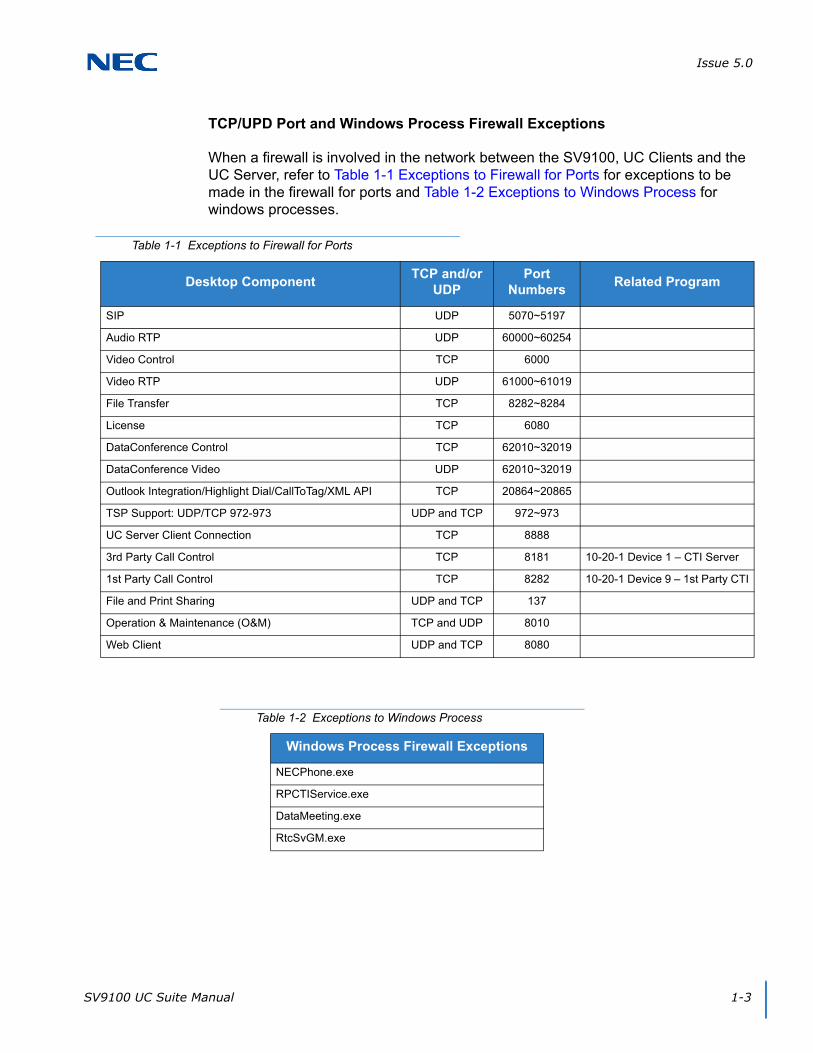
Issue 5.0
SV9100 UC Suite Manual 1-3
TCP/UPD Port and Windows Process Firewall Exceptions
When a firewall is involved in the network between the SV9100, UC Clients and the UC Server, refer to Table 1-1 Exceptions to Firewall for Ports for exceptions to be made in the firewall for ports and Table 1-2 Exceptions to Windows Process for windows processes.
Table 1-1 Exceptions to Firewall for Ports
Desktop ComponentTCP and/or
UDPPort
NumbersRelated Program
SIP UDP 5070~5197
Audio RTP UDP 60000~60254
Video Control TCP 6000
Video RTP UDP 61000~61019
File Transfer TCP 8282~8284
License TCP 6080
DataConference Control TCP 62010~32019
DataConference Video UDP 62010~32019
Outlook Integration/Highlight Dial/CallToTag/XML API TCP 20864~20865
TSP Support: UDP/TCP 972-973 UDP and TCP 972~973
UC Server Client Connection TCP 8888
3rd Party Call Control TCP 8181 10-20-1 Device 1 – CTI Server
1st Party Call Control TCP 8282 10-20-1 Device 9 – 1st Party CTI
File and Print Sharing UDP and TCP 137
Operation & Maintenance (O&M) TCP and UDP 8010
Web Client UDP and TCP 8080
Table 1-2 Exceptions to Windows Process
Windows Process Firewall Exceptions
NECPhone.exe
RPCTIService.exe
DataMeeting.exe
RtcSvGM.exe
Issue 5.0
1-4 Introduction to UC Suite
SECTION 3 INSTALLATION CONSIDERATIONS
The UC Suite can be installed in two different configurations, either UC Client or UC Client with a connection to the UC Server.
3.1 UC Client
Each PC with the UC Client has its own connection to the SV9100. The UC Client communicates to the SV9100 via the LAN on the TCP port defined for the 1st-Party CTI connection in Program 10-20-01, although a 1st Party CTI license is not required for the UC Client. The 1st-Party CTI connection is device 9 in 10-20-01 and the recommended port is 8282.
3.2 UC Client with UC Server Connection
When the client is connected to the UC Server, the desktop application can view DSS/BLF information for all stations and trunks in the system if programmed. The DSS/BLF status is provided to the Client from the UC Server. The UC Server is also required for Phone Message, Quick Message, a Shared Central Directory and Presence. Users do not have to maintain their own directory with a UC Server connection. The Shared Central Directory is viewed by all users, and any changes made by one user will be seen by the other users.
The UC Server communicates to the SV9100 via the LAN on the TCP port defined for the 3rd-Party CTI connection in Program 10-20-01. The 3rd-Party CTI connection is device 1 in 10-20-01 and the recommended port is 8181. The PCs with the UC Client then have a second connection. This additional connection is to the PC that has the UC Server. The UC Client communicates to the UC Server via the LAN on TCP port 8888. This port can be changed using Program 10-69-04.
3.3 Remote Connections
Network Address Translation (NAT) is not supported. As a result, any UC Client must appear to be on the same network as the SV9100 VoIP Interface (IPLE). For remote UC Clients, such as a Softphone, this can be achieved using a VPN connection to the network where SV9100 resides.
Issue 5.0
SV9100 UC Suite Manual 1-5
SECTION 4 SYSTEM REQUIREMENTS
The minimum recommended PC requirements and the supported operation systems are described in this section.
4.1 Minimum PC Requirements
The minimum recommended PC requirements for running the UC Suite application are as follows:
Processor Speed: 2GHz
RAM: 4GB
Display: Super VGA (800 x 600) or higher
Available Disk Space: 40GB
CD-ROM Drive
Network Adapter
Sound Card
Video Camera (optional)
Microphone/Headset/USB Handset (optional)
Speakers (optional)
ADA-L is required for Recording/Personal Greeting with deskset
4.2 Supported Operating Systems
The UC Suite application is supported on the following operation systems:
Windows Embedded Standard SP3 (InServer Blade)
Windows 7 Professional SP1 (32- and 64-bit)
Windows Server 2008 (32- and 64-bit)
Windows Server 2012, Windows Server 2012 R2
Prior to installing SV9100 UC Advanced Services, Microsoft .NET 3.5 must be enabled. Follow the link below for instructions.
https://technet.microsoft.com/en-us/library/dn482071.aspx
Install SV9100 UC Advanced Services after enabling .NET 3.5 features as described in the technical note.
Windows 8 Professional and Enterprise (32- and 64-bit)
Windows 8.1 Professional and Enterprise (32- and 64-bit)
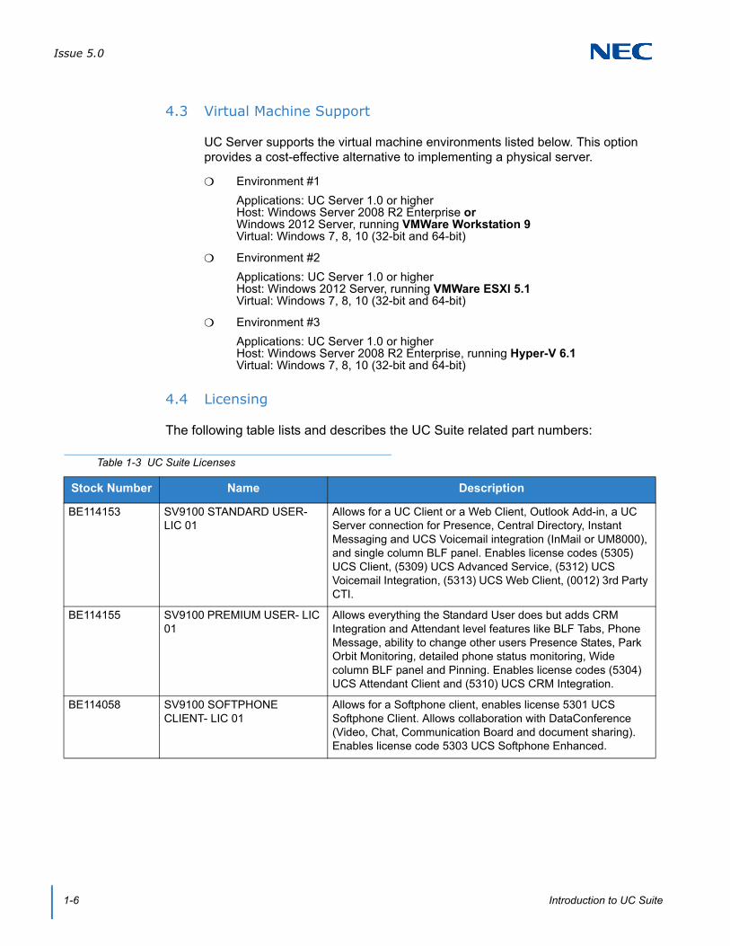
Issue 5.0
1-6 Introduction to UC Suite
4.3 Virtual Machine Support
UC Server supports the virtual machine environments listed below. This option provides a cost-effective alternative to implementing a physical server.
Environment #1
Applications: UC Server 1.0 or higherHost: Windows Server 2008 R2 Enterprise orWindows 2012 Server, running VMWare Workstation 9Virtual: Windows 7, 8, 10 (32-bit and 64-bit)
Environment #2
Applications: UC Server 1.0 or higherHost: Windows 2012 Server, running VMWare ESXI 5.1Virtual: Windows 7, 8, 10 (32-bit and 64-bit)
Environment #3
Applications: UC Server 1.0 or higherHost: Windows Server 2008 R2 Enterprise, running Hyper-V 6.1Virtual: Windows 7, 8, 10 (32-bit and 64-bit)
4.4 Licensing
The following table lists and describes the UC Suite related part numbers:
Table 1-3 UC Suite Licenses
Stock Number Name Description
BE114153 SV9100 STANDARD USER- LIC 01
Allows for a UC Client or a Web Client, Outlook Add-in, a UC Server connection for Presence, Central Directory, Instant Messaging and UCS Voicemail integration (InMail or UM8000), and single column BLF panel. Enables license codes (5305) UCS Client, (5309) UCS Advanced Service, (5312) UCS Voicemail Integration, (5313) UCS Web Client, (0012) 3rd Party CTI.
BE114155 SV9100 PREMIUM USER- LIC 01
Allows everything the Standard User does but adds CRM Integration and Attendant level features like BLF Tabs, Phone Message, ability to change other users Presence States, Park Orbit Monitoring, detailed phone status monitoring, Wide column BLF panel and Pinning. Enables license codes (5304) UCS Attendant Client and (5310) UCS CRM Integration.
BE114058 SV9100 SOFTPHONE CLIENT- LIC 01
Allows for a Softphone client, enables license 5301 UCS Softphone Client. Allows collaboration with DataConference (Video, Chat, Communication Board and document sharing). Enables license code 5303 UCS Softphone Enhanced.
SV9100 UC Suite Manual 2-1
Chapter 2
UNIVERGE® SV9100
Installation
Any previous SV8100 Desktop Suite software must be completely uninstalled before installing the SV9100 UC Suite.
The installation of the SV9100 UC Suite includes prerequisite software if the installation determines these do not already exist on the PC.
The following prerequisite software is installed:
Microsoft .NET Framework 4.0
Microsoft Visual C++ 2005 SP1 Redistributable Package
After the prerequisite software is installed, the UC Suite Client installs. This installation includes the following applications:
SV9100 UC Suite Client
Microsoft Outlook Add-In
Video Test Tool
The UC Suite is installed in the following directory:
C:\Program Files\NEC\NEC UC Suite
Application logs are in the following directory:
c:\Program Data\NEC-i\PC Phone\logfiles
After installation is complete, the following application environment is available, depending on what installation options where chosen:
Program group named “NEC”
Within NEC group are the following:
UC Suite
Video Test Tool
SV9100 3rd Party CTI Driver
UC Server Configuration
A shortcut for UC Suite installs on the Windows desktop.
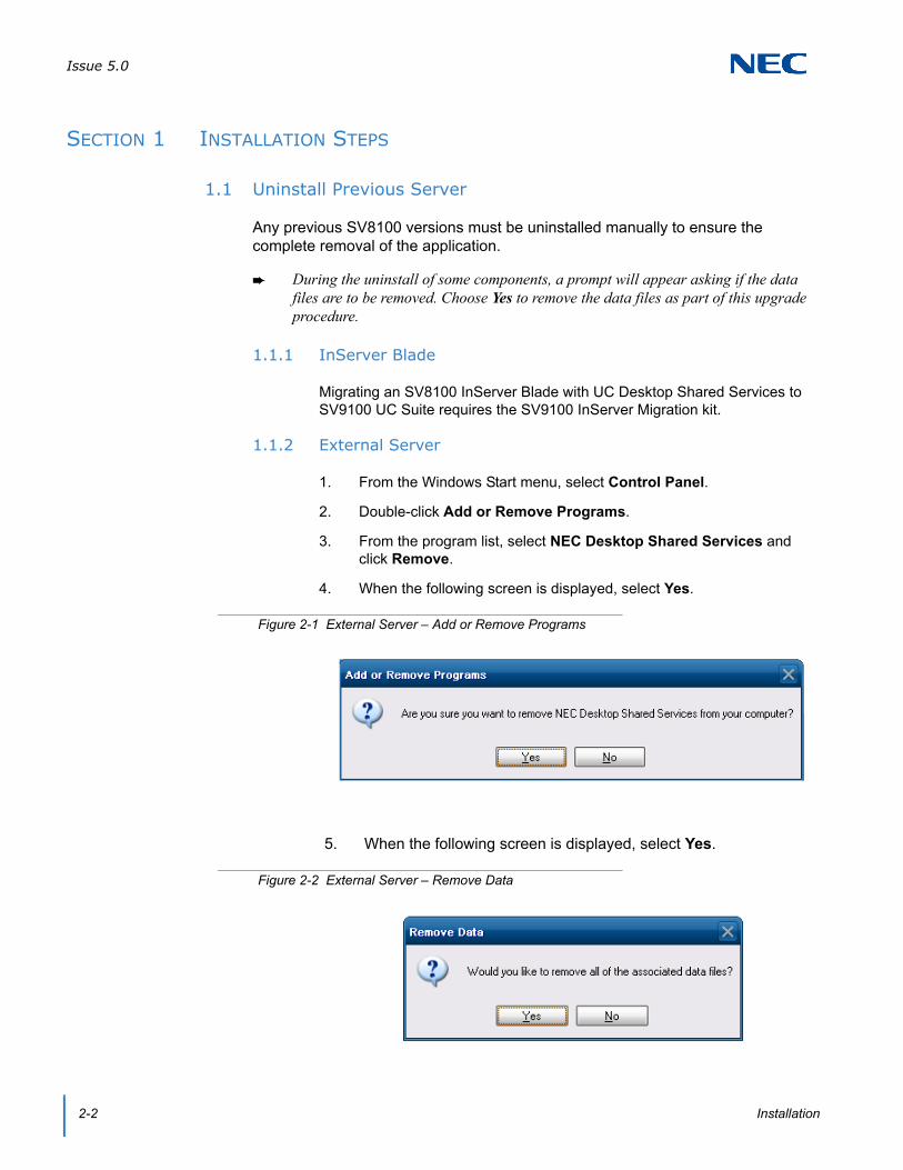
Issue 5.0
2-2 Installation
SECTION 1 INSTALLATION STEPS
1.1 Uninstall Previous Server
Any previous SV8100 versions must be uninstalled manually to ensure the complete removal of the application.
During the uninstall of some components, a prompt will appear asking if the data files are to be removed. Choose Yes to remove the data files as part of this upgrade procedure.
1.1.1 InServer Blade
Migrating an SV8100 InServer Blade with UC Desktop Shared Services to SV9100 UC Suite requires the SV9100 InServer Migration kit.
1.1.2 External Server
1. From the Windows Start menu, select Control Panel.
2. Double-click Add or Remove Programs.
3. From the program list, select NEC Desktop Shared Services and click Remove.
4. When the following screen is displayed, select Yes.
5. When the following screen is displayed, select Yes.
Figure 2-1 External Server – Add or Remove Programs
Figure 2-2 External Server – Remove Data

Issue 5.0
SV9100 UC Suite Manual 2-3
6. From the program list, select NEC Infrontia Telephony Driver(3rd) and click Remove.
7. Follow the prompts to complete the uninstall of this item.
8. Reboot the blade. (If directly connected with a keyboard, monitor, and mouse, choose Start>Shutdown>Restart. If connected with Remote Desktop, press Ctl+Alt+End and choose Shutdown>Restart.)
1.2 Install UC Server
1. Double-click the UC_Server-1_0_0.exe. If a Security Warning pops up, click Run.
2. When the License Agreement screen appears, click Yes.
Figure 2-3 UC Server – License Agreement

Issue 5.0
2-4 Installation
3. At the NEC UC Server Welcome window, click Next.
4. Define the installation folder or click Next to accept the default folder.
Figure 2-4 UC Server – Setup Wizard
Figure 2-5 UC Server – Select Installation Folder
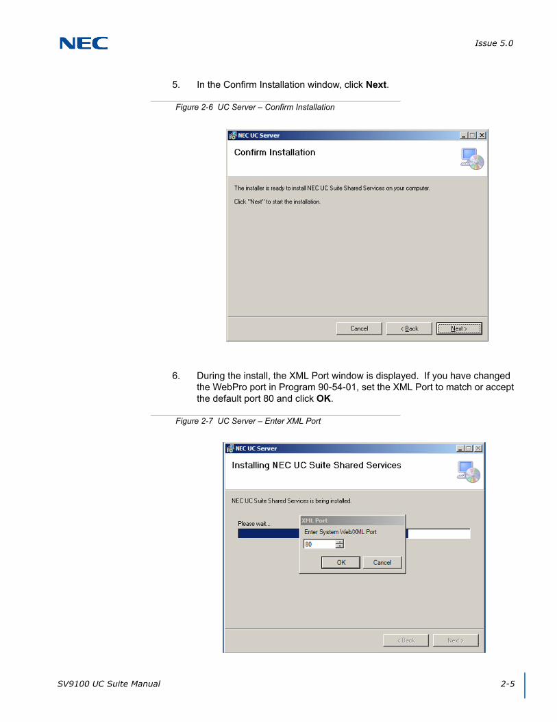
Issue 5.0
SV9100 UC Suite Manual 2-5
5. In the Confirm Installation window, click Next.
6. During the install, the XML Port window is displayed. If you have changed the WebPro port in Program 90-54-01, set the XML Port to match or accept the default port 80 and click OK.
Figure 2-6 UC Server – Confirm Installation
Figure 2-7 UC Server – Enter XML Port

Issue 5.0
2-6 Installation
7. In the Installation Complete window, select Close.
8. The NEC UC Web Suite install will start next. In the NEC UC Web Suite Welcome window, click Next.
Figure 2-8 UC Server – Installation Complete
Figure 2-9 UC Web Suite – Setup Wizard
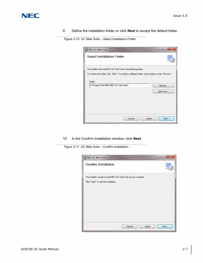
Issue 5.0
SV9100 UC Suite Manual 2-7
9. Define the installation folder or click Next to accept the default folder.
10. In the Confirm Installation window, click Next.
Figure 2-10 UC Web Suite – Select Installation Folder
Figure 2-11 UC Web Suite – Confirm Installation

Issue 5.0
2-8 Installation
11. In the Web Server Port window, accept the default HTTP port 8080 and click OK.
12. In the Installation Complete window, click Close.
Figure 2-12 UC Web Suite – Web Server Port
Figure 2-13 UC Web Suite – Installation Complete

Issue 5.0
SV9100 UC Suite Manual 2-9
13. The SV9100 3rd Party CTI Driver will install next. In the 3rd Party CTI Driver Welcome screen, click Next.
14. Accept the license agreement and click Next.
Figure 2-14 3rd Party CTI Driver – Install Wizard
Figure 2-15 3rd Party CTI Driver – License Agreement
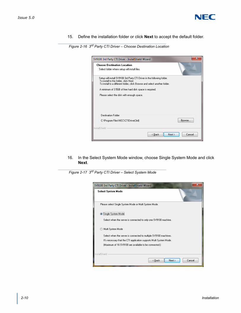
Issue 5.0
2-10 Installation
15. Define the installation folder or click Next to accept the default folder.
16. In the Select System Mode window, choose Single System Mode and click Next.
Figure 2-16 3rd Party CTI Driver – Choose Destination Location
Figure 2-17 3rd Party CTI Driver – Select System Mode

Issue 5.0
SV9100 UC Suite Manual 2-11
17. In the Ready to Install the Program window, click Install.
18. Click Finish in the InstallShield Wizard Complete window.
Figure 2-18 3rd Party CTI Driver – Ready to Install Program
Figure 2-19 3rd Party CTI Driver – Installation Complete

Issue 5.0
2-12 Installation
19. After the 3rd Party CTI Driver install completes, the CTI Driver Settings window appears. Define the IP address of the SV9100 in the SV9100 IP Address field.
Figure 2-20 3rd Party CTI Driver – Settings Screen

Issue 5.0
SV9100 UC Suite Manual 2-13
20. Click the Starting Option button and select Always running in the Starting Option of CTI Driver window and click OK.
21. To save the changes to the CTI Driver Settings, click Apply.
22. Select OK to the message stating It will start CTI Driver.
Figure 2-21 3rd Party CTI Driver – Starting Option of CTI Driver
Figure 2-22 3rd Party CTI Driver – CTI Driver Start Message
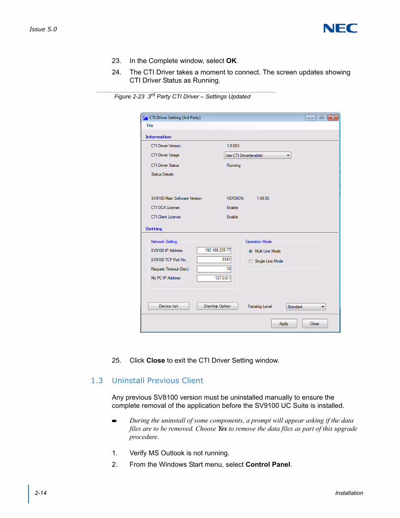
Issue 5.0
2-14 Installation
23. In the Complete window, select OK.
24. The CTI Driver takes a moment to connect. The screen updates showing CTI Driver Status as Running.
25. Click Close to exit the CTI Driver Setting window.
1.3 Uninstall Previous Client
Any previous SV8100 version must be uninstalled manually to ensure the complete removal of the application before the SV9100 UC Suite is installed.
During the uninstall of some components, a prompt will appear asking if the data files are to be removed. Choose Yes to remove the data files as part of this upgrade procedure.
1. Verify MS Outlook is not running.
2. From the Windows Start menu, select Control Panel.
Figure 2-23 3rd Party CTI Driver – Settings Updated
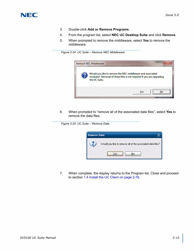
Issue 5.0
SV9100 UC Suite Manual 2-15
3. Double-click Add or Remove Programs.
4. From the program list, select NEC UC Desktop Suite and click Remove.
5. When prompted to remove the middleware, select Yes to remove the middleware.
6. When prompted to “remove all of the associated data files”, select Yes to remove the data files.
7. When complete, the display returns to the Program list. Close and proceed to section 1.4 Install the UC Client on page 2-16.
Figure 2-24 UC Suite – Remove NEC Middleware
Figure 2-25 UC Suite – Remove Data
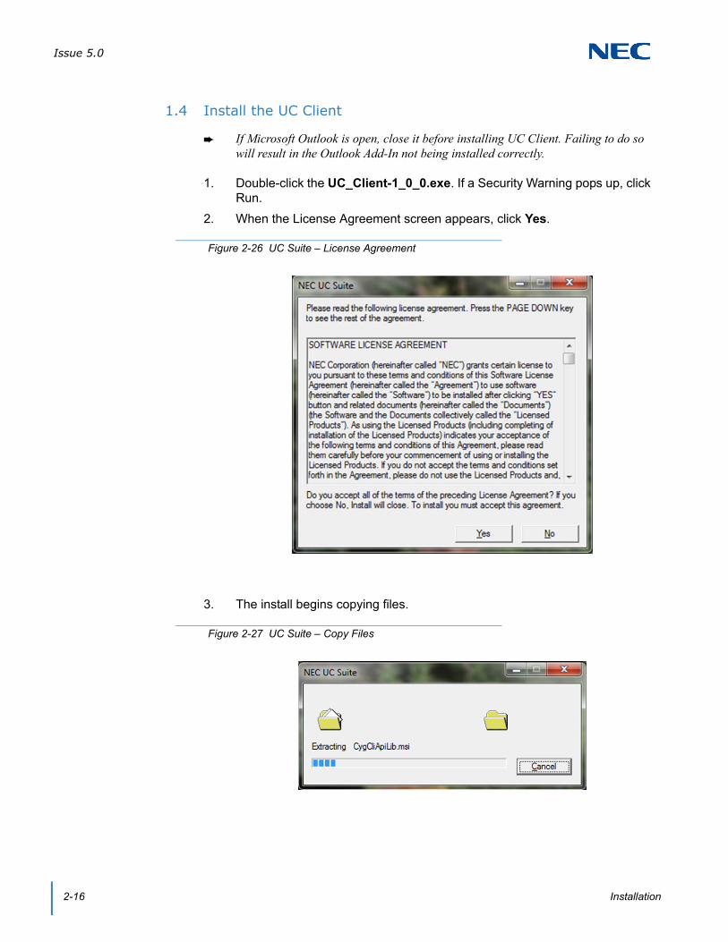
Issue 5.0
2-16 Installation
1.4 Install the UC Client
If Microsoft Outlook is open, close it before installing UC Client. Failing to do so will result in the Outlook Add-In not being installed correctly.
1. Double-click the UC_Client-1_0_0.exe. If a Security Warning pops up, click Run.
2. When the License Agreement screen appears, click Yes.
3. The install begins copying files.
Figure 2-26 UC Suite – License Agreement
Figure 2-27 UC Suite – Copy Files

Issue 5.0
SV9100 UC Suite Manual 2-17
4. At the NEC UC Suite Welcome window, click Next.
5. Define the installation folder or click Next to accept the default folder.
Figure 2-28 UC Suite – Setup Wizard
Figure 2-29 UC Suite – Select Installation Folder
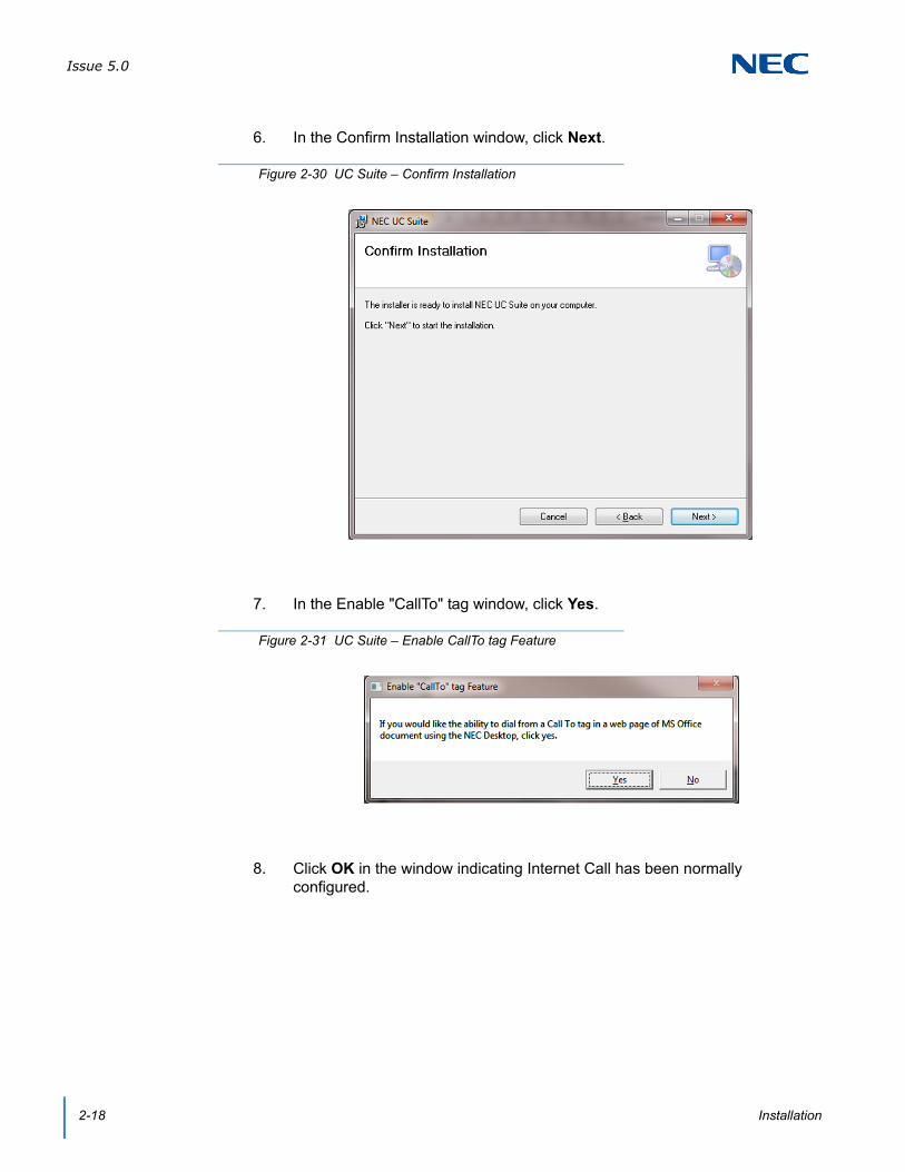
Issue 5.0
2-18 Installation
6. In the Confirm Installation window, click Next.
7. In the Enable "CallTo" tag window, click Yes.
8. Click OK in the window indicating Internet Call has been normally configured.
Figure 2-30 UC Suite – Confirm Installation
Figure 2-31 UC Suite – Enable CallTo tag Feature
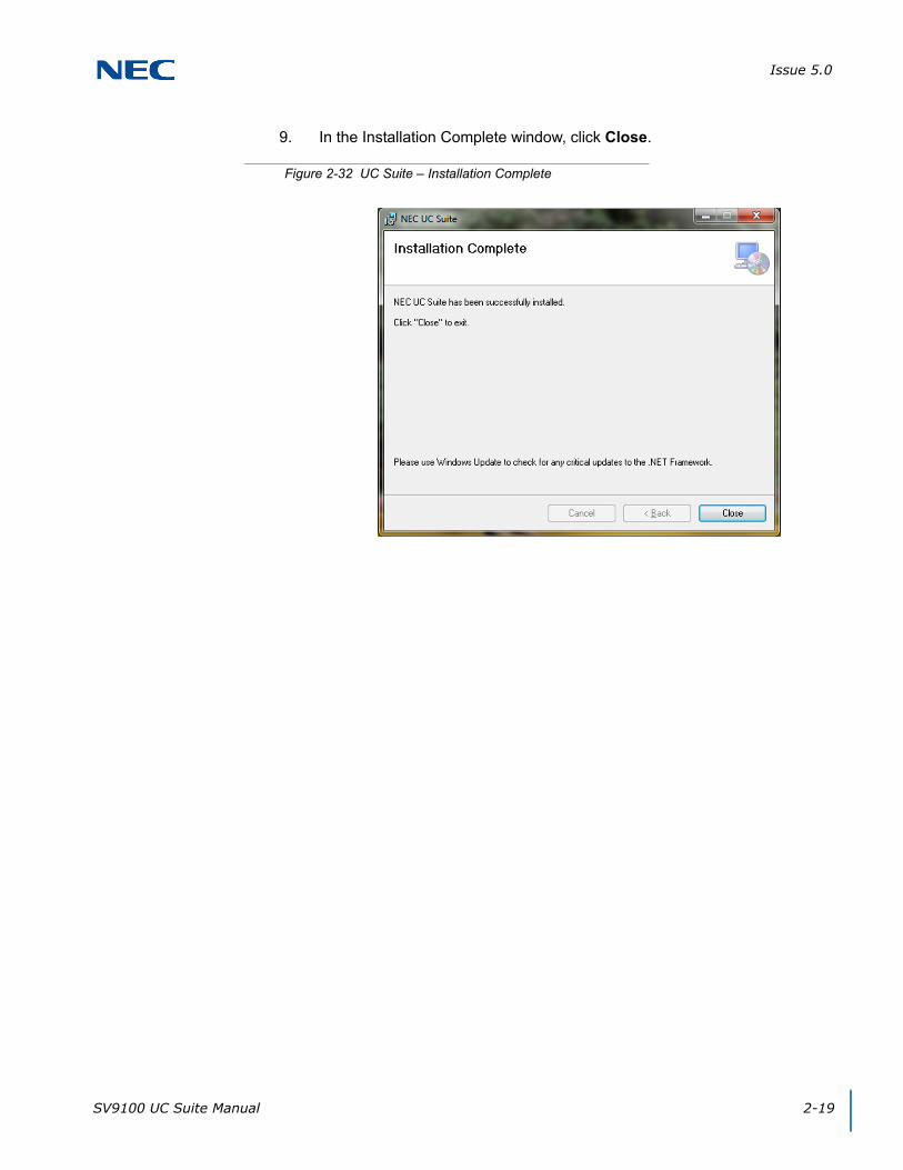
Issue 5.0
SV9100 UC Suite Manual 2-19
9. In the Installation Complete window, click Close.
Figure 2-32 UC Suite – Installation Complete
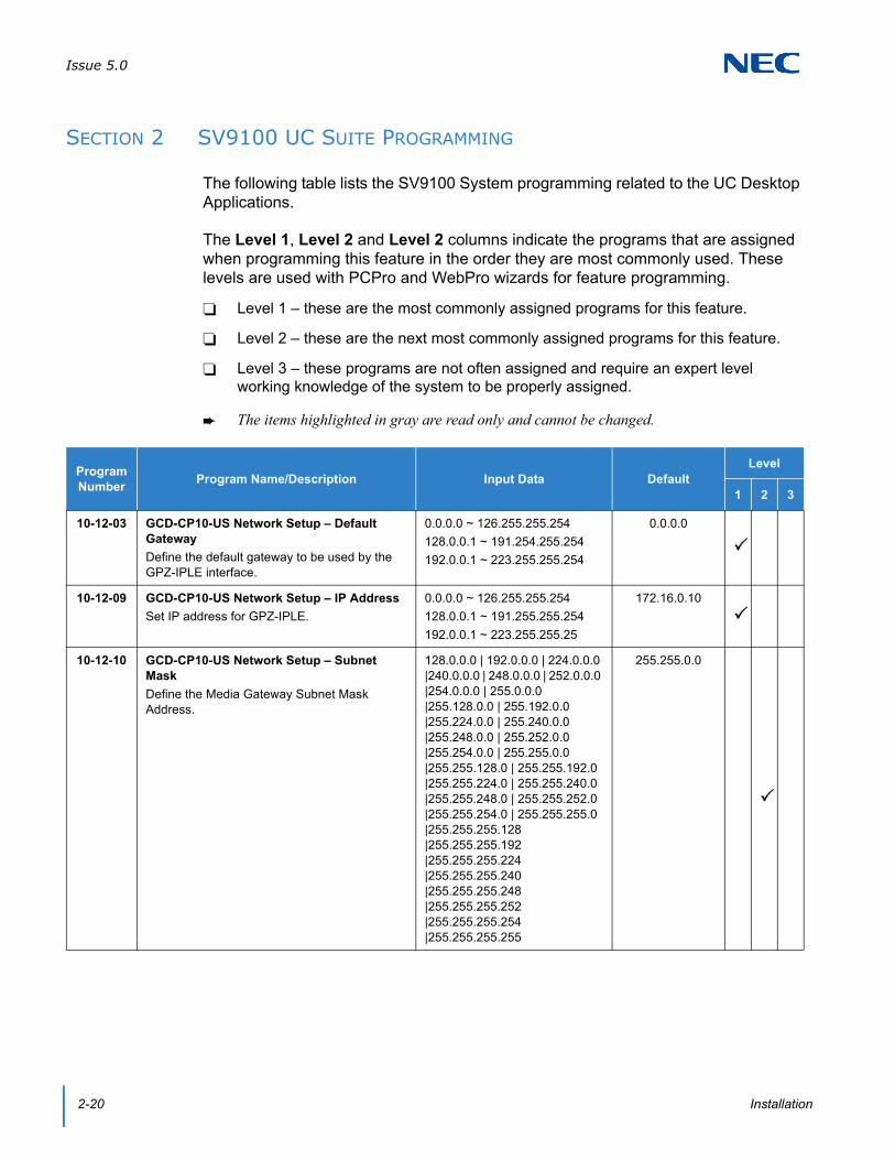
Issue 5.0
2-20 Installation
SECTION 2 SV9100 UC SUITE PROGRAMMING
The following table lists the SV9100 System programming related to the UC Desktop Applications.
The Level 1, Level 2 and Level 2 columns indicate the programs that are assigned when programming this feature in the order they are most commonly used. These levels are used with PCPro and WebPro wizards for feature programming.
Level 1 – these are the most commonly assigned programs for this feature.
Level 2 – these are the next most commonly assigned programs for this feature.
Level 3 – these programs are not often assigned and require an expert level working knowledge of the system to be properly assigned.
The items highlighted in gray are read only and cannot be changed.
Program Number
Program Name/Description Input Data DefaultLevel
1 2 3
10-12-03 GCD-CP10-US Network Setup – Default Gateway
Define the default gateway to be used by the GPZ-IPLE interface.
0.0.0.0 ~ 126.255.255.254
128.0.0.1 ~ 191.254.255.254
192.0.0.1 ~ 223.255.255.254
0.0.0.0
10-12-09 GCD-CP10-US Network Setup – IP Address
Set IP address for GPZ-IPLE.
0.0.0.0 ~ 126.255.255.254
128.0.0.1 ~ 191.255.255.254
192.0.0.1 ~ 223.255.255.25
172.16.0.10
10-12-10 GCD-CP10-US Network Setup – Subnet Mask
Define the Media Gateway Subnet Mask Address.
128.0.0.0 | 192.0.0.0 | 224.0.0.0 |240.0.0.0 | 248.0.0.0 | 252.0.0.0 |254.0.0.0 | 255.0.0.0 |255.128.0.0 | 255.192.0.0|255.224.0.0 | 255.240.0.0 |255.248.0.0 | 255.252.0.0 |255.254.0.0 | 255.255.0.0|255.255.128.0 | 255.255.192.0 |255.255.224.0 | 255.255.240.0 |255.255.248.0 | 255.255.252.0 |255.255.254.0 | 255.255.255.0|255.255.255.128 |255.255.255.192 |255.255.255.224 |255.255.255.240 |255.255.255.248 |255.255.255.252 |255.255.255.254 |255.255.255.255
255.255.0.0
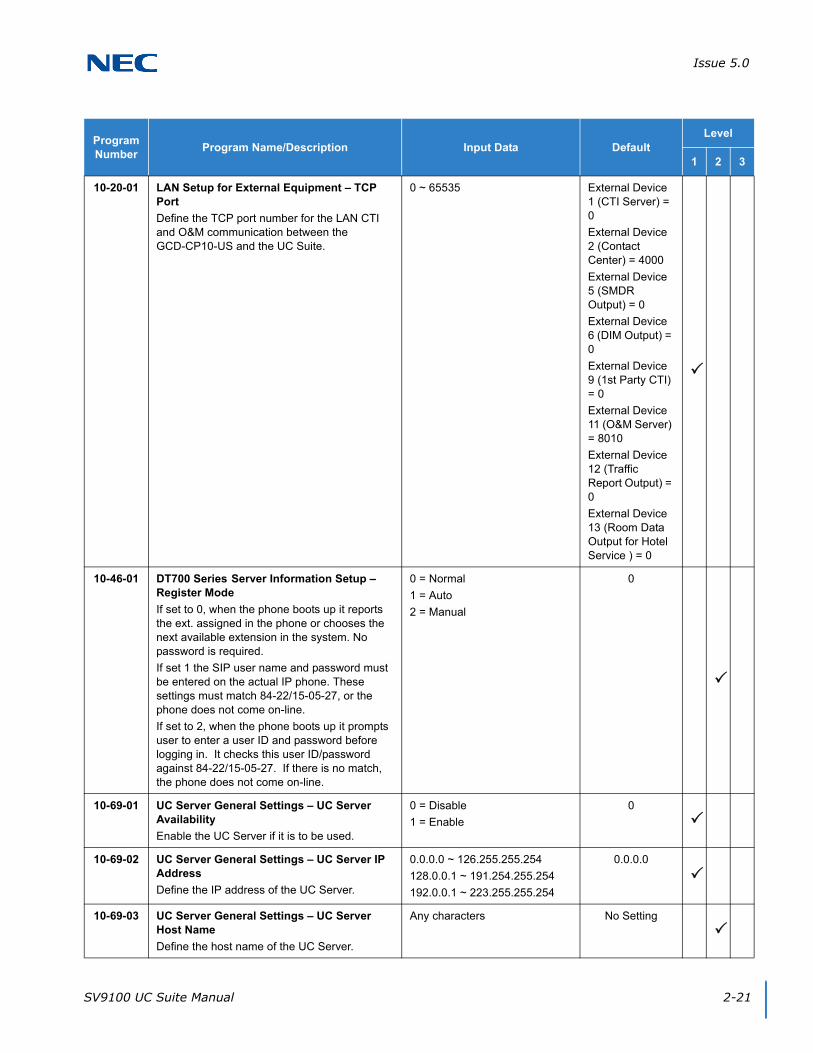
Issue 5.0
SV9100 UC Suite Manual 2-21
10-20-01 LAN Setup for External Equipment – TCP Port
Define the TCP port number for the LAN CTI and O&M communication between the GCD-CP10-US and the UC Suite.
0 ~ 65535 External Device 1 (CTI Server) = 0
External Device 2 (Contact Center) = 4000
External Device 5 (SMDR Output) = 0
External Device 6 (DIM Output) = 0
External Device 9 (1st Party CTI) = 0
External Device 11 (O&M Server) = 8010
External Device 12 (Traffic Report Output) = 0
External Device 13 (Room Data Output for Hotel Service ) = 0
10-46-01 DT700 Series Server Information Setup – Register Mode
If set to 0, when the phone boots up it reports the ext. assigned in the phone or chooses the next available extension in the system. No password is required.
If set 1 the SIP user name and password must be entered on the actual IP phone. These settings must match 84-22/15-05-27, or the phone does not come on-line.
If set to 2, when the phone boots up it prompts user to enter a user ID and password before logging in. It checks this user ID/password against 84-22/15-05-27. If there is no match, the phone does not come on-line.
0 = Normal
1 = Auto
2 = Manual
0
10-69-01 UC Server General Settings – UC Server Availability
Enable the UC Server if it is to be used.
0 = Disable
1 = Enable
0
10-69-02 UC Server General Settings – UC Server IP Address
Define the IP address of the UC Server.
0.0.0.0 ~ 126.255.255.254
128.0.0.1 ~ 191.254.255.254
192.0.0.1 ~ 223.255.255.254
0.0.0.0
10-69-03 UC Server General Settings – UC Server Host Name
Define the host name of the UC Server.
Any characters No Setting
Program Number
Program Name/Description Input Data DefaultLevel
1 2 3
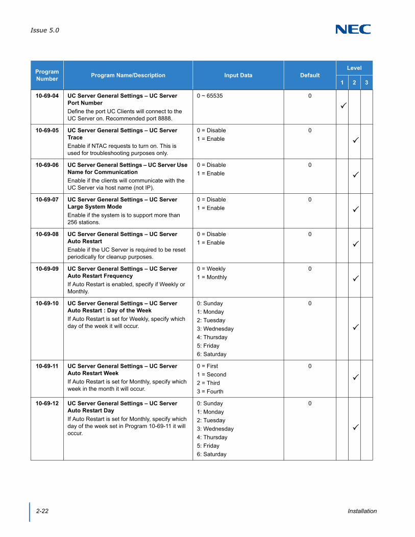
Issue 5.0
2-22 Installation
10-69-04 UC Server General Settings – UC Server Port Number
Define the port UC Clients will connect to the UC Server on. Recommended port 8888.
0 ~ 65535 0
10-69-05 UC Server General Settings – UC Server Trace
Enable if NTAC requests to turn on. This is used for troubleshooting purposes only.
0 = Disable
1 = Enable
0
10-69-06 UC Server General Settings – UC Server Use Name for Communication
Enable if the clients will communicate with the UC Server via host name (not IP).
0 = Disable
1 = Enable
0
10-69-07 UC Server General Settings – UC Server Large System Mode
Enable if the system is to support more than 256 stations.
0 = Disable
1 = Enable
0
10-69-08 UC Server General Settings – UC Server Auto Restart
Enable if the UC Server is required to be reset periodically for cleanup purposes.
0 = Disable
1 = Enable
0
10-69-09 UC Server General Settings – UC Server Auto Restart Frequency
If Auto Restart is enabled, specify if Weekly or Monthly.
0 = Weekly
1 = Monthly
0
10-69-10 UC Server General Settings – UC Server Auto Restart : Day of the Week
If Auto Restart is set for Weekly, specify which day of the week it will occur.
0: Sunday
1: Monday
2: Tuesday
3: Wednesday
4: Thursday
5: Friday
6: Saturday
0
10-69-11 UC Server General Settings – UC Server Auto Restart Week
If Auto Restart is set for Monthly, specify which week in the month it will occur.
0 = First
1 = Second
2 = Third
3 = Fourth
0
10-69-12 UC Server General Settings – UC Server Auto Restart Day
If Auto Restart is set for Monthly, specify which day of the week set in Program 10-69-11 it will occur.
0: Sunday
1: Monday
2: Tuesday
3: Wednesday
4: Thursday
5: Friday
6: Saturday
0
Program Number
Program Name/Description Input Data DefaultLevel
1 2 3

Issue 5.0
SV9100 UC Suite Manual 2-23
10-69-13 UC Server General Settings – UC Server Auto Restart Time
Specify the time of day the Auto Restart will occur. This applies to Monthly or Weekly.
00:00 ~ 23:59 00:00
10-70-01 UC Server Voicemail Interface Settings – UC Server Voicemail Integration
Enable if the UC Suite will have Voicemail Integration.
0 = Disable
1 = Enable
0
10-70-02 UC Server Voicemail Interface Settings – UM8000 IP Address
If the voicemail system is UM8000, specify the IP address of the UM8000.
0.0.0.0 ~ 126.255.255.254
128.0.0.1 ~ 191.254.255.254
192.0.0.1 ~ 223.255.255.254
0.0.0.0
10-70-03 UC Server Voicemail Interface Settings – UM8000 Port Number
If the voicemail system is UM8000, specify the port number UC Suite will connect to the UM8000 on.
This should be set to port 1024.
0 ~ 65535 0
10-71-01 UC Server MIS Settings – MIS Server IP Address
If the UC Server will integrate to the Contact Center Server for Abandoned Call Alerts, define the IP address of the Contact Center Server.
0.0.0.0 ~ 126.255.255.254
128.0.0.1 ~ 191.254.255.254
192.0.0.1 ~ 223.255.255.254
0.0.0.0
10-71-02 UC Server MIS Settings – MIS Server Computer Name
If the UC Server will integrate to the Contact Center Server for Abandoned Call Alerts, define the Contact Center Server's computer name.
Any characters No Setting
10-71-03 UC Server MIS Settings – MIS Server Port Number
If the UC Server will integrate to the Contact Center Server for Abandoned Call Alerts, define the port number it should connect on.
For external server this should be set to 8080 and for InServer Blade set this to 9090.
0 ~ 65535 0
13-04-01 Speed Dialing Number and Name – Speed Dialing Data
External numbers defined in the multi-device group show up in the bin referenced in Program 15-22 for the mobile extension.
Maximum of 24 digits (0 ~ 9, , #, @, P, R)
@ = Wait for Answer Supervision - ISDN trunks only
P = Pause - Analog Trunk Only R = Hook flash - Analog Trunk Only
No Setting
15-05-27 IP Telephone Terminal Basic Data Setup – Personal ID Index
When the SIP Multiline telephone is using manual/auto registration, assign each phone a unique personal index. Then go to command 84-22 to assign the user name and password.
0 ~ 960 0
Program Number
Program Name/Description Input Data DefaultLevel
1 2 3

Issue 5.0
2-24 Installation
15-05-28 IP Telephone Terminal Basic Data Setup – Addition Information Setup
Set Talking Party to 0 for Desktop Application Softphone.
0 = Do not inform
1 = Inform
0
15-07-01 Programmable Function Keys
Assign a function key to terminals.
Line Key 1 ~ 48
0 ~ 99 (Normal Function Code 751 by default)00 ~ 99 (Appearance Function Code) (Service Code 752 by default)
Refer to the Programming Manual for default values.
15-22-01 Mobile Extension Setup – Mobile Extension Target Setup
For each Mobile Extension number defined in the Multi-Device Group in 20-63, select the Speed Dial bin number to be associated with it.
0 ~ 9999
(0 = No setting
1 ~ 9999 = target of mobile extension)
0
20-23-06 System Options for CTI – 3rd Party CTI IP Address
Read only program that displays the IP address of the currently connected 3rd Party CTI Server.
0.0.0.0 ~ 126.255.255.254
128.0.0.1 ~ 191.255.255.254
192.0.0.1 ~ 223.255.255.254
0.0.0.0.0
20-58-01 UC Server Presence Settings – UC Server Presence States: In the Office
Enable or Disable the In the Office Presence State for UC Suite.
0 = Disable
1 = Enable
0
20-58-02 UC Server Presence Settings – UC Server Presence States: On Vacation
Enable or Disable the On Vacation Presence State for UC Suite.
0 = Disable
1 = Enable
0
20-58-03 UC Server Presence Settings – UC Server Presence States: Business Travel
Enable or Disable the Business Travel Presence State for UC Suite.
0 = Disable
1 = Enable
0
20-58-04 UC Server Presence Settings – UC Server Presence States: In a Meeting
Enable or Disable the In a Meeting Presence State for UC Suite.
0 = Disable
1 = Enable
0
20-58-05 UC Server Presence Settings – UC Server Presence States: Out to Lunch
Enable or Disable the Out to Lunch Presence State for UC Suite.
0 = Disable
1 = Enable
0
20-58-06 UC Server Presence Settings – UC Server Presence States: Sick
Enable or Disable the Sick Presence State for UC Suite.
0 = Disable
1 = Enable
0
20-58-07 UC Server Presence Settings – UC Server Presence States: Gone for the Day
Enable or Disable the Gone for the Day Presence State for UC Suite.
0 = Disable
1 = Enable
0
Program Number
Program Name/Description Input Data DefaultLevel
1 2 3
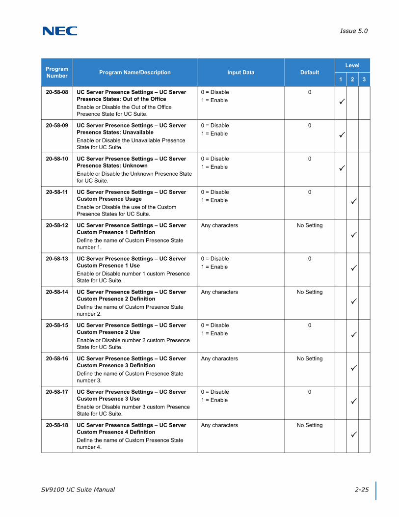
Issue 5.0
SV9100 UC Suite Manual 2-25
20-58-08 UC Server Presence Settings – UC Server Presence States: Out of the Office
Enable or Disable the Out of the Office Presence State for UC Suite.
0 = Disable
1 = Enable
0
20-58-09 UC Server Presence Settings – UC Server Presence States: Unavailable
Enable or Disable the Unavailable Presence State for UC Suite.
0 = Disable
1 = Enable
0
20-58-10 UC Server Presence Settings – UC Server Presence States: Unknown
Enable or Disable the Unknown Presence State for UC Suite.
0 = Disable
1 = Enable
0
20-58-11 UC Server Presence Settings – UC Server Custom Presence Usage
Enable or Disable the use of the Custom Presence States for UC Suite.
0 = Disable
1 = Enable
0
20-58-12 UC Server Presence Settings – UC Server Custom Presence 1 Definition
Define the name of Custom Presence State number 1.
Any characters No Setting
20-58-13 UC Server Presence Settings – UC Server Custom Presence 1 Use
Enable or Disable number 1 custom Presence State for UC Suite.
0 = Disable
1 = Enable
0
20-58-14 UC Server Presence Settings – UC Server Custom Presence 2 Definition
Define the name of Custom Presence State number 2.
Any characters No Setting
20-58-15 UC Server Presence Settings – UC Server Custom Presence 2 Use
Enable or Disable number 2 custom Presence State for UC Suite.
0 = Disable
1 = Enable
0
20-58-16 UC Server Presence Settings – UC Server Custom Presence 3 Definition
Define the name of Custom Presence State number 3.
Any characters No Setting
20-58-17 UC Server Presence Settings – UC Server Custom Presence 3 Use
Enable or Disable number 3 custom Presence State for UC Suite.
0 = Disable
1 = Enable
0
20-58-18 UC Server Presence Settings – UC Server Custom Presence 4 Definition
Define the name of Custom Presence State number 4.
Any characters No Setting
Program Number
Program Name/Description Input Data DefaultLevel
1 2 3
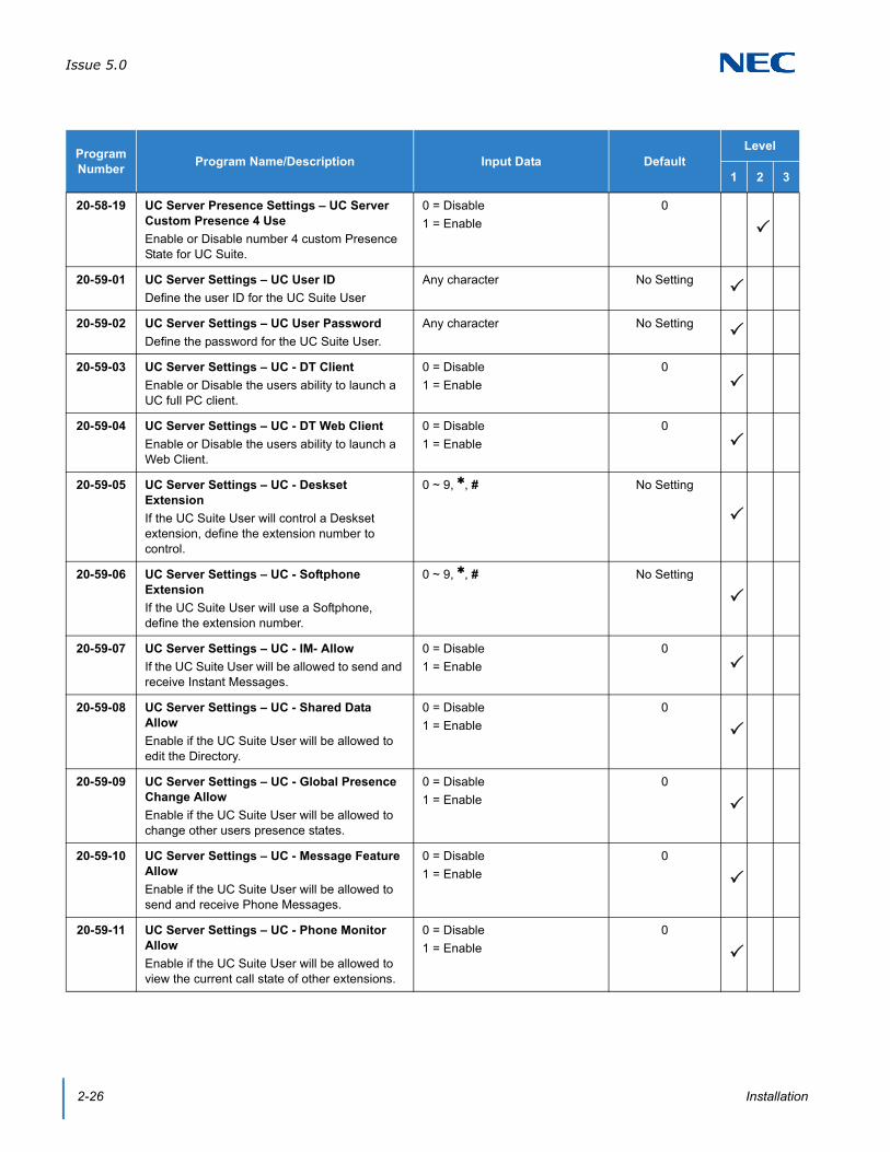
Issue 5.0
2-26 Installation
20-58-19 UC Server Presence Settings – UC Server Custom Presence 4 Use
Enable or Disable number 4 custom Presence State for UC Suite.
0 = Disable
1 = Enable
0
20-59-01 UC Server Settings – UC User ID
Define the user ID for the UC Suite User
Any character No Setting
20-59-02 UC Server Settings – UC User Password
Define the password for the UC Suite User.
Any character No Setting
20-59-03 UC Server Settings – UC - DT Client
Enable or Disable the users ability to launch a UC full PC client.
0 = Disable
1 = Enable
0
20-59-04 UC Server Settings – UC - DT Web Client
Enable or Disable the users ability to launch a Web Client.
0 = Disable
1 = Enable
0
20-59-05 UC Server Settings – UC - Deskset Extension
If the UC Suite User will control a Deskset extension, define the extension number to control.
0 ~ 9, , # No Setting
20-59-06 UC Server Settings – UC - Softphone Extension
If the UC Suite User will use a Softphone, define the extension number.
0 ~ 9, , # No Setting
20-59-07 UC Server Settings – UC - IM- Allow
If the UC Suite User will be allowed to send and receive Instant Messages.
0 = Disable
1 = Enable
0
20-59-08 UC Server Settings – UC - Shared Data Allow
Enable if the UC Suite User will be allowed to edit the Directory.
0 = Disable
1 = Enable
0
20-59-09 UC Server Settings – UC - Global Presence Change Allow
Enable if the UC Suite User will be allowed to change other users presence states.
0 = Disable
1 = Enable
0
20-59-10 UC Server Settings – UC - Message Feature Allow
Enable if the UC Suite User will be allowed to send and receive Phone Messages.
0 = Disable
1 = Enable
0
20-59-11 UC Server Settings – UC - Phone Monitor Allow
Enable if the UC Suite User will be allowed to view the current call state of other extensions.
0 = Disable
1 = Enable
0
Program Number
Program Name/Description Input Data DefaultLevel
1 2 3
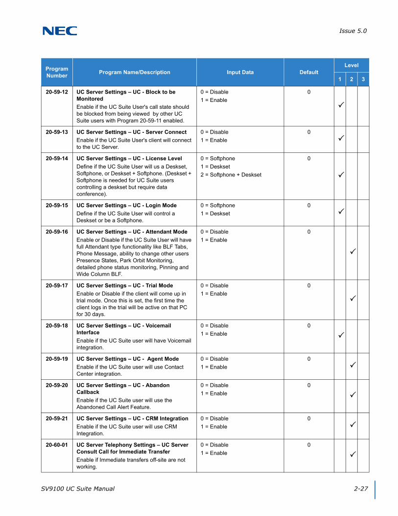
Issue 5.0
SV9100 UC Suite Manual 2-27
20-59-12 UC Server Settings – UC - Block to be Monitored
Enable if the UC Suite User's call state should be blocked from being viewed by other UC Suite users with Program 20-59-11 enabled.
0 = Disable
1 = Enable
0
20-59-13 UC Server Settings – UC - Server Connect
Enable if the UC Suite User's client will connect to the UC Server.
0 = Disable
1 = Enable
0
20-59-14 UC Server Settings – UC - License Level
Define if the UC Suite User will us a Deskset, Softphone, or Deskset + Softphone. (Deskset + Softphone is needed for UC Suite users controlling a deskset but require data conference).
0 = Softphone
1 = Deskset
2 = Softphone + Deskset
0
20-59-15 UC Server Settings – UC - Login Mode
Define if the UC Suite User will control a Deskset or be a Softphone.
0 = Softphone
1 = Deskset
0
20-59-16 UC Server Settings – UC - Attendant Mode
Enable or Disable if the UC Suite User will have full Attendant type functionality like BLF Tabs, Phone Message, ability to change other users Presence States, Park Orbit Monitoring, detailed phone status monitoring, Pinning and Wide Column BLF.
0 = Disable
1 = Enable
0
20-59-17 UC Server Settings – UC - Trial Mode
Enable or Disable if the client will come up in trial mode. Once this is set, the first time the client logs in the trial will be active on that PC for 30 days.
0 = Disable
1 = Enable
0
20-59-18 UC Server Settings – UC - Voicemail Interface
Enable if the UC Suite user will have Voicemail integration.
0 = Disable
1 = Enable
0
20-59-19 UC Server Settings – UC - Agent Mode
Enable if the UC Suite user will use Contact Center integration.
0 = Disable
1 = Enable
0
20-59-20 UC Server Settings – UC - Abandon Callback
Enable if the UC Suite user will use the Abandoned Call Alert Feature.
0 = Disable
1 = Enable
0
20-59-21 UC Server Settings – UC - CRM Integration
Enable if the UC Suite user will use CRM Integration.
0 = Disable
1 = Enable
0
20-60-01 UC Server Telephony Settings – UC Server Consult Call for Immediate Transfer
Enable if Immediate transfers off-site are not working.
0 = Disable
1 = Enable
0
Program Number
Program Name/Description Input Data DefaultLevel
1 2 3
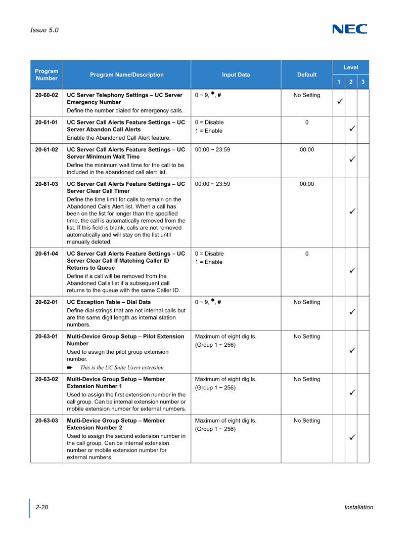
Issue 5.0
2-28 Installation
20-60-02 UC Server Telephony Settings – UC Server Emergency Number
Define the number dialed for emergency calls.
0 ~ 9, , # No Setting
20-61-01 UC Server Call Alerts Feature Settings – UC Server Abandon Call Alerts
Enable the Abandoned Call Alert feature.
0 = Disable
1 = Enable
0
20-61-02 UC Server Call Alerts Feature Settings – UC Server Minimum Wait Time
Define the minimum wait time for the call to be included in the abandoned call alert list.
00:00 ~ 23:59 00:00
20-61-03 UC Server Call Alerts Feature Settings – UC Server Clear Call Timer
Define the time limit for calls to remain on the Abandoned Calls Alert list. When a call has been on the list for longer than the specified time, the call is automatically removed from the list. If this field is blank, calls are not removed automatically and will stay on the list until manually deleted.
00:00 ~ 23:59 00:00
20-61-04 UC Server Call Alerts Feature Settings – UC Server Clear Call If Matching Caller ID Returns to Queue
Define if a call will be removed from the Abandoned Calls list if a subsequent call returns to the queue with the same Caller ID.
0 = Disable
1 = Enable
0
20-62-01 UC Exception Table – Dial Data
Define dial strings that are not internal calls but are the same digit length as internal station numbers.
0 ~ 9, , # No Setting
20-63-01 Multi-Device Group Setup – Pilot Extension Number
Used to assign the pilot group extension number.
This is the UC Suite Users extension.
Maximum of eight digits.
(Group 1 ~ 256)
No Setting
20-63-02 Multi-Device Group Setup – Member Extension Number 1
Used to assign the first extension number in the call group. Can be internal extension number or mobile extension number for external numbers.
Maximum of eight digits.
(Group 1 ~ 256)
No Setting
20-63-03 Multi-Device Group Setup – Member Extension Number 2
Used to assign the second extension number in the call group. Can be internal extension number or mobile extension number for external numbers.
Maximum of eight digits.
(Group 1 ~ 256)
No Setting
Program Number
Program Name/Description Input Data DefaultLevel
1 2 3
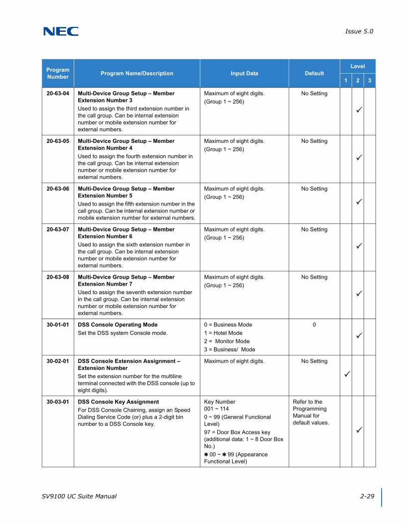
Issue 5.0
SV9100 UC Suite Manual 2-29
20-63-04 Multi-Device Group Setup – Member Extension Number 3
Used to assign the third extension number in the call group. Can be internal extension number or mobile extension number for external numbers.
Maximum of eight digits.
(Group 1 ~ 256)
No Setting
20-63-05 Multi-Device Group Setup – Member Extension Number 4
Used to assign the fourth extension number in the call group. Can be internal extension number or mobile extension number for external numbers.
Maximum of eight digits.
(Group 1 ~ 256)
No Setting
20-63-06 Multi-Device Group Setup – Member Extension Number 5
Used to assign the fifth extension number in the call group. Can be internal extension number or mobile extension number for external numbers.
Maximum of eight digits.
(Group 1 ~ 256)
No Setting
20-63-07 Multi-Device Group Setup – Member Extension Number 6
Used to assign the sixth extension number in the call group. Can be internal extension number or mobile extension number for external numbers.
Maximum of eight digits.
(Group 1 ~ 256)
No Setting
20-63-08 Multi-Device Group Setup – Member Extension Number 7
Used to assign the seventh extension number in the call group. Can be internal extension number or mobile extension number for external numbers.
Maximum of eight digits.
(Group 1 ~ 256)
No Setting
30-01-01 DSS Console Operating Mode
Set the DSS system Console mode.
0 = Business Mode
1 = Hotel Mode
2 = Monitor Mode
3 = Business/ Mode
0
30-02-01 DSS Console Extension Assignment – Extension Number
Set the extension number for the multiline terminal connected with the DSS console (up to eight digits).
Maximum of eight digits. No Setting
30-03-01 DSS Console Key Assignment
For DSS Console Chaining, assign an Speed Dialing Service Code (or) plus a 2-digit bin number to a DSS Console key.
Key Number001 ~ 114
0 ~ 99 (General Functional Level)
97 = Door Box Access key (additional data: 1 ~ 8 Door Box No.)
00 ~ 99 (Appearance Functional Level)
Refer to the Programming Manual for default values.
Program Number
Program Name/Description Input Data DefaultLevel
1 2 3

Issue 5.0
2-30 Installation
84-20-02 SIP Extension Basic Information Setup – Session Timer Value
Define the periodic refresh time that allows both user agents and proxies to determine if the SIP session is still active.
0 ~ 65535 seconds 180
84-20-03 SIP Extension Basic Information Setup – Minimum Session Timer Value
Define to convey the minimum allowed value for the SIP session timer.
0 ~ 65535 seconds 180
84-22-01 DT800/DT700 Series Multiline Logon Information Setup – User ID
Input the User ID for each Personal ID Index(1-960) when using auto or manual registration in 10-46-01.
Maximum of 32 characters. No Setting
84-22-02 DT800/DT700 Series Multiline Logon Information Setup – Password
Input the Password for each Personal ID Index (1-960) when using auto or manual registration in 10-46-01.
Maximum of 16 characters. No Setting
84-22-04 DT800/DT700 Series Multiline Logon Information Setup – Log Off
When the registration mode (10-46-01) is set to manual, and the phone prompts for a login, the previous user ID appears so the user only has to enter the password.
When enabled, the extension assigned to the Personal ID Index can be logged off or overridden by another IP multiline station or Softphone.
In Manual mode a user can also Logoff the IP phone to allow another user to login with their own user ID and password. To Logoff the IP phone:Press the Down Arrow Softkey, press the Prog Softkey, and then press the LOGOFF Softkey.
0 = Off
1 = On
1
84-26-01 IPL Basic Setup – IP Address
Assign the IP address for the DSP on the GPZ-IPLE.
xxx.xxx.xxx.xxx Slot 1 = 172.16.0.20
Program Number
Program Name/Description Input Data DefaultLevel
1 2 3

SV9100 UC Suite Manual 3-1
Chapter 3
UNIVERGE® SV9100
UC Client Startup
The UC Client can be started in any of the following ways:
Double-click the NEC UC Suite icon within the Windows desktop area.
Select Start/All Programs/NEC/NEC UC Suite.
When the UC Client is started, the Login to the Phone System window appears:
Enter the SV9100 IP Address in System Address.
Enter the User Name and Password from Programs 20-59-01 and 20-59-02.
If the client will be a soft phone, check the Login as Softphone check box.
If the client will user CRM integration, check the Enable CRM Integration check box.
If the client will be a soft phone and the audio settings need to be changed, check the Change Audio Settings check box.
Figure 3-1 Login to Phone System Screen
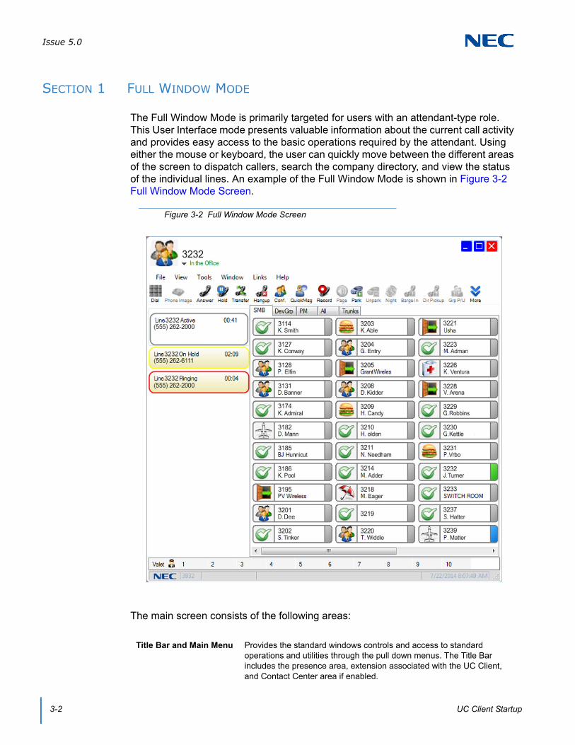
Issue 5.0
3-2 UC Client Startup
SECTION 1 FULL WINDOW MODE
The Full Window Mode is primarily targeted for users with an attendant-type role. This User Interface mode presents valuable information about the current call activity and provides easy access to the basic operations required by the attendant. Using either the mouse or keyboard, the user can quickly move between the different areas of the screen to dispatch callers, search the company directory, and view the status of the individual lines. An example of the Full Window Mode is shown in Figure 3-2 Full Window Mode Screen.
The main screen consists of the following areas:
Figure 3-2 Full Window Mode Screen
Title Bar and Main Menu Provides the standard windows controls and access to standard operations and utilities through the pull down menus. The Title Bar includes the presence area, extension associated with the UC Client, and Contact Center area if enabled.
Issue 5.0
SV9100 UC Suite Manual 3-3
1.1 Title Bar and Main Menu
The Title Bar and Main Menu provide the standard windows controls and access to basic operations and utilities through pull down menus.
The standard Windows controls on the Title Bar are as follows:
The Main Menu provides a drop down menu, which lists all of the functions available within a selected category. The functions available from the Main Menu are as follows:
File
View
Function Toolbar Provides quick access to the most commonly used call processing and attendant functions.
Active Call List Displays information about the current call, a list of all calls currently active on the console, and active Quick Messages.
BLF/DSS Area Provides the Busy Lamp field and Direct Station Select functionality, comparable to a DSS module. Also includes a special tab for Speed Dial numbers.
Minimize Hide the application's main window and include an entry to restore the application in the Windows task bar.
Maximize/Restore Change the size of the application main window. Maximize increases the size of the window to fill the entire display. The Restore function reduces the size of the main window to the previous dimensions.
Close Exit the desktop application.
Exit Close the UC Client.
Standard Window Change UI mode to Standard Window view.
Toolbar Change UI mode to Toolbar mode.
Sort BLF By Change the sort order of the BLF buttons. Sort options are Extension, First Name, and Last Name.

Issue 5.0
3-4 UC Client Startup
Tools
Window
Preferences Customize operational settings for the UC Client.
Volume Control Changes the volume level of a Softphone.
Profiles Save and select user profiles.
Color Selection Change the color scheme of the UC Client main window and IM window. Below is an example of the custom color window that opens when choosing color selection.
Start Color Choose the color to start with on the left side of the screen.
End Color Choose the color to end with on the right side of the screen.
Gradient Pattern Preview
Preview how the selected colors will look.
Restore Default Set the color scheme back to default.
Save Save the new color settings.
Cancel Cancel the new color settings and abort changes.
Call Log Open a separate window to view the call history.
Directory Open a separate window to view the Directory/Contact List.
Phone Image Display emulation phone image/control when the Desktop Application is run in IP Softphone mode.
Abandoned Calls Open a separate window to view the abandoned call list.
Agent Monitor Opens an Agent Monitor window used to view the current status of other Contact Center Agents.
Queue Monitor Opens a Queue Monitor window to view real-time statistics associated with a set of selected queues.

Issue 5.0
SV9100 UC Suite Manual 3-5
Links
Help
1.2 Function Toolbar
The Function Toolbar provides quick access to the most commonly used call processing functions. A function on the toolbar can be selected by using the mouse to click on the desired function button or by pressing the associated hotkey sequence on the keyboard. If additional information is required to complete the operation, then a supporting menu is displayed requesting additional input from the user.
Individual buttons on the Function Toolbar become disabled if the function is not allowed for the current state of the telephone. For example, the Answer button is only enabled when a call is ringing on the telephone.
Available functions are:
Dialpad Opens a dialpad for dialing digits during a call.
SV9100 PCPro Opens a PCPro Window if PCPro is installed on the machine.
CallTo: Setup Opens a window Yes and No options for Enabling or Disabling the CallTo tag feature. When Enabled, the CallTo tag feature provides the ability to dial from a CallTo tag/hyperlink within a web page or MS Office document using the Desktop Application.
Highlight Dial Starts the Highlight Dial process in the system tray. The Highlight Dial process can be turned on or off. When turned on, highlighting a number in any program will automatically dial the number from the UC Suite.
Contents and Index
Access the on-line help system by topic.
About View the copyright notice and current revision of the desktop application.
Add/Edit Note Hold
Answer Last Number Redial
Auto Callback Night Mode
Auto Handset/Auto Headset Page
Background Music Park
Barge In Phone Image
Issue 5.0
3-6 UC Client Startup
The operation of each of these functions is further described in Section 1 Toolbar Functions on page 4-1.
1.3 Active Call List
The Active Call List displays all of the calls that are currently being handled by the application. The list includes calls that are in the following states:
Ringing
Connected
Held
1.3.1 Active Call List Format
The active call entry that is displayed on the top of the list is always the connected (active) call.
Each entry in the active call list includes the following information, based upon the current state of the call:
Line/Trunk Identifier
Connection Status
Timer displaying time in current state
Calling Party/Called Party Identification
User-defined notes
DNIS information when provided.
Callback Request Phone Message
Call Redirect Pickup Other Group
Conference Quick Message
Custom Message Record
Dial Switch Login Mode
Directed Call Pickup Transfer
Do Not Disturb Unpark
Forward Calls Video
FTP Voice Mail
Group Call Pickup Voice Over
Hang Up
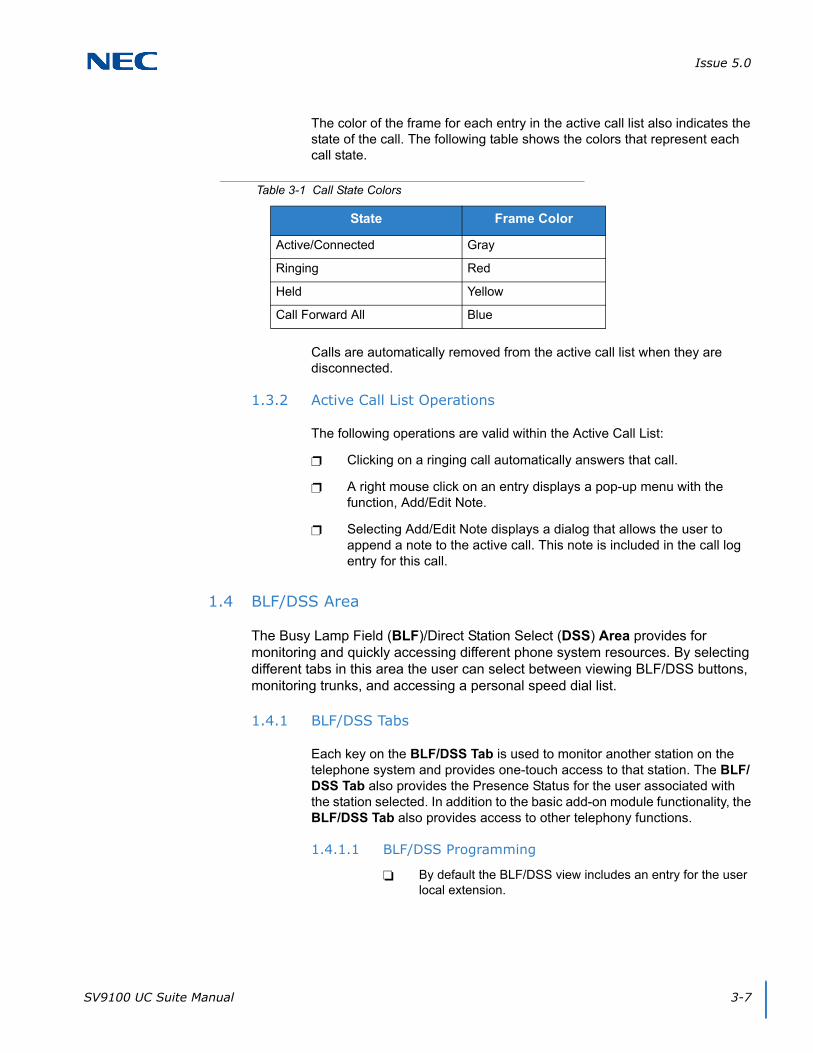
Issue 5.0
SV9100 UC Suite Manual 3-7
The color of the frame for each entry in the active call list also indicates the state of the call. The following table shows the colors that represent each call state.
Calls are automatically removed from the active call list when they are disconnected.
1.3.2 Active Call List Operations
The following operations are valid within the Active Call List:
Clicking on a ringing call automatically answers that call.
A right mouse click on an entry displays a pop-up menu with the function, Add/Edit Note.
Selecting Add/Edit Note displays a dialog that allows the user to append a note to the active call. This note is included in the call log entry for this call.
1.4 BLF/DSS Area
The Busy Lamp Field (BLF)/Direct Station Select (DSS) Area provides for monitoring and quickly accessing different phone system resources. By selecting different tabs in this area the user can select between viewing BLF/DSS buttons, monitoring trunks, and accessing a personal speed dial list.
1.4.1 BLF/DSS Tabs
Each key on the BLF/DSS Tab is used to monitor another station on the telephone system and provides one-touch access to that station. The BLF/DSS Tab also provides the Presence Status for the user associated with the station selected. In addition to the basic add-on module functionality, the BLF/DSS Tab also provides access to other telephony functions.
1.4.1.1 BLF/DSS Programming
By default the BLF/DSS view includes an entry for the user local extension.
Table 3-1 Call State Colors
State Frame Color
Active/Connected Gray
Ringing Red
Held Yellow
Call Forward All Blue

Issue 5.0
3-8 UC Client Startup
Additional BLF buttons are created for each extension that is programmed as a one-touch key on the user’s phone for stations without a UC Server connection. UC Server will provide BLF buttons for each station in the system. (MB 15-07-01 and 30-03-01).
One-Touch keys must be programmed on buttons that physically appear on the phone for DSS/BLF status without UC Server. BLF information will not be provided to the UC Client for any one-touch keys that are programmed on buttons higher than the phone has physically.
The UC Client acquires the list of programmed one-touch keys at startup.
Any changes to the phone programming that occur while the application is running are reflected in the application only after the application is restarted.
Alternately, the Tools → Preferences → BLF/DSS tab includes a Synchronize function that reads the current phone programming.
1.4.1.2 BLF Button Design
Each BLF button includes an LED image, followed by an identifier.
The LED image changes color to indicate the current state of the extension.
The supported colors/states are as follows: Gray (Idle), Green (Busy), Red (Call Forward Immediate/DND All).
The label can show the extension number, directory name associated with this extension, or both, as determined by the user settings.
1.4.1.3 BLF/DSS Layout
The Preferences → BLF/DSS tab specifies the layout of the BLF/DSS area. Through this dialog the user can set the following:
Define BLF Groups (tabs).
Set Visible BLF Groups (tabs).
Specify members of each BLF Group.
Define label format for the BLF buttons.
Specify the name order used on the BLF and Directory views.
The Preferences dialog is further defined in the Preferences section of this document.
The user can also change the sort order of the BLF buttons using the View → Sort BLF By options on the Main Menu. The available sort options are by Extension, by First Name, or by Last Name.
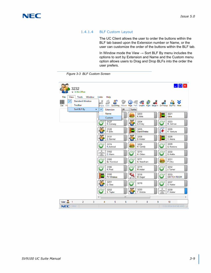
Issue 5.0
SV9100 UC Suite Manual 3-9
1.4.1.4 BLF Custom Layout
The UC Client allows the user to order the buttons within the BLF tab based upon the Extension number or Name, or the user can customize the order of the buttons within the BLF tab.
In Window mode the View → Sort BLF By menu includes the options to sort by Extension and Name and the Custom menu option allows users to Drag and Drop BLFs into the order the user prefers.
Figure 3-3 BLF Custom Screen

Issue 5.0
3-10 UC Client Startup
When the Custom option is selected, the user can re-order the buttons within a BLF tab by dragging a button into a new location. This operation is accomplished by placing the mouse /cursor over a button and holding down the left mouse button while moving the cursor to a new button position. During the Drag and Drop, the mouse/cursor changes to a re-order cursor to indicate that the operation is in progress.
When the mouse button is released, the dragged BLF button is inserted into that position and the remaining BLF buttons are shifted down.
1.4.1.5 BLF/DSS Operations
The BLF/DSS buttons provide one-touch access as follows:
When the local phone is idle, selecting an idle BLF button initiates a call to that extension.
When the local phone has an active call, selecting an idle BLF button initiates a transfer to that extension.
A configuration option set in Tools → Preferences → Shortcuts defines the action when the user double-clicks on a busy BLF with an active call. The options are:
Send active call to voice mail for the selected extension.
Put caller on hold and initiate voice over.
Camp caller on second line of selected extension.
Performing a right mouse click on a BLF button provides access to the following functions:
Dial
Voice Mail
Quick Message
Phone Message
Instant Message
Transfer
Conference
Voice Over
Camp
Call Redirect
Add/Edit Note
Clear Note
Each of these functions is further described in the Functions section of this document.

Issue 5.0
SV9100 UC Suite Manual 3-11
1.4.1.6 Trunks Tab
The Trunks tab allows the user to monitor the status of the trunk appearances that are programmed on the local phone.
The LED image shows the trunk status using the following color scheme: Gray (Idle), Red (Ringing), Green (Busy).
The Trunks tab can be hidden by clearing the corresponding Visible tabs setting within the Tools → Preferences → BLF DSS tab.
1.4.1.7 Speed Dial Tab
A special tab labeled Speed Dial is included in the BLF/DSS area. When selected, this tab displays a set of buttons that the user has designated as speed dials.
Clicking on an entry in the Speed Dial list immediately generates a call to the selected number.
Entries are added to the Speed Dial list through the Directory/Contact List/Personal windows.
A right-mouse click on a Speed Dial entry opens a menu that allows the user to Dial the selected entry or Delete the entry from the Speed Dial list.
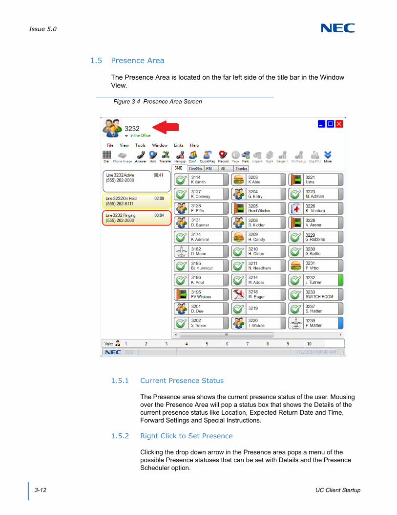
Issue 5.0
3-12 UC Client Startup
1.5 Presence Area
The Presence Area is located on the far left side of the title bar in the Window View.
1.5.1 Current Presence Status
The Presence area shows the current presence status of the user. Mousing over the Presence Area will pop a status box that shows the Details of the current presence status like Location, Expected Return Date and Time, Forward Settings and Special Instructions.
1.5.2 Right Click to Set Presence
Clicking the drop down arrow in the Presence area pops a menu of the possible Presence statuses that can be set with Details and the Presence Scheduler option.
Figure 3-4 Presence Area Screen

Issue 5.0
SV9100 UC Suite Manual 3-13
SECTION 2 TOOLBAR MODE
The Toolbar Mode presents valuable information about the current call activity and provides easy access to the basic operations required by the normal phone user. The Toolbar User Interface (UI) layout takes up a minimum amount of space on the desktop, so as to not interfere with the operation or viewing of other applications. An example of the Toolbar Mode is shown below.
The toolbar consists of the following areas:
Each of these screen regions is further described in the sections to follow.
2.1 Dial String Field
The Dial String Field is a combo box in which the user specifies the phone number to be dialed.
The drop down list for this field contains the most recently dialed numbers.
The drop down list displays up to 20 numbers.
The numbers are listed with the most recent at the top.
Selecting a number from the list places the number as the current number to be dialed.
Figure 3-5 Toolbar
Dial String Field Specifies the number to be dialed and maintains a list of the most recently dialed numbers.
Call Status Area Color-coded icons represent the status of active calls.
Dial/Hangup Button Controls the hookswitch state of the phone.
Speed Dial List Displays a user-maintained list of frequently dialed numbers.
File Button Provides access to additional menu items, such as configuration settings and additional application views.
Hold Button Places the active call on Hold.
Presence Area Displays the current presence state of the user with a drop down arrow to change presence states.
Contact Center Area Displays the Contact Center Agent's current Contact Center state with a drop down arrow to change Contact Center state.
Function Toolbar Provides quick access to the most commonly used call processing and application functions.
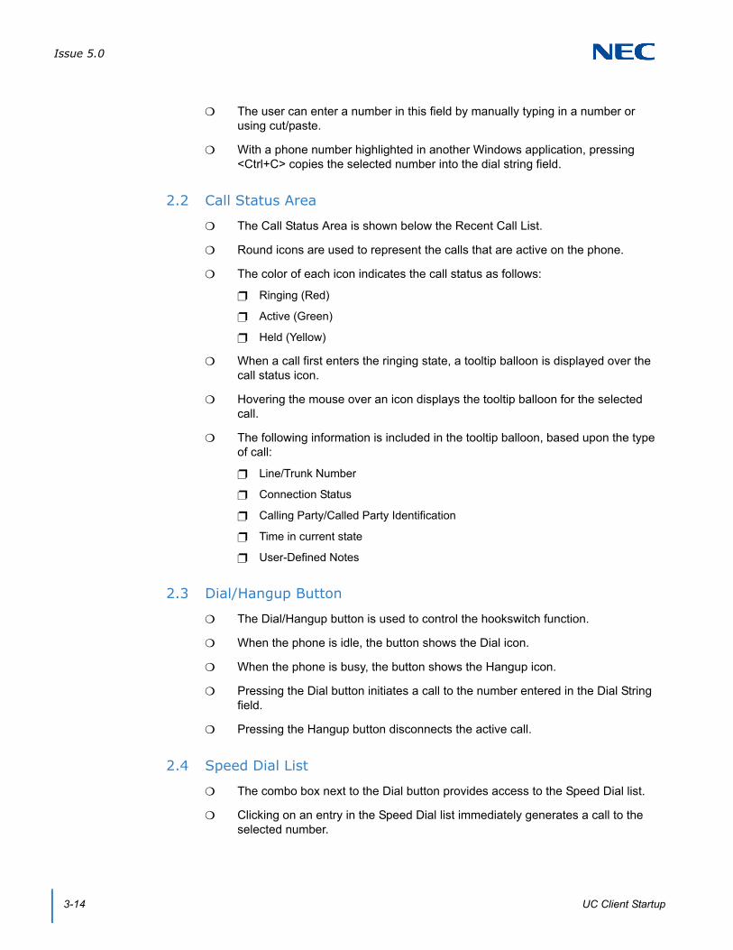
Issue 5.0
3-14 UC Client Startup
The user can enter a number in this field by manually typing in a number or using cut/paste.
With a phone number highlighted in another Windows application, pressing <Ctrl+C> copies the selected number into the dial string field.
2.2 Call Status Area
The Call Status Area is shown below the Recent Call List.
Round icons are used to represent the calls that are active on the phone.
The color of each icon indicates the call status as follows:
Ringing (Red)
Active (Green)
Held (Yellow)
When a call first enters the ringing state, a tooltip balloon is displayed over the call status icon.
Hovering the mouse over an icon displays the tooltip balloon for the selected call.
The following information is included in the tooltip balloon, based upon the type of call:
Line/Trunk Number
Connection Status
Calling Party/Called Party Identification
Time in current state
User-Defined Notes
2.3 Dial/Hangup Button
The Dial/Hangup button is used to control the hookswitch function.
When the phone is idle, the button shows the Dial icon.
When the phone is busy, the button shows the Hangup icon.
Pressing the Dial button initiates a call to the number entered in the Dial String field.
Pressing the Hangup button disconnects the active call.
2.4 Speed Dial List
The combo box next to the Dial button provides access to the Speed Dial list.
Clicking on an entry in the Speed Dial list immediately generates a call to the selected number.

Issue 5.0
SV9100 UC Suite Manual 3-15
Entries are added to the Speed Dial list through the Directory/Contact List/Personal windows.
A right-mouse click on a Speed Dial entry opens a menu that provides access to the following functions:
Edit – Open the associated database entry for editing.
Dial – Place a call to the selected number.
Transfer Immediate – perform a blind transfer of the active call to the selected destination.
Transfer Supervised – initiate a supervised transfer of the active call to the selected destination.
Conference – initiate a conference call with the selected destination.
E-Mail – create a new e-mail message with the selected name as the intended recipient.
Delete – remove the selected entry from the Speed Dial list.
2.5 File Button
The File button provides access to functions for configuring the application and changing the view/UI mode. The functions available from the File button are as follows:
Preferences
Call Log
Directory
View
Customize application-level configuration settings.
Open a separate window to view the call history.
Open a separate window to view the Directory/Contact List/Personal Directory.
Window Change UI mode to Full Window mode.
Phone Image Display emulation phone image/control.
Issue 5.0
3-16 UC Client Startup
Links
Help
Exit
Phone Image
This same pop-up menu can be accessed by pressing the right mouse button while pointing at an open area within the toolbar.
2.6 Hold Button
The Hold button places the active call on hold.
The Hold button is only enabled when a call is active on the phone.
SV8100 PCPro Opens a PCPro Window if PCPro is installed on the machine.
CallTo: Setup Opens a window Yes and No options for Enabling or Disabling the CallTo tag feature. When Enabled, the CallTo tag feature provides the ability to dial from a CallTo tag/hyperlink within a web page or MS Office document using the UC Desktop Application.
Highlight Dial Starts the Highlight Dial process in the system tray. The Highlight Dial process can be turned on or off. When turned on, highlighting a number in any program will automatically dial the number from the UC Client.
Contents and Index Access the on-line help system by topic.
About View the copyright notice and current revision of the UC Client.
Close the UC Client.
Open the emulation phone mode.
Issue 5.0
SV9100 UC Suite Manual 3-17
2.7 Function Toolbar
The Function Toolbar provides quick access to the most commonly used call processing functions. A function on the toolbar can be selected by using the mouse to click on the desired function button or pressing the associated hotkey sequence on the keyboard. If additional information is required to complete the operation, then a supporting menu is displayed requesting additional input from the user.
Individual buttons on the Function Toolbar become disabled if the function is not allowed for the current state of the telephone. For example, the Answer button is only enabled when a call is ringing on the telephone.
Available functions are:
The operation of each of these functions is further described in Section 1 Toolbar Functions on page 4-1.
Add/Edit Note Hold
Answer Last Number Redial
Auto Callback Night Mode
Auto Handset/Auto Headset Page
Background Music Park
Barge In Phone Image
Callback Request Phone Message
Call Redirect Pickup Other Group
Conference Quick Message
Custom Message Record
Dial Switch Login Mode
Directed Call Pickup Transfer
Do Not Disturb Unpark
Forward Calls Voice Mail
Group Call Pickup Voice Over
Hang Up

Issue 5.0
3-18 UC Client Startup
SECTION 3 EMULATION PHONE MODE (PHONE IMAGE)
The Emulation Phone is an on-screen representation of a deskset that can be opened through the Window or Toolbar modes. This user interface option is provided to allow users access to telephony functions through individual key presses.
3.1 Emulation Phone Base Module
The base module for the emulation phone simulates a 24-button deskset, as shown in Figure 3-6 Emulation Phone Base Module.
The emulation phone image operates in the same manner as a physical deskset, with the following exceptions:
The LCD display does not support the double-height setting.
The labels shown above the programmable keys are limited to six characters.
Figure 3-6 Emulation Phone Base Module

Issue 5.0
SV9100 UC Suite Manual 3-19
The JogKey (Round, four-position control) does not provide the same functionality as the physical phone. The up and down sides of the control will open the volume adjustment bar, and the left side will bring up the redial number.
3.2 Emulation Phone Add-On Module
The Phone Image tab on the Preferences menu allows the user to specify an expansion module be included in the phone image. When this option is selected, an eight-button add-on module will be displayed, as shown in Figure 3-7 Emulation Phone Add-On Module.
The add-on module operates in the same manner as the physical add-on module by providing eight programmable buttons to enhance the base module.
Figure 3-7 Emulation Phone Add-On Module

Issue 5.0
3-20 UC Client Startup
3.3 Emulation Phone DSS Module
The Phone Image tab on the Preferences menu allows the user to specify an attendant module be included in the phone image. When this option is selected, a 60-button DSS module will be displayed, as shown in Figure 3-8 Emulation Phone DSS Module.
Each button on the DSS module includes two LEDs.
The right LED is green and when lit indicates that a message is pending on the destination extension.
The left LED is red and simulates a solid lit LED, as well as supporting all of the different flash rates that are available on the physical DSS module.
The state of the red LED tracks the same conditions that affect the LED on the physical DSS module.
Figure 3-8 Emulation Phone DSS Module
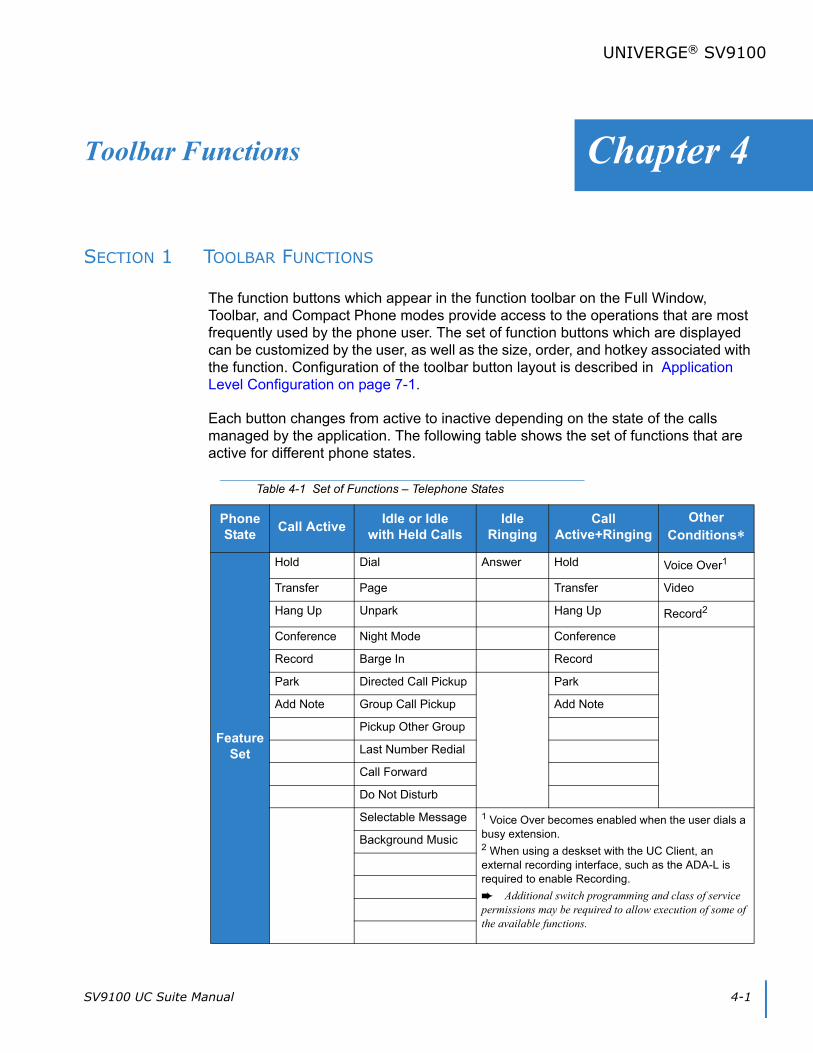
SV9100 UC Suite Manual 4-1
Chapter 4
UNIVERGE® SV9100
Toolbar Functions
SECTION 1 TOOLBAR FUNCTIONS
The function buttons which appear in the function toolbar on the Full Window, Toolbar, and Compact Phone modes provide access to the operations that are most frequently used by the phone user. The set of function buttons which are displayed can be customized by the user, as well as the size, order, and hotkey associated with the function. Configuration of the toolbar button layout is described in Application Level Configuration on page 7-1.
Each button changes from active to inactive depending on the state of the calls managed by the application. The following table shows the set of functions that are active for different phone states.
Table 4-1 Set of Functions – Telephone States
Phone State
Call ActiveIdle or Idle
with Held CallsIdle
RingingCall
Active+RingingOther
Conditions
Feature Set
Hold Dial Answer Hold Voice Over1
Transfer Page Transfer Video
Hang Up Unpark Hang Up Record2
Conference Night Mode Conference
Record Barge In Record
Park Directed Call Pickup Park
Add Note Group Call Pickup Add Note
Pickup Other Group
Last Number Redial
Call Forward
Do Not Disturb
Selectable Message 1 Voice Over becomes enabled when the user dials a busy extension.2 When using a deskset with the UC Client, an external recording interface, such as the ADA-L is required to enable Recording.
Additional switch programming and class of service permissions may be required to allow execution of some of the available functions.
Background Music
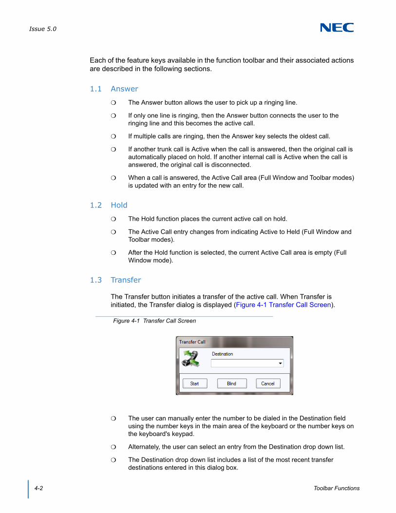
Issue 5.0
4-2 Toolbar Functions
Each of the feature keys available in the function toolbar and their associated actions are described in the following sections.
1.1 Answer
The Answer button allows the user to pick up a ringing line.
If only one line is ringing, then the Answer button connects the user to the ringing line and this becomes the active call.
If multiple calls are ringing, then the Answer key selects the oldest call.
If another trunk call is Active when the call is answered, then the original call is automatically placed on hold. If another internal call is Active when the call is answered, the original call is disconnected.
When a call is answered, the Active Call area (Full Window and Toolbar modes) is updated with an entry for the new call.
1.2 Hold
The Hold function places the current active call on hold.
The Active Call entry changes from indicating Active to Held (Full Window and Toolbar modes).
After the Hold function is selected, the current Active Call area is empty (Full Window mode).
1.3 Transfer
The Transfer button initiates a transfer of the active call. When Transfer is initiated, the Transfer dialog is displayed (Figure 4-1 Transfer Call Screen).
The user can manually enter the number to be dialed in the Destination field using the number keys in the main area of the keyboard or the number keys on the keyboard's keypad.
Alternately, the user can select an entry from the Destination drop down list.
The Destination drop down list includes a list of the most recent transfer destinations entered in this dialog box.
Figure 4-1 Transfer Call Screen

Issue 5.0
SV9100 UC Suite Manual 4-3
The actions associated with each of the dialog buttons are described in the following sections.
1.3.1 Transfer Call – Start
When the Start button is selected, the software will initiate a supervised transfer of the call. The Transfer dialog will be updated (refer to Figure 4-2 Transfer Call – Start).
Selecting the Complete button will connect the original caller to the destination and disconnect the user.
Selecting the Disconnect button will hang up from the call to the Destination, and reconnect to the original caller.
1.3.2 Transfer Call – Blind
When the Blind button is selected, the application will initiate an unsupervised transfer to the specified destination.
Once the transfer is complete, the active call will be removed from the active call area (Full Window and Toolbar modes).
1.3.3 Transfer Call – Cancel
When the Cancel button is selected, the transfer operation will be cancelled and the Transfer dialog will be closed.
Pressing the Esc key will also initiate the Cancel operation.
1.4 Hang Up
The Hang Up button will disconnect the user from the active call.
When the active call is disconnected, the associated entry in the Active Call list will be removed (Full Window and Toolbar modes).
Figure 4-2 Transfer Call – Start

Issue 5.0
4-4 Toolbar Functions
1.5 Dial
The Dial button allows the user to initiate an outbound call. When Dial is selected, the number in the dial field is called.
The user can manually enter the number to be dialed in the Dial field using the number keys within the main area of the keyboard or the number keys on the keyboard keypad.
Alternately, the user may select an entry from the Dial drop down list.
The Dial drop down list includes a list of the most recent dial destinations entered within this dialog box.
1.6 Conference
The Conference button will initiate a conference that adds a third party to the active call. When the Conference function is selected, the following menu will be displayed (refer to Figure 4-3 Conference Call Screen).
The user can manually enter the number to be dialed in the Destination field using the number keys within the main area of the keyboard or the number keys on the keyboard keypad.
Alternately, the user may select an entry from the Destination drop down list.
The Destination drop down list includes a list of the most recent conference destinations entered within this dialog box.
The actions associated with each of the dialog buttons are described in the following sections.
Figure 4-3 Conference Call Screen
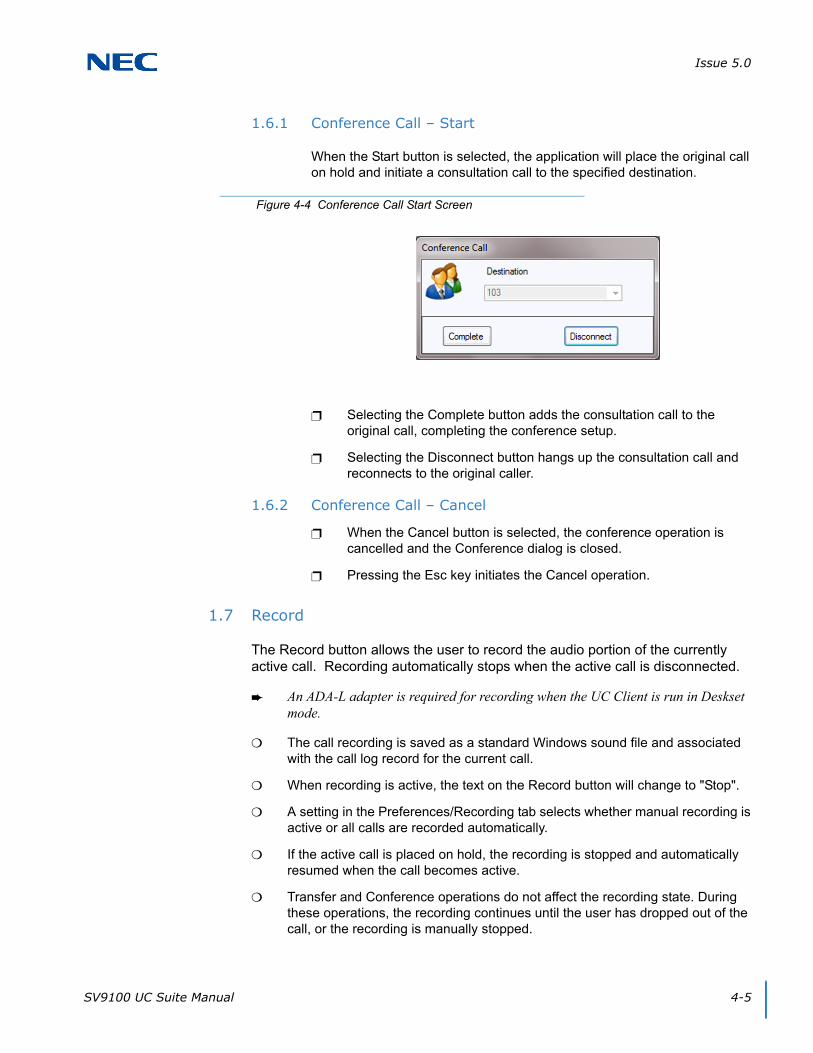
Issue 5.0
SV9100 UC Suite Manual 4-5
1.6.1 Conference Call – Start
When the Start button is selected, the application will place the original call on hold and initiate a consultation call to the specified destination.
Selecting the Complete button adds the consultation call to the original call, completing the conference setup.
Selecting the Disconnect button hangs up the consultation call and reconnects to the original caller.
1.6.2 Conference Call – Cancel
When the Cancel button is selected, the conference operation is cancelled and the Conference dialog is closed.
Pressing the Esc key initiates the Cancel operation.
1.7 Record
The Record button allows the user to record the audio portion of the currently active call. Recording automatically stops when the active call is disconnected.
An ADA-L adapter is required for recording when the UC Client is run in Deskset mode.
The call recording is saved as a standard Windows sound file and associated with the call log record for the current call.
When recording is active, the text on the Record button will change to "Stop".
A setting in the Preferences/Recording tab selects whether manual recording is active or all calls are recorded automatically.
If the active call is placed on hold, the recording is stopped and automatically resumed when the call becomes active.
Transfer and Conference operations do not affect the recording state. During these operations, the recording continues until the user has dropped out of the call, or the recording is manually stopped.
Figure 4-4 Conference Call Start Screen
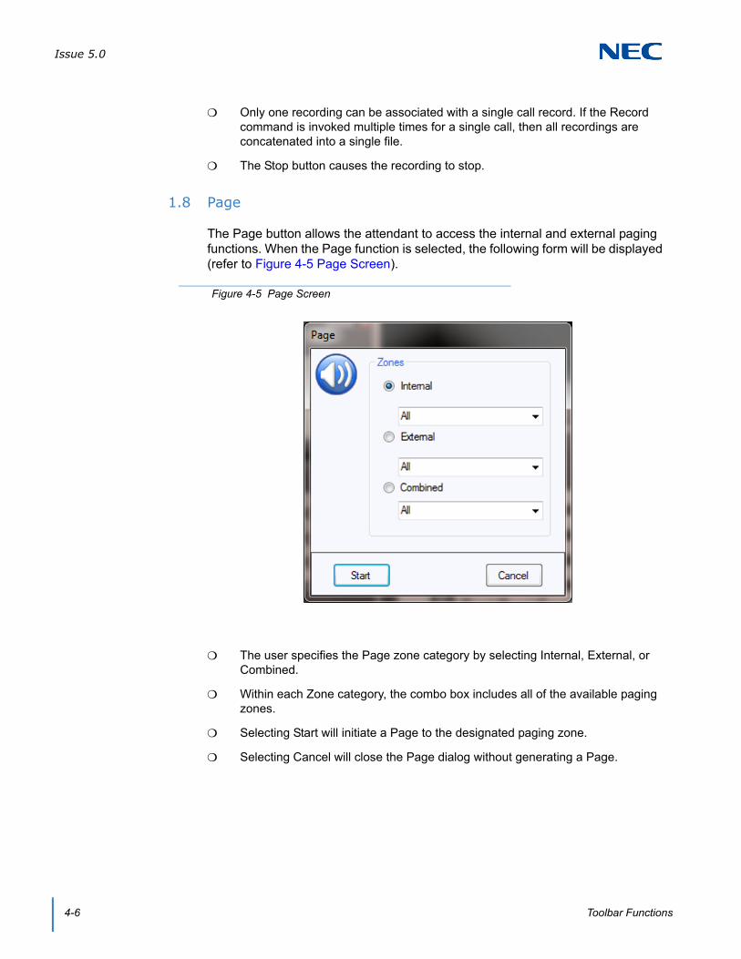
Issue 5.0
4-6 Toolbar Functions
Only one recording can be associated with a single call record. If the Record command is invoked multiple times for a single call, then all recordings are concatenated into a single file.
The Stop button causes the recording to stop.
1.8 Page
The Page button allows the attendant to access the internal and external paging functions. When the Page function is selected, the following form will be displayed (refer to Figure 4-5 Page Screen).
The user specifies the Page zone category by selecting Internal, External, or Combined.
Within each Zone category, the combo box includes all of the available paging zones.
Selecting Start will initiate a Page to the designated paging zone.
Selecting Cancel will close the Page dialog without generating a Page.
Figure 4-5 Page Screen

Issue 5.0
SV9100 UC Suite Manual 4-7
1.9 Park
The Park button will transfer the active call to a specific park orbit. When this function is selected, the following dialog will be displayed (refer to Figure 4-6 Park Call Screen).
The spinner control allows the user to select the destination Park orbit.
Selecting the Start button will place the active call in the selected Park orbit.
Selecting the Cancel button will close the Park Call dialog without initiating a call park operation.
If the Park operation fails because the selected Park orbit is not available, an error message will be displayed.
1.10 Unpark
The Unpark button will retrieve a call from a specific park orbit. When this function is selected, the following dialog in Figure 4-7 Unpark Call Screen, will be displayed.
The spinner control allows the user to select the destination Park orbit.
Selecting the Start button will attempt to retrieve a call from the specified Park orbit.
Figure 4-6 Park Call Screen
Figure 4-7 Unpark Call Screen
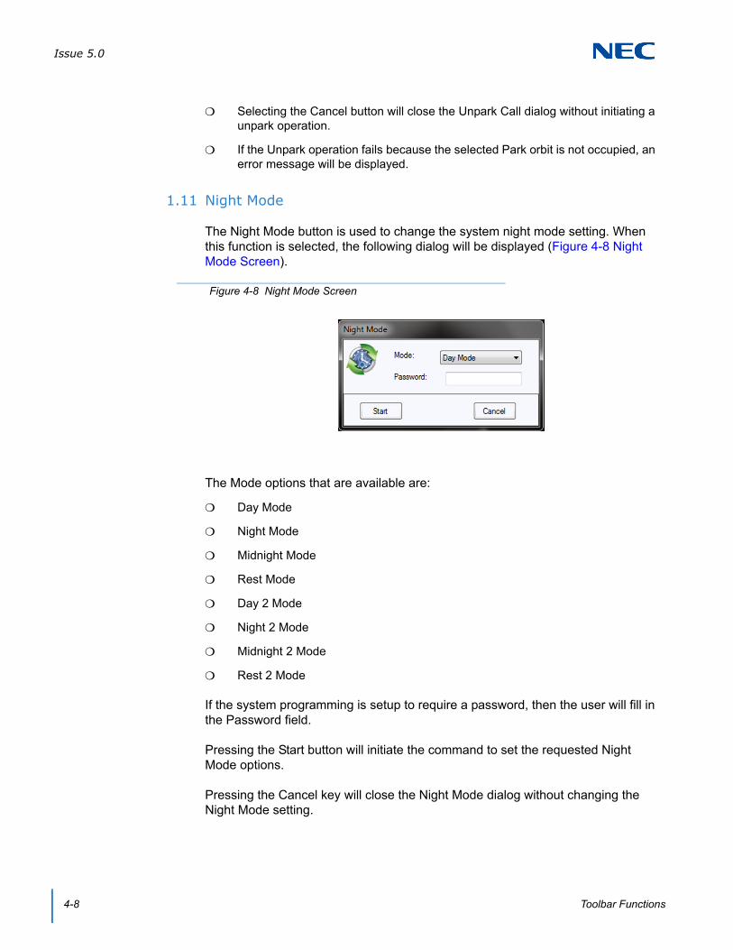
Issue 5.0
4-8 Toolbar Functions
Selecting the Cancel button will close the Unpark Call dialog without initiating a unpark operation.
If the Unpark operation fails because the selected Park orbit is not occupied, an error message will be displayed.
1.11 Night Mode
The Night Mode button is used to change the system night mode setting. When this function is selected, the following dialog will be displayed (Figure 4-8 Night Mode Screen).
The Mode options that are available are:
Day Mode
Night Mode
Midnight Mode
Rest Mode
Day 2 Mode
Night 2 Mode
Midnight 2 Mode
Rest 2 Mode
If the system programming is setup to require a password, then the user will fill in the Password field.
Pressing the Start button will initiate the command to set the requested Night Mode options.
Pressing the Cancel key will close the Night Mode dialog without changing the Night Mode setting.
Figure 4-8 Night Mode Screen

Issue 5.0
SV9100 UC Suite Manual 4-9
1.12 Barge In
The Barge In button allows the user to enter another extension’s established call. When this function is selected, the following dialog will be displayed (refer to Figure 4-9 Barge In Screen).
The Number field allows the user to enter the extension to Barge In.
The Number field pull down list includes the most recent entries for this field.
When the Start button is selected, the Barge In feature will be applied to the selected extension.
When the Cancel button is selected, the Barge In dialog will close.
If the Barge In operation fails, an error message will be displayed.
The Barge In operation will fail if the specified extension does not have an established call.
The Barge In operation will fail if the user does not have the appropriate Class of Service permissions to execute Barge In.
1.13 Directed Call Pickup
The Directed Call Pickup function allows the user to pickup a ringing call from a specified extension. When the Directed Call Pickup function is selected, the following dialog will be displayed (refer to Figure 4-10 Directed Call Pickup Screen).
Figure 4-9 Barge In Screen
Figure 4-10 Directed Call Pickup Screen
Issue 5.0
4-10 Toolbar Functions
The Pickup Type field is automatically set to Directed Call Pickup.
The Number field allows the user to specify the extension to be picked up by either manually entering a number or selecting a number from the pull down list.
The Number field is a pull down menu that stores the most recent text entered in this field.
Pressing the Start button initiates the Call Pickup for the specified extension.
Pressing the Cancel button closes the Call Pickup dialog without executing the call pickup operation.
The Pickup Type field allows the user to initiate other call pickup features, including Group Call Pickup, Pickup Other Group and Call Pickup Specific Group.
1.14 Group Call Pickup
The Group Call Pickup function allows the user to pickup a ringing call from within their call pickup group. When the Group Call Pickup function is selected, the phone will initiate the group call pickup.
1.15 Pickup Other Group
The Pickup Other Group function allows the user to pickup a ringing call from within another call pickup group. When the Pickup Other Group function is selected, the phone will initiate the other group pickup function.
1.16 Last Number Redial
The Last Number Redial function allows the user to easily initiate a call to a previously dialed number.
1.17 Voice Over
The Voice Over function allows the user to interrupt another user extension that is busy on another call. The Voice Over function is enabled when the user has dialed a busy extension. Selecting the Voice Over function at this time will connect the user to the busy extension.
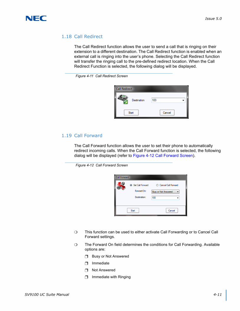
Issue 5.0
SV9100 UC Suite Manual 4-11
1.18 Call Redirect
The Call Redirect function allows the user to send a call that is ringing on their extension to a different destination. The Call Redirect function is enabled when an external call is ringing into the user’s phone. Selecting the Call Redirect function will transfer the ringing call to the pre-defined redirect location. When the Call Redirect Function is selected, the following dialog will be displayed.
1.19 Call Forward
The Call Forward function allows the user to set their phone to automatically redirect incoming calls. When the Call Forward function is selected, the following dialog will be displayed (refer to Figure 4-12 Call Forward Screen).
This function can be used to either activate Call Forwarding or to Cancel Call Forward settings.
The Forward On field determines the conditions for Call Forwarding. Available options are:
Busy or Not Answered
Immediate
Not Answered
Immediate with Ringing
Figure 4-11 Call Redirect Screen
Figure 4-12 Call Forward Screen
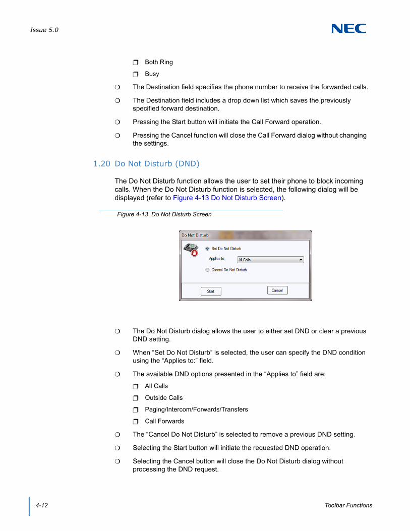
Issue 5.0
4-12 Toolbar Functions
Both Ring
Busy
The Destination field specifies the phone number to receive the forwarded calls.
The Destination field includes a drop down list which saves the previously specified forward destination.
Pressing the Start button will initiate the Call Forward operation.
Pressing the Cancel function will close the Call Forward dialog without changing the settings.
1.20 Do Not Disturb (DND)
The Do Not Disturb function allows the user to set their phone to block incoming calls. When the Do Not Disturb function is selected, the following dialog will be displayed (refer to Figure 4-13 Do Not Disturb Screen).
The Do Not Disturb dialog allows the user to either set DND or clear a previous DND setting.
When “Set Do Not Disturb” is selected, the user can specify the DND condition using the “Applies to:” field.
The available DND options presented in the “Applies to” field are:
All Calls
Outside Calls
Paging/Intercom/Forwards/Transfers
Call Forwards
The “Cancel Do Not Disturb” is selected to remove a previous DND setting.
Selecting the Start button will initiate the requested DND operation.
Selecting the Cancel button will close the Do Not Disturb dialog without processing the DND request.
Figure 4-13 Do Not Disturb Screen
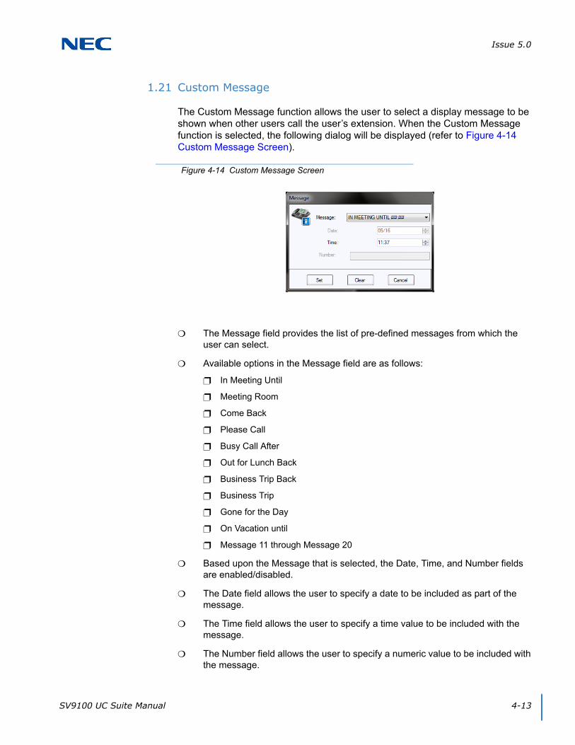
Issue 5.0
SV9100 UC Suite Manual 4-13
1.21 Custom Message
The Custom Message function allows the user to select a display message to be shown when other users call the user’s extension. When the Custom Message function is selected, the following dialog will be displayed (refer to Figure 4-14 Custom Message Screen).
The Message field provides the list of pre-defined messages from which the user can select.
Available options in the Message field are as follows:
In Meeting Until
Meeting Room
Come Back
Please Call
Busy Call After
Out for Lunch Back
Business Trip Back
Business Trip
Gone for the Day
On Vacation until
Message 11 through Message 20
Based upon the Message that is selected, the Date, Time, and Number fields are enabled/disabled.
The Date field allows the user to specify a date to be included as part of the message.
The Time field allows the user to specify a time value to be included with the message.
The Number field allows the user to specify a numeric value to be included with the message.
Figure 4-14 Custom Message Screen
Issue 5.0
4-14 Toolbar Functions
Selecting the Set button will assign the specified Custom Message to the phone.
Selecting the Clear button will remove the assigned message from the phone.
Selecting the Cancel button will close the Message dialog without processing the custom message operation.
1.22 Background Music
The Background Music function will send audio from a music source to the user’s telephone.
When Background Music is enabled, the music will be played whenever the phone is idle.
If Background Music is enabled, then selecting the Background Music a second time will disable the feature.
1.23 Auto Callback
The Auto Callback function allows the user to request a callback from another extension.
The Auto Callback function can be applied whenever the user dials an internal extension that is either busy or does not answer.
After setting a callback, the destination extension will callback the local extension when the phone is idle or the user next uses the telephone.
1.24 Phone Image
The Phone Image button is only available when controlling an IP Softphone. When the Phone Image button is selected, it will launch the emulation phone view.
1.25 Auto Handset/Auto Headset
The Auto Handset/Auto Headset button is a toggle button that switches between using the Handset or Headset for making outgoing calls and answering incoming calls. A Headset button must be programmed on the phone. (15-07-01, or SC 751: 05 Headset).
The Auto Handset/Auto Headset button is only available when the phone is in an idle state. Toggling between Handset and Headset is not supported during an active call.
When choosing Desktop Client (Deskset Only) with Shared Services, each device must be set to Auto Speaker Mode in the Telephony Service Provider (TSP) on the Shared Services Server. If the device is set to Auto Headset Mode, the Auto Headset/Auto Handset option will be disabled within Desktop.
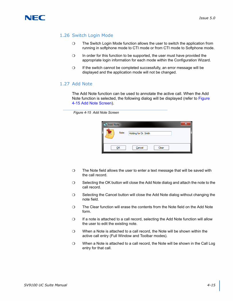
Issue 5.0
SV9100 UC Suite Manual 4-15
1.26 Switch Login Mode
The Switch Login Mode function allows the user to switch the application from running in softphone mode to CTI mode or from CTI mode to Softphone mode.
In order for this function to be supported, the user must have provided the appropriate login information for each mode within the Configuration Wizard.
If the switch cannot be completed successfully, an error message will be displayed and the application mode will not be changed.
1.27 Add Note
The Add Note function can be used to annotate the active call. When the Add Note function is selected, the following dialog will be displayed (refer to Figure 4-15 Add Note Screen).
The Note field allows the user to enter a text message that will be saved with the call record.
Selecting the OK button will close the Add Note dialog and attach the note to the call record.
Selecting the Cancel button will close the Add Note dialog without changing the note field.
The Clear function will erase the contents from the Note field on the Add Note form.
If a note is attached to a call record, selecting the Add Note function will allow the user to edit the existing note.
When a Note is attached to a call record, the Note will be shown within the active call entry (Full Window and Toolbar modes).
When a Note is attached to a call record, the Note will be shown in the Call Log entry for that call.
Figure 4-15 Add Note Screen
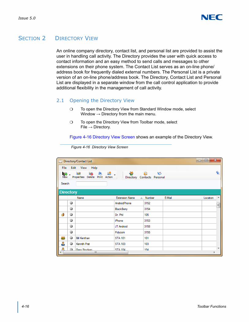
Issue 5.0
4-16 Toolbar Functions
SECTION 2 DIRECTORY VIEW
An online company directory, contact list, and personal list are provided to assist the user in handling call activity. The Directory provides the user with quick access to contact information and an easy method to send calls and messages to other extensions on their phone system. The Contact List serves as an on-line phone/address book for frequently dialed external numbers. The Personal List is a private version of an on-line phone/address book. The Directory, Contact List and Personal List are displayed in a separate window from the call control application to provide additional flexibility in the management of call activity.
2.1 Opening the Directory View
To open the Directory View from Standard Window mode, select Window → Directory from the main menu.
To open the Directory View from Toolbar mode, select File → Directory.
Figure 4-16 Directory View Screen shows an example of the Directory View.
Figure 4-16 Directory View Screen

Issue 5.0
SV9100 UC Suite Manual 4-17
The Directory consists of the following areas:
2.1.1 Title Bar and Main Menu
The Title Bar and Main Menu provide the standard windows controls and access to basic operations and utilities through pull down menus.
The standard Windows controls on the Title Bar are as follows:
The Main Menu provides a drop down menu, which lists all of the functions available within a selected category. The functions available from the Main Menu are as follows:
File
Title Bar and Main Menu
Provides the standard windows controls and access to standard operations and utilities through the pull down menus.
Function Toolbar Provides quick access to functions that maintain the directories and change the database view.
Search Area Allows the user to quickly locate an entry in the table by name.
Table Viewer Presents the database contents in a tabular format with each column showing a different data item for the listed entries.
Minimize Hide the Directory View and include an entry to restore the form in the Windows task bar.
Maximize/Restore Change the size of the Directory View. Maximize increases the size of the window to fill the entire display. The Restore function reduces the size of the window to the previous dimensions.
Close Exit the Directory View.
New Entry Add a new entry to the current database.
Departments/Companies Setup a new Department or Company within the database.
Properties Edit the current settings for the selected database entry.
Delete Remove the selected entry from the database.
Print Print the contents of the database. Available print options are: Print All, Print Selected, Page Setup, and Print Preview.
Exit Close the Directory View.
Issue 5.0
4-18 Toolbar Functions
Edit
View
Help
2.1.2 Function Toolbar
The Function Toolbar provides access to the functions that are used to maintain the database and change the layout of the Directory View. A function on the toolbar can be selected by using the mouse to click on the desired function button.
The functions available on the Function Toolbar are as follows:
NEW
PROPERTIES
DELETE
Select All Select all entries in the database.
Search Use the Search function to locate an entry by Name.
Hidden Entries Hide/Unhide entries that have their visibility attribute set to "Hide".
Set Visible Actions Hide/Unhide the list of actions that appear in the pop-up menu.
Set Visible Columns Hide/Unhide the columns that appear in the Table Viewer.
Contents and Index Access the on-line help system by topic.
About View the copyright notice and current revision of the UC Client.
New Entry
New Department
Issue 5.0
SV9100 UC Suite Manual 4-19
ACTION
DIRECTORY
CONTACTS
PERSONAL
PINNING
To the far right side of the toolbar, there is a pushpin. Clicking on this pins the directory widow to a tab in the BLF/DSS view. When pinned, if the Directory tab is active, the pin will UnPin the directory from a tab and make it a separate window.
Print All
Print Selected
Page Setup
Print Preview
Dial Extension
Dial Alternate
Voicemail
Transfer
Conference
Voice Over
Camp
Call Pickup
Quick Message
Phone Message
Add Note
Properties
Delete
Add to Speed Dial

Issue 5.0
4-20 Toolbar Functions
2.1.3 Search Area
The Search Area allows the user to quickly locate an entry in the database by Name field. The following rules apply to using the search area:
To access the Search capability click inside the Search field on the Directory window.
To search for entries that match the first name, enter the full or partial search string in the Search field. Example: Entering "John" will list all entries with first names of John and Johnny.
To search for entries that match a full or partial first and last name enter the first name, followed by a space, followed by the last name. Example: Entering "John Stevens" will list John Stevens and Johnny Stevenson. Example: Entering "S T" will list all entries whose first name starts with S and last name starts with T.
To search for entries that match only the last name enter a space as the first character in the Search field, followed by the full or partial last name. Example: Entering " T" will list all entries whose last name starts with T.
To Clear the Search results delete all the characters in the Search field or press the Esc key on the keyboard while the cursor is in the Search field.
2.1.4 Table Viewer
The Table Viewer displays the contents of the selected database in tabular format.
Each column represents a field within the database structure.
Each row represents an entry within the selected database.
The column widths can be adjusted by “dragging” one edge of the column in the header row to a new position.
The column order can be changed by dragging the column header to a new position.
The visible columns can be modified by using the View → Set Visible Columns function on the main menu.

Issue 5.0
SV9100 UC Suite Manual 4-21
A right mouse click on a row will open a pop-up menu that displays all of the available functions for that entry.
A double click on an entry when the phone is idle will initiate a call to the selected entry.
A configuration option set in Tools → Preferences → Shortcuts defines the action when the user double-clicks on a busy directory entry with an active call. The options are:
Send active call to voice mail for the selected extension.
Put caller on hold and initiate voice over.
Camp caller on second line of selected extension.
Figure 4-17 Select Visible Columns Screen
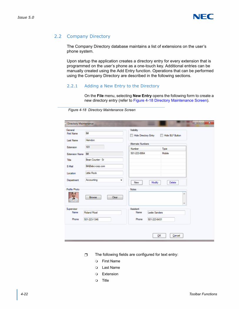
Issue 5.0
4-22 Toolbar Functions
2.2 Company Directory
The Company Directory database maintains a list of extensions on the user’s phone system.
Upon startup the application creates a directory entry for every extension that is programmed on the user’s phone as a one-touch key. Additional entries can be manually created using the Add Entry function. Operations that can be performed using the Company Directory are described in the following sections.
2.2.1 Adding a New Entry to the Directory
On the File menu, selecting New Entry opens the following form to create a new directory entry (refer to Figure 4-18 Directory Maintenance Screen).
The following fields are configured for text entry:
First Name
Last Name
Extension
Title
Figure 4-18 Directory Maintenance Screen

Issue 5.0
SV9100 UC Suite Manual 4-23
Location
Department
Profile Photo
Supervisor Name
Supervisor Phone
Assistant Name
Assistant Phone
Notes
The Department field is a drop down list of all of the Departments that have been defined.
The Profile Photo area is used to browse to a photo file to be used as the Profile Photo or to clear the currently selected photo. (Version 6.5.0.0 or higher).
The Hide Directory Entry option will hide this entry from being visible in the Table Viewer.
The Hide BLF button applies to extensions that have associated BLF buttons within the Full Window mode. Selecting this option will hide the associated BLF.
To enter an alternate number, select New in the Alternate Number area, and enter the telephone number and type.
Selecting Save will add the new entry to the Directory and exit the Directory Maintenance menu.
Selecting Add will save the new entry and clear the form for a new entry.
To add a new Department to the Directory, select Departments from the File Menu.
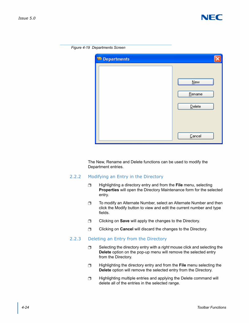
Issue 5.0
4-24 Toolbar Functions
The New, Rename and Delete functions can be used to modify the Department entries.
2.2.2 Modifying an Entry in the Directory
Highlighting a directory entry and from the File menu, selecting Properties will open the Directory Maintenance form for the selected entry.
To modify an Alternate Number, select an Alternate Number and then click the Modify button to view and edit the current number and type fields.
Clicking on Save will apply the changes to the Directory.
Clicking on Cancel will discard the changes to the Directory.
2.2.3 Deleting an Entry from the Directory
Selecting the directory entry with a right mouse click and selecting the Delete option on the pop-up menu will remove the selected entry from the Directory.
Highlighting the directory entry and from the File menu selecting the Delete option will remove the selected entry from the Directory.
Highlighting multiple entries and applying the Delete command will delete all of the entries in the selected range.
Figure 4-19 Departments Screen

Issue 5.0
SV9100 UC Suite Manual 4-25
2.2.4 Printing the Directory
From the File menu, selecting the Print option, followed by Print All will cause the entire directory to be sent to the default printer.
Highlighting a set of entries to be printed and selecting File → Print → Print Selected from the main will cause the selected directory entries to be sent to the default printer.
2.3 Contacts/Personal Lists
The Contacts and Personal databases are used to maintain a list of business contacts and personal contacts.
Contacts and Personal Contacts can be imported into the directory from a .csv file. From the File menu, Import and Export options are available to create and maintain the Contacts and Personal Contacts database via a .csv file.
Operations that can be performed using the Contacts/Personal databases are described in the following sections.
2.3.1 Adding a New Entry to the Contacts/Personal List
On the File menu selecting New Entry will open the following form to create a new entry (refer to Figure 4-20 Contacts/Personal List).
Figure 4-20 Contacts/Personal List
Issue 5.0
4-26 Toolbar Functions
The following fields are configured for text entry:
First Name
Last Name
Telephone
Title
Address
City
State/Prov
Zip/Postal
Country
Notes
The Company Name field is a drop down list of all of the Companies that have been defined.
To enter an alternate number, select New in the Alternate Number area, and enter the telephone number and type.
Selecting Save will add the new entry to the Directory and exit the Directory Maintenance menu.
Selecting Add will save the new entry and clear the form for a new entry.
To add a new Department to the Directory, from the New button within the Directory window, select New Department, enter the name of the department and click OK.
2.3.2 Modifying an Entry in the Contacts/Personal List
Highlighting an entry and from the File menu, selecting Properties will open the database form for the selected entry.
To modify an Alternate Number, select an Alternate Number and then click the Modify button to view and edit the current number and type fields.
Clicking on Save will apply the changes to the Contacts/Personal list.
Clicking on Cancel will discard the changes to the Contacts/Personal.
2.3.3 Deleting an Entry from the Contacts/Personal List
Selecting the entry with a right mouse click and selecting the Delete option on the pop-up menu will remove the selected entry from the database.
Highlighting the entry and from the File menu selecting the Delete option will remove the selected entry from the database.
Highlighting multiple entries and applying the Delete command will delete all of the entries in the selected range.
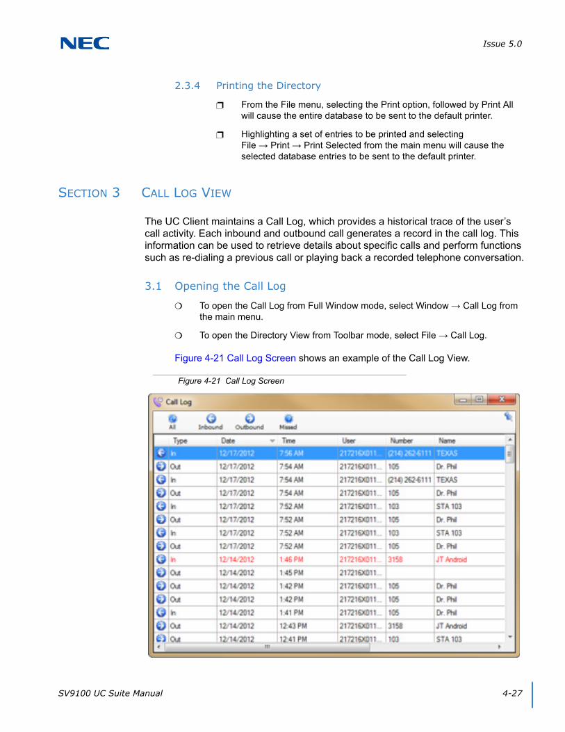
Issue 5.0
SV9100 UC Suite Manual 4-27
2.3.4 Printing the Directory
From the File menu, selecting the Print option, followed by Print All will cause the entire database to be sent to the default printer.
Highlighting a set of entries to be printed and selecting File → Print → Print Selected from the main menu will cause the selected database entries to be sent to the default printer.
SECTION 3 CALL LOG VIEW
The UC Client maintains a Call Log, which provides a historical trace of the user’s call activity. Each inbound and outbound call generates a record in the call log. This information can be used to retrieve details about specific calls and perform functions such as re-dialing a previous call or playing back a recorded telephone conversation.
3.1 Opening the Call Log
To open the Call Log from Full Window mode, select Window → Call Log from the main menu.
To open the Directory View from Toolbar mode, select File → Call Log.
Figure 4-21 Call Log Screen shows an example of the Call Log View.
Figure 4-21 Call Log Screen

Issue 5.0
4-28 Toolbar Functions
The Directory consists of the following areas:
The Title Bar and Main Menu provides the standard windows controls and access to standard operations and utilities through the pull down menus.
The Filter Toolbar allows the user to apply filters to the visible call records.
The Record Viewer presents the call log records in a tabular format with each column showing a different attribute of the call record.
Each of these screen regions is further described in the following sections.
3.1.1 Title Bar and Main Menu
The standard Windows controls on the Title Bar are as follows:
Minimize – Hide the Call Log View and include an entry to restore the form in the Windows task bar.
Maximize/Restore – Change the size of the Call Log View. Maximize increases the size of the window to fill the entire display, the Restore function reduces the size of the window to the previous dimensions.
Close – Exit the Call Log View.
The Main Menu provides a drop down menu, which lists all of the functions available within a selected category. The functions available from the Main Menu are as follows:
Call Log
Delete – Delete a call record from the Call Log.
Print – Print the contents of the call log. Available print options are Print All, Print Selected, Page Setup, and Print Preview.
Archive – Save the call history to an external file.
View
Set Visible Columns – Hide/Unhide the columns that appear in the Call Log.
3.1.2 Filter Toolbar
The Filter Toolbar allows the user to select the set of call records that will be displayed in the Call Log view, as follows:
Selecting Inbound will only display the call records for incoming calls.
Selecting Outbound will only display the call records for outgoing calls.
Selecting Missed will only display the incoming calls that were not answered.
Selecting All will display the entire list of call records.

Issue 5.0
SV9100 UC Suite Manual 4-29
3.1.3 Record Viewer
The Record Viewer displays the list of call records as indicated by the selected filter.
Each column represents an attribute of the call record.
Each row represents a call record.
A disk icon in the Type column indicates that a recording is attached to the call record.
The column widths can be adjusted by “dragging” one edge of the column in the header row to a new position.
The column order can be changed by dragging the column header to a new position.
The visible columns can be modified by using the View → Set Visible Columns function on the main menu .
A right mouse click on a row will open a pop-up menu that displays all of the available functions for that record.
A double click on an entry when the phone is idle will initiate a redial to the selected entry.
Figure 4-22 Visible Columns Menu
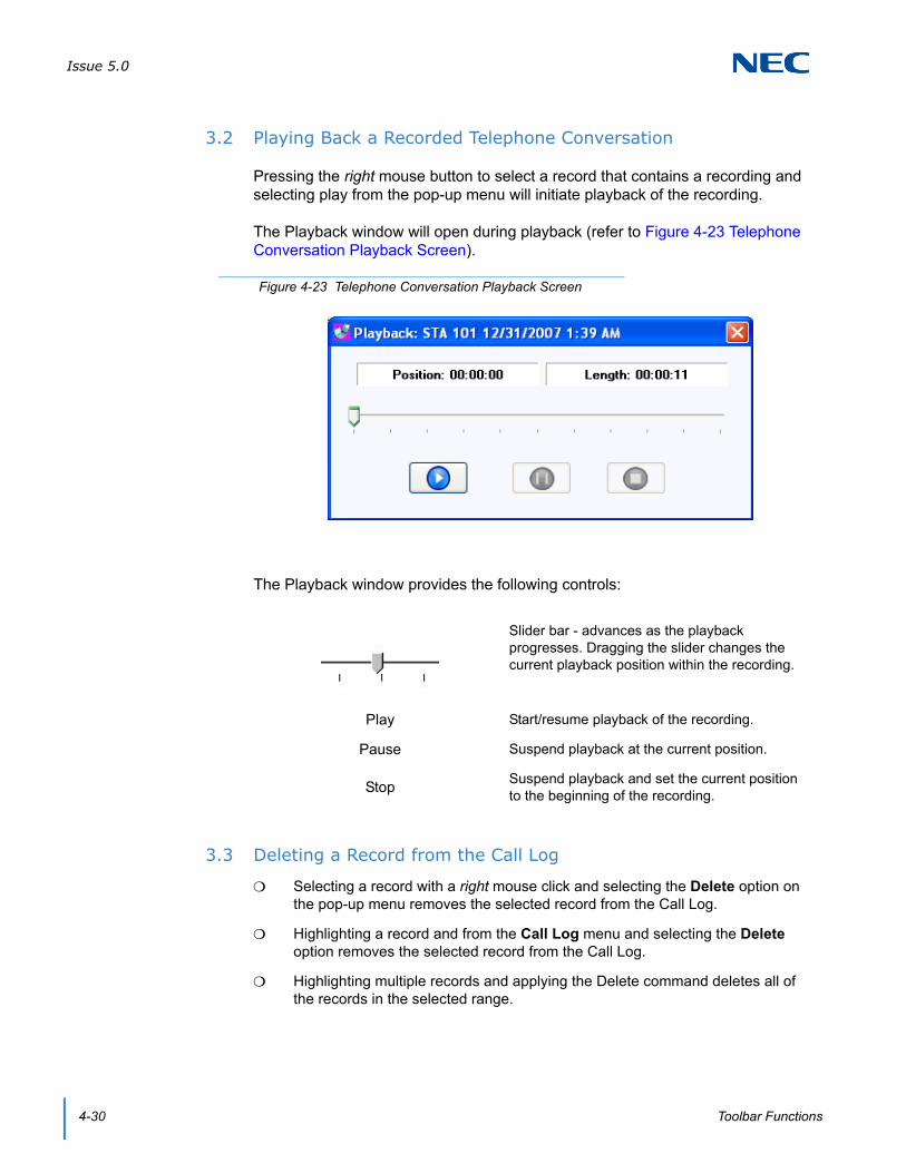
Issue 5.0
4-30 Toolbar Functions
3.2 Playing Back a Recorded Telephone Conversation
Pressing the right mouse button to select a record that contains a recording and selecting play from the pop-up menu will initiate playback of the recording.
The Playback window will open during playback (refer to Figure 4-23 Telephone Conversation Playback Screen).
The Playback window provides the following controls:
3.3 Deleting a Record from the Call Log
Selecting a record with a right mouse click and selecting the Delete option on the pop-up menu removes the selected record from the Call Log.
Highlighting a record and from the Call Log menu and selecting the Delete option removes the selected record from the Call Log.
Highlighting multiple records and applying the Delete command deletes all of the records in the selected range.
Figure 4-23 Telephone Conversation Playback Screen
Slider bar - advances as the playback progresses. Dragging the slider changes the current playback position within the recording.
Play Start/resume playback of the recording.
Pause Suspend playback at the current position.
StopSuspend playback and set the current position to the beginning of the recording.
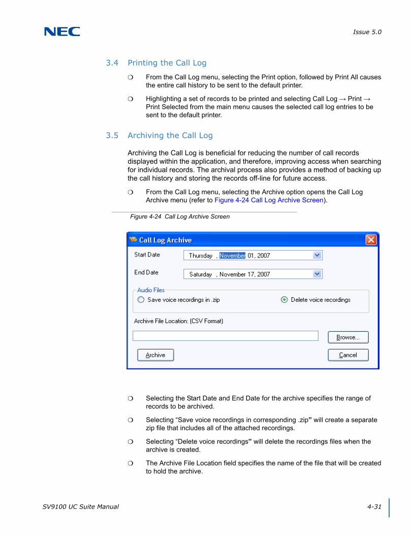
Issue 5.0
SV9100 UC Suite Manual 4-31
3.4 Printing the Call Log
From the Call Log menu, selecting the Print option, followed by Print All causes the entire call history to be sent to the default printer.
Highlighting a set of records to be printed and selecting Call Log → Print → Print Selected from the main menu causes the selected call log entries to be sent to the default printer.
3.5 Archiving the Call Log
Archiving the Call Log is beneficial for reducing the number of call records displayed within the application, and therefore, improving access when searching for individual records. The archival process also provides a method of backing up the call history and storing the records off-line for future access.
From the Call Log menu, selecting the Archive option opens the Call Log Archive menu (refer to Figure 4-24 Call Log Archive Screen).
Selecting the Start Date and End Date for the archive specifies the range of records to be archived.
Selecting “Save voice recordings in corresponding .zip” will create a separate zip file that includes all of the attached recordings.
Selecting “Delete voice recordings” will delete the recordings files when the archive is created.
The Archive File Location field specifies the name of the file that will be created to hold the archive.
Figure 4-24 Call Log Archive Screen

Issue 5.0
4-32 Toolbar Functions
Selecting Archive will create the specified archive file in CSV (Comma Separated Values) format.
After the archive file is created, all of the selected archive records will be removed from the call log.
Selecting Cancel will close the Call Log Archive dialog without creating an archive file.
3.6 Pinning
To the far right side of the toolbar, there is a pushpin. Clicking this pins the Call Log widow to a tab in the BLF/DSS view. When pinned, if the Call Log tab is active, the pin will UnPin the Call Log from a tab and make it a separate window.
SV9100 UC Suite Manual 5-1
Chapter 5
UNIVERGE® SV9100
Contact Center Agent
SECTION 1 INTRODUCTION
UC Client that are also Contact Center agents can perform Contact Center functions from within the UC Client. Contact Center functions included in the UC Client are Login, Logout, Off Duty, Wrap Up, view Agent Monitor, and view Queue Monitor. With UC Suite Version 4.0 or higher, Web Client supports Contact Center Agent integration. Refer to Chapter 17 UC Web Client for additional information.
SECTION 2 LICENSING
The Contact Center Agent functions will require that the UC Server Connect option be selected and active for the individual UC User. The Contact Center Agent functions will operate successfully in all three operating modes (Deskset, Softphone, and Deskset + Softphone). The Contact Center Agent functions will an Agent Client licenses.
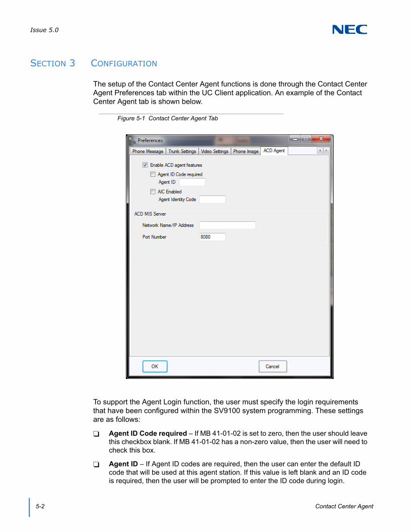
Issue 5.0
5-2 Contact Center Agent
SECTION 3 CONFIGURATION
The setup of the Contact Center Agent functions is done through the Contact Center Agent Preferences tab within the UC Client application. An example of the Contact Center Agent tab is shown below.
To support the Agent Login function, the user must specify the login requirements that have been configured within the SV9100 system programming. These settings are as follows:
Agent ID Code required – If MB 41-01-02 is set to zero, then the user should leave this checkbox blank. If MB 41-01-02 has a non-zero value, then the user will need to check this box.
Agent ID – If Agent ID codes are required, then the user can enter the default ID code that will be used at this agent station. If this value is left blank and an ID code is required, then the user will be prompted to enter the ID code during login.
Figure 5-1 Contact Center Agent Tab

Issue 5.0
SV9100 UC Suite Manual 5-3
AIC Enabled – If MB 41-17-01 is set to 0 for this extension, then this checkbox should be left blank. If MB 41-17-01 is set to 1, then this box should be checked.
Agent Identity Code (AIC) – If AIC is enabled, then the user can specify the AIC to use during the login operation. If this field is left blank and an AIC is required, then the user will be prompted for the code during the login operation.
To communicate with the Contact Center Server, the user must specify the following settings:
Contact Center Network Name/IP Address
Contact Center Port Number
These fields will be blank by default and are optional. For the Contact Center Integration to be active, the user must specify valid settings for both of these fields.
SECTION 4 CONTACT CENTER AGENT STATE
The UC Client user interface includes a control that allows the user to change their current Contact Center state. This control is a drop-down menu that includes the following four selections:
Login
Logout
Wrap-up
Off-Duty/Rest
Within the toolbar mode, this control appears on the right side of the Presence selector. This will cause the function button area to be reduced in size accordingly. The following image shows an example of the toolbar with the Agent control enabled.
Figure 5-2 Contact Center Agent – Toolbar
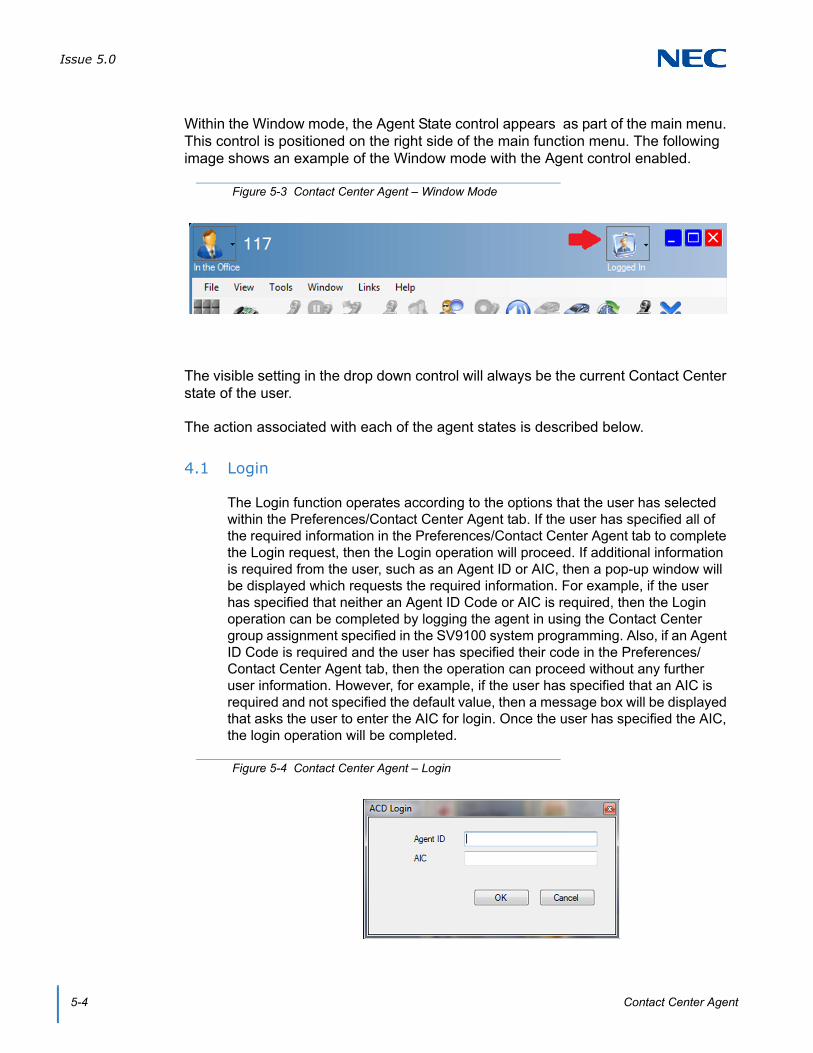
Issue 5.0
5-4 Contact Center Agent
Within the Window mode, the Agent State control appears as part of the main menu. This control is positioned on the right side of the main function menu. The following image shows an example of the Window mode with the Agent control enabled.
The visible setting in the drop down control will always be the current Contact Center state of the user.
The action associated with each of the agent states is described below.
4.1 Login
The Login function operates according to the options that the user has selected within the Preferences/Contact Center Agent tab. If the user has specified all of the required information in the Preferences/Contact Center Agent tab to complete the Login request, then the Login operation will proceed. If additional information is required from the user, such as an Agent ID or AIC, then a pop-up window will be displayed which requests the required information. For example, if the user has specified that neither an Agent ID Code or AIC is required, then the Login operation can be completed by logging the agent in using the Contact Center group assignment specified in the SV9100 system programming. Also, if an Agent ID Code is required and the user has specified their code in the Preferences/Contact Center Agent tab, then the operation can proceed without any further user information. However, for example, if the user has specified that an AIC is required and not specified the default value, then a message box will be displayed that asks the user to enter the AIC for login. Once the user has specified the AIC, the login operation will be completed.
Figure 5-3 Contact Center Agent – Window Mode
Figure 5-4 Contact Center Agent – Login

Issue 5.0
SV9100 UC Suite Manual 5-5
If the user is not currently logged into the Contact Center, then the Login function will be enabled. If the user is already logged into the Contact Center, then the Login function will only be enabled if the user has enabled AIC. In that case, the user can change their AIC by selecting the Login function and following the same process by specifying another AIC value.
4.2 Logout
The Logout operation issues a logout operation for the agent. The Logout operation will only be enabled when the user is logged into the Contact Center.
4.3 Wrapup
The Wrap Up function places the user into the Wrap Up mode. While in Wrap Up mode the user will not receive any calls from the Contact Center. The Wrap Up function will act as a toggle, so that if the user is already in Wrap Up mode, selecting Wrap Up again will exit the user from Wrap Up mode.
4.4 Off Duty
The Off Duty function places the user into the Off Duty mode. While in Off Duty (Rest) mode the user will not receive any calls from the Contact Center. The Off Duty function will act as a toggle, so that if the user is already in Off Duty mode, selecting Off Duty again will exit the user from Off Duty mode.
SECTION 5 QUEUE MONITOR
The Queue Monitor function can be accessed from the Window drop down menu. When this option is selected, a Queue Monitor window will be opened that allows the user to view the real-time statistics associated with a set of selected queues. The following image shows an example of the Queue Monitor window.
Figure 5-5 Contact Center Agent – Queue Monitor

Issue 5.0
5-6 Contact Center Agent
The columns within the Queue Monitor window will be fixed. However, each user will be able to select which queues will be included. By default each user will not have any queues selected for the table. The first time that the user selects the Queue Monitor function, the following menu will be displayed which allows them to select the queues to display.
The names of the Queues to populate this list will be retrieved from the Contact Center Server. The Select All option will check all of the defined Queues. The OK button will apply the Queue selections. The Cancel button will exit the menu without changing the selected queues.
After selecting the queues from the list, the table will then be displayed.
The functions that are available on the main menu within the Queue Monitor are as follows:
File/Exit – closes the Queue Monitor window.
View/Select Queues – open the selector window to select the queues to display.
View/Set Thresholds – open the threshold window to set the threshold levels.
Figure 5-6 Contact Center Agent – Select Queues

Issue 5.0
SV9100 UC Suite Manual 5-7
Selecting the Set Thresholds option opens the following form.
Each section of the Thresholds menu allows the user to set the limits for each statistic (Calls In Queue, Logged In and Longest Call). Each threshold can be enabled individually by enabling the checkbox next to the name of the field. Each threshold has two levels. If the field value exceeds the specified threshold for Level 1, then the color of the cell changes to the specified color. If the field value exceeds Level 2, then the cell color changes to the specified color for that level.
Selecting OK will apply the new threshold levels. Selecting Cancel will exit the menu without applying any changes.
SECTION 6 AGENT MONITOR
The Agent Monitor function can be accessed from the View drop down menu. When this option is selected, an Agent Monitor window will be opened that allows the user to view the current state of other Contact Center agents. The following image shows an example of the Agent Monitor window.
Figure 5-7 Contact Center Agent – Queue Thresholds
Figure 5-8 Agent Monitor Window

Issue 5.0
5-8 Contact Center Agent
The column statistics within the Agent Monitor window will be fixed. However, each user will be able to select which agents will be included. By default each user will not have any agents selected for the table. The first time that the user selects the Agent Monitor function, the following menu will be displayed which allows them to select the agents to display.
The names of the agents to populate this list will be all of the agents that are defined within Contact Center. After selecting the agents from the list, the table will then be displayed.
The functions that are available on the main menu within the Agent Monitor are as follows:
File/Exit – closes the Agent Monitor window.
View/Select Agents – opens the selector window to specify the agents to include in the table.
SECTION 7 EMERGENCY CALL
A logged in agent will be able to initiate an Emergency Call from the UC Client. The Emergency Call option will be shown as an option Agent State drop down menu. This function will only be enabled if the user has enabled the Contact Center Agent features and an Emergency Call button has been programmed on the user’s phone.
Selecting the Emergency Call button will alert the assigned Contact Center supervisor that the issuing agent requires assistance.
Figure 5-9 Select Agents Window
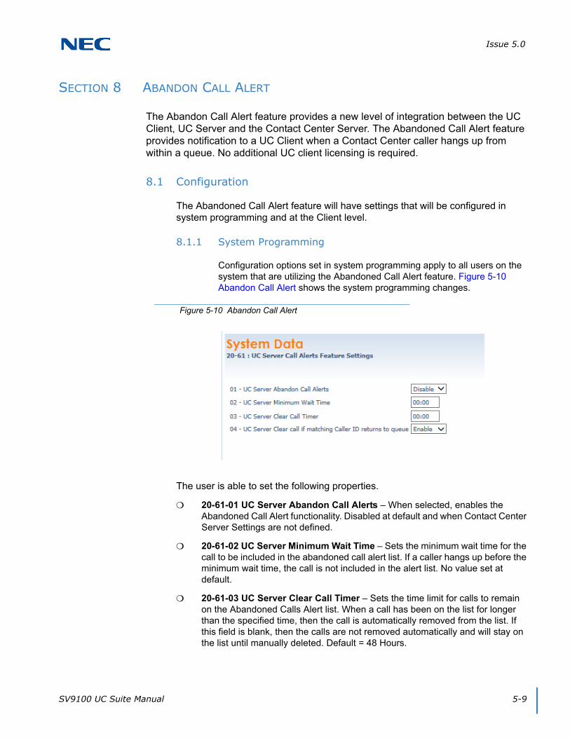
Issue 5.0
SV9100 UC Suite Manual 5-9
SECTION 8 ABANDON CALL ALERT
The Abandon Call Alert feature provides a new level of integration between the UC Client, UC Server and the Contact Center Server. The Abandoned Call Alert feature provides notification to a UC Client when a Contact Center caller hangs up from within a queue. No additional UC client licensing is required.
8.1 Configuration
The Abandoned Call Alert feature will have settings that will be configured in system programming and at the Client level.
8.1.1 System Programming
Configuration options set in system programming apply to all users on the system that are utilizing the Abandoned Call Alert feature. Figure 5-10 Abandon Call Alert shows the system programming changes.
The user is able to set the following properties.
20-61-01 UC Server Abandon Call Alerts – When selected, enables the Abandoned Call Alert functionality. Disabled at default and when Contact Center Server Settings are not defined.
20-61-02 UC Server Minimum Wait Time – Sets the minimum wait time for the call to be included in the abandoned call alert list. If a caller hangs up before the minimum wait time, the call is not included in the alert list. No value set at default.
20-61-03 UC Server Clear Call Timer – Sets the time limit for calls to remain on the Abandoned Calls Alert list. When a call has been on the list for longer than the specified time, then the call is automatically removed from the list. If this field is blank, then the calls are not removed automatically and will stay on the list until manually deleted. Default = 48 Hours.
Figure 5-10 Abandon Call Alert

Issue 5.0
5-10 Contact Center Agent
20-61-04 UC Server Clear Call if matching Caller ID returns to queue – Determines whether a call will be removed from the Abandoned Calls list if a subsequent call returns to queue with the same Caller ID. Enabled at default.
8.1.2 Client Configuration
Client level options are controlled through the Preferences settings for each individual user. The Preferences/Contact Center Agent menu contains the settings that are associated with this feature. Figure 5-11 Preferences shows an example of the updated Preferences/Contact Center menu.
Figure 5-11 Preferences

Issue 5.0
SV9100 UC Suite Manual 5-11
Within this configuration screen the user is able to set the following properties.
Enable Alerts – When selected, enables the Abandoned Call Alert function. When disabled, all of the other controls within the frame are disabled. Disabled at default and when Contact Center MIS Server Settings are not defined.
Active Queues – Specifies which queues will be included in the Abandoned Calls list. Default is all queues unchecked.
Audible Alert – Plays an alert tone for every new call that is added to the Abandoned Call Alert list. Enabled by default.
Popup Alert – Displays a popup message, similar to the missed call alert, for every new call added to the Abandoned Call Alert list. Enabled by default.
8.1.3 UC Client Alerts
UC Client users can receive Abandoned Call Alerts in both Window and Toolbar modes.
In Window mode, the alert indicator appears in the Status area of the main form. If the Audible Alert is set, then the alert tone will be played for every new abandoned call that is received. Figure 5-12 UC Client Alert shows an example of the Abandoned Call alert image.
The Abandoned Call alert image is a flashing icon that helps draw attention to the status. The number next to the flashing icon shows the number of abandoned calls that are currently included in the Abandoned Calls list. If the Abandoned Calls list does not have any calls that have not been handled, then the alert area will be blank. Clicking on the Abandoned Calls alert icon will open the Abandoned Calls alert list.
In Toolbar mode, the alert indicator will appear in the notification area just below the Speed Dial list. If the Audible Alert is set, then the alert tone will be played for every new abandoned call that is received. Figure 5-13 Abandoned Call Alert Image shows an example of the Abandoned Call alert image.
Figure 5-12 UC Client Alert

Issue 5.0
5-12 Contact Center Agent
The Abandoned Call alert image shows the number of abandoned calls that are currently included in the Abandoned Calls list. Clicking on the Abandoned Calls alert icon will open the Abandoned Calls alert list.
If the user has selected the option to receive a Popup Alert, then a notification message appears in the lower right hand section of the screen when a new Abandoned Call has been added to the list. Figure 5-14 Abandoned Call Popup shows an example of the Abandoned Call popup.
The Abandoned Call popup appearance follows the same rules for the other notification pop ups that the user has selected within Preferences/Notification Settings.
8.1.4 Abandoned Calls Alert Window
The Abandoned Calls alert window lists all of the abandoned calls in table format. Open the window by clicking on the Alert icon, from the popup link, or from the Window menu. The Abandoned Calls Alert Window can be pinned to a tab in the BLF area, similar to the Directory and Call Log windows. Figure 5-15 Abandoned Calls Window shows an example of the Abandoned Calls window.
Figure 5-13 Abandoned Call Alert Image
Figure 5-14 Abandoned Call Popup
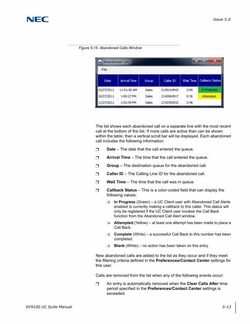
Issue 5.0
SV9100 UC Suite Manual 5-13
The list shows each abandoned call on a separate line with the most recent call at the bottom of the list. If more calls are active than can be shown within the table, then a vertical scroll bar will be displayed. Each abandoned call includes the following information:
Date – The date that the call entered the queue.
Arrival Time – The time that the call entered the queue.
Group – The destination queue for the abandoned call.
Caller ID – The Calling Line ID for the abandoned call.
Wait Time – The time that the call was in queue.
Callback Status – This is a color-coded field that can display the following values:
In Progress (Green) – a UC Client user with Abandoned Call Alerts enabled is currently making a callback to this caller. This status will only be registered if the UC Client user invokes the Call Back function from the Abandoned Call Alert window.
Attempted (Yellow) – at least one attempt has been made to place a Call Back.
Complete (White) – a successful Call Back to this number has been completed.
Blank (White) – no action has been taken on this entry.
New abandoned calls are added to the list as they occur and if they meet the filtering criteria defined in the Preferences/Contact Center settings for this user.
Calls are removed from the list when any of the following events occur:
An entry is automatically removed when the Clear Calls After time period specified in the Preferences/Contact Center settings is exceeded.
Figure 5-15 Abandoned Calls Window
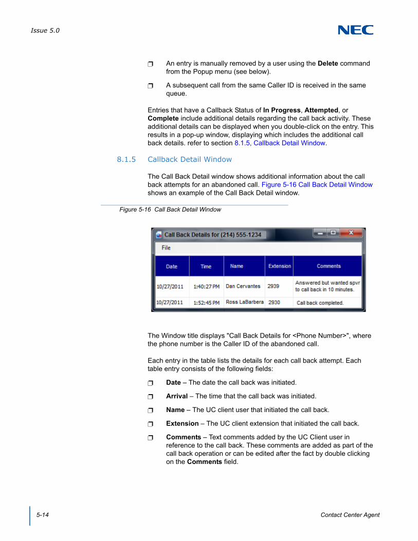
Issue 5.0
5-14 Contact Center Agent
An entry is manually removed by a user using the Delete command from the Popup menu (see below).
A subsequent call from the same Caller ID is received in the same queue.
Entries that have a Callback Status of In Progress, Attempted, or Complete include additional details regarding the call back activity. These additional details can be displayed when you double-click on the entry. This results in a pop-up window, displaying which includes the additional call back details. refer to section 8.1.5, Callback Detail Window.
8.1.5 Callback Detail Window
The Call Back Detail window shows additional information about the call back attempts for an abandoned call. Figure 5-16 Call Back Detail Window shows an example of the Call Back Detail window.
The Window title displays "Call Back Details for <Phone Number>", where the phone number is the Caller ID of the abandoned call.
Each entry in the table lists the details for each call back attempt. Each table entry consists of the following fields:
Date – The date the call back was initiated.
Arrival – The time that the call back was initiated.
Name – The UC client user that initiated the call back.
Extension – The UC client extension that initiated the call back.
Comments – Text comments added by the UC Client user in reference to the call back. These comments are added as part of the call back operation or can be edited after the fact by double clicking on the Comments field.
Figure 5-16 Call Back Detail Window
Issue 5.0
SV9100 UC Suite Manual 5-15
Double-click on the Comments field to edit the contents of this field.
The file menu includes three operations: Save, Print and Exit.
The Exit command closes the Call Back Detail Window.
The Save function writes the current contents of the Call Back Detail window to a file. When the Save function is initiated, a file selection dialog displays that allows the user to designate the target location for the file.
The user is able to save the file in any of the following formats: Comma-Separated Values (CSV) or XML.
The Print command opens a print dialog that allows the user to send the Call Back Detail list to a printer. The report output is similar to the table layout for the Call Back Detail and includes the following header:
Call Back Detail for <Telephone Number>
<Current Date and Time>
If the printout is more than one page, the header is repeated for every page, while the bottom of the page includes the page number.
8.2 Popup Menu
When the user selects an entry in the Abandoned Calls list and right-clicks using the mouse, a popup menu with the following options is displayed:
Call Back – Described in section 8.2.1 Callback below.
Delete – Removes the selected entry from the Abandoned Call Alerts list for all users. The Delete function will always be enabled for all entries.
Clear Status – Remove the Returned Call status from the selected entry. The Clear Status is only enabled for entries that currently have their status set to Returned Call. This allows a user, who attempted to return a call, to reset the status if they were not able to contact the caller.
8.2.1 Callback
The Call Back function initiates a call to the Caller ID number for the selected entry. The Call Back function is only enabled if the Caller ID field is not blank and the user telephone is idle.
When the Call Back function is selected, the Status column for the selected entry changes to In Progress. This status change will effectively notify other users that action has been taken to return the call to this customer.

Issue 5.0
5-16 Contact Center Agent
A supporting window opens as part of the Call Back request to allow the user to specify additional details about the Call Back activity. Figure 5-17 Call Back Status shows an example of the Call Back Status window.
The fields in the Call Back Status window are described below:
Comments – This text field allows the user to enter details about the attempted call back activity. Default is blank.
Change Status to "Complete" – This option allows the user to specify that this entry in the Abandoned Call Alerts table should be shown as Complete. Default is unchecked.
Remove this entry from Abandoned Call List – This option allows the user to specify that this entry can be removed from the Abandoned Call List.
Figure 5-17 Call Back Status

SV9100 System Hardware Manual 6-1
Chapter 6
UNIVERGE® SV9100
Answering Center
SECTION 1 INTRODUCTION
The Answering Center module provides additional features to the UC Client to help provide more efficient call handling in a multi-tenant environment. In the target environment, a UC Client user has the task of answering calls for a variety of different businesses. The Answering Center module identifies the company being called and displays information on the UC Client user’s screen to assist with handling the call.
SECTION 2 INSTALLATION
The Answering Center module is distributed as a separate executable.
To install the Answering Center module, double-click the setup.exe file in the AnswerCenter folder.
During the installation, a new program titled Answering Center is added to the All Programs → NEC programs group.
SECTION 3 CONFIGURATION
3.1 Configuring UC Client Preferences
1. With the UC Client running, go to Preferences → Screen Pop in the Toolbar view, or Tools → Preferences → Screen Pop in Window view.
2. In the Third Party Interface section, check Enable Third Party Interface and Enhanced XML Interface.
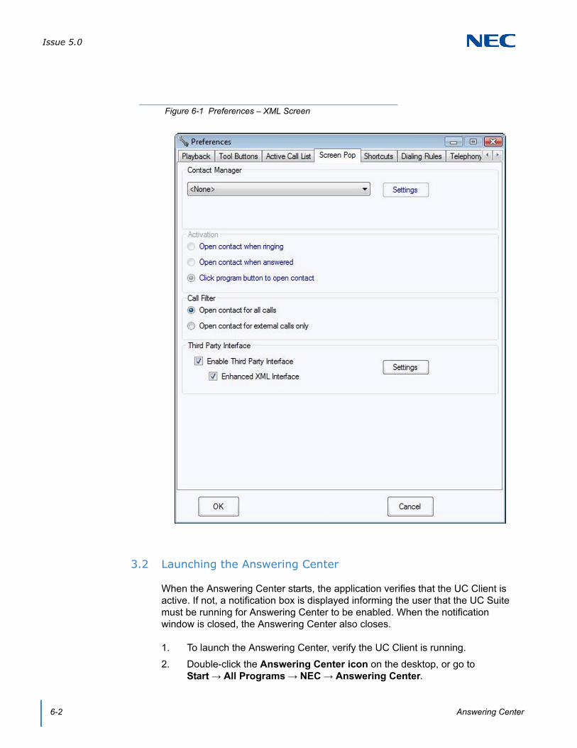
Issue 5.0
6-2 Answering Center
3.2 Launching the Answering Center
When the Answering Center starts, the application verifies that the UC Client is active. If not, a notification box is displayed informing the user that the UC Suite must be running for Answering Center to be enabled. When the notification window is closed, the Answering Center also closes.
1. To launch the Answering Center, verify the UC Client is running.
2. Double-click the Answering Center icon on the desktop, or go toStart → All Programs → NEC → Answering Center.
Figure 6-1 Preferences – XML Screen

Issue 5.0
SV9100 System Hardware Manual 6-3
3. When successfully started, an Answering Center icon is added to the notification area of the taskbar.
3.3 Database Setup
The profiles database can either be stored locally, or as a shared resource on the UC Server PC. In most cases, this is on the UC Server PC allowing multiple Answering Center users to access the same Profiles database. When changes are made to the Profiles database by an Answering Center client, changes are immediately made available to the Answering Center clients.
1. Right-click the Answering Center icon in the system tray and choose Setup → Database.
2. In the Database Setup window, select where the database is to reside. If on the UC Server PC, define the UC Server PC IP Address and TCP port (default: 8888).
3. If no match is found, nothing is displayed. If preferred, check the box for Display dialed number if not found.
Figure 6-2 Answer Icon
Figure 6-3 Right-Click Answer Center Icon

Issue 5.0
6-4 Answering Center
4. Right-click on the Answering Center icon in the system tray and choose exit.
5. Re-launch the Answering Center.
SECTION 4 PROFILES
The Profiles function is used to define the different company profiles that are recognized by the Answering Center. When the Profiles option is selected, a window is displayed with the following controls:
A list of currently defined profiles, in alphabetical order using the Name field.
Function buttons for New, Properties and Delete.
4.1 Managing Profiles
1. Right-click on the Answering Center icon in the system tray and choose Profiles.
Figure 6-4 Database Setup Screen
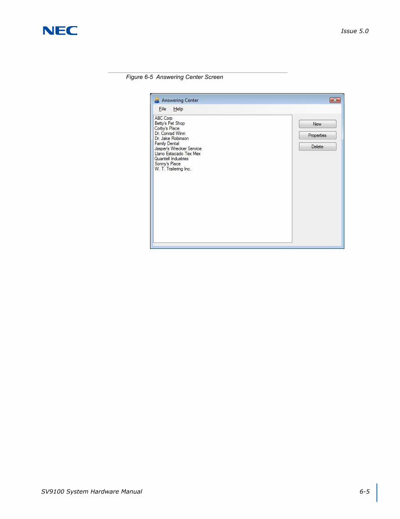
Issue 5.0
SV9100 System Hardware Manual 6-5
Figure 6-5 Answering Center Screen

Issue 5.0
6-6 Answering Center
2. To create a new profile, click the New button.
The Company Name field displays the name of the company or the individual associated with the profile.
The Company Address displays the physical address of the company or the individual associated with the profile.
The Hours of Operation display the times the business is open.
The Inbound Phone Numbers field displays the full telephone numbers associated with the Profile. This field accepts multiple numbers and can be entered either formatted or unformatted. For example, (214)-381-4881, 214-381-4881 or 2143814881 are all valid.
Figure 6-6 New Profile Screen
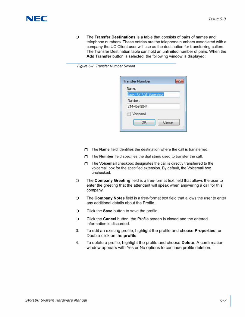
Issue 5.0
SV9100 System Hardware Manual 6-7
The Transfer Destinations is a table that consists of pairs of names and telephone numbers. These entries are the telephone numbers associated with a company the UC Client user will use as the destination for transferring callers. The Transfer Destination table can hold an unlimited number of pairs. When the Add Transfer button is selected, the following window is displayed:
The Name field identifies the destination where the call is transferred.
The Number field specifies the dial string used to transfer the call.
The Voicemail checkbox designates the call is directly transferred to the voicemail box for the specified extension. By default, the Voicemail box unchecked.
The Company Greeting field is a free-format text field that allows the user to enter the greeting that the attendant will speak when answering a call for this company.
The Company Notes field is a free-format text field that allows the user to enter any additional details about the Profile.
Click the Save button to save the profile.
Click the Cancel button, the Profile screen is closed and the entered information is discarded.
3. To edit an existing profile, highlight the profile and choose Properties, or Double-click on the profile.
4. To delete a profile, highlight the profile and choose Delete. A confirmation window appears with Yes or No options to continue profile deletion.
Figure 6-7 Transfer Number Screen

Issue 5.0
6-8 Answering Center
SECTION 5 ANSWERING CENTER FUNCTIONS
The Answering Center program icon is visible in the system tray when the Answering Center application is active. Right-click on the Answering Center icon to open a pop-up menu with the following options:
Profiles – used to define the different company profiles recognized by the Answering Center.
Setup – used to set the font attributes for the pop-up screen and specify the location of the Profiles database.
Help – opens the Help file for the Answering Center application.
About – displays an informational dialog that includes the name of the product, the product version number and a copyright notice.
Exit – closes the Answering Center application.
When the Answering Center receives notification from the UC Client that an incoming call has been answered on the local telephone, the application takes the following actions:
The dialed number is compared to the list of DID numbers in the Profiles list.
If a matching entry is found, a Profile window opens in the center of the screen displaying the following information:
Company Name
Company Address
Hours of Operation
Company Greeting
Transfer Destinations
Notes
OK button
If a match is not found, no action is taken unless defined in the Database setup.
Refer to Figure 6-8 Incoming Call Screen on page 6-9 for an example of a Profile pop-up.

Issue 5.0
SV9100 System Hardware Manual 6-9
Pressing Enter with the focus on the notification window closes the window.
The user can reposition the notification window. Future notification windows are shown at the last location.
If one of the Transfer Destination entries (Blue underlined numbers) is selected while on an active call, the Answering Center initiates a supervised transfer to the selected telephone number. Once the transfer destination is initiated, the transfer screens within the UC Suite are used to complete the transfer.
Figure 6-8 Incoming Call Screen

Issue 5.0
6-10 Answering Center
SV9100 System Hardware Manual 7-1
Chapter 7
UNIVERGE® SV9100
Application Level Configuration
SECTION 1 INTRODUCTION
The Preferences function allows the user to customize the UC Client user interface and operation.
From the Full Window mode, the Preferences settings can be accessed by selecting Tools → Preferences on the main menu.
From the Toolbar mode the Preferences settings can be accessed by selecting File → Preferences.
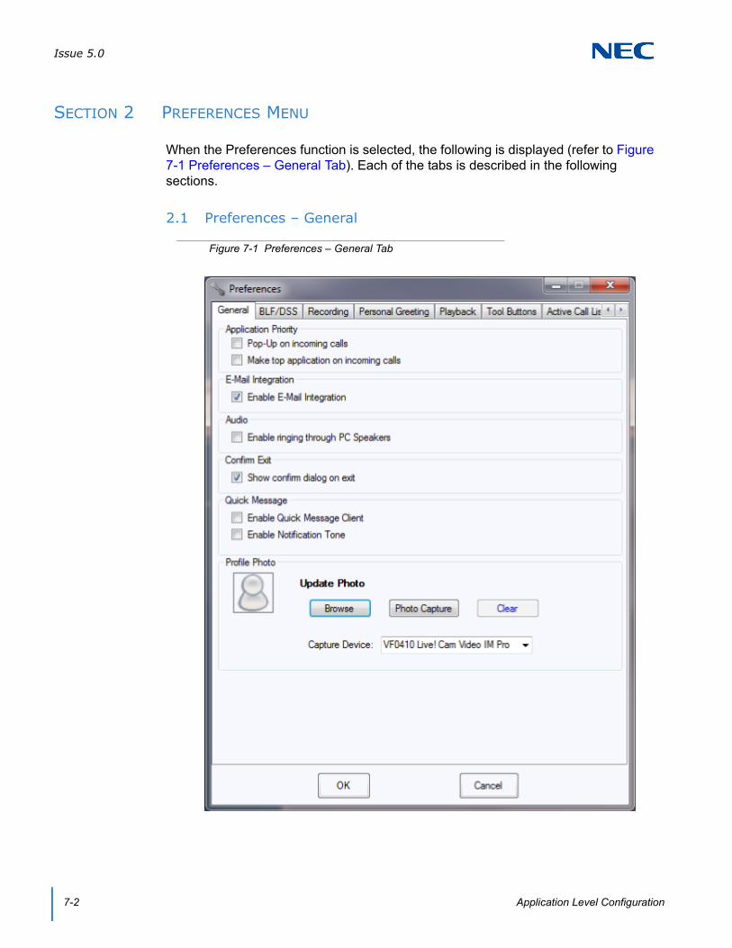
Issue 5.0
7-2 Application Level Configuration
SECTION 2 PREFERENCES MENU
When the Preferences function is selected, the following is displayed (refer to Figure 7-1 Preferences – General Tab). Each of the tabs is described in the following sections.
2.1 Preferences – General
Figure 7-1 Preferences – General Tab
Issue 5.0
SV9100 System Hardware Manual 7-3
The Pop-Up on incoming calls option applies when the application in Full Window mode is minimized. If this option is selected, the application will be restored from a minimized state when an incoming call is received.
The Make top application on incoming calls applies to the Full Window mode. When selected, this option causes the application window to become the top active application when an incoming call is received.
The Auto Hide option allows the toolbar view to be hidden when other applications are the currently active window.
The Enable E-Mail integration option can be selected to utilize a MAPI-compatible e-mail client in conjunction with the desktop application. E-mail functions are provided within the call log and for directory/contact list entries that have designated e-mail addresses.
The Enable ringing through PC speakers option controls whether a ringing tone is played through the default sound device for each incoming call.
The Show confirm dialog on exit controls if a confirmation dialog is presented each time the user closes the application.
The Enable Quick Message Client enables the ability for UC Client to receive quick messages.
The Enable Notification Tone enables a audible tone when a Quick Message is received.
The Browse button opens a browse window to point to the image to upload. The image must be a 1 to 1 ratio or it will be cropped to the center of the image. The image can be .bmp, .jpeg, .png, or .gif file format.
The Photo Capture button opens a window to capture a profile photo with the camera device selected in the Capture Device field. In the Photo Capture window, click Capture when ready to take the picture; click Save to save the image shown, and click Retake to capture a new image.
Click Clear to reset the Profile Photo to the default image.
Select the camera to be used in the Capture Device field.
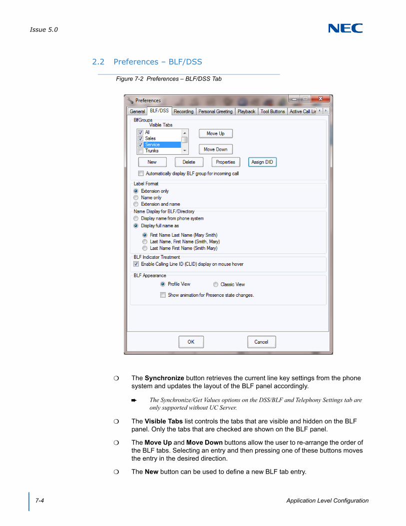
Issue 5.0
7-4 Application Level Configuration
2.2 Preferences – BLF/DSS
The Synchronize button retrieves the current line key settings from the phone system and updates the layout of the BLF panel accordingly.
The Synchronize/Get Values options on the DSS/BLF and Telephony Settings tab are only supported without UC Server.
The Visible Tabs list controls the tabs that are visible and hidden on the BLF panel. Only the tabs that are checked are shown on the BLF panel.
The Move Up and Move Down buttons allow the user to re-arrange the order of the BLF tabs. Selecting an entry and then pressing one of these buttons moves the entry in the desired direction.
The New button can be used to define a new BLF tab entry.
Figure 7-2 Preferences – BLF/DSS Tab
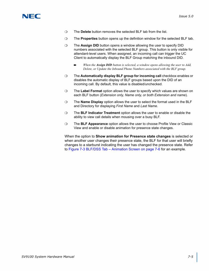
Issue 5.0
SV9100 System Hardware Manual 7-5
The Delete button removes the selected BLF tab from the list.
The Properties button opens up the definition window for the selected BLF tab.
The Assign DID button opens a window allowing the user to specify DID numbers associated with the selected BLF group. This button is only visible for attendant-level users. When assigned, an incoming call can trigger the UC Client to automatically display the BLF Group matching the inbound DID.
When the Assign DID button is selected, a window opens allowing the user to Add, Delete, or Update the Inbound Phone Numbers associated with the BLF group.
The Automatically display BLF group for incoming call checkbox enables or disables the automatic display of BLF groups based upon the DID of an incoming call. By default, this value is disabled/unchecked.
The Label Format option allows the user to specify which values are shown on each BLF button (Extension only, Name only, or both Extension and name).
The Name Display option allows the user to select the format used in the BLF and Directory for displaying First Name and Last Name.
The BLF Indicator Treatment option allows the user to enable or disable the ability to view call details when mousing over a busy BLF.
The BLF Appearance option allows the user to choose Profile View or Classic View and enable or disable animation for presence state changes.
When the option to Show animation for Presence state changes is selected or when another user changes their presence state, the BLF for that user will briefly changes to a starburst indicating the user has changed the presence state. Refer to Figure 7-3 BLF/DSS Tab – Animation Screen on page 7-6 for an example.
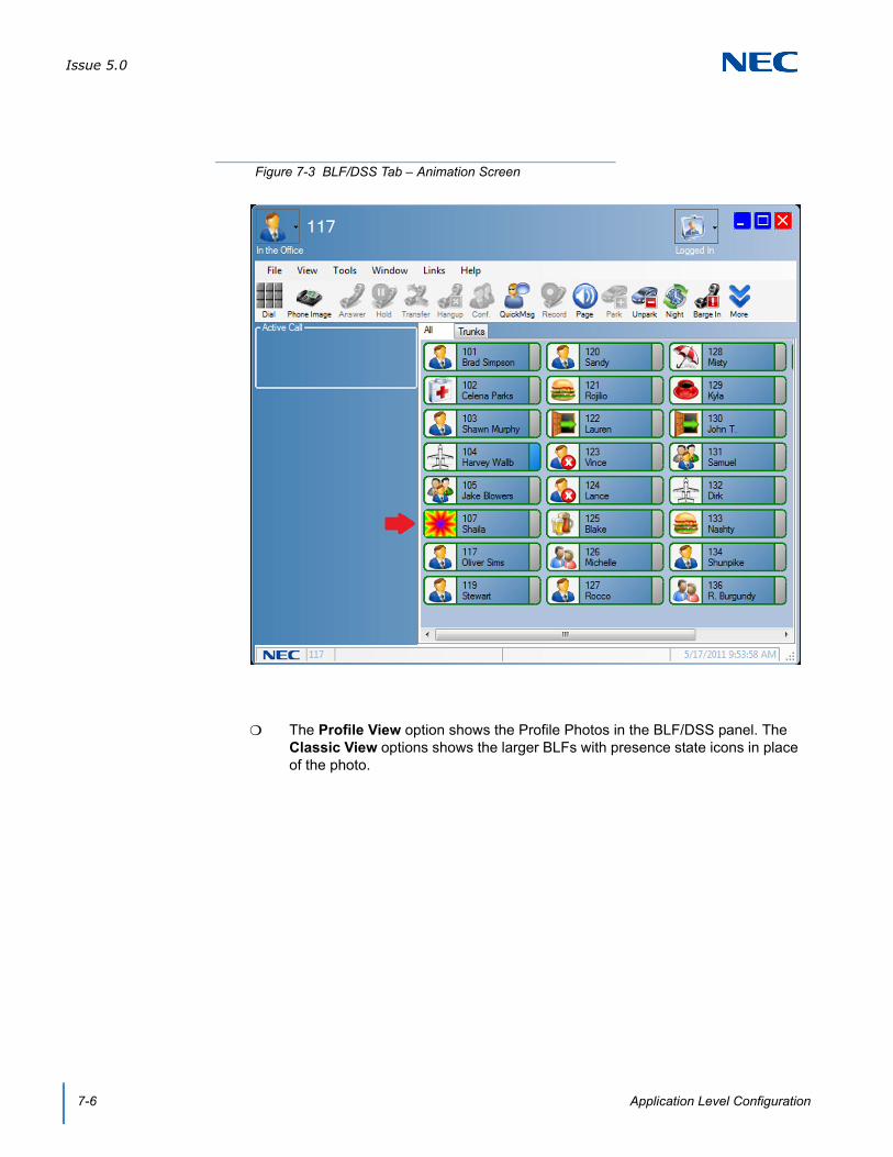
Issue 5.0
7-6 Application Level Configuration
The Profile View option shows the Profile Photos in the BLF/DSS panel. The Classic View options shows the larger BLFs with presence state icons in place of the photo.
Figure 7-3 BLF/DSS Tab – Animation Screen

Issue 5.0
SV9100 System Hardware Manual 7-7
When Profile View is selected, the option to Show animation for Presence state changes shows the text of the presence state flashing. The profile picture does not show the starburst animation as it does in Classic View.
Figure 7-4 BLF/DSS – Profile View
Issue 5.0
7-8 Application Level Configuration
2.3 Preferences – Recording
The Recording Device selector allows the user to specify which recording interface is used to record calls. If no recording device is detected, then this option is disabled.
The Record All Calls option allows the user to specify that recording is automatically started for every call.
The Enable beep tone while recording option plays a beep tone at the start of recording to alert the parties on the call that recording is taking place.
Figure 7-5 Preferences – Recording Tab

Issue 5.0
SV9100 System Hardware Manual 7-9
2.4 Preferences – Personal Greeting
The Playback Device option allows the user to specify the audio device to use for playing the greeting.
The Enable Voice Greeting checkbox allows the user to designate that the Personal Greeting is active.
The File field is used to specify the audio file to play as the Personal Greeting.
The Browse button opens a file explorer window and allows the user to navigate through their file system.
The Play button plays back the specified audio file for review.
The Stop button stops the playback of the specified audio file.
Figure 7-6 Preferences – Personal Greeting Tab

Issue 5.0
7-10 Application Level Configuration
2.5 Preferences – Playback
The Playback Device option allows the user to specify the audio device used for playing back recordings.
The Playback through ADA option specifies whether or not recordings play back through the ADA-L adapter on deskset stations.
Figure 7-7 Preferences – Playback Tab
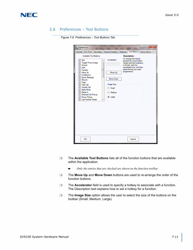
Issue 5.0
SV9100 System Hardware Manual 7-11
2.6 Preferences – Tool Buttons
The Available Tool Buttons lists all of the function buttons that are available within the application.
Only the entries that are checked are shown on the function toolbar.
The Move Up and Move Down buttons are used to re-arrange the order of the function buttons.
The Accelerator field is used to specify a hotkey to associate with a function. The Description text explains how to set a hotkey for a function.
The Image Size option allows the user to select the size of the buttons on the toolbar (Small, Medium, Large).
Figure 7-8 Preferences – Tool Buttons Tab
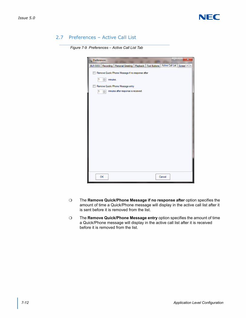
Issue 5.0
7-12 Application Level Configuration
2.7 Preferences – Active Call List
The Remove Quick/Phone Message if no response after option specifies the amount of time a Quick/Phone message will display in the active call list after it is sent before it is removed from the list.
The Remove Quick/Phone Message entry option specifies the amount of time a Quick/Phone message will display in the active call list after it is received before it is removed from the list.
Figure 7-9 Preferences – Active Call List Tab

Issue 5.0
SV9100 System Hardware Manual 7-13
2.8 Preferences – Screen Pop
The Contact Manager option selects which application to utilize to pop a contact entry.
Supported applications are ACT! 2005 and higher, Goldmine 6.7 and higher, Time Matters, Tiger Paw and Browser-based CRMs. Each user using CRM Integration requires the UCS CRM Integration license (license code 5310).
ACT! 2001, 2012, and 2013 are supported with the following conditions:
In Act → Tools → Preferences → Communications → Dialer Preferences choose NEC Single Line Device as modem or line and uncheck Hide dialer after dialing.
Windows Phone and Modem properties need to be configured for local dialing.
With ACT! 2012 and 2013, either use the “Hang up” button in the ACT! dialer window to disconnect the call, or toggle the handset if you hang up the phone and close the ACT! dialer window. Failure to do either would hold the dialer open in ACT!
With ACT! 2013, a reboot is required after setting the integration up.
Figure 7-10 Preferences – Screen Pop Tab

Issue 5.0
7-14 Application Level Configuration
The Settings button allows the user to designate specific information about the selected contact application.
To pass Caller ID to a Browser-based CRM use %ID where the caller ID should be placed in the URL. (For example, www.doyoulikewebsites.com/%ID.)
The Activation option determines at what point the contact will be located and displayed.
The Call Filter option determines which types of calls initiate a screen pop (all calls or external calls only).
The Enable Third Party Interface and Enhanced XML Interface are used when integrating third party applications via XML.
2.9 Preferences – Shortcuts
The One touch transfer will initiate option specifies which action type of transfer (Supervised or Immediate) is initiated when the user clicks on an idle BLF button (Full Window Mode) with an active call.
Figure 7-11 Preferences – Shortcuts Tab

Issue 5.0
SV9100 System Hardware Manual 7-15
The Double-click on a busy extension option allows the user to specify the action to be initiated from the BLF panel or Directory when double clicking a busy extension.
The Pressing the <Enter> key will send the chat message option allows the user to designate whether the Enter key is used as a method to send a Chat message. If this is not selected, then the user must press the Send button on the Chat window to send a message.
The Enable Highlighted Dial Feature option turns on the ability to Highlight a number in any program and have the desktop automatically call that number when the number is copied, or paste it into the dial field and it will be dialed when the users selects Dial. The Hot Key can be in a range from Ctrl-F1 through Ctrl-F12.
2.10 Preferences – Dialing Rules
The Station Number Length field specifies how many digits for internal station numbers. Additional digits will be ignored.
The Emergency Number field specifies the number dialed for emergency calls.
Figure 7-12 Preferences – Dialing Rules Tab
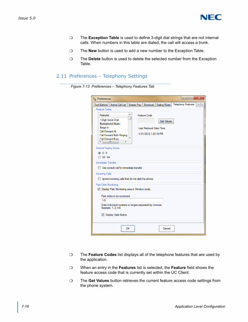
Issue 5.0
7-16 Application Level Configuration
The Exception Table is used to define 3-digit dial strings that are not internal calls. When numbers in this table are dialed, the call will access a trunk.
The New button is used to add a new number to the Exception Table.
The Delete button is used to delete the selected number from the Exception Table.
2.11 Preferences – Telephony Settings
The Feature Codes list displays all of the telephone features that are used by the application.
When an entry in the Features list is selected, the Feature field shows the feature access code that is currently set within the UC Client.
The Get Values button retrieves the current feature access code settings from the phone system.
Figure 7-13 Preferences – Telephony Features Tab

Issue 5.0
SV9100 System Hardware Manual 7-17
The text below the Get Values button shows the last time that the O&M (Operation and Maintenance) interface was successfully used to retrieve the access code settings from the phone system.
The Internal Paging Zones option specifies the range of Paging Zones that are defined in the telephone system.
In the Immediate Transfer section, select the Use consult call for immediate transfer option when transferring to stations that are call forwarded off site.
In the Incoming Calls section, select the Ignore incoming calls that do not alert the phone option when the station has keys that flash but do not ring (for example: virtuals with delay or no ringing).
In the Park Orbit Monitoring section, check the Display Park Monitoring area in Window mode to enable the Park bar.
Define the Park orbits to be monitored of the 64 system park orbits (for example: 1, 2, 4-10).
Check the Display Valet Button to add the Valet button to the park bar. The valet button parks the call in the next available Park Orbit.

Issue 5.0
7-18 Application Level Configuration
2.12 Preferences – Voice Mail
The Enable Voicemail Interface option controls if the voice mail functions within the application are enabled.
The Voicemail Pilot Number is specified if transfers to voice mail require the pilot number to be utilized instead of the quick transfer to voice mail service code. The Voicemail Pilot Number should also be entered for Voicemail to be an option when setting forwarding based on Presence settings.
The Enable Access to voicemail messages and greetings needs to be checked to access the mailbox.
If the mailbox requires a password for login check the Password required for voicemail login box.
Define the Password for the mailbox.
Figure 7-14 Preferences – Voice Mail Tab
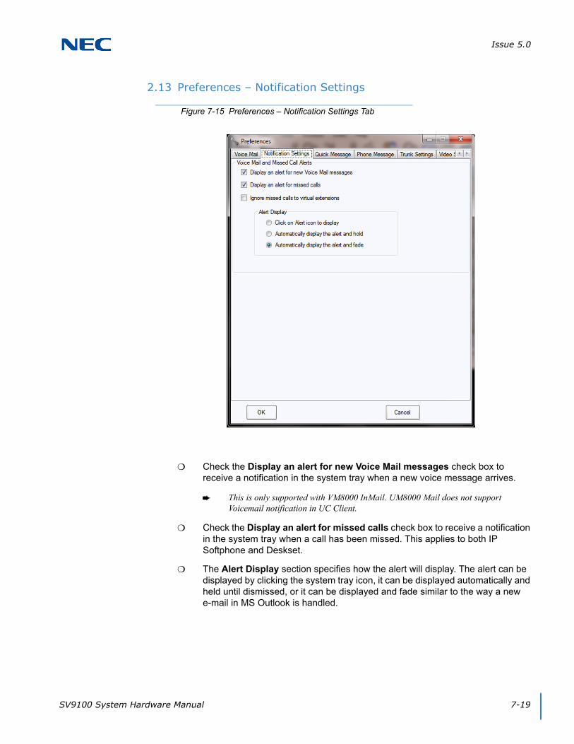
Issue 5.0
SV9100 System Hardware Manual 7-19
2.13 Preferences – Notification Settings
Check the Display an alert for new Voice Mail messages check box to receive a notification in the system tray when a new voice message arrives.
This is only supported with VM8000 InMail. UM8000 Mail does not support Voicemail notification in UC Client.
Check the Display an alert for missed calls check box to receive a notification in the system tray when a call has been missed. This applies to both IP Softphone and Deskset.
The Alert Display section specifies how the alert will display. The alert can be displayed by clicking the system tray icon, it can be displayed automatically and held until dismissed, or it can be displayed and fade similar to the way a new e-mail in MS Outlook is handled.
Figure 7-15 Preferences – Notification Settings Tab

Issue 5.0
7-20 Application Level Configuration
2.14 Preferences – Quick Message
The Messages section is where existing messages can be edited and messages can be created or deleted.
The Responses section is where responses are associated with messages. Responses can be created or deleted.
The New button allows creation of a new message.
The Delete button deletes the highlighted message.
Figure 7-16 Preferences – Quick Message Menu
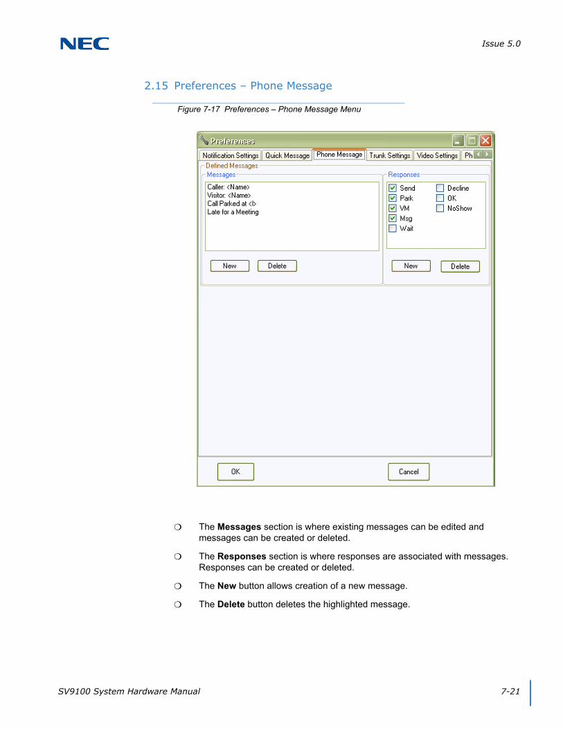
Issue 5.0
SV9100 System Hardware Manual 7-21
2.15 Preferences – Phone Message
The Messages section is where existing messages can be edited and messages can be created or deleted.
The Responses section is where responses are associated with messages. Responses can be created or deleted.
The New button allows creation of a new message.
The Delete button deletes the highlighted message.
Figure 7-17 Preferences – Phone Message Menu

Issue 5.0
7-22 Application Level Configuration
2.16 Preferences – Trunk Settings
The Synchronize button causes the desktop application to query the phone system and retrieve the current trunk definitions for the local phone.
The Trunk Name field can be used to specify a name to be displayed on the button within the Trunks tab.
The BLF Active checkbox controls if the specified trunk is visible or hidden.
Figure 7-18 Preferences – Trunk Settings Tab

Issue 5.0
SV9100 System Hardware Manual 7-23
2.17 Preferences – Video Settings
The Device field allows the user to specify which camera is used for the video call function.
The Frame Rate and Bit Rate fields allow the user to control the quality of the video transmission.
The Mirror My Image option reverses the self-image within the video window.
The Start sending when call is started automatically starts transmitting the video image when the video call is connected. If this option is not set, the user must use the Send button on the video window to start transmitting their video image.
Figure 7-19 Preferences – Video Settings Menu

Issue 5.0
7-24 Application Level Configuration
The Connect with voice party option automatically attempts to start a video call session when the Video option is selected. The video session is requested with the active voice caller.
The End video when voice call ends option stops the video transmission automatically when the associated voice call is terminated.
2.18 Preferences – Phone Image
When the Expansion Module option is selected, the phone image will include an 8-button add-on module.
When the Attendant Module option is selected, the phone image will include a 60-button DSS module.
Figure 7-20 Preferences – Phone Image Tab

SV9100 UC Suite Manual 8-1
Chapter 8
UNIVERGE® SV9100
UC Server
UC Server is required to support the following features:
Central Directory
Phone Message
Quick Message
Presence
Park Orbit Monitoring
Profile Sharing
The UC Server manages shared resources and provide communication facilities between user endpoints. UC Server handles the following functions:
Shared Directory/Contact List – provides a shared database that includes the company directory and external contact list that can be accessed by all users.
Centralized BLF Monitoring – the 3rd-Party TSP is used to monitor the status of all stations on the system. Updates are provided by the shared services to the individual clients.
Common Trunk Labeling – provides a central storage for assigning labels to trunks.
Quick Messaging – manages delivery of messages and responses from attendant level users to end users.
Phone Messaging – manages the delivery of messages and responses from attendant level users to end user desksets.
Presence – indicates the Availability Status, Location, Expected Return Date and Time, Forward Settings for the phone and Special Instructions for UC Suite users.
Presence Status is viewable through the Directory or the BLF area of the Window view. Presence status is set manually by each user. Attendant level users can be given permission to set the Presence status of other users if they forget.
Presence is available in the Toolbar and Window views.

Issue 5.0
8-2 UC Server
Presence states can be customized for each site. The system administrator can determine which Presence states are valid, change the icon for the pre-defined Presence states, and define up to four custom presence states with custom labels/names and custom icons.
Scheduling of Presence state changes is supported by a list of Presence Events each user defines in the new user interface or through the Outlook Calendar. Users also have the ability to view and set Presence status and call forwarding rules while they are out of the office. This can be achieved through mobile devices that support web browsing and desktop web browsers like Internet Explorer®.
SECTION 1 INSTALLATION
UC Server is installed separately from the UC Client installation. The UC Server must be installed on a PC that can be accessed by all of the UC Clients.
1.1 Configuration
UC Server Configuration is the configuration utility installed as part of the UC Server installation. This configuration utility is accessible from within the NEC program group. The following are screens from each tab of the UC Server Configuration and a description of each field.
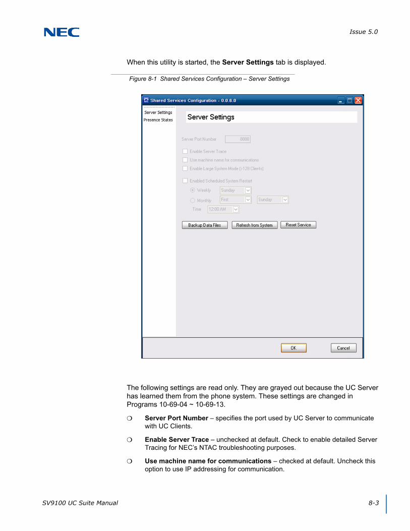
Issue 5.0
SV9100 UC Suite Manual 8-3
When this utility is started, the Server Settings tab is displayed.
The following settings are read only. They are grayed out because the UC Server has learned them from the phone system. These settings are changed in Programs 10-69-04 ~ 10-69-13.
Server Port Number – specifies the port used by UC Server to communicate with UC Clients.
Enable Server Trace – unchecked at default. Check to enable detailed Server Tracing for NEC’s NTAC troubleshooting purposes.
Use machine name for communications – checked at default. Uncheck this option to use IP addressing for communication.
Figure 8-1 Shared Services Configuration – Server Settings
Issue 5.0
8-4 UC Server
Enable Large System Mode – enable when the system has more than 256 UC clients. Exceeding 256 clients is only supported with Shared Services and in non-softphone mode.
The Enable Scheduled System Restart option will be unchecked (disabled). However, when the user checks the Large System Mode option, the Scheduled System Restart option is checked automatically. The user can still disable the Scheduled System Restart option and have the Large System Mode option selected.
When the Scheduled System Restart option is selected, the Weekly, Monthly, and Time controls are enabled. Selecting the Weekly option allows the user to select one day of the week (Sunday . . . Saturday) from the drop down list. Selecting the Monthly option allows the user to select the week (First, Second, Third, Last) and the day of the week (Sunday . . . Saturday) when the restart will occur. The Time field allows the user to select the time of day for the restart to occur. The Time drop down list includes hourly values from 12:00AM through 11:00PM.
The default time for the restart will be Weekly on Sunday at 12:00AM.

Issue 5.0
SV9100 UC Suite Manual 8-5
The Presence States tab of the UC Server Configuration allows the administrator to customize the Presence States icons. The remaining items in this tab are read only. Enabling or disabling the Presence States or changing the name of the custom presence states is accomplished in Programs 20-58-01 ~ 20-58-19.
Enabled – field is read only showing if the presence state is enabled or not.
State – field is read only showing the name of the presence state.
Icon – to change the icon associated with a Presence State, left-click the current icon. A browse window will open. Browse to the icon to be associated with the Presence State. To reset to the default icon, right-click and choose Reset.
Figure 8-2 Shared Services Configuration – Presence States
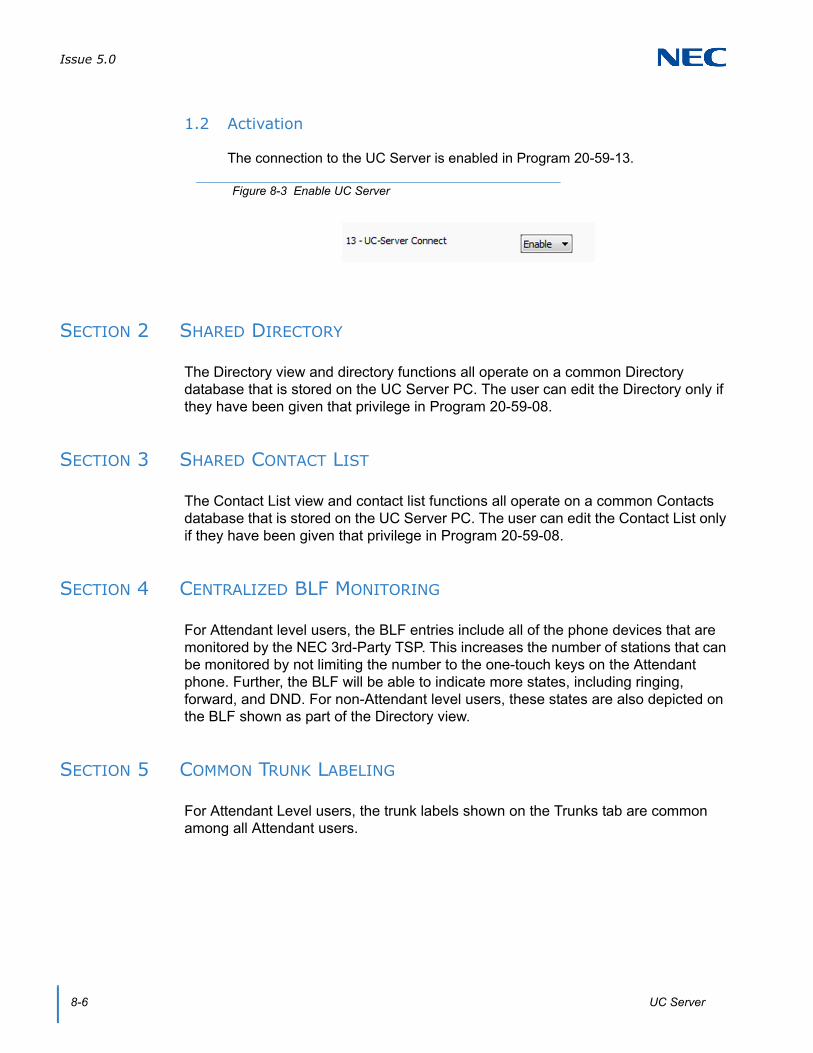
Issue 5.0
8-6 UC Server
1.2 Activation
The connection to the UC Server is enabled in Program 20-59-13.
SECTION 2 SHARED DIRECTORY
The Directory view and directory functions all operate on a common Directory database that is stored on the UC Server PC. The user can edit the Directory only if they have been given that privilege in Program 20-59-08.
SECTION 3 SHARED CONTACT LIST
The Contact List view and contact list functions all operate on a common Contacts database that is stored on the UC Server PC. The user can edit the Contact List only if they have been given that privilege in Program 20-59-08.
SECTION 4 CENTRALIZED BLF MONITORING
For Attendant level users, the BLF entries include all of the phone devices that are monitored by the NEC 3rd-Party TSP. This increases the number of stations that can be monitored by not limiting the number to the one-touch keys on the Attendant phone. Further, the BLF will be able to indicate more states, including ringing, forward, and DND. For non-Attendant level users, these states are also depicted on the BLF shown as part of the Directory view.
SECTION 5 COMMON TRUNK LABELING
For Attendant Level users, the trunk labels shown on the Trunks tab are common among all Attendant users.
Figure 8-3 Enable UC Server

Issue 5.0
SV9100 UC Suite Manual 8-7
SECTION 6 PHONE MESSAGING
When in Window mode, users who have enabled the UC Server have the ability to send Phone Messages to other users. Phone Messages can be sent from the Window mode to any extension on the phone system. The Phone Message is shown as a short text message on the phone display, allowing the user to respond using the softkeys.
Phone Messages and responses are tracked in the Active Call panel in the Full Window mode.
6.1 Sending and Receiving Phone Messages
Select the Phone Message function to display the following menu (refer to Figure 8-4 Phone Message Menu).
The To: button allows the users to select one or multiple recipients to receive the Phone Message. The available destinations include all of the active phone devices on the system.
The user selects the text to be sent by selecting one of the predefined messages in the Message list or entering text manually in this field.
The four Responses fields indicate the predefined responses that are displayed to the recipient above the softkeys.
Figure 8-4 Phone Message Menu
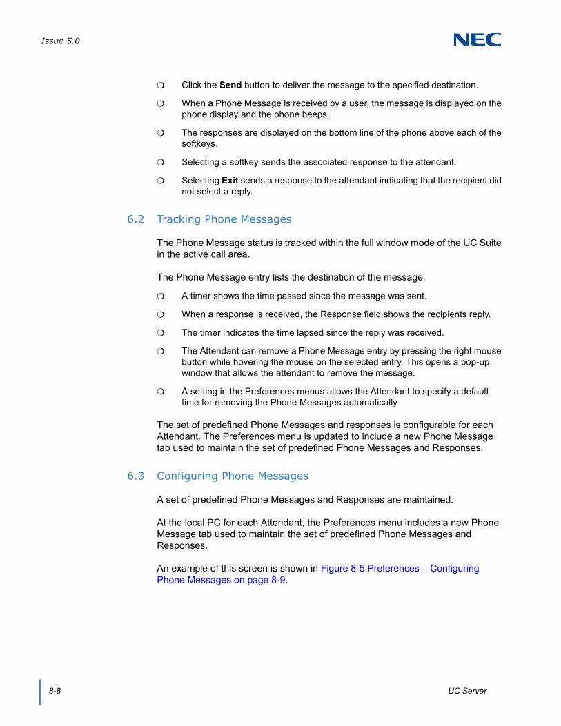
Issue 5.0
8-8 UC Server
Click the Send button to deliver the message to the specified destination.
When a Phone Message is received by a user, the message is displayed on the phone display and the phone beeps.
The responses are displayed on the bottom line of the phone above each of the softkeys.
Selecting a softkey sends the associated response to the attendant.
Selecting Exit sends a response to the attendant indicating that the recipient did not select a reply.
6.2 Tracking Phone Messages
The Phone Message status is tracked within the full window mode of the UC Suite in the active call area.
The Phone Message entry lists the destination of the message.
A timer shows the time passed since the message was sent.
When a response is received, the Response field shows the recipients reply.
The timer indicates the time lapsed since the reply was received.
The Attendant can remove a Phone Message entry by pressing the right mouse button while hovering the mouse on the selected entry. This opens a pop-up window that allows the attendant to remove the message.
A setting in the Preferences menus allows the Attendant to specify a default time for removing the Phone Messages automatically
The set of predefined Phone Messages and responses is configurable for each Attendant. The Preferences menu is updated to include a new Phone Message tab used to maintain the set of predefined Phone Messages and Responses.
6.3 Configuring Phone Messages
A set of predefined Phone Messages and Responses are maintained.
At the local PC for each Attendant, the Preferences menu includes a new Phone Message tab used to maintain the set of predefined Phone Messages and Responses.
An example of this screen is shown in Figure 8-5 Preferences – Configuring Phone Messages on page 8-9.
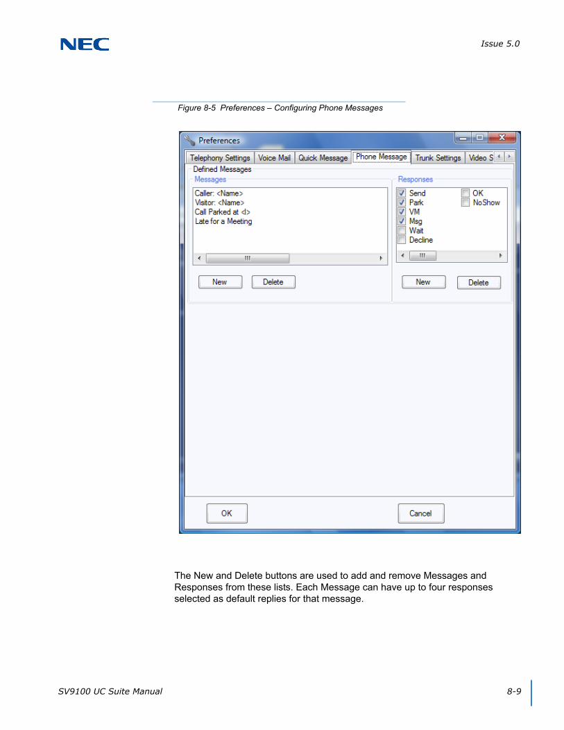
Issue 5.0
SV9100 UC Suite Manual 8-9
The New and Delete buttons are used to add and remove Messages and Responses from these lists. Each Message can have up to four responses selected as default replies for that message.
Figure 8-5 Preferences – Configuring Phone Messages

Issue 5.0
8-10 UC Server
SECTION 7 PRESENCE
Presence provides the ability to indicate Availability Status, Location, Expected Return Date and Time, Forward Settings of the phone, and Special Instructions. The Presence status is viewable through the Shared Services Directory or the BLF section of the Window view. Moving the mouse over an extensions Presence Status icon will show the details and special instructions for the extension.
Figure 8-6 Presence Status – Window View
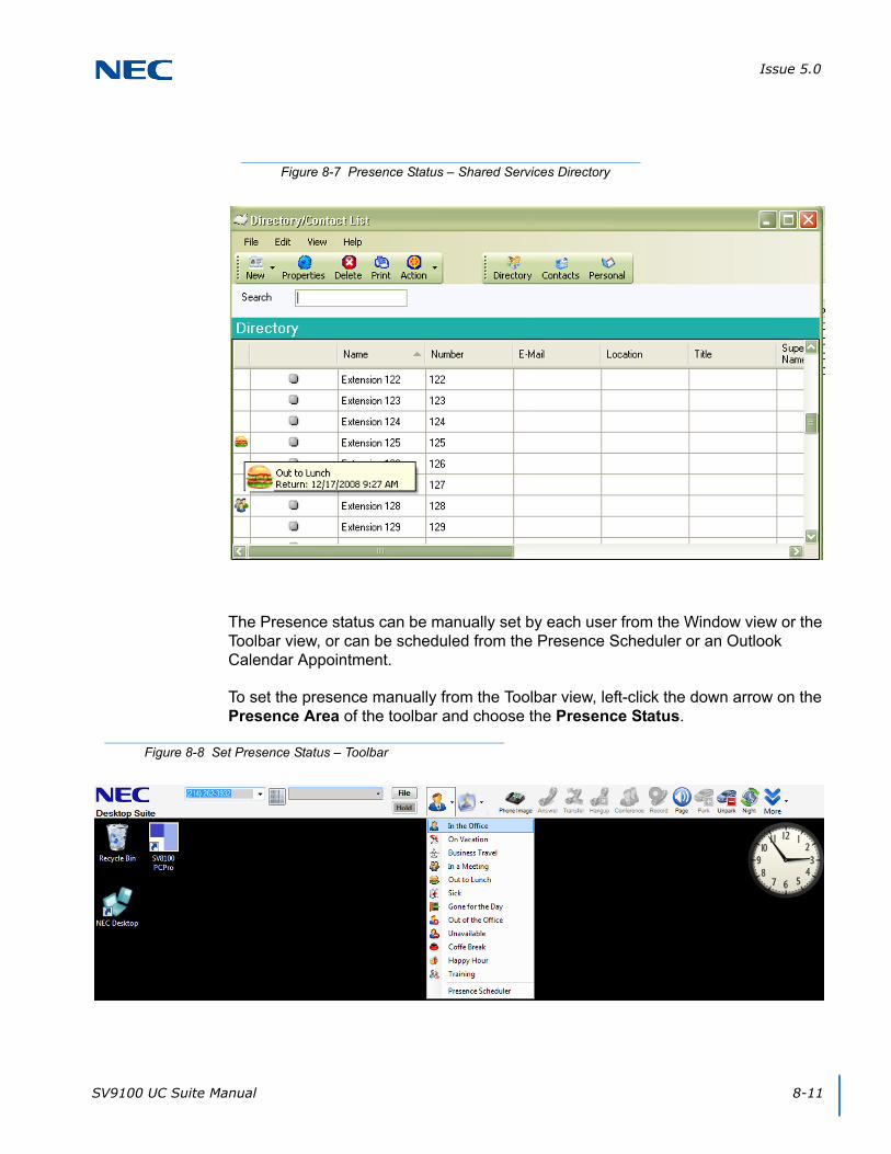
Issue 5.0
SV9100 UC Suite Manual 8-11
The Presence status can be manually set by each user from the Window view or the Toolbar view, or can be scheduled from the Presence Scheduler or an Outlook Calendar Appointment.
To set the presence manually from the Toolbar view, left-click the down arrow on the Presence Area of the toolbar and choose the Presence Status.
Figure 8-7 Presence Status – Shared Services Directory
Figure 8-8 Set Presence Status – Toolbar

Issue 5.0
8-12 UC Server
To set the presence manually from the Window view, right-click the Presence Area of the Window view and choose the Presence Status.
Users can set the details of each Presence Status. The details that can be defined are Subject, Location, Presence State, Expected Return Date and Time, Forward Settings for the Presence Status and Remarks.
Figure 8-9 Set Presence Status – Window

Issue 5.0
SV9100 UC Suite Manual 8-13
Use the Subject field to describe the activity related to this Presence Event. This is an optional field and is blank by default.
Use the Location field to set the user’s location when they choose the associated Presence Status.
Use the Presence State field to select the Presence State. Only active Presence States are shown in the drop down list.
Use Phone Settings field to set the forward destination of the user’s phone when they choose the associated Presence Status.
The forward destination options in the drop down list are pulled from the user’s entry in the Directory and the voice mail pilot defined in Preferences.
Use the Expected Return to set the estimated return date and time for the user.
Use the Remarks field to define special instructions for users when the user chooses the associated Presence Status.
Users with the Attendant license level can be given permission to set the Presence Status for other users. This is enabled in Program 20-59-09.
To set the Presence Status for another user, an Attendant simply right-clicks a user’s BLF in the Window view and chooses Set Presence from the drop down menu.
Figure 8-10 Set Details Screen
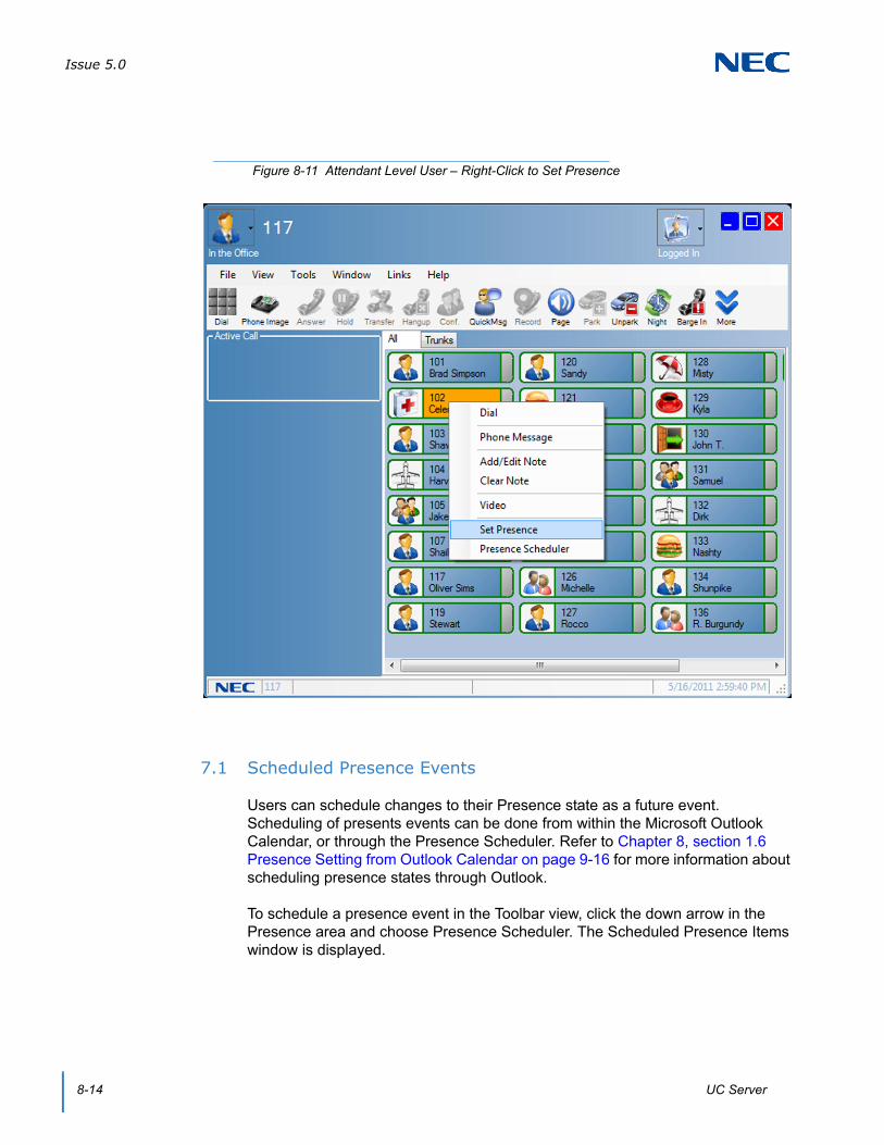
Issue 5.0
8-14 UC Server
7.1 Scheduled Presence Events
Users can schedule changes to their Presence state as a future event. Scheduling of presents events can be done from within the Microsoft Outlook Calendar, or through the Presence Scheduler. Refer to Chapter 8, section 1.6 Presence Setting from Outlook Calendar on page 9-16 for more information about scheduling presence states through Outlook.
To schedule a presence event in the Toolbar view, click the down arrow in the Presence area and choose Presence Scheduler. The Scheduled Presence Items window is displayed.
Figure 8-11 Attendant Level User – Right-Click to Set Presence
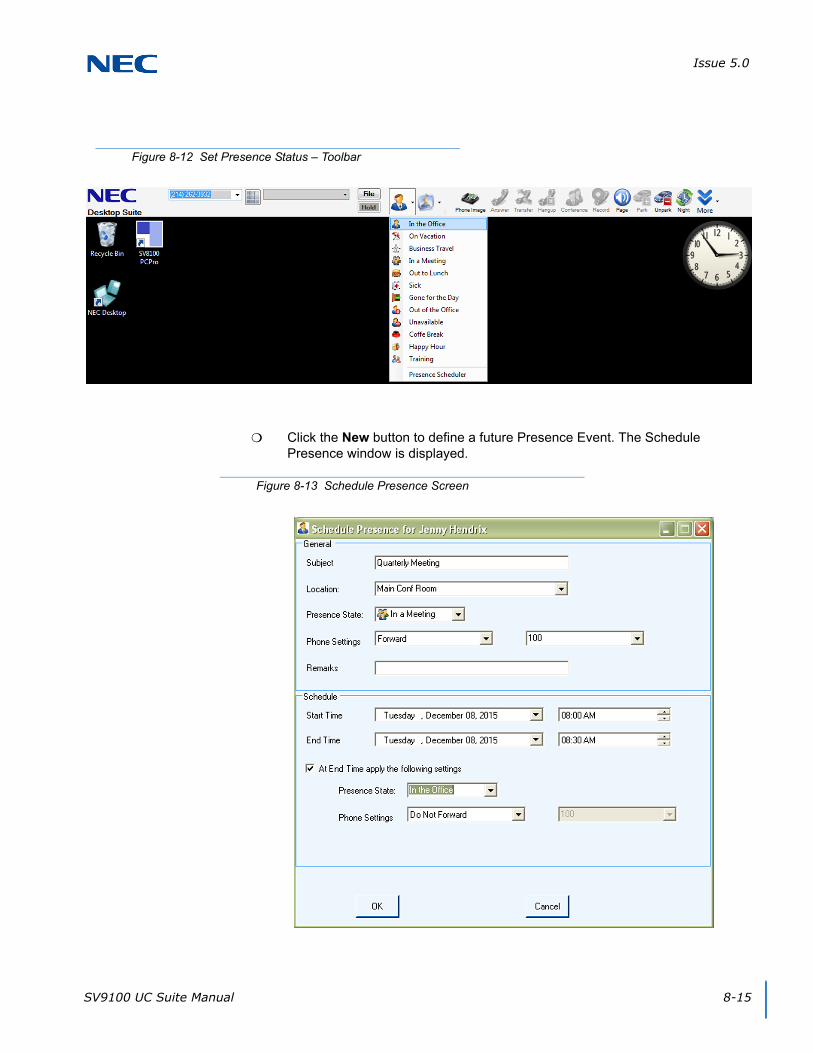
Issue 5.0
SV9100 UC Suite Manual 8-15
Click the New button to define a future Presence Event. The Schedule Presence window is displayed.
Figure 8-12 Set Presence Status – Toolbar
Figure 8-13 Schedule Presence Screen

Issue 5.0
8-16 UC Server
Subject – allows the user to describe the activity related to this Presence event. This is an optional field and is blank by default.
Location – allows the user to describe the location associated with this event. This is an optional field and is blank by default. A history of the most recent Locations associated with this Presence State is maintained and can be accessed using the drop down control.
Presence State – allows the user to select the Presence state to be entered. Only the active Presence states for this site are shown in the drop down list.
Phone Settings – allows the user to specify a phone setting for this event. The first drop down box includes the options Do Not Forward, Forward, Do Not Disturb, Forward Both Ringing and Don't Change Forwarding. If Forward Immediate is selected, then the second selector is active and allows the user to specify the forwarding destination. The drop down list on this selector initially includes all of the alternate numbers for this user in the Shared Services Directory. The user can also manually enter a dial string into this field. Manually entered numbers will be included in the drop down list for future access. The default Phone Setting is None.
Remarks – allows the user to specify any additional information about this Presence event.
Start Time – specifies the date and time that the designated Presence event will occur. The default will be the current date and time, which means the specified Presence state will be assigned when the user clicks the OK button. If the user specifies a time in the future then this will be scheduled as a future Presence event.
End Time – allows the user to specify a time when this Presence event will end. By default, the End Date and Time will be blank. This indicates the Presence event will continue until the user manually selects a different state or another Presence event is scheduled.
At End Time... – fields become enabled if the user has selected the “At End Time apply the following settings.”. The user can designate the Presence State and Phone Settings that will be applied when the End Time occurs. The default is that both of these fields are blank. If the user specifies an End Time, but does not specify these settings, then the Presence State and Phone Settings are not changed.
7.1.1 Viewing Scheduled Presence Events
A user can view their scheduled Presence events by selecting the View Presence Events option from the Presence drop down menu. When this option is selected, a table will be displayed that lists all of the future Presence Events.

Issue 5.0
SV9100 UC Suite Manual 8-17
Clicking on an underlined Event opens the Presence Details window for that event and allows the user to modify the settings.
A right-mouse click on an entry opens a pop-up window with the options ‘Modify’ and ‘Delete’. Modify opens the Presence Details window allowing the user to update the settings. The Delete function removes the selected entry from the list and cancels the event.
The Scheduled Presence Items window also includes scheduled Presence events that have been defined using the Outlook Calendar integration. These entries cannot be modified using the Presence Details menu, but must be updated from within Outlook.
If the user attempts to Modify an event that was defined in Outlook, an information box is displayed with the message: “This Presence event is associated with an Outlook Calendar entry. Please use Outlook to update the Presence settings.”
7.1.2 Viewing Presence Events for Others
If a user is authorized to set Presence for other users, that user can also view and modify scheduled Presence events for other users. The new option “Presence Scheduler” will be added to the BLF and Directory View pop-up menus.
Figure 8-14 Scheduled Presence Items Screen

Issue 5.0
8-18 UC Server
When this option is selected, the event table for the selected user will be displayed. This table will have the same functionality described in the previous section to modify and delete the entries in the table.
7.1.3 Conflicting Presence Events
When a user completes the definition of a new Presence event or modification of an existing event, the UC Suite compares the event to other scheduled Presence events. If the new/updated event overlaps the time period for an existing event, a warning message will be displayed that indicates a conflict has been found. The message box includes the information about the existing event. From this message box, the user is able to select to update the new event or update the previously defined event. If the previously defined event is an Outlook Calendar event, the time of the new/updated event is adjusted to follow the conflicting event.
7.2 Smart Presence
With UC Suite Version 4.0 and higher, the Smart Presence feature updates a user’s Presence or availability based upon pre-defined rules and the detection of phone and PC activities. Different settings for this feature are available in the UC Client and UC Web Client. The following sections describe the settings for the UC Client. Refer to Chapter 17 UC Web Client for Web Client settings.
7.2.1 UC Client Smart Presence
The UC Client provides visual indicators within a BLF entry to signify the Presence state and availability of a UC user. The following example shows the BLF display in Profile view.
In this mode, the current Presence state is shown as text below the Extension/Name. The In the Office state is always shown in a green font, while other states are displayed in red. Also, Name/Extension fields are displayed in blue if the user is logged in and show in black if the user is not logged in to UC Suite.
Figure 8-15 Example of BLF Display in Profile View
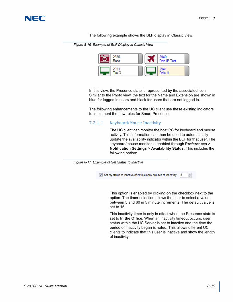
Issue 5.0
SV9100 UC Suite Manual 8-19
The following example shows the BLF display in Classic view:
In this view, the Presence state is represented by the associated icon. Similar to the Photo view, the text for the Name and Extension are shown in blue for logged in users and black for users that are not logged in.
The following enhancements to the UC client use these existing indicators to implement the new rules for Smart Presence:
7.2.1.1 Keyboard/Mouse Inactivity
The UC client can monitor the host PC for keyboard and mouse activity. This information can then be used to automatically update the availability indicator within the BLF for that user. The keyboard/mouse monitor is enabled through Preferences > Notification Settings > Availability Status. This includes the following option:
This option is enabled by clicking on the checkbox next to the option. The timer selection allows the user to select a value between 5 and 60 in 5 minute increments. The default value is set to 15.
This inactivity timer is only in effect when the Presence state is set to In the Office. When an inactivity timeout occurs, user status within the UC Server is set to inactive and the time the period of inactivity began is noted. This allows different UC clients to indicate that this user is inactive and show the length of inactivity.
Figure 8-16 Example of BLF Display in Classic View
Figure 8-17 Example of Set Status to Inactive

Issue 5.0
8-20 UC Server
In Profile mode, a user is designated inactive by changing the following UI elements:
The In the Office text is displayed in a black font.
The Photo is shown in black and white, instead of color.
A hover pop-up for an inactive user displays details of the inactivity.
In Classic mode, a user is designated inactive by changing the following UI elements:
The In the Office icon is shown in Gray.
The following conditions also apply to this feature:
If a user is marked as inactive and keyboard or mouse activity is detected, the activity status should be changed to Active.
If a user is marked as inactive and has an active call on their extension, the activity status should be changed to Active.
If the user’s extension is in use, the inactivity timer should not be started until the phone is Idle.
Figure 8-18 Example of Changing User to Inactive
Figure 8-19 Example of Inactivity Details
Figure 8-20 Designate User Inactive – Classic View
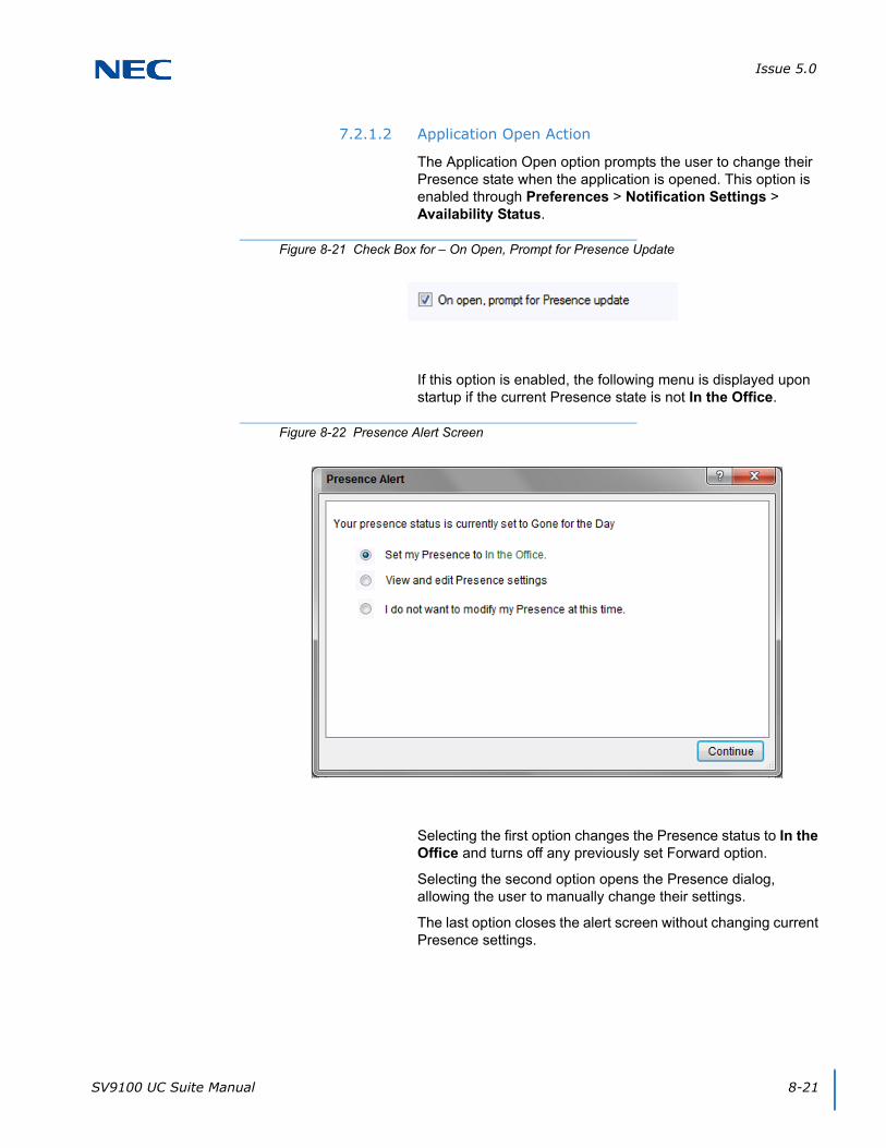
Issue 5.0
SV9100 UC Suite Manual 8-21
7.2.1.2 Application Open Action
The Application Open option prompts the user to change their Presence state when the application is opened. This option is enabled through Preferences > Notification Settings > Availability Status.
If this option is enabled, the following menu is displayed upon startup if the current Presence state is not In the Office.
Selecting the first option changes the Presence status to In the Office and turns off any previously set Forward option.
Selecting the second option opens the Presence dialog, allowing the user to manually change their settings.
The last option closes the alert screen without changing current Presence settings.
Figure 8-21 Check Box for – On Open, Prompt for Presence Update
Figure 8-22 Presence Alert Screen

Issue 5.0
8-22 UC Server
7.2.1.3 Application Close Actions
The Application Close option prompts the user to change their Presence state from In the Office, when the application is closed. This option is enabled through Preferences > Notification Settings > Availability Status. The following option is added within the Availability Status frame for that menu.
This option is Enabled by default.
When enabled, the following menu pops up if the user exits the UC client application while their Presence state is In the Office.
The options provided allow the user to continue to exit without updating the Presence state or, to specify a new Presence state by accessing the Presence menu.
Figure 8-23 Check Box for – On Exit, Prompt for Presence Update
Figure 8-24 Exit Alert Screen
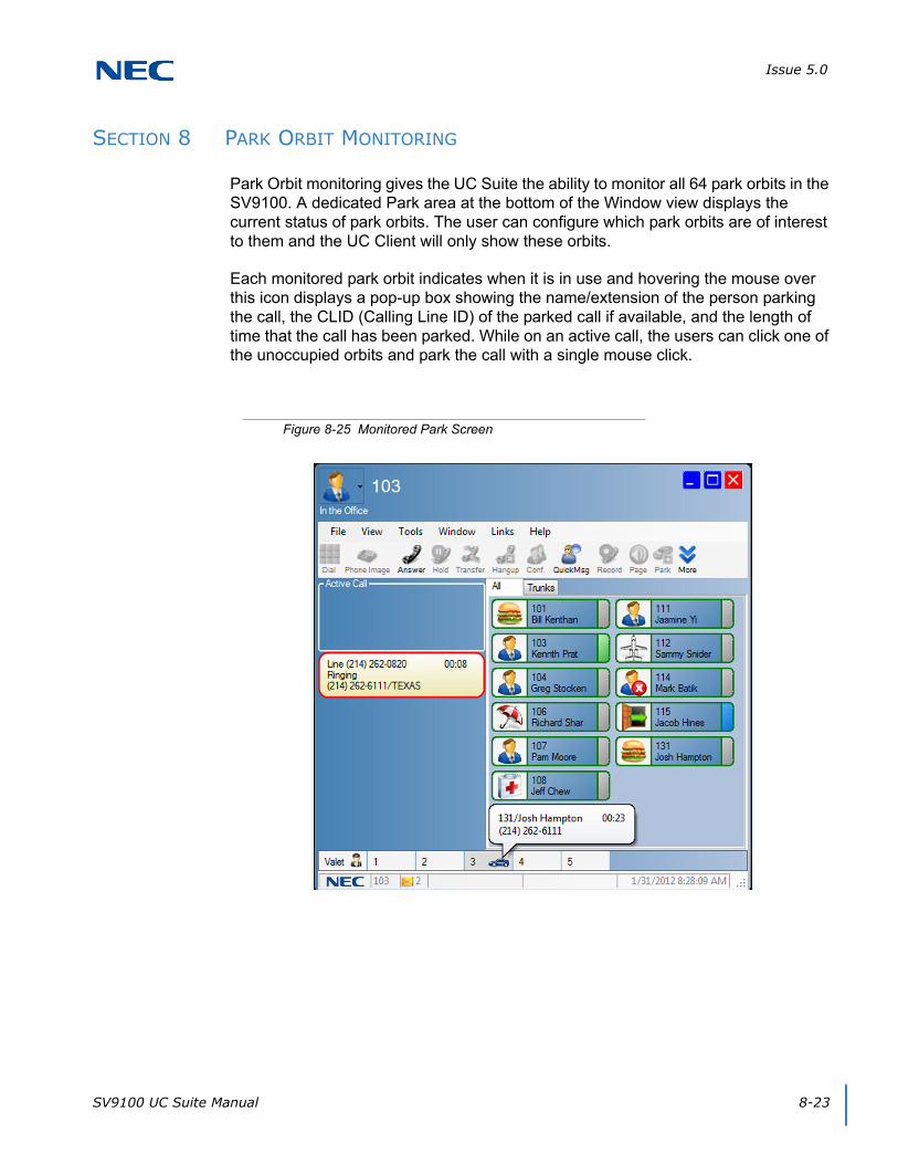
Issue 5.0
SV9100 UC Suite Manual 8-23
SECTION 8 PARK ORBIT MONITORING
Park Orbit monitoring gives the UC Suite the ability to monitor all 64 park orbits in the SV9100. A dedicated Park area at the bottom of the Window view displays the current status of park orbits. The user can configure which park orbits are of interest to them and the UC Client will only show these orbits.
Each monitored park orbit indicates when it is in use and hovering the mouse over this icon displays a pop-up box showing the name/extension of the person parking the call, the CLID (Calling Line ID) of the parked call if available, and the length of time that the call has been parked. While on an active call, the users can click one of the unoccupied orbits and park the call with a single mouse click.
Figure 8-25 Monitored Park Screen

Issue 5.0
8-24 UC Server
The Park Area can also be configured to include a Valet button which will use the Step Park function to park the call in the next available park orbit. The Valet option is also available when you right-click an active call.
Also, while on an active call, users can Drag and Drop the call to an available park orbit or the Valet button to park the call in the next available orbit.
Figure 8-26 Valet Button
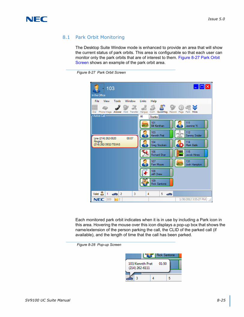
Issue 5.0
SV9100 UC Suite Manual 8-25
8.1 Park Orbit Monitoring
The Desktop Suite Window mode is enhanced to provide an area that will show the current status of park orbits. This area is configurable so that each user can monitor only the park orbits that are of interest to them. Figure 8-27 Park Orbit Screen shows an example of the park orbit area.
Each monitored park orbit indicates when it is in use by including a Park icon in this area. Hovering the mouse over this icon displays a pop-up box that shows the name/extension of the person parking the call, the CLID of the parked call (if available), and the length of time that the call has been parked.
Figure 8-27 Park Orbit Screen
Figure 8-28 Pop-up Screen
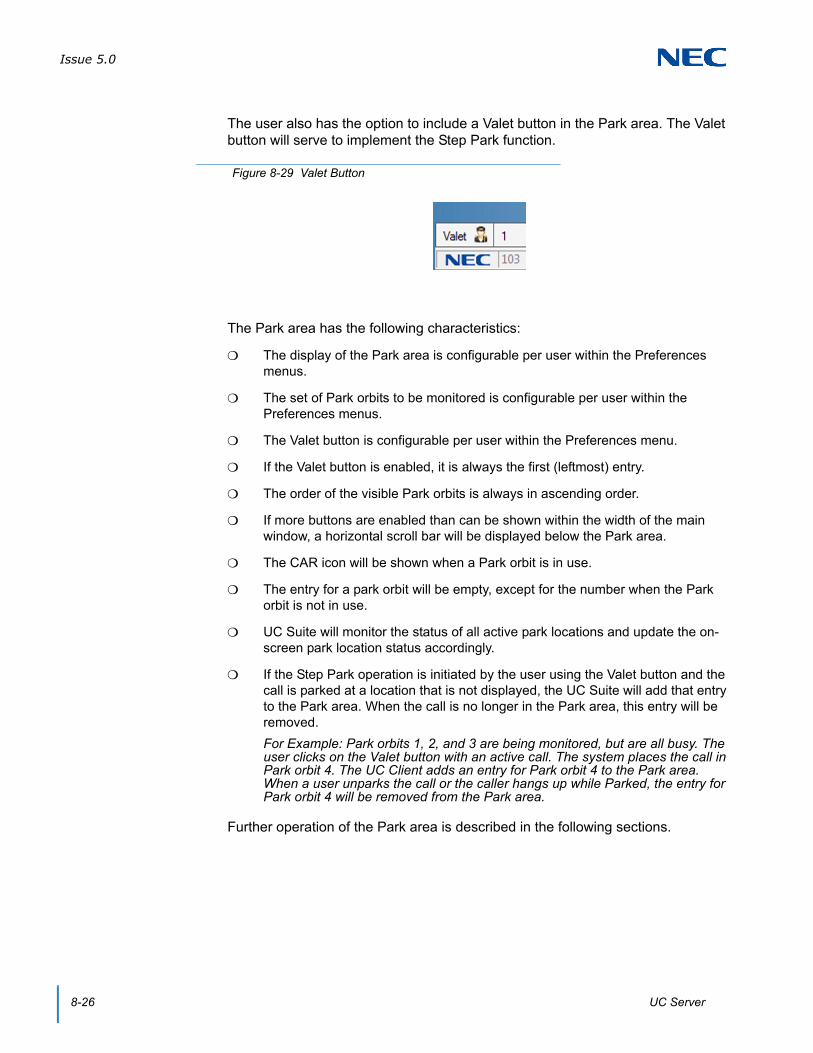
Issue 5.0
8-26 UC Server
The user also has the option to include a Valet button in the Park area. The Valet button will serve to implement the Step Park function.
The Park area has the following characteristics:
The display of the Park area is configurable per user within the Preferences menus.
The set of Park orbits to be monitored is configurable per user within the Preferences menus.
The Valet button is configurable per user within the Preferences menu.
If the Valet button is enabled, it is always the first (leftmost) entry.
The order of the visible Park orbits is always in ascending order.
If more buttons are enabled than can be shown within the width of the main window, a horizontal scroll bar will be displayed below the Park area.
The CAR icon will be shown when a Park orbit is in use.
The entry for a park orbit will be empty, except for the number when the Park orbit is not in use.
UC Suite will monitor the status of all active park locations and update the on-screen park location status accordingly.
If the Step Park operation is initiated by the user using the Valet button and the call is parked at a location that is not displayed, the UC Suite will add that entry to the Park area. When the call is no longer in the Park area, this entry will be removed.
For Example: Park orbits 1, 2, and 3 are being monitored, but are all busy. The user clicks on the Valet button with an active call. The system places the call in Park orbit 4. The UC Client adds an entry for Park orbit 4 to the Park area. When a user unparks the call or the caller hangs up while Parked, the entry for Park orbit 4 will be removed from the Park area.
Further operation of the Park area is described in the following sections.
Figure 8-29 Valet Button

Issue 5.0
SV9100 UC Suite Manual 8-27
8.2 Other Park Operations
Besides the existing Park/Unpark feature buttons, the user will be able to initiate a Park/Unpark using the following methods:
One-click Park – clicking on an empty Park location while on a call sends the current call to the designated Park location.
Drag and Drop Park – the user can drag and drop a call from the active call area into one of the empty Park locations.
One-click Unpark – if the phone is idle, clicking on the park location will retrieve the call from the park orbit. If the phone is in use, the one-click Unpark is disabled.
One-click Valet Park – clicking on the Valet button while on a call initiates the Step Park function for the active call.
Drag and Drop Valet Park – the user can drag and drop a call from the active call area onto the Valet Park area to initiate the Step Park function.
Menu Valet Park – the user can right-click on the active call to bring up a submenu that includes the Valet Park option, as shown below. The Valet Park option is only displayed if the user has enabled the Park area and Valet Park.

Issue 5.0
8-28 UC Server
8.3 Park Area Configuration
Each user can configure their Park area by adjusting the settings within the Preferences menus. To configure the Park Area settings in Preferences, refer to Figure 8-30 Telephony Features Tab.
The Park Orbit Monitoring Configuration settings are described below:
Display Park Monitoring area in Window Mode – enables the Park Area.
Park Orbits to be monitored – list of Park orbits to be monitored. The format for the list of monitored orbits is described on the menu (Example: 1,2,4-6). If the user enters incorrect or ill-formatted strings for the list, an error will be displayed when the user clicks OK or tries to change to a different tab.
Display Valet Button – the user can enable the display of the Valet button by selecting this checkbox.
Figure 8-30 Telephony Features Tab

Issue 5.0
SV9100 UC Suite Manual 8-29
8.4 Toolbar Mode
Additionally, the toolbar mode has been updated so that calls parked through the application are displayed in the toolbar. This will occur with or without shared services. Additionally, the parked call will be represented using the car symbol, rather than the yellow circle, as shown in the following example.
SECTION 9 PROFILE SHARING
The UC Client provides configuration flexibility by allowing each user to customize their personal settings. The Preferences tabs allow the user to control settings associated with user interface layout, function operation, and default actions. In many business environments most of these configuration settings will be standardized for different classes of users. The Profile Sharing feature allows the system installer to duplicate the setup for multiple UC Clients. Profile Sharing is only available to clients that are connected to UC Server.
9.1 Profile Sharing Function
A new Profiles function will be added to the main menu functions in both Window and Toolbar modes. The Profiles function will be accessed, as follows:
In Window mode, the Profiles function is added to the Tools menu.
In Toolbar mode, the Profiles function is added under the File menu between the Preferences and Call Log selections.
If the user is not connected to UC Server, the Profiles option is not displayed.
Figure 8-31 Updated Toolbar Screen
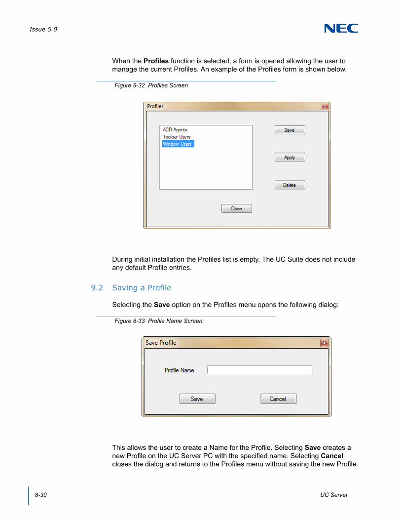
Issue 5.0
8-30 UC Server
When the Profiles function is selected, a form is opened allowing the user to manage the current Profiles. An example of the Profiles form is shown below.
During initial installation the Profiles list is empty. The UC Suite does not include any default Profile entries.
9.2 Saving a Profile
Selecting the Save option on the Profiles menu opens the following dialog:
This allows the user to create a Name for the Profile. Selecting Save creates a new Profile on the UC Server PC with the specified name. Selecting Cancel closes the dialog and returns to the Profiles menu without saving the new Profile.
Figure 8-32 Profiles Screen
Figure 8-33 Profile Name Screen
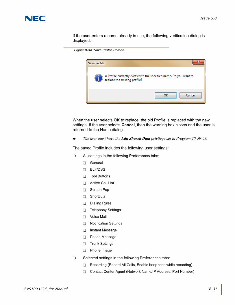
Issue 5.0
SV9100 UC Suite Manual 8-31
If the user enters a name already in use, the following verification dialog is displayed.
When the user selects OK to replace, the old Profile is replaced with the new settings. If the user selects Cancel, then the warning box closes and the user is returned to the Name dialog.
The user must have the Edit Shared Data privilege set in Program 20-59-08.
The saved Profile includes the following user settings:
All settings in the following Preferences tabs:
General
BLF/DSS
Tool Buttons
Active Call List
Screen Pop
Shortcuts
Dialing Rules
Telephony Settings
Voice Mail
Notification Settings
Instant Message
Phone Message
Trunk Settings
Phone Image
Selected settings in the following Preferences tabs:
Recording (Record All Calls, Enable beep tone while recording)
Contact Center Agent (Network Name/IP Address, Port Number)
Figure 8-34 Save Profile Screen
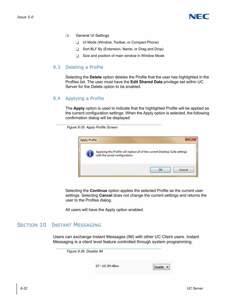
Issue 5.0
8-32 UC Server
General UI Settings
UI Mode (Window, Toolbar, or Compact Phone)
Sort BLF By (Extension, Name, or Drag and Drop)
Size and position of main window in Window Mode
9.3 Deleting a Profile
Selecting the Delete option deletes the Profile that the user has highlighted in the Profiles list. The user must have the Edit Shared Data privilege set within UC Server for the Delete option to be enabled.
9.4 Applying a Profile
The Apply option is used to indicate that the highlighted Profile will be applied as the current configuration settings. When the Apply option is selected, the following confirmation dialog will be displayed:
Selecting the Continue option applies the selected Profile as the current user settings. Selecting Cancel does not change the current settings and returns the user to the Profiles dialog.
All users will have the Apply option enabled.
SECTION 10 INSTANT MESSAGING
Users can exchange Instant Messages (IM) with other UC Client users. Instant Messaging is a client level feature controlled through system programming.
Figure 8-35 Apply Profile Screen
Figure 8-36 Disable IM
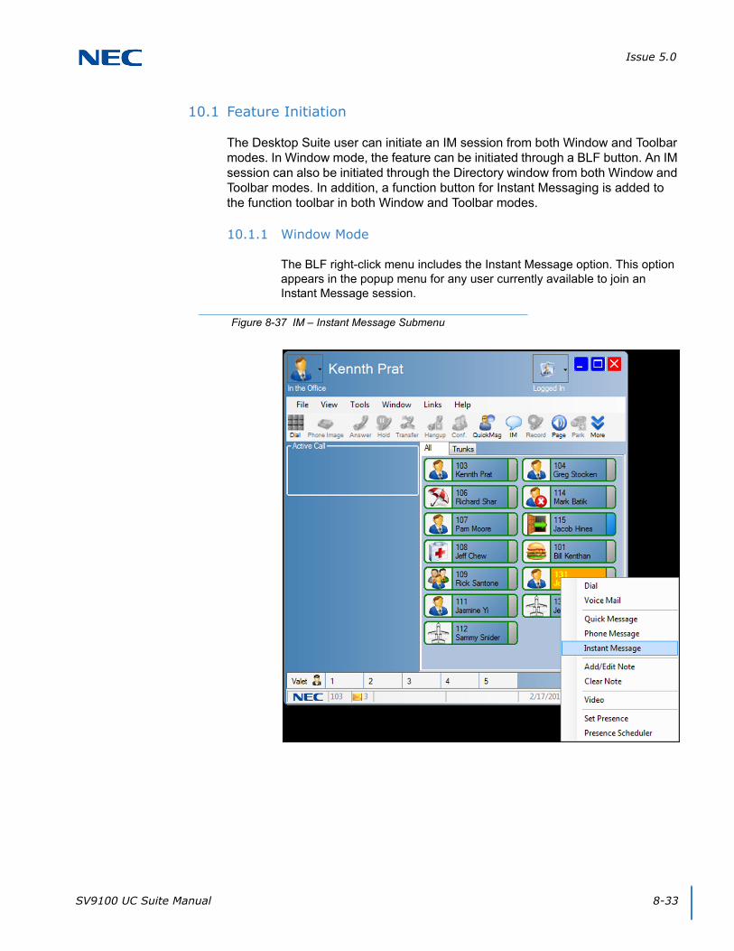
Issue 5.0
SV9100 UC Suite Manual 8-33
10.1 Feature Initiation
The Desktop Suite user can initiate an IM session from both Window and Toolbar modes. In Window mode, the feature can be initiated through a BLF button. An IM session can also be initiated through the Directory window from both Window and Toolbar modes. In addition, a function button for Instant Messaging is added to the function toolbar in both Window and Toolbar modes.
10.1.1 Window Mode
The BLF right-click menu includes the Instant Message option. This option appears in the popup menu for any user currently available to join an Instant Message session.
Figure 8-37 IM – Instant Message Submenu
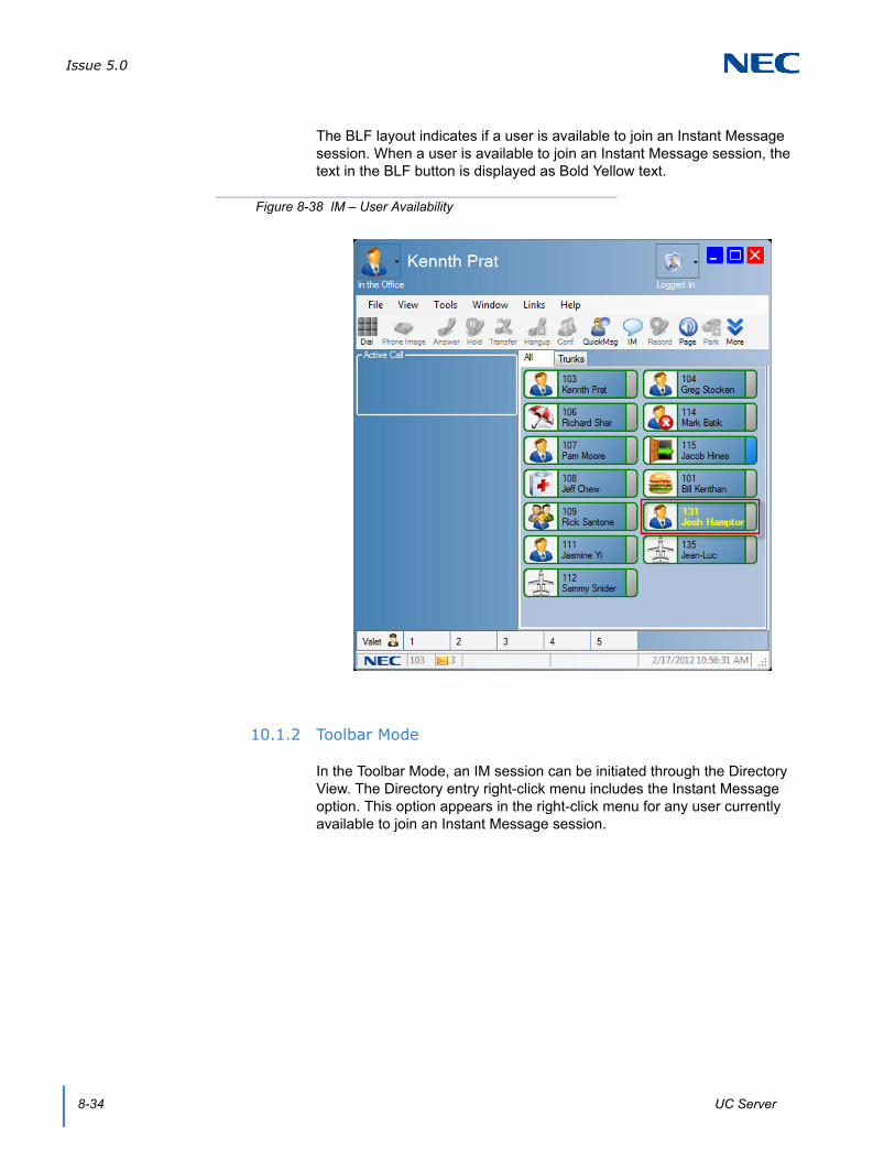
Issue 5.0
8-34 UC Server
The BLF layout indicates if a user is available to join an Instant Message session. When a user is available to join an Instant Message session, the text in the BLF button is displayed as Bold Yellow text.
10.1.2 Toolbar Mode
In the Toolbar Mode, an IM session can be initiated through the Directory View. The Directory entry right-click menu includes the Instant Message option. This option appears in the right-click menu for any user currently available to join an Instant Message session.
Figure 8-38 IM – User Availability
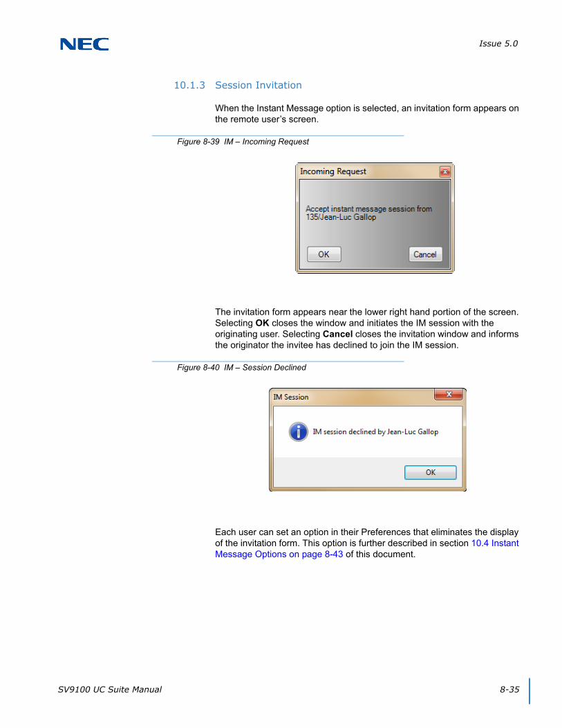
Issue 5.0
SV9100 UC Suite Manual 8-35
10.1.3 Session Invitation
When the Instant Message option is selected, an invitation form appears on the remote user’s screen.
The invitation form appears near the lower right hand portion of the screen. Selecting OK closes the window and initiates the IM session with the originating user. Selecting Cancel closes the invitation window and informs the originator the invitee has declined to join the IM session.
Each user can set an option in their Preferences that eliminates the display of the invitation form. This option is further described in section 10.4 Instant Message Options on page 8-43 of this document.
Figure 8-39 IM – Incoming Request
Figure 8-40 IM – Session Declined
Issue 5.0
8-36 UC Server
10.1.4 Instant Message Button
A new Instant Message function button is added to the function toolbar.
This button will only be enabled for users who have their user privileges set to allow Instant Messaging.
When this function is selected, a submenu is displayed showing all of the users currently available to participate in an Instant Message session.
To select an Instant Message participant, highlight the desired name then click on the Start button. Clicking the Cancel button closes the window without initiating an Instant Message session.
10.1.5 Session Restrictions
The following restrictions apply to the Instant Message function:
A user may establish up to eight simultaneous IM sessions.
Only one IM session may be established between two parties.
If a user has set their Presence status to Unavailable, they will not be shown as available for an IM session. A user can initiate an IM session if their status is Unavailable.
Figure 8-41 IM – Function Button
Figure 8-42 IM – Available Users
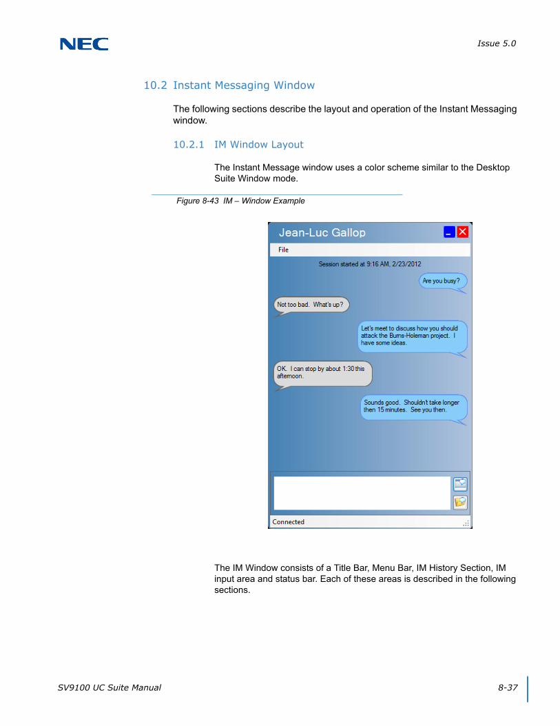
Issue 5.0
SV9100 UC Suite Manual 8-37
10.2 Instant Messaging Window
The following sections describe the layout and operation of the Instant Messaging window.
10.2.1 IM Window Layout
The Instant Message window uses a color scheme similar to the Desktop Suite Window mode.
The IM Window consists of a Title Bar, Menu Bar, IM History Section, IM input area and status bar. Each of these areas is described in the following sections.
Figure 8-43 IM – Window Example
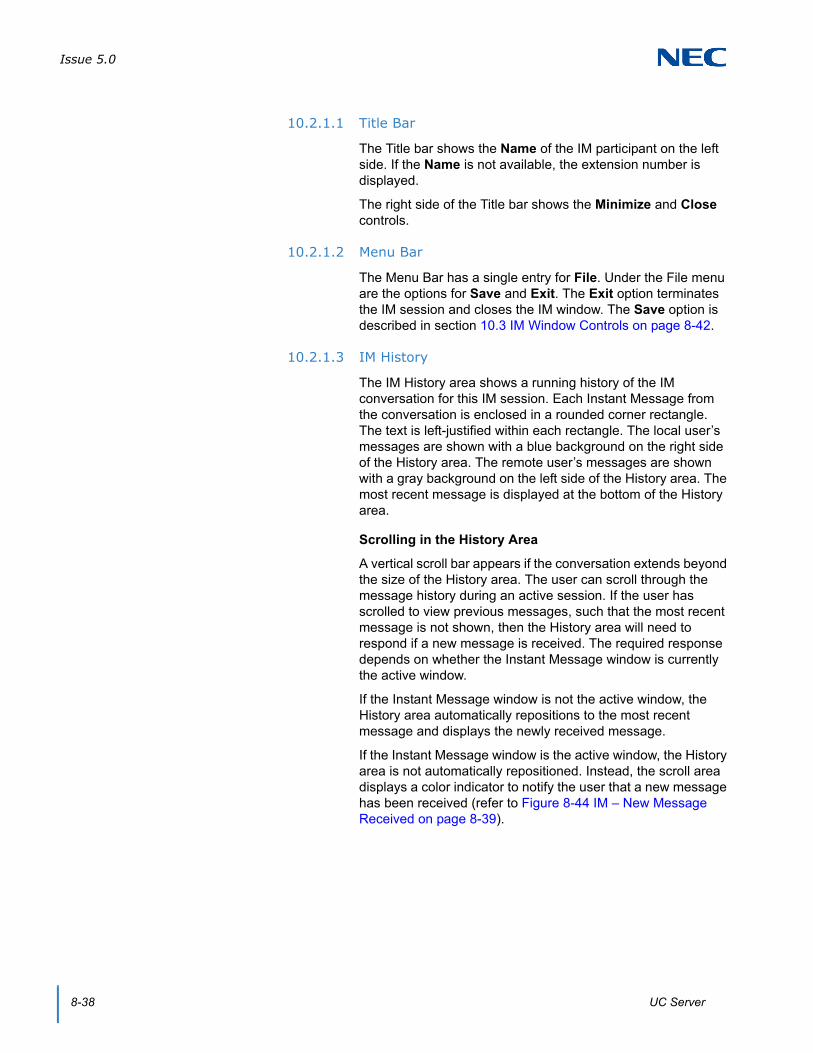
Issue 5.0
8-38 UC Server
10.2.1.1 Title Bar
The Title bar shows the Name of the IM participant on the left side. If the Name is not available, the extension number is displayed.
The right side of the Title bar shows the Minimize and Close controls.
10.2.1.2 Menu Bar
The Menu Bar has a single entry for File. Under the File menu are the options for Save and Exit. The Exit option terminates the IM session and closes the IM window. The Save option is described in section 10.3 IM Window Controls on page 8-42.
10.2.1.3 IM History
The IM History area shows a running history of the IM conversation for this IM session. Each Instant Message from the conversation is enclosed in a rounded corner rectangle. The text is left-justified within each rectangle. The local user’s messages are shown with a blue background on the right side of the History area. The remote user’s messages are shown with a gray background on the left side of the History area. The most recent message is displayed at the bottom of the History area.
Scrolling in the History Area
A vertical scroll bar appears if the conversation extends beyond the size of the History area. The user can scroll through the message history during an active session. If the user has scrolled to view previous messages, such that the most recent message is not shown, then the History area will need to respond if a new message is received. The required response depends on whether the Instant Message window is currently the active window.
If the Instant Message window is not the active window, the History area automatically repositions to the most recent message and displays the newly received message.
If the Instant Message window is the active window, the History area is not automatically repositioned. Instead, the scroll area displays a color indicator to notify the user that a new message has been received (refer to Figure 8-44 IM – New Message Received on page 8-39).

Issue 5.0
SV9100 UC Suite Manual 8-39
If the user has scrolled the History area so that the most recent message is not shown and then Sends a new message, the History area is automatically repositioned to show the new message.
Copy within the History Area
The user can highlight any of the text in the History messages and use the Copy function to add the text to the Copy/Paste buffer. The Copy function can be initiated using the keyboard Copy command or by using a right mouse click on the highlighted string to bring up the editing menu. The Copy command is the only function available in the edit menu.
Figure 8-44 IM – New Message Received
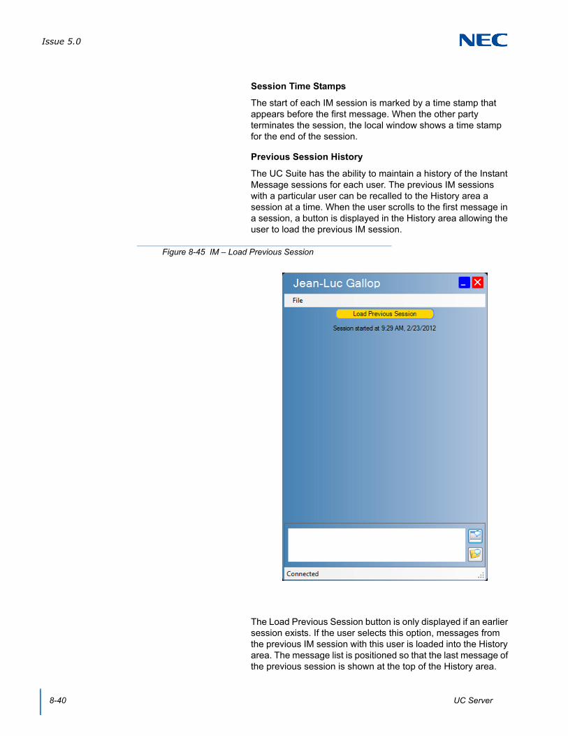
Issue 5.0
8-40 UC Server
Session Time Stamps
The start of each IM session is marked by a time stamp that appears before the first message. When the other party terminates the session, the local window shows a time stamp for the end of the session.
Previous Session History
The UC Suite has the ability to maintain a history of the Instant Message sessions for each user. The previous IM sessions with a particular user can be recalled to the History area a session at a time. When the user scrolls to the first message in a session, a button is displayed in the History area allowing the user to load the previous IM session.
The Load Previous Session button is only displayed if an earlier session exists. If the user selects this option, messages from the previous IM session with this user is loaded into the History area. The message list is positioned so that the last message of the previous session is shown at the top of the History area.
Figure 8-45 IM – Load Previous Session

Issue 5.0
SV9100 UC Suite Manual 8-41
Each session is separated by the appropriate time stamps and a divider line, as shown in the figure below.
10.2.2 Input Area
The Input area allows the local user to enter a new message to be sent to the remote user. After typing a message, the user can send the message clicking on the Send button. There is also a Preferences setting on the Shortcuts menu labeled “Pressing the <Enter> key will send the chat message” that determines if the Enter key will send the message.
The text editing functions for Cut, Copy, and Paste are available to edit the text in the Input area.
The Input area also includes a Save button. The function of the Save button is described below in the IM Window controls section.
The Send and Save buttons include tooltips that show the button function when the mouse cursor is hovered over the button.
Figure 8-46 IM – Time Stamp Example

Issue 5.0
8-42 UC Server
10.2.3 Status Bar
The Status Bar shows the current state of the IM session. The possible states for the IM session are as follows:
Waiting – Invitation to an IM session has been sent and waiting for the response.
Connected – IM session is currently in progress.
Disconnected – The connection to UC Server has been interrupted or the other party has closed the IM window. When the other party has terminated the session, the local window shows a time stamp for the end of the session.
<User Name> is typing – Indicates that the remote IM participant is in currently entering a response. This status is triggered by the remote user entering keystrokes within the Input Area. The status returns to Connected when the user sends the message or a keystroke has not been entered for five seconds.
10.3 IM Window Controls
The Input area includes a Send button and a Save button. The Send button creates a new message using the text that is currently entered in the text editing area.
The Save button writes all of the messages in the current conversation to a text file. When the user selects the Save option from either the File/Save command or the Save button, a file section window is displayed.
Once the user has specified the file location and presses the Save button, the current message history is written to the specified text file.
Figure 8-47 IM – Session Disconnected
Issue 5.0
SV9100 UC Suite Manual 8-43
An example of the text file format is shown below.
12/6/2011 11:32:22AM IM with Dave Bentsen
[Dave Bentsen]: Are you busy?
[Dan Cervantes]: I have time for a quick meeting.
[Dave Bentsen]: Where shall we meet?
[Dan Cervantes]: Let's go to the Large Conference Room. How about in 10 minutes. I'll bring the PowerPoint to review and also the latest document from the customer.
[Dave Bentsen]: That sounds good. I also have some comments that I received from an e-mail
The first line of the file shows the date and time that the IM session was started and the participant’s Name. The IM conversation is then shown with each message starting on a separate line, separated by a blank line. Each individual message is tagged with the user name. The extension will be shown if the Name is not available.
10.4 Instant Message Options
A new tab will be added to the Preferences window which contains the options for the Instant Message feature. Figure 8-48 IM – Preferences Screen on page 8-44 shows an example of the new Instant Message tab.

Issue 5.0
8-44 UC Server
The settings in the Instant Message tab are described in the following sections.
10.4.1 General Settings
The General settings for the Instant Message tab are as follows:
Display Invitation form when receiving IM request – This option controls whether an invitation form is displayed when the user receives a request to join an IM session. If this option is selected, the invitation form is displayed before the IM window opens. If this option is not selected when the user receives a request to start an IM session, the IM window automatically opens.
The default is for this option to be enabled.
Figure 8-48 IM – Preferences Screen
Issue 5.0
SV9100 UC Suite Manual 8-45
Pressing the <Enter> key will send the message – In the current release of the Desktop Suite, this option is shown in the Shortcuts tab and applies to the RTP Chat feature. When this option is selected, pressing the Enter key while typing an Instant Message in the Input area automatically sends the message. If this option is not selected, the Enter key inserts a carriage return into the Input area and the user must press the Send button to deliver the message.
The default is for this option to be enabled.
Font Size – This option controls the size of the font in the user’s local IM window. This font size selection applies to both the History area and the Input area. The Font Size options available for selection are 8, 10, 12, and 14.
The default font size is 8.
10.4.2 History Settings
The History settings for the Instant Message tab are as follows:
Prompt to save IM session on exit – If this option is selected, a prompt to Save the History is displayed when the user closes the IM window. If this option is not selected, the prompt is not be displayed.
The default is for this option to be enabled.
Automatically save all IM sessions – If this option is selected, all IM sessions are automatically saved to a file when the IM window is closed. When this option is selected, the Location field becomes active allowing the user to specify the folder where the files will be written. The Browse button opens a file selection window allowing the user to navigate through the file system to select the folder location.
The default is for this option to be disabled.
If this option is enabled, the user is not prompted to save the session when the IM session is closed, regardless of the previous setting.
Display most recent IM session in History area – If this option is selected, the most recent IM session between the two participants is displayed in the History area when a new IM session is started. If this option is not selected, then the History area will be blank when the IM session is started.
The default is for this option to be enabled.
Keep history of most recent sessions – This option allows the user to control how many previous sessions are saved for display in the History area. If this option is selected, the specified number of IM sessions can be recalled within the History area. The application automatically deletes IM sessions that are older than the specified number of sessions.
Issue 5.0
8-46 UC Server
The number of sessions that can be selected are 5, 10, 25, and 50.
If this option is not selected, the application only keeps the previous session.
10.4.3 Notification Settings
The Notification settings for the Instant Message tab are as follows:
Audible alarm when invitation/start of new IM session – When this option is selected an audible alarm is generated when the invitation is displayed for the user to join an IM session. If the user has the invitation display disabled, the alarm sounds when the IM window is displayed at the start of a new session.
The default is for this option to be enabled.
Audible alarm when new IM message received – When this option is selected an audible alarm is generated for each new IM message received. The new message alarm occurs even if the window is not top-most or is minimized.
The default is for this option to be disabled.
Pop IM window to top when new IM message received – Selecting this option will pop the IM window to the front of the display when a new message is received. Even though the window will pop to the top, the keyboard input still remains with the window that had focus before the IM window was popped. This prevents the user keyboard input from accidentally be switched to the IM input area.
The default is for this option to be enabled.
SV9100 UC Suite Manual 9-1
Chapter 9
UNIVERGE® SV9100
Outlook Add-In
SECTION 1 OUTLOOK ADD-IN
The Outlook Add-In allows users to make calls, End Call, Conference, Transfer, and perform screen pops through the Contacts folder within MS Outlook using UC Suite. The Outlook Add-In is installed during installation of UC Client. The UC Desktop Application must be running for the Outlook Add-In to function, unless the standalone Outlook Add-In has been installed.
A separate install of the Outlook Add-In is provided to deliver Outlook functionality with the Web Client. The Outlook Add-In can be configured to point to the UC Server for call control.
The Outlook Add-In is supported with the following Outlook Versions (32-bit and 64-bit):
Outlook 2003
Outlook 2007
Outlook 2010
Outlook 2013
1.1 Configuration
First choose UC Suite Telephony Settings from the Tools Menu within Outlook.

Issue 5.0
9-2 Outlook Add-In
When making calls to outside numbers using the Outlook Add-In, the dialing rules from Control Panel → Phone and Modem Options will be followed.
The UC Suite Settings window will open.
Figure 9-1 Outlook Configuration

Issue 5.0
SV9100 UC Suite Manual 9-3
General: Check the Enable box to enable the Outlook Add-In.
General: Check the Automatically launch NEC Desktop Suite when Outlook starts if this is desired.
General: Click on the Reinitialize button to start the connection to the SV9100.
General: The Connect Directly To Shared Services check box will allow the Outlook Add In to communicate directly with the UC Server module for telephony control and events. This option should be used if the user is not running the UC Client in conjunction with the Outlook Add-In.
General: Define the Network Name/IP Address of the UC Server.
General: Define the Port Number on the UC Server system for communications with clients.
Highlight Dial: The Enable Highlighted Dial Feature option allows the user to highlight a phone number in a supported application and then press a hot key to automatically begin dialing that number.
Highlight Dial: Define the Highlight Dial Hotkey that will initiate the dialing sequence when a string of digits is highlighted. Valid hotkeys are two-key combinations of the Ctrl key, plus F1 through F12.
Screen Pop: The Activation option determines at what point the contact will be located and displayed.
Screen Pop: Click on the Pick Folder button to specify an Outlook folder other than the default Contacts folder.
Figure 9-2 NEC Desktop Telephony Settings

Issue 5.0
9-4 Outlook Add-In
Screen Pop: The Call Filter option determines which types of calls initiate a screen pop (all calls or external calls only).
Presence: Check the Automatically assign Presence to any new calendar event to select either a Presence state or a pre-defined Presence Profile that will automatically be associated with any new calendar event. (UC Suite 4.0 and higher).
Presence: The Presence Profile option includes a drop down list of the currently defined Presence Profiles. (UC Suite 4.0 and higher)
Presence: The Presence State option allows the user to select a Presence State that will automatically be assigned to any new calendar event. If this option is selected, then the Subject, Location, Remarks, and Start/End time will automatically be included in the Presence event, based upon the corresponding fields within the calendar event.
Even though the scheduled Presence event will be associated with a new calendar item, the user will still have the ability to update the Presence settings by accessing the individual calendar event. (UC Suite 4.0 and higher)
Presence: The Do not copy event text into Remarks field option allows the user to not automatically include the event text within the Remarks field of a Presence event. This rule will be applied regardless of whether the automatic assignment of Presence is utilized. (UC Suite 4.0 and higher)
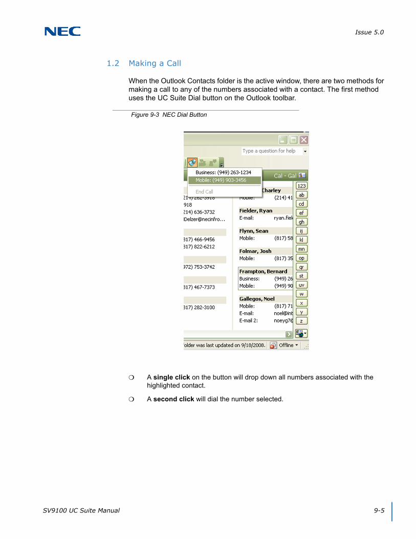
Issue 5.0
SV9100 UC Suite Manual 9-5
1.2 Making a Call
When the Outlook Contacts folder is the active window, there are two methods for making a call to any of the numbers associated with a contact. The first method uses the UC Suite Dial button on the Outlook toolbar.
A single click on the button will drop down all numbers associated with the highlighted contact.
A second click will dial the number selected.
Figure 9-3 NEC Dial Button
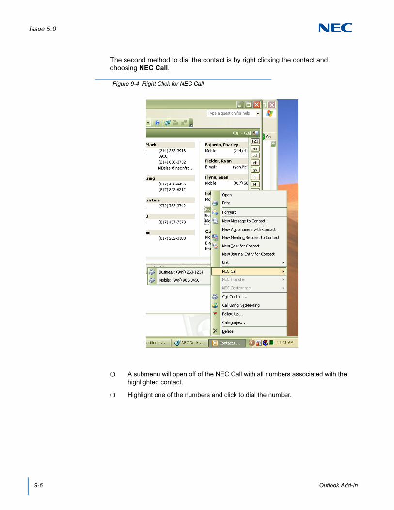
Issue 5.0
9-6 Outlook Add-In
The second method to dial the contact is by right clicking the contact and choosing NEC Call.
A submenu will open off of the NEC Call with all numbers associated with the highlighted contact.
Highlight one of the numbers and click to dial the number.
Figure 9-4 Right Click for NEC Call
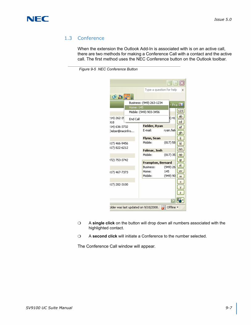
Issue 5.0
SV9100 UC Suite Manual 9-7
1.3 Conference
When the extension the Outlook Add-In is associated with is on an active call, there are two methods for making a Conference Call with a contact and the active call. The first method uses the NEC Conference button on the Outlook toolbar.
A single click on the button will drop down all numbers associated with the highlighted contact.
A second click will initiate a Conference to the number selected.
The Conference Call window will appear.
Figure 9-5 NEC Conference Button

Issue 5.0
9-8 Outlook Add-In
Once the destination party answers, click the Complete button to complete the Conference.
Either before the destination party answers or after they answer, click the Disconnect button to disconnect with the destination party and be reconnected to the original caller.
The second method to Conference in a contact is by right clicking the contact and choosing NEC Conference.
Figure 9-6 Conference Call Window
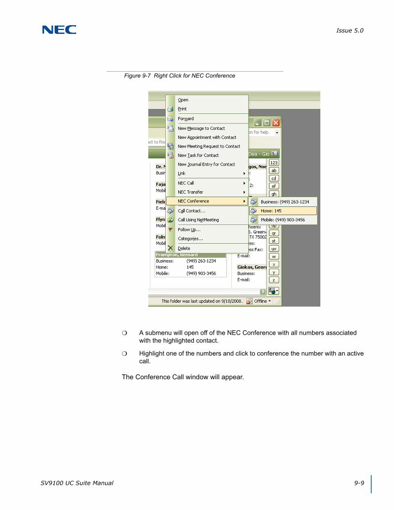
Issue 5.0
SV9100 UC Suite Manual 9-9
A submenu will open off of the NEC Conference with all numbers associated with the highlighted contact.
Highlight one of the numbers and click to conference the number with an active call.
The Conference Call window will appear.
Figure 9-7 Right Click for NEC Conference
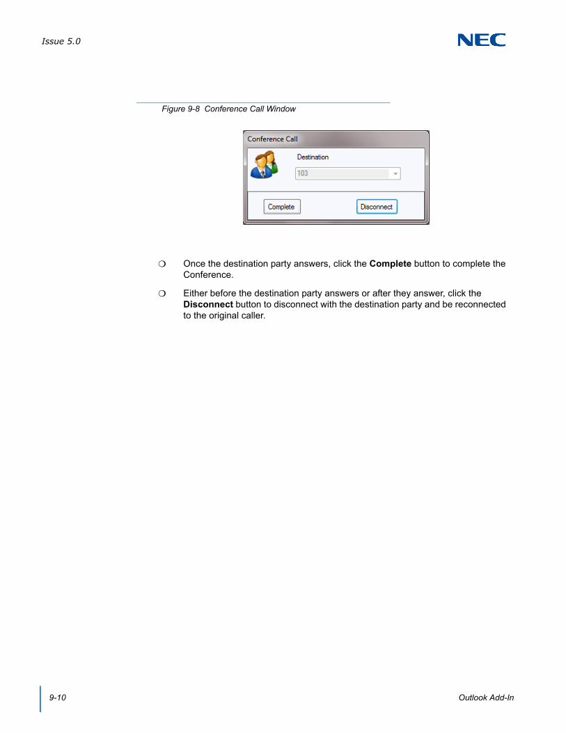
Issue 5.0
9-10 Outlook Add-In
Once the destination party answers, click the Complete button to complete the Conference.
Either before the destination party answers or after they answer, click the Disconnect button to disconnect with the destination party and be reconnected to the original caller.
Figure 9-8 Conference Call Window

Issue 5.0
SV9100 UC Suite Manual 9-11
1.4 Transfer
When the extension the Outlook Add-In is associated with is on an active call, there are two methods for transferring the call to a contact. The first method uses the NEC Transfer button on the Outlook toolbar.
A single click on the button will drop down all numbers associated with the highlighted contact.
A second click will initiate a Transfer to the number selected.
The Transfer Call window will appear.
Figure 9-9 NEC Transfer Button
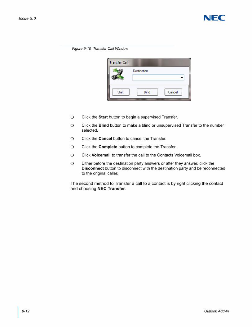
Issue 5.0
9-12 Outlook Add-In
Click the Start button to begin a supervised Transfer.
Click the Blind button to make a blind or unsupervised Transfer to the number selected.
Click the Cancel button to cancel the Transfer.
Click the Complete button to complete the Transfer.
Click Voicemail to transfer the call to the Contacts Voicemail box.
Either before the destination party answers or after they answer, click the Disconnect button to disconnect with the destination party and be reconnected to the original caller.
The second method to Transfer a call to a contact is by right clicking the contact and choosing NEC Transfer.
Figure 9-10 Transfer Call Window

Issue 5.0
SV9100 UC Suite Manual 9-13
A submenu will open off of the NEC Transfer with all numbers associated with the highlighted contact.
Highlight one of the numbers and click to transfer the active call to the number selected.
The Transfer Call window will appear.
Figure 9-11 NEC Transfer Right Click

Issue 5.0
9-14 Outlook Add-In
Click the Start button to begin a supervised Transfer.
Click the Blind button to make a blind or unsupervised Transfer to the number selected.
Click the Cancel button to cancel the Transfer.
Click the Complete button to complete the Transfer.
Click Voicemail to transfer the call to the Contacts Voicemail box.
Either before the destination party answers or after they answer, click the Disconnect button to disconnect with the destination party and be reconnected to the original caller.
Figure 9-12 Transfer Call Window
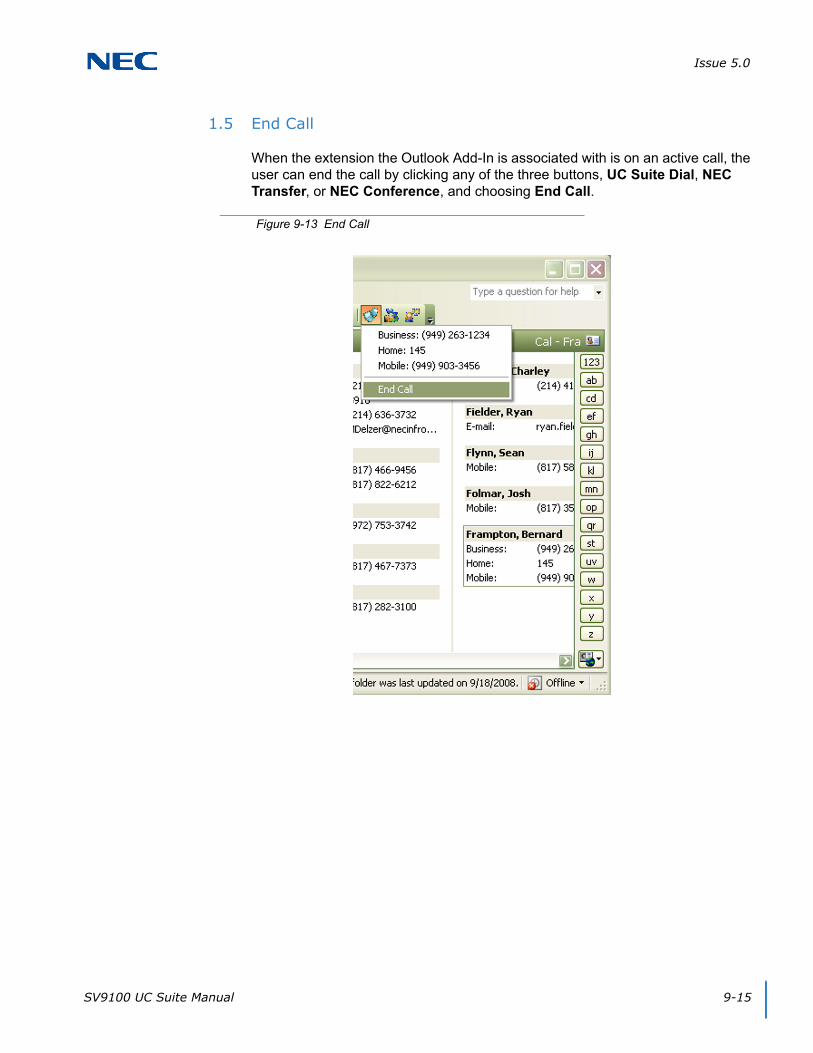
Issue 5.0
SV9100 UC Suite Manual 9-15
1.5 End Call
When the extension the Outlook Add-In is associated with is on an active call, the user can end the call by clicking any of the three buttons, UC Suite Dial, NEC Transfer, or NEC Conference, and choosing End Call.
Figure 9-13 End Call

Issue 5.0
9-16 Outlook Add-In
1.6 Presence Setting from Outlook Calendar
A UC Client user can associate a Presence State with an Outlook Calendar appointment. Recurring appointments in Outlook only make the initial presence state change. New toolbar items are added to the Outlook appointment dialog with the following items:
NEC Logo – this button identifies the toolbar. When this button is clicked, the About box for the UC Suite will be displayed.
Set Presence – this button opens up a supporting dialog which allows the user to specify the details of the Presence setting for this appointment.
Current Presence State – This button shows the current Presence state that has been selected for the appointment. If a Presence State is not selected, the status will show “No Presence State”. If a Presence State is not Selected, then the Appointment will not result in a scheduled Presence event. Rolling the mouse over this button will show a tool tip, which displays the current Phone Setting.
Figure 9-14 Outlook Presence Appointment Screen

Issue 5.0
SV9100 UC Suite Manual 9-17
1.6.1 Assigning a Presence State
When a new appointment is defined in Outlook, a Presence state will not be associated with the appointment. If the user does not assign a Presence state, then the appointment will not have any affect on the user's Presence settings.
When the user selects the Set Presence button, the Schedule Presence Window is displayed:
The following fields will be pre-populated with the values that are specified in the Outlook Appointment form:
Subject
Location
Start Time
End Time
If you set an Outlook appointment for less than 30 minutes, when you open the Presence Form, it will change the duration to 30 minutes.
Figure 9-15 Schedule Presence Screen
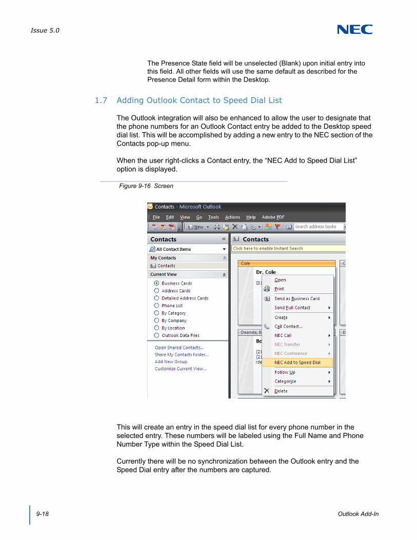
Issue 5.0
9-18 Outlook Add-In
The Presence State field will be unselected (Blank) upon initial entry into this field. All other fields will use the same default as described for the Presence Detail form within the Desktop.
1.7 Adding Outlook Contact to Speed Dial List
The Outlook integration will also be enhanced to allow the user to designate that the phone numbers for an Outlook Contact entry be added to the Desktop speed dial list. This will be accomplished by adding a new entry to the NEC section of the Contacts pop-up menu.
When the user right-clicks a Contact entry, the “NEC Add to Speed Dial List” option is displayed.
This will create an entry in the speed dial list for every phone number in the selected entry. These numbers will be labeled using the Full Name and Phone Number Type within the Speed Dial List.
Currently there will be no synchronization between the Outlook entry and the Speed Dial entry after the numbers are captured.
Figure 9-16 Screen
SV9100 System Hardware Manual 10-1
Chapter 10
UNIVERGE® SV9100
Salesforce Integration
This chapter describes the setup and operation that allows the UC Suite to integrate with Salesforce.com®. This integration allows users to initiate calls to contacts from within Salesforce.com and to search for contacts automatically when an incoming call is received.
SECTION 1 OVERVIEW
The Salesforce.com integration module requires a Salesforce.com Professional, Enterprise, or Unlimited Edition account. The integration module is compatible with the following browsers: Internet Explorer® 7, 8, 9 and Firefox® 3.6. Firefox 4 is not currently supported.
When integrated with the UC Suite, this module provides access to the following operations through the Salesforce.com interface:
Call contact phone number
Dial phone number directly
Answer incoming call
End active call
Hold active call
Retrieve a Held call
Transfer active call
Pop contact on incoming call that matches phone number
IMPORTANT
UCS CRM Integrate (license code 5310 in Program 10-50-01) is required for Salesforce.com integration.
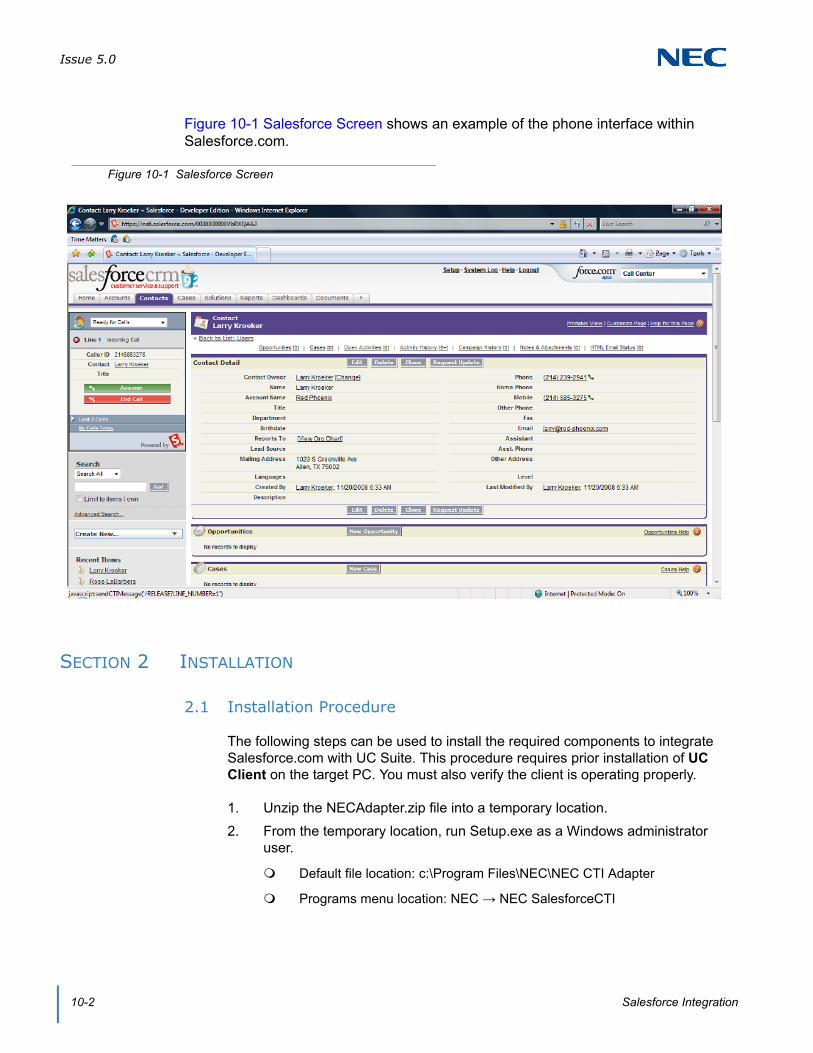
Issue 5.0
10-2 Salesforce Integration
Figure 10-1 Salesforce Screen shows an example of the phone interface within Salesforce.com.
SECTION 2 INSTALLATION
2.1 Installation Procedure
The following steps can be used to install the required components to integrate Salesforce.com with UC Suite. This procedure requires prior installation of UC Client on the target PC. You must also verify the client is operating properly.
1. Unzip the NECAdapter.zip file into a temporary location.
2. From the temporary location, run Setup.exe as a Windows administrator user.
Default file location: c:\Program Files\NEC\NEC CTI Adapter
Programs menu location: NEC → NEC SalesforceCTI
Figure 10-1 Salesforce Screen
Issue 5.0
SV9100 System Hardware Manual 10-3
SECTION 3 SALESFORCE.COM CONFIGURATION
The following sequence should be performed to configure Salesforce.com for use with UC Suite.
1. Log in to Salesforce as an administrator user.
2. Click Setup → Customize (under App Setup) → Call Center → Call Centers.
3. Click Import.
4. Click Browse and navigate to the call center definition file in your NEC Adapter program file directory. In default installations, this file is located at:c:\Program Files\NEC\NEC CTI Adapter\ NecAdapter.xml
5. Click Import.
6. Click Manage Call Center Users.
7. Click Add More Users.
8. Enter search criteria to find a Salesforce user who will be a NEC Call Center user. Click Find.
9. Select the checkbox next to the name of one or more users who should have access to the NEC Call Center adapter. Click Add to Call Center.
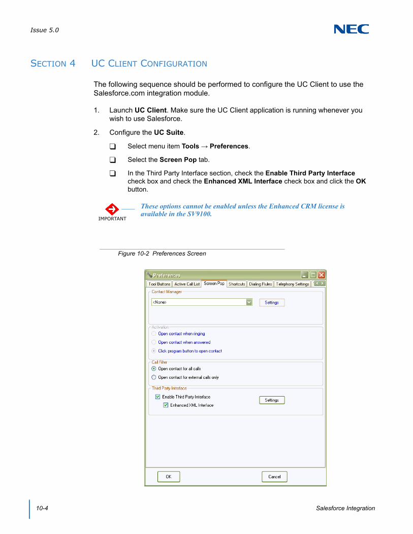
Issue 5.0
10-4 Salesforce Integration
SECTION 4 UC CLIENT CONFIGURATION
The following sequence should be performed to configure the UC Client to use the Salesforce.com integration module.
1. Launch UC Client. Make sure the UC Client application is running whenever you wish to use Salesforce.
2. Configure the UC Suite.
Select menu item Tools → Preferences.
Select the Screen Pop tab.
In the Third Party Interface section, check the Enable Third Party Interface check box and check the Enhanced XML Interface check box and click the OK button.
IMPORTANT
These options cannot be enabled unless the Enhanced CRM license is available in the SV9100.
Figure 10-2 Preferences Screen
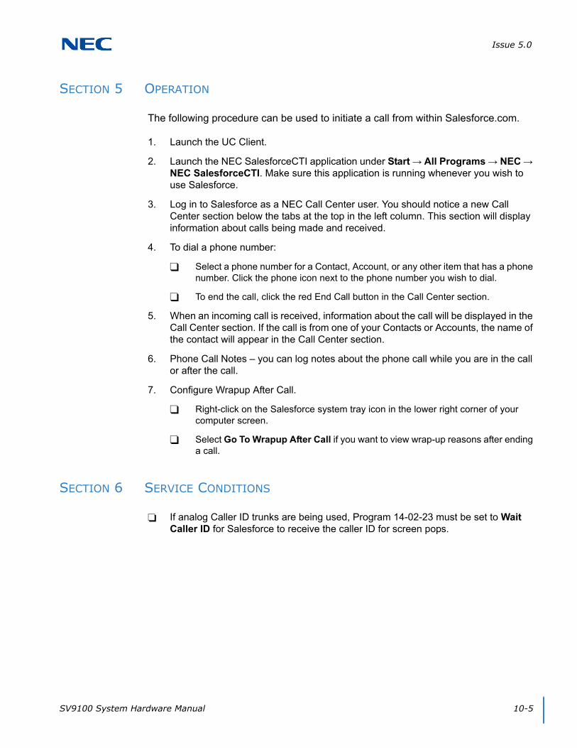
Issue 5.0
SV9100 System Hardware Manual 10-5
SECTION 5 OPERATION
The following procedure can be used to initiate a call from within Salesforce.com.
1. Launch the UC Client.
2. Launch the NEC SalesforceCTI application under Start → All Programs → NEC → NEC SalesforceCTI. Make sure this application is running whenever you wish to use Salesforce.
3. Log in to Salesforce as a NEC Call Center user. You should notice a new Call Center section below the tabs at the top in the left column. This section will display information about calls being made and received.
4. To dial a phone number:
Select a phone number for a Contact, Account, or any other item that has a phone number. Click the phone icon next to the phone number you wish to dial.
To end the call, click the red End Call button in the Call Center section.
5. When an incoming call is received, information about the call will be displayed in the Call Center section. If the call is from one of your Contacts or Accounts, the name of the contact will appear in the Call Center section.
6. Phone Call Notes – you can log notes about the phone call while you are in the call or after the call.
7. Configure Wrapup After Call.
Right-click on the Salesforce system tray icon in the lower right corner of your computer screen.
Select Go To Wrapup After Call if you want to view wrap-up reasons after ending a call.
SECTION 6 SERVICE CONDITIONS
If analog Caller ID trunks are being used, Program 14-02-23 must be set to Wait Caller ID for Salesforce to receive the caller ID for screen pops.

Issue 5.0
10-6 Salesforce Integration

SV9100 UC Suite Manual 11-1
Chapter 11
UNIVERGE® SV9100
Tigerpaw
SECTION 1 INTRODUCTION
This chapter describes the setup and operation that allows UC Suite to integrate with Tigerpaw® software. Tigerpaw software offers a comprehensive contact management system that includes account management, scheduling, customer history, notes, management of tasks and synchronization with Outlook. The integration with UC Suite allows users to initiate calls to contacts from within Tigerpaw and to open contacts automatically when an incoming call is received.
SECTION 2 OVERVIEW
Desktop Suite has been tested with Tigerpaw versions 9, 10.7.6, and 11.0.244.
UCS CRM Integrate (5310) license to enable the Tigerpaw integration. If this license is not installed, the UC Suite will not display the option to enable Tigerpaw integration.
When the Tigerpaw integration is enabled within the NEC Desktop Suite, the following operations are available:
Pop contact on incoming call that matches phone number.
Call contact phone number.
SECTION 3 UC CLIENT CONFIGURATION
To configure UC Client to use Tigerpaw CRM integration for screen pops complete the following:
1. To launch UC Client, ensure the UC Suite application is running whenever you wish to use Tigerpaw.

Issue 5.0
11-2 Tigerpaw
2. To configure UC Client:
a. Select menu item Tools → Preferences.
b. Select the Screen Pop tab.
c. Select Tigerpaw within the Contact Manager section and click the OK button.
a. Set the Activation and Call Filter settings to determine when to initiate the screen pop and which type of calls should cause the screen pop.
3. When an incoming call arrives, UC Client uses the calling line number to search the Tigerpaw database for a match. If a match is found, the associated contact is displayed, refer to Figure 11-1 Tigerpaw CRM Screen.
The contact screen may differ based upon the version of Tigerpaw in use and individual configuration settings.
Figure 11-1 Tigerpaw CRM Screen

Issue 5.0
SV9100 UC Suite Manual 11-3
SECTION 4 OPERATION
The following can be used to initiate a call from within Tigerpaw:
1. Select the contact to be dialed and open the dialing control, refer to Figure 11-2 Example of Dial Number Screen.
The dialing screen may differ based upon the version of Tigerpaw in use.
2. In the TAPI section, select NEC Single Line Device, refer to Figure 11-2 Example of Dial Number Screen.
3. Select the Dial button to initiate the call.
4. The UC Suite interface will update to show the status of the call.
5. Further operations can be initiated on the active call through the UC Suite, such as Transfer, Conference, Hold and HangUp.
Figure 11-2 Example of Dial Number Screen

Issue 5.0
11-4 Tigerpaw

SV9100 UC Suite Manual 12-1
Chapter 12
UNIVERGE® SV9100
Desktop Registration and Softphone Override
The UC Client registers with the SV9100 system as an IP (SIP) Station when Softphone or Softphone + Deskset license level is chosen in Program 20-59-14. This means that a UC Client + Softphone configured to control a physical phone uses an additional port from the system capacity when a non-Deskset Only license level is chosen in the configuration. In this scenario, two ports are in use, one for the physical extension and one for the UC Client connection. If the UC Client is run as just a Softphone, or as a UC Client controlling a Softphone, only the port the Softphone is registered on is used. If the UC Client is run for a deskset (physical phone) and a Deskset Only license level is chosen, no additional port is taken by the Desktop.
SECTION 1 REGISTRATION TYPES
When the UC Client is run for a Softphone or a non-Deskset Only license level, the UC Client registers as an IP station. There are three types of registration; Plug and Play, Automatic, and Manual.
Plug and Play requires no user name and password.
Automatic is not supported for UC Suite.
Manual requires a user name and password and the user is prompted to enter them.
Manual registration is required if the Softphone is to override an IP multiline phone and use the same extension number. When this is done, the IP multiline phone goes into a Log Off state and the Softphone comes up as the extension the IP phone used to be. This allows a user to use the same extension whether in the office or on the road.
If automatic or manual mode is used, the user must enter a user name and password. If the UC Client is run in deskset mode (controlling a physical phone) and the deskset phone used is an IP phone, the user name and password used for the UC Desktop Application is different than that of the actual IP phone. Below outlines examples of a SV9100 system set for Manual registration. The example assumes the system has 32 digital stations using ports 1~32 and eight IP stations using ports 33~40. The number plan has extensions 101~199 assigned to ports 1~99.
Issue 5.0
12-2 Desktop Registration and Softphone Override
Example 1IP station extension 150 is using port 33 and logs in with the user name and password assigned to extension 150. If a user wants to run a UC Client for extension 150, a new user name and password must be defined. This username and password must be assigned to an unused port. In this example, it can be ports 41~99 and the example will use port 41 (ext 141). In Manual registration, when the UC Client is launched, the user will be prompted for a user name and password. The user would enter the user name and password assigned to extension 141. At this point, port 41 will no longer be available in the system because it is registered to the PC running the UC Client for extension 150. The key point in this example is that the UC Client running in deskset mode for an IP phone cannot use the same user name and password assigned to the IP phone because the UC Client connection uses a different port.
Example 2Digital station extension 101 is using port 1. If a user wants to run a UC Client for extension 101, a user name and password must be assigned to a port the UC Client will use to register with the system. In this example, port 42 (ext 142) will be used. In Manual registration, when the UC Client is launched, the user will be prompted for a user name and password. The user would enter the user name and password assigned to extension 142. At this point, port 42 will no longer be available in the system because it is registered to the PC running the UC Client for extension 101.
Example 3IP station extension 151 is using port 34 and logs in with the user name and password assigned to extension 151. The person that sits at extension 151 in the office goes out of the office and wishes to run the UC Client as a Softphone for extension 151. This is only possible if the registration mode is manual. When the UC Client is launched, the user will be prompted for a user name and password. The user would enter the user name and password assigned to extension 151. The IP station that was 151 in the office will show Log Off in the display, and the UC Client Softphone will come up as extension 151. When the user is back in the office, they would press the exit soft key and the phone will reset and prompt for a login. They would enter the user name and password assigned to extension 151, and the IP phone will come back up as extension 151.
Example 4A user wishes to have a Softphone that is a different extension than the one they use in the office. A user name and password can be assigned to extension 143. In Manual registration, when the user launches the UC Client, the user will be prompted for a password. The user would enter the user name and password assigned to extension 143, and the Softphone extension will be 143. At this point, port 43 will no longer be available in the system because it is registered to the PC running the UC Client for Softphone extension 143.

Issue 5.0
SV9100 UC Suite Manual 12-3
SECTION 2 SERVICE CONDITIONS
The following service conditions apply:
When running UC Client in deskset mode for an IP phone and the registration mode is set to manual, the user name and password must be different than that of the IP phone.
A Softphone that is assigned a DSS console cannot override another IP phone.
A Softphone cannot override an IP phone that is assigned a DSS console.
When a Softphone with a DSS console is logged in, it cannot log in with a different user name and password.
When a UC Client is launched on one PC using a User ID and Password in deskset or Softphone mode, the same User ID and Password cannot be used on a different PC in a different mode.
Any IP multiline terminal or UC Client must appear to be on the same network as the SV9100 VoIP Interface (IPLE). For remote UC Clients, such as Softphone, this can be achieved by using a VPN connection to the network where the SV9100 resides.

Issue 5.0
12-4 Desktop Registration and Softphone Override

SV9100 UC Suite Manual 13-1
Chapter 13
UNIVERGE® SV9100
Data Conference
SECTION 1 INTRODUCTION
Data Conference provides support for Video Conference (maximum of eight parties), Communications Board, File Transfer and Chat. Data Conference can be accessed from the Function Toolbar or the More drop down. The image below is an example of a Data Conference.
Data Conference requires an UCS Soft Phone Enhancement license (5303) and is not available in the Deskset Only configuration.
The following sections describe how to use the Data Conference module for Chat, File Transfer, Video and Communications board.
Figure 13-1 Data Meeting Screen

Issue 5.0
13-2 Data Conference
SECTION 2 STARTING A DATA MEETING
1. When on a call with another UC Client user, click the Data Conference icon on the toolbar, or select Data Conference from the More drop down.
Figure 13-2 Data Conference Tool
Figure 13-3 Data Conference Menu

Issue 5.0
SV9100 UC Suite Manual 13-3
2. The Choose Party Dialog box opens. Choose the other Desktop users to add to the Conference and click Start.
3. The other party receives an Incoming Request Window. Clicking OK will open the Data Conference Window for them as well.
Figure 13-4 Choose Party Screen
Figure 13-5 Incoming Request Screen
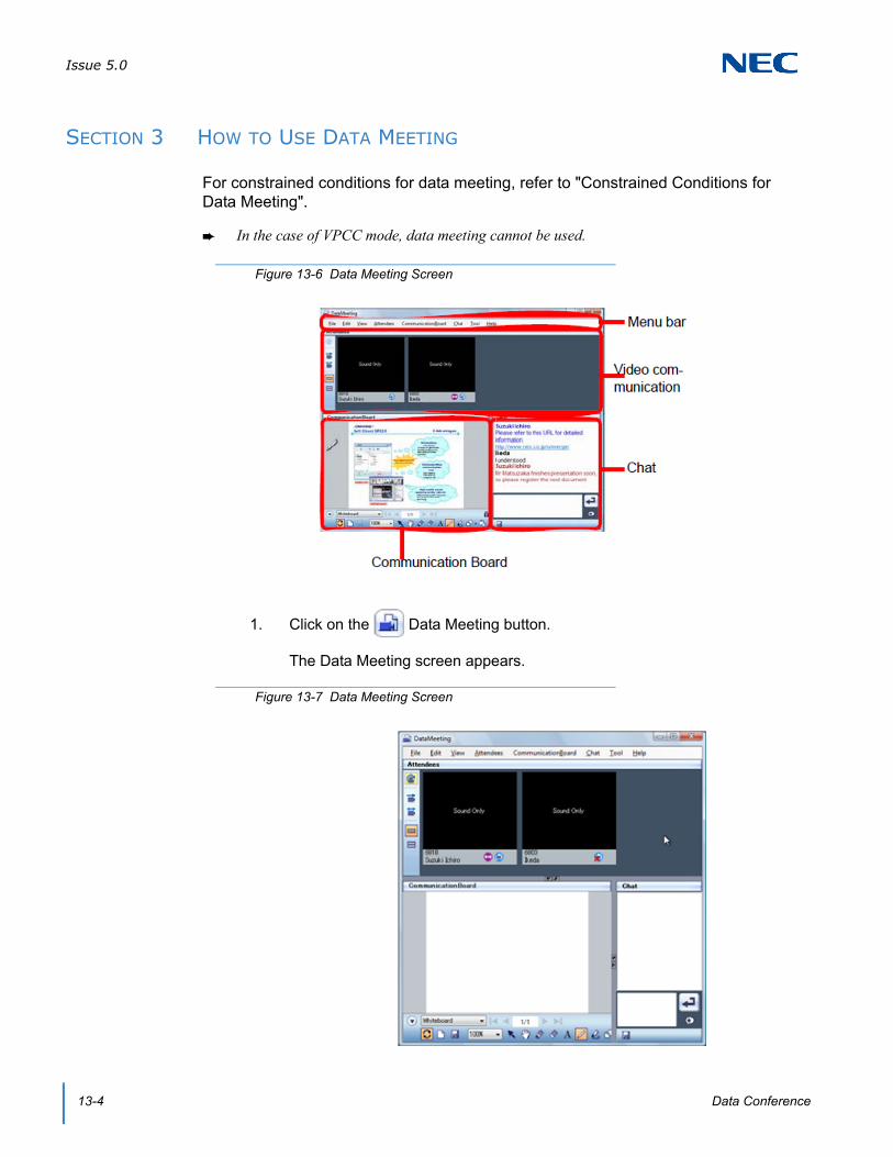
Issue 5.0
13-4 Data Conference
SECTION 3 HOW TO USE DATA MEETING
For constrained conditions for data meeting, refer to "Constrained Conditions for Data Meeting".
In the case of VPCC mode, data meeting cannot be used.
1. Click on the Data Meeting button.
The Data Meeting screen appears.
Figure 13-6 Data Meeting Screen
Figure 13-7 Data Meeting Screen

Issue 5.0
SV9100 UC Suite Manual 13-5
The Data conference participation invitation dialog appears on the display of the other party.
2. The other party clicks on the button.
The Data Meeting screen appears on the display of the other party.
Data Meeting is now started.
Figure 13-8 Data Conference Participation Invitation
Figure 13-9 Data Meeting Screen – Other Party
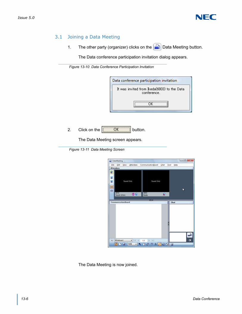
Issue 5.0
13-6 Data Conference
3.1 Joining a Data Meeting
1. The other party (organizer) clicks on the Data Meeting button.
The Data conference participation invitation dialog appears.
2. Click on the button.
The Data Meeting screen appears.
The Data Meeting is now joined.
Figure 13-10 Data Conference Participation Invitation
Figure 13-11 Data Meeting Screen
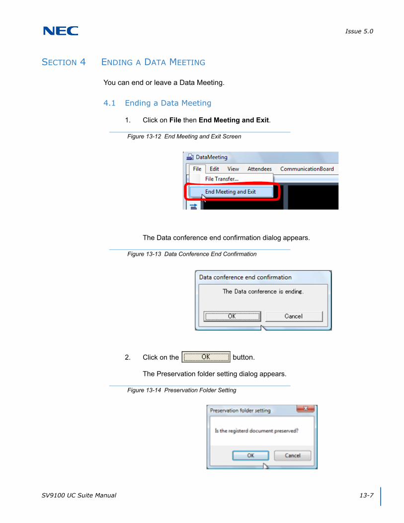
Issue 5.0
SV9100 UC Suite Manual 13-7
SECTION 4 ENDING A DATA MEETING
You can end or leave a Data Meeting.
4.1 Ending a Data Meeting
1. Click on File then End Meeting and Exit.
The Data conference end confirmation dialog appears.
2. Click on the button.
The Preservation folder setting dialog appears.
Figure 13-12 End Meeting and Exit Screen
Figure 13-13 Data Conference End Confirmation
Figure 13-14 Preservation Folder Setting

Issue 5.0
13-8 Data Conference
3. Click on the button.
To save the data:On the Preservation folder setting dialog click OK to save the data.
The Data Meeting ends.
4.2 Leaving a Data Meeting
Participants can leave a data meeting. Even when a participant leaves a meeting, other participants can continue the meeting.
1. You are in a Data Meeting.
2. Click on File then Leave and Exit.
The Data conference leaving confirmation dialog appears.
3. Click on the button.
Figure 13-15 End Meeting and Exit Screen
Figure 13-16 Data Conference Leaving Confirmation

Issue 5.0
SV9100 UC Suite Manual 13-9
If data is currently registered, the Preservation folder setting dialog appears.
4. Click on the button.
To save the data:Click the OK button on the Preservation folder setting dialog to save the data.
5. You leave the Data Meeting.
SECTION 5 USING VIDEO COMMUNICATION
Allows Data Meeting participants to talk face-to-face.
Video communication is available only when you are talking with the other party. The Data Meeting button is not displayed when you are not talking with the other party.
5.1 Icons
Figure 13-17 Preservation Folder Setting
Figure 13-18 Data Meeting Areas Defined

Issue 5.0
13-10 Data Conference
5.2 Starting Video Communication
1. You are in a Data Meeting.
2. Click on the Stop video transmission button.
Your image is transmitted to the other party.
To start video communication immediately:You can start video communication immediately by clicking the Data Meeting button without clicking on the Stop Video Transmission icon. For details, refer to "Configuring video transmission/reception".
Table 13-1 Video Icons
Button Name Description
Update participant list Updates the participant list to the latest state.
Display video in single-deck format
Displays video in single-deck format.
Display video in double-deck format
Displays video in double-deck format.
Stop video transmission
Starts/stops video transmission.
Stop video transmission/reception
Starts/stops video transmission/reception.
Organizer icon Indicates that the participant is the organizer.
Data Meeting status icon
Indicates if the user during a call can join or have joined the data meeting.
Call status icon Indicates the status of the user during a call.
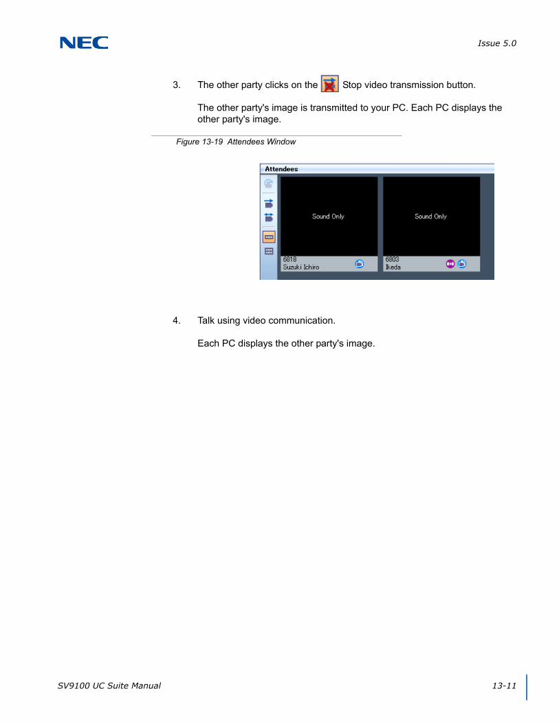
Issue 5.0
SV9100 UC Suite Manual 13-11
3. The other party clicks on the Stop video transmission button.
The other party's image is transmitted to your PC. Each PC displays the other party's image.
4. Talk using video communication.
Each PC displays the other party's image.
Figure 13-19 Attendees Window

Issue 5.0
13-12 Data Conference
SECTION 6 USING THE COMMUNICATION BOARD
Data meeting participants can use the white board on their own PC. Participants can share data and write in the shared data freely to share and exchange information. Operations can be performed simultaneously.
6.1 Icons
Figure 13-20 Communication Board Screen
Table 13-2 Common Icons
Button Name Description
Open/Close Toolbar button
Switches display/nondisplay of the lower part of the toolbar.
Data Name box Selects the data or displays the selected data name.
Top Page button Displays the top page of the displayed data.
Previous Page button Displays the previous page of the displayed data.
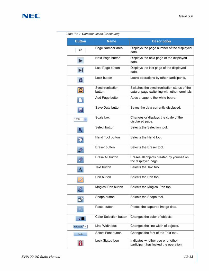
Issue 5.0
SV9100 UC Suite Manual 13-13
Page Number area Displays the page number of the displayed data.
Next Page button Displays the next page of the displayed data.
Last Page button Displays the last page of the displayed data.
Lock button Locks operations by other participants.
Synchronization button
Switches the synchronization status of the data or page switching with other terminals.
Add Page button Adds a page to the white board.
Save Data button Saves the data currently displayed.
Scale box Changes or displays the scale of the displayed page.
Select button Selects the Selection tool.
Hand Tool button Selects the Hand tool.
Eraser button Selects the Eraser tool.
Erase All button Erases all objects created by yourself on the displayed page.
Text button Selects the Text tool.
Pen button Selects the Pen tool.
Magical Pen button Selects the Magical Pen tool.
Shape button Selects the Shape tool.
Paste button Pastes the captured image data.
Color Selection button Changes the color of objects.
Line Width box Changes the line width of objects.
Select Font button Changes the font of the Text tool.
Lock Status icon Indicates whether you or another participant has locked the operation.
Table 13-2 Common Icons (Continued)
Button Name Description

Issue 5.0
13-14 Data Conference
6.2 Sharing Data
Data can be shared at a meeting by data registration.
6.2.1 Drag and Drop
1. Drag the data to be shared.
2. Drop it on the Communication Board.
Figure 13-21 Drag and Drop Screen
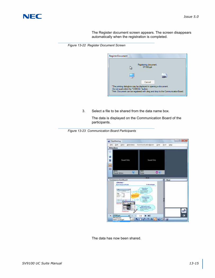
Issue 5.0
SV9100 UC Suite Manual 13-15
The Register document screen appears. The screen disappears automatically when the registration is completed.
3. Select a file to be shared from the data name box.
The data is displayed on the Communication Board of the participants.
The data has now been shared.
Figure 13-22 Register Document Screen
Figure 13-23 Communication Board Participants

Issue 5.0
13-16 Data Conference
6.2.2 Menu
1. Select the Communication Board menu.
2. Select Open Document.
The Open screen appears.
3. Select a file to be shared.
Figure 13-24 Communication Board Menu
Figure 13-25 Open Screen
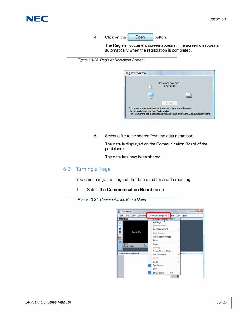
Issue 5.0
SV9100 UC Suite Manual 13-17
4. Click on the button.
The Register document screen appears. The screen disappears automatically when the registration is completed.
5. Select a file to be shared from the data name box.
The data is displayed on the Communication Board of the participants.
The data has now been shared.
6.3 Turning a Page
You can change the page of the data used for a data meeting.
1. Select the Communication Board menu.
Figure 13-26 Register Document Screen
Figure 13-27 Communication Board Menu
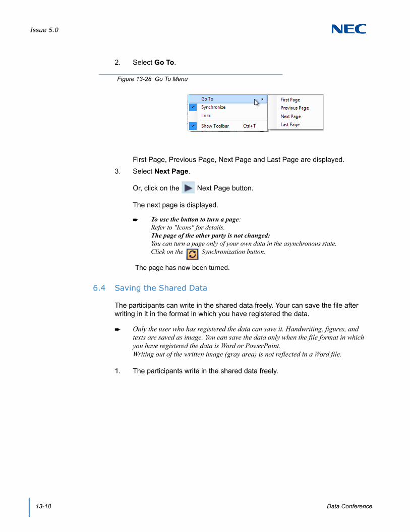
Issue 5.0
13-18 Data Conference
2. Select Go To.
First Page, Previous Page, Next Page and Last Page are displayed.
3. Select Next Page.
Or, click on the Next Page button.
The next page is displayed.
To use the button to turn a page:Refer to "Icons" for details. The page of the other party is not changed:You can turn a page only of your own data in the asynchronous state.Click on the Synchronization button.
The page has now been turned.
6.4 Saving the Shared Data
The participants can write in the shared data freely. Your can save the file after writing in it in the format in which you have registered the data.
Only the user who has registered the data can save it. Handwriting, figures, and texts are saved as image. You can save the data only when the file format in which you have registered the data is Word or PowerPoint.Writing out of the written image (gray area) is not reflected in a Word file.
1. The participants write in the shared data freely.
Figure 13-28 Go To Menu
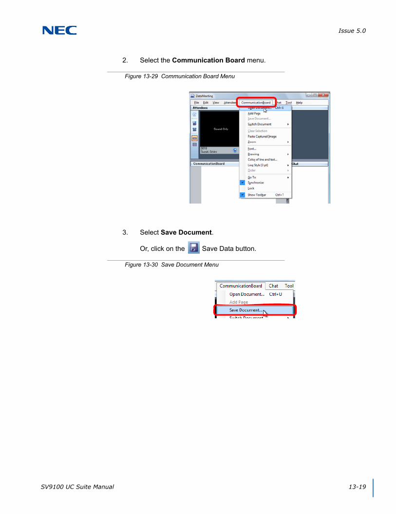
Issue 5.0
SV9100 UC Suite Manual 13-19
2. Select the Communication Board menu.
3. Select Save Document.
Or, click on the Save Data button.
Figure 13-29 Communication Board Menu
Figure 13-30 Save Document Menu
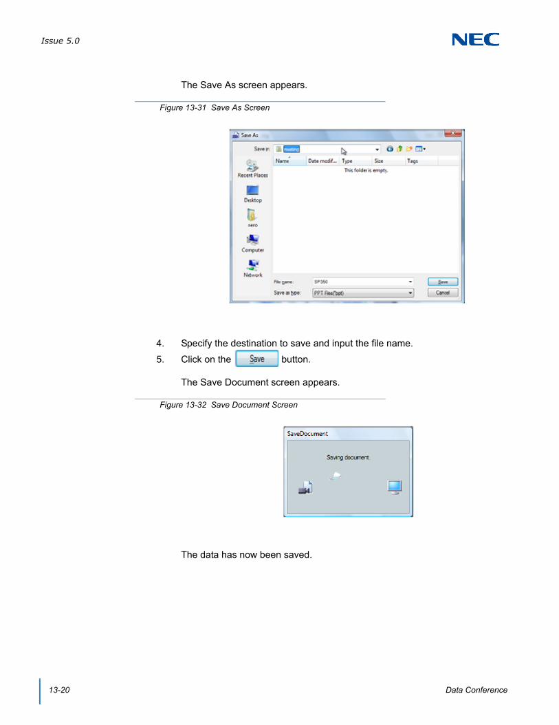
Issue 5.0
13-20 Data Conference
The Save As screen appears.
4. Specify the destination to save and input the file name.
5. Click on the button.
The Save Document screen appears.
The data has now been saved.
Figure 13-31 Save As Screen
Figure 13-32 Save Document Screen

Issue 5.0
SV9100 UC Suite Manual 13-21
SECTION 7 USING FILE TRANSFER
You can transfer a file to the participants of a data meeting.
7.1 Transferring a File
Drag and drop the target file on the target screen. The Material distribution screen appears.
1. You are in a data meeting.
2. Select a file to transfer.
3. Drag and drop it on the screen of the participant to whom you want to transfer it.
Or, click File then File Transfer.
Figure 13-33 Drag and Drop Screen
Figure 13-34 File Transfer Menu

Issue 5.0
13-22 Data Conference
The Material distribution screen appears.
4. Select Specified user under Distribution target.
To transfer the file to all participants:Select All users in Distribution target to transfer the file to all participants.
Figure 13-35 Material Distribution Screen
Figure 13-36 Material Distribution Screen – Specified User
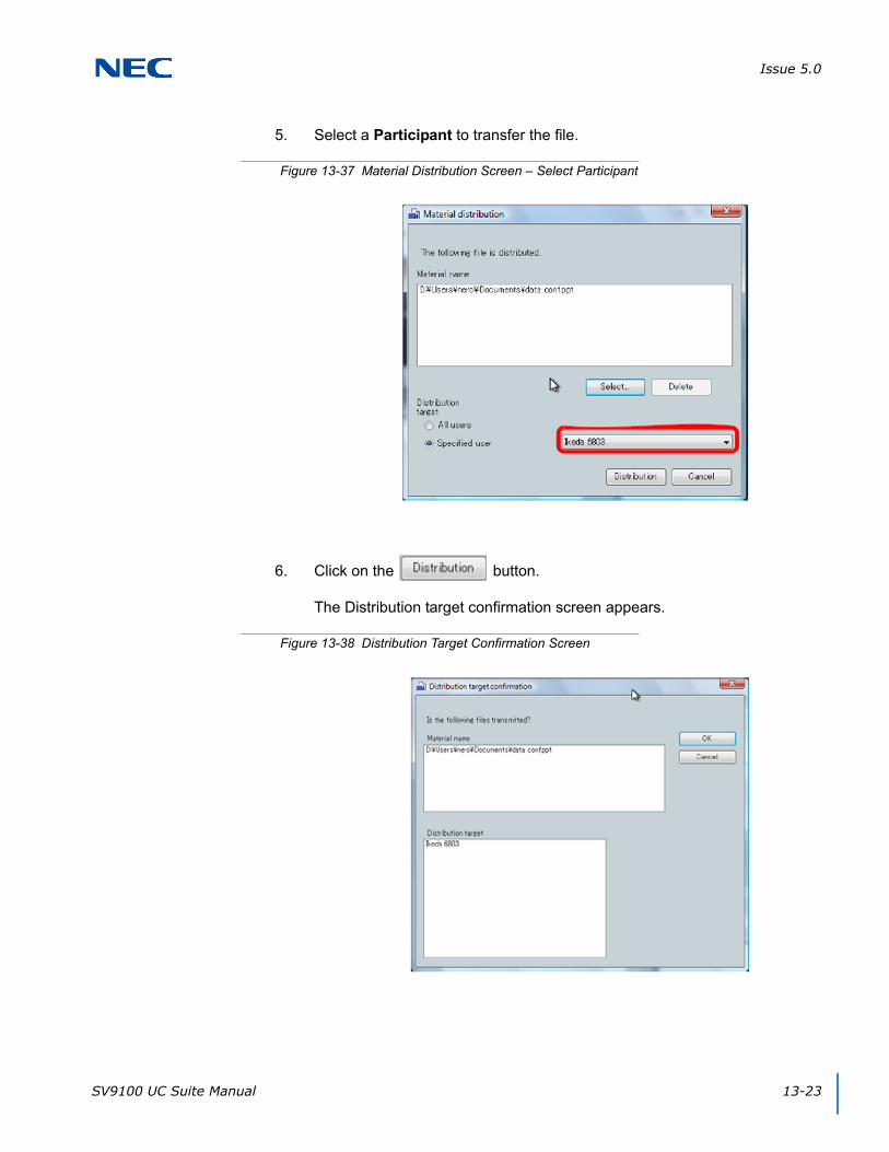
Issue 5.0
SV9100 UC Suite Manual 13-23
5. Select a Participant to transfer the file.
6. Click on the button.
The Distribution target confirmation screen appears.
Figure 13-37 Material Distribution Screen – Select Participant
Figure 13-38 Distribution Target Confirmation Screen
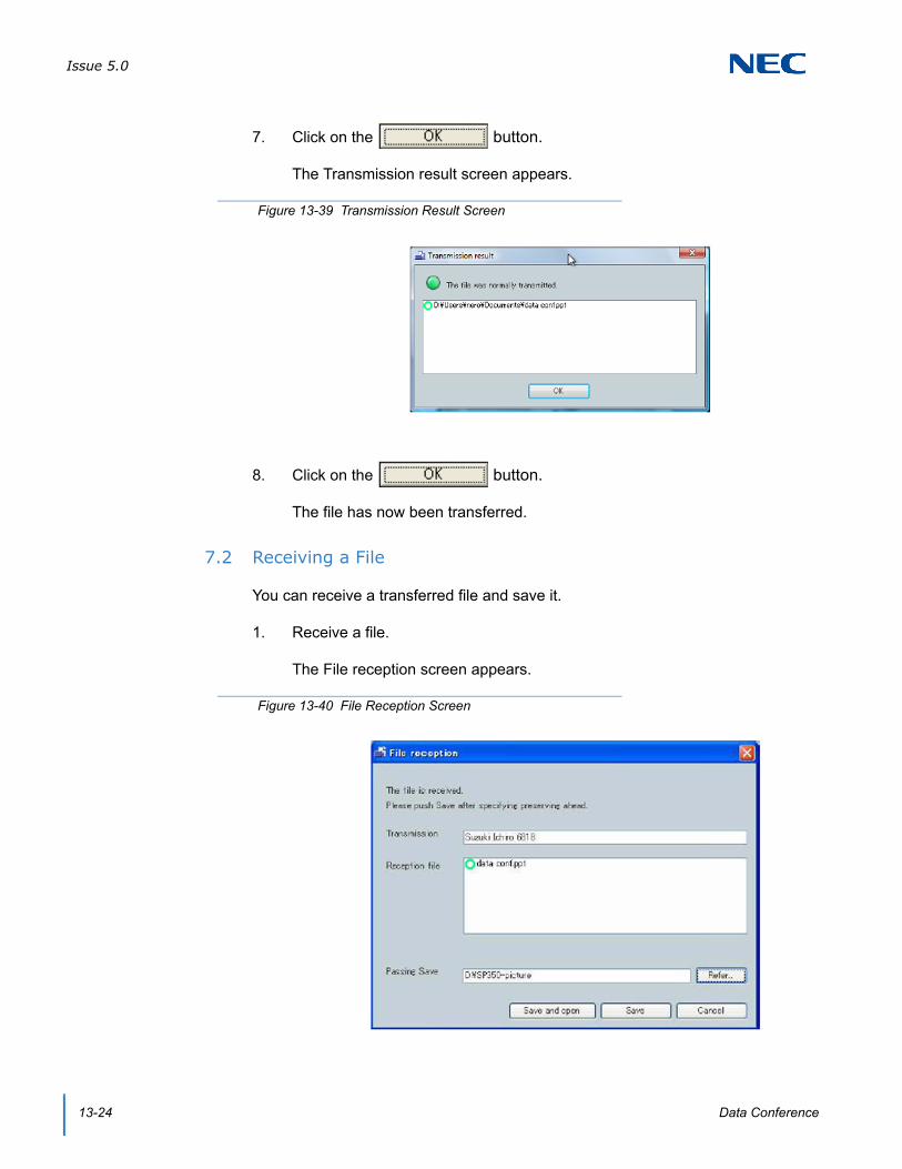
Issue 5.0
13-24 Data Conference
7. Click on the button.
The Transmission result screen appears.
8. Click on the button.
The file has now been transferred.
7.2 Receiving a File
You can receive a transferred file and save it.
1. Receive a file.
The File reception screen appears.
Figure 13-39 Transmission Result Screen
Figure 13-40 File Reception Screen
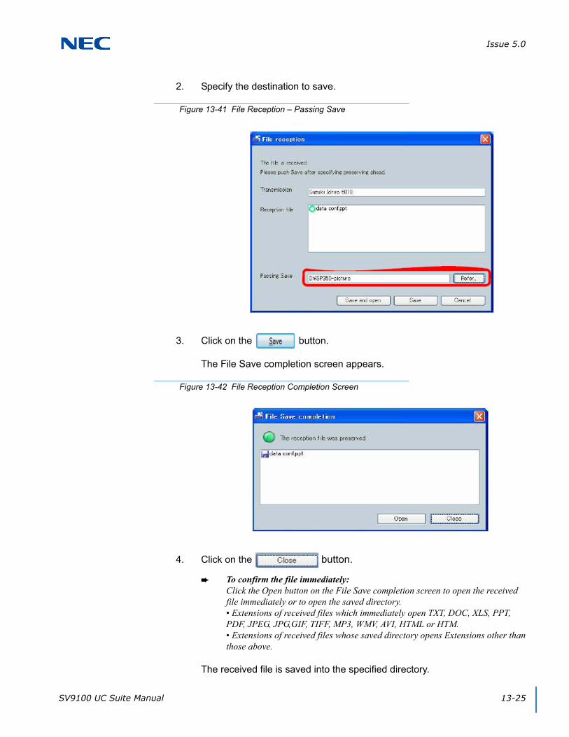
Issue 5.0
SV9100 UC Suite Manual 13-25
2. Specify the destination to save.
3. Click on the button.
The File Save completion screen appears.
4. Click on the button.
To confirm the file immediately:Click the Open button on the File Save completion screen to open the received file immediately or to open the saved directory.• Extensions of received files which immediately open TXT, DOC, XLS, PPT, PDF, JPEG, JPG,GIF, TIFF, MP3, WMV, AVI, HTML or HTM.• Extensions of received files whose saved directory opens Extensions other than those above.
The received file is saved into the specified directory.
Figure 13-41 File Reception – Passing Save
Figure 13-42 File Reception Completion Screen

Issue 5.0
13-26 Data Conference
SECTION 8 USING CHAT
You can communicate with the other party using characters (chat). You can give contents that are hard to convey in conversation (website address, address, etc.) easily.
8.1 Icons
Figure 13-43 Chat Screen
Table 13-1 Chat Icons
Button Name Description
Save File button Saves all messages in the chat display area as a text file.
Send Chat button Sends the message in the chat display area to all other participants.
Display Whisper Chat screen button
Displays the Whisper Chat screen to send whisper chat.
Switch Display check box
Sets whether to display the Whisper Chat screen after the message transmission.
Send Chat button Sends the message in the chat display area to the participant specified in the Destination field.
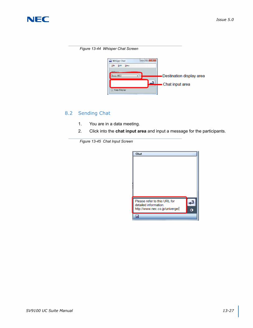
Issue 5.0
SV9100 UC Suite Manual 13-27
8.2 Sending Chat
1. You are in a data meeting.
2. Click into the chat input area and input a message for the participants.
Figure 13-44 Whisper Chat Screen
Figure 13-45 Chat Input Screen

Issue 5.0
13-28 Data Conference
3. Click on the Send Chat button.
Or, in the Chat menu click on Send. The input message is displayed on the display of other participants.
To restrict the destination of a message:When three or more parties are using chat, you can send a message to a specific participant. For details, refer to "Sending WhisperChat".
4. When you receive a message from a participant, the chat display area displays it.
Repeat Steps 3 to 5 for conversation using characters.
Figure 13-46 Chat Send Screen
Figure 13-47 Chat Receive Screen

Issue 5.0
SV9100 UC Suite Manual 13-29
5. To save the content of the chat when you finish the chat, click on the Save File button.
Or, in the Chat menu select Save. The Save As screen appears.
6. Specify the file name to save.
7. Click on the button.
8.3 Sending Whisper Chat
You can send a message only to the specified participant.
1. You are in a data meeting.
Figure 13-48 Save As Screen
Figure 13-49 Save As – Specify File Name

Issue 5.0
13-30 Data Conference
2. Click on the Whisper Chat button.
The Whisper Chat screen appears.
3. Select a destination to send whisper chat.
4. Click the chat input area and input a message.
Figure 13-50 Whisper Chat Screen
Figure 13-51 Whisper Chat – Address
Figure 13-52 Whisper Chat – Input Area
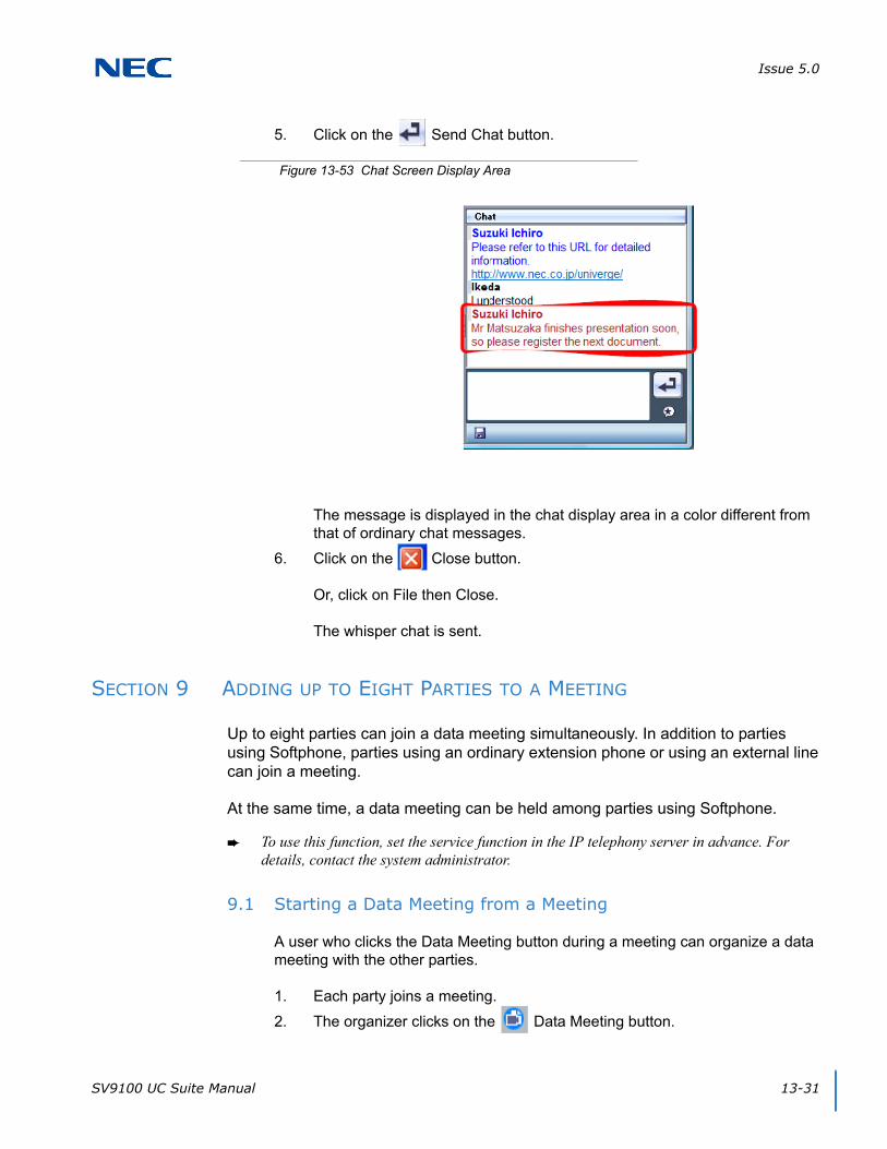
Issue 5.0
SV9100 UC Suite Manual 13-31
5. Click on the Send Chat button.
The message is displayed in the chat display area in a color different from that of ordinary chat messages.
6. Click on the Close button.
Or, click on File then Close.
The whisper chat is sent.
SECTION 9 ADDING UP TO EIGHT PARTIES TO A MEETING
Up to eight parties can join a data meeting simultaneously. In addition to parties using Softphone, parties using an ordinary extension phone or using an external line can join a meeting.
At the same time, a data meeting can be held among parties using Softphone.
To use this function, set the service function in the IP telephony server in advance. For details, contact the system administrator.
9.1 Starting a Data Meeting from a Meeting
A user who clicks the Data Meeting button during a meeting can organize a data meeting with the other parties.
1. Each party joins a meeting.
2. The organizer clicks on the Data Meeting button.
Figure 13-53 Chat Screen Display Area
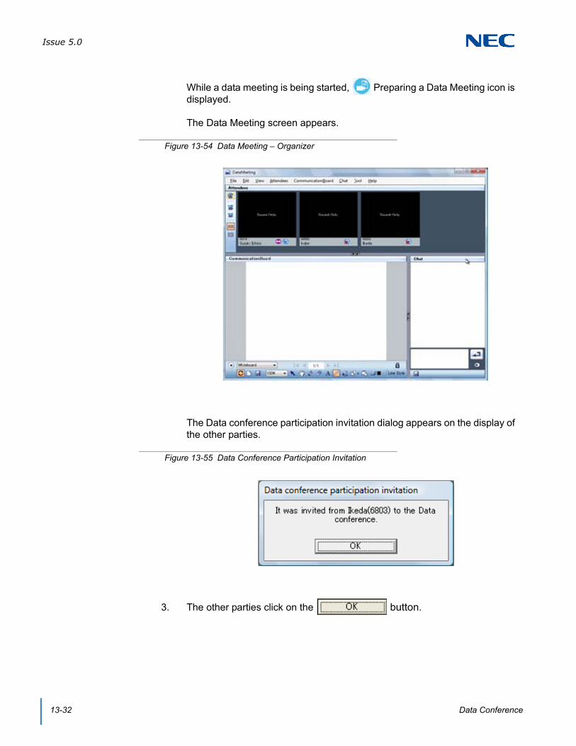
Issue 5.0
13-32 Data Conference
While a data meeting is being started, Preparing a Data Meeting icon is displayed.
The Data Meeting screen appears.
The Data conference participation invitation dialog appears on the display of the other parties.
3. The other parties click on the button.
Figure 13-54 Data Meeting – Organizer
Figure 13-55 Data Conference Participation Invitation

Issue 5.0
SV9100 UC Suite Manual 13-33
The Data Meeting screen appears on the display of the other parties.
The screen above shows an example of a 5-party meeting.
The data meeting is started from a meeting.
SECTION 10 HOW TO USE VARIOUS SETTINGS
You can set up various items for a data meeting.
10.1 Displaying the Settings Screen
1. Click Tool then Set Up.
Figure 13-56 Data Meeting – 5-Party Example
Figure 13-57 Setup Menu
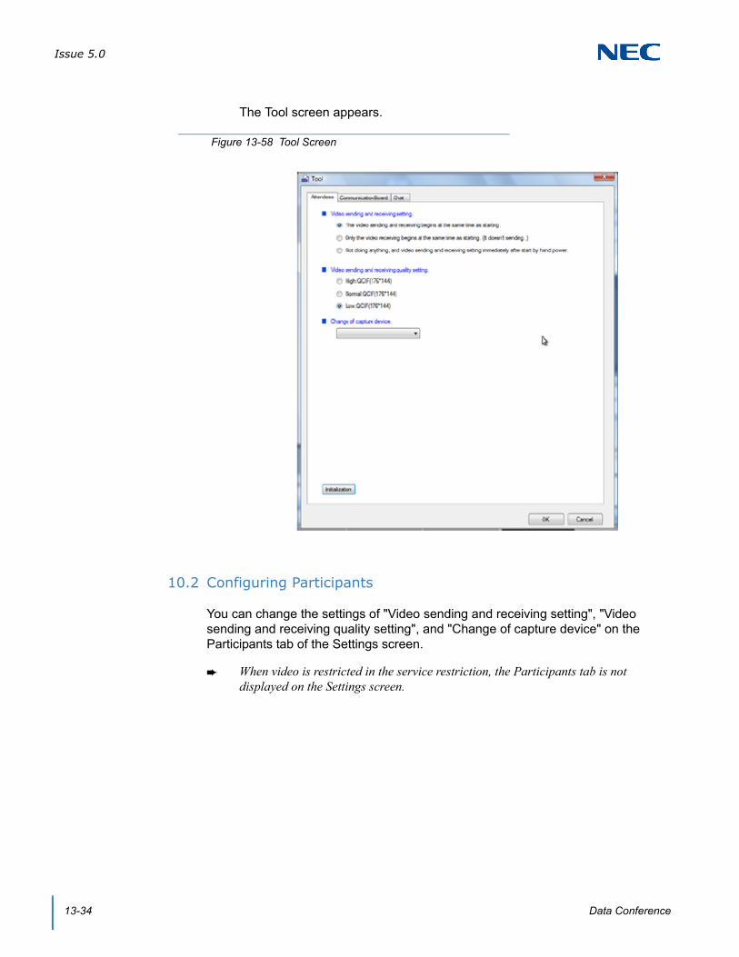
Issue 5.0
13-34 Data Conference
The Tool screen appears.
10.2 Configuring Participants
You can change the settings of "Video sending and receiving setting", "Video sending and receiving quality setting", and "Change of capture device" on the Participants tab of the Settings screen.
When video is restricted in the service restriction, the Participants tab is not displayed on the Settings screen.
Figure 13-58 Tool Screen

Issue 5.0
SV9100 UC Suite Manual 13-35
10.2.1 Video Sending and Receiving Setting
You can set whether to transmit/receive video simultaneously with the start of a data meeting.
To start video transmission/reception simultaneously with the start of a data meeting:Select The video sending and receiving begins at the same time as starting. to start video transmission/reception simultaneously with the start of a data meeting.
To start only video reception simultaneously with the start of a data meeting:Select Only the video receiving begins at the same time as starting. (It doesn't sending.) to start only video reception simultaneously with the start of a data meeting.
To not transmit/receive video right after the start of a data meeting, but to start video transmission/reception manually:Select Not doing anything, and video sending and receiving setting immediately after start by hand power. to start video transmission/reception manually.
Figure 13-59 Video Sending and Receiving Setting

Issue 5.0
13-36 Data Conference
10.2.2 Video Sending and Receiving Quality Setting
You can set the quality of the video to be transmitted.
The change is reflected the next time you join a data meeting.
To use the high quality video transmission:Select High: QCIF (176*144) to use the high quality video transmission for a data meeting.
To use the ordinary quality video transmission:Select Normal: QCIF (176*144) to use the ordinary quality video transmission for a data meeting.
To use the low quality video transmission:Select Low: QCIF (176*144) to use the low quality video transmission for a data meeting.
Figure 13-60 Video Sending and Receiving Quality Setting
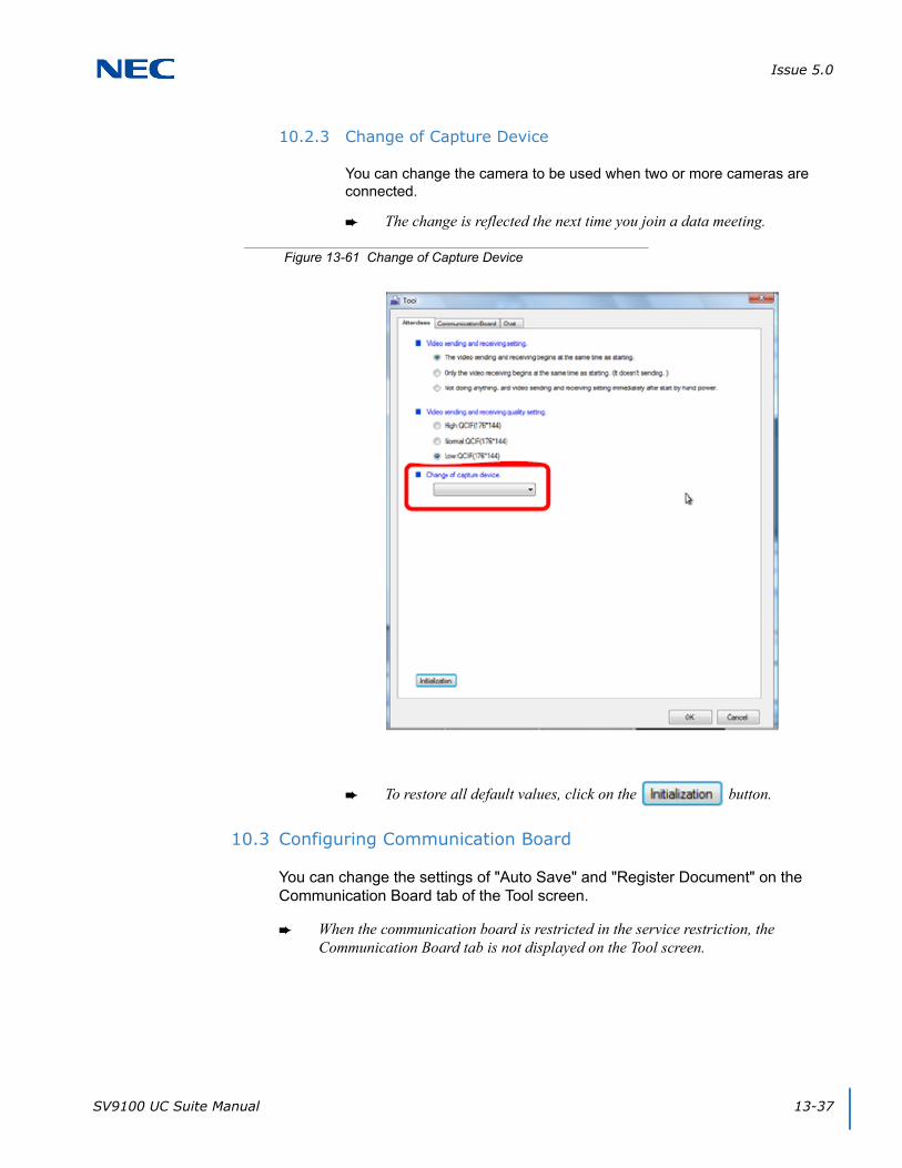
Issue 5.0
SV9100 UC Suite Manual 13-37
10.2.3 Change of Capture Device
You can change the camera to be used when two or more cameras are connected.
The change is reflected the next time you join a data meeting.
To restore all default values, click on the button.
10.3 Configuring Communication Board
You can change the settings of "Auto Save" and "Register Document" on the Communication Board tab of the Tool screen.
When the communication board is restricted in the service restriction, the Communication Board tab is not displayed on the Tool screen.
Figure 13-61 Change of Capture Device
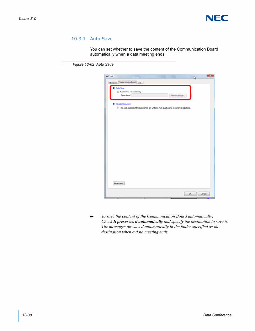
Issue 5.0
13-38 Data Conference
10.3.1 Auto Save
You can set whether to save the content of the Communication Board automatically when a data meeting ends.
To save the content of the Communication Board automatically:Check It preserves it automatically and specify the destination to save it. The messages are saved automatically in the folder specified as the destination when a data meeting ends.
Figure 13-62 Auto Save
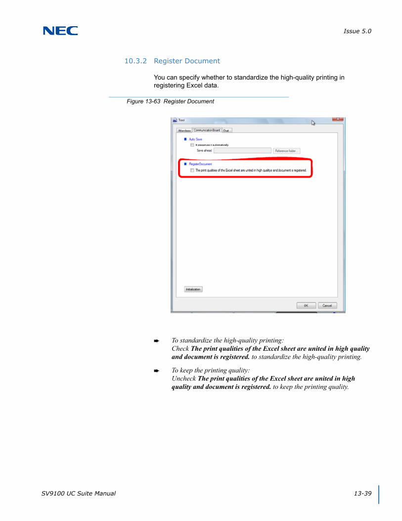
Issue 5.0
SV9100 UC Suite Manual 13-39
10.3.2 Register Document
You can specify whether to standardize the high-quality printing in registering Excel data.
To standardize the high-quality printing:Check The print qualities of the Excel sheet are united in high quality and document is registered. to standardize the high-quality printing.
To keep the printing quality:Uncheck The print qualities of the Excel sheet are united in high quality and document is registered. to keep the printing quality.
Figure 13-63 Register Document
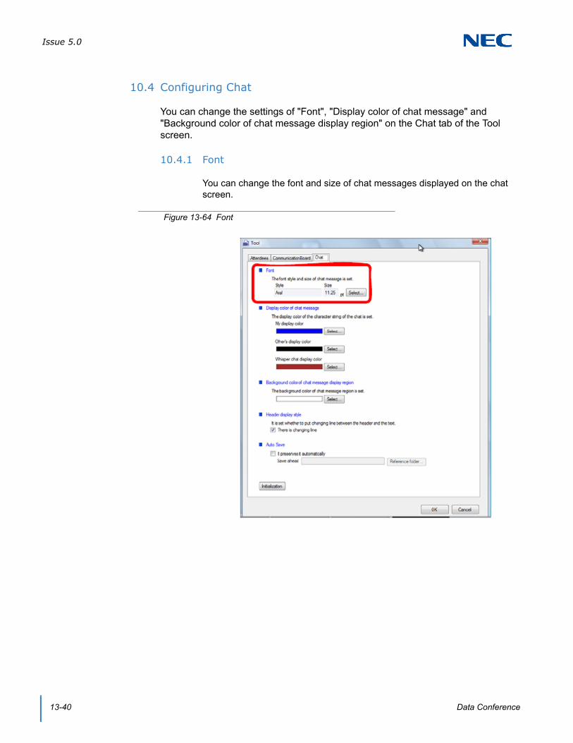
Issue 5.0
13-40 Data Conference
10.4 Configuring Chat
You can change the settings of "Font", "Display color of chat message" and "Background color of chat message display region" on the Chat tab of the Tool screen.
10.4.1 Font
You can change the font and size of chat messages displayed on the chat screen.
Figure 13-64 Font

Issue 5.0
SV9100 UC Suite Manual 13-41
10.4.2 Display Color of Chat Message
You can change the color of chat messages displayed on the chat screen.
To change the display color of messages you transmit:Select and set My display color to change the display color of your own messages. For whisper chat messages, the Whisper chat display color is used.
To change the display color of other participants' messages:Select and set Other’s display color to change the display color of other participants' messages.
To change the display color of whisper chat messages:Select and set Whisper chat display color to change the display color of whisper chat messages.
Figure 13-65 Display Color of Chat Message
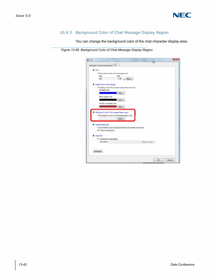
Issue 5.0
13-42 Data Conference
10.4.3 Background Color of Chat Message Display Region
You can change the background color of the chat character display area.
Figure 13-66 Background Color of Chat Message Display Region

Issue 5.0
SV9100 UC Suite Manual 13-43
10.4.4 Header Display Style
You can specify whether to insert a line break between the header (user name) and the message.
To remove the line break between the header (user name) and the message:Uncheck There is changing line to remove the line break between the user name and the message.
Figure 13-67 Header Display Style

Issue 5.0
13-44 Data Conference
10.4.5 Auto Save
You can set whether to save chat messages automatically when a data meeting ends.
To save chat messages automatically when a data meeting ends:Check It preserves it automatically and specify the destination to save them. The messages are saved automatically in the folder specified as the destination when a data meeting ends.
Figure 13-68 Auto Save
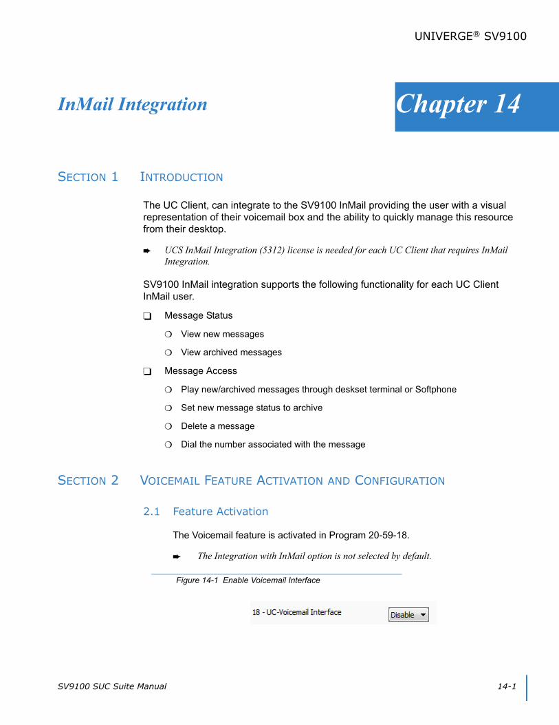
SV9100 SUC Suite Manual 14-1
Chapter 14
UNIVERGE® SV9100
InMail Integration
SECTION 1 INTRODUCTION
The UC Client, can integrate to the SV9100 InMail providing the user with a visual representation of their voicemail box and the ability to quickly manage this resource from their desktop.
UCS InMail Integration (5312) license is needed for each UC Client that requires InMail Integration.
SV9100 InMail integration supports the following functionality for each UC Client InMail user.
Message Status
View new messages
View archived messages
Message Access
Play new/archived messages through deskset terminal or Softphone
Set new message status to archive
Delete a message
Dial the number associated with the message
SECTION 2 VOICEMAIL FEATURE ACTIVATION AND CONFIGURATION
2.1 Feature Activation
The Voicemail feature is activated in Program 20-59-18.
The Integration with InMail option is not selected by default.
Figure 14-1 Enable Voicemail Interface

Issue 5.0
14-2 InMail Integration
2.2 Feature Configuration
Each user can enable the voicemail integration feature by adjusting the settings within the Preferences menus. Refer to Figure 14-2 Preferences – Voice Mail Tab for the integration options available on the Voicemail tab.
Enable access to voicemail messages – controls if the user can display the voicemail message window. By default this option is not be selected.
Password required for voicemail login – indicates if the user voicemail account is setup to require a password for login. By default this option is not be selected. This field will only be enabled if the previous field has been selected.
Password – allows the user to enter their numeric password to login to the voicemail system. This field will only be enabled if the previous field has been selected.
Figure 14-2 Preferences – Voice Mail Tab
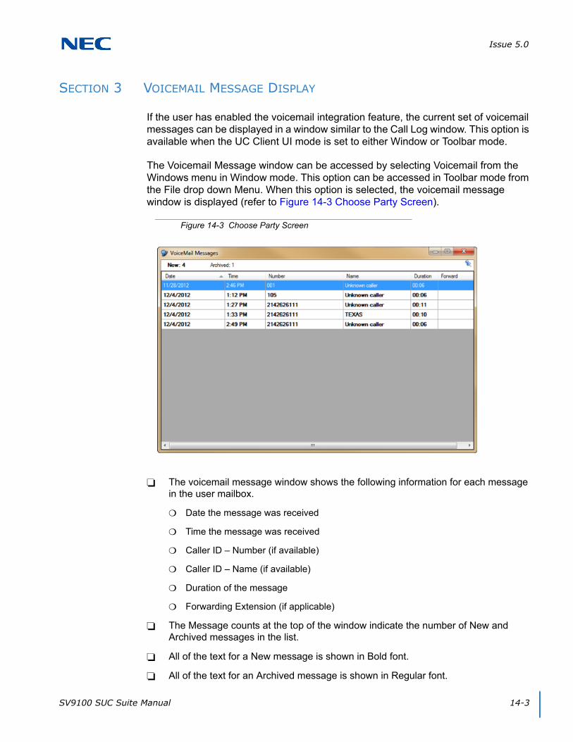
Issue 5.0
SV9100 SUC Suite Manual 14-3
SECTION 3 VOICEMAIL MESSAGE DISPLAY
If the user has enabled the voicemail integration feature, the current set of voicemail messages can be displayed in a window similar to the Call Log window. This option is available when the UC Client UI mode is set to either Window or Toolbar mode.
The Voicemail Message window can be accessed by selecting Voicemail from the Windows menu in Window mode. This option can be accessed in Toolbar mode from the File drop down Menu. When this option is selected, the voicemail message window is displayed (refer to Figure 14-3 Choose Party Screen).
The voicemail message window shows the following information for each message in the user mailbox.
Date the message was received
Time the message was received
Caller ID – Number (if available)
Caller ID – Name (if available)
Duration of the message
Forwarding Extension (if applicable)
The Message counts at the top of the window indicate the number of New and Archived messages in the list.
All of the text for a New message is shown in Bold font.
All of the text for an Archived message is shown in Regular font.
Figure 14-3 Choose Party Screen

Issue 5.0
14-4 InMail Integration
The user can re-sort the message list using the Date, Number, Name, Duration, and Forward fields. The default is to sort by Date, with the most recent message at the top.
The width of each field can be adjusted by the user.
The standard Window controls allow the user to Maximize, Minimize and Close the voicemail message list.
Pinning – to the far right side of the toolbar, there is a pushpin. Clicking this pins the Voicemail Messages widow to a tab in the BLF/DSS view. When pinned, if the Voicemail tab is active, the pin will UnPin the Voicemail from a tab and make it a separate window.
SECTION 4 VOICEMAIL MESSAGE OPERATIONS
4.1 Playback, Archive, Delete or Dial Number Associated with Message
A right mouse click on a New message will open a pop-up menu allowing the user to Play, Archive, Delete or Dial the message. Figure 14-4 VoiceMail Messages – Menu Screen provides an example of the operations available.
Play – initiates playback of the selected message through the supported telephone device (Softphone or deskset).
While Playback is in progress, no other voicemail functions can be initiated.
Archive – changes the status of the selected message from New to Archived.
Playing a New message does not automatically change the status to Archive.
A right mouse click on an Archived message displays only the Play and Delete functions.
Figure 14-4 VoiceMail Messages – Menu Screen

Issue 5.0
SV9100 SUC Suite Manual 14-5
Delete – removes the selected message from the list and from the user voicemail box.
Dial – dial the extension or phone number associated with a message.
4.2 Forward Message
If a voicemail message has been forwarded to the user, the Forward column indicates the extension that forwarded the message (refer to Figure 14-5 Data Meeting Screen). Hovering the mouse over the Forward cell in the message list opens a balloon displaying additional details of the forwarding party.
The Forward balloon includes the following information (if available):
Name of Forwarding Party
Length of Introduction
Date Message was Forwarded
Time Message was Forwarded
4.3 New Message Indication
If the user has enabled the voicemail integration, a new message indication is displayed in both the Window and Toolbar mode. The indicator shows the number of New messages in the user mailbox. Figure 14-6 Window Mode and Figure 14-7 Toolbar Mode on page 14-6 show the location of the indicator within both modes.
Figure 14-5 Data Meeting Screen

Issue 5.0
14-6 InMail Integration
Upon startup the desktop client checks the New message count. If the New message count is greater than zero, the message icon and message count is displayed. The message count is updated when the UC Client receives events that affect the new message count. If the new message count goes to zero, the message icon is removed.
Figure 14-6 Window Mode
Figure 14-7 Toolbar Mode
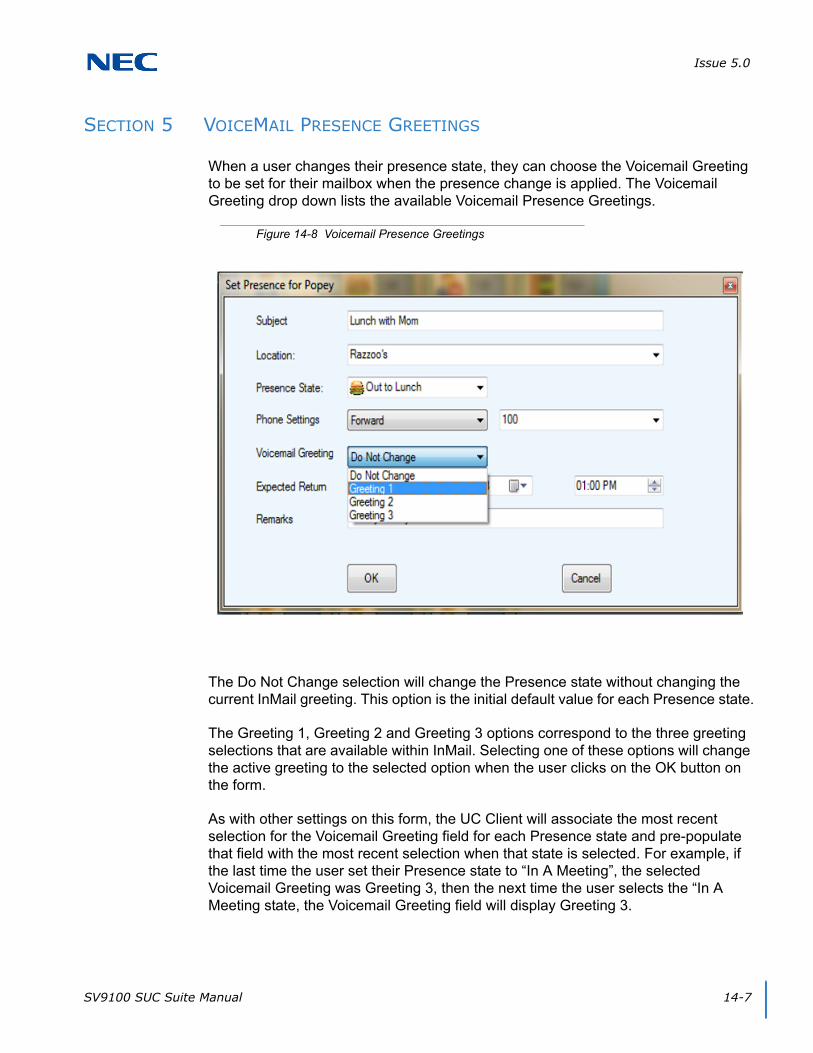
Issue 5.0
SV9100 SUC Suite Manual 14-7
SECTION 5 VOICEMAIL PRESENCE GREETINGS
When a user changes their presence state, they can choose the Voicemail Greeting to be set for their mailbox when the presence change is applied. The Voicemail Greeting drop down lists the available Voicemail Presence Greetings.
The Do Not Change selection will change the Presence state without changing the current InMail greeting. This option is the initial default value for each Presence state.
The Greeting 1, Greeting 2 and Greeting 3 options correspond to the three greeting selections that are available within InMail. Selecting one of these options will change the active greeting to the selected option when the user clicks on the OK button on the form.
As with other settings on this form, the UC Client will associate the most recent selection for the Voicemail Greeting field for each Presence state and pre-populate that field with the most recent selection when that state is selected. For example, if the last time the user set their Presence state to “In A Meeting”, the selected Voicemail Greeting was Greeting 3, then the next time the user selects the “In A Meeting state, the Voicemail Greeting field will display Greeting 3.
Figure 14-8 Voicemail Presence Greetings
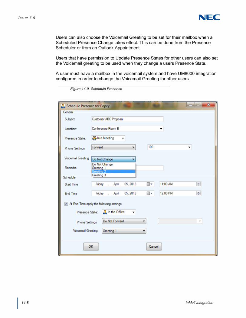
Issue 5.0
14-8 InMail Integration
Users can also choose the Voicemail Greeting to be set for their mailbox when a Scheduled Presence Change takes effect. This can be done from the Presence Scheduler or from an Outlook Appointment.
Users that have permission to Update Presence States for other users can also set the Voicemail greeting to be used when they change a users Presence State.
A user must have a mailbox in the voicemail system and have UM8000 integration configured in order to change the Voicemail Greeting for other users.
Figure 14-9 Schedule Presence
Issue 5.0
SV9100 SUC Suite Manual 14-9
SECTION 6 EXCEPTIONS
If the UC Client is unable to access the voicemail interface when the user attempts to open the voicemail message display, an error window is displayed that indicating the error received. Some of the error conditions that should be indicated are:
Could not access voicemail system
Could not access requested mailbox
Invalid mailbox password

Issue 5.0
14-10 InMail Integration
SV9100 UC Suite Manual 15-1
Chapter 15
UNIVERGE® SV9100
UM8000 Integration
SECTION 1 INTRODUCTION
Desktop can integrate to the SV9100 UM8000 providing the user with a visual representation of their voicemail box and the ability to quickly manage this resource from their desktop.
One UMS Client license (License number 1404) per UC Client user that will use UM8000 integration.
SV9100 UM8000 integration supports the following functionality for each Desktop UM8000 user.
Message Status
View Number of New and Archived Messages
View New and Archived Message Properties
Message Access
Play New/Archived Messages through PC audio device
Set New Message status to Archive
Delete a Message
Return Call if Number is present
Presence Voice Mail Greetings
Assign a Voice Mail Greeting to:
A Presence Change
A Scheduled Presence Change
A Outlook Appointment Presence Change

Issue 5.0
15-2 UM8000 Integration
SECTION 2 VOICEMAIL FEATURE CONFIGURATION – DESKTOP
The VM Feature is activated in Program 20-59-18.
Each user can enable the voicemail integration feature by adjusting the settings within the Preferences menus. The voicemail integration options are available on the Voicemail tab, as shown below.
Figure 15-1 Enable Voicemail Interface
Figure 15-2 Preferences Menu – Voice Mail

Issue 5.0
SV9100 UC Suite Manual 15-3
Enable access to voicemail messages and greetings – controls if the user can display the voicemail message window and Voicemail Greetings field in Presence Window. This is a read only option that is set by Program 20-59-18.
Security code required for voicemail login – indicates if the user’s voicemail account is setup to require a password or security code for login. By default this option will not be selected.
Personal ID – define the personal ID of the mailbox the users Desktop will be associated with. By default will be blank.
Security Code – allows the user to enter their numeric password to login to the voicemail system.
UM8000 IP Address – define the IP Address of the UM8000 Voicemail system. By default will be blank.
SECTION 3 VOICEMAIL MESSAGE DISPLAY
If the user has enabled the voicemail integration feature, the current set of voicemail messages can be displayed in a window similar to the Call Log window. This option is available when the UC Client UI mode is set to either Window or Toolbar mode. If the Voicemail window is pinned to the BLF view, it will show up as a tab in the BLF view and not a separate window.
The Voicemail Message window can be accessed by selecting Voicemail from the Windows menu in Window mode. This option can be accessed in Toolbar mode from the File drop down Menu. When this option is selected, the voicemail message window will open. Refer to Figure 15-3 VoiceMail Messages Screen on page 15-4 for an example of this window.
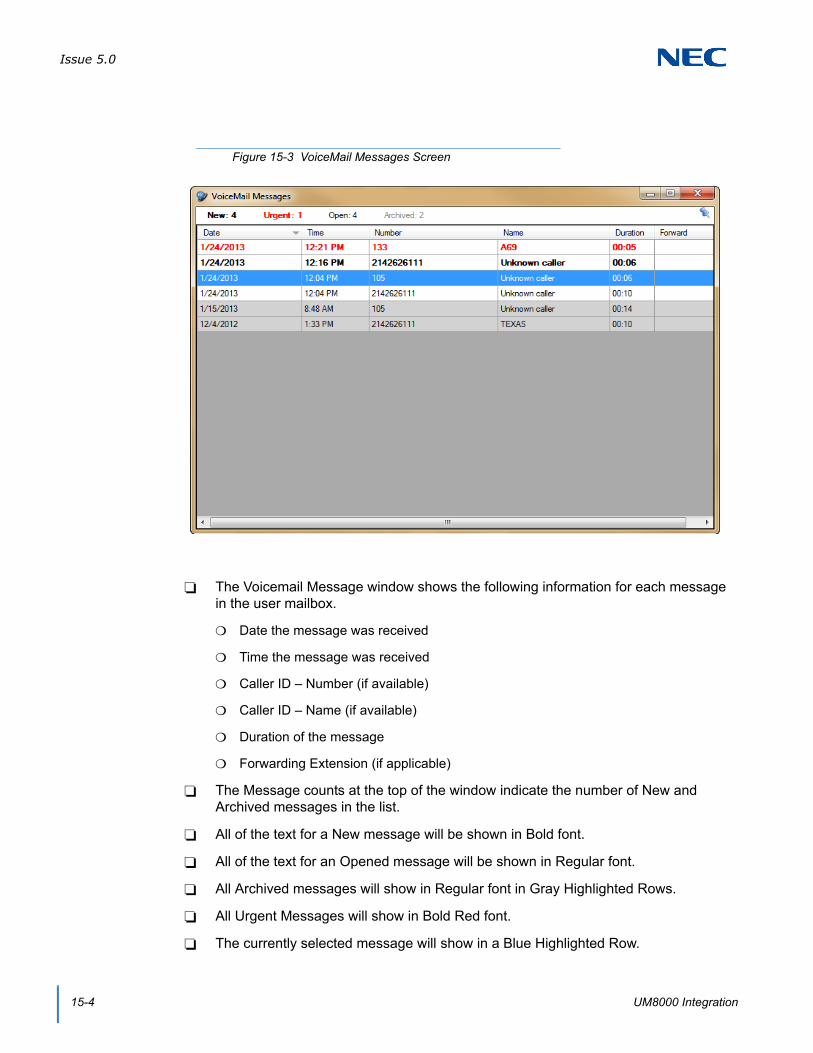
Issue 5.0
15-4 UM8000 Integration
The Voicemail Message window shows the following information for each message in the user mailbox.
Date the message was received
Time the message was received
Caller ID – Number (if available)
Caller ID – Name (if available)
Duration of the message
Forwarding Extension (if applicable)
The Message counts at the top of the window indicate the number of New and Archived messages in the list.
All of the text for a New message will be shown in Bold font.
All of the text for an Opened message will be shown in Regular font.
All Archived messages will show in Regular font in Gray Highlighted Rows.
All Urgent Messages will show in Bold Red font.
The currently selected message will show in a Blue Highlighted Row.
Figure 15-3 VoiceMail Messages Screen
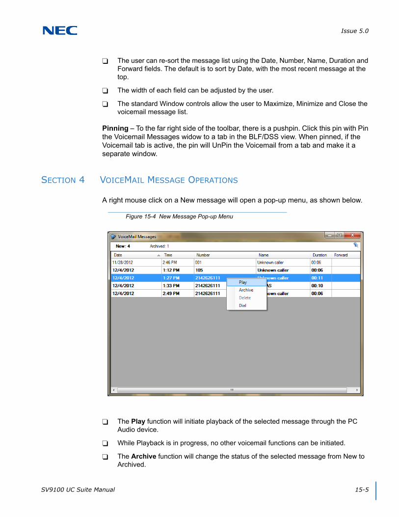
Issue 5.0
SV9100 UC Suite Manual 15-5
The user can re-sort the message list using the Date, Number, Name, Duration and Forward fields. The default is to sort by Date, with the most recent message at the top.
The width of each field can be adjusted by the user.
The standard Window controls allow the user to Maximize, Minimize and Close the voicemail message list.
Pinning – To the far right side of the toolbar, there is a pushpin. Click this pin with Pin the Voicemail Messages widow to a tab in the BLF/DSS view. When pinned, if the Voicemail tab is active, the pin will UnPin the Voicemail from a tab and make it a separate window.
SECTION 4 VOICEMAIL MESSAGE OPERATIONS
A right mouse click on a New message will open a pop-up menu, as shown below.
The Play function will initiate playback of the selected message through the PC Audio device.
While Playback is in progress, no other voicemail functions can be initiated.
The Archive function will change the status of the selected message from New to Archived.
Figure 15-4 New Message Pop-up Menu

Issue 5.0
15-6 UM8000 Integration
The Delete function will remove the selected message from the list and from the user voicemail box.
A right mouse click on an Archived message will offer only the Play and Dial functions.
Playing a New message will not automatically change the status to Archive.
SECTION 5 FORWARD MESSAGE DETAILS
If a voicemail message has been forwarded to the user, the Forward column will indicate the extension that forwarded the message. Hovering the mouse over the Forward cell in the message list will open a balloon that will include the additional details of the forwarding party. An example of this information is shown in the following image.
The Forward balloon includes the following information (if available):
Name of Forwarding Party
Length of Introduction
Date Message was Forwarded
Time Message was Forwarded
Figure 15-5 Forward Column Balloon Details

Issue 5.0
SV9100 UC Suite Manual 15-7
SECTION 6 NEW MESSAGE INDICATION
If the user has enabled the VoiceMail Integration, then a new message indication will be shown in both Window mode and Toolbar mode. The indicator will show the number of New messages in the user mailbox. The following examples show the location of the indicator within both modes.
Upon startup, the UC Client will check the New message count. If the New message count is greater than zero, then the message icon and message count will be displayed. The message count will be updated when the UC Client receives events that affect the new message count. If the new message count goes to zero, then the message icon will be removed.
Figure 15-6 New Message – Window Mode
Figure 15-7 New Message – Toolbar Mode

Issue 5.0
15-8 UM8000 Integration
SECTION 7 VOICEMAIL PRESENCE GREETINGS FEATURE CONFIGURATION
The UM8000 can be configured to support the Presence Greetings that are associated with a UC Suite Presence State.
In the UM8000 Main Menu, go to System → Configuration → Presence Greetings. In the Presence Integration drop down, choose UC Suite. Define the Default Presence Greeting, the Presence Greetings, and record a system wide greeting for each Presence State.
Figure 15-8 Presence Greeting Screen
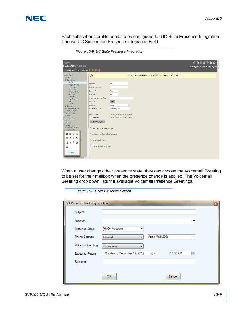
Issue 5.0
SV9100 UC Suite Manual 15-9
Each subscriber’s profile needs to be configured for UC Suite Presence Integration. Choose UC Suite in the Presence Integration Field.
When a user changes their presence state, they can choose the Voicemail Greeting to be set for their mailbox when the presence change is applied. The Voicemail Greeting drop down lists the available Voicemail Presence Greetings.
Figure 15-9 UC Suite Presence Integration
Figure 15-10 Set Presence Screen

Issue 5.0
15-10 UM8000 Integration
Users can also choose the Voicemail Greeting to be set for their mailbox when a Scheduled Presence Change takes effect. This can be done from the Presence Scheduler or from an Outlook Appointment.
Users that have permission to Update Presence States for other users can also set the Voicemail greeting to be used when they change a users Presence State.
A user must have a mailbox in the voicemail system and have UM8000 integration configured in order to change the Voicemail Greeting for other users.
Figure 15-11 Schedule Presence Screen

Issue 5.0
SV9100 UC Suite Manual 15-11
SECTION 8 EXCEPTIONS
If the UC Suite is unable to access the voicemail interface when the user attempts to open the voicemail message display, an error window will be displayed that indicates the error that was received. Some of the error conditions that should be indicated are:
Could not access voicemail system
Could not access requested mailbox
Invalid mailbox password
The voicemail interface will also be inhibited if the user mailbox is in use through telephone access. In this case, the Play, Delete and Archive functions will be disabled until the voicemail interface can be accessed.

Issue 5.0
15-12 UM8000 Integration
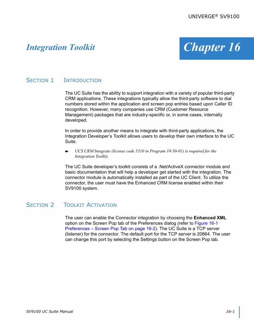
SV9100 UC Suite Manual 16-1
Chapter 16
UNIVERGE® SV9100
Integration Toolkit
SECTION 1 INTRODUCTION
The UC Suite has the ability to support integration with a variety of popular third-party CRM applications. These integrations typically allow the third-party software to dial numbers stored within the application and screen pop entries based upon Caller ID recognition. However, many companies use CRM (Customer Resource Management) packages that are industry-specific or, in some cases, internally developed.
In order to provide another means to integrate with third-party applications, the Integration Developer’s Toolkit allows users to develop their own interface to the UC Suite.
UCS CRM Integrate (license code 5310 in Program 10-50-01) is required for the Integration Toolkit.
The UC Suite developer’s toolkit consists of a .Net/ActiveX connector module and basic documentation that will help a developer get started with the integration. The connector module is automatically installed as part of the UC Client. To utilize the connector, the user must have the Enhanced CRM license enabled within their SV9100 system.
SECTION 2 TOOLKIT ACTIVATION
The user can enable the Connector integration by choosing the Enhanced XML option on the Screen Pop tab of the Preferences dialog (refer to Figure 16-1 Preferences – Screen Pop Tab on page 16-2). The UC Suite is a TCP server (listener) for the connector. The default port for the TCP server is 20864. The user can change this port by selecting the Settings button on the Screen Pop tab.

Issue 5.0
16-2 Integration Toolkit
The Connector is a .NET ActiveX DLL. There is a COM class for the Plug-in named CrmPlugin.DSApi. A second class, CallEventArgs, is used as a convenience class to pass data related to telephony events received from the UC Suite. To access the DSApi class the integrator must add a reference to the CrmPlugin Typelib.
The class has a single property:
IsConnected – Returns true if the connection to UC Suite is active.
The class has the following methods:
AnswerCall – Answer the call specified by the call handle parameter.
ConferenceCall – Initiate a three way conference with the current call and the specified destination.
Figure 16-1 Preferences – Screen Pop Tab
Issue 5.0
SV9100 UC Suite Manual 16-3
DialDigits – Send a Dial request to the UC Suite. The digits to dial are passed as a parameter.
DropCall – Hangup the call specified by the call handle parameter.
HoldCall – Place the specified call on hold.
MakeCall – Send a make call request to the UC Suite. The number to dial is passed as a parameter.
RetrieveCall – Retrieve the specified on hold call.
Shutdown – Close the connection to UC Suite.
Startup – Open a connection to UC Suite. Returns true if the connection is successful.
TransferCall – Perform an immediate transfer of the current call to the requested destination number.
TransferCallToVoicemail – Perform an immediate transfer of the current call to the destination mail box.
The class raises two events:
OnConnectionStateChanged – This event is raised when the state of the connection to UC Suite changes. The ConnectionStateArgs parameter has two fields. The IsConnected field indicates whether the connection is active.
OnCallEvent – This event is raised when a call event is received from UC Suite. The event has a single parameter of type CallEventArgs.
The class has several properties describing attributes of the event. The same class is used both for incoming call status events and dial out status events The ‘IsOutbound’ property may be used to determine the direction of the call. The following properties are supported:
CalledID – The called number or DNIS as identified by the telephone system.
CallerID – The caller ID for an inbound call or the called ID for an outbound call.
CallerName – This field is not populated in the current TAPI implementation.
CallHandle – This field represents an internal ID associated with the call that generated the event.
ChangeTime – The time when the event occurred.
IsOutbound – A Boolean indicating the direction of the call.
State – The state of the call as defined in the CallStates enumeration. Valid States are: Busy, Conferenced, Connected, Dialing, Dialtone, Disconnected, Idle, Offering, OnHold, Proceeding, Ringback and Unknown.

Issue 5.0
16-4 Integration Toolkit
Status – A string representing the status of the call out status messages.
TrunkNumber – The trunk number of the current call event. A trunk number of 0 represents an internal call.
SV9100 UC Suite Manual 17-1
Chapter 17
UNIVERGE® SV9100
UC Web Client
SECTION 1 INTRODUCTION
UC Web Client allows a user to launch the UC Client from within an Internet browser window. The browser-based client will provide many of the features that are available within the full UC Client.
The availability of a browser-based UC Web Client allows users to access the SV9100 UC functionality on a variety of platforms, including:
Remote Desktop Services (formerly Terminal Services) environments
Citrix environments
Non-Windows environments (Apple, Linux, etc.)
Tablet (UC Suite Version 3.0.0.0 or higher).
Additionally, traditional Windows users may find the deployment and maintenance of the UC Web Client more efficient than the full Windows client installation.
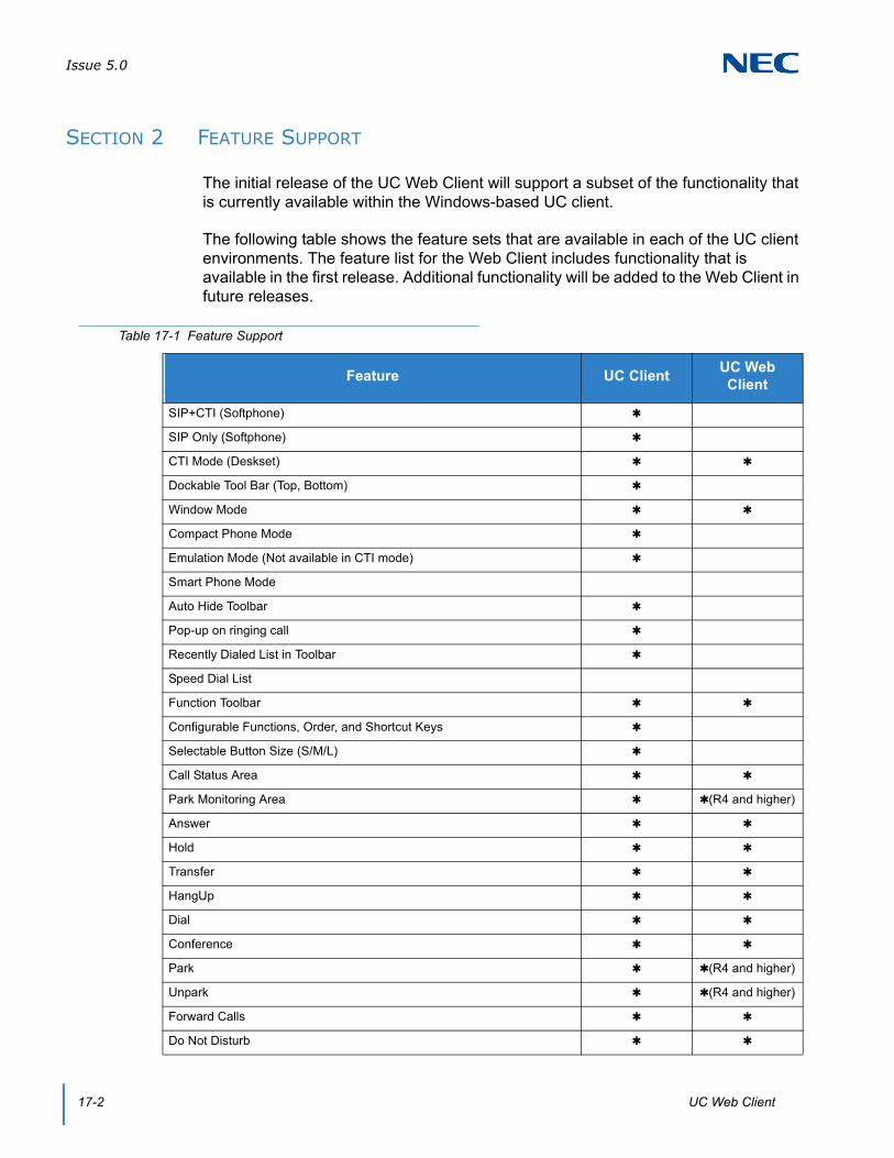
Issue 5.0
17-2 UC Web Client
SECTION 2 FEATURE SUPPORT
The initial release of the UC Web Client will support a subset of the functionality that is currently available within the Windows-based UC client.
The following table shows the feature sets that are available in each of the UC client environments. The feature list for the Web Client includes functionality that is available in the first release. Additional functionality will be added to the Web Client in future releases.
Table 17-1 Feature Support
Feature UC ClientUC Web Client
SIP+CTI (Softphone)
SIP Only (Softphone)
CTI Mode (Deskset)
Dockable Tool Bar (Top, Bottom)
Window Mode
Compact Phone Mode
Emulation Mode (Not available in CTI mode)
Smart Phone Mode
Auto Hide Toolbar
Pop-up on ringing call
Recently Dialed List in Toolbar
Speed Dial List
Function Toolbar
Configurable Functions, Order, and Shortcut Keys
Selectable Button Size (S/M/L)
Call Status Area
Park Monitoring Area (R4 and higher)
Answer
Hold
Transfer
HangUp
Dial
Conference
Park (R4 and higher)
Unpark (R4 and higher)
Forward Calls
Do Not Disturb
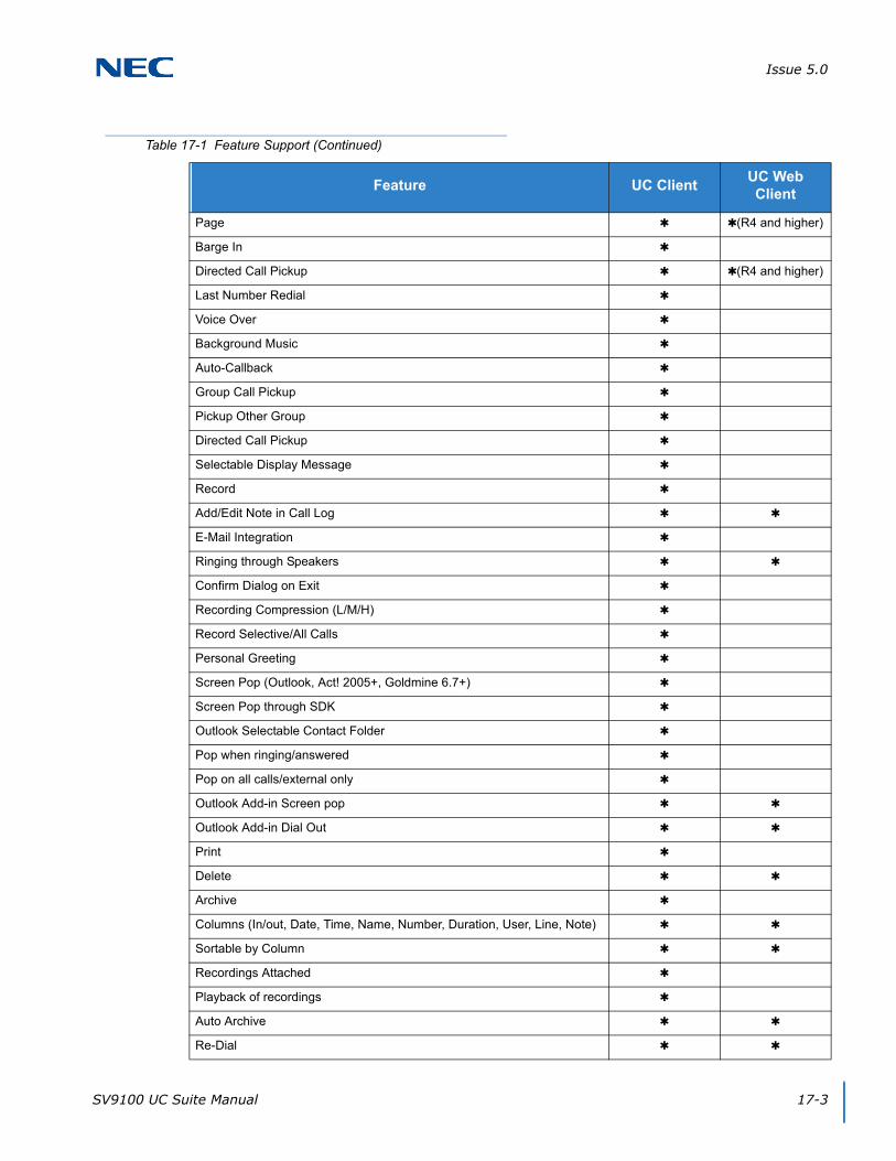
Issue 5.0
SV9100 UC Suite Manual 17-3
Page (R4 and higher)
Barge In
Directed Call Pickup (R4 and higher)
Last Number Redial
Voice Over
Background Music
Auto-Callback
Group Call Pickup
Pickup Other Group
Directed Call Pickup
Selectable Display Message
Record
Add/Edit Note in Call Log
E-Mail Integration
Ringing through Speakers
Confirm Dialog on Exit
Recording Compression (L/M/H)
Record Selective/All Calls
Personal Greeting
Screen Pop (Outlook, Act! 2005+, Goldmine 6.7+)
Screen Pop through SDK
Outlook Selectable Contact Folder
Pop when ringing/answered
Pop on all calls/external only
Outlook Add-in Screen pop
Outlook Add-in Dial Out
Delete
Archive
Columns (In/out, Date, Time, Name, Number, Duration, User, Line, Note)
Sortable by Column
Recordings Attached
Playback of recordings
Auto Archive
Re-Dial
Table 17-1 Feature Support (Continued)
Feature UC ClientUC Web Client
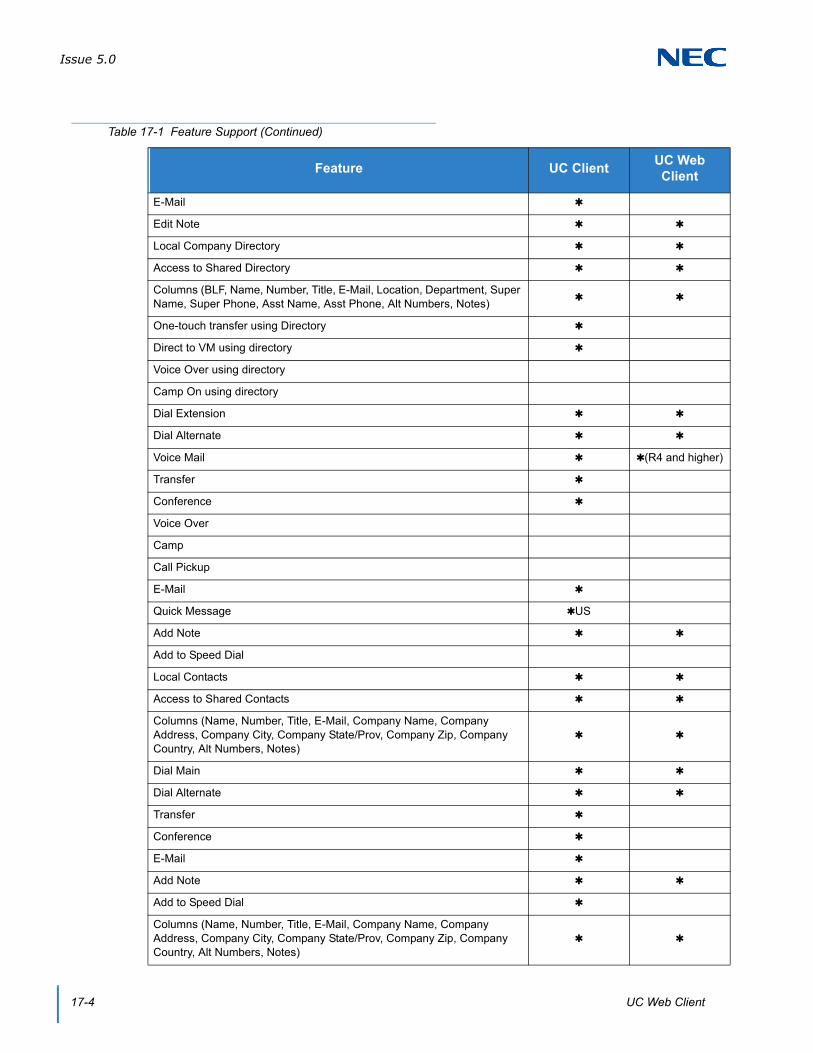
Issue 5.0
17-4 UC Web Client
Edit Note
Local Company Directory
Access to Shared Directory
Columns (BLF, Name, Number, Title, E-Mail, Location, Department, Super Name, Super Phone, Asst Name, Asst Phone, Alt Numbers, Notes)
One-touch transfer using Directory
Direct to VM using directory
Voice Over using directory
Camp On using directory
Dial Extension
Dial Alternate
Voice Mail (R4 and higher)
Transfer
Conference
Voice Over
Camp
Call Pickup
Quick Message US
Add Note
Add to Speed Dial
Local Contacts
Access to Shared Contacts
Columns (Name, Number, Title, E-Mail, Company Name, Company Address, Company City, Company State/Prov, Company Zip, Company Country, Alt Numbers, Notes)
Dial Main
Dial Alternate
Transfer
Conference
Add Note
Add to Speed Dial
Columns (Name, Number, Title, E-Mail, Company Name, Company Address, Company City, Company State/Prov, Company Zip, Company Country, Alt Numbers, Notes)
Table 17-1 Feature Support (Continued)
Feature UC ClientUC Web Client

Issue 5.0
SV9100 UC Suite Manual 17-5
Dial Main
Dial Alternate
Transfer
Conference
Add Note
Add to Speed Dial
Print All/Selected/Preview Directories
Search Directory
Set Visible Columns
Set Visible Functions
Delete Directory Entry
Application Help
About (Version, License, Copyright)
License Activation
Trial Mode
Quick Message
Phone Message
Instant Message
Local One Touch Keys (108) (108 + 24 + 8)
System-Wide BLF
BLF Icon (Idle, Ring, Active, DND, Fwd Immediate)
Name
Extension
BLF Groups/Tabs (Order, Visibility)
Configurable Text
Configurable Order
One-touch transfer
Quick VM transfer
Voice Over
Camp call
Dial
VoiceMail (R4 and higher)
Transfer
Conference
Table 17-1 Feature Support (Continued)
Feature UC ClientUC Web Client
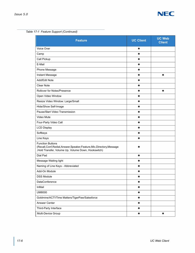
Issue 5.0
17-6 UC Web Client
Voice Over
Camp
Call Pickup
Phone Message
Instant Message
Add/Edit Note
Clear Note
Rollover for Notes/Presence
Open Video Window
Resize Video Window: Large/Small
Hide/Show Self-Image
Pause/Start Video Transmission
Video Mute
Four-Party Video Call
LCD Display
Softkeys
Line Keys
Function Buttons (Recall,Conf,Redial,Answer,Speaker,Feature,Mic,Directory,Message ,Hold Transfer, Volume Up, Volume Down, Hookswitch)
Dial Pad
Message Waiting light
Naming of Line Keys - Abbreviated
Add-On Module
DSS Module
DataConference
InMail
UM8000
Goldmine/ACT!/Time Matters/TigerPaw/Salesforce
Answer Center
Third-Party Interface
Multi-Device Group
Table 17-1 Feature Support (Continued)
Feature UC ClientUC Web Client

Issue 5.0
SV9100 UC Suite Manual 17-7
SECTION 3 COMPATIBILITY
The Web Client Service is supported on the InServer Blade or on an External Server.
The target browsers for the UC Web Client Version 3.0.0.0 are as follows:
Internet Explorer® 11
Firefox® 37
Google Chrome™ 41
Safari™ 5.0.6
Issue 5.0
17-8 UC Web Client
SECTION 4 LICENSING
The UC Web Client will utilize a license code separate from the UC Client. Each UC Web Client will require one available UC Web Client license (5313) for the login to be successful. If a client license is not available, then an error message will be displayed when the login is attempted. An example of this error is shown below in the User Login section of this document.
The client license will be released by the application when the user logs out of the UC Web Client. Similarly, the existing UC Client will release it’s client license when the UC Client is closed.

Issue 5.0
SV9100 UC Suite Manual 17-9
SECTION 5 USER LOGIN AND SHARED SERVICES CONFIGURATION
Access to the UC Web Client will be controlled through a Login screen with user credentials defined in Programs 20-59-01 and 20-59-02.
Users access the UC Web Client login screen by pointing a browser to the UC Server’s URL, for example http://192.168.1.100/ucsuite. An example of the Login screen layout is shown in the following image.
Figure 17-1 UC Server User Settings
Figure 17-2 UC Suite Login

Issue 5.0
17-10 UC Web Client
Entering a valid User ID/Password combination will allow the user access the UC Client. If an invalid User ID or Password is entered an error will be displayed and the user will be allowed to re-enter the login credentials. The following image shows an example of the error message that will be displayed for an invalid login attempt.
If the User ID / Password combination is valid, but a client license is not available, an error message will be displayed to indicate that there are insufficient licenses.
Checking the Remember me option will cause the Login page to automatically fill in the User name field with the last entered value the next time the Login page is accessed.
If the browser is being used does not support all of the application functionality, a warning message is displayed on the Login Screen. The following image shows an example of the warning message.
Figure 17-3 Desktop Suite Login – Invalid Login
Figure 17-4 Browser Warning

Issue 5.0
SV9100 UC Suite Manual 17-11
When the user first logs in, the Empty Personal Buddy List window will appear.
This allows the user to create a list of buddies to communicate with and monitor status. This window appears with each login until the user defines buddies in their Personal Buddy List. Clicking Later removes the window and the user can edit the buddy list at a later time.
The application also checks the current Presence state for the user and pops up a selection menu if the current status is not set to In Office. The following image shows an example of this reminder message.
The user can elect to change their current status to In office, a different Presence state or leave their Presence status unchanged.
Figure 17-5 Empty Personal Buddy List
Figure 17-6 Presence Status Warning

Issue 5.0
17-12 UC Web Client
The Do not show me this window again today feature can be used to temporarily disable the display of this reminder.

Issue 5.0
SV9100 UC Suite Manual 17-13
SECTION 6 USING THE UC WEB CLIENT
6.1 UC Web Screen Layout
The UC Web Client main screen consists of the following sections:
Main Control Menu – This area includes the Product Name, Views, Dial feature, My Status function, and Feature menu options.
Search Function – Allows the user to filter the current display to quickly locate an entry.
Only searches within the currently active buddy list.
Minimum of two characters must be entered to start the search.
Searches the following fields within the Company Directory: First Name, Last Name, Extension Name.
Matches only First Name and Last Name fields if the Search characters are at the beginning of the string.
Matches Extension Name field if the Search characters occur anywhere in the string.
Active Call Area – The active call area displays entries for each call being controlled by the application, as well as the tracking of Phone Messages. This is a collapsible panel that is not visible when no calls are active.
Current View – This area displays the contents of the currently selected view, such as Home/Buddy List, Contacts, Call History, and Chats.
In Internet Explorer® and Android® browsers (including UT880), the Profile Pictures display the full image whether the user is logged in or not. For users that are logged out, the presence text is grayed out.
In Firefox and Google Chrome™, the Profile Pictures display the full image if the user is logged in. If the user is logged out a grayed out image is shown.
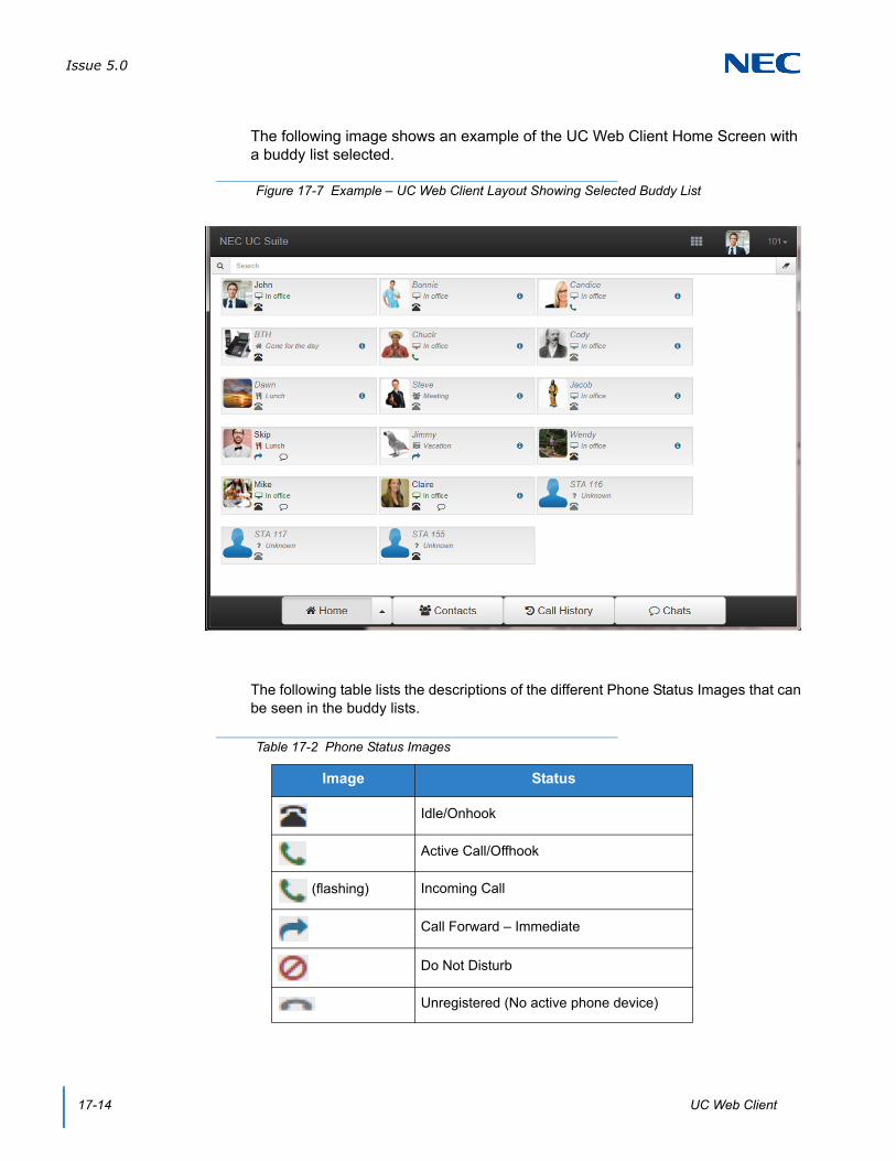
Issue 5.0
17-14 UC Web Client
The following image shows an example of the UC Web Client Home Screen with a buddy list selected.
The following table lists the descriptions of the different Phone Status Images that can be seen in the buddy lists.
Figure 17-7 Example – UC Web Client Layout Showing Selected Buddy List
Table 17-2 Phone Status Images
Image Status
Idle/Onhook
Active Call/Offhook
(flashing) Incoming Call
Call Forward – Immediate
Do Not Disturb
Unregistered (No active phone device)
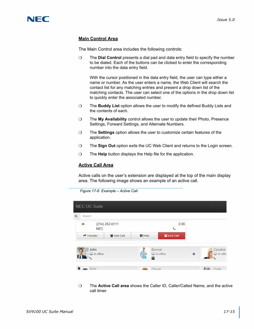
Issue 5.0
SV9100 UC Suite Manual 17-15
Main Control Area
The Main Control area includes the following controls:
The Dial Control presents a dial pad and data entry field to specify the number to be dialed. Each of the buttons can be clicked to enter the corresponding number into the data entry field.
With the cursor positioned in the data entry field, the user can type either a name or number. As the user enters a name, the Web Client will search the contact list for any matching entries and present a drop down list of the matching contacts. The user can select one of the options in the drop down list to quickly enter the associated number.
The Buddy List option allows the user to modify the defined Buddy Lists and the contents of each.
The My Availability control allows the user to update their Photo, Presence Settings, Forward Settings, and Alternate Numbers.
The Settings option allows the user to customize certain features of the application.
The Sign Out option exits the UC Web Client and returns to the Login screen.
The Help button displays the Help file for the application.
Active Call Area
Active calls on the user’s extension are displayed at the top of the main display area. The following image shows an example of an active call.
The Active Call area shows the Caller ID, Caller/Called Name, and the active call timer.
Figure 17-8 Example – Active Call

Issue 5.0
17-16 UC Web Client
Selecting the Transfer option opens the Dial control that allows the user to specify the transfer destination. This control allows the user to specify whether the transfer should be an Immediate or Attended (Supervised) transfer. If the user cancels the Transfer operation, then the user is reconnected to the original caller.
The Add Call option allows the user to add another party to the conversation as part of a Conference operation. Selecting the Add Call option will open a Dial control that allows the user to specify the conference party. After selecting the conference party, the user initiates a call to the conference party. Once the conference party answers, the user can then add the party to the original call by clicking on the Join button. If the user presses the Cancel option, then the second caller is disconnected, and the user can reconnect to the original caller. The Add Call option can be performed multiple times to setup a multi-party conference call.
The Hold function will place the active call on Hold. When the active call is on hold, a Resume option will be displayed which will allow the user to pick up the Held call.
The End Call function will hang up from the original caller.
Settings
The Settings option allows the user to alter certain configuration settings for the Web Client application. The following image shows the Settings categories that are available when this feature is selected.
Figure 17-9 Settings Screen

Issue 5.0
SV9100 UC Suite Manual 17-17
Personal Profile
The following image shows the settings that are available within theSettings – Personal Profile menu.
Photo
The Photo selection area allows the user to select a new photo or clear their current photo selection.
The Change option opens a file browser window allowing the user to designate the image file to use.
The Clear option removes the current Photo selection and restores the photo to the default image.
Other Numbers
The Other Numbers selection area allows the user to add additional numbers to be reached at. When their phone icon is clicked on, these Other Numbers will be an option to call along with their internal extension.
The Edit button gives the option to Add, Save, and Cancel. Define the Number and Type of number it is and click Save.
Figure 17-10 Settings – Personal Profile

Issue 5.0
17-18 UC Web Client
Display
The following image shows the settings that are available within the Settings – Display menu.
The Show Filter/Search option controls whether the Search field is displayed on the main screen. By default this option is set to On.
The Enable launch of email client option controls whether the e-mail integration function is enabled within the Buddy List entries. The user must have an email client configured on their PC for this feature to function properly.
The Employee label format specifies the label content that will be used within entries in the Buddy List. The available options are Extension Name, Extension, First Name first, Last Name first, and First Name only.
The Compressed employee view shows slimmer buddy BLFs allowing more to fit per page. Clicking the name displays a balloon with information not shown in the compressed view.
The Hide Off-line Users options controls whether the Buddy List panel includes entries that do not currently have an active UC client. The default is Off which will show all selected users, regardless if they are active.
The Display layout option allows the user to select the format for the BLF layout. The options are to display the BLF entries in Multiple Columns or in One Column. The default for PC browsers is Multiple Column layout.
Figure 17-11 Settings – Display

Issue 5.0
SV9100 UC Suite Manual 17-19
Notifications
The following image shows the settings that are available within the Settings – Notifications menu.
The Play tone for incoming chats option will generate a tone when a new chat request is received. The default for this option is On.
The Play tone for incoming calls option controls if a tone is generated for a new incoming call. The default for this option is On.
The Visual notification option controls whether pop up notification boxes are shown when another user logs in, logs out or changes their presence state. The default for this option is On.
Figure 17-12 Settings – Notifications
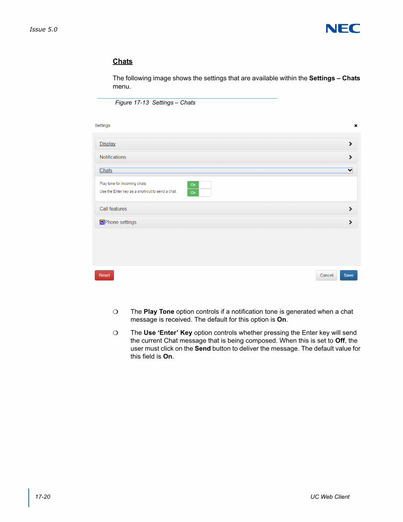
Issue 5.0
17-20 UC Web Client
Chats
The following image shows the settings that are available within the Settings – Chats menu.
The Play Tone option controls if a notification tone is generated when a chat message is received. The default for this option is On.
The Use ‘Enter’ Key option controls whether pressing the Enter key will send the current Chat message that is being composed. When this is set to Off, the user must click on the Send button to deliver the message. The default value for this field is On.
Figure 17-13 Settings – Chats

Issue 5.0
SV9100 UC Suite Manual 17-21
Call Features
The following image shows the settings that are available within the Settings – Call Features menu.
This selection controls the level of Call Control that will be available within the Web Client. These options are valuable when the Web Client is accessed from different devices, such as desktop PC’s, tablets, and smart phones.
The first option is to enable controlling the phone that is associated with the user’s account. This is accomplished through communication with the UC Server to control the deskset. This is the normal operating mode when the Web Client is being accessed from the PC on the user’s desk.
The second option not supported in Version 3.0 or earlier.When supported, this option does not control the user’s business phone, but uses the mobile device (smart phone) to make calls. This allows the user to view their Buddy List, company directory, contacts list, and call log and generate calls through their smartphone to numbers stored in those locations.
The last option is to disable call control options within the application. This option is valuable when the Web Client is accessed through a tablet when the user is not at their desk. In this mode the user may access the Web Client to view the Buddy List status and to change their own Presence status or call handling settings.
Figure 17-14 Settings – Call Features

Issue 5.0
17-22 UC Web Client
6.2 Handling Calls
Answering Incoming Calls
When a call is received at the user’s desktop phone, the Web Client will display a pop-up window to notify the user of the incoming call. The following image shows an example of an incoming call.
The incoming call notification window shows the inbound Caller ID and Caller Name (if available). This window also gives the options to Answer the call, Ignore the call, or send the call to Voicemail. The Voicemail option is only available if the user has successfully defined the voicemail integration settings.
If the user selects the Answer option, the call is answered and the Incoming Call window is closed.
If the user selects the Ignore option, the Incoming Call window is closed, but the call will continue to ring on the extension until the call rolls to voicemail or the caller hangs up.
When the user selects the Voicemail option, the call is immediately transferred to the user’s voicemail box and the Incoming Call window is closed.
Disconnecting from a Call
To disconnect from an active call:
Press the End Call button within the Active Call entry.
Figure 17-15 Active Call Area Display
Figure 17-16 Disconnecting from an Active Call Display

Issue 5.0
SV9100 UC Suite Manual 17-23
Placing an Outbound Call
When the UC Web Client is idle (no active call), the user can initiate an outbound call. The NEC Web Client provides the Dial Control on the Main Control Area as one means to initiate a call to an external number. Special dialing features are also available within the Buddy List and Contacts View.
To initiate a call using the Dial Control:
1. Enter a phone number within the data entry field of the Dial Control.
2. Press the Dial icon to initiate the call.
To initiate a call using a Buddy List:
1. Within the Buddy List, click on the Phone icon within the selected Buddy entry.
2. If multiple numbers are associated with the selected contact a submenu will open listing the available numbers. Select the desired number from the list.
To initiate a call within the Contacts Tab:
Click on the Phone icon for the selected Contact entry.
Figure 17-17 Dial Control Field
Figure 17-18 Example of Buddy List Status
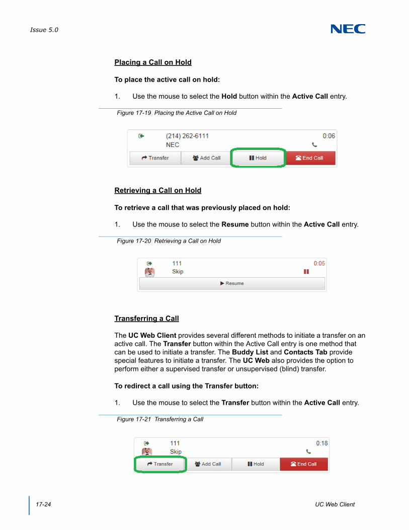
Issue 5.0
17-24 UC Web Client
Placing a Call on Hold
To place the active call on hold:
1. Use the mouse to select the Hold button within the Active Call entry.
Retrieving a Call on Hold
To retrieve a call that was previously placed on hold:
1. Use the mouse to select the Resume button within the Active Call entry.
Transferring a Call
The UC Web Client provides several different methods to initiate a transfer on an active call. The Transfer button within the Active Call entry is one method that can be used to initiate a transfer. The Buddy List and Contacts Tab provide special features to initiate a transfer. The UC Web also provides the option to perform either a supervised transfer or unsupervised (blind) transfer.
To redirect a call using the Transfer button:
1. Use the mouse to select the Transfer button within the Active Call entry.
Figure 17-19 Placing the Active Call on Hold
Figure 17-20 Retrieving a Call on Hold
Figure 17-21 Transferring a Call

Issue 5.0
SV9100 UC Suite Manual 17-25
2. Enter the number to be dialed in the Destination field within the Transfer Call menu.
3. Select the Attended Transfer option within the Data Entry area to initiate a supervised transfer. When the destination party answers, announce the transfer and then select Connect. If the destination does not answer or does not want to take the call, select Cancel to reconnect to the original caller.
Select the Immediate Transfer option within the Data Entry area to initiate an unsupervised (blind) transfer. The call will be immediately routed to the specified destination.
Using the Phone button to initiate a transfer within the BLF Tab:
1. Within the Buddy List, use the Phone button within a BLF entry to select the station to receive the call.
2. From the Transfer Call Window, select either Attended Transfer or Immediate Transfer options.
Figure 17-22 Enter the Transfer Destination Number
Figure 17-23 Transferring within the BLF Tab

Issue 5.0
17-26 UC Web Client
To initiate a transfer to a Contact entry:
Within the Contacts Tab:
1. Click the phone icon of the desired entry to initiate a Transfer.
2. To initiate a transfer to an Alternate Number, click on the Alternate Number field and select the desired destination.
Setting Up a Conference Call
With an active call on the UC Web Client, the user can establish a conference between the active call and a third party. Conference calls can be set up using the Add Call button on the Active Call entry. Special features within the Buddy List also allow a conference to be setup with a specific party.
To initiate a Conference using the Add Call button:
1. Use the mouse to select the Add Call button within the Active Call entry.
2. Enter the telephone number of the conference party within the Setup Conference Call Window.
Figure 17-24 Setting Up a Conference Call
Figure 17-25 Enter the Conference Party Telephone Number

Issue 5.0
SV9100 UC Suite Manual 17-27
3. Select the Add Call option within the Setup Conference Call Window to initiate the conference.
4. When the destination answers, announce the conference and then select Join to create the three-way conference call. If the destination does not answer or does not want to participate in the conference, select the Cancel option.
6.3 My Availability
The My Availability control allows the user to update their Presence Settings, Forward Settings and Mobility (Multi-Device Group) Settings. The following image shows an example of the My Availability menu.
Presence Status
The Presence Status area allows the user to change their current Presence state and schedule future Presence changes. Clicking on the Presence state will open a drop down list of all of the available Presence states. Selecting an option from the drop down list will change the user’s current Presence state.
Figure 17-26 Example – My Availability
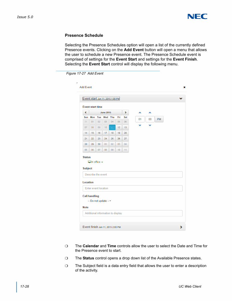
Issue 5.0
17-28 UC Web Client
Presence Schedule
Selecting the Presence Schedules option will open a list of the currently defined Presence events. Clicking on the Add Event button will open a menu that allows the user to schedule a new Presence event. The Presence Schedule event is comprised of settings for the Event Start and settings for the Event Finish. Selecting the Event Start control will display the following menu.
The Calendar and Time controls allow the user to select the Date and Time for the Presence event to start.
The Status control opens a drop down list of the Available Presence states.
The Subject field is a data entry field that allows the user to enter a description of the activity.
Figure 17-27 Add Event
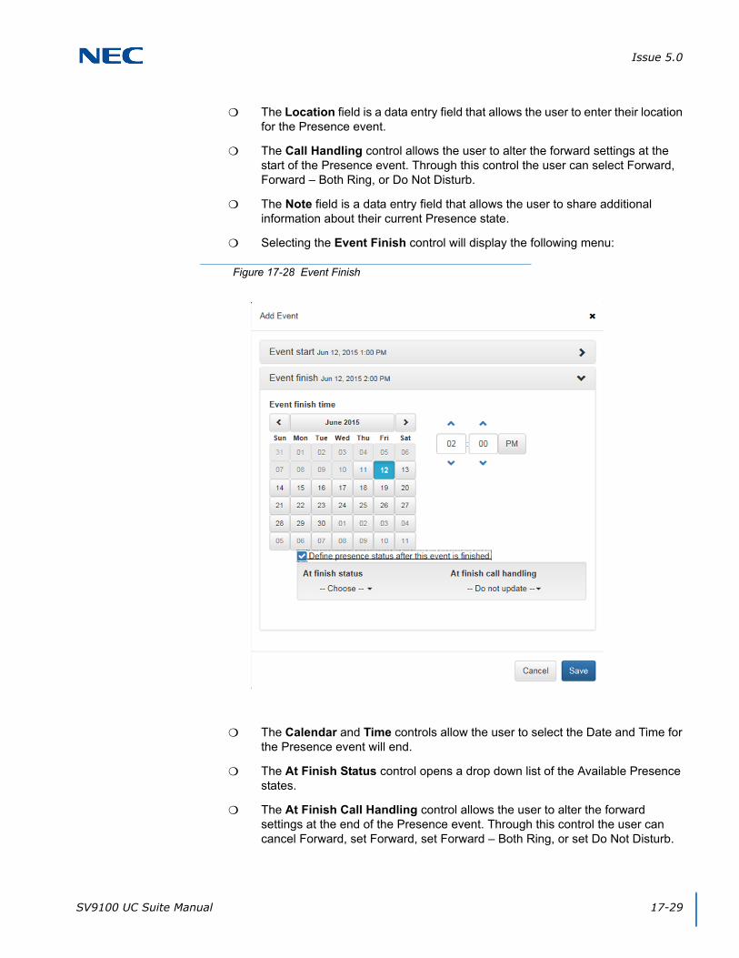
Issue 5.0
SV9100 UC Suite Manual 17-29
The Location field is a data entry field that allows the user to enter their location for the Presence event.
The Call Handling control allows the user to alter the forward settings at the start of the Presence event. Through this control the user can select Forward, Forward – Both Ring, or Do Not Disturb.
The Note field is a data entry field that allows the user to share additional information about their current Presence state.
Selecting the Event Finish control will display the following menu:
The Calendar and Time controls allow the user to select the Date and Time for the Presence event will end.
The At Finish Status control opens a drop down list of the Available Presence states.
The At Finish Call Handling control allows the user to alter the forward settings at the end of the Presence event. Through this control the user can cancel Forward, set Forward, set Forward – Both Ring, or set Do Not Disturb.
Figure 17-28 Event Finish

Issue 5.0
17-30 UC Web Client
Note
The Note field is a data entry field that allows the user to share additional information about their current Presence state.
Advanced Settings
The Advanced Settings fields on the My Status screen allows the user to specify additional Presence information about their Presence state, Location, and Expected Return.
The Subject field is a data entry field that allows the user to enter a description of the activity.
The Location field is a data entry field that allows the user to enter their location for the Presence event.
The Expected Return allows the user to select a Date and Time to indicate the expected end of the specified Presence event.
Mobility (Multi-Device Group)
The boxes within this section represent phone numbers currently included in the Multi-Device Group. As in the PC Client, numbers that appear as part of the group can be individually enabled or disabled, without deleting the entry.
Adding Numbers
The Add additional phone control allows the user to add another number to the Multi-Device Group.
Figure 17-29 Mobility (Multi-Device Group)

Issue 5.0
SV9100 UC Suite Manual 17-31
The user enters the dialing digits into the Phone Number field for the number to add to the group. The checkbox allows the user to enable/disable the inclusion of this number in the group, without deleting the entry.
Editing Entries
Selecting the Edit function (pencil icon) within an entry opens the Edit menu.
Editing an entry allows the user to change the phone number or enable/disable the activation of the entry within the Multi-Device group.
Deleting Entries
Selecting the Delete function (red X) within an entry will remove the entry and delete the definition from the Multi-Device group.
The Enable All and Disable All buttons will either Enable or Disable the Members of the Multi-Device Group.
Figure 17-30 Add Additional Numbers
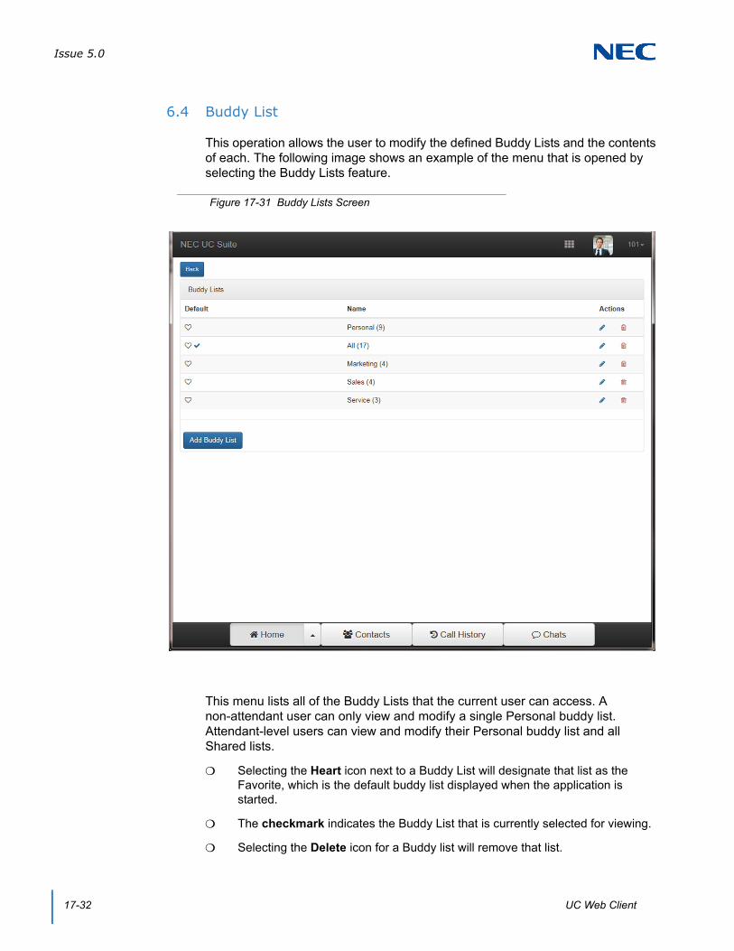
Issue 5.0
17-32 UC Web Client
6.4 Buddy List
This operation allows the user to modify the defined Buddy Lists and the contents of each. The following image shows an example of the menu that is opened by selecting the Buddy Lists feature.
This menu lists all of the Buddy Lists that the current user can access. A non-attendant user can only view and modify a single Personal buddy list. Attendant-level users can view and modify their Personal buddy list and all Shared lists.
Selecting the Heart icon next to a Buddy List will designate that list as the Favorite, which is the default buddy list displayed when the application is started.
The checkmark indicates the Buddy List that is currently selected for viewing.
Selecting the Delete icon for a Buddy list will remove that list.
Figure 17-31 Buddy Lists Screen
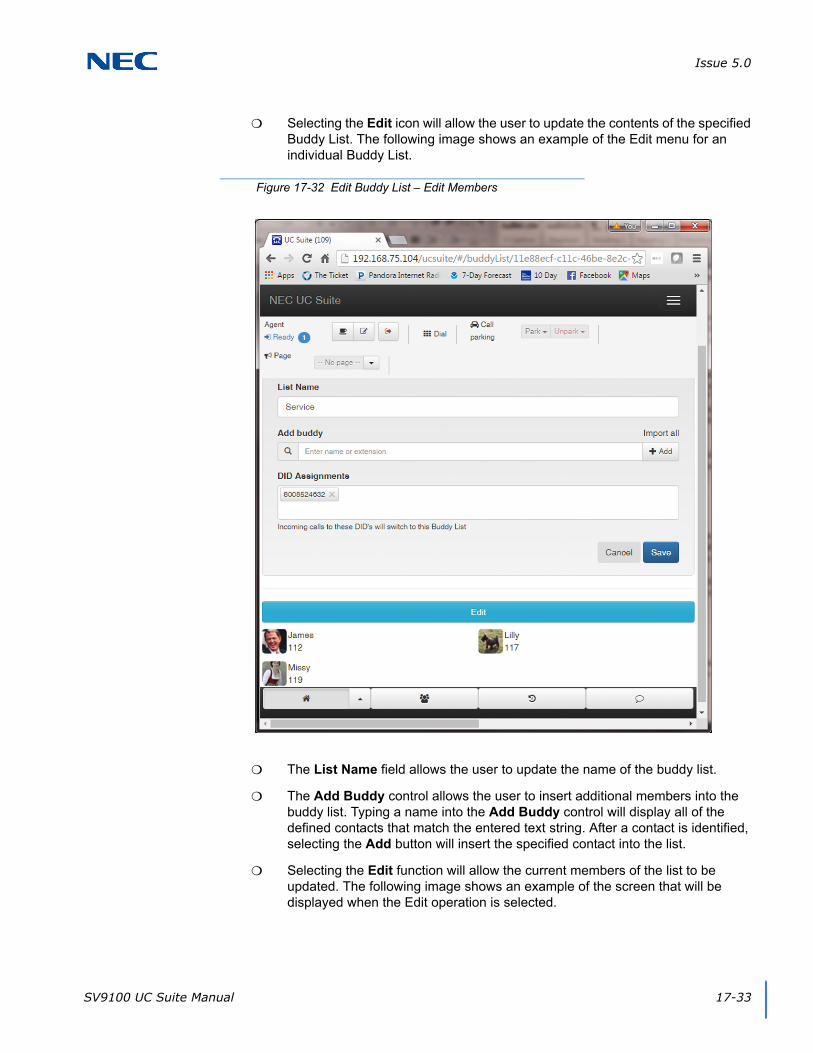
Issue 5.0
SV9100 UC Suite Manual 17-33
Selecting the Edit icon will allow the user to update the contents of the specified Buddy List. The following image shows an example of the Edit menu for an individual Buddy List.
The List Name field allows the user to update the name of the buddy list.
The Add Buddy control allows the user to insert additional members into the buddy list. Typing a name into the Add Buddy control will display all of the defined contacts that match the entered text string. After a contact is identified, selecting the Add button will insert the specified contact into the list.
Selecting the Edit function will allow the current members of the list to be updated. The following image shows an example of the screen that will be displayed when the Edit operation is selected.
Figure 17-32 Edit Buddy List – Edit Members

Issue 5.0
17-34 UC Web Client
Each member has a checkbox next to their entry.
Pressing Delete removes the selected entries from the Buddy list.
Pressing Done completes the Edit Members operation.
The DID Assignments area allows the user to Add, Delete, and Edit Inbound numbers associated with a Buddy List. This is only available for users that have attendant-level privileges. When assigned, an incoming call can trigger the Web Client to automatically display the Buddy List matching the inbound DID.
If the user attempts to enter a number currently associated with a different Buddy List, a message box appears displaying the following: This number is currently associated with the BLF group <group name>. Do you want to override this assignment?
Figure 17-33 Edit Buddy List – Edit and Delete
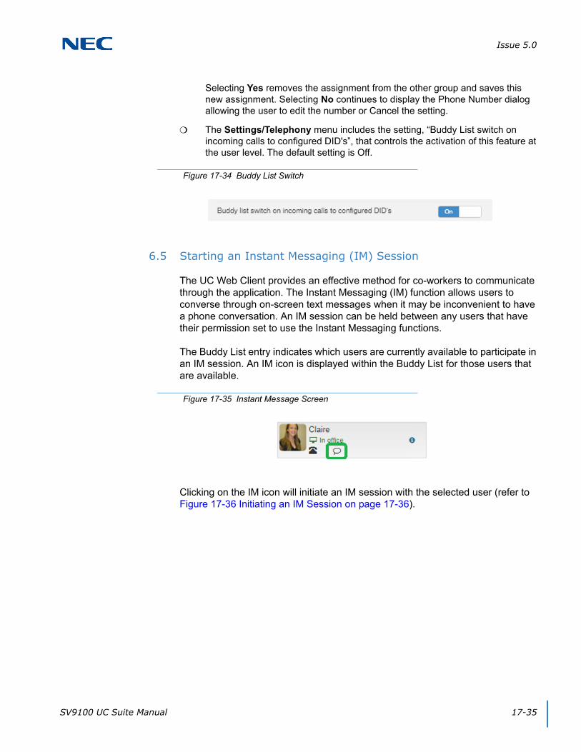
Issue 5.0
SV9100 UC Suite Manual 17-35
Selecting Yes removes the assignment from the other group and saves this new assignment. Selecting No continues to display the Phone Number dialog allowing the user to edit the number or Cancel the setting.
The Settings/Telephony menu includes the setting, “Buddy List switch on incoming calls to configured DID's”, that controls the activation of this feature at the user level. The default setting is Off.
6.5 Starting an Instant Messaging (IM) Session
The UC Web Client provides an effective method for co-workers to communicate through the application. The Instant Messaging (IM) function allows users to converse through on-screen text messages when it may be inconvenient to have a phone conversation. An IM session can be held between any users that have their permission set to use the Instant Messaging functions.
The Buddy List entry indicates which users are currently available to participate in an IM session. An IM icon is displayed within the Buddy List for those users that are available.
Clicking on the IM icon will initiate an IM session with the selected user (refer to Figure 17-36 Initiating an IM Session on page 17-36).
Figure 17-34 Buddy List Switch
Figure 17-35 Instant Message Screen

Issue 5.0
17-36 UC Web Client
The data entry box at the bottom of the screen can be used to enter messages to be sent to the other party. Clicking on the Send button will deliver the message to the other party’s IM window and also writes the message within your own IM window. Any messages received from the other party will be shown when they arrive within the IM window.
Figure 17-36 Initiating an IM Session
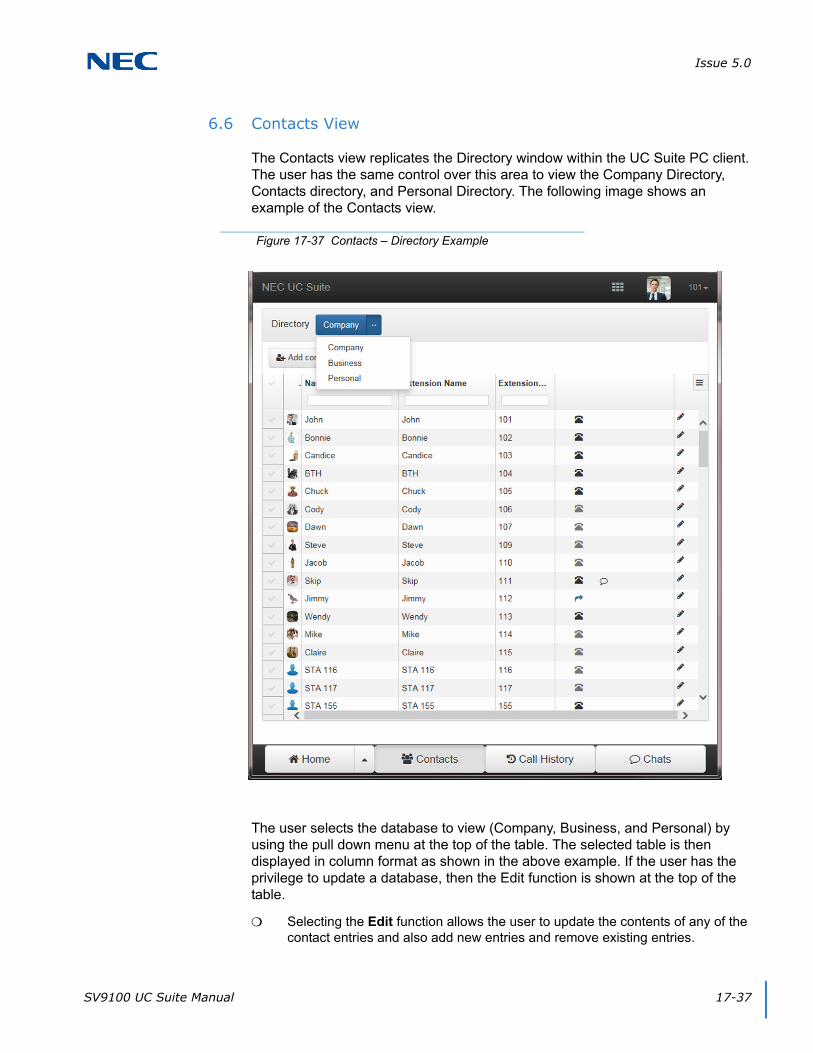
Issue 5.0
SV9100 UC Suite Manual 17-37
6.6 Contacts View
The Contacts view replicates the Directory window within the UC Suite PC client. The user has the same control over this area to view the Company Directory, Contacts directory, and Personal Directory. The following image shows an example of the Contacts view.
The user selects the database to view (Company, Business, and Personal) by using the pull down menu at the top of the table. The selected table is then displayed in column format as shown in the above example. If the user has the privilege to update a database, then the Edit function is shown at the top of the table.
Selecting the Edit function allows the user to update the contents of any of the contact entries and also add new entries and remove existing entries.
Figure 17-37 Contacts – Directory Example
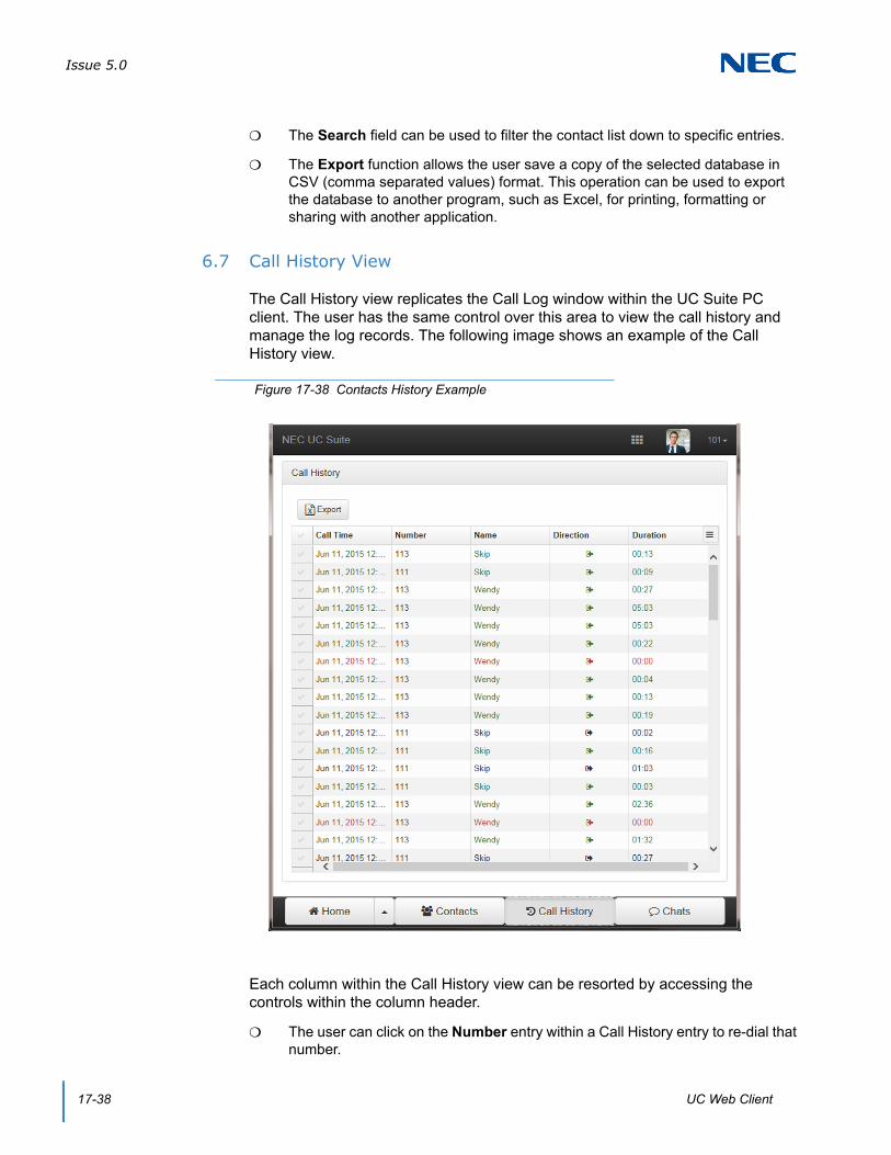
Issue 5.0
17-38 UC Web Client
The Search field can be used to filter the contact list down to specific entries.
The Export function allows the user save a copy of the selected database in CSV (comma separated values) format. This operation can be used to export the database to another program, such as Excel, for printing, formatting or sharing with another application.
6.7 Call History View
The Call History view replicates the Call Log window within the UC Suite PC client. The user has the same control over this area to view the call history and manage the log records. The following image shows an example of the Call History view.
Each column within the Call History view can be resorted by accessing the controls within the column header.
The user can click on the Number entry within a Call History entry to re-dial that number.
Figure 17-38 Contacts History Example
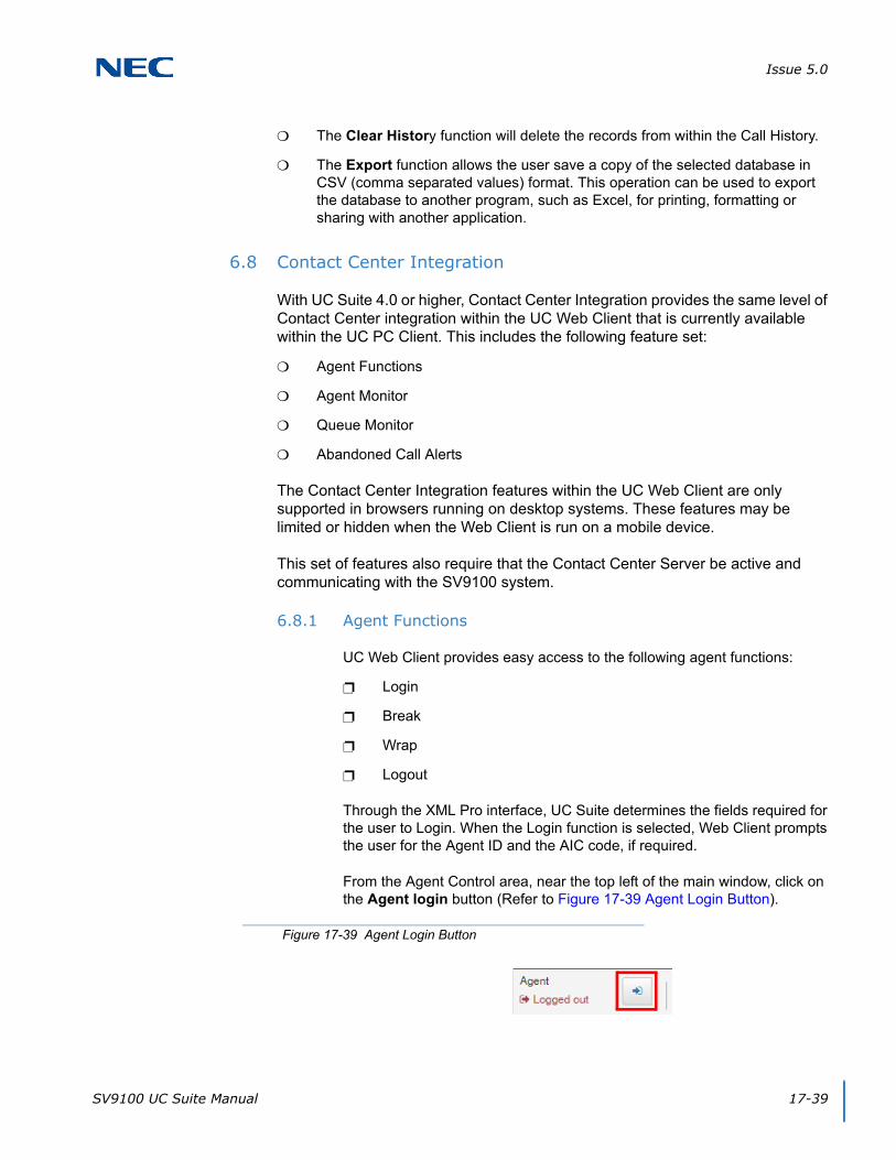
Issue 5.0
SV9100 UC Suite Manual 17-39
The Clear History function will delete the records from within the Call History.
The Export function allows the user save a copy of the selected database in CSV (comma separated values) format. This operation can be used to export the database to another program, such as Excel, for printing, formatting or sharing with another application.
6.8 Contact Center Integration
With UC Suite 4.0 or higher, Contact Center Integration provides the same level of Contact Center integration within the UC Web Client that is currently available within the UC PC Client. This includes the following feature set:
Agent Functions
Agent Monitor
Queue Monitor
Abandoned Call Alerts
The Contact Center Integration features within the UC Web Client are only supported in browsers running on desktop systems. These features may be limited or hidden when the Web Client is run on a mobile device.
This set of features also require that the Contact Center Server be active and communicating with the SV9100 system.
6.8.1 Agent Functions
UC Web Client provides easy access to the following agent functions:
Login
Break
Wrap
Logout
Through the XML Pro interface, UC Suite determines the fields required for the user to Login. When the Login function is selected, Web Client prompts the user for the Agent ID and the AIC code, if required.
From the Agent Control area, near the top left of the main window, click on the Agent login button (Refer to Figure 17-39 Agent Login Button).
Figure 17-39 Agent Login Button
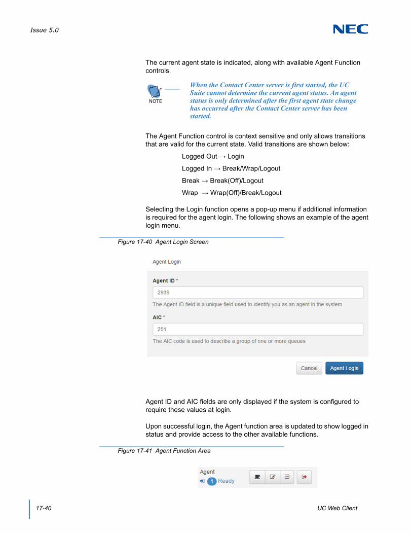
Issue 5.0
17-40 UC Web Client
The current agent state is indicated, along with available Agent Function controls.
The Agent Function control is context sensitive and only allows transitions that are valid for the current state. Valid transitions are shown below:
Logged Out → Login
Logged In → Break/Wrap/Logout
Break → Break(Off)/Logout
Wrap → Wrap(Off)/Break/Logout
Selecting the Login function opens a pop-up menu if additional information is required for the agent login. The following shows an example of the agent login menu.
Agent ID and AIC fields are only displayed if the system is configured to require these values at login.
Upon successful login, the Agent function area is updated to show logged in status and provide access to the other available functions.
NOTE
When the Contact Center server is first started, the UC Suite cannot determine the current agent status. An agent status is only determined after the first agent state change has occurred after the Contact Center server has been started.
Figure 17-40 Agent Login Screen
Figure 17-41 Agent Function Area

Issue 5.0
SV9100 UC Suite Manual 17-41
If AIC codes are being used, the Add Queue function will be active when the user is Logged In, allowing the user to enter an additional AIC code.
6.8.2 Agent Monitor
The Agent Monitor function is added to the UC Web Client allowing an agent-enabled user the ability to monitor the status of other agents. The data used to populate the Agent Monitor display is received from the Contact Center server.
6.8.2.1 Agent Monitor Definition
Each user can select the agents that are included in their Agent Monitor display. The set of agents are selected using the Settings/Agent menu. The following displays an example of the Monitor Agents area within this menu.
The Select agents to monitor control allows the user to select the agents to include in the table. Clicking within the control displays a list of agents that can be selected to add to the list. An agent can be removed from the list by clicking the X next to their entry. The Select All and Unselect All options provide shortcuts to Add/Remove all of the agents.
6.8.2.2 Agent Monitor Display
The following is an example of the agent monitor entries.
Figure 17-42 Example of Monitor Agents Screen
Figure 17-43 Example of Agent Monitor Entries
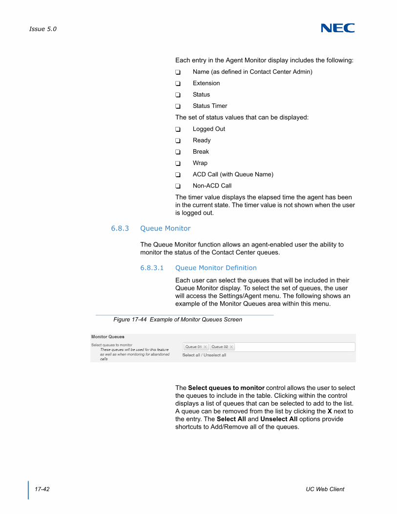
Issue 5.0
17-42 UC Web Client
Each entry in the Agent Monitor display includes the following:
Name (as defined in Contact Center Admin)
Extension
Status
Status Timer
The set of status values that can be displayed:
Logged Out
Ready
Break
Wrap
ACD Call (with Queue Name)
Non-ACD Call
The timer value displays the elapsed time the agent has been in the current state. The timer value is not shown when the user is logged out.
6.8.3 Queue Monitor
The Queue Monitor function allows an agent-enabled user the ability to monitor the status of the Contact Center queues.
6.8.3.1 Queue Monitor Definition
Each user can select the queues that will be included in their Queue Monitor display. To select the set of queues, the user will access the Settings/Agent menu. The following shows an example of the Monitor Queues area within this menu.
The Select queues to monitor control allows the user to select the queues to include in the table. Clicking within the control displays a list of queues that can be selected to add to the list. A queue can be removed from the list by clicking the X next to the entry. The Select All and Unselect All options provide shortcuts to Add/Remove all of the queues.
Figure 17-44 Example of Monitor Queues Screen
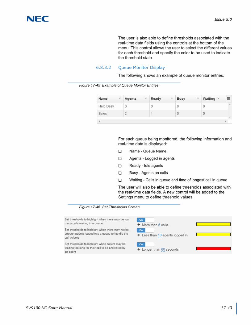
Issue 5.0
SV9100 UC Suite Manual 17-43
The user is also able to define thresholds associated with the real-time data fields using the controls at the bottom of the menu. This control allows the user to select the different values for each threshold and specify the color to be used to indicate the threshold state.
6.8.3.2 Queue Monitor Display
The following shows an example of queue monitor entries.
For each queue being monitored, the following information and real-time data is displayed:
Name - Queue Name
Agents - Logged in agents
Ready - Idle agents
Busy - Agents on calls
Waiting - Calls in queue and time of longest call in queue
The user will also be able to define thresholds associated with the real-time data fields. A new control will be added to the Settings menu to define threshold values.
Figure 17-45 Example of Queue Monitor Entries
Figure 17-46 Set Thresholds Screen
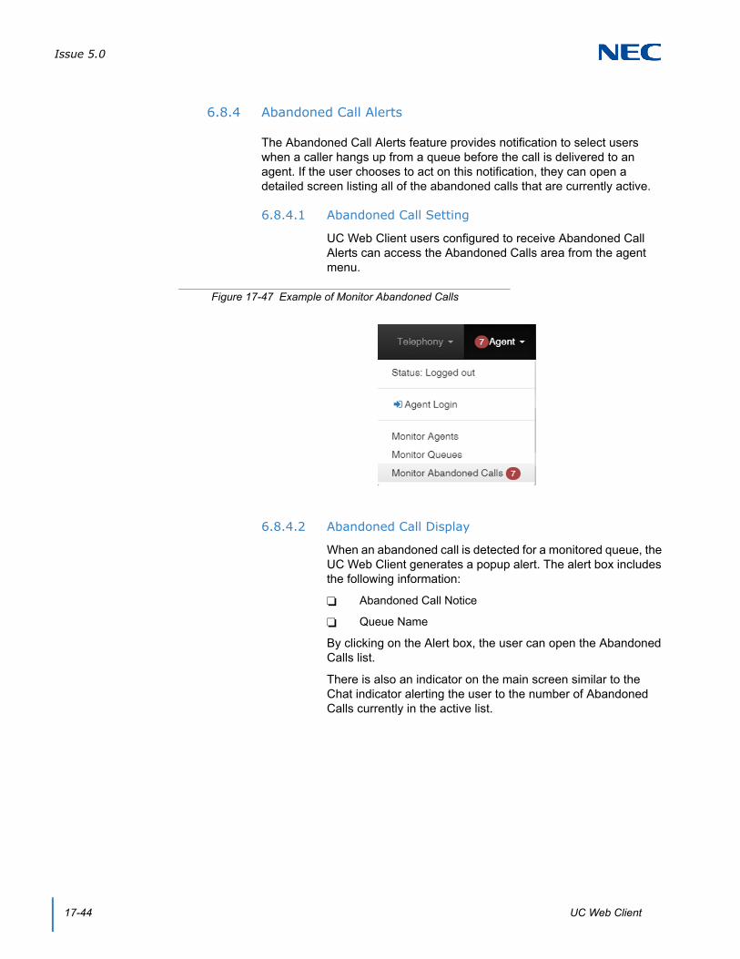
Issue 5.0
17-44 UC Web Client
6.8.4 Abandoned Call Alerts
The Abandoned Call Alerts feature provides notification to select users when a caller hangs up from a queue before the call is delivered to an agent. If the user chooses to act on this notification, they can open a detailed screen listing all of the abandoned calls that are currently active.
6.8.4.1 Abandoned Call Setting
UC Web Client users configured to receive Abandoned Call Alerts can access the Abandoned Calls area from the agent menu.
6.8.4.2 Abandoned Call Display
When an abandoned call is detected for a monitored queue, the UC Web Client generates a popup alert. The alert box includes the following information:
Abandoned Call Notice
Queue Name
By clicking on the Alert box, the user can open the Abandoned Calls list.
There is also an indicator on the main screen similar to the Chat indicator alerting the user to the number of Abandoned Calls currently in the active list.
Figure 17-47 Example of Monitor Abandoned Calls

Issue 5.0
SV9100 UC Suite Manual 17-45
The following is an example of the abandoned calls list.
The Abandoned Calls list has an entry for each Abandoned Call that is currently active. Each entry includes the following details:
Call date/time
Queue name
Caller ID
Wait Time in Queue
Callback Status
Comment
Extension performing callback
Name of user performing callback
The icons on the right side of the menu perform the following operations:
Show detailed callback information
Edit the status of this call back entry
Clear the current callback status
Delete the call from the list
Figure 17-48 Example of Abandoned Calls List

Issue 5.0
17-46 UC Web Client
Also, the user can initiate a callback by clicking on the number in the Caller field. A status screen displays allowing the user to specify the disposition of the call. The following shows an example of a callback menu.
On this screen, the user can enter comments to describe the results of the call. After the call is complete, the user can also select to update the Callback status.
6.9 Presence Profiles
The Presence Profiles feature allows UC Web Client users to create a shortcut for frequently used presence settings. This feature is accessible from within the Presence menu by selecting the Profiles option.
Figure 17-49 Callback Status Display
Figure 17-50 Example of Presence Profile Screen
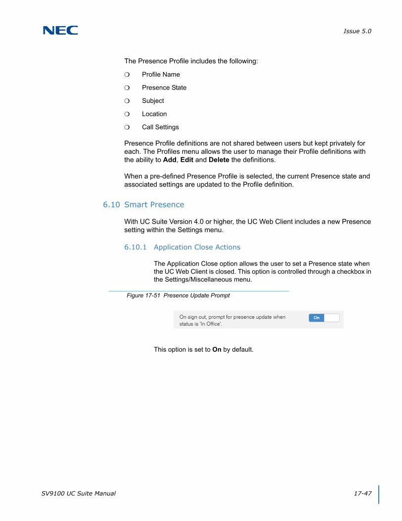
Issue 5.0
SV9100 UC Suite Manual 17-47
The Presence Profile includes the following:
Profile Name
Presence State
Subject
Location
Call Settings
Presence Profile definitions are not shared between users but kept privately for each. The Profiles menu allows the user to manage their Profile definitions with the ability to Add, Edit and Delete the definitions.
When a pre-defined Presence Profile is selected, the current Presence state and associated settings are updated to the Profile definition.
6.10 Smart Presence
With UC Suite Version 4.0 or higher, the UC Web Client includes a new Presence setting within the Settings menu.
6.10.1 Application Close Actions
The Application Close option allows the user to set a Presence state when the UC Web Client is closed. This option is controlled through a checkbox in the Settings/Miscellaneous menu.
This option is set to On by default.
Figure 17-51 Presence Update Prompt
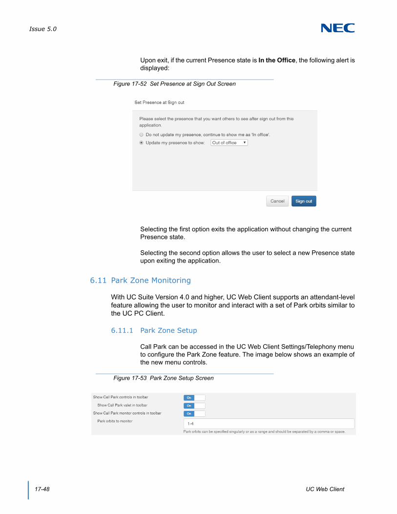
Issue 5.0
17-48 UC Web Client
Upon exit, if the current Presence state is In the Office, the following alert is displayed:
Selecting the first option exits the application without changing the current Presence state.
Selecting the second option allows the user to select a new Presence state upon exiting the application.
6.11 Park Zone Monitoring
With UC Suite Version 4.0 and higher, UC Web Client supports an attendant-level feature allowing the user to monitor and interact with a set of Park orbits similar to the UC PC Client.
6.11.1 Park Zone Setup
Call Park can be accessed in the UC Web Client Settings/Telephony menu to configure the Park Zone feature. The image below shows an example of the new menu controls.
Figure 17-52 Set Presence at Sign Out Screen
Figure 17-53 Park Zone Setup Screen
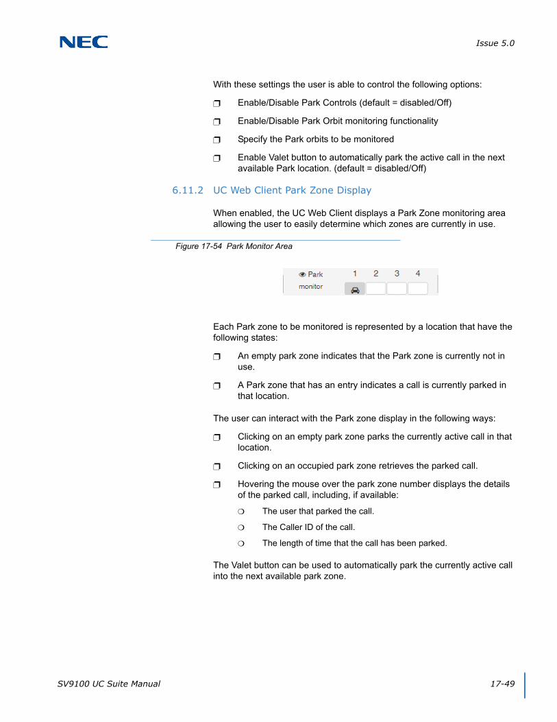
Issue 5.0
SV9100 UC Suite Manual 17-49
With these settings the user is able to control the following options:
Enable/Disable Park Controls (default = disabled/Off)
Enable/Disable Park Orbit monitoring functionality
Specify the Park orbits to be monitored
Enable Valet button to automatically park the active call in the next available Park location. (default = disabled/Off)
6.11.2 UC Web Client Park Zone Display
When enabled, the UC Web Client displays a Park Zone monitoring area allowing the user to easily determine which zones are currently in use.
Each Park zone to be monitored is represented by a location that have the following states:
An empty park zone indicates that the Park zone is currently not in use.
A Park zone that has an entry indicates a call is currently parked in that location.
The user can interact with the Park zone display in the following ways:
Clicking on an empty park zone parks the currently active call in that location.
Clicking on an occupied park zone retrieves the parked call.
Hovering the mouse over the park zone number displays the details of the parked call, including, if available:
The user that parked the call.
The Caller ID of the call.
The length of time that the call has been parked.
The Valet button can be used to automatically park the currently active call into the next available park zone.
Figure 17-54 Park Monitor Area

Issue 5.0
17-50 UC Web Client
6.12 Handset/Headset
With UC Suite Version 4.0 and higher, UC Web Client adds the Handset/Headset operation allowing the user to switch their default phone setting between using the handset/speaker and using an attached headset. The user must have a Headset key assigned on their phone for this feature to be operational.
This control has been added to the Settings/Telephony menu.
To ensure that the Headset/Handset value agrees with the current setting on the phone, during startup the application sets the telephone to the last value that was entered within the application.
6.13 Night Mode Switch Setting
With UC Suite Version 4.0 and higher, UC Web Client adds the Night Mode attendant level feature that can change the operational functionality of the phone system. This operation is accessed from the Settings > Telephony Menu or from the Telephony drop down on the Web Client tool bar.
Figure 17-55 Headset/Handset Switch Setting
Figure 17-56 Day or Night Mode Setting
Figure 17-57 Example of Telephony Menu
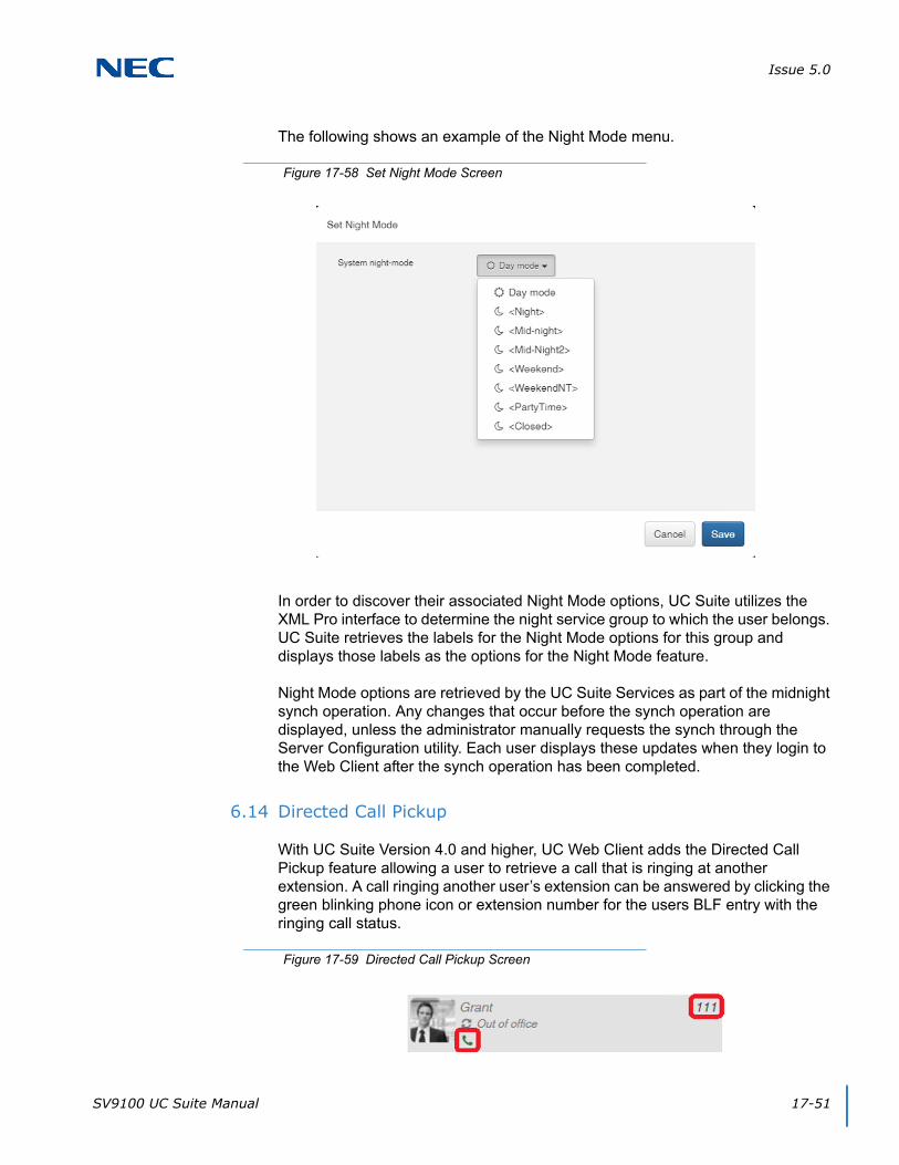
Issue 5.0
SV9100 UC Suite Manual 17-51
The following shows an example of the Night Mode menu.
In order to discover their associated Night Mode options, UC Suite utilizes the XML Pro interface to determine the night service group to which the user belongs. UC Suite retrieves the labels for the Night Mode options for this group and displays those labels as the options for the Night Mode feature.
Night Mode options are retrieved by the UC Suite Services as part of the midnight synch operation. Any changes that occur before the synch operation are displayed, unless the administrator manually requests the synch through the Server Configuration utility. Each user displays these updates when they login to the Web Client after the synch operation has been completed.
6.14 Directed Call Pickup
With UC Suite Version 4.0 and higher, UC Web Client adds the Directed Call Pickup feature allowing a user to retrieve a call that is ringing at another extension. A call ringing another user’s extension can be answered by clicking the green blinking phone icon or extension number for the users BLF entry with the ringing call status.
Figure 17-58 Set Night Mode Screen
Figure 17-59 Directed Call Pickup Screen
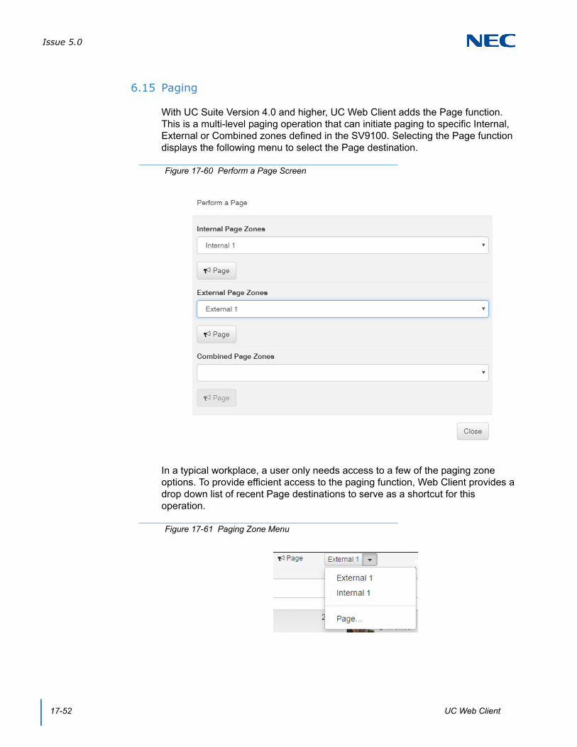
Issue 5.0
17-52 UC Web Client
6.15 Paging
With UC Suite Version 4.0 and higher, UC Web Client adds the Page function. This is a multi-level paging operation that can initiate paging to specific Internal, External or Combined zones defined in the SV9100. Selecting the Page function displays the following menu to select the Page destination.
In a typical workplace, a user only needs access to a few of the paging zone options. To provide efficient access to the paging function, Web Client provides a drop down list of recent Page destinations to serve as a shortcut for this operation.
Figure 17-60 Perform a Page Screen
Figure 17-61 Paging Zone Menu

Issue 5.0
SV9100 UC Suite Manual 17-53
For example, if an attendant on different occasions needs to access Internal Zone 1, External Zone 1 and the Combined zone 1, the drop down list includes these options.
6.16 Voicemail Quick Access
With UC Suite Version 4.0 and higher, UC Web Client provides the user with quick access to another user’s voicemail box. This enhancement is implemented by adding a Voicemail option under the Phone submenu within a BLF entry.
If the user has an active call, the caller can be easily transferred to another user’s mailbox by opening the Phone menu for the target BLF extension and then selecting Voicemail.
If the UC Web Client user’s extension is idle, then they can quickly dial another user’s voicemail box to leave a message by clicking on the Phone option within the target BLF and selecting the Voicemail option.
Figure 17-62 Example of Selecting Voicemail

Issue 5.0
17-54 UC Web Client
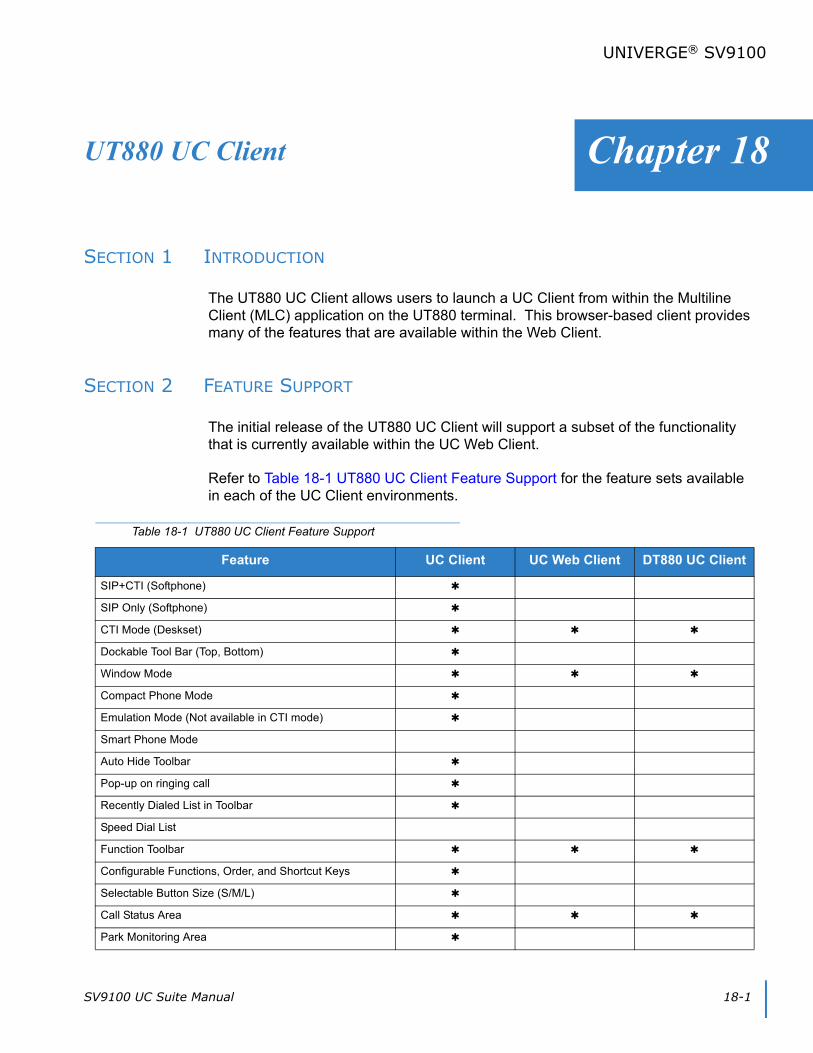
SV9100 UC Suite Manual 18-1
Chapter 18
UNIVERGE® SV9100
UT880 UC Client
SECTION 1 INTRODUCTION
The UT880 UC Client allows users to launch a UC Client from within the Multiline Client (MLC) application on the UT880 terminal. This browser-based client provides many of the features that are available within the Web Client.
SECTION 2 FEATURE SUPPORT
The initial release of the UT880 UC Client will support a subset of the functionality that is currently available within the UC Web Client.
Refer to Table 18-1 UT880 UC Client Feature Support for the feature sets available in each of the UC Client environments.
Table 18-1 UT880 UC Client Feature Support
Feature UC Client UC Web Client DT880 UC Client
SIP+CTI (Softphone)
SIP Only (Softphone)
CTI Mode (Deskset)
Dockable Tool Bar (Top, Bottom)
Window Mode
Compact Phone Mode
Emulation Mode (Not available in CTI mode)
Smart Phone Mode
Auto Hide Toolbar
Pop-up on ringing call
Recently Dialed List in Toolbar
Speed Dial List
Function Toolbar
Configurable Functions, Order, and Shortcut Keys
Selectable Button Size (S/M/L)
Call Status Area
Park Monitoring Area
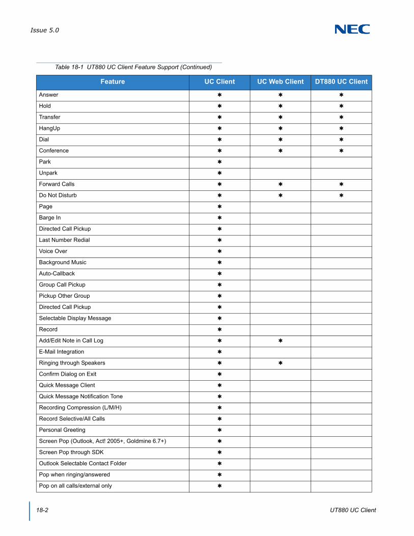
Issue 5.0
18-2 UT880 UC Client
Answer
Hold
Transfer
HangUp
Dial
Conference
Park
Unpark
Forward Calls
Do Not Disturb
Page
Barge In
Directed Call Pickup
Last Number Redial
Voice Over
Background Music
Auto-Callback
Group Call Pickup
Pickup Other Group
Directed Call Pickup
Selectable Display Message
Record
Add/Edit Note in Call Log
E-Mail Integration
Ringing through Speakers
Confirm Dialog on Exit
Quick Message Client
Quick Message Notification Tone
Recording Compression (L/M/H)
Record Selective/All Calls
Personal Greeting
Screen Pop (Outlook, Act! 2005+, Goldmine 6.7+)
Screen Pop through SDK
Outlook Selectable Contact Folder
Pop when ringing/answered
Pop on all calls/external only
Table 18-1 UT880 UC Client Feature Support (Continued)
Feature UC Client UC Web Client DT880 UC Client

Issue 5.0
SV9100 UC Suite Manual 18-3
Outlook Add-in Screen pop
Outlook Add-in Dial Out
Delete
Archive
Columns (In/out, Date, Time, Name, Number, Duration, User, Line, Note)
Sortable by Column
Recordings Attached
Playback of recordings
Auto Archive
Re-Dial
Edit Note
Local Company Directory
Access to Shared Directory
Columns (BLF, Name, Number, Title, E-Mail, Location, Department, Super Name, Super Phone, Asst Name, Asst Phone, Alt Numbers, Notes)
One-touch transfer using Directory
Direct to VM using directory
Voice Over using directory
Camp On using directory
Dial Extension
Dial Alternate
Voice Mail
Transfer
Conference
Voice Over
Camp
Call Pickup
Quick Message US
Add Note
Add to Speed Dial
Local Contacts
Access to Shared Contacts
Table 18-1 UT880 UC Client Feature Support (Continued)
Feature UC Client UC Web Client DT880 UC Client

Issue 5.0
18-4 UT880 UC Client
Columns (Name, Number, Title, E-Mail, Company Name, Company Address, Company City, Company State/Prov, Company Zip, Company Country, Alt Numbers, Notes)
Dial Main
Dial Alternate
Transfer
Conference
Add Note
Add to Speed Dial
Columns (Name, Number, Title, E-Mail, Company Name, Company Address, Company City, Company State/Prov, Company Zip, Company Country, Alt Numbers, Notes)
Dial Main
Dial Alternate
Transfer
Conference
Add Note
Add to Speed Dial
Print All/Selected/Preview Directories
Search Directory
Set Visible Columns
Set Visible Functions
Delete Directory Entry
Application Help
About (Version, License, Copyright)
License Activation
Trial Mode
Quick Message
Phone Message
Instant Message
Local One Touch Keys (108) (108 + 24 + 8)
System-Wide BLF
BLF Icon (Idle, Ring, Active, DND, Fwd Immediate)
Name
Extension
Table 18-1 UT880 UC Client Feature Support (Continued)
Feature UC Client UC Web Client DT880 UC Client
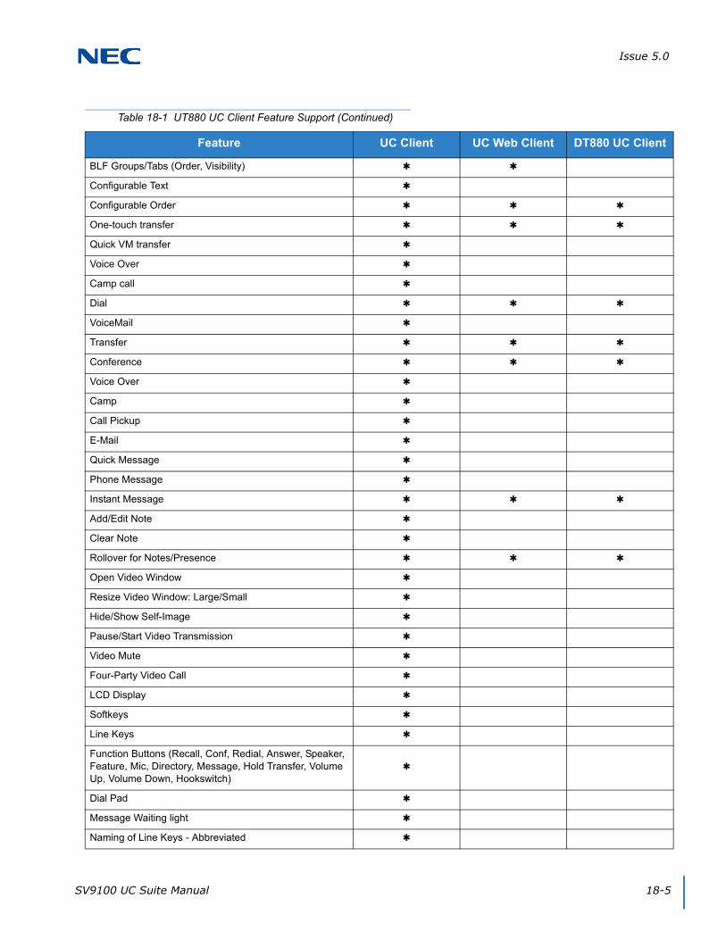
Issue 5.0
SV9100 UC Suite Manual 18-5
BLF Groups/Tabs (Order, Visibility)
Configurable Text
Configurable Order
One-touch transfer
Quick VM transfer
Voice Over
Camp call
Dial
VoiceMail
Transfer
Conference
Voice Over
Camp
Call Pickup
Quick Message
Phone Message
Instant Message
Add/Edit Note
Clear Note
Rollover for Notes/Presence
Open Video Window
Resize Video Window: Large/Small
Hide/Show Self-Image
Pause/Start Video Transmission
Video Mute
Four-Party Video Call
LCD Display
Softkeys
Line Keys
Function Buttons (Recall, Conf, Redial, Answer, Speaker, Feature, Mic, Directory, Message, Hold Transfer, Volume Up, Volume Down, Hookswitch)
Dial Pad
Message Waiting light
Naming of Line Keys - Abbreviated
Table 18-1 UT880 UC Client Feature Support (Continued)
Feature UC Client UC Web Client DT880 UC Client

Issue 5.0
18-6 UT880 UC Client
SECTION 3 COMPATIBILITY
The UT880 Client is supported with UC Server version 3.0.0.0 or higher on the InServer Blade or on an External Server.
The UT880 Client is a part of the Multiline Client (MLC) applications version 1.0.
SECTION 4 LICENSING
The UT880 UC Client will utilize a license code separate from the UC Client. Each UT880 UC Client will require one available UC Web Client license (5313) for the login to be successful. If a client license is not available, then an error message will be displayed when the login is attempted. An example of this error is shown below in the User Login section of this document.
The client license will be released by the application when the user logs out of the UT880 UC Client.
Add-On Module
DSS Module
DataConference
Application Sharing
Whiteboard
Chat
File Transfer
InMail
UM8000
Goldmine/ACT!/Time Matters/TigerPaw/Salesforce
Answer Center
Third-Party Interface
Multi-Device Group
Table 18-1 UT880 UC Client Feature Support (Continued)
Feature UC Client UC Web Client DT880 UC Client
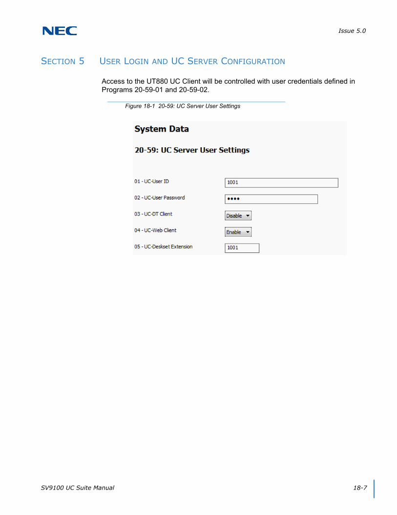
Issue 5.0
SV9100 UC Suite Manual 18-7
SECTION 5 USER LOGIN AND UC SERVER CONFIGURATION
Access to the UT880 UC Client will be controlled with user credentials defined in Programs 20-59-01 and 20-59-02.
Figure 18-1 20-59: UC Server User Settings

Issue 5.0
18-8 UT880 UC Client
Users can access the UT880 UC Client after entering the UC Suite Server address and port, UC Suite User Name, and UC Suite Password in the SIP Account Settings within the Multiline Client (MLC) application. An example of this is shown below.
Figure 18-2 MLC – SIP Account Settings Screen

Issue 5.0
SV9100 UC Suite Manual 18-9
Selecting the UC Suite icon at the bottom of the NMLT application brings up the UT880 UC Client login.
Figure 18-3 UT880 UC Suite – Login Screen
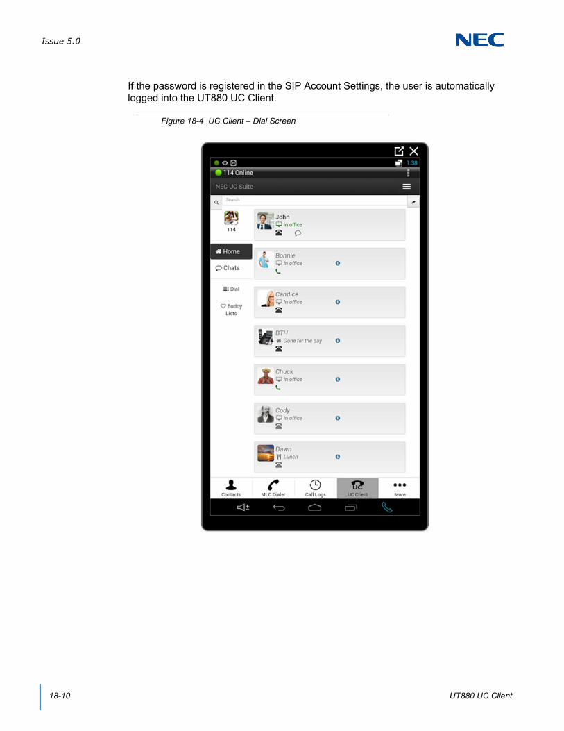
Issue 5.0
18-10 UT880 UC Client
If the password is registered in the SIP Account Settings, the user is automatically logged into the UT880 UC Client.
Figure 18-4 UC Client – Dial Screen
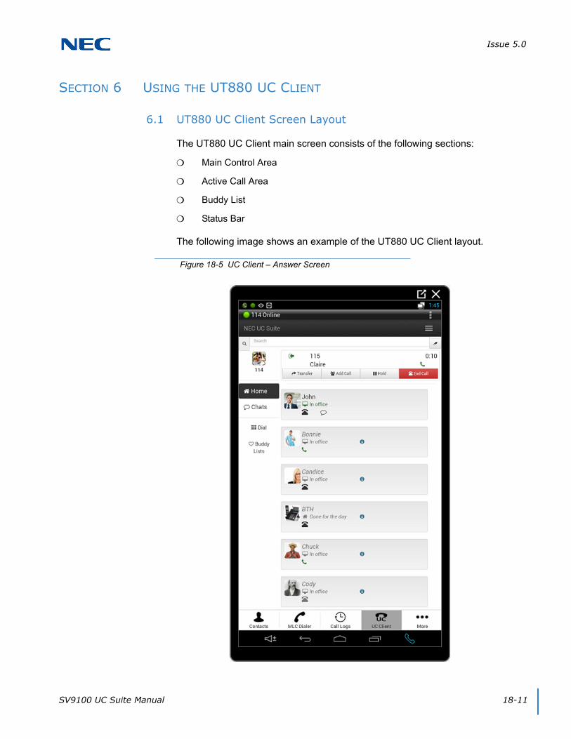
Issue 5.0
SV9100 UC Suite Manual 18-11
SECTION 6 USING THE UT880 UC CLIENT
6.1 UT880 UC Client Screen Layout
The UT880 UC Client main screen consists of the following sections:
Main Control Area
Active Call Area
Buddy List
Status Bar
The following image shows an example of the UT880 UC Client layout.
Figure 18-5 UC Client – Answer Screen
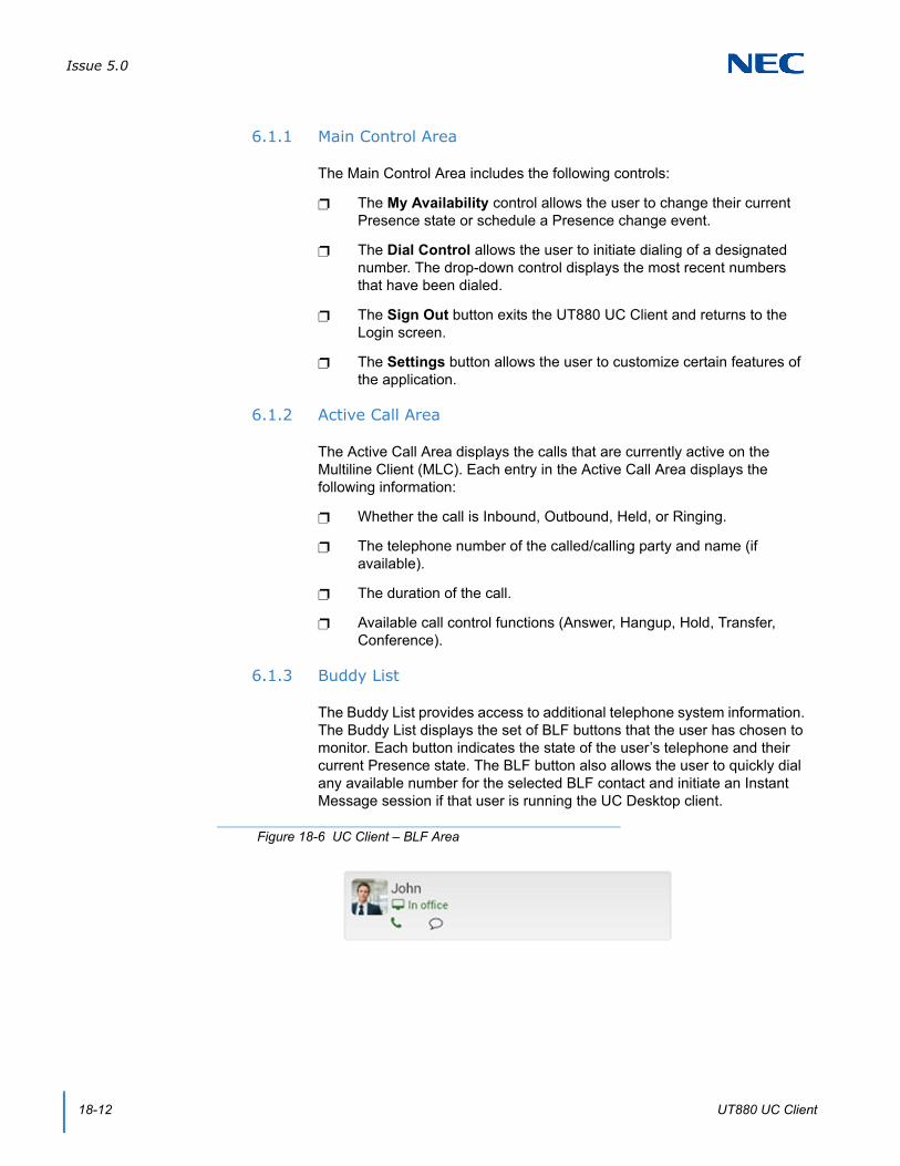
Issue 5.0
18-12 UT880 UC Client
6.1.1 Main Control Area
The Main Control Area includes the following controls:
The My Availability control allows the user to change their current Presence state or schedule a Presence change event.
The Dial Control allows the user to initiate dialing of a designated number. The drop-down control displays the most recent numbers that have been dialed.
The Sign Out button exits the UT880 UC Client and returns to the Login screen.
The Settings button allows the user to customize certain features of the application.
6.1.2 Active Call Area
The Active Call Area displays the calls that are currently active on the Multiline Client (MLC). Each entry in the Active Call Area displays the following information:
Whether the call is Inbound, Outbound, Held, or Ringing.
The telephone number of the called/calling party and name (if available).
The duration of the call.
Available call control functions (Answer, Hangup, Hold, Transfer, Conference).
6.1.3 Buddy List
The Buddy List provides access to additional telephone system information. The Buddy List displays the set of BLF buttons that the user has chosen to monitor. Each button indicates the state of the user’s telephone and their current Presence state. The BLF button also allows the user to quickly dial any available number for the selected BLF contact and initiate an Instant Message session if that user is running the UC Desktop client.
Figure 18-6 UC Client – BLF Area
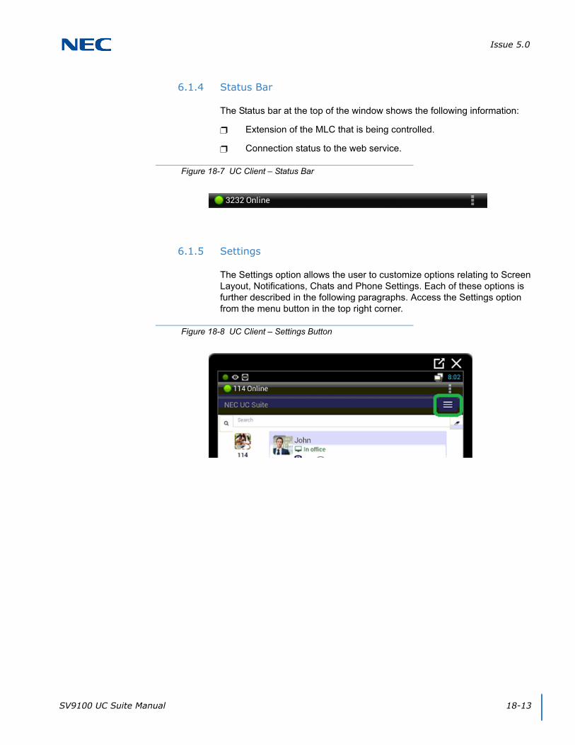
Issue 5.0
SV9100 UC Suite Manual 18-13
6.1.4 Status Bar
The Status bar at the top of the window shows the following information:
Extension of the MLC that is being controlled.
Connection status to the web service.
6.1.5 Settings
The Settings option allows the user to customize options relating to Screen Layout, Notifications, Chats and Phone Settings. Each of these options is further described in the following paragraphs. Access the Settings option from the menu button in the top right corner.
Figure 18-7 UC Client – Status Bar
Figure 18-8 UC Client – Settings Button

Issue 5.0
18-14 UT880 UC Client
Figure 18-9 UC Client – Settings Screen

Issue 5.0
SV9100 UC Suite Manual 18-15
6.1.5.1 Personal Profile
The following image shows the settings available within theSettings – Personal Profile menu.
Photo
The Photo selection area allows the user select a new photo or clear their current photo selection.
The Change option opens a file browser window allowing the user to designate an image file to use.
The Clear option removes the current Photo selection and restores the photo to the default image.
Figure 18-10 UC Client – Personal Profile

Issue 5.0
18-16 UT880 UC Client
Other Numbers
The Other Numbers selection area allows the user to add additional numbers to be reached at. When their phone icon is clicked on, these Other Numbers will be an option to call along with their internal extension.
The Edit button gives the option to Add, Save, and Cancel. Define the Number and Type of number it is and click Save.
6.1.5.2 Display
The following image shows the settings that are available within the Settings – Display menu.
Figure 18-11 UT880 – Display
Issue 5.0
SV9100 UC Suite Manual 18-17
The Show Filter/Search option controls whether the Search field is displayed on the main screen. By default this option is set to On.
The Enable launch of email client option controls whether the e-mail integration function is enabled within the Buddy List entries.
The Employee label format specifies the label content that will be used within entries in the Buddy List. The available options are Extension Name, Extension, First Name first, Last Name first, and First Name only.
The Compressed employee view makes the members of a buddy list smaller in order for more to fit per screen. By default this option is set to Off.
The Hide Offline Users options controls whether the Buddy List panel includes entries that do not currently have an active UC client. The default is Off which will show all selected users, regardless if they are active.
IMPORTANT
The user must have an email client configured on their PC for this feature to function properly.
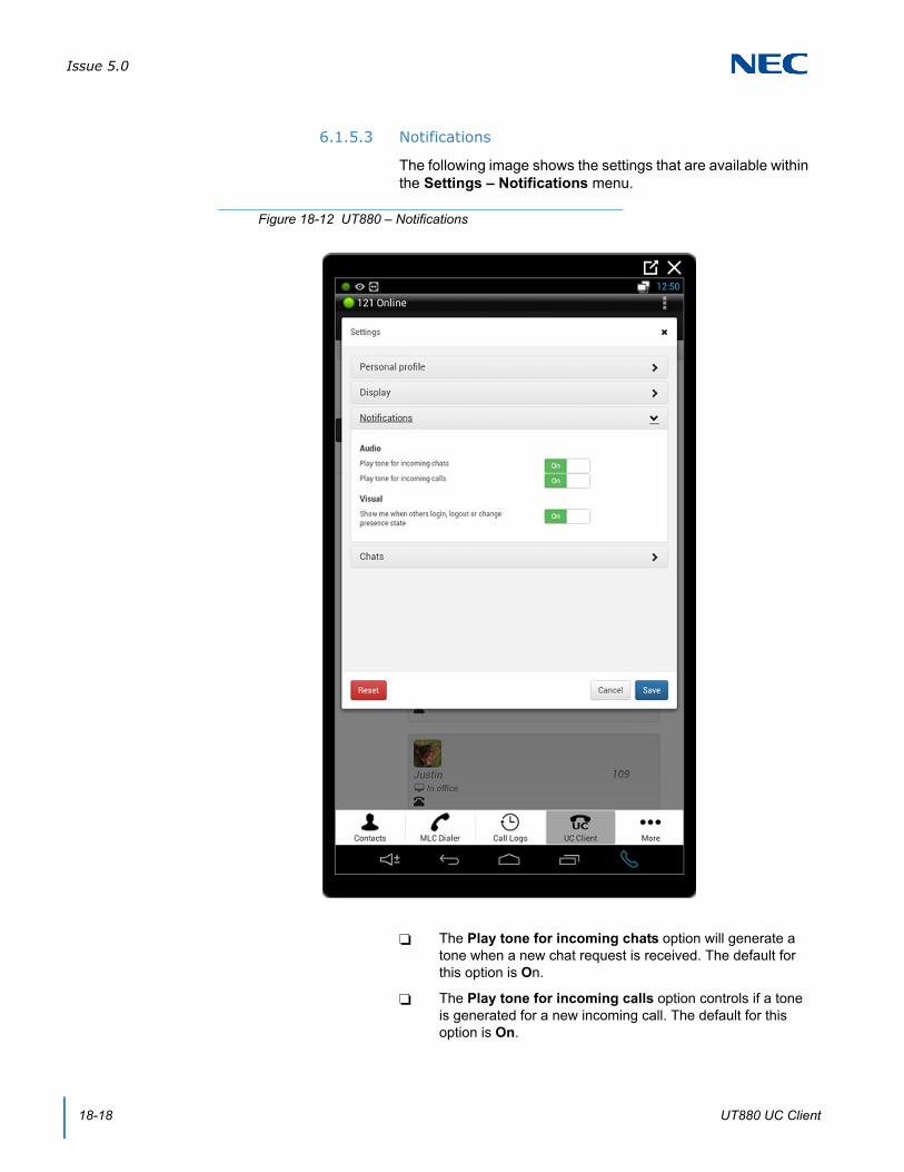
Issue 5.0
18-18 UT880 UC Client
6.1.5.3 Notifications
The following image shows the settings that are available within the Settings – Notifications menu.
The Play tone for incoming chats option will generate a tone when a new chat request is received. The default for this option is On.
The Play tone for incoming calls option controls if a tone is generated for a new incoming call. The default for this option is On.
Figure 18-12 UT880 – Notifications

Issue 5.0
SV9100 UC Suite Manual 18-19
The Visual notification option controls whether pop up notification boxes are shown when another user logs in, logs out or changes their presence state. The default for this option is On.
6.1.5.4 Chats
The following image shows the settings that are available within the Settings – Chats menu.
The Play Tone option controls if a notification tone is generated when a chat message is received. The default for this option is On.
Figure 18-13 UT880 – Chats

Issue 5.0
18-20 UT880 UC Client
The Use ‘Enter’ Key option controls whether pressing the Enter key will send the current Chat message that is being composed. When this is set to Off, the user must click on the Send button to deliver the message. The default value for this field is On.
6.2 Handling Calls
6.2.1 Answering Incoming Calls
When a call arrives, the UC Client generates a new ringing call in the Active Call Area.
The user can answer the call by clicking on the Answer button within the Incoming Call window.
If the user has another active call when a ringing call is answered, the active call will automatically be placed on hold.
6.2.2 Disconnecting from a Call
To disconnect from an active call:
Press the End Call button within the Active Call entry.
Figure 18-14 UC Client – Incoming Call
Figure 18-15 UC Client – End Call

Issue 5.0
SV9100 UC Suite Manual 18-21
6.2.3 Placing an Outbound Call
When the UC Client is idle (no active call), the user can initiate an outbound call. The UC Client provides the Dial button on the Main Control area as one means to initiate a call to an external number. Special dialing features are also available within the Buddy List.
6.2.3.1 To Initiate a Call Using the Dial Control
1. Press the Dial button.
2. Dial the number or select one of the matching numbers from the drop down.
3. Press the Dial button to initiate the call.
Figure 18-16 UC Client – Dial Button
Figure 18-17 UC Client – Make a Call

Issue 5.0
18-22 UT880 UC Client
6.2.3.2 To Initiate a Call Using a BLF/DSS in a Buddy List
1. Select the desired BLF in the Buddy List. Click on the Call (Phone) button within the selected BLF.
2. If multiple numbers are associated with the selected contact, a submenu will open listing the available numbers. Select the desired number from the list.
6.2.4 Placing a Call on Hold
6.2.4.1 To Place the Active Call on Hold
1. Tap the Hold button within the Active Call entry.
6.2.4.2 Retrieving a Call on Hold
To retrieve a call that was previously placed on hold:
1. Use the mouse to select the Retrieve (Answer) button within the Active Call entry.
Figure 18-18 UC Client – Call (Phone) Button
Figure 18-19 UC Client – Hold Button
Figure 18-20 UC Client – Retrieve (Answer) Button

Issue 5.0
SV9100 UC Suite Manual 18-23
6.2.5 Transferring a Call
The UC Client provides two methods to initiate a transfer on an active call. The Transfer button within the Active Call entry is one method that can be used to initiate a transfer. The Buddy List provides special features to initiate a transfer. The UC Client also provides the option to perform either a supervised transfer or unsupervised (blind) transfer.
6.2.5.1 To Redirect a Call Using the Transfer Button
1. Tap the Transfer button within the Active Call entry.
2. Enter the number to be dialed in the Enter name or phone number field within the Transfer Call menu.
3. Select the Attended Transfer option within the Data Entry area to initiate a supervised transfer. When the destination party answers, announce the transfer and then select Connect. If the destination does not answer or does not want to take the call, select Cancel to reconnect to the original caller.
- OR -
Select the Immediate option within the Data Entry area to initiate an unsupervised (blind) transfer. The call will be immediately routed to the specified destination.
Figure 18-21 UC Client – Transfer Button
Figure 18-22 UC Client – Transfer Call Menu
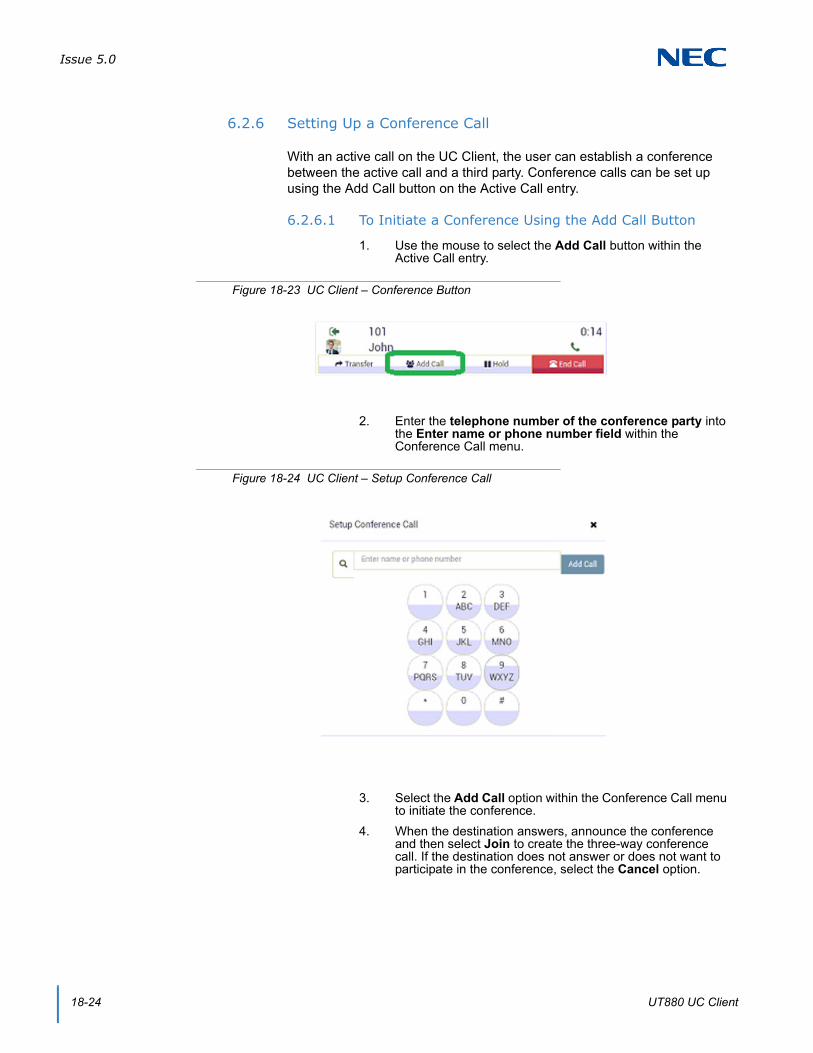
Issue 5.0
18-24 UT880 UC Client
6.2.6 Setting Up a Conference Call
With an active call on the UC Client, the user can establish a conference between the active call and a third party. Conference calls can be set up using the Add Call button on the Active Call entry.
6.2.6.1 To Initiate a Conference Using the Add Call Button
1. Use the mouse to select the Add Call button within the Active Call entry.
2. Enter the telephone number of the conference party into the Enter name or phone number field within the Conference Call menu.
3. Select the Add Call option within the Conference Call menu to initiate the conference.
4. When the destination answers, announce the conference and then select Join to create the three-way conference call. If the destination does not answer or does not want to participate in the conference, select the Cancel option.
Figure 18-23 UC Client – Conference Button
Figure 18-24 UC Client – Setup Conference Call

Issue 5.0
SV9100 UC Suite Manual 18-25
6.3 My Availability
The My Availability control allows the user to update their Photo, Presence Settings, Forward Settings, and Alternate Numbers. The following image shows an example of the My Availability menu.
Figure 18-25 My Availability Screen
Issue 5.0
18-26 UT880 UC Client
Photo Update
The Photo selection area allows the user select a new Photo or clear their current photo selection. Selecting the Change option will open a file browser window that allows the user to designate an image file to use for the photo. Selecting the Clear option removes the current Photo selection and restores the photo to the default image.
Presence Status
The Presence Status area allows the user to change their current Presence state and schedule future Presence changes. Clicking on the Presence state will open a drop down list of all of the available Presence states. Selecting an option from the drop down list will change the user’s current Presence state.
Presence Schedule
Selecting the Presence Schedules option will open a list of the currently defined Presence events. Clicking on the Add Event button will open a menu that allows the user to schedule a new Presence event. The Presence Schedule event is comprised of settings for the Event Start and settings for the Event Finish. Selecting the Event Start control will display the following menu.
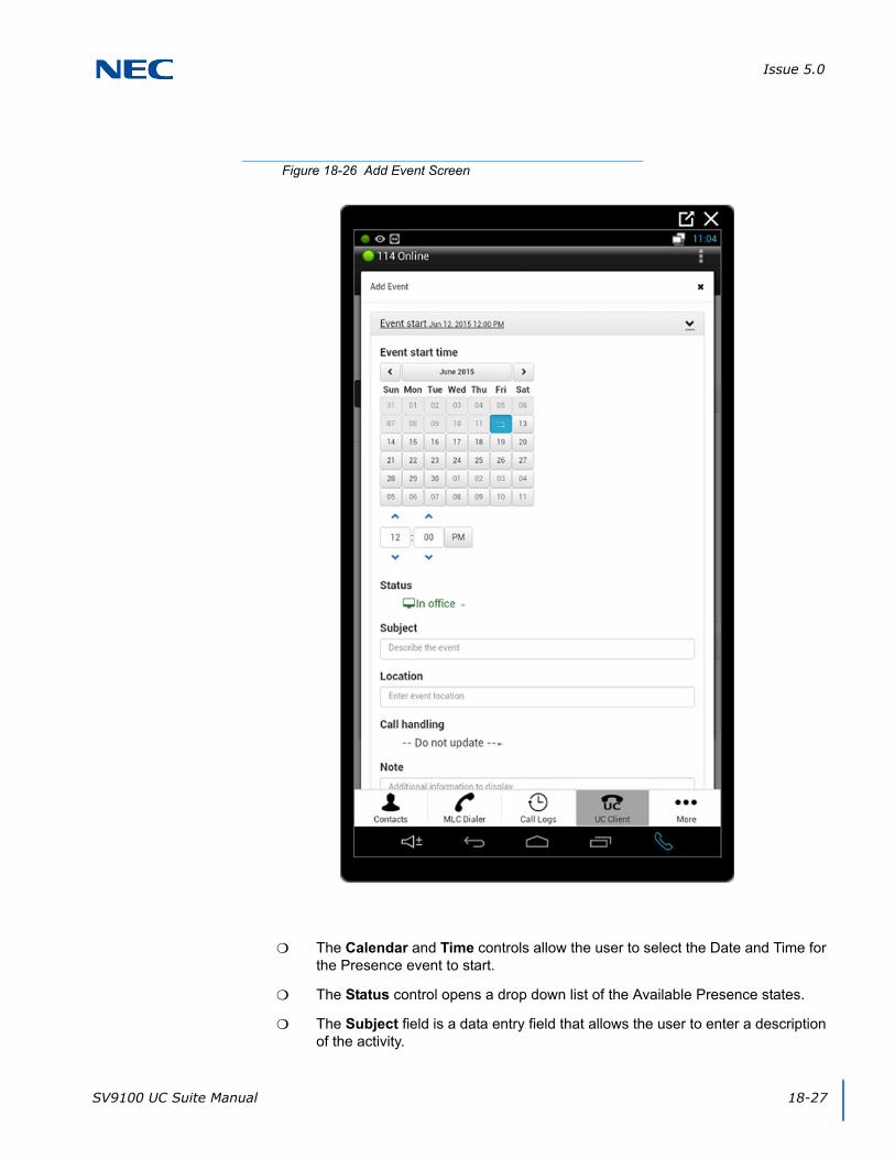
Issue 5.0
SV9100 UC Suite Manual 18-27
The Calendar and Time controls allow the user to select the Date and Time for the Presence event to start.
The Status control opens a drop down list of the Available Presence states.
The Subject field is a data entry field that allows the user to enter a description of the activity.
Figure 18-26 Add Event Screen

Issue 5.0
18-28 UT880 UC Client
The Location field is a data entry field that allows the user to enter their location for the Presence event.
The Call Handling control allows the user to alter the forward settings at the start of the Presence event. Through this control the user can select Forward, Forward – Both Ring, or Do Not Disturb.
The Note field is a data entry field that allows the user to share additional information about their current Presence state.
Selecting the Event Finish control will display the following menu:
Figure 18-27 Event Finish Screen
Issue 5.0
SV9100 UC Suite Manual 18-29
The Calendar and Time controls allow the user to select the Date and Time for the Presence event will end.
The At Finish Status control opens a drop down list of the Available Presence states.
The At Finish Call Handling control allows the user to alter the forward settings at the end of the Presence event. Through this control the user can cancel Forward, set Forward, set Forward – Both Ring, or set Do Not Disturb.
Note
The Note field is a data entry field that allows the user to share additional information about their current Presence state.
Advanced Settings
The Advanced Settings fields on the My Status screen allows the user to specify additional Presence information about their Presence state, Location, and Expected Return.
The Subject field is a data entry field that allows the user to enter a description of the activity.
The Location field is a data entry field that allows the user to enter their location for the Presence event.
The Expected Return allows the user to select a Date and Time to indicate the expected end of the specified Presence event.
6.4 Buddy List
This operation allows the user to modify the defined Buddy Lists and the contents of each. The following image shows an example of the menu that is opened by selecting the Buddy Lists feature.
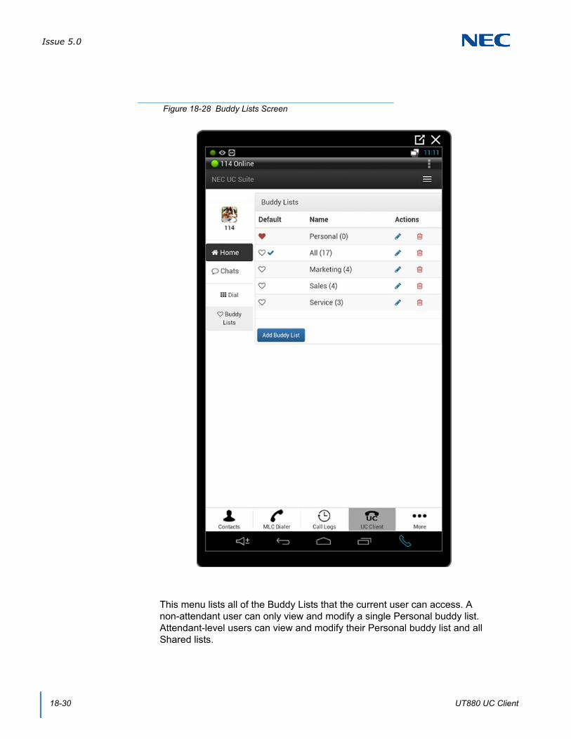
Issue 5.0
18-30 UT880 UC Client
This menu lists all of the Buddy Lists that the current user can access. A non-attendant user can only view and modify a single Personal buddy list. Attendant-level users can view and modify their Personal buddy list and all Shared lists.
Figure 18-28 Buddy Lists Screen
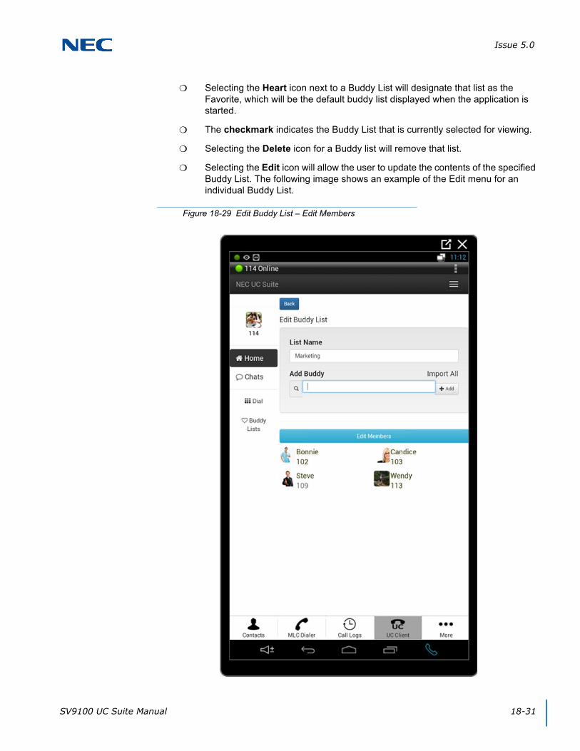
Issue 5.0
SV9100 UC Suite Manual 18-31
Selecting the Heart icon next to a Buddy List will designate that list as the Favorite, which will be the default buddy list displayed when the application is started.
The checkmark indicates the Buddy List that is currently selected for viewing.
Selecting the Delete icon for a Buddy list will remove that list.
Selecting the Edit icon will allow the user to update the contents of the specified Buddy List. The following image shows an example of the Edit menu for an individual Buddy List.
Figure 18-29 Edit Buddy List – Edit Members

Issue 5.0
18-32 UT880 UC Client
The List Name field allows the user to update the name of the buddy list.
The Add Buddy control allows the user to insert additional members into the buddy list. Typing a name into the Add Buddy control will display all of the defined contacts that match the entered text string. After a contact is identified, selecting the Add button will insert the specified contact into the list.
Selecting the Edit Members function will allow the current members of the list to be updated. The following image shows an example of the screen that will be displayed when the Edit Members operation is selected.
For optimum performance, it is recommended to limit the number of members in a buddy list to 25 or less for a UT880 client.
Figure 18-30 Edit Buddy List – Delete
Issue 5.0
SV9100 UC Suite Manual 18-33
Each member has a checkbox next to their entry.
Pressing the Delete button will remove all of the selected entries from the Buddy list.
Pressing Done will complete the Edit Members operation.

Issue 5.0
18-34 UT880 UC Client
SV9100 UC Suite Manual 19-1
Chapter 19
UNIVERGE® SV9100
Multi-Device Support
SECTION 1 INTRODUCTION
With SV9100 Version 4000, a new feature called Multi-Device Support allows a user to have a multi-device group that is associated with a pilot number. When the pilot extension receives a call, all of the devices in the group will ring. Any member phone in the group can answer the incoming call, and once answered, all phones in the group will stop ringing.
The Multi-Device group can include both internal extensions and external phone numbers. To add an external number to the Multi-Device group requires that the telephone number be setup as a Mobile Extension, associating the external number with a Speed Dial bin and internal extension.
End Users can administer their Multi-Device group via an enhancement to the UC Suite clients.
SECTION 2 COMPATIBILITY
The Multi-Device Group support is supported with SV9100 Version 4000 software and UC Suite Version 3.5.
SECTION 3 LICENSING
The Multi-Device Support feature will be available to UC Suite Full Clients, Web Clients, and UT880 Clients without requiring an additional license. However, since this feature is only available starting with SV9100 Version 4000, the UC client will check for the SV9100 R4 license and only surface this feature if the R4 license is present.

Issue 5.0
19-2 Multi-Device Support
SECTION 4 UC SUITE CLIENT INTEGRATION
4.1 XML Pro Access
The UC Client utilizes the XML Pro interface to read and write program settings within the SV9100 system programming. This interface will be used to identify the current Multi-Device Support settings for a user and allow the user to update the numbers that are included in the Multi-Device group.
At startup, the UC Client will scan the Program 20-63-01 values to determine if the phone technician has enabled this client to use the Multi-Device Support feature. Only users whose extension matches a pilot number in Program 20-63-01 will be allowed to access this feature within UC Suite.
If a user has been setup to use this feature, the UC Suite will provide access to a form that allows the user to view and modify the members of the Multi-Device group. The following sections define the interface that will be provided in both the UC Client and Web Client applications.
4.2 Client Feature Access
For users that have been setup to use the Multi-Device feature, a new option labeled Multi-Device Group will appear in the Main menu under the Tools section. This option will be available in both Window Mode and Toolbar Mode.
When the Multi-Device Group function is selected, the following (refer to Figure 19-1 Multi-Device Group Screen on page 19-3) is displayed:
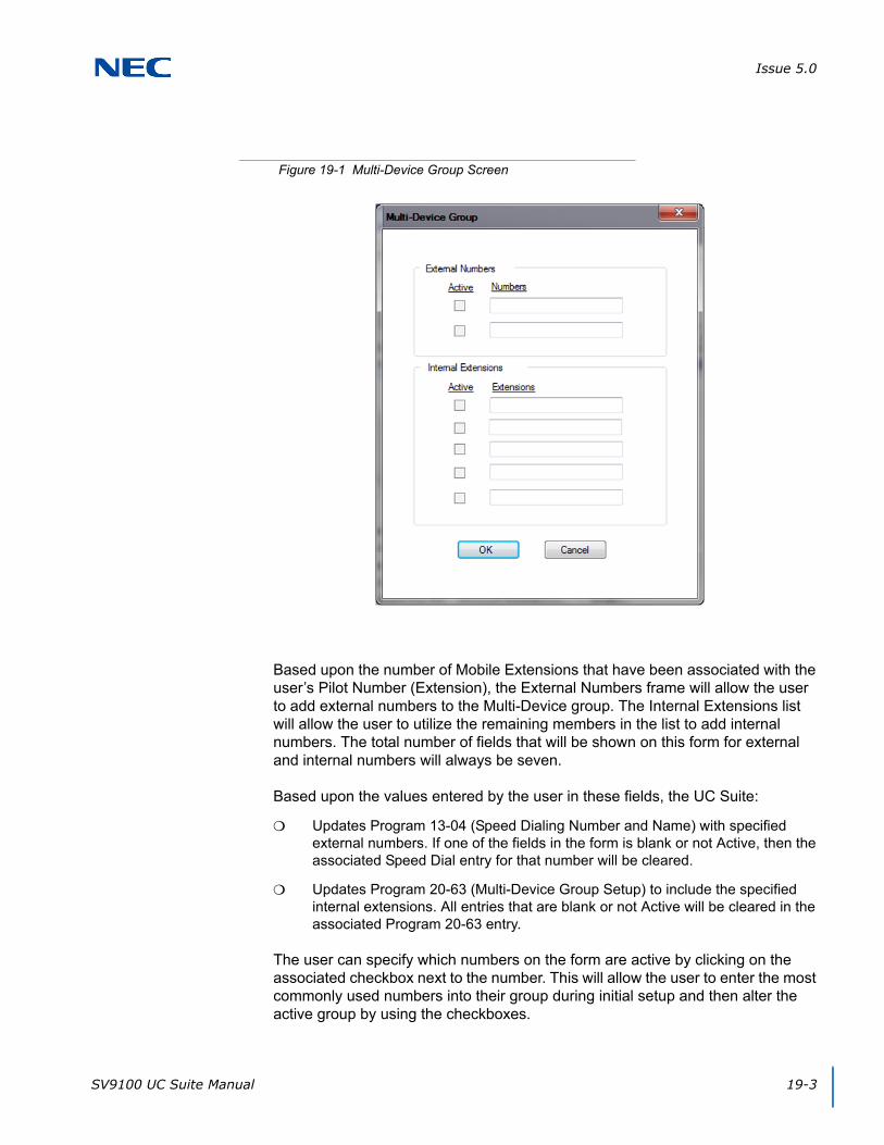
Issue 5.0
SV9100 UC Suite Manual 19-3
Based upon the number of Mobile Extensions that have been associated with the user’s Pilot Number (Extension), the External Numbers frame will allow the user to add external numbers to the Multi-Device group. The Internal Extensions list will allow the user to utilize the remaining members in the list to add internal numbers. The total number of fields that will be shown on this form for external and internal numbers will always be seven.
Based upon the values entered by the user in these fields, the UC Suite:
Updates Program 13-04 (Speed Dialing Number and Name) with specified external numbers. If one of the fields in the form is blank or not Active, then the associated Speed Dial entry for that number will be cleared.
Updates Program 20-63 (Multi-Device Group Setup) to include the specified internal extensions. All entries that are blank or not Active will be cleared in the associated Program 20-63 entry.
The user can specify which numbers on the form are active by clicking on the associated checkbox next to the number. This will allow the user to enter the most commonly used numbers into their group during initial setup and then alter the active group by using the checkboxes.
Figure 19-1 Multi-Device Group Screen

Issue 5.0
19-4 Multi-Device Support
4.3 Web Client Feature Access
Within the Web Client, the Multi-Device feature is accessed from the My Availability page.
After selecting My Availability, the user can edit the Multi-Device Group settings in the Mobility (Multi-Device Group) section. Users can Enable All numbers, Disable All numbers, Edit or Remove Existing Numbers, and Add New Numbers.
4.4 Error Handling
When the user presses the OK button on the Multi-Device Group form, the client will attempt to update the appropriate programs within SV9100 system programming. If an error is returned from this operation, the client will display an error message, as indicated by the SV9100 CPU.
Some possible causes for errors are:
An extension was entered that is currently associated with another pilot number’s group.
An invalid or undefined extension number was entered.
SECTION 5 SERVICE CONDITIONS
The following list of service conditions are associated with the implementation of this feature.
Deskset+Softphone Mode – When the UC Client is setup to run in Deskset+Softphone mode, the client will always use the Deskset extension to search for a matching Multi-Device pilot number. This will allow the phone technician to only be required to setup one entry in Program 20- 63 for this user.
BLF – When the pilot of a multi-device group is ringing, all members of the group will show ringing. However, once one of the members in the group answers the call, the answering party will show busy in the BLF panel.
Program Synchronization – The layout of the Multi-Device Group menu (external vs. internal numbers) will be set based upon the system programming at the time that the UC Client is launched. Any changes made within the system programming that affect this feature will require the UC client to be restarted to recognize the new settings.
When a station in a Multi-Device group is busy, only the BLF for the active station will show busy, not all stations in the Multi-Device Group.
If internal extensions or mobile extensions are added to the Multi-Device Group via system programming using Program 20-63 the UC Client must be restarted to reflect these changes.
Issue 5.0
SV9100 UC Suite Manual 19-5
The number of external numbers available in the Multi-Device group is directly related to the number of Mobile Extensions defined in the group (Program 20-63). If the user requires additional external numbers, more mobile extensions need to also be added to the group using Program 20-63. The UC Suite must be restarted for these changes to take effect.
When a UC Client is configured with the Softphone+Deskset license level in Program 20-59-14, the UC Client will always use the Deskset extension to search for a matching Multi-Device Pilot.
If DND or CFA is set for the pilot or any member of the MDG group, only the station that is set will show DND or CFA in the UC Suite BLF view, not each member in the group.
UC Client, v.3.0 or earlier is incompatible with the SV9100 R4 CPU. Use of these UC Client versions may limit access to some UC features.
UC Client, v.3.5 will not be fully compatible with the SV9100 R3 CPU or earlier. In particular, the CRM integration features within the UC Client will not be enabled.

Issue 5.0
19-6 Multi-Device Support

SV9100 UC Suite Manual 20-1
Chapter 20
UNIVERGE® SV9100
InControl Call Reporting
SECTION 1 INTRODUCTION
InControl Call Reporting is a series of browser based reports that will generate sought after business analytics to help management make better business decisions. There are three types of reports; Detailed, Summary and Other. All reports are displayed on the opening page (after authentication).
Detailed Reports
Extension Call Details
Phone Number Details (Cradle to Grave)
Summary Reports
Departments Call Summary
Extension Summary by Departments
Extension Call Summary
Other Reports
Trunk Utilization
The InControl Call Reporting database can hold approximately 2 million calls for every GB of disk storage space.
SECTION 2 SYSTEM REQUIREMENTS
Contact Center Version 1.6
UC Suite Version 4.0
Internet Browser:
Internet Explorer 11
Mozilla Firefox 44
Google Chrome 48
NOTE
For InControl Reporting, only Contact Center and UC Suite software is required. InControl Reporting does not require Contact Center and UC Suite licenses. Refer to Section 3 Licensing for required licenses.
Issue 5.0
20-2 InControl Call Reporting
SECTION 3 LICENSING
InControl Server License (2107)
P-Event License (2101)
InControl Addon License (5327)
SECTION 4 LOGIN
InControl Call Reporting is accessed by pointing a supported browser to the reports URL.
The URL for InControl Call Reporting is http://{IP address of the UC Suite/Contact Center server}/reports.
Example: http://192.168.1.10/reports
User login and password as well as user rights are assigned in memory block 20-59.
SECTION 5 SETTINGS MANAGEMENT (ADMINISTRATION)
Settings Management is accessible by mouse clicking on the user’s extension number in the open browser window. Settings has two licensing levels:
Premium user - Administration. A user with a Premium user license has access to manage the directory.
Standard users are able to make changes to their personal settings (First day of the week and time format).
5.1 Department Administration
Extensions must be associated with a Department in order to run the Extension Summary by Departments and Department Call Summary reports. This section demonstrates the required department settings.
1. In the reports client, click the extension drop down towards the top right of the screen. From the drop down menu select Administration. You must be a premium user with the attendant option enabled in Program 20-59.
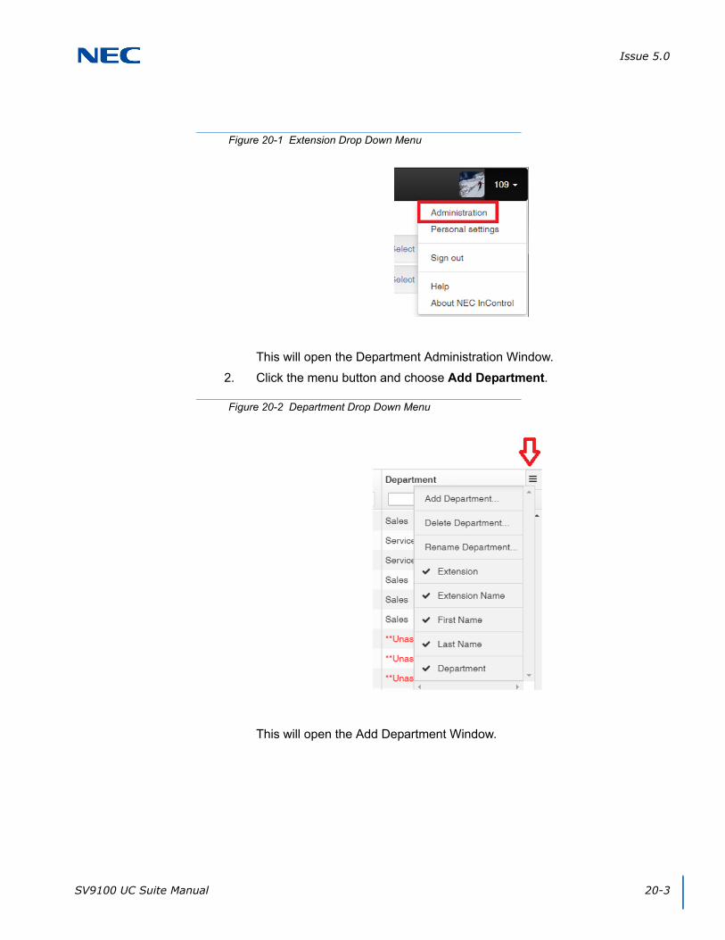
Issue 5.0
SV9100 UC Suite Manual 20-3
This will open the Department Administration Window.
2. Click the menu button and choose Add Department.
This will open the Add Department Window.
Figure 20-1 Extension Drop Down Menu
Figure 20-2 Department Drop Down Menu
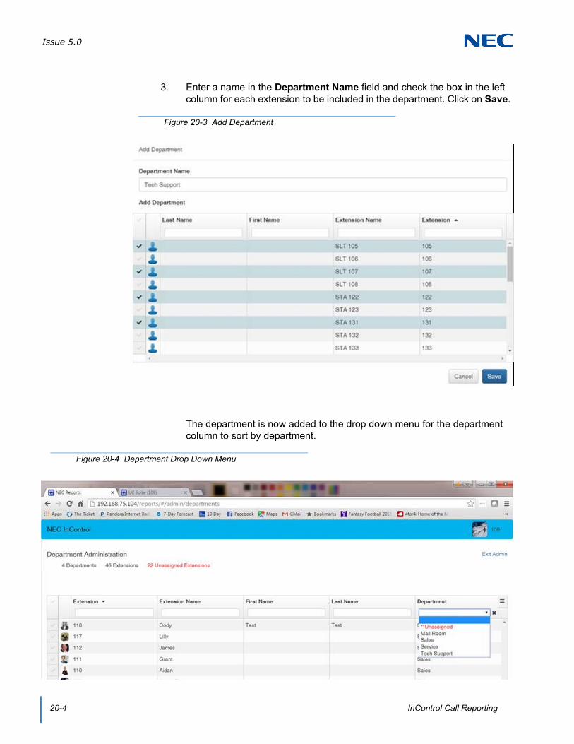
Issue 5.0
20-4 InControl Call Reporting
3. Enter a name in the Department Name field and check the box in the left column for each extension to be included in the department. Click on Save.
The department is now added to the drop down menu for the department column to sort by department.
Figure 20-3 Add Department
Figure 20-4 Department Drop Down Menu

Issue 5.0
SV9100 UC Suite Manual 20-5
4. To add extensions to an existing department, check the box in the left column for each extension to be added. Click on Move Extensions.
5. Define a new Department or select an existing department from the drop down list and select Save.
Figure 20-5 Move Extensions
Figure 20-6 Select Department
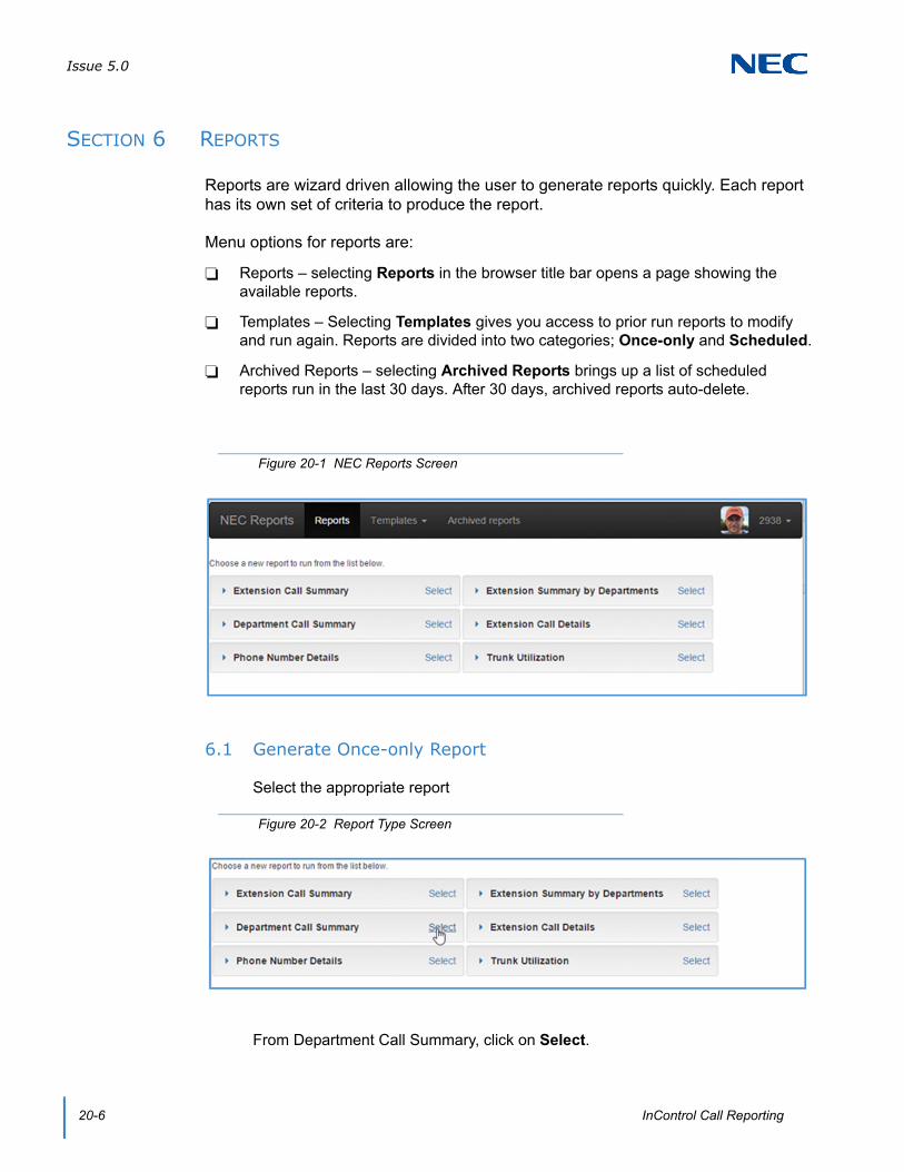
Issue 5.0
20-6 InControl Call Reporting
SECTION 6 REPORTS
Reports are wizard driven allowing the user to generate reports quickly. Each report has its own set of criteria to produce the report.
Menu options for reports are:
Reports – selecting Reports in the browser title bar opens a page showing the available reports.
Templates – Selecting Templates gives you access to prior run reports to modify and run again. Reports are divided into two categories; Once-only and Scheduled.
Archived Reports – selecting Archived Reports brings up a list of scheduled reports run in the last 30 days. After 30 days, archived reports auto-delete.
6.1 Generate Once-only Report
Select the appropriate report
From Department Call Summary, click on Select.
Figure 20-1 NEC Reports Screen
Figure 20-2 Report Type Screen
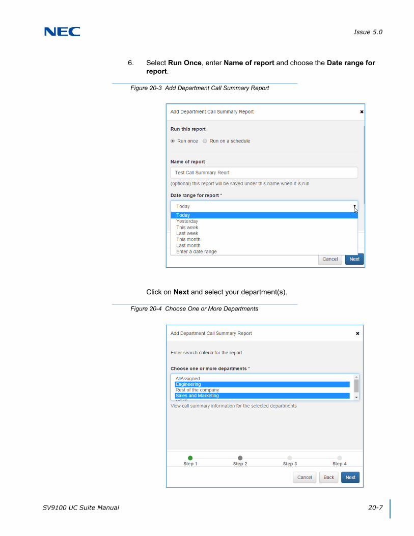
Issue 5.0
SV9100 UC Suite Manual 20-7
6. Select Run Once, enter Name of report and choose the Date range for report.
Click on Next and select your department(s).
Figure 20-3 Add Department Call Summary Report
Figure 20-4 Choose One or More Departments

Issue 5.0
20-8 InControl Call Reporting
7. Select report columns.
8. Review settings.
9. If settings are correct, click on Run.
Figure 20-5 Report Columns
Figure 20-6 Summary Report
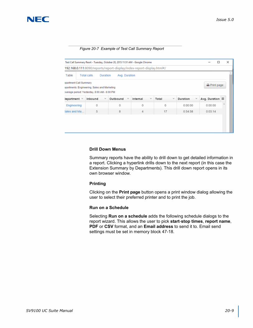
Issue 5.0
SV9100 UC Suite Manual 20-9
Drill Down Menus
Summary reports have the ability to drill down to get detailed information in a report. Clicking a hyperlink drills down to the next report (in this case the Extension Summary by Departments). This drill down report opens in its own browser window.
Printing
Clicking on the Print page button opens a print window dialog allowing the user to select their preferred printer and to print the job.
Run on a Schedule
Selecting Run on a schedule adds the following schedule dialogs to the report wizard. This allows the user to pick start-stop times, report name, PDF or CSV format, and an Email address to send it to. Email send settings must be set in memory block 47-18.
Figure 20-7 Example of Test Call Summary Report
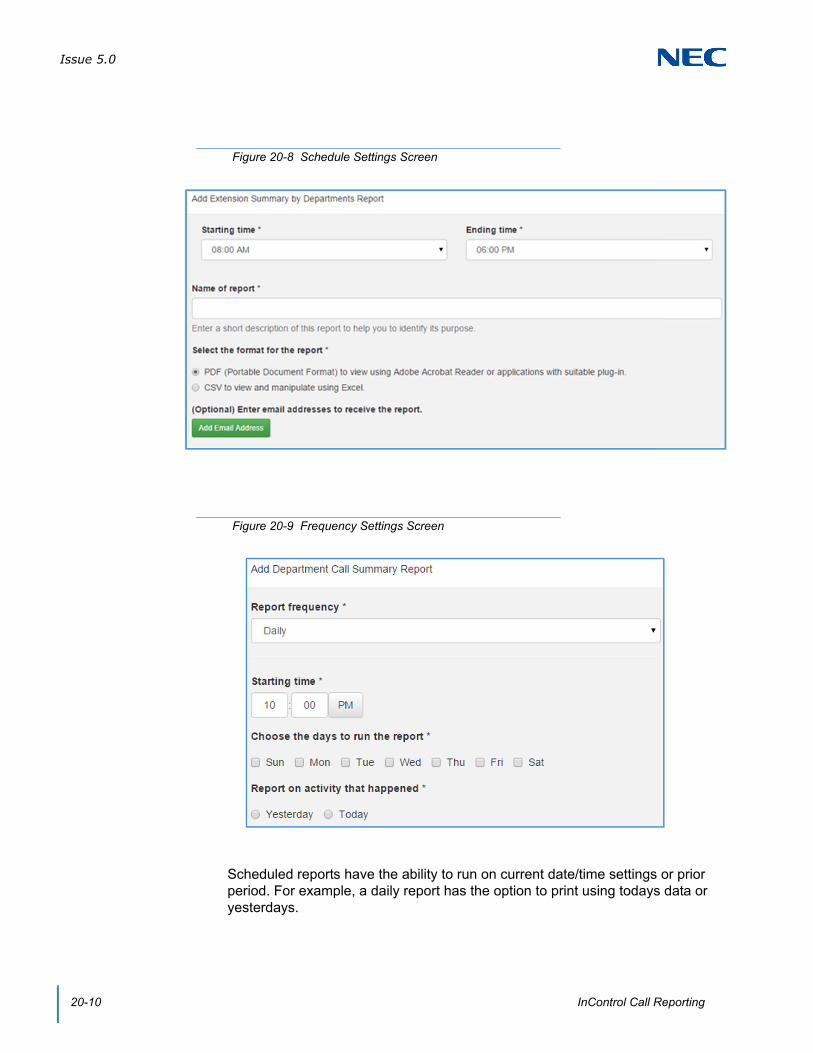
Issue 5.0
20-10 InControl Call Reporting
Scheduled reports have the ability to run on current date/time settings or prior period. For example, a daily report has the option to print using todays data or yesterdays.
Figure 20-8 Schedule Settings Screen
Figure 20-9 Frequency Settings Screen
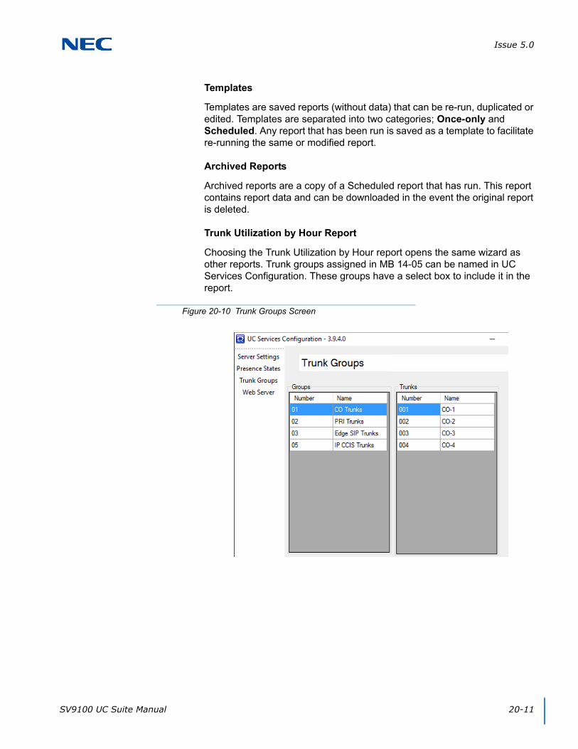
Issue 5.0
SV9100 UC Suite Manual 20-11
Templates
Templates are saved reports (without data) that can be re-run, duplicated or edited. Templates are separated into two categories; Once-only and Scheduled. Any report that has been run is saved as a template to facilitate re-running the same or modified report.
Archived Reports
Archived reports are a copy of a Scheduled report that has run. This report contains report data and can be downloaded in the event the original report is deleted.
Trunk Utilization by Hour Report
Choosing the Trunk Utilization by Hour report opens the same wizard as other reports. Trunk groups assigned in MB 14-05 can be named in UC Services Configuration. These groups have a select box to include it in the report.
Figure 20-10 Trunk Groups Screen

Issue 5.0
20-12 InControl Call Reporting
Figure 20-11 Add Trunk Utilization Report
Figure 20-12 Example of Trunk Utilization Table
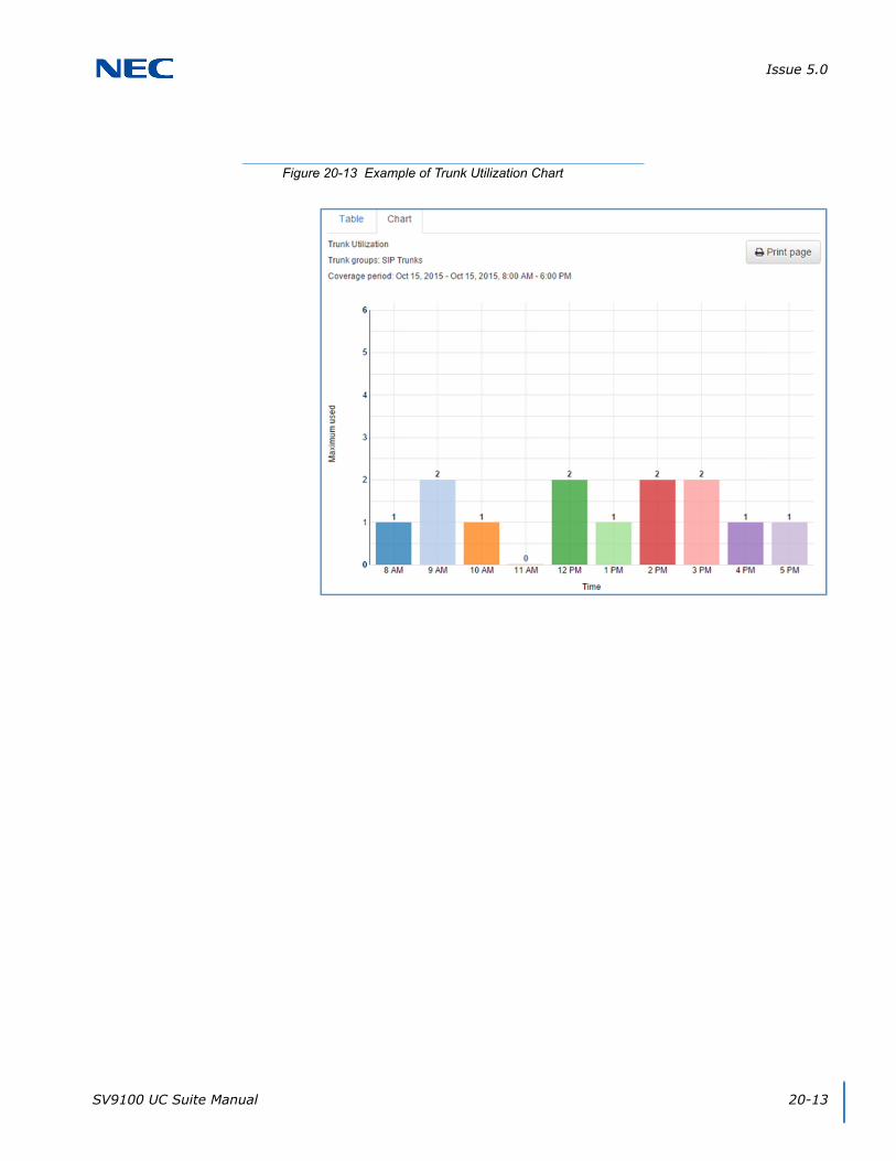
Issue 5.0
SV9100 UC Suite Manual 20-13
Figure 20-13 Example of Trunk Utilization Chart

Issue 5.0
20-14 InControl Call Reporting
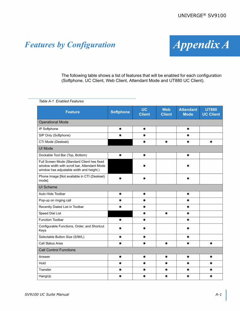
SV9100 UC Suite Manual A-1
Appendix A
UNIVERGE® SV9100
Features by Configuration
The following table shows a list of features that will be enabled for each configuration (Softphone, UC Client, Web Client, Attendant Mode and UT880 UC Client).
Table A-1 Enabled Features
Feature SoftphoneUC
ClientWeb
ClientAttendant
ModeUT880
UC Client
Operational Mode
IP Softphone
SIP Only (Softphone)
CTI Mode (Deskset)
UI Mode
Dockable Tool Bar (Top, Bottom)
Full Screen Mode (Standard Client has fixed window width with scroll bar, Attendant Mode window has adjustable width and height.)
Phone Image [Not available in CTI (Deskset) mode]
UI Scheme
Auto Hide Toolbar
Pop-up on ringing call
Recently Dialed List in Toolbar
Speed Dial List
Function Toolbar
Configurable Functions, Order, and Shortcut Keys
Selectable Button Size (S/M/L)
Call Status Area
Call Control Functions
Answer
Hold
Transfer
HangUp

Issue 5.0
A-2 Features by Configuration
Dial
Conference
Page
Park
Unpark
Barge In
Directed Call Pickup
Last Number Redial
Voice Over
Forward Calls
Background Music
Auto-Callback
Do Not Disturb
Group Call Pickup
Pickup Other Group
Directed Call Pickup
Selectable Display Message
Non Call Control Functions
Record
Add/Edit Note in Call Log
E-Mail Integration
Ringing through Speakers
Confirm Dialog on Exit
Record Selective/All Calls
Personal Greeting
Screen Pop (Outlook, Act! 2005+, Goldmine
6.7+, Time Matters) 1
Screen Pop through SDK
Outlook Selectable Contact Folder
Pop when ringing/answered
Pop on all calls/external only
Outlook Add-in Screen pop
Outlook Add-in Dial Out
Multi-Device Group
Table A-1 Enabled Features (Continued)
Feature SoftphoneUC
ClientWeb
ClientAttendant
ModeUT880
UC Client
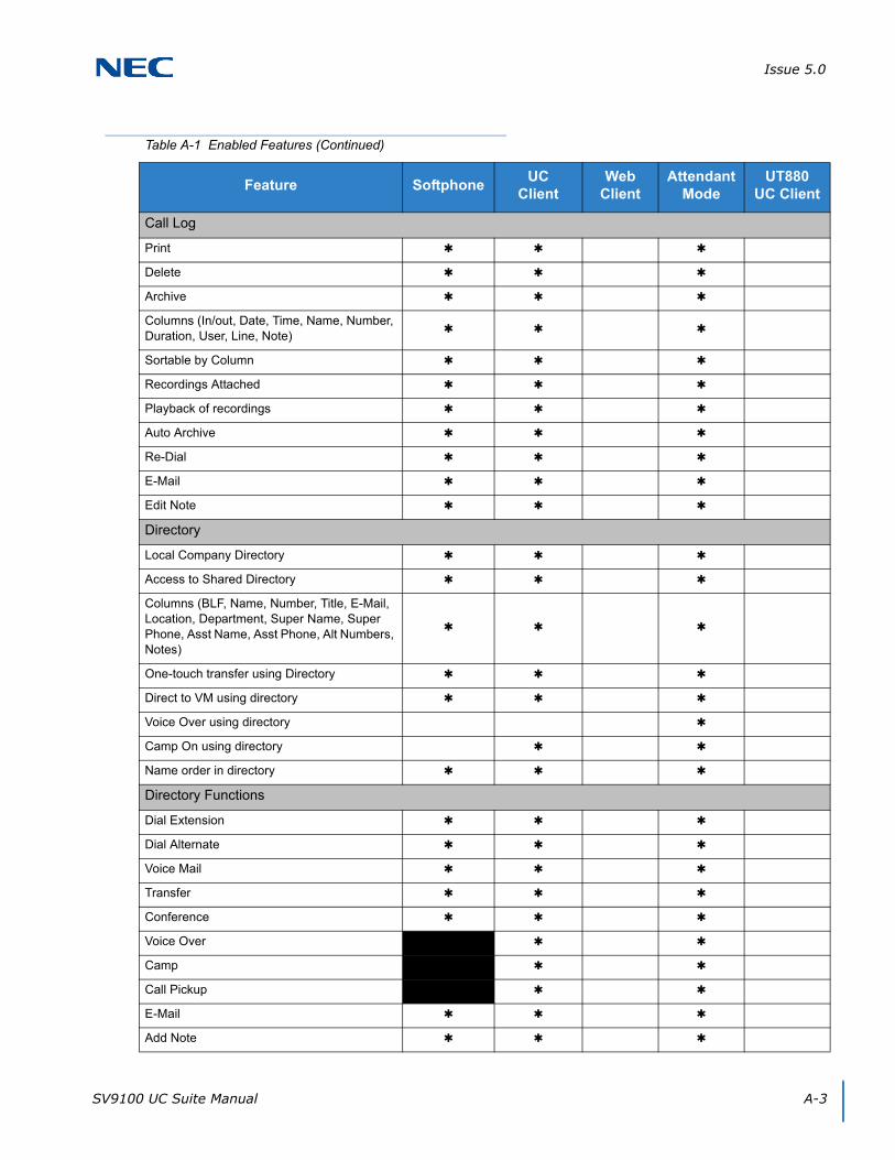
Issue 5.0
SV9100 UC Suite Manual A-3
Call Log
Delete
Archive
Columns (In/out, Date, Time, Name, Number, Duration, User, Line, Note)
Sortable by Column
Recordings Attached
Playback of recordings
Auto Archive
Re-Dial
Edit Note
Directory
Local Company Directory
Access to Shared Directory
Columns (BLF, Name, Number, Title, E-Mail, Location, Department, Super Name, Super Phone, Asst Name, Asst Phone, Alt Numbers, Notes)
One-touch transfer using Directory
Direct to VM using directory
Voice Over using directory
Camp On using directory
Name order in directory
Directory Functions
Dial Extension
Dial Alternate
Voice Mail
Transfer
Conference
Voice Over
Camp
Call Pickup
Add Note
Table A-1 Enabled Features (Continued)
Feature SoftphoneUC
ClientWeb
ClientAttendant
ModeUT880
UC Client
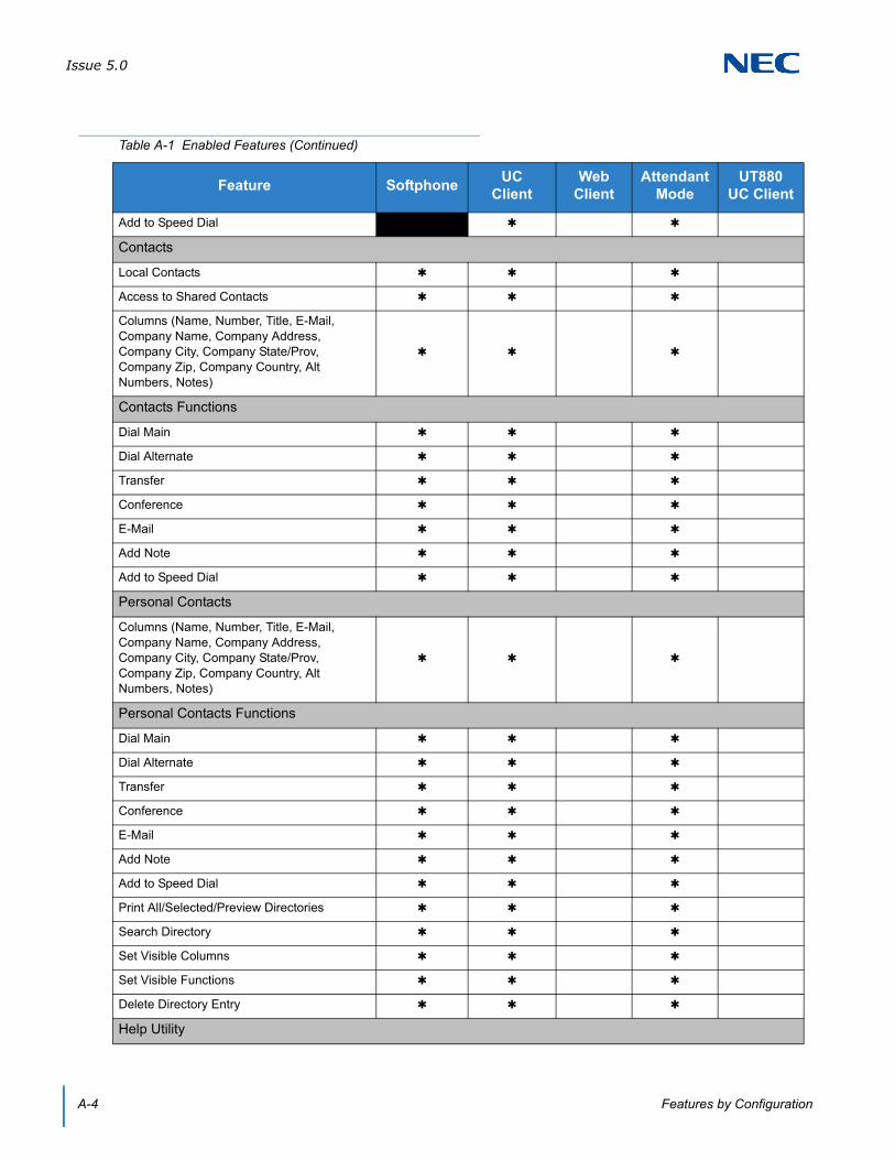
Issue 5.0
A-4 Features by Configuration
Add to Speed Dial
Contacts
Local Contacts
Access to Shared Contacts
Columns (Name, Number, Title, E-Mail, Company Name, Company Address, Company City, Company State/Prov, Company Zip, Company Country, Alt Numbers, Notes)
Contacts Functions
Dial Main
Dial Alternate
Transfer
Conference
Add Note
Add to Speed Dial
Personal Contacts
Columns (Name, Number, Title, E-Mail, Company Name, Company Address, Company City, Company State/Prov, Company Zip, Company Country, Alt Numbers, Notes)
Personal Contacts Functions
Dial Main
Dial Alternate
Transfer
Conference
Add Note
Add to Speed Dial
Print All/Selected/Preview Directories
Search Directory
Set Visible Columns
Set Visible Functions
Delete Directory Entry
Help Utility
Table A-1 Enabled Features (Continued)
Feature SoftphoneUC
ClientWeb
ClientAttendant
ModeUT880
UC Client

Issue 5.0
SV9100 UC Suite Manual A-5
Application Help
About (Version, License, Copyright)
Licensing
License Activation
Trial Mode
Attendant Functions
Active ringing call list
Top Most on Ringing Call
Quick Transfer Voice Mail
Quick Voicemail to an extension
Call Redirect
Able to send Phone Message
Able to set/reset Night Mode
BLF/DSS Panel
Local One Touch Keys (108) (108 + 24 + 8)
System-Wide BLF
BLF Icon (Idle, Ring, Active, DND, Fwd Immediate)
Name
Extension
BLF Groups/Tabs (Order, Visibility)
Configurable Text
Configurable Order
One-touch transfer
Quick VM transfer
Voice Over
Camp call
Functions (BLF)
Dial
VoiceMail
Transfer
Conference
Voice Over
Camp
Call Pickup
Table A-1 Enabled Features (Continued)
Feature SoftphoneUC
ClientWeb
ClientAttendant
ModeUT880
UC Client
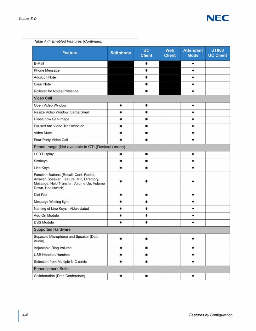
Issue 5.0
A-6 Features by Configuration
Phone Message
Add/Edit Note
Clear Note
Rollover for Notes/Presence
Video Call
Open Video Window
Resize Video Window: Large/Small
Hide/Show Self-Image
Pause/Start Video Transmission
Video Mute
Four-Party Video Call
Phone Image (Not available in CTI (Deskset) mode)
LCD Display
Softkeys
Line Keys
Function Buttons (Recall, Conf, Redial, Answer, Speaker, Feature, Mic, Directory, Message, Hold Transfer, Volume Up, Volume Down, Hookswitch)
Dial Pad
Message Waiting light
Naming of Line Keys - Abbreviated
Add-On Module
DSS Module
Supported Hardware
Separate Microphone and Speaker (Dual Audio)
Adjustable Ring Volume
USB Headset/Handset
Selection from Multiple NIC cards
Enhancement Suite
Collaboration (Data Conference)
Table A-1 Enabled Features (Continued)
Feature SoftphoneUC
ClientWeb
ClientAttendant
ModeUT880
UC Client

UC Suite Manual
NEC Corporation of AmericaIssue 5.0
SV9100®