UML Distilled - the mailing list overview page
194
UML Distilled Applying the Standard Object Modeling Language Martin Fowler with Kendall Scott ADDISON-WESLEY An imprint of Addison Wesley Longman, Inc. Reading, Massachusetts • Harlow, England • Menlo Park, California Berkeley, California • Don Mills, Ontario • Sydney Bonn • Amsterdam • Tokyo • Mexico City
-
Upload
khangminh22 -
Category
Documents
-
view
0 -
download
0
Transcript of UML Distilled - the mailing list overview page

UML Distilled
Applying the Standard Object Modeling Language
Martin Fowlerwith
Kendall Scott
ADDISON-WESLEYAn imprint of Addison Wesley Longman, Inc.Reading, Massachusetts • Harlow, England • Menlo Park, CaliforniaBerkeley, California • Don Mills, Ontario • SydneyBonn • Amsterdam • Tokyo • Mexico City

Many of the designations used by manufacturers and sellers to distinguishtheir products are claimed as trademarks. Where those designations appear inthis book, and Addison Wesley Longman, Inc., was aware of a trademarkclaim, the designations have been printed in initial capital letters or all capitalletters.
The author and publisher have taken care in preparation of this book, butmake no express or implied warranty of any kind and assume no responsibil-ity for errors or omissions. No liability is assumed for incidental or conse-quential damages in connection with or arising out of the use of theinformation or programs contained herein.
As we prepared for this reprint, the OMG standards group was about to release ver-sion 1.2 of the UML. Although I haven’t been following every part of this discussion(it is a very specialized topic), I have looked at the issues they have been discussing,and I don’t think the planned changes affect the level of detail provided in UML Dis-tilled. So, I’ve not needed to make any additional changes to the 1.1 printing to sup-port version 1.2.
Martin Fowler
Copyright © 1997 by Addison Wesley Longman, Inc.
All rights reserved. No part of this publication may be reproduced, stored in aretrieval system, or transmitted, in any form or by any means, electronic,mechanical, photocopying, recording, or otherwise, without the prior writtenpermission of the publisher. Printed in the United States of America. Pub-lished simultaneously in Canada.
Executive Editor: J. Carter ShanklinAssistant Editor: Angela BuenningProject Manager: Sarah WeaverCopyeditor: Arlene RichmanProofreader: Maine Proofreading ServicesIndex and Composition: Kendall ScottCover Design: Simone Payment
8 9 CRS 01 00 99 98Eighth printing, September 1998
Addison Wesley Longman, Inc., books are available for bulk purchases bycorporations, institutions, and other organizations. For more informationplease contact the Corporate, Government, and Special Sales Department at(800) 238-9682.

The Addison-Wesley Object Technology SeriesGrady Booch, Ivar Jacobson, and James Rumbaugh, Series Editors[http://www.awl.com/cseng/otseries/]
David Bellin and Susan Suchman Simone, The CRC Card Book0-201-89535-8
Grady Booch, Object Solutions: Managing the Object-Oriented Project0-8053-0594-7
Grady Booch, Object-Oriented Analysis and Design with ApplicationsSecond Edition 0-8053-5340-2
Dave Collins, Designing Object-Oriented User Interfaces0-8053-5350-X
Martin Fowler with Kendall Scott UML Distilled: Applying the Standard Object Modeling Language0-201-32563-2
Martin Fowler, Analysis Patterns: Reusable Object Models0-201-89542-0
Ivar Jacobson, Maria Ericsson, and Agenta JacobsonThe Object Advantage: Business Process Reengineering with Object Technology0-201-42289-1
Ivar Jacobson, Magnus Christerson, Patrik Jonsson, and Gunnar OvergaardObject-Oriented Software Engineering: A Use Case Driven Approach0-201-54435-0
Ivar Jacobson, Martin Griss, and Patrik JonssonSoftware Reuse: Architecture, Process and Organization for Business SuccessISBN 0-201-92476-5
Wilf LaLonde, Discovering Smalltalk0-8053-2720-7
Lockheed Martin Advanced Concepts Center and Rational Software Corpora-tion, Succeeding with the Booch and OMT Methods: A Practical Approach0-8053-2279-5
Thomas Mowbray and William RuhInside CORBA: Distributed Object Standards & Applications0-201-89540-4
Ira Pohl, Object-Oriented Programming Using C++Second Edition, 0-201-89550-1

David N. Smith, IBM Smalltalk: The Language0-8053-0908-X
Daniel Tkach and Richard Puttick, Object Technology in Application Development Second Edition 0-201-49833-2
Daniel Tkach, Walter Fang, and Andrew SoVisual Modeling Technique: Object Technology Using Visual Programming0-8053-2574-3
Available Spring 1998
Grady Booch, James Rumbaugh, and Ivar Jacobson Unified Modeling Language User Guide 0-201-57168-4
Ivar Jacobson, Grady Booch, and James RumbaughThe Objectory Software Development Process0-201-57169-2
James Rumbaugh, Ivar Jacobson, and Grady Booch Unified Modeling Language Reference Manual0-201-30998-X

Preface
I never expected to write a methods book.
I was approached to write one late in 1992. By then, however, all thereally influential methods books had been published, and I didn'tthink I had anything significant to add to the literature. As far as I wasconcerned, the ground was covered—there were better things to do. Ihad decided not to create a new methodology that was “fowler” thanall the others, and there were already too many methodologies.
When Grady Booch, Jim Rumbaugh, and Ivar Jacobson (the “threeamigos”) joined forces to form a single Unified Modeling Language(UML), I was delighted. Arguments over which method to choose aresome of the most tiresome arguments I’ve had to deal with, particu-larly since they have little impact on the final result. I was glad to seethat argument go away.
When I was approached to write this book, the amigos were beginningto write their books; these books will be the authoritative works on theUML. However, there is a need for a short book to both provide some-thing while the three of them are working on their larger works andact as a concise UML guide. I intended to make this volume the short-est methods book ever written.
Although this is a noble aim for me, is this the right book for you?
I’ll start by telling you what this book is not.
• It is not a tutorial on OO analysis and design with the UML. Theuser’s guide, led by Grady Booch, will be that book.
• It is not a definitive reference guide to the notation and its seman-tics. The reference guide, led by Jim Rumbaugh, will be that book.
• It is not a detailed guide to the process of using the UML on object-oriented projects. The process guide, led by Ivar Jacobson, will bethat book.
xv

xvi
P
REFACE
This book is a short guide to the key parts of the notation, the seman-tics, and the process. I am aiming it at those who already have usedobject technology, probably with one of the many currently availableOO analysis and design methods. This book tells you quickly what thekey elements of the notation are and what they mean, and it suggestsan outline process for using them. I’ve also taken the opportunity toadd tips and suggestions from my use of object methods over the lastdecade.
Because it is a short book, it will be easier to digest the information andget used to what the UML has to say. It also will provide a good firstplace to look for reference information.
Chapter 1 looks at what the UML is, the history of its development,and the reasons why you might want to use it.
Chapter 2 discusses the object-oriented development process. Al-though the UML exists independent of process, I find it hard to discussmodeling techniques without talking about where they fit in withobject-oriented development.
Chapters 3 through 10 discuss the various modeling techniques of theUML, in turn. I have organized these chapters around the kinds of dia-grams I find useful. I describe the notation, including its semantics,and provide tips about using the techniques. My philosophy is tomake clear what the UML says and, at the same time, give you myopinions on how best to use it.
Chapter 11 gives a small example to show how the UML fits in withprogramming using (of course) Java.
The inside covers summarize the UML notation. You may find it use-ful to refer to these as you are reading the chapters so that you cancheck on the notation for the various modeling concepts.
Scattered within the “official UML” chapters are a number of sidebarson other techniques I have found valuable but which are not empha-sized in the UML. They certainly can and should be used with theUML.

A
CKNOWLEDGMENTS
xvii
For each UML and non-UML technique, I’ve provided summariesabout when to use the technique and where to find more information.As I write this, there are no UML books on the market, so I have refer-enced only pre-UML books. Although the notation is different, manyof the concepts are the same, and it will be a while before these booksshould be relegated to the basement.
Of course, this book, like any book written within our industry, will beout of date as soon as it is finished. To combat this, I’m making theinevitable use of the World Wide Web. To get my latest thoughts onmethods, take a look at the Web site for this book: <www.awl.com/cseng/titles/0-201-32563-2>.
Acknowledgments
Putting out a book this fast required a lot of help from people whowent beyond the normal effort that goes into producing a book to doeverything that much more quickly.
Kendall Scott played an important role in pulling together all thematerial and working over the text and graphics.
The three amigos, Grady Booch, Ivar Jacobson, and Jim Rumbaugh,have been full of support and advice. We have burned up many hoursof transcontinental phone calls, and they have improved the bookgreatly (as well as my understanding of the UML).
A good slate of book reviewers is essential to doing a good job on abook. Not only did these reviewers give me the feedback I needed,they also turned around their comments in less than a week to keep toour tight deadlines. My thanks to: Simmi Kochhar Bhargava ofNetscape Communications Corporation, Eric Evans, Tom Hadfield ofEvolve Software, Inc., Ronald E. Jeffries, Joshua Kerievsky of Indus-trial Logic, Inc., Helen Klein of the University of Michigan, JamesOdell, and Vivek Salgar of Netscape Communications Corporation.Double thanks to Tom Hadfield because he did it twice!

xviii
P
REFACE
I want to thank Jim Odell for two things: first, for coordinating theObject Management Group (OMG) effort to get a single standardUML, which will be a big step forward for our industry; and second,for encouraging me to get into the object-oriented analysis and designfield. Oh, and thanks for reviewing the book, too!
Thanks to Cindy for dealing with me being absent even when I washome.
I can’t even imagine the difficulties that my editor, J. Carter Shanklin,and his assistant, Angela Buenning, went through to get this book outas quickly as they did. Whatever these difficulties were, I’m sureCarter and Angela deserve my thanks.
Last, but not least, thanks to my parents for helping me start off with agood education, from which all else springs.
Martin FowlerMelrose, MassachusettsMay [email protected]://ourworld.compuserve.com/homepages/Martin_Fowler

Contents
Foreword .................................................................................................... xiii
Preface ................................................................................................................... xv
Acknowledgments............................................................................. xvii
Chapter 1: Introduction ...................................................................................... 1
What Is the UML? ................................................................................... 1How We Got Here .................................................................................. 2Notations and Meta-Models................................................................ 5Why Do Analysis and Design? ........................................................... 7
Learning OO. . . . . . . . . . . . . . . . . . . . . . . . . . . . . . . . . . . . . . . . . . . . 7Communicating with Domain Experts . . . . . . . . . . . . . . . . . . . . . 9Understanding the Big Picture . . . . . . . . . . . . . . . . . . . . . . . . . . . 10
Looking for More Information.......................................................... 10
Chapter 2: An Outline Development Process .......................................... 13
Overview of the Process ..................................................................... 14Inception .................................................................................................. 16Elaboration.............................................................................................. 16
Dealing with Requirements Risks. . . . . . . . . . . . . . . . . . . . . . . . . 17Dealing with Technological Risks. . . . . . . . . . . . . . . . . . . . . . . . . 22Dealing with Skills Risks . . . . . . . . . . . . . . . . . . . . . . . . . . . . . . . . 23Dealing with Political Risks . . . . . . . . . . . . . . . . . . . . . . . . . . . . . . 25Baseline Architecture . . . . . . . . . . . . . . . . . . . . . . . . . . . . . . . . . . . 25When Is Elaboration Finished? . . . . . . . . . . . . . . . . . . . . . . . . . . . 26Planning . . . . . . . . . . . . . . . . . . . . . . . . . . . . . . . . . . . . . . . . . . . . . . 26
Construction ........................................................................................... 29
Refactoring.............................................................................. 30When to Use Refactoring . . . . . . . . . . . . . . . . . . . . . . . . . . . . . . . . 32Where to Find Out More . . . . . . . . . . . . . . . . . . . . . . . . . . . . . . . . 32
vii

viii
C
ONTENTS
Iterative Development and Planning . . . . . . . . . . . . . . . . . . . . . . 33Using the UML in Construction . . . . . . . . . . . . . . . . . . . . . . . . . . 33
Patterns.................................................................................... 36When to Use Patterns . . . . . . . . . . . . . . . . . . . . . . . . . . . . . . . . . . . 39Where to Find Out More . . . . . . . . . . . . . . . . . . . . . . . . . . . . . . . . 39
Transition ................................................................................................ 40When to Use Iterative Development .............................................. 41Where to Find Out More .................................................................... 41
Chapter 3: Use Cases ......................................................................................... 43
User Goals and System Interactions ............................................... 44Use Case Diagrams .............................................................................. 45
Actors . . . . . . . . . . . . . . . . . . . . . . . . . . . . . . . . . . . . . . . . . . . . . . . . 46Uses and Extends . . . . . . . . . . . . . . . . . . . . . . . . . . . . . . . . . . . . . . 48
When to Use Use Cases ...................................................................... 51Where to Find Out More .................................................................... 51
Chapter 4: Class Diagrams: The Essentials............................................... 53
Perspectives ............................................................................................ 55Associations............................................................................................ 56Attributes ................................................................................................ 63Operations............................................................................................... 63
CRC Cards .............................................................................. 64When to Use CRC Cards . . . . . . . . . . . . . . . . . . . . . . . . . . . . . . . . 66Where to Find Out More . . . . . . . . . . . . . . . . . . . . . . . . . . . . . . . . 66
Generalization........................................................................................ 68Constraint Rules.................................................................................... 69
Design by Contract.................................................................. 70When to Use Design by Contract . . . . . . . . . . . . . . . . . . . . . . . . . 72
When to Use Class Diagrams............................................................ 73Where to Find Out More . . . . . . . . . . . . . . . . . . . . . . . . . . . . . . . . 73
Where to Find Out More .................................................................... 74
Chapter 5: Class Diagrams: Advanced Concepts.................................... 75
Stereotypes.............................................................................................. 75Multiple and Dynamic Classification............................................. 77Aggregation and Composition......................................................... 80

C
ONTENTS
ix
Derived Associations and Attributes.............................................. 82Interfaces and Abstract Classes ........................................................ 85Reference Objects and Value Objects.............................................. 88Collections for Multi-Valued Roles ................................................. 89Frozen ....................................................................................................... 90Classification and Generalization .................................................... 91Qualified Associations......................................................................... 91Association Class................................................................................... 93Parameterized Class............................................................................. 96Visibility................................................................................................... 99
Chapter 6: Interaction Diagrams................................................................. 103
Sequence Diagrams ............................................................................ 104Concurrent Processes and Activations. . . . . . . . . . . . . . . . . . . . 106
Collaboration Diagrams.................................................................... 108Comparing Sequence and Collaboration Diagrams ................ 111
Conditional Behavior . . . . . . . . . . . . . . . . . . . . . . . . . . . . . . . . . . 112When to Use Interaction Diagrams ............................................... 112Where to Find Out More................................................................... 112
Chapter 7: Package Diagrams ...................................................................... 113
When to Use Package Diagrams .................................................... 119Where to Find Out More................................................................... 120
Chapter 8: State Diagrams............................................................................. 121
Concurrent State Diagrams.............................................................. 126When to Use State Diagrams........................................................... 128Where to Find Out More................................................................... 128
Chapter 9: Activity Diagrams....................................................................... 129
Activity Diagrams for Use Cases ................................................... 132Swimlanes ............................................................................................. 138Decomposing an Activity................................................................. 140When to Use Activity Diagrams..................................................... 141Where to Find Out More................................................................... 142

x
C
ONTENTS
Chapter 10: Deployment Diagrams ........................................................... 143
When to Use Deployment Diagrams............................................ 145
Chapter 11: UML and Programming ......................................................... 147
Patient Observation: Domain Model............................................ 148Patient Observation: Specification Model................................... 152Moving to Code................................................................................... 155
Appendix A: Techniques and Their Uses........................................... 167
Appendix B: Changes from UML 1.0 to 1.1 ........................................ 169
Bibliography............................................................................................. 173
Index........................................................................................................... 177

Figures
Figure 1-1: UML 1.0 Meta-Model Extract .......................................... 6
Figure 2-1: Outline Development Process ......................................... 14Figure 2-2: Proxy Design Pattern ...................................................... 37Figure 2-3: Scenario Analysis Pattern ............................................... 38
Figure 3-1: Use Case Diagram........................................................... 45
Figure 4-1: Class Diagram ................................................................. 54Table 4-1: Class Diagram Terminology ............................................ 57Figure 4-2: Cardinality Notations ...................................................... 59Figure 4-3: Class Diagram with Navigabilities ................................. 61Figure 4-4: Class-Responsibility-Collaboration (CRC) Card............ 65
Figure 5-1: Multiple Classification .................................................... 78Figure 5-2: Dynamic Classification ................................................... 79Figure 5-3: Aggregation and Composition ........................................ 81Figure 5-4: Alternative Notation for Composition ............................ 82Figure 5-5: Derived Associations and Attributes............................... 83Figure 5-6: Time Period Class ........................................................... 84Figure 5-7: Window as Abstract Class .............................................. 86Figure 5-8: Interfaces and Abstract Class: An Example from Java... 87Figure 5-9: Lollipop Notation for Interfaces ..................................... 87Figure 5-10: Qualified Association.................................................... 92Figure 5-11: Association Class .......................................................... 93Figure 5-12: Promoting an Association Class to a Full Class ........... 94Figure 5-13: Association Class Subtleties ......................................... 95Figure 5-14: History Stereotype for Associations ............................. 96Figure 5-15: Parameterized Class ...................................................... 97
xi

xii
F
IGURES
Figure 5-16: Bound Element (Version 1) .......................................... 97Figure 5-17: Bound Element (Version 2) .......................................... 98
Figure 6-1: Sequence Diagram ........................................................ 104Figure 6-2: Concurrent Processes and Activations .......................... 107Figure 6-3: Sequence Diagram: Check Failure................................ 109Figure 6-4: Collaboration Diagram with Simple Numbering .......... 110Figure 6-5: Collaboration Diagram with Decimal Numbering........ 111
Figure 7-1: Package Diagram .......................................................... 115Figure 7-2: Advanced Package Diagram ......................................... 117
Figure 8-1: State Diagram................................................................ 122Figure 8-2: State Diagram Without Superstates .............................. 124Figure 8-3: State Diagram with Superstates .................................... 125Figure 8-4: Payment Authorization.................................................. 126Figure 8-5: Concurrent State Diagram............................................. 127
Figure 9-1: Activity Diagram........................................................... 130Figure 9-2: Receiving an Order ....................................................... 134Figure 9-3: Receiving Supply .......................................................... 136Figure 9-4: Receive Order and Receive Supply............................... 137Figure 9-5: Swimlanes ..................................................................... 139Figure 9-6: Decomposed Activity Diagram..................................... 140
Figure 10-1: Deployment Diagram .................................................. 144
Figure 11-1: Patient Observation Domain Model............................ 149Figure 11-2: Patient Observation Object Diagram .......................... 150Figure 11-3: Another Patient Observation Object Diagram ............ 151Figure 11-4: Patient Observation Specification Model.................... 153Figure 11-5: Patient Observation Operations................................... 154Figure 11-6: Patient Observation Sequence Diagram...................... 156Figure 11-7: Another Patient Observation Specification Model ..... 164

xiii
Foreword
When we began to craft the Unified Modeling Language, we hopedthat we could produce a standard means of expressing design thatwould not only reflect the best practices of industry, but would alsohelp demystify the process of software system modeling. We believethat the availability of a standard modeling language will encouragemore developers to model their software systems before buildingthem. The benefits of doing so are well-known to the developer com-munity.
The creation of the UML was itself an iterative and incremental pro-cess very similar to the modeling of a large software system. The endresult is a standard built on, and reflective of, the many ideas and con-tributions made by numerous individuals and companies from theobject community. We began the UML effort, but many others helpedbring it to a successful conclusion; we are grateful for their assistance.
Creating and agreeing on a standard modeling language is a signifi-cant challenge by itself. Educating the development community, andpresenting the UML in a manner that is both accessible and in the con-text of the software development process, is also a significant chal-lenge. In this deceptively short book, Martin Fowler has more thanmet this challenge.
In a clear and friendly style, Martin not only introduces the keyaspects of UML, but also clearly demonstrates the role UML plays inthe development process. Along the way, we are treated to abundantnuggets of modeling insight and wisdom drawn from Martin's 10-plusyears of design and modeling experience.
The result is a book we recommend to modelers and developers inter-ested in getting a first look at UML and in gaining a perspective on thekey role it plays in the development process.
Grady BoochIvar JacobsonJames Rumbaugh

Chapter 1
Introduction
What Is the UML?
The Unified Modeling Language (UML) is the successor to the waveof object-oriented analysis and design (OOA&D) methods thatappeared in the late ‘80s and early ‘90s. It most directly unifies themethods of Booch, Rumbaugh (OMT), and Jacobson, but its reach willbe wider than that. As I write this, the UML is in the middle of a stan-dardization process with the OMG (Object Management Group), and Iexpect it to be the standard modeling language in the future.
The UML is called a modeling language, not a method. Most methodsconsist, at least in principle, of both a modeling language and a pro-cess. The modeling language is the (mainly graphical) notation thatmethods use to express designs. The process is their advice on whatsteps to take in doing a design.
The process parts of many methods books are rather sketchy. Further-more, I find that most people, when they say they are using a method,use the modeling language, but rarely follow the process. So in manyways, the modeling language is the most important part of themethod. It is certainly the key part for communication. If you want todiscuss your design with someone, it is the modeling language thatboth of you need to understand, not the process you used to get to thatdesign.
1

2
C
HAPTER
1 I
NTRODUCTION
The three amigos are also working on a unified process, which they aregoing to call the Rational Unified Process. You don’t have to use theRational Unified Process in order to use the UML—they are distinctlyseparate. In this book, however, I talk a little bit about process in orderto put the techniques of the modeling language in context. Within thisdiscussion, I use the basic steps and terms of the Rational Unified Pro-cess, but the text is not a description of the the Rational Unified Pro-cess. I find that I use many different processes, depending on my clientand on the kind of software I am building. While I think a standardmodeling language is valuable, I don’t see a comparable need for astandard process, although some harmonization on vocabulary wouldbe useful.
How We Got Here
In the 1980s, objects began to move away from the research labs andtook their first steps toward the “real” world. Smalltalk stabilized intoa platform that people could use, and C++ was born.
Like many developments in software, objects were driven by program-ming languages. Many people wondered how design methods wouldfit into an object-oriented world. Design methods had become verypopular in industrial development in the ‘70s and ‘80s. Many felt thattechniques to help people do good analysis and design were just asimportant to object-oriented development.
The key books about object-oriented analysis and design methodsappeared between 1988 and 1992:
• Sally Shlaer and Steve Mellor wrote a pair of books (1989 and 1991)on analysis and design; the material in these books has evolvedinto their Recursive Design approach (1997).
• Peter Coad and Ed Yourdon also wrote books that developedCoad's lightweight and prototype-oriented approach to methods.See Coad and Yourdon (1991a and 1991b), Coad and Nicola (1993),and Coad et al. (1995).

HOW WE GOT HERE 3
• The Smalltalk community in Portland, Oregon, came up withResponsibility-Driven Design (Wirfs-Brock et al. 1990) and Class-Responsibility-Collaboration (CRC) cards (Beck and Cunningham1989).
• Grady Booch had done a lot of work with Rational Software indeveloping Ada systems. His books featured several examples(and the best cartoons in the world of methods books). See Booch(1994 and 1995).
• Jim Rumbaugh led a team at the research labs at General Electric,which came out with a very popular book about a method calledObject Modeling Technique (OMT). See Rumbaugh et al. (1991) andRumbaugh (1996).
• Jim Odell based his books (written with James Martin) on his longexperience with business information systems and InformationEngineering. The result was the most conceptual of these books.See Martin and Odell (1994 and 1996).
• Ivar Jacobson built his books on his experience with telephoneswitches for Ericsson and introduced the concept of use cases inthe first one. See Jacobson (1994 and 1995).
As I prepared to travel to Portland for OOPSLA ’94, the methods scenewas pretty split and competitive. Each of the aforementioned authorswas now informally leading a group of practitioners who liked hisideas. All of these methods were very similar, yet they contained anumber of often annoying minor differences among them. The samebasic concepts would appear in very different notations, which causedconfusion to my clients.
Talk of standardization had surfaced, but nobody seemed willing todo anything about it. Some were opposed to the very idea of standardsfor methods. Others liked the idea but were not willing to put in anyeffort. A team from the OMG tried to look at standardization but gotonly an open letter of protest from all the key methodologists. GradyBooch tried an informal morning coffee approach, with no more suc-cess. (This reminds me of an old joke. Question: What is the differencebetween a methodologist and a terrorist? Answer: You can negotiatewith a terrorist.)

4 CHAPTER 1 INTRODUCTION
For the OO methods community, the big news at OOPSLA ‘94 was thatJim Rumbaugh had left General Electric to join Grady Booch at Ratio-nal Software, with the intention of merging their methods.
The next year was full of amusements.
Grady and Jim proclaimed that “the methods war is over—we won,”basically declaring that they were going to achieve standardization theMicrosoft way. A number of other methodologists suggested formingan Anti-Booch Coalition.
By OOPSLA ‘95, Grady and Jim had prepared their first publicdescription of their merged method: version 0.8 of the Unified Methoddocumentation. Even more significantly, they announced that RationalSoftware had bought Objectory, and that Ivar Jacobson would be join-ing the Unified team. Rational held a party to celebrate the release ofthe 0.8 draft that was very well-attended. It was also quite a lot of fun,despite Jim Rumbaugh’s singing.
During 1996, Grady, Jim, and Ivar, now widely referred to as the threeamigos, worked on their method, under its new name: the UnifiedModeling Language (UML). However, the other major players in theobject methods community were not inclined to let the UML be the lastword.
An OMG task force was formed to do standardization in the methodsarea. This represented a much more serious attempt to address theissues than previous OMG efforts in the methods area. Mary Loomiswas given the chair; later Jim Odell joined as co-chair and took overleadership of the effort. Odell made it clear that he was prepared togive up his method to a standard, but he did not want a Rational-imposed standard.
In January 1997, various organizations submitted proposals for amethods standard to facilitate the interchange of models. These pro-posals focus on a meta-model and an optional notation. Rationalreleased version 1.0 of the UML documentation as their proposal tothe OMG.
As I write this, Jim Odell and the OMG group have spent a lot of timeworking on the semantics of the UML and harmonizing the varioussubmissions. We now have a single UML 1.1 proposal with wideindustry support.

NOTATIONS AND META-MODELS 5
Notations and Meta-Models
The UML, in its current state, defines a notation and a meta-model.
The notation is the graphical stuff you see in models; it is the syntax ofthe modeling language. For instance, class diagram notation defineshow items and concepts such as class, association, and multiplicity arerepresented.
Of course, this leads to the question of what exactly is meant by anassociation or multiplicity or even a class. Common usage suggestssome informal definitions, but many people want more rigor than that.
The idea of rigorous specification and design languages is most preva-lent in the field of formal methods. In such techniques, designs andspecifications are represented using some derivative of predicate cal-culus. Such definitions are mathematically rigorous and allow noambiguity. However, the value of these definitions is by no means uni-versal. Even if you can prove that a program satisfies a mathematicalspecification, there is no way to prove that the mathematical specifica-tion actually meets the real requirements of the system.
Design is all about seeing the key issues in the development. Formalmethods often lead to getting bogged down in lots of minor details.Also, formal methods are hard to understand and manipulate, oftenharder to deal with than programming languages. And you can’t evenexecute them.
Most OO methods have very little rigor; their notation appeals to intu-ition rather than formal definition. On the whole, this does not seem tohave done much harm. These methods may be informal, but manypeople still find them useful—and it is usefulness that counts.
However, OO methods people are looking for ways to improve therigor of methods without sacrificing their usefulness. One way to dothis is to define a meta-model: a diagram, usually a class diagram, thatdefines the notation.
Figure 1-1 is a small piece of the UML 1.1 meta-model that shows therelationship among associations and generalization. (The extract isthere just to give you a flavor of what meta-models are like. I’m noteven going to try to explain it.)

6 CHAPTER 1 INTRODUCTION
Figure 1-1: UML 1.1 Meta-Model Extract
How much does the meta-model affect the user of the modeling nota-tion? Well, it does help define what is a well-formed model—that is,one that is syntactically correct. As such, a methods power user shouldunderstand the meta-model. However, most users of methods do notneed such deep understanding to get some value out of using theUML notation.
This is why I was able write a useful book before the UML meta-modelwas completely defined. The changes in the meta-model between 1.0and 1.1 did not cause any major changes to the contents of this book. Iwill not be rigorous in this book; rather, I will follow the traditionalmethods path and appeal to your intuition.
How strictly should you stick to the modeling language? Thatdepends on the purpose for which you are using it. If you have aCASE tool that generates code, then you have to stick to the CASEtool’s interpretation of the modeling language in order to get accept-able code. If you are using the diagrams for communication purposes,then you have a little more leeway.
Feature
*
0..1
Parameter
{ordered}
FeatureStructural
FeatureBehavioral

WHY DO ANALYSIS AND DESIGN? 7
If you stray from the official notation, then other developers will notfully understand what you are saying. However, there are times whenthe official notation can get in the way of your needs. I’ll admit that inthese cases, I’m not at all afraid to bend the language. I believe that thelanguage should bend to help me communicate, rather than the otherway around. But I don’t do it often, and I’m always aware that a bendis a bad thing if it causes communication problems. In this book, Imention those places where I’m inclined to do a bit of bending.
Why Do Analysis and Design?
When it comes down to it, the real point of software development iscutting code. Diagrams are, after all, just pretty pictures. No user isgoing to thank you for pretty pictures; what a user wants is softwarethat executes.
So when you are considering using the UML, it is important to askyourself why you are doing it and how it will help you when it comesdown to writing the code. There’s no proper empirical evidence toprove that these techniques are good or bad, but the following subsec-tions discuss the reasons that I often come across for using them.
Learning OO
A lot of people talk about the learning curve associated with OO—theinfamous paradigm shift. In some ways, the switch to OO is easy. Inother ways, there are a number of obstacles to working with objects,particularly in using them to their best advantage.
It’s not that it’s difficult to learn how to program in an OO language.The problem is that it takes a while to learn to exploit the advantagesthat object languages provide. Tom Hadfield puts it well: Object lan-guages allow advantages but don’t provide them. To use these advan-tages, you have to make the infamous paradigm shift. (Just make sureyou are sitting down at the time!)

8 CHAPTER 1 INTRODUCTION
The techniques in the UML were to some degree designed to help peo-ple do good OO, but different techniques have different advantages.
• One of the most valuable techniques for learning OO is CRC cards(see page 64), which are not part of the official UML (although theycan and should be used with it). They were designed primarily forteaching people to work with objects. As such, they are deliber-ately different from traditional design techniques. Their emphasison responsibilities and their lack of complex notation make themparticularly valuable.
• Interaction diagrams (see Chapter 6) are very useful because theymake the message structure very explicit and, thus, are useful forhighlighting over-centralized designs, in which one object is doingall the work.
• Class diagrams (see Chapters 4 and 5), used to illustrate class mod-els, are both good and bad for learning objects. Class models arecomfortably similar to data models; many of the principles thatmake for a good data model also make for a good class model. Themajor problem in using class diagrams is that it is easy to developa class model that is data-oriented rather than being responsibility-oriented.
• The concept of patterns (see page 36) has become vital to learningOO because using patterns gets you to concentrate on good OOdesigns and to learn by following an example. Once you have got-ten the hang of some basic modeling techniques, such as simpleclass diagrams and interaction diagrams, it is time to start lookingat patterns.
• Another important technique is iterative development (see Chap-ter 2). This technique does not help you learn OO in any directway, but it is the key to exploiting OO effectively. If you do itera-tive development from the start, then you will learn, in context, theright kind of process and begin to see why designers suggest doingthings the way they do.
When you start using a technique, you tend to do it by the book. Myrecommendation is to begin with the simple notations that I talk abouthere, particularly with class diagrams. As you get comfortable, youcan pick up the more advanced ideas as you need them. You may alsofind you wish to extend the method.

WHY DO ANALYSIS AND DESIGN? 9
The UML has an extension mechanism that uses stereotypes. I talkabout stereotypes only in the context of class diagrams, but you canuse stereotypes with any diagram to extend its meaning. The threeamigos’ books will go into more detail on that. Just make sure youreally understand what the construct means. Toward that end, I like tolook at any construct from three perspectives: conceptual, specifica-tion, and implementation (see Chapter 4).
Communicating with Domain Experts
One of our biggest challenges in development is that of building theright system—one that meets users’ needs at a reasonable cost. This ismade more difficult because we, with our jargon, have to communi-cate with users, who have their own, more arcane, jargon. (I did a lot ofwork in health care, and there the jargon isn't even in English!) Achiev-ing good communication, along with good understanding of the users’world, is the key to developing good software.
The obvious technique to use in addressing this is use cases (see Chap-ter 3). A use case is a snapshot of one aspect of your system. The sumof all use cases is the external picture of your system, which goes along way toward explaining what the system will do.
A good collection of use cases is central to understanding what yourusers want. Use cases also present a good vehicle for project planning,because they control iterative development, which is itself a valuabletechnique since it gives regular feedback to the users about where thesoftware is going.
While use cases help with communication about surface things, it isalso crucial to look at the deeper things. This involves learning howyour domain experts understand their world.
Class diagrams (see Chapters 4 and 5) can be extremely valuable here,as long as you use them in a conceptual manner. In other words, youshould treat each class as a concept in a user’s mind, part of his or herlanguage. The class diagrams you draw are then not diagrams of dataor of classes, but diagrams of the language of your users. James Martinand Jim Odell's “foundations” book (1994) is a good source for thiskind of thinking with class diagrams.

10 CHAPTER 1 INTRODUCTION
I have found activity diagrams (see Chapter 9) to be very useful incases in which workflow processes are an important part of the users’world. Since activity diagrams support parallel processes, they canhelp you get away from unnecessary sequences. The way these dia-grams de-emphasize the links to classes, which can be a problem inlater design, becomes an advantage during this more conceptual stageof the development process.
Understanding the Big Picture
As a consultant, I often have to breeze into a complex project and lookintelligent in a very short period of time. I find the design techniques Idiscuss above invaluable for that because they help me acquire anoverall view of the system. A look at a class diagram can quickly tellme what kinds of abstractions are present in the system and where thequestionable parts are that need further work. As I probe deeper, Iwant to see how classes collaborate, so I ask to see interaction dia-grams that illustrate key behaviors in the system.
If this is useful to me as an outsider, it is just as useful to the regularproject team. It’s easy to lose sight of the forest for the trees on a largeproject. With a few choice diagrams in hand, you can find your wayaround the software much more easily.
To build a road map, use package diagrams (see Chapter 7) at thehigher levels to scope out a class diagram. When you draw a class dia-gram for a road map, take a specification perspective. It is very impor-tant to hide implementations with this kind of work. Don’t documentevery interaction; instead, focus on the key ones.
Use patterns (see page 36) to describe the key ideas in the system; theyhelp you to explain why your design is the way it is. It is also useful todescribe designs you have rejected and why you rejected them. Ialways end up forgetting that kind of decision.
Looking for More Information
This book is not a complete and definitive reference to the UML, letalone OO analysis and design. There are a lot of words out there and a
LOOKING FOR MORE INFORMATION 11
lot of worthwhile things to read. As I discuss the individual topics, Iwill talk about other books you should go to for more in-depth infor-mation on the ideas in the UML and on OOA&D in general.
Of course, your first step beyond this book should be the three amigos’books on the UML. As I write this, they are planning three books, eachof which will be led by one of the three.
Grady Booch is leading the work on the user’s guide. This will be atutorial book that will contain a number of in-depth case studies onhow to use the UML on practical problems. It will go into more detailthan this book and give more advice on how to use the UML well.
Jim Rumbaugh is leading the effort on the reference book, the defini-tive guide to the UML's notation and meta-model. It will be the finalsource of information about what the UML means when it says some-thing.
Ivar Jacobson is working on a book that will describe the process ofusing the UML. Strictly speaking, the UML is a modeling languageand does not contain anything about the process you use to developsoftware. That is why the amigos use the term “modeling language”and not “method,” since a method should properly include a process. Ihave outlined a lightweight process in this book to give the techniquesand the notation some context. Jacobson’s book will go into moredetail.
Of course, the three amigos’ books are not the only books you shouldread to learn about good OOA&D. My list of recommended bookschanges frequently; take a look at the Survey of Analysis and DesignMethods page at my Web site for the most current version, reachablefrom <ourworld.compuserve.com/homepages/Martin_Fowler> (myhome page).
If you are new to objects, I recommend my current favorite introduc-tory book, Larman (1998). He has a strong responsibility-drivenapproach to design that is worth following. If you want to know moreabout objects from a conceptual point of view, Martin and Odell (1998)is now available in a UML edition. Real-time developers should get acopy of Douglass (1998).

12 CHAPTER 1 INTRODUCTION
In particular, I suggest reading books on patterns for material that willtake you beyond the basics. Now that the methods war is over, I thinkthat patterns will be where most of the interesting material about anal-ysis and design will appear. Inevitably, however, people will come upwith new analysis and design techniques, and it is likely that they willtalk about how these techniques can be used with the UML. This isanother benefit of the UML; it encourages people to add new tech-niques without duplicating work that everyone else has done.
Chapter 2
An Outline Development Process
The UML is a modeling language, not a method. The UML has nonotion of process, which is an important part of a method.
The three amigos have developed a merged process called the RationalUnified Process. (It used to be called Objectory.) I don’t believe you canhave a single process for software development. Various factors associ-ated with software development lead you to different kinds of process.These factors include the kind of software you are developing (real-time, information system, desktop product), the scale (single devel-oper, small team, 100-plus-member team), and so forth. So, the amigosare trying to come up with a process framework, something that willcapture the common elements but still give people the latitude to usetechniques that are appropriate for their project.
The title of this book is UML Distilled, so I could have safely ignoredprocess. However, I don’t believe that modeling techniques make anysense without knowing how they fit into a process.
13

14 CHAPTER 2 AN OUTLINE DEVELOPMENT PROCESS
I think it’s important to discuss the process first so that you can seehow an object-oriented development works. I won’t go into greatdetail on the process; I will provide just enough to give you a sense ofthe typical way in which a project that uses these techniques is run.
As I discuss the outline process, I will use the terminology and outlineframework of the Rational Unified Process. (I have to use something,and that seems as good as anything.) I have not tried to describe theRational Unified Process; that is beyond the scope of this book. Rather,I’m describing a lightweight, low-ceremony process that is consistentwith Rational’s process. For full details on the Rational Unified Pro-cess, you should go to the amigos’ process book.
Although the Rational Unified Process process contains details aboutwhat kinds of models to develop at the various stages in the process, Iwon’t go into such details. Nor will I specify tasks, deliverables, androles. My terminology is looser than that of the Rational Unified Pro-cess—that is the price one pays for lightweight description.
Whatever process discussion there is, don’t forget that you can use anyprocess with the UML. The UML is independent of process. Youshould pick something that is appropriate for your kind of project.Whatever process you use, you can use the UML to record the result-ing analysis and design decisions.
Overview of the Process
Figure 2-1 shows the high-level view of the development process.
Figure 2-1: Outline Development Process
Inception Elaboration Transition
1 2 3 ...
Construction

OVERVIEW OF THE PROCESS 15
This process is an iterative and incremental development process, inthat the software is not released in one big bang at the end of theproject but is, instead, developed and released in pieces. The construc-tion phase consists of many iterations, in which each iteration buildsproduction-quality software, tested and integrated, that satisfies a sub-set of the requirements of the project. The delivery may be external, toearly users, or purely internal. Each iteration contains all the usual life-cycle phases of analysis, design, implementation, and testing.
In principle, you can start at the beginning: Pick some functionalityand build it, pick some other functionality, and so forth. However, it isworthwhile to spend some time planning.
The first two phases are inception and elaboration. During inception,you establish the business rationale for the project and decide on thescope of the project. This is where you get the commitment from theproject sponsor to go further. In elaboration, you collect more detailedrequirements, do high-level analysis and design to establish a baselinearchitecture, and create the plan for construction.
Even with this kind of iterative process, there is some work that has tobe left to the end, in the transition phase. This can include beta testing,performance tuning, and user training.
Projects vary in how much ceremony they have. High-ceremonyprojects have a lot of formal paper deliverables, formal meetings, for-mal sign-offs. Low-ceremony projects might have an inception phasethat consists of an hour's chat with the project’s sponsor and a planthat sits on a spreadsheet. Naturally, the bigger the project, the moreceremony you need. The fundamentals of the phases still occur, but invery different ways.
I try to keep the ceremony to a minimum, and my discussion reflectsthat. There will be plenty of high-ceremony processes to choose fromelsewhere.
I’ve shown iterations in the construction phase, but not in the otherphases. In fact, you can have iterations in all phases, and it is often agood idea to do so in a large phase. Construction is the key phase inwhich to iterate, however.

16 CHAPTER 2 AN OUTLINE DEVELOPMENT PROCESS
That's the high-level view. Now we will delve into the details so thatwe have enough information to see where the techniques discussedlater in the book fit into the larger scheme of things. In doing this, Iwill talk a bit about these techniques and when to use them. You mayfind it a little confusing if you are unfamiliar with the techniques. Ifthat’s the case, skip those bits and come back to them later.
Inception
Inception can take many forms. For some projects, it’s a chat at the cof-fee machine: “Have a look at putting our catalog of services on theWeb.” For bigger projects, it might be a full-fledged feasibility studythat takes months.
During the inception phase, you work out the business case for theproject—roughly how much it will cost and how much it will bring in.You will also need to get a sense of the project’s scope. You may needto do some initial analysis to get a sense of the size of the project.
I don’t tend to make a big deal of inception. Inception should be a fewdays’ work to consider if it is worth doing a few months’ worth ofdeeper investigation during elaboration (see below). At this point, theproject’s sponsor agrees to no more than a serious look at the project.
Elaboration
So you have the go-ahead to start a project. At this stage, typically, youhave only a vague idea of the requirements. For instance, you might beable to say:
We are going to build the next-generation customer supportsystem for the Watts Galore Utility Company. We intend touse object-oriented technology to build a more flexible systemthat is more customer-oriented—specifically, one that willsupport consolidated customer bills.
Of course, your requirements document will likely be more expansivethan that, but it may not actually say very much more.

ELABORATION 17
At this point, you want to get a better understanding of the problem.
• What is it you are actually going to build?• How are you going to build it?• What technology are you going to use?
In deciding what issues to look into during this phase, you need to bedriven, first and foremost, by the risks in your project. What are thethings that could derail you? The bigger the risk, the more attentionyou have to pay to it.
In my experience, risks can usefully be classified into four categories:
1. Requirements risks. What are the requirements of the system? Thebig danger is that you will build the wrong system, one that doesnot do what the customer wants it to do. During the elaborationphase, you need to get a good handle on the requirements andtheir relative priorities.
2. Technological risks. What are the technological risks you have toface? Ask yourself these questions.
a. You are going to use objects. Have you much experience doingOO design work?
b. You have been told to use Java and the Web. How well does thistechnology work? Can you actually deliver the functions thatusers need through a Web browser connected to a database?
3. Skills risks. Can you get the staff and expertise you need?4. Political risks. Are there political forces that can get in the way and
seriously affect your project?
There may be more in your case, but risks that fall into these four cate-gories are nearly always present.
Dealing with Requirements Risks
Requirements are important and are where UML techniques can mostobviously be brought to bear. The starting point is use cases. Use casesdrive the whole development process.
Use cases are discussed in detail in Chapter 3; I will just give you abrief description here of what use cases are.

18 CHAPTER 2 AN OUTLINE DEVELOPMENT PROCESS
A use case is a typical interaction that a user has with the system inorder to achieve some goal. Imagine the word processor that I am cur-rently using. One use case would be “make selected text bold”;another would be “create an index for a document.”
As you can see from these examples, use cases can vary considerablyin size. The key is that each one indicates a function that the user canunderstand and that has value for that user. A developer can respondwith specifics.
It will take me two months to do the index function for you. Ialso have a use case to support grammar checking. I havetime to do only one—which would you like first? If you wantbold text, I can do that in a week, and I can do italics at thesame time.
Use cases provide the basis of communication between sponsors anddevelopers in planning the project.
One of the most important things to do in the elaboration phase is todiscover all the potential use cases for the system you are building. Inpractice, of course, you aren’t going to get all of them. You want to getmost, however, particularly the most important ones. It’s for this rea-son that, during the elaboration phase, you should schedule inter-views with users for the purpose of gathering use cases.
Use cases do not need to be detailed. I usually find a paragraph orthree of descriptive text is sufficient. This text should be specificenough for the users to understand the basic idea and for the develop-ers to have a broad sense of what lurks inside.
Use cases are not the whole picture, however. Another important taskis to come up with the skeleton of a conceptual model of the domain.Within the heads of one or more users lies a picture of how the busi-ness operates. For instance:
Our customers may have several sites, and we provide sev-eral services to these sites. At the moment, a customer gets abill for all services at a given site. We want that customer tobe billed for all services at all sites. We call this consolidatedbilling.

ELABORATION 19
This passage contains the words “customer,” “site,” and “service.”What do these terms mean? How do they fit together? A conceptualdomain model starts to answer these questions and, at the same time,lays the foundation for the object model that will be used to representthe objects in the system later in the process. I use the term domainmodel to describe any model whose primary subject is the world thatthe computer system is supporting, whatever stage of the develop-ment process you are in.
In the Rational Unified Process, you use different models to capturedifferent aspects of development. Domain models and use cases cap-ture functional requirements; analysis models explore the implicationsof these requirements for a particular application; design models addthe internal infrastructure to make the application work. The RationalUnified Process’s domain model is mostly built before you find anyuse cases; its purpose is to explore the vocabulary of the domain interms that are meaningful to the domain experts.
After you have a domain model and a use case model, you develop adesign model that realizes both the information in the domain objectsand the behavior in the use cases. The design model adds classes toactually do the work and also to provide a reusable architecture forfuture extensions. In larger projects, you may develop an intermediateanalysis model to explore the consequences of the external require-ments before making design decisions.
The Rational Unified Process does not require you to construct theentire system in a “waterfall” manner. It is important to get the keydomain classes and key use cases correct and then to build a reusablesystem architecture that will support future extensions. Then, addi-tional uses cases can be added incrementally, and they can be imple-mented in the design model as part of an iterative developmentprocess. The whole system should not be built in one “big bang.”
I find two UML techniques particularly valuable in building domainmodels.
• Class diagrams, when drawn from a conceptual perspective (seeChapter 4), are great for capturing the language of the business.You can use these diagrams to lay out the concepts that the busi-ness experts use as they think about the business and to lay out theways those experts link concepts together.

20 CHAPTER 2 AN OUTLINE DEVELOPMENT PROCESS
• Activity diagrams (see Chapter 9) complement class diagrams bydescribing the workflow of the business—that is, the steps peoplego through in doing their jobs. The key aspect of activity diagramsis that they encourage finding parallel processes, which is impor-tant in eliminating unnecessary sequences in business processes.
Some people like to use interaction diagrams (see Chapter 6) toexplore how various roles interact in the business. By thinking aboutworkers and activities together, they find it easier to gain an under-standing of the process. I prefer to use activity diagrams to figure outwhat needs to be done first and to address who does what later.
Interaction diagrams are more useful during that later step. Also,interaction diagrams don’t encourage parallel processes in the wayactivity diagrams do. You can use activity diagrams with swimlanes todeal with both people and parallelism, but it does make the diagramsmore complicated. (You can also use state diagrams [see Chapter 8] inconjunction with workflow, but I find them more awkward to use inthat context.)
Domain modeling can be a great adjunct to use cases. When I gatheruse cases, I like to bring in a domain expert and explore how that per-son thinks about the business, with the help of conceptual class dia-grams and activity diagrams.
In this situation, I use minimal notation, I don’t worry about rigor, andI make lots of informational notes on the diagram. I don’t try to cap-ture every detail. Instead, I focus on important issues and areas thatimply risk. I draw lots of unconnected diagrams without worryingabout consistency and interrelationships among diagrams.
I find that this process can quickly yield a lot of understanding. Armedwith this understanding, I find that I can more easily identify the usecases for the different users.
After I’ve covered most of the relevant areas, I like to consolidate thedifferent diagrams into a single consistent domain model. For this, Iuse one or two domain experts who like to get deeper into the model-ing. I maintain a conceptual perspective but, at the same time, becomemore rigorous.
I try to develop a single domain model that will support all therequirements expressed in the earlier discrete models. This model can

ELABORATION 21
then act as a starting point for building classes and a deeper classdesign in the construction phase. If this model is large, I use packagesto divide the model into chunks. I’ll do consolidation for class andactivity diagrams and perhaps draw a couple of state diagrams forclasses that have interesting lifecycles.
You should think of the initial domain model as a skeleton, not as ahigh-level model. The term “high-level model” implies that a lot ofdetails are missing. I have seen this mistake made in several situations,expressed as, for instance, “Don’t show attributes on these models.”The results are models with no substance. It’s easy to see why develop-ers deride such efforts.
You can’t take the opposite approach and build a detailed model, how-ever. If you do, it will take ages and you will die from analysis paraly-sis. The trick is to find and concentrate on the important details. Mostof the details will be dealt with during iterative development. This iswhy I prefer to think of this model as a skeleton. The skeleton is thefoundation of the rest of the model. It is detailed, but it is only a smallpart of the story.
Naturally, this does not tell you how to differentiate bone from flesh;that is the art of the skilled analyst, and I haven’t figured out how tobottle that yet!
Domain modeling is also driven by the use cases as they becomeknown. As use cases appear, the modeling team should look at them toassess whether they contain anything that could have a strong impacton the domain model. If so, they should explore further; if not, the usecases should be put aside for the time being.
The team that builds the domain model should be a small group (twoto four people) that includes developers and domain experts. Thesmallest viable team would be one developer and one domain expert.The domain expert (and preferably the developer, too) should betrained in how to use the appropriate UML diagrams for conceptualmodeling.
The team should work intensively during the elaboration period untilit reaches closure on the model. During this period, the leadershipshould ensure that the team neither gets bogged down in details noroperates at so high a level that their feet don’t touch the ground. Once

22 CHAPTER 2 AN OUTLINE DEVELOPMENT PROCESS
they get the hang of what they are doing, bogging down is the biggestdanger. A hard deadline works well in concentrating minds.
As part of understanding the requirements, you should build a proto-type of any tricky parts of the use cases. Prototyping is a valuable tech-nique for getting a better understanding of how more dynamicsituations work. Sometimes, I can feel I understand the situation wellfrom the diagrams, but there are other times when I feel I really need aprototype to get a proper feel for what’s going on. Usually, I don't pro-totype the whole picture but, instead, use the overall domain model tohighlight areas that do need prototyping.
When you use a prototype, don’t be constrained by the environment inwhich you will actually deliver. I have often gained a lot from analysisprototyping in Smalltalk, even if I am building a C++ system.
Dealing with Technological Risks
The most important thing to do in addressing technological risks is tobuild prototypes that try out the pieces of technology you are thinkingof using.
For example, say you are using C++ and a relational database. Theseare the steps you should follow:
1. Get the C++ compilers and other tools.2. Build a simple part of an early version of the domain model. See
how the tools work for you.3. Build the database and connect it to the C++ code.4. Try several tools. See which ones are easiest to work with and best
suited for the job. Get comfortable with the tools you choose.
Don’t forget that the biggest technological risks are inherent in howthe components of a design fit together, rather than present in any ofthe components themselves. You may know C++ well, and you mayknow relational databases well, but putting them together is not soeasy. This is why it is very important to get all the components youintend to use and fit them together at this early stage of the process.
You should also address any architectural design decisions during thisstage. These usually take the form of ideas of what the major compo-

ELABORATION 23
nents are and how they will be built. This is particularly important ifyou are contemplating a distributed system.
As part of this exercise, focus on any areas that look like they will bedifficult to change later. Try to do your design in a way that will allowyou to change elements of the design relatively easily. Ask yourselfthese questions.
• What will happen if a piece of technology doesn’t work?• What if we can’t connect two pieces of the puzzle?• What is the likelihood of something going wrong? How would we
cope if that happens?
As with the domain model, you should look at the use cases as theyappear in order to assess if they contain anything that could crippleyour design. If you fear they may contain a “purple worm,” investi-gate further.
During this process, you will typically use a number of UML tech-niques to sketch out your ideas and document the things you try.Don’t try to be comprehensive at this point; brief sketches are all youneed and, therefore, all you should use.
• Class diagrams (see Chapters 4 and 5) and interaction diagrams(see Chapter 6) are useful in showing how components communi-cate.
• Package diagrams (see Chapter 7) can show a high-level picture ofthe components at this stage.
• Deployment diagrams (see Chapter 10) can provide an overview ofhow pieces are distributed.
Dealing with Skills Risks
I often go to conferences and listen to case-study talks given by peoplewho have just done an object-oriented project. They usually answerthe question: “What were your biggest mistakes?” with responses thatalways include “We should have gotten more training.”
It never ceases to amaze me how companies embark on important OOprojects with little experience and little thought to how to gain more.

24 CHAPTER 2 AN OUTLINE DEVELOPMENT PROCESS
People worry about the costs of training, but they pay every penny asthe project takes longer.
Training is a way to avoid making mistakes because instructors havealready made those mistakes. Making mistakes takes time, and timecosts money. So you pay the same either way, but not having the train-ing causes the project to take longer.
I’m not a big fan of formal training courses. I’ve taught many of themand designed some as well. I remain unconvinced that they are effec-tive in teaching object-oriented skills. They give people an overview ofwhat they need to know, but they don’t really pass on the core skillsthat you need to do a serious project. A short training course can beuseful, but it’s only a beginning.
If you do go for a short training course, pay a lot of attention to theinstructor. It is worth paying a lot extra for someone who is knowl-edgeable and entertaining because you will learn a lot more in the pro-cess. Also, get your training in small chunks, just at the time you needit. If you don’t apply what you have learned in a training coursestraight away, you will forget it.
The best way to acquire OO skills is through mentoring, in which youhave an experienced developer work with your project for anextended period of time. The mentor shows you how to do things,watches what you do, and passes on tips and short bits of training.
A mentor will work with the specifics of your project and knowswhich bits of expertise to apply at the right time. In the early stages, amentor is one of the team, helping you come up with a solution. Astime goes on, you become more capable and the mentor does morereviewing than doing. My goal as a mentor is to render myself unnec-essary.
You can find mentors for specific areas or for the overall project. Men-tors can be full time or part time. Many mentors like to work a weekout of each month on each project; others find that too little. Look for amentor with knowledge and the ability to transfer that knowledge.Your mentor may be the most important factor in your project’s suc-cess; it is worth paying for quality.
If you can’t get a mentor, consider a project review every couple ofmonths or so. Under this setup, an experienced mentor comes in for a

ELABORATION 25
few days to review various aspects of the design. During this time, thereviewer can highlight any areas of concern, suggest additional ideas,and outline any useful techniques that the team may be unaware of.Although this does not give you the full benefits of a good mentor, itcan be valuable in spotting key things that you can do better.
You can also supplement your skills by reading. Try to read a solidtechnical book at least once every other month. Even better, read it aspart of a book group. Find a couple of other people who want to readthe same book. Agree to read a few chapters a week, and spend anhour or two discussing those chapters with the others. By doing this,you can gain a better understanding of the book than by reading it onyour own. If you are a manager, encourage this. Get a room for thegroup; give your staff the money to buy technical books; allocate timefor a book group.
The patterns community has found book groups to be particularlyvaluable. Several patterns reading groups have appeared. Look at thepatterns home page (<http://st-www.cs.uiuc.edu/users/patterns/pat-terns.html>) for more information about these groups.
As you work through elaboration, keep an eye out for any areas inwhich you have no skills or experience. Plan to acquire the experienceat the point at which you need it.
Dealing with Political Risks
I can’t offer you any serious advice on this because I’m not a skilledcorporate politician. I strongly suggest that you find someone who is.
Baseline Architecture
An important result of elaboration is that you have a baseline archi-tecture for your system. This architecture consists of
• Your list of use cases, which tells you what the requirements are• Your domain model, which captures your understanding of the
business and serves as the starting point for your key domainclasses
• Your technology platform, which describes the key pieces ofimplementation technology and how they fit together

26 CHAPTER 2 AN OUTLINE DEVELOPMENT PROCESS
This architecture is the foundation of your development; it acts as theblueprint for later stages. Inevitably, the details of the architecture willchange, but it shouldn’t sustain too many serious changes.
The importance of a stable architecture does vary with your technol-ogy, however. In Smalltalk, you can make significant architecturalchanges much more easily because of the rapid edit-run cycle timesand the lack of strong typing. This allows architecture to be very evo-lutionary, as illustrated by the Episodes process pattern (see Cunning-ham 1996). In C++, it is more important to have a stable architecturethat underpins construction.
When Is Elaboration Finished?
My rule of thumb is that elaboration takes about a fifth of the totallength of the project. Two events are key indicators that elaboration iscomplete:
• The developers can feel comfortable providing estimates, to thenearest person-week of effort, of how long it will take to build eachuse case.
• All the significant risks have been identified, and the major onesare understood to the extent that you know how you intend to dealwith them.
Planning
The essence of a plan is to set up a series of iterations for constructionand to assign use cases to iterations.
The plan is finished when each use case is put into an iteration andeach iteration's start date has been identified. The plan isn’t moredetailed than that.
The first step is to categorize the use cases.
• The users should indicate the level of priority for each use case. Iusually use three levels.— “I absolutely must have this function for any real system.”— “I can live without this function for a short period.”

ELABORATION 27
— “It’s an important function, but I can survive without it for awhile.”
• The developers should consider the architectural risk associatedwith each use case, which is the risk that if the use case is put asideuntil late in the project, the work that has gone before will be sig-nificantly compromised, resulting in a lot of rework. Again, I tendto use three categories: high risk, possible but not likely, and littlechance.
• The developers should assess how confident they feel about esti-mating the effort required for each use case. I refer to this as theschedule risk. I find three levels useful here, as well.— “I’m pretty sure I know how long it will take.”— “I can estimate the time only to the nearest person-month.”— “I have no idea.”
Once this is done, you should estimate the length of time each use casewill require, to the nearest person-week. In performing this estimate,assume you need to do analysis, design, coding, unit testing, integra-tion, and documentation. Assume also that you have a fully commit-ted developer with no distractions (we'll add a fudge factor later).
Note that I believe that the developers should estimate, not the manag-ers. In keeping with that idea, you should ensure that the developerwith the most knowledge of a given use case does the estimate.
Once your estimates are in place, you can assess whether you areready to make the plan. Look at the use cases with high schedule risk.If a lot of the project’s time is tied up in these use cases or if these usecases contain a lot of architectural risk, then you need to do more elab-oration.
The next step is to determine your iteration length. You want a fixediteration length for the whole project so that you get a regular rhythmto the iteration delivery. An iteration should be long enough for you todo a handful of use cases. For Smalltalk, it can be as low as two to threeweeks, for instance; for C++, it can be as high as six to eight weeks.
Now you can consider how much effort you have for each iteration.
A good place to start is to assume your developers will operate at anaverage of 50% efficiency—half their time will be spent on developing

28 CHAPTER 2 AN OUTLINE DEVELOPMENT PROCESS
use cases. Multiply the length of the iteration by the number of devel-opers by one-half. The result is how much development effort youhave for each iteration. For instance, given eight developers and athree–week iteration length, you would have 12 developer-weeks (8 *3 * 1/2) of effort per iteration.
Add up your time for all use cases, divide by the effort per iteration,and add one for luck. The result is your first estimate of how manyiterations you will need for your project.
The next step is to assign the use cases to iterations.
Use cases that carry high priority, architectural risk, and/or schedulerisk should be dealt with early. Do not put off risk until the end! Youmay need to split big use cases, and you will probably revise use caseestimates in light of the order in which you are doing things. You canhave less work to do than the effort in the iteration, but you shouldnever schedule more than your effort allows.
For transition, allocate from 10% to 35% of the construction time fortuning and packaging for the delivery. (Use a higher figure if you areinexperienced with tuning and packaging in your current environ-ment.)
Then add a contingency factor: 10% to 20% of the construction time,depending on how risky things look. Add this factor to the end of thetransition phase. You should plan to deliver without using contin-gency time—that is, on your internal target date—but commit todeliver at the end of contingent time.
After following all these guidelines, you should have a plan thatshows the use cases that will be done during each iteration. This plansymbolizes commitment among developers and users; a good namefor this plan is the commitment schedule. This schedule is not cast instone—indeed, everyone should expect the commitment schedule tochange as the project proceeds. Since it is a commitment betweendevelopers and users, however, changes must be made jointly.
As you can see from this discussion, use cases serve as the foundationfor planning the project, which is why the UML puts a lot of emphasison them.
CONSTRUCTION 29
Construction
Construction builds the system in a series of iterations. Each iterationis a mini-project. You do analysis, design, coding, testing, and integra-tion for the use cases assigned to each iteration. You finish the iterationwith a demo to the user and perform system tests to confirm that theuse cases have been built correctly.
The purpose of this process is to reduce risk. Risk often appearsbecause difficult issues are left to the end of the project. I have seenprojects in which testing and integration are left to the end. Testingand integration are big tasks, and they always take longer than peoplethink.
Back in the days of OS/360, Fred Brooks estimated that half a givenproject was testing (and the inevitable bug fixing). Testing and integra-tion are more difficult when left to the end—and more demoralizing.
All this effort leads to a big risk. With iterative development, you dothe whole process for every iteration, which gets you into the habit ofcoping with all the issues each time.
The older I get, the more aggressive I get about testing. I like KentBeck’s rule of thumb that a developer should write at least as muchtest code as production code. Testing should be a continuous process.No code should be written until you know how to test it. Once youhave written it, write the tests for it. Until the tests work, you cannotclaim to have finished writing the code.
Test code, once written, should be kept forever. Set up your test codeso that you can run every test with a simple command line or GUI but-ton push. The code should respond either with “OK” or with a list offailures. Also, all tests should check their own results. There is nothingmore time-wasting than having a test output a number, the meaning ofwhich you have to research.
Separate the tests into unit and system tests. Unit tests should be writ-ten by the developers. They should be organized on a package basisand coded to test the interfaces of all classes. System tests should bedeveloped by a separate small team whose only job is testing. Thisteam should take a black-box view of the system and take particular

30 CHAPTER 2 AN OUTLINE DEVELOPMENT PROCESS
delight in finding bugs. (Sinister mustaches and cackling laughs areoptional but desirable.)
The iterations within construction are both incremental and iterative.
• The iterations are incremental in function. Each iteration builds onthe use cases developed in the previous iterations.
• They are iterative in terms of the code base. Each iteration willinvolve rewriting some existing code to make it more flexible.Refactoring (see sidebar) is a highly useful technique in iteratingthe code. It’s a good idea to keep an eye on the amount of codethrown away in each iteration. Be suspicious if less than 10% of theprevious code is discarded each time.
Refactoring
Have you come across the principle of software entropy? It sug-gests that programs start off in a well-designed state, but as newbits of functionality are tacked on, programs gradually lose theirstructure, eventually deforming into a mass of spaghetti.
Part of this is due to scale. You write a small program that does aspecific job well. People ask you to enhance the program, and itgets more complex. Even if you try to keep track of the design,this can still happen.
One of the reasons that software entropy occurs is that when youadd a new function to a program, you build on top of the existingprogram, often in a way the existing program was not intended tosupport. In such a situation, you can either redesign the existingprogram to better support your changes or you can work aroundthose changes in your additions.
Although in theory it is better to redesign your program, this usu-ally results in extra work because any rewriting of your existingprogram will introduce new bugs and problems. Remember theold engineering adage: “If it ain’t broke, don't fix it!” However, ifyou don’t redesign your program, the additions will be morecomplex than they should be.

CONSTRUCTION 31
Gradually, this extra complexity will exact a stiff penalty. There-fore, there is a trade-off: Redesigning causes short-term pain forlonger-term gain. Schedule pressure being what it is, most peopleprefer to put their pain off to the future.
Refactoring is a term used to describe techniques that reduce theshort-term pain of redesigning. When you refactor, you do notchange the functionality of your program; rather, you change itsinternal structure in order to make it easier to understand andwork with.
Refactoring changes are usually small steps: renaming a method,moving a field from one class to another, consolidating two simi-lar methods into a superclass. Each step is tiny, yet a couple ofhours’ worth of performing these small steps can do a world ofgood to a program.
Refactoring is made easier by the following principles:
• Do not refactor a program and add functionality to it at thesame time. Impose a clear separation between the two whenyou work. You might swap between them in short steps—forinstance, half an hour refactoring, an hour adding a new func-tion, and half an hour refactoring the code you just added.
• Make sure you have good tests in place before you beginrefactoring. Run the tests as often as possible. That way, youwill know quickly if your changes have broken anything.
• Take short, deliberate steps. Move a field from one class toanother. Fuse two similar methods into a superclass. Refactor-ing often involves making many localized changes that resultin a larger-scale change. If you keep your steps small and testafter each step, you will avoid prolonged debugging.
You should refactor when
• You add functionality to your program and you find the oldcode getting in the way. When that becomes a problem, stopadding the new function and, instead, refactor the old code.
32 CHAPTER 2 AN OUTLINE DEVELOPMENT PROCESS
• You have difficulty understanding the code. Refactoring is agood way of helping you understand the code and preservingthat understanding for the future.
You will often find you want to refactor code that someone elsewrote. When you do this, do it alongside the code’s author. It isdifficult to write code in a way that others can easily understand.The best way to refactor is to work alongside someone who doesunderstand the code. Then you can combine her understandingwith your unfamiliarity.
When to Use Refactoring
Refactoring is a much underused technique. It has only begun tobe recognized, mainly in the Smalltalk community. However, Ibelieve it is a key technique in improving software development,regardless of your environment. Ensure that you understand howto do refactoring in a disciplined way. One way to do this is tohave your mentor teach you the techniques.
Where to Find Out More
Because refactoring is still a new technique, little has been writtenabout it. William Opdyke’s Ph.D. thesis (1992) is probably themost extensive treatment of the subject, but it is geared to auto-matic refactoring tools rather than techniques that humans canuse now. Kent Beck is one of the foremost exponents of refactor-ing; his patterns book (1996) includes many patterns that are cen-tral to refactoring. See also Beck’s 1997 article, which gives a goodflavor of the process of refactoring.
If you use VisualWorks or IBM Smalltalk, you should downloadRefactory, a tool that supports refactoring (see <http://st-www.cs.uiuc.edu/users/droberts/Refactory.html>). This tool was devel-oped by Don Roberts and John Brant, who work with RalphJohnson at the University of Illinois. I believe that this tool is themost important development in coding tools since the IntegratedDevelopment Environment.

CONSTRUCTION 33
Integration should be a continuous process. For starters, full integra-tion is part of the end of each iteration. However, integration can andshould occur more frequently than that. A developer should integrateafter every significant piece of work. The full suite of unit tests shouldbe run at each integration to ensure full regression testing.
Iterative Development and Planning
Within each iteration, you can also do more detailed planning. A keypart of any plan is coping with things that are not going according toplan. Let’s face it; it always happens.
The key feature of iterative development is that it is time-boxed—youare not allowed to slip any dates. Instead, use cases can be moved to alater iteration via negotiation and agreement with the sponsor. Thepoint of this is to maintain a regular habit of hitting dates and to avoidthe bad habit of slipping dates.
Note, however, that if you find yourself deferring too many use cases,it’s time to redo the plan, including reestimating use case effort levels.By this stage, the developers should have a better idea of how longthings will take.
Using the UML in Construction
All UML techniques are useful during this stage. Since I am going torefer to techniques I haven’t had a chance to talk about yet, feel free toskip this section and come back to it later.
As you look to add a given use case, you first use the use case to deter-mine what your scope is. A conceptual class diagram (see Chapter 4)can be useful to rough out some concepts for the use case and see howthese concepts fit with the software that has already been built. If theuse case contains significant workflow elements, you can look at thosewith an activity diagram (see Chapter 9).
The advantage of these techniques at this stage is that they can be usedin conjunction with the domain expert. As Brad Kain says: Analysisoccurs only when the domain expert is in the room (otherwise it ispseudo-analysis).

34 CHAPTER 2 AN OUTLINE DEVELOPMENT PROCESS
I have found that for the move to design, a specification-perspectiveclass diagram (see Chapter 4) can be useful in mapping out the classesin more detail. Interaction diagrams (see Chapter 6) are valuable toshow how the classes will interact to implement the use case.
You can try to draw the class and interaction diagrams directly or useCRC cards (see page 64) to explore the behavior, and then documentwith diagrams, if you wish. Regardless of which approach you take, Ibelieve it is important to pay a lot of attention to responsibilities in thisstage of the work.
I find UML diagrams useful for getting an overall understanding of asystem. In doing this, however, I should stress that I do not believe inproducing detailed diagrams of the whole system. To quote WardCunningham (1996):
Carefully selected and well-written memos can easily substi-tute for traditional comprehensive design documentation.The latter rarely shines except in isolated spots. Elevate thosespots...and forget about the rest.
Confine your documentation to the areas in which the documentationhelps. If you find the documentation isn’t helping you, it's a sign thatsomething is going wrong.
I use a package diagram (see Chapter 7) as my logical road map of thesystem. This diagram helps me understand the logical pieces of thesystem and see the dependencies (and keep them under control).
I like to use tools to help me identify the dependencies and to makesure I don't miss them. Even simple tools such as Perl scripts can helphere. Java, with its explicit support for packages, is a great help. Adeployment diagram (see Chapter 10), which shows the high-levelphysical picture, may also prove useful at this stage.
Within each package, I like to see a specification-perspective class dia-gram. I don’t show every operation on every class. I show only theassociations and key attributes and operations that help me under-stand what is in there.
This class diagram acts as a graphical table of contents. Often, it helpsto keep a glossary of classes that contains brief definitions of eachclass, often via statements of responsibilities. It is also a good idea to

CONSTRUCTION 35
keep responsibility statements in the code as comments and extractthem with a suitable tool.
If a class has complex lifecycle behavior, I draw a state diagram (seeChapter 8) to describe it. I do this only if the behavior is sufficientlycomplex, which I find doesn’t happen often. More common are com-plicated interactions among classes, for which I produce an interactiondiagram.
My favorite form of documentation has three basic elements.
1. One or two pages describing a few classes in a class diagram2. A few interaction diagrams showing how the classes collaborate3. Some text to pull the diagrams together
Often I include some important code, written in a literate programstyle. If there is a particularly complex algorithm involved, I’ll con-sider using an activity diagram (see Chapter 9), but only if it gives memore understanding than the code alone. In these cases, I use a specifi-cation-perspective or implementation-perspective class diagram orperhaps both—it depends on what I'm trying to communicate.
In the Rational Unified Process, you should draw interaction diagrams(see Chapter 7) for every use case you identify. These interaction dia-grams should cover every scenario. You don’t need a separate diagramfor each scenario, but you should ensure that the logic of every sce-nario is captured by the interaction diagram that addresses the associ-ated use case. For more information on the details of the RationalUnified Process, see the amigos’ process book.
If I find concepts that are coming up repeatedly, I use patterns (seesidebar) to capture the basic ideas.
I use patterns in a number of ways; I also tend to use various forms ofpatterns. A pervasive design pattern would suggest the use of a Gangof Four–style pattern (see Gamma et al. 1994). However, I use otherforms as well, depending on what best seems to fit a particular situa-tion. (As you might expect, I keep a particular eye out for analysis pat-terns—see Fowler 1997.)
Patterns are useful within the scope of a project and also in communi-cating good ideas outside the project. Indeed, I see patterns as particu-larly valuable for cross-project communication, as well.

36 CHAPTER 2 AN OUTLINE DEVELOPMENT PROCESS
Patterns
The UML tells you how to express an object-oriented design. Pat-terns look, instead, at the results of the process: example models.
Many people have commented that projects have problemsbecause the people involved were not aware of designs that arewell-known to those with more experience. Patterns describecommon ways of doing things. They are collected by people whospot repeating themes in designs. These people take each themeand describe it so that other people can read the pattern and seehow to apply it.
Let’s look at an example. Say you have some objects running in aprocess on your desktop, and they need to communicate withother objects running in another process. Perhaps this process isalso on your desktop; perhaps it resides elsewhere. You don’twant the objects in your system to have to worry about findingother objects on the network or executing remote procedure calls.
What you can do is create a proxy object within your local processfor the remote object. The proxy has the same interface as theremote object. Your local objects talk to the proxy using the usualin-process message sends. The proxy then is responsible for pass-ing any messages on to the real object, wherever it might reside.
Figure 2-2 is a class diagram (see Chapter 4) that illustrates thestructure of the Proxy pattern.
Proxies are a common technique used in networks and elsewhere.
People have a lot of experience using proxies in terms of knowinghow they can be used, what advantages they can bring, their limi-tations, and how to implement them. Methods books like this onedon’t discuss this knowledge; all they discuss is how you can dia-gram a proxy. Although useful, it is not as useful as discussing theexperience involving proxies.

CONSTRUCTION 37
Figure 2-2: Proxy Design Pattern
In the early 1990s, some people began to capture this experience.They formed a community interested in writing patterns. Thesepeople sponsor conferences and have produced several books.
The most famous patterns book to emerge from this group is theGang of Four book (Gamma et al. 1994), which discusses 23 designpatterns in detail.
If you want to know about proxies, this is the source. The Gang ofFour book spends 10 pages on the subject, giving details abouthow the objects work together, the benefits and limitations of thepattern, common variations and usages, and implementation tipsfor Smalltalk and C++.
Proxy is a design pattern because it describes a design technique.Patterns can also exist in other areas. Say you are designing asystem for managing risk in financial markets. You need tounderstand how the value of a portfolio of stocks changes overtime. You could do this by keeping a price for each stock andtime-stamping the price. However, you also want to be able toconsider the risk in hypothetical situations (for instance, “Whatwill happen if the price of oil collapses?”).
Real Subject
request()
Proxy
request()
Subject
request()
1
«method»realSubject.request()

38 CHAPTER 2 AN OUTLINE DEVELOPMENT PROCESS
To do this, you can create a Scenario that contains a whole set ofprices for stocks. Then you can have separate Scenarios for theprices last week, your best guess for next week, your guess fornext week if oil prices collapse, and so forth. This Scenario pattern(see Figure 2-3) is an analysis pattern because it describes a pieceof domain modeling.
Figure 2-3: Scenario Analysis Pattern
Analysis patterns are valuable because they give you a better startwhen you work with a new domain. I started collecting analysispatterns because I was frustrated by new domains. I knew Iwasn’t the first person to model them, yet each time I had to startwith a blank sheet of paper.
The interesting thing about analysis patterns is they crop up inunusual places. When I started working on a project to do corpo-rate financial analysis, I was enormously helped by a set of pat-terns I had previously discovered in health care.
See Fowler (1997) to learn more about Scenario and other analysispatterns.
Timepoint
QuoteInstrument
Scenario
Scenario
Element1 * * 1
*
* 1
1

CONSTRUCTION 39
A pattern is much more than a model. A pattern must also includethe reason why it is the way it is. It is often said that a pattern is asolution to a problem. The pattern must make the problem clear,explain why it solves the problem, and also explain in what cir-cumstances it works and does not work.
Patterns are important because they are the next stage beyondunderstanding the basics of a language or a modeling technique.Patterns give you a series of solutions and also show you whatmakes a good model and how you go about constructing a model.They teach by example.
When I started out, I wondered why I had to invent things fromscratch. Why didn’t I have handbooks to show me how to docommon things? The patterns community is trying to build thesehandbooks.
When to Use Patterns
Patterns should be used all the time. Whenever you try to developsomething in analysis, design, coding, or project management,you should search for any available patterns that might help you.
Where to Find Out More
At the moment, the patterns field is still young, so there is notmuch material (which is a relief in a way since the patterns com-munity has not figured out how to index the material yet!).
The central source of information on patterns is the PatternsHome Page on the Web: <http://st-www.cs.uiuc.edu/users/pat-terns/patterns.html>. This gives you key information aboutbooks, conferences, and the like. A number of patterns and infor-mation about them are kept at Ward Cunningham’s Portland Pat-terns Repository page: <http://c2.com/ppr/index.html>.
40 CHAPTER 2 AN OUTLINE DEVELOPMENT PROCESS
Transition
The point of iterative development is to do the whole developmentprocess regularly so that the development team gets used to deliveringfinished code. But there are some things that should not be done early.A prime example is optimization.
Optimization reduces the clarity and extensibility of the system inorder to improve performance. That is a trade-off you need to make—after all, a system does have to be fast enough to meet users’ require-ments. But optimizing too early makes development tougher, so this isone thing that does need to be left to the end.
During transition, there is no development to add functionality (unlessit is small and absolutely essential). There is development to fix bugs.
The most influential book on patterns is Gamma et al. (1994),which is a book of design patterns. You can also find design pat-terns in Buschmann (1996), together with higher-level architec-tural patterns. These discuss how such things as pipes and filters,blackboard architectures, and reflection work. At a lower level,you can find books, such as Kent Beck's on Smalltalk patterns(1996), on patterns for specific programming languages. Many ofBeck's patterns are good for other languages, as well. For domainmodeling, I have to suggest my book (Fowler 1997) on analysispatterns.
The patterns community has regular Pattern Languages of Pro-gramming (PLoP) conferences, which are designed to help pat-terns writers. Selected patterns from these conferences arepublished in the PLoPD series of books (Coplien and Schmidt1995 and Vlissides et al. 1996), which include many valuablepapers.
The UML includes some notation to describe the use of a designpattern. I don't go into it here as it is still in its early stages ofusage, but you will find more about it in the three amigos’ books.
WHERE TO FIND OUT MORE 41
A good example of a transition phase is that time between the betarelease and the final release of a product.
When to Use Iterative Development
You should use iterative development only on projects that you wantto succeed.
Perhaps that’s a bit glib, but as I get older, I get more aggressive aboutusing iterative development. Done well, it is an essential technique,which you can use to expose risk early and to obtain better controlover development. It is not the same as having no management(although, to be fair, I should point out that some have used it thatway). It does need to be well-planned. But it is a solid approach, andevery OO development book encourages using it—for good reason.
Where to Find Out More
The obvious starting point is the three amigos’ process book.
My favorite sources include Goldberg and Rubin (1995), Booch (1994),McConnell (1996), Graham (1993), and Cockburn (1998).
• Goldberg and Rubin talk a lot about general principles and cover alot of ground.
• Booch’s book is more directed. It says what he does, and it offerslots of advice and rules of thumb.
• McConnell also presents plenty of advice, much of it tailored to thekind of process described in this chapter.
• If you want a step-by-step, fully defined methodology for iterativedevelopment, the best material I have seen is in Graham’s book.
• Cockburn is a great read on the key things to remember for an OOproject. Everyone involved in an OO project should read this first,especially since it’s only a couple of hundred pages long.

42 CHAPTER 2 AN OUTLINE DEVELOPMENT PROCESS
Rational Software has an unpublished description of the current ver-sion of the Rational Unified Process process as a product. In publishedbooks, the closest description comes in Jacobson (1994 and 1995). Youshould also take a look at the patterns papers contained in Coplien andSchmidt (1995), and at Ward Cunningham’s “episodes” paper (1996).
Kent Beck is working on a book of project management patterns.When it comes out, it will doubtless be an excellent resource. In fact,many ideas in this chapter come from conversations with him andWard Cunningham, as well as from phone conversations with IvarJacobson.
Chapter 3
Use Cases
Use cases are interesting phenomena. For a long time, in both object-oriented and traditional development, people used typical scenarios tohelp them understand requirements. However, these scenarios weretreated very informally—always done but rarely documented. IvarJacobson is well-known for changing this with his Objectory methodand associated book (his first one).
Jacobson raised the visibility of the use case (his name for a scenario)to the extent that it became a primary element in project developmentand planning. Since his book was published (1994), the object commu-nity has adopted use cases to a remarkable degree. My practice hascertainly improved since I started using use cases in this manner.
So what is a use case?
In essence, a use case is a typical interaction between a user and a com-puter system. Take the word processor I’m using to write this book.Two typical use cases would be “make some text bold” and “create anindex.” From just those examples, you can get a sense for a number ofproperties of use cases.
• A use case captures some user-visible function.• A use case may be small or large.• A use case achieves a discrete goal for the user.
43

44 CHAPTER 3 USE CASES
In its simplest usage, you capture a use case by talking to your typicalusers and discussing the various things they might want to do withthe system. Take each discrete thing they want to do, give it a name,and write up a short textual description (no more than a few para-graphs).
During elaboration, this is all you need to get started. Don’t try to cap-ture all the details right at the start—you can get them when you needthem. If you think that a given use case has major architectural ramifi-cations, however, you will need more details up front. Most use casescan be detailed during the given iteration as you build them.
User Goals and System Interactions
An important issue I’ve come across with use cases is the differencebetween what I call user goals and system interactions. For example,consider the style sheet functionality found in most word processors.
With system interactions, you can say that the use cases wouldinclude the likes of “define a style,” “change a style,” and “move astyle from one document to another.” However, all these use casesreflect things the user is doing with the system rather than the realgoals the user is trying to achieve. The real user goals might bedescribed with terms like “ensure consistent formatting for a docu-ment” and “make one document’s format the same as another.”
This dichotomy between user goal and system interaction is notpresent in all situations. For example, the process of indexing a docu-ment is pretty much the same whether you think of it as a user goal ora system interaction. However, where user goals and system interac-tions do differ, it is important to be aware of the difference.
Both styles of use cases have their applications. System interaction usecases are better for planning purposes; thinking about user goals isimportant so that you can consider alternative ways to satisfy thegoals. If you rush too quickly toward system interaction, you will missout on creative ways to satisfy user goals more effectively than youmight by using the obvious first choice. In each case it is a good idea toask yourself, “Why did we do that?” That question usually leads to abetter understanding of the user goal.

USE CASE DIAGRAMS 45
In my work, I focus on user goals first, and then I come up with usecases to satisfy them. By the end of the elaboration period, I expect tohave at least one set of system interaction use cases for each user goal Ihave identified (at minimum, for the user goals I intend to support inthe first delivery).
Use Case Diagrams
In addition to introducing use cases as primary elements in softwaredevelopment, Jacobson (1994) also introduced a diagram for visualiz-ing use cases. The use case diagram is also now part of the UML.
Figure 3-1: Use Case Diagram
Figure 3-1 shows some of the use cases for a financial trading system.
I’ll begin discussion of the elements of this diagram by talking aboutthe actors.
Set Limits
Analyze
Valuation Price Deal
Risk
Capture Deal
Limits Exceeded
Update Accounts
Trading Manager
Trader
«extends» Salesperson
«uses»
«uses»
Accounting System
Actor
Use Case
46 CHAPTER 3 USE CASES
Actors
An actor is a role that a user plays with respect to the system. There arefour actors in Figure 3-1: Trading Manager, Trader, Salesperson, andAccounting System.
There will probably be many traders in the given organization, but asfar as the system is concerned, they all play the same role. A user mayalso play more than one role. For instance, one senior trader may playthe Trading Manager role and also be a regular trader; a Trader mayalso be a Salesperson. When dealing with actors, it is important tothink about roles rather than people or job titles.
Actors carry out use cases. A single actor may perform many usecases; conversely, a use case may have several actors performing it.
In practice, I find that actors are most useful when trying to come upwith the use cases. Faced with a big system, it can often be difficult tocome up with a list of use cases. It is easier in those situations to arriveat the list of actors first, and then try to work out the use cases for eachactor.
Note that actors don’t need to be human, even though actors are repre-sented as stick figures within a use case diagram. An actor can also bean external system that needs some information from the current sys-tem. In Figure 3-1, we can see the need to update the accounts for theAccounting System.
The subject of interactions with external systems causes a lot of confu-sion and stylistic variations among users of use case diagrams.
1. Some people feel that all interactions with remote systems need tobe shown on the diagram. For example, if you need access to Reu-ters in order to price a deal, you should show a link between thePrice Deal use case and Reuters.
2. Some feel that you should only show external-interaction use caseswhen it is the other system that initiates the contact. Using thisrule, you would show only the use case for the Accounting Systemif that system invokes some process to tell the source system to dothat.

USE CASE DIAGRAMS 47
3. Some feel that you should show system actors only when they arethe ones who need the use case. So if the system generates a fileevery night that is subsequently picked up by the Accounting Sys-tem, then Accounting System is the relevant actor because it is theone that needs the file produced.
4. Some feel that thinking of a system as an actor is the wrong focus.Instead, they deem an actor is a user who wants something fromthe system (for example, a particular file). In the case of our exam-ple system, the actors would be the internal auditors of the com-pany.
All things considered, I lean toward option 3.
Use cases are all about externally-required functionality. If theAccounting System needs a file, that is a requirement that needs to besatisfied.
Accessing Reuters is important but not a user need. If you followoption 4, you end up analyzing the Accounting System, which issomething you would probably rather not get into. That said, youshould always question use cases with system actors, find out whatthe real user goals are, and consider alternative ways of meeting thosegoals.
When I’m working with actors and use cases, I don’t worry too muchabout what the exact relationships are among them. Most of the time,what I’m really after is the use cases; the actors are just a way to getthere. As long as I get all the use cases, I’m not worried about thedetails of the actors.
One situation in which the actors do live on, however, is in configuringthe system for different kinds of users. If your system has use casesthat correspond with high-level user functions, you can use the actor/use case links to profile individual users. Each user would have anassociated list of actor names, which you would use to determinewhich use cases that user can perform.
Another good reason to track the actors involves needing to knowwho wants which use case. This can be important when you areassessing competing needs. Understanding the actors may help younegotiate among competing development demands. They can also beuseful in specifying security policy.

48 CHAPTER 3 USE CASES
Some use cases don’t have clear links to specific actors. Consider a util-ity company. Clearly, one of its use cases is “send out bill.” It’s not soeasy to identify an associated actor, however. No particular user rolerequests a bill. The bill is sent to the customer, but the customerwouldn’t object if it didn’t happen. The best guess at an actor here isthe Billing Department, in that it gets value from the use case. But Bill-ing is not usually involved in playing out the use case.
Actors can have various roles with regard to a use case. They can bethe ones that get value from the use case, or they can just participate inthe use case. Depending on how you use the actor relationship, differ-ent actor roles will be important to you. I tend to be most concernedwith controlling system development. So I’m generally most inter-ested in who wants a given use case to be built—usually those peoplewho get value from the use case.
The key is to remain aware that some use cases will not pop out as aresult of the process of thinking about the use cases for each actor. Ifthat happens, don’t worry too much. The important thing is under-standing the use cases and the user goals they satisfy.
A good source for identifying use cases is external events. Think aboutall the events from the outside world to which you want to react. Agiven event may cause a system reaction that does not involve users,or it may cause a reaction primarily from the users. Identifying theevents that you need to react to will help you identify the use cases.
Uses and Extends
In addition to the links among actors and use cases, there are two othertypes of links in Figure 3-1. These represent the uses and extends rela-tionships among use cases. These are often the source of confusion forpeople who get the purposes of these two verbs confused, so take amoment to understand them.
You use the extends relationship when you have one use case that issimilar to another use case but does a bit more.
In our example, the basic use case is Capture Deal. This is the case inwhich all goes smoothly. There are things that can upset the smoothcapture of a deal, however. One of these things is when some limit isexceeded—for instance, the maximum amount the trading organiza-

USE CASE DIAGRAMS 49
tion has established for a particular customer. Here we don’t performthe usual behavior associated with the given use case; we carry out avariation.
We could put this variation within the Capture Deal use case. How-ever, this would clutter that use case with a lot of special logic, whichwould obscure the “normal” flow.
Another way to address the variation is to put the normal behavior inone use case and the unusual behavior somewhere else. The followingis the essence of the extends relationship.
1. Capture the simple, normal use case first.2. For every step in that use case, ask “What could go wrong here?”
and “How might this work out differently?”3. Plot all variations as extensions of the given use case. There will
often be a fairly high number of extensions. Listing them sepa-rately makes things much easier to understand.
You may find that you do use case splitting in both the elaboration andconstruction phases. In elaboration, I often split any use case that’s get-ting too complicated. However, there are use cases whose full com-plexity I don’t get into until construction.
I split at the construction stage of the project if I can’t build the wholeuse case in one iteration. I split a complex use case into a normal caseand a few extensions and then build the normal case in one iterationand the extensions as part of one or more later iterations. (This willresult in a change of the commitment schedule, of course, and needs tobe negotiated with the users.)
The uses relationship occurs when you have a chunk of behavior thatis similar across more than one use case and you don’t want to keepcopying the description of that behavior. For instance, both AnalyzeRisk and Price Deal require you to value the deal. Describing deal val-uation involves a fair chunk of writing, and I hate copy-and-pasteoperations. So I spun off a separate Value Deal use case for this situa-tion and referred to it from the original use cases.
Note the similarities and differences between extends and uses. Bothof them imply factoring out common behavior from several use cases
50 CHAPTER 3 USE CASES
to a single use case that is used, or extended by, several other use cases.However, the intent is different.
The two types of relationships imply different things in their links toactors. In the case of extends, actors have a relationship to the use casethat is being extended. It is assumed that a given actor will performboth the base use case and all of the extensions. With a uses relation-ship, there is often no actor associated with the common use case.Even if there is, that actor is not considered to be performing the otheruse cases.
Apply the following rules.
• Use extends when you are describing a variation on normal behav-ior.
• Use uses when you are repeating yourself in two or more separateuse cases and you want to avoid repetition.
You may hear the term scenario in connection with use cases. Thisword is used inconsistently. Sometimes, scenario is used as a synonymfor use case. Within the UML, scenario refers to a single path through ause case, one that shows a particular combination of conditions withinthat use case. For example, if we want to order some goods, we wouldhave a single use case with several associated scenarios: one in whichall goes well; one in which there are not enough goods; one in whichour credit is refused; and so forth.
As you perform your modeling tasks, you will come up with modelsthat express how to do your use cases, either in software or in people(that is, squishyware). Obviously, there is more than one way to carryout a use case. In UML-speak, we say that a use case can have manyrealizations.
Often, you may want to sketch out several realizations to discussbefore you decide which one to go with. If you do this, always remem-ber to keep notes about discarded realizations, including why you dis-carded them. I don’t want to tell you how many hours I have wastedin discussions that featured the likes of “I know there was a reason whywe didn't do that….”

WHERE TO FIND OUT MORE 51
When to Use Use Cases
I can’t imagine a situation now in which I would not use use cases.They are an essential tool in requirements capture and in planning andcontrolling an iterative project. Capturing use cases is one of the pri-mary tasks of the elaboration phase—in fact, it is the first thing youshould do.
Most of your use cases will be generated during that phase of theproject, but you will uncover more as you proceed. Keep an eye out forthem at all times. Every use case is a potential requirement, and untilyou have captured a requirement, you cannot plan to deal with it.
Some people list and discuss the use cases first, then do some model-ing. I sometimes do that, but I’ve also found that conceptual modelingwith users helps uncover use cases. I recommend that you try it bothways and see which works best for you.
Different designers make use of use cases with varying degrees ofgranularity. For example, Ivar Jacobson says that for a 10-person-yearproject, he would expect about 20 use cases (not counting uses andextends relationships). In a recent project of about the same magni-tude, I had more than 100 use cases. I prefer smaller-grained use casesbecause they make it easier to work with the commitment schedule.However, too many use cases can be overwhelming. I don’t think thereis one right answer at the moment, so be flexible and work with what-ever seems comfortable.
Where to Find Out More
I think the world is still waiting for a really good book on use cases.Naturally, Jacobson’s first book (1994) is a source, given that it's thebook that started the ball rolling. Jacobson’s follow-up book (1995) isuseful for its accent on business process use cases (which arguablyshould be used all the time). Ian Graham (1993) also includes somegood advice (he uses the term “script” in place of “use case”). Youshould also look at the papers on use cases at Alistair Cockburn's Website: <http://members.aol.com/acockburn>.

52 CHAPTER 3 USE CASES

Chapter 4
Class Diagrams:The Essentials
The class diagram technique has become truly central within object-oriented methods. Virtually every method has included some varia-tion on this technique.
In addition to being widely used, the class diagram is also subject tothe greatest range of modeling concepts. Although the basic elementsare needed by everyone, the advanced concepts are used less often.Therefore, I’ve broken my discussion of class diagrams into two parts,the essentials (this chapter) and the advanced (see Chapter 5).
A class diagram describes the types of objects in the system and thevarious kinds of static relationships that exist among them. There aretwo principal kinds of static relationships:
• associations (for example, a customer may rent a number of vid-eos)
• subtypes (a nurse is a kind of person)
Class diagrams also show the attributes and operations of a class andthe constraints that apply to the way objects are connected.
The various OO methods use different (and often conflicting) termi-nology for these concepts. This is extremely frustrating but inevitable,given that OO languages are just as inconsiderate. It is in this area thatthe UML will bring some of its greatest benefits in simplifying thesedifferent diagrams.
53

54 CHAPTER 4 CLASS DIAGRAMS: THE ESSENTIALS
Figure 4-1 shows a typical class diagram.
Figure 4-1: Class Diagram
Order
dateReceivedisPrepaidnumber : Stringprice : Money
dispatch()close()
Customer
nameaddress
creditRating():String
creditCard#
Order Line
quantity : Integerprice : MoneyisSatisfied : Boolean
PersonalCustomer
CorporateCustomer
contactNamecreditRatingcreditLimit
remind()
Product
Employee
1
0..1
Class
Multiplicity:
1
Multiplicity: mandatory
{creditRating() ==
Association
Operations
lineitems
1
Multiplicity:
ConstraintGeneralization
* Many-valuedsales rep
billForMonth(Integer)
*
*
*
{if Order.customer.creditRating is“poor,” then Order.isPrepaidmust be true}
Role
Attributes
“poor”}Name
optional

PERSPECTIVES 55
Perspectives
Before I begin describing class diagrams, I would like to bring out animportant subtlety in the way people use them. This subtlety is usu-ally undocumented but has an impact on the way you should interpreta diagram, for it very much concerns what it is you are describing witha model.
Following the lead of Steve Cook and John Daniels (1994), I say thatthere are three perspectives you can use in drawing class diagrams (orindeed any model, but this breakdown is most noticeable in connec-tion with class diagrams).
• Conceptual. If you take the conceptual perspective, you draw adiagram that represents the concepts in the domain under study.These concepts will naturally relate to the classes that implementthem, but there is often no direct mapping. Indeed, a conceptualmodel should be drawn with little or no regard for the softwarethat might implement it, so it can be considered language-indepen-dent. (Cook and Daniels call this the essential perspective; I use theterm “conceptual” because it has been around for a long time.)
• Specification. Now we are looking at software, but we are lookingat the interfaces of the software, not the implementation. We arethus looking at types rather than classes. Object-oriented develop-ment puts a great emphasis on the difference between interfaceand implementation, but this is often overlooked in practicebecause the notion of class in an OO language combines both inter-face and implementation. So you often hear the interfaces referredto as types and the implementation of those interfaces as theclasses. Most methods, influenced by the language treatment, havefollowed suit. This is changing (Java and CORBA will have someinfluence here), but not quickly enough. A type represents an inter-face that may have many implementations, different because of,say, implementation environment, performance characteristics, orvendor. The distinction can be very important in a number ofdesign techniques based on delegation; see the discussion of thistopic in Gamma et al. (1994).

56 CHAPTER 4 CLASS DIAGRAMS: THE ESSENTIALS
• Implementation. In this view, we really do have classes and we arelaying the implementation bare. This is probably the most often-used perspective, but in many ways the specification perspective isoften a better one to take.
Understanding perspective is crucial to both drawing and readingclass diagrams. Unfortunately, the lines between the perspectives arenot sharp, and most modelers do not take care to get their perspectivesorted out when they are drawing. As I talk about class diagrams fur-ther, I will stress how each element of the technique depends heavilyon the perspective.
When you draw a diagram, draw it from a single, clear perspective.When you read a diagram, make sure you know from which perspec-tive it has been drawn. That knowledge is essential if you are to inter-pret the diagram properly.
Perspective is not part of the formal UML, but I have found itextremely valuable when modeling and when reviewing models. TheUML can be used with all three perspectives. By tagging classes with astereotype (see page 75), you can provide an indication of the perspec-tive. You mark classes with «implementation class» to show imple-mentation perspective and «type» for specification and conceptualperspectives. Most users of OO methods take an implementation per-spective, which is a shame because the other perspectives are oftenmore useful.
Table 4-1 lists four UML terms that appear in Figure 4-1 and their cor-responding terms within other well-established methodologies.
Associations
Figure 4-1 shows a simple class model that would not surprise anyonewho has worked with order processing. I'll describe each of the piecesand talk about how you would interpret them from the various per-spectives.
I’ll begin with the associations. Associations represent relationshipsbetween instances of classes (a person works for a company; a com-pany has a number of offices).

ASSOCIATIONS 57
Table 4-1: Class Diagram Terminology
From the conceptual perspective, associations represent conceptualrelationships between classes. The diagram indicates that an Order hasto come from a single Customer and that a Customer may make sev-eral Orders over time. Each of these Orders has several Order Lines,each of which refers to a single Product.
Each association has two roles; each role is a direction on the associa-tion. Thus, the association between Customer and Order contains tworoles: one from Customer to Order; the second from Order to Cus-tomer.
A role can be explicitly named with a label. In this case, the role in thedirection Order to Order Lines is called Line Items. If there is no label,you name a role after the target class—so the role from Order to Cus-tomer would be called Customer. (In this book, I refer to the class thatthe role goes from as the source and the class the role goes to as the tar-get. This means that there is a Customer role whose source is Orderand whose target is Customer.)
A role also has multiplicity, which is an indication of how manyobjects may participate in the given relationship. In Figure 4-1, the *between Customer and Order indicates that a Customer may have
UML Class Association Generalization Aggregation
Booch Class Has Inherits Containing
Coad Class &Object
InstanceConnection
Gen-Spec Part-Whole
Jacobson Object AcquaintanceAssociation
Inherits Consists of
Odell Object Type
Relationship Subtype Composition
Rumbaugh Class Association Generalization Aggregation
Shlaer/Mellor
Object Relationship Subtype N/A

58 CHAPTER 4 CLASS DIAGRAMS: THE ESSENTIALS
many Orders associated with it; the 1 indicates that an Order comesfrom only one Customer.
In general, the multiplicity indicates lower and upper bounds for theparticipating objects. The * actually represents the range 0..infinity: aCustomer need not have placed an Order, and there is no upper limit(in theory, at least!) to the number of Orders a Customer may place.The 1 stands for 1..1: an Order must have been placed by exactly oneCustomer.
The most common multiplicities in practice are 1, *, and 0..1 (you canhave either none or one). For a more general multiplicity, you can havea single number (such as 11 for players on a cricket team), a range(such as 2..4 for players of a canasta game), or discrete combinations ofnumbers and ranges (such as 2, 4 for doors in a car).
Figure 4-2 shows cardinality notations in the UML and the major pre-UML methods.
Within the specification perspective, associations represent responsi-bilities.
Figure 4-1 implies that there are one or more methods associated withCustomer that will tell me what orders a given Customer has made.Similarly, there are methods within Order that will let me know whichCustomer placed a given Order and what Line Items comprise anOrder.
If there are standard conventions for naming query methods, I canprobably infer from the diagram what these methods are called. Forexample, I may have a convention that says that single-valued rela-tionships are implemented with a method that returns the relatedobject and multi-valued relationships are implemented with an enu-meration (iterator) into a collection of the related objects.
Working with a naming convention like this in Java, for instance, I caninfer the following interface for an Order class:
class Order {
public Customer customer();
//Enumeration of order linespublic Enumeration orderLines();

ASSOCIATIONS 59
Figure 4-2: Cardinality Notations
Obviously, programming conventions will vary from place to placeand will not indicate every method, but they can be very useful infinding your way around.
1 1..* 0..1 *
An A is always An A is always An A is asso- An A is asso-
reading left to right
Booch(1st ed.)
* may be unidirectional** unidirectional
Booch(2nd ed.)*
associated withone B
associated withone or more B
ciated withzero or one B
ciated with zero,one, or more B
Coad
Jacobson**
Martin/Odell
Shlaer/Mellor
Rumbaugh
Unified
A B
A B
A B
A B
A B
A B
A B
A B A B
A B
A B
A B
A B
A B
A B
A B A B A B
A B
A B
A B
A B
A B
A B
A BA B
A B
A B
A B
A B
A B
A B 1 1..N 0..1 N
1 + ? *
1 1,m 0,1 0,m
[1] [1,M] [0,1] [0,M]
C C
1+

60 CHAPTER 4 CLASS DIAGRAMS: THE ESSENTIALS
Figure 4-1 also implies some responsibility for updating the relation-ship. There should be some way of relating the Order to the Customer.Again, the details are not shown; it could be that you specify the Cus-tomer in the constructor for the Order. Or, perhaps there is an addOrdermethod associated with Customer. You can make this more explicit byadding operations to the class box (as we will see later).
These responsibilities do not imply data structure, however. From aspecification-level diagram, I can make no assumptions about the datastructure of the classes. I cannot and should not be able to tell whetherthe Order class actually contains a pointer to Customer, or whether theOrder class fulfills its responsibility by executing some selection codethat asks each Customer if it refers to a given Order. The diagram indi-cates only the interface—nothing more.
If this were an implementation model, we would now imply thatthere are pointers in both directions between the related classes. Thediagram would now say that Order has a field that is a collection ofpointers to Order Lines and also has a pointer to Customer. In Java, wecould infer something like the following:
class Order {
private Customer _customer;
private Vector _orderLines;
class Customer {
private Vector _orders;
In this case, we cannot infer anything from the associations about theinterface. The operations on the class would give us this information.
Now take a look at Figure 4-3. It is basically the same as Figure 4-1except that I have added a couple of arrows on the association lines.These arrows indicate navigability.
In a specification model, this would indicate that an Order has aresponsibility to tell you which Customer it is for, but a Customer hasno corresponding ability to tell you which Orders it has. Instead ofsymmetrical responsibilities, we now have responsibilities on only oneside of the line. In an implementation diagram, one would indicatethat Order contains a pointer to Customer but Customer would notpoint to Order.

ASSOCIATIONS 61
Figure 4-3: Class Diagram with Navigabilities
Order
dateReceivedisPrepaidnumber : Stringprice : Money
dispatch()close()
Customer
nameaddress
creditRating():String
creditCard#
Order Line
quantity : Integerprice : MoneyisSatisfied : Boolean
PersonalCustomer
CorporateCustomer
contactNamecreditRatingcreditLimit
remind()
Product
Employee
1
0..1
1
{creditRating()
lineitems
1
* sales rep
billForMonth(Integer)
*
*
*
{if Order.customer.creditRating is“poor,” then Order.isPrepaidmust be true}
Navigability
== “poor”}

62 CHAPTER 4 CLASS DIAGRAMS: THE ESSENTIALS
As you can see, navigability is an important part of implementationand specification diagrams. I don’t think navigability serves any use-ful purpose on conceptual diagrams, however.
You will often see a conceptual diagram that first appears with no nav-igabilities. Then the navigabilities are added as part of the shift to thespecification and implementation perspectives. Note also that the nav-igabilities are likely to be different between specification and imple-mentation.
If a navigability exists in only one direction, we call the association auni-directional association. A bi-directional association containsnavigabilities in both directions. The UML says that you treat associa-tions without arrows to mean either the navigability is unknown orthe association is bi-directional. Your project should settle on one orthe other meaning. I prefer it to mean “undecided” for specificationand implementation models.
Bi-directional associations include an extra constraint, which is thatthe two roles are inverses of each other. This is similar to the notion ofinverse functions in math. In the context of Figure 4-3, this means thatevery Line Item associated with an Order must be associated with theoriginal Order. Similarly, if you take an Order Line and look at the LineItems for the associated Order, you should see the original Order Linein the collection. This property holds true within all three perspectives.
There are several ways of naming associations. Traditional data mod-elers like to name an association using a verb phrase so that the rela-tionship can be used in a sentence. Most object modelers prefer to usenouns to name one or the other of the roles, since that corresponds bet-ter to responsibilities and operations.
Some people name every association. I choose to name an associationonly when doing so improves understanding. I’ve seen too many asso-ciations with names like “has” or “is related to.” If there is no name onthe role, I consider the name of the role to be the name of the targetclass, as I indicated previously.

OPERATIONS 63
Attributes
Attributes are very similar to associations.
At the conceptual level, a Customer’s name attribute indicates thatCustomers have names. At the specification level, this attribute indi-cates that a Customer object can tell you its name and has some way ofsetting a name. At the implementation level, a Customer has a field(also called an instance variable or a data member) for its name.
Depending on the detail in the diagram, the notation for an attributecan show the attribute’s name, type, and default value (the UML syn-tax is visibility name: type = defaultValue, where visibility is the same asfor operations, described in the next section).
So what is the difference between an attribute and an association?
From the conceptual perspective, there is no difference—an attributecarries just another kind of notation that you can use if it seems conve-nient. Attributes are always single-valued. Usually, a diagram doesn’tindicate whether an attribute is optional or mandatory (althoughstrictly speaking, it should).
The difference occurs at the specification and implementation levels.Attributes imply navigability from the type to the attribute only. Fur-thermore, it is implied that the type contains solely its own copy of theattribute object, implying that any type used as an attribute has valuerather than reference semantics.
I’ll talk about value and reference types later on. For the moment, it’sbest to think of attributes as small, simple classes, such as strings,dates, money objects, and non-object values, such as int and real.
Operations
Operations are the processes that a class knows to carry out. Theymost obviously correspond to the methods on a class. At the specifica-tion level, operations correspond to public methods on a type. Nor-mally, you don’t show those operations that simply manipulateattributes, because they can usually be inferred. You may need to indi-

64 CHAPTER 4 CLASS DIAGRAMS: THE ESSENTIALS
cate, however, whether a given attribute is read-only or immutable(that is, its value never changes). In the implementation model, youmay want to show private and protected operations, as well.
The full UML syntax for operations is
visibility name (parameter-list) : return-type-expression {property-string}
where
• visibility is + (public), # (protected), or – (private)• name is a string• parameter-list contains (optional) arguments whose syntax is the
same as that for attributes• return-type-expression is an optional, language-dependent specifica-
tion• property-string indicates property values that apply to the given
operation
An example operation might be: + latestAmountOf (PhenomenonTypevalue) : Quantity
Within conceptual models, operations should not attempt to specifythe interface of a class. Instead, they should indicate the principalresponsibilities of that class, perhaps using a couple of words summa-rizing a CRC responsibility (see sidebar).
CRC Cards
In the late 1980s, one the biggest centers of object technology wasthe research labs of Tektronix, in Portland, Oregon. These labs hadsome of the main users of Smalltalk, and many key ideas in objecttechnology were developed there. Two renowned Smalltalk pro-grammers there were Ward Cunningham and Kent Beck.
Cunningham and Beck were and are concerned about how toteach the deep knowledge of Smalltalk they had gained. From thisquestion of how to teach objects came the simple technique ofClass-Responsibility-Collaboration (CRC) Cards.

OPERATIONS 65
Rather than use diagrams to develop models, as most methodolo-gists did, Cunningham and Beck represented classes on 4 x 6index cards. And rather than indicate attributes and methods onthe cards, they wrote responsibilities.
So what is a responsibility? It is really a high-level description ofthe purpose of the class. The idea is to try to get away from adescription of bits of data and process and instead capture thepurpose of the class in a few sentences. The choice of a card isdeliberate. You are not allowed to write more than will fit on thecard (see Figure 4-4).
Figure 4-4: Class-Responsibility-Collaboration (CRC) Card
The second C refers to collaborators. With each responsibility, youindicate which other classes you need to work with to fulfill it.This gives you some idea of the links between classes—still at ahigh level.
Order
Check if items in stock Order Line
Determine price Order Line
Check for valid payment Customer
Dispatch to delivery address
Class Name
Responsibility Collaboration

66 CHAPTER 4 CLASS DIAGRAMS: THE ESSENTIALS
One of the chief benefits of CRC cards is that they encourage ani-mated discussion among the developers. They are especiallyeffective when you are walking through a use case to see how theclasses are going to implement it. Developers pick cards as eachclass collaborates in the use case. As ideas about responsibilitiesare formed, you can write them on the cards. Thinking aboutresponsibilities is important, because it gets you away fromclasses as dumb data holders and eases the team members towardunderstanding the higher-level behavior of each class.
A common mistake I see people make is generating long lists oflow-level responsibilities. This is really missing the point. Theresponsibilities should easily fit on a card. I would question anycard with more than three responsibilities. Ask yourself if theclass should be split or if the responsibilities would be betterstated by rolling them up into higher-level statements.
When to Use CRC Cards
Some people find CRC cards to be wonderful; others find thetechnique leaves them cold.
I certainly think you should try them out to see if the team likesworking with them. Use them especially if your teams are gettingbogged down in too many details too early or if they seem to beidentifying classes that seem cluttered and lack clear definitions.
You can use class diagrams and interaction diagrams (see Chapter6) to capture and formalize the results of CRC modeling into aUML-notated design. Ensure that each class within your class dia-grams has a statement of its responsibilities.
Where to Find Out More
Sadly, Cunningham and Beck have never written a book aboutCRC, but you can find their original paper (Beck and Cunning-ham 1989) on the Web (<http://c2.com/doc/oopsla89/paper.html>). On the whole, the book that best describes this techniqueand, indeed, the whole notion of using responsibilities, is RebeccaWirfs-Brock's (1990). It is a relatively old book by OO standards,but it has aged well.
OPERATIONS 67
I often find it useful to distinguish between operations that change thestate of a class and those that don’t. A query is an operation that gets avalue from a class without changing that class’ observable state. Theobservable state of an object is the state you can determine from itsassociated queries.
Consider an Account object that calculates its balance from a list ofentries. To improve performance, Account might cache the result ofthe balance calculation in a field for future queries. So if the cache isempty, the first time the “balance” operation is called, it puts the resultinto the cache field. The “balance” operation thus changes the actualstate of the Account object but not the observable state because all que-ries return the same value whether or not the cache is full. Operationsthat do change the observable state of an object are called modifiers.
I find it helpful to be clear about the difference between queries andmodifiers. Queries can be executed in any order, but the sequence ofmodifiers is more important. It’s my practice to avoid returning valuesfrom modifiers in order to keep them separate.
Other terms you sometimes see are getting methods and setting meth-ods. A getting method is a method that returns a value from a field(and does nothing else). A setting method puts a value into a field(and does nothing else). From the outside, a client should not be ableto tell if a query is a getting method nor if a modifier is a settingmethod. Knowledge of getting and setting methods is entirely internalto the class.
Another distinction is between operation and method. An operation issomething that is invoked on an object (the procedure call) while amethod is the body of procedure. The two are different when you havepolymorphism. If you have a supertype with three subtypes, each ofwhich overrides the supertype’s “foo” operation, you have one opera-tion and four methods that implement it.
People usually use operation and method interchangeably, but thereare times when it is useful to be precise about the difference. Some-times, people distinguish them by using the terms method call ormethod declaration (for operation) and method body.

68 CHAPTER 4 CLASS DIAGRAMS: THE ESSENTIALS
Languages have their own naming conventions. In C++, operationsare called member functions, while Smalltalk calls operations meth-ods. C++ also uses the term members of a class to mean a class's oper-ations and methods.
Generalization
A typical example of generalization involves the personal and corpo-rate customers of a business. They have differences but also many sim-ilarities. The similarities can be placed in a general Customer class (thesupertype) with Personal Customer and Corporate Customer as sub-types.
This phenomenon is also subject to different interpretations at the dif-ferent levels of modeling. Conceptually, for instance, we can say thatCorporate Customer is a subtype of Customer if all instances of Cor-porate Customer are also, by definition, instances of Customer. A Cor-porate Customer is then a special kind of Customer. The key idea isthat everything we say about a Customer (associations, attributes,operations) is true also for a Corporate Customer.
Within a specification model, generalization means that the interfaceof the subtype must include all elements from the interface of thesupertype. The subtype’s interface is said to conform to the super-type’s interface.
Another way of thinking of this involves the principle of substitut-ability. I should be able to substitute a Corporate Customer within anycode that requires a Customer, and everything should work fine.Essentially, this means that if I write code assuming I have a Customer,then I can freely use any subtype of Customer. The Corporate Cus-tomer may respond to certain commands differently from anotherCustomer (per the principle of polymorphism), but the caller shouldnot need to worry about the difference.
Generalization at the implementation perspective is associated withinheritance in programming languages. The subclass inherits all themethods and fields of the superclass and may override inherited meth-ods.

CONSTRAINT RULES 69
The key point here is the difference between generalization at the spec-ification perspective (subtyping, or interface-inheritance) and at theimplementation perspective (subclassing, or implementation-inherit-ance). Subclassing is one way to implement subtyping. You can alsoimplement subtyping through delegation—indeed, many of the pat-terns described in Gamma et al. (1994) are about ways of having twoclasses with similar interfaces without using subclassing. You mightalso look at Martin and Odell’s “pragmatics” book (1996) or Fowler(1997) for other ideas on implementations for subtyping.
With either of these forms of generalization, you should always ensurethat the conceptual generalization also applies. I have found that ifyou don’t do this, you run into trouble because the generalization isnot stable when you make changes later on.
Sometimes, you come across cases in which a subtype has the sameinterface as its supertype but the subtype implements operations in adifferent way. If you do, you may choose not to show the subtype on aspecification-perspective diagram. I usually do if the users of the classwould find it of interest that types may exist, but I don’t if the sub-types are varied only because of internal implementation reasons.
Constraint Rules
Much of what you are doing in drawing a class diagram is indicatingconstraints.
Figure 4-3 indicates that an Order can be placed only by a single Cus-tomer. The diagram also implies that each Line Item is thought of sep-arately: You say 40 brown widgets, 40 blue widgets, and 40 redwidgets, not 40 red, blue, and brown widgets. Further, the diagramsays that Corporate Customers have credit limits but Personal Cus-tomers do not.
The basic constructs of association, attribute, and generalization domuch to specify important constraints, but they cannot indicate everyconstraint. These constraints still need to be captured; the class dia-gram is a good place to do that.

70 CHAPTER 4 CLASS DIAGRAMS: THE ESSENTIALS
The UML defines no strict syntax for describing constraints other thanputting them inside braces ({}). I like using an informal English,emphasizing readability. You can also use a more formal statement,such as predicate calculus or some derivative. Another option is to usea fragment of program code.
Ideally, rules should be implemented as assertions in your program-ming language. These correspond with the Design by Contract notionof invariants (see sidebar). I like to create a checkInvariant method onclasses that have invariants and call it within debug code to help checkinvariants.
Design by Contract
Design by Contract is a design technique developed by BertrandMeyer. The technique is a central feature of the Eiffel languagethat he developed. Design by Contract is not specific to Eiffel,however; it is a valuable technique that can be used with any pro-gramming language.
At the heart of Design by Contract is the assertion. An assertion isa Boolean statement that should never be false and, therefore, willonly be false because of a bug. Typically, assertions are checkedonly during debug and are not checked during production execu-tion. Indeed, a program should never assume that assertions arebeing checked.
Design by Contract uses three kinds of assertions: post-condi-tions, pre-conditions, and invariants.
Pre-conditions and post-conditions apply to operations. A post-condition is a statement of what the world should look like afterexecution of an operation. For instance, if we define the operation“square root” on a number, the post-condition would take theform input = result * result, where result is the output and input isthe input value. The post-condition is a useful way of saying whatwe do without saying how we do it—in other words, of separat-ing interface from implementation.

CONSTRAINT RULES 71
A pre-condition is a statement of how we expect the world to bebefore we execute an operation. We might define a pre-conditionfor the “square root” operation of input >= 0. Such a pre-conditionsays that it is an error to invoke “square root” on a negative num-ber and that the consequences of doing so are undefined.
On first glance, this seems a bad idea, because we should putsome check somewhere to ensure that “square root” is invokedproperly. The important question is who is responsible for doingso.
The pre-condition makes it explicit that the caller is responsiblefor checking. Without this explicit statement of responsibilities,we can get either too little checking (because both parties assumethat the other is responsible) or too much (both parties check). Toomuch checking is a bad thing, because it leads to lots of duplicatechecking code, which can significantly increase the complexity ofa program. Being explicit about who is responsible helps toreduce this complexity. The danger that the caller forgets to checkis reduced by the fact that assertions are usually checked duringdebugging and testing.
From these definitions of pre-condition and post-condition, wecan see a strong definition of the term exception, which occurswhen an operation is invoked with its pre-condition satisfied, yetit cannot return with its post-condition satisfied.
An invariant is an assertion about a class. For instance, anAccount class may have an invariant that says that balance ==sum(entries.amount()). The invariant is “always” true for allinstances of the class. Here, “always” means “whenever the objectis available to have an operation invoked on it.”
In essence, this means that the invariant is added to pre-condi-tions and post-conditions associated with all public operations ofthe given class. The invariant may become false during executionof a method, but it should be restored to true by the time anyother object can do anything to the receiver.
72 CHAPTER 4 CLASS DIAGRAMS: THE ESSENTIALS
Assertions can play a unique role in subclassing.
One of the dangers of polymorphism is that you could redefine asubclass’s operations to be inconsistent with the superclass’soperations. Assertions stop you from doing this. The invariantsand post-conditions of a class must apply to all subclasses. Thesubclasses can choose to strengthen these assertions, but they can-not weaken them. The pre-condition, on the other hand, cannot bestrengthened but may be weakened.
This looks odd at first, but it is important to allow dynamic bind-ing. You should always be able to treat a subclass object as if itwere an instance of the superclass (per the principle of substitut-ability). If a subclass strengthened its pre-condition, then a super-class operation could fail when applied to the subclass.
Essentially, assertions can only increase the responsibilities of thesubclass. Pre-conditions are a statement of passing a responsibil-ity on to the caller; you increase the responsibilities of a class byweakening a pre-condition. In practice, all of this allows muchbetter control of subclassing and helps you to ensure that sub-classes behave properly.
Ideally, assertions should be included in the code as part of theinterface definition. Compilers should be able to turn assertionchecking on for debugging and remove it for production use. Var-ious stages of assertion checking can be used. Pre-conditions oftengive you the best chances of catching errors for the least amountof processing overhead.
When to Use Design by Contract
Design by Contract is a valuable technique that you should usewhenever you program. It is particular helpful in building clearinterfaces.

WHEN TO USE CLASS DIAGRAMS 73
When to Use Class Diagrams
Class diagrams are the backbone of nearly all OO methods, so you willfind yourself using them all the time. This chapter covers the basicconcepts; Chapter 5 discusses many of the advanced concepts.
The trouble with class diagrams is that they are so rich that they can beoverwhelming to use. Here are a few tips.
• Don’t try to use all the notations available to you. Start with thesimple stuff in this chapter: classes, associations, attributes, andgeneralization. Introduce other notations from Chapter 5 onlywhen you need them.
Only Eiffel supports assertions as part of its language, but Eiffelis, unfortunately, not a widely used language. It is straightfor-ward to add mechanisms to C++ and Smalltalk to support someassertions. It is rather more awkward to do so to Java, but it ispossible.
UML does not talk much about assertions, but you can use themwithout any trouble. Invariants are equivalent to constraint ruleson class diagrams, and you should use these as much as possible.Operation pre-conditions and post-conditions should be docu-mented within your operation definitions.
Where to Find Out More
Meyer’s book (1997) is a classic (albeit now huge) work on OOdesign that talks a lot about assertions. Kim Walden and Jean-Marc Nerson (1995) and Steve Cook and John Daniels (1994) useDesign by Contract extensively in their books.
You can also get more information from ISE (Bertrand Meyer'scompany) at <www.eiffel.com>.

74 CHAPTER 4 CLASS DIAGRAMS: THE ESSENTIALS
• Fit the perspective from which you are drawing the models to thestage of the project.
— If you are in analysis, draw conceptual models.
— When working with software, concentrate on specification models.
— Draw implementation models only when you are illustrating a particular implementation technique.
• Don’t draw models for everything; instead, concentrate on the keyareas. It is better to have a few diagrams that you use and keep up-to-date than to have many forgotten, obsolete models.
The biggest danger with class diagrams is that you can get boggeddown in implementation details far too early. To combat this, focus onthe conceptual and specification perspectives. If you run into theseproblems, you may well find CRC cards (see page 64) to be extremelyuseful.
Where to Find Out More
The three amigos’ books will serve as the definitive reference for classdiagrams. If you are new to objects, the best currently available book isLarman (1998), which uses UML notation. For a conceptual perspec-tive, try Martin and Odell’s “foundations” book (1998), now availablein a UML edition. After that, any good OO book will add interestinginsights. Of the older books, I particularly like Cook and Daniels(1994) for its treatment of perspectives and the formality that theauthors introduce.

Chapter 5
Class Diagrams: Advanced Concepts
The concepts described in Chapter 4 correspond with the key nota-tions in class diagrams. Those are the first ones to understand andbecome familiar with, as they will comprise 90% of your effort inbuilding class diagrams.
The class diagram technique, however, has bred dozens of notationsfor additional concepts. I find that I don’t use these often, but they arehandy when they are appropriate. I’ll discuss them one at a time, andpoint out some of the issues in using them. Remember, however, thatthey are all optional, and many people have gotten a lot of value out ofclass diagrams without using these additional items.
You will probably find this chapter somewhat heavy going. The goodnews is that you can safely skip this chapter during your first passthrough the book and come back to it later.
Stereotypes
The idea of stereotypes was coined by Rebecca Wirfs-Brock (Wirfs-Brock et al. 1990). The concept has been seized with great enthusiasm
75

76 CHAPTER 5 CLASS DIAGRAMS: ADVANCED CONCEPTS
by the inventors of the UML, albeit in a way that doesn’t really meanthe same thing. Both ideas have value, however.
The original idea of a stereotype was a high-level classification of anobject that gave you some indication of the kind of object it was. Anexample is the distinction between a “controller” and a “coordinator.”
Often, you run into OO designs in which one class seems to do all thework, often via a big doIt method, and the other classes basically donothing but encapsulate data. This is a poor design because it meansthat the controller is very complex and difficult to deal with.
To improve this, you move behavior from the controller to the rela-tively dumb data objects, so those objects become more intelligent andget higher-level responsibilities. The controller now becomes a coordi-nator. The coordinator is responsible for firing off tasks in a particularsequence, but other objects know how to carry out these tasks.
The essence of the stereotype is that it suggests certain outline respon-sibilities for a class. The UML has taken this idea and turned it into ageneral extension mechanism for the language itself.
In Jacobson's original work (1994), he classifies all the classes in a sys-tem into three classifications: interface objects, control objects, andentity objects. (His control objects are, when well-designed, like Wirfs-Brock’s coordinators.) Jacobson suggested rules for how these kinds ofclasses should communicate and gave each kind a different icon. Thisdistinction is not a core part of the UML. Instead, these kinds of classesare actually stereotypes of classes—indeed, they are very much stereo-types in the Wirfs-Brock sense of the term.
Stereotypes are usually shown in text between guillemets («controlobject»), but they can also be shown by defining an icon for the stereo-type. The idea is that if you are not using Jacobson’s approach, you canforget about the stereotypes. If you want to use that approach, you candefine the stereotypes and the rules for using them.
Many extensions to the core UML can be described as a collection ofstereotypes. Within class diagrams, these might be stereotypes ofclasses, associations, or generalizations. You can think of the stereo-types as subtypes of the meta-model types Class, Association, andGeneralization.

MULTIPLE AND DYNAMIC CLASSIFICATION 77
I’ve noticed that people using the UML tend to get confused betweenconstraints and stereotypes. If you mark a class as abstract, is that aconstraint or a stereotype? The current official documents call it a con-straint, but you should be aware that there is a blurred usage betweenthe two. This is not surprising as subtypes are often more constrainedthan supertypes.
Multiple and Dynamic Classification
Classification refers to the relationship between an object and its type.
Most methods make certain assumptions about this type of relation-ship—assumptions that are also present in mainstream OO program-ming languages. These assumptions were questioned by Jim Odell,who felt that they were too restrictive for conceptual modeling. Theassumptions are of single, static classification of objects; Odell sug-gests using multiple, dynamic classification of objects for conceptualmodels.
In single classification, an object belongs to a single type, which mayinherit from supertypes. In multiple classification, an object may bedescribed by several types that are not necessarily connected by inher-itance.
Note that multiple classification is different from multiple inheritance.Multiple inheritance says a type may have many supertypes, but that asingle type must be defined for each object. Multiple classificationallows multiple types for an object without defining a specific type forthe purpose.
As an example of this, consider a person subtyped as either man orwoman, doctor or nurse, patient or not (see Figure 5-1). Multiple clas-sification allows an object to have any of these types assigned to it inany allowable combination without the need for types to be definedfor all the legal combinations.
If you use multiple classification, you need to be sure that you make itclear which combinations are legal. You do this by labeling a generali-zation line with a discriminator, which is an indication of the basis ofthe subtyping. Several subtypes can share the same discriminator. All

78 CHAPTER 5 CLASS DIAGRAMS: ADVANCED CONCEPTS
subtypes with the same discriminator are disjoint—that is, anyinstance of the supertype may be an instance of only one of the sub-types within that discriminator. A good convention is to have all sub-classes that use one discriminator roll up to one triangle, as shown inFigure 5-1. Alternatively, you can have several arrows with the sametext label.
Figure 5-1: Multiple Classification
A useful (but non standard UML) constraint is to mark the discrimina-tor as {mandatory}. This means that any instance of the superclassmust be an instance of one of the subclasses in that group. (The super-class is then abstract.)
To illustrate, note the following legal combinations of subtypes in thediagram: (Female, Patient, Nurse); (Male, Physiotherapist); (Female,Patient); and (Female, Doctor, Surgeon). Note also that combinationssuch as (Patient, Doctor) and (Male, Doctor, Nurse) are illegal: Theformer because it doesn’t include a type from the {mandatory} Sex dis-criminator; the latter because it contains two types from the Role dis-criminator. Single classification, by definition, corresponds to a single,unlabeled discriminator.
Female
Male
Person
Patient
Doctor
Nurse
Physio-
Family
therapist
Surgeon
Doctor
sex{mandatory}
patient
role
Discriminator

MULTIPLE AND DYNAMIC CLASSIFICATION 79
Another question is whether an object may change its type. A goodexample here is of a bank account. When the account is overdrawn, itsubstantially changes its behavior—specifically, several operations(including “withdraw” and “close”) get overridden.
Dynamic classification allows objects to change type within the sub-typing structure; static classification does not. With static classifica-tion, a separation is made between types and states; dynamicclassification combines these notions.
Should you use multiple, dynamic classification? I believe it is usefulfor conceptual modeling. You can do it with specification modeling,but you have to be comfortable with the techniques for implementingit. The trick is to implement in such a way that it looks the same assubclassing from the interface so that a user of a class cannot tell whichimplementation is being used. (See Fowler 1997 for some techniques.)However, like most of these things, the choice depends on the circum-stances, and you have to use your best judgment. The transformationfrom a multiple, dynamic interface to a single static implementationmay well be more trouble than it is worth.
Figure 5-2: Dynamic Classification
Figure 5-2 shows an example of using dynamic classification for a per-son's job, which, of course, can change. This can be appropriate, butthe subtypes would need additional behavior, instead of being just
Female
Male
Person
Manager
Engineer
Salesman
Sex{mandatory}
Job«dynamic»

80 CHAPTER 5 CLASS DIAGRAMS: ADVANCED CONCEPTS
labels. In these cases, it is often worth creating a separate class for thejob and linking the person to it with an association. I wrote a pattern,called Role Models, on this subject; you can find information about thispattern, and other information that supplements my Analysis Patternsbook, at <http://www.aw.com/cp/fowler.html>.
Aggregation and Composition
One of my biggest bêtes noires in modeling is aggregation. It’s easy toexplain glibly: Aggregation is the part-of relationship. It’s like saying acar has an engine and wheels as its parts. This sounds good, but thedifficult thing is considering what the difference is between aggrega-tion and association.
Peter Coad gave an example of aggregation as the relationshipbetween an organization and its clerks; Jim Rumbaugh stated that acompany is not an aggregation of its employees. When the gurus can’tagree, what are we to do? The trouble is, there is no single accepteddefinition of the difference between aggregation and association usedby all methodologists.
In fact, few of them use any kind of formal definition. The importantpractical thing is that everyone employs a slightly different notion, soyou have to beware of the concept. I have always been wary of theconcept, and I usually prefer to avoid it unless the project team agreeson some rigorous and useful meaning.
In addition to plain aggregation, the UML offers a stronger variety ofaggregation, called composition. With composition, the part objectmay belong to only one whole; further, the parts are usually expectedto live and die with the whole. Any deletion of the whole is consideredto cascade to the parts.
This cascading delete is often considered to be a defining part of aggre-gation, but it is implied by any role with a 1..1 multiplicity; if youreally want to delete a Customer, for instance, you must cascade thatdelete to Orders (and thus to Order Lines).
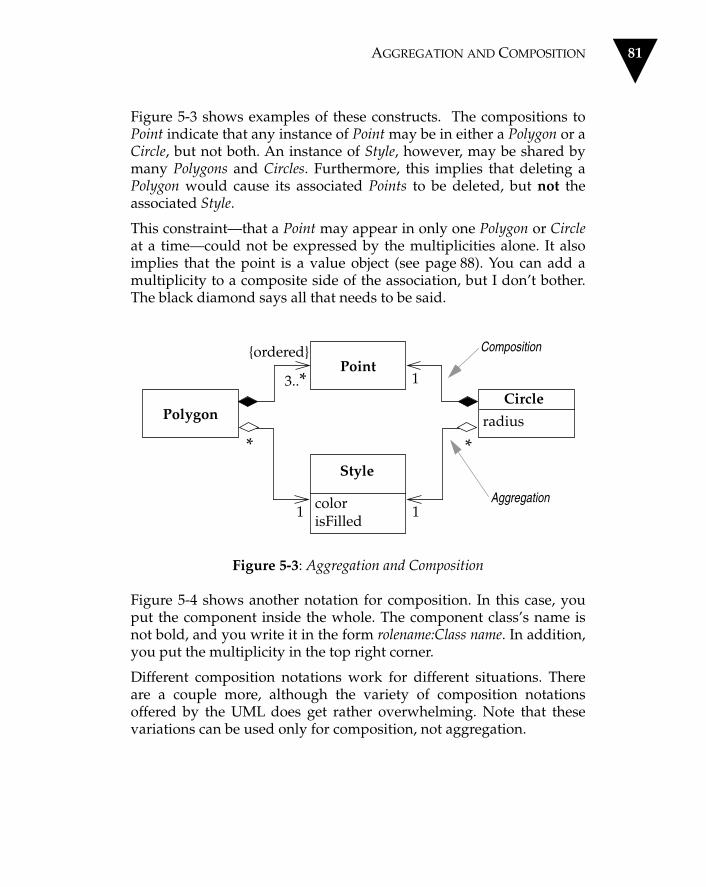
AGGREGATION AND COMPOSITION 81
Figure 5-3 shows examples of these constructs. The compositions toPoint indicate that any instance of Point may be in either a Polygon or aCircle, but not both. An instance of Style, however, may be shared bymany Polygons and Circles. Furthermore, this implies that deleting aPolygon would cause its associated Points to be deleted, but not theassociated Style.
This constraint—that a Point may appear in only one Polygon or Circleat a time—could not be expressed by the multiplicities alone. It alsoimplies that the point is a value object (see page 88). You can add amultiplicity to a composite side of the association, but I don’t bother.The black diamond says all that needs to be said.
Figure 5-3: Aggregation and Composition
Figure 5-4 shows another notation for composition. In this case, youput the component inside the whole. The component class’s name isnot bold, and you write it in the form rolename:Class name. In addition,you put the multiplicity in the top right corner.
Different composition notations work for different situations. Thereare a couple more, although the variety of composition notationsoffered by the UML does get rather overwhelming. Note that thesevariations can be used only for composition, not aggregation.
Polygon
Point{ordered}
3..*
1
Style
colorisFilled
Aggregation
Composition
1
1
radius
Circle
* *

82 CHAPTER 5 CLASS DIAGRAMS: ADVANCED CONCEPTS
Figure 5-4: Alternative Notation for Composition
Derived Associations and Attributes
Derived associations and derived attributes are those that can be cal-culated from other associations and attributes, respectively, on a classdiagram. For example, an age attribute of a Person can be derived ifyou know that Person’s date of birth.
Each perspective brings its own interpretation of derived features onclass diagrams. The most critical of these has to do with the specifica-tion perspective. From this angle, it is important to realize that derivedfeatures indicate a constraint between values, not a statement of whatis calculated and what is stored.
Figure 5-5 shows a hierarchical structure of accounts drawn from aspecification perspective. The model uses the Composite pattern (seeGamma et al. 1994).
Style
{ordered}
*
1
3..*
Polygon
Point
*
1
1
Circle
Point

DERIVED ASSOCIATIONS AND ATTRIBUTES 83
Figure 5-5: Derived Associations and Attributes
Note the following.
• Entry objects are attached to Detail Accounts.• The balance of an Account is calculated as the sum of Entry
amounts.• A Summary Account's entries are the entries of its components,
determined recursively.
Since Figure 5-5 illustrates a specification model, it does not state thatAccounts do not contain fields to hold balances; such a cache may wellbe present, but it is hidden from the clients of the Account class.
entries role is derived usingcomponents.entries
Summary Account
DetailAccount
Entry
amount:Money
Account
/balance:Money
0..1 1
/entriescomponents {hierarchy}
{balance = sum of amounts of entries}
Derived RoleDerived Attribute
Note
**

84 CHAPTER 5 CLASS DIAGRAMS: ADVANCED CONCEPTS
Figure 5-6: Time Period Class
I can illustrate how derived elements indicate constraints with a classnamed Time Period (see Figure 5-6).
If this is a specification diagram, then although it suggests that startand end are stored and duration is calculated, a programmer can, infact, implement this class in any fashion that maintains that externalbehavior. For instance, storing start and duration and calculating end isperfectly acceptable.
On implementation diagrams, derived values are valuable for annotat-ing fields that are used as caches for performance reasons. By markingthem and recording the derivation of the cache, it is easier to seeexplicitly what the cache is doing. I often reinforce this in the code byusing the word “cache” on such a field (for instance, balanceCache).
On conceptual diagrams, I use derived markers to remind me wherethese derivations exist and to confirm with the domain experts that thederivations exist. They then correlate with their use in specificationdiagrams.
In the worlds of OMT and Odell, you showed a derived association bya slash on the association line. This usage is not part of the UML, but Iconfess I do it anyway—it looks clearer, particularly when I don’tname the association.
Time Period
start:Date
end:Date
/duration:Date

INTERFACES AND ABSTRACT CLASSES 85
Interfaces and Abstract Classes
One of the great qualities of object-oriented development is that youcan vary the interfaces of classes independent of the implementation.Much of the power of object development comes from this property.However, few people make good use of it.
Programming languages use a single construct, the class, which con-tains both interface and implementation. When you subclass, youinherit both. Using the interface as a separate construct is rarely used,which is a shame.
A pure interface (as in Java) is a class with no implementation, and,therefore, has operation declarations but no method bodies and nofields. Interfaces are often declared through abstract classes. Suchclasses may provide some implementation, but often they are used pri-marily to declare an interface. The point is that subclassing (or someother mechanism) will provide the implementation, but clients willnever see the implementation, only the interface.
The text editor represented in Figure 5-7 is a typical example of this. Toallow the editor to be platform-independent, we define a platform-independent abstract Window class. This class has no operations; itonly defines an interface for the text editor to use. Platform-specificsubclasses can be used as desired.
If you have an abstract class or method, the UML convention is to ital-icize the name of the abstract item. You can use the {abstract} con-straint, as well (or instead). I use {abstract} on whiteboards because Ican’t write italic text. With a diagramming tool, however, I prefer theelegance of italics.
Subclassing is not the only way to do this, however. Java provides aspecific interface, and the compiler checks that the class provides animplementation for all operations defined for that interface.
In Figure 5-8, we see InputStream, DataInput, and DataInputStream(defined in the standard java.io file). InputStream is an abstract class;DataInput is an interface.

86 CHAPTER 5 CLASS DIAGRAMS: ADVANCED CONCEPTS
Figure 5-7: Window as Abstract Class
Some client class, say, OrderReader, needs to use DataInput’s function-ality. The DataInputStream class implements both the DataInput andInputStream interfaces and is a subclass of the latter.
The link between DataInputStream and DataInput is a refinement rela-tionship. Refinement is a general term used in the UML to indicate agreater level of detail. It can be used for implementation of interfacesor for some other purposes (see the three amigos’ books for specifics).Refinement is deliberately similar to generalization.
In a specification model, both subclassing and refinement would berepresented as subtyping; the distinction between refinement and gen-eralization is valid only for implementation models. Some modelerswould prefer to use «type» rather than «interface». I prefer «interface»because it makes the role of the interface explicit.
Text Editor
Windows Window
toFront()
toBack()
X11 Window
toFront()
toBack()
Mac Window
toFront()
toBack()
Window
toFront()
toBack()
{abstract}
Dependency

INTERFACES AND ABSTRACT CLASSES 87
Figure 5-8: Interfaces and Abstract Class: An Example from Java
The link between OrderReader and DataInput is a dependency. Itshows that the OrderReader uses the DataInput interface for somepurpose. I will talk more about dependencies in Chapter 7. Essentially,a dependency indicates that if the DataInput interface changes, theOrderReader may also have to change. One of the aims of develop-ment is to keep dependencies to a minimum so that the effects ofchanges are minimized.
Figure 5-9 shows an alternative, more compact notation. Here, theinterfaces are represented by small circles (often called lollipops) com-ing off the classes that implement them.
Figure 5-9: Lollipop Notation for Interfaces
DataInput
DataInputStream
InputStream OrderReader{abstract}
«interface»
Dependency
Refinement
Generalization
DataInputStream
OrderReader
DataInput
InputStream
Dependency
Interface

88 CHAPTER 5 CLASS DIAGRAMS: ADVANCED CONCEPTS
There is no distinction between refining an interface and subclassingan abstract class.
Abstract classes and interfaces are similar, but there is a difference.Both allow you to define an interface and defer its implementationuntil later. However, the abstract class allows you to add implementa-tion of some of the methods; an interface forces you to defer definitionof all methods.
Reference Objects and Value Objects
One of the common things said about objects is that they have identity.This is true, but it is not quite as simple as that. In practice, you findthat identity is important for reference objects, but not so important forvalue objects.
Reference objects are things like Customer. Here, identity is veryimportant, because you usually want only one software object to des-ignate a customer in the real world. Any object that references a Cus-tomer object will do so through a reference or pointer; all objects thatreference this Customer will reference the same software object. Thatway, changes to a Customer are available to all users of the Customer.
If you have two references to a Customer and you wish to see if theyare the same, you usually compare their identities. Copies may be dis-allowed, and if they are allowed, they tend to be made rarely, perhapsfor archive purposes or for replication across a network. If copies aremade, you need to sort out how to synchronize changes.
Value objects are things like Date. You often have multiple valueobjects representing the same object in the real world. For example, itis normal to have hundreds of objects that designate 1–Jan–97. Theseare all interchangeable copies. New dates are created and destroyedfrequently.
If you have two dates and wish to see if they are the same, you don’tlook at their identities—you look at the values they represent. Thisusually means you have to write an equality test operator, which fordates would make a test on year, month, and day (or whatever the
COLLECTIONS FOR MULTI-VALUED ROLES 89
internal representation is). Usually each object that references 1–Jan–97has its own dedicated object, but sometimes you do get shared dates.
Value objects should be immutable (frozen). In other words, youshould not be able to take a date object of 1–Jan–97 and change thesame date object to be 2–Jan–97. Instead, you should create a new 2–Jan–97 object and link to that first object. The reason for this is that ifthe date were shared, you would update another object's date in anunpredictable way.
In C++, this is not an issue because you try hard not to share dates;sharing value objects leads to memory management problems. Inplace of that, you can override assignment to make copies. Withinmemory-managed environments such as Java, this is more important,especially since dates are not immutable in Java. As a rule of thumb,don't change a value object.
In days gone by, the difference between reference objects and valueobjects was clearer. Value objects were the built-in values of the typesystem. Now you can extend the type system with your own classes,so this issue requires more thought. Within the UML, attributes areusually used for value objects and associations are used for referenceobjects. You can also use composition for value objects.
I don’t find that the distinction between reference and value objects isuseful with conceptual models. There is no difference between the twoconstructs from the conceptual perspective. If I represent a link to avalue object with an association, I usually mark the multiplicity of therole from the value to its user as *, unless there is a uniqueness rule(such as a sequence number).
Collections for Multi-Valued Roles
A multi-valued role is one whose multiplicity’s upper bound isgreater than 1 (for instance, *). The usual convention is that multi-val-ued roles are thought of as sets. There is no ordering for the targetobjects, and no target object appears in the role more than once. Youcan change these assumptions, however, by attaching a constraint.

90 CHAPTER 5 CLASS DIAGRAMS: ADVANCED CONCEPTS
The {ordered} constraint implies that there is an ordering to the targetobjects (that is, the target objects form a list). Target objects may appearonly once in the list.
I use the {bag} constraint to indicate that target objects may appearmore than once, but there is no ordering. (If I want ordering and multi-ple appearances, I would use {ordered bag}, although I haven’t neededto do that yet.) I also use the {hierarchy} constraint to indicate that thetarget objects form a hierarchy, and I use the {dag} constraint to indi-cate a directed acyclic graph.
Frozen
Frozen is a constraint that the UML defines as applicable to a role, butwhich can usefully be applied to attributes and classes as well.
On an attribute or role, frozen indicates that the value of that attributeor role may not change during the lifetime of the source object. Thevalue must be set at object creation and may never change after that.The initial value may be null. Of course, if that’s true when the objectis constructed, it will be true as long as the object is alive. This impliesthat there must be an argument for this value in a constructor, and thatthere is no command operation that updates this value.
When applied to a class, frozen indicates that all roles and attributesassociated with that class are frozen.
Frozen is not the same as read-only. Read-only implies that a valuecannot be changed directly but may change due to a change in someother value. For instance, if a person has a date of birth and an age,then the age may be read-only, but it cannot be frozen. I mark “freez-ing” using the {frozen} constraint, and I mark read-only values with{read only}.
If you are thinking of “freezing” something, bear in mind that peoplemake mistakes. In software, we model what we know about the world,not how the world is. If we were modeling how the world is, a “date ofbirth” attribute for a Person object would be frozen, but for most cases,we would want to change it if we found that a previous recording wasincorrect.

QUALIFIED ASSOCIATIONS 91
Classification and Generalization
I often hear people talk about subtyping as the “is a” relationship. Iurge you to beware of that way of thinking. The problem is that thephrase “is a” can mean different things.
Consider the following phrases.
1. Shep is a Border Collie.2. A Border Collie is a Dog.3. Dogs are Animals.4. A Border Collie is a Breed.5. Dog is a Species.
Now try combining the phrases. If I combine phrases 1 and 2, I get“Shep is a Dog”; 2 and 3 taken together yield “Border Collies are Ani-mals.” And 1 plus 2 plus 3 gives me “Shep is an Animal.” So far, sogood. Now try 1 and 4: “Shep is a Breed.” The combination of 2 and 5is “A Border Collie is a Species.” These are not so good.
Why can I combine some of these phrases and not others? The reasonis that some are classification (the object Shep is an instance of the typeBorder Collie) and some are generalization (the type Border Collie is asubtype of the type Dog). Generalization is transitive, classification isnot. I can combine a classification followed by a generalization, but notvice versa.
I make this point to get you to be wary of “is a.” Using it can lead toinappropriate use of subclassing and confused responsibilities. Bettertests for subtyping in this case would be the phrases “Dogs are kindsof Animals” and “Every instance of a Border Collie is an instance of aDog.”
Qualified Associations
A qualified association is the UML equivalent of a programming con-cept variously known as associative arrays, maps, and dictionaries.

92 CHAPTER 5 CLASS DIAGRAMS: ADVANCED CONCEPTS
Figure 5-10: Qualified Association
Figure 5-10 shows a way of representing the association between theOrder and Order Line classes that uses a qualifier. The qualifier saysthat in connection with an Order, there may be one Order Line for eachinstance of Product.
Conceptually, this example indicates that you cannot have two OrderLines within an Order for the same Product. From a specification per-spective, this qualified association would imply an interface along thelines of
class Order {
public OrderLine lineItem (Product aProduct);
public void addLineItem (Number amount,Product forProduct);
Thus, all access to a given Line Item requires the identity of a Productas an argument. A multiplicity of 1 would indicate that there must be aLine Item for every Product; * would indicate that you can have multi-ple Order Lines per Product but that access to the Line Items is stillindexed by Product.
From an implementation perspective, this suggests the use of an asso-ciative array or similar data structure to hold the order lines.
Class Order {
private Dictionary _lineItems;
Order Line
amount:NumberOrder Product 0..1
line item
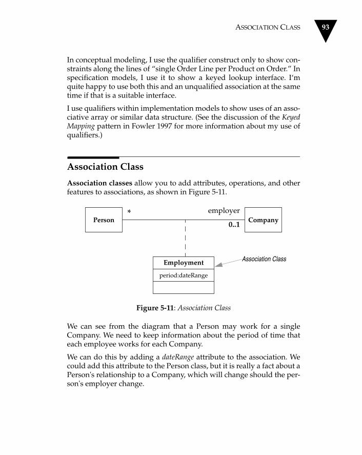
ASSOCIATION CLASS 93
In conceptual modeling, I use the qualifier construct only to show con-straints along the lines of “single Order Line per Product on Order.” Inspecification models, I use it to show a keyed lookup interface. I‘mquite happy to use both this and an unqualified association at the sametime if that is a suitable interface.
I use qualifiers within implementation models to show uses of an asso-ciative array or similar data structure. (See the discussion of the KeyedMapping pattern in Fowler 1997 for more information about my use ofqualifiers.)
Association Class
Association classes allow you to add attributes, operations, and otherfeatures to associations, as shown in Figure 5-11.
Figure 5-11: Association Class
We can see from the diagram that a Person may work for a singleCompany. We need to keep information about the period of time thateach employee works for each Company.
We can do this by adding a dateRange attribute to the association. Wecould add this attribute to the Person class, but it is really a fact about aPerson's relationship to a Company, which will change should the per-son's employer change.
Employment
period:dateRange
CompanyPerson0..1
employer
Association Class
*

94 CHAPTER 5 CLASS DIAGRAMS: ADVANCED CONCEPTS
Figure 5-12: Promoting an Association Class to a Full Class
Figure 5-12 shows another way to represent this information: makeEmployment a full class in its own right. (Note how the multiplicitieshave been moved accordingly.) In this case, each of the classes in theoriginal association has a single-valued role with regard to theEmployment class. The “employer” role now is derived, although youdon’t have to show this.
What benefit do you gain with the association class to offset the extranotation you have to remember? The association class adds an extraconstraint, in that there can be only one instance of the associationclass between any two participating objects. I feel the need for anexample.
Take a look at the two diagrams contained in Figure 5-13. These dia-grams have much the same form. However, we could imagine a Per-son working for the same Company at different periods of time (thatis, he or she leaves and later returns). This means that a Person couldhave more than one Employment association with the same Companyover time. With regard to the Person and Skill classes, it would be hardto see why a Person would have more than one Competency in thesame Skill—indeed, you would probably consider that an error.
In the UML, only the latter case is legal. You can have only one Com-petency for each combination of Person and Skill. The top diagram inFigure 5-13 would not allow a Person to have more than one Employ-ment with the same Company. If you need to allow this, you need tomake Employment a full class, in the style of Figure 5-12.
Employment
period : dateRange CompanyPerson1 0..1 1
0..1/employer
**

ASSOCIATION CLASS 95
Figure 5-13: Association Class Subtleties
In the past, modelers made various assumptions about the meaning ofan association class in these circumstances. Some assumed that youcan have only unique combinations (such as competency), while oth-ers did not assume such a constraint. Many people did not think aboutit at all and may have assumed the constraint in some places and notin others. So when using the UML, remember that the constraint isalways there.
You often find this kind of construct with historic information, such asin the Employment case above. A useful pattern here is the HistoricMapping pattern described in Fowler (1997). We can use this by defin-ing a «history» stereotype (see Figure 5-14).
Employment
period:dateRange
CompanyPersonemployer
Competency
level
SkillPerson
**
* *

96 CHAPTER 5 CLASS DIAGRAMS: ADVANCED CONCEPTS
Figure 5-14: History Stereotype for Associations
The model indicates that a Person may only work for a single Com-pany at one time. Over time, however, a Person may work for severalCompanies. This suggests an interface along the lines of
class Person {
//get current employerCompany employer();
//employer at a given dateCompany employer(Date);
void changeEmployer(Company newEmployer,Date changeDate);
void leaveEmployer (Date changeDate);
The «history» stereotype is not part of the UML, but I mention it herefor two reasons. First, it is a notion I have found useful on several occa-sions in my modeling career. Second, it shows how you can use stereo-types to extend the UML.
Parameterized Class
Several languages, most noticeably C++, have the notion of a parame-terized class (also known as a template).
This concept is most obviously useful for working with collections in astrongly typed language. This way, you can define behavior for sets ingeneral by defining a template class Set.
Person Company
employer «history»
0..1
*

PARAMETERIZED CLASS 97
class Set <T> {
void insert (T newElement);
void remove (T anElement);
When you have done this, you can use the general definition to makeset classes for more specific elements.
Set <Employee> employeeSet;
You declare a parameterized class in the UML using the notationshown in Figure 5-15.
Figure 5-15: Parameterized Class
The T in the diagram is a placeholder for the type parameter. (You mayhave more than one.) In an untyped language, such as Smalltalk, thisissue does not come up, so this concept is not useful.
A use of a parameterized class, such as Set<Employee> from above, iscalled a bound element.
You can show a bound element in two ways. The first way mirrors theC++ syntax (see Figure 5-16).
Figure 5-16: Bound Element (Version 1)
Set
insert(T)remove(T)
T
Template ParameterTemplate Class
Set <Employees>
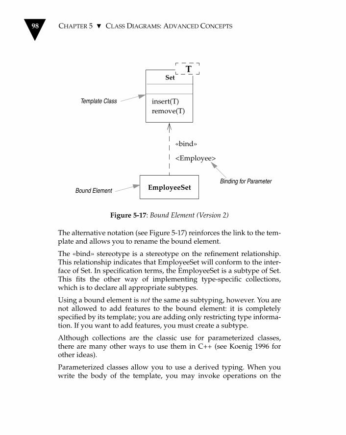
98 CHAPTER 5 CLASS DIAGRAMS: ADVANCED CONCEPTS
Figure 5-17: Bound Element (Version 2)
The alternative notation (see Figure 5-17) reinforces the link to the tem-plate and allows you to rename the bound element.
The «bind» stereotype is a stereotype on the refinement relationship.This relationship indicates that EmployeeSet will conform to the inter-face of Set. In specification terms, the EmployeeSet is a subtype of Set.This fits the other way of implementing type-specific collections,which is to declare all appropriate subtypes.
Using a bound element is not the same as subtyping, however. You arenot allowed to add features to the bound element: it is completelyspecified by its template; you are adding only restricting type informa-tion. If you want to add features, you must create a subtype.
Although collections are the classic use for parameterized classes,there are many other ways to use them in C++ (see Koenig 1996 forother ideas).
Parameterized classes allow you to use a derived typing. When youwrite the body of the template, you may invoke operations on the
Set
insert(T)remove(T)
T
EmployeeSet
«bind»
<Employee>
Template Class
Bound ElementBinding for Parameter

VISIBILITY 99
parameter. When you later declare a bound element, the compiler triesto ensure that the supplied parameter supports the operationsrequired by the template.
This is a derived typing mechanism because you do not have to definea type for the parameter; the compiler figures out if the binding is via-ble by looking at the source of the template. This property is central tothe use of parameterized classes in C++'s STL; these classes can also beused for other interesting tricks.
Using parameterized classes does have repercussions—for example,they can cause considerable code bloat in C++. I rarely use parameter-ized classes in conceptual modeling, mostly because they are usedmainly for collections, which are implied by associations. (One case Ido use it for is the Range pattern; see Fowler 1997). I only use parame-terized classes in specification and implementation modeling if theyare supported by the language I am using.
Visibility
I must confess to having some trepidation about this section.
Visibility is one of those subjects that is simple in principle but hascomplex subtleties. The simple idea is that any class has public andprivate elements. Public elements can be used by any other class; pri-vate elements can be used only by the owning class. However, eachlanguage makes its own rules. Although they all use terms such as“public,” “private,” and “protected,” these terms mean differentthings in different languages. These differences are small, but theylead to confusion, especially for those of us who use more than onelanguage.
The UML tries to address this without getting into a horrible tangle.Essentially, within the UML, you can tag any attribute or operationwith a visibility indicator. You can use any marker you like, and itsmeaning is language-dependent. However, the UML provides three(rather hard to remember) abbreviations for visibility: + (public), –(private), and # (protected).

100 CHAPTER 5 CLASS DIAGRAMS: ADVANCED CONCEPTS
I’m tempted to leave it at that, but unfortunately, people draw dia-grams that use visibility in specific ways. Therefore, to really under-stand some of the common differences that exist among models, youneed to understand the approaches that different languages take tovisibility. So, let's take a deep breath and dive into the murk.
We start with C++, because it’s the basis for standard UML usage.
• A public member is visible anywhere in the program and may becalled by any object within the system.
• A private member may be used only by the class that defines it.• A protected member may be used only by (a) the class that defines
it or (b) a subclass of that class.
Consider a Customer class that has a Personal Customer subclass.Consider also the object Martin, which is an instance of Personal Cus-tomer. Martin can use any public member of any object in the system.Martin may also use any private member of the class Personal Cus-tomer. Martin may not use any private members defined within Cus-tomer; Martin may, however, use protected members of Customer andprotected users of Personal Customer.
Now look at Smalltalk. Within that language, all instance variables areprivate, and all operations are public. However, private doesn’t meanthe same thing in Smalltalk that it does in C++. In a Smalltalk system,Martin can access any instance variable within his own object whetherthat instance variable was defined within Customer or Personal Cus-tomer. So, in a sense, private in Smalltalk is similar to protected inC++.
Ah, but that would be too simple.
Let's go back to C++. Say I have another instance of Personal Cus-tomer, called Kendall. Kendall can access any member of Martin thatwas defined as part of the Personal Customer class, whether public,private, or protected. Kendall may also access any protected or publicmember of Martin that was defined within Customer. However, inSmalltalk, Kendall cannot access Martin's private instance variables—only Martin’s public operations.
In C++, you may access members of other objects of your own class inthe same way that you access your own members. In Smalltalk, it

CLASS SCOPE FEATURES 101
makes no difference whether another object is of the same class or not;you can access only public parts of another object.
I prefer not to access private or protected members of other objects ofthe same class. Many others follow this (unstated) convention.
Java is similar to C++ in that it offers free access to members of otherobjects of one’s own class. Java also adds a new visibility level calledpackage. A member with package visibility may be accessed only byinstances of other classes within the same package.
In keeping with our theme, to ensure that things are not too simple,Java slightly redefines protected visibility. In Java, a protected membermay be accessed by subclasses but also by any other class in the samepackage as the owning class. This means that in Java, protected ismore public than package.
Java also allows classes to be marked public or package. A publicclass’s public members may be used by any class that imports thepackage to which the class belongs. A package class may be used onlyby other classes in the same package.
C++ adds a final twist. One C++ method or class can be made a friendof a class. A friend has complete access to all members of a class—hence, the phrase “in C++, friends touch each other’s private parts.”
When you are using visibility, use the rules of the language in whichyou are working. When you are looking at a UML model from else-where, be wary of the meanings of the visibility markers, and be awareof how those meanings can change from language to language.
I usually find that visibilities change as you work with the code, sodon’t get too hung up on them early on.
Class Scope Features
You can define operations or attributes at class scope. This means thatthey are features of the class, rather than of each object. These opera-tions or attributes correspond to static members in C++ or Java and toclass methods or variables in Smalltalk. You show them just the sameas any other operation or attribute, except that you underline them.

102 CHAPTER 5 CLASS DIAGRAMS: ADVANCED CONCEPTS

Chapter 6
Interaction Diagrams
Interaction diagrams are models that describe how groups of objectscollaborate in some behavior.
Typically, an interaction diagram captures the behavior of a single usecase. The diagram shows a number of example objects and the mes-sages that are passed between these objects within the use case.
I’ll illustrate the approach with a simple use case that exhibits the fol-lowing behavior.
• The Order Entry window sends a “prepare” message to an Order.
• The Order then sends “prepare” to each Order Line on the Order.
• Each Order Line checks the given Stock Item.
— If this check returns “true,” the Order Line removes the appro-priate quantity of Stock Item from stock.
— Otherwise, the quantity of Stock Item has fallen below the reor-der level, and that Stock Item requests a new delivery.
There are two kinds of interaction diagrams: sequence diagrams andcollaboration diagrams.
103

104 CHAPTER 6 INTERACTION DIAGRAMS
Sequence Diagrams
Within a sequence diagram, an object is shown as a box at the top of adashed vertical line (see Figure 6-1).
Figure 6-1: Sequence Diagram
an Order Entrywindow
an Order an Order Line a Stock Item
a Reorder
a Delivery Item
Item
Message
Object * [for all order lines]
Iteration
hasStock := check ()
prepare ()
[hasStock] remove()
Condition
needsReorder:= needsToReorder()
Self-Delegation
[needsReorder]new
Return
[hasStock] new
Creation
prepare ()

SEQUENCE DIAGRAMS 105
This vertical line is called the object’s lifeline. The lifeline representsthe object’s life during the interaction. This form was first popularizedby Jacobson.
Each message is represented by an arrow between the lifelines of twoobjects. The order in which these messages occur is shown top to bot-tom on the page. Each message is labeled at minimum with the mes-sage name; you can also include the arguments and some controlinformation, and you can show self-delegation, a message that anobject sends to itself, by sending the message arrow back to the samelifeline.
Two bits of control information are valuable. First, there is a condition,which indicates when a message is sent (for example, [needsReorder]).The message is only sent if the condition is true. The second usefulcontrol marker is the iteration marker, which shows that a message issent many times to multiple receiver objects, as would happen whenyou are iterating over a collection. You can show the basis of iterationwithin brackets (such as *[for all order lines]).
As you can see, Figure 6-1 is very simple and has immediate visualappeal. This is its great strength.
One of the hardest things to understand in an object-oriented programis the overall flow of control. A good design has lots of small methodsin different classes, and at times it can be tricky to figure out the over-all sequence of behavior. You can end up looking at the code trying tofind the program. This is particularly true for those new to objects.Sequence diagrams help you to see that sequence.
This diagram includes a return, which indicates the return from a mes-sage, not a new message. Returns differ from the regular messages inthat the line is dashed.
The POSA diagrams (Buschmann et al. 1996), on which much of theUML sequence chart notation is based, use returns extensively. I donot. I find that returns add a lot of clutter to a diagram and tend toobscure the flow. All returns are implied by the way the messages aresequenced. I only use returns on those occasions when they improvethe clarity of the diagram.
106 CHAPTER 6 INTERACTION DIAGRAMS
My advice is to show returns only when they improve clarity. The onlyreason I used a return in Figure 6-1 is to demonstrate the notation; ifyou remove the return, I think the diagram remains just as clear.
In UML 1.0, returns were indicated by feathered arrowheads ratherthan dashed lines. I found that so difficult to implement that I useddashed lines anyway , so I’m glad to see the change.
I mention this because I’d like to offer a piece of general advice here:Be very wary of going against the UML notation. This notation willbecome a well-understood notation, and to do something non-stan-dard will harm your communication with other designers. If some-thing is causing painful confusion, however, I would do somethingnon-standard. After all, the primary purpose of the diagram is com-munication. If you do break the UML’s rules, do it sparingly andclearly define what you have done.
Concurrent Processes and Activations
Sequence diagrams are also valuable for concurrent processes.
In Figure 6-2, we see some objects that are checking a bank transaction.
When a Transaction is created, it creates a Transaction Coordinator tocoordinate the checking of the Transaction. This coordinator creates anumber (in this case, two) of Transaction Checker objects, each ofwhich is responsible for a particular check. This process would make iteasy to add different checking processes because each checker is calledasynchronously and proceeds in parallel.
When a Transaction Checker completes, it notifies the TransactionCoordinator. The coordinator looks to see if all the checkers calledback. If not, the coordinator does nothing. If they have, and all of themare successful, as in this case, then the coordinator notifies the Transac-tion that all is well.
Figure 6-2 introduces a number of new elements to sequence dia-grams. First, you see activations, which appear explicitly when amethod is active because it is either executing or waiting for a subrou-tine to return. Many designers use activations all the time. I find theydon’t add much to procedural execution, so I use them only in concur-rent situations.
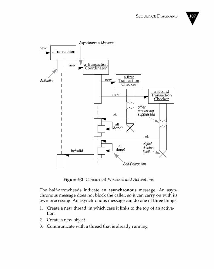
SEQUENCE DIAGRAMS 107
Figure 6-2: Concurrent Processes and Activations
The half-arrowheads indicate an asynchronous message. An asyn-chronous message does not block the caller, so it can carry on with itsown processing. An asynchronous message can do one of three things.
1. Create a new thread, in which case it links to the top of an activa-tion
2. Create a new object3. Communicate with a thread that is already running
a secondTransaction
Checker
a firstTransaction
Checker
a TransactionCoordinator
a Transactionnew
Activation
Asynchronous Message
new
new
otherprocessingsuppressed
objectdeletesitself
new
ok
ok
alldone?
alldone?
Self-Delegation
beValid

108 CHAPTER 6 INTERACTION DIAGRAMS
Object deletion is shown with a large X. Objects can self-destruct(shown in Figure 6-2), or they can be destroyed by another message(see Figure 6-3).
You can show the consequences of self-delegation more clearly whenyou have activations. Without them, or without the stacking notationused here, it is hard to tell where further calls occur after a self-delega-tion—either in the calling method or the called method. The stackingactivations make this clear. I sometimes find this is a reason to use acti-vations in a procedural interaction, even though I don’t usually useactivations in these cases.
Figures 6-2 and 6-3 show two of the scenarios in the “transactionchecking” use case. I have drawn each scenario separately. There aretechniques for combining the conditional logic onto a single diagram,but I prefer not to use them because it makes the diagram too compli-cated.
In Figure 6-3, I’ve employed a very useful technique: I’ve inserted tex-tual descriptions of what's happening along the left side of thesequence diagram. This involves lining up each text block with theappropriate message within the diagram. This helps in understandingthe diagram (at the cost of some extra work). I do this for documentsI’m going to keep but not for whiteboard sketches.
Collaboration Diagrams
The second form of the interaction diagram is the collaboration dia-gram.
Within a collaboration diagram, the example objects are shown asicons. As on a sequence diagram, arrows indicate the messages sentwithin the given use case. This time, however, the sequence is indi-cated by numbering the messages.
Numbering the messages makes it more difficult to see the sequencethan putting the lines down the page. On the other hand, the spatiallayout allows you to show other things more easily. You can show howthe objects are linked together and use the layout to overlay packagesor other information.

COLLABORATION DIAGRAMS 109
Figure 6-3: Sequence Diagram: Check Failure
You can use one of several numbering schemes for collaboration dia-grams. The simplest is illustrated in Figure 6-4. Another approachinvolves a decimal numbering scheme, seen in Figure 6-5.
In the past, most people used the simple numbering scheme. The UMLuses the decimal scheme because it makes it clear which operation is call-ing which other operation, although it can be harder to see the overallsequence.
a secondTransaction
Checker
a firstTransaction
Checker
a TransactionCoordinator
new
new
new
new
fail
beInvalid
deletinganotherobject
kill
killcheckers
a TransactionWhen aTransactionis created…
…it creates aCoordinator tomanage the checking.
The Coordinator
If a given check
…and tells theTransactionthat it is invalid.
creates a seriesof Checkers, onefor each kind ofcheck. TheseCheckers dotheir checks asseparate processes.
fails, the Coordi-nator kills allother Checkersthat are stillrunning…

110 CHAPTER 6 INTERACTION DIAGRAMS
Figure 6-4: Collaboration Diagram with Simple Numbering
Regardless of what numbering scheme you use, you can add the samekind of control information you might show on a sequence diagram.
In Figures 6-4 and 6-5, you can see the various forms of the UML'sobject naming scheme. This takes the form objectName : ClassName,where either the object name or the class name may be omitted. Notethat if you omit the object name, you must retain the colon so that it isclear that it is the class name and not the object name. So the name“Macallan line : Order Line” indicates an instance of Order Line calledMacallan line (this is an order I would particularly appreciate). I tendto name objects in the Smalltalk style that I used in the sequence dia-grams. (This scheme is legal UML because “anObject” is a perfectlygood name for an object.)
: Order Entry Window
: Order
Macallan line : Order Line
: Delivery Item : Reorder Item
Macallan stock : Stock Item
Object
1: prepare() Message
2*[for all order lines]: prepare()
7 [hasStock]: new
3: hasStock := check ()4: [hasStock]: remove()
6 [needsReorder]: new
5: needsReorder := needToReorder() Self-Delegation
Sequence Number

COMPARING SEQUENCE AND COLLABORATION DIAGRAMS 111
Figure 6-5: Collaboration Diagram with Decimal Numbering
Comparing Sequence and Collaboration Diagrams
Different developers have different preferences when it comes tochoosing the form of interaction diagram to use. I usually prefer thesequence diagram because I like the emphasis it puts on sequence; it iseasy to see the order in which things occur. Others prefer the collabo-ration diagram because they can use the layout to indicate how objectsare statically connected.
One of the principal features of either form of an interaction diagramis its simplicity. You can easily see the messages by looking at the dia-gram. However, if you try to represent something other than a singlesequential process without much conditional or looping behavior, thetechnique begins to break down.
: Order Entry Window
: Order
Macallan line : Order Line
: Delivery Item : Reorder Item
Macallan stock : Stock Item
1: prepare()
1.1*[for all order lines]: prepare()
1.1.3: [hasStock]: new
1.1.1: hasStock := check ()1.1.2: [hasStock]: remove()
1.1.2.2 [needsReorder]:
1.1.2.1: needsReorder :=
Sequence Number
needToReorder()
new

112 CHAPTER 6 INTERACTION DIAGRAMS
Conditional Behavior
What is the best way to show a lot of conditional behavior?
There are two schools of thought. One is to use separate diagrams foreach scenario. The other is to use conditions on messages to indicatethe behavior.
I prefer the former. Interaction diagrams are at their best when thebehavior is simple; they quickly lose their clarity with more complexbehavior. If I want to capture complex behavior in a single diagram, Iprefer to use an activity diagram (see Chapter 9).
The UML provides a lot of additional syntax for sequence diagrams,based on the work of the patterns team at Siemens (Buschmann et al.1996). I won’t go into it in detail here, mainly because I’m not too keenon the complexity it encourages. To me, the beauty of interaction dia-grams is their simplicity, and many of the additional notations lose itin their drive to computational completeness. I encourage you not torush to the more complex forms of interaction diagrams, because youmay find the simpler ones provide the best value.
When to Use Interaction Diagrams
You should use interaction diagrams when you want to look at thebehavior of several objects within a single use case. They are good atshowing collaborations among the objects; they are not so good at pre-cise definition of the behavior.
If you want to look at the behavior of a single object across many usecases, use a state transition diagram (see Chapter 8). If you want tolook at behavior across many use cases or many threads, consider anactivity diagram (see Chapter 9).
Where to Find Out More
Buschmann et al. (1996) uses many extensions that are currently in themix for the UML and should give you a good idea of what is in store.

Chapter 7
Package Diagrams
One of the oldest questions in software methods is: How do you breakdown a large system into smaller systems? We ask this questionbecause as systems get large, it becomes difficult to understand themand the changes we make to them.
Structured methods used functional decomposition, in which theoverall system was mapped as a function and broken down into sub-functions, which were broken down further into sub-sub-functions,and so forth. The functions were like the use cases in an object-ori-ented system in that functions represented something the system as awhole did.
Those were the days when process and data were separated. So inaddition to a functional decomposition, there was also a data struc-ture. This took second place, although some Information Engineeringtechniques grouped data records into subject areas and producedmatrices to show how the functions and data records interacted.
It is from this viewpoint that we see the biggest change that objectshave wrought. The separation of process and data is gone, functionaldecomposition is gone, but the old question still remains. One idea isto group the classes together into higher-level units. This idea, appliedvery loosely, appears in many object methods. In the UML, this group-ing mechanism is called the package.
113

114 CHAPTER 7 PACKAGE DIAGRAMS
The idea of a package can be applied to any model element, not justclasses. Without some heuristics to group classes together, the group-ing becomes arbitrary. The one I have found most useful and the onestressed most in the UML is the dependency. I use the term packagediagram for a diagram that shows packages of classes and the depen-dencies among them.
Strictly speaking, packages and dependencies are elements on a classdiagram, so a package diagram is just a form of class diagram. In prac-tice, I find I draw these diagrams for different reasons, so I like to usedifferent names.
A dependency exists between two elements if changes to the defini-tion of one element may cause changes to the other. With classes,dependencies exist for various reasons: One class sends a message toanother; one class has another as part of its data; one class mentionsanother as a parameter to an operation. If a class changes its interface,then any message it sends may no longer be valid.
Ideally, only changes to a class’s interface should affect any other class.The art of large-scale design involves minimizing dependencies—thatway, the effects of change are reduced and the system requires lesseffort to change.
In Figure 7-1, we have domain classes that model the business,grouped into two packages: Orders and Customers. Both packages arepart of an overall domain package. The Order Capture application hasdependencies with both domain packages. The Order Capture UI hasdependencies with the Order Capture application and the AWT (a JavaGUI toolkit).
A dependency between two packages exists if any dependency existsbetween any two classes in the packages. For example, if any class inthe Mailing List package is dependent on any class in the Customerspackage, then a dependency exists between their corresponding pack-ages.
There is an obvious similarity between package dependencies andcompilation dependencies. In fact, there is a vital difference: Withpackages, the dependencies are not transitive.
An example of a transitive relationship is one in which Jim has a largerbeard than Grady, and Grady has a larger beard than Ivar, so we can
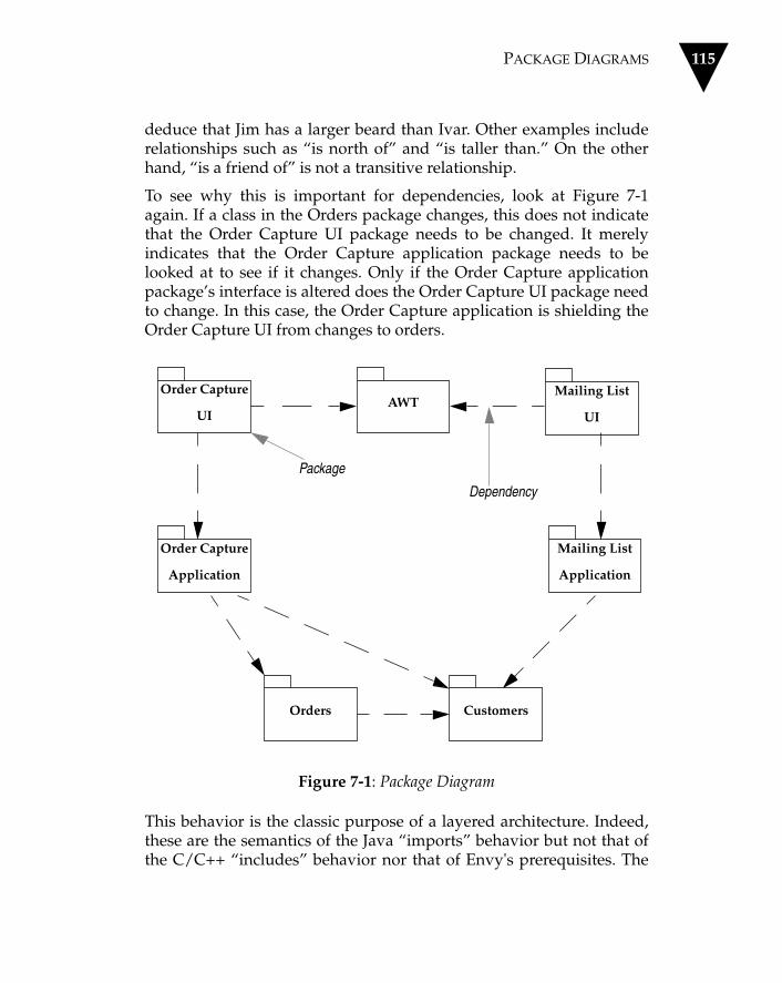
PACKAGE DIAGRAMS 115
deduce that Jim has a larger beard than Ivar. Other examples includerelationships such as “is north of” and “is taller than.” On the otherhand, “is a friend of” is not a transitive relationship.
To see why this is important for dependencies, look at Figure 7-1again. If a class in the Orders package changes, this does not indicatethat the Order Capture UI package needs to be changed. It merelyindicates that the Order Capture application package needs to belooked at to see if it changes. Only if the Order Capture applicationpackage’s interface is altered does the Order Capture UI package needto change. In this case, the Order Capture application is shielding theOrder Capture UI from changes to orders.
Figure 7-1: Package Diagram
This behavior is the classic purpose of a layered architecture. Indeed,these are the semantics of the Java “imports” behavior but not that ofthe C/C++ “includes” behavior nor that of Envy's prerequisites. The
Orders Customers
Mailing List
Application
Mailing List
UIAWT
Order Capture
UI
Order Capture
Application
Package
Dependency

116 CHAPTER 7 PACKAGE DIAGRAMS
C/C++ includes is transitive, which means that the Order Capture UIwould be dependent on the Orders package. A transitive dependencymakes it difficult to limit the scope of changes with compilation.
What does it mean to draw a dependency to a package that containssubpackages? Designers use different conventions. Some assume thatdrawing a dependency to a “containing” package gives visibility tothe contents of all contained packages and their contents. Others saythat you only see classes within the containing package, not classeswithin nested packages (that is, the view is opaque).
You should state which convention you are using within your projector make it clear by putting stereotypes on the packages. I suggest youuse the «transparent» stereotype to indicate that you can see intonested packages and use the «opaque» stereotype to indicate that youcan't. My convention here is that packages are transparent.
What do you see if you have a dependency into a package? Essentially,you see all public classes in the package and all of their public meth-ods. Under the visibility scheme of C++, this can lead to a problembecause you may want a class that contains methods that can be seenby other objects within the same package but not by objects thatbelong to other packages.
This is why Java has the package visibility. Obviously, this makes iteasy for Java. You can mark classes and operations with package visi-bility within C++. Even though that convention will not be enforcedby the compiler, it is still useful in design.
A useful technique here is to reduce the interface of the package fur-ther by exporting only a small subset of the operations associated withthe package’s classes. You can do this by giving all classes package vis-ibility so that they can only be seen by other classes in the same pack-age and by adding extra public classes for the public behavior. Theseextra classes, called Facades (Gamma et al. 1994), then delegate publicoperations to their shyer companions in the package.
Packages do not offer answers about how to reduce dependencies inyour system, but they do help you to see what the dependencies are—and you can only work to reduce dependencies when you can seethem. Package diagrams are a key tool for me in maintaining controlover a system's overall structure.

PACKAGE DIAGRAMS 117
Figure 7-2: Advanced Package Diagram
Sybase
Interface
DatabaseInterface
Orders Customers
Domain
{abstract}
QuantityMoneyDateRange
{global}
Oracle
InterfaceCommon
Mailing List
Application
Mailing List
UIAWT
Order Capture
UI
Order Capture
Application

118 CHAPTER 7 PACKAGE DIAGRAMS
Figure 7-2 is a more complex package diagram that contains additionalconstructs.
First, we see that I have added a Domain package that contains theorders and customers packages. This is useful because it means I candraw dependencies to and from the overall package, instead of manyseparate dependencies.
When you show a package's contents, you put the name of the pack-age in the “tab” and the contents inside the main box. These contentscan be a list of classes (such as in the Common package), another pack-age diagram (as in Domain), or a class diagram (not shown, but theidea should be obvious by now).
Most of the time, I find it sufficient to list the key classes, but some-times a further diagram is useful. In this case, I've shown that whilethe Order Capture application has a dependency to the entire Domainpackage, the Mailing List application is dependent only on the Cus-tomers package. Strictly speaking, simply listing the classes isn't pureUML (you should show the class icons), but this is one of the areas inwhich I would be inclined to bend the rules.
Figure 7-2 shows the Common package marked as {global}. Thismeans that all packages in the system have a dependency to Common.Obviously, you should use this construct sparingly, but commonclasses (such as Money) are used everywhere.
You can use generalization with packages. This means that the specificpackage must conform to the interface of the general package. This iscomparable to the specification perspective of subtyping within classdiagrams (see Chapter 4). Therefore, in accordance with Figure 7-2, theDatabase Broker can use either the Oracle Interface or the Sybase Inter-face. When generalization is used like this, the general package may bemarked as {abstract} to show that it merely defines an interface that isimplemented by a more specific package.
Generalization implies a dependency from the subtype to the super-type. (You don't need to show the extra dependency; the generaliza-tion itself is enough.) Putting abstract classes in a supertype package isa good way of breaking cycles in the dependency structure. In this sit-uation, the database interface packages are responsible for loading andsaving the domain objects in a database. They therefore need to know

PACKAGE DIAGRAMS 119
about the domain objects. However, the domain objects need to triggerthe loading and saving.
The generalization allows us to put the necessary triggering interface(various load and save operations) into the database interface package.These operations are then implemented by classes within the subtypepackages. We don't need a dependency between the database interfacepackage and the Oracle interface package, because at run time it willactually be the subtype package that gets called by the domain. But thedomain only thinks it is dealing with the (simpler) database interfacepackage. Polymorphism is just as useful for packages as it is withclasses.
As a rule of thumb, it is a good idea to remove cycles in the depen-dency structure. I'm not convinced that you can remove all cycles, butyou should certainly minimize them. If you do have them, try to con-tain them within a larger containing package. In practice, I have foundcases in which I have not been able to avoid cycles between domainpackages, but I do try to eliminate them from the interactions betweenthe domain and external interfaces. Package generalization is a keyelement in doing this.
In an existing system, dependencies can be inferred by looking at theclasses. This is a very useful task for a tool to perform. I find thishandy if I am trying to improve the structure of an existing system. Auseful early step is to divide the classes into packages and to analyzethe dependences among the packages. Then I refactor to reduce thedependencies.
When to Use Package Diagrams
Packages are a vital tool for large projects. Use them whenever a classdiagram that encompasses the whole system is no longer legible on asingle letter-size (or A4) sheet of paper.
You want to keep your dependencies to a minimum since this reducescoupling. However, the heuristics for this are not well understood.

120 CHAPTER 7 PACKAGE DIAGRAMS
Packages are particularly useful for testing. Although I do write sometests on a class by class basis, I prefer to do my unit testing on a pack-age by package basis. Each package should have one or more testclasses that test the behavior of the package.
Where to Find Out More
The original source for packages was Grady Booch (1994); he calledthem class categories. His treatment was very brief, however. The bestdiscussion I know of this subject is by Robert Martin (1995), whosebook gives several examples of using Booch and C++, with a lot ofattention paid to minimizing dependencies. You can also find valuableinformation in Wirfs-Brock 1990; the author refers to packages as sub-systems.

Chapter 8
State Diagrams
State diagrams are a familiar technique to describe the behavior of asystem. They describe all the possible states a particular object can getinto and how the object's state changes as a result of events that reachthe object. In most OO techniques, state diagrams are drawn for a sin-gle class to show the lifetime behavior of a single object.
There are many forms of state diagrams, each with slightly differentsemantics. The most popular one used in OO techniques is based onDavid Harel's statechart (Vol. 8). It was first used for OO methods byOMT and adopted by Grady Booch in his second edition (1994).
Figure 8-1 shows a UML state diagram for an order in the order pro-cessing system I introduced earlier in the book. The diagram indicatesthe various states of an order.
We begin at the start point and show an initial transition into theChecking state. This transition is labeled “/get first item.” The syntaxfor a transition label has three parts, all of which are optional: Event[Guard] / Action. In this case, we have only the action “get first item.”Once we perform that action, we enter the Checking state. This statehas an activity associated with it, indicated by a label with the syntaxdo/activity. In this case, the activity is called “check item.”
121

122 CHAPTER 8 STATE DIAGRAMS
Figure 8-1: State Diagram
Notice that I used the terms “action” for the transition and “activity”for the state. Although they are both processes, typically implementedby some method on Order, they are treated differently. Actions areassociated with transitions and are considered to be processes thatoccur quickly and are not interruptible. Activities are associated withstates and can take longer. An activity may be interrupted by someevent.
Note that the definition of “quickly” depends on the kind of systemyou are producing. Within a hard real-time system, “quickly” maymean within a few machine instructions; for regular information sys-tems, “quickly” might mean less than a few seconds.
When a transition has no event within its label, it means that the tran-sition occurs as soon as any activity associated with the given state iscompleted. In this case, that means as soon as we are done with theChecking. Three transitions come out of the Checking state. All threehave only guards on their label. A guard is a logical condition that will
Checking
do/checkitem
Dispatching
do/initiatedelivery
Waiting Delivered
[Not all items checked]
/get first item
Delivered
Item Received[some items not in stock]
[All items checked &&some items not in stock] Ite
m Received
[all item
s availa
ble]
[All items checked && all items available]
self-transition
transition
start
activity
State
/get next item
STATE DIAGRAMS 123
return only “true” or “false.” A guarded transition occurs only if theguard resolves to “true.”
Only one transition can be taken out of a given state, so we intend theguards to be mutually exclusive for any event. in Figure 8-1, weaddress three conditions.
1. If we have not checked all items, we get the next item and return to the Checking state to check it.
2. If we have checked all items and they were all in stock, we transi-tion to the Dispatching state.
3. If we have checked all items but not all of them were in stock, wetransition to the Waiting state.
I'll look at the Waiting state first. There are no activities for this state, sothe given order sits in this state waiting for an event. Both transitionsout of the Waiting state are labeled with the Item Received event. Thismeans that the order waits until it detects this event. At that point, itevaluates the guards on the transitions and makes the appropriatetransition (either to Dispatching or back to Waiting).
Within the Dispatching state, we have an activity that initiates a deliv-ery. There is also a single, unguarded transition triggered by the Deliv-ered event. This indicates that the transition will always occur whenthat event occurs. Note, however, that the transition does not occurwhen the activity completes; instead, once the “initiate delivery” activ-ity is finished, the given order remains in the Dispatching state untilthe Delivered event occurs.
The final thing to address is a transition named “cancelled.” We wantto be able to cancel an order at any point before it is delivered. Wecould do this by drawing separate transitions from each of the Check-ing, Waiting, and Dispatching states. A useful alternative is to create asuperstate of all three states and then draw a single transition fromthat. The substates simply inherit any transitions on the superstate.
Figures 8-2 and 8-3 show how these approaches reflect the same sys-tem behavior. Even with only three duplicated transitions, Figure 8-2looks rather cluttered. Figure 8-3 makes the whole picture muchclearer, and if changes are needed later, it is harder to forget the can-celled event.

124 CHAPTER 8 STATE DIAGRAMS
Figure 8-2: State Diagram Without Superstates
In the current examples, I have shown an activity within a state, indi-cated by text in the form do/activity. You can also indicate other thingswithin a state.
If a state responds to an event with an action that does not cause atransition, you can show this by putting text in the form eventName /actionName in the state box.
Checking
do/checkitem
Dispatching
do/initiatedelivery
Waiting
Delivered
cancelled
Item Received[some items not in stock]
[All items checked &&some items not in stock] Ite
m Received
[all item
s availa
ble]
[all items checked && all items available]
Cancelled
cancelled
[Not all items checked]/get next item

STATE DIAGRAMS 125
Figure 8-3: State Diagram with Superstates
There are also two special events, entry and exit. Any action that ismarked as linked to the entry event is executed whenever the givenstate is entered via a transition. The action associated with the exitevent is executed whenever the state is left via a transition. If you havea transition that goes back to the same state (this is called a self-transi-tion) with an action, the exit action would be executed first, then thetransition's action, and finally the entry action. If the state has an asso-ciated activity, as well, that activity is executed after the entry action.
Active
do/checkitem
Dispatching
do/initiatedelivery
Waiting
Delivered
Item Received[some items not in stock]
[All items checked &&some items not in stock] Ite
m Received
[all item
s availa
ble]
[all items checked && all items available]
Cancelled
[Not all items checked]
cancelled
Checking
Superstate name
/get next item

126 CHAPTER 8 STATE DIAGRAMS
Concurrent State Diagrams
In addition to states of an order that are based on the availability of theitems, there are also states that are based on payment authorization. Ifwe look at these states, we might see a state diagram like the one inFigure 8-4.
Here we begin by doing an authorization. The “check payment” activ-ity finishes by signaling that the payment is approved. If the paymentis OK, the given order waits in the Authorized state until the “deliver”event occurs. Otherwise, the order enters the Rejected state.
The Order object exhibits a combination of the behaviors shown in Fig-ures 8-1 and 8-2. The associated states and the Cancelled state dis-cussed earlier can be combined on a concurrent state diagram (seeFigure 8-5).
Figure 8-4: Payment Authorization
Authorizing
do/checkpayment
Authorized Rejected
Delivered
[payment OK]
[payment not OK]

STATE DIAGRAMS 127
Figure 8-5: Concurrent State Diagram
Note that in Figure 8-5, I left out details of the internal states.
The concurrent sections of the state diagram are places in which at anypoint, the given order is in two different states, one from each dia-gram. When the order leaves the concurrent states, it is only in a singlestate. We can see that an order starts off in both the Checking andAuthorizing states. If the “check payment” activity of the Authorizingstate completes successfully first, then the order will be in the Check-ing and Authorized states. If the “cancel” event occurs, then the orderwill be in only the Cancelled state.
Concurrent state diagrams are useful when a given object has sets ofindependent behaviors. Note, however, that you should not get toomany concurrent sets of behaviors occurring in a single object. If youhave several complicated concurrent state diagrams for an object, youshould consider splitting the object into separate objects.
Authorizing Authorized
Cancelled
Delivered
Rejected
Dispatching
Waiting
Checking
cancelled
end

128 CHAPTER 8 STATE DIAGRAMS
When to Use State Diagrams
State diagrams are good at describing the behavior of an object acrossseveral use cases. They are not very good at describing behavior thatinvolves a number of objects collaborating together. As such, it is use-ful to combine state diagrams with other techniques. For instance,interaction diagrams (see Chapter 6) are good at describing the behav-ior of several objects in a single use case, and activity diagrams (seeChapter 9) are good at showing the general sequence of actions forseveral objects and use cases.
Some people find state diagrams natural, but many find them unnatu-ral. Keep an eye on how people are working with them—it may be thatyour team does not find state diagrams useful to their way of working.That is not a big problem; as always, you should remember to use themix of techniques that works for you.
If you do use state diagrams, don't try to draw them for every class inthe system. Although this approach is often used by high-ceremonycompletists, it is almost always a waste of effort. Use state diagramsonly for those classes that exhibit interesting behavior, where buildingthe state diagram helps you understand what is going on. Many peo-ple find that UI and control objects have the kind of behavior that isuseful to depict with a state diagram.
Where to Find Out More
Both Grady Booch (1994) and Jim Rumbaugh (1991) have material onstate diagrams, although neither contains much more detail thanappears in this chapter. The most detailed treatment of statecharts is inCook and Daniels (1994), a book I strongly recommend if you often usestatecharts. The semantics they define are much more detailed than inother books. Although those semantics may not be entirely consistentwith UML semantics, the authors do go into detailed issues that youshould be aware of if you are using state diagrams. As a real-timebook, Douglass (1998) has a lot to say about state diagrams, includinginformation on how to implement them.

Chapter 9
Activity Diagrams
Activity diagrams are one of most unexpected parts of the UML.
Unlike most other techniques in the UML, the activity diagram doesn’thave clear origins in the previous works of the three amigos. The activ-ity diagram combines ideas from several techniques: the event dia-grams of Jim Odell, SDL state modeling techniques, and Petri nets.These diagrams are particularly useful in connection with workflowand in describing behavior that has a lot of parallel processing.
In Figure 9-1, which comes from the UML 1.0 documentation, the coresymbol is the activity. The interpretation of this term depends on theperspective from which you are drawing the diagram. In a conceptualdiagram, an activity is some task that needs to be done, whether by ahuman or a computer. In a specification-perspective diagram or animplementation-perspective diagram, an activity is a method on aclass.
Each activity can be followed by another activity. This is simplesequencing. For example, in Figure 9-1, the Put Coffee in Filter activityis followed by the Put Filter in Machine activity. So far, the activity dia-gram looks like a flowchart. We can explore the differences by lookingat the Find Beverage activity.
129

130 CHAPTER 9 ACTIVITY DIAGRAMS
Figure 9-1: Activity Diagram
Find Beverage
[no coffee]
Put Coffee in Filter
Add Water to Reservoir
Get Cups
Put Filter in Machine
Turn On Machine
Brew Coffee
Pour Coffee
Get Can of Cola
Drink Beverage
[found coffee]
^coffeePot.TurnOn
light goes out
[no cola]
[found cola]
Person
Activity
Guard Decision Activity
Synchronization Bar
End

ACTIVITY DIAGRAMS 131
Find Beverage has two triggers coming out of it. Each trigger has aguard, a logical expression that evaluates to “true” or “false” just as ona state diagram (see Chapter 8). In the case of Figure 8-1, the personwill follow the Find Beverage activity by thinking about coffee or cola.
We'll assume that we can find a bag of Peet’s New Guinea and godown the coffee route. This trigger leads to a synchronization bar,attached to which are three outgoing triggers. These triggers go to thePut Coffee in Filter, Add Water to Reservoir, and Get Cups activities,respectively.
The diagram says that these three activities can occur in parallel.Essentially, this means that their order is irrelevant. I could put coffeein the filter first, then add water to the reservoir, and then get the cups,or I could get the cups, then add the coffee to the filter—you get thepicture.
I can also do these activities by interleaving. I could get a cup, addsome water to the reservoir, get another cup, get some more water, andso forth. Or I could do some of this simultaneously: pour the water inwith one hand while I reach for a cup with another. Any of these is cor-rect, according to the diagram.
The activity diagram allows me to choose what order in which to dothings. In other words, it merely states the essential sequencing rules Ihave to follow. This is the key difference between an activity diagramand a flowchart. Flowcharts are normally limited to sequential pro-cesses; activity diagrams can handle parallel processes.
This is important for business modeling. Businesses often have unnec-essarily sequential processes. A technique like this that encouragesparallel behavior is valuable in these situations because it encouragespeople to move away from unnecessary sequences in their behaviorand to spot opportunities to do things in parallel. This can improve theefficiency and responsiveness of business processes.
Activity diagrams are also useful for concurrent programs since youcan graphically lay out what threads you have and when they need tosynchronize.

132 CHAPTER 9 ACTIVITY DIAGRAMS
When you get parallel behavior, you need to synchronize. We don’twant to turn on the coffee machine until we have put the filter in themachine and water in the reservoir. This is why we see the outboundtriggers from these activities coming together in a synchronization bar.A plain synchronization bar like this indicates that the outbound trig-ger occurs only when both inbound triggers have occurred. As we willsee later, these bars can be more complicated.
A further synchronization occurs later: The coffee has to be brewedand cups must be available before we can pour the coffee.
Now let’s move on to the other track.
In this case, we have a compound decision. The first decision is aboutcoffee, which governs the two triggers coming out of the Find Bever-age. If there is no coffee, we are faced with a second decision, this onebased on cola.
When we have decisions like this, we mark the second decision with adecision diamond. This allows us to describe nested decisions. We canhave any number of nested decisions.
The Drink activity has two triggers coming into it, which means that itis performed in either case. For the moment, you can think of this as anOR case (I do it if one trigger or the other occurs) and the synchroniza-tion bar as the AND case (I do it if one trigger and the other occurs).
Activity Diagrams for Use Cases
Figure 9-1 describes a method on the type Person. Activity diagramsare useful for describing complicated methods. They can also be usedelsewhere—for instance, to describe a use case.
Consider a use case for order processing.
When we receive an order, we check each line item on theorder to see if we have the goods in stock. If we do, we assignthe goods to the order. If this assignment sends the quantityof those goods in stock below the reorder level, we reorder thegoods. While we are doing this, we check to see if the paymentis OK. If the payment is OK and we have the goods in stock,

ACTIVITY DIAGRAMS 133
we dispatch the order. If the payment is OK but we don’t havethe goods, we leave the order waiting. If the payment isn’tOK, we cancel the order.
See Figure 9-2 for a visual representation of this use case.
This figure introduces a new construct to the activity diagram. Take alook at the incoming trigger associated with the Check Line Item activ-ity. It is marked with a *. This is a multiplicity marker (the samemarker used in class diagrams; see Chapter 4) to show that when wereceive an order, we have to carry out the Check Line Item activity foreach line item on the order. This means that the Receive Order activityis followed by one invocation of the Authorize Payment activity andmultiple invocations of the Check Line Item activity. All of these invo-cations occur in parallel.
This highlights the second source of parallelism in an activity diagram.You can get parallel activities through multiple transitions coming outof a synchronization bar; you can also get parallel activities when thesame activity is triggered through a multiple trigger. Whenever youhave a multiple trigger, you should indicate on the diagram what thebasis of the trigger is, as in this case with [for each item on].
When you see a multiple trigger, you usually see a synchronizationbar, farther down in the diagram, that brings the parallel threadstogether. In this case, we see this bar before the Dispatch Order activ-ity. The synchronization bar has a condition applied to it. Each time atrigger comes to the synchronization bar, the condition is tested. If thecondition is true, the outbound trigger occurs. (You can also useanother * to indicate the threads coming together. I prefer not to showa second * as it makes the diagram too confusing. I find that the syn-chronization condition makes things clear.)
Unlabeled synchronization bars work in the same way. The lack of acondition means that the default condition for synchronization bars isused. The default is that all incoming triggers have occurred. That'swhy there were no conditions on the bars in Figure 9-1.

134 CHAPTER 9 ACTIVITY DIAGRAMS
Figure 9-2: Receiving an Order
CheckLineItem
ReceiveOrder
CancelOrder
Assign toOrder
AuthorizePayment
DispatchOrder
ReorderItem
[failed]
[for each lineitem on order]
[succeeded] [in stock]
[need to reorder]
[stock assigned to all line items and
payment authorized]
*
Multiple Trigger
Synchronization Condition

ACTIVITY DIAGRAMS 135
An activity diagram need not have a defined end point. The end pointof an activity diagram is the point at which all the triggered activitieshave been run and there are no more left to do. On Figure 9-2, markingan explicit end point would not be helpful.
Figure 9-2 also has a dead end: the Reorder Item activity. After thisactivity is performed, nothing more happens. Dead ends are fine on anon-terminating activity diagram like this. Sometimes, they are obvi-ous, as for Reorder Item. At other times, they are not so obvious. Lookat the Check Line Item activity. It has only one outbound trigger,which has a condition. What happens if the given line item isn’t instock? Nothing—the thread just stops there.
In our example, we cannot dispatch an order until we get an incomingdelivery that replenishes the stock. This might be a separate use case.
When a supply delivery comes in, we look at the outstandingorders and decide which ones we can fill from this incomingsupply. We then assign each of these to its appropriate orders.Doing this may release those orders for dispatching. We putthe remaining goods into stock.
Figure 9-3 is an activity diagram that represents this use case.
This second use case shows how the order can wait to be dispatcheduntil we get another delivery.
When each of two use cases shows part of the whole picture, I find ituseful to draw a combined diagram, like the one in Figure 9-4. Thisdiagram shows the activity diagrams for both use cases superimposedon each other, so you can see how actions in one use case affect actionsin the other. Such an activity diagram has multiple start points, whichis perfectly fine as the activity diagram represents how the businessreacts to multiple external events.
I find this ability of activity diagrams to show behavior that spansmultiple use cases to be particularly helpful. Use cases give us slices ofinformation about a domain viewed from the outside; when we look atthe internal picture, we need to see the whole. Class diagrams (seeChapter 4) show us the whole picture of interconnected classes, andactivity diagrams do the same for behavior.

136 CHAPTER 9 ACTIVITY DIAGRAMS
Figure 9-3: Receiving Supply
ChooseOutstandingOrder Items
AddRemainder
to Stock
AssignGoods to
Order
ReceiveSupply
DispatchOrder
[for each chosenorder item]
[all outstanding order items filled]
[stock assigned to all line items and
payment authorized]
*

ACTIVITY DIAGRAMS 137
Figure 9-4: Receive Order and Receive Supply
ChooseOutstandingOrder Items
AddRemainder
to Stock
AssignGoods to
Order
CheckLineItem
ReceiveOrder
CancelOrder
ReceiveSupply
Assign toOrder
AuthorizePayment
DispatchOrder
ReorderItem
[failed]
[for each lineitem on order]
[succeeded][in stock]
[for each
order item]
[need to reorder]
[all outstanding order items filled]
[stock assigned to all line items
and payment
*
*
authorized]
chosen

138 CHAPTER 9 ACTIVITY DIAGRAMS
Swimlanes
Activity diagrams tell you what happens, but they do not tell you whodoes what. In programming, this means that the diagram does notconvey which class is responsible for each activity.
In domain modeling, this means that the diagram does not conveywhich people or departments are responsible for each activity. Oneway around this is to label each activity with the responsible class orhuman. This works, but does not offer the same clarity as interactiondiagrams (see Chapter 6) for showing communication among objects.
Swimlanes are a way around this.
To use swimlanes, you must arrange your activity diagrams into verti-cal zones separated by lines. Each zone represents the responsibilitiesof a particular class or, in the case of Figure 9-5, a particular depart-ment.
Swimlanes are good in that they combine the activity diagram’s depic-tion of logic with the interaction diagram’s depiction of responsibility.However, they can be difficult to draw on a complex diagram. I haveused non-linear zones on occasion, which is better than nothing.(Sometimes you have to stop trying to say too much in one diagram.)
Some people make sure to assign activities to objects when they drawan activity diagram. Others are happy to work with the activity dia-gram first, to get an overall sense of the behavior, and assign the activ-ities to objects later. I’ve seen people who assign immediately getemotional about those who defer assignment; they make unpleasantaccusations of drawing dataflow diagrams and not being object-ori-ented.
I confess I sometimes draw an activity diagram without assigningbehavior to objects until later. I find it useful to figure out one thing ata time. This is particularly true when I’m doing business modeling andencouraging a domain expert to think of new ways of doing things.That way works for me. Others prefer to assign behavior to objectsimmediately. You should do whatever you’re more comfortable doing.The important thing is to assign activities to classes before you aredone. Often, I use an interaction diagram (see Chapter 6).

ACTIVITY DIAGRAMS 139
Figure 9-5: Swimlanes
ChooseOutstandingOrder Items
AddRemainder
to Stock
AssignGoods to
Order
CheckLineItem
ReceiveOrder
CancelOrder
ReceiveSupply
Assign toOrder
AuthorizePayment
DispatchOrder
ReorderItem
Finance OrderProcessing
StockManager
[for each lineitem on order]*
[failed]
[succeeded]
[in stock]
[need to reorder]
[all outstanding order items filled]
[stock assignedto all line items
and paymentauthorized]
[for each
order item]* chosen
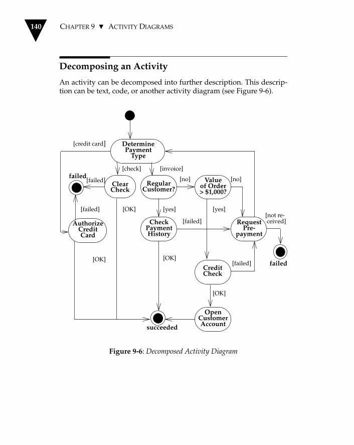
140 CHAPTER 9 ACTIVITY DIAGRAMS
Decomposing an Activity
An activity can be decomposed into further description. This descrip-tion can be text, code, or another activity diagram (see Figure 9-6).
Figure 9-6: Decomposed Activity Diagram
CreditCheck
CheckPaymentHistory
ClearCheck
AuthorizeCreditCard
DeterminePayment
Type
Valueof Order> $1,000?
OpenCustomerAccount
RegularCustomer?
RequestPre-
payment
[credit card]
failed
[failed]
[failed]
succeeded
[check] [invoice]
[OK]
[OK] [yes]
[no]
[OK]
[failed]
[yes]
[OK]
[failed]
[not re- ceived]
[no]
failed

ACTIVITY DIAGRAMS 141
When you draw an activity diagram as a decomposition of a higher-level activity, you must provide a single start point. You can, however,provide as many end points as there are outgoing triggers within thehigher-level activity. This allows the subsidiary diagram to return avalue that determines later triggering. For instance, Figure 9-6 showsthe Authorize Credit Card activity, which returns either “succeeded”or “failed.”
Figure 9-6 was drawn from a conceptual perspective, but it is not toodifficult to imagine drawing this as a graphical portrayal of program-ming code, just like a flowchart. I tend not to do this, for the same rea-son that I don’t draw flowcharts. It's usually easier to simply write thecode. If you find graphics useful here, you might try this, particularlyif you want to show multiple threads.
There are tools that can execute Odell’s event diagrams, a precursor toactivity diagrams. If you are using such a tool, you might find it valu-able for prototyping.
If you have a lot of logic to represent, activity diagrams can easilybecome too tangled. In this situation, a truth table can be a better rep-resentation.
When to Use Activity Diagrams
Like most behavioral modeling techniques, activity diagrams havedefinite strengths and weaknesses, so they are best used in combina-tion with other techniques.
The great strength of activity diagrams lies in the fact that they sup-port and encourage parallel behavior. This makes them a great tool forworkflow modeling and, in principle, for multi-threaded program-ming. Their great disadvantage is that they do not make the linksamong actions and objects very clear.
You can define what a relationship is by labeling an activity with anobject name or by using swimlanes (which divide an activity diagrambased on responsibilities), but this does not have the simple immedi-acy of interaction diagrams (see Chapter 6). For this reason, some peo-ple feel that using activity diagrams is not object-oriented and, thus,

142 CHAPTER 9 ACTIVITY DIAGRAMS
bad. I’ve found that the technique can be very useful, and I don’tthrow useful tools out of my toolkit.
I like to use activity diagrams in the following situations.
• Analyzing a use case. At this stage, I’m not interested in allocatingactions to objects; I just need to understand what actions need totake place and what the behavioral dependencies are. I allocatemethods to objects later and show those allocations with an inter-action diagram.
• Understanding workflow across many use cases. When use cases inter-act with each other, activity diagrams are a great tool for represent-ing and understanding that behavior. In situations that aredominated by workflow, I find them a superb tool.
• Dealing with multi-threaded applications. I have not used activity dia-grams for this purpose, but they are well-suited to it.
Don’t use activity diagrams in the following situations.
• Trying to see how objects collaborate. An interaction diagram is sim-pler and gives you a clearer picture of collaborations.
• Trying to see how an object behaves over its lifetime. Use a state dia-gram (see Chapter 8) for that.
Where to Find Out More
Activity diagrams are based on a number of workflow-orientedapproaches. The most immediate ancestor is Jim Odell’s event dia-gram, which you can find out more about in Martin and Odell’s “foun-dations” book (1994).

Chapter 10
Deployment Diagrams
A deployment diagram shows the physical relationships among soft-ware and hardware components in the delivered system. A deploy-ment diagram is a good place to show how components and objectsare routed and move around a distributed system.
Each node on a deployment diagram represents some kind of compu-tational unit—in most cases, a piece of hardware. The hardware maybe a simple device or sensor, or it could be a mainframe.
Figure 10-1 shows a PC connected to a UNIX server through TCP/IP.Connections among nodes show the communication paths over whichthe system will interact.
Components on a deployment diagram represent physical modules ofcode. In my practice, these correspond exactly to the packages on apackage diagram (see Chapter 7), so the deployment diagram showswhere each package is running on the system.
The dependencies among the components should be the same as thepackage dependencies. These dependencies show how componentscommunicate with other components. The direction of a given depen-dency indicates the knowledge in the communication.
143
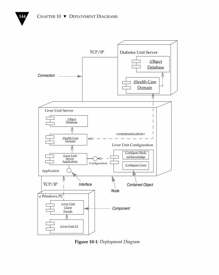
144 CHAPTER 10 DEPLOYMENT DIAGRAMS
Figure 10-1: Deployment Diagram
:ObjectDatabase
:Health CareDomain
Diabetes Unit ServerTCP/IP
:Configure Medi-cal Knowledge
:Configure Users
«communication»
Liver Unit Configuration
Liver Unit Server
Configuration
Application
:ObjectDatabase
:Health CareDomain
:Liver UnitServer
Application
TCP/IP
a Windows PC
:Liver UnitClientFacade
:Liver Unit UI
Connection
Interface
Component
Node
Contained Object

WHEN TO USE DEPLOYMENT DIAGRAMS 145
So in the diagram, the Liver Unit UI is dependent on the Liver UnitClient Facade since it calls specific methods on the facade. Althoughthe communication is two-way, in the sense that the Facade returnsdata, the Facade is not aware of who is calling it and is thus not depen-dent on the UI. In the communication between the two Health CareDomain components, both are aware that they are talking to anotherHealth Care Domain component, so the communication dependencyis two-way.
A component may have more than one interface, in which case youcan see which components communicate with each interface. On Fig-ure 9-1, the PC contains two components: the UI and the applicationfacade. The application facade talks to the application interface of theserver application. A separate configuration component runs only onthe server. The application communicates with its local Health CareDomain component, which may communicate with other Health CareDomain components on the network.
The use of multiple Health Care Domain components is hidden fromthe application. Each Health Care Domain component has a local data-base.
When to Use Deployment Diagrams
In practice, I haven’t seen this kind of a diagram used much. Most peo-ple do draw diagrams to show this kind of information, but they areinformal cartoons. On the whole, I don't have a problem with thatsince each system has its own physical characteristics that you want toemphasize. As we wrestle more and more with distributed systems,however, I'm sure we will require more formality as we understandbetter which issues need to be highlighted in deployment diagrams.

146 CHAPTER 10 DEPLOYMENT DIAGRAMS

Chapter 11
UML and Programming
So far, I have discussed a lot of notation. One large question looms:How does a programmer actually use the UML as part of the dailygrind of programming? I’ll answer this by talking about how I use theUML when I’m programming, even on a small scale. I won’t go into alot of detail, but I hope this will give you a sense of what you can dowith the UML.
Let’s imagine a computer system designed to pull together informa-tion about patients for a hospital.
Various health care professionals make observations about patients.This simple system will allow someone to get information about thoseobservations and add additional observations. As this is a short book, Iwill wave my arms about the database links and the UI and only con-sider the basic domain classes.
This is such a simple example that it has but a single use case, named“review and add patient observations.” We can elaborate on that witha few scenarios.
• Ask for the latest heart rate of a patient.• Ask for the blood group of a patient.
147

148 CHAPTER 11 UML AND PROGRAMMING
• Update a patient’s level of consciousness.• Update a patient’s heart rate. The system marks the rate as slow,
normal, or fast, according to the system’s built-in ranges.
My first step in the process is to come up with a conceptual model thatdescribes the concepts in this domain. At this stage, I’m not thinkingabout how the software is going to work, only about how to organizeconcepts in the minds of the doctors and nurses. I'll start with a modelbased on several analysis patterns from Fowler (1997): Observation,Quantity, Range, and Phenomenon with Range.
Patient Observation: Domain Model
Figure 11-1 shows the initial domain model for our system.
How do these concepts represent the information in the domain?
I’ll start with the simple concepts of Quantity, Unit, and Range. Quan-tity represents a dimensioned value, such as 6 feet—a quantity withamount of 6 and unit of feet. Units are simply those categories of mea-surement with which we want to deal. Range allows us to talk aboutranges as a single concept—for instance, a range of 4 feet to 6 feet isrepresented as a single Range object with an upper bound of 6 feet anda lower bound of 4 feet. In general, ranges can be expressed in terms ofanything that can be compared (using the operators <, >, <=, >=, and=), so the upper and lower bounds of a Range are both magnitudes.(Quantities are a kind of magnitude.)
Each observation made by a doctor or nurse is an instance of theObservation concept and is either a Measurement or a CategoryObservation. So a measurement of a height of 6 feet for Martin Fowlerwould be represented as an instance of Measurement. Associated withthis Measurement are the amount 6 feet, the Phenomenon Type“height,” and the Patient named Martin Fowler. Phenomenon Typesrepresent the things that can be measured: height, weight, heart rate,and so forth.

PATIENT OBSERVATION: DOMAIN MODEL 149
Figure 11-1: Patient Observation Domain Model
Measurement
amount:Quantity
Quantity
amount:Numberunit:Unit
Observation
Range
upper:Magnitudelower:Magnitude
Patient
CategoryObservation
isPresent:Boolean
Phenomenon
range:Range
Unit
PhenomenonType
0..1 *
1
*
1
*
*
1
measurement
category«dynamic»

150 CHAPTER 11 UML AND PROGRAMMING
An observation that Martin Fowler's blood type is O would be repre-sented as a Category Observation whose associated Phenomenon is“blood group O.” This Phenomenon is linked to the PhenomenonType “blood group.”
Figure 11-2 should make things a little clearer at this point.
Figure 11-2: Patient Observation Object Diagram
Figure 11-3 shows that we can make an Observation serve as both aMeasurement and a Category Observation by stating that a Measure-ment of “90 beats per minute” can also be a Category Observationwhose associated Phenomenon is “fast heart rate.”
At this stage, I have looked at only the representation of the concepts; Ihaven’t thought much about behavior. I don’t always do that, but itseems an appropriate starting point for a problem that is mainly aboutdealing with information.
For the moment, I’m still talking about patient observation concepts,just as I would be doing with a doctor or a nurse. (Indeed, that is whathappened in real life. The conceptual models were built by a couple ofdoctors and a nurse, with me helping.) To make the move to an object-oriented program, I have to decide how to deal with the conceptualpicture in terms of software. For this exercise, I have chosen the Javaprogramming language. (I had to get Java into this book somehow!)
height :Phenomenon
Type
blood group :Phenomenon
Type
blood group A : Phenomenon
blood group O : Phenomenon
a Measurementamount = 6 ft
a CategoryObservation
Martin Fowler :Patient
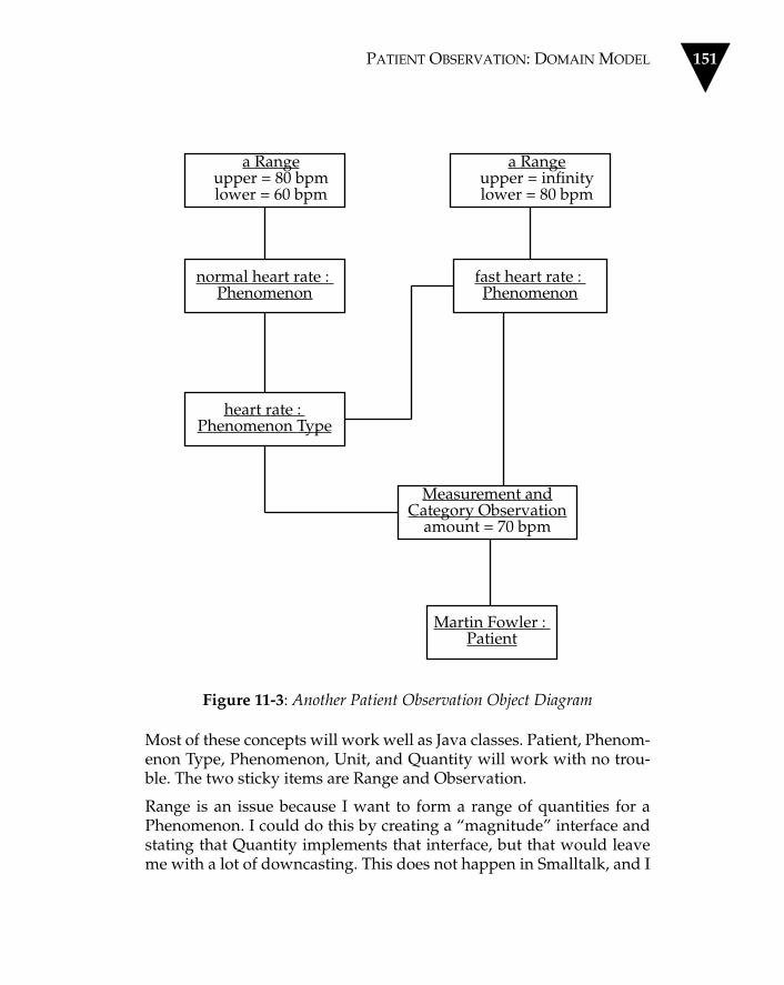
PATIENT OBSERVATION: DOMAIN MODEL 151
Figure 11-3: Another Patient Observation Object Diagram
Most of these concepts will work well as Java classes. Patient, Phenom-enon Type, Phenomenon, Unit, and Quantity will work with no trou-ble. The two sticky items are Range and Observation.
Range is an issue because I want to form a range of quantities for aPhenomenon. I could do this by creating a “magnitude” interface andstating that Quantity implements that interface, but that would leaveme with a lot of downcasting. This does not happen in Smalltalk, and I
normal heart rate : Phenomenon
fast heart rate : Phenomenon
heart rate : Phenomenon Type
a Rangeupper = infinitylower = 80 bpm
a Rangeupper = 80 bpmlower = 60 bpm
Martin Fowler : Patient
Measurement andCategory Observation
amount = 70 bpm

152 CHAPTER 11 UML AND PROGRAMMING
can use parameterized types in C++. For this exercise, I prefer to use aQuantityRange class that uses the Range pattern.
My problem with Observation is that an Observation can be both aCategory Observation and a Measurement at the same time (see Figure11-3). In Java, like most other programming languages, we have onlysingle classification. I decided to deal with this by allowing any Obser-vation to have an associated Phenomenon, which effectively lets theObservation class implement both the Observation and CategoryObservation concepts.
These decisions do not result in a perfect state of affairs, but they arethe kind of pragmatic imperfection that allows work to get done. Don’ttry to do software that exactly maps the conceptual perspective. Try,instead, to be faithful to the spirit of conceptual perspective but stillrealistic considering the tools you are using.
Patient Observation: Specification Model
Figure 11-4 reflects modifications I made to the domain model to takeinto account some of the factors associated with a target language.
The patient observation model is now at the specification perspective.It shows the class interfaces rather than the classes themselves. I mightkeep the conceptual model for another day but, more likely, I willwork only with the specification model from this point forward. I trynot to keep too many models around. My rule of thumb is that if I can-not keep a model up to date, it goes in the bin. (I know I’m lazy, too!)
Now let’s look at the behavior associated with our patient observationmodel.
The first scenario asks for the latest heart rate of the patient. The firstquestion is: Whose responsibility is it to handle this request? ThePatient seems the natural choice. The Patient needs to look at all itsobservations, determine which are measurements of the PhenomenonType “heart rate,” and find the latest value. To do this, I will have toadd a timepoint to Measurement. Because this can apply to otherobservations, as well, I’ll add it to Observation, too.

PATIENT OBSERVATION: SPECIFICATION MODEL 153
Figure 11-4: Patient Observation Specification Model
A similar responsibility exists for Phenomenon: Find the latest Cate-gory Observation that has a Phenomenon for the given PhenomenonType.
Figure 11-5 shows operations that I’ve added to Patient to reflect mythinking.
Don’t try too hard to come up with operations if they are not obviousjust yet. The most important thing to go for is a statement of responsi-bility. If you can cast that in the form of an operation, that’s fine; other-wise, a short phrase is useful in describing the responsibility.
Measurement
amount:Quantity
Observation
Patient
Phenomenon
range:QuantityRange
PhenomenonType 1 *
0..1
*
0..1 *
*
1

154 CHAPTER 11 UML AND PROGRAMMING
Figure 11-5: Patient Observation Operations
Updating the patient’s level of consciousness involves creating a newObservation of the appropriate Phenomenon. In doing that, the userwould usually like to pick a Phenomenon from a pop-up list of somekind. We can handle that by getting the Phenomenon objects associ-ated with a particular Phenomenon Type as this responsibility isimplied by the association between the two.
Measurement
amount: Quantity
Observation
Patient
Phenomenon
range:QuantityRange
PhenomenonType 1 *
0..1
*
0..1 *
*
1
timepoint
latestAmountOf (Phenomenon Type) : QuantityphenomenonOf (Phenomenon Type) : Phenomenon

MOVING TO CODE 155
In adding a measurement, we need to create a new Measurement.Some additional complication comes from the fact that the Measure-ment needs to look to see if there is a Phenomenon that can beassigned. Here the Measurement can ask its associated PhenomenonType if there is a Phenomenon to assign.
There is some collaboration among the objects here, which suggeststhat this is a good place for a sequence diagram (see Figure 11-6).
Do you have to draw all of these diagrams?
Not necessarily. Much depends on how well you can visualize what isgoing on and how easy it is to work in your programming language.In Smalltalk, it’s often just as easy to write the code as it is to thinkwith the diagrams. With C++, the diagrams are more useful.
The diagrams don’t have to be works of art. I usually sketch them outon a paper pad or a small whiteboard. I transfer them to a drawingtool (or CASE tool) only if I think it’s worth the effort of keeping themup to date because they help clarify the behavior of the classes. At thispoint in a project, I might also use CRC cards (see page 64) in additionto or instead of the diagrams I’ve been describing in this chapter.
Moving to Code
Now we can take a look at some of the code that implements the ideasI discussed in the previous sections. I'll begin with Phenomenon Typeand Phenomenon since they are quite closely linked.
The first thing to think about is the association between them: Shouldthe interface allow navigability in both directions? In this case, I thinkso because both directions will be valuable and they are closely linkedconcepts, in any case. Indeed, I am happy to implement the associationwith pointers in both directions, too. I shall make it an immutableassociation, however, as these are objects that are set up and then leftalone—they are not modified often, and when they are, we can createthem again.

156 CHAPTER 11 UML AND PROGRAMMING
Figure 11-6: Patient Observation Sequence Diagram
a Measurementheart rate :
Phenomenon Typeslow heart rate :
Phenomenonnormal heart rate :
Phenomenon
new
findPhenomenon()
includes (Quantity)
false
includes (Quantity)
true
normal heart rate

MOVING TO CODE 157
Some people have trouble with two–way links. I don’t find them trou-blesome if I ensure that one class takes the overall responsibility forkeeping the link up to date, assisted by a “friend” or helper method, asnecessary.
Let's look at some declarations.
public class PhenomenonType extends DomainObject {
public PhenomenonType(String name) {super(name);};
void friendPhenomenonAdd(Phenomenon newPhenomenon) {// RESTRICTED: only used by Phenomenon_phenomena.addElement(newPhenomenon);};
public void setPhenomena(String[] names) {for (int i = 0; i < names.length; i++)new Phenomenon(names[i], this);
};
public Enumeration phenomena() {return _phenomena.elements();};
private Vector _phenomena = new Vector();
private QuantityRange _validRange;
}
I use the convention of adding an underscore before all fields. It helpsme avoid getting my names confused.
public class Phenomenon extends DomainObject {
public Phenomenon(String name, PhenomenonType type) {super (name);_type = type;_type.friendPhenomenonAdd(this);};

158 CHAPTER 11 UML AND PROGRAMMING
public PhenomenonType phenomenonType() {return _type;};
private PhenomenonType _type;
private QuantityRange _range;
}
package observations;
public class DomainObject {
public DomainObject(String name) {_name = name;};
public DomainObject() {};
public String name() {return _name;};
public String toString() {return _name;};
protected String _name = "no name";
}
I’ve added a DomainObject class, which knows about names and willdo any other behavior that I want all of my domain classes to do.
I can now set up these objects with code along the lines of the follow-ing.
PhenomenonType sex =
new PhenomenonType(“gender”).persist();
String[] sexes = {“male”, “female”};
sex.setPhenomena(sexes);

MOVING TO CODE 159
The persist() operation stores the Phenomenon Type in a registryobject so that you can get it again later with a static get() method. I'llskip the details of that.
Next, I’ll put in the code to add observations to a patient. Here I don’twant all the associations to be two-way. I have the patient hang on to acollection of observations since the observations are used in the con-text of a patient.
public class Observation extends DomainObject {
public Observation(Phenomenon relevantPhenomenon,Patient patient, Date whenObserved) {_phenomenon = relevantPhenomenon;patient.observationsAdd(this);_whenObserved = whenObserved;
};
private Phenomenon _phenomenon;
private Date _whenObserved;
}
public class Patient extends DomainObject {
public Patient(String name) {super(name);};
void observationsAdd(Observation newObs) {_observations.addElement(newObs);};
private Vector _observations = new Vector();
}
With this I can create observations.
new Patient("Adams").persist();
new Observation(PhenomenonType.get(“gender”).
phenomenonNamed(“male”), Patient.get(“Adams”),new Date (96, 3, 1) );

160 CHAPTER 11 UML AND PROGRAMMING
class PhenomenonType {
public Phenomenon phenomenonNamed(String name) {Enumeration e = phenomena();while (e.hasMoreElements() ){Phenomenon each = (Phenomenon)e.nextElement();if (each.name().equals(name))return each;
};
return null;}
After creating observations, I need to be able to find the latest phenom-enon.
class Patient
public Phenomenon phenomenonOf(PhenomenonType phenomenonType){return (latestObservation(phenomenonType) ==null ? new NullPhenomenon() :latestObservation(phenomenonType).phenomenon() );
}
private ObservationlatestObservation(PhenomenonType value) {return latestObservationIn(observationsOf(value) ); }
private EnumerationobservationsOf(PhenomenonType value) {Vector result = new Vector();Enumeration e = observations();while (e.hasMoreElements() ){Observation each = (Observation) e.nextElement();if (each.phenomenonType() == value)result.addElement(each);
};return result.elements();}

MOVING TO CODE 161
private Observation latestObservationIn(Enumeration observationEnum) {if (!observationEnum.hasMoreElements() )return null;Observation result =(Observation)observationEnum.nextElement();if (!observationEnum.hasMoreElements() )return result;
do{Observation each =(Observation)observationEnum.nextElement();if (each.whenObserved().after(result.whenObserved() ) )result = each;
}
while (observationEnum.hasMoreElements() );
return result;}
class Observation
public PhenomenonType phenomenonType() {return _phenomenon.phenomenonType();}
There are several methods that combine to do this. You could draw adiagram to show this, but I tend not to bother. The way I decompose amethod has more to do with refactoring (see page 30) than it does withprior design.
We can now look at adding the behavior for measurements.
First, let’s see the definition of the Measurement class and its construc-tor.
public class Measurement extends Observation {
public Measurement(Quantity amount,PhenomenonType phenomenonType,Patient patient, Date whenObserved) {initialize (patient, whenObserved);
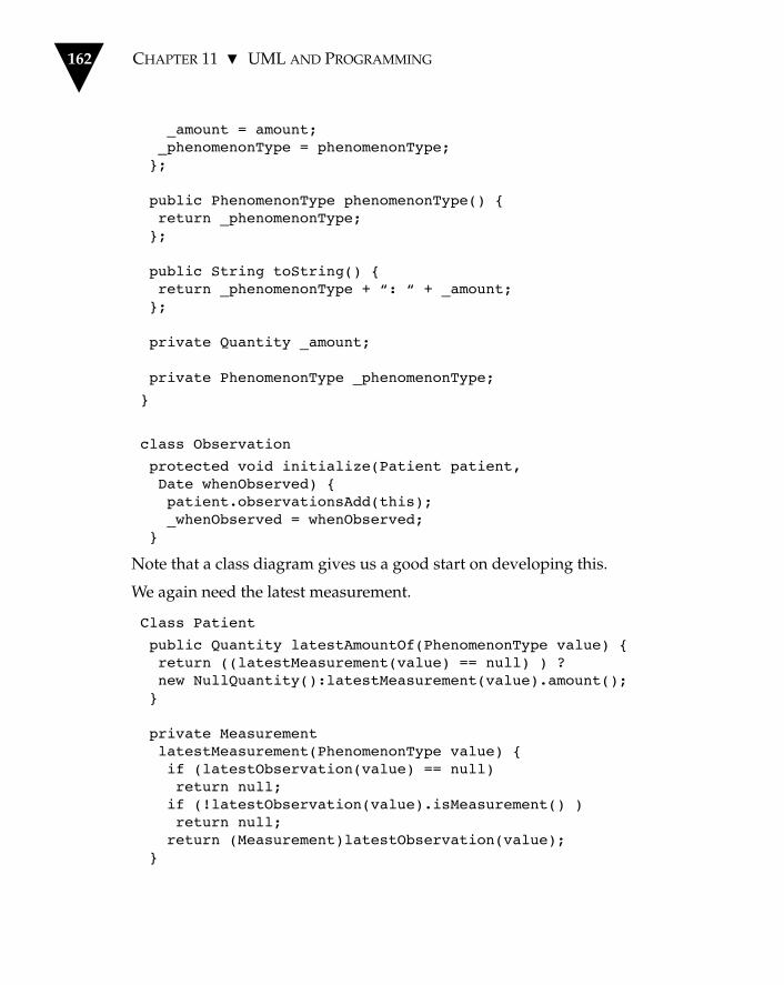
162 CHAPTER 11 UML AND PROGRAMMING
_amount = amount;_phenomenonType = phenomenonType;};
public PhenomenonType phenomenonType() {return _phenomenonType;};
public String toString() {return _phenomenonType + “: “ + _amount;};
private Quantity _amount;
private PhenomenonType _phenomenonType;
}
class Observation
protected void initialize(Patient patient,Date whenObserved) {patient.observationsAdd(this);_whenObserved = whenObserved;
}
Note that a class diagram gives us a good start on developing this.
We again need the latest measurement.
Class Patient
public Quantity latestAmountOf(PhenomenonType value) {return ((latestMeasurement(value) == null) ) ?new NullQuantity():latestMeasurement(value).amount();}
private MeasurementlatestMeasurement(PhenomenonType value) {if (latestObservation(value) == null)return null;if (!latestObservation(value).isMeasurement() )return null;return (Measurement)latestObservation(value);
}

MOVING TO CODE 163
In both of these cases, the class diagram suggests basic structure andwe add behavior to it to support more interesting queries.
At this stage, we could describe our position with the specification-perspective class diagram shown in Figure 11-7.
Take a look at how this diagram stresses interface over implementa-tion. I’ve modeled the role from Phenomenon Type to Phenomenon asa qualified role because that’s the primary interface on PhenomenonType. Similarly, I’ve shown Observation with a link to PhenomenonType because the interface exists there, even though the measurementis the only one with a direct pointer to Phenomenon.
Looking at this diagram, we can see that the only difference betweenMeasurement and Observation is that Measurement has a quantity. Wecould remove the Measurement class entirely from the specificationmodel by allowing any observation to have a (potentially null) quan-tity.
We could still have a separate Measurement class, which would haveamount and phenomenon type fields, but nobody outside the packagewould be aware of the class's existence. We would need to add Factorymethods (Gamma et al. 1994) either on Observation or on Patient toallow the appropriate class to be created.
I will leave that change as an exercise for the reader and move on toassigning a Phenomenon automatically for a Measurement.
Figure 11-7 illustrates the general process.
First, we need to add a method call to Measurement's constructor.
Class Measurement
public Measurement (Quantity amount,PhenomenonType phenomenonType,Patient patient, Date whenObserved)initialize (patient, whenObserved);_amount = amount;_phenomenonType = phenomenonType;_phenomenon = calculatePhenomenonFor(_amount);

164 CHAPTER 11 UML AND PROGRAMMING
Figure 11-7: Another Patient Observation Specification Model
This delegates the task to Phenomenon Type.
Class Measurement
public Phenomenon calculatePhenomenonFor(Quantity arg) {return _phenomenonType.phenomenonIncluding(arg);}
Measurement
amount:Quantity
Observation
Patient
Phenomenon
range:QuantityRange
PhenomenonType
0..1
0..1 **
1
timepoint
latestAmountOf (Phenomenon Type) : QuantityphenomenonOf (Phenomenon Type) : Phenomenon
1
*
String
0..1

MOVING TO CODE 165
This asks each phenomenon in turn.
Class PhenomenonType
public Phenomenon phenomenonIncluding (Quantity arg) {Enumeration e = phenomena();while (e.hasMoreElements()){Phenomenon each = (Phenomenon) e.nextElement();if (each.includes(arg))return each;
};
return null;}
Class Phenomenon
public boolean includes (Quantity arg) {return (_range == null ? false:_range.includes(arg));}
The code flows out well from the sequence diagram. In practice, I usu-ally use a sequence diagram to rough out the interaction and thenmake some changes as I code it. If the interaction is important, I willupdate the sequence chart as part of my documentation. If I think thesequence chart will not add much clarity to the code, I file the roughsequence chart in the circular filing cabinet.
This is a brief example of how to use the UML with a programminglanguage, but it should give you a good idea of the process. You don’thave to be on a high-ceremony project to find using bits of the UMLhandy. You don’t have to use all of it, just the bits you like.
Sketching out a design with a class diagram and an interaction dia-gram can help get your thoughts in order and make it easier to code. Ithink of these sketches as fast prototypes. You don’t have to hold on tothe diagrams later, but you may find it easier for yourself and others tounderstand the code if you do.
You don’t need a fancy and expensive CASE tool. A whiteboard and asimple drawing tool on your computer will do fine. Of course there areuseful CASE tools, and if you are involved in a larger project, youmight consider getting one.

166 CHAPTER 11 UML AND PROGRAMMING
If you do, compare it to the baseline of a simple drawing tool and aword processor (it’s amazing how much you can do with Visio andWord, for instance). If the tool has code generation, look carefully athow it generates code. Code generation forces the CASE tool to take avery particular interpretation of the diagrams, which will affect theway you draw the diagrams and what the diagrams mean.
I’ve done medium-size projects in which we started with a CASE tooland ended up throwing it away. Don't be afraid to do that if you findthe tool isn’t helping.
You can find more about this example via my Web site (<our-world.compuserver.com/homepages/Martin_Fowler>). The versionof the example at the site goes more deeply into some of the layeringissues involved in getting this model to a user interface.

Appendix A
Techniques and Their Uses
Technique Purpose
Activity Diagram Shows behavior with control structure. Can show many objects over many uses, many objects in single use case, or implementation of method. Encourages parallel behavior.
Class Diagram Shows static structure of concepts, types, and classes. Concepts show how users think about the world; types show interfaces of software components; classes show imple-mentation of software components.
CRC Cards Helps get to essence of class’s purpose. Good for exploring how to implement use case. Use if getting bogged down with details or if learning object approach to design.
DeploymentDiagram
Shows physical layout of components on hardware nodes.
167

168 APPENDIX A TECHNIQUES AND THEIR USES
Design by Contract Provides rigorous definition of operation’s purpose and class’s legal state. Encode these in class to enhance debugging.
Interaction Diagram Shows how several objects collaborate in single use case.
Package Diagram Shows groups of classes and dependencies among them.
Patterns Offers useful bits of analysis, design, and coding techniques. Good examples to learn from; starting point for designs.
Refactoring Helps in making changes to working pro-gram to improve structure. Use when code is getting in the way of good design.
State Diagram Shows how single object behaves across many use cases.
Use Case Elicits requirements from users in meaning-ful chunks. Construction planning is built around delivering some use cases in each iteration. Basis for system testing.
Technique Purpose

Bibliography
Kent Beck: Smalltalk Best Practice Patterns. Prentice Hall, 1996.
Kent Beck: “Make It Run, Make It Right: Design Through Refactor-ing.” The Smalltalk Report, Vol. 6, No. 4, pp. 19-24, SIGS Publications,January 1997.
Kent Beck and Ward Cunningham: “A Laboratory For TeachingObject-Oriented Thinking.” Proceedings of OOPSLA 89. SIGPLANNotices, Vol. 24, No. 10, pp. 1-6. See <http://c2.com/doc/oopsla89/paper.html>
Grady Booch: Object-Oriented Analysis and Design with Applications,Second Edition. Addison-Wesley, 1994.
Grady Booch: Object Solutions: Managing the Object-Oriented Project.Addison-Wesley, 1996.
Frank Buschmann, Regine Meunier, Hans Rohnert, Peter Sommerlad,and Michael Stal: Pattern-Oriented Software Architecture: A System ofPatterns. John Wiley & Sons, 1996.
Peter Coad and Jill Nicola: Object-Oriented Programming. Yourdon,1993.
Peter Coad, David North, and Mark Mayfield: Object Models: Strategies,Patterns and Applications. Prentice Hall, 1995.
Peter Coad and Edward Yourdon: Object-Oriented Analysis. Yourdon,1991.
Peter Coad and Edward Yourdon: Object-Oriented Design. Yourdon,1991.
Alistair Cockburn: Surviving Object-Oriented Projects. Addison-Wesley,1998.
173

174 BIBLIOGRAPHY
Steve Cook and John Daniels: Designing Object Systems: Object-OrientedModeling with Syntropy. Prentice Hall, 1994.
James Coplien: “A Generative Development Process PatternLanguage.” In Coplien and Schmidt, 1995, pp. 183-237.
James O. Coplien and Douglas C. Schmidt, eds.: Pattern Languages ofProgram Design [PLoPD1]. Addison-Wesley, 1995.
Ward Cunningham: “EPISODES: A Pattern Language of CompetitiveDevelopment.” In Vlissides et al. 1996, pp. 371-388.
Bruce Powel Douglass: Real-Time UML. Addison-Wesley, 1998.
Martin Fowler: Analysis Patterns: Reusable Object Models. Addison-Wesley, 1997.
Erich Gamma, Richard Helm, Ralph Johnson, and John Vlissides[Gang of Four]: Design Patterns: Elements of Reusable Object-OrientedSoftware. Addison-Wesley, 1995.
Adele Goldberg and Kenneth S. Rubin: Succeeding With Objects:Decision Frameworks for Project Management. Addison-Wesley, 1995.
Ian Graham: Object-Oriented Methods, Second Edition. Addison-Wesley,1994.
David Harel: “Statecharts: A Visual Formalism for Complex Systems.”In Science of Computer Programming, Vol. 8, 1987.
Ivar Jacobson, Magnus Christerson, Patrik Jonsson, and GunnarÖvergaard: Object-Oriented Software Engineering: A Use Case DrivenApproach. Addison-Wesley, 1992.
Ivar Jacobson, Maria Ericsson, and Agneta Jacobson: The ObjectAdvantage: Business Process Reengineering with Object Technology.Addison-Wesley, 1995.
Andrew Koenig and Barbara Moo: Ruminations on C++: A Decade ofProgramming Insight and Experience. Addison-Wesley, 1997.
Craig Larman: Applying UML and Patterns. Prentice Hall, 1998.
James Martin and James J. Odell: Object-Oriented Methods: A Founda-tion (UML Edition). Prentice Hall, 1998.

BIBLIOGRAPHY 175
James Martin and James J. Odell: Object-Oriented Methods: PragmaticConsiderations. Prentice Hall, 1996.
Robert Cecil Martin: Designing Object-Oriented C++ Applications: Usingthe Booch Method. Prentice Hall, 1995.
Steve McConnell: Rapid Development: Taming Wild Software Schedules.Microsoft Press, 1996.
Bertrand Meyer: Object-Oriented Software Construction. Prentice Hall,1997.
William F. Opdyke: Refactoring Object-Oriented Frameworks. Ph.D.Thesis, University of Illinois at Urbana-Champaign, 1992. See <ftp://st.cs.uiuc.edu/pub/papers/refactoring/opdyke-thesis.ps.Z>
James Rumbaugh: OMT Insights. SIGS Books, 1996.
James Rumbaugh, Michael Blaha, William Premerlani, Frederick Eddy,and William Lorenzen: Object-Oriented Modeling and Design. PrenticeHall, 1991.
Sally Shlaer and Stephen J. Mellor: Object Lifecycles: Modeling the Worldin States. Yourdon, 1991.
Sally Shlaer and Stephen J. Mellor: Object-Oriented Systems Analysis:Modeling the World in Data. Yourdon, 1989.
Sally Shlaer and Stephen J. Mellor: “Recursive Design of an Applica-tion Independent Architecture.” IEEE Software, Vol. 14, No. 1, 1997.
John M. Vlissides, James O. Coplien, and Norman L. Kerth, eds.:Pattern Languages of Program Design 2 [PLoPD2]. Addison-Wesley, 1996.
Kim Walden and Jean-Marc Nerson: Seamless Object-Oriented SoftwareArchitecture: Analysis and Design of Reliable Systems. Prentice Hall, 1995.
Rebecca Wirfs-Brock, Brian Wilkerson, and Lauren Wiener: DesigningObject-Oriented Software. Prentice Hall, 1990.

176 BIBLIOGRAPHY

INDEX 177
Index
Aabstract class
compared to interface 88notation 85
Abstract constraint 85action 122activations 106activity
decomposing 140on activity diagram 129on state diagram 122
activity diagrams 10, 20, 33, 35, 112, 128,167
defined 129examples 130, 134, 136, 137, 139, 140when to use 141
actordefined 46relationship with use cases 47
aggregationdefined 80example 81
analysis patternsdefined 38example 38Historic Mapping 95Keyed Mapping 93Observation 148Phenomenon with Range 148Quantity 148Range 99, 148, 152Role Models 80Scenario 38
architectural risk 27
assertiondefined 70role in subclassing 72
association 53as responsibility 58bi-directional 62defined 56naming 62navigability 60roles 57uni-directional 62
association classdefined 93example 93promoting to full class 94subtleties 95
association role 172asynchronous message 107attribute
defined 63notation 63
BBag constraint 90baseline architecture, components 25Beck, Kent 3, 29, 32, 40, 42, 64, 66, 173bi-directional association 62Bind stereotype 98Booch, Grady xv, xvii, 1, 3, 4, 11, 41, 57,
59, 120, 121, 128, 173See also Three amigos
bound element 97Brandt, John 32Brooks, Fred 29Buschmann, Frank 40, 105, 112, 173

178 INDEX
Ccardinality 59ceremony 15class diagrams 8, 9, 10, 19, 23, 33, 34, 35,
36, 118, 135, 162, 163, 167cardinality notations 59defined 53examples 37, 38, 54, 61, 78, 79, 83, 84,
86, 87, 92, 93, 94, 95, 96, 97, 98, 149,153, 154, 164
perspectives 55terminology 57when to use 73
classification 91defined 77types 77, 79
Class–Responsibility–Collaboration(CRC) cards
See CRC cardsclass scope 171Coad, Peter 2, 57, 59, 80, 173Cockburn, Alistair 41, 51, 173code examples (Java) 58, 60, 92, 96, 97,
157, 158, 159, 160, 161, 162, 163, 164,165
collaboration diagramcomparing to sequence diagram 111defined 108examples 110, 111
collaboration role 172commitment schedule 28Complete constraint 78, 171component 143Composite pattern 82composition
defined 80, 171notation 81, 82
conceptual perspectiveactivities 129associations 57attributes 63defined 55derived associations 84derived attributes 84example 149
generalization 68operations 64qualified associations 92, 93when to use 74
concurrent state diagramdefined 126example 127
condition 105connection 143constraints 69
abstract 85bag 90complete 78, 171dag 90frozen 90, 171global 118hierarchy 90mandatory 171ordered 90read only 90
construction phaseand UML 33defined 15description 29
Cook, Steve 55, 73, 74, 128, 173Coplien, James 42, 174CRC cards 3, 8, 34, 74, 155, 167
defined 64example 65using with use cases 66when to use 66
Cunningham, Ward 3, 26, 34, 39, 42, 64,66, 173, 174
DDag constraint 90Daniels, John 55, 73, 74, 128, 173deletion 108dependency
defined 114on class diagrams 87on deployment diagrams 143

INDEX 179
deployment diagrams 23, 34, 167defined 143example 144when to use 145
derived associationdefined 82example 83
derived attributedefined 82example 83
Design by Contract 70, 168defined 70when to use 72
design model 19design patterns
Composite 82defined 37example 37Facade 116Proxy 37
discriminator 77domain model
activity diagrams 138building 20, 21defined 19guidelines 21team 21using with use cases 20
Douglass, Bruce Powel 11, 128, 173dynamic classification
defined 79example 79
Eelaboration phase
building domain model 18defined 15description 16discovering use cases 18, 44, 51finishing 26risk categories 17
entry event 125Episodes pattern 26event diagrams 141, 142
exceptiondefined 71
exit event 125extends relationship
defined 48example 45when to use 50
FFacade pattern 116Factory methods 163field 63Fowler, Martin 35, 38, 40, 69, 79, 93, 95,
99, 148, 174friend 101frozen 90Frozen constraint 90, 171functional decomposition 113
GGang of Four 35, 37, 40, 55, 69, 82, 116,
163, 174generalization 91
defined 68using with packages 118
getting method 67Global constraint 118Goldberg, Adele 41, 174Graham, Ian 41, 51, 174guard
on activity diagram 131on state diagram 122
HHadfield, Tom xvii, 7Harel, David 121, 174Hierarchy constraint 90Historic Mapping pattern 95History stereotype 95, 96

180 INDEX
Iimplementation class 170implementation perspective
activities 129associations 60attributes 63defined 56derived associations 84derived attributes 84generalization 68operations 64qualified associations 92, 93refinement 86subclassing 86when to use 74
inception phasedefined 15description 16
Information Engineering 113interaction diagrams 8, 10, 20, 23, 34, 35,
66, 128, 138, 141, 142, 168defined 103examples 104, 110, 111, 156types 103when to use 112
interfacecompared to abstract class 88compared to Type stereotype 170defined 85
Interface stereotype 86invariant 70
defined 71similarity to assertion 70
ISE 73iteration
assigning use cases 28determining length 27determining number 28elements 15incremental nature 30iterative nature 30
iteration marker 105, 172iterative development 8
defined 14when to use 41
JJacobson, Ivar xv, xvii, 1, 3, 4, 11, 42, 43,
45, 51, 57, 59, 76, 105, 174See also Three amigos
Johnson, Ralph 32, 174See also Gang of Four
KKeyed Mapping pattern 93Koenig, Andrew 98, 174
LLarman, Craig 11, 174lifeline 105lollipop notation 88Loomis, Mary 4
MMandatory constraint 171Martin, James 3, 9, 11, 59, 69, 74, 142, 174Martin, Robert 120, 174Mellor, Steve 2, 57, 59, 175mentoring 24meta-model
defined 5extract from UML 1.0 6
method 67Meyer, Bertrand 70, 73, 174modeling language 1modifier 67multiple classification
defined 77example 78
multiple trigger 133multiplicity
defined 57on activity diagrams 133
multi-valued role 89

INDEX 181
Nnavigability
defined 60examples 61types 62
Nerson, Jean-Marc 73, 175node 143notation 5
Oobject diagram, examples 150, 151Object Management Group (OMG) xvi-
ii, 1, 3, 4, 6Object Modeling Technique (OMT)
See OMTObjectory 2, 4, 14, 19, 35, 41, 43observable state 67Observation pattern 148Odell, Jim xvii, xviii, 3, 4, 9, 11, 57, 59, 69,
74, 77, 84, 129, 141, 142, 174OMT 1, 3, 84, 121Opaque stereotype 116Opdyke, William 32, 175operation
defined 63, 67notation 64
optimization 40Ordered constraint 90
Ppackage 114package diagrams 10, 23, 34, 143, 168
defined 114examples 115, 117when to use 119
package visibility 101, 116parameterized class
defined 96example 97
patterns 8, 10, 12, 35, 168defined 36See also Analysis patterns
See also Design patternswhen to use 39
perspective, types 55Petri nets 129Phenomenon with Range pattern 148plan
adding to during iterative develop-ment 33
building 26political risk
dealing with 25defined 17
post-condition 70pre-condition 71private visibility
in C++ 100in Smalltalk 100
processdefined 1overview 14phases 15
protected visibilityin C++ 100in Java 101
prototyping 22, 141Proxy pattern 37public visibility
in C++ 100in Java 101in Smalltalk 100
Qqualified association
defined 91example 92
Quantity pattern 148query 67
RRange pattern 99, 148, 152Rational Unified Process 2, 13, 14, 19, 35,
42Rational Software 3, 4, 42

182 INDEX
Read Only constraint 90realization 50Recursive Design 2refactoring 30, 161, 168
defined 31principles 31when to use 32
Refactory 32reference object 88refinement 88
defined 86requirements risk
dealing with 17defined 17
responsibility 65Responsibility-Driven Design 3return 105, 172risk
categories 17dealing with 17, 22, 23, 25
Roberts, Don 32role 57, 172Role Models pattern 80Rubin, Kenneth S. 41, 174Rumbaugh, Jim xv, xvii, 1, 3, 4, 11, 57,
59, 80, 121, 128, 175See also Three amigos
Sscenario 50Scenario pattern 38schedule risk 27SDL 129self-delegation
consequences 108defined 105
self-transition 125sequence diagram 165
comparing to collaboration diagram111
defined 104examples 104, 107, 109, 156
setting method 67Shlaer, Sally 2, 57, 59, 175Siemens 112
single classification 77skills risk
dealing with 23defined 17
source 57specification perspective
activities 129associations 58attributes 63defined 55derived associations 84derived attributes 84examples 153, 154, 164generalization 68operations 63qualified associations 92, 93refinement 86subclassing 86subtyping 118when to use 74
state diagrams 20, 35, 112, 142, 168defined 121examples 122, 124, 125, 126when to use 128
statechart 121static classification 79stereotype
as extension mechanism 9defined 76notation 76
stereotypesbind 98history 95, 96interface 86opaque 116transparent 116type 86
STL 99subclassing 69, 72, 85, 88substitutability
and assertions 72defined 68
subtype 53subtyping 69, 98superstate 123, 125

INDEX 183
swimlanedefined 138examples 139
synchronization bar 131system interactions 44
Ttarget 57technological risk
dealing with 22defined