uiy 4, zo1 - Board of Commissioners of Public Utilities
268
newfoundiand #abrador r o a nalcor energy company ~ uiy 4, zo1~ Board of Commissioners of Public Utilities P rince Charles Building 120 Torbay Road, P.O. Box 21040 St. John's, NL A1A 5B2 Attention: Ms. Cheryl Blundon Director of Corporate Services &Board Secretary Dear Ms. Blundon: Nydro Place. 500 Columbus Drive. P .O. Box 12400. St. john`s. NL C~n~d~ AFB 4K7 t . 749.737.1440 ~.74R.737.18U0 w ww.nEh.nl.ca Re: A Report by Newfoundland and Labrador Hydro (Hydro) pursuant to Order No. P.U. 2 2(2016) regarding the refurbishment of the gas generator engines at the Hardwoods Gas Turbine Plant and the Stephenville Gas Turbine Plant —Updated Report E nclosed please find the original plus 9 copies of Hydro's updated report on the failure analysis, i ncluding recommendations for long-term reliability. Should you have any questions, please contact the undersigned. Yours truly, NEWFOUNDLAND AND LABRADOR HYDRO M ichael Ladha Legal Counsel &Assistant Corporate Secretary TLP/bs cc: Gerard Hayes —Newfoundland Power Dennis Browne, Q.C. —Consumer Advocate Paul Coxworthy—Stewart McKelvey Stirling Scales Thomas J. O'Reilly, Q.C. —Cox &Palmer Sheryl Nisenbaum — Praxair Canada Inc. ecc: Larry Bartlett—Teck Resources Ltd.
-
Upload
khangminh22 -
Category
Documents
-
view
0 -
download
0
Transcript of uiy 4, zo1 - Board of Commissioners of Public Utilities

newfoundiand #abrador
roa nalcor energy company
~uiy 4, zo1~
Board of Commissioners of Public UtilitiesPrince Charles Building120 Torbay Road, P.O. Box 21040St. John's, NL A1A 5B2
Attention: Ms. Cheryl BlundonDirector of Corporate Services &Board Secretary
Dear Ms. Blundon:
Nydro Place. 500 Columbus Drive.
P.O. Box 12400. St. john`s. NL
C~n~d~ AFB 4K7
t. 749.737.1440 ~.74R.737.18U0
www.nEh.nl.ca
Re: A Report by Newfoundland and Labrador Hydro (Hydro) pursuant to Order No. P.U.22(2016) regarding the refurbishment of the gas generator engines at the HardwoodsGas Turbine Plant and the Stephenville Gas Turbine Plant —Updated Report
Enclosed please find the original plus 9 copies of Hydro's updated report on the failure analysis,including recommendations for long-term reliability.
Should you have any questions, please contact the undersigned.
Yours truly,
NEWFOUNDLAND AND LABRADOR HYDRO
Michael LadhaLegal Counsel &Assistant Corporate Secretary
TLP/bs
cc: Gerard Hayes —Newfoundland Power Dennis Browne, Q.C. —Consumer AdvocatePaul Coxworthy—Stewart McKelvey Stirling Scales Thomas J. O'Reilly, Q.C. —Cox &Palmer
Sheryl Nisenbaum — Praxair Canada Inc.
ecc: Larry Bartlett—Teck Resources Ltd.

Gas Turbine Failure Analysis Recommended Actions
Implementation Update
July 4, 2017
A Report to the Board of Commissioners of Public Utilities

Gas Turbine Failure Analysis Recommendations – Implementation Update
Newfoundland and Labrador Hydro i
Executive Summary 1
During the winter of 2016, in-service engine failures occurred at Newfoundland and Labrador 2
Hydro’s (Hydro) Stephenville and Hardwoods gas turbine facilities. On February 8, Hardwoods 3
End A suffered a combustion can failure. On March 26, Stephenville End A suffered a low 4
pressure compressor number 2 bearing failure. In both cases, damage was extensive and the 5
units required refurbishment. 6
7
A failure analysis was completed for each engine failure to determine the root cause(s) and 8
through the process of investigation and analysis a number of potential causes were identified, 9
as well as a number of recommendations for improvement. In addition, a consultant, 10
Performance Improvements Limited (PI), was engaged to review Hydro’s operation and 11
maintenance practices and provide recommendations for improvement of these practices to 12
ensure reliable operation into the future. The final report by PI has now been received, which 13
includes their final recommendations related to the aspects of operation, monitoring, control 14
and maintenance of the gas turbines. 15
16
This report provides a further update on the progress of implementation of the 17
recommendations arising from the root cause analyses and from PI’s review, as committed to in 18
the Gas Turbine Failure Analysis Recommended Actions Implementation Update submitted to 19
the Board of Commissioners of Public Utilities (the Board) on April 17, 2017. 20

Gas Turbine Failure Analysis Recommendations – Implementation Update
Newfoundland and Labrador Hydro 1
Table of Contents
Executive Summary .................................................................................................................................. i
1.0 Background ....................................................................................................................................... 2 2.0 Failure Analysis Recommendations .................................................................................................. 2 3.0 Performance Improvements Limited Operational and Maintenance Review ................................. 4
3.1 Vibration Monitoring ................................................................................................................. 4 3.2 Lube Oil System .......................................................................................................................... 4 3.3 Fuel system ................................................................................................................................ 5 3.4 Manual Shut Down and Trip ...................................................................................................... 6
3.5 Fire Protection ........................................................................................................................... 6 3.6 Mechanical Aspects ................................................................................................................... 7
4.0 Operational Improvement ................................................................................................................ 7 4.1 Vibration Monitoring ................................................................................................................. 7
4.1.1 Vibration monitoring location ............................................................................................. 8 4.1.2 Vibration settings ................................................................................................................ 8
4.2 Lube Oil System .......................................................................................................................... 8 4.2.1 Lubricating oil ...................................................................................................................... 9 4.2.2 Lube oil sampling and analysis ............................................................................................ 9
4.2.3 Lube oil filtration ............................................................................................................... 10 4.2.4 Lube oil heating ................................................................................................................. 10 4.2.5 Lube oil tank modifications ............................................................................................... 11 4.2.6 Magnetic chip detectors .................................................................................................... 11
4.3 Borescope Inspections ............................................................................................................. 11 4.4 Exhaust Gas Temperature Spread ........................................................................................... 11 4.5 Fuel Systems ............................................................................................................................ 12 4.6 Acceleration/deceleration Curves ........................................................................................... 14
4.7 Emergency Stop Pushbuttons .................................................................................................. 14 4.8 Fire Protection ......................................................................................................................... 14 4.9 Trip String ................................................................................................................................. 15 4.10 Mechanical Aspect - Bellows .................................................................................................. 15
5.0 Planned Maintenance Review ........................................................................................................ 16
5.1 Shorter Term Improvements ................................................................................................... 16 5.2 Longer Term Improvements .................................................................................................... 17
6.0 Implementation Status Summary .................................................................................................. 18 7.0 Conclusion ..................................................................................................................................... 20
Appendix A - PI report

Gas Turbine Failure Analysis Recommendations– Implementation Update
1.0 Background 1
During the winter of 2016, in-service engine failures occurred at Newfoundland and Labrador 2
Hydro’s (Hydro) Stephenville and Hardwoods gas turbine facilities. Both engines were shipped 3
to Alba Power Limited (Alba Power) for detailed inspection and refurbishment. In addition to 4
this work, analysis was carried out to determine the root cause(s) of the failures, and 5
recommendations were investigated to improve reliability of the two generation plants. 6
7
This report is the further update committed in the update report submitted to the Board on 8
April 17, 2017. This report provides an update of continued progress of the implementation of 9
recommendations resulting from the root cause analyses of the engine failures. 10
11
Through AMEC Foster Wheeler, Hydro engaged consultant Performance Improvements Limited 12
(PI), with expertise in gas turbines, to oversee the failure analysis process for the Stephenville 13
engine and expanded the engagement with this gas turbine expert to review Hydro’s 14
operational and maintenance practices with the aim of confirming existing practices and 15
making recommendations for improvement. 16
17
2.0 Failure Analysis Recommendations 18
The root cause analyses of the engine failures were completed by Alba Power, with input from 19
Hydro technical staff and the involvement of PI. These analyses resulted in the identification of 20
potential root causes of the failures as well as a number of recommendations for improving the 21
protection, operation and reliability of the engines as described in the following sections. 22
23
The potential contributing factors in the Hardwoods failure were determined to be related to 24
fuel quality, nozzle/burner defects or contamination, and changes in operating temperature 25
within the engine. PI suggested the most probable cause of the Stephenville engine failure to 26
be lube oil condition (breakdown of the oil’s capability to maintain a lubricating film), and 27
offered a potential secondary cause of lube oil contamination (particulate in the oil). While 28

Gas Turbine Failure Analysis Recommendations– Implementation Update
vibration monitoring was not identified as a root cause of the Stephenville engine failure, PI 1
recommended a review and potential improvement related to this aspect of unit monitoring. As 2
a result of the investigation and failure analysis into both engine failures, the following 3
recommendations were made: 4
1. Initiate fuel sampling to ensure fuel quality. 5
2. Review and adjust alarm and trip settings for exhaust gas temperature spread and 6
adjust as necessary. 7
3. Increase borescope inspection frequency to identify any indications of combustion 8
chamber deterioration. 9
4. Review the control system logic related to acceleration/deceleration curves to ensure 10
they are within specifications. 11
5. Carry out a review of the vibration protection settings and adjust as necessary. 12
6. Review maintenance schedule for appropriate actions for step changes in vibration and 13
appropriate actions for alarms. 14
7. Review the complete oil system to ensure oil cleanliness and that filtration is adequate. 15
8. Continue to clean and flush oil system prior to re-installation of the gas turbines post 16
overhaul. 17
9. Consider the addition of an off engine filter between the lube oil tank and the engine. 18
10. Review and adjust as necessary maintenance schedules for oil sampling and analysis, 19
and oil replacement to remove any potential future concern with oil quality. 20
21
These recommendations, while provided in relation to specific failures, apply to both the 22
Hardwoods and Stephenville sites. All items, with the exception of items 4 and 9 have been 23
completed, as discussed in Section 4 of this report. 24

Gas Turbine Failure Analysis Recommendations– Implementation Update
3.0 Performance Improvements Limited Operational and Maintenance 1
Review 2
3
PI’s operational review of the Hardwoods and Stephenville facilities has generated the following 4
observations and recommendations, in addition to those resulting from the failure analyses. 5
The following is a summary of the recommendations by system only, with further discussion 6
related to these recommendations located in the PI report, included as Appendix A of this 7
report. 8
9
3.1 Vibration Monitoring 10
1. Configure relay outputs as high vibration trips and incorporate into a trip string (see 11
Section 4.9). 12
2. Consider installing a compliant monitoring system and incorporate into a safety 13
instrumented system. 14
15
3.2 Lube Oil System 16
1. Do not install a new filter in the lubricating oil supply line but ensure the filter in the 17
scavenge return is effective: 18
a. Install a differential pressure transmitter measuring the differential across the 19
lubrication oil (LO) filter, display the reading at the control room and provide high 20
and low alarms. 21
b. Monitor the filter differential pressure (DP) throughout the service life of the 22
cartridge. Install analogue reading device so that high, low, and healthy DP can all be 23
confirmed. 24
c. Check the set points of the filter internal bypass and high pressure/differential alarm 25
against the filter elements being used. 26
d. Adjust alarm points based on operational experience to allow adequate headroom 27
over operating conditions but maximize sensitivity. 28

Gas Turbine Failure Analysis Recommendations– Implementation Update
e. Ensure documentation is updated; for example, the Curtiss Wright manual specifies 1
15 psig1, which is too high. 2
f. Carry out regular element changes. 3
2. Monitor condition of oil by sampling. Changes in the following parameters are possible 4
indicators of developing problems: 5
a. Iron content. 6
b. Oxidation and increased acidity indicate deterioration, which may be associated 7
with, or may lead to, bearing failure. 8
c. Presence of NOx, COx and SOx is likely to result from contact with combustion gases 9
and is likely to be associated with oxidation of the oil. 10
3. Lubricating oil takeoff and check lubricating oil before machine start: 11
a. Install a valve on the gas generator lubricating oil tank drain point, e.g., reduce and 12
use ½” instrument valve. 13
b. If practical, change the draw off point to elevate it above the tank bottom. 14
c. If b above cannot be achieved, when there has been a downtime period of days or 15
more for the turbine, sample oil at the tank drain point to ensure cleanliness. 16
4. Continue to check chip detectors after each running period. 17
5. Consider installing online chip detection of a type which will detect the type of debris 18
characteristic of rolling element bearings. If the engines are to run for extended periods 19
this could give warning of a developing fault. 20
21
3.3 Fuel system 22
1. Install an additional liquid fuel shut off valve downstream of the mechanical fuel pumps, 23
such as the Woodward LSOV25 Liquid shutoff valve, which is IEC 61511 compliant. 24
2. Control fuel shut off valves independently from the Basic Process Control System (BPCS) 25
using a trip string. 26
3. Replace LF-7 (Atkomatic 32480) liquid fuel recirculation valve with a fail close valve. 27
4. Install check valves in the recirculation lines to back up the new LF-7 valve. 28 1 Pounds per square inch gauge.

Gas Turbine Failure Analysis Recommendations– Implementation Update
5. Remove the supplemental fuel pump from the fuel system at Stephenville. Remove 1
redundant pipework from both sites to reduce potential for fuel leakage. 2
6. Implement logic to trip the turbine on significant mismatch between fuel demand, fuel 3
valve position and fuel flow. 4
5
3.4 Manual Shut Down and Trip 6
1. Install a trip string as a second layer of protection independent of the BPCS. 7
2. Install clearly labelled E-Stop push buttons at the package. 8
3. Install clearly labelled E-Stop push buttons at the office, workshop buildings, and near 9
exit gates. 10
4. Incorporate all E-Stop push buttons into the trip string. 11
5. The external fuel block valve with manual activation should be identified with clear 12
instruction on how to shut in an emergency. 13
6. Related to the Hardwood site, the gas generator A external fuel valve LF-8 position 14
switch should be wired back to the fire panel. 15
7. Related to the Hardwood site, gas generators A and B external fuel valve arrangements 16
should be modified to make access to the handles straightforward. 17
18
3.5 Fire Protection 19
1. Install flame detectors and also consider oil mist detection, reporting to the existing fire 20
system, if compatible (otherwise provide the necessary signal processing). 21
2. Verify that the fire protection system is routinely inspected and tested, and that 22
inspection includes checks that ensure the enclosure is sufficiently leak tight and 23
ventilation dampers operate for the extinguishant to be effective. 24
3. Ensure there are sufficient manual extinguishant release points. 25
4. Incorporate a fire trip into the trip string. 26
5. Install locks on the enclosure doors under control of the site operator. 27
6. Consider providing door open indication at the control room. 28

Gas Turbine Failure Analysis Recommendations– Implementation Update
3.6 Mechanical Aspects 1
1. Install independent over speed protection. 2
2. Consider replacement of the bellows with new. 3
4
PI’s review of Hydro’s maintenance strategy and procedures has resulted in recommendations 5
related to maintenance scope, frequency, and documentation. Further discussion of the 6
specifics of the review and the resulting recommendations is contained in Section 5 of this 7
report. 8
9
These items have been considered and several changes, as detailed in Section 5, have been 10
made. Further review of the maintenance strategy, preventative maintenance program, and 11
documentation is ongoing to ensure that it is complete and adequate. The preventative 12
maintenance strategy is reviewed annually and revised, as required, based on operational 13
experience and maintenance information. 14
15
4.0 Operational Improvement 16
As a result of the analyses and reviews completed, a number of operational changes have been 17
identified, which are expected to improve the operation of both units and enhance their future 18
short and long term reliability. The following sections describe the current status of the various 19
systems and components and the recommended changes. 20
21
4.1 Vibration Monitoring 22
Hydro’s gas turbine vibration monitoring systems conform to the original equipment 23
manufacturer (OEM) recommendations for vibration monitoring, with the exception of 24
vibration monitoring location. These systems utilize accelerometer-based monitoring with 25
protection settings as recommended by the OEMs for the engines. Through the engine failure 26
analyses and site reviews, further upgrades have been recommended and investigated to 27
enhance the current systems’ operation and effectiveness. 28

Gas Turbine Failure Analysis Recommendations– Implementation Update
4.1.1 Vibration monitoring location 1
During a review of the vibration monitoring system for the engines, an alternate vibration 2
monitoring location recommended by the engine OEM, Rolls Royce, was investigated. The 3
original location for the vibration monitoring was recommended by the package (power turbine 4
and all off engine auxiliaries) OEM, Curtiss Wright Power Systems (Curtiss Wright). Due to the 5
design of Curtiss Wright supplied pipes and ductwork, it is not possible to measure vibration at 6
the Rolls Royce recommended location with the accelerometer design currently installed at the 7
original location. Review of alternative low profile, high temperature accelerometers, which 8
might fit in the recommended location, has resulted in several potential accelerometers that 9
may fit the recommended location and be able to be incorporated into the vibration monitoring 10
system. Hydro is in the process of procuring the equipment necessary to test an accelerometer 11
at this location to ensure its suitability. Should the test prove successful, Hydro will install this 12
accelerometer at the recommended location on all units. It is expected that this work will be 13
completed prior to the 2017/2018 winter operating season. 14
15
4.1.2 Vibration settings 16
Review of the vibration alarm and trip settings has confirmed that the current alarm and trip 17
settings are in agreement with the OEM recommended limits (Rolls Royce Service Bulletin 402, 18
May 2000). However, further review has indicated that there are time delays associated with 19
the activation of these alarms and trips that impact the timing of their activation. PI’s 20
recommendation is to limit the delay to a maximum of 1 second on both the alarm and trip 21
settings. However, Rolls Royce recommends a 0.2 second delay be applied to the alarm and trip 22
settings. Hydro has implemented the Rolls Royce recommended settings. 23
24
4.2 Lube Oil System 25
The existing engine lube oil systems are original to the units and have not been modified since 26
their initial installation and commissioning. A review of the entire system, its monitoring, 27
operation, and maintenance, has resulted in improvements being identified and implemented 28
to enhance the operation and effectiveness of these systems. 29

Gas Turbine Failure Analysis Recommendations– Implementation Update
4.2.1 Lubricating oil 1
The lube oil being used in the engines has been reviewed and confirmed to be appropriate for 2
the service. Rolls Royce Service Bulletin 429, dated September 2007, includes Mobil Jet II as 3
approved oil for Olympus C-rated engines. 4
5
4.2.2 Lube oil sampling and analysis 6
Due to concerns raised related to oil handling, sampling, and analysis, specifically the condition 7
of the lube oil prior to failure, a review of Hydro’s procedures related to oil sampling and 8
analysis has been initiated and Hydro has included this review in the engagement with PI. 9
10
Hydro has increased the frequency of its lube oil sampling and analysis to monthly, from 11
previous intervals of first annually and then quarterly. While this is a frequency greater than the 12
OEM recommended level of monitoring (three month intervals), Hydro has taken this step to 13
allow consistent review of oil quality and to inform the eventual decision on the appropriate 14
monitoring frequency based on the current level of operation. 15
16
Additionally, a review of the analysis performed on the oil samples was undertaken to confirm 17
that the analysis being completed is appropriate and being conducted in accordance with OEM 18
recommendations and industry standard practice. Rolls Royce service bulletin 429 (September 19
2007) provides guidance related to oil sampling. Hydro has decided to perform a complete 20
analysis package on all lube oil samples. Once sufficient data has been obtained, this level of 21
analysis may be adjusted to include only those items that are of specific concern to the 22
operation of the gas turbines. 23
24
Hydro has also previously initiated annual lube oil replacement and lube oil system cleaning, 25
including filter replacement, which is completed prior to the winter operating season each year. 26

Gas Turbine Failure Analysis Recommendations– Implementation Update
4.2.3 Lube oil filtration 1
Alba Power recommended that Hydro install additional lube oil filtration on the outlet of the 2
tank before the engine. The review of this proposal was included in PI’s scope of work. 3
4
PI’s initial review did not produce a definitive recommendation; however, further evaluation 5
has resulted in a recommendation in the final report to not add the proposed filter to the 6
existing system. PI has provided specific recommendations for improvements to the existing 7
system related to monitoring and control of the scavenge filter. Hydro is reviewing the 8
implementation of these recommendations and will implement as it deems practical and 9
appropriate. This implementation will require engineering design and procurement prior to 10
completion. 11
12
In addition, Hydro has procured and now utilizes filter carts that incorporate water removal as 13
well as particulate filtration to the 5 micron levels that are used in filtering the oil as it is 14
pumped into the lube oil reservoir during oil changes. This ensures the quality of oil entering 15
the unit during operation. 16
17
4.2.4 Lube oil heating 18
The engine lube oil is heated by a thermostatically controlled heater located in the lube oil tank. 19
The function of the heater has been previously tested and proven to be operating correctly in 20
all engine lube oil systems. 21
22
Additional testing and monitoring of the lube oil tank heater during site commissioning of 23
engine number 202205 in Hardwoods End A has confirmed that it functions within specified 24
limits during operation. Therefore, it was concluded not to have had a detrimental effect on oil 25
condition and no further changes to this system are required or planned. Further testing of the 26
heater control on both units at Stephenville confirmed that the heater controls were operating 27
as they should on both units. 28

Gas Turbine Failure Analysis Recommendations– Implementation Update
4.2.5 Lube oil tank modifications 1
PI has proposed modifications to the lube oil tank to limit carry over of lube oil contaminants to 2
the oil being delivered to the engines. Hydro will review the practicality of making this 3
modification. If the modification cannot be made, additional monitoring of the oil related to 4
contamination will be implemented as recommended by PI. 5
6
4.2.6 Magnetic chip detectors 7
PI has recommended that Hydro consider the installation of an online magnetic chip detection 8
system, which will detect the type of debris characteristic of rolling element bearings and has 9
provided information on systems that may be appropriate. Hydro will investigate the 10
installation of online monitoring of engine wear debris in the lube oil system. In the interim, 11
Hydro has commenced monthly inspection of the magnetic chip detectors on all its units and 12
will continue to check after every run of the engines. 13
14
4.3 Borescope Inspections 15
It is recommended that the frequency of borescope inspections be increased to help identify 16
any potential issues with combustion section components. Hydro was completing these 17
inspections once a year and has now increased the frequency of borescope inspections to twice 18
a year, as recommended by Alba Power. To date, inspections have been completed on both 19
units in Stephenville and inspections are planned for the units at Hardwoods. The units at both 20
sites will be inspected again in the fall, prior to the 2017/2018 winter operating season. 21
22
4.4 Exhaust Gas Temperature Spread 23
A review of all alarm and trip settings related to combustion section operation has been 24
completed. The alarm and trip settings as found were in accordance with OEM 25
recommendations, as noted in Rolls Royce Service Bulletin 188 (April 1977) and were set as 26
follows: 27
Alarm – 50°C; 28
Shut down – 60°C; and 29

Gas Turbine Failure Analysis Recommendations– Implementation Update
Trip – 65°C. 1
2
While the settings were found to be in accordance with OEM recommendations, given the 3
experience of the combustion can failure, the settings have now been modified as follows: 4
Alarm – 40°C; 5
Shut down – 50°C; and 6
Trip – 55°C. 7
8
Further, an operating instruction has been implemented that requires shut down of the unit 9
when the exhaust gas temperature (EGT) spread reaches the alarm set point. A borescope 10
inspection of the unit is then to be completed to determine the condition of the combustion 11
section and its suitability for further operation prior to returning the unit to service. 12
13
4.5 Fuel Systems 14
A number of recommendations have been made related to the fuel systems for the units. The 15
fuel systems at all sites are being inspected and components replaced as necessary as part of 16
the life extension projects at each site this year. These projects include the replacement of 17
obsolete components and the addition of improved monitoring and control of the fuel system. 18
19
4.5.1 Fuel sampling and analysis 20
Hydro has completed fuel sampling and analysis to ensure the quality of fuel being delivered to 21
its gas turbine facilities. Fuel samples were taken at Hardwoods, in a location recommended by 22
Alba Power, and sent for analysis to ensure the fuel meets Hydro’s specifications and also to 23
ensure that the fuel was within the additional specifications/limits that Alba Power 24
recommended for contaminants. The fuel supplied to both sites is from the same supplier and 25
thus would generally be expected to have the same quality. The analysis results have confirmed 26
that the fuel meets Hydro’s specification and also that the fuel has not been contaminated. 27
Hydro plans to conduct fuel sampling and analysis on an annual basis to ensure that the fuel 28

Gas Turbine Failure Analysis Recommendations– Implementation Update
being supplied meets the specification. In addition, Hydro is considering testing the fuel at each 1
site to ensure that fuel contamination is not occurring within the local fuel systems. 2
3
4.5.2 Liquid fuel shut off valve 4
PI has indicated that the Altair 3-way shut off valves utilized in the units’ fuel systems, while still 5
functioning, are no longer supported by an OEM and has recommended that this valve be 6
replaced by a current model. PI has suggested the Woodward LSOV25 as a potential 7
replacement and Hydro is reviewing the use of this valve. Once an appropriate replacement 8
valve is found, the Altair valves will be replaced in both sites. 9
10
4.5.3 Fuel recirculation valves 11
PI has indicated that the fuel recirculation valves installed at Stephenville pose a potential path 12
to bypass the fire shut off valve. This situation has been rectified by the installation of normally 13
closed recirculation valves rather than the normally open valves that were previously installed, 14
which prevent the bypass of the fire fuel shut off valve. 15
16
4.5.4 Fire Fuel shut off valves 17
PI has made recommendations related to the fire fuel shut off valves installation and 18
identification. The fire fuel shut off valves are being replaced at Hardwoods in 2017 and these 19
recommendations will be considered in the installation. 20
21
4.5.5 Supplemental fuel pumps 22
PI has recommended that the supplemental fuel pumps be removed from the fuel system at 23
Stephenville and also the removal of the pipework from both sites to reduce the potential for 24
fuel leakage. This has been completed. 25

Gas Turbine Failure Analysis Recommendations– Implementation Update
4.5.6 Logic changes 1
PI has recommended that control system logic be implemented to trip the units on mismatch 2
between fuel demand, fuel valve position, and fuel flow. Hydro is reviewing the requirements 3
related to implementation of this logic. 4
5
4.6 Acceleration/deceleration Curves 6
A review of the control system logic related to engine acceleration and deceleration started in 7
December 2016. The initial recommendation from Alba Power was not feasible as the 8
Hardwoods and Stephenville instrumentation and control systems do not have the necessary 9
equipment to incorporate the recommended changes. Alba Power has modified their 10
recommendation to match the installed equipment at Hardwoods and Stephenville. ABB 11
Incorporated (ABB), the control system vendor, has been engaged to complete the logic 12
changes and test them using a simulator prior to making modifications to the logic in the field. 13
It is expected that site modifications to the logic will be completed prior to the 2017/2018 14
winter operating season. 15
16
4.7 Emergency Stop Pushbuttons 17
During its onsite review of the gas turbine facilities, PI identified that emergency stop 18
pushbuttons were not available outside the engine enclosures to allow for immediate manual 19
shut down of the units if an emergency condition should occur within the enclosure. These will 20
be installed as part of the instrumentation upgrades being completed at both sites this year. 21
22
4.8 Fire Protection 23
PI has recommended upgrades to the fire protection system for the engine enclosures including 24
consideration of the installation of flame detectors and oil mist detection for inclusion into the 25
existing fire protection system if compatible. A detailed review of how these types of detection 26
can be included into the existing system is required prior to implementation. Hydro will 27
consider this recommendation and determine the potential for implementation. 28

Gas Turbine Failure Analysis Recommendations– Implementation Update
Hydro inspects the fire protection system regularly, as well as the operation of the dampers and 1
associated equipment. Based on this recommendation, Hydro will review the maintenance 2
schedule for these items and ensure that the requirements are met for reliable operation. 3
4
4.9 Trip String2 5
PI has recommended the use of a trip string as a means of integrating independent layers of 6
protection into the existing system. This trip string would include a series of machinery 7
protection shut downs that would activate in the event of a control system failure. The trip 8
string would include trips as a result of the following: 9
• Fire; 10
• Emergency stop push button activation; 11
• Engine over speed; 12
• Fuel valve deviation from set point; 13
• High enclosure temperature; and 14
• High vibration. 15
16
Hydro will review the introduction of a trip string to provide added protection into the existing 17
system. 18
19
4.10 Mechanical Aspect - Bellows 20
PI has identified the bellows coupling (expansion joint) between the engine and power turbine 21
as a weak point, due to repeated weld repairs over the years, and has recommended that the 22
bellows be replaced. Hydro will propose the purchase of an additional spare bellows and 23
refurbishment of the existing spare in the 2018 Capital Budget Application. This will provide one 24
spare bellows for each site. 25
2 A trip string offers a means of integrating independent layers of protection into existing systems. A series of relays (or safety relays) would have their normally open contacts connected in series forming a “string”. The coils of these relays are each energized by separate elements of a protection system, such as vibration, over speed, devices for sensing pressures and temperatures, etc. The result is that if any one of the detection devices senses a parameter out of specification, it de-energizes its relay, cutting power to the fuel shutoff valve.

Gas Turbine Failure Analysis Recommendations– Implementation Update
5.0 Planned Maintenance Review 1
PI’s engagement included completing a review of Hydro’s preventative maintenance program 2
for its gas turbines and to provide recommendations for improvement. The review included a 3
comparison of the preventative maintenance program for Hardwoods with the maintenance 4
information provided in the Curtiss Wright manuals for the units. The Stephenville unit was 5
then also checked for consistency with the Hardwoods unit. Thus, the commentary related to 6
the maintenance review applies to both sites. The following short term and long term 7
recommendations were made with respect to the review of the preventative maintenance 8
program. 9
10
5.1 Shorter Term Improvements 11
1. Make an assessment of which systems and equipment are critical to safety, production 12
and the environment and ensure that they are subject to some form of maintenance 13
plan. 14
2. Whilst the cause of early bearing failure is under investigation, continue to check 15
magnetic chip detectors after each run comparing quantity and appearance of debris 16
collected with the previous test and between detectors. 17
3. Carry out monthly (suggested) sampling and quality checks on the gas generator 18
lubricating oil. Readjust when confidence is gained that adequate quality is being 19
maintained. 20
4. Monitor the pressure upstream of the gas generator lube oil (GGLO) scavenge return 21
filter (in the absence of a direct measurement of DP across it) daily, investigate any “off 22
trend” behaviour. 23
5. Carry out regular proof tests on safety critical instrumented functions. 24
25
These shorter term items have already been implemented, are planned to be implemented, or 26
are under review, as discussed in Section 6. 27

Gas Turbine Failure Analysis Recommendations– Implementation Update
5.2 Longer Term Improvements 1
1. Ensure that key documentation such as reference drawings, maintenance routines and 2
operating procedures are “as-built”. 3
2. Ensure all equipment is included in the maintenance plan. Use the relevant system 4
drawings to identify. 5
3. Ensure all potential hazardous scenarios are identified and hence which instrumentation 6
is critical. 7
4. Adjust proof testing and maintenance regime to reflect the assessed criticality of the 8
function. 9
5. Ensure that full detail is included in or referenced from the maintenance check 10
documents so that the user has sufficient information to carry out the task effectively, 11
including: 12
• Specific and unambiguous references to the equipment by tag numbers, etc. 13
• Instructions in sufficient detail to ensure adequacy and consistency of the work 14
carried out. 15
• Clear instructions on the records to be kept and a convenient way of recording (Log 16
sheets and fields in the work order as appropriate). 17
18
This information may be provided as work orders stored in the existing Oracle/JD 19
Edwards system. 20
6. Ensure proof test results and other maintenance records are stored in a way that allows 21
easy access for review and comparison with previous tests and other similar equipment. 22
7. Ensure spares holdings are appropriate to allow repair within acceptable timescales. 23
8. Apply the IEC 61511 “SIL” approach retrospectively to determine whether the 24
protection systems are adequately designed and their optimum test and maintenance 25
frequency. Proof test interval is determined as part of this process. 26
27
These longer term items will be reviewed by Hydro in a prioritized manner. Some items have 28
been addressed since the documents were provided for review and as part of other parallel 29

Gas Turbine Failure Analysis Recommendations– Implementation Update
review activities. Hydro is in the process of reviewing these recommendations and 1
incorporating them into its maintenance strategy and program for the gas turbines, as 2
appropriate. 3
4
6.0 Implementation Status Summary 5
Hydro has made a number of process and operational improvements following the root cause 6
investigations and since PI completed their initial review. Hydro continues to implement 7
improvements to its operation and maintenance processes related to the Hardwoods and 8
Stephenville gas turbines as these improvements are identified. Since the filing of the April 17, 9
2017, report, the following progress has been made: 10
1. Vibration monitoring location – An accelerometer has been found that will fit in the 11
recommended monitoring location with minor adjustment of the pipework and is 12
compatible with the existing vibration monitoring system. An accelerometer and 13
associated equipment has been ordered to allow a test of the new system prior to 14
implementation across all units. 15
2. Vibration settings – Planned changes to time delay settings have been made in all 16
systems. No further recommendations have been made related to vibration settings and 17
thus no further changes are planned at this time. 18
3. Lube oil filtration – PI has recommended improved scavenge oil filter monitoring rather 19
than the installation of an additional filter on the supply side of the lube oil system. 20
Hydro will review this recommendation and complete the engineering necessary to 21
determine whether this can be incorporated within the existing system. 22
4. Fuel sampling and analysis – Results have been reviewed in detail and the fuel being 23
supplied meets Hydro’s specification. In addition, the fuel is within the limits specified 24
for the contaminants analysis. 25
5. Acceleration/Deceleration changes – the logic changes required have been determined 26
and are being developed by the system vendor and will be tested prior to field 27
implementation. 28

Gas Turbine Failure Analysis Recommendations– Implementation Update
6. Altair valve replacement – A replacement valve has been proposed for the Altair valve, 1
and this is being reviewed for suitability with the systems. If appropriate, these valves 2
will be replaced at both sites. 3
7. Fuel recirculation valves – The recirculation valves have been replaced in Stephenville 4
with current normally closed valves, as recommended. The existing valves at Hardwoods 5
are normally closed valves and replacement of these valves will be completed as part of 6
the fuel system upgrades this year. 7
8. Fire fuel shut off valves – The fire fuel shut off valves are being replaced at Hardwoods 8
during the planned fuel system upgrades this year. The replacement valves are now on 9
site. 10
11
PI has completed their review of all aspects of unit operation, monitoring, control and 12
maintenance, and have provided recommendations that may further improve the reliability of 13
these units going forward. This report has been reviewed and an implementation plan and 14
schedule is being developed for further investigation, review and implementation of these 15
recommendations as appropriate. 16
17
The items remaining to be investigated further or implemented at this time include: 18
1. Vibration monitoring location change; 19
2. Lube oil tank modifications; 20
3. Review of additional lube oil scavenge filter monitoring; 21
4. Acceleration/Deceleration schedule logic changes; 22
5. Review the use of the Woodward LSOV25 as a replacement for the Altair 3-way valve; 23
6. Review of the addition of fuel system logic changes; 24
7. Review of the introduction of a trip string related to protection trip of the engines; 25
8. Review of improvements to the fire protection system; and 26
9. Detailed review and revision of the planned maintenance strategy and program. 27
Gas Turbine Failure Analysis Recommendations– Implementation Update
It is expected that these remaining recommendations resulting from the failure analyses 1
performed and PI’s review will be able to be implemented prior to the 2017/2018 winter 2
operating season, with the exception of items 6, 7, 8 and 9. These items require varying degrees 3
of engineering review, detailed design, procurement, and implementation and will require 4
considerable resources and time to complete. 5
6
7.0 Conclusion 7
Hydro’s investigation into the root cause of the failures of the engines at Hardwoods and 8
Stephenville in the winter of 2016 is complete and has resulted in a number of recommended 9
operational, maintenance, and design improvements. Many of the recommended 10
improvements have already been implemented and most of the remaining improvements are 11
expected to be implemented prior to the 2017/2018 winter operating season. 12
13
PI’s assessment of the Hardwoods and Stephenville gas turbines has also been completed. Their 14
findings have been discussed previously in this report. As indicated in Section 6 of this report, 15
some of PI’s recommendations have been implemented and others will require further 16
engineering review to determine if they are feasible and appropriate before they can be 17
implemented. 18
19
Hydro is committed to continued reliable operation of these units and to implementing the 20
various recommendations contained in this report as well as any further improvements that are 21
identified through ongoing review and investigation. Hydro will keep the Board informed on the 22
progress of implementation of the remaining recommended improvements to operation, 23
maintenance, monitoring, and control of the gas turbines with submission of a further update 24
to the Board within its Winter Readiness Report, to be filed prior to the 2017/2018 winter 25
operating season. 26

Technical and Engineering Reviews of
Hardwoods and Stephenville Gas Turbine
Operation, Maintenance and Protection
NEWFOUNDLAND AND LABRADOR HYDRO
Doc. No.: 11017-REP-001 Template No.: BMS-EN-TP-012 Rev 2.0
Appendix A Page 1 of 245

Newfoundland & Labrador Hydro Technical and Engineering Reviews of Hardwoods & Stephenville Gas Turbine Operation, Maintenance and Protection Site Document No.: 11017-REP-001 Rev A.0 Date: 22/06/2017 < />
www.pi-ltd.com Page 2 of 54
Document Revision History Rev Description Date
Prepared By
Checked By
Approved By
0.3 Issued for Internal Comment 18/04/2017 JW DU CS
1.0 Issued for Client Comment 20/04/2017 JW DU CS
1.1 Issued for Client Comment 22/6/2017 JW SB CS
A.0 Issued for Use 26/6/2017 JW SB CS
Abbreviations
BPCS Basic Process Control System CAD Canadian Dollars CW Curtiss Wright DCS Distributed Control System DP Differential Pressure DVP Digital Valve Positioner EGT Exhaust Gas Temperature E-Stop Emergency Stop FMV Fuel Metering Valve GG Gas Generator GGLO Gas Generator Lube Oil HAZOP Hazard and Operability Study HMI Human Machine Interface / SCADA HWD Hardwoods I/O Input/Output IP Intellectual Property ISSOW Integrated Safe System Of Work IPF Instrumented Protective Function LO Lubricating Oil LOTO Lock Off Tag Off LOPA Layer of Protection Analysis MLO Main Lube Oil NO Normally Open OS Operating System PC Personal Computer PSI Pounds per Square Inch PT Power Turbine PTW Permit To Work QNX Quantum Software Systems UNIX abbreviation RR Rolls-Royce SIF Safety Instrumented Function SIS Safety Instrumented System SIL Safety Integrity Level SVL Stephenville TMEL Target Mitigated Event Level USD US Dollars
Appendix A Page 2 of 245

Newfoundland & Labrador Hydro Technical and Engineering Reviews of Hardwoods & Stephenville Gas Turbine Operation, Maintenance and Protection Site Document No.: 11017-REP-001 Rev A.0 Date: 22/06/2017 < />
www.pi-ltd.com Page 3 of 54
Table of Contents 1 Overview ............................................................................................................................................................ 6
1.1 Geographical location ........................................................................................................................................ 6
1.2 Background ........................................................................................................................................................ 6
1.3 Scope .................................................................................................................................................................. 7
1.4 Use of Review Findings ...................................................................................................................................... 7
2 Executive Summary ............................................................................................................................................ 8
3 Applicable Standards........................................................................................................................................ 10
3.1 IEC 61511 Functional Safety – Safety Instrumented Systems for the Process Industry .................................. 10
3.2 API 670 Machinery Protection Systems ........................................................................................................... 12
3.3 ISO 21789 Gas Turbine Applications – Safety .................................................................................................. 12
4 Control and Protection System Detail .............................................................................................................. 13
4.1 Gas Turbine Control and Protection System .................................................................................................... 13
4.2 Operator interface and HMI............................................................................................................................. 13
4.3 Instrumentation Upgrade Project. ................................................................................................................... 14
5 Fuel System ...................................................................................................................................................... 15
5.1 Fuel Valves – General Information ................................................................................................................... 15
5.2 AV-LF-1 Altair 366V200 3-way valve ................................................................................................................ 16
5.3 LF-7 Atkomatic Recirculation Valves ................................................................................................................ 17
5.4 FC-LF-1 Woodward LQ25 Fuel Metering Valves (SVL)...................................................................................... 21
5.5 FC-LF-1 CCC ALV10 Fuel Metering Valves (HWD) ............................................................................................. 22
5.6 PF&M-LF-5 Supplemental Fuel Pump .............................................................................................................. 24
5.8 Fuel line failures ............................................................................................................................................... 25
5.9 Recommendations ........................................................................................................................................... 25
6 Vibration Protection System ............................................................................................................................ 26
6.1 Compliant Vibration Monitoring Systems ........................................................................................................ 26
7 Manual Shutdown and Trip .............................................................................................................................. 27
7.1 Trip String ......................................................................................................................................................... 27
7.2 Control Room ................................................................................................................................................... 27
7.3 Enclosure .......................................................................................................................................................... 27
7.4 Recommendations ........................................................................................................................................... 31
8 Fire Protection ................................................................................................................................................. 32
8.1 Detection .......................................................................................................................................................... 33
8.2 Fire Safety Compliance..................................................................................................................................... 33
8.3 Access to Enclosures ........................................................................................................................................ 33
Appendix A Page 3 of 245

Newfoundland & Labrador Hydro Technical and Engineering Reviews of Hardwoods & Stephenville Gas Turbine Operation, Maintenance and Protection Site Document No.: 11017-REP-001 Rev A.0 Date: 22/06/2017 < />
www.pi-ltd.com Page 4 of 54
8.4 Recommendations ........................................................................................................................................... 34
9 Mechanical Aspects ......................................................................................................................................... 35
9.1 Bellows Failures................................................................................................................................................ 35
9.2 Recommendations ........................................................................................................................................... 35
10 Maintenance .................................................................................................................................................... 36
10.1 Initial Review .................................................................................................................................................... 36
10.2 Gap Analysis ..................................................................................................................................................... 37
10.3 Considerations about Bearing Failures ............................................................................................................ 37
10.4 Safety, Business and Environmental Critical Items. ......................................................................................... 38
10.5 Safety Critical Element Proof Testing. .............................................................................................................. 38
10.6 Spares ............................................................................................................................................................... 38
10.7 Time Base ......................................................................................................................................................... 38
10.8 Recommendations ........................................................................................................................................... 39
10.9 Work protection system / permits ................................................................................................................... 39
11 Review of GG Lube Oil System ......................................................................................................................... 40
11.1 Background ...................................................................................................................................................... 40
11.2 System Description .......................................................................................................................................... 40
11.3 Curtiss Wright and Rolls-Royce GGLO Systems Compared .............................................................................. 41
11.4 Curtiss Wright LO Tank Arrangement. ............................................................................................................. 43
11.5 Scavenge Return Filter ..................................................................................................................................... 44
11.6 Proposed Cartridge Filter in LO Feed ............................................................................................................... 45
11.7 Oil flow and filter element selection ................................................................................................................ 47
11.8 LO Sampling and Analysis Results .................................................................................................................... 47
11.9 On line Chip Detection ..................................................................................................................................... 49
11.10 Conclusions ...................................................................................................................................................... 50
11.11 Recommendations ........................................................................................................................................... 50
12 Trip Setpoint Verification ................................................................................................................................. 51
APPENDICES 1. Marked Copies of:
a. HWDGT Operators Daily Checks b. HWD Semi-annual Maintenance c. HWDGT & SVLGT Annual Inspection d. HVYGT Operators 5 Year Check e. HVYGT P & C 6 Year Check f. Maintenance Gas Turbine Insp & Maint. Curtiss Wright 4.3.2.33 g. Drawing No 183481: Air Start System.
Appendix A Page 4 of 245

Newfoundland & Labrador Hydro Technical and Engineering Reviews of Hardwoods & Stephenville Gas Turbine Operation, Maintenance and Protection Site Document No.: 11017-REP-001 Rev A.0 Date: 22/06/2017 < />
www.pi-ltd.com Page 5 of 54
2. Brochures for chip detection systems:
a. Gastops Metalscan MS4000 b. Poseidon DM 4500
3. OIM Manual for Sensonics DN2011 Dual Channel Vibration Monitor
4. AGAT Oil Analysis Reports
REFERENCES Title Drawing numbers: HWD SVL
1 Schematic, Liquid fuel system (P&ID) 183511 183392 2 Gas Turbine Controls Schematics 373-E-XXX 374-E-XXX
3 Air Start System 183481 4 Common Gas Turbine Insp & Maint. Curtiss Wright 4.3.2.33 4.3.2.33 5 Curtiss Wright Operations and Maintenance Manual for Hardwoods
Section 0 to 8
6 HWDGT Operators Daily Checks 7 HWD Semi-annual Maintenance 8 HVYGT Operators 5 Year Checks 9 HVYGT P & C 6 Year Check
10 HWD & SV Maintenance Strategy Manual - 4.3.2.32
11 Machinery Protection Systems, API STANDARD 670, FIFTH EDITION, NOVEMBER 2014
12 IEC 61511:2014 , Functional safety — Safety instrumented systems for the process industry sector
Appendix A Page 5 of 245

Newfoundland & Labrador Hydro Technical and Engineering Reviews of Hardwoods & Stephenville Gas Turbine Operation, Maintenance and Protection Site Document No.: 11017-REP-001 Rev A.0 Date: 22/06/2017 < />
www.pi-ltd.com Page 6 of 54
1 Overview
1.1 Geographical location
Hardwoods site is located near to Paradise, St John’s, Newfoundland Stephenville Site is located south of Stephenville, Newfoundland
Fig 1. Stephenville generator package
Curtiss Wright power generator sets are installed at SVL and HWD. They consist of two RR Olympus GG’s acting upon two free power turbines, which are connected via clutches to a central Brush alternator. They can be operated in the following modes:
One GG (generating approx. 25MW)
Both GG’s (generating approx. 50MW)
Synchronous Condense (Power Factor Correction).
1.2 Background
PI Gas Turbines have been asked to assist with reviewing the current systems that operate the two gas turbine power generating stations, regarding safety and reliability. This work required a detailed site survey of both sites, and a review of the maintenance / inspection procedures and schedules. This report details the findings of the review.
Appendix A Page 6 of 245

Newfoundland & Labrador Hydro Technical and Engineering Reviews of Hardwoods & Stephenville Gas Turbine Operation, Maintenance and Protection Site Document No.: 11017-REP-001 Rev A.0 Date: 22/06/2017 < />
www.pi-ltd.com Page 7 of 54
1.3 Scope
The scope of this review covers the gas turbine, and driven equipment from a rotating machinery point of view. Generator electrical control and protection is outside the scope of this study and is already well managed by Hydro.
1.4 Use of Review Findings
This report highlights areas for improvement however it is not exhaustive. A thorough review, eg HAZOP would be expected to find other potential improvements. Similarly PI would recommend re-engineering of safety instrumented systems to IEC 61511 using LOPA to define SIL requirements and loop architecture, but acknowledge that significant improvements can be made without full compliance with IEC 61511.
Appendix A Page 7 of 245

Newfoundland & Labrador Hydro Technical and Engineering Reviews of Hardwoods & Stephenville Gas Turbine Operation, Maintenance and Protection Site Document No.: 11017-REP-001 Rev A.0 Date: 22/06/2017 < />
www.pi-ltd.com Page 8 of 54
2 Executive Summary The two generating plants at Hardwoods and Stephenville have recently suffered a number of issues. These include fire in turbine enclosures, a fire in the machine itself, and a bearing collapse in one of the Olympus gas generators. This report discusses these events and surrounding facts and makes recommendations as to improvements which can be made. A number of weaknesses has been found in the design and operation, some have been illustrated by the observed events. It is recommended that these are addressed by engineering change. The intermittent and irregular nature of the operating periods of the engines with long periods of downtime between starts should be considered in engineering and operation, including the effect on familiarity of personnel (human factors). It is recommended that instructions for fuel shutoff by local manual operation of the LF-8 valves are posted conspicuously close to the valves themselves, also that emergency stop and fire extinguishant release call points are sufficient in number and correctly positioned. The sites are more than 4 decades old so tend not to comply with some modern standards, in particular instrumented protective functions are not designed to the IEC 61511 “SIL” approach. Where improvements are needed PI would recommend use of this approach where possible; however improvements to instrumented protection have been identified and can be implemented whether or not IEC 61511 is used. It is recommended that a trip string is introduced to the power to the shutoff valve, to provide independent protection against critical deviations such as fire and overspeed. The following would be included:
Fire
Overspeed
Fuel valve deviation
Additional emergency stop buttons
High enclosure temperature
High vibration It is recommended that critical safety functions such as overspeed protection are implemented independently of the process control system, and that unreliable and obsolete components such as the Altair 3 way fuel shut off valve, and the Atkomatic fuel recycle valve on the Stephenville site are replaced with current types. The replacement fuel shut off valves would be incorporated into the trip string as the main means of engine shutdown. The fuel recirculation route through the LF-7 Atkomatic valve provides an unintended route for fuel to reach the machine and which defeats the LF-8 fire valves. This presents greater risk to the Stephenville site where the LF-7 valves are fail open types. Replacement with normally closed types and backed up by check valves would mitigate this risk. The Instrumentation Upgrade and Fuel System Upgrade projects currently in progress may provide an opportunity to implement some of the improvements recommended in this report. Fire detection in the enclosure is by temperature probes. Flame detection and external manual activation points are recommended as an enhancement. Fire indication in the enclosure should trip the machine. A logic function to compare fuel flow demand, and fuel flow feedback from the control valve position would provide protection against gross overfuelling.
Appendix A Page 8 of 245

Newfoundland & Labrador Hydro Technical and Engineering Reviews of Hardwoods & Stephenville Gas Turbine Operation, Maintenance and Protection Site Document No.: 11017-REP-001 Rev A.0 Date: 22/06/2017 < />
www.pi-ltd.com Page 9 of 54
The high vibration trip operates via the BPCS; this function should be implemented separately and input to the trip string. The existing AB vibration monitors have relay contact outputs which could be configured for that purpose, however the monitors are not IEC 61511 compliant. The setpoints correspond to the values from the CW manuals, however there may be scope to tighten the trip limits to detect any incipient failure as early as possible. The gap analysis done between the operations routines and the CW instructions generally showed current maintenance frequencies to be less than CW suggest. However it is understood that certain items such as inspection of the chip detection have been increased in light of recent events. A detailed study based on as built drawings would be needed to ensure that all critical items are included in a maintenance plan. The existing filtration in gas generator lubricating oil system scavenge return should be capable of keeping the oil sufficiently clean, however the monitoring arrangement is currently inadequate and should be improved, specifically the recommended maximum operating differential pressure is 15 psi DP whilst the bypass opens at 10 psi DP. This is recommended in preference to installing a new filter in the LO supply line. Raising the offtake from the LO tank above the tank bottom would reduce the risk of a slug of solids being drawn into the engine at start up. Two vendors have been found who can supply equipment which appears suitable for wear debris monitoring. They have a large price difference, the more expensive having the greater experience and acceptance for gas turbine applications.
Appendix A Page 9 of 245

Newfoundland & Labrador Hydro Technical and Engineering Reviews of Hardwoods & Stephenville Gas Turbine Operation, Maintenance and Protection Site Document No.: 11017-REP-001 Rev A.0 Date: 22/06/2017 < />
www.pi-ltd.com Page 10 of 54
3 Applicable Standards The following standards define practices applicable to operating gas turbines safely. By following the guidance laid down in them in re-engineering parts of the systems, and following their guidance over operating the units, Hydro would be in a much better position regarding safety.
3.1 IEC 61511 Functional Safety – Safety Instrumented Systems for the Process Industry
IEC 61511 is considered best practice based on combined industry experience and is the benchmark standard for functional safety for gas turbines in it is used in Canada, UK and elsewhere. It covers the design and management requirements for Safety Instrumented Systems throughout the entire “Safety Lifecycle” This includes initial concept, design, implementation, operation, and maintenance through to decommissioning. IEC 61511 is the Process Sector specific version of “IEC 61508, Functional Safety of Electrical/Electronic/Programmable Electronic Safety-related Systems (E/E/PE, or E/E/PES)” published in 1998 by the International Electrotechnical Commission (IEC), updated in 2010. This standard covers Functional Safety for all industries and has had sector specific versions created for Nuclear, Manufacturing and the Process industries. IEC 61511 revision 1 applies to process industries, it was released in 2003. Revision 2 was released in 2016. Various National Standards bodies, Such as BSI in the UK and CAN/CSA in Canada have adopted this standard. IEC 61511 has been adopted by the National Standard of Canada (Norme Nationale du Canada) as : “Functional safety — Safety instrumented systems for the process industry sector — Part 1: Framework, definitions, system, hardware and application programming requirements” “CAN/CSA-C22.2 No. 61511-1:17” (IEC 61511-1:2016, MOD). Parts two and three are also adopted. The CSA, Canadian Standards Association list IEC 61511 for functional safety. OSHA, the Occupational Safety and Health Administration endorse ANSI S84 / IEC 61511 as a “national consensus standard” for the application of safety instrumented systems for the process industries. PI work to IEC 61511 under AMEC’s approval. In the United States IEC 61511 was adopted as ANSI/ISA 84.00.01-2004, and was issued in September 2004. This standard primarily mirrors IEC 61511, with the exception of the addition of a grandfather clause being added, detailing how legacy systems should be assessed. IEC 61511 recommends other standards be adhered to if relevant. This makes it ideal when undertaking projects where several standards may be relevant. In this case API 670 – machinery protection systems, and ISO 21789 Gas turbine applications - safety, are amongst the standards which apply. As IEC 61511 is a descriptive standard, ie the goal to be achieved is specified. It is left to the user to create a design which achieves that goal with minimum cost and complexity. For example API 670 may be used to design the fuel system, IEC 61511 is then used to validate the design and control the overall lifecycle. The principle of IEC 61511 is to determine the reliability required for the SIF, this is denoted as a SIL level. SIL stands for Safety Integrity Level, this is the level of risk reduction provided by a safety instrumented function. It is normally denoted as a power of 10 from 1 to 4, so 1 is a risk reduction by a factor of 10 and 2 is a risk reduction by a factor of 100. SIL 1 and 2 are commonly found in plant of this type, SIL 3 is occasionally used. The design of the protection loop follows from the SIL required and the frequency of proof testing. SIL 1 can typically be achieved by a simple loop with annual testing. SIL 2 typically needs dual input and output devices with annual testing. To apply the IEC 61511 process, the hazards are identified, ideally by following a formalised process such as HAZOP, then the TMELs are established. The loop architecture and proof test frequency they need are determined by LOPA/ SIL evaluation. The safety instrumented system is then designed and implemented and the maintenance regime put in place. Maintenance includes regular proof tests and device maintenance to OEM specifications, to support the safety lifecycle. This process is controlled by the safety lifecycle also described in IEC 61511.
Appendix A Page 10 of 245

Newfoundland & Labrador Hydro Technical and Engineering Reviews of Hardwoods & Stephenville Gas Turbine Operation, Maintenance and Protection Site Document No.: 11017-REP-001 Rev A.0 Date: 22/06/2017 < />
www.pi-ltd.com Page 11 of 54
Non-instrumented safety functions such as relief valves and pressure vessel integrity need to perform to a standard and so require proof testing and maintenance. This is not covered by IEC 61511 however performance of those devices can be taken into account in determining SIL levels required for IPFs.
3.1.1 Typical Gas Turbine Hazards
Typically for a gas turbine package the hazards that are usually managed by SIF’s would include, but are not limited to:
Overspeed (PT and GG)
Vibration (PT, GG, and driven equipment)
Exhaust gas temperature spread
EGT max temperature
Flameout
ESD push button(s)
Fire / smoke / oil mist
High enclosure temperature
3.1.2 Management of Change and Safety Engineering
Every gas turbine unit is different when considering the severity of risks influenced by factors such as proximity to members of the public. In this respect HWD may come out with higher severity than SVL due to the proximity of a busy highway. It is generally accepted by regulators and operating companies that the risk to 3
rd parties is set lower, typically
by one or two orders of magnitude, than the equivalent risk to company personnel. This is taken into account when setting SIL levels required of a given safety instrumented function. To apply IEC 61511 the duty holder (Hydro) must provide or approve TMEL values, target values for frequency of undesirable events. There are industry norms for this. All controls modifications are managed by Hydro by an engineering team. However there are no functions for safety engineering approval or verification of changes. Third parties making modifications are treated as OEM’s, and are therefore fully responsible for the design verification. A third party is used to validate all mechanical design work for new installations and modifications, but only covers mechanical scopes with respect to design approval, and on-site inspection and verification before commissioning but not Safety / Protection engineering.
Appendix A Page 11 of 245

Newfoundland & Labrador Hydro Technical and Engineering Reviews of Hardwoods & Stephenville Gas Turbine Operation, Maintenance and Protection Site Document No.: 11017-REP-001 Rev A.0 Date: 22/06/2017 < />
www.pi-ltd.com Page 12 of 54
3.2 API 670 Machinery Protection Systems
Machinery Protection Systems, API Standard 670, Fifth Edition, November 2014 is the machinery protection systems standard for rotating machinery and describes functions such as power turbine overspeed, vibration protection and fuel system design for gas turbines. It is a prescriptive standard, in that it clearly states what design must be followed. In this study its guidance on fuel design and protection systems are of particular interest.
3.3 ISO 21789 Gas Turbine Applications – Safety
This standard combines aspects of the previous guidance note PM84 (Control of safety risks at gas turbines used for power generation, guidance note from the UK Health and Safety Executive) and the current API 670.
Appendix A Page 12 of 245

Newfoundland & Labrador Hydro Technical and Engineering Reviews of Hardwoods & Stephenville Gas Turbine Operation, Maintenance and Protection Site Document No.: 11017-REP-001 Rev A.0 Date: 22/06/2017 < />
www.pi-ltd.com Page 13 of 54
4 Control and Protection System Detail
4.1 Gas Turbine Control and Protection System
The BPCS are similar on both sites, apart from processor upgrades at SVL and variations in card layout and I/O. The BPCS performs all control and protection functionality. The main fuel shutoff valve is controlled by a digital output of the BPCS, with no intervention from any independent layers of protection such as relay trip string. (See 7.1 below) At HWD the system is a Bailey Infi90 at SVL it is a Bailey Infi90 with upgraded ABB Symphony-Plus BRC410 dual processors Currently all hazard protection is performed by the BPCS (the DCS), ABB, the manufacturer of the Bailey Infi90 BPCS stated it cannot comply with IEC 61511 (ie: is not SIL capable) and there is no independent safety system, no independent layer of protection. This is considered a significant weakness in the current design, protection against dangerous upsets such as overspeed should be independent of the control system, this is known as segregation. To highlight this issue, the power turbine overspeed SIF is examined below in terms of system segregation, to determine whether the SIF can protect the power turbine in the event of Bailey Infi90 failure. Applying IEC 61511, the speed inputs to the Bailey Infi90 is the field measurement element of the speed control system. This is part of the gas generator unit BPCS. The BPCS is considered a separate layer of protection during SIL setting exercises, claimed to have a significant risk reduction factor. This cannot be claimed twice, therefore any BPCS functions cannot be claimed as part of a SIF. Similarly any probes sending speed signals to the BPCS cannot also be part of a SIF. API 670, also prohibits using the BPCS as part of any overspeed protection system stating: “The speed sensors used as inputs to the electronic overspeed detection system shall not be shared with any other system.” (Section 8.3.1) and “Electronic overspeed detection shall be separate and distinct from the speed control system, with exception of final control elements.” (Section 8.3.2) “Combining the overspeed system with any other control, protection, or monitoring systems (except as allowed by 8.3.3) shall not be allowed. This restriction includes the monitoring systems of Section 7.” (Section 8.3.4) The intent is to ensure overspeed protection in the event of speed control system failure. Combining the overspeed detection with other systems may degrade the overall system response time, impact ease of serviceability and isolation, or otherwise interfere with overspeed integrity. To be compliant with those standards and achieve segregation certain hazards need to be protected against using an independent layer of protection, which can be added in parallel to the existing system.
4.2 Operator interface and HMI
In both HWD and SVL the HMI comprises Bailey PCView HMI software on QNX operating system based PC. The HMI is an important part of the system, as all operator functions are controlled by it. There are no panel buttons or switches to operate the unit in case of an HMI failure. Hydro have already identified this as a potential weakness, and both sites keep a spare HMI PC ready to exchange if a fault occurs. There are also regular hard disk backups taken, which capture any changes to setpoints, and tuning parameters. The HMI is not easy to use when compared with more modern HMI systems, it offers basic graphical live information, unit control functions, and a datalogging facility which are difficult to customise for changing needs. ABB offer upgrades for this standard of HMI, however, since it is not safety critical, and judging the expected life of the units left, this may not be worth pursuing.
Appendix A Page 13 of 245

Newfoundland & Labrador Hydro Technical and Engineering Reviews of Hardwoods & Stephenville Gas Turbine Operation, Maintenance and Protection Site Document No.: 11017-REP-001 Rev A.0 Date: 22/06/2017 < />
www.pi-ltd.com Page 14 of 54
4.3 Instrumentation Upgrade Project.
There is currently a project in progress to improve instrumentation, primarily that associated with the generator, MLO and cooling. This may provide an opportunity to implement some of the instrumentation upgrades recommended in this report. Hydro have not yet placed orders for the new instruments, giving this project an opportunity to guide the selection process of certain safety critical instruments. It may be possible to use a “prior use” argument to use existing field instruments; pressure and temperature transmitters, pressure switches, valves etc. as part of an upgraded IEC 61511 compliant system. This would be investigated when required SIFs are identified.
Appendix A Page 14 of 245

Newfoundland & Labrador Hydro Technical and Engineering Reviews of Hardwoods & Stephenville Gas Turbine Operation, Maintenance and Protection Site Document No.: 11017-REP-001 Rev A.0 Date: 22/06/2017 < />
www.pi-ltd.com Page 15 of 54
5 Fuel System HWD and SVL use a similar fuel system layout, the main difference being the fuel metering valves. Tanks feed a fuel forwarding building, containing pumps, filters and a heater. The fuel is heated to between 10 and 30˚C to prevent freezing. The heated fuel is circulated round a loop when the units are not running, via bypass valves in the enclosure. The bypass system is activated by a temperature switch outside the enclosure when the fuel temperature falls below 5˚C.
5.1 Fuel Valves – General Information
CW Tagname
DCS Tagname
Description
LF-38 LF38 Tank outlet shutoff motorised valve LF8 120LFS External block valve (Fire system) SV-LF-1 220LFSV Engine driven fuel pump swash plate servo valve AV-LF-1 120LFAV Altair 3-way valve (DCS control system shutdown) FC-LF-1 FV-2 (SVL Only) LQ25 internal shutoff (DCS control system start permissive,
not trip logic)
Appendix A Page 15 of 245

Newfoundland & Labrador Hydro Technical and Engineering Reviews of Hardwoods & Stephenville Gas Turbine Operation, Maintenance and Protection Site Document No.: 11017-REP-001 Rev A.0 Date: 22/06/2017 < />
www.pi-ltd.com Page 16 of 54
5.2 AV-LF-1 Altair 366V200 3-way valve
Fig 2. Altair 3-Way Valve at Hardwoods.
Hydro employees report the Altair 3-way shut-off valves to have been found to leak past the seals on several occasions and failing to provide adequate isolation. On those occasions Hydro or Alba power have changed the O-rings themselves. Altair were bought out by Midland Ross approximately 20 years ago, who in turn were bought by Honeywell. Honeywell were unable to provide any information on this valve when asked. Although not substantiated, it was reported that Honeywell no longer support the Altair products which means effectively the OEM no longer exists so overhaul by the OEM is impossible. This valve cannot be used as part of an IEC 61511 compliant system because no reliability data or failure rate data is available to calculate its probability of failure upon demand (PFD). No data is available to justify a “prior use” argument. It is recommended that the valve is replaced with a current type
Appendix A Page 16 of 245

Newfoundland & Labrador Hydro Technical and Engineering Reviews of Hardwoods & Stephenville Gas Turbine Operation, Maintenance and Protection Site Document No.: 11017-REP-001 Rev A.0 Date: 22/06/2017 < />
www.pi-ltd.com Page 17 of 54
5.3 LF-7 Atkomatic Recirculation Valves
Fig 3. LF-7 Atkomatic Recirculation Valves SVL 32840 (Left) HWD 31840 (Right)
This valve allows diesel fuel to recirculate back to the fuel forwarding building, bypassing the on-engine pumps during cold weather periods. The recirculation system is designed to keep the fuel temperature above 5˚C The fuel recirculation bypass solenoid valves, LF-7, are reported often to fail open allowing fuel to flow during running conditions. On Stephenville the valve is the Atkomatic 32840 which is a normally open valve (see Fig 4), which means that the valve will open under spring force upon loss of power or solenoid failure. On Hardwoods it is the 31840 valve which is normally closed.
Appendix A Page 17 of 245

Newfoundland & Labrador Hydro Technical and Engineering Reviews of Hardwoods & Stephenville Gas Turbine Operation, Maintenance and Protection Site Document No.: 11017-REP-001 Rev A.0 Date: 22/06/2017 < />
www.pi-ltd.com Page 18 of 54
Fig 4. Extract from Atkomatic datasheet showing Catalogue Number 32840 as Normally Open and 31840 as Normally Closed
Fig 5. Extract from Atkomatic datasheet showing typical cross section of these valve types
Fail open is inappropriate for LF-7 since the consequence of it failing open or leaking badly is to defeat the action of LF-8 the external block valve intended for fire shutoff. If LF-8 is closed, the turbine will carry on running on fuel drawn in via the open LF-7 and return line with potentially dangerous consequences. This is described in Fig 6:
LF-7 has failed open on Turbine A.
Fuel is being supplied from the fuel forwarding module.
Turbine A is running.
Turbine B is not running.
LF-7 is open on Turbine B, for recirculation due to TS-LF-1 sensing fuel temperature at that point dropping below 5˚C.
Personnel notice an issue with Turbine A (such as an undetected fire through the window).
Personnel manually close external block valve LF-8.
LF-8 closure stops main fuel flow to turbine (Green line illustrates no flow).
Turbine A engine driven pumps draw fuel backward through return line via failed LF-7 of Turbine A. This fuel is available from Turbine B’s open LF-7 and LF-8. (Red line illustrates flow).
Appendix A Page 18 of 245

Newfoundland & Labrador Hydro Technical and Engineering Reviews of Hardwoods & Stephenville Gas Turbine Operation, Maintenance and Protection Site Document No.: 11017-REP-001 Rev A.0 Date: 22/06/2017 < />
www.pi-ltd.com Page 19 of 54
Fig 6. LF7 Failure Mode Example
Appendix A Page 19 of 245

Newfoundland & Labrador Hydro Technical and Engineering Reviews of Hardwoods & Stephenville Gas Turbine Operation, Maintenance and Protection Site Document No.: 11017-REP-001 Rev A.0 Date: 22/06/2017 < />
www.pi-ltd.com Page 20 of 54
This failure mode has been witnessed at Stephenville, although not in an emergency. One turbine had been successfully started with hand valve LF-1 unintentionally left closed (in the main fuel supply). The unit started, the generator synchronised, however exported electrical power was limited to 2MW by the restricted fuel flow. Investigation found that hand valve LF1 had been left closed, and the fuel had been flowing through the faulty open LF-7 from the other turbines recirculation connection. The fire detection system closes both external LF8 block valves simultaneously which reduces the chances of this happening when a fire is detected by the system. Manual operation of this valve can be detected by a switch installed on the valve body. However at HWD only one of these switches is actually wired. Improvements could be made as follows:
Install a current type of normally closed valve and change the control logic to suit.
Install check valves in the recirculation lines.
Implement a test regime.
Appendix A Page 20 of 245

Newfoundland & Labrador Hydro Technical and Engineering Reviews of Hardwoods & Stephenville Gas Turbine Operation, Maintenance and Protection Site Document No.: 11017-REP-001 Rev A.0 Date: 22/06/2017 < />
www.pi-ltd.com Page 21 of 54
5.4 FC-LF-1 Woodward LQ25 Fuel Metering Valves (SVL)
Fig 7. FC-LF-1 Woodward LQ25 at Stephenville
The LQ25 9908-233M is used in conjunction with a Digital Valve Positioner (DVP) mounted externally in FCV2-JB. The LQ25 has an internal shut-off valve which is reported to have given problems with sticking, which has caused starting issues. This internal shutoff valve is not currently used as a fuel shutoff valve, it is part of the start permissive logic. Woodward confirmed the LQ25 (9908-233M) internal SOV is not capable of achieving any SIL rating under IEC 61511. A separate shut off valve should be used to implement a segregated protection function.
Appendix A Page 21 of 245

Newfoundland & Labrador Hydro Technical and Engineering Reviews of Hardwoods & Stephenville Gas Turbine Operation, Maintenance and Protection Site Document No.: 11017-REP-001 Rev A.0 Date: 22/06/2017 < />
www.pi-ltd.com Page 22 of 54
5.5 FC-LF-1 CCC ALV10 Fuel Metering Valves (HWD)
Fig 8. FC-LF-1 CCC ALV10 at Hardwoods
Initial issues were experienced with the CCC fuel metering valves. This was due to too great a pressure being presented to the return / spillback line, causing damage to seals in the valve. One incident saw the CCC valve pass 100% fuel flow to the turbine. The unit had to be manually shut down by personnel pressing an E-Stop button, as no protection system detected the valve issue, nor the fire in the exhaust stack. There is no monitoring of the CCC valve, for the DCS, or an independent protection system to initiate a unit trip if the 4-20mA flow demand signal does not correspond to the 4-20mA Flow Feedback signal. “Out of position trip” logic (based on fuel flow for this valve) would have prevented the occurrence had it been implemented with the fuel metering valve upgrade.
Appendix A Page 22 of 245

Newfoundland & Labrador Hydro Technical and Engineering Reviews of Hardwoods & Stephenville Gas Turbine Operation, Maintenance and Protection Site Document No.: 11017-REP-001 Rev A.0 Date: 22/06/2017 < />
www.pi-ltd.com Page 23 of 54
Fig 9. Extract from CCC ALV10 datasheet shows available I/O to implement flow checking
Hydro have mitigated against repeat occurrences by reconnecting the spillback port to a lower pressure part of the fuel supply system. It has been noted that since changing the fuel pipe connections to the CCC valves, no more seals have failed, and the valves have given reliable service. The CCC ALV10 does not offer a fuel shutoff function, see Fig 10.
Fig 10. Extract from ALV10 Installation and Operation Manual
Appendix A Page 23 of 245

Newfoundland & Labrador Hydro Technical and Engineering Reviews of Hardwoods & Stephenville Gas Turbine Operation, Maintenance and Protection Site Document No.: 11017-REP-001 Rev A.0 Date: 22/06/2017 < />
www.pi-ltd.com Page 24 of 54
5.6 PF&M-LF-5 Supplemental Fuel Pump
Fig 11. Supplemental fuel pump and motor at Stephenville
Supplemental fuel pumps were installed at both sites. These pumps were intended to assist the engine driven fuel pumps, however they are not used or indeed needed and are now considered an unnecessary complexity to the fuel system. At Hardwoods, the pumps have been removed, and fuel lines capped off, but remain in place. The motors remain in place. At Stephenville the system is still in place and connected but not used. The fuel system redesign project being carried out by Hydro gives an opportunity to remove these pumps and all associated pipework, simplifying the system and removing opportunities for leaks. Removing the motors would allow more space in the enclosure.
Appendix A Page 24 of 245

Newfoundland & Labrador Hydro Technical and Engineering Reviews of Hardwoods & Stephenville Gas Turbine Operation, Maintenance and Protection Site Document No.: 11017-REP-001 Rev A.0 Date: 22/06/2017 < />
www.pi-ltd.com Page 25 of 54
5.8 Fuel line failures
In December 2014 fires occurred in both SVL and HWD turbine enclosures. These were due to poor manufacturing quality of a set of fuel hoses recently installed on both sites. Hydro have mitigated against repeat occurrences by defining standards for fuel hose manufacturing and testing.
5.9 Recommendations
There is currently a project in progress to upgrade the fuel systems. This may provide an opportunity to carry out some of the improvements recommended below.
1. Install an additional liquid fuel shut off valve downstream of the mechanical fuel pumps such as the Woodward LSOV25 Liquid shutoff valve which is IEC 61511 compliant.
2. Control fuel shut off valves independently from the BPCS using a trip string.
3. Replace LF-7 (Atkomatic 32840) Liquid fuel recirculation valve with a fail close valve.
4. Install check valves in the recirculation lines to supplement the new LF-7 valve.
5. Remove the supplemental fuel pump from the fuel system at Stephenville. Remove redundant pipework from both sites, to reduce potential for fuel leakage.
6. Implement logic to trip the turbine on significant mismatch between fuel demand, fuel valve position and fuel
flow.
Appendix A Page 25 of 245

Newfoundland & Labrador Hydro Technical and Engineering Reviews of Hardwoods & Stephenville Gas Turbine Operation, Maintenance and Protection Site Document No.: 11017-REP-001 Rev A.0 Date: 22/06/2017 < />
www.pi-ltd.com Page 26 of 54
6 Vibration Protection System Referring to HWD Wiring Diagram 373-008A: The vibration protection system uses accelerometers on the casings of the GG, power turbine, exciter and generator. These are connected to Allen Bradley XM-120 and XM-161 monitoring modules. The modules are used to produce a 4-20mA signal, which is passed to the DCS. The DCS then compares the value against a setpoint for alarm, and trip functions Trip setpoints were verified against OEM figures and found to be correct. PI recommends a delay of no more than 1 second to be used for vibration trips. The safety action is currently carried out by the DCS, also neither the XM-120 nor XM-161 are compliant to IEC 61511. The units have relay outputs which could be configured as trip functions and incorporated into a trip string. A new vibration monitor would be needed to achieve IEC 61511 compliance.
6.1 Compliant Vibration Monitoring Systems
Several manufacturers produce vibration monitoring systems which are compliant and can form part of a safety instrumented system.
PI have identified a vibration monitoring system manufactured by Sensonics as an ideal and cost effective monitoring system to form part of a safety instrumented system. The DN2611 Dual channel Vibration monitor is SIL certified product conforming to IEC 61508.
The vibration monitoring unit is dual channel, DIN rail mounted and can accept inputs from a variety of accelerometer and velocity transducers. Each unit offers three alarm relay contacts, for warning, danger and the third for fault monitoring. The unit also has one 4-20mA analogue output per channel. A front panel indicator provides relay status along with a display which shows current vibration, alarm and warning levels. A buffered raw transducer signal from each channel is available through a BNC socket. The safety maximum response time of the monitoring system is 1000ms with measurement update at 100ms. This product is easily installed and can form part of an IEC 61511 compliant safety instrumented system.
The new units would interface with the same I/O as the existing units, using the same sensor inputs and giving the same outputs to the DCS. The new safety trip function would be by relay contact outputs into the trip string.
Four units would be required at each site at a unit cost of GBP 1070, approximately USD 1350, CAD 1800.
The Operation, Installation, Maintenance and Safety Handbook is in Appendix 3.
5.4 Recommendations
1. Configure relay outputs as high vibration trips and incorporate into a trip string.
2. Consider installing a compliant monitoring system and incorporate into a safety instrumented system.
Appendix A Page 26 of 245

Newfoundland & Labrador Hydro Technical and Engineering Reviews of Hardwoods & Stephenville Gas Turbine Operation, Maintenance and Protection Site Document No.: 11017-REP-001 Rev A.0 Date: 22/06/2017 < />
www.pi-ltd.com Page 27 of 54
7 Manual Shutdown and Trip
7.1 Trip String
A trip string offers a means of integrating independent layers of protection into the existing system. A series of relays (or safety relays) would have their normally open contacts connected in series forming a “string”. The coils of these relays are each energised by separate elements of a protection system, such as vibration, overspeed, devices for sensing pressures and temperatures etc. The result is that if any one of the detection devices senses a parameter out of specification, it de-energises its relay, cutting power to the fuel shutoff valve. Neither Hardwoods nor Stephenville uses a trip string to shut off the fuel supply to the unit upon an emergency shutdown. All machinery protection shutdowns rely on a digital output of the BPCS to shut off the fuel. In the event of a BPCS failure or override being left on there is no protection system in place. A segregated layer of protection is required.
7.2 Control Room
There is one manual E-Stop button in the control room on the control panel. It is wired to a digital input of the BPCS so it will have no effect in the event of a BPCS failure. An independent layer of protection is required.
7.3 Enclosure
7.3.1 Emergency stop pushbuttons
It is common practice to have a set of emergency stop (E-Stop) pushbuttons around the outside of the package enclosure, however there are none on the HWD and SVL sites. Typically these are wired in series to a relay coil, the contact of which is usually connected as part of the trip string to cut power to the fuel shutoff valve. This trip string would also include all SIFs required to shut off fuel to the gas turbine, overspeed, vibration etc.
7.3.2 External block valve LF-8 (fire) manual activation
At the unit, the manual levers of the LF-8 external block valves (fire) provide a facility to manually shut down each turbine, however there is no signage to make that clear to anyone without prior knowledge. It is recommended to install signage so that a competent but un-briefed person could use the valve in an emergency. Closing one LF-8 will only close the fuel off to the one gas turbine, allowing the other to continue running.
Appendix A Page 27 of 245

Newfoundland & Labrador Hydro Technical and Engineering Reviews of Hardwoods & Stephenville Gas Turbine Operation, Maintenance and Protection Site Document No.: 11017-REP-001 Rev A.0 Date: 22/06/2017 < />
www.pi-ltd.com Page 28 of 54
Fig 12. SVL GGB LF-8 External block valve with manual operation handle.
At SVL, the position reporting switches of both LF-8 valves are wired, however, at HWD, one is not wired, and the electrical port is blanked off, see Fig 13. Both HWD LF-8 valves manual activation handles are in relatively inaccessible positions, behind electrical conduit (GGA), and at the rear face of the valve (GGB). See Fig 14 and Fig 15.
Appendix A Page 28 of 245

Newfoundland & Labrador Hydro Technical and Engineering Reviews of Hardwoods & Stephenville Gas Turbine Operation, Maintenance and Protection Site Document No.: 11017-REP-001 Rev A.0 Date: 22/06/2017 < />
www.pi-ltd.com Page 29 of 54
Fig 13. HWD external block valve LF-8 with switch not wired and blanking plug fitted.
Fig 14. HWD GGA external block valve LF-8 manual activation handle in a position with restricted access.
Appendix A Page 29 of 245

Newfoundland & Labrador Hydro Technical and Engineering Reviews of Hardwoods & Stephenville Gas Turbine Operation, Maintenance and Protection Site Document No.: 11017-REP-001 Rev A.0 Date: 22/06/2017 < />
www.pi-ltd.com Page 30 of 54
Fig 15. HWD GGB external block valve LF-8 manual activation handle in a position with restricted access.
Appendix A Page 30 of 245

Newfoundland & Labrador Hydro Technical and Engineering Reviews of Hardwoods & Stephenville Gas Turbine Operation, Maintenance and Protection Site Document No.: 11017-REP-001 Rev A.0 Date: 22/06/2017 < />
www.pi-ltd.com Page 31 of 54
Fig 16. Spare new external block valve LF-8 stored at HWD
The LF-8 valves are Laurence 4814 2” CF8M Soli-Con Valve type 810SC678DCWLCPSS1. No response has been received from the manufacturer regarding suitability of this valve for use in an IEC 61511 certified system.
7.4 Recommendations
1. Install a trip string as a second layer of protection independent of the BPCS. 2. Install clearly labelled E-Stop push buttons at the package. 3. Install clearly labelled E-Stop buttons at the office and workshop buildings and near exit gates. 4. Incorporate all E-Stop push buttons into the strip string. 5. The external fuel block valve with manual activation should be identified with clear instruction on how to
shut in an emergency. 6. Hardwood site, GGA external fuel valve LF-8 position switch should be wired back to the fire panel. 7. Hardwood site, GGA and GGB external fuel valve arrangement should be modified to make access to the
handles straightforward.
Appendix A Page 31 of 245

Newfoundland & Labrador Hydro Technical and Engineering Reviews of Hardwoods & Stephenville Gas Turbine Operation, Maintenance and Protection Site Document No.: 11017-REP-001 Rev A.0 Date: 22/06/2017 < />
www.pi-ltd.com Page 32 of 54
8 Fire Protection Heat sensors are the only way of detecting a fire in the enclosures. No flame detection or oil mist detection is provided. Both sites have experienced various fires in the GG enclosures. There was an event when the diesel fuel lines were replaced; the lines installed had welds of inferior quality which as not detected at inspection. They initiated diesel leaks, causing fires, at SVL, and HWD. Recognising that undetected fire could occur and be a hazard to personnel opening the door, windows have recently been added to the doors to allow personnel to see inside the enclosure before opening the door. A fire occurred at HWD when the CCC fuel metering valve experienced a fault and stuck fully open, possibly contributing to flames leaving the exhaust stack. In 2002 both HWD and SVL received fire system upgrades, a new Inergen fire extinguishant system is now controlled by an Ansul AutoPulse 442R panel installed by K&D Pratt and certified as “inspected in accordance with recognised and accepted standards for such inspections and was found to be in proper working order”.
Fig 17. Typical fire detection and extinguishant activation panel.
Appendix A Page 32 of 245

Newfoundland & Labrador Hydro Technical and Engineering Reviews of Hardwoods & Stephenville Gas Turbine Operation, Maintenance and Protection Site Document No.: 11017-REP-001 Rev A.0 Date: 22/06/2017 < />
www.pi-ltd.com Page 33 of 54
8.1 Detection
The fire detection system uses a chain of ceiling mounted heat detectors.
Fig 18. Ceiling mounted fire heat detector.
The heat detectors will only activate once a fire is established. Other means of detection such as optical flame detectors which can sense a fire starting could limit damage. Oil mist detectors which can detect a spray of diesel before it has ignited could also be useful. Fire detectors can be prone to false indication, to avoid unwanted shutdowns it is common practice to provide more than one detector and voting logic which initiates the trip when a sufficient number indicate fire to provide a reliable signal. Flame detectors should give outputs which can be viewed by the operators.
8.2 Fire Safety Compliance
NFPA, the National Fire Protection Association, produced the following relevant standards:
NFPA 37, Installation and Use of Stationary Combustion Engines and Gas Turbines
NFPA 30, Flammable and Combustible Liquids Code
NFPA 70, National Electrical Code These standards may be referred to if required, the IEC 61511 Safety Lifecycle could be used to manage and evaluate any system design and implementation.
8.3 Access to Enclosures
Hydro has a policy of no entry to the enclosure while the unit is running, but there is no mechanism in place to control entry. No locks, interlocks, or monitoring for alarms or trips is employed on any of the enclosure doors, meaning the enclosures can be accessed while the units are operational without the operator knowing.
Appendix A Page 33 of 245

Newfoundland & Labrador Hydro Technical and Engineering Reviews of Hardwoods & Stephenville Gas Turbine Operation, Maintenance and Protection Site Document No.: 11017-REP-001 Rev A.0 Date: 22/06/2017 < />
www.pi-ltd.com Page 34 of 54
A simple solution would be a lock on the door, where the key is controlled under the existing LOTO procedure. Further to this, switches can be added to the doors to cause system alarm, or shutdown if a door it opened.
8.4 Recommendations
1. Install flame detectors, also consider oil mist detection, reporting to the existing fire system if compatible (otherwise provide the necessary signal processing).
2. Verify that the fire protection system is routinely inspected and tested, and that inspection includes checks that the enclosure is sufficiently leak tight and ventilation dampers operate for the extinguishant to be effective.
3. Ensure there are sufficient manual extinguishant release points. 4. Incorporate a fire trip into the trip string. 5. Install locks on the enclosure doors under control of the site operator. 6. Consider providing door open indication at the control room.
Appendix A Page 34 of 245

Newfoundland & Labrador Hydro Technical and Engineering Reviews of Hardwoods & Stephenville Gas Turbine Operation, Maintenance and Protection Site Document No.: 11017-REP-001 Rev A.0 Date: 22/06/2017 < />
www.pi-ltd.com Page 35 of 54
9 Mechanical Aspects
9.1 Bellows Failures
The bellows coupling between the GG and the PT has been identified as a weak point. There are records of bellows repairs dating back as far as 1982. A bellows rupture was occurred at HWD in 2016. The unit ran for several minutes before the enclosure thermocouple shut the unit down on high temperature.
Fig 19. Ruptured bellows Feb 2017
A more severe failure of the bellows is not unlikely given the numerous repairs which have been required during the lives of the units, as well as the recent failure. Although not visible in the recent failure event, when the bellows leaks the governor software will try to maintain PT speed against the leak, by running the GG faster by increasing fuel flow, this could lead to a GG overspeed event in the absence of overspeed protection on the gas generator shafts. If overspeed protection is improved as recommended, bellows failure is a likely cause of demand on that system. Risk would be reduced by replacing the existing bellows which have been extensively repaired with new items.
9.2 Recommendations
1. Install independent overspeed protection as described above. 2. Consider replacement of the bellows with new.
Appendix A Page 35 of 245

Newfoundland & Labrador Hydro Technical and Engineering Reviews of Hardwoods & Stephenville Gas Turbine Operation, Maintenance and Protection Site Document No.: 11017-REP-001 Rev A.0 Date: 22/06/2017 < />
www.pi-ltd.com Page 36 of 54
10 Maintenance 10.1 Initial Review
The maintenance instructions referenced by the ORACLE / JD Edwards system were downloaded. The Oracle / JD Edwards database driven system issues work orders for periodic maintenance and checks to the site controllers. The instructions for HWD were reviewed and then compared with the maintenance information in the CW manuals. A cross check against the Stephenville documentation showed the two to be almost identical so observations and conclusions are relevant to both installations. The daily, semi annual, annual, 5 yearly and 6 yearly checks were reviewed, details are contained in marked copies of the following which are included in the appendices.
Daily Operator Checks
Semi-Annual Maintenance
Annual Maintenance
Gas Turbine Insp. & Maint. Curtiss Wright 4.3.2.33
Air Start System Schematic, Dwg. No. 183481
The daily checks are considered suitable for “walk through” type checks, but the required activities are often not specified precisely, with frequent use of “etc.” More detail would be useful and is needed for more complicated checks. Marked drawings and checklists would ensure all items in a group are listed to be checked. This would for example ensure that all chip detectors are examined at the specified interval. The 5 yearly checks refer to work orders. These are understood to be generated by the Oracle/JD Edwards system and currently reference the maintenance procedures. The Oracle system may be configurable to provide a means of recording detailed maintenance instructions, test results and remarks. Observations have been marked on the procedures included in the appendices. General observations are summarised below
1. A maintenance instruction template with a set of standard headings, fields for key information and for recording observations would be useful to ensure that all considerations are identified and consistency of implementation.
2. Some paragraphs contain statements about required equipment status, isolations, and permit to work also equipment required to carry out the task. A consistent policy to include these or not would be useful. A subheading “isolation status” might be included in the standard template mentioned above. Knowledge of the required isolation status allows maintenance to be planned to work efficiently alongside production.
3. Sufficient detail needs to be included or cross referenced (eg to relevant sections in the CW manuals) to promote completeness and consistency in the maintenance activities. These could be included in the Hydro procedures or possibly put into the work orders in Oracle. Convenience of use is a consideration; in some cases it may be preferable to include information rather than to reference other documents, however where information uplifted from other documents, consideration must be given to change control.
4. Equipment would best be referred to by tag numbers and drawing reference.
5. The procedures contain fields for remarks and observations. It would be useful for these to be stored in a way which allows results of successive tests to be compared, and hence maintenance intervals to be adjusted and reliability of critical devices to be measured.
Appendix A Page 36 of 245

Newfoundland & Labrador Hydro Technical and Engineering Reviews of Hardwoods & Stephenville Gas Turbine Operation, Maintenance and Protection Site Document No.: 11017-REP-001 Rev A.0 Date: 22/06/2017 < />
www.pi-ltd.com Page 37 of 54
10.2 Gap Analysis
The Hydro procedures were compared with the CW document “Gas Turbine Insp & Maint. 4.3.2.33” further comments were added to the marked copies of the Hydro procedures and a marked copy of 4.3.2.33 was produced, see appendix 1f. Symbols have been used to indicate tasks included in the daily, semi annual and annual check procedures. Items not found in the Hydro procedures are also marked. Note that where page number references are used these are sequential numbers as would be displayed by an electronic tool such as Adobe rather than the ones marked on the pages. Reference was also made to a study carried out in 2008, “HWD & SV Maintenance Strategy Manual - 4.3.2.32”, the primary purpose of which is understood to have been cost reduction. The comparison is not completely precise because the descriptions in the documents are abbreviated, it can be unclear whether an item in the CW document is actually covered in the Hydro document. The marking convention used identifies where an activity in the CW Manual is included in the Hydro procedures but at a different frequency. Neither the frequencies listed in the CW document nor in the current hydro procedures are necessarily appropriate, and review is recommended. Higher inspection and test frequencies are believed appropriate for safety and business critical elements, see below regarding lubricating oil and chip detection. The maintenance frequencies given in the Hydro procedures, tend to be consistent with those identified in the HWD & SV Maintenance Strategy Manual - 4.3.2.32. they are not the same as in the CW document. Some components and systems listed in CW manual 4.3.2.33 look to be absent in the HWD and SVL installations, such as the spray cooling system. Other items listed for maintenance are probably obsolete such as the recorders listed under control sequencer instrumentation, which need bearings and belts changing during their service life. Some of the content is questionable such as page 35 item 4 which recommends checking fan blade pitch setting every month. Some invasive activities such as inspecting thrust bearings and check blade clearances listed as yearly checks in the CW document 4.3.2.33 might better be scheduled on running hours if the duty cycle is low. Many activities listed in the CW documentation are manual lubrication. These could be incorporated into a greasing schedule which could be listed to align with a plant walk through. A complete checklist is essential to ensure all lubrication points are covered. Activities such as belt tension checks could also be included.
10.3 Considerations about Bearing Failures
A possible cause cited for the recent bearing failures is poor lubricating oil quality. Oil sampling is listed as an annual check in the Hydro procedures, it is recommended that it is made more frequent, the CW Manual 4.3.2.33 lists it as a monthly activity. Rising pressure differential across the fine filter in the LO return line could be an indicator of bearing failure as debris collects on the element. CW manual 4.3.2.33 pg 26 lists replacement of F-GGLO-1, the fine filter in oil returns, as an annual activity. It is listed a 5 yearly in the Hydro procedures. Given the recent history more frequent replacement may be more appropriate. High differential across the filter is sensed by the pressure switch PS-GGLO-3 immediate action is needed on alarm activation. Reliable operation and appropriate setting of this switch is important. The limit of 15 psi differential quoted in the CW Manual 4.3.2.33 is higher than the 10 psi differential setpoint of the filter bypass and is inappropriate, (see section 11.5) The CW document 4.3.2.33 lists inspection of magnetic chip detectors as a monthly activity however it is listed as a semi annual activity in the Hydro procedures. Given the historic bearing failure the frequency might be increased. It is understood that currently the detectors are inspected after every run, which seems adequate but is not reflected in the procedures. CW manual book 2 section 2.1.11.3 gives detail on inspection of the chip detectors and returning to service after contamination has been found, also on inspecting the deposits from the detectors and actions to be taken.
Appendix A Page 37 of 245

Newfoundland & Labrador Hydro Technical and Engineering Reviews of Hardwoods & Stephenville Gas Turbine Operation, Maintenance and Protection Site Document No.: 11017-REP-001 Rev A.0 Date: 22/06/2017 < />
www.pi-ltd.com Page 38 of 54
10.4 Safety, Business and Environmental Critical Items.
No reference was seen to testing of safety critical mechanical devices such as PSVs, nor inspection of pressure vessels, such as the 500 psi starting air receivers, in the Hydro procedures reviewed. 3 yearly inspection of the start air receivers is listed in the HWD & SV Maintenance Strategy Manual - 4.3.2.32. Maintenance and testing needs to be in place for all safety critical devices. Electrical checks and calibration of instruments are included in the Hydro procedures as 5 and 6 yearly items however from the detail given it is not clear whether all equipment is covered. All measurement devices require periodic calibration. Safety critical measurements such as speed input to the overspeed shutdown need to be proof tested with a suitable frequency. Proof test procedures can be produced as part of this project.
Whether or not the SIL process is followed it is essential that all plant items including protection and control devices are identified and subject to some form of maintenance and testing. The identification task must be done rigorously with reference to current drawings. Taking the air start system as an example, drawing 183481, the drawing was marked up to show items requiring maintenance and those which are expected to be safety critical, see appendix 1g. Tag numbers on that drawing are not unique PS-CA-3 for example appears on the A and B modules. References must be unambiguous eg in this case by prefixing with A or B. Drawings used must be as built and be accurate with respect to plant modifications. HAZOP is commonly used to qualitatively identify the undesirable consequences of failure or unintended operation. Test and maintenance schedules can initially be based on such qualitative assessment. SIL type analysis should be applied to engineering changes. For existing equipment it can be applied later to ensure maintenance of items according to their criticality, to give adequate protection and security of production without excessive cost due to over maintaining. The widely accepted IEC 61508/61511 “SIL” approach is discussed in 3.1 above. It sets performance requirements and appropriate test frequency for individual elements of protection loops based in the risk incurred by failure.
10.5 Safety Critical Element Proof Testing.
Test procedures need to be carefully devised to test adequately. For example when testing a level switch the test must prove its performance in the actual application. If the cover is removed and the mechanism operated the test would not reveal a leaking float. The interaction with the process tends to be the source of unreliability rather than the electrical loop. Where switches are used as tripping devices failure tends to be unrevealed and particular attention is needed; transmitters have the advantage that provided their analogue output is suitably displayed it can be easily checked to ensure that the transmitter is working. The test regime needs to assess and record whether the device would have worked as found, recording a fail if it would not, irrespective of the subsequent repair. From the test results over a period actual performance is determined and the test regime adjusted if necessary.
10.6 Spares
Spares holdings were not reviewed but they need to be appropriate to allow remediation of a fault, which may mean restoration of production, within an acceptable timescale. The choice of which spares to keep depends on delivery lead time, impact of a failure, their cost and possibly impending obsolescence. It is important that key safety functions can be repaired without undue delay even if their failure does not stop production.
10.7 Time Base
Many maintenance activities such as LO quality checks and condition of hot parts of the engine are more dependent on running hours than calendar time passed. Since the stations are often used for power factor correction without the engines in use cost may be saved by scheduling maintenance on hours run.
Appendix A Page 38 of 245

Newfoundland & Labrador Hydro Technical and Engineering Reviews of Hardwoods & Stephenville Gas Turbine Operation, Maintenance and Protection Site Document No.: 11017-REP-001 Rev A.0 Date: 22/06/2017 < />
www.pi-ltd.com Page 39 of 54
10.8 Recommendations
Shorter Term
1. Make an assessment of which systems and equipment are critical to safety production and the environment and ensure that they are subject to some form of maintenance plan.
2. Whilst the cause of early bearing failure is under investigation, continue to check magnetic chip detectors after each run comparing quantity and appearance of debris collected with the previous test and between detectors.
3. Carry out monthly (suggested) sampling and quality checks on the gas generator lubricating oil. Re adjust when confidence is gained that adequate quality is being maintained.
4. Monitor the pressure upstream of the GGLO scavenge return filter (in the absence of a direct measurement of DP across it) daily, investigate any “off trend” behaviour.
5. Carry out regular proof tests on safety critical instrumented functions.
Longer Term
1. Ensure that key documentation such as reference drawings, maintenance routines and operating procedures are “as-built”
2. Ensure all equipment is included in the maintenance plan. Use the relevant system drawings to identify. 3. Ensure all potential hazardous scenarios are identified and hence which instrumentation is critical. 4. Adjust proof testing and maintenance regime to reflect the assessed criticality of the function. 5. Ensure that full detail is included in or referenced from the maintenance check documents so that the user has
sufficient information to carry out the task effectively, this includes: a. Specific and unambiguous references to the equipment by tag numbers etc. b. Instructions in sufficient detail to ensure adequacy and consistency of the work carried out. c. Clear instructions on the records to be kept and a convenient way of recording. (Log sheets and fields in
the work order as appropriate.) This information may be provided as work orders stored in the existing Oracle/JD Edwards system.
6. Ensure proof test results and other maintenance records are stored in a way which allows easy access for review and comparison with previous tests and other similar equipment.
7. Ensure spares holdings are appropriate to allow repair within acceptable timescales. 8. Apply the IEC 61511 “SIL” approach retrospectively to determine whether the protection systems are
adequately designed and their optimum test and maintenance frequency. Proof test interval is determined as part of this process.
10.9 Work protection system / permits
No form of PTW or ISSOW system was seen to manage work tasks. However a “Tailboard” is carried out before jobs are started. This is the equivalent to a pre-job toolbox talk. LOTO is employed for isolations. For on-site tasks, “Job safety analysis” and “Job based risk assessments” are used.
Appendix A Page 39 of 245

Newfoundland & Labrador Hydro Technical and Engineering Reviews of Hardwoods & Stephenville Gas Turbine Operation, Maintenance and Protection Site Document No.: 11017-REP-001 Rev A.0 Date: 22/06/2017 < />
www.pi-ltd.com Page 40 of 54
11 Review of GG Lube Oil System
11.1 Background
It has been suggested that the recent bearing failures are due to the lubricating oil leaving the storage tank may have been contaminated. It is therefore proposed by Alba Power to install a fine filter in the suction line to the lubricating oil pump in the Olympus gas generators. Reference proposal dated 10 August 2016. This section considers this proposal and other aspects of oil and bearing health. Many RR Olympus engines have been in service over several decades. It is to be expected that the lube oil system is well developed and fit for purpose; bearing failures due to design inadequacies in it would be unexpected. Faults in the system or unusual features of the application would be expected as the most likely cause of the failure rather than design shortcomings.
11.2 System Description
Fig 20 shows the gas generator and external LO system. Oil is stored in a tank which is maintained at a small positive pressure from a connection to the gas generator. A tank heater keeps the oil warm and mobile when the machine is shut down. Oil is drawn from the bottom of the tank and delivered to the suction of the shaft driven lube oil pump in the gas generator through stainless steel tubing. The gas generator contains scavenge pumps which provide the pressure to drive the return flow through a cartridge filter before being delivered back to the tank. This is a typical arrangement for a lubricating oil system serving an engine. Low pressure switches PS-GGLO-1 and PS-GGLO-2 provide protection to the engine on loss of oil pressure under running and idling conditions initiating trip. PS-GGLO-3 measures pressure upstream of the return oil filter giving an alarm indication only as a measure of condition of the filter. TC-GGLO-1 measures temperature of oil leaving the tank. The cartridge filter in the LO scavenge return prevents wear debris from reaching the LO tank where it would otherwise tend to settle. According to the RCA report on the bearing failure, P10854-RPT-004 Rev 2, the scavenge filter was blocked and the relief bypass had opened so metal particles were returned to the tank and found in the supply side of the system. It is understood that after the failure the system was completely cleaned and that the filter bypass and pressure switch are now operating correctly. [e mail M Khalifa/J Wilson 14:35 29 May 17].
Appendix A Page 40 of 245

Newfoundland & Labrador Hydro Technical and Engineering Reviews of Hardwoods & Stephenville Gas Turbine Operation, Maintenance and Protection Site Document No.: 11017-REP-001 Rev A.0 Date: 22/06/2017 < />
www.pi-ltd.com Page 41 of 54
11.3 Curtiss Wright and Rolls-Royce GGLO Systems Compared
Comparing the Curtiss Wright system with the Rolls-Royce system, they are almost identical. The RR Drawing (Fig 21) shows a 400µ strainer on the draw-off from the tank additional to the 400µ strainer at the pressure pump suction.
Fig 20. Curtiss Wright packaged Olympus gas generator lube oil system (GGLO).
Appendix A Page 41 of 245

Newfoundland & Labrador Hydro Technical and Engineering Reviews of Hardwoods & Stephenville Gas Turbine Operation, Maintenance and Protection Site Document No.: 11017-REP-001 Rev A.0 Date: 22/06/2017 < />
www.pi-ltd.com Page 42 of 54
Fig 21. Rolls-Royce packaged Olympus gas generator lube oil system (GGLO)
Appendix A Page 42 of 245

Newfoundland & Labrador Hydro Technical and Engineering Reviews of Hardwoods & Stephenville Gas Turbine Operation, Maintenance and Protection Site Document No.: 11017-REP-001 Rev A.0 Date: 22/06/2017 < />
www.pi-ltd.com Page 43 of 54
11.4 Curtiss Wright LO Tank Arrangement.
Fig 22. Extract from LO tank drawing 495033
The design of the LO tank has weakness in the draw off arrangement, the offtake is common with the drain and has only a 5/8” upstand from the bottom of the tank. In a typical arrangement the draw off would be elevated to prevent bottom sediment and water (BS&W) from being delivered to the engine, and the drain would be at the lowest point in the bottom of the tank to allow BS&W to be removed. The intermittent operation of the engine increases the risk associated with the draw off; if a bottom layer accumulates to the point where it is leaving with the oil being drawn off, then when the engine shuts down the material in suspension will settle and as the layer thickens material will be displaced into draw off pipework below the tank. When the engine is started that slug of BS&W will be delivered to the engine and may cause damage. A sample point to allow this to be checked could be provided by replacing the drain plug with a plugged valve. A sample of oil could be drawn to allow a visual check and any contaminants to be drawn off, when the machine is to be started after a period of downtime. The possibility of drawing off solids would be reduced if the draw off could be elevated. It is understood that the oil is being filtered periodically using temporary equipment which provides mitigation whilst the practice continues however eventually deposits should be expected to accumulate.
Appendix A Page 43 of 245

Newfoundland & Labrador Hydro Technical and Engineering Reviews of Hardwoods & Stephenville Gas Turbine Operation, Maintenance and Protection Site Document No.: 11017-REP-001 Rev A.0 Date: 22/06/2017 < />
www.pi-ltd.com Page 44 of 54
11.5 Scavenge Return Filter
It is recommended that effort is focussed on ensuring the existing fine filter in the scavenge return is effective, improving instrumentation to provide reliable monitoring. This involves installing a differential pressure transmitter measuring the pressure drop across the filter, displaying at the control point and generating high and low DP alarms. The high alarm would be set below the pressure at which the bypass opens, say at 8 psi DP, and the low alarm would be set 10% below the measured DP across a new filter element. Fine filtration at some point in the lubricating oil system is essential and it must be adequately monitored and maintained. When the bearing failure occurred the filter blocked and the bypass opened allowing debris to circulate, instrumentation was subsequently checked and found to be operating satisfactorily however the configuration and settings of the existing instrumentation, also the maintenance information need attention. The setpoint of the pressure switch PS-GGLO-3 is 15 psig and the filter bypass opens at 10 psi DP, so if there is less than 5 psi in the LO tank the bypass will open before the alarm annunciates and any variation in the tank pressure offsets the differential pressure across the filter. This is likely to have contributed to the bearing failure in 2015. Differential measurement across the filter with an alarm setpoint less than the setpoint of the bypass valve would eliminate this. The CW maintenance manual specifies filter changes when the differential reaches 15 psi DP or a minimum of once a year. Rolls Royce specify a maximum of 10 psi DP. 15 psi DP is inappropriate because the bypass opens at 10 psi DP. A maximum differential of 9 psi DP is recommended as an initial figure. The alarm point should be reduced to give maximum sensitivity with a working headroom above the normal operating DP when the system behaviour is known. Setting to 5% (say) above the filter DP after 1 year of service would be satisfactory. PS-GGLO-3 is a switch, this means any failure will be unrevealed until a test is carried out. If the device was a transmitter with an analogue display the operator would get to know what normal indications look like and whether the current reading looks healthy and live. The output from the transmitter would preferably be displayed at the control room and provided with high and low alarms. In the absence of a transmitter some benefit could be realised by having a local gauge. A low differential would result if the bypass is stuck open or the element had failed, or is not sealing correctly with the housing. An analogue indication readily visible to the operator with high and low alarms could provide early warning of a failure developing during a run. Regular filter changes and effective monitoring can do much to prevent build up of particulates in the LO system, however monitoring of filter differential may not give early indication of a developing bearing failure. The manual magnetic chip detectors should reveal failure developing during the previous run but not whilst the engine is running. An alternative which could provide further early warning would be on-line detection of wear debris.
Appendix A Page 44 of 245

Newfoundland & Labrador Hydro Technical and Engineering Reviews of Hardwoods & Stephenville Gas Turbine Operation, Maintenance and Protection Site Document No.: 11017-REP-001 Rev A.0 Date: 22/06/2017 < />
www.pi-ltd.com Page 45 of 54
11.6 Proposed Cartridge Filter in LO Feed
It is not recommended to install additional filtration in the LO feed to the engine, but to ensure the cartridge filter in the scavenge return is operational and properly monitored. The recommendation would be different if Alba or any other service company insisted on it as a requirement for the guarantee on the service replacement equipment. Such a condition would be unusual and is understood not to apply here. The paragraphs below discuss the merits and requirements of the feed side filter if it was to be installed. Additional filtration in the LO feed would bring some advantage in terms of oil quality but would introduce a pressure drop into the pressure pump suction path and the possibility of losing or restricting the oil flow to the engine. It would need to have instrumentation to allow blockage or malfunction to be detected. It would not provide a complete remedy to failure of the scavenge filter which would allow debris to settle in the LO tank. A Vokes E238L duplex cartridge filter has been recommended by Alba Power, no element selection in terms of capacity or rating in microns is included. Generally it is good practice to minimise equipment which can generate pressure drop in the suction line to a pump fed from a tank operating near ambient pressure, although often there is a strainer. Sometimes referred to as a “bolt catcher” this has a coarse mesh size and offers little pressure drop. It is unlikely to block progressively with running hours, rather it prevents larger particles and objects such as construction debris from reaching the pump. The RR design shows a 400µ filter at the tank outlet which would catch much of the contamination eg commissioning debris which might be introduced through the tank. It is not fine enough to catch wear debris. The absence of the tank outlet strainer in the CW arrangement is not seen as problematic because the engine mounted 400µ filter in the suction to the LO pressure pump makes it redundant.
Fig 23. Extract from the On Engine LO Schematic.
Appendix A Page 45 of 245

Newfoundland & Labrador Hydro Technical and Engineering Reviews of Hardwoods & Stephenville Gas Turbine Operation, Maintenance and Protection Site Document No.: 11017-REP-001 Rev A.0 Date: 22/06/2017 < />
www.pi-ltd.com Page 46 of 54
The pressurisation of the tank and the low vapour pressure of lubricating oils would help to maintain suction head at the pump, nevertheless a fine filter with a significant pressure drop brings the possibility of losing suction pressure to the LO supply pump. The engine should be protected against this by the low LO pressure trips however the new filter would increase the demand on those trips. The line from the tank to the pump suction is not trace heated or insulated. Assuming this remains the case when the new filter is installed, the effect of cooling to ambient temperature during winter conditions should be considered. It would be difficult to exceed the maximum tolerable differential pressure across the new filter because of the low driving pressure from the tank, however if a collapse did occur and a slug of debris entered the engine the result could be significant downtime and repair cost. If the new filter is made permanent, monitoring its condition should be considered. As a minimum a local reading differential pressure gauge is recommended. The correct measurement range is likely to be less than the filter manufacturer’s standard. With the LO tank slightly above atmospheric pressure a range greater than 1 bar would be inappropriate, 0.5 bar is likely to be suitable. The usual arrangement of a LO filter is in the scavenge return (reference RR GGLO diagram in Fig 21), as the original Olympus design, the Vokes filters are likely to be rated based on installation in such an arrangement. The suggested type is available with design capacities of 5, 12 and 18 gpm. For installation on the suction side of the pump rather than on the delivery side of a pump, where the sensitivity to pressure drop is greater it is recommended that the filter is generously sized; such as by selecting the next larger catalogued unit than required for the flow. The detail of the LO system, selection basis of the new filter and its impact on the pump suction condition was not available. It is recommended that this is reviewed prior to installation. Apart from any contamination of the oil in the tank, the new filter would be expected to collect relatively little debris. Most of the wear debris from the engine should be collected by the filter in the scavenge return line.
Appendix A Page 46 of 245

Newfoundland & Labrador Hydro Technical and Engineering Reviews of Hardwoods & Stephenville Gas Turbine Operation, Maintenance and Protection Site Document No.: 11017-REP-001 Rev A.0 Date: 22/06/2017 < />
www.pi-ltd.com Page 47 of 54
11.7 Oil flow and filter element selection
The proposal does not include any information regarding the filter element rating in microns, nor the selection of a suitable filter unit from the options available. Rolls-Royce Fig 21 notes the oil flow from the tank to the GG pumps to be 350 Imperial gallon / hour. This equates to 5.3 Imperial gallon / min (6.3 US gallon / min). The quoted Vokes filter figures are in US gallon / min. To select a filter unit capacity, one of the 12 gallon / min elements would be the logical choice being the next available capacity. However, the penalty is a filter DP of 3.5 psi when a new clean element is installed (in practice this would be dependent on flow), a DP which would increase as the filter clogs. The filters offer an internal bypass function upon a blocked filter raising the DP. This bypass activates at 12 ±2 psi DP. The pump is likely to lose suction placing a demand on the low LO pressure trip to protect the engine before the bypass operates. Given the low pressure in the LO tank, the engine would be likely to lose oil feed before the bypass opens.
11.8 LO Sampling and Analysis Results
Sampling analysis results would have been of limited value in predicting the bearing failure, but are more useful for monitoring condition of the oil itself. Data from the CW manuals is less useful than comparison with the specified and measured values for new oil. Fig 24 compares key LO specifications and sample analysis results
Item
Iron Visc Oxidation TAN Water
ppm cSt
(40oC) abs units MgKOH/g ppm
CW Spec for Shell Oil - 34-44 - 1.0
increase <1000
CW Spec for Exxon Oil - 24-32 - 1.0
increase <1000
RR Spec for Esso Turbine 2380
- 39.1-50.6
- 1.0
increase <1000
Spec for new Mobil Jet II - 27.6 - 0.03 -
AGAT New Oil
- 25.8 43 0.08 -
AGAT No 130090 before failure
0 28.1 66 0.07 189
SKF report. Oil from failed engine
21 24.75 - 0.1 -
AGAT No 131037 From system immediately
after failure. 49 26.7 5 0.06 344
AGAT No 36459 2 years before failure
25.8 118 1.84 109
AGAT No 131030 May 2017
1 26.3 36 0.05 237
Fig 24. LO Specifications and Analysis Results.
The data and measurements are scattered but the analysis can give some warning. Increases in iron, oxidation number or TAN are alerts to possible problems. Unusual increase in any of these is a cue to look for other indications of developing problems, also to repeat the sample test for confirmation.
Appendix A Page 47 of 245

Newfoundland & Labrador Hydro Technical and Engineering Reviews of Hardwoods & Stephenville Gas Turbine Operation, Maintenance and Protection Site Document No.: 11017-REP-001 Rev A.0 Date: 22/06/2017 < />
www.pi-ltd.com Page 48 of 54
21 ppm of iron was found in the sample taken from the failed engine. This is consistent with the sample taken from the system immediately after failure which indicated 49 ppm. The sample taken before the failure contained none. This is to be expected; the failure will have released iron into the system. Iron in the LO is a strong indicator of trouble and elevated levels should be investigated, however is not possible to conclude that iron in oil analysis is a good measure of a developing failure. Levels may not increase much until the failure, which may occur rapidly, is imminent. Deposits on the magnetic chip detectors are likely to be as good an indicator or a better one. The oxidation absorbance number given in the AGAT reports and the total acid number (TAN) are measures of oxidation, elevated values are seen in the samples taken before and immediately after the failure. However the TAN in those samples was much lower than the limit of 1.0 mg/g increase between samples indicated in the CW data. AGAT report a TAN of 0.08 mg/g for new oil, more than for sample 130090 taken before the failure, and almost 3 times the figure of 0.03 mg/g given in the manufacturer’s spec for Mobil Jet II. All those low numbers are likely to be effectively zero in terms of the sensitivity of the test. The oxidation absorbance number is a guide but not a clear measure. The AGAT report from May 2017 shows an oxidation no of 43 for new oil and a lower value of 36 for the oil sampled that month. The measurement of 66 from the sample taken before the failure is high but not clearly extreme and unlikely to draw attention to trouble. Sample 36459, 2 years before the failure indicated substantially higher measures of oxidation than those around the time of failure, it also shows elevated levels of combustion products NOx COx and SOx, but was not associated with bearing failure. Such measurements could be the result of contact of oil with combustion gases. Water is a combustion product yet that sample shows 109 ppm, a lower value than other samples on the report, that is consistent with contact between oil and gas at high temperature which would tend to strip out water. For a similar installation Rolls Royce specify 6 monthly oil changes during which the LO tank is swilled with kerosene. No reference to this was found in the CW manuals. (See Fig 25 below)
Fig 25. Extract from RR SK 30 Olympus maintenance manual.
Appendix A Page 48 of 245

Newfoundland & Labrador Hydro Technical and Engineering Reviews of Hardwoods & Stephenville Gas Turbine Operation, Maintenance and Protection Site Document No.: 11017-REP-001 Rev A.0 Date: 22/06/2017 < />
www.pi-ltd.com Page 49 of 54
11.9 On line Chip Detection
On line lubricant condition and machinery wear monitoring is a developing product area, with a number of devices and technologies on the market and under development with various manufacturers. PI’s experience that such systems can give spurious indication however state of the art equipment would be expected to perform better than the earlier types. PI were recently approached by a vendor, Gastops who produce a sensor system Metalscan 4000 which is designed to detect the type of particles typical of degradation of rolling element bearings. Their system is approved and used by well known gas turbine manufacturers and users. PI contacted a North Sea operator who installed Metalscan on GE LM 2500 gas turbines, they have found the system satisfactory, specifically spurious indications were not a problem. The sensor is a flow cell which is installed to carry the entire lubricant returns flow between the scavenge pump and the cartridge filter, it uses an electromagnetic principle similar to that of a linear variable differential transformer to detect passage of a debris particle by its magnetic effect. The output is as a particle count against which alarms can be set, and the sensitivity is set to detect the metal flakes characteristic of fatigue in rolling element bearings, which have a size around 200µm, these are much larger than the smaller micron sized particles generated by “benign” wear. The flow through sensor connects to a local base unit, suitably environmentally rated for plant applications including flammable atmospheres. The base unit hands off data via a Modbus serial link to whatever device is used for logging and display. It would be most convenient to provide a display for the operator at the control room via the existing BPCS and HMI, provided a suitable communications card can be installed. Alternatively a standalone PC can be provided. The above detail was obtained from an approach by Gastops. An Internet source http://www.machinerylubrication.com/Read/521/in-line-wear-debris-detectors, gives a review of nine companies producing lubricant and wear monitoring instrumentation, some offer them more than one technology including Metalscan.
From a brief review the Metalscan product looks to be one of those more suitable for this application. Gastops indicated that a system comprising a single flow through sensor and base unit would cost about USD 20,000 (approx. CAD 26,400) per single channel unit. A second company, Poseidon market a product using similar technology to Metalscan. The Trident DM 4500 field unit costs about USD 3,150 (approx. CAD 4,260) it contains the detector and processing logic to sort the counts into size categories, there is no additional field mounted base unit. Similar to Metalscan the detector takes the full flow of LO from the scavenge return. The data is handed off via a Modbus serial link to be displayed, logged and used to generate alarms as required. If required the DM 4500 can interface with an Internet gateway, Trident AP 2200 which costs about USD 450, (approx. CAD 590) data is then gathered and processed by Poseidon and accessed via a web portal, avoiding the need to interface with the existing control computer there is a monthly charge of a few dollars for this service. A third option is to use a local PC as the logging and display device. The Poseidon product is inexpensive and likely to be “state of the art”, Poseidon having recently bought two rival companies, Macom and Manor Technology whose IP development has been incorporated into the Poseidon products. Their experience mainly relates to non - gas turbine applications such as wind turbine gearboxes. The maximum temperature rating of 85
oC may be limiting. Measured values of LO returns temperature would need to be considered,
also unlike the Gastops product aeration and foaming in the returns stream may give false counts. Given the low cost this product could be installed on a trial basis with a view to making permanent or trying the more expensive Gastops product if the results are not satisfactory. Product information for the Gastops and Poseidon devices is contained in Appendix 2
Appendix A Page 49 of 245

Newfoundland & Labrador Hydro Technical and Engineering Reviews of Hardwoods & Stephenville Gas Turbine Operation, Maintenance and Protection Site Document No.: 11017-REP-001 Rev A.0 Date: 22/06/2017 < />
www.pi-ltd.com Page 50 of 54
11.10 Conclusions
The cartridge filter in the LO scavenge return should be capable of providing the required micron level filtration. Improvement to that filter arrangement to ensure reliability is preferred to installing a second similar filter in the LO feed to the machine. On line chip detection could be useful to give early warning of a developing condition. The types featuring electromagnetic particle counting in a full flow sensor are preferred to those which capture particles and give an output based on amount of material captured. Oil analysis reports are useful for monitoring oil condition and may indicate problems developing, however they are less likely to indicate the onset of a bearing failure.
11.11 Recommendations
1. Do not install a new filter in the LO supply line but ensure the filter in the scavenge return is effective:
a. Install a differential pressure transmitter measuring the differential across the LO filter, display the reading at the control room and provide high and low alarms.
b. Monitor the filter DP throughout the service life of the cartridge. Install analogue reading device so that high, low and healthy DP can all be confirmed.
c. Check the setpoints of the filter internal bypass and high pressure/differential alarm against the filter elements being used.
d. Adjust alarm points based on operational experience to allow adequate headroom over operating conditions with but maximise sensitivity.
e. Ensure documentation is updated: the CW manual specifies 15 psi DP which is too high. f. Carry out regular element changes.
2. Monitor condition of oil by sampling, changes in the following are possible indicators of developing problems: a. Iron content. b. Oxidation and increased acidity indicate deterioration which may be associated with, or may
lead to, bearing failure. c. Presence of NOx, COx and SOx is likely to result from contact with combustion gases and is
likely to be associated with oxidation of the oil.
3. LO Takeoff and Check LO before machine start a. Install a valve on the GG LO tank drain point, eg reduce and use ½” instrument valve. b. If practical change the draw off point to elevate it above the tank bottom. c. If b above cannot be achieved, when there has been a downtime period of days or more for
the turbine, sample oil at the tank drain point to ensure cleanliness.
4. Continue to check chip detectors after each running period.
5. Consider installing on – line chip detection of a type which will detect the type of debris characteristic of rolling
element bearings. If the engines are to run for extended periods this could give warning of a developing fault.
Appendix A Page 50 of 245

Newfoundland & Labrador Hydro Technical and Engineering Reviews of Hardwoods & Stephenville Gas Turbine Operation, Maintenance and Protection Site Document No.: 11017-REP-001 Rev A.0 Date: 22/06/2017 < />
www.pi-ltd.com Page 51 of 54
12 Trip Setpoint Verification The table Fig 27 compares installed setpoints from copied from the software listing and compares with the values in the CW documentation and a similar RR Olympus installation.
There are differences between the figures; the software is not set according to the listing in the CW manuals. The reasons for the differences are not clear; however the installed figures do not look inappropriate and do not raise any immediate concern. It is worth noting the larger exhaust temperature differential installed 65
oC for HWD and 55
oC for
SVL, compared with the CW figure of 37 oC.
Parameter Curtiss Wright setting
Direction RR if applicable
Found in Software
Remarks
PT (N3) Overspeed 4140 rpm High N/A 4140 RPM (CLD-017)
OK
Main Lube Oil Pressure
20 psi Low N/A 20 psi (CLD-049)*
OK
Power Turbine Main Lube Oil Drain Temperature
82°C High N/A 85°C on Thrust Drain (CLD-100)
Higher than CW figure, review if possible to lower to 82°C
85°C on Common Drain (CLD-100)
Higher than CW figure, review if possible to lower to 82°C
Fuel Pressure 5 psi Low N/A Pressure Switch (CLD-61)
Ensure annual testing proves calibration and trip function
Exhaust Temperature
800°C High 775°C 776°C (CLD-092)
OK
Exhaust Temperature Differential (Spread)
37°C *** High 60°C For C rated GG
65°C (CLD-093)
Higher than CW figure, review if possible to lower to RR 60°C
GG Lube Oil Pressure PSGGLO1 (Running)
50 psi Low 50 psi Pressure Switch Ensure annual testing proves calibration and trip function
GG Lube Oil Pressure PSGGLO2 (Idle)
10 psi Low N/A Pressure Switch Ensure annual testing proves calibration and trip function
Flame Failure Temperature
190°C Low 204.44°C (CLD-073)
OK
GG vibration 5 mils (=127µm) (Curtiss position)
High 124 µm
N/A Displacement N/A
High 19mm/s avg. (= 24.2mm/s p-p) (RR position)
1.2 in/s pp operational (= 30.5mm/s p-p) 3.6 in/s pp during accel. (= 91.4 mm/s p-p) (CLD-103)
Velocity trip level is close to RR figures, but slightly higher. This may be due to requirements of the particular GG installed and should be in agreement with GG over-hauler.
Starter Failure 1900 rpm N2
High N/A ? Not Found in Logic, consider implementation.
265 psi to motor
High N/A Pressure Switch (CLD-057)**
Ensure annual testing proves calibration and trip
Appendix A Page 51 of 245

Newfoundland & Labrador Hydro Technical and Engineering Reviews of Hardwoods & Stephenville Gas Turbine Operation, Maintenance and Protection Site Document No.: 11017-REP-001 Rev A.0 Date: 22/06/2017 < />
www.pi-ltd.com Page 52 of 54
Parameter Curtiss Wright setting
Direction RR if applicable
Found in Software
Remarks
function
100 sec overcrank
High N/A N/A Various other starter watchdogs take place of this 100 sec timer.
Enclosure Temperature
85°C High N/A 70°C (CLD-097)
OK
Fuel Pressure 15 psi High N/A Pressure Switch Ensure annual testing proves calibration and trip function
GG Lube Oil Temperature
Alarm 74°C High Alarm 100°C Trip 115°C Curtiss Wright and RR specify different alarm points; unit actually has a trip point, so not a direct comparison.
Fig 26. Hardwoods Trip Verification
Appendix A Page 52 of 245

Newfoundland & Labrador Hydro Technical and Engineering Reviews of Hardwoods & Stephenville Gas Turbine Operation, Maintenance and Protection Site Document No.: 11017-REP-001 Rev A.0 Date: 22/06/2017 < />
www.pi-ltd.com Page 53 of 54
Parameter Curtiss Wright setting
Direction RR if applicable
Found in Software
Remarks
PT (N3) Overspeed 4140 rpm High N/A 4140rpm (CLD-017)
OK
Main Lube Oil Pressure
20 psi Low N/A 20 psi (CLD-049)*
OK
Main Lube Oil Temperature
82°C High N/A 82°C on Thrust Drain (CLD-100)
OK
85°C on Common Drain (CLD-100)
High – Review if possible to lower to 82°C
Fuel Pressure 5 psi Low N/A Pressure Switch (CLD-61)
Ensure annual testing proves calibration and trip function
Exhaust Temperature
800°C High 775°C 680°C (CLD-092)
OK
Exhaust Temperature Differential (Spread)
37°C High 60°C For C rated GG
55°C (CLD-093)
Higher than CW figure, but within RR C-rated figure.
GG Lube Oil Pressure PSGGLO1 (Running)
50 psi Low 50 psi Pressure Switch Ensure annual testing proves calibration and trip function NOTE: PLC logic states 40 psi for SVL, but 50 psi for HWD
GG Lube Oil Pressure PSGGLO2 (Idle)
10 psi Low N/A Pressure Switch Ensure annual testing proves calibration and trip function
Flame Failure Temperature
190°C Low 204.44°C (CLD-73)
OK
GG vibration 5 mils (=127µm) (Curtiss position)
High 124 µm
N/A Displacement N/A
High 19mm/s avg. (= 24.2mm/s p-p) (RR position)
1.2 in/s pp operational (= 30.5mm/s p-p) 3.6 in/s pp during accel. (= 91.4 mm/s p-p) (CLD-103)
Acceleration trip level is close to RR figures, but slightly higher. This may be due to requirements of the particular GG installed and should be in agreement with GG over-hauler.
Starter Failure 1900 rpm N2
High N/A ? Not Found in Logic, consider implementation.
265 psi to motor
High N/A Pressure Switch (CLD-057)**
Ensure annual testing proves calibration and trip function
100 sec overcrank
High N/A N/A Various other starter watchdogs take place of this 100 sec timer.
Enclosure Temperature
85°C High N/A 82°C (CLD-097)
OK
Fuel Pressure 15 psi High N/A Pressure Switch Ensure annual testing proves calibration and trip function
Appendix A Page 53 of 245

Newfoundland & Labrador Hydro Technical and Engineering Reviews of Hardwoods & Stephenville Gas Turbine Operation, Maintenance and Protection Site Document No.: 11017-REP-001 Rev A.0 Date: 22/06/2017 < />
www.pi-ltd.com Page 54 of 54
GG Lube Oil Temperature
Alarm 74°C High Alarm 100°C Trip 115°C Curtiss Wright and RR specify different alarm points; unit actually has a trip point, so not a direct comparison.
Fig 27. Stephenville Trip Verification
Notes: RR info from SK30 Olympus engine manual 7740, and cross referenced to RR Olympus training notes. *CLD-049 shows alarms and trips associated with Engine (GG) Lube Oil, but these are observing Main Lube Oil (Power Turbine and generator). This does not pose a protection issue, as GG Lube Oil pressure protection is provided by pressure switches PSGGL01 and PSGGL02, but may be found misleading. **CLD-057 starter motor high pressure switch PS-CA3 is denoted as STARTER OPERATIONAL-A, whereas in the Starter Air P&ID (183481) is denoted as STARTER OVER PRESSURE. The notation in the software may be found misleading. *** The CW figure may not refer to the same engine rating as installed.
Appendix A Page 54 of 245
Newfoundland and Labrador Hydro PI Gas Turbines Limited Hardwoods and Stephenville Job No: 11017 Gas Turbine Protection Site Survey Document No.
APPENDIX 1a: MARKED COPY OF
HWDGT Operators Daily Checks
11017-REP-001 Rev 1.1
Appendix A Page 55 of 245

2014-04-07 Rev-04
GAS TURBINE OPERATORS DAILY CHECKS
In CW 4.3.2.33
1. CONTROL MODULE
a. PC Pg 53 recording instrument
b. MCC
c. AVR
d. Check Meters, lights
e. General Safety Check
f. Building heating / air conditioning
2. FUEL FORWARDING MODULE
a. Forwarding Pumps
b. Filter/coalescer
c. Inergen fire system
d. Lighting, heating, vents, etc…
e. Sump drains
3. A&B MODULES
GAS GENERATOR 'A'
a. Fuel Leaks
b. Air Leaks
c. GG Oil YES
d. Electrical Connections
e. Sump Drains
f. Fan Forced Heaters
GAS GENERATOR 'B'
a. Fuel Leaks
b. Air Leaks
c. GG Oil YES c. GG Oil YES
d. Electrical connections
e. Sump Drains
f. Fan Forced Heaters
Power Turbine 'A'
a. Oil Leaks pg 81
b. Blankets & Thermocouple
c. Bellows Assembly pg 81
d. Bearing Supports pg 83
Power Turbine 'B'
a. Oil Leaks pg 81
b. Blankets & Thermocouple
c. Bellows Assembly pg 81
d. Bearing Supports pg 83
Appendix A Page 56 of 245

2014-04-07 Rev-04
GAS TURBINE OPERATORS DAILY CHECKS
In CW
4.3.2.33 Tue Wed Thur Fri
4. GENERAL
a. Lighting
b. Heaters
c. Coolant Leaks
5. FIRE PROTECTION
a. Verify all Openings
b. Check Inergen System
6. ALTERNATOR MODULE
a. Jacking Pumps
b. Bearing Supports
c. Air Filters
d. Lighting/Heating
e. Air filters
7. AUXILIARY MODULE
a. Pumps
b. Demister
c. MLO System YES
d. Glycol System
e. Ligh ti ng/Heating
f. Inergen fire system
8. COMPRESSED AIR SYSTEM
a. Air Leaks
b. Compressor oil
Expected
value/Comments
a. Air Leaks
b. Compressor oil
c. Dryer & receiver Tanks
d. Confirm Operation of Drains
9. GLYCOL
a. Coolant
b. Heat Exchangers
Appendix A Page 57 of 245

2014-04-07 Rev-04
GAS TURBINE OPERATORS DAILY CHECKS
In CW
4.3.2.33 Tue Wed Thur Fri
10. MISCELLANEOUS
a. Sump level
b. Yard fencing
c. Tank Farm
d. Security
e. Check all drums for leaks and ensure
secondary containment.
11. FUEL OFF-LOADING MODULE
a. Building
b. Varec Gauge
c. Check Double Wall Fuel Pipe
12. MAINTENANCE BUILDING
a. Building
b. Water Supply
13. TERMINAL STATIONS
a. Building
b. Recorder
c. Security
d. Alarms
14. REMARKS
Expected
value/Comments
Inspection Date:
Inspected By:
Appendix A Page 58 of 245

2014-04-07 Rev-04
GAS TURBINE OPERATOR'S
DAILY CHECK GUIDE
FOR UNIT & ASSOCIATED EQUIPMENT
1. CONTROL MODULE PI COMMENTS
a. PC (alarms, printer, paper, etc.
what does etc. comprise? CW manual 4.3.2.33 pg 53 refers to
recorder paper and ink.
b. MCC's (lights, bkr's, general condition, heaters, SS transformer temp., etc.)
This might benefit from a checklist of specific items identified by
tag nos.
c. AVR (inverter, charger, batteries, etc.) As above
d. Check kwhr meters, lights, etc. Do readings need to be recorded and filed?
e. General safety check (building lighting, building heating/air conditioning.)
Checklist would ensure consistency and that everything is
covered.
2. FUEL FORWARDING MODULE
a. Forwarding pumps (leaks, pressure, temperature, flow, etc.) If readings are recorded and filed then trends can be identified.
b. Filter/Coalescer (leaks, pressure across filter, etc.) As above
Checklist would ensure consistency and that everything is
c. Sump drains, etc.
Checklist would ensure consistency and that everything is
covered.
d. General safety check (building Lighting, heating, vents, etc.) As above
3. A & B MODULES
GAS GENERATOR "A"
Include checks on inlet plenum. CW Manual 4.3.2.33 pg 51
refers to daily checks on an evaporative cooler. Do the HWD
units have this?
a. Fuel leaks (lines, fittings, gauges, valves, etc.)
Marked drawing with the lines in question would ensure
consistency and completeness
b. Air leaks (starter, lines, etc.)
As above, also method statement would be useful for finding
leaks.
Appendix A Page 59 of 245

2014-04-07 Rev-04
c. GG Oil (level, leaks, heater, fittings, valves, etc.)
Include temperature and oil level check (CW Man. 4.3.2.33
pg27). Checklist and method statement would be useful. Eg what
exactly are the checks on the heater.
d. Electrical connections.
Checklist would ensure consistency and that everything is
covered.
e. Sump drains As above
f. Fan forced heaters. As above
GAS GENERATOR "B" As GG A
a. Fuel leaks (lines, fittings, gauges, valves, etc.)
b. Air leaks (starter, lines, etc.)
c. GG Oil (level, leaks, heater, fittings, valves, etc.)
d. Electrical connections.
e. Sump drains
f. Fan forced heaters.
POWER TURBINE "A"
a. Oil leaks (lines, clutch module, etc.)
Checklist would ensure consistency and that everything is
covered.
b. Blankets and thermocouples (burnt indication, etc.) As above
c. Bearing supports (leaks, wear, etc.) As above
d. Bellows assembly (security of attachment, cracks in flanges & volute, etc.) As above d. Bellows assembly (security of attachment, cracks in flanges & volute, etc.) As above
Appendix A Page 60 of 245

2014-04-07 Rev-04
POWER TURBINE "B" As PT A
a. Oil leaks (lines, clutch module, etc.)
b. Blankets and thermocouples (burnt indication, etc.)
c. Bearing supports (leaks, wear, etc.)
d. Bellows assembly (security of attachment, cracks in flanges & volute, etc.)
4. GENERAL
a. Lighting.
Checklist would ensure consistency and that everything is
covered.
b. Heaters. As above
c. Coolant leaks. As above
5. FIRE PROTECTION
a. Verify all doors and openings are well sealed and auto closers are functioning.
Checklist would ensure consistency and that everything is
covered.
b. Check Inergen fire system (fire panel, pressure, etc. As above
6. ALTERNATOR MODULE
What are checks on pressure switches and gauges? Are
a. Jacking pumps (leaks, gauges, pressure switches, etc.)
What are checks on pressure switches and gauges? Are
readings from gauges to be recorded Checklist/logsheet/method
statement would be useful.
b. Bearing supports (leaks, wear, etc.) How is wear to be determined?
c. Check conditions of air filters. What type of check? Method statement.
d. Lighting. Checklist
7. AUXILIARY MODULE
a. Pumps (leaks, pressure, etc.)
Checklist and logsheet would ensure consistency and allow
trends to be identified.
b. Demister & evacuator (leaks, etc.) As above
c. MLO system (temperature, pressure, leaks, etc.) As above. 4.3.2.33 pg 92: check oil level and flow indicators.
d. Glycol system (temperature, pressure, leaks, etc.) As above
e. Lighting. Checklist
Appendix A Page 61 of 245

2014-04-07 Rev-04
8. COMPRESSED AIR SYSTEM Drawing 183481. CW manual 4 page 4-9 listss weekly checks.
a. Air leaks (lines safety valves, unloaders, etc.
Marked drawing and /or checklist would ensure completeness
and consistency.
b. Compressor oil (level, color, etc.)
How is the colour to be assessed? Activity as listed in CW
Manual 4.3.2.33
c. Dryer & receiver tanks (leaks, etc.) Method? No dryer is shown on dwg 183481
d. Confirm operation of condensate drains. As above
e. Check oil-water separator for leaks and levels.
As above. Could not find an oil water separator on dwg.,183481.
Does this mean the auto drains which separate oily water from
air? Line above mentions condensate drains
9. GLYCOL SYSTEM
a. Coolant (leaks, temperature, etc.)
b. Heat exchangers (fans, belts, guards, motors, etc.)
Checklist and method statement. Include checks on ventilation
openings in motors and air coolers (4.3.2.32 pg 31)
Checklists required. CW Man 4.3.2.33 pg 92 refers to
combustible gas related equipment. If present this will need
10. MISCELLANEOUS
combustible gas related equipment. If present this will need
maintenance and is probably safety critical.
a. Sump level
b. Yard fencing (signs, holes, etc.)
c. Tank farm (piping, leaks, vegetation, etc.)
d. Security (check back gate, fence, etc.)
e. Check all drums for leaks and ensure secondary containment.
Appendix A Page 62 of 245

2014-04-07 Rev-04
11. FUEL OFF-LOADING MODULE
a. Building (fuel leaks, lighting, heating, vents, etc.)
b. Varec gauge: m. Oil temperature: F.
c. Check double wall fuel pipe vacuum gauge.
12. MAINTENANCE BUILDING
a. Building (general condition, lighting, security, etc.)
b. Water supply (hot/cold water, leaks, etc.)
c. Check spill-kit is sealed
13. TERMINAL STATION
a. Building (lighting, heating, water, etc.)
b. Recorder - frequency/mw/mvar (check date, time, paper, etc.)
c. Security (fire door closed, etc.)
d. Alarms SVL has an alarm check. Worthwhile here.
14. REMARKS:
Appendix A Page 63 of 245

Newfoundland and Labrador Hydro PI Gas Turbines Limited Hardwoods and Stephenville Job No: 11017 Gas Turbine Protection Site Survey Document No.
APPENDIX 1b: MARKED COPY OF
HWD Semiannual Maintenance
11017-REP-001 Rev 1.1
Appendix A Page 64 of 245

1
2011-05-10 Rev 04
SEMI-ANNUAL INSPECTIONS
HARDWOODS GAS TURBINE
1. Inlet plenum A & B
2. Gas generator A & B
3. Power turbine A & B
4. Exhaust A & B
5. Fuel forwarding and off-loading
6. Jacking pumps
7. Demister
8. Vent fan
9. Glycol system
10. Alternator
11. Sump and dykes
12. Fire protection system
13. 13.8 KV Switchgear Module
Appendix A Page 65 of 245

2
GAS TURBINE
UNIT & ASSOCIATED EQUIPEMENT
SEMI-ANNUAL INSPECTION
DATE:__________________ INSPECTED BY:___________________________
Inlet Plenum A:
1. Inspect inlet plenum for rocks, dirt, rust, sand, paint chips, or anything else that could
cause blade damage or deterioration. Clean and apply coating as required. Ensure that
door gaskets seal sufficiently to prevent ingress of dirt into the inlet plenum. Seal until no
daylight can be seen. Wear protective covering over boots and place a mat at the
entrance. Remarks: _______________________________________________________
________________________________________________________________________
2. Check the inlet temperature thermocouple reading on computer with a digital
thermometer held next to thermocouple probe. Remarks: _______________________
_____________________________________________________________________
Inlet Plenum B.
1. Inspect inlet plenum for rocks, dirt, rust, sand, paint chips, or anything else that
could cause blade damage or deterioration. Clean and apply coating as required.
Ensure that door gaskets seal sufficiently to prevent egress of dirt into the inlet
plenum. Seal until no daylight can be seen. Wear protective covering over boots
and place a mat at the entrance.
Remarks: _______________________________________________________
________________________________________________________________________
Comment [j1]: Detail as 4.3.2.33 pg 50
Appendix A Page 66 of 245

3
2. Check the inlet temperature thermocouple reading on computer with a digital
thermometer held next to thermocouple probe. Remarks: _______________________
_____________________________________________________________________
Gas Generator A:
1. Inspect the five chip detectors for metallic deposits (refer to C.W. Manual,
Volume (111 7.2.1.2-14) Remarks:
__________________________________________________________________
__________________________________________________________________
2. Drain and refill the air starter with 150cc.( 5oz.) of clean generator lubricating oil.
Remarks: _________________________________________________________
3. Inspect the ignition units and igniter plugs. Check for security of connections
And any physical damage. Remarks: ____________________________________
4. Inspect combustion chamber outer casing general condition. Inspect the engine to
power turbine bellows for dents, distortion, hot spots, etc.
Remarks:_________________________________________________________
5. Check lube oil tank level using the dipstick level indicator. Top up as required.
Remarks:
_________________________________________________________________
6. Check that the drainage hole is clear and free. Remarks: ____________________
7. Check forced air heaters, lubricate motors if required.
Remarks:__________________________________________________________
Comment [j2]: This refers to the SVL manual only. 4.3.2.33 pg12 it 14
Comment [j3]: 4.3.2.33 pg 10 it12
Comment [j4]: 4.3.2.33 pg 14 it20
Comment [j5]: 6 monthly is too
infrequent unless the duty cycle is very low.
Comment [j6]: Detail reqd.
Appendix A Page 67 of 245

4
Gas Generator B
1. Inspect the five chip detectors for metallic deposits (refer to C.W. Manual,
Volume (111 7.2.1.2-14) Remarks:
__________________________________________________________________
__________________________________________________________________
2. Drain and refill the air starter with 150cc.( 5oz.) of clean generator lubricating oil.
Remarks: _________________________________________________________
3. Inspect the ignition units and igniter plugs. Check for security of connections
And any physical damage. Remarks: ____________________________________
4. Inspect combustion chamber outer casing general condition. Inspect the engine to
power turbine bellows for dents, distortion, hot spots, etc.
Remarks:_________________________________________________________
5. Check lube oil tank level using the dipstick level indicator. Top up as required.
Remarks:
_________________________________________________________________
6. Check that the drainage hole is clear and free. Remarks: ____________________
7. Check forced air heaters, lubricate motors if required.
Remarks:__________________________________________________________
Appendix A Page 68 of 245

5
Power Turbine A:
1. Inspect the inside of the power turbine volute for falling objects, cracks,
loose or defective deflector rings, etc.
a) Inspect bolts for evidence of any bolt movement, broken wire or broken tack weld.
b) Remove and discard any bolts showing signs of being dislodged.
c) Clean threaded bolt holes.
d) Clean existing tack weld material.
e) Install new bolts to recommended torque of 90 +/- in-lbs (see attached service
bulletin), (use washers only if they were supplied with the bolts when they were
purchased)
f) Reinstall all lock wires.
g) Put a small tack weld between the head of each bolt and the ring.
h) Put the tack weld between the deflector ring and the casing.
Remarks:________________________________________________________________
________________________________________________________________________
Power Turbine B:
1. Inspect the inside of the power turbine volute for falling objects, cracks,
loose or defective deflector rings, etc.
a) Inspect bolts for evidence of any bolt movement, broken wire or broken tac weld.
b) Remove and discard any bolts showing signs of being dislodged.
c) Clean threaded bolt holes.
d) Clean existing tack weld material.
e) Install new bolts to recommended torque of 90 +/- in-lbs (see attached service
bulletin), (use washers only if they were supplied with the bolts when they were
purchased)
f) Reinstall all lock wires.
g) Put a small tack weld between the head of each bolt and the ring.
h) Put the tack weld between the deflector ring and the casing.
Remarks:
________________________________________________________________________
________________________________________________________________________
Comment [j7]: 4.3.2.33 pg 86 item 1, items 2-7 should also be considered.
Comment [j8]: Is tack welding the
recognized means of locking the bolts? If
not the local heating may create problems
with the metallurgy.
Appendix A Page 69 of 245

6
Exhaust A:
1. Check snow doors and cylinders for ease of operation, lubricate as required.
Check operation of limit switches, wiring, air leaks, etc. Remarks:
________________________________________________________________________
________________________________________________________________________
Exhaust B:
1. Check snow doors and cylinders for ease of operation, lubricate as required.
Check operation of limit switches, wiring, air leaks, etc. Remarks:
________________________________________________________________________
________________________________________________________________________
Fuel forwarding & off-loading:
1. Check the filter vessels, heater vessel, etc. for fuel leaks. Note: Fuel
temperature:_________ and Pressure:___________.
Remarks_______________________________________________________
2. Check fuel forwarding and off-loading pumps for leaks, etc. grease as
required.
Remarks:_____________________________________________________
3. Check fuel flow meters for leaks, etc.
Remarks:______________________________________________________
4. Lubricate all manual valves as required.
Remarks:______________________________________________________
5. Check diesel generator tank for leaks, level etc.
Remarks_______________________________________________________
6. Check turbine oil storage for leaks, etc.
Remarks:_______________________________________________________
Comment [j9]: 4.3.2.33 gives more
detail than this. Pg 17 it 2, 3
Comment [j10]: More detail in CW
manuals. 4.3.2.33 pg 20
Appendix A Page 70 of 245

7
7. Check that the drainage hole is free and clear.
Remarks:_______________________________________________________
8. Clean Y-strainers in the fuel system. Remarks:
_______________________________________________________________
9. Verify DC pump operation and pressure. Remarks:
_______________________________________________________________
Jacking Pumps:
1. Check all pumps and fittings for leaks. Remarks:
________________________________________________________________________
________________________________________________________________________
Demister:
1. Inspect mounting hardware, hose and connections. Check for oil leaks, vibration
etc. Remarks: _____
_____________________________________________________________________
2. Clean/change filter as required. Remarks: ______________________________
Glycol System:
1. Check tightness & condition of belts. Remarks:
________________________________________________________________________
________________________________________________________________________
2. Lubricate all manual valves, flow control valves, etc. and grease bearings as
required. Remarks:
________________________________________________________________________
________________________________________________________________________
Comment [j11]: 4.3.2.33 pg16 it1 and
pg 17 it 1
Comment [j12]: How is need to replace
determined?
Comment [j13]: : 4.3.2.33 pg34
Comment [j14]: Checklist reqd.
Appendix A Page 71 of 245

8
Alternator:
1. Check condition of air filters (front and back ends), alternator cooling system –
HWD only. Remarks: __________________________________
2. Check alternator anti-condensation heaters, load readings, etc. Remarks:
_________________________________________________________
3. Replace earth fault indication brush, if required. (Exciter room).
Remarks_____________________________
Sump & Dykes:
1. Check level of fluid in sump. Operate level switch to get alarm in control room.
Arrange to have sump pumped out if close to level switch. Remarks:_______________
______________________________________________________________________
2. Check for debris & weeds inside dyke. Remarks: ________________________
______________________________________________________________________
3. Check to make sure no liner in dyke is exposed. Remarks: _________________
______________________________________________________________________
4. Check varec gauge for freedom of movement, reading compares with fuel dips.
Remarks: ______________________________________________________________
5. Check fuel lines, expansion joints, etc., for leaks, rust, etc. Remarks __________
13.8 kv Switchgear Module:
1. Inspect area around flange and reseal if required to prevent water from getting on
13.8 kV equipment. Remarks:
__________________________________________________________________
__________________________________________________________________
Comment [j15]: 4.3.2.33 pg31 it 2.
Earthing brush also needs inspection. (item
1)
Appendix A Page 72 of 245
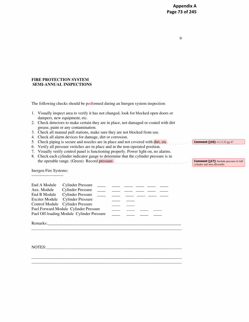
9
FIRE PROTECTION SYSTEM
SEMI-ANNUAL INSPECTIONS
The following checks should be performed during an Inergen system inspection:
1. Visually inspect area to verify it has not changed, look for blocked open doors or
dampers, new equipment, etc.
2. Check detectors to make certain they are in place, not damaged or coated with dirt
grease, paint or any contamination.
3. Check all manual pull stations, make sure they are not blocked from use.
4. Check all alarm devices for damage, dirt or corrosion.
5. Check piping is secure and nozzles are in place and not covered with dirt, etc.
6. Verify all pressure switches are in place and in the non-operated position.
7. Visually verify control panel is functioning properly. Power light on, no alarms.
8. Check each cylinder indicator gauge to determine that the cylinder pressure is in
the operable range. (Green) Record pressure.
Inergen Fire Systems:
-----------------------
End A Module Cylinder Pressure ____ ____ ____ ____ ____ ____
Aux. Module Cylinder Pressure ____ ____ ____ ____ ____ ____
End B Module Cylinder Pressure ____ ____ ____ ____ ____ ____
Exciter Module Cylinder Pressure ____ ____
Control Module Cylinder Pressure ____ ____
Fuel Forward Module Cylinder Pressure ____ ____ ____ ____
Fuel Off-loading Module Cylinder Pressure ____ ____ ____ ____
Remarks:________________________________________________________________
________________________________________________________________________
NOTES:_________________________________________________________________
________________________________________________________________________
________________________________________________________________________
Comment [j16]: 4.3.2.32 pg 47
Comment [j17]: Include pressure fo full
cylinder and min allowable.
Appendix A Page 73 of 245

10
Appendix A Page 74 of 245

Newfoundland and Labrador Hydro PI Gas Turbines Limited Hardwoods and Stephenville Job No: 11017 Gas Turbine Protection Site Survey Document No.
APPENDIX 1c: MARKED COPY OF
HWDGT & SVLGT Annual Inspection
11017-REP-001 Rev 1.1
Appendix A Page 75 of 245
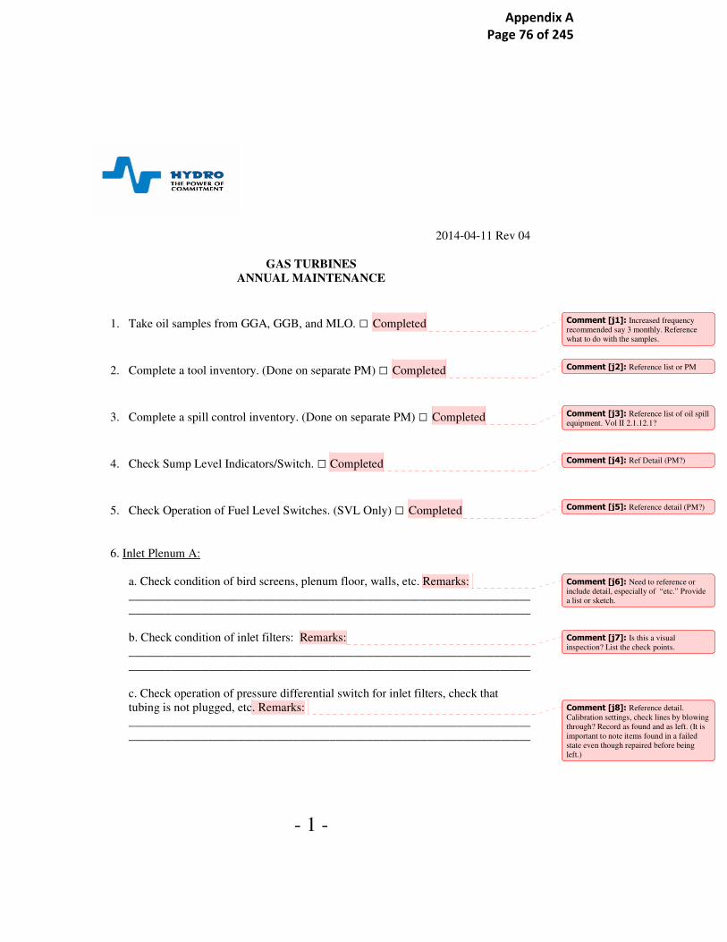
- 1 -
2014-04-11 Rev 04
GAS TURBINES
ANNUAL MAINTENANCE
1. Take oil samples from GGA, GGB, and MLO. □ Completed
2. Complete a tool inventory. (Done on separate PM) □ Completed
3. Complete a spill control inventory. (Done on separate PM) □ Completed
4. Check Sump Level Indicators/Switch. □ Completed
5. Check Operation of Fuel Level Switches. (SVL Only) □ Completed
6. Inlet Plenum A:
a. Check condition of bird screens, plenum floor, walls, etc. Remarks:
__________________________________________________________________
__________________________________________________________________
b. Check condition of inlet filters: Remarks:
__________________________________________________________________
__________________________________________________________________
c. Check operation of pressure differential switch for inlet filters, check that
tubing is not plugged, etc. Remarks:
__________________________________________________________________
__________________________________________________________________
Comment [j1]: Increased frequency
recommended say 3 monthly. Reference
what to do with the samples.
Comment [j2]: Reference list or PM
Comment [j3]: Reference list of oil spill
equipment. Vol II 2.1.12.1?
Comment [j4]: Ref Detail (PM?)
Comment [j5]: Reference detail (PM?)
Comment [j6]: Need to reference or
include detail, especially of “etc.” Provide
a list or sketch.
Comment [j7]: Is this a visual
inspection? List the check points.
Comment [j8]: Reference detail.
Calibration settings, check lines by blowing
through? Record as found and as left. (It is
important to note items found in a failed
state even though repaired before being
left.)
Appendix A Page 76 of 245

- 2 -
d. Check condition of monoclones, fans & ductwork for cracks. (HWD Only)
Remarks:
__________________________________________________________________
__________________________________________________________________
e. Inspect and check operation of blow-in-doors for freedom of movement and
operation of alarm limit switches. Remarks:
__________________________________________________________________
__________________________________________________________________
f. Lubricate blow-in door hinges and limit switches. Remarks:
__________________________________________________________________
__________________________________________________________________
g. Check louvers and lubricate for freedom of movement, etc, on enclosure fans 1
& 2 GGA. Verify noise free operation of the fans. Remarks:
__________________________________________________________________
__________________________________________________________________
h. Inspect all ladders and climbing systems as per fall protection program
checklist. Remarks:
__________________________________________________________________
__________________________________________________________________
7. Inlet Plenum B:
a. Check condition of bird screens, plenum floor, walls, etc. Remarks:
__________________________________________________________________
__________________________________________________________________
b. Check condition of inlet filters: Remarks:
__________________________________________________________________
__________________________________________________________________
c. Check operation of pressure differential switch for inlet filters, check that
tubing is not plugged, etc. Remarks:
__________________________________________________________________
__________________________________________________________________
d. Check condition of monoclones, fans & ductwork for cracks. (HWD Only)
Remarks:
__________________________________________________________________
__________________________________________________________________
Comment [j9]: List detail including tag numbers. Record as found and as left.
Comment [j10]: Record as found and as
left.
Comment [j11]: Include detail eg
sketch/drawing or checklist.
Comment [j12]: Comments as for A
Comment [j13]: This is also in SVL
procedure
Appendix A Page 77 of 245

- 3 -
e. Inspect and check operation of blow-in-doors for freedom of movement and
operation of alarm limit switches. Remarks:
__________________________________________________________________
__________________________________________________________________
f. Lubricate blow-in door hinges and limit switches. Remarks:
__________________________________________________________________
__________________________________________________________________
g. Check louvers and lubricate for freedom of movement, etc, on enclosure fans 1
& 2 GGA. Verify noise free operation of the fans. Remarks:
__________________________________________________________________
__________________________________________________________________
h. Inspect all ladders and climbing systems as per fall protection program
checklist. Remarks:
__________________________________________________________________
__________________________________________________________________
6. Gas Generator A:
Inlet Area Inspection
a. Check for cracks in nose bullet. Remarks:
__________________________________________________________________
__________________________________________________________________
b. Wipe/clean entry guide vanes with rag and appropriate solvent; do not use wire
brush. Inspect with extension light and mirror. If indication of cracks, investigate
using dye penetrate procedure. Also inspect the first stage compressor shrouded
stators. If damage is found, complete a secondary inspection of first stage stator
blades for impact, erosion, corrosion, fatigue damage. This involves removing LP
compressor casings and stator blades for secondary inspection and possibly
returning to overhaul facility. Remarks:
__________________________________________________________________
__________________________________________________________________
c. Check nose cone flange, rubber connector, band clamps, retaining plates and
alignment. Remarks:
__________________________________________________________________
__________________________________________________________________
Comment [j14]: Method? Visual, Dye
pen?
Comment [j15]: CWMan 4.3.2.33 pg 2
it 2
Comment [j16]: Reference acceptance
criteria. Section 2.1.11.2 of CW manual.
Comment [j17]: CWMan 4.3.2.33 pg 2
it 1
Appendix A Page 78 of 245

- 4 -
Gas Generator General Maintenance
a. Check all fuel, oil and airlines for condition and security of connections.
Remarks:
__________________________________________________________________
__________________________________________________________________
b. Inspect and lubricate the fuel pressure regulator (LF-4) shaft and check for
leaks. Remarks:
__________________________________________________________________
__________________________________________________________________
c. Inspect liquid fuel valve and actuator for loose bolts, oil leaks, wear, binding
and security of mounting. Remarks:
__________________________________________________________________
__________________________________________________________________
d. Remove the air system strainer screen (ST-CA-1) Inspect and clean, check the
air regulating system components for leaks, cleanliness, etc. Remarks:
__________________________________________________________________
__________________________________________________________________
e. Inspect and lubricate the fuel fire valve plunger rod to assure freedom of
operation. Remarks:
__________________________________________________________________
__________________________________________________________________
f. Check the security of the supplementary fuel pump/motor assembly. Check the
supplementary fuel filter indicator. Clean/change filter if required. Remarks:
__________________________________________________________________
__________________________________________________________________
g. Check all junction boxes for security of terminals, tidiness, overheating, etc.
Remarks:
__________________________________________________________________
__________________________________________________________________
h. Check nozzle strainers (screens) Remarks:
__________________________________________________________________
__________________________________________________________________
i. Replace two air filters – one on the regulator, and one under the floor grating.
Remarks:
__________________________________________________________________
__________________________________________________________________
Comment [j18]: Checklist 4.3.2.33 pg5
it 6
Comment [j19]: Detail ref? 4 .3.2.33 pg25it 2
Comment [j20]: How do we test for
binding?
Comment [j21]: Change only?
Comment [j22]: checklist
Appendix A Page 79 of 245

- 5 -
j. Clean fuel nozzles in ultrasonic bath (using sodium hydroxide), only if EGT has
been problematic. Attempt to clean ourselves first, with factory clean as last
resort. Note: we have two styles of fuel injection nozzles- the newer style can not
be taken apart on-site for cleaning. Remarks:
__________________________________________________________________
__________________________________________________________________
k. Replace lube oil filters. Note there are 2 GG lube oil system filters – one per
each end. Remarks:
__________________________________________________________________
__________________________________________________________________
Fuel Lines
a. For fuel lines to the nozzles, inspect piping clips (brackets) for security & wear;
replace clips if cracked or worn packing. Ensure no metal-to-metal contact
between pipe & clip; ensure there are no plastic bands or tape on flex lines.
Remarks:
__________________________________________________________________
__________________________________________________________________
7. Gas Generator B:
Inlet Area Inspection
a. Check for cracks in nose bullet. Remarks:
__________________________________________________________________
__________________________________________________________________
b. Wipe/clean entry guide vanes with rag and appropriate solvent; do not use wire
brush. Inspect with extension light and mirror. If indication of cracks, investigate
using dye penetrate procedure. Also inspect the first stage compressor shrouded
stators. If damage is found, complete a secondary inspection of first stage stator
blades for impact, erosion, corrosion, fatigue damage. This involves removing LP
compressor casings and stator blades for secondary inspection and possibly
returning to overhaul facility. Remarks:
__________________________________________________________________
__________________________________________________________________
c. Check nose cone flange, rubber connector, band clamps, retaining plates and
alignment. Remarks:
__________________________________________________________________
__________________________________________________________________
Comment [j23]: Whatv isa the
symptom? Temperature spread?
Comment [j24]: Are the two types
easily identified?
Comment [j25]: Nered to clarify which there refer to. There are apparently 12 in the
gas generator plus the tanlk strainer and
duplex filter. Volume 2 3-32 refers to a
single pressure filter. The diagram shows
individual 550 micron strainers serving
each bearing. Need to serviceF-GGLO-1
4.3.2.33 pg26 it 1
Comment [j26]: As GG A
Appendix A Page 80 of 245

- 6 -
Gas Generator General Maintenance
a. Check all fuel, oil and airlines for condition and security of connections.
Remarks:
__________________________________________________________________
__________________________________________________________________
b. Inspect and lubricate the fuel pressure regulator (LF-4) shaft and check for
leaks. Remarks:
__________________________________________________________________
__________________________________________________________________
c. Inspect liquid fuel valve and actuator for loose bolts, oil leaks, wear, binding
and security of mounting. Remarks:
__________________________________________________________________
__________________________________________________________________
d. Remove the air system strainer screen (ST-CA-1) Inspect and clean, check the
air regulating system components for leaks, cleanliness, etc. Remarks:
__________________________________________________________________
__________________________________________________________________
e. Inspect and lubricate the fuel fire valve plunger rod to assure freedom of
operation. Remarks:
__________________________________________________________________
__________________________________________________________________
f. Check the security of the supplementary fuel pump/motor assembly. Check the
supplementary fuel filter indicator. Clean/change filter if required. Remarks:
__________________________________________________________________
__________________________________________________________________
g. Check all junction boxes for security of terminals, tidiness, overheating, etc.
Remarks:
__________________________________________________________________
__________________________________________________________________
h. Check nozzle strainers (screens) Remarks:
__________________________________________________________________
__________________________________________________________________
Appendix A Page 81 of 245

- 7 -
i. Replace two air filters – one on the regulator, and one under the floor grating.
Remarks:
__________________________________________________________________
__________________________________________________________________
j. Clean fuel nozzles in ultrasonic bath (using sodium hydroxide), only if EGT has
been problematic. Attempt to clean ourselves first, with factory clean as last
resort. Note: we have two styles of fuel injection nozzles- the newer style can not
be taken apart on-site for cleaning. Remarks:
__________________________________________________________________
__________________________________________________________________
Fuel Lines
a. For fuel lines to the nozzles, inspect piping clips (brackets) for security & wear;
replace clips if cracked or worn packing. Ensure no metal-to-metal contact
between pipe & clip; ensure there are no plastic bands or tape on flex lines.
Remarks:
__________________________________________________________________
__________________________________________________________________
Power Turbine A:
1. Check the security of thermocouple terminations, etc.
Remarks:
__________________________________________________________________
__________________________________________________________________
2. Inspect the power turbine cover blankets for general condition. Remarks:
__________________________________________________________________
__________________________________________________________________
3. Check vibration detectors security of pickup and connections. Remarks:
__________________________________________________________________
__________________________________________________________________
4. Inspect the front and rear bearing supports for oil seepage at covers. Check all
hold down bolts, etc. Remarks:
__________________________________________________________________
__________________________________________________________________
5. Inspect the exhaust volute general condition, mount supports and load reference
Comment [j27]: Checklist
Comment [j28]: Checklist
Appendix A Page 82 of 245

- 8 -
indication (refer to C.W. Operation & Maintenance Manual, Section 2.2.2.2)
Remarks:
__________________________________________________________________
__________________________________________________________________
6. Check security of power turbine fasteners at inter-turbine duct to stator casing,
stator casing to bellows, and bellows exhaust volute, as per Rolls Royce Service
Bulletin 423. Remarks:
__________________________________________________________________
__________________________________________________________________
Power Turbine B:
1. Check the security of thermocouple terminations, etc.
Remarks:
__________________________________________________________________
__________________________________________________________________
2. Inspect the power turbine cover blankets for general condition. Remarks:
__________________________________________________________________
__________________________________________________________________
3. Check vibration detectors security of pickup and connections. Remarks:
__________________________________________________________________
__________________________________________________________________
4. Inspect the front and rear bearing supports for oil seepage at covers. Check all
hold down bolts, etc. Remarks:
__________________________________________________________________
__________________________________________________________________
5. Inspect the exhaust volute general condition, mount supports and load reference
indication (refer to C.W. Operation & Maintenance Manual, Section 2.2.2.2)
Remarks:
__________________________________________________________________
__________________________________________________________________
6. Check security of power turbine fasteners at inter-turbine duct to stator casing,
stator casing to bellows, and bellows exhaust volute, as per Rolls Royce Service
Bulletin 423.
Comment [j29]: OK
Comment [j30]: As power Turbine A
Comment [j31]: No calibration check
Appendix A Page 83 of 245

- 9 -
Remarks:__________________________________________________________
__________________________________________________________________
Clutch A:
1. Check the clutch box base hold down bolts. Inspect grounding brush.
Remarks:
__________________________________________________________________
__________________________________________________________________
Clutch B:
1. Check the clutch box base hold down bolts. Inspect grounding brush.
Remarks:
__________________________________________________________________
__________________________________________________________________
Exhaust A:
1. Check the exhaust stack inside wall panels for security of insulation, plates, etc.
Remarks:__________________________________________________________
__________________________________________________________________
Exhaust B:
1. Check the exhaust stack inside wall panels for security of insulation, plates, etc.
Remarks:__________________________________________________________
__________________________________________________________________
Vent Fan:
1. Check mounting bolts, fan, fan coupling, louver free to move, etc… verify
operation. Remarks:
__________________________________________________________________
__________________________________________________________________
Appendix A Page 84 of 245

- 10 -
Alternator:
AVR / Exciter
1. Internal inspection of exciter. Remove covers and check tightness of bolts, fuse
clips, brackets, etc… test diodes. Review interval of this after each inspection.
Remarks:
__________________________________________________________________
__________________________________________________________________
Fuel:
1. Verify fuel servo stroke characteristic. Remarks:
_______________________________________________________________
_______________________________________________________________
2. Clean Y-strainers in the fuel system. Remarks:
_______________________________________________________________
_______________________________________________________________
3. Replace last chance fuel filter and supplementary fuel pump filter. Also clean
out the bottom of the housings at the time of filter replacement. Remarks:
__________________________________________________________________
__________________________________________________________________
Fuel Storage
1. Check drain valve main tank for water & dirt contamination.
Remarks:__________________________________________________________
__________________________________________________________________
__________________________________________________________________
2. Check tank sides, roof, and associated piping for excessive rust, etc…
Remarks:
__________________________________________________________________
__________________________________________________________________
3. Check and grease all fuel valve stems and associated equipment.
Comment [j32]: How?
Comment [j33]: This has general
applicability. A method of recording,
comparing and reviewing failures is needed.
Comment [j34]: Drawing ref 183511
Comment [j35]: How?
Comment [j36]: Same tag used for more than 1 eg ST-LF-1
Comment [j37]: Identify on drawings.
Comment [j38]: CW Manual 4.3.2.33
pg 25 it1
Comment [j39]: Reference drawing
183511? Filters and coalescers on fuel
skid. CW Man 4.3.2.33 p 20 it2,4
Appendix A Page 85 of 245

- 11 -
Remarks:
__________________________________________________________________
__________________________________________________________________
Lube Oil
1. Replace actuator filter and clean out the bottom of the housing. Remarks:
_______________________________________________________________
_______________________________________________________________
2. Jacking Pumps: Check motor brushes; Check operation pressures and shaft lift
(both ends) with dial indicator Note: The following motors must be on prior to
performing this test Evacuator, Demister, MLO pump & Jacking Pump.
Check hold down bolts and grease motor bearing if required. Remarks:
__________________________________________________________________
__________________________________________________________________
3. Main Lube Pumps: Check general condition. Grease bearings as required;
Check brushes on DC motors. Remarks:
__________________________________________________________________
__________________________________________________________________
4. Main Lube Oil Tank: Drain condensation from main tank. Use valve at
bottom of tank; Check level of oil in tank (dipstick), add as required. Remarks:
__________________________________________________________________
__________________________________________________________________
5. GG Lube Oil Filter: Replace filters annually. There are 2 filters required, one
on each end. Remarks:
__________________________________________________________________
__________________________________________________________________
Cooling
Note: Both items below are for HWD only.
Comment [j40]: PT & Alt LO system.
CR Manual 4.1 page 4-1
Comment [j41]: Tags PJO1 and PJO2
on the alternator in drawing 183482 listed as 3 monthly and other in 4.3.2.33 pg39
Comment [j42]: Main LO filters F-LO-
1 should be changed annually. 4.3.2.33 pg 36 as 1 and 3 monthly.
Comment [j43]: This should be done
more frequently than annually. 4.3.2.33 pg
35 it1
Comment [j44]: This has already been
mentioned above. This section is (or
appears to be) the PT & Alt LO system.
Comment [j45]: Which filters does this
refer to? It’s the cartridge filter in the return
line F-GGLO-1that’s critical.
Comment [j46]: When arePSVs tested
general question but eg LO.2 on dwg
183482
Comment [j47]: Specify alternator air
cooling. There is also a glycol cooling loop
associated with the LO system.
Appendix A Page 86 of 245

- 12 -
1. Check filter block switch, (check hose is not let go or pinched) Remarks:
__________________________________________________________________
__________________________________________________________________
2. Check Alternator Dampers:
2(a) Alternator stopped. (Work permit in effect Inverter Panel Breaker #5 OFF).
2(b) Discharge dampers and re-circ dampers closed.
2(c) Check linkages and lubricate.
2(d) Restore 120 volt AC (Inverter Panel Breaker #5 ON).
2(e) Jumper in control module points 21222 and 21223.
2(f) Discharge dampers OPEN.
2(g) Check linkages and lubricate.
2(h) Adjust thermostat above ambient temperature. (Thermostat located in air
inlet after filters on B side. Extension ladder to access door)
2(i) Re-circ dampers OPEN.
2(j) Discharge dampers CLOSE.
2(k) Check linkages and lubricate.
2(l) Return thermostat to 5 degrees Celsius.
2(m) Re-circ dampers CLOSE (ambient temperature above 5 degrees Celsius).
2(n) Discharge dampers OPEN.
2(o) Remove jumpers on points 21222 and 21223.
2(p) Discharge dampers CLOSE.
Remarks:
_______________________________________________________________
_______________________________________________________________
_______________________________________________________________
_______________________________________________________________
Comment [j48]: Dwg, tag, check
calibration.
Comment [j49]: Emg damper test 4.3.2.33 pg 77
Comment [j50]: This is the first
reference to PTW, isolation etc. Need policy to include or exclude it in the
maintenance procedures.
Comment [j51]: Drawing ref
Comment [j52]: detail
Comment [j53]: explain purpose,
drawing ref. In which panel. Is this to open
the discharge dampers?
Comment [j54]: Need policy re
including equipment. Possibly include sections in a standard template.
Appendix A Page 87 of 245

- 13 -
_______________________________________________________________
_______________________________________________________________
Glycol System:
1. Check cooling fans pitch angle settings & general condition of blades.
Remarks:__________________________________________________________
__________________________________________________________________
2. Check for leaks, and check expansion tank glycol level. Make note of tank
level. Check low level alarm switch. Remarks:
__________________________________________________________________
__________________________________________________________________
3. Drain off some glycol and check contamination content and protection level.
Remarks:
__________________________________________________________________
__________________________________________________________________
4. Check heat exchanger cooling tubes and vanes for leaks, rust, etc. Remarks:
__________________________________________________________________
__________________________________________________________________
5. Check the condition and operation of the three-way thermostat. (Lubricate all
moving parts) Remarks:
__________________________________________________________________
__________________________________________________________________
6. Clean the Y-strainers in the glycol systems. Remarks:
__________________________________________________________________
__________________________________________________________________
Comment [j55]: This is the cooling
circuit serving the LO. Dwg 183517
Comment [j56]: What are correct
settings?
Comment [j57]: Top up? With what?
Comment [j58]: Detail.
Comment [j59]: Detail or cross
reference.
Comment [j60]: Identify on drawings.
Appendix A Page 88 of 245

- 14 -
Buildings and Properties:
1. Check forced air heaters, lubricate motors if required.
Remarks:_______________________________________________________
_______________________________________________________________
_______________________________________________________________
2. Check mounting bolts, fan, fan coupling, louver free to move, etc… verify
operation. Remarks:
_______________________________________________________________
_______________________________________________________________
_______________________________________________________________
3. Check lighting at tank farm (operate photocell for lighting) Remarks:
_______________________________________________________________
_______________________________________________________________
4. Check steps and handrail on tank and over dyke for security. Remarks:
_______________________________________________________________
_______________________________________________________________
5. Test the 3 fire alarm pull station and associated alarm devices. Remarks:
_______________________________________________________________
_______________________________________________________________
_______________________________________________________________
6. Inspect all ladders & climbing systems per fall protection checklist, available
in Lotus Notes. Remarks:
_______________________________________________________________
_______________________________________________________________
.
Completed by:____________________________________________________________
Date: ___________________________________________________________________
Comment [j61]: How does the user
decide…should we just lubricate?
Comment [j62]: Do these need toi be
marked on a layout?
Comment [j63]: And these
Comment [j64]: Still? Can we include it
here?
Comment [j65]: There are systems
missing from this procedure, eg air start,
fire detection.., governor,
Appendix A Page 89 of 245

- 15 -
Appendix A Page 90 of 245

Newfoundland and Labrador Hydro PI Gas Turbines Limited Hardwoods and Stephenville Job No: 11017 Gas Turbine Protection Site Survey Document No.
APPENDIX 1d: MARKED COPY OF
HVYGT Operators 5 Year Check
11017-REP-001 Rev 1.1
Appendix A Page 91 of 245

HVY GT 5 YEAR INSPECTION
Completed by: Date:
Work Order:
/
TURBINE/GENERATOR
a. Monitor and Record Noise Level
b. Verify Pressure Gauge Operation
c. Instrumentation Sensors
d. Verify IRD Equipment
e. Air System
f. Oil Filters
g. Fuel Filters
h. Air Filters
i. DC Oil Pumps GG ______Amps PT_______Amps
j. Clean/Inspect Bus Duct
k. Doble Bus Duct
l. Megger Stator 1 min_____ 10 min_____ PI ______
m. Megger Rotor 1 min _____ 10 min______ PI ______
n. Megger Exciter 1 min _____ 10 min______ PI ______
o. Doble Stator
p. Megger S/S Transformer 1 min _____10 min PI_______
q. S/S Transformer A______ B______ C_____ Amps
r. SF6 Breaker P.M.
s. Metering
FIRE PROTECTION
a. Test / Recertify Fire System
b. Fire System Piping
c. System Integrity
NOTES:
Expected value / Comments
SUPERVISOR:________________________________ DATE:__________________________________
Appendix A Page 92 of 245

2014-05-26 Rev-04
GAS TURBINE OPERATOR'S
5 YEAR CHECK GUIDE
FOR UNIT & ASSOCIATED EQUIPMENT
TURBINE:
a. Obtain a building layout plan and measure noise levels at predetermined areas inside the
building, keeping in mind the same areas will be measured and compared infuture. Attach the drawing
to the workorder for scanning
b. Calibrate all pressure gauges associated with unit Air, Oil, Fuel, Coolant, noting each gauge
calibrated workorder c. Calibrate all RTD's, Pressure Switches,Temperature Switches,Transducers,etc. associated
with unit Air, Oil, Fuel, Coolant, recording each with the calibrated value separately on the workorder.
This procedure references work orders. These should
provide the deatail method statement and a record for
d. Calibrate all IRD sensors and monitoring equipment on Turbine, Generator, Alternator, etc. does this include CW Man 34.3.2.33pg14 it 21?
e. Clean/Inspect and lubricate Air System components, valves, sensors, et. does this include CW Man 4.3.2.33 pg 11 it 13?
f. Replace all lube oil filters on unit checklist reqd. CW Man 4.3.2.33 pg 13 it 15.16.17
g. Replace all fuel filters, clean on board mesh fuel filters & clean filter housings
h. Replace inside air filters, wash/replace outside air filters
Appendix A Page 93 of 245

2014-05-26 Rev-04
i. Lubricate GG & PT Dc pumps and record amperage of each list tag nos, wo nos etc. Which pumps does this referto?
j. Clean and inspect bus duct
k. Perform doble test on bus duct
l. Perform megger tests on stator. Record 1 minute and 10 minute test, calculate and record
polarization index.
m. Perform megger tests on rotor. Record 1 minute and 10 minute test, calculate and record
polarization index.
n. Perform megger tests on exciter. Record 1 minute and 10 minute test, calculate and record
polarization index.
o. Perform doble test on stator
p. Perform megger tests on station service transformer. Record 1 minute and 10 minute test,
calculate and record polarization index.
q. Clean, check connections, on station service transformer and associated equipment, i.e.
disconnects, panels, etc. Measure station service load during after service run up
r. Perform SF6 breaker p.m. as per terminals maintenance manual procedure
s. Calibrate statistical and plant metering
FIRE SYSTEM
a. Have contractor test and recertify fire system and hoses. a. Have contractor test and recertify fire system and hoses.
b. Perform pressure test on fire system piping
c. Check room integrity, door seals, vents, louvers, etc. as per NFPA 2001
REMARKS:
Appendix A Page 94 of 245

Newfoundland and Labrador Hydro PI Gas Turbines Limited Hardwoods and Stephenville Job No: 11017 Gas Turbine Protection Site Survey Document No.
APPENDIX 1e: MARKED COPY OF
HVYGT P & C 6 Year Check
11017-REP-001 Rev 1.1
Appendix A Page 95 of 245

HVY GT PROTECTION CONTROL 6 YEAR INSPECTION
Completed by: Date:
Work Order:
/
a. Relay Trip 86 and 94 Relays
PI: Checked against CW Manual 4.3.2.33 Items covered in
this and 5 yearly indicated with lilac circles.
b. Relay Protection Timers, Elect/Mech
c. Relay Protection Timers, Electronic
d. Electronic Protection Relays
e. Elect/Mech C/V Solenoid Type Protection Relays
f. Elect/Mech C/V Induction Type Protection Relays
g. Transducers
h. Panel Metering
i. Panel Transformers
j. AVR
BREAKER / METAL CLAD SWITCHGEAR
All checks & tests to be completed with Breaker racked out
k. Counter Before Operating ___________
l. Ductor(100 A (micro ohm): A _____B______C______
m. Timing Close A _______B________C________
n. Timing Trip A _______B________C________
o. Doble Test
p. Inspect Arcing Chamber
q. Command Current Close _______ Trip________
r. Control Coil (ohms) Close_______ Trip________
s. Megger (5Kv bkr. open) A_______B_______C_______
t. Counter After Operating ____________
u. Lubricate Control Block
v. Check Primary Connections
w. Check / Lubricate Latching Pawl
x. Check Erosion Indicator, Wipes and Gaps
y. Perform Vacuum Interrupter Integrity Test
Expected value / Comments
y. Perform Vacuum Interrupter Integrity Test
NOTES:
SUPERVISOR:________________________________ DATE:__________________________________
Appendix A Page 96 of 245

Newfoundland and Labrador Hydro PI Gas Turbines Limited Hardwoods and Stephenville Job No: 11017 Gas Turbine Protection Site Survey Document No.
APPENDIX 1f: MARKED COPY OF
Maintenance Gas Turbine Insp & Maint. Curtiss Wright 4.3.2.33
11017-REP-001 Rev 1.1
Appendix A Page 97 of 245

,.w
_ _ . , .._ .
.....
. .
._~,...
...
,...
. ..
~.;.
~9
Appendix A Page 98 of 245

, .
x
r
1
,~j
., ..,_ ...
' t _ - t ~
~" ',SYSTEM/ e0l4PONENT
a t L
~ - ~~REQUENGY
. , REQUIREDINSPECTION/I~i~TE~IANCE R~MARICS
. SYSTEM INSPECTION AND.. a a cn~~ch ~
~zas
- ,.
MAINTENANCE .,-+~-, o
,
~c •-~ ~o ~+
Gas Gene~'ator, (Jl~raapus ~~8~~ -and.
nCn TYPe
NOTE: These instructions d n r rt to:co e all det~i~.$ or variations in e i~ment'~nor to provide. forevery possible Conti e y o e et in c nectio~ with inspection and ma tenance. ,hould furCherinformation be desir e ter sh ul referred to .the Vendor~Manual
Functional Checks ;; _
1. General X' Refer to general instructionsfor routine servicing and re-pair by replacement Pori,gas.generator and associated sys-terns provided in Section 2 ofOperation and MaintenanceManual.
2. Gas Path X~ Refer to H~oK Section. and MayorField periodic inspectioncriteria provided in Section 2of Operation and Z~laintenanceManual.
=~iSZE SAd $~/SteIDB >
,
1. Nose Bullet X Inspect for cracks. Report any clacks to C-W,~ Replaceassembly.
Entry Guide Vanes X Meat► vanes ~it~ kerosene.. Crack indi~at~ons should bye thor-'Visually inepect~~vames with ~. ougblx,inv etigated using-the dyeflashlight and m~~ror, ~penetrat~t ~tspeet~it~ pFgcedur~;
- - •: inform ~C-{~ of, damage. found during~ ~ ~
y ~ N
NOT FOUND IN HYDRO
IN HWD DAILY
IN HWD SEMI ANNUAL
IN HWD ANNUAL
IN HWD 5 YEARLY
Appendix A Page 99 of 245

A
rSYSTEMICOMPONENT
'
FREQUENCY., %za K
REQUIRED:INSPE~TIONIMAINTENANCE.
,.. .. ;
REMARKS
• ~
r1 p3 •-1 ~O yam+
2. Entry Guide Vanes inspection; For identification(Continued purposes the vanes must be num-
bered anti-clockwise viewed fromthe front of the gas generator;i.e. No, l at top dead center;Compare damage with Limits of Ac-ceptance C-W Bulletin #3.
3. Compressor ( e R qu e X Visually inspect Compressor {Same as item 2)blades and vanes for signs Minor nicks and dents may beof foreign ob,~ect damage, blended. Contact C-W for per-cracka and distortions; missible blending limits.As necessary, remove and re-place compressor cases inaccordance with Section 2.
{ - c e t Inspect the First Stage.E tr G d V e Compressor Shrouded StatorsI sp t o e 2 as follows:
Remove bolts retainingy ~:a
~1.inlet plenum ~eptwa door,.open doors.
i 2. Clean lst stage. ~sh~oudedstator vane segm~nt~ xith .solvent.
3 Visually inspect airfoilta► shroud 3oints of each
- _ .. - ~ gta~+or vane for crackingy2 ~ w.
of the filled i~raze
~ T ---..~ '
e. f
% ~ ~ `" •. ~
h, tn ~ a
S
Appendix A Page 100 of 245

r. _ ... . _ - , .. _ , ..S ~~ ,e • .. ^ ..a . -n «..r ~. =rumar.~ ..~ s .
$
. ~. SYSTEMIC~UNEN~
s ~'
~ . ~ t
~ FREQUENCY
'-
~~ REQUIREDINSPECTION/M~I.NTENA`i~CE REMARKS `J
i • •
~ ~
Compressor.. (Cont'd) 4 If a suspect crack isfounds aPPlY Pressure tot~eshroud and attempt toopen c=ack. (It is likelythat any crack may merely.:be .cracking of the rockharlacquer}
- X X 5. If the crack does not openrecord position, length,hours run,. and refer toSIB No. 14, Figure 1illustration.
b. If gaping crack is found,segment (P/N BDA 9766)should be changed; Ifnecessary, remove affectedL.P. stator housing half.in accordance with SIBNo. l4 and Section 2 ofOperations and Maintenance .Manual.
4 Compressor Wash ( en Re ui ed X Clean Compressor per HandbookInstructions provided with op-tional C-W wash skid PjN928041 and in accordance withSection 2 Operation Procedures. .
Anti-Icing Spatem ~ Check condition and. security -of piping, clamps, electrical ;binding cables and clips..
_,__ . , .~,,y_
'~r
t,
i
CONDITIONALON CRACKBEINGOBSERVED
Appendix A Page 101 of 245

,,
~ ~ ~ e i
$ ~Nv
SX1R
7
k
7
~;
SYSTEM/COMPONENT FREQUENCYREQUIRED ' f
INSPECTIQNI~"IAINTENANCE REM~'~RKS
~
~
v~ cn atYi
pG
H
~
~.+ ~"
M
~".+
~A *—! tit? Q
Anti-Icing System Visually inspect actuator and(Cont'd) valve as follows:
1. Remove actuator and valveby releasing the kingclamps for and aft of theanti icing valve.
2. Check that the valve is inthe closed position and.carry out a functionalcheck to ensure that theactuator and valve. operatecorrectly.
3. Rep3ace unit, if necessary.
Inspect actuator and valve.
Cooling and Lubrication R Check pipe for condition andSystem _ security of cvnn~ction (Refer
to Section 2 of Operations andMaintenance Manual).
Fuel Spstem { yen Re u d Check filter element. Bleed Service filter element and valvesfuel systems valves and lines. in accordance with the periodicas necessary. conditions specified and proce-
dures provided in Section 2 (~per-~ - a anon and Maintenance Manual.}.
~.Farhzust Annulus V ~ to , 1 ~ ~ x Esa.~3.ne for crack.. *4., Minar e=asks are ....acceptable., hoW-_ ~ ~, ' H s.)
~.dInspect the°bellow jri nt and ever frequency of Inspection must~ ~
.~ ..: . ,.. ~. w..M.
r
~ . .~ ~ _
a
Appendix A Page 102 of 245

__ _ . , _,>
. .
_. .
._
,,:
.. ,,t
~~
~ i
SYSTEM/ COMPONENT
-y 6 ~
_~ . ~ ,~ F'T~EQUEI~C~ ~
" + AtiQl~ li~G~:
~:. { INSPECTIOIdIMAINTENANCE- ' I
S
4' N ~ ~ ~ ~ ~
. .Exhaust Annulus 'inter-turbine duct for failure be increased or exhaust annulus(Cont~d) indicated bar fuel, uil or gas repaired
leakage.
9.- Combustion. Chambers. ( a co da ce w h 1. Visually inspect the two One crack on each surface up toc it ri f r of ~ chutes for cracking of the 0.5 inches 1 ng is acceptable.S ct on In pe tin attachment welds and the All cracks b yond acceptableto in Se tin center support web. limits are t be repair welded.
0 0ertin ndin en nc nu 1) 2. Inspect all tapped holes Reject any w th broken bolts which
X for thread damage. cannot be ex ratted.Clean up all tapped holesprior to reinstalling Reject any w th cracks longer khansnouts. 0.5 inches o where the flame spray
plate has wo through to the3. Inspect snout. pilot sur- parent mater al.
faces for wear and crack-~ing.
Combustion Chamber X 1. Inspect swirler for cracks. Only one cra k per vane is per-Assembly muted. - i
a. Cracks not to exceed0.9 inches in lengthin four vanes and theremainder not to ex-ceed 0.6 inches.
i
i~'
Y
4.
.,
~~~
Appendix A Page 103 of 245

SYSTEM/COMPONENT FREQUENCY'REQUIRED
INSPECTIONIIKAINTENANGE REMARItS
'
~+ ~+ _
H ~ ~ ~ Off.'. ,e~
3 ~-i c~1 ~o ~ p
Combustion Chamber b. Cracks in ttie sw rlerAssembly (Cont~d) inner ring. must not
exceed Q.375 inches inlength..
2. Inspect s~irler assemblyfor align~aent by placing astraight edge across thefront face" of the combus-
. tion chamber and measuringthe gap which is not toexceed 0.025 inches.
3. Inspect flares for crack-ing, 6urn.ing and dstor-tion.
a. Cracks euceeding U.25inches are not accept--able.
.
b. No burning of the flareedges mare than 1Qx ofthe material thickness
. is acceptable. .
c. No discernable dstor-Lion of the flare gapis permissible. Gap
- ~ should be 0.125 inchese aoa~n~l~. ;
. ., ~.
Appendix A Page 104 of 245

_..._.
jt _. _ _ w~ .. ~;.,
~T _ _.,. , -'
t
i
yN0
~~
,SYSTEM/COMPONENT
r ; , t ~ - v ~,~
FREQUENCY ~
[ ~ ~ AtiQUli~aY
INSPECTID~I/MAINTENANCE REMARKS
H
a+
~ q ~ ~~''
~+ i
c*~ O~i 3 .-~ ~D y+
Combustion Chamber 4. Inspect the inner connec- [where fretti g has reduced theAssembly ~Cont'd) tors for wear and crack- metal thick ss to below 0.020
ing. Cracks in intercon- inches blend back using appropri'-vector cuff gelds emceed- ate hand gr der.ing 0.25 inches are not ac
_ cep table. Cracks exceed- Closure of t e gap between theing the limit stated should cuff and th combustion chamber '~be repair welded. barrel is acceptable,
5. Inspection of combustionchamber barrel assembly,
a, Local. bulging up to oneinch diameter is ac-eeptable`provided nocracking is apparentand the bulging is notwithin 0.325 inches ofan adjacent hole.
b. Cracking between the0.125 .inches diameterholes downstream of the .male interconnector isacceptable providedthat not more thanthree (3) holes areconnected. Cracks ex-ceeding this limit mustbe repair welded. '~
R:_
,~ ~
F
i;
f,~
~~~
'~., _ ~, ,4~..__ ~~; _ ~~ _..~
Appendix A Page 105 of 245

SYSTEM/COMPONENT FREQUENCYREQUIRED
INSPECTIONjMAINTENANCE REMARKS
• •v~ c~ ~+ a~ c~
s~ •-r r't ~o ~ o
Combustion Chamber c. Cracking of the rivetAssembly (Cont'd) tack welds is not
acceptable.
d. Cooling skirts are tobe dye penetrant in-spected. No cracks inthe cooling ski=ts isacceptable. Cracks intack welds adjacent tothe interconnectorsshould be rewelded.
6. Gaps for the. .first threecooling rings should meal-
~ ure 0.125. inches and• 0.080-O.U90 inches for the
r~a~ support ring.
7. Erosion ar burningaf thecooling rings up to tenpercent of the materialthickness is allowable. a
$. Inspect combustion chamber(ignitor position) forfretting up to a depth of0.U50 inches at bushing.If treating has occuredinspect igniters for nteg- .''
;~
. ;rity.
.
Appendix A Page 106 of 245

---~ .. _ ..
,. ~ 4 L
a _
t _ ~
~,. .... . _.. ..
'.
~ a , . _-. . ._..
#
-.,
^~ ~ r~ t
SY$TEMj~OMPONENTi ~ f r
FREQUENCY~ i~r~U~a~wll
INSPECTION/MAINTENANCE REMA.ItICS
9 ~„+
r~•
~
u~•
v~
~.~
aN ~4
~~"+ ~ `~~i ~,
A~ ~3 ,~-~ ~'1 ~a }~+~ o
Combustion Chamber 9. Inspect combustion chamberAssembly {Cant'd} rear support locating area
for wear. Wear at this• area is acceptable provid-
ing that the hard face teasnot worn through to theparent metal as indicatedby change in color fromsilver to gold.
10. All skin cracks in thebarrel surface area shouldbe weld repaired..
lU Combustion Chamber fluter X Inspection - Inspect. forCasing cracks, dents, distortion and
hot spots.
11. Turbine Entry Duct ~ X Inspect for broken welds, Any part d feet or damage beyond(n c rd c w h cracks, excessive wear on acceptable limits mill have to be
ri r r of mating lugs, and foreign ob- repaired o replaced by heavyec io I ~ t n ~ ect damage, ma.intenanc procedure or oirerhaul.of S ct o 2f e t ns ai to nc n 1
12, Air Starter X Drain and refill with 150 cc Refer to S ction 2 Operation and
4' to is of clean Gas Generator lubri- Ma.intenanc Manual for Fitting ther SO in eating oil per C-W Service Air starte..u e e 4 Bulletin X11.n s).
-
,t
~ `_
Appendix A Page 107 of 245

rN
wa
~.~.
SYSTEM/COMPONENT FREQUENCYREQUIRED
INSPECTION/MAINTENANCE g~~~~g
~., ~,
A 3 .-1 c*1 vD ~+ p
13. Phonic Wheels X 1. Check insulation and Equipment Required:security of terminals.
1. Variable speed drive with flex2. Check and calibrate the coupling 500 - 4QtJ0 RPM 1J2 HP
magnetic pickups on testrig. 2. One 1.5 OHM + 57 resistor.
3. AC voltmeter 0 - lOV 20K OHM/V
4. Digital frequency meter 0-4KHz.
Procedure:
1. Remove phonic wheel assemblies
2. Remove covers and check forQ. (?fJ7 in. air gad.
3. Lube bearings. Ensure wheelsaxe free to turn.
4, Verify output voltage at 2500Hz to be between 2. $ V-4. U V
tom) •
5. If voltage reading is low - reduce air gap to a min. of O.OUin. and recheck output. Zfvoltage reading is high - in=
~ crease air gap to U.O10 in.
_. .Recheck. >f .
6. Reinstall on gas geneica°,tor. `
Frequency of test requireddepends on purpose ofsignal . may be included initem d of the 5 year checks.If used for overspeedprotection it, must be testedto achieve specifiedreliability.
Appendix A Page 108 of 245

.. ~ . , .. .~.. ~. ; n.,
..
Y
. ~.. _.g
,.... .
_. ..P ~ ~ ~ ~ 7
n;
SYSTEM/COMPONENT ~
~. 1 z
a l~ ~ . ~
FREQUENCY
3
~ ~ REQUIREDINSPECTION/MAINTENANCE REMARKS
r ~ ~
H ~ ~: ~~..
~ ~"1 ~ ~ O
14. Magnetic Chip Detectors X Inspection of (5) chip detec- Whenever me a1 is found removetors for metallic deposits. housing and screen and analyze
the plug de osits as follows:
1. Remove he detector plugs bypushing the knurled end inwardand~tur anti-clockwise to re-lease t e bayonet type fitting.
2. Use a gasifying glass to de-termine type of deposit des-cribed n Metal Deposit Chartprovide in Section 2 of Oper-ation a dMaintenance Manual.
3. Replace detector as necessaryafter f tting new seals.
NOTE:
If the gas enerator is rejected,the deposit from detector andfilter shou d beplaced in a suit-able contai er, labeled, and re-turned with the gas generator forexamination and analysis.
If any doub exists in establishingthe source f any deposit and be-fore reject ng the gas generator.,consult Curtiss-Wright Corporation,
. Wood-Ridge, New Jersey,
_. ~ ,~,
_-
Appendix A Page 109 of 245
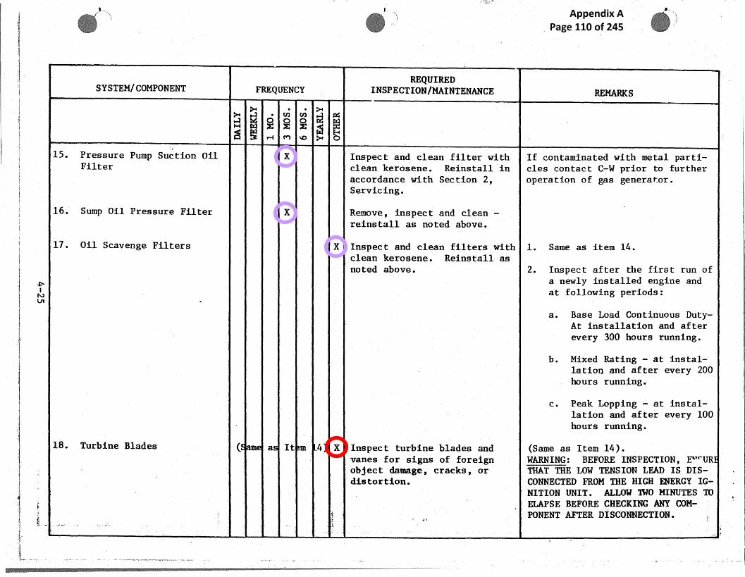
II.._., ~ ~ ~r:
'"
s
SYSTEM/COMPONENT FREQUENCYREQUIRED
INSPECTION/MAINTENANCE g~~~g
~., ~.,
~'~t ~ p.~-1 ~o
15. Pressure Pump Suction - Oil X Inspect and clean filter with If contaminated with metal parti-Filter clean. kerosene. Reinstall in Iles Contact C-W prior to further
accordance with Section 2, operation of gas generator.Servicing.
16: Sump Oil Pressure Filter X Remove, inspect and clean -reinstall as noted above.
17. Oil Scavenge Filters X Inspect anc~ clean filters with' 1. Same as item 14.clean ~eroseneo Reinstall asnoted above. 2. Inspect after the first run of
a newly installed engine andat following periods:
a. Base Load Continuous Duty-At installation and afterevery 300 hours running.
b. Mixed Rating - at instal-la Lion and after every 200hours running.
c. Peak Lopping - at instal-lation and after every 100hours running.
18. Turbine Blades ( a It m 4~ X Inspect turbine blades and (Same as Item 1G).vanes for signs of foreign WARNING: BEFCIRE INSPECTION, E""'URobject damage, cracks, or THAT THE LOW TENSION LEAD IS DIS-distarL on. COI~TNECTED FROM THE HIGH ENERGY I~-. NITION UNIT. ALLOW TWO MINUTES TO
ELAPSE BEFORE CHECKING ANY CaM--~, PONENT AFTER DISCONNECTION.
Appendix A Page 110 of 245

' s ~
SY~TEMjCOMPONENT . ~
~
FREQ~TENCY
REQUIRED~~NSPECTION/MAINTENANCE - REMARKS
~ . -cn
~~'"
cn ~ a~H w '~.. ~~r .~
l~ 3 +-1 M ~O yW+ O
19. Ignition Unit and Igniter X 1. Check for security ofPlugs connections.
2. Inspect for physical dam-age in accordance withSection 2 of Operation andMaintenance Manual.
3. Isolate one unit at a time WARNING; XERCISE.CARE DUE TO HIGand check (audibly) at the VOLTAGE AN FUEL VAPOR BUILD UP.
gas generator for .properigniter. plug firing.
' 20. Junction Box X Check all electrical wiring(Port Side of Intermediate and cables for secure connec-Casing) tions and any signs of damage
and overheating..
21. Vibration Detector X Check calibration of detector A vibratio table, power amplifier,Or en in (frequency range 20-400cps} oscilllator and image microscope
ch ng } and use a spare calibration will be re uized if recalibration
pickup; Fit the Vibration is requirePickup in accordance with Sec-t ion 2 Operation and Mainte-nance Manual..
22. Gas Temperature Control' X 1. Check security of ~.ermi-Or en in pals.ch ng
2. Check circuit resistance Use a =esi tance bridge and
and insulation of thereto- "megger"couple harness.
may be included in 5yr checks, item d.Function checks needto be more frequentfor critical items.
Appendix A Page 111 of 245

wV
t
I ~ _y ._1
SYSTEM/COMPONENT FREQUENCYREQUIRED
INSPECTIaN/MA.INTENANCE REMARKS
~ ~.,
H W ~ ~ ~ .e~
A 3 .—~ cy't ~p ~W.+ p
22. Gas Temperature Control 3. Calibrate the temperature Use millivolt injection equipment.(Continued) indicator and check con-
trol and trip setting ofgas temperature controlunit.
u
4,... .... . _. .. .. ..r.».. P ».. .., .. ,. . .
~>
Appendix A Page 112 of 245

N
j ~, ~Y ~
~.
SYSTEM/COMPONENT FREQUENCYREQUIRED
INSPECTION/MAINTENANCE REMARKS
LIQUID FUEL H
>+• cn cn c~
'SUPPLY SYSTEM ~ ~ ,..~ c~ ~o ~ p I .
Fuel Off Loading Skid
1. "'Y" Strainer, Mobile and X Flush through blow-off valve, Periodical y open "Y" strainer
Field Supply Inlet (1/8" blow-off v lve to flush out accum-
Perforated Screen) ulated for,ign matter. Frequencyof servici g requirement should b~establishe consistent ~~ith indi-vidual sit operating experience.
2.. "Y" Strainer, Off Loading X .Flush through blow-off valve. Same as It m 1, above.
Pump Discharge
3. Pump, Off Loading i X Inspection of pump shaft seal. Monitor 1 kage and adequacy of
lubricatio at pump shaft seal(packing Uox). Mechanical sealsor packin are interchangeable in
the same ox. Inspection andservice r quirements differ de-
pending u on configuration. Serv-ice in ac ordance with Component
Vendor In truction, Ingersoll-
Rand, Fo SPAD-14C.
4. Motor, Off Loading Pump; X Lubrication. All ball Baring motors that havegrease fi tings and plugs near the
bearings re to be lubricated inaccordant with motor manufac-
turer's i struction. -Refer to af-fected co portent vendor instructio
for speci is service recomanenda-
tion.
Appendix A Page 113 of 245

__ ~.y ~
f
rN
SYSTEMrCOMP`ONENT FREQUENCY .REQUIRED
INSPECTION/MAINTENANCE ~M~~
H
~
~
~
~~-a ~
~-+'
~
Q
t~
M ~
rte+'
Q3 *-~ ~D
4. Motor, Off Loading Pump X Check moor bearing tempera- Periodically check motor bearing(Contod) ture. temperature. .Temperature above
88°C is indicative of a~ abnormalcondition warranting investigativeaction.
S. System Piping and Sealing X Check for leakage. Monitor to ensure sealing integ-rity of all pipe connections,sealing surfaces gland fittings,etc. This should be accomplishedon a continuing routine basis.
Fuel Forwarding PumpsSkid Assembly
1. "Y" Strainer, Inlet X Flush through blow-off port.. Periodically, open "Y" strainer(1/16" Perforated Screen) blow-off ports to flush out accu=
mutated foreign matter. Closeparts. Ensure proper positioningof butterfly valves. Frequencyof servicing requirement should beestablished consistent with indi-vidual site operating experience.
2. Pump (2), AC Fuel X Inspection of pump shaft seal. Monitor leakage and adequacy ofForwarding lubrication at pump shaft seal
{stuffing box) . Mechanical sea1.3or packing are interchangeable '1the same box. Inspection andservice requirements differ de-pending upon configuration. Ser-vice in accordance with ComponentVendor Instruction.
semi annual maintenanceincludes leak checks for rest ofsystem. Piping not specificallymentioned.
Appendix A Page 114 of 245

,.a ~ ~ ~;.~ ~ _ .r .~._... .r .: ~b.~ ;..~:.
f
1 s ', ~
w0
~ SYSTEM/COMPONENT
.,
FREQUENCYREQUIRED
INSPECTION/MAINTENANCE
.
REMARKS
H W ~.. ~ dT
'rWiA 3 r-1 M ~O Q
3, Motor (2), AC Fuel ~ X Lubrication. All ball b aring motors that hiveForwarding Pump _ grease fit ings and plugs near the
bearings a e to lubricated in ac-cordance w th motor manufacturer'sinstructio s. Refer to affecKedcomponent endor instruction forspecific s rvice recommendation.
X Check motor bearing tempera- Periodical y check motor bearingture temperatur Temperature above
88'C is in icative of an abnormalcondition arranting investigativeaction.
4, Pump, DEC Fuel Forwarding X Bearing lubrication. Lubricate earings in accordancewith Compo ent Vendor, Gould,Maintenanc Instructions, SectionIII,:, consi tenfi, with type bearinglubricatio provided. Pump -may.incorporat externally oiled bear-ings, grea e lubricated bearingsor sealed earngs.
X Ins ection ofp pump shaft. seal. Monitor le ka eg ~ and adequacy oflubricatio .at 'Pump shaft seal(stuffing ox).~ Mechanical sealsor packing are ;interchangeable inthe same b x. ;Inspection and ser-vice requi emenjts differ dependingupon confi urat~~on. Service inaccordance wth~Component Vendor.
j
(.r
~~
~ ~__,~ ~ j
Appendix A Page 115 of 245

-,j
%4~ . 1
w►-a
I
T F.
; .
SYSTEM{COMPONENT FREQUENCYREQUIRED
INSPECTION/MAINTENANCE ~~~t~
~,+• cn cn
~+a c~
H W ~ ~ ~ a3 r-1 M +o ~ O
4. Pump, DC Fuel Forwarding X Check pump bearing temperature Periodically check pump bearing(Cont~d) temperature. Temperature above
82'C is indicative of an abnormalcondition warranting investigativeaction. Refer to Component VendorMaintenance Instructions.
S. Motor, DC Fuel Pump X Lubrication. All ball bearing motors that haveForwarding grease fittings and plugs neai the
bearings are to be lubricated inaccordance with motor manufacturerinstructions. Refer to affectedcomponent vendor instruction forspecific service recommendation.
6. Spstem Piping and Sealing X Leak check all fittings, lines Monitor to ensure sealing integ-and components. rity of ali pipe connections, .
sealing surfaces, gland fittings,etc. This should be accomplishedon a continuing routine basis.
Fuel Conditioning Skid
1. Filter, Fuel X X Replace filter elements. Replace filter elements when pres-sure diffe=~ntial across the fil-ter reaches 15 psig or once..a yearwhichever occurs first. Refer t-ovendor instruction for removal ^ndreplacement of component elementsand to Section 2 of Operation andMaintenance Manual for preliminaryprocedures to removal of component
Appendix A Page 116 of 245

t
i'F
REQUIRED
SYSTEM/COMPONENT FREQUENCY INSPECTION/MAINTENANCE REMARKS
a Q v~ cn ~ pG
H ~i
~~~r-1 M ~D }i O
g
1. Filter, Fuel (Cont'd) Clean interior of sediment and Drain fue from filter by removing
replace filter element. ~GG4C) drain plu on bottom and bleedplug on t p, Remove cover byturning t e cover nut handle CCW,
a hacking t e cover off the case.y' Remove th element., clean interior~'' and repla e element with A+C-8330E-
EE1Z. Re nstall drain and bleed~ :~ nut .
s,#2. Filter, Fuel Uil (Coalesces) X X Replace filter elements. Same as I em 1, above.
3. Filter, Gas Fuel (F-GF-~1) X X Inspect gaskets and 0-rings for Same as I em 1, above.
signs of damage.
eplace filter elements.
4. Liquid Fuel Meter, X X dust and clean flora meter; Replace d ubtful or defective
Totalizing (FM-LF-1) Check the gearshafts and bush- parts...; Re ex to vendor instruction
ings for excessive. wear and oil for adjus went and disassembly and
~3 ings for wear and nicks; clean assembly rocedures.
11 parts in kerosene.
Water Inflection Sy$tem(GG4C-1DF)
~~ 1. Regulated "Water-In"'~y
Components
,~ a. Inlet Valve, Piping X isually check all components
Fittings, Couplings, or leakage, dirt, corrosion,.~ Elbows, etc. tc. and security of Conn ec-
ions .
iwN
__
i -
• 1i
~ 1
ta
t
I '
i
{
/'
~\f
i !
no gas fuel
No reference to water injectionfound in other documents.Does it exist on these engines?
Appendix A Page 117 of 245

't
d
i
' ~~ ~
SYSTEM/COMPONENT FREQUENCYREQUIRED
INSPECTION/MAINTENANCE REMARKS
~+ • cn cn ~'cw
H W ~ ~ ~
Q ~ r-1 M ~p ~ Q
b. .Water Pump (Sundyne LMV) X Af er in ti l Visually check gearbox oil ~ Maintain the fluid level within th24 ho rs of level. block circle in the sight glass,op ra io .) even when pump is in operation.
40 0 rs or X Change gearbox oil.
80 0 rs or X Change gearbox oil filter.
X Check for Seal drain leakage, Check port numbers for seal drainRep.,lace Seals if leakage sud- on Seal Fort Identification Plate.denly increases.
X Inspect gea=box heat exchangerfor leakage.
X Check for leakage through Pressure test heat exchanger andheat exchanger into cooling replace if required in accordancefluid. with Vendor Instructions.
X Replaee Radial Ball Bearingson gearbox idler and low speedshafts every 3. .years.
R Inspect and service Driver inaccordance with .Vendors In-structions.
X ' When Driver is removed for Remove all grease from femalenormal maintenance, lubricate splines, then apply 5cc of anti-the interconnection shaft fretting compound (Sundstrand,splines. PjN b8.8272-1j to spline at each
end of shaft.
Appendix A Page 118 of 245

. ti_ . .,_.. .. _Y
V
} _
__
. ~ ~.
r
..
r y
4 i +~
~ ~ ~ ~
w
j
SYSTEM/COMPONENT FREQUENCY~Q Y L1h~3SJ
INSPECTION/MAINTENANCE REMARItS
H 2O~"
~ ~ ~ ~ a
~i ,~'i
rl ~'~1 ~D ~+ O
b. Water Puanp (Simdyne X ' If , flexible coupling ~ ~.s used Refer to Sundyne Instruction ManuaLMV) (Cont'd) service 'in accordance ~rlth for repl c.~ment parts which are
Vendors Instructions. required as a result of removal ofPump Mec apical Seal, Gearbox High
. ~ Speed Sh f t Mechanical 5ea1, Impeller, Ind cer or Diffuser, GearboxLow Spee Shaft Seal or for gear-box irate pal repair.
2, Water Conditioning Skid To be supplied.
~. Fuel Distribution Block Refer to Liquid Fuel SupplyGG4C-~.DF Fuel. Control compo-nenta.
4. Air Supply Skid (Water'Infection and Nozzle PurgeAir SuPP1Y~
a. Tubing, Elbows, Tiea, X Check all piping and associa-Nipplea, Sleeves, Shut- tior~ parts for 1eal~s and gropeOff Valves, etc. and tight connections. Re-
tighten parts as meceseary.
b. Solenoid Valve X Check for sluggi$h valve oper- If valve fails to operate, cut off(Automatic Switch Co.) ation or excessive leakage ~ line pressure and energize the
~' when voltage is applied to solenoid. A metallic click is_ coil. If the valve indicates heard if the solenoid is operating.
any of the above conditions, If a ,di$t pct hum is in evidence'; .. check for damage and clogging. the vralve is not operating fully.
Clean valve by removing accumu. The press ~ re must not e$ceed t~._ tlat~ons of foreign matter. stamped o the nameplate.
)~ ` __ y
Appendix A Page 119 of 245

~ _..~l
1 ,.
SYSTEM/COMPONENT FREQUENCYREQUIRED_
INSPECTION/MAINTENANCE g.~~~g
H
>+
~ ~
o ~
~ ~".+
E.-~ M ~O ~ Q
b. Solenoid Valve X Replace worn or damaged parts.(Automatic Switch Co.) Check pressure at the solenoid(Cont'd) valve.
c. Air Safety Valve X Check that inlet connection to(Lonergan) valve is clean.
X Dismantle the valve for in- During reassembly, make sure thespection and repair and charge flange bolts are tightened evenlyset pressure in accordance to exert uniform pressure.with manufacturer's instruc-tions.
d. High Pressure Regula- X Check springcase vent openings The set pressure of relief valvetion Valve to see that they are not should not be adjusted over a(Fisher 1301F) plugged. range greater than + 10% of the
original set pressure of the valve
X Inspect regulator periodically WARNING: TO AVOID PERSONAL INJURYfor damage or after and over- AND EQUIPMENT DAMAGE, ISOLATE THEpressure or unusual condition. REGULATOR FROM ALL PRESSURE. CON-
TINUOUSLY RELEASE PRESSURE FROMREGULATOR BEFORE ATTEMPTING DIS-ASSF.MBLY. DISASSF,MBLE VALVE ICIACCORDANCE WITA VENDOR INSTRUC-TIONS.
X Check that the range of allow- Change regulator spring if pressurable pressure settings is as setting is beyond nameplate rangesshown on nameplate, required; use a pressure gaugE [o
monitor pressure when making ad-~ustments.
iw
Appendix A Page 120 of 245

SYSTEM/COMPONENT
d. Hfgh Pressure Regula-tion Valve(Fisher 1301F)(Coat' d)
5. Compressed Air-Filter~~ Dryer~o',' (Filter Eng. Co, , A38}
FREQUENCYREQUIRED
INSPECTION/MAINTENANCE ~,~K~
H
y.
W
v~~
cn~
y.
~
c~x~,Q''
X Check the valve disc., dia- Normal w ar of the valve disc andphragm, body gasket, diaphragm seat'rn is accelerated by highhead gasket and seat ring; re- pressure drops and when largeplace gaits as necessary. Th+e mounts f impurities exist in thefrequency of inspection and flow str am. External sources mayreplacement depends upon the also~'cau e damage to the regulatorseverity of se=vice conditionsor the requirements of stateand federal laws.
X Check for excessive hydro- Clean an disassemble air-filtercarbon, sulphur residue and dryer in accordance with vendor,.pipe scale,
Check the filter element,screen and gasket for properfunctioning.
X Change filter element as re-quired.
Check "0" rings and seals, andfor pit marks on metal sur-faces. ~~
_ _... ___ _. _ _ ___ _ Check separator and dryer forproperfunctioning.
Appendix A Page 121 of 245

iwv
SYSTEMjCOMPQN-ENT',
FREQUENCYREQUIRED
INSPECTION/MAINTENANCE REMA,RK,S
H
~+
w ~ ~ ~
~
°~ aC~ 3r Mr-! vo ~+ O
Fire Valve
1. Valve, Fire (S) LF-8 X Lubricate engaging bolt and Apply a slight amount of siliconelatch. grease to surface of engaging bolt
latch.
2. System Piping and Sealing X Check for leakage. Monitor to ensure sealing integ-rity of all pipe connections, sealing surfaces, gland fittings, etc.This should be accomplished on acontinuing routine basis.
Turbine EnclosureComponents
1. Filter, Final Fuel ~ X Replace filter elements. Replace filter elements when pres-sure differential across filterreaches 15 psig or once a yearwhichever occurs first.
2. Regulator, Fuel Pressure X .Lubricate packing box. ~ Keep lubricator filled with speci-fled lubricant, Refer to Compo-nent .Vendor, Masoneilan, Instruc-Lions .
Appendix A Page 122 of 245

owo
SYSTEM/COMPONENT FREQUENCY`REQUIRED
INSPECTIONIMAINTEI~AIw10E REMARKS
GAS GENERATOR LUBE OIL SUPPLYN
y,
w ~v'~
"~~
~,~ ~~(External to Gas Generator
1. Filter, Oil (F-GGLO-l~ X X Inspect andjor replace. Replace f lter element once a year.or when p ensure differentialacross fi .ter reaches 15 psid.
2. Lube Oil Sample Check X Qualitative oil sample check. Perform s mple check of lube oilon ~. mont ly basis. Apply follow-ing crite is for acceptability:
a. Kne tic Viscosity -C.S @ 100'F 34.0 minimum
44.0 maximum
b. 2ota1 Acid No. -1.4 mgm KOH/gm increase
c. Water Content, ~ Vol. - 0.1
d. Sapon ication Value -155 0 Min. ROH/gal.
e. Flash Point C.O.C. - 424'F
f. Insol ble Material - 0.21
Failure t satisfy sample checkrequireme t warrants completecleaning f system oil and filter.
If autama is drain trap. is notused dra at least weekly or moreoften if ecessary.
,{t~,,
important diagnostic. OIlsamples need to becorrectly assessed, the listof points in the remarkscolumn is unlikely to besufficient.
15 psi looks high.
Appendix A Page 123 of 245
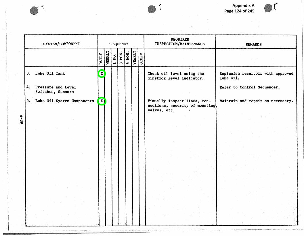
1
SYSTEM/ Ct?MPONENT FREQUENCYREQUIRED
INSPECTION jMAINTENANCE ItEMARiZS
H.e~
y+
~
~+
~c~ cn do ~ o!~ T-+
3. Lube Oil Tank X Check oil level using the Replenish reservoir with approveddipstick level indicator. lube oil.
4. Pressure and Level Refer to Control Sequencer.Switches, Sensors
5. Lube Oil System Components X Visually inspect lines, con- Maintain and repair as necessary.nections, ;sec~rity of mounting
s
valves, etc.
w~o
Appendix A Page 124 of 245

----_ ~ . , ~ n . _ m __ _ .. _e.. ~ ____ _
4 , -,.
z
~,
0
r-
SYSTEM/COMPONENT FREQUENCYREQUIRED
INSPECTION./MAIN~'ENANGE REMARKS
x o `~'o `~
AIR START SYSTEM
af-+ w ~
c'"'1
a'~
ri t0 i7+ Q
1. Air Compressors X Inspect and fill oil level; If auto.. tic drain trap is notdrain traps. used dra n at least weekly ar amore
_ often if necessary.
X X Drain and change oil. Every 30 hours or every 3 monthswhiche~e occurs first. Use lub-ricating oil type and viscosityrecommen ed in Vendor ComponentManual, Worthington).SAE 20 if in heated building.or 4U f ambient temperatureis lU0 F or higher.
SAE 10 if unit is subjected tofreezi g temperature.
X Clean equipment. Clean cy inders and intercaoling.fins wit compressed air.
X Clean air filter, clean com- Clean wi h compressed air or re-pressor valve, clean motor, place if necessary. Inlet andcheck belt tension. discharg valves should be in-
spected nd any dirt ar carbon re-moved fr m seats, Blow off motorwindings with dry compressed air.Check fo accumulation of fa~eign~f~.t~rr
X ~ Motor lubrication and Sleeve b wring motors should beservice. oiled wi h SAE 10 oil. Ball bear-
ings sho ld be repacked yearlywith a g ease about the same con-sistency as vaseline, or stiffer.
},
Appendix A Page 125 of 245

~~~t
r
p
E
`~
1
SYSTEM/COMPONENT ~ FREQUENCYREQUIRED
INSPECTION/MAINTENANCE REMARKS
~ ~ ~ ~ ~
H ~ `~. iii ~. ..
r-1 M ~C? ~ CHj
1. Air Compressors (Cont'd) Do not oil commutator. Inspectmotor brushes and replace ifnecessary. Shape brushes to fitcontour of commutator.
X .Tighten all dolts. For torque valve refer to vendor's{Ingersoll-Rand) literature on aircompressors.
2. Strainer, Starting Air X X Clean strainer. Periodically open strainer blow-"Z'" Type, Muessco No. 7b2 out port to remove collected for-
eign matter. Inspect strainerelement and clean or replace an-ntially .
3. Air Dryer X Inspect air dryer./filter Inspection and Maintenance of airelement. start system required before
scheduling if:
1. Operational lags indicatepressure trend toward abnormal.
2. Pressure alarm has been an-nunciate+~.
Control Valve X Inspect starter Control valveand regulators for leakage.Check. security of startercontrol valve loading turbine.
Air Sta:=ter Refer to Gas Generator Hard-ware.
._ , _— _ __------
No dryer found on HWDdrwawings.
Appendix A Page 126 of 245

- - _ _.. .,_:.. . ,. -~
. ...i
.M.~
w . ... ..
_ ~ i t
in:
SYSTEM/COMPONENT `FREQUENCY
REQUIREDINSPECTION/IKAINTENANCE
y
REMARKS
ALTERNATOR N~..~w
o~
"'~o~E
o~ a
~r ~ ~ ~ ~ ~ o
Mechanical Components
Bearings X If arise in bearing tempera- Bearings re normally trouble free
ture is observed, check oil providing they are supplied with
supply pressure at bearing and clean oil at the correct tempera-
condition of oil filters. Cure and ressure.
Pilot Exciter X Check vibration levels on the The flexi le coupling is in the
pilot excitor, if levels are form of a nylon sleeve with in--
exceeded, check ternal ge r teeth connecting twogear whee s, one on the main shaf t
a. Alignment of the pilot and- one o the pilot. exciter shaft.
e~ccitor.Replace d teriorated components.
b. The coupling sleeve wear.
• c. The pilot excitor bearingsfor wear.
X Check exciter bearings at Syear intervals; Replace bear-ings with grease every 10, 000operating hours as specified iSection 2 Operation and Mainte-nance Manual.
~~ ;,~~ _,
Appendix A Page 127 of 245

~ / - , I►~1,
9' — _
;Y
e
w
SYSTEMICOMPONENT FREQUENCYREQUIRED
INSPECTION/MAINTENANCE REMARKS
H
yW ~ ~
crt
~
~
T
Q3 ~-i W
3. Air Cooled Heat Exchange X Check fan, V belt, motor andUnit (Perfex Inc.) bearings.(CLR-GL-1, FiE-GA-2 and -3
For Drive Assembly X Check the fan blade angle. All blades should be set at samelocation, that is, if the first
X Check that there is no less blade was set at a position of 12than lj2" clearance between o'clock in the fan ring all subse-tip of the longest blade and quent blades should be similiarlythe inside surface of the fan positioned as the fan is rotated.ring.
X Check V belts fot evidence Refer to manufacturers instructionof loosening. Retighten if for tensioning the belts.necessary.
X Check that ventilation openingof motor are clear of dust,dirt or other debris.
X Checl~ the fan matoz bearingsfor wear and lubricate themotor in accordance with theinstriuction plate on the unitand Vendor Instructions.
Heat E~cchanger Tube X Check the tube. bundles for Refer to Vendor Instruction Ma..ualBundles ~ serviceabilitq and damage. ,
does this need to be done dailyin the HWD/SVL environment?
Appendix A Page 128 of 245

SYSTEM/COMPONENT FREQUENCYREQUIRED
INSPECTION/MAINTENANCE REMARKS
~ ~ ~ ~ a
H W ~ ~ ~ +~ ~ ,
A ~ M ~D ~~-1 ~+
Electrical Components
1. Shaft Earthing. Brush X X Brush inspection. WARNING: THE MACHINE SHOULD BESTgPPED ISOLATED FROM ALLSUPPLIES BEFORE ANY PART QF ITIS TOUCH D.
NOTE
Refer to Section 2 Operation andMa.intena ce Manual for egecalcare and inspection required farthe com onent systems after an ex-tended eriod of idleness.
Examine rush every 6 months or2500 ho rs. Replace on condition,if wear exceeds two-thirds or ifany det rioration is evident.
2. Rotor Earth Fault Slip Ring X X Brush inspection. Examine rush every 3 months orBrush ' 1000 ho rs. Replace on condition,
if wear is excessive or if anydetetio ation is evident.
3. RecCifier Assembly x External cleaning. Remove in and foreign materialfrow ex ernal surface of rectifierevery 5 OU hours ar sooner if ex-cessive accumulation is apparent.
- ~
~ ~
included as semi annual check
Appendix A Page 129 of 245

~ ~
r~,
'1~,
SYSTEMjCOMPONENT FREQUENCY ~REQUIRED
IN3PECTIONIMAINTENANCE REMARKS
>+ >-+
aH wp~ ~ ~ ~ `~3 cr► ~c o*-r ~
4, Alternator Stator. End X Inspection and external Remove surface deposits of dustWindings cleaning. and/or oil from stator end wind-
ings by wiping with Inhibited IIITrichloroethane, i.e. "Genklene"(I. C.I.) or equivalent. If therecommended solution is not avail-able, clean windings with a raglightly dampened with white spiritFarticular care must be taken not
. to wash the contamination furtherinto the windings as such treatmencan cause a serious breakdown.Perform every 10,C1C10 hours orsooner it excessive accumulationis apparent. Exercise caution toensure foreign matter is removed,and not introduced further intowindings.
5. Automatic Synchronizer X Clean and inspect. The FRS-210 requires no per~.odicmaintenance, Inspection should bemade to ensure unit is kept cleanand free from dirt and moisture.Accumulation o£ dust should be re-moved from zhe unit with a softb=isle brush or with clean cow-pressed air.
Appendix A Page 130 of 245

., .S
-rs 'r .., ,. ~
,may ~ 3.. ..:rY ~^G.::6 " _ .. ~'~ ' ~ ~' 9 ~ _l~ ~ ~' ~ h
i ' ..
,~REQUIRED
SYSTEM/COMPONENT FREQUENCY INSPECTION/MAINTENANCE ' RE,MARKS
~ ~ ~ ~ a
MAIN LUKE OIL SYSTEM ►'~-+ t~~' ~ ~ ~o ~ o
Air Cooled Heat Egchan es ~Ecod e.
X Inspect and clean exterior When,nec ssarp remove side panels..1. Cooler(CLR-GL-1 + CLR-LO-1) surfaces of cooler core. on modul to gain access to cooler
Clean as necessary with com- headers n each side for tube re-pressed air or warm water jet. pair or lugging.
2. V-Belt X Check V belt far alignment and Refer to endor Manual for ten-tensioning. Retighten if signing -belts.necessary.
X Clean V~elt when necessary-using a cloth moistened withalcohol, benzene or gasoline.
3. Motor and Shaft Bearings (6 d ys Check the motor and shaftbearings for wear and lubri-ca.te as determined by goodpractice. Use only high graderecommended lubricants. .
X Inspect the shielded bearingsfor wear at 2 or 3 year inter-vale.
X Check motior and bearing tem-` ,peraturea.
~ ~r. ~'~
_ -
glycol system onlyis covered in hydromanual.
unusual to clean thebelt.
replace if necessary.
Appendix A Page 131 of 245
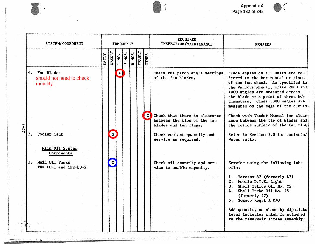
\ ~\L..
- ,,'% ~ .
SYSTEM/COMPONENT FREQUENCYREQUIRED,
INSFECTIUN/MAINTENANCE.
~~~tg
H
>+
~~.r ~~r'
~
~~ ~.
W r~i
c~"1 p+—i ~D }+
4. Fan Blades X Check the pitch angle settings Blade angles on all units are re-of the fan blades. (erred to the horizontal or plane
of the fan wheel. As specified inthe Vendors Manual, class 20013 and7U00 angles are measured acrossthe blade at a point of three hubdiameters. Class 5U0fJ angles aremeasured on the edge of the clevis
X Check that there is clearance Check with Vendor Manual for clear. between the tips of the fan ance between the tip of blades andblades and fan rings. the inside surface of the fan ring
5. Cooler Tank X Check coolant quantity and Refer to Section 3.0 for coolants)service as required. Water ratio.
Main Oil SystemComponents
1. Main Oil Tanks X Check oil quantity and ser- Service using the following TubeTNK-LO-1 and TNK-L0~-2 vice to usable capacity. oils
1. Teresso 32 {formerly 43~2 Mobile D.T.E. Light3. She11 Tellus 011 No. 254. She11 Turbo Oil No. 25
{formerly 2?)5. Texaco Regal A Rj0
Add quantity, as shown by dipstickslevel indicator which is attachedto the reservoir screen assemblq.
i
.~,_~ .... ....., _ ~ .vm.x. ~,~,. ~~....~......R.n~.e_ _ ,. _ _. .
should not need to checkmonthly.
Appendix A Page 132 of 245

;: .., _ .. ~ _ ..._ .. .~ .. _.~. _ x F~
..
_
i y
wg
f.
sSYSTEM/COMPONENT FREQUENCY
~ REQUIRED
.
INSPECTIONJMAINTENANCE REMARK$
N c~ ~~3 ~
c~*-+ •c y+ o .
X ' Drain condensation from sys- Utilize t ak~drain at bottom rear,tem. left Bide of large tank. Drain
approxma ely ten (10) gallons ofliquid to ensure removal-of accu-mulated w ter. Accomplish aftersystem ha been inoperative atleast 8 h urs.
2. Main Lube Pump MotorsAux. DC Pump (2) X Inspect. and clean. Remove co utator access covers.Mntor, P-LO-2 b -3 Blow out ith dry co~ressed air
(50 psi x.) to remoge accumu-lated dus and foreign matter.Inspect b uehes for proper bed-ding';and freedom of movement intheir ho dera.
X Check brush lengths. Replace rushes if worn below• 3/4" (19 ) . Refer to VendorComponen Bulletin.
X ~ ~ Check bearing lubrication. Relubric to per bulletin utilizinggrease s ecified on motor dataplate..
Main AC Pump MAtor P-LO-1 X~ Check bearing lubrication. Relubric to as ~►ecessary per Ven-do~ Comp vent Instructions.
t.~ , _ _.
Appendix A Page 133 of 245

r- ,~ .,,f
~ ~ ~~
i~o
SYSTEM/COMPONENT.
FREQUENCYREQUIRED
INSPECTION/MAINTENANCE REMARKS
~., ~.,
~ ~H ~ '~rF'.a ~+ .~.~'
r-i tr1 ~O ?'+ (~
NOTEWhen a pump is installed for thefirst time, either as new or afterremoval for maintenance, thethrust bearing is dry and could bedamaged in the first €ew secondsuntil the oil reaches the screwelements. It is therefore advis-able to check the priming of thepump when first put into se=viceon site, so that the situationwhere a pump 1s removed during in-stallation and tipped over isguarded against.
(Pump priming is necessary forboth AC and DC motor driven units.
Gear type pumps are normally selfpriming, but on an initial starthand priming is recommended.
3. Main Lube Oil Filter X X Replacement of cartridge e1e- To service filters, replace cart-F-LO-1 meats, ridges yearly or when pressure
differential is 20 psi {whicheveroccurs first)- using the followingprocedure:
1. Shut off gate valves I.U--1~ endL0-11 and open drain valveLO-12 or LU-31 to drain oilfrom filter housing,
included in 5 yrly checksitem f (?)
Appendix A Page 134 of 245

i ~
1
~n0
r .i. Y. '~ 1.. r
,._ ~ . F
' w S
,C.w...._ — s ~x
s ~. ~ ~ ~ ~{ ~
~
't ',
REQUIREDi
SYSTEM/COMPONENT FREQUENCY INSPECTION/MAINTENANCE REMARKg~,
a~
"'~o
~
c o~
~ `~
F
H ~ ~ .~ !~ ~~-~1 M tCa ~+ +O
2. Loos n bolts retaining thecove,
_.aesem~ly.
3. Lift off cover using overhead fmono ail and suitable hoist # ''and emove individual seal ~ ',plat assemblies from the topof ch stack. ~ '
i s
4-. Lift off top cartridges and{ :.
lift out cartridge posts to. remo e remaining cartridges in t~
the stacks. Cartridge posts..can e reuaved by twisting.the slightly in either direc-tio and pulling them upward to 4fre them from the p+edea tale
. 5. The center poets should becle ned. Do not attempt to
',re ve cartrd e edeatals.Whe cleaning around the cart-rid e pedestals, be careful
' not to allow contaminant to' pas down through the pedes- ''' tal into the filtered fluid icha er. ~
6. 'Che k condition of the coverf
gas et and replace if nec~~-ear
7. 'Rea semble replacement cart-rid ea and the filter assembly
.r i ~ ',
~ 1 ~ ~,'_~~~
Appendix A Page 135 of 245

~,. ~ ~.
~. ~. ~~
SYSTEM/COMPONENT FREQUENCYREQUIRED
ZNSPECTIQN/MAINTENANCE REMARItg
H
a~
w
~ ~ ~ a
c~
4. Oil Jack~.ng Pump Motor X Check bearing lubrication. Remove bearing caps and examineP-JtJ-1 grease for consisfiency and suf-
f is iency. Apply bearing lub rica-tion as necessary. Refer to Ven-dor Component Maintenance Instruc-tiona. Recommended grease isShell Alvania 2.
X Bearing grease renewal. Bearings should be completely re-serviced with grease every 2 years
. Shell Alvania 2.
X Inspect brushes for wear. Periodically, not to exceed threemonth intervals, inspect brushesfor excessive or•abnarmal wear.Check bush pressure against thecommutator and freedom of brushesin their holders, Refer to VendorComponent Maintenance In$tructions
5. Three-way Thermostatic X .Disassembly inspection and Disassemble valve, inspect andControl Valve ~ ~ cleaning. clean per- Vendor Component Mainte-
Hance InsCructions. Valve body~ . need not. be removed from pipework
to perform this inspection,
6. Oil Supply and Drain Piping R Inspect for leakage. Surveillance for leakage should bea continuing process, Ensuresealing integrity by visual obser-vation of alb fluid connecting
,.
t
Appendix A Page 136 of 245

_ _
., :.~.
• _
itoN
SYSTEM/~OMPUNENT ~
~._...
FREQUENCY. REQUIRED
INSPECTIONIMAINTENANCE REMA;RiCS
' N
~
W
vi
~
cri ,teaps~,~
c~
~
~"'1
~ x.
O~-1 ~C► }~
junction ; sealing flanges, valvegland pa kings, filter housingcovers, anks, etc. Correct any. .leakage onditian observed.
7. Pressure Switches, Sensors, . Refer to Control Sequencer. ~ Check an calibrate as .required..Level Switches, etc.
r ,;
Appendix A Page 137 of 245

w
SYSTEM/COMPONENT FRE UENCYQ INSPEC OgUIRED
TI N/MAINTENANCE REMARKS
~ "'`~
.
FIRE SYSTEMaN
o~ ~
o~
a~~e
r-1 M, ~D ~+ O
CAUTION:AS A SAFETY PRECAIITION, BEFORE ANYMAINTENANCE IS CONDUCTED ON THEUNIT, LOCK OUT THE UNIT AND SWITCAUFF THE FIRE PROTECTION CIRCUIT. TODISARM THE HALON SYSTEM TO PROTECTPERSONNEL WORKING INSIDE THE I~?D-t)LES FROM ACCIDENTAL DISCHARGE OFTHIS SYSTEM.
Halon Systems(Safety Firat Pro~uctbandJor Fenwa~l)
1.~ General Systems X Normal sgstem chec~C. Check pressure gauges of each storage container. If the pressure isless than 325 paig at 70'F thecontainer should be removed byqualified personnel, inspected andreconditioned as necessarq, Checkall components supporting hardwareand tighten and repair as requiredVisuallq check .all components foz
~ , seeurity and evidence of damage.Refer to Vendor Manual far zemovalresetting and reinstalling of sy~-tem components and to Section 4Operation and Maintenance ManL-'_for Pressure and Actuation Checks:
2. Control Units R Control unit function. Depress the,"Alarm Test" button ~tthe top on the ins~.de panel of the
k ~ control unit. The alarm life and
,.~. ~_. ~ ~.. , ._ ,~,.v ~_.~~~ _. _ ~...~.... .~...~~~.~~..,, _ ~_ .._ , ~ ~ ,~ .,.~., _~. ~ .F .. . _ ._.
now replaced withInergen? checks insemi-annualmaintenance.
Further checks in 5yearly maintenance.Exact content isunclear.
Appendix A Page 138 of 245

_ ~. .. - _ ._.. _. _~r
I'
,~
,.r
r~,+
SYSTEM/COMPONENT FREQUENCY`REQUIRED-
INSPECTION/MAINTENANCE REMARKS
a
~
~' o
~
~
~
`~'
~
~ ac.
~
other co ected alarm devices must'~ funct,ion. Supplementary devices.
operating on a fire condition. mustrespond.
3. Detectors and Initiators X Inspect, clew, and t est Defector enses to be cleaned as(Fenwall and/or Scott) ; (Fenwall) followsz Shut off system. Clean
ITHElens 'with lens tissue. If covered
WARNING: INITIATOR ASSEIrF- ~ with oil r other material imperviBLY IS A CLASS "C" EXPI~OSIVE. ous to ultraviolet rays, cleanHANDLE AND', STORE IN ACCORDANCE with,tiss e soaked in solvent sup-WITH.APPROPRIATE REGULATIONS. plied, not damage gasket andWEAR SAFETY GLASSES OR A FACE detector aint. Spray lens withSHIELD WHILE HANDLING. ' an anti- tatic solution such as
Anti-Sts No. 6 available fromBrown La oratories, Philadelphia,
~' Pa.,,or quivalent. Turn systemI,on.
I~' % I~aspect clean and test.s Clean pr duct of combustion detec-tors !by lowing clean dry airthrough he opening between col-lector p ateand well where radiumsensor i .located; remoee foreign
I i material with a swab saturated~,' ~ with',alc hol.
Ins ect clean and teat theP800~aeres gas monitor (Scott)
~, X Check instrument zero sett n sS''~ Ad~uat na~rument in excess of
SX of full scale.
'~i 4
' , `...
Appendix A Page 139 of 245
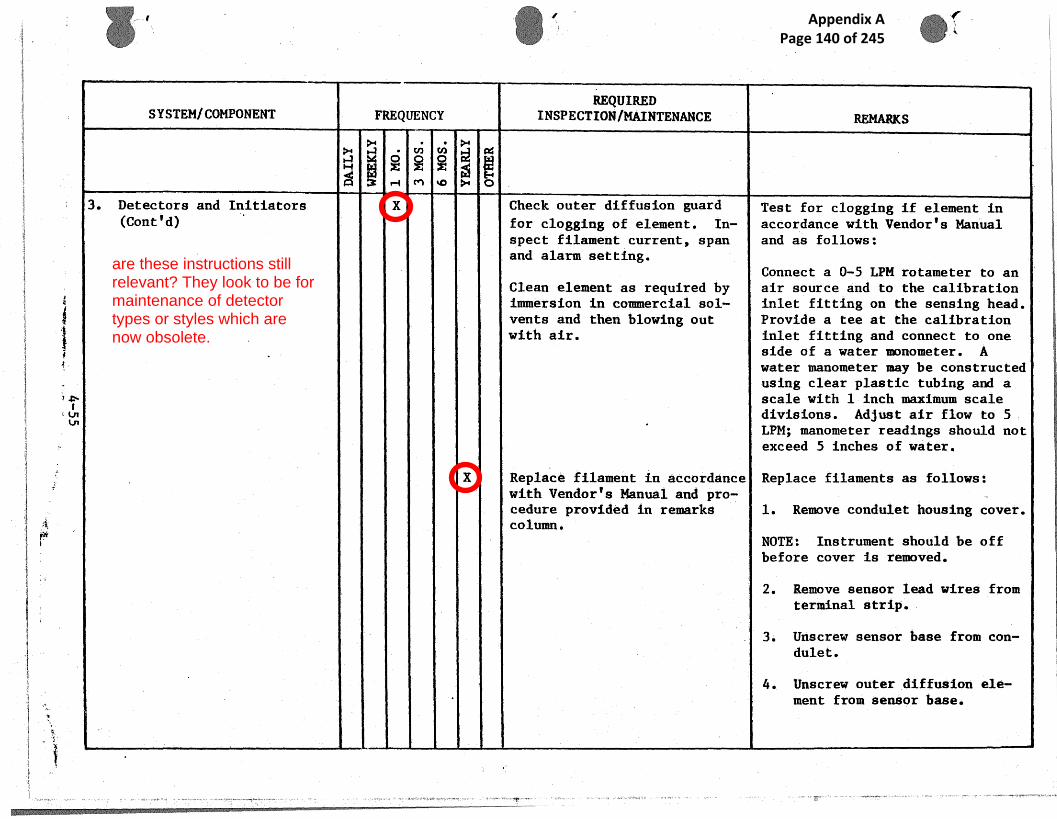
rr
Ix
I", ~;~ o
SYSTEM/COMPONENT FREQUENCYREQUIRED
INSPECTION/MAINTENANCE g~~g~s
~, y~
H ~ r~~+ ~i
q~ r1 ~O ~r—~i - O
3. Detectors and Initiators X Check outer diffusion guard Test for clogging if element in(Cont'd) ~ for clogging of element. In-- accordance with Vendor's Manual
spect filament current, span and as follows:and alarm setting.
Connect a 4-5 LPM rotameter to anClean element as required by air source and to the calibrationiimnersion in commercial sot- inlet fifiting on the sensing head.vents and then blowing aut Provide a tee at the calibration
. with air, inlet fitting and connect to oneside of a water manometer. Awater manometer maq be constructedusing clear plastic tubing and ascale with 1 inch maacimum scaledivisions . Ad3 us t air flow to SLPM; manometer readings should notexceed S inches of water.
X Replace filament in accordance Replace filaments as follows:with Vendor's Manual and pro- ..cedure provided in remarks 1. Remove condulet housing cover.column.
NQTE: Instrument should be offbefore cover is removed.
2. Remove sensor Lead wires fromterminal strip. -
3, Unscrew sensor base from con-dulet.
4. Unscrew outer diffusion e1e-ment from sensor base.
are these instructions stillrelevant? They look to be formaintenance of detectortypes or styles which arenow obsolete.
Appendix A Page 140 of 245

vc
SYSTEM/COMPONENT FREQUENCYREQUIRED
INSPECTION/MAINTENANCE REM~~RiCS
y. y~
N r~~ ~ ~ ~ ~ ~ o
S. Unsc~ inner. diffusion e1e-meet rom sensor base..
b. Clip re lugs from sensor,leads.
7. Unscr _ active and .referencefile nts from sensor base.-
8. Screw reference filament ~mtilit bo tams in sensor base.
NOTE: ' If filament wire is touchedby hand, ontamination and filamenpoisoning may occur, Extreme careshould be taken to prevent thisc~ccfi~rrr-enc .
~ ~ 9. Feed 3lament leads from activf law nts through port in sen-sor b se and screw active ele-ment til it bottoms in sen-sor e.
. R hest t~i~er~~ai detee~a~s. Test cc3mb Lion detectors as fal- .-
',
~.ovs1.v
1. Pero the functional tests~~.provi ed in the Vendor"s .(Fenw 11) Manual, or as fo1-.3~e~s
Appendix A Page 141 of 245

r ~
a~nV
t',~,
SYSTEM/COMPONENT FREQUENCYREQUIRED
INSPECTIfJN/MAINTENANCE RE,MARI~g
~• v~ v9
~+~ p4
H W ~ ~ ~
M ~ ~+ Q•-i
3. Detectors and Initiators 2. Check Fenwall Detectors, used(Cont'd) on GG4 engines, as required,
and when exposed to a tempera-ture exceeding 550°F {288°C)as follows:
a. Disconnect DC power to thesystem,
b. Remove the detectors fromthe function boxes.
c. .Connect an ohmmeter acrossthe faire leads and insertinto. a canCrolled he$tbath of oil or other fluid
d. Thermal detectors used toactivate the fire suppre-aion system should close
_ ~~. .~
at 4so°F + Zo~~.
~ a
Appendix A Page 142 of 245

.~
SYSTEMICOMPONENT ~ FREQUENCY1tEQUIRED
ZNSPECTIONIMA.INTENANCE REMARKS
~ sn cri ~ a
X Test initiators« The init stars are destroyed by--its open Lion and must be replacedafter sy tem activation. Becauseof its e plosive nature the assenr-bly shou d be checked and tested
. in actor ante with the Vendor In-structio s.as follows: Disconnectinitiato s at each agent storagecontains and i~astall jumper wires.at the c nnector in place of the'
_ initiato s. 'Connect a 24 VDC testlamp in eries with the initiatorloop and connect to initiator ter-urinals a control unit. `Install a
. ~temporar dumper across actuatingterminal of a detector unit andturn sys em on, The test lice,trouble its anti alarm should functiara, dumpers are removed. fromeach...-ini iator cable, the test lit.should g out. If system is equipped witha $ecandary or reverse
SuPP1Ys uzn system off; switch tosecondar supply and repeat testprocedur Disconnect all tem-porary t st wiring: remove testdevices, reconnect all system
Y componen s and activate system.
va
_r s .,
>-
Appendix A Page 143 of 245
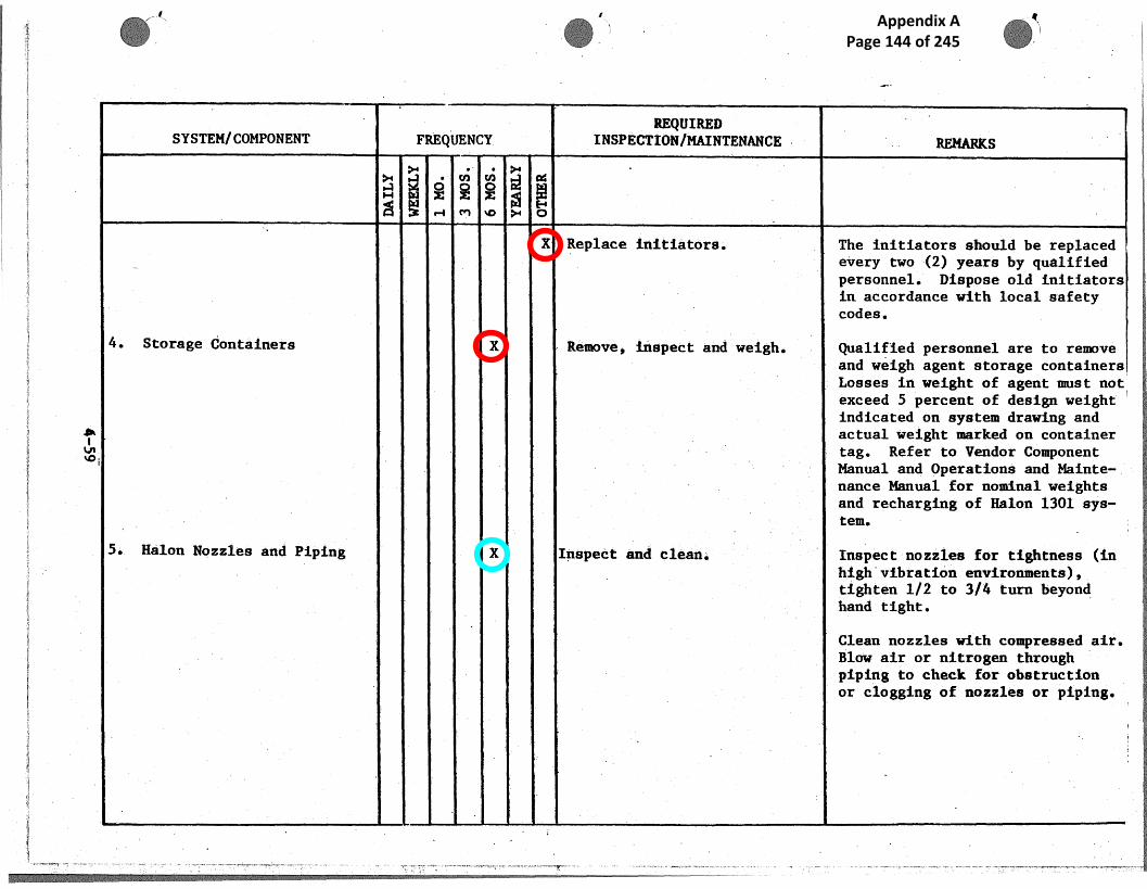
a
_r'~
SYSTEM/COMPONENT FREQUENCYREQUIRED
INSPECTIONIMAINTENANCE ~.
~ . . REMARKS
H
~+ • ~ ~.+
'r°~ ~ ~ r►, ~ o~o
X Replace initiators. The initiators should be replaced_ ~ every two (2) years bq qualified
personnel. Dispose old initiators~.n accordance with local safetycodes.
4. Storage Containers X Remove, inspect and weig~i Qualified personnel are to removeand weigh agent storage containersLosses in weight of agent must not eexceed 5 percent of design weightindicated on spstem drawing andactual weight marked on containertag. Refer to Vendor ComponentManual and Uperations and Mainte-.nance Manual for nominal weightsand recharging of Halon 1301 sys-tem.
5, Hahn Nozzles and Piping X Inspect and clean. Inspect nozzles fo= tightness (in. high~vibraton envi=onments),
tighten 1/2 to 3/4 turn beyondhand tight.
Clean nozzles With compressed air.Blow. air or nitrogen throughpiping to check for obstructionor clogging of nozzles or piping.
Appendix A Page 144 of 245

' ...
,~..~ ,r ~ -
ro~0
~~
"i ' I' '
SYSTEM/COMPONENT FREQUENCY~QUI~I}
INSPECTION/MAINTENANCE REMARKS~~
N
~
~ ~
N
~'
~
~ :
~
~
a
d~ p~ .~l 3 ~-~1 M ~O ,'Y+ O
III
Carbon Dioxide (CO2)
Extinguishing System'(Walter ~C3.dde)
General S'stemY X Normal S stem Insection.Y P Refer to Vendor Walter~ Kidde)Manual f r removal, Resetting and
'; Perform the followin voce-,8 P reinstal ing of system components.
I!duce as required or when COZ
I~j
has been discharged:
~ 1, Remove c linden for checl~y,~ weighing. If cylinder re-'; gieters less than 90X,FULL'I
it is to be recharged Co` FULL capacity.
2. When cylinder is discon-'
~I ~ nected:~ ~ .
', ~ a. Check operation of', mechanical trip.
I~~, b Remove glass from pull ~ ~
',~ bog and operate handleto ensure cable has
.
', ~ ~ freedom of movementwithin ita conduit re-
', ~ ~ place glass.
c. Reset the mechanical'release trip, pressure
', ~ switch, fusible links .and pull bou.
'~ ~
j
~ _ ~ ~~_
~~ _ ;~ !~,~~
is this system now replacedwith Inergen extinguishant? Isit necessary to weigh thebottles?
Appendix A Page 145 of 245

r - ~"t: ~ ~ ,.
~ ~ric
SYSTEM/COMPONENT FREQUENCYREQUIRED
INSPECTION/MAINTENANCE REMARKS
a ~ o `r'~o i~ °~
~ ~ ~ ~ ~ ~..~
`General Spstem ~Cont'd} d. Check contents of ..premix vessel through thsight glass level Vin-dicator. Top up asrequired.
. e Operate 3 in, gatevalve to ensure free- .c~om of movement.
.~
Appendix A Page 146 of 245
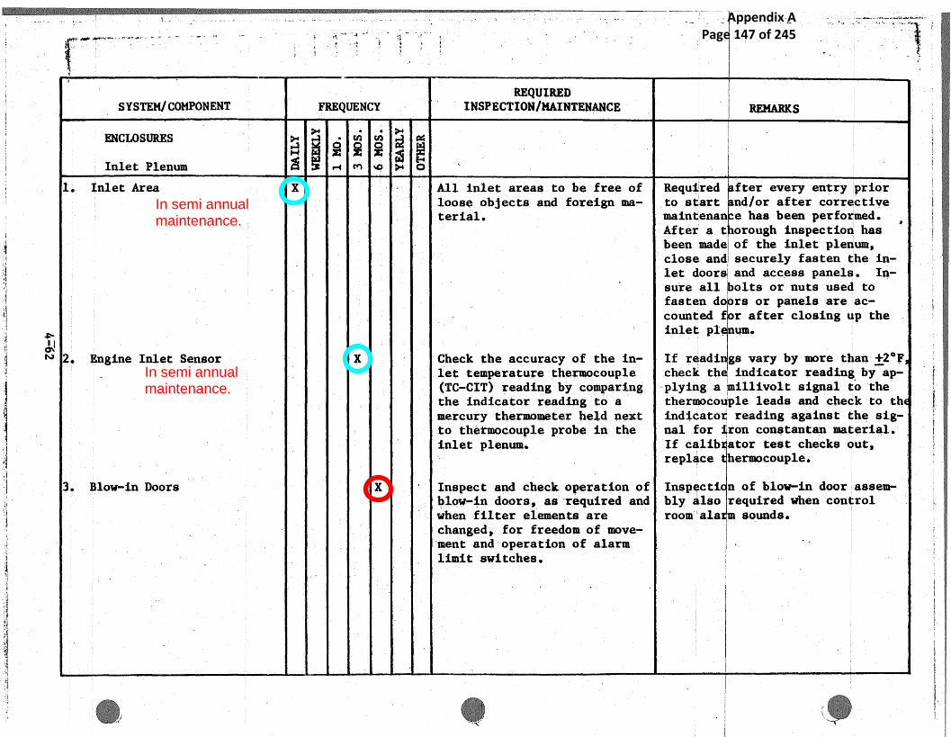
_~._:_. o — ._ _., , . , .. ~ .... , .~.. .. ,r , , , . ._ .. _ _ ~ ~ w,~...
.<
3
,`
~ IN
SYSTEM/COMPONENT FREQUENCY ~REQUIRED
~ ~ INSPECTION/MAINTENANCE REMARKS
ENCLOSURES >+ c~ri cis ~ a
Inlet Plenum rd r-r cn ~o y+ oI
1 Inlet Area X l All inlet areas to be free of Required fter every entry 'priorloose objects and foreign ma- to start nd/or after correctiveterial. maintenan e has been performed.
After a.t orough inspection hasbeen made of the inlet plenum,close and securely fasten the in-let doore and access panels. In-sure !all. olts or nuts used tofasten do ra or panels are'ac-
. counted f r after closing up theinlet pl. um.
2 Engine Inlet Sensor X C~ieck the accuracy of the in- If ready ge vary by more than +2°Flet temperature thermocouple check th indicator reading by ap-(TC-CIT) reading by comparing plying a illivolt signal to the
` the indicator reading to a theru~oco ple leads and check to thmercury thermometer- he~.d next indicato reading against the sig-to thermocouple probe in the nal for ron constantan material.inlet plenum. If calib.ator test checks .out,
'' replace hermacouple.
3 Blow-ln Doors X . Inspect and chec]~c operation of Inspecti n.of blo~r-in door,assem-blow-ln doors, as~required and bly also required when confrolwhen filter elements are room'ala sounds.changed, for freedom of move-~ment and operation of alarm '•
. limit switches.
. ~,~ __.
In semi annualmaintenance.
In semi annualmaintenance.
Appendix A Page 147 of 245

d
Ir'
.~
i
} ~~
SYSTEMjCOMPONENT FREQUENCY1\GQU i[i~~
INSPECTION/MAINTENANCE REMARKS
a "' `~' ~ a~aH ~
o~: ~ rte+ `~~"'
w E~ _
4. Inlet Silencer X Inspect accessible silencer Single cracks of less than 3" may.- baffles for cracks and ~ecu- be stopped drilled, unless cracks
ri~y of attached components. are running toward each otherwhich would result in eventualbreaking away of material: Theselater types of cracks should be
• weld repaired a~n~d excess materialand slag carefully removed fromplenum area.
5. Drainage X Check level of drainage tank. and pimp out ~f necessary.
Evaporative Cooler Assembly X Check water level Co tanks,(Burgess In~ustrea~ ~ ~ water~supplp pressure to noz-
zles and any nwzzles for. clog-gins•
X Cheek tank water for cleanli-ness and any sludge collectionon tank bottom. If dirty,drain hose down and ref ill witclean water; recheck setting ofloat valve.
X Inspect condition of coolerinferiors, plenum and tanks .
rnw
Is this installed on the Hydroplant. No reference to it hasbeen found elsewhere.
Appendix A Page 148 of 245

i —.
P... i
' . . .. - .
< - . _ ,_.. _ ,. <. - a ..
io+
SYSTEM/COMPONENT FREQUENCYREQUIRED
INSPECTION/MAINTENANCE REMARKS
~ ~' ~~~3
~c~
~ ~oA r+ ~a a+
X Clean tank thoroughly, Scrape or wire brush all areas ofcorrosion and touch up with zincrich pain..
X Inspect spray nozzles. Remove Note some erosion will not affectand'replgce any with badly cooler pe formancematerially, buteroded orifices. obviously. bad ones should be re-
placed..
X It~epect all spray drain piping Refer to erformance criteria pro-for any leaks at seals or vided in ection 1 Operation and~ointa. The pump should be Maintenan e Manual illustrationlubricated and inspected. with titl "Intake Air evapora-
tive Cool r Curve."
R ~: Check eliminator blades ifwater carry-over is apparent
` in the plenum area.
X . Check condition of implosiondoor hardware. Check and oilif necessary and make sure
; hinges and latches operatefreely. Recheck release pointand limit switch operation. .
%' ;Remove and replace ~olyure-thane foam cell filters.
__ ,
No reference to spray coolingfound in other CW manuals.Is this section relevant?
Appendix A Page 149 of 245

it ~ t
o~v+~
a
9
t'~
SYSTEM/COMPONENT FREQUENCYREQUIRED
INSPECTION/MAINTENANCE REMARKS
r~-~
+-~ cr► ~A >+ c3
Control Building
1. AC/DC Motor Control Centers X X General; Inspect, clean and Refer ~o'Motor Control Centersservice, .
2. Sequence Timers X Check timer settings, mounting Refer to Control Sequencer.and terminal connections.
3. Recording Instrument X Inspect ink supply paper sup-ply and instrument zero set-ting.
X .Flush and clean inkwell. Use water or alcohol. Use penC~.ean pen capillary tube and clewing wire to clean pen tip.tip. - Flush with water.
X Clean and lubricate motor Bear nge may be removed for clean-chart drive bearings and~re- ing by taking out three machineroll drive mechanism. ~ screws which secure mechanism aide
plates. Clean bearings by brush- .ng out with naptha. D=y and lub-
ricate bearings with Westinghouse~ ~ . C1ock Oil Style No. 935136 or
. equivalent.
~. Watt~our Meters ~ X R,ep1~~~ Refer to.Vendo= Component Manual.
Appendix A Page 150 of 245

SYSTEM/COMPONENT FREQUENCY1tEQUIRED
INSPECTION/MAINTENANCE REi~iARKS
', _ ~ ~ , .-1 c+'1 do ~►+ D
5. Circuit Breakers X~ ~~ General, inspect far cleanli- Initial i sp~ection and lubricationHess, inspect contacts, in- is after months of service orspect for loose parts, lubri- number of operations.gate.
Refer to ,endor CompoAent Manualfor instr coons to' disassemble,contac t a ~ us~tment, cleaning andlubricati n. {Special lubricantis requir d in a few places andmust'be a plied with care).
WARNING: IN THE OPERATION OF T'~iEBATTERIES GASES ARE FORMED WHICHMAY BEE COSINE IF IGNITED.NEVER, BRI G ANY BURNING MATERIAL
. ; . SUCH AS L GHTED MATCHES, CIGARETTEAND THE L KE, OR SPARKS OF ANY K~IN THE BA TERM ROOM.
6 Batteries ~ X ~ ~ Check battery fluid level and Immediate y after installation,hydrometer reading of pilot check and record voltage acrosscell. each cell and specific gravity of
each cell During this check, thecell with the lowest voltage andspecific cavity will be deter-mined and may be used as a pilotce11 for eriodic checks.
.,
Appendix A Page 151 of 245

r ~h
4
SYSTEM/COMPONENT FREQUENCYREQUIRED
INSPECTIUN~MAINTENANCE ~ REMARKS
a+ ~ y ~ a
X Check and record battery cell Add distilled water to each cellvoltage. as often as necessary to maintain
fluid level.
R Ghecic and record hydrometerreadings of each cell and tem-pe=ature of each fifth (5thcell. Compare readings withprevious readings for signs ofdeterioration.
7. Inverter X Check for cleanliness and re- Check inspection readings withcord output voltage and fre- previous data.quency .
8. Battery Charger X Check for cleanliness, and re- Check inspection readings withcord output voltage and amper- previous data.age.
9. annunciator ~ X Rel.amp as necessary. Remove front bezel and window~as-aemblq, replace bulb, then replace:bezel and window assembly.
X t~nnunciator Care# replac~met~t. Remove window and bezel assembly;grasp light box at the edges andpull sharply. To replace the mod-ule align the new module in placeand start into the socket; then
.,; ,,~. _:. ~. ~ o.~ .
finish with a share Push..,
io~.v
Limited electrical checksfound in 5 yearly.
Appendix A Page 152 of 245

y - .. :
F
ro~a
SYSTEM/COMPONENT FREQt1ENCYREQUIRED
INSPECTION/MAINTENANCE REMARKS
~
a
~ ~ ~ a.
~ ~ ~. ~~
10. Fire Control System ~ ~ For normal system check andcontrol unit function, referto Halon Fire Protection of . ..System Inspection and Mainte-. .Hance chart.
Control sequencerInstrumentation
-Refer to Op rations ~ MaintenanceManual,,. for listing of test equip-went requlr d to inspect, cali-
• brate and intain control,sequencinstruments ion.
1. Level Switches ~ X Inspect float mechanism$ for Calibrate l vel switches. by vary-(As applicable): freedom of movement. Check ing the liq id level in Che relate
electrical wiring for security tanks or me sure level above tankin dry coed tion. Refer to Vendor.literature or details.
2. Thermal Switches X Inspect all temperature Reter to to perature switch bu11~-Temperature Switches switches for proper voltage tins in Ven or. Component Manuals
and evidence of filling fluid for check a d calibration proce-on external parts and freedom dures. 'Qf plungers and conical~s~prings
~( { ,
checklists with tag numbersare needed to ensure alldevices are checked. Safetycritical ones need to be prooftested and results recorded.
Generic statements areincluded in 5 yearly checks. Itis unclear which arespecifically addressed. Theremay be lists in associatedwork orders.
Appendix A Page 153 of 245

~,
SYSTEM/COMPONENT FREQUENCYREQUIRED
INSPECTION/MAINTENANCE R~MARI~S
a v~ ~n ~ aaN ~
o~ ~ ~ ~
Check dare thermal sw tc~ies Disconnect the heat actuator de-and calibrate. vice ,from the system. (Refer to
Vendor Manual for precautionarymeasures during system maintenanceConnect a 24V DC test lamp, a powesource and the detecCor in series.Heat the detector with a heat lampon other convenient source.
When the test lamp lights, removethe heat source and allow detectorto cool. 7'tie test lamp should goout and the detector contactsshould be open. Contact closure
. ~ temp+~rgturea are gi~ren 3.n Oper-~ ations and Maintenance Manual.
Relays -Voltage (DC) X X Inspect, clean, test. The n~ ntenante period for varioust3rpes of relays vary from b monthsto the maximum of 24 months .Testing and cleaning of relays andcontacts are generally in accord-ance with proc€dures used for the
• Motor Control Center and instruc-tions for testing the individualtype of relays are given in theVendor Instruction Manuals.
Appendix A Page 154 of 245

.;.~QurttEt~SYSTEMICOMPONENT FREQUENCY INSPECTION/MAINTENANCE ~ ~ REMARKS
a ,.a o
~i
`n `'r' ~ c~
N W ~i ~.a Q~
4. Limit Switches ~ X Inspect for tightness and Check for on~nector tightness,test. Actuate sw tchea manually in cir-
cu t or wi h test instrument todetermine witch closing and open-i~g. Cali rate by adjustingmount3.ng, tc. to actuate switchlever and oller at desired posi-Lion. Che k switch contacts post- ktiara with est light or other in-dcating t st instrument.
5. ' Pressure Switches & ~ X ~ Inspect $witch and transmitterTransmitters for leaks, shorts and securit~t ¢
of mounting.
X: Inspect and calibrate Calibrate r check pressure' i i ~ switches u rag easily adjusted
Y '_,~ ? s
f p~reasure s urce capable of pro-' i s f ducing a p ensure.equal to the 4
3 ~ _ ~ t ~ ~ proof prey ure of the switch. Qse.~ . Z ~s ~ F _
~ accurate p ensure gage connected
t to pressur source and low voltageindicator fight for contact checksCheck alai and trip settings usingage and 1 to fo= reference. Re-fer to Ve or Component Manualsfor test d adjustment instruc-tions for articular switch.
}
__
5 yearly checks item c (?)
Appendix A Page 155 of 245

r
.c,vN
SYSTEMjCOMPONENT FREQUENCY. ttEQUTRED
INSPECTIONIMAINTENANCE ~~p~~g
a 'a o `r'o ~ `~
..
►-a r~ ~ ~ ~~e +r~.-~+ ~o ~ o
6. Vibration Monitors X System test. then the test button is depresseda signal is applied to the inputof the channel selected and the DC
~~ output of this channel is shown onthe meter provided the channel se-lect switch is indicating the Channel tested. The teat signal pro-vides full sole deflection. Dur-ing this operation a relap lockoutis provided to desensitize .thealarm and shutdown relaps, but. theindicator lamps will be energized.
This procedure checks the overallga~.n of the system, the reaction othe comparators and the amount oftime delay. There is~a delay of1,0 seconds between the time whenthe test button is released and thtime when themonito=ing functionis resumed. The test signal is applied to the channel whose test
~ ` but tan is pushed even when thechannel select switch is indicat-ng a different channel. The
mete= will not respond, but themonitoring function of the testedchannel will be interrupted a*~dthe indicator lamps will light.
Appendix A Page 156 of 245

,:
N
.
SYSTEM/COMPONENT FREQUENCY.
REQUIRED..
INSPECTIONIMAINTENANGE REMARKS
y{ >•
~ aH w ~ ~ ~a~ ~ ~ ~, ~o a+ o
6. Vibration Manitora (Cont'd) Mantenanc ~ Service for detailtest, Cali ration and trouble-shooting p ocedures..
X To calbra e monitor installed inpanel, pro eed as follows;
Step 1. Turn off AC power. to eter and ad ust mechanical zeroon front of meter to pointer po ition of zero..Turn AC power back an
Step. 2. Disconnect pickup inp t leads.. to hannel No. 1. Connectthe sine wave output f the ascil ator to the inputterminals of Channel o. 1. Conn ct the DVI~i to theoscillator output. C nnect the s uaZe wave output ofthe oscillator to the .frequency c unter. Remove ChannelNo. 1 ca=d and zeinst 11 with the extender card, Dis-connect circuit atten anon on Te m 10.
Step 3. Set oscillator to 140 Hz at 24 MV. Adjust R28 far1 mil on the monitor' eter. CW t raise.
Step 4. Set. oscillator to 100 Hz at 24$ Adjust R.5 to set10 mils. If R5 has n effect, ad ust Rl until RSadjustments do have. a effect, i. if you are .tryingto raise R5 with no ~ feet, raise with Rl slightlymore than 9 mils then set 4 mils ith R5. CCW on RSto raise. CW an Rl t raise.
Step 5. Repeat steps 3 and 4 ntil no further adjustments ofRl, RS and R28 is req iced.
~ ~ ~ ~ ~
~... ~,, ,
included in 5 year checks,item d (?)
Appendix A Page 157 of 245

_ i ~ r~,~ } ~ ~ 'ti
SYSTEM/COMPONENT FREQUENCYREQUIRED
INSPECTION/MAINTENANCE REMARKS
~+ >+
aH ~ ~ ~ ~ ~
3 r~ .o.-~ y~ . o
6. Vibration Monitors (Cont'd) Step 6. Press test button on ront of channel card and adjust' R26 to near full seal Ensure R26 is still in control
at the maximum attain b1e meter reading nearest l0 mils.
Step 7. Repeat steps 5 and b ntil no further ad;~ustments are re-qui=ed.
Step 8. Set the ~ecor~ended put (MV) (at 1a0 H~} and check themeter reaclings
1 mil2 mil3 mil4 mil5 mil6 mil7 mil
.
` 8 mii9 mil
NOTE: f 0.05 is acce table ~t 2 through 5 mils.-f- 0.1 is acce table at 6 through.$ mile.
Step 9, Disconnect teat equip ent at back of Channel No, landreconnect leads remov, d in Step 2. Remove extendercard and reinstallch nnel card.
Step 10. Push alarm button and ad3ust alarm to' 5 mils, relea~~button. Push shutda button and ad,~ust shutdown to10 mils.
Step 11. Repeat Steps 2 throng lU for the remaining channels.
Appendix A Page 158 of 245

i
SYSTEM/COMPONENT FREQUENCYREQUIRED
=NSPECTION/MAINTENANCE MARKS
~ ~ ~ a
6. Vibration Manitars (Cont'd) X Inspect transducer wiring for Check settin of X13 overspeedcfiafing ar other damage. switches (AD 0 and. ADll} by apply-Inspect transducer mount for ing oscillat r signal of lOQO Hz
. security. to terminal 'and 6 of speedawiCch. Ope reset c+~ntact betwee
X Check switch settings, Terminals 7 nd $. Connect ahmetebetween shut own switch terminals3 ':and 4, (sh uldread closed). Increase oscil ator frequency untiloh~neter on ernuinals 3 and 4 in-d3.cate open. Frequency should be4140 Hz. Re uce oscillator fre-quency to ab ut 1000 Hz. Terminal3 and 4 shou d read open untilspeed switch is reset by momentar-ily closing ontacts 7 and 8.
Check freque cy~ (RPM) at which theD13 speed rel ys operate by increasing or deer sing. oscillator fre-quency and nitoring relays:
~14T10X1 - d -energize - 1000 HZ214T10X1 (increase}
114T32X1 - e.ergi~e - 3200 HZ214T32X1 (increase
l ~~
~-_
Appendix A Page 159 of 245

,r a r— _
~i
SYSTEI~t/COMPONENT FREQUENCYREQUIRED
INSPECTION/MAINTENANCE ItEi►iARitg
a>+w ~ ~ ~
~+r'~ a
r,3. ,-~ .o ~.+ o
6. Vibration Monitors (,Cont'd~ X Ga~ibrate N~+ speed monitor for Use N4 speed conversion below..meter readout and set points. Set points at which relays operate
are as follows
14N4RX -energize - 50 RPM(decrease
14G1OX1 - de-energize -1400 RPM(increase
14G32X1 -energize - 320t? RPM.{increase
14G36X1 -energize - 3600 RPM(increase
7. Speed Circuits Woodward ~X Inspect transducer wiring for NOTE: - Woodward governor has over-Control chafing or other damage. In- speed switches which will be set
sped transducer mount for during the governor calibration.securt,ty.
Nl {HZ) x 2.3622 = RPM ~ti. ..
N2 (Hz) x 2.$6801 RPMN3 (Hz) x 1.111 =RPM ~~N4 (Hz) x 1.1538.= RPM
X Inspect and test calibrate Check Nl, N2 and N3 speed trans-.speed circuits. ducers and cables for continuit•*,
resistances -and shorts to ground.
iv~n
Appendix A Page 160 of 245

iVO~
SYSTF.M/COMPONENT FREQUENCYREQUIRED
INSPECTION/MAINTENANCE ~ REMARKS
a{ . ~ ~ ~+ aH «~a" `~"i `~`+
F3 3 .-1 ~'1 t0 ~'' C1 .
7. Speed Circuity Woodward Testing nd performance checks of
Control (Cont'd) ~ the N1 2 and N3 speed circuitsrelated o the Woodward Governorshould b accomplished in accor-dance wi h procedures outlined inVendor C mponent literature, Wood-ward Man al 43027 and associatedt~u~.leCin Reference ControlSchemati s or Sequencer WiringDiagrams~tGovernor Signal Inputsand Unit Speed Paints) for trans-`ducer in ut connections and fre-quency/s eed conversions.
X Routine cleaning. Clean in ernal parts by removingdust and foreign matter by brush-ing, wip ng with clean dry cloth.Compress d air at low pressure maybe used o blow dust from hard toreach ar as.
CAUTION: INTERNAL PARTS SHOULDONLY BE EANED WHEN PUWER.IS RE-MOVED F M TFiE 43027 RACK CABINET.
$. ,Speed Circuits Hamilton. 0 s. X Perform a basic check of Hamil
Standard Control ' ton Standard SPC 2fl, Refer to' Hamilton Standard Fuel- ControlManual Checkout and specifiedoperating characteristics ofSPC 2H.
are these relevant? Othermanuals refer to a Woodwardgovernor.
Appendix A Page 161 of 245

~ 4. , ~
SYSTEM/COMPONENT FREQUENCYREQUIRED
ZNSPECTI~N/MAINTENANCE REMLARI~S
N
~
~ ~ ~ ~
~+
~ ar~+
r~•-~ ~o a+ o
8. Speed Circuits ~tamiltonStandard Control (Cont'd)
SFC2H Overspeed 4 s. X Check SPC2H Uverspeed. Use NOTE: If SPC2H is equipped withhigh impediance 4-digit fre- dual N3 (NF) feature, activate thequency counter. :high Max. N3 switch in sequencerAccuracy + 2 Hz. cabinet before starting the unit.
1. Deactivate any other overspeedswitch supplied.
2. Start in Manual Mode.
3. Uae governor switch and. in-. creasie N3 speed slowly to
shutdown. Do not exceed' ~ *N3 RPM.
* Gurtisa-Wright: to set this value
4. Shutoff valves should close at*N3 RPM.
5. If necessary, ad3ust as fo1-. lows:
a. Remove fuel control coverand locate R-14i on N3card.
b. If shutdown occurred belowspecified RPM, adjust R-141 clockwise to increaseshutdown RPM, __
Overspeed shutdownsensors are safetycritical.
Appendix A Page 162 of 245

o __
, .
K. .,SYSTEMICOMPONENT FREQtTENCY
~ REQUIREDINSPECTION/MAINTENANCE REM[AKItS
~~~~o 0~0 ~ °~
_
~3~
c~ o~c ~ ~c y+
$. ,Speed Circuits Hamiltan ~ ~ ~ c, peat steps 1 thru 3.Standard Control (Cont'd)
d. f shutdown did not occury *N3 RPM, use governorwitch to set *N3 RPM, and
. hen adjust R-141 counter-lockwise until shutdownccurs.
e. epeat Steps 1 thru 3 forcheck.
NOTE: I SPC2H is equipped withdual N3 (NF) feature, deactivatehigh Max N3 switch after shut-down.
*Curtiss Wright. to set this value.
Droop Resistor X Check voltage drop across 1. Dete ine the lUOx power out-Droop Resistor. Ad.~ust as put or the Peak Load Schedulerequired. ad~u ted for ambient tempera-
tune and station elevation.
2. Usin Kilowatt Hour Metermeth d, determine actual poweroutp t for peak Load Schedule.
i
Appendix A Page 163 of 245

s
r
SYSTEM/CUMPONENT ~ FREQUENCYREQUIRED
INSPECTION/MAINTENANCE RE~!fARKs
a ~H ~ ca~ ~'~
~' a~ a
~3 rti ~o.~
•-~ }~,
8. Speed Circuits Hamilton 3. If actual power output is equaStandard Control {Cont~d) to 100 of the adjusted value
determined in Step 1, above,the Dtoop Resistor setting at80°F should be 300 Mullivolts(RMS~ measured at the fuel .control terminals using an un-grounded 11 megohm input.im-pedance.
4. If conditions prevent 104Xpower output, the Droop Resis-
~ for voltage drop should be indirect proportion to the per-centage of power output:
D=oop Millivolts (RMS)(X Power Output) x 3
NOTE: While checking and settingthe d=oop voltage, the fuel con-trol droop setting must be 4X andthe.VAR's moat be at unity powerfactor.
Nl, N2 N3 Sensors e X Check Speed Sensors Nl and N2 1. Measure N3 signal voltagefor security of mounting and, across SPC2H terminals 1-2.wiring integrity. 2. Measure N2 signal voltage
across SPC2H terminals 4-5.X Cheek Speed Sensors N2 N3 3. The acceptable range of either
signal voltage. N2 or N3 signal voltage isfrom 3 to 5 VAC.
4. .Voltage. is adjusted by addingor rem+aving transducer shims. ,~
Appendix A Page 164 of 245

~. _~
~ SYSTEM/COMPONENT FREQLTENGY
~+. v~ c,~
>+c~4G
~ ~ ~, .~ ~ o
8. Speed Circuits Hamilton ~ ~ NOTEi ,N more than .009 totalStandard Control (Conttd) shim thi kness may be added to or
removed rom the original installeshim set ings. Minimal meter sen-stivity should be at least 1,000ohms/vol AC.
9. RTD Recorder and Circuit X Inspect wiring and connec-bons for tightness and secu-city of mounting.
X Test and calibrate RTD Stator Refer to Qperation and Maintenancecircuits and recorder. Manual, ection 3, for test setup
and resi Lance values vs tempera-ture conv ersion chart. Refer toControl chema.tics, for RTD inputconnecti ns. Calibrate by substi-tuting r sistance values repre-senting empeirature for the RTDin the c rcuit as close to thealternat r as possible. Refer tryVendor C mponent.Manual for basiccalibrat on procedures.
X RTD Circuit Checks.. Prior to calibration or malfunctioof syste Check for shorts andproper r sistance values perSection of. Operation ~ Mainte-nonce Ma ual.
o
REQUIREDINSPECTION/MAINTENANCE REMfARKS
Appendix A Page 165 of 245

{
N
~ ~
~ _.,.t'' ~
SYSTEM/COMPONENT FREQUENCYREQUIRED
INSPECTION/MAINTENANCE RE~
r . . .
SYSTEM/ CaMPONENT FREQUENCYREQUIRED
INSPECTION/MAINTENANCE REMAIt~tS
~., y.
H .~
.-1 ~'''► ~G ,yam+ O
1D. I/C Thermocouple Circuit X X Cleaning and lubrication (Refer to Vendar Component Manual(26R Recorders (Normal Conditions), Check. for servi e periods and instruc-
thermocouple wiring, connec- bons). nce a month clean pertors. ~ carriage r print wheel carriage
~. shafC and carriage guide rod with. a small q amity of oil on a clean
. cloth. Pace 2 or 3 drops of railon the pi -ion and gears and smallegears as oted.
Every 2 nths ail parts as desig-nated in nual. Clean .measuringand contr 1 slidewires with clothmoistened with beAzine. (Use car-bon tetra hloride if use of ben-zine is p ohibited). Clean allother eli e -wires with a cleancloth lig tly coated with a thinfilm ;of v seline. ~ Every ~+ monthsoil all p its indicated by manual.
Every 8 nths lubricate and cleanas previo s and clean comdnutator .contacts:NOTE:: Us L&N lubricants, Part NoStd. 7b3.
is this still current?
Appendix A Page 167 of 245

3
{
y .
sav
,__- .( ~~' 1
SYSTEM/C4MPONENT FREQUENCYREQUIRED
INSPECTION/MAINTENANCE gE;~~~
.a~aH
~ o~"
"'~
o ~ a~"
10. I/C Thermocouple Circuit . X X Motor Bearing Inspection and Sealed bearings cannot be serviced(Cont'd) replacement. with lubricant.. Noisy aid/or
rough bearings should be .replaced.Refe= to Vendor Component Manual.
X X A Cleaning and Lubrication Refer to Vendor Component Manual;(Unusual Conditions). for service periods and instruc-
tions ,
X Calibrate recorder. ~ Disconnect sensor input leads andtest .each thermocouple circuit farcontinuity check. (Refer to Con-trol Schematics, Temperature Re-cording and Monitoring, for termi-nal connections). Check calibra-tion of 26R recorder by manuallyoperating point advance and slide-wire mechanisms while monitoring.scaile readings at which switch contacts operate. Inject millivoltsignals (I/C} corresponding tospecific temperature values toverify trip and alarm settings.
~1 C/A Thermocouple C~reu~.t X X Cleaning and lubrication See Vendor Component Mariu~l(26EMjR ~tecorde~) {Normal Conditions).
X X Motor Bearing inspection andreplacement.
is this still current?unusual to
is this still current?
Appendix A Page 168 of 245

_.,. . .~ - ~ .... _ _
SYSTEMjCUMPONENT FREQUENCYREQUIRED
INSPECTIUN/MAINTENANCE REMARKS
}• y~
~ ~ ~ ~ o~3.~ -C~~A 'der-~s~a~pi~e -Ci~c~i~ - ~ X .tai ate ~+e~cc~r~ r. --w it use
{26EM/R Recorder) Cont'd, couple in ut. Refer to ControlSchematic. , Tempe=azure Recordingand Mont ring, for C/A e~austtemperatu e thermocouple connec-tio~zs to itch aad recorder, Cal-
. ~ ~-ra~te # ~#~lr. -~e~~tae~st gas ~ ttune sett ngs during the Woodwardcontrol c libration. Refer toControl S hematics, Gov. Sequencin
. ~ Inputs, f r governor terminal con-nections. Calibration of governorshould be accomplished during com-pliance w th Item 8, using Wood-ward Manu 1 43027 and associated
12, Sequence Logic Timers X Check time settings, mounting When requ red due to logic changeand terminal connections. or timer eplacement. Refer to
Control. S hematics.associated withthe folio ing circuits £or thevarious s t ongs1. End a d Unit Haurmeters Anti-
. Ice C n~rol2. End S arting, Master Start To
Run T ansitian and Horn Control3. End A iliaries and Unit Fuel.
Control.,~. ,4. U~~.t l.a~red:~T~r~:ps ~(Cia$s ~~
-Elect .cal Tripa
'S. ~ S+~qu+~nce aContrui6. End B Sequence Control7. Main ube &Fuel System Control8. Unit v. Auto:SynchroniZing
and B Baker; Closure Control
Appendix A Page 169 of 245

_.~ _. ~~`~
ia~r
~ .
.SYSTEM/COMPONENT FREQUENCY
REQUIRED .INSPECTION/MAINTENANCE RE~
SYSTEM] COMPONENT
µ ~ , _. ,
FREQtTFNCY°REQUIRED
INSPECTION/MAINTENANCE RL~iKARKS
~ ~ ~,;
tom.q~+
R
p~
3 r-1 M ~O ~►+ O
12. Sequence Logic Timers Breaker Close and Anti-Cycle2--4 BC, Control Schematic (C rcuit 8)
Governor Auta Loading Pulse2-6bI Control. Schematic (Ci cuit 8)
Governor Auto Loading Pulse2-66P, Control Schematic (Ci cuit $)
Starter Watchdog.102. S, Control Schematic~(Ci suit 9)
Purge Timer. 102 P, Control Schematic. (Ct cuit 9)
Lightoff Verification Watchdog.102 LV, Control Schematic (C rcuit 9}
Turbine/Gen. Auxiliaries Watch og2A, Control Schematic (Crcu t 9)
Post Lube Timer No. 162 PLl Control Schematic (C rcuit 9~ ~ .
First Acceleration WatchdoglUZ ATl, Control Schematics Circuit 9
Sec. Acceleration Watchdog102 AT2, Control Schematics Circuit 9
Turb. Breakaway Watchdog102 TB Control Schematic (C rcuit 9) .
itt~
Appendix A Page 171 of 245

y r -r
~ .
SYSTEM/GUMPONENT FREQUENCYREQQIRED
INSPECTIQN/MAINTENANCE R~MA,RKS
~ ~ ~ ~+ ~
1"~ ~ ~.+ ~ rte, '_'~jp~i3 +~-~i r~1 ~O
W~+ Q
2. Sequence Logic~Tmers Overall Auto Seq. Watchdog(Cont'd~ 34 S, Control Schematic (Cir it 9)
Post' Lube No. 262 PL2, Control Schematic.{C rcuit 9)
Breaker Closure2-3BC Control Schematic (C cuit 4)
3. Relays (Generator X X Inspect, clean contacts The maintenance period -for theProtective) various types of generator pro- ~
tective relays cover from 6 monthsto 24 month periods.
X Test. In general, voltage operated re-lays should be tested to ensuresatisfactory operation at 5t39~ to120X normal volts for DC opera-tion, or 80x to 120X normal voltsfor AC operation. Contact main-tenance and gap settings, relaytests and test aet-ups, calibra-tion and assembly information iscontained in the Vendor Component.Manuals for the part~.cular type ofrelay.
4 Dynalcb Monitors ~ X X Calibrate. No specific inspection or'mai^`e-Series TC 2000 Hance required. Unit replacement
necessary if malfunction occurs._ ~ Calibration is required if control
~. ,~..~.__ . r ~ _. m . , . e n_, M . .
Appendix A Page 172 of 245

10000
-- - --..~_,_~._ ~_._._.n_
-.
_: _ .:- - _
SYSTF~.I~/ CQMPdNENT FREQUENCYREQUIRED
INSPECTION/MAINTENANCE gT;t~ARKS~ ~
N
~
W
• ui cn~
~.,~
p4
~,"~~' ~~,, ~"~,
c~ ~ O
.
L~. 3 ~ ~D
14. Dynalco Monitors ' systems ettings are changed. Re-Series TG 2000 (Cont'd) fer to V ndor Component Manual,
Dynalco, TC 20010 .for calibrationinstruct ons.
Turbine.Mndule.
1. Switches, •pressure Inspect and calibrate. Refer to Control Sequencer In-temperature, speed and level strument tion.
2. Fire Protection Inspect and calibrate,, Refer to Fire Protection System.
3'. Fuel,.Lube, Air .and Inspect and calibrate. Refer to Ga$ Generator, HardwareHydraulic and Syst ms.
4 Scycondary Air Fans ' X X X Motor .and fan bearings Direct d ive fans -Add 1/3 cubiclubrication. inch of cease per bearing cavity
every b nths.
Belt dri en fans -Lubricate every1000 hou s or 2 months, add 1/3cubic in h of grease per bearingcavity.
All 1750 RPM ~ators to be inspec-ted ever 6 years. All 3.45Q RPMmotors t be inspected every 3years. nspection requires motorto be re ved from fan casing anddismantl Refer to Vendor Compo-Went Man 1 for motor regreasinginstruct ons.
Appendix A Page 173 of 245

__~ ~~
i00
SYSTEMjCOMPONENT FREQUENCYREQUIRED
INSPECTIONjMAINTENANCE g,EMAg,K,g
a cra aaH ~
o~ ~
~ ~
`t~ 3~ .-~ ~, w ~+ a
4. Secondary Air Fans {Cont'd) Recommended lubricants are:Gulf Crown EP2, Esso MP Grease HAlvania Grease 2, Sun Prestige42Grease, Regal AFB No. 2.
Alternator Mndule
1. Switches, Pressure Temper- Inspect and calibrate. Refer to Control Sequencer Instru-ature, Speed and Level mentation.
2. Fire ~'rotectian Inspect and calibrate. Pipes and nozzles in each end can-opy are fitted for. use with "Ha1onGas" or Carbon Dioxide (CD2) fireextinguishing equipment. Manu-facturer's recommended safety pre-ca.utions must be carefully ob-served. Refer to Fire ProtectionSystem.
3. Doors X Apply one drop of fine machineoil to the locka, door hingesand bulkhead door catches.
4 . Louvers and Driving ~4 ur ~ Apply drops of fine oil to en- All bearings on the emergencyLinkage ~ sure proper operation. ~ shutters (madutral motor linkage.
dampers) are nylon brushes (bear-ings } .
5. Emergency Shatters X Release shutters to ensure Access to the latch box on thethey close by gravity,. Reset emergency exhaust shutters is from
.- to fihe open position by lift- . the air intake compartment. The.:: ing the reset lever until Che reset lever hangs down in the same
~ ' x - latch box engages place. Access to the .two latch., ..._ _ ~,
-- _
calibration may be included in5 yearly checks item c
Appendix A Page 174 of 245
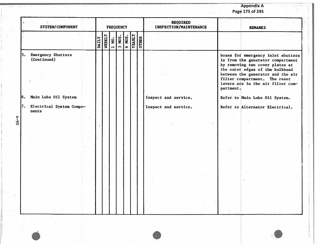
~ .SYSTEM/COMPONENT FREQUENCY
REQUIREDINSPECTIONjMAINTENANCE REMARKS
},rn v~
~►.x
~-1 r'~ ~O }Wi O
5. Emergency Shutters boxes fo emergency inlet shutters'.(Continued) is from he generator compartment
by remov ng two cover plates atthe oute edges of the bulkheadbetween he generator and the airfilter c mpartment. The resetlevers a e in the air filter com-partment
6. Main Lube Oil System Inspect. and service. Refer to Main.Lube Oil System.
7. Electrical System Compo- Inspect and: service. Refer to Alternator Electrical.vents
~o
Appendix A Page 175 of 245

t - . ~,~ ~l
~aN
Vin..... , :.. A . w _. o- ~ ~ ~ .
SYSTEM/COMPONENT FREQUENCYREQUIRED
INSPECTION/MAINTENANCE.REMARKS
GUVERNOR ~ ~ ~ ~
c*'~ ~ o.-~ ~o
General Control Rack ~ X Clean and inspect internal CAUTIaN: INTERNAL PARTS SHOULDparts of all, modules. ONLY BE CLEANED WHEN FOWER IS
REMOVED FROM THE 43027 RACKCABINET,
~~ Remove dust and foreign matter bybrushing with a clean dry brush.
Large surfaces should be wipedwith a clean, dry lint-free clot.
Compressed air at low pressureshould be used to blow dust fromhard to reach places.
Inspect generally for evidence. ofloose components and discoloration
. ~ When modules are replaced, cali-brate in accordance with VendorComponent Manual (Woodward .
EG-3P Actuator ~ X Inspect actuator for loose Refer to Vendor Component Manual,bolts, oil leaks and security Woodward Bulletin 8256~C.
` of mounting. Inspect linkagefor wear and binding.
- L-qu d Fuel Valve ~ Inspect for loose bolts, leaksand rough bearings.
X Inspection of all parts when Visual inspection of all parts fordisassembly is required, damage or wear. Refer to Vendor
. Component Manual, Bullet~.n 45002Afor disassemblq and inspectioninstructions.
Appendix A Page 176 of 245
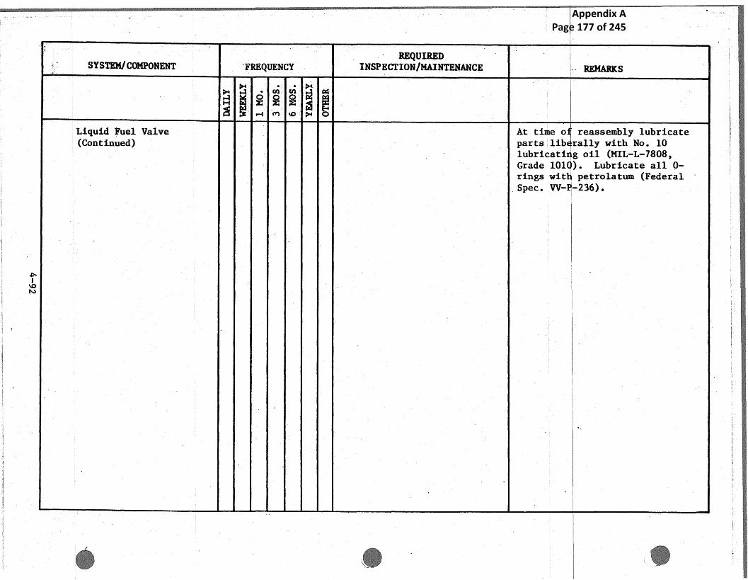
a it N
95
S
4
SYSTFM.jCOMPONENT `~~QUENCYREQUIRED
INSPECTIONIMAINTENANCE . - REMARKS
aH~~o~c~'o~~
I
`~
Liquid Fuel Valve~
At time o reassembly lubricate(Continued) parts lib rally with No. 10
. lubxicati g oil (MIL-L-7808,. Grade 101 3. Lubricate all 0-
rings wit petrolatum .(FederalSpec. W- _236)«
Appendix A Page 177 of 245

~_~ M .~
,~~ow
;'
SYSTEM/ COMPQNENT FREQUENCYREQUIRED
INSPECTION/MAINTENANCE RF.~sARI~S
a+• v, ~
~.,a
~ .CT-2 POWER TURBINE tai ~ ~ ~ ~
r-! cn ~o ?+ o
Operating Reco=ds X Review operating log sheetsfor trends:
Auxiliary oil pressure andFilter Drop
Main Lube oil filter dif-ferentialpressures
Front and Rear Thrust Bear-. ing 011 Temperatures
Front and Rear radial .bear-ing oil temperatures
Vibration (Vertical)
Rundown time (Power. Turbine}Overspeed Trips
Uil and Air systems X Visual inspection of lines, Check for security of mounting_connections, fittings, in- chafing, leaks., etc.strumentation, function boxes,thermrocouples vibration and` .speed pickups,:: etc, .
Ma~or~ Assembl~ea
1. Bellows Assembly X Checl~ far security of attach- "Dye check" suspected areas, t'on-ing flanges; deck for cracks firmed cracks should be repair
welded. Cracks in excess of1-1 1~2" (38.1 mm) found in theconvoluted area of the bellows te-quires replacement of the assem-t
Appendix A Page 178 of 245

~. ~ . _ REQUIRED::.: Y
~ ~ ~ SYS'TEM/COI~'O~TENT ~' FREQ[T~NCY INSPECTION/MAINTENANCE REMARKS~ r
N ~ ~ ~ ~ ~H
Bellows Assembly (Cont'd} ~ bly. ; bra ks in the attaching.flange ma be wela~a.
X 'Check the Bellows Inlet Visually nspect fore and aft; ,
. Housing :.Air Seal flange to bellows weldment for.cracks or pulled seams. conformto applic ble method providedabove.
2. Inlet Housing X Visual lnspection`af welds. Check fro t and rear flanges, fInspect cooling air elbows struts an condition of inlet sand tube. ~ housing c ver assembly.
3. Stator & Rotor.Assembly X Inspect condition of first and 1. Check general condition ofsecond stage clearance gages, gages indication of rubbing.first and second stage xotor If co tact is indicated measurblades .and stator vanes. the d stance from the mounting
flang surface to tip of theIndic for and. record. Measurethick ess of shim if installedand r cord. Identify all meas
. ureme is relative to its loca-~ ton n the stator housing as-
sembl.
•2. Discs embly and reassemble
stato and rotor assembly, asneces cry in accordance withOpera ion. and Maintenance Man-ual S c tion 2
. Remove bo oscope inspection por:plugs to heck first and secondstage tur ine rotor blades and
',
~~
Appendix A Page 179 of 245

__~~1~
a `,~
SYSTEM/COMPONENT FREQUENCYREQUIRED
INSPECTION/MAINTENANCE REMARKS
~, - cn v~ ~.; aH
~ ~ wt~>+ o .
3. Stator &Rotor Assembly stator vanes; check first stage{Continued) stator leading edges and vane
surfaces through the inlet ducthousing. Check the second stagestator vanes trailing edge andsurfaces by entering the exhaustvolute through the viewing port.
If a discrepancy is evident re-quiring further checking and dis-assembly, check .first and secondstage stator vanes end labyrinthseals for condition. Minor damagemap be repairable per Curtiss-Wright Engineering Instruction.
4. Exhaust. Volute X Check security and. conditionof base support and attachmentof seal to exhaust system;check condition of insulationblankets for tears aid secur-ity of attachments. Repair asrequired.
X Inspect exhaust volute generalconditions, mount supports andload reference indication inaccordance with Operation andMaintenance Manual, Section 2.
5. Thrust Bearing X Inspect Bearing Supports. Check for oil seepage at bearingsupport cover surfaces. . If seep,-age is evident, check for security
~ ° - ~ of attachment, porous or failed~, ,.~~ .x ~ .~
,._...: ..n. _.
Appendix A Page 180 of 245

4
t,~
_ . _ ,;~ ~, ;f i
..
SYSTEM/COMPUI~ENT ':r
----'-
FREQUENCYREQUIRED
INSPECTION/MAINTENANCE REMARKS
Hd
}+
~
'• >+
W
c'~ ~ O _• ~i 3 ~ .o
5. Thrust Bearing (Cont'd~ ', ~ welds. I no weld failure is evidor after eld repair is performed,
. aPPly sea ant compount RTV-732 toall matin surfaces and torque bol
X Inspect bearing surfaces, ring Remove an inspect 3 shoes fromassemblies, upper. and lower forward sembly and 2 shoes fromleveling plates 'and shoes, and rear ease ly for wear and condi-measure axial clearances in tion. If wear is apparent, replacaccordance with Operation and if requir d. Install bearing cap.Maintenance Manual, Vol.. '.1,Section 2.
Instrumentation Check resistance readings of Measure r sistance of followingPower Turbine components at componentJunction Box.
1. Front and Rear Journal BearingTherm couple
2. Front and Rear Thrust BearingPad R istance Temperature
. Lleme is3. Thrus Bearing Oil-.Out Thermo-
coupl4. Beari g Support Vibration Pick-
upsS. Turbi e Disc Cooling Air Ther-
mocou le6. Gas E try Thermocouples
Front ~ Rear Radial Bearings X Inspect bearing supports. Check ; for oil seepage at bearingsupport c ver surf aces . If seeT-
X Inspect bearing surfaces and. age is ev dent, check for securitycaps and measure diametrical of attach ent, porous or failedclearances in accordance with welds. I no weld failure is
Appendix A Page 181 of 245

t~iv;
s
i
_r,,,
SYSTF~I~+I/COMPONENT FREQUENCYREQUIRED
INSPECTION/MAINTENANCE REtSARKS
. H
y.,
~ `~. ~"i ~+
~.;
c '1 '.~*--1 ~D C3
7. Front &Rear Radial Bearings Operation and Maintenance evident or after weld repair is(Continued) Manual, Vol. I, Section 2. performed, apply sealant compound
RTV-732 to all mating surfaces and
i
torque bolts.
Appendix A Page 182 of 245

„~ ..... SYSTEM/COMPONENT
n ~
FREQUENCYREQUIRED
INSPECTItJNjMAINTEt1ANCE REMARKS
>+•
` .v~ cn
$.;~ ~
EXHAUST: STACK H ~
~ rti ~o ~ o
.General 0 hr o X
1. Power Turbine E~iaust Inspect: the inside of Power Exhaust tack inspection can beVolute Turbine Exhaust Volute for carried hrough inspection hales
falling objects and cracks, in Stack and in Power Turbine Ex-haust Vo ute. A thorough inspee-tion can e carried throughclimbing inside the Stack and/orusing a ucket crane and laddersto inspect the top section of theStack.
2. Diffuser Section Inspect Diffuser Section for Stop crac propagation by drillinginside cracks. a relief ole at end of crack.
Fill crac with welding rad.Choose welding sod material ghatis compatible with the. parts beingwelded.
3. ~plitter Sections Inspect Splatter Sections forthe following:
1. Cracks in boxes2. Splatter's Supports integ-
rity3. Splatter's guides integ-
city4. Splatter's perforated ~~
Flates and Sides5. Insulation .Material inside
Splatters
Appendix A Page 183 of 245

w'-mot — .
,~—~-s
` -
.
'
SYSTEM~C(?MFONENT FREQUENCYREQUIRED
INSPECTIONjMAINTENANCE REMARKS
y~
~H ~ ~ ~ ~. ~ ~ 3e +-i a, w ~ o
4. Expansion Joint:` Check F,xpansion Joint integ-rity of Insulation Material -and tJutside Cover.
5. Flanges Check that bolts on allflanges are tight.
6. Stack Skin (Outside). Check Stack outside skin fogintegrity.
7 Screen Section Inspect Screen Section for.collected objects, if any.
Appendix A Page 184 of 245

:.;~ .: . :, _ :.. , .
SYSTEM/ COMPONENT~
.. .
~?REQUENCY '
REQUIREDF
INSPECTION/MAINTENANCE RE~1fARItS
~ cn cn ~ a4
e
S.S.S. CLUTCH M ~
~"'~ M ~p ,~+ O
General The only items likely to re- During rep acement of parts, check
quire maintenance aye the pr - all sl din assemblies .for freedom.many and secondary pawls and of movemen and lightly oil parts
insulation. When gas turbine as necessa y.alternator set ha.~ been dis-mantled disassemble clutchcompletely and inspect detailparts described in~ Section 3.0of Operations and MaintenanceManual . .
1. insulation ' {2 0 ou s X Ci~.eck insulation between alter- Replace in ulation as necessary in
i it al y) natar clutch and alternator conformanc with requirements of
Shaft Input Shaft. Alternator manufacturer.
2. Primary and Secondary (1 0 12 0 to is X Check pawls for excessive wear Replace pa 1s at maximum starts
Pawls or ~s re ui ed'du on the ~tose, profile and bear- limit rega dless of their apparent
to op ra in f it re ing surfaces. condition;
Inspect the pa~lbearing bores Ensure tha pawls are facing the
in the relay helical sliding correct di ection and that primary
component and the pawl retain- pawl sprin s give the correct load-
ing ring. ing. Chec their operation as'des-cribed in endor Literature.
Inspect the primary pawlsprings; check that a radialload of 3-112 ozs . applied atthe top of the pawl nose willbust move the pawl into con- ..tact with the stop pin.
a Ratchet and Relay Check for signs of .excessive
Clutch Teeth ear and chipping of the flanks.and end of com orients.
r
no maintenance listed forthe clutch. Someinsulation tests included in5 yearly checks itemsl,m,n,p but no specificmention of the clutch.
Appendix A Page 185 of 245

' ^ ,~
~j !►- J~ + y ...
w
~ ~
SYSTEM/COMPONENT ~ FREQUENCYREQUIRED
INSPECTION/MAINTENANCE A;EMARKg
~ Q ~ o ~ aFLEXIBLE COUPLINGS ~ ~ ~ ~
3 .-1 M vD y+ O
Cou lin (Bendix) ~~ X Inspect drive shaft couplings DOTEfor loose bolts, rnuts, keys or Identification of coupling mr~delhubs . should be confirmed to assure ap-
plicabie inspecCion and maintenanceX Disassemble, =e~ove oil lubri- procedures are adhered to, The re-'
cant piping. Inspect coupling quired inspections listed refer tocontact surfaces for wear. In standard Bendix coupling models and'spent gear type coupling8 for pa=t numbers as followstexcessive backlash. Inspectdiaphragm. for xust end joz cor- a. 67E322A-1717rcasion. Perform alignment b. 67E416-1796check. c. 67E410-1797
d. 67E308-1798e. b?E322A-1666
u tinp g (Bier Bath) X Check th+e driue shaft couplingsfour loose nuts and bolts. .
X Check the weight balance of Replace with weight` equivalentcoupling bol[ an,d nut sets. parts {within 0.1 gram)Inspect coupling crontact sur-faces for wear. Inspect thet~w~o half circle gaskets . on bothends . - Inspect the -cover splitLine gaskets. Check su=face tosurface runout {Power Turbine
r ,~
ta` Electric Generator)
t,#
~. ~ .
no maintenance listed forcouplings.
Appendix A Page 186 of 245

_: _ __;, _~..~~~-w .. , __..
w ...
SYSTEM/C~MPONENT
~
_ ~'REQUEH~YREQUIRED
INSPECTION/MAINTE~tAI~CE ~,
_..,. ,.._...,
* MARKS;~
~+ • vy cn ,cifHIGH VULTAGE SWITCHGEAR t"~+
t~~y~i .-~ c~ ~o ~ ' a
Switch ear Gubicles X Checic sw tchgear cubicles }`~ ~ WARNINGperiodically for proper opera- HIGH VOLTA E IS PRESENT IN MANYtion of the anti-condensate ARIAS OF ITCHGEAR ENCLOSURE.heaters,' cleanliness and gen- THE BREAKE 1~IIJ$T BE RACKED OUT ANDeral condition of connections LINE SIDE ISCONNEGTS OPENED PRIORand exposed .wiring. ~0 PERFORM NG WORK NTAR HIGH VOLT-
AGE EQUIP T.
Awc Nary Transformer X Inspect and clean transformer.z Check windings for accumula-
bons of dirt on insulating~rfaces, loose: connections,signs of overheating and volt-age creepage over insulatingsurfaces as evidences by tracking or carbonization. Checkall current carrying. parts.such as wires, cables and bussbars for signs of overheating'due to"poor connections.
Inspect condition of tap Dry trans ormer, if required, bychangers or terminal boards. applying Bated air (not to exceedClean windings with a 'vacuum 110 °C) an check by insulation re-cleaner, compressed air or a sistance easurement,nitrogen source (less than25 prig},
Main Power Transformer(RTE-ASEA Corp..}
1. Transformer Uil X X Check oil levels.. Levels sh uld never be below themarkings f the ail level indica-tors . oi1 levels in the tankand mecha ism compartment should b
~ _~ ~)'
J
Appendix A Page 187 of 245

°,...` ~
_ ~
~ ~
0w
;~
~;
-~:A.
_ ..
SYSTEI~t/COMPONENT a
a ~
FREQUENCY ~REQUIRED
INSPECTIQN/MAINTENANCE R~@~,~g
a ''a o "' o ~ a
~ •~~ a~ o:
1. Transformer Oil (Continued) checked at two week intervals dur-ing the first month o€ operationand annually or when required aftethat.
Change oil in the t=ansformer whenit is warm and viscosity of oil islow in accordance with instructionsin Vendor Component Manual.
X Test ~i1. Samples Sample. oil from the bottom oftransformer tank and not from oilstored in the sampling pipe. Aglass receptacle is desirable so.that if air or water. is present itmay be readily observed. If airPresent, allow the sample fio stand.until the oil. is clear of air bub-
. . tiles. If water is not present in. sufficient quantity za settle out,
the oil may sfiill contain considerable moisture in a suspendedstate.Test oil sample for dielectricstrength and for specified propertvalues presented. in vendor litera-tore in accordance with ASTM speci
_ fication X877, Perform test priorX Check acidity and flashpont to breaking of anq seals ar remov-
~~' ~ (Peneky Martens Test). if oil ing any cover openings.
~~ ° .¢ ~ s in accordance with VendorManual.
;.~'
~
X~ ,,
,..
X Inspect and replace oil causer Replace gel~when its ability to. ~ `' vat an system Silica Gel absorb moisture begins to dimin s:::..~k
y _
* YrH r. f':. ' . - 'rod' ., ,. ;.
Appendix A Page 188 of 245

SYSTEM/COMPONENT
,, -
rFREQUENCYI~EQUIR~T~
INSPECTICINIMAINTENANCE
~ _.
..~ REMARitS`
w.e~ r~.
1. Transformer Oil {Continued) Breather and if necessary the -Refer to endor instruction far rePressure Vacuum Regulator in newal~and regeneration of the gel.the sealed tank system.
2. Oil Level and Flow X ~ X Inspect and.. clean yes vendor
Indieatcars; Oil Pumps ;instructions. As necessarywith Motors ' ~ °perform an t3perating Test,
Megger Test and general testof electrical circuits.
3. External Circuits and (3 d y~ of er X Check the following;Control Equipment i s"t 11 ti )
1. Control circuit voltage Power fac or tests on the unit mus~2. F~cess heating of parts be made w enever the unit is de-
evidenced by discoloration energized for'•long periods (1'of metal parts, charred month or re) or the. unit isinsulation, or odor. opened fo any reason. I~ addi-
3. Freedom of moving parts tion, pow r factor tests should be
(no binding or sticking) performed annually.4. F~cessive noise in relay
coils5. Excessive arcing in open-
ing circuits. 6. Proper. functioning of
timing devices, sequencingof devices, relief devicealarm contacts, aid ther- ,.mometer contacts.
'7. Evidence of water orliquids in control. cabinet
4, Combustible Gas Level ..X X Visually-inspect and clean as_ Nitrogen as Equipment, if sup-Ntragen Equipment - necessary, plied, sh uld be checked to deter-
Gas Operated Relay i 'Perform an Qpera~ ng Test, mine that the regulator is opera-
some of the check points lookodd. Noise in relay coils,arcing of contacts.
Appendix A Page 189 of 245

__ _s
~
., , :.i~,
~) .
f
t
.~.fF-N0~,+
r
d -
aSYSTEMICUMPON~NT
~
FREQUENCYREQUIRED
INSPECTION/1~AI~i2ENANCE
..
% ~ REMARKS
H W ~:
4. Combustible Gas Level ~ Megger Test and general ~eaC Ling properly. Refer to Vendor(Continued) of electrical circuits as 1Kanual Accessory Section tlperating
required. Instructions.Perform a ~c~mbustible Gas Test Always observe the rate of rise offor combustible gases weekly the combustible gas level. Zf theduring the.. first. month of op- cambu~tible gas level reaches 0.3xer~to~t. After the first at any time, Weeklp tests shouldsynth until the end of the $e mF►de to determine if the levelfirst year matte this test is conatanr or increasing. Ifmonthly. After one .year 1n after four weeks the level remainsoperation run the test on a constant, r.e~ume the. normal testquarterly bas~.s. schedule as above. If the level
. cont~auea to ri9e, an attemptshould be made to locale the causeHowever, this attempt should be
` k made whenever a 0.5x level is de-R.~ tected. If at any tine a 1.Of
combustible gas level 3s detected.::; de-energize the unit until the
source of the gas is determined..
5. `Transformer Tempera~~re ~ ~A ~r ~ ed X Check. te erature indicator For transformers furnished with~~'her~►meters and,.. Thermostats} thermi~meters for oil and winding
.d~~` n~ abnormal temperature temperatures, the setting valuesrise; as necessary perform 1n of the signaling contacts may be
~ ~ ` , t?perat~.ng Test, Megger Teat set as required by customer stand=~nc~ General Test of the elec-~ arils, or the following recommends-.:t,r cal e rcu~.te . bans t
° b Naturally cooled 011 Winding.~ and forced Temp. Temp►.
air Eooiea go° 9~°Cj 4. ~ ~ ~ t
T'w.
_,. ' ..
:,~_ Thermometer contacts, used for ~~
.. ,. .. .
~ _ . .
Appendix A Page 190 of 245
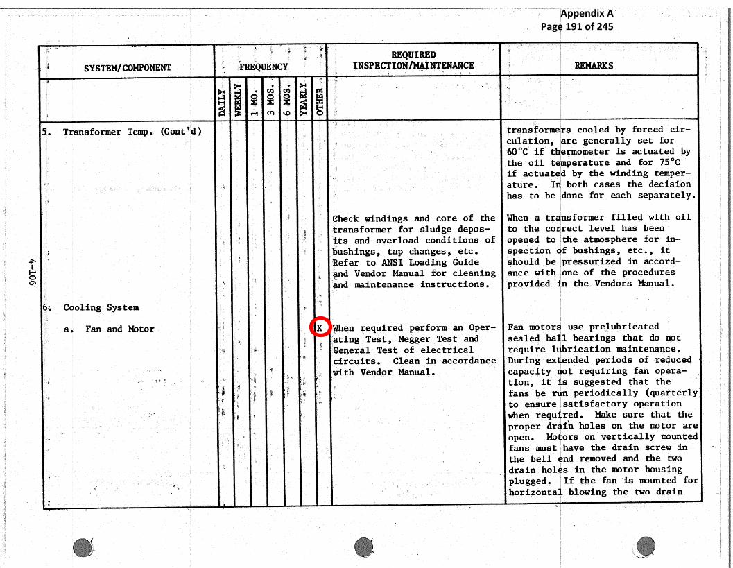
SYSTEM/COMP'ONENT
$.
~ FRE~tIENCY xREQUIRED
INSPECTION/MAINTENANCE ~ _REMARKS~... ,w ,.
H "~' ~ s~
i-+1 M ti0 ,~ Ca
5. Transformer Temg. (Contfd} transformers. cooled by .forced cir-culation, are .generally set forb0°C if t ermometer is actuated bythe oil. t perature and for 75°C
a4 if actuat d by the winding temper-p x ature. I both cases the decision
g has to be done for. each separately.
check windings and core of the. When a tr nsformer filled with oil
~,ransformer for sludge degas- to the co rest level has been
~ its and overload conditions of opened to the atmosphere for in-
a ' bushings , tap changes , etc . spec t ion f bushings , etc . , it
Refer to ANSI Loading Guide should be pressurized in accord--and Vendor Manual for cleaning ance with one of the procedures
end maintenance instructions. provided n the Vendors Manual.
6~. Cooling System
a Fan and Motor r X When .required perform an. Oper- Fan motor use prelubricated
~ acing Test, Megger Test and sealed ba 1 bearings that do not.~`~ General Test of electrical require 1 bricat3.on maintenance.
circuits. Clean in accordance During ex ended periods of reduced
-° ~` _ - ~ $a~w, cai.th Vendor Manual. capacity of requiring fan opera-.ffi ... , :. ::. ,.. ~
~~ tion it~ s su ested that the
.~g$, ~ ~,
s ~ F, fans be n periodically. (quarterlyto ensure satisfactory operation
r z~~ :~ - ~
rwhen requ red. Make sure that the
~, ~ ~ proper dr in holes on the motor areF ~. open. M,~ ors on vertically mounted
•fans must have the drain screw ink the bell nd removed and the two
~ ~ ~ drain hol s in the motor haus ing.. ~ _ _._w plugged. If the fan is mounted for. .
,~. ~~,
~x horizonta Mowing the two drain
L .. g
,,.... !
i. `~ ~ ~
~~
Appendix A Page 191 of 245

~s
SYSTEM/COMP4I3ENT
1 ~ ~
FREQUENCYREQUIRED
INSPECTION/MAINTENANCE: ~
~ ~ REMfARKS
a ~"' o ~,, ~a ~ c~
' ~ N. - ~:
~. ,,~ cY1 cQ ~+ Q
a Fan and Motor, ~ screws in the body of the motor(Continued ~ ~ ~ must be removed and the hole in
~ ` ; ~ ~ the bell end ,plugged.,{ ,,z; ~ s
b. Air Cooled ail Coolers J ( e~ re u e ~ In general there is no need to If formation of sludge in the oiland Radiators Y ~ ` ~ ~ keep cao~.ng surfaces clean. has set in, .the sludge .map deposit
'~~ Check .oil for sludge formation. in horizontal surfaces in radiators° - ~ and coolers. In such a case, the.
radiators and the Coolers should berinsed in connection with thechanging of oil. If .the sludge.does no.t loosen by flushing with
. _ ~ ~ oil, use benzine, trichlorethylene,R .~:`
~;etc . , and afterwards flush with oil
If it becomes necessary to remove a. ~ radiator, first close the valves,
~ ,. top and bottom, and bolt them in. , ~
~ :.the closed position. Next, drain` .the oil from the radiator by re-moving the 3/~+ inch drain plug from
c the bottom header and the 3/4 inchvent plug from the top. Afterdraining the oil., remove the radia--
_ ~ ~ - tor. If the radiator,. is to be offa r
~for any length of time, the trans-
_ former valves should be ~a.sketed. ~ and covered with covers. This also
,~' s , ~ applies to tie radiator header openings.
. Valves ~
~ _ As required, e~cam ne and clew.. .. -, .... ,.. ~ ,
~ t' ~
~ ..~. .' all breathers anci small open-'" . sk .. ~, ..
µ
ngs in pressure' relief valves~. and pressure 'vacuum bleeders. ,
:.
Appendix A Page 192 of 245
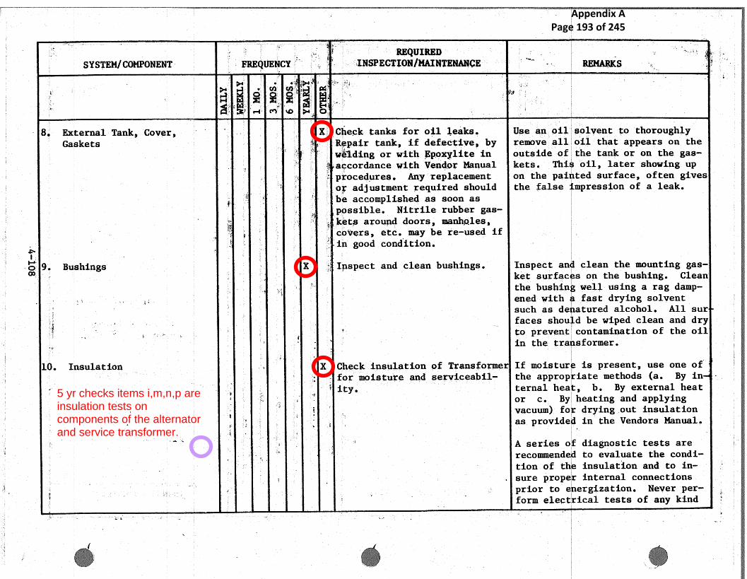
_ ,
SYSTEMlG4MPO~tEN~ ~ ~ ~REQ►UENCY ~ . `~
...
~Q~I~~
` -INSPECT~QNIMAII~TENAN~E . •~~ . ._. ~ ItKS °,~ '`
y' . ' vi' cn : '~ ap
H1
8 external Tank, Cover, ' ~ ~ X Check tanks far oi]. -leaks,. Use an a►il solvent to thoroughlyGaskets " R~p~ir tank, if def.ec~Cive, by remove all oil that appears. on the, : , . ~ , w~~d3ng or with Epor~lite in outside of the tank or on the gas-
accordance with '4Tendor Manual kets. Thi ;ail, later showing up: , ~ procedures. Any replacement on the poi ted surface, .often gives
~ ~ : : o~ adjustment required should the false mpressian of a leak. .~ : - be accomplished as soon as
~possible. Nitrile rubber gas-
• -.,T ~ ' ~. ket~s around doors, manholes,. ~ co'~~rs, ..etc.. may be re-used if? .in .good condition.
9. Bushings - . X ~; inspect and clean bushings. Inspect an the mounting gas-ket surfac
.cleans on the bushing. Clean
'° the bush~.n well us ing a rag damp-fiened with :fast drying. solvent
. ~ ' such as de atured alcohol. All sur_ r faces shou d be wiped clean and dry.
to prevent contamination of the oilin the tra sformer.
10. Insulation ~ ~ X Check insulation of Transformer If moistur is present, use one of;; ~ for moisture and serviceabil- the approp iate methods (a. By in
x, ' ~ ~ it y ternal hea b. By external heat,~ or c. By heating and applyinga vacuum): fo drying .out insulation
F
-. as provide in the Vendors Manual,
~. `" A series of diagnostic tests are` ~ recomnnende to evaluate the. condi-
tion of t insulation and to in-~. L _ sure prop r,internal connectionsprior to ergization. Neyerper-
3 ~ farm electrical tests of any kindry. ,e
__ _r
.~
5 yr checks items i,m,n,p areinsulation tests oncomponents of the alternatorand service transformer.
Appendix A Page 193 of 245

~~ P,~~ ,s
,i
! ,.
,~
~ ~.
i
i
~ ~~
P
~ `
r
w.
t
I
a
4.
9 '
~_ ~ .,lr
SYSTEMICOMPONENT °FREQUENCY INSPECTQN/MAINTENANCE ~ REMARKS
a. ~'`~o "'~
"' ~ ~aM ~
0. Inst~la,tion '~`
~k:
ie t~ i on a unit. under vacuum. Flashovers
(Continued) ~ ~ can .occur at voltages as low as~ 250 volts.: Before applying any
k voltage on the. transformer makeY
,{
sure that all bushing current
_ ;` ; ': t=ansformers are shorted out. Re-y , :fer to Vendors Manual.
Main Pawer Trans~o r .. ~,: ~ A
{Hawker Siddeley)
Transformer 0~1 X 4 ~ Check..o~~. levels.. Levelsshcauld never ~e below the< markings o f o tl g~utges o f the ex-~
pansion vessel and below the tapf.
changes diverter switch compart-<.,~~~ -~ meet.
~~~ ~ Y X ' ~ L Test v 1 ~ wimples Sample .taken from. main tank while°'
4~~ ~T:
t,. (See B.~.0 P 100 '" ~~r~ oil 1s warm. Oil sample taken fromS~
f requet cy) sample valve of ter a f ew pints,.a~ ~~ ~= x ~ . should be run of f before sample is
~~ p ~~'- . collected in a chen~.call cl~a.nY ~~'~~,' s d container, Sa le should be
~' i i ;t t~.~, ~ stored for 15 min. to .permit any. ~.` ',_ . .~ ~ , ~ ` ` air 1~ubbles to surface. Dil tests
r a :. µ ~-~ ~~ ~ ' ~. f
~should be ca=ried out in accordance
. `. ~ x , ~.~~ a
with British Standazd Gode of Prac-.. .ry ' t ce C.P. 1009, Electrical ~erie~: ~ ;~ ~ ~
::, ._ _ _for the Maintenance of Insulating
~ Qil.
_~ _r
ue ,~ ~ z k~ ,..
., ~ , #•. Replacement bf soil used , st be inne . ` ,: ; . . . , ~'accordance with~~ B S. 148 {1959) a _;:dinstructions in Vendor Co onent° *
Appendix A Page 194 of 245

e
4
_ -
--j.
.~- '9t,,
~.. . ,.,
~ ,
..: ,. q_.
_ , a ;,.~. ~_~~
..SYSTEM/Ct3MI~NENT ';
D~~.
' Fj~CfU +ICX;~j~~"~'
INSPECTI~NJ1' ~j,IVFfiEN~aNC.E
:; , + a
'p~ " Y:...
r _.. _'
. ..
..
r,
~/
._.
t
o~ ~}
. . r4
_
~'.,
,.,. . ~,., ;.:~ , ::
1. _Transformer ~~.~~ r ~
~E~~, ~ ;# _ ~ . s
,. ..~ ~At .the sa ie ::time the condition of~
~ : the oil i the conservator sump,~ S
: SA
~~ . ,
should be examined. A pet-cock is
~
. ~ ~ F ~l „~: .provided ar this purpose. Theacidity o :the oil should also be
~. checked.
2. Silica-Gel Breather `$ ~ ~ inspect and replace ~ When char e becomes 2i3 saturated. Sizea W & S ~ a ~ , .~ .' it shou~:d b'e repla+~ed. When the
- - ~: . '`' charge is ~:ctive and dry the color, ~F ., _: `'v ~ ' ~ ~ ~ ~ -~ s. blue. - . When. the charge is satu-
~~': Ys A ~ ,,,.'
-rated the color .changes to pale,. .. . ; ~ pink. To reactivate, the container~,, ~ ; _ .4' should be heated in an oven to ao
-~~ ~, "' : - j :- ~. temperatu e of aPFroximately 2$0°F~x ~
.,~ - (14.0.°C) f r a sufficient length of
~ ~ time to e sure that the whole ofa ~= - ~ ~'
-,the mass
_
f gel att~in~ the ~ spe. ~ ~: x - ~.
w
:F
r:r~
cific tem-,
erature axed t~,e bluey
r ~-'
color is estored. ~ ~
'.
9.:~ 3 .. 5
x:~ ~..1 a.~
~
p
~+i..
~ -~ Ga$ &Oil Uperated Relay_
¢ ~ ~~G
~:i
~ hest electrical c~.rcuits ~k
:Check ope ation of the gas and ail'i
~~ ~~ , ~
,~ ,~,: ~ '- operated : elay alarm and trip can-a
ar
. : ~ ~, ~ ~, .~ 1
,~.
,3 ~
rs tac is b~ n j ec t ion o f air to the ~ =~~T
}
~. 4 1 ~ ~: ~,~} ~ ~ .~ test pet ocks. i.~
~ ~-° S ~ ~ general, inspect for oil 7Leaks Refer to endor Component Manuala '°~ ; ~~ z~ .~_ ~~ ~ ~ ~ ecurity of ~auntfng :Section 0/3,/1 £or testing and ad
_ . - - ._, ..,. ... ~ ~ ~~ ~ RE
, ! ~: ~ r ~ _ .. w3 u s tment ns true t ions .
.~ a ~ ~~
4, Temperature controller ; ~ ~ ` , . ~ - ~ ~ ~td~ustment and/or regla~eement -only if a ~ustmeats are greater+ ~ ~
,~ ~~ : > - ~~ ;~f switches. Resetmaximum than + 1~ of dial ranges. Refer
§__: :.~,..w_ __. ~ ~ r ~pointer. .~ - ~o Vendor ~Comp~anent Manual for ad-
.__
.. ~ustment nstructions.
_ ..~_ -. ,.. . ..
.~,.r
,! __~:; `~~ J
Appendix A Page 195 of 245

--,~ j
~_ ~
~~ ~ ~\~ I
i
SYSTEM/COMPONE~tT .~~REQUENCY ~ ~ :REQUIRED
; 4 INSPECTIONIMAINT~NANCE
., .._ .1
x : _ . .~. RE~+[ARKS
.. ~~/•I~~ /~/•~~
}
s,... ..
i•# ~ ~ 0 E
5 Cooling System 'k ~ ~ _~ i ~ ~ f :~: { _~ ~ ~ , ~- e,
a. Con~rolletY
-~
' ~a
-
~
}
~
~
~..
Ac~~u~tment
~i Fan l~ M+~tor ~4
•.~: ~ ~ ;j
~-
~~
r
~ ~' ~~ Inspect for security a►f
z
mounting....:,: y. ~ r ~: .
T ~ '• ~ 1~ Lubricate motor begrfn~s The motor bearings are lub=ieatedr~~. ,
p 4s t ..
(Ba11 tYPe) at the fa~ctory.~ Un~.~s4~ Qtherwise:.
: , ~ ~ ~; ~. ~ ~ 'stated on the nameplate, the co=-. - reef grade of grease and re-lubr-~ ~ ~ ~ ~. - ~S{:~ cation period area a~ follows:
.: ~~< <r
' .
. ~ Ky
t . ~ -.R
~ ' S~iell Alva~i a-every 2 yrs-up to_;: _ ~: ~ ~ 400
~ ~s. . y -` ~; ~. .: ~ 1t.A, of every 1 yr-41°C-60°C#~ ~~ : ~; ~ ~ ~ # ~She~.l ,Alvan~.a 2 -every 6 months~
~~ j ~_ ~ ~ 61°C-8Q°C. m;.., a
_~ ` ~~PP11~s to fans ~ranning continu-
i x, ,~-:~ ,-g ~ :=
tou~sly:`" For .~nte=m3.ttent operation
i'r ~ a Y ~;- . . , ~ to 40 hrs/week, relubrication
i.
'' s period R4. For operation up tog a::~ ; , ~ hrs/week, relubricaton period
~ t~ .$0
X~~~. ~.~ ~;,
~'.. . . .
,~': ~; ~ ~ Lubric~ite; ~citic~r bear~r~~s~ Lubricate through lubricators with
''' - , ~. _ ~-_
~ ~.A,~ z ~, ~° (Sleeve type) _ ~ $ood, quality ,light machine oil.
' ~ ~ 4
~- ~ x
" c: Motor Prot~ct~o Relay X ~ ~ i~... _: r.w ... ..«
Inspect connecti~ns, ~heat~~= ~i. ..~
~...~
`. ~ mounting screws, and fuses fob.~.~ t :.~ ~< s : . ~~~ - :t~
tsecurity of mounting. _~
.._ :
a. . ~t►ta~r Cu~tactors ~--.., .
%
-
y
~ . ~ :~: . `;~.. ~
X '~~ ~~Clean. act~t ~ :~for ~t ~tsit ~ ~ Aou ~ s `~ cow -lete witha~ ng i .~ d` p~
,... ~, .. `magnet and coil by removing the 2°.~ ~
i
Appendix A Page 196 of 245

,~ ~
NN
l
.~,wi
~Y~ST'EM/ Ct F'5t3%~Ng~
~ ~ .- yi w
wr y f ZI
a ~~ ~P~F'tEt~UE~iCY : ~#
~~R ~{~n}- 1 T ~■y■
INSPECTIt}N/M4IN~l~NA~I~~- ` . _ ' ,~ - RE~tAIiKS
r .,:.
~" ' ~ .-~ c"~ 'gyp y+ O ` "" _ ,- ', ~ ' _
d. ~cstor Con,~acro~s ~ ~.;' ~
'`~ ~ _ ~ .~:, .captive screws. ~~t~w oc~~. .,all dust. . -. . F
~.' :~~ont°d~°° ~ ,~'1
~ ,;'.
gts
4`
.i 'i .~~$.
with.. low' pressure 'air. Do nat~" ~
`_' ~ ~: polish, f le or gre~.se contact~ ~gk
~, faces.
_ M + wz y - ; { ~ P ~ ,~ ° Remove co 1 and clean magnet faces§ i ; ~` -
;. ~
~ with a cl th containing sufficient., y
~` Tight mac ins ail to leave a thin,- ~ - ~_ . . ~ :~` i
b, .a . .,.
3:~, film' on~ t e pole faces. Refer to
~. : '~ ~x ~: ~x a \.2.T..' j .
c~i~dor .Co portent Manual Section.. -~ : _ -:..
t- ~~ -~ ~,W /3 f r '~.etailed instructions,< ., .~ ~.: . . , . _.g
6. Pressure ~e~ie~ ~'i~s~ e~ ~ ~,. ~~ - ` ~.~' ~. fissure protective coatfng of ~ ~~lve req- . ices re-setting only if~~ ~ , ~a~~int is inta~t.4
,sema~~aor~: indicates ~ ,.unit hasz s; s ~ ~ ~~~c~tone .
7"~ Tap Changer ,= ~ ~X ~ ~ respect flange ~o~:nts for oil k` .~i~~ten e ch bolt s:~: ,~~a.tly, moving1 g = A F - ` ~° ~ beaks ar tightness. `around~ th fla~ag~~ unt~~~a the ~ca~r
Mete }~,oi~~
:t Yeas-`been made leakL
~ proof.
a: t~ea~r ~'~a~~,j
' ~ b ~= '~ ~_ X ~ lubricate ' ~ ubrica~~..all .surfaces with m~lyb-' ~~' den` d~~-'ul h~d~ aste onl ifP~ ,P Yi s original; ,
:.~~~ .ca~t~►n has been in-
~'= ~
-'~
advertent y wiped away during in-~~' ~' ~. ~ apectan. ~ f ilm of this ~ lubri-
a ~ , _ ~° ~; ~ f ~ ~ ~ ~ rant and; d be maintained on all~. right fe roue parts t~ obviate
~- rusti~►g.:2
-
Yr
§,,~
: ..~ . ~ f
. ~, d~,~ustmer►~, brake re-set. Should far any season th~~ -. _ . w~ , . r # _ - N~ . ~__ ,rake ~eq w:.fires a~ j us tme~t, ref e` t
,::;~}~~~ - - r ~~'- ~ ~te a~r .~o oneint Manuals Section., .._.,.
_ A
~~~?~ fo procedures,
Appendix A Page 197 of 245

F
7
t
~.11
a
.~
.~
i~--~4
;'r.
;~
..
i
'.
4k 4
~_-! ~~,
_.~
„ i
SYSTEM/COMPONE
~ . .,.
`xFREQUENCY° ~
e
+
REQUIRED ~
INSPECTION/MAINTENANCE ~ =
,.~,~; ~ 1 C u,. ~'
., _` . ~ , ,~S,,....;a .. ~- :, 4; , ,
~ ~ ~ ~ _.
~ ~,i
7. Tap changer (Gomttd),4
~ i~
~
~
~. .. .
~.. ~
~
. ~~, ~ ~ •*., ~s
~. 3 J. r . ,.,} ~ t
b. She b ste ~i'iix l a ~p y p ty ~s X ~ ~, ' ~rlspec~ 'and clean ~,..
Clean fqr~ m~a,~erial from switchswitches _~
dy~ :
_~ -co~~tar~tsr.; .• ~ Us~~-lntti f.~ee cloth7 .: Y t ~,: ~ ~ a y~~ ~ ~~ ~moiste~,ed with carbon 1tetrach
,. ..,. ~ rid .
A:.
.~
~
8' Dust Filters ~ ~ ~~ ~ ~ ~~..:.; p TM~ Ins ee t filter° ~ q c~ c~'~ inspection msy ~~varyPre uen
` ~.• ~ _ ,~ ~ ~ - ~ 3• ~. . F ,ry ~. ~~ 'according to. $ate c~n+di~ o~~~.' `'
~~
~~s' '~
." _
~y E
~ ,. ~ i '..~h~ ..
~ck~ should be ,n~a+d~.. Co assess..g
,: _~
~~ . ~ *~ y:
the condition of the filter to~ ~bl~~sh a frequency of inspec
~ F~ ~~~ ~ ..~~ : '+ :~.:.~~~~" ~: ~ io .~ itF~,t n,. tees are kc►~ be replaced
. : ,. ,,, ( "- .. r ,~r ~ ` ~; .. ~
f
when ~ ed- `~
~ircuit'Breaker ~(,~ 0cr . '
HoS
~s{~1
. .:' a
4,~~
:, ~.. ., . T
:Aetna irtspeetion and' mainte--' w:; . . , " ' .._-- ~ - . nan~ce will depend upon indi , .,
t .. `y ~~ ,
``~ victual application conditions:. .
kF.~
~~ ,
; `~ z Some atmospheric conditions °~: ::E
.~,~ 3 ~ -~. ~ such as extremes of dust and:
_ , =~~ moisture o= . cvrros~:ve aces
~.4, ,.: x m :g'~~ lndiea.te insp~ect3on` andt~
~, maintenance at mire =fre+quent
. ~ ~~ _
~ ~~ ~ ~:.
_~~ ' ~ interval.
_ iy i'~
,P ~
~ ~ ~:.. . ~ v, }. . ' ~ - ~ : # : ~ E:heclt` for icontact ov~ilap, 7 Clean and ad,~ust .'~~ , x~p~l.a~e the_ ., f.s . ,~ s . s_ . .. k : , . . j , : ~ ,;. ,. ~ ~._
. ~ ,., ;
~h~ck ~ha~ ~movab~le~ conC~ct ~ ~ component in accc~r+danc+~ with Vendorw ~~:. :~ ~= `= blades fit snugly against lour „Manual (Westinghouse °Instructior~._.
~. ,. ~ ~~ ~° coMtact block. "for Parcel-Line Type DH-P Circuit.;~
_ .m
~. '~_ ~ .. --a
~..
µ ,,
, . _ «.... _. .,n,___._.___~
.~i
5 Yearly checksinclude unspecifiedmaintenance on anSF6 breaker.
Appendix A Page 198 of 245

-i Z ~ ;~
~.~~STE~ICOMg0~1~~i~ k
~.F ~ ~ y
- ~ ,FREQtI~I~CY f ~ _
p~ *p,~t
~ iXCa~~~i.LVf+~ Y3 s.:.
- :. INSPECTION~MA~~~I'~~i4NCE~
`.,
REMARKS_..
y, ~ r.,~ ~ . f~r~
i ~~
~'..
cry ~t~
~cLQW V{3L-TAGE SWITCHGEAR ,,'~.r.
~. ~ ~.~' ;~ :: _:~ t ~~!
,~ eei ~t~ '3
■
~witchgear Cubicles ~ 4 ,>;`
-
_
~ ~
'X ~ _ g ~ `.~fer to Switch ~ ~:C~i~b' cues ,°~j~ ~ j-
:.. Auuiliar Transformer ~ ``~ ~ ~ x ~' X~ . ; ~ ~R~fer to A. ~1#ter. ~Txa~sfc~~ner
Circuit. ~Breake~ Y ~y, r
, ~ - . - ~ X.o
~ :•I~spect fQr .e~`ean~.'~n~~s-':.'and ~~ ~: _ ~ .,. ,
(Westinghouse.:NB3U84t1) ~ ~~x~:
.. r q : ;~ '~ ~ ~~~~e'rvice~t~i~::ity. Re~~~r' ~=to.:a
Ct~ ~ ~
:.~
-.
~~~ndor pane~t;. Ma~t~~:l~ ~. . a x
~:~ z a 4
Gas Boost Ca~apressor - ~ '; 'System Switchgear
_;;f, - ~~ - ~ t ~. ~ x~.
` ~
~
i~ Vacuum, C~.rcu~t Bxe~:kers ~' ~`_ -
P- ~; routine deck at, 2 year .period,.~~
~nspeet , chan sm ~and,~ linkages,~~~; _ ~ k ~` ~~~.b~.~cat wilt •~~~! o .l. .{Per-
} ~tp
~4
.;tt oil-m st# spt.~:~y j~roffi above~~ ;.~' , ~; r
~
t~~.~hin th meeha: sm s~de`,plates
~-
# '. ~-t:. J-~ ~ say ~
~~...f in use .~ ~ .. .. ..
~~~ F .tongs :.
_
~ ~ .~ .itt ngs a~,d contacts ~ ~~n~~p~~t f =~~ings for :tightness.~;. , Cheep b~~ k~r ca~at~et wear. (Re- :_
~'iTendor' Y ~ ~ fer~ to;~"Se t i n 7 ~ tom .onent~ P~ F ~ ~, Manual, ~~ ~ush ° ~~~.t~~gear Lt~d•.
.No., i
..
~.... ~T t'
~r ~
~.,:,T..,:,._.~ .
aa~
F.,
n55/~~tlil~) .
_zr M1
~ ~~ CQ~.tacts ~
_
: { '
-.'
'~
,{.:.:,
n
',. ~~ ;e
auxiliary contacts 2 ~r~ar f~.nspect :a ~d ~o~l-+~~a~~~ f necessary, ap` ~ ,, y ~ ., .. ~~~. '~,nspection. +1 ~.hin ilm .~f vaseline- Check-~ Y
..:: ~;~ ,-..t, r r R - ef~l.ect~i4 tiffs >in~~.cate~d ~~n Vendor
._ _ .~ ~ 1~ ~ °~ _ =~Qmpon~r~t_ , . ~r _.
~: Transfo~merss `~i 9 ~~
_ t = ' ~ - ~~ ,' ~`-
" ~ year gins pct and lul~~'~.fate ~ n,~ pct .s inter .l.;inka e and ~~~bri-~.j •3 1~
t
{ ~: date w ~~ •SAS .~0 o 1. Replace. ~ ~ ; fi`° ~~ ~ ~ fuses :if ecessary..
~ .. ..
~ ~ j
Y
.~~ -
_ - ..
a.
.:' # :. G
. . , ).
/ - '•!
~ ~. . ~ ..
6 Yearly checks includevarioustests on unspecifiedelectrical equipment includingcircuit breakers.
Appendix A Page 199 of 245

SYSTEMJ CQM3.'ONENT ~'~ ~
FR~~QtJ~NC : f-
REQUIRED x.. ._.
INSPECTION/MAINTENANCE ~ '
.. .. __ . _ . . _ ,.r .. ~' ~.. ,REMl~1RKS '~
{Y s~i '1TI~
~ M1 ... '~ i-~ ~1 r
Gas Boost Compressor Systemi ~
V~~
~+~ ~
~..~ A
'`r ~
~ 4~, . j ~ , ~` `" ~ ~ 4rt *r t. -:x~ r . r ;; ~ , ~.~Switchgear (Cone d) . :. r .
~'S :Electrical ~ V ~~ ~ ~: 2 year. inspection. ~ ~ Check circuits during routine in-<~_ ., ~ ~ ~ g~T sped on. Examine coils to ensure
~~~ ~'_~
g'.x~ ~'..,.
g
Y7
..
,y
~rz
~ ~1
'~$''~~ ~
2 i +~ .Iy n"i LLS Oi~I tion and connectio s ire Y `_~ ;~ n f
~;: ~ = Y ~ °sound. n~ur` tr Aping batteries
E
. , . ~ ~n...~~~i ~ ~ ,:. <. f ~
._are frame from faults and ,are ~
~ ~. ~ b a~+ ..c gec~.. ~ . ~ ~ k
6, Relays ~ ~ ~~ r
~' X
. 4~
~ Ins ec~ clean and lubricate Tri 3n control` rely s auxiliary'~ - ~ "~ 3 ~ =aid indicating and.measu~ ng re-~~ ~. ~
. ,~ ~ J. ~.f ., ~ _ ~.
ays. Removed fit,; t 'felts, wash,, '~ `~ _
, ,~i~n water' and detergent or some
t . ,Y. •r
-. mot, •.
'f...
. :~~.y~
..
p,
r . ~ ~i—•
Y~' t
•other suiCabl~ solvent Rinse,~;_
- ,,,,a~..•f ...~~ ~~ •:
~.,~ :t~
. , ;:1 - :~..~ :. . Ft- ~ ~
j~""~ j •, - :..1 ~—
ary -and coat with thin film of
~:R. .. •~a ...>_~~,. f.
r
h:, s:~ ` :~ .light m~.chine oil : and 'replace.
y;
#
E
~..
.i, ,~
~ , ~
r
~.~ Con~sets ~ Inspect contacts and if neeessary~R ~°, ;` ,~` .clean with burn~:shing tool.,.
r ~
-~': ~
..t
~;- - .~ r_ ,
i0perat~on '` - Test voltage operated relays for~ , ~ ~ _
~. f~
: ,,_ to 120Y normal volts DC or 8U~.R
.. 1 [ ~ ~ ' to 120 no mal v lts AC (~tefet~ r ~ ~ ~ ~ to~
P Al i .' r ~ '~ t . a
. ~ ~$ F;:,,;.~ ,
~ ~~ ,
~ .~,
~ r ~_ . -~ ,~ a ~ .~~,., _ . x,,.,.- - Vendor Component Manual; English
._y ~b of' ' '. i _ ~- ~ .. ~1' Electric Relay Ins.ti~ctian MS/56Q$.1 i —
a ~
:~
s_~ c ~. ._ .. for-:test circuit information re-... ,.~
., '.,, ' ~ z { t _ ~~ ::1a tact a s ~n{1 ressures. ;Y g P P~
'• ' ~ 7 r d~~ ~ t y.2 .. ~ •..F _
i'.
~. r,
._ - ~ . z- _ -,~! t , / i ~t
_.
Appendix A Page 200 of 245
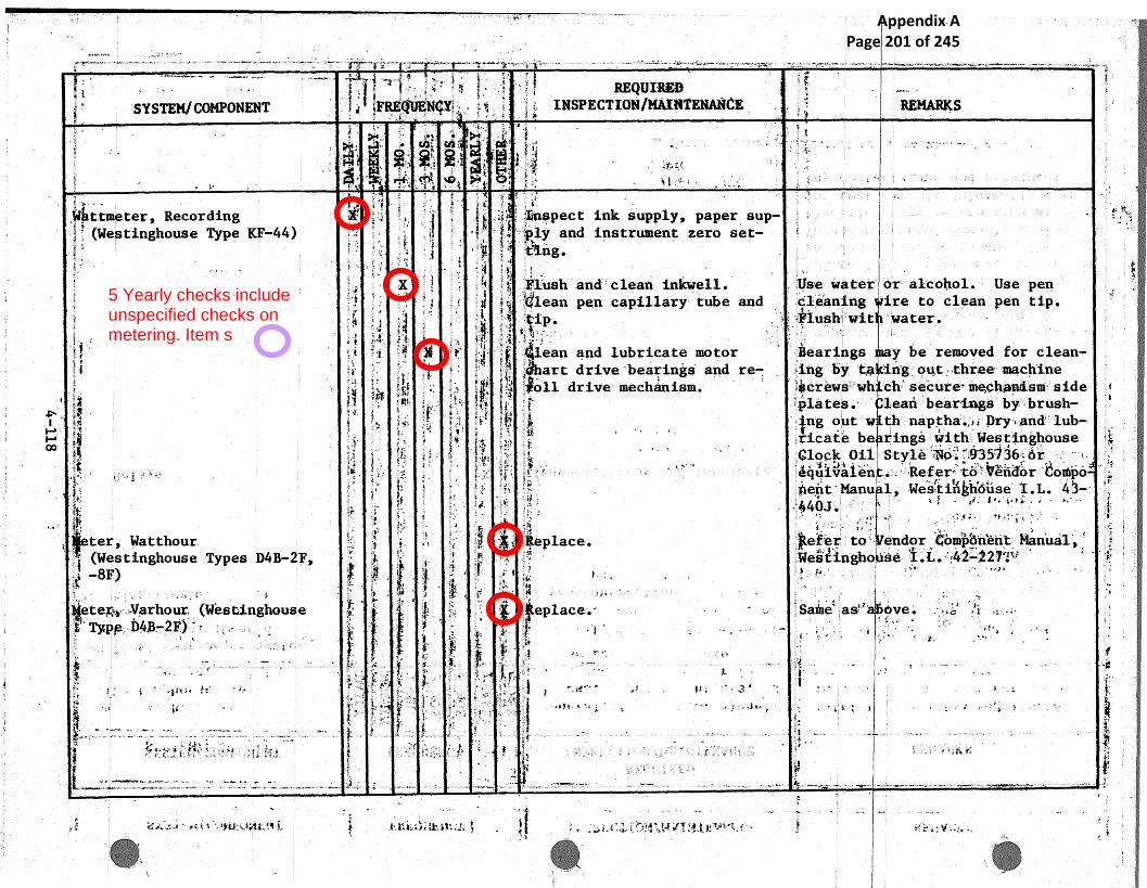
_ . .. ,,
..
~~,....~w ..~.. ~., . ._ _ ._. ., ....x£ ~ '~' %.
E SYSTEM/CO~iPOKENT ,~. .°_
,r 5 s ~i
__ INSPECTI(1N/MA~~TENAN~~
t ~
,~x
REMARKS
h ~,(~~ ~ { ~{
a ~.s.
c ,_
~
~. .:' ~ ...
W~ttmeter, Recording ~ F ' :, , ~ ~~
~~ ~
~ °Ii~nspect inl~ suPP~Ys Paper sup- ... 1' ~.. _. .
(Westinghouse 7~ype KF-44) :: ♦ ~. ~ { - 'fly and instrument zero .set- -:.
' R~~ ~ X ~ '~ ~~ t Flush and clean inkwell. ~,.. <tfse~=water o~r alcohol. ' Use penj s"~?
a . ~ , ~: ,
F ~~ s _
F~
Glean pin capillary tube and Cl:~aning i!re to clean: den tip..fi j ~ ~s ~ip~. ~~`Yush wit. , 'water .
~ 'lean .~~ ~ ~ ~ t ~ ~ Y ~ ~ ~} ~ ~ s ` and lubricate motor~~bear~n~gs
~3earingst,~.
y be removed £'or clean-'i ~x~ ~. , ~ art dive and r.e- -~.ng by n~g_ o~u~ ~.t~ir~ee. ~aachine
s.. ~ .~ ,,~ tit~
;~ :~}~ ~~~} , '~~oll drive mechanism. ~$crews~~wh chi secure; m~~i,~~.sm~ side~ bea~ri~ugs~~~ - ~ ~~,~.
~r~,~
4~f~
a:~~
~.~ °~~ t~ ~,~ ~ ~ `pl.ates.~ ~ lean by brush-
~~n.,~. ~ r ~ ~,F ~;i.~ ~ ' ~~
,~~ ng out w th naptha F~, Dry , :and lub-_.
~~ _ ~~.1~ .
e ~ ~ ~' ~ ~
~~
~,.Y i~ ~ ~ r
~: r3cate bei k .
rings with Westinghouse~~ x,. ~. . ftt ~` : # ~ - . flock Oil Style i~o ~'r9'35~36 -fir
~~ ~. ~ ~ s: ~ ~ ~ ~ eq,~iva1'en ..- - -Ref er~ ~~ o~~ ~~~ii~or ~ ~o~po~~~. ` ~'
; Y z.~
~ u ,r, Ve it' Manu ~ 1, Westin~h"~use~ ~.L. 43-.
ter Watthour. ~::r
~ ~f~~~
'~ .,: . ~~ f~
.~ dace.~e ~tef~e~' to ~ ~}., endor ~'omp~nen~ frtanual~,.`~ ~.-~r42 ~2~;' i~ ~ (Westinghouse Types D4B-2F,
~8~j`~ ~ i
~<~ a~~
ti~X r
~~ , S
''=~ ~_
~nTest~ng~►o'se~ ~~, ~ ~ i,. ,~~~
~y~
'~ 3 ' 'y a#f ~f ~ ~ ~ Y, ~ 7 .
~ ete~~~~ ~Uarhour< ~ ~West~.nghouse r~~ ~ ~`~ ~_~' ~ eplace~ Sa~he' ag", ~ve.~ ~,~' ~:`: ~ .- _ ~, .
1. ~`
. .
t ~ ~ ~ ~ {' r ~ ~~~.. v p~ e
nF ,~ r ~
r{!P, ~
...c ~.
S#. .,
j ~ h t a ~ } f ~
.. .~~
` ~i
t.
y'
r 't
~ 5
r ~.+-1 a fib• S ~ hJ s " ~
~
F i ~~
i'
i ~~
i 1
.~...
p t
~~ to ,I,.,..-7 ' .fits ~il_1~~~..:..~ ~_ ~ .~'. •. ~_il~t .t~.'., ~t: era t .~~ t ~.t i,f. .Y: i #S~ ~x~.~~,t .';f.~-~x. a ~.r ~~i'>. 1`-.<e4
~ ,~y,...~. ,. , '.,
i_l
5 Yearly checks includeunspecified checks onmetering. Item s
Appendix A Page 201 of 245

.- .__;; ~,
,r- ..-~€. - i
~.,
~ ~~ ~;,
•,_ f1
- r.i
N~.
. ~ a.
1' i''
~.
j !!k' ,
t
V1
. .:,, ..„ .. .., ,.. ~., a s,~.. ...~. _
SYSTEi'~iICOMPONEN~ ~: 1
..z } ~ ~ } vE ~,. ~ ; : ;
~; _~ ~tNC~ ! ~ A ~~ ,
~ F
REQU DINSPECT 4N/ NTENA~ICE
~,
'~ , REMARKS ` #
~ ~~. ~ ~ ~ ~
~~ ~~. rte.
~rfi
_~ ~ ~ ~ ,
~ ~'~~1i ''i ~.~ . ~O. ,
~~.rcuit ,breakers ~.' ~ ; ~ ~4 ~
~~
~
~~ ~
General, inspect for cleanl~.~~_
Initial inspection and lubric~tion~~~., . (Wee~ingha~t~s~e T}~pes ~ ~ -, ~ t ~ >.~ ~~- .~ ~~ 1lness., ~nspec~ contacts ad ~ is ofter ~..6 months of service or
D3206~ DS4~6 DS532) ~~.. ~'.
§~
~ust contacts ~ inspect for nt~mtier° of~ operations : t.. ..
. ~ ~ . r ~ :~ .loose pa~r~s„ lub~icate~ ji
i
~.' ~ `.~, ~
~ ~~~
~ ~: Type ~D~S2~~i , ~~~SQ Operations
.~:; ~ j°'TYpe lDS4~lfr T X00 Operations'~ . ~ ~ 1`gpe ~ bS~~3~1 - 2S~ Operations,~
~ ~ ~rr _ _ ~
~, ..~ ~
~~
~~ ~ ~
1~~Refer~ to Vendor Component Manual,
~~~Wsstnghoiis`e~~-~.B7 .~j ~ ~ t~ x +33-790-B for i..'a
{y
, ,~
.structions 'to c~~.sasseml~le, conta~' ~ ,~ ~~ .r; ~ ° ad~ust~terit cleaning and ~ lubrica-
.~~ {~ # T ~ :. .iion. ~ ee ~.al f lubrie~nt ~ is re- }_ 1 fop ~ - .
~ ~ .~ ~t~ _ quired in a' dew :p~~~es end must be. .a ~ ~ ~ 3~ ~
~ .s ~; ~F:_h
F ,,, ~y~~"~PP~'~ed with `~are~ ~~~Re~£~ t~~ ~P
r~~' ~'
t
~ ~
,~ ..Y, i . ,. ~ ~ ra ~ h ~3 'o~'abovt~`~manual8 ~ ~(,~ ,
' _ - 4 ~ ,~ ~ '
'. :. µ
} fit w ~ v , .. ~ , `, ~ f r, ~ Y y ye ' . ~ i •
_
, ,
r . , ~}e 'g p (
~
++
~
L
~~
~~
~ _ ~ 4
r ¢E S }` ,r~ u ~S ~ 1fY~~~'~ d~,» ` ~
,. .. ~.
~~,;
~ + ~e_ .''
,..w .,_— :. a.:,. .._ -,..,x,.. .r .a
~, ~~.,
~, -... ~ ,_ ..,~~ e
~ • ~,L ~
r
.. Y4 . Avj
~
4L.
R t r a
.:.. ... y
*tea .a
.. 1
..~
.r... ~•
a..
~
~.
.'
~
~
~.S Y
T~- .,,~..r ~..:- Gov w.~w.t+...e~r. ~Y.., +mNa ♦ Nww~4.QM1'iFM1i>~^.0 ~..w✓'rntin~vP—~~++v.+i...x ~. ni l eiJw.
.... .. ... .. .... w ~... , i~, :-, rte, ~ . . ♦ - ~ ~ j
., . .~., . {~ + ~, .. 5:~.
y .:, ~. .t., ..
R
.. ~~~:~
Appendix A Page 202 of 245

.. ,._ , ~„ _ ,,.
. , _ ~
,. .. .... ..7
SY~7'EM/C+~MPONEN~ FREQUENC~t~~U~~~ M
IHSPECTIONIMAINT'EN~N~E ~ Rl~d!SARICS
AC f ~?C. ~2{~R . ~4~N~ROL CENTERS H w.~
v, u, ~ W.
-, r-1 M tG }~ . Q ~.
Geme~al ~I$rtt~`,tare X Check for tight co~ne~tions~ Badly wo n'or ,pitted contactsClean relay cantacts. ~ shoal=d b replaced. Do,..not use.
Bus Har~r~a`re, 'Circuit ~ ~ lubr~.can , emery paper, sandpaperBreaker :and Sw~c~ or file o clean car dress up anyTerminals Co~tac~c~r portion f ttte el~ctrica~. equip-and Relay Term~:~la~ls., went. R place silver cadmium con-Terminal Blocks ', ~ _ tact poi is o~f line staa~.ters:.
rather " t an dean n~g for :sanding.
Use. alum; num oxide paper for othersanding peg~t~ion.
WARNING: ALL CIRCUITS S~iQULD BEDE-ENERGIZED AND.. DISCONNECT ICE-
~r VICES LOCKED OPEN WHEN WORKT.I~G.QN UNIT EQUIPMENT.
X Check operations of equ pu~ent
_. ~ .
CAUTION: ONLY:: AUTHORIZED PERSON-under energized conditions NEL MAY PEN .UNIT DQORS WHILEusing precautionary measures. STARTE~L IT 7IS. .'ENERGIZED..
When servicing e~.ectrical equip- .' ment ref r ta.,:specific instruction
bulletin .contained in the ~Tendor
f
Component Manual.
i ,
.. i._ ~ i -
~. i
~. _
." , -
~~ ~~ 1
mss.:.,.. '. i. ..
5 yearly checks item j and kare tests on the bus duct.
Appendix A Page 203 of 245

Newfoundland and Labrador Hydro PI Gas Turbines Limited Hardwoods and Stephenville Job No: 11017 Gas Turbine Protection Site Survey Document No.
APPENDIX 1g: MARKED COPY OF
Drawing No: 183481: Air Start System
11017-REP-001 Rev 1.1
Appendix A Page 204 of 245
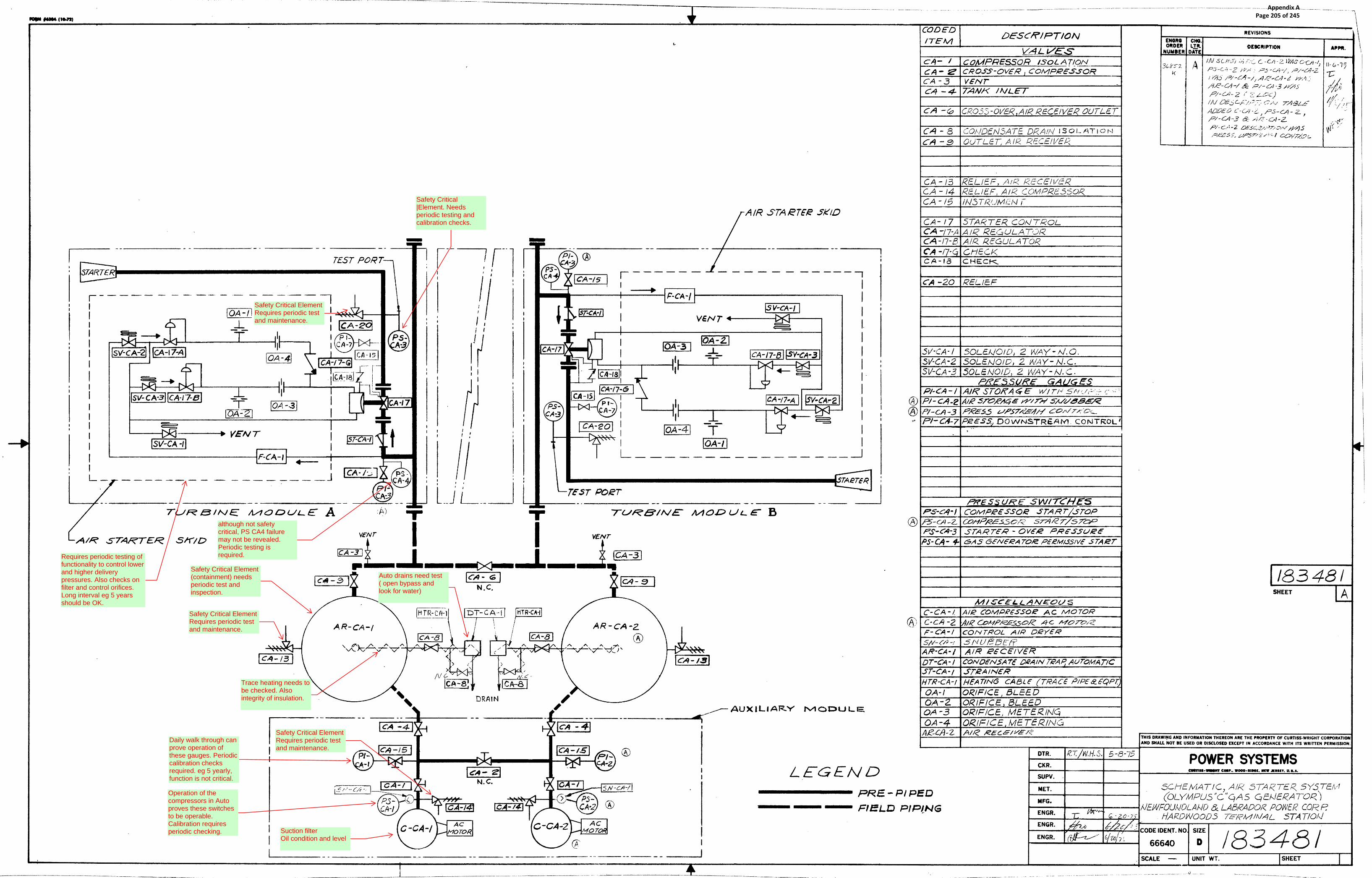
Safety Critical ElementRequires periodic testand maintenance.
Suction filterOil condition and level
Safety Critical ElementRequires periodic testand maintenance.
Auto drains need test( open bypass andlook for water)
Safety Critical Element(containment) needsperiodic test andinspection.
Trace heating needs tobe checked. Alsointegrity of insulation.
Operation of thecompressors in Autoproves these switchesto be operable.Calibration requiresperiodic checking.
Daily walk through canprove operation ofthese gauges. Periodiccalibration checksrequired. eg 5 yearly,function is not critical.
although not safetycritical, PS CA4 failuremay not be revealed.Periodic testing isrequired.
Safety Critical ElementRequires periodic testand maintenance.
Safety Critical|Element. Needsperiodic testing andcalibration checks.
Requires periodic testing offunctionality to control lowerand higher deliverypressures. Also checks onfilter and control orifices.Long interval eg 5 yearsshould be OK.
Appendix A Page 205 of 245

Newfoundland and Labrador Hydro PI Gas Turbines Limited Hardwoods and Stephenville Job No: 11017 Gas Turbine Protection Site Survey Document No.
APPENDIX 2a: BROCHURE FOR
Gastops Metalscan MS 4000
11017-REP-001 Rev 1.1
Appendix A Page 206 of 245

100% Detection of Fe and NFe metal particlesEasy to installEasy to interpretRugged, solid-state with no moving partsFull function continuous built-in test (BIT)Proven reliability in harsh machinery environmentsProven reliability in high temperature environmentsProven reliability in hazardous environments
Earliest reliable detection of component damageMonitor damage progression and estimate remaining lifeAvoid unplanned outagesAvoid equipment secondary damage
FEATURES
BENEFITS
gastops.comHead Office1011 Polytek StreetOttawa ON K1J 9J3 Canada
Halifax Office65 John Savage Avenue, Unit 5Dartmouth NS B3B 2C9 Canada
St. John’s Office146a Glencoe DriveMount Pearl NL A1N 4S9 Canada
North America1 800 363 8658
Worldwide+1 613 744 3530
ON-LINE OIL DEBRIS MONITOR
MS4000
Real-time detection of damage - anytime, anywhere.MetalSCAN MS4000 oil debris sensor monitors metal particles generated from
rotating equipment due to bearing and gear damage. Assess how much time you have to schedule maintenance before equipment failure occurs.
RequirementThe energy, marine, and aerospace industries require condition monitoring that is capable of detecting bearing and gear damage at the earliest stage of progression, and provide insight into the extent of the damage and its impact on the remaining life of the equipment.
It is understood that condition monitoring cannot be used to avoid damage occurring to the equipment, however, the right technique is used to effectively limit the damage and avoid outright failure of the equipment, where failure is defined as damage sufficient so that the equipment can no longer operate. Managing the risk from the context of the equipment operator is based upon planning the maintenance actions, thus achieving:
Reduction of lost revenue – the equipment can be scheduled to be out of service for the shortest possible time, where the replacement equipment parts, equipment, and maintenance crews are on site at the time of shutdown.
Reduction of repair costs - reduced equipment damage such that the extent of the repair is much less than if the equipment was to operate to failure.
An additional benefit of effective risk management is the potential for improved coverage from the insurers, which is delivered in terms of reduced premiums, reduced deductibles and/or reduced depreciation.
Appendix A Page 207 of 245

Description
SPECIFICATIONS
ON-LINE OIL DEBRIS MONITOR
MS4000 SYSTEM
MetalSCAN is an on-line debris monitoring system designed to detect the passage of metallic particles in fluid lines. The system, which can be used in any pipe flow situation, is particularly suited to equipment applications where it detects metallic debris in a lubrication oil system and provides early indication of component damage.
The MetalSCAN MS4000 system consists of the following major components:
A non-intrusive through flow Sensor which is fitted to the fluid line to be monitored.
A custom low noise Sensor Cable which connects the sensor to the electronics.
A Control Unit which processes the raw signal from the sensor and extracts information about the size and type (ferromagnetic or non-ferromagnetic) of the metallic debris detected.
A host monitoring system which displays the current counts data, trend data, computes equipment health indices and announces warning/alarm exceedances. This function can be performed by an existing monitoring system host or by a dedicated standalone PC.
MS4000 is available in two basic configurations defined by the Control Unit option:
Multi-Sensor System - which includes from 1 to 6 Sensors and Sensor Cables, each connected to a multi-sensor Control Unit.
Single Sensor System - which includes one Sensor, one Sensor Cable, and a single-sensor Control Unit.
gastops.comHead Office1011 Polytek StreetOttawa ON K1J 9J3 Canada
Halifax Office65 John Savage Avenue, Unit 5Dartmouth NS B3B 2C9 Canada
St. John’s Office146a Glencoe DriveMount Pearl NL A1N 4S9 Canada
North America1 800 363 8658
Worldwide+1 613 744 3530
C008850_002
1)
2)
Single-sensor
Power Requirement
System
Rated Current:
Communication Interface
Cabling Distance
24 VDC
0.3A
RS485 Modbus
up to 4000ft / 1200m
24 VDC
0.8A
RS485 Modbus
up to 4000ft / 1200m
Multi-sensor
COMPLIANCELC Listed (USA & Canada)
Class I, Div 2, Groups A to D Hazardous LocationsNEMA 250 (Type 4)1
FCC part 15Conforms to ASTM D7685
CE Marking IP 66
Pressure EquipmentASME B31.3B (Process Piping Standard)
Note 1NEMA 4 - Standard EnclosureNEMA 4x - Stainless Steel Enclosure
Up to 6 MS4000 Sensors
Control Unit
Monitoring System
Switch or Circuit Breaker or Appliance Coupler
MS4000 Sensor
Control Unit
Monitoring System
RS485 RS485
Switch or Circuit Breaker or Appliance Coupler
SINGLE-SENSOR SYSTEM MULTI-SENSOR SYSTEM
Appendix A Page 208 of 245

3/8 INCH SENSOR 3/4 INCH SENSOR 1-1/4 INCH SENSOR
ON-LINE OIL DEBRIS MONITOR
MS4000 SENSOR
The MS4000 Sensors are welded stainless steel assemblies designed to be installed directly into the fluid line with fluid flowing in either direction. The sensors are designed to operate in severe industrial and/or hazardous environments with large temperature extremes and high vibration levels. They are available in three sizes: 3/8", 3/4" and 1-1/4" nominal line diameter. The sensing element consists of three internal coils. The two outside field coils are oppositely wound and are driven by an alternating current source so that their respective magnetic fields are opposed and cancel at the center point between the field coils. The centrally positioned sense coil measures the disturbances in the magnetic fields caused by metallic particles as they pass through the sensor. The magnitude of the disturbance measured as a voltage defines the size of the particle and the phase shift of the signal defines whether the metallic particle is ferromagnetic (Fe) or non-ferromagnetic (NFe).
* The Equivalent Spherical Diameter (ESD) of an irregular-shaped object is the diameter of a sphere of equivalent volume.
gastops.comHead Office1011 Polytek StreetOttawa ON K1J 9J3 Canada
Halifax Office65 John Savage Avenue, Unit 5Dartmouth NS B3B 2C9 Canada
St. John’s Office146a Glencoe DriveMount Pearl NL A1N 4S9 Canada
North America1 800 363 8658
Worldwide+1 613 744 3530
C008850_002
Maximum Pressure
Maximum Temperature
Minimum Flow Rate
Maximum Flow Rate 4.3 USGPM16.2 L/min
48 USGPM180 L/min
175 USGPM665 L/min
0.056 USGPM0.21 L/min
0.50 USGPM1.9 L/min
2.1 USGPM8.0 L/min
500 psi / 3500 kPa 500 psi / 3500 kPa
Fluid Conditions 3/8 inch 3/4 inch
375°F / 190°C 375°F / 190°C 375°F / 190°C
100 psi / 700 kPa
1-1/4 inch
Weight
3/8 inch
Bore
Sensor Nominal Line Size
Plumbing Connection (female)
Minimum Ambient Temperature
Maximum Ambient Temperature
0.30” / 7.6mm
-6 SAE O-ring Boss
-40°F / -40°C
375°F / 190°C
0.70” / 17.8mm
-12 SAE O-ring Boss
-40°F / -40°C
375°F / 190°C
3/4 inch
1.5lbs / 0.7kg 2.0lbs / 0.9kg 5.5lbs / 2.5kg
Electrical Connector MIL-DTL-38999 MIL-DTL-38999 MIL-DTL-38999
1.06” / 26.9mm
-20 SAE O-ring Boss
-40°F / -40°C
375°F / 190°C
1-1/4 inch
Description
SPECIFICATIONS
Minimum Detectable Particle Size
Fe (ESD*/sphere)
NFe silver (ESD*/sphere)
65μm / 100μm
200μm / 305μm
130μm / 200μm
270μm / 415μm
180μm / 275μm
345μm / 530μm
3/8 inch 3/4 inch 1-1/4 inch
Appendix A Page 209 of 245

ON-LINE OIL DEBRIS MONITOR
MS4000 CONTROL UNIT
The MS4000 Control Unit houses the modular electronics for MS4000 system and is available as either a multi-sensor unit with capacity for up to 6 sensors or a single-sensor unit designed for only one sensor. In either case, the enclosure is a steel housing designed for back-side mounting on a bulkhead or plate with all interconnecting cables entering through the bottom of the unit. Note that the electronics of the control unit cannot be relocated outside of this enclosure (i.e. in another rack) due to EMI and signal grounding control requirements.
The multi-sensor Control Unit includes separate modules for power input, power supply, control, and sensor interface, each plugged into a backplane chassis. The chassis has a capacity for 6 separate sensor modules. The single sensor Control Unit is similar to the multi-sensor unit except it has the capacity to house only one sensor module.
Communication to the host is via industry standard Modbus RS485 serial communications which supports up to 30 separate Control Units (single or multi) can be linked together to a single host monitoring system communication port.
gastops.comHead Office1011 Polytek StreetOttawa ON K1J 9J3 Canada
Halifax Office65 John Savage Avenue, Unit 5Dartmouth NS B3B 2C9 Canada
St. John’s Office146a Glencoe DriveMount Pearl NL A1N 4S9 Canada
North America1 800 363 8658
Worldwide+1 613 744 3530
C008850_002
SINGLE-SENSOR CONTROL UNIT MULTI-SENSOR CONTROL UNIT
Splash proof - for outdoor and indoor installations (IP66)
Finish
Environment
Control Unit
Enclosure Size - nominal
Minimum Ambient Temperature
Maximum Ambient Temperature
Maximum Weight
Painted mild steel (blue)
Splash proof - for outdoor and indoor installations (IP66)
Painted mild steel (blue) or optional stainless steel
Single-sensor
8.80w x 20.5h x 8.33d (in)224w x 521h x 212d (mm)
-40°F / -40°C
Multi-sensor
16w x 20.5h x 8.33d (in)406w x 521h x 212d (mm)
-40°F / -40°C
131°F / 55°C
25.5lbs / 11.6kg
131°F / 55°C
36.0lbs / 16.3kg (6 sensors)
Description
SPECIFICATIONS
Appendix A Page 210 of 245

ON-LINE OIL DEBRIS MONITOR
MS4000 SENSOR CABLE
MS4000 SENSOR BRACKETS
gastops.comHead Office1011 Polytek StreetOttawa ON K1J 9J3 Canada
Halifax Office65 John Savage Avenue, Unit 5Dartmouth NS B3B 2C9 Canada
St. John’s Office146a Glencoe DriveMount Pearl NL A1N 4S9 Canada
North America1 800 363 8658
Worldwide+1 613 744 3530
C008850_002
The MS4000 Sensor is electrically connected to the Control Unit using the Sensor Cables provided as part of the MetalSCAN system. The inductive coils of the sensor assembly are designed to achieve maximum sensitivity to particles present in the flow. The cabling and connectors play a significant part in achieving the level of sensitivity necessary for the system to operate properly. The cables are factory assembled and available in 12 and 20 foot lengths. The result is an extremely robust cable connection system that provides assurance of the required detection performance and sensitivity.
A double shield is provided on each of the four coaxial cables within the cable assembly. Each coaxial cable is terminated at the Control Unit end via a BNC connector while at the sensor end the cables are brought together into a single aerospace grade MIL-DTL-38999 Series III connector. The coaxial cables are further shielded by a tinned copper braid covering and then mechanically contained by a high temperature silicone impregnated fibreglass sleeve.
The sensors can be installed in any orientation with fluid flowing in either direction. The recommended location for the sensors is directly downstream of the wear elements in the lubrication system. There must be no debris traps or filters between the sensor and the oil wetted components being monitored.
The sensors can be supported by brackets attached to the ends of the body as shown below, or by the fluid line, provided that the fluid line is well supported. The sensor body is not designed to support mechanical loads.
Sensor bracket material: Anodized aluminum (clamps) and stainless steel (bolts and washers).
Description
Description
SPECIFICATIONSSensor Cable Length
Connector (sensor end)
Connectors (Control Unit End)
Minimum Ambient Temperature
Maximum Ambient Temperature
12ft / 3.7m
4x BNC
20ft / 6.1m
4x BNC
MIL-DTL-38999 Series III MIL-DTL-38999 Series III
-40°F / -40°C
375°F / 190°C
-40°F / -40°C
375°F / 190°C
Weight 3lbs / 1.4kg 4lbs / 1.8kg
SPECIFICATIONSSensor Bracket Dimensions
3/8 Inch Sensor
3/4 Inch Sensor
1-1/4 Inch Sensor
A
2.60
1.88
3.75
66
48
95
2.75
2.25
4.00
70
57
102
0.75
0.63
1.00
19
16
25
2.19
1.75
3.00
56
44
76
1/4-20UNC x 3 in
1/4-20UNC x 3 in
Bolt (Hex Socket)
3/8-16UNC x 4.5 in
B C Dmmin in mm in mm in mm
E
Appendix A Page 211 of 245

ON-LINE OIL DEBRIS MONITOR
MS4000 MONITOR SOFTWARE
The MS4000 Monitor is a PC software application that runs under Microsoft Windows designed to interface with one or more MS4000 systems and provide the user interface for tracking the health of the machine(s) being monitored. The software provides the capability to continuously record and display MetalSCAN data, to annunciate warnings and alarms when debris accumulation exceeds user-defined limits, and to interface to external data acquisition or monitoring systems.
The MS4000 Monitor includes several display pages, which can be selected using the dedicated pushbutton controls located on the application toolbar. The three primary pages are the Status, Counts, and Trends pages.
The Equipment Status page displays a summary of the debris accumulation measurements and operational health of the channel for the selected Equipment. The purpose of the Equipment Status Page is to enable the operator to quickly assess the condition of the monitored equipment. The display features bar charts that compare the accumulated debris (Fe counts, Fe mass or NFE counts) against set limits.
The Equipment Status page also provides the capability to visibly annunciate alarm, warning and system conditions. Whenever MS4000 Monitor detects a new alarm or warning condition, it automatically changes the display page to annunciate the system or equipment health condition by displaying a colored contour around the affected channel.
The Counts page provides high resolution current information of the accumulated debris including ferromagnetic (Fe) and non-ferromagnetic (NFe) count totals, categorized by size and by type, either Fe or NFe. It also provides a graphical display of size distribution by counts or mass, for any selected sensor.
The Trends page displays the time history of debris accumulation data along with the user-defined warning or alarm limits for the selected parameter, allowing the user to assess the current severity of the equipment condition, to review the time history, and to estimate the remaining operating life of the equipment.
gastops.comHead Office1011 Polytek StreetOttawa ON K1J 9J3 Canada
Halifax Office65 John Savage Avenue, Unit 5Dartmouth NS B3B 2C9 Canada
St. John’s Office146a Glencoe DriveMount Pearl NL A1N 4S9 Canada
North America1 800 363 8658
Worldwide+1 613 744 3530
C008850_002
Description
Appendix A Page 212 of 245

Ordering Information
ON-LINE OIL DEBRIS MONITOR
MS4000 SYSTEM
gastops.comHead Office1011 Polytek StreetOttawa ON K1J 9J3 Canada
Halifax Office65 John Savage Avenue, Unit 5Dartmouth NS B3B 2C9 Canada
St. John’s Office146a Glencoe DriveMount Pearl NL A1N 4S9 Canada
North America1 800 363 8658
Worldwide+1 613 744 3530
C008850_002
Including: 24 VDC single sensor control unit, 1 x 3/4" sensor, 1 x 20 ft. sensor cable, USB/RS485 converter, MS4000 Monitor Software, user's manual, 12 month warranty.
One Sensor MS4000 System (Single)Order: System - 01S
Including: 24 VDC multi-sensor control unit, 1 x 3/4" sensor, 1 x 20 ft. sensor cable, USB/RS485 converter, MS4000 Monitor Software, user's manual,12 month warranty.
One Sensor MS4000 System (Multi)Order: System - 01M
ORDER NOW
North America: 1 800 363 8658Worldwide: +1 613 744 [email protected]
Including: 24 VDC multi-sensor control unit, 2 x 3/4" sensors, 2 x 20 ft. sensor cables, USB/RS485 converter, MS4000 Monitor Software, user's manual, 12 month warranty.
Two Sensor MS4000 SystemOrder: System - 02M
Including: 24 VDC multi-sensor control unit, 3 x 3/4" sensors, 3 x 20 ft. sensor cables, USB/RS485 converter, MS4000 Monitor Software, user's manual, 12 month warranty.
Three Sensor MS4000 SystemOrder: System - 03M
Including: 24 VDC multi-sensor control unit, 4 x 3/4" sensors, 4 x 20 ft. sensor cables, USB/RS485 converter, MS4000 Monitor Software, user's manual, 12 month warranty.
Four Sensor MS4000 SystemOrder: System - 04M
Including: 24 VDC multi-sensor control unit, 5 x 3/4" sensors, 5 x 20 ft. sensor cables, USB/RS485 converter, MS4000 Monitor Software, user's manual, 12 month warranty.
Five Sensor MS4000 SystemOrder: System - 05M
Including: 24 VDC multi-sensor control unit, 6 x 3/4" sensors, 6 x 20 ft. sensor cables, USB/RS485 converter, MS4000 Monitor Software, user's manual, 12 month warranty.
Six Sensor MS4000 SystemOrder: System - 06M
Substitute 3/8" Sensor (per sensor), 12 month warranty.
MS4000 Sensor - 3/8”Order: Option - 13
Substitute 1-1/4" Sensor (per sensor), 12 month warranty.
MS4000 Sensor - 1-1/4”Order: Option - 05
Substitute 12 ft. Sensor Cable (per cable), 12 month warranty.
MS4000 Cable - 12ftOrder: Option - 06
MetalSCAN Barrier Kit for RS485 communication intrinsic safety isolation required for ATEX certification, including: barrier unit, serial null modem cable, ATEX system label, 12 month warranty.
MS4000 ATEX Barrier KitOrder: Option - 17x
Substitute 1-1/4" Sensor (per sensor), 12 month warranty.
MS4000 Stainless Steel EnclosureOrder: Option - 07
OPTIONS
Appendix A Page 213 of 245

Newfoundland and Labrador Hydro PI Gas Turbines Limited Hardwoods and Stephenville Job No: 11017 Gas Turbine Protection Site Survey Document No.
APPENDIX 2b: BROCHURE FOR
Poseidon Trident DM4500
11017-REP-001 Rev 1.1
Appendix A Page 214 of 245

TRIDENT ™ DM4500Wear Debris Monitor
Poseidon Systems’ Trident™ DM4500 Wear Debris Monitor is a real-time, in-line fluid sensing technology for the detection of metallic wear debris and particulates in a lubrication system. By continuously monitoring wear debris generation, the device alerts users to faults in their earliest stages, allowing for lower cost correction actions than conventional schedule based maintenance.
The DM4500 Wear Debris Monitor will detect, categorize (ferrous vs. non-ferrous), and size metals within a machinery lubrication system. The monitor will detect and measure particles with an estimated spherical diameter of 40 micron ferrous and 150 micron non-ferrous and larger. A wide range of output formats are available including particle type/size, approximate mass, and particle counts in user configurable bins.
DM4500 is a standalone sensor with customizable hose fittings. Ordering with BSPP fittings provides a direct replacement for existing TA10s,. JIC, SAE Boss, and Compression fittings are available as off the shelf options. The DM4500 is also backward compatible with the popular TechAlert™ 10 (TA10) Debris Monitor.
PRODUCT OVERVIEW
BENEFITS40 micron ferrous & 150 micron non-ferrous debris detection ability
Industry standard communication interface
Mounting footprint matched to TA10 for drop-in replacement
Particle size/mass estimates
Volumetric flow rate estimates
Total particle count estimation
KEY FEATURES
©2016 Poseidon Systems, LLC
Real-time monitoring leads to improved asset health management
Optimize machinery oil sample timing & maintenance intervals
Improve asset health state awareness
Advanced warning enables improved asset maintenance & logistics planning
Reduce cost of unscheduled downtime
Appendix A Page 215 of 245

TECHNICAL SPECIFICATIONSDetection Sensitivity (Debris)
Communications
Oil Connection
Ambient Temperature
Fluid Temperature
Volumetric Flow Rate
Sensor Bore Diameter
Ingress Protection
Power Supply
Weight
40 µm Ferrous & 150 µm Non-Ferrous Metallic Particles
RS485/RS232 Modbus RTU, Pulse Output
3/4” -16 SAE Female, -8 JIC Male, -8 BSPP Male, or 1/2” Compression
-40 to 185˚F (-40 to 85˚C)
-40 to 185˚F (-40 to 85˚C)
0.25 o 10 GPM (0.95 to 38 LPM)
0.472 inches (12 mm)
IP65
10-30 VDC, 300 mA
1.5 pounds (0.68 kg)
©2016 Poseidon Systems, LLC
Poseidon Systems, LLC200 Canal View Blvd.Rochester, NY 14623
Phone: (585) 239-6025
Email:[email protected]
Website: www.PoseidonSys.com
Appendix A Page 216 of 245

Newfoundland and Labrador Hydro PI Gas Turbines Limited Hardwoods and Stephenville Job No: 11017 Gas Turbine Protection Site Survey Document No.
APPENDIX 3: OIM Manual for
Sensonics DN2611 Dual Channel Vibration Monitor
11017-REP-001 Rev 1.1
Appendix A Page 217 of 245

Issue.3
SENSONICS LTD Northbridge Road Telephone: +44 (0) 1442 876 833 Berkhamsted Fax: +44 (0) 1442 876 477 Herts E-mail: [email protected] HP4 1EF Web site: www.sensonics.co.uk United Kingdom
DN2611 Dual Channel
Vibration Monitor
Operation, Installation, Maintenance and Safety Handbook
Ref. HB1306-2
Appendix A Page 218 of 245

HB.1306-2 Page. 2
1.1 History sheet
ISSUE/ DATE
COMMENT APPROVED OWNER
ACCEPTED QA
1 First Issue A. PITT R.KING
2 Functional Safety added A. PITT R.KING
3 SIL Level updated A. PITT R.KING
Appendix A Page 219 of 245

HB.1306-2 Page. 3
Contents
REF. HB1306-2 ................................................................................................................................................................1
1.1 HISTORY SHEET .....................................................................................................................................................2
CONTENTS.......................................................................................................................................................................3
INTRODUCTION.............................................................................................................................................................4
INSTALLATION..............................................................................................................................................................5
MOUNTING......................................................................................................................................................................5
CONNECTION/CABLING ..................................................................................................................................................5
OPERATIONAL SETTINGS..........................................................................................................................................5
SCALING .........................................................................................................................................................................6
FILTERS ..........................................................................................................................................................................7
CONNECTION DETAILS...............................................................................................................................................8
INPUTS (2 WIRE ICP TYPE DEVICES)...........................................................................................................................9
INPUTS (3/4 WIRE DEVICES OR 2-WIRE PASSIVE) .......................................................................................................9
OUTPUTS.....................................................................................................................................................................9
LOWER RAIL ...............................................................................................................................................................9
MODULE OPERATION ...............................................................................................................................................10
MODULE SPECIFICATION........................................................................................................................................10
FUNCTIONAL SAFETY ...............................................................................................................................................12
SAFETY RELATED PARAMETERS .................................................................................................................................12
RELIABILITY DATA .......................................................................................................................................................12
ELECTROMAGNETIC COMPATIBILITY ...........................................................................................................................13
CERTIFICATION DATA ..................................................................................................................................................13
INSTALLATION AND CONFIGURATION ..........................................................................................................................13
START UP.....................................................................................................................................................................13
MODULE OVERIDE .......................................................................................................................................................13
PERIODIC TESTING REQUIREMENTS............................................................................................................................14
PERIODIC INSPECTION .................................................................................................................................................14
PERIODIC PARTS REPLACEMENT ................................................................................................................................14
OTHER PREVENTATIVE MAINTENANCE .......................................................................................................................14
FAULT HANDLING AND DETECTION .............................................................................................................................15
REPAIR AND REPLACEMENT ........................................................................................................................................15
SHUTDOWN ..................................................................................................................................................................15
TOOLS NECESSARY FOR MAINTENANCE ....................................................................................................................15
BREAKDOWN MAINTENANCE ................................................................................................................................16
WARRANTY POLICY ..................................................................................................................................................16
SPECIFICATION SHEET SPECIFIC TO CONTRACT ATTACHED ...................................................................17
Appendix A Page 220 of 245
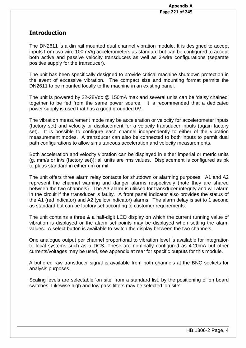
HB.1306-2 Page. 4
Introduction
The DN2611 is a din rail mounted dual channel vibration module. It is designed to accept inputs from two wire 100mV/g accelerometers as standard but can be configured to accept both active and passive velocity transducers as well as 3-wire configurations (separate positive supply for the transducer). The unit has been specifically designed to provide critical machine shutdown protection in the event of excessive vibration. The compact size and mounting format permits the DN2611 to be mounted locally to the machine in an existing panel.
The unit is powered by 22-28Vdc @ 150mA max and several units can be ‘daisy chained’ together to be fed from the same power source. It is recommended that a dedicated power supply is used that has a good grounded 0V. The vibration measurement mode may be acceleration or velocity for accelerometer inputs (factory set) and velocity or displacement for a velocity transducer inputs (again factory set). It is possible to configure each channel independently to either of the vibration measurement modes. A transducer can also be connected to both inputs to permit dual path configurations to allow simultaneous acceleration and velocity measurements. Both acceleration and velocity vibration can be displayed in either imperial or metric units (g, mm/s or in/s (factory set)); all units are rms values. Displacement is configured as pk to pk as standard in either um or mil. The unit offers three alarm relay contacts for shutdown or alarming purposes. A1 and A2 represent the channel warning and danger alarms respectively (note they are shared between the two channels). The A3 alarm is utilised for transducer integrity and will alarm in the circuit if the transducer is faulty. A front panel indicator also provides the status of the A1 (red indicator) and A2 (yellow indicator) alarms. The alarm delay is set to 1 second as standard but can be factory set according to customer requirements. The unit contains a three & a half-digit LCD display on which the current running value of vibration is displayed or the alarm set points may be displayed when setting the alarm values. A select button is available to switch the display between the two channels. One analogue output per channel proportional to vibration level is available for integration to local systems such as a DCS. These are nominally configured as 4-20mA but other currents/voltages may be used, see appendix at rear for specific outputs for this module. A buffered raw transducer signal is available from both channels at the BNC sockets for analysis purposes.
Scaling levels are selectable ‘on site’ from a standard list, by the positioning of on board switches. Likewise high and low pass filters may be selected ‘on site’.
Appendix A Page 221 of 245

HB.1306-2 Page. 5
Installation
Mounting
The monitor is designed to be mounted on a DIN rail (this may be of the ‘G’ type or the 35mm ‘Top Hat’ type). The monitor is not “weather proof” and as such should be protected against damp conditions with a suitable enclosure. The monitor should also be protected against temperatures outside of the operating range 0 to 50°C (the monitor will dissipate a maximum of 4 watts during operation). The monitor may be mounted either vertically or horizontally.
Connection/Cabling
It is recommended that the cable to the transducer is a screened cable and that one end only is connected to earth (preferably connected to the ‘SCN’ input on the monitor). The power-input cable can be any suitably rated cable but it is recommended that the 0V side of the supply is earthed (suitably near to the monitor). The monitor has an internal automatically re-settable fuse but the supply should also have some suitable over current protection. The output signal cable should also be screened and one end connected to earth (preferably connected to the ‘SCN’ output on the monitor). It is recommended that if armoured conduit is used to protect the cabling that one end of the metal armouring is isolated to prevent ‘earth loops’.
Appendix A Page 222 of 245

HB.1306-2 Page. 6
Operational settings
The setting options detailed below are the standard options available with the DN2611. It is possible the settings in the unit supplied may be different due to specific customer requirements. These setting parameters will be detailed on the IS. Sheet provided with the unit and this handbook. To gain access to the configuration switches remove the four screws securing the side of the unit (adjacent to BNC connector) as shown below. This will reveal the four sets of switches to be used to set the range and filter settings.
Scaling
The output scaling can be set to the following default ranges, each channel may be set to a different range by configuring the switches accordingly. Note the unit is factory set to the required units of measurement and available scale ranges, either g or mm/s or inch/s: Scale in g sw1 & 3 Scale in mm/s sw1 & 3 0 to 10g 6 0 to 20mm/s 6 0 to 12.5g 5 0 to 25mm/s 5 0 to 15g 4 0 to 30 mm/s 4 0 to 20g 3 0 to 50 mm/s 3 0 to 25g 2 0 to 75 mm/s 2 0 to 50g 1 0 to 100 mm/s 1 Scale in inch/S…sw1 & 3 0 to 1 inch/s 6 0 to 1.5 inch/s 4 0 to 2 inch/s 3
Appendix A Page 223 of 245

HB.1306-2 Page. 7
Filters Switches 2 & 4 permit different filter characteristics to be set for each of the channels. The following values can be selected as standard: - Low pass freq.’ sw2 & 4 1 kHz 1, 2, 3 & 4 off (Factory default) 2 kHz 1 & 3 on 10 kHz 1, 2, 3 & 4 on High pass freq.’ sw2 & 4 2.5 Hz 5, 6, 7 & 8 off 5 Hz 5 & 8 on 10 Hz 5, 6, 7 & 8 on (Factory default) The four switch sets are identified as detailed below.
SW1 Channel A Scaling
SW2 Channel A Filter Settings
SW3 Channel B Scaling
SW4 Channel B Filter Settings
Appendix A Page 224 of 245

HB.1306-2 Page. 8
Connection Details
The module offers connections via standard 0.2” pitch terminal rail with a tension clamp connect facility operated via insertion of a terminal flat blade screwdriver in to the appropriate terminal. See below for connector operation. Note it is only possible to operate the terminal via the top access point. We recommend only appropriately crimped terminals are fixed to the rail. The connections are arranged above and below the main display facia as illustrated below.
Appendix A Page 225 of 245

HB.1306-2 Page. 9
INPUTS (2 wire ICP type devices)
A Hi = Connect Channel A Accelerometer High (+ve). A Lo = Connect Channel A Accelerometer Low (0v). A0 = Connect Channel A Accelerometer Cable Screen. A = Ignore for vibration (utilised for temperature option) B Hi = Connect Channel B Accelerometer High (+ve) . B Lo = Connect Channel B Accelerometer Low (0v). B0 = Connect Channel B Accelerometer Cable Screen. A = Ignore for vibration (utilised for temperature option)
INPUTS (3/4 wire devices or 2-wire passive)
Please see associated IS. Sheet for the wiring of alternatives to ICP
OUTPUTS
A Hi = Channel A Analogue Output (4-20mA) High (+ve). A Lo = Channel A Analogue Output (4-20mA) Low (0v). A Scn = Channel A Analogue Output (4-20mA) Cable Screen. B Hi = Channel B Analogue Output (4-20mA) High (+ve). B Lo = Channel B Analogue Output (4-20mA) (0v). B Scn = Channel B Analogue Output (4-20mA) Cable Screen.
LOWER RAIL
+24V IN = Power Input Connection +24V d.c. 0V IN = Power Input Connection 0V. A1NO = Alarm 1 (RED) Relay Connection for Normally Open. A1COM = Alarm 1 (RED) Common Relay Connection. A1NC = Alarm 1 (RED) Relay Connection for Normally Closed. A2NO = Alarm 2 (YELLOW) Relay Connection for Normally Open. A2COM = Alarm 2 (YELLOW) Common Relay Connection. A2NC = Alarm 2 (YELLOW) Relay Connection for Normally Closed. A3NO = Alarm 3 (Trans/PSU Integrity) Relay Connection for Normally Open. A3COM = Alarm 3 (Trans/PSU Integrity) Common Relay Connection. A3NC = Alarm 3 (Trans/PSU Integrity) Relay Connection for Normally Closed. R/S Hi = External reset input from voltage free contacts R/S Lo = External reset input from voltage free contacts +24V OUT = Power Output Daisy Chain Connection +24V d.c. to Next DN2601 Monitor. 0V OUT = Power Output Daisy Chain Connection 0V to Next DN2601 Monitor.
Appendix A Page 226 of 245

HB.1306-2 Page. 10
Module Operation
With operational switch settings selected and +24V power applied, the module will power up and display either a channel A or channel B reading (dependant on last state prior to power down). By pressing the select button the display will switch between channel A and channel B vibration values. The channel selected is indicated by the backlight behind either A of B located below the display. With no transducer connected the display should read virtually zero (0.00) on the selected channel. The OK light will be red indicating a transducer integrity fault. With the transducer connected a low reading will now be obtained in the presence of no detected vibration i.e. <0.1mm/s. The OK light will only return to green once valid transducer inputs are present on both channels unless defeated (see below). If single channel operation is required the channel defeat switch adjacent to the accelerometer input terminals can be utilised. Switching 1 for channel A or 2 for channel B will defeat the alarm functions (A1, A2 and A3 relays and associated lamps) effectively disabling the channel. The alarm window for both A1 and A2 can be adjusted within the set range of the channel. With the appropriate channel selected, press and hold either A1 or A2 and adjust the appropriate potentiometer accessible through the front panel to the required alarm level. Note the module has an optional reset facility (factory configured). If enabled, A1 and A2 relay functions are latching (de-energised to alarm) – operating the reset facility clears the latched status. If the reset facility is disabled, all relays and alarm indications are fleeting / non-latching only (de-energised to alarm). The A3 transducer integrity relay is fixed as non-latching and de-energised to alarm. The transducer signal is available at the front panel BNC buffered outputs with unity gain and a DC frequency response. This facility enables the user to carry out a more detailed analysis of the vibration signal using a portable device.
Module Specification
Power Supply Voltage Range : 18V – 36V dc Power Consumption : 3.6W typ 5W max Re-settable Fuse rating : 250mA Signal : Two ICP type inputs +18V typ 2.4mA current source Sensitivity : 100mV/g or 4mV/mm/s Other sensitivities can be factory set Measurement range : Various selectable up to 50g / 100mm/s Higher ranges can be factory set.
Appendix A Page 227 of 245

HB.1306-2 Page. 11
Measurement accuracy : ± 0.5%, 1g @ 80Hz Filters : 12dB / octave LPF and HPF 2.5Hz to 10kHz max bandwidth (-3dB) Transducer Integrity : ICP alarm window <8V & > 16V : Passive sensor integrity based on SC/OC detection Current Outputs : 4-20mA nominal load 220Ohm ± 0.5%, ±0.08mA accuracy ± 1.0%, ±0.16mA linearity BNC Outputs : Buffered transducer inputs typically ±1% accuracy Relay Rating : 0.5A @ 125Vac Operating Temperature Range : 0ºC to 50ºC Din Rail Mount : TS32 or TS35 Mass : 0.45 kg Mechanical Outline – see below.
Appendix A Page 228 of 245

HB.1306-2 Page. 12
Functional Safety
This section of the manual describes the user responsibilities for installation and operation of the DN2611 monitor in a Safety Instrumented Function. In order to ensure the safe usage of this product, all procedures in this section must be followed in conjunction with the general instructions provided in the rest of this manual.
Safety Related parameters The following variables and interfaces can be used as part of the Safety instrumented Function. Variables: Vibration Interfaces: Alarm Relay Contacts. Safety Response Time: 1000ms maximum Measurement Updates: 100ms. Failure of the system is indicated through A3 relay which is set as normally energised. Note: Alarm relays A1 and A2 should be configured as de-energised to alarm to ensure a fail safe condition.
Reliability Data The data is valid with the following requirements: The system operates in a low demand mode (The frequency of demands for operation made on the system is no greater than one per year and no greater than twice the proof test frequency). The connected system must detect both the integrity A3 relay in conjunction with the configured alarm relay (A1, A2) Failure Data According to IEC 61508 DN2611 Single measurement channel Total Failure Rate 1.813 per million hours λdd – Dangerous Detected Failures 0.157 per million hours λdu – Dangerous Undetected Failures 0.583 per million hours λs – Safe Failure State 1.073 per million hours The PFD value for a single channel is 2.6e-3 (Proof test interval is 1 year). The DN2611 module continuously monitors the attached sensor for a detected fault. For environmental and operational limits refer to the Module Specification.
Appendix A Page 229 of 245

HB.1306-2 Page. 13
Electromagnetic Compatibility The DN2611 conforms to the following EMC requirements. EMC directive 2004/108/EC as per EN61326
Certification Data The DN2611 monitor is classified as a Type A system according to IEC 61508 with a hardware fault tolerance of 0. Based on internal diagnostics the monitor has a Safe failure Fraction of 68% and therefore may be used up to SIL 2 as a single simplex channel based on the latest MTBF field failure data. Higher certification is possible when configured as a duplex system, please refer to Sensonics for further details. The DN2611 monitor has a proof test interval of 1 year in order to maintain a SIL-2 rating. It is the responsibility of the user organisation to ensure that personnel involved in the use and maintenance of the product are properly training and qualified to carry out the required activities.
Installation and Configuration Refer to the relevant sections of this handbook for configuration to the required application. The DN2611 should be located in a secure panel to prevent tampering of the user settings specific to the SIL application.
Start Up Following initial configuration of the module to the required measurement mode and alarm settings, on cycling the power the module shall automatically perform the measurements without any further user interaction. Should a static alarm exist due to the dynamic nature of the sensor performance under start up, the alarm can be reset through either the front panel push button or the remote reset facility (closed contact) on the terminal rail. The diagnostic monitoring and associated relay shall clear within the module start up period which shall exceed the bias stabilisation time of the connected sensors.
Module Overide The following functions can be utilised to over ride the module safety function Reset (permanent closed contact)
Appendix A Page 230 of 245

HB.1306-2 Page. 14
Manual shutdown of the system, manual activation of the safe state or manual de-activation of safety function are not within the scope of this specification and specific to the customer interfaces to the equipment.
Periodic Testing Requirements The required proof test interval for the DN2611 Monitor is 12 months. This test shall encompass:-
• Signal injection to simulate the transducer output to confirm accuracy and operation
of the alarm relays. Removing the sensor shall also confirm operation of the
module integrity relay.
• It is also recommended, but not essential, to calibrate the module on an annual
cycle to check and adjust if necessary the measurement accuracy.
Periodic Inspection Other than the proof test, no other periodic inspection is required.
Periodic Parts Replacement No periodic parts replacement is required.
Other Preventative Maintenance No other preventative maintenance is required. Required Maintenance Documentation A record of each channel configuration should be maintained. A maintenance log shall be kept. Each log entry shall include:
• The cause for the maintenance activity (scheduled maintenance such as proof test, calibration check, etc) and its date and the maintenance action taken.
• The personnel performing the maintenance. • The date(s) on which the maintenance was initiated and concluded.
In addition, any faults occurring with the monitor should be recorded in the maintenance log and also reported to Sensonics (+44 1442 876833). In order to verify the mode of operation (low demand or high demand), each demand on the Safety System involving the DN2611 equipment should be recorded in the maintenance log and reported to Sensonics (+44 1442 876833).
Appendix A Page 231 of 245

HB.1306-2 Page. 15
Fault Handling and Detection The DN2611 monitor offers the following diagnostics for the anticipated sensor interfaces as listed below.
• Accelerometer, window monitoring of bias voltage.
Window monitoring detects both short circuit and open circuit faults on signal cables as well as failure of operation of the device. A fault detected in any of the above shall result in the module integrity relay (A3) being de-energised and the front panel OK LED changing from green to red.
Repair and Replacement Parts replacement for the DN2611 monitor is limited to the electronic assemblies and housing. A proof test must be performed following any repair. However, it is recommended on all failure conditions the monitor is returned to Sensonics for repair and adequate stock of complete module spares are maintained by the end user to affect the 24hour mean time to repair period.
Shutdown No special procedures are required when removing power to the Monitor. No change to the module configuration shall occur. Note:- Alarm relays will de-energise and therefore the system safety function may be activated.
Tools Necessary for Maintenance
• Means to provide a measured and injected signal to stimulate the channel and verify the channel measurement accuracy and alarm trip points (Sensonics can provide suitable sensor simulators). The measurement accuracy of the injected signal should be at least ten times better than the measurement accuracy of the module.
• Means to verify the alarm relay changeover of contacts when an alarm condition occurs.
Appendix A Page 232 of 245

HB.1306-2 Page. 16
Breakdown Maintenance
The equipment is factory set and designed for reliable operation without maintenance. Should a failure occur, then it is recommended that the equipment be returned to Sensonics for examination and repair.
On-site repair or re-adjustment of internal settings should only be carried out, if considered essential, by a qualified electronic engineer after careful study of the circuit diagrams and other relevant data provided in the handbook. Sensonics offers an out of warranty repair and or re-calibration services please contact the sales department for more details (see the front page for telephone/web site numbers).
Warranty Policy
All Sensonics products are warranted against defects in materials and workmanship. The warranty applies to transducers and analogue signal conditioning for a period of one year. Certain components, listed in the applicable instruction manuals with other warranty periods specified, are accepted. All warranty periods apply from the date of delivery. Sensonics will repair or replace products that prove to be defective during the warranty period, providing the failure or misuse or abnormal operating conditions have not caused damage. Fuses and lamps are specifically excluded from warranty. If the malfunction or a portion thereof is determined by Sensonics to have been caused by misuse or abnormal conditions of operation, an estimate of cost to repair will be submitted to the purchaser for approval before beginning any repair work. This warranty is also invalidated if an unauthorised person carries out re-adjustment or attempted repair. Liability under the warranty is limited to servicing and adjusting the equipment returned to the factory, with transportation charges prepaid by the purchaser. No other warranty is expressed or implied and no liability for consequential damage is accepted.
Appendix A Page 233 of 245

HB.1306-2 Page. 17
Specification Sheet Specific to Contract Attached
IS3456/X
Appendix A Page 234 of 245

HB.1306-2 Page. 18
Appendix A Page 235 of 245

HB.1306-2 Page. 19
Appendix A Page 236 of 245

HB.1306-2 Page. 20
SENSONICS LTDSENSONICS LTDSENSONICS LTDSENSONICS LTD
DN2611 Dual Channel
Vibration Monitor
Operation, Installation, Maintenance and Safety Handbook
Handbook Ref. HB1306-2
Appendix A Page 237 of 245

Newfoundland and Labrador Hydro PI Gas Turbines Limited Hardwoods and Stephenville Job No: 11017 Gas Turbine Protection Site Survey Document No.
APPENDIX 4:
AGAT Analysis Reports
11017-REP-001 Rev 1.1
Appendix A Page 238 of 245

Should you wish to provide feedback to AGAT Laboratories, please access our Customer review form at www.agatlabs.com/review.htm. This input is extremely important to us because your well being and satisfaction is our number one priority.
REFER TO REVERSE FOR QUALITY CONTROL REPORT, EXPLANATION OF VARIANCE AND POSSIBLE CAUSES.
LEGEND -
Equipment Reliability and Lubricants Testing Services
UR LR UC LC -Upper Reportable-Lower Reportable -Upper Critical-Lower Critical
3650 21st Street N.E., Calgary, AB, T2E6V6
Phone:(403)299-2000 Fax:(403)299-2105
* Ital -Custom Limit
NEWFOUNDLAND & LABRADOR HYDRO
0L-202204
3769512
P.O. BOX 2002
BISHOP'S FALLS, NL A0H 1C0
05/13/16
16C117043
MOBIL JET II (NFLD. & LAB. HYDRO)
GGA LUBE SYSTEM
ENGINE
OLYMPUS JET ENGINE SVL GT
#1-GGA LUBE OIL
JIM WHEELER/RAY ROWE/PAUL KEOUGH
Client:
ATTN:
Date analyzed:
Work order:
Oil brand & grade:
Unit #:
Component:
Serial #:
Make:
Model:
Location:
OAS #:
Unit Location: #1-GGA LUBE OIL
Client Ref #:
UNIT DATA SPECTROGRAPHIC ANALYSIS (PPM)
Sample# DateSampled
ComponentService
OilService
OilChanged
AlAluminum
CrChromium
CuCopper
FeIron
SnTin
PbLead
SiSilicon
MoMolybdenum
NiNickel
AgSilver
KPotassium
NaSodium
BBoron
BaBarium
CaCalcium
MgMagnesium
MnManganese
PPhosphorus
ZnZinc
New Oil 0 0 0 0 0 0 0 0 0 0 0 0 0 0 0 0 0 2907 07 5 1 49 UR 2 0 3 0 0 0 0 0 0 0 0 0 1 2450 005/06/16 450 hrs hrs N1310370 0 0 0 0 0 9 0 0 0 0 2 0 0 0 0 0 2790 003/16/15 175.2 hrs 175.2 hrs1300901 0 0 0 0 1 1 0 0 0 0 1 0 0 0 0 0 2690 011/07/141300880 0 0 0 0 0 1 0 0 0 0 0 0 0 0 0 0 2640 010/25/14 N1300820 0 1 1 0 1 2 0 0 0 1 0 0 0 5 0 0 2610 403/08/13 N364590 0 1 0 0 0 1 0 0 0 1 1 0 0 1 0 0 2614 102/07/12 N364581 0 1 1 0 1 2 0 0 0 1 0 1 0 8 0 0 2912 202/23/10 281 hrs N648321 0 0 0 0 3 1 0 0 0 1 0 1 0 4 0 0 2960 204/25/08 219.2 hrs266170 0 0 1 0 3 0 0 0 0 13 UR 1 0 0 7 1 0 3174 401/04/07 N5342948
PHYSICAL PROPERTIES OIL DEGRADATION
Sample# Glycol H2O Viscosity
40°C 100°C%
Solids% Fuel %
SOOT OXD NOX COX SO4 ZDDP TBNTAN
abs/cm-1
ISO CLEANLINESS
4
Micron size
6 14 ISO CodeMin.
RPVOTKF Flash Point
°C
New Oil 25.8 5.1 0.08
131037 26.7N N 5.4 0.0 5 0 0 0 0.060344 ppm
130090 28.1N N 5.3 0.0 66 UC 0 0 0 0.070189 ppm
130088 24.4N N 4.6 0.0 0 0 0 0 0.740170 ppm
130082 26.4N N 5.4 0.0 35 UC 0 0 0 0.010302 ppm
36459 25.8N N 5.4 0.1 118 UC 1 3 0 1.84 UR3109 ppm
36458 23.9N N 5.5 0.0 93 UC 0 2 0 0.085136 ppm
64832 26.1N N 0.0 0.26
26617 24.9N N 0..0 0.61
5342948 26.3N N 1.20
Sample#
WEAR CONTROL CHART
300 60 90 120 150
COMMENTS
Comments:
131037 64
130090 0
130088 2
130082 0
36459 3
36458 1
64832 4
26617 4
5342948 4
AGAT Laboratories Liability Shall Not Exceed The Cost Of Analysis. *Results relate only to the items tested
* COMPONENT SERIAL NUMBER MUST BE GIVEN TO GENERATE HISTORY. Bold faced elements are included in Wear Control Chart.
Page 1 of 5
Appendix A Page 239 of 245

Quality Control Report
NEWFOUNDLAND & LABRADOR HYDRO
0L-202204
3769512
P.O. BOX 2002
BISHOP'S FALLS, NL A0H 1C0
05/13/16
16C117043
MOBIL JET II (NFLD. & LAB. HYDRO)
GGA LUBE SYSTEM
ENGINE
OLYMPUS JET ENGINE SVL GT
#1-GGA LUBE OIL
JIM WHEELER/RAY ROWE/PAUL KEOUGH
Client:
ATTN:
Date analyzed:
Work order:
Oil brand & grade:
Unit No.:
Component:
Serial No.:
Make:
Model:
Location:
OAS No.:
Unit Location: #1-GGA LUBE OIL
Client Ref #:
Flagged Result Possible Causes Significance of Result / Recommended Action
Fe - Iron Iron is the base element in steel and is therefore present in many lubricated components (liners, piston rings, pistons, rockers arms, cylinders, shafts, gears, valve bridges, oil pump rolling element bearings, housings and cases). Iron is also present in rust and may indicate water contamination.
Higher than expected iron levels may indicate wear or contamination. Identify and evaluate the source. Check for signs of rust, scale and corrosion. Consider filtering or changing the oil.
Page 2 of 5
Appendix A Page 240 of 245

Sample Status and Trending
Oil brand & grade:
NEWFOUNDLAND & LABRADOR HYDRO
0L-202204
3769512
P.O. BOX 2002
BISHOP'S FALLS, NL A0H 1C0
05/13/16
16C117043
MOBIL JET II (NFLD. & LAB. HYDRO)GGA LUBE SYSTEM
ENGINE
OLYMPUS JET ENGINE SVL GT
C-677969
JIM WHEELER/RAY ROWE/PAUL KEOUGH
Client:
ATTN:
Date Analyzed:
Work order:
Unit #:
Component:
Serial #:
Make:
Model:
Location:
Sample #:Unit Location: #1-GGA LUBE OIL
Client Ref #:
Date Sampled: 05/13/16
Your Sample Score:
2
Rankings: 0-3 Normal, 4-6 Reportable, 7-10 Critical
Sample Score:
Normal Reportable Critical
Trend Graphs
New Oil 26617 36458 130082 130090Sample No
0
5
10
15
20
25
30
35
40
45
50
Fe
New Oil 26617 36458 130082 130090Sample No
23.5
24
24.5
25
25.5
26
26.5
27
27.5
28
28.5
VIS
C40
New Oil 26617 36458 130082 130090Sample No
0
10
20
30
40
50
60
70
TW
M
New Oil 26617 36458 130082 130090Sample No
0
1
2
3
4
5
6
7
8
Al
New Oil 26617 36458 130082 130090Sample No
0
0.5
1
1.5
2
2.5
3
3.5P
b
New Oil 26617 36458 130082 130090Sample No
0
1
2
3
4
5
6
7
8
9
Si
New Oil 36459 130088 131037Sample No
4.7
4.8
4.9
5
5.1
5.2
5.3
5.4
5.5
5.6
VIS
C10
0
New Oil 26617 36458 130082 130090Sample No
0
0.1
0.2
0.3
0.4
0.5
0.6
0.7
0.8
0.9
1
Cu
Page 3 of 5
Appendix A Page 241 of 245

Should you wish to provide feedback to AGAT Laboratories, please access our Customer review form at www.agatlabs.com/review.htm. This input is extremely important to us because your well being and satisfaction is our number one priority.
LEGEND -
Equipment Reliability and Lubricants Testing Services
UR LR UC LC -Upper Reportable-Lower Reportable -Upper Critical-Lower Critical
3650 21st Street N.E., Calgary, AB, T2E6V6
Phone:(403)299-2000 Fax:(403)299-2105
* Ital -Custom Limit
NEWFOUNDLAND & LABRADOR HYDRO
3769512
P.O. BOX 2002
BISHOP'S FALLS, NL A0H 1C0
05/13/16
16C117043
MOBIL JET II (NFLD. & LAB. HYDRO)
MOBIL JET II
NEW OIL
JIM WHEELER/RAY ROWE/PAUL KEOUGH
Client:
ATTN:
Date analyzed:
Work order:
Oil brand & grade:
Unit #:
Component:
Serial #:
Make:
Model:
Location:
OAS #:
Unit Location:
Client Ref #:
UNIT DATA SPECTROGRAPHIC ANALYSIS (PPM)
Sample# DateSampled
ComponentService
OilService
OilChanged
AlAluminum
CrChromium
CuCopper
FeIron
SnTin
PbLead
SiSilicon
MoMolybdenum
NiNickel
AgSilver
KPotassium
NaSodium
BBoron
BaBarium
CaCalcium
MgMagnesium
MnManganese
PPhosphorus
ZnZinc
New Oil 0 0 0 0 0 0 0 0 0 0 0 0 0 0 0 0 0 2907 00 0 0 0 0 0 1 0 0 0 0 0 0 0 0 0 0 2770 005/06/16 N131038
PHYSICAL PROPERTIES OIL DEGRADATION
Sample# Glycol H2O Viscosity
40°C 100°C%
Solids% Fuel %
SOOT OXD NOX COX SO4 ZDDP TBNTAN
abs/cm-1
ISO CLEANLINESS
4
Micron size
6 14 ISO CodeMin.
RPVOTKF Flash Point
°C
New Oil 25.8 5.1 0.08
131038 26.0N N 5.2 0.04 1.7
Sample#
WEAR CONTROL CHART
300 60 90 120 150
COMMENTS
Comments:
131038 0
AGAT Laboratories Liability Shall Not Exceed The Cost Of Analysis. *Results relate only to the items tested
* COMPONENT SERIAL NUMBER MUST BE GIVEN TO GENERATE HISTORY. Bold faced elements are included in Wear Control Chart.
Page 4 of 5
Appendix A Page 242 of 245

Should you wish to provide feedback to AGAT Laboratories, please access our Customer review form at www.agatlabs.com/review.htm. This input is extremely important to us because your well being and satisfaction is our number one priority.
LEGEND -
Equipment Reliability and Lubricants Testing Services
UR LR UC LC -Upper Reportable-Lower Reportable -Upper Critical-Lower Critical
3650 21st Street N.E., Calgary, AB, T2E6V6
Phone:(403)299-2000 Fax:(403)299-2105
* Ital -Custom Limit
NEWFOUNDLAND & LABRADOR HYDRO
202223
3769512
P.O. BOX 2002
BISHOP'S FALLS, NL A0H 1C0
05/13/16
16C117043
MOBIL JET II (NFLD. & LAB. HYDRO)
GGB LUBE SYSTEM
ENGINE
OLYMPUS SVL GT
JIM WHEELER/RAY ROWE/PAUL KEOUGH
Client:
ATTN:
Date analyzed:
Work order:
Oil brand & grade:
Unit #:
Component:
Serial #:
Make:
Model:
Location:
OAS #:
Unit Location:
Client Ref #:
UNIT DATA SPECTROGRAPHIC ANALYSIS (PPM)
Sample# DateSampled
ComponentService
OilService
OilChanged
AlAluminum
CrChromium
CuCopper
FeIron
SnTin
PbLead
SiSilicon
MoMolybdenum
NiNickel
AgSilver
KPotassium
NaSodium
BBoron
BaBarium
CaCalcium
MgMagnesium
MnManganese
PPhosphorus
ZnZinc
New Oil 0 0 0 0 0 0 0 0 0 0 0 0 0 0 0 0 0 2907 00 0 0 2 0 0 0 0 0 0 0 0 0 0 0 0 0 2630 005/06/16 hrs hrs N1310390 0 0 0 0 0 7 0 0 0 1 2 1 0 0 0 0 2800 003/16/15 122.9 hrs 122.9 hrs1300910 0 0 0 0 0 0 0 0 0 0 0 0 0 0 0 0 2440 010/25/14 N130081
PHYSICAL PROPERTIES OIL DEGRADATION
Sample# Glycol H2O Viscosity
40°C 100°C%
Solids% Fuel %
SOOT OXD NOX COX SO4 ZDDP TBNTAN
abs/cm-1
ISO CLEANLINESS
4
Micron size
6 14 ISO CodeMin.
RPVOTKF Flash Point
°C
New Oil 25.8 5.1 0.08
131039 26.2N N 5.6 0.0 8 0 0 0 0.110327 ppm
130091 26.1N N 5.6 0.0 48 UC 0 1 0 0.120375 ppm
130081 26.1N N 5.5 0.0 37 UC 0 0 0 0.090341 ppm
Sample#
WEAR CONTROL CHART
300 60 90 120 150
COMMENTS
Comments:
131039 2
130091 0
130081 0
AGAT Laboratories Liability Shall Not Exceed The Cost Of Analysis. *Results relate only to the items tested
* COMPONENT SERIAL NUMBER MUST BE GIVEN TO GENERATE HISTORY. Bold faced elements are included in Wear Control Chart.
Page 5 of 5
Appendix A Page 243 of 245

Should you wish to provide feedback to AGAT Laboratories, please access our Customer review form at www.agatlabs.com/review.htm. This input is extremely important to us because your well being and satisfaction is our number one priority.
The ISO Code and Particle Count can only be evaluated as acceptable in conjunction with a consultation of the manufacturer's guideline's for the specific unit.
LEGEND -
Equipment Reliability and Lubricants Testing Services
UR LR UC LC -Upper Reportable-Lower Reportable -Upper Critical-Lower Critical
3650 21st Street N.E., Calgary, AB, T2E6V6
Phone:(403)299-2000 Fax:(403)299-2105
* Ital -Custom Limit
NEWFOUNDLAND & LABRADOR HYDRO
202223
3769512
P.O. BOX 2002
BISHOP'S FALLS, NL A0H 1C0
05/26/17
17C127461
MOBIL JET II (NFLD. & LAB. HYDRO)
GGB LUBE SYSTEM
ENGINE
OLYMPUS SVL GT
2022, B
JIM WHEELER/RAY ROWE/PAUL KEOUGH
Client:
ATTN:
Date analyzed:
Work order:
Oil brand & grade:
Unit #:
Component:
Serial #:
Make:
Model:
Location:
OAS #:
Unit Location:
Client Ref #:
UNIT DATA SPECTROGRAPHIC ANALYSIS (PPM)
Sample# DateSampled
ComponentService
OilService
OilChanged
AlAluminum
CrChromium
CuCopper
FeIron
SnTin
PbLead
SiSilicon
MoMolybdenum
NiNickel
AgSilver
KPotassium
NaSodium
BBoron
BaBarium
CaCalcium
MgMagnesium
MnManganese
PPhosphorus
ZnZinc
New Oil 0 0 0 0 0 0 0 0 0 0 0 0 0 0 0 0 0 2907 00 0 0 0 0 0 0 0 0 0 0 0 0 0 0 0 0 2870 005/12/17 hrs hrs N1310260 0 0 0 0 0 0 0 0 0 0 0 0 0 1 0 0 2960 102/10/17 hrs hrs N1310410 0 0 0 0 0 0 0 0 0 0 0 0 0 0 0 0 2730 001/19/17 hrs hrs1310450 0 1 2 0 2 0 0 0 0 1 0 0 0 2 0 0 3460 209/09/16 357 hrs hrs N1310420 0 0 2 0 0 0 0 0 0 0 0 0 0 0 0 0 2630 005/06/16 hrs hrs N1310390 0 0 0 0 0 7 0 0 0 1 2 1 0 0 0 0 2800 003/16/15 122.9 hrs 122.9 hrs1300910 0 0 0 0 0 0 0 0 0 0 0 0 0 0 0 0 2440 010/25/14 N130081
PHYSICAL PROPERTIES OIL DEGRADATION
Sample# Glycol H2O Viscosity
40°C 100°C%
Solids% Fuel %
SOOT OXD NOX COX SO4 ZDDP TBNTAN
abs/cm-1
ISO CLEANLINESS
4
Micron size
6 14 ISO CodeMin.
RPVOTKF Flash Point
°C
New Oil 25.8 5.1 43 0.08
131026 26.1N N 5.5 0.0 0 1 3 0 0.0401981 642 61 18/17/13348 ppm
131041 26.1N N 5.5 0.0 37 UC 0 1 0 0.5109024 2804 138 20/19/14154 ppm
131045 26.1N N 5.3 0.0 35 UC 0 1 0 0.06012754 4473 376 21/19/16143 ppm
131042 25.3N P 5.3 0.0 0 2 3 0 0.12039881 14066 1745 22/21/180.09%
131039 26.2N N 5.6 0.0 8 0 0 0 0.110327 ppm
130091 26.1N N 5.6 0.0 48 UC 0 1 0 0.120375 ppm
130081 26.1N N 5.5 0.0 37 UC 0 0 0 0.090341 ppm
Sample#
WEAR CONTROL CHART
300 60 90 120 150
COMMENTS
Comments:
131026 0
131041 0
131045 0
131042 5
131039 2
130091 0
130081 0
AGAT Laboratories Liability Shall Not Exceed The Cost Of Analysis. *Results relate only to the items tested
* COMPONENT SERIAL NUMBER MUST BE GIVEN TO GENERATE HISTORY. Bold faced elements are included in Wear Control Chart.
Page 1 of 2
Appendix A Page 244 of 245

Should you wish to provide feedback to AGAT Laboratories, please access our Customer review form at www.agatlabs.com/review.htm. This input is extremely important to us because your well being and satisfaction is our number one priority.
LEGEND -
Equipment Reliability and Lubricants Testing Services
UR LR UC LC -Upper Reportable-Lower Reportable -Upper Critical-Lower Critical
3650 21st Street N.E., Calgary, AB, T2E6V6
Phone:(403)299-2000 Fax:(403)299-2105
* Ital -Custom Limit
NEWFOUNDLAND & LABRADOR HYDRO
202040
3769512
P.O. BOX 2002
BISHOP'S FALLS, NL A0H 1C0
05/26/17
17C127461
MOBIL JET II (NFLD. & LAB. HYDRO)
GGA LUBE SYSTEM
TURBINE
ROLLS ROYCE
TYPE 2022,
OLYMPUS C
ROBERT SHANDERA/PAUL KEOUGH
Client:
ATTN:
Date analyzed:
Work order:
Oil brand & grade:
Unit #:
Component:
Serial #:
Make:
Model:
Location:
OAS #:
Unit Location:
Client Ref #:
UNIT DATA SPECTROGRAPHIC ANALYSIS (PPM)
Sample# DateSampled
ComponentService
OilService
OilChanged
AlAluminum
CrChromium
CuCopper
FeIron
SnTin
PbLead
SiSilicon
MoMolybdenum
NiNickel
AgSilver
KPotassium
NaSodium
BBoron
BaBarium
CaCalcium
MgMagnesium
MnManganese
PPhosphorus
ZnZinc
New Oil 0 0 0 0 0 0 0 0 0 0 0 0 0 0 0 0 0 2907 00 0 0 1 0 0 1 0 0 0 0 0 0 0 2 0 0 2740 005/12/17 hrs hrs N1310300 0 0 0 0 0 0 0 0 0 0 0 0 0 0 0 0 2960 008/22/16 hrs 0 hrs YA4750200 0 0 1 0 0 0 0 0 0 0 0 0 0 0 0 0 2480 007/01/16 hrs hrsA4750210 0 0 1 0 0 1 0 0 0 1 0 0 0 1 0 0 2390 104/26/16 NA475014
PHYSICAL PROPERTIES OIL DEGRADATION
Sample# Glycol H2O Viscosity
40°C 100°C%
Solids% Fuel %
SOOT OXD NOX COX SO4 ZDDP TBNTAN
abs/cm-1
ISO CLEANLINESS
4
Micron size
6 14 ISO CodeMin.
RPVOTKF Flash Point
°C
New Oil 25.8 5.1 43 0.08
131030 26.3N N 5.4 0.0 36 0 1 0 0.050237 ppm
A475020 26.0N N 5.4 0.0 77 UC 0 4 0 0.042496 ppm
A475021 26.8N N 5.4 0.0 38 UC 0 0 0 0.010390 ppm
A475014 26.2N N 5.6 0.03145 ppm
Sample#
WEAR CONTROL CHART
300 60 90 120 150
COMMENTS
Comments:
131030 1
A475020 0
A475021 1
A475014 1
AGAT Laboratories Liability Shall Not Exceed The Cost Of Analysis. *Results relate only to the items tested
* COMPONENT SERIAL NUMBER MUST BE GIVEN TO GENERATE HISTORY. Bold faced elements are included in Wear Control Chart.
Page 2 of 2
Appendix A Page 245 of 245