U ser' s Guide ...
61
TenuPol-5 Instruction Manual Table of Contents Page U ser's Guide .. .. ... ... . .. . . .. ... .. ........ .. . ... .... .. ....... .. .. ... . .. . . 1 Reference Guide ..................................................... 25 Always state Seria/ No and Voltagelfrequency if you have teehnical questions or when ordering spare parts. You will find the Serial No. and Voltage on the type plate ofthe machine itself. We may also need the Date and Artícle No of the manual. This informatíon ís found on the front cover. The following restríctions should be observed, as violation of the restrictions may cause cancellation of Struers legal obllgatlons: lnstructlon Manuals: Struers lnstructíon Manual may only be u sed in connection with Struers equipment covered by lhe lnstruction Manual. Servlce Manuals: Struers Service Manual may only be used by a trained techniclan authorised by Struers. The Service Manual may only be u sed in connectlon with Struers equipment covered by the Service ManuaL Struers assumes no responslbility for errors in the manual texUillustrations. The information in this manual is subject to changas without notice. The manual may mentlon accessories or parts not included in the present verston of the equipment. The contents. of this manual is the property of Struers. Reproductlon of any part of thls manual without the wrltten permission of Struers is not allowed. All rights reservad. l!li Struers 2000. Struers AIS Valhll:ljs Alié 176 DK-2610 Denmark Telephone +45 36 70 35 00 Fax +45 38 27 27 01
-
Upload
khangminh22 -
Category
Documents
-
view
3 -
download
0
Transcript of U ser' s Guide ...

TenuPol-5 Instruction Manual
Table of Contents Page
U ser' s Guide . . . . . . . . . . . . . . . . . . . . . . . . . . . . . . . . . . . . . . . . . . . . . . . . . . . . . . . . . . . . . 1 Reference Guide ..................................................... 25
Always state Seria/ No and Voltagelfrequency if you have teehnical questions or when ordering spare parts. You will find the Serial No. and Voltage on the type plate ofthe machine itself. We may also need the Date and Artícle No of the manual. This informatíon ís found on the front cover.
The following restríctions should be observed, as violation of the restrictions may cause cancellation of Struers legal obllgatlons: lnstructlon Manuals: Struers lnstructíon Manual may only be u sed in connection with Struers equipment covered by lhe lnstruction Manual. Servlce Manuals: Struers Service Manual may only be used by a trained techniclan authorised by Struers. The Service Manual may only be u sed in connectlon with Struers equipment covered by the Service ManuaL
Struers assumes no responslbility for errors in the manual texUillustrations. The information in this manual is subject to changas without notice. The manual may mentlon accessories or parts not included in the present verston of the equipment.
The contents. of this manual is the property of Struers. Reproductlon of any part of thls manual without the wrltten permission of Struers is not allowed.
All rights reservad. l!li Struers 2000.
Struers AIS Valhll:ljs Alié 176 DK-2610 R~~:~dovre/Copenhagen Denmark Telephone +45 36 70 35 00 Fax +45 38 27 27 01

TenuPol-5 Instruction Manual
, ... , ••. s Slftty 1'*-titl S..tt
,. be rtadl ca.tf•ltr btfort ...
'· 2. Ollloft r.t ~ 110 l'lt ~N
l»:i. cf a:nrr:J· fol',ill. 1ht ~ ~ bO tln'IIIO
• ~ '* n.n b ~~~~~C'IOU: -. --~..., .. O! .... hf'!t ~~- CO"l'.llr'lll!
.. 1! Nl';r.f~ IN p:l]!l<'rii'C ~!CCM 1:10 Cl .. :.d li'U.....,.,. Cl811'itt
' ~ 1!)' 110 CC4n N ~i:V;~ 11!11 ~ tdlil>"ii'Q
,. Ot44!r'·•"" a.ttf!"l ~ ~
=~= "'el!~~) ..
"-••.......,111-CJIIIHI!JI I.IMMIIIt~M-JP' _ lfli"llr .. ,!W ..... t!~t .. .!Ptlll· 1.-"""LW ltP111Jifli• 1 -.M•I'IIIIIPI 1~81'~ IIN',Jiffm lft!HilftiR .W1WJIJfliPP ~·!\. lllf•... .... ilijflh) ~t!ll"'IJ!fil ... "" .... i lll• Wl'4fttlw. ~~
""""'"""" ... .,,..,., ~·-~ ........ -· ·--- .. .....--.-,, ··-.., ____ - · -· ¡
•

•

TenuPol-5 Instruction Manual
User's Guide Table of Contents Page
1. Gettlng Started Checking the Contents of Packing ................................................. 3
Box with Control Unit ........................................................... 3 Box with Polishing Unit ........................................................ 3
Placing the TenuPol-5 ..................................................................... 3 · Control U nit .................................................................................... 3 Placing the TenuPol ........................................................................ 3 Polishing U nit ................................................................................. 3 Getting Acquainted with TenuPol-5 ............................................... 4
TenuPol-5 ............................................................................... 4 Supplying Power ............................................................................. 5
Changing the Voltage ............................................................ 5 Selecting the Mains Cable ..................................................... 5
Connecting the Polishing U nit ....................................................... 6 Setting up the Polishing Unit.. .............................................. 6
Software Settings ............................................................................ 7 Conñguration Menu ............................................................... 7 Setting the Language ............................................................. 8
2. Basic Operations Using the Controls .......................................................................... 9
Front Panel Controls ofTenuPol-5 ........................................ 9 Groups of Keys ....................................................................... 9 Acoustic Signals ..................................................................... 9 Location of Main Switch ........................................................ 9
Front Panel Controls .................................................................... 10 Reading the Display ...................................................................... 11
Sleep Mode ........................................................................... 11 ChangingiEditing Values .............................................................. 12
Numeric Values ................................................................... 12 Alphanumeric Values .......................................................... 13
Electrolytic Preparation ............................................................... 14 Pre·treatment of the specimen ............................................ 14 Thinning- options .................................................................. 14
Pre-thinning ................................................................ 14 Blanking ................................................................... 14 Final Thinning ............................................................ 15
Choosing a Method .............................................................. 16
1

2
TenuPol-5 Instruction Manual
Filling the Container with Electrolyte ............... , ......................... 17 Mounting the Jet Holders ............................................................. 17 Mounting the Specimen in the Specimen Holder ........................ 18 Starting the Thinning Process ...................................................... 18 Stopping the Process ..................................................................... 18 Post Treatment of the Specimen .................................................. 19 Emptying the Container of the Electrolyte .................................. 19 Cleaning the Polishing Cell ........................................................... 19 Calibration of the Pump ............................................................... 20
Calibration Certifica te ......................................................... 20 U sing the Calibration Tube ................................................. 20
3. Handling and Safety Precautions Electrolytes in General ................................................................. 22 Perchloric Acid in Particular ........................................................ 22 Training of Operators ................................................................... 22 Mixing the Solution ...................................................................... 23 Storage of Perchloric Acid or Solution .......................................... 23 Firc D.lld Explosion Hazards ......................................................... 23 Disposal ......................................................................................... 28

Checking the Contents of Packing
Box with Control Unit
Box with Polishing Unit
Placing the TenuPol-5 Control Unit
Placing the TenuPol Polishing Unit
TenuPol-5 lnstruction Manual
1. Getting Started
TenuPol-5 is delivered in two boxea, one for the control unit and one for the polishing unit. The boxes contain the following items:
1 TenuPol-5 control unit 2 Mains cable 1 Set of Instruction Manuals 1 Connection adapter 1 Thermometer, electronic +35/-50°C
1 TenuPol polishing unit 1 Thermometer pocket 1 Specimen holder for 3 mm dia. specimens 1 Jet holder, inside diametcr 1 mm, set with 2 pes 1 Protection casing 1 P"C-reservoir, insulated 1 P"C-reservoir, uninsulated 2 8 mm dia. tube for cooling coil, 1 m 1 Jet holder with ascending tube 1 Return tube
The TenuPol-5 control unit should be placed on a stable and plane table with an adequate working height.
The TenuPol polishing unit should be placed on a stable and pJane table resistant to chemicals with an adequatc working height, preferably in a fume cabinet. The unit should be placed close to the water supply or to a separatc cooling unit.
3

Getting Acquainted with TenuPol-5
TenuPol-5
4
TenuPol-5 lnstruction Manual
Take a moment to familiarise yourselfwith the location and names of the TenuPol-5 components.
A
Struers TenuPol-5
...J.J...J...J ..J
..J...J...J.J ...J D
A Control writ
CD Control unit, front panel/front panel control(s) ª' Main switch
B Polishing unit
CD Insulated reservoir (?) Base plate @ Pump ® Hole for thermometer ~ Protection casing ® Specimen holder (/) Polishing cell ® Jet holder
------------------------------
Supplying Power
Changing the Voltage
Selecting the Mains Cable
TenuPol-5 Instruction Manual
IMPORTANT Check that the mains voltage corresponds to the voltage setting
of the control unit.
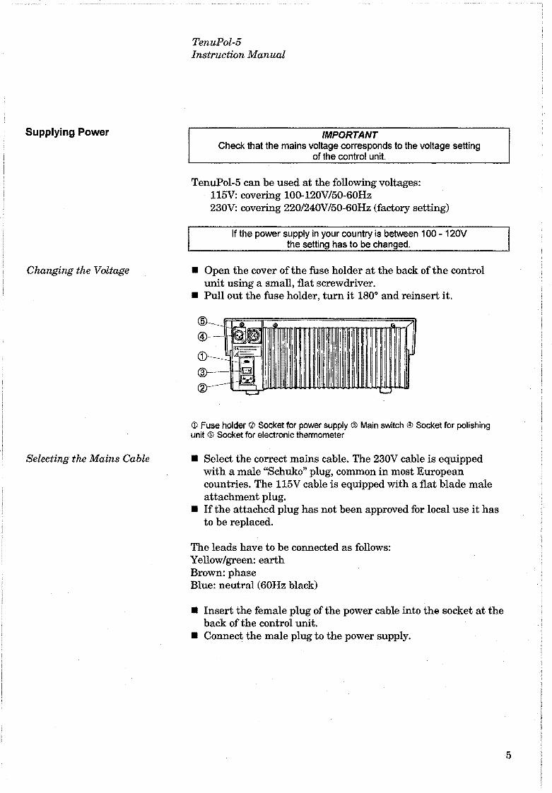
TenuPol-5 can be used at the following voltages: 115V: covering 100-120V/50-60Hz 230V: covering 220/240V/50-60Hz (factory setting)
lf the power supply in your country is between 1 00 - 120V the setting has to be changed.
• Open the cover of the fuse holder at the back of the control unit using a small, flat screwdriver.
• Pull out the fuse holder, turn it 180° and reinsert it.
tD Fuse holder <lJ Socket for power supply ® Main switch {!) Socket for polishing unit ~ Socket for electronic thermometer
• Select the correct mains cable. The 230V cable is equipped with a male "Schuko" plug, common in most European countries. The 115V cable is equipped with a flat blade male attachment plug.
• If the attachcd plug has not been approved for local use it has to be replaced.
The leads have to be connected as follows: Y ellow/green: earth Brown: phase Blue: neutral (60Hz black)
• Insert the female plug of the power cable into the socket at the back of the control unit.
• Connect the male plug to the power supply.
5

TenuPol-5 Instruction Manual
Connecting the Polishing Unit Connect the cable from the polishing unit to the adapter packed with the control unit; connect it to back ofthe control unit and secure the plug by turning the retaining ring.
Setting up the Polishing Unit • Place the base plate with pump and cooling coil on the
6
insulated PVC reservoir. • Insert the electronic thermometer in the drilled hole between
the polishing cell and the pump motor. The electronic thermometer should always be used during polishing.
• Connect one ofthe included tubes with one end to the cooling coil and with the other end to the water mains. Connect the other tube to the other side of the cooling coil and lead it to the drain. When working with an external cooling unit select suitable insulated tubes and connect them between the cooling unit and the cooling coil. Please see the manual of your external cooling unit for suitable tubes.
• Alternatively: if cooling of the electrolyte cannot be obtained by using cooling water oran external cooling unit, cooling down the electrolyte can be carried out by using the uninsulated PVC reservoir placed in an ice bath.

Software Settings
Configuration Menu
TenuPol-5 Instruction Manual
Switch on the power at the main switch located at the back of the control unit. The following display will appear briefly:
UERSION 1. 0 //¡Slruers -:1:.1:.1:.1 :.1
:.1:.1:.1:1 :.1 1 '!'! ~ -e']
TenuPol-5 Mterwards the display will change to the last screen shown before TenuPol-5 was switched off, usually a method for electrolytic thinning. When switching TenuPol-5 on for the first time, the display to appear should be the MAIN MENU. If the heading in the display is different, press Ese, until the MAIN MENU appears (a long beep can be heard)
The MAIN MENU is the highest level in the menu structure. (See also the Menu Overview, Section 7). From here you can go to the pre-defined Struers methods, your own methods, manual functions or the configuration menu.
~
USER METHODS
MI=INUI=IL FUNCT.
t11=1IN MENU
'~ 1; )1
CONFIG.
~~~~ Press MENU DOWN ~" to select CONFIGURATION
~
........ Press ENTER ......J to activate the CONFIGURATION m en u
7
Setting the Language
8
TenuPol-5 lnstruction Manual
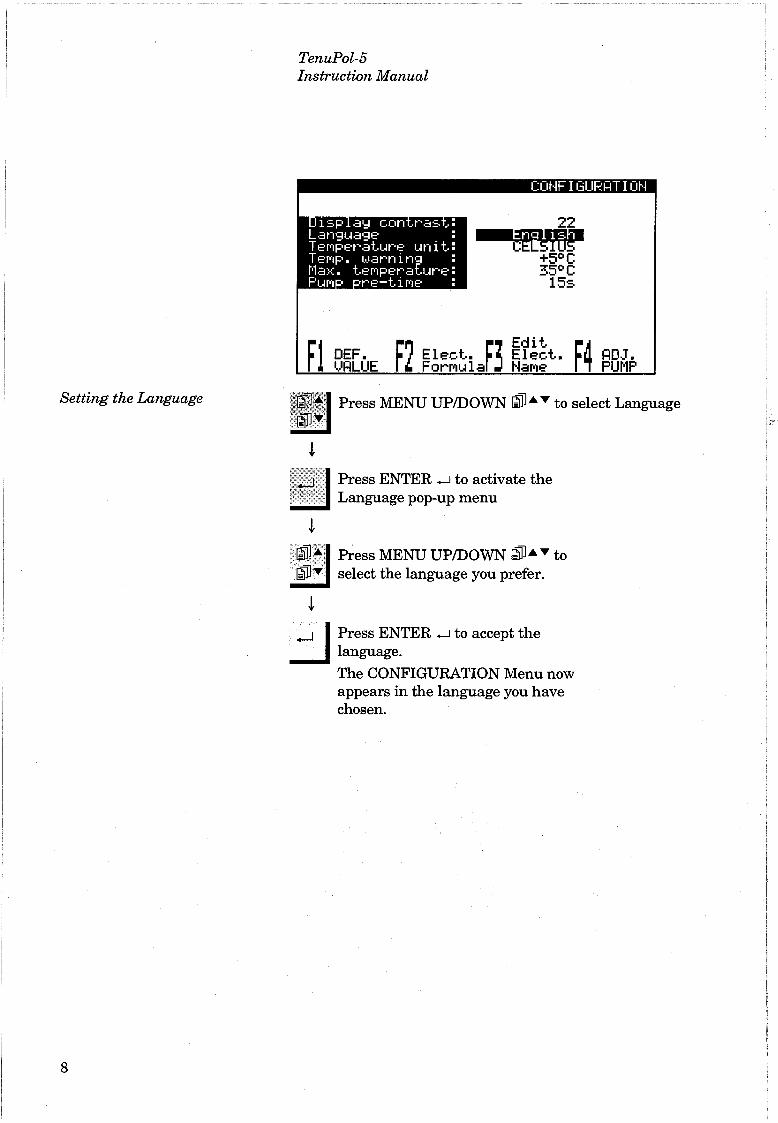
Press MENU UP/DOWN ~·.,.. to select Language
. :'.:.··~····· •• , Press ENTER .-J to activa te the " "'•<. ·· Language pop-up menu
¡
~~,~ Press MENU UP/DOWN ~·.,.. to ..!!:J select the language you prefer.
¡
....J 1 Press ENTER .....J to accept the __J language.
The CONFIGURATION Menu now appears in the language you have eh osen.

Using the Controls Front Panel Controls of TenuPol-5
Groups of Keys
Acoustic Signals
TenuPol-5 Instruction Manual
2. Basic Operations
A A Programming and monitoring functions. B STAR.T <f;fBTOP@ ofTenuPol-5
B
Id Short Reep: when a key is pressed, a shod beep indica tes that the command has been accepted.
G Long Beep: a long beep indicates that the key is innctive at the moment.
Location of Main Switch The main switch is located at the back of the control unit.
Please Note ... The contents of the program memory are not lost
when the main switch is tumed off.
9
1
¡. 1 ! -t .
!
1
1

Front Panel Controls
N ame
Q) MAl N SWITCH
START
STOP
MENU
MENU
EN TER
10
Key
TenuPol-5 Instruction Manual
Function
The main switch is located at the back of the control unit.
Starts the thinning process according to the pre-set method.
Stops the thinning process.
Scrolls up in the menu tree structure of TenuPol-5. When setting a parameter the value increa!'ies.
N ame
® FUNCTION KEY
® FUNCTION KEY
Key
Scrolls down in the menu tree structure of TenuPol-5. When setting a parameter the value decreases.
® _:_j4 FUNCTION KEY
Accepts a marked parameter value or chooses a menu.
ESC
Function
Controls for various purposes. See the bottom line of the individual screens.
Controls for various purposes. See the bottom line of the individual screens.
Controls for various purposes. See the bottom line of the individual screens.
Controls for various purposes. See the bottom line of the individual screens.
Leaves the present menu or aborts functionslchanges.
----~ --·------------------- - --------- --- -
Reading the Display
A
B
A-
e
SleepMode
TenuPol-5 lnstruction Manual
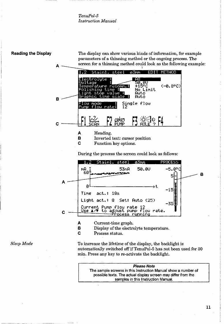
The display can show various k.inds of information, for example parameters of a thinning method or the ongoing process. The screen for a thinning method could look as the following example:
<-a.aoc
A Heading. B Inverted text: cursor position e Function key options.
During the process the screen could look as follows:
A B e
53MA 50.01J
e~ .. --------------------4t -15
TiMe act.: 18:s Light act.: 8 Set: Auto (25)
-35 Current PuMp flow rate 12 Use &/T to adjust puMp flow rate.
Process runnin
Current-time graph. Display of the electrolyte temperatura. Process status.
B
To increase the lifetime of the display, the backlight is automatically switched offifTenuPol-5 has not been used for 30 min. Press any key to re-actívate the backlight.
PleaseNote The sample screens in this lnstruction Manual show a number of
possible texts. The actual display screen may differ from the samples in this lnstruction Manual.
11

Changing/Editing Values
Numeric Values
12
TenuPol-5 Instruction Manual
Depending on the type of value, there are two different ways of editing.
~ .. ¡
RS ... ~ No LiPüt Ruto 30s
flow
<-s.a-=-c
Press MENU UP/DOWN ~..._ • to select the numeric value you want to change, e.g. Voltage:
!',j ;¡ Press ENTER ..J, t" edit the value.
t Two square brackets [ ] appear around thevalue.
~ ..._ Press MENU UP/DOWN ~ ..._ • to increase or decrease • the numeric value. ~ .. ; c;;.l Press ENTER ..J, to accept the new value.
Pressing Ese, aborts the changes, preserving the original value.
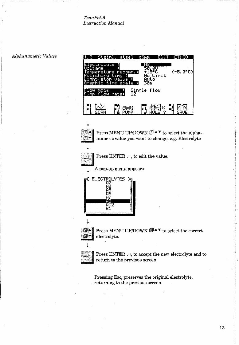
Alphanumeric Values
TenuPol-5 Instruction Manual
e.eml!ll -;. so ~ +15°C <-5.0°C
No Lirüt RYto 30s
flow
¡
..to. Press MENU UP/DOWN ~Á • to select the alphanumeric value you want to chnngc, c.g. Electrolyte
iliiiiiii.. ...
¡
~ Press ENTER to edit the value.
¡ A pop-up menu appears
..,¡¡¡¡¡¡,. ....
........
Press MENU UP/DOWN ~Á • to select the correct electrolyte .
Press ENTER .......J, to accept the new electrolyte and to return to the previous screen .
Pressing Ese, preserves the original electrolyte, returning to the previous screen.
13

Electrolytic Preparation
Pre-treatment of the specimen
Thinning options
Pre-thinning
Blanking
14
TenuPol-5 Instruction Manual
Prior to electrolytic thinning, discs of 3 mm (2.3 mm) diameter anda thickness of0.1 to 0.5 mm have to be prepared. For that, methods such as spark-machining or mechanical turning and cutting are well known. However, this pre-thinning (see below) can also be carried out on the TenuPol-5, the original sample being a cut-off disc, thickness ma.x. 1 mm, diameter ma.x. 21 mm. Such a disc may be cut on e.g. an Accutom precision cut-offmachine. The cut-off disc is now ground down on SiC paper, e.g. on a LaboPol or RotoPol grinding/polishing machine. It is recommended to fix the disc to a plane block ofmetal using double-adhesive tape. It is ground first on one side, then on the other on the rotating disc, finished with # 1000 SiC-paper and should then be ma.x. 1 mm thick. The Accustop (see Accessories) can be used for plane-parallel grinding of specimens. When the specimen has been made ready for preparation, it is important to avoid oxidation of the specimen as this may cause the specimen not to be satisfactorily polished in TenuPol-5. If the specimen has been punched out of a foil, it must also be fine-ground on both sides to remove any oxidation before preparation on Tenn Pol-ñ.
Three diffet·ent ways of elect!'Olyíic Uú.nuing can be carried out on TenuPol-5.
The cut-off and possibly pre-ground specimen can be pre-thinned using the specimen holder (TETMA) allowing to polish an area of 10 mm diameter from both sides. 'l'o fit the specimen holder, the specimen must not be more than 1 mm thick and not more than 21 mm in diameter. 2.5 mmjets are used (extra equipment TETET). The polishing should not be carried on to perforation. Depending on the original thickness the polishing time will vary and must be established from case to case. After pre-thinning the thickness should be 0.1-0.5 mm. Instead ofusing the light stop value, the polishing time has to be set to an appropriate value.
When equipped with the 2.5 mm jets (TETET), TenuPol-5 may be used for cutting out 3 mm (2.3 mm) specimens electrolytically in the 10 mm specimen holder (TETMA). The larger specimen, which should be 0.1-0.5 mm thick, is first degreased in alcohol. One side ofthe specimen is covered completely with a special acid-resistant tape, having an acid-resistant adhesive. On the other side are stuck 1-4 discs of tape of 3 mm (2.3 mm) diameter within a circle of 10 mm diameter. The tape is available as a kit (accessory: TENKI). The tape must be pressed securely against the metal. The specimen is now placed into the specimen holder, so that there is a free area, which can be removed during

FinalThinning
TenuPol-5 Instruction Manual
polishing, around the small tape discs. When the holder has been set into the polishing cell, the cathode on the side where the specimen is completely covered, is disconnected by pulling out the banana plug. The specimen is then polished in the usual way until the exposed area has disappeared. The 3 mm (2.3 mm) metal specimens will now be present under the tape discs. They are disengaged, washed and are ready for the final thinning. The standard supplied jet holders ha ve jets with an inside diameter of 1 mm. For thinning and electrolytic blanking with the 10 mm specimen holder, however, jets with an inside diameter of 2.5 mm have to be used. When using highly viscous electrolytes it may be necessary to use 2.5 mm jets (TETET) also in connection with 2.3 mm and 3 mm specimen holders.
This will normally consist in polishing of 3 mm (2.3 mm) diameter specimens with the 1 mm jets. The polishing is carried on until a small hole appears and will usually be stopped using the light stop value, reacting as soon as a hole is established. By adjusting the light stop value, the hole size can be changed. As soon as the thinning is finished, the current is interrupted, a beeper sounds and the specimen holder must be taken out and opened in a small bath of e.g. ethanol or distilled water, kept ready close to the polishing cell, to stop chemical etching. From this the t:~pecimen is transferred to a hath of e.g. ethanol by means of a pair of tweezers. It may then be laid on a piece of filter paper, where it dries in a couple of seconds and is ready for examination or storing. 'l'hinned specimens may be kept under vacuum in a desiccator with silicagel. In most cases they can also be kept in glycerol, which will protect them against the action of the atmosphere.
Hi

Choosing a Method
16
TenuPol-5 Instruction Manual
In the Main Menu, select STRUERS METHODS and press ENTER -.J . The following screen will appear:
0.1 Stainl. ste-e-1 e10MM R8 1!1
~:~ t-ow ~-s~e-e~ Low e-ste-el
01!:¡!1'111"'1 031'111'11 ~~ 1!1 * 0.5 Low C-ste-e-1 031'111'11 R8 * 0.6 IMpax 45HRC e10MM R2 1!1
0.7 IMpax 45HRC 031'111'11 R2 * 0.8 IMtax 45HRC 031'111'11 R8 * 0.9 Ti aniuM 0101'111'11 R3 1!1 0.10 TitaniuM 031'111'11 R3 * • ~1 ~ ~¿ ~~ ~~
Two different types of methods are displayed for each material. The methods for pre-thinning and blanking, a total of 8 methods, are shown with 010 mm and a small symbol for a clock. next to thc clectrolyte name:
0.1 Stainl. steel 010MM R8 e
The methods for final thinning, a total of 10 methods, display 03 mm and a small symbol for a light source next to the electrolyte name.
13.4 Low C-st.e-e-1 A2 * Select the appropriate method using MENU UP/DOWN !illll .. !illll~
and press ENTER -.J. The following screen will appear:
A2 43.0U +5°C (-5.0°C No L11"'11t Auto Auto
Single- flow 20
The method contains all parameters for fmal thinning.

-------------- ..... ·············------····--· ... - ----- · ·····------- ·······--------- -•-- --
Filling the Container with Electrolyte
Mounting the Jet Holders
TenuPol-5 Instruction Manual
Please refer to the section on Handling and Safety Precautions before handling the electrolytes.
• Remove the base plate with pump and cooling coil from the insulated electrolyte container.
• Fill the (insulatedl uninsulated) electrolyte container with electrolyte. A minimum of 1litre is requested, 1 Vz litres are recommended.
• Place the base plate with pump and cooling coil back on the container filled with electrolyte.
IMPORTANT Funnel, gloves, ventilation as well as all other prescribed equipment must be
used during emptying.
• Place one jet holder in the polishing chamber and slide the sleeve into the groove until the holder fits tightly against the back wall ofthe chamber.
• Mount the other jet similarly at the other side of the chamber.
• Connect the two banana plugs in the corresponding sockets in the jet holders.
• Place the protecting casing over the polishing cell.
l .
..
1
1
17
l
1 1
1
1 ' .

Mounting the Specimen in the Specimen Holder
Starting the Thinning Process
Stopping the Process
18
TenuPol-5 Instruction Manual
Specimens to be mounted in the specimen holder should be of a diameter of3 mm and ofa thickness ofO.l-0.5 mm. • Take the two grey halves of the specimen holder apart. (This
can be facilitated by turning one half away from the other like the two hands of a watch)
• Remove the white diaphragm from one part. Click the two grey halves back together again (a click is heard). The diaphragm must not be inserted.
• Place the specimen holder with the cut-out part being turned upwards.
• Place the specimen over the hole ofthe platinum strip. • Press the diaphragm carefully down into the cut-out until it
fits tightly against the specimen.
• Make sure that the correct type and amount of electrolyte has been filled ln the electrolyte container.
• Place the specimen holder in the polishing cell so that the contact piece of the specimen holder confronts the contact piece of the polishing cell.
• Select the correct method • Check the temperature of the electrolyte. • Press <1> START.
• When the light stop value is used the process is autornatlca.lly stopped, when a hole is made in the specimen. This is normally used for the final thinning.
• When the timer is used the process is stopped when the preset time has run out, no matter if a hole has been made or not. The timer is used for pre-thinning and blanking.
• The process can be stopped at any time during operation by pressing ©STOP.

Post Treatment of the Specimen
Emptying the Container of the Electrolyte
Cleaning the Polishing Cell
TenuPol-5 Instruction Manual
As soon as the thinning is finished, the current is interrupted, a beeper sounds and the specimen holder must be taken out and opened in a small bath of e.g. ethanol or distilled water, kept ready close to the cell, to stop chemical etching. From this the specimen is transferred to a bath of e.g. ethanol by means of a pair oftweezers. It may then be laid on a piece offilter paper, where it dries in a couple of seconds and is ready for examination or storing.
• Remove the base plate with pump and cooling coil from the insulated electrolyte container.
• If the electrolyte is to be used again pour the electrolyte carefully back into the electrolyte bottle.
• lf the electrolyte is not to be used again it should be filled into a container suitable for disposal. Please observe the local regulations and instructions for disposal.
IMPORTANT Funnel, gloves, ventilation as well as all other prescribed equipment must be
used during emptying.
Mter emptying the reservoir from electrolyte, the polishing unít should be cleaned with water by pumping water through the polishing cell instead of electrolyte. • Fill the reservoir with water. • Select Cleaning in the Manual J;'w1ctions monu and follow thc
instructions on the display.
19

Calibration of the Pump
Calibration Certificate
Using the Calibration Tube
20
TenuPol-5 Instruction Manual
To calibrate the polishing unit and to make sure the flow rate settings in the Struers methods are correct, the pump has to be adjusted befare it is being used for the first time. When TenuPol-5 is started for the first time the following screen will appear:
RDJUST PUt·1P
The pu~p ~ust be adJusted.
::. l~IITH TUBE
RDJUST WITH NUMBERS
Use &~ to select adJust procedure. ( = Select Ese: Rbort)
You can now either adjust the pump with the tube or with the numbers indicated on the enclosed Calibration Certificate.
On the enclosed calibration certificnte the values for rnaximum and mínimum pump flow for each specific polishing unit can be found. Instcnd of running the actual calibration, the values can simply be entered in the respective categories.
The following routine has to be followed. Press ENTER -J to proceed to the next screen.
RDJUST PUMP
1r===t.: I n:sert cont..a i ner ~J==;;r Please insert a container
filled with 2 litre water. Rdd a drop of detergent.
Press ENTER t.o continue or Ese to abort.. ( : Continue Ese: Rbort.)
Make sure to fill the PVC-reservoir with the stated amount of water, then add one drop of detergent to rclease the surface bmsion ofthe water. Mter following the instruction, press ENTER _1, and the following message will pop up.

TenuPol-5 Instruction Manual
Insert tubes
t=IDJUST PUMP
Insert Jet holder wíth aseending tube~ return tube
and speeiMen holder wit.h speeiMen.
Press EHTER to eontinue or Ese to abort. ( : Contínue Ese: Rbort)
Follow the instructions on the screen, then press ENTER .,_] to proceed to the next screen.
100 M
.Ji'rom this screen both the minimum and the maximum flow of the electrolyte are adjusted. Relect maximum pump flow and press ENTER -.J to sLai"L Lhe pump.
Press MENU UP/DOWN li1W•"' to adjust the water level to the upper mark. Press ENTER • 1 to save the value. Then repeat thc procedure for minimum pump flow. The values should be in the neighbourhood of 120 for the maximum flow and around 75 for the minimum flow. Press Ese when done with the calibration.
21

Electrolytes in General
Perchloric Acid in Particular
Training of Operators
22
TenuPol-5 Instruction Manual
3. Handling and Safety Precautions
When using electrolytes all necessary safety measures should be taken. Apart from the safety precautions listed in the following, a material Safety Data Sheet for each ofthe electrolytes used should be requested from the supplier.
• It is essential that the user(s) is/are fully instructed in the work procedure of these electrolytes.
• TenuPol-5 is designed for use with electrolytes recommended by Struers. Other electrolytes, e.g. electrolytes containing strong bases or acids, may harm the construction or endanger the safety of the user.
NOTE Many electrolytes contain alcohol or other inflammable solvents. Make sure
that all safety precautions are followed when using such electrolytes.
• Struers electrolytes are not marketed in the US. The chemical compounds needed for the electrolyte must be purchased independently.
NOTE Be sure to request Material Safety Data Sheets for each chemical acquired.
• When cleaning the apparatus after use, make sure that no electrolyte is allowed to dry and/or crystallise inside the apparatus or on the polished material.
• It is essential that the user is fully trained in the use of TenuPol-5 and electrolytes involved.
Electrolytes from Struers (and those suggested for use by Struers) with the prefix A consist of approx. 11 stock solution to which 15 to 90 ml perchloric acid (60%) should be added. Before mixing the perchloric acid to the stock solution it is of great importance that the following safety precautions are carefully observed. Furthermore a Material Safety Data Sheet for the perchloric acid in question can be supplied upon request.
• All personnel involved in the mixing, use, storage, transportation, and disposal of the electrolyte or its components, should be thoroughly trained in the precautions for handling perchloric acid.
• Great importance must be attached to precautions against inhalation ofvapours ofthe solution or its components, against skin contact, mixing and overheating, and concerning storage and disposal methods.

Mixing the Solution
Storage of Perchloric Acid or Solution
Fire and Explosion Hazards
Disposal
TenuPol-5 Instruction Manual
• Place the solventlwater mixture in a water bath with temperature control. Carefully add the perchloric acid to the solventlwater mixture, stir continuously.
• The mixing must tak.e place in a ventilated chemical fume hood designed for perchloric acid use.
• The operator(s) must use the listed protective clothing or devices: full face shield or splash goggles, rubber gloves and lab coat or coveralls.
• Avoid the use of any combustible or carbonaceous containers, reaction vessels, spill pans, storage shelves, or materials of this type when dealing with the acid.
• Do not permit any acid to crystallise on bottle necks, caps, or anywhere else.
• Store in a secure, cool, and ventilated area with a metal, glass, or ceramic spill catch pan.
• Store away from other chemicals, combustible and organic materials.
• Do not, under any circumstances, permit solutions to dry out.
• 60% perchloric acid is a strongly corrosive and oxidising product. Heating may cause an explosion and contact with combustible material may cause fire.
• Fire fighting should be done from a protected location. Extinguish with water spray only. Do not use dry chemicals or carbon dioxide.
• Do not produce anhydrous perchloric acid, either from its salts or from aqueous solutions, e.g. by heating with high boiling acids or dehydrating agents, such as sulphuric acid or phosphorous pentoxide. In addition to spontaneous explosion, the anhydrous acid explodes instantaneously on contact with oxidizable organic materials.
• The use or storage ufperchloric ::~cid should be limited to quantities less than 500g per hood.
Follow local regulations for disposal of spillage and waste. Dilution and/or neutralisation are the normally recommended methods of disposal ofth~ ~lectrolyte.
23

24
TenuPol-5 Instruction Manual

TenuPol-5 lnstruction Manual
Reference Guide Table of Contents
1. Advanced Operations
Page
Configuration Menu ...................................................................... 27 Display contrast ................................................................... 28 Language .............................................................................. 28 Temperature unit ................................................................. 28 Temperature warning .......................................................... 28 Maximum temperature ........................................................ 28 Pump pre-time ..................................................................... 28 F1, Default value ................................................................. 28 F2, Electrolyte Formula ....................................................... 28 F3, Edit Electrolyte Name ................................................... 28 F4, Adjust pump .................................................................. 29
Method Options ............................................................................. 31 Copying a Method ................................................................ 31 Pasting a Method ................................................................. 33 Resetting a Method .............................................................. 33 Renaming a Method ............................................................. 34 N ame Editing Principies ..................................................... 35 Saving a Method .................................................................. 35
Method Parameters ...................................................................... 37 Electrolyte ............................................................................ 37 Voltage ................................................................................. 37 Recommended temperature ................................................. 37 Polishing time ...................................................................... 38 Light stop val u e ................................................................... 38 Graphic time scalc ,!-,,,,,,,, ........................................ ,,t!tfllliiJf .......... 38 Flow n1ode ............................................................................ 38
Single flow ................................................................... 38 Dual flow, step mode .................................................. 39 Dual flow, ramp mode ................................................ 39
Pump flow rate ..................................................................... 39 Establishing New Methods ........................................................... 40
Scanning ............................................................................... 40 Scanning Result ................................................................... 41 Ideal Current Density Curve ............................................... 43 Defining the Polishing Voltage ............................................ 43 F1 Re-sean ............................................................................ 44
Saving a Sean .............................................................. 44
25

26
TenuPol-5 Instruction Manual
Optimising the Results ................................................................. 45 Problem Areas ...................................................................... 45
Geometric conditions .................................................. 45 Type of Electrolyte ...................................................... 45 Flow Rate 45 Temperature ............................................................... 45 Electrical Conditions .................................................. 45
Polishing Defects ................................................................. 45 Defective Polishing ..................................................... 46 Hole too Large ............................................................. 46
Manual Functions ......................................................................... 4 7 Change Electrolyte ............................................................... 48 Cleaning ............................................................................... 48 Pump .................................................................................... 49 Pre-treatment ofthe Specimen ........................................... 49
2. Accessories TenuPol-5 PC Interface ................................................................ 50
Installation of Communication Software ............................ 50 Saving screens ..................................................................... 50 Sean functions ...................................................................... 51 Switch Box for TenuPol-5 .................................................... 51 Connecting the Switch Box .................................................. 51
3. Consumables Electrolytes ................................................................................... 53
4. Trouble-Shooting .............................................. . Electrolyte ..................................................................................... 54 Polishing circuit ............................................................................ 54
5. Maintenance Daily Service ................................................................................. 55
Polishing Unit ...................................................................... 55 Control Unit ......................................................................... 55
&. Technical Data ................................................................... 56
7. Meno Overview ................................................................... 57

Configuration Menu
TenuPol-5 lnstruction Manual
1. Advanced Operations
Press Ese until you reach the Main Menu (a long beep can be heard).
~
STRUERS USER M~NU~L METHODS ~lETHODS FUNCT.
~1RIN MENU
,~, Prcss MENU DOWN ~" to select CONFIGURATION
~
.....J 1 Press ENTER ....J Lu uctivutc thc CONFIGURATION __J menn
Engfi~ CELSIUS
+5°C 35°C
15s
27

Display contrast
Language
Temperature unit
Temperature warning
Maximum temperature
Pump pre-time
Fl, Default ualue
F2, Electrolyte Formula
F3, Edit Electrolyte Name
28
TenuPol-5 Instruction Manual
The contrast settings ofthe display can be adjusted accordingly.
The language can be set to either English, German, French or Japanese.
The temperature can be displayed in either Celsius or Fahrenheit.
The temperature can be pre-set in each individual method. Temperature warning is used to give an indication that the electrolyte temperature has increased to a certain value above the temperature set in the method. That could be due to insufficient cooling. The temperature warning value can be adjusted between O-l0°C 1 O-l8°F, or it can be set toNO WARNING.
The absolute maximum temperature of the electrolyte can be set. lfthis value is reached during the process, TenuPol-5 will shut off automatically. The maximum values can be set to between -50 to 35°C 1 -58 -95°F.
Running time of the pump before the current is applied. This is used to achieve an even flow of electrolyte from the very start of the process. The pump pre-time can be adjusted between 5 - 20 seconds.
The factory setting of every single value can be restored by pressing the function key Fl when the appropriate value is highlighted.
The formulas and mixing conditions of all Strucrs clcctrolytcs can be found here.
lf you are using your own electrolytes, the names can be changed from U ser X toa more descriptive name ofyour own choice. Press F3 to start the editing function, select the name and follow the guidelines described in the chapter Advanced Operations, Name Editing Principies, to change the name ofthe electrolyte.
lmportant When the name of a user defined electrolyte is changed, it will also be changed automatically in all the methods where this electrolyte is used.

F4, Adjust pump
TenuPol-5 Instruction Manual
To calibrate the polishing unit and to make sure the flow rate settings in the Struers methods are correct, the pump has to be adjusted before it is being used for the first time (see Users Guide, Calibration ofthe Pump). Also for subsequent checking of the pump this function can be used. To carry out the adjustment, press F4 and the following screen appears.
¡:¡oJUST PU~1P
rr==::[.. I nsert con la i ner :J==::¡¡ Ple.ase insert .a container
filled wilh 2 litre water. Add .a drop of detergent.
Press EHTER lo continue or Ese lo .abort. < : Continue Ese: ¡:¡borl)
Make sure to fill the PVC-reservoir to the maximum mark with water and add one drop of detergent to release the surface tension ofthe water. Mter following the instruction, press F.NTER . 1, and the following mcssage will pop up.
¡:¡oJUST PUMP
rr===:{.. I nsert tubes .. J=====;¡
Insert Jet holder wilh .ascending ~ube~ return tube
.and speciMen holder wit.h speciMen.
Press EHTER lo continue or E~c lo .abort. < : Continue Ese: Aborl)
Follow the instructions on the screen, then press ENTER ....J to proceed to the next screen.
29

30
TenuPol-5 Instruction Manual
From this screen both the minim1.un and the maxi.m1.1m f1ow of the electrolyte are adjusted. Select maximum pump flow and press ENrl'ER .......! to start the pump.
[ 120] 75
to regulate the flow. Rcljust to the upper Mark
=
Press MENU UP/DOWN G)i]•,. to adjust the water level to the upper mark. Press ENTER .......! to save the value. Then repeat the procedure for mínimum pump flow. The values should be in the neighbourhood of 125 fbr the maximum ílow and around 75 for the mínimum flow. Press Ese when done with the calibration.

Method Options
Copying a Method
TenuPol-5 Instruction Manual
There are severa! different possibilities when working with methods. As the Struers methods can not be changed, the first step will usually be to copy a Struers method into the U ser methods database.
In the Main Menu select STRUERS METHODS.
lE t )1
USER MANUAL CONFIG. METHODS FUNCT.
i' .,_J <1 Press ENTER ._~ to activa te the __j STRUERS METHODS menu
....... , ~:~ ;::.t.a111.L. st.e-e-1
Low C-ste-e-1 0~MM
010MM 0.4 Low C-ste-e-1 03MM 0.5 Low C-ste-e-1 03MM 0.6 IPlpax 45HRC 111l~MM 0.7 IMpax 45HRC 0 MM 0.8 IMtax 45HRC 03MM 0.9 Ti aniuM 010MI'I 0.10 TitaniuM 03MM
.¡,.
rl ~ rl r~ r~
';E1}iil Select the correct method and press ~Fl:COPY.
¡ A pop-up menu will appear.
~~ (!t * A2 * A8 * R2 e R2 * A8 * A3 e A3 *
1
31

32
TenuPol-5 Instruction Manual
0:3 L COPY TO BUFFER 0.4 L 0.5 L Stainl. steel 010MM 0.6 I 0.7 I 0.8 I 0.9 TitaniuM 010MM 0.10 TitaniuM 03MM
.,¡..
* * * * * *
copy the Method to buf. Ese: l=lbort)
! When you are asked for conñrmation,
Y,':fj .1 Press ENrER ~ .
! The method is now resident in the buffer. To save the method in a different location:
•. E~c 1 Press Ese to return to the Main Menu.
1 In the Main Menu select USER ~ M~'l'HODS.
~ 1 Press ENTER ....J to activate the USER __j METHODS menu.

Pasting a Method
Resetting a Method
TenuPol-5 Instruction Manual
111 111~
l
·! • ~ !;:MP!--Y Me!--!'10~ 1.3 EMpty Method 1.4 EMpty Method 1.5 EMpty Method 1.6 EMpty Method 1.7 EMpty Method 1.8 EMpty Method 1.9 EMpty Method 1.10 EMpty Method
Fl F~ D r1l F3 l. PRSTE
¡ Select where (group and method) you want to paste the method from the buffer.
'~2,:,1 Press F2:PASTE.
¡ When you are asked for con.:firmation,
_..j 1 Presa ENTER ...J.
¡
• t:~ 1.4 1. 5 1. 6 1. 7 1. 8 1.9 1.10
~ f{ PRSTE FROM BUFFER }: E Stainl. steel 010MM E E E EMpty !l'le-thod Er;pty l"''ethod
Press ENTER to paste Method frol"'' buf. (~: Paste Ese: Rbort)
1
If a method is not used anymore it can be reset to the default val u es.
¡ Select the method you want to reset.
~~f=!~~~~ Press F3:RESET
~ ¡
:isl Press ENTER ...J to oonfinn the resetting of the method.
33

Renaming a Method
34
TenuPol-5 Instruction Manual
The names ofthe methods in the User methods database can be edited and changed. After copying a method from the Struers methods the name can be changed to a name of your choice.
Select the method you want to rename.
Press F4:RENAME
~ The following screen will appear:
1.1 Stainl. steel e10MM EOIT N~ME
NaMe: jstainl. steel 0lOMM
Press ENTER to accept the text, or press • to select a new character.
rL .f. r~ ......._ !S!!S!!S!+ ......-DELETE RIGHT
U se Fl or F3 to select the character to ~ change
~ .. , Press MENU DOWN ilill" to move to the character set.
~
Name Editing Principies
Saving a Method
TenuPol-5 Instruction Manual
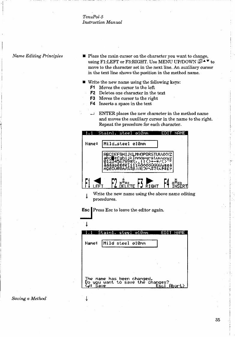
• Place the main cursor on the character you want to change, using Fl:LEFT or F3:RIGHT. Use MENU UP/DOWN ~.._,.. to move to the character set in the next line. An auxiliary cursor in the text line shows the position in the method name.
• Write the new name using the following keys: F1 Moves the cursor to the left F2 Deletes one character in the text F3 Moves the cursor to the right F4 Inserts a space in the text
.....J ENTER places the new character in the method name and moves the auxiliary cursor in the name to the right. Repeat the procedure for each character.
1.1 Stainl. steel 010MM EDIT NRME
NaMe: IMild-steel 010MM
RBCDEFGHIJKLMNOPQRSTUUWXYZ ~y~¡~~9~~~k~~~~()~~~j~$~t aáaa:;:eé~e i f. :1: ·iño6ooüúuu· ·¡;0a i=i9Éth.ifl0f:t.fÑ;fi) 1 )t?J-1'\;f;-=< =.t:,~$:8'7
r~ ~~~~ r1 ~ r1. OELETE rJ RIGHT
¡ Write the new name using the above name editing procedures.
E~c 1 Press Ese to leave the editor again.
! 1.1 Stainl. steel ~10MM EDIT NRME
The naMe has been changed. Do you want to save the changes? < : Save Ese: ort)
35

36
TenuPol-5 Instruction Manual
........ Press ENTER .....J to save the new name .
While working with a user method, you can save the changes you have made in the database.
• As soop. as a parameter is changed in a method, F4:SA VE will be shown on the bottom line ofthe display.
F4 1 Prsss F4:SA VE to sa.ve the changes after __J all necessary parameters have been
~ altered .
..,_j 1 Press ENTER .....J to confirm saving thc __J modified method.
Unless you already have named the method, the name will automatically change from Empty method to Unnamed method. This will show that at least one parameter has been changed compared to a default method.

Method Parameters
Electrolyte
Voltage
Recommended temperature
TenuPol-5 Instruction Manual
No Lir'li t Ruto Ruto
Single flow 10
lmportant When saving changes, the original method will be overwritten.
lf you want to keep the original method, you must make a copy of the original method and make the changes in the copy rather than changing the
original method. See Copying a Method.
For every method a series of parameters can be changed:
H.O::: ~.7V +0°C (-5.0°C) No LifYlit Ruto Ruto
Single flow 10
Pmssing F.NTF.R. ....J allows you to select hetween:
The standard Struers electrolytes are included, and additional 10 Users electrolytes are also available.
The voltage can be set between 0.1-100.0 Volt in steps of0.1 Volt.
The recommended temperature can be set to values between -50 to +35°C or -58 to +95°F. To the right ofthe recommended
37

Polishing time
Light stop value
Graphic time scale
Flow mode
Single fl.ow
38
TenuPol-5 Instruction Manual
temperature the actual temperature of the electrolyte can be seen. Iflow temperatures are recommended, an external cooling unit must be used to cool the electrolyte down to the required temperature. The 2 numbers displayed on TenuPol-5 are only for monitoring purposes, the actual electrolyte temperature can not be controlled from there.
Please see also the section Configuration on how to set Temp. warning and Max. temperature.
The time can be set and adjusted as follows.
The setting No Limit must be used ifthe automatic mode, where the occurring hole is detected, is used.
The light stop value can be set to the following values:
Auto: The polishing unit is equipped with an infrared sensor, constantly measuring light emitted from an infrared light placed on the opposite side of the samplc. As soon as the sample is thin enough to allow light to pass through, i.e. a hole has been made, the polishing process is stopped automatically and the reached value is displayed. As the holes sometimes develop very fast a relatively high value might be experienced.
Time setting: Ifthe polishing process is stopped immediately, the hole might be to small. Therefore it is possible toseta light stop value manually. The set value should be bigger than the va.luc reached with the Auto setting as this usually is the lowest value achievable with this material.
While the process is running the current-time graph is updated continuously. When the graphic time scale is set to Auto, the last three minutes of the process are displayed. If shorter or longer times should be displayed the setting can be changed. Times from 10 sec. to 30 min can be set.
There are three different fl.ow modes, Single fl.ow, Dual fl.ow, step mode and Dual fl.ow, ramp mode.
The same flow rate is used throughout the polishing process

Dual flow, step mode
Dual flow, ramp mode
Pump flow rate
TenuPol-5 lnstructíon Manual
lf the total polishing time is known, dual flow can be used to reduce the flow towards the end. This can minimise eventual damage of the very thin edges because of too high flow of electrolyte. There are two different possibilities:
The flow is reduced from the initial flow to the final flow in one step.
The flow is reduced gradually from the initial flow to the fmal flow.
The flow rate can be set between O - 50.
39

Establishing New Methods
Scanning
40
TenuPol-5 Instruction Manual
If you are working with materials which are not covered by the standard methods in the database with the Struers methods there is another way in establishing parameters.
Chose the method you want to use for the new material in the User database. (Ifnecessary copy one from the Struers methods frrst.)
....... Press ENTER -1 to show all the parameters of the method .
R8
~ No LiMit Ruto Ruto
Single flow 19
~ SRUE
! Ifnecessary, the electrolyte has to be changed. Please find the correct electrolyte for your material in the section Consumables . .:J Press F1 to go to the scanning function.
!
SCRN 1. Set Max. volt.: 50U ~~6)HM@Q 1;11 r:ar :sean
Set the maximum voltage that will be applied during scanning. Values between 10 ~ 100 V can be set. Adjust the flow rate to the correct value.
~','i Press START <!> to run the sean,

Scanning Result
TenuPol-5 Instruction Manual
After running the sean,
~~J.~~ Press ENTER ..J to see the current ~ density curve.
Pi 60
50U A 0~--------------------------~
~1 ~ r~e8tf~~E L1 FILlER LAEHH~HC f RE-SC~H fL 50U fJ SC~H f,SCRH
This is an example of a possible scanning result. The graph shows the current density curve and can be used to define an approximate value for the polishing voltage. A tangent. A is also displayed. After displaying the sean, the tangent is cutting the curve in the middle. This is not an indication for a possible definition of the polishing voltage, this has to be set by the user according to the instructions later in this chapter.
41

Filter Sean
Enhance Sean
42
TenuPol-5 Instruction Manual
Sometimes the scanning curve can display a lot of "noise", making it diffi.cult to define the correct polishing voltage. Then F3: Filter Sean can be used to clean the scanning curve. The result willlook somewhat like on the following screen:
1"1 70
50 U 0~----------------------------~
~1 ~ ~~~8tf~~E ~7 FILTER ~AENHRNC f RE-SCRN f' 50U rJ SCRN f,SCRN
Ifit still i::~ diffi.cult to determine the correct polishing voltage F4: Enhance Sean may be used to amplify the scanning curve. The result might look like the following screen:
M 80
50 U e~~------------------------~
~1 ~ ~~~8[f~~E L7 FILTER LAENHRNC r RE-SCRN f' 50U rJ SCRN f,SCRN

Ideal Current Density Curve
Defining the Polishing Voltage
TenuPol-5 Instruction Manual
Anodlc Dlssolutlon
+--Direct-..,...-----lndirect---------,,_.
'+--- Best Pollshlng ---illlll+4- Fonnatlon of Oxygen --+-
A ;·"t:---Fonnalíon of Layer
+- Etching __,...,._ __ --- Polishiny -----+
--+ Voltage in Volt
This is a graph showing an ideal current density curve.
For best electrolytic polishing the formation of a viscous layer is necessary. The formation starts in area B - e, with area e - D being best for polishing. Our teBts hove show11 that lhe thickest possible viscous layer is best for most uniform polishing results. The thickest viscous layer is found in the area C - D where the highest voltnge 1 current ratio is found. The tangent can be used to define this point. Move the tangent along the current density curve in the area e- D, using MENU UP/DOWN ~· ~. until the tangent shows the smallest angle relative to the X-axis (point A). Then press F2 to record the polishing voltage in the method. The voltage where the tangent is touching the current denRity curve is displayed on the ::;creen (B).
M 60
e ..... .............................................. se u
Ll ~ L~~8tt~~E L1 FILTER LAEHHRHC f RE-SCRH f' 29U f~ SCRH f1SCRH
B
A
43

Fl Re~scan
F3 Hole
Saving a Sean
44
TenuPol~5
Instruction Manual
~~~~, Press Ese to return to the method.
~ The voltage value for polishing has been inserted in the method.
R8 29.0U +15°C 3M 0s
Wo flow
<-5.0°C
To save the new settings for the voltage press F4 SA VE.
To repeat the sean, simply press Fl Re-sean while still viewing the screen with the current density curve.
To check the size of the obtained hole it can be re-measured after the thinning process. Press F3, the polishing chamber will be filled with electrolyte and the light value will be measured again.
With a PO-Interface kit it is possiblc to transfer the sean data to a PC. There it is possible to import the data into a spreadsheet, and to (..Tea te g¡·aphs of the current density curves. These graphs can then be saved and compared if necessary. Please see the chapter on Accessories for details.

Optimising the Results
Problem Areas
Geometric conditions
Type of Electrolyte
Flow Rate
Temperature
Electrical Conditions
Polishing Defects
TenuPol-5 lnstruction Manual
If a sufficient high quality is not obtained in electrolytic polishing it will be necessary to alter the polishing conditions. There are five important parameters: • the geometrical conditions • the type of electrolyte • the flow rate ofthe electrolyte • the temperature • the electrical conditions
In TenuPol-5 the geometrical conditions are fixed and can only be altered by changing or altering certain components. As to the other parameters the following will apply:
The chemical composition of the electrolyte is highly important for the quality of the polishing. An tmsuitable electrolyte will cause inferior polishing, oxidised or etched surface, pittings or one-sided polishing, i.e. only one side of the specimen is polished, the other is black and oxidised. lt is not at all certain that an electrolyte, which in other apparatus (e.g. the LectroPol-5) will polish a certain material, will also be suitable for thinning it on the TenuPol-5. In the literature numerous examples are cited of electrolytes suitable for t.hinning.
The flow rate determines first of all whether a viscous anodic layer can be maintained during polishing. Jet polishing tends to remove the layer. The proper choice offlow rate is therefore . 111ostly determined b,y Lhe material to be polished and by the Hleetrolyte. The best flow rate differs much from caseto ca81:l and it is not possible to give general rules.
In sorne cases a lower temperature will give better results. A lower temperature slows down the polishing and provides less etching and oxidation.
ThP. elect.rical conditions of co1.1rse determined whether a polishing is at all obtained. The right conditions will only be present within a certain range of current densities.
With Tenupol-5, the polishing defects may be divided into the following classes: • Defective polishing, i.e. wrong polishing conditions, so that a
mirror-like finish is absent on one or both sides ofthe specimen. Pitting may be present.
• Polishing takes place, but no thin area is present at the edge of the hole.
45

Defective Polishing
Hole too Large
46
TenuPol-5 lnstruction Manual
Try to alter the electrical conditions. Perhaps the voltage was too low to reach the polishing range. Pittings may arise if the current was too high. A lowering of the temperature may make the polishing less sensitive to voltage changes. The flow rate should be altered. A too high flow rate may break up the polishing layer, which may be the cause of one side of the specimen not being polished. A slower flow may allow a polishing layer to be built up.
lf nothing helps it can be concluded that the material in question cannot be polished by the electrolyte and another electrolyte should be tried.
The hole may have grown too large, so that the thin foil first formed has disappeared. Just like electrolytic polishing will attack the tops ofthe aspirates ofthe surface, it will attack the edge ofthe holeas being an asperity. Especially when the jet effect is strong it is very important to stop the process while the hole is small. Adjustment of the flow rate may be helpful. A vigorous jet may attack a too small area. Another electrical current density should also be tried. Set the Light Stop Value to Auto. Sometimes a lower temperature will give a better profile around the hole, possible on account of a change ofviscosity.
lfnothing helps it is probable that the electrolyte is not suitable for thinning the material in question, although it will electropolish it. Try another electrolyte.

Manual Functions
TenuPol-5 Instruction Manual
Several manual functions are included in the software of TenuPol-5.
Press Ese until you reach the Main Menu (a long beep can be heard).
~
STRUERS USER METHODS METHODS
MRIN MENU
lE 1; )J
CONFIG.
~·~ Press MENU UP/DOWN .!!:J FUNCTIONS
"' ... to select MANUAL
! ....J 1 Press ENTER .....J to actívate the
__J MANUAL FUNCTIONS Menu
MRNURL FUNCT I ot6
Ooc:::J u:oo•oo•=~•u•:oo••• ~ CLERNING
,g,tg, PUMP
47

Change Electrolyte
Cleaning
48
TenuPol-5 Instruction Manual
When changing from a method with one electrolyte to a method with a different electrolyte, the electrolyte has to be changed. TenuPol-5 will automatically request that the electrolyte is changed and the system cleaned. However this function can also be started manually.
After selecting CHANGE ELECTROL YTE and pressing ENTER .._l, the following screen will appear:
CHRNGE OF ELECTROLYTE
ReMove Electrolyte: R8 1. Lift the polishing unit. 2. Place it in the container
with water. 3. ReMove the present elec.
Press ENTER when ready for the next step or Ese to abort. ( : Next ste Ese: Rbort)
Just follow the instructions and press ENTER --1 when ready for the next step. There are a total of 5 screens guiding you through the complete sequence. The process can be stoppcd and aborted at any time by pressing Ese.
After working with TenuPol-5 is finished the system has to be cleaned. Cleaning is the first part of the above procedure. After selecting CLEANING and pressing ENTER .._l, the following screen will appear:
CLERNING
u==::[ .. ReMove Electrolyte .,J====;J
1. Lift the polishing unit. 2. Place it in the container
with water. 3. ReMove the present elec.
Press ENTER when ready for the next step or Ese to abort. ( : Next ste Ese: Rbort)
Just follow the instructions and press ENTER .._j when ready for the next step. There are a total of 4 screens guiding you through the complete sequence. The process can be stopped and aborted at any time by pressing Ese.

Pump
Pre-t1·eatment of the Specimen
TenuPol-5 Instruction Manual
This is the manual activation of the pum p. After selecting PUMP and pressing ENTER ......J, the following screen will appear:
MRNURL FUNCTIONS
PUMP RUNNING Rdjust flow rate:
Use &~ to adJust the flow rate. /Ese: Rbort)
[-]
U se MENU UP/DOWN ~ ... "' to adjust the flow rate. ENTER ......J o.nd Ese will stop the pump again.
The purpose of pre-treatment is to prepare discs of 3 mm (2.3 mm) diameter thickness 0.1 to 0.5 mm. Methods such as spark-machining or mechanical turning and cutting are well known. The preparation can also be done on the TenuPol-5, the original sample being a cut-off disc, thickness max. 1 mm, diameter max. 21 mm. Such a disc may be cut on e.g. an Accutom precision cut-off machine. The cut-off disc is now ground down on abrasive paper, e.g. on Knuth-Rotor. It is recommended to fix the disc toa plane block ofmetal by doublc·ndhcsivc tape. lt is ground first on one side, then on the other on the rotating disc, finished with grain 1000 paper and should then be max. 1 mm thick. The Accustop (see Accessorics) can be used for plane-parallel grinding of specimens. When the specimen has been made ready for preparation, it is important to avoid oxidation of the specimen as this may cause the specimen not to be satisfactorily polished on TenuPol-5. If the specimen has been punched out of a foil, it must be fineground on both sides to remove any impurities before preparation on TenuPol-5.
49

TenuPol-5 PC Interface Installation of Communication Software.
Saving screens
50
TenuPol-5 Instruction Manual
2. Accessories
Insert the diskette labelled Struers PC Interface Software V 1.0 into the PC, change to drive a: (your diskette drive) and type INSTALL. The necessary file PCIF.EXE will be copied into a newly created directory called Struers on your e: \drive. If you do not want this directory to be created, simply copy the file PCIF.EXE into your preferred directory. Then change to that directory and type PCIF to start the programme.
As a next step you are asked to specify the Com port you have connected TenuPol-5 to. This can either be Coml or Com2.
r.=====C Co M port., ·]===:::::::;¡
No CoM port sp~cifi@d Enter CoM port (l/2) _
Press 1 or 2 to specify the Com port you are using.
The Software then checks the connection to TenuPol-5 and will start downloading all the necessary information from TenuPol-5.
r==[ Statl.IS J==
S!!aro;bcing •.•• On ol'll
All functions can then also be controlled from the PC, and the individual screens can be saved as bitmap (.BMP) files by pressing ALT and D at the same time. When saving screens successively the .BMP files will be numbered consecutively starting with SCREENO.BMP

Sean functions
Switch Box for TenuPol-5
Connecting the Switch Box
TenuPol-5 Instructíon Manual
When using the Sean Function on TenuPol-5 the values obtained can be sent to the PC. Immediately after the Sean is fmished, press the F5 key on your PC, and the numbers will be saved in a file called SCAN.DAT. This file can be imported into any spread sheet (Please see the manual for your spread sheet on details of how to import comma separated files), and used to create graphs of the current density curves. These graphs can than be saved and compared ifnecessary. As this file is generated in TenuPol-5 it will always have the same name. To save severa! Scans please remember to rename the first file before starting the second sean. Otherwise the file will be overwritten. It is also important to save the file directly after the sean, as soon ns you go back to the method the daLa are lost.
TenuPol-5 can be used to control two polishing units. A Switch Box is available as an accessory.
• RemovA the phtg from thA polishing tmit at thc back of the control unit.
• Connect the plug from the Switch Box instead. · • Connect the cables from the polishing units to the Switch Box
and secure the plug by turning the retaining ring.
Place the Switch Box in a convenient position. Turn the selector switch to position 1 or 2 to swap between polishing units.
51

52
TenuPol-5 Instruction Manual
of3/2.3 mm mens TENKI TenuPol-5, polishing unit TENPO
Switchbox for connection of two TenuPol-5 LECBO polishing tables toa TenuPol-5 Control Unit
PCB Connection Kit for data transfer between LECPC TenuPol-5 anda PC
Accustop, specimen holder for accurate removal ASTOP of material by manual grinding.
lnsert for Accustop, For thinning of 3 mm dia. ASTEN specimens. For thinning on Tenupol.

Electrolytes
TenuPol-5 lnstruction Manual
3. Consumables
Electrolyte A2.
Electrolyte A3
Electrolyte A8
Electrolyte AC2
Electrolyte 02
Electrolyte E5
Aluminium lron Nickel Sil ver Steel Tin Titanium
Martensitic Steel Molybdenum Titanium Vanadlum Zirconium
Stainless Steel Chromium Hafnium Nickel Titanium
Cast lron Magnesium Nickel Steels
Brass Copper Gold
Brass Bronze Carbon Steel Cast lron Materials with strongly varying structural elements
53

No cell connection
Temperature above max. limit
TenuPol-5 is switched on but the display is blank
Electrolyte
Polishing circuit
54
TenuPol-5 Instruction Manual
4. Trouble·Shooting
The mains voltage is too low compared to the setting on the back of the control unit.
There is no connection to the polishing unit.
The electrolyte temperature is above the pre-set limit.
See section "Supplying power" on how to change the voltage settings.
Make sure that the plug from the polishing unit is connected to the back of the control unit.
Connect TenuPol-5 to tap water orto an externa! cooling unit and wait until the temperature is below the specified limit.
The backlight of the display has been Press any key to re-actívate the switched off, TenuPol-5 is in Sleep backlight. Mode.
• Check the age of the mixed electrolyte. The mixture should not be more than 3 months old.
• Check the number of polishings made with the electrolyte. The electrolyte can be worn out by too many polishings.
• Check that the correct combination of material and electrolyte is used.
• Check that the electrolyte is sufficiently cooled during operation.
• Check that all plugs are properly connected. • Check that the stainless specimen holder contact part is
intact and connected to the platinum strip. • Check that the specimen holder is connected to the polishing
chamber spring contact when mounted in the chamber. • Check the voltage over the spring contact and the jet holder
banana plugs (or the platinum wire in the jets).
í·-

Daily Service
Polishing Unit
Control Unit
TenuPol-5 lnstruction Manual
5. Maintenance
Clean TenuPol-5 every day when you are finished working.
Residuals of the electrolyte used previously may spoil the following polishing. Therefore it is recommended to rinse the polishing cell and pump thoroughly before filling in a new electrolyte and at the end of every day.
• Go to MANUAL FUNCTIONS in the MAIN MENU. • Select CLEANING. • Follow the instructions on the screen. • Mter the cleaning program has finished, use a damp cloth to
wipe all accessible surfaces of the polishing unit including the inside where the electrolyte container is stored.
• Thoroughly wash all the specimen holders which have been used.
WARNING! Do not use acetone or similar solvents.
TenuPol should not be left filled with electrolyte for an unnecessarily long time, as the submerged parts may be attacked.
Especially A-8 will shorten the life of the metal parts. N ever turn the polishing unit upside down, particularly not when there is electrolyte in the pump, as this may trickle from the pump up to the motor and cause thc axle to stick. Take care that the motor housing does not come in contact with the electrolyte. If copper or copper alloys have been thinned, sorne copper may have deposited on the cathodes. This may be removed with a few drops ofnitric acid before the rinsing.
Avoid spilling electrolyte on the cabinet or front plate of control unit. Clean the front plate with a damp cloth after use.
55
56
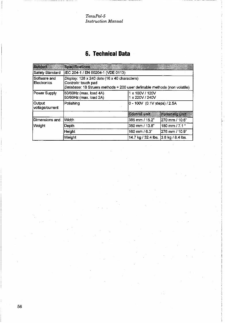
Software and Electronics
Power Supply
voltage/current
TenuPol-5 lnstruction Manual
&. Technical Data
Display: 128 x 240 dots (16 x 40 characters) Controls: touch pad Database: 18 Struers methods + 200 user definable methods (non volatile)
(max. load 4A) 1 x 100V /120V ''-'utour,L (maX. load 2A) 1 X 22QV /24QV
O- 1 OOV (0.1V steps) /2.5A
Weight
' ,~.....

TenuPol-5 Instruction Manual
TenuPol-5 Menu Structure
1
Struers Methods
1
1 ViewMethod
~ 1
PROCESS START
F1 Copy 1
U ser Methods
1 ,.___j
1
Edil Method
t PROCESS
START
7. Menu Overview
MAINMENU
1 F1 Copy 1 F2 lnsert F3 Rese! Manual F4 Rename Functions
1 Change 1 Electrolyte
1 aeaning 1
1 Pump 1
1
Configuration
1 Display 1 contrast
1 Language 1
1 Temperatura 1 unit
1
1 Temp. 1 warning
1 Max. 1 temperatura
1 Pump 1 pre-tirne
F1 Default Value F2 Electrolyte
Formula F3 Edit Elect.
Menu F4 Adjust pump
57