Typhoon at CommsNet 2013: experimental experience on AUV navigation and localization
6
Typhoon at CommsNet 2013: experimental experience on AUV navigation and localization B. Allotta *,** F. Bartolini ** A. Caiti *,*** R. Costanzi ** F. Di Corato *** D. Fenucci *** J. Gelli ** P. Guerrini **** N. Monni ** A. Munaf` o **** M. Natalini ** L. Pugi ** A. Ridolfi ** J.R. Potter **** * ISME Interuniversity Res. Ctr. on Integrated Systems for the Marine Environment (e-mail: [email protected]). ** DIEF Dept. Industrial Engineering, University of Florence, Florence, Italy (e-mail: benedetto.allotta@unifi.it) *** DII & Centro Piaggio University of Pisa, Pisa, Italy (e-mail: [email protected]) **** CMRE NATO S&TO Ctr. for Maritime Research and Experimentation, La Spezia, Italy (e-mail: [email protected]) Abstract: The CommsNet 2013 experiment took place in September 2013 in the La Spezia Gulf, North Tyrrhenian Sea. Organized and scientifically led by the NATO S&T Org. Ctr. for Maritime Research and Experimentation (CMRE, formerly NURC), with the participation of several research institutions, the experiment included among its objectives the evaluation of on-board acoustic Ultra-Short Base Line (USBL) systems for navigation and localization of Autonomous Underwater Vehicles (AUVs). The ISME groups of the Universities of Florence and Pisa jointly participated to the experiment with one Typhoon class vehicle. This is a 300 m depth rated AUV with acoustic communication capabilities originally developed by the two groups for archaeological search. The CommsNet 2013 Typhoon, equipped with an acoustic modem/USBL head, navigated within the fixed nodes acoustic network deployed by CMRE. This allows the comparison between inertial navigation, acoustic self-localization and ground truth represented by GPS signals (when the vehicle was at the surface). The preliminary results of the experiment show that the acoustic USBL self-localization is effective, and it has the potential to improve the overall vehicle navigation capabilities. Keywords: Autonomous vehicles, marine systems, navigation, positioning systems, AUV (Autonomous Underwater Vehicle) 1. INTRODUCTION In the framework of the THESAURUS project (Italian acronym for “TecnicHe per l’Esplorazione Sottomarina Archeologica mediante lUtilizzo di Robot aUtonomi in Sciami”) a class of AUVs (called Typhoon) able to co- operate in swarms to perform navigation, exploration and surveillance of underwater archaeological sites has been developed. The project specifications are quite ambitious: the low cost vehicles have to operate with a maximum depth of more than 300 m, an autonomy ranging from 8 to 12 hours is required and a maximum speed of 5-6 knots has to be achieved. Briefly, the Typhoon class AUV is a low cost vehicle with remarkable performances and power on-board. In particular, it is worth to note that the depth specification is very significant for archaeological interests: the depth of 300 m is prohibitive for usual diver operations and it is also higher compared to the depth specification of many commercial low cost AUVs. The total carried payload is quantified in about 30-40 kg and the cost of the vehicle is limited (less than 50000 e). Low production and maintenance costs are a mandatory specification of the project, considering the necessity of producing several vehicles for a team composed of middle- sized vehicles. A first fleet of three different underwater vehicles, cooperating in a single team, has been developed, as visible in Fig. 1: see Allotta et al. (2012) and Allotta et al. (2013). The three vehicles can be characterized as follows. Vision Explorer A vehicle equipped with cameras, laser and structured lights for an accurate visual inspection and surveillance of archaeological sites. The visual in- spection involves a short range distance (few meters) between the vehicle and the target site, and the capa- bility of performing precise manoeuvring and hovering; Acoustic Explorer Preliminary exploration of wide ar- eas to recognize potentially interesting sites involves the use of acoustic instruments, such as side-scan-sonar. Extended autonomy, a stable and a noiseless behaviour have to be preferred. This kind of vehicle can perform long range missions. Consequently, navigation sensors able to compensate the drift of the inertial sensors, such
Transcript of Typhoon at CommsNet 2013: experimental experience on AUV navigation and localization

Typhoon at CommsNet 2013: experimentalexperience on AUV navigation and
localization
B. Allotta ∗,∗∗ F. Bartolini ∗∗ A. Caiti ∗,∗∗∗ R. Costanzi ∗∗
F. Di Corato ∗∗∗ D. Fenucci ∗∗∗ J. Gelli ∗∗ P. Guerrini ∗∗∗∗
N. Monni ∗∗ A. Munafo ∗∗∗∗ M. Natalini ∗∗ L. Pugi ∗∗
A. Ridolfi ∗∗ J.R. Potter ∗∗∗∗
∗ ISME Interuniversity Res. Ctr. on Integrated Systems for theMarine Environment (e-mail: [email protected]).
∗∗ DIEF Dept. Industrial Engineering, University of Florence,Florence, Italy (e-mail: [email protected])
∗∗∗ DII & Centro Piaggio University of Pisa, Pisa, Italy (e-mail:[email protected])
∗∗∗∗ CMRE NATO S&TO Ctr. for Maritime Research andExperimentation, La Spezia, Italy (e-mail: [email protected])
Abstract: The CommsNet 2013 experiment took place in September 2013 in the La SpeziaGulf, North Tyrrhenian Sea. Organized and scientifically led by the NATO S&T Org. Ctr. forMaritime Research and Experimentation (CMRE, formerly NURC), with the participation ofseveral research institutions, the experiment included among its objectives the evaluation ofon-board acoustic Ultra-Short Base Line (USBL) systems for navigation and localization ofAutonomous Underwater Vehicles (AUVs). The ISME groups of the Universities of Florenceand Pisa jointly participated to the experiment with one Typhoon class vehicle. This is a 300m depth rated AUV with acoustic communication capabilities originally developed by the twogroups for archaeological search. The CommsNet 2013 Typhoon, equipped with an acousticmodem/USBL head, navigated within the fixed nodes acoustic network deployed by CMRE.This allows the comparison between inertial navigation, acoustic self-localization and groundtruth represented by GPS signals (when the vehicle was at the surface). The preliminary resultsof the experiment show that the acoustic USBL self-localization is effective, and it has thepotential to improve the overall vehicle navigation capabilities.
Keywords: Autonomous vehicles, marine systems, navigation, positioning systems, AUV(Autonomous Underwater Vehicle)
1. INTRODUCTION
In the framework of the THESAURUS project (Italianacronym for “TecnicHe per l’Esplorazione SottomarinaArcheologica mediante lUtilizzo di Robot aUtonomi inSciami”) a class of AUVs (called Typhoon) able to co-operate in swarms to perform navigation, exploration andsurveillance of underwater archaeological sites has beendeveloped. The project specifications are quite ambitious:the low cost vehicles have to operate with a maximumdepth of more than 300 m, an autonomy ranging from8 to 12 hours is required and a maximum speed of 5-6knots has to be achieved. Briefly, the Typhoon class AUVis a low cost vehicle with remarkable performances andpower on-board. In particular, it is worth to note thatthe depth specification is very significant for archaeologicalinterests: the depth of 300 m is prohibitive for usual diveroperations and it is also higher compared to the depthspecification of many commercial low cost AUVs. Thetotal carried payload is quantified in about 30-40 kg andthe cost of the vehicle is limited (less than 50000 e).
Low production and maintenance costs are a mandatoryspecification of the project, considering the necessity ofproducing several vehicles for a team composed of middle-sized vehicles. A first fleet of three different underwatervehicles, cooperating in a single team, has been developed,as visible in Fig. 1: see Allotta et al. (2012) and Allottaet al. (2013). The three vehicles can be characterized asfollows.
Vision Explorer A vehicle equipped with cameras, laserand structured lights for an accurate visual inspectionand surveillance of archaeological sites. The visual in-spection involves a short range distance (few meters)between the vehicle and the target site, and the capa-bility of performing precise manoeuvring and hovering;
Acoustic Explorer Preliminary exploration of wide ar-eas to recognize potentially interesting sites involvesthe use of acoustic instruments, such as side-scan-sonar.Extended autonomy, a stable and a noiseless behaviourhave to be preferred. This kind of vehicle can performlong range missions. Consequently, navigation sensorsable to compensate the drift of the inertial sensors, such
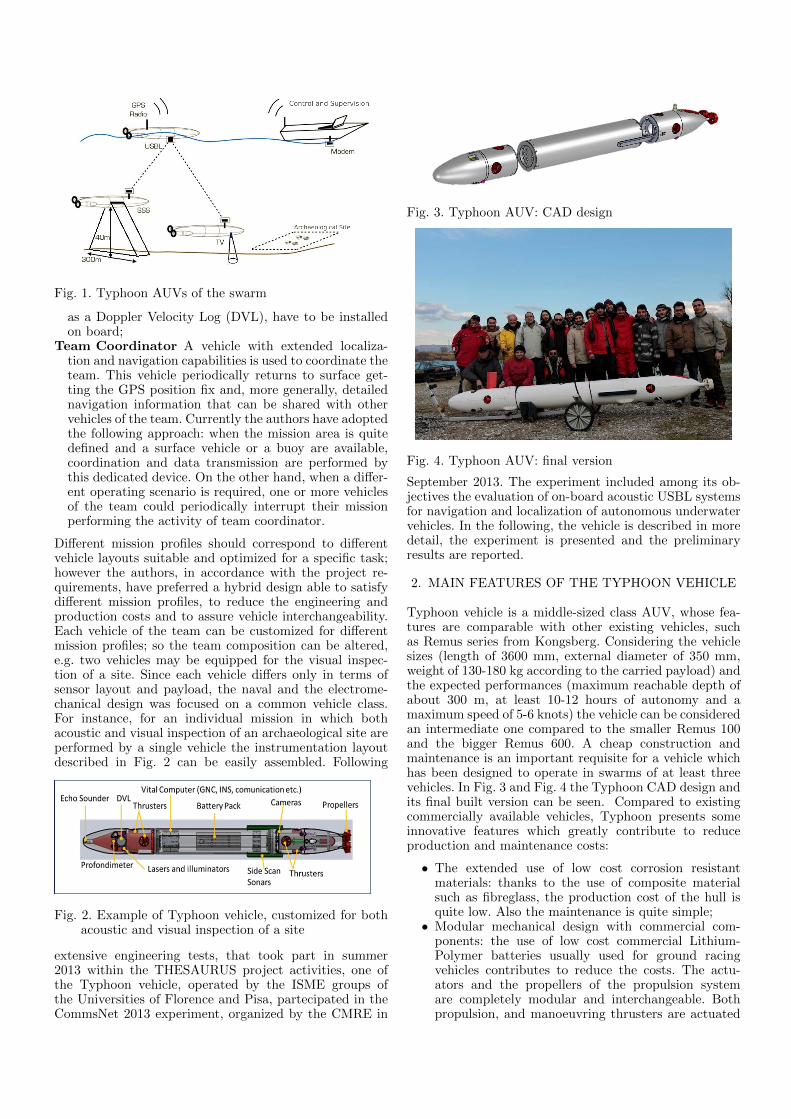
Fig. 1. Typhoon AUVs of the swarm
as a Doppler Velocity Log (DVL), have to be installedon board;
Team Coordinator A vehicle with extended localiza-tion and navigation capabilities is used to coordinate theteam. This vehicle periodically returns to surface get-ting the GPS position fix and, more generally, detailednavigation information that can be shared with othervehicles of the team. Currently the authors have adoptedthe following approach: when the mission area is quitedefined and a surface vehicle or a buoy are available,coordination and data transmission are performed bythis dedicated device. On the other hand, when a differ-ent operating scenario is required, one or more vehiclesof the team could periodically interrupt their missionperforming the activity of team coordinator.
Different mission profiles should correspond to differentvehicle layouts suitable and optimized for a specific task;however the authors, in accordance with the project re-quirements, have preferred a hybrid design able to satisfydifferent mission profiles, to reduce the engineering andproduction costs and to assure vehicle interchangeability.Each vehicle of the team can be customized for differentmission profiles; so the team composition can be altered,e.g. two vehicles may be equipped for the visual inspec-tion of a site. Since each vehicle differs only in terms ofsensor layout and payload, the naval and the electrome-chanical design was focused on a common vehicle class.For instance, for an individual mission in which bothacoustic and visual inspection of an archaeological site areperformed by a single vehicle the instrumentation layoutdescribed in Fig. 2 can be easily assembled. Following
Fig. 2. Example of Typhoon vehicle, customized for bothacoustic and visual inspection of a site
extensive engineering tests, that took part in summer2013 within the THESAURUS project activities, one ofthe Typhoon vehicle, operated by the ISME groups ofthe Universities of Florence and Pisa, partecipated in theCommsNet 2013 experiment, organized by the CMRE in
Fig. 3. Typhoon AUV: CAD design
Fig. 4. Typhoon AUV: final version
September 2013. The experiment included among its ob-jectives the evaluation of on-board acoustic USBL systemsfor navigation and localization of autonomous underwatervehicles. In the following, the vehicle is described in moredetail, the experiment is presented and the preliminaryresults are reported.
2. MAIN FEATURES OF THE TYPHOON VEHICLE
Typhoon vehicle is a middle-sized class AUV, whose fea-tures are comparable with other existing vehicles, suchas Remus series from Kongsberg. Considering the vehiclesizes (length of 3600 mm, external diameter of 350 mm,weight of 130-180 kg according to the carried payload) andthe expected performances (maximum reachable depth ofabout 300 m, at least 10-12 hours of autonomy and amaximum speed of 5-6 knots) the vehicle can be consideredan intermediate one compared to the smaller Remus 100and the bigger Remus 600. A cheap construction andmaintenance is an important requisite for a vehicle whichhas been designed to operate in swarms of at least threevehicles. In Fig. 3 and Fig. 4 the Typhoon CAD design andits final built version can be seen. Compared to existingcommercially available vehicles, Typhoon presents someinnovative features which greatly contribute to reduceproduction and maintenance costs:
• The extended use of low cost corrosion resistantmaterials: thanks to the use of composite materialsuch as fibreglass, the production cost of the hull isquite low. Also the maintenance is quite simple;
• Modular mechanical design with commercial com-ponents: the use of low cost commercial Lithium-Polymer batteries usually used for ground racingvehicles contributes to reduce the costs. The actu-ators and the propellers of the propulsion systemare completely modular and interchangeable. Bothpropulsion, and manoeuvring thrusters are actuated

with the same motor and drive system: a standard ac-tuation unit with a 200 W brushless motor and drivedirectly fed by the 48 V provided by the batteriesand controlled through an industrial CAN bus, seeCarlton (2012). The same actuation system can alsobe used to control movable navigation surfaces likerudders and fins, resulting in a highly customizableactuation system. The calibration of the pitch staticattitude can also be performed moving the accumu-lators whose axial position is controlled by a screwsystem;
• Extended use of fast prototyping techniques: the ve-hicle is easy customizable since many componentsand accessories are built using ABS plastic material,shaped using 3D printers. This way, many compo-nents may be easily customized and rebuilt in fewhours. Moreover, the prototyping techniques havegreatly accelerated the production of the components.
2.1 Acoustic Communication
As mentioned in the Introduction, the acoustic communi-cation system has been designed having in mind an oper-ation with a team of Typhoon vehicles. To this aim, thevehicles have to estabilish a communication network basedon a time-sharing bi-directional/broadcast communicationscheme. The goal is to create a flexible structure capa-ble of ensuring low-delay communication and the reliabletransmission of specific messages necessary for the safetyof the swarm and for exploration missions. The networkis composed by a few layers, as shown in Fig. 5, and itdoes not include most of the complexity typically presentin terrestrial networks. The implemented networking sys-tem has already been described in Caiti et al. (2013).Its main features are reported here for self-consistency.The bottom layer is represented by the EvoLogics acousticmodem/USBL, which manages the physical transmissionof the signal into the water. The adopted communicationmode provided by the modem, namely instant messag-ing, does not require connection establishment procedures,allows for broadcast messaging and permits a messagemaximum size of 64 bytes. The modem also implementscollision avoidance techniques (Medium Access Control -MAC) and provides basic network functionalities, includ-ing an addressing system that can be exploited at the linklayer. The medium access control is completed througha channel time division mechanism: time is divided intoslots and each node is assigned a slot where it has toconcentrate all its communication burden. The networklink layer is composed by a combination of the modemnetworking features and of the Mission Oriented OperatingSuite (MOOS) framework, Newman (2003). MOOS is apublisher/subscriber system for inter-process communi-cation through message exchange. Messages are associ-ated to an information descriptor, called topic, containedin the messages themselves. Publishers send their mes-sages to a dispatcher, represented by a central database(MOOSDB), which is responsible for forwarding messagesto the subscribers based on their topic. Subscribers haveto preliminary declare their interest in specific topics byissuing subscription to the dispatcher itself. Within thissetting, each acoustic node is equipped with a process thathandles the communication with the acoustic device: whena new message is received from the modem, it publishes
Fig. 5. Layered structure of the underwater acoustic net-work
the information in the Inbox topic, whereas during atransmission, it reads a message from the Outbox topicand forwards it to the modem for the physical trans-mission. To increase the throughput of the network andthe probability that an important message is transmittedas soon as possible, messages are organized in a priorityqueue. More specifically, four classes of messages have beenidentified, each of which associated with a decreasing pri-ority; among them, the localization messages, periodicallyexchanged between the vehicles to have USBL updates orrange measurements, are relevant to the aim of CommsNet2013 experiment. To avoid an indefinitely growth of thequeue when an application generates data at a higherrate than the acoustic channel can support, at each stepthe messages are filtered on the basis of the time slotduration and those that cannot fit into the available timeare discarded. Moreover, the organization of the queueis performed both during the non-communication periodsand the communication time slot available to the vehicle;this way, the network supports real-time data delivery,meaning that the data are produced, organized and thentransmitted during the communication period of the node.Finally, the network link layer also includes an additionalsub-layer, namely the performance/network layer, used toadapt the requests coming from the application level tothe constraints of the layers below it and of the acousticchannel. The highest layer, namely the application layer,utilizes MOOS as software infrastructure. An applicationwhich wants to join the network has only to publish in thetopic Outbox the data to be sent acoustically towardsthe desired nodes and to register to the topic Inbox tobe notified when new acoustic messages are received. Thisway, the network becomes completely transparent from theapplication point of view.
3. EXPERIMENT DESCRIPTION
The CommsNet 2013 experiment has been organized bythe NATO Centre for Maritime Research and Experimen-tation (CMRE, formerly NURC) with the main objectiveto test the performance of several acoustic communicationand localization systems using underwater networks. Sev-eral teams from different institutions, each one interestedin testing different systems, have been involved in theexperimentations, held with the support of NRV Alliance.

CommsNet 2013 took place from Sept. 9th to Sept. 22th
in La Spezia and was originally planned in the west areaof Palmaria island, Gulf of La Spezia, North TyrrhenianSea, where CMRE has a permanent testbed for under-water networking and communication purposes (LOON -Littoral Ocean Observatory Network - Alves et al. (2012)).In CommsNet 2013, the LOON installation consisted offour EvoLogics modems, placed on the seabed and cable-connected to the shore so that they could be continuouslyoperated and monitored. The LOON modems are com-patible with those installed on-board the Typhoon, so thatthe vehicle could use its USBL modem to estimate its rela-tive position with respect to the fixed LOON installation.Hence, the role of the Typhoon in this experimentationwas to perform both surface and underwater navigationin autonomous modality, while trying to localize itself orthe other nodes of the network using the USBL measure-ment. In the first week, due to adverse sea and weatherconditions, a preliminary test was carried out within theLa Spezia harbour using re-deployable, battery operated,EvoLogics modems as fixed nodes. In the second week,the trial was carried out in the open sea close to theLOON area. The operating groups have worked in parallelas much as possible, but most of the trials were carried outin series to not interfere the one with the others. Due tothe weather constraints and to the time-division nature ofthe experiment, it was possible to do a limited number ofruns, all using the Typhoon mounting the USBL head. Inthe following, the preliminary results as obtained in someof the runs will be illustrated.
4. RESULTS
The results of the Typhoon trials that took place onSept. 12th and Sept. 22th are now reported. In the firstone, Typhoon has executed an autonomous mission withinthe La Spezia harbour, consisting in the repetition of atriangle-shaped path with vertices placed in the waypointsWP1, WP2 and WP3. In this area, some battery-operatedmodems were deployed to build an ad-hoc installationof fixed nodes: using them the vehicle can localize itselfusing the on-board USBL. In the second one, Typhoonwas supposed to autonomously travel along a path on theLOON area, localizing itself with respect to the LOONsubmerged modems by means of the on board USBLmodem. The reference path for the mission was defined bythree waypoints respectively called Janus1, M2 (position ofthe second one of the four LOON modems) and Typhoon1.In both runs, the absolute position of the fixed nodes isknown, so the relative localization with respect to themallows to deduce a measure of the absolute position of theTyphoon. In Table 1 the waypoints of the two missionsare defined. In the Sept. 12th run, Typhoon began theautonomous mission from waypont WP1, then it had to
Table 1. Definition of the mission Waypoints
Date Waypoint Latitude (◦) Longitude (◦)
WP1 44.095000 9.862050Sept. 12th WP2 44.094300 9.859420
WP3 44.093750 9.861580
Janus1 (J1) 44.031890 9.830962Sept. 22th M2 44.032116 9.828285
Typhoon1 (T1) 44.030610 9.829312
repeat the reference path twice, both on surface. Naviga-tion was performed on the basis of GPS measurements,so that they can be used in post-processing as a ground-truth to evaluate the accuracy of USBL fixes. In the Sept.22th run, Typhoon reached J1 from the deployment point,then it travelled three times along the triangle J1-M2-T1-J1: the first and the third times on the surface whereasthe second time at a depth of 5 meters surfacing on eachwaypoint and every two and a half minutes to reset thedrift in the position estimation through a GPS fix. Thepaths were both covered with a reference speed of 0.7 m/s.The two triangles are between 550 m and 600 m long; thedetailed subdivision of the paths is reported in Table 2.Tolerance on waypoints, to consider them achieved, wasalways set to 20 m. A direct comparison of raw navigation
Table 2. Lengths of the path segments
Date Segment Length (m)
Sept. 12th
WP1-WP2 225WP2-WP3 183WP3-WP1 144
Total 552
Sept. 22th
J1-M2 216M2-T1 186T1-J1 194Total 596
data (GPS, USBL and dead reckoning) is given in Fig. 6,where all the significant mission variables are shown. Inthe plots, the following elements are represented.
Magenta diamonds Waypoints, identified by their shortname.
Continue blue line It represents the travelled path esti-mated through the GPS measurements in Fig. 6(a) anddead reckoning algorithm based on orientation measure-ments from IMU, a forward speed calculated as functionof the longitudinal propeller thrust and GPS fixes inFig. 6(b).
Red circles In Fig. 6(b), they represent GPS fixes; theyare dense around the points of surfacing and absentwhen Typhoon antenna was underwater.
Red downward-pointing triangle Points of the esti-mated path corresponding to the moment when Ty-phoon was able to localize one of the LOON modems.
Black upward-pointing triangle The Typhoon esti-mated position on the basis of the acoustic fixes fromthe USBL modem.
Downward-pointing triangles and Upward-pointing trian-gles are associated through a progressive numeration. The
Table 3. Error between estimated position andUSBL fixes
Sept. 12th Sept. 22th
Fix Error (m) Fix Error (m) Fix Error (m)
1 2.35 11 8.48 1 18.892 2.27 12 2.15 2 27.413 3.38 13 5.94 3 14.424 8.18 14 8.44 4 19.265 3.04 15 4.26 5 24.856 13.23 16 9.83 6 7.897 2.91 17 11.55 7 14.918 1.89 18 1.32 8 21.769 3.11 19 1.16 9 12.2010 5.09 10 12.49

20 40 60 80 100 120 140 160 180 200
0
20
40
60
80
100
120
140
Raw data of Sept. 12th
run
East direction [m]
Nort
h d
irection [m
] WP1
WP2
WP3
1
2
3 4
5
6
7
8 910
1112
13
14
15
16
17
1819
1
2
3
4
5
6
7
8 9
10
11
12
13 14
15
16
17
1819
Waypoints
GPS path
GPS @ USBL fixes
USBL Fixes
(a)
0 50 100 150 200
0
20
40
60
80
100
120
140
160
180
J1
10
10
1
Raw data of Sept. 22th
run (second repetition)
East direction [m]
2
1
T1
2
99
8
3
8
45
7
7
3M2
6645
Nort
h d
irection [m
]
Waypoints
Dead Reckoning Path
GPS Fixes
Dead Reckoning @ USBL Fixes
USBL Fixes
(b)
Fig. 6. Plots of the two experiments. In Fig. 6(a) the Typhoon run of Sept. 12th, executed in La Spezia harbour, isrepresented. In Fig. 6(b) part of the Sept. 22th Typhoon experiment, conducted on the LOON, is illustrated.

amount of acoustic fixes obtained during the two missionsis respectively 19 and 10, recieved with an average periodof 69 s in the first trial and 119 s in the second one.In Table 3 the navigation errors between the positionestimated through the measurements of the navigationsensors and the corresponding one based on the USBL fixesare reported for both trials. Since the navigation of theSept. 12th trial was entirely based on GPS measurements,the errors obtained from this run are particulary relevantto quantify the reliability of the USBL-based positionestimate with respect to the effective navigation posi-tion. The position estimation error accumulated duringthe underwater navigation of the Sept. 22th mission canbe evaluated as the distance between the first GPS fixafter surfacing and the last estimated position before it.Typhoon surfaced five times during the analyzed part ofthe mission; for each of these, the value of the accumulateddrift is reported in Table 4. While the errors reported in
Table 4. Error of the dead reckoning positionestimation with respect to GPS fixes
Surfacing Accumulated drift (m)
1 13.992 22.393 35.054 19.595 24.36
Table 3 and Table 4 are to be expected considering thenavigation sensors employed, it is clear that the combi-nation of acoustic and on-board sensor navigation offersthe opportunity to improve navigation capabilities. Thisprocessing is currently on-going and it will be reported inthe near future.
5. CONCLUSIONS
The paper presents the contribution of the Typhoon AUV,developed in the framework of the THESAURUS project,to the CommsNet 2013 experiment, organized by NATOS&T Org. Ctr. for Maritime Research and Experimenta-tion (CMRE, formerly NURC), held with the support ofNRV Alliance. Typhoon AUV, at its first experimental ex-perience after the end of the THESAURUS project, provedto be able to perform the required tasks completely au-tonomously, playing a fundamental role for the CommsNet2013 experiment. The paper reports the raw navigationand acoustic localization data logged from the on boardsensors during a part of one of the missions performed byTyphoon during the two weeks of experimentation. Thelogged data will be used for a systematic post-processactivity in order to investigate and test navigation datafusion procedures to improve localization accuracy withrespect to the raw data here reported. Fig. 7 shows Ty-phoon AUV during a surface phase of one of the missionsperformed in the Ligurian Sea in front of Porto Venereduring CommsNet 2013 experiment.
ACKNOWLEDGEMENTS
The THESAURUS project has been financed by PARFAS REGIONE TOSCANA Linea di Azione 1.1.a.3(http://thesaurus.isti.cnr.it).
Fig. 7. Typhoon AUV during CommsNet 2013 experiment
REFERENCES
Allotta, B., Costanzi, R., Monni, N., Pugi, L., Ridolfi, A.,and Vettori, G. (2012). Design and simulation of anautonomous underwater vehicle. In European Congresson Computational Methods in Applied Sciences andEngineering ECCOMAS 2012.
Allotta, B., Pugi, L., Bartolini, F., Costanzi, R., Ridolfi,A., Monni, N., Gelli, J., Vettori, G., Gualdesi, L., andNatalini, M. (2013). The THESAURUS project, a longrange AUV for extended exploration, surveilance andmonitoring of archeological sites. In V InternationalConference on Computational Methods in Marine En-gineering ECCOMAS MARINE 2013.
Alves, J., Potter, J., Zappa, G., Guerrini, P., andBeen, R. (2012). A testbed for collaborative de-velopment of underwater communications and net-working. In MILITARY COMMUNICATIONS CON-FERENCE, 2012 - MILCOM 2012, 1–8. doi:10.1109/MILCOM.2012.6415691.
Caiti, A., Calabro, V., Fabbri, T., Fenucci, D., and Mu-nafo, A. (2013). Underwater communication and dis-tributed localization of AUV teams. In OCEANS -Bergen, 2013 MTS/IEEE, 1–8. doi:10.1109/OCEANS-Bergen.2013.6608166.
Carlton, J. (2012). Marine propellers and propulsion.Butterworth-Heinemann.
Newman, P. (2003). The MOOS - crossplatform software for robotics research.http://www.robots.ox.ac.uk/ mobile/MOOS/wiki/pmwiki.php.