TWH 200E TWH 300E TWH 300EH - Origen Energy Ltd
76
Export KALIKO EN Thermodynamic water heater TWH 200E TWH 300E TWH 300EH C003182-B Installation and Service Manual 300026515-001-05
-
Upload
khangminh22 -
Category
Documents
-
view
0 -
download
0
Transcript of TWH 200E TWH 300E TWH 300EH - Origen Energy Ltd

Export
KALIKO EN
Thermodynamic water heater
TWH 200ETWH 300ETWH 300EH
C003182-B
Installation andService Manual
300026515-001-05

Declaration of conformity
The device complies with the standard type described inthe EG declaration of conformity. It was manufactured andcommissioned in accordance with European directives.The original declaration of conformity is available from themanufacturer.

Contents
1 Safety instructions and recommendations ..............................................61.1 Safety instructions ...............................................6
1.1.1 Installation ...............................................................61.1.2 Hydraulic connections .............................................61.1.3 Electrical connections .............................................71.1.4 Internet Site .............................................................71.1.5 Miscellaneous .........................................................8
1.2 Recommendations ................................................8
1.3 Liabilities ...............................................................91.3.1 Manufacturer’s liability .............................................91.3.2 Installer’s liability .....................................................9
1.4 Safety data sheet: R-134a refrigerant ...............101.4.1 Product identification .............................................101.4.2 Hazard identification ..............................................101.4.3 Composition / Information on the ingredients ........101.4.4 First aid .................................................................101.4.5 Fire prevention measures .....................................111.4.6 In the event of accidental spillage .........................111.4.7 Handling ................................................................111.4.8 Personal protection ...............................................121.4.9 Considerations on disposal ...................................121.4.10 Regulations ...........................................................12
2 About this manual ....................................................................................132.1 Symbols used .....................................................13
2.2 Abbreviations ......................................................13
3 Technical specifications ..........................................................................143.1 Homologations ....................................................14
3.1.1 Certifications .........................................................143.1.2 Directive 97/23/EC ................................................143.1.3 Factory test ...........................................................14
3.2 Technical specifications ....................................153.2.1 Characteristics of the appliance ............................153.2.2 Heating time of the DHW tank depending on the air
temperature ...........................................................153.2.3 Max domestic hot water set point reached by the heat
pump depending on the air temperature ...............16
19/01/2015 - 300026515-001-05 1

4 Technical description ..............................................................................174.1 General description ............................................17
4.2 Main parts ............................................................18
4.3 Operating principle .............................................18
5 Installation ................................................................................................205.1 Regulations governing installation ...................20
5.2 Package list .........................................................205.2.1 Standard delivery ..................................................205.2.2 Accessories ...........................................................20
5.3 Storage and transport ........................................215.3.1 Transport ...............................................................21
5.4 Choice of the location ........................................225.4.1 Type plate .............................................................225.4.2 Positioning of the appliance ..................................225.4.3 Main dimensions ...................................................26
5.5 Positioning the appliance ..................................285.5.1 Unpacking the appliance .......................................285.5.2 Positioning the appliance ......................................285.5.3 Levelling ................................................................29
5.6 Hydraulic connections .......................................295.6.1 Connecting the calorifer to the domestic water circuit
(secondary circuit) .................................................295.6.2 Connection to a boiler (Version EH) ......................315.6.3 Connection to solar collectors (Version EH) .........33
5.7 Condensates discharge .....................................35
5.8 Installing the control system in the livingroom .....................................................................355.8.1 Choose a location .................................................355.8.2 Operations to be carried out on the thermodynamic
DHW tank ..............................................................365.8.3 Installing the control system in the living
room ......................................................................37
5.9 Electrical connections ........................................385.9.1 Recommendations ................................................385.9.2 Connecting the hydraulic back-up (Version
EH) ........................................................................385.9.3 Access to the connection terminal HP/HC ............395.9.4 Connection with HP/HC signal connected ............405.9.5 Connection with timer programming .....................425.9.6 Connection with timer programming and photovoltaic
signal .....................................................................43
Contents
19/01/2015 - 300026515-001-05 2
5.10 Electrical principle diagram ...............................44
5.11 Filling the thermodynamic DHW tank ...............45
6 Commissioning ........................................................................................466.1 Control panel .......................................................46
6.1.1 Description of the keys ..........................................466.1.2 Description of the display ......................................466.1.3 Browsing in the menus ..........................................48
6.2 Check points before commissioning ................48
6.3 Putting the appliance into operation ................496.3.1 Commissioning ......................................................49
6.4 Checks and adjustments aftercommissioning ...................................................49
6.5 Choosing the operating mode ...........................49
6.6 Reading out measured values ...........................506.6.1 Measurements menu ............................................506.6.2 Counters ................................................................50
6.7 Modifying the installer parameters ...................526.7.1 Access to parameters ...........................................526.7.2 List of the parameters ...........................................536.7.3 Control system sequence ......................................546.7.4 Return to the factory settings ................................54
7 Switching off the appliance .....................................................................567.1 Installation shutdown .........................................56
7.2 Antifreeze protection ..........................................56
8 Checking and maintenance .....................................................................578.1 General instructions ...........................................57
8.2 Maintenance operations to be performed ........588.2.1 Refrigerant circuit ..................................................588.2.2 Hydraulic circuit .....................................................588.2.3 Aeraulics ...............................................................588.2.4 Impressed current anode ......................................588.2.5 Checking the safety valve or unit ..........................588.2.6 Descaling ..............................................................598.2.7 Cleaning the condensates discharge duct ............59
19/01/2015 - 300026515-001-05 3

8.3 Accessing the bottom inspection trap .............60
8.4 Maintenance form ...............................................61
9 Troubleshooting .......................................................................................629.1 Messages (Code type bxx or Exx) .....................62
9.1.1 Messages (type code bXX) ..............................629.1.2 Messages (type code EXX) ..............................64
9.2 Message and error history .................................659.2.1 Err error display ....................................................669.2.2 bL blockage display ...............................................669.2.3 Reset error and blockage history ..........................66
10 Spare parts ................................................................................................6710.1 General ................................................................67
10.2 Spare parts ..........................................................6710.2.1 Heat pump .............................................................6710.2.2 DHW tank ..............................................................69
Contents
19/01/2015 - 300026515-001-05 4

19/01/2015 - 300026515-001-05 5
1 Safety instructions andrecommendations
1.1 Safety instructions
DANGER
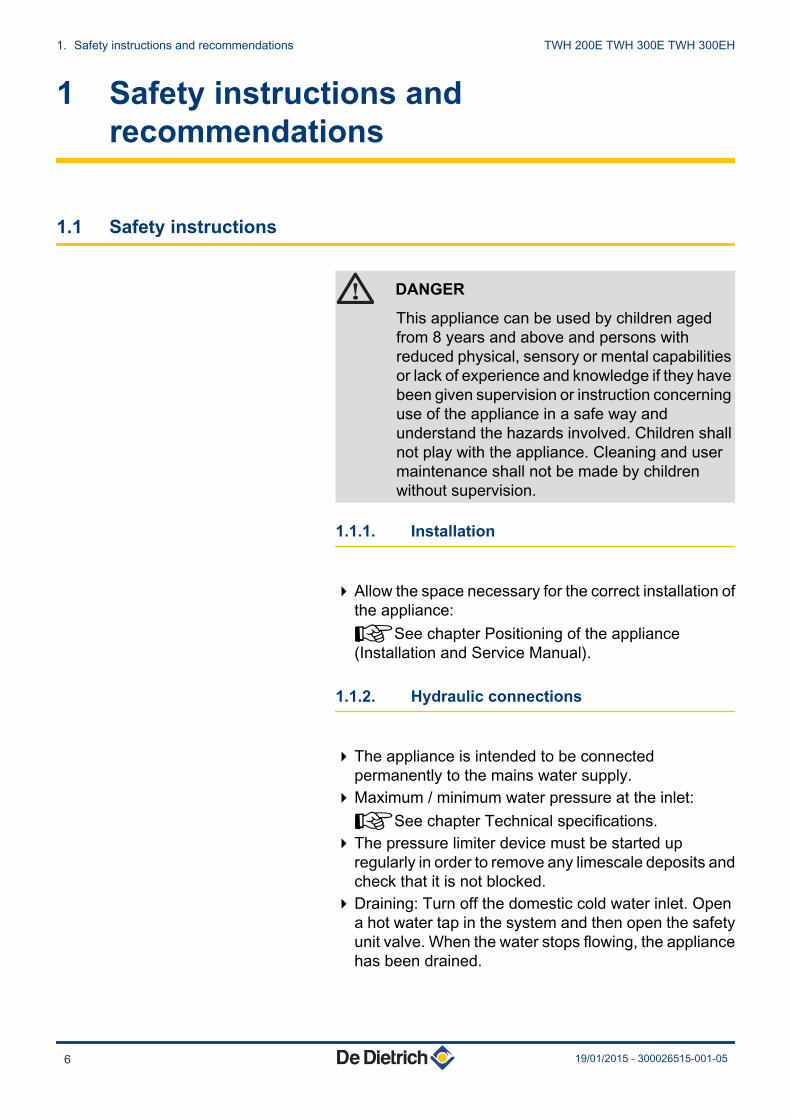
This appliance can be used by children agedfrom 8 years and above and persons withreduced physical, sensory or mental capabilitiesor lack of experience and knowledge if they havebeen given supervision or instruction concerninguse of the appliance in a safe way andunderstand the hazards involved. Children shallnot play with the appliance. Cleaning and usermaintenance shall not be made by childrenwithout supervision.
1.1.1. Installation
4Allow the space necessary for the correct installation ofthe appliance:¼See chapter Positioning of the appliance(Installation and Service Manual).
1.1.2. Hydraulic connections
4The appliance is intended to be connectedpermanently to the mains water supply.
4Maximum / minimum water pressure at the inlet:¼See chapter Technical specifications.
4The pressure limiter device must be started upregularly in order to remove any limescale deposits andcheck that it is not blocked.
4Draining: Turn off the domestic cold water inlet. Opena hot water tap in the system and then open the safetyunit valve. When the water stops flowing, the appliancehas been drained.
1. Safety instructions and recommendations TWH 200E TWH 300E TWH 300EH
6 19/01/2015 - 300026515-001-05
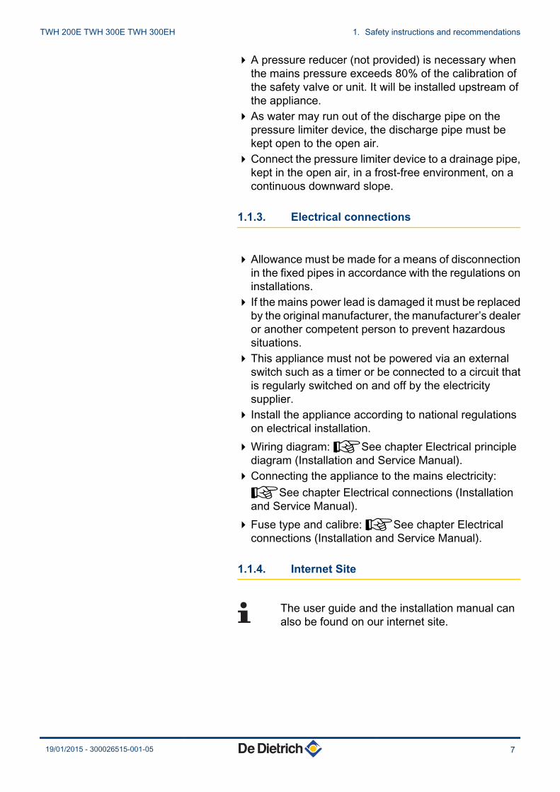
4A pressure reducer (not provided) is necessary whenthe mains pressure exceeds 80% of the calibration ofthe safety valve or unit. It will be installed upstream ofthe appliance.
4As water may run out of the discharge pipe on thepressure limiter device, the discharge pipe must bekept open to the open air.
4Connect the pressure limiter device to a drainage pipe,kept in the open air, in a frost-free environment, on acontinuous downward slope.
1.1.3. Electrical connections
4Allowance must be made for a means of disconnectionin the fixed pipes in accordance with the regulations oninstallations.
4 If the mains power lead is damaged it must be replacedby the original manufacturer, the manufacturer’s dealeror another competent person to prevent hazardoussituations.
4This appliance must not be powered via an externalswitch such as a timer or be connected to a circuit thatis regularly switched on and off by the electricitysupplier.
4 Install the appliance according to national regulationson electrical installation.
4Wiring diagram: ¼See chapter Electrical principlediagram (Installation and Service Manual).
4Connecting the appliance to the mains electricity:¼See chapter Electrical connections (Installationand Service Manual).
4Fuse type and calibre: ¼See chapter Electricalconnections (Installation and Service Manual).
1.1.4. Internet Site
The user guide and the installation manual canalso be found on our internet site.
TWH 200E TWH 300E TWH 300EH 1. Safety instructions and recommendations
19/01/2015 - 300026515-001-05 7
1.1.5. Miscellaneous
DANGER
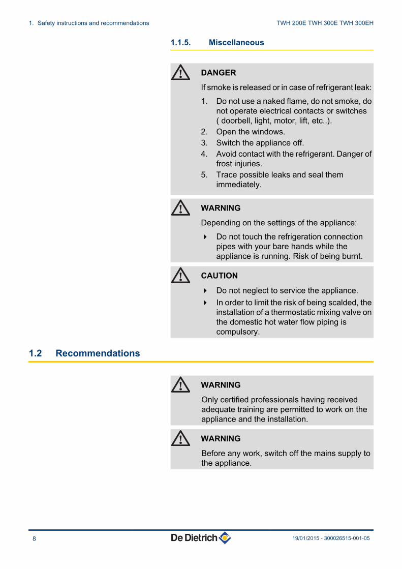
If smoke is released or in case of refrigerant leak:1. Do not use a naked flame, do not smoke, do
not operate electrical contacts or switches( doorbell, light, motor, lift, etc..).
2. Open the windows.3. Switch the appliance off.4. Avoid contact with the refrigerant. Danger of
frost injuries.5. Trace possible leaks and seal them
immediately.
WARNING
Depending on the settings of the appliance:4 Do not touch the refrigeration connection
pipes with your bare hands while theappliance is running. Risk of being burnt.
CAUTION
4 Do not neglect to service the appliance.4 In order to limit the risk of being scalded, the
installation of a thermostatic mixing valve onthe domestic hot water flow piping iscompulsory.
1.2 Recommendations
WARNING
Only certified professionals having receivedadequate training are permitted to work on theappliance and the installation.
WARNING
Before any work, switch off the mains supply tothe appliance.
1. Safety instructions and recommendations TWH 200E TWH 300E TWH 300EH
8 19/01/2015 - 300026515-001-05
1.3 Liabilities
1.3.1. Manufacturer’s liability
Our products are manufactured in compliance with therequirements of the various applicable European
Directives. They are therefore delivered with [ markingand all relevant documentation.In the interest of customers, we are continuouslyendeavouring to make improvements in product quality.All the specifications stated in this document are thereforesubject to change without notice.
Our liability as the manufacturer may not be invoked in thefollowing cases:4Failure to abide by the instructions on using the
appliance.4Faulty or insufficient maintenance of the appliance.4Failure to abide by the instructions on installing the
appliance.
1.3.2. Installer’s liability
The installer is responsible for the installation andcommissioning of the appliance. The installer mustrespect the following instructions:4Read and follow the instructions given in the manuals
provided with the appliance.4Carry out installation in compliance with the prevailing
legislation and standards.4Perform the initial start up and carry out any checks
necessary.4Explain the installation to the user.4 If a maintenance is necessary, warn the user of the
obligation to check the appliance and maintain it ingood working order.
4Give all the instruction manuals to the user.
TWH 200E TWH 300E TWH 300EH 1. Safety instructions and recommendations
19/01/2015 - 300026515-001-05 9

1.4 Safety data sheet: R-134a refrigerant
1.4.1. Product identification
4Refrigerant name: R-134a
1.4.2. Hazard identification
4Effects harmful to health:- The vapours are heavier than air and may lead to
asphyxia owing to reduced oxygen levels.- Liquefied gas: Contact with the liquid may cause
serious frost and eye injuries.4Product classification: This product is not classified as
a "hazardous preparation" according to EuropeanUnion regulations.
CAUTION
If refrigerant is mixed with air, it may lead topressure surges in the refrigeration pipes andcause an explosion and other hazards.
1.4.3. Composition / Information on theingredients
4Chemical nature: 1,1,1,2-Tetrafluoroethane R-134a.4 Ingredients that may lead to hazardous situations:
Substance name Concentration CAS number CE number Classification GWP1,1,1,2-Tetrafluoroethane R-134a 100 % 811-97-2 212-377-0 1300
1.4.4. First aid
4 If inhaled: Evacuate the subject from the contaminatedarea and take him into the open air.If feeling unwell: Call a doctor.
4 In the event of contact with the skin: Treat frostinjuries as burns. Rinse in abundant water, do notremove clothing (risk of adhesion to the skin).If skin burns appear, call a doctor immediately.
1. Safety instructions and recommendations TWH 200E TWH 300E TWH 300EH
10 19/01/2015 - 300026515-001-05

4 In the event of contact with the eyes: Rinseimmediately in water, holding the eyelids well apart (atleast 15 minutes).Consult an ophthalmologist immediately.
1.4.5. Fire prevention measures
4Appropriate extinguishing agents: All extinguishingagents can be used.
4 Inappropriate extinguishing agents: None to ourknowledge. In the event of fire nearby, use theappropriate extinguishing agents.
4Specific hazards:- Rise in pressure.
In the presence of air, an inflammable mixture mayform under certain temperature and pressureconditions
- Toxic and corrosive vapours may be released by theeffect of the heat.
4Special intervention methods: Cool the volumesexposed to heat with water spray.
4Protection of the firemen:- Full facepiece self-contained breathing apparatus- Complete body protection.
1.4.6. In the event of accidental spillage
4 Individual precautions:- Avoid contact with the skin and eyes- Do not intervene without appropriate protective
equipment- Do not inhale the vapours- Evacuate the hazardous area- Stop the leakage- Eradicate all sources of ignition- Ventilate the spillage area mechanically (Risk of
asphyxia).4Cleaning / Decontamination: Allow residual product to
evaporate.
1.4.7. Handling
4Technical measures: Ventilation.
TWH 200E TWH 300E TWH 300EH 1. Safety instructions and recommendations
19/01/2015 - 300026515-001-05 11
4Precautions to be taken:- No smoking- Prevent the accumulation of electrostatic charges- Work in a well ventilated place.
1.4.8. Personal protection
4Respiratory protection:- If insufficient ventilation: AX type cartridge mask- In confined spaces: Full facepiece self-contained
breathing apparatus.4Hand protection: Protective gloves in leather or nitrile
rubber.4Eye protection: Safety glasses with side protection.4Skin protection: Clothing made mostly of cotton.4 Industrial hygiene: Do not drink, eat or smoke at the
place of work.
1.4.9. Considerations on disposal
4Product waste: Consult the manufacturer or thesupplier for information on recovery or recycling.
4Soiled packaging: Reuse or recycle afterdecontamination. Destroy in authorised installations.
WARNING
Disposal must be done in compliance withprevailing local and national regulations.
1.4.10. Regulations
4EC Regulation 842/2006: Fluorinated greenhousegases under the Kyoto Protocol.
1. Safety instructions and recommendations TWH 200E TWH 300E TWH 300EH
12 19/01/2015 - 300026515-001-05

2 About this manual
2.1 Symbols used
In these instructions, various danger levels are employed to draw theuser’s attention to particular information. In so doing, we wish tosafeguard the user’s safety, highlight hazards and guarantee correctoperation of the appliance.
DANGER
Risk of a dangerous situation causing serious physicalinjury.
WARNING
Risk of a dangerous situation causing slight physicalinjury.
CAUTION
Risk of material damage.
Signals important information.
¼Signals a referral to other instructions or other pages in theinstructions.
Before installing and commissioning the device, readcarefully the instruction manuals provided.
2.2 Abbreviations
4 HP: Heat pump4 DHW: Domestic hot water4 LP: Low pressure4 HP: High pressure4 CFC: Chlorofluorocarbon4 Qpr: Static losses (Thermal losses from the DHW tank when it is
off for 24 hours)4 COP: Performance coefficient4 HP/HC: Peak hours / Off-peak hours
TWH 200E TWH 300E TWH 300EH 2. About this manual
19/01/2015 - 300026515-001-05 13

3 Technical specifications
3.1 Homologations
3.1.1. Certifications
n Electrical compliance / Marking CE
This product complies to the requirements to the european directivesand following standards:
4 2006/95/EC Low Voltage DirectiveReference Standard: EN 60.335.1.
4 2004/108/EC Electromagnetic Compatibility DirectiveReference Standard: EN 50.081.1 / EN 50.082.1 / EN 55.014.
3.1.2. Directive 97/23/EC
This product conforms to the requirements of european directive 97 /23 / EC, article 3, paragraph 3, on pressure equipment.
3.1.3. Factory test
Before leaving the factory, each appliance is tested for the following:
4 Water tightness4 Air tightness4 Electrical safety.
3. Technical specifications TWH 200E TWH 300E TWH 300EH
14 19/01/2015 - 300026515-001-05

3.2 Technical specifications
3.2.1. Characteristics of the appliance
Model TWH 300 E TWH 300 EH TWH 200 ECapacity litres 270 260 215Output (HP) -Air temperature = 15°C W 1700 1700 1700Absorbed electrical power (HP) W 500 500 500COP (1) 2.94 2.75 2.90
Nominal air flow rate (DP = 25 Pa)(1) m3/h 320 320 320
Electrical resistor output W 2400 2400 2400Operating pressure bar (MPa) 10 (1,0) 10 (1,0) 10 (1,0)Power supply voltage V 230 230 230Circuit breaker A 16 16 16Exchanger surface m2 - 1.00 -
Continuous output DT = 35 K (2) (3) litres per hour - 955.6 -
Flow rate over 10 minutes with DT = 30 K (2) l/10 mm - 420 -
Vmax(1) litres 388 383 281.9
Pes(1) W 34 36 30
Maximum length of the air connection Diameter 160 mm(4) m 26 26 26R134a refrigerant kg 1.45 1.45 1.45Weight (empty) kg 105 123 92(1) Value obtained with an air temperature of 7 and a water inlet at 10 °C, as per EN16147 based on Specification LCIE N°103-15/B:2011(2) Domestic cold water input at 10°C - Primary inlet temperature at 80°C(3) Output: 34.1 kW(4) The installation of suction and backflow conduits on the heat pump lessens its performance
3.2.2. Heating time of the DHW tank depending onthe air temperature
Scenario for complete heating of the DHW tank
A Heating time for a set point of 51°CB Heating time for a set point of 62°CY Heating time (Hours)X Air temperature (°C)
0
2
4
6
8
10
12
14
16
18
20
-5 0 5 10 15 20 25 30 35
Y
X
B
A
C003447-A
TWH 200E TWH 300E TWH 300EH 3. Technical specifications
19/01/2015 - 300026515-001-05 15

3.2.3. Max domestic hot water set point reachedby the heat pump depending on the airtemperature
Y Max domestic hot water temperature (°C)X Air temperature (°C)
C003483-B
51°
-5 0 5 7 10 X
55°
65°
Y
3. Technical specifications TWH 200E TWH 300E TWH 300EH
16 19/01/2015 - 300026515-001-05

4 Technical description
4.1 General description
The DHW tanks in the TWH range have the following characteristics:
4 Floor-standing thermodynamic storage DHW tank4 Thermodynamic unit extracting energy from unheated ambient air
or outside air4 Control panel with display of the volume of water heated and
hourly programming4 Heat exchanger for connection to a boiler or a solar circuit (Version
EH)4 Steatite electrical resistor 2.4 kW4 Enamelled tank protected by impressed current anode4 Very thick insulation (0% CFCs)
The thermodynamic water heater is a hot water tank that can beheated by:
4 The Heat Pump (up to 65°C)4 The electric heating resistance (Electrical back-up - AUTO and
Boost mode) (up to 70°C)4 The additional heat exchanger (Version EH)
TWH 200E TWH 300E TWH 300EH 4. Technical description
19/01/2015 - 300026515-001-05 17

4.2 Main parts
1 Fan2 Evaporator3 Expansion valve4 Solenoid valve for defrosting5 Regulation6 temperature sensor7 Impressed current anode8 Safety thermostat9 Steatite electrical resistor10 temperature sensor11 Air conduits12 High pressure (HP) pressure switch13 Low pressure (LP) pressure switch14 Compressor15 Pressure measurement point - High pressure (HP)16 Ventilation grid17 Domestic hot water outlet18 Condenser19 Cold water inlet
4.3 Operating principle
The thermodynamic DHW tank uses unheated ambient air or outsideair to prepare DHW.
The refrigerant circuit is a closed circuit in which the R-134arefrigerant plays the role of an energy carrier.
The heat from the intake air is transferred to the refrigerant in thefinned heat exchanger at a low evaporation temperature.
The refrigerant is sucked in by a compressor in vapour form, whichraises it to a higher pressure and temperature and sends it to thecondenser. In the condenser, the heat extracted in the evaporator andsome of the energy absorbed by the compressor are released intothe water.
C003185-F
5
6
10
2
1
3
4
15
16
13
12
14
17
11
19
18
8
7
9
4. Technical description TWH 200E TWH 300E TWH 300EH
18 19/01/2015 - 300026515-001-05

The refrigerant is depressurised in the thermostatic expansion valveand is cooled. The refrigerant can again extract the heat contained inthe inlet air into the evaporator.
1 Compressor2 Low pressure (LP) pressure switch3 Condenser4 Domestic hot water tank5 Heat exchanger (Version EH)6 Steatite electrical resistor7 Impressed current anode8 Temperature regulator (HP)9 Limiting thermostat10 Temperature regulator (Electric heating
resistance)11 Sensor tube12 Filter-drier13 Thermostatic expansion valve14 Ambient air thermostat15 Evaporator16 Fan17 Expansion valve bulb18 Sensor tube19 Solenoid valve for defrosting20 High pressure (HP) pressure switch
C003625-D
TWH 200E TWH 300E TWH 300EH 4. Technical description
19/01/2015 - 300026515-001-05 19
5 Installation
5.1 Regulations governing installation
CAUTION
Installation and maintenance of the appliance must bedone by a qualified professional in accordance withprevailing statutory texts and codes of practice.
5.2 Package list
5.2.1. Standard delivery
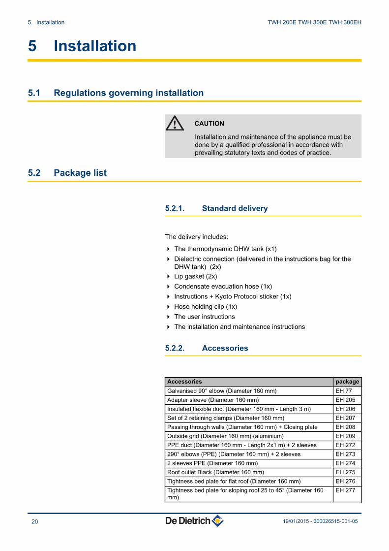
The delivery includes:
4 The thermodynamic DHW tank (x1)4 Dielectric connection (delivered in the instructions bag for the
DHW tank) (2x)4 Lip gasket (2x)4 Condensate evacuation hose (1x)4 Instructions + Kyoto Protocol sticker (1x)4 Hose holding clip (1x)4 The user instructions4 The installation and maintenance instructions
5.2.2. Accessories
Accessories packageGalvanised 90° elbow (Diameter 160 mm) EH 77Adapter sleeve (Diameter 160 mm) EH 205Insulated flexible duct (Diameter 160 mm - Length 3 m) EH 206Set of 2 retaining clamps (Diameter 160 mm) EH 207Passing through walls (Diameter 160 mm) + Closing plate EH 208Outside grid (Diameter 160 mm) (aluminium) EH 209PPE duct (Diameter 160 mm - Length 2x1 m) + 2 sleeves EH 272290° elbows (PPE) (Diameter 160 mm) + 2 sleeves EH 2732 sleeves PPE (Diameter 160 mm) EH 274Roof outlet Black (Diameter 160 mm) EH 275Tightness bed plate for flat roof (Diameter 160 mm) EH 276Tightness bed plate for sloping roof 25 to 45° (Diameter 160mm)
EH 277
5. Installation TWH 200E TWH 300E TWH 300EH
20 19/01/2015 - 300026515-001-05

Accessories packageReduced elbow kit EH 434Connection kit for safety unit ER 208Outside grate for taking in and discharging air (Diameter 160mm)
EH 558
5.3 Storage and transport
CAUTION
4 Have 2 people available.4 Use a 3-wheel hand truck.4 Handle the appliance with gloves.4 The appliance cover cannot be used for transport
operations. The cover is not capable of withstandingheavy weights.
4 Model 300 : Allow a minimum room height ofapproximately 2.15 mModel 200 : Allow a minimum room height ofapproximately 1.84 m.
4 The thermodynamic DHW tank must be stored and transported inits packaging and not filled with water.
4 Ambient transport and storage temperatures admissible: from-20 to +60°C.
5.3.1. Transport
We recommend shipping the appliance vertically.
It is possible to ship the appliance horizontally over shortdistances but only on its back.
CAUTION
The appliance must never be stacked or laid on anotherside; it may otherwise malfunction or break down.
C003496-B
TWH 200E TWH 300E TWH 300EH 5. Installation
19/01/2015 - 300026515-001-05 21

5.4 Choice of the location
5.4.1. Type plate
4 The type plate must be accessible at all times.4 The type plate identifies the product and provides the following
information:- Appliance type- Manufacturing date (Year - Week)- Serial number.
5.4.2. Positioning of the appliance
CAUTION
When installing the appliance, respect the IP21environmental rating.
CAUTION
4 Do not install the thermodynamic water heater inpremises exposed to gas, vapours or dust.
4 The appliance must not take in air containingsolvents or explosive materials.
4 The air taken in must in no event be dusty.4 Adequate thermal insulation in relation to adjacent
living spaces is recommended.4 Temperature of the ambient air or of the air taken in
by the heat pump for optimum running: from 10 to35°C.
4 Install the appliance in a dry, frost-free room at a minimumtemperature of 7°C.
4 Install the appliance on a flat, solid surface.
C003192-D
5. Installation TWH 200E TWH 300E TWH 300EH
22 19/01/2015 - 300026515-001-05
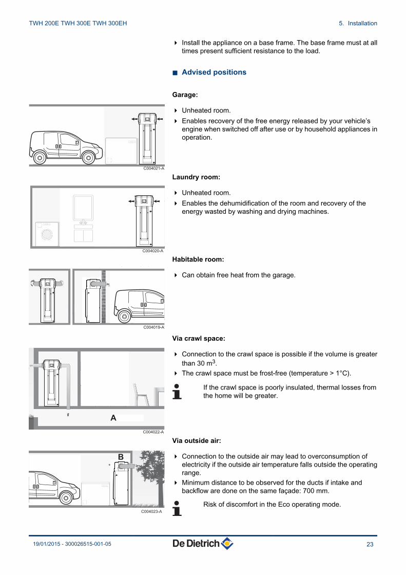
4 Install the appliance on a base frame. The base frame must at alltimes present sufficient resistance to the load.
n Advised positions
Garage:
4 Unheated room.4 Enables recovery of the free energy released by your vehicle’s
engine when switched off after use or by household appliances inoperation.
Laundry room:
4 Unheated room.4 Enables the dehumidification of the room and recovery of the
energy wasted by washing and drying machines.
Habitable room:
4 Can obtain free heat from the garage.
Via crawl space:
4 Connection to the crawl space is possible if the volume is greaterthan 30 m3.
4 The crawl space must be frost-free (temperature > 1°C).
If the crawl space is poorly insulated, thermal losses fromthe home will be greater.
Via outside air:
4 Connection to the outside air may lead to overconsumption ofelectricity if the outside air temperature falls outside the operatingrange.
4 Minimum distance to be observed for the ducts if intake andbackflow are done on the same façade: 700 mm.
Risk of discomfort in the Eco operating mode.
C004021-A
C004020-A
C004019-A
A
C004022-A
C004023-A
B
TWH 200E TWH 300E TWH 300EH 5. Installation
19/01/2015 - 300026515-001-05 23
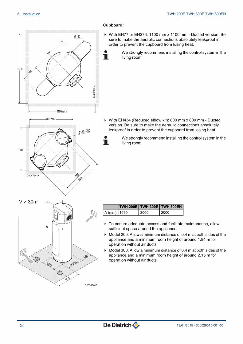
Cupboard:
4 With EH77 or EH273: 1100 mm x 1100 mm - Ducted version. Besure to make the aeraulic connections absolutely leakproof inorder to prevent the cupboard from losing heat.
We strongly recommend installing the control system in theliving room.
4 With EH434 (Reduced elbow kit): 800 mm x 800 mm - Ductedversion. Be sure to make the aeraulic connections absolutelyleakproof in order to prevent the cupboard from losing heat.
We strongly recommend installing the control system in theliving room.
TWH 200E TWH 300E TWH 300EHA (mm) 1690 2000 2000
4 To ensure adequate access and facilitate maintenance, allowsufficient space around the appliance.
4 Model 200: Allow a minimum distance of 0.4 m at both sides of theappliance and a minimum room height of around 1.84 m foroperation without air ducts.
4 Model 300: Allow a minimum distance of 0.4 m at both sides of theappliance and a minimum room height of around 2.15 m foroperation without air ducts.
C0
03
48
1-C
690
300
1100
1100 mini
0 160
C004734-A
0 160 / 200
800 mini
800
826
598
C003188-F
V > 30m3
150
150
min.400
min.400
690
A
0 600
5. Installation TWH 200E TWH 300E TWH 300EH
24 19/01/2015 - 300026515-001-05
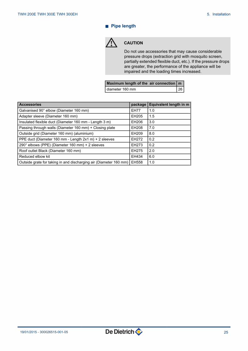
n Pipe length
CAUTION
Do not use accessories that may cause considerablepressure drops (extraction grid with mosquito screen,partially extended flexible duct, etc.). If the pressure dropsare greater, the performance of the appliance will beimpaired and the loading times increased.
Maximum length of the air connection mdiameter 160 mm 26
Accessories package Equivalent length in mGalvanised 90° elbow (Diameter 160 mm) EH77 1.0Adapter sleeve (Diameter 160 mm) EH205 1.5Insulated flexible duct (Diameter 160 mm - Length 3 m) EH206 3.0Passing through walls (Diameter 160 mm) + Closing plate EH208 7.0Outside grid (Diameter 160 mm) (aluminium) EH209 8.0PPE duct (Diameter 160 mm - Length 2x1 m) + 2 sleeves EH272 0.2290° elbows (PPE) (Diameter 160 mm) + 2 sleeves EH273 0.2Roof outlet Black (Diameter 160 mm) EH275 2.0Reduced elbow kit EH434 6.0Outside grate for taking in and discharging air (Diameter 160 mm) EH558 1.0
TWH 200E TWH 300E TWH 300EH 5. Installation
19/01/2015 - 300026515-001-05 25

5.4.3. Main dimensions
n TWH 200E - TWH 300E
C003183-E
50°
A
690
90
B
1025
810
4(1)
3
1
2
4
A Impressed current anode
Z Steatite electrical resistor 2.4 kW
E Domestic hot water outlet G 3/4"
R Domestic cold water inlet G 3/4"(1) Adjustable feet
¼See chapter "Positioning the appliance", page28
TWH 200E TWH 300EA 1690 2000B 974 1287
5. Installation TWH 200E TWH 300E TWH 300EH
26 19/01/2015 - 300026515-001-05
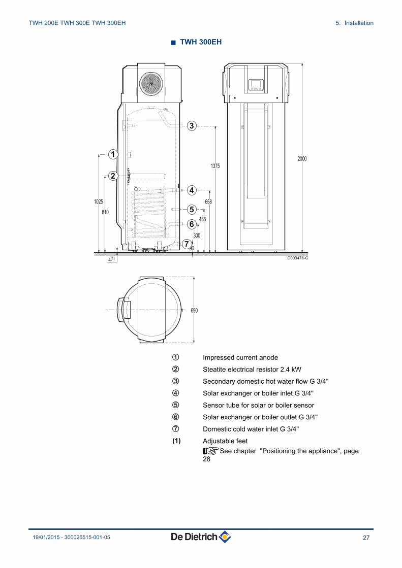
n TWH 300EH
C003476-C
90
690
810
300
455
658
1375
2000
1025
4(1)
1
2
3
4
5
6
7
A Impressed current anode
Z Steatite electrical resistor 2.4 kW
E Secondary domestic hot water flow G 3/4"
R Solar exchanger or boiler inlet G 3/4"
T Sensor tube for solar or boiler sensor
Y Solar exchanger or boiler outlet G 3/4"
U Domestic cold water inlet G 3/4"(1) Adjustable feet
¼See chapter "Positioning the appliance", page28
TWH 200E TWH 300E TWH 300EH 5. Installation
19/01/2015 - 300026515-001-05 27

5.5 Positioning the appliance
5.5.1. Unpacking the appliance
CAUTION
Remove all packaging materials. Check that the contentsare intact. If you notice a defect, do not use the applianceand contact the supplier.
1. Remove the retaining screw from the fan grille.2. Turn the grille anticlockwise.3. Remove the fan grille.4. Unscrew the 2 screws from the compressor support part.5. Remove the compressor support part and discard it.6. Put the grille back in place.7. Turn the grille clockwise to fit it back into its housing.8. Put the retaining screws in place.
5.5.2. Positioning the appliance
¼Refer to the instructions affixed to the packaging of theappliance
M003102-A
1
2
3
4
5
6
7
8
5. Installation TWH 200E TWH 300E TWH 300EH
28 19/01/2015 - 300026515-001-05

5.5.3. Levelling
To improve condensates evacuation, we recommend tiltingthe appliance slightly backwards.
1. Level the appliance using the adjustable feet.(1) Adjustable feet, Basic dimension 4 mmCan be adjusted from 4 mm to 21 mm
5.6 Hydraulic connections
CAUTION
Before making the hydraulic connections, it is essential torinse the circuit to get rid of any particles that may damagecertain units (safety valve, pumps, valves, etc.).If rinsing has to be done using an aggressive product,neutralise the rinsing water before disposing of it in thewaste water network.
Using hoses which are too short or too rigid encouragesthe transmission of vibrations and the production of noises.
Version EH: Make all the hydraulic connections for the DHW tankusing flexible pipes.
5.6.1. Connecting the calorifer to the domesticwater circuit (secondary circuit)
When making the connections, it is imperative that the standards andcorresponding local directives are respected.
n Specific precautions
Before making the connection, rinse the drinking water inletpipes in order not to introduce metal or other particles into theappliance’s tank.
C003187-E
B
21(1)
19
3°
TWH 200E TWH 300E TWH 300EH 5. Installation
19/01/2015 - 300026515-001-05 29

CAUTION
Do not connect the domestic hot water connection directlyto copper pipes in order to prevent galvanic couples in iron/copper (risk of corrosion). It is compulsory to fit thedomestic hot water connection with a dielectricconnection (Supplied).
n Safety valve or safety unit
CAUTION
In accordance with safety rules, a safety unit calibrated to7 bar must be mounted on the DHW tank’s domestic coldwater inlet.
7 bar safety valve (0.7 MPa).
4 Integrate the safety valve in the cold water circuit.4 Install the safety valve close to the calorifer in a place which is
easy to access.
n Size
4 The diameter of the safety unit and its connection to the DHW tankmust be at least equal to the diameter of the DHW tank’s domesticcold water inlet.
4 No isolating devices must be fitted between the valve or the safetyunit and the DHW tank.
4 The outlet pipe in the valve or safety assembly must not beblocked.
To avoid restricting the flow of water in the event of overpressure:
4 The safety device drain pipe must have a uniform and sufficientgradient and its diameter must be at least equal to that of the outletopening of the safety device (to prevent the flow of water beinghindered if the pressure is too high).
4 The cross section of the discharge pipe from the safety unit mustbe at least equal to the cross section of the opening of the safetyunit outlet.
n Isolating valves
Hydraulically isolate the primary and secondary circuits using stopvalves to facilitate maintenance operations on the unit. The valvesmake it possible to carry out maintenance on the calorifer and itscomponents without draining the entire installation.
These valves are also used to isolate the calorifer unit whenconducting a pressurised check on the leak tightness of theinstallation if the test pressure is greater than the admissible operatingpressure.
5. Installation TWH 200E TWH 300E TWH 300EH
30 19/01/2015 - 300026515-001-05
CAUTION
If the mains pipes are made of copper, fit a sleeve madeof steel, cast iron or any other insulating material betweenthe tank’s hot water outlet and the pipes to preventcorrosion to the connection.
n Connecting the domestic cold water
Make the connection to the cold water supply according to thehydraulic installation diagram.Install a water drain in the boiler room and a funnel-siphon for thesafety unit.
The components used for the connection to the cold water supplymust comply with the prevailing standards and regulations in thecountry concerned. Fit a one-way valve to the domestic cold watercircuit.
n Pressure reducer
If the mains pressure exceeds 80% of the calibration of the valve orsafety unit (e.g. 5,5 bar (0,55 MPa) for a safety unit calibrated to 7 bar(0,7 MPa)), a pressure reducer must be installed upstream of theappliance. Install the pressure reducer downstream the water meterin such a way as to ensure the same pressure in all of the installationpipes.
n Measures to take to prevent hot water flow return
Fit a one-way valve to the domestic cold water circuit.
5.6.2. Connection to a boiler (Version EH)
CAUTION
Before making the water connections of the heating circuitand domestic hot water tank heat exchanger, it isimperative to rinse the circuits to remove any particleswhich might damage the components (safety valve,pumps, valves, ...).
TWH 200E TWH 300E TWH 300EH 5. Installation
19/01/2015 - 300026515-001-05 31

C003613-B
A
A Boiler1 Heating flow2 Heating return3 Safety valve4 Pressure gauge7 Automatic air vent9 Isolating valve11 Heating pump16 Expansion vessel17 Drain cock18 Filling the heating circuit21 Outside sensor22 Boiler sensor24 DHW calorifier exchanger primary inlet25 DHW calorifier heat exchanger primary outlet26 DHW pump27 Non-return valve28 Domestic cold water inlet
5. Installation TWH 200E TWH 300E TWH 300EH
32 19/01/2015 - 300026515-001-05
29 Pressure reducer30 Safety unit33 DHW sensor50 Disconnector51 Thermostatic valve52 Differential valve (only with module fitted with a 3-speed
pump)57 Domestic hot water outlet90 Anti-thermosiphon loop
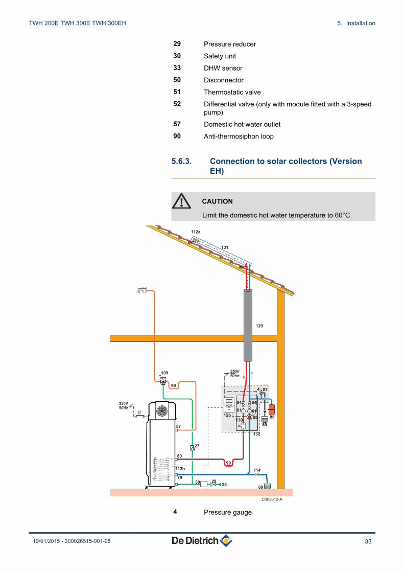
5.6.3. Connection to solar collectors (VersionEH)
CAUTION
Limit the domestic hot water temperature to 60°C.
C003612-A
4 Pressure gauge
TWH 200E TWH 300E TWH 300EH 5. Installation
19/01/2015 - 300026515-001-05 33

27 Non-return valve28 Domestic cold water inlet29 Pressure reducer30 Safety unit57 Domestic hot water outlet61 Thermometer79 Primary solar exchanger outlet on the DHW calorifier80 Primary solar exchanger inlet on the DHW calorifier84 Stop valve with releasable non-return valve85 Primary solar circuit pump87 Safety valve calibrated at 6 bar88 Solar expansion vessel89 Heat transfer fluid container90 Anti-thermosiphon loop (= 10 x Pipe diameter)109 Domestic hot water thermostatic mixing valve112a Solar sensor probe112b Solar DHW sensor114 Primary solar circuit filling and draining device126 Solar regulator129 Insulation130 Manual bleed degasser131 Solar collectors132 Complete solar station with solar regulator
5. Installation TWH 200E TWH 300E TWH 300EH
34 19/01/2015 - 300026515-001-05
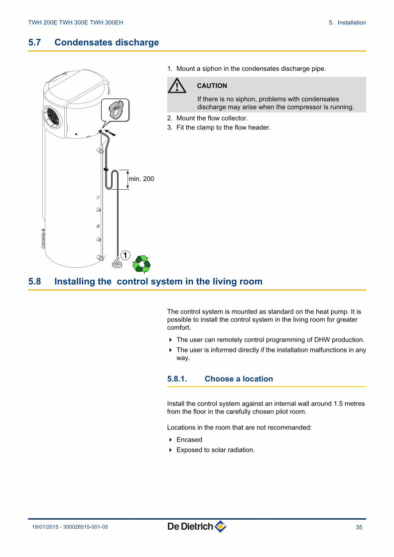
5.7 Condensates discharge
1. Mount a siphon in the condensates discharge pipe.
CAUTION
If there is no siphon, problems with condensatesdischarge may arise when the compressor is running.
2. Mount the flow collector.3. Fit the clamp to the flow header.
5.8 Installing the control system in the living room
The control system is mounted as standard on the heat pump. It ispossible to install the control system in the living room for greatercomfort.
4 The user can remotely control programming of DHW production.4 The user is informed directly if the installation malfunctions in any
way.
5.8.1. Choose a location
Install the control system against an internal wall around 1.5 metresfrom the floor in the carefully chosen pilot room.
Locations in the room that are not recommanded:
4 Encased4 Exposed to solar radiation.
1
C0
03
65
6-B
min. 200
TWH 200E TWH 300E TWH 300EH 5. Installation
19/01/2015 - 300026515-001-05 35

5.8.2. Operations to be carried out on thethermodynamic DHW tank
1. Unscrew the 2 screws.2. Remove the front cover.
3. Separate the control system command module from its base.4. Disconnect the command module (2 wires).5. Unscrew the 2 fastening wires on the base.6. Remove the wire and discard it.
7. Unscrew the 2 fastening screws on the base of the control paneland remove the base.
C003254-C
1
1
2
6
4
3
5
C003329-D
7
C003408-D
5. Installation TWH 200E TWH 300E TWH 300EH
36 19/01/2015 - 300026515-001-05

8. Connect the 2 wires for connecting the command module at theappliance end (not supplied).
9. Replace the front cover.10.Tighten the 2 screws.
5.8.3. Installing the control system in the livingroom
1. Drill 2 holes with a Ø of 6 mm.2. Put the plugs in place.3. Attach the wall support.
C003330-D
8
C003334-G10
139
10
1
2
3
6
C003331-A
TWH 200E TWH 300E TWH 300EH 5. Installation
19/01/2015 - 300026515-001-05 37

4. Connect the 2 wires on the command module.5. Put the control system module in place.
5.9 Electrical connections
5.9.1. Recommendations
WARNING
4 Only qualified professionals may carry out electricalconnections, always with the power off.
4 Do not connect the power supply directly to the HP/HC contact.
The earthing shall comply with local standards.
Power the appliance with a circuit that includes a 16 A omnipolarcircuit breaker, D curve type, with a gap of more than 3 mm.
The DHW tank is delivered with a 3G cable. If the power cable isdamaged, it must be replaced by the manufacturer, its after salesservice or persons with similar qualifications in order to obviate anydanger.The electricity supply is connected to the mains by connection cable(~230 V, 50 Hz) and electrical plug.
The HP/HC connection is made on the terminal block.
5.9.2. Connecting the hydraulic back-up (VersionEH)
1. Remove the front cover.¼See chapter "Installing the control system in the livingroom", page 35
4
5
C003407-D
5. Installation TWH 200E TWH 300E TWH 300EH
38 19/01/2015 - 300026515-001-05

C003618-B
Backup
2. Access to the PCB.3. Connect the boiler back-up connector (boiler back-up). To set the
boiler inlet, refer to the boiler instruction manual.
5.9.3. Access to the connection terminal HP/HC
1. Unscrew the 2 screws.2. Remove the front cover.
C003254-C
1
1
2
TWH 200E TWH 300E TWH 300EH 5. Installation
19/01/2015 - 300026515-001-05 39

3. Access to the PCB.4. Make the electrical connection using a cable with a cross section
of 1,5 mm2.
5.9.4. Connection with HP/HC signal connected
n Shunt connection with HP/HC relay (Dry contact in theheat pump)
1 Meter
C003335-A
HP/HC
230V
C003335-B
C003617-E
A
A
B
C1 C2
538 kW/h1
1A1
A2
0
Auto
0
15 / 45 A500 mA
TEST 16 A40 A 2 A
30
mA
L
N
X11-2 HP/H
X11-1 LINE
C
1 2
3 4 4
5. Installation TWH 200E TWH 300E TWH 300EH
40 19/01/2015 - 300026515-001-05
2 Connection circuit breaker3 AC type differential switch4 Circuit breakerA Power cable 1,5 mm2
B Shunt 1,5 mm2
4 Set parameter P04 to 2.4 The heat pump and additional heating are not permitted to operate
in Peak Hours4 Rapid Boost heating at one touch4 The 2 signal wires must be routed as far as the appliance’s box
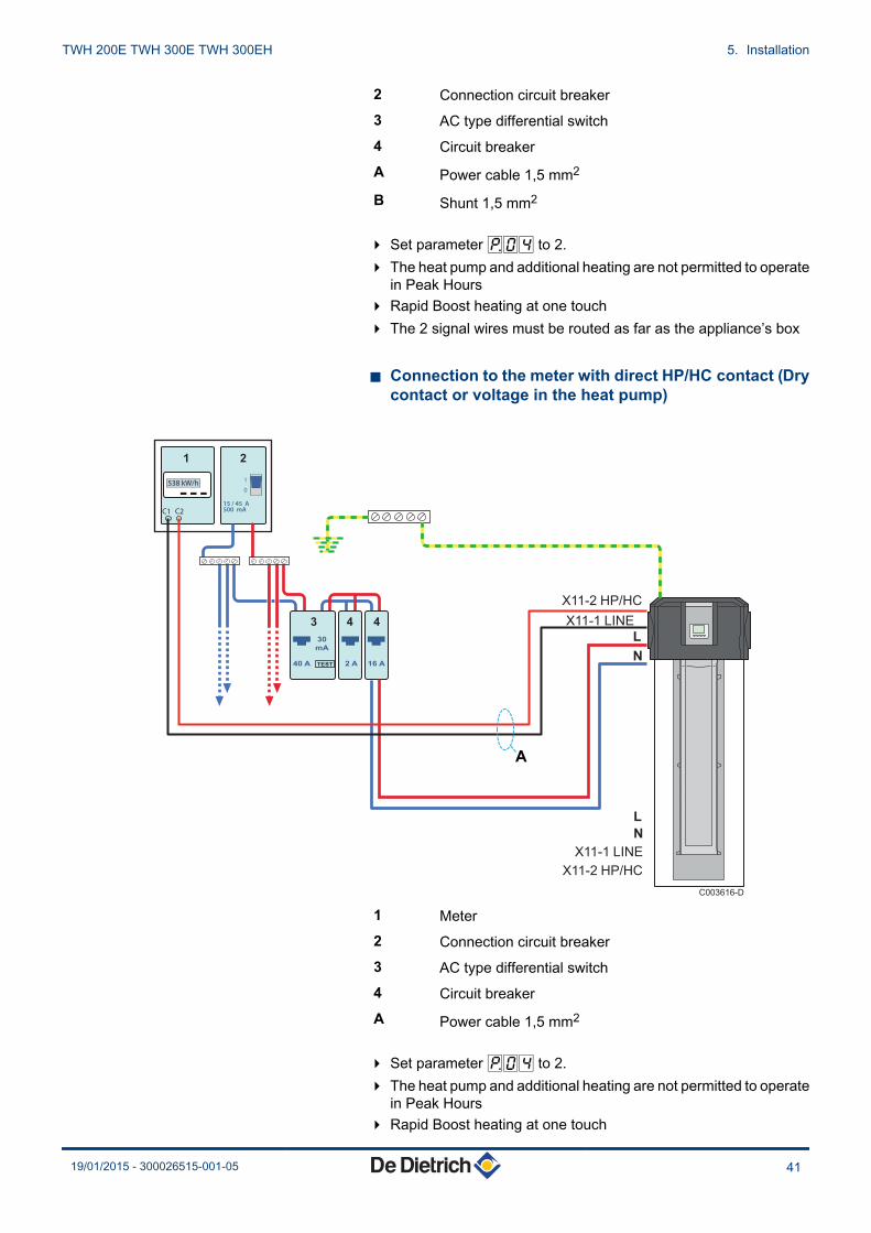
n Connection to the meter with direct HP/HC contact (Drycontact or voltage in the heat pump)
1 Meter2 Connection circuit breaker3 AC type differential switch4 Circuit breakerA Power cable 1,5 mm2
4 Set parameter P04 to 2.4 The heat pump and additional heating are not permitted to operate
in Peak Hours4 Rapid Boost heating at one touch
C1 C2
538 kW/h1
0
15 / 45 A500 mA
TEST 16 A40
C003616-D
A 2 A
30
mA
L
N
X11-2 HP/H
X11-1 LINE
C
L
N
X11-2 HP/HC
X11-1 LINE
A
1 2
3 4 4
TWH 200E TWH 300E TWH 300EH 5. Installation
19/01/2015 - 300026515-001-05 41
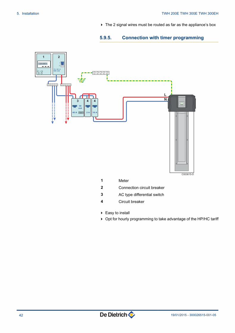
4 The 2 signal wires must be routed as far as the appliance’s box
5.9.5. Connection with timer programming
1 Meter2 Connection circuit breaker3 AC type differential switch4 Circuit breaker
4 Easy to install4 Opt for hourly programming to take advantage of the HP/HC tariff
C1 C2
538 kW/h1
0
15 / 45 A500 mA
TEST 16 A40
C003615-D
A 2 A
30
mA
L
N
1 2
3 4 4
5. Installation TWH 200E TWH 300E TWH 300EH
42 19/01/2015 - 300026515-001-05
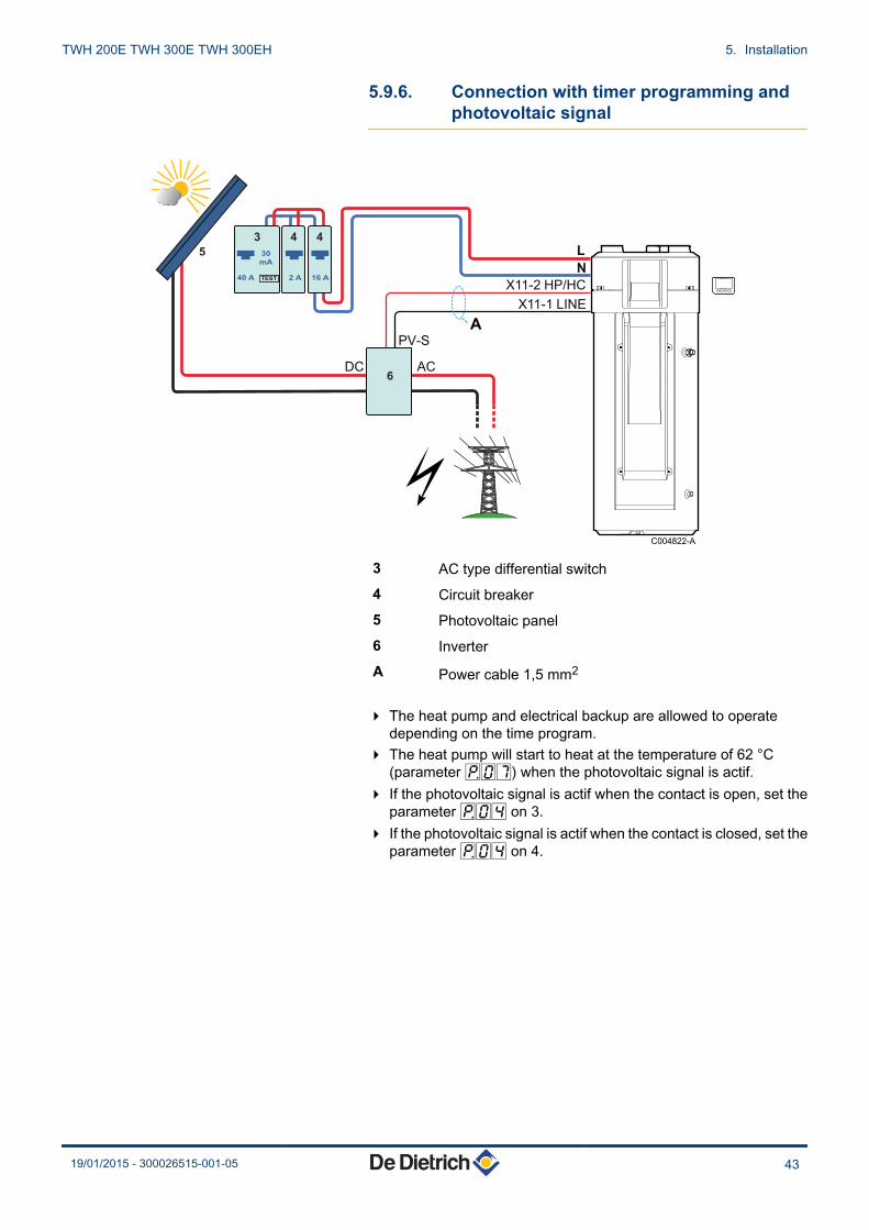
5.9.6. Connection with timer programming andphotovoltaic signal
C004822-A
A
TEST 16 A40 A 2 A
30
mA
L
N
X11-2 HP/H
PV-S
DC AC
X11-1 LINE
C
3
5
6
4 4
3 AC type differential switch4 Circuit breaker5 Photovoltaic panel6 InverterA Power cable 1,5 mm2
4 The heat pump and electrical backup are allowed to operatedepending on the time program.
4 The heat pump will start to heat at the temperature of 62 °C(parameter P07) when the photovoltaic signal is actif.
4 If the photovoltaic signal is actif when the contact is open, set theparameter P04 on 3.
4 If the photovoltaic signal is actif when the contact is closed, set theparameter P04 on 4.
TWH 200E TWH 300E TWH 300EH 5. Installation
19/01/2015 - 300026515-001-05 43

5.10 Electrical principle diagram
3
34
PC
U-1
95
2 θ°C
12
1
2
X8
15
4
4
12
6
12
3
12
2
12
3
X-H
C
12
1
X7
2
θ°C
22
1
1
12 X3
1
X1
12
θ°C
2 1
2 X4
1
θ°C
2 1
2 X2
13
X5
56
2 θ°C
12
1
1
2
4
P
CO
M
NC
NO
L
SP
L1
N
12
34
1
X-B
1
1
�
2
�
R5
R4
R3
R1
R2
S1
S2
S3
TA
S4
S5
P
TS
X6
12
24
R6
2
5
12
3
KL
IXO
N
HP
ALIMENTATION 230 V
SPC003402-B
A Control panel
Z Fan
E Solenoid valve for defrosting
R Compressor
T Condenser
Y Electric heating resistance
5. Installation TWH 200E TWH 300E TWH 300EH
44 19/01/2015 - 300026515-001-05
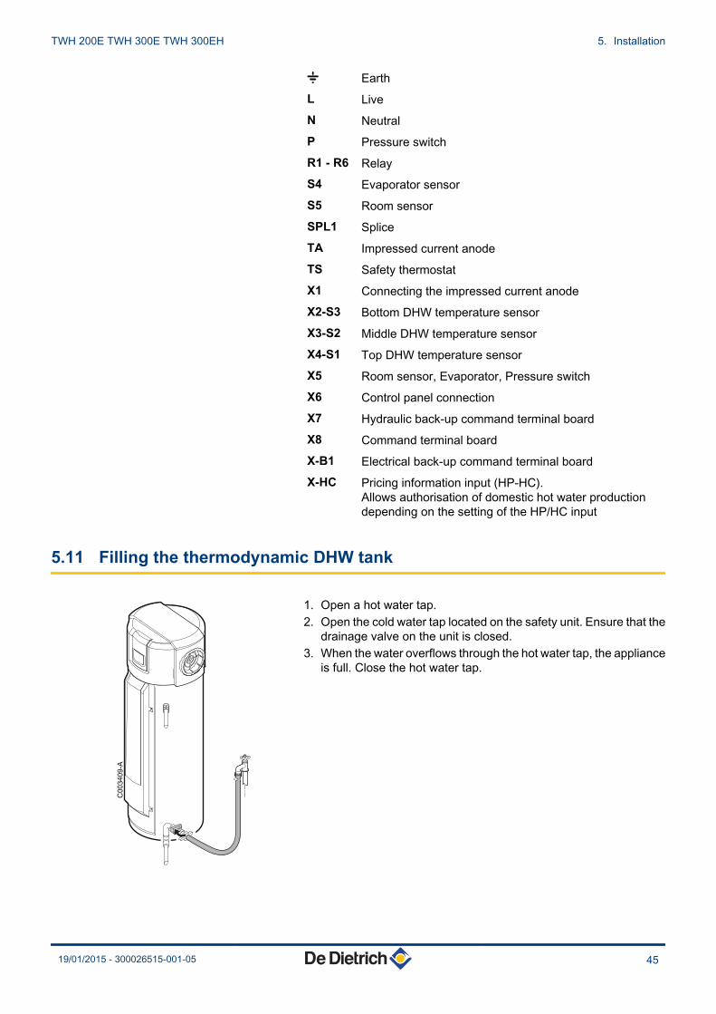
* EarthL LiveN NeutralP Pressure switchR1 - R6 RelayS4 Evaporator sensorS5 Room sensorSPL1 SpliceTA Impressed current anodeTS Safety thermostatX1 Connecting the impressed current anodeX2-S3 Bottom DHW temperature sensorX3-S2 Middle DHW temperature sensorX4-S1 Top DHW temperature sensorX5 Room sensor, Evaporator, Pressure switchX6 Control panel connectionX7 Hydraulic back-up command terminal boardX8 Command terminal boardX-B1 Electrical back-up command terminal boardX-HC Pricing information input (HP-HC).
Allows authorisation of domestic hot water productiondepending on the setting of the HP/HC input
5.11 Filling the thermodynamic DHW tank
1. Open a hot water tap.2. Open the cold water tap located on the safety unit. Ensure that the
drainage valve on the unit is closed.3. When the water overflows through the hot water tap, the appliance
is full. Close the hot water tap.
C003409-A
TWH 200E TWH 300E TWH 300EH 5. Installation
19/01/2015 - 300026515-001-05 45
6 Commissioning
6.1 Control panel
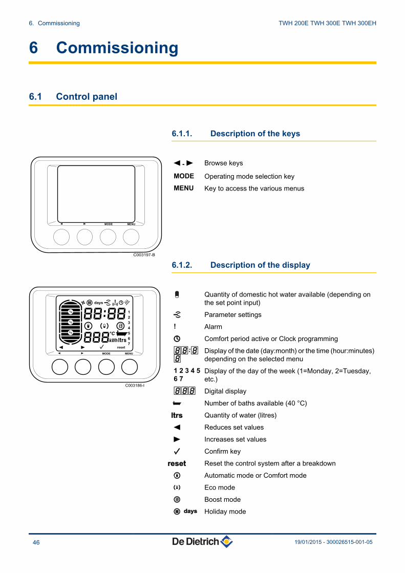
6.1.1. Description of the keys
( - ) Browse keys
MODE Operating mode selection keyMENU Key to access the various menus
6.1.2. Description of the display
! Quantity of domestic hot water available (depending onthe set point input)
J Parameter settings! Alarm
K Comfort period active or Clock programming88[88
Display of the date (day:month) or the time (hour:minutes)depending on the selected menu
1 2 3 4 56 7
Display of the day of the week (1=Monday, 2=Tuesday,etc.)
888 Digital display
L Number of baths available (40 °C)
X Quantity of water (litres)
( Reduces set values
) Increases set values
B Confirm key
V Reset the control system after a breakdown
M Automatic mode or Comfort mode
% Eco mode
W Boost mode
> C Holiday mode
C003197-B
MENUMODE
1
2
3
4
5°C
6
7
14
34
12
MENU
C003186-I
MODE
6. Commissioning TWH 200E TWH 300E TWH 300EH
46 19/01/2015 - 300026515-001-05

M + W Boost function active via the HP/HC inlet
% + W Boost function active via the HP/HC inlet
> C+ W
Boost function active via the HP/HC inlet
n DHW production mode indicator
The main display indicates the domestic hot water production mode.
Display Domestic hot waterproduction
Description
C003487-B
Heat pump The 2 segments of the tank flash simultaneously when domestic hot water productionis handled by the heat pump
C003484-B
Electrical back-up The right-hand segment of the tank flashes when domestic hot water production ishandled by electrical back-up
C003485-B
Hydraulic additional heating The left-hand segment of the tank flashes when domestic hot water production ishandled by hydraulic back-up (Version EH)
C003486-A
Heat pump + Electrical back-up + Hydraulic additionalheating
The 2 segments of the tank flash alternately when domestic hot water production ishandled by the heat pump, by electrical back-up and by hydraulic backup (EH version)
n Indicator of the water volume available
When producing domestic hot water, the display indicates the numberof baths available and the level to which the tank is filled (quantity ofhot water available).
4 The number of baths is calcuated based on a domestic hot watertemperature of 40°C.
4 The level to which the tank is filled is calculated according to theset point temperature.
4 Set the 2 parameters, P18 and P19, according to theappliance model.¼See chapter: "Modifying the installer parameters", page52
C003493-B
14
34
12
TWH 200E TWH 300E TWH 300EH 6. Commissioning
19/01/2015 - 300026515-001-05 47

6.1.3. Browsing in the menus
1. Press the MENU key. The SE nS 1 menu is displayed(Temperature measurement).
2. Use the ( and ) keys to scroll through the menus (See tablebelow).
3. To access the selected menu, press the MODE key (B).4. To go back to the previous display, press the key MENU.5. To go back ty the main display, press once key MENU.
Accessing the menu Menu Description See chapter1x MENU SE nS
1Measurements menu ¼ "Reading out measured values", page 50
1x ) CL OC2
Setting the time and the date ¼Refer to the user instructions
2x ) Pr oG3
Modify an hourly programme ¼Refer to the user instructions
3x ) Co un4
Meters ¼ "Counters", page 50
4x ) PA rA5
Setting parameters ¼ "Reading out measured values", page 50
5x ) Er bL6
Failure history ¼ "Message and error history", page 65
6x ) Co dE7
Installer parameters ¼ "Modifying the installer parameters", page 52
6.2 Check points before commissioning
4 Check that the thermodynamic DHW tank is full of water.4 Check the seals.4 Check that the safety devices are operating correctly.4 Check the operating mode.
C003203-E1x
3
14
34
12
MENUMODE
C003204-B1x
2x
3x...
14
34
12
MENUMODE
6. Commissioning TWH 200E TWH 300E TWH 300EH
48 19/01/2015 - 300026515-001-05
6.3 Putting the appliance into operation
6.3.1. Commissioning
CAUTION
Initial commissioning must be done by a qualifiedprofessional.
CAUTION
After positioning the appliance, wait one hour beforestarting it up.
Carry out the commissioning operations in the following order:
1. Connect to the mains.2. Check that no error codes or messages are shown on the display.
The domestic hot water set point temperature is set to 55°C incomfort mode.
3. Select the Boost operating mode.¼See chapter: "Choosing the operating mode", page 49
4. The compressor starts up after 120 seconds if DHW production isrequired.
6.4 Checks and adjustments after commissioning
4 Check the leak tightness of the connections.4 Check the temperature of the 3 DHW temperature sensors to
ensure that the appliance operates correctly.If the readout values are incorrect, check the positioning of thesensors in the sensor tube.
4 A few days after start up of the appliance, a visual inspection mustbe made to check for any leaks in the water system or anyblockages in the condensates runoff.
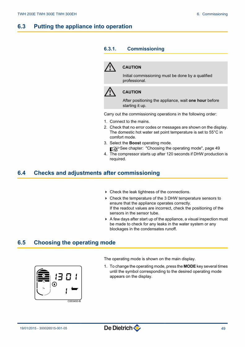
6.5 Choosing the operating mode
The operating mode is shown on the main display.
1. To change the operating mode, press the MODE key several timesuntil the symbol corresponding to the desired operating modeappears on the display.
C003493-B
14
34
12
TWH 200E TWH 300E TWH 300EH 6. Commissioning
19/01/2015 - 300026515-001-05 49

Display Operatingmode
Description
M Automatic orComfort
Comfort programme activatedDomestic hot water production is handled by the heat pump and by electrical back-up if necessary(+ Hydraulic back-up for EH version).If domestic hot water production is not satisfied by the compressor after a modifiable time delay(factory setting: 5 hours - Parameter P23), the back-ups start up.
% Eco Reduced programme activated.Domestic hot water production is handled by the heat pump alone.After the compressor stops, the displayed quantity of domestic hot water available may not becomplete (!).
W Boost Forced operating activatedDomestic hot water production is handled simultaneously by the heat pump and the electrical back-up for a modifiable period (factory setting: 6 hours).
> days Vacation Holiday periodShutting down domestic hot water production.The domestic hot water temperature is kept at 10°C.
6.6 Reading out measured values
6.6.1. Measurements menu
1. Press once the MENU key. The SE nS 1 menu is displayed.2. Press the MODEB key to go to the Measurements menu. The SE
01 menu is displayed.3. Use the ( and ) keys to switch from one measurement to
another.
Parameters Description UnitSE 01 Top DHW temperature sensor °CSE 02 Middle DHW temperature sensor °CSE 03 Bottom DHW temperature sensor °CSE 04 Room sensor °CSE 05 Evaporator temperature sensor °CSE 06 Electricity tariff:
4 HP1: Peak hours4 HC0: Off-peak hours
St Su Operating status / sub-status of the control systemsequence
SP 1 Back-up setpoint °CSP 2 Compressor setpoint °C
6.6.2. Counters
n Displaying the counters
1. Press once the MENU key. The SE nS 1 menu is displayed.
C003206-D1x
2x
3x...
14
34
12
MENUMODE
6. Commissioning TWH 200E TWH 300E TWH 300EH
50 19/01/2015 - 300026515-001-05

2. Press the ) key 3 times. The Co un 4 menu is displayed.3. Press the MODE B key to go to the Counters menu. The number
of the counter is shown to the right of the display.
4. Use the ( and ) keys to switch from one counter to another (Seetable below).
5. To exit this menu, press the MODE B key.6. To go back to the main display, press the MENU button.
Meter Description Unit1 Total electric energy input for DHW production kWh2 Electric energy input by the compressor in the last 24 hours
The counter is reset at 00:00 hours every dayWh
3 Electric energy input by the electrical back-up in the last 24 hoursThe counter is reset at 00:00 hours every day
Wh
4 Number of hours operation of the hydraulic backup h5 Number of hours powered up h6 Instantaneous output W
n Resetting the counters
1. Press once the MENU key. The SE nS 1 menu is displayed.2. Press the ) key 3 times. The Co un 4 menu is displayed.3. Press the MODE B key to go to the Counters menu. The number
of the counter is shown to the right of the display.
4. Use the ( and ) keys to switch from one counter to another.5. Press the V key to reset the meter displayed to zero.
C004186-A
14
34
12
MENUMODE
C003210-C
114
34
12
MENUMODE
C004186-A
14
34
12
MENUMODE
C003210-C
114
34
12
MENUMODE
TWH 200E TWH 300E TWH 300EH 6. Commissioning
19/01/2015 - 300026515-001-05 51

6. Confirm using key MODE B.7. To exit this menu, press the MODE B key.8. To go back to the main display, press the MENU button.
6.7 Modifying the installer parameters
CAUTION
Modification of the factory settings may be detrimental tothe functioning of the appliance.
6.7.1. Access to parameters
To prevent input errors, access to this menu requires the use of theaccess code 012.
1. Press once the MENU key. The SE nS 1 menu is displayed.2. Press the ) key 6 times. The Co dE menu is displayed.
3. Enter the access code 012 using the ( or ) keys.4. Press the MODE B-key for the menu. The parameter P1
displays.
5. Scroll through the parameters using the ( or ) key.6. To modify a parameter, press the MODE B key. The parameter
value flashes.7. Set the desired value using the ( or ) key.8. Confirm using key MODE B.
C004187-B
14
34
12
MENUMODE
C003203-E1x
3
14
34
12
MENUMODE
C004192-A
14
34
12
MENUMODE
C003211-B
14
34
12
MENUMODE
6. Commissioning TWH 200E TWH 300E TWH 300EH
52 19/01/2015 - 300026515-001-05
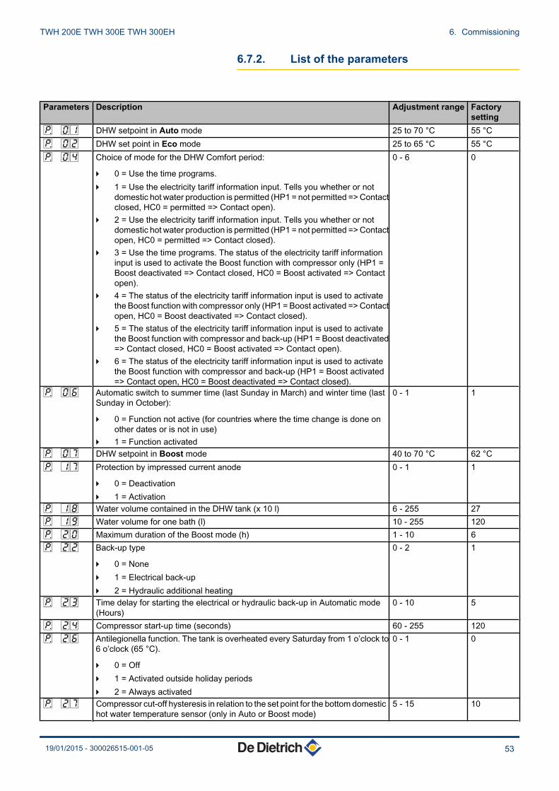
6.7.2. List of the parameters
Parameters Description Adjustment range Factorysetting
P 01 DHW setpoint in Auto mode 25 to 70 °C 55 °CP 02 DHW set point in Eco mode 25 to 65 °C 55 °CP 04 Choice of mode for the DHW Comfort period:
4 0 = Use the time programs.4 1 = Use the electricity tariff information input. Tells you whether or not
domestic hot water production is permitted (HP1 = not permitted => Contactclosed, HC0 = permitted => Contact open).
4 2 = Use the electricity tariff information input. Tells you whether or notdomestic hot water production is permitted (HP1 = not permitted => Contactopen, HC0 = permitted => Contact closed).
4 3 = Use the time programs. The status of the electricity tariff informationinput is used to activate the Boost function with compressor only (HP1 =Boost deactivated => Contact closed, HC0 = Boost activated => Contactopen).
4 4 = The status of the electricity tariff information input is used to activatethe Boost function with compressor only (HP1 = Boost activated => Contactopen, HC0 = Boost deactivated => Contact closed).
4 5 = The status of the electricity tariff information input is used to activatethe Boost function with compressor and back-up (HP1 = Boost deactivated=> Contact closed, HC0 = Boost activated => Contact open).
4 6 = The status of the electricity tariff information input is used to activatethe Boost function with compressor and back-up (HP1 = Boost activated=> Contact open, HC0 = Boost deactivated => Contact closed).
0 - 6 0
P 06 Automatic switch to summer time (last Sunday in March) and winter time (lastSunday in October):
4 0 = Function not active (for countries where the time change is done onother dates or is not in use)
4 1 = Function activated
0 - 1 1
P 07 DHW setpoint in Boost mode 40 to 70 °C 62 °CP 17 Protection by impressed current anode
4 0 = Deactivation4 1 = Activation
0 - 1 1
P 18 Water volume contained in the DHW tank (x 10 l) 6 - 255 27P 19 Water volume for one bath (l) 10 - 255 120P 20 Maximum duration of the Boost mode (h) 1 - 10 6P 22 Back-up type
4 0 = None4 1 = Electrical back-up4 2 = Hydraulic additional heating
0 - 2 1
P 23 Time delay for starting the electrical or hydraulic back-up in Automatic mode(Hours)
0 - 10 5
P 24 Compressor start-up time (seconds) 60 - 255 120P 26 Antilegionella function. The tank is overheated every Saturday from 1 o’clock to
6 o’clock (65 °C).
4 0 = Off4 1 = Activated outside holiday periods4 2 = Always activated
0 - 1 0
P 27 Compressor cut-off hysteresis in relation to the set point for the bottom domestichot water temperature sensor (only in Auto or Boost mode)
5 - 15 10
TWH 200E TWH 300E TWH 300EH 6. Commissioning
19/01/2015 - 300026515-001-05 53
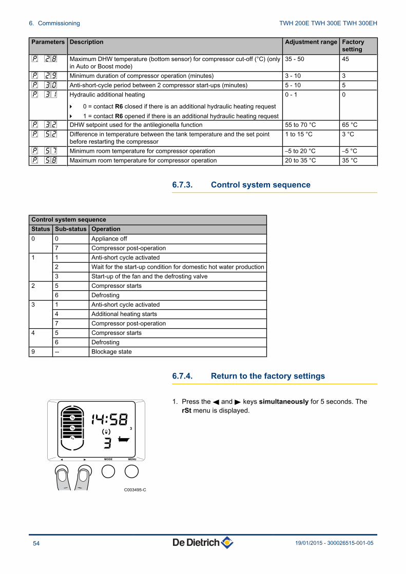
Parameters Description Adjustment range Factorysetting
P 28 Maximum DHW temperature (bottom sensor) for compressor cut-off (°C) (onlyin Auto or Boost mode)
35 - 50 45
P 29 Minimum duration of compressor operation (minutes) 3 - 10 3P 30 Anti-short-cycle period between 2 compressor start-ups (minutes) 5 - 10 5P 31 Hydraulic additional heating
4 0 = contact R6 closed if there is an additional hydraulic heating request4 1 = contact R6 opened if there is an additional hydraulic heating request
0 - 1 0
P 32 DHW setpoint used for the antilegionella function 55 to 70 °C 65 °CP 52 Difference in temperature between the tank temperature and the set point
before restarting the compressor1 to 15 °C 3 °C
P 57 Minimum room temperature for compressor operation –5 to 20 °C –5 °CP 58 Maximum room temperature for compressor operation 20 to 35 °C 35 °C
6.7.3. Control system sequence
Control system sequenceStatus Sub-status Operation0 0 Appliance off
7 Compressor post-operation1 1 Anti-short cycle activated
2 Wait for the start-up condition for domestic hot water production3 Start-up of the fan and the defrosting valve
2 5 Compressor starts6 Defrosting
3 1 Anti-short cycle activated4 Additional heating starts7 Compressor post-operation
4 5 Compressor starts6 Defrosting
9 -- Blockage state
6.7.4. Return to the factory settings
1. Press the ( and ) keys simultaneously for 5 seconds. TherSt menu is displayed.
C003495-C
3
14
34
12
MENUMODE
6. Commissioning TWH 200E TWH 300E TWH 300EH
54 19/01/2015 - 300026515-001-05
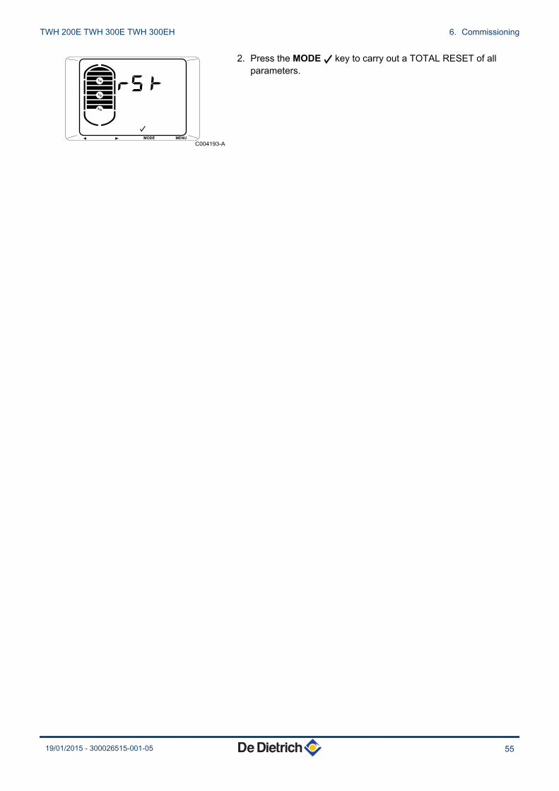
2. Press the MODE B key to carry out a TOTAL RESET of allparameters.
C004193-A
14
34
12
MENUMODE
TWH 200E TWH 300E TWH 300EH 6. Commissioning
19/01/2015 - 300026515-001-05 55

7 Switching off the appliance
7.1 Installation shutdown
CAUTION
Try to avoid switching off the appliance in order to maintainprotection against corrosion. The appliance’s frostprotection continues to be activated.
7.2 Antifreeze protection
In the event of extended absence (holiday), programme thecorresponding number of days. The temperature of the water in thetank is maintained at 10°C.
¼Refer to the user instructions.
7. Switching off the appliance TWH 200E TWH 300E TWH 300EH
56 19/01/2015 - 300026515-001-05

8 Checking and maintenance
8.1 General instructions
CAUTION
Installation and maintenance of the appliance must bedone by a qualified professional in accordance withprevailing statutory texts and codes of practice.
CAUTION
Before working on the appliance, ensure that it is switchedoff and safe.
CAUTION
Check the discharge on the compressor condenser forsingle phase voltages.
CAUTION
Before working on the cooling circuit, switch off theappliance and wait a few minutes. Some equipment suchas the compressor and the pipes can reach temperatureshigher than 100°C and high pressures, which may causeserious burns.
When the appliance is switched off, the fan continues torun by inertia for around one minute.
Maintenance operations are important for the following reasons:
4 To guarantee optimum performance4 To extend the life of the equipment4 To provide an installation which offers the customer optimum
comfort over time.
CAUTION
At no time allow water to get into the controlcomponents. Before starting cleaning, disconnect themains power plug or switch off the appliance.
TWH 200E TWH 300E TWH 300EH 8. Checking and maintenance
19/01/2015 - 300026515-001-05 57
8.2 Maintenance operations to be performed
8.2.1. Refrigerant circuit
No maintenance is required on the refrigerant circuit in thethermodynamic water heater.
8.2.2. Hydraulic circuit
Check the watertightness of the water connections.
8.2.3. Aeraulics
n Cleaning the evaporator
DANGER
Risk of injury on the sharp-edged fins.
CAUTION
Do not distort or damage the fins.
4 Clean the evaporator at regular intervals using a soft-haired brush.4 Carefully realign the fins using a suitable comb if they are bent.
n Cleaning the fan
Check the cleanliness of the fan 1 time per year. Clogging by dustand other particles impairs the heat pump’s performance.
8.2.4. Impressed current anode
No maintenance operations are required on an impressed currentanode.
The appliance’s control panel must be switched on toensure operation of the impressed current anode.
8.2.5. Checking the safety valve or unit
Operate the safety valve or unit at least 1 time per month to checkthat it is running correctly. This check provides forewarning of anyexcess pressure that may damage the DHW tank.
8. Checking and maintenance TWH 200E TWH 300E TWH 300EH
58 19/01/2015 - 300026515-001-05

WARNING
Failure to abide by this maintenance rule may causedamage to the DHW tank and void its warranty.
8.2.6. Descaling
Use a new leak tight seal on the inspection trap.
In hard water regions, we recommend asking the installer to carry outan annual descaling operation on the DHW tank’s exchanger in orderto maintain its performance.
1. Turn off the domestic cold water inlet.2. Drain the DHW tank.3. Open a hot water tap.4. Open the valve on the safety unit.5. Remove the insulation from the inspection hatch.6. Pull out the DHW sensor.7. Remove the inspection trap (13 mm spanner).8. Remove the 2 bulbs from the safety thermostat.9. Remove the limescale deposited in the tank in the form of sludge
or strips. Keep the limescale on the walls of the tank: it provideseffective protection against corrosion and enhances the DHWtank’s insulation.
10.Then replace all the parts in reverse order.
Each time it is opened, the lip gasket must be replaced toguarantee tightness. Place the gasket’s positioning tabtowards the outside of the DHW tank.
11.After each intervention, ensure that the installation is watertight.
The screws retaining the visit trap must be tightened to6 N·m +1/-0. Use a torque wrench.
8.2.7. Cleaning the condensates discharge duct
Check the cleanliness of the condensates discharge pipe. Anobstruction by dust may cause poor condensates flow or even a riskof excessive accumulation of water.
DANGER
Risk of the heat pump malfunctioning.
C003214-F
TWH 200E TWH 300E TWH 300EH 8. Checking and maintenance
19/01/2015 - 300026515-001-05 59

8.3 Accessing the bottom inspection trap
Have a lip gasket and a retainer ring on hand for theinspection hatch.
1. Disconnect the mains supply.2. Drain the DHW tank.3. Open a hot water tap.4. Open the valve on the safety unit.5. Set the appliance to repair position 1.6. Check the extent of scaling in the tank and on the exchanger.
Keep the limescale on the walls of the tank: it provides effectiveprotection against corrosion and enhances the DHW tank’sinsulation.Remove limescale deposits from the bottom of the tank.Remove limescale deposits from the exchanger to guarantee itsperformance.
7. Fit the unit together.
CAUTION
Each time it is opened, the lip gasket + retainer ring unitmust be replaced to guarantee tightness.Place the gasket’s positioning tab towards the outside ofthe DHW tank.
8. After reassembly, check the tightness of the lower flange.
The screws retaining the visit trap must be tightened to6 N·m +1/-0. Use a torque wrench.
85°1
C003190-B
8. Checking and maintenance TWH 200E TWH 300E TWH 300EH
60 19/01/2015 - 300026515-001-05
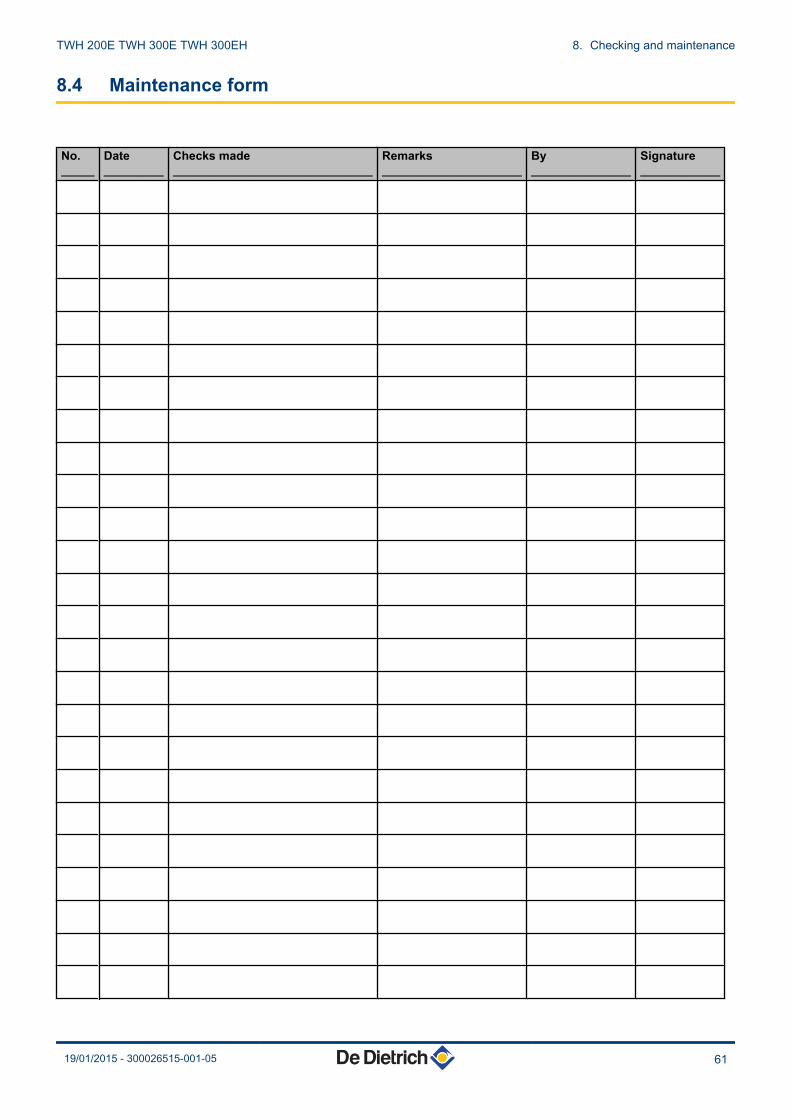
8.4 Maintenance form
No._____
Date_________
Checks made______________________________
Remarks_____________________
By_______________
Signature____________
TWH 200E TWH 300E TWH 300EH 8. Checking and maintenance
19/01/2015 - 300026515-001-05 61

9 Troubleshooting
9.1 Messages (Code type bxx or Exx)
9.1.1. Messages (type code bXX)
In the case of failure, the control panel displays a message and acorresponding code.
1. Make a note of the code displayed.The code is important for the correct and rapid diagnosis of thetype of failure and for any technical assistance that may beneeded.
2. Disconnect and reconnect the mains cable.The appliance will restart only when the malfunction has beencorrected.
3. If the code is displayed again, correct the problem by following theinstructions in the table below:
Code no. Description Checking / solutionB00 Parameter error on the PCU PCB Reset the parametersB01 Pressure switch alarm
Note: DHW production is handled by back-up if back-up enabled
4 Check the power supply to the compressor4 Check the pressure switch connection
B02 Maximum DHW temperature exceededNote: DHW production is not covered (by thecompressor or the back-up)
4 Check the connection on the top DHW sensor4 Check that the back-up is not running permanently
B03 The room temperature is higher than 35°C.The compressor is outside its operatingrange.Note: DHW production is handled by back-up if back-up enabled.
4 Modify the parameters according to the instructions in themanual.
4 The compressor will handle DHW production once the roomtemperature is less than 35°C.
B04 The room temperature is less than -5°C.Note: DHW production is handled by back-up if back-up enabled.
4 Modify the parameters according to the instructions in themanual.
4 The compressor will handle DHW production once the roomtemperature is higher than -5°C.
B25 The bottom DHW temperature sensor isshort circuited
Bad connection
4 Check whether the sensor is connected4 Check the link and the connectors4 Check that the sensor has been correctly fittedSensor fault
4 Check the Ohmic value of the sensor4 Replace the sensor if necessary
9. Troubleshooting TWH 200E TWH 300E TWH 300EH
62 19/01/2015 - 300026515-001-05

Code no. Description Checking / solutionB26 The bottom DHW temperature sensor is
openBad connection
4 Check whether the sensor is connected4 Check the link and the connectors4 Check that the sensor has been correctly fittedSensor fault
4 Check the Ohmic value of the sensor4 Replace the sensor if necessary
B27 The top DHW temperature sensor is shortcircuited
Bad connection
4 Check whether the sensor is connected4 Check the link and the connectors4 Check that the sensor has been correctly fittedSensor fault
4 Check the Ohmic value of the sensor4 Replace the sensor if necessary
B28 The top DHW temperature sensor is open Bad connection
4 Check whether the sensor is connected4 Check the link and the connectors4 Check that the sensor has been correctly fittedSensor fault
4 Check the Ohmic value of the sensor4 Replace the sensor if necessary
B32 The impressed current anode is in opencircuit.
4 Check that the connection cable between the SCU PCB and theanode is not severed
4 Check that the anode is not broken4 Check that the DHW tank is correctly filled with waterRemarks:
4 Domestic hot water production has stopped but cannonetheless be restarted using key V (For 72 hours)
4 Protection against corrosion is not ensuredB33 The impressed current anode is short-
circuited.4 Check that the connection cable between the PCU PCB and the
anode is not short-circuited4 Check that the anode is not short-circuitedRemarks:
4 Domestic hot water production has stopped but cannonetheless be restarted using key V (For 72 hours)
4 Protection against corrosion is not ensuredB40 Measurement error on the domestic hot
water temperature sensors.Remarks:
4 This message is only displayed on initialcommissioning.
4 This message disappears after 10minutes or when you press the B key.
The 3 sensors do not measure the same value
4 Check the location of the sensors.
ErrBuS
No communication between the controlpanel and the PCU board.
4 Check the wiring between the control panel and the PCU board.
InIt12
No communication between the controlpanel and the PCU board.
4 Check the wiring between the control panel and the PCU board.
If the causes of the problem are still present after several attempts atautomatic start-up, the appliance goes into lockdown mode (alsocalled failure).
TWH 200E TWH 300E TWH 300EH 9. Troubleshooting
19/01/2015 - 300026515-001-05 63

¼see chapter: "Messages (type code EXX)", page 64
9.1.2. Messages (type code EXX)
1. The display shows :- The symbol (!)- The symbol V- The fault code (for example E02).
2. After correcting the failure, press the V key for 2 seconds. Ifthe error code continues to display, search for the cause in theerror table and apply the solution.
Code no. Description Checking / solutionE00 The parameter storage unit on the PCU
electronic board is defectiveReplace the PCU PCB
E01 The middle DHW temperature sensor is shortcircuitedNote: DHW production is not covered
Bad connection
4 Check whether the sensor is connected4 Check the link and the connectors4 Check that the sensor has been correctly fittedSensor fault
4 Check the Ohmic value of the sensor4 Replace the sensor if necessary
E02 The middle DHW temperature sensor is openNote: DHW production is not covered
Bad connection
4 Check whether the sensor is connected4 Check the link and the connectors4 Check that the sensor has been correctly fittedSensor fault
4 Check the Ohmic value of the sensor4 Replace the sensor if necessary
E04 The room temperature sensor is short circuitedNote: DHW production is handled by back-up ifback-up enabled
Bad connection
4 Check whether the sensor is connected4 Check the link and the connectors4 Check that the sensor has been correctly fittedSensor fault
4 Check the Ohmic value of the sensor4 Replace the sensor if necessary
E05 The room temperature sensor is openNote: DHW production is handled by back-up ifback-up enabled
Bad connection
4 Check whether the sensor is connected4 Check the link and the connectors4 Check that the sensor has been correctly fittedSensor fault
4 Check the Ohmic value of the sensor4 Replace the sensor if necessary
C003212-B
2"
14
34
12
MENUMODE
9. Troubleshooting TWH 200E TWH 300E TWH 300EH
64 19/01/2015 - 300026515-001-05

Code no. Description Checking / solutionE06 The evaporator temperature sensor is short
circuitedNote: DHW production is handled by back-up ifback-up enabled
Bad connection
4 Check whether the sensor is connected4 Check the link and the connectors4 Check that the sensor has been correctly fittedSensor fault
4 Check the Ohmic value of the sensor4 Replace the sensor if necessary
E07 The evaporator temperature sensor is openNote: DHW production is handled by back-up ifback-up enabled
Bad connection
4 Check whether the sensor is connected4 Check the link and the connectors4 Check that the sensor has been correctly fittedSensor fault
4 Check the Ohmic value of the sensor4 Replace the sensor if necessary
E08 Malfunction on the defrosting functionNote: DHW production is handled by back-up ifback-up enabled
4 Check activation of the defrosting solenoid valve4 Check the position of the temperature sensor in the evaporator4 Check that the fan is working correctly4 Check that the condensates can flow freely
E09 The low pressure pressure switch alarmsounds for more than 120 secondsNote: DHW production is handled by back-up ifback-up enabled
4 Check the position of the temperature sensor in the evaporator4 Check that the fan is working correctly4 Check that the condensates can flow freely
E10 The low pressure pressure switch alarm hasbeen tripped more than 3 times during the last24 hoursNote: DHW production is handled by back-up ifback-up enabled
4 Check the position of the temperature sensor in the evaporator4 Check that the fan is working correctly4 Check that the condensates can flow freely4 Check the refrigerant load
9.2 Message and error history
The Er bL 6 menu is used to consult the last 16 messages and thelast 16 errors displayed by the control panel.
1. Press once the MENU key. The SE nS 1 menu is displayed.2. Press the ) key 5 times. The Er bL 6 menu is displayed.
3. Press the MODE B key to go to this menu.
Accessing the menu Menu Description1x ) Err Error history2x ) bL Blockage history3x ) CLr Reset error and blockage history
C003203-E1x
3
14
34
12
MENUMODE
C004189-A
14
34
12
MENUMODE
TWH 200E TWH 300E TWH 300EH 9. Troubleshooting
19/01/2015 - 300026515-001-05 65

4. The Er r menu is displayed with the number of errors that haveoccurred.
5. To go back to the previous display, press the key MENU.
9.2.1. Err error display
1. When the Err menu is dislayed, press the MODE B key.2. The code EXX for the last error that occurred is displayed as
are its time and date alternately.3. - Press the MODE (B) key to access details of the error.
- Use the ( and ) keys to browse the error list.- Use the MENU key to go back to the error list.
9.2.2. bL blockage display
1. When the bL menu is dislayed, press the MODE B key.2. The code bXX for the last blockage that occurred is displayed
as are its time and date alternately.3. - Press the MODE (B) key to display the details of the error.
- Use the ( and ) keys to scroll through the blockage list.- Use the MENU key to go back to the blockage list.
9.2.3. Reset error and blockage history
1. When the Er bL menu is dislayed, press the MODE B key.2. The error and blockage history are reset.
C004190-A
14
34
12
MENUMODE
C004191-A
14
34
12
MENUMODE
9. Troubleshooting TWH 200E TWH 300E TWH 300EH
66 19/01/2015 - 300026515-001-05

10 Spare parts
10.1 General
When it is observed subsequent to inspection or maintenance workthat a component in the appliance needs to be replaced, use onlyoriginal spare parts or recommended spare parts and equipment.
To order a spare part, give the reference number shownon the list.
10.2 Spare parts
10.2.1. Heat pump
C003489-B
8
29
21
16
24
22
19
13
1
18
5
15
28
14
6
2
3
12
17
11
4
7
10
4
20
23
25
26
27
TWH 200E TWH 300E TWH 300EH 10. Spare parts
19/01/2015 - 300026515-001-05 67

Markers Reference Description1 SFH41000 Base frame2 7606446 Air sensor3 SFH22039 Evaporator sensor4 SFH32178 Electrical harness5 SFH24053 Coil6 SFH40173 Sensor bracket7 SFH31034 Command module8 SFH20050 Compressor10 SFH33170 Earthing connector11 SFH37008 Motorised fan12 SFH31306 Control system board13 SFH23108 Expansion valve14 SFH24052 Solenoid valve15 SFH22234 LP pressure switch16 SFH21038 Filter drier17 SFH40172 Fan bracket18 SFH41001 Control panel bracket19 SFH41002 Air duct20 SFH98172 Foam gasket21 SFH40171 Compressor bracket22 SFH25298 Heat exchanger23 SFH12102 Valve plug24 SFH22056 Tank sensor 0.5 m + Connector25 SFH22057 Tank sensor 1.5 m + Connector26 SFH22058 Tank sensor 2 m + Connector27 200020513 Screw bag Heat pump28 7611992 Wired high pressure (HP) pressure switch29 7610320 Compressor insulation
10. Spare parts TWH 200E TWH 300E TWH 300EH
68 19/01/2015 - 300026515-001-05

10.2.2. DHW tank
C003477-H
17
20
28
29
21
20
15
23
22
25
24
9
10b
12
10a
12
1
4
3
2
56
30
31
18
8
267
31
32
19
11
Markers Reference Description1 7614973 Heating element2 97862390 Housing for heating element3 7607345 Fastening plate4 95363327 Thermostat5 200011080 Connection cable - Black (x3)6 300019070 Connection bridge7 89534902 Earth wire8 300025717 Power supply cable9 95013133 Lip gasket diameter 82 mm10a 200021118 Connection G 3/4" ACI complet
As of serial number 193
TWH 200E TWH 300E TWH 300EH 10. Spare parts
19/01/2015 - 300026515-001-05 69
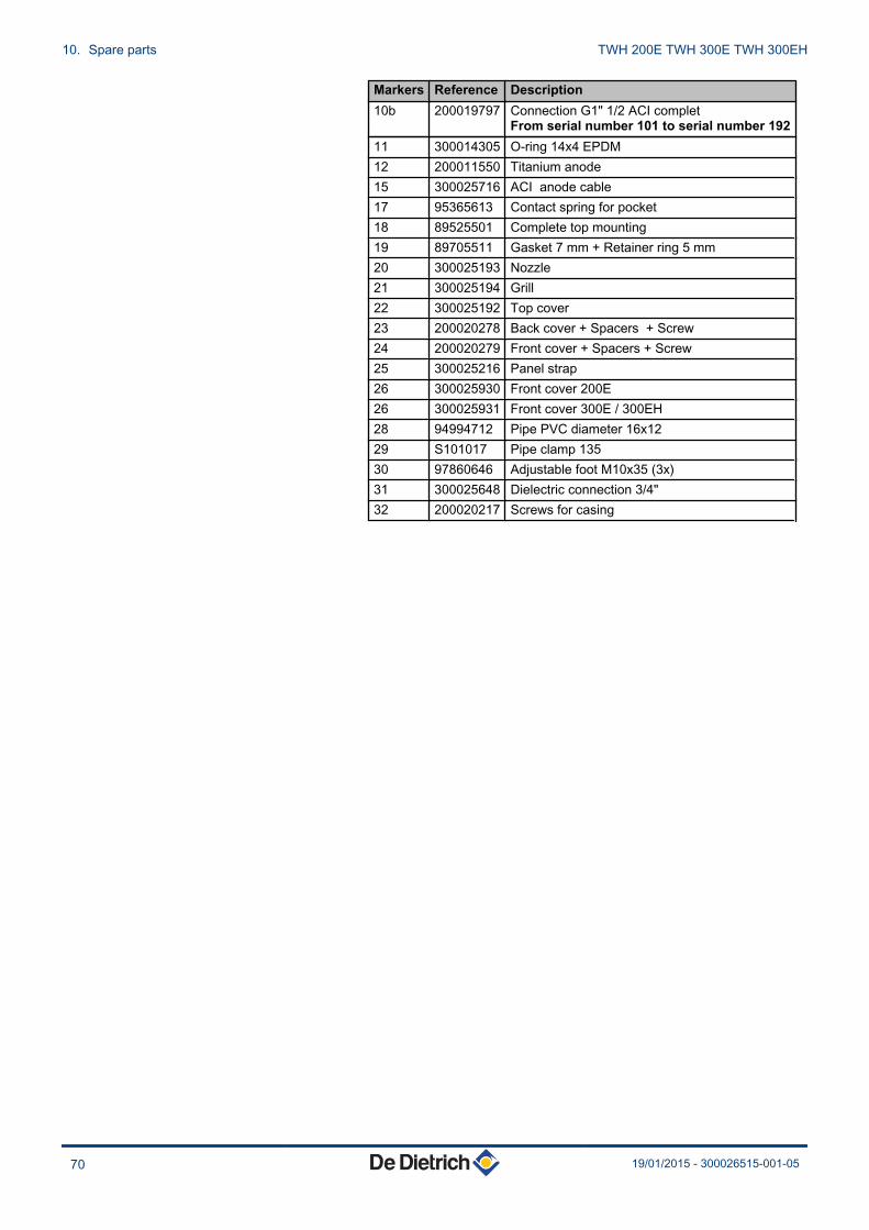
Markers Reference Description10b 200019797 Connection G1" 1/2 ACI complet
From serial number 101 to serial number 19211 300014305 O-ring 14x4 EPDM12 200011550 Titanium anode15 300025716 ACI anode cable17 95365613 Contact spring for pocket18 89525501 Complete top mounting19 89705511 Gasket 7 mm + Retainer ring 5 mm20 300025193 Nozzle21 300025194 Grill22 300025192 Top cover23 200020278 Back cover + Spacers + Screw24 200020279 Front cover + Spacers + Screw25 300025216 Panel strap26 300025930 Front cover 200E26 300025931 Front cover 300E / 300EH28 94994712 Pipe PVC diameter 16x1229 S101017 Pipe clamp 13530 97860646 Adjustable foot M10x35 (3x)31 300025648 Dielectric connection 3/4"32 200020217 Screws for casing
10. Spare parts TWH 200E TWH 300E TWH 300EH
70 19/01/2015 - 300026515-001-05

TWH 200E TWH 300E TWH 300EH 10. Spare parts
19/01/2015 - 300026515-001-05 71

10. Spare parts TWH 200E TWH 300E TWH 300EH
72 19/01/2015 - 300026515-001-05

DUEDI S.r.l.
DE DIETRICH SERVICE
BDR Thermea (Czech republic) s.r.o
www.duediclima.it
www.dedietrich.cz
Distributore Ufficiale EsclusivoDe Dietrich-Thermique Italia
www.dedietrich-heiztechnik.com
Freecall 0800 / 201608
Jeseniova 2770/56130 00 Praha 3
+49 (0)25 72 / 9161-0+49 (0)25 72 / 9161-102
Via Passatore, 12 - 12010San Defendente di CervascaCUNEO
+39 0171 857170+39 0171 [email protected]
+420 271 001 [email protected]
IT
DE DIETRICH THERMIQUE S.A.S
DE DIETRICH THERMIQUE Iberia S.L.U.www.dedietrich-calefaccion.es
C/Salvador Espriu, 1108908 L’HOSPITALET de LLOBREGAT
+34 935 475 [email protected]
ES
129164, Россия, г. МоскваЗубарев переулок, д. 15/1
Бизнес-центр «Чайка Плаза», офис 309
+7 (495) 221-31-51
CZ
AD
001-
AK
© CopyrightAll technical and technological information contained in these technical instructions,as well as any drawings and technical descriptions supplied, remain our propertyand shall not be multiplied without our prior consent in writing.
19/01/2015
300029092-001-05300029092-001-05300029092-001-05300026515-001-05
DE DIETRICH THERMIQUE
57, rue de la Gare F- 67580 MERTZWILLER - BP 30