Tunnel Squeezing Deformation Control and the Use of ... - MDPI
19
Citation: Zheng, X.; Wu, K.; Shao, Z.; Yuan, B.; Zhao, N. Tunnel Squeezing Deformation Control and the Use of Yielding Elements in Shotcrete Linings: A Review. Materials 2022, 15, 391. https://doi.org/10.3390/ ma15010391 Academic Editor: Sukhoon Pyo Received: 1 December 2021 Accepted: 3 January 2022 Published: 5 January 2022 Publisher’s Note: MDPI stays neutral with regard to jurisdictional claims in published maps and institutional affil- iations. Copyright: © 2022 by the authors. Licensee MDPI, Basel, Switzerland. This article is an open access article distributed under the terms and conditions of the Creative Commons Attribution (CC BY) license (https:// creativecommons.org/licenses/by/ 4.0/). materials Review Tunnel Squeezing Deformation Control and the Use of Yielding Elements in Shotcrete Linings: A Review Xiaomeng Zheng 1,2 , Kui Wu 1, *, Zhushan Shao 1 , Bo Yuan 1,2 and Nannan Zhao 1,2 1 School of Civil Engineering, Xi’an University of Architecture and Technology, Xi’an 710055, China; [email protected] (X.Z.); [email protected] (Z.S.); [email protected] (B.Y.); [email protected] (N.Z.) 2 Shaanxi Key Lab. of Geotechnical and Underground Space Engineering (XAUAT), Xi’an University of Architecture and Technology, Xi’an 710055, China * Correspondence: [email protected] Abstract: Shotcrete lining shows high resistance but extremely low deformability. The utilization of yielding elements in shotcrete lining, which leads to the so-called ductile lining, provides a good solution to cope with tunnel squeezing deformations. Although ductile lining exhibits great advan- tages regarding tunnel squeezing deformation control, little information has been comprehensively and systematically available for its mechanism and design. This is a review paper for the purpose of summarizing the development history and discussing the state of the art of ductile lining. It begins by providing a brief introduction of ductile lining and an explanation of the importance of studying this issue. A following summary of supporting mechanism and benefits of ductile lining used in tunnels excavated in squeezing ground conditions is provided. Then, it summarizes the four main types of yielding elements applied in shotcrete lining and introduces their basic structures and mechanical per- formances. The influences of parameters of yielding elements on the supporting effect are discussed and the design methods for ductile lining are reviewed as well. Furthermore, recommendations for further research in ductile lining are proposed. Finally, a brief summary is presented. Keywords: tunnel; squeezing deformation; yielding element; ductile lining performance 1. Introduction Deep excavation in squeezing grounds for tunnel engineers normally implies excessive tunnel convergences [1–7], and these rock deformations usually take slowly, sometimes lasting for one week, several months, or more than one year, after tunnel excavation is completed [8–15]. Conventional rigid tunnel shotcrete linings, where rock deformations are strictly limited, are unable to work against great overburden pressure which is triggered by considerable rock deformations [16,17], and the bad phenomenons of shotcrete falls or cracking, or even serious tunnel collapse are often observed [18,19]. In such a condi- tion, it is almost infeasible to contain deformation energy involved by means of heavier linings [20–22]. In order to avoid shotcrete lining failure in deep excavation through squeezing grounds, the use of yielding elements in shotcrete lining, leading to the so-called “ductile lining”, has gradually gained more attention. In fact, at first tunnel engineers took actions to divide the shotcrete shell into several segments, where longitudinal gaps were left in advance, in order to accept considerable rock deformations without damaging shotcrete. Unfortunately, this practice led to circumferential internal forces in lining segments not being greatly transferred over these reserved gaps, consequently followed by a significant decrease of shotcrete lining resistance [23]. Then, ductile lining replacing the open gaps with yielding elements was proposed with the attention to address the problems of both acceptance of considerable rock deformations and transfer of shotcrete lining internal forces. Yielding elements show a stronger deformability than shotcrete, providing shotcrete lining Materials 2022, 15, 391. https://doi.org/10.3390/ma15010391 https://www.mdpi.com/journal/materials
-
Upload
khangminh22 -
Category
Documents
-
view
7 -
download
0
Transcript of Tunnel Squeezing Deformation Control and the Use of ... - MDPI
�����������������
Citation: Zheng, X.; Wu, K.; Shao, Z.;
Yuan, B.; Zhao, N. Tunnel Squeezing
Deformation Control and the Use of
Yielding Elements in Shotcrete
Linings: A Review. Materials 2022, 15,
391. https://doi.org/10.3390/
ma15010391
Academic Editor: Sukhoon Pyo
Received: 1 December 2021
Accepted: 3 January 2022
Published: 5 January 2022
Publisher’s Note: MDPI stays neutral
with regard to jurisdictional claims in
published maps and institutional affil-
iations.
Copyright: © 2022 by the authors.
Licensee MDPI, Basel, Switzerland.
This article is an open access article
distributed under the terms and
conditions of the Creative Commons
Attribution (CC BY) license (https://
creativecommons.org/licenses/by/
4.0/).
materials
Review
Tunnel Squeezing Deformation Control and the Use of YieldingElements in Shotcrete Linings: A ReviewXiaomeng Zheng 1,2, Kui Wu 1,*, Zhushan Shao 1, Bo Yuan 1,2 and Nannan Zhao 1,2
1 School of Civil Engineering, Xi’an University of Architecture and Technology, Xi’an 710055, China;[email protected] (X.Z.); [email protected] (Z.S.); [email protected] (B.Y.);[email protected] (N.Z.)
2 Shaanxi Key Lab. of Geotechnical and Underground Space Engineering (XAUAT),Xi’an University of Architecture and Technology, Xi’an 710055, China
* Correspondence: [email protected]
Abstract: Shotcrete lining shows high resistance but extremely low deformability. The utilization ofyielding elements in shotcrete lining, which leads to the so-called ductile lining, provides a goodsolution to cope with tunnel squeezing deformations. Although ductile lining exhibits great advan-tages regarding tunnel squeezing deformation control, little information has been comprehensivelyand systematically available for its mechanism and design. This is a review paper for the purpose ofsummarizing the development history and discussing the state of the art of ductile lining. It begins byproviding a brief introduction of ductile lining and an explanation of the importance of studying thisissue. A following summary of supporting mechanism and benefits of ductile lining used in tunnelsexcavated in squeezing ground conditions is provided. Then, it summarizes the four main types ofyielding elements applied in shotcrete lining and introduces their basic structures and mechanical per-formances. The influences of parameters of yielding elements on the supporting effect are discussedand the design methods for ductile lining are reviewed as well. Furthermore, recommendations forfurther research in ductile lining are proposed. Finally, a brief summary is presented.
Keywords: tunnel; squeezing deformation; yielding element; ductile lining performance
1. Introduction
Deep excavation in squeezing grounds for tunnel engineers normally implies excessivetunnel convergences [1–7], and these rock deformations usually take slowly, sometimeslasting for one week, several months, or more than one year, after tunnel excavation iscompleted [8–15]. Conventional rigid tunnel shotcrete linings, where rock deformations arestrictly limited, are unable to work against great overburden pressure which is triggeredby considerable rock deformations [16,17], and the bad phenomenons of shotcrete fallsor cracking, or even serious tunnel collapse are often observed [18,19]. In such a condi-tion, it is almost infeasible to contain deformation energy involved by means of heavierlinings [20–22].
In order to avoid shotcrete lining failure in deep excavation through squeezinggrounds, the use of yielding elements in shotcrete lining, leading to the so-called “ductilelining”, has gradually gained more attention. In fact, at first tunnel engineers took actionsto divide the shotcrete shell into several segments, where longitudinal gaps were left inadvance, in order to accept considerable rock deformations without damaging shotcrete.Unfortunately, this practice led to circumferential internal forces in lining segments notbeing greatly transferred over these reserved gaps, consequently followed by a significantdecrease of shotcrete lining resistance [23]. Then, ductile lining replacing the open gapswith yielding elements was proposed with the attention to address the problems of bothacceptance of considerable rock deformations and transfer of shotcrete lining internal forces.Yielding elements show a stronger deformability than shotcrete, providing shotcrete lining
Materials 2022, 15, 391. https://doi.org/10.3390/ma15010391 https://www.mdpi.com/journal/materials

Materials 2022, 15, 391 2 of 19
with high possible resistance and able to accommodate the controlled rock deformationsthrough their compressible deformations [24–29]. Ductile linings were first applied in theGalgenberg tunnel, Austria, in 1994, where the yielding elements consisted of groups ofaxially loaded steel pipes having some manufactured local weakness, and the large squeez-ing deformations occurring were successfully overcome by using the yielding elements inshotcrete linings [30]. Due to the great advantages of ductile lining in tunnel squeezingdeformation control, many research efforts have been made to continuously develop andimprove high-performance yielding elements over the past two decades [31–35], suchas the glass fiber reinforced plastic element (FFU) [16], telescope yielding element [36],and lining stress controller element [37]. Of course, good applications of these yieldingelements in shotcrete linings have been also achieved in many tunnel cases, for instancein the Tauern tunnel in Austria [38], the Lyon-Torino Base tunnel connecting France andItaly [31,39], and the Yangshan tunnel in China [32,33,40]. In Table 1, a brief summary offamous tunnels throughout the world is provided, where large squeezing deformationswere satisfactorily controlled by applying ductile linings [18,25,30–33,37–43]. In many in-ternational conferences, including World Tunnel Congress [18,27,44–46], International RockMechanics Congress [16,36,47–51], and many other conferences [42,52–55], much attentionhas been paid and hot discussions raised on the topic of design and use of ductile linings insqueezing rock tunnels. In addition, many researchers have also attempted to investigatethe influences of the limited set of design parameters on ductile lining performances orthe interaction between rocks and linings, and presented their results in research articleform [19,23,25,56–65]. The use of yielding elements in shotcrete linings for tunnel squeezingdeformation control at first glance appears as simple work, however in practice it is ratherchallenging because of the time-dependent hardening of shotcrete, non-linear mechani-cal response of yielding elements, and the time and tunnel face-advancement dependentdevelopment of rock deformations. A more serious failure would take place remarkablyif they are employed incorrectly [66,67]. However, up to now, there still has not been asystematic and comprehensive summary on previous research, which is fundamental forfuture research leading to a deeper understanding and better application of ductile linings.
Table 1. Selected tunnels employing ductile linings.
Tunnel Name Country Reference
Galgenberg tunnel Austria [30]Semmering pilot tunnel Austria [41]
Strengen tunnel Austria [42]Tauern tunnel Austria [38]Koralm tunnel Austria [37]
Lyon-Torino Base tunnel Italy [31,39]Ibbenbüren coal mine tunnel Germany [25]
Lötschberg Base tunnel Switzerland [18]Ceneri Base tunnel Switzerland [43]Yangshan tunnel China [32,33,40]
Previous to this work, little information was comprehensively and systematicallyavailable for the mechanism and design of ductile linings in squeezing rock tunnels. Thisis a review paper concentrating on the development history and state of the art of ductilelinings. This review article is arranged in six Sections. After the “Introduction”, thesupporting mechanism and benefits of ductile linings applied in squeezing rock tunnelsare explained in Section 2. Section 3 summarizes four main types of yielding elements(Highly deformable concrete element, Lining stress controller element, Wabe element, andSupport resistance limiting damper) and introduces their basic structures and mechanicalperformances. In Section 4, the influences of parameters of yielding elements on thesupporting effect are discussed and the design methods for ductile lining are reviewed.
Materials 2022, 15, 391 3 of 19
Based on authors’ experience in this research field, recommendations for further researchin ductile lining are proposed in Section 5. Finally, a brief summary is proposed.
2. Supporting Mechanism and Benefits of Ductile Linings
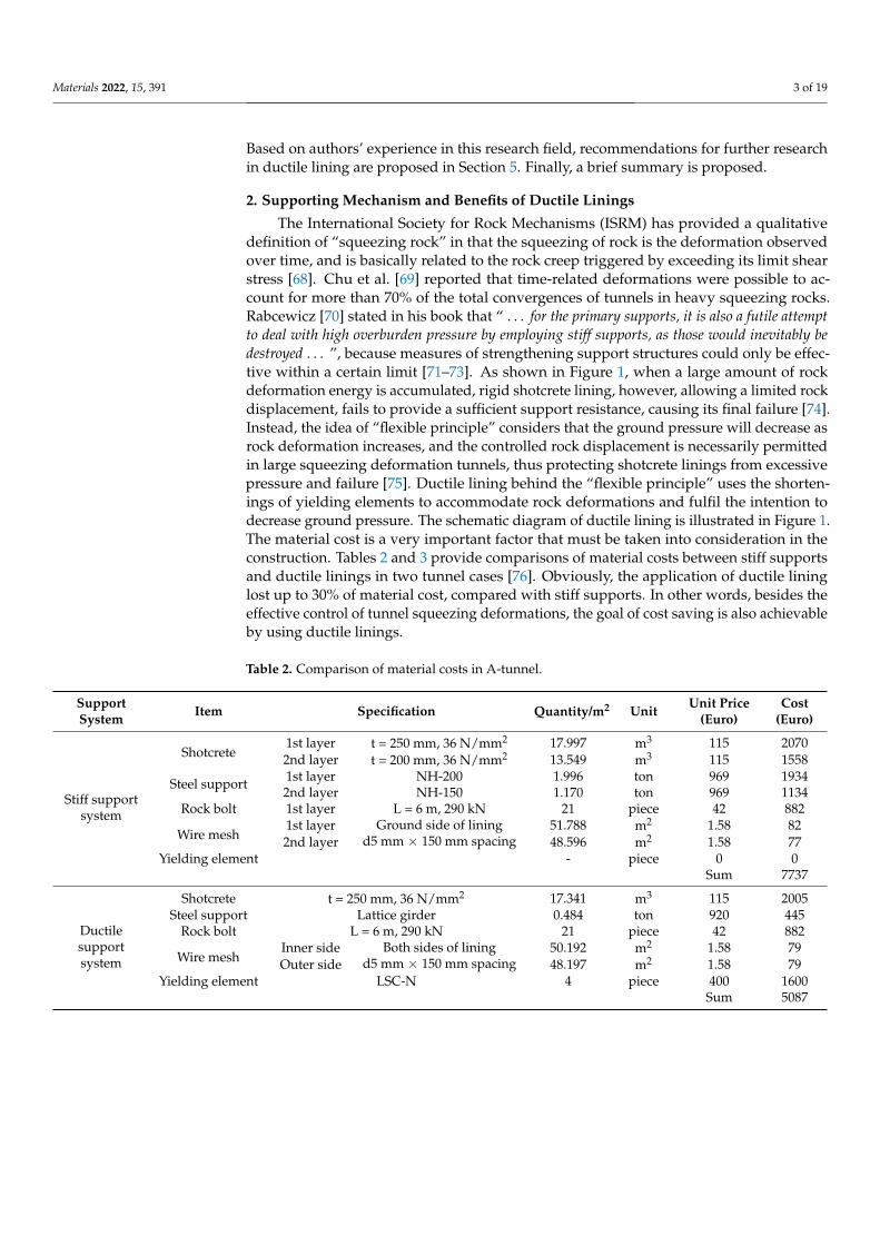
The International Society for Rock Mechanisms (ISRM) has provided a qualitativedefinition of “squeezing rock” in that the squeezing of rock is the deformation observedover time, and is basically related to the rock creep triggered by exceeding its limit shearstress [68]. Chu et al. [69] reported that time-related deformations were possible to ac-count for more than 70% of the total convergences of tunnels in heavy squeezing rocks.Rabcewicz [70] stated in his book that “ . . . for the primary supports, it is also a futile attemptto deal with high overburden pressure by employing stiff supports, as those would inevitably bedestroyed . . . ”, because measures of strengthening support structures could only be effec-tive within a certain limit [71–73]. As shown in Figure 1, when a large amount of rockdeformation energy is accumulated, rigid shotcrete lining, however, allowing a limited rockdisplacement, fails to provide a sufficient support resistance, causing its final failure [74].Instead, the idea of “flexible principle” considers that the ground pressure will decrease asrock deformation increases, and the controlled rock displacement is necessarily permittedin large squeezing deformation tunnels, thus protecting shotcrete linings from excessivepressure and failure [75]. Ductile lining behind the “flexible principle” uses the shorten-ings of yielding elements to accommodate rock deformations and fulfil the intention todecrease ground pressure. The schematic diagram of ductile lining is illustrated in Figure 1.The material cost is a very important factor that must be taken into consideration in theconstruction. Tables 2 and 3 provide comparisons of material costs between stiff supportsand ductile linings in two tunnel cases [76]. Obviously, the application of ductile lininglost up to 30% of material cost, compared with stiff supports. In other words, besides theeffective control of tunnel squeezing deformations, the goal of cost saving is also achievableby using ductile linings.
Table 2. Comparison of material costs in A-tunnel.
SupportSystem Item Specification Quantity/m2 Unit Unit Price
(Euro)Cost
(Euro)
Stiff supportsystem
Shotcrete1st layer t = 250 mm, 36 N/mm2 17.997 m3 115 20702nd layer t = 200 mm, 36 N/mm2 13.549 m3 115 1558
Steel support 1st layer NH-200 1.996 ton 969 19342nd layer NH-150 1.170 ton 969 1134
Rock bolt 1st layer L = 6 m, 290 kN 21 piece 42 882
Wire mesh1st layer Ground side of lining
d5 mm × 150 mm spacing51.788 m2 1.58 82
2nd layer 48.596 m2 1.58 77Yielding element - piece 0 0
Sum 7737
Ductilesupportsystem
Shotcrete t = 250 mm, 36 N/mm2 17.341 m3 115 2005Steel support Lattice girder 0.484 ton 920 445
Rock bolt L = 6 m, 290 kN 21 piece 42 882
Wire meshInner side Both sides of lining
d5 mm × 150 mm spacing50.192 m2 1.58 79
Outer side 48.197 m2 1.58 79Yielding element LSC-N 4 piece 400 1600
Sum 5087

Materials 2022, 15, 391 4 of 19
Table 3. Comparison of material costs in B-tunnel.
SupportSystem Item Specification Quantity/m2 Unit Unit Price
(Euro)Cost
(Euro)
Stiff supportsystem
Shotcrete1st layer t = 250 mm, 36 N/mm2 21.308 m3 115 24502nd layer t = 200 mm, 36 N/mm2 16.555 m3 115 1904
Steel support 1st layer NH-200 2.208 ton 1208 24502nd layer NH-150 1.361 ton 1208 1644
Rock bolt 1st layer L = 6 m, 290 kN 25 piece 42 1050
Wire mesh1st layer Ground side of lining
d5 mm × 150 mm spacing51.309 m2 1.58 81
2nd layer 47.718 m2 1.58 75Yielding element - piece 0 0
Sum 9654
Ductilesupportsystem
Shotcrete t = 250 mm, 36 N/mm2 20.459 m3 115 2353Steel support Lattice girder 0.474 ton 920 436
Rock bolt L = 6 m, 290 kN 25 piece 42 1050
Wire meshInner side Both sides of lining
d5 mm × 150 mm spacing49.314 m2 1.58 78
Outer side 46.920 m2 1.58 74Yielding element LSC-N 6 piece 400 2400
Sum 6391
Figure 1. Comparison of supporting characteristic curves between stiff lining and ductile lining [35].Reproduced with permission from [37].
The general supporting characteristic curve for ductile lining is shown in Figure 1.Clearly, it can be broadly divided into three stages [63]. The first stage should be regardedas the common elastic deformations of both shotcrete and yielding elements after ductilelinings are installed because the internal forces accumulated in the linings does not exceedthe yielding stress of yielding elements during this stage. However, this process does notlast a long time and the element yielding stress will be easily achieved [77]. When theyielding elements yield in the second stage, the internal forces in the lining will not increaseand lining pressure remains practically unchanged. In this stage, the circumferential short-enings of the lining are totally caused by the plastic deformations of yielding elements andthe controlled rock displacement is accepted with a constant support resistance pyield [78].

Materials 2022, 15, 391 5 of 19
This stage is called the yielding stage, which cleverly makes the supporting law of ductilelinings basically fit with the deformation characteristics of squeezing rocks. After the gapsclose, in other words, the ultimate compressive strain of yielding elements is achieved, thedeformation of ductile linings proceeds into the third stage. In the third stage, the defor-mation behavior of ductile linings does not differ from that of conventional rigid linings,using strong resistance only provided by shotcrete to avoid further rock displacements.Finally, an equilibrium in point C, as shown in Figure 1, is obtained between the groundand ductile lining, where the rock displacement is permitted to a considerable level andground pressure is controlled within the bearing capacity of shotcrete linings.
3. Main Types of Yielding Elements
Over the past two decades, a series of yielding elements have been developed andimproved, for instance, the FFU element [16], Meypo, DeCo-grout, Complex [25], andTelescope yielding element [36], in order to make their mechanical performances moresuitable for the deformation behaviors of shotcrete and squeezing grounds. Broadly,according to their manufacturing materials, all yielding elements available can be dividedinto two groups: Porous concrete-based element and steel-based element [37]. A furthersub-classification of steel-based element is also possible, which includes steel pipe-basedelement and steel plate-based element. The applications of both two types of yieldingelements are shown in Figure 2, where the use of porous concrete-based elements canbe seen in Figure 2a,b, steel pipe-based elements can be seen in Figure 2c–e, and steelplate-based elements can be seen in Figure 2f. In this section, the structures and mechanicalproperties of four yielding elements mostly used in squeezing rock tunnels are discussedin detail, including one porous concrete-based element, two steel pipe-based elements, andone steel plate-based element.
Figure 2. Illustration for applications of yielding elements in tunnels; (a,b) porous concrete-based ele-ment; (c–e) steel pipe-based element; and (f) steel plate-based element. Reproduced with permissionfrom [37].

Materials 2022, 15, 391 6 of 19
3.1. Highly Deformable Concrete (Hidcon) Element
Hidcon element, as shown in Figure 2a,b, is usually made of high-strength concretematrix with porous additives [24]. Sometimes, tunnel engineers prefer to call it the “porousconcrete element”. If the Hidcon element is adopted as the yielding element used inshotcrete linings, some other additives are also often used, in order to increase the compres-sive strength and deformability of this element [78]. Taking the Hidcon element used inthe Saint Martin La Porte access adit of the Lyon–Turin Base tunnel as an example, steelfibres and hollow glass particles were applied in the elements [79]. The addition of steelfibres led to a significant improvement of element strength, and the hollow glass particlescontributed to an increase of element controllable compression value, as a result of particlescollapsing at a predefined compressive stress.
Typical stress-strain curves for the Hidcon element employed in the Saint Martin LaPorte access adit are plotted in Figure 3. It is obvious that Hidcon elements present a highinitial stiffness within a small strain range, followed by an almost unchanged resistanceover a great strain range after reaching their yielding stress. The maximum strain ofthe Hidcon element in Figure 3 can even amount to 50%, and its resistance exhibited ahigh increase in the later deformation stage. Another advantage of the Hidcon elementshould be highlighted in that there usually does not exist a sudden brittle failure duringits shortenings. However, tunnel engineers often worry about the damage of progressivehardening shotcrete when using Hidcon elements in shotcrete linings because of their highstiffness in the early deformation stage.
Figure 3. Stress-strain curves for Hidcon elements applied in the Saint Martin La Porte access adit [79].Reproduced with permission from [79].
3.2. Lining Stress Controller Element
As previously mentioned, groups of axially-loaded steel pipes were first appliedas the yielding elements used in shotcrete linings in the Galgenberg tunnel, Austria, in1994 [30]. Considering the low strength of young shotcrete, those pipes featured a row ofholes in order to decrease their initial stiffness. However, this type of yielding elementshowed a quite unstable load-displacement behavior due to the buckling of steel pipes. Toovercome such a problem, tunnel engineers working at the Institute for Rock Mechanics

Materials 2022, 15, 391 7 of 19
and Tunnelling, Graz University of Technology, Austria, attempted to add shorter guidingpipes in length and insert them in those steel pipes, thus optimizing the buckling route ofpipe elements [37], which is the so-called “Lining stress controller” (LSC).
Up to now, a good Lining stress controller consists of axially loaded steel pipes,where additional pipes are simultaneously installed at both ends of the element, alignedconcentrically with the load-bearing pipes [24], as shown in Figure 2d. The development ofload-bearing pipe buckling folds either inwards or outwards is strictly restrained due to thepresence of these additional guiding pipes installed concentrically. Lining stress controllercan take advantage of rationally symmetrical cylinder buckling in this way, making itsload-displacement behavior better match the strength development of shotcrete. Obviously,it is very convenient to adjust the bearing capacity and allowable shortening value of theLSC element by flexibly determining the number and length of steel pipes used in theelement. Figure 4 exhibits the load-displacement curve for a LSC element, where fouryielding steel pipes are contained and two of them are 30 mm shorter in length. It can beseen that a practically linearly increasing load resistance is provided by the LSC elementuntil its shortening value of 80 mm. Subsequently, its load resistance oscillates within astable range of 2050 kN and 2500 kN, triggered by pipe buckling.
Figure 4. Load-displacement curve for a LSC element [37]. Reproduced with permission from [37].
3.3. Wabe Element
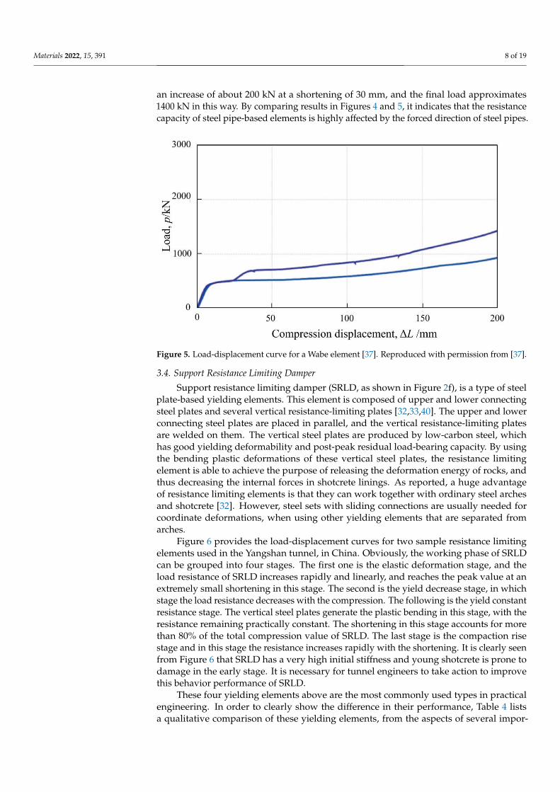
The Wabe element, compared with the LSC element, is composed of a set of trans-versely loaded steel pipes, which are connected with steel plates and finally bonded bytop and bottom plates, as illustrated in Figure 2e. The Wabe element was first proposedand applied in the second tube of the Tauern tunnel [38]. The load-displacement curvefor a Wabe element consisting of three rows of five steel pipes each, is plotted in Figure 5.It clearly shows that there is a remarkable increase of initial load resistance of the Wabeelement during a very small shortening of about 8 mm, but this value in the LSC elementapproximately equals to 80 mm. A load resistance of about 500 kN can be provided after acompression of 10 mm is completed, which remains almost constant in the next few tens ofcentimeters of shortening. The element resistance presents a small increase from about thecompression deformation of 80 mm, and its final value approximately equals to 900 kNwith 200 mm of shortening.
Of course, it is also feasible, like the LSC element, to insert additional steel pipes thathave smaller diameters to increase the load resistance of the Wabe element. It can be easilyfound in Figure 5 that the resistance of the Wabe element (with additional steel pipes) has
Materials 2022, 15, 391 8 of 19
an increase of about 200 kN at a shortening of 30 mm, and the final load approximates1400 kN in this way. By comparing results in Figures 4 and 5, it indicates that the resistancecapacity of steel pipe-based elements is highly affected by the forced direction of steel pipes.
Figure 5. Load-displacement curve for a Wabe element [37]. Reproduced with permission from [37].
3.4. Support Resistance Limiting Damper
Support resistance limiting damper (SRLD, as shown in Figure 2f), is a type of steelplate-based yielding elements. This element is composed of upper and lower connectingsteel plates and several vertical resistance-limiting plates [32,33,40]. The upper and lowerconnecting steel plates are placed in parallel, and the vertical resistance-limiting platesare welded on them. The vertical steel plates are produced by low-carbon steel, whichhas good yielding deformability and post-peak residual load-bearing capacity. By usingthe bending plastic deformations of these vertical steel plates, the resistance limitingelement is able to achieve the purpose of releasing the deformation energy of rocks, andthus decreasing the internal forces in shotcrete linings. As reported, a huge advantageof resistance limiting elements is that they can work together with ordinary steel archesand shotcrete [32]. However, steel sets with sliding connections are usually needed forcoordinate deformations, when using other yielding elements that are separated fromarches.
Figure 6 provides the load-displacement curves for two sample resistance limitingelements used in the Yangshan tunnel, in China. Obviously, the working phase of SRLDcan be grouped into four stages. The first one is the elastic deformation stage, and theload resistance of SRLD increases rapidly and linearly, and reaches the peak value at anextremely small shortening in this stage. The second is the yield decrease stage, in whichstage the load resistance decreases with the compression. The following is the yield constantresistance stage. The vertical steel plates generate the plastic bending in this stage, with theresistance remaining practically constant. The shortening in this stage accounts for morethan 80% of the total compression value of SRLD. The last stage is the compaction risestage and in this stage the resistance increases rapidly with the shortening. It is clearly seenfrom Figure 6 that SRLD has a very high initial stiffness and young shotcrete is prone todamage in the early stage. It is necessary for tunnel engineers to take action to improvethis behavior performance of SRLD.
These four yielding elements above are the most commonly used types in practicalengineering. In order to clearly show the difference in their performance, Table 4 listsa qualitative comparison of these yielding elements, from the aspects of several impor-

Materials 2022, 15, 391 9 of 19
tant factors, including deformability, initial stiffness, yield stress, installation procedure,serviceability, and costs.
Figure 6. Displacement-load curve for the resistance limiting element [32]. Reproduced with permis-sion from [37].
Table 4. Qualitative comparison of four mentioned yielding elements.
Criterion HidCon LSC Wabe SRLD
Deformability Medium High High HighInitial stiffness High Medium Low High
Yield stress Medium High Low LowInstallation procedure Medium Medium Medium Simple
Serviceability Difficult Difficult Difficult DifficultCosts Low Low Medium Low
4. Mechanical Performance for Ductile Linings4.1. Factors Influencing the Performance of Ductile Linings
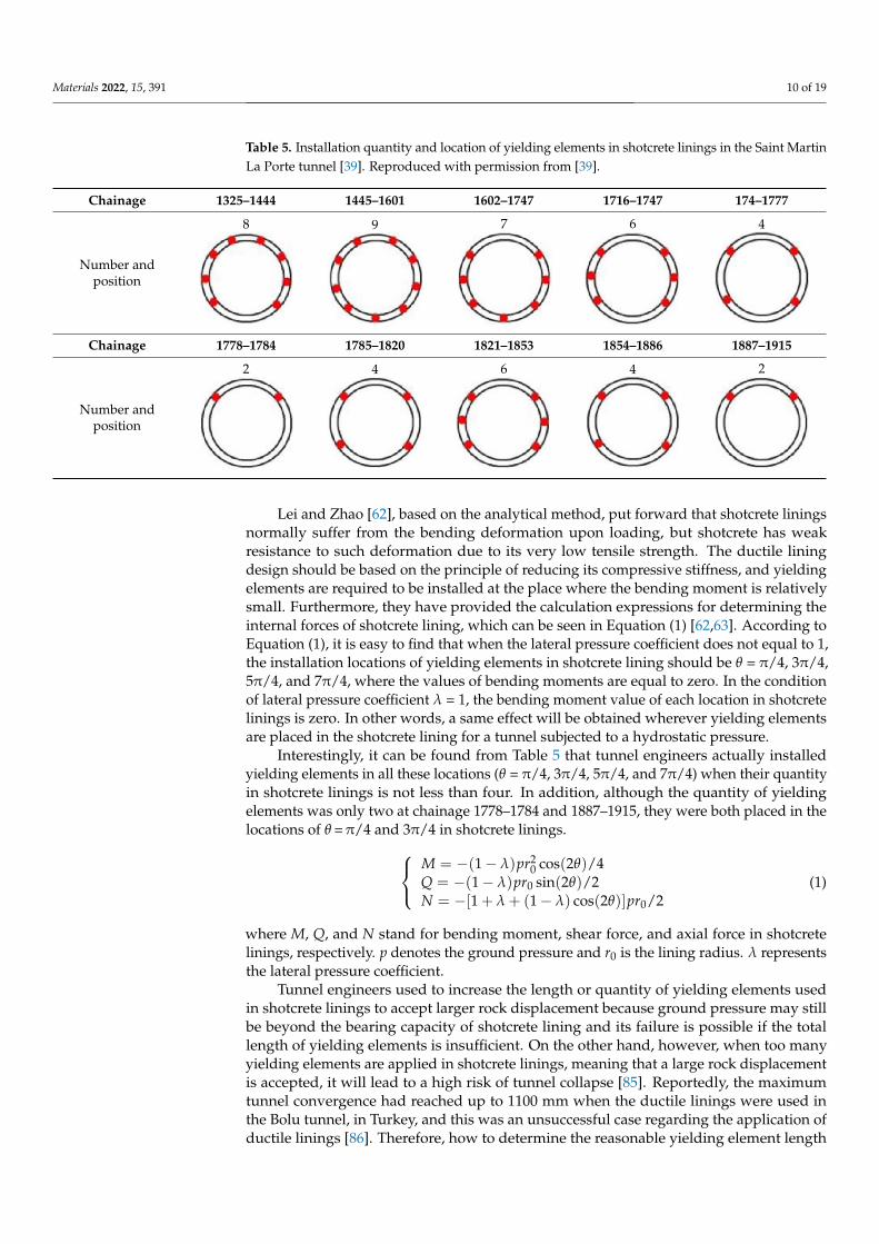
The installation quantity and location of yielding elements in shotcrete linings, report-edly, were changed several times in the Saint Martin La Porte adit, in order to fulfil therequirements of tunnel closure and shotcrete lining bearing capacity [39]. Table 5 providesthese solutions used before in the tunnel. Of course, the performance of ductile lining isabsolutely associated with many other factors, besides the installation quantity and locationof yielding elements. Many researchers have made many efforts on this topic, in orderto achieve a better understanding of the supporting mechanism and better mechanicalbehavior of ductile lining [80–85]. In this section, a summary of factors and how theyinfluence the ductile lining performance is provided in detail.
Materials 2022, 15, 391 10 of 19
Table 5. Installation quantity and location of yielding elements in shotcrete linings in the Saint MartinLa Porte tunnel [39]. Reproduced with permission from [39].
Chainage 1325–1444 1445–1601 1602–1747 1716–1747 174–1777
Number andposition
8 9 7 6 4
Chainage 1778–1784 1785–1820 1821–1853 1854–1886 1887–1915
Number andposition
2 4 6 4 2
Lei and Zhao [62], based on the analytical method, put forward that shotcrete liningsnormally suffer from the bending deformation upon loading, but shotcrete has weakresistance to such deformation due to its very low tensile strength. The ductile liningdesign should be based on the principle of reducing its compressive stiffness, and yieldingelements are required to be installed at the place where the bending moment is relativelysmall. Furthermore, they have provided the calculation expressions for determining theinternal forces of shotcrete lining, which can be seen in Equation (1) [62,63]. According toEquation (1), it is easy to find that when the lateral pressure coefficient does not equal to 1,the installation locations of yielding elements in shotcrete lining should be θ = π/4, 3π/4,5π/4, and 7π/4, where the values of bending moments are equal to zero. In the conditionof lateral pressure coefficient λ = 1, the bending moment value of each location in shotcretelinings is zero. In other words, a same effect will be obtained wherever yielding elementsare placed in the shotcrete lining for a tunnel subjected to a hydrostatic pressure.
Interestingly, it can be found from Table 5 that tunnel engineers actually installedyielding elements in all these locations (θ = π/4, 3π/4, 5π/4, and 7π/4) when their quantityin shotcrete linings is not less than four. In addition, although the quantity of yieldingelements was only two at chainage 1778–1784 and 1887–1915, they were both placed in thelocations of θ =π/4 and 3π/4 in shotcrete linings.
M = −(1 − λ)pr20 cos(2θ)/4
Q = −(1 − λ)pr0 sin(2θ)/2N = −[1 + λ + (1 − λ) cos(2θ)]pr0/2
(1)
where M, Q, and N stand for bending moment, shear force, and axial force in shotcretelinings, respectively. p denotes the ground pressure and r0 is the lining radius. λ representsthe lateral pressure coefficient.
Tunnel engineers used to increase the length or quantity of yielding elements usedin shotcrete linings to accept larger rock displacement because ground pressure may stillbe beyond the bearing capacity of shotcrete lining and its failure is possible if the totallength of yielding elements is insufficient. On the other hand, however, when too manyyielding elements are applied in shotcrete linings, meaning that a large rock displacementis accepted, it will lead to a high risk of tunnel collapse [85]. Reportedly, the maximumtunnel convergence had reached up to 1100 mm when the ductile linings were used inthe Bolu tunnel, in Turkey, and this was an unsuccessful case regarding the application ofductile linings [86]. Therefore, how to determine the reasonable yielding element length
Materials 2022, 15, 391 11 of 19
is the key to the successful application of ductile linings in squeezing rock tunnel. Ourgroup [60,63,87] has analytically investigated the mechanical response of ductile liningsupported tunnels, and provided the theoretical solutions for rock displacement and liningpressure. Based on the analytical results, we further analyzed the influence of yield elementlength on tunnel time-dependent behavior. Our findings showed that there is a linearrelationship between yielding element length and rock displacement (or lining pressure) inlinear viscoelastic geomaterial. Rock displacement increases as element length increaseswhile lining pressure shows an opposite trend. Our conclusion can strongly prove thepoint of view that it is very effective to increase yielding element length to achieve lowerground pressure and thus make it within the bearing capacity of shotcrete lining. However,under such a circumstance, excessive rock deformations possibly leading to tunnel collapseshould also be given sufficient attention. Tian et al. [57,58] performed a series of numericalstudies on ductile linings and suggested that if the total length of yielding element inshotcrete linings is finally determined, it will be better to select an element in shorter length,in order to obtain a more uniform lining stress distribution. However, we [63] consideredthat tunnel engineers must also take the construction convenience into account to finalizethe yielding element length.
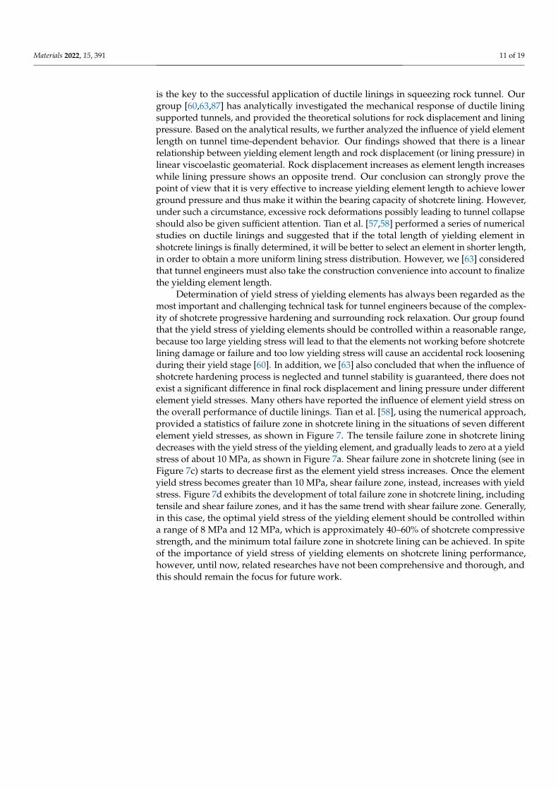
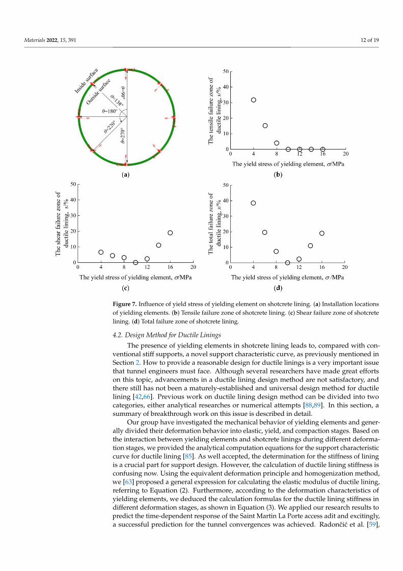
Determination of yield stress of yielding elements has always been regarded as themost important and challenging technical task for tunnel engineers because of the complex-ity of shotcrete progressive hardening and surrounding rock relaxation. Our group foundthat the yield stress of yielding elements should be controlled within a reasonable range,because too large yielding stress will lead to that the elements not working before shotcretelining damage or failure and too low yielding stress will cause an accidental rock looseningduring their yield stage [60]. In addition, we [63] also concluded that when the influence ofshotcrete hardening process is neglected and tunnel stability is guaranteed, there does notexist a significant difference in final rock displacement and lining pressure under differentelement yield stresses. Many others have reported the influence of element yield stress onthe overall performance of ductile linings. Tian et al. [58], using the numerical approach,provided a statistics of failure zone in shotcrete lining in the situations of seven differentelement yield stresses, as shown in Figure 7. The tensile failure zone in shotcrete liningdecreases with the yield stress of the yielding element, and gradually leads to zero at a yieldstress of about 10 MPa, as shown in Figure 7a. Shear failure zone in shotcrete lining (see inFigure 7c) starts to decrease first as the element yield stress increases. Once the elementyield stress becomes greater than 10 MPa, shear failure zone, instead, increases with yieldstress. Figure 7d exhibits the development of total failure zone in shotcrete lining, includingtensile and shear failure zones, and it has the same trend with shear failure zone. Generally,in this case, the optimal yield stress of the yielding element should be controlled withina range of 8 MPa and 12 MPa, which is approximately 40–60% of shotcrete compressivestrength, and the minimum total failure zone in shotcrete lining can be achieved. In spiteof the importance of yield stress of yielding elements on shotcrete lining performance,however, until now, related researches have not been comprehensive and thorough, andthis should remain the focus for future work.
Materials 2022, 15, 391 12 of 19
Figure 7. Influence of yield stress of yielding element on shotcrete lining. (a) Installation locationsof yielding elements. (b) Tensile failure zone of shotcrete lining. (c) Shear failure zone of shotcretelining. (d) Total failure zone of shotcrete lining.
4.2. Design Method for Ductile Linings
The presence of yielding elements in shotcrete lining leads to, compared with con-ventional stiff supports, a novel support characteristic curve, as previously mentioned inSection 2. How to provide a reasonable design for ductile linings is a very important issuethat tunnel engineers must face. Although several researchers have made great effortson this topic, advancements in a ductile lining design method are not satisfactory, andthere still has not been a maturely-established and universal design method for ductilelining [42,66]. Previous work on ductile lining design method can be divided into twocategories, either analytical researches or numerical attempts [88,89]. In this section, asummary of breakthrough work on this issue is described in detail.
Our group have investigated the mechanical behavior of yielding elements and gener-ally divided their deformation behavior into elastic, yield, and compaction stages. Based onthe interaction between yielding elements and shotcrete linings during different deforma-tion stages, we provided the analytical computation equations for the support characteristiccurve for ductile lining [85]. As well accepted, the determination for the stiffness of liningis a crucial part for support design. However, the calculation of ductile lining stiffness isconfusing now. Using the equivalent deformation principle and homogenization method,we [63] proposed a general expression for calculating the elastic modulus of ductile lining,referring to Equation (2). Furthermore, according to the deformation characteristics ofyielding elements, we deduced the calculation formulas for the ductile lining stiffness indifferent deformation stages, as shown in Equation (3). We applied our research results topredict the time-dependent response of the Saint Martin La Porte access adit and excitingly,a successful prediction for the tunnel convergences was achieved. Radoncic et al. [59],

Materials 2022, 15, 391 13 of 19
based on the convergence-confinement method, summarized the design procedure ofductile linings as six steps: 1. Determination of the equilibrium point; 2. calculation ofrock displacement; 3. plotting the time-advance chart; 4. plotting the maximum supportresistance curve; 5. assigning the shotcrete capacity; and 6. examination of the ductilelining stiffness. The detailed calculation process can be seen in his literature [59].
E∗ =E1E2∑i=n
i=1 (l1i + l2i)
E1∑i=ni=1 l2i + E2∑i=n
i=1 l1i(2)
where E* denotes the elastic modulus of homogenized ductile lining, and E1 and E2represent the elastic moduli of shotcrete and yielding element material, respectively. l1i andl2i stand for the segmental shotcrete lining and yielding element lengths, respectively.
K(j)s =
E∗
(1+ν1)· r2
0−(r0−ds)2
(1−2ν1)r20+(r0−ds)
2 (j = 1)
0 (j = 2)E1
(1+ν1)· r2
0−(r0−ds)2
(1−2ν1)r20+(r0−ds)
2 (j = 3)
(3)
in which Ks is the homogenized ductile lining stiffness, and ν1 denotes shotcrete Poisson’sratio. ds stands for ductile lining thickness. Based on the lining stiffness, the relationshipbetween lining pressure (p) and tunnel displacement (u) can be written as:
p = Ksur0
. (4)
If the role of steel arches in ductile linings is considered [90], the composite ductilelining stiffness can be provided in Equation (5).
Ktot = K(j)s + K(j)
sa (5)
where Ktot represents the total stiffness of composite ductile lining, and Ksa stands for steelarch stiffness. Herein, it should be noted that in case of the steel arch having function ofcoordinate deformation with ductile lining, its stiffness in the second stage is K(2)
sa = 0.Ramoni and Anagnostou [56] attempted to use a numerical method to provide some
supporting characteristic curves for several different types of tunnel linings, as shown inFigure 8. The numerical study is conducted in a tunnel subjected to a hydrostatic pressure,therefore, the lining pressure p and tunnel displacement (the radial displacement of innercontour of lining) u in Figure 8 keep the same in each direction. Table 6 lists the detailedcomponents of these linings. Under the same geological conditions, results in Figure 8 wellvalidate the supporting effect of ductile linings is significantly influenced by those factors,as mentioned previously. Based on the analytical computation equations for support char-acteristic curve for ductile lining, our group has successfully reproduced one of the curvesin Figure 8 [85]. Of course, tunnel engineers can now easily, by using advanced computertechnologies, obtain the estimation of tunnel performance in situations of different ductilelining designs. However, the premise is that there should be a preliminary design guidance,in turn providing reliable verification of the numerical design method.

Materials 2022, 15, 391 14 of 19
Figure 8. Characteristic curves for different types of tunnel linings [56]. Reproduced with permissionfrom [56].
Table 6. Tunnel support system [56]. Reproduced with permission from [56].
SupportSystem
ShotcreteThickness
d1/cmArch Type
Yielding ElementsMaterial Length d2/cm IllustrationNumber × Yielding
Deformation/cm
Rigid support - - - - -
RS15 15 TH36 - - -
RS25 25 TH36 - - -
Ductile lining - - - - -YS15/S5 15 TH36 4 × 5.0 Styrofoam 5YS15/C5 15 TH36 4 × 2.5 Concrete 5
YS15/C15 15 TH36 4 × 7.5 Concrete 15YS25/C15 25 TH36 4 × 7.5 Concrete 15
5. Challenges and Directions for Future Research
Ductile linings have huge advantages in the tunnel squeezing deformation control.The use of yielding elements in shotcrete linings is a very challenging task because thesupporting effects are influenced by many factors, and a more serious failure would happenif they are wrongly designed and applied. Up to now, although many researchers havecarefully investigated ductile linings by various approaches, there still has not been amaturely-established design method for them. This greatly limits the popularization andapplication of ductile linings in squeezing rock tunnels. Many further researches arestill needed for transferring and extending ductile lining beneficial effects into practicalapplications. Based on the authors’ experience in this research field, we summarize thegeneral recommendations in following three points (1)–(3), and outline the specific researchsuggestions in (4)–(7).
1. Development of higher performance yielding elements, making them harmoniouslywork with progressive hardening shotcrete;

Materials 2022, 15, 391 15 of 19
2. Establishment of rock quality evaluation system, making it quick and easy to judgethe applicability of ductile linings in such grounds;
3. Development of universal ductile lining design method, leading to its wider applica-tions in squeezing rock tunnels;
4. How to determine the interface interaction between rock and ductile lining, especiallyin the situation of anisotropic ground stress;
5. How to accurately predict the tunnel convergence with ductile lining parametersselected, so as to tunnel over-excavation in advance;
6. How to qualitatively determine the influence of ductile lining parameters on itsperformance, such as shotcrete hardening, yielding element installation location, andyield stress;
7. How to repair ductile linings during construction or service, with unexpected failureoccurring.
6. Conclusions
Ductile linings show great advantages in tunnel squeezing deformation control. How-ever, previous to this work, little information has been comprehensively and systematicallyavailable for its mechanism and design. This review paper discusses the developmenthistory and the state of the art of ductile linings. Findings in this study are summarized inthe following points.
The use of yielding elements in shotcrete lining, leading to the so-called “ductilelining” is for the purpose of accepting considerable rock deformations and better use ofshotcrete high resistance without damage. The deformation process of ductile lining can begenerally divided into three stages. When the yielding elements yield, the circumferentialshortenings of the lining are totally caused by the plastic deformations of yielding elementsand the internal forces in the lining will not increase, keeping the lining pressure practicallyunchanged. The rock displacement is mainly released in this stage. All yielding elementscan be, based on their manufacturing materials, broadly divided into two groups: Porousconcrete-based element and steel-based element. Structures and mechanical performancesof the four most commonly used yielding elements, HidCon, LSC, Wabe, and SRLD, areintroduced, and a qualitative comparison between these four elements are provided fromsix aspects. The strength and initial stiffness are the most important parameters for yieldingelements that an engineer should pay sufficient attention to.
Shotcrete linings usually suffer from bending deformation, but shotcrete has weakresistance due to its very low tensile strength. When the lateral pressure coefficient doesnot equal to 1, the optimal installation locations of yielding elements in shotcrete liningsshould be θ =π/4, 3π/4, 5π/4, and 7π/4, where bending moment values equal to zero.Rock displacement increases as yielding element length increases while lining pressureshows an opposite trend. The yield stress of yielding elements has a great influence onshotcrete failure and the yield stress of yielding elements is required to be controlled withina reasonable range, which should not be too large or too small. How to provide a reasonabledesign for ductile linings is still a crucial task for tunnel engineers. Previous work on ductilelining design methods can be divided into analytical studies or numerical attempts. Finally,some important recommendations for further research are outlined.
Author Contributions: Conceptualization, K.W.; methodology, X.Z. and K.W.; software, B.Y. andN.Z.; validation, X.Z.; formal analysis, X.Z.; investigation, B.Y. and N.Z.; resources, K.W.; datacuration, B.Y.; writing—original draft preparation, X.Z. and K.W.; writing—review and editing,K.W.; visualization, N.Z.; supervision, Z.S.; project administration, Z.S.; funding acquisition, Z.S. Allauthors have read and agreed to the published version of the manuscript.
Funding: This research was funded by [National Natural Science Foundation of China] grant number[11872287], and [Foundation of Shaanxi Key Research and Development Program] grant number[2019ZDLGY07-10].
Institutional Review Board Statement: Not applicable.
Materials 2022, 15, 391 16 of 19
Informed Consent Statement: Not applicable.
Data Availability Statement: Not applicable.
Conflicts of Interest: The authors have declared that there are no competing interests in their work.
References1. Tran-Manh, H.; Sulem, J.; Subrin, D. Progressive degradation of rock properties and time-dependent behavior of deep tunnels.
Acta Geotech. 2016, 11, 693–711. [CrossRef]2. Vrakas, A.; Anagnostou, G. Ground Response to Tunnel Re-profiling Under Heavily Squeezing Conditions. Rock Mech. Rock Eng.
2016, 49, 2753–2762. [CrossRef]3. Wu, K.; Shao, Z.; Qin, S.; Li, B. Determination of Deformation Mechanism and Countermeasures in Silty Clay Tunnel. J. Perform.
Constr. Facil. 2020, 34, 04019095. [CrossRef]4. Iasiello, C.; Torralbo, J.C.G.; Fernández, C.T. Large deformations in deep tunnels excavated in weak rocks: Study on Y-Basque
high-speed railway tunnels in northern Spain. Undergr. Space 2021, 6, 636–649. [CrossRef]5. Xu, C.; Xia, C. A new large strain approach for predicting tunnel deformation in strain-softening rock mass based on the
generalized Zhang-Zhu strength criterion. Int. J. Rock Mech. Min. Sci. 2021, 143, 104786. [CrossRef]6. Chu, Z.; Wu, Z.; Liu, Q.; Liu, B.; Sun, J. Analytical Solution for Lined Circular Tunnels in Deep Viscoelastic Burgers Rock
Considering the Longitudinal Discontinuous Excavation and Sequential Installation of Liners. J. Eng. Mech. 2021, 147, 04021009.[CrossRef]
7. Nistor, M.M.; Rahardjo, H.; Satyanaga, A.; Hao, K.Z.; Xiaosheng, Q.; Sham, A.W.L. Investigation of groundwater table distributionusing borehole piezometer data interpolation: Case study of Singapore. Eng. Geol. 2020, 271, 105590. [CrossRef]
8. Kontogianni, V.; Psimoulis, P.; Stiros, S. What is the contribution of time-dependent deformation in tunnel convergence? Eng.Geol. 2006, 82, 264–267. [CrossRef]
9. Paraskevopoulou, C.; Diederichs, M. Analysis of time-dependent deformation in tunnels using the Convergence-ConfinementMethod. Tunn. Undergr. Space Technol. 2018, 71, 62–80. [CrossRef]
10. Zhang, C.; Cui, G.; Zhang, Y.; Zhou, H.; Liu, N.; Huang, S. Squeezing deformation control during bench excavation for the Jinpingdeep soft-rock tunnel. Eng. Fail. Anal. 2020, 116, 104761. [CrossRef]
11. Wu, K.; Shao, Z.; Qin, S.; Zhao, N.; Chu, Z. An Improved Nonlinear Creep Model for Rock Applied to Tunnel DisplacementPrediction. Int. J. Appl. Mech. 2021, 13, 2150094. [CrossRef]
12. Arora, K.; Gutierrez, M.; Hedayat, A.; Cruz, E.C. Time-Dependent Behavior of the Tunnels in Squeezing Ground: An ExperimentalStudy. Rock Mech. Rock Eng. 2021, 54, 1755–1777. [CrossRef]
13. Chu, Z.; Wu, Z.; Wang, Z.; Weng, L.; Liu, Q.; Fan, L. Micro-mechanism of brittle creep in saturated sandstone and its mechanicalbehavior after creep damage. Int. J. Rock Mech. Min. Sci. 2021, 149, 104994. [CrossRef]
14. Hu, B.; Sharifzadeh, M.; Feng, X.-T.; Guo, W.; Talebi, R. Role of stress, slenderness and foliation on large anisotropic deformationsat deep underground excavations. Int. J. Min. Sci. Technol. 2021, 31, 577–590. [CrossRef]
15. Zhao, N.; Shao, Z.; Wu, K.; Chu, Z.; Qin, S. Time-Dependent Solutions for Lined Circular Tunnels Considering RockboltsReinforcement and Face Advancement Effects. Int. J. Géoméch. 2021, 21, 04021179. [CrossRef]
16. Kurokawa, S.; Masumoto, K.; Koizumi, Y.; Okada, Y.; Utsuno, M. Evaluation of deformable support in squeezing ground byexperiment and numerical analysis. In Proceedings of the 5th ISRM Young Scholars’ Symposium on Rock Mechanics andInternational Symposium on Rock Engineering for Innovative Future, Okinawa, Japan, 1–4 December 2019.
17. Wu, K.; Shao, Z.; Sharifzadeh, M.; Chu, Z.; Qin, S. Analytical Approach to Estimating the Influence of Shotcrete HardeningProperty on Tunnel Response. J. Eng. Mech. 2022, 148, 04021127. [CrossRef]
18. Kovári, K. Design methods with yielding support in squeezing and swelling rocks. In Proceedings of the World Tunnel Congress,Budapest, Hungary, 23–28 May 2009.
19. Schubert, W. Dealing with squeezing conditions in Alpine tunnels. Rock Mech. Rock Eng. 1996, 29, 145–153. [CrossRef]20. Ortlepp, W.; Stacey, T. Performance of tunnel support under large deformation static and dynamic loading. Tunn. Undergr. Space
Technol. 1998, 13, 15–21. [CrossRef]21. Öge, I.F. Revisiting the assessment of squeezing condition and energy absorption of flexible supports: A mine development case.
Tunn. Undergr. Space Technol. 2021, 108, 103712. [CrossRef]22. Wu, K.; Shao, Z. Study on the Effect of Flexible Layer on Support Structures of Tunnel Excavated in Viscoelastic Rocks. J. Eng.
Mech. 2019, 145, 04019077. [CrossRef]23. Lackner, R.; Macht, J.; Hellmich, C.; Mang, H.A. Hybrid Method for Analysis of Segmented Shotcrete Tunnel Linings. J. Geotech.
Geoenvironmental Eng. 2002, 128, 298–308. [CrossRef]24. Radoncic, N.; Schubert, W.; Moritz, B. Ductile support design. Géoméch. Und Tunn. 2009, 2, 561–577. [CrossRef]25. Mezger, F.; Ramoni, M.; Anagnostou, G. Options for deformable segmental lining systems for tunnelling in squeezing rock. Tunn.
Undergr. Space Technol. 2018, 76, 64–75. [CrossRef]26. Wu, K.; Shao, Z.; Qin, S.; Zhao, N. Mechanical analysis of tunnels supported by yieldable steel ribs in rheological rocks. Geomech.
Eng. 2019, 19, 61–70. [CrossRef]

Materials 2022, 15, 391 17 of 19
27. Hammer, A.L.; Thewes, M. Integration of yielding elements in various computational methods for calculations in differentplanning and construction phases. In Proceedings of the ITA-AITES World Tunnel Congress, Dubai, United Arab Emirates, 21–26April 2018.
28. Ghorbani, M.; Shahriar, K.; Sharifzadeh, M.; Masoudi, R. A critical review on the developments of rock support systems in highstress ground conditions. Int. J. Min. Sci. Technol. 2020, 30, 555–572. [CrossRef]
29. Fan, S.; Song, Z.; Xu, T.; Wang, K.; Zhang, Y. Tunnel deformation and stress response under the bilateral foundation pitconstruction: A case study. Arch. Civ. Mech. Eng. 2021, 21, 109. [CrossRef]
30. Schubert, W.; Brunnegger, S.; Staudacher, R.; Wenger, J. Further development of yielding elements and connecting elements forshotcrete. Géoméch. Und Tunn. 2018, 11, 575–581. [CrossRef]
31. Barla, G.; Bonini, M.; Semeraro, M. Analysis of the behaviour of a yield-control support system in squeezing rock. Tunn. Undergr.Space Technol. 2011, 26, 146–154. [CrossRef]
32. Qiu, W.; Wang, G.; Gong, L.; Shen, Z.; Li, C.; Dang, J. Research and application of resistance-limiting and energy-dissipatingsupport in large deformation tunnel. Chin. J. Rock Mech. Eng. 2018, 37, 1785–1795. [CrossRef]
33. Deng, Y.; Xie, J.; Li, S. Research and Application of Support Resistant Limiting Dampers in the Deep-Buried Large-Section LoessTunnel. Adv. Civ. Eng. 2020, 2020, 8841703. [CrossRef]
34. Entfellner, M.; Hamdi, P.; Wang, X.; Wannenmacher, H.; Amann, F. Temporary Removal: Investigating High-Strength ExpandedPolystyrene (HS-EPS) as yielding support elements for tunnelling in squeezing ground conditions. Tunn. Undergr. Space Technol.2021, 118, 104186. [CrossRef]
35. Wu, K.; Shao, Z.; Qin, S.; Wei, W.; Chu, Z. A critical review on the performance of yielding supports in squeezing tunnels. Tunn.Undergr. Space Technol. 2021, 115, 103815. [CrossRef]
36. Verient, M.; Kluckner, A.; Radoncic, N.; Schubert, W. Investigations on telescope yielding elements with porous filling. InProceedings of the ISRM Regional Symposium-EUROCK, Salzburg, Austria, 7–10 October 2015.
37. Moritz, B. Yielding elements—Requirements, overview and comparison/Stauchelemente—Anforderungen, Überblick undVergleich. Géoméch. Und Tunn. 2011, 4, 221–236. [CrossRef]
38. Weidinger, F.; Lauffer, H. The Tauern tunnel first and second tubes from the contractor’s viewpoint. Géoméch. Und Tunn. 2009, 2,24–32. [CrossRef]
39. Bonini, M.; Barla, G. The Saint Martin La Porte access adit (Lyon–Turin Base Tunnel) revisited. Tunn. Undergr. Space Technol. 2012,30, 38–54. [CrossRef]
40. Li, C.; Wang, G.; Qiu, W.; Gong, L.; Zhao, Y.; Wang, Q. Research and application of support resistant limiting dampers in thetunnel with high horizontal geostress. Mod. Tunn. Tech. 2020, 57, 15–24. [CrossRef]
41. Moritz, B. Ductile Support System for Tunnels in Squeezing Rock. Ph.D. Thesis, Graz University of Technology, Graz, Austria,1999.
42. Kolymbas, D. Stress and deformation fields around a deep circular tunnel. In Tunnelling and Tunnel Mechanics: A Rational Approachto Tunnelling; Springer: Berlin/Heidelberg, Germany, 2005; pp. 273–306.
43. Merlini, D.; Stocker, D.; Falanesca, M.; Schuerch, R. The Ceneri Base Tunnel: Construction Experience with the Southern Portionof the Flat Railway Line Crossing the Swiss Alps. Engineering 2018, 4, 235–248. [CrossRef]
44. Bhavsar, H.; Dinis, A.; Fernandes, E.M.; Antunes, P.; Melâneo, F. Design and construction of tunnels in zones subjected to highconvergences. In Proceedings of the World Tunnel Congress, São Paulo, Brazil, 9–14 May 2014.
45. Schubert, W.; Brunnegger, S. New ductile tunnel lining system. In Proceedings of the World Tunnel Congress, Bergen, Norway,9–15 June 2017.
46. Hasanpour, R.; Hammer, A.L.; Thewes, M. Analysis of multilateral interaction between shotcrete, yielding support and squeezingground by means of two different numerical methods. In Proceedings of the ITA-AITES World Tunnel Congress, Dubai, UnitedArab Emirates, 21–25 April 2018.
47. Button, E.A.; Schubert, W.; Moritz, B. The application of ductile support methods in Alpine tunnels. In Proceedings of the 10thISRM Congress, Sandton, South Africa, 8–12 September 2003.
48. Anagnostou, G.; Cantieni, L. Design and analysis of yielding support in squeezing ground. In Proceedings of the 11th ISRMCongress, Lisbon, Portugal, 9–13 July 2007.
49. Radoncic, N.; Schubert, W. Calculation of the shotcrete utilization for lining with integrated yielding elements. In Proceedings ofthe ISRM International Symposium on Rock Mechanics-SINOROCK 2009, Hong Kong, China, 1922 May 2009.
50. Radoncic, N.; Schubert, W. System behaviour in weak ground: Comparison of yielding elements. In Proceedings of the 12thISRM Congress, Beijing, China, 16–21 October 2011.
51. Li, C.C. Development trend of underground rock support. In Proceedings of the 13th ISRM Congress, Montreal, QC, Canada,10–13 May 2015.
52. Thut, A.; Naterop, D.; Steiner, P.; Stolz, M. Tunnelling in squeezing rock-yielding elements and face control. In Proceedings of the8th International Symposium on Tunnel Construction and Underground Structures, Lubljana, Slovenia, 15–30 October 2006.
53. Schubert, W. Design of ductile tunnel linings. In Proceedings of the 42nd US Rock Mechanics Symposium (USRMS), San Francisco,CA, USA, 29 June–2 July 2008.
Materials 2022, 15, 391 18 of 19
54. Hammer, A.L.; Hasanpour, R.; Hoffmann, C.; Thewes, M. Numerical analysis of interaction behavior of yielding supports insqueezing ground. In Proceedings of the 9th European Conference on Numerical Methods in Geotechnical Engineering, Porto,Portugal, 25–27 June 2018.
55. Schubert, W.; Radoncic, N. Tunnelling in “Squeezing” ground conditions-problems and solutions. In Proceedings of the 13thISRM International Congress of Rock Mechanics, Montreal, QC, Canada, 10–13 May 2015.
56. Ramoni, M.; Anagnostou, G. The Interaction Between Shield, Ground and Tunnel Support in TBM Tunnelling Through SqueezingGround. Rock Mech. Rock Eng. 2010, 44, 37–61. [CrossRef]
57. Tian, H.; Chen, W.; Yang, D.; Wu, G.; Tan, X. Numerical analysis on the interaction of shotcrete liner with rock for yieldingsupports. Tunn. Undergr. Space Technol. 2016, 54, 20–28. [CrossRef]
58. Tian, H.; Chen, W.; Tan, X.; Yang, D.; Wu, G.; Yu, J. Numerical investigation of the influence of the yield stress of the yieldingelement on the behaviour of the shotcrete liner for yielding support. Tunn. Undergr. Space Technol. 2018, 73, 179–186. [CrossRef]
59. Radoncic, N.; Schubert, W. Novel method for ductile lining pre-design. Geomech. Tunn. 2011, 4, 195–210. [CrossRef]60. Wu, K.; Shao, Z.; Qin, S.; Zhao, N.; Hu, H. Analytical-based assessment of effect of highly deformable elements on tunnel lining
within viscoelastic rocks. Int. J. Appl. Mech. 2020, 12, 2050030. [CrossRef]61. Cantieni, L.; Anagnostou, G. The interaction between yielding supports and squeezing ground. Tunn. Undergr. Space Technol.
2009, 24, 309–322. [CrossRef]62. Lei, S.X.; Zhao, W. Study on the mechanism of circumferential yielding support for soft rock tunnel with large deformation. Rock
Soil Mech. 2020, 41, 1039–1047. [CrossRef]63. Wu, K.; Shao, Z.; Qin, S. An analytical design method for ductile support structures in squeezing tunnels. Arch. Civ. Mech. Eng.
2020, 20, 1–13. [CrossRef]64. Gschwandtner, G.G.; Galler, R. Input to the application of the convergence confinement method with time-dependent material
behaviour of the support. Tunn. Undergr. Space Technol. 2012, 27, 13–22. [CrossRef]65. Fan, S.; Song, Z.; Xu, T.; Zhang, Y. Investigation of the microstructure damage and mechanical properties evolution of limestone
subjected to high-pressure water. Constr. Build. Mater. 2021, 316, 125871. [CrossRef]66. Asef, M.; Reddish, D.; Lloyd, P. Rock–support interaction analysis based on numerical modelling. Geotech. Geol. Eng. 2000, 18,
23–37. [CrossRef]67. Sun, Y.; Bi, R.; Chang, Q.; Taherdangkoo, R.; Zhang, J.; Sun, J.; Huang, J.; Li, G. Stability Analysis of Roadway Groups under
Multi-Mining Disturbances. Appl. Sci. 2021, 11, 7953. [CrossRef]68. Barla, G. Squeezing rocks in tunnels. Int. Soc. Rock Mech. News J. 1995, 2, 44–49.69. Chu, Z.; Wu, Z.; Liu, Q.; Liu, B. Analytical Solutions for Deep-Buried Lined Tunnels Considering Longitudinal Discontinuous
Excavation in Rheological Rock Mass. J. Eng. Mech. 2020, 146, 04020047. [CrossRef]70. Rabcewicz, L.V. Gebirgsdruck und Tunnelbau; Springer: Berlin/Heidelberg, Germany, 1994.71. Hoek, E.; Guevara, R. Overcoming Squeezing in the Yacambú-Quibor Tunnel, Venezuela. Rock Mech. Rock Eng. 2009, 42, 389–418.
[CrossRef]72. Krastanov, G.; Daller, J.; Preh, A. Tunnel design in squeezing rock conditions with high overburden. In Proceedings of the 28th
ITA General Assembly and World Tunnel Congress, Sydney, Australia, 2–8 March 2002.73. Wu, K.; Shao, Z.; Hong, S.; Qin, S. Analytical solutions for mechanical response of circular tunnels with double primary linings in
squeezing grounds. Geomech. Eng. 2020, 22, 509–518. [CrossRef]74. Barla, G. Full-face excavation of large tunnels in difficult conditions. J. Rock Mech. Geotech. Eng. 2016, 8, 294–303. [CrossRef]75. Wu, K.; Shao, Z. Visco-Elastic Analysis on the Effect of Flexible Layer on Mechanical Behavior of Tunnels. Int. J. Appl. Mech. 2019,
11, 1950027. [CrossRef]76. Sakai, K.; Schubert, W. Study on ductile support system by means of convergence confinement method. In Proceedings of the 5th
ISRM Young Scholars’ Symposium on Rock Mechanics and International Symposium on Rock Engineering for Innovative Future,Okinawa, Japan, 1–4 December 2019.
77. Chu, Z.; Wu, Z.; Liu, B.; Liu, Q. Coupled analytical solutions for deep-buried circular lined tunnels considering tunnel faceadvancement and soft rock rheology effects. Tunn. Undergr. Space Technol. 2019, 94, 103111. [CrossRef]
78. Wu, K.; Shao, Z.; Qin, S. A solution for squeezing deformation control in tunnels using foamed concrete: A review. Constr. Build.Mater. 2020, 257, 119539. [CrossRef]
79. Barla, G.; Debernardi, D.; Sterpi, D. Time-Dependent Modeling of Tunnels in Squeezing Conditions. Int. J. Géoméch. 2012, 12,697–710. [CrossRef]
80. Xu, C.; Xia, C.; Du, S. Simplified solution for viscoelastic-plastic interaction between tunnel support and surrounding rock basedon MC and GZZ strength criteria. Comput. Geotech. 2021, 139, 104393. [CrossRef]
81. Sun, Y.; Li, G.; Zhang, J.; Huang, J. Rockburst intensity evaluation by a novel systematic and evolved approach: Machine learningbooster and application. Bull. Int. Assoc. Eng. Geol. 2021, 80, 8385–8395. [CrossRef]
82. Cebasek, T.M.; Likara, J. A three-dimensional static numerical model of a complex underground structure in high squeezingground. Acta Geotech. Slov. 2015, 12, 4–15.
83. Schubert, W.; Moritz, B. Controllable ductile support system for tunnels in squeezing rock. Felsbau 1998, 16, 224–227.84. Schubert, W.; Radoncic, N. New yielding elements for tunnel linings: Design requirements, layout and influence on system
behavior. In Proceedings of the ISRM International Symposium-EUROCK 2013, Wroclaw, Poland, 23–24 September 2013.

Materials 2022, 15, 391 19 of 19
85. Wu, K.; Shao, Z.; Sharifzadeh, M.; Hong, S.; Qin, S. Analytical computation of support characteristic curve for circumferentialyielding lining in tunnel design. J. Rock Mech. Geotech. Eng. 2021, 14, 854. [CrossRef]
86. Dalgic, S. Tunneling in squeezing rock, the Bolu tunnel, Anatolian Motorway, Turkey. Eng. Geol. 2002, 67, 73–96. [CrossRef]87. Wu, K.; Shao, Z.; Qin, S. Study on the interaction mechanism between surrounding rock and liner with yielding elements in
squeezing tunnels. Eng. Mech. 2020, 37, 1–10. [CrossRef]88. Cristescu, N.; Fota, D.; Medves, E. Tunnel support analysis incorporating rock creep. Int. J. Rock Mech. Min. Sci. Géoméch. Abstr.
1987, 24, 321–330. [CrossRef]89. Liu, Y.; Sulem, J.; Subrin, D.; Tran-Manh, H.; Humbert, E. Time-Dependent Behavior of Saint-Martin-La-Porte Exploratory
Galleries: Field Data Processing and Numerical Modeling of Excavation in Squeezing Rock Conditions. Int. J. Géoméch. 2021, 21,04021239. [CrossRef]
90. Yan, Q.; Li, S.C.; Xie, C.; Li, Y. Analytical Solution for Bolted Tunnels in Expansive Loess Using the Convergence-ConfinementMethod. Int. J. Géoméch. 2018, 18, 04017124. [CrossRef]