True 3D Viewer - zSpace CDN
192
1 | Page True 3D Viewer, User Manual, DOC-00500, Rev P True 3D Viewer User Manual This manual supports software version 1.6.4 Rev P: October 2019
-
Upload
khangminh22 -
Category
Documents
-
view
2 -
download
0
Transcript of True 3D Viewer - zSpace CDN

1 | P a g e True 3D Viewer, User Manual, DOC-00500, Rev P
True 3D Viewer
User Manual
This manual supports software version 1.6.4
Rev P: October 2019

2 | P a g e True 3D Viewer, User Manual, DOC-00500, Rev P
**** THIS PAGE EMPTY ****

True 3D Viewer, User Manual, DOC-00500, Rev P 3 | P a g e
© Copyright 2019. EchoPixel Inc. All rights reserved.
EchoPixel and the EchoPixel logo, True 3D, are trademarks of EchoPixel Inc. All other
trademarks are the property of their respective owners.
EchoPixel, Inc. 4677 Old Ironsides Drive, Suite 445 Santa Clara, CA 95054 USA
0 Service & Support Information
Technical Support
Phone Support: +1 (844) 273-7766 x2 (toll free in USA)
or +1 (650) 666-2776
Email Support: [email protected]
Live support is available 9AM to 5PM, Pacific
Sales Support
Sales Phone: +1 (844) 273-7766 x1 (toll free in USA)
or +1 (650) 666-2776
Email Sales: [email protected]
Training videos and tutorials:
https://vimeo.com/album/3117105
Password: epxtraining
1 Intended Use
Product Name: True 3D Viewer
Intended Use: The True 3D Viewer Software is intended for processing, review, analysis, communication and media interchange of digital images acquired from CT, MRI and Ultrasound sources. It is also intended as software for pre-operative analysis of surgical options. The True 3D Viewer Software is designed for use only with performance tested hardware specified in the user documentation. The device is intended to be used by health care professionals, who are responsible for making all final patient management decisions.
2 Environment of Use
Environment of Use: The True 3D Viewer is intended for use in clinic or hospital
settings.

4 | P a g e True 3D Viewer, User Manual, DOC-00500, Rev P
**** THIS PAGE EMPTY ****

True 3D Viewer, User Manual, DOC-00500, Rev P 5 | P a g e
Table of Contents
0 Service & Support Information ................................................................................................... 3
1 Intended Use ............................................................................................................................... 3
2 Environment of Use .................................................................................................................... 3
3 Use or Function ........................................................................................................................... 9
3.1 Device description ........................................................................................................... 9
4 Definitions ................................................................................................................................... 9
5 Operational Precautions and Limitations ................................................................................. 10
5.1 Warnings & Cautions ..................................................................................................... 10
5.2 Contraindications .......................................................................................................... 13
5.3 General Statement on Computer Access and Security ................................................. 13
5.4 Table of Symbols ........................................................................................................... 14
6 Installation ................................................................................................................................ 16
6.1 Configurations ............................................................................................................... 16
6.2 System Components – Software ................................................................................... 23
6.3 Off-The-Shelf (OTS) software used in the EchoPixel system ........................................ 23
6.4 System Set-up & Hardware Installation ........................................................................ 24
7 Using the EchoPixel System – The Patient Browser ................................................................. 26
7.1 Run the patient browser ............................................................................................... 26
7.2 Action Buttons (tools): .................................................................................................. 28
7.3 The Study List Window .................................................................................................. 28
7.4 The Study Description ................................................................................................... 29
7.5 The Series Description ................................................................................................... 29
7.6 The Search Criteria Area................................................................................................ 30
7.7 Checking Services .......................................................................................................... 31
7.8 Searching for Data from the Local (EchoPixel System) database ................................. 33
7.9 Open DICOM data from the Patient Browser ............................................................... 34
7.10 Searching (QUERY) for Data from a Remote Application Entity ................................... 35
7.11 Retrieve Patient Data .................................................................................................... 36
7.12 Import Patient Data from a CD, DVD or USB Drive ....................................................... 37
7.13 Export Patient Data ....................................................................................................... 38
7.14 DICOM Push Patient Data ............................................................................................. 38
7.15 Delete Patient Data ....................................................................................................... 39

6 | P a g e True 3D Viewer, User Manual, DOC-00500, Rev P
7.16 Auto Load Data .............................................................................................................. 39
7.17 Status ............................................................................................................................. 40
7.18 Diagnostics ..................................................................................................................... 41
8 Using the EchoPixel System – Principals of Operation ............................................................. 42
8.1 Modes of Operation ...................................................................................................... 43
8.2 User Interface ................................................................................................................ 43
8.3 Software Version, contact and UDI information ........................................................... 45
8.4 Interaction Inputs .......................................................................................................... 46
9 Performance Characteristics and Specifications ....................................................................... 48
9.1 Inputs ............................................................................................................................. 48
9.2 Outputs .......................................................................................................................... 48
9.3 Visualization Modes....................................................................................................... 48
9.4 Specialized Tools ............................................................................................................ 48
9.5 Seeds .............................................................................................................................. 49
9.6 Functional / Interactive Features .................................................................................. 49
10 Viewer Operating Instructions .................................................................................................. 50
10.1 Stereo Alignment Test ................................................................................................... 50
10.2 Adjust Display Angle (Configuration A only) ................................................................. 51
10.3 Display on a Secondary Display ..................................................................................... 51
10.4 Switch between Patient Browser and Viewer ............................................................... 52
10.5 Opening DICOM image data from the local hard drive ................................................. 52
10.6 Explanation of loadable data types ............................................................................... 55
10.7 View Modes ................................................................................................................... 60
10.8 Interactions .................................................................................................................... 74
10.9 Measurements ............................................................................................................. 100
10.10 Surgical Tools for Visualization .................................................................................... 116
10.11 Image Processing ......................................................................................................... 118
10.12 Editing mode ................................................................................................................ 120
10.13 Volume Editing ............................................................................................................ 121
10.14 Segmentations ............................................................................................................. 122
10.15 Adjust ray length.......................................................................................................... 131
10.16 Adjusting the Rendering Performance ........................................................................ 132

True 3D Viewer, User Manual, DOC-00500, Rev P 7 | P a g e
10.17 Show Help window ...................................................................................................... 134
10.18 Saving / Outputs .......................................................................................................... 136
10.19 Reporting ..................................................................................................................... 138
10.20 Recording and Playback Functions .............................................................................. 140
10.21 Feedback ..................................................................................................................... 140
10.22 Networking .................................................................................................................. 141
10.23 zView Setup (Configuration A only) ............................................................................ 144
10.24 User Preferences ......................................................................................................... 146
10.25 Security and visible patient information ..................................................................... 151
10.26 Shortcuts ..................................................................................................................... 161
10.27 Context Menu.............................................................................................................. 163
10.28 Ultrasound Interactions .............................................................................................. 164
11 Calibration Procedures ........................................................................................................... 167
11.1 Atracsys Head Tracking (Configuration C only) ........................................................... 167
11.2 Dimenco Display Tracking System Calibration (For Reference Only) ......................... 168
12 Residual Hazards ..................................................................................................................... 171
13 Instructions for Cleaning, Service and Maintenance .............................................................. 172
14 Bibliography ............................................................................................................................ 173
15 Labels ...................................................................................................................................... 173
Appendix A - Advanced Segmentations tutorial ............................................................................. 174
A.1 Segmentation Process. ......................................................................................................... 174
A.2 Image Segmentation Phase. ................................................................................................. 174
A.3 Gaussian Filter ...................................................................................................................... 174
A.4 Confidence Connected Image Filter ..................................................................................... 175
A.5 Connected Threshold Image Filter ....................................................................................... 175
A.6 Voting Binary Hole Filling Image Filter ................................................................................. 175
A.7 Binary Dilate Image Filter ..................................................................................................... 175
A.8 Mesh (surface) generation phase. ........................................................................................ 175
Appendix B – Quick Way to Measure Interpupillary Distance ....................................................... 177
Appendix C – Exporting Volumetric (3D & 4D) Studies from a GE Vivid Ultrasound Device.......... 179
Appendix D - Convert Philips US CV Image Data using QLab Table of Contents ............................ 184
Appendix E - Set up the True 3D Viewer to import Philips (3DDCM) ultrasound data .................. 189

8 | P a g e True 3D Viewer, User Manual, DOC-00500, Rev P
Appendix F - Document History ...................................................................................................... 192

True 3D Viewer, User Manual, DOC-00500, Rev P 9 | P a g e
3 Use or Function
3.1 Device description
The True 3D Viewer Software is an application that enables a Health Care Professionals (HCP) to visualize and interact with DICOM image data, from CT, MR, XA and Ultrasound imaging modalities, to assist in clinical decision making.
The hardware, required to run the True 3D Viewer Software, is comprised of a
performance tested, OTS (Off The Shelf) desktop computer and Virtual Reality display
with 3D glasses, which includes a motion tracking system that includes a pointing
device.
See Section 6.1 for information on the performance tested hardware configuration required to use the EchoPixel True 3D Viewer Software as a medical device.
4 Definitions
Term Definition
AE Application Entity - Uniquely identifies a DICOM device or program. Typically labeled with numbers and uppercase characters only.
An end point of a DICOM information exchange, including the DICOM network or media interface software; that is, the software that sends or receives DICOM information objects or messages. A single device may have multiple application entities.
DICOM Digital Imaging and Communications in Medicine (DICOM) is a standard for handling, storing, printing, and Data Transmission information in medical imaging
HCP Health Care Professional
MPR MultiPlanar Reconstruction (MPR) a method of reconstruction performed by creating a volume by stacking slices
PACS Picture Archiving Communication System
UDI Unique Device Identifier

10 | P a g e True 3D Viewer, User Manual, DOC-00500, Rev P
5 Operational Precautions and Limitations
5.1 Warnings & Cautions
– A Warning alerts the reader about a situation which, if not avoided, could result in death or serious injury. [FDA Guidance on Medical Device Patient Labeling, 2001]
– A precaution (Caution) is used for the statement of a hazard alert that warns the reader of a potentially hazardous situation which, if not avoided, may result in minor or moderate injury to the user or patient or damage to the equipment or other property. [FDA Guidance on Medical Device Patient Labeling, 2001]
WARNINGS and CAUTIONS
Caution: Federal law (U.S.) restricts this device to sale by or on the order of a physician. The True 3D Viewer system is only for use by licensed or trained medical professionals, when used for analysis of surgical options.
Caution: This product is intended only as a supplement to standard methods of interpreting radiological images. It should not be exclusively relied upon for arriving at a diagnosis, treatment plan or other decision that may affect patient care.
Caution: Select slice thickness and slice spacing in image acquisition so that details of diagnostic interest are not lost due to the inter slice spacing being too large. Be aware that the inherent limitations of a scan slice thickness set the ultimate available resolution limit.
Caution: As with any medical imaging process, the user must be fully conversant with the limitations of the basic imaging modality and of ensuing image processing. This includes understanding the limitation of the initial series acquisition, image processing technology used, and image display methods. Also, be aware that medical imaging is valid only when appropriate measures have been taken to obtain optimal images with correct orientation and correct patient identifiers.
Caution: To reduce the possibility of orientation errors (commonly known as sidedness errors), it is recommended that a fiducial be incorporated in the image capture process.
Caution: Viewing volumetric data with improper stereo alignment may adversely affect how the user perceives object depth.
Caution: To reduce the possibility of misinterpreted pathology or anatomical structures, the user is advised to refer to the source 2D data.
Caution: For accurate and reliable 3D reconstructions, the following criteria must be met: Inter-slice distance cannot exceed 10mm Identical field of view and display center must be used for all images in the scanned series. The radiologic technologist must enter accurate orientation information at the scanner console for each series. If not, the device will display incorrect orientation labels for the volume.

True 3D Viewer, User Manual, DOC-00500, Rev P 11 | P a g e
WARNINGS and CAUTIONS
Caution: It is essential that the user read, understand, and follow the directions for loading a study or volume in this manual. Incorrect loading procedures could cause errors in image orientation, scaling or measurements.
Caution: The user adjustable setting for eye separation should be adjusted for each user. An incorrect eye separation distance may cause eye fatigue and headaches for the user. See Appendix B for information on setting inter-pupillary distance
Caution: The True 3D Viewer allows the importation of externally generated annotations (surface files (STL & PLY formats), centerlines, labels. Once imported, the user must exercise caution to understand that these annotations were NOT generated from the patient’s image data. When loading an EchoPixel Scene, that contains externally generated and imported annotations, a message will be presented to the user to acknowledge that the image data contains such items.
Caution: The limitations of three-dimensional image processing are similar to the limitations of 3D imaging.
Caution: It is always possible, however unlikely, for incorrect images to be rendered or for images to be misinterpreted leading to a possible error in diagnosis or treatment or surgical plan. For this reason, it is essential that the user always verifies the correct protocol and view are loaded for each series. Possible causes of incorrect image rendering are algorithm failure or incorrect information appearing in a series header.
Caution: For a series to be rendered properly, and for accurate diagnostic viewing, it is essential that correct information appear in the image series DICOM header. For these reasons, it is essential the user always verifies the correct protocol and views have been loaded for each series. Incorrect information in the image series header may cause the following hazards: Incorrect protocol and/or view selections leading to error or delay in diagnosis or treatment plan. Image reversal causing misinterpretation of anatomical locations. Dimensional error leading to incorrect dimension measurement possibly causing user to misjudge the size of anatomical structures. Threshold error, causing processed images to contain less detail than the original images. Transparency error rendering key image areas transparent.
Caution: The use of any software or hardware other than those specified may violate the safety, effectiveness and design controls of this medical device and that such use may result in an increased risk to users and patients. Only components supplied or recommended by EchoPixel should be used with the True 3D Viewer system.
Caution: The surface smoothing processes in the True 3D Viewer segmentation algorithm may produce artifacts or reduce imaged pathology size.

12 | P a g e True 3D Viewer, User Manual, DOC-00500, Rev P
WARNINGS and CAUTIONS
Caution: The Workstation that is running the True 3D Viewer Software may be connected to auxiliary external Stereo and non-Stereo displays. These types of displays should NOT be used for diagnostic or surgical planning uses for human patients.
Caution: Use of the True 3D Viewer when the user is fatigued may result in impaired perception.
Caution: Placement of the workstation and display running the True 3D Viewer software should consider the lighting necessary for adequate contrast of the displayed images.
Caution: The True 3D Viewer allows the user to define an orientation on Ultrasound loaded images. Once defined and saved, the user must exercise caution when visualizing the data, as it may not be representative of actual patient orientation. When reloading a scene with a defined orientation, a message will be presented to the user indicating orientation was previously defined.
Caution: The True 3D Viewer allows the user to view measurement results without visualizing measurements on the data. The user must exercise caution when reviewing these measurements and ensure there is visual review of the data and the measurements when reviewing these results.
Caution: When using the zSpace or HP stereoscopic displays, only a single operator (user), wearing a single pair of head tracked 3D Glasses, should engage for any diagnostic or clinical interpretation of image data using the EchoPixel True 3D Viewer Software. Other 3D Glasses or viewing devices have not been validated for clinical use.
Caution: The True 3D Viewer allows the user to project measurements and annotations from the XA data onto the corresponding fluoroscopy data. The user must exercise caution when visualizing these measurements, as the projections may be overlaid incorrectly when not properly aligned.
Warning: When the True 3D Viewer is connected to an ultrasound scanning system to as is receiving a streamed data sequence, the possibility of missed frames and temporarily delayed and visualized data could result in HCP misinterpretation of current anatomy and instrumentation positioning.

True 3D Viewer, User Manual, DOC-00500, Rev P 13 | P a g e
WARNINGS and CAUTIONS
Caution: Ethernet Network connectivity: Users are responsible for the security of the connection of the EchoPixel System to the user’s network. As EchoPixel’s system may be used for temporary storage of patient imaging data, the user is responsible to ensure the integrity of the security of the data, operating system, and executable programs, stored on the EchoPixel system.
• Connection of the EchoPixel system to a user network, that includes other equipment, could result in previously unidentified risks, to patients, operators and / or third parties
• The User should identify, analyze, evaluate and control these risks.
• Subsequent changes to the user’s network could introduce new risks and require additional analysis;
changes to the user’s network include:
o changes in the user’s network configuration;
o connection of additional items to the user’s network;
o disconnecting items from the user’s network;
o update of equipment connected to the user’s network; and upgrade of equipment connected to the user’s network.
5.2 Contraindications
None Known
5.3 General Statement on Computer Access and Security
EchoPixel has found that each medical facility has their own requirements and tools for controlling network and computer access and security. For instance, some sites use Bitlocker to encrypt their drives, some use McAfee or Symantec. Some sites use Active Directory to control access and use of the computer workstation.
EchoPixel has not found any of these operating system-based tools to interfere with the operation of the True 3D Viewer software.
Each site should configure and secure the workstation that will run the EchoPixel True 3D Viewer software as part of their installation process for the new system.
Upon request, EchoPixel will supply the MDS2 (Manufacturer Disclosure Statement for Medical Device Security) document. (ask for DOC-00057).

14 | P a g e True 3D Viewer, User Manual, DOC-00500, Rev P
5.4 Table of Symbols
Symbol Description Symbol Description
Information that may relate to safety of the patient, operator or the equipment
ISO 7000: .0434A, EN 15223-1
Serial Number
ISO 7000: 2498, EN 15223-1
Alternating Current (AC)
IEC 60417: 5032
Authorized representative in the European Community
ISO 7000: N/A, EN 15223-1
Date of Manufacture
ISO 7000: 2497, EN 15223-1
Catalog Number
ISO 7000: 2493, EN 15223-1
Manufacturer
ISO 7000: 3082, EN 15223-1
Shipping & Storage:
Fragile
ISO 7000: 0621, EN 15223-1
Shipping & Storage:
Keep Dry
ISO 7000: 0626, EN 15223-1
General Caution Sign
ISO 7010: W001
Shipping & Storage:
Temperature Limits
ISO 7000: 0632, EN 15223-1
V
Voltage
Shipping & Storage:
This Side Up
ISO 7000: 0623
Hz
Cycles per second
Shipping & Storage:
Humidity Limits
ISO 7000: 2620, EN 15223-1

True 3D Viewer, User Manual, DOC-00500, Rev P 15 | P a g e
Symbol Description Symbol Description
Waste Electrical & Electronic Equipment (WEEE) standard
Applies to EU Member States only: this system should not be considered as household waste
IEC 50419
Shipping & Storage:
Pressure Limits
ISO 7000: 2621, EN 15223-1
For Safe Use of the system Consult the Instructions for Use (Operator Manual)
ISO 7010: M002
Shipping & Storage:
Maximum Stack weight
ISO 7000: 0630
Additional Information is available in the Instructions for Use (Operator Manual)
ISO 7000: 1641, EN 15223-1
USA Federal Law restricts this device to sale by or on the order of a licensed healthcare practitioner
21 CFR 901.109 (b) (1)

16 | P a g e True 3D Viewer, User Manual, DOC-00500, Rev P
6 Installation
6.1 Configurations
EchoPixel provides the True 3D Viewer Software as a standalone application, designed to operate on a performance tested hardware configuration. See Table 3 for the defined hardware configuration.
Table 1: Software Part Number
EchoPixel PN
Description Contents
EP-00003-xx
MODEL EchoPixel Model True 3D Viewer Software - (-xx Country)
Note: Software only, user is responsible to obtain specified performance tested hardware
True 3D Viewer Software
Documentation
NOTE: (-xx) as the suffix for the Part Number represents any country specific configurations.
Table 2: Currently Defined Country Suffix Codes
-xx Country
-00 USA
Table 3: Performance Tested Hardware Configuration (Planning-A)
Component MFG & Model Specifications
Computer Workstation
EchoPixel Configured
Lenovo P520
PC with Windows 10 Pro (64bit)
Four core, dual thread 3.6GHz Xeon processor (or equivalent)
Minimum: 32 GB of system memory (RAM).
nVidia Quadro Graphics Processing Unit (GPU) P4000 Graphics card with 8GB of video memory.
Open-GL 1.4 support (or later) stereo compatible graphics with Display Port.
4x USB 3.0 Ports
Ethernet 10/100/1000 Mbps RJ-45 port

True 3D Viewer, User Manual, DOC-00500, Rev P 17 | P a g e
Component MFG & Model Specifications
Computer Workstation
EchoPixel Configured
HP Z4
PC with Windows 10 Pro (64bit)
Four core, dual thread 3.6GHz Xeon processor (or equivalent)
Minimum: 32 GB of system memory (RAM).
nVidia Quadro Graphics Processing Unit (GPU) P4000 Graphics card with 8GB of video memory.
Open-GL 1.4 support (or later) stereo compatible graphics with Display Port.
4x USB 3.0 Ports
Ethernet 10/100/1000 Mbps RJ-45 port
Computer Workstation
EchoPixel Configured
HP Z440
PC with Windows 10 Pro (64bit)
Four core, dual thread 2.2GHz Xeon processor (or equivalent)
Minimum: 32 GB of system memory (RAM).
nVidia Quadro Graphics Processing Unit (GPU) M5000 Graphics card with 8GB of video memory.
Open-GL 1.4 support (or later) stereo compatible graphics with Display Port.
500GB Solid State Drive (SSD)
2 USB 2.0 ports, 2 USB 3.0 Ports
Ethernet 10/100/1000 Mbps RJ-45 port
Display & Tracking System
HP Zvr
23.6 inch (diagonal) 1920x1080 full HD 16:9 Stereoscopic
3D Polarized Tracking Glasses (regular + Clip-on)
3D Controller (Stylus):
Three programmable buttons
6 degrees of freedom (DOF) sensor, Haptic Resonator, 2 IR LED’s, one at each end
NOTE: The EchoPixel True 3D Software has been verified on the hardware
configuration(s) noted above.

18 | P a g e True 3D Viewer, User Manual, DOC-00500, Rev P
Table 4: Performance Tested (Minimum) Hardware Configuration (Review Mode-B)
Component MFG & Model Specifications
Computer Workstation
EchoPixel Configured
HP Z440
PC with Windows 7 or 10 (64bit)
Four core, dual thread 2.2GHz Xeon processor (or equivalent)
Minimum: 32 GB of system memory (RAM).
nVidia Quadro Graphics Processing Unit (GPU) M5000 Graphics card with 8GB of video memory.
Open-GL 1.4 support (or later) stereo compatible graphics with DVI.
500GB Solid State Drive (SSD)
2 USB 2.0 ports, 2 USB 3.0 Ports
Ethernet 10/100/1000 Mbps RJ-45 port
Display Dimenco 3D 49.375 inch (diagonal) 3840x1080 full HD 16:9 Stereoscopic
Head Tracking
Point Grey Research
Chameleon 3 CM3-U3-13Y3M
Sensor: OnSemi PYTHON1300 (1/2” Mono CMOS)
Resolution: 1280x1024
Interface: USB 3.0
Bus Speed: S5000
IIDC Version 1.32
Firmware Version 1.13.3.0
3D Controller
LeapMotion Controller
S314A015731
4 pin USB Type A
200 fps
Foot switch
.steute
MKF 1PW-MED HID
Applied standards: IEC 60601-1; UL 60601-1; IEC 60529
Shock-proof thermoplastic, UL 94 V-0/V0-2
Switching voltage: max. 25 VAC / 60 VDC
Degree of protection: IP X6 to IEC/EN 60529
Switch-on current: Reed contacts: max. 1 A, micro switch: max. 5 A
NOTE: The EchoPixel True 3D Software has been verified on the hardware
configuration noted above.

True 3D Viewer, User Manual, DOC-00500, Rev P 19 | P a g e
Table 5: Performance Tested (Minimum) Hardware Configuration (Review Mode – C)
Component MFG & Model Specifications
Computer Workstation
EchoPixel Configured
HP Z440
PC with Windows 7 or 10 (64bit)
Four core, dual thread 2.2GHz Xeon processor (or equivalent)
Minimum: 32 GB of system memory (RAM).
nVidia Quadro Graphics Processing Unit (GPU) M5000, or K4200 Graphics card with 8GB of video memory.
Open-GL 1.4 support (or later) stereo compatible graphics with DVI.
500GB Solid State Drive (SSD)
2 USB 2.0 ports, 2 USB 3.0 Ports
Ethernet 10/100/1000 Mbps RJ-45 port
Display Dimenco 3D 49.375 inch (diagonal) 3840x1080 full HD 16:9 Stereoscopic
Head Tracking
Atracsys FusionTrack250
fTk250
Accuracy: < 0.45mm RMS
Infrared illumination: ~850 nm
Measurement rate: 120 Hz
Latency: < 15 ms
Interface to PC: Gigabit Ethernet 1000BASE_T (IEEE 802.3ab)
Power requirements: Power over Ethernet (PoE+ IEEE 802.3at-2009)
3D Controller
LeapMotion Controller
S314A015731
4 pin USB Type A
200 fps
Foot switch
.steute
MKF 1PW-MED HID
Applied standards: IEC 60601-1; UL 60601-1; IEC 60529
Shock-proof thermoplastic, UL 94 V-0/V0-2
Switching voltage: max. 25 VAC / 60 VDC
Degree of protection: IP X6 to IEC/EN 60529
Switch-on current: Reed contacts: max. 1 A, micro switch: max. 5 A
NOTE: The EchoPixel True 3D Software has been verified on the hardware
configuration noted above.

20 | P a g e True 3D Viewer, User Manual, DOC-00500, Rev P
Table 6: Performance Tested (Minimum) Hardware Configuration D
Component MFG & Model Specifications
Computer Workstation
EchoPixel Configured
HP Z440
PC with Windows 10 Pro (64bit)
Four core, dual thread 2.2GHz Xeon processor (or equivalent)
Minimum: 32 GB of system memory (RAM).
nVidia Quadro Graphics Processing Unit (GPU) M5000, or K4200 Graphics card with 8GB of video memory.
Open-GL 1.4 support (or later) stereo compatible graphics with DVI.
500GB Solid State Drive (SSD)
2 USB 2.0 ports, 2 USB 3.0 Ports
Ethernet 10/100/1000 Mbps RJ-45 port
Display & Head
Tracking System
Barco RealSense stereo camera
3D Controller
LeapMotion Controller
S314A015731
4 pin USB Type A
200 fps
Foot switch
.steute
MKF 1PW-MED HID
Applied standards: IEC 60601-1; UL 60601-1; IEC 60529
Shock-proof thermoplastic, UL 94 V-0/V0-2
Switching voltage: max. 25 VAC / 60 VDC
Degree of protection: IP X6 to IEC/EN 60529
Switch-on current: Reed contacts: max. 1 A, micro switch: max. 5 A
NOTE: The EchoPixel True 3D Software has been verified on the hardware
configuration noted above.
For information on operating the True 3D Viewer Software on the historical Dell and zSpace hardware platform, please contact EchoPixel Service Support (See page 3)
The performance tested hardware, listed in Table 3, Table 4, Table 5 and Table 6, meets the specifications identified in Table 7.

True 3D Viewer, User Manual, DOC-00500, Rev P 21 | P a g e
Table 7: Specifications of the Performance Tested Hardware Configuration
Component Minimum Hardware Specifications
Computer Workstation • PC with Windows 10 (64bit)
• Four core, dual thread 3.5GHz Intel I7 or Xeon processor (or equivalent)
• 32 GB of system memory (RAM).
• NVidia Quadro P4000, M5000, or K4200 Graphics card with 4GB of video memory.
• Open-GL 1.4 support (or later) stereo compatible graphics with Display Port.
• 512GB Drive (Hard Drive or Solid State – Solid State preferred)
• 2x USB 3.0 ports + 2x USB 2.0 ports OR 4xUSB 3.0 ports
• 1x Ethernet port
• The Computer must be supported in the EchoPixel Software
Display • The display must be able to display in a frame (time) sequential or Side by side stereoscopic format
• The Display must be able to support an input resolution of either:
1. 1920 x 1080
2. 3840 x 1080
• The Display must be supported in the EchoPixel Software
Head Tracking • Provide location information to the software about the relative position of the user’s head location in 6 degrees of freedom mobility
• The Head Tracking mechanism must be supported in the EchoPixel Software

22 | P a g e True 3D Viewer, User Manual, DOC-00500, Rev P
Component Minimum Hardware Specifications
Interaction Device • Provide location information, to the software, about the relative position of the “ray control mechanism” in 6 degrees of freedom mobility
• The system’s interaction input device will have a mechanism to allow the user to “select” (momentary action) or “hold” (continuous action) an active item in the 3D space as intersected by the ray.
• The system’s interaction input device will have a 2nd mechanism to allow the user to “select” (momentary action) a programmed function (as defined by the EchoPixel Software).
• The system’s interaction input device will have a 3rd mechanism to allow the user to “select” (momentary action) a programmed function (as defined by the EchoPixel Software).
Note: The action mechanism(s) may be provided by a separate device.
• The Interaction device must be supported in the EchoPixel Software

True 3D Viewer, User Manual, DOC-00500, Rev P 23 | P a g e
6.2 System Components – Software
Table 8: Software Specification
Specifications
Visualization Modes
Intuitive 2D, True 3D, C-Arm Slab, Haptic annotation, Radiology and Surgery.
Data Inputs
Read and display CT, MR and XA standard DICOM / DICOMDIR files along with select1 Ultrasound DICOM files.
DICOM Query & Retrieve
(Mono-frame/enhanced DICOM, multi-frames/Standard DICOM).
Import STL files.
Data Outputs
Export Anonymized DICOM.
Export STL of 3D surface segmentations.
Save Workflow Scenes: restore saved scene state. Application screenshot as PNG image file.
Interaction
Object Picking, Pan, Window Width / Window Level adjustment of 2D MPR views, Transfer function Dial, Label, Rotation, Zoom in/out
Functional
Measurements, Surface and Volume measurements, Region growing segmentation, ROI selection, volume editing, transfer function presets, save and edit.
6.3 Off-The-Shelf (OTS) software used in the EchoPixel system
6.3.1 zSpace
Table 9: zSpace system requirements and setup
Title zSpace System Tracker
Manufacturer zSpace, Inc.
Version 4.4.2.27, See EchoPixel Website for additional tested and supported versions
Configuration zSpace System Tracker Software must be installed, no configuration needed.
1 GE vivid E90, E95 and Philips E33, GI, 3DDCM

24 | P a g e True 3D Viewer, User Manual, DOC-00500, Rev P
6.3.2 NVidia
Table 10: NVidia Driver details
Title Video Card driver - NVidia
Manufacturer Nvidia, Inc.
Version QUADRO DESKTOP/QUADRO NOTEBOOK
DRIVER RELEASE 430.64, see EchoPixel Website for tested and supported versions
Configuration See section Error! Reference source not found. for configuration.
6.3.3 Dimenco
Table 11: Dimenco head tracking requirements and setup
Title Head Tracking Software - Dimenco
Manufacturer Dimenco
Version 1.0
Configuration Dimenco head tracking software must be installed
6.3.4 LeapMotion
Table 12: LeapMotion tracking requirements and setup
Title Tracking Software - Atracsys
Manufacturer LeapMotion
Version 4.0.0+52173
Configuration LeapMotion tracking software must be installed
6.3.5 Atracsys
Table 13: Atracsys tracking requirements and setup
Title Tracking Software - Atracsys
Manufacturer Atracsys
Version 4_2_1_dev_x64
Configuration Atracsys tracking software must be installed
6.4 System Set-up & Hardware Installation
Note: EchoPixel does not manufacture the Off-The-Shelf hardware components used to run the EchoPixel True 3D Viewer software medical device. EchoPixel may, as a courtesy to customers, arrange to have the hardware materials purchased and delivered to the end customer. The end customer is responsible for the maintenance and support of the hardware components. Product warranty and registration, with the original manufacturers, is the responsibility of the customer.
Refer to EchoPixel document DOC-00060 for installation instructions on each of the configurations.

True 3D Viewer, User Manual, DOC-00500, Rev P 25 | P a g e
System Set-up & Hardware Installation
6.4.1 Familiarize yourself with the Computer Workstation connections (Front View) (Note: HP Z440 computer is shown, other Computer Workstations will have similar connectivity).
Item Symbol Function
1 Auxiliary Drive Bays Reserved for future use
2 Optical Drive
3
Power Button
4
Hard drive activity light
5
USB 3.0 charging port (x1)
6
USB 3.0 ports (x3)
7
Audio-out (headphone)/Audio-in (microphone) combo jack (Reserved for Future Use)
8
Audio-in (microphone) jack (Reserved for Future Use)

26 | P a g e True 3D Viewer, User Manual, DOC-00500, Rev P
7 Using the EchoPixel System – The Patient Browser
7.1 Run the patient browser
Either Click on Desktop True 3D Viewer ICON
Or
Windows Bar - Start – All Programs – EchoPixel – True 3D Viewer
A window will appear requesting user name and password.
Enter user name and password.
Unless modified, the default use ID and password are
Username: admin
Password: admin
NOTE: this window also displays the Software Version as well as UDI information.
The default password can be changed and new users established (see §10.25.1)

True 3D Viewer, User Manual, DOC-00500, Rev P 27 | P a g e
Following a successful LOGIN, the True 3D Viewer’s Patient Browser Window will be displayed.
Figure 1: Patient Browser Window
The Patient Browser window can be viewed as functional areas:
Figure 2: Patient Browser Functional Areas
Where the:
Patient List Window will show Patients information that is available from the selected source.

28 | P a g e True 3D Viewer, User Manual, DOC-00500, Rev P
Study Description Window will show the study or studies available for a selected patient.
Series Description Window will show the series that available for the selected patient’s, selected study.
7.2 Action Buttons (tools):
7.2.1 Refresh: This tool refreshes the patient directory list. This will refresh the list after an import, export, send or retrieve are performed. All search filters will go back to default
7.2.2 Load: This tool will load a selected study (note: this button functions the same as the Load Data button in the Search Criteria section.
7.2.3 Import: Allows user to import DICOM patient data from a CD/DVD, USB or data drive. See §7.12 on how to use this tool.
7.2.4 Export: Allows the user to export DICOM data to a new folder, USB or CD/DVD on the local drive. See §7.13 on how to use this tool.
7.2.5 Send: This allows the user to send (push) DICOM patient data to a remote location once an established remote node has been set up. See §7.14 on how to use this tool.
7.2.6 Retrieve: This allows the user to query/retrieve from a remote node to pull patient DICOM data to the local drive (i.e. PACS or scanner).
7.2.7 Delete: allows the user to delete a series, or the entire study from the local drive. See §7.15 on how to use this tool.
7.2.8 Status: This tells the user if an import, export, send or retrieve have been completed See §7.16 on how to use this tool.
7.2.9 Diagnostics: This is a system alert. It allows the user to restart the DICOM and patient services. It also displays error alerts. This tool will highlight, in yellow, when there is an alert. See §7.18 on how to use this tool.
7.3 The Study List Window
The study list contains the patient name, ID, Age, Gender, and Data Source
Figure 3: Patient List
True 3D Viewer, User Manual, DOC-00500, Rev P 29 | P a g e
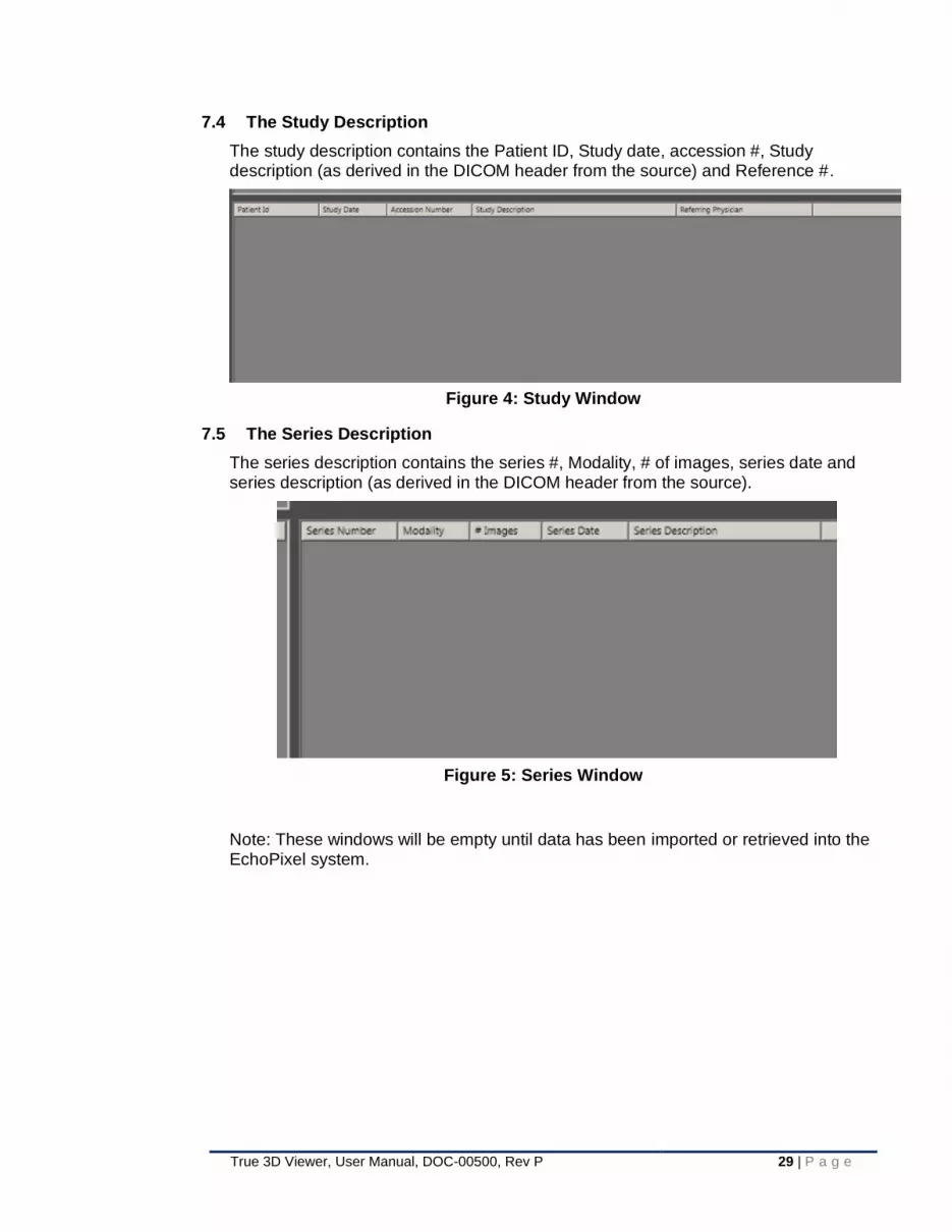
7.4 The Study Description
The study description contains the Patient ID, Study date, accession #, Study description (as derived in the DICOM header from the source) and Reference #.
Figure 4: Study Window
7.5 The Series Description
The series description contains the series #, Modality, # of images, series date and series description (as derived in the DICOM header from the source).
Figure 5: Series Window
Note: These windows will be empty until data has been imported or retrieved into the EchoPixel system.

30 | P a g e True 3D Viewer, User Manual, DOC-00500, Rev P
7.6 The Search Criteria Area
The Search Criteria Area is a set of filters that allow the user to narrow or broaden a search for specific patients or study types.
These filters will search for patient data from the local drive or a remote destination.
All of the search filters can be used together to narrow the search of a particular patient.
Source: automatically defaults to
local drive. By pulling down the
arrow, the user can switch to Q/R
from a remote node
Modality: The user can filter by
exam types for All, CT, MRI, XA or
Ultrasound
Patient Name: This will allow the
user to string filter all data on the
drive to a patients last name
Patient ID: This is a unique ID
assigned to a patient upon check
in
Accession number: this number
is generated when an order for a
scan is created in a PACS
interface
Study Date: the user can search
for patient exams by narrowing
down the search for today,
yesterday, last week, last month or
Range.
Calendars (Range): if the user
selects Range, a specific day,
month and year range can be used
to search for patient data. Select
the search button when done. The
Search Button only applies to the
Study Date.
Show All: this button displays all
patient exams on the local drive
Load Data: this button is actually
associated with the selections in
the other windows to provide a
localized button to load a data set.

True 3D Viewer, User Manual, DOC-00500, Rev P 31 | P a g e
If a remote AE has been selected, the buttons, in the Search Criteria area will change. Since the information found is on a remote device (AE), once the filter criteria has been set, the Query button can be used to request all possible data descriptors from the remote entity that conforms to the filter settings.
7.7 Checking Services
To review the background services, click on “Diagnostics” button.
Figure 6: Diagnostics Action Button

32 | P a g e True 3D Viewer, User Manual, DOC-00500, Rev P
A window will appear, showing status windows for the services, indicating in green, that both the DICOM service and patient services are working.
Figure 7: Diagnostics Window
Note: If there is an error message that reads “system is offline”, it may be necessary to restart the services for the DICOM and patient services.
To restart the services, right mouse click on “My Computer” from the desktop:
• Select manage
• Select “service and applications” by double clicking
• Select “services”
• Look for epxDICOMService-right mouse click and select “start”
• After the start is finished, do the same thing for epxPatientService

True 3D Viewer, User Manual, DOC-00500, Rev P 33 | P a g e
7.8 Searching for Data from the Local (EchoPixel System) database
At login, the LOCAL database will be the default selected search location.
Use the Show All button to see all the data available in the Local DataBase.
To perform a search for a specific patient’s data or a set of data from the EchoPixel (Local) database
• Enter the filter criteria to identify the specific data set or sets desired.
• Click on the “Search” button when the filter criteria is defined.
Figure 8: Patient Browser with Patient
If the filter’s criteria are met and the study or studies exist, the study information will appear in the Patient List Window.

34 | P a g e True 3D Viewer, User Manual, DOC-00500, Rev P
7.9 Open DICOM data from the Patient Browser
Load a Study of one or more Series
The True 3D Viewer allows user to open a single Study or one or more Series.
Figure 9: Patient Browser all windows loaded
Click the Refresh button at the upper left corner of the screen.
In the Patient List Window, select the desired Patient.
Single Study
After selecting the desired Patient, select a Study from the Study Description Window. Double click to open the selected Study; alternatively, user may press the “Load” button. All Series under that Study (displayed in the Series Description Window) will load into the application.
One or more Series
To open some but not all Series within a given Study, select the desired Study and then all desired Series under it.
If opening a single Series, simply double click on the desired Series to open it.
If opening multiple Series, hold “Ctrl” and click on each Series to be opened. To quickly select a long list of consecutive Series, hold “Shift” and select the first and last Series in the sequence them as well as all Series in between. When all desired Series are highlighted, click the “Load” button above to open them in the application.

True 3D Viewer, User Manual, DOC-00500, Rev P 35 | P a g e
The currently supported modalities (all based on SOP class UID - DICOM tag 0008,0016) on the patient browser that will pass through to the viewer are:
• 1.2.840.10008.5.1.4.1.1.2", "STANDARD_CT";
• 1.2.840.10008.5.1.4.1.1.4", "STANDARD_MR";
• 1.2.840.10008.5.1.4.1.1.66", "RAW_DATA";
• 1.2.840.10008.5.1.4.1.1.3.1", "ULTRASOUND_MULTIFRAME";
• 1.2.840.10008.5.1.4.1.1.12.1", "STANDARD_XRAY_ANGIO"
• 1.2.840.10008.5.1.4.1.1.6.2", "ENHANCED US VOLUME"
• 1.2.840.113543.6.6.1.3.10002", "PHILIPS ULTRASOUND"
7.10 Searching (QUERY) for Data from a Remote Application Entity
Select the drop down arrow on the Source button, any configured remote AE’s will be available for selection (see §Error! Reference source not found. for setting up a remote AE). Select the desired Remote AE.
Make sure to narrow the search filters for patient name, modality, ID, accession number and / or Date Range.
Select “Query” button when done.
If the filter’s criteria are met and the study or studies exist, the study information will appear in the Patient List Window.
The study or series can be selected and then data may then be retrieved into the local database.
Figure 10: Patient Browser query remote server

36 | P a g e True 3D Viewer, User Manual, DOC-00500, Rev P
7.11 Retrieve Patient Data
Once a successful Query has been performed (§7.10), the user can dive further into the Queried information and retrieve the desired imaging series.
Patient: Left mouse button clicking on the desired patient, shown in Patient List Window, all the available studies, for that patient will then populate and show in the Study Description Window. The user could press the Retrieve button at this point and thus retrieve all studies for the selected Patient.
Patient Study: instead of Pressing the Retrieve button, discussed in the previous paragraph, the user could left mouse button clicking on the desired Study, shown in Study Description Window. All the available Series, for that patient, for that study will then populate and show in the Series Description Window. The user could press the Retrieve button at this point and thus retrieve all Series for the selected Patient Study.
Patient Series: instead of Pressing the Retrieve button, discussed in the previous paragraphs, the user could left mouse button clicking on the desired Series, shown in Series Description Window. The selected series will be highlighted. The user could press the Retrieve button at this point and thus retrieve just the selected Series for the selected Patient Study.
Once any successful Retrieval of data is performed, the selected data will now be available for use and can be recalled from the LOCAL database (see §7.8)
NOTE: the image data from the Remote AE cannot be opened directly into the True 3D Viewer. It must first be retrieved to the local database and then opened.
Figure 11: Patient Browser Remote window

True 3D Viewer, User Manual, DOC-00500, Rev P 37 | P a g e
7.12 Import Patient Data from a CD, DVD or USB Drive
The Patient Browser allows user to import DICOM Patient data (exported DICOM data from PACS or Imaging Workstation as DICOM part-10 files) into the system. The User can import patient data from a CD/DVD drive, USB flash drive, external hard drive, or from any directory.
Figure 12: Patient Browser Import function
Select import from the toolbar
An Import Window pops up.
Import of patient data is started by selecting “browse” followed by clicking Import button. The user can monitor progress status of patient import by clicking the “Status” button.
Note: Move File: If user plans to import data from the local drive, then the user could select “Move File” check box. This moves the DICOM files from a selected directory to a system to avoid duplication of patient data on the hard drive.
Recursive Import: By default, the recursive check box is selected. This allows the import process to import data from sub-directories under selected patient data directory.
File Filter: If imported data has a file extension “.dcm”, then the user could set the file filter *.* or *.dcm. If exported DICOM files have no file extension, then the user could set a file filter *

38 | P a g e True 3D Viewer, User Manual, DOC-00500, Rev P
7.13 Export Patient Data
Allows the user to export DICOM data to a new folder, USB or CD/DVD on the local drive
Figure 13: Patient Browser Export function
Select the DICOM patient study or series to export
Select export from the toolbar
7.14 DICOM Push Patient Data
This allows the user to send or push DICOM patient data to a remote location once an established remote node has been set up (see section: Error! Reference source not found. for setting up a remote AE)
Figure 14: Patient Browser Sending data

True 3D Viewer, User Manual, DOC-00500, Rev P 39 | P a g e
Highlight the patient’s study or series:
Select “Send”.
A pop up window will display.
Select the drop down Remote AE title and choose the direct send to destination.
Select “Push” when done.
Select “Status” to see the file progress.
7.15 Delete Patient Data
Allows the user to delete patient DICOM study or series data from the local drive
Figure 15: Patient Browser Delete function
Select the study to delete.
The user can choose to delete an entire study, or just one series.
When Delete is selected, a pop up displays as a warning.
The user can Cancel the command, or select OK to delete.
Select Refresh button to show that the study has been deleted from the study list.
7.16 Auto Load Data
It is possible for data to automatically load in the True 3D Viewer when data is pushed to the system or imported. When the Auto Load feature is turned on, the user does not need to select the data on the patient browser and click the load button, instead the data will automatically load.
Use these instructions to turn on the Auto Load:
1. Open the Patient Browser.
2. Check the Auto Load box next to the Load Data button.

40 | P a g e True 3D Viewer, User Manual, DOC-00500, Rev P
After turning on the auto load feature, when data is imported or pushed to the system, it will be loaded into the True 3D Viewer.
7.17 Status
Pressing the Status button will activate a pop-up status window providing information on requests and the status of pending or completed transfers.
In addition, the status button is color coded. When new status information is available, the button text will turn Green. The text color is cleared when the Status button is pressed.
Figure 16: Patient Browser Status window

True 3D Viewer, User Manual, DOC-00500, Rev P 41 | P a g e
7.18 Diagnostics
This is a system alert. It allows the user to restart the DICOM and patient services. It also displays error alerts. This tool will highlight in yellow when there is an alert.
Figure 17: Patient Browser Diagnostics indicator
Select the diagnostics tool to show an alert.
Figure 18: Diagnostics window with disconnected warning
The alert shows the systems patient services is offline.
Click the “restart patient services” tab to reconnect.

42 | P a g e True 3D Viewer, User Manual, DOC-00500, Rev P
8 Using the EchoPixel System – Principals of Operation
The True 3D Viewer loads DICOM image data and presents a Virtual Reality 3D rendered view of the DICOM image data.
The True 3D Viewer software application enables HCPs to visualize and interact with image data and depictions of tissues and organs as if they were real physical objects. The user wears passive 3D glasses and uses a 3D controller. All standard 2D images can be displayed at the same time as the True 3D volume data when the user preference is configured.
Figure 19: User working with True 3D Viewer

True 3D Viewer, User Manual, DOC-00500, Rev P 43 | P a g e
8.1 Modes of Operation
Depending on hardware configuration, the EchoPixel software will run in one of two
modes:
8.1.1 Planning Mode
Planning Mode is available only under Configuration A. It provides full application
functionality (subject to license availability). For the remainder of this document, features
or functionality only available in Planning Mode will be denoted by
8.1.2 Review Mode
Review Mode becomes active under hardware Configurations B, C, and D if
accompanied by a valid Glasses-free license. It provides access to a limited set of
functionality that has been deemed compatible with the connected hardware components.
For the remainder of this document, features or functionality only available in Review
Mode will be denoted by
8.2 User Interface
The software does not perform any compression of images. Because there is no reversible or irreversible compression or processing, there is no loss of image quality or any loss of information content from the original image.
Anatomical data can be shown in one of two visualization modes - Intuitive 2D or True 3D. Intuitive 2D shows anatomical data in the form of 2D MPR images, while True 3D shows anatomical data in the form of a volumetric object.
Although the User Interface varies slightly depending on which licenses are activated and other factors, the following elements are always visible:
• Main object - interactive image or volume
• Interaction panel - shows current interaction mode (e.g. Zoom, etc.) & scale
• Information panel - contains various information about main object
• Cut plane - the cut plane is applied to main object
• Orientation Object - shows orientation of main object
• 3D UI icon – Will display 3D buttons to start different interactions
Figure 20: Basic User Interface

44 | P a g e True 3D Viewer, User Manual, DOC-00500, Rev P
The basic interaction functions can be accessed via the 3D UI, the EchoPixel icon located at the upper right corner of the 3D space.
By intersecting it with the interaction ray and clicking on the front stylus button a series options appear that enable the user access to the following functionality when the user uses the 3D controller to click on the button:
i2D – Change main object to 2D MPR image
WWWL – Start Window width and window level adjustment
3D – Change main object to volume/True 3D
TFDial – Start transfer function dial interaction
Zoom – Start a scale (increase or decrease) of the main object
Label – Place a label (marker) and text to a location of the image date
2 Point Measurement – Start a 2-point measurement
Orientation – Change image data orientation to: Axial Sagittal Coronal
Auto Scroll/Rotate – Automatically: Rotate horizontally Rotate vertically Scroll cut plane
Reset – Reset image data to default position (e.g. coronal)
Cine Play – For gated or 4D image data, Play Pause, Next/Prior frame
Edit Volume – Start freehand volume editing
Bookmarking – Create a bookmark, Go to next / prior bookmark
Exit interaction: Go back to default interaction (Object Picking)

True 3D Viewer, User Manual, DOC-00500, Rev P 45 | P a g e
Other functions:
1. Show Axis labels (only visible with US loaded) 2. When the user hovers the 3D controller ray over a 3D button, it will
change color to yellow (if it is enabled). 3. If a feature is disabled due to the state of the application, the button
corresponding to that feature will be disabled (user cannot pick it and the text will turn gray).
4. If a feature is unavailable due to the type of data loaded, the button corresponding to that feature will be hidden from the user.
5. The application will arrange buttons with similar functionality in groups such that clicking on a parent menu button will cause a group of buttons to appear next to the menu button, with lines connecting the menu button to the lower level button
• Pull-down menus - most functions can be selected here; these features are labelled in the figure below.
• Context Menu - most functions can be selected here
Figure 21: Basic user interface – Menus
8.3 Software Version, contact and UDI information
To display the About Window, from the User Interface pull-down menus, select the Help option. In the resulting pull-down menu, select the “Show About Window” option.
This window contains information on how to contact EchoPixel, view the software version and view the Unique Device Identification number (UDI).

46 | P a g e True 3D Viewer, User Manual, DOC-00500, Rev P
Figure 22. About True 3D Viewer Window
Note: Image above is sample only, Software Version number, UDI and Available Licenses may be different dependent upon your configuration
8.4 Interaction Inputs
The True 3D Viewer software makes use of several input interaction devices: the 3D controller, mouse, keyboard shortcuts, and possibly an external footswitch.
8.4.1 3D Controller
The 3D controller is the primary means of data interaction. It allows users to directly engage objects in 3D space. Depending on the particular hardware configuration, up to three separate buttons may be available with the following functionality:
• Front / Center – used to interact with 3D objects and make menu selections (Note: with some interaction controller devices, Front / Center button functionality may be provided by an external footswitch)
• Left – Delete Labels and pause Annotation Mode (see §10.7.5)
• Right - Show/Hide Context Menu (see §10.27)
• Figure 23: Interaction Controller Sample Device: The zSpace stylus

True 3D Viewer, User Manual, DOC-00500, Rev P 47 | P a g e
The 3D controller is represented in the 3D scene as a blue ray – hereafter referred to as the “interaction ray” or just “ray”. When the interaction ray makes contact with a qualifying 3D object in the scene, the ray color will turn green. Depending on the utilized 3D controller device, this color change may also be accompanied by some type of haptic feedback (e.g., vibration when using the zSpace stylus). When in Object Picking mode (the application default - see §10.8.1), pressing and holding the Front / Center button while the ray is intersecting a qualifying 3D object will establish a handle to the picked / intersected object, turning the ray yellow and allowing the user to freely move and rotate that object. When the cut plane is enabled (see §10.7.4), intersecting the cut plane cone with the ray will change the ray color to cyan.
Table 14 Summary of Ray Colors
Ray Color Conditions
Dark blue Default ray color.
Green Interaction ray is intersecting a pickable 3D object
Yellow Interaction ray is locked onto a 3D object
Cyan Interaction ray is intersecting the cut plane cone
In Planning Mode-capable configurations, the 3D controller can also be used to operate the mouse cursor, allowing the user to interact with objects with which they could not normally interact using the ray, such as tabs and menus. The “N” key and Right button toggle whether the interaction controller operates as a mouse or a ray. To make selections with the 3D controller while in mouse mode, use the Front / Center button.
8.4.2 Mouse
The mouse can also be used to control the cursor and perform operations in a menu or window. The mouse is typically a more convenient way to control the cursor than the 3D controller.
8.4.3 Keyboard
Many of the program’s functions are mapped to the keyboard. Some keys act as shortcuts to functions that can also be performed with the 3D controller or mouse, while other keys are tied to actions that can only be performed with the keyboard. Therefore, it is important to be familiar with hotkey functions.
Lastly, most actions can also be accessed in the pull-down menus (also referred to as the “file menus”).

48 | P a g e True 3D Viewer, User Manual, DOC-00500, Rev P
9 Performance Characteristics and Specifications
The True 3D Viewer loads CT, MRI, XA and select2 Ultrasound DICOM image data and displays a True 3D rendered view that enables Health Care Professionals to view anatomy in open 3D space as if it were a real physical object. Additionally, doctors can interact with the anatomy via a hand-directed 3D controller, allowing them to quickly localize and scrutinize anatomical structures of interest.
Note: Some functions are not available to all licensed users. Please check within this manual the functions that are not available.
9.1 Inputs
• Read and display standard CT, MRI, XA and select2 Ultrasound DICOM Files (enhanced DICOM not supported)
• 3D Surface models (STL, PLY file formats)
9.2 Outputs
• Export Anonymized DICOM.
• Export 3D Surface models (STL, PLY file formats)
• Save Workflow Scenes: restore saved scene state.
• Application screenshot as PNG image file; Secondary capture screenshots
9.3 Visualization Modes
All visualization modes include an orientation object and information panel:
• Radiology view – Radiology interpretation view.
• Surgery view – Surgical interpretation view.
• Intuitive 2D – Spatially Registered 2D MPR, MIP, MinIP.
• True 3D – Volume rendered (Composite, MIP, MinIP)
• Slab – Partial volume view.
• Annotation Mode – Image data is displayed on surface plan of display to facilitate resting of the users hand on the screen and improve marking and annotating objects.
9.4 Specialized Tools
• Freehand cut plane control – determines 2D MPR and volume clip.
• Measurements of any visible object (mm’s / in’s). Line, poly line, spline, orthogonal, angle, sizing protocol, vector decomposition
• Surface Area and Volume of segmented surfaces.
• Region growing segmentation generating 3D surfaces.
• Centerline extraction of a segmented surface.
• ROI selection – selection of volume of interest updating across visualization modes.
2 GE Ultrasound vivid e90, vivid e95, and Philips e33, GI, 3DDCM

True 3D Viewer, User Manual, DOC-00500, Rev P 49 | P a g e
• Transfer function presets, save and edit.
9.5 Seeds
Seeds are points that the user can place to define the path of a measurement or
annotate patient anatomy.
9.6 Functional / Interactive Features
• Object Picking – translate and rotate objects. →
• Surface Only Object Picking – translate and rotate surfaces only
• Pan – translate objects
• Window Width / Window Level adjustment of 2D MPR views. →
• Transfer function Dial – fine adjustment of volume rendering transfer function. →
• Gradient Opacity Dial – adjustment of the opacity for each point in the transfer function
• Label – mark and add a text label to object features. →
• Rotation – Rotate objects along user defined directions and points.
• Zoom in/out – Scale objects to user defined size. →

50 | P a g e True 3D Viewer, User Manual, DOC-00500, Rev P
10 Viewer Operating Instructions
CAUTION: BEFORE EACH SESSION
The Stereoscopic Alignment Test must be performed each time the user opens the application to ensure optimal depth perception.
Failure to perform this test may result in improper depth perception as well as adverse physiological effects such as headache and dizziness.
10.1 Stereo Alignment Test
The Stereo Alignment Test allows the user to test if the system is displaying the correct left/right sequence of images and reverse them, if needed.
Making sure that stereo alignment is properly configured is critical before viewing any image data. If the left/right sequence of images is reversed, the user will see the volume with the reverse z-orientation; objects that should appear to be protruding from the display will instead appear behind it.
To test whether the stereo alignment is properly configured, use the mouse to select Enable Stereo Alignment Test under the Settings pull-down menu on the top toolbar.
Two cones will appear: a red cone positioned on the left side of the screen and a blue cone positioned on the right. The red cone should only be visible with the left eye, while the blue cone should only be visible with the right eye. To test this, the user should close your right eye and the only cone you see should be the red cone. Close only the left eye and the only cone that is visible should be the blue one. If the user is not seeing the cones exactly as described, hit the X key to swap the stereo alignment. Make sure that the cones are shown as described before viewing volumetric data. Click on Enable Stereo Alignment Test again to exit the test.
You should always run through the stereo alignment test whenever you first start the application. Viewing volumetric data with improper stereo alignment may adversely affect how the user perceives object depth.
Figure 24: Stereo Alignment Test

True 3D Viewer, User Manual, DOC-00500, Rev P 51 | P a g e
Alternative Controls
You can also reverse the left/right sequence of images by selecting Swap Eyes (L/R) under the Settings pull-down menu or by using the keyboard shortcut of hitting the “X” key.
10.2 Adjust Display Angle (Configuration A only)
When the application starts, it will detect the angle of the display and accommodate the current screen angle. However, the application will not check the angle of the display after the application has been started. Therefore, we suggest restarting the application after changing the display angle.
10.3 Display on a Secondary Display
10.3.1 Display on a second stereo-enabled display (Projector)
The application supports the ability to duplicate the Zvr display to an additional stereo monitor. To do this, connect the additional stereo display and change the display settings to “Duplicate Display”.
Note: The connected stereo display must support the Time-Sequential 3D format.
In the case that this secondary display is a Stereoscopic 3D compatible it is important for the main display running True 3D is the primary display.
This is configured by accessing the control panel of the video card → display settings → Set up Multiple displays and right click on the display (Zvr, etc) and select make primary

52 | P a g e True 3D Viewer, User Manual, DOC-00500, Rev P
If the display is a 3D Projector, follow the below steps to ensure proper functionality:
1. Turn on your projector.
2. Connect your 3D source (DisplayPort on HDMI input)
3. Ensure video card is configured correctly with the projector being the secondary display, the Zvr needs to be the primary display.
4. If using RF Active 3D Glasses, connect the RF emitter to the projector and turn on your 3D glasses. Please refer to the 3D glasses user manual on how to operate the 3Dglasses.
5. Your projector will automatically display 3D.
If 3D is not displayed, you will be required to adjust the settings in the 3D menu
Menu > "Display" > "3D" > "3D Mode" > "DLP Link"
If the 3D image does not look correct, you may also be required to adjust the 3D sync invert.
Turn this on if the image looks odd. Menu > "Display" > "3D" > "3D Sync Invert" > "On".
10.3.2 Display on second non-stereo monitor
The application supports the ability to replicate the 3D scene on an additional non stereo monitor. To do this, connect the additional stereo display and change the display settings to “Extend these Displays”.
Note: The projection of only one eye is displayed on the non-stereo monitor so that the result is a non-stereo view of the True 3D Viewer 3D space.
There are a couple limitations involved in running a single application on multiple monitors:
• The additional monitor must have a 2K resolution (1920 x 1080)
10.4 Switch between Patient Browser and Viewer
To switch from the Patient Browser to the Patient Viewer, close the Patient Browser by clicking the X at the top right of the Patient Browser.
To switch from the Patient Viewer to the Patient Brower, select either Close Data or Open DICOM under the File pull-down menu.
10.5 Opening DICOM image data from the local hard drive
Under File menu, click Open DICOM

True 3D Viewer, User Manual, DOC-00500, Rev P 53 | P a g e
A new window will appear titled DICOM Series Selector, showing all the folders from
the preferred input directory you have designated in the User Preferences. The
window will allow you to select the folder that contains a single DICOM series. To
open the 3DDCM data type, make sure it is saved in a folder in the preferred input
directory, or you can click “Browse for Root Directory” and navigate to where the
data is saved.
To view information about a DICOM series contained in a folder, click on it to display its
DICOM header information in the adjacent Series Details panel located on the right side of
the dialog.

54 | P a g e True 3D Viewer, User Manual, DOC-00500, Rev P
If information about the DICOM series appears in the Series Details panel, the folder’s
DICOM series is ready to be loaded successfully by clicking on the open button in the
lower right corner.
If the series loads successfully, the window will disappear, the image data will be visible.
Note that larger series often take time to load. For large series, you will often see a
“Processing image” loading bar, followed by a “Generating histogram” loading bar before
the image data is visualized.
Errors when loading DICOM Data
There are several potential errors that can occur with loading DICOM data. Each error
message that can appear in the Series Details panel of the DICOM window and its cause
is described below:
• “Child directory found in this folder. Please navigate into directory or remove child directories.”
This error message indicates that the selected directory contains multiple folders. To
open a DICOM series, you need to select the folder that directly points to the series,
not to a folder that contains a folder with DICOM data.
• “Please select a single directory containing a single DICOM series.”
This error message indicates that the folder may contain two or more DICOM series.
This could also indicate there are no DICOM files in that folder. To avoid this error,
ensure that the selected folder contains no more than one DICOM series.

True 3D Viewer, User Manual, DOC-00500, Rev P 55 | P a g e
• “The selected data is larger than 4 GB. The system cannot load the data.”
A DICOM series cannot be loaded if it exceeds the 4 GB size limit.
10.6 Explanation of loadable data types
The True 3D Viewer allows user to load the data types categorized in the subsections
below.
10.6.1 Load Surfaces (STL or PLY files)
There are three ways to load surfaces (aka segmentations): using the surface loading Wizard or loading a DICOM surface file or Regular surface file directly. The Surface loading wizard will load either a DICOM surface or Regular surface file type but will provide additional options for loading data such as initial positioning and the option to load multiple surface files simultaneously.
Surface Loading Wizard
The surface loading wizard will load either a DICOM surface file or Regular surface file, depending on whether user selects the option “Surface Derived From Data”; if selected, the surface file(s) will be loaded as a DICOM surface file. If not selected, the surface file will be loaded as a Regular surface file(s).
The difference between loading DICOM surface files and Regular surface files is that the former loads the segmentation in the location from which it was derived, while the latter loads the segmentation in the center of the screen. Without the data from which the surface was derived, it wouldn’t make sense for the application to register the surface file to any loaded image data. Furthermore, DICOM surface files will fail to load if user tries to open a DICOM surface before loading its associated DICOM image data set.
Beyond helping load the appropriate file type (DICOM surface or Regular surface), user can make several additional changes in the surface loading wizard including selecting the units displayed for measurement data associated with the surface file, and the positioning of the volume when a surface file is loaded.
To start the surface loading wizard, go to File > Load Surface File > Start Wizard…
Loading surface files generated from external applications
Surface files that were generated outside of the True 3D Viewer application can also be loaded. The Surface Properties window (see §10.14.3) will show an asterisk next to each loaded surface file that was generated in this instance or another instance of the True 3D Viewer application.

56 | P a g e True 3D Viewer, User Manual, DOC-00500, Rev P
Figure 25: Surface Loading Wizard Window
Load DICOM Surface
To load a DICOM Surface file, go to File > Load Surface File > DICOM Surface.
Load Regular Surface
To load a Regular Surface file, go to File > Load Surface File > Regular Surface.
If unsure of what data is saved in a segmentation file, review the section on saving segmentations (see §10.18.1) to learn what associated data is saved when exporting as a segmentation.
When loading data, the folder specified in the output directory of User Preferences (see §10.20) will load.
Selecting Surface Only
By pressing the “H” key, you are able to object pick the surface only. This will allow you to rotate and translate the surface by isolating the surface from the other objects.
Notes
When a surface file is loaded without an open DICOM image set, features that don’t apply to surface files are inactivated until a DICOM image set is loaded.
When importing surfaces, it is up to the user to ensure proper scaling. For Volume/Surface Area, it is a measurement of the surface and not the image data contained within. Please see section for Segmentations.
10.6.2 Loading a Single Image
When you load a single slice image into the application, certain features that would
normally be available when loading a set of images will be disabled or limited.

True 3D Viewer, User Manual, DOC-00500, Rev P 57 | P a g e
The following features will be completely disabled in the application:
1. Transfer functions
2. Cut plane
3. ROI creation
4. Reference view
5. Intuitive 2D
6. Volume
7. C-Arm
8. Segmentation
9. Slab mode
10. Orthogonal measurement
11. Sizing protocol measurement
When data is loaded, the image slice will be oriented such that it is facing the user.
The orientation object will reflect the proper orientation of the image relative to the
patient.
Interaction differences:
• Rotation of image with arrow keys – This operation always takes place
about the center of the image instead of the center of the cut plane.
• Scrolling functionality (Page up/down) – This operation will translate the
image forward or backwards in space, rather than moving the data through
the cut plane.
• Resetting the image data - This operation will place the image slice in the
center of the 3D space and facing the user, rather than moving the image
data to the center of the 3D space in the currently selected orientation.
• Annotation mode – Annotation mode will reorient the image slice such that
it is facing the user on the plane of the display, rather than moving the
current cross section of the volume to the plane of the display.
• Image Realignment – This operation will bring the image slice to the user’s
selected cut plane orientation and facing the user, rather than bringing the
current cross section of the image data to the selected cut plane
orientation.
10.6.3 User interface and functionality when loading multiple DICOM series
This section describes the user interface and functionality changes that occur
when multiple series are loaded. Refer to §7.5 to learn how to load multiple series.
A series is a continuous set of images from a patient scan. When you load multiple
series that are related (i.e. share the same image size), the series will be grouped
into a single Image Set (refer to §10.6.4).
Functionality
Use the “<” or “>” keys to cycle through each Series within an Image Set. These commands are also available in the Study pull-down menu, which appears in the application only when multiple Series or Image Sets have been loaded.

58 | P a g e True 3D Viewer, User Manual, DOC-00500, Rev P
Multi Series Dialog
“Show Multi Series Dialog” (under Study pull-down menu) allows user to edit
properties for each image Series. The following controls are available in the
Multiple Series Dialog:
Image Number – Select the image Series to be displayed
Annotation Visibility Lock – When enabled, annotations created on the specified
image will maintain their visibility even when the user is viewing a different image
within the image set.
Surface Visibility Lock – When enabled, surfaces loaded for the specified image
will maintain their visibility even when the user is viewing a different image within
the image set.
Default Color – Change the default color for data associated with an image Series,
controlling the color of surface files, lines, measurements, and annotations.
The Series Details panel on the far right will show detailed information about the
selected Series. The contents of the Series Detail panel can also be viewed under
Reporting > View Image Info.
Figure 26: Multiple Image Settings Window
Notes
When Surface Visibility Lock is enabled, surface files can only be moved
independently of the image data in the series from which they were generated.
This also applies to the Surface Properties window; bringing up the Surface
Properties window while viewing a series will only show surface files generated in

True 3D Viewer, User Manual, DOC-00500, Rev P 59 | P a g e
that series. Likewise, for the Annotation Visibility Lock, annotations can only be
moved or modified in the image series where they were originally created.
Changing the Default Color associated with an image series will retroactively
change the color of all existing data associated with that image series with the
exception of surface files, which will remain their original color.
10.6.4 User interface and functionality when loading Multiple Image Sets
An Image Set is comprised of all related Series; when multiple image series are
loaded into the application at the same time and they are not all related to each
other, they will be divided into independent image sets. The application will load
each image and let the user switch between them freely. Each image (and the
work that the user does on that image) will be completely independent of other
images. In other words: measurements, annotations, segmentations, regions of
interest, etc. that the user creates on one image will remain in that image if the
user switches to another image.
Functionality
When multiple Image Sets are open in the application, the Information Panel will
specify the Image Set as well as the particular Series within that Image Set that
are currently being displayed.
Use “shift+<” and “shift+>” to cycle through all Image Sets that have been loaded
into the application. These commands are also available in the Study pull-down
menu, which appears in the application only when multiple Series or Image Sets
have been loaded.
Notes
When saving a scene, the application will allow the user to save a scene for only
the currently selected Image Set.
When switching between Image Sets, the following items will persist for a given
Image Set:
• Labels and measurements
• Surfaces
• Transfer functions
• Window width/Window level (WW/WL)
• Region of Interest (ROI)
• Slab mode
• Cut plane enabled/disabled
• Scale
• Scene state
• Hide All Objects enabled/disabled

60 | P a g e True 3D Viewer, User Manual, DOC-00500, Rev P
The following items/user preferences will be maintained for the user as they switch
to different images:
• Default cut plane position
• Cut plane appearance (crosshairs, cone)
• Reference view visibility
• Measurement units
10.7 View Modes
10.7.1 Intuitive 2D
Intuitive 2D is the visualization mode that displays 2D MPR images.
Activate Intuitive 2D
Press F1 to activate Intuitive 2D. or →
User Interface
The primary features of Intuitive 2D are briefly described below. Refer to the figure below to observe their location and appearance.
• Main object - 2D image in the center
• Orientation Object - shows current orientation of the main object using either a box or human model
• Information panel - contains basic data of the main object
• Interaction panel - indicates the current interaction state
• Cut plane (see §10.7.3) - defines the 2D MPR image. The cut plane is represented by the light blue corners and wireframe cone in the center.
Alternative controls
Intuitive 2D can also be accessed by selecting Intuitive 2D in the View Modes tab of the Context Menu or under the Views pull-down menu.

True 3D Viewer, User Manual, DOC-00500, Rev P 61 | P a g e
Figure 27: Intuitive 2D mode

62 | P a g e True 3D Viewer, User Manual, DOC-00500, Rev P
10.7.2 True 3D - Volume
True 3D, also known as Volume, is the visualization mode that displays image data as a volumetric object.
Activate True 3D
Press F2 to activate True 3D.
User Interface
The primary features of True 3D are briefly described below. Refer to the figure below to observe their location and appearance.
• Main object - volume in the center
• Orientation Object - shows current orientation of the volume using a box or human model.
• Information panel - contains basic data of the volume
• Interaction panel - indicates the current interaction state
• Cut plane (§10.7.3) - defines the volume cross section. The cut plane is represented by the light blue corners and wireframe cone in the center.
Alternative controls
Volume mode can also be accessed by selecting Volume under the “View Modes” tab of the Context Menu or select “Volume” under the Views drop-down menu in the top toolbar or pressing F2 on the keyboard.
Figure 28: Volume Mode

True 3D Viewer, User Manual, DOC-00500, Rev P 63 | P a g e
10.7.3 Fluoroscopic Simulation View
Fluoroscopic view, also known as C-Arm view, is a simulation of the C-Arm device on the
anatomy. To enter C-Arm view, you can either press F3 on the keyboard or select C-Arm
from the Views menu
The fluoro image will be in the same position as the cut plane. To view any part of the
volume in a fluoro image, move the cut plane to the slice desired.
The C-arm dialog can be opened using the same keyboard shortcut or menu item (View >
C-Arm). From the dialog, the user will be able to change the following
• Volume position through C-Arm navigation: the user will be able to enter LAO,
RAO, CRA and CAU values.
• Fluoro image translation: the user will be able to adjust the Right-Left, Posterior-
Anterior, and Superior-Inferior positions of the fluoro image.
• Translucent fluoro – enables the translucency of the fluoro image.
• Show model – the c-arm reference model can be turned on or off
• Use Edited Volume: Visualize the cut volume in the Fluoro image
• Project Annotations: Project the measurements or labels on the Fluoro image
• C-Arm view: the user can view the volume in the following ways
o Fluoro + Slab (Default)
o Fluoro image only
o Volume cross section only
Figure 29: C-Arm Dialog and Reference Model

64 | P a g e True 3D Viewer, User Manual, DOC-00500, Rev P
10.7.3.1 Loading a Fluoroscopy Image
1. Import patient fluoro data set and press Load. The fluoro image will be visualized
either next to the volume, or overlaid in the volume, depending on the User
Preference. The default is set to side by side.
2. Open the Fluoro menu that appears in the menu bar. The following options are
available:
a. Toggle Cine
b. Show Fluro
c. Reset Fluoro-Volume Alignment
d. Fluoro Blending
e. Project Annotations
f. Bring Fluoro to Screen
g. Next Frame
h. Previous Frame
i. Next Set
j. Previous Set
k. Overlaid
l. Side by Side (set by User Preference)
10.7.3.1.1 Load Multiple Fluoroscopy Images (Series)
1. Import patient fluoro data series and press Load.
2. On the menu bar, open the fluoro Menu and select Next Set or Previous Set. The
images will display in “series” tracked by the interactive panel frame information
(i.e. 1/75).
10.7.3.2 Fading Fluoroscopy Images (controlling translucency of displayed fluoroscopic images)
To fade fluoroscopy images
Use this feature to adjust the fade of the fluoro volume blending into the image.
1. Open the Fluoro menu found at the menu bar.
2. Select Fluoro blending.
3. Ensuring that the interaction ray is not intersecting the volume, press down the
front button and move the controller from right to left. This will adjust the fading
level.
10.7.3.3 Fluoroscopy Bi-Plane
Use this feature to display two 2D fluoroscopy slices at separate angles. You will then be
able to reposition and set the visibility of each slice independently.
1. Open the Fluoro menu found at the menu bar.
2. Select Show Fluoro.
3. Check or Uncheck Plane A for Fluoro image and c-arm angle visibility.
4. Check or uncheck Plane B for Fluoro image and c-arm angle visibility.
5. Use the 3D controller to move each plane individually.

True 3D Viewer, User Manual, DOC-00500, Rev P 65 | P a g e
10.7.3.4 Fluoroscopy Projected Annotations
Use this feature to project the measurements and labels made on a volume
dataset onto the Fluoro image, this will result in having a 3D annotation on the
volume and a corresponding 2D annotation on the fluoro image.
1. With Cone beam and Fluoro data side by side on the True 3D viewer.
2. Create a measurement on the Cone beam CT.
3. Select Fluoro from the menu. Select project annotations.
4. Measurement will be projected onto Fluoro image.
10.7.3.5 Fluoro View Side by Side vs Overlaid
When loading a volume with its corresponding fluoro images, there are options in
the user preferences on how to visualize.
Under the Advanced tab in User Preferences:
Figure 30: User Preference for Fluoro visualization
The default view will load as follows:

66 | P a g e True 3D Viewer, User Manual, DOC-00500, Rev P
Figure 31: Fluoro Side by Side on Screen
When the user preference is set to Overlaid In volume:
Figure 32: Fluoro Overlaid in Volume

True 3D Viewer, User Manual, DOC-00500, Rev P 67 | P a g e
Lastly, when the fluoro is loaded Overlaid, on screen:
Figure 33: Fluoro Overlaid on screen
Each of these variations can also be achieved with the use of the menu items:
• Overlaid
• Side by Side
• Bring Fluoro to screen
There is also the option after rotating the volume to revert back to the alignment of
the fluoro at any moment using the menu item. All visualization from the normal 3D
controller movements on the volume is also achievable, however, only translation
is possible on the fluoro slice. The user must take caution to realign the fluoro with
the volume to the best of their knowledge, especially when projecting annotations
(see cautions section).
Note that the overlay of the volume and fluoro images is not a registration
and thus does not have an estimated accuracy.
By default, the fluoro image will be placed at the center of the volume. The user
can adjust the position of the fluoro image within the volume to assess the
anatomy of the volume relative to the fluoro image.
10.7.4 Cut plane instrument
This tutorial explains the 3D controller interactions that can be performed on the cut plane.
The cut plane is a virtual instrument that is applied to the main object to generate cross section views. The cut plane is represented by a light blue wireframe cone and four corners.
Its primary function is to generate a cross section of the image data in Intuitive 2D (see §10.7.1) or True 3D (see §10.7.2). The center of the cut plane is also frequently used as the central axis of rotation for the main object (see §10.8.10).

68 | P a g e True 3D Viewer, User Manual, DOC-00500, Rev P
Cut plane interaction
Change the location and orientation of the cut plane by selecting the cone. The cone marks the center of the cut plane, which is outlined by the four corners.
1. Using the 3D controller, move the interaction ray towards the cone. Once the ray intersects the cone, the ray and cut plane will turn cyan to indicate that the ray is intersecting the cut plane and not part of the main object around it.
Note: The cone is intentionally small so it does not obstruct the view of the anatomy. To enlarge the cone to make it easier to select, hold down the keyboard’s Space Bar until the cut plane has been selected.
2. With the ray still cyan, press down on the front button of the 3D controller to select the cut plane.
3. The ray and features of the cut plane will appear yellow for as long as the cut plane is selected. Hold the front button down for as long as you wish to move the cut plane.
4. While the cut plane is selected, you can move it freely in 3D space, both in Intuitive 2D and Volume modes.
Depending on the settings in the” Advanced tab” under User Preferences (see §10.20), the cut plane cone and corners may turn invisible while the cut plane is engaged instead of turning yellow.
Cut plane features
Adjust the appearance of the cut plane with the Plus key (+) on the numeric key pad. The Plus key (+) cycles through each preset combination of cut plane features. The default cut plane features are the cone and four corners. With each subsequent press of the Plus key (+), the following cut plane features will be generated:
1. Cone, corners, crosshairs
2. Crosshairs
3. Hide all cut plane features
Pressing the Plus key (+) again will restart the cycle from the default cut plane setting (cone and four corners). Hiding certain cut plane features can help in un-obstructing meaningful parts of the generated cross section.
Disable/Enable cut plane
You can enable or disable the cut plane in True 3D by pressing the U key. Pressing U disables the cut plane, displaying the complete volume. Pressing U again returns the cut plane to its location before the cut plane was disabled and restores the ability to view image data in Intuitive 2D.
Rotate cut plane
To rotate the cut plane cone about the normal axis, press the “[" or “]” keys to rotate the cut plane counterclockwise or clockwise, respectively.

True 3D Viewer, User Manual, DOC-00500, Rev P 69 | P a g e
Enlarge cut plane cone
The cut plane cone can be enlarged by pressing Spacebar. While the Spacebar is depressed, the cut plane cone will be enlarged and all image data will be non-interactive to facilitate selection of the cone.
Precision scrolling
The cut plane can also be translated by 1 slice along its normal direction using the keyboard. To translate the cut plane from inferior to superior by 1 slice, press Home on the keyboard. To translate the cut plane from superior to inferior by 1 slice, press End on the keyboard.
This function is useful for moving through slices in a more slow and controlled manner.
(a) Default cut plane position. The cut plane features (4 corners and the cone) are outlined in blue.
(b) Cut plane interaction
Figure 34: Cut Plane

70 | P a g e True 3D Viewer, User Manual, DOC-00500, Rev P
3 Point Cut Plane
Use this function to set a cut plane on specific points. This cut plane customization is used
for more accurate positioning if needed.
1. In the menu bar, click on Views > Set Cut Plane Cross Section > 3
Point Plane.
2. With the 3D controller, select three points where you’d like to create a
cut plane.
3. Press Esc and the cut plane is defined by the three points.
4. Press R to return to the original orientation.
Cut Plane Finder
Use this tool to set the cut plane using a grid.
1. In the menu bar, click on Views > Set Cut Plane Cross Section
> Cut Plane Finder
2. A grid will appear in the middle of the volume
3. Using the 3D controller, point at the middle cone to rotate and
translate the plane, or point at the four green spheres to just
rotate
Figure 35: Cut Plane Finder
10.7.5 Annotation mode
Annotation mode aligns the cut plane (see §10.7.3) with the physical plane of the display.

True 3D Viewer, User Manual, DOC-00500, Rev P 71 | P a g e
When any type of measurement function is activated, Annotation mode (see §10.7.5) will also be activated. The reason behind the tie between Annotation mode and measurement functions is that, when the cut plane is aligned with the physical plane of the display, it facilitates more precise interaction with voxels by allowing user to use the display as a drawing board.
Disable/enable Annotation mode during measurements
You can decide whether measurement functions activate Annotation mode by checking/unchecking “Switch to Annotation Mode during Measurements” under the Measurements pull-down menu. Measurement functions activate Annotation mode by default.
10.7.6 Annotation visibility settings
Annotation Properties
Press the Insert key to bring up the Annotation Properties Dialog. This will allow user to view any measurement or Label created in groups of the following:
• Labels (see §10.8.5)
• Line Measurements (see §10.9)
• Spline Measurements
• Angles
• Vector Placements
• Orthogonal
• Sizing
• Oval Opening
• Centerlines
The default grouping will be based on type of measurement. The user will have the ability to combine groups, rename the titles of the groups, and change settings based on groups or individual measurements. The titles of the measurements default to group type and number. These are also customizable.
The user can adjust the settings for:
• Visibility – Toggles the visibility for the annotation
• Seeds - Label seeds and Measurement endpoints (see §9.5)
• Labels - Text labels for Annotations and Measurements
• Label Background- Adds black box behind any seed annotations (e.g. Labels, measurements) for easier viewing
• Line width – Adjusts the line width of the Label seeds and measurements’ line
• Color – changes the color of the measurements’ line, and label’s seeds.
• Delete – Delete the annotation.
• Visibility of ALL the annotations on screen at once
• The visibility of annotations that are hidden by the cut plane.

72 | P a g e True 3D Viewer, User Manual, DOC-00500, Rev P
Figure 36: Annotation Properties
This ability to change the visibility selections is only active if a Label or measurements are present in the volume.
The user will also have the capability of viewing and exporting the results of the measurements on the window. The results in the window will only show one measurement at a time, which the user can pick in the drop down under the Results column. The exported results will come in a CSV file, with the name of each measurement and each of its corresponding results.
10.7.7 Information and Interaction Panels
The viewer has two panels on the bottom of the screen that indicate Patient information, current interaction, Scale, and C-Arm Angles.
Information Panel
This shows all the patient information:
• Patient Name
• Patient ID
• Series Description
• Modality
• Series Date

True 3D Viewer, User Manual, DOC-00500, Rev P 73 | P a g e
• WW/WL
Figure 37: Patient Information
Interaction Panel
This will show the current Interaction, Scale and C-Arm angles.
Figure 38: Interaction Panel
From the Settings menu, there are options to hide the Information Panels, and CArm Angles
Figure 39: Show Information Panels

74 | P a g e True 3D Viewer, User Manual, DOC-00500, Rev P
10.8 Interactions
10.8.1 Object Picking - translate and rotate objects
Object Picking allows you to freely translate and rotate the main object, as well as scroll through 2D MPR image slices.
Activation
Object Picking is the default interaction state, unless you have already selected another interaction state, Object Picking is enabled. Look at the interaction panel at lower right; if it indicates Object Picking, then that interaction state is currently enabled.
It can be accessed via the 3D UI →
If the interaction panel indicates anything else, press the ESC key to return to Object Picking.
Object Picking interaction
Select any point on the main object with the 3D controller and move it in the direction you want the main object to move.
1. Use the 3D controller to position the interaction ray so that it is intersecting the main object; the ray should turn green. Depending on the particular controller hardware, the color change may be accompanied by some type of haptic feedback (e.g., a vibration in the case of the zSpace stylus)
2. With the ray still green, press and hold down the front button of the 3D controller to grab the main object. The ray turns yellow, remaining so as long as the front button is depressed.
3. Moving the 3D controller towards the screen results in the next proximal image/volume slice being generated at the cut plane position and orientation, while moving it away from the screen results in the next distal slice being generated at the cut plane. Hold down on the front button to continue to move the main object.
4. Alternatively, users may use the 3D controller to grab and manipulate the
cut plane itself. To do so, release all 3D controller buttons and position
the interaction ray so that it is intersecting the cut plane cone; the ray color should change to cyan. Press and hold down the front button of the 3D controller. The ray and cut plane corners will turn yellow, remaining so as long as the front button is depressed. Users can then move the 3D controller to modify the position and orientation of the cut plane to
generate a new image / volume slice at the cut plane position and orientation.
Precision scrolling
It is often useful to move the main object or the cut plane in slower, and more controlled manner.
Through main object
You can move the main object by 1 slice using the Page Up and Page Down keys. To move the main object from by 1 slice, press Page Up. To move the main object from by 1 slice, press Page Down.

True 3D Viewer, User Manual, DOC-00500, Rev P 75 | P a g e
Through cut plane
The cut plane (see §10.7.3) can also be translated by 1 slice along its normal direction using the keyboard, generating a new slice of the main object. To translate the cut plane from inferior to superior by 1 slice, press Home on the keyboard. To translate the cut plane from superior to inferior by 1 slice, press End on the keyboard. This function is useful for moving through slices in a slower and more controlled manner.
Alternative controls
Object Picking can also be selected under the Actions pull-down menu from the top toolbar.
(a) Default orientation
(b) Object Picking in action
Figure 40: Object Picking

76 | P a g e True 3D Viewer, User Manual, DOC-00500, Rev P

True 3D Viewer, User Manual, DOC-00500, Rev P 77 | P a g e
10.8.2 Pan - translate objects
This tutorial will explain how to pan (i.e. translate) objects with the 3D controller.
The Pan action has the same functionality as Object Picking (see §10.8.1) with the only exception being that Pan does not allow main object rotations.
Activation
To activate the Pan function, press the” P” key. The interaction panel at lower right will now indicate Pan.
Pan interaction
Select any point on the main object using the 3D controller and move it in the direction user directs the main object to move.
1. Use the 3D controller to position the interaction ray so that it is intersecting the main object; the ray should turn green. Depending on the particular controller hardware, the color change may be accompanied by some type of haptic feedback (e.g., a vibration in the case of the zSpace stylus).
2. While the interaction ray is still green, press and hold down the front controller button. The ray will turn yellow and the main object’s position will change in conjunction with that of the controller until the front button is released.
Notes
Remember that Pan allows only object translation. The Pan action is useful when you want to manipulate the main object using the 3D controller without accidentally changing its orientation.
Alternative controls
Pan can also be selected under the Actions pull-down menu.

78 | P a g e True 3D Viewer, User Manual, DOC-00500, Rev P
(a) Default orientation
(b) Pan in action
Figure 41: Pan

True 3D Viewer, User Manual, DOC-00500, Rev P 79 | P a g e
10.8.3 Zoom
Zoom allows you to change the scale of the main object.
Activation
Select Zoom by pressing the” Z” key or by using the 3D UI → . The interaction panel at lower right will now indicate Zoom.
Zoom interaction
With the interaction ray blue (i.e., not intersecting any 3D objects), hold the front 3D controller button while moving the controller to the right-hand side of the display to scale up the main object; move it towards the left-hand side of the display to scale down. The scale of the main object can be further increased or decreased by repeating this process.
Alternative controls
Zoom can also be selected under the Actions pull-down menu.
(a) Default orientation
(b) Zoom in action. Notice the zoom level indicated in the interaction panel in lower right next to the main object.
Figure 42: Zoom

80 | P a g e True 3D Viewer, User Manual, DOC-00500, Rev P
10.8.4 Hover - voxel value
Hover allows you to view the density value and coordinates of the voxel intersected by the front tip of the ray.
Examining a voxel’s HU value
1. Use the 3D controller to move the far end of the interaction ray towards a voxel of interest.
2. Once the interaction ray intersects the image volume, the ray will turn green. The density value and coordinates of the intersected voxel will appear in the information panel in the lower left of the screen. Coordinate values will be in the lower left of the information panel (x/y/z). The density value will be in the lower right of the information panel.
Figure 43: Hover

True 3D Viewer, User Manual, DOC-00500, Rev P 81 | P a g e
10.8.5 Labeling
Select Labeling
Select Labeling by pressing the “L” key or by using the 3D UI → . The
interaction panel at lower right will now indicate Labeling.
Point Label
Select a point with the 3D controller to Label. To select a point:
1. Position the 3D controller so that the interaction ray is intersecting the main object, upon which the ray will turn green. Depending on the particular controller hardware, the color change may be accompanied by some type of haptic feedback (e.g., a vibration in the case of the zSpace stylus).
2. With the ray still green, click the front 3D controller button to place a Label there.
3. A small green box around the selected voxel will appear and a window will appear in the lower part of the screen.
4. Enter text in the box with the keyboard. To save the text and the Label, select OK with the front 3D controller button. The text should appear next to the Label.
After a Label has been placed, the interaction state will automatically return to “Object Picking” (see §10.8.1). Therefore, user will need to press “L” prior to placing each new Label.
USER TIP! To steady the ray, when selecting a Label placement point, it is advised to rest your hand on the surface of the screen.
Movement
To move a Label with the 3D controller:
1. Enter Editing mode by pressing the “E” key. The interaction panel will indicate Editing, indicating that application is in the correct interaction state.
2. Once the interaction ray intersects the Label, press and hold the front 3D controller button and move the 3D controller to move the Label.
Spline Label
The user can also trace with a label a path or anatomy of interest. To access the Spline label, go through the pull-down menu Actions → Labeling → Spline.
To trace a Spline:
1. Position the 3D controller so that the interaction ray is intersecting the main object, upon which the ray will turn green. Depending on the particular controller hardware, the color change may be accompanied by some type of haptic feedback (e.g., a vibration in the case of the zSpace stylus).
2. With the ray still green, click the front 3D controller button to place a Label there.
3. A small green box around the selected voxel will appear and a window will appear in the lower part of the screen.

82 | P a g e True 3D Viewer, User Manual, DOC-00500, Rev P
4. Move the controller to a new location and select a new point by repeating steps 1 – 3.
5. Once the points tracing the area of interest are complete, press the ESC key on the keyboard or use the exit interaction button on the 3D UI. Enter text in the box with the keyboard. To save the text and the Label, select OK with the front 3D controller button. The text should appear next to the Label.
After a Label has been placed, the interaction state will automatically return to “Object Picking” (see §10.8.1).
Deletion
Last annotation placed
The simplest way to delete a Label is by hitting the “Minus” key, which deletes the last annotation (Label or measurement) placed. When the desired Label to be deleted is not the last annotation created, you must use the Editing mode.
Editing mode
To delete a Label with the 3D controller:
1. Enter Editing mode by pressing the E key. The interaction panel will indicate Editing, indicating that application is in the correct interaction state.
2. Delete the Label by selecting it with the left 3D controller button.
Alternative controls
Labeling can also be selected under the Actions pull-down menu in the top toolbar.
Figure 44: Labeling
10.8.6 Hiding Annotations - hiding measurements and Labels
Annotations such as Labels (see §10.8.5) and measurements (see §10.9) can be hidden from view by pressing the A key. Press the A key again for Labels and measurements to reappear. This can also be done through the Views file menu. A

True 3D Viewer, User Manual, DOC-00500, Rev P 83 | P a g e
checkmark in front of Hide All Annotations will indicate whether the annotations are visible.
Notes
Once the Hide all annotations feature is enabled, the interaction with the annotations properties will be disabled. That means user won’t be able to change their settings until they are visible again.
10.8.7 Adjusting window width or window level
Window Width and Window Level (abbreviated “WW/WL”) allow the contrast of 2D images to be adjusted. You can create a custom WW/WL with the 3D controller or select a preset WW/WL using the keyboard numbers shown in preset WW/WL below.
Custom WW/WL
Select Ray WW/WL
Select the function that allows you to adjust the window width or window level by
pressing the” W” key or via the 3D UI → .
The interaction panel in the lower right of the screen will now read” WW/WL”.
Window width
To adjust the window width:
1. Make sure the interaction ray is blue, hold down on the front 3D controller button and move the ray horizontally across the screen. As soon as the front button is released, 3D controller movement will cease to affect the window width.
2. Window width can be further increased or decreased by repeating this process. Next to “WW/WL” in the information panel (in lower left), the window width is represented by the number on the left.
3. To increase the range of the width, press down on the CTRL button moving the 3D controller horizontally with the front button pressed down. This will allow the full range of the width to be changed with a slight movement.
Window level
To adjust the window level:
1. Make sure the interaction ray is blue, hold down on the front 3D controller button and move the ray vertically across the screen. As soon as you release the front 3D controller button, controller movement will cease to affect the window level.
2. Window level can be further increased or decreased by repeating this process. Next to “WW/WL” in the information panel (at lower left), the window level is represented by the number on the right.

84 | P a g e True 3D Viewer, User Manual, DOC-00500, Rev P
3. To increase the range of the window level, press down on the CTRL button while moving the 3D controller vertically with the front button pressed. This will allow the full range of the window level to be changed with a slight movement.
Preset WW/WL
There are several window level presets that are optimized for different tissue structures:
• F9 - colon
• F10 - soft tissue
• F11 - lung
• F12 - bone

True 3D Viewer, User Manual, DOC-00500, Rev P 85 | P a g e
(a) Default window width
(b) New window width
(c) User preferences: WW/WL
Figure 45: Adjusting window width and window level with interaction or user preferences

86 | P a g e True 3D Viewer, User Manual, DOC-00500, Rev P
10.8.8 Transfer Function
Transfer functions control the opacity and color of tissues in the volume (see §10.7.2). There are several ways to modify transfer functions:
1. Transfer Function Window
2. Transfer Function Dial
3. Gradient Opacity Dial
The Transfer Function Window contains the full set of transfer function features. The Transfer Function Dial allows you to shift the entire transfer function laterally.
The Gradient Opacity Dial allows you to alter the opacity all levels of the transfer function loaded. Note: This change will only be reflected by a message in the Transfer Function window but will not change the transfer function settings.
Transfer Function Window
The main way to change transfer functions is by using the transfer function window. When the T key is pressed, the transfer function window will appear, containing several tabs: S, L, F, and W. This tutorial will only discuss the functionality of the S tab.
Primary features
Some of the features of the transfer function window are briefly described:
• Histogram - gray histogram in X and Y-coordinate system shows proportion of tissues in the corresponding voxel range (x-axis represents HU values)
• Color bar - shows colors assigned to tissues in the histogram; tissues are assigned the color in the section of the color bar directly overhead
• Arrow - controls color of tissues in the corresponding voxel range
• Cross - controls opacity of tissues in the corresponding voxel range (y-axis represents opacity values) Observe the labelled figure below to learn the location and appearance of these features.
• Flip Opacity – This will allow the user to flip the transfer function so that all loaded opacity points will have their values inverted.
Figure 46: Transfer function window (labelled)

True 3D Viewer, User Manual, DOC-00500, Rev P 87 | P a g e
Select new preset
For the remainder of this tutorial, you will be instructed to use the mouse. On the S tab, the Select New Preset button allows you to apply a preset transfer function that is optimized for the kind of image data indicated by its name.
Assign new preset
Two preset transfer functions can also be applied to shortcuts. Selecting a preset transfer function under Preset 1 will assign that preset to the 1 key. Selecting a preset transfer function under Preset 2 will assign that preset to the 2 key. Pressing 1 or 2 will apply the corresponding transfer function to the volume.
User Preference for Transfer Function
For each data type, CT, MR, and US, a preset for the transfer function is set from 0-9.
From the transfer function window, you can set the presets 1 and 2 for the scene opened.
In the user preferences, the user will be able to select which preset the data will initially load, preset 1, preset 2, and if enabled, the Advanced Measurement transfer function preset for each data type. There are additional rows for each preset 1-10, once clicked, the user should be able to select for each.
These transfer functions presets can be reset at any time, but will remain even after closing the application.
Figure 47: User Preferences Transfer Functions

88 | P a g e True 3D Viewer, User Manual, DOC-00500, Rev P
Figure 48: Additional Presets in User Preferences
Create new transfer function / Modify existing preset
The histogram and color bar allow you to manually create a transfer function or modify an existing preset. The process for assigning a color and opacity to different tissue structures:
1. Click the left mouse button in the histogram to add a new color. A new cross will appear at the point you clicked, along with a new arrow in the color bar directly over it.
2. Double click the left mouse button on the arrow to assign a different color to the voxels in this range.
3. Press the middle mouse button on the cross and drag the mouse to change the opacity of tissues in this region. To make the tissues in this range more opaque, move the cross up. To make them less opaque, move it down.
4. Press and hold the left mouse button over an arrow and drag to move it and its corresponding cross on the histogram. Right click on an arrow to remove it and its corresponding cross.
5. Select Save Current Preset to save the newly created transfer. You will be able to name the preset before saving.
6. To close the transfer function window, press the ESC key.
Transfer Function Dial
You can also adjust the transfer function by selecting the Transfer Function Dial. Activation
The Transfer Function Dial is activated with the D key or via the 3D UI
→ .
The interaction panel in the lower right screen will now indicate “Transfer Function Dial”.

True 3D Viewer, User Manual, DOC-00500, Rev P 89 | P a g e
Gradient Opacity Dial
You can also adjust the opacity of all points on the loaded Transfer Function preset by selecting the Gradient Opacity Dial
This is activated with the “Shift+D” key. The interaction panel in the lower right screen will now indicate “Gradient Opacity Dial”
In the Transfer Function window, the only indication will be some text:
Figure 49: Gradient Opacity Applied
Interaction
With the interaction ray blue, move the 3D controller to the left or right with the front button depressed. This results in a complete lateral shift of all arrows and crosses on the histogram. To accelerate the range for the dial, pressing down on CTRL while moving the 3D controller will change the transfer function further.
To return to “Object Picking” (see §10.8.1), press the ESC key, or click the front button of the 3D controller while the interaction ray is intersecting the image.
Notes
As you move the cursor through the histogram coordinate system, the HU and opacity values of the point corresponding to the cursor will be shown.
There is a collection of transfer functions that come with the application. One of these presets, the Advanced Measurements transfer function preset, cannot be modified.
Alternative controls
The Transfer Function Dial can also be selected by going under the “Actions” pull-down menu in the top toolbar and selecting “Transfer Function Dial”. Similarly, the Gradient Opacity Dial is found in the same pull down menu.

90 | P a g e True 3D Viewer, User Manual, DOC-00500, Rev P
(a) Assigning a color to a new arrow
(b) New arrow with color change applied
(c) Deleted arrow. The newly created green arrow has been removed;
notice that its corresponding cross has been automatically removed as a result.
Figure 50: Transfer Function

True 3D Viewer, User Manual, DOC-00500, Rev P 91 | P a g e
10.8.9 Data orientation
There are several shortcuts that change the orientation of the cut plane, providing a different view of the patient’s anatomy. These shortcuts can be divided into two types: Visualization presets and Anatomical orientation presets.
Visualization presets refer to preset views that dictate the angle at which all data is displayed relative to the screen. Anatomical orientation presets refer to preset views that dictate the position of the cut plane relative to the patient’s anatomy.
Visualization presets - toggle between the Radiology and Surgical views with the “V” key
• Radiology view - main object and cut plane are aligned to the plane of the display
• Surgical view - main object and cut plane are aligned perpendicular to the grid
Visualization presets influence the way anatomical orientation presets are displayed. As an example: with the Radiology view and F5 applied, the result would be an axial view of the anatomy with data being visualized parallel to the screen. With the Surgical view and F5 applied, the result would be an axial view of the anatomy with data being visualized perpendicular to the horizontal grid.
Anatomical orientation presets
• Axial - F5 key
• Coronal - F6 key
• Sagittal - F7 key
• Sagittal Horizontal - F8 key
Reset to last Anatomical orientation preset
• R key - resets the position and orientation of the main object to the most recently selected Anatomical orientation preset this can be accessed via
the 3D UI →
• Shift + R - resets the position, orientation, and scale of the main object to the most recently selected Anatomical orientation preset

92 | P a g e True 3D Viewer, User Manual, DOC-00500, Rev P
(a) F5 - Axial
Or via the 3D UI →
(b) F6 - Coronal
Or via the 3D UI →
(c) F7 - Sagittal
Or via the 3D UI →

True 3D Viewer, User Manual, DOC-00500, Rev P 93 | P a g e
(d) F8 – Sagittal Horizontal
Figure 51: Data Orientations
10.8.10 Auto Rotation
You can automatically rotate the volume vertically or horizontally. You can also automatically move the cross section generated by the cut plane intersecting with the main object through the main object along the plane's normal. Toggling auto rotation can change scroll direction when it reaches outside of the 3D space.
Up/Down Rotation This can be accessed via the 3D UI as →
1. Click Views > Cut Plane Position > Radiology.
2. Click Views > Toggle Auto Rotation > Up/Down.
Right/Left Rotation This can be accessed via the 3D UI as →
1. Click Views > Cut Plane Position > Radiology.
2. Click Views > Toggle Auto Rotation > Select Right/Left.
Tips:
1. To stop auto rotation, press Esc.
2. To reset the orientation, press R.
Auto Scroll This can be accessed via the 3D UI as →
2. Move the volume to the center of the screen.
3. Move the cut plane to the center of the volume.
4. Click Views > Toggle Auto Scroll. The volume moves through the parallel cut
plane.

94 | P a g e True 3D Viewer, User Manual, DOC-00500, Rev P
Tips
1. Move the cut plane so that the cone is pointing towards the right (rotate
the 3D controller left to point the cone right). The volume scrolls and
changes its position to move in the position where the cone is facing.
2. Press ESC to stop Auto Scroll. The volume will freeze in its current
position and orientation.
10.8.11 Rotating data
You can rotate the main object around the volume center or around the cut plane (see §10.7.3). There are several ways to rotate the main object, using arrows, the Flip menu item or align to Cut plane menu item.
Set Orientation with hot keys
• F key – flips the main object 180 degrees around the volume
• G key – Align the volume about the cut plane
Each of the following controls makes use of the arrow key, where the arrow key chosen corresponds with the direction of rotation.
Rotation about volume center
• Shift + arrow key - rotates main object about the volume center by 1 degree
• Shift + Ctrl + arrow key - rotates main object about the volume center by degrees specified under Default Rotation in User Preferences from the top toolbar (see §10.20).
Rotation about cut plane center (where the cone indicates cut plane center)
• Arrow key - rotates main object about the cone by 1 degree with each press
• Ctrl + arrow key - rotates main object around the center of the wire mesh placement by degrees specified under Default Rotation in User Preferences
Notes
Before rotating data around the cut plane, EchoPixel recommends that you press the Plus key (+) twice to display the cut plane cross hairs so that it will be easier to see how the arrow keys will affect the visualization of your data. The green lines indicate the direction of rotation of the left and right arrow keys and the red lines indicate the direction of rotation of the up and down arrow keys.
10.8.12 Orientation Object
The Application will update the orientation of the orientation object relative to the volume
or 2D-MPR rotation.
There are two types of Orientation Objects, Orientation box and Human model.

True 3D Viewer, User Manual, DOC-00500, Rev P 95 | P a g e
The orientation box is a 6 sided cube with the letters:
• A – Anterior, P – Posterior
• L – Left, R – Right
• S – Superior, I – Inferior
The human model, the most intuitive orientation object, can be set from the Settings
menu, or in the User Preferences.
Figure 52: Orientation Object Settings
Figure 53: User Preference Orientation Object
10.8.13 Viewing slabs of tissue
Slab mode allows user to set the draw distance of MPR image slices behind the cut plane.
When Slab mode is enabled, the window width and window level settings (see §10.8.7) applied to the 2D image (see §10.7.1) will be applied to the volume (see §10.7.2).
Enable/Disable Slab mode
• Shift+L key - enable/disable Slab mode
Change slab thickness
• Increase thickness – Shift+Page Up
• Decrease thickness - Shift + Page Down
The slab thickness will display in the interaction panel in lower right screen. The default slab thickness is 50mm.

96 | P a g e True 3D Viewer, User Manual, DOC-00500, Rev P
Notes
When Slab mode is disabled, the previous transfer function will be applied to the volume.
(a) Slab view on (25 mm thickness)
(b) Slab view off (complete volume of patient’s anatomy visible)
Figure 54: Slab Mode

True 3D Viewer, User Manual, DOC-00500, Rev P 97 | P a g e
10.8.14 Region of Interest (ROI)
This tutorial explains how to select a visually isolated section from the rest of the volume. This selection is called a “region of interest” or ROI.
To select a region of interest:
1. Press I to activate ROI generation.
2. Use the 3D controller to move the interaction ray towards the point closest to the center of the area intended for isolation.
3. Once the blue interaction ray turns green, press and hold down the front 3D controller button.
4. With the front 3D controller button depressed, rotate the 3D controller clockwise. This scales the ROI size.
5. Release the front button to set the ROI. A pop-up window will appear for you to confirm the ROI.
6. To change the scale of the ROI view, change the dial in the pop-up window. The default is 1.0.
7. Select Yes to confirm or Cancel to return to the full volume view.
8. Press <I> to discard the ROI and return to the volume.

98 | P a g e True 3D Viewer, User Manual, DOC-00500, Rev P
ROI Shapes
There are two shapes to choose from when creating an ROI, Sphere or Cube. The default is set to Sphere
It can be changed in the Settings menu.
Figure 55: ROI shape
Return to Full view
To return to full view, select Return to Full Image under the View Modes tab in the Context Menu:
1. Open the Context Menu by clicking the right 3D controller button.
2. Open the modes tab by selecting it with the front 3D controller button, or using the mouse.
3. Select Return to Full Image with the front 3D controller button or mouse.
Notes
The ROI becomes the new main object. Therefore, all the interactions that were available for the full image can now be performed on the ROI independently.
Alternative controls
ROI Generation can also be selected under the Actions pull-down menu on the top toolbar. The shape of the ROI can be changed from the Settings menu, from Cube to Shape.

True 3D Viewer, User Manual, DOC-00500, Rev P 99 | P a g e
Figure 56: ROI Change Shape

100 | P a g e True 3D Viewer, User Manual, DOC-00500, Rev P
10.9 Measurements
Note: Most measurements are only available with Planning Mode-capable
configurations
10.9.1 Two Point Measurement
Two Point Measurement allows the user to perform precise linear measurements.
The action for performing two point measurements, called “Two Point Measurement”, allows the user to select two points on the main object and compute the straight-line distance between them.
Activation
Select Two Point Measurement by pressing the “M” key on the keyboard or via the
3D UI → .
The interaction panel in the lower right screen will now indicate “Two Point Measurement”.
Two Point Measurement interaction
Select two points on the main object to create a measurement.
1. Use the 3D controller to position the interaction ray so that it is intersecting the object of interest; the ray should turn green. Depending on the particular controller hardware, the color change may be accompanied by some type of haptic feedback (e.g., a vibration in the case of the zSpace stylus)
2. Click on the front 3D controller button to place the first point.
3. Place a second point in the same way.
4. Once two points have been placed, the distance between them will appear next to the second point placed.
To pause the measurement interaction, press the left 3D controller button. To resume the measurement interaction, press the left 3D controller button again. Pausing the measurement interaction between placing the first and second points can be helpful in measuring between two points on different planes.
Once two consecutive points have been placed, the interaction state will return to “Object Picking” (see §10.8.1).
USER TIP (Configuration A Only)! To steady the ray, when selecting a measurement placement point, it is advised to rest your hand, holding the 3D controller, on the surface of the screen.
Delete entire measurement
To delete the two point measurement, hit the “Minus key” (-) on the keyboard. Note that the Minus key deletes the last annotation (i.e. Labels, measurements, and seeds), so be sure that the measurement is the last annotation placed.
Modify individual seeds
To learn how to modify individual seeds (see §9.5) on the measurement, such as moving, deleting, and annotating measurement seeds, see §10.12

True 3D Viewer, User Manual, DOC-00500, Rev P 101 | P a g e
Alternative controls
Two Point Measurement can also be selected from the top toolbar dropdown menu under “Measurements”. Select “Annotation two point measurement”.
(a) Default orientation
(b) Measurement created
Figure 57: Two Point Measurement

102 | P a g e True 3D Viewer, User Manual, DOC-00500, Rev P
10.9.2 Orthogonal Measurement
The Orthogonal Measurement tool allows measurement of the length and width of an empty cavity, such as arteries and vessels.
Select Orthogonal Measurement
Select Start Orthogonal Measurement under the Advanced Measurements tab (abbreviated “Adv Meas”) of the Context Menu:
1. Open the Context Menu by clicking the right 3D controller button.
2. Open the Advanced Measurements tab. Make a cursor selection with the 3D controller by clicking on its front button, or by using the mouse.
3. Select Start Orthogonal Measurement. The interaction panel in the lower right screen will now indicate “Orthogonal Measurement”.
Appearance and orientation
Upon activating the measurement function, Annotation mode (see §10.7.5) is enabled. Furthermore, the volume will be displayed with an Advanced Measurements transfer function (“AdvancedMeasurements”).
Orthogonal Measurement interaction
1. Use the 3D controller to position the interaction ray over the area of interest so that it reaches into the desired hollow structure for measurement. Two perpendicular lines will appear through the end point of the ray.
2. Line placement can be rotated by rotating the 3D controller. The plane of measurement can also be moved in the Z direction by moving the 3D controller towards and away from the display.
3. Move the plane of measurement further into the screen by moving the 3D controller towards it. Move the plane of measurement in the other direction by moving the 3D controller away from the screen.
4. Press the front 3D controller button to set the current line placement. A measurement label will display next to both lines, indicating their length.
Once you have completed an Orthogonal Measurement, the interaction will return to Object Picking (see §10.8.1), and the cut plane orientation and View Mode will revert to their previous settings, meaning that the Intuitive 2D view will be shown if it was displayed prior to measuring. Notice, however, that the transfer function will not automatically revert.
Delete entire measurement
To delete the orthogonal measurement, hit the Minus key. Note that the Minus key deletes the last annotation (i.e. Labels, measurements, and seeds), so be sure that the measurement is the last annotation placed.
Modify individual seeds
To learn how to modify individual seeds (see §9.5) on the measurement, such as moving, deleting, and annotating measurement seeds, see §10.12.

True 3D Viewer, User Manual, DOC-00500, Rev P 103 | P a g e
Notes
Orthogonal Measurements can also be activated without annotation mode by unchecking the “Switch to Annotation Mode” during Measurement in the Measurements pull-down menu on the top toolbar.
For increased precision, recall that Page Up key on the keyboard translates the cut plane by 1 slice from inferior to superior. Page Down translates the cut plane by 1 slice from superior to inferior.
Alternative controls
Orthogonal Measurements can also be activated under the Measurements pull-down menu in the top toolbar.
The measurement interaction can also be stopped by pressing the right 3D controller button and selecting Stop Measurement, which will return the interaction state to Object Picking.
The ESC key is functionally equivalent to the Stop Measurement button.
Figure 58: Orthogonal Measurement
10.9.3 Spline Measurement
The Spline Measurement tool allows the user to draw a curved line and calculate its length.
Select Spline Measurement
Select Start Spline Measurement under the Advanced Measurements tab (abbreviated “Adv Meas”) of the Context Menu:
1. Open the Context Menu by clicking the right 3D controller button.

104 | P a g e True 3D Viewer, User Manual, DOC-00500, Rev P
2. Open the Advanced Measurements tab by selecting it with the cursor. Make a cursor selection with the 3D controller by clicking on its front button.
3. Select Start Spline Measurement. The interaction panel in lower right screen will now indicate “Spline Measurement”.
Appearance and orientation
Upon activating the measurement function, Annotation mode (see section §10.7.5) is enabled.
Spline Measurement interaction
1. Use the 3D controller to position the interaction ray over the point of interest. Once the ray turns green, click the front controller button to place a point of measurement.
2. Perform this operation again for each desired point. A green line will appear between each successive point.
3. When complete with setting the points through which your curved line will be drawn, press the right 3D controller button and select Stop Measurement. The distance of the entire curved line will be shown next to the final point placed.
Upon stopping the Spline Measurement interaction, the cut plane will revert to its previous position and the interaction state will change to Object Picking (see §10.8.1).
Delete entire measurement
To delete the last placed seed in the spline measurement, hit the Shift + Minus key (-). Note that the Minus key deletes the last annotation (i.e. Labels, measurements, and seeds), so be sure that the measurement is the last annotation placed.
Modify individual seeds
To learn how to modify individual seeds (see §9.5) on the measurement, such as moving, deleting, and annotating measurement seeds, see §10.12.
Notes
Spline Measurement can also be activated without Annotation mode by unchecking the “Switch to Annotation” from the pull down menu from the top toolbar.
For increased precision, recall that Page Up translates the cut plane by 1 slice from inferior to superior. Page Down translates the cut plane by 1 slice from superior to inferior.
Alternative controls
Spline Measurements can also be activated under the Measurements pull-down menu in the top toolbar. The ESC key is functionally equivalent to the Stop Measurement button.

True 3D Viewer, User Manual, DOC-00500, Rev P 105 | P a g e
Figure 59: Spline Measurement
10.9.4 Polyline Measurement
The Polyline Measurement tool allows measurement of the complete line distance of a multi-point path.
Select Polyline Measurement
Select Start Polyline Measurement under the Advanced Measurements tab (abbreviated “Adv Meas”) of the Context Menu:
1. Open the Context Menu by clicking the right 3D controller button.
2. Open the Advanced Measurements tab by selecting it with the cursor. Make a cursor selection with the 3D controller by clicking on its front button.
3. Select Start Polyline Measurement. The interaction panel at lower right will now indicate Polyline Measurement.
Appearance and orientation
Upon activating the measurement function, Annotation mode (see section §10.7.5) is enabled.
Polyline Measurement interaction
1. Use the 3D controller to position the interaction ray over the point of interest. Once the interaction ray turns green, click the front 3D controller button to place a point of measurement.
2. Perform this operation again for each desired point. When a point is placed, the straight-line distance between it and the first point is displayed next to that point.
3. Once the path is completed, press the right 3D controller button and select Stop Measurement.

106 | P a g e True 3D Viewer, User Manual, DOC-00500, Rev P
Upon stopping the Spline Measurement interaction, the cut plane will revert to its previous position and the interaction state will change to Object Picking (see §10.8.1).
Delete entire measurement
To delete the last placed polyline measurement, hit the Shift + Minus key (-). Note that the Minus key deletes the last annotation (i.e. Labels, measurements, and seeds), so be sure that the measurement is the last annotation placed.
Modify individual seeds
To learn how to modify individual seeds (see §9.5) on the measurement, such as moving, deleting, and annotating measurement seeds, see §10.12.
Notes
Polyline Measurement can also be activated without annotation mode by unchecking the Switch to Annotation Mode during Measurement check box in the Measurements pull-down menu.
For increased precision, recall that Page Up translates the cut plane by 1 slice from inferior to superior. Page Down translates the cut plane by 1 slice from superior to inferior.
Alternative controls
Polyline Measurement can also be activated under the Measurements pull-down menu from the top toolbar. The ESC key is functionally equivalent to the Stop Measurement button.
Figure 60: Polyline Measurement

True 3D Viewer, User Manual, DOC-00500, Rev P 107 | P a g e
10.9.5 Angle Measurement
The Angle Measurement tool allows the user to draw two lines and find the angle between them.
Select Angle Measurement
Select Start Angle Measurement under the Advanced Measurements tab (abbreviated “Adv Meas”) of the Context Menu:
1. Open the Context Menu by clicking the right 3D controller button.
2. Open the Advanced Measurements tab by selecting it with the cursor. Make a cursor selection with the 3D controller by clicking on its front button.
3. Select Start Angle Measurement. The interaction panel at lower right will now indicate “Angle Measurement”.
Appearance and orientation
Upon activating the measurement function, Annotation mode (see §10.7.5) is enabled.
Angle Measurement interaction
• Use the 3D controller to position the interaction ray over the point of interest. Once the ray turns green, click the front 3D controller button to place a point of measurement.
• Place two more points to complete an angle. The shortest angle between the two sides will display next to the second point, meaning the maximum obtainable angle measure is 180 degrees.
Upon stopping the Angle Measurement interaction, the cut plane will revert to its previous position and the interaction state will change to Object Picking (see §10.8.1).
Delete entire measurement
To delete the last created angle measurement, hit the Minus key (-). Note that the Minus key deletes the last annotation (i.e. Labels, measurements, and seeds), so be sure that the measurement is the last annotation placed.
Modify individual seeds
To learn how to modify individual seeds (see §9.5) on the measurement, such as moving, deleting, and annotating measurement seeds, see §10.12.
Notes
To interrupt the angle measurement interaction and return to Object Picking without completing a measurement, press the ESC key.
Angle Measurement can also be activated without annotation mode by unchecking the Switch to Annotation Mode during Measurement check box in the Measurements pull-down menu in the top toolbar.
For increased precision, recall that Page Up translates the cut plane by 1 slice from inferior to superior. Page Down translates the cut plane by 1 slice from superior to inferior.

108 | P a g e True 3D Viewer, User Manual, DOC-00500, Rev P
Alternative controls
Angle Measurement can also be activated under the Measurements pull-down menu in the top toolbar.
Figure 61: Angle Measurement
10.9.6 Vector Placement
The Vector Placement tool allows you to create a vector and then measure the angle formed between that vector and the X, Y, and Z-axes.
Select Vector Placement
Select Vector Placement under the Measurements pull-down menu.
Vector Placement interaction
Press the front 3D controller button to place the first point, then place the second point in the same way. An arrow will appear at the end of the second point; the arrow serves to distinguish the vector from the X, Y, and Z-axes.
Selecting X, Y, or Z components
You can toggle what angles are shown in the Vector Decomposition window - any combination of Vector-X angle, Vector-Y angle, or Vector-Z angle can be visualized.
To open the Vector Decomposition window:
1. Hit the E key to enter Editing mode.
2. With the interaction ray intersecting the vector arrow, press the right controller button.

True 3D Viewer, User Manual, DOC-00500, Rev P 109 | P a g e
Figure 62: Vector with all three angles shown
10.9.7 Sizing Protocol Measurement
The Sizing Protocol Measurement tool provides a series of measurements to facilitate device sizing for implantation.
Select Sizing Protocol Measurement
Align the cut plane over the cross-sectional view of the desired endoluminal area. Then select Sizing Protocol Measurement under the Measurements pull-down menu.
Appearance and orientation
Upon activating the measurement function, Annotation mode (see section sub:Annotation-mode) is enabled and the application will switch to the Advanced Measurement transfer function preset specified in User Preferences. Furthermore, a grid will appear over the cut plane surface and the transfer function will change to a setting optimized for endoluminal visualization.
Sizing Protocol Measurement interaction
Use the 3D controller to position the interaction ray tip anywhere inside the hollow desired structure. Two features will be drawn - an outline of the endoluminal cross-section, and a line from the center of the endoluminal cross-section to the deepest possible point.
Measurements for cross-section
• Maximum diameter
• Minimum diameter
• Total area
• Equivalent diameter
Measurements for depth line
• Center to depth

110 | P a g e True 3D Viewer, User Manual, DOC-00500, Rev P
• Degrees from normal
(a) Before engaging Sizing Protocol
(b) After activating Sizing Protocol Measurement
Notice the change in transfer function, re-positioning of the main object, and the grid replacing the cut plane.
Figure 63: Sizing Protocol-1

True 3D Viewer, User Manual, DOC-00500, Rev P 111 | P a g e
(c) Measurement Created
(d) Profile view of measurement
Figure 64: Sizing Protocol-2
10.9.8 Oval Opening Measurement
The Oval Opening measurement will place a series of points that radiate outwards from a click point chosen by the user. The points will outline the opening to be measured.
Select Oval Opening Measurement
Align the cut plane over the cross-sectional view of the desired opening area. Then select Oval Opening Measurement under the Measurements pull-down menu.
Appearance and orientation
Upon activating the measurement function, Annotation mode (see section sub:Annotation-mode) is enabled and the application will switch to the Advanced Measurement transfer function preset specified in User Preferences. Furthermore, a grid will appear over the cut plane surface and the transfer function will change to a setting optimized for endoluminal visualization.

112 | P a g e True 3D Viewer, User Manual, DOC-00500, Rev P
Oval Opening Measurement interaction
Use the 3D controller to position the interaction ray tip anywhere inside the opening. An outline of the endoluminal cross-section will be drawn.
Measurements for cross-section
• Maximum diameter
• Minimum diameter
• Total area
• Equivalent diameter
• Perimeter
Figure 65: Before engaging Oval Opening
Figure 66: During Oval Opening measurement

True 3D Viewer, User Manual, DOC-00500, Rev P 113 | P a g e
Notice the change in transfer function, re-positioning of the main object, and the grid
replacing the cut plane.
Figure 67: Results of Oval Opening Measurement
10.9.9 Calculating Image from Selected Data
The Volume calculation tool will allow you to calculate the total volume of a selection of voxels that are present in the currently visible data.
There are two ways to select the data for volume calculation: Total visible data or selecting an ROI. The volume calculation also depends on the transfer function visible on the data.
Select The Volume Calculation
Under the measurements menu drop down, there is an item entitled Volume Calculation from Selected Data:
Visible Data:
This will generate color on every voxel that is visible

114 | P a g e True 3D Viewer, User Manual, DOC-00500, Rev P
Figure 68: Volume Calculation
When a transfer function is changed, the calculation will also change:
Figure 69: Changed Preset Volume Calculation
Select ROI:
Figure 70: ROI Volume Calculation
Volume Calculation Menu
The menu will allow the user to change the threshold values for the voxels being used to calculate the volume.
There are color change options, to better view on different transfer functions.

True 3D Viewer, User Manual, DOC-00500, Rev P 115 | P a g e
The calculate button will show the result of the volume, but will disappear once the window is closed
10.9.10 Centerline Measurement
Once a centerline has been extracted or imported from an external source (see section 10.14.4), a measurement can be placed on the centerline.
This measurement will trace along the centerline with a length result.
Figure 71: Centerline Measurement
10.9.11 Vessel Tracking
The vessel Tracking tool is used to automatically trace a small vessel, with a
corresponding Spline measurement that will not be visible by default. It is mainly a visual
tool for the Liver TACE procedure and can only be accessed with an Advanced license.
Under the Actions Menu, select Vessel Tracking, this can also be accessed via the 3D UI
→ .

116 | P a g e True 3D Viewer, User Manual, DOC-00500, Rev P
If this is the first instance of Vessel tracking, the anatomy will be reviewed, which will be
done in the background indicated by a task background window.
Figure 72: Background Process Bar
Once the Anatomy analysis is done, one needs to select the Vessel Tracking menu item
again. Place the first seed at one end of the vessel, then continue to trace the vessel by
placing seeds along the path. Only two points are necessary. Click the ESC keyboard key
or click the Exit Interaction icon from the 3D menu to initiate the vessel track. The spline
will complete. There will be no visible label or seeds.
From the Annotation Properties window, the spline’s measurement value can be
visualized. You can choose from there whether to show the Label.
CAUTION: When using the Vessel Tracking feature, be sure to move the volume so that,
when viewed, the created spline matches the desired vessel path.
10.9.12 Change unit of measurement
You have the option to display millimeters or inches wherever measurements are concerned.
Select the desired measurement by going under the Settings pull-down menu and hover over Units. Click the desired measurement type. A checkmark will be placed next to the measurement that is currently shown.
Notes
The selected units apply to both measurements that have already been placed as well as all future measurements.
10.10 Surgical Tools for Visualization
This next section will give information on the visual tool kit for typical cardiac surgical
procedures. They are mainly for visualization and have no anatomical measurement
value, only on how long or big of an area the tool will help to visualize. These tools are
only accessible with a valid Surgical Tools license.

True 3D Viewer, User Manual, DOC-00500, Rev P 117 | P a g e
10.10.1 Surgical Patch
The surgical patch is, for intents and purposes, an oval measurement with a filled in area.
The filled in area is semi-transparent. This oval measurement is calculated the same
manner as described in §10.9.8
To use this tool, select Surgical Patch from the Surgical Tools menu. Once this is
selected, the viewer will follow the same placement guidelines as in §10.9.8. Notice that if
the enclosing contour self-intersects or has too large an eccentricity, the results will return
N/A and the contour will turn red to indicate that no valid measurements could be
produced. This tool is to simulate a patch covering an opening in Cardiac Surgery.
10.10.2 Surgical Conduit
The Surgical Conduit will mimic, visually, a pipe surrounding an outlined spline (from the
user). For example, if one wanted to insert a tube through the Aorta in the heart, the
Surgical Conduit will allow the user to create a spline from the beginning to the end of the
Aorta, and result in a tubular surface, mimicking a conduit use in Cardiac Surgery.
Outline the Spline:

118 | P a g e True 3D Viewer, User Manual, DOC-00500, Rev P
Press Escape to get the visualization of the Conduit:
10.11 Image Processing
Smoothing
To make the volume(s) smoother, go to Views > Image Processing, which will bring up the
Image Processing window.
There are different types of Image Smoothing techniques that are available; Gaussian,
Median, or Curvature Driven. To further fine-tune smoothing performance, expand the
Advanced Options dropdown to view the full list of user-adjustable parameters:
Figure 73: Gaussian Image Smoothing Method Advanced Options
Press Process in order to start the smoothing. Once the image has been altered by
smoothing, an indicator icon will appear in the menu bar. Clicking on this warning symbol
will bring up the following image:

True 3D Viewer, User Manual, DOC-00500, Rev P 119 | P a g e
Figure 74: Image Smooth Warning Indicator
Figure 75: Warning Indicator Details
Options
The following options are also available in the Image Processing window:
• Reset to Original Image – removes all smoothing that has been applied to the
image.
• Apply To All Loaded Images – applies smoothing to all currently loaded images
• Preview – allows the user to preview the effect of smoothing the currently
displayed image from a multi-image series using the selected smoothing options.
If the user is satisfied with the smoothing result, they have the option to apply the
same smoothing to all images in the series.
** Note: The user is not able to smooth images on single slice data sets

120 | P a g e True 3D Viewer, User Manual, DOC-00500, Rev P
Figure 76: Image Smoothing Window on a multi-series volume
10.12 Editing mode
Editing mode allows the user to modify individual seeds.
In editing mode, you can move, delete, and label individual seeds.
If the seed is part of a measurement line, moving or deleting a seed will result in the measurement being re-drawn through the new location of the existing measurement seeds.
Movement
To move a seed with the 3D controller:
1. Enter Editing mode by pressing the “E key” on the keyboard. The interaction panel will indicate “Editing”, indicating that the application is in the correct interaction state.
2. Once the interaction ray intersects a seed, press and hold the front 3D controller button to move the seed.
Deletion
To delete a measurement, point with the 3D controller:
1. Enter Editing mode by pressing the “E key”. The interaction panel will indicate “Editing”, indicating that the application is in the correct interaction state.
2. Once the interaction ray intersects a seed, click the left 3D controller button to delete the seed.
Point annotation
To annotate a seed:
1. Hit the E key to enter Editing mode.
2. Hit the L key to enter Labeling mode.
3. Select the desired annotation seed with the front 3D controller button.

True 3D Viewer, User Manual, DOC-00500, Rev P 121 | P a g e
4. A window containing a text field will appear. Text entered in this field will appear in the label next to that seed.
Notes
Annotations for seeds belonging to a measurement can’t be added or modified.
Text entered on the second line in the seed annotation text field will not show up in the label.
10.13 Volume Editing
The user will be able to edit the loaded image data by removing sections of the image from view. To use this feature, go to Actions > Edit Volume…
There are several ways the user can edit the current volume data set:
Add Cut plane (CTRL+X)
This will cut everything the cut plane is applied to. Once the volume is moved, the userwill be able to see the edits.
This is a onetime edit and the interaction panel will stay on Object picking.
Cut with Shape (CTRL + C)
This action will keep the user in Volume editing mode until the user is done cutting out the volume.
The default shape is located under the Settings menu, under “Choose ROI/Edit Shape” The user will be able to change this shape in between edits.
The user will be able to pause in between volume edits with the shape tool.
Freehand Edits (CTRL + F)
This action will allow the user to draw out any shape to cut the volume from the inside of the shape or outside.
Once the interaction is initialized, the interaction tool will be used to draw out the shape holding down on the front button. Once the desired shape is fulfilled, the user will have the option to remove inside the shape or outside. Once the button is pressed the volume will be edited.
This can also be accessed via the 3D UI → →
Undo (CTRL+Z)
This will allow the user to undo the last edit
Clear All Edits
This will allow the user to clear the entirety of the volume edits done in that session.
Show Edits
This allows the user to show all the edits on the volume and easily turn those edits off to show the original data.

122 | P a g e True 3D Viewer, User Manual, DOC-00500, Rev P
Notes
The shape of the Edit can be changed. See §10.8.14
10.14 Segmentations
10.14.1 Seed placement
This tutorial explains how to place seeds to be used as reference points for segmenting. Each seed indicates the HU value of the voxel where it was placed. By placing several seeds on the desired tissue structures, the user can more accurately gauge where to set the pixel value threshold for more optimal segmentations. To learn about setting parameters for segmentations and how to complete the rest of the segmentation process, refer to the next tutorial (see §10.14.2).
Placing seeds (see §9.5)
The following steps explain how to place seeds on the main object:
1. Select Annotation Segmentation by pressing the S key; the interaction panel in the lower right screen will now indicate “Segmentation” and the image data will be shown in Intuitive 2D (see §10.7.1).
2. Select up to 5 seeds on the desired segmentation region using the front 3D controller button. To place seeds at different levels within the data, use the Page Up or Page Down keys to translate the cut plane by 1 slice.
3. Press the “S” on the keyboard again to bring up the window, which will be discussed in the next tutorial. It is generally easier to use the mouse to make selections in this window.
To delete the last seed placed, hit the minus key (-).
Notes
You will need to place at least one seed before you can bring up the window and generate a segmentation.
Alternative controls
Annotation Segmentation can also be selected under the View Modes tab of the Context Menu. Annotation Segmentation can also be selected under the Actions pull-down menu in the top toolbar.

True 3D Viewer, User Manual, DOC-00500, Rev P 123 | P a g e
(a) Segmentation mode activated; notice that the position and orientation of
the support view is changed and the cut plane removed
(b) Seeds placed in Segmentation mode. These will be used as
reference points for generating a segmentation
Figure 77: Segmentations part 1 - seed placement

124 | P a g e True 3D Viewer, User Manual, DOC-00500, Rev P
10.14.2 Segmentation parameters: two primary sets
There are two primary parameter sets for generating segmentations. This tutorial describes the adjustable parameters and how to generate the segmentation once you are satisfied with the settings. To learn more about segmentation parameters, refer to the Advanced Segmentation tutorial (see Appendix A). To learn about all features related to existing segmentations, see the next tutorial (see §10.14.3).
Pixel HU threshold for different tissues
The first set of parameters relates to the range of voxel HU values that best defines the desired segmentation region of interest. The I, J, and K columns show the xyz coordinates of each seed. The HU Value column shows the seed’s density. Select the “Connected Threshold Segmentation” tab by clicking the right 3D controller button. Set the Upper Threshold and Lower Threshold values. Only tissue structures whose voxels fall within this range will be segmented.
Pixel variance that connected voxels must meet the second set of parameters relates to the acceptable level of variance that connected voxels must meet.
Generating segmentations
Once you are satisfied with the parameters, select “Process Segmentation” to accept. The final segmentation will be generated and you will be asked to confirm or discard the segmentation. If confirmed, the segmentation will be accepted and the cut plane and main object positions and orientations will revert to their previous settings. You will now be able to interact with the segmentation.
Notes
Segmentations are different from the main object in that the cut plane (see §10.7.3) is not applied to them. Therefore, the segmentation can be moved freely in 3D space and its surface will remain in full view.
The segmentation can be selected with the 3D controller and moved independently of the main object. However, when interacting with the main object, the segmentation will snap back to its proper location. You can disable/enable this feature by checking/unchecking “Disable Drag and Drop” in the Surface Properties window, by selecting Shift + S on the keyboard.

True 3D Viewer, User Manual, DOC-00500, Rev P 125 | P a g e
(a) Segmentation window
(b) Segmentation generated. Blue volume is the new
segmentation
Figure 78: Segmentations part 2 - setting parameters and generating segmentations

126 | P a g e True 3D Viewer, User Manual, DOC-00500, Rev P
10.14.3 Surface Properties
Press Shift + S to bring up the Surface Properties window. This window is for modifying existing segmentations. Modify segmentation data, as well as change the appearance and interaction properties of segmentations.
Each feature of this window is explained below under “Universal settings”. This can apply to all segmentations, individual settings, and can also be applied to segmentations individually.
Universal settings
• Apply Cut Plane to All Surfaces - toggles whether or not the cut plane applies to segmentations. Shift + S in top left corner allows the user to turn on/off
• Hide All Surfaces - toggles visibility of all segmentations (invisible or visible)
Individual settings: Shift + S
• Name - shows segmentation name; enter text to change segmentation name
• Visibility - toggles segmentation visibility (invisible or visible)
• Enable Cut Plane - toggles whether or not the cut plane applies to that particular segmentation
• Drag and Drop - when drag and drop is disabled, the segmentation will snap back into its original position after interacting with the main object. When drag and drop is enabled, the segmentation will not automatically return to its original position under any circumstances.
• Cap cross section – Allows for the viewer to view the cross section of the cut plane when enabled.
• Group – Allows multiple surfaces to group together. When translated or rotated, the surfaces will move together if enabled.
• Color - shows segmentation color; click to assign new color to segmentation
• Opacity - change opacity of segmentation
• Nudge – allows the rotation and translation of the surface according to its own coordinates or volume.
• Create Surface Shell – Allows for a thicker shell of the surface for 3D printing purposes.
• Export - export segmentation. The selected segmentation will be exported as an STL file (filename.stl). Unless otherwise changed, the segmentation will be saved under its assigned name. To learn what data is saved in a segmentation file, review saving segmentations (see §10.18.1).
• Delete - delete segmentation data

True 3D Viewer, User Manual, DOC-00500, Rev P 127 | P a g e
Default settings
By default, after generating a segmentation, the segmentation is visible. Its opacity is set to 1.0 (no transparency). The cut plane is not applied to the segmentation, and Drag and Drop is disabled.
Nudge Tool
The nudge tool is specific to a surface’s movements. This tool will allow you to rotate and translate just the surface in accordance to its own coordinates or the “world” coordinates (or data coordinates).
After you click “Nudge” in the surface properties window, a Nudge Surface window will open. Here, you can rotate and translate about X, Y or Z axes.
It will automatically load in Surface coordinates, with Red, Green and Blue lines on the surface indicating the location of the axes.
In World Coordinates, no lines will indicate the axes, rather it will rotate and translate depending on the Data’s axes and position.
Figure 79: Surface Nudge Tool
Volume/Surface Area measurement
The user will be able to view the measurement for the volume and surface area for a surface by placing a Label on the surface. The calculation will only be visible if the segmentation is closed. It will not work for shells created from segmentations or open surfaces.
NOTE:
The measurement for a volume/surface area is a measurement of the surface and not the image data contained within. When importing surfaces, it is up to the user to ensure proper scaling.
The application will only allow measurements to be made within the same surface.

128 | P a g e True 3D Viewer, User Manual, DOC-00500, Rev P
(a) Surface Properties window controls magnified
(b) Surface Properties window in program
Figure 80: Surface Properties

True 3D Viewer, User Manual, DOC-00500, Rev P 129 | P a g e
10.14.4 Centerlines
The application will allow centerlines to be extracted from surface data, or loaded from and external source.
Loading an external Centerline
From the application, the user will be able to load a centerline .xml file onto the volume.
Select Load Centerlines from the File menu, this will allow you to open any .xml file with centerline information from an external source (specifically from the source Syngo.via)
Figure 81: Loading External Centerlines
Note: Once a scene has been saved with external items, such as centerlines, labels and surfaces, a caution icon will remain to indicate the centerline, landmarks and surfaces may be generated from an external source.
Figure 82: Caution Icon indicating external items
Extracting a Centerline
The Extract Centerline tool allows you to draw a centerline between two points on a segmentation. Extracting centerlines is only available for segmentations. To generate a segmentation, see §10.14.1

130 | P a g e True 3D Viewer, User Manual, DOC-00500, Rev P
Select Extract Centerline tool
Press the K key to enable the tool that allows you to extract a centerline.
The interaction panel will indicate “Extract Centerline” in lower right screen, indicating that the application is in the correct interaction state. Annotation mode (see section §10.7.5) will be enabled.
Generating a centerline
Select two points on a segmentation to define the start and end points of the centerline:
1. Use the 3D controller to position the interaction ray over the point of interest. Once the ray turns green, click the front 3D controller button to place a point.
2. Place a second point in the same way. A window will appear telling the user that the centerline is “Processing”.
When completed, the centerline will contain many points and the segmentation will become transparent.
Modifying a centerline
You can move any point on the centerline with the 3D controller:
1. Enter Editing mode by pressing the “E” key on the keyboard. The interaction panel will indicate “Editing” in the lower right screen, indicating that the application is in the correct interaction state.
2. Once the interaction ray intersects the measurement point, press and hold the front 3D controller button to move it.
Deleting a centerline
To delete the entire centerline:
1. Enter Editing mode by pressing the “E” key. The interaction panel will indicate “Editing” in the lower right screen, indicating that the application is in the correct interaction state.
2. Once the ray intersects any measurement point, click the left 3D controller button to delete the entire centerline.
Notes
The points on the centerline are numerous; they are often so close together that the user may interpret this as a thick, continuous line.
Since the centerline is part of the segmentation, it may be helpful to learn about segmentation properties and settings.
Although the process of generating a centerline requires a segmentation, you can delete the segmentation and the centerline will remain (see §10.14.3).

True 3D Viewer, User Manual, DOC-00500, Rev P 131 | P a g e
Alternative controls
The Extract Centerline tool can also be accessed under the Actions pull-down menu from the top toolbar.
(a) Segmentation
(b) Segmentation with centerlines
Figure 83: Generating Centerlines
10.15 Adjust ray length
This action allows you to set the length of the interaction ray associated with the 3D controller.
Activation
You can change the interaction ray length under the Settings pull-down menu from the top toolbar. Adjust ray length using the slider, up and down arrows, or type a specific ray length in the input window.

132 | P a g e True 3D Viewer, User Manual, DOC-00500, Rev P
Notes
We recommend a long ray, 10 cm or longer, for Object Picking (see §10.8.1) and Pan (see §10.8.2) interactions and a shorter ray, 6 cm or shorter, for measurements (see §10.9).
10.16 Adjusting the Rendering Performance
The EchoPixel software attempts to render volumetric medical image data so as to
maximize both image quality and interaction responsiveness. For most datasets, the
default rendering settings are sufficient to achieve high quality visualizations while
minimizing performance lag. However, under certain conditions, users may wish to
manually fine-tune the rendering performance to achieve specific results. User-modifiable
volume rendering settings can be accessed by selecting “Volume Rendering Control” from
the Settings pull down menu. A dialog appears with the following options:
Auto Sample Density Adjustment
This toggle switch sets whether the EchoPixel default rendering parameters should be
used (ON by default). If this toggle switch is set to OFF, an additional Sample Density
slider appears as described below.
Sample Density
This slider allows users to manually adjust the volume rendering sample density. Moving
the slider to the left degrades the rendered image quality, but typically increases the
system responsiveness. Likewise, moving the slider to the right improves the image
quality, but may introduce additional system lag.

True 3D Viewer, User Manual, DOC-00500, Rev P 133 | P a g e
Figure 84 (Top) An under-sampled dataset demonstrating typical Moiré patterns
(Bottom) Increasing the sample density reduces artifacts and improves the visualization, but may adversely impact system responsiveness
Use Jittering
Jittering is a technique that can help minimize the Moiré patterns / “wood-grain”-like
artifacts that can arise when sampling is insufficient. It applies a small perturbation to
each cast ray, effectively transforming the structured artifacts to unstructured noise. If the
image quality is beleaguered by these types of artifacts, but increasing the sample density
is impractical, toggling the Use Jittering switch to ON may improve the visualization
without significantly exacerbating lag time.

134 | P a g e True 3D Viewer, User Manual, DOC-00500, Rev P
Figure 85 Jittering can help reduce structured artifacts without significantly
degrading system performance
Note: It is not recommended to use jittering while playing CINE loops with 4D data
10.17 Show Help window
Select the “Help” pull-down menu from the top toolbar, then select “Show Help Window” to open the Help window. This contains three tabs: two tabs that comprise a list of every keyboard commands (Basic Shortcuts and Advanced Shortcuts), and the third tab (Stylus) explaining stylus button features (pertains to Configuration A only).
Select a tab with the mouse cursor.
Notes
It is important to remember that not all actions can be performed using keyboard commands. However, some commands are exclusively tied to keys. Therefore, it is important to be familiar with this list.

True 3D Viewer, User Manual, DOC-00500, Rev P 135 | P a g e
Figure 86: Help Window

136 | P a g e True 3D Viewer, User Manual, DOC-00500, Rev P
10.18 Saving / Outputs
10.18.1 Saving Segmentations
Saving segmentations
To save a segmentation:
1. Hit Shift + S to open up the Surface Properties window (see §10.14.3).
2. Click on Export to save the corresponding segmentation.
All properties that are modifiable from the Surface Properties window are saved in a Scene.
Notes
When a segmentation is imported, the name that appears in the Surface Properties window is determined by the name of the segmentation file (.stl), NOT the name in the Surface Properties window when that segmentation was exported.
10.18.2 Create Scene Bookmarks
While in the same session, all file data can be saved in steps known as Scene Bookmarks. As you change the file data, new scene bookmarks can be added; this includes transfer function settings (see §10.8.8), Labels (see 10.8.5), measurements (see §10.9), etc. The file will also open the scene just as it was left, with the magnification and orientation of the main object preserved along with the cut plane position.
A bookmark can be created by pressing the hotkey “B” or by going through the pulldown menu File → Create Scene Bookmark or by pressing the onscreen icon
→
Each scene bookmark can be viewed, name changed, deleted and saved as a DICOM or exportable scene throughout an entire session.
To view the current bookmarks created and organize them into a report you can access the choose scene bookmark window through the pull down menu File → Show Scene Bookmarks
Figure 87: Scene Bookmarks

True 3D Viewer, User Manual, DOC-00500, Rev P 137 | P a g e
Note: You can save many scene bookmarks, but it will not write to a DICOM file or True3D scene file until saved to DICOM or to an exportable scene.
To save a Scene file to DICOM use the pulldown menu File → Save Scene to DICOM
Navigating through Scene Bookmarks:
You can go to different saved scene bookmarks by the Scene Bookmark window (Next/Previous buttons), or the keyboard shortcuts CTRL+> or CTRL+<
Another way of navigating between the bookmarks is to use the pulldown menu File → Load Next/Previous Scene Bookmark
Or use the onscreen arrow icons next to the add bookmark icon
→
10.18.3 Save Scene to DICOM
All file data can be saved by selecting Save Scene to DICOM under the File pull-down menu.
To save a Scene file to DICOM use the pulldown menu File → Save Scene to DICOM
This will take everything saved from a scene bookmark into a Scene DICOM.
10.18.4 Screenshots
You can take a screenshot of whatever is being rendered by the application at any time.
Taking screenshots
Press the “C” key on the keyboard to take a screenshot. A single 2D PNG image file will be saved.
Capture or ignore panels
The “Screen Capture Information Panel Visibility” setting allows you to decide whether screenshots capture or ignore panels in the application. When panels are set to ignore, image data underneath it is also captured in the screenshot.
The “Screen Capture Information Panel Visibility” setting can be found under the Advanced tab in the User Preferences pull-down menu.
Notes
Windows will not show up in the saved image, but the image will appear otherwise identical to how the screen looked the moment the shot was taken; this includes the presence of bookmarks (see §10.8.5), measurements (see §10.9), the ray, etc. Ensure this is the desired image you want saved.
A screenshot can also be taken by selecting “Capture Screenshot” under the Reporting pull-down menu from the top toolbar.

138 | P a g e True 3D Viewer, User Manual, DOC-00500, Rev P
10.19 Reporting
Select Reporting
Create a report by selecting “Create Report” under the Reporting pull-down menu from the top toolbar. Once Create Report is selected, a reporting window appears.
Create report
The top input window is where the report is given a title.
The first tab is the Report Text
Figure 88: Report Creator - Report Text
This section will allow you to add any text to your report regarding Clinical, Comparison,
Findings and Impressions.
Image Information
The next section is the Image information which contains all information generated from
the DICOM file. This section can’t be edited.

True 3D Viewer, User Manual, DOC-00500, Rev P 139 | P a g e
Figure 89: Image Information
Note: These two sections will always appear in the generated report, along with
the Patient Information.
Creating a report with screen shots
Any screenshots (see §10.18.4) taken of the current DICOM file can be added or removed. Add an image to the report by selecting “Add Image to Report”; remove an image from the report by selecting “Remove Image From “.
Create an image caption by writing a comment in the input window below the image. The output location of the report is specified under User Preferences (see §10.20).

140 | P a g e True 3D Viewer, User Manual, DOC-00500, Rev P
Figure 90: Report with Screen Captures
Notes
To create a report with screen captures, you will need to have already saved at least 1 screenshot of the current data.
When the report is saved, the first page will generate the Patient Information, second will be the Report Text input from the user, third will be the Image information generated from the DICOM tags and lastly images will appear in the order added. The report is saved as a PDF file.
10.20 Recording and Playback Functions
To record actions
1. Load a dataset onto the viewer.
2. Open Reporting > Record/Playback Actions
3. Open the file folder, choose a folder, and enter a name for the
recording. The recording will automatically save in the file after
recording.
4. Press the Record button and move the volume.
5. When finished, press the Stop Recording button.
6. Press the Play button to watch the recording.
7. To delete the recording, open the file folder in the recording window,
right-click on the file, and select Delete.
10.21 Feedback
Should the user find any problems with the System, the user can send Feedback or an Error report from the Help menu. This will allow the user to send a message to the feedback team at EchoPixel Inc. The information the team receives will

True 3D Viewer, User Manual, DOC-00500, Rev P 141 | P a g e
provide enough information to diagnose any issues the user might have reached in their workflow. No PHI (Protected Health Information) is contained in the email message.
Figure 91: Send Feedback
10.22 Networking
Connect two computers on the same local internet to visualize simple data interactions of
another user. A Sender Computer is the computer where the user will be interacting with
the data. A Receiver Computer is a computer where the user would like to observe
simple interactions.
Receiver Computer Steps (computer where user would like to observe simple
interactions)
1. Load a dataset from the patient browser.
2. Open Reporting > Networking . The following window will be displayed
3. Select the Allow another system to connect
4. Change the port number if desired. The IP Address displayed is the IP
address for the computer.

142 | P a g e True 3D Viewer, User Manual, DOC-00500, Rev P
5. Click Connect button. The following window will be displayed. At any
time to stop waiting for a connection to end a connection to the Sender
Computer, click Disconnect.
6. When a remote Sender Computer tries to connect, the following
message will be displayed. Press Click to accept the connection.
Sender Computer Steps (computer where the user will be interacting with the
data)
1. Load a dataset from the patient browser.
2. Open Reporting > Networking . The following window will be
displayed
3. Select the Connect to Another System

True 3D Viewer, User Manual, DOC-00500, Rev P 143 | P a g e
4. Click Edit next to the Select System drop down. The following window will be
displayed
5. Click on the Computer Name text field and enter a new name for the receiver.
6. Click on the IP Address text field and enter the receiver’s IP address
Click Save.
7. Under Select System drop down, select the receiver computer.
8. Click Connect once the receiving computer is setup to allow another system to
connect.
9. If the connection is not successful (remote system does not respond within 30
seconds), then the following window will be displayed. Click OK to close the
message.
10. If the connection is successful, then the following window will be displayed. Click
OK to close the window. Now all interactions will be visible to the remote
computer Receiver Computer.
11. At any time during the session, the user can press the sync View to ensure the current view is set to the remote computer To disconnect from the remote computer and stop sending events, click on the Disconnect button

144 | P a g e True 3D Viewer, User Manual, DOC-00500, Rev P
10.23 zView Setup (Configuration A only)
zView allows the user to project what is seen on the screen to a projector or secondary
monitor. It can also be used to create a video showing the user, of the True 3D Viewer,
interacting with the 3D Volumes. In order to use zView in augmented reality mode, you
will need a web cam connected to your system as well as a special license from zSpace.
Contact EchoPixel support for assistance for use of this feature.
If the system has the correct utilities and license for a zView application, the True 3D
Viewer can record a 2D video that depicts the True 3D experience that a user has in front
of the system. Here are the steps to follow to set up this feature.
Connect second 2D 1920x1080 resolution monitor via HDMI/Display to the workstation
computer.
1. Right-mouse-button click on a non-icon area of the Windows desktop.
2. Select the Display Settings option
3. Ensure that the 2nd display is identified as Screen 2
4. Ensure that the Screen Resolution of the 2nd display is: 1920x1080
5. Ensure that for Display Orientation is set to Landscape
6. Set the Multiple displays option to: Extended these displays
7. When prompted to Keep or Revert the changes, click on the KEEP button.
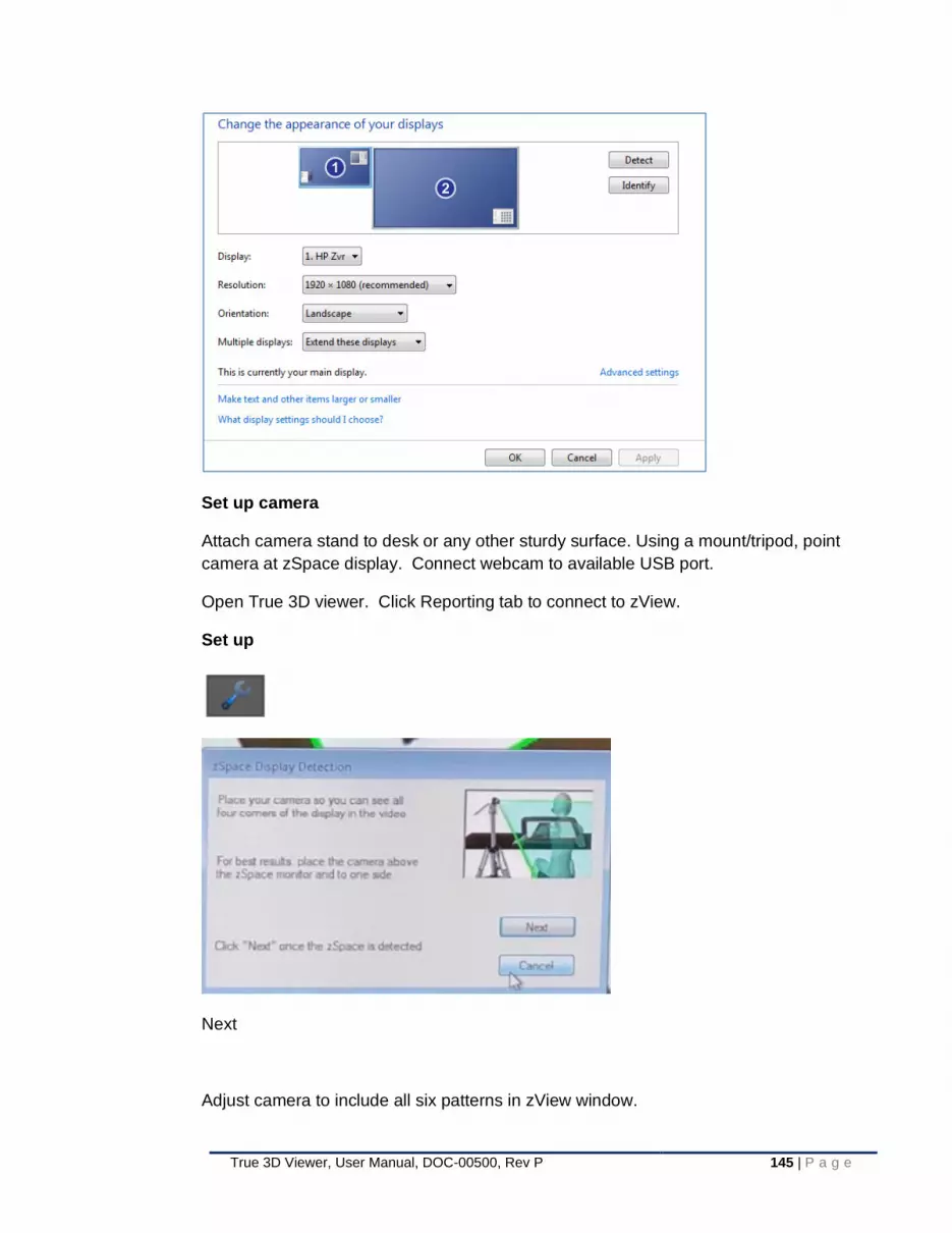
True 3D Viewer, User Manual, DOC-00500, Rev P 145 | P a g e
Set up camera
Attach camera stand to desk or any other sturdy surface. Using a mount/tripod, point
camera at zSpace display. Connect webcam to available USB port.
Open True 3D viewer. Click Reporting tab to connect to zView.
Set up
Next
Adjust camera to include all six patterns in zView window.

146 | P a g e True 3D Viewer, User Manual, DOC-00500, Rev P
Click finish.
Use the 3D controller to select cut plane. Pull cut plane off zSpace screen. Pull anatomy
to cut plane.
Image will appear in front of zSpace display.
Figure 92: zView application with True 3D Viewer
10.24 User Preferences
Start-up settings can be modified by going to User Preferences under the Settings pull-down menu from the top toolbar. There are three tabs: Loading Defaults, Basic, and Advanced. Below, the features under each tab are described.
Loading Defaults tab
• Default Orientation - choose the initial orientation of the 2D image or volume upon startup; options are axial, coronal, or sagittal

True 3D Viewer, User Manual, DOC-00500, Rev P 147 | P a g e
• Default Orientation Object – choose the initial orientation object; options are Orientation box or human model.
• Reference View Scale: Choose size of Reference view, small, medium or large
• Start Reference View Visibility – choose whether reference view is on or off after stating application
• Default Switch to Annotation Mode during Measurement – choose if annotation mode is automatically enabled when a measurement function is engaged
• Default Apply Advanced Measurement Transfer Function – choose if the advanced measurement transfer function is applied when an advanced measurement is done on the volume
• Default Start Mode - select whether DICOM data is first displayed in Intuitive 2D or Volume mode upon start-up
• Default Cut Plane Position - choose between displaying the main object with Radiology or Surgical view upon start-up
• Default Ray Length - defines the length of the 3D controller interaction ray upon start-up
Figure 93: User Preferences Loading Defaults
Basic tab
• Preferred Input Directory - specifies the folder that appears on the left panel of the Open DICOM window when loading image data
• Preferred Output Directory - specifies the folder that opens when the user saves an image, scene, export a segmentation, or anonymize DICOM image data; saving a report always automatically saves to this location

148 | P a g e True 3D Viewer, User Manual, DOC-00500, Rev P
• Data Sharing Email Address – specifies which email address will be implemented when sending reports or screen shots from. Auto populates the Email dialog in the From field.
• Default Rotation - defines the degree to which each press of the Ctrl + Arrow controls rotates the main object about the cut plane center (Ctrl + Arrow) or the volume center (Shift + Ctrl + Arrow)
• Default Text Size – defines the 3D Menu and information panel size
Figure 94: User Preferences Basic
Advanced tab
• Context Menu Visibility - show/hide Context Menu
• Cut Plane Visibility when selected - show/hide the cut plane during cut plane interaction with the ray
• Screen Capture Information Panel Visibility - select whether panels are captured or ignored when taking screenshots
• Annotation Point Editing – select whether editing is performed in free space or on visible objects when in editing mode
• Fluoroscopy Default Viewing Mode – select whether the fluoroscopy image will load next to the volume or overlaid in the volume
• Fluoroscopy Default Loading Position – When Fluoroscopy is loaded overlaid, select whether the Fluoroscopy image will be on screen, with the volume rotated so the angulation of the fluoroscopy image is parallel to the screen, or in volume so the volume stays in its default loading position with the fluoroscopy angulated inside the volume
• Eye Separation – adjusts display settings to accommodate distance between viewer’s eyes (the selectable range is 5 to 8 cm); See Appendix B for additional information.

True 3D Viewer, User Manual, DOC-00500, Rev P 149 | P a g e
Figure 95: User Preferences Advanced
Transfer Functions tab
Ability to change the defaults for the following for the data types in CT, MR, XA and Ultrasound.
• Default on Initial Lod – sets the transfer for when the application first opens
• Advanced Measurements – sets the transfer function for when the user is in an advanced measurement
• Preset 1 – sets the transfer function for preset 1
• Preset 2 – sets the transfer function for preset 2
• Additional presets: Shows the rest of the presets
• Preset 3-10 – sets the transfer functions for presets 3-10

150 | P a g e True 3D Viewer, User Manual, DOC-00500, Rev P
Figure 96: Transfer Function User Preference
Figure 97: Additional Presets in Transfer Function User Preferences
Window Width/Level tab
You will be able to change the window width and window level presets for the data
types CT, MR, XA and US
• Preset 1 – sets the window width/level for F9
• Preset 2 – sets the window width/level for F10
• Preset 3 – sets the window width/level for F11

True 3D Viewer, User Manual, DOC-00500, Rev P 151 | P a g e
• Preset 4 – sets the window width/level for F12
Figure 98: Window Width/Level user preference
To accept any changes to the user preference settings, click Save. To exit the window without applying changes, click Cancel.
Notes
It is important to remember that saved scene settings have priority over user preferences (see §10.20) settings. If any settings, established in a scene, conflict with those set in the user preferences, the saved scene settings will take priority. For example, if you set a ray length of 10 and bind the 1 key to the MRI transfer function preset before saving your scene, those will take priority over the ray length and 1 key assignment specified in user preferences when you load that scene.
10.25 Security and visible patient information
10.25.1 System administration
System administration allows the user to:
• Manage users
• View user login activity
• Log system performance while the program is open
• Log Audit – documents the access or manipulation of PHI (Protected Health Information).
• Set a specified program expiration time
• Configure connected hardware and / or application settings
Select System Administration
Select System Administration under the Settings pull-down menu from the top toolbar. There are two tabs under System Administration - the User Management

152 | P a g e True 3D Viewer, User Manual, DOC-00500, Rev P
tab and System Utilities tab. The available settings under each tab are organized by function and described below:
User Management tab
User information and privileges
Each username will be listed along with its corresponding password, user type, and access to save reports and anonymize data.
• User Type - Open this dropdown menu to label a user as an Administrator, Field Engineer, Emergency, Sales, or User.
• Report Authorization - Check to enable the user to create reports
• Anonymize Authorization - Check to enable the user to anonymize DICOM data
Create/delete user
• Create New User - Creates a new user and sets their username and password
• Delete User - Delete a user by clicking on the username to be deleted and then clicking the Delete User button.
Figure 99: System Administration
System Utilities tab
• Session expiration
o Set Session Expiration Time - Establish the time of inactivity that will cause the application to log out. Any annotations on the data will be lost if not previously saved.

True 3D Viewer, User Manual, DOC-00500, Rev P 153 | P a g e
• Logging activity
o Set Logging Level - choose between Info, Debug, Advanced, Profiling, or All.
o Open Login Log - A user with administrator rights can select this button to open a text document listing the login activity. The list will show the following information for each login: Username, Password, Date, Time, Access Granted, and Authorization Level.
• Audit Log
o Set Log Date Range – allows the user to set the date ranges to retrieve the audit log
o Open Audit Log – A user with administrator rights can select this button to open the text document listing the audit log activity. The list will show the following information: Date, Time, Username, Authorization level, Patient ID, Patient Name, Accession Number, Action performed
o Set Retention Duration – allows the user with administrator rights to select how long the audit logs are retained
After changing settings, click Save in the lower right corner of the window to accept them; click Cancel to reject changes.
Figure 100: System Utilities Tab
Manage 3D Settings tab
This tab provides functionality for configuring a second connected display (§10.3)
Note: These options will be disabled under hardware Configurations B, C, and D

154 | P a g e True 3D Viewer, User Manual, DOC-00500, Rev P
• Extended Display
o Enable: Determines whether the 3D scene should be duplicated on
the extended display
o Stereo Format: Sets the stereo format of the extended display.
Currently supported options are Time Sequential and Non-Stereo
Figure 101: Manage 3D Settings
After changing settings, click Save in the lower right corner of the window to accept them; click Cancel to reject changes.
Interaction Calibration tab
This tab provides functionality for configuring the 3D controller.

True 3D Viewer, User Manual, DOC-00500, Rev P 155 | P a g e
• Offsets: Controls the mapping between the position of the 3D controller in physical space, and the position of the interaction ray on the display. Users may change each of the X, Y, and Z offsets, which modify the mapping between horizontal, vertical, and depth displacements, respectively.
Note: It is recommended that users keep all interaction offsets set to their default values in order to maximize range of motion
• Key for Button Press: The keyboard key that is triggered when the user steps on the footswitch. This effectively enables a user to use the keyboard as an alternate means for replicating the Front / Center button functionality
Head Tracking tab
The Head Tracking tab provides functionality for configuring the active head tracking system.
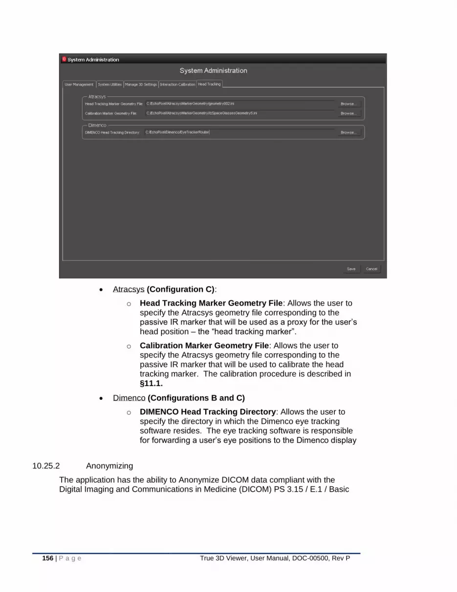
156 | P a g e True 3D Viewer, User Manual, DOC-00500, Rev P
• Atracsys (Configuration C):
o Head Tracking Marker Geometry File: Allows the user to specify the Atracsys geometry file corresponding to the passive IR marker that will be used as a proxy for the user’s head position – the “head tracking marker”.
o Calibration Marker Geometry File: Allows the user to specify the Atracsys geometry file corresponding to the passive IR marker that will be used to calibrate the head tracking marker. The calibration procedure is described in §11.1.
• Dimenco (Configurations B and C)
o DIMENCO Head Tracking Directory: Allows the user to specify the directory in which the Dimenco eye tracking software resides. The eye tracking software is responsible for forwarding a user’s eye positions to the Dimenco display
10.25.2 Anonymizing
The application has the ability to Anonymize DICOM data compliant with the Digital Imaging and Communications in Medicine (DICOM) PS 3.15 / E.1 / Basic

True 3D Viewer, User Manual, DOC-00500, Rev P 157 | P a g e
Application Level Confidentiality Profile (Implementation of E.1.1 De-identify & E.1.2 Re-identify).
Only a user with “anonymize” rights can anonymize data (see §10.25.1).
1. To save an anonymized copy of the data, select Anonymize under the Reporting pull-down menu.
2. A window will appear, showing the following:
a. preferred output directory specified under User Preferences (see §10.20). Allows ability to create and name a folder where an anonymized copy of the data can be stored or save it under an existing folder. Hit Save to trigger the anonymize process and save the data.
b. A text entry to Add a patient name
c. A text entry to add a Patient ID.
d. A checkbox to keep the series description
Figure 102: Anonymize window
Indicators of anonymized data
Each file in the folder has an ANON suffix added to the end of its original file name. This indicates that the data is anonymized.
When attempting to load the anonymized data via the load DICOM command, you can preview the DICOM series in the Series Details panel of the DICOM Series Selector window. Any DICOM tag specified under the DICOM Confidentiality Profile will be hidden.
When loading from the patient browser, the anonymized patient will be seen as an entirely new patient, under the Patient Name and ID given in the Anonymize window.
When opening anonymized data, the Patient Name will be the text entered from the Anonymize window.

158 | P a g e True 3D Viewer, User Manual, DOC-00500, Rev P
(a) Load anonymized data window. Notice that Patient Name and
Protocol name are now absent from the Series Details panel (left blank in Anonymize window above)
(b) An anonymized DICOM series is displayed. Notice that the Patient
Name is now missing from the information panel, this one was left blank
Figure 103: Anonymization
NOTE: Philips 3DDCM data can not be anonymize.
10.25.3 De-Anonymizing
The De-Anonymize DICOM command is compliant with the Digital Imaging and Communications in Medicine (DICOM) PS 3.15 / E.1 / Basic Application Level Confidentiality Profile (Implementation of E.1.1 De-identify & E.1.2 Re-identify).

True 3D Viewer, User Manual, DOC-00500, Rev P 159 | P a g e
Only a user with “anonymize” rights can de-anonymize DICOM image data (see §10.25.1) that is located on the local hard drive, DVD drive and through USB ports. All patient information originally associated with the file will become visible once again.
1. To save a de-anonymized copy of the data, select De-Anonymize under the Reporting pull-down menu in the top toolbar.
2. A window will appear, showing the preferred output directory specified under User Preferences (see §10.20). Here, the user can name the folder where the user desires to save the de-anonymized copy of the data or save it under an existing folder. Hit save to trigger the de-anonymize process and save the data.
Indicators of De-anonymized data
EchoPixel files that have been de-anonymized, will have the ANON suffix (indicates anonymized data) removed, indicating that the patient data is visible.
When attempting to load the de-anonymized data via the load DICOM command, you can preview the DICOM series in the Series Details panel of the DICOM Series Selector window. Any DICOM tag specified under the DICOM Confidentiality Profile will be visible. You will also see the Patient Name in the information panel at lower left.
Notes
Only DICOM series that were anonymized with the True 3D Viewer can be de-anonymized with the True 3D Viewer.

160 | P a g e True 3D Viewer, User Manual, DOC-00500, Rev P
(a) Load de-anonymized data window. Notice that the Patient Name and
Protocol Name are present in the Series Details panel, where they would be absent for anonymized
(b) A de-anonymized DICOM series is displayed. Notice that the Patient
Name is present in the information panel, where it would be absent for anonymized data
Figure 104: Data de-anonymization

161 | P a g e True 3D Viewer, User Manual, DOC-00500, Rev P
10.26 Shortcuts

162 | P a g e True 3D Viewer, User Manual, DOC-00500, Rev P

163 | P a g e True 3D Viewer, User Manual, DOC-00500, Rev P
10.27 Context Menu
The Context Menu is comprised of four tabs: Action Modes, View Modes, Advanced Measurements. Each tab contains an interactive list of buttons to engage the corresponding action.
Interaction
To bring up the Context Menu, press the right 3D controller button. The Context Menu will appear in the lower right corner of the screen. The buttons of the Context Menu can be selected with the mouse cursor, but not the ray. To close the Context Menu, press the right 3D controller button again. If the Context Menu is not visible, check the “Advanced” tab under User Preferences (see §10.20) to ensure that it is not set to Hidden.
The interactive buttons in each tab of the Context Menu are shown below, along with a brief description of their function or main purpose.
Figure 105: Action Modes tab
Figure 106: View Modes tab
Figure 107: Advanced Measurement tab

164 | P a g e True 3D Viewer, User Manual, DOC-00500, Rev P
10.28 Ultrasound Interactions
10.28.1 Obtaining Ultrasound data
The EchoPixel True 3DViewer can import volumetric (3D) data from GE and
Philips Ultrasound systems. The following Appendices provide information on
exporting and configuring the Ultrasound Data as well as how to be able to import
the data into the EchoPixel True 3D software:
Appendix C– Exporting Volumetric (3D & 4D) Studies from a GE Vivid Ultrasound
Device
Appendix D- Convert Philips US CV Image Data using QLab Table of Contents
Appendix E- Set up the True 3D Viewer to import Philips (3DDCM) ultrasound
data
10.28.2 Ultrasound Menu
When an US data set is loaded, a menu item entitled Ultrasound will appear in the
file menus. This will contain information depending on US type.
If the US has default color, it will apply on the volume visible as a transfer function
(See § 10.8.8)
There is an option to set the Patient orientation (see § 10.28.6 )
If the US data set has Doppler information, the menu will have the options to show
the Doppler data, and Apply the cut plane to the Doppler.
Figure 108: Ultrasound Menu
10.28.3 Navigating through the series images
The Study menu is now highlighted when opening a multi-slice Ultrasound image. The user will be able to navigate through each series of the US data image similar to that of navigating Multiple Series Image Data (see §10.6.3)
10.28.4 Cine Function
Under the Study menu, the cine function items will appear. Once the Cine is started, the multi-slice US data will display all the series images in a loop. The user will be able to adjust the speed, change the color to the default and start or stop the cine. The default cine speed will depend on the data, and the increase/decrease increments are always 100ms.
The hot key for this function is “/” this can also be accessed via the 3D UI →
for play, pause, next and prior frames.

True 3D Viewer, User Manual, DOC-00500, Rev P 165 | P a g e
To show next and previous images, the same hotkeys for scrolling through series is used “.” and “,”
Figure 109: Cine Menu US Data
10.28.5 ECG Trace
The user will be able to show the ECG Trace of some data sets. Once selected, a graph will show points indicating the number of the series, the x axis will show the time in seconds of the series image, and the y axis will show the signal intensity. The highlighted point on the graph will correspond to the current series on the screen. As the cine goes, the highlighted point will change according to the image on the screen.
Figure 110: ECG Trace example
10.28.6 Ultrasound Orientation
There is no orientation object when an Ultrasound is loaded. There is an option under the
Ultrasound menu to set the orientation for the patient.

166 | P a g e True 3D Viewer, User Manual, DOC-00500, Rev P
Figure 111: Ultrasound Orientation
When the orientation is defined, a set of 6 lines will intersect through the data, allowing the
user to set the following directions:
• Anterior/Posterior
• Right/Left
• Inferior/Superior
Once these are set, after pressing Esc, the orientation object will remain on the screen as
a reference. The user will have the option to keep the labels of the directions on.
Figure 112: Ultrasound data with Orientation Labels

True 3D Viewer, User Manual, DOC-00500, Rev P 167 | P a g e
11 Calibration Procedures
11.1 Atracsys Head Tracking (Configuration C only)
Because the Atracsys system tracks the position of a known IR-reflective marker as
opposed to directly tracking a user’s eye or head positions, markers used for head
tracking must be calibrated against a separate marker representing known eye
positions. The calibration procedure is as follows:
11.1.1 Ensure that valid head tracking and calibration markers have been specified. This can be achieved through the System Administration windows as described in §10.25.1
11.1.2 Under the Settings pull-down menu from the top toolbar, select “Head Tracking Calibration”. The following screen appears:
11.1.3 With both the head tracking and calibration markers mounted in such a manner that each has a clear and unobstructed view of the Atracsys tracker device cameras, stand facing the display at a distance of approximately 3-5 feet. A green circular icon with a checkmark inside indicates that the corresponding marker has been recognized by the tracking system:

168 | P a g e True 3D Viewer, User Manual, DOC-00500, Rev P
11.1.4 If there is negligible relative motion between the two makers, an additional icon will appear indicating that the calibration procedure has produced a stable result:
11.1.5 Once the calibration is stable, press any key to complete the calibration procedure. The calibration marker may now be removed and stored.
Note: Calibration data is stored along with each user profile and reloaded at the start
of each session. Therefore (provided that the head tracking marker is positioned
consistently across sessions), it is expected that calibration need only be performed
once when a new user logs into the application for the first time using their unique
credentials.
11.2 Dimenco Display Tracking System Calibration (For Reference Only)
Under normal operating conditions, the tracked position of the user’s eyes should
always be reported within the coordinate frame of the display. However, if the tracking
system is somehow perturbed or misaligned, or if any of the internal tracking system
configuration files become corrupted, then the tracking system may need to be
recalibrated. This situation is generally recognizable when the user begins to “see
double” in either certain regions, or throughout the entirety of the display area. The
calibration procedure is outlined below:
11.2.1 Configuration B
11.2.1.1 From the Dimenco Eye Tracker installation directory, navigate to and start FeatureExtraction.exe
11.2.1.2 Set the keyboard focus to the “Key Input” window
11.2.1.3 Press [Shift + b], which will show a black screen with a green cross centered on the Dimenco display
11.2.1.4 Set the origin
11.2.1.4.1 Press [Shift + p]
11.2.1.4.2 Sit approximately 1 meter away from the display. Move your head to the center of the display where the center of the cross lies between your eyes as seen reflected on the screen. Press [Enter]
11.2.1.4.3 Repeat the previous step, but at a distance of ~1.5-2.0 meters from the display

True 3D Viewer, User Manual, DOC-00500, Rev P 169 | P a g e
11.2.1.4.4 Press [spacebar] to lock the measurement. A green dot should appear between your two eyes, and should follow your movements, always remaining between your eyes
11.2.1.4.5 Press [Shift + s] to save the settings
11.2.1.5 Set the rotation
11.2.1.5.1 Move your head to the left or right edge of the display. If the green dot appears too high or too low, press [Shift + 9] or [Shift + 0] to shift the dot up or down. Verify the new positioning by moving to all extremes of the display
11.2.1.5.2 Press [Shift + s] to save the settings
11.2.1.6 Set the filter coefficient
11.2.1.6.1 When you move your head, the green dot may either lag behind or overshoot your movements. Press [+] or [-] on the numpad to change the aggressiveness of the filter
11.2.1.6.2 Press [Shift + s] to save the settings
11.2.1.7 Set the viewing distance
11.2.1.7.1 Stand approximately 1.2 meters away from the display
11.2.1.7.2 Press [Shift + v]. You should see a completely black screen when one eye is closed and a completely white screen when the opposite eye is closed
11.2.1.7.3 Press [left arrow] until you clearly see a pattern of repetitive bars
11.2.1.7.4 Use the [e] and [Shift + e] keys to adjust the orientation of this pattern until it is completely horizontal
11.2.1.7.5 Press [right arrow] until these bars have disappeared and you once again see a completely black screen when one eye is closed and a completely white screen when the oppose eye is closed
11.2.1.7.6 Press [Shift + s] to save the settings
11.2.1.8 Set the centerview
11.2.1.8.1 Press [Shift + m]. You should see a repeating pattern of three vertical bars
11.2.1.8.2 The amount of crosstalk should be the same for both eyes. You can verify this by first closing your left eye and ensuring that the right bar in each group appears bright and the left bar is dark. Do the same with your right eye, ensuring that the left bar in each group appears bright and the right bar appears dark. The brightness levels should be equal for both eyes. If not, press the [page up] and [page down] keys until the proper result is achieved
11.2.1.8.3 Press [Shift + s] to save the settings
11.2.2 Configuration C
11.2.2.1 From the Dimenco Eye Tracker installation directory, navigate to and start EyeTrackerRouter.exe

170 | P a g e True 3D Viewer, User Manual, DOC-00500, Rev P
11.2.2.2 Navigate to the EchoPixel True3D Viewer bin directory (C:\Program Files\EchoPixel\True3D Viewer\bin) and type “cmd” in the Windows file explorer address bar to open a command prompt.
11.2.2.3 Type the following line into the command prompt:
epxAtracsysEyePositionForwarder [AtracsysCalibrationMarkerGeometryFile]
where [AtracysCalibrationMarkerGeometryFile] is the filename corresponding to the
Atracsys marker geometry file characterizing the calibration marker.
11.2.2.4 Mount the Atracsys calibration marker and follow the steps outlined in §11.2.1.2 - 11.2.1.8

True 3D Viewer, User Manual, DOC-00500, Rev P 171 | P a g e
12 Residual Hazards
When the True 3D Viewer System is used for its Intended Purpose by Health Care Professionals, trained in using imaging systems for their Intended Purpose the True 3D Viewer System has one identified residual hazard that is considered at an Intolerable level. See the WARNING statement in section 5.1
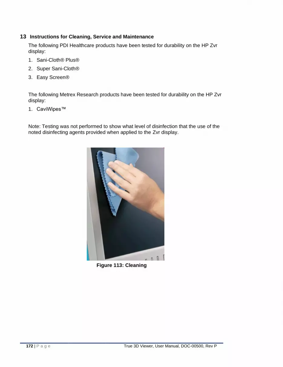
172 | P a g e True 3D Viewer, User Manual, DOC-00500, Rev P
13 Instructions for Cleaning, Service and Maintenance
The following PDI Healthcare products have been tested for durability on the HP Zvr display:
1. Sani-Cloth® Plus®
2. Super Sani-Cloth®
3. Easy Screen®
The following Metrex Research products have been tested for durability on the HP Zvr display:
1. CaviWipes™
Note: Testing was not performed to show what level of disinfection that the use of the noted disinfecting agents provided when applied to the Zvr display.
Figure 113: Cleaning

True 3D Viewer, User Manual, DOC-00500, Rev P 173 | P a g e
14 Bibliography
No bibliography
15 Labels
Figure 114: Sample of a True 3D Viewer Software and Labeling Disc
Note: This is a SAMPLE of the label on the disc. The contents and versions may vary
from release to release and lot to lot. If needed, contact
[email protected] to obtain an image of the current release.

174 | P a g e True 3D Viewer, User Manual, DOC-00500, Rev P
Appendix A - Advanced Segmentations tutorial
This tutorial explains segmentation features in advanced detail.
A.1 Segmentation Process.
The implemented image segmentation process to generate 3D surfaces is comprised of an image segmentation phase with 4 steps and a mesh (surface) generation phase with 5 steps.
A.2 Image Segmentation Phase.
The image segmentation phase will always process the image data across 4 filters that will generate a binary image mask of the segmented feature.
The HPC will have the option to choose between two image segmentation algorithms that implement region growing strategies. A region growing strategy means that the segmentation mask is created by the HCP selecting points that correspond to the desired structure and the algorithm recursively filtering the image to iteratively grow the identified segmentation region.
The following steps describe the image segmentation process for both segmentation region growing strategies:
Segmentation Process.
1. Reduce image noise by applying a Gaussian image filter.
2. Based on the HCP selected points, apply to the resulting image from the Gaussian image filter the Confidence Connected or Connected Threshold segmentation strategy.
3. Apply a binary hole fill image filter that will recursively fill any potential “hole” resulting from the segmentation strategy.
4. Dilate (expand) the resulting mask from the hole fill image filter to better approximate the edge of the target segmentation structure.
Table 15: Advanced Segmentation
Below is a description of each filter applied through the segmentation phase.
A.3 Gaussian Filter
Blurs an image by separable convolution with discrete Gaussian kernels.
This filter performs Gaussian blurring by separable convolution of an image and a discrete Gaussian operator.
The Gaussian operator used here was described by Tony Lindeberg (Discrete Scale-Space Theory and the Scale-Space Primal Sketch. Dissertation: Royal Institute of Technology, Stockholm, Sweden. May 1991.) The Gaussian kernel used here was designed so that smoothing and derivative operations commute after discretization.
The variance or standard deviation is evaluated as pixel units.

True 3D Viewer, User Manual, DOC-00500, Rev P 175 | P a g e
A.4 Confidence Connected Image Filter
Segment pixels with similar statistics using connectivity.
This filter extracts a connected set of pixels whose pixel intensities are consistent with the pixel statistics of a seed point. The mean and variance across a neighborhood (26-connected) are calculated for a seed point. Then pixels connected to this seed point whose values are within the confidence interval for the seed point are grouped. The width of the confidence interval is controlled by the "Multiplier" variable (the confidence interval is the mean plus or minus the "Multiplier" times the standard deviation). If the intensity variations across a segment were Gaussian, a "Multiplier" setting of 2.5 would define a confidence interval wide enough to capture 99% of samples in the segment.
The HCP can set the multiplier value between 0.1 and 5.0.
After this initial segmentation is calculated, the mean and variance are re-calculated. All the pixels, defined in the previous segmentation, are used to calculate the mean and the standard deviation (as opposed to using the pixels in the neighborhood of the seed point). The segmentation is then recalculated using these refined estimates for the mean and variance of the pixel values. This process is repeated for the specified number of iterations. Setting the "NumberOfIterations" to zero stops the algorithm after the initial segmentation from the seed point.
The HCP can set the number of iterations between 1 and 10.
A.5 Connected Threshold Image Filter
Label pixels that are connected to a seed and lie within a range of values.
The filter labels pixels with a 255 voxel value that is connected to an initial Seed AND lie within a Lower and Upper threshold range.
The HCP can set the Lower and Upper threshold values between the minimum and maximum image values of the loaded data.
A.6 Voting Binary Hole Filling Image Filter
Fills in holes and cavities by applying a voting operation on each pixel. The filter will iteratively be applied to the mask image, a total of 10 iterations.
A.7 Binary Dilate Image Filter
Fast binary dilation.
This filter is a binary dilation morphologic operation. This implementation is based on the papers:
• L.Vincent, "Morphological transformations of binary images with arbitrary structuring elements”, and
• N.Nikopoulos et al. "An efficient algorithm for 3d binary morphological transformations with 3d structuring elements for arbitrary size and shape". IEEE Transactions on Image Processing. Vol. 9. No. 3. 2000. pp. 283-286.
A.8 Mesh (surface) generation phase.
The resulting binary mask from the image segmentation phase is converted into a 3D surface by applying 5 filters, initially operating on the image mask and at the end smoothing the resulting 3D surface.

176 | P a g e True 3D Viewer, User Manual, DOC-00500, Rev P
Regardless of the segmentation strategy applied in the image segmentation phase, the following filters are applied through the mesh generation process.
Image Gaussian Smooth – Performs a Gaussian convolution.
This filter implements a convolution of the input image mask with a Gaussian.
Marcing Cubes – Generates isosurface(s) from volume.
Filter that takes as input a volume (e.g., 3D structured point set) and generates on output one or more isosurfaces. One or more contour values must be specified to generate the isosurfaces.
Because the image segmentation phase generates a binary image mask whose segmentation values are 255, the isosurface value is set to 255.
Smooth PolyData Filter – Adjusts point positions using Laplacian smoothing.
Filter that adjusts point coordinates using Laplacian smoothing. The effect is to "relax" a mesh, making the cells better shaped and the vertices more evenly distributed.
The algorithm proceeds as follows. For each vertex v, a topological and geometric analysis is performed to determine which vertices are connected to v, and which cells are connected to v. Then, a connectivity array is constructed for each vertex. (The connectivity array is a list of lists of vertices that directly attach to each vertex.)
Next, an iteration phase begins over all vertices. For each vertex v, the coordinates of v are modified according to an average of the connected vertices. (A relaxation factor is available to control the amount of displacement of v). The process repeats for each vertex. This pass over the list of vertices is a single iteration.
The NumberOfIterations is a cap on the maximum value of 200 of smoothing passes. The Convergence Ivar is a limit on the maximum point motion, it is set to 0. If the maximum motion during an iteration is less than Convergence, then the smoothing process terminates. (Convergence is expressed as a fraction of the diagonal of the bounding box.)
Triangle Filter – Create triangle polygons from input polygons and triangle strips. Filter that generates triangles from input polygons and triangle strips.
Clean Polygonal Filter – Filter that merges duplicate points, and/or remove unused points and/or remove degenerate cells.
Filter that takes polygonal data as input and generates polygonal data as output. It can merge duplicate points (within specified tolerance and if enabled), eliminate points that are not used, and if enabled, transform degenerate cells into appropriate forms (for example, a triangle is converted into a line if two points of triangle are merged).

177 | P a g e True 3D Viewer, User Manual, DOC-00500, Rev P
Appendix B – Quick Way to Measure Interpupillary Distance
Purpose: When the True 3D Viewer generates the images for the right and left eyes, these images are generated assuming that the default distance between the viewer’s eyes are 6cm apart. Slight variations in this pupillary distance won’t provide a noticeable difference in the perceived 3 dimensional images. The 6cm is a default distance but this can be changed in the User Preferences section and can be attributed to each signed-in individual’s preferences. Measurement of pupillary distance:
There are many ways to measure the pupillary distance. You might have a prescription from your optometrist. If not, there are some very simple ways to obtain a measurement. In all cases, you will need a ruler. A metric ruler is best but it is also possible to use a US Customary scale ruler and then perform the mathematic conversion.
Step 1. Place the Ruler above your eyes, with the metric scale as close to your eyes as possible.
Step 2. Use one of the following methods to obtain a measurement: a) Have an associate view the ruler
and measure the distance between your eyes.
b) Look in a mirror and provide your own measurement (least favorable method)
c) Using a Cell Phone, take a “selfie” of your face. When taking the photo, make sure to focus your eyes on an object in the distance so as to reduce the effect of your eyes crossing to focus on the phone.

178 | P a g e True 3D Viewer, User Manual, DOC-00500, Rev P
Step 3. Obtain the measurement: To convert a US Customary scale (inches) to centimeters (cm), multiply the measured inches by 0.394.
Step 4. Enter this distance into the User Preference for Eye Separation (see section
10.22)

179 | P a g e True 3D Viewer, User Manual, DOC-00500, Rev P
Appendix C – Exporting Volumetric (3D & 4D) Studies from a GE Vivid Ultrasound Device
Note: This is guidance information only, refer to the device User or Reference Manual.
Ultrasound studies can be exported to either a CD/DVD-ROM or to a USB Memory Stick.
If using a CD / DVD:
Preparing the CD/DVD
Note: Only CD-R or DVD-R (depending on your system model) can be used!!
Insert the medium in the CD-Tray.
Go to the Config (F2) on the Ultrasound system or on EchoPAC in the first row.
Select the Connectivity tab.
Afterwards click on the Tools tab in the middle of the screen.
1. Select the right medium by using the arrow at the end of the row.
2. Enter a name for the CD/DVD. Don’t use special characters like *?§$-.
3. Then press the format button.
A warning pops up if you want to overwrite all existing data. This needs to be answered with OK.
Depending on the medium size this process takes a little bit of time.
Note:
EchoPAC SW only cannot store directly on CD!!
EchoPAC SW only is for installation on users computers. These computers have various setups and different types of programs for burning CD/DVD. It’s not possible to directly access this huge variation of programs from the EchoPAC Software.
If using a USB Flash Device
Note: For Patients safety it is only recommended to use the GE tested USB Flash Disk.
Note 2: Depending on the Ultrasound System’s age it might be possible that there is no USB plug. Then only CD can be used.
Preparing the USB Memstick
It’s not necessary to format the USB Flash Disk before using.

180 | P a g e True 3D Viewer, User Manual, DOC-00500, Rev P
Save images
Recall the desired image from the archive.
You may optimize the image with the post processing functionality.
… save as
Move the mouse cursor over the image.
Press the right mouse key or the Update/Menu button.
A small menu opens. From this select the Save As function.
A new window opens
Select the drive
Click on the arrow in the first line to open a list with possible storage devices.
Working on Vivid 7, Vivid S6, Vivid I or EchoPAC PC Turnkey
You may choose between:
• CD/DVD writable
• USB Flash Disk
Working on EchoPAC SW only
It is possible to use the USB Flash Disk for storage otherwise the images need to be stored on the internal hard disk.
Select image format
In the lower part of the window the image format needs to be selected.
Click on the arrow to get the full list of image formats.
• AVI Cineloop
• MPEG Cineloop
• JPEG Still frame
• RAW DICOM and DICOM need a special DICOM viewer for review and cannot be used for normal presentations.
• For EchoPixel use, choose: VolDICOM (only present with 4D option) and HDF are for research purposes.
Image name
You may enter your own name for each image. Otherwise the system will automatically name the images with Image01, Image02, Image 03…..
Select the image capture size
Usually only the Ultrasound image will be stored. For special purposes also a quad view or the full screen can be stored as image.
Choose from the following options:
Image only only the ultrasound image will be stored
Secondary capture a still frame of the complete whole screen is stored
Quad view when a quad view is used for image review this can be stored when choosing this option
Save
When all options are chosen simply press the Save button.
Depending on the image size the storage process can take some time.

True 3D Viewer, User Manual, DOC-00500, Rev P 181 | P a g e
Follow the same procedure for all images of interest.
Ejecting the media
Note:
• The media has to be properly ejected to avoid loss of data or damage of the media!
• Press the Eject button (F3) on the keyboard or alternatively press the Alt + E keys together.
• Select the media that was used for the storing the images.
• Depending on the amount of data the proper ejection can take several minutes.
• Especially when a CD or DVD was used the burning process is starting with this action.
• Once the system has finished the operation a message appears on the screen.
• The media can be safely removed from the system now.
Images on Internal hard disk
Note:
Only when an EchoPAC SW only was used and the images are stored on the internal hard disk.
Where to find the images
• Images can be found in the export folder of EchoPAC.
• The exact location can be seen in the in the save as window.
• In this example the images are on D:\EchoPAC_PC\ARCHIVE\export D part of the hard drive EchoPAC folder on drive D:
• Archive folder inside the EchoPAC folder
• Export folder inside the Archive folder
• By using i.e. the Windows explore the images can be found on this location.
• The images can now be moved to another location on the computer or on a USB Flash Disk.
• By using the computer’s file burning application, the images can also be burned on a CD/DVD.
Source Information: GE Healthcare, Vivid Club document – “How to save images for a Presentation”
Import into the True 3D Viewer
Insert the created media (CD/DVD or USB Flash Device) to the computer running the EchoPixel True 3D Viewer. From the Patient Browser, Import the desired study.

182 | P a g e True 3D Viewer, User Manual, DOC-00500, Rev P
First in order to export VolDicom Datasets a 3D image must first be selected and a Flash drive inserted in USB port or Disk in the disk drive:
Open desired 3D image
Right click on image using the “update/menu” button up and to the right of the trackball on the system.
“System Menu” will appear

True 3D Viewer, User Manual, DOC-00500, Rev P 183 | P a g e
Choose “Save As” option
Choose “VolDicom” form “Save as type” menu
Eject USB via “Alt+E” on keyboard to ensure media is closed properly and bring to EchoPixel Workstation.

184 | P a g e True 3D Viewer, User Manual, DOC-00500, Rev P
Appendix D - Convert Philips US CV Image Data using QLab Table of Contents
Requirements
• Qlab version 10 or greater installed on a system
• Volumetric data from a Philips Ultrasound System
Qlab Conversion Instructions
Open Qlab by clicking on the QLAB Icon on the computer desktop
File → Open
Browse to the location of the Philips Volumetric US data.
Select all of the desired series and press the “Open” button.
All of the desired series will be listed in the bottom right Qlab window.

True 3D Viewer, User Manual, DOC-00500, Rev P 185 | P a g e
Select a Series that has a Q ( ) in the upper right corner and double click.
The series will open in a viewer.
Click on the Q in the tool bar and select CV 3D Viewer
NOTE: Only series that have this Q can be converted to be opened in the True 3D Viewer

186 | P a g e True 3D Viewer, User Manual, DOC-00500, Rev P
The selected series will open in the CV 3D Viewer.
Click the Export Image icon in lower left of screen (highlighted in yellow below):
This brings up a Export dialog. Update the File Name if desired, under “Save as Type”, select Cartesian DICOM (3DDCM) and click save.

True 3D Viewer, User Manual, DOC-00500, Rev P 187 | P a g e
This results in a .dcm file with Cartesian parameters with the True 3D Viewer can open.
Trouble Shooting
Enabling Cartesian DICOM option If you do not see “Cartesian DICOM(3DDCM)” as type, you may need to enable Cartesian export. To enable Cartesian Export, go into the core preferences at the lower left of the screen (highlighted in yellow below):
Turn on the option:

188 | P a g e True 3D Viewer, User Manual, DOC-00500, Rev P
Error “Unsupported Modality type” when trying to load data If you see the following error:
Then most likely, the wrong data type was selected when saving in QLab. Please try to re-export from Qlab and ensure “Cartesian DICOM (3DDCM)” is selected.

189 | P a g e True 3D Viewer, User Manual, DOC-00500, Rev P
Appendix E - Set up the True 3D Viewer to import Philips (3DDCM) ultrasound data
In order to load 3DDCM data, the application will need to be run in a different mode known
as “Stand Alone Mode”. The following will provide instructions on how to bypass the
patient browser and open any DICOM data type in the viewer.
Setting up the application to run in “Stand Alone mode”
Using a Windows Explorer application, navigate to the following directory:
C:\Program Files\Echopixel\True3DViewer\bin
Locate the file epxMain.exe. Right Mouse Button click on the filename.
At this point you may want to create a shortcut of the application in “Stand Alone Mode” to
your desktop for the future.

190 | P a g e True 3D Viewer, User Manual, DOC-00500, Rev P
It is advised to rename the new desktop shortcut. Single Left Mouse button click on the
Icon then press the F2 key.
From here, the user can Double Left Mouse Button Click on the True 3D Stand Along icon
to start the application.
Login into the application:

True 3D Viewer, User Manual, DOC-00500, Rev P 191 | P a g e
Once the application opens only the viewer is maximized. There is no Patient Browser.
The user can now load DICOM data following the steps in section 10.5.

192 | P a g e True 3D Viewer, User Manual, DOC-00500, Rev P
Appendix F - Document History
Revision Change Order / Summary of Change / Justification
of Change
Document Date
(dd-mmm-yyyy)
J
ECO-00158
Summary of change: Updated to include changes to software 1.6.1
Justification of change: Provide users with information needed to operate the True 3D Viewer
01-Apr-2017
K
ECO-00197
Summary of change: Updated to with 1.6.2 login window and mention of the About Window. Add 1.6.2 (Canyon Project) Release Features. Add Eye Separation measurement to Annex.
Justification of change: Comply with requests from Health Canada plus Canyon Updates
26-Aug-2017
L
ECO-00215
Summary of change: Updated Manufacturing address. Add info on Stand Alone mode
Justification of change: EchoPixel moved to a new location, updates to maintain labeling compliance. Stand alone mode used to import 3DDCM ultrasound files.
19-Jan-2018
M
ECO-00226
Summary of change: Updated to include features for the 1.6.3 release
Justification of change: Provide users with information needed to safely operate the True 3D Viewer
01-May-2018
N
ECO-00248
Summary of change:
1. Updated features for the 1.6.4 release 2. Removed installation and software setup to DOC-
00060. Referred installation to same.
Justification of change:
1. Provide users with information needed to safely operate the True 3D Viewer
2. With varying configurations and amount of True 3D Features, needed a way to reduce the document volume and make it easier for users to find needed information.
13-Sep-2018
Document Owner: Development