TROUBLESHOOTING GUIDE - It works!
11
1 ILQ TROUBLESHOOTING GUIDE Rev. 1.1, Date 1-15-2009
-
Upload
khangminh22 -
Category
Documents
-
view
1 -
download
0
Transcript of TROUBLESHOOTING GUIDE - It works!

1
ILQ
TROUBLESHOOTING GUIDE
Rev. 1.1, Date 1-15-2009

2
ILQ – Series (until June 2008)
Troubleshooting: ILQ with rectangle circuit board on driver side
Table of content: Page
1) Gate overview and connector setup………………....2
2) Gate does not tilt open up…………………………….3
3) Gate is not lowering down…………………………….4
4) Gate is not auto tilting down at ground level…....…..5
5) Gate is not tilting up at ground level..………………..6
6) Gate is not lifting up.…………………………………..7
7) Gate is not closing……………………………………..8
8) Electrical schematic……………………………………9
9) Hydraulic schematic………………………………….10
*****MAKE SURE YOUR BATTERIES ARE FULLY CHARGED
AND IN GOOD CONDITIONS*****
Tools needed:
1.) Voltmeter2.) Test light3.) 8” jumper cable (16ga. or smaller)4.) Screw driver flat head or 13mm (1/2”) wrench
Interlift Inc.
Phone: 888-774-5844
Fax: 562-924-8318
Email: [email protected]

3
Overview of liftgate and connector setup of circuit board
1
2
1.) Cab cut-off switch
2.) Control panel
3.) B-13 lift arm switch
4.) B-16 platform sensor
5.) Pump & motor tray
6.) Circuit board
7.) foot control
8.) Serial tag
1
2
3
4
5
6
7
8
B13 LIFT ARM B16 PLATFORM
POWER PACK CYLINDERS
CAB CUT OFFSWITCH
CONTROL PANEL
HAND REMOTE
GR
OU
ND
LIFT 15 (2 ea) TILT 14 (2ea)

4
1) GATE DOES NOT TILT OPEN UP
a) Check resettable Circuit Breaker on top of batteries � Push Reset Tab back in, if popped out
b) Check fuse on top of batteries (qty 1) and
at pump & motor (qty 2) inside the main tube on passenger side
c) Start truck and run engine in fast idle for charging the battery
� if liftgate starts working, recharge batteries� test batteries and truck charging system
d) Check power at motor solenoid on the small terminals with voltmeter by pushing the
up-function and hold it for 10 sec with gate in stored position (DEADHEAD GATE)
(above 10 Volt is necessary for proper use of liftgate) � less than 10 V; Jump X-2 #2 to X8 #4
� voltage jumps more than 1volt, call Interlift for assistance
****DO NOT LEAVE JUMPER ON – GATE MUST BE SHUT OFF WHEN NOT IN USE****
1.1) Check Battery Power
a) Unplug X5 (B-13 and B-16 Sensors) and X7 (Hand control) ***Set Jumper at X-7 at #4.1 to #4.2***
Keep the 2 connectors unplugged (gate will operate without plugs connected, will loose auto tilt)
b) Unplug X-1 (Main power), wait 10 seconds and plug X-1 back to the board (Reset the board)
c) Plug each connector back, one at a time and check functions of gate after plugging in each
1.2) Check for short in optional equipment
a) Check voltage at X4 #14 and Ground X-11 while pushing the tilt knobs for opening up the release
valves at the tilt cylinders. No Voltage � check for loose wire at X-6 or no signal at X-6 #14
b) Listen for clicking of the release valves at the tilt cylinders (outer cylinders)
- If valves are not clicking � check wire for damaged spots, loose connections or a bad valve
1.3) Check voltage supply to release valves on tilt cylinder
a) Check voltage at X-1 #3 and Ground X-11 while pushing opening knobs to engage motor solenoid
No voltage � board might be damaged
b) Check voltage at small motor solenoid studs and Ground motor post while pushing knobs
and listen for clicking of the motor solenoid – no voltage or clicking � check wire to motor solenoid
c) Check for voltage across the small motor solenoid studs with test light while turning knob
See a light � power is reaching solenoid.
d) Check for main power at the big solenoid studs, one has voltage; if not check connections to battery
e) Check big solenoid studs for voltage while pushing the opening knobs � if not � solenoid is bad
f) Jump large terminals at motor solenoid
- If motor runs � motor solenoid is bad
- If motor does not run � Bad motor or bad ground
- Tap on motor � motor starts running – bad brushes
1.4) Check motor solenoid power
Interlift Inc.
Phone: 888-774-5844
Fax: 562-924-8318
Email: [email protected]
ILQ
SERIES

5
2) GATE IS NOT LOWERING DOWN
a) Check resettable Circuit Breaker on top of batteries � Push Reset Tab back, if popped out.
b) Check fuse on top of batteries (qty 1) and
at pump& motor (qty 2) inside the main tube on passenger side
c) Start truck and run engine in fast idle for charging the battery
� if liftgate starts working, recharge batteries � test batteries and truck charging system
d) Check power at motor solenoid on the small terminals with voltmeter by pushing the
up-function knob and hold for 10 sec with gate upper lift position (DEADHEAD GATE)
(above 10 Volt is necessary for proper use of liftgate) � less than 10V; Jump X-2 #2 to X-8 #4
� voltage jumps more than 1 volt, call Interlift for assistance
****DO NOT LEAVE JUMPER ON – GATE MUST BE SHUT OFF WHEN NOT IN USE****
2.1) Check Battery Power
a) Unplug X-5(B-13 and B-15 Sensors) and X-7(Hand control) ***Set Jumper at X-7 from #4.1 to #4.2***
Keep the 2 connectors unplugged (gate also operates without plugs connected, will loose auto tilt)
b) Unplug X-1 (Main power), wait 10 seconds and plug X-1 back to the board (Reset the board)
c) Plug each connector back one at a time and check functions of gate after plugging in each
2.2) Check for short in optional equipment
a) Check voltage at X-4 #15 and Ground X-11while pushing the lowering knob for opening
the release valves at the lift cylinders. No voltage � check for bad knob or loose wire at control panel
b) Listen for clicking of the release valves at the lift cylinder (inner cylinders)
� If valves are not clicking � check wire for damaged spots or loose connections
2.3) Check voltage supply to release valves on lift cylinder
a) Check Voltage at X-1 #12 and Ground X-11while pushing knob to engage the shift valve at
the pump and motor inside the main tube
b) Override the shift valve by pushing down the center brass pin with small Phillips screwdriver while
pushing the down knob
� Gate will lower down � check the valve and look for damaged wire or loose connections
2.4) Gate is lowering down very slowly � S5 at motor not engaged
Motor
Reservoir
S5 Shift Valve
Interlift Inc.
Phone: 888-774-5844
Fax: 562-924-8318
Email: [email protected]
ILQ
SERIES

6
3) GATE IS NOT AUTO TILTING
AT GROUND LEVEL
a) Check resettable Circuit Breaker on top of batteries � Push Reset Tab back in, if popped out
b) Check fuse on top of batteries (qty 1) and
at pump& motor (qty 2) inside the main tube on passenger side
c) Start truck and run engine in fast idle for charging the battery
� if liftate starts working, recharge batteries � test batteries and truck charging system
d) Check power at motor solenoid on the small terminals with voltmeter when gate in upper lift position (above 10 Volt is necessary for proper use of liftgate) � less than 10V; Jump X-2 #2 to X-8 #4
� voltage jumps more than 1 volt, call interlift for assistance
****DO NOT LEAVE JUMPER ON – GATE MUST BE SHUT OFF WHEN NOT IN USE****
3.1) Check Battery Power
a) Check the position of the B-13 Sensor on the inside of the passenger side liftarm
� Sensor has to be in a horizontal position when gate is 8”-10” above ground
b) Check if the inner X-5 Plug is loose (color sequence = brown, black)
3.2) Check adjustment of auto-tilt sensor B-13
a) Check voltage at X-5 #(BLACK)(B-13) to Ground X-11 while platform is on ground � 12V
b) Check voltage at X5 #(BROWN)(B-13) to Ground (J11) while platform is on ground � 12V
� No voltage on BROWN � Look for damaged spots, loose connection or bad B-13
c) Check voltage at Ground X-11 to X4 #14 while pushing the lowering button when gate is on
ground for opening up the release valves at the tilt cylinders
d) Listen for clicking of the release valves at the tilt cylinder (outer cylinders)
� If valves are not clicking � check wire for damaged spots or loose connections
3.4) Check voltage supply to release valves on tilt cylinder
a) Check voltage at X-6 #4.2 to Ground X-11 for power supply of the control panel
at X-7 #4.2 to Ground X-11 for power supply of the hand control
b) Check voltage at X-6 #6.1(lower) to Ground X-11 for lowering signal
�Signal on X-6 #6.1 � control panel is ok; if no signal check for damaged wire or loose connectors
inside control panel or damaged knob
3.3) Check function of control panel or hand control
Interlift Inc.
Phone: 888-774-5844
Fax: 562-924-8318
Email: [email protected]
ILQ
SERIES

7
4) GATE IS NOT TILTING UP AT GROUND
a) Check resettable Circuit Breaker on top of batteries � Push Reset Tab back in, if popped out
b) Check fuses on top of batteries (qty 1) and
at pump& motor (qty 2) inside the main tube on passenger side
c) Start truck and run engine in fast idle for charging the battery
� if liftgate starts working, recharge batteries � afterwards test batteries and truck charging system
d) Check power at motor solenoid on the small terminals with voltmeter
(above 10 Volt is necessary for proper use of liftgate) � less than 10 V; Jump X-2 #2 to X8 #4
� voltage jumps more than 1volt, call Interlift for assistance
****DO NOT LEAVE JUMPER ON – GATE MUST BE SHUT OFF WHEN NOT IN USE****
4.1) Check Battery Power
a) Check voltage at X-1 #3 to Ground X-11 while turning lift knob to engage motor solenoid
b) Check for voltage at small motor solenoid studs and Ground motor post while pushing button and
listen for clicking of the motor solenoid – no voltage or clicking � check wire to motor solenoid
c) Check for voltage across the small motor solenoid studs with test light while pushing button
�See a light � power is reaching solenoid.
d) Check for main power at the big solenoid studs, one has voltage; if not check connections to battery
e) Check both big solenoid studs for voltage while pushing the lifting button � if not � solenoid is bad
f) Jump large terminals at motor solenoid
- If motor runs � motor solenoid is bad
- If motor does not run � Bad motor or bad ground
- Tap on motor � motor starts running – bad brushes
4.3) Check motor solenoid power to run the motor (2nd person needed)
a) Check voltage at X1 #12 and Ground X-11 while pushing button to engage the shift valve at
the pump and Motor inside the main tube (2nd person needed)
b) While pushing the button to make the motor run, override shift valve by pushing the center brass pin
with small Phillips screwdriver
� Gate will tilt up, if not � check the valve and look for damaged wire or loose connections
4.4) Check function of shift valve S5 at pump & motor
a) Check voltage at X-6 #4.2 to Ground X-11 for power supply of the control box
X-7 #4.2 to Ground X-11 for power supply of the hand control
b) Check voltage at X-6 #5.1(lift) to Ground X-11 for lifting signal
�Signal on X-6 #5.1 � control box is ok; if no signal check for damaged wire or loose connectors
inside control box or damaged turn knob
4.2) Check function of control box or hand control
MotorReservoir
S5 Shift Valve
Interlift Inc.
Phone: 888-774-5844
Fax: 562-924-8318
Email: [email protected]
ILQ
SERIES

8
5) GATE IS NOT LIFTING UP
a) Check resettable Circuit Breaker on top of batteries � Push Reset Tab back in, if popped out.
b) Check fuse on top of batteries (qty 1)
at pump& motor (qty 2) inside the main tube on passenger side
c) Start truck and run engine in fast idle for charging the battery
� if liftgate start working, recharge batteries � test batteries and truck charging system
d) Check power at motor solenoid on the small terminals with voltmeter
(above 10 volt is necessary for proper use of liftgate) � less than 10V; Jump X-2 #2 to X-8 #4
� voltage jumps more than 1 volt, call Interlift for assistance
****DO NOT LEAVE JUMPER ON – GATE MUST BE SHUT OFF WHEN NOT IN USE****
5.1) Check Battery Power
a) Unplug X-5 (B-13 and B-16 sensors) and X-7(Hand control) ***Set Jumper at X-7 at #4.1 to #4.2***
Keep the 2 connectors unplugged (gate will operate without plugs connected, will loose auto tilt)
b) Unplug X-1 (Main power), wait 10 seconds and plug X-1 back to the board (Reset the board)
c) Plug each connector back, one at a time and check functions of gate after plugging in each.
5.3) Check for short in optional equipment
a) Check for voltage at X-1 #3 to Ground X-11 to engage motor solenoid while pushing lift knob
No voltage � board might be damaged
b) Check for voltage at small motor solenoid studs to Ground motor stud while pushing button and
listen for clicking of the motor solenoid – no voltage or clicking � check wire to motor solenoid
c) Check voltage across the small motor solenoid terminals with test light while pushing button
See a light � power is reaching solenoid
d) Check for main power at the large solenoid studs one has voltage; if not check connections to battery
e) Check both big solenoid studs for voltage while pushing the opening button � if not � solenoid is bad
f) Jump large terminals at motor solenoid
- If motor runs � motor solenoid is bad
- If motor does not run � Bad motor or bad ground
- Tap on motor � motor starts running – bad brushes
5.4) Check motor solenoid power to run the motor (2nd person needed)
a) Check voltage at X-6 #4.2 to Ground X-11 for power supply of the control panel
X-6 #4.2 to Ground X-11 for power supply of the control panel
b) Check voltage at X-6 #5.1(lift) to Ground X-11 for lifting signal
�Signal on X-6 #5.1 � control box is ok; if no signal, check for damaged wire or loose connectors
inside control panel or damaged buttons
5.2) Check function of control panel or hand control
Interlift Inc.
Phone: 888-774-5844
Fax: 562-924-8318
Email: [email protected]
ILQ
SERIES

9
6) GATE IS NOT CLOSING
a) Check resettable Circuit Breaker on top of batteries � Push Reset Tab back in, if popped out
b) Check fuse on top of batteries (qty 1)
at pump& motor (qty 2) inside the main tube on passenger side
c) Start truck and run engine in fast idle for charging the battery
� if liftgate start working, recharge batteries � test batteries and truck charging system
d) Check power at motor solenoid on the small terminals with voltmeter by pushing the
up-function buttons and hold for 10 sec with gate in upper position (DEADHEAD GATE)
(above 10 Volt is necessary for proper use of liftgate) � less than 10V; Jump X-2 #2 to X-8 #4
� voltage jumps more than 1 volt, call interlift for assistance
****DO NOT LEAVE JUMPER ON – GATE MUST BE SHUT OFF WHEN NOT IN USE****
6.1) Check Battery Power
a) Check voltage at X-1 #3 and Ground X-11 to engage motor solenoid while pushing lift button
No voltage � board might be damaged (2nd person needed)
b) Check voltage at small motor solenoid studs and Ground motor stud while pushing buttons and
listen for clicking of the motor solenoid – no voltage or clicking � check wire to motor solenoid
c) Check voltage across the small motor solenoid terminals with test light while pushing buttons
See a light � power is reaching solenoid
d) Check main power at the large solenoid studs, one has voltage; if not check connections to battery
e) Check both big solenoid studs for voltage while pushing the opening buttons � if not � solenoid is bad
f) Jump large terminals at motor solenoid
- If motor runs � motor solenoid is bad
- If motor does not run � Bad motor or bad ground
- Tap on motor � motor starts running – bad brushes
6.4) Check motor solenoid power to run the motor
a) Check voltage at X-6 #4.2 to Ground X-11 for power supply of the control panel
at X-7 #4.2 to Ground X-11 for power supply of the hand control
b) Check voltage at X-6 #3.1(close) to Ground X-11 for lifting signal
�Signal on X-6 #3.1 � control box is ok; if no signal, check for damaged wire or loose connectors
inside control box or damaged buttons
6.2) Check function of control box
a) Check Voltage at X-1 #12 and Ground X-11 while pushing buttons to engage the shift valve at
the pump and motor inside the main tube (2nd person needed)
b) Override the shift valve by pushing down the center brass pin with small Phillips screwdriver while
pushing the buttons �Gate will close up �check the valve, look for damaged wire or loose connections
6.3) Check for S5 valve on pump & motor not engaged
Interlift Inc.
Phone: 888-774-5844
Fax: 562-924-8318
Email: [email protected]
ILQ
SERIES
10
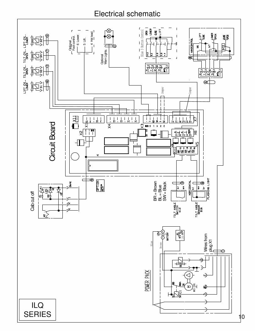
Circu
it B
oard
Cab c
ut off
Optio
nal
Warn
Lig
hts
Wires
from
plu
g X
1150
Blue
Brown
Jumper
Optio
nal
Foot co
ntrol
6 Low
er
5 Lift
4 H
ot le
ad
BR
= B
row
nB
L = B
lue
SW
= B
lack
3Blue 3 Button Control
Jumper
Electrical schematic
ILQ
SERIES

11
Functions:
Lift: M+S1+S2Lower: S1+S2+S5Tilt Up: M+S5Tilt Down: S3+S4Horiz. Open: M+S3+S4
Pressure Relief
2850 PSI200 bar
Shift Valve S5
Restrictor Valve R5
Flow Divider
Functions:
S1 and S2 = Release Valve for lowering functionS3 and S4 = Release Valve for tilt down functionR1 and R2 = Flow Restrictor located inside hose adaptor on lift cylinderR3 and R4 = Flow Restrictor located inside hose adaptor on tilt cylinderS5 = Shift Valve is activated on tilt up and lowering functionR5 = Restrictor Valve located in power packFlow Divider is activated, when fluid is going back into the power packIf Flow Divider is loose or hanging up the fluid is circulated back in to tank
Hydraulic schematic
ILQ
SERIES