PowerSCADA Expert v. 8.0 System Integrator's Manual - It works
304
PowerSCADA Expert v. 8.0 System Integrator's Manual User Guide 63220-100-200I1 03/2015
-
Upload
khangminh22 -
Category
Documents
-
view
0 -
download
0
Transcript of PowerSCADA Expert v. 8.0 System Integrator's Manual - It works

PowerSCADA Expert v. 8.0 System Integrator's ManualUser Guide
63220-100-200I1
03/2015


Safety information
Important information
Read these instructions carefully and look at the equipment to become familiar withthe device before trying to install, operate, service or maintain it. The following spe-cial messages may appear throughout this bulletin or on the equipment to warn ofpotential hazards or to call attention to information that clarifies or simplifies a pro-cedure.
The addition of either symbol to a "Danger" or "Warning" safety label indicatesthat an electrical hazard exists which will result in personal injury if the instruc-tions are not followed.
This is the safety alert symbol. It is used to alert you to potential personal injuryhazards. Obey all safety messages that follow this symbol to avoid possibleinjury or death.
DANGERDANGER indicates an imminently hazardous situation which, if not avoided,will result in death or serious injury.
WARNINGWARNING indicates a potentially hazardous situation which, if not avoided,could result in death or serious injury.
CAUTIONCAUTION indicates a potentially hazardous situation which, if not avoided,could result in minor or moderate injury.
NOTICENOTICE is used to address practices not related to physical injury. Thesafety alert symbol shall not be used with this signal word.
Please note
Electrical equipment should be installed, operated, serviced and maintained only by qualified personnel.No responsibility is assumed by Schneider Electric for any consequences arising out of the use of thismaterial.
A qualified person is one who has skills and knowledge related to the construction, installation, and oper-ation of electrical equipment and has received safety training to recognize and avoid the hazards involved.

Safety precautionsDuring installation or use of this software, pay attention to all safety messagesthat occur in the software and that are included in the documentation. Thefollowing safety messages apply to this software in its entirety.
WARNINGUNINTENDED EQUIPMENT OPERATION
• Do not use the software for critical control or protection applicationswhere human or equipment safety relies on the operation of the controlaction.
• Do not use the software to control time-critical functions because com-munication delays can occur between the time a control is initiated andwhen that action is applied.
• Do not use the software to control remote equipment without securing itwith an authorized access level, and without including a status object toprovide feedback about the status of the control operation.
Failure to follow these instructions can result in death or serious injury.
WARNING
INACCURATE DATA RESULTS
• Do not incorrectly configure the software, as this can lead to inaccuratereports and/or data results.
• Do not base your maintenance or service actions solely on messagesand information displayed by the software.
• Do not rely solely on software messages and reports to determine if thesystem is functioning correctly or meeting all applicable standards andrequirements.
• Consider the implications of unanticipated transmission delays or fail-ures of communications links.
Failure to follow these instructions can result in death, serious injury,equipment damage, or permanent loss of data.

Contents 63220-100-200I103/2015
ContentsSafety information 1
Important information 1Please note 1
Safety precautions 1Contents iIntroduction 1PowerSCADA Expert—A Complete Solution 1Assumptions 1What is SCADA? 1What is PowerSCADA Expert? 2Prepare for PowerSCADA Expert 2
Components of a Project 2Configuration Tools 2Runtime Environment 3Supported Device Types and Protocols 3How Do Drivers Work? 3Two Subscription Types 3Subscription Expirations 4
Edit Driver Parameters 4Problems with Duplicate Devices using PowerLogic Drivers 4
System Requirements and Installation Instructions 5Uninstall and Reinstall PowerSCADA Expert 5
Quick Start: Typical Workflow 5IEC 61850 System Setup Workflow 8Get More Information 9Manuals 9Help files 9Customer support 9
Use the Migration Utility 10The Profile Editor 12Overview of the Profile Editor 13Typical Workflow Illustration 13Workflow Overview 14Create/Edit Device Type 15Create/Edit Device Profile 16Create/Edit Unit Templates 17
Launch the Profile Editor 17Locked and Custom Icons 17Set the Screen Resolution 18
Profile Editor Main Menu Options 18Add Engineering Unit Templates, Units, and Conversions 19Set Up Engineering Templates and Select Conversions 19Apply Conversions 21Delete a Template 21
Add or Edit a Base Engineering Unit or Conversion 22Edit a Base Engineering Unit or Conversion 23Delete a Base Engineering Unit or Conversion 23
Define Device Types and Tags 23Device Type Screens and Workflow 23Use the Define Device Type Tags Tab 24Add, Edit, or Delete a Device Type 26Edit a Device Type 27Delete a Device Type 28
© 1990–2015 Schneider Electric All Rights Reserved i

Assign Tags to Generic I/O Points 28Print the .CSV File 29Set Up Device Type Categories 29Add a Category or Subcategory 30Edit a Category/Subcategory Name 30Delete a Category or Subcategory 30
Edit Functional Addresses 31Add Custom Tags and Tag Addresses 31Set Up Custom Tags 31Edit a Custom Tag 33Delete a Custom Tag 34Edit Tag Addresses 34Real-Time Tag Addresses 34Onboard Alarm Tag Addresses 36Reset Tag Addresses 36Control Tag Addresses 37Edit Address Information 38Add a New Tag Address 38
Edit Generic Tag Addresses 39Create Device Profiles 39Enable Waveforms 39View Device Profiles 39Add Edit or Delete Device Profile 41Add a Profile 41Edit a Profile 42Delete a Profile 43
Select Trend Intervals 43Set Up Trend Intervals 43To add a trend interval: 43To edit a trend interval: 43To delete a trend interval: 44
Edit IEC 61850 Datasets 44Create a New DataSet 44Create a DataSet from an Existing DataSet 44Copy a DataSet to a Device Type 45Edit and Delete DataSets 45
Edit IEC 61850 Report Control Blocks 45Create a New Report Control Block 45Create a Report Control Block from an Existing Report Control Block 46Copy a Report Control Block to a Device Type 46Edit and Delete Report Control Blocks 46
Create a Composite Device Type 46Create Data Concentrator Device 48G3200 Device Setup 48For use with multiple devices 49In the Profile Editor 49In CET850 49In PowerSCADA Expert 49
For use with a single device 49In the Profile Editor 49In CET850 49In PowerSCADA Expert 50
DNP3 Protocol Support 50Set Up Projects in the Profile Editor 50Project Screens and Workflow 50Typical Workflow 51
The Set Up Projects Tab 51
ii © 1990–2015 Schneider Electric All Rights Reserved
63220-100-200I1 Contents03/2015

Contents 63220-100-200I103/2015
Adding a Project 52Edit a Project 53Delete a Project 53Edit and Delete Information in a Project 54Customize Tag Names 54Add Project Parameters 54
Import and Export Project Files 54Export a Project 55Before you export 55To export a Profile Editor project to the PowerSCADA Expert project: 55To Move Files if the Profile Editor is not with the Server (Reuse of a Project) 56
Profile Editor Export 56SCL Export 57Exporting the File 57
Import Files into the Profile Editor 57Import SCL Files 59
Import Filter Screen 59Functional Constraints 59Report Control Blocks 59
Import Reconciliation Screen 60Left-hand pane: 61Middle pane: 62Right-hand pane: 63Complete the Import 63
Using Import Templates 64Creating a New Template During Import 64Applying a Template During Import 64Deleting a Template 65
Tag Types 65IEC 61850 Tag Construction 65Define an Enumeration 66Use Special Tags to Control Circuit Breaker Status 67
Format Code Definitions 67Real-Time Format Code Definitions 67Alarm Format Code Definitions 68Control Format Code Definitions Rules of Operation 69Predefined Control Format Codes 69Predefined Reset Format Codes 69Custom Control and Reset Format Codes 69
Logic Codes 69Block Writes 85
The Profile Wizard 87Before You Use the Profile Wizard 87Add the Cluster, Network Address, and Servers 88When You Set Up More than two I/O Servers per Cluster 90Enter Copy for Translation 91
Using the Wizard to Add and Remove Devices 91Add a Device to a Project 92Add a TCP Device to a Project 92Add the TCP Device 92
Add a Serial Device to a Project 94Adding the Serial Device 94
Add a DNP3_TCP Device 96Add the DNP3_TCP Device 96
Add an IEC 61850 Device to a Project 98Add the IEC 61850 Device 98LDName 99
© 1990–2015 Schneider Electric All Rights Reserved iii

BRCBs and URCBs 99Port Names 100Edit Devices in a PowerSCADA Expert Project 100Edit a Profile and Add it Back to the Project 100Edit a Device in PowerSCADA Expert Only 101Add Device Data in PowerSCADA Expert Only 101
Remove a Device From the Project 101Add Multiple Devices through the Automation Interface 102Use the OLE Automation Interface to Add and Remove Devices 103Examples 104C# 104Excel VBA 105
Command Line Interface 105Interface Workflow 105Prerequisite information 106Interface 107
The Design Time Environment 109Typical Workflow 109The PowerSCADA Expert Pages 110Create a Project 110Reuse Projects Created in the Profile Editor 111Before You Begin 111Add a New Graphics Page 111Change the Background Color of Pages 112Change the Genie Color in Project Pages 112Set a New Page as the Project Startup Page 112Create a One-Line on a Graphics Page 112Enable Lockout/Tagout 114Use Menu Configuration to Edit Pagemenu.dbf (Change the Graphics Page Appearance) 115Create New Genies 116To create a copy of a genie: 117To create a custom symbol for a custom genie: 117
Set Up IEC 61850 Advanced Control 117Enable the Advanced Control 118
Delete Information from PowerSCADA Expert 118Use PowerSCADA Expert One-Lines 118One-Line Flowchart 118What Are PowerSCADA Expert One-Lines? 120Where are the files located? 120
One-Line Device (zOL) 120One-Line Colors 121Assigning Colors 121
Add INI Settings to AdvOneLine.ini and Citect.ini 121AdvOneLine.ini Settings 121Citect.ini Settings 123
Start and Stop One-Lines 123Work with Genies 123Genie Type Descriptions 124Configure an Automatic Transfer Switch (ATS) 124Transfer Switch Information: Left/Right/Bottom 124Display Information 124
Configure a Busbar 125Configure a Circuit Breaker or Switch 125Configure a Meter 126Configure a Source 126Configure a Transformer 127GenieConfiguration.xml File 127
iv © 1990–2015 Schneider Electric All Rights Reserved
63220-100-200I1 Contents03/2015

Contents 63220-100-200I103/2015
SupportedGenies.xml File 127Work in the Configuration Utility 128One-Line Configuration Utility 128Modify AdvOneLine.csv 128
Review Genie Configurations 128One-Line Errors and Warnings 130Communication Errors 130Error Logging 130
Perform Repairs for One-Lines 131Automatic Transfer Switch (ATS) Information 132ATS Information 132ATS Errors 133
Busbar Information 133Busbar Errors 134
Breaker and Switch Information 134Breaker and Switch Errors 134
Meter Information 135Meter Errors and Warnings 135
Source Information 136Source Errors and Warnings 136
Transformer Information 137Transformer Errors 137
Work with Alarms 138Alarms Overview 138PC-Based Alarms 138Onboard Alarms 138
Set Up Alarm Pages 139Add Setpoints and Delays 139Set Up an Alarm Based on an Enumeration 139Change an Alarm Severity 140Enable Waveforms for Onboard Alarms 140Set Parameters for Event Log Length and Historical Logging of Events 140Event Storage: [Alarm]SummaryLength Parameter 140Event Logging: [PLSEventLog] Parameter 141
Add an Onboard Alarm Tag 141Set Up Audible Alarms 142
Restore and Back Up Projects 142Restore a Project 142PowerSCADA Expert Backup 143
Use Cicode to Customize a Project 143Use Cicode in PLS_Include 143PLSProviderEngine.ci Module 143Module Construction 143CallProvider 143GetProviderStatus 144GetProviderResult 145
Clear Cache and Refresh Platform 145PLS_CLearCache 145PLS_PlatformRefresh 146
Customize Default Behaviours 146Time Zone Settings 146Time Synchronization 147Trend Tag Scan Intervals 147Disk Storage Calculation for Trends 148Deadbands and Ignored Devices and Topics 148
© 1990–2015 Schneider Electric All Rights Reserved v

Waveform Management 150Waveform Storage 150Waveform Database and Special Waveform Tags 150
The Runtime Environment 152Launch and Close the Runtime Environment 153View the Graphics Page in the Runtime Environment 153Log On to the Runtime Environment 153View the Interface 153Lockout/Tagout Icon 154Communications Loss 155
View the Alarms/Events Page 155Equipment Column 155Filter Information 156Remove/Insert/Move Columns 156Sort by Column 156The Event Log 156The Alarm Log 156Unacknowledged Alarms and Disabled Alarms 157Alarm and Events Logging 157Acknowledge, Silence and Print 157
When Alarms do not Display Correctly 158Event/Alarm Log Columns Table 159Alarm/Event Filter Form 160Use Security Viewer 161Security Viewer Filter 162Use the Analysis Page 163Use the Equipment Pop-Up Page 164Perform IEC61850 Advanced Control 165View Waveforms 165Enter Setpoints for Alarms 165View Real-Time Trends 166View Lists of Real-Time Information for the Genie 166Override Tag Status 166
Perform IEC 61850 Advanced Control 167EcoStruxure WebServices (EWS) 169Use Basic Reports 169Set up the Runtime Environment for Basic Reports 170Create the Menu Items for Report Page 170Add the Following INI Parameters 170
Set Up a Display Client for Basic Report Viewing 171Tasks in the Basic Reporting Application 171Create and View Basic Reports 171Run a New Basic Report 171Run a Basic Report and Save its Configuration 172View a Basic Report Using a Saved Configuration 172Modify and View a Basic Report Using a Saved Configuration 173Remove a Saved Configuration 173
Configure Email Settings to Send Basic Reports 173Send Basic Reports via Email 174Scheduling Basic Reports 176
Read, Export, Print, and Edit Basic Reports 176Toolbar Options 177Export a Basic Report 177Edit the Basic Report Appearance 178
PowerSCADA Expert Basic Reports 178Single Device Usage Reports 178Multi Device Usage Reports 179
vi © 1990–2015 Schneider Electric All Rights Reserved
63220-100-200I1 Contents03/2015

Contents 63220-100-200I103/2015
Tabular Reports 180Trend Reports 180
Enable Windows Authentication for Basic Reporting 181URL Routing for Basic Reports 182Windows 2008 R2 and Windows 7 182Windows XP 182
Localization for Basic Reports 182Template Editor 183Use LiveView 183LiveView Tables 184LiveView Basic Readings Summary 184LiveView Power Flow Summary 184LiveView Energy Summary 185LiveView Energy Readings 185LiveView Fundamental Phasor Readings 185LiveView THD Current Summary 185LiveView THD Voltage Summary 186LiveView Uptime Summary 186LiveView Incremental Reactive Energy Summary 186LiveView Incremental Real Energy Summary 187LiveView Harmonic Apparent Power Flows 187LiveView Harmonic Reactive Power Flows 188LiveView Harmonic Real Power Flows 188LiveView Demand Current Summary 189Live View Demand Voltage Summary 189
LiveView Viewer 189Open LiveView from a URL Link 190LiveView Viewer Display 190
Where's My Device? 191Missing Topics 191Clear Cache and Platform Refresh 192
Set Up LiveView 192Create Menu Item for LiveView Page 193Create a LiveView Template 194LiveView Formatting 194LiveView Placeholders 195LiveView Formulas 196LiveView Thresholds 197Modify LiveView Template 198Duplicate LiveView Template 198LiveView Delete 199LiveView Template Localization 199Enable Windows Authentication for LiveView 199
Rapid Access Labels 200Before You Begin 200Create the Sticker 201Read the Sticker 201Troubleshooting 202
Multi-Monitor Support 202The Demo Mode 202Application Configuration Utility 203Application Services 204Diagnostics 204EcoStruxure Web Services Setup 204Avoiding EWS Provider Timeouts 205Event Notification Service 205
Application Services Host—Citect Data Platform 205
© 1990–2015 Schneider Electric All Rights Reserved vii

Applications 206One-Line Engine 206Basic Reports 207
Single Sign On 208Single Sign-On (SSO) Calls from a Web Client 208
Assign and Control User Privileges 209Default User Access Settings (Privileges) 209Add and Modify User Accounts 210Use Windows Integrated Users 210
Change Access Rights 211Appendix 1: Default Genie Library 212PLS_ALARM 212PLS_ANSI_BASE_1 / PLS_ANSI_BASE_2 212PLS_ANSI_CB_1 / PLS_ANSI_CB_2 214PLS_ANSI_SW_1 / PLS_ANSI_SW_2 215PLS_DISPLAY 215PLS_GEN_BASE_1 / PLS_GEN_BASE_2 216PLS_GEN_CMD_1 / PLS_GEN_CMD_2 217PLS_GEN_EQ_1 / PLS_GEN_EQ_2 217PLS_IEC_BASE_1 / PLS_IEC_BASE_2 218PLS_IEC_CB_1 / PLS_IEC_CB_2 218PLS_IEC_SW_1 / PLS_IEC_SW_2 219PLS_METER 219ITEM1 220
Appendix 2: Citect INI Parameters 221Parameters Database 221General PowerSCADA Expert Parameters 222watchtime 222kernelStatisticUpdateRate 222UseWriteMultiRegistersOnly 222timeout 223retry 223RetryTimeout 223RetryException 224standbyRefreshRate 224standbyCheckTime 224statusUnitCheckTime 225initUnitCheckTime 225initCacheTimeout 225cacheRefreshTime 226TimeSync 226StatusRegister 226StatusRegistersCount 227StatusRegisterType 227ModbusBase 227RegMode 228timeZone 228
Alarm Parameters 229UsePLSFilter 229
Performance Tuning Parameters 229Bandwidth Allocation Parameters 229BandwidthAllocation 230
Packet Blocking Optimisation Parameters 230enableScatteredReads 230percentBlockFill 230maxBlockSize 231minBlockSize 231
viii © 1990–2015 Schneider Electric All Rights Reserved
63220-100-200I1 Contents03/2015

Contents 63220-100-200I103/2015
Tag Scan Rate Parameters 232HighScanRate 232LowScanRate 232
Advanced Tag Block Capabilities (Invalid Memory Access Blocks defined) 232Invalid Block Tag Definition Syntax 233Configuration Notes 234Write-only Memory 235Tag Blocking Notes 236Write-only Tags 236
Waveform Parameters 237WaveformsDisable 237WaveformMatchMargin 238WaveformCheckTime (PM, CM, and Sepam) 238WaveformZone (Sepam) 238
Sepam Event Reading Parameters 238EventTable 238EventIdle 239
MicroLogic Modules Configuration Parameters 239CCM 239Module-Specific Packet Blocking Optimisation Settings 239MicrologicV INI Settings 240
Data Replication Parameters 240Database root folder path 240Database root UNC path 240Replication destination configuration 240
Graphics Library Parameters 241Maximum number of entries that can be held in Event Log 241Parameters for Alarm and Event States 241
© 1990–2015 Schneider Electric All Rights Reserved ix

Integration Parameters 242Appendix 3: Additional INI Parameters 244Quantum PLC Time-Stamped Events 244
Appendix 4: Glossary 245Appendix 5: Frequently Asked Questions (FAQs) 254If I don't use PowerLogic drivers, how do I create device profiles? 254How should we manage categories and subcategories? 254When should I create a device type rather than device profile? 254How do we synchronize a new PC with the master Profile Editor PC? 254What do I do before I add or remove devices in the Profile Wizard? 254What are the requirements for device names? 255How do I troubleshoot device communications issues? 255How do I use MODBUS communications methods? 256How can I add more than one device at a time? 256What are the naming conventions for servers and clusters? 256How and when do I create users for the Runtime environment? 256How do I manage projects in the Citect Explorer environment of PowerSCADA Expert? 257On the Graphics page, what do I need to know about creating genies? 258How do we customize existing templates? 258How do I change the default pickup/dropout text for alarms? 259What can I modify during runtime? 260Why do the browser navigation buttons not work? 260What can I set up in logging and archiving? 260How do I create and configure busbars? 260What INI parameters should I use for debugging? 261How do I tune my system for best performance? 262If a tag is configured, how is it polled in the device? 263Device popup from a one-line: Why do the fields overlap? 264Can I change the %CLUSTER% name in the Profile Wizard? 264When viewing PowerSCADA Expert from a web client, I see a licensing error. How do I fix it? 264A device can prevent writes to its registers: how do I ensure that writes are successful? 265How do I prevent PowerSCADA Expert from accidentally making invalid areas in memory available toreads and writes? 265How do I create an audit in the Event Log for user logins and logouts? 265Why do I get an "out of memory" message when I try to run the Automation Interface? 266Why am I seeing #COM for circuit breaker status in the genie status page? 266Why can't I acquire waveforms in the waveform viewer? 266Why won't the Excel DBF Add-In toolbar install? 267What causes the "First dbf record" error message? How do I keep it from happening? 267Why is my device in comms loss? 267How do I set up select before operate? 267
Index of Terms 268
x © 1990–2015 Schneider Electric All Rights Reserved
63220-100-200I1 Contents03/2015

Introduction 63220-100-200I103/2015
IntroductionWelcome to the help file for PowerSCADA Expert, v8.0. To navigate through the file,you can use the search options on the left. Additionally, you can access other relatedPowerSCADA Expert help files.
In this section, you will find these topics:
PowerSCADA Expert—A Complete Solution on page 1
Assumptions on page 1
What is SCADA? on page 1
What is PowerSCADA Expert? on page 2
Prepare for PowerSCADA Expert on page 2
Components of a Project on page 2
Configuration Tools on page 2
Runtime Environment on page 3
Supported Device Types and Protocols on page 3
System Requirements and Installation Instructions on page 5
Uninstall and Reinstall PowerSCADA Expert on page 5
Quick Start: Typical Workflow on page 5
IEC 61850 System Setup Workflow on page 8
Get More Information on page 9
Manuals on page 9
Help files on page 9
Customer support on page 9
PowerSCADA Expert—A Complete SolutionThe PowerSCADA Expert system provides a complete solution for the monitoring andcontrol of any electrical distribution network. Using PowerSCADA Expert 8.0 as theengine, this product includes additional tools that users will use to acquire data fromvarious devices, and then to apply the data for HMI viewing, alarming, trending, andreporting.
In this section, you will find these topics:
Assumptions on page 1
What is SCADA? on page 1
What is PowerSCADA Expert? on page 2
AssumptionsThe person who installs the product will have received training in the entirePowerSCADA Expert product and will understand the application’s basic functions.
What is SCADA?SCADA (Supervisory Control and Data Acquisition) is a system that collects data fromvarious points, both local and remote, and then stores the data at a central location.The system also can control equipment at an installation.
© 1990–2015 Schneider Electric All Rights Reserved 1

What is PowerSCADA Expert?This product includes several tools that use the PowerSCADA Expert engine to collectinformation from all PowerLogic devices:
• In the Profile Editor, you create, configure, and modify profiles for device types thatuse the same tags (for example, to set up alarms and trends).
• In the Profile Wizard, you add and modify devices in the PowerSCADA Expertsystem.
• In the One-Line Configuration utility, you can review genie configurations, and thenmake necessary repairs before you compile your project.
• In the CitectSCADA Graphics Builder (design time mode), you create one-linedrawings, into which you can incorporate objects (genies). Genies are versatileobjects that include variables or other expressions that are specified when youview the drawing.
• In the CitectSCADA Graphics Builder (runtime mode), users can view the final one-line drawings, including alarms, events, and history data. With the appropriatedegree of password-controlled authority, users can also perform advanced tasks,such as changing alarm setpoints and racking devices in and out.
Prepare for PowerSCADA ExpertFor a full discussion about preparation for a project, see Plan a Project in theCitectSCADA.chm help file (Program Files > Schneider Electric > PowerSCADA Expert> v8.0 > bin). This section of the help discusses physical layout, requirements such asarchitecture and security, and project design.
Components of a ProjectFor detailed information about the components that make up a project, seeComponents of a project in the citectSCADA.chm help file (Program Files>Schneider Electric > PowerSCADA Expert > v8.0 > bin). The project componentsinclude graphic components, tags, alarms, system components, communicationscomponents, I/O Server components and Cicode/CitectVBA.
Configuration ToolsConfiguration tools consist of:
Profile Editor: Use this tool to select tags to be used by device types (tags must beconsistent with IEC 61850 naming conventions), create device profiles for individualdevices, and create projects that include the device profiles to be used in a singleinstallation. You can specify real-time tags, PC-based alarm tags, onboard alarm tags,trend tags, and reset tags to be generated for this device.
Profile Wizard: Using this wizard, you will import device profile information from theProfile Editor into a project. This tool is simply a means of moving device profileinformation into the project and converting it into formats that PowerSCADA Expert canuse.
Citect Explorer: Use Citect Explorer for basic navigation. From here, you also choosethe active project.
Citect Project Editor: Use the Project Editor for entering database-type information,such as adding clusters and servers, creating new users, and editing tags withinprojects.
2 © 1990–2015 Schneider Electric All Rights Reserved
63220-100-200I1 Introduction03/2015

Introduction 63220-100-200I103/2015
Graphics Builder, Design-Time environment: Use the Citect Graphics Builder tocreate one-line drawings that users can view in the runtime environment. Thesedrawings are populated with interactive objects that are generated by genies. You canalso use the graphics tool to set up system alarms and trends.
Runtime EnvironmentThe runtime environment is where the end user views system information. Thisenvironment includes (from the information added in the design-time page) one-linepages with interactive objects, alarm and event pages, and analysis pages (trends andwaveforms).
Supported Device Types and ProtocolsWhen you install the product, you are prompted to choose the drivers that you will use.A certain number of generic drivers are installed by default (including PowerLogicdevice types), and you are not prompted for them. Device types and protocolssupported in PowerSCADA Expert are:
• Generic MODBUS (includes BCPM and any device, such as a PLC or UPS, thatcommunicates via MODBUS). When adding a controllable device in the ProfileEditor, such as a circuit breaker, use the “Controllable Device” driver; otherwise,use the “Generic Power Device” driver. For JBus devices, select Generic JBusDevice.
• Sepam 20, 40, and 80 Range, 2000• Masterpact MicroLogic 5P and 6P, A, H• Compact NSX (MicrologicV)• CM2000• CM4000 series• PM650• PM800 series• PM5000 series• PM700 series• ION protocol devices• IEC 61850 protocol devices• IEC 870-5-104• DNP3• BCPMA (branch circuit power meter, full feature support)• CSI SER (Cyber Sciences SER)
How Do Drivers Work?The following paragraphs describe driver subscriptions. For each unique tag requestmade, the I/O server adds one point to the point count. Tag subscriptions are limitedbased on the point count in the license. Exceeding the subscribed point count willultimately cause the I/O server to shut down.
Two Subscription Types
There are two different types, one used between the graphics level and I/O server, andone for polling devices and cache refreshing. The subscription between drivers andpolling devices does not increase point count. Only the subscription that begins at aclient system and ends up in the I/O server will increase point count. Via this
© 1990–2015 Schneider Electric All Rights Reserved 3
subscription, requests are sent to the drivers with value changes propagating all theway back to the client system. The client system could be the display client, alarmserver, trend server and so on. What a driver then chooses to do with the requests—interms of coupling this to a physical request to a field device—can differ, depending onthe protocol. Some simple protocols propagate the request straight through to the fielddevice; others have their own polling scheme to the field device and merely service thedriver requests from a cache.
Subscription Expirations
If a tag is no longer being read, the cache refreshes in this manner: Graphics clientsubscriptions are immediately unsubscribed when the graphics page is closed.Although most drivers release subscriptions if no client is requesting them, theIOServer is capable of background polling (configurable on a per-device basis). Thesetag subscriptions are not released, and the driver still polls them. However, they are notcounted anywhere, because nothing is consuming the data for those tags on theIOServer. On the other hand, once a subscription goes against the point count, itremains in the count as long as the project is running.
Expiration is immediate if no clients are subscribed to the tag. An "expiration time-outvalue" is not configurable.
Edit Driver ParametersCertain IEC 61850 devices may have driver parameters associated with them. You canedit the datasets and report control blocks that will then be exported to PowerSCADAExpert.
To begin editing driver parameters: from the Create Device Profiles tab, click theParameters sub-tab.
To begin editing datasets, click Edit in the DataSets line. Follow instructions in Edit IEC61850 Datasets on page 44 for help.
To begin editing report control blocks, click Edit in the Report Control Blocks line.Follow instructions in Edit IEC 61850 Report Control Blocks on page 45 for help.
Problems with Duplicate Devices using PowerLogic DriversIf you have duplicate devices that use PowerLogic drivers, you will have systemproblems. The PowerLogic drivers that are affected are:
• Generic Power Device• MicroLogic• MicroLogic A• CM4000• PM800• SEPAM20• SEPAM40• SEPAM80
A duplicate device is created when two or more I/O devices in a system communicatewith a single physical device. For this to be true, the I/O devices would have the sameIPaddress, same TCP port, and same MODBUS device address.
System performance would be affected, and there would be problems with onboardalarms. More seriously, it could result in a system crash.
4 © 1990–2015 Schneider Electric All Rights Reserved
63220-100-200I1 Introduction03/2015

Introduction 63220-100-200I103/2015
System Requirements and Installation InstructionsSee the Vijeo Citect Installation and Configuration Guide for a complete discussion ofsystem requirements and installation instructions. A PDF copy is on the installationdisk.
Uninstall and Reinstall PowerSCADA ExpertUse Add/Remove Programs in the Control Panel to uninstall these programs:
• PowerSCADA Expert 8.0 (if you uninstall this, you also uninstall the Profile Editor)• PowerSCADA Expert Profile Editor• Any additional PowerSCADA Expert programs, such as the WebServer, that you
installed
If you uninstall programs after you have already created projects, the project data willnot be deleted. It is in [Project Drive]\Documents and Settings\ All Users\ApplicationData\Schneider Electric\PowerSCADA Expert 8.0. The first time you launch theapplication after you re-install it, it will locate the project data and re-link it.
Quick Start: Typical WorkflowThe following is a brief description of the steps you will take when you create a(Modbus or non-61850) system. Also, see Typical Workflow Illustration on page 13 fora flow chart that illustrates the Profile Editor workflow.
NOTE: If you are upgrading from a previous version, you should run the MigrationUtility. See Use the Migration Utility on page 10.
1. Identify the equipment and devices to be used in the system: List all of thedevice types that you will need.
2. Create a system architecture drawing: Indicate how all devices will interrelate.
3. Prepare the network addressing scheme: Define the Ethernet IP address for eachgateway/PLC/CM4000 and the MODBUS slave address devices.
4. Install the hardware: Install the devices and equipment for the system. Create all ofthe communications connections that are necessary. Make sure that devices areset up for the onboard alarms and waveform captures that you want to view fromgraphics pages.
5. Set up device type categories and units/conversions in the Profile Editor: Usethe Setup Device Type Categories screen to add categories (an optional featurethat will make it easier to sort device types in the Profile Wizard). Also use theProfile Editor to add unit conversions (e.g., watts/megawatts) that are used inindividual installations. Most typical conversions have already been added to theproduct. For individual tag conversions, you can also add "exceptions" (mostly usedin WAGES topics).
6. Add/edit device types in the Profile Editor: The device type includes all of thedetails that define a device: real-time tags, alarm tags, trend tags, resets, andcontrols. Use the Define Device Type Tags tab to add and edit device types, createcustom tags, and to assign tags to device types. Although the device type includesall of the information we know about a device, the device profile (see step 8)includes only the specific tags that are needed for that device in a customer’sinstallation.
7. (optional) Edit tag addresses in the Profile Editor: As needed, add or edit theaddress attributes of individual tags for a single device type. This includes suchitems as the number of registers used by the tag, bitmasking, and logic code.
© 1990–2015 Schneider Electric All Rights Reserved 5

8. Create device profiles in the Profile Editor: The profile is a subset of the devicetype’s functionality. Use the Create Device Profile tab to create a device profile;select only the tags required for a customer. On this tab and the related Add/EditDevice Profile screen, you also specify tags to be used for onboard waveformcaptures, PC-based alarms, and trends.
9. Create and configure a project in Citect Explorer: From Citect Explorer, add anew project. From the Project Editor page, add at least one cluster and networkaddress, and the servers that will be used (alarm, report, I/O, and trend). Set'Publish Alarm properties' to TRUE when setting up the alarm server (expand thescreen by pressing F2). This must be set; otherwise you will not be able to editwhile in the setpoints page.
10. Create a corresponding project in the Profile Editor: In the Set Up Projects tab,select the device profiles for the devices that are included in the project created inthe previous step. Add the project to the Profile Editor, using the same name youcreated in the previous step. To view the list of projects that have already beencreated, click the Display Projects button (on the Add/Edit Project screen):
Each profile will include all of the device attributes that you have set up in earliersteps.
11. Export devices from the Profile Editor: From the Set Up Projects tab, choose asingle project and click Export Project to convert device tags into a format usablewithin PowerSCADA Expert, and to move them to the location where they can beimported into PowerSCADA Expert.
12. Use the Profile Wizard to set up clusters and add devices to PowerSCADAExpert: Use the Profile Wizard to set up clusters (created in step 9). See Add aDevice to a Project on page 92 for additional information.
NOTE: To use the one-line graphics, you must add a memory device called zOL tothe project. See One-Line Device (zOL) on page 120.
Use the Profile Wizard to add the exported devices, one at a time; or use theAutomation Interface (Add Multiple Devices through the Automation Interface onpage 102)to add all of the devices from one page (example found in: ProgramFiles\Schneider Electric\PowerSCADA Expert 8.0\Bin\Example Automation.xls).You will need device networking information for this step.
13. Compile and correct errors in PowerSCADA Expert: Note: It is always a goodidea to pack before you compile (Project Editor > File > Pack). To compile theproject, click Compile, located at the top of the Project Editor:
Then correct any errors and note any warnings.
14. Create graphics in the Citect Graphics Builder: Use the Graphics Builder (thedesign time environment) to create one-line diagrams that incorporate icons andobjects for the user to read information from the system. You will use this feature toadd genies that, when launched from the runtime environment, provide real-timesystem information.
15. Use the Menu Configuration tool to set up the appearance of the runtimeenvironment. The Menu Configuration tool creates/edits the pagemenu.dbf file,which controls the appearance of tabs and menus for a specific project in theruntime environment. Access it via the Citect Project Editor (System > MenuConfiguration). You can copy and paste the pagemenu.dbf file from the PLS_
6 © 1990–2015 Schneider Electric All Rights Reserved
63220-100-200I1 Introduction03/2015

Introduction 63220-100-200I103/2015
Example project to your own project; or you can configure your own template fromscratch.
16. Add at least one user in the Citect Project Editor. From the Users window(System > Users), add at least one user to the project.
17. To configure : Click Tools > One-Line Configuration to launch. Use theconfiguration utility to validate the project one-line, and to configure the project foranimation.
NOTE: Each time you make a change to the one-line, after the system is set up, youneed to run the configuration utility again to update the one-line. See One-LineFlowchart on page 118.
18. Compile (File > Compile), then run the project: Compile the project:
Then correct any errors and note any warnings. Run the project:
Each time you add genies to a project, you need to associate them with devices,and then compile and run again.
19. Run the Computer SetupWizard. This wizard, located in Project Editor > Tools >Computer Setup Wizard, customizes your computer for use with PowerSCADAExpert. To run the wizard, click:
Ensure that a startup function is defined. You must call PLS_StartAdvOneLine () onall machines where the zOL device is running. (See One-Line Device (zOL) onpage 120 for information about the zOL device).
NOTE: When running the Computer Setup Wizard, do not change the startup page(leave the ini settings as <default>) Changing the startup page at this point willresult in navigation problems.
NOTE: If you choose Multi-Process (Server and Control Client), you must alsochoose Networked (connect to other SCADA computers) at thefollowing screen. Otherwise, reporting functionality may be affected.
20. Set up reporting, Live View tables, and Rapid Access Labels: Add anyreports and report configurations that you want (see Use Basic Reports on page169). Add any Live View views that you want (see Use LiveView on page 183). Ifdesired, set up rapid access labels (see Rapid Access Labels on page 200).
21. Test the system: Verify that the runtime environment objects all operate correctly,that the system is recording data and that all alarms and waveforms function.Ensure that all commands are tested and verified.
© 1990–2015 Schneider Electric All Rights Reserved 7

WARNING
UNINTENDED EQUIPMENT OPERATION
• Ensure that all commands are being correctly interpreted by each device.• Verify that the device is physically locked out/tagged out before performing
work on it or any downstream equipment.• Also consider the possibility of communications loss that could yield false read-
ings.• Ensure that all safety regulations and procedures have been followed before
you work on the equipment.
Failure to follow these instructions can result in death or serious injury.
IEC 61850 System Setup WorkflowThese are the basic steps you need to follow to set up an IEC 61850 device in yourproject.
1. List all of the SCL files (ICD, CID) for the IEC 61850 devices in your installation. ICDfiles are preferred. Pay special attention to data concentrated devices (for example,the G3200 with multiple devices communicating through it; see G3200 DeviceSetup on page 48).
2. Import the first ICD file into the Profile Editor (see Import Filter Screen on page 59).
a. Create the device type.b. Match or verify tags for PowerSCADA Expert.c. Complete the import.
3. Create a device profile for the IEC 61850 device type (see Add an IEC 61850Device to a Project on page 98).
a. If needed, add/edit datasets and report control blocks (see Edit IEC 61850Datasets on page 44 and Edit IEC 61850 Report Control Blocks on page 45).
b. Select the appropriate tags for PowerSCADA Expert to monitor for this device.4. Repeat steps 2 and 3 for additional ICD files.
5. Create a Profile Editor project, adding the device profiles. Configure as needed.
6. Export to PowerSCADA Expert, and to SCL.— PowerSCADA Expert creates the equipment.profiles file for the Profile Wizard or
Automation Interface.— SCL will create an IID file for the profile. If newly added datasets and/or report
control blocks are to be used, this IID file is required for step 7. Otherwise, youcan use the original ICD file.
7. Use the appropriate IEC 61850 configuration tool for the device to configure a CIDfile from the ICD/IID file. Then download it to the device.
8. Create the project.
a. From within PowerSCADA Expert, add a new project.b. Add the appropriate clusters, networks, and servers.
9. Using the Profile Wizard or Automation Interface, add your devices toPowerSCADA Expert.
When you are prompted for the SCL file, use the CID file you created in step 7.
For more information, see Add an IEC 61850 Device to a Project on page 98.
10. Compile and run the project.
8 © 1990–2015 Schneider Electric All Rights Reserved
63220-100-200I1 Introduction03/2015
Introduction 63220-100-200I103/2015
Get More InformationFor additional information, use one of these options:
Manuals on page 9
Help files on page 9
Customer support on page 9
ManualsIn addition to this System Integrator’s Guide, there are these additional documents thatmay provide helpful information:
• Vijeo Citect Installation Guide: a PDF copy is on the installation disk• Release Notes: located on the installation disk, this file includes information
specific to this release of the product• Readme file: located on the installation disk, this file also includes late-breaking
information about this release
Help filesIn addition to the help file released with this product, there are several related helpfiles. They are located in the PowerSCADA Expert Bin folder: \SchneiderElectric\PowerSCADA Expert 8.0\Bin).
Customer supportThe following is the contact information for customer support:
Schneider Electric
35, rue Joseph Monier
CS 30323
F - 92506 Rueil Malmaison Cedex
www.schneider-electric.com
© 1990–2015 Schneider Electric All Rights Reserved 9
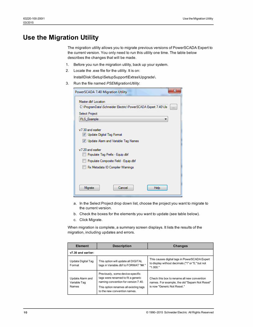
Use the Migration UtilityThe migration utility allows you to migrate previous versions of PowerSCADA Expert tothe current version. You only need to run this utility one time. The table belowdescribes the changes that will be made.
1. Before you run the migration utility, back up your system.2. Locate the .exe file for the utility. It is on:
InstallDisk:\Setup\SetupSupport\Extras\Upgrade\.
3. Run the file named PSEMigrationUtility:
a. In the Select Project drop down list, choose the project you want to migrate tothe current version.
b. Check the boxes for the elements you want to update (see table below).c. Click Migrate.
When migration is complete, a summary screen displays. It lists the results of themigration, including updates and errors.
Element Description Changes
v7.30 and earlier:
Update Digital TagFormat
This option will update all DIGITALtags in Variable.dbf to FORMAT "##."
This causes digital tags in PowerSCADAExpertto display without decimals ("1" or "0," but not"1.000."
Update Alarm andVariable TagNames
Previously, some device-specifictags were renamed to fit a genericnaming convention for version 7.40.
This option renames all existing tagsto the new convention names.
Check this box to rename all new conventionnames. For example, the old "Sepam Not Reset"is now "Generic Not Reset."
10 © 1990–2015 Schneider Electric All Rights Reserved
63220-100-200I1 Use theMigration Utility03/2015

Use theMigration Utility 63220-100-200I103/2015
Element Description Changes
v7.20 and earlier:
Populate TagPrefix-Equip.dbf
Equipment Name, which was used tobuild tag names, is now theequipment hierarchy name (can nolonger be used to build tag names)
TagPrefix field added. It is now used to buildtags.
If the TagPrefix field is empty, IODevice name isused to populate Tag Prefix. If IODevice name isalso empty (in a composite device),EquipmentName is used IF there are no periodsin the name.
PopulateComposite Field -Equip.dbf
The Parent field (previously used todetermine the parent piece ofequipment) has been removed fromthe .dbf file.
The Composite field replaces the Parent field.The Composite field will display the Parent fieldinformation, if applicable.
Fix MetadataID CompilerWarnings
The Cicode function StrToLocal nolonger allows partially translated text.For example, in@(Protection),2,"Protection" must be translated.
Also, "2" is themetadata ID; in allcustom fields (1-8) of all alarm tags,the ID part of the field must beremoved.
All custom fields in alarm tags will remove the IDpart (1-8) of the field, IF the translation identifieris present. Thus, in@(Protection), 2 the "2" isremoved; it will be changed to@(Protection).
© 1990–2015 Schneider Electric All Rights Reserved 11

The Profile EditorThis section describes how to use the Profile Editor to create device type tags, andthen to use these tags as building blocks for device types. Secondly, there areinstructions for creating device profiles for unique devices. Finally, there areinstructions for creating projects for each installation or customer.
In this section, you will find these topics:
Overview of the Profile Editor on page 13
Typical Workflow Illustration on page 13
Launch the Profile Editor on page 17
Add Engineering Unit Templates, Units, and Conversions on page 19
Define Device Types and Tags on page 23
Device Type Screens and Workflow on page 23
Print the .CSV File on page 29
Add Custom Tags and Tag Addresses on page 31
Add, Edit, or Delete a Device Type on page 26
Edit Tag Addresses on page 34
Edit Generic Tag Addresses on page 39
Edit Functional Addresses on page 31
Create Device Profiles on page 39
Enable Waveforms on page 39
View Device Profiles on page 39
Add Edit or Delete Device Profile on page 41
Edit IEC 61850 Datasets on page 44
Edit IEC 61850 Report Control Blocks on page 45
IEC 61850 System Setup Workflow on page 8
Create Data Concentrator Device
G3200 Device Setup on page 48
Set Up Projects in the Profile Editor on page 50
Project Screens and Workflow on page 50
The Set Up Projects Tab on page 51
Add, Edit, or Delete a Project on page 52
Create a Composite Device Type
Edit and Delete Information in a Project on page 54
Customize Tag Names on page 54
Import and Export Project Files on page 54
Tag Types on page 65
Customize Tag Names on page 54
IEC 61850 Tag Construction on page 65
Define an Enumeration on page 66
Format Code Definitions on page 67
Logic Codes on page 69
12 © 1990–2015 Schneider Electric All Rights Reserved
63220-100-200I1 The Profile Editor03/2015

The Profile Editor 63220-100-200I103/2015
Overview of the Profile EditorThe Profile Editor is a multiple-screen application that allows you to perform four basictasks: create device types, create device profiles, and set up projects.
Use the Define Device Type Tags tab and its screens to add and edit information forreal-time, onboard alarm, control and reset tags and to create and edit device types.See Define Device Types and Tags on page 23 for complete instructions.
Use the Create Device Profiles tab and its screens to add and edit individual profilesfor specific devices. A device profile is a subset of the possible variable tags, alarmtags, and trend tags for a particular device type. See Create Device Profiles on page39 for complete instructions.
Use the Set Up Project tab and its screens to bring together all of the system attributesfor a single customer or installation. For example, the customer installation will includea certain combination of device profiles (depending on the devices installed at thesite). The project allows a specific unit template to be applied, converting units (such aswatts) into units used by the customer (such as megawatts). This causes tags to displayin the converted format. Projects also allow you to rename tags to suit a customer’sneeds (for example, Current A could be renamed to Current Phase A). See Set UpProjects in the Profile Editor on page 50 for complete instructions.
This product uses the IEC61850 tag-naming convention to create tags that measuredevice quantities. Although most of the tags you will use are already entered into thesystem, you can add custom tags. For more information, see Tag Types on page 65.
Typical Workflow IllustrationThe following four flow charts illustrate the use of the Profile Editor. The first illustrationprovides an overview, and the following illustrations show:
• creating/editing a device type• creating/editing a device profile• creating/editing unit templates
© 1990–2015 Schneider Electric All Rights Reserved 13

Workflow Overview
14 © 1990–2015 Schneider Electric All Rights Reserved
63220-100-200I1 The Profile Editor03/2015

The Profile Editor 63220-100-200I103/2015
Create/Edit Device Type
© 1990–2015 Schneider Electric All Rights Reserved 15

Create/Edit Device Profile
16 © 1990–2015 Schneider Electric All Rights Reserved
63220-100-200I1 The Profile Editor03/2015

The Profile Editor 63220-100-200I103/2015
Create/Edit Unit Templates
Launch the Profile EditorTo launch the Profile Editor, click Start > Programs > Schneider Electric >PowerSCADA Expert 8.0 > Config Tools > Profile Editor. The Profile Editor screendisplays with the Define Device Tags tab selected. There are two other tabs, used tocreate device type profiles and projects.
Locked and Custom IconsTwo icons may appear to the right of the Add/Edit button on some screens: the lockedicon and the custom icon.
The Locked Icon :
This icon indicates that the selected file (e.g., device type, profile, or project) cannot beedited. All standard device types (for example, Circuit Monitor 4000, MicroLogic TypeP, Power Meter 800) are automatically locked; they cannot be unlocked.
To lock a device type that you create, follow these steps:
© 1990–2015 Schneider Electric All Rights Reserved 17
1. From the Define Device Type Tags screen, click Add/Edit.2. On the Add/Edit Device Type screen, you can choose Create New, Create From, or
Edit Existing.
3. Enter the new device information, or select the device to be edited.
4. To lock the device, check the box named Lock This Device Type.
5. Click Save & Exit to save the “lock” and exit the screen.
After you lock a device type, you cannot unlock it. However, you can restore it in thismanner: Copy the locked device type (Create From on the Add/Edit Device Typescreen), then save the copy with a new name.
The Custom Icon :
This icon indicates that a device type or profile is user-created. It may have beencreated new, created from an existing device type or profile, or created by editing anunlocked custom device type or profile.
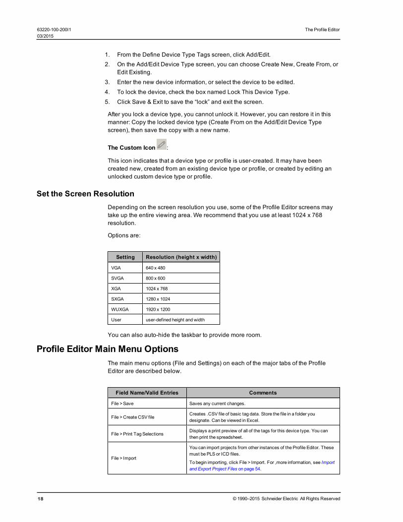
Set the Screen ResolutionDepending on the screen resolution you use, some of the Profile Editor screens maytake up the entire viewing area. We recommend that you use at least 1024 x 768resolution.
Options are:
Setting Resolution (height x width)
VGA 640 x 480
SVGA 800 x 600
XGA 1024 x 768
SXGA 1280 x 1024
WUXGA 1920 x 1200
User user-defined height and width
You can also auto-hide the taskbar to provide more room.
Profile Editor Main Menu OptionsThe main menu options (File and Settings) on each of the major tabs of the ProfileEditor are described below.
Field Name/Valid Entries Comments
File >Save Saves any current changes.
File >Create CSV fileCreates .CSV file of basic tag data. Store the file in a folder youdesignate. Can be viewed in Excel.
File >Print Tag SelectionsDisplays a print preview of all of the tags for this device type. You canthen print the spreadsheet.
File > Import
You can import projects from other instances of the Profile Editor. Thesemust be PLS or ICD files.
To begin importing, click File > Import. For ,more information, see Importand Export Project Files on page 54.
18 © 1990–2015 Schneider Electric All Rights Reserved
63220-100-200I1 The Profile Editor03/2015

The Profile Editor 63220-100-200I103/2015
Field Name/Valid Entries Comments
File > Export
You can export a PLS or ICD file to be used in another instance of theProfile Editor, or to be used as a backup.
To begin exporting, click File > Import. For ,more information, see Importand Export Project Files on page 54
Settings >Display AdvancedProperties
Causes additional “advanced information” columns to display.
Settings > Remove ImportTemplates
You can delete any import template that has been added to the project. Toadd import templates, seeUsing Import Templates on page 64.
Settings >Set Up Custom TagsDisplays the Add/Edit Custom Tags screen. SeeSet Up Custom Tags onpage 31 for a description of this screen.
Settings >Set Up Device TypeCategories
Displays the Set Up Device Type Categories. SeeSet Up Device TypeCategories on page 29 for a description of this screen.
Settings >Set Up Engineering UnitTemplates
Displays the Set Up Engineering Unit Templates screen. Click Set UpEngineering Templates and Select Conversions on page 19 for adescription of this screen.
Settings >Set Up Trend DefinitionsDisplays the Set Up Trend Definitions screen. Click Set Up TrendIntervals on page 43 for more information.
Add Engineering Unit Templates, Units, and ConversionsAn engineering unit is a part of a tag. Use engineering unit templates to simplify theconversion between base units and their conversions (such as inches to centimetres)and to provide consistency in recording data in reports and on-screen viewing. Forexample, in one project you might want to see amperes reported as kiloamps. Inanother, you might want to see amperes as milliamps. You will use the Units screens todetermine the conversion for standard units and custom units (tied to custom tags) thatyou create.
You can also create templates to organize user-created unit/conversion pairs. Eachtemplate will include all of the predefined engineering units and conversions, as wellas the ones you assign to it. These templates can then be used in system projects (seethe Set Up Project tab for creating projects).
In this section, you can learn about:
Set Up Engineering Templates and Select Conversions on page 19
Add or Edit a Base Engineering Unit or Conversion on page 22
Set Up Engineering Templates and Select ConversionsUse the Set Up Engineering Unit Templates screen when you want to add, edit, ordelete an engineering unit template, or to make changes to how the unit is reported.
To view the Set Up Engineering Units screen, click Settings > Set Up Engineering UnitTemplates. The following table describes the parts of the Set Up Engineering UnitTemplates screen (it assumes that Display ‘Advanced’ Fields is checked). When youhave finished making change, click Save & Exit.
© 1990–2015 Schneider Electric All Rights Reserved 19

FieldName Valid Entries Comments
TemplateOptions box
Create New Click to begin creating a new engineering unit template.
Create FromClick to create an engineering units template that is based on anexisting template.
Edit ExistingOnly available if you have added a template.
Click to edit an engineering unit or its conversion.
DeleteOnly available if you have added a template.
Click to begin deleting an engineering unit and its conversion. Youcannot delete a locked template.
UnitTemplate toCreate From
From the drop-downmenu,select the template youwish to copy, in order tocreate a new template.
This field is live only whenCreate From is chosen as the option.The new template will initially include all of the units/conversions ofthe original; but you can add units and change the conversionsettings.
UnitTemplateName
This field is blank if youselectedCreate New orCreate From; type thename of the new template.A name displays if youhave selected a templateto edit; you can change thename.A name displays, but it isgreyed out if you selected atemplate to delete.Click Save to save thechanges youmake.
When creating a new template or creating from an existingtemplate, type the name of the new template.
To change the name of an existing template, choose it from theUnit Template to Deletemenu, then change the name here.
Lock thisTemplate
Click to prevent thetemplate from being editedin the future.
The only way to “edit” a locked template is to delete it, and addback a new one with the edits entered.
DisplayAssociatedProjects
Live only when in “Edit”mode. Displays all projectsthat use this template.
You only need this if you want to delete a template that isassociated with a project. Note the projects that display in the list,then go to the Set Up Project tab. For each project that you noted,change the unit template.
Display‘Advanced’Fields
Check this box to displayadditional columns ofinformation about thetemplate.
Unchecked: displays the unit and its abbreviation only. Checked:displays also the conversion, and its abbreviation andmultiplier.
Default Units Subtab
Use this subtab tomanage unit templates and to add global changes to a unit.
Base Unit n/aMany standard units are pre-defined; they cannot be edited ordeleted. To add a unit or edit a user-created unit, seeAdd or Edit aBase Engineering Unit or Conversion on page 22.
Abbreviation n/aAdded for the unit when the selected unit was created. To edit auser-created unit, seeAdd or Edit a Base Engineering Unit orConversion on page 22.
SelectedUnit
Click the down arrow todisplay and select thepreferred conversion forthe unit.
Many conversions are pre-defined. To add or edit a conversionunit, seeAdd or Edit a Base Engineering Unit or Conversion onpage 22.
Fahrenheit to Celsius temperature conversions must be handledby editing Cicode (Citect.ini).
Abbreviation n/aThis is abbreviation for the selected unit. When the Selected Unit ischanged, this field changes accordingly.
20 © 1990–2015 Schneider Electric All Rights Reserved
63220-100-200I1 The Profile Editor03/2015

The Profile Editor 63220-100-200I103/2015
FieldName Valid Entries Comments
Multiplier n/a
Added for the unit and for the conversion when the base unit wascreated. Pre-defined units/conversions cannot be changed. To edita user-created unit, seeAdd or Edit a Base Engineering Unit orConversion on page 22.
Offset n/aUsed for units that havemore than one scale. For example, fortemperature, if the base is degree Celsius, and you want to offsetto Fahrenheit, you would type 32 here (and 1.8 in themultiplier).
Add/EditUnits button
Click to display theAdd/Edit Units screen.
Use that screen to add units/conversions, or to edit user-createdunits/conversions.
Unit Exceptions Subtab
Use this tab to apply "exceptions" for individual tags, changing the way the unit is reported for the tag(s). This ismost commonly used for WAGES tags.
TagsChoose an individual tag ortag subgroup.
This tag will be reported with the new settings.
Options
1. From the dropdown list,choose the unit you want touse for this tag/tag group.
2. Click the radio button forthe exception to bemade.
3. Either double-click thetag, or click the right arrowtomove it to the Exceptionlist.
1. If you choose Apply Unit Conversion, the tag will be reportedaccording the unit you select. For example, if you want to report AirVolume in gallons, rather than cubic meters, choose "gallon" fromthe Select Unit dropdown list.
2. Click "Apply Unit Conversion" to convert and report the tagaccording to the unit you selected. Click "Apply Unit NameOnly" toadd the unit name to it, but not convert it, when it is reported.
ExceptionList
Review your changes.
You can check or uncheck tags here, changing them from oneconversion option to the other. When you uncheck a tag, you donot remove it, you change it from being converted to simply beingreported according the unit you selected.
Apply Conversions
Use this screen to apply unit conversions to a template. To add a new conversion, seeAdd or Edit a Base Engineering Unit or Conversion on page 22.
To apply a conversion:
1. From the main window of the Profile Editor, click Settings > Set Up Engineering UnitTemplates.
2. Click Edit Existing, then select the template for which you want to select unitconversions.
3. In the Selected Unit column, click the down arrow and select the conversion youwant to use. Fahrenheit to Celsius temperature conversions are handled by offsets(see Add or Edit a Base Engineering Unit or Conversion on page 22).
4. Repeat step 3 for all units that you want to change.
5. Click Save to save the change, or click Save & Exit to save changes and close thescreen.
Delete a Template
You cannot delete either the standard template or a locked template.
To delete a template:
© 1990–2015 Schneider Electric All Rights Reserved 21
1. From the Define Device Type Tags tab, click Settings > Set Up Engineering UnitTemplates.
2. Click the Delete radio button, on the left, to delete a template.
3. Choose the template from the drop-down list.
4. Click Delete, on the right, to delete the selected template. At the Confirm Deleteprompt. click Yes.
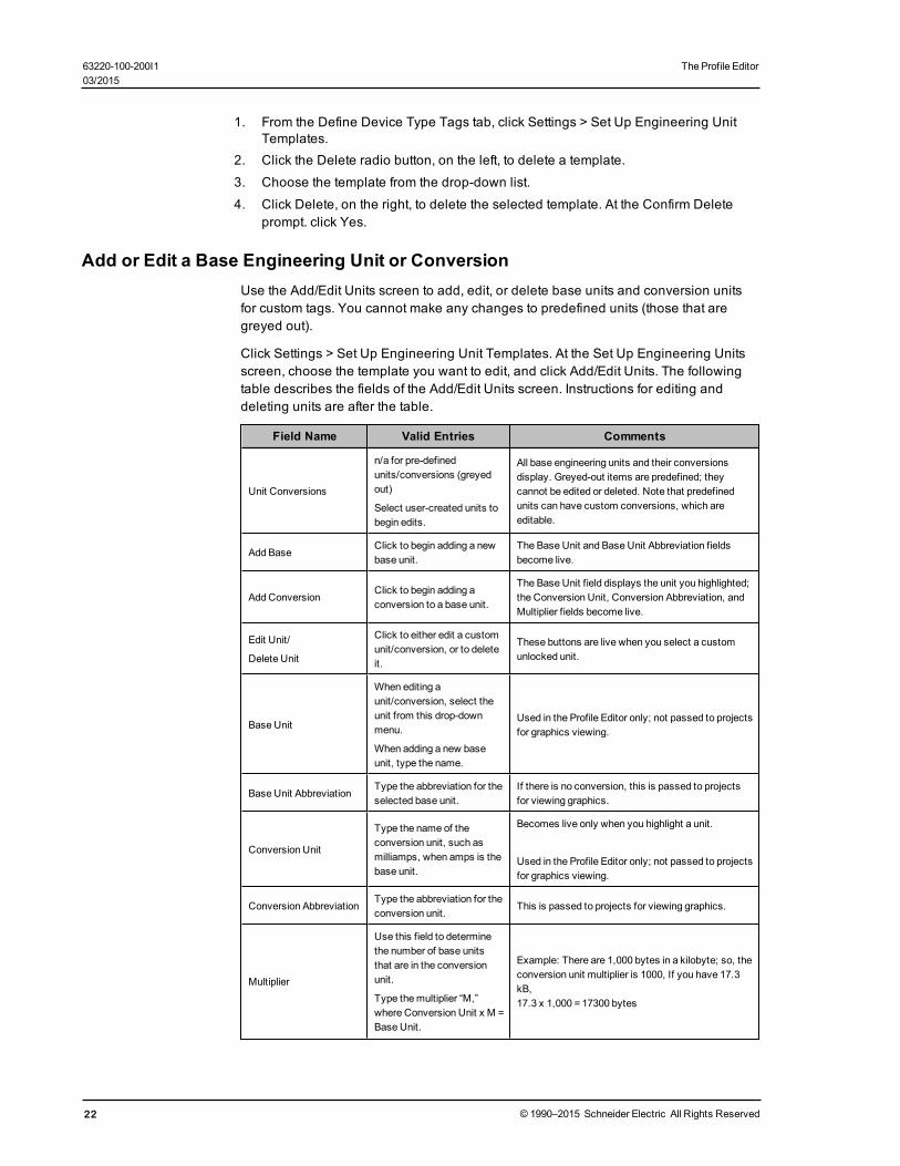
Add or Edit a Base Engineering Unit or ConversionUse the Add/Edit Units screen to add, edit, or delete base units and conversion unitsfor custom tags. You cannot make any changes to predefined units (those that aregreyed out).
Click Settings > Set Up Engineering Unit Templates. At the Set Up Engineering Unitsscreen, choose the template you want to edit, and click Add/Edit Units. The followingtable describes the fields of the Add/Edit Units screen. Instructions for editing anddeleting units are after the table.
Field Name Valid Entries Comments
Unit Conversions
n/a for pre-definedunits/conversions (greyedout)
Select user-created units tobegin edits.
All base engineering units and their conversionsdisplay. Greyed-out items are predefined; theycannot be edited or deleted. Note that predefinedunits can have custom conversions, which areeditable.
Add BaseClick to begin adding a newbase unit.
The Base Unit and Base Unit Abbreviation fieldsbecome live.
Add ConversionClick to begin adding aconversion to a base unit.
The Base Unit field displays the unit you highlighted;the Conversion Unit, Conversion Abbreviation, andMultiplier fields become live.
Edit Unit/
Delete Unit
Click to either edit a customunit/conversion, or to deleteit.
These buttons are live when you select a customunlocked unit.
Base Unit
When editing aunit/conversion, select theunit from this drop-downmenu.
When adding a new baseunit, type the name.
Used in the Profile Editor only; not passed to projectsfor graphics viewing.
Base Unit AbbreviationType the abbreviation for theselected base unit.
If there is no conversion, this is passed to projectsfor viewing graphics.
Conversion Unit
Type the name of theconversion unit, such asmilliamps, when amps is thebase unit.
Becomes live only when you highlight a unit.
Used in the Profile Editor only; not passed to projectsfor graphics viewing.
Conversion AbbreviationType the abbreviation for theconversion unit.
This is passed to projects for viewing graphics.
Multiplier
Use this field to determinethe number of base unitsthat are in the conversionunit.
Type themultiplier “M,”where Conversion Unit x M =Base Unit.
Example: There are 1,000 bytes in a kilobyte; so, theconversion unit multiplier is 1000, If you have 17.3kB,17.3 x 1,000 =17300 bytes
22 © 1990–2015 Schneider Electric All Rights Reserved
63220-100-200I1 The Profile Editor03/2015

The Profile Editor 63220-100-200I103/2015
Field Name Valid Entries Comments
OffsetUse this field to determine anumeric offset.
Example: If degrees Celsius is the base unit, andyou are creating a conversion unit for Fahrenheit,you would enter amultiplier of 1.8 and an offset of32.
Edit a Base Engineering Unit or Conversion
Changes are global, for all templates. You cannot change any predefined engineeringunits/conversions (greyed out).
To edit a unit or conversion:
1. To edit the unit: With the base unit highlighted, click Edit Unit. You can edit the baseunit and base unit abbreviation. Click OK to save the changes.
2. To edit a conversion: With the conversion highlighted, click Edit Unit. You can editthe conversion unit, abbreviation, and multiplier. Click Save to save the changes orclick Save & Exit to save the changes and close the screen.
Delete a Base Engineering Unit or Conversion
Deletions are global, for all templates. You cannot delete units any predefinedunits/conversions (greyed out).
To delete a unit or conversion:
1. To delete a unit: With the base unit highlighted, click Delete Unit. At the ConfirmDelete prompt, click Yes. Click OK to close the screen.
2. To delete a conversion: With the conversion highlighted, click Delete Unit. At theConfirm Delete prompt, click Yes. Click Save & Exit to save the changes and closethe screen.
Define Device Types and TagsThe Define Device Type Tags tab and its related screens are used to define device-related data: custom tags, device types, and base units/conversions. You will useseveral screens to add and manage this data.
To access these screens, click the Define Device Type Tags tab on the main ProfileEditor screen.
In this section, you can learn about:
Device Type Screens and Workflow on page 23
Use the Define Device Type Tags Tab on page 24
Add, Edit, or Delete a Device Type on page 26
Print the .CSV File on page 29
Set Up Device Type Categories on page 29
Edit Functional Addresses on page 31
Device Type Screens and WorkflowOn the Define Device Type Tags tab, follow these general steps to add tags anddevices to your system:
1. To manage the units and unit conversions that you will use (such as amperes intomilliamperes), see Add or Edit a Base Engineering Unit or Conversion on page 22.
2. To manage the tags you will use, see Define Device Types and Tags on page 23.
© 1990–2015 Schneider Electric All Rights Reserved 23

3. To add and edit custom tags, see Add Custom Tags and Tag Addresses on page31.
4. To add or edit device types, see Add, Edit, or Delete a Device Type on page 26.
5. To establish device type categories and subcategories, used in reporting, see Printthe .CSV File on page 29.
6. To edit tag addresses, see Edit Tag Addresses on page 34.
The PowerSCADA Expert system uses the IEC61850 tag naming convention. Forinformation about the types of IEC61850 tags and their configuration, see Tag Typeson page 65.
Use the Define Device Type Tags TabThe Define Device Type Tags tab displays device types and the tags that may beassociated each device type. This includes real-time, onboard alarm, control, and resettags. Most of the fields on this tab are read only (they can be changed on otherscreens). The following table describes this tab. The tags listed assume that AdvancedProperties has been checked. Not all elements appear on every sub-tab.
Field Name/Valid Entries Comments
Device Type Name/Select the devicetype.
Each device type includes a different number of tag categories, whichalso changes the list of tags that display.
The device list includes the default device types, as well as any thathave been created for this system.
Add/Edit button/Click to open theAdd/Edit Device Type screen.
Provides ameans of adding new device types and editing customdevice types (user-created device types that are not locked). Alsoprovides ameans of adding new custom tags and editing existingtags.
Locked/Custom icons:Locked icon indicates that the list of selected tags cannot be edited.Custom icon indicates that the device type was created by a user.See Locked and Custom Icons on page 17 for complete information.
Tag groups (left-hand pane)
Select a tag group; the tags included inthat group display on the right.
Each tag belongs to a group. The group is determined when thedevice is added to the system. For custom tags, this is on theAdd/Edit Custom Tags screen. Tags for standard device types arepre-determined and cannot be changed.)
Note: If a tag group displays in red copy, there is at least one addressthat is not valid for the tag to which it is assigned. To correct thisissue, click the tag group, ensure that Display Advanced Properties isselected, then scroll down through the tags in the right-hand column.The tags that have invalid addresses will have the “Edit...” displayedin red. Click this field to open the Edit Address page; correct the errorsin the address.
Tag tabs: Real Time, OnBoard Alarm, Control, and Reset
Click a tab to view the tags of that type that are included for the selected device type.
If the device type is not locked, you can use the Add/Edit Device Type screen to edit the list of tags.
Tag Description (all tag types)/Displayonly
This is the tag name, hard-coded for standard tags. For custom tags:The name is from the Tag Name field in the Add/Edit Custom Tagsscreen.
24 © 1990–2015 Schneider Electric All Rights Reserved
63220-100-200I1 The Profile Editor03/2015

The Profile Editor 63220-100-200I103/2015
Field Name/Valid Entries Comments
Units/Display onlyLists the abbreviation, added when creating the engineering unittemplate.
IEC Tag Name/Display onlyTag name that conforms to IEC61850 standard. See Tag Types onpage 65 for more information.
Type (Real Time only)/Display only Displays the data type chosen when the tag was created.
Address (not Control tags)/
To edit, click the Edit Address link.
Displays the address information for this tag, including elements suchas type of register, number of registers, and scaling and bitmaskingdata. Tag Types on page 65 for a detailed description of addressconstruction.
Normally Closed (Control tags only)/
Check the box to invert the functionalityof the control. See description.
For a control with one command, writing a 1 to the tag will cause thecommand to occur. (This option is greyed out.)
For a control with two commands that is either static or normallyopen, writing a 1 to the tag will cause the first command to occur;writing a 0 will cause the second to occur. (Checkbox not checked.)
For a control with two commands that is normally closed, writing a 1to the tag will cause the second command to occur; writing a 0 willcause the first command to occur. (Checkbox checked.)
Edit Addr/Click to display Edit Addressscreen. (Real Time andOnboard Alarmonly)
Provides themeans of changing the elements of an unlocked real-time tag address (for example, the number of registers, theirnumbers, and whether they are consecutive).
SeeEdit Tag Addresses on page 34. for detailed information.
Register 1/Display only (Real Time tagsonly)
This field contains first register used to store this tag. If there areadditional registers, they are indicated in the address. The totalnumber of registers is listed in the Num Registers column. This fieldallows you to verify and/or change the value of Register 1 withouthaving to open the Edit Address screen. Note: If you enter a numberthat is not compatible with other address
settings, you are prompted to go to the Edit Address screen.
Num Registers/Display only (Real Timetags only)
Displays the number of registers used by this tag.
Formatting/Select the format type fromthe drop-down list (Real Time tags only)
After you change formatting for a tag andmove the cursor to anotherfield, you are asked whether you want to open the Address Editor. Ifyou click No, the format is unchanged; if you click Yes, the EditAddress screen opens for you to enter the appropriate changes forthis tag. SeeEdit Tag Addresses on page 34.
Scaling Register/View or enter theregister number (Real Time tags only)
This is entered in the Edit Address screen, but it can be edited here. Itis the register used to read the value for scaling. Note: If you enter anumber that is not compatible with other address settings, you areprompted to go to the Edit Address screen.
Functional Address/Display only (RealTime, Onboard Alarm, Control, andReset tags)
If you have added a functional address for this tag, it displays here.To add or edit this address, use the Edit Functional Address field.
Note: Functional addressing is described inAppendix 4: Glossary onpage 245.
Edit Functional Address/Add the codefor the address
Typically used for data concentrators, the functional address is ameans of entering the individual data points needed to definemultipleaddresses. Entered as a formula (must be in C#), it will contain thevariables the user must enter when the block is instantiated by theProfileWizard.
A simple example:
Address =
"T:MV;m:" + (startingpoint + 1005).ToString() + ";L:P:22"
© 1990–2015 Schneider Electric All Rights Reserved 25

Field Name/Valid Entries Comments
Youwould then define "startingpoint" when instantiatiing the profile inthe ProfileWizard.
Tag ID/Display only/Display onlyAssigned by the system when the tag was created. If this is a customtag, it will be a negative number.
Category Type (real-time only)
Utility Type (real-time only)
Statistical Type (real-time only)
Quantity (real-time only)
Each of these types is a real-time filter, added when the tag wascreated. SeeSet Up Custom Tags on page 31 for more information.
Categorization (onboard alarm only)
Subcategorization (onboard alarm only)
Alarm Type (onboard alarm only)
Alarm Group (onboard alarm only)
Alarm Level (onboard alarm only)
Each of these is an onboard alarm folder, added when the tag wascreated. SeeSet Up Custom Tags on page 31 for more information.
Add, Edit, or Delete a Device TypeUse the Add/Edit Device Type screen to begin adding, editing, or deleting a devicetype from the system. To view this screen, click the Define Device Type Tags tab; thenclick Add/Edit, to the right of the Device Type Name field.
The following table describes the parts of the Add/Edit Device Type screen.
For instructions on editing or deleting device types, see the steps below the table.
Field Name Valid Entries Comments
Create New
Click one of theradio buttons toselect the actionyou want totake.
Click to add a device type that is not based on an existingtype.
Create From Click to copy an existing device type.
Edit Existing Click to edit an unlocked device type.
Delete ExistingClick to delete an unlocked device type that is not associatedwith a profile.
Device Type (to CreateFrom/to Edit/ to Delete)
select typeSelect the device type that you want to create from, edit, ordelete.
Copy Addressing
Active when you choose Create From. Check this box if tocopy the addressing of the “from” device. This gives each tagin the new device type the same address string as thematching tag in the “from” device.
Device Type Name
Type or selectthe name:
maximum 32characters,
do not use \ / : *? < > |
If creating a device type, type the name. If editing a devicetype, the device type that was selected for editing displayshere. You can change the name here.
Lock this Device Type
Check to lockdevice, so that itcannot beedited.
This action cannot be undone.
You cannot edit a locked device type. If it is a standard devicetype, you cannot edit or delete it. If you added the devicetype, you can delete it but not edit it.
26 © 1990–2015 Schneider Electric All Rights Reserved
63220-100-200I1 The Profile Editor03/2015

The Profile Editor 63220-100-200I103/2015
Field Name Valid Entries Comments
Device CategoryChoose thecategory for thisdevice.
To create categories, seePrint the .CSV File on page 29.
In addition to predefined categories, you can add customcategories. SeeSet Up Device Type Categories on page 29for instructions. Categories are used in the Device Creationwizard, and are ameans of shortening the list of devices youmust view.
Subcategory
Choose thesubcategory forthis device, ifneeded.
As with categories, subcategories are created in thePrint the.CSV File screen.
DriverSelect the driverfor the devicetype.
Predefined drivers are created for all PowerLogic compatibledevices, though youmay need to use these drivers formultiple device types. For example, you would use theCM4000 driver for a CM3000.
Use the Generic Power Device driver for third-party devices.The Controllable Device driver is currently not used. UseGeneric JBus Device driver for JBus devices.
Display Associated Profiles
(Active only inEdit mode)
Click to displaya list of profilesthat areassociated withthe selecteddevice type.
This list is used when you want to delete a device type that isassociated with a profile. In Edit mode, select the device typeyou want to delete; then click this button. Note the profile(s)associated with the device type.
Before you can delete the device type, go to the Add/EditDevice Profile screen, locate each profile in the list. Youcannot save an empty profile, so youmust either selectanother device type for it or delete the profile. Then you candelete the device type.
IEC Tags n/a
This list includes all tags that have been added to the system,standard tags as well as custom tags that you have added.Tags are listed in their groups (such as 100ms, OnboardAlarm, Power Factors).
Selected Tags
Select tags fromTags; click theright arrow tomove them tothis box.
You canmove single tags or entire tag groups. They must bemoved one at a time (cannot shift+click to select).
Note: You cannot deselect tags for a device type if thatdevice is associated with a device profile.
Add/Edit Custom TagsClick to beginadding a customtag.
Live when creating or editing a tag. Opens the Add/EditCustom Tags screen. SeeAddCustom Tags and TagAddresses on page 31 for instructions.
If you add a custom tag here, you are prompted to save thedevice type. After adding the tag, you have the option ofadding that tag to the device type.
Edit a Device Type
You cannot edit any locked device type. When a device type is locked, the locked icondisplays on the Define Device Type Tags tab:
If you want an edited version of a locked device type, you must create a new devicetype from it and then delete the original device type. Certain “standard” device typescan be used to create new types, but they cannot be deleted. Examples: Circuit Monitor4000, Power Meter 800, and Sepam S42.
There are two ways to edit device types:
• From the Define Device Type Tags tab, select a device type; make these changes:
© 1990–2015 Schneider Electric All Rights Reserved 27

Edit the functional address (see Edit Functional Addresses on page 31).
Real Time Tags sub-tab: you can edit the address (see Edit Tag Addresses onpage 34) and choose a different format.
• From the Define Device Type Tags tab, select the device type you want to edit, thenclick Add/Edit. Follow through the screens to edit additional information:
In the Device Type Options box, click Edit Existing.
Click the Device Type to Edit list to display the Select Device box. Select the devicetype that you want to edit.
You can change the device type name, category, subcategory, and driver. You canalso lock the device.
Select tags and tag groups and move them into or out of the Selected Tags list.
If a device type is associated with a device profile, you cannot deselect tags.
After all of the appropriate changes are made, click Save to save your currentsettings.
To create additional custom tags, click Add/Edit Custom Tags; otherwise, click Save& Exit to save your settings and close the window.
If you add a tag to a group that is already included in a device type, you must thenindividually add the tag to that device type.
Delete a Device Type
You cannot delete any standard device type or any custom device type that isassociated with a device profile; those device types do not display in this option.
To view a list of profiles associated with a device type, switch to the Edit Existing view,then select the device type you want to delete. Click List Profiles associated with thisDevice Type to display all associated profiles. Before you can delete the device type,return to the Add/Edit Device Profile screen for each profile in the list; either select anew device type for the profile or delete the profile entirely.
To delete a device type:
1. From the Define Device Type Tags tab, click Add/Edit.2. In the Device Type Options box, click Delete.
3. From the drop-down list, select the device type you want to delete (the list includesonly unlocked or custom device types; you cannot delete any of the “standard”device types or custom device types that are associated with a profile.
4. Click Delete. At the Confirm prompt, click Yes.
Assign Tags to Generic I/O Points
Device types have default tags that have the appropriate formatting and addressingassigned for all the generic I/O points. It may be necessary to redefine a generic I/Opoint by assigning it to a tag that has a specific meaning.
Example 1: The Branch Circuit Monitor 42 has been configured to read 42 currentchannels. To assign channel 1 to Current A, follow these steps:
1. From the Branch Circuit Monitor 42 device type, choose the “Ch.01 Current tag.”2. Note the addressing and formatting for the tag.
3. Locate and add the standard tag that you want to assign to this channel. In theexample above, you would add “Current A.”
4. Edit the address of the Current A tag to match the address of Channel 1.
28 © 1990–2015 Schneider Electric All Rights Reserved
63220-100-200I1 The Profile Editor03/2015
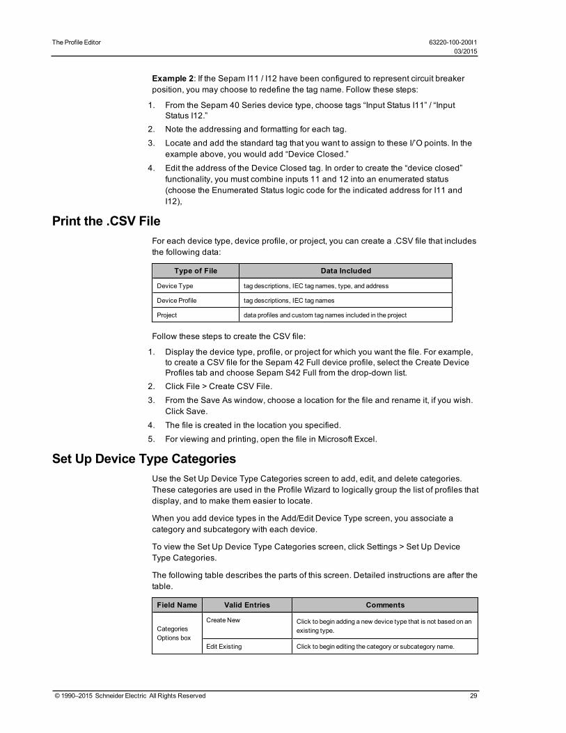
The Profile Editor 63220-100-200I103/2015
Example 2: If the Sepam I11 / I12 have been configured to represent circuit breakerposition, you may choose to redefine the tag name. Follow these steps:
1. From the Sepam 40 Series device type, choose tags “Input Status I11” / “InputStatus I12.”
2. Note the addressing and formatting for each tag.
3. Locate and add the standard tag that you want to assign to these I/’O points. In theexample above, you would add “Device Closed.”
4. Edit the address of the Device Closed tag. In order to create the “device closed”functionality, you must combine inputs 11 and 12 into an enumerated status(choose the Enumerated Status logic code for the indicated address for I11 andI12),
Print the .CSV FileFor each device type, device profile, or project, you can create a .CSV file that includesthe following data:
Type of File Data Included
Device Type tag descriptions, IEC tag names, type, and address
Device Profile tag descriptions, IEC tag names
Project data profiles and custom tag names included in the project
Follow these steps to create the CSV file:
1. Display the device type, profile, or project for which you want the file. For example,to create a CSV file for the Sepam 42 Full device profile, select the Create DeviceProfiles tab and choose Sepam S42 Full from the drop-down list.
2. Click File > Create CSV File.
3. From the Save As window, choose a location for the file and rename it, if you wish.Click Save.
4. The file is created in the location you specified.
5. For viewing and printing, open the file in Microsoft Excel.
Set Up Device Type CategoriesUse the Set Up Device Type Categories screen to add, edit, and delete categories.These categories are used in the Profile Wizard to logically group the list of profiles thatdisplay, and to make them easier to locate.
When you add device types in the Add/Edit Device Type screen, you associate acategory and subcategory with each device.
To view the Set Up Device Type Categories screen, click Settings > Set Up DeviceType Categories.
The following table describes the parts of this screen. Detailed instructions are after thetable.
Field Name Valid Entries Comments
CategoriesOptions box
Create New Click to begin adding a new device type that is not based on anexisting type.
Edit Existing Click to begin editing the category or subcategory name.
© 1990–2015 Schneider Electric All Rights Reserved 29

Field Name Valid Entries Comments
Delete ExistingClick to begin deleting a category. You cannot delete acategory that is associated with a device type.
Category Name
If new: Type the name.
If editing or deleting, select the name from the drop-downmenu.
Predefined categories do not display. Currently, there is onepredefined category: Schneider Electric.
SubcategoriesOptions box.
As with categories, you cancreate new, edit existing, ordelete.
If new: Type the name.
If editing or deleting, select the name from the drop-downmenu.
You cannot delete a subcategory that is associated with adevice type.
Predefined subcategories do not display. Currently, thepredefined subcategories are: Protection Device, MonitoringDevice, and PLC.
Add a Category or SubcategoryTo add a category/subcategory:
1. Click Create New in the appropriate box (Categories or Subcategories).2. In the Name field, type the name of the new category or subcategory.
3. Click OK to save the new entry and close the screen.
Edit a Category/Subcategory NameTo change the name of a category or subcategory:
1. From the appropriate box, click Edit Existing.2. From the dropdown menu, select the category or subcategory that you want to edit.
3. Type the new name for this category or subcategory.
4. Click Save to make the change, or click Save & Exit to save changes and close thescreen.
Delete a Category or SubcategoryPredefined categories/subcategories, or those associated with a device type, do notdisplay for deletion. To delete a device type associated with a category/subcategory,change to the “Edit” view, select the category or subcategory, then click the List DeviceTypes... button. Note the device types and go to the Add/Edit Device Types screen.Change the category/subcategory on that page. Then you can return to the Set UpDevice Type Categories screen to delete the category/subcategory.
To delete a category or subcategory:
1. From the appropriate box, click Delete Existing.2. From the dropdown menu, select the category or subcategory that you want to
delete.
3. Click Delete.
4. At the Confirm prompt, click Yes.
30 © 1990–2015 Schneider Electric All Rights Reserved
63220-100-200I1 The Profile Editor03/2015

The Profile Editor 63220-100-200I103/2015
5. Click Save to save the change, or click Save & Exit to save changes and close thescreen.
Edit Functional AddressesUse this feature to add variables to addressing. You can re-use a variable bycopying/pasting parts of it into other addresses, then making changes to the code foruse in other tags. You will be prompted for these variables in the Profile Wizard.
To access the Edit Functional Address screen, click the Edit Functional Address buttonfor a real time tag, onboard alarm tag, control tag, or reset tag. The fields on this screenare used in this way:
1. Tag Name and Original Address: These fields display from the tag you selected;you cannot edit this information.
2. Device Variables: Click New to begin adding new variable properties. Thefollowing fields become live:
a. Name: This name must be in format %NNN%, where NNN includes only lettersor underscores.
b. Description: This required field is free-form. It displays in the Profile Wizard andwill help you ensure that you have the correct information entered.
c. Regular Expression: You can use one of the pre-defined expressions, or youcan create your own
d. Test Value: This will become the default in Citect; use it here for testing the newaddress.
e. Help: Use this optional field to add more definition to this address. It displays inthe Profile Wizard.
3. Code Body: Enter the code in C# to define the action you want to take place.
4. Return: Type the return statement that you want from C# code. It might look like:
string.Format("SomeString{0}SomeOtherString", someVariable)
5. Result: Click Test in the lower right corner of the screen. If there is a compile error,check your C# code. Otherwise, the result displays. Verify that it is what youwanted.
Add Custom Tags and Tag AddressesPowerSCADA Expert comes with most of the tags that are needed for each devicetype. However, you can create custom tags to assign to device types and deviceprofiles. You can also edit address attributes for any tag.
NOTE: To avoid potential communication errors, you should use the Profile Editor tocreate all custom tags that will communicate with equipment.
In this section, you can learn about:
Set Up Custom Tags
Edit Tag Addresses on page 34
Edit Tag Addresses
Set Up Custom TagsUse the Add/Edit Custom Tags screen to edit the information about a custom tag. Toview this screen, click Add/Edit Custom Tags at the bottom of the Add/Edit Device Typescreen; or, from the upper left of the Profile Editor screen, click Settings > Set Up
© 1990–2015 Schneider Electric All Rights Reserved 31

Custom Tags. The Add/Edit Custom Tags screen displays. The following tabledescribes the fields.
Instructions for editing or deleting a custom tag are after the table.
Field Name Valid Entries Comments
Custom TagOptions
Create New Click to begin adding a new tag.
Create FromClick to begin adding a new tag that is based on anexisting custom tag. For example, youmight want tochangemetadata for another custom tag.
Edit Existing Click to edit the attributes of an existing tag.
Delete ExistingClick to delete a tag (tag cannot be associated with adevice type).
Tag to Create From
Tag to Edit
Tag to Delete
From the drop-downmenu, select the tag you want tocreate from, edit or delete.
Delete buttonLive only when Delete Existing is selected. Click todelete the tag. You can only delete custom tags notassociated with a device type.
Display AssociatedDevice Types
Click to display devicetypes that areassociated with this tag.
Live only when in Edit mode. Click to list device typesthat are associated with this custom tag. Note thedevice types so that you can delete the tag from them (inthe Add/Edit Device Type screen) before you delete thetag.
SeeDelete a Custom Tag on page 34 for instructions onusing this button.
Tag Name
Type the new tag name;or type the changedname for a tag you areediting.
Maximum 32 characters; can include any alpha ornumeric character, as well underscore (_) and backslash(\). Must begin with either an alpha character ofunderscore.
Display Name
Type the name that youwant to display whenselecting the tag and inother displays.
Youmight use this field for additional information on theAdd/Edit Custom Tags screen. For example, you coulddescribe the data that it logs. It does not displayanywhere else in the system.
Group Select the group.Includes all of the real-time groups (such as 100ms,controls, currents) plus onboard alarms, resets, andcontrols.
Data Type Select the data type.
These are PowerSCADAExpert tag data types. Theyaffect the logic codes that are available for display in theEdit Address screen. See Logic Codes on page 69 for thedata type that matches each logic code.
Eng. Units Select the base unit.These are the base engineering units for tags, fromEngineering Unit Setup.
Ignore Unit Conversion
Check to cause thesystem to ignore anyconversions that wereadded for this tag.
Causes reporting to be according to the base unit, ratherthan the conversion that was chosen for this tag in thetemplate that is being used.
Add Eng Unit
Click to open theAdd/Edit Units screen,to add a new engineeringunit and/or conversion.
Provides a quicker means of adding an engineering unitthat had been overlooked.
Citect FormatSelect the numericalformat.
This is used for display purposes in PowerSCADAExpert graphics pages. It determines where the decimaldisplays.
32 © 1990–2015 Schneider Electric All Rights Reserved
63220-100-200I1 The Profile Editor03/2015

The Profile Editor 63220-100-200I103/2015
Field Name Valid Entries Comments
Choose the reporting format, to be used in PowerSCADAExpert, from ## to #0.#####. For example, if you select#.##, the number 8.12579 would be displayed as 8.12.
Polling Priority Low, Normal, or High
Indicates the level of priority PowerSCADAExpert useswhen reading data from devices.
Note: In the address field, a priority of 1 =High, 2 =Medium,3 = Low.
Alarm On TextFor onboard alarms only:enter the text for whenthe alarm is On.
This text displays on the Create Device Profiles tab forthe onboard alarm tag, when it is selected for the devicetype in the profile. It also displays in the Alarm Log.
Alarm Off TextFor onboard alarms only:enter the text for whenthe alarm is Off.
Display ‘Advanced’ filterselections
Check to displayadditional filter options inthe Real Time Filter andAlarm Filter tabs
Displays several additional filter options on the two“Filter” tabs. These options will be useful in the future forreporting purposes.
You can include additional filters for either real time filters or alarm filters. Though not currently used, these filterswill providemetadata for later reporting. Standard tags have some of these filters selected.
A typical usage for these filters might be: when creating a custom tag from an already existing standard tag, youcan creatematchingmetadata by using the filters that have been built in to the standard tag.
Real Time Filters tab (dropdown lists are expanded when “Display ‘Advanced’ filter selections” ischecked)
Category TypeSelect a category for thistag.
This field provides metadata about the tag. It will be usedin future reports.
Utility Type Select a utility type. Metadata for future use in reporting.
Statistical Type Select a statistical type. Metadata for future use in statistical reporting.
Quantity Select a quantity. Metadata for future use in statistical reporting.
Alarm Filters tab (dropdown lists are expanded when “Display ‘Advanced’ filter selections” ischecked)
CategorizationSelect the alarmcategory
Used for filtering and sorting alarm data. Alsometadatafor future use in statistical reporting.
Alarm Type Select the alarm type.Used for filtering and sorting alarm data. Alsometadatafor future use in statistical reporting.
Alarm Group Select the group.Used for filtering and sorting alarm data. Alsometadatafor future use in statistical reporting.
Subcategorization Select a subcategory.Used for filtering and sorting alarm data. Alsometadatafor future use in statistical reporting.
Alarm LevelSelect the severity levelof the alarm.
Used for filtering and sorting alarm data. Alsometadatafor future use in statistical reporting.
Edit a Custom Tag
You can edit any custom tag. To edit a tag:
1. Open the Add/Edit Custom Tags screen (from the Add/Edit Device Type screen,click Add/Edit Custom Tags).
2. In the Custom Tag Options box, click Edit Existing.
© 1990–2015 Schneider Electric All Rights Reserved 33

3. You can change any of the tag attributes. (This does not change the tag’sassignment status; if it is selected for a device type, it does not move back to theIEC Tags list.)
4. Click Save to save changes, or click Save & Exit to save changes and close thescreen.
Delete a Custom Tag
You can delete any custom tag that is not associated with a device type.
If the tag is associated with a device type, you must first deselect the tag:
1. Change the option to Edit Existing and display the tag you want to delete.2. Click Display Associated Device Types to display all device types that include this
tag. Make a note of the device types.
3. Return to the Add/Edit Device Type screen. For each device type listed, deselectthe tag that you want to delete.
Continue deleting the tag:
1. Open the Add/Edit Custom Tags screen.2. In the Custom Tag Options box, click Delete Existing.
3. From the drop-down menu, choose the tag you want to delete.
4. Click Delete. At the Confirm prompt, click Yes.
5. Click Save to save the change, or click Save & Exit to save changes and close thescreen.
Edit Tag Addresses
Use the Edit Address screen to edit the attributes of a single tag address. If a devicetype is locked, you cannot edit any of its tag addresses; they will be greyed out. Athorough discussion of IEC61850 tags and their construction is included in Tag Typeson page 65 and Logic Codes on page 69.
NOTE: Case and order are critical in the tag address. Be careful to observe the exactaddress order. For address order, see Logic Codes on page 69. Also, be sure you usethe correct case. For example, use M for register numbers in hexadecimal, and use mfor register numbers in decimal.
To view the Edit Address screen, open the Define Device Type Tags tab, choose thedevice type, then click the Edit... field for the tag that you want to change. The EditAddress screen is different for real-time and alarm tags. Each type of tag (real-time,onboard alarm, reset, and control) is described separately in the following tables.
Real-Time Tag Addresses
The following table describes the fields of the Edit Address screen for real-time tags.
Field Name Entry Comments
Data Type For display onlyYou can edit this field in the Add/Edit Custom Tagsscreen.
PriorityHigh, Normal, or Low
Logic Code:You can edit this field either here or in the Add/EditTag screen.
34 © 1990–2015 Schneider Electric All Rights Reserved
63220-100-200I1 The Profile Editor03/2015

The Profile Editor 63220-100-200I103/2015
Field Name Entry Comments
Logic CodeSelect the logic codefor this tag.
The logic code list depends on the Data Type forthis tag. For more information about logic codes,see Logic Codes on page 69.
DisplayRegisters in:
hexadecimal/decimalClick the radio button for the way you want to viewregister information.
Module Select moduleChoose the type of module in which the tag is used.Used for Micrologic at this time.
Register Type Select register typeSelect the type of register that is to be written orread.
Number ofRegisters
Select the total numberof registers for thisaddress (1-10).
Is Consecutive, checkif the registers are tobe consecutive(determined in the logiccode).
Enables for editing the appropriate registers in thelines below.
FixedScale/RegisterScale
Click the radio buttonfor the correct type ofscale.
A fixed scale is the actual value of the scale. Aregister scale is the register address where thescale is held.
The value will be scaled in this manner: Value x 10x
where X = the scale.
Scales can only be –10 to 10.
ConversionFactor
Enter themultiplier toconvert the base unitsto the desiredconversion.
Conversion factors are used for straightmultiplication with the value. The conversion factorcould also be changed in the Add/Edit Units screen(Settings >Select Units >Add/Edit Units.
Conversion factors take this form:
####E##. For example,
123E-2 becomes 123x10-2
which becomes 1.23.
Offset y = ,x + b
y = the final value reported by PLSCADAb = the offsetm = the conversion factorx = the original value in themeterb = rarely used, mainly in temperature conversion
The offset is added to the final value (after theconversion factor is applied).
Register 1-4Enter the registernumber.
Be aware of whether you chose hexadecimal ordecimal. Use the same format here.
Bitmask forRegister 1-4
For digital input/outputtags: Set the bits to 1or 0 tomatch thepattern for “True” in thedevice register.
When all bits match exactly the pattern in theregister, the status is True. When any one bit doesnot match the pattern in the register, the status isFalse.
Note: On PM8s and CM4s, there is a device-specific format, DIgIn and DigOut. In each case,youmust first specify the indicator register (whichbecomes the first register). The second register willhave themask.
Invert ResultCheck this box toinvert.
Will turn False to True or vice versa; typically usedfor Normally Open or Normally Closed.
© 1990–2015 Schneider Electric All Rights Reserved 35

Onboard Alarm Tag Addresses
The following table describes the fields of the Edit Address screen for onboard alarmtags.
Field Name Entry Comments
Tag Name For display onlyThis is the tag name, which cannot bechanged.
File Number Select the number.This is the file number for the alarm file on thedevice.(Sepam has no file number; enter 0.)
Module Select themodule.Choose the type of module in which the tag isused. Used for Micrologic at this time.
Unique ID Choose the identifier.
This unique identifier must be used to ensurethat alarms will annunciate correctly. For CM4,PM8, PM5000, andMicrologic, the unique IDmust be decimal. For Sepam, the unique ID isthe coil bit address that indicates the alarm; itmust be in hexadecimal.
Hexadecimal check boxCheck this box if you want to display the ID inhexadecimal, rather than decimal.
Has UniqueSub ID
check boxCheck if this tag has a unique sub-identifier(Micrologic, CM4000, PM800, and PM5000devices).
Unique Sub ID Enter the Sub ID.Enter the unique sub-identifier. Active only ifUnique Sub ID box is checked.
Reset Tag Addresses
NOTE: Once the tag is set up, writing a 1 to the tag will cause the “write” to occur.
Standard device types include some pre-defined resets. These pre-defined commandscause proprietary functions within the device. Do not edit these commands.
To add a custom reset that will operate by writing to a register, do the following:
1. From the Add/Edit Custom Tags screen, set the Group to Resets and the Data Typeas Digital. Save the tag.
2. Add the new tag(s) to the appropriate device type(s).
3. From the Define Device Type Tags tab, locate the tag and click Edit.
The following table describes the fields of the Edit Address screen for reset tags.
Box Name Field Name Comments
TagInformation
Command Type The Command Type and Command to Edit are alreadyselected.Command to Edit
DataInformationbox
Data Type: for display only You can edit this field in the Add/Edit Custom Tags screen.
Priority: High (default) Cannot be edited.
Logic Code: Select the logiccode for this tag.
Choose the appropriate logic code for this tag. See LogicCodes on page 69.
36 © 1990–2015 Schneider Electric All Rights Reserved
63220-100-200I1 The Profile Editor03/2015

The Profile Editor 63220-100-200I103/2015
Box Name Field Name Comments
DeviceInformationbox
Display Registers in:hexadecimal/decimal
Click the radio button for the way you want to view registerinformation.
ModuleChoose the type of module in which the tag is used. Used forMicrologic at this time.
Register Type Select the type of register that is to be written or read.
Number ofRegisters
There is only one register forthis address.
Enables for editing the appropriate registers in the lines below.
FixedScale/RegisterScale
n/a Not used for digital logic codes.
ConversionFactor
n/a Not used for digital logic codes.
Register 1 Enter the register number.Be aware of whether you chose hexadecimal or decimal. Usethe same format here.
Bitmask forRegister 1
For digital input/output tags:Set the bits to 1 or 0 tomatchthe pattern for “True” in thedevice register.
When all bits match exactly the pattern in the register, thestatus is True. When any one bit does not match the pattern inthe register, the status is False.
Note: On PM8s and CM4s, there is a device-specific format,DIgIn and DigOut. In each case, youmust first specific theindicator register (which becomes the first register). Thesecond register will have themask.
Invert Result n/a Not used for resets.
Control Tag Addresses
NOTE: For a control with one command, once the tag is set up, writing a 1 to the tagwill cause the “write” to occur. For a control with two commands that is either static ornormally open, writing a 1 to the tag will cause the first command (ON) to occur; writinga 0 will cause the second (OFF) to occur. For a control with two commands that isnormally closed, writing a 1 to the tag will cause the second command (OFF) to occur;writing a 0 will cause the first command (ON) to occur.
Standard device types include some pre-defined controls. For example, Operate(ENERGIZE). These pre-defined commands cause proprietary functions within thedevice. Do not edit these commands.
To add a custom control that will operate by writing to a register, do the following:
1. From the Add/Edit Custom Tags screen, set the Group to Controls and the DataType as Digital. Save the tag.
2. Add the new tag(s) to the appropriate device type(s).
3. From the Define Device Type Tags tab, locate the tag and click Edit.
The following table describes the fields of the Edit Address screen for control tags.
© 1990–2015 Schneider Electric All Rights Reserved 37

Box Name Field Name Comments
TagInformation
Command Type
For commands that have an opposite (such as On andOff),choose Normally Open/Normally Closed or Static with OffCommand. For commands with only one action, chooseStatic without Off Command.
Command to EditIf you are editing a command with two parts, use theCommand to Edit drop-downmenu to select the OnCommand.
DataInformationbox
Data Type: for display only You can edit this field in the Add/Edit Custom Tags screen.
Logic Code: Select the logiccode for this tag.
Choose the appropriate logic code for this tag. See LogicCodes on page 69.
DeviceInformationbox
Display Registers in:hexadecimal/decimal
Click the radio button for the way you want to view registerinformation.
ModuleChoose the type of module in which the tag is used. Used forMicrologic at this time.
Register Type Select the type of register that is to be written or read.
Number ofRegisters (1)
n/a Enables for editing the appropriate registers in the lines below.
FixedScale/RegisterScale
Click the radio button for thecorrect type of scale.
A fixed scale is the actual value of the scale. A register scaleis the register address where the scale is held.
The value will be scaled in this manner: Value x 10x
where X = the scale.
Scales can only be –10 to 10.
ConversionFactor
n/a Not used for digital controls.
Register 1 Enter the register number.Be aware of whether you chose hexadecimal or decimal. Usethe same format here.
Bitmask forRegister 1
For digital input/output tags:Set the bits to 1 or 0 tomatchthe pattern for “True” in thedevice register.
When all bits match exactly the pattern in the register, thestatus is True. When any one bit does not match the pattern inthe register, the status is False.
Note: On PM8s and CM4s, there is a device-specific forma,DIgIn and DigOut. In each case, youmust first specific theindicator register (which becomes the first register). Thesecond register will have themask.
Invert Result n/a Not used for digital controls.
Edit Address Information
To edit address information for a real-time tag:
1. From the Define Device Type Tags tab, choose a device type (cannot be locked).From the Real Time Tags sub-tab, highlight the tag whose address you want to edit.
2. In the Edit Address column, click “Edit” for the address you want to edit.
The Edit Address screen displays.
3. You can change any of the tag address attributes. See the preceding table fordescriptions of each field.
4. Click OK to save changes and close the screen.
Add a New Tag Address
You can also add a tag address, when none exists. As with editing addresses, click theEdit Address column for a tag; then follow instructions in the table above.
38 © 1990–2015 Schneider Electric All Rights Reserved
63220-100-200I1 The Profile Editor03/2015

The Profile Editor 63220-100-200I103/2015
Edit Generic Tag Addresses
This screen displays when you click Edit for an address of a non-PowerLogiccompatible device type, such IEC 61850 or DNP3.
The variable tag properties used in this screen are described in a topic in the Citecthelp file. For detailed information, see Variable Tag Properties in thecitectSCADA.chm help file (Program Files> Schneider Electric > PowerSCADA Expert> v8.0 > bin).
Create Device ProfilesUse the Create Device Profiles screens to view and edit profiles for individual devices.Profiles are predefined for the standard devices; you will mostly use this feature to addthird-party device profiles. Before you create profiles, you need to be sure that all of thetags and device types that you need are created (see Define Device Types and Tagson page 23). Also make sure that you have added any new units/conversions anddevice type categories/subcategories that are needed.
In this section, you can learn about:
Enable Waveforms on page 39
View Device Profiles on page 39
Add Edit or Delete Device Profile on page 41
Select Trend Intervals on page 43
Set Up Trend Intervals on page 43
Edit IEC 61850 Datasets on page 44
Edit IEC 61850 Report Control Blocks on page 45
IEC 61850 System Setup Workflow on page 8
Create a Composite Device Type on page 46
Create Data Concentrator Device on page 48
G3200 Device Setup on page 48
DNP3 Protocol Support on page 50
Enable WaveformsOn the Create Device Profiles tab, in the Onboard Alarm Tags sub-tab, there is aWaveform checkbox. Check the box for each alarm tag for which you want to be able toview waveforms. On the device, the alarm must also be set up for the waveform to becaptured on event and stored in one of the device’s data logs.
To acquire waveforms for Sepam, use the CET manual. For PowerLogic devices,reference the PMCU help file.
As device information is polled and received by PowerSCADA Expert, the waveformbecomes available for viewing. See The Alarm Log in View the Alarms/Events Page onpage 155 for information on viewing waveforms in the runtime environment.
View Device ProfilesThe Create Device Profiles tab displays all of the tags that are included in each devicetype profile. It is the starting point for creating/editing device profiles for individualdevices. Most of the data on this screen displays for information only; however, to
© 1990–2015 Schneider Electric All Rights Reserved 39

enable waveforms, you need to check the Waveform box (see Enable Waveforms onpage 39 for more information). To begin making changes, click Add/Edit. The followingtable describes the fields on this tab. The tags listed assume that Advanced Propertieshas been checked. Not all elements appear on every sub-tab. Detailed instructions areafter the table.
Field Name Valid Entry Comments
TagGroups (left-hand pane)
Click a group to display thegroups of tags that havebeen selected for the chosendevice profile.
To associate tags and tag groups with adevice type (thus creating a deviceprofile), click Add/Edit.
Device ProfileChoose the device for whichyou want to view profiledetails.
Device Profiles are created on theAdd/Edit Device Profile screen (clickAdd/Edit).
Add/Edit buttonClick to display the Add/EditDevice Profile screen.
Use that screen to add device profilesand to associate PC-based alarms andtrends.
Tag type sub-tabs
Click to display the selectedtags for each type of tag:real-time, trend, PC-basedalarm, onboard alarm,control, or reset.
Organized according to tag groups.
Tag Description n/aThis is the tag name used when addingthe tag.
IEC Tag Name n/aThis is the IEC61850-compatible namecreated when the tag was added.
Waveform
(Onboard Alarm)
Check this box as part of theprocess of enablingwaveform viewing.
Youmust also set up the alarm andwaveform capture in the onboard filesof the device. Waveforms will then beviewable in the runtime environment.
Category Type
(Real Time)n/a
These are real-time filters. Theyprovidemetadata to be used in futurereporting.
Utility Type
(Real Time)n/a
Statistical Type
(Real Time)n/a
Quantity
(Real Time)n/a
Categorization(PC Based andOnboard Alarm)
n/a
These are alarm filters. They can beused for filtering and sorting alarm datain the runtime environment. They alsoprovidemetadata to be used in futurereporting.
Subcategorization
(PC Based andOnboard Alarm)
n/a
Alarm Type
(PC Based andOnboard Alarm)
n/a
Alarm Group
(PC Based andOnboard Alarm)
n/a
Alarm Level
(PC Based andOnboard Alarm)
From the drop-down list, youcan edit the alarm level.
If PC-based and/or onboard alarms areset for this profile, you can change theirlevels here.
40 © 1990–2015 Schneider Electric All Rights Reserved
63220-100-200I1 The Profile Editor03/2015

The Profile Editor 63220-100-200I103/2015
To view profile information, select the device profile from the drop-down menu. Use thetag tabs (such as real-time, trend) to view the tag groups included in this device profile.
To begin adding, editing, or deleting a profile, click Add/Edit.
Add Edit or Delete Device ProfileUse the Add/Edit Device Profile screen to add device profiles to the system. To viewthis screen, go to the Create Device Profiles tab.
Add a Profile1. Open the Create Device Profiles tab (from the Create Device Profiles tab, click
Add/Edit).2. In the Profile Options box, click Create New or Create From.
If you are creating from another device profile, choose it from the Device Profile toCreate From drop-down menu.
3. Click Next to make the name and description fields live.
4. Type a unique Device Profile Name, maximum 32 characters;do not use \ / : * ? < > |
5. If you want to lock this profile, preventing anyone from editing it, check the Lock thisDevice Profile box. This action cannot be undone. If you wish to edit a lockedprofile, you must use the Create From option to add a new one, then delete thelocked one.
6. (optional) Type a device description. This will display as a tool tip in later screens.
7. Click Next again to make the remaining fields live.
8. From the Available Devices list, highlight the first device or device group(Protection, Monitoring, Composite) to be included in this profile. Click the rightarrow button to move it to the Selected Devices box. You must select and movedevices or device groups one at a time (no shift+click to select multiples).
9. If you will want to import this project into another instance of the Profile Editor, seeAdd Project Parameters on page 54.
10. When you have all of the devices you want, click Next.
11. From the Device Type Tags list on the left, select the tags you want to include in thisprofile. You can select entire tag groups or individual tags from a group; but youmust select them one at a time.
12. After each addition, the tag or tag group displays in the Selected tags box. You canoverride any tag name (typically for generic I/O devices with multiple tags, such asinputs, for which names alone would not be intuitive in runtime. To override a tag,select it, then click Override Tag Name. Choose the tag you want. Click OK. Thenew tag will correctly display the value of the original tag, but will take theappearance of the override tag (such as description, metadata).
13. The final column, Is Device Tag, displays only for composite devices. Check thisbox to tie a tag back to its actual physical device. For example, if the same tag is inthree devices, and you set PC-based alarms for each device, you need to be ableto determine which device has a problem in runtime. To prevent confusion, check IsDevice Tag to cause PowerSCADA Expert to report the tag for its physical device,rather than the composite device.
14. When you have selected all tags, click Next.
NOTE: If you have duplicate tags from multiple devices, you need to resolve this byusing an override for one of the tags.
© 1990–2015 Schneider Electric All Rights Reserved 41
15. On the next page, choose whether each tag will have a PC-based alarm and/ortrend associated with it. Click Finish.
When the project is added to the project, PC based alarms are added to the AnalogAlarms or Digital Alarms file. When the project is added to the project, historicaltrends are added to the Trend Tags file. Logging will automatically begin when thetag is added to the project.
By default, there are two different intervals for scanning trend tags. All selected tagsare scanned every 15 minutes with FIFO storage of 12 months. For the followingtags, there is an additional “short” scanning interval of 5-seconds, with FIFO storageof two weeks:
Current A, Current B, Current C, Voltage A-B, Voltage B-C, Voltage C-A, PowerFactor Total, Apparent Power Total, Reactive Power Total, Real Power Total, andFrequency.
For instructions on changing the “short” scan interval settings, see Trend Tag ScanIntervals on page 147.
To change a trend interval for a tag, see Select Trend Intervals on page 43 To addadditional trend tags, see Set Up Trend Intervals on page 43.
16. The Driver Parameters box contains options that you can check for IEC61850devices. If a device includes datasets and report control blocks, you can edit theinformation on the Edit IEC 61850 Datasets on page 44 and Edit IEC 61850 ReportControl Blocks on page 45 screens.
17. Check the Close Wizard box, and click Finish to return to Create Device Profilestab/. Or, leave it unchecked, and click Finish to return to the Add/Edit Device Profilescreen.
Edit a Profile
Only unlocked profiles are available for editing.
1. Open the Create Device Profiles tab (from the Create Device Profiles tab, clickAdd/Edit).
2. In the Profile Options box, click Edit Existing.
3. From the drop-down menu, choose the profile you want to edit.
4. You can change any of the attributes that have been selected for this profile.
5. Click Save to save the change, or click Save & Exit to save changes and close thescreen.
There are two ways to edit tags:
• From this first screen, you can select a profile and then:— Trend Tags sub-tab: choose trend intervals (to create or edit intervals, see Set
Up Trend Intervals on page 43).— PC Based Alarms or Onboard Alarms sub-tabs: change alarm levels (this will
override the default that is set in Set Up Custom Tags on page 31).— Onboard Alarms sub-tab: enable waveform capture for on-board alarms (see
Enable Waveforms for Onboard Alarms on page 140 for complete instructionson enabling these waveform captures).
— Onboard Alarms sub-tab: add Alarm On and Alarm Off text. What you enter herewill override the default setting that comes from the custom tag (see Set UpCustom Tags on page 31 for more information).
— Parameters sub-tab: Edit parameters for IEC 61850 driver parameters (see EditDriver Parameters on page 4 for more information).
• Click Add/Edit to progress through several screens to edit all aspects of the profile.See the tables below for detailed instructions.
42 © 1990–2015 Schneider Electric All Rights Reserved
63220-100-200I1 The Profile Editor03/2015

The Profile Editor 63220-100-200I103/2015
Delete a Profile
You cannot delete standard profiles or custom profiles that have been associated withprojects. To delete a custom profile that is associated with a project, you need to go tothe Set Up Project tab.
1. Open the Create Device Profiles tab (from the Create Device Profiles tab, clickAdd/Edit).
2. In the Profile Options box, click the Delete Existing radio button.
3. From the drop-down menu, highlight the profile you want to delete.
4. Click Delete.
5. At the Confirm prompt, click Yes.
6. Exit the screen.
Select Trend IntervalsUse the Select Trend Intervals screen to edit settings for existing trends for specificdevice profile/tag combinations. To create new trends, see Set Up Trend Intervals onpage 43.
To change a trend interval, follow these steps:
1. On the Create Device Profiles tab, choose the device profile, then click the TrendTags sub-tab.
2. Locate the tag for which you want to change the trend. Click Edit.
3. At the Select Trend Intervals screen, you can select one or all of the intervaloptions.
4. Click OK.
Set Up Trend IntervalsFor any of the trend definitions that are in the system, you can add or edit trendintervals.
To add a trend interval:1. Access the screen: Click Settings > Set Up Trend Definitions.2. From the Set Up Trend Definitions screen:
a. Click New to begin adding a new trendb. Select a trend, then click Copy to create a new trend from an existing trend.
3. Type a name: must begin with either an alpha character (A-Z or a-z) or theunderscore character (_). Any following characters must be either alpha characters(A-Z or a-z), digit characters (0 - 9), backslash characters (\), or underscorecharacters (_).
4. Type the appropriate information in the following fields. For detailed information,see Trend Tag Properties in the citectSCADA.chm help file (Program Files>Schneider Electric > PowerSCADA Expert > v8.0 > bin).
5. Click OK to save the new trend definition, which displays in the left-hand box.
To edit a trend interval:1. From the Set Up Trend Definitions screen, select the trend name, then click Edit.2. You can edit any of the fields except the trend name.
© 1990–2015 Schneider Electric All Rights Reserved 43

To delete a trend interval:1. From the Set Up Trend Definitions screen, highlight the name of the trend to be
deleted.2. Click Delete, then click Yes when you are asked to confirm.
Edit IEC 61850 DatasetsUse this screen to add and edit IEC 61850 tag datasets to a profile. To access thisscreen, display the Create Device Profiles tab for a device that includes ICD files. Clickthe Parameters sub-tab, then click Edit on the DataSets line.
NOTE: Not all ICD files allow you to add, edit, or delete datasets. If all fields are greyedout, you will not be able to change the set.
In the upper left corner are the device profile name and device type names that comefrom an imported ICD file. All of the entry fields are initially greyed out. The device typedatasets (upper box) are resident in the ICD. The device profile datasets (lower box)have been created or copied from other datasets in the device type or device profile.
Create a New DataSet
1. To begin creating a dataset, click Create New beside the Device Profile DataSetsbox.
The fields on the right side of the screen become live.
2. Type a name and description for the new dataset. These are free-form fields, butthey must comply with IEC 61850 standards.
3. Choose the appropriate logical device, then choose the logical node for thatdevice.
4. Choose the functional constraint for the content. This will filter the display of devicetype objects/topics in the box below.
When you choose All, you must then choose an object that already has a functionalconstraint in it. If you choose a specific constraint, the list of available objects isfiltered to display only those that include that constraint.
5. From the Device Type Objects, choose the appropriate objects for this profile.
6. Click OK.
The new dataset is added in the lower left, to the Device Profile list.
Create a DataSet from an Existing DataSet
You can create a new dataset either from one that resides in the ICD (from the devicetype) or from the device profile.
1. To begin creating a dataset from another block, click the dataset (either device typeor device profile) to be used as the starting point for the new dataset. Click CreateFrom.
2. Make the appropriate changes. You must change the name. All datasets in a singleprofile must have unique names.
3. Click OK.
The new name displays under the Device Profile List.
44 © 1990–2015 Schneider Electric All Rights Reserved
63220-100-200I1 The Profile Editor03/2015

The Profile Editor 63220-100-200I103/2015
Copy a DataSet to a Device Type
This feature will not typically be used. If, however, you delete a dataset from the devicetype, but later decide you want to add it back, follow this procedure. (You cannot deletedatasets that are used by a report control block.)
1. From the Device Type DataSets box, highlight the dataset you want to add back.2. Click Copy To.
The dataset displays under the Device Type list in the Device Profile DataSets.
Edit and Delete DataSets
You cannot edit or delete datasets that are being used by a report control block orthose that belong to the device type.
To edit a dataset, highlight its name, then click Edit. Make the desired changes, thenclick OK.
To delete a dataset, highlight its name. Click Delete, then click OK.
Edit IEC 61850 Report Control BlocksUse this screen to edit report control blocks for device type information that comes fromimported ICD files. To access this screen, display the Create Device Profiles tab for adevice that includes ICD files. Click the Parameters sub-tab, then click Edit on theReport Control Blocks line.
NOTE: Not all ICD files allow you to add, edit, or delete report control blocks. If allfields are greyed out, you will not be able to change the set.
In the upper left corner are the device profile name and device type names that comefrom an imported ICD file. All of the entry fields are initially greyed out. The device typereport control blocks (upper box) are resident in the imported ICD file. The deviceprofile report control blocks (lower box) have been created or are copied from reportcontrol blocks in the device type or device profile.
Create a New Report Control Block1. To begin creating a new report control block, click Create New beside the Device
Profile Report Control Blocks box.
The fields on the right side of the screen become live.
2. Type a name and description for the new report control block, conforming to the IEC61850 naming conventions.
3. Choose the appropriate dataset for this block. Datasets are added/edited in theAdd/Edit DataSets screen, accessed from the Parameters sub-tab on the CreateDevice Profiles tab.
4. Type a report ID, again conforming to the IEC 61850 convention.
5. ConfRev determines the version number of the report control block.
6. If this is a buffered block (BRCB), check Buffered and enter the time and integrityperiod. (Indexing is currently unavailable in PowerSCADA Expert).
7. Check the appropriate boxes for trigger conditions and report content.
8. Click OK.
The new report control block is added in the lower left, to the Device Profile list.
© 1990–2015 Schneider Electric All Rights Reserved 45

Create a Report Control Block from an Existing Report Control Block
You can create a new report control block either from a block that resides in the ICD(from the device type) or from the device profile.
1. To begin creating a block from another block, click the report control block (eitherdevice type or device profile) to be used as the starting point for the newblock. Click Create From.
2. Make the appropriate changes. You must change the name. All report controlblocks in a single profile must have unique names.
3. Click OK.
The new name displays under the Device Profile List.
Copy a Report Control Block to a Device Type
This feature will not typically be used. If, however, you delete a report control blockfrom the device type, but later decide you want to add it back, follow this procedure.
1. From the Device Type Report Control Blocks box, highlight the block you want toadd back.
2. Click Copy To.
The report control block displays under the Device Type list in the Device ProfileReport Control Blocks.
Edit and Delete Report Control Blocks
You cannot edit or delete datasets that belong to the device type.
To edit a report control block, highlight its name, then click Edit. Make the desiredchanges, then click OK.
To delete a report control block, highlight its name. Click Delete, then click OK.
Create a Composite Device TypeA composite device is a device profile that includes more than one device type. Eachdevice type can use its own protocol for communication.
With the composite device type, the user can use two devices for a single monitoringpoint. For example, a circuit breaker and a monitoring device can provide data to thissingle point. Because PowerSCADA Expert combines the functionality of the multipledevices, end users only need to consider a single device when analysing a location intheir system.
Cyber Sciences Sequence of Events Recorders (SER)
For instructions on setting up and using Cyber Sciences SERs, refer to the systemtechnical note (STN) entitled How can I Use Cyber Sciences SERs withPowerSCADA Expert?
Follow these steps to create the composite device type:
1. From the Create Device Profiles tab, click Add/Edit.
2. At the Add/Edit Device Profile screen, choose whether you are creating a newdevice or creating from an existing device. If you are creating from a device type,select it. Click Next.
46 © 1990–2015 Schneider Electric All Rights Reserved
63220-100-200I1 The Profile Editor03/2015

The Profile Editor 63220-100-200I103/2015
3. Still on the Ad/Edit Device Profile screen, give the composite device type a name.Optionally, add a description (which will become a tool tip display in later screens).Click Next.
4. Choose the device types to be in the composite. Click Next.
The Add/Edit Device Profile displays with only device type tags available forselection.
5. Add the tags you need for each device type listed on the left. To add all of the tagsfor a device type, highlight the device type name and click the right green arrow.
You may find, especially when dealing with generic I/O, that the tag name is notdescriptive enough to determine what it is when reading data in runtime mode.Thus, you may want to override the generic name with something more meaningful.
For example, a device may have ten inputs: Ind1, Ind2, Ind3, and so on. Usingthose names, you have no idea what each input is reading. If you override the tag,the tag's value will still come from the original tag (it still keeps the addressing fromthe device); however the tag's appearance (name, metadata, display name) will betaken from the new tag.
6. To override a tag:
a. Highlight the tag, then click Override Tag Name.b. From the Select Tag window, choose the tag you want. If necessary, enter a
search term, then click Search to display related tags.c. Choose the tag, then click OK.
Only for composite devices, the Is Device Tag check box displays. Use this box totie a tag back to its actual physical device. For example, you might have the sametag in each of three devices, and you want to set PC-based alarms for each one.Normally, the composite device would generate a single alarm, but you would notbe able to specify which physical device has the problem. To prevent confusion,you would check the Is Device Tag, which will cause PowerSCADA Expert to reportthis tag for its physical device.
7. Check Is Device Tag to read this tag as specific to the physical device, not theentire profile..
8. Click Next to begin selecting tags for PC-based alarms and trends.
9. For each tag in the profile, determine whether it should have a PC-based alarmand/or trend associated with it. Check the boxes as appropriate.
When the profile is added to the project, PC based alarms are added to the AnalogAlarms or Digital Alarms file.
When the profile is added to the project, historical trends are added to the TrendTags file. Logging will automatically begin when the tag is added to the project.
There are two different intervals for scanning trend tags. All selected tags arescanned every 15 minutes with FIFO storage of 12 months. For the following tags,there is an additional “short” scanning interval of 5-seconds, with FIFO storage oftwo weeks:Current A, Current B, Current C, Voltage A-B, Voltage B-C, Voltage C-A, PowerFactor Total, Apparent Power Total, Reactive Power Total, Real Power Total, andFrequency.
For instructions on changing the “short” scan interval settings, see Trend Tag ScanIntervals on page 147.
10. The Driver Parameters box allows you to specify certain parameters to be attachedto device profiles. Currently used in IEC61850 devices, the available parameterswill automatically populate this box. See the illustration below for an example.
© 1990–2015 Schneider Electric All Rights Reserved 47

In this example, Device 2 has two parameters, DataSets and Report Control Blocks.
11. Check the parameter(s) that you want to include in this profile.
To edit, this parameter, return to the Create Device Profiles tab, and click theParameters sub-tab. See Edit IEC 61850 Datasets on page 44 and Edit IEC 61850Report Control Blocks on page 45 for information on editing these two parameters.
12. Check the Close Wizard box, and click Finish to return to Create Device Profilestab/ Or, leave it unchecked, and click Finish to return to the Add/Edit Device Profilescreen.
Create Data Concentrator DeviceWhen you create a data concentrator and/or a data-concentrated devices in the ProfileEditor, all of the related devices must use the same protocol. Examples of dataconcentrators are PLCs that use inputs from various devices or an RTU thatconcentrates data from multiple devices.
To add a data concentrator to your project, follow these steps in the Profile Editor:
1. From the Define Device Type Tags tab, add a custom device type for the dataconcentrator. Use the Generic Power Device driver.
2. Add the tags that are specific to the data concentrator (such as device date andtime).
3. Add addresses for any custom tags you created.
4. Add the data-concentrated device. Use the Generic Power Device driver, as youdid for the data concentrator.
5. Add the tags for the data-concentrated device (such as currents, voltages, andbreaker status).
6. Add addresses for these tags (or add functional addressing for them).
7. Repeat steps 4 through 6 for additional data-concentrated devices.
8. From the Create Device Profiles tab, add a device profile for each data-concentrated device type you included.
9. From the Set Up Projects tab, add the profiles to a project.
G3200 Device SetupUse these instructions to set up a G3200 gateway in PowerSCADA Expert.
48 © 1990–2015 Schneider Electric All Rights Reserved
63220-100-200I1 The Profile Editor03/2015

The Profile Editor 63220-100-200I103/2015
For use with multiple devices
Before you begin, create the ICD files for each unique device type that willcommunicate via the G3200.
In the Profile Editor
1. Import each unique ICD file.2. Create the profiles for each device.
3. Modify existing profiles, as needed (adding/modifying tags, and so on).
4. Create the project that will include the GS3200 (mark profiles under the G3200 asdata concentrated devices).
a. Ensure that "Add As Default" is not checked for the project.b. Add the first device profile.c. At the Select Profiles screen, enter the Configured Name, and check the "Data
Is Concentrated" box.d. Continue with steps "b" and "c" for additional device profiles.
5. Run PowerSCADA Expert and SCL exports.
In CET850
Create the CID file for the G3200 gateway.
In PowerSCADA Expert
1. Open the Profile Wizard.2. To the System Devices, add an IEC 61850 data concentrator for the G3200.
a. Enter instance information screen, select the BRCBs that you need.b. Select the CID file you created in CET850.c. Complete the remaining steps in the Profile Wizard.
3. Add a new device for each device under the G3200.
a. From the Enter instance information screen, change the logical device asneeded. Select the unit name of the G3200 device for the data concentrator.
For use with a single device
Although we recommend that you add individual G3200 devices as described in thesection above, you can also do it this way:
Before you begin, create the ICD files for the device type that will communicate via theG3200.
In the Profile Editor
1. Import the ICD file.2. Create the device profile.
3. Modify the profile as needed
4. Create the project, but do not mark it as Data Concentrated Devices.
In CET850
Create the CID file for the G3200 gateway.
© 1990–2015 Schneider Electric All Rights Reserved 49

In PowerSCADA Expert
1. Open the Profile Wizard.2. Add the device.
a. From the Enter instance information screen, select the BRCBs that you need.b. Change the logical device as needed.c. Select the CID file you created in CET850.d. Complete the remaining steps in the Profile Wizard.
DNP3 Protocol SupportYou can create device types and profiles that use the DNP3 protocol. See Add aDNP3_TCP Device on page 96 or Add a Serial Device to a Project on page 94 formore information.
You will then be able to enter DNP3 addresses, although the Profile Editor will notverify that the address has an allowed format.
The Profile Editor will include device types, and will include profiles for ION 7650,which natively supports DNP3. The Profile Editor will include device types for Sepam20, 40, and 80 that have the ACE969TP module (which supports DNP3).
Set Up Projects in the Profile EditorThe Set Up Projects tab and screen are used to create separate projects for eachcustomer or installation. This tab makes it easy to select only the devices that are usedat that site. Project data is exported to PowerSCADA Expert for use in the DeviceCreation Wizard.
To access these screens, click the Set Up Projects tab on the main Profile Editorscreen.
In this section, you can learn about:
Project Screens and Workflow on page 50
The Set Up Projects Tab on page 51
Add, Edit, or Delete a Project on page 52
Create a Composite Device Type on page 46
Edit and Delete Information in a Project on page 54
Customize Tag Names on page 54
Project Screens and WorkflowThis section contains two screens:
The Set Up Project tab has three sub-tabs:• The Selected Device Profiles tab displays all of profiles that are included in the
Project that is displayed in the drop-down menu.• The Customize Tag Names sub-tab provides a means of customizing individual tag
names.• The Project Parameters sub-tab allows you to add optional lines of information
about this project. This information will be exported and can be used for verification
50 © 1990–2015 Schneider Electric All Rights Reserved
63220-100-200I1 The Profile Editor03/2015

The Profile Editor 63220-100-200I103/2015
or identification when you want to import the project (for example, you might add aversion number or creator name).
You can click Export Project to create an .XML file that contains all of the project datanecessary for use in the Profile Wizard. If PowerSCADA Expert is installed and thecorresponding PowerSCADA Expert project has been created, this also copies the filethat is used by the Device Creation Wizard to the PowerSCADA Expert project.
On the Add/Edit Project screen, you can add, edit, or delete projects.
Typical Workflow
To create a project file, you must first have established tags, device types, and deviceprofiles. Additionally, you need to set up at least one base unit/conversion template.After these files are created, follow these steps:
1. Open the Add/Edit Project screen.2. Add a new project, or copy and edit an existing project.
3. Select the device profiles that you want to use for this installation.
4. If a device profile has multiple drivers, choose the driver, and determine whetherthe individual device types will use functional addresses and act as dataconcentrators.
5. Save the project and close the Add/Edit Project screen.
6. To customize tag names: From the Set Up Project tab, click the Customize TagNames sub-tab. Change the name of any tag. For example, the customer mightneed “Current A” to read “Current Phase A.” The customized tag name will be usedin all device profiles in the project for which you have created the customized tag.For this change to be in the PowerSCADA Expert project: you need to delete thedevice profile from that project and then re-export it.
7. To add optional project information: From the Set Up Project tab, click the ProjectParameters sub-tab. You can add optional information that will help verify oridentify this project later. You could, for example, add the version or the creator'sname. This information will be available when you import this project at a later date.
8. To refresh tags: From the Set Up Project tab, click the Selected Device Profiles sub-tab. Click the Refresh Tags button for any profile. You are prompted to confirm thatyou want to update changes you have made to this tag for the selected profile. Forthis change to be in the PowerSCADA Expert project: you need to remove thedevice profile from that project and then re-add it.
9. Click Export Project to create an Equipment.Profiles file of all of the profilesincluded in the project. To view Equipment.Profiles, click the folder button, to theright of the Export button:
The Set Up Projects TabUse the Set Up Project tab to begin adding, editing, or deleting projects. A projectincludes all of the tags that belong to the device profiles that you have created andadded to the project. From this screen you also export individual projects to the .XMLfile format, which you can add via the Profile Wizard.
This screen includes three tabs:
© 1990–2015 Schneider Electric All Rights Reserved 51

• Selected Device Profiles: (read only) You can view all of the profiles that areincluded in each project in the system. Profiles are listed with their descriptions.
• Customize Tag Names: You can customize tag names (for example, instead ofCurrent A, you might need to use Current Phase A) within a single project. SeeCustomize Tag Names on page 54.
• Project Parameters: You can add optional information to be associated with theexport. This information can help you identify the correct project when you areimporting. See Add Project Parameters on page 54.
To add or edit project information, click Add/Edit. The Add/Edit Project screen displays.See Add, Edit, or Delete a Project on page 52 for more information.
To export a project, select it from the Project drop-down menu, choose the exportoption you want (File > Export), then click Export. See Export a Project on page 55 formore information.
To specify a tag to be used for onboard waveform captures, click the Onboard AlarmTags sub-tab. Locate the tag and check the Waveform box.
To view the most recently exported project, click the folder button to the right of theExport button:
Add, Edit, or Delete a ProjectUse the Add/Edit Project screen to begin adding, editing, or deleting projects. A projectincludes all of the tags that belong to the device profiles that you have created andadded to the project. From this screen you also export individual projects to the formatthat can be added to PowerSCADA Expert (using the Profile Wizard).
Adding a ProjectTo add a project:
1. First ensure that you have set up the tags, device types, and device profiles that youwant to include. Also, add at least one unit template.
2. Click the Set Up Projects tab, and click Add/Edit.
3. In the Project Options box, click Create New or Create From.
If you are creating from another project, choose it from the Project to Create Fromdrop-down list.
4. Type a Project Name: maximum 32 characters; name must be alpha-numeric only,must begin with an alpha character, no punctuation allowed. Do not use:
\ / : * ? < > |
5. To view a list of projects that have already been added to PowerSCADA Expert,click the Display Projects button:
A list displays with the projects that have been added (greyed out if there are noprojects yet or if the Profile Editor is not on the same computer as the server). Toopen a project for editing, select it and click OK.
6. If you want to lock the project, preventing anyone from editing it, check the Lock thisProject box. This action cannot be undone. If you wish to edit a locked project, youmust use the Create From feature to add a new one, then delete the locked one.
52 © 1990–2015 Schneider Electric All Rights Reserved
63220-100-200I1 The Profile Editor03/2015

The Profile Editor 63220-100-200I103/2015
7. Type a Description for the project. This description displays as a tool tip when youhover over the project name on the main Set Up Project tab.
8. Select a Unit Template from the drop-down list. Unit templates are created on theUnits screens. See Set Up Engineering Templates and Select Conversions onpage 19 for instructions on creating templates.
To add a new unit template, click Set Up Eng. Unit Templates. The Set UpEngineering Unit Templates page displays. See Add or Edit a Base EngineeringUnit or Conversion on page 22 for help.
9. From the Device Profiles box, select the first profile you want to include in thisproject.
If this device profile will NOT have functional addressing or data concentration,check the "Add As Default" box at the bottom of the screen. (For a description offunctional addressing, see the Functional Addressing entry in Appendix 4: Glossaryon page 245.)
Click to move the device profile to the Selected Device Profiles box.
If the Select Profile Drivers screen displays, one of the following is true.— You did not check the "Add As Default" box for a device type, so the system
does not know how to use the functional address/data concentrator option.Check the appropriate box to turn the related option "on."
— At least one of the device types in this profile includes multiple drivers. For eachmultiple-driver device type listed, choose the driver that you want to use in thisproject. Additionally, you can check either of the Functional Address or Data IsConcentrated boxes to enable those features.
10. Give the device type a Configured Name. This name might indicate its status (whichdriver it uses, whether it has a functional address, and so on) in future projectreferences.
11. When all profiles are added, click Save to save the changes, or click Save & Exit tosave changes and close the screen.
Edit a ProjectYou can only edit projects that are unlocked.
To edit a project:
1. Open the Add/Edit Project tab (from the Set Up Project tab, click Add/Edit).2. In the Project Options box: Select the project to be edited from the drop-down list,
then click Edit Existing.
3. You can change any attribute of the project.
4. Click Save to save the change, or click Save & Exit to save changes and close thescreen.
Delete a ProjectYou can only delete unlocked projects.
To delete a project:
1. Open the Add/Edit Project tab (from the Set Up Project tab, click Add/Edit).2. In the Project Options box: Select the project to be deleted from the drop-down list,
then click Delete Existing.
3. Click Delete.
© 1990–2015 Schneider Electric All Rights Reserved 53

Edit and Delete Information in a ProjectAfter you have exported a project to a PowerSCADA Expert project, you still need touse the Device Creation Wizard to add system information to the PowerSCADA Expertproject. See Before You Use the Profile Wizard on page 87 for information about thisprocess.
Customize Tag NamesFrom the Set Up Project tab, click the Customize Tag Names sub-tab. You can add acustom name for any tag in the system, predefined and custom tags. The customizedname will be used anywhere the original name would be used, but only for the projectthat is selected in the drop-down menu. When you use the Export option, it will be usedby the Profile Wizard.
Add Project ParametersThe Project Parameters sub-tab allows you to add optional lines of information aboutthis project. This information can be used for verification or identification when youwant to import the project.
To add project parameters:
1. From the Set Up Projects tab, click the Project Parameters sub-tab.2. On the first available line, type a name and value for this information. Example: If
you want to track versions, in the Name field, you might type "Version." Then, in theValue field, type the appropriate version for this project.
The new parameter is added. It will help you identify the project when you want toimport it into another instance of the Profile Editor.
Import and Export Project FilesIn the Profile Editor, you can import and export these files:
• Export all of the tags and devices from a Profile Editor project into a project; seeExport a Project on page 55.
• Export SCL files, which allows you to export IID files that have been previouslyimported from an SCL file. The IID file can then be imported into other instances ofthe Profile Editor. See SCL Export on page 57.
• Export a Profile Editor project. This makes a backup copy, which you can laterimport into a different instance of the Profile Editor. This is useful when you want toshare custom tags and devices. See Profile Editor Export on page 56.
• Import a project from another instance of the Profile Editor or from an IEC61850 file.• Import SCL files. You can import from the profile data of IEC61850-compliant
devices and create device types. These files can be exported as an IID profile or asa PowerSCADA Expert profile.
• Import ICD files. You can import either functional constraints or report controlblocks.
The import process works the same for each type of import. The only exception is thatyou cannot import profiles when you are importing SCL files. See Import Files into theProfile Editor on page 57.
When importing data, you will need to reconcile the import information with theinformation that exists in the Profile Editor.
54 © 1990–2015 Schneider Electric All Rights Reserved
63220-100-200I1 The Profile Editor03/2015

The Profile Editor 63220-100-200I103/2015
You can also use templates, both in exporting and importing. See Using ImportTemplates on page 64.
Export a ProjectUse this feature to export a project from the Profile Editor into PowerSCADA Expert.
If the Profile Editor is on the same computer with PowerSCADA Expert, and if you havecreated a matching project in the PowerSCADA Expert project, this process will copyall project data—device tags, device types, and device profiles—into that project. If theProfile Editor is not on a computer with PowerSCADA Expert, you need to manuallymove the exported file to the PowerSCADA Expert server. See To Move Files if theProfile Editor is not with the Server, below.
Before you export
If you are exporting a project for the first time to the PowerSCADA Expert project, youneed to create a matching project in PowerSCADA Expert. To do this:
1. Launch the instance of PowerSCADA Expert to which you will be exporting data:Click Start > Programs > Schneider Electric > PowerSCADA Expert 8.0 >PowerSCADA Expert Explorer.
2. From the Citect Explorer window, click File > New Project.
3. In the New Project Window, add the project . Be sure that Template Resolution isSXGA.
If you have questions about any of the fields, click Help.
4. Add your project to the Profile Editor, ensuring that the name matches exactly theone that you added in PowerSCADA Expert (to ensure that it correctly exports to itsmatching project).
To export a Profile Editor project to the PowerSCADA Expert project:1. Open the Set Up Projects tab.2. From the Project list, select the project to be exported.
3. Click File > Export; then check the PowerSCADA Expert option. (The selectedexport(s) are indicated beneath the Export Project button.)
4. Click Export Project.
NOTE: If you have added custom tags to devices, but the tag addressing isincomplete, a message displays with the name(s) of the device profile(s) thatcontain the tag(s). Return to the Define Device Type Tags tab. Locate any tags forwhich “Edit...” is red. Click Edit... to open the Edit Address screen. Make thenecessary changes. From the Set Up Project tab, refresh the tags for those profiles.Then try exporting again.
A progress bar displays while the various profiles are saved. The resulting files areexported to these locations in the Profile Editor (assuming that you accepted thedefault locations during installation):— Each Project file, used by the Profile Editor, is stored in Documents and
Settings\All Users\Application Data\Schneider Electric\ProfileEditor\v8.0\Projects.
— Each Profile Wizard profile file is stored in Documents and Settings\AllUsers\Application Data\Schneider Electric\Profile Editor\v8.0\WizardProfiles\[project name]. A single file for each included profile.
— The Equipment.Profiles file (contains all of the Profile Wizard profile informationand the base profile information used by the Profile Wizard) is stored in
© 1990–2015 Schneider Electric All Rights Reserved 55
Program Files\Schneider Electric\Profile Editor\v8.0\WizardProfiles\[projectname]\Profile Wizard.
In PowerSCADA Expert, files are located in the following folders:— DeviceProfiles contains .XML files for every profile (these are used by the
Profile Editor).— DeviceTypes contains .XML files for all device types (these are used by the
Profile Editor).— Projects contains all .XML files for all projects (these are used by the Profile
Editor).— DeviceWizardProfiles contains the exported device profiles and equipment
profiles files, organized by project (these are used by the Profile Wizard).5. On the Project Editor window, use the Profile Editor to add device information.
To Move Files if the Profile Editor is not with the Server (Reuse of a Pro-ject)
When the Profile Editor is not on the same computer as the PowerSCADA Expertserver, you need to move the export file to the server computer. Follow these steps:
1. Export the project from the Profile Editor.2. Click the folder icon beside the Export link:
3. Copy the file (Equipment.profiles) that displays and move it to a portable drive.
4. On the PowerSCADA Expert server computer, paste Equipment.profiles in thislocation:
[Drive Letter]:\Documents and Settings\All Users\Application Data\SchneiderElectric\PowerSCADA Expert 8.0\User\[Project]
where:
[Drive Letter]: is the drive on which you installed the PowerSCADA Expert server
the Application Data and ProgramData folders cannot be hidden (set the folderview for “view hidden folders”)
[Project] is the name of the project you are creating; you must have already addedthis project to PowerSCADA Expert (see Before you export, above).
5. From the Citect Project Editor, click Tools > Profile Wizard to begin adding deviceinformation to the PowerSCADA Expert project.
Profile Editor ExportTo back up a project file, see PowerSCADA Expert Backup on page 143.
Use this procedure when you want export (back up) a Profile Editor project for re-use inanother instance of the Profile Editor. This is useful when you have custom tags andcustom devices that you want to share in other projects. After you export the project,you can use the Import feature to apply this project to another version 7.20 or laterProfile Editor project.
1. From within the Profile Editor, click the Set Up Projects tab.2. From the Project drop down box, select the project you want to back up.
3. Click File > Export, then ensure that the Profile Editor Export option is checked.
4. See Customize Tag Names on page 54 and Add Project Parameters on page 54for the information you need to make the changes that you want.
56 © 1990–2015 Schneider Electric All Rights Reserved
63220-100-200I1 The Profile Editor03/2015

The Profile Editor 63220-100-200I103/2015
5. Click Export Project.
Exported projects will include, in addition to the project data:
• a unique project name, the date of the export• the name of the computer to which it was saved• the (optional) description added when the source project was created.
The project (which will be named YOUR PROJECT.pls) is exported to the followinglocation:
C:\Program Data\Schneider Electric\PowerSCADA Expert\v8.0\Applications\ProfileEditor\Projects\YourProjectName.pls.
SCL ExportUse this feature to export IID files (previously imported from an SCL file). The IID filecan then be imported into other instances of the Profile Editor.
This process does not correct any errors in the files. If the imported file was an IID filefrom a different instance of the Profile Editor, it will contain the same configuration andcommunication information as the original. If the imported file was a Gateway SCL filewith multiple devices, you can export each device as a separate IID file (theconfiguration and communication information is taken directly from the Gateway SCLfile).
The only ways you can edit these files are:
• You can delete data sets, and then add new ones.• You can edit report control blocks (buffered or unbuffered).
Perform these edits in the device profile before you export, and they will be exported tothe IID file.
Exporting the File
Follow these steps to export IID files:
1. From the Set Up Projects tab, select the project from which you want to export. (Theproject must have devices that include ICD files.)
2. Click File > Export; then check the SCL Export box.
NOTE: The export(s) that you select display beneath the Export Project button, onthe right side of the screen.
3. Click Export Project.
The Export Summary displays with the results of the export. When the export displaysunder the Success topic, the listed files were exported. When the export displays underthe Warnings topic, the reason that the export did not succeed is listed for the devicetypes shown.
The exported files, listed according to their device types, will be saved in:
[Project Drive]\Program Data\SchneiderElectric\PowerSCADA Expert\v8.0\Applications\ProfileEditor\WizardProfiles\<project name>\SCL Export\sclFileName.iid).
Import Files into the Profile EditorUse this feature to import either an existing project or SCL files into the Profile Editor.This is commonly used to share project information by importing custom tags and
© 1990–2015 Schneider Electric All Rights Reserved 57

devices from another instance of the Profile Editor; but you can also import SCL filesfrom an IEC 61850 device.
For Profile Editor projects, you can import tags, device types, and profiles. For SCLimports, you cannot import profiles.
NOTE: You cannot complete the import until you match, merge, or reject every item.
Follow these steps to import data into the Profile Editor:
1. Before you begin, consider the source of the information you want to import. Westrongly recommend that you use a master PC from which you draw thisinformation. This will ensure that you are using a single source. Also, back up yourdata folder before you start. This gives you data to revert to, in case youaccidentally lose data.
2. Note the location of the project file or other file (SCL, CID) that you want to import.
3. From the Profile Editor, click File > Import.4. At the Import File Selection window, click browse ( ), then navigate to the
location of the file you want to import.
The Import Properties box displays the _ProjectName, _Description, _DateTime,and _ComputerName information. These lines were automatically generated forthis file. Any additional lines will be information that you added on the ProjectParameters sub-tab when you created or exported the project.
Use this information to verify that you are about to import the files that you want.
5. If desired, select an import template from the drop down list. (To create a template,see Creating a New Template During Import in Using Import Templates on page64.) If you select a template, the import will accept default properties from thetemplate. For example, if the template has alarm settings from a device, and youare importing tags for that device, the import will use those alarm settings.
6. When you locate the desired file, click Open to choose it. Then click Start Import.
The system analyses the import and attempts to match imported items with existingitems on the local machine.
If you are importing a .pls file, skip to step 8.
If you are importing IEC 61850 data, the Import Filter screen displays. Use thisscreen to perform an initial filter on functional constraints or on report controlblocks. SeeImport Reconciliation Screen on page 60 for more information.
7. Make your selections, then click Continue.
8. When the Import Reconciliation screen displays, you can begin the process ofmatching or rejecting individual tags.See Import Reconciliation Screen on page 60for a description of the parts of this screen.
9. On the Import Reconciliation screen, click an item in middle pane. Respond to theitem according to your preference for it. You must set the status first for units, thentags, and finally the device type.
10. After you match or ignore all items in the import list, the Complete Import buttonbecomes live. Click Complete Import.
After the import is saved, the Save Import Template dialog displays. See UsingImport Templates on page 64 for instructions on creating, using, and deletingimport templates.
58 © 1990–2015 Schneider Electric All Rights Reserved
63220-100-200I1 The Profile Editor03/2015

The Profile Editor 63220-100-200I103/2015
Import SCL Files
You can import SCL files from individual devices, provided the files conform toIEC61850 specifications. You can also import an individual device from a GatewaySCL file that contains multiple devices.
NOTE: You can only import SCL files that meet the schema requirements for Ed 1.4 ofIEC61850. If an SCL file does not meet these requirements, an error message willdisplay, telling you that the scheme must validate against the scheme of Ed. 1.4. TheProfile Editor will accept SCL files that use either Ed. 1 or Ed. 2 data structures; but itwill apply data structures only as defined in Ed. 2.
During this import, you need to reconcile mismatches; and data will be available forcreating device types, device profiles, and projects. If you import an SCL for a PM700,note that all tags for date and time are excluded by default.
You can save the information in one of two ways:
• IID file: This IID file will maintain all of the configuration and communicationinformation that comes from its device. The only items you can change are:— You can delete datasets and control blocks, and add new ones.— You can edit buffered and unbuffered control blocks (provided you have created
them in the Profile Editor).• PowerSCADA Expert profile: The data will then follow the normal rules for the
profiles in this project.
Import Filter ScreenThis screen displays after you choose an IEC 61850 file to import (.ICD, .CID, or .IIDextension) and click Start Import. Use this screen to begin filtering data for import. Youchoose whether to filter on functional constraints or report control blocks.
Functional Constraints1. Click the Functional Constraint button.2. Choose the functional constraints that you want to include.
The filters the list of devices for which you will import data to those that contain oneor more of the selected functional constraints.
3. Check the device(s) that you want to include.
Report Control Blocks1. Click the Report Control Block button.
The list of devices and their related report control blocks that are included in theimport file displays in the middle column.
2. Check the devices and/or related report control blocks that you want to include inthe import. If you check a device, all of the report control blocks under it areincluded.
The right-hand column displays the IEDs/report control blocks that you haveselected.
NOTE: Use the filter above the middle pane to search. You can enter partial namesseparated by dots to further shorten the list.
The figure below illustrates an example in which a search was done first on "bcu"and then on "incomer" (note that entries are not case sensitive). The search stringwould be:
© 1990–2015 Schneider Electric All Rights Reserved 59
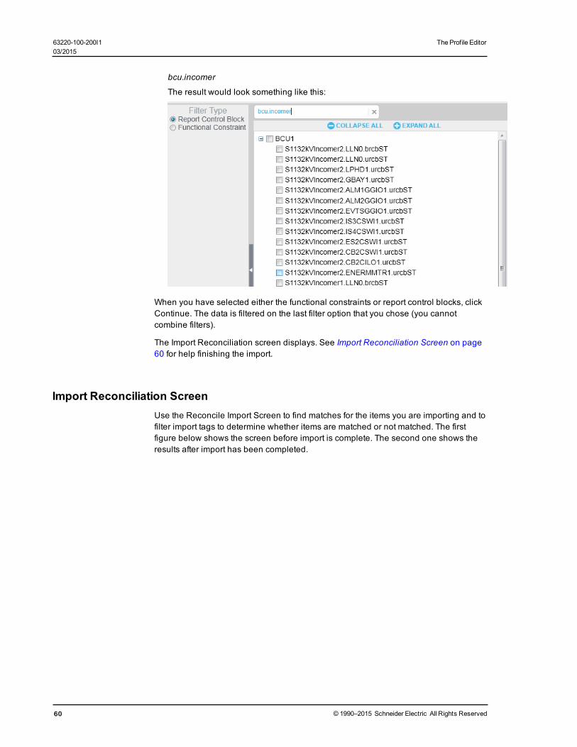
bcu.incomer
The result would look something like this:
When you have selected either the functional constraints or report control blocks, clickContinue. The data is filtered on the last filter option that you chose (you cannotcombine filters).
The Import Reconciliation screen displays. See Import Reconciliation Screen on page60 for help finishing the import.
Import Reconciliation ScreenUse the Reconcile Import Screen to find matches for the items you are importing and tofilter import tags to determine whether items are matched or not matched. The firstfigure below shows the screen before import is complete. The second one shows theresults after import has been completed.
60 © 1990–2015 Schneider Electric All Rights Reserved
63220-100-200I1 The Profile Editor03/2015

The Profile Editor 63220-100-200I103/2015
The screen is divided into three panes:
Left-hand pane:
The selections made in this pane provide an initial filter for what you view in the middlepane (see below). The tree view at the top shows the imported file data categories:
For .pls files imported from the Profile Editor, the categories are: deviceprofiles, device types, tags, and units.
For IEC61850 files, the categories are: Data, Datasets, Unbuffered Reports,Buffered Reports, and GOOSE.
Select a category to filter the list in the middle pane to only the items belonging to thatcategory.
© 1990–2015 Schneider Electric All Rights Reserved 61

To further filter the middle pane, click one of the matched status lines (matched,partially matched, unmatched) to view only items of that status. The number of items inthat status also displays.
Middle pane:
This pane shows a tree view with data.
Filter: To filter on a specific item, type the name (such as phsA for phase A current).The entry can be the exact name, or you can enter a partial name or even a wildcard(*). The filter is not case sensitive.
The data in the middle pane is filtered to include only the items for the tag you specify.To clear the filter so you can enter a new one, click the "x" beside the filter box.
Collapse All/Expand All: Click Collapse All to collapse all nodes on the screen.Only the top-level nodes will display. Conversely, click Expand All to open all nodes,displaying all of the information on all nodes.
The bottom section of the middle pane displays, in tree form, the data that you selectedin the left-hand pane:
• For files imported from the Profile Editor (.pls files), you can view: Show All, DeviceProfiles, Device Types, Tags, and Units.
• For IEC 61850 files, you can view: Data, Datasets, Unbuffered Reports, BufferedReports, and GOOSE.
The bullets indicate:
: exact match; item is either a perfect match to a local item, or you accepted a
merge for it
: unverified match; item is a partial match to a local item
: no match; item does not match any local item
Items that have no icon beside them are ignored during the import.
Re-match Items within a Logical Node
Because IEC 61850 tags are often imported with prepended information (logical node:LN) that prevents the import from matching them, you may find several unmatcheditems. You can use the re-match feature to enable matching for them.
To do this, right-click the logical node where the unmatched items are found, andchoose Re-match.
The import feature will then exclude the logical node, and use the remaininginformation in the item name to find matches. In the screen shown above, it wouldinclude functional constraint (FC) ST, data objects (DO) PhyHealth and Proxy, andfive data attributes below them:
ST.PhyHealth.q
ST.PhyHealth.t
ST.Proxy.q
ST.Proxy.stVal
ST.Proxy.t
62 © 1990–2015 Schneider Electric All Rights Reserved
63220-100-200I1 The Profile Editor03/2015
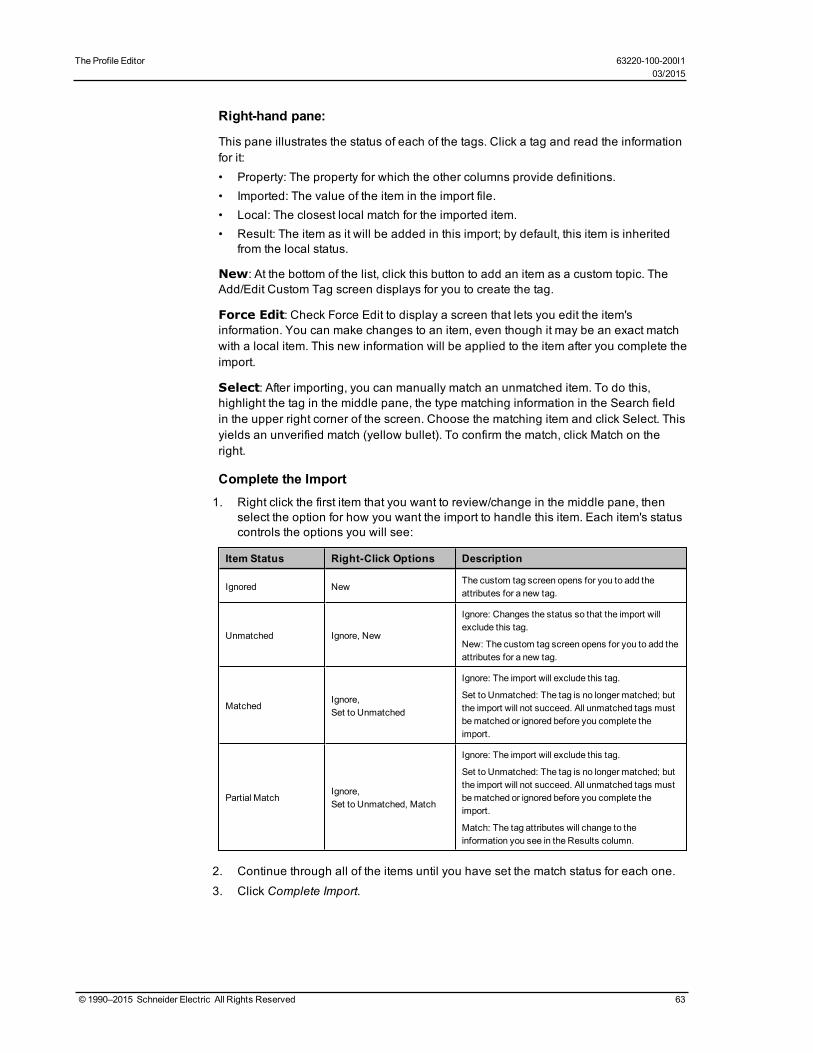
The Profile Editor 63220-100-200I103/2015
Right-hand pane:
This pane illustrates the status of each of the tags. Click a tag and read the informationfor it:• Property: The property for which the other columns provide definitions.• Imported: The value of the item in the import file.• Local: The closest local match for the imported item.• Result: The item as it will be added in this import; by default, this item is inherited
from the local status.
New: At the bottom of the list, click this button to add an item as a custom topic. TheAdd/Edit Custom Tag screen displays for you to create the tag.
Force Edit: Check Force Edit to display a screen that lets you edit the item'sinformation. You can make changes to an item, even though it may be an exact matchwith a local item. This new information will be applied to the item after you complete theimport.
Select: After importing, you can manually match an unmatched item. To do this,highlight the tag in the middle pane, the type matching information in the Search fieldin the upper right corner of the screen. Choose the matching item and click Select. Thisyields an unverified match (yellow bullet). To confirm the match, click Match on theright.
Complete the Import1. Right click the first item that you want to review/change in the middle pane, then
select the option for how you want the import to handle this item. Each item's statuscontrols the options you will see:
Item Status Right-Click Options Description
Ignored NewThe custom tag screen opens for you to add theattributes for a new tag.
Unmatched Ignore, New
Ignore: Changes the status so that the import willexclude this tag.
New: The custom tag screen opens for you to add theattributes for a new tag.
MatchedIgnore,Set to Unmatched
Ignore: The import will exclude this tag.
Set to Unmatched: The tag is no longer matched; butthe import will not succeed. All unmatched tags mustbematched or ignored before you complete theimport.
Partial MatchIgnore,Set to Unmatched, Match
Ignore: The import will exclude this tag.
Set to Unmatched: The tag is no longer matched; butthe import will not succeed. All unmatched tags mustbematched or ignored before you complete theimport.
Match: The tag attributes will change to theinformation you see in the Results column.
2. Continue through all of the items until you have set the match status for each one.
3. Click Complete Import.
© 1990–2015 Schneider Electric All Rights Reserved 63

Using Import TemplatesYou can create, edit, and apply templates when you import files. You can also deleteimport templates. A template will include tags that you import into the Profile Editor froma project in another instance of the Profile Editor, or it will contain ICD files from an IEC61850 device.
You will want to create a template for custom situations, like when you are importingSCL files or adding custom tags and devices.
Creating a New Template During Import
To create a new template:
1. From the either type of import (Profile Editor or SCL), choose the file (.pls or .icd)that you want to import.
2. Complete the matching for the items.
3. Click Complete Import.
4. At the Save Import Template prompt, click Yes.
5. Click the New radio button, then type a name for the new template. The name mustbegin with a letter. It can contain alpha-numeric characters, as well as dashes andspaces. Click OK to save it.
In future imports, you will be able to apply this template. When you do, the system willautomatically match, where appropriate, the import items with the local items.
Applying a Template During Import
In this procedure, you will import files, and you will either create a new import template,or you will edit an existing one.
NOTE: Be careful when applying a template: you will overwrite an existing template onthe local computer with the information that you choose during matching. Oncecompleted, you cannot undo this.
To apply an existing template:
1. From the Set Up Projects tab, select a project for which you want to import data.2. Click File > Import, then choose the file (.pls or .icd) that you want to import.
3. From the Import Template drop down list, choose the template you want to use. Thisis just a starting point for this import to make it quicker to match items. You will applythe template in step 7.
4. Click Start Import.
After the import completes, the Import Reconciliation screen displays. The list in theleft-hand pane should have some exact and partial matches.
5. As you work through the items, you must either designate that each a match orignored.
6. When all items are completed, click Complete Import.
7. At the Save Import Template dialog, click No to import without applying a template.Or click Yes to either save a new template or edit the one you chose in step 3:— To create a new template for this import, click New, then type an Import
Template Name.— To edit a template, click Edit, then select the template from the drop down menu.
This will edit the template by adding the changes you made during matching.This cannot be undone after you click OK.
64 © 1990–2015 Schneider Electric All Rights Reserved
63220-100-200I1 The Profile Editor03/2015

The Profile Editor 63220-100-200I103/2015
8. Click OK.
The import is completed, and the new template is created, or the existing template isedited to include the changes you made during matching.
Deleting a Template
You can delete any import template, even if it was applied during a previous import.
To do this:
1. Click Settings > Remove Import Templates.2. At the Import Templates dialog, select the template you want to delete, then click
Delete.
The template is deleted.
Tag TypesThis product includes a variety of tag types: real-time, alarm, and trend. Most of the tagsthat you will need are already added. However, you can add custom tags to suitspecial needs. This section describes how tags are constructed and provides furtherspecific information about the construction of format codes, logic codes, andaddresses.
In this section, you can learn about:
IEC 61850 Tag Construction on page 65
Define an Enumeration on page 66
Format Code Definitions on page 67
Logic Codes on page 69
Block Writes on page 85
IEC 61850 Tag ConstructionIEC 61850 tags are flexible, which allows them to specify how functions areimplemented in devices. The IEC 61850 tag was developed for medium-voltage andhigh-voltage applications, such as monitoring, control, and substation automation.
Some of our devices include data and functionality that are not yet covered by IEC61850. For these devices, the general IEC61850 formatting was followed whencreating tags.
If you are writing Cicode (see Use Cicode to Customize a Project on page 143). Youwill need to know the IEC 61850 tag name that you added to the device profile for thatdevice. You can print the .csv file to view tag names (see Print the .CSV File on page29). Apart from that, you would only need to add tags if you are installing a third-partydevice that is not standard to PowerSCADA Expert. If you do need to add tags, createany category you wish, and follow the format shown below.
Tags shall be no longer than 29 characters. Use a backslash as a separator betweentag parts. Tags are constructed in this manner:
EquipmentName\Logical_Node\Data Object\Data Attribute (may have more than one)
The following table lists the main categories for the common logical nodes. After thetable, the most commonly used category (Mxxx: metering and measurement) isdescribed.
© 1990–2015 Schneider Electric All Rights Reserved 65

CategoryName Description
Axxx automatic control; e.g., ATCC (tap changer), AVCO (voltage control)
Cxxx supervisory control; e.g., CILO (interlocking), CSWI (switch control)
Gxxx generic functions; e.g., GGIO (generic I/O)
Ixxx interfacing/archiving; e.g., IARC (archive), IHMI (HMI)
Lxxx system logical nodes; e.g., LLNO (common), LPHD (physical device)
Mxxxmetering andmeasurement; e.g., MMXU (measurement), MMTR (metering), MSTA (meteringstatistics), MSQI (sequence and imbalance), MHAI (harmonics and interharmonics)
Pxxxprotection; e.g., PDIF (differential), PIOC (instantaneous overcurrent or rate of rise.), PDIS(distance), PTOV (time-overvoltage)
Rxxx protection related; e.g., RREC (auto reclosing), RDRE (disturbance)
Sxxx sensors, monitoring; e.g., SARC (arcs), SPDC (partial discharge)
Txxx instrument transformer; e.g., TCTR (current), TVTR (voltage)
Xxxx switchgear; e.g., XCBR (circuit breaker), XCSW (switch)
Zxxx other equipment; e.g., ZCAP (cap control), ZMOT (motor)
The following example illustrates the IEC 61850 tag for current A:
EquipmentName\MMXU1\A\PhsA
where:
M = the category
MXU = measurement of currents, voltages, power, and impedances
1 = the instance (there could be multiple MMXU tags)
A = the data object, current
PhsA = the attribute that further defines the data object, phase A
All of the tags that are currently used in the system can be viewed from the ProfileEditor, Define Device Type Tags tab. Click Settings > Display Advanced Properties todisplay the full tag names.
Define an EnumerationAn enumeration is a single value (0-15) that is used to define a condition that isdetermined by multiple-bit input. You will add enumerations to handle scenarios thatare more complicated than simply true-false, to allow for dynamic contingencies. Forexample, when you need to use multiple bits to describe the position of a circuitbreaker, you might do the following:
Bit y (closed) | Bit x (open). Note that the least significant bit is register 1.
Bit x | Bity Status Circuit Breaker Position Returned
Value
0 | 0 Indeterminate Circuit breaker is neither open nor closed 0
0 | 1 Open Circuit breaker is open. 1
66 © 1990–2015 Schneider Electric All Rights Reserved
63220-100-200I1 The Profile Editor03/2015

The Profile Editor 63220-100-200I103/2015
Bit x | Bity Status Circuit Breaker Position Returned
Value
1 | 0 Closed Circuit breaker is closed. 2
1 | 1 ErrorCircuit breaker is reporting both open and closedcondition.
Possible device/wiring error3
Using the enumerated status, we place the register and bitmask for the open positionin register 1 (least significant) and the register and bitmask for the closed position inregister 2 (most significant).
Use Special Tags to Control Circuit Breaker Status
When you want to include a device that does not have a pre-defined device profile(such as a third-party circuit breaker), you must identify the registers that the deviceuses for the operations you want, then choose the correct tags and tag addresses towrite to these registers. Finally, when creating the one-line on the graphics page, youwill choose the appropriate genie:
1. Determine the device registers used for the open and close operations on thecircuit breaker.
2. In the Profile Editor, choose the tag needed for each operation.
3. Ensure that tag address references the correct action and register(s). See Edit TagAddresses on page 34 for instructions on editing the address,
4. When adding a genie for the circuit breaker on the graphics page, choose from thedefault library (see Appendix 1: Default Genie Library on page 212), or create acustom genie (see Create New Genies on page 116).
Format Code DefinitionsThe address field is part of the tag. It includes a variety of attributes, some of which arerequired, and some optional. The following tables list the attributes, whether they arerequired, and their possible modifiers. All parts of a tag are case sensitive. The order ofthe fields is fixed; and all fields are separated by semi-colons. See Logic Codes onpage 69 for templates of constructed tags.
Real-Time Format Code Definitions
Attributes Modifiers Comments
T (type)
Required
SS = single status
DS =double statusenumeration
ST = string
UT =UTC time
MV =measured value(float)
CM =complexmeasured value (float)
BC =binary counter(integer)
Temporarily, this may return a string; when PowerSCADAExpert is upgraded to handle large integers, this will change.
D (module—Micrologic devices)
B =BCM
P=PM
M =MM
© 1990–2015 Schneider Electric All Rights Reserved 67

Attributes Modifiers Comments
C =CCM
M/m/S/s/C/c/I/i(register type)
M =holding registers inhexadecimal
m =holding registers indecimal
S = input coil (statusregister) in hexadecimal
s = input coil (statusregister) in decimal
C =output coil (writableonly) in hexadecimal
c = output coil (writableonly) in decimal
I = input register (readonly) in hexadecimal
i = input register (readonly) in decimal
Register NumberModifiers (registernumber from 1–4)
u## =## registers areunsigned, ## is adecimal
s## = ## registers aresigned; ## is a decimal
After themodifier, theremay be a number indicating scalingfactor. See “V,” below in this table. Used for conversion to SIunits, this number will be:
RegisterValue x scale
For SS and DS: theremust be a 1U default; themodifier willbe a bitmask:
- Themask must use hex only, 16 bits/register
- Attach the ones, then the zeromask, to the register; ifyou only have ones masks, just attach them
- Only one register cases can be inverted. Add :I after themasks for inversion.
N (scale)numerical entries;range is -10 to 10
N defines a constant scale; the logic code knows how to useit.
R (scale register) the register number indecimal
R defines the holding register where the scale is held; thelogic code knows how to use it.
E (priority)
single digit: 1, 2, or 3;default 2 is used if thisis not included
(1 = high, 2 = normal, 3= low)
Defines the priority PowerSCADAExpert uses in processingdata.
V (conversion factor)Use scientific notationwithout the decimal.
Examples: 354E-3 = 0.354
354E1 =3540Will bemultiplied before the value is returned.
L:P (logic code)
Required The number that isused comes from theLogic Codes table.
L:P is the logic code for PowerLogic. Other codes mayfollow, such a L:I for ION.
For logic code descriptions, see Logic Codes on page 69
Alarm Format Code Definitions
Attributes Modifiers Comments
T (type)
RequiredALM =alarm
68 © 1990–2015 Schneider Electric All Rights Reserved
63220-100-200I1 The Profile Editor03/2015
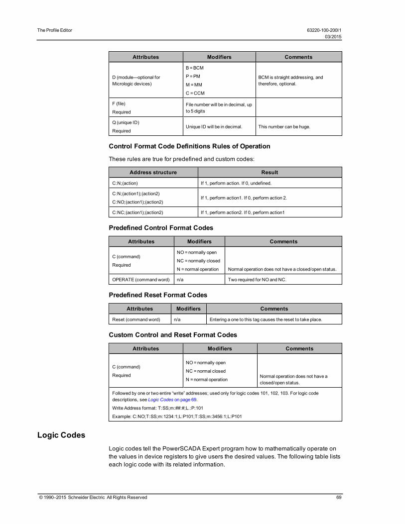
The Profile Editor 63220-100-200I103/2015
Attributes Modifiers Comments
D (module—optional forMicrologic devices)
B =BCM
P=PM
M =MM
C =CCM
BCM is straight addressing, andtherefore, optional.
F (file)
RequiredFile number will be in decimal, upto 5 digits
Q (unique ID)
RequiredUnique ID will be in decimal. This number can be huge.
Control Format Code Definitions Rules of Operation
These rules are true for predefined and custom codes:
Address structure Result
C:N;(action) If 1, perform action. If 0, undefined.
C:N;(action1);(action2)
C:NO;(action1);(action2)If 1, perform action1. If 0, perform action 2.
C:NC;(action1);(action2) If 1, perform action2. If 0, perform action1
Predefined Control Format Codes
Attributes Modifiers Comments
C (command)
Required
NO=normally open
NC =normally closed
N =normal operation Normal operation does not have a closed/open status.
OPERATE (command word) n/a Two required for NO and NC.
Predefined Reset Format Codes
Attributes Modifiers Comments
Reset (command word) n/a Entering a one to this tag causes the reset to take place.
Custom Control and Reset Format Codes
Attributes Modifiers Comments
C (command)
Required
NO=normally open
NC =normal closed
N =normal operationNormal operation does not have aclosed/open status.
Followed by one or two entire “write” addresses; used only for logic codes 101, 102, 103. For logic codedescriptions, see Logic Codes on page 69.
Write Address format: T:SS;m:##:#;L.:P:101
Example: C:NO;T:SS;m:1234:1;L:P101;T:SS;m:3456:1;L:P101
Logic CodesLogic codes tell the PowerSCADA Expert program how to mathematically operate onthe values in device registers to give users the desired values. The following table listseach logic code with its related information.
© 1990–2015 Schneider Electric All Rights Reserved 69

LogicCode
IECType
PowerSCADA ExpertData Type
RegisterDefinitio
n
ScaledRequire
d?(registeror fixed)
DeviceSpecific?
Notes
READS
InvalidBlock
(L:P:0)
IB LONGUp to 1,000sequentialregisters
NoGenericonly
Defines invalid blocksof memory in thedevice. The driverdoes not includethese registers inblock reads.
Date / Time(L:P:1)(3 register)
UT LONG3 sequentialregisters
NoGeneric – ifit fits
Register N:
High byte =Month 1–12Low byte =Day 1–31
Register N+1:
High byte =Year 0–199 (+1900)
Low byte =Hour 0–23
Register N+2:
High byte =minutes0–59Low byte = seconds0–59
Date / Time(L:P:2)(6 register)
UT LONG6 sequentialregisters
NoGeneric
- if it fits
Register N: Seconds0–59
Register N+1:Minutes 0–59
Register N+2: Hours0–23
Register N+3: Day1–31
Register N+4: Month1–12
Register N+5: Year0–199 (+1900)
Date / Time(L:P:3)(3 or 4register --CircuitMonitor/PowerMeter)
UT LONG3 or 4sequentialregisters
No CM/PM
Register N:
High byte =Month 1–12,Low byte =Day 1–31
Register N+1:
High byte =Year 0–199 (+1900)
Low byte =Hour 0–23
Register N+2:
High byte =minutes0–59Low byte = seconds0–59
Register N+3:
msec = 0–999(unused)
70 © 1990–2015 Schneider Electric All Rights Reserved
63220-100-200I1 The Profile Editor03/2015
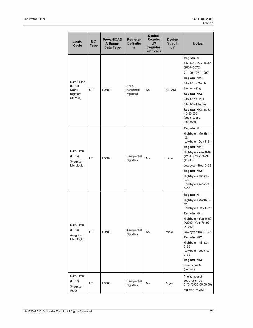
The Profile Editor 63220-100-200I103/2015
LogicCode
IECType
PowerSCADA ExpertData Type
RegisterDefinitio
n
ScaledRequire
d?(registeror fixed)
DeviceSpecific?
Notes
Date / Time(L:P:4)(3 or 4registersSEPAM)
UT LONG3 or 4sequentialregisters
No SEPAM
Register N:
Bits 0–6 =Year: 0 –70(2000– 2070)
71 – 99 (1971–1999)
Register N+1:
Bits 8-11 =Month
Bits 0-4 =Day
Register N+2:
Bits 8-12 =Hour
Bits 0-5 =Minutes
Register N+3: msec= 0-59,999(seconds arems/1000)
Date/Time
(L:P:5)
3-registerMicrologic
UT LONG3 sequentialregisters
No micro
Register N:
High byte =Month 1–12,Low byte =Day 1–31
Register N+1:
High byte =Year 0–69(+2000), Year 70–99(+1900)
Low byte =Hour 0–23
Register N+2:
High byte =minutes0–59Low byte = seconds0–59
Date/Time
(L:P:6)
4-registerMicrologic
UT LONG4 sequentialregisters
No micro
Register N:
High byte =Month 1–12,Low byte =Day 1–31
Register N+1:
High byte =Year 0–69(+2000), Year 70–99(+1900)
Low byte =Hour 0–23
Register N+2:
High byte =minutes0–59Low byte = seconds0–59
Register N+3:
msec = 0–999(unused)
Date/Time
(L:P:7)
3-registerArgos
UT LONG3 sequentialregisters
No Argos
The number ofseconds since01/01/2000 (00:00:00)
register 1 =MSB
© 1990–2015 Schneider Electric All Rights Reserved 71

LogicCode
IECType
PowerSCADA ExpertData Type
RegisterDefinitio
n
ScaledRequire
d?(registeror fixed)
DeviceSpecific?
Notes
register 2 = LSB
register 3 =milliseconds
Date/Time
(L:P:8)
4-registerIEC 870-5-4
UT LONG4 sequentialregisters
No generic
Register N:
Bits 0–6 =Year: 0 –127 (2000– 2127)
Register N+1:
Bits 8-11 =Month
Bits 0-4 =Day
Register N+2:
Bits 8-12 =Hour
Bits 0-5 =Minutes
Register N+3: msec= 0-59,999(seconds arems/1000)
Modulo 10k(L:P:10)
BC STRINGUp to 4registers
No generic
Result is a stringrepresentation.
Range is 0 to9,999,999,999,999,999
Each register has arange of 0 to 9,999
Result is:– R4*10,000^3 +R3*10,000^2 +R2*10,000 +R1
Modulo 10kVal
(L:P:11)BC REAL
Up to 4registers
No generic
Result is a stringrepresentation.
Range is 0 to9,999,999,999,999,999
Each register has arange of 0 to 9,999
Result is:– R4*10,000^3 +R3*10,000^2 +R2*10,000 +R1
NOTE: This logiccode (and all REALlogic codes) has anaccuracy of sevendigits. Anything longerthan seven digitsshould not beconsidered accurate.
Modulo 10kEnergy
(L:P:12)BC STRING
Up to 4registers
No generic
Result is a stringrepresentation.
Range is 0 to9,999,999,999,999.9
Each register has arange of 0 to 9,999
72 © 1990–2015 Schneider Electric All Rights Reserved
63220-100-200I1 The Profile Editor03/2015

The Profile Editor 63220-100-200I103/2015
LogicCode
IECType
PowerSCADA ExpertData Type
RegisterDefinitio
n
ScaledRequire
d?(registeror fixed)
DeviceSpecific?
Notes
Result is– (R4*10,000^3 +R3*10,000^2 +R2*10,000 +R1)/1000
Modulo 10kEnergy Val
(L:P:13)BC REAL
Up to 4registers
No generic
Result is a stringrepresentation.
Range is 0 to9,999,999,999,999.9
Each register has arange of 0 to 9,999
Result is– (R4*10,000^3 +R3*10,000^2 +R2*10,000 +R1)/1000
NOTE: This logiccode (and all REALlogic codes) has anaccuracy of sevendigits. Anything longerthan seven digitsshould not beconsidered accurate.
PL DigitalInput SS
(L:P:20)SS LONG 2 registers No CM/PM
First register (100–199 inclusive)indicates that this is adigital input register.
Second register ismasked to test foreither one 1 or one 0.
Result is: 0 = off and 1=on.
This result can beinverted.
PL DigitalInput DS
(L:P:21)DS LONG 2 registers No CM/PM
Same as PLDigitalInput SS except:
Result is 0 =intermediate, 1 = off,2 = on, 3 = bad-state.
Inversion will invertonly off and on states.
PL DigitalInput TF
(L:P:22)SS DIGITAL 2 registers No CM/PM
Same as PLDigitalInput SS except:
Result is: 0 = falseand 1 = true.
This result can beinverted.
PL DigitalOutput SS
(L:P:23)SS LONG 2 registers No CM/PM
First register (200–299 inclusive)indicates that this is adigital output register.
© 1990–2015 Schneider Electric All Rights Reserved 73

LogicCode
IECType
PowerSCADA ExpertData Type
RegisterDefinitio
n
ScaledRequire
d?(registeror fixed)
DeviceSpecific?
Notes
Second register ismasked to test foreither one 1 or one 0.
Result is: 0 = off and 1=on.
This result can beinverted.
PL DigitalOutput DS
(L:P:24)DS LONG 2 registers No CM/PM
Same as PLDigitalOutput SS, except:
Result is:0 = intermediate, 1 =off, 2 = on, 3 = bad-state.
Inversion will invertonly off and on states.
PL DigitalOutput TF
(L:P:25)SS DIGITAL 2 registers No CM/PM
Same as PLDigitalOutput SS except:
Result is: 0 = falseand 1 = true.
This result can beinverted.
Status SS(L:P:26)
SS LONGUp to 4registers
No Generic
Each register iscompared to a ones’mask. Optionally itcan be compared to azeros’ mask. (Use theEdit Address screenin the Profile Editor tocreatemasks for theuser.)
Result is: 0 = off and 1=on.
If there is only oneregister, the resultcan be inverted.
Status ORSS
(L:P:226)SS LONG
2 to 4registers
No Generic
Each register iscompared to a ones’mask. These resultsare OR’ed together.Optionally, it can becompared to a zeros’mask. (Use the EditAddress screen in theProfile Editor to createmasks for the user.)
Result is: 0 = off and 1=on.
Status DS(L:P:27)
DS LONGUp to 4registers
No Generic
Same as Status SSexcept:
Result is: 0 =intermediate, 1 = off,2 = on, 3 = bad-state.
74 © 1990–2015 Schneider Electric All Rights Reserved
63220-100-200I1 The Profile Editor03/2015

The Profile Editor 63220-100-200I103/2015
LogicCode
IECType
PowerSCADA ExpertData Type
RegisterDefinitio
n
ScaledRequire
d?(registeror fixed)
DeviceSpecific?
Notes
Inversion will invertonly off and on states.
Status ORDS
(L:P:227)DS LONG
2 to 4registers
No Generic
Same as Status ORSS except:
Result is: 0 =intermediate, 1 = off,2 = on, 3 = bad-state.
Status TF(L:P:28)
SS DIGITALUp to 4registers
No Generic
Same as Status SSexcept:
Result is: 0 = falseand 1 = true.
This result can beinverted.
Status ORTF
(L:P:228)SS DIGITAL
2 to 4registers
No Generic
Same as Status ORSS except:
Result is: 0 = falseand 1 = true.
Status Int(L:P:29)
BC LONG 1 register No CM/PM
One register is bitanded with onemask.The result will be aninteger that can beused to choose theappropriateenumeration.
StatusEnumeration
(L:P:229)
EN LONG1 to 4registers
No Generic
Each register iscompared to a ones’mask. Optionally itcan be compared to azeros’ mask. (Use theEdit Address screenin the Profile Editor tocreatemasks for theuser.)
Result is acombination of theresults for eachregister, using thisformula:
result for register 1 *2^0 + result forregister 2 * 2^1 +result for register 3 *2^2 + result forregister 4 * 2^3
PL AnalogInput
(L:P:30)
MV/CM
REAL 3 registers No CM/PM
First register (300–399 inclusive)indicates that this is aanalog input register.
Second register istreated as a signedvalue.
© 1990–2015 Schneider Electric All Rights Reserved 75
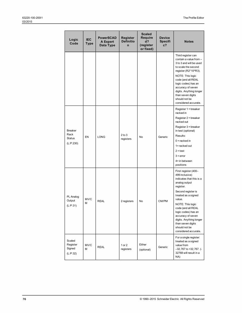
LogicCode
IECType
PowerSCADA ExpertData Type
RegisterDefinitio
n
ScaledRequire
d?(registeror fixed)
DeviceSpecific?
Notes
Third register cancontain a value from –3 to 3 and will be usedto scale the secondregister (R2*10^R3).
NOTE: This logiccode (and all REALlogic codes) has anaccuracy of sevendigits. Anything longerthan seven digitsshould not beconsidered accurate.
BreakerRackStatus
(L:P:230)
EN LONG2 to 3registers
No Generic
Register 1 = breakerracked in
Register 2 = breakerracked out
Register 3 = breakerin test (optional)
Results:
0 = racked in
1= racked out
2 = test
3 = error
4= in betweenpositions
PL AnalogOutput
(L:P:31)
MV/CM
REAL 2 registers No CM/PM
First register (400–499 inclusive)indicates that this is aanalog outputregister.
Second register istreated as a signedvalue.
NOTE: This logiccode (and all REALlogic codes) has anaccuracy of sevendigits. Anything longerthan seven digitsshould not beconsidered accurate.
ScaledRegisterSigned
(L:P:32)
MV/CM
REAL1 or 2registers
Either
(optional)Generic
For a single register:treated as a signedvalue from–32,767 to +32,767. (-32768 will result in aNA)
76 © 1990–2015 Schneider Electric All Rights Reserved
63220-100-200I1 The Profile Editor03/2015

The Profile Editor 63220-100-200I103/2015
LogicCode
IECType
PowerSCADA ExpertData Type
RegisterDefinitio
n
ScaledRequire
d?(registeror fixed)
DeviceSpecific?
Notes
For two registers: theregisters will beconcatenatedtogether, the firstregister filling bits 16–32 and the secondregister filling bits 0–15. Values will rangefrom
–2,147,483,648 to –2,147,483,647.
Values can be scaledusing a fixed scale ora scale register.
NOTE: This logiccode (and all REALlogic codes) has anaccuracy of sevendigits. Anything longerthan seven digitsshould not beconsidered accurate.
ScaledRegisterUnsigned
(L:P:33)
MV/CM
REAL1 to 4registers
Either
(optional)Generic
For a single register:treated as anunsigned value from 0to 65,535.
For two registers: theregisters will beconcatenatedtogether, the firstregister filling bits 16–32 and the secondregister filling bits 0–15. Values will rangefrom
0 to 4,294,967,295.
Values can be scaledusing a fixed scale ora scale register.
NOTE: This logiccode (and all REALlogic codes) has anaccuracy of sevendigits. Anything longerthan seven digitsshould not beconsidered accurate.
ScaledRegisterSigned NoNA
(L:P:34)
MV/CM
REAL1 or 2registers
Either
(optional)Generic
Same as ScaledRegister except that asingle register withvalue -32768 isacceptable and will bereported as such.
© 1990–2015 Schneider Electric All Rights Reserved 77

LogicCode
IECType
PowerSCADA ExpertData Type
RegisterDefinitio
n
ScaledRequire
d?(registeror fixed)
DeviceSpecific?
Notes
NOTE: This logiccode (and all REALlogic codes) has anaccuracy of sevendigits. Anything longerthan seven digitsshould not beconsidered accurate.
ScaledRegisterSignedSEPAM A
(L:P:35)
MV/CM
REAL 2 registersEither
(optional)Generic
Same as ScaledRegister except that0xFFFFFFFF or0x00007FFF will beNA.
NOTE: This logiccode (and all REALlogic codes) has anaccuracy of sevendigits. Anything longerthan seven digitsshould not beconsidered accurate.
ScaledRegisterSignedSEPAM B
(L:P:36)
MV/CM
REAL 2 registersEither
(optional)Generic
Same as ScaledRegister except that0xFFFFFFFF will beNA.
NOTE: This logiccode (and all REALlogic codes) has anaccuracy of sevendigits. Anything longerthan seven digitsshould not beconsidered accurate.
IEEE 32Real
(L:P:37)
MV/CM
REAL2 sequentialregisters
No Generic
Uses the IEEEstandard for floating-point arithmetic (IEEE754);
register 1 is MSB,register 2 is LSB
NOTE: This logiccode (and all REALlogic codes) has anaccuracy of sevendigits. Anything longerthan seven digitsshould not beconsidered accurate.
ScaledRegisterSignedSEPAM2000Format B
(L:P:38)
MV/CM
REAL 1 registerEither
(optional)Generic
For a single register:treated as a signedvalue from–32,767 to +32,767:
From the value of theunsigned register,subtract 32768; thenapply the scale.
78 © 1990–2015 Schneider Electric All Rights Reserved
63220-100-200I1 The Profile Editor03/2015

The Profile Editor 63220-100-200I103/2015
LogicCode
IECType
PowerSCADA ExpertData Type
RegisterDefinitio
n
ScaledRequire
d?(registeror fixed)
DeviceSpecific?
Notes
0000 or FFFF will beNA.
NOTE: This logiccode (and all REALlogic codes) has anaccuracy of sevendigits. Anything longerthan seven digitsshould not beconsidered accurate.
PL String(L:P:39)
ST STRING1 to 10sequentialregisters
No GenericEach register canrepresent up to twoASCII characters.
SumRegisters(L:P:40)
MV/CM
REAL1 to 4registers
Either
(required)Generic
Result is:
R1 +…+Rn *10^scale
NOTE: This logiccode (and all REALlogic codes) has anaccuracy of sevendigits. Anything longerthan seven digitsshould not beconsidered accurate.
DivideRegisters
(L:P:41)
MV/CM
REAL 3 registersEither
(required)Generic
Result is:
R1/R2 * R3 *10^scale
If R2 is zero, resultwill be #COM
NOTE: This logiccode (and all REALlogic codes) has anaccuracy of sevendigits. Anything longerthan seven digitsshould not beconsidered accurate.
MultiplyRegisters
(L:P:42)
MV/CM
REAL1 to 4registers
Either
(required)Generic
Result is:
R1 * … * Rn *10^scale
NOTE: This logiccode (and all REALlogic codes) has anaccuracy of sevendigits. Anything longerthan seven digitsshould not beconsidered accurate.
AverageRegisters
(L:P:43)
MV/CM
REAL1 to 4registers
Either
(required)Generic
Result is:
Avg(R1…Rn) *10^scale
© 1990–2015 Schneider Electric All Rights Reserved 79
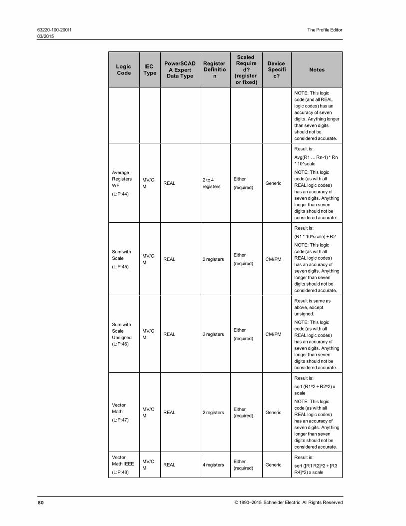
LogicCode
IECType
PowerSCADA ExpertData Type
RegisterDefinitio
n
ScaledRequire
d?(registeror fixed)
DeviceSpecific?
Notes
NOTE: This logiccode (and all REALlogic codes) has anaccuracy of sevendigits. Anything longerthan seven digitsshould not beconsidered accurate.
AverageRegistersWF
(L:P:44)
MV/CM
REAL2 to 4registers
Either
(required)Generic
Result is:
Avg(R1…Rn-1) * Rn* 10^scale
NOTE: This logiccode (as with allREAL logic codes)has an accuracy ofseven digits. Anythinglonger than sevendigits should not beconsidered accurate.
Sum withScale
(L:P:45)
MV/CM
REAL 2 registersEither
(required)CM/PM
Result is:
(R1 * 10^scale) +R2
NOTE: This logiccode (as with allREAL logic codes)has an accuracy ofseven digits. Anythinglonger than sevendigits should not beconsidered accurate.
Sum withScaleUnsigned(L:P:46)
MV/CM
REAL 2 registersEither
(required)CM/PM
Result is same asabove, exceptunsigned.
NOTE: This logiccode (as with allREAL logic codes)has an accuracy ofseven digits. Anythinglonger than sevendigits should not beconsidered accurate.
VectorMath
(L:P:47)
MV/CM
REAL 2 registersEither(required)
Generic
Result is:
sqrt (R1^2 +R2^2) xscale
NOTE: This logiccode (as with allREAL logic codes)has an accuracy ofseven digits. Anythinglonger than sevendigits should not beconsidered accurate.
VectorMath IEEE
(L:P:48)
MV/CM
REAL 4 registersEither(required)
GenericResult is:
sqrt ([R1 R2]^2 + [R3R4]^2) x scale
80 © 1990–2015 Schneider Electric All Rights Reserved
63220-100-200I1 The Profile Editor03/2015
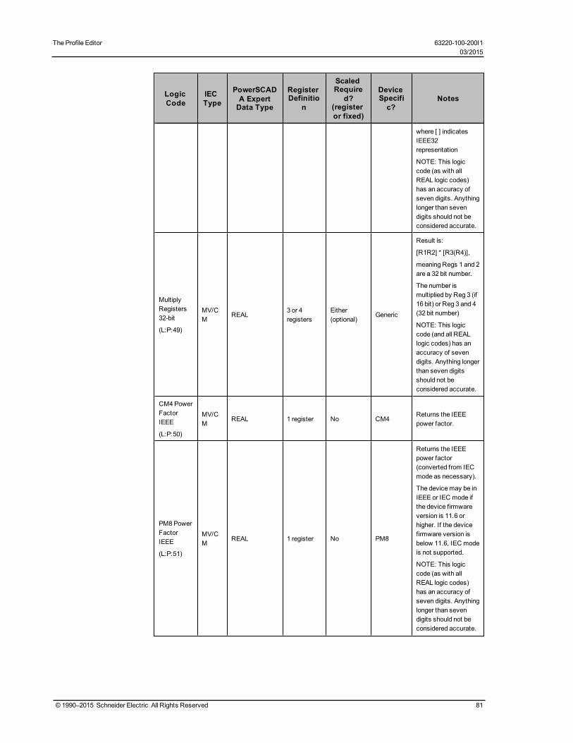
The Profile Editor 63220-100-200I103/2015
LogicCode
IECType
PowerSCADA ExpertData Type
RegisterDefinitio
n
ScaledRequire
d?(registeror fixed)
DeviceSpecific?
Notes
where [ ] indicatesIEEE32representation
NOTE: This logiccode (as with allREAL logic codes)has an accuracy ofseven digits. Anythinglonger than sevendigits should not beconsidered accurate.
MultiplyRegisters32-bit
(L:P:49)
MV/CM
REAL3 or 4registers
Either(optional)
Generic
Result is:
[R1R2] * [R3(R4)],
meaning Regs 1 and 2are a 32 bit number.
The number ismultiplied by Reg 3 (if16 bit) or Reg 3 and 4(32 bit number)
NOTE: This logiccode (and all REALlogic codes) has anaccuracy of sevendigits. Anything longerthan seven digitsshould not beconsidered accurate.
CM4 PowerFactorIEEE
(L:P:50)
MV/CM
REAL 1 register No CM4Returns the IEEEpower factor.
PM8 PowerFactorIEEE
(L:P:51)
MV/CM
REAL 1 register No PM8
Returns the IEEEpower factor(converted from IECmode as necessary).
The devicemay be inIEEE or IEC mode ifthe device firmwareversion is 11.6 orhigher. If the devicefirmware version isbelow 11.6, IEC modeis not supported.
NOTE: This logiccode (as with allREAL logic codes)has an accuracy ofseven digits. Anythinglonger than sevendigits should not beconsidered accurate.
© 1990–2015 Schneider Electric All Rights Reserved 81
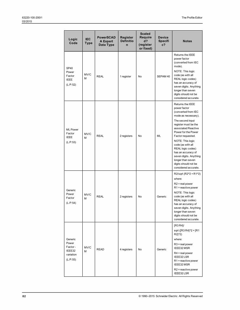
LogicCode
IECType
PowerSCADA ExpertData Type
RegisterDefinitio
n
ScaledRequire
d?(registeror fixed)
DeviceSpecific?
Notes
SP40PowerFactorIEEE
(L:P:52)
MV/CM
REAL 1 register No SEPAM 40
Returns the IEEEpower factor(converted from IECmode).
NOTE: This logiccode (as with allREAL logic codes)has an accuracy ofseven digits. Anythinglonger than sevendigits should not beconsidered accurate.
ML PowerFactorIEEE
(L:P:53)
MV/CM
REAL 2 registers No ML
Returns the IEEEpower factor(converted from IECmode as necessary).
The second inputregister must be theassociated ReactivePower for the PowerFactor requested.
NOTE: This logiccode (as with allREAL logic codes)has an accuracy ofseven digits. Anythinglonger than sevendigits should not beconsidered accurate.
GenericPowerFactor
(L:P:54)
MV/CM
REAL 2 registers No Generic
R2/sqrt (R2^2 +R1^2)
where:
R2 = real powerR1 = reactive power
NOTE: This logiccode (as with allREAL logic codes)has an accuracy ofseven digits. Anythinglonger than sevendigits should not beconsidered accurate.
GenericPowerFactor -IEEE32variation
(L:P:55)
MV/CM
READ 4 registers No Generic
[R3 R4]/
sqrt ([R3 R4]^2 + [R1R2]^2)
where:
R3 = real powerIEEE32MSR
R4 = real powerIEEE32 LSRR1 = reactive powerIEEE32 MSR
R2 = reactive powerIEEE32 LSR
82 © 1990–2015 Schneider Electric All Rights Reserved
63220-100-200I1 The Profile Editor03/2015

The Profile Editor 63220-100-200I103/2015
LogicCode
IECType
PowerSCADA ExpertData Type
RegisterDefinitio
n
ScaledRequire
d?(registeror fixed)
DeviceSpecific?
Notes
SP2000PowerFactorIEEE
(L:P:56)
MV/CM
REAL 1 register NoSEPAM2000
Returns the IEEEpower factor(converted from IECmode).
NOTE: This logiccode (as with allREAL logic codes)has an accuracy ofseven digits. Anythinglonger than sevendigits should not beconsidered accurate.
ScaledRegisterSigned 64-bit
(L:P:57)
MV/CM
REAL 4 registersEither
(optional)Generic
Reads a 64-bit signedinteger and returns aREAL value.
NOTE: This logiccode (as with allREAL logic codes)has an accuracy ofseven digits. Anythinglonger than sevendigits should not beconsidered accurate.
PowerFactorIEEE
(L:P:58)
MV/CM
REAL 2 registers No Generic
Takes a 4 quadrantpower factor (IEEE32real) and returns anIEEE power factor
IEEE 64-bitdouble
(L:P:59)
MV/CM
REAL 4 registers No Generic
Uses the IEEEstandard for floating-point arithmetic (IEEE754); returns thevalue as 32-bit REAL.
NOTE: This logiccode (as with allREAL logic codes)has an accuracy ofseven digits. Anythinglonger than sevendigits should not beconsidered accurate.
IEEE 64-bitdouble
(L:P:60)
MV/CM
STRING 4 registers No Generic
Uses the IEEEstandard for floating-point arithmetic (IEEE754); returns thevalue as 64-bitSTRING.
NOTE: This logiccode (as with allREAL logic codes)has an accuracy of 15digits. Anything longerthan 15 digits shouldnot be consideredaccurate.
© 1990–2015 Schneider Electric All Rights Reserved 83

LogicCode
IECType
PowerSCADA ExpertData Type
RegisterDefinitio
n
ScaledRequire
d?(registeror fixed)
DeviceSpecific?
Notes
WRITES (these are write-only; see below for Read/Write codes)
NOTE: If the device is capable of preventing (blocking) writes to its registers, verify that the "block" feature isdisabled before you implement the write.
StatusWriteRegister
(L:P:101)
SS LONG 1 register No Generic
If you input 1 to thistag it will write theMASK value to theregister.
StatusWriteRegisterAND
(L:P:102)
SS LONG 1 register No Generic
If you input 1 to thistag it will read theregister andAND theMASK with theregister (This puts a 0wherever there is a 1in themask andleaves the rest alone).
StatusWriteRegisterOR
(L:P:103)
SS LONG 1 register No Generic
If you input 1 to thistag it will read theregister andOR theMASK with theregister (This puts a 1wherever there is a 1in themask andleaves the rest alone).
WriteRegisterUnsigned
(L:P:110)
MV/CM
REAL 1 register Either Generic
This will take the inputvalue read in anddivide out the scalefactor and theconversion factor. Itwill then round to thenearest whole numberand if it is a value from0 to 65535 it will putthis value in theregister.
NOTE: This logiccode (and all REALlogic codes) has anaccuracy of sevendigits. Anything longerthan seven digitsshould not beconsidered accurate.
84 © 1990–2015 Schneider Electric All Rights Reserved
63220-100-200I1 The Profile Editor03/2015

The Profile Editor 63220-100-200I103/2015
LogicCode
IECType
PowerSCADA ExpertData Type
RegisterDefinitio
n
ScaledRequire
d?(registeror fixed)
DeviceSpecific?
Notes
WriteRegisterSigned
(L:P:111)
MV/CM
REAL 1 register Either Generic
This will take the inputvalue read in anddivide out the scalefactor and theconversion factor. Itwill then round to thenearest whole numberand convert thesigned value to anunsigned value from 0to 65535. It will putthis value in theregister.
NOTE: This logiccode (and all REALlogic codes) has anaccuracy of sevendigits. Anything longerthan seven digitsshould not beconsidered accurate.
READ/WRITES
Read/WriteHoldingRegister
(L:P:120)
MV/CM
LONG 1 register No Generic
You can write anyvalue from 0 to 65535and read an unsignedvalue from the sameregister.
Read/WriteCoilRegister
(L:P:121)
SS DIGITAL 1 register No GenericYou can write 0 or 1and read a value fromthe same register.
Block WritesBlock writes represent blocks of registers that are updated in a single write operation.There are two types of block writes:
• fixed: fully specified and compiled before run time. Writing the value of ‘1’ to such avariable tag causes the specified fixed values to be written to the specifiedregisters.
• variable: specified on the fly. The registers and the values to be written are notfixed; they are specified during run time by the user.
Fixed block writes have the following format:
T:BWF;[D:{B|C|M|P};]S:<start_register>,<values>
where
B, C, M, or P are applicable only to Micrologic devices (otherwise the D: sectionis omitted) and is the module (manager) identifier (Circuit Breaker, Chassis,Metering, Protection).
<start_register> is the first register number for a contiguous block of registers.
© 1990–2015 Schneider Electric All Rights Reserved 85

<values> is a comma-separated list of up to 10 values that will be written to theregisters starting from <start_register>.
For example:
T:BWF;S:100,1,2,3,4,-5
Variable block writes have the following format:where
B, or C, or M, or P is applicable only to Micrologic devices (otherwise the D:section is omitted altogether) and is the module (manager) identifier (CircuitBreaker, Chassis, Metering, Protection)
For example:
T:BWV;
The start register and the values to be written follow exactly the same rules and syntaxas the definition for the Fixed Block Write, however, these are specified at the time thewrite operation is performed. For example, specifying “S:100,1,2,3,4,-5” as thewrite value for the tag “T:BWV;“ would write values 1,2,3,4, and -5 to the registers 100,101, 102, 103, and 104.
86 © 1990–2015 Schneider Electric All Rights Reserved
63220-100-200I1 The Profile Editor03/2015

The ProfileWizard 63220-100-200I103/2015
The Profile WizardThis chapter discusses how to use the Profile Wizard to add an individual deviceprofile to, or remove it from, a project. From the Profile Editor, you export profile datainto a file that is available to be imported into a PowerSCADA Expert project. Fromthere, use the Profile Wizard to add the device profile into the project. Real-time tags,control tags, and alarm tags in the Profile Editor become variable tags in PowerSCADAExpert. Alarm tags will also have a second tag in time-stamped digital alarms or time-stamped analog alarms, depending on whether they are on-board or PC-based.
To add a small number of profiles to the PowerSCADA Expert project, it makes senseto use the Profile Wizard. However, when you want to add a very large number ofprofiles, use the Automation Interface to save time. This feature allows you to addmultiple devices in a single step. For information, see Add Multiple Devices through theAutomation Interface on page 102 for information.
Throughout the Profile Wizard, there are fields that will only accept a valid entry. Theyare marked with a red asterisk (!). The asterisk remains there until you enter aresponse that is of the correct length or includes only the acceptable characters. Theasterisk disappears when you have entered a valid response.
In this section, you will find these topics:
Before You Use the Profile Wizard on page 87
Add the Cluster, Network Address, and Servers on page 88
When You Set Up More than two I/O Servers per Cluster on page 90
Using the Wizard to Add and Remove Devices on page 91
Add a Device to a Project on page 92
Add a TCP Device to a Project on page 92
Add a Serial Device to a Project on page 94
Add a DNP3_TCP Device on page 96
Add an IEC 61850 Device to a Project on page 98
Port Names on page 100
Remove a Device From the Project on page 101
Edit Devices in a PowerSCADA Expert Project on page 100
Add Multiple Devices through the Automation Interface on page 102
Use the OLE Automation Interface to Add and Remove Devices on page 103
Examples on page 104
Command Line Interface on page 105
Interface Workflow on page 105
Before You Use the Profile WizardBefore you can add device profiles, you need to establish the folder structure andnetwork addresses in the project: Launch the product: click Start > Programs >Schneider Electric > PowerSCADA Expert 8.0 > PowerSCADA Expert 8.0 Explorer.Three windows display:
• Citect Project Editor• Citect Explorer• Citect Graphics Builder
© 1990–2015 Schneider Electric All Rights Reserved 87

Have a copy of each device’s connection information: communications protocol and IPaddress. You will enter this information when you add the devices.
In Citect Explorer, add a project that has the same name as the one set up in the ProfileEditor (File > New Project). Then add the following configuration records in the ProjectEditor (Servers):
• at least one cluster; A cluster is a group of alarms servers, trends servers, reportsservers, and I/O servers. For additional information about clusters, see Clusteringin the citectSCADA.chm help file (Program Files> Schneider Electric >PowerSCADA Expert > v8.0 > bin).
• a network server address for each cluster: The name added here is linked to theIP address. This is the address to be used by all of the servers in the cluster. Whenusing the host computer as the server, you can use the IP loopback address:127.0.0.1.
• at least one of each relevant type of server: There are four types of server: alarm,report, trend, and IO.
NOTE: When naming these servers, do not use the following names: IO_Server,Report_Server, Alarm_Server, Trend_Server, and Client. These names are used inCitect. Adding them here will cause a compilation error.
An alarm server monitors all alarms and displays an alarm on the appropriateclient(s) when an alarm condition becomes active.
A reports server controls report processing; you can request reports at any time orwhen specific events occur.
A trends server controls the accumulation and logging of trend information; thisinformation provides a current and historical view of the system, and can beprocessed for display on a graphics page or printed in a report.
An I/O server is a dedicated communications server that exchanges data betweenI/O devices and Control Clients.
• a project to PowerSCADA Expert: Then compile and correct any errors. After thefirst compile, run the Computer Setup Wizard (Project Editor > Tools > ComputerSetup Wizard. This wizard prepares the computer for use with PowerSCADAExpert.
NOTE: When running the Computer Setup Wizard, do not change the startup page(leave the ini settings as <default>). Changing the startup page at this point willresult in navigation problems. To change the startup page, see Set a New Page asthe Project Startup Page on page 112.
NOTE: When running the Computer Setup Wizard: If you choose Multi-Process(Server and Control Client), you must also choose Networked (connect toother SCADA computers) at the following screen. Otherwise, reportingfunctionality may be affected.
Add the Cluster, Network Address, and ServersFollow these steps to add the network address, which consists of at least one cluster,servers, and the related IP address. Each project must have at least one cluster, anetwork address, and one of each type of server that will be used. Clusters are used tologically and/or physically separate the servers in a system. Having multiple clusterson a large project (called scalability) helps maintain system performance.
1. From the Citect Explorer screen, display the project: In the upper left corner of thescreen, choose the project from the drop-down menu.
2. From the Project Editor screen, click Servers > Clusters.
88 © 1990–2015 Schneider Electric All Rights Reserved
63220-100-200I1 The ProfileWizard03/2015

The ProfileWizard 63220-100-200I103/2015
3. At the Cluster screen, type the cluster name.
To be able to communicate with system devices, its name must be between twoand 16 characters, no spaces. It must be unique to the project.
If there is only one cluster, the system automatically chooses it for a project. If thereare multiple clusters, you have to select the one you want.
4. If desired, type a description in the Comment field.
This field can be used for translation purposes. See Enter Copy for Translation onpage 91 for more information.
5. Click Add.
The new cluster name displays in the window.
6. Close the Cluster window.
If a cluster already exists, you can add a new one: with the existing namedisplayed, click Replace to create a duplicate of the existing one; overwrite thename of the one you just added and click Add to save the new name. Both clusterswill be in the system. To view all of the clusters added to this project, use the scrollbar on the right side of the window.
7. Still on the Citect Explorer screen, click Servers > Network Addresses.
Adding network servers enables you to handle data from large installations, and touse multiple servers.
8. At the Network Addresses screen, type a name for the network server; then enterthe IP address for this server. This is the address that all of the servers in thisproject will use. If the servers are on the local machine, you can use the loopbackaddress (127.0.0.1).
The Comment field can be used for translation purposes. See Enter Copy forTranslation on page 91 for more information.
9. Click Add, then exit the screen to save the server name.
10. Note the name so that you can re-use it for the remaining servers.
11. To add an alarm server, click Servers > Alarm Servers.
12. At the Alarm Servers screen:— At the Cluster Name screen, choose the cluster you will use for this server.— At the Network Addresses field, choose the network name that you added for
this system.— In the Mode field, specify whether this server is primary or standby. The standby
server acts as a backup, providing redundancy in case the primary server goesdown.
— In the Port field, select whether this is a primary or standby server (default:primary). You can have one primary and one standby server for each cluster.An additional set of prompts displays when you “expand” the screen. Toexpand, click F2 when the Alarm Servers screen is active. In the Publish AlarmProperties, choose whether alarm properties will be viewable as variable tags(default = false). If you set it to true, the alarm server monitors the port youspecify as if it were an I/O connector.
— Click Add to save the new alarm server. Exit the window.13. Repeat steps 11 and 12 for other server types that you need to add.
NOTE: When you delete a cluster, you must also click File > Pack to completelydelete it from the system.
14. Click File > Compile.
15. If there are errors and/or warnings after the page is compiled:
© 1990–2015 Schneider Electric All Rights Reserved 89
a. At each error, click GoTo, which opens the location where the error hasoccurred.
b. Using the information in the error message, correct the error.c. After all errors are addressed, re-compile to verify that the errors are removed.
For additional information, click Help at the error screen.
When You Set Up More than two I/O Servers per ClusterIf you need to add more than two I/O servers to a cluster, you need to define aredundant I/O device called NetworkTagsDev for each of the servers. If you do not dothis, you can lose device status information during runtime.
If the cluster includes only one or two I/O servers, the I/O devices are automaticallyadded when you add the cluster during Profile Wizard configuration (see Add theCluster, Network Address, and Servers on page 88). If a system has more than two I/Oservers in a cluster, you must manually add the NetworkTagsDev I/O device for theremaining servers (after the first pair).
To create the board, port, and NetworkTagsDev I/O device, ensure the following:
• all redundant NetworkTagsDev I/O devices have the same number• the Startup Mode field is set to Standby; do this for all standby NetworkTagsDev I/O
devices, including the one created by the Profile Wizard• the Equipment field is set to <Cluster>_NetworkTagsDev
The field values for the forms in each of the I/O servers should be:
Boards FormBoard Name: <any unique name> (suggestion: BOARDy_SVRz)Board Type: DISKXMLAddress: 0Leave everything else blank.
Ports FormPort Name: <any unique name> (suggestion: PORTx_BOARDy_SVRz)Port Number: <any unique number within the I/O server> (suggestion: x)Board Name: <use the board name defined above>Leave everything else blank.
I/O Devices FormName: NetworkTagsDevNumber: <same number as the one defined in the corresponding device>Address: NetworkTagsDevProtocol: DISKXMLPort Name: <use the port name defined above>Startup Mode: StandbyEquipment: <Cluster> _NetworkTagsDevLeave everything else blank.
Notes:• Startup Mode is only visible when in extended form mode (press F2 to toggle
between simple form mode and extended form mode, while in the I/O device form).
90 © 1990–2015 Schneider Electric All Rights Reserved
63220-100-200I1 The ProfileWizard03/2015

The ProfileWizard 63220-100-200I103/2015
• The Equipment field is hidden by default. To change it to visible, open units.dbf (inthe project folder) in Excel.
• If the system has one or two I/O servers per cluster, the startup mode of the standbyNetworkTagsDev I/O device could be set to StandbyWrite in the Profile Wizard. Ifthe system has more than two I/O servers per cluster, the startup mode of allstandby NetworkTagsDev I/O devices must be set to Standby.
One side effect of this is that, when the system switches to a redundant I/O server,affected devices will momentarily lose communication as the system transitions tothe redundant server.
• If the primary and redundant alarms servers are synchronizing, data will be slow todisplay in the Alarm Log and Events Log.
Enter Copy for TranslationThere are several “description” or “comment” fields throughout this tool. These fieldscan be used to create copy for translation purposes. If you type a Comment in thisformat:
@(XXX), where XXX = the copy that is to be translated,
the copy you typed in the comment field is added to the default language, namedEnglish.DBF. After the project is compiled, this file is located in Documents andSettings\All Users\Application Data\Schneider Electric\PowerSCADA Expert 8.0\User\[your project]. English.dbf contains terms that will be translated from English.
To create another language file for translation, set the Citect.ini parameter [Language]LocalLanguage to the specified language, then re-compile. So, for example, if you setthis parameter to French, a French.dbf file is created in the project folder when youcompile. You can then enter the translated text in the LOCAL field of the file. Repeatthis same step for each additional language file you want in this project.
After translation, there will be an additional .dbf file for each translated language. Atruntime, the user will be able to choose the .dbf file that is to be used in the display,thus changing the language used in the display.
Using the Wizard to Add and Remove DevicesThis section describes how to use the Profile Wizard to manage device information in aproject. Before you begin adding devices, make sure you have completed the tasksdescribed in Before You Use the Profile Wizard on page 87.
You will use these procedures to add remove, or edit device data:
Add a Device to a Project on page 92
Add a TCP Device to a Project on page 92
Add a Serial Device to a Project on page 94
Add a DNP3_TCP Device on page 96
Add an IEC 61850 Device to a Project on page 98
Port Names on page 100
Remove a Device From the Project on page 101
Edit Devices in a PowerSCADA Expert Project on page 100
Add Multiple Devices through the Automation Interface on page 102
© 1990–2015 Schneider Electric All Rights Reserved 91
Add a Device to a ProjectThe Profile Wizard allows you to add one device at a time. To add more than onedevice at a time, use the Automation Interface. See Add Multiple Devices through theAutomation Interface on page 102 for instructions.
Click one of these links to display instructions for each type of protocol:
Add a TCP Device to a Project on page 92
Add a Serial Device to a Project on page 94
Add a DNP3_TCP Device on page 96
Add an IEC 61850 Device to a Project on page 98
Add a TCP Device to a ProjectUse this procedure when you want to add a generic TCP or Modbus TCP device to aproject. Note that these instructions assume that you have two I/O servers, and that youwill be renaming ports.
Before you begin, make sure that you have added at least one cluster and theappropriate servers for this project (see Add the Cluster, Network Address, and Serverson page 88).
Then, make sure that you have set up each of these clusters in the Profile Wizard:
Cluster Setup: Before you add devices, you need to set up each cluster that wascreated for the project (you must have added at least one cluster to PowerSCADAExpert before you do this):
1. From the Profile Wizard, under System Devices, click Cluster Setup. Click Next.2. At the Enter Instance Information screen, a cluster name displays. Click Next.
3. If there are multiple clusters, the Select cluster screen displays. Choose the clusteryou want to set up. Click Next.
4. If there are multiple I/O servers in the cluster, the Select I/O servers screen displays.Check Supports Redundancy and select the I/O servers to which you want to addthe device. Click Next. If there are more than two IO servers per cluster, you mustset them up manually (seeWhen You Set Up More than two I/O Servers per Clusteron page 90).
5. At the Ready to perform action screen, click Next.
If you have more than one cluster to add, repeat steps 3a through 3e for eachcluster.
When you are finished adding clusters and I/O servers, you return to the ProfileWizard welcome screen.
Add the TCP Device
Follow these steps to add TCP devices:
1. From the Citect Explorer screen, display the project to which you want to add thedevices: In the upper left corner of the screen, choose the project from the drop-down menu.
2. From the Citect Project Editor, click Tools > Profile Wizard.
The Profile Wizard welcome screen displays.
3. Click Create an I/O Device in the project, then click Next.
92 © 1990–2015 Schneider Electric All Rights Reserved
63220-100-200I1 The ProfileWizard03/2015

The ProfileWizard 63220-100-200I103/2015
4. At the Choose profile screen, select the first device profile that you want to use toadd a device to the project. Click Next.
NOTE: To ensure that the Alarm Log displays properly: Use the correct PM5000S orPM5000S1 driver for devices:
Use the PM5000S driver (for the most recent Alarm Log implementation) with:— PM51XX— PM53XX— PM55XX— PM5350PB— PM5350IB with FW version 3.00 and higher
Use the PM5000S1 driver (for previous Alarm Log implementation) with:— PM5350 with FW prior to version 3.00
5. At the Enter instance information screen, type a descriptive profile name, forexample: CM4Bay1Circuit1 (no spaces or punctuation; to allow space inPowerSCADA Expert, the preferred limit is 16 characters). The Comment field isstored in the equipment.dbf file.
NOTE: There are several “description” or “comment” fields throughout the product.These fields can be used to create copy for translation purposes. If you type aComment in this format:
@(XXX), where XXX = the copy that is to be translated,
the copy you typed in the comment field is added to the default language, namedEnglish.DBF. After the project is compiled, this file is located in Documents andSettings\All Users\Application Data\Schneider Electric\PowerSCADA Expert8.0\User\[your project]. English.dbf contains terms that will be translated fromEnglish.
To create another language file for translation, set the Citect.ini parameter[Language]LocalLanguage to the specified language, then re-compile. So, forexample, if you set this parameter to French, a French.dbf file is created in theproject folder when you compile. You can then enter the translated text in theLOCAL field of the file. Repeat this same step for each additional language file youwant in this project.
At runtime, the user will be able to choose the .dbf file that is to be used in thedisplay, thus changing the language used in the display.
Click Next.
6. At the Select I/O servers screen, choose the primary and standby servers. You canonly set the standby server if you check the "Supports Redundancy" box. ClickNext.
7. At the Configure Sub-Profile Communications Method screen, choose thecommunications method used for the first sub-profile in this project. Click Next.
8. At the Communications Settings screen, type the gateway address and stationaddress for each of the servers. If you check the "Same as Primary" box for standby,you will use the same addresses for the primary and standby. Click Next.
9. At the Port Settings screen, you can rename each of the ports. A new port will begenerated for each new name. Click Next. (See more information about namingports in Port Names on page 100.)
10. Repeat steps 6 through 8 for each of the sub-profiles in this project.
11. At the Ready to perform action screen, click Next.
After the devices are added, a screen displays telling you that the project wasupdated successfully.
© 1990–2015 Schneider Electric All Rights Reserved 93

To view a detailed list of all of the device profiles and all operations performed inthe project, check the View audit log box. The list displays after the device is added.
To continue adding or removing device profiles, click Next. Repeat steps 3 through8.
12. When you have finished adding devices, uncheck the Add/remove more equipmentoption, then click Finish.
If you checked the View audit ... box, the list displays.
If you did not check the Add/remove... box, the Profile Wizard closes. If you checkedthe Add/remove ... box, the Welcome screen displays again.
13. From any of the three PowerSCADA Expert screens, compile the project.
14. When all errors are corrected, click File > Run to view the runtime environment.
Add a Serial Device to a ProjectUse this procedure when you want to add a generic serial or DNP3 via serial device toa project. Note that these instructions assume that you have two I/O servers, and thatyou will be renaming ports.
Before you begin, make sure that you have added at least one cluster and theappropriate servers for this project (see Add the Cluster, Network Address, and Serverson page 88).
Then, make sure that you have set up each of these clusters in the Profile Wizard:
Cluster Setup: Before you add devices, you need to set up each cluster that wascreated for the project (you must have added at least one cluster to PowerSCADAExpert before you do this):
1. From the Profile Wizard, under System Devices, click Cluster Setup. Click Next.2. At the Enter Instance Information screen, a cluster name displays. Click Next.
3. If there are multiple clusters, the Select cluster screen displays. Choose the clusteryou want to set up. Click Next.
4. If there are multiple I/O servers in the cluster, the Select I/O servers screen displays.Check Supports Redundancy and select the I/O servers to which you want to addthe device. Click Next. If there are more than two IO servers per cluster, you mustset them up manually (seeWhen You Set Up More than two I/O Servers per Clusteron page 90).
5. At the Ready to perform action screen, click Next.
If you have more than one cluster to add, repeat steps 3a through 3e for eachcluster.
When you are finished adding clusters and I/O servers, you return to the ProfileWizard welcome screen.
Adding the Serial Device
Follow these steps to add serial devices.
1. From the Citect Explorer screen, display the project to which you want to add thedevice: In the upper left corner of the screen, choose the project from the drop-down menu.
2. From the Citect Project Editor, click Tools > Profile Wizard.
The Profile Wizard welcome screen displays.
Click Create an I/O Device in the project, then click Next.
94 © 1990–2015 Schneider Electric All Rights Reserved
63220-100-200I1 The ProfileWizard03/2015
The ProfileWizard 63220-100-200I103/2015
3. At the Choose profile screen, select the first device profile that you want to use toadd a device to the project. Click Next.
NOTE: To ensure that the Alarm Log displays properly: Use the correct PM5000S orPM5000S1 driver for devices:
Use the PM5000S driver (for the most recent Alarm Log implementation) with:— PM51XX— PM53XX— PM55XX— PM5350PB— PM5350IB with FW version 3.00 and higher
Use the PM5000S1 driver (for previous Alarm Log implementation) with:— PM5350 with FW prior to version 3.00
4. At the Enter instance information screen, type a descriptive profile name, forexample: CM4Bay1Circuit1 (no spaces or punctuation; to allow space inPowerSCADA Expert, the preferred limit is 16 characters). The Comment field isstored in the equipment.dbf file.
NOTE: There are several “description” or “comment” fields throughout the product.These fields can be used to create copy for translation purposes. If you type aComment in this format:
@(XXX), where XXX = the copy that is to be translated,
the copy you typed in the comment field is added to the default language, namedEnglish.DBF. After the project is compiled, this file is located in Documents andSettings\All Users\Application Data\Schneider Electric\PowerSCADA Expert8.0\User\[your project]. English.dbf contains terms that will be translated fromEnglish.
To create another language file for translation, set the Citect.ini parameter[Language]LocalLanguage to the specified language, then re-compile. So, forexample, if you set this parameter to French, a French.dbf file is created in theproject folder when you compile. You can then enter the translated text in theLOCAL field of the file. Repeat this same step for each additional language file youwant in this project.
At runtime, the user will be able to choose the .dbf file that is to be used in thedisplay, thus changing the language used in the display.
Click Next.
5. At the Select I/O servers screen, choose the primary and standby servers. You canadd information for the standby server if you check the "Supports Redundancy"box. Click Next.
6. At the Configure Sub-Profile Communications Method screen, choose thecommunications method used for the first sub-profile in this project. Click Next.
7. At the Communications Settings screen, type all of the information for each server(com port, baud rate, and so on). If you check the "Same as Primary" box forstandby, you will use the same addresses for the primary and standby. Click Next.
8. At the Port Settings screen, you can rename each of the ports. (See moreinformation about naming ports in Port Names on page 100.)
9. Repeat steps 6 through 8 for the remaining sub-profiles.
10. When you finish adding the last sub-profile, the Ready to perform action screendisplays Click Next.
After the devices are added, a screen displays telling you that the project wasupdated successfully.
© 1990–2015 Schneider Electric All Rights Reserved 95

To view a detailed list of all of the device profiles and all operations performed inthe project, check the View audit log box. The list displays after the device is added.
To continue adding or removing device profiles, click Next. Repeat steps 3 through8.
11. When you have finished adding devices, click Finish at the Project updatedsuccessfully screen.
If you checked the View audit ... box, the list displays.
The Profile Wizard closes.
12. From any of the three screens, compile the project.
13. When all errors are corrected, click File > Run to view the runtime environment.
Add a DNP3_TCP DeviceUse this procedure when you want to add a DNP3_TCP device to a project. Note thatthese instructions assume that you have two I/O servers, and that you will be renamingports.
Before you begin, make sure that you have added at least one cluster and theappropriate servers for this project (see Add the Cluster, Network Address, and Serverson page 88).
Then, make sure that you have set up each of these clusters in the Profile Wizard:
Cluster Setup: Before you add devices, you need to set up each cluster that wascreated for the project (you must have added at least one cluster to PowerSCADAExpert before you do this):
1. From the Profile Wizard, under System Devices, click Cluster Setup. Click Next.2. At the Enter Instance Information screen, a cluster name displays. Click Next.
3. If there are multiple clusters, the Select cluster screen displays. Choose the clusteryou want to set up. Click Next.
4. If there are multiple I/O servers in the cluster, the Select I/O servers screen displays.Check Supports Redundancy and select the I/O servers to which you want to addthe device. Click Next. If there are more than two IO servers per cluster, you mustset them up manually (seeWhen You Set Up More than two I/O Servers per Clusteron page 90).
5. At the Ready to perform action screen, click Next.
If you have more than one cluster to add, repeat steps 3a through 3e for eachcluster.
When you are finished adding clusters and I/O servers, you return to the ProfileWizard welcome screen.
Add the DNP3_TCP Device
Follow these steps to add TCP devices:
1. From the Citect Explorer screen, display the project to which you want to add thedevices: In the upper left corner of the screen, choose the project from the drop-down menu.
2. From the Citect Project Editor, click Tools > Profile Wizard.
The Profile Wizard welcome screen displays.
Click Create an I/O Device in the project, then click Next.
96 © 1990–2015 Schneider Electric All Rights Reserved
63220-100-200I1 The ProfileWizard03/2015

The ProfileWizard 63220-100-200I103/2015
3. At the Choose profile screen, select the first device profile that you want to use toadd a device to the project. Click Next.
4. At the Enter instance information screen, type a descriptive profile name, forexample: CM4Bay1Circuit1 (no spaces or punctuation; to allow space inPowerSCADA Expert, the preferred limit is 16 characters). The Comment field isstored in the equipment.dbf file.
NOTE: There are several “description” or “comment” fields throughout the product.These fields can be used to create copy for translation purposes. If you type aComment in this format:
@(XXX), where XXX = the copy that is to be translated,
the copy you typed in the comment field is added to the default language, namedEnglish.DBF. After the project is compiled, this file is located in Documents andSettings\All Users\Application Data\Schneider Electric\PowerSCADA Expert8.0\User\[your project]. English.dbf contains terms that will be translated fromEnglish.
To create another language file for translation, set the Citect.ini parameter[Language]LocalLanguage to the specified language, then re-compile. So, forexample, if you set this parameter to French, a French.dbf file is created in theproject folder when you compile. You can then enter the translated text in theLOCAL field of the file. Repeat this same step for each additional language file youwant in this project.
At runtime, the user will be able to choose the .dbf file that is to be used in thedisplay, thus changing the language used in the display.
Click Next.
5. At the Select I/O servers screen, choose the primary and standby servers. You canonly set the standby server if you check the "Supports Redundancy" box. ClickNext.
6. At the Configure Sub-Profile Communications Method screen, choose thecommunications method used for the first sub-profile in this project. Click Next.
7. At the Communications Settings screen, type the IP address, port number, anddevice address for each of the servers.
NOTE: The DNP3 port number is by definition 20000. You must type 20000 here inorder for communications to work correctly.
If you check the "Same as Primary" box for standby, you will use the sameaddresses for the primary and standby. Click Next.
8. At the Port Settings screen, you can rename each of the ports. A new port will begenerated for each new name. Click Next. (See more information about namingports in Port Names on page 100.)
9. Repeat steps 6 through 8 for each of the sub-profiles in this project.
10. At the Ready to perform action screen, click Next.
After the devices are added, a screen displays telling you that the project wasupdated successfully.
To view a detailed list of all of the device profiles and all operations performed inthe project, check the View audit log box. The list displays after the device is added.
To continue adding or removing device profiles, click Next. Repeat steps 3 through8.
11. When you have finished adding devices, uncheck the Add/remove more equipmentoption, then click Finish.
© 1990–2015 Schneider Electric All Rights Reserved 97

If you checked the View audit ... box, the list displays.
If you did not check the Add/remove... box, the Profile Wizard closes. If you checkedthe Add/remove ... box, the Welcome screen displays again.
12. From any of the three screens, compile the project.
13. When all errors are corrected, click File > Run to view the runtime environment.
Add an IEC 61850 Device to a ProjectUse this procedure when you want to add an IEC 61850 device to a project. Note thatthese instructions assume that you have two I/O servers, and that you will be renamingports.
There will be an additional .dbf file for each translated language. At runtime, the userwill be able to choose the .dbf file that they want to use in the display. This changes thelanguage in the display.
Before you begin, make sure that you have added at least one cluster and theappropriate servers for this project (see Add the Cluster, Network Address, and Serverson page 88.
Then, make sure that you have set up each of these clusters in the Profile Wizard:
Cluster Setup: Before you add devices, you need to set up each cluster that wascreated for the project (you must have added at least one cluster to PowerSCADAExpert before you do this):
1. From the Profile Wizard, under System Devices, click Cluster Setup. Click Next.2. At the Enter Instance Information screen, a cluster name displays. Click Next.
3. If there are multiple clusters, the Select cluster screen displays. Choose the clusteryou want to set up. Click Next.
4. If there are multiple I/O servers in the cluster, the Select I/O servers screen displays.Check Supports Redundancy and select the I/O servers to which you want to addthe device. Click Next. If there are more than two IO servers per cluster, you mustset them up manually (seeWhen You Set Up More than two I/O Servers per Clusteron page 90).
5. At the Ready to perform action screen, click Next.
If you have more than one cluster to add, repeat steps 3a through 3e for eachcluster.
When you are finished adding clusters and I/O servers, you return to the ProfileWizard welcome screen.
Add the IEC 61850 Device1. From the Citect Explorer screen, display the project to which you want to add the
devices: In the upper left corner of the screen, choose the project from the drop-down menu.
2. From the Citect Project Editor, click Tools > Profile Wizard.
The Profile Wizard welcome screen displays.
Click Create an I/O Device in the project, then click Next.
3. At the Choose profile screen, select the first device profile that you want to use toadd a device to the project. Click Next.
4. At the Enter instance information screen, type a descriptive profile name, forexample: Bay1Circuit1 (no spaces or punctuation; to allow space in PowerSCADA
98 © 1990–2015 Schneider Electric All Rights Reserved
63220-100-200I1 The ProfileWizard03/2015

The ProfileWizard 63220-100-200I103/2015
Expert, the preferred limit is 16 characters). The Comment field is stored in theequipment.dbf file.
NOTE: There are several “description” or “comment” fields throughout the product.These fields can be used to create copy for translation purposes. If you type aComment in this format:
@(XXX), where XXX = the copy that is to be translated,
the copy you typed in the comment field is added to the default language, namedEnglish.DBF. After the project is compiled, this file is located in Documents andSettings\All Users\Application Data\Schneider Electric\PowerSCADA Expert8.0\User\[your project]. English.dbf contains terms that will be translated fromEnglish.
To create another language file for translation, set the Citect.ini parameter[Language]LocalLanguage to the specified language, then re-compile. So, forexample, if you set this parameter to French, a French.dbf file is created in theproject folder when you compile. You can then enter the translated text in theLOCAL field of the file. Repeat this same step for each additional language file youwant in this project.
At runtime, the user will be able to choose the .dbf file that is to be used in thedisplay, thus changing the language used in the display.
LDNameIn the Additional Information section at the bottom, you can change the originallogical device names for the IED. This is required only if the logical device namewas changed in the SCL file that was imported into the Profile Editor.
BRCBs and URCBsIn the Additional Information, you can also enter BRCB or URCB information.BRCBs (buffered report control blocks) and URCBs (unbuffered report controlblocks) can be used to return data in blocks rather than in individual tags. To entereither one, you need to have downloaded an SCL file for the device in question.When you click the line to add data, you must browse to the SCL file and select theBRCB/URCB you want. You will need the logical device, logical node, and RCBnames. The Help column gives examples of the formatting that is required.
Click Next.
5. At the Communications Settings screen, browse to the location where you havesaved the SCL file. If there is only one IED, it displays automatically; otherwise,choose the correct device. Click Next.
6. At the Ready to perform action screen, click Next.
After the devices are added, a screen displays telling you that the project wasupdated successfully.
To view a detailed list of all of the device profiles and all operations performed inthe project, check the View audit log box. The list displays after the device is added.
To continue adding or removing device profiles, click Next. Repeat steps 3 through6.
7. When you have finished adding devices, uncheck the Add/remove more equipmentoption, then click Finish.
If you checked the View audit ... box, the list displays.
If you did not check the Add/remove... box, the Profile Wizard closes. If you checkedthe Add/remove ... box, the Welcome screen displays again.
© 1990–2015 Schneider Electric All Rights Reserved 99

8. From any of the three screens, compile the project.
9. When all errors are corrected, click File > Run to view the runtime environment.
Port NamesThe Profile Wizard does not take into account that multiple projects might be 'linkedtogether' via a global include project. For instance, it does not allow you to specify aunique port name and port number, such that they will not conflict with other projects.
There are three possibilities:
• Protocols that support port name changes: includes Generic TCP and MODBUSTCP
• Protocols that support re-use of ports only: see the table below for protocols andsettings that need to match
• Protocols that do not support port name changes: all protocols not mentionedabove
The table below shows the settings that must match between the protocols for thatcolumn. For example, if you combine two generic serial protocols or a generic serialwith a DNP3 via serial, all of the checked items need to match between them.
Generic Serial,DNP3 via Serial
MODBUS RTUvia Serial
DNP3 via TCP/IP,IEC 60870-5-104via TCP/IP,MODBUS RTU viaGateway
Board Type X X X
I/O Server Name X X X
Port Number X X
Baud Rate X X
Data Bits X X
Stop Bits X X
Parity X X
IP Address X
Network Port Number X
All attached I/O devices must use thesame protocol.
X X
Using the Port Settings page in the Profile Wizard, you can name ports. See Add aDevice to a Project on page 92 for more information.
Edit Devices in a PowerSCADA Expert Project
Edit a Profile and Add it Back to the Project
This feature works only if the device was added in version 7.20 or later. You cannotupdate devices that were added in version 7.10.
After you have added devices to the project, and you make changes to the device inthe Profile Editor (e.g., add a large number of tags),you can use the Profile Wizard tobring the changes in the project.
NOTE: If you have made manual changes to the profile in PowerSCADA Expert(Citect), do not use this process: you could corrupt your data. You must delete the
100 © 1990–2015 Schneider Electric All Rights Reserved
63220-100-200I1 The ProfileWizard03/2015

The ProfileWizard 63220-100-200I103/2015
device from the project, re-export it from the Profile Editor, and add it back to Citect viathe Profile Wizard.
To use this method of importing changes:
1. Make the changes in the Profile Editor. Make sure you refresh the tags before youcontinue.
2. Export the project from the Set Up Projects tab.
3. From the Citect Project Editor, click Tools > Profile Wizard.
4. At the Welcome screen, check Update one or more I/O Device(s) in the project.Click Next.
5. At the choose update type screen, check whether you want to update all instancesin a profile, or just one instance. Click Next.
6. Note the two possibilities:
a. If you selected all instances, choose the profile, and click Next.b. If you selected "one instance," the Update profile instance screen displays.
From the drop down list, choose the instance you want to update.7. At the Ready to perform action screen, note the instance(s) you are about to
update. If you want to change your choice, click Back.
To compress the project files in PowerSCADA Expert, check "Pack databases afterupdate."
When you have made the update choice you want, click Next.
When the update is finished, the Project updated successfully screen displays. Youcan view an audit log of changes that have been made, process more changes, orclick Finish to leave the Profile Wizard.
Edit a Device in PowerSCADA Expert Only
If, when you added the device to the project, you entered incorrect information (e.g.wrong IP address), do the following:
1. Delete the device from the project: Use the “Remove a device from the project”feature in the Profile Wizard.
2. In the Profile Wizard, add the device back to the project.
Add Device Data in PowerSCADA Expert Only
If you need to add a small amount of data to a device that is in the project (e.g., add asingle tag), add it directly in PowerSCADA Expert. Be sure that you also add it to thedevice in the Profile Editor so that it is available for other devices in the future.
Remove a Device From the Project1. From the Citect Explorer screen, display the project from which you want to remove
the device: In the upper left corner of the screen, choose the project from the drop-down menu.
2. From the Citect Project Editor, click Tools > Profile Wizard.
The Profile Wizard welcome screen displays.
3. Click Remove a device from the project, then click Next.
4. At the Remove a device screen, click the dropdown menu to display the equipmentnames that were used when the device profiles were added in the Profile Wizard.From this list, select the device that you want to remove. Click Next.
5. At the Ready to perform action:
© 1990–2015 Schneider Electric All Rights Reserved 101

To compress the project files after removing this profile, click Pack databases.
Click Next.
After the device is deleted, a screen displays telling you that the project wasupdated successfully.
To view a detailed list of devices that you have added or deleted, check the Viewaudit log box. The list will show all of the device data that has been added, as wellas the data that has been removed in this session. The list displays after you clickFinish.
6. To continue removing devices, check Add/remove more devices, then click Next.Repeat steps 4 and 5.
7. When you have finished removing devices, uncheck Add/remove more devices,then click Finish.
If you checked the View audit ... box, the list displays.
If you did not check the Add/remove... box, the Profile Wizard closes. If you checkedthe Add/remove... box, the Welcome screen displays again.
Add Multiple Devices through the Automation InterfaceThe Automation Interface allows you to add multiple devices at a time, instead of usingthe Profile Wizard, which only adds one device at a time. Follow these instructions toadd large quantities of devices into the project. (This example is for MODBUS TCP.See the table at the end of these instructions for other comms methods.)
NOTE: If you install the product on a computer that does not have Microsoft Excelinstalled, you will not be able to run the Automation Interface. To ensure properMicrosoft COM registration with Excel, you must install Excel before you installPowerSCADA Expert. If Excel is installed after PowerSCADA Expert, you will see an"out of memory" message when you try to run the macro. The solution is to uninstallboth PowerSCADA Expert and Excel. After that, first reinstall Excel, then reinstallPowerSCADA Expert.
1. For an existing project: Before you begin, make a backup copy of your project. SeePowerSCADA Expert Backup on page 143 for instructions.
For a new project: In the Citect Explorer, add a new project. From the Project Editor,define a cluster; and add alarm, trend, and I/O servers (see Before You Use theProfile Wizard on page 87).
2. In the Profile Editor, create a project that includes the devices included in thisinstallation. Give the project the same name you used in step 1.
3. Open Excel 2003 or Excel 2007 and enable macros (Click the Developer tab, thenMacro security. Click Enable all Macros).
4. In Excel, open Example Automation.xls (Program Files\SchneiderElectric\PowerSCADA Expert 8.0\Bin). This sample spreadsheet can be edited toinclude the communications methods you will use. Then, enter the devices that youwant to add to the project in the spreadsheet.
5. From the Setup worksheet at the bottom of the spreadsheet, make these changes:
a. Cell B2: Enter the path to Citect.ini:For Windows XP: Documents and Settings\All Users\ApplicationData\Schneider Electric\PowerSCADA Expert 8.0\Config.
b. Cell B3: Type the project name.c. Cell B4: Enter the path to the location of equipment.profiles:
6. From the Input worksheet at the bottom of the spreadsheet, enter the followinginformation for each device that you want to add:
102 © 1990–2015 Schneider Electric All Rights Reserved
63220-100-200I1 The ProfileWizard03/2015

The ProfileWizard 63220-100-200I103/2015
a. Profile Name: Type the complete name (to view exact addresses, openequipment.profiles in Notepad), for example:SchneiderElectric.Protection Device.Sepam S42 Full
b. Name: Enter the device name (no spaces or punctuation, limit of 32 characters).This becomes the equipment name in the PowerSCADA Expert project. You willuse this when adding genies to drawings.
c. Cluster: Type the cluster name from step 1.d. Primary IO Server Name: Type the I/O server added in step 1. It becomes the
primary server.e. CommsMethod: Type the communications protocol being used, e.g.,
MODBUS/RTU via Gateway. See table below for alternate communicationconnections.
f. Additional Prompts will display, depending on the communication connectionbeing used. See the table below for a list of data required for each commsmethod.
g. EquipmentAddress: Type the device address (required only for MODBUS/RTUand MODBUS/RTU via Gateway; optional for other comms methods).
7. Close Citect Explorer if it is open.
8. In Example Automation.xls, click Tools > Macro > Macros. Highlight the macrocalled ThisWorkbook.AddDevices, then click Run.
Devices are created, according to the information you added. When device creationis complete, a message displays.
NOTE: For large systems, this can take quite a long time. While the macro isrunning, there is no feedback on the screen.
9. Launch PowerSCADA Expert and verify communication for all of the devices listedin the spreadsheet.
If Example Automation.xls does not include a communications connection that youwant to use, you can add the new connection. The following table lists connections andthe required information for each.
CommsMethod ComPort BaudRate
DataBits
StopBits Parity IP
AddressEquipmentAddress
Generic Serial 1 X X X X X X 2
MODBUS/RTU X X X X X X
Generic TCP X X 2
MODBUS/RTU viaGateway
X X
MODBUS/TCP X X 2
Generic Serial comms must be set up via Gateway in this release.
2 Optional
Use the OLE Automation Interface to Add and Remove DevicesIn this section, you will find these topics:
Examples on page 104
Command Line Interface on page 105
Interface Workflow on page 105
© 1990–2015 Schneider Electric All Rights Reserved 103

There is also an OLE Automation interface that allows you to add and remove devicesfrom a project. The interface can be used by VB, .NET, and by C++ clients. It is thebuilding block for building a bulk interface based on Excel.
IEquipmentAutomation. The equipment automation interface facilitates readingequipment profiles, selecting a profile by name, setting the required information andsaving the profile to a project.
INameValueCollection. The INameValueCollection interface provides the means toset the attributes and comms properties. The interface provides the method SetValuefor setting a named value for the currently selected profile. If the name is notrecognised, the method will return false and errors will be handled by the current erroroutput method. In the case where an error has occurred, the GetErrorMessages maybe called on the EquipmentAutomation interface to get more information about whatwent wrong.
Examples
C#
After a C# project is created, a reference to the EquipmentAutomation.dll should beestablished.
Using the equipment automation will be made easier by using the correct namespaceas shown:
using Citect.CitectSCADA.Equipment.Automation;
The following is an example of some typical C# code that will select a profile, set it upand save it.
EquipmentAutomation myAuto = new EquipmentAutomation();myAuto.IniFile =@"C:\Documents and Settings\All Users\Application Data\SchneiderElectric\PowerSCADA Expert 8.0\Config\citect.ini";
myAuto.ReadProfiles(@"C:\Documents and Settings\All Users\Application Data\SchneiderElectric\PowerSCADA Expert 8.0\User\TestProfiles\equipment.profiles");
string profileName = "Schneider Electric.Protection Device.Branch Circuit Monitor Full";
if (myAuto.SelectProfile(profileName)){
If (myAuto.SelectProfile(profileName))
{NameValueCollection myAttributes = myAuto.ProfileAttributes;myAttributes.SetValue("NAME", "yourEquipName");myAttributes.SetValue("CLUSTER", "yourCluster");myAuto.ServerNamePrimary = "PrimaryServer";myAuto.SetCommsMethod("Modbus/RTU via Gateway");INameValueCollection myCommsProperties =myAuto.CommsMethodPropertiesPrimary;myCommsProperties.SetValue("IPAddress", "10.0.0.1");myCommsProperties.SetValue("EquipmentAddress", "1");equipmentAutomation.SaveProfile("TestProfiles");
}
104 © 1990–2015 Schneider Electric All Rights Reserved
63220-100-200I1 The ProfileWizard03/2015

The ProfileWizard 63220-100-200I103/2015
}
Excel VBA
An example spreadsheet, called “Example Automation.xls,” is provided in the bindirectory. This spreadsheet has a “Setup” and an “Input” sheet. The Setup sheetcontains information about the ini file location, the project name, and the profile that isused. The Input page contains information that is used by the macro to select a profile,set the attributes, set the IO server name, select the comms method and set theappropriate comms properties.
Command Line InterfaceThe Device Wizard allows the wizard to be launched from the command line. It usesthe flag /i to specify the location of the Power SCADA Ini file (usually found in the configdirectory of the user/data directory), and the flag /p to specify the project name. Thearguments to these flags must immediately follow the flag without a space. It isrecommended to use quotes around the ini filename.
In addition to launching the wizard, the Device Wizard allows a merge of a deviceprofile XML file with the current “master” device profile XML file. The given file mustconform to the profiles schema.
Additional help may be obtained by using the /h flag.
EquipmentWizard.exe /?
EquipmentWizard.exe /p”ProjectName” /i”iniFile”
EquipmentWizard.exe /p”ProjectName” /i”iniFile” /m”MergeProfileName”
Interface WorkflowThe general workflow, when adding devices via the automation interface, is illustratedin the following flowchart. Success values can be checked at each step in the processby checking the Boolean return value or by checking the engine errors.
© 1990–2015 Schneider Electric All Rights Reserved 105
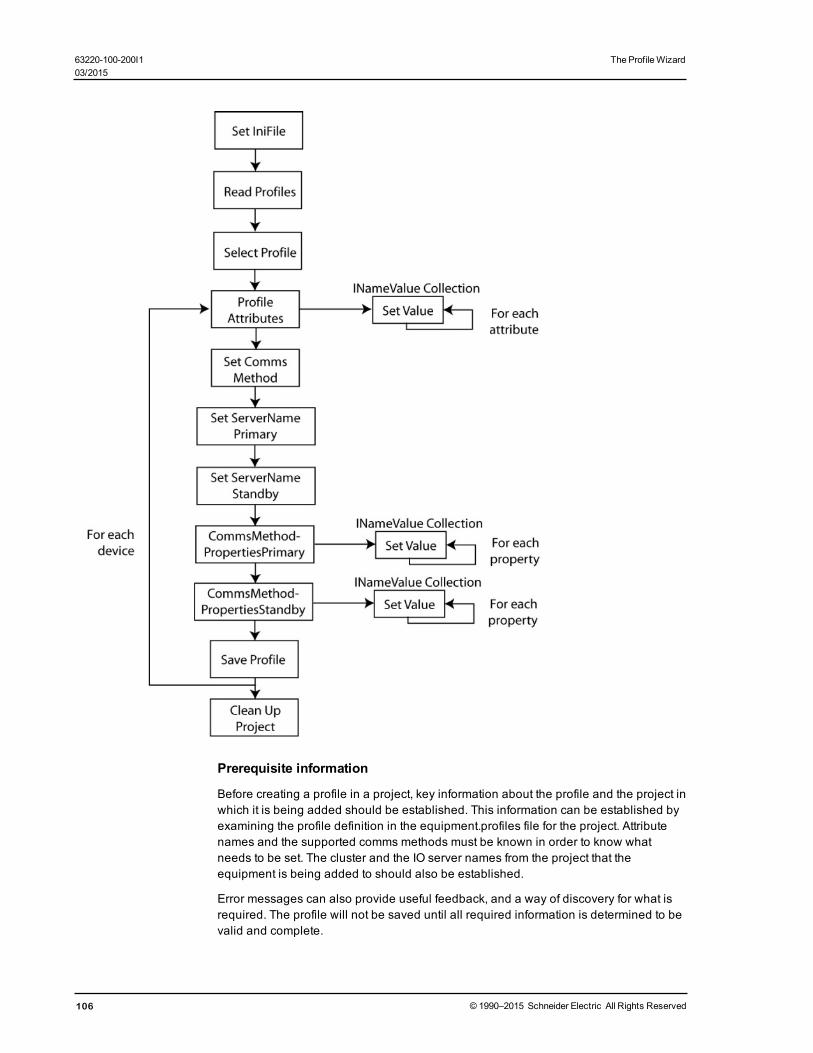
Prerequisite information
Before creating a profile in a project, key information about the profile and the project inwhich it is being added should be established. This information can be established byexamining the profile definition in the equipment.profiles file for the project. Attributenames and the supported comms methods must be known in order to know whatneeds to be set. The cluster and the IO server names from the project that theequipment is being added to should also be established.
Error messages can also provide useful feedback, and a way of discovery for what isrequired. The profile will not be saved until all required information is determined to bevalid and complete.
106 © 1990–2015 Schneider Electric All Rights Reserved
63220-100-200I1 The ProfileWizard03/2015
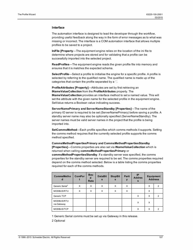
The ProfileWizard 63220-100-200I103/2015
Interface
The automation interface is designed to lead the developer through the workflow,providing useful feedback along the way in the form of error messages as to what wasmissing or incorrect. The interface is a COM automation interface that allows multipleprofiles to be saved to a project.
IniFile [Property—The equipment engine relies on the location of the ini file todetermine where projects are stored and for validating that a profile can besuccessfully imported into the selected project.
ReadProfiles—The equipment engine reads the given profile file into memory andensures that it is matches the expected schema.
SelectProfile—Select a profile to initialise the engine for a specific profile. A profile isselected by referring to the qualified name. The qualified name is made up of thecategories that contain the profile separated by a ‘.’.
ProfileAttributes [Property]—Attributes are set by first retrieving anINameValueCollection from the ProfileAttributes property. TheINameValueCollection provides an interface method to set a named value. This willset the attribute with the given name for the selected profile in the equipment engine.SetValue returns a Boolean value indicating success.
ServerNamePrimary and ServerNameStandby [Properties]—The name of theprimary IO server is required to be set (ServerNamePrimary) before saving a profile. Astandby server name may also be optionally specified (ServerNameStandby). Theserver names must be valid server names in the project that the profile is beingimported into.
SetCommsMethod—Each profile specifies which comms methods it supports. Settingthe comms method requires that the currently selected profile supports the commsmethod specified.
CommsMethodPropertiesPrimary and CommsMethodPropertiesStandby[Properties]—Comms properties are also set via INameValueCollection which isreturned when calling commsMethodPropertiesPrimary orcommsMethodPropertiesStandby. If a standby server was specified, the commsproperties for the standby server are required to be set. The comms properties requireddepend on the comms method selected. Below is a table listing the comms propertiesrequired for each of the comms methods.
CommsMethod
ComPort
Baud
Rate
DataBits
StopBits
Parity
IPAddres
s
EquipmentAddress
Generic Serial1 X X X X X X 2
MODBUS/RTU X X X X X X
Generic TCP X X 2
MODBUS/RTUvia Gateway
X X
MODBUS/TCP X X 2
1 Generic Serial comms must be set up via Gateway in this release.2 Optional
© 1990–2015 Schneider Electric All Rights Reserved 107

SaveProfile—SaveProfile takes the name of the project to which the profile is beingsaved. Saving a profile involves writing all output values defined in the profile definitionto the specified project. A two-phase commit process is used to ensure that data isvalid before committing changes permanently. Saving profiles to a different project willresult in an automatic cleanup of the first project. See CleanupProject for moreinformation.
ResetSelectedProfile—A call to ResetSelectedProfile will clear data associated withthe selected profile, as well as clearing any accumulated errors. After saving a profilesuccessfully, this method will be called automatically to allow the next profile to besaved.
DeleteEquipment—DeleteEquipment requires the project name that the equipment isto be deleted from as well as the name of the equipment that is being deleted. It willscan through the project looking for records that were added for a specific piece ofequipment and will remove them accordingly. Removal of file outputs which weredefined in the profile from which the equipment was added is not performed as thesefiles may contain sensitive data that has since been added to these files. Additionally,those dbf entries in the profile under dbf-file that do not have an equip field are notremoved, as there is no way of determining if they are exclusively used by this piece ofequipment.
CleanupProject—CleanupProject performs operations such as re-indexing of dbf filesand packing dbf files. Errors detected by this phase are reported as warnings and donot trigger a rollback. This operation should be called after all save operations havebeen performed on a project.
NoErrors [Property]—This is a Boolean property that can be used to determine if anyerrors have been collected.
GetErrorMessages—Detailed error messages may be obtained by callingGetErrorMessages, which returns a string with errors and warnings on multiple lines.
ErrorOutput [Property]—The error handling approach be set with the ErrorOutputproperty. Error Handling.
The values used for the error output are:
• None = 1• Dialog = 2 [default]• Console (silent if run from excel) = 4
Error Handling—Each interface method returns a Boolean indicating the success ofthat operation. Accumulated errors will prevent progression through the workflow andas such, this return state should be examined at each stage. A call toResetSelectedProfile will clear accumulated errors, but it is recommended that errorsare addressed before you proceed.
Information about errors and warnings can be obtained through a call toGetErrorMessages. By default, a dialog will display with error information at each stepof the workflow, but this can be controlled with the ErrorOutput property.
108 © 1990–2015 Schneider Electric All Rights Reserved
63220-100-200I1 The ProfileWizard03/2015

The Design Time Environment 63220-100-200I103/2015
The Design Time EnvironmentThis chapter discusses how to use genies to create one-line diagrams for customers. Inthis section, you will find these topics:
Typical Workflow on page 109
The PowerSCADA Expert Pages on page 110
Create a Project on page 110
Use PowerSCADA Expert One-Lines
One-Line Flowchart on page 118
What Are PowerSCADA Expert One-Lines? on page 120
One-Line Device (zOL) on page 120
One-Line Colors on page 121
Add INI Settings to AdvOneLine.ini and Citect.ini on page 121
Start and Stop One-Lines on page 123
Work with Genies on page 123
Work in the Configuration Utility on page 128
Work with Alarms on page 138
Alarms Overview on page 138
Work in the Configuration Utility on page 128
Add Setpoints and Delays on page 139
Set Up an Alarm Based on an Enumeration on page 139
Change an Alarm Severity on page 140
Enable Waveforms for Onboard Alarms on page 140
Set Parameters for Event Log Length and Historical Logging of Events on page 140
Add an Onboard Alarm Tag on page 141
Set Up Audible Alarms on page 142
Restore and Back Up Projects on page 142
Restore a Project on page 142
PowerSCADA Expert Backup on page 143
Use Cicode to Customize a Project on page 143
Work in the Configuration Utility on page 128
Work in the Configuration Utility on page 128
Trend Tag Scan Intervals on page 147
Disk Storage Calculation for Trends on page 148
Typical WorkflowWhen creating a graphics page, these are the steps you will usually follow:
1. Before you begin, make sure you have:
a. created a project in the Profile Editorb. added a project with the same name to PowerSCADA Expert; added at least
one cluster, network address, and serverc. exported the project from the Profile Editord. used the Profile Wizard to add devices to the project
© 1990–2015 Schneider Electric All Rights Reserved 109

2. From the Graphics Builder window, add a new page, using the style and pagetemplate you prefer. Instructions assume that you will use the default template; but ifyou create your own template, use the Menu Configuration tool to add menuheadings that will display on the one-line in runtime. (See Use Menu Configurationto Edit Pagemenu.dbf (Change the Graphics Page Appearance) on page 115 formore information about changing the appearance of the graphics page.)
3. Add genies to the page to create the one-line drawing.
4. Compile and run the project. Note any errors and warnings; correct all errors.Review warnings for problems such as missing tags.
5. Run the project to view the graphics page in the runtime environment.
The PowerSCADA Expert PagesWhen you launch the product (v8.0), three windows are opened:
• Citect Explorer: Use this application to explore and add projects. The product isshipped with a project that has example page configuration. Project names arelisted in the left-hand pane.
• Citect Project Editor: Use this application to edit the PowerSCADA Expertconfiguration. For example, use it to add clusters, network addresses, and servers;and to launch the Profile Wizard and the One-Line Configuration utility.
• Citect Graphics Builder: Use this application to build graphic display pages for aproject. A standard PowerSCADA Expert library of genies is provided. The geniescontain logic such as control outputs and rack-in/rack-out. Once assembled andopened in the runtime environment, they provide an interactive view of aninstallation’s power system.
Create a ProjectThe information in this section is based on the Normal template from the PLS_Style_1library. The Normal template includes all of the tabs and buttons that are described inthe topics here. If you want to edit selections on the tabs and buttons, use the MenuConfiguration tool. For instructions on editing templates with the Menu Configurationtool, see Use Menu Configuration to Edit Pagemenu.dbf (Change the Graphics PageAppearance) on page 115.
When you modify the template or create a completely new template, the informationprovided here for creating graphics pages may only apply as a guide.
When you rename a project (using the .Project Properties option in Citect), you will seeerror messages when you try to add new projects. To fix this problem, just shut downand then restart PowerSCADA Expert.
In this section, you will find these topics:
Reuse Projects Created in the Profile Editor on page 111
Add a New Graphics Page on page 111
Set a New Page as the Project Startup Page on page 112
Create a One-Line on a Graphics Page on page 112
Use Menu Configuration to Edit Pagemenu.dbf (Change the Graphics PageAppearance) on page 115
Create New Genies on page 116
Delete Information from PowerSCADA Expert on page 118
110 © 1990–2015 Schneider Electric All Rights Reserved
63220-100-200I1 The Design Time Environment03/2015

The Design Time Environment 63220-100-200I103/2015
Reuse Projects Created in the Profile EditorYou may want to create a “standard” project that can be reused for differentinstallations. For instructions on saving and then reusing projects, follow these steps:
1. Export the project from the Set Up Project tab of the Profile Editor.2. Click the folder icon beside the Export link:
3. Copy the file (Equipment.profiles) that displays. If you need to use this file toanother computer, you can move it to a portable drive.
4. On the server computer, paste Equipment.profiles in this location, where:
[Drive Letter]: is the drive on which you installed the server
the Application Data and Program Data folders are not hidden (set the folder viewfor “view hidden folders”)
[Project] is the name of the project you are creating; you must have already addedthis project to PowerSCADA Expert (see Before You Export, above).
5. Be sure you have created the files described in Before You Begin on page 111.
Before You BeginBefore you start adding data in the project, make sure that you have:
• used the Profile Editor to add all of the device types, device profiles, and projects• from Citect Explorer, created a project; from the Citect Editor, added clusters,
network addresses, and servers• exported devices from the Profile Editor• added devices into the PowerSCADA Expert project, using the Profile Wizard
Add a New Graphics PageYou need to add a project in two places before you add pages. First add the project toPowerSCADA Expert, from the Citect Explorer screen (see steps below). Then add it tothe Profile Editor. See Add, Edit, or Delete a Project on page 52 for instructions.
1. From the Citect Explorer screen, choose the project for which you will create agraphic.
2. On the Graphics Builder screen, click File > New > Page.
3. On the Use Template popup, set the resolution to SXGA (or default), and uncheckthe Title Bar option. Select the page template (for example, normal). Click OK.
NOTE: If you use any style that is not preceded by “pls,” the PowerSCADA Expertgraphics features will not be included. If you want to change the attributes of thedefault style, copy pls_style_1 and paste it in your project; rename it, and make thedesired changes. The new template can then be used for your pages.
The graphics page displays in design-time mode.
4. To make changes to the menus and tabs that display on the screen, use MenuConfiguration tool. See Use Menu Configuration to Edit Pagemenu.dbf (Changethe Graphics Page Appearance) on page 115 for instructions on making thesechanges.
5. Save the graphics page, giving it the desired name and selecting the project thatyou have just added.
© 1990–2015 Schneider Electric All Rights Reserved 111

Change the Background Color of PagesYou have the option of changing the background color of individual pages in yourproject. To do this, follow these steps:
1. Create a new project, using "high contrast" as the starter project.
This project will already include all of the pages that you will use. There will also bea new parameter, called PageColorExt. This parameter includes the extension thatallows you to color backgrounds.
2. To designate background color for each page, pick the color in the Graphics Editor.
You can also change the genie font colors on your project pages. To do this seeChange the Genie Color in Project Pages on page 112.
Change the Genie Color in Project PagesYou have the option of changing the color of genies in pages of your project. To dothis:
In your project, add a new parameter to the Graphics section, called GenieFont. Enterthe value designation for the color you want to use. Make sure that there is sufficientcontrast between the two colors so that the genie colors will be visible.
NOTE: If you use the "high contrast" starter project to create your project, thisparameter is automatically added, as are all of the pages that you will use. Forinstructions on changing the background color of your project pages, see Change theBackground Color of Pages on page 112.
Set a New Page as the Project Startup PageAfter you add a new page, follow these steps to make it be the system starting page. Ifyou do not make these settings correctly, the system will not properly execute thestartup routine, and the browser navigation buttons will not work.
1. Open the Parameters dialog (Project Editor > System > Parameters).a. In the Section Name field, type MultiMonitors.b. In the Name field, type StartupPage.c. In the Value field, type the name of the new page.d. If you intend to use multiple monitors, and want to use a different startup page
for a particular monitor, you can specify it by adding another parameter with thename of StartupPage<n>, where <n> is the monitor number (for example,StartupPage2, for startup page on the second monitor).
2. In the Computer Setup Wizard (General Options Page), leave the ini settings as<default>.
Create a One-Line on a Graphics PageYou will build a one-line by adding genies to the new page. For more informationabout genies, see Genies and Super Genies in the citectSCADA.chm help file(Program Files> Schneider Electric > PowerSCADA Expert > v8.0 > bin).
To begin creating a one-line, start adding genies to the page:
1. Click the “genie” icon on the toolbar:
112 © 1990–2015 Schneider Electric All Rights Reserved
63220-100-200I1 The Design Time Environment03/2015

The Design Time Environment 63220-100-200I103/2015
2. From the Paste Genie screen, choose a library (to ensure that all PowerSCADAExpert features are available, choose a library that begins with “pls”). If you want toedit a genie or create a new one, see Create New Genies for instructions.
3. From the available icons in the selected library, select a genie; click OK to paste thegenie on the graphics page.
4. A popup window displays for you to enter genie properties. Enter the requestedinformation for the appropriate object:
Configure a Busbar on page 125
Configure a Circuit Breaker or Switch on page 125
Configure a Meter on page 126
Configure a Source on page 126
Configure a Transformer on page 127
NOTE: An asterisk in any of the windows indicates that it is a required field.5. If a message displays telling you that variable tags are not found, and asking if you
want to add the unknown tags, this is not a problem. The genie is expecting to seea variable, but one may not exist in the equipment (for example, it could be lookingfor a “racked out” variable in a Sepam). Click No to this message.
NOTE: To disable this message, go to the Project Editor page. Click Tools >Options. From the Options window, de-select “Prompt on tag not exist.”
The genie is added to the page.
6. Continue adding the genies to make up the graphics page.
After you create the graphics page, you need to compile it. You can run the page toreview its elements and correct any errors.
NOTE: Do not drag genies off of the page. They will disappear.7. On the Graphics Page, click File > Compile.
While the page is being compiled, the Compiler displays each file name as it isbeing compiled. A message then displays, telling you that compilation wassuccessful.
8. If there are errors and/or warnings after the page is compiled, a message boxdisplays, telling you the number of errors and warnings. You must understand allwarnings and correct all of the errors. To begin, do the following:
a. Click OK at the Compiler message.The Compile Errors window displays the first error.
b. Note the error message. For more information on each error, click Help; note theDescription for that Error Message.
c. To correct the error, click the GoTo link.The appropriate window displays for you to correct that error.
9. Correct each error. Warnings do not need to be corrected in order to run the project;but they should be checked to see if they impact the project (such as a tag that isnot defined).
10. If you delete any entries, click File > Pack to clean up the files.
11. Re-compile and verify that all of the errors have been addressed.
NOTE: You can also view the Compile Errors window from the Project Editor (File >Compile Errors).
12. After all errors are corrected, run the project (File > Run).
© 1990–2015 Schneider Electric All Rights Reserved 113

The Graphics page displays in the runtime environment. Note: Until you edit theMenu Configuration file, only basic tabs will display on the Graphics page.
13. Before you can view your one-line, you need to edit the Menu Configuration file,which controls the appearance of the graphics page in the runtime environment.See Use Menu Configuration to Edit Pagemenu.dbf (Change the Graphics PageAppearance) on page 115 for help.
Enable Lockout/Tagout
DANGERHAZARD OF ELECTRIC SHOCK, EXPLOSION, OR ARC FLASH
• Do not rely solely on the display of the icon on the one-line. Before working onthe equipment, verify that the device is physically locked out/tagged out beforeperforming work on it or any downstream equipment.
• Ensure that all safety regulations and procedures have been followed beforeyou work on the equipment.
Failure to follow these instructions will result in death or serious injury.
NOTE: Do not incorrectly configure the tag, as this can lead to unexpected equipmentoperation. Also consider the possibility of communications loss that could yield falsereadings.
With this feature, you can cause the "locked out" icon (shown above) to display on yourgraphics page in runtime. The icon displays when a tag attribute for a device reaches aspecified value. For example, you might set a PLC tag to 0 when the equipment is inlockout/tagout (the door is open), and to 1 when the equipment status indicates that thedoor is closed.
This is a read-only feature; but it does not prevent controls to the device or area. Thisfeature is not available in PLS_Example.
Follow these steps to enable the icon for a device:
1. From the pls_gen_eq_2 genie library, add the lockout/tagout genie to the graphicspage. Position it beside the equipment that is being monitored.
2. From Variable Tags, choose the device tag (or create a custom tag) that you want,and associate it with the device that will read the lockout/tagout status.
3. Define what indicates the status (for example, door status open, 0 = false and 1 =true).
4. Edit the lockout/tagout genie to read the tag on the device. Make the lockout/tagoutgenie visible when the device tag indicates that the device is in lockout/tagoutstatus; and make the icon hidden when the device is not in lockout/tagout. (Bydefault, lockout/tagout status is hidden when the tag property is "NOT [variabletag].")
To continue the example, if the tag is reading door status open and the value = 0,then the door is open and in lockout/tagout; if the value = 1, the door is closed and
114 © 1990–2015 Schneider Electric All Rights Reserved
63220-100-200I1 The Design Time Environment03/2015

The Design Time Environment 63220-100-200I103/2015
not in lockout/tagout.
The following graphic illustrates how it might look in when adding the genie:
Use Menu Configuration to Edit Pagemenu.dbf (Change the Graphics PageAppearance)
The Menu Configuration form (System > Menu Configuration in Project Editor) editsPagemenu.dbf in your project. This controls the runtime environment screenappearance: tabs and menus on the screen. By the entries you add there, you can alsospecify actions to be taken when an option is selected.
Because it takes much effort to create the items that display on a graphics page, youcan use the menu settings from the PLS_Example project as a template for your newproject template. From it, you can copy and paste settings into an individual project’smenu configuration file.
The following illustrates a blank Menu Configuration file (see the table below fordescriptions of the numbered fields):
Menu Item Description
1: OrderThe relative position within the final graphics page. If you leave this field blank,the default value 0 is used. (64 characters maximum)
2: Levels 1 through 4These items establish themenu levels that will display. For example, youmight use "Single Lines" for level 1, followed by the substation for level 2, andthe graphic name for level 3. (Each line: 256 characters maximum)
© 1990–2015 Schneider Electric All Rights Reserved 115

Menu Item Description
3: Menu Command
The Cicode expression that you want to execute. Typically, you will use the"page display" command followed by the actual page you want to see. Forexample:
PLSPageDisplay("CB_IEC_1")
which displays the page CB_IEC_1.
4: Symbol
Displays a defined image along with the description for that level.
Images must already be defined in the project/include project. They arespecified in the format <library name>,<symbol name>. For example, in PLS_Example, the symbol used for the level 2 of Single Lines is Substation3,entered as PLS_Icons.Substation3.
Different menu levels are designed to be used with different symbol sizes foroptimal display. For Level 1 items (tab), the recommended symbol size is 16 x16 pixels. For Level 2 items, (buttons), the recommended symbol size is 32 x32 pixels. Symbols are not displayed for menu items of Level 3 or beyond.
5: CommentYou can use up to 128 characters to add a comment (will not display onscreen).
To copy information from the PLS_Example project, do the following:
1. Open the PLS_Example project. Then, from the Citect Project Editor, click System >Menu Configuration.
The Menu Configuration for PLS_Example displays.
2. From Citect Explorer, change the project to your new project.
3. In the Citect Project Editor, click Menu Configuration.
Now both Menu Configuration windows display.
4. To copy the entire record, you can use the Copy Record and Paste Record menucommand. From the desired record in the PLS_Example project window, select themenu command Edit > Copy Record. Then go to the desired record in your projectwindow, and select menu command Edit > Paste Record. Do further editing asrequired. Alternatively, you can selectively copy information from the source recordto your project, line by line.
5. To save the menu configuration record in your project, choose either the "Replace"or "Add" button. Compile the project; then run it again.
The Graphics page in the runtime environment of your project will now displayaccording to the settings you have made.
Create New GeniesThere are two ways to add new one-line genies to a project:
Copy a genie: Create a genie that is completely compatible with current genies, havingthe same genie parameters and functionality. To do this, you can copy an existinggenie and change attributes. This type of genie must be added to theSupportedGenies.xml File on page 127.
Create a unique genie: Create a genie that has unique parameters, validationrequirements, and output types. See instructions below for this. This type of genie mustbe added to both the SupportedGenies.xml File on page 127 and theGenieConfiguration.xml File on page 127.
The easiest way to create a new genie is to make a copy of a similar genie from thestandard library and edit it in your project. We recommend, when adding layers, thatyou keep the dimensions of the new layers the same as the original. For a list of all of
116 © 1990–2015 Schneider Electric All Rights Reserved
63220-100-200I1 The Design Time Environment03/2015

The Design Time Environment 63220-100-200I103/2015
the standard PowerSCADA Expert genies, including all of the smaller parts that youcould use to create genies, see Appendix 1: Default Genie Library on page 212.
When you modify a genie, the modifications will be in effect for all instances of thatgenie in the project.
To create a copy of a genie:1. Open the genie that you want to use as a template: From Citect Graphics Builder,
click File > Open. Click the Genie tab, then select the library and the templategenie. Click OK.
2. Save the genie with a new name in your local project.
3. To separate the genie into layers, click the genie and drag a layer to the bottomright.
4. Repeat the process to pull all of the layers apart.
Each layer is a sub-genie that controls a different aspect of the overall genie.
5. Make the changes that you wish to the genie.
NOTE: Be careful to maintain the same dimensions for any new layers that youcreate.
6. To re-assemble the genie, draw a marquis around all of the parts; then clickArrange > Align, and choose Top and Left. Click OK.
The newly created genie, when applied to a page, will display with the generic inputform. To create a customized form similar to those found with the default genies, youmust create a new .FRM file. Examples are found in the PLS_Include project directory.
You can rotate any of the genies.
To create a custom symbol for a custom genie:
PowerSCADA Expert genies are complex genies with the added ability to animatecolor during runtime (showing changing states). These genies are comprised ofmultiple symbols that have the same attributes (all call the same Cicode function).
1. Create the new symbol.2. Configure the symbol to display the customized colors in the runtime environment
by calling the PLS_GetBusColorIndex(INT nColorIndex) function, which is providedin PowerSCADA Expert. This function must be called from the Array Condition areaof the Symbol properties window.
Each Array symbol can display up to 255 colors. Please ensure that the defaultcolor palette matches the palette used in PLS_Include. The parameter for PLS_GetBusColorIndex(INT nColorIndex) is the busbar number that determines theanimated color. Always use the %variable% notation. Using this notation permitsyou to reuse genies.
See the default symbols in the PowerSCADA Expert libraries that begin with PLS_.
3. Save the symbol and use it in a custom genie.
Set Up IEC 61850 Advanced ControlThe advanced control window provides two advanced controls (synchro check andinterlock check) that you can use with IEC 61850 IEDs.
See Perform IEC 61850 Advanced Control on page 167 for information on using theseadvanced controls.
© 1990–2015 Schneider Electric All Rights Reserved 117

WARNING
UNINTENDED EQUIPMENT OPERATION
• Do not incorrectly configure the tag, as this can lead to unexpected equipmentoperation.
• Ensure that you understand the effects of using the "bypass" option so you donot shut down critical equipment.
• Also consider the possibility of communications loss that could yield false read-ings.
• Ensure that all safety regulations and procedures have been followed beforeyou work on the equipment.
Failure to follow these instructions can result in death or serious injury.
Enable the Advanced Control
Before you can use the advanced control, you must add the appropriate variableSTRING tag to be used when you send the command. For breaker control, the"operate" tag typically used is:
S33K_A_INC\CSWI1\Pos\ctVal
For this tag, you need to then add the corresponding STRING tag:
S33K_A_INC\CSWI1\Pos\ctVal\str
If you are using select before operate (SBOw), you also need to add a STRING tag forit.
Delete Information from PowerSCADA ExpertIf you find you need to delete any data that you have entered (clusters, servers, genies,and so on), follow the normal procedure to delete the data, then use the Packcommand to completely delete it. To do this, click File > Pack on the Project Editor.
Use PowerSCADA Expert One-LinesClick the following links for related one-line information.
One-Line Flowchart on page 118
What Are PowerSCADA Expert One-Lines? on page 120
One-Line Device (zOL) on page 120
One-Line Colors on page 121
Add INI Settings to AdvOneLine.ini and Citect.ini on page 121
Start and Stop One-Lines on page 123
One-Line FlowchartThis chart provides an overview of the process that you will follow to set up and useanimation in one-lines.
For detailed information on one-lines see:
Running the AOL Configuration Utility:
Review Genie Configurations on page 128
Perform Repairs for One-Lines on page 131
118 © 1990–2015 Schneider Electric All Rights Reserved
63220-100-200I1 The Design Time Environment03/2015

The Design Time Environment 63220-100-200I103/2015
Setting Up Animation Colors:
One-Line Colors on page 121
INI Settings and Passwords:
Add INI Settings to AdvOneLine.ini and Citect.ini on page 121
After you run the project, ensure that the password is encrypted (see IsEncrypted inAdd INI Settings to AdvOneLine.ini and Citect.ini on page 121).
© 1990–2015 Schneider Electric All Rights Reserved 119

Ensure that all steps in the Quick Start procedure have been followed:Quick Start:Typical Workflow on page 5.
What Are PowerSCADA Expert One-Lines?PowerSCADA Expert one-lines provide the following features. They:
• graphically propagate unknown conditions downstream through a one-linediagram. When there is a communications loss to a device, the one-line providesaccurate system status, even though information is not available.
• eliminate "seesaw logic": when bus status temporarily toggles on and off after anupstream breaker opens
• handle the continuation of a one-line diagram when it extends from one page toanother
• provide built-in support for power flow diagrams; one-line color"animates," based on the source that is feeding the circuit.
Where are the files located?
Listed below are several important files in one-line animation. Changing any of thesefiles could make the animation be inoperative.
PLS_IncludeAdvOneLine.exe Application running the core one-line bus animation logic engine
AdvOneLine.ini Specifies performance and configuration parameters for AdvOneLine
AdvOneLine.csv One-line example configuration
Current RUN projectAdvOneLine.csv Specifies the system configuration for AdvOneLine
AdvOneLine.ini Specifies performance and configuration parameters for AdvOneLine
AdvOneLineDebugBus.csvCreated at runtime to help debug the AdvOneLine.csv by specifying allbus connections
AdvOneLineStatusLog.txtCreated at runtime to specify status and error messages that mightoccur
One-Line Device (zOL)To use one-line graphics, you must create a memory device named zOL. One-linegraphics use the zOL device to drive animation. You must have at least one zOLdevice per project.
To add the zOL device:
1. Open the Profile Wizard.2. Click Create an I/O Device in the project. Click Next.
3. Select the device called OneLine Device Setup. Click Next.
4. Follow the remaining steps to add the device.
By default, this device will support 100 sources, 1000 buses, 1000 meters, and 1000breakers. You can modify this via the Profile Editor:
1. On the Setup Projects tab, choose the project.2. Click the Project Parameters subtab.
120 © 1990–2015 Schneider Electric All Rights Reserved
63220-100-200I1 The Design Time Environment03/2015

The Design Time Environment 63220-100-200I103/2015
3. Enter the optional project parameters (MaxBreakers, MaxBuses, MaxMeters,MaxSources). Valid entries are from 1 to 9999 (only 200 for MaxSources).
4. On the Selected Device Profiles subtab, click Refresh Tags.
5. Export the project.
6. In the Profile Wizard: Select the Update one or more I/O Device(s) in the projectoption. This updates the zOL I/O device parameters entered in step 3.
The new one-line device is ready to be used in the selected project.
One-Line ColorsIn previous versions of the software, line coloring was determined by the line activestate of the busbar. Driven by the busbar color, this state was then fed to all of thecomponents on that page.
In PowerSCADA Expert 8.0, coloring is based on the source and meter line activestates. Sources dictate the colors for each genie. Meters can only determine if a bus isactive. When the bus is live, the meter then colors based on the source that isconnected to the bus. If there is no source, the default color is used.
NOTE: Depending on how you configure transformers, you can either use this "pass-through" coloring, or you can use "voltage-level" coloring. See Configure aTransformer on page 127 for more information.
Assigning Colors
To assign a color to a source, open the Color Configuration tab of the One LineConfiguration Utility (Citect Editor > Tools > One-Line Configuration).
1. Choose the project for which you want to assign colors.2. Choose the Project Color Palette. Select the project in which the project genies are
defined: usually PLS_Include.
3. For each source or transformer, choose the desired color: click the color cell for thatsource/transformer; then choose the color from the dropdown list. You can alsoselect a color for unknown sources, off, and error. To indicate a flashing color, youcan select two colors.
4. When all colors are assigned, click Save.
Add INI Settings to AdvOneLine.ini and Citect.iniNOTE: See Application Configuration Utility on page 203 for screens that streamlineconfiguration.
All .ini settings are made in the OneLineEng section of the .INI files.
You must have correct .INI settings in order for the one-lines to run properly. Ensurethat the following .INI parameters are properly set:
AdvOneLine.ini Settings
The following parameters are set in the Application Configuration Utility (One-LineEngine on page 206): UpdateInterval, PrimaryServerIP, StandbyServerIP,HealthTimeout, MaxStartupDelay, LoginUserName, LoginPassword, andLogFileLength.
© 1990–2015 Schneider Electric All Rights Reserved 121

Parameter Description Default Value
Updateinterval
The interval at which the system tries to solve thesystem one-line. This interval can be changed to slowdown the rate at which the animation is solved.Specifying a rate faster than possible will force theengine to solve the system as quickly as possible.
1000msec
PrimaryServerIP
Used by redundant configurations to specify theIP address of the server on which the primaryIOServer resides. This parameter is required for aredundant configuration. If either the primary orstandby IP addresses are not specified, the logicengine will assume that the system is not redundant.
N/A
StandbyServerIP
Used by redundant configurations to specify the IPaddress of the server on which the standby IOServerresides. This parameter is required for a redundantconfiguration. If either the primary of standby IPaddresses are not specified, the logic engine willassume that the system is not redundant.
N/A
HealthTimeout
This is a performance parameter that dictates thatamount of time that must elapse before the one-lineengine is considered non-functioning, and a PC-basedalarm is raised in PowerSCADA.
[Updateinterval] +[TagSubscribeWait] * 5milliseconds
Minimum value: 1000msec
DefaultColor
This cosmetic parameter tells the engine the defaultcolor to be assigned to objects on the screen atsystem startup. This is useful for identifyingcomponents that have been left out of the CSV orsimply as ameans of having the engine set allcurrently unused objects to a color that indicates thatthey are not beingmonitored. If an invalid color isspecified, the engine will default to black.
250
MaxStartupDelay
Sets the amount of time the AdvOneLine.exe has tostart up. If this time is exceeded, initial tagsubscriptions will not succeed, and the EXEwill reportan exception.
60 sec
StartupDelaySets the amount of time after AdvOneLine.exe hasstarted for the system to be on line and allinitializations complete.
[Updateinterval] +[TagSubscribeWait] * 5milliseconds
Minimum value: 1000msec
LoginUserNameThis is the Citect user name to be used for thectAPI connection in AdvOneLine.
aol
LoginPasswordThis is the Citect user password to be used for thectAPI connection in AdvOneLine.
aol
IsEncryptedDetermines if the password is encrypted. The firsttime the project is opened in run time, the password isautomatically encrypted, and this will be set to True.
False (changed to True afterthe first run and successfulpassword encryption)
CitectIniPath32
Provides the path to the global Citect.ini file for a 32-bit operating system install. This settingmust bechanged if SCADA is not installed on the C: drive, or ifthe Citect.ini file is moved/installed in anotherdirectory.
Default value: C:\Documentsand Settings\AllUsers\ApplicationData\SchneiderElectric\PowerSCADAExpert8.0\Config
LogFileLengthSuggests the log file length in number of lines. Aftersurpassing this limit, the log file is saved with suffix“.bak,” and a new file is created.
Default value: 5000
Allowed values: 10–10000
DebugLevelSets the level of logging for AdvOneLine.exe.
Multiple values are separated by | (e.g., Error|Warn).
N/A
Allowed values:
All, Error, Warn, Debug
122 © 1990–2015 Schneider Electric All Rights Reserved
63220-100-200I1 The Design Time Environment03/2015

The Design Time Environment 63220-100-200I103/2015
Citect.ini Settings
Parameter Description Default Value
AutoRestartIndicates whether the one-line will restart itself whenthe logic engine is not responding.
0 (disabled)
Allowed values: 0, 1
ServerRole
Informs the local instance of PowerSCADAwhere it is(primary or standby server). This parameter iscontrolled by the AdvOneLine.exe application. The userdoes not need to create or modify this parameter. It isset based on the PrimaryServer IP andStandbyServerIP parameter settings.
Primary
StartupDelay
This is a performance parameter that dictates thatamount of time that must elapse before the one-lineengine is considered nonfunctioning, and a PC-basedalarm is raised in PowerSCADA.
15 sec
Start and Stop One-LinesIf you need to start or stop AdvOneLine.exe, call one of these Cicode functions.
Only call these functions on an I/O server that is communicating with an One-LineDevice (zOL) on page 120.
To stop AdvOneLine.exe, call:
PLS_StopAdvOneLine(STRING sIOServer="",STRING sCluster="")
To start AdvOneLine.exe, call:
PLS_StartAdvOneLine(STRING sIOServer="",STRING sCluster="")
NOTES:• If the default parameters are used, the functions will run on the local machine.• If you call the function from a remote server, enter the I/O server name and cluster to
run the function on that server. You must be logged in to perform this action.
Work with GeniesUse these topics to create and configure genies:
Genie Type Descriptions on page 124
Configure an Automatic Transfer Switch (ATS) on page 124
Configure a Busbar on page 125
Configure a Circuit Breaker or Switch on page 125
Configure a Meter on page 126
Configure a Source on page 126
Configure a Transformer on page 127
Enable Lockout/Tagout on page 114
Create New Genies on page 116
GenieConfiguration.xml File on page 127
SupportedGenies.xml File on page 127
© 1990–2015 Schneider Electric All Rights Reserved 123

Genie Type Descriptions
In the One Line Configuration Utility, there are several genies. Each one has a certaindefined list of information that displays by default. You can also expand this list toinclude everything that is known about that genie type. To learn about each genie'sdata, click one of the following links:
Breaker and Switch Information on page 134
Meter Information on page 135
Source Information on page 136
Transformer Information on page 137
For configuration instructions, see:
Configure a Busbar on page 125
Configure a Circuit Breaker or Switch on page 125
Configure a Meter on page 126
Configure a Source on page 126
Configure a Source on page 126
Configure an Automatic Transfer Switch (ATS) on page 124
See also:
Enable Lockout/Tagout on page 114
GenieConfiguration.xml File on page 127
SupportedGenies.xml File on page 127
Configure an Automatic Transfer Switch (ATS)
Use this option to configure automatic transfer switches (ATS) that you add to a one-line in the graphics builder.
1. Display the Transfer Switch window by pasting the appropriate genie on to thegraphics builder page.
Transfer Switch Information: Left/Right/Bottom
2. Breaker Number: Type the ID numbers you want to use for the left side and rightside of this ATS. Valid entries: 1–1000. Each number must be unique within thisone-line.
3. Busbar: Type the numbers of the left and right source busbars, and for thedestination (bottom) busbar. Valid entries: 1–1000.
4. Label: For each ATS side, type the information that you want to appear on theswitch in the runtime environment (example: Pri and Emer).
5. Closed Expression: For each side of the switch, type the information that shoulddisplay when that side is closed (example: Tag1 <> 1). Do not use "NOT" in theexpression.
Display Information
1. Label 1/Label 2: Type the descriptive information that you want to appear in theupper left corner of the genie in the runtime environment.
2. Click OK to save the genie to the page and to return to the graphics builder page.
For information on how colors are determined, see One-Line Colors on page 121.
124 © 1990–2015 Schneider Electric All Rights Reserved
63220-100-200I1 The Design Time Environment03/2015

The Design Time Environment 63220-100-200I103/2015
Configure a Busbar
Use this option to configure busbars that you add to a one-line in the graphics builder.Using this option, you can assign a busbar number to a busbar, and ultimately, to usebusbars to connect genies on a one-line.
Busbar numbers associate devices within drawings, and they help you set upanimation for genies. The busbar entered here is also used for the associated device.
1. Display the busbar window by pasting the busbar genie on to the graphics builderpage.
2. Busbar Number: type the number you want to use for this busbar. Valid entries: 1–1000.
3. Line Active: This field is no longer used.4. Click OK to save the genie to the page and to return to the graphics builder page.
For information on how colors are determined, see One-Line Colors on page 121
Configure a Circuit Breaker or Switch
Use this option to configure circuit breakers or switches that you add to a one-line inthe graphics builder.
1. Display the circuit breaker or switch window by pasting the appropriate genie on tothe graphics builder page.
2. Equipment: From the drop-down list, choose the name of the equipmentrepresented by the genie (this is the equipment name that you entered in the ProfileWizard or Automation Interface, e.g., CM4Main). To view the equipment that isavailable for this page, you must have the project selected in the Citect Explorer.
3. Breaker/Switch Number: Type the number you want to use for this breaker orswitch. Valid entries: 1–1000. This number must be unique within this one-line.
4. Source and Destination: When you connect to busbars, type the numbers for theconnection source and destination busbars. Valid entries: 1–1000.
5. Label 1 and Label 2: Type the information that you want to appear in the upper leftcorner of the genie in the runtime environment.
6. Value Type: From the drop-down list, choose the tag you want to use for this genie.The related information displays in the lower left corner of the genie in the runtimeenvironment.
This tag causes real-time data (such as currents) to display on the genie statuspage in the runtime environment. If you do not choose a tag here, the status pagewill not display the real-time data. See Use the Equipment Pop-Up Page on page164 for more information.
7. Units: From the drop-down list, choose the unit that you would like to display on thegenie in the runtime environment. Units that display here were added in the ProfileEditor (see Add or Edit a Base Engineering Unit or Conversion on page 22).
8. Multiplier: Enter the multiplier that is to be applied to the units chosen in step 7.9. Click OK to save the genie to the page and to return to the graphics builder page.
NOTE: If you choose to resize a circuit breaker genie after you paste it into a page, youmust keep the relative dimensions (proportions) the same. Otherwise, the rackedin/racked out animation will not display correctly.
For information on how colors are determined, see One-Line Colors on page 121.
© 1990–2015 Schneider Electric All Rights Reserved 125

Configure a Meter
Use this option to configure meters that you add to a one-line in the graphics builder.
1. Display the meter window by pasting the meter genie on to the graphics builderpage.
2. Equipment: From the drop-down list, choose the name of the equipmentrepresented by the genie (this is the equipment name that you entered in the ProfileWizard or Automation Interface, e.g., CM4Main). To view the equipment that isavailable for this page, you must have the project selected in the Citect Explorer.
3. Meter Number: Type the number you want to use for this meter (valid entries: 1–1000). This number must be unique within this one-line.
4. Busbar Number: Type the number for the busbar that connects to the meter. Validentries: 1–1000.
5. Line Active: Enter the appropriate Cicode expression (such as MyTag1 > 0) todetermine when the meter detects power on the busbar. See "How do I create andconfigure busbars" inAppendix 5: Frequently Asked Questions (FAQs) on page 254for more information.
6. Label 1 and Label 2: Type the information that you want to appear in the upper leftcorner of the genie in the runtime environment.
7. Value Type: From the drop-down list, choose the tag you want to use for this genie.The related information displays in the lower left corner of the genie in the runtimeenvironment.
This tag causes real-time data (such as currents) to display on the genie statuspage in the runtime environment. If you do not choose a tag here, the status pagewill not display the real-time data. See Use the Equipment Pop-Up Page on page164 for more information.
8. Units: From the drop-down list, choose the unit that you would like to display on thegenie in the runtime environment. Units that display here were added in the ProfileEditor (see Add or Edit a Base Engineering Unit or Conversion on page 22).
9. Multiplier: Enter the multiplier that is to be applied to the units chosen in step 8.10. Click OK to save the genie to the page and to return to the graphics builder page.
For information on how colors are determined, see One-Line Colors on page 121.
Configure a Source
Use this option to configure sources (e.g., utilities and generators) that you add to aone-line in the graphics builder.
1. Display the source window by pasting the generator or utility genie on to thegraphics builder page.
2. Source Number: Type the number you want to use for this source (valid entries: 1–100). This number must be unique within this one-line.
The source number is used when you determine coloring for the one-line. For moreinformation on this, see One-Line Colors on page 121.
3. Busbar Number: Type the number for the busbar that connects to the source. Validentries: 1–1000.
4. Line Active: Enter the appropriate Cicode expression (such as MyTag1 > 0) todictate when the source powers the busbar. See "How do I create and configurebusbars" inAppendix 5: Frequently Asked Questions (FAQs) on page 254 for moreinformation.
5. Click OK to save the genie to the page and to return to the graphics builder page.
126 © 1990–2015 Schneider Electric All Rights Reserved
63220-100-200I1 The Design Time Environment03/2015

The Design Time Environment 63220-100-200I103/2015
For information on how colors are determined, seeOne-Line Colors on page 121.
Configure a Transformer
Use this option to configure transformers that you add to a one-line in the graphicsbuilder.
1. Display the transformer window by pasting the appropriate genie on to the graphicsbuilder page.
2. Top and Bottom Source Number: For each source, whether top or bottom, type asource number to control voltage-level coloring for the secondary side busbar.Valid entries: 1–100.
There are two possible configurations:
Pass-through coloring: If you leave these fields blank, the transformer will transferthe color that is assigned to the primary side (source) to the secondary side(destination) busbar. For example, if Source 3 feeds the source busbar of atransformer, and you leave this field blank, then Source 3 will also feed thedestination busbar (and the Source 3 color will be used).
Voltage-level coloring: When you enter top and bottom source numbers, thetransformer colors the one line based on this number. For example, if Source 3feeds the top of the transformer, but you enter 5 for the bottom source, thetransformer feeds the color from Source 5 to the destination (bottom) busbar.
3. Source and Destination: When you connect to busbars, type the numbers for theconnection source and destination busbars. Valid entries: 1–1000.
4. Label 1 and Label 2: Type the information that you want to appear in the upper leftcorner of the genie in the runtime environment.
5. Click OK to save the genie to the page and to return to the graphics builder page.
For information on how colors are determined, see One-Line Colors on page 121.
GenieConfiguration.xml File
Example
Use the GenieConfiguration.xml file to define both completely new (unique) geniesand those that have been copied and modified from an existing genie.
This file defines each genie in detail. It links fields with genie parameters names,defines validation, and defines how to export each genie for the one-line.
Some fields have limited possibilities. See the comments for each part of the XML file.
See also: SupportedGenies.xml File on page 127
SupportedGenies.xml File
Example
Use this file to define genies that support one-line coloring.
This file links genies in a library to a "genie type." In this file, you need to define theproject name, library name, and genie name. The genie name may be "*": which willselect all genies that library. You can exclude individual genies.
See also: GenieConfiguration.xml File
© 1990–2015 Schneider Electric All Rights Reserved 127

Work in the Configuration UtilityUse these topics to learn about how you use the Configuration Utility to review genieconfigurations before you compile a project. Then you can view errors and warnings,and repair and upgrade genies.
One-Line Configuration Utility on page 128
Review Genie Configurations on page 128
One-Line Errors and Warnings on page 130
Perform Repairs for One-Lines on page 131
Automatic Transfer Switch (ATS) Information on page 132
Busbar Information on page 133
Breaker and Switch Information on page 134
Meter Information on page 135
Source Information on page 136
Transformer Information on page 137
One-Line Configuration Utility
To access this screen, click Tools > One-Line Configuration from the Citect Editorscreen. There are two tabs.
On the Genie Configuration tab, you can:• view genie types, along with their states (normal, warning, error) and their
properties• repair genies that are part of a version 7.30 or later project:
— corrects incorrect breaker, source, meter, transformer, and Sim source numbers— corrects invalid line active when a connected busbar has a valid line active
• repair and upgrade genies that are part of a project from a version earlier than 7.30— renumbers ALL breaker, source, meter, and Sim source numbers— corrects invalid line active when a connected busbar has a valid line active— reassigns ALL valid busbars
See Review Genie Configurations for information about using this tab.
On the Color Configuration tab, you can assign colors to sources. see One-LineColors on page 121 for information about using this tab.
Modify AdvOneLine.csv
After you run the One-Line Configuration Utility, open the project to verify that theanimation is working correctly. If the animation is not correct, repeat the process ofrunning the utility and verifying out animation until all errors are corrected.
Review Genie Configurations
Use the one-line configuration utility to review genie configurations before you compileyour project.
Errors ( ) and warnings ( ). You must correct errors; otherwise, you may notbe able to compile, and the animation will not work. Although you might not need tocorrect warnings, you should review them to ensure that their settings are correct. Note
128 © 1990–2015 Schneider Electric All Rights Reserved
63220-100-200I1 The Design Time Environment03/2015

The Design Time Environment 63220-100-200I103/2015
that, as you hover over an error or warning icon, a tooltip tells you what is wrong withthe genie.
Before you use the compile, do the following:
• If you are upgrading from an earlier version, run Update Pages in the GraphicsBuilder.
• Create the pages.
To launch the utility:
1. Make sure you are viewing the system for which you want to view information.2. From the Citect Editor, click Tools > One-Line Configuration.
A message displays, telling you to that Citect will be hidden.
3. Click OK.
The first time you load the utility, a large system could take a couple of minutes toload. After that, it should load with a minute.
The utility displays with the following information:
Field Description
Project Default: the project selected in Citect Explorer
Show By:
Type: Information is sorted first by genie type, then by page. This option is usefulwhen you want to see all genies of a certain type together, regardless of wherethey are in the drawing pages.
Page: Information is sorted first by page, then by genie type. This option is usefulwhen you want to see all genies on a certain page.
Advanced PropertiesCheck this box to view the basic information plus any additional informationrelevant to that genie type.
State Filters:Check the individual boxes for how you want to view information. For example,youmight only be interested in viewing genies that have error states. This optioncontrols only the genie information in the right-hand pane.
Genie Types Types are: breakers, busbars, meters, sources, and transformers
Genie Information
Columns of information display:
In the Basic (default) view: themost used information
If you click Advanced Properties, you see the basic information, followed by all ofthe information known about the genie(s) you are viewing.
Repair—Upgrade Project
Check this box to cause the repair feature to repair the entire project.
Use this feature only to upgrade projects that are earlier than PowerSCADAExpert 8.0. This option repairs the entire project, renumbering all busbars,breakers, meters, duplicate Sim sources, and sources. Additionally, busbar lineactive states are used to determinemeter and source line active states.
DO NOT perform Repair—Upgrade Project more than once, and do not perform iton a PowerSCADAExpert 8.0 project.
Repair This feature attempts to repair errors and warnings.
For specific information about each type of genie, click a link below:
Breaker and Switch Information on page 134
Busbar Information on page 133
© 1990–2015 Schneider Electric All Rights Reserved 129

Meter Information on page 135
Source Information on page 136
Transformer Information on page 137
One-Line Errors and Warnings
Typical one-line errors are:
• CSV formatting errors• files required by the logic engine are locked or open in another process• nonexistent tags are specified in CSV conditions• not running the Computer Setup Wizard for the runtime project
Communication Errors
When communication errors occur, the object that has lost communications gives an"unknown" status, which is graphically represented in the one-line animation.
Objects in the one-line should be defined to display the communication errors as adifferent color. The errors are calculated using the quality of a tag. If a tag or pointbecomes invalid, it is assumed that the communication is also off line. When thisoccurs, the graphical objects (buses, breaker, and sources) should change to the pre-set "unknown status" color (the array position 255 in the graphic).
Error Logging
The most common errors in a CSV file are logged to the Run project in a file namedAdvOneLineStatusLog.txt. The file can contain several messages The table below liststhese errors and their descriptions.
Error Message Description
Main Execution Loop Unexpected FailureThemain logic loop has thrown an exception that has not beenhandled by other error messages.
AdvOneLineDebugBus.Csv is lockedAnother process or user has this required CSV file locked.Ensure that you do not have the file open.
PowerSCADAExpertRunning ProjectPath: "PATH"Does not Exist. PleaseShutdown your Project and Try Running yourComputer SetupWizard
The Citect.ini "Run" parameter has an invalid project path thatdoes not exist. Run the Computer SetupWizard, and this pathshould be corrected.
PowerSCADAExpertRunning Project Pth NotSpecified. Please Shutdown your Project andTry Running your Computer SetupWizard
This problem is almost exclusively caused by not running theComputer SetupWizard.
PLSCADA is not in runtimeYoumust have your project running before you execute theAdvOneLine.exe file.
Failed to Establish Connection with CTAPI.PLSEngine.establishPLSConnection(FAILED CONNECTION)
This error message indicates the PLS API connection hasunexpectedly been disconnected.
Required CSV file is lockedThe CSV file specified (AdvOneLine.csv) is locked by anotherprocess or user. Ensure that you do not have the file open.
Invalid prefix located inCSVParser.FormatCSVData
The CSV parser has detected an invalid component prefix. Thiserror message should not occur.
ERROR: Duplicate Component NameEncountered
Check the CSV file to ensure that you do not have two sources,meters, or breakers with the same component number.
130 © 1990–2015 Schneider Electric All Rights Reserved
63220-100-200I1 The Design Time Environment03/2015

The Design Time Environment 63220-100-200I103/2015
Error Message Description
ERROR: Invalid Node1 Number EncounteredIn the Bus1 column, you have a node that is not a numberbetween 1 and 1000.
ERROR: Invalid Node2 Number EncounteredIn the Bus2 column, you have a node that is not a numberbetween 1 and 1000.
ERROR: Node Not Specified You have a component without a Bus1 and/or Bus2 specified.
ERROR: Invalid Condition StringEncountered (MESSAGE)
You have a syntax error in your condition column. Read themessage. It will give details about the syntax error, the line onwhich it occurred, and (if applicable) the character at which itoccurred.
One or more of the tags specified in your CSVfile do not exist in your Runtime SCADAproject
Examine your CSV file. Either add the tags listed above the errormessage, or remove the tags from the CSV
By default, only exceptions are logged. For more details, see the information on theAdd INI Settings to AdvOneLine.ini and Citect.ini.
Perform Repairs for One-Lines
Before you begin, back up your project.
CAUTIONDATA CORRUPTION
Always make a backup copy of your project before you perform a repair.
Failure to follow these instructions can result in data loss and corruption of yourproject.
Follow these steps to view the One Line Configuration Utility, and to make repairs toyour projects:
1. Open the utility: From the Citect Project Editor, click Tools > One-LineConfiguration.
The first time you launch this utility, it could take several minutes for it to read all ofthe project information.
The utility will read the project's graphics pages to analyse the project. If it appearsthat the project is from a version prior to PowerSCADA Expert 8.0, a messagedisplays, telling you that the project appears to be out of date. The default "UpgradeProject" is checked in the lower right corner.
2. Click OK.
Genie information for the selected project displays. For descriptions of the fields onthis page, see Review Genie Configurations.
3. Choose the type of repair you want to perform:
Repair option alone (Upgrade Project not checked) attempts to fix errors andwarnings in a project (used for PowerSCADA Expert 8.0).
Repair option with Upgrade Project checked is used to upgrade projectsfrom previous versions of the product. This option renumbers all genies in theproject. Do not perform this option on a project more than once, and do not performit on PowerSCADA Expert 8.0 projects.
NOTE: When two busbars have the same line active, they are assigned the samebusbar number.
© 1990–2015 Schneider Electric All Rights Reserved 131

The following table describes the repairs made in each option.
Genie Type Repair Repair— Upgrade Project
Breaker Breaker Number ALL Breaker Numbers
SourcesSource Number
Line Active
ALL Source Numbers
Line Active
MetersMeter Number
Line Active
ALL Meter Numbers
Line Active
TransformersSim Source Numbers (top andbottom)
Sim Source Numbers (top and bottom)
Busbars ----All valid busbars will be reassigned, includingdestination and source busbars for breakers andtransformers
4. Click Repair.
You see a message that describes the degree of repair that is about to take place.
Each message says that graphics pages "will not be modified by the repairprocess." This means that the repairs will not be applied to your project graphicspages until you press Save.
5. Click Yes to initiate the repair option that you have selected.
A Repair Summary window displays, listing the repairs that have been initiated.
6. To save a .csv copy of this summary, click Export. At the Save As window, type a filename and choose the location at which you want to save the file.
7. Click OK.
The genie information changes, indicating that the repairs have been made.
8. Click Save.
The Save window appears. This is where the changes are saved to your project.
9. Click Yes to save the changes to the graphics pages of the project.
Or click No to back out of making the changes.
If you click No, click Close, then click No when you are asked whether you want tosave the modified project.
If you click Yes, the changes are saved to the project. For a large project, this mighttake several minutes. When the repairs are saved to the project, you see a SaveSummary window, which lists the repairs that were made and saved.
Click Export to save a .csv file of these changes. Click OK to exit the summarywindow and return to the One Line Configuration Utility window.
10. It is possible that some errors and warnings will not be repaired, for example,missing busbar numbers or missing equipment. Click individual errors or warningsto view them (note that the warning and error icons include a tooltip to tell you whatis wrong). Note the missing information, then go to the graphics builder to make thenecessary changes.
11. Compile the project and then run it.
Automatic Transfer Switch (ATS) Information
ATS Information
The most commonly used information about the ATS genie displays by default.
132 © 1990–2015 Schneider Electric All Rights Reserved
63220-100-200I1 The Design Time Environment03/2015
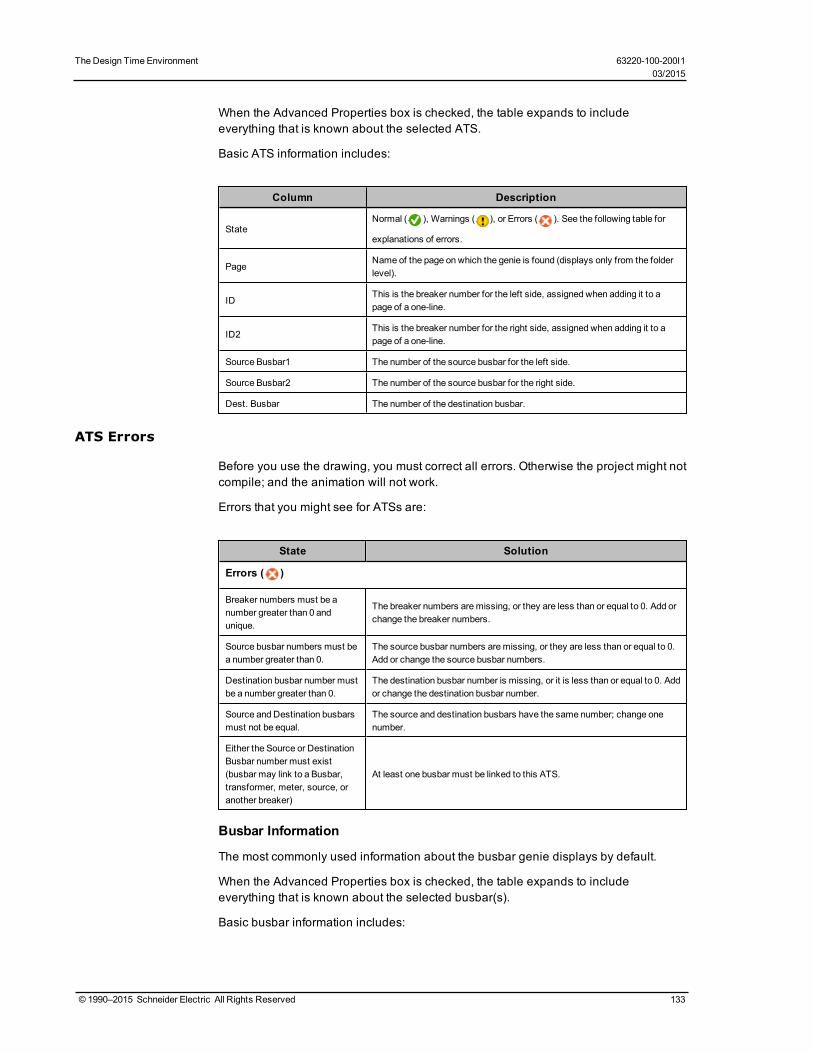
The Design Time Environment 63220-100-200I103/2015
When the Advanced Properties box is checked, the table expands to includeeverything that is known about the selected ATS.
Basic ATS information includes:
Column Description
StateNormal ( ), Warnings ( ), or Errors ( ). See the following table for
explanations of errors.
PageName of the page on which the genie is found (displays only from the folderlevel).
IDThis is the breaker number for the left side, assigned when adding it to apage of a one-line.
ID2This is the breaker number for the right side, assigned when adding it to apage of a one-line.
Source Busbar1 The number of the source busbar for the left side.
Source Busbar2 The number of the source busbar for the right side.
Dest. Busbar The number of the destination busbar.
ATS Errors
Before you use the drawing, you must correct all errors. Otherwise the project might notcompile; and the animation will not work.
Errors that you might see for ATSs are:
State Solution
Errors ( )
Breaker numbers must be anumber greater than 0 andunique.
The breaker numbers aremissing, or they are less than or equal to 0. Add orchange the breaker numbers.
Source busbar numbers must bea number greater than 0.
The source busbar numbers aremissing, or they are less than or equal to 0.Add or change the source busbar numbers.
Destination busbar number mustbe a number greater than 0.
The destination busbar number is missing, or it is less than or equal to 0. Addor change the destination busbar number.
Source and Destination busbarsmust not be equal.
The source and destination busbars have the same number; change onenumber.
Either the Source or DestinationBusbar number must exist(busbar may link to a Busbar,transformer, meter, source, oranother breaker)
At least one busbar must be linked to this ATS.
Busbar Information
The most commonly used information about the busbar genie displays by default.
When the Advanced Properties box is checked, the table expands to includeeverything that is known about the selected busbar(s).
Basic busbar information includes:
© 1990–2015 Schneider Electric All Rights Reserved 133

Column Description
StateNormal ( ), Warnings ( ), or Errors ( ). See the following
table for explanations of errors and warnings.
PageName of the page on which the genie is found (displays only from thefolder level).
IDThis is the busbar number, assigned when adding it to a page of aone-line.
Busbar Errors
Before you use the drawing, you must correct all errors. Otherwise the project might notcompile; and the animation will not work.
Errors that you might see for busbars are:
State Solution
Errors ( )
Busbar number must be anumber greater than 0.
The busbar number is missing, or it is less than or equal to 0. Add orchange the busbar number.
Breaker and Switch Information
The most commonly used information about the breaker genie displays by default.
When the Advanced Properties box is checked, the table expands to includeeverything that is known about the selected breaker(s).
Basic breaker information includes:
Column Description
StateNormal ( ), Warnings ( ), or Errors ( ). See the following table for
explanations of errors.
PageName of the page on which the genie is found (displays only from the folderlevel).
ID This is the breaker number, assigned when adding it to a page of a one-line.
EquipmentThe equipment name entered when adding the genie via the ProfileWizard orAutomation Interface.
Source Busbar The number of the source busbar.
Dest. Busbar The number of the destination busbar.
Breaker and Switch Errors
Before you use the drawing, you must correct all errors. Otherwise the project might notcompile; and the animation will not work.
Errors that you might see for breakers are:
134 © 1990–2015 Schneider Electric All Rights Reserved
63220-100-200I1 The Design Time Environment03/2015

The Design Time Environment 63220-100-200I103/2015
State Solution
Errors ( )
Breaker number must be anumber greater than 0 andunique.
The breaker number is missing, or it is less than or equal to 0. Add or changethe breaker number.
Source busbar number must be anumber greater than 0.
The source busbar number is missing, or it is less than or equal to 0. Add orchange the source busbar number.
Destination busbar number mustbe a number greater than 0.
The destination busbar number is missing, or it is less than or equal to 0. Addor change the destination busbar number.
Source and Destination busbarsmust not be equal.
The source and destination busbars have the same number; change onenumber.
Equipment must be present.There is no equipment attached to the breaker. Add the appropriateequipment.
Either the Source or DestinationBusbar number must exist(busbar may link to a Busbar,transformer, meter, source, oranother breaker)
At least one busbar must be linked to this breaker.
Meter Information
The most commonly used information about the meter genie displays by default.
When the Advanced Properties box is checked, the table expands to includeeverything that is known about the selected breaker(s).
Basic meter information includes:
Column Description
StateNormal ( ), Warnings ( ), or Errors ( ). See the following table for
explanations of errors and warnings.
PageName of the page on which the genie is found (displays only from the folderlevel).
ID This is themeter number, assigned when adding it to a page of a one-line.
EquipmentThe equipment name entered when adding the genie via the ProfileWizard orAutomation Interface.
Source Busbar The number of the incoming busbar.
Line ActiveThe Cicode expression (such as MyTag1 >0) that determines when themeter detects power on the busbar.
Meter Errors and Warnings
Before you use the drawing, you must correct all errors. Otherwise the project might notcompile; and the animation will not work.
Warnings indicate settings that might be incorrect. Verify that the settings indicated bythe warnings are what you want.
Errors and warnings that you might see for meters are:
© 1990–2015 Schneider Electric All Rights Reserved 135
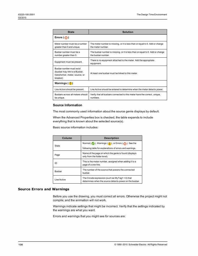
State Solution
Errors ( )
Meter number must be a numbergreater than 0 and unique.
Themeter number is missing, or it is less than or equal to 0. Add or changethemeter number.
Busbar number must be anumber greater than 0.
The busbar number is missing, or it is less than or equal to 0. Add or changethe busbar number.
Equipment must be present.There is no equipment attached to themeter. Add the appropriateequipment.
Busbar number must exist(busbar may link to a Busbar,transformer, meter, source, orbreaker)
At least one busbar must be linked to this meter.
Warnings ( )
Line Active should be present. Line Active should be entered to determine when themeter detects power.
Busbars across all meters shouldbe unique.
Verify that all busbars connected to this meter have the correct, unique,numbers.
Source Information
The most commonly used information about the source genie displays by default.
When the Advanced Properties box is checked, the table expands to includeeverything that is known about the selected source(s).
Basic source information includes:
Column Description
StateNormal ( ), Warnings ( ), or Errors ( ). See the
following table for explanations of errors and warnings.
PageName of the page on which the genie is found (displaysonly from the folder level).
IDThis is themeter number, assigned when adding it to apage of a one-line.
BusbarThe number of the source that powers the connectedbusbar.
Line ActiveThe Cicode expression (such as MyTag1 >0) thatdetermines when the source detects power on the busbar.
Source Errors and Warnings
Before you use the drawing, you must correct all errors. Otherwise the project might notcompile; and the animation will not work.
Warnings indicate settings that might be incorrect. Verify that the settings indicated bythe warnings are what you want.
Errors and warnings that you might see for sources are:
136 © 1990–2015 Schneider Electric All Rights Reserved
63220-100-200I1 The Design Time Environment03/2015

The Design Time Environment 63220-100-200I103/2015
State Solution
Errors ( )
Source number must be anumber greater than 0and unique.
The source number is missing, or it is less than or equal to0. Add or change the source number.
Busbar number must be anumber greater than 0and unique acrosssources.
The busbar number is missing, or it is less than or equal to0. Add or change the busbar number.
Busbar number mustexist (busbar may link toa Busbar, transformer, orbreaker)
At least one busbar must be linked to this source.
Warnings ( )
Line Active should bepresent.
Line Active should be entered so the source can detectpower on the busbar.
Transformer Information
The most commonly used information about the transformer genie displays by default.
When the Advanced Properties box is checked, the table expands to includeeverything that is known about the selected transformer(s).
Basic transformer information includes:
Column Description
StateNormal ( ), Warnings ( ), or Errors ( ). See the following table for
explanations of errors.
PageName of the page on which the genie is found (displays only from the folderlevel).
ID This is the breaker number, assigned when adding it to a page of a one-line.
Source Busbar The number of the source busbar.
Dest. Busbar The number of the destination busbar.
Sim. Source This is the top source number used when adding the transformer.
Sim. Source 2 This is the bottom source number used when adding the transformer.
Transformer Errors
Before you use the drawing, you must correct all errors. Otherwise the project might notcompile; and the animation will not work.
Errors that you might see for transformers are:
State Solution
Errors ( )
© 1990–2015 Schneider Electric All Rights Reserved 137

State Solution
Source busbar number must be anumber greater than 0.
The source busbar number is missing, or it is less than or equal to 0. Add orchange the source busbar number.
Destination busbar number mustbe a number greater than 0.
The destination busbar number is missing, or it is less than or equal to 0. Addor change the source busbar number.
Source and Destination busbarsmust not be equal.
The source and destination busbars have the same number; change onenumber.
Either the Source or DestinationBusbar number must exist(busbar may link to a Busbar,transformer, meter, source, oranother breaker)
At least one busbar must be linked to this transformer.
If a top or bottom source isidentified, it must be greater than0.
The number for the top or bottom source for this transformer must be greaterthan zero (for voltage-level transformers) or must be left blank (for pass-through transformers).
Work with AlarmsIn this section, you will find these topics:
Alarms Overview on page 138
Set Up Alarm Pages on page 139
Add Setpoints and Delays on page 139
Set Up an Alarm Based on an Enumeration on page 139
Change an Alarm Severity on page 140
Enable Waveforms for Onboard Alarms on page 140
Set Parameters for Event Log Length and Historical Logging of Events on page 140
Add an Onboard Alarm Tag on page 141
Set Up Audible Alarms on page 142
Alarms OverviewThis section discusses two alarm types: time stamped analog and time stamped digital.To access the alarms, from Citect Explorer, select the project folder, then click Alarms.In the right-hand pane, the alarm types display. Double-click the one you want toview/edit.
PC-Based Alarms1. PC-based alarm tags are added in the Profile Editor, when adding each device
profile. See Add Edit or Delete Device Profile on page 41for instructions. Forinstructions on entering setpoints and delays, see Add Setpoints and Delays onpage 139.
Onboard Alarms
If onboard alarms have been configured in a supported device, you can use the ProfileEditor to map these alarms to digital time-stamped alarms in PowerSCADA Expert.
You cannot configure new onboard alarms from PowerSCADA Expert. You must addthe alarm at the device, then you can create the alarm tag for it here. See Add anOnboard Alarm Tag on page 141.
138 © 1990–2015 Schneider Electric All Rights Reserved
63220-100-200I1 The Design Time Environment03/2015

The Design Time Environment 63220-100-200I103/2015
Set Up Alarm PagesUse this procedure to create separate alarm pages for each alarm type in the project.Follow these steps for each alarm page you want:
1. From Citect Project Editor, click System > Menu Configuration.2. In the Menu Command line, add the Cicode method that will open the page:
PLSDspShowAlarm(INT nType)
where nType = the type of alarm (e.g., 1=unacknowledged, 3=disabled)
Example (for disabled alarms):
PLSDspShowAlarm(3)
For information about alarm types, see AlarmDsp in the Cicode ProgrammingReference help file.
Add Setpoints and DelaysAny time you change setpoints, you should immediately restart the project. Otherwise,setpoints will not be properly read (they will be truncated and either rounded down orup to a whole integer).
There are two ways to add setpoints and delays for analog alarms. Before you entersetpoints and delays, ensure that you have configured the alarm server so that PublishAlarm Properties is set to TRUE.
• From the Analog Alarms window (accessible from the Project Explorer or ProjectEditor screens), you can type the setpoint and delay values for each alarm.
• When in the runtime environment, you can edit setpoints/delays that were set by themethod above. See Use the Equipment Pop-Up Page on page 164 for instructions.
Also, set the following parameter to allow persisting of alarm parameters at runtime.
[Alarm] UseConfigLimits = 1
Set Up an Alarm Based on an EnumerationFor instructions on defining an enumeration in the Profile Editor, see Define anEnumeration on page 66.
An example of an enumeration alarm is:
0 = unknown
1 = good
2 = warning
3 = alarm
To add an alarm that is based on an enumeration, follow these steps:
1. Open the analog alarm in PowerSCADA Expert.2. To alarm on states 0, 2, and 3:
Set Low = 1 (if the value < 1, the alarm indicates an unknown state)
Set High = 1 (if the value > 1, the alarm indicates a warning)
Set High High = 2 (if the value > 2, the alarm indicates an alarm)
© 1990–2015 Schneider Electric All Rights Reserved 139

3. In the Category field, ensure that the correct alarm level is entered (_PLSALM_HIGH, _PLSALM_MEDIUM, _PLSALM_LOW, _PLSALM_EVENT).
4. Replace the alarm.
Change an Alarm SeverityTo change the severity of an alarm, follow these steps:
1. Open the analog alarm in PowerSCADA Expert.2. In the Category field, ensure that the correct alarm level is entered (_PLSALM_
HIGH, _PLSALM_MEDIUM, _PLSALM_LOW, _PLSALM_EVENT).
3. Replace the alarm.
Enable Waveforms for Onboard AlarmsTo enable waveforms, making them available for viewing in the runtime environment,follow these steps:
1. At the device, or via the meter configuration software (PMCU), add the alarm andenable the automatic capture of a waveform when the alarm occurs.
2. In the Profile Editor, on the Create Device Profiles tab, for the same alarm youadded in PMCU, check the Waveform box.
When this alarm occurs at the device, the waveform will be captured. The files willbe transmitted to PowerSCADA Expert and will be available for viewing. Theamount of time this takes depends on the number of I/O servers you have and thenumber of serial devices on a chain. On a very large system with numerous serialdevices, this could take as much as an hour.
You can view the waveform from the Alarm Log in the runtime environment. SeeUse the Equipment Pop-Up Page on page 164 for instructions.
Set Parameters for Event Log Length and Historical Logging of EventsYou can use two parameters to determine the maximum number of entries in the EventLog and whether you want to log entries after they are FIFO’d out of the Event Log.
Event Storage: [Alarm]SummaryLength Parameter
The maximum number of alarms that can be stored is controlled by the Alarm Summarylength parameter, which defines the maximum number of alarm summary entries(Event Log entries) that can be held in memory. You can view these alarm summaryentries on the Alarm Log page. Each event requires 256 bytes of memory, plus thelength of the comment. 32,000 entries will require at least 8 MB of memory. If you havemany events, you should ensure that there is enough memory to store them in RAM.
The default value is 5000.
When the value is set to a number greater than 1000 for a multiple-cluster system, thealarm log might not display correctly. The list of alarm history that displays on a clientmight be shorter than the actual history stored on the alarm server. To avoid thisproblem, do one or more of the following:
• Set alarm filtering in the alarm viewer to reduce the number of alarms that arereturned by the server.
• Only support a one-cluster system.• If a multiple-cluster system is necessary, display a separate alarm page for each
cluster.
140 © 1990–2015 Schneider Electric All Rights Reserved
63220-100-200I1 The Design Time Environment03/2015

The Design Time Environment 63220-100-200I103/2015
Event Logging: [PLSEventLog] Parameter
Use this parameter to determine whether you will log Event Log entries and the fileformat that will used for logging. If you choose to log, you must specify the file format:XML or CSV.
[PLSEventLog]
FIleFormat = 0 = no file logging, 1 = CSV format, 2 = XML format (default = 0)
EntryCount number of entries logged per disk file (1-3200; default = 250)
ScanRate time in seconds between writing to file, when waiting for a new event (1 to3200; default = 10); may be ignored if the entry count is reached or if a large number ofalarms or events is triggered
The filename will have this format:
<Project Name>_<Cluster Name>_PLSEventLog.YYMMDDHHMMSS.xxx (where xxxis the file format selected). The log files will be stored in the Data folder.
[Path]
PLSEventLog=c:\SharedData\Alarm
To specify the alarm fields to be logged, use:
[AlarmFormat]
EventLog=OnDate | Date, OnTimeMS | Time, Custom1 | Equipment, Name |Description,SumState | State | Custom2 | Location, UserName | User
Format]Summary =Alarm =Equipment =LastAlarm =
[AlarmHeading]
<FieldName> = <Display Name>
Add an Onboard Alarm TagWhen a device onboard alarm has not been included in PowerSCADA Expert, you canadd it from the Profile Editor. You need to follow these steps to include the device’sunique identifier. Otherwise, the alarm will not annunciate in the Graphics page.
You can only add onboard alarms for devices using the CM4, PM8, Micrologic, orSepam drivers. CM4, PM8, and Micrologic unique IDs must be decimal; SEPAMunique IDs must be hexadecimal.
1. From the device, obtain the unique identifier for this alarm. Additionally, forMicroLogic, you need to include the unique sub-identifier.
2. You also need the file number in which alarms on stored on the device.
3. From the Profile Editor, add the onboard alarm (see Onboard Alarm Tag Addresseson page 36 in Editing Tag Addresses.
© 1990–2015 Schneider Electric All Rights Reserved 141
Set Up Audible AlarmsYou can use a variety of Windows wave files for audible alarms. To enable this feature,follow these steps:
1. Define the alarm sound to be used and the repeat interval for each priority in thealarm you want to be audible. Enter the following information, either in the projectparameters (Citect Project Editor > System > Parameters) or in the Citect.ini file:
a. [Alarm]b. Sound<priority>=<wave file name>c. Sound<priority>Interval=<repeating interval in milliseconds>
If the device is added through the Profile Wizard, the alarm priority will be 1, 2, and3 for _PLSALM_HIGH, _PLSALM_MEDIUM, _PLSALM_LOW alarms respectively.
The user can define specific wave files for the sounds. We support the followingWindows operating system sounds:
SystemAsterisk
SystemExclamation
SystemQuestion
SystemDefault
SystemHand
SystemExit
SystemStart
2. After alarms are set up: When an alarm occurs, its specified alarm sound will playcontinually according to the specified interval. The alarm sound will stop wheneither:— the user clicks Silence Alarm on the alarm page— the alarm is acknowledged
Restore and Back Up ProjectsIn this section, you will find these topics:
Restore a Project on page 142
PowerSCADA Expert Backup on page 143
Restore a ProjectTo restore a project, overwriting its current settings, follow these steps:
1. From the Citect Explorer, select the project you want to restore; click Tools >Restore.
2. In the Restore from box, browse to the location of the file you will use to restore.
3. In the To box, check Current Project.
4. In the Options box, check Configuration files to restore backed up INI files and theTimeSyncConfig.xml file (used to store time synchronization settings). If you backedup the sub-directories under the project, the directories will be listed under Selectsub-directories to restore. You can restore all or no sub-directories, or you canselect specific sub-directories to restore.
5. Click OK.
142 © 1990–2015 Schneider Electric All Rights Reserved
63220-100-200I1 The Design Time Environment03/2015
The Design Time Environment 63220-100-200I103/2015
PowerSCADA Expert BackupUse this feature to back up a Citect project file. To back up a Profile Editor project file,see Profile Editor Export on page 56.
1. From the Citect Explorer, click Tools > Backup.2. At the Backup Project window, select the project you want to back up
3. Browse to the location where you want to store the backup file.
4. In the Options box, check “Save configuration files.” This saves the citect.ini file.
5. Click OK.
The backup .CTZ file is written to the location that you choose during backup. This is aCitect Zip file; you can open it with WinZip.
Use Cicode to Customize a ProjectCicode is a programming language designed for use in this product to monitor andcontrol plant equipment. It is a structured language similar to Visual Basic or 'C'. Youneed no previous programming experience to use it. However, it is assumed that youwill have received Cicode training before you attempt to use Cicode.
Using Cicode, you can access all real-time data (variables) in the project: variabletags, alarms, trends, reports, and so on. You can also use Cicode to interface with thecomputer's operating system and communication ports.
For information about driver-specific INI parameters that you can configure, seeAppendix 2: Citect INI Parameters on page 221 .
For information about other parameters, see the Cicode Reference help file in thecitectSCADA.chm help file (Program Files> Schneider Electric > PowerSCADA Expert> v8.0 > bin).
Use Cicode in PLS_IncludeSeveral Cicode modules have been written specifically for use in PLS_Include. Thissection describes each module.
Click to view descriptions/instructions for each module:
PLSProviderEngine.ci Module on page 143
Clear Cache and Refresh Platform on page 145
PLSProviderEngine.ci ModuleUse this module when you want to invoke a provider to produce results that can bedisplayed or acted on in a custom table or report that you create. Providers invoked bythis method must be written so that they take a single string as input and return a singlestring as output.
Module Construction
The following string functions are included in this module:
CallProvider
This function invokes a provider (whose GUID-based identifier must appear in thesProvider argument) with a single string as input (the sArgs argument). The input string
© 1990–2015 Schneider Electric All Rights Reserved 143
can consist of anything that is meaningful to the provider that you invoke.
The provider then returns a string-based token.
Construction of CallProvider:
STRING FUNCTION CallProvider(STRING sProvider, STRING sArgs)
INT hHandle;
STRING sResult;
ErrSet(1);
sProvider = "^"" + sProvider + "^"";
sArgs = "^"" + sArgs + "^"";
hHandle = DLLOpen("ProviderGatewayUnmanaged.dll", "MakeRequest","CCC");
sResult = DLLCall(hHandle, sProvider + "," + sArgs);
DLLClose(hHandle);
IF IsError() THEN RETURN "ERROR"; END
RETURN sResult;
END
--------------
GetProviderStatus
This function reports the status of a provider invocation by showing the percentage ofits completeness. A provider has completed its work when the status reaches 100percent,
To retrieve status with this function, pass in a token (obtained previously by callingCallProvider) and examine the number contained in the function's return string (from 0to 100).
Construction of GetProvider Access:
------------
STRING FUNCTION GetProviderStatus(STRING sToken)
INT hHandle;
INT iPercent;
ErrSet(1);
sToken = "^"" + sToken + "^"";
hHandle = DLLOpen("ProviderGatewayUnmanaged.dll", "GetPercent","JC");
iPercent = DLLCall(hHandle, sToken);
DLLClose(hHandle);
IF IsError() THEN RETURN "ERROR"; END
RETURN iPercent;
END
-------------
144 © 1990–2015 Schneider Electric All Rights Reserved
63220-100-200I1 The Design Time Environment03/2015

The Design Time Environment 63220-100-200I103/2015
GetProviderResult
This function retrieves the result from a provider. Pass a unique token (obtainedpreviously by calling CallProvider) to this function. It returns the provider result as astring. Note that you should only call this function after you verify that the provider workis 100 percent complete.
Construction of GetProviderResult:
------------
STRING FUNCTION GetProviderResult(STRING sToken)
INT hHandle;
STRING sResult;
ErrSet(1);
sToken = "^"" + sToken + "^"";
hHandle = DLLOpen("ProviderGatewayUnmanaged.dll", "GetResult","CC");
sResult = DLLCall(hHandle, sToken);
DLLClose(hHandle);
IF IsError() THEN RETURN "ERROR"; END
RETURN sResult;
END
--------------
Clear Cache and Refresh PlatformWhen you add, delete, or update a device or topic, you need to shut down and thenrestart, the PowerSCADA Expert run mode. At that time, we recommend that you alsoclear the cache and then refresh the platform. This will ensure that data is madeavailable to App Mods.
When you clear the cache, you remove data that is potentially out-of-date. Thus, werecommend that you clear the cache of outdated material.
After you clear the cache, you need to refresh the platform. This step will refresh theSchneider Electric CoreServiceHost, updating its list of devices and topics
Each of these methods uses the PLSProviders.ci module. See PLSProviderEngine.ciModule on page 143 for instructions on creating the statements needed.
PLS_CLearCache
In the Schneider Electric CoreServiceHost, when you call a provider and it returns itsresult, it caches that result for a given amount of time (which varies by provider). Ifsomeone calls that provider again, the system will return the cached result.
If someone adds a device during this time, and then restarts run mode, the device isnot available for features like LiveView or basic reporting. Thus, if someone tries toview a table or run a basic report, using the new device, it will not display. The next callthat is made to the cache will refresh it.
NOTE: You may also wish to create a graphics page that includes a button that callsthe cache and/or refresh.
© 1990–2015 Schneider Electric All Rights Reserved 145

To clear the cache, call the PLS_ClearCache function by doing one of the following:
• If the Schneider Electric CoreServiceHost is on the machine from which you areinvoking the function, you can call it with no input parameters:
PLS_ClearCache();
This may be done during startup or using a button handler.• If the Schneider Electric CoreServiceHost is on a different machine, you must
supply parameters to identify where the Application Services core resides. Forexample, if the customer's Schneider Electric CoreServiceHost resides on anIOServer named "IOServer1" on "Cluster1", to call PLS_ClearCache, enter:
PLS_ClearCache("IOServer", "IOServer1", "Cluster1");
This cannot be done at startup; you must do it after the startup routine is run. Forexample, you might use a button handler.
PLS_PlatformRefresh
After you clear the cache, run the platform refresh to update the Schneider ElectricCoreServiceHost, causing it to refresh its list of devices and topics.
To run the refresh, call the PLS_PlatformRefresh function by doing one of thefollowing:
• If the Schneider Electric CoreServiceHost is on the machine from which you areinvoking the function, you can call it with no input parameters:
PLS_PlatformRefresh();
• If the Schneider Electric CoreServiceHost is on a different machine, you mustsupply parameters to identify where the Application Services core resides. Forexample, if the customer's Schneider Electric CoreServiceHost resides on anIOServer named "IOServer1" on "Cluster1", to call PLS_PlatformRefresh, enter:
PLS_PlatformRefresh("IOServer", "IOServer1", "Cluster1");
Customize Default BehavioursIn this section, you will find these topics:
Time Zone Settings on page 146
Time Synchronization on page 147
Trend Tag Scan Intervals on page 147
Disk Storage Calculation for Trends on page 148
Deadbands and Ignored Devices and Topics on page 148
To learn about the parameters that you can use to configure drivers, see Appendix 2:Citect INI Parameters on page 221.
Time Zone SettingsThe system allows you to interact with devices located in a different time zone than thePowerSCADA Expert I/O Server. To do this, the system converts any alarm/waveformtimestamp as well as the actual time sent within the Set Time command from / to thelocal time zone. In order to take into account daylight savings properly, the Windowstime zones database is used. Thus, time zone names must be taken directly from thisdatabase (case-insensitive), otherwise the system will default to using the I/O server’slocal time zone. The Windows time zone database is located in the Windows registry inHKEY_LOCAL_MACHINE\SOFTWARE\Microsoft\Windows NT\CurrentVersion\TimeZones\. Examples of time zone names are
146 © 1990–2015 Schneider Electric All Rights Reserved
63220-100-200I1 The Design Time Environment03/2015
The Design Time Environment 63220-100-200I103/2015
• AUS Central Standard Time• China Standard Time• Pacific Standard Time (Mexico)
Time zones for remote devices can be specified on two levels:
1. Use section [ProtocolName.ClusterName.PortName.IODeviceName] to specify thetime zone for a particular device, e.g.
[PLOGIC870.Cluster1.PM870_Port.PM870_Device1]
Timezone = Singapore Standard Time
2. Use general section [POWERLOGICCORE] to specify the time zone for all devices,e.g.
[POWERLOGICCORE]
Timezone = Mountain Standard Time
The device-specific time zone specification takes precedence. In other words, if both ofthe above examples are present in the Citect.ini file, the PM870_Device1 would belocated in “Singapore Standard Time” time zone, and all the other I/O devices in theproject would be located in “Mountain Standard Time” time zone.
If there is no time zone specification (or if it does not match the time zone fromWindows database), the device would be in the same time zone as the machine wherethe I/O Server is running; thus, no time conversion will be done.
If only the first of the above examples is present within the Citect.ini file, the PM870_Device1 would be located in “Singapore Standard Time,” and all the other devices usethe current local time zone.
Time SynchronizationCurrent time can be sent to the corresponding device by means of Set Time commandor (in case of Sepam) by writing directly to the corresponding registers within thedevice. In addition to the manual procedure, this process can be scheduled to occurperiodically (using PowerSCADA Expert events).
Non-manual time synchronization causes the Set Time command to be sentautomatically, based on a device state or event originating from within the device.
Automatic time synchronization applies only to Micrologic and PM devices and takesplace based on the following rules:
1. For Micrologic devices, the value of the top-most bit of the register 679 is examined(for both the Circuit Breaker Manager and the Chassis Manager). If the bit is equalto 1, it means that the device is out of sync and needs to be synchronized.
2. For PM devices, an alarm 50700 (“Unary Power Up / Reset”) indicates that thedevice needs to be synchronized. In addition, bit 6 of register 3055 of the device isexamined. If this bit is equal to 1, the device has a real-time clock; so automatic timesynchronization should never take place.
Trend Tag Scan IntervalsWhen you select a trend tag for a device profile (Add/Edit Device Profile screen), thetag will be scanned at the “long” interval” (every 15 minutes, with FIFO storage of 12months); but certain trend tags have an additional “short” scan interval. This interval isset by default at 5 seconds, with FIFO storage of two weeks.
© 1990–2015 Schneider Electric All Rights Reserved 147

The default tags are: Current A, Current B, Current C, Voltage A-B, Voltage B-C,Voltage C-A, Power Factor Total, Apparent Power Total, Reactive Power Total, RealPower Total, and Frequency. When you choose one of these tags for trending, you willget both long and short interval trending. The long interval trend will use the trend tagname from the Profile Editor. The short interval trend tag will have the same name asthe long tag with an “s” appended to it.
You can edit the Profile Editor.exe.config file to add or delete tags that will have shortscan intervals, and to change the short scan interval for all of the tags that are listed.
To edit short scan interval settings, follow these steps:
1. Locate and open Profile Editor.exe.config in Notepad:
[Project Drive]\Program Data\ SchneiderElectric\PowerSCADA Expert\v8.0\Applications\Profile Editor
2. To change the short scan interval, scroll the "TrendShortIntervalSamplePeriod"setting. The default value is 00:00:05, or five seconds (HH:MM:SS). Changing thisrate will change the interval for all of the tags that are listed in the setting in step 3.
3. To change the tags that are included in the short scan interval, scroll to the"TrendShortIntervalTags" setting. The numbers listed (defaults:1003,1004,1005,1050,1046,1042,1014,1015,1016,1001,1034) are the tag IDs.You can add or delete tags. Tag IDs are listed on the Define Device Type Tags tab(when the Advanced Properties option checked).
NOTE: If you choose a device that includes the tags in this list, you will alwayshave these short scan interval tags included.
For example, if you wanted to change the scan interval to ten seconds and addOvercurrent A for a CM4000, you would edit these two lines in this way:
"TrendShortIntervalSamplePeriod" value="00:00:10"
"TrendShortIntervalTags"value="1003,1004,1005,1050,1046,1042,1014,1015,1016,1001,1034,19"
Disk Storage Calculation for TrendsThere are two methods of calculating disk space usage for trends: scaled and floatingpoint. The Profile Editor uses floating point by default. For more information on thesecalculations, see Calculating Disk Storage in the citectSCADA.chm help file(Program Files> Schneider Electric > PowerSCADA Expert > v8.0 > bin).
Deadbands and Ignored Devices and TopicsThese two features allow you to limit information that you see in system queries anddata acquisition. You set the limits for these features in the Configuration.xml file(C:\Program Files (x86) > Schneider Electric > PowerSCADA Expert > v8.0 >Applications > AppServices > bin > Configuration.xml).
Deadbands
148 © 1990–2015 Schneider Electric All Rights Reserved
63220-100-200I1 The Design Time Environment03/2015

The Design Time Environment 63220-100-200I103/2015
<ConfigurationItem Key="Deadbands" Category="Platform Mapping"Application="CitectPlatform">
<Value />
</ConfigurationItem>
Use this line in Configuration.xml to reduce the sensitivity to minor changes in real-timedata. You can set default deadbands for variable tags. To set a deadband, enter thefollowing in the value field:
<Value>XX|NN;</Value>
where XX is the IEC 61850 tag name and NN is the percentage. For example, to setCurrent A to 5% and Current B to 10%, you would enter the following:
<Value>mmxu1\A\phsA|5.0;mmxu1\A\phsB|10.0;</Value>
Ignored Devices/Ignored Topics
Use these two lines in the Configuration.xml to develop a list of devices and topics thatyou want to ignore in system queries/data acquisition. Typically, you will use this toexclude devices such as the memory device zOL. Ignored devices and topics will notappear in Reporting or LiveView.
To set a value for ignored devices, type the Citect device names (semi-colon delimited)that you want to ignore. For example, to exclude zOL (the one-line memory device) andthe network tags device (for monitoring comms loss), type:
<Value>zOL;NetworkTagsDev</Value>
In the Ignored Topics list, type the topic names (semi-colon delimited) that you want toignore. Do not include the device name prefix that displays in the Citect project tagnames. For example, to exclude AlarmUnhandled and AlarmInvalidTimestamp, type:
<Value>AlarmUnhandled;AlarmInvalidTimestamp</Value>
Save your changes.
© 1990–2015 Schneider Electric All Rights Reserved 149

Waveform ManagementThis chapter discusses how waveforms are stored and associated with alarms. In thissection, you will find these topics:
Waveform Storage on page 150
Waveform Database and Special Waveform Tags on page 150
Waveform StorageWaveform records are organized within devices into files. These files are periodicallychecked for and downloaded as they appear on the device. When downloaded, on thePowerSCADA Expert I/O server the files are converted into a Comtrade format andthen stored in a hierarchical fashion.
A single waveform will be stored as follows:
<Waveform DBroot>\<ClusterName>\<IODeviceName>\Waveforms\<UTCTimestamp>.CFG
<Waveform DBroot>\<ClusterName>\<IODeviceName>\Waveforms\<UTCTimestamp>.DAT
For example,
C:\Data\Cluster1\Sepam_IODev\Waveforms\
DST_00000000001203566197_0000000511_utc.CFG
DST_00000000001203566197_0000000511_utc.DAT
Waveform DB root path is configured in the WaveformDB configuration section.
NOTE: in case of redundant I/O devices, only the name of the primary I/O device will beused when waveform storage path is constructed.
The CFG file is a Comtrade configuration file, and the DAT file is the Comtrade datafile. Within the CFG file is a timestamp that reflects the device time start time of thewaveform (this time is not adjusted to the I/O Server time zone or daylight saving, but itis stored per the device configuration). The file name has the UTC time in secondssince 1970 of the waveform.
The prefix of waveform file name reflects the type of the waveform. Currently,waveforms of the following types are supported:
DST_ Disturbance waveform
ADT_ Adaptive waveform
SST_ Steady state waveform
If it is detected that the waveform data file has changed while it is being downloaded,the file gets discarded and is not stored on the IOServer.
Waveform Database and Special Waveform TagsPowerSCADA Expert allows you to browse the waveform database for specific I/Odevices. Search for all waveforms within certain time frame is also supported, allowingyou to search for all waveforms that could be linked with a given alarm. When you
150 © 1990–2015 Schneider Electric All Rights Reserved
63220-100-200I1 Waveform Management03/2015

Waveform Management 63220-100-200I103/2015
perform this search, a list of all matching waveforms displays. If there are multiplewaveforms in the list, you can select the waveform you want to view.
In addition, there are two special digital waveform tags defined (0 = FALSE, 1 = TRUE):
• WaveformDownloading: indicates whether a waveform file is currently beingdownloaded
• WaveformCollectionEnabled: indicates whether the waveform collection isenabled at all
The figure below illustrates a configuration example and replication and linkageprocesses.
© 1990–2015 Schneider Electric All Rights Reserved 151

The Runtime EnvironmentThis chapter discusses the Graphics page in the runtime environment. In this section,you will find these topics:
Launch and Close the Runtime Environment on page 153
View the Graphics Page in the Runtime Environment on page 153
Log On to the Runtime Environment on page 153
View the Interface on page 153
View the Alarms/Events Page on page 155
When Alarms do not Display Correctly on page 158
Event/Alarm Log Columns Table on page 159
Alarm/Event Filter Form on page 160
Use the Analysis Page on page 163
Use the Equipment Pop-Up Page on page 164
Perform IEC 61850 Advanced Control on page 167
EcoStruxure WebServices (EWS) on page 169
Use Basic Reports on page 169
Set up the Runtime Environment for Basic Reports on page 170
Set Up a Display Client for Basic Report Viewing on page 171
Tasks in the Basic Reporting Application on page 171
Single Device Usage Reports on page 178
Multi Device Usage Reports on page 179
Tabular Reports on page 180
Trend Reports on page 180
Enable Windows Authentication for Basic Reporting on page 181
URL Routing for Basic Reports on page 182
Localization for Basic Reports on page 182
Use LiveView on page 183
LiveView Viewer on page 189
Set Up LiveView on page 192
LiveView Formulas on page 196
LiveView Placeholders on page 195
LiveView Thresholds on page 197
LiveView Formatting on page 194
Multi-Monitor Support on page 202
The Demo Mode on page 202
Application Configuration Utility on page 203
Application Services on page 204
Application Services Host—Citect Data Platform on page 205
Applications on page 206
Single Sign On on page 208
152 © 1990–2015 Schneider Electric All Rights Reserved
63220-100-200I1 The Runtime Environment03/2015

The Runtime Environment 63220-100-200I103/2015
Launch and Close the Runtime EnvironmentLaunch Runtime: To launch the runtime environment, don one of the following:• Click Start > Programs > Schneider Electric > PowerSCADA Expert 8.0
>PowerSCADA Expert Runtime.• From any of the Citect windows, click File > Run.• From the toolbar of any of the Citect windows, click Run Project:
Close Runtime: There are two ways to shut down the runtime environment:• Click the “X” in the upper right corner of the screen. Then enter a user name and
password. (It is important to define at least one user in your project.)• From the computer taskbar, click the Runtime Manager:
This displays the Runtime Manager screen. Click Shutdown All. There is norequired user name/password. Unless you disable this feature on the taskbar,users can shut down the runtime environment without having to enter anyinformation.
View the Graphics Page in the Runtime EnvironmentIn the runtime environment, the Graphics Page displays with the appearance that isdetermined by the Menu Configuration file for this project. If you need to change theappearance of tabs and menus, see Use Menu Configuration to Edit Pagemenu.dbf(Change the Graphics Page Appearance) on page 115.
In this section, you will find these topics:
Log On to the Runtime Environment on page 153
View the Interface on page 153
View the Alarms/Events Page on page 155
Use Security Viewer on page 161
Security Viewer Filter on page 162
When Alarms do not Display Correctly on page 158
Event/Alarm Log Columns Table on page 159
Alarm/Event Filter Form on page 160
Use the Analysis Page on page 163
Use the Equipment Pop-Up Page on page 164
Perform IEC 61850 Advanced Control on page 167
Log On to the Runtime EnvironmentIn the upper right-hand corner, click the Login link. Then enter your User ID andpassword. The features that are available will vary, depending on your user level.
View the InterfaceThe runtime environment page includes a variety of tabs. If your page is created basedon the Normal template from the pls_include_1 library, you will see the following:
© 1990–2015 Schneider Electric All Rights Reserved 153

In the upper left corner of the screen, the project name is listed. Your logon name isbelow that. At the top of the page, there are left and right navigation arrows that allowyou to go to previously visited pages.
These two arrows allow you to go back and forward one page in your navigationhistory. To see the history of visited pages, click the small down arrow next to the rightarrow. This displays a listing of visited pages (the current page is checked). To jump toa page in this list, click it in the menu.
Just beneath the left and right arrows is the alarm banner. It lists the last five activealarms.
Beneath the alarm banner is a tabbed-style menu. Its contents are determined by theinformation entered in the Menu Configuration tool: Use Menu Configuration to EditPagemenu.dbf (Change the Graphics Page Appearance) on page 115. These tabsdisplay in two rows:
• The upper row is typically used for organizing pages into several topics (or tabs). Atypical system would include topics for single lines, alarms/events, analysis (fortrends), and system supervision (allows you to view the network connection topics).
• The lower row lists the links/pages under the topic that is currently selected in theupper row. If you select the single lines topic on the upper row, the lower rowdisplays all of the links to individual single line pages.
If there are more links available than the ones that fit on the page, a small arrowdisplays at the right hand side of the row. Click the arrow to display a pop-up menu ofthe remaining links. Click a link in the menu to shift the contents of the row to make itvisible for selection.
NOTE: When viewing the single lines: if the busbars and circuit breakers do not displayas expected, it could be that a custom genie is not set up correctly. See Create NewGenies on page 116 for details on customizing genies.
Lockout/Tagout Icon
This feature causes an icon (see below) to display when a tag attribute for a deviceindicates that the equipment should be locked out and tagged out. For example, youcould assign a tag value from a PLC or other indicating device that reads the conditionof the device.
Lockout/tagout icon:
154 © 1990–2015 Schneider Electric All Rights Reserved
63220-100-200I1 The Runtime Environment03/2015

The Runtime Environment 63220-100-200I103/2015
DANGERHAZARD OF ELECTRIC SHOCK, EXPLOSION, OR ARC FLASH
• Do not rely solely on the display of the icon on the one-line. Before working onthe equipment, verify that the device is physically locked out/tagged out beforeperforming work on it or any downstream equipment.
• Ensure that all safety regulations and procedures have been followed beforeyou work on the equipment.
Failure to follow these instructions will result in death or serious injury.
See Enable Lockout/Tagout on page 114 for instructions on enabling thelockout/tagout feature.
NOTE: Do not incorrectly configure the tag, as this can lead to unexpected equipmentoperation. Also consider the possibility of communications loss that could yield falsereadings.
Communications Loss
When there is a communication loss for a device, the genie or any part of the genie onthe one-line page should have cross-hatches (gray dots) over the affected area, and acommunication loss (CL) indication displays on the genie. An alarm should alsoannunciate. The color state before communication was lost will remain unchanged.
However, the indication of loss of communications does not filter through theentire bus animation: the downstream part of the drawing may still appear as ifcommunication is working. When any part of a one-line drawing losescommunication, do not continue to trust downstream readings until you addressthe loss of communication.
View the Alarms/Events PageSee also: Use the Equipment Pop-Up Page on page 164
To view the alarms or events, click the Alarms/Events tab; then select the tab for theAlarm Log or Event Log. The Event Log displays all alarms and events that haveoccurred. The Alarms Log displays enabled alarms.
See The Alarm Log, below, for descriptions of color codes.
Equipment Column
On the left side of the page, there is an equipment column. To hide or display thiscolumn, click the splitter:
© 1990–2015 Schneider Electric All Rights Reserved 155

All of the equipment in the project is listed. Most of the equipment is grouped byvoltage level. By default, none of the names are checked, which means thatinformation for all of them will display. To list alarms and events for a shortened list ofequipment, check the box(es) to the left of the equipment name(s).
The number to the right of the equipment name is the number of active alarms for thatequipment.
Filter Information
To filter the information that displays, click Filter, just above the Date column (seeAlarm/Event Filter Form on page 160 for more information). From the Alarm Filterwindow, you can select from a variety of filters.
Remove/Insert/Move Columns
To remove a column from the list, right-click its header and select Remove Column.
To insert a column, right-click a column header, select Insert Column, then check thename of the column from the dropdown list. The new column displays to the left of thecolumn you right-clicked. If you right-click the white area to the right of existingcolumns, you will insert the column to the right of the last column.
To move a column, left-click the column that is to be moved. Drag the column to theposition you want it.
Sort by Column
To sort on the information in a single column (such as the Equipment column), double-click the column header. It will toggle between ascending and descending order.
The Event Log
The Event Log lists alarm/event activity, most recent first (provides sequence of eventsinformation). The time is reported to the millisecond. You can display the Messagecolumn to see the most detail (such as, "Alarms disabled" and "Alarm xxxacknowledged").
The Alarm Log
To filter the alarms that display, click Filter, just above the Date column (seeinstructions on using the filter option in Alarm/Event Filter Form on page 160). From theAdvanced Alarm Filter window, you can filter by date range, by text matches for variousattributes, or by alarm type.
Notice the alarm colors:
• Acknowledged active alarms display in a normal red font.• Unacknowledged active alarms display in a bold red font.• Acknowledged inactive alarms display in a normal gray font.• Unacknowledged inactive alarms display in a bold gray font.
Each alarm provides additional options. To view these options, right-click the alarm.Then you can do the following. Note that these changes will remain only until youleave the page. To set the order, use the parameters,
• acknowledge or disable the alarm• view alarm detail (similar to the genie status page in the single lines of the runtime
environment)
156 © 1990–2015 Schneider Electric All Rights Reserved
63220-100-200I1 The Runtime Environment03/2015

The Runtime Environment 63220-100-200I103/2015
• view waveforms: (If the [equipment name Waveform] option does not display, thereare no waveforms for this alarm.) Waveforms can display only if the device is set to“acquire on event,” and the waveform option is checked in the Profile Editor (seeEnable Waveforms on page 39).
When the waveform is available for viewing, the Search Waveform dialog displays.From this dialog, click Time Range, and then select the appropriate times; or clickAll Available to see all waveforms for this equipment. Click OK to display a list ofwaveforms that fit the date criteria. Highlight the waveform and click View.
After the selected waveform displays, you can view a PDF file that describes theoperation of the waveform viewer. Access this file (WaveWeb.pdf in the Citect Binfolder (64-bit example: C:\Program Files (x86)\Schneider Electric\PowerSCADAExpert 8.0\Bin).
Waveforms must be correctly set up before they will display. See EnableWaveforms for Onboard Alarms on page 140 for more information. See Use theEquipment Pop-Up Page on page 164 for instructions on viewing waveforms.
When you select the waveform option, you may see a message telling you “pleasetry again after waveform has been acquired.” This means one of two things:— the alarm has been acquired at the device, but it has not yet been passed to
PowerSCADA Expert— the device was not set to acquire a waveform, and the waveform option was
checked in the Profile Editor
NOTE: If there are multiple waveforms captures for this alarm, and if there is adisturbance waveform, it is the only one that is available here. If there are both anadaptive and transient, but no disturbance, the one with the earliest time stampdisplays.
Unacknowledged Alarms and Disabled Alarms
As with the Alarm Log, these logs display either unacknowledged alarms or disabledalarms. The sort and filter options operate as they do in the Alarm Log.
Alarm and Events Logging
Alarms from the Event Log can be saved to a file on the alarm server, thus protectingthem from being lost when the FIFO size is passed. This feature is disabled by default,but it can be enabled by setting the FileFormat INI parameter.
[PLSEventLog] FileFormat: Determines the file format to be used for loggingalarm/event data to disk files.
Allowable Values:0 - (Disable)1 - (CSV)2 – (XML)
Default value: 0
Acknowledge, Silence and Print
Each of the logs includes these buttons:
Button Description
Acknowledge Current Page of Alarms: Click to acknowledge all of the alarms that display on thecurrent page.
© 1990–2015 Schneider Electric All Rights Reserved 157

Button Description
Note: You can acknowledge individual alarms in this way: Right-click the alarm that you want toacknowledge, then choose Acknowledge. On a touch screen, tap twice on the alarm row to displaythemenu, then tap "Acknowledge."
Silence Alarms: Click to silence all active alarms. This does not clear unacknowledged alarms ormake alarms inactive; it only stops the audible portion of the alarm.
Print/Export Alarms: Click to begin printing or exporting part or all of the log. Select All or the numberof pages, then choose whether to print or export (to HTML file, which can then be opened in Excelor OpenOffice). When printing, the default location is:
Windows XP: Documents and Settings\All Users\Application Data\Schneider Electric\PowerSCADAExpert 8.0\Data
Vista operating systems or later: ProgramData\Schneider Electric\PowerSCADAExpert 8.0\Data
Notes: When printing: To avoid truncation of data, choose the Landscape orientation.
When using Internet Explorer 8 and a dot matrix printer, youmight have problems with overlappingcolumns in the printout. To solve this, either switch to Internet Explorer 7 or select a "square"matrix(e.g., 180 x 180 DPI).
When Alarms do not Display CorrectlyAlarms may display incorrectly for a variety of reasons. The following table lists somecommon issues and resolutions.
Issue Cause Resolution
Alarm Log and Event Log donot display any data.
If there are two alarmservers, primary andredundant (standby), theymay be synchronizing. Thiscauses data to displayslowly.
Data will display; but it could take severalminutes.
Alarms display in AlarmLog, but not in Event Log orBanner
Themissing alarm(s) weretriggered while the runtimegraphics page was notrunning.
These alarms will only display in the Alarm Logunless they are triggered again while the runtimegraphics page is running. This will only affectalarms that were triggered before the runtimescreen was running.
PC-based and onboardalarms do not appear ordisappear as expected.
This is due to the difference between way the two alarm types are handled:
When an alarm is enabled, the system processes alarms for that tag. If the alarmis disabled, the system cannot process alarms for that tag.
For the PC-Based alarm, the condition for this is, for example, IA > 80; if the tagvalue for IA is > 80, the appearance will show. The tag is constantly scanned, sothe condition triggers the alarm once it is enabled.
For the Onboard alarm, the condition for this is a digital tag, which is set by thedriver when a new alarm record on the device is read. If the alarm was disabled,the driver cannot set the digital tag. When the alarm is enabled, nothing happensbecause the alarm was already "processed" by the driver and will never getreprocessed.
Thus, there is no resolution.
The number of alarms thatdisplay is fewer than thelimit set by Alarm Summarylength parameter.
This happens when thenumber of alarms exceeds1000 and the system hasmultiple clusters.
Use one or more of these procedures:
Set alarm filtering in the alarm viewer to reducethe number of alarms that can display.
Only support a one-cluster system.
If a multiple-cluster system is necessary, displaya separate alarm page for each cluster.
158 © 1990–2015 Schneider Electric All Rights Reserved
63220-100-200I1 The Runtime Environment03/2015

The Runtime Environment 63220-100-200I103/2015
Issue Cause Resolution
Cannot filter on categoriesfor alarms.
The new categories do notdisplay in the list when youwant to select them.
Use Custom Filter 8 instead. Currently, it is theonly means available for adding custom filteringto alarms. For more information, seeAlarm/EventFilter Form on page 160.
Page Down button causesan empty page to display.
The last alarm was on theprevious page. When thereare nomore alarms, pressingPage Down displays a blankpage.
Click Page Up to return to the previous page (andthe last alarms for the system).
Event/Alarm Log Columns TableThis table lists the Citect column headings that are available for use when viewing theevent log and alarm logs. To add a column to the table, right-click the column-headingrow, then select Insert Column and choose the column from the list. The columndisplays to the left of where you right-clicked. To move columns left or right, drag anddrop them. To insert a column to the right of the table, right-click the white space next tothe existing columns.
To remove a column from the table, right-click its header and select Remove Column.
Column Name Description
AlmCommentalarm log only: these entries come from the time-stamped digital alarm window“Comment” fields
Area area, value needs to be set between 0 and 255
Category event; or high, medium, or low alarm
Changealarm logs only: when the alarm changes state:first state, second state
Cluster cluster name to which the alarm belongs
Comment alarm log only: displays comments from the alarm
Custom3 through 8 custom filters
Date date (MMDDYYYY) that the event occurred or that the alarm annunciated
Description description of alarm e.g., Sag Vcn or Under Voltage B-C
Equipment default equipment name displays; used for alarm filtering and viewing
Help help page
Location Onboard or PC-Based
LogState alarm logs only: The last state that the alarm passed through.
Millisec alarm logs only: time (MS) that alarm annunciated
Operator user name from the Citect users list
Priority the alarm category's priority
Priv privilege = security level
Stateevent log: state of the entry in the event log.. event
alarm log: disappearance, appearance
Tag alarm tag
Time time (HH:MM:SS:MS) that alarm annunciated
TimeQuality This column displays the quality (accuracy) of the time stamp for alarms/events.
© 1990–2015 Schneider Electric All Rights Reserved 159

Column Name Description
Use the "Time Sync" filter to display only data that has confirmed time quality in the log(seeAlarm/Event Filter Form on page 160 for instructions on enabling the filter).When there is no SER data, this column reads "No Time Sync Information."When the filter is set to Yes, the view displays only the available time sync informationfrom SER devices.Note: If there is no SER data from any device and the filter is set to Yes, the entire logwill be blank.
Alarm/Event Filter FormThis topic describes the PLSCADA filter form. The information in the Citect filter form isthe same, but is presented differently on the page. To change the filter form, use theUsePLSFilter parameter:
[Alarm] UsePLSFilter
default: 1 (use PLSCADA filter form)
Change to 0 to use the Citect filter form.
To filter for the information that displays in the alarm logs and the event log, click Filter(in the upper left corner of the screen). The Advanced Alarm Filter screen displays. Thetable below describes its settings.
Filter Option Description: Display all alarms for:
Basic Filter box:
Start Date/EndDate
a date range.Choosing only a start date displays alarms from that date to the current date.Choosing only an end date displays alarms for the past year up to that date.For example, to display alarms only for today’s date, enter only a start date.
Start Time/EndTime
a time range.Choosing only a beginning time displays alarms from that time through the end of the day(23:59:59 or 11:59:59 p.m.).Choosing only an ending time from the start of the day (00:00:00 or 12:00:00 a.m.) throughthe time selected.
Tag
a single tag; use tag name only, do not include equipment name. For example, enterMMXU1\A\phsA, not MainCM4\MMXU1\A\phsA.
To filter on tag and equipment, enter the tag here and the equipment in the EquipmentName field.
Equipment Namea device (entered when using the ProfileWizard or Automation Interface; (listed in CitectExplorer >System >Equipment)
Clustera single cluster, which was added when setting up the project (listed in Project Editor >Servers >Clusters)
Alarm DescriptionAlarm Desc from Time Stamped Digital Alarms: a customized on and off text description,such as “active” and “inactive”
Custom Filter
There are eight custom filters, which can be assigned by the customer in each alarm. Agroup of alarms in a specific location could have the same name in CUSTOM8 so thatcustom filtering can be easily applied.
Custom8 has a default assignment of “Equipment.” To change custom filter assignments,use the AlarmFormat parameter (Project Editor >System >Parameters). This is the onlymeans available for filtering on a custom field. When viewing the log, you can use the newcustom filter by typing it into the Custom Filter field.
Group Filter box:
160 © 1990–2015 Schneider Electric All Rights Reserved
63220-100-200I1 The Runtime Environment03/2015
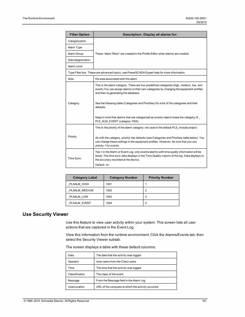
The Runtime Environment 63220-100-200I103/2015
Filter Option Description: Display all alarms for:
Categorization
These “alarm filters” are created in the Profile Editor when alarms are created.
Alarm Type
Alarm Group
Subcategorization
Alarm Level
Type Filter box: These are advanced topics; see PowerSCADAExpert help for more information.
Area the area associated with the alarm
Category
This is the alarm category. There are four predefined categories (high, medium, low, andevent).You can assign alarms to their own categories by changing the equipment profilesand then re-generating the database.
See the following table (Categories and Priorities) for a list of the categories and theirdefaults.
Keep inmind that alarms that are categorized as events need to keep the category of _PLS_ALM_EVENT (category 1004).
Priority
This is the priority of the alarm category; not used in the default PLS_Include project.
As with the category, priority has defaults (see Categories and Priorities table below). Youcan change these settings in the equipment profiles. However, be sure that you usepriority 1 for events.
Time Sync
Yes = in the Alarm or Event Log, only events/alarms with time quality information will belisted. The time sync data displays in the TimeQuality column of the log. Data displays tothe accuracy recorded at the device.
Default: no
Category Label Category Number Priority Number
_PLSALM_HIGH 1001 1
_PLSALM_MEDIUM 1002 2
_PLSALM_LOW 1003 3
_PLSALM_EVENT 1004 0
Use Security ViewerUse this feature to view user activity within your system. This screen lists all useractions that are captured in the Event Log.
View this information from the runtime environment: Click the Alarms/Events tab; thenselect the Security Viewer subtab.
The screen displays a table with these default columns:
Date The date that the activity was logged
Operator User name from the Citect users
Time The time that the activity was logged
Classification The class of the event.
Message From theMessage field in the Alarm Log
UserLocation URL of the computer at which the activity occurred
© 1990–2015 Schneider Electric All Rights Reserved 161

For more information on these fields, see Alarm SOE fields in the citectSCADA.chmhelp file (Program Files> Schneider Electric > PowerSCADA Expert > v8.0 > bin).
To change the view of the log, you can use any of the sort or filter features that areavailable in the Event Log.
There are three ways to filter information:
• To the left of the log, you can check one or more of the devices in the system. Thisfilters information to include data only for those devices. When nothing is checked,all devices are included.
• You can turn columns "on" and "off." To add columns, right click in the header areaof the log, then choose Insert Column. From the list that drops down, you can checkan additional column title. The new column displays to the left of the column youclicked.
To remove a column, right click on the header of the column you want to delete,then click Remove Column.
• You can filter that data that is included. To do this, use the Security Viewer filter. Forinstructions on filtering the columns in the log, see Security Viewer Filter on page162.
Security Viewer FilterTo filter for the information that displays in the security viewer log, click Filter (in theupper left corner of the screen). The Security View Filter screen displays. The tablebelow describes its settings.
FilterOption Description: Display all alarms for:
Basic Filter box:
StartDate/EndDate
Choosing only a start date displays alarms from that date to the current date.Choosing only an end date displays alarms for the past year up to that date.For example, to display alarms only for today’s date, enter only a start date.
StartTime/EndTime
Choosing only a beginning time displays alarms from that time through the end of the day(23:59:59 or 11:59:59 p.m.).Choosing only an ending time from the start of the day (00:00:00 or 12:00:00 a.m.) through thetime selected.
ClusterThis is a single cluster, which was added when setting up the project (listed in Project Editor >Servers >Clusters)
AreaArea (Between 0 and 255). SeeAlarm SOE fields in the citectSCADA.chm help file (ProgramFiles>Schneider Electric >PowerSCADA Expert > v8.0 > bin).
ClassificationThe class of the event. SeeAlarm SOE fields in the citectSCADA.chm help file (ProgramFiles>Schneider Electric >PowerSCADA Expert > v8.0 > bin).
Operator The user ID of the person who has logged on PowerSCADAExpert.
Message This comes from theMessage field in the Alarm Log.
Custom Filter
There are eight custom filters, which can be assigned by the customer in each alarm. A group ofalarms in a specific location could have the same name in CUSTOM8 so that custom filteringcan be easily applied.
Custom8 has a default assignment of “Equipment.” To change custom filter assignments, usethe AlarmFormat parameter (Project Editor >System >Parameters). This is the only meansavailable for filtering on a custom field. When viewing the log, you can use the new custom filterby typing it into the Custom Filter field.
162 © 1990–2015 Schneider Electric All Rights Reserved
63220-100-200I1 The Runtime Environment03/2015
The Runtime Environment 63220-100-200I103/2015
Use the Analysis PageThe Analysis Page offers two options for viewing data trends. In either option, you mustselect the tag(s) that are to be included. To be available for viewing in trends, a tagmust be included in a device profile, and it must have the “Trend Tag” box checked(see for more information).
Trend data is automatically logged when you check “Trend Tag” for tag and then add itto the project. If too many tags are chosen as trend tags, it could cause the hard drive tofill up.
NOTE: The maximum number of tags (pens) that will display correctly on the screen isten. If you exceed ten pens, labels for these pens will not display correctly. Use one ofthese methods to correct this issue:
1. Enlarge the window to accommodate the extra pens/labels.2. Write custom code to cause the labels to always be in the same position,
overlapping each other when the trend pen is created. The user can then move thelabel around for better viewing.
3. As with option number two, control the label positions with code; but then, move thelabels back to that same spot when a user selects the trend pen again.
There are two methods of calculating disk space usage: scaled and floating point. Formore information on these calculations, see Calculating Disk Storage in thecitectSCADA.chm help file (Program Files> Schneider Electric > PowerSCADA Expert> v8.0 > bin).
• Trending: Use this option to view historical trends. To select tags, click the Add Penbutton on the toolbar:
Then associate the pen with a tag. By default, most trend data is polled every 15minutes, and it is stored for one year (Citect Project Editor > Tags > Trend Tags) oruntil it is FIFO’d out. Some tags are polled every 5 seconds and are stored for twoweeks. These tags are:
Current ACurrent BCurrent CApparent Power TotalReactive Power TotalReal Power TotalVoltage A-BVoltage B-CVoltage C-AFrequencyPower Factor Total
• Instant Trend: Use this option to view real-time trends. This allows viewing of datathat is not set up for storage. To select tags for this trend, click the Instant TrendSelector on the toolbar:
NOTE: If one of the pens returns a value of "1.#R,' the tag selected was not valid; nonumber could be reported for it. None of the values for any of the pens in the trendwill be updated. To solve this issue, close the trend and open it again. This time, donot include the pen that gave the invalid return.
© 1990–2015 Schneider Electric All Rights Reserved 163
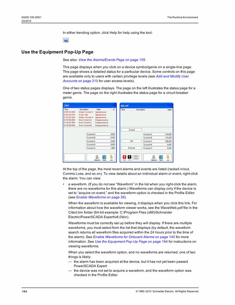
In either trending option, click Help for help using the tool:
Use the Equipment Pop-Up PageSee also: View the Alarms/Events Page on page 155
This page displays when you click on a device symbol/genie on a single-line page.This page shows a detailed status for a particular device. Some controls on this pageare available only to users with certain privilege levels (see Add and Modify UserAccounts on page 210 for user access levels).
One of two status pages displays. The page on the left illustrates the status page for ameter genie. The page on the right illustrates the status page for a circuit breakergenie.
At the top of the page, the most recent alarms and events are listed (racked in/out,Comms Loss, and so on). To view details about an individual alarm or event, right-clickthe alarm. You can view:
• a waveform. (If you do not see “Waveform” in the list when you right-click the alarm,there are no waveforms for this alarm.) Waveforms can display only if the device isset to “acquire on event,” and the waveform option is checked in the Profile Editor(see Enable Waveforms on page 39).
When the waveform is available for viewing, it displays when you click this link. Forinformation about how the waveform viewer works, see the WaveWeb.pdf file in theCitect bin folder (64-bit example: C:\Program Files (x86)\SchneiderElectric\PowerSCADA Expert\v8.0\bin).
Waveforms must be correctly set up before they will display. If there are multiplewaveforms, you must select from the list that displays (by default, the waveformsearch returns all waveform files acquired within the 24 hours prior to the time ofthe alarm). See Enable Waveforms for Onboard Alarms on page 140 for moreinformation. See Use the Equipment Pop-Up Page on page 164 for instructions onviewing waveforms.
When you select the waveform option, and no waveforms are returned, one of twothings is likely:— the alarm has been acquired at the device, but it has not yet been passed
PowerSCADA Expert— the device was not set to acquire a waveform, and the waveform option was
checked in the Profile Editor
164 © 1990–2015 Schneider Electric All Rights Reserved
63220-100-200I1 The Runtime Environment03/2015

The Runtime Environment 63220-100-200I103/2015
• details about the device (currents, voltages, powers, resets, others.),• Finally, you can acknowledge or disable the alarm. Acknowledged and disabled
alarms are moved to their own sub-tabs.
On the left side of the of the status page, status messages display, based on the tagsdefined for equipment referenced in this genie. The list varies, depending on thedevice. Possible tags are:
XCBR1\Pos Position (circuit breakers only)XCBR1\CCBRkdPos Racked Out (circuit breakers only)XCBR1\CBRkdPos Matching Fault/Trip Circuit Supervision (circuit breakers only)XCBR1\Loc Local/Remote (circuit breakers only)XCBR1\ESwPos Earth Switch (circuit breakers only)PTRC1\Op TrippedLPHD1\EEHealth Communication Failure
NOTE: For MicroLogic Type P devices, circuit breaker status fields will display #COM ifthe device does not have a CCM. Thus, you should not add any tags that refer to theCCM, such as Racked In/Racked Out.
On the right side of the page, real-time values will display for the tag type that youchose in the Value field when you added the genie in the design-time mode. Forexample, if you enter MMXU1\A\phsA as the value, you will see real-time currents here,as illustrated above. If you did not enter anything in the Value field when adding thegenie, this area will be blank.
At the bottom left corner of the circuit breaker status page, Open, Close, Reset (forcircuit breakers).
At the bottom right corner, are the Setpoints, Trend, and List options. See the followingsections for descriptions.
Perform IEC61850 Advanced Control
To begin using the advanced control feature, click Check in the lower left section of thewindow. See Set Up IEC 61850 Advanced Control on page 117 for information onsetup. See Perform IEC 61850 Advanced Control on page 167 for information onperforming this advanced control.
View Waveforms
After you select a waveform for viewing from the genie status page, the externalwaveform viewer displays it. For instructions on using the tool's analysis feature, seeWaveWeb.PDF, located in the Bin folder of the PowerSCADA Expert 8.0 Bin folder(example: C:\Program Files (x86)\Schneider Electric\PowerSCADA Expert 8.0\Bin.
Enter Setpoints for Alarms
NOTE: Any time you change setpoints, you should immediately restart the project.Otherwise, setpoints will not be properly read (they will be truncated and eitherrounded down or up to a whole integer).
To add setpoints for alarms, follow these steps:
1. View the page, then click the genie for which you want to enter setpoints. A statuswindow displays with the name of the genie.
2. Click Setpoints, then choose Analog, Digital, or All. When the Alarm Setpointsscreen displays, select the first value you want to change. At the “keypad” screen
© 1990–2015 Schneider Electric All Rights Reserved 165

(see below), enter the new value. Click OK to save it. Do this for each setpoint thatyou want to change.
Based on these setpoints, alarms can begin to display both in the alarms window at thetop of the runtime screen and on the Alarms/Events tab (assuming you have set one upfor this installation).
When there is a comms loss for a device: the last state before the loss happened isdisplayed on the screen.
The indication of loss of communications does not filter through the entire busanimation: the downstream part of the drawing may still appear as ifcommunication is working. When any part of a one-line drawing losescommunication, do not continue to trust downstream readings until you addressthe loss of communication.
View Real-Time Trends
This option displays an historical trend. The data that displays is determined by thevalue that was selected in the Value Type field when this genie was added to the one-line page.
To view a trend: From the one-line page in the runtime environment, click a genie toview its status window. Click Trend, in the lower right corner. The Analyst screendisplays for that trend.
You can select the timeframe for the trend. You can also uncheck phases to removethem from the trend, or highlight a phase to bring it to the front of the trend. For detailedinformation about the buttons on the screen, click “?” at the top of the page.
View Lists of Real-Time Information for the Genie
To view lists of real-time currents, voltages; powers; resets and controls; andmiscellaneous readings, click List, in the lower right corner, then click an item from thelist: Currents, Voltages, Powers, Resets, or Others.
For resets and controls, which are interactive, you should assign users a high level ofsecurity. For a list of the default user levels, see Add and Modify User Accounts onpage 210. That link also includes information on creating unique users.
When you click an item from the list, individual tag readings display for that tag type(depending on the tags that you have chosen for this device type). When you click anyitem in that list, the tag pop-up menu displays with these options: Trend, Override Tag,Control Inhibit Tag, and Tag Status. See Override Tag Status, below, for details.
Override Tag Status
From the list, you can right-click individual tags and override status settings. To accessthis feature, the user account must be at least level 4.
Trend: This link allows you to view a trend for the tag that you clicked.
166 © 1990–2015 Schneider Electric All Rights Reserved
63220-100-200I1 The Runtime Environment03/2015

The Runtime Environment 63220-100-200I103/2015
Override Tag: You can use this feature to override a real-time value that is incorrect, orto test graphics. Enter the value that you want the system to "read" for this tag in theOverride Value line. When you click Apply, the tag is highlighted. When you havefinished the test, return to this list to remove the override.
Control Inhibit Tag: When this feature is ON, you will not be able to process writes forthis tag. To enable this inhibit, click Apply for this tag from the list. The tag reading ishighlighted. To disable this feature, return to the list view of this tag; click Remove.
You can perform control inhibit on an entire device. To do this, you will use theIODeviceControl Cicode function. For more information, see the I/O DeviceProperties topic in the citectSCADA.chm help file (Program Files> Schneider Electric> PowerSCADA Expert > v8.0 > bin).
Tag Status: This screen views the status of the display value, override status, controlinhibit status, and field value. You can also change the override status and controlinhibit status on this screen.
Changing background colours: Default colors are assigned for the tag override andcontrol inhibit. Change the default background colors in the parameters, not in the inifile.
To change the color for tag overrides, use OverrideTextBackgroundColor. To changethe color for control inhibits, use ControlInhibitTextBackgroundColor. For detailed help,see Page Parameters in the Parameters.chm help file (Start > Programs > SchneiderElectric > PowerSCADA Expert 8.0 > PowerSCADA Expert Web-based Help).
Perform IEC 61850 Advanced ControlThe advanced control window provides these options for IEC 61850 IEDs:
• run synchro check on the selected equipment• run interlock check on the selected equipment• send a command to open or close the equipment
You can either check the features without sending an open/close command, or you cansend an open/close command without running the checks..
Only users who have privilege level of Engineer or Admin can perform these checks oroperate the equipment.
WARNING
UNINTENDED EQUIPMENT OPERATION
• Do not incorrectly configure the tag, as this can lead to unexpected equipmentoperation.
• Ensure that you understand the effects of using the "bypass" option so you donot shut down critical equipment.
• Also consider the possibility of communications loss that could yield false read-ings.
• Ensure that all safety regulations and procedures have been followed beforeyou work on the equipment.
Failure to follow these instructions can result in death or serious injury.
NOTE: For information on enabling this feature, see Set Up IEC 61850 AdvancedControl on page 117
© 1990–2015 Schneider Electric All Rights Reserved 167

To access the advanced control window, open the equipment genie pop-up page onthe one-line. Note that, after you enable this feature, there is a "Check" button on thelower left:
Click Check, and the advanced control window opens:
Synchro Check: Use synchro check to verify that the waveforms for the equipment'spower factor, voltage, and current are all aligned.
On the Synchro Check line, click Check to perform the synchro check, or click Bypassto ignore the synchro check. Default: Check.
Interlock Check: Use interlock to verify that there are no blocking conditions thatneed to be considered before switches are opened or closed.
On the Interlock Check line, click Check to perform the interlock check option, or clickBypass to ignore the interlock check. Default: Check.
168 © 1990–2015 Schneider Electric All Rights Reserved
63220-100-200I1 The Runtime Environment03/2015

The Runtime Environment 63220-100-200I103/2015
Test: Click Operate if you want to send the command to the equipment and tocomplete the "value" setting. Click Test if you want to send the command to theequipment, and to verify the synchro and/or interlock statuses, but not complete the"value" setting. Default: Operate.
NOTE: If you choose "Check" for the synchro and/or interlock checks and "Operate" forthe Test line, the open/close operation will not occur if the equipment fails the checks.
Value: Choose the command that you want to send to the equipment: open or close.Default: Closed if the breaker is open; otherwise, Open.
Send: Click to send the command to the device to perform the action(s) that youselected.
EcoStruxure WebServices (EWS)EcoStruxure Web Services (EWS) for PowerSCADA Expert was developed to sharereal-time, historical, and alarm data with StruxureWare Building Operations (SBO) andhistorical data with Power Monitoring Expert (PME). Do not confuse this feature withthe EWS server that was released as a part of PowerSCADA Expert/Vijeo Citectversion 7.40 (which is for tag level process data).
EWS uses web-based http protocol to transfer data. It enables two-way data transfers,which allows the acknowledgment of alarms from SBO. To include this new EWSimplementation in your installation, select the EWS Server checkbox duringinstallation.
EWS is set up and configured using the Application Configuration Utility (Start > AllPrograms > Schneider Electric > PowerSCADA Expert 8.0 > Config Tools > ApplicationConfig Utility. For details, see EcoStruxure Web Services Setup on page 204 .
Use Basic ReportsThe reporting feature is an IIS web application that is typically hosted on the sameserver as the PowerSCADA services. The PLS_Inlude project defines a PLS_ReportPage (along with its screen resolution-specific variant pages). PLS_ReportPagecontains a Microsoft Web Browser ActiveX control in which the reporting web pagesare displayed.
Before you can set up Basic Reports and generate/view reports, you must set up dataacquisition parameters. To do this, use the Application Configuration Utility. SeeApplication Services Host—Citect Data Platform on page 205 and (for receiving reportsvia email) Basic Reports on page 207 for instructions.
In System > Menu Configuration, menu tabs are configured to use the new "PLS_ReportDsp()" Cicode function to send URLs to the web browser control at runtime. Thecontrol then browses to the available reporting web pages. See the PLS_Exampleproject for examples of this functionality.
When switching between PowerSCADA Expert projects in runtime, you must restart theSchneider Electric Service Host (CoreServiceHost) service before you run thereporting application. This allows the reporting application to load data from thecurrently running PowerSCADA Expert project.
To get started setting up a report, see Set up the Runtime Environment for BasicReports on page 170.
For descriptions of each report type, see PowerSCADA Expert Basic Reports on page178.
© 1990–2015 Schneider Electric All Rights Reserved 169
NOTE: If you install Matrikon Explorer on the same computer as PowerSCADA Expert8.0, the LiveView and reporting features will not launch. To prevent this, installMatrikon before you install PowerSCADA Expert 8.0. If you install Matrikon after youinstall PowerSCADA Expert 8.0, you need fix the issue in this way: Go to IIS > ISAPIFilters, and then reset the dll that is already selected (click browse and re-selectv4.0.30319 aspnet_filter.dll). Click OK.).
Set up the Runtime Environment for Basic ReportsFollow these steps to add new items to the project, add the necessary INI parametersfor CtAPI and basic report security, and create the CtAPI connection for reporting.
Create the Menu Items for Report Page
For a complete discussion of reporting web application URLs, see Create and ViewBasic Reports on page 171.
The following steps describe how to interact with the reporting web application via theruntime environment.
1. From Citect Project Editor, click System > Menu Configuration.2. Add the new menu item that you want for each of your basic reports.
3. In each of these menu items, in the Menu Command line, add the Cicode methodthat will display a report tab. You can create your own custom method or use thedefault:PLS_ReportDsp(STRING sIPAddress, STRING sName, STRING sOptions = "", STRING
sTitle="")
Examples:PLS_ReportDsp(“10.10.10.10", "SingleDeviceReport”,
"ShowConfiguration/MyConfiguration", “Single Device Usage Report”);
which opens a configured single device report with the saved configuration name"MyConfiguration"
orPLS_ReportDsp(“10.10.10.10", "SingleDeviceReport”, "", “Single Device Usage
Report”);
which opens an unconfigured single device usage report at the parameters entrypage
Add the Following INI Parameters
To allow trend queries that yield the desired amount of historical data:
[Trend]MaxRequestLength =100000000,allowable range: 1–100000000(example: a value of 70080 would yield two years of data for one device/one topic,assuming 15-minute trends)
To allow CtAPI to connect remotely:
[CtAPI]Remote = 1
To define a privilege level for users to view reports:
[Reporting]PrivLevel - Default = 0
To define an area for users to view reports:
[Reporting]Area - Default = 0
170 © 1990–2015 Schneider Electric All Rights Reserved
63220-100-200I1 The Runtime Environment03/2015

The Runtime Environment 63220-100-200I103/2015
Set Up a Display Client for Basic Report ViewingTo be able to properly interact with the basic reporting web application at a displayclient, you must set a registry key to force the Microsoft Web Browser ActiveX control touse Internet Explorer 9 emulation.
Create the following DWORD value at the following registry key path:
Path: HKEY_LOCAL_MACHINE\SOFTWARE\Wow6432Node\Microsoft\InternetExplorer\MAIN\FeatureControl\FEATURE_BROWSER_EMULATION
Value Name: Citect32.exe
Value: 9999 (decimal)
NOTE: This registry setting affects the Citect32.exe process only. It has no effect onother applications that use the MS Web Browser ActiveX control.
Tasks in the Basic Reporting ApplicationYou can use the following tasks within the reporting application to create, view, andemail basic reports:
Perform IEC 61850 Advanced Control on page 167
Create and View Basic Reports on page 171
Configure Email Settings to Send Basic Reports on page 173
Send Basic Reports via Email on page 174
Read, Export, Print, and Edit Basic Reports on page 176
Create and View Basic Reports
This section explains how you can create basic reports and save report configurationsusing a web browser (e.g., Internet Explorer).
For instructions on interacting with the reporting web application via the runtimeenvironment, see Set up the Runtime Environment for Basic Reports on page 170.
You can generate basic reports in two ways:
• run a new report by entering parameters• run a report from a saved configuration
Run a New Basic Report
There are two options for this:
1. Browse directly to the URL of the report. Use this format:
http://<ServerName>/Reporting/Report/<ReportName>
where:
<ServerName> = the name or IP of the reporting server
<ReportName> = the name of the report you wish to view
Standard report names are:— MultiDeviceReport— SingleDeviceReport— TabularReport— TrendReport
© 1990–2015 Schneider Electric All Rights Reserved 171

2. Browse to the default reporting URL, and click the report you want to view.
An example of this format is:
http://<ServerName>/Reporting/
where:
<ServerName> = the name or IP of the reporting server
Additional formats are required, depending on the operating systems. For moreinformation, see URL Routing for Basic Reports on page 182.
Run a Basic Report and Save its Configuration
NOTE: If you plan to view a basic report using Rapid Access Labels on page 200, youmust save a configuration. After it is saved and you generate a rapid access label, donot change the configuration name. If the configuration name is changed, you mustgenerate a new rapid access label.
To create and save a basic report configuration so you can view it later:
1. Visit the "build configuration" URL of the report you wish to use. Use this format:
http://<ServerName>/Reporting/Report/<ReportName>/BuildConfiguration
where:
<ServerName> = the name or IP of the reporting server
<ReportName> = the name of the report you wish to view
2. Enter the report query parameters.NOTE: If you enter a fixed date range, all reports that you generate with thisconfiguration will use that date range. The best practice is to use one of the relativedate ranges, such as "last month."
3. After the report displays, scroll to the bottom of the page. You should see a text boxwith XML. This XML represents your saved report configuration. Copy the entirecontents of the text box into the text editor of your choice.
4. Save this new file to the Reporting\ReportConfigurations\ directory, located on theapplication root install directory (which is also the physical directory behind thereporting web application's virtual path in IIS).
Example (64 bit):C:\Program Files (x86)\Schneider Electric\PowerSCADA Expert\PowerSCADAExpert Reporting\Reporting\ReportConfigurations\
The filenamemust be in the following format:<ReportName>_<ConfigurationName>.cfg
where:
<ReportName> = the name of the report (such as MultiDeviceReport,SingleDeviceReport)
<ConfigurationName> = a name for this configuration (alphanumeric only)
If you use Notepad, ensure that you apply the correct suffix (.cfg) and not the default(.txt).
View a Basic Report Using a Saved Configuration
To view a basic report with a saved configuration, browse to the URL of the report andspecify the configuration. This method runs the report directly with the savedconfiguration (you cannot change the parameters).
172 © 1990–2015 Schneider Electric All Rights Reserved
63220-100-200I1 The Runtime Environment03/2015

The Runtime Environment 63220-100-200I103/2015
This URL is in the following format:
http://<ServerName>/Reporting/Report/<ReportName>/<ReportConfiguration>
where:
<ServerName> = the name or IP of the reporting server
<ReportName> = the name of the report you wish to view
<ReportConfiguration> = the name of the saved configuration to use
Modify and View a Basic Report Using a Saved Configuration
Use this procedure to modify a configuration that you saved according to "Run a BasicReport and Save its Configuration," above.
Browse to the "show configuration" URL for the report that you want to modify. Use thisformat:
http://<ServerName>/Reporting/Report/<ReportName>/<ReportConfiguration>/ShowConfiguration
where:
<ServerName> = the name or IP of the reporting server
<ReportName> = the name of the report you want to view/modify
<ReportConfiguration> = the name of the saved configuration to use
Run the report as you normally would, editing selections on the parameter entry pageas necessary.
After the report runs, a text box displays at the bottom of the finished report. It containsthe new XML of your saved configuration.
Copy and paste this new XML into your saved configuration file (overwriting the oldXML).
Remove a Saved Configuration
To remove a saved configuration, delete the saved configuration file fromReporting\ReportConfigurations\ directory, described above:
Example (64 bit):C:\Program Files (x86)\Schneider Electric\PowerSCADAExpert\v8.0\Applications\Reporting\ReportConfigurations
Configure Email Settings to Send Basic Reports
Follow these steps to configure email settings so that you can send PowerSCADAExpert basic reports to multiple email addresses.
NOTE: You must configure the SMTP server and email list(s) before you email reports.See Send Basic Reports via Email on page 174 for instructions on sending theseemails.
SMTP Server and From Address
For instructions on setting up the SMTP server, see Basic Reports on page 207.
Email Lists
© 1990–2015 Schneider Electric All Rights Reserved 173

Before you can send email via the URL or ReportMailer method, you must create atleast one email list:
1. Open your preferred text editor; enter one or more email addresses (one per line,no commas).
2. Save this text file in the Reporting\ReportConfigurations\ directory, located on theapplication root install directory (which is also the physical directory behind thereporting web application's virtual path in IIS).
Example (64 bit):C:\Program Files (x86)\Schneider Electric\PowerSCADA Expert\PowerSCADAExpert Reporting\Reporting/ReportConfigurations\
The filename must be in the following format:
Email_<EmailListName>.cfg
where:
<EmailListName> = an alphanumeric (no spaces) name for the email list (forexample, Administration)
Email Body
The email body that you send is contained in a resource (.resx) file in theReporting\bin\Resources\Reporting.en-US.resx\ directory, located on the applicationroot install directory (which is also the physical directory behind the reporting webapplication's virtual path in IIS).
Example (64 bit):C:\Program Files (x86)\Schneider Electric\PowerSCADA Expert\PowerSCADAExpert Reporting\bin\Resources\Reporting.en-US.resx\
The email body is the same for all Report Configurations and Email Lists, but you canmodify the entry for ReportEmailBody to change the body of the email that is sent.
Send Basic Reports via Email
Before you can send PowerSCADA Expert basic reports via email, you must configurethe SMTP server and email list(s) before you email reports. See Configure EmailSettings to Send Basic Reports on page 173 for instructions on configuring thisinformation.
There are three ways to send basic reports via email:
1. The Report Viewer email button
Use this method to send a customized one-time email to an individual or group ofemail addresses.
1. Run the report as normal.
2. Click the Email icon ( ) in the report viewer.
3. Enter the requested information in the pop-up dialog.
4. Click Send.
2. Visit a Specific URL
NOTE: Each visit to a URL causes the email to be sent. Be sure that you have thecorrect report and email list before you visit this URL/send the email. Also, you shouldsecure this URL using the web.config file. For information on modifying/using theweb.config file, see http://support.microsoft.com, and search on kb 815179.
174 © 1990–2015 Schneider Electric All Rights Reserved
63220-100-200I1 The Runtime Environment03/2015

The Runtime Environment 63220-100-200I103/2015
To send a basic report to an existing email list, visit the following URL:
http://<ServerName>/Reporting/Report/<ReportName>/<ReportConfiguration>/Email/<EmailList>
where:
<ServerName> = the name or IP of the reporting server
<ReportName> = the name of the report you wish to view
<ReportConfiguration> = the name of the saved configuration to use
<EmailList> = the name of the email list you wish to use
You must use a saved configuration (see Create and View Basic Reports on page171 for instructions). You cannot change report parameters from this URL.
No progress bar or update will display, as these interfere with some schedulingclients.
3. Use Cicode via ReportMailer
You can use a utility called ReportMailer to email basic reports. This command lineutility is located in the PLS_Include project. It can be called by Cicode. You can createa button on the graphics page and have it call the Cicode function or use a scheduledprocess to trigger an email.
Before you can use ReportMailer, you need to create or edit the file calledReportMailer.ini file that is in your project (not in PLS_Include). The ReportMailer.inifile must include the text listed in the table below:
Text Field Required Setting Description
LoginUsername demoUsername for logging in to reporting system for emailingreports
LoginPassword demo User's password, will be encrypted on the first run
IsEncrypted False
Flag that indicates if the password is encrypted. If youchange the password, edit the field (replacing the unreadableencrypted entry, if one exists). Then change this value toFalse. The new password will be encrypted at the nextstartup cycle, and this field will be updated to True.
ScadaBinPath
C:\Program Files (x86)\SchneiderElectric\PowerSCADAExpert 8.0\Bin
The bin path of PowerSCADAExpert
LogOnUrlhttp://SCADASERVER/Reporting/LogOn.aspx
The URL of the logon page(this is an example; use your ownserver name)
ReportServerName SCADASERVERThe name or IP address of the server running the reportingapplication
LogLevel All
The level of logging you want in the report mailer application.This log is saved to a ReportMailerLog.txt file in the runningproject's directory. Possible settings are ALL, DEBUG,ERROR,WARN.
After this file is configured, run the ReportMailer.exe with the following syntax:
ReportMailer.exe <ReportName> <ReportConfiguration> <EmailList><ScadaProjectPath>
where:
© 1990–2015 Schneider Electric All Rights Reserved 175

<ReportName> = the name of the report you wish to view
<ReportConfiguration> = the name of the saved configuration to use
<EmailList> = the name of the email list you wish to use
<ScadaProjectPath> = the full path to your SCADA project
This command line application may be called from Cicode following the belowexample:
FUNCTION
PLS_EmailReport()ErrSet(1);STRING FilePath = ParameterGet("CtEdit","User","") + "\PLS_Include\ReportMailer.exe " +
"MultiDeviceReport SampleConfiguration SampleList " +"^"C:\ProgramData\Schneider Electric\PowerSCADA Expert8.0\User\PLS_Example^"";Exec(FilePath);
END
NOTES— The SCADA project path must be enclosed in escaped quotes (^").— This is an asynchronous (non-blocking) call. While the EXEC() method will
return immediately, it may take a few moments to run and email the report. Seethe web.config timeout value (see option 2 above) for more information.
— You can also call the ReportMailer application directly from a command line. Inthis case, you can add the term "blocking" to the command line (as a fifthparameter). This causes ReportMailer to act in a synchronous state (block thecall) and to return any error messages to the console. Never use the "blocking"parameter by Cicode, as it could prevent EXEC() from returning in a timelyfashion.
Scheduling Basic Reports
You can schedule the emailing of basic reports by executing the above Cicode as anaction from a timed event. For more information, see Configuring Events in theCitectSCADA.chm help file (Program Files> Schneider Electric > PowerSCADA Expert> v8.0 > bin).
You can also use the Windows Task Scheduler to send these reports. Refer toMicrosoft's documentation on the task scheduler at: http://windows.microsoft.com/en-US/windows7/schedule-a-task.
Read, Export, Print, and Edit Basic Reports
After you create a basic report, you can:
• change its appearance (Page Setup)• print it• change its view: HTML or PDF• scroll to the beginning, previous page, next page, or last page• export it to a variety of formats• email it
The toolbar options table below describes these options.
176 © 1990–2015 Schneider Electric All Rights Reserved
63220-100-200I1 The Runtime Environment03/2015

The Runtime Environment 63220-100-200I103/2015
Toolbar Options
The report toolbar includes several options:
Option Description
Parameters/ReportToggle between viewing the parameters (setup)page and the report.
Parent/Child reports Not currently used.
Hide/Show Not currently used.
Page SetupClick this link to open the Page setup window,where you can determine paper size, and pageorientation andmargins.
PrintClick this link to print the report.
NOTE: For best formatting of the report, youshould export to PDF, and then print.
Print PreviewIn HTMLmode, click this link to view the printoutput.
Viewer ModeYou can view in HTML or PDF mode. Select themode, then click Viewer Mode to change theview.
Viewer Mode Set ( )Click to confirm the choice of viewer mode.
Pagination Click the left and right arrows to page backwardand forward in the report. Or type the pagenumber you want to see.
Select a formatFor exporting, choose the format (not HTML)that you want.
Export ( ) See instructions below for exporting a report.
Email ( )
Click this link, and then enter the requestedinformation. Click Send.
For other ways to email reports, seeSend BasicReports via Email on page 174.
Export a Basic Report
Before you can print a basic report, you must export it into a format that can be printed.
You can export to:• Acrobat (Pdf) File• Web Archive• Word Document• Xml File• XLS Document
To export:
1. While viewing the report, select a format, then click Export ( ).
2. Type the location at which you want to save the file.
3. Set any other properties you wish.
© 1990–2015 Schneider Electric All Rights Reserved 177

4. Click Export.
Edit the Basic Report Appearance
With the report displayed, you can:
• Change the paper size• Change the paper source• Change the page orientation• Change the page margins• Change the number of pages per sheet• Add a watermark
PowerSCADA Expert Basic ReportsDuring runtime, you can create, view, save, and print basic reports.
Before you can view basic reports, there must be data logged for the project. See Usethe Analysis Page on page 163 for help.
You must also create a report tab for the graphics page in runtime mode. See Set upthe Runtime Environment for Basic Reports on page 170.
NOTE: If the Schneider Electric CoreServiceHost has not been refreshed after devicesor topics have been added, you should clear the cache and refresh the platform inorder to access the new devices or topics.
See Clear Cache and Refresh Platform on page 145 for instructions.
After you have logged trend information, you can create and view basic reports. Fromthe graphics page in the runtime environment, click the reports tab and choose thebasic report type you want to create:
Single Device Usage Reports on page 178
Multi Device Usage Reports on page 179
Tabular Reports on page 180
Trend Reports on page 180
Rapid Access Labels on page 200
See also:
Localization for Basic Reports on page 182
Single Device Usage Reports
Use single device usage reports to display historical energy data from a single deviceand multiple topics. A single device report includes only usage and consumptiontopics.
NOTE: The report is optimized for up to five topics. If you choose too many topics, thechart legend can become unreadable.
Before you can create and view a report, you must set up reporting in the runtimeenvironment. See Set up the Runtime Environment for Basic Reports.
To set up a single device usage report, follow these steps:
1. Browse to the single device report in the reporting web application. Whenprompted, enter your Citect user account information. Click Login.
2. At the next screen:
178 © 1990–2015 Schneider Electric All Rights Reserved
63220-100-200I1 The Runtime Environment03/2015

The Runtime Environment 63220-100-200I103/2015
— Type a report title.— In Reporting Period, choose the date range for this report, for example, last
week.If you choose Custom..., the Start Date/Time and End Date/Time fields display.Enter the date and hour:minutes:AM/PM. (The date/time fields do not apply forthe other reporting periods.)
— From the Period Grouping dropdown box, choose the interval by which youwant to see the data reported. (The options here vary, depending on the daterange selected.)
— Highlight the name of the device that you want for the report.— Check the topics to be included.
3. Click Generate Report.
After the report is generated, it displays on the screen. It includes a usage summarytable, and a graph and table for each topic you selected. You will probably have topage forward in the report to see all of the information.
For information about reading, exporting, printing, or editing reports, see Read, Export,Print, and Edit Basic Reports.
Multi Device Usage Reports
Use multi device usage reports to display historical energy data for multiple devicesand one topic. A multi device usage report includes only usage and consumptiontopics.
NOTE: If you choose too many devices, the chart legend can become unreadable.
Before you can create and view a report, you must set up reporting in the runtimeenvironment. See Set up the Runtime Environment for Basic Reports.
To set up a multi device usage report, follow these steps:
1. Browse to the multi device usage report in the reporting web application. Whenprompted, enter your Citect user account information. Click Login.
2. At the next screen, do the following:— Type a report title.— In Reporting Period, choose the date range for this report, for example, last
week.If you choose Custom..., the Start Date/Time and End Date/Time fields display.Enter the date and hour:minutes:AM/PM. (The date/time fields do not apply forthe other reporting periods.)
— From the Period Grouping dropdown box, choose the interval by which youwant to see the data reported. (The options here vary, depending on the daterange selected.)
— Check the names of the devices for the report.— Highlight the topic to be included.
3. Click Generate Report.
After the report is generated, it displays on the screen. It includes a usage summary, avalue table by interval for all of the devices selected, and a pie chart. You will probablyhave to page forward in the report to see all of the information.
For information about reading, exporting, printing, or editing reports, see Read, Export,Print, and Edit Basic Reports.
© 1990–2015 Schneider Electric All Rights Reserved 179

Tabular Reports
Use tabular reports to display a system's historical data in a table format. Tabularreports can include one or more devices and one or more topics. A tabular report caninclude all available topics.
NOTE: The report is optimized for up to five topics. If you choose too many devices ortopics, the chart legend can become unreadable.
Before you can create and view a report, you must set up reporting in the runtimeenvironment. See Set up the Runtime Environment for Basic Reports.
To set up a tabular report, follow these steps:
1. Browse to the tabular report in the reporting web application. When prompted, enteryour Citect user account information. Click Login.
2. At the next screen, do the following:— Type a report title.— In Reporting Period, choose the date range for this report, for example, last
week.If you choose Custom..., the Start Date/Time and End Date/Time fields display.Enter the date and hour:minutes:AM/PM. (The date/time fields do not apply forthe other reporting periods.)
— From the Period Grouping dropdown box, choose the interval by which youwant to see the data reported. (The options here vary, depending on the daterange selected.)If you leave the default By Interval, you will get every data point in the selecteddate range.
— Check the name(s) of the device(s) for the report.— Check the topic(s) to be included.
3. Click Generate Report.
After the report is generated, it displays as a table on the screen. It lists data for all ofthe tags according to their timestamps. You will probably have to page forward in thereport to see all of the information.
For information about reading, exporting, printing, or editing reports, see Read, Export,Print, and Edit Basic Reports.
Trend Reports
Use trend reports to display a system's historical data in a trend (line) and tableformats. Trend reports can include one or more devices and one or more topics. Atrend report can include all available topics.
NOTE: The report is optimized for up to five topics. If you choose too many devices ortopics, the chart legend can become unreadable.
Before you can create and view a report, you must set up reporting in the runtimeenvironment. See Set up the Runtime Environment for Basic Reports.
To set up a trend report, follow these steps:
1. Browse to the trend report in the reporting web application. When prompted, enteryour Citect user account information. Click Login.
2. At the next screen, do the following:— Type a report title.— In Reporting Period, choose the date range for this report, for example, last
week.
180 © 1990–2015 Schneider Electric All Rights Reserved
63220-100-200I1 The Runtime Environment03/2015
The Runtime Environment 63220-100-200I103/2015
If you choose Custom..., the Start Date/Time and End Date/Time fields display.Enter the date and hour:minutes:AM/PM. (The date/time fields do not apply forthe other reporting periods.)
— From the Period Grouping dropdown box, choose the interval by which youwant to see the data reported. (The options here vary, depending on the daterange selected.)If you leave the default By Interval, you will get every data point in the selecteddate range.
— Click the name(s) of the device(s) for the report.— Click the topic(s) to be included.
3. Click Generate Report.
After the report is generated, it displays on the screen. It includes a trend for each topicincluded (selected data points over the period of the trend) followed by a table withevery timestamp in the period selected. You will probably have to page forward in thereport to see all of the information.
For information about reading, exporting, printing, or editing reports, see Read, Export,Print, and Edit Basic Reports.
Enable Windows Authentication for Basic ReportingYou may want to use Windows Authentication for logging in to the Basic Reportsapplication. This could be to authenticate from Active Directory or to provide a single-sign-on. Follow the steps below to configure Windows Authentication.
NOTE: These steps are specific to Windows 7; they may be different for other operatingsystems. For further assistance, view Microsoft's documentation on this topic at:
http://technet.microsoft.com/en-us/library/cc754628(v=ws.10).aspx
1. Turn on the Windows Authentication feature:
a. From the control panel, click Programs and Features > Turn Windows featureson or off.
b. Check Windows Authentication.2. Enable Windows Authentication in IIS:
a. From the Control Panel > Administrative Tools, choose Internet InformationServices (IIS).
b. Select the root node from the tree on the left (or the Reporting website, if thisserver hosts multiple sites).
c. From the right hand pane, in the IIS section, click Authentication.d. Enable Windows Authentication.
3. Modify web.config to specify Windows Authentication:
a. From the root of the Reporting direction, locate web.config.b. Change the line:
<authentication mode="Forms">to<authentication mode="Windows">
4. Add roles to web.config:
You must add roles to web.config to allow access to the basic reporting application.For example, to allow the role (group) Administrators, add the following to theweb.config file:
<authorization>
© 1990–2015 Schneider Electric All Rights Reserved 181

<allow roles="Administrators"/><deny users="?" />
</authorization>
Modifying the web.config file is an advanced topic that is covered on the Microsoftwebsite.
See the following link for instructions provided on the Microsoft website:
http://www.iis.net/configreference/system.webserver/security/authentication/windowsauthentication
Additional information may be available in the following knowledge base article:
http://support.microsoft.com, and search on kb/815179.
URL Routing for Basic ReportsThe basic reporting application uses Asp.NET extensionless URL routing. Dependingon your operating system, you may need to follow additional steps to enableURL routing in your project.
Windows 2008 R2 and Windows 7
Microsoft has discovered an issue with extensionless URL routing in certaininstallations of IIS 7.0 and IIS 7.5. To address this issue, Microsoft has released a hotfixreferenced by KB article 980368. This hotfix is available athttp://support.microsoft.com/kb/980368.
This hotfix is included in Service Pack 1 for Windows 2008 R2 and Windows 7. Toreceive the hotfix, you should install Service Pack 1. This installation providesadditional important updates to the operating system. To obtain Service Pack 1 forWindows 2008 R2 and Windows 7, go to either Windows Update orhttp://support.microsoft.com/kb/976932.
Windows XP
When you install IIS on a Windows XP operating system, IIS version 5.1 is installed.When browsing to the default URL, you must append to the URL "default.aspx".
Example:
http://<servername>/Reporting/default.aspx
Localization for Basic ReportsTo localize basic reports, you must first rename and translate the .resx files into thetarget language(s), called "culture names." The .resx files are located in thePowerSCADA Expert Resources directory (default location: C:\Program Files (x86)\SchneiderElectric\PowerSCADA Expert\v8.0\Applications\AppServices\bin\Resources).
Make copies of the .resx files listed in the table below. Change the extensions of thecopies into the culture name for the target language. Note that you do not need toinclude both the culture ("es") and the region ("ES"), unless you specifically want alanguage that is different from the default.
For example, BinningResources.en-US.resx would be named BinningResources.es-ES.resx when you localize it into Castillian Spanish.
182 © 1990–2015 Schneider Electric All Rights Reserved
63220-100-200I1 The Runtime Environment03/2015
The Runtime Environment 63220-100-200I103/2015
For a list of the culture names you can use, see the National Language Support (NLS)API Reference, currently at:
NLS API
After you change the extensions, provide translations for the strings in each .resx file.
Store the localized .resx files in the same Resources folder as the English versions.
Template EditorUse theTemplate Editor to begin creating, duplicating, modifying, and deletingLiveView templates and views.
See Set Up LiveView on page 192 for complete instructions.
Use LiveViewPowerSCADA Expert provides the ability to create and view LiveView templates andviews. Some basic predefined templates are included with the software; you can createnew templates or make copies of the predefined templates and edit the copies.
Before you view LiveView templates and views, you must set up data acquisitionparameters. To do this, use the Application Configuration Utility. See ApplicationServices Host—Citect Data Platform on page 205 for instructions.
NOTES:• If you find that a predefined table does not include enough cells for the data you
want to display, use the duplicate feature to make a copy of the predefined table.Then add the needed cells to the duplicate.
• If you install Matrikon Explorer on the same computer as PowerSCADA Expert 8.0,the LiveView and reporting features will not launch. To prevent this, install Matrikonbefore you install PowerSCADA Expert 8.0. If you install Matrikon after you installPowerSCADA Expert 8.0, you need fix the issue in this way: Go to IIS > ISAPIFilters, and then reset the dll that is already selected (click browse and re-selectv4.0.30319 aspnet_filter.dll). Click OK.).
You can only view data in these templates if your system is online and you areconnected to devices that provide data.
To begin creating LiveView templates, click Start > Programs > Schneider Electric >PowerSCADA Expert 8.0 > Config Tools > Table Editor. The LiveView Template Editorscreen displays.
To view a template, see LiveView Viewer on page 189.
To create a new template, see Set Up LiveView on page 192.
See also:
LiveView Formulas on page 196
LiveView Placeholders on page 195.
LiveView Thresholds on page 197
LiveView Formatting on page 194
© 1990–2015 Schneider Electric All Rights Reserved 183
LiveView TablesClick any of the following links to learn about the live view tables:
LiveView Basic Readings Summary on page 184
LiveView Power Flow Summary on page 184
LiveView Energy Summary on page 185
LiveView Energy Readings on page 185
LiveView Fundamental Phasor Readings on page 185
LiveView THD Current Summary on page 185
LiveView THD Voltage Summary on page 186
LiveView Uptime Summary on page 186
LiveView Incremental Reactive Energy Summary on page 186
LiveView Incremental Real Energy Summary on page 187
LiveView Harmonic Apparent Power Flows on page 187
LiveView Harmonic Reactive Power Flows on page 188
LiveView Harmonic Real Power Flows on page 188
LiveView Demand Current Summary on page 189
Live View Demand Voltage Summary on page 189
LiveView Basic Readings Summary
This summary displays real-time basic power information for a selected device ordevices. After opening the basic readings summary template, you set the updateinterval for this summary. You can also add or remove devices from the summary.
Make your selections, and click Display Table.
The basic readings summary provides this data:
• voltage A-B (V)• current A (A)• real power (kW)• power factor
LiveView Power Flow Summary
This summary displays a power flow summary for your system devices. Use theinformation from this table to help optimize the system's power flow.
After opening the power flow summary template, you set the update interval for thissummary. You can also add or remove devices from the summary.
Make your selections, and click Display Table.
The power flow summary provides this data:
• real power (kW)• reactive power (kVAR)• apparent power (kVA)• demand average (kW)• demand peak (kW)• predicted demand (kW)
184 © 1990–2015 Schneider Electric All Rights Reserved
63220-100-200I1 The Runtime Environment03/2015

The Runtime Environment 63220-100-200I103/2015
LiveView Energy Summary
This summary displays an energy summary for your system devices. Use theinformation from this table to help monitor the system's energy consumption.
After opening the energy summary template, you set the update interval for thissummary. You can also add or remove devices from the summary.
Make your selections, and click Display Table.
The energy summary provides this data:
• real power (kW)• reactive power (kVAR)• apparent power (kVA)• block demand real power (kW)• thermal demand real power (kW)• peak block demand real power (kW)• peak thermal demand real power (kW)• block demand real power predicted (kW)• thermal demand real power predicted (kW)
LiveView Energy Readings
This table displays accumulated energy readings for a single device. Data isaccumulated beginning with the last energy reset for the device.
Energy values, will be according to one of these accumulation methods:
Absolute (unsigned): The device stores positive energy values, regardless of thedirection of power flow. The energy value increases, even during reverse power flow.
Signed: The device stores both positive and negative energy values. The energyvalue increases or decreases, depending on the direction of the power flow.
After opening the live view energy readings table, choose the device you want and setthe update interval for this table. Click Display Table.
The live view energy readings table provides these accumulated readings:
• real energy (kWHr)• reactive energy (kVARHr)• apparent energy (kVAHr)
LiveView Fundamental Phasor Readings
This summary displays a fundamental phasor readings table for a single device, toconfirm that the system is properly wired.
After opening the fundamental phasor reading template, choose the device for whichyou want readings and set the update interval for this table. Click Display Table.
The fundamental phasor readings table provides a phasor diagram that indicatescurrent and voltage magnitudes and angles for each phase.
LiveView THD Current Summary
This summary displays a THD current summary for your system devices. Use theinformation from this table to monitor your equipment and system power quality.
© 1990–2015 Schneider Electric All Rights Reserved 185

After opening the THD current summary template, you set the update interval for thissummary. You can also add or remove devices from the summary.
Make your selections, and click Display Table.
The THD current summary provides this data:
THD current (%):
• phase A• phase B• phase C• neutral
LiveView THD Voltage Summary
This summary displays a THD voltage summary for your system devices. Use theinformation from this table to monitor your equipment and system power quality.
After opening the THD voltage summary template, you set the update interval for thissummary. You can also add or remove devices from the summary.
Make your selections, and click Display Table.
The THD current summary provides this data:
THD voltage (%):
• Vab• Vbc• Vca• Van• Vbn• Vcn
LiveView Uptime Summary
This summary displays an uptime summary for your system devices. Use theinformation from this table to view the number of seconds the equipment has been inuptime (defined as all three phases > 10% nominal), and to view the percentage ofuptime vs. total time. The summary includes the last 12 months.
After opening the uptime summary template, you set the update interval for thissummary. You can also add or remove devices from the summary.
Make your selections, and click Display Table.
The uptime summary provides this data:
For the past 12 months:
• Uptime %• Uptime• Downtime
LiveView Incremental Reactive Energy Summary
This summary displays an incremental reactive energy summary for your systemdevices. Use the information from this table to monitor transmission of energy beyondthe previous baseline, to help achieve optimum loading.
186 © 1990–2015 Schneider Electric All Rights Reserved
63220-100-200I1 The Runtime Environment03/2015

The Runtime Environment 63220-100-200I103/2015
After opening the incremental reactive energy summary template, you set the updateinterval for this summary. You can also add or remove devices from the summary.
Make your selections, and click Display Table.
The incremental reactive energy summary provides this data:
• incremental reactive energy into the load (kVARHr)• incremental reactive energy out of the load (kVARHr)• date/time of the last incremental energy update
LiveView Incremental Real Energy Summary
This summary displays an incremental real energy summary for your system devices.Use the information from this table to monitor the energy usage and production abovethe previous baseline, to help achieve optimum loading.
After opening the incremental real energy summary template, you set the updateinterval for this summary. You can also add or remove devices from the summary.
Make your selections, and click Display Table.
The incremental real energy summary provides this data:
• incremental real energy into the load (kVARHr)• incremental real energy out of the load (kVARHr)• date/time of the last incremental energy update
LiveView Harmonic Apparent Power Flows
The harmonic apparent power flows table displays real-time apparent power flowinformation. Use this information to help determine the impact of harmonics on systemequipment.
After opening the harmonic apparent power flows template, select the device, thenclick Display Table.
In the upper right, you can set the update interval for this table.
You can set meter registers to enable frequency domain analysis of waveforms and theformat used in analysis. Harmonics and trend tables reflect these register settings. Fordetails about these settings, read the Notes to the right of the table.
The harmonic apparent power flows table provides this data:
• meter type• wiring type• FFT magnitudes• FFT enable• FFT status• FFT hold time• remaining hold • total voltage harmonic distortion for all three phases• total current harmonic distortion for all three phases• harmonic components for all three phases:
— power flow in from the utility— power flow out to the utility— apparent power
© 1990–2015 Schneider Electric All Rights Reserved 187

Magnitudes and angles are available for all odd harmonics from H1 through H31.
LiveView Harmonic Reactive Power Flows
The harmonic reactive power flows table displays real-time reactive power flowinformation. Use this information to help determine the impact of harmonics on systemequipment.
After opening the harmonic reactive power flows template, select the device, then clickDisplay Table.
In the upper right, you can set the update interval for this table.
You can set meter registers to enable frequency domain analysis of waveforms and theformat used in analysis. Harmonics and trend tables reflect these register settings. Fordetails about these settings, read the Notes to the right of the table.
The harmonic reactive power flows table provides this data:
• meter type• wiring type• FFT magnitudes• FFT enable• FFT status• FFT hold time• Remaining hold • total voltage harmonic distortion for all three phases• total current harmonic distortion for all three phases• harmonic components for all three phases:
— power flow in from the utility— power flow out to the utility— reactive power
Magnitudes and angles are available for all odd harmonics from H1 through H31.
LiveView Harmonic Real Power Flows
The harmonic real power flows table displays real-time real power flow information.Use this information to help determine the impact of harmonics on system equipment.
After opening the harmonic real power flows template, select the device, then clickDisplay Table.
In the upper right, you can set the update interval for this table.
You can set meter registers to enable frequency domain analysis of waveforms and theformat used in analysis. Harmonics and trend tables reflect these register settings. Fordetails about these settings, read the Notes to the right of the table.
The harmonic real power flows table provides this data:
• meter type• wiring type• FFT magnitudes• FFT enable• FFT status• FFT hold time• remaining hold
188 © 1990–2015 Schneider Electric All Rights Reserved
63220-100-200I1 The Runtime Environment03/2015

The Runtime Environment 63220-100-200I103/2015
• total voltage harmonic distortion for all three phases• total current harmonic distortion for all three phases• harmonic components for all three phases:
— power flow in from the utility— power flow out to the utility— real power
Magnitudes and angles are available for all odd harmonics from H1 through H31.
LiveView Demand Current Summary
This summary displays a demand current summary for your system devices. Use theinformation from this table to help monitor the system's demand current.
After opening the demand current summary template, you set the update interval forthis summary. You can also add or remove devices from the summary.
Make your selections, and click Display Table.
The demand current summary provides this data:
average demand current and peak demand (both in amps)
• Ia• Ib• Ic
Live View Demand Voltage Summary
This summary displays a demand voltage summary for your system devices. Use theinformation from this table to monitor the system's demand voltage.
After opening the demand voltage summary template, you set the update interval forthis summary. You can also add or remove devices from the summary.
Make your selections, and click Display Table.
The demand voltage summary provides this data:
demand voltage
• Vab• Vbc• Vca• Van• Vbn• Vcn
LiveView ViewerUse this screen to view table templates, and to view or create table views, in theLiveView Viewer.
To open this screen, in Runtime mode, click the menu links that have been set upwhen you created the graphics page (see Create Menu Item for LiveView Page onpage 193). In the PLS_Example project, there is a tab for LiveView. For informationabout an individual table, click a link from the Contents folder.
© 1990–2015 Schneider Electric All Rights Reserved 189

NOTE: If you plan to view a table using the Rapid Access Labels on page 200 feature,do not change its name after you print the QR code. If the name is changed, you mustgenerate a new rapid access label.
Open LiveView from a URL Link
Before you can open LiveView from a URL link, you must select a template and thedesired devices, display the table, and save it as a View.
To open this view using a URL link, use one of these options:
• From the computer where LiveView is installed, enterhttp://localhost/LiveViewViewer
• From a remote client computer, enterhttp://10.10.10.10/LiveViewViewer(where 10.10.10.10 is the URL of the server where LiveView resides)
To automatically open a specific table when you launch LiveView Viewer, add thetable name to the end of the address. For example, to open the basic readingssummary view while on the local computer, you would enter:
http://localhost/LiveViewViewer/Basic Readings Summary View
LiveView Viewer Display
The Live View Viewer displays with two tabs, Templates and Views.
Templates: A template includes all setup data (placeholders, formulas, thresholds,and formatting); but it does not have devices selected. The templates include those thatare predefined (designated by the locked symbol: ), as well as those that have
been defined in the Setup window.
To view a template, select it from the list. Then, select the device(s) for which you wantto display values. (Only devices that have at least one assigned topic from the topicplaceholders in this template are available for selection.
Click Display Table to view the template in the right-hand pane.
To save a template as a view, display the template. Click ( ) on the upper right of
the Viewer page. In the View Name window, edit the name, then click OK. The newview is saved in Tables > Views on the server. The view will also display in the left-hand pane of the Views tab.
Views: A view is a template that is saved with its device selection(s). The views listedare saved on the server in Tables > Views. Views are available to all users, whether onthe server or a client. They also display on the Views tab of the Live View Viewer.
To open a view, highlight its name, then click Display. The view displays in the right-hand pane with updated data. You can delete a view (click Delete, to the right of theView tab). You can change a view by adding or deleting devices and then eitheroverwriting the view or saving it as a new view.
Update List: This link forces the cached table and view lists to be refreshed, displayingany newly added tables and views.
Select Device(s) and Update Device List: This link forces any new devices (with atleast one assigned topic) to display. In the Select Device(s) list, you can move deviceshigher or lower in the list that you see, so that they display in the order you prefer. Todo this, right-click and highlight a device, then click one of these icons:
190 © 1990–2015 Schneider Electric All Rights Reserved
63220-100-200I1 The Runtime Environment03/2015

The Runtime Environment 63220-100-200I103/2015
: Move to the top (double arrow) or move up one step (single arrow)
: Move to the bottom (double arrow) or move down one step (single arrow)
Where's My Device? on page 191: Click this link to explain why an expected devicedoes not display in the table.
Template and View Features
The template (after you click Display) or view displays with devices and data. Thefollowing information is included:
Placeholders: All placeholders that were added during setup will display with theappropriate device name or tag value.
Thresholds: If any of the tag values are outside of the normal range established inthe Thresholds that were added during setup, the font color will reflect the high or lowstatus of that tag.
On the right-hand side of the top of the screen are these buttons:
Save ( ): Click to save a template as a "view." You are prompted to name the
view (default: table name appended with "view"). The view is saved in Tables> Views on the server. The view includes the devices that were selected for thetable.
Notes ( ): Click to display a description of the table that was added when the tablewas set up.
Print ( ): Click to print a copy of the table with its current values.
Last Update: This is the most recent date/time that the template or view values wereupdated.
Update Interval: Choose the interval of time that will pass between requests to updatethe data in the template or view. Options are:
Manual: Updates only occur when you click Update Now.
5 seconds
10 seconds
30 seconds
1 minute
10 minutes
Update Now: Click to manually update values and refresh the template or view.
Where's My Device?This help topic displays when you click "Where's My Device?" below the device list inLiveView Viewer.
Missing Topics
Only devices that have topics available for the selected template will appear in thedevice selection list. If you do not see an expected device, it is missing because it doesnot include topics that are used in this template.
© 1990–2015 Schneider Electric All Rights Reserved 191

If this is a template that you have created, you can open the template in the LiveViewPlaceholders on page 195 screen of LiveView Template Editor to add the placeholder(s). If this is a predefined template, you cannot change it; you will need to make aduplicate template and then add the desired placeholder(s).
Clear Cache and Platform Refresh
If the Schneider Electric CoreServiceHost has not been refreshed after devices ortopics have been added, you should clear the cache and refresh the platform in orderto access the new devices or topics.
See Clear Cache and Refresh Platform on page 145 for instructions.
Set Up LiveViewUse this application to begin creating, duplicating, modifying, and deleting LiveViewtemplates and views.
You can configure a LiveView template in LiveView Template Editor, and then displayit on the server or on a web client. A "template" includes all of the setup data exceptdevices.
You can create "views" of templates in LiveView Viewer. A "view" is a template thatincludes devices.
To access LiveView Template Editor, click Start > Programs > Schneider Electric >PowerSCADA Expert > v8.0 Config Tools >Template Editor.
Only one user at a time can access LiveView Template Editor. When a user accessesLiveView Template Editor, a file called TemplateEditor.lock is saved on thePowerSCADA Expert folder of the server (default location: Program Files > SchneiderElectric > PowerSCADA Expert > v8.0 > Applications > LiveView > Viewer). Ifnecessary, an administrator can unlock the utility by deleting TemplateEditor.lock fromthe server.
Here you can see:• Notes icon ( ):This opens a free-form field to add any descriptive information
about the template that will be useful. The information displays in a notes field, tothe right of the template. This field closes when you click Done.
• In the left-hand pane are the following:
New: (You are prompted to save if you are editing a template that is not saved.)Click to save the template you are editing, and then to add a new template. The"New Template" name displays in the list, a new template file is uploaded to theserver in Table > Templates, and an empty template displays in the right-handpane. All fields are set to their defaults.
Duplicate: Click to save a copy of the selected template. The current templatename is used with "Copy" appended. Use this option to edit a predefined template.
NOTE: If you find that a predefined table does not include enough cells for the datayou want to display, create a duplicate. Then add the needed cells to the duplicate.
Delete: Click to delete the current template (you cannot delete predefinedtemplates). Confirm that you want to delete it. All views associated with the templatewill also be deleted.
Select Template: This list includes all of the templates that are set up. Predefinedtemplates display a lock icon ( ) to the left of the name. These templates cannot
192 © 1990–2015 Schneider Electric All Rights Reserved
63220-100-200I1 The Runtime Environment03/2015

The Runtime Environment 63220-100-200I103/2015
be deleted or edited.
Template Name: Overwrite the current name, which updates the template hereand in the list of templates. This will also update the views that are associated withthis template.
Single Device/Multiple Device: Click the radio button for the type of templateyou want (default: Single Device).
View Area: Use this field to determine the area of the table that will be viewed inLiveView Viewer. When you set up a table, there may be information (such asformulas or notes) that you do not want to display in the final table in the Viewer. Toselect only the material that you want to view, do one of the following:— In the View Area text field, type the cell range that you want to view (for
example, A1:D20).— Select the cells that you want to include, then press Use Selection.
In either case, a border displays around the cells in the range you select.
Save the template. When you view it in LiveView Viewer, it will only include thecells you selected.
Save: This button becomes live only after you make a change to a template that isbeing edited. The template is saved as an .xlsx file; it is uploaded to the server inTable > Templates. The saved template appears in the View tab after you clickSave. (You do not need to click Save when you create a new template or aduplicate; these files are automatically saved.)
To create a new template, see Create a LiveView Template on page 194.
To modify an existing template, see Modify LiveView Template on page 198.
To duplicate a template, see Duplicate LiveView Template on page 198.
To delete a template, see LiveView Delete on page 199.
See also:
LiveView Formulas on page 196
LiveView Placeholders on page 195
LiveView Thresholds on page 197
LiveView Formatting on page 194
Create Menu Item for LiveView PageThe following steps describe how to interact with the LiveView application via theruntime environment.
1. From Citect Project Editor, click System > Menu Configuration.2. Add the new menu item that you want for each of your LiveView tables.
3. In each of these menu items, in the Menu Command line, add the Cicode methodthat will display a LiveView tab. You can create your own custom method or use thedefault:
PLS_LiveViewDsp(STRING sIPAddress, STRING sViewName = "", STRINGsTitle = "")
Example:
© 1990–2015 Schneider Electric All Rights Reserved 193

PLS_LiveViewDsp(“10.10.10.10", "BasicReadingsSummary”,"ShowConfiguration/MyConfiguration", “Basic Readings Summary”);
which opens a configured LiveView table view with the saved configuration name"MyConfiguration".
Create a LiveView TemplateTo add a new LiveView template:
1. Open LiveView Setup, then click New.
An empty template displays with a "New Template" name.
2. Overwrite the template name with a name of your choice, up to 100 characters(limited to A–Z, a–z, 0–9, spaces, underscores, hyphens, and parentheses).
3. To continue setting up the template, click one of the links below.
Template Name: default: New Template (or, if an earlier New Template exists,appended with a 1)
Single Device/Multiple Devices. The default is single device. If you want amultiple device table, click Multiple Devices.
NOTE: Table grid lines do not display in the LiveView Viewer, but they do display inLiveView Setup.
See also:
To add data formulas to the real-time table, see LiveView Formulas on page 196.
To add data (device names and tag names) to the real-time table, see LiveViewPlaceholders on page 195.
To add visual alerts (color changes) when the value of the tag associated with a cellbecomes too high or too low, see LiveView Thresholds on page 197.
To add formatting to cells, such as font and font size, see LiveView Formatting on page194.
LiveView FormattingUse this feature to add cell formatting, such as font, font size, and color. To use thisfeature, click the Formatting subtab in LiveView Template Editor. A formatting toolbardisplays on the screen. It allows you to set the appearance of the cells in the template.
NOTE: Formatting changes become visible only after you click outside of the cell thatyou change.
To format a cell or range of cells, select the cell(s). When you select a format, the activecell(s) will be set to the specified format attribute. When a cell becomes active, theformat selections on the toolbar will reflect the selections for that cell. When you selectmultiple cells, the format selections will reflect those of the first cell you select.
Then you can format the cell appearance:
• Choose font and font size.• Choose whether to apply bold, italics, or underline.• Choose a color for the font (default is black), and for the background of the cells
(default is white).• Choose the horizontal alignment: flush left, centered, or flush right.• Choose the vertical alignment: top, center, or bottom.
194 © 1990–2015 Schneider Electric All Rights Reserved
63220-100-200I1 The Runtime Environment03/2015

The Runtime Environment 63220-100-200I103/2015
• If more than one cell is selected, Merge Cells is enabled. Check this box to mergethe selected cells into one large cell.
• In the Data Type drop-down box, select the type of data that will be in the selectedcell(s):— Text (default); theWrap Text box displays; check this box if you want text to
wrap and stay within the cell.— Date; In the Format field that displays, type the format you want to use (Excel
formatting is supported):24-hour format: m/d/yy h:mm:ssAM/PM format: m/d/yy h:mm:ss AM/PM or m/d/yy hh:mm:ss AM/PM
— Number; In the Decimal Places field that displays, choose the number ofdecimal places you want; if desired, check the Use 1000 Separator box to insertthe separator (for example, comma, depending on your regional settings).
• You can resize the row height or column width by dragging row/column header. Atooltip displays the height or width as you resize it.
Alternatively, right click anywhere in the template to display a context menu thatallows you to insert/remove columns or rows, or to type the column width and rowheight.
Save your changes.
See also:
To add data formulas to the Live View template, see LiveView Formulas on page 196.
To add data (device names and tag names) to the Live View template, see LiveViewPlaceholders on page 195.
To add visual alerts (color changes) when the value of the tag associated with a cellbecomes too high or too low, see LiveView Thresholds on page 197
See also:
LiveView Formulas on page 196
LiveView Thresholds on page 197
LiveView Placeholders on page 195
LiveView PlaceholdersPlaceholders provide the data (device names and tag names) to a LiveView template.The placeholders are the identifiers that are added when setting up the template, butare replaced with the name of the selected device or the tag value when the templateis viewed.
To use this feature, click the Placeholder subtab in LiveView Template Editor.Thenenter the appropriate information in the following fields.
1. To begin, place the cursor in a cell. Note that the Insert Location displays the cellnumber for the placeholder you are setting.
2. TAG Value/Device Name:
From the drop-down field in the top left corner of the page, choose either Tag Valueor Device Name.
Tag Value: Select the tag group, such as Alarm, Current, Energy. Beneath the taggroup, select the specific tag you want. The list is filtered to include only the mostcommon tags that belong to the group you selected. To view all of the tagsavailable in this tag group, check Show Advanced.
© 1990–2015 Schneider Electric All Rights Reserved 195

Device Name:The list of devices is filtered to include only devices for which thistemplate's data is available. To display the device name in this cell of the template,select Device Name. You will choose the actual device during runtime.
3. Insert Location: This offers a second way of inserting the placeholder location.After choosing the device or tag, type the cell number for the placeholder cell.
4. Insert: Click to add the selected placeholder to the specified cell.
Continue adding placeholders as needed.
See also:
LiveView Formulas on page 196
LiveView Thresholds on page 197
LiveView Formatting on page 194
LiveView FormulasFollow these instructions to add the formulas needed to include data in a Live Viewtemplate. You can add formulas to:
• add, subtract, multiply, or divide the contents of two individual cells• add, multiply, or average the contents of a range of cells
To use this feature, click the Formulas subtab in LiveView Template Editor. Thenchoose one of the following fields:
• Cell: Use this field to enable a formula for two individual cells. Then enter:Cell 1 Address: Type the cell address. The cell address displays in this field.Operator: Choose the operator you want to use: +, –, *, or /.Cell 2 Address: Type the cell address. The cell address displays in this field.
• Cell Range: Use this field to enable a formula for a range of cells. Then enter:Operation: Choose average, product, or sum.Cell Range: Type the cell range (format C4:C20), or select the range of cells toinclude in the formula. The cell range displays in this field.
• Insert Location: Type the cell number.• Insert: Click this button to build the formula you have specified, and to add it to the
cell you added to Insert Location.
Repeat the above procedure for the rest of the formulas you want to use for this LiveView template.
NOTES:• You must "Protect Current Sheet" in order for formulas to be maintained and visible
in the LiveView Template Editor.• If you want to use conditional formulas ("IF" formulas), you must first create them in
Excel. To do this, you must access the template you want on the server (ProgramFiles > Schneider Electric > Applications > LiveView > TemplateEditor >TemplatesTemp). Open the template in Excel and add the conditional formula(s) that youwant. After you save the changes, the formula(s) will function correctly in Live View.You must copy the IF statement into every cell of the column that displays the resultof the IF statement.
• In multiple device tables that rely on formulas to display information for eachdevice, the results column will display zeroes when that row has no device in it. To
196 © 1990–2015 Schneider Electric All Rights Reserved
63220-100-200I1 The Runtime Environment03/2015

The Runtime Environment 63220-100-200I103/2015
avoid this, use a formula that will display no result if there is no device in that row. Inthe following example, when no device is in cell A2, no results will display (nozeroes) in cell E2.
See also:
LiveView Placeholders on page 195
LiveView Thresholds on page 197
LiveView Formatting on page 194
LiveView ThresholdsUse this feature to display tag readings that fall outside of the normal range. You canapply it to an individual cell or a range of cells. You determine the tag or tags for whichyou want to display out-of-normal (threshold) readings. When the value of the tag in acell (or any tag in a cell range) is below the minimum or above the maximum that youset, the tag value displays in the threshold cell.
You can set both minimum and maximum values for a cell or cell range. Use differentcolors to indicate the high and low readings.
To use this feature, click the Threshold subtab in LiveView Setup. To add a threshold:
1. Cell: For a single cell: Select the cell for which you want the font color to change.The font color will change when the value for the tag in that cell goes above thespecified Max Value (or below the Min Value) for the threshold.
or
Cell Range: For a range of cells, either select the range, or type the range in theformat C4:C20.
NOTE: When setting up a multiple-device table, you should use a cell range toensure that threshold font colors display for each device in the table.
2. Min Value: Type the low value for the "normal" range. If the tag value drops belowthis value, the cell font color will change as specified in step 3.
3. BelowMin Threshold Color: Open the color palette and select the font color thatyou want to indicate the "low" status.
4. Max Value: Type the high value for the "normal" range. If the tag value goes abovethis value, the cell font color will change as specified in step 5.
5. Above Max Threshold Color: Open the color palette and select the font color thatyou want to indicate the "high" status.
6. Insert Location: Choose an empty cell, one that is not part of the table. This cell willbe the location for the threshold definition that you are creating.
The default cell for the threshold definition is the next available cell in the template.For example, if the tag in cell B7 has an unused cell to the right of it (C7), thethreshold definition defaults to C7. Then, when the value in B7 exceeds thethreshold defined in C7, the value in B7 displays in the font color you specified. Tooverride the default cell location, change it in the Insert Location field.
© 1990–2015 Schneider Electric All Rights Reserved 197

7. Insert: Click here to create the threshold(s).
The threshold definition is in the form: <<Threshold;B2:B20;Min=100;Max=1000>>
See also:
LiveView Formulas on page 196
LiveView Placeholders on page 195
LiveView Formatting on page 194
Modify LiveView TemplateYou can modify any template except one that is predefined. Predefined templates havea lock icon ( ) beside their names.
1. Open LiveView Template Editor. In Runtime mode, click the menu links that havebeen set up when you created the graphics page (see Create Menu Item forLiveView Page on page 193). In the PLS_Example project, there is a tab forLiveView.
2. Highlight the name of the template that you want to modify.
The template displays.
3. You can change any field on the template. Click any of the subtabs (Placeholder,Formula, Threshold, or Formatting) to edit the related information. For help on thesubtabs, see the "See Also" links below.
4. When you have finished making changes, click Save.
Continue working with other templates.
See also:
LiveView Placeholders on page 195
LiveView Formulas on page 196
LiveView Thresholds on page 197
LiveView Formatting on page 194
Duplicate LiveView TemplateUse this feature to make an exact copy of any template, including predefinedtemplates. The duplicate will not be locked, allowing you to edit and save it as adifferent template.
1. Open LiveView Template Editor. In Runtime mode, click the menu links that havebeen set up when you created the graphics page (see Create Menu Item forLiveView Page on page 193). In the PLS_Example project, there is a tab forLiveView.
2. Highlight the name of the template that you want to duplicate.
The template displays.
3. Click Duplicate (on the top of the left-hand pane).
The duplicate template is added to the list. It has the same name of its originaltemplate, appended with "Copy."
4. Change the name of the duplicated template to differentiate it from its original.
5. Make the desired changes and then click Save to save them.
198 © 1990–2015 Schneider Electric All Rights Reserved
63220-100-200I1 The Runtime Environment03/2015

The Runtime Environment 63220-100-200I103/2015
LiveView DeleteYou can delete any template except one that is predefined.
1. Open LiveView Template Editor. In Runtime mode, click the menu links that havebeen set up when you created the graphics page (see Create Menu Item forLiveView Page on page 193). In the PLS_Example project, there is a tab forLiveView.
2. Highlight the name of the template that you want to delete.
The template displays.
3. Click Delete (on the top of the left-hand pane).
You are prompted to verify the deletion.
4. Click Yes to delete the template, or click No to cancel the deletion.
Continue working with other templates.
LiveView Template LocalizationYou can easily localize your LiveView templates. To do this, you will need to replaceEnglish terms with the localized ones. Follow these instructions to create the localizedfile:
1. Choose the language that you need for your localized terms.— Go to Control Panel > Internet Options > Languages. In the Language
Preference box, click Add to display the possible languages.— Highlight the language you need. For example, French for France is: French(France) [fr-FR]. Click OK.
— In the Language Preference box, highlight the new language and click Move upto move it to the top of the list of languages. Click OK.
2. Locate the file called LiveViewViewer.resx. The default location is in the App_GlobalResources folder.
3. Make a copy of the resx file.
4. Use Visual Studio to open the copy resx file.
5. Replace the English terms in the right hand column with the localized terms thatyou need.
6. Save this file with a new extension, which must match the language. For theexample above, the new file name would be:
LiveViewViewer.fr-FR.resx
The LiveView template fields that you replaced will now display in the localizedlanguage.
Enable Windows Authentication for LiveViewYou may wish to use Windows Authentication for logging in to LiveView. If you want touse Windows Authentication, you must follow standard IIS authentication methods.Follow the steps below to configure Windows Authentication.
NOTE: These steps are specific to Windows 7; they may be different for other operatingsystems. For further assistance, view Microsoft's documentation on this topic at:
http://technet.microsoft.com/en-us/library/cc754628(v=ws.10).aspx
1. Turn on the Windows Authentication feature:
© 1990–2015 Schneider Electric All Rights Reserved 199
a. From the control panel, click Programs and Features > Turn Windows featureson or off.
b. Check Windows Authentication.2. Enable Windows Authentication in IIS:
a. From the Control Panel > Administrative Tools, choose Internet InformationServices (IIS).
b. Select the root node from the tree on the left (or the LiveViewViewer node, if thisserver hosts multiple sites).
c. From the right hand pane, in the IIS section, click Authentication.d. Enable Windows Authentication.
3. Modify web.config to specify Windows Authentication:a. Locate web.config:
C:\Program Files\Schneider Electric\PowerSCADA Expert\v8.0\Applications\LiveView\Viewer
b. Change the line:<authentication mode="Forms">to<authentication mode="Windows">
4. Add roles to web.config:
You must add roles to web.config to allow access to the LiveVIew application. Forexample, to allow the role (group) Administrators, add the following to theweb.config file:
<authorization><allow roles="Administrators"/><deny users="?" />
</authorization>
Modifying the web.config file is an advanced topic that is covered on the Microsoftwebsite.
You will enable Windows Authentication in IIS and modify web.config to specify LiveView.
See the following link for instructions provided on the Microsoft website:
http://www.iis.net/configreference/system.webserver/security/authentication/windowsauthentication
Additional information may be available in the following knowledge base article:
http://support.microsoft.com, and search on kb/815179.
Rapid Access LabelsUse this report to create quick-response code (QR code) stickers that can be placed onyour system equipment to provide quick access to PowerSCADA Expert standardreports and LiveView table views. You can also generate a label for any URL. After youcreate and print the code stickers, you will be able to read them with a QR code readerthat is installed on a Smart Phone, iPhone, or other device.
Before You BeginMake sure that you have completely configured your system. This includes:
• Set up all servers, equipment, and addressing
200 © 1990–2015 Schneider Electric All Rights Reserved
63220-100-200I1 The Runtime Environment03/2015

The Runtime Environment 63220-100-200I103/2015
• Create the reports and LiveView views that you want to see. Note that the reportconfiguration names and Live View view names cannot be changed after youcreate the QR stickers, as the links would be broken to the reports/table views.
• To view a report, you must first save the report configuration. See Run a Report andSave its Configuration in Create and View Basic Reports on page 171 forinstructions.
• All devices that will be used to scan QR codes must be on the same network withthe server.
• Purchase the label stock paper for the labels you will print. Use Avery 6578Label Stock, or equivalent. Other label stock may not be spaced correctly, whichcould result in the labels not printing correctly.
Create the Sticker1. Ensure that you have a laser printer set up and available for printing.2. At the printer that you will use to print the labels, insert the blank label stickers. Use
Avery 6578 Label Stock or equivalent.3. Browse to the Rapid Access Labels report in the reporting web application. When
prompted, enter your Citect user account information. Click Login.
The Rapid Access Labels screen displays.
4. From the Server Address drop down list, choose the IP address that is connected tothe same network as the wireless access points.Do not use an IP provided by DHCP, as the IP address can change frequently.If your network supports DNS, we recommend that you use the machine name ofthe server.
5. In the Port box, accept the default "80" or, if necessary, enter a different port.
6. In the Select items to generate labels box, check the report configuration(s) andLiveView table(s) for which you want to print stickers.
7. Optional: You may wish to print a sticker for a different URL (such as a corporatewebsite). To do this, enter the URL in the URL line of the Manual URL Entries box(the site name automatically displays in the upper box).
8. Optional: On the Caption line, you can type any text that you want to have printedabove the QR code on the sticker. If you want the output table or report to have atitle, enter it here.
9. Click Generate Report.
NOTE: To print correctly, use the icon on the report control bar, not the one from thebrowser (which would add a header and footer, and throw off alignment).
Read the StickerThe sticker(s) print at the designated printer. Each one has a title that is one of thefollowing:
• a report configuration name• a LiveView name• user-entered text from the Caption text box
Place each sticker in the desired location, such as next to the device that is beingmonitored.
To read a sticker, use a QR code reader (such as a Smart phone or iPhone). Thereader must have access to the network and server. We recommend that you use theQR Droid application if you are viewing reports/tables from an Android phone.
© 1990–2015 Schneider Electric All Rights Reserved 201
TroubleshootingIf you cannot read the QR code, verify the following:
• Your phone/reader has access to the wireless network, and the server can bereached by the IP you selected when generating labels.
• The server address and port name are correct.• The report configuration name or LiveView table name are correct (and have not
been changed or deleted).
Multi-Monitor SupportPowerSCADA Expert provides the means for viewing the runtime environment frommultiple monitors. This setup allows you to view unrelated information at separatemonitors that are placed beside each other. In this example, there are four monitors,configured left to right in a single row:
Main Monitor Monitor 2 Monitor 3 Monitor 4
(displays Windows Start button)
In the Citect.ini file for the project, add the following instructions:
Add the following instructions to the Citect.ini file (changes can be added directly to theCitect.ini file or in the project database, via menu command: System > Parameters inProject Editor):
[MultiMonitors]Monitors = 4StartupPage1 =StartupPage2 =StartupPage3 =StartupPage4 =
where
Monitors = n; n = number of monitors used to display the pages in the project
The windows display according to the formation of the monitors—such as left-to-right,top-to-bottom or grid—set in the Windows operating system. By default, this is set viathe Windows Start menu > Control Panel > Display applet.
StartupPage1 = startup page that needs to be displayed on monitor 1
StartupPage2 = startup page that needs to be displayed on monitor 2
StartupPage3 = startup page that needs to be displayed on monitor 3
StartupPage4 = startup page that needs to be displayed on monitor 4
The Demo ModeYou can run PowerSCADA Expert without the hardware key in demonstration (Demo)mode. In demonstration mode, you can use all product features normally, but withrestricted runtime and I/O.
If you configure PowerSCADA Expert to run as multiple processes on one CPU ormultiple CPUs, you cannot use it in demo mode; but if you run it as one process, youcan use a demo mode. The following demonstration modes are available:
202 © 1990–2015 Schneider Electric All Rights Reserved
63220-100-200I1 The Runtime Environment03/2015

The Runtime Environment 63220-100-200I103/2015
• The one-line engine will run for 60 minutes.
• Reporting and LiveView do NOT work, because it requires a valid license.
• 15 minutes with a maximum of 50,000 real I/O.• 10 hours with a maximum of one dynamic real I/O. This is useful for demonstrations
using memory and disk I/O. PowerSCADA Expert starts in this mode if no hardwarekey is available. If the system detects that you are using more than one real I/Opoint at runtime, it will switch to the 15-minutes demo mode.
Writing to any tag through DDE, CTAPI, or ODBC will cause that tag to contribute tothe dynamic point count, even if it is a memory or disk I/O point. So, if you write tomore than one point through these interfaces, it will switch to the 15-minute demomode.
• 8 hours with a maximum of 42,000 real I/O. This is only available through specialPowerSCADA Expert Integration Partners (CIP) keys.
Application Configuration UtilityUse the Application Configuration Utility to easily configure many features that wouldrequire more time-consuming effort if performed via INI settings. See Add INI Settingsto AdvOneLine.ini and Citect.ini on page 121 for details about these settings.
Options that are available on every page are:
Restart Services: This feature is available only when changes are made to the CitectData Platform page. Click this link to restart Application Services. If you click inside anyfield of this area and then click Display Selected or Display All, you are prompted tosave your changes before the configuration file displays.
Display Selected: Click this link to display the settings that have been entered inspecific area of the Application Configuration Utility (Application Services, ApplicationServices Host, Applications, Security) that you are viewing.
Display All: Click this link to view the settings that have been entered for the entireApplication Configuration Utility.
Tooltips: To view help for an individual field, point your mouse and hover over the field.
The Application Configuration Utility includes these sections:
Application Services: TheApplication Services on page 204 section includes screensfor setting up:• Diagnostics on page 204• EcoStruxure Web Services Setup on page 204 (EWS)• Event Notification Service on page 205
Application Services Host: This includes:
Application Services Host—Citect Data Platform on page 205: four tabs containsettings to configure server/user name, ignored devices and topics, deadbands, and todisplay the license of the server.
Applications: This includes:
Basic Reports on page 207: Use this screen to set up the delivery mode and emailaddress from which PowerSCADA Expert 8.0 basic reports will be sent.
One-Line Engine on page 206: Three tabs contain settings to configure one lineengine behaviors.
© 1990–2015 Schneider Electric All Rights Reserved 203

Security• Single Sign On on page 208
Application ServicesUse this section to configure services that connect with Citect. There are three tabs:
Diagnostics on page 204: This is a read-only list of web services hosted by theSchneider Electric CoreServiceHost, details about them, and whether they are running.You can also choose the logging level.
EcoStruxure Web Services Setup on page 204: EWS uses web-based http protocol totransfer data. It enables two-way data transfers, which allows the acknowledgment ofalarms from SBO.
Event Notification Service on page 205: This feature serves alarms and events to theEvent Notification Module application through a web service endpoint namedAlarms/Alarm Proxy.
Diagnostics
Logging Level:
This feature turns on extra diagnostic information that can be useful when diagnosingproblems that occur in application services or its hosted applications (such asLiveView). Choose the level of logging to be used in all applications. Debug andVerbose increase the amount of information that is logged during runtime forapplications such as Basic Reports and LiveView.
• Normal: Use when the project is live.• Debug: includes additional logging statements (in the Windows event log named
PowerLogic). This logging should not affect performance in the system duringruntime.
• Verbose: releases additional diagnostic information, such as large lists, that couldaffect system performance.
Service Inventory:
This is a read-only list of web services hosted by the Schneider ElectricCoreServiceHost, details about them, and whether they are running.
EcoStruxure Web Services Setup
This feature configures the PowerSCADA Expert EcoStruxure Web Services (EWS)server. (See EcoStruxure WebServices (EWS) on page 169 on page 1 for a descriptionof this server.). Do not confuse this information with the EWS server that was releasedwith PowerSCADA Expert 7.40. That implementation is specific to the Citect core. Itwas developed only for real-time tag data acquisition. The implementation beingreleased with this product also acquires historical data and alarms.
The fields are:
• Alarm Acknowledgment Wait Period: The amount of time allowed for PowerSCADAExpert to process an alarm acknowledgment request. Choose a value that allowsthe system enough time to allow acknowledgments to be processed, while not solong as to delay processing.
• Initial Alarm Request Length:The number of days worth of alarm to requestfrom PowerSCADA Expert.
204 © 1990–2015 Schneider Electric All Rights Reserved
63220-100-200I1 The Runtime Environment03/2015

The Runtime Environment 63220-100-200I103/2015
• Max Request Size: The number of alarms returned with one request. The default(1000 alarms) should be sufficient to maintain alarm data integrity (ensuring that allalarms are returned in each call), while also maintaining system performance.
• Alarm Settle Time: The number of seconds "grace period" to allow the Citect AlarmServer to finish inserting alarms that are in process at the time of the poll. If you setthis too low, you could miss alarms. If you set it too high, it may take longer foralarms to come into EWS.
• EWS/Citect User Association: Use this block to manage user names andpasswords. This provides EWS Digest Authentication for the user, permitting themto view data. However, for the user to be able to acknowledge alarms, theusername/password must match a username/password added to the PowerSCADAExpert project. When this user acknowledges an alarm through EWS, Citect verifiesthe credentials of the user and acknowledges the alarm under this user's identity.
To add a user, click Add. At the Add User screen, type an established Citectusername and password. Click Test Citect Credentials to verify the name andpassword. When you enter a valid username and password, a message displaystelling you they are valid.
Avoiding EWS Provider Timeouts
When you attempt to retrieve a large amount of data from the EWS server, you couldsee an error telling you that the call has timed out.To correct this, you can temporarilyincrease the timeout period, which will allow the target application to receive the data.To do this, modify the key named ProviderTimeoutInMinutes, found in the EWS virtualdirectory, under Web.config.
Default location;
C:\Program Files (x86)\Schneider Electric\PowerSCADAExpert\v8.0\Applications\EWS\Web.config
After the data that you want is processed, you need to return this key to its originalsetting.
Event Notification Service
This feature serves alarms and events to the Event Notification Module (ENM)application through a web service endpoint named Alarms/Alarm Proxy. The fields are:• Maximum Number of Alarms/Events per Call: This field controls the maximum
number of alarms or events that can be requested in one poll. As the requestingclient continues to request data, additional data will be served at the same rate.
• Poll Period: The frequency at which the Event Notification Service polls Citectruntime for alarms (in seconds).
• Alarm Settle Time: The number of seconds "grace period" to allow the Citect AlarmServer to finish inserting alarms that are in process at the time of the poll. If you setthis too low, you could miss alarms. If you set it too high, it may take longer foralarms to come into ENM.
Application Services Host—Citect Data PlatformThis section relates to how the core service host connects to Citect.
Use this page to link a Citect user name and password to be used when the SchneiderElectric CoreServiceHost services connect with Citect runtime. Before you begin:
• Add the username/password to the Citect project.
• Have Citect running in runtime mode.
© 1990–2015 Schneider Electric All Rights Reserved 205

Then follow these steps:
1. Citect I/O Server Address: Choose the server address for the project that isrunning.
2. Citect User Name: Type the user name for this user.3. Citect Password: Type the password for this user.4. Test Credentials: Click to verify these credentials. If you see an error, verify the
name and password, and that Citect runtime is running, and try again.
When your Citect project is running and the credentials are valid, you seeConnection Successful. The user name and password can be used to connect toCitect.
Citect Licensing Details: This is a read-only field that displays the license keycurrently in use on the Citect server machine.
ApplicationsUse this section to set up information for:
Basic Reports on page 207
One-Line Engine on page 206
One-Line Engine
To access this feature, click Start > All Programs > Schneider Electric > PowerSCADAExpert 8.0 > Config Tools > Configurator.There are three tabs in the One-Line Enginemodule. On all three tabs, two buttons at the bottom allow you to:
Restart AOL: Click to manually restart the Advanced One Line engine.
Save: Click to save the settings you have entered.
Citect User: After you add a user to your Citect project, use this tab to test whether theuser ID can be used by the One Line engine to connect with runtime. Type the Citectuser ID and password, and click Test Credentials. The test connection will attempt tolog in with this user information. A message displays, telling you whether the userinformation passed. If it does not pass, you see a message telling you that theconnection failed because the user name/password are incorrect orPowerSCADA Expert is not running. Make sure that PowerSCADA Expert is runningand that the user name/password have been set up in Citect, then try again.
General: You can edit the following parameters that enable one lines to run properly.For more complete descriptions of the parameters, see Add INI Settings toAdvOneLine.ini and Citect.ini on page 121. If you are not setting up a redundantsystem, the default settings should be sufficient.
• Update Interval: interval in seconds at which the system tries to solve the systemone-line
• Max Startup Delay: sets the amount of time in seconds the AdvOneLine.exe has tostart up
• Health Timeout: performance parameter; dictates the amount of time in secondsthat must elapse before the one-line engine is considered to be non-functioning
• Log File Length: suggests the log file length in number of lines• Debug Level: selects the level of logging for AdvOneLine.exe
Redundancy:
206 © 1990–2015 Schneider Electric All Rights Reserved
63220-100-200I1 The Runtime Environment03/2015

The Runtime Environment 63220-100-200I103/2015
• Primary Server IP: used in redundant configurations to specify the IP address of theprimary IOServer. Click Clear to clear the current address, then type the correctaddress for the primary server.
• Standby Server IP: used in redundant configurations to specify the IP address of thestandby IO Server. Click Clear to clear the current address, then type the correctaddress for the secondary server.
Use the following two buttons to save an encryption key and export it to anothercomputer as an .aes file.
NOTICELOSS OF SYSTEM CONFIDENTIALITY/INTEGRITY/AVAILABILITY
Do not save the .aes encryption file to the local computer. Always export it to asecure site, such as a secure network or to the target computer.
Failure to follow these instructions can result in unauthorized access to, modi-fication of, and unavailability of the system.
This allows you to move an INI file from one computer to another and to have itscontents unencrypted for use by that computer.• Export Key: After making/verifying changes here or in the AdvOneLine.ini file, click
to save a configuration that you can use on another computer.
A Save As window displays, allowing you to browse to the preferred location. Savethe .aes to a secure location, such as a secure network drive or a flash drive.
• Import Key: After you save the .aes file to the secure drive, ensure that the drive isaccessible to new computer. At the new computer, click this button to access the.aes file.
After you access the .aes file at the new computer, copy the INI file to the newcomputer. You will be able to access and use it.
Remove the .aes files from the source computer.
Basic Reports
Use this screen to set up the delivery method and email address from whichPowerSCADA Expert 8.0 basic reports will be sent. These settings specify theSMTP server for emailing basic reports. They are not used for Event NotificationService.
Define the following:
• Timeout: The number of seconds PowerSCADA Expert will attempt to deliver anemail before no longer attempting
• Delivery Method: Network (default), Pickup Delivery from IIS, or Specified PickupDirectory. This is an SMTP-specific setting. In most cases, use Network. For moreinformation on SMTP, see the Micrologic Developer Network website.
• 'From' Address: the address from which reports will be sent.• Host: The IP or network address of the SMTP server.• Port: The network port to be used; default for SMTP is 25.• Use Default Credentials: If required by the SMTP server being used, uncheck the
box and enter the appropriate user name and password. If not required, check thebox and enter the SMTP user name and password used for reporting.
© 1990–2015 Schneider Electric All Rights Reserved 207

Single Sign OnUse this feature to associate a Citect user with either a PowerSCADA Expert (PSE) orPower Monitoring Expert (PME) username/password. When the Citect user is logged into runtime and accesses an external applications (such as Dashboards), the SSO userpassword from PME is used to authenticate with the external application.
We recommend, when you use Single Sign On, that you maintain the components onthe same computer or in a secure network. If higher security is needed, use SSL(https).
NOTICELOSS OF SYSTEM CONFIDENTIALITY/INTEGRITY/AVAILABILITY
Ensure that all single sign on information is secured, either on the same computer ora secure network.
Failure to follow these instructions can result in unauthorized access to, modi-fication of, and unavailability of the system.
The fields are:
• Application: From the drop-down list, choose the application (such as Dashboards,Basic Reporting, Advanced Reporting, Diagrams, LiveView) for which you wantCitect-to-SSO user mapping.
• Timeout: The time after which the system will stop trying to find a match. If no matchis found, single sign on for this user will not take place.
• Guest User: This feature allows you to create users in PME or PSE that will havefewer feature privileges. The guest user does not have an established Citectaccount, but will need to have a PME or PSE account that matches thisusername/password.
Check Guest User, then click Edit to launch the Edit User dialog. In the Edit Userdialog, type the SSO user and password that match the username and password ofthe PME or PSE user.
• Users: Add/modify the users to have access to the selected application. Use thisarea to add users who do need to have a Citect user account.— Citect User: the Citect username that is requesting authorization.— SSO User:/SSO Password: The established credentials for this user, either from
PowerSCADA Expert or Power Monitoring Expert.
Single Sign-On (SSO) Calls from a Web Client
PowerSCADA Expertautomatically detects calls that are made from a web client. Thecalls are sent to an I/O server. However, there are two additional requirements:
• You must first set two INI parameters for the I/O server and cluster to handle the call:
[SSO]
RemoteCallHandlerServer = {Name of I/O server that willexecute call}
RemoteCallHandlerCluster = {Cluster of I/O server that willexecute call}
• When using single sign-on from a web client, the user must be logged in with anSSO account.
208 © 1990–2015 Schneider Electric All Rights Reserved
63220-100-200I1 The Runtime Environment03/2015

Assign and Control User Privileges 63220-100-200I103/2015
Assign and Control User PrivilegesNOTE: You need to give users appropriate levels of access, depending on the workthey will do. For safety reasons, only advanced users should be given access to suchfeatures as controls and resets.
This chapter discusses how to establish user security for the system. This sectionincludes the following topics:
Default User Access Settings (Privileges) on page 209
Add and Modify User Accounts on page 210
Change Access Rights on page 211
Default User Access Settings (Privileges)User access rights (privileges) are defined in System > Roles form, in the ProjectEditor. The following table describes the access rights. These privileges are includedin PLSSecurity.ci file (in the PLS_Include project). Any changes made to this file will beoverwritten when PLS_Include is updated (every new release). You need to documentevery change you make, so that you can update PLSSecurity.ci when PLS_Include isupgraded.
Access Right Roles / Global Privileges
DescriptionAccess LevelLabel
AccessLevelValue
Operator1 Operator2 Engineer Administrator Kernel
2 4 6 7 8
Circuit breaker,switch control
PL_Sec_CBControl
1 X X X X
IED configurationPL_Sec_IEDConfig
2 X X X
Circuit breakertagging
PL_Sec_Tagging
3 X X X
Alarmsacknowledgment
PL_Sec_AlmAck
4 X X X X X
Alarm deletionPL_Sec_AlmDelete
5 X X X
Alarmconfiguration
PL_Sec_AlmConfig
6 X X X
Add/remove log-inusers
PL_Sec_UserConfig
7 X X
Reset alarms indevice
PL_Sec_AlmReset
8 X X
Shutdown runtimePL_Sec_Shutdown
9 X X X
View waveformsPL_Sec_ViewWaveform
10 X X X X X
NOTE: Privileges 1, 3, and 5 are currently unused. You can use them as you wish. SeeChange Access Rights on page 211 for instructions on changing access levelprivileges.
A method of limiting access to the design time/configuration environment is to removethe user rights to certain PowerSCADA Expert files. From the server, use Windowssecurity to remove user accounts from individual features. For example, access to the
© 1990–2015 Schneider Electric All Rights Reserved 209

following list of .exe files should be restricted to users who have designtime/configuration privileges.
• CtDraw32.exe - Graphics builder• CtEdit32.exe - Project Editor• CtExplor.exe - Project Explorer• ProfileWizard.exe - Profile Wizard• ColorSwap.exe - Color Swap Tool• ProfileEditor.exe - Profile Editor
All of these files need to have the same level of security, as they are interrelated.
Additionally, to prevent users from accessing and changing the code responsible forenforcing user security in the runtime environment, you need to lock down the userrights for the Cicode files (.ci extension) in the PLS_Includes project.
NOTE: Another way to lock users out from changing an existing project is to implementread-only projects.
Add and Modify User AccountsYou must add at least one user to any project before you can run and view it. Eachuser must have a role and a user account. Terms you need to understand are:
• privilege: the level of access that is applied to a system element; a user accounthas individual privileges, which the user can then control
• role: contains a defined set of privileges, that are assigned to users
The Users screen controls all of the user access levels for each project. To assign useraccess, follow these steps:
1. From the PowerSCADA Expert Explorer, choose the project for which you want toassign user access.
2. From the Project Editor, click System > Roles.
3. For the first user, assign a user role, Windows group name (optional), and globalprivileges. If you need additional information, click Help from that screen. For globalprivileges, see the table in Default User Access Settings (Privileges) on page 209for the level of each type of access right.
4. After you add the first role, click Add.
5. From the Project Editor, click System > Users.
6. Assign a user account. If you need additional information, click Help from thatscreen.
7. After you add the first user, click Add.
8. To add additional users, do the following: with a user displayed, click Add (whichcreates a copy of the user); type the new user information in place of the oldinformation; then click Replace to overwrite the information.
Note that the record count increases by one with each addition. To view the usersone at a time, scroll through the list.
Use Windows Integrated UsersInstead of using the above method to define users in the project, you can incorporatePowerSCADA Expert users and security options with the standard Windows securitysystem. Using the integrated Windows security feature, the Windows user can log on toPowerSCADA Expert runtime with runtime privileges and areas configured within the
210 © 1990–2015 Schneider Electric All Rights Reserved
63220-100-200I1 Assign and Control User Privileges03/2015

Assign and Control User Privileges 63220-100-200I103/2015
project. For a Windows user to be able to log on to runtime, it must be linked to aPowerSCADA Expert "role," which is defined in the project with associated privileges.
To assign Windows integrated user access,
To link a Windows user to a PowerSCADA Expert role, you should add the "role" thatspecifies the Windows group of which the Windows user is a member.
The pre-existing AutoLogin capability is extended to include the client, when the useris a Windows user, having an associated PowerSCADA Expert role. In order to invokethis functionality for a Windows user, you need to set the [Client]AutoLoginModeparameter in the Citect.ini file.
Instead of using auto-login when the system starts up, users can also log in toPowerSCADA Expert using any Windows user credential that is a member of the linkedgroup.
When the name of a PowerSCADA Expert user also has the same name as a Windowsuser, the PowerSCADA Expert user takes priority at runtime. However, if a validPowerSCADA Expert user login does not succeed for some reason, the Windows usercredentials will not be checked and an alert will be generated to advise that the loginwas not effective.
For more information, see Using PowerSCADA Expert with WindowsSecurity in the citectSCADA.chm help file (Program Files> Schneider Electric >PowerSCADA Expert > v8.0 > bin).
Change Access RightsYou can edit the default access rights to each of the eight levels, thus changing theprivileges that are available at each level. This is done in the PLSSecurity.ci file (in thePLS_Include project).
To change access rights:
1. Open PLSSecurity.ci.2. Locate the AccessRights section.
3. For each right that you want to add (for example, to add access privileges forworking with switches), add a new CASE.
4. Save and close PLSSecurity.ci.
NOTE: PLSSecurity.ci is overwritten any time that the PLS_Include project isoverwritten. This happens with every release of the product, including service packs.To ensure that you do not lose changes that you enter, you need to:
• Note the changes that you make. Keep a copy of these changes.• Re-merge the changes every time that the PLS_Include project is overwritten.
© 1990–2015 Schneider Electric All Rights Reserved 211
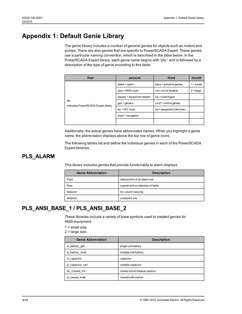
Appendix 1: Default Genie LibraryThe genie library includes a number of general genies for objects such as motors andpumps. There are also genies that are specific to PowerSCADA Expert. These geniesuse a particular naming convention, which is described in the table below. In thePowerSCADA Expert library, each genie name begins with “pls,” and is followed by adescription of the type of genie according to this table:
first second third fourth
pls
indicates PowerSCADAExpert library
alarm =alarm base =primitive genies 1 = small
ansi =ANSI style cb = circuit breaker 2 = large
display = equipment details sw = switchgear
gen =generic cmd = control genies
iec = IEC style eq = equipment (devices)
style = navigation
Additionally, the actual genies have abbreviated names. When you highlight a geniename, the abbreviation displays above the top row of genie icons.
The following tables list and define the individual genies in each of the PowerSCADAExpert libraries.
PLS_ALARMThis library includes genies that provide functionality to alarm displays.
Genie Abbreviation Description
Field data portion of an alarm row
Row a genie with a collection of fields
Selector for column resizing
Setpoint a setpoint row
PLS_ANSI_BASE_1 / PLS_ANSI_BASE_2These libraries include a variety of base symbols used to created genies forANSI equipment.1 = small size2 = large size
Genie Abbreviation Description
sl_battery_gen single-cell battery
sl_battery_multi multiple-cell battery
sl_capacitor capacitor
sl_capacitor_vari variable capacitor
SL_Closed_HV closed circuit breaker position
sl_closed_knife closed knife switch
212 © 1990–2015 Schneider Electric All Rights Reserved
63220-100-200I1 Appendix 1: Default Genie Library03/2015

Appendix 1: Default Genie Library 63220-100-200I103/2015
Genie Abbreviation Description
sl_closed_lv closed low-voltage circuit breaker
sl_conductive_path_1 conductive path 1
sl_conductive_path_2 conductive path 2
sl_conductive_path_3 conductive path 3
sl_conductor_junction conductor junction
sl_contact_nc_closed contact break, closed
sl_contact_nc_open contact break, open
sl_contact_no_closed contact make, closed
sl_contact_no_open contact make, open
sl_contact_term contact terminal
sl_ct current transformer
sl_in_cb_rack incoming, circuit breaker racked out, plug
SL_In_Rack incoming, circuit breaker racked out, socket
sl_in_sw_head incoming switch head
sl_inductor inductor
sl_inductor_adjust adjustable inductor
sl_inductor_gen general inductor
sl_inductor_magcore magnetic core inductor
sl_inductor_vari variable inductor
sl_open open symbol
sl_open_fuse_sw open isolating fuse-switch
SL_Open_HV open high-voltage circuit breaker
sl_open_knife open knife-type switch
SL_Open_LV open low-voltage circuit breaker
sl_out_cb_rack outgoing, circuit breaker racked out, plug
SL_Out_Rack outgoing, circuit breaker racked out, socket
sl_pb_break push-button, break
sl_pb_make push-button, make
sl_pb_term push-button, terminal
sl_pt potential transformer
sl_relay relay
sl_resistor resistor
sl_resistor_adjust adjustable resistor
sl_resistor_vari variable resistor
sl_separable_con_closed separable connector, closed
sl_separable_con_open separable connector, open
sl_separable_con_plug separable connector plug
sl_separable_con_socket separable connector socket
© 1990–2015 Schneider Electric All Rights Reserved 213

PLS_ANSI_CB_1 / PLS_ANSI_CB_2These libraries include genies for ANSI-type high-voltage and low-voltage drawoutcircuit breakers.1 = small size2 = large sizeAdditional definitions:
bus = busway
cb = circuit breaker
hv = high voltage
lv = low voltage
dr = drawout
nd = non-drawout
fd = earth at bottom (feeder)
inc = earth at top (incomer)
nes = no earth
nc = not remote control
c = remote control
Genie Abbreviation Description
hv_cb_bus_dr_c high-voltage drawout circuit breaker, remote control
hv_cb_bus_dr_nc high-voltage drawout circuit breaker, not remote
hv_cb_bus_nd_c high-voltage non-drawout circuit breaker, not remote
hv_cb_bus_nd_nc high-voltage non-drawout circuit breaker, not remote
hv_cb_fd_dr_c high-voltage, drawout circuit breaker, remote control, with earth at bottom
hv_cb_fd_dr_nchigh-voltage, drawout circuit breaker, no remote control, with earth atbottom
hv_cb_fd_nd_chigh-voltage, non-drawout circuit breaker, remote control, with earth atbottom
hv_cb_fd_nd_nchigh-voltage, non-drawout circuit breaker, no remote control, with earth atbottom
hv_cb_inc_dr_c high-voltage, drawout circuit breaker, remote control, with earth at top
hv_cb_inc_dr_nc high-voltage, drawout circuit breaker, no remote control, with earth at top
hv_cb_inc_nd_c high-voltage, non-drawout circuit breaker, remote control, with earth at top
hv_cb_inc_nd_nchigh-voltage, non-drawout circuit breaker, no remote control, with earth attop
hv_cb_nes_dr_c high-voltage drawout circuit breaker, remote control, no earth
hv_cb_nes_dr_nc high-voltage drawout circuit breaker, no remote control, no earth
hv_cb_nes_nd_c high-voltage non-drawout circuit breaker, remote control, no earth
hv_cb_nes_nd_nc high-voltage non-drawout circuit breaker, no remote control, no earth
lv_cb_bus_dr_clow-voltage drawout circuit breaker, remote control, busbar-type with earthat bottom
214 © 1990–2015 Schneider Electric All Rights Reserved
63220-100-200I1 Appendix 1: Default Genie Library03/2015

Appendix 1: Default Genie Library 63220-100-200I103/2015
Genie Abbreviation Description
lv_cb_bus_dr_nclow-voltage drawout circuit breaker, no remote control, busbar-type withearth at bottom
lv_cb_bus_nd_clow-voltage non-drawout circuit breaker, remote control, busbar-type withearth at bottom
lv_cb_bus_nd_nclow-voltage non-drawout circuit breaker, no remote control, busbar-typewith earth at bottom
lv_cb_fd_dr_clow-voltage drawout circuit breaker, remote control, earth on load side(bottom of drawing)
lv_cb_fd_dr_nclow-voltage drawout circuit breaker, no remote control, earth on load side(bottom of drawing)
lv_cb_fd_nd_clow-voltage non-drawout circuit breaker, remote control, earth on load side(bottom of drawing)
lv_cb_fd_nd_nclow-voltage non-drawout circuit breaker, no remote control, earth on loadside (bottom of drawing)
lv_cb_inc_dr_clow-voltage drawout circuit breaker, remote control, earth on feeder (top ofdrawing)
lv_cb_inc_dr_nclow-voltage drawout circuit breaker, no remote control, earth on feeder (topof drawing)
lv_cb_inc_nd_clow-voltage non-drawout circuit breaker, remote control, earth on feeder(top of drawing)
lv_cb_inc_nd_nclow-voltage non-drawout circuit breaker, no remote control, earth on feeder(top of drawing)
lv_cb_nes_dr_c low voltage drawout circuit breaker, no earth, remote control
lv_cb_nes_dr_nc low voltage drawout circuit breaker, no earth, no remote control
lv_cb_nes_nd_c low voltage non-drawout circuit breaker, no earth, remote control
lb_cb_nes_nd_nc low voltage non-drawout circuit breaker, no earth, no remote control
PLS_ANSI_SW_1 / PLS_ANSI_SW_2These libraries include ANSI-style switches:1 = small size2 = large size
Genie Abbreviation Description
sw_fused switch: feeder, fused
sw_fused_isolated switch: feeder, fused, isolated
sw_general switch: feeder, general
sw_knife switch: knife type
PLS_DISPLAYThis library includes two genies that provide data row items for equipment.
Genie Abbreviation Description
equiplistitem data row for the equipment tag list
EquipValueItem data row for the equipment popup
© 1990–2015 Schneider Electric All Rights Reserved 215

PLS_GEN_BASE_1 / PLS_GEN_BASE_2These libraries include a variety of "parts" related to generators, motors, andtransformers.
Genie Abbreviation Description
chassis_ground chassis ground
Dev_Base device base
es_inc earth switch, incomer
es_out earth switch, feeder
Gen_1 generator, option 1
Gen_2 generator, option 2
gen_AC generator: AC
gen_DC generator: DC
genset engine-generator
ground ground
Motor_1 motor, option 1
Motor_2 motor, option 2
motor_ac motor: AC
motor_dc motor: DC
motor_synch motor: synchronous
SL_Base circuit breaker base symbol
sl_br_in circuit breaker line in, non-drawout
sl_br_out circuit breaker line out, non-drawout
SL_Bustie bus tie
SL_CommLoss comms loss
SL_Discrepancy position discrepancy
sl_harmonic_filter_1 harmonic filter 1
sl_harmonic_filter_2 harmonic filter 2
SL_In incoming bus
SL_Local local, rather than remote control
SL_Out feeder
SL_Tripped tripped
Test_CB_Control health test for the circuit breaker control
transformer_1_in transformer 1: general, on-line
transformer_1_in_y transformer 1: star (wye), on-line
transformer_1_out transformer 1: general, off-line
transformer_1_out_d transformer 1: delta, off-line
transformer_1_out_y transformer 1: star (wye), off-line
transformer_2_in transformer 2: general, on-line
216 © 1990–2015 Schneider Electric All Rights Reserved
63220-100-200I1 Appendix 1: Default Genie Library03/2015

Appendix 1: Default Genie Library 63220-100-200I103/2015
Genie Abbreviation Description
transformer_2_in_Y transformer 2: star (wye), on-line
transformer_2_out transformer 2: general, off-line
transformer_2_out_D transformer 2: delta, off-line
transformer_2_out_Ytransformer 2: star (wye), off-line (no 2 IND? or 1 IN D?)
PLS_GEN_CMD_1 / PLS_GEN_CMD_2These libraries include genies that control display of popups and values:1 = small size2 = large size
Genie Abbreviation Description
CmdDetail provides access to the equipment detail popup
cmddetail_meter provides access to themeter detail popup
Control control in a circuit breaker
value value section of a circuit breaker
value_meter value section of ameter
PLS_GEN_EQ_1 / PLS_GEN_EQ_2These libraries include the general equipment used to make up generators, motors,and transformers:1 = small size2 = large size
Genie Abbreviation Description
busbar_horz horizontal busbar
busbar_vert vertical busbar
gen_ac generator: AC
gen_dc generator: DC
gen_nd_1 generator 1: no current designation
gen_nd_2 generator 2: no current designation
mot_ac motor: AC
mot_dc motor: DC
mot_nd_1 motor 1: no current designation
mot_nd_2 motor 2: no current designation
mot_syn motor, synchronous
trans_nd_1 transformer 1: no connection designation
trans_nd_2 transformer 2: no connection designation
trans_sd_1 transformer 1: star-delta (wye-delta)
trans_sd_2 transformer 2: star delta (wye-delta)
trans_ss_1 transformer 1: star-star (wye-wye)
trans_ss_2 transformer 2: star-star (wye-wye)
© 1990–2015 Schneider Electric All Rights Reserved 217

PLS_IEC_BASE_1 / PLS_IEC_BASE_2These libraries include a variety of symbols for IEC equipment:1 = small size2 = large size
Genie Abbreviation Description
sl_cap_bank_tuned_3 capacitor bank 3: tuned
sl_cap_bank_tuned_4 capacitor bank 4: tuned
sl_capacitor capacitor
sl_capacitor_vari capacitor, variable
sl_closed closed switch
sl_contact_nc contact break
sl_ct contact
sl_fuse_1 fuse, option 1
sl_fuse_2 fuse, option 2
SL_Head head
sl_head_2 head
sl_in_cb_rack incoming, circuit breaker when racked out, plug
SL_In_Rack incoming, circuit breaker when racked out, socket
sl_in_sw_hd_isol incoming, switch head, isolated
sl_in_sw_head incoming, switch head
sl_inductor inductor
sl_inductor_adjust inductor, adjustable
SL_Open open
sl_out_cb_rack feeder, circuit breaker when racked out, plug
SL_Out_Rack feeder, circuit breaker when racked out, socket
sl_resistor resistor
sl_resistor_adjust resistor with adjustable contact
sl_resistor_vari resistor, variable
sl_sw_static_1 static switch 1
sl_sw_static_2 static switch 2
PLS_IEC_CB_1 / PLS_IEC_CB_2These libraries include high-voltage drawout circuit breakers:
1 = small size2 = large size
GenieAbbreviation Description
hv_cb_bus_dr_c high-voltage drawout circuit breaker, remote control
hv_cb_bus_dr_nc high-voltage drawout circuit breaker, no remote control
hv_cb_bus_nd_c high-voltage non-drawout circuit breaker, remote control
218 © 1990–2015 Schneider Electric All Rights Reserved
63220-100-200I1 Appendix 1: Default Genie Library03/2015

Appendix 1: Default Genie Library 63220-100-200I103/2015
GenieAbbreviation Description
hv_cb_bus_nd_nc high-voltage non-drawout circuit breaker, no remote control
hv_cb_fd_dr_chigh-voltage, drawout circuit breaker, remote control, earth atbottom
hv_cb_fd_dr_nchigh-voltage, drawout circuit breaker, no remote control, earthat bottom
hv_cb_fd_nd_chigh-voltage, non-drawout circuit breaker, remote control, earthat bottom
hv_cb_fd_nd_nchigh-voltage, non-drawout circuit breaker, no remote control,earth at bottom
hv_cb_inc_dr_chigh-voltage, drawout circuit breaker, remote control, earth attop
hv_cb_inc_dr_nchigh-voltage, drawout circuit breaker, no remote control, earthat top
hv_cb_inc_nd_chigh-voltage, non-drawout circuit breaker, remote control, earthat top
hv_cb_inc_nd_nchigh-voltage, non-drawout circuit breaker, no remote control,earth at top
hv_cb_nes_dr_c high-voltage drawout circuit breaker, remote control, no earth
hv_cb_nes_dr_nchigh-voltage drawout circuit breaker, no remote control, noearth
hv_cb_nes_nd_chigh-voltage non-drawout circuit breaker, remote control, noearth
hv_cb_nes_nd_nchigh-voltage non-drawout circuit breaker, no remote control, noearth
PLS_IEC_SW_1 / PLS_IEC_SW_2These libraries include IEC-style switches:
1 = small size2 = large size
Genie Abbreviation Description
sw_general general switch
sw_isolated isolated switch
PLS_METERThis library includes meter symbols.
Genie Abbreviation Description
circuit monitor PowerSCADAExpert circuit monitor
egx PowerSCADAExpert EGX
generic_meter generic meter
ion_7650 ION 7650meter
micrologic all Mircologic meters
power_meter PowerSCADAExpert power meter
© 1990–2015 Schneider Electric All Rights Reserved 219

Genie Abbreviation Description
quantum PowerSCADAExpert Quantum
sepam all Sepam metersI
ITEM1This library includes miscellaneous symbols.
Genie Abbreviation Description
Item1 value type and units block for a circuit breaker
Item2 value type and units block for a circuit breaker
tab1 menu tab
Tab2 menu tab
220 © 1990–2015 Schneider Electric All Rights Reserved
63220-100-200I1 Appendix 1: Default Genie Library03/2015
Appendix 2: Citect INI Parameters 63220-100-200I103/2015
Appendix 2: Citect INI ParametersThere are a number of Citect INI parameters that you may use to configure driverparameters. These settings may be configured at the protocol level, cluster level, portlevel, or device level. More specific settings will override a general one. The order ofprecedence is:
Protocol Name > Cluster Name > Port Name > I/O Device Name
The level at which you want the INI settings to be in effect determines the name youdefine. For example:
To set the default timeout for all devices using the Micrologic protocol, use:[MICROLOGIC]Timeout = 2000To override this default for cluster ‘Cluster_1,’ use:[MICROLOGIC.Cluster_1]Timeout = 1000To override the default value for port ‘Port_1’ on cluster ‘Cluster_1,’ use:[MICROLOGIC.Cluster_1.Port_1]Timeout = 3000To override the default value for I/O device ‘CircuitBreaker_1’ on port ‘Port_1’ oncluster ‘Cluster_1,’ use:[MICROLOGIC.Cluster_1.Port_1.CircuitBreaker_1]Timeout = 4000Most settings can be configured to be specific to a particular I/O device. Exceptions arenoted in the description for the individual parameter.
Parameters DatabaseAll INI parameters described in the sections below can be set in the Parametersdatabase. Using special syntax, you can access the parameters in the Project Editor(System < Parameters):
• The section name generally corresponds to the INI section name, although itincludes the protocol name, cluster name, and primary device name only.
• The name is the INI value name.
If the parameter is set in the Parameters database, it becomes a new default for eitherprotocol, cluster, or a concrete device (depending on the section name hierarchy).
Examples:
Section Name: [MICROLOGIC.Cluster_1.Breaker_1]Name: TimeoutValue: 2000This defines a new default timeout value for a redundant pair of MicroLogic devices(primary device is named Breaker_1 in Cluster_1).
Section Name: [PWRMODBUS.Cluster1]Name: UseWriteMultiRegistersOnlyValue: 0
This sets UseWriteMultiRegistersOnly to 0 for all PWRMODBUS devices in Cluster 1.
The INI file is read after the parameter database is processed; thus the override optionsare set in the Parameters database.
© 1990–2015 Schneider Electric All Rights Reserved 221
In this section, you will find parameters organized into these categories:
General PowerSCADA Expert Parameters on page 222
Performance Tuning Parameters on page 229
Waveform Parameters on page 237
Sepam Event Reading Parameters on page 238
MicroLogic Modules Configuration Parameters on page 239
Data Replication Parameters on page 240
General PowerSCADA Expert ParametersThe following parameters are common to all PowerSCADA Expert devices.
watchtimeControls how often the product will interrogate the driver to determine whether it is stillonline. This parameter can only be configured for an entire driver, and hence will havethe driver dll name as its section name. Where another setting may be [PM870], to setthis setting it must be [PLOGIC], as PLOGIC is the name of the dll. This is the onlyparameter whose section name is defined in this fashion.
Parameter type: secondsDefault Value: 2Example: [SEPAM] watchtime = 5
kernelStatisticUpdateRateControls how frequently the statistics displayed in the driver kernel window areupdated. This time period can be increased in order to decrease CPU load. Thisparameter can only be configured for the entire protocol (as with the watchtimeparameter); it will have the driver dll name as its section name.
Parameter type: millisecondsDefault value: 5000
Examples:[SEPAM40]kernelStatisticUpdateRate = 20000
[SEPAM80]kernelStatisticUpdateRate = 10000
UseWriteMultiRegistersOnlyControls PWRMODBUS driver behaviour when a single register is to be written. Thisparameter is set to 1 by default, enabling all writes to be made using "write multipleregisters" MODBUS function. Setting this parameter to 0 allows driver to perform writeusing "write single register" function if (and only if) one MODBUS register is about to bewritten in current operation.
Parameter type: integerDefault value: 1
Examples:
[PWRMODBUS]
222 © 1990–2015 Schneider Electric All Rights Reserved
63220-100-200I1 Appendix 2: Citect INI Parameters03/2015

Appendix 2: Citect INI Parameters 63220-100-200I103/2015
UseWriteMultiRegistersOnly = 1
[PWRMODBUS.MYCLUSTER.PORT_1.BCM1]UseWriteMultiRegistersOnly = 0
timeoutControls how long the driver waits for a response from a device before setting thatdevice as offline. This value should be greater than the device/gateway timeout period.A timed out request will not be retried. The reason for this is that TCP is a guaranteedtransport mechanism, and the lack of a response indicates that the device is offline orcommunication has been lost with that device. A device connected via a gatewayshould use the gateway's retry mechanism.
Parameter type: millisecondsDefault value: 5000
Examples:
[SEPAM40]Timeout = 2000
[SEPAM40.MYCLUSTER.PORT_1.SLOW_SEPAM]Timeout = 15000
retryDefines the number of retry attempts for specific MODBUS requests. Retries may occureither when the request is timed out or certain MODBUS exception reply messages arereceived. The exact behaviour is controlled by the RetryTimeout and RetryExceptionparameters.
Parameter type: number of attemptsDefault value: 3
Examples:
[SEPAM40]retry = 1
[SEPAM40.MYCLUSTER.PORT_1.SEPAM_DEVICE]retry = 5
RetryTimeoutWhen enabled (by default), the driver will re-try a timed-out MODBUS request.
Parameter type: long (boolean)Default value: 1
Examples:
[SEPAM40]RetryTimeout = 1
[SEPAM40.MYCLUSTER.PORT_2.SEPAM_DEVICE]RetryTimeout = 0
© 1990–2015 Schneider Electric All Rights Reserved 223
RetryExceptionWhen enabled (disabled by default), the driver will re-try a MODBUS request that hasreceived MODBUS Exception messages. The number of retries is defined by the Retryparameter.
When Retry Exception is enabled, retry occurs when any of the following MODBUSexception messages is received:
SLAVE_DEVICE_FAILURE_EXCEPTION = 0x5GATEWAY_PATH_UNAVAILABLE_EXCEPTION = 0xAGATEWAY_TARGET_DEVICE_FAILED_TO_RESPOND_EXCEPTION = 0xBSLAVE_DEVICE_BUSY_EXCEPTION = 0x6MEMORY_PARITY_ERROR_EXCEPTION = 0x8NEGATIVE_ACKNOWLEDGE_EXCPETION = 0x7
Parameter type: long (boolean)Default value: 0
Examples:
[SEPAM40]RetryTimeout = 1
[SEPAM40.MYCLUSTER.PORT_2.SEPAM_DEVICE]RetryTimeout = 0
standbyRefreshRateControls how often a standby IO server attempts to poll a device to update its cache.This time period determines the maximum age that values may be when switching froma primary IO server to a standby. Decreasing this value degrades communications tothe device.
Parameter type: secondsDefault value: 60
Examples:
[SEPAM40]standbyRefreshRate = 30
[SEPAM40.MYCLUSTER.PORT_1.SLOW_SEPAM]standbyRefreshRate = 120
standbyCheckTimeControls how often the driver will enquire of PowerSCADA Expert as to whether it is instandby or primary mode. This value can be increased to reduce CPU load.
Parameter type: millisecondsDefault value: 500
Examples:
[SEPAM40]standbyCheckTime = 500
224 © 1990–2015 Schneider Electric All Rights Reserved
63220-100-200I1 Appendix 2: Citect INI Parameters03/2015
Appendix 2: Citect INI Parameters 63220-100-200I103/2015
[SEPAM40.MYCLUSTER.PORT_1.SLOW_SEPAM]standbyCheckTime = 1000
statusUnitCheckTimeThis parameter defines how frequently the driver will try to re-establish the connectionwith a device that has gone offline on a port that is not disconnected. It sets themaximum rate at which the driver enquires of the device, to determine if it is stilloperational. If the "watchtime" parameter is set to a longer time, that value will be usedinstead.
NOTE: If a network gateway has multiple devices connected to it, and one device isdisconnected, the driver takes it offline and does not try to reconnect it according to thisparameter's schedule. If the port is taken offline and then is reconnected, the driver willreconnect the devices immediately.
Parameter type: secondsDefault value: 5 (20 for MicroLogic)
Example:
[SEPAM40]statusUnitCheckTime = 5
[SEPAM40.MYCLUSTER.PORT_1.SLOW_SEPAM]standbyCheckTime = 10
initUnitCheckTimeControls how long the driver waits before attempting to bring a device online after ithas gone offline. This value can be decreased to bring offline devices back into servicein a shorter period of time. In a multi-drop scenario, this time should be relatively long,to prevent init unit requests from stalling communications to the rest of the devices onthat port.
Parameter type: secondsDefault value: 120
Examples:
[SEPAM40]initUnitCheckTime = 5
[SEPAM40.MYCLUSTER.PORT_1]initUnitCheckTime = 120
initCacheTimeoutControls how long the driver will spend attempting to populate the cache beforebringing a device online. When a tag has been incorrectly configured, the device willcome online after this period of time.
Parameter type: secondsDefault value: 60
Examples:[SEPAM40]
© 1990–2015 Schneider Electric All Rights Reserved 225

initCacheTimeout = 60
[SEPAM40.MYCLUSTER.PORT_1.SLOW_SEPAM]initCacheTimeout = 30
cacheRefreshTimeControls the maximum rate at which the driver will attempt to repopulate its cache. If thedriver cannot refresh its cache within the time period specified, it will collect data as fastas the network allows.
Parameter type: millisecondsDefault value: 500
Examples:[SEPAM40]cacheRefreshTime = 1000
[SEPAM40.MYCLUSTER.PORT_1.FAST_SEPAM]cacheRefreshTime = 200
[SEPAM40.MYCLUSTER.PORT_1.UNIMPORTANT_DEVICE]cacheRefreshTime = 5000
TimeSyncEnables/disables time synchronization for the PM5000S driver. On startup and on a15-minute schedule, the driver reads each device clock. If a device clock is not withinthe specified 10-second drift, the driver sets the time on that device to the currentsystem time.
Parameter type: booleanDefault value: 0 (PM5000S) or 1 (PM5000S1)
NOTE: This is a driver-level parameter, not a protocol-level parameter. All entries mustbe under the PM5000S section of the .ini file. By default, the PM5000S1 protocolenables time sync. For the PM5000S, it is disabled by default because most deviceswill have battery backup and GPS time sync availability.
Example:[PM5000S] TimeSync = 1
StatusRegisterDefines a holding register that the driver reads to determine whether a device isresponding to communication requests. The result of this read is not important,however it must be a valid register address within the device.
Parameter type: register addressDefault value: 1100 (2 for Sepam) (PM1200 requires that this value be set to 3911)
Examples:
[PWRMODBUS]statusRegister = 1000
[PWRMODBUS.MYCLUSTER.PORT_DEVICE_PM1200]statusRegister = 3911
226 © 1990–2015 Schneider Electric All Rights Reserved
63220-100-200I1 Appendix 2: Citect INI Parameters03/2015

Appendix 2: Citect INI Parameters 63220-100-200I103/2015
StatusRegistersCountDefines the number of registers that the driver reads to determine whether a device isresponding to communication requests. The result of this read is not important,however it must be a valid register address within the device.
Parameter type: number of registersDefault value: 1 (PM1200 requires that this value be set to 2)
Examples:
[PWRMODBUS]statusRegistersCount = 2
[PWRMODBUS.MYCLUSTER.PORT_DEVICE_PM1200]statusRegistersCount = 2
StatusRegisterTypeUsed together with StatusRegister; defines the type of the status register. Can only beconfigured for the PWRMODBUS driver. This parameter can have one of the followingvalues:
0 - HOLDING register (default)1 - INPUT register2 - COIL register3 - DIGITAL input (input coil) register
Any other value equals the default.
Parameter type: register typeDefault value: 0
Example:
[PWRMODBUS]
statusRegister = 1000
[PWRMODBUS.MYCLUSTER.PORT_1.DEVICE_A]
statusRegister = 16000
statusRegisterType = 2
ModbusBaseDefines the base address for a device. Some MODBUS device registers are definedusing a base address of 1. in this case, reading register 100 would actually requirereading register 99. In other devices (such as the Sepam) the base address is 0. Thisparameter allows the base address to be configured according to the device.
Parameter type: integerDefault value: 0 for Sepam; 1 for all other drivers
Examples:
[PWRMODBUS]ModbusBase = 1
© 1990–2015 Schneider Electric All Rights Reserved 227
[PWRMODBUS.MYCLUSTER.PORT_1.DEVICE_A]ModbusBase = 0
RegModeSpecifies the order of bytes in a device register. It can only bet set for PWRMODBUSdriver, and is supposed to be unit-specific. Value values are:
RegMode Order of bytes
Big endian (default) 0 1 0
Little endian 1 0 1
Any other value reverts to big endian.
Parameter type: integerDefault value: 0
Examples:
[PWRMODBUS]RrMode = 0 # Default
[PWRMODBUS.MYCLUSTER.PORT_1.DEVICE_A]RegMode = 1 # This device has little endian registers
timeZoneTime zone names are taken directly from the Windows registry database (case-insensitive), and will otherwise default to using the I/O server's local time zone. TheWindows time zone database is located in the Windows registry in:
HKEY_LOCAL_MACHINE\SOFTWARE\Microsoft\Windows NT\CurrentVersion\TimeZones\. The examples of time zone names are:AUS Central Standard TimeChina Standard TimePacific Standard Time (Mexico)
Use the general section [POWERLOGICCORE] to specify the time zone for all devices,e.g.[POWERLOGICCORE]Timezone = Mountain Standard Time
This sets the default time zone for all devices (Sepam, PLogic, Micrologic,PWRMODBUS). Otherwise the time zone can be specified for each device withprecedence taken as described in the start of this section.
Examples:
[PLOGIC870.Cluster1.Singapore_Port]Timezone = Singapore Standard Time
[PLOGIC870.Aus_Cluster]Timezone = Aus Central Standard Time
Not having a time zone specification means that the device is in the same time zone asthe machine where the I/O Server is running. No time conversion will be done.
228 © 1990–2015 Schneider Electric All Rights Reserved
63220-100-200I1 Appendix 2: Citect INI Parameters03/2015
Appendix 2: Citect INI Parameters 63220-100-200I103/2015
Alarm ParametersThe following parameters are used for alarms.
UsePLSFilterControls whether alarm/event filtering is done by the PLSCADA filter form or the Citectfilter form. Both forms cause the same information to display on the page, but each ispresented in a different format.
Parameter type: integer
Default value: 1 (PLSCADA filter form)
Example: [ALARM] UsePLSFilter = 1
Performance Tuning ParametersSeveral parameters are provided to allow tuning of the performance. Theseparameters fall into three broad categories; bandwidth allocation, packet blockingoptimisation, and tag scan rates.
Bandwidth Allocation ParametersBandwidth can be allocated for the different types of data as desired. The parametersto perform this are as follows:
[Parameter] [Default Value] [Parameter Type]
EventBandwidth 25 integer
WaveformsBandwidth 12 integer
CommandsBandwidth 13 integer
RealTimeBandwidth 50 integer
The percentage bandwidth allocated to each queue will be the ratio of an individualqueue's value when compared to the total sum of defined bandwidths. The defaultvalues have a sum of 100 for ease of reference. Any unused bandwidth will be sharedamongst the other categories.
Bandwidth can be configured at the port level, but not the device level.
Example:[SEPAM40]EventsBandwidth 30WaveformsBandwidth 5CommandsBandwidth 15RealTimeBandwidth 50
[SEPAM40.MYCLUSTER.PORT_1]EventsBandwidth 50WaveformsBandwidth 30CommandsBandwidth 10RealTimeBandwidth 10
© 1990–2015 Schneider Electric All Rights Reserved 229
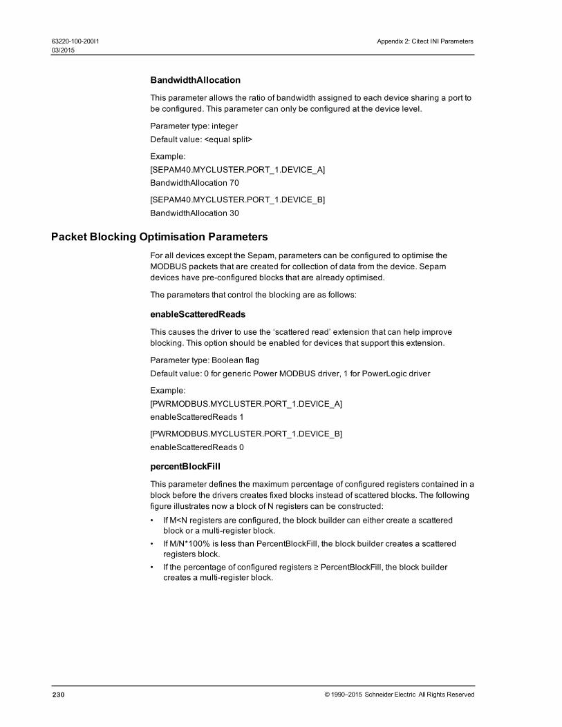
BandwidthAllocation
This parameter allows the ratio of bandwidth assigned to each device sharing a port tobe configured. This parameter can only be configured at the device level.
Parameter type: integerDefault value: <equal split>
Example:[SEPAM40.MYCLUSTER.PORT_1.DEVICE_A]BandwidthAllocation 70
[SEPAM40.MYCLUSTER.PORT_1.DEVICE_B]BandwidthAllocation 30
Packet Blocking Optimisation ParametersFor all devices except the Sepam, parameters can be configured to optimise theMODBUS packets that are created for collection of data from the device. Sepamdevices have pre-configured blocks that are already optimised.
The parameters that control the blocking are as follows:
enableScatteredReads
This causes the driver to use the ‘scattered read’ extension that can help improveblocking. This option should be enabled for devices that support this extension.
Parameter type: Boolean flagDefault value: 0 for generic Power MODBUS driver, 1 for PowerLogic driver
Example:[PWRMODBUS.MYCLUSTER.PORT_1.DEVICE_A]enableScatteredReads 1
[PWRMODBUS.MYCLUSTER.PORT_1.DEVICE_B]enableScatteredReads 0
percentBlockFill
This parameter defines the maximum percentage of configured registers contained in ablock before the drivers creates fixed blocks instead of scattered blocks. The followingfigure illustrates now a block of N registers can be constructed:
• If M<N registers are configured, the block builder can either create a scatteredblock or a multi-register block.
• If M/N*100% is less than PercentBlockFill, the block builder creates a scatteredregisters block.
• If the percentage of configured registers ≥ PercentBlockFill, the block buildercreates a multi-register block.
230 © 1990–2015 Schneider Electric All Rights Reserved
63220-100-200I1 Appendix 2: Citect INI Parameters03/2015

Appendix 2: Citect INI Parameters 63220-100-200I103/2015
Parameter type: percentageDefault value: 50
Example:[PM870.MYCLUSTER.PORT_1.PM_DEVICE]percentBlockFill 50
[CM4000.MYCLUSTER.PORT_1.CM_DEVICE]percentBlockFill 80
maxBlockSize
This parameter defines the maximum number of registers that can be read in a singlerequest. By default, this is 124, but some devices can read more than this.
Parameter type: integerDefault value: 124
Example:
[PWRMODBUS.MYCLUSTER.PORT_1.DEVICE_A]maxBlockSize 1024
minBlockSize
This parameter defines the minimum number of registers to read as a fixed blockbefore the block builder will instead add those registers to a scattered block. If latencyis low, and scattered reads are expensive, this value should be lower. If latency is high,or scattered reads are inexpensive, it is better to set this value higher. Only applicablewhen scattered reads are enabled.
Parameter type: integerDefault value: 20
Example:[PM870.MYCLUSTER.PORT_1.LOW_LATENCY_DEVICE]
© 1990–2015 Schneider Electric All Rights Reserved 231

minBlockSize 10
[CM4000.MYCLUSTER.PORT_1.HIGH_LATENCY_DEVICE]minBlockSize 100
Tag Scan Rate ParametersEach tag can be configured at a priority level from 1-3 where 1 is the highest.Parameters exist to adjust the relative scan rates of the high and low priority tags incomparison to the nominal tag scan rate.
HighScanRate
Parameter type: percent relative to nominalDefault value: 50
LowScanRate
Parameter type: percent relative to nominalDefault value: 200
Using the default parameters, the high priority tags will be refreshed twice as fast asthe normal priority tags, and the low priority tags will be refreshed at half the rate of thenormal priority tags. These parameters can be configured at the port level and higher.
Using the default settings and a nominal tag refresh rate of 1 second:
Low Priority Tag Refresh: 2000 msNormal Priority Tag Refresh: 1000 msHigh Priority Tag Refresh: 500 ms
Example:[PM870.MYCLUSTER.PORT_1]]HighScanRate 25LowScanRate 500T
Advanced Tag Block Capabilities (Invalid Memory Access Blocks defined)Some devices may restrict access to certain memory registers. Such registers may beavailable for read only, write only or may not be available at all, resulting in a MODBUSexception when the registers are addressed.
Definition: Blocks of registers that cannot be read or written to are referred as “invalidmemory access blocks.”
These devices create a challenge for the PWRMODBUS driver. If the device hasinvalid blocks that do not support scattered reads (or they are disabled for this device),the driver may try to read registers in blocks that intersect with the registers that cannotbe read. This can result in the whole block being invalidated and, in certain cases, mayalso result in device being taken offline. Figure 1 (below) illustrates an invalid block inthe middle of an address space.
232 © 1990–2015 Schneider Electric All Rights Reserved
63220-100-200I1 Appendix 2: Citect INI Parameters03/2015

Appendix 2: Citect INI Parameters 63220-100-200I103/2015
Figure 1 shows how the "invalid memory access block" affects MODBUS registerblocking. In this situation, if the driver does not know that the block of 3 inaccessibleregisters exists, it will try to block all registers from 1 to N (depending on data that wasrequested by the real-time data collector). This block, however, will never be readsuccessfully, as the device will respond with an exception to all attempts to read invalidregisters.
If the configuration includes information about invalid memory access blocks, the driverwill create two blocks instead of one, as shown in Figure 2:
In Figure 2, invalid registers were taken into account when the block was constructed.When configuring device that has invalid memory areas, it is especially important todefine all blocks that may interfere with any of the tags.
Invalid Block Tag Definition Syntax
Invalid access memory areas are defined as variable tags, using the following formatfor the address:
T:IB;{m|i|c|s}:<start_register>:u<count>;E:1;L:P:0
where
• m, i, c and s define the type of MODBUS register
• <start_register> is the first register address of the invalid access block
• <count> defines the number of registers in the invalid access block
Example:
© 1990–2015 Schneider Electric All Rights Reserved 233

T:IB;m:300:u10;E:1;L:P:0
This defines an invalid access block of ten holding registers starting from register 300.
Configuration Notes
When one or more invalid access blocks is defined according to the syntax above, tagsconfigured to read any of invalid registers will be affected by it. If any of the tagregisters fall into an invalid memory access block, this tag will not be readable; anyattempt to read its value will result in #COM, as shown on Figure 3:
However, such tags do not affect other tags, because the PWRMODBUS driverimplements algorithms that prevent tags from being invalidated by invalid memoryblock logic.
Tags that try to use invalid registers are detected on startup and can be found byanalysing the log file. This is an example trace:
[DEBUG] [REAL][GeneralDriver::BaseDatapointBuilder::BuildDataPoints()] Adding datapoint. Tag - BCM1\H_QIVR34\SwlStr Address -T:SS;m:283:2;E:1;L:P:26 Datapoint: class Datapoints::Status_SS
[DEBUG] [REAL][RealTimeData::DeviceCache::Subscribe()] InitRegisters: Polled Registers: Address:283 Type:3
[ERROR] [MISC] [RealTimeData::BlockBuilder::AddDataPoint()] Cannotadd datapoint, one or more invalid memory addresses fall into non-splittable block
[ERROR] [MISC][GeneralDriver::BaseDatapointBuilder::BuildDataPoints()] Could notinit datapoint. Tag BCM1\H_QIVR34\SwlStr AddressT:SS;m:283:2;E:1;L:P:26. Analyze other messages, this tag addressmay contain invalid registers
Such output is expected when a holding register with address 283 is declared invalid.This trace helps figure out any configuration issues.
234 © 1990–2015 Schneider Electric All Rights Reserved
63220-100-200I1 Appendix 2: Citect INI Parameters03/2015

Appendix 2: Citect INI Parameters 63220-100-200I103/2015
Write-only Memory
If a certain register range is accessible for write only, no additional configuration maybe needed. However, to prevent the driver block optimizer from including theseregisters in a poll, they also must be configured by adding “invalid block” tags asdescribed in the Invalid Block Tag Definition Syntax, described above. Declaring theseregisters invalid will not prevent drivers from trying to write to them. Figure 4 illustratesa write-only memory configuration:
Write-only registers should not be confused with write-only datapoints that internallyread a register before attempting to write. Declaring the register they read invalid willresult in a datapoint not working; such mistake should be avoided. Figure 4 shows“WriteOnlyDP” as an example; this tag cannot be read (it will result in #COM), butinternally it needs to get the register value before writing into it. If this register wasdeclared invalid, tag writes would also not succeed.
Figure 5 illustrates a write-only datapoint:
© 1990–2015 Schneider Electric All Rights Reserved 235
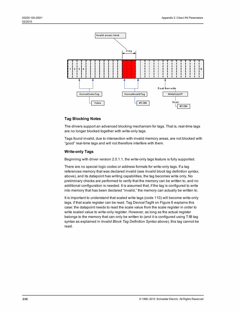
Tag Blocking Notes
The drivers support an advanced blocking mechanism for tags. That is, real-time tagsare no longer blocked together with write-only tags.
Tags found invalid, due to intersection with invalid memory areas, are not blocked with“good” real-time tags and will not therefore interfere with them.
Write-only Tags
Beginning with driver version 2.0.1.1, the write-only tags feature is fully supported.
There are no special logic codes or address formats for write-only tags. If a tagreferences memory that was declared invalid (see Invalid block tag definition syntax,above), and its datapoint has writing capabilities, the tag becomes write only. Nopreliminary checks are performed to verify that the memory can be written to, and noadditional configuration is needed. It is assumed that, if the tag is configured to writeinto memory that has been declared “invalid,” the memory can actually be written to.
It is important to understand that scaled write tags (code 110) will become write-onlytags, if that scale register can be read. Tag Device\TagN on Figure 6 explains thiscase: the datapoint needs to read the scale value from the scale register in order towrite scaled value to write-only register. However, as long as the actual registerbelongs to the memory that can only be written to (and it is configured using T:IB tagsyntax as explained in Invalid Block Tag Definition Syntax above), this tag cannot beread.
236 © 1990–2015 Schneider Electric All Rights Reserved
63220-100-200I1 Appendix 2: Citect INI Parameters03/2015
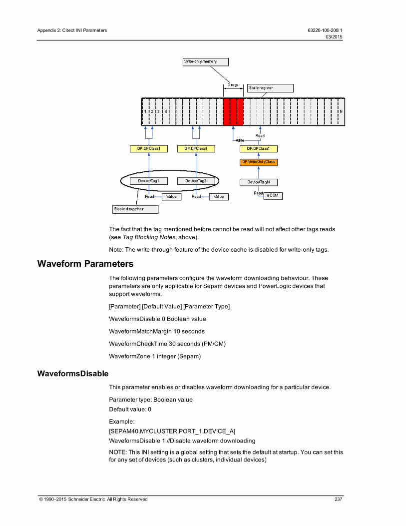
Appendix 2: Citect INI Parameters 63220-100-200I103/2015
The fact that the tag mentioned before cannot be read will not affect other tags reads(see Tag Blocking Notes, above).
Note: The write-through feature of the device cache is disabled for write-only tags.
Waveform ParametersThe following parameters configure the waveform downloading behaviour. Theseparameters are only applicable for Sepam devices and PowerLogic devices thatsupport waveforms.
[Parameter] [Default Value] [Parameter Type]
WaveformsDisable 0 Boolean value
WaveformMatchMargin 10 seconds
WaveformCheckTime 30 seconds (PM/CM)
WaveformZone 1 integer (Sepam)
WaveformsDisableThis parameter enables or disables waveform downloading for a particular device.
Parameter type: Boolean valueDefault value: 0
Example:[SEPAM40.MYCLUSTER.PORT_1.DEVICE_A]WaveformsDisable 1 //Disable waveform downloading
NOTE: This INI setting is a global setting that sets the default at startup. You can set thisfor any set of devices (such as clusters, individual devices)
© 1990–2015 Schneider Electric All Rights Reserved 237

There is also a tag that will change an individual device's setting at runtime (it will resetto the default when you restart the project). This tag isLLNO\WaveformCollectionEnabled. 1 = True, 0 = False.
WaveformMatchMarginAlarms are matched to waveforms by the timestamp of each. This parameter is themaximum difference between alarm timestamp and waveform timestamp for theproduct to consider it a match.
Parameter type: secondsDefault value: 10
Example:[SEPAM40]WaveformMatchMargin 2
WaveformCheckTime (PM, CM, and Sepam)This parameter defines the time the driver will wait between checking for newwaveforms.
Parameter type: secondsDefault value: 30
Example:[SEPAM40.MYCLUSTER.PORT_1.DEVICE_A]WaveformCheckTime 60 (checks every 60 seconds)
WaveformZone (Sepam)This parameter defines the Sepam waveform zone that the Sepam driver will use tocollect waveforms from the device. This allows two masters to extract waveforms fromthe same device. Valid values are 1 or 2.
Parameter type: integerDefault value: 1
Example:[SEPAM40.MYCLUSTER.PORT_1.DEVICE_A]WaveformZone 2
Sepam Event Reading ParametersThese two Sepam parameters are described below.
EventTableThis parameter defines the Sepam event table that the Sepam driver uses to collectalarms from a device. This allows two masters to extract alarms from the same device.Valid values are 1 or 2.
Parameter type: integerDefault value: 1
Example:
238 © 1990–2015 Schneider Electric All Rights Reserved
63220-100-200I1 Appendix 2: Citect INI Parameters03/2015

Appendix 2: Citect INI Parameters 63220-100-200I103/2015
[SEPAM40.MYCLUSTER.PORTO_1.DEVICE_A]EventTable 2
EventIdleThis parameter defines the time that the driver will wait before requesting the nextevent from a Sepam device. It may be possible to reduce this value to increase the rateat which alarms can be retrieved from the device.
Parameter type: millisecondsDefault value: 500
Example:[SEPAM40.MYCLUSTER.PORTO_1.DEVICE_A]EventIdle 200
MicroLogic Modules Configuration ParametersA MicroLogic unit consists of three or four modules, each acting as a separateMODBUS device; however the I/O server views MicroLogic as one I/O device. Thecommunication control module (CCM) is optional for MicroLogic; its presence may bedetected by the driver or specified in the INI file.
CCMThe CCM parameter specifies whether a CCM is present on the device or if the drivershould try to detect its presence ("auto mode"). Valid values are:
CCM not present - 0CCM present - 1Auto mode - 2 (default)
Any other value reverts to auto mode.
Parameter type: integerDefault value: 2
Example:[Micrologic.MYCLUSTER.PORT_1.DEVICE_A]CCM=1
Module-Specific Packet Blocking Optimisation SettingsDue to different firmware versions, MicroLogic modules may require different blockingsettings. This is especially true when MicroLogic contains a BCM that supportsMODBUS "read multiple registers" requests for up to 124 registers, and an MM or aPM module that supports 21 register reads at max. The MicroLogic driver allowsblocking optimisation parameters to be overridden for each of the device's modules, asin the following example:[Micrologic.MYCLUSTER.PORT_1.DEVICE_A]maxBlockSize = 124
[Micrologic.MYCLUSTER.PORT_1.DEVICE_A.BCM]maxBlockSize = 21
© 1990–2015 Schneider Electric All Rights Reserved 239

The parameter set for the device applies to all of its modules unless overridden in amodule-specific section (e.g., [Micrologic.MYCLUSTER.PORT_1.DEVICE_A.BCM])
These parameters can be overridden:
• enableScatteredReads• minBlockSize• maxBlockSize• PercentBlockFill
This applies to the BCM, CCM, MM, and PM modules.
MicrologicV INI SettingsThe MicrologicV device driver includes these additional INI settings:• Level3: This is the level 3 device password (four digits), used by the driver when
executing commands.• Level4: This is the level 4 device password (four digits), used by the driver when
executing commands.
If you do not supply this parameter, the driver uses the default device passwords.
Data Replication ParametersThese parameters are used to configure the data directory paths of your servers. Thesesettings are server wide, and must be added to the ‘WaveformDB’ area of the ini file.
Database root folder pathWaveform databases for all units will locate on the filesystem under the same commonfolder. The path to the root folder will be specified in the citect.ini file:
[WaveformDB]LocalRoot = c:\path\to\the\database\root
This path must be specified as local path.
By default, the PowerSCADA Expert[DATA] directory is be used as database rootfolder.
Database root UNC pathFor waveform files to be accessible by the remote clients, the database root folder mustbe available as network shared folder. The UNC name of this folder must be specifiedin the INI file
[WaveformDB]UNCPath = \\computerName\shareToTheLocalRootAbove
If the UNC path to the database root is not specified, all waveform file names returnedby the library will be local file names for the I/O server, making viewing the waveformson the remote clients impossible.
Replication destination configurationIn redundant scenario, the replication target folder must be specified for replication towork
240 © 1990–2015 Schneider Electric All Rights Reserved
63220-100-200I1 Appendix 2: Citect INI Parameters03/2015
Appendix 2: Citect INI Parameters 63220-100-200I103/2015
[WaveformDB]ReplicationDestinationRoot=\\OtherMachine\share\path
The destination path is the name of the network share on the redundant machinewhere its waveform database root is located. It must also allow write access.
No default value for it is assumed.
If not set or share is not accessible, no replication will be preformed.
Graphics Library Parameters
Maximum number of entries that can be held in Event LogThe Alarm Summary length parameter in Citect.ini defines the maximum number ofentries that can be held in the Event Log (default = 5000 entries). You can view allevents in the Event Log and alarms in the alarm logs (Alarm Log, UnacknowledgedAlarms, Disabled Alarms).
Each event requires 256 bytes of memory, plus the length of the comment. 32,000entries will require at least 8 MB of memory. If you have many events, you shouldensure that there is enough memory to store them in RAM.
After the parameter number is reached, older events are FIFO’d out to storage in[Installed Project Directory]\Schneider Electric\PowerSCADA Expert 8.0\Logs
Parameters for Alarm and Event States
[Alarm]UseConfigLimits = 1CacheLength = 2500
!Sound1 = <wave file name>!Sound1Interval = <repeating interval in milliseconds>!Sound2 = <wave file name>!Sound2Interval = <repeating interval in milliseconds>!Sound3 = <wave file name>!Sound3Interval = <repeating interval in milliseconds>
[AlarmFormat]EventLog=OnDate | Date, OnTimeMS | Time, Custom1 | Equipment, Name | Descrip-tion,SumState | State | Custom2 | Location, UserName | User
[AlarmStateText]ON=<default text for ACTIVE state>OFF=<default text for INACTIVE state>ACK=<default text for ACKNOWLEDGED state>ENA=<default text for ENABLE state>DIS=<default text for DISABLE state>CLE=<default text for CLEAR state>
These parameters are read only when the system starts up. The user must restartPowerSCADA Expert if they change these parameters.
© 1990–2015 Schneider Electric All Rights Reserved 241
If you do not specify any value for these parameters, these default values will be used,in this order: .
Appearance
Disappearance
Acknowledge
Enable
Disable
Clear
[PLSEventLog]FileFormat=0EntryCount=250ScanRate=10
[Path][PLSEventLog]=c:\SharedData\Alarm
[General] IODevCheckStartupDelayDelay time before the I/O server starts checking for I/O device status at start-up. Thedelay allows time for the I/O devices to come online. Otherwise, the I/O server wouldhave triggered alarms to indicate that communication was not successful for the rel-evant equipment.Allowed Values: ≥ 0Default Value: 0
[General] IODevCheckInterval
The time interval in seconds that the I/O server repeats the I/O device status check.Allowed Values: ≥ 2Default Value: 2
Integration ParametersThe following parameters deal with single sign-on and integration ofPowerSCADA Expert and Power Monitoring Expert.
[SSO]PSEHostName
If you do not have Power Monitoring Expert installed, and you wantPowerSCADA Expert reports, use this parameter. This parameter specifies theIP address for PowerSCADA Expert.
Default: localhost
[SSO]HostName
This parameter specifies the IP address for Power Monitoring Expert.
Default: localhost
[SSO]RemoteCallHandlerServer
This parameter specifies the I/O server that will execute the call from a web client.
Default:N/A
242 © 1990–2015 Schneider Electric All Rights Reserved
63220-100-200I1 Appendix 2: Citect INI Parameters03/2015

Appendix 2: Citect INI Parameters 63220-100-200I103/2015
[SSO]RemoteCallHandlerCluster
This parameter specifies the cluster of the I/O server that will execute the call from aweb client.
Default:N/A
© 1990–2015 Schneider Electric All Rights Reserved 243

Appendix 3: Additional INI ParametersThe following parameters are added to support device types as they are added to thesystem.
Quantum PLC Time-Stamped EventsThe PWRMODBUS driver supports Quantum time-stamped events. You must set thefollowing INI parameter to enable time-stamped alarms downloading:
[PWRMODBUS]
TSEventsEnabled = 10 by default, valid values 1 or 0
TSMailboxAddress = 11041104 by default
TSAddrLost = 705705 by default
244 © 1990–2015 Schneider Electric All Rights Reserved
63220-100-200I1 Appendix 3: Additional INI Parameters03/2015

Appendix 4: Glossary 63220-100-200I103/2015
Appendix 4: Glossary
address
The address contains all the information the SCADA system needs to get values from aknown device, and to return a value determined by the values read from the deviceand the calculation rules defined in the address.
alarm categorization
Added when setting up custom tags, this is one of the alarm filters. which will be usedfor filtering and sorting alarms in the Alarm Log. Categories are: normal, over, over hs,rate of change, reversal, sag, swell, transient, under, and under hs.
alarm text (On/Off)
For onboard alarms, this is the text (added while adding a custom tag) that displayswhen the alarm is on or off. This text will display in the Alarm Log.
alarm filters
Setup in the Profile Editor, these filters help you filter and sort data that displays in theAlarm Log.
alarm groups
Added when setting up custom tags, this is one of the alarm filters. which will be usedfor filtering and sorting alarms. Groups are: frequencies, motors, power factors, powers,temperatures, time, and voltages.
alarm levels
Added when setting up custom tags, this is one of the alarm filters. which will be usedfor filtering and sorting alarms. Levels are: event, high, medium, and low.
alarm types
Added when setting up custom tags, this is one of the alarm filters. which will be usedfor filtering and sorting alarms. Types are: diagnostic, power quality, protection, andsystem.
Automation Interface
Used instead of the Profile Wizard, this tool allows you to add multiple devices at a timeto a project.
bandwidth
The amount of space or processor resource being used by a part of the system. Youcan use the bandwidth allocation parameters to allocate bandwidth for different typesof data.
baud rate
The speed of transmission of electrical signals on a line. This is often described in bitsper second (bps), although the baud rate and bps are not truly interchangeable. Thebaud is actually the measurement of how frequently the sound changes on the line.
© 1990–2015 Schneider Electric All Rights Reserved 245

bitmask
A mask is defined as data that is used with an operation to extract information that isstored in another location of the code. A bitmask is the most common mask used. Itextracts the status of certain bits in a binary string or number (a bit field or bit array).
Cicode
This programming language, which is similar to Visual Basic or "C," allows you toaccess and edit real-time data in the project. Although not difficult to use, the personworking in Cicode must have received Cicode training.
cluster
A discrete group of alarms servers, trends servers, reports servers, and I/O servers. Itwould usually also possess local control clients. For a plant comprising severalindividual sections or systems, multiple clusters can be used, one cluster for eachsection.
CommsMethod (communications method)
This is the communication protocol, such as MODBUS/RTU via Gateway, that is beingused by a device. When adding devices in the automation interface, you will need tospecify the CommsMethod.
ComPort
(also COM port) The computer's communications port used to connect to devices, forsending and receiving serial data.
composite device type
A composite profile can be made from more than one device type. Each device typeincluded in the composite profile can use its own protocol for communication. Thecomposite device type allows the engineer to use two devices for one monitoring point,e.g., a breaker and a monitoring device. PowerSCADA Expert combines thefunctionality of the two devices so that the end user only needs to consider one devicewhen analysing that location in their system.
configuration environment
(See design time environment.)
control
This is a command written to a device register that then causes an action within someequipment. There are a series of default control tags in PowerSCADA Expert toachieve these actions. For example, in the Sepam 40, there are control tags to operatea circuit breaker and enable a recloser.
custom device type
This is a "new" device type that is added to a system. Although the Profile Editorincludes many standard device types, it may be necessary to add a new device typethat includes custom tags, or one that includes a different set of tags than the standarddevice types.
custom tag
246 © 1990–2015 Schneider Electric All Rights Reserved
63220-100-200I1 Appendix 4: Glossary03/2015

Appendix 4: Glossary 63220-100-200I103/2015
This is a "new" tag that is added to the system. Although the Profile Editor includesmany standard tags, you may need to add a tag for a third party device, or to edit anexisting tag to change its attributes. In these cases, you need to add a custom tag.These tags are then added to a customized device type to be made available inprofiles and projects. The custom tag creation interface applies rules to the tag creationto help guide the user to making tags that will correctly retrieve the desired informationfrom devices.
DataBits
This is the number of data bits used in data transmission. The I/O device and theComPort must have the same value.
data type
Data types are restricted to these types that are supported by the SCADA system:digital, int, long, real, and string.
demomode
This demonstration mode allows you to run the product without a hardware key. Youcan use all of the product features, but with limited runtime and I/O options. See TheDemo Mode on page 202 for details.
design time environment
To be used only by the person who is creating and installing the project for the enduser, this is the environment in which you add devices, profiles, and projects, as wellas create genies and one-lines.
device category
Used in the Profile Wizard to logically group device profiles, to make them easier tolocate. The default category is "Schneider Electric, and the default subcategories are"Monitoring Device," "PLC," and "Protective Device." Do not confuse these terms with:
• categorization and subcategorization (alarm filters, used during runtime, to filterand sort alarm data)
• category type: real-time filters that provide metadata for future reporting
device profile
A subset of the device type: where the device type includes all of a device type'sattributes, the device profile includes only the specific tags that are used by anindividual customer. A device profile is set up like a device type, except that it isspecially configured for a particular need. For example, a CM4000 that is being used tomonitor the main at a given facility would have a different profile from the CM4000 thatis used to monitor water and gas at a facility. The profile also allows you to designatethat some tags will be used for trending and/or for PC-based alarming.
device type
A device type contains all the information for retrieving the available information from agiven device type. This information is stored in the form of tags. Tags can be of thesetypes: real-time, onboard alarms, controls, and Resets. Real Time tags can be furtherseparated into groups such as Currents or Energies.
A device type has a name and has one or more drivers associated with it. It also hasone or more tags associated with it; for each driver/tag combination, the device typecan have an address.
© 1990–2015 Schneider Electric All Rights Reserved 247

device type drivers
These are programs that allow PowerSCADA Expert to interact with a device or seriesof devices. PowerSCADA Expert includes several generic drivers (generic MODBUS,Sepam 40 Range, MicroLogic 5P and 6P, CM4000 series, and PM800 series) thatinteract with "standard" device types.
engineering unit templates
Used for conversions between base units and their conversions (for example, inches tocentimeters or amperes to kiloamps).
enumeration (used for the circuit breaker status)
This is a single value (0-5) that defines a condition that is determined by multiple bits.They allow for dynamic contingencies, such as when you need to use multiple bits todescribe the position of a circuit breaker.
format code
These codes define the attributes of the address field of a tag. See Format CodeDefinitions on page 67 for a list of format codes.
functional addressing
Creates addressing for a device that has data residing in different registers. Functionaladdressing dynamically addresses the device, based on its configuration (using C#,you can write code to account for user-defined variables). When you add the profile toa project, you will enable functional addressing. Then, when exporting to the ProfileWizard, you are prompted for the variable(s) related to these device types.
genie
A genie is a multi-layer graphic that is used on the Graphics page to indicate an object,such as a motor, generator, circuit breaker, or switch. Using genies, you only have toconfigure common behaviours of that object once. The default genie library includes alarge number of pre-defined genies. A graphics page can contain any number ofgenies.
ICD file
IED capability description: This is the file that is imported into the Profile Editor from anIEC 61850 device. Editing for ICD files is limited to the ability to add/delete datasetsand control blocks, and the ability to edit buffered and unbuffered control blocks thatwere created in the Profile Editor.
IEC tag name
The IEC 61850-compatible name that is created when a tag is created. This is thename that is used by the SCADA system. The tag names provided use an abbreviatedform of the IEC 61850 naming convention. A tag name cannot include any specialcharacters except ( _ \ ). It can be a maximum of 32 characters.
IED
Intelligent electronic device
IID
248 © 1990–2015 Schneider Electric All Rights Reserved
63220-100-200I1 Appendix 4: Glossary03/2015

Appendix 4: Glossary 63220-100-200I103/2015
Instantiated IED description: defines the configuration of one IED for a project; is usedas the data exchange format. This file contains data for just the IED that is beingconfigured.
logic code
Logic codes tell the program how to mathematically certain values in device registers,thus providing values that the user needs. Examples of logic codes are date and timefor a circuit monitor or a Sepam device, digital inputs/outputs, and IEEE power factor.
metadata
Metadata provides data about other data. In PowerSCADA Expert, metadata mightinclude additional information about a custom tag: its category type, utility type,statistical type, or quantity. It is often used for reporting purposes.
multi-monitor support
This option allows you to view the runtime environment from multiple computermonitors. In PowerSCADA Expert, this allows you to view a different startup page oneach monitor.
onboard alarm
Onboard alarms are alarms that are detected and stored in a device's data logs. If anonboard alarm is configured within a device, you can map it, via the Profile Editor, to adigital time-stamped alarm in PowerSCADA Expert. These alarms and associatedwaveforms can be read and displayed in the Alarm Log.
parity
Parity is used as a simple means of detecting error by verifying that the result is odd oreven. In PowerSCADA Expert, parity is required for the generic serial or MODBUS/RTUcomms methods, when adding a device.
PC-based alarms
PC-based alarms are alarms that are detected from a device and are stored in thesoftware. You can add them to the Profile Editor when you create the device profile. AllPC-based alarms are analog by default.
PMCU
The Meter Configuration Help Utility. Use this application to set up the features withinPowerLogic devices, and enabling such features as onboard alarms and waveforms.The information that is generated from PMCU is then available for use withinPowerSCADA Expert.
point (see SCADA tag)
polling priority
When adding a custom tag, this field determines the level of priority that PowerSCADAExpert uses when reading data from the related device. Options are low, normal, orhigh.
PowerSCADA Expert tag name library
This library includes electrical parameters, or measurements or topics. A tag name hasthree parts:
© 1990–2015 Schneider Electric All Rights Reserved 249

• an easy to read name (such as Current Phase A)• a unique identifier• meta data (attributes used to categorize the data for intelligent display/analysis)
Profile Editor
This tool allows you to create device type tags, device types, and device profiles. Thisinformation is then imported into PowerSCADA Expert, for use in creating graphicspages.
Profile Wizard
This tool allows you add device profiles to, or delete them from, a project. From theProfile Editor, you export profile data into a file that can be used in the project. Fromthere, you use the Profile Wizard to add the device profile into a project.
project
A project is made up of any number of profiles. Profiles that have been added to aproject can be imported into the SCADA system and made available for setting upactual devices in the SCADA system.
A project name must match exactly between the Profile Editor and Citect SCADA.
Each project includes: a unit template, display name, and one or more instantiateddevice profiles (instantiated by choosing a device profile and specifying a name). Thefollowing is a simple example of how device profiles and projects inherit informationfrom the device type.
• The device type myCM4Type can use either the Modbus driver or the IEC 61850driver.
• The device profile myCM4Profile inherits this device type.• The projectmyCM4Project instantiates the myCM4Profile and calls it
myModbgusCM4, and it specifies that it uses the Modbus driver.• When this project is imported into the SCADA system, Modbus addressing will be
used.
register scaling
This is a conversion that is the result of applying a scaling multiplier to a register value.
resets
This feature allows you to reset data from a device. There are some pre-defined resets,such as device date/time and onboard data logs, You can also add custom resets.
reserved names
The following terms are reserved for use in the Include project. If you use them inprojects that you create, they can cause compilation errors:
• IO_Server• Report_Server• Alarm_Server• Trend_Server• Client
runtime environment
250 © 1990–2015 Schneider Electric All Rights Reserved
63220-100-200I1 Appendix 4: Glossary03/2015
Appendix 4: Glossary 63220-100-200I103/2015
This is where the end user views system information. This environment includes theone-line diagrams with interactive objects, alarm and event pages, and analysis pages(from which users can view trends and waveforms).
SCADA tag (SCADA point)
A SCADA tag is an extension of the tag name. A SCADA tag is made up of five parts:two in addition to those already defined in the PowerSCADA Expert tag library:
• an easy to read name (such as Current Phase A)• a unique identifier• an address (where on a device to read the raw data from)• a formatting scheme (what to do with the data after it is read to scale it)• meta data (attributes used to categorize the data for intelligent display/analysis).
SCL
Substation Configuration Language, the configuration description language forcommunication in electrical substations related to IEDs (defined by IEC 61850-6). Thislanguage is used when importing/exporting ICD files. SCL files are used in suchdevices as G3200 gateways.
StopBits
The number of bits that signals the end of a character in asynchronous transmission.The number is usually 1 or 2. Stop bits are required in asynchronous transmissionsbecause the irregular time gaps between transmitted characters make it impossible forthe server or I/O device to determine when the next character should arrive.
super-genie
Dynamic pages (usually pop-ups) to which the system can pass information when theruntime page displays. You can use super-genies for pop-up type controllers (for avery specific task that may not be always needed).
tag
Any quantity or measurement (topic) that is recorded by the device; for example,current A. All tag names will use the IEC61850 naming convention. The user cancreate custom tags; the naming convention will be in the following format:
<EquipmentName>\<PointName>
Where <EquipmentName> uses '_' (underscore character as a separator)
Where <PointName> uses '\' (backslash as a separator)
For example: SST_MV_BUSA_INC1\XCBR1\Pos
A tag contains a tag description, units, tag name, data type, and address.
Tags include the following (* indicates required information):
tag name*display name*group*data type*engineering unitsCitect formatting
© 1990–2015 Schneider Electric All Rights Reserved 251
polling priorityalarm "on" textalarm "off" textcategory typeutility typestatistical typequantityalarming categorizationalarm typealarm groupalarm subcategorizationalarm level
The tag's group determines the tag's class:
If the tag's group is onboard alarm, control, or reset, the tag's class is the same.
If the tag's group is anything else, the tag's class is real time.
tag address
This "address" includes everything you need to know about a tag (quantity/topic).Included are the data type, priority, and logic code; and how the tag is displayed inregisters. You can change address attributes on the Edit Address screen. The full tagaddress displays on the Define Device Type Tags tab when "Advanced Properties" isselected.
tag description
The tag description is a human readable name which can include spaces and specialcharacters (except for \ / : * ? < > | ). The description can be a maximum of 32characters long.
tag group
The basic groups include: real-time, of which there are several sub-groups (forexample, currents, energies, frequencies and power factors); onboard; control; andreset.
units
Units are the standard measurement associated with the quantity measured by a tag.Units come in two types: base units and conversion units.
Some information is common to all units, and some applies only to conversion units:
Common Information: base unit name, base unit abbreviation
Conversion Unit Information: conversion unit name, conversion unit abbreviation,offset, multiplier
units template
The units template defines the conversion factor that must be applied to the standardunits provided in order to give the user their information in their desired units. The unitsprofile applies to an entire project. For example, If the standard unit for a device is MW,but the user wants their project to display KW, they must define this units conversion inthe units template and then apply it to an entire project.
252 © 1990–2015 Schneider Electric All Rights Reserved
63220-100-200I1 Appendix 4: Glossary03/2015

Appendix 4: Glossary 63220-100-200I103/2015
user privileges (user access, user rights)
This feature allows you to control the amount of access that each user has to thesystem. User privileges are password-protected. SeeDefault User Access Settings(Privileges) on page 209 for more information.
vector math
Vector math and vector math IEEE are two logic codes. They are the result of math thatuse vectors, which are directed quantities.
© 1990–2015 Schneider Electric All Rights Reserved 253
Appendix 5: Frequently Asked Questions (FAQs)The following items provide information about topics that generate frequent questions.
If I don't use PowerLogic drivers, how do I create device profiles?The easiest way to do this is to:
Create a device type using a non-PowerLogic driver (like MODNET).
1. Using that device type, create a device profile.
2. You need to change the addressing of the new device type. The easiest way to dothis is to copy the addressing from a known device type, and then make thenecessary changes for the new device type.
How should we manage categories and subcategories?We recommend that each integration team decide in advance which categories andsubcategories they will use. The automation interface requires the entire Profile name(which uses the category and subcategory as part of its name). Thus, you must beconsistent in naming if the profiles are going to be shared and re-used.
1. Category should be used for a vendor.2. Subcategory should be used to describe a type of device.
3. From the master computer that has the Profile Editor installed, create the categoriesand subcategories that you plan to use.
4. Copy the DeviceTypeCategories.xml file (located in the OS-specific data directory:Data/Profile Editor/ Vx.x ) to every computer being used to create profiles.
When should I create a device type rather than device profile?Create a new device type, instead of a profile, when the addressing for a specific tagneeds to change. An example:
The integration team can choose which Input to which they will wire circuit breakerstatus and position. In this case, the tags for circuit breaker status and position wouldhave different addressing, based on how that particular circuit breaker is wired. Werecommend a new device type in this case.
How do we synchronize a new PC with the master Profile Editor PC?To synchronize a new machine with the latest device types and profiles from yourmaster Profile Editor PC, you can:
• Use the Import feature to import tags, device types, and profiles from either anexisting project or from SCL files. See Import Files into the Profile Editor on page 57for full details.
• On the source PC: From the OS-specific Data/Profile Editor/ Vx.x directory, copy theentire OS-specific Data/Profile Editor/ Vx.x directory to the corresponding directoryon the destination machine.
What do I do before I add or remove devices in the Profile Wizard?1. You must close all open dbf files in the Project Editor (or in Excel).2. If you are removing a device, check “pack database after removal” on the last page
of the wizard.
254 © 1990–2015 Schneider Electric All Rights Reserved
63220-100-200I1 Appendix 5: Frequently AskedQuestions (FAQs)03/2015
Appendix 5: Frequently AskedQuestions (FAQs) 63220-100-200I103/2015
3. Any changes that you made inside the Citect Project Editor (such as setpoints ordata type modifications) are lost when you delete the device from PowerSCADAExpert.
What are the requirements for device names?Device Name:
Keep Device name ≤ 16 characters. Use _ as a separator.
If you use a naming convention that incorporates location, you will be able to dofiltering on alarm location.
• For example, Site_Building_Panel_device would be named Sx_Bx_Px_Device.(Site1_Building1_Panel1_CM41 — S1_B1_P1_CM41).
• The fewer levels you have, the more characters you can have in each level.
Device Comment:
Use this field for an alias of the device name.
This comment will be placed in the Equipment database, which is accessible fromCicode.
How do I troubleshoot device communications issues?PowerSCADA Expert drivers provide default communication settings that work withmost devices. However, in cases when communication losses occur, use this checklistfor finding the issues.
1. Initial checks, if the device is attached via a gateway:— Ensure that all communication settings are correct on the gateway and device.— Check the gateway timeout. A setting that is too low will cause many timeouts to
occur. A setting that is too high will impact performance. We recommend a 3second timeout, because most devices work well with this setting. Somedevices may require a higher timeout (5 seconds).
2. In all communication setups (also see the driver help for parameters):— Ensure that the PowerSCADA Expert driver timeout is correct. We recommend
that you set this to:gateway timeout x number of clients + paddingExample: If the gateway timeout is 3 seconds and there are 3 clients, set thetimeout in PowerSCADA Expert to 10 seconds.
— Check the maximum block read size. Some devices do not handle large blockreads well. When you lower the maximum block read size, the requests aresmaller and faster. The downside is that more requests will be sent to thedevice, and tags will refresh more slowly.
— Check the device to see if there are registers that it cannot read. Some devicesdo not allow access to all registers.Example: Data is in register 100-125 and 130-150. PowerSCADA Expert willperform one read from 100-150. If 126-129 do not allow reading, this packet willreturn an exception. Use the appropriate logic code to mark these registers asinvalid reads.
— If there are still timeout/no response issues, enable retries on exception. Somedevices may not respond if they are performing other functions. In this case,a0x0A or 0x0B exception will be returned to PowerSCADA Expert, which willcause a communication loss. Enabling the "retry on exception" will re-try therequest.
© 1990–2015 Schneider Electric All Rights Reserved 255

How do I use MODBUS communications methods?MODBUS TCP/IP via Gateway: Use this for any device that is not speaking TCP/IPnatively. These devices connect through a gateway device such as an EGX or ECC.
MODBUS TCPIP: Use this for any device that can speak TCP/IP natively. This includesCM4 or PM8 devices that have an ECC card installed.
How can I add more than one device at a time?The Automation Interface requires that the profiles have already been exported fromthe Profile Editor to the project.
If the automation spreadsheet attempts to add a device that is already present in theproject, an error will be thrown.
In the event that an error is thrown (for invalid profiles, communication parameters,etc), the row containing the error will display in Excel. To prevent duplicate deviceentries from being attempted, you must remove any rows above the row indicatedin the error message.
If you need to keep a record of the devices added to the system, then keep each of thespreadsheets that was used to install devices in a known location for that customer.
The Setup Sheet needs to be modified for each project. Specify the entire path for eachfile.
The Input Sheet requires the following:
The entire path name for each profile. The path name for a profile is based on thecategory and subcategory from the Profile editor.
Example: Schneider Electric.Monitoring Device.Branch Circuit Monitor Full
What are the naming conventions for servers and clusters?There is no enforced naming convention for server and cluster names, other than therestriction that each server name and cluster name must be unique. Cluster namesmust be a maximum of 16 characters, no spaces; they may not begin with a number.
Each team should come up with a naming convention for the servers and clusters. Ifthe team is consistent, it will make it easier to edit/create the automation spreadsheetused for device addition.
How and when do I create users for the Runtime environment?New projects do not have any users created by default.
The default graphics objects (such as circuit breakers and alarm pages) areconstructed using a pre-defined set of user privileges the security grid). Duringdevelopment, you must have users of various privilege levels for testing purposes.Create users for each of the various levels according to the security grid. To make thebest use of these privileges, we recommend that you use this security grid whenadding users as you create new projects.
See Default User Access Settings (Privileges) on page 209. For additional information,see Using Security in the citectSCADA.chm help file (Program Files> SchneiderElectric > PowerSCADA Expert > v8.0 > bin).
256 © 1990–2015 Schneider Electric All Rights Reserved
63220-100-200I1 Appendix 5: Frequently AskedQuestions (FAQs)03/2015
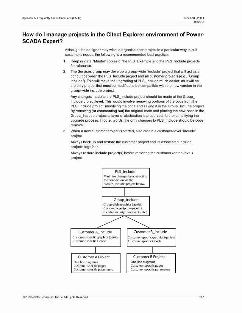
Appendix 5: Frequently AskedQuestions (FAQs) 63220-100-200I103/2015
How do I manage projects in the Citect Explorer environment of Power-SCADA Expert?
Although the designer may wish to organise each project in a particular way to suitcustomer's needs, the following is a recommended best practice:
1. Keep original ‘Master’ copies of the PLS_Example and the PLS_Include projectsfor reference.
2. The Services group may develop a group-wide “include” project that will act as aconduit between the PLS_Include project and all customer projects (e.g., "Group_Include"). This will make the upgrading of PLS_Include much easier, as it will bethe only project that must be modified to be compatible with the new version in thegroup-wide include project.
Any changes made to the PLS_Include project should be made at the Group_Include project level. This would involve removing portions of the code from thePLS_Include project, modifying the code and saving it in the Group_Include project.By removing (or commenting out) the original code and placing the new code in theGroup_Include project, a layer of abstraction is preserved, further simplifying theupgrade process. In other words, the only changes to PLS_Include should be coderemoval.
3. When a new customer project is started, also create a customer-level “include”project.
Always back up and restore the customer project and its associated includeprojects together.
Always restore include project(s) before restoring the customer (or top-level)project.
© 1990–2015 Schneider Electric All Rights Reserved 257

4. Upgrading PLS_Include:
Document all changes to PLS_Include. This is absolutely necessary whenupgrading to a new version of the PLS_Include project.
Minimize changes to the PLS_include project.
Abstract as many changes to the PLS_Include project as possible. This should beaccomplished by the use of multiple include projects as shown in the diagramabove.
New versions of PLS_Include will include a detailed description of each change,allowing you to merge the old and new versions.
New versions of PLS_Include will maintain backward compatibility where possible.
On the Graphics page, what do I need to know about creating genies?1. Creating a new genie:
The easiest way to create a new genie is to use an existing genie from the library.This ensures that the new genie is compatible with the system, and that it preservesthis feature:— A sizing guide (a dotted rectangle) is included; it displays during graphics edit
mode. This guide ensures that new genies can be swapped with existinggenies without the need to recreate portions of the drawing. Save the new geniein the appropriate project (do not overwrite the provided genies).
Save the new genie in the appropriate project (do not overwrite the providedgenies).
2. Copying a genie to another project:
Open the genie in the graphics editor, and do a <save as> into anotherproject/library.
3. Genie Form Files:
Any new genie (copied or created) will not have a .frm file entry associated with it.While the new genie is functional, it will show a cryptic unformatted properties boxin the Graphics Editor. You can create your own .frm file with the needed entries byfollowing the instructions available in the Citect Knowledge base.
If you want to use the .frm dialog box that belongs to the genie you copied, go to thePLS_Include library; locate the .ctm and .ftm files. Each library has its own .ctm/.ftmfiles that include the description for every genie in the library. (This is an ascii textfile that you can open in any text editor.) Find the genie that you copied (or onwhich you're basing the new form). Copy the portion that matches the copied genie,and create a .frm file that has the desired library name on it. Copy in the text fromthe .frm file. Restart Citect Explorer or it will not detect the new .frm.
4. Genie Sizing
The provided genies come in two sizes: size 1 and size 2. When making a newgenie for reuse among multiple projects, it will be beneficial to create a genie forboth sizes. Follow the same steps for both sizes (sizing guides are provided forboth sizes).
How do we customize existing templates?Template Editing:
All objects on the page contain one or more Animation Numbers (ANs). Symbols takeone AN while genies may take tens to hundreds of ANs. Placeholder ANs allow you toadd objects to a template that is used on existing pages.
258 © 1990–2015 Schneider Electric All Rights Reserved
63220-100-200I1 Appendix 5: Frequently AskedQuestions (FAQs)03/2015

Appendix 5: Frequently AskedQuestions (FAQs) 63220-100-200I103/2015
Some default templates contain ANs that have associated Cicode functions that rely onthe animation number to remain a fixed number. For this reason, we have pre-allocated a set of ANs for the default templates. The base normal template uses ANs1–263, and it has placeholder ANs from 264–500. When customizing this template,you should use the placeholder ANs as required.
You can place an AN (or a placeholder AN) on the page by using the “System 3.x/4.xtools available in the Graphics Builder under Tools< Options.
The default template uses ANs 1–263 and it has placeholder ANs from 264–500.
New objects added to a page or template will take the next available ANs. Anypreviously used (and now abandoned) ANs will be reused.
To add an object on the template, you must:
1. Open the template.2. View the page properties and change the page width to 2000. This will reveal the
hidden placeholder ANs on the page. You may have to change the width to a widerdimension for widescreen templates.
3. Determine how many ANs the new object requires. (You can place the new objecton a blank page and then view the object in the object browser.)
4. Remove exactly the amount of ANs to allow the new object to be placed on thetemplate. Remove ANs beginning with the lowest available placeholder AN (in thedefault template, this would be 264).
5. Place the object on the template.
6. Save the template.
7. Create a new page based on this template.
8. Drop a numeric object on the page.
a. This object’s AN should be 502 (501 is reserved for placing the template on thepage).
b. If the object has an AN less than 502 then you have unused AN(s) on thetemplate. This must be resolved. (Place additional ANs on the template to rectifythis situation.)
c. If the object has an AN greater than 502 then you have too many ANs on thetemplate (a AN on the template is going beyond the 500 limit). You must find theculprit (via the object browser) and rectify the situation using the steps above.
How do I change the default pickup/dropout text for alarms?The default ‘pickup/dropout’ text is shown as Appearance/Disappearance.
To change globally:
This text may be changed by configuring INI parameters in the citect.ini file. Formore information, see the System Integrator’s Guide (Graphics Library Parameterson page 241)
This is the global fallback text that will be used in the event that pickup/dropout textis not specific on a per-alarm basis in the Device Profile. You can specify the per-alarm pickup/drop-out text on the profile tab in the Profile Editor.
To change on an individual basis:
See the System Integrator's Guide (View Device Profiles on page 39, "Alarm OnText" and "Alarm Off Text").
© 1990–2015 Schneider Electric All Rights Reserved 259
What can I modify during runtime?Set-point Configuration during runtime: In the Alarm Server entry in the project editor,view the advanced properties (F2) and set publish alarm properties = TRUE
Events Accessible at runtime: By default, 5000 events are accessible (view, filter,print) during runtime. Additional events are logged to disk. The number of eventsaccessible at runtime may be changed by the [Alarm] SummaryLength parameter inthe INI file.
Why do the browser navigation buttons not work?If the browser navigation buttons do not work when you are viewing the runtimewindow, you have probably added a new page, but have not done the following:
• added the startup page to the Page parameter. See Set a New Page as the ProjectStartup Page on page 112 for help.
• left the INI settings at <default>. In the Computer Setup Wizard, General OptionsSetup screen, do not change the StartupPage field; leave it as <default>.
What can I set up in logging and archiving?Event Logging and Archiving:
Event fields that are logged to disk may be configured by adjusting the AlarmFormatparameter.
There is no automatic maintenance performed on the log files. It is important that thelog/waveform data be cleared out periodically (to prevent the hard drive from filling up;this does not affect performance).
How do I create and configure busbars?When drawing one-line diagrams:
Analyse the drawings at a customer site.
Number the busbars consistently on the one line diagram(s). If busbar 14 spansacross multiple pages, it should be numbered busbar 14 on all pages. Label thevoltage level (0–3) on each busbar.
Uses for Line Active:
Page Connections: Many one-line diagrams will span multiple pages. To connectthese pages together, you must use the line active field of the ‘incomers’ of thesecond and subsequent pages. Set the line active field of the incoming busbars onthese pages to an expression that references the nearest device on the samebusbar of the previous page.
Metered Busbar: Many busbars are actually metered. It is more accurate to allowthese metering devices to dictate state than to rely solely on the simulation (seeExpressions below).
Configuration of Line Active:
Simulation: If the Line-Active field is left blank, the busbar state will be determinedby surrounding devices.
Expressions:
A Cicode expression in the form of Device\Tag > Nominal Voltage (I.E., S1_B1_P1_CM41\MMXU1\PhV\zavg > 120).
260 © 1990–2015 Schneider Electric All Rights Reserved
63220-100-200I1 Appendix 5: Frequently AskedQuestions (FAQs)03/2015

Appendix 5: Frequently AskedQuestions (FAQs) 63220-100-200I103/2015
If the expression is TRUE, the ACTIVE color will be shown. The active color isdetermined by the voltage level assigned.
If the expression is FALSE, the DE-ENERGIZED color will be shown.
Hard-Coded:
If no upstream devices are available (in the event of an incomer, for example), youmay have no other choice than to ‘hard code’ this field to a ‘1’. This forces thebusbar to always be ACTIVE.
What INI parameters should I use for debugging?We recommend that you contact Technical Support before performing any debugging.
Parameter: [PowerLogicCore]DebugCategory = All
DebugLevel = All (or Error)
LogFileArchive = Deprecated; no longer used. Use [Debug]SysLogArchive instead.
LogFileSize = Deprecated; no longer used. Use [Debug]SysLogSize instead.
Parameter Details:
DebugCategory defines which message categories to log. (See table below).
DebugLevel defines debug levels of messages to be logged. (See table below).
Debug Levels
The following debug levels are accepted by PowerLogic driver core library:
WARN: log all warning level messages
ERROR: log all error messages
TRACE: log all trace messages
DEBUG: log all debug messages
ALL: include all level messages
Debug Categories
PowerLogic core library and drivers messages are grouped in categories. Each ofthese categories can be enabled independently from others in any combination.
MISC: miscellaneous messages that do not all into any other category
ALARM: messages related to alarms, regarding collection and detection
WAVE: messages related to waveforms -- waveforms download, processing
REAL: messages related to real-time data collection
STATE: messages related to internal object-state changes
CORE: core events that do not fall into driver-specific logic
MODBUS: TCP/MODBUS messages
ENTRY: trace messages produced when driver API entry points are called
PORT: traces related to the port events
UNIT: traces related to specific unit events
WAVETOALARM: not used
DATAPOINT: debug messages related to data points
STATISTICS: enables driver statistics data output
COMMAND: messages related to commands
© 1990–2015 Schneider Electric All Rights Reserved 261
REPLICATION: messages produced by replication subsystem
ALL: enables all categories
Parameter: [Debug]Menu = 1
Parameter Details:
The Menu parameter determines whether the Kernel option is displayed on the controlmenu of the runtime menu. This can also be enabled using the Computer Setup Editor.
How do I tune my system for best performance?There are several parameters that you can use to enhance your system's performance:
Driver-tuning parameters:
Parameter (Back Polling Rate): [SEPAM40]
CacheRefreshTime = 1000
InitUniCheckTime = 120
Retry = 3
Timeout = 1000
Parameter Details:
The CacheRefreshTime parameter controls the maximum rate at which the driverwill attempt to repopulate its cache. If the driver cannot refresh its cache within thetime period specified, it will collect data as fast as the network allows.
This back polling rate can be global to all devices or tuned up to a specific I/Odevice.
The InitUniCheckTime parameter controls how long the driver will wait beforeattempting to bring a device online after it has gone offline. This value can bedecreased to bring offline devices back into service in a shorter period of time. In amulti-drop scenario, this time should be relatively long, to prevent init unit requestsfrom stalling communications to the rest of the devices on that port.
The Retry parameter defines the number of retry attempts for specific MODBUSrequests. Retries will only occur in response to the MODBUS errors which aredefined below.
The Timeout parameter controls how long the driver will wait for a response from adevice before setting that device as offline. This value should be greater than thedevice/gateway timeout period.
Parameter: [Device]WatchTime = 5000
Parameter Details:
Device WatchTime is the frequency that PowerSCADA Expert checks devices forhistory files and flushes logging data to disk.
Default: 5000
Range: 1000–3600000 milliseconds.
Miscellaneous Parameters
Parameter: [Kernel]Task = 20000
262 © 1990–2015 Schneider Electric All Rights Reserved
63220-100-200I1 Appendix 5: Frequently AskedQuestions (FAQs)03/2015
Appendix 5: Frequently AskedQuestions (FAQs) 63220-100-200I103/2015
Parameter Details:
Kernel Task is the number of tasks. Increasing the number of kernel tasks is usedwhen “Out of Kernel Task” message is received. The change will be likely for largesystems.
Default Value: 256
Range: 50–32767
Parameter: [Page]ScanTime = 250
Parameter Details:
Page ScanTime determines how often the Animator refreshes a graphics page atruntime.
Default: 250
Range: 1–60000 milliseconds
Parameter: [ALARM]ScanTime = 500
Parameter Details:
Alarm ScanTime determines the rate at which alarms are scanned and processed.
Default: 500
Range: 0–60000 milliseconds
If a tag is configured, how is it polled in the device?In other words, is a tag only polled on demand when it is requested by a client (forexample, when the operator displays a page with the tag on it)? Or are all configuredtags polled all of the time, with the relative polling rates/communications bandwidthcarefully managed?
The ModNet driver polls real-time tags on a user demand basis (when a user opens apage with the tags on it). Therefore, the time to retrieve data will vary, depending notonly on the communications bandwidth, but on the amount of data being requested.This can vary significantly, depending on which pages are displayed by the operatorsat any particular time.
The PWRMODBUS driver polls all configured tags; however, different types of tags canbe polled at different relative rates, and the available communications bandwidth iscarefully managed. This approach means that tag update rates are not subject to thescalability issues associated with operator actions (as is the case for the ModNetdriver). It is also advantageous in that performance issues associated withcommunications bandwidth or IODevice response times can be determined atSAT/time of implementation and are not subject to significant change during operation.
The different tag types can be allocated relative importance in data requests,expressed as a percentage. (See Bandwidth Allocation Parameters in PerformanceTuning Parameters on page 229.) Keep in mind that any unused bandwidth allocation(from, for example, events retrieval) is made available for other data types to use. If theevent does not need the default 25% allocation, it will be made available to the otherparameters (real-time tag retrieval, etc). This potentially increases the update rate ofreal-time tags.
© 1990–2015 Schneider Electric All Rights Reserved 263

Additionally, the real-time tag relative scan rate based on priority can be set to threedifferent levels. (See Tag Scan Rate Parameters in Performance Tuning Parameterson page 229.) This means that, if some real-time tags are more important that others,you can set their relative priorities. For example, configuration tags vs. important real-time tags vs. normal real-time tags.
Device popup from a one-line: Why do the fields overlap?This is controlled by a parameter entry:
Section: Page
Name: EquipDetailDescLength (the total number of characters in a single row of thispopup)
Default = 48. The problem will occur with a larger font or if the window is resized. Thedefault value of 48 can be changed or the window and associated genies can beresized.
Can I change the %CLUSTER% name in the Profile Wizard?No. If you change the placeholder %CLUSTER% to any other name in the ProfileWizard, the system will be unable to find the actual cluster to which it refers.
When viewing PowerSCADA Expert from a web client, I see a licensingerror. How do I fix it?
First, verify that the appropriate licensing is available.
A web client requires the same number of ports open as a standard control or view-only client. You only need to allow communication to those servers from which theclient needs information. For example, alarm, trend, reports, and I/O.
When you open PowerSCADA Expert from a client computer, and you see a licensingerror, make these port settings. This will open both PowerSCADA Expert and thelicense key server (7001: USB sentinel key port) in the routers and firewalls betweenthe client and the server. The ports that you need to open are listed in boldface:
Default Port Server Type Server Role
21 FTP server IDCpage downloads for IDC
Internet display server/client communications
80 Web server project files for Web client
2073 CTAPI CTAPI communications
2074 client Cicode debugging
2084 Reports server Reports server communications
2080 Alarm server Alarm server communications
2085 Trends server Trends server communications
2078 IO server legacy I/O communications
2080 Alarm server alarm properties connector
2081 time server time server communications
2082 IO server publish subscribe I/O server communications
20222 ODBC ODBC server
264 © 1990–2015 Schneider Electric All Rights Reserved
63220-100-200I1 Appendix 5: Frequently AskedQuestions (FAQs)03/2015

Appendix 5: Frequently AskedQuestions (FAQs) 63220-100-200I103/2015
A device can prevent writes to its registers: how do I ensure that writesare successful?
PowerSCADA Expert cannot provide feedback about whether a write to a deviceregister is successful. If a device is capable is preventing (blocking) writes to itsregisters (for example, Sepam), you need to verify that its “block” feature is notenabled. Do this at the device.
NOTE: In Cicode, you can also use the tagwrite function in blocking mode, i.e., bSyncparameter = true; Check the return code: 0 = success, anything else = error. For moreinformation, see the Cicode Programming Reference help file.
How do I prevent PowerSCADA Expert from accidentally makinginvalid areas in memory available to reads and writes?
PowerSCADA Expert normally optimises its packets for greatest performance. Thisoptimisation can sometimes includes invalid areas of memory in devices. These invalidareas can be specifically defined and excluded from optimisation packets created byPowerSCADA Expert. See Advanced Tag Blocking Capabilities in Performance TuningParameters on page 229 for more information.
How do I create an audit in the Event Log for user logins and logouts?//LOGOUT
FUNCTION
PLSLoginUser()
© 1990–2015 Schneider Electric All Rights Reserved 265
//INT iPage = PageInfo(1);
INT iPage = WinNumber();
IF mbLoginFormShown[iPage] = TRUE THEN
RETURN; //form already shown
END
//prevent multiple forms
mbLoginFormShown[iPage] = TRUE;
IF (UserInfo(0) <> "0") THEN
// Confirm User Action
IF (0 = Message(StrToLocalText("@(Confirm)"), StrToLocalText("@(Logout)"), 1+32)) THEN
PLSAlmDspEventAdd(0, 0, 1, "User Logout", Name(), "Logout", "");
Logout();
END
mbLoginFormShown[iPage] = FALSE;
RETURN;
END
IF (0 = LoginForm())
PLSAlmDspEventAdd(0, 0, 1, "User Login", Name(), "Login", "");
END
mbLoginFormShown[iPage] = FALSE;
END
Why do I get an "out of memory" message when I try to run the Auto-mation Interface?
The problem is that you did not have Microsoft Excel installed before you installedPowerSCADA Expert. The only solution is to uninstall both Excel and PowerSCADAExpert; then, reinstall first Excel and then PowerSCADA Expert.
Why am I seeing #COM for circuit breaker status in the genie statuspage?
If this is a Micrologic P device, and it does not have a CCM, you will not be able to viewdata referring to circuit breaker status, e.g. racked in/racked out. When there is noCCM, the device profile should not have tags that refer to the CCM.
Why can't I acquire waveforms in the waveform viewer?The "acquire" feature (the "A" button on the waveform viewer) does not work inPowerSCADA Expert. You can, however, view waveforms from device onboardwaveform files. To do this:
• At the device or in the meter configuration software, add the appropriate alarm, andenable automatic capture of the waveform when the alarm occurs.
• In the Profile Editor (Create Device Profiles tab), check the Waveform box for thealarm you added.
266 © 1990–2015 Schneider Electric All Rights Reserved
63220-100-200I1 Appendix 5: Frequently AskedQuestions (FAQs)03/2015

Appendix 5: Frequently AskedQuestions (FAQs) 63220-100-200I103/2015
• When the alarm occurs, the waveform is captured. You can view the waveform inthe Alarm Log. You can also view alarms/waveforms from a drawing in the runtimeenvironment. Click the genie for the device; right-click the alarm to view thewaveform.
Note that, in very large systems, it could take as much as an hour for the waveformto appear.
Why won't the Excel DBF Add-In toolbar install?When you are installing the Excel DBF Add-In toolbar, you may see this error: "Error1308. Source file not found....."
You can click "ignore" at this error, and the install will finish. The next time you openExcel, the DBF toolbar will display.
What causes the "First dbf record" error message? How do I keep itfrom happening?
The error message "First dbf record" tells you that a project is not found. This happenswhen you add a project, and then rename it or delete it. Then, when you try to create anew project, you see this error message.
To resolve this issue, simply shut down and then restart the Citect Explorer.
Why is my device in comms loss?When you bring your system on line, and you find that PowerSCADA Expert has lostcommunications with a device, check the following:
• Verify that the physical correction is correct and secure.• Verify the IP address.• Verify the Modbus address.• Check the statusRegister, statusRegistersCount, and statusRegisterType (see for
details)
How do I set up select before operate?For systems in which you can determine that a single user is selecting a device prior tosending an open/close command, you can add a "select before operate" button.
To do this:
1. Locate the Select Before Operate tag in the variable tags.2. Append \str to the end of the tag name.
3. Change the data type to STRING.
4. Click Add.
This creates the SBOw tag for the IEC 61850 advanced control screen. For moreinformation about advanced control, see:
Set Up IEC 61850 Advanced Control on page 117
Perform IEC 61850 Advanced Control on page 167
© 1990–2015 Schneider Electric All Rights Reserved 267

Index of Terms
.
.aes file
encryption 207
1
1.#R
value returned in instant trend 163
A
access rights
adding for users 39
changing for users 211
Windows integrated users 210
ACE969TP device type
used with DNP3 50
ACE969TP module
used with DNP3 50
additional sources of information 9
address
correcting missing or invalid 24
functional 25, 53
defiined 248
advanced control
perform for IEC 61850 165
set up
IEC 61850 117
advanced tag block capabilities
configuration notes 234
invalid block tag definition syntax 233
tag blocking notes 236
write-only memory 235
write-only tags 236
AdvOneLine.csv 120
AdvOneLine.exe 120
stopping and starting 123
AdvOneLine.ini 120
AdvOneLine.ini settings
one-lines 121
AdvOneLineDebug.Bus.csv 120
AdvOneLineStatusLog.txt 120
alarm
adding an onboard tag 141
associated with waveforms 150
category 161
category number 161
changing pickup/dropout text 259
changing the severity 140
codes
unique identifier 36
colors 156
filtering
custom 160, 162
historical logging parameters 140
issues 158
level
setting in Profile Editor 40
onboard 138
pc-based 138
setting up in Profile Editor 42
priority 161
priority number 161
© 1990–2015 Schneider Electric All Rights Reserved 268
Index of Terms 63220-100-200I103/2015

setting up based on an enumeration 139
states
startup parameters 241
tags
adding 139
alarm filters 160
alarm format code definitions 68
alarm log 156
column headings described 159
filtering 156, 160
freezing 156
logging data to disk 157
printing 158
problem with alarms not displaying 140, 158
sorting 155-156
Alarm On/Alarm Off text 42
alarm pages
adding to the project 139
Alarms/Events page
equipment column 155
filtering alarms 161
remove/insert/move columns 156
viewing 155
AlarmSummaryLength parameter
maximum number of entries in the EventLog 140-141
analysis page 163
and all REAL 70
animation
loss of communication not filtering correct 155
not display correctly when genie dimensionswrong 125
animation numbers (ANs)
used in objects 258
Application Services
restart 203
setup 204
Applications 206
array
genie properties 117
assigning tags to generic I/O points 28
assumptions
about PowerSCADA Expert systemintegrators 1
before system integrator can set up system 1
ATS
configuring 124
errors 133
information 132
audible alarms
setup 142
auto assign genie 128, 131
auto configure genie 128, 131
automation interface
"out of memory" message 102
adding multiiple devices 102
required information 103
B
back ground color
changing in projects 112
63220-100-200I1 Index of Terms03/2015
269 © 1990–2015 Schneider Electric All Rights Reserved

background colors
changing 167
backup
Citect project file 143
Profile Editor project file 56
base unit and conversion
adding and editing 22
deleting 23
basic readings summary 184
basic reports
Internet Explorer 9 emulation 171
set up delivery method and email address 207
before you use the Profile Wizard 87
block writes
using 85
BRCB
entering for IEC 61850 device 99
entering for IEC61850 device 99
breaker
configuring 125
errors 134
information 134
browser navigation buttons do not work 112
busbar
configuring 125
creating and configuring 260
errors 134
information 133
busbars
two with same line active 131
C
CacheRefreshTime parameter 262
calculating disk storage 148, 163
CallProvider
PLSProviders.ci 143
CASE
changing user access rights 211
category/subcategory
adding 30
deleting 30
editing 30
managing 254
changing alarm severity 140
circuit breaker status
using special tags to control 67
Citect platform connection 205
Citect.ini
used to customize a project 143
citect.ini file
setting up multiple monitors 202
Citect.ini settings
one-line 121, 123
clear cache 145
Live View 192
reporting 178
cluster
adding 88
CLUSTER name (%CLUSTER%)
changing 264
© 1990–2015 Schneider Electric All Rights Reserved 270
Index of Terms 63220-100-200I103/2015

cluster setup
in the Profile Wizard 92, 94, 96, 98
redundantI/O servers 90
collapse/expand all
Import Reconciliation screen 62
color
active
busbars 261
changing background in projects 112
changing for genies 112
colors
assigning to one-lines 121
changing background 167
comment field
used in translation 89
comms loss
troubleshooting 267
communications loss 155
troubleshooting 267
compile and run 6
Compile Errors window
viewing PowerSCADA Expert errors 113
Complete Import button 58, 63
composite device type
creating 46
Computer Setup Wizard
running after first compile 6, 88
when adding a startup page 112
configuration
one-line engine 206
configuration tools
described 2
configure
application services 203
control format codes 69
control inhibit 167
controls
how they operate 25, 37
conversions
to base units 21
core service host
connection with Citect 205
core services
configure 203
CoreServiceHost
restart when changing runtime projects 169
create menu item for LiveView page 193
creating
CSV file 29
device profile 39
engineering template 19
genie 116
one-line on a graphics page 112
PowerSCADA Expert project 110
project 50
CSV file
creating, viewing, printing 18, 29
CTZ file
backup file 143
63220-100-200I1 Index of Terms03/2015
271 © 1990–2015 Schneider Electric All Rights Reserved

custom
control format codes 69
filters
alarms 160, 162
genie
creating 117
icon 17
reset
adding 36
symbol
creating 117
tag
deleting 34
deleting when associated with a devicetype 34
editing 33
custom tag
adding 32
customer support contact information 9
customize tag names
sub-tab 50
customizing a project with Citect.ini 143
customizing tag names 51, 54
D
data concentrator
setup 48
data points
defining individually in an address 25
data replication parameter 240
datasets
adding/editing 44
DBF Add-In toolbar will not install 267
deadbands 148
debugging
INI parameters to use 261
define
device types and tags 23
enumeration 66
demand current summary 189
demand voltage summary 189
demo mode
using 202
design-time environment
described 110
device
adding multiple 256
adding to the PowerSCADA Expert project 92
name
requirements 255
popup
overlapping fields 264
profile
adding 52
creating 39
defined 6
deleting 43
editing 42
removing from a PowerSCADA Expert pro-ject 101
tags
defining 23
© 1990–2015 Schneider Electric All Rights Reserved 272
Index of Terms 63220-100-200I103/2015

type
adding, editing, deleting 26
defined 5
defining 23
deleting 28
editing 27
locking 17
unlocking 18
device communications issues
troubleshooting 255
device profile
add as default 53
device type
category/subcategory
adding 30
deleting 30
editing 30
composite 46
drivers
INI parameters 146
drivers and protocols
list of supported 3
name
limitations 26
Device Wizard
before you use it 87
devices in the PowerSCADA Expert project
editing 100
diagnostics (Application Conifguration Utility 204
disabling "tag not exist" prompt. 113
disk storage calculations 148, 163
display client
basic report viewing 171
display projects button
adding a project in the Profile Editor 6, 52
DNP3-TCP device
adding 96
DNP3 protocol support 50
DNP3_serial
adding to PowerSCADA Expert project 94
documentation in this release 9
driver parameters
editing 4
selecting for a profile 47
setting up in the Profile Editor 42
drivers
choosing for device types 27
general PowerSCADA Expert 222
generic power device 3
how they work 3
subscription expirations 4
subscription types 3
duplicate devices
defined 4
E
EcoStruxure Web Services (EWS)
configuration 204
avoid timeouts 205
introduction 169
63220-100-200I1 Index of Terms03/2015
273 © 1990–2015 Schneider Electric All Rights Reserved

configure to send basic reports 173
sending reports 174
encryption
aes file for saving INI file to a differentcomputer 207
password 119, 122
energy readings 185
energy summary 185
engineering template
creating 19
engineering units
adding 22
exceptions 21
adding from the Project tab 53
deleting 23
editing 23
multipliers and offsets 21-22
English.dbf
used in translation 93, 95, 97, 99
English.dbf file
used for translation 93, 95, 97, 99
entering copy for translation 91, 93, 95, 97, 99
enumeration
defining 66
setting up alarm based on 139
status enumeration logic code 75
equipment column
alarms/events pages 155
equipment name
adding via Automation Interface 103
adding via Profile Wizard 93, 95, 97-98
using when creating a one-line 113
equipment pop-up page 164
Equipment.Profiles
file storage location 55
viewing 51
errors
ATS 133
breaker 134
busbar 134
meter 135
sources 136
switch 133-134
transformer 137
errors and warnings
correcting in the graphics page 113
one-line 130
event filters 160
event log 156
acknowledge, silence, print 157
logging data to disk 157
problem with alarms not displaying 140
event notification serivce
Application Configuration Utility 205
events
historical logging 140
storage limitations 140
Example Automation.xls
using to export multiple devices 102
Excel DBFAdd-In toolbar will not install 267
© 1990–2015 Schneider Electric All Rights Reserved 274
Index of Terms 63220-100-200I103/2015

expanding PowerSCADA Expert screens
F2 key 89
export
PowerSCADA Export 55
Profile Editor (backup) 56
project files from Profile Editor 54
SCL files 57
F
F2 key
use to expand PowerSCADA Exportscreens 89
use to expand screens 89
FAQs 254
"out of memory" message in Automation Inter-face 266
#COM error for circuit breaker status 266
adding more than one device at a time 256
adding/removing devices in Profile Wizard 254
auditing user logins/logouts in the EventLog 265
browser navigation buttons do not work 260
can I change %CLUSTER% name 264
changing default pickup/dropout text 259
creating and configuring busbars 260
creating device profiles without PowerLogicdrivers 254
creating users in Runtime 256
device name requirements 255
device type vs device profile 254
device writing to its registers 265
Excel DBF Add-In toolbar will not install 267
How do I troubleshoot device communicationsissues? 255
how to use MODBUS communicationsmethods 256
if tag is defined, is it polled 263
INI parameters used for debugging 261
licensing error at web client 264
managing categories and subcategories 254
managing projects in PowerSCADAExport 257
naming conventions for servers/clusters 256
overlapping fields in device popup 264
performance tuning parameters 262
preventing reads/writes to invalid ares ofmemory 265
synchronize new PC with master PC 254
what are genies 258
what can be set up in logging andarchiving 260
what can I modify during runtime? 260
working with templates 258
FileFormat parameter
historical logging of alarms and events 141,157
filter
import data 61-62
filter genie states 129, 159
filter the alarm and event logs 160
filters
real time and alarm 33
First dbf record
error 267
force edit 63
format codes
alarm definitions 68
63220-100-200I1 Index of Terms03/2015
275 © 1990–2015 Schneider Electric All Rights Reserved

control definitions 69
custom control 69
definitions 67
predefined control 69
real-time definitions 67
reset 69
frm file
associated with new genie 258
FRM file
formatting genie appearance 117
functional address 25, 53
definition 248
edit 31
functional constraints
IEC 61850 59
fundamental phasor readings 185
G
G3200 setup 48
generic I/O points
assigning tags 28
generic MODBUS drivers
included in system 3
genie
adding to a drawing 112
auto assign 128, 131
auto configure 128, 131
busbar 125
configuration
viewing 128
creating and editing 116
grouping 129
icon 112
in Graphics page 258
libraries
ITEM1 220
PLS_ALARM 212
PLS_ANSI_BASE_1 / PLS_ANSI_BASE_2 212
PLS_ANSI_CB_1 / PLS_ANSI_CB_2 214
PLS_ANSI_SW_1 / PLS_ANSI_SW_2 215
PLS_DISPLAY 215
PLS_GEN_BASE_1 / PLS_GEN_BASE_2 216
PLS_GEN_CMD_1 / PLS_GEN_CMD_2 217
PLS_GEN_EQ_1 / PLS_GEN_EQ_2 217
PLS_IEC_BASE_1 / PLS_IEC_BASE_2 218
PLS_IEC_CB_1 / PLS_IEC_CB_2 218
PLS_IEC_SW_1 / PLS_IEC_SW_2 219
PLS_METER 219
meter 126
repairing 131
resizing 125
source 126
state filters 129
switch/circuit breaker 125
transformer 127
genie color
changing in project pages 112
GenieConfiguration.xml file
one-line 127
© 1990–2015 Schneider Electric All Rights Reserved 276
Index of Terms 63220-100-200I103/2015
genies
PowerSCADA Expert 124
GetProviderResult
PLSProviders.ci 145
GetProviderStatus
PLSProviders.ci 144
getting more information 9
graphics library parameters 241
graphics page
adding in PowerSCADA Export 111
setting as startup page 112
Graphics runtime environment
editing appearance 115
group by type or page 129
guest user
single sign on 208
H
harmonic apparent power flows 187
harmonic reactive power flows 188
harmonic real power flows 188
help files 9
historical parameters of alarms
setup 140
historical trends
viewing 163
viewing from a one-line 166
HostName
ini parameter 242
I
I/O server
adding before using the Equipment Wizard 88
ICD file
editing 57
icons
locked and custom 17
IEC
import filter for ICD files 59
IEC 61850
adding device to PLS project 98
advanced control setup 117
datasets
adding/editing 44
functional constraints 59
general workflow 8
perform advanced control 167
re-match 62
report control blocks 59
adding/editing 45
tag construction 65
tags
logic codes described 69
IED
defined 248
IF logic
Live View 196
ignored devices and topics 148
IID
defined 248
63220-100-200I1 Index of Terms03/2015
277 © 1990–2015 Schneider Electric All Rights Reserved

import
files into Profile Editor 57
filter data 61
ignore 63
match option 63
project files into Profile Editor 54
removing import templates 65
SCL files 59
set to unmatched 63
template
applying 58
using 64
import filter
IEC 61850 files 59
import Import reconciliation screen 60
incremental reactive energy summary 186
incremental real energy summary 187
INI parameters 221
for historical reports 170
for supported device type drivers 146
to use in debugging 261
instant trend
pens stop updating 163
viewing 163
interlock check
IEC 61850 devices 167
internationalization
real-time tables 199
Internet Explorer 9 emulation
reporting 171
intervals
trend tags 47
invalid or missing tag address
correction 24
IP address
entering in Example Automation.xls 103, 107
Is Device Tag
reporting for composite devices 41
J
JBus
adding 3, 27
L
launchiing the profile editor 17
licensing error at web client 264
LiveView
basic readings summary 184
conditional formulas 196
create menu item 193
create new template 194
data format 195
delete 199
demand current summary 189
demand voltage summary 189
does not launch (Matrikon Explorer) 183
duplicate 198
edit predefined template 192
energy readings 185
energy summary 185
formatting 194
formulas 196
© 1990–2015 Schneider Electric All Rights Reserved 278
Index of Terms 63220-100-200I103/2015

fundamental phasor readings 185
harmonic apparent power flows 187
harmonic reactive power flows 188
harmonic real power flows 188
incremental reactive energy summary 186
incremental real energy summary 187
internationalization 199
introduction 183
lock setup 192
minimum/maximum readings 197
modify 198
placeholders 191, 195
power flow summary 184
save a template 193
save a view 191
setup 192
tables list 184
templates 190
THD current summary 185
THD voltage summary 186
thresholds 197
update device list 190
update intervals 191
update list 190
update now 191
uptime summary 186
URL link to launch 190
view area 193
viewer window 189
views 190
Where's my device? 191
LiveView Template Editor 183
locked device type
cannot delete 28
unlocking 18
locked icon 17
locking a device type 17
lockout/tagout 154
enable 114
logging level 204
logic codes
definitions 69
loopback address
used for network addresses 88-89
M
main menu options 18
manuals 9
Matrikon
LiveView and reporting do not launch 170, 183
memory device
one-lines 120
menu
main options 18
Menu Configuration
used to edit Graphics page menuinformation 6, 115
Menu Configuration tool 114
metadatafields.xml
use to edit alarm filters 161
meter
configuring 126
63220-100-200I1 Index of Terms03/2015
279 © 1990–2015 Schneider Electric All Rights Reserved

errors 135
information 135
Micrologic
genie in Graphics Builder 219
MicrologicV INI settings 240
Microsoft Excel
using to add devices to the database 102
migration utility 10
MODBUS communications methods 256
multi-device reports 179
multiple monitor support 202
N
naming ports 100
navigation arrows
runtime environment 154
network address
adding 89
network address and servers
adding before using Profile Wizard 88
NetworkTagsDev I/O device
adding 90
normally closed
control tags 25
O
OLE automation interface
add and remove devices 103
onboard alarm tag
adding 141
onboard alarms 138
one-line
adding to a graphics page 112
coloring 121
communication errors 130
PowerSCADA Expert
described 120
repairing 131
one-line animation file locations 120
One-Line Configuration Utility 128
one-line device 120
one-line engine
configuration 206
one-line flowchart 118
one-line memory device 120
out of memory message
when running Automation Interface 102
override
tag name 41, 47
override tag status 166
P
pack
after deleting a cluster 89
using to delete data 118
Pagemenu.dbf
editing 115
parameters
advanced tag block capabilities 232
alarm and event state 241
AlarmFormat 160, 162
AlarmSummaryLength 140-141
© 1990–2015 Schneider Electric All Rights Reserved 280
Index of Terms 63220-100-200I103/2015

AlarmUseConfigLimits 139
Bandwidth Allocation (port level) 229
BandwidthAllocation (device level) 230
cacheRefreshTime 226
CCM (Micrologic) 239
Citect INI 221
ClientAutoLoginMode
used to set up Windows integrateduser 211
CommandsBandwidth 229
data replication 240
database described 221
driver
editing 4
selecting for a profile 47
enableScatteredReads 230
EventBandwidth 229
EventIdle 239
EventTable 238
general PowerSCADA Expert drivers 222
graphics library 241
HighScanRate 232
initCacheTimeout 225
initUnitCheckTime 225
kernelStatisticUpdateRate 222
LowScanRate 232
maxBlockSize 231
Micrologic 239
MicrologicV INI settings 240
minBlockSize 231
ModbusBase 227
module-specific packet blocking optimisationsettings 239
packet blocking optimization 230
percentBlockFill 230
performance tuning 229, 262
PLSEventLog 141
PLSEventLogFileFormat 157
RegMode 228
retry 223
retryexception 224
retrytimeout 223
Sepam Event Reading 238
standbyCheckTime 224
standbyRefreshRate 224
statusRegister 226-227
statusregistertype 227
statusUnitCheckTime 225
Tag Scan Rate 232
time synchronization 147
time zone settings 146
TimeBandwidth 229
timeout 223
TimeSync 226
timeZone 228
usewritemultiregistersonly 222
watchtime 222
waveform 237
WaveformBandwidth 229
WaveformCheckTime 238
WaveformMatchMargin 238
WaveformsDisable 237
63220-100-200I1 Index of Terms03/2015
281 © 1990–2015 Schneider Electric All Rights Reserved
WaveformZone 238
password encryption 119, 122
pc-based alarms 138
setting up 42
performance tuning parameters 229, 262
pickup/dropout text
changing for alarms 259
platform refresh 145
LiveView 192
reporting 178
PLS export 55
PLS_ClearCache 145
PLS_Example project 7, 110
PLS_PLatformRefresh 146
PLS_ReportDsp()
Cicode function
used in report configuration 169
PLS_ReportPage
used in report definition 169
PLSAnimBusbar()
Cicode function for custom genieanimation 117
PLSEventLog parameter
allowable values 157
historical logging of events 141
PLSProviders.ci module 143
PM5000
device profiles for the Profile Wizard 93, 95
PM5000S 93, 95
PM5000S1 93, 95
PMCU
adding onboard alarms and waveformcaptures 140
defined 249
polling rules for tags 263
port renaming
serial 94
ports
naming 100
renaming
serial 95
TCP 93, 97
power flow summary 184
PowerSCADA Expert
backup 143
described 2
naming conventions 256
project
creating 110
uninstall and reinstall 5
PowerSCADA Expert one-lines
described 120
error logging 130
genie introduction 124
GenieConfigureation.xml file 127
introduction 128
SupportedGenies.xml file 127
predefined control format codes 69
predefined project
PLS_Example 110
© 1990–2015 Schneider Electric All Rights Reserved 282
Index of Terms 63220-100-200I103/2015
printing
CSV file 29
printing the alarm log 158
privileges
user
PowerSCADA Expert 209
profile editor
export 56
launching 17
overview 13
Profile Editor
importing files into 57
Profile Editor.exe.config
using to change trend tag scan intervals 148
Profile Wizard
adding a device 87
adding a device to a project 92
before you use it 87
editing device information in a PowerSCADAExpert project 100
removing a device 101
profiles
adding, editing, deleting 41
enabling waveforms 39
file storage location 55
name limitations 41
viewing 39
project
adding 52
cannot add 267
creating in PowerSCADA Expert database 55
deleting 53
editing 53
exporting (to Citect from Profile Editor) 55
managing in PowerSCADA Expert 257
name limitations 52
problems when renaming in Citect 110
reusing 111
setting up 50
project parameters
sub-tab 50
using to add information for imports 51
Project Parameters sub-tab 54
project XML files
storage location 55
PSEHostName
ini parameter for SSO 242
Q
Quantum PLC
genie in Graphics Builder 220
time-stamped events 244
quick start 5
R
rack position
displaying incorrectly 125
Rapid Access Label
configure the report 172
create and use 200
label stock 201
view LiveView tables 190
re-match IEC 61850 items 62
63220-100-200I1 Index of Terms03/2015
283 © 1990–2015 Schneider Electric All Rights Reserved

read logic codes 70
read/write logic codes 85
real-time format codes definitions 67
real-time lists
viewing from genies 166
redundant I/O servers
cluster setup 90
refreshing tags in the Project tab 51, 55
RemoteCallHandlerCluster
ini 243
RemoteCallHandlerServer
ini 242
repair
one lines 131
project 129
upgrade project 129
report configuration
saving 172
report control blocks
IEC 61850 59
reporting basic
application tasks 171
ReportMailer utility
sending email reports 175
reports
adding to runtime menu 170
basic
accessing, creating, modifying,removing 171
configure email to send 173
editing appearance 178
export 177
exporting, printing, saving 176
localization 182
set up a display client for reportviewing 171
set up delivery method and emailaddress 207
URL routing 182
do not launch (Matrikon Explorer) 170
enable Windows Authentication 181
feature described 169
INI parameters 170
introduction 178
multi device usage 179
PLS_ReportDsp() 169
PLS_ReportPage 169
sending via email 174
setting up in the runtime menu 170
single device usage 178
SMTP server and from address 173
tabular 180
trend 180
using ReportMailer 175
reserved names
do not use in projects 250
reset format codes 69
resets
adding custom 36
how they operate 25, 37
restart services 203
© 1990–2015 Schneider Electric All Rights Reserved 284
Index of Terms 63220-100-200I103/2015

restore
project file 142
resx files
localization 182
reusing a project file 56, 111
roles
adding user 210
runtime environment
described 3
launching and closing 153
viewing 153
S
SBOw tag
creating 267
SCADA
defined 1
scan intervals
trend tags 147
scattered reads
using enableScatteredReads parameter 230
SCL
defined 251
export 57
SCL files
importing 59
screen resolution
Profile Editor 18
security viewer 161
filter 162
select before operate
setup 267
Select Devices
LiveView 190
Selected Device Profiles
sub-tab 50
selecting 21
Sepam
genie in Graphics Builder 220
sequence of events
alarm/event logs 160
SER (sequence of events recorder) 3, 46, 159,161
serial device
adding to PowerSCADA Expert project 94
servers
adding 89
adding to PowerSCADA Expert 88
described 88
servers/clusters
naming conventions 256
service inventory 204
setpoints and delays
entering 139
entering from the runtime environment 165
setting up
alarm based on an enumeration 139
audible alarms 142
device type categories 29
normally closed/normally open controls 25
63220-100-200I1 Index of Terms03/2015
285 © 1990–2015 Schneider Electric All Rights Reserved

severity
changing for alarms 140
show by type or page 129
sim source
transformer top and bottom 137
single device reports 178
single sign on 208
guest user 208
SMTP server
for reports 173
sorting the alarm log 40, 155-156
source
configuring 126
errors 136
information 136
start and stop AdvOneLine 123
startup page
setting 112
state filters 129
storage limitations
calculating disk space 148, 163
subscriptions
drivers 3
support
technical 9
SupportedGenies.xml file
PowerSCADA Expert one-lines 127
switch
configuring 125
errors 134
information 132, 134
symbol
creating custom for custom genie 117
synchro check
IEC 61850 devices 167
set up
IEC 61850 117
synchronize new PC with master PC 254
system creation steps 5
T
tabular usage reports 180
tag
custom
adding 32
customizing the name 51
IEC 61850 described 65
refreshing in the Project tab 51
tag-polling rules 263
tag addresses
adding 38
control 37
correcting missing or invalid 24
editing 34, 38
generic 39
onboard alarm 36
real-time 34
reset 36
tag count
driver subscriptions 3
© 1990–2015 Schneider Electric All Rights Reserved 286
Index of Terms 63220-100-200I103/2015

tag definitions
printing the CSV file 29
tag names
customizing 54
tag override 41, 47
tag status
overriding 166
tag types 65
tags
assigning to generic I/O points 28
scanning intervals for trend tags 47
TCP device
adding to PowerSCADA Expert project 94, 98-99
adding to project 92
technical support 9
Template Editor
LiveView 183
lock 192
templates
creating 19
deleting 21
imports 64
working with 258
THD current summary 185
THD voltage summary 186
The_Profile_Wizard 87
time-stamped events
Quantum PLC 244
time quality
alarm/event logs 160
Time Sync
filter for alarm or event log 161
time synchronization parameter 147
time zone setting parameter 146
transfer switch
configuring 124
transformer
configuring 127
errors 137
information 137
top and bottom 137
voltage-level and pass-through 121, 127, 138
translation
using description fields 91
trend tag intervals 163
changing in the Profile Editor 43
trend tag scan intervals 47, 147
trend usage reports 180
trending (Analysis Page)
described 163
trends
maximum number of pens 163
setting up in Profile Editor 42-43
viewing from within a one-line 166
typical workflow
creating a graphics page 109
creating a project in Profile Editor 51
creating a system 5
Profile Editor 13
63220-100-200I1 Index of Terms03/2015
287 © 1990–2015 Schneider Electric All Rights Reserved
U
uninstalling and reinstalling PowerSCADAExpert 5
unique ID
determining for onboard alarms 36, 141
units (engineering) and conversions
creating or editing a units template 19, 21
deleting 23
deleting a unit template 21
editing 23
exceptions 21
uptime summary 186
URCB
entering for IEC 61850 device 99
URL
visit to send reports via email 174
URL link
launch Live View Viewer 190
URL reporting for basic reports 182
UsePLSFilter
alarm/event filter parameter 160, 229
user access
adding and modifying 209
changing rights 211
Windows integrated 210
useraccess
default settings 209
users
creating in Runtime environment 256
using block writes 85
V
value type
controlling real-time display 165
Variable tags not found
disabling the prompt 113
W
waveform
why can't Iacquire? 266
waveform parameters 237
waveforms
enabling in Create Device Profiles tab 39, 52
enabling onboard 140
linking to alarms 150
management 150
special digital tags 151
storage rules 150
viewing from the Alarm Log 157
viewing from the runtime environment 157
viewing in the runtime environment 165
WaveWeb waveform viewer 157
PDF location 165
web.config
securing a URL for sending reports viaemail 174
SMTP server used when sending email 173
specify Windows Authentication, adding rolesfor LiveView 200
specify Windows Authentication, adding rolesfor Reporting 181
specifyWindows Authentication, adding rolesfor Live View 200
Where's my device? 191
© 1990–2015 Schneider Electric All Rights Reserved 288
Index of Terms 63220-100-200I103/2015

Windows Authentication
enable for Live View 199
enable for reports 181
Windows integrated user accounts 210
Windows security
using to remove user access rights 209
write logic codes 84
writes (logic codes) 85
X
XML files
storage for project files 55
Z
zOL
memory device for one-lines 120
63220-100-200I1 Index of Terms03/2015
289 © 1990–2015 Schneider Electric All Rights Reserved

Schneider Electric35, rue JosephMonierCS 30323F - 92506 RueilMalmaison Cedexwww.schneider-electric.com
PowerLogic is a trademarkof Schneider Electric in France, the USA, and other countries. Othertrademarksare the property of their respective owners.This product must be installed, connected, and used in compliance with prevailing standardsand/orinstallation regulations. As standards, specifications, and designs change from time to time, alwaysask for confirmation of the information given in this publication.63220-100-200I1MN03/2015Replaces63220-100-200H1, dated 09/2014© 2014 Schneider Electric. All RightsReserved.