
Face to Face or Mediated Communication? Personality Makes ...
Upload
khangminh22Category
view
0download
0
Graphic Logic Controller
GLC2600T
GLC2400T
GLC2300T
GLC2300L Graphic Logic Controller
SERIES2000
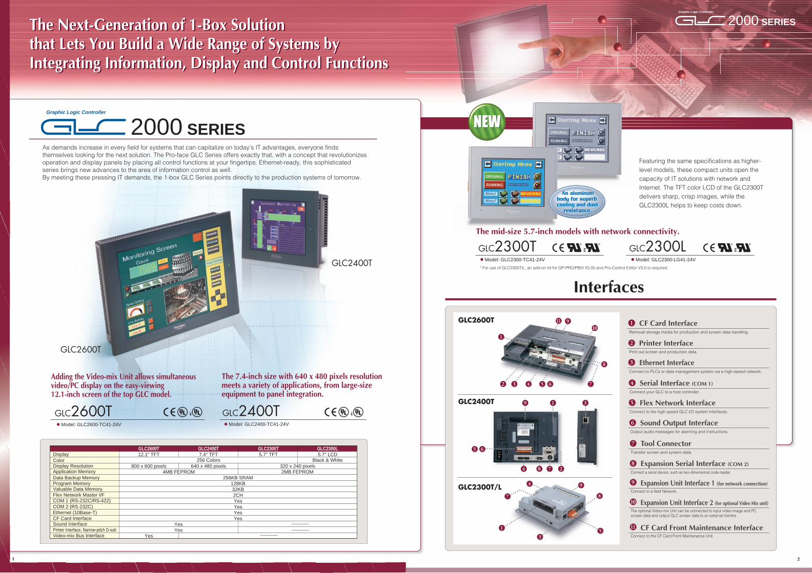
Adding the Video-mix Unit allows simultaneousvideo/PC display on the easy-viewing12.1-inch screen of the top GLC model.
The 7.4-inch size with 640 x 480 pixels resolutionmeets a variety of applications, from large-sizeequipment to panel integration.
As demands increase in every field for systems that can capitalize on today's IT advantages, everyone finds themselves looking for the next solution. The Pro-face GLC Series offers exactly that, with a concept that revolutionizes operation and display panels by placing all control functions at your fingertips. Ethernet-ready, this sophisticated series brings new advances to the area of information control as well.By meeting these pressing IT demands, the 1-box GLC Series points directly to the production systems of tomorrow.
Featuring the same specifications as higher-level models, these compact units open the capacity of IT solutions with network and Internet. The TFT color LCD of the GLC2300T delivers sharp, crisp images, while the GLC2300L helps to keep costs down.
2000 SERIESGraphic Logic Controller
2000 SERIESGraphic Logic Controller
GLC2400T
GLC2400T
lModel: GLC2400-TC41-24V
GLC2600T
GLC2600T
lModel: GLC2600-TC41-24V
GLC2300TlModel: GLC2300-TC41-24V
GLC2300LlModel: GLC2300-LG41-24V
1
9
10
11
8
2
3
5
4
6
7
3
8
9
1
7
1
2 3 4 5 6 7
8
10911
5
GLC2300T/L
GLC2400T
GLC2600TDisplay 12.1" TFT 7.4" TFT
256 Colors Black & White5.7" TFT
800 x 600 pixels 640 x 480 pixels4MB FEPROM 2MB FEPROM
256KB SRAM128KB32KB2CHYesYesYesYes
YesYes
320 x 240 pixels
5.7" LCDColorDisplay ResolutionApplication MemoryData Backup MemoryProgram MemoryValuable Data MemoryFlex Network Master I/FCOM 1 (RS-232C/RS-422)COM 2 (RS-232C) Ethernet (10Base-T)CF Card InterfaceSound Interface
Video-mix Bus InterfacePrinter Interface, Narrow-pitch D-sub
GLC2400T GLC2300T GLC2300L
Yes
4
The Next-Generation of 1-Box Solutionthat Lets You Build a Wide Range of Systems by Integrating Information, Display and Control Functions
GLC2600T CF Card InterfaceRemoval storage media for production and screen data handling.
* For use of GLC2300T/L, an add-on kit for GP-PRO/PBIII V5.05 and Pro-Control Editor V3.0 is required.
Expansion Unit Interface 1 (for network connection)Connect to a field Network.
Expansion Unit Interface 2 (for optional Video Mix unit)The optional Video-mix Unit can be connected to input video image and PC screen data and output GLC screen data to an external monitor.
CF Card Front Maintenance InterfaceConnect to the CF Card Front Maintenance Unit.
Expansion Serial Interface (COM 2)Connect a serial device, such as two-dimensional code reader.
Printer InterfacePrint out screen and production data.
Ethernet InterfaceConnect to PLCs or data management system via a high-speed network.
Flex Network InterfaceConnect to the high-speed GLC I/O system interfaces.
Serial Interface (COM 1)Connect your GLC to a host controller.
Sound Output InterfaceOutput audio messages for alarming and instructions.
Tool ConnectorTransfer screen and system data.
2784
65
21
Interfaces
The Next-Generation of 1-Box Solutionthat Lets You Build a Wide Range of Systems by Integrating Information, Display and Control Functions
19 3
An aluminumbody for superbcooling and dust
resistance.
An aluminumbody for superbcooling and dust
resistance.
The mid-size 5.7-inch models with network connectivity.
NEWNEW

Information flows smoothly to and from the host PC via a CF card or Ethernet, forming a highly reliable system for process control or data collection and providing reliable, assured support for management strategy building.
Data Collection and Distribution
Versatile interfaces support flexible expansion for a control system that meets your needs.
Useful Interfaces to Meet Your Needs
The remote I/O system contributes to more reliable, high-speed control, cutting costs and work for wiring.*For details of Flex Network, refer to the GLC catalogs or contact your local sales representative.
Distributed I/OTerminals for up to 1008 Points
GW-CJ01-V** PSW-ED01-V**2-way2-way
3-way3-way
1-way1-wayEasy datatransfer with the CF card.
Ethernet
Single-board computer
PC
PLC
InverterTemperature
controller
Serial devices, such as barcode reader or two-dimensional code reader.
• PROFIBUS• DeviceNet
Fieldbus slave connection• INTERBUS• Ethernet
• CANopen
SIO 1ch (COM 1) To connect various controllers
SIO 2ch (COM 2)
Expansion Bus
FN-X16TS41 FN-XY08TS41
16-point Sink/Source Input
FN-Y08RL41
8-point RelayOutput / 1 Common
8-point Sink/Source Input,8-point SinkTransistor Output
FN-Y16SK41 FN-Y16SC41
16-point Sink Output
16-point Source Output
FN-X32TS41
32-point Sink/Source Input
FN-AD04AH11 FN-DA04AH11
4-channel AnalogOutput Unit
4-channelAnalog Input Unit
FN-HC10SK41
High-speedCounter Unit
FN-PC10SK41
1-axisPositioning Unit
Analog Unit
I/O Unit
Secured and real-time data exchange with commonly usedPC applications over CF card, Ethernet or the Internet.
Backed by Reliable Development Applications
*To use GLC2300T/L, an add-on kit to GP-PRO/PBIII and Pro-Control Editor is required.
VM
Amplifier Servomotor1-axis Positioning UnitFlex Network
Precision equipment field, semiconductor inspection line
GLC
Video images provide virtually on-site monitoring of line conditions.
The Video-mix Unit enables more realistic monitoring and control
Surveillancecamera
System example...
Adding the Video-mix Unit enables high-precision line surveillance and control over the same screen. Remote operation and monitoring ensures trouble free line control. Plus, the expandability of the GLC2600T with the 3-way control opens up a wealth of new production possibilities.
GPW-PB01W-V**GLCCNT-ED01W-V**
Dynamic Link betweenControl and Screen DataBy simply dragging the symbols you've created in your ladder program onto the GP-PRO/PBIII for Windows screen, all of the data (addresses, labels, and names) required to create on-screen parts is automatically set.
Pro-Control GP-PRO/PBIIIfor Windows
Super-easy Control Programming to Optimize the PerformanceLogic Program Development
GLCCNT-ED01W-V**
Complete Set of Instructions
I/O ConfigurationAn I/O configuration can be made easily by selecting an I/O unit to be used and then dragging-and-dropping the created variable name over the desired I/O terminal diagram's I/O unit. The I/O configuration screen is based on an image of the terminal block, allowing you to quickly and intuitively, Configure inputs and outputs.
GLC uses the most popular control language of ladder logic.The instructions used in this software were selected based on their frequency and ease of use.
A Host of Functions to Simplify System Development
On-line EditingEasy Maintenance and Real-time Monitoring
Ethernet Communication SupportedHigh-speed and Remote Data Transfer
A Wide Range of Protocols SupportedIncreased System Expandability for Distributed Control
CF Card Memory Loader
Easy-to-carry Tool for Control, Screen and ProductionData Maintenance
Professional Screen CreationScreen Editor
Flexible Displays of WindowsFont Images
JPEG Screen Capturing for Status Recording
BMP Images for Customizable Parts
256-color Library Parts for Realistic Screens
NEWFunctions*
NEWFunctions*
On-line Selection of Multiple Languages
Up to 16 different languages texts can be registered, for on-line display change. The import/export functions of multiple languages tables allow easy input and translation on a CSV file.
Instant Language Display Changes
English French Germanfor Windows
GPW-PB01W-V**for Windows
*These feature will be available with GP-PRO/PBIII C Package01.
Drag and DropDrag and Drop
for a Variety of System Development Needs
Highly Functional Software
*Available Soon
*Available Soon
*Available Soon
*
**
Greater 3-Way Expansion:Information, Communication, and Control
43
*Only for GLC2600T.
Logic Program Development Screen Editor
Web Operation Software Data Collection Software

Co
nve
rsio
nT
imer
/Co
un
ter
Inst
ruct
ion
s
Mat
hem
atic
al In
stru
ctio
ns
As shown in this diagram, the GLC scan time consists of the time to execute the logic (ladder) program and the time for graphic/communication/touch processing. The time required to execute the logic program is called "logic time."
( µ sec) ( µ sec) ( µ sec)
Bit
Man
ipu
lati
on
Read
Run
Write
GraphicPhase
Reads all input from the I/O driver.
Example Scan time: 10ms Logic time: 4ms (from the "Logic Execution Speed" reference above) Graphic/communication/touch processing time: 10-4 = 6ms
*The scan time is set by the operator, but it is automatically adjusted every 64 scans and includes an error of approximately 0.02%.
Executes the logic program.
Writes all output to the I/O driver.
Screen refresh, communication and touchprocessing (including SIO communication)
Scan
Runs the logic program
Graphic/communication/touch processing
Reads the input Writes theoutput
(10ms min.)
: Scan time : Logic time
START
GLC Scan Time (Program Execution Cycle)
Block Move
File Move
Move
Rotate Left
Shift Left
Shift Right
Rotate Right
LogicalMultiply
Logical Add
ExclusiveLogical Add
Bit Negation
Retention Coil
Negated Coil
NegatedRetention Coil
Unlatch Coil
UnlatchRetention Coil
LatchRetention Coil
Latch Coil
Divide
Add
Subtract
Multiply
ResidualProcessing
Decrement
Increment
Equal To (=)
GreaterThan (>)
Greater orEqual To (>=)
Less Than (<)
Less orEqual To (<=)
Not Equal (<>)
TimerOn-Delay
Ladder Logic Instruction List
Class Type SymbolSpeed (ON/OFF)
2600T/2400T 2300T/LInst.Class Type Symbol
Speed (ON/OFF)2600T/2400T 2300T/L
Inst.
0.3
0.3
0.3
0.3 0.3
11
7.7
18.8
12
4 7.6
8.5
7.9 7.9
19.21.6
0.3
0.3
0.3
0.3
0.3
0.3
0.3
0.3
0.3
0.3
0.3 0.3
0.3
0.3
0.3
0.3
0.3
0.3
0.3
0.3
0.3
0.3
0.3
0.3
0.3
0.3
1.7
2.3
9.9
9.9
0.3
10
8
8
0.3
0.3
0.3
0.3
8
8
0.3
1.7
2.7
10
10
0.3
10
8.1
8.1
8.1
0.3
0.3
8.1
0.3
3.1 3.3
0.3
0.3
ANDEN DN
A C
B
OREN DN
A C
B
XOREN DN
A C
B
NOTEN DNA C
P
N
M
R
S
MULEN DN
A C
B
SUBEN DN
A C
B
ADDEN DN
A C
B
SHREN DN
A C
N
SHLEN DN
A C
N
ROREN DN
A C
N
ROLEN DN
A C
N
FMOVEN DNA D
B
C
BMOVEN DNA E
B
C
D
MOVEN DNIN OUT
EQEN
A
Q
B
GTEN Q
A C
B
GEEN Q
A
B
DIVEN DN
A C
B
DECEN DN
A
INCEN DN
A
TOFIN QPT ET
FOR
A
NEXT
TPIN QPT ET
CTUCE Q
R
PV CV
CTDCE Q
R
PV CV
EN DN
CTUDCE Q
UP QU
R QD
PV CV
NormallyOpen
TimerOff-Delay
Timer Pulse
Counter Up
Jump
Return fromSubroutine
Jump toSubroutine
Counter Down
CounterUp Down
NO
BMOV
DIV
TOF
CTU
CTD
JMP
JSR –>>SubroutineName<<–
RET
Repeat*1
FOR
NEXT
–<RETURN>–
CTUD
–>>LabelName
TP
DEC
INC
EQ
GT
GE
FMOV
MOV
ROL
ROR
SHL
SHR
ADD
SUB
MUL
NC
PT
NT
NM
SM
OR
RM
M
NEG
RST
SET
AND
NOT
XOR
OUT
Class Type SymbolSpeed (ON/OFF)
2600T/2400T 2300T/LInst.
Output Coil
NormallyClosed
PositiveTransition
NegativeTransition
* All instruction speeds given here are for your reference only. Instruction execution speed can vary slightly from the above value, depending on program and memory conditions. For details, contact your local Pro-face distributor.
*1 These new instructions will be provided on GP-PRO/PBIII C Package01.
1.91.9
43.6
3.21.5
ENCOEN DN
A B
DECOEN DN
A B
BCDEN DN
A BBCD
ConversionBCD
Encode*1 ENCO
Decode*1 DECO
0.3
0.3
0.3
0.3
0.3
0.3
LTEN Q
A
B
LEEN Q
A
B
NEEN Q
A
B
LT
LE
NE
7.8 9.9TON
IN QPT ET
TON
43.4BIN
EN DN
A BBinary
ConversionBIN
0.30.3
MODEN DN
A C
BMOD
Lo
gic
Op
erat
ion
Mo
vem
ent
Inst
ruct
ion
s
RM
SM
MI
65
NEW
NEW
NEW
• The newly supported drivers require "GP-PRO/PBIII for Windows" Version 6.0. *Available soon • These drivers are included in the "GP-PRO/PBIII for Windows" Version 6.0 software package. Please check with your local Pro-face distributor for recently available drivers not listed here.• Each connection requires a specific Link Unit, connection option(s), and cable. Various precautions must also be observed. Please refer to the GP-PRO/PBIII for Windows Equipment Connection Manual for this information. An I/F Unit may also be required, limiting application to large-type connections.• n:1(Multi-link) = multiple GP : 1 PLCs * 1:n = 1 GP : multiple PLCs * n:m = multiple GP : multiple PLCs
Series Name CPU Link Direct
FanucFANUC Power Mate(Motion Controllers)
FANUC Series 16-MC Power Mate
Series Name CPU DirectFATEK Facon FB 20MC
Series Name CPU Link Direct T-Link
Fuji MICREX-F
FLEX-PC
F70S
NB1
F80H F81
F120 F120H F120S F200
F30 F50 F60
F80
F250
NB2 NB3
NJ NS
CPU731/732 CPU771/772
CPU780/781/782 CPU788/789 CPM915/925
CPX935 CGR935 CPM790 CSE784
CSE924/925
Series90-70
Series Name CPU Link Direct
GE Fanuc Automation
Series90-30CPU311
CPU360/363/364 CPU313/323 CPU340/341
CPU350/351/352 CSE311/313
CSE323/331/340
CPU331
CPX772/782 CPX928 CGR772
Series Name CPU Link Direct Multi-Link DeviceNet
Hitachi
HIDIC-H
HIZAC EC
HIDIC-S10α2α(LWP000)
2αE(LWP040) 2αH(LWP070)
4α 4αF
H20H28
2αHf(LWP075)
LQP010
LQP011S10mini
H40H64H-200H-252CH-300
H-700 H-302
H-702 H-2000 H-2002 H4010
(EH-CPU448)EH-150
EC-40HRMICRO-EH
LQP000
Series Name CPU Link Direct
Izumi/Idec
FA-3S
MICRO3
MICROSmartFC4A(All-in-One Type)
MICROSmartFC4A(Slim Type)
OpenNet Controller FC3
PF3S-CP11 PF3S-CP12
FC4A-C10R2B
FC4A-D20K3 FC4A-D20S3
FC4A-D20RK1 FC4A-D20RS1 FC4A-D40K3 FC4A-D40S3
FC4A-C16R2B FC4A-C24R2B
FC3A-CP2K FC3A-CP2S
PF3S-CP13 MICRO3
FA-2PF2-CPU1
PF2-CPU5M FA-2J PF2J-CPU1
Series Name CPU Link Direct Multi-Link
KZ-300
KZ-A500
KeyenceKZ-300 KZ-350
KZ-A500
KV
KV-700
KV-10 KV-16 KV-24 KV-40
KV-700*
*The KZ-700 uses the KZ-300 and KZ-A500 protocol.
Series Name CPU Link
Koyo/PLC Direct
KOSTAC SZ
KOSTAC SU
KOSTAC SG
KOSTAC SR
DL-205DL-305DL-405
D2-240D3-330D4-430D4-440
SG-8 SU-5 SU-6
SU-6B SZ-4
SR-21 SR-22
Series Name CPU Link
MatsushitaElectric
Panadac 7000P7000-PLC-001
P7000-PLC-031H P7000-PLC-031S P7000-PLC-A01
Series Name CPU Link Direct Multi-Link
Matsushita Electric Works/NAIS
MEWNETFP2 FP3 FP5
FP10(S) FP1
FP-M
FP0 FP10SH
Series Name CPU Link Multi-Link Ethernet CC-Link
Mitsubishi MELSEC-A
A2A-S1
A2U
A4U
A2US A2US-S1
A2USH-S1
A3U
AOJ2
A2SH
AOJ2H A1N
A2N-S1 A2N
A3N
A2CJ-S3
A3H
A1S A1SH A1SJ
A1SJH A1SCPUC24-R2
A2S
A2CCPUC24
Direct
A2A
A3A
A2U-S1
Series Name CPU Direct Modbus Plus(n:m)
Modicon Modbus Master*1
884/984
– *2
884 984A/984B
*1 The GP becomes a slave. *2 The connection port varies depending on the model.
Series Name
OmronSYSMAC C
SYSMAC CS1
SYSMAC CJ
SYSMAC α
SYSMAC CV
C20H C28H C40H C120
C120F C200H
C200HS C500
C500F C1000H
C1000HF C2000
C2000H CQM1-CPU11 CQM1-CPU42
CQM1H-CPU21CQM1-CPU51CQM1-CPU61
CPM1-20CDR-A **
CPM2C CPM2A
SRM1-CO2
CS1G-CPU43 CS1G-CPU44 CS1G-CPU45 CS1H-CPU63 CS1H-CPU64 CS1H-CPU65 CS1H-CPU66 CS1H-CPU67 CJ1G-CPU44
CS1G-CPU42
CJ1G-CPU45
C200HX-CPU64
C200HE-CPU42 C200HE-CPU42-Z C200HG-CPU43
C200HX-CPU44 C200HG-CPU63
C200HX-CPU64-Z C200HX-CPU85-Z
CV500 CV1000 CVM1
CPU Link 1:nDirect Multi-Link
Device-Net Ethernet
Series Name CPU Link
ORIM VEXTA E1 CPU11
Series Name CPU DF1 Device-Net DH+ DH
485Remote
I/OMulti-Link
Rockwell(Allen-Bradley)
SLC500
PLC-5PLC-5/11
PLC-5/30 PLC-5/40 PLC-5/40L PLC-5/60 PLC-5/60L
SLC-5/04 PLC-5 Series
****
SLC-5/03 SLC-5/02 SLC-5/01
PLC-5/20
ControlLogix 5550 1756-L11756-L1M11756-L1M21756-L1M3
Series Name CPU Link Multi-Link
Sharp New Satellite JWJW20
JW-32CUH JW-32CUH1
JW-33CUH3 JW50
JW70 JW100
Series Name CPU LinkShinko SELMART SELMART
Series Name CPU Link Direct INTERBUSMPIProfibus
SIMATIC-S5
SIMATIC S7-300
SIMATIC S7-400
SIMATIC 505
SIMATIC S7-200
S5 90U S5 95U S5 100U S5 115U S5 135U S5 155U
CPU212
****
CPU214CPU221CPU222CPU224CPU226
CPU312IFM CPU313
CPU314CPU315
CPU315-2DP
CPU413-2DP
SIMATIC545-1101SIMATIC545-1102SIMATIC545-1103SIMATIC545-1104SIMATIC545-1105SIMATIC545-1106SIMATIC555-1101SIMATIC555-1102SIMATIC555-1103SIMATIC555-1104
SIMATIC555-1106SIMATIC555-1105
Siemens(SIMATIC)
Series Name CPU Link Multi-Link Ethernet
Toshiba
PROSEC T
PROVISOR B
PROSEC EX EX2000 T3
T3H T2N
T2EB200CH
B200CUFB200CURM
B200CUFRM
Series Name CPU Link
Toshiba MachinePROVISOR TC200
TCCUH TCCUHS TCCUSS
Series Name CPU Link Direct Multi-Link
Yaskawa Memocon-SCU84 U84J U84S
GL40S GL60S
GL60H GL70H
GL120 GL130
Series Name CPU Link Direct 1:n Multi-Link
n:m Ethernet Device -Net
Yokogawa FACTORY ACE
STARDOM
FA500 FA-M3FCNFCJ
MP900
Control Pack
Memocon MicroCP-9200SH
PROGIC-8 PROGIC-8 Micro
MP920 MP930
CP-9200H CP-9200
Mitsubishi
FR-E520-K FR-E540-K
FR-A520L-K FR-A540L-K
FR-A520-K FR-A540-K
FR-E520S-K FR-E510W-K FR-F520-K FR-F540-K FR-F520L-K FR-F540L-K
FR-S510W-K-R FR-S520-K-R
FR-S520S-K-R
1:nSeries Name Inverter
FREQROL-E500
FREQROL-A500
FREQROL-A500L
FREQROL-F500
FREQROL-F500L
FREQROL-S500
FR-B-K FR-B3-K
FREQROLB, B3
Series Name Inverter
FVR-E11S
FVR-C11S
FVRE11S-2FVRE11S-7FVRC11S-2FVRC11S-6FVRC11S-7
1:n
Fuji FRENICS5000G11S
FRENICS5000P11S
FRNG11S-2FRNG11S-4FRNP11S-2
FRNP11S-4
Series Name Temperature Controllers 1:n
Fuji Micro Controller-X(PXR)PXR4-M00 PXR4-V00
Toho
1:nTTM-004--A
Series Name Temperature ControllersTTM-004
TTM-X04--TTM-X04TTM-00B--
TTM-100B4---
TTM-100B8---
TTM-114----
TTM-115----
TTM-117----
TTM-119----
TTM-124----TTM-125----
TTM-127----
TTM-129----
TTM-304--N--
TTM-305--N--
TTM-309--N--TTM-300B--N--
TTM-1520----
TTM-1521----
TTM-1522----
TTM-1523----
TTM-1524----
TTM-1525----
TTM-1920----
TTM-1921----TTM-1922----TTM-1923----TTM-1924----TTM-1925----
TTM-110B----
TTM-00BTTM-10L---TTM-10L
TTM-100B
TTM-110
TTM-110B
TTM-120
TTM-1020
TTM-300
TTM-300B
Series Name Temperature Controllers 1:n
OMRONE5_N Digital
Temperature Controller
Modular Dual Loop Temperature Controller
E5EN--FLK E5CN--FLK E5GN--FLK E5AN--FLK E5ZN--FLK
Series Name Temperature Controllers 1:n
RKC
CB Series
SR-Mini
CB100 Z-1021 CB400 Z-1021 CB500 Z-1021 CB700 Z-1021 CB900 Z-1021
H-PCP-A Z-1021
Series Name Temperature Controllers 1:n
Shinko Technos
FC
GC
FIR
FCL
PC-900
FCD-13A ,C
FCD-15A ,C FCD-13A ,C5
FCD-15A ,C5 FCR-13A ,C
FCR-13A ,C5 FCR-15A ,C
FCR-15A ,C5 FIR-201-M ,C FIR-201-M ,C5 GCS-300,C5 FCL-13A,C5
C CPT-20A
PC-935 ,C PC-935 ,C5 PC-955 ,C
PC-955 ,C5
DMC
Series Name Temperature Controllers 1:n
YamatakeSDC
SDC20 SDC21 SDC30 SDC31
SDC40A SDC40B SDC40G DMC10
GREEN SERIES
UT320-1 UT350-1 UT420-7 UT450-1 UT450-2
Yokogawa M&C UT2000UT2400- UT2800-
Series Name Temperature Controllers 1:n
Indicates newly tested connection confirmation.
··· Under development (Tentatively scheduled to be marketed in February 2002.)
Indicates newly supported protocol.
Series Name Servo 1:nMatsushita
ElectricMINAS-AMINAS-S
MDA MUDS
Mitsubishi
Series Name CPU Link Multi-Link Ethernet CC-LinkDirect
MELSEC-F2
MELSEC-FX
F2-20M F2-40M F2-60M
FX0
FX1 FX1S FX2 FX2C
FX2N-64MR FX2NC-32MT
FX0N-60MR
A1FX
FX2N
Q02CPU-A
Q02HCPU-A
Q06HCPU-A
MELSEC-QnA
MELSEC-Q
Q4A
Q4AR
Q3A
Q2A Q2A-S1 Q2AS
Q2AS-S1 Q2ASH
Q12HCPU Q25HCPU
Q06HCPU
Q02HCPU
Q02CPU
Q00CPU Q00JCPU Q01CPU
PLCs Connectable Controllers
Temperature Controllers
Servo
Inverters
Series Name CPU Link 1:n
ToyotaTOYOPUC-PC2
TOYOPUC-PC3
PC2 L2
PC2J PC3J
*

1:N
Cyclic Time Division, half-duplex
Format, bit, CRC-12 verification
6Mbps/12Mbps (selectable)
Differential,pulse-transformer isolation
Multi-Drop Connection
200m/channel at 6Mbps,100m/channel at 12Mbps
63 (number of occupied points varies according to I/O units)
Max. Numberof Nodes
This high-speed remote I/O unit for 6Mbps/12Mbps data communication can be used without giving the impression of being remote. Up to 1008 I/O points can be connected, with a communication delay time of only 0.94ms (for 512 points at 12Mbps). The network can be extended up to 400 meters (2 channels at 6Mbps).
Serial I/FAsynchronous: RS-232C/RS-422;
data length: 7 or 8bits;stop bit: 1 or 2bits; parity: none,
odd or even; transmission rate: 2400 to 115.2Kbps
1
2
3
4
5
6
7
8
9
10
11
12*
13*
14
15
16
17
18
19
20
21
22
23
24
25
FG
SD
RD
RS
CS
NC
SG
CD
TRMX
RDA
SDA
RESERVE
RESERVE
VCC
SDB
RDB
NC
CSB
ERB
ER
CSA
ERA
NC
NC
NC
Frame ground
Send data (RS-232C)
Receive data (RS-232C)
Request send (RS-232C)
Clear send (RS-232C)
No connection
Signal ground
Carrier detect (RS-232C)
Termination (RS-422)
Receive data A (RS-422)
Send data A (RS-422)
Reserve
Reserve
5V ±5% output 0.25A
Send data B (RS-422)
Receive data B (RS-422)
No connection
Clear send B (RS-422)
Enable receive B (RS-422)
Enable receive (RS-232C)
Clear send A (RS-422)
Enable receive A (RS-422)
No connection
No connection
No connection
Pin Assingments
1
1
1
6
12
13
14
25
Pin No. Signal Name Condition
*Pins 12 and 13 are reserves. Do not connect anything to them.
Recommended Connector:Recommended Cover:
Recommended Cable:
Dsub 25-pin plug XM2A-2501 (Omron)Dsub 25-pin cover XM2S-2511 (Omron)Jack Screw XM2Z-0071 (Omron)* Use M2.6 x 0.45 coarse thread screws to mount.CO-MA-VV-SB5P x 28AWG (Hitachi Cable)
Tool ConnectorAsynchronous: TTL level non-procedural command Connect
data transfer cable for transferring data,serial printer, Bar code reader
I/F Connector (GLC2600T/2400T)
I/O Connector Specifications
1
2
3
4
5
6
7
8
CD
RD
SD
ER
SG
DR
RS
CS
9 RI/VCC
Input
Input
Input
Output
––––––
Input
Output
Input
Input/Output
Pin AssingmentsPin No. Signal Name Signal DirecyionCarrier detect (RS-232C)
Receive data (RS-232C)
Send data (RS-232C)
Enable receive (RS-232C)
Signal Ground
Dta set ready (RS-232C)
Request send (RS-232C)
Clear send (RS-232C)
Ring Indicate (RS-232C)
+5V+5% 0.25A
Condition
Recommended Connector:Recommended Cover:
Dsub 9-pin socket XM2D-0901 (Omron)Dsub 9-pin cover XM2S-0913 (Omron)Jack Screw XM2Z-0073 (Omron)
I/O Connector Specifications
Tool Connector
GLC2600-TC41-24V GLC2400-TC41-24V GLC2300-TC41-24V GLC2300-LG41-24V
GLC2600-TC41-24V GLC2400-TC41-24V GLC2300-TC41-24V GLC2300-LG41-24V
GLC2600T GLC2300T/LGLC2400T
TypeColors
Backlight
ResolutionNominal Display Area (mm)Brightness ControlContrast Control
Display Sizes*2
Dis
play
able
Cha
ract
ers
Ext
erna
l Int
erfa
ces
Tex
t
TFT Color LCD
-
Monochrome
8 levels of adjustment available via touch panel.
Black and White256 colors, No blink/64 colors, 3-speed blink (software control)*1
CCFL (average lifespan of 50,000 hours min.with continuous operation) User replaceable. CCFL (average lifespan of 50,000 hours min.with continuous operation)
CCFL (average lifespan of 50,000 hours min.with continuous operation) User replaceable.
800 x 600 pixels 640 x 480 pixels 320 x 240 pixelsW246.0mm [9.69in.] x H184.5mm [7.27in.] W149.8mm [5.9in.] x H112.3mm [4.42in.] W115.2mm [4.54in.] x H86.4mm [3.40in.]
4 levels via touch panel
Language Fonts*2
Memory
ControlMemory*3
8 x 8 Dots
ASCII: (Code page 850) Alphanumeric (including European fonts), Chinese: (GB2312-80 codes) simplified Chinese fonts, Japanese: ANK 158 type, Kanji: 6962 types (JIS Type 1 and 2), Korean: (KSC5601-1992 codes) Hangul fonts, Taiwanese: (Big 5 codes) traditional Chinese fonts
100 char. x 75 rows8 x 16 Dots
16 x 16 Dots32 x 32 Dots
Font Sizes
100 char. x 37 rows50 char. x 37 rows25 char. x 18 rows
80 char. x 60 rows80 char. x 30 rows40 char. x 30 rows20 char. x 15 rows
40 char. x 30 rows40 char. x 15 rows20 char. x 15 rows10 char. x 7 rows
8 x 8 pixels, 8 x 16 pixels, 16 x 16 pixels, 32 x 32 pixelsWidth: 1, 2, 4 or 8 times expandable/Height: 1/2, 1, 2, 4 or 8 times expandable
4MB FLASH EPROM(approx. 1280 screens at 3.2KB/screen) 2MB FLASH EPROMSRAM 256KB – uses lithium battery*4
128KB FEPROMSRAM 32KB – uses lithium battery*4
ApplicationData BackupProgram AreaVariable Area
Serial (COM 1)Expansion Serial
(COM 2)
Ethernet
Tool Connector
Asynchronous Transmission Method: RS-232C/RS-422 Data Length: 7 or 8 bits Stop Bit: 1 or 2 bits Parity: None, Odd or Even Data Transmission Speed: 2400 to 115.2kbpsAsynchronous Transmission Method: RS-232C/RS-422 Data Length: 7 or 8 bits Stop Bit: 1 or 2 bits Parity: None,
Odd or Even Data Transmission Speed: 2400 to 38.4kbps
Synchronous TTL level nonprocedure command I/F <During screen creation> Used to connect a data transfer cable for transferring data from screen creation software.
<During logic program development>Used to connect a data transfer cable for transferring data from logic program development software. <During Operation>Used as a bar code reader and serial printer. (Conforms to NEC PC9801 keyboard I/F.)
IEEE802.3 (10Base-T)
CF Card 1 slot (CompactFlash™)
-
-*6-
-
External CF CardPrinter
Fle
x N
etw
ork
Sound Output
Auxiliary Input/Output
Expansion Unit I/F 1Expansion Unit I/F 2
CF Card Front Maintenance Unit Connector -Compatible with NEC PC-PR201/PL , EPSON ESC/P24-J84(C), HP Laser Jet PCL 4 command printer *5
1: N
6Mbps/12Mbps
Multi-Drop Connection200m/channel at 6Mbps, 100m/channel at 12Mbps
Cyclic Time Division, half-duplex
Differential, pulse-transformer isolationFormat, bit, CRC-12 verification
63 (1008 I/O points)
External Reset Input (1), Input Voltage: DC24V±10%, Input Current: 4mA (TYP),Min. Pulse Width: 2ms, Operating Voltage: ON Voltage Min. DC21.1V, OFF Voltage Max. DC3V, Isolation: Photocoupler
External Speaker Connection (Terminal Block) Monaural 1CH Speaker Output 70mW (Rated Load: 8Ω, Frequency: 1kHz)Sound Line Out Output 2.7Vp-p (Rated Load: 10kΩ) Recommended wire: AWG#28 to #16
Communication ConfigurationYes -
Yes
Connection MethodMax. Distance
Communication MethodCommunication Speed
Communication I/FError Check
Max. Number of Nodes
Unit: mm [in.] Unit: mm [in.] Unit: mm [in.]
170
[6.6
9]
Under 4-R3
204.5 +1 0
159.
5+1 0
204.0 [8.03]
215 [8.46]
138
[5.4
3]
Under 4-R3
155 [6.10]
171 [6.73]
317 [12.48]
243
[9.5
7]
301 [11.85]
301.5 [11.87 ]+1 0
+0.04 0
+0.04 0
227.
5 [
8.96
]
+1 0
+0.
04 0
+0.
04 0
<Panel Cut Dimensions> <Panel Cut Dimensions> <Panel Cut Dimensions>
[8.05 ] 156+1 0 [6.14 ]
[6.2
8
]
123.
5+1 0 [4
.86
]
*1 Changing the "Colors" setting to "256 colors" will disable the blink feature on all of your project’s screen. If you wish to use the blink feature, do not change this setting to "256 colors".*2 The display font varies depending on the selected language and expansion ratio.*3 The 128-KB program area is allotted in SRAM for online editing use.*4 A lithium battery's lifetime is: 10 years when the battery's ambient temperature is under 40˚C, 4.1 years when the battery's ambient temperature is under 50˚C, 1.5 years when the battery's ambient temperature is under 60˚C, When used for backup: Approximately 60 days, with a fully charged battery Approximately 6 days, with a half-charged battery.*5 Printers with only Windows drivers cannot be used. However, certain types of printers with both Windows® and DOS® drivers can be used. For details, contact your local Pro-face distributor.*6 GLC2300T/L supports serial printers.
ItemModel
Item Model
*7 Operating temperature reflects the panel external (GLC unit front face) and panel internal temperatures.*8 The degree of protection provided by these products is equivalent to IP65f, however their performance cannot be guaranteed for every environment. Be sure to confirm your work environment requirements prior to installation.
DC24VInput VoltageRated Voltage
Power ConsumptionAllowable Voltage Drop
Voltage EnduranceInsulation Resistance
Ambient Operating TemperatureStorage Temperature
Ambient HumidityStorage Humidity
Vibration ResistanceNoise Immunity
(via noise simulator)Electrostatic Discharge Immunity
DustAtmospheric Endurance
Atmosphere
DC19.2~DC28.8V50W or less 28W or less 22W or less
10ms or lessAC1000V at 20mA for 1 minute (between charging and FG terminals)
Above 20MΩ at DC500V (between charging and FG terminals)0˚C to 50˚C*7-20˚C to 60˚C
10~90%RH (non-condensing, drybulb temperature: 39˚C or less)10~90%RH (non-condensing, drybulb temperature: 39˚C or less)
IEC61131-2(JIS B 3501)Compliant When vibration is NOT continuous:10Hz to 57Hz 0.075mm, 57Hz to 150Hz 9.8m/s2 When vibration is continuous:10Hz to 57Hz 0.035mm, 57Hz to 150Hz 4.9m/s2 X, Y, Z directions for 10 times (80min.)Noise Voltage: 1500Vp-p,
Pulse Duration: 1 µs Arise time: 1nsNoise Voltage: 1000Vp-p,
Pulse Duration: 1 µs Arise time: 1nsContact discharge of 6kV (IEC 61000-4-2 Level 3)
800hPa to 1,114hPa (2,000 meters or lower)Free of corrosive gases
Grounding
External Dimensions
Cooling Method
Rating
Weight
100Ω or less, or your country's applicable standard
3.5kg (7.7lb) or less (main unit only) 1.7kg (3.7lb) or lessNatural air circulation
W317mm [12.48in.] x H243mm [9.57in.] x D58mm [2.28in.] (main unit only) W215mm [8.46in.] x H170mm [6.69in.] x D60mm [2.36in.]1.2kg (2.6lb) or less (main unit only)
W171mm [6.73in.] x H138mm [5.43in.] x D60mm [2.36in.]
Equivalent to IP65f (JEM1030) *8, and NEMA TYPE#250 4 x / 12(limited to the front face after installation in a panel)Certifications EN55011, EN61000-6-2, UL / C-UL1604 EN55022 Class A, EN50082-2, UL60950
0.1mg/m3 or less (non-conductive levels)
Ele
ctric
alE
nviro
nmen
tal
Str
uctu
ral
+0.04 0
+0.0
4 0
Under 4-R3
Communication Configuration
ConnectionMethod
CommunicationMethod
CommunicationSpeed
CommunicationI/F
Error Check
Max. Distance
123456789
101112
AUXCOMAUXRESET
TR+TR-SLDTR+TR-SLD
RESERVESP OUT
GNDLINE OUT
External Reset CommonExternal Reset Input
CH1 Communication DataCH1 Communication Data
CH1 Cable Shield LineCH2 Communication DataCH2 Communication Data
CH2 Cable Shield LineReserve
Speaker OutputGround
Sound Lineout Output
Ext.Reset
FlexNetwork
SoundOutput
––
Pin AssingmentsPin No. Signal Name Condition
I/F Connector (GLC2300T/L)
123456
TR+TR-SLDTR+TR-SLD
CH1 Communication DataCH1 Communication Data
CH1 Cable Shield LineCH2 Communication DataCH2 Communication Data
CH2 Cable Shield Line
Pin AssingmentsPin No. Signal Name Condition
5
1
9
6
Functional Specifications
GLC Distributed I/O, Flex Network, I/F Specifications
Serial I/F (COM 1) Specifications
Serial I/F (COM 2) Specifications
Common I/F Specifications
General Specifications
External Interfaces
87
Built-in Interface Specifications
58 [2.28] 8 [0.31]
227
[8.9
4]
7.5 [0.3]
60 [2.36]
159.
0 [6
.26]
5 [0.2]
60 [2.36]
123
[4.8
4]
* GLC2300T/L support serial printer connection.

Under 4.8W Under 7.2W
Max. 0.35kg (0.8lb)
168mm (W) x 50mm (H) x 50mm (D) 6.61in (W) x 1.96in (H) x 1.96in (D)
Inp
ut/
Ou
tpu
t
Resolution
Output/Input Channels
ConversionTime
Input/Output Range
Input/Output Range
Selection
Offset/Gain Setting
Accuracy
IsolationMethod
ConversionTiming
Post-conversionProcessing
0.3% / FS(25˚C) 0.5% / FS(0~55˚C)
FN-AD04AH11 FN-DA04AH11
IP30
12bit
4 (fixed)
Max. 2msec/4 channels
4-channelAnalog Input Unit
4-channelAnalog Output Unit
Set by rotary switch
Calibration function Set upper and lower limits of each
range by switch
DIO Terminals
FN-XY16SC41
16-point Sink/Source Input,16-point Source Transistor Output
FN-X32TS41
32-point Sink/Source Input
FN-Y16SC41
16-point Source Output
FN-Y16SK41
16-point Sink Output
FN-X16TS41
16-pointSink/Source Input
FN-Y08RL41
8-pointRelay Output/
1 Common
FN-XY08TS41
8-point Sink/Source Input,8-point Sink
Transistor Output
FN-XY16SK41
16-point Sink/Source Input,16-point Sink Transistor Output
DC24V
DC20.4~28.8V
10ms or less (for DC24V power supply)
Under 1.5W Under 1.0W Under 1.5W
AC1500V at 10mA for 1 minute(between charging and non-charging parts)
AC1500V at 10mA for 1 minute (between inputs/outputs and FG terminal), AC500V for 1 minute (between primary and secondary sides of power supply)
Above 10MΩ at 500VDC (between charging and non-charging parts)
0 ~ 55˚C
–25 ~70˚C
30% RH to 95% RH (non-condensing) Level RH-1
30% RH to 95% RH (non-condensing) Level RH-1
0.1mg/m3 or less (non-conductive levels)
Free of corrosive gases
DC24V
DC20.4~28.8V
10ms or less (for DC24V power supply)
Above 10MΩ at 500VDC (between charging and non-charging parts)
0 ~ 55˚C
–25 ~70˚C
30% RH to 95% RH (non-condensing) Level RH-1
30% RH to 95% RH (non-condensing) Level RH-1
0.1mg/m3 or less (non-conductive levels)
Free of corrosive gases
5Hz to 55Hz, 60m/s2 for 2 hours each in X, Y, and Z directions *1
Noise voltage: 1000Vp-p, Pulse Duration: 1µs, Arise time: 1ns
Contact discharge of 6kV (IEC 61000-4-2 Level 3)
35-mm DIN track or screw mounting
Natural air circulation
Noise voltage: 1000Vp-p, Pulse Duration: 1µs, Arise time: 1ns
Contact discharge of 6kV (IEC 61000-4-2 Level 3)
35-mm DIN track or screw mounting
Natural air circulation
Max. 0.15kg (0.3lb)
108mm (W) x 45mm (H) x 49mm (D) 4.25in (W) x 1.77in (H) x 1.92in (D)
IP20
DC24V
DC20.4~28.8V
16 points(common for sink/
source types)
8 points(common for sink/
source types)––
Type 1*2 ––
––
––
Min. DC15V ––
Max. DC5V ––
4.1kΩ ––
Max. 1.5ms ––
Max. 1.5ms ––
–– DC24V
DC20.4~28.8V
1W or less (with all outputs
ON/DC24V)
1.2W or less (with all outputs
ON/DC24V)––
––
––
––
––
––
––
––
––
––
––
––
––
––
––
––
––
––
––
––
Unit Rated Voltage
Allowable Voltage Range
Allowable Voltage Drop
Internal Power Consumption
Voltage Endurance
Insulation Resistance
Ele
ctri
cal
En
viro
nm
enta
lS
tru
ctu
ral
Inp
ut/
Ou
tpu
tIn
put
Out
put
Ambient Operating Temperature
Storage Temperature
Ambient Humidity
Storage Humidity
Dust
Atmosphere
Vibration Resistance
Noise Immunity (via noise simulator)
Electrostatic Discharge Immunity
Mounting Method
Cooling Method
Weight
External Dimensions
Rating
Input Terminal Rated Voltage
Input Terminal AllowableVoltage Range
Input Points
Input Type
Input ON Voltage
Input OFF Voltage
Input Impedance
Input Delay
Output Delay
Output Terminal Rated Voltage
Output Terminal Allowable Voltage Range
Output Current
Clamp Voltage
Leakage Current
OFF – ON
ON – OFF
OFF – ON
ON – OFF Max. 5ms
1A at AC240V (resistive load, dielectric load)
1A at DC24V (resistive load, dielectric load)
0.1mA
1mA/DC5V
Max. 1ms
Max. 50mΩ
Max. 1ms
Min. 100,000 operations
Min. 20,000,000 operations
1
Contact Rating
Min. Closing Load
Initial Contact Resistance
Electrical Lifetime
Mechanical Lifetime
Occupied Node Number
Analog Units
Max. 200m x 2 (at 6Mbps)
Max. 200m Max. 200m
Channel 1 Channel 2
400mUp to 1008 points
International Safety Standards
Model numbers ending in "41" comply with the following standards:
Power Consumption
Output Points8 points
(open drain sink output)
16 points (open drain sink output)
8 points/1 common
0.2A/point (8 points/1 common, max.
common current 1.6A)
0.2A/point (16 points/1 common,
max. common current 2.0A)
Max. Load Current1.0A/point (8 points/
1 common, max. common current 4.0A)
Short-circuit Protection None None
––
––
––
––
––
––
––
––
Max. 10ms
Max. DC1.5V
Max. 0.1mA
Max. DC1.5VVoltage Drop (ON Voltage)
DC39V±1V
Max. 1ms
Max. 1ms
DC39V±1V
0 to 5V (impedance 1MΩ)
0 to 5V (impedance 1kΩ)
1 to 5V(impedance 1MΩ)
1 to 5V(impedance 1kΩ)
0 to 10V(impedance 1MΩ)
0 to 10V(impedance 1kΩ)
-5 to 5V(impedance 1MΩ)
-5 to 5V(impedance 1kΩ)
-10 to 10V(impedance 1MΩ)
-10 to 10V(impedance 1kΩ)
0 to 20mA(impedance 200Ω)
0 to 20mA(impedance 400Ω)
4 to 20mA(impedance 200Ω)
4 to 20mA(impedance 400Ω)
Photocouplerisolation
(between inputterminal and
internal circuit)
Photocouplerisolation
(between outputterminal and
internal circuit)
Simple average, moving average Delete max./min.
values of sample data
Continual conversionof all channels (not selectable)
OccupiedNode Number
4
*1 IEC61131-2 (JIS B 3501) compliantWhen vibration is NOT continuous: 10Hz to 57Hz, 0.075mm, 57Hz to 150Hz, 9.8m/s2
When vibration is continuous: 10Hz to 57Hz, 0.035mm, 57Hz to 150Hz, 4.9m/s2
X, Y, Z directions for 10 times (90min).
*2 Digital input for detecting signals from relay contacts, pushbuttons, switches,or other mechanical contact switching devices.
High-speed of 6Mbps/12Mbps
1-axis Positioning Unit (FN-PC10SK41) High-speed Counter Unit (FN-HC10SK41)
Output Section Circuit Diagram (FN-DA04AH11)Input Section Circuit Diagram (FN-AD04AH11)
The Flex Network 1-axis Positioning Unit allows positioning data to be shared by the Unit and the GLC.
Freely changeable counter input. Meets a variety of counting applications, and allows versatile input and output.
Positioning Unit High-speed Counter
ItemControl Axes
Control Input Method
Programming Method
Max. Positioning Memory
Pulse Output Method
Output Frequency
Max. No. of Pulses
Acceleration/Deceleration Method
Position Setting
Backlash Compensation
Control Modes
Home Reset Function
Home Compensation
1
DC24V photocoupler isolation
Sequence program and teaching loader via LogiTouch
90 points (ABS/INC)
CW/CCW method, line driver output/open collector output
250k/500k/1 M/2Mpps, parameter selectable
±2,147,483,648 (32-bit counter)
Trapezoidal acceleration/deceleration, S-shaped acceleration/deceleration
Absolute/incremental
0 to 65,535 pulses
Direct positioning instructions/memory point instructions
4 types (free, low-speed, and two high-speed)
0 to 65,535 pulses
Occupied Node Number 4
Specification Item
Counter Classifications
and Counting Ranges*1
Occupied Node Number
Input Method
Multiply Selector
16-bit up counter x 2, 10kHz/1kHz selectable, 0 to 65,535
32-bit up counter x 1, 200kHz/50kHz selectable, ±2,147,483,648
32-bit up/down counter x 1, 200kHz/50kHz selectable, ±2,147,483,648
8
2-phase/1-phase rotary encoder input(differential input possible)/sensor input
1/2/4
Specification
Comparator Output
Counter Classification
Programmable Cam Switch
Linear counter, ring counter, frequency counter
Coincidence comparison output(applicable to 16-bit/32-bit up counters)
Applicable to 32-bit up/down counters; 8 dogs x 2 cams (1 cam, 1 output; forward-reverse operation possible)
*1 Selectable
*1 The input section shows the wiring diagram with the sink output type.*2 The dotted box shows the wiring diagram with the source output type.
*3 The COM power supply can be changed according to the relay specifications.*4 When using IN0 to IN15, use COM1 as the input common. When using IN16 to IN31, use COM2 as the input common.
(a) Voltage input
Voltageoutput unit
Currentoutput unit
AG
FG
AG
200Ω
Shield
Shield
FG AnalogGND
AnalogGND
Analog switch OP amp A/D converter
(b) Current input
1MΩ
(a) Voltage output
D/Aconverter
D/Aconverter
Voltageinput unit
Currentinput unit
V+
AG
FG
I +
AG
FG
(b) Current output
Low pass filter
Analog switch OP amp A/D converterLow pass filter
FN-X16TS41*1 FN-XY08TS41*1 FN-Y08RL41*3 FN-Y16SK41
FN-Y16SC41 FN-X32TS41*1 FN-XY16SK41*1 FN-XY16SC41*1
Internalcircuit
Input 0
Input 15
Input 0Internalcircuit
Input 7Output 0
Output 7
Input 0
Internalcircuit
Output 7
Output 0
Input 7
Internalcircuit
V+
I +
Performance Specifications Performance Specifications
Flex Network I/O Specifications
Flex Network I/O Circuit Diagrams
Available SoonAvailable SoonGLC Distributed I/O System
109
Output 0
Output 15
Internalcircuit
COM1
INPUT Input 0
Input 15
INPUT
0
*2
*2
*2
*2 *2
*2
*4
*4R
R
R
R
123456789101112131415
16171819202122232425262728293031
COM2
Internalcircuit
Input 16
Input 31
Internalcircuit
OV+24V
COM
0123456789101112131415
L
LR
R
0123456789101112131415
OUTPUT
RINPUT
V-V+
Input 0
Input 15Output 0
Output 15
Internalcircuit
OV+24V
COM
0123456789101112131415
L
L
0123456789101112131415
OUTPUT
RINPUT
V-V+
Input 0
Input 15Output 0
Output 15
Internalcircuit
Available Soon

GPW-PB01W-V**PSW-ED01-V** GW-CJ01-V**
For Tool Connector
Software
Maintenance OptionFor Flex Network I/0For Expansion Unit Interface 2
For Expansion Unit Interface 1
For Printer Interface
For Serial Interface For CF Card Interface
GLCCNT-ED01W-V**
for Windows
CPU I/F Cablefor Mitsubishi PLC A Series
GP430-IP10-O
CPU I/F Cablefor Mitsubishi PLC FX Series
GP430-IP11-O
RS-422 cablefor Two-port AdapterII
GP070-MDCB11
Two-port AdapterII forMitsubishi PLC A. QnA. FX Series
GP070-MD11
*Data transfer cable sold separately.
*For GLC2300T/L, an add-on kit for GP-PRO/PBIII V5.05 and Pro-Control Editor V3.0 is required.
Data Transfer Cable
GPW-CB02 RS-232 Cable (5m)
GP410-IS00-O
CF Card Adaptor
GP077-CFAD10
CF Card (16M)
GP077-CF20CF Card (32M)
GP077-CF30RS-422 Cable (5m)
GP230-IS11-OFor Multi-link Cable
GP230-IS12-O
RS-442 Connector Terminal Block Adapter
GP070-CN10-O
Backlight Connector Cover
Screw Lock Terminal Block
PS-BH00
Installation Fastener
GP070-AT01
Printer Cable
PSM-PRCB00
GLC2400TFor
GLC2600TFor
CF Card Front Maintenance
GP077-CFFM10
PS600-BU00-MS
PS400-BU00-MS
PS300-BU00-MS
Rubber Gasket
GP570-WP10-MS
PS400-WP00-MS
PS300-WP00-MS
Flex Network Communication Cable
FN-CABLE2010-31-MS (10m)
FN-CABLE2050-31-MS (50m)
FN-CABLE2200-31-MS (200m)
GLC2400TFor
GLC2300LFor
GLC2600TFor
GLC2600TFor
GLC2400TFor
GLC2300L/TFor
GLC2300-FNCN01 GLC2300L/TFor
GLC2600TFor
GPL-AXCN01GLC2400T
For
GLC2600TFor
Screen Protection Sheet(5 sheets/set)
PSL-DF00
PS400-DF00
PS300-DF00
GLC2400TFor
GLC2300L/TFor
GLC2600TFor
GLC2600TFor
Video-mix Unit
GP2000-VM41
PROFIBUS Slave Unit*
CA1-PFSALL-21
DeviceNet Slave Unit*
CA1-DNSALL-21
CANopen Slave Unit*
CA1-COSALL-21MPI Adapter
GP070-MPI-41
Accessories
*Available Soon
*Available Soon
NP011117-GLC2000-01E16
Global Head OfficeDigital Electronics Corporation8-2-52 Nanko-higashiSuminoe-ku, Osaka 559-0031JAPANTel: +81-(0)6-6613-3116Fax: +81-(0)6-6613-5888http://[email protected]
ChinaPro-face China Representative Office 3606C, Southern Security TowerNo. 580, Nanjing Road WestShanghai 200041P. R. CHINATel: +86-(0)21-5234-1646Fax: +86-(0)21-5234-1649http://[email protected]
South KoreaPro-face Korea Co., Ltd.Room #701, Jaeyoung Building678-10 Deungchon-dongKangseo-ku, Seoul 157-030SOUTH KOREATel: +82-(0)2-658-6835Fax: +82-(0)2-3664-6839http://[email protected]
TaiwanPro-face Taiwan Co., Ltd.2F, No. 69 Fushing North RoadTaipei 105TAIWAN R.O.C.Tel: +886-(0)2-2772-5208Fax: +886-(0)2-8773-7892http://[email protected]
North/South AmericaPro-face America, Inc./ Xycom750 North Maple RoadSaline, MI 48176U.S.A.Tel: +1-734-429-4971Fax: +1-734-429-1010http://[email protected]
European Head OfficePro-face HMI B.V.Amsteldijk 1661079 LH AmsterdamTHE NETHERLANDSTel: +31 (0)20 6464 134Fax: +31 (0)20 6464 358http://[email protected]
FrancePro-face France S.A.S.Le Vinci1, rue Henri Becquerel77290 Mitry-MoryFRANCETel: +33 (0)1 60 21 22 91Fax: +33 (0)1 60 21 22 92http://[email protected]
GermanyPro-face Deutschland GmbHAlbertus-Magnus-Straße 1142719 SolingenGERMANYTel: +49 (0)212 258 260Fax: +49 (0)212 258 2640http://[email protected]
ItalyPro-face Italia S.p.A.Via Carcano 4420033 Desio (MI)ITALYTel: +39 0362 33 71 63Fax: +39 0362 30 77 25http://[email protected]
ScandinaviaPro-face HMI ScandinaviaDanmarksvej 30 L1 8660 Skanderborg DENMARK Tel: +45 70 22 0122Fax: +45 70 22 0133http://[email protected]
United KingdomPro-face UK, Ltd.The Venture Centre,The Science Park,Coventry CV4 7EZENGLANDTel: +44 (0)2476 692363Fax: +44 (0)2476 692365http://[email protected]
2001 Digital Electronics Corporation All Rights Reserved.
www.pro-face.comWorldwide Contacts:
[email protected] [email protected]
General Info:Technical Info:
Caution: Before operating any of these products, please be sure to read all related manuals thoroughly.
For printing purposes, the colors in this catalog may differ from those of the actual unit.Actual user screens may differ from the screens shown here.LCD screens may exhibit minute grid-points (light and dark) on the Display Panel surface. Also, "Contouring" - where some parts of the screen are brighter than others, producing a wavelike pattern - may occasionally occur. Both are normal for an LCD display and are not defects.Microsoft® Excel, Access are registered trademarks of Microsoft Corporation.All product names used in this catalog are the registered trademarks of their respective companies.All information contained in this catalog is subject to change without notice.
Logic Program Development
Screen Editor Data Collection Software Web Operation Software
Copyright © 2022 FDOKUMEN