CS/CJ Series Ethernet driver - PRO-FACE
70
1 OMRON Corporation CS/CJ Series Ethernet Driver 1 System Configuration ....................................................................................................... 3 2 Selection of External Device ............................................................................................ 7 3 Example of Communication Setting ................................................................................. 8 4 Setup Items .................................................................................................................... 56 5 Supported Device........................................................................................................... 60 6 Device Code and Address Code .................................................................................... 67 7 Error Messages .............................................................................................................. 69
-
Upload
khangminh22 -
Category
Documents
-
view
3 -
download
0
Transcript of CS/CJ Series Ethernet driver - PRO-FACE

1
OMRON Corporation
CS/CJ Series Ethernet Driver
1 System Configuration....................................................................................................... 3
2 Selection of External Device ............................................................................................ 7
3 Example of Communication Setting ................................................................................. 8
4 Setup Items .................................................................................................................... 56
5 Supported Device........................................................................................................... 60
6 Device Code and Address Code.................................................................................... 67
7 Error Messages.............................................................................................................. 69

CS/CJ Series Ethernet Driver
GP-Pro EX Device/PLC Connection Manual 2
Introduction
This manual describes how to connect the Display and the External Device (target PLC).
In this manual, the connection procedure will be described by following the below sections:
1 System Configuration
This section shows the types of External
Device which can be connected and SIO
type.
"1 System Configuration" (page 3)
2 Selection of External Device
Select a model (series) of the External
Device to be connected and connection
method.
"2 Selection of External Device" (page 7)
3 Example of Communication Settings
This section shows setting examples for
communicating between the Display and
the External Device.
"3 Example of Communication Setting" (page 8)
4 Setup Items
This section describes communication
setup items on the display.
Set communication settings of the Display
with GP-Pro Ex or in offline mode.
"4 Setup Items" (page 56)
Operation

CS/CJ Series Ethernet Driver
GP-Pro EX Device/PLC Connection Manual 3
1 System Configuration
The system configuration in the case when the External Device and the Display are connected is shown.
Series CPU*1 Link I/FCommunication
MethodSetting Example
CS Series
CS1H-CPU67CS1H-CPU66CS1H-CPU65CS1H-CPU64CS1G-CPU45CS1G-CPU44CS1G-CPU43CS1G-CPU42CS1H-CPU67HCS1H-CPU66HCS1H-CPU65HCS1H-CPU64HCS1H-CPU63HCS1G-CPU45HCS1G-CPU44HCS1G-CPU43HCS1G-CPU42HCS1H-CPU67-V1CS1H-CPU66-V1CS1H-CPU65-V1CS1H-CPU64-V1CS1H-CPU63-V1CS1G-CPU45-V1CS1G-CPU44-V1CS1G-CPU43-V1CS1G-CPU42-V1
CS1W-ETN01
Ethernet (UDP)Setting Example 1 (page 8)
CS1W-ETN11
CS1W-ETN21
Ethernet (UDP)Setting Example 3 (page 14)
Ethernet (TCP)Setting Example 4 (page 17)
CJ1 Series
CJ1G-CPU45CJ1G-CPU44CJ1M-CPU23CJ1M-CPU22CJ1M-CPU21CJ1M-CPU13CJ1M-CPU12CJ1M-CPU11CJ1H-CPU66HCJ1H-CPU65HCJ1G-CPU45HCJ1G-CPU44HCJ1G-CPU43HCJ1G-CPU42H
CJ1W-ETN11
Ethernet (UDP)Setting Example 2 (page 11)
CJ1W-ETN21
Ethernet (UDP)Setting Example 3 (page 14)
Ethernet (TCP)Setting Example 4 (page 17)

CS/CJ Series Ethernet Driver
GP-Pro EX Device/PLC Connection Manual 4
CJ2 Series
CJ2H-CPU68-EIPCJ2H-CPU67-EIPCJ2H-CPU66-EIPCJ2H-CPU65-EIPCJ2H-CPU64-EIPCJ2M-CPU35CJ2M-CPU34CJ2M-CPU33CJ2M-CPU32CJ2M-CPU31
EtherNet/IP port on CPU
Ethernet (UDP)Setting Example 5 (page 20)
Ethernet (TCP)Setting Example 6 (page 24)
CJ1W-ETN21
Ethernet (UDP)Setting Example 7 (page 28)
Ethernet (TCP)Setting Example 8 (page 32)
CJ2H-CPU68CJ2H-CPU67CJ2H-CPU66CJ2H-CPU65CJ2H-CPU64CJ2M-CPU15CJ2M-CPU14CJ2M-CPU13CJ2M-CPU12CJ2M-CPU11
CJ1W-ETN21
Ethernet (UDP)Setting Example 7 (page 28)
Ethernet (TCP)Setting Example 8 (page 32)
CP1 Series
CP1H-XDR-ACP1H-XDT-DCP1H-XDT1-DCP1H-XADR-ACP1H-XADT-DCP1H-XADT1-DCP1H-YDT-D
CJ1W-ETN21
Ethernet (UDP)Setting Example 9 (page 36)
Ethernet (TCP)Setting Example 10 (page 40)
CP2E Series CP2E-ND-Built-in LAN port on CPU unit
Ethernet (UDP)Setting Example 13 (page 50)
Ethernet (TCP)Setting Example 14 (page 53)
NX1 Series NX102-Built-in EtherNet/IP Port (PORT2) on CPU unit
Ethernet (UDP)Setting Example 11 (page 44)
Ethernet (TCP)Setting Example 12 (page 47)
*1 differs depending on the number of CPU input-output points.
• The time of GP4000 series can be automatically updated in [Clock Update Settings] of GP-Pro EX.
For details on [Clock Update Settings], refer to GP-Pro EX Reference Manual.
Series CPU*1 Link I/FCommunication
MethodSetting Example

CS/CJ Series Ethernet Driver
GP-Pro EX Device/PLC Connection Manual 5
Device Configuration
• 1:1 Connection
• 1:n Connection
• 1:n Connection (access beyond network)
Set the relay node between networks to allow you to access the External Device with the different network
address. You can access beyond maximum 3 levels of network.

CS/CJ Series Ethernet Driver
GP-Pro EX Device/PLC Connection Manual 6
• m:1 Connection
• m:n Connection
• The number of Display units has no limit. Note that more number of connecting units will result in
increasing the communication load.
• The number of Display units has no limit. Note that more number of connecting units will result in
increasing the communication load.

CS/CJ Series Ethernet Driver
GP-Pro EX Device/PLC Connection Manual 7
2 Selection of External Device
Select the External Device to be connected to the Display.
Setup Items Setup Description
Number of Devices/PLCs
Enter an integer from 1 to 4 to define the number of Devices/PLCs to connect to the display.
Manufacturer Select the maker of the External Device to be connected. Select "OMRON Corporation".
Series
Select a model (series) of the External Device to be connected and connection method. Select "CS/CJ Series Ethernet".Check the External Device which can be connected in "CS/CJ Series Ethernet" in system configuration.
"1 System Configuration" (page 3)
Port Select the Display port to be connected to the External Device.
Use System Area
Check this option when you synchronize the system data area of Display and the device (memory) of External Device. When synchronized, you can use the ladder program of External Device to switch the display or display the window on the Display.
Cf. GP-Pro EX Reference Manual "LS Area (Direct Access Method Area)"This can also be set in GP-Pro EX or in the Display's offline mode.
Cf. GP-Pro EX Reference Manual "Display Unit (System Area) Settings Guide"Cf. Maintenance/Troubleshooting Guide "Main Unit - System Area Settings"

CS/CJ Series Ethernet Driver
GP-Pro EX Device/PLC Connection Manual 8
3 Example of Communication Setting
Examples of communication settings of the Display and the External Device, recommended by Pro-face, are
shown.
3.1 Setting Example 1
Setting of GP-Pro EX
Communication Settings
To display the setting screen, select [Device/PLC Settings] from [System setting window] in workspace.
• Set the optional network address of the Display in [Network].
• If you do not access beyond network, set "0" for [Network].
• Set the optional node address of the Display in [Node].

CS/CJ Series Ethernet Driver
GP-Pro EX Device/PLC Connection Manual 9
Device Setting
To display the setting screen, click ([Setting]) of External Device you want to set from [Device-Specific
Settings] of [Device/PLC Settings].
When you connect multiple External Device, click from [Device-Specific Settings] of [Device/PLC
Settings] to add another External Device.
Notes
• Check with a network administrator about IP address. Do not set the duplicate IP address.
• Set IP address on the External Device for IP address in Device-specific settings.
• You need to set IP address on the Display in the offline mode of the Display.
• The default port No. of the External Device is 9600. Always perform the same settings for the port No. of the
Display and the External Device.
• Set the different node addresses between the Display and the External Device.
• Set the IP address you set for the External Device in [IP address].
• Set the network address you set for the External Device in [Network].
• If you do not access beyond network, set "0" for [Network].
• Set the node address you set for the External Device in [Node].

CS/CJ Series Ethernet Driver
GP-Pro EX Device/PLC Connection Manual 10
Setting of External Device
Double-click [I/O Table] in the project window to display the [PC I/O Table] window. Select [Unit Settings] from
the menu displayed by right-clicking on the Ethernet unit in the window to select the Ethernet Unit Setting Screen.
Notes
• Check with a network administrator about IP address and subnet mask. Do not set the duplicate IP address.
• Do not set the duplicate Node number.
• Always perform the same settings for the port No. of the Display and the External Device.
Setup Items Settings
IP Address Conversion IP Address Table Method
IP Address Table Node address and IP address you set in the Display.
IP Address Setting Rotary Switch*2 192.168.0.1
Source Network Address*1
*1 Parameter used when you access beyond network.Set in the routing table of "CX-Net Network Configuration". Please refer to the manual of the External Device for more details.
0
Node Address Setting Rotary Switch*2
*2 Set with the rotary switch on the front of the Ethernet unit.
1
Unit No. Setting Rotary Switch*2 0
FINS/UDP Port 9600
• For the Unit No., set the External Device unit number.
• For the Node Address, set the External Device node number. Enter the same value in the Device-
specific settings dialog box's [Node] field.

CS/CJ Series Ethernet Driver
GP-Pro EX Device/PLC Connection Manual 11
3.2 Setting Example 2
Setting of GP-Pro EX
Communication Settings
To display the setting screen, select [Device/PLC Settings] from [System setting window] in workspace.
• Set the optional network address of the Display in [Network].
• If you do not access beyond network, set "0" for [Network].
• Set the optional node address of the Display in [Node].

CS/CJ Series Ethernet Driver
GP-Pro EX Device/PLC Connection Manual 12
Device Setting
To display the setting screen, click ([Setting]) of External Device you want to set from [Device-Specific
Settings] of [Device/PLC Settings].
When you connect multiple External Device, click from [Device-Specific Settings] of [Device/PLC
Settings] to add another External Device.
Notes
• Check with a network administrator about IP address. Do not set the duplicate IP address.
• Set IP address on the External Device for IP address in Device-specific settings.
• You need to set IP address on the Display in the offline mode of the Display.
• The default port No. of the External Device is 9600. Always perform the same settings for the port No. of the
Display and the External Device.
• Set the different node addresses between the Display and the External Device.
• Set the IP address you set for the External Device in [IP address].
• Set the network address you set for the External Device in [Network].
• If you do not access beyond network, set "0" for [Network].
• Set the node address you set for the External Device in [Node].

CS/CJ Series Ethernet Driver
GP-Pro EX Device/PLC Connection Manual 13
Setting of External Device
Double-click [I/O Table] in the project window to display the [PC I/O Table] window. Select [Unit Settings] from
the menu displayed by right-clicking on the Ethernet unit in the window to select the Ethernet Unit Setting Screen.
Notes
• Check with a network administrator about IP address and subnet mask. Do not set the duplicate IP address.
• Do not set the duplicate Node number.
• Always perform the same settings for the port No. of the Display and the External Device.
Setup Items Settings
IP Address Conversion IP Address Table Method
IP Address Table Node address and IP address you set in the Display.
IP Address 192.168.0.1
Source Network Address*1
*1 Parameter used when you access beyond network.Set in the routing table of "CX-Net Network Configuration". Please refer to the manual of the External Device for more details.
0
Node Address Setting Rotary Switch*2
*2 Set with the rotary switch on the front of the Ethernet unit.
1
Unit No. Setting Rotary Switch*2 0
FINS/UDP Port 9600
• For the Unit No., set the External Device unit number.
• For the Node Address, set the External Device node number. Enter the same value in the Device-
specific settings dialog box's [Node] field.

CS/CJ Series Ethernet Driver
GP-Pro EX Device/PLC Connection Manual 14
3.3 Setting Example 3
Setting of GP-Pro EX
Communication Settings
To display the setting screen, select [Device/PLC Settings] from [System setting window] in workspace.
• Set the optional network address of the Display in [Network].
• If you do not access beyond network, set "0" for [Network].
• Set the optional node address of the Display in [Node].

CS/CJ Series Ethernet Driver
GP-Pro EX Device/PLC Connection Manual 15
Device Setting
To display the setting screen, click ([Setting]) of External Device you want to set from [Device-Specific
Settings] of [Device/PLC Settings].
When you connect multiple External Device, click from [Device-Specific Settings] of [Device/PLC
Settings] to add another External Device.
Notes
• Check with a network administrator about IP address. Do not set the duplicate IP address.
• Set IP address on the External Device for IP address in Device-specific settings.
• You need to set IP address on the Display in the offline mode of the Display.
• The default port No. of the PLC is 9600. For UDP connection, always perform the same settings for the port
No. of the Display and the External Device.
• Set the different node addresses between the Display and the External Device.
• Set the IP address you set for the External Device in [IP address].
• Set the network address you set for the External Device in [Network].
• If you do not access beyond network, set "0" for [Network].
• Set the node address you set for the External Device in [Node].

CS/CJ Series Ethernet Driver
GP-Pro EX Device/PLC Connection Manual 16
Setting of External Device
Double-click [I/O Table] in the project window to display the [PC I/O Table] window. Select [Unit Settings] from
the menu displayed by right-clicking on the Ethernet unit in the window to select the Ethernet Unit Setting Screen.
Notes
• Check with a network administrator about IP address and subnet mask. Do not set the duplicate IP address.
• Do not set the duplicate Node number.
• For UDP connection, always perform the same settings for the port No. of the Display and the External
Device.
Setup Items Settings
IP Address Conversion Auto Creation Method (dynamic)
Line Speed Auto Detection
IP Address 192.168.0.1
Source Network Address*1
*1 Parameter used when you access beyond network.Set in the routing table of "CX-Net Network Configuration". Please refer to the manual of the External Device for more details.
0
Node Address Setting Rotary Switch*2
*2 Set with the rotary switch on the front of the Ethernet unit.
1
Unit No. Setting Rotary Switch*2 0
FINS/UDP Port 9600
• For the Unit No., set the External Device unit number.
• For the Node Address, set the External Device node number. Enter the same value in the Device-
specific settings dialog box's [Node] field.

CS/CJ Series Ethernet Driver
GP-Pro EX Device/PLC Connection Manual 17
3.4 Setting Example 4
Setting of GP-Pro EX
Communication Settings
To display the setting screen, select [Device/PLC Settings] from [System setting window] in workspace.
• Set the optional network address of the Display in [Network].
• If you do not access beyond network, set "0" for [Network].
• Set the optional node address of the Display in [Node].

CS/CJ Series Ethernet Driver
GP-Pro EX Device/PLC Connection Manual 18
Device Setting
To display the setting screen, click ([Setting]) of External Device you want to set from [Device-Specific
Settings] of [Device/PLC Settings].
When you connect multiple External Device, click from [Device-Specific Settings] of [Device/PLC
Settings] to add another External Device.
Notes
• Check with a network administrator about IP address. Do not set the duplicate IP address.
• Set IP address on the External Device for IP address in Device-specific settings.
• You need to set IP address on the Display in the offline mode of the Display.
• The default port No. of the External Device is 9600. For UDP connection, always perform the same settings
for the port No. of the Display and the External Device.
• Set the different node addresses between the Display and the External Device.
• Set the IP address you set for the External Device in [IP address].
• Set the network address you set for the External Device in [Network].
• If you do not access beyond network, set "0" for [Network].
• Set the node address you set for the External Device in [Node].

CS/CJ Series Ethernet Driver
GP-Pro EX Device/PLC Connection Manual 19
Setting of External Device
To communicate GP and SYSMAC-CS1 Series (EtherNet Unit: CS1W-ETN21), CJ Series (EtherNet Unit:
CJ1W-ETN21), you need to set the EtherNet Unit of PLC.
Double-click [I/O Table] in the project window to display the [PC I/O Table] window. Select [Unit Settings] from
the menu displayed by right-clicking on the Ethernet unit in the window to select the Ethernet Unit Setting Screen.
Notes
• Check with a network administrator about IP address and subnet mask. Do not set the duplicate IP address.
• Do not set the duplicate Node number.
Setup Items Settings
IP Address Conversion Auto Creation Method (dynamic)
Line Speed Auto Detection
IP Address 192.168.0.1
Source Network Address*1
*1 Parameter used when you access beyond network.Set in the routing table of "CX-Net Network Configuration". Please refer to the manual of the External Device for more details.
0
Node Address Setting Rotary Switch*2
*2 Set with the rotary switch on the front of the Ethernet unit.
1
Unit No. Setting Rotary Switch*2 0
FINS/TCP Port 9600
• For the Unit No., set the External Device unit number.
• For the Node Address, set the External Device node number. Enter the same value in the Device-
specific settings dialog box's [Node] field.

CS/CJ Series Ethernet Driver
GP-Pro EX Device/PLC Connection Manual 20
3.5 Setting Example 5
Setting of GP-Pro EX
Communication Settings
To display the setting screen, select [Device/PLC Settings] from [System setting window] in workspace.
• Set the optional network address of the Display in [Network].
• If you do not access beyond network, set "0" for [Network].
• Set the optional node address of the Display in [Node].

CS/CJ Series Ethernet Driver
GP-Pro EX Device/PLC Connection Manual 21
Device Setting
To display the setting screen, click ([Setting]) of External Device you want to set from [Device-Specific
Settings] of [Device/PLC Settings].
When you connect multiple External Device, click from [Device-Specific Settings] of [Device/PLC
Settings] to add another External Device.
Notes
• Check with a network administrator about IP address. Do not set the duplicate IP address.
• Set IP address on the External Device for IP address in Device-specific settings.
• You need to set IP address on the Display in the offline mode of the Display.
• The default port No. of the PLC is 9600. For UDP connection, always perform the same settings for the port
No. of the Display and the External Device.
• Set the different node addresses between the Display and the External Device.
• Set the IP address you set for the External Device in [IP address].
• Set the network address you set for the External Device in [Network].
• If you do not access beyond network, set "0" for [Network].
• Set the node address you set for the External Device in [Node].

CS/CJ Series Ethernet Driver
GP-Pro EX Device/PLC Connection Manual 22
Setting of External Device
For External Device communication settings, use the DIP switch and rotary switch of the External Device and
ladder software (CX-Programmer). For IP address settings, with Auto (dynamic).
Refer to your External Device manual for details.
DIP Switch Setting
Rotary Switch Setting
Ladder Software Setting
1 Start up the ladder software.
2 Select [New] in the [File] menu to display [Change PLC] dialog box.
3 Select External Device in the [Device Type].
4 Click [Settings...] in the [Device Type] to display the [Device Type Settings] dialog box.
5 Select CPU type in the [CPU Type] and click [OK].
6 Select connection type in the [Network Type].
Dip
SwitchSetting Description
SW1 OFFSet whether the user memory is writable or not.ON: Write disableOFF: Write enable
SW2 OFFSet whether data is loaded from a memory card or not when the power is on. ON: Load enableOFF: Load disable
SW3 OFF Not used.
SW4 OFF Not used.
SW5 OFFSet communication speed of serial port.ON: Communication speed of ladder software (Toolbus) is automatically recognized.OFF: Accordance with communication setting of ladder software.
SW6 OFF Switch the status of special auxiliary relay (A395.12).
SW7 OFF Set the type of simplified backup.
SW8 OFF Always OFF.
Setup Items Setting Value
Unit No. 0
Setup Items Setting Value
NODE No.x 161 0
x 160 1
• For the Unit No., set the External Device unit number.
• For the NODE No., set the External Device node number. Enter the same value in the Device-
specific settings dialog box's [Node] field.

CS/CJ Series Ethernet Driver
GP-Pro EX Device/PLC Connection Manual 23
7 Click [OK].
8 Double-click [IO Table and Unit Setup] in the tree view of the work space to display the [PLC IO Table].
9 Double-click built-in EtherNet/IP port in the [Built-in Port/Inner-Board] of the tree view to display the [Edit
Parameters] dialog box.
10 Set [IP Address ] and [Sub-net Mask] in the [TCP/IP] tab as below.
11 Set [FINS/UDP port ] and [Conversion] in the [FINS/UDP] tab as below.
12 Click [OK]
13 Transfer the communication settings to External Device.
14 Reboot the External Device.
Notes
• Check with a network administrator about IP address and subnet mask. Do not set the duplicate IP address.
• Do not set the duplicate Node number.
• For UDP connection, always perform the same settings for the port No. of the Display and the External
Device.
Setup Items Setting Value
IP Address 192.168.0.1
Sub-net Mask 255.255.255.0
Setup Items Setting Value
FINS/UDP port Default (9600)
Conversion Auto (Dynamic)

CS/CJ Series Ethernet Driver
GP-Pro EX Device/PLC Connection Manual 24
3.6 Setting Example 6
Setting of GP-Pro EX
Communication Settings
To display the setting screen, select [Device/PLC Settings] from [System setting window] in workspace.
• Set the optional network address of the Display in [Network].
• If you do not access beyond network, set "0" for [Network].
• Set the optional node address of the Display in [Node].

CS/CJ Series Ethernet Driver
GP-Pro EX Device/PLC Connection Manual 25
Device Setting
To display the setting screen, click ([Setting]) of External Device you want to set from [Device-Specific
Settings] of [Device/PLC Settings].
When you connect multiple External Device, click from [Device-Specific Settings] of [Device/PLC
Settings] to add another External Device.
Notes
• Check with a network administrator about IP address. Do not set the duplicate IP address.
• Set IP address on the External Device for IP address in Device-specific settings.
• You need to set IP address on the Display in the offline mode of the Display.
• The default port No. of the External Device is 9600.
• Set the different node addresses between the Display and the External Device.
• Set the IP address you set for the External Device in [IP address].
• Set the network address you set for the External Device in [Network].
• If you do not access beyond network, set "0" for [Network].
• Set the node address you set for the External Device in [Node].

CS/CJ Series Ethernet Driver
GP-Pro EX Device/PLC Connection Manual 26
Setting of External Device
For External Device communication settings, use the DIP switch and rotary switch of the External Device and
ladder software (CX-Programmer). For IP address settings, with Auto (dynamic).
Refer to your External Device manual for details.
DIP Switch Setting
Rotary Switch Setting
Ladder Software Setting
1 Start up the ladder software.
2 Select [New] in the [File] menu to display [Change PLC] dialog box.
3 Select External Device in the [Device Type].
4 Click [Settings...] in the [Device Type] to display the [Device Type Settings] dialog box.
5 Select CPU type in the [CPU Type] and click [OK].
6 Select connection type in the [Network Type].
Dip
SwitchSetting Description
SW1 OFFSet whether the user memory is writable or not.ON: Write disableOFF: Write enable
SW2 OFFSet whether data is loaded from a memory card or not when the power is on. ON: Load enableOFF: Load disable
SW3 OFF Not used.
SW4 OFF Not used.
SW5 OFFSet communication speed of serial port.ON: Communication speed of ladder software (Toolbus) is automatically recognized.OFF: Accordance with communication setting of ladder software.
SW6 OFF Switch the status of special auxiliary relay (A395.12).
SW7 OFF Set the type of simplified backup.
SW8 OFF Always OFF.
Setup Items Setting Value
Unit No. 0
Setup Items Setting Value
NODE No.x 161 0
x 160 1
• For the Unit No., set the External Device unit number.
• For the NODE No., set the External Device node number. Enter the same value in the Device-
specific settings dialog box's [Node] field.

CS/CJ Series Ethernet Driver
GP-Pro EX Device/PLC Connection Manual 27
7 Click [OK].
8 Double-click [IO Table and Unit Setup] in the tree view of the work space to display the [PLC IO Table].
9 Double-click built-in EtherNet/IP port in the [Built-in Port/Inner-Board] of the tree view to display the [Edit
Parameters] dialog box.
10 Set [IP Address ] and [Sub-net Mask] in the [TCP/IP] tab as below.
11 Set [FINS/TCP port ] in the [FINS/TCP] tab as below.
12 Click [OK]
13 Transfer the communication settings to External Device.
14 Reboot the External Device.
Notes
• Check with a network administrator about IP address and subnet mask. Do not set the duplicate IP address.
• Do not set the duplicate Node number.
Setup Items Setting Value
IP Address 192.168.0.1
Sub-net Mask 255.255.255.0
Setup Items Setting Value
FINS/TCP port Default (9600)

CS/CJ Series Ethernet Driver
GP-Pro EX Device/PLC Connection Manual 28
3.7 Setting Example 7
Setting of GP-Pro EX
Communication Settings
To display the setting screen, select [Device/PLC Settings] from [System setting window] in workspace.
• Set the optional network address of the Display in [Network].
• If you do not access beyond network, set "0" for [Network].
• Set the optional node address of the Display in [Node].

CS/CJ Series Ethernet Driver
GP-Pro EX Device/PLC Connection Manual 29
Device Setting
To display the setting screen, click ([Setting]) of External Device you want to set from [Device-Specific
Settings] of [Device/PLC Settings].
When you connect multiple External Device, click from [Device-Specific Settings] of [Device/PLC
Settings] to add another External Device.
Notes
• Check with a network administrator about IP address. Do not set the duplicate IP address.
• Set IP address on the External Device for IP address in Device-specific settings.
• You need to set IP address on the Display in the offline mode of the Display.
• The default port No. of the PLC is 9600. For UDP connection, always perform the same settings for the port
No. of the Display and the External Device.
• Set the different node addresses between the Display and the External Device.
• Set the IP address you set for the External Device in [IP address].
• Set the network address you set for the External Device in [Network].
• If you do not access beyond network, set "0" for [Network].
• Set the node address you set for the External Device in [Node].

CS/CJ Series Ethernet Driver
GP-Pro EX Device/PLC Connection Manual 30
Setting of External Device
For External Device communication settings, use the rotary switch of the External Device and ladder software
(CX-Programmer). For IP address settings, with Auto (dynamic).
Refer to your External Device manual for details.
Rotary Switch Setting
Ladder Software Setting
1 Start up the ladder software.
2 Select [New] in the [File] menu to display [Change PLC] dialog box.
3 Select External Device in the [Device Type].
4 Click [Settings...] in the [Device Type] to display the [Device Type Settings] dialog box.
5 Select CPU type in the [CPU Type] and click [OK].
6 Select connection type in the [Network Type].
7 Click [OK].
8 Double-click [IO Table and Unit Setup] in the tree view of the work space to display the [PLC IO Table] dialog
box.
9 Double-click the slot number that connects to the link I/F from the [Main rack] of the tree view to display the
[Select Unit] dialog box.
10 Select a link I/F to be registered from the [Communications Adapter] of the tree view.
11 Click [OK] to display the [Add Unit] dialog box.
12 Enter "1" in the [Unit].
13 Click [OK].
14 Double-click the link I/F that was registered in the [PLC IO Table] dialog box to display the [Edit Parameters]
dialog box.
15 Set the communication settings in the [Setting] tab as below.
16 Click [OK]
Setup Items Setting Value
Unit No. 1
Setup Items Setting Value
NODE No.x 161 0
x 160 1
• For the Unit No., set the External Device unit number.
• For the NODE No., set the External Device node number. Enter the same value in the Device-
specific settings dialog box's [Node] field.
Setup Items Setting Value
IP Address 192.168.0.1
Sub-net Mask 255.255.255.0
FINS/UDP port Default (9600)
Conversion Auto (Dynamic)

CS/CJ Series Ethernet Driver
GP-Pro EX Device/PLC Connection Manual 31
17 Transfer the communication settings to External Device.
18 Reboot the External Device.
Notes
• Check with a network administrator about IP address and subnet mask. Do not set the duplicate IP address.
• Do not set the duplicate Node number.
• For UDP connection, always perform the same settings for the port No. of the Display and the External
Device.

CS/CJ Series Ethernet Driver
GP-Pro EX Device/PLC Connection Manual 32
3.8 Setting Example 8
Setting of GP-Pro EX
Communication Settings
To display the setting screen, select [Device/PLC Settings] from [System setting window] in workspace.
• Set the optional network address of the Display in [Network].
• If you do not access beyond network, set "0" for [Network].
• Set the optional node address of the Display in [Node].

CS/CJ Series Ethernet Driver
GP-Pro EX Device/PLC Connection Manual 33
Device Setting
To display the setting screen, click ([Setting]) of External Device you want to set from [Device-Specific
Settings] of [Device/PLC Settings].
When you connect multiple External Device, click from [Device-Specific Settings] of [Device/PLC
Settings] to add another External Device.
Notes
• Check with a network administrator about IP address. Do not set the duplicate IP address.
• Set IP address on the External Device for IP address in Device-specific settings.
• You need to set IP address on the Display in the offline mode of the Display.
• The default port No. of the External Device is 9600.
• Set the different node addresses between the Display and the External Device.
• Set the IP address you set for the External Device in [IP address].
• Set the network address you set for the External Device in [Network].
• If you do not access beyond network, set "0" for [Network].
• Set the node address you set for the External Device in [Node].

CS/CJ Series Ethernet Driver
GP-Pro EX Device/PLC Connection Manual 34
Setting of External Device
For External Device communication settings, use the rotary switch of the External Device and ladder software
(CX-Programmer). For IP address settings, with Auto (dynamic).
Refer to your External Device manual for details.
Rotary Switch Setting
Ladder Software Setting
1 Start up the ladder software.
2 Select [New] in the [File] menu to display [Change PLC] dialog box.
3 Select External Device in the [Device Type].
4 Click [Settings...] in the [Device Type] to display the [Device Type Settings] dialog box.
5 Select CPU type in the [CPU Type] and click [OK].
6 Select connection type in the [Network Type].
7 Click [OK].
8 Double-click [IO Table and Unit Setup] in the tree view of the work space to display the [PLC IO Table] dialog
box.
9 Double-click the slot number that connects to the link I/F from the [Main rack] of the tree view to display the
[Select Unit] dialog box.
10 Select a link I/F to be registered from the [Communications Adapter] of the tree view.
11 Click [OK] to display the [Add Unit] dialog box.
12 Enter "1" in the [Unit].
13 Click [OK].
14 Double-click the link I/F that was registered in the [PLC IO Table] dialog box to display the [Edit Parameters]
dialog box.
15 Set the communication settings in the [Setting] tab as below.
Setup Items Setting Value
Unit No. 1
Setup Items Setting Value
NODE No.x 161 0
x 160 1
• For the Unit No., set the External Device unit number.
• For the NODE No., set the External Device node number. Enter the same value in the Device-
specific settings dialog box's [Node] field.
Setup Items Setting Value
IP Address 192.168.0.1
Sub-net Mask 255.255.255.0
FINS/TCP port Default (9600)
Conversion Auto (Dynamic)

CS/CJ Series Ethernet Driver
GP-Pro EX Device/PLC Connection Manual 35
16 Click [OK]
17 Transfer the communication settings to External Device.
18 Reboot the External Device.
Notes
• Check with a network administrator about IP address and subnet mask. Do not set the duplicate IP address.
• Do not set the duplicate Node number.

CS/CJ Series Ethernet Driver
GP-Pro EX Device/PLC Connection Manual 36
3.9 Setting Example 9
Setting of GP-Pro EX
Communication Settings
To display the setting screen, select [Device/PLC Settings] from [System setting window] in workspace.
• Set the optional network address of the Display in [Network].
• If you do not access beyond network, set "0" for [Network].
• Set the optional node address of the Display in [Node].

CS/CJ Series Ethernet Driver
GP-Pro EX Device/PLC Connection Manual 37
Device Setting
To display the setting screen, click ([Setting]) of External Device you want to set from [Device-Specific
Settings] of [Device/PLC Settings].
When you connect multiple External Device, click from [Device-Specific Settings] of [Device/PLC
Settings] to add another External Device.
Notes
• Check with a network administrator about IP address. Do not set the duplicate IP address.
• Set IP address on the External Device for IP address in Device-specific settings.
• You need to set IP address on the Display in the offline mode of the Display.
• The default port No. of the PLC is 9600. For UDP connection, always perform the same settings for the port
No. of the Display and the External Device.
• Set the different node addresses between the Display and the External Device.
• Set the IP address you set for the External Device in [IP address].
• Set the network address you set for the External Device in [Network].
• If you do not access beyond network, set "0" for [Network].
• Set the node address you set for the External Device in [Node].

CS/CJ Series Ethernet Driver
GP-Pro EX Device/PLC Connection Manual 38
Setting of External Device
For External Device communication settings, use the rotary switch of the External Device and ladder software
(CX-Programmer). For IP address settings, with Auto (dynamic).
Refer to your External Device manual for details.
Rotary Switch Setting
Ladder Software Setting
1 Start up the ladder software.
2 Select [New] in the [File] menu to display [Change PLC] dialog box.
3 Select External Device in the [Device Type].
4 Click [Settings...] in the [Device Type] to display the [Device Type Settings] dialog box.
5 Select CPU type in the [CPU Type] and click [OK].
6 Select connection type in the [Network Type].
7 Click [OK].
8 Double-click [IO Table and Unit Setup] in the tree view of the work space to display the [PLC Type Selection]
dialog box.
9 select the External Device.
10 Click [OK] to display the [PLC IO Table] dialog box.
11 Double-click the slot number that connects to the link I/F from the [Main rack] of the tree view to display the
[Select Unit] dialog box.
12 Select a link I/F to be registered from the [Communications Adapter] of the tree view.
13 Click [OK] to display the [Add Unit] dialog box.
14 Enter "1" in the [Unit].
15 Click [OK].
16 Double-click the link I/F that was registered in the [PLC IO Table] dialog box to display the [Edit Parameters]
dialog box.
17 Set [IP Address ] and [Sub-net Mask] in the [Setting] tab as below.
18 Click [OK]
19 Transfer the communication settings to External Device.
Setup Items Setting Value
Unit No. 1
Setup Items Setting Value
NODE No.x 161 0
x 160 1
• For the Unit No., set the External Device unit number.
• For the NODE No., set the External Device node number. Enter the same value in the Device-
specific settings dialog box's [Node] field.
Setup Items Setting Value
IP Address 192.168.0.1
Sub-net Mask 255.255.255.0

CS/CJ Series Ethernet Driver
GP-Pro EX Device/PLC Connection Manual 39
20 Reboot the External Device.
Notes
• Check with a network administrator about IP address and subnet mask. Do not set the duplicate IP address.
• Do not set the duplicate Node number.
• For UDP connection, always perform the same settings for the port No. of the Display and the External
Device.

CS/CJ Series Ethernet Driver
GP-Pro EX Device/PLC Connection Manual 40
3.10 Setting Example 10
Setting of GP-Pro EX
Communication Settings
To display the setting screen, select [Device/PLC Settings] from [System setting window] in workspace.
• Set the optional network address of the Display in [Network].
• If you do not access beyond network, set "0" for [Network].
• Set the optional node address of the Display in [Node].

CS/CJ Series Ethernet Driver
GP-Pro EX Device/PLC Connection Manual 41
Device Setting
To display the setting screen, click ([Setting]) of External Device you want to set from [Device-Specific
Settings] of [Device/PLC Settings].
When you connect multiple External Device, click from [Device-Specific Settings] of [Device/PLC
Settings] to add another External Device.
Notes
• Check with a network administrator about IP address. Do not set the duplicate IP address.
• Set IP address on the External Device for IP address in Device-specific settings.
• You need to set IP address on the Display in the offline mode of the Display.
• The default port No. of the External Device is 9600. For UDP connection, always perform the same settings
for the port No. of the Display and the External Device.
• Set the different node addresses between the Display and the External Device.
• Set the IP address you set for the External Device in [IP address].
• Set the network address you set for the External Device in [Network].
• If you do not access beyond network, set "0" for [Network].
• Set the node address you set for the External Device in [Node].

CS/CJ Series Ethernet Driver
GP-Pro EX Device/PLC Connection Manual 42
Setting of External Device
For External Device communication settings, use the rotary switch of the External Device and ladder software
(CX-Programmer). For IP address settings, with Auto (dynamic).
Refer to your External Device manual for details.
Rotary Switch Setting
Ladder Software Setting
1 Start up the ladder software.
2 Select [New] in the [File] menu to display [Change PLC] dialog box.
3 Select External Device in the [Device Type].
4 Click [Settings...] in the [Device Type] to display the [Device Type Settings] dialog box.
5 Select CPU type in the [CPU Type] and click [OK].
6 Select connection type in the [Network Type].
7 Click [OK].
8 Double-click [IO Table and Unit Setup] in the tree view of the work space to display the [PLC Type Selection]
dialog box.
9 select the External Device.
10 Click [OK] to display the [PLC IO Table] dialog box.
11 Double-click the slot number that connects to the link I/F from the [Main rack] of the tree view to display the
[Select Unit] dialog box.
12 Select a link I/F to be registered from the [Communications Adapter] of the tree view.
13 Click [OK] to display the [Add Unit] dialog box.
14 Enter "1" in the [Unit].
15 Click [OK].
16 Double-click the link I/F that was registered in the [PLC IO Table] dialog box to display the [Edit Parameters]
dialog box.
17 Set [IP Address ] and [Sub-net Mask] in the [Setting] tab as below.
18 Click [OK]
19 Transfer the communication settings to External Device.
Setup Items Setting Value
Unit No. 1
Setup Items Setting Value
NODE No.x 161 0
x 160 1
• For the Unit No., set the External Device unit number.
• For the NODE No., set the External Device node number. Enter the same value in the Device-
specific settings dialog box's [Node] field.
Setup Items Setting Value
IP Address 192.168.0.1
Sub-net Mask 255.255.255.0

CS/CJ Series Ethernet Driver
GP-Pro EX Device/PLC Connection Manual 43
20 Reboot the External Device.
Notes
• Check with a network administrator about IP address and subnet mask. Do not set the duplicate IP address.
• Do not set the duplicate Node number.

CS/CJ Series Ethernet Driver
GP-Pro EX Device/PLC Connection Manual 44
3.11 Setting Example 11
Setting of GP-Pro EX
Communication Settings
To display the setting screen, select [Device/PLC Settings] from [System setting window] in workspace.
• Set the optional network address of the Display in [Network].
• If you do not access beyond network, set "0" for [Network].
• Set the optional node address of the Display in [Node].

CS/CJ Series Ethernet Driver
GP-Pro EX Device/PLC Connection Manual 45
Device Setting
To display the setting screen, click ([Setting]) of External Device you want to set from [Device-Specific
Settings] of [Device/PLC Settings].
When you connect multiple External Device, click from [Device-Specific Settings] of [Device/PLC
Settings] to add another External Device.
Notes
• Check with a network administrator about IP address. Do not set the duplicate IP address.
• Set IP address on the External Device for IP address in Device-specific settings.
• You need to set IP address on the Display in the offline mode of the Display.
• The default port No. of the PLC is 9600. For UDP connection, always perform the same settings for the port
No. of the Display and the External Device.
• Set the different node addresses between the Display and the External Device.
• Set the IP address you set for the External Device in [IP address].
• Set the network address you set for the External Device in [Network].
• If you do not access beyond network, set "0" for [Network].
• Set the node address you set for the External Device in [Node].

CS/CJ Series Ethernet Driver
GP-Pro EX Device/PLC Connection Manual 46
Setting of External Device
Use the ladder software (Sysmac Studio) to configure communication settings for the External Device.
Refer to your External Device manual for details.
1 Start up the ladder software.
2 From [Multiviewer Explorer], click [Configuration].
3 Double click [Controller Setup].
4 Double click [Built-in EtherNet/IP Port Setings] to display the setup screen.
5 From [IP Address - Port2], select [Use the Port2] check box.
6 Select [Fixed settings] to set the IP address as follows.
7 Click the [FINS setting] button to display the setup screen.
8 Set [FINS/UDP] as follows.
9 Transfer the communication settings to the External Device.
Notes
• Check with a network administrator about IP address and subnet mask. Do not set the duplicate IP address.
• Do not set the duplicate Node number.
• For UDP connection, always perform the same settings for the port No. of the Display and the External
Device.
Setup Items Setting Value
IP address 192.168.0.1
Subnet mask 255.255.255.0
• Port 2 must be configured to a different network than port 1. When the IP address for Port 2 is
198.168.0.1, set Port 1 to 192.168.1.1.
Setup Items Setting Value
FINS/UDP port number 9600
IP address FINS address conversion method
Automatic generation

CS/CJ Series Ethernet Driver
GP-Pro EX Device/PLC Connection Manual 47
3.12 Setting Example 12
Setting of GP-Pro EX
Communication Settings
To display the setting screen, select [Device/PLC Settings] from [System setting window] in workspace.
• Set the optional network address of the Display in [Network].
• If you do not access beyond network, set "0" for [Network].
• Set the optional node address of the Display in [Node].

CS/CJ Series Ethernet Driver
GP-Pro EX Device/PLC Connection Manual 48
Device Setting
To display the setting screen, click ([Setting]) of External Device you want to set from [Device-Specific
Settings] of [Device/PLC Settings].
When you connect multiple External Device, click from [Device-Specific Settings] of [Device/PLC
Settings] to add another External Device.
Notes
• Check with a network administrator about IP address. Do not set the duplicate IP address.
• Set IP address on the External Device for IP address in Device-specific settings.
• You need to set IP address on the Display in the offline mode of the Display.
• The default port No. of the External Device is 9600. For UDP connection, always perform the same settings
for the port No. of the Display and the External Device.
• Set the different node addresses between the Display and the External Device.
• Set the IP address you set for the External Device in [IP address].
• Set the network address you set for the External Device in [Network].
• If you do not access beyond network, set "0" for [Network].
• Set the node address you set for the External Device in [Node].

CS/CJ Series Ethernet Driver
GP-Pro EX Device/PLC Connection Manual 49
Setting of External Device
Use the ladder software (Sysmac Studio) to configure communication settings for the External Device.
Refer to your External Device manual for details.
1 Start up the ladder software.
2 From [Multiviewer Explorer], click [Configuration].
3 Double click [Controller Setup].
4 Double click [Built-in EtherNet/IP Port Setings] to display the setup screen.
5 From [IP Address - Port2], select the [Use the Port2] check box.
6 Select [Fixed settings] to set the IP address as follows.
7 Click the [FINS setting] button to display the setup screen.
8 Set [FINS/TCP] as follows.
9 Transfer the communication settings to the External Device.
Notes
• Check with a network administrator about IP address and subnet mask. Do not set the duplicate IP address.
• Do not set the duplicate Node number.
Setup Items Setting Value
IP address 192.168.0.1
Subnet mask 255.255.255.0
• Port 2 must be configured to a different network than port 1. When the IP address for Port 2 is
198.168.0.1, set Port 1 to 192.168.1.1.
Setup Items Setting Value
FINS/TCP port number 9600
Server/Client Client
Connected IP Address 192.168.0.2
Automatic assignment Select
Automatically assigned FINS node address
239

CS/CJ Series Ethernet Driver
GP-Pro EX Device/PLC Connection Manual 50
3.13 Setting Example 13
Setting of GP-Pro EX
Communication Settings
To display the setting screen, select [Device/PLC Settings] from [System setting window] in workspace.
• Set the optional network address of the Display in [Network].
• If you do not access beyond network, set "0" for [Network].
• Set the optional node address of the Display in [Node].

CS/CJ Series Ethernet Driver
GP-Pro EX Device/PLC Connection Manual 51
Device Setting
To display the setting screen, click ([Setting]) of External Device you want to set from [Device-Specific
Settings] of [Device/PLC Settings].
When you connect multiple External Device, click from [Device-Specific Settings] of [Device/PLC
Settings] to add another External Device.
Notes
• Check with a network administrator about IP address. Do not set the duplicate IP address.
• Set IP address on the External Device for IP address in Device-specific settings.
• You need to set IP address on the Display in the offline mode of the Display.
• The default port No. of the External Device is 9600. For UDP connection, always perform the same settings
for the port No. of the Display and the External Device.
• Set the different node addresses between the Display and the External Device.
• Set the IP address you set for the External Device in [IP address].
• Set the network address you set for the External Device in [Network].
• If you do not access beyond network, set "0" for [Network].
• Set the node address you set for the External Device in [Node].

CS/CJ Series Ethernet Driver
GP-Pro EX Device/PLC Connection Manual 52
Setting of External Device
Use the ladder software (CX-Programmer) to configure communication settings for the External Device.
Refer to your External Device manual for details.
1 From the Start menu, select [OMRON] - [Communications Middleware Utilities] - [DirectEthernetUtility].
2 From [Slect a nework card], select the network card to use.
3 Start up the ladder software.
4 From the [PLC] menu, click [Auto Online] - [CP1/CP2 built-in Ethernet Online] to display the [CP1/CP2 Ethernet
Online] dialog box.
5 From [Connection Type] select [Hub Connection] and click [Browse].
6 Select the External Device to connect, and click [OK].
7 Click [Connect].
8 From the tree view, double click [Settings] to display the [PLC Settings] window.
9 Set the following setup items on the [Built-in Ethernet] tab.
10 Click [FINS/UDP Setting], and set the following setup items.
11 Click [OK].
12 Transfer the communication settings to the External Device.
13 Restart the External Device.
Notes
• Check with a network administrator about IP address and subnet mask. Do not set the duplicate IP address.
• Do not set the duplicate Node number.
• For UDP connection, always perform the same settings for the port No. of the Display and the External
Device.
• If connecting the Display and the External Device directly, select [Direct Connection].
Setup Items Setting Value
IP address 192.168.0.1
Subnet mask 255.255.255.0
Node 1
• In the [FINS/UDP Setting], when [Conversion] is set to [Auto (Dynamic)], set the fourth octet of
the IP address as the node number.
Setup Items Setting Value
FINS/UDP Port Default (9600)
Conversion Auto (Dynamic)

CS/CJ Series Ethernet Driver
GP-Pro EX Device/PLC Connection Manual 53
3.14 Setting Example 14
Setting of GP-Pro EX
Communication Settings
To display the setting screen, select [Device/PLC Settings] from [System setting window] in workspace.
• Set the optional network address of the Display in [Network].
• If you do not access beyond network, set "0" for [Network].
• Set the optional node address of the Display in [Node].

CS/CJ Series Ethernet Driver
GP-Pro EX Device/PLC Connection Manual 54
Device Setting
To display the setting screen, click ([Setting]) of External Device you want to set from [Device-Specific
Settings] of [Device/PLC Settings].
When you connect multiple External Device, click from [Device-Specific Settings] of [Device/PLC
Settings] to add another External Device.
Notes
• Check with a network administrator about IP address. Do not set the duplicate IP address.
• Set IP address on the External Device for IP address in Device-specific settings.
• You need to set IP address on the Display in the offline mode of the Display.
• The default port No. of the External Device is 9600. For UDP connection, always perform the same settings
for the port No. of the Display and the External Device.
• Set the different node addresses between the Display and the External Device.
• Set the IP address you set for the External Device in [IP address].
• Set the network address you set for the External Device in [Network].
• If you do not access beyond network, set "0" for [Network].
• Set the node address you set for the External Device in [Node].

CS/CJ Series Ethernet Driver
GP-Pro EX Device/PLC Connection Manual 55
Setting of External Device
Use the ladder software (CX-Programmer) to configure communication settings for the External Device.
Refer to your External Device manual for details.
1 From the Start menu, select [OMRON] - [Communications Middleware Utilities] - [DirectEthernetUtility].
2 From [Slect a nework card], select the network card to use.
3 Start up the ladder software.
4 From the [PLC] menu, click [Auto Online] - [CP1/CP2 built-in Ethernet Online] to display the [CP1/CP2 Ethernet
Online] dialog box.
5 From [Connection Type] select [Hub Connection] and click [Browse].
6 Select the External Device to connect, and click [OK].
7 Click [Connect].
8 From the tree view, double click [Settings] to display the [PLC Settings] window.
9 Set the following setup items on the [Built-in Ethernet] tab.
10 Click [FINS/TCP Setting], and set the following setup items.
11 Click [OK].
12 Transfer the communication settings to the External Device.
13 Restart the External Device.
Notes
• Check with a network administrator about IP address and subnet mask. Do not set the duplicate IP address.
• Do not set the duplicate Node number.
• If connecting the Display and the External Device directly, select [Direct Connection].
Setup Items Setting Value
IP address 192.168.0.1
Subnet mask 255.255.255.0
Node 1
Setup Items Setting Value
FINS/TCP Port Default (9600)

CS/CJ Series Ethernet Driver
GP-Pro EX Device/PLC Connection Manual 56
4 Setup Items
Set communication settings of the Display with GP-Pro EX or in offline mode of the Display.
The setting of each parameter must be identical to that of External Device.
"3 Example of Communication Setting" (page 8)
4.1 Setup Items in GP-Pro EX
Communication Settings
To display the setting screen, select [Device/PLC Settings] from [System setting window] in workspace.
• Set the Display’s IP address in offline mode.
Cf. Maintenance/Troubleshooting Guide "Ethernet Settings"
Setup Items Setup Description
Port No.For UDP connection, use an integer from 1024 to 65535 to enter the port No. of the Display. For TCP connection, the port No. of the Display is fixed to "Auto Assign", and it will be automatically assigned.
TimeoutUse an integer from 1 to 127 to enter the time (s) for which the Display waits for the response from the External Device.
RetryIn case of no response from the External Device, use an integer from 0 to 255 to enter how many times the Display retransmits the command.
Wait To SendUse an integer from 0 to 255 to enter standby time (ms) for the Display from receiving packets to transmitting next commands.
Source Address
Network Enter the network address of the Display, using 0 to 127.
Node Enter the node address of the Display, using 1 to 254.

CS/CJ Series Ethernet Driver
GP-Pro EX Device/PLC Connection Manual 57
Device Setting
To display the setting screen, click ([Setting]) of External Device you want to set from [Device-Specific
Settings] of [Device/PLC Settings].
When you connect multiple External Device, click from [Device-Specific Settings] of [Device/PLC
Settings] to add another External Device.
Setup Items Setup Description
Series Select a series of the External Device.
IP Address
Set IP address of the External Device.
• Check with a network administrator about IP address. Do not set the duplicate IP address.
Port No.
Enter the port No. of the External Device, using 1 to 65535.
• UDP connection: Do not use the port No. 53/123, which are reserved in the system.• TCP connection: Do not use the port No. 20/21/25/53/110, which are reserved in the
system.
Destination Address
Network Enter the network address of the External Device, using 0 to 127.
Node Enter the node address of the External Device, using 1 to 254.

CS/CJ Series Ethernet Driver
GP-Pro EX Device/PLC Connection Manual 58
4.2 Setup Items in Offline Mode
Communication Settings
To display the setting screen, touch [Device/PLC Settings] from [Peripheral Settings] in offline mode. Touch the
External Device you want to set from the displayed list.
• Refer to the Maintenance/Troubleshooting Guide for information on how to enter offline mode or
about the operation.
Cf. Maintenance/Troubleshooting Guide "Offline Mode"
Setup Items Setup Description
Port No.For UDP connection, use an integer from 1024 to 65535 to enter the port No. of the Display. For TCP connection, the port No. of the Display will be automatically assigned regardless of the entered value.
TimeoutUse an integer from 1 to 127 to enter the time (s) for which the Display waits for the response from the External Device.
RetryIn case of no response from the External Device, use an integer from 0 to 255 to enter how many times the Display retransmits the command.
Wait To SendUse an integer from 0 to 255 to enter standby time (ms) for the Display from receiving packets to transmitting next commands.
Network Address Enter the network address of the Display, using 0 to 127.
Node Address Enter the node address of the Display, using 1 to 254.

CS/CJ Series Ethernet Driver
GP-Pro EX Device/PLC Connection Manual 59
Device Setting
To display the setting screen, touch [Device/PLC Settings] from [Peripheral Settings]. Touch the External Device
you want to set from the displayed list, and touch [Device].
Setup Items Setup Description
Device/PLC NameSelect the External Device to set. Device/PLC name is a title of the External Device set with GP-Pro EX. (Initial value [PLC1])
Series Display the External Device series.
IP Address
Set IP address of the External Device.
• Check with a network administrator about IP address. Do not set the duplicate IP address.
Port No. Enter the port No. of the External Device, using 1 to 65535.
Network Address Enter the network address of the External Device, using 0 to 127.
Node Address Enter the node address of the External Device, using 1 to 254.

CS/CJ Series Ethernet Driver
GP-Pro EX Device/PLC Connection Manual 60
5 Supported Device
Range of supported device address is shown in the table below. Please note that the actually supported range of
the devices varies depending on the External Device to be used. Please check the actual range in the manual of
your External Device.
5.1 CS/CJ1 Series
This address can be specified as system data area.
Device Bit Address Word Address32
bitsNotes
Channel I/O 0000.00 - 6143.15 0000 - 6143 *1
*1 Do not write in Channel I/O address 1500-1899 and Data Memory address D30000-D31599 from the Display. Because those address are used for setting the system on the External Device.
Internal Auxiliary Relay W000.00 - W511.15 W000 - W511
Special Auxiliary Relay A000.00 - A959.15 A000 - A959 *2
*2 Write disable in A000 to A447.
Latch Relay H000.00 - H511.15 H000 - H511
Timer (Time Up Flag) T0000 - T4095 - *3
*3 Write disable
Counter (Count Up Flag) C0000 - C4095 - *3
Timer (Current Value) - T0000 - T4095
Counter (Current Value) - C0000 - C4095
Data Memory D00000.00 - D32767.15 D00000 - D32767 *1
Extension Data Memory(E0-EC)
E000000.00 - EC32767.15 E000000 - EC32767 *4 *5
*4 Max 13 bank (E0 to EC) can be used. 1 bank is 32768 words. Available bank number is different depending on the CPU unit.
*5 CJM1 Series does not include the extension data memory (E0 to EC, current bank EM).
Extension Data Memory(Current Bank)
- EM00000 - EM32767 *5*6
*6 CJ1 Series does not include the extension data memory (Current bank EM).
Task Flag (Bit)
TKB00 - TKB31 - *3
Task Flag (Status)
TK00.00 - TK31.07 TK00 - TK30 *3
Index Register - IR00 - IR15 *7
*7 Write disable during RUN
Data Register - DR00 - DR15 *7

CS/CJ Series Ethernet Driver
GP-Pro EX Device/PLC Connection Manual 61
• Please refer to the GP-Pro EX Reference Manual for system data area.
Cf. GP-Pro EX Reference Manual "LS Area (Direct Access Method Area)"• Please refer to the precautions on manual notation for icons in the table.
"Manual Symbols and Terminology"

CS/CJ Series Ethernet Driver
GP-Pro EX Device/PLC Connection Manual 62
5.2 CJ2 Series
This address can be specified as system data area.
Device Bit Address Word Address32
bitsNotes
Channel I/O 0000.00 - 6143.15 0000 - 6143 *1
*1 Do not write in Channel I/O address 1500-1899 and Data Memory address D30000-D31599 from the Display. Because those address are used for setting the system on theExternal Device.
Internal Auxiliary Relay
W000.00 - W511.15 W000 - W511
Special Auxiliary Relay
A0000.00 - A1471.15A10000.00 - A11535.15
A0000 - A1471A10000 - A11535
*2
*2 Write disable in A000 - A447 and A10000 - A11535.
Latch Relay H000.00 - H511.15 H000 - H511
Timer (Time Up Flag) T0000 - T4095 - *3
*3 Write disable
Counter (Count Up Flag)
C0000 - C4095 - *3
Timer (Current Value) - T0000 - T4095
Counter (Current Value)
- C0000 - C4095
Data Memory D00000.00 - D32767.15 D00000 - D32767 *1
Extension Data Memory(E0-E18)
E0 00000.00 - E18 32767.15
E0 00000 - E18 32767 *4
*4 Max 24 bank (E0 to E18) can be used. 1 bank is 32768 words. Available bank number is different de-pending on the CPU unit.
Extension Data Memory(Current Bank)
- EM00000 - EM32767
Task Flag (Bit)
TKB000 - TKB127 - *3
Task Flag (Status)
TK000.00 - TK127.07 TK000 - TK126 *3
Index Register - IR00 - IR15 *5
*5 Write disable during RUN
Data Register - DR00 - DR15 *5

CS/CJ Series Ethernet Driver
GP-Pro EX Device/PLC Connection Manual 63
• Please refer to the GP-Pro EX Reference Manual for system data area.
Cf. GP-Pro EX Reference Manual "LS Area (Direct Access Method Area)"• Please refer to the precautions on manual notation for icons in the table.
"Manual Symbols and Terminology"

CS/CJ Series Ethernet Driver
GP-Pro EX Device/PLC Connection Manual 64
5.3 CP1 Series
This address can be specified as system data area.
Device Bit Address Word Address32
bitsNotes
Channel I/O 0000.00 - 6143.15 0000 - 6143
Internal Auxiliary Relay
W000.00 - W511.15 W000 - W511
Special Auxiliary Relay
A000.00 - A959.15 A000 - A959 *1
*1 Write disable in A000 - A447.
Latch Relay H000.00 - H511.15 H000 - H511
Timer (Time Up Flag) T0000 - T4095 - *2
*2 Write disable
Counter (Count Up Flag)
C0000 - C4095 - *2
Timer (Current Value) - T0000 - T4095
Counter (Current Value)
- C0000 - C4095
Data Memory D00000.00 - D32767.15 D00000 - D32767
Task Flag (Bit)
TKB00 - TKB31 - *2
Task Flag (Status)
TK00.00 - TK31.07 TK00 - TK30 *2
Index Register - IR00 - IR15 *3
*3 Write disable during RUN
Data Register - DR00 - DR15 *3
• Please refer to the GP-Pro EX Reference Manual for system data area.
Cf. GP-Pro EX Reference Manual "LS Area (Direct Access Method Area)"• Please refer to the precautions on manual notation for icons in the table.
"Manual Symbols and Terminology"

CS/CJ Series Ethernet Driver
GP-Pro EX Device/PLC Connection Manual 65
5.4 CP2E Series
This address can be specified as system data area.
Device Bit Address Word Address32
bitsNotes
Channel I/O 000.00 - 289.15 000 - 289
Internal Auxiliary Relay
W000.00 - W127.15 W000 - W127
Special Auxiliary Relay
A000.00 - A959.15 A000 - A959 *1
*1 Write disable in A000 - A447.
Latch Relay H000.00 - H127.15 H000 - H127
Timer (Time Up Flag) T000 - T255 - *2
*2 Write disable
Counter (Count Up Flag)
C000 - C255 - *2
Timer (Current Value) - T000 - T255
Counter (Current Value)
- C000 - C255
Data Memory D00000.00 - D16383.15 D00000 - D16383
Index Register - IR00 - IR15 *3
*3 Write disable during RUN
Data Register - DR00 - DR15 *3
• Please refer to the GP-Pro EX Reference Manual for system data area.
Cf. GP-Pro EX Reference Manual "LS Area (Direct Access Method Area)"• Please refer to the precautions on manual notation for icons in the table.
"Manual Symbols and Terminology"

CS/CJ Series Ethernet Driver
GP-Pro EX Device/PLC Connection Manual 66
5.5 NX1 Series
This address can be specified as system data area.
The device descriptions used in GP-Pro EX and the External Device are different. Please be aware of these
differences when setting up devices.
Device Bit Address Word Address32
bitsNotes
Channel I/O 0000.00 - 6143.15 0000 - 6143
Internal Auxiliary Relay
W000.00 - W511.15 W000 - W511
Latch Relay H000.00 - H511.15 H000 - H511
Data Memory D00000.00 - D32767.15 D00000 - D32767
Extension Data Memory(E0-EC)
E000000.00 - EC32767.15 E000000 - EC32767 *1
*1 Max 13 bank (E0 to EC) can be used. 1 bank is 32768 words. Available bank number is different depending on the CPU unit.
Device GP-Pro EX External Device
Channel I/O ... CIO
Internal Auxiliary Relay W WR
Latch Relay H HR
Data Memory D DM
Extension Data Memory(E0-EC)
En EMn
• Please refer to the GP-Pro EX Reference Manual for system data area.
Cf. GP-Pro EX Reference Manual "LS Area (Direct Access Method Area)"• Please refer to the precautions on manual notation for icons in the table.
"Manual Symbols and Terminology"

CS/CJ Series Ethernet Driver
GP-Pro EX Device/PLC Connection Manual 67
6 Device Code and Address Code
Use device code and address code when you select "Device Type & Address" for the address type in data displays.
6.1 CS/CJ1 Series, CJ2 Series, CP1 Series, NX1 Series
Device Device NameDevice Code
(HEX)Address Code
Channel I/O - 0080 Word Address
Internal Auxiliary Relay W 0082 Word Address
Special Auxiliary Relay A 0085 Word Address
Latch Relay H 0084 Word Address
Timer (Current Value) T 0060 Word Address
Counter (Current Value) C 0061 Word Address
Data Memory D 0000 Word Address
Extension Data Memory(E0-E18)
E0 0010 Word Address
E1 0011 Word Address
E2 0012 Word Address
E3 0013 Word Address
E4 0014 Word Address
E5 0015 Word Address
E6 0016 Word Address
E7 0017 Word Address
E8 0018 Word Address
E9 0019 Word Address
EA 001A Word Address
EB 001B Word Address
EC 001C Word Address
ED 001D Word Address
EE 001E Word Address
EF 001F Word Address
E10 0020 Word Address
E11 0021 Word Address
E12 0022 Word Address
E13 0023 Word Address

CS/CJ Series Ethernet Driver
GP-Pro EX Device/PLC Connection Manual 68
6.2 CP2E Series
Extension Data Memory(E0-E18)
E14 0024 Word Address
E15 0025 Word Address
E16 0026 Word Address
E17 0027 Word Address
E18 0028 Word Address
Extension Data Memory(Current Bank)
EM 0001 Word Address
Task Flag (Status)
TK 0002 Word Address
Index Register IR 0003 Word Address
Data Register DR 0004 Word Address
Device Device NameDevice Code
(HEX)Address Code
Channel I/O - 0080 Word Address
Internal Auxiliary Relay W 0082 Word Address
Special Auxiliary Relay A 0085 Word Address
Latch Relay H 0084 Word Address
Timer (Current Value) T 0060 Word Address
Counter (Current Value) C 0061 Word Address
Data Memory D 0000 Word Address
Index Register IR 0003 Word Address
Data Register DR 0004 Word Address
Device Device NameDevice Code
(HEX)Address Code
CS/CJ Series Ethernet Driver
GP-Pro EX Device/PLC Connection Manual 69
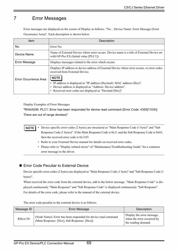
7 Error Messages
Error messages are displayed on the screen of Display as follows: "No. : Device Name: Error Message (Error
Occurrence Area)". Each description is shown below.
Display Examples of Error Messages
"RHAA036: PLC1: Error has been responded for device read command (Error Code: 4355[1103h]
There are out of range devises)"
Error Code Peculiar to External Device
Device specific error codes (2 bytes) are displayed as "Main Response Code (1 byte)" and "Sub Response Code (1
bytes)".
When received the error code from the external device, add to the below message. "Main Response Code" is dis-
played continuously "Main Response" and "Sub Response Code" is displayed continuously "Sub Response".
For details of the error code, please refer to the manual of the external device.
The error code peculiar to the external device is as follows.
Item Description
No. Error No.
Device NameName of External Device where error occurs. Device name is a title of External Device set with GP-Pro EX.(Initial value [PLC1])
Error Message Displays messages related to the error which occurs.
Error Occurrence Area
Displays IP address or device address of External Device where error occurs, or error codes received from External Device.
• IP address is displayed as "IP address (Decimal): MAC address (Hex)".• Device address is displayed as "Address: Device address".• Received error codes are displayed as "Decimal [Hex]".
• Device specific error codes (2 bytes) are structured as "Main Response Code (1 byte)" and "Sub
Response Code (1 bytes)". If the Main Response Code is 0x11 and the Sub Response Code is 0x03,
then the received error code is 0x1103.
• Refer to your External Device manual for details on received error codes.
• Please refer to "Display-related errors" of "Maintenance/Troubleshooting Guide" for a common
error message to the driver.
Message ID Error Message Description
RHxx130(Node Name): Error has been responded for device read command (Main Response: [Hex], Sub Response: [Hex])
Display the error message, when the error occurred by the reading demand.

CS/CJ Series Ethernet Driver
GP-Pro EX Device/PLC Connection Manual 70
RHxx131(Node Name): Error has been responded for device write command (Main Response: [Hex], Sub Response: [Hex])
Display the error message, when the error occurred by the write demand.
Message ID Error Message Description