Panel Computer PL-5700 Series User Manual - PRO-FACE
110
1 PL-5700 Series User’s Manual Preface Digital’s PL-5700 series of Panel Computers (hereafter referred to as the “PL”) are multipurpose factory automation (FA) computers, which embody Digital’s latest, cost-effective architecture. Before using the PL, be sure to read this manual thoroughly to familiarize yourself with the PL’s operation procedures and functions. The word “PL” refers to the following models: PL-5700T1-24VC (with CE marking) PL-5700T1 (Standard 100V unit) PL-5701T1 (Standard 100V unit) PL-5700S1 (Standard 100V unit) PL-5701S1 (Standard 100V unit) PL-5700L1 (Standard 100V unit) PL-5701L1 (Standard 100V unit) 1. It is forbidden to copy the contents of this manual in whole, or in part, without the permission of the Digital Electronics Corporation. 2. The information in this manual is subject to change without notice. 3. This manual was written with care; however, if you should find any error or omis- sions, please contact Digital and inform them of your findings. 4. Please be aware that Digital is not responsible for damages resulting from the use of our products, regardless of article 3. 5. Specifications set out in this manual are for overseas products only,and,as a result,some differences may exist between the specifications given here and the Japanese ones. Product names used in this manual are the trademarks of their respective manufac- turers. © Copyright 1997, Digital Electronics Corporation MS-DOS ® and Windows ® are registered trademarks of the Microsoft Corporation. IBM ® DOS ® are registered trademarks of IBM. NOTE:
-
Upload
khangminh22 -
Category
Documents
-
view
0 -
download
0
Transcript of Panel Computer PL-5700 Series User Manual - PRO-FACE
1PL-5700 Series User’s Manual
PrefaceDigital’s PL-5700 series of Panel Computers (hereafter referred to as the “PL”) aremultipurpose factory automation (FA) computers, which embody Digital’s latest,cost-effective architecture.Before using the PL, be sure to read this manual thoroughly to familiarize yourselfwith the PL’s operation procedures and functions.
The word “PL” refers to the following models:PL-5700T1-24VC (with CE marking)PL-5700T1 (Standard 100V unit)PL-5701T1 (Standard 100V unit)PL-5700S1 (Standard 100V unit)PL-5701S1 (Standard 100V unit)PL-5700L1 (Standard 100V unit)PL-5701L1 (Standard 100V unit)
1. It is forbidden to copy the contents of this manual in whole, or in part, without thepermission of the Digital Electronics Corporation.
2. The information in this manual is subject to change without notice.
3. This manual was written with care; however, if you should find any error or omis-sions, please contact Digital and inform them of your findings.
4. Please be aware that Digital is not responsible for damages resulting from the useof our products, regardless of article 3.
5. Specifications set out in this manual are for overseas products only,and,as aresult,some differences may exist between the specifications given here and theJapanese ones.
Product names used in this manual are the trademarks of their respective manufac-turers.© Copyright 1997, Digital Electronics CorporationMS-DOS® and Windows® are registered trademarks of the Microsoft Corporation.IBM® DOS® are registered trademarks of IBM.
NOTE:
2 PL-5700 Series User’s Manual
Preface
Safe Product UsageThis manual contains a variety of safety markings to help you safely and correctlyoperate Digital’s PL-5700 series of Panel Computers, which includes the PL-5700T1,PL-5701T1, PL-5700L1, PL-5701L1, PL-5700S1, PL-5701S1, and PL-5700T1-24VC. Be sure to keep this manual handy for future reference.
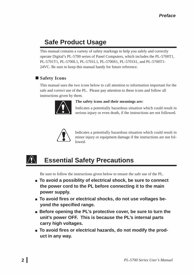
Safety IconsThis manual uses the two icons below to call attention to information important for thesafe and correct use of the PL. Please pay attention to these icons and follow allinstructions given by them.
The safety icons and their meanings are:
Indicates a potentially hazardous situation which could result inserious injury or even death, if the instructions are not followed.
Indicates a potentially hazardous situation which could result inminor injury or equipment damage if the instructions are not fol-lowed.
Essential Safety Precautions
Be sure to follow the instructions given below to ensure the safe use of the PL.
To avoid a possiblity of electrical shock, be sure to connectthe power cord to the PL before connecting it to the mainpower supply.To avoid fires or electrical shocks, do not use voltages be-yond the specified range.Before opening the PL’s protective cover, be sure to turn theunit’s power OFF. This is because the PL’s internal partscarry high voltages.To avoid fires or electrical hazards, do not modify the prod-uct in any way.
3PL-5700 Series User’s Manual
Preface
Before replacing the 100V unit’s backlight, be sure to turnthe unit’s power OFF to avoid electrical shocks. (Note: DoNOT attempt to replace the 24V unit’s backlight)Do not create touch panel switches that are used to eithercontrol or to ensure the safety of equipment and personnel.Mechanical switches, such as an emergency stop switch, adeadman (two-handed) start switch, etc., must be installedand operated via a separate system.If metal particles, water or other types of liquids contact anyof the PL’s internal parts, immediately turn the unit’s powerOFF, unplug the power cord, and contact either your dealeror Digital Electronics Corporation.Read and understand Chapter 4 “Installation and Wiring”thoroughly in order to select an appropriate installation loca-tion for the PL.Before either plugging in or unplugging a board or interfaceconnector, be sure to turn the PL’s power OFF.To prevent a possible explosion, do not install the PL in ar-eas containing flammable gases.
General Safety PrecautionsFollow the instructions given below for correct and safe use of the PL.
• Do not push on the PL’s screen too strongly, with either yourfinger or with a hard object. Excessive pressure canscratch, crack or damage the screen.
• If the screen becomes dirty or smudged, moisten a soft clothwith diluted neutral detergent, wring the cloth well, and wipethe display. Do not use thinner or organic solvents.
• Do not use a pointed object, such as a mechanical pencil orscrewdriver, to press any of the touch panel’s switches,since they can damage the display.
• Avoid exposing and operating the PL in direct sunlight, hightemperatures and humidity, and in areas where excessivedust and vibration will occur.

4 PL-5700 Series User’s Manual
Preface
• To prevent the PL from overheating, be sure its air circula-tion vents are clear and clean, and keep the unit’s operationarea well-ventilated.
• Avoid operating or storing the PL near chemicals, or wherechemicals can come into contact with the unit.
• Before the PL is initially started, be sure to install its memory(DIM) module. If this module is not installed, the unit will notoperate.
Notes on Handling the LCDThe FP's LCD contains a strong irritant. If the panel is ever cracked and the LCD'sliquid contacts your skin, be sure to wash it with running water for at least 15minutes. If any of this liquid should enter your eye, be sure to flush your eye withrunning water for more than 15 minutes, and see a doctor immediately.
The current brightness of the LCD screen will depend on the screen's current dis-play and the LCD's contrast adjustment. Any brightness variations that result arenormal for LCD displays (i.e. dark and light points).
There are minute grid-points on the LCD surface. These points are not defects. Occasionally crosstalk (shadows appearing on extended display lines) will appear
on the display. This phenomenon is a common attribute of LCDs and is not adefect.
The displayed color will look different when viewed from an angle outside thespecified view angle. This is also normal.
Displaying a single screen image for long periods of time can cause an afterimage toremain on the screen. To correct this, turn the unit OFF for 5 to 10 minutes, thenON again. This phenomenon is a common attribute of the LCDs, and is not adefect. To prevent this effect, you can:
- use the Display OFF feature; if the same image is to be displayed for a long period of time.
- change the screen display periodically to prevent the displaying of a singleimage for a long period of time.
5Series PL-5700 User’s Manual
Table of ContentsPreface
Preface ......................................................................................................... 1Safe Product Usage...................................................................................... 2Safety Precautions ....................................................................................... 2Table of Contents ......................................................................................... 5Before Using the PL .................................................................................... 8Features........................................................................................................ 9Unpacking the PL ........................................................................................ 10Information Symbols ................................................................................... 10
Chapter 1 Overview
1-1 System Configuration ..................................................................................... 1-1
1-2 Options ........................................................................................................... 1-2
1-3 PL Series Panel Types .................................................................................... 1-3
Chapter 2 Specifications
2-1 General Specifications ................................................................................. 2-11. Electrical Specifications .............................................................................. 2-12. Environment Specifications......................................................................... 2-13. Dimensions .................................................................................................. 2-2
2-2 Performance Specifications ......................................................................... 2-31. Performance Specifications ......................................................................... 2-32. Display Functions ........................................................................................ 2-43. Expansion Slots ........................................................................................... 2-6
2-3 Interface Specifications ............................................................................... 2-71. Printer Interface ........................................................................................... 2-72. Keyboard Interface ...................................................................................... 2-73. Mouse Interface ........................................................................................... 2-74. RS-232C Interface (COM1/COM2) ............................................................ 2-85. RS-485 Interface (COM3) ........................................................................... 2-86. Jumper Settings ........................................................................................... 2-97. Using the Contrast Adjustment Knob ............................................................ 2-10
2-4 PL External Features ................................................................................... 2-11
2-5 PL Dimensions ............................................................................................ 2-131. PL-5700T1 PL-5700T1-24VC, PL-5700S1, PL-5700L1 : ..................................
General Dimensions ....................................................................................... 2-132. PL-5701T1, PL-5701S1, PL-5701L1 : General Dimensions................................ 2-143. Installation Hole Dimensions ...................................................................... 2-15
6PL-5700 Series User’s Manual
Chapter 3 Installing Optional Units and Expansion Boards
3-1 Available Options and Expansion Boards ................................................. 3-1
3-2 Installing Options and Expansion Boards ................................................. 3-31. Installing DIM Modules (PL-EM000/EM001/EM002) .......................... 3-32. Installing the External Cache Memory Board (PL-EC000) .................... 3-5 3. Installing the HDD unit (PL-HD000) or the Flash File Disk Unit (PL-FF000/FF001) .. 3-64. Installing the FDD Unit (PL-FD000/FD001) ......................................... 3-105. Installing the Memory Card Interface Unit (PL-MC000) ....................... 3-136. Installing the IDE Slave Adapter (PL-SA000) ....................................... 3-147. Installing the Flash ROM Board (PL-FR000) ........................................ 3-158. Installing an Expansion Board ................................................................ 3-16
Chapter 4 Installation and Wiring
4-1 Installing the PL ........................................................................................ 4-11. Installation Procedures ........................................................................... 4-1
4-2 Wiring the PL ............................................................................................ 4-51. Connecting the Power Cord .................................................................... 4-52. Cautions: 100V PL-5700 T*/S*/L* Units .............................................. 4-73. Grounding Cautions................................................................................ 4-84. Cautions When Connecting I/O Signal Lines ......................................... 4-8
Chapter 5 System Set-up
5-1. Set-up Procedures .................................................................................... 5-1
5-2. System Parameters ................................................................................... 5-31. Main ........................................................................................................ 5-32. Advanced ................................................................................................ 5-63. Power ...................................................................................................... 5-84. Exit ......................................................................................................... 5-9
Chapter 6 Bundled Software
6-1 File List ..................................................................................................... 6-1
6-2 Touch Panel Input File .............................................................................. 6-31. PLATPH.EXE (Touch Panel Handler) ................................................... 6-32. PLCALIB.EXE (Touch Panel Data Calibration) .................................... 6-11
6-3 Other Files ................................................................................................. 6-131. DISP.EXE (Display ON/OFF Program) ................................................. 6-132. FANALARM.EXE (CPU Cooling Fan Alarm Detection Program)....... 6-133. BLSAVER.SCR (Windows®3.1 Screen Saver / Windows®95 Screen Saver) .... 6-13
7Series PL-5700 User’s Manual
Chapter 7 Maintenance and Inspection7-1 Cleaning the Display ................................................................................. 7-17-2 Replacing the 100V Unit’s Backlight ....................................................... 7-27-3 Periodic Check .......................................................................................... 7-3
Appendices1. Hardware Configuration .............................................................................. A-1
1. I/O Mapping ....................................................................................... A-12. Memory Mapping .............................................................................. A-33. IRQ Mapping ..................................................................................... A-4
2. Serial Communications ............................................................................... A-53. Printer Cable Connections ........................................................................... A-64. Touch Panel Handler Sample Program ........................................................ A-75. BIOS Lists ................................................................................................... A-15
Index ..................................................................................................................... i - iii

8PL-5700 Series User’s Manual
Before Using the PLPrior to use, be sure your PL is set up as follows.
Install PL memory Refer to 1-2 Options and the instruction manual that camewith the memory; 3-2 1. Installing the DIM Module (PL-EM000/EM001/EM002); 3-2 2. Installing the ExternalCache Memory Board (PL-EC000)
Install HDD unit Refer to 1-2 Options and the instruction manual that camewith either the HDD unit; 3-2 3. Installing the HDD Unit(PL-HD000), or the Flash File Disk Unit (PL-FF000/FF001);3-2 4. Installing the FDD Unit (PL-FD000/FD001); 3-2 5.Installing the Memory Card Interface Unit (PL-MC000)”;3-2 6. Installing the IDE Slave Adapter (PL-SA000); 3-27. Installing the Flash ROM Board (PL-FR000)
Turn the PL ON Refer to 4-2 Wiring the PL
System Setup Refer to Chapter 5 System Set-up
OS Installation Refer to the OS’s installation manual (e.g. Windows® 95package’s manual)
• For system setup and OS installation, a PS/2 type keyboard is necessary.• To use Windows® 3.1 or Windows® 95, install the PL-5700 Driver & Utility
Disk’s Display Driver. (For installation information, see the disk’sREADME.TXT file)
• For information on the PL-5700’s bundled utility software, see theREADME.TXT file on the Driver & Utility Disk.
Caution• Before turning the PL ON, be sure to install its memory(DIM module). If this module is not installed, the PL can beturned on, but will not operate.
9Series PL-5700 User’s Manual
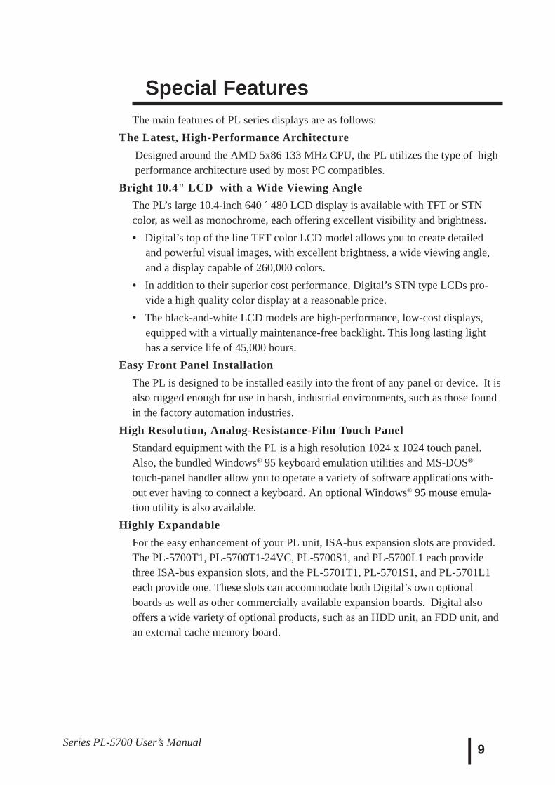
Special FeaturesThe main features of PL series displays are as follows:
The Latest, High-Performance Architecture Designed around the AMD 5x86 133 MHz CPU, the PL utilizes the type of high performance architecture used by most PC compatibles.
Bright 10.4" LCD with a Wide Viewing AngleThe PL’s large 10.4-inch 640 ´ 480 LCD display is available with TFT or STNcolor, as well as monochrome, each offering excellent visibility and brightness.• Digital’s top of the line TFT color LCD model allows you to create detailed
and powerful visual images, with excellent brightness, a wide viewing angle,and a display capable of 260,000 colors.
• In addition to their superior cost performance, Digital’s STN type LCDs pro-vide a high quality color display at a reasonable price.
• The black-and-white LCD models are high-performance, low-cost displays,equipped with a virtually maintenance-free backlight. This long lasting lighthas a service life of 45,000 hours.
Easy Front Panel InstallationThe PL is designed to be installed easily into the front of any panel or device. It isalso rugged enough for use in harsh, industrial environments, such as those foundin the factory automation industries.
High Resolution, Analog-Resistance-Film Touch PanelStandard equipment with the PL is a high resolution 1024 x 1024 touch panel.Also, the bundled Windows® 95 keyboard emulation utilities and MS-DOS®
touch-panel handler allow you to operate a variety of software applications with-out ever having to connect a keyboard. An optional Windows® 95 mouse emula-tion utility is also available.
Highly ExpandableFor the easy enhancement of your PL unit, ISA-bus expansion slots are provided.The PL-5700T1, PL-5700T1-24VC, PL-5700S1, and PL-5700L1 each providethree ISA-bus expansion slots, and the PL-5701T1, PL-5701S1, and PL-5701L1each provide one. These slots can accommodate both Digital’s own optionalboards as well as other commercially available expansion boards. Digital alsooffers a wide variety of optional products, such as an HDD unit, an FDD unit, andan external cache memory board.

10PL-5700 Series User’s Manual
Information SymbolsThis manual uses the following icons.
Indicates a warning or a product limitation. Be sure to follow the instruc-tions given with this icon to insure the safe operation of the PL.
Contains additional or useful information.
* Indicates terms or items that require further explanation. See the footnoteon that page.
Indicates pages containing related information.
1. 2. Indicates steps used to accomplish a given task. Be sure to follow thesesteps in the order they are written.
Unpacking the PLThe PL package should include the following items:
When using the function keys,attach the labels as shown below.
PL-5700User’sManual
PL UnitPL-5700T1, PL-5700T1-24VCPL-5701T1, PL-5700S1, PL-5701S1,PL-5700L1, PL-5701L1
Installation Gasket
Power Cord (notincluded with 24V model)
Function Key Labels
Mounting Brackets(four)
Driver & Utility Disk
Panel ComputerPL-5700 SeriesUser’s Manual
PL-5700 Series User’s Manual 1-1
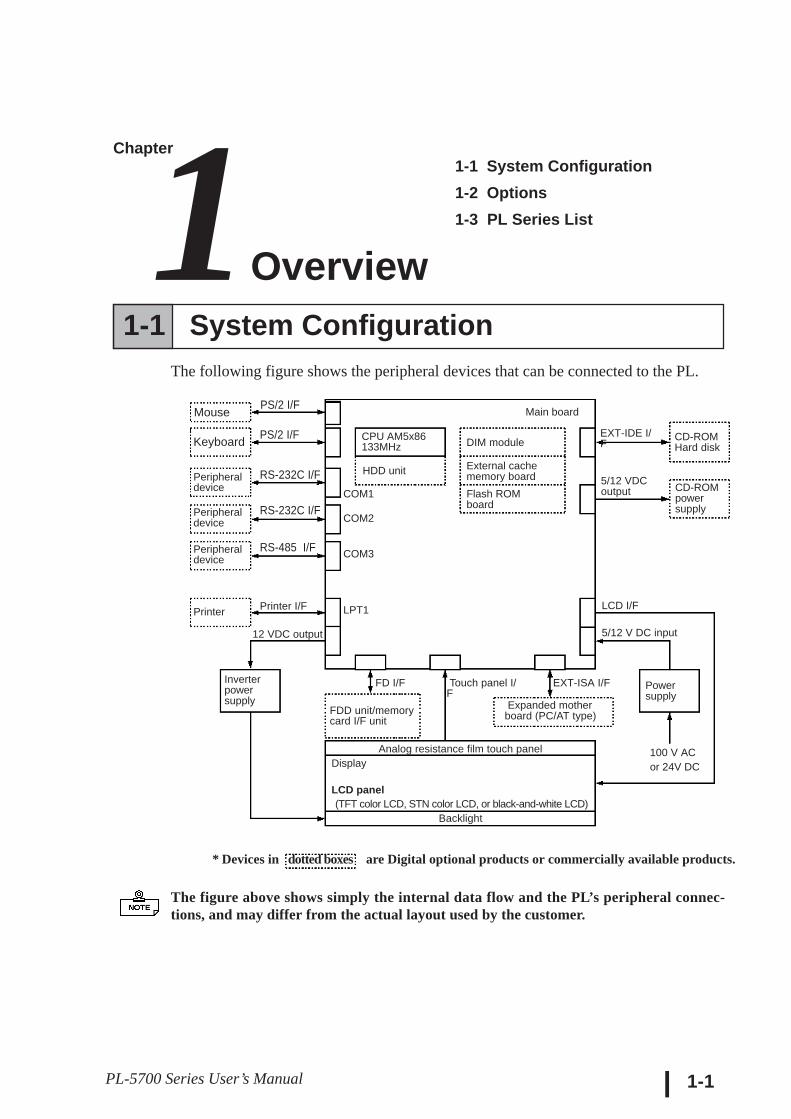
1-1 System ConfigurationThe following figure shows the peripheral devices that can be connected to the PL.
The figure above shows simply the internal data flow and the PL’s peripheral connec-tions, and may differ from the actual layout used by the customer.
1-1 System Configuration1-2 Options1-3 PL Series List
* Devices in dotted boxes are Digital optional products or commercially available products.
Main board
Peripheraldevice
Peripheraldevice
Printer
RS-232C I/F
RS-485 I/F
Printer I/F
12 VDC output
Inverterpowersupply
FDD unit/memorycard I/F unit
FD I/F
Analog resistance film touch panelDisplay
LCD panel (TFT color LCD, STN color LCD, or black-and-white LCD)
Backlight
Touch panel I/F
EXT-ISA I/F
Expanded mother board (PC/AT type)
COM2
COM3
LPT1
5/12 V DC input
Powersupply
100 V ACor 24V DC
Keyboard
Peripheraldevice
PS/2 I/F
RS-232C I/F
CPU AM5x86133MHz
HDD unit
COM1
DIM module
External cachememory boardFlash ROMboard
CD-ROMHard disk
CD-ROMpowersupply
5/12 VDCoutput
EXT-IDE I/F
LCD I/F
Mouse PS/2 I/F
Chapter1Overview
PL-5700 Series User’s Manual
Overview
1-2
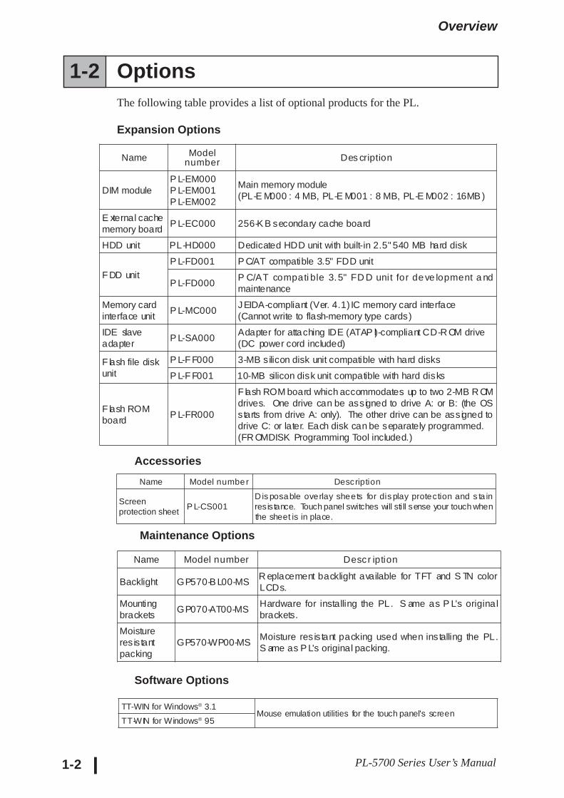
1-2 OptionsThe following table provides a list of optional products for the PL.
Expansion Options
Accessories
Maintenance Options
Software Options
Name Modelnumber Des cription
DIM moduleP L-EM000P L-EM001P L-EM002
Main memory module(PL-E M000 : 4 MB, PL-E M001 : 8 MB, PL-E M002 : 16MB )
E xternal cachememory board
P L-EC000 256-K B secondary cache board
HDD unit PL-HD000 Dedicated HDD unit with built-in 2.5" 540 MB hard disk
F DD unit
P L-FD001 P C/AT compatible 3.5" FDD unit
P L-FD000P C/AT compati ble 3.5" FD D unit for de ve lopment a ndmaintenance
Memory cardinterface unit
P L-MC000JEIDA-compliant (Ver. 4.1) IC memory card interface(Cannot write to flash-memory type cards)
IDE slaveadapter
P L-SA000Adapter for attaching IDE (ATAP I)-compliant CD-R OM drive(DC power cord included)
F lash file diskunit
P L-F F000 3-MB silicon disk unit compatible with hard disks
P L-F F001 10-MB silicon disk unit compatible with hard disks
F lash ROMboard
P L-FR000
F lash ROM board which accommodates up to two 2-MB R OMdrives. One drive can be assigned to drive A: or B: (the OSstarts from drive A: only). The other drive can be assigned todrive C: or later. Each disk can be separately programmed.(FR OMDISK Programming Tool included.)
Name Model number Description
Screenprotection sheet
P L-CS001Dis posable overlay sheets for dis play protection and s ta inresistance. Touch panel switches will sti ll sense your touch whenthe sheet is in place.
Name Model number Descr iption
Backlight GP570-B L00-MSR eplacement backlight available for TFT and S TN colorLCDs.
Mountingbrackets
GP070-AT00-MSHardware for installing the PL. S ame as P L's originalbrackets.
Moistureresistantpacking
GP570-WP00-MSMoisture res is tant packing used when ins talling the PL.S ame as P L's original packing.
TT-WIN for Windows® 3.1Mouse emulation utilities for the touch panel's screen
TT-WIN for Windows® 95

PL-5700 Series User’s Manual
Overview
1-3
^ ^ ^* if “24VC” is not written, the unit is 100V type.
Expansion SlotsDisplayB/W LCD PL-5701L1 PL-5700L1STN color LCD PL-5701S1 PL-5700S1
TFT color LCD PL-5701T1PL-5700T1/PL5700T1-24VC
1-Slot type 3-Slot Type
1-3 PL Series Panel TypesModel number
P L - 5 7 0 0 T 1-24VC*
PL-5700 seriesDisplay type
Expansion slots L : Black-and-white LCD 0 : 3-slot type S : STN color LCD 1 : 1-slot type T : TFT color LCD

PL-5700 Series User’s Manual 1-4
MEMOThis page is intentionally left blank.
2-1Panel Computer PL-5700 Series User’s Manual
Chapter2Specifications
2-1 General Specifications2-2 Performance Specifications2-3 Interface Specifications
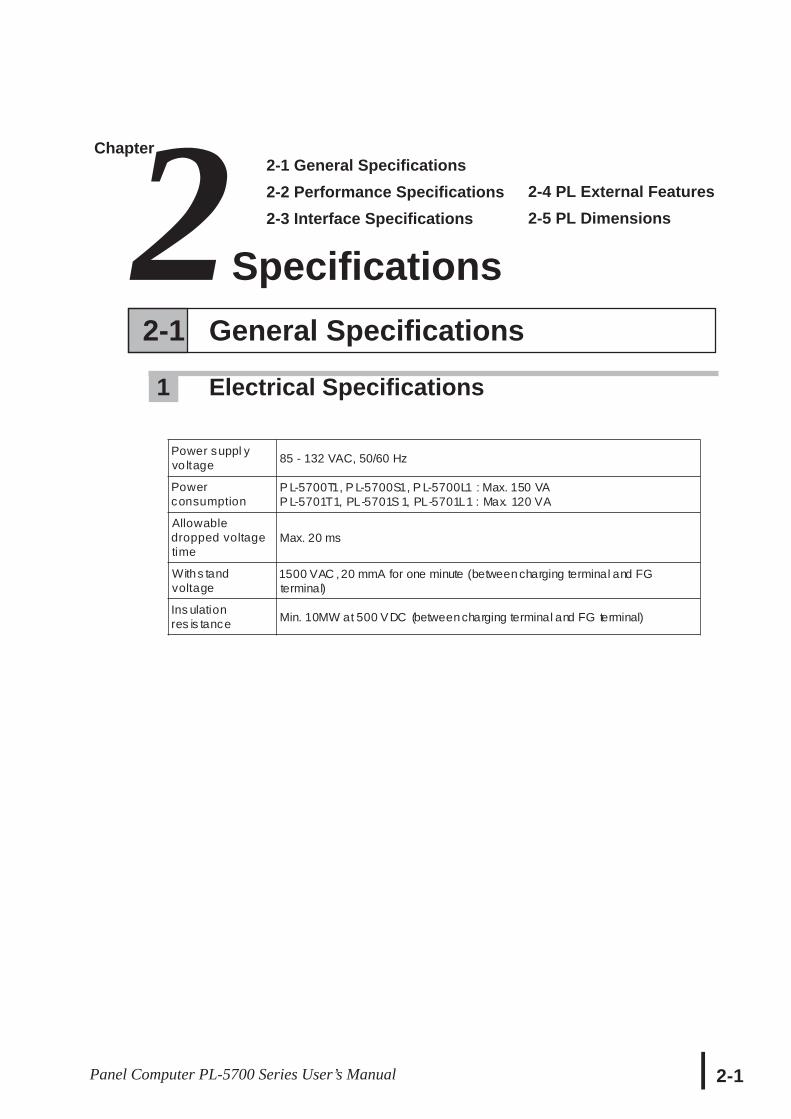
2-1 General Specifications
1 Electrical Specifications
2-4 PL External Features2-5 PL Dimensions
Power suppl yvo ltage 85 - 132 VAC, 50/60 Hz
Powerconsumption
P L-5700T1, P L-5700S1, P L-5700L1 : Max. 150 VAP L-5701T1, PL-5701S 1, PL-5701L1 : Max. 120 VA
Allowabledropped voltagetime
Max. 20 ms
Withs tandvoltage
1500 VAC ,20 mmA for one minute (betweencharging terminal and FGterminal)
Ins ulationres is tance Min. 10MW at 500 VDC (betweencharging terminal and FG terminal)
Specifications
2-2 PL-5700 Series User’s Manual
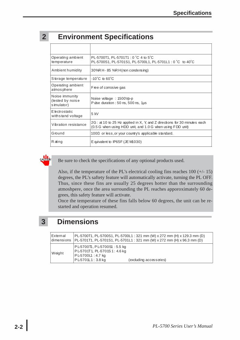
3 Dimensions
2 Environment Specifications
Be sure to check the specifications of any optional products used.
Also, if the temperature of the PL’s electrical cooling fins reaches 100 (+/- 15)degrees, the PL’s saftety feature will automatically activate, turning the PL OFF.Thus, since these fins are usually 25 degrees hotter than the surroundingatmoshpere, once the area surrounding the PL reaches apporoximately 60 de-grees, this safety feature will activate.Once the temperature of these fins falls below 60 degrees, the unit can be re-started and operation resumed.
Operating amb ienttemperature
PL-5700T1, PL-5701T1 : 0 ˚C 4 to 5˚CPL-5700S1, PL-5701S1, PL-5700L1, PL-5701L1 : 0 ˚C to 40˚C
Ambient humidity 30%R H- 85 %R H(non condensing)
S torage temperatu re -10˚C to 60˚C
Operating ambientatmos phere F ree of corrosive gas
Noise immunity(tested by nois es imulato r)
Noise voltage : 1500Vp-pP ulse duration : 50 ns, 500 ns, 1µs
E lectrostaticwiths tand voltage 5 kV
V ibration resistance 2G : at 10 to 25 Hz applied in X, Y, and Z directions for 30 minutes each(0.5 G when using HDD unit, and 1.0 G when using F DD unit)
Ground 100Ω or less,or your country's applicable standard.
R ating E quivalent to IP65F (JE M1030)
Externaldimensions
PL-5700T1, PL-5700S1, PL-5700L1 : 321 mm (W) x 272 mm (H) x 129.3 mm (D)PL-5701T1, PL-5701S1, PL-5701L1 : 321 mm (W) x 272 mm (H) x 96.3 mm (D)
Weight
P L-5700T1, P L-5700S1 : 5.5 kgP L-5701T1, PL-5701S 1 : 4.6 kgP L-5700L1 : 4.7 kgP L-5701L1 : 3.8 kg (excluding accessories)
Specifications
2-3PL-5700 Series User’s Manual
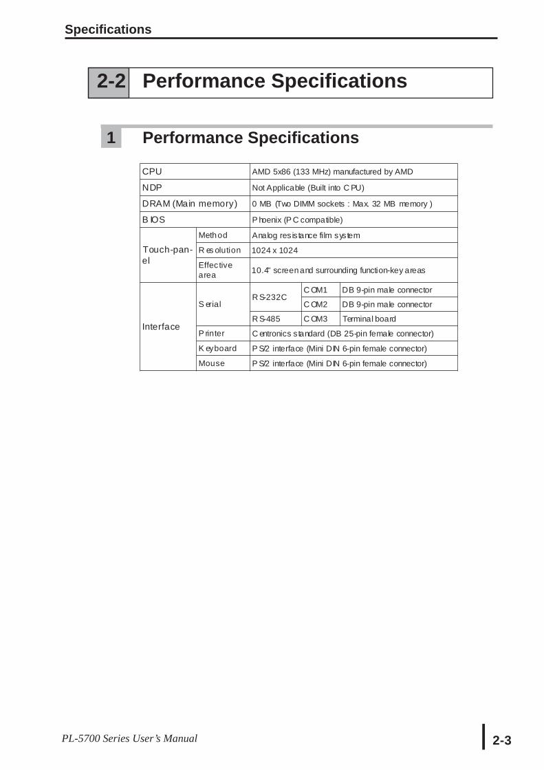
2-2 Performance Specifications
1 Performance Specifications
CPU AMD 5x86 (133 MHz) manufactured by AMD
NDP Not Applicable (Built into C PU)
DRAM (Main memory) 0 MB (Two DIMM sockets : Max. 32 MB memory )
B IOS P hoenix (P C compatible)
Touch-pan-el
Method Analog resistance film system
R es olution 1024 x 1024
Effec tivearea 10.4" screenand surrounding function-key areas
Interface
S erialR S-232C
C OM1 DB 9-pin male connector
C OM2 DB 9-pin male connector
R S-485 C OM3 Terminal board
P rinter C entronics standard (DB 25-pin female connector)
K eyboard P S/2 interface (Mini DIN 6-pin female connector)
Mouse P S/2 interface (Mini DIN 6-pin female connector)
Specifications
2-4 PL-5700 Series User’s Manual
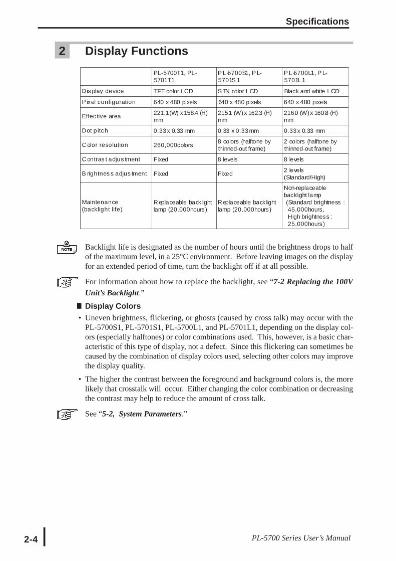
2 Display Functions
Backlight life is designated as the number of hours until the brightness drops to halfof the maximum level, in a 25°C environment. Before leaving images on the displayfor an extended period of time, turn the backlight off if at all possible.
For information about how to replace the backlight, see “7-2 Replacing the 100VUnit’s Backlight.”
ll Display Colors• Uneven brightness, flickering, or ghosts (caused by cross talk) may occur with the
PL-5700S1, PL-5701S1, PL-5700L1, and PL-5701L1, depending on the display col-ors (especially halftones) or color combinations used. This, however, is a basic char-acteristic of this type of display, not a defect. Since this flickering can sometimes becaused by the combination of display colors used, selecting other colors may improvethe display quality.
• The higher the contrast between the foreground and background colors is, the morelikely that crosstalk will occur. Either changing the color combination or decreasingthe contrast may help to reduce the amount of cross talk.
See “5-2, System Parameters.”
PL-5700T1, PL-5701T1
P L -5700S1, P L-5701S 1
P L -5700L1, P L-5701L 1
Dis play device TFT color LCD S TN color LCD Black and white LCD
P ixel configuration 640 x 480 pixels 640 x 480 pixels 640 x 480 pixels
Effec tive area 221.1(W) x158.4 (H)mm
215.1 (W)x 162.3 (H)mm
216.0 (W)x 160.8 (H)mm
Dot p itch 0.33 x 0.33 mm 0.33 x 0.33 mm 0.33 x 0.33 mm
C olor resolution 260,000colors8 colors (halftone bythinned-out frame)
2 colors (halftone bythinned-out frame)
C ontras t adjus tment F ixed 8 levels 8 levels
B rightnes s adjus tment F ixed Fixed2 levels(Standard/High)
Maintenance(backlight life)
R eplaceable backlightlamp (20,000hours)
R eplaceable backlightlamp (20,000hours)
Non-replaceablebacklight lamp(Standard brightness :45,000hours,High brightness :25,000hours)
Specifications
2-5PL-5700 Series User’s Manual
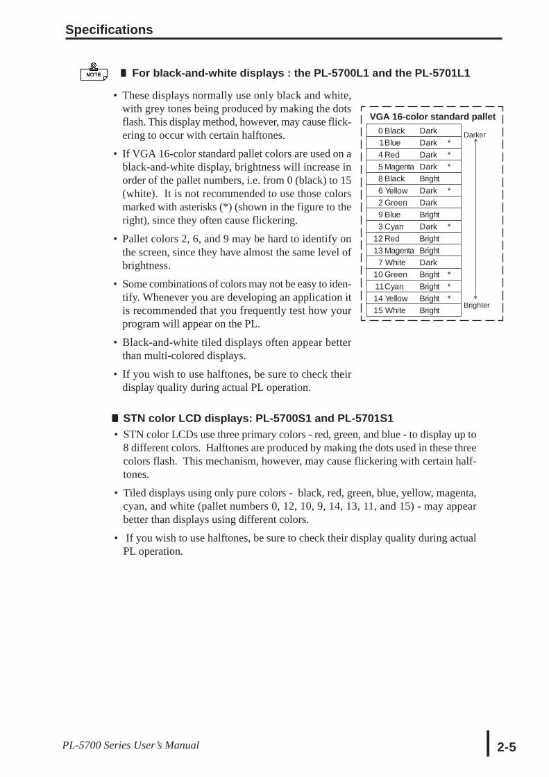
II For black-and-white displays : the PL-5700L1 and the PL-5701L1
• These displays normally use only black and white,with grey tones being produced by making the dotsflash. This display method, however, may cause flick-ering to occur with certain halftones.
• If VGA 16-color standard pallet colors are used on ablack-and-white display, brightness will increase inorder of the pallet numbers, i.e. from 0 (black) to 15(white). It is not recommended to use those colorsmarked with asterisks (*) (shown in the figure to theright), since they often cause flickering.
• Pallet colors 2, 6, and 9 may be hard to identify onthe screen, since they have almost the same level ofbrightness.
• Some combinations of colors may not be easy to iden-tify. Whenever you are developing an application itis recommended that you frequently test how yourprogram will appear on the PL.
• Black-and-white tiled displays often appear betterthan multi-colored displays.
• If you wish to use halftones, be sure to check theirdisplay quality during actual PL operation.
III STN color LCD displays: PL-5700S1 and PL-5701S1• STN color LCDs use three primary colors - red, green, and blue - to display up to
8 different colors. Halftones are produced by making the dots used in these threecolors flash. This mechanism, however, may cause flickering with certain half-tones.
• Tiled displays using only pure colors - black, red, green, blue, yellow, magenta,cyan, and white (pallet numbers 0, 12, 10, 9, 14, 13, 11, and 15) - may appearbetter than displays using different colors.
• If you wish to use halftones, be sure to check their display quality during actualPL operation.
VGA 16-color standard pallet
Darker
Brighter
^
^
0 Black Dark1Blue Dark *4 Red Dark *5 Magenta Dark *8 Black Bright6 Yellow Dark *2 Green Dark9 Blue Bright3 Cyan Dark *
12 Red Bright13 Magenta Bright
7 White Dark10 Green Bright *11Cyan Bright *14 Yellow Bright *15 White Bright
Specifications
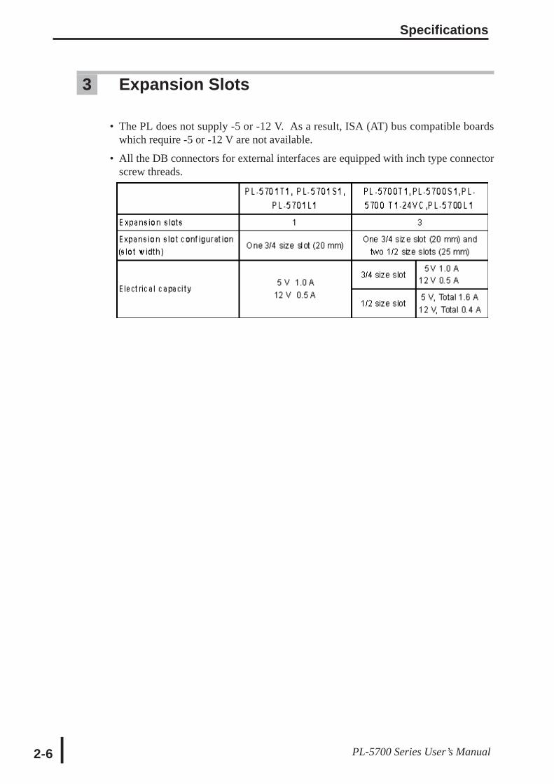
2-6 PL-5700 Series User’s Manual
3 Expansion Slots
• The PL does not supply -5 or -12 V. As a result, ISA (AT) bus compatible boardswhich require -5 or -12 V are not available.
• All the DB connectors for external interfaces are equipped with inch type connectorscrew threads.
Specifications
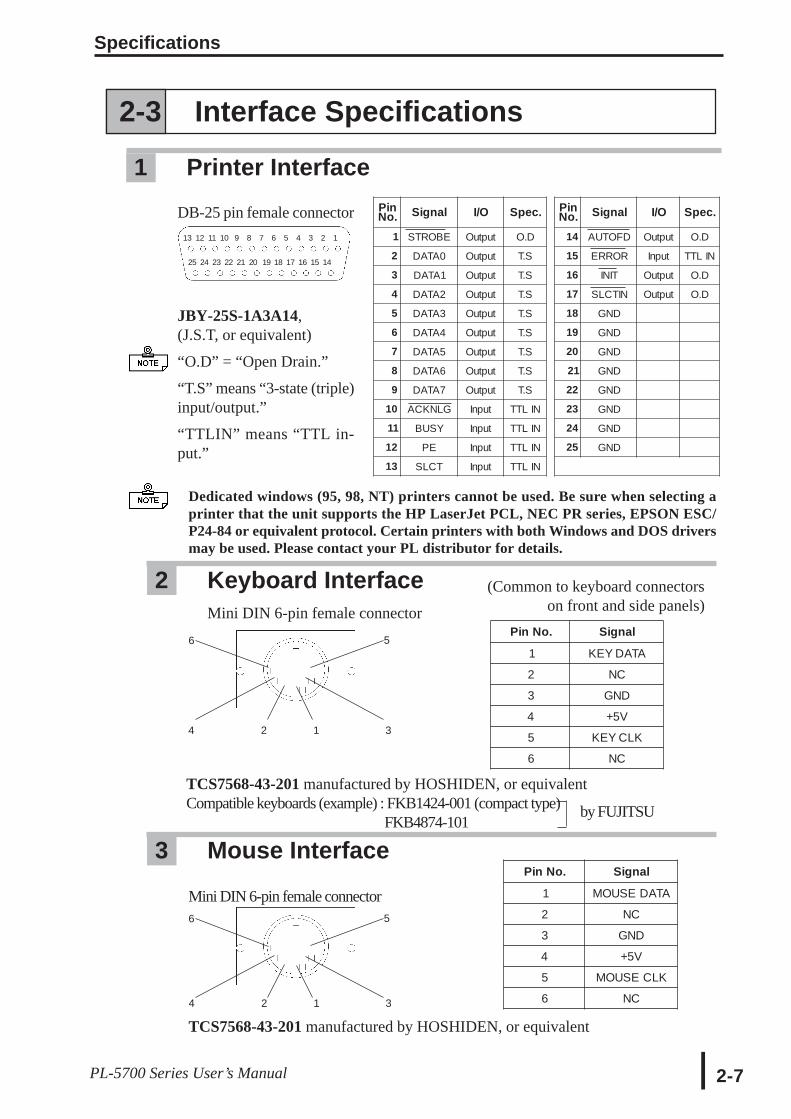
2-7PL-5700 Series User’s Manual
PinNo. Signal I/O Spec. Pin
No. Signal I/O Spec.
1 STROBE Output O.D 14 AUTOFD Output O.D
2 DATA0 Output T.S 15 ERROR Input TTL IN
3 DATA1 Output T.S 16 INIT Output O.D
4 DATA2 Output T.S 17 SLCTIN Output O.D
5 DATA3 Output T.S 18 GND
6 DATA4 Output T.S 19 GND
7 DATA5 Output T.S 20 GND
8 DATA6 Output T.S 21 GND
9 DATA7 Output T.S 22 GND
10 ACKNLG Input TTL IN 23 GND
11 BUSY Input TTL IN 24 GND
12 PE Input TTL IN 25 GND
13 SLCT Input TTL IN
DB-25 pin female connector
JBY-25S-1A3A14,(J.S.T, or equivalent)
“O.D” = “Open Drain.”
“T.S” means “3-state (triple)input/output.”
“TTLIN” means “TTL in-put.”
13 12 11 10 9 8 7 6 5 4 3 2 1
25 24 23 22 21 20 19 18 17 16 15 14
Mini DIN 6-pin female connector
6
4 2 1 3
5
TCS7568-43-201 manufactured by HOSHIDEN, or equivalent
6 5
(Common to keyboard connectorson front and side panels)
2 Keyboard InterfaceMini DIN 6-pin female connector
3 Mouse Interface
Dedicated windows (95, 98, NT) printers cannot be used. Be sure when selecting aprinter that the unit supports the HP LaserJet PCL, NEC PR series, EPSON ESC/P24-84 or equivalent protocol. Certain printers with both Windows and DOS driversmay be used. Please contact your PL distributor for details.
2-3 Interface Specifications
1 Printer Interface
4 2 1 3
TCS7568-43-201 manufactured by HOSHIDEN, or equivalentCompatible keyboards (example) : FKB1424-001 (compact type)
FKB4874-101by FUJITSU
Pin No. Signal
1 KEY DATA
2 NC
3 GND
4 +5V
5 KEY CLK
6 NC
Pin No. Signal
1 MOUSE DATA
2 NC
3 GND
4 +5V
5 MOUSE CLK
6 NC

Specifications
2-8 PL-5700 Series User’s Manual
5 RS-485 Interface (COM3)
<Interface Circuit>SN751178N or equivalent
TD+
TD-
RD+
RD-
GND
FG
J9
220
220
J10
DB 9 pin male connector
1 2 3 4 5
6 7 8 9
RXD
7 6 5 4 3 2 1
M3 screws
TXD
DTR
Use the GND and FG terminals only when the connected device requires them.
This unit’s RS-485 (RS-422) Port is not isolated, there-fore, it is crucial that you connect the SG/GND (SignalGround) terminals. If this is not done, the RS-485 (RS-422) circuit may be damaged.
4 RS-232C Interface (COM1/COM2)
JEY-9P-1A3A14 - by J.S.T, or equivalent
*1 : With COM2, pin 9 can be configured for +5 V output, via a jumper.
See next page’s “2-3, 6 Jumper Settings”.
Pin No. Signal Pin No. Signal
1 CD 6 DSR
2 RXD 7 RTS
3 TXD 8 CTS
4 DTR 9 RI/(5V)*1
5 GND
Pin No. Signal
1 TD-
2 RD-
3 TD+
4 RD+
5 GND
6 FG
7 NC
Specifications
2-9PL-5700 Series User’s Manual
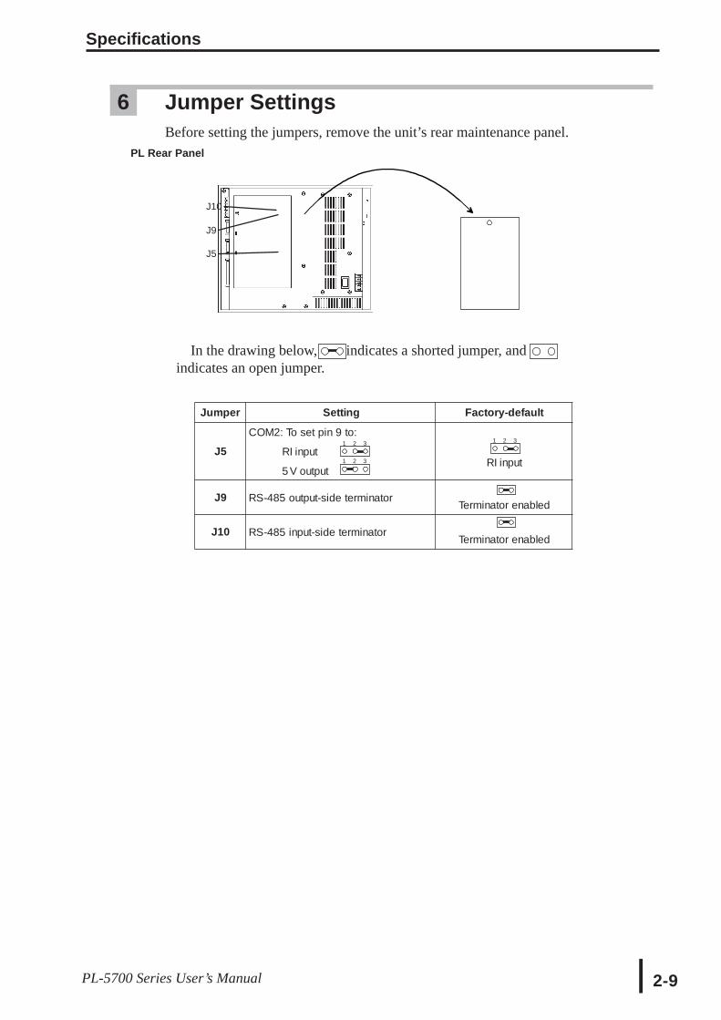
6 Jumper SettingsBefore setting the jumpers, remove the unit’s rear maintenance panel.
PL Rear Panel
J10
J9
J5
In the drawing below, indicates a shorted jumper, and indicates an open jumper.
1 2 3
1 2 3
1 2 3
Jumper Setting Factory-default
J5COM2: To set pin 9 to:
RI input
5 V outputRI input
J9 RS-485 output-side terminator Terminator enabled
J10 RS-485 input-side terminator Terminator enabled
Specifications
2-10 PL-5700 Series User’s Manual
Side View
Remove the dummyunit.
^
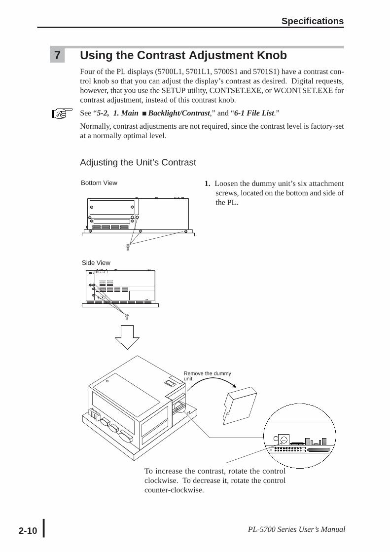
7 Using the Contrast Adjustment KnobFour of the PL displays (5700L1, 5701L1, 5700S1 and 5701S1) have a contrast con-trol knob so that you can adjust the display’s contrast as desired. Digital requests,however, that you use the SETUP utility, CONTSET.EXE, or WCONTSET.EXE forcontrast adjustment, instead of this contrast knob.
See “5-2, 1. Main Backlight/Contrast,” and “6-1 File List.”Normally, contrast adjustments are not required, since the contrast level is factory-setat a normally optimal level.
Adjusting the Unit’s Contrast
1. Loosen the dummy unit’s six attachmentscrews, located on the bottom and side ofthe PL.
To increase the contrast, rotate the controlclockwise. To decrease it, rotate the controlcounter-clockwise.
Bottom View
Specifications
2-11PL-5700 Series User’s Manual
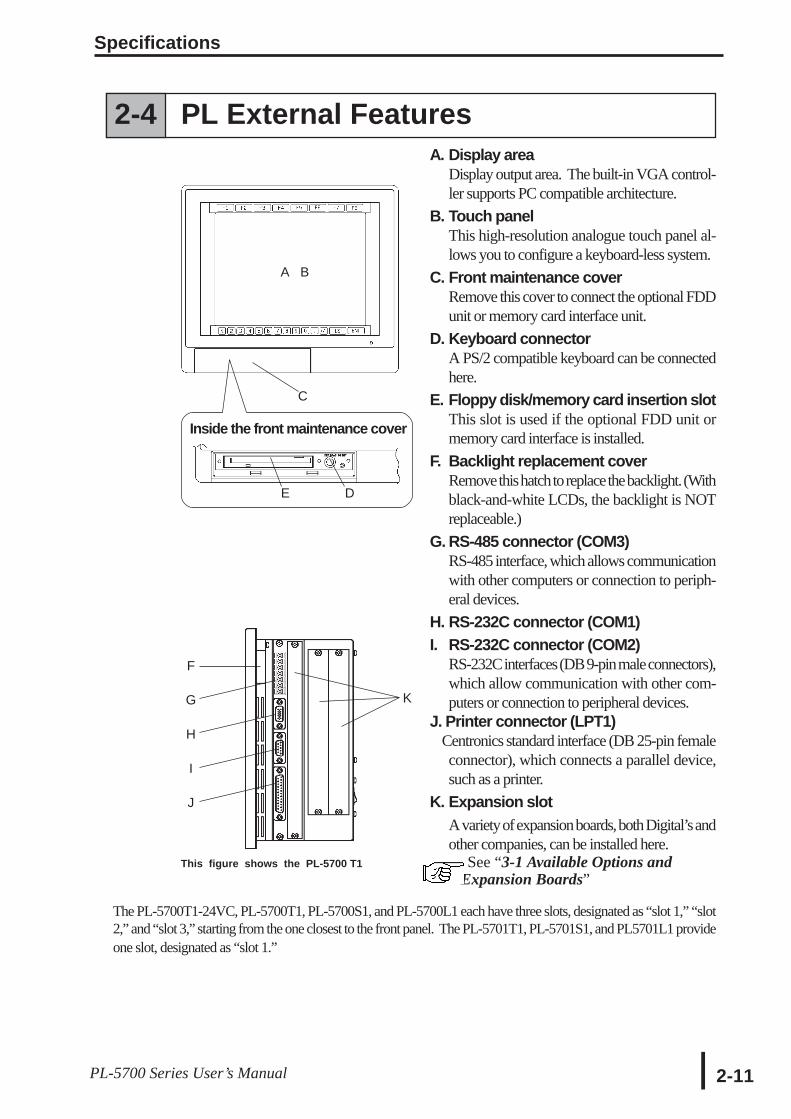
A. Display areaDisplay output area. The built-in VGA control-ler supports PC compatible architecture.
B. Touch panelThis high-resolution analogue touch panel al-lows you to configure a keyboard-less system.
C. Front maintenance coverRemove this cover to connect the optional FDDunit or memory card interface unit.
D. Keyboard connectorA PS/2 compatible keyboard can be connectedhere.
E. Floppy disk/memory card insertion slotThis slot is used if the optional FDD unit ormemory card interface is installed.
F. Backlight replacement coverRemove this hatch to replace the backlight. (Withblack-and-white LCDs, the backlight is NOTreplaceable.)
G. RS-485 connector (COM3)RS-485 interface, which allows communicationwith other computers or connection to periph-eral devices.
H. RS-232C connector (COM1)I. RS-232C connector (COM2)
RS-232C interfaces (DB 9-pin male connectors),which allow communication with other com-puters or connection to peripheral devices.
J. Printer connector (LPT1) Centronics standard interface (DB 25-pin female
connector), which connects a parallel device,such as a printer.
K. Expansion slotA variety of expansion boards, both Digital’s andother companies, can be installed here.
See “3-1 Available Options and Expansion Boards”
A B
C
Inside the front maintenance cover
E D
F
G
H
I
J
K
This figure shows the PL-5700 T1
The PL-5700T1-24VC, PL-5700T1, PL-5700S1, and PL-5700L1 each have three slots, designated as “slot 1,” “slot2,” and “slot 3,” starting from the one closest to the front panel. The PL-5701T1, PL-5701S1, and PL5701L1 provideone slot, designated as “slot 1.”
2-4 PL External Features
Specifications
2-12 PL-5700 Series User’s Manual
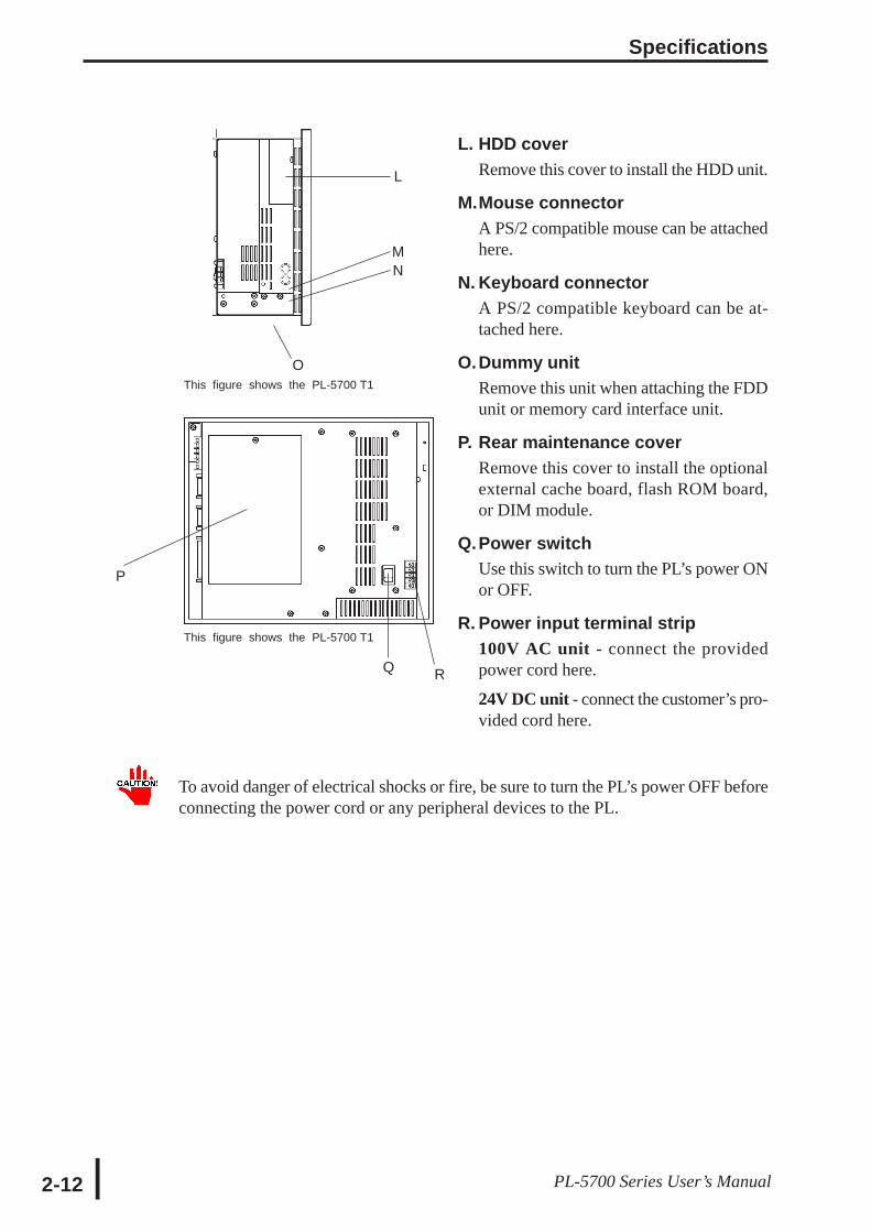
L. HDD coverRemove this cover to install the HDD unit.
M.Mouse connectorA PS/2 compatible mouse can be attachedhere.
N. Keyboard connectorA PS/2 compatible keyboard can be at-tached here.
O.Dummy unitRemove this unit when attaching the FDDunit or memory card interface unit.
P. Rear maintenance coverRemove this cover to install the optionalexternal cache board, flash ROM board,or DIM module.
Q.Power switchUse this switch to turn the PL’s power ONor OFF.
R. Power input terminal strip100V AC unit - connect the providedpower cord here.
24V DC unit - connect the customer’s pro-vided cord here.
To avoid danger of electrical shocks or fire, be sure to turn the PL’s power OFF beforeconnecting the power cord or any peripheral devices to the PL.
L
MN
P
This figure shows the PL-5700 T1
This figure shows the PL-5700 T1
O
Q R
Specifications
2-13PL-5700 Series User’s Manual
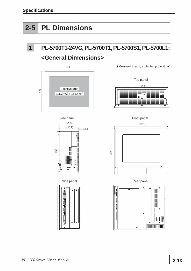
Top panel
290
(Measured in mm, excluding projections)
Effective area
211.2 (W) x 158.4 (H)
312
272
129.3(116.1)
Side panel
13.2
250
312
272
Side panel Rear panel
Front panel
2-5 PL Dimensions
1 PL-5700T1-24VC, PL-5700T1, PL-5700S1, PL-5700L1:<General Dimensions>
Specifications
2-14 PL-5700 Series User’s Manual
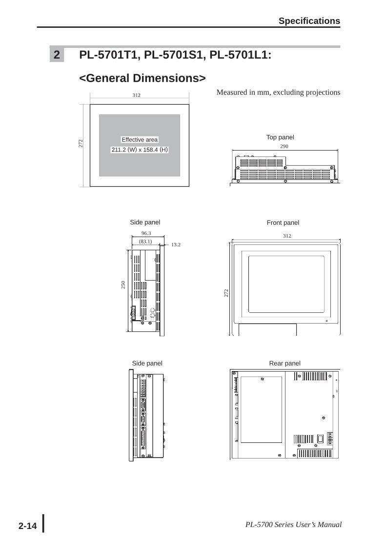
2 PL-5701T1, PL-5701S1, PL-5701L1:
<General Dimensions>Measured in mm, excluding projections
Side panel Rear panel
96.3(83.1)
Side panel
13.2
312
Front panel
Top panel290
272
Effective area
211.2 (W) x 158.4 (H)
312
272
250
Specifications
2-15PL-5700 Series User’s Manual
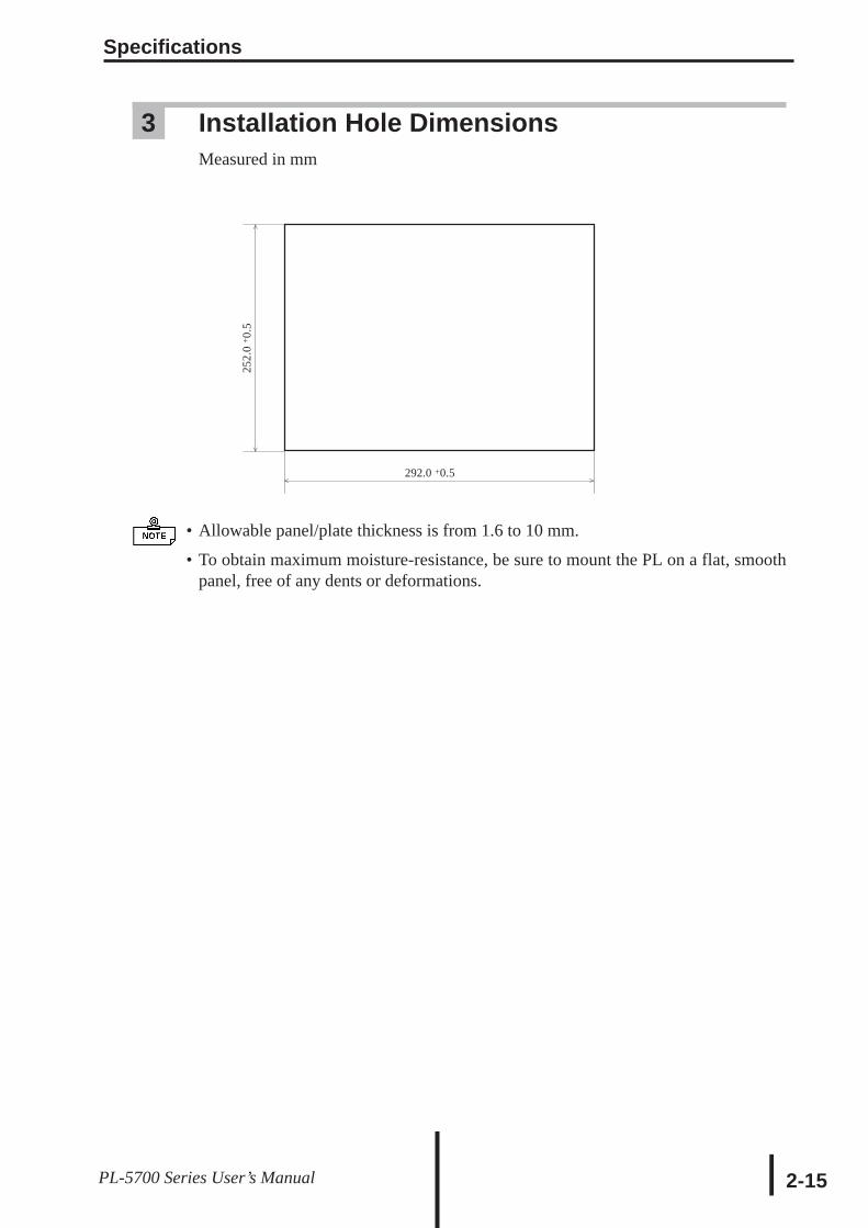
3 Installation Hole DimensionsMeasured in mm
• Allowable panel/plate thickness is from 1.6 to 10 mm.
• To obtain maximum moisture-resistance, be sure to mount the PL on a flat, smoothpanel, free of any dents or deformations.
^
^ ^
^
252.
0 + 0
.5
292.0 +0.5
Specifications
2-16 PL-5700 Series User’s Manual
MEMO
This page intentionally left blank.
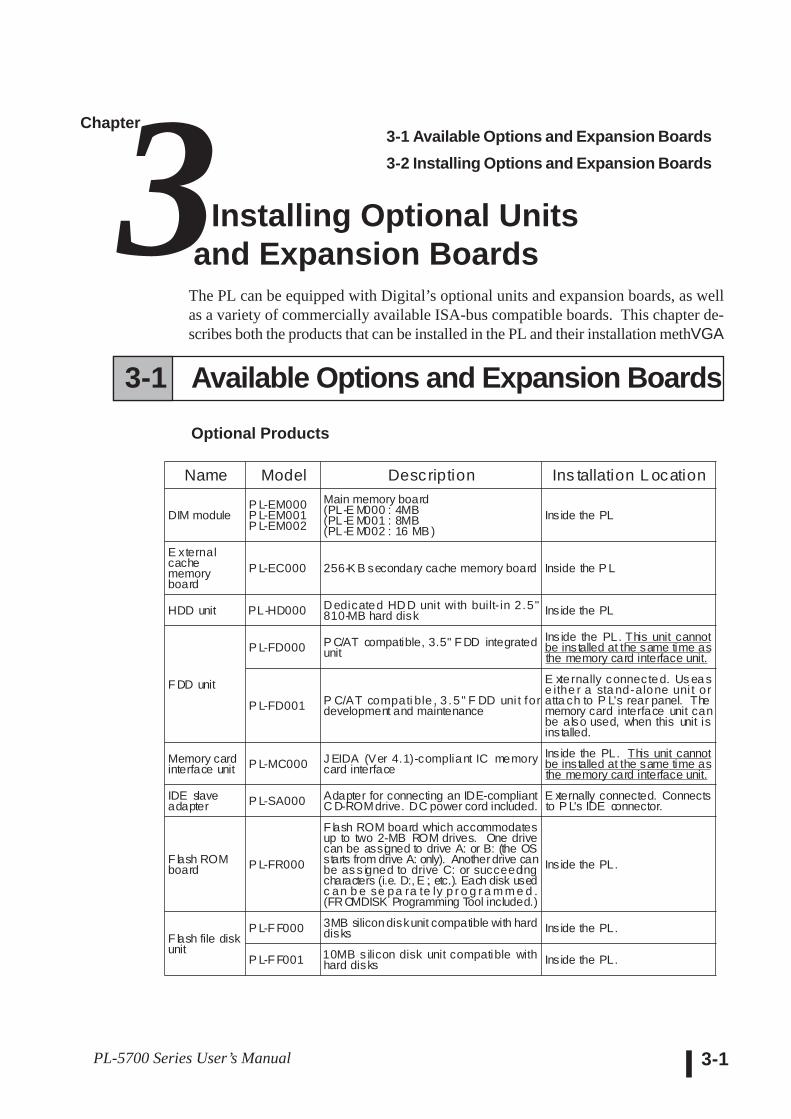
The PL can be equipped with Digital’s optional units and expansion boards, as wellas a variety of commercially available ISA-bus compatible boards. This chapter de-scribes both the products that can be installed in the PL and their installation methVGA
PL-5700 Series User’s Manual 3-1
Chapter3 3-1 Available Options and Expansion Boards3-2 Installing Options and Expansion Boards
Installing Optional Unitsand Expansion Boards
Name Model Description Ins tallation L ocation
DIM moduleP L-EM000P L-EM001P L-EM002
Main memory board(PL-E M000 : 4MB(PL-E M001 : 8MB(PL-E M002 : 16 MB )
Inside the PL
E xternalcachememoryboard
P L-EC000 256-K B secondary cache memory board Inside the P L
HDD unit PL-HD000 Dedicated HDD unit with built- in 2.5"810-MB hard disk Inside the PL
F DD unit
P L-FD000 P C/AT compatible, 3.5" F DD integratedunit
Ins ide the PL. This unit cannotbe installed at the same time asthe memory card interface unit.
P L-FD001 P C/AT compati ble , 3 .5 " F DD uni t fordevelopment and maintenance
E xternally connected. Us ea se ithe r a sta nd-alone uni t oratta ch to P L's rear panel. Thememory card interface unit canbe also used, when this unit isinstalled.
Memory cardinterface unit P L-MC000 J EIDA (Ver 4.1)-compliant IC memory
card interfaceInside the PL. This unit cannotbe installed at the same time asthe memory card interface unit.
IDE slaveadapter P L-SA000 Adapter for connecting an IDE-compliant
C D-ROMdrive. DC power cord included.E xternally connected. Connectsto P L's IDE connector.
F lash ROMboard P L-FR000
F lash ROM board which accommodatesup to two 2-MB ROM drives. One drivecan be assigned to drive A: or B: (the OSstarts from drive A: only). Another drive canbe as s igned to drive C: or succeedingcharacters (i.e. D:, E :, etc.). Each disk usedc an b e se pa ra te ly p r o g r a m m e d .(FROMDISK Programming Tool included.)
Ins ide the PL.
F lash file diskunit
P L-F F000 3MB silicon diskunit compatible with harddisks Inside the PL.
P L-F F001 10MB s ilicon disk unit compatible withhard disks Inside the PL.
3-1 Available Options and Expansion BoardsOptional Products
Optional Units and Expansion Boards
PL-5700 Series User’s Manual3-2
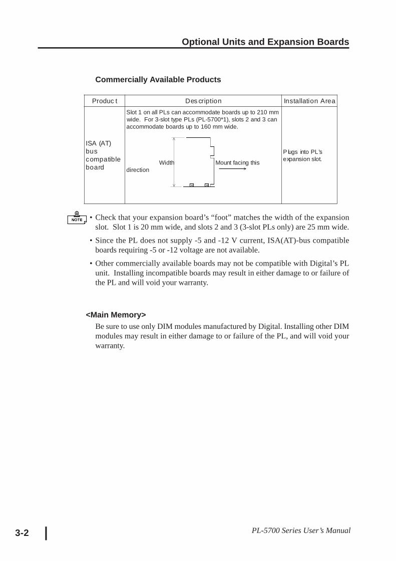
Commercially Available Products
• Check that your expansion board’s “foot” matches the width of the expansionslot. Slot 1 is 20 mm wide, and slots 2 and 3 (3-slot PLs only) are 25 mm wide.
• Since the PL does not supply -5 and -12 V current, ISA(AT)-bus compatibleboards requiring -5 or -12 voltage are not available.
• Other commercially available boards may not be compatible with Digital’s PLunit. Installing incompatible boards may result in either damage to or failure ofthe PL and will void your warranty.
<Main Memory>Be sure to use only DIM modules manufactured by Digital. Installing other DIMmodules may result in either damage to or failure of the PL, and will void yourwarranty.
^
^
^
Produc t Des cription Installation Area
ISA (AT)buscompatibleboard
Slot 1 on all PLs can accommodate boards up to 210 mmwide. For 3-slot type PLs (PL-5700*1), slots 2 and 3 canaccommodate boards up to 160 mm wide.
Width Mount facing thisdirection
P lugs into PL'sexpansion slot.
Optional Units and Expansion Boards
3-3PL-5700 Series User’s Manual
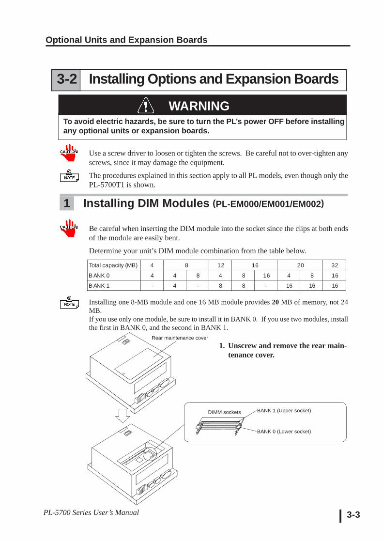
1. Unscrew and remove the rear main-tenance cover.
DIMM sockets BANK 1 (Upper socket)
BANK 0 (Lower socket)
WARNING
Rear maintenance cover
3-2 Installing Options and Expansion Boards
To avoid electric hazards, be sure to turn the PL’s power OFF before installingany optional units or expansion boards.
Use a screw driver to loosen or tighten the screws. Be careful not to over-tighten anyscrews, since it may damage the equipment.
The procedures explained in this section apply to all PL models, even though only thePL-5700T1 is shown.
1 Installing DIM Modules (PL-EM000/EM001/EM002)
Be careful when inserting the DIM module into the socket since the clips at both endsof the module are easily bent.
Determine your unit’s DIM module combination from the table below.
Installing one 8-MB module and one 16 MB module provides 20 MB of memory, not 24MB.If you use only one module, be sure to install it in BANK 0. If you use two modules, installthe first in BANK 0, and the second in BANK 1.
Total capacity (MB) 4 8 12 16 20 32
B ANK 0 4 4 8 4 8 16 4 8 16
B ANK 1 - 4 - 8 8 - 16 16 16
Optional Units and Expansion Boards
PL-5700 Series User’s Manual3-4
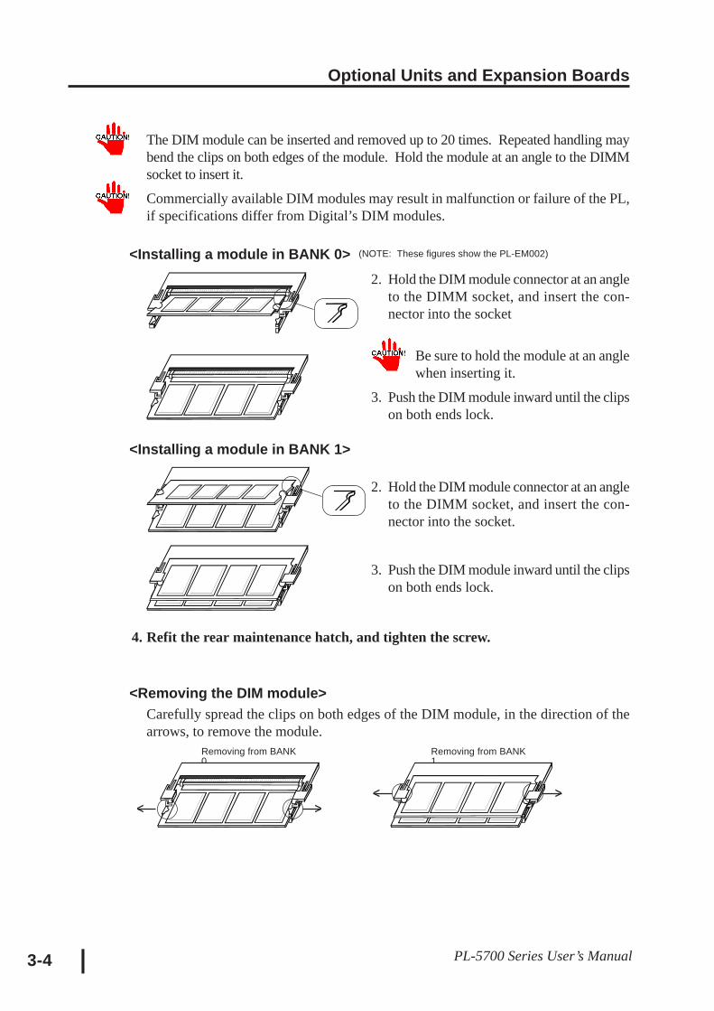
The DIM module can be inserted and removed up to 20 times. Repeated handling maybend the clips on both edges of the module. Hold the module at an angle to the DIMMsocket to insert it.
Commercially available DIM modules may result in malfunction or failure of the PL,if specifications differ from Digital’s DIM modules.
4. Refit the rear maintenance hatch, and tighten the screw.
<Removing the DIM module>Carefully spread the clips on both edges of the DIM module, in the direction of thearrows, to remove the module.
2. Hold the DIM module connector at an angleto the DIMM socket, and insert the con-nector into the socket
Be sure to hold the module at an anglewhen inserting it.
3. Push the DIM module inward until the clipson both ends lock.
2. Hold the DIM module connector at an angleto the DIMM socket, and insert the con-nector into the socket.
3. Push the DIM module inward until the clipson both ends lock.
<Installing a module in BANK 1>
<Installing a module in BANK 0> (NOTE: These figures show the PL-EM002)
Removing from BANK0
Removing from BANK1
^ ^
^ ^
Optional Units and Expansion Boards
3-5PL-5700 Series User’s Manual
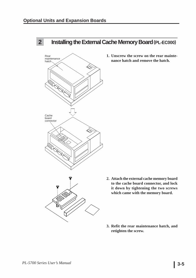
2 Installing the External Cache Memory Board (PL-EC000)
1. Unscrew the screw on the rear mainte-nance hatch and remove the hatch.
2. Attach the external cache memory boardto the cache board connector, and lockit down by tightening the two screwswhich came with the memory board.
3. Refit the rear maintenance hatch, andretighten the screw.
Rearmaintenancehatch
Cacheboardconnector
Optional Units and Expansion Boards
PL-5700 Series User’s Manual3-6
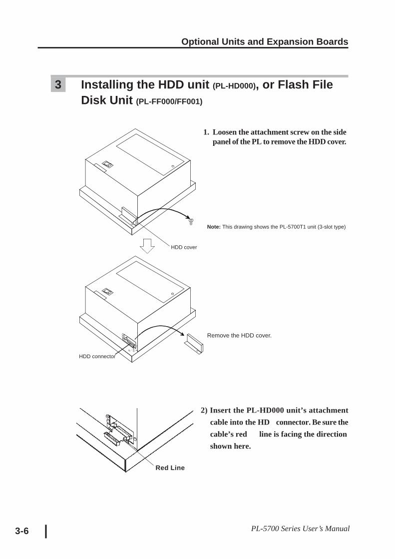
3 Installing the HDD unit (PL-HD000), or Flash FileDisk Unit (PL-FF000/FF001)
1. Loosen the attachment screw on the sidepanel of the PL to remove the HDD cover.
Remove the HDD cover.
HDD connector
HDD cover
Note: This drawing shows the PL-5700T1 unit (3-slot type)
2) Insert the PL-HD000 unit’s attachmentcable into the HD connector. Be sure thecable’s red line is facing the directionshown here.
Red Line

Optional Units and Expansion Boards
3-7PL-5700 Series User’s Manual
When the Heat Protector is NOT Needed
3) Attach the PL-HD000 and secure it inplace with the two screws given.
Be sure the sidewith the seal isfacing up.
PL-HD000
4) Insert the cable into the PL - HD000 unit’sconnector. Be careful that the pins arealigned as shown in the drawing here. (The
four pins on the far right will be unused)
5) Place the cover back in
place, and fasten its screws.
CAUTION: If the pins are in-serted incorrectly, the unit maybe damaged
<PL-HD000 Connector>
Do not usethese pins
Connect thecable to here
Optional Units and Expansion Boards
PL-5700 Series User’s Manual3-8
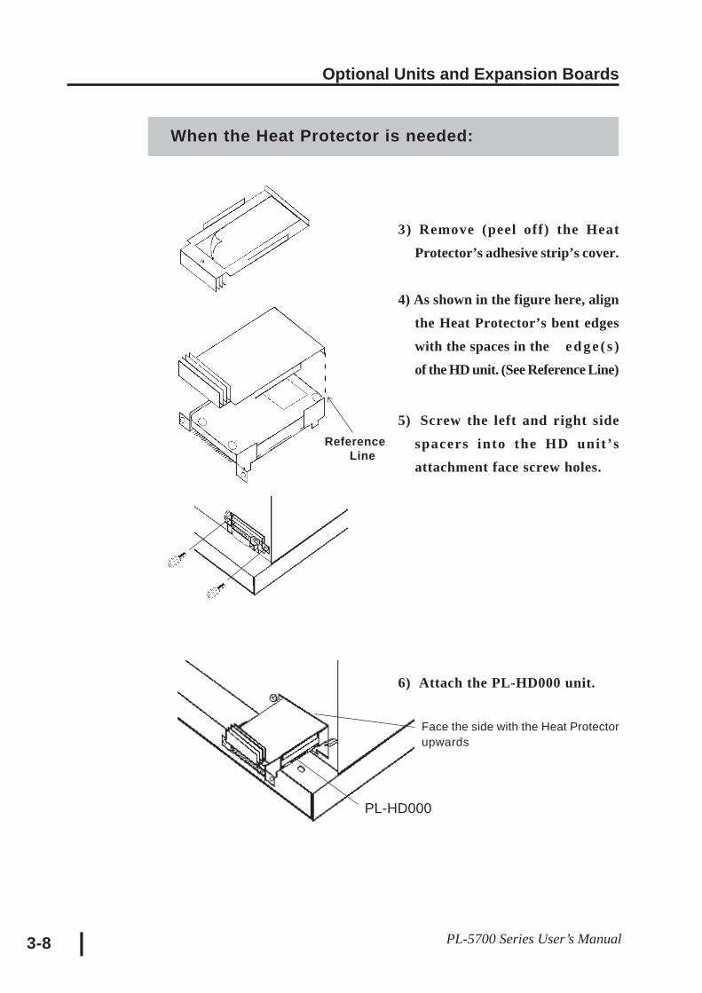
When the Heat Protector is needed:
3) Remove (peel off) the HeatProtector’s adhesive strip’s cover.
4) As shown in the figure here, alignthe Heat Protector’s bent edgeswith the spaces in the e d g e ( s )of the HD unit. (See Reference Line)
5) Screw the left and right sidespacers into the HD unit’sattachment face screw holes.
6) Attach the PL-HD000 unit.
Face the side with the Heat Protectorupwards
ReferenceLine
PL-HD000
Optional Units and Expansion Boards
3-9PL-5700 Series User’s Manual
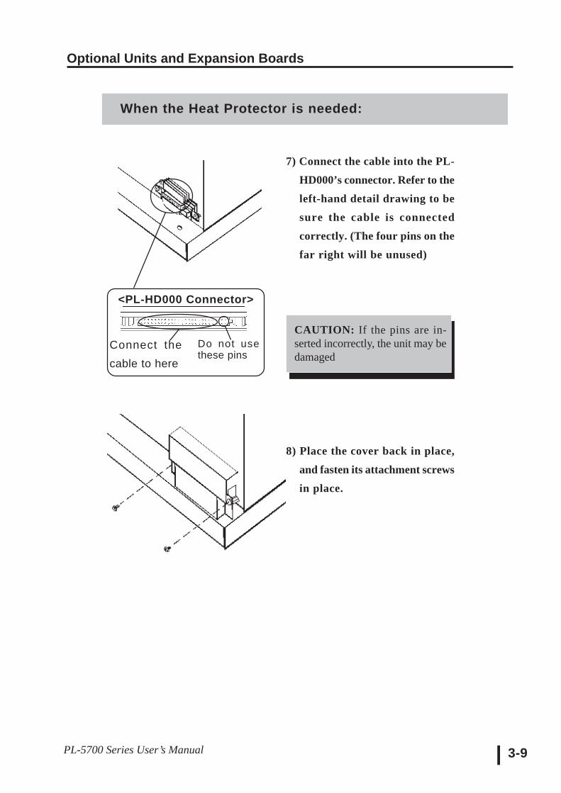
7) Connect the cable into the PL-HD000’s connector. Refer to theleft-hand detail drawing to besure the cable is connectedcorrectly. (The four pins on thefar right will be unused)
8) Place the cover back in place,and fasten its attachment screwsin place.
When the Heat Protector is needed:
CAUTION: If the pins are in-serted incorrectly, the unit may bedamaged
<PL-HD000 Connector>
Do not usethese pins
Connect thecable to here
Optional Units and Expansion Boards
PL-5700 Series User’s Manual3-10
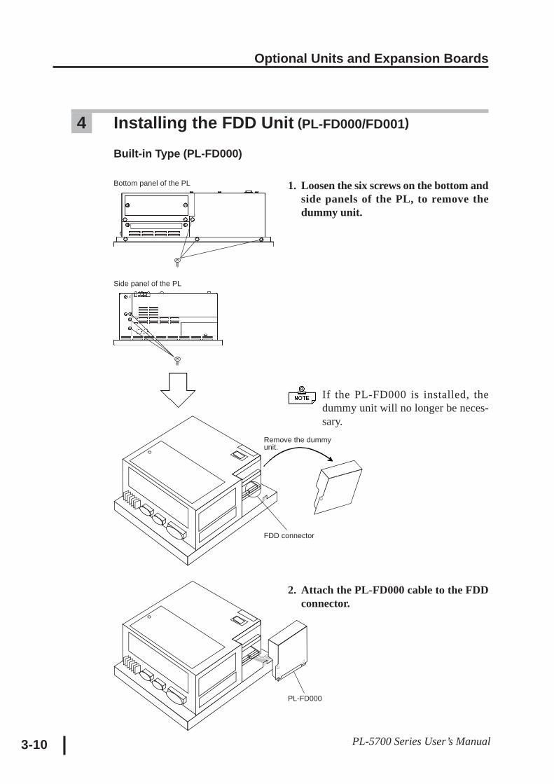
1. Loosen the six screws on the bottom andside panels of the PL, to remove thedummy unit.
If the PL-FD000 is installed, thedummy unit will no longer be neces-sary.
2. Attach the PL-FD000 cable to the FDDconnector.
4 Installing the FDD Unit (PL-FD000/FD001)
Built-in Type (PL-FD000)
Bottom panel of the PL
Side panel of the PL
Remove the dummyunit.
FDD connector
PL-FD000
Optional Units and Expansion Boards
3-11PL-5700 Series User’s Manual
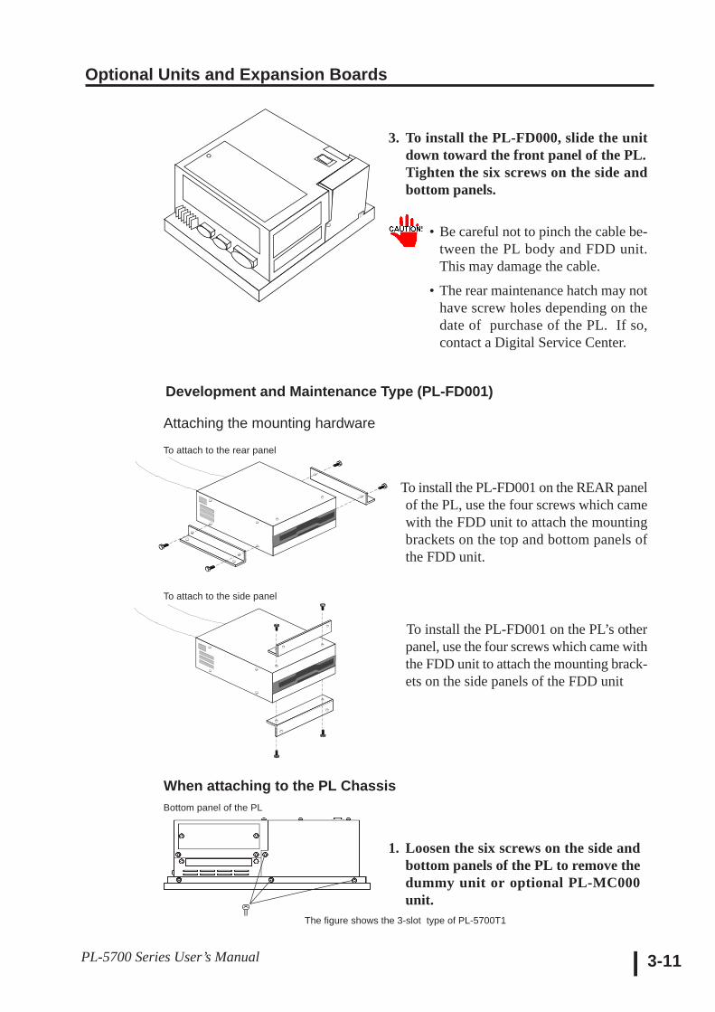
3. To install the PL-FD000, slide the unitdown toward the front panel of the PL.Tighten the six screws on the side andbottom panels.
• Be careful not to pinch the cable be-tween the PL body and FDD unit.This may damage the cable.
• The rear maintenance hatch may nothave screw holes depending on thedate of purchase of the PL. If so,contact a Digital Service Center.
To install the PL-FD001 on the REAR panelof the PL, use the four screws which camewith the FDD unit to attach the mountingbrackets on the top and bottom panels ofthe FDD unit.
To install the PL-FD001 on the PL’s otherpanel, use the four screws which came withthe FDD unit to attach the mounting brack-ets on the side panels of the FDD unit
Bottom panel of the PL
Development and Maintenance Type (PL-FD001)
Attaching the mounting hardware
To attach to the rear panel
To attach to the side panel
When attaching to the PL Chassis
1. Loosen the six screws on the side andbottom panels of the PL to remove thedummy unit or optional PL-MC000unit.
The figure shows the 3-slot type of PL-5700T1
Optional Units and Expansion Boards
PL-5700 Series User’s Manual3-12
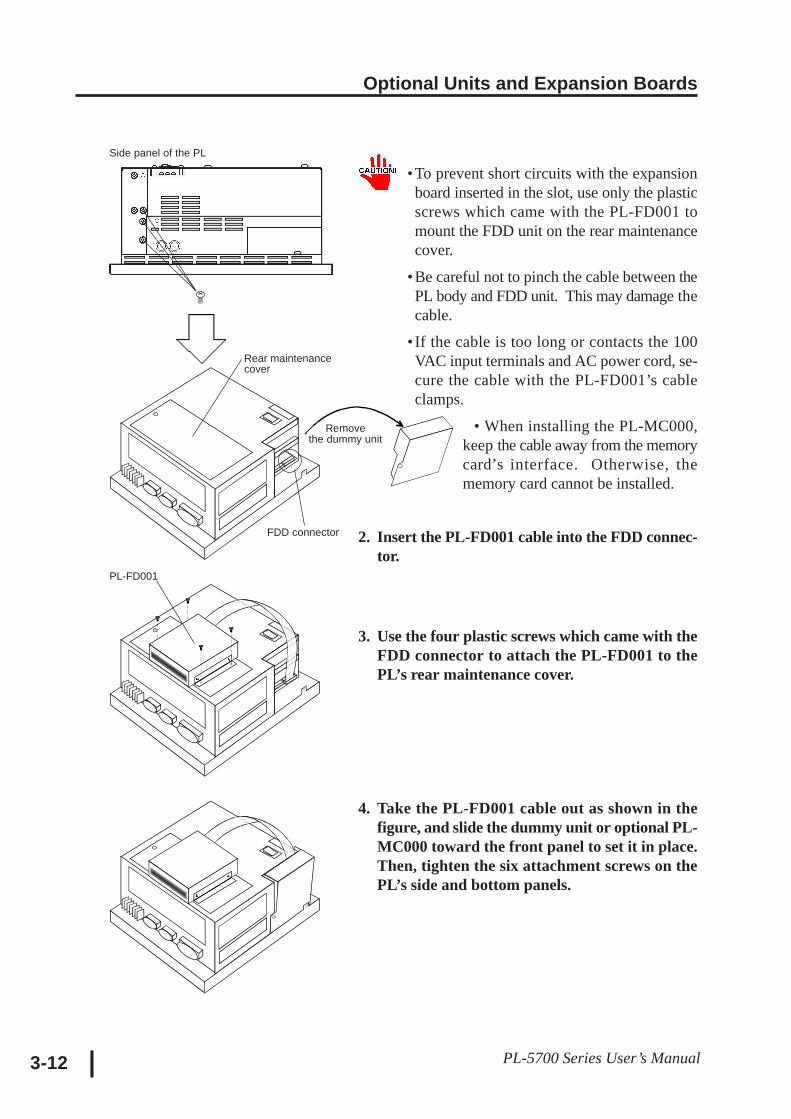
•To prevent short circuits with the expansionboard inserted in the slot, use only the plasticscrews which came with the PL-FD001 tomount the FDD unit on the rear maintenancecover.
•Be careful not to pinch the cable between thePL body and FDD unit. This may damage thecable.
• If the cable is too long or contacts the 100VAC input terminals and AC power cord, se-cure the cable with the PL-FD001’s cableclamps.
• When installing the PL-MC000,keep the cable away from the memorycard’s interface. Otherwise, thememory card cannot be installed.
2. Insert the PL-FD001 cable into the FDD connec-tor.
3. Use the four plastic screws which came with theFDD connector to attach the PL-FD001 to thePL’s rear maintenance cover.
4. Take the PL-FD001 cable out as shown in thefigure, and slide the dummy unit or optional PL-MC000 toward the front panel to set it in place.Then, tighten the six attachment screws on thePL’s side and bottom panels.
Side panel of the PL
Removethe dummy unit
FDD connector
Rear maintenancecover
PL-FD001
Optional Units and Expansion Boards
3-13PL-5700 Series User’s Manual
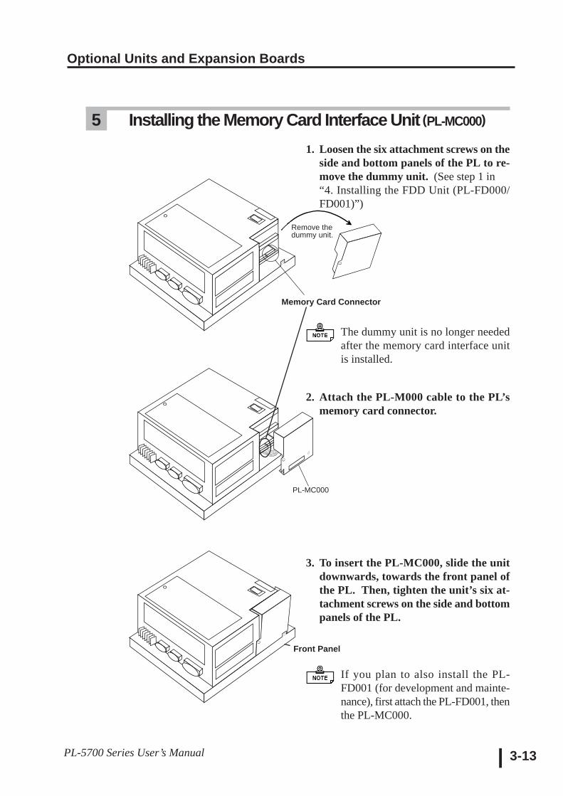
5 Installing the Memory Card Interface Unit (PL-MC000)
1. Loosen the six attachment screws on theside and bottom panels of the PL to re-move the dummy unit. (See step 1 in“4. Installing the FDD Unit (PL-FD000/FD001)”)
The dummy unit is no longer neededafter the memory card interface unitis installed.
2. Attach the PL-M000 cable to the PL’smemory card connector.
3. To insert the PL-MC000, slide the unitdownwards, towards the front panel ofthe PL. Then, tighten the unit’s six at-tachment screws on the side and bottompanels of the PL.
If you plan to also install the PL-FD001 (for development and mainte-nance), first attach the PL-FD001, thenthe PL-MC000.
Remove thedummy unit.
Memory Card Connector
PL-MC000
Front Panel
Optional Units and Expansion Boards
PL-5700 Series User’s Manual3-14
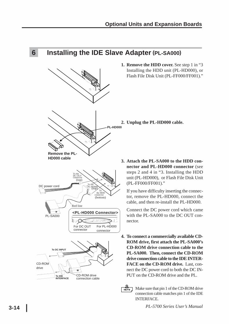
6 Installing the IDE Slave Adapter (PL-SA000)
1. Remove the HDD cover. See step 1 in “3Installing the HDD unit (PL-HD000), orFlash File Disk Unit (PL-FF000/FF001).”
2. Unplug the PL-HD000 cable.
3. Attach the PL-SA000 to the HDD con-nector and PL-HD000 connector (seesteps 2 and 4 in “3. Installing the HDDunit (PL-HD000), or Flash File Disk Unit(PL-FF000/FF001).”
If you have difficulty inserting the connec-tor, remove the PL-HD000, connect thecable, and then re-install the PL-HD000.
Connect the DC power cord which camewith the PL-SA000 to the DC OUT con-nector.
4. To connect a commercially available CD-ROM drive, first attach the PL-SA000’sCD-ROM drive connection cable to thePL-SA000. Then, connect the CD-ROMdrive connection cable to the IDE INTER-FACE on the CD-ROM drive. Last, con-nect the DC power cord to both the DC IN-PUT on the CD-ROM drive and the PL.
Make sure that pin 1 of the CD-ROM driveconnection cable matches pin 1 of the IDEINTERFACE.
To DC INPUT
CD-ROMdrive
^
^
To IDEINTERFACE
CD-ROM driveconnection cable
DC power cord
To theDC OUTconnector (top)
PL-SA000
^^
^
To thePL-HD000 (top)
To the HDDconnector(bottom)
Red line
Remove the PL-HD000 cable
PL-HD000
<PL-HD000 Connector>
For DC OUTconnector
For PL-HD000connector
Optional Units and Expansion Boards
3-15PL-5700 Series User’s Manual
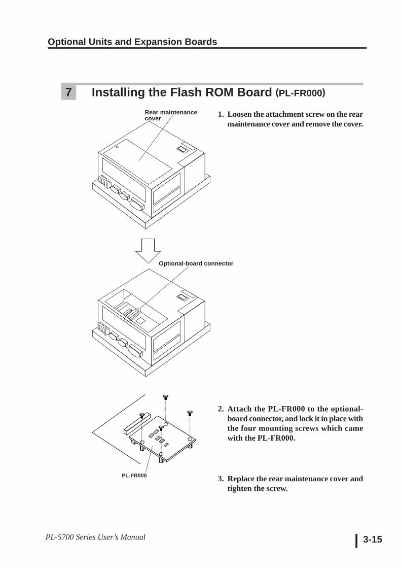
7 Installing the Flash ROM Board (PL-FR000)
1. Loosen the attachment screw on the rearmaintenance cover and remove the cover.
2. Attach the PL-FR000 to the optional-board connector, and lock it in place withthe four mounting screws which camewith the PL-FR000.
3. Replace the rear maintenance cover andtighten the screw.
Rear maintenancecover
Optional-board connector
PL-FR000
Optional Units and Expansion Boards
PL-5700 Series User’s Manual3-16
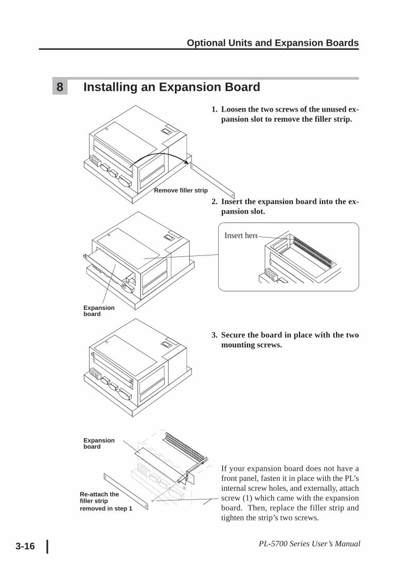
8 Installing an Expansion Board1. Loosen the two screws of the unused ex-
pansion slot to remove the filler strip.
2. Insert the expansion board into the ex-pansion slot.
3. Secure the board in place with the twomounting screws.
If your expansion board does not have afront panel, fasten it in place with the PL’sinternal screw holes, and externally, attachscrew (1) which came with the expansionboard. Then, replace the filler strip andtighten the strip’s two screws.
Remove filler strip
Insert here
Expansionboard
Expansionboard
Re-attach thefiller stripremoved in step 1
Chapter4Installation and Wiring
4-1 Installing the PL4-2 Wiring the PL
This chapter describes how to install and wire the PL.
4-1Panel Computer PL-5700 Series User’s Manual
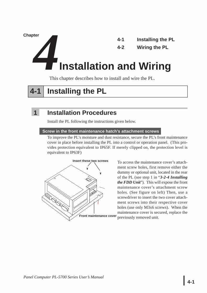
To access the maintenance cover’s attach-ment screw holes, first remove either thedummy or optional unit, located in the rearof the PL (see step 1 in “3-2-4 Installingthe FDD Unit”). This will expose the frontmaintenance cover’s attachment screwholes. (See figure on left) Then, use ascrewdriver to insert the two cover attach-ment screws into their respective coverholes (use only M3x6 screws). When themaintenance cover is secured, replace thepreviously removed unit.Front maintenance cover
4-1 Installing the PL
1 Installation ProceduresInstall the PL following the instructions given below.
Screw in the front maintenance hatch’s attachment screwsTo improve the PL’s moisture and dust resistance, secure the PL’s front maintenancecover in place before installing the PL into a control or operation panel. (This pro-vides protection equivalent to IP65F. If merely clipped on, the protection level isequivalent to IP63F)
Insert these two screws
Installation and Wiring
4-2PL-5700 Series User’s Manual
> <
> <
1.6 - 10.0 mm
Moisture resistantpackingRear
panel
Panel
Mounting hole
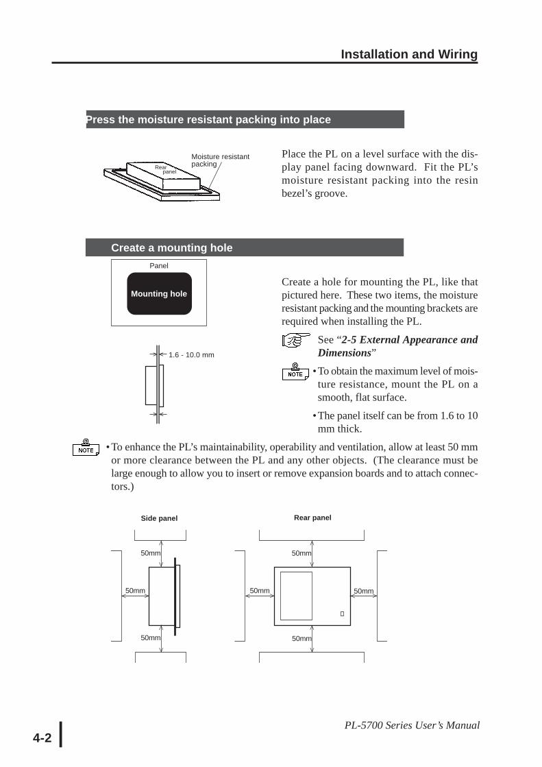
Press the moisture resistant packing into place
Place the PL on a level surface with the dis-play panel facing downward. Fit the PL’smoisture resistant packing into the resinbezel’s groove.
Create a mounting hole
Create a hole for mounting the PL, like thatpictured here. These two items, the moistureresistant packing and the mounting brackets arerequired when installing the PL.
See “2-5 External Appearance andDimensions”
•To obtain the maximum level of mois-ture resistance, mount the PL on asmooth, flat surface.
•The panel itself can be from 1.6 to 10mm thick.
• To enhance the PL’s maintainability, operability and ventilation, allow at least 50 mmor more clearance between the PL and any other objects. (The clearance must belarge enough to allow you to insert or remove expansion boards and to attach connec-tors.)
^^
^^
^ ^
^^
^^
^ ^^ ^
50mm
50mm
50mm 50mm 50mm
50mm
50mm
Side panel Rear panel
Installation and Wiring
4-3PL-5700 Series User’s Manual
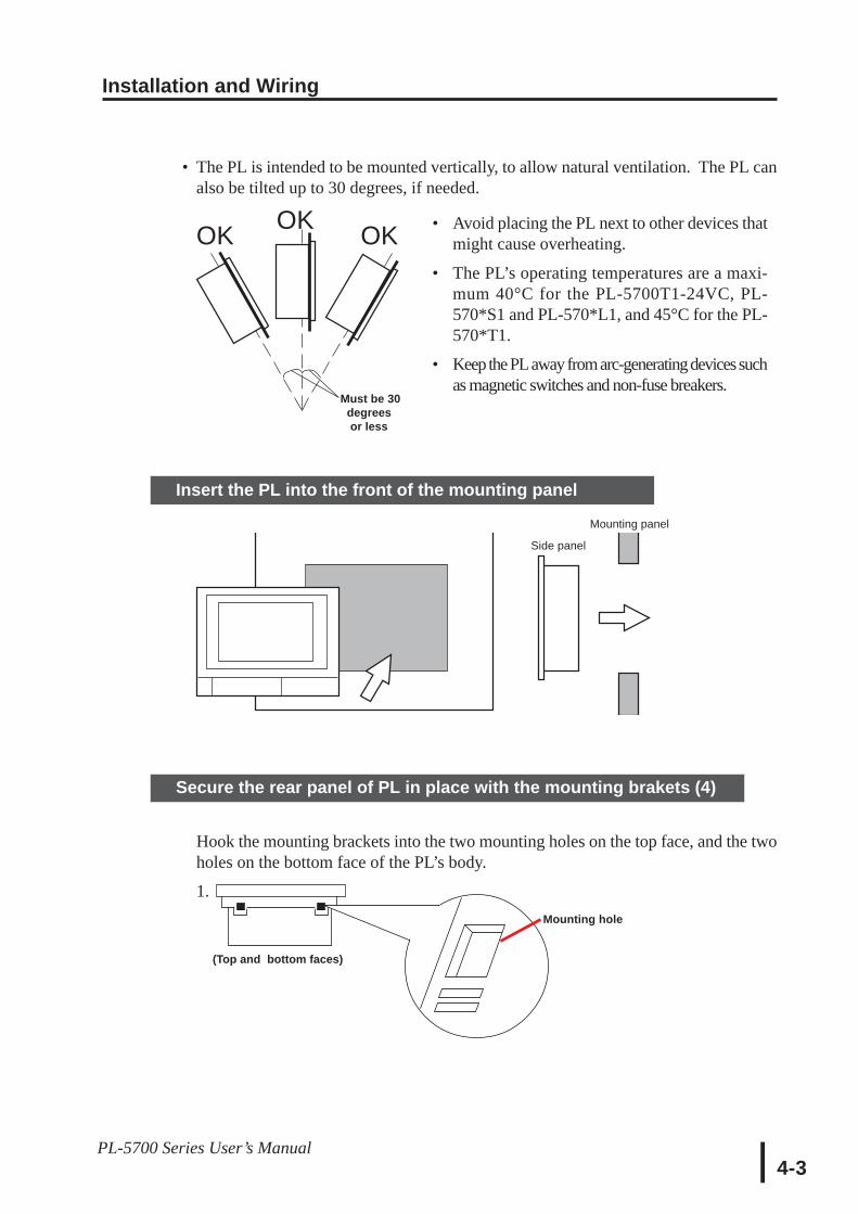
• The PL is intended to be mounted vertically, to allow natural ventilation. The PL canalso be tilted up to 30 degrees, if needed.
• Avoid placing the PL next to other devices thatmight cause overheating.
• The PL’s operating temperatures are a maxi-mum 40°C for the PL-5700T1-24VC, PL-570*S1 and PL-570*L1, and 45°C for the PL-570*T1.
• Keep the PL away from arc-generating devices suchas magnetic switches and non-fuse breakers.
Must be 30 degrees or less
OK OKOK
(Top and bottom faces)
Mounting hole
Side panel
Mounting panel
Insert the PL into the front of the mounting panel
Secure the rear panel of PL in place with the mounting brakets (4)
Hook the mounting brackets into the two mounting holes on the top face, and the twoholes on the bottom face of the PL’s body.
1.
Installation and Wiring
4-4PL-5700 Series User’s Manual
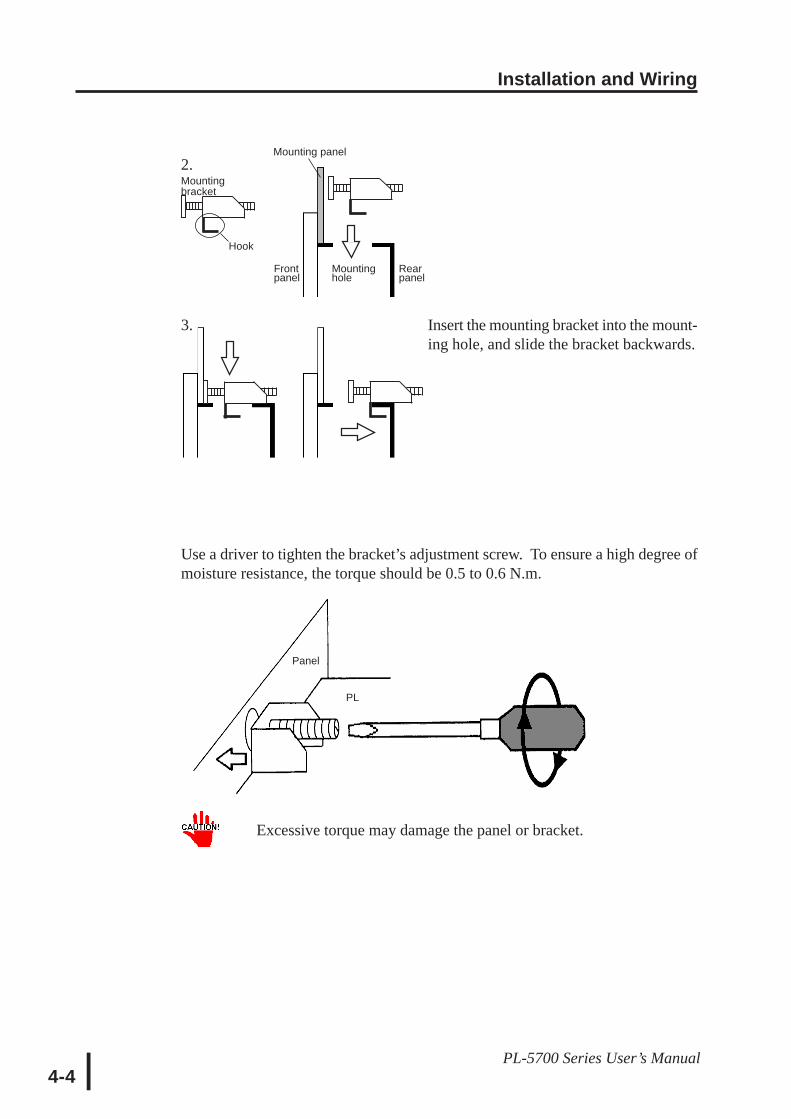
2.
3. Insert the mounting bracket into the mount-ing hole, and slide the bracket backwards.
Use a driver to tighten the bracket’s adjustment screw. To ensure a high degree ofmoisture resistance, the torque should be 0.5 to 0.6 N.m.
Excessive torque may damage the panel or bracket.
Mountingbracket
Hook
Mounting panel
Frontpanel
Rearpanel
Mountinghole
Panel
PL

Installation and Wiring
4-5PL-5700 Series User’s Manual
4-2 Wiring the PL
1 Connecting the Power Cord (not included with 24V unit)
To prevent electric shocks, be sure to turn the PL OFF before connecting the power cord.
The PL-5700T1, PL-5701T1, PL-5700S1, PL-5701S1, PL-5700L1, and PL-5701L1 areall designed to run on a 100V AC power supply. To avoid the dangers of fire, electrichazards, and damage to equipment, use only the specified power supply voltage.
The power cord must be connected to the power terminals, on the rear of the PL.
WARNING
Power switch
Screw size :M3
*1 The three power terminals are:AC100V L = AC Input Terminal—live lineAC100V N = AC Input Terminal—neutral lineFG = Ground Terminal connected to the FP chassis
+24V- FG
Power Terminal Block
FG
Crimp-on Ring
Terminals
+24V-
24V UnitPL-5700T1-24VC
FG
Power Terminal Block
FG *1
Crimp-on Ring
Terminals
NLNL100V AC Unit
PL-5700T*/S*/L*
C21
Screw size :M3
Installation and Wiring
4-6PL-5700 Series User’s Manual
^^
^
φφφφφ 3.2 mm or largerMax. 6.0 mm
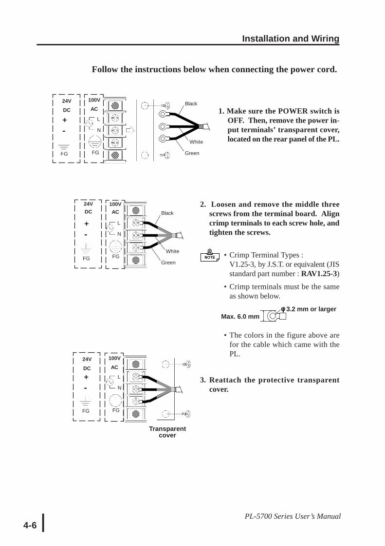
Follow the instructions below when connecting the power cord.
Transparentcover
Black
White
Green
L
N
FGFG
100VAC
24VDC
L
N
FGFG
100VAC
24VDC
+-
+-
Black
White
Green
L
N
FGFG
100VAC
24VDC
+-
Black
White
Green
1. Make sure the POWER switch isOFF. Then, remove the power in-put terminals’ transparent cover,located on the rear panel of the PL.
2. Loosen and remove the middle threescrews from the terminal board. Aligncrimp terminals to each screw hole, andtighten the screws.
• Crimp Terminal Types :V1.25-3, by J.S.T. or equivalent (JISstandard part number : RAV1.25-3)
• Crimp terminals must be the sameas shown below.
• The colors in the figure above arefor the cable which came with thePL.
3. Reattach the protective transparentcover.
Installation and Wiring
4-7PL-5700 Series User’s Manual
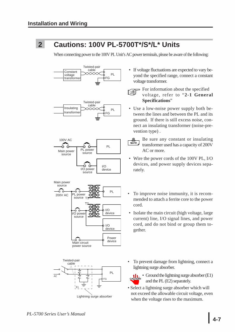
2 Cautions: 100V PL-5700T*/S*/L* UnitsWhen connecting power to the 100V PL Unit’s AC power terminals, please be aware of the following:
• If voltage fluctuations are expected to vary be-yond the specified range, connect a constantvoltage transformer.
For information about the specifiedvoltage, refer to “2-1 GeneralSpecifications”
• Use a low-noise power supply both be-tween the lines and between the PL and itsground. If there is still excess noise, con-nect an insulating transformer (noise-pre-vention type) .
Be sure any constant or insulatingtransformer used has a capacity of 200VAC or more.
• Wire the power cords of the 100V PL, I/Odevices, and power supply devices sepa-rately.
• To improve noise immunity, it is recom-mended to attach a ferrite core to the powercord.
• Isolate the main circuit (high voltage, largecurrent) line, I/O signal lines, and powercord, and do not bind or group them to-gether.
• To prevent damage from lightning, connect alightning surge absorber.
• Ground the lightning surge absorber (E1)and the PL (E2) separately.
• Select a lightning surge absorber which will not exceed the allowable circuit voltage, even when the voltage rises to the maximum.
Constantvoltagetransformer
Twisted-paircable
PLFG
Insulatingtransformer
Twisted-paircable
PLFG
Twisted-paircable
PL
FG
Lightning surge absorber
Main powersource
PL powersource T1
T2
I/O powersource
PL
I/Odevice
I/Odevice
Main circuitpower source
Powerdevice
100V AC
PL powersource
I/O powersource
PL
I/Odevice
AC
E1
Main powersource
200V AC
Installation and Wiring
4-8PL-5700 Series User’s Manual
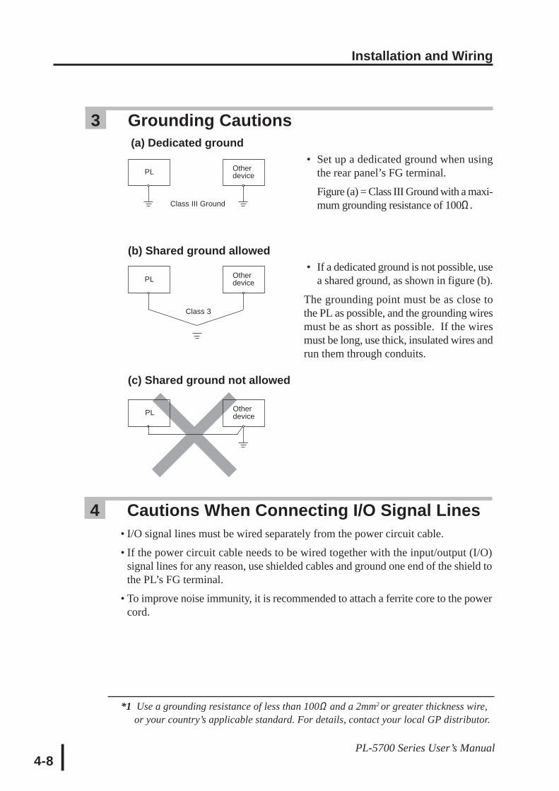
3 Grounding Cautions (a) Dedicated ground
• Set up a dedicated ground when usingthe rear panel’s FG terminal.
Figure (a) = Class III Ground with a maxi-mum grounding resistance of 100Ω.
(b) Shared ground allowed • If a dedicated ground is not possible, use
a shared ground, as shown in figure (b).
The grounding point must be as close tothe PL as possible, and the grounding wiresmust be as short as possible. If the wiresmust be long, use thick, insulated wires andrun them through conduits.
(c) Shared ground not allowed
PL
PL Otherdevice
Otherdevice
Otherdevice
Class III Ground
Class 3
PL
4 Cautions When Connecting I/O Signal Lines • I/O signal lines must be wired separately from the power circuit cable.
• If the power circuit cable needs to be wired together with the input/output (I/O)signal lines for any reason, use shielded cables and ground one end of the shield tothe PL’s FG terminal.
• To improve noise immunity, it is recommended to attach a ferrite core to the powercord.
*1 Use a grounding resistance of less than 100Ω and a 2mm2 or greater thickness wire,or your country’s applicable standard. For details, contact your local GP distributor.
5-1PL-5700 Series User’s Manual
Chapter5System Setup
5-1 Setup Procedures5-2 System Parameters
This chapter describes how to configure the system before operating the PL, andlists the system parameters.
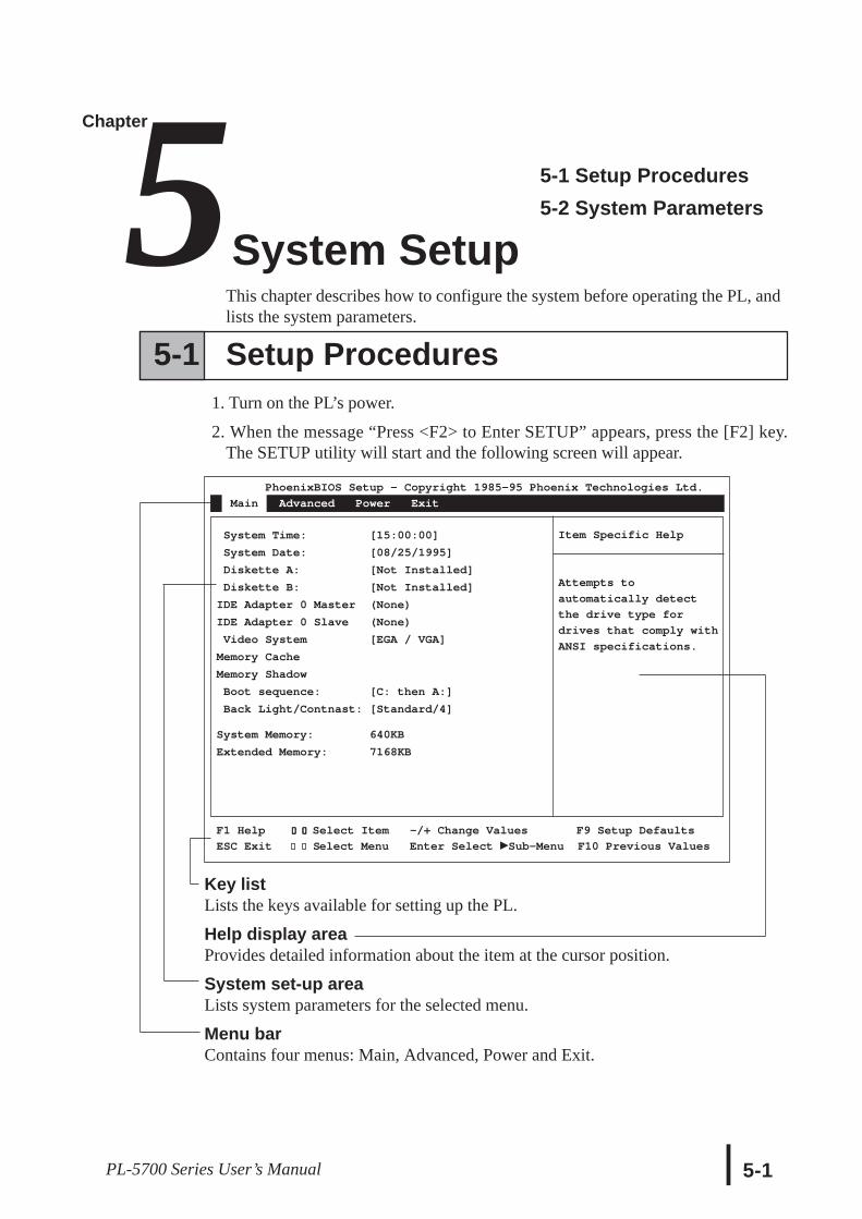
Key listLists the keys available for setting up the PL.
Help display areaProvides detailed information about the item at the cursor position.
System set-up areaLists system parameters for the selected menu.
Menu barContains four menus: Main, Advanced, Power and Exit.
PhoenixBIOS Setup - Copyright 1985-95 Phoenix Technologies Ltd.
Main Advanced Power Exit
System Time: [15:00:00]
System Date: [08/25/1995]
Diskette A: [Not Installed]
Diskette B: [Not Installed]
IDE Adapter 0 Master (None)
IDE Adapter 0 Slave (None)
Video System [EGA / VGA]
Memory Cache
Memory Shadow
Boot sequence: [C: then A:]
Back Light/Contnast: [Standard/4]
System Memory: 640KB
Extended Memory: 7168KB
Item Specific Help
Attempts to
automatically detect
the drive type for
drives that comply with
ANSI specifications.
F1 Help ↑↑↑↑↑ ↓↓↓↓↓ Select Item -/+ Change Values F9 Setup Defaults
ESC Exit ← → Select Menu Enter Select Sub-Menu F10 Previous Values← →
5-1 Setup Procedures1. Turn on the PL’s power.
2. When the message “Press <F2> to Enter SETUP” appears, press the [F2] key.The SETUP utility will start and the following screen will appear.

System Set-up
5-2 PL-5700 Series User’s Manual
The keys available for operating the SETUP utility are as follows.
[F1] : Provides information related to the entire SETUP utility. Use the [↑] or[↓] key to scroll the display.
[↑] [↓] : Moves the cursor to select an item from the menu.
[-][+] : Changes the value at the cursor position.
[F9] : Returns the parameters listed in the system setup area to the default val-ues.
[ESC] : Goes to the Exit menu.
[←][→] : Changes the menu screens.
[Enter] : If the [Enter] key is pressed while the cursor is placed on the item markedwith a black delta ( ), a submenu will appear. Pressing the [ESC] keyon the submenu will return you to the main menu.
[F10] : Returns the parameters listed in the system setup area to the CMOS’scurrent values.
System Set-up
5-3PL-5700 Series User’s Manual
5-2 System Parameters
1 MainSystem TimeEnter the hour, minute, and second values, in the order and ranges given below.
Hour : 00 - 23
Minute : 00 - 59
Second : 00 - 59
Use the [Enter] key to place the cursor on an item you want to change, and enterthe desired value.
System DateEnter the month, day, and year, in the order and ranges given below.
Month : 01 - 12
Day : 01 -31
Year : four digits
Use the [Enter] key to place the cursor on an item you want to change, and enterthe desired value.
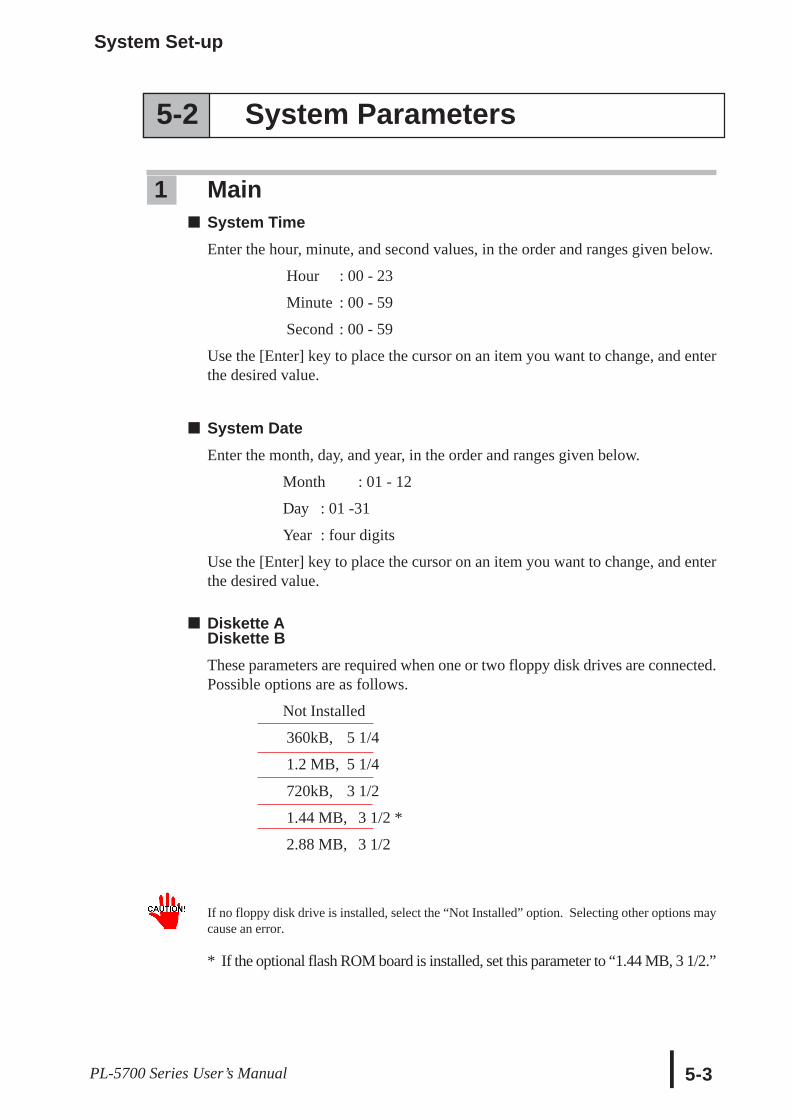
Diskette ADiskette BThese parameters are required when one or two floppy disk drives are connected.Possible options are as follows.
Not Installed
360kB, 5 1/4
1.2 MB, 5 1/4
720kB, 3 1/2
1.44 MB, 3 1/2 *
2.88 MB, 3 1/2
If no floppy disk drive is installed, select the “Not Installed” option. Selecting other options maycause an error.
* If the optional flash ROM board is installed, set this parameter to “1.44 MB, 3 1/2.”
System Set-up
5-4 PL-5700 Series User’s Manual
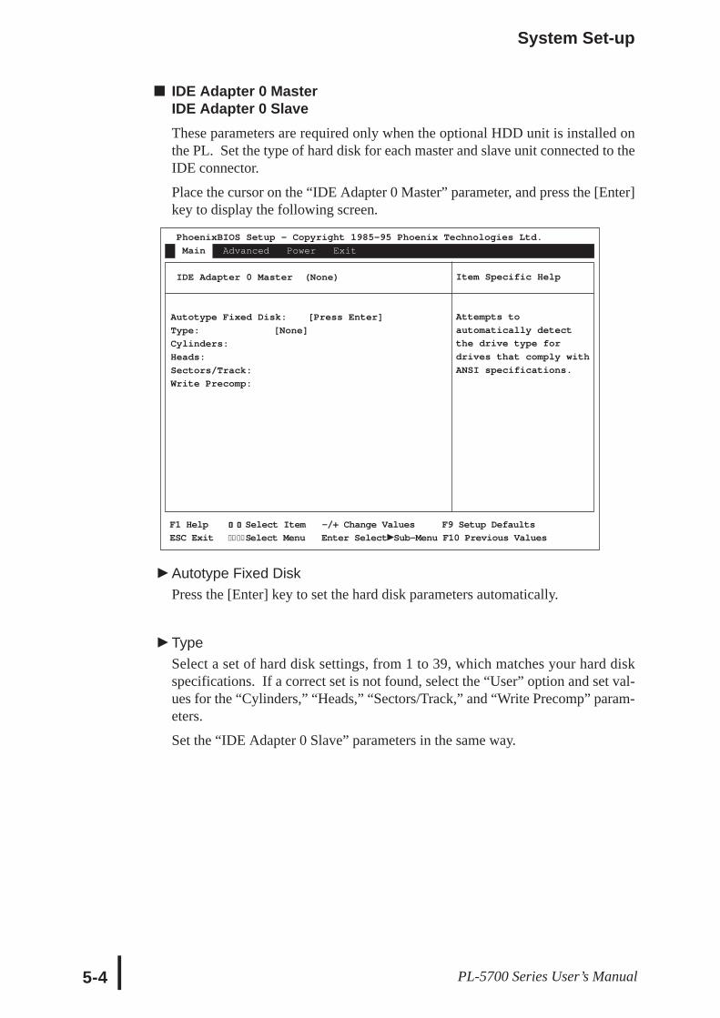
IDE Adapter 0 MasterIDE Adapter 0 SlaveThese parameters are required only when the optional HDD unit is installed onthe PL. Set the type of hard disk for each master and slave unit connected to theIDE connector.
Place the cursor on the “IDE Adapter 0 Master” parameter, and press the [Enter]key to display the following screen.
Autotype Fixed DiskPress the [Enter] key to set the hard disk parameters automatically.
TypeSelect a set of hard disk settings, from 1 to 39, which matches your hard diskspecifications. If a correct set is not found, select the “User” option and set val-ues for the “Cylinders,” “Heads,” “Sectors/Track,” and “Write Precomp” param-eters.
Set the “IDE Adapter 0 Slave” parameters in the same way.
Item Specific Help
Attempts to
automatically detect
the drive type for
drives that comply with
ANSI specifications.
F1 Help ↑↑↑↑↑ ↓↓↓↓↓ Select Item -/+ Change Values F9 Setup Defaults
ESC Exit ← → Select Menu Enter Select Sub-Menu F10 Previous Values← →
PhoenixBIOS Setup - Copyright 1985-95 Phoenix Technologies Ltd.
Main Advanced Power Exit
IDE Adapter 0 Master (None)
Autotype Fixed Disk: [Press Enter]
Type: [None]
Cylinders:
Heads:
Sectors/Track:
Write Precomp:
System Set-up
5-5PL-5700 Series User’s Manual
Memory CachePress the Enter key to set the cache memory parameters.
Memory ShadowMemory shadow copies information from the ROM BIOS to RAM to improvethe PL’s performance.
System shadowThis parameter is fixed as “Enabled,” since information in the system BIOS mustbe copied to RAM.
Video shadowSelects whether or not information in the video BIOS is copied to RAM.
Shadow Memory RegionsSelects the starting address to which the BIOS information is copied to. Thisparameter is required when installing a board containing the extended BIOS inthe extended ROM area.
Boot sequenceSelects the drive from which you want to start the OS.
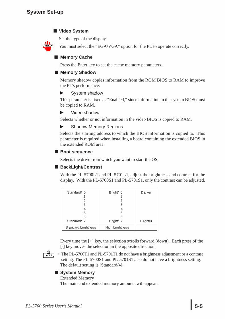
BackLight/ContrastWith the PL-5700L1 and PL-5701L1, adjust the brightness and contrast for thedisplay. With the PL-5700S1 and PL-5701S1, only the contrast can be adjusted.
Every time the [+] key, the selection scrolls forward (down). Each press of the[-] key moves the selection in the opposite direction.
• The PL-5700T1 and PL-5701T1 do not have a brightness adjustment or a contrast setting. The PL-5700S1 and PL-5701S1 also do not have a brightness setting.The default setting is [Standard/4].
System MemoryExtended MemoryThe main and extended memory amounts will appear.
Video SystemSet the type of the display.
You must select the “EGA/VGA” option for the PL to operate correctly.
Standard/
Standard/
01234567
B right/
B right/
01234567
Darker
B righter
S tandard brightness High brightness
System Set-up
5-6 PL-5700 Series User’s Manual
Item Specific Help
F1 Help ↑↑↑↑↑ ↓↓↓↓↓ Select Item -/+ Change Values F9 Setup Defaults ESC
Exit ← → Select Menu Enter Select Sub-Menu F10 Previous Values← →
F1 Help ↑↑↑↑↑ ↓↓↓↓↓ Select Item -/+ Change Values F9 Setup Defaults ESC
Exit ← → Select Menu Enter Select Sub-Menu F10 Previous Values← →
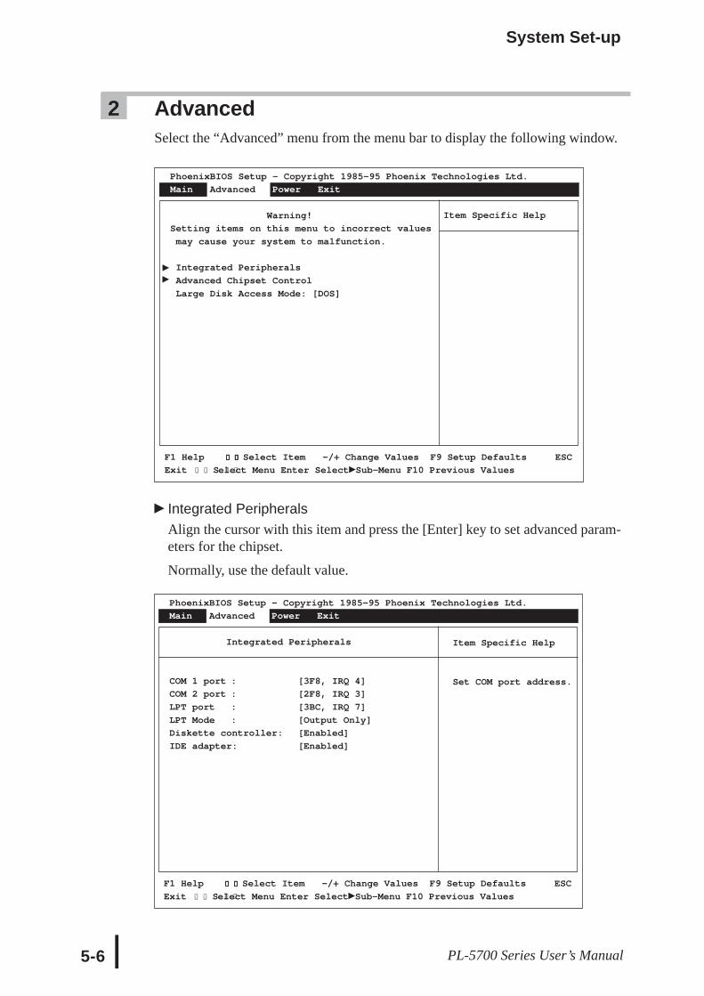
Integrated PeripheralsAlign the cursor with this item and press the [Enter] key to set advanced param-eters for the chipset.
Normally, use the default value.
2 AdvancedSelect the “Advanced” menu from the menu bar to display the following window.
PhoenixBIOS Setup - Copyright 1985-95 Phoenix Technologies Ltd.
Main Advanced Power Exit
Warning!
Setting items on this menu to incorrect values
may cause your system to malfunction.
Integrated Peripherals
Advanced Chipset Control
Large Disk Access Mode: [DOS]
Item Specific Help
Set COM port address.
PhoenixBIOS Setup - Copyright 1985-95 Phoenix Technologies Ltd.
Main Advanced Power Exit
Integrated Peripherals
COM 1 port : [3F8, IRQ 4]
COM 2 port : [2F8, IRQ 3]
LPT port : [3BC, IRQ 7]
LPT Mode : [Output Only]
Diskette controller: [Enabled]
IDE adapter: [Enabled]
System Set-up
5-7PL-5700 Series User’s Manual
COM 1 PortThis setting designates the value used for the PL’s COM 1 port address. Theselections include [Disabled], [3F8/IRQ4], [2F8/IRQ3], [2E8/IRQ3] and [Auto].The factory setting is [3F8/IRQ4] and is recommended.
COM 2 PortThis setting designates the value used for the PL’s COM 1 port address. Theselections include [Disabled], [2F8/IRQ3], [3E8/IRQ4], [2E8/IRQ3] and [Auto].The factory setting is [2F8/IRQ3] and is recommended.
LPT PortThis setting designates the value used for the PL’s LPT port address. The selec-tions include [Disabled], [3BC/IRQ7], [378/IRQ7], or [278/IRQ5]. When usingany setting other than [Disabled], the LPT mode setting must be changed to [OutoutOnly] or [Bi-Directional]. The factory setting is [3BC/IRQ7] and is recommended.
LPT ModeThis setting designates the mode of the PL’s PLT port address. The selectionsinclude [Output Only] (unidirectional), and [Bi-Directional] (both directions).The factory setting is [Output Only] and is recommended. When the LPT Port isset to [Disabled], this setting is also disabled.
Diskette controllerThe selections include [Disabled] or [Enabled]. The factory setting is [Enabled]and is recommended.
IDE adapterThe selections include [Disabled] or [Enabled]. The factory setting is [Enabled]and is recommended.
System Set-up
5-8 PL-5700 Series User’s Manual
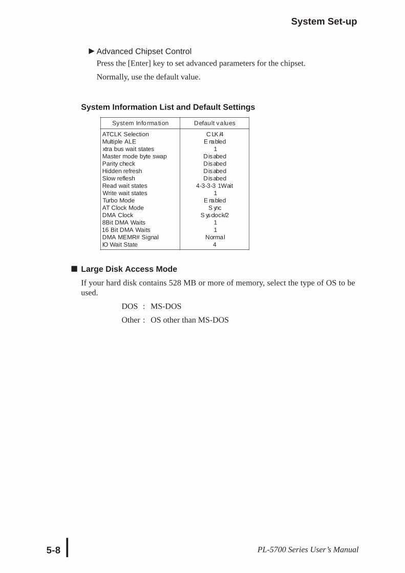
System Information List and Default Settings
Large Disk Access ModeIf your hard disk contains 528 MB or more of memory, select the type of OS to beused.
DOS : MS-DOS
Other : OS other than MS-DOS
Advanced Chipset ControlPress the [Enter] key to set advanced parameters for the chipset.
Normally, use the default value.
System Info rmation Default values
ATCLK SelectionMultiple ALExtra bus wait statesMaster mode byte swapParity checkHidden refreshSlow refleshRead wait statesWrite wait statesTurbo ModeAT Clock ModeDMA Clock8Bit DMA Waits16 Bit DMA WaitsDMA MEMR# SignalIO Wait State
C LK /4E nabled
1DisabedDisabedDisabedDisabed
4-3-3-3 1Wait1
E nabledS ync
S ysclock/211
Normal4
System Set-up
5-9PL-5700 Series User’s Manual
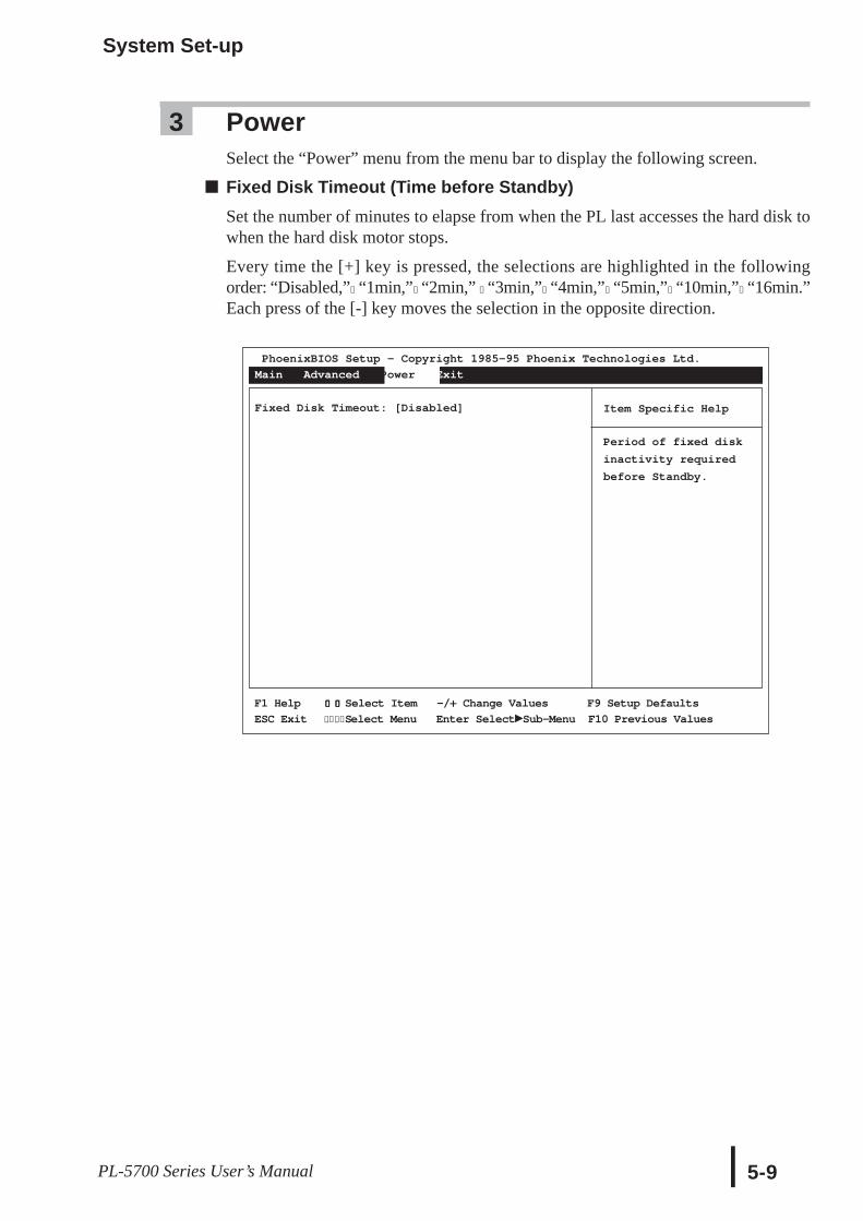
3 PowerSelect the “Power” menu from the menu bar to display the following screen.
Fixed Disk Timeout (Time before Standby)Set the number of minutes to elapse from when the PL last accesses the hard disk towhen the hard disk motor stops.
Every time the [+] key is pressed, the selections are highlighted in the followingorder: “Disabled,”→“1min,”→“2min,” →“3min,”→“4min,”→“5min,”→“10min,”→“16min.”Each press of the [-] key moves the selection in the opposite direction.
PhoenixBIOS Setup - Copyright 1985-95 Phoenix Technologies Ltd.
Main Advanced Power Exit
Fixed Disk Timeout: [Disabled] Item Specific Help
Period of fixed disk
inactivity required
before Standby.
F1 Help ↑↑↑↑↑ ↓↓↓↓↓ Select Item -/+ Change Values F9 Setup Defaults
ESC Exit ← → Select Menu Enter Select Sub-Menu F10 Previous Values← →
System Set-up
5-10 PL-5700 Series User’s Manual
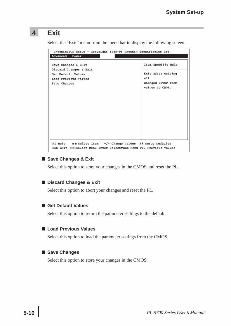
4 ExitSelect the “Exit” menu from the menu bar to display the following screen.
Save Changes & ExitSelect this option to store your changes in the CMOS and reset the PL.
Discard Changes & ExitSelect this option to abort your changes and reset the PL.
Get Default ValuesSelect this option to return the parameter settings to the default.
Load Previous ValuesSelect this option to load the parameter settings from the CMOS.
Save ChangesSelect this option to store your changes in the CMOS.
PhoenixBIOS Setup - Copyright 1985-95 Phoenix Technologies Ltd. Main
Advanced Power Exit
Save Changes & Exit
Discard Changes & Exit
Get Default Values
Load Previous Values
Save Changes
Item Specific Help
Exit after writing
all
changed SETUP item
values to CMOS.
F1 Help ↑↑↑↑↑ ↓↓↓↓↓ Select Item -/+ Change Values F9 Setup Defaults
ESC Exit ← → Select Menu Enter Select Sub-Menu F10 Previous Values← →
Chapter6Bundled SoftwareThe PL comes with programs not supplied in the standard MS-DOS or Windows® OS,including touch panel input programs. This chapter explains the types of software bundledwith this product, hereafter refered to as “this software.”
6-1Panel Computer PL-5700 Series User’s Manual
6-1 File List6-2 Touch Panel Input File6-3 Other Files
6-1 File List
• Digital does not guarantee this software will work with OSs other than those listed here.
File name Des cription
README.TXTC on ta in s d e tai l ed in fo rm at io n o n i nc lud e d f i l es a n d u p- to -d at en ew s. Re ad th is fi l e b e fo re us in g a n y o f t he bu n dl eds of t wa re .
The following software runs on Windows® 3.1/3.11 and/or Windows® 95.
File name Des cription
WCONTSET.E-XE
C ON TS ET uti l i ty ' s e xp l a na ti o n a nd up d a te fo rW ind o ws ®3 . 1 /W ind o ws ® 9 5
B LS AVER .S CRT uns o f f t he b a c kl i g ht. C onta ins S cr e e n S ave r fo rW ind o ws ®3 .1 and S cr e e n S ave r fo r W ind o ws ®9 5 .
• WCONTSET.EXE cannot be used with the PL-5700T1, PL-5700T1-24VC, or PL-5701T1.
Also, the brightness setting is unused on the PL5700S1 and PL-5701S1.
The following software runs only on Windows® 3.1 or 3.11.
File name Des cription
FUNCKEY.EXE
U ti l i t y fo r us e wi t h W i nd o ws 3 . 1 /3 .1 1 s of t wa r e . Is us edto r e c o r d a nd a u t o m a te ke ys tr o k e s , wh i c h a r e a ct i va te dv i a to uc hi ng us er d e f i ne d func t i o n k e y s a ro und th ep e r i p he ry o f t he Touc h P a ne l.
Bundled Software
6-2PL-5700 Series User’s Manual
The following PL-5700 software is for use with MS-DOS systems
• Must be version 3.21 or later.
• Digital does not guarantee this software will work with any OS other than thosepreviously mentioned.
• This software is made for use with MS-DOS. Do not use it in a Windows® environ-ment.
• CONTSET.EXE cannot be used with the PL-5700T1, PL-5700T1-24VC or PL-5701T1. Also, the brightness setting is ignored on the PL5700S1 and PL-5701S1.
• For an explanation of the EXTCOM.SYS, CONTSET.EXE, WCONTSET.EXE andFUNCKEY.EXE applications, refer to their respective README.TXT file.
File name Des cription
PLATPH.EXETouch panel handlerC onverts input from the touch panel in line with display panel resolution (640 x480). It is also compatible with Digital P anel Computers of the PL-386 family.
P LC ALIB .E XE
Touch panel data calibrationB ytouching the specified position on the panel, the difference between the logicvalue and measured value is corrected. Furthermore, using the PLATPH.E XEapplication, it is possible to create files with data based on calibration resultsobtained here.
K EYEM_P L.EXEK eyboard emulatorDisplays a picture of a keyboard on the screen, enabling input from the touchpanel.
DIS P.EXEDis play On/Off programTurns the display, including the backlight, on/off.
FANALAR M.EXE Detects alarms in the C PU cooling fan.
E XTCOM.SYSC OM port driver (reception interrupt acknowledge). For details , see theR EADME.TXT file on the same disk.
C ONTS ET.E XEF or setti ng contrast with the PL-5700S1 and P L-5701S 1when equipped with thebacklight brightness and contrast control uti lity for the P L-5700L1 and P L-5701L1.
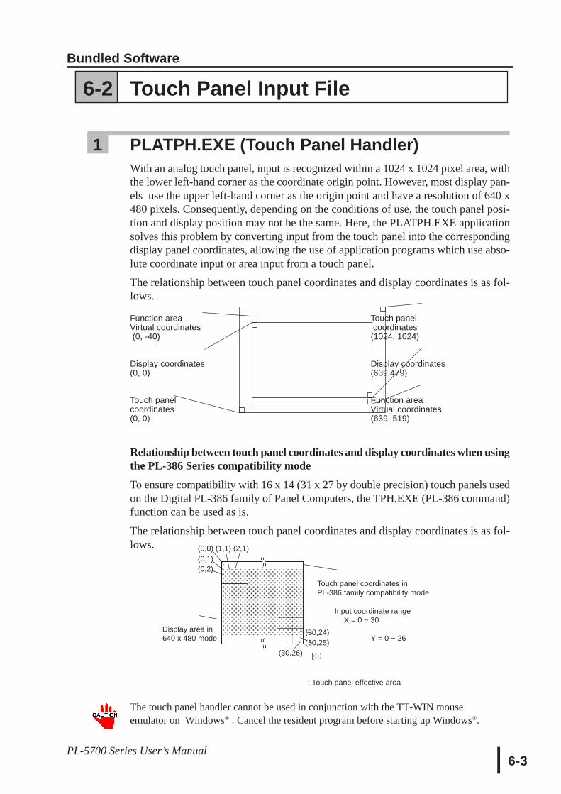
Bundled Software
6-3PL-5700 Series User’s Manual
(0,0) (1,1) (2,1)(0,1)(0,2)
(30,24)(30,25)
(30,26)
6-2 Touch Panel Input File
1 PLATPH.EXE (Touch Panel Handler)With an analog touch panel, input is recognized within a 1024 x 1024 pixel area, withthe lower left-hand corner as the coordinate origin point. However, most display pan-els use the upper left-hand corner as the origin point and have a resolution of 640 x480 pixels. Consequently, depending on the conditions of use, the touch panel posi-tion and display position may not be the same. Here, the PLATPH.EXE applicationsolves this problem by converting input from the touch panel into the correspondingdisplay panel coordinates, allowing the use of application programs which use abso-lute coordinate input or area input from a touch panel.
The relationship between touch panel coordinates and display coordinates is as fol-lows.
Function area Touch panelVirtual coordinates coordinates (0, -40) (1024, 1024)
Display coordinates Display coordinates(0, 0) (639,479)
Touch panel Function areacoordinates Virtual coordinates(0, 0) (639, 519)
Relationship between touch panel coordinates and display coordinates when usingthe PL-386 Series compatibility mode
To ensure compatibility with 16 x 14 (31 x 27 by double precision) touch panels usedon the Digital PL-386 family of Panel Computers, the TPH.EXE (PL-386 command)function can be used as is.
The relationship between touch panel coordinates and display coordinates is as fol-lows.
Touch panel coordinates inPL-386 family compatibility mode
Input coordinate rangeX = 0 ~ 30
Display area in 640 x 480 mode Y = 0 ~ 26
: Touch panel effective area
The touch panel handler cannot be used in conjunction with the TT-WIN mouseemulator on Windows® . Cancel the resident program before starting up Windows®.
Bundled Software
6-4PL-5700 Series User’s Manual
Start-upPLATPH [Parameter] [↵] or PLATPH -r [↵]* Parameters
-a<n> Specifies the I/O base address of the touch panel’s SIO port.
Hexadecimal, Default: 2e8 (COM4)n= 3f8 (COM1)
n 2f8 (COM2)3e8 (COM3)2e8 (COM4)
-q<n> Specifies the interrupt level (IRQ) of the touch panel’s SIO port.
Default: 10 (COM4)n= 4 (COM1)3 (COM2)
11 (COM3)10 (COM4)
-i<n> Sets the software interrupt vector number when calling up functions.Hexadecimal, Default: n=59
-r Cancels the resident command.
-c <path name> Specifies the data file containing the calibrated value obtained fromthe PLCALIB.EXE application (touch panel data calibration).
When defaulted to, the PLATPH.CAL of the current directory is specified. ∗ Example platph -a2e8 -q10 -cc:\platph.cal Normally, only “platph” is needed.
At startup, the following message will appear on the screen.
Analog Touch Panel Handler PLATPH.EXE Version X.XX Copyright (c) 199X Digital Electronics Corporation Stay resident.
After startup, these commands reside in memory.
• If an error is generated because, for example, there is no file created by thePLCALIB.EXE application, the following message appears on the screen, and thesystem will start up in a mode that does not calibrate data.
WARNING!! Can’t open CAL file. Stay resident.
• Unless properly calibrated, the display and touch panel input positions may not be the same.
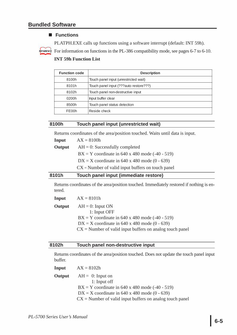
Bundled Software
6-5PL-5700 Series User’s Manual
FunctionsPLATPH.EXE calls up functions using a software interrupt (default: INT 59h).
For information on functions in the PL-386 compatibility mode, see pages 6-7 to 6-10.
INT 59h Function List
Function code Description
8100h Touch panel input (unrestricted wait)
8101h Touch panel input (???auto restore???)
8102h Touch panel non-destructive input
0200h Input buffer clear
8500h Touch panel status detection
FE00h Reside check
8100h Touch panel input (unrestricted wait)
Returns coordinates of the area/position touched. Waits until data is input.Input AX = 8100hOutput AH = 0: Successfully completed
BX = Y coordinate in 640 x 480 mode (-40 - 519)DX = X coordinate in 640 x 480 mode (0 - 639)CX = Number of valid input buffers on touch panel
8101h Touch panel input (immediate restore)
Returns coordinates of the area/position touched. Immediately restored if nothing is en-tered.
Input AX = 8101h
Output AH = 0: Input ON 1: Input OFF
BX = Y coordinate in 640 x 480 mode (-40 - 519)DX = X coordinate in 640 x 480 mode (0 - 639)CX = Number of valid input buffers on analog touch panel
8102h Touch panel non-destructive input
Returns coordinates of the area/position touched. Does not update the touch panel inputbuffer.
Input AX = 8102h
Output AH = 0: Input on1: Input off
BX = Y coordinate in 640 x 480 mode (-40 - 519)DX = X coordinate in 640 x 480 mode (0 - 639)CX = Number of valid input buffers on analog touch panel
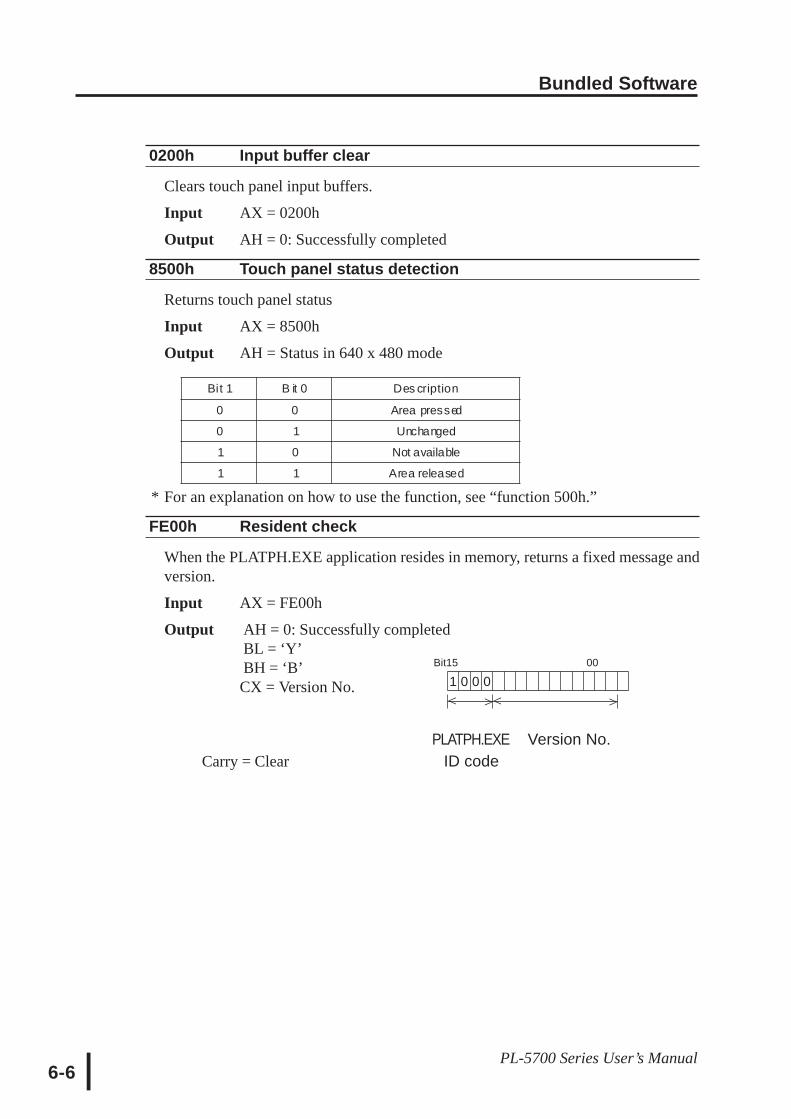
Bundled Software
6-6PL-5700 Series User’s Manual
Bit15 00
1 0 0 0
^ ^^ ^
Bit 1 B it 0 Des cription
0 0 Area pressed
0 1 Unchanged
1 0 Not available
1 1 Area released
0200h Input buffer clear
Clears touch panel input buffers.
Input AX = 0200h
Output AH = 0: Successfully completed
8500h Touch panel status detection
Returns touch panel status
Input AX = 8500h
Output AH = Status in 640 x 480 mode
* For an explanation on how to use the function, see “function 500h.”
FE00h Resident check
When the PLATPH.EXE application resides in memory, returns a fixed message andversion.
Input AX = FE00h
Output AH = 0: Successfully completedBL = ‘Y’BH = ‘B’CX = Version No.
PLATPH.EXE Version No.Carry = Clear ID code
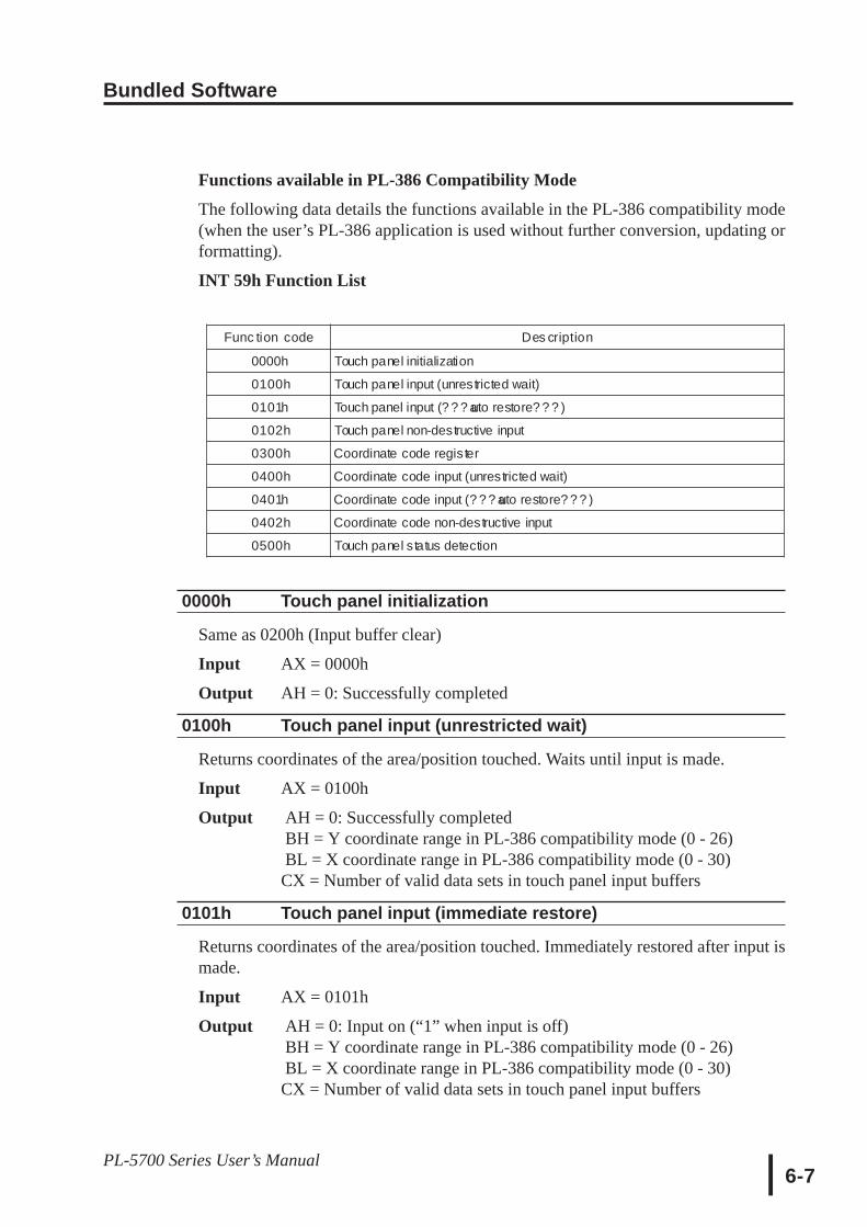
Bundled Software
6-7PL-5700 Series User’s Manual
Functions available in PL-386 Compatibility Mode
The following data details the functions available in the PL-386 compatibility mode(when the user’s PL-386 application is used without further conversion, updating orformatting).
INT 59h Function List
Func tion code Des cription
0000h Touch panel initialization
0100h Touch panel input (unrestricted wait)
0101h Touch panel input (? ? ? auto restore? ? ? )
0102h Touch panel non-destructive input
0300h Coordinate code register
0400h Coordinate code input (unrestricted wait)
0401h Coordinate code input (? ? ? auto restore? ? ? )
0402h Coordinate code non-destructive input
0500h Touch panel status detection
0000h Touch panel initialization
Same as 0200h (Input buffer clear)
Input AX = 0000h
Output AH = 0: Successfully completed
0100h Touch panel input (unrestricted wait)
Returns coordinates of the area/position touched. Waits until input is made.
Input AX = 0100h
Output AH = 0: Successfully completedBH = Y coordinate range in PL-386 compatibility mode (0 - 26)BL = X coordinate range in PL-386 compatibility mode (0 - 30)CX = Number of valid data sets in touch panel input buffers
0101h Touch panel input (immediate restore)
Returns coordinates of the area/position touched. Immediately restored after input ismade.
Input AX = 0101h
Output AH = 0: Input on (“1” when input is off)BH = Y coordinate range in PL-386 compatibility mode (0 - 26)BL = X coordinate range in PL-386 compatibility mode (0 - 30)CX = Number of valid data sets in touch panel input buffers

Bundled Software
6-8PL-5700 Series User’s Manual
0102h Touch panel non-destructive input
Returns coordinates of the area/position touched. Does not update touch panel input buffer.
Input AX = 0102h
Output AH = 0: Input present (No input = 1)BH = Y coordinate range in PL-386 compatibility mode (0 - 26)BL =X coordinate range in PL-386 compatibility mode (0 - 30)CX = Number of valid data sets in touch panel input buffers
0300h Coordinate code register
Registers code corresponding to the display coordinates.
Input AX = 0300hES = Segment from coordinate code management tableDI = Offset from coordinate code management table
Output AH =0: Successfully completed
∗ Relationship between coordinate code management table and coordinate codeES : DI Coordinate code Coordinate & Coordinate code
management tableCoordinate & Coordinate code
Coordinate & Coordinate code
∗∗∗∗∗ Coordinate code management table setupThe coordinate code management table manages positions of multiple coordinate code lists.
Number (n) of registered coordinate code lists
Offset of 1st coordinate code lis t
S egment of 1st coordinate code lis t
Offset of 2nd coordinate code lis t
S egment of 2nd coordinate code lis t
:
Offset of nth coordinate code lis t
S egment of nth coordinate code lis t
~~~~
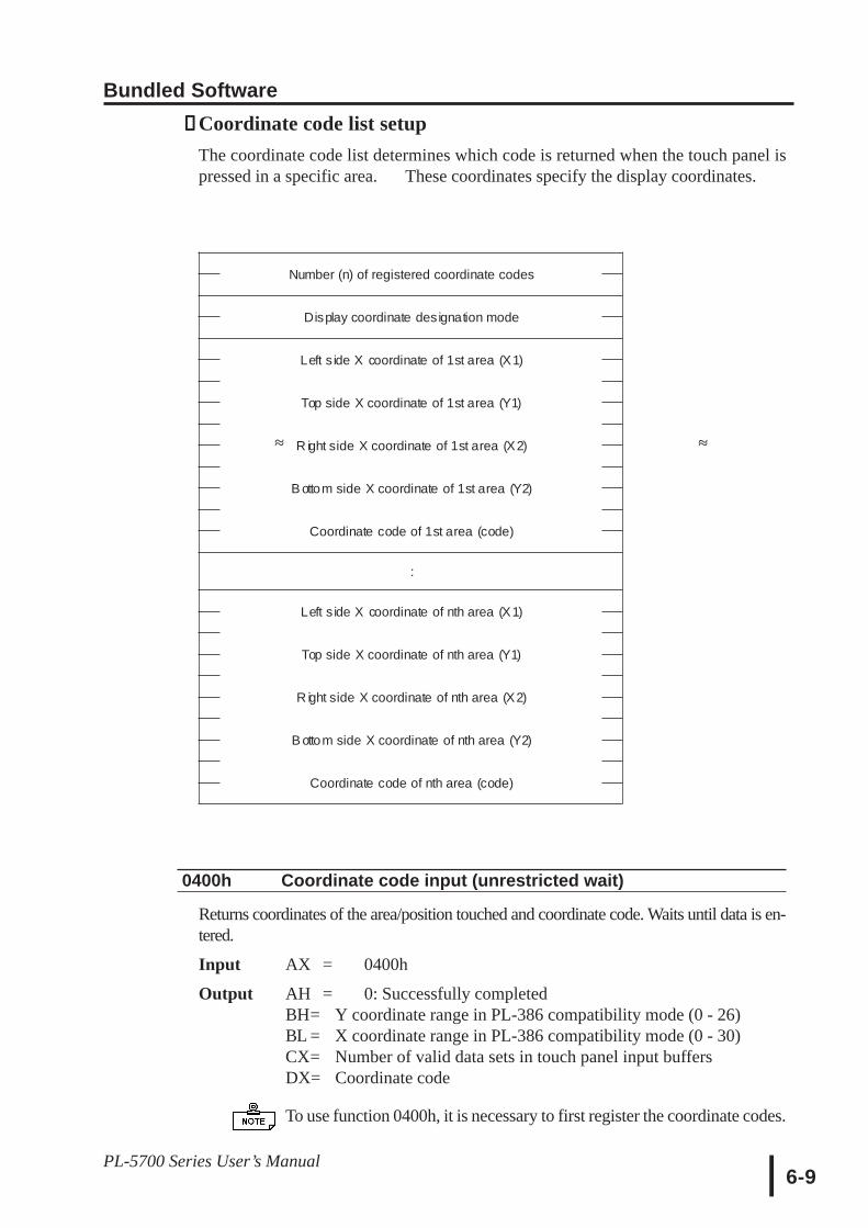
Bundled Software
6-9PL-5700 Series User’s Manual
∗∗∗∗∗ Coordinate code list setupThe coordinate code list determines which code is returned when the touch panel ispressed in a specific area. These coordinates specify the display coordinates.
Number (n) of registered coordinate codes
Display coordinate designation mode
Left s ide X coordinate of 1st area (X1)
Top side X coordinate of 1st area (Y1)
R ight side X coordinate of 1st area (X2)
B ottom side X coordinate of 1st area (Y2)
Coordinate code of 1st area (code)
:
Left s ide X coordinate of nth area (X1)
Top side X coordinate of nth area (Y1)
R ight side X coordinate of nth area (X2)
B ottom side X coordinate of nth area (Y2)
Coordinate code of nth area (code)
0400h Coordinate code input (unrestricted wait)
Returns coordinates of the area/position touched and coordinate code. Waits until data is en-tered.
Input AX = 0400h
Output AH = 0: Successfully completedBH= Y coordinate range in PL-386 compatibility mode (0 - 26)BL = X coordinate range in PL-386 compatibility mode (0 - 30)CX= Number of valid data sets in touch panel input buffersDX= Coordinate code
To use function 0400h, it is necessary to first register the coordinate codes.
~~~~
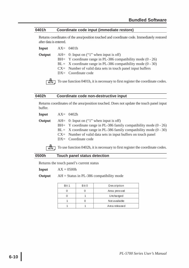
Bundled Software
6-10PL-5700 Series User’s Manual
0401h Coordinate code input (immediate restore)
Returns coordinates of the area/position touched and coordinate code. Immediately restoredafter data is entered.
Input AX= 0401h
Output AH= 0: Input on (“1” when input is off)BH= Y coordinate range in PL-386 compatibility mode (0 - 26)BL = X coordinate range in PL-386 compatibility mode (0 - 30)CX= Number of valid data sets in touch panel input buffersDX= Coordinate code
To use function 0401h, it is necessary to first register the coordinate codes.
0402h Coordinate code non-destructive input
Returns coordinates of the area/position touched. Does not update the touch panel inputbuffer.
Input AX= 0402h
Output AH= 0: Input on (“1” when input is off)BH= Y coordinate range in PL-386 family compatibility mode (0 - 26)BL = X coordinate range in PL-386 family compatibility mode (0 - 30)CX= Number of valid data sets in input buffers on touch panelDX= Coordinate code
To use function 0402h, it is necessary to first register the coordinate codes.
0500h Touch panel status detection
Returns the touch panel’s current status
Input AX = 0500h
Output AH = Status in PL-386 compatibility mode
Bit 1 B it 0 Des cription
0 0 Area pressed
0 1 Unchanged
1 0 Not available
1 1 Area released
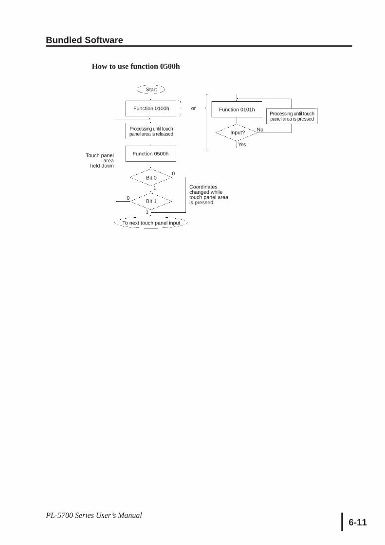
Bundled Software
6-11PL-5700 Series User’s Manual
Start
Function 0100h
Processing until touchpanel area is released
Touch panelarea
held down
Function 0500h
Bit 0
Bit 1
To next touch panel input
Coordinateschanged whiletouch panel areais pressed.
or Function 0101h
Input?
Processing until touchpanel area is pressed
No
Yes
0
0
1
1
How to use function 0500h
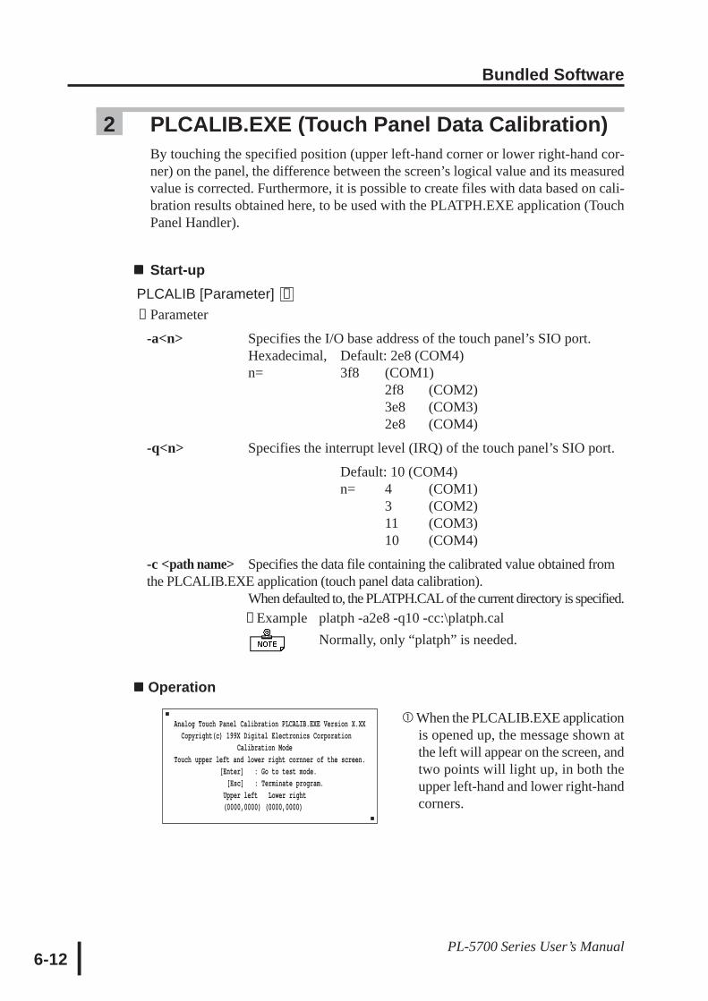
Bundled Software
6-12PL-5700 Series User’s Manual
2 PLCALIB.EXE (Touch Panel Data Calibration)By touching the specified position (upper left-hand corner or lower right-hand cor-ner) on the panel, the difference between the screen’s logical value and its measuredvalue is corrected. Furthermore, it is possible to create files with data based on cali-bration results obtained here, to be used with the PLATPH.EXE application (TouchPanel Handler).
Start-upPLCALIB [Parameter] [↵]∗ Parameter
-a<n> Specifies the I/O base address of the touch panel’s SIO port.Hexadecimal, Default: 2e8 (COM4)n= 3f8 (COM1)
n 2f8 (COM2)3e8 (COM3)2e8 (COM4)
-q<n> Specifies the interrupt level (IRQ) of the touch panel’s SIO port.
Default: 10 (COM4)n= 4 (COM1)
3 (COM2)11 (COM3)10 (COM4)
-c <path name> Specifies the data file containing the calibrated value obtained fromthe PLCALIB.EXE application (touch panel data calibration).
When defaulted to, the PLATPH.CAL of the current directory is specified. ∗ Example platph -a2e8 -q10 -cc:\platph.cal Normally, only “platph” is needed.
Operation
Analog Touch Panel Calibration PLCALIB.EXE Version X.XX Copyright(c) 199X Digital Electronics Corporation Calibration ModeTouch upper left and lower right cornner of the screen. [Enter] : Go to test mode. [Esc] : Terminate program. Upper left Lower right (0000,0000) (0000,0000)
When the PLCALIB.EXE applicationis opened up, the message shown atthe left will appear on the screen, andtwo points will light up, in both theupper left-hand and lower right-handcorners.

Bundled Software
6-13PL-5700 Series User’s Manual
Touch each point, in the order it appears.
• Do not touch both points simultaneously.
• Touch the panel exactly on the lit up areas.
• The measured value is redisplayed if you touch the panel again.
The difference between the logic value and themeasured value is obtained.
•To quit programming, press the [Esc] key.Then, when the message shown on the leftappears, press the [Y] key. The programwill end without saving data. Here, press-ing the [N] key will return you to the cali-bration mode.
Start up the “Test Mode” with the [↵↵↵↵↵] key.This mode tests the calibrated value to deter-mine if it is correct or not.The perimeter is OK if it is drawn along the pathyou traced by finger. Otherwise, return to the“Calibration Mode” and touch the lit up areasagain.
•You can return to the “Calibration Mode”with the [Esc] key.
If test results are OK, press the [Enter] key.When the message shown at the left appears,input the data file name and press the [↵] key.
•When specifying the data file name for the pa-rameter (-C=[path name]) at thePLCALIB.EXE start-up, the program endswithout displaying the message shown on theleft.
Terminate program without saving calibration data?(Y/N)
Analog Touch Panel Calibration PLCALIB.EXE Version X.XXCopyright (c) 199X Digital Electronics Corporation
Calibration Mode
Touch upper left and lower right corner of the screen.[Enter : Go to test mode.
[Esc] : Terminate program.Upper left Lower right(0039.0026) (0997.0988)
The measured value isdisplayed on the screen.
Analog Touch Panel Calibration PLCALIB.EXE Version X.XXCopyright (c) 199X Digital Electronics Corporation
Test Mode
[Enter] : Save calibration data and Exit.[Esc] : Return to calibration mode.
Calibration data name? PLATPH.CAL_
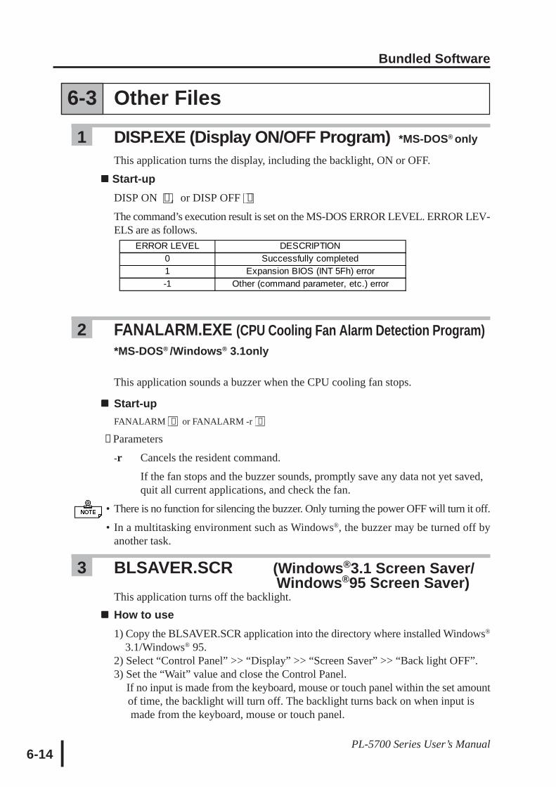
Bundled Software
6-14PL-5700 Series User’s Manual
6-3 Other Files
1 DISP.EXE (Display ON/OFF Program) *MS-DOS® only
This application turns the display, including the backlight, ON or OFF.
Start-upDISP ON [↵,] or DISP OFF [↵]
The command’s execution result is set on the MS-DOS ERROR LEVEL. ERROR LEV-ELS are as follows.
2 FANALARM.EXE (CPU Cooling Fan Alarm Detection Program)*MS-DOS® /Windows® 3.1only
This application sounds a buzzer when the CPU cooling fan stops.
Start-upFANALARM [↵] or FANALARM -r [↵]
∗ Parameters
-r Cancels the resident command.
If the fan stops and the buzzer sounds, promptly save any data not yet saved,quit all current applications, and check the fan.
• There is no function for silencing the buzzer. Only turning the power OFF will turn it off.
• In a multitasking environment such as Windows®, the buzzer may be turned off byanother task.
3 BLSAVER.SCR (Windows®3.1 Screen Saver/( Windows®95 Screen Saver)
This application turns off the backlight.How to use1) Copy the BLSAVER.SCR application into the directory where installed Windows®
3.1/Windows® 95.2) Select “Control Panel” >> “Display” >> “Screen Saver” >> “Back light OFF”.3) Set the “Wait” value and close the Control Panel. If no input is made from the keyboard, mouse or touch panel within the set amount of time, the backlight will turn off. The backlight turns back on when input is made from the keyboard, mouse or touch panel.
ERROR LEVEL DESCRIPTION0 Successfully completed1 Expansion BIOS (INT 5Fh) error-1 Other (command parameter, etc.) error
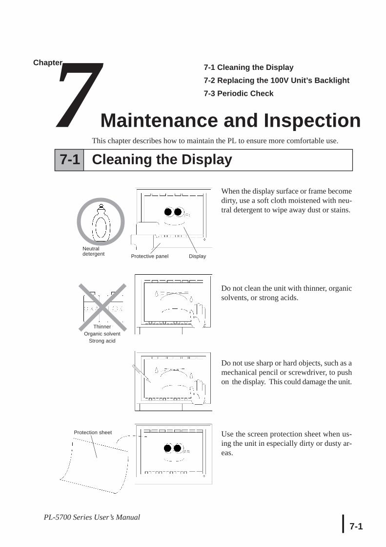
Maintenance and Inspection
7-1PL-5700 Series User’s Manual
Chapter7Maintenance and Inspection
7-1 Cleaning the Display7-2 Replacing the 100V Unit’s Backlight7-3 Periodic Check
This chapter describes how to maintain the PL to ensure more comfortable use.
When the display surface or frame becomedirty, use a soft cloth moistened with neu-tral detergent to wipe away dust or stains.
Do not clean the unit with thinner, organicsolvents, or strong acids.
Do not use sharp or hard objects, such as amechanical pencil or screwdriver, to pushon the display. This could damage the unit.
Use the screen protection sheet when us-ing the unit in especially dirty or dusty ar-eas.
Neutraldetergent
ThinnerOrganic solvent
Strong acid
Protective panel Display
Protection sheet
7-1 Cleaning the Display
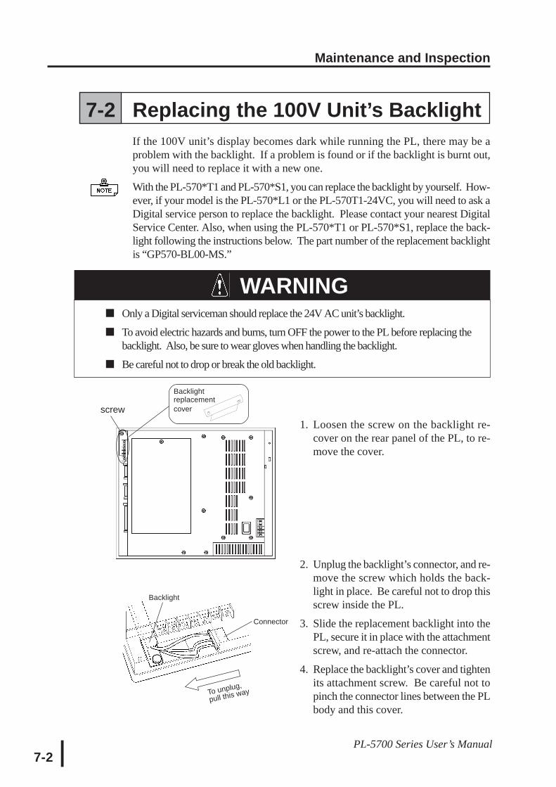
Maintenance and Inspection
7-2PL-5700 Series User’s Manual
1. Loosen the screw on the backlight re-cover on the rear panel of the PL, to re-move the cover.
2. Unplug the backlight’s connector, and re-move the screw which holds the back-light in place. Be careful not to drop thisscrew inside the PL.
3. Slide the replacement backlight into thePL, secure it in place with the attachmentscrew, and re-attach the connector.
4. Replace the backlight’s cover and tightenits attachment screw. Be careful not topinch the connector lines between the PLbody and this cover.
Backlightreplacementcover
Backlight
Connector
To unplug,
pull this way
WARNING
screw
7-2 Replacing the 100V Unit’s BacklightIf the 100V unit’s display becomes dark while running the PL, there may be aproblem with the backlight. If a problem is found or if the backlight is burnt out,you will need to replace it with a new one.
With the PL-570*T1 and PL-570*S1, you can replace the backlight by yourself. How-ever, if your model is the PL-570*L1 or the PL-570T1-24VC, you will need to ask aDigital service person to replace the backlight. Please contact your nearest DigitalService Center. Also, when using the PL-570*T1 or PL-570*S1, replace the back-light following the instructions below. The part number of the replacement backlightis “GP570-BL00-MS.”
Only a Digital serviceman should replace the 24V AC unit’s backlight.
To avoid electric hazards and burns, turn OFF the power to the PL before replacing thebacklight. Also, be sure to wear gloves when handling the backlight.
Be careful not to drop or break the old backlight.
Maintenance and Inspection
7-3PL-5700 Series User’s Manual
7-3 Periodic CheckCheck the PL periodically to ensure it is in good working condition.
• Ambient environment check pointsIs the ambient temperature within the specified range?
0 to 45°C for the PL-5700T1 andPL-5701T1
0 to 40°C for the PL-5700S1, PL-5700T1-24VC, PL-5701S1, PL-5700L1, and PL-5701L1
Is the ambient humidity within the specified range (30 to 85 %RH) ?
Is the atmosphere free of corrosive gas ?
• Electrical specifications checkIs the voltage adequate (85 to 132 V AC, 50/60 Hz for the 100V AC units) ?
(19.2V to 28.8V DC, 50/60 Hz for the 24V DC unit) ?
• Installation check pointsIs the connection cable firmly connected (not loose) ?
Are any bolts or screws loose ?
Are there any flaws or tears in the moisture resistant packing ?
• Display checkIs the display bright enough ?
Maintenance and Inspection
7-4PL-5700 Series User’s Manual
MEMO
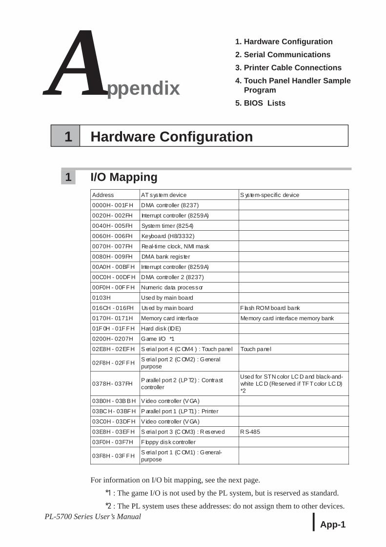
App-1PL-5700 Series User’s Manual
1. Hardware Configuration2. Serial Communications3. Printer Cable Connections4. Touch Panel Handler Sample Program5. BIOS Lists
ChapterAppendix
1 Hardware Configuration
1 I/O Mapping
For information on I/O bit mapping, see the next page.
*1 : The game I/O is not used by the PL system, but is reserved as standard.
*2 : The PL system uses these addresses: do not assign them to other devices.
Address AT system device S ystem-specific device
0000H- 001F H DMA controller (8237)
0020H- 002FH Interrupt controller (8259A)
0040H- 005FH System timer (8254)
0060H- 006FH Keyboard (H8/3332)
0070H- 007FH Real-time clock, NMI mask
0080H- 009FH DMA bank register
00A0H - 00BF H Interrupt controller (8259A)
00C0H - 00DF H DMA controller 2 (8237)
00F0H - 00F F H Numeric data processor
0103H Used by main board
016CH - 016FH Used by main board F lash ROM board bank
0170H- 0171H Memory card interface Memory card interface memory bank
01F 0H - 01F F H Hard disk (IDE)
0200H- 0207H Game I/O *1
02E8H - 02EF H S erial port 4 (C OM4 ) : Touch panel Touch panel
02F8H - 02F F HS erial port 2 (C OM2) : Generalpurpose
0378H- 037FHP arallel port 2 (LP T2) : Contrastcontroller
Used for STN color LC D and black-and-white LC D (Reserved if TF Tcolor LC D)*2
03B0H - 03B B H Video controller (VGA)
03BC H- 03BF H P arallel port 1 (LP T1) : Printer
03C0H - 03DF H Video controller (VGA)
03E8H - 03EF H S erial port 3 (C OM3) : R eserved R S-485
03F0H - 03F7H F loppy disk controller
03F8H - 03F F HS erial port 1 (C OM1) : General-purpose
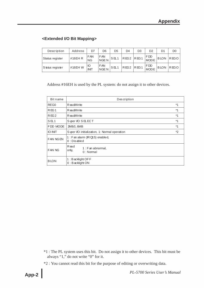
Appendix
App-2 PL-5700 Series User’s Manual
<Extended I/O Bit Mapping>
Descr ip tion Address D7 D6 D5 D4 D3 D2 D1 D0
Status register #16EH RFANNG
FANNGE N
S EL1 R EG2 R EG1F DDMODE
B LON R EGO
S tatus register #16EH WIOINIT
FANNGE N
S EL1 R EG2 R EG1F DDMODE
B LON R EGO
Address #16EH is used by the PL system: do not assign it to other devices.
Bit name Des cription
REG0 R ead/Write *1
R EG1 R ead/Write *1
R EG2 R ead/Write *1
S EL1 S uper I/O S ELEC T *1
F DD MODE 2MB/1.6MB *1
IO INIT S uper I/O initialization, 1: Normal operation *2
FAN NGEN1 : F an alarm (IR Q15) enabled,0 : Disabled
FAN NGR eadonly,
1 : F an abnormal,0 : Normal
B LON1 : B acklight OF F0 : B acklight ON
*1 : The PL system uses this bit. Do not assign it to other devices. This bit must bealways “1,” do not write “0” for it.
*2 : You cannot read this bit for the purpose of editing or overwriting data.
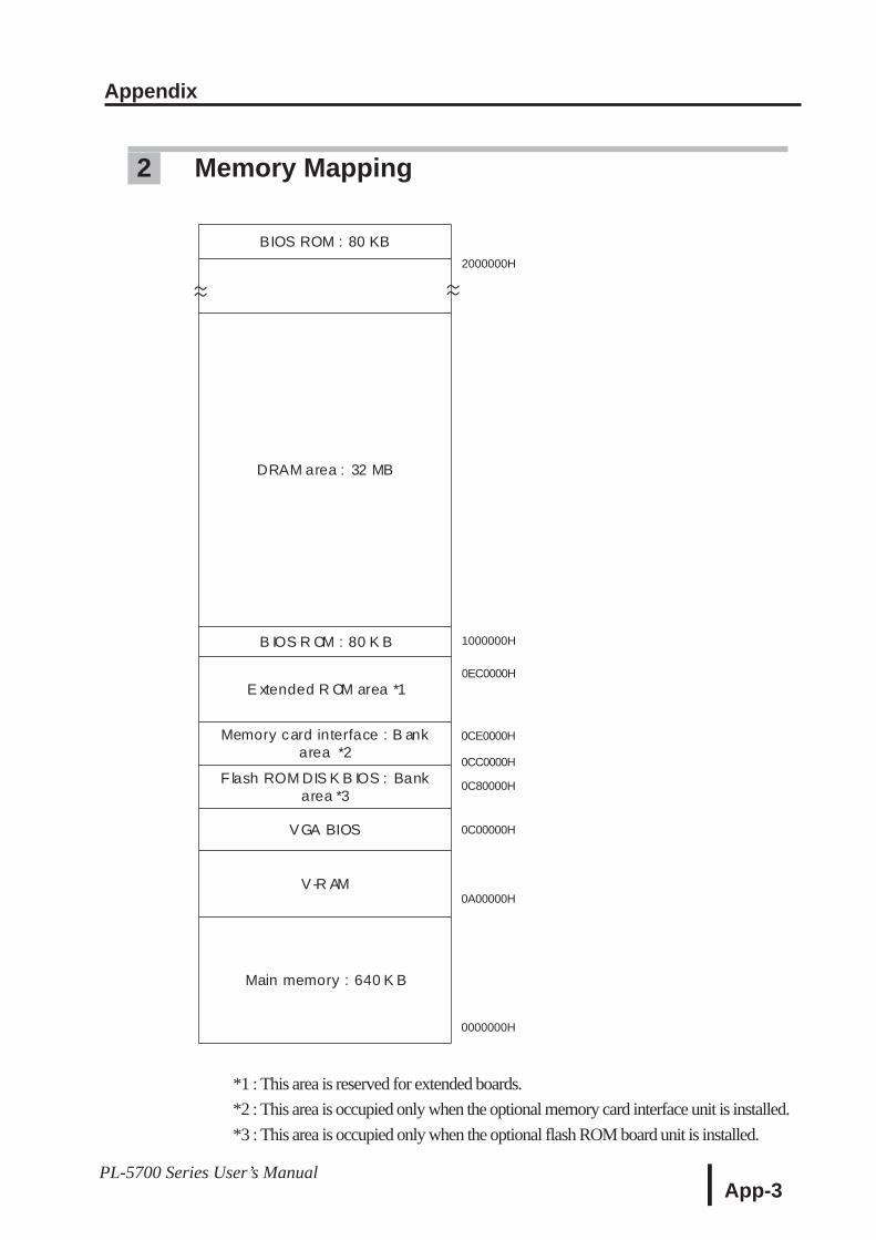
Appendix
App-3PL-5700 Series User’s Manual
BIOS ROM : 80 KB
DRAM area : 32 MB
B IOS R OM : 80 K B
E xtended R OM area *1
Memory card interface : B ankarea *2
F lash ROM DIS K B IOS : Bankarea *3
VGA BIOS
V-R AM
Main memory : 640 K B
2000000H
1000000H
0EC0000H
0CC0000H
0C80000H
0C00000H
0CE0000H
0A00000H
0000000H
~~ ~~
2 Memory Mapping
*1 : This area is reserved for extended boards.*2 : This area is occupied only when the optional memory card interface unit is installed.*3 : This area is occupied only when the optional flash ROM board unit is installed.
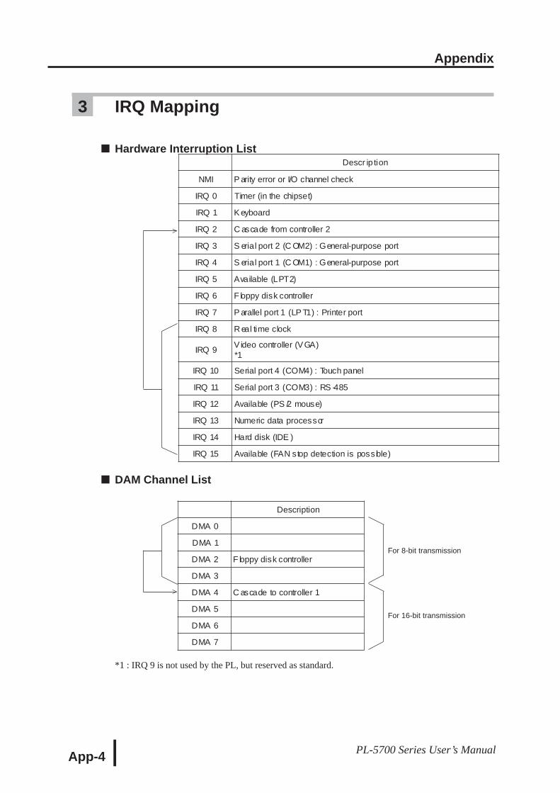
Appendix
App-4 PL-5700 Series User’s Manual
For 8-bit transmission
For 16-bit transmission
^^
3 IRQ Mapping
Hardware Interruption List
DAM Channel List
*1 : IRQ 9 is not used by the PL, but reserved as standard.
Descr ip tion
NMI P arity error or I/O channel check
IRQ 0 Timer (in the chipset)
IRQ 1 K eyboard
IRQ 2 C ascade from controller 2
IRQ 3 S erial port 2 (C OM2) : General-purpose port
IRQ 4 S erial port 1 (C OM1) : General-purpose port
IRQ 5 Available (LPT2)
IRQ 6 F loppy disk controller
IRQ 7 P arallel port 1 (LP T1) : Printer port
IRQ 8 R eal time clock
IRQ 9V ideo controller (VGA)*1
IRQ 10 Serial port 4 (COM4) : Touch panel
IRQ 11 Serial port 3 (COM3) : RS -485
IRQ 12 Available (PS /2 mouse)
IRQ 13 Numeric data processor
IRQ 14 Hard disk (IDE )
IRQ 15 Available (FAN stop detection is possible)
Description
DMA 0
DMA 1
DMA 2 F loppy disk controller
DMA 3
DMA 4 C ascade to controller 1
DMA 5
DMA 6
DMA 7
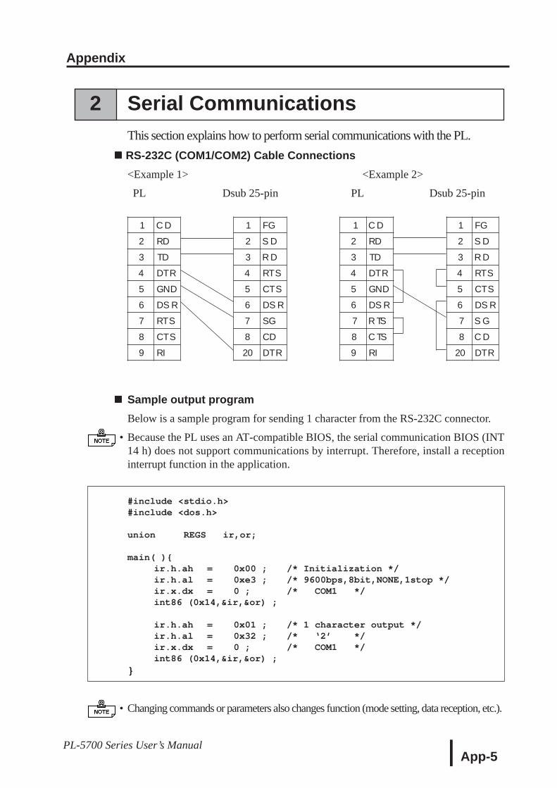
Appendix
App-5PL-5700 Series User’s Manual
2 Serial CommunicationsThis section explains how to perform serial communications with the PL.
RS-232C (COM1/COM2) Cable Connections<Example 1> <Example 2>
PL Dsub 25-pin PL Dsub 25-pin
Sample output programBelow is a sample program for sending 1 character from the RS-232C connector.
• Because the PL uses an AT-compatible BIOS, the serial communication BIOS (INT14 h) does not support communications by interrupt. Therefore, install a receptioninterrupt function in the application.
#include <stdio.h>#include <dos.h>
union REGS ir,or;
main( )ir.h.ah = 0x00 ; /* Initialization */ir.h.al = 0xe3 ; /* 9600bps,8bit,NONE,1stop */ir.x.dx = 0 ; /* COM1 */int86 (0x14,&ir,&or) ;
ir.h.ah = 0x01 ; /* 1 character output */ir.h.al = 0x32 ; /* ‘2’ */ir.x.dx = 0 ; /* COM1 */int86 (0x14,&ir,&or) ;
• Changing commands or parameters also changes function (mode setting, data reception, etc.).
1 C D 1 FG 1 C D 1 FG
2 RD 2 S D 2 RD 2 S D
3 TD 3 R D 3 TD 3 R D
4 DTR 4 RTS 4 DTR 4 RTS
5 GND 5 CTS 5 GND 5 CTS
6 DS R 6 DS R 6 DS R 6 DS R
7 RTS 7 SG 7 R TS 7 S G
8 CTS 8 CD 8 C TS 8 C D
9 RI 20 DTR 9 RI 20 DTR
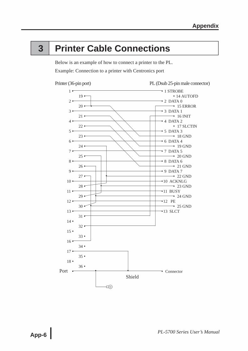
Appendix
App-6 PL-5700 Series User’s Manual
•
•
•
•
Port • •
3 Printer Cable ConnectionsBelow is an example of how to connect a printer to the PL.
Example: Connection to a printer with Centronics port
Printer (36-pin port) PL (Dsub 25-pin male connector)11 • • 1 STROBE
19 • • 14 AUTOFD12 • • 2 DATA 0
20 • • • 15 ERROR13 • • 3 DATA 1
21 • • 16 INIT14 • • 4 DATA 2
22 • • 17 SLCTIN15 • • 5 DATA 3
23 • • 18 GND16 • • 6 DATA 4
24 • • 19 GND17 • • 7 DATA 5
25 • • 20 GND18 • • 8 DATA 6
26 • • 21 GND19 • • 9 DATA 7
27 • • 22 GND10 • •10 ACKNLG
28 • • 23 GND11 • •11 BUSY
29 • • 24 GND12 • •12 PE
30 • • 25 GND13 • •13 SLCT
31 •14 •
32 •15 •
33 •16 •
34 •17 •
35 •18 •
36 • • • Connector
Shield
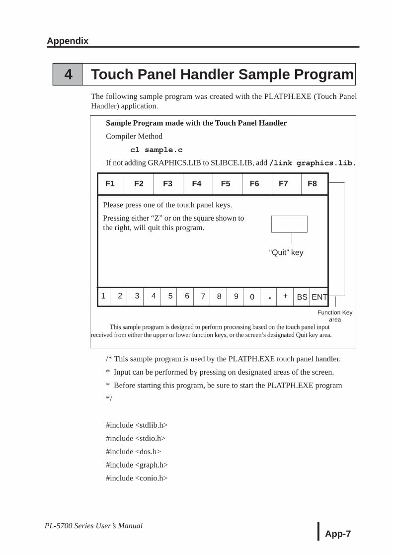
Appendix
App-7PL-5700 Series User’s Manual
“Quit” key
Function Keyarea
Please press one of the touch panel keys.
Pressing either “Z” or on the square shown tothe right, will quit this program.
F8F7F6F5F4F3F2F1
ENTBS+.0987654321
4 Touch Panel Handler Sample ProgramThe following sample program was created with the PLATPH.EXE (Touch PanelHandler) application.
Sample Program made with the Touch Panel Handler
Compiler Method
cl sample.c
If not adding GRAPHICS.LIB to SLIBCE.LIB, add /link graphics.lib.
This sample program is designed to perform processing based on the touch panel inputreceived from either the upper or lower function keys, or the screen’s designated Quit key area.
/* This sample program is used by the PLATPH.EXE touch panel handler.
* Input can be performed by pressing on designated areas of the screen.
* Before starting this program, be sure to start the PLATPH.EXE program
*/
#include <stdlib.h>
#include <stdio.h>
#include <dos.h>
#include <graph.h>
#include <conio.h>
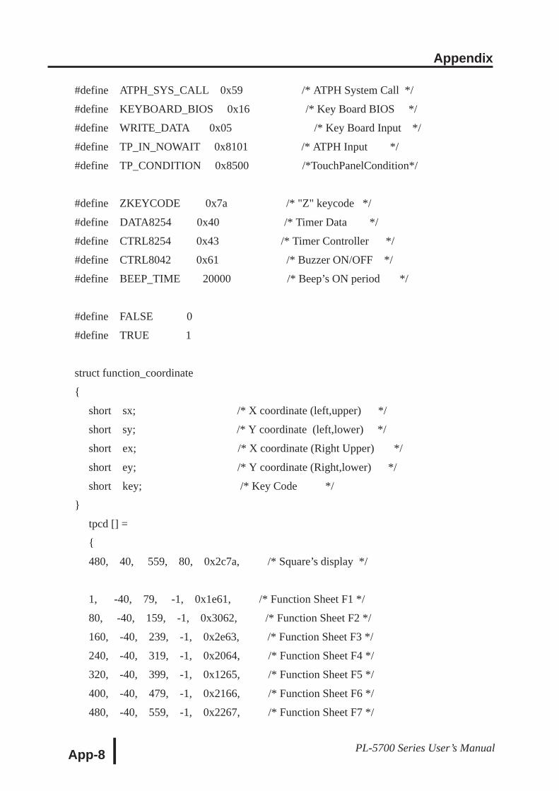
Appendix
App-8 PL-5700 Series User’s Manual
#define ATPH_SYS_CALL 0x59 /* ATPH System Call */
#define KEYBOARD_BIOS 0x16 /* Key Board BIOS */
#define WRITE_DATA 0x05 /* Key Board Input */
#define TP_IN_NOWAIT 0x8101 /* ATPH Input */
#define TP_CONDITION 0x8500 /*TouchPanelCondition*/
#define ZKEYCODE 0x7a /* "Z" keycode */
#define DATA8254 0x40 /* Timer Data */
#define CTRL8254 0x43 /* Timer Controller */
#define CTRL8042 0x61 /* Buzzer ON/OFF */
#define BEEP_TIME 20000 /* Beep’s ON period */
#define FALSE 0
#define TRUE 1
struct function_coordinate
short sx; /* X coordinate (left,upper) */
short sy; /* Y coordinate (left,lower) */
short ex; /* X coordinate (Right Upper) */
short ey; /* Y coordinate (Right,lower) */
short key; /* Key Code */
tpcd [] =
480, 40, 559, 80, 0x2c7a, /* Square’s display */
1, -40, 79, -1, 0x1e61, /* Function Sheet F1 */
80, -40, 159, -1, 0x3062, /* Function Sheet F2 */
160, -40, 239, -1, 0x2e63, /* Function Sheet F3 */
240, -40, 319, -1, 0x2064, /* Function Sheet F4 */
320, -40, 399, -1, 0x1265, /* Function Sheet F5 */
400, -40, 479, -1, 0x2166, /* Function Sheet F6 */
480, -40, 559, -1, 0x2267, /* Function Sheet F7 */
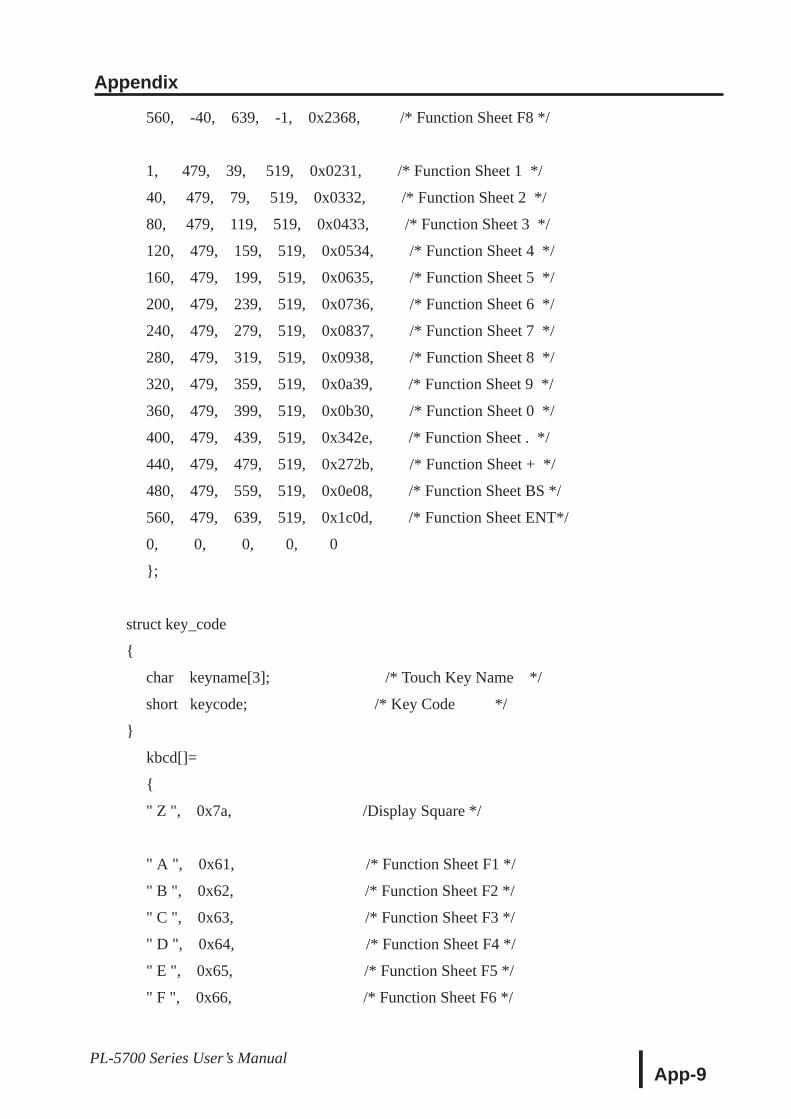
Appendix
App-9PL-5700 Series User’s Manual
560, -40, 639, -1, 0x2368, /* Function Sheet F8 */
1, 479, 39, 519, 0x0231, /* Function Sheet 1 */
40, 479, 79, 519, 0x0332, /* Function Sheet 2 */
80, 479, 119, 519, 0x0433, /* Function Sheet 3 */
120, 479, 159, 519, 0x0534, /* Function Sheet 4 */
160, 479, 199, 519, 0x0635, /* Function Sheet 5 */
200, 479, 239, 519, 0x0736, /* Function Sheet 6 */
240, 479, 279, 519, 0x0837, /* Function Sheet 7 */
280, 479, 319, 519, 0x0938, /* Function Sheet 8 */
320, 479, 359, 519, 0x0a39, /* Function Sheet 9 */
360, 479, 399, 519, 0x0b30, /* Function Sheet 0 */
400, 479, 439, 519, 0x342e, /* Function Sheet . */
440, 479, 479, 519, 0x272b, /* Function Sheet + */
480, 479, 559, 519, 0x0e08, /* Function Sheet BS */
560, 479, 639, 519, 0x1c0d, /* Function Sheet ENT*/
0, 0, 0, 0, 0
;
struct key_code
char keyname[3]; /* Touch Key Name */
short keycode; /* Key Code */
kbcd[]=
" Z ", 0x7a, /Display Square */
" A ", 0x61, /* Function Sheet F1 */
" B ", 0x62, /* Function Sheet F2 */
" C ", 0x63, /* Function Sheet F3 */
" D ", 0x64, /* Function Sheet F4 */
" E ", 0x65, /* Function Sheet F5 */
" F ", 0x66, /* Function Sheet F6 */
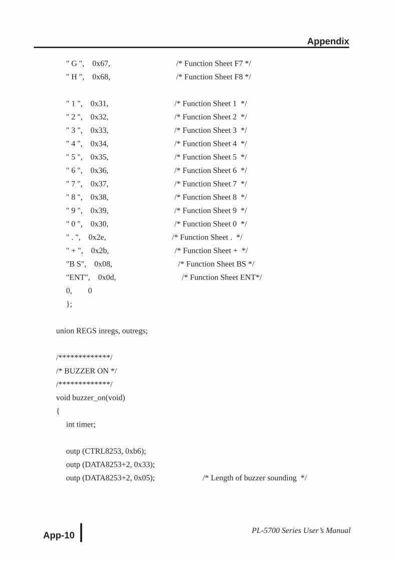
Appendix
App-10 PL-5700 Series User’s Manual
" G ", 0x67, /* Function Sheet F7 */
" H ", 0x68, /* Function Sheet F8 */
" 1 ", 0x31, /* Function Sheet 1 */
" 2 ", 0x32, /* Function Sheet 2 */
" 3 ", 0x33, /* Function Sheet 3 */
" 4 ", 0x34, /* Function Sheet 4 */
" 5 ", 0x35, /* Function Sheet 5 */
" 6 ", 0x36, /* Function Sheet 6 */
" 7 ", 0x37, /* Function Sheet 7 */
" 8 ", 0x38, /* Function Sheet 8 */
" 9 ", 0x39, /* Function Sheet 9 */
" 0 ", 0x30, /* Function Sheet 0 */
" . ", 0x2e, /* Function Sheet . */
" + ", 0x2b, /* Function Sheet + */
"B S", 0x08, /* Function Sheet BS */
"ENT", 0x0d, /* Function Sheet ENT*/
0, 0
;
union REGS inregs, outregs;
/*************/
/* BUZZER ON */
/*************/
void buzzer_on(void)
int timer;
outp (CTRL8253, 0xb6);
outp (DATA8253+2, 0x33);
outp (DATA8253+2, 0x05); /* Length of buzzer sounding */
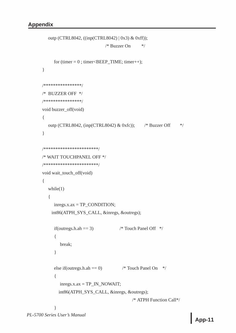
Appendix
App-11PL-5700 Series User’s Manual
outp (CTRL8042, ((inp(CTRL8042) | 0x3) & 0xff));
/* Buzzer On */
for (timer = 0 ; timer<BEEP_TIME; timer++);
/****************/
/* BUZZER OFF */
/****************/
void buzzer_off(void)
outp (CTRL8042, (inp(CTRL8042) & 0xfc)); /* Buzzer Off */
/***********************/
/* WAIT TOUCHPANEL OFF */
/***********************/
void wait_touch_off(void)
while(1)
inregs.x.ax = TP_CONDITION;
int86(ATPH_SYS_CALL, &inregs, &outregs);
if(outregs.h.ah == 3) /* Touch Panel Off */
break;
else if(outregs.h.ah == 0) /* Touch Panel On */
inregs.x.ax = TP_IN_NOWAIT;
int86(ATPH_SYS_CALL, &inregs, &outregs);
/* ATPH Function Call*/
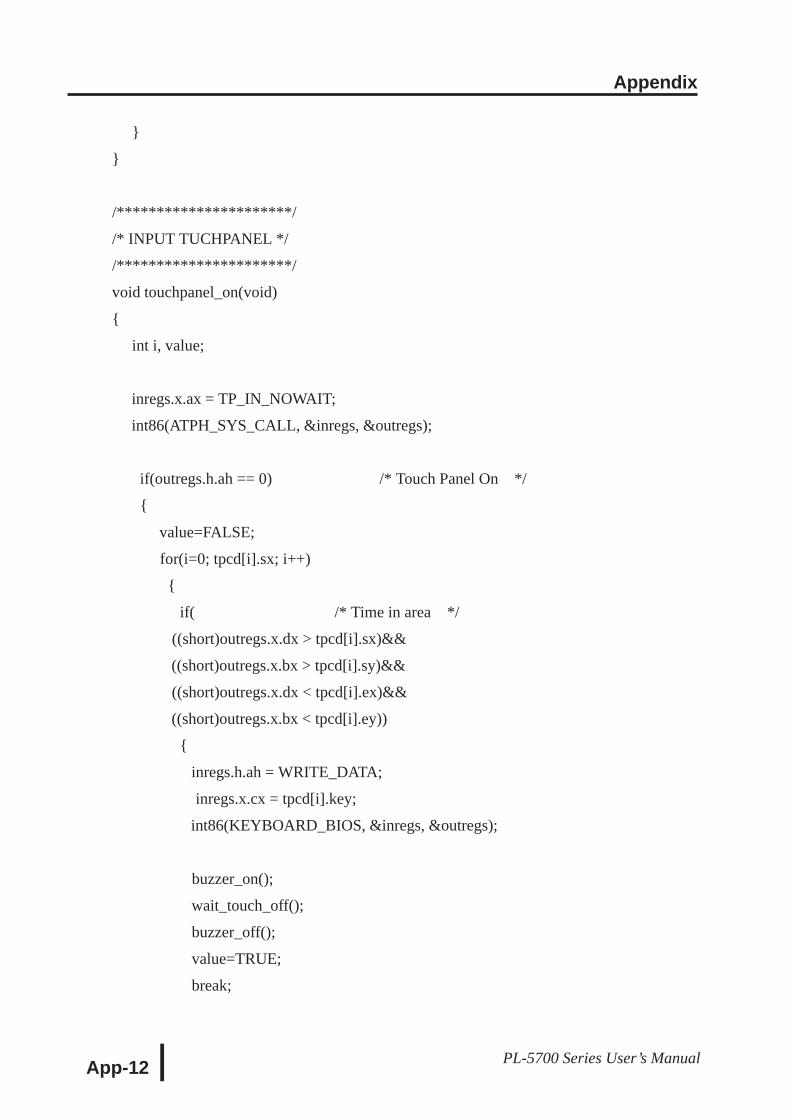
Appendix
App-12 PL-5700 Series User’s Manual
/**********************/
/* INPUT TUCHPANEL */
/**********************/
void touchpanel_on(void)
int i, value;
inregs.x.ax = TP_IN_NOWAIT;
int86(ATPH_SYS_CALL, &inregs, &outregs);
if(outregs.h.ah == 0) /* Touch Panel On */
value=FALSE;
for(i=0; tpcd[i].sx; i++)
if( /* Time in area */
((short)outregs.x.dx > tpcd[i].sx)&&
((short)outregs.x.bx > tpcd[i].sy)&&
((short)outregs.x.dx < tpcd[i].ex)&&
((short)outregs.x.bx < tpcd[i].ey))
inregs.h.ah = WRITE_DATA;
inregs.x.cx = tpcd[i].key;
int86(KEYBOARD_BIOS, &inregs, &outregs);
buzzer_on();
wait_touch_off();
buzzer_off();
value=TRUE;
break;
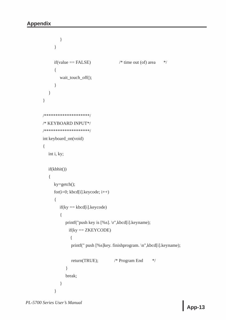
Appendix
App-13PL-5700 Series User’s Manual
if(value == FALSE) /* time out (of) area */
wait_touch_off();
/********************/
/* KEYBOARD INPUT*/
/********************/
int keyboard_on(void)
int i, ky;
if(kbhit())
ky=getch();
for(i=0; kbcd[i].keycode; i++)
if(ky == kbcd[i].keycode)
printf("push key is [%s]. \r",kbcd[i].keyname);
if(ky == ZKEYCODE)
printf(" push [%s]key. finishprogram. \n",kbcd[i].keyname);
return(TRUE); /* Program End */
break;
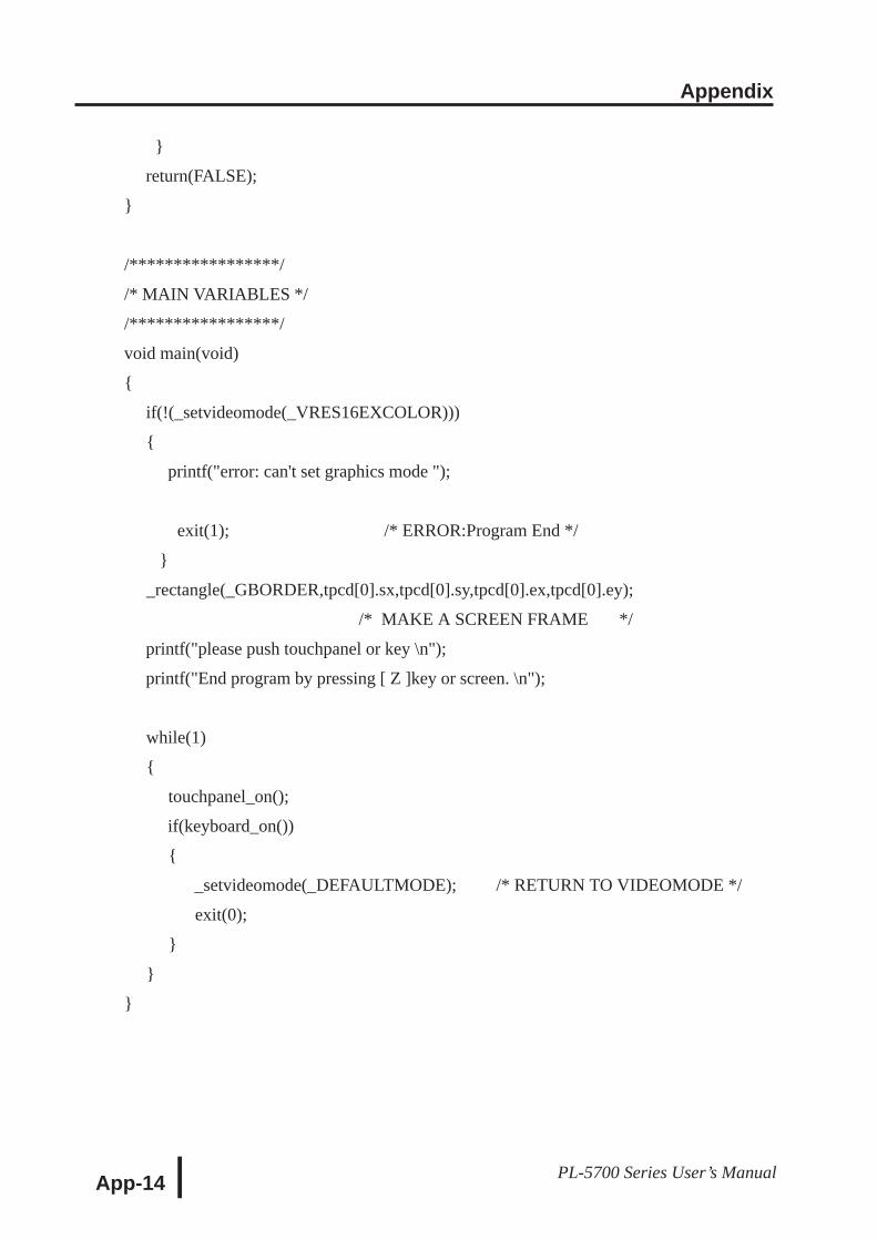
Appendix
App-14 PL-5700 Series User’s Manual
return(FALSE);
/*****************/
/* MAIN VARIABLES */
/*****************/
void main(void)
if(!(_setvideomode(_VRES16EXCOLOR)))
printf("error: can't set graphics mode ");
exit(1); /* ERROR:Program End */
_rectangle(_GBORDER,tpcd[0].sx,tpcd[0].sy,tpcd[0].ex,tpcd[0].ey);
/* MAKE A SCREEN FRAME */
printf("please push touchpanel or key \n");
printf("End program by pressing [ Z ]key or screen. \n");
while(1)
touchpanel_on();
if(keyboard_on())
_setvideomode(_DEFAULTMODE); /* RETURN TO VIDEOMODE */
exit(0);

Appendix
App-15PL-5700 Series User’s Manual
5 BIOS ListsINT 5h Display Hard Copy
INT 10h Video BIOS
Operation Input O utput
S creenhard copy
0050:0000hP rint-screen flag0: Hard copy function unused or
completed successfully1: Now printing
-1: Error
Operation Input O utput
Setting video modeAH =AL =
00hValue of selected mode(Bits 0 ~ 6), V ideo RAMclear (B it 7)
S etti ng cursorshape
AH =C G=C L =
01hC ursor start position anddisplayC ursor end position
S etti ng cursorposition
AH =B H =DH =DL =
02hP age No.Value of specified lineValue of specified column
R eading cursorposition
AH =B H =
03hP age No.
C H=C L =DH =DL =
C ursor start position and displayC ursor end positionC urrent cursor line positionC urrent cursor column position
R eading light penposition
AH = 04h
AH ==
B X =C H=C X =DH =DL =
0: Light pen switch is off.1: Light pen switch is on.X coordinate (0 - 319, 639)Y coordinate (0 - 199)Y coordinate in new graphic mode(0, XXX)Light pen line position in characterunitsLight pen column position incharacter units
S witching activepage
AH =AL =
05hP age No.
S crolling up
AH =AL =B H =C H=C L =
DH =DL =
07hNumber of lines to scroll upAttr ibute of line to clearHighest line in scroll uprangeF arthest left column inscroll up rangeLowest line in scroll uprangeF arthest right column inscroll up range
S crolling down
AH =AL =B H =C H=C L =
DH =DL =
06hNumber of lines to scrolldownAttr ibute of line to clearHighest line in scroll downrangeF arthest left column inscroll down rangeLowest line in scroll downrangeF arthest right column inscroll down range
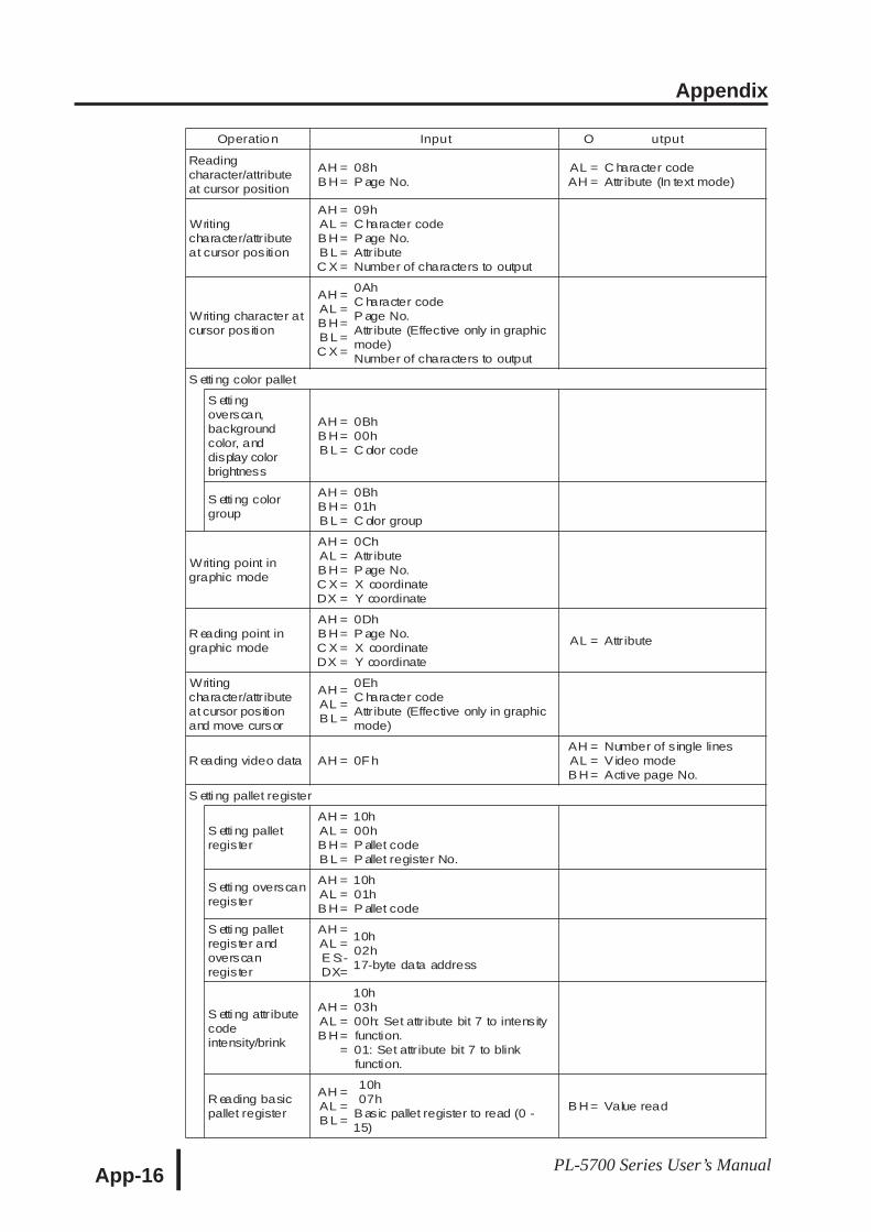
Appendix
App-16 PL-5700 Series User’s Manual
Operation Input O utput
Readingcharacter/attributeat cursor position
AH =B H =
08hP age No.
AL =AH =
C haracter codeAttr ibute (In text mode)
Writingcharacter/attr ibuteat cursor position
AH =AL =B H =B L =C X =
09hC haracter codeP age No.Attr ibuteNumber of characters to output
Writing character atcursor position
AH =AL =B H =B L =C X =
0AhC haracter codeP age No.Attr ibute (Effective only in graphicmode)Number of characters to output
S etti ng color pallet
S etti ngoverscan,backgroundcolor, anddisplay colorbrightness
AH =B H =B L =
0Bh00hC olor code
S etti ng colorgroup
AH =B H =B L =
0Bh01hC olor group
Writing point ingraphic mode
AH =AL =B H =C X =DX =
0ChAttr ibuteP age No.X coordinateY coordinate
R eading point ingraphic mode
AH =B H =C X =DX =
0DhP age No.X coordinateY coordinate
AL = Attr ibute
Writingcharacter/attr ibuteat cursor positionand move cursor
AH =AL =B L =
0EhC haracter codeAttr ibute (Effective only in graphicmode)
R eading video data AH = 0F hAH =AL =B H =
Number of s ingle linesV ideo modeActive page No.
S etti ng pallet register
S etti ng palletregister
AH =AL =B H =B L =
10h00hP allet codeP allet register No.
S etti ng overscanregister
AH =AL =B H =
10h01hP allet code
S etti ng palletregister andoverscanregister
AH =AL =E S:-DX=
10h02h17-byte data address
S etti ng attr ibutecodeintensity/brink
AH =AL =B H =
=
10h03h00h: Set attr ibute bit 7 to intensityfunction.01: Set attr ibute bit 7 to blinkfunction.
R eading basicpallet register
AH =AL =B L =
10h07h
Basic pallet register to read (0 -15)
B H = Value read
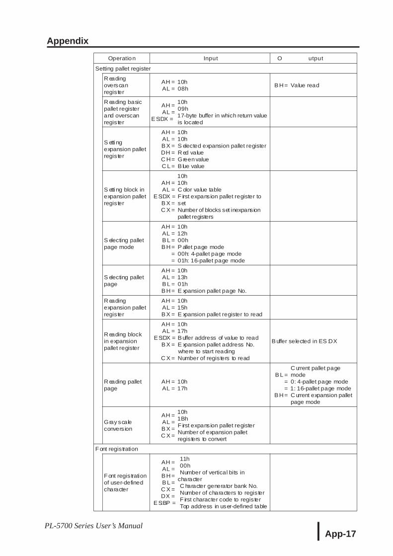
Appendix
App-17PL-5700 Series User’s Manual
Operation Input O utput
Setting pallet register
R eadingoverscanregister
AH =AL =
10h08h
B H = Value read
R eading basicpallet registerand overscanregister
AH =AL =
ES:DX =
10h09h17-byte buffer in which return valueis located
S etti ngexpansion palletregister
AH =AL =B X =DH =C H=C L =
10h10hS elected expansion pallet registerR ed valueGreenvalueB lue value
S etti ng block inexpansion palletregister
AH =AL =
ES:DX =B X =C X =
10h10hC olor value tableF irst expansion pallet register tosetNumber of blocks set inexpansionpallet registers
S electing palletpage mode
AH =AL =B L =B H =
==
10h12h00hP allet page mode00h: 4-pallet page mode01h: 16-pallet page mode
S electing palletpage
AH =AL =B L =B H =
10h13h01hE xpansion pallet page No.
R eadingexpansion palletregister
AH =AL =B X =
10h15hE xpansion pallet register to read
R eading blockin expansionpallet register
AH =AL =
ES:DX =B X =
C X =
10h17hB uffer address of value to readE xpansion pallet address No.where to start readingNumber of registers to read
B uffer selected in ES :DX
R eading palletpage
AH =AL =
10h17h
B L ===
B H =
C urrent pallet pagemode0: 4-pallet page mode1: 16-pallet page modeC urrent expansion palletpage mode
Gray scaleconvers ion
AH =AL =B X =C X =
10h1BhF irst expansion pallet registerNumber of expansion palletregisters to convert
F ont registration
F ont registrationof user-definedcharacter
AH =AL =B H =B L =C X =DX =
E S:BP =
11h00hNumber of vertical bits in
characterC haracter generator bank No.Number of characters to registerF irst character code to registerTop address in user-defined table
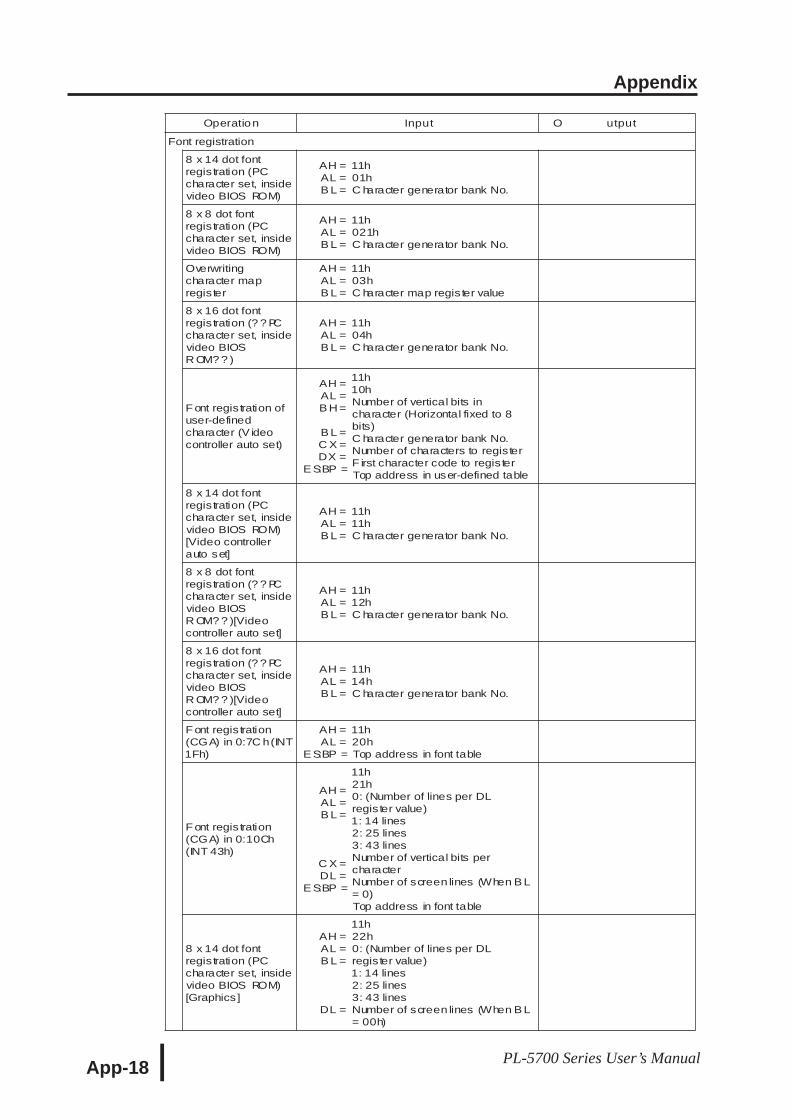
Appendix
App-18 PL-5700 Series User’s Manual
Operation Input O utput
Font registration
8 x 14 dot fontregistration (PCcharacter set, insidevideo BIOS ROM)
AH =AL =B L =
11h01hC haracter generator bank No.
8 x 8 dot fontregistration (PCcharacter set, insidevideo BIOS ROM)
AH =AL =B L =
11h021hC haracter generator bank No.
Overwritingcharacter mapregister
AH =AL =B L =
11h03hC haracter map register value
8 x 16 dot fontregistration (? ? PCcharacter set, insidevideo BIOSR OM? ? )
AH =AL =B L =
11h04hC haracter generator bank No.
F ont registration ofuser-definedcharacter (V ideocontroller auto set)
AH =AL =B H =
B L =C X =DX =
E S:BP =
11h10hNumber of vertical bits incharacter (Horizontal fixed to 8bits)C haracter generator bank No.Number of characters to registerF irst character code to registerTop address in user-defined table
8 x 14 dot fontregistration (PCcharacter set, insidevideo BIOS ROM)[Video controllerauto set]
AH =AL =B L =
11h11hC haracter generator bank No.
8 x 8 dot fontregistration (? ? PCcharacter set, insidevideo BIOSR OM? ? )[Videocontroller auto set]
AH =AL =B L =
11h12hC haracter generator bank No.
8 x 16 dot fontregistration (? ? PCcharacter set, insidevideo BIOSR OM? ? )[Videocontroller auto set]
AH =AL =B L =
11h14hC haracter generator bank No.
F ont registration(CGA) in 0:7C h(INT1Fh)
AH =AL =
E S:BP =
11h20hTop address in font table
F ont registration(CGA) in 0:10Ch(INT 43h)
AH =AL =B L =
C X =DL =
E S:BP =
11h21h0: (Number of lines per DLregister value)1: 14 lines2: 25 lines3: 43 linesNumber of vertical bits percharacterNumber of screen lines (When B L= 0)Top address in font table
8 x 14 dot fontregistration (PCcharacter set, insidevideo BIOS ROM)[Graphics]
AH =AL =B L =
DL =
11h22h0: (Number of lines per DLregister value)1: 14 lines2: 25 lines3: 43 linesNumber of screen lines (When B L= 00h)
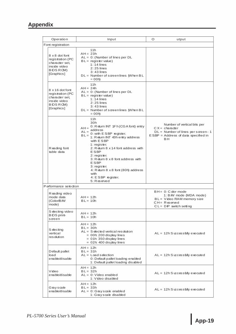
Appendix
App-19PL-5700 Series User’s Manual
Operation Input O utput
Font registration
8 x 8 dot fontregistration (PCcharacter set,ins ide videoB IOS R OM)[Graphics]
AH =AL =B L =
DL =
11h23h0: (Number of lines per DLregister value)1: 14 lines2: 25 lines3: 43 linesNumber of screen lines (When B L= 00h)
8 x 16 dot fontregistration (PCcharacter set,ins ide videoB IOS R OM)[Graphics]
AH =AL =B L =
DL =
11h24h0: (Number of lines per DLregister value)1: 14 lines2: 25 lines3: 43 linesNumber of screen lines (When B L= 00h)
R eading fonttable data
AH =AL =B L =
11h30h0: R eturn INT 1F h(CGA font) entryaddress0: with E S:BP register.1: R eturn INT 43h entry addresswith E S:BP1: register.2: R eturn 8 x 14 font address withE S:BP2: register.3: R eturn 8 x 8 font address withE S:BP3: register.4: R eturn 8 x 8 font (80h) addresswith4: E S:BP register.5: R eserved
C X =DL =
E S:BP =
Number of vertical bits percharacterNumber of lines per screen - 1Address of data specified inB H
P erformance selection
R eading videomode data(Color/B/Wmode)
AH =B L =
12h10h
B H =
B L =C H=C L =
0: C olor mode1: B /W mode (MDA mode)V ideo RAM memory sizeR eservedDIP switch setti ng
S electing videoB IOS print-screen
AH =B L =
12h10h
S electingverticalresolution
AH =B L =AL =
===
12h30hS elected vertical resolution00h: 200 display lines01h: 350 display lines02h: 400 display lines
AL = 12h S uccessfully executed
Default palletloadenable/disable
AH =B L =AL =
12h31hLoad selection0: Default pallet loading enabled1: Default pallet loading disabled
AL = 12h S uccessfully executed
V ideoenable/disable
AH =B L =AL =
12h32h0: V ideo enabled1: V ideo disabled
AL = 12h S uccessfully executed
Gray scaleenable/disable
AH =B L =AL =
12h33h0: Gray scale enabled1: Gray scale disabled
AL = 12h S uccessfully executed
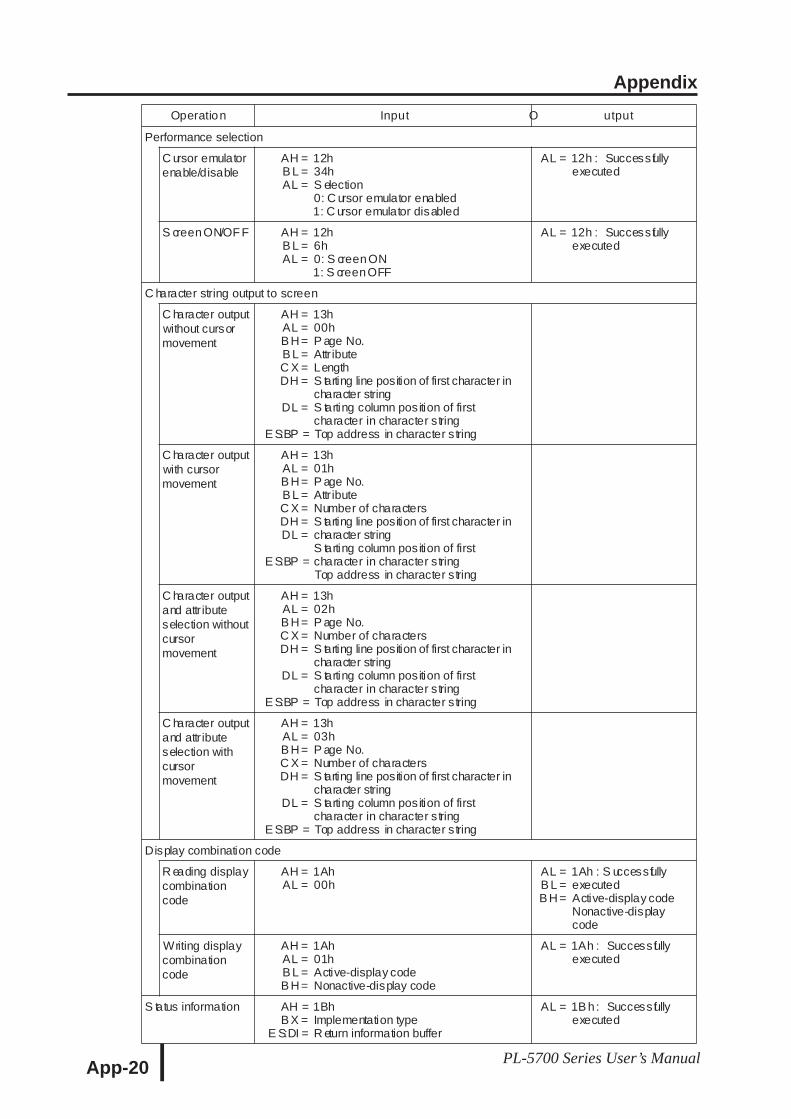
Appendix
App-20 PL-5700 Series User’s Manual
Operation Input O utput
Performance selection
C ursor emulatorenable/disable
AH =B L =AL =
12h34hS election0: C ursor emulator enabled1: C ursor emulator disabled
AL = 12h : Successfullyexecuted
S creenON/OF F AH =B L =AL =
12h6h0: S creenON1: S creenOFF
AL = 12h : Successfullyexecuted
C haracter string output to screen
C haracter outputwithout cursormovement
AH =AL =B H =B L =C X =DH =
DL =
E S:BP =
13h00hP age No.Attr ibuteLengthS tarting line position of first character incharacter stringS tarting column position of firstcharacter in character stringTop address in character string
C haracter outputwith cursormovement
AH =AL =B H =B L =C X =DH =DL =
E S:BP =
13h01hP age No.Attr ibuteNumber of charactersS tarting line position of first character incharacter stringS tarting column position of firstcharacter in character stringTop address in character string
C haracter outputand attr ibuteselection withoutcursormovement
AH =AL =B H =C X =DH =
DL =
E S:BP =
13h02hP age No.Number of charactersS tarting line position of first character incharacter stringS tarting column position of firstcharacter in character stringTop address in character string
C haracter outputand attr ibuteselection withcursormovement
AH =AL =B H =C X =DH =
DL =
E S:BP =
13h03hP age No.Number of charactersS tarting line position of first character incharacter stringS tarting column position of firstcharacter in character stringTop address in character string
Display combination code
R eading displaycombinationcode
AH =AL =
1Ah00h
AL =B L =B H =
1Ah : S uccessfullyexecutedActive-display codeNonactive-displaycode
Writing displaycombinationcode
AH =AL =B L =B H =
1Ah01hActive-display codeNonactive-display code
AL = 1Ah : Successfullyexecuted
S tatus information AH =B X =
E S:DI =
1BhImplementation typeR eturn information buffer
AL = 1B h: Successfullyexecuted
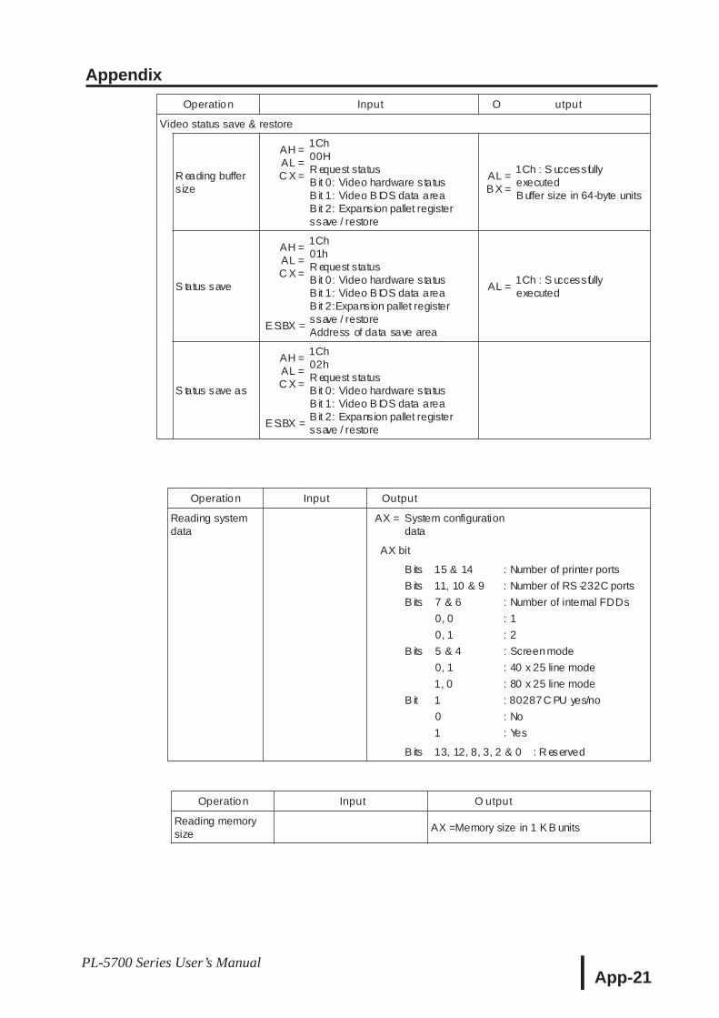
Appendix
App-21PL-5700 Series User’s Manual
Operation Input O utput
Video status save & restore
R eading buffers ize
AH =AL =C X =
1Ch00HR equest statusB it 0: Video hardware statusB it 1: Video B IOS data areaB it 2: Expansion pallet registerssave / restore
AL =B X =
1Ch : S uccessfullyexecutedB uffer size in 64-byte units
S tatus save
AH =AL =C X =
E S:BX =
1Ch01hR equest statusB it 0: Video hardware statusB it 1: Video B IOS data areaB it 2:Expansion pallet registerssave / restoreAddress of data save area
AL =1Ch : S uccessfullyexecuted
S tatus save as
AH =AL =C X =
E S:BX =
1Ch02hR equest statusB it 0: Video hardware statusB it 1: Video B IOS data areaB it 2: Expansion pallet registerssave / restore
Operation Input Output
Reading systemdata
AX = System configurationdata
AX bit
B its
B its
B its
B its
B it
15 & 14
11, 10 & 9
7 & 6
0, 0
0, 1
5 & 4
0, 1
1, 0
1
0
1
: Number of printer ports
: Number of RS -232C ports
: Number of internal FDDs
: 1
: 2
: Screenmode
: 40 x 25 line mode
: 80 x 25 line mode
: 80287C PU yes/no
: No
: Yes
B its 13, 12, 8, 3, 2 & 0 : R eserved
Operation Input O utput
Reading memorysize
AX =Memory size in 1 K B units
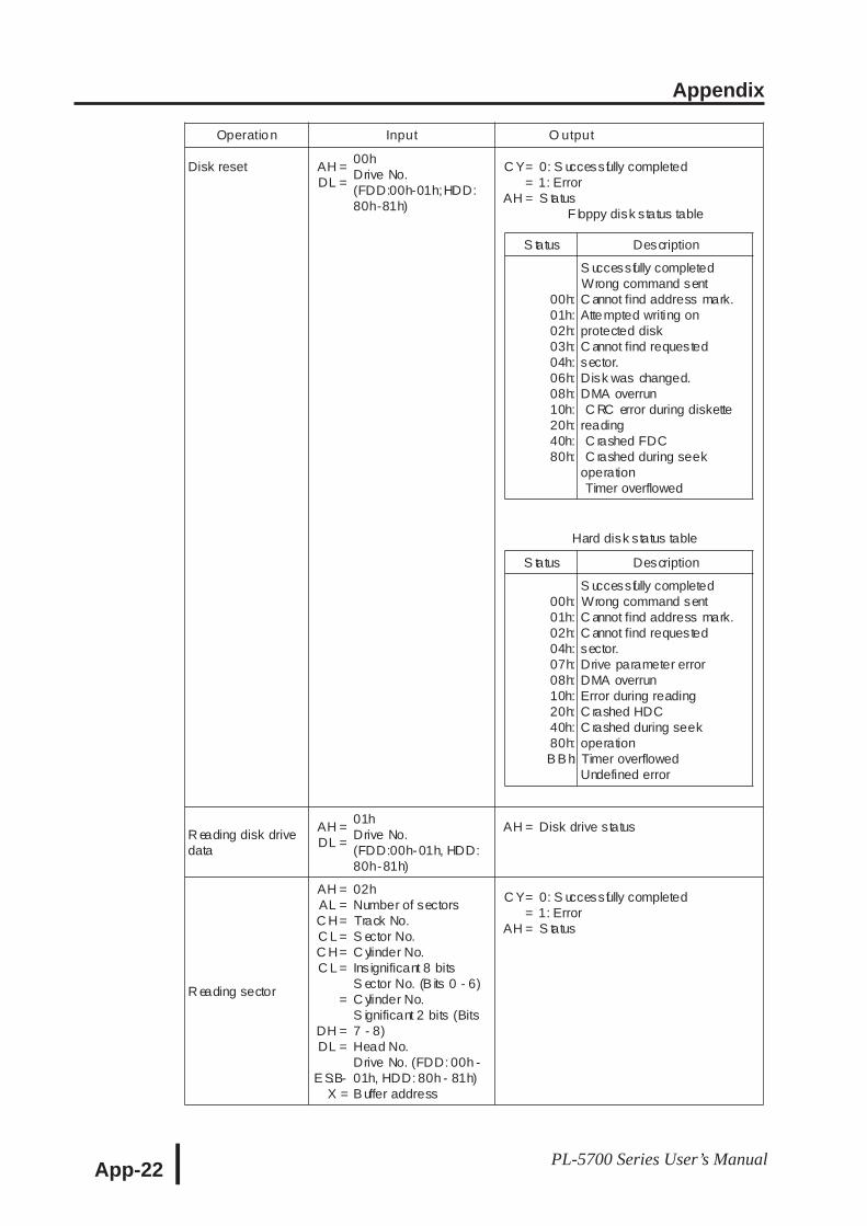
Appendix
App-22 PL-5700 Series User’s Manual
Operation Input O utput
Disk reset AH =DL =
00hDrive No.(FDD:00h-01h;HDD:80h-81h)
C Y==
AH =
0: S uccessfully completed1: ErrorS tatus
F loppy disk status table
S tatus Description
00h:01h:02h:03h:04h:06h:08h:10h:20h:40h:80h:
S uccessfully completedWrong command sentC annot find address mark.Attempted writing onprotected diskC annot find requestedsector.Disk was changed.DMA overrunC RC error during diskette
readingC rashed FDCC rashed during seek
operationTimer overflowed
Hard disk status table
S tatus Description
00h:01h:02h:04h:07h:08h:10h:20h:40h:80h:B B h:
S uccessfully completedWrong command sentC annot find address mark.C annot find requestedsector.Drive parameter errorDMA overrunError during readingC rashed HDCC rashed during seekoperationTimer overflowedUndefined error
R eading disk drivedata
AH =DL =
01hDrive No.(FDD:00h-01h, HDD:80h-81h)
AH = Disk drive status
R eading sector
AH =AL =C H=C L =C H=C L =
=
DH =DL =
E S:B-X =
02hNumber of sectorsTrack No.S ector No.C ylinder No.Ins ignificant 8 bitsS ector No. (B its 0 - 6)C ylinder No.S ignificant 2 bits (Bits7 - 8)Head No.Drive No. (FDD: 00h -01h, HDD: 80h - 81h)B uffer address
C Y==
AH =
0: S uccessfully completed1: ErrorS tatus
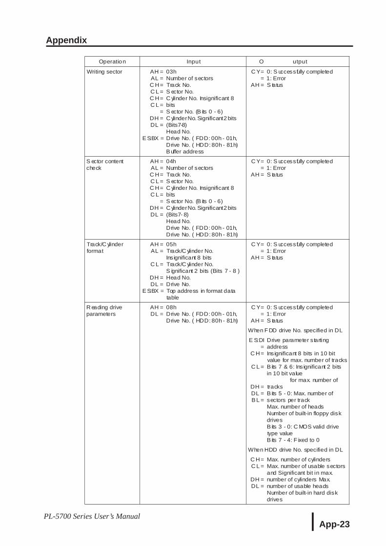
Appendix
App-23PL-5700 Series User’s Manual
Operation Input O utput
Writing sector AH =AL =C H=C L =C H=C L =
=DH =DL =
E S:BX =
03hNumber of sectorsTrack No.S ector No.C ylinder No. Insignificant 8bitsS ector No. (B its 0 - 6)C ylinderNo. Significant2 bits(Bits7-8)Head No.Drive No. ( FDD: 00h - 01h,Drive No. ( HDD: 80h - 81h)B uffer address
C Y==
AH =
0: S uccessfully completed1: ErrorS tatus
S ector contentcheck
AH =AL =C H=C L =C H=C L =
=DH =DL =
04hNumber of sectorsTrack No.S ector No.C ylinder No. Insignificant 8bitsS ector No. (B its 0 - 6)C ylinderNo. Significant2 bits(Bits7- 8)Head No.Drive No. ( FDD: 00h - 01h,Drive No. ( HDD: 80h - 81h)
C Y==
AH =
0: S uccessfully completed1: ErrorS tatus
Track/C ylinderformat
AH =AL =
C L =
DH =DL =
E S:BX =
05hTrack/C ylinder No.Ins ignificant 8 bitsTrack/C ylinder No.S ignificant 2 bits (Bits 7 - 8 )Head No.Drive No.Top address in format datatable
C Y==
AH =
0: S uccessfully completed1: ErrorS tatus
R eading driveparameters
AH =DL =
08hDrive No. ( FDD: 00h - 01h,Drive No. ( HDD: 80h - 81h)
C Y==
AH =
0: S uccessfully completed1: ErrorS tatus
When F DD drive No. specified in DL
E S:DI=
C H=
C L =
DH =DL =B L =
Drive parameter startingaddressInsignificant 8 bits in 10 bitvalue for max. number of tracksB its 7 & 6: Ins ignificant 2 bitsin 10 bit value
for max. number oftracksB its 5 - 0: Max. number ofsectors per trackMax. number of headsNumber of built-in floppy diskdrivesB its 3 - 0: C MOS valid drivetype valueB its 7 - 4: F ixed to 0
When HDD drive No. specified in DL
C H=C L =
DH =DL =
Max. number of cylindersMax. number of usable sectorsand Significant bit in max.number of cylinders Max.number of usable headsNumber of built-in hard diskdrives
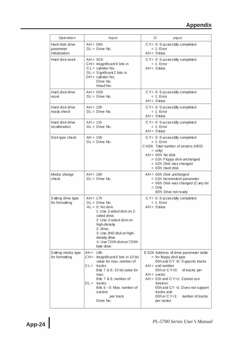
Appendix
App-24 PL-5700 Series User’s Manual
Operation Input O utput
Hard disk driveparameterinitialization
AH =DL =
09hDrive No.
C Y==
AH =
0: S uccessfully completed1: ErrorS tatus
Hard disk seek AH =C H=C L =DL =DH =
0ChInsignificant 8 bits incylinder No.S ignificant 2 bits incylinder No.Drive No.Head No.
C Y==
AH =
0: S uccessfully completed1: ErrorS tatus
Hard disk drivereset
AH =DL =
0DhDrive No.
C Y==
AH =
0: S uccessfully completed1: ErrorS tatus
Hard disk driveready check
AH =DL =
10hDrive No.
C Y==
AH =
0: S uccessfully completed1: ErrorS tatus
Hard disk driverecalibration
AH =DL =
11hDrive No.
C Y==
AH =
0: S uccessfully completed1: ErrorS tatus
Disk type check AH =DL =
15hDrive No.
C Y==
CX:DX=
AH ====
0: S uccessfully completed1: ErrorTotal number of sectors (HDDonly)00h: No disk01h: F loppy disk unchanged02h: Disk was changed03h: Hard disk
Media changecheck
AH =DL =
16hDrive No.
AH ====
00h: Disk unchanged01h: Inconsistent parameter06h: Disk was changed (C arry bitON)80h: Drive not ready
S etti ng drive typefor formatti ng
AH =DL =AL =
17hDrive No.0: No disk1: Use 2-sided disk on 2-sided drive.2: Use 2-sided disk onhigh-density2: drive.3: Use 2HD diskon high-density drive.4: Use 720Kdiskon720K-byte drive.
C Y==
AH =
0: S uccessfully completed1: ErrorS tatus
S etti ng media typefor formatti ng
AH =C H=
C L =
DL =
18hInsignificant 8 bits in 10 bitvalue for max. number oftracksB its 7 & 6: 10 bit value formax.B its 7 & 6: number oftracksB its 5 - 0: Max. number ofsectors
per trackDrive No.
E S:DI=
AH =
AH =AH =
Address of drive parameter tablefor floppy disk type00h and CY =0: S upports tracksand number00h or C Y=0: of tracks persector.01h and C Y=1: Cannot usefunction.00h and CY =1: Does not supporttracks and00h or C Y=1: number of tracksper sector.
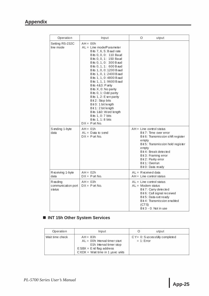
Appendix
App-25PL-5700 Series User’s Manual
INT 15h Other System Services
Operation Input O utput
Setting RS-232Cline mode
AH =AL =
DX =
00hLine mode/ParameterB its 7, 6, 5: B aud rateB its 0, 0, 0: 110 BaudB its 0, 0, 1: 150 BaudB its 0, 1, 0: 300 B audB its 0, 1, 1: 600 B audB its 1, 0, 0: 1200 B audB its 1, 0, 1: 2400 B audB its 1, 1, 0: 4800 B audB its 1, 1, 1: 9600 B audB its 4&3: P arityB its X, 0: No parityB its 0, 1: Odd parityB its 1, 2: E ven parityB it 2: Stop bitsB it 0: 1 bit lengthB it 1: 2 bit lengthB its 1&0: Word lengthB its 1, 0: 7 bitsB its 1, 1: 8 bitsP ort No.
S ending 1-bytedata
AH =AL =DX =
01hData to sendP ort No.
AH = Line control s tatusB it 7: Time over errorB it 6: Transmission shift registeremptyB it 5: Transmission hold registeremptyB it 4: Break detectedB it 3: Framing errorB it 2: Parity errorB it 1: OverrunB it 0: Data ready
R eceiving 1-bytedata
AH =DX =
02hP ort No.
AL =AH =
R eceived dataLine control status
R eadingcommunication portstatus
AH =DX =
03hP ort No.
AL =AL =
Line control statusModem statusB it 7: Carry detectedB it 6: Call signal receivedB it 5: Data-set readyB it 4: Transmission enabled(CTS)B it 3 - 0: Not in use
Operation Input O utput
Wait time check AH =AL =
E S:BX =CX:DX =
83h00h: Interval timer start01h: Interval timer stopE nd flag addressWait time in 1 µsec units
C Y==
0: S uccessfully completed1: Error
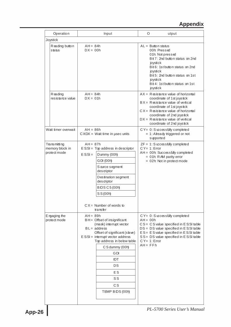
Appendix
App-26 PL-5700 Series User’s Manual
Operation Input O utput
Joystick
R eading buttonstatus
AH =DX =
84h00h
AL = Button status00h: Pressed01h: Not pressedB it 7: 2nd button status on 2ndjoystickB it 6: 1st button status on 2ndjoystickB it 5: 2nd button status on 1stjoystickB it 4: 1st button status on 1stjoystick
R eadingresistance value
AH =DX =
84h01h
AX =
B X =
C X =
DX =
R esistance value of horizontalcoordinate of 1st joystickR esistance value of verticalcoordinate of 1st joystickR esistance value of horizontalcoordinate of 2nd joystickR esistance value of verticalcoordinate of 2nd joystick
Wait timer overwait AH =CX:DX =
86hWait time in µsec units
C Y==
0: S uccessfully completed1: Already triggered or notsupported
Transmitti ngmemory block inprotect mode
AH =E S:SI =
87hTop address in descriptor
ZF =C Y=AH =
==
1: S uccessfully completed1: Error00h: Successfully completed01h: R AM parity error02h: Not in protect mode
E S:SI = Dummy (00h)
GDI (00h)
S ource segmentdescriptor
Destination segmentdescriptor
B IOS C 5 (00h)
S S (00h)
C X = Number of words totransfer
E ngaging theprotect mode
AH =B H =
B L =
E S:SI =
89hOffset of ins ignificant(mask) interrupt vectoraddressOffset of s ignificant (s lave)interrupt vector addressTop address in below table
C Y=AH =C S =DS =E S =S S =C Y=AH =
0: S uccessfully completed00hC S value specified in E S:SI tableDS value specified in E S:SI tableE S value specified in E S:SI tableDS value specified in E S:SI table1: ErrorF F hC S dummy (00h)
GDI
IDT
DS
E S
S S
C S
TEMP B IOS (00h)
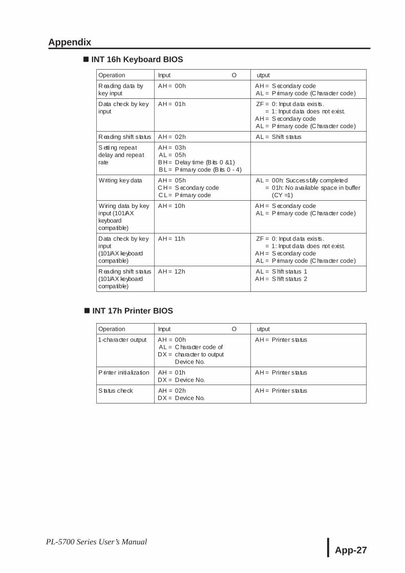
Appendix
App-27PL-5700 Series User’s Manual
INT 16h Keyboard BIOS
INT 17h Printer BIOS
Operation Input O utput
R eading data bykey input
AH = 00h AH =AL =
S econdary codeP rimary code (C haracter code)
Data check by keyinput
AH = 01h ZF ==
AH =AL =
0: Input data exists.1: Input data does not exist.S econdary codeP rimary code (C haracter code)
R eading shift s tatus AH = 02h AL = Shift s tatus
S etti ng repeatdelay and repeatrate
AH =AL =B H =B L =
03h05hDelay time (B its 0 &1)P rimary code (B its 0 - 4)
Writing key data AH =C H=C L =
05hS econdary codeP rimary code
AL ==
00h: Successfully completed01h: No available space in buffer(CY =1)
Wiring data by keyinput (101/AXkeyboardcompatible)
AH = 10h AH =AL =
S econdary codeP rimary code (C haracter code)
Data check by keyinput(101/AX keyboardcompatible)
AH = 11h ZF ==
AH =AL =
0: Input data exists.1: Input data does not exist.S econdary codeP rimary code (C haracter code)
R eading shift s tatus(101/AX keyboardcompatible)
AH = 12h AL =AH =
S hift status 1S hift status 2
Operation Input O utput
1-character output AH =AL =DX =
00hC haracter code ofcharacter to outputDevice No.
AH = Printer status
P rinter initialization AH =DX =
01hDevice No.
AH = Printer status
S tatus check AH =DX =
02hDevice No.
AH = Printer status
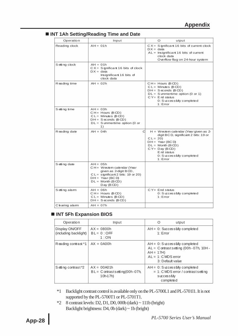
Appendix
App-28 PL-5700 Series User’s Manual
INT 1Ah Setting/Reading Time and Date
INT 5Fh Expansion BIOS
*1 Backlight contrast control is available only on the PL-5700L1 and PL-5701l1. It is notsupported by the PL-5700T1 or PL-5701T1.
*2 8 contrast levels: D2, D1, D0, 000b (dark) ~ 111b (bright)Backlight brightness: D4, 0b (dark) ~ 1b (bright)
Operation Input O utput
Reading clock AH = 01h C X =DX =AL =
S ignificant 16 bits of current clockdataInsignificant 16 bits of currentclock dataOverflow flag on 24-hour system
S etti ng clock AH =C X =DX =
01hS ignificant 16 bits of clockdataInsignificant 16 bits ofclock data
R eading time AH = 02h C H=C L =DH =DL =C Y=
Hours (B CD)Minutes (B CD)S econds (B CD)S ummertime option (0 or 1)E nd status0: S uccessfully completed1: Error
S etti ng time AH =C H=C L =DH =DL =
03hHours (B CD)Minutes (B CD)S econds (B CD)S ummertime option (0 or1)
R eading date AH = 04h C H =
C L =DH =DL =C Y=
Western calendar (Year given as 2-digit BC D, significant 2 bits:19 or20)Year (BC D)Month (B CD)Day (B CD)E nd status0: S uccessfully completed1: Error
S etti ng date AH =C H=
C L =DH =DL =
05hWestern calendar (Yeargiven as 2-digit BCD,significant 2 bits: 19 or 20)Year (BC D)Month (B CD)Day (B CD)
S etti ng alarm AH =C H=C L =DH =
06hHours (B CD)Minutes (B CD)S econds (B CD)
C Y= End status0: S uccessfully completed1: Error
C learing alarm AH = 07h
Operation Input O utput
Display ON/OFF(including backlight)
AX =B L =
0800h0 : OFF1 : ON
AH = 0: Successfully completed1: Error
R eading contrast *1 AX = 0A00h AH =AL =AH =AL =
0: S uccessfully completedC ontrast setti ng (00h - 07h, 10H -17H)1: C MOS error3: Default value
S etti ng contrast *2 AX =B L =
00A01hC ontrastsetti ng(00h-07h,10h-17h)
AH ==
0: S uccessfully completed1: C MOS error / contrast setti ngsuccessfuly
completed