Triumphal Arch presentation by site engineer
31
A presentation prepared by one of the site engineers restoring the Memorial Arch and Bridge of Remembrance, outlining the damage to the structures, the repair designs and the construction methodologies. Lessons learned from one of New Zealand’s most challenging civil engineering projects: rebuilding the earthquake damaged pipes, roads, bridges and retaining walls in the city of Christchurch 2011 - 2016. This document has been provided as an example of a tool that might be useful for other organisations undertaking complex disaster recovery or infrastructure rebuild programmes. For more information about this document, visit www.scirtlearninglegacy.org.nz Triumphal Arch presentation by site engineer Story: Bridge of Remembrance and Memorial Arch Theme: Construction
-
Upload
khangminh22 -
Category
Documents
-
view
1 -
download
0
Transcript of Triumphal Arch presentation by site engineer

A presentation prepared by one of the site engineers restoring the Memorial Arch and Bridge of
Remembrance, outlining the damage to the structures, the repair designs and the construction
methodologies.
Lessons learned from one of New Zealand’s most challenging civil engineering projects:
rebuilding the earthquake damaged pipes, roads, bridges and retaining walls in the city of
Christchurch 2011 - 2016.
This document has been provided as an example of a tool that might be useful for other organisations undertaking complex disaster recovery or infrastructure rebuild programmes.
For more information about this document, visit www.scirtlearninglegacy.org.nz
Triumphal Arch presentation by site engineer
Story: Bridge of Remembrance and Memorial Arch
Theme: Construction


Triumphal Arch 2011 Earthquake Repair & Strengthening Works
Dave Kennedy – Site Engineer – Downer NZ

Established 1924 to commemorate soldiers of the Great War 1914-1918
1965 2015

Original Construction & Ground Conditions
• Sandstone cladded concrete structure with a cavity at its core
• Cavity dimension approximately 400mm
• Constructed for £16078 over approximatly 21 months

Ground Formation
• Bearing on existing pad foundations with deeper foundations to the North
• Ground type Silty Gravel - Dense Sand – Silty Gravel

Planning & Designing

What happened the structure during the 2011 earthquake?
Differential settlement across the 4 columns

What happened the structure during the 2011 earthquake?
Horizontal displacement at the top half of the structure

What happened the structure during the 2011 earthquake?
Cracking and spalling of stonework
Combination of all of the above deemed the Arch structure unstable forcing the Council to close the area from public use
Work commenced by Downer in June 2013 to strengthen and repair the structure

Horizontal movement saved the structure
Designers have said that the horizontal movement/shearing along the top half of the structure saved it from total collapse occurring

Design

Design - Starting from the bottom • Place grout filled ‘Micro Piles’ to dense
sand layer – then “bulbing” occurs by injecting grout into the surrounding natural voids creating a stable base
• Micro piles used as loading to ground around structure must be kept to a minimum
• Replace existing shallow foundations with new reinforced pile cap
Existing Concrete Foundations New RC pilecap
New grout filled micropiles

Pile Cap Plan View
Existing concrete foundations
New RC Pilecap New grout filled micropiles

Micropiling explained
Micropiles are deep foundations constructed using high-strength, small-diameter steel pipe
• A casing is drilled to a required depth
• Reinforcing steel and grout is placed in the casing
Advantages:
• Resists compressive, uplift/tension and lateral loads
• Drilling rigs allow installation in restricted access with minimal disruption to normal operations
https://www.youtube.com/watch?v=TNXd577IReE

Design - Rocking Collars
• Base of columns widened to create the same footprint for each column

Design - Rocking Collars
•M64 steel bars cored through base restrained at both ends to steel plates
•Horizontal 200mm deep gap cut between existing concrete and base of column
•Perimeter wall constructed around base with steel members to “clamp” the base in position from horizontal shear movement

Design – Steel Columns
Built up box
sections placed
in cavity's to
carry movement
safely to the base
and strengthen
the structure

Design – Sliding Plates and Post Tensioning
Sliding plates pressed against each other to create a movement joint at the crown of each arch

Design – Sliding Plates and Post Tensioning
• Due to each archway being cut through the centre post tensioning was necessary to retain the shape and integrity of the arches during seismic activity
• Carried out by placing woven steel strands into a ‘dry’ duct and tensioned from both ends
• Process can only happen once the surrounding new concrete has reached its design strength – 40mpa

Constructability - Typical Working Environment
Restricted work environment = high operative turnover
Working in confined spaces whilst operating heavy dust emitting power tools
Risk to accuracy of installation
1.8
m
0.4m

Constructability – Opening up works
1. Remove stone 2. Install structural elements

Constructability – Opening up works
3. Encase in concrete 4. Reinstate existing stone

Constructability Issues – Pouring Concrete
• Concrete requires certain size gaps in order to flow and compact to form a solid and void free element
• Standard aggregate and concrete additives weren't suitable for the narrow spaces within the Arch voids hence a highly flowable mix was agreed upon
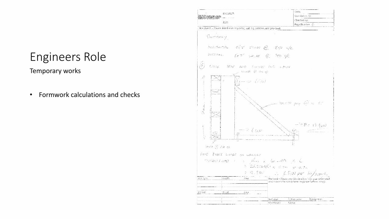
Engineers Role Temporary works
• Formwork calculations and checks

Engineers role – Temporary works
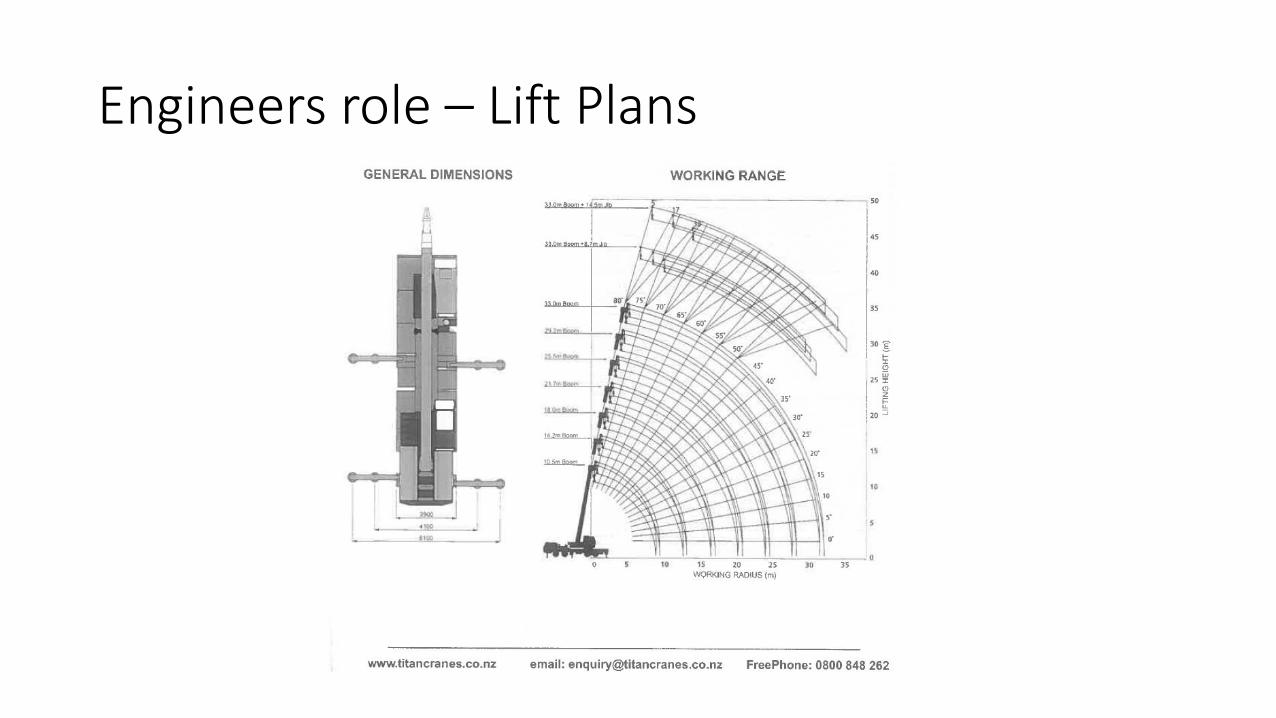
Engineers role – Lift Plans

Engineers role – Movement monitoring

Engineers role - SWMS Item
#
Job Step
Identified Hazards
What could result in harm
** Refer to Annex 1 for Hazard ID Checklist
INITIAL
Risk Level
Control Measures In order of preference, can hazards be:
1. Eliminated?
2. Substituted for a safer alternative?
3. Controlled by physical barriers, guards or mechanical aids?
4. Controlled by training and work procedures?
5. Controlled by the use of PPE?
Note: Refer to appropriate Work Instruction/Management Procedure when detailing
controls.
RESIDUAL
Risk Level
Responsibility for
Control
Measures
Likelihood Certain
Likely
Moderate
Unlikely
Rare
Severity
Major
Serious
Medium
Minor
Risk
High-H
Med-M
Low-L
Risk
High-H
Med-M
Low-L
1.0 Crane Set Up & Delivery of Stage 2 sliding plates
Crane to arrive onsite first and position itself in
correct location onsite. Crane will reverse into
Oxford Tce off Lichfield Street with the use of
spotters to stop traffic. Spotters will guide the
Crane while reversing down Oxford Tce and into
site compound.
The Crane will be positioned and set up by Titan
Crane operatives.
The Sliding Plate Assembly is to be delivered to
site by Semi-Trailer and is to enter the site in the
same procedure as for the Crane.
Lifting operation is to be undertaken early in the
morning to avoid strong winds and to minimise
plant/pedestrian interface when crane and
semi-trailer arrive onsite.
Toolbox to be held onsite before beginning lifting
operation to go over lift plan and roles of each
operative.
Moving Plant & Equipment (Generic
for whole SWMS) Moderate Medium Moderate
Toolbox meeting to discuss job and hazards.
Plant/personnel segregation or exclusion zone.
Spotter guiding plant at all times.
Daily Plant Checks.
Licenced, Trained and Competent operators.
Operators are not to use mobile phones while operating equipment.
Exclusion zone in swing area of plant.
Correct PPE to be worn at all times.
Suitable guards in place over all moving parts.
Reversing should be minimised where possible and use spotters.
Make eye contact with operator before approaching machine.
Only use plant and equipment for tasks that they are designed for.
Only operator and spotter to be present in excavation area.
Low
All
Operator
People/Plant Interface Likely Medium Moderate
Ensure all fences and gates are locked.
Perform all tasks in a professional manner (you are being watched).
Spotter to guide crane & trucks into site & stop pedestrians where required.
Low
All
Oil leaks from machinery (Generic for
whole SWMS) Moderate Medium Moderate
Spill kits on site and workforce briefed to all affected and signed
acceptance.
Daily Plant check sheets completed.
Low
Operator
All
2.0 Removal of Existing Stones to top of Major Arch
Procedure for removing stones:
PART 1 – Preparation:
1st Row Stones
Cut front face mortar joints and proceed to
“explode” stones (method of breaking down
existing stones to be replaced)
Place strops around top of arch to ensure stones
do not fall out before crane hooks on – strops to
be in contact with all faces of stone - if not in
contact place timber off-cuts with foam
underneath
Lifting/Suspended Load Unlikely Major High
Lift plan to be in place & signed off
Lifting Chains & Gear to be tagged with current lifting cert.
Steel sections lifting eyes designed by Downer Temporary Works Engineer.
Crane to have correct certification.
Crane Operative to be correctly trained and competent.
Load to be rigged by Titan’s Rigger.
Tag Lines to be attached to Steel Boxes and controlled by operatives on
the ground.
Steel Boxes to be positioned in place by dogman using radio
communication.
No ground worker to be below suspended load.
Monitor weather conditions and delay lift if winds are too high.
Exclusion zone set up around crane while it is operating.
Ensure safety strops are in place until crane is fully hooked onto stone.
Moderate
Operatives
Crane Driver
Dogman/Rigger
Engineer
Manual Handling Moderate Minor Moderate
Assess any loads before lifting and follow manual handling procedures.
Ensure crew members are fit for task.
Mechanical lifting where possible.
2+ man lift for loads over 25kg.
Correct PPE to be worn including gloves.
Ensure hands are kept well away from pinch points and areas where they
could be crushed.
Low
All
Working at height Moderate Serious High
Working at height permit to be in place.
Harness to be worn when on top level of scaffold.
Weekly scaffold checks
Moderate
All

Engineering/Construction Facts Heating of existing voids: stone is naturally porous therefore a poor insulator – each void had to be heated prior to each concrete pour to assist curing time
Matching new replacement stone to existing stone: refurbishment requires removed material to be replaced like for like. The replaced stone at the arch was sourced from the original quarry in Tasmania, Australia

Extract from Bridge of Remembrance Committee Report - 1924