Efficient simulation environment of wireless radio communications in MEMS modular robots
Upload
khangminh22Category
view
0download
0
WIRELESS ENGINEER THE JOURNAL OF RADIO RESEARCH & PROGRESS
tANUARY 1954
VOL. 31 No. 1 THREE SHILLINGS AND SIXPENCE
_
•ei FOR VIIGH-FREQUENCY ir
INSULATION—specify
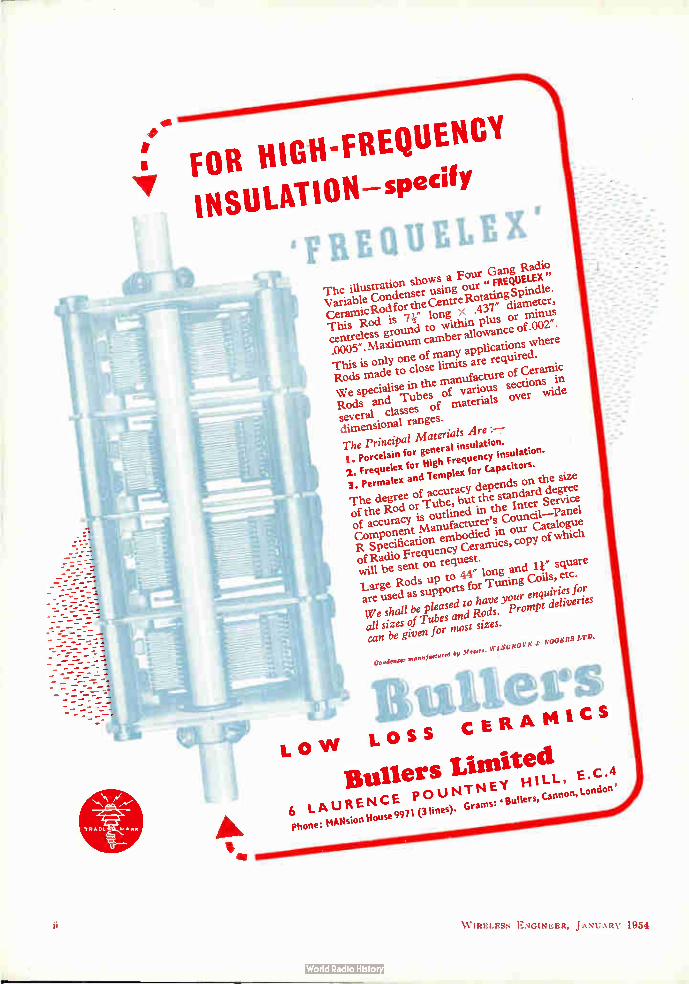
°F11EQUELEi' The illustration shows a Four Gang Radio Variable Condenser using our '. FREQUELEX" CeramicRod for the Centre Rotating Spindle. This Rod is '11" long x .er diameter, centreless ground to within plus or minus .0005". Maximum camber allowance of .002".
This is only one of many applications where Rods made to close limits are required. We specialise in the manufacture of Ceramic Rods and Tubes of various sections in several classes of materials over wide
dimensional ranges. The Principal Materials Are :— I. Porcelain for general insulation. 2. Frequelex for High Frequency insulation. 3. Permalex and Tempt for Capacitors. The degree of accuracy depends on the size of the Rod or Tube, but the standard degree of accuracy is outlined in the Inter Service Component Manufacturer's Council—Panel R Specification embodied in our Catalogue of Radio Frequency Ceramics, copy of which
will be sent on request. Large Rods up to 44" long and w square are used as supports for Tuning Coils, etc. We shall be pleased to have your enquiries for all sizes of Tubes and Rods. Prompt deliveries
can be given for most sizes.
CO'" manufactured by M oe. IT 1XUROV t: .1 ROD le RS LTD.
ill eft%
LOW LOSS CERAMICS
Bullets Limited 6 LAURENCE POUNTNEY HILL, Phone: Mesion House 9971 (3 lines). Grams: ' Butlers, Cannon, London'
W IRELESS ENGINEER, JANUARY 1954
/VARIAC Reg'd Tr1de M rk
voltage
regulating transformers
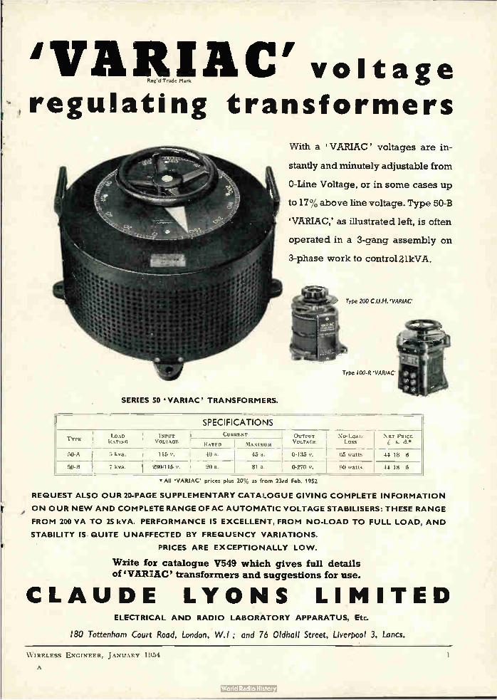
SERIES 50 • VARIAC' TRANSFORMERS.
TYPE LOAD INPUT RATING VOLTAGE
50-A
80-8
kva.
7 kva.
With a VARIAC' voltages are in-
stantly and minutely adjustable from
0-Line Voltage, or in some cases up
to 17% above line voltage. Type 50-B
'VAFtlAC,' as illustrated left, is often
operated in a 3-gang assembly on
3-phase work to control 21kVA.
SPECIFICATIONS CURRENT
RATED I MAXIEUM
116 v. 40 a. 45 a.
MO e.
Type 200 C.U.H. 'VARIAC
Type 100-R VARIAC
OUTPUT NO-LOAD NET PRICE VOLTAGE Loss £ s. d.*
0-135 v. 65 watts 44 18 6
20 a. 31 a. 0-270 V. 00 watts 44 18 6
All VARIAC' prices plus 20% as from 23rd Feb. 1952
REQUEST ALSO OUR 20-PAGE SUPPLEMENTARY CATALOGUE GIVING COMPLETE INFORMATION
ON OUR NEW AND COMPLETE RANGE OF AC AUTOMATIC VOLTAGE STABILISERS: THESE RANGE
FROM 200 VA TO 25 kVA. PERFORMANCE IS EXCELLENT, FROM NO-LOAD TO FULL LOAD, AND
STABILITY IS QUITE UNAFFECTED BY FREQUENCY VARIATIONS.
PRICES ARE EXCEPTIONALLY LOW.
Write for catalogue V549 which gives full details of ‘VARIAC' transformers and suggestions for use.
CLAUDE LYONS LIMITED ELECTRICAL AND RADIO LABORATORY APPARATUS, Etc.
I80 Tottenham Court Road, London, W.I ; and 76 Oldhall Street, Liverpool 3, Lancs.
W IRELESS ENGINEER, JANUARY 1954
A

APPLICATION O.
SERIES 38
IN this instance the Series 38 " Flexilant" _Mounting protects a delicate instrument from vibration and shock.
Other applications are manifold — from
aircraft to power-station instrument panels:
from ship's instruments to the protection of
pyrometers in a steel works.
We produce a range of components that
absorb vibration; eliminate noise; suppress
shock. Our new catalogue lists all these
for you.
RUBBER BONDERS LIMITED
IN ASSOCIATION WITH EMPIRE RUBBER COMPANY .( Proprietor*: H.G. MILLS LTD. )
HUNSTABLE *** BEDFORDSHIRE
TELEPHONE. DUNSTABLE 533.531 14 LINES) TELEGRAMS: SPANDIT. DUNSTABLE
88.85
W IRELESS ENGINEER, JANUARY 1954
A Technical Handbook for Electronic Engineers
This Handbook contains the fullest information about all types of Ferranti
Valves and Cathode Ray Tubes, giving for each type complete data such as
physical details, base connections, ratings, operating conditions, with
graphs, etc., where necessary. The whole is a most valuable book of
reference to the electronics engineer. It is in loose-leaf form, so that new
data can readily be inserted.
Price S'-
Additional data sheets will be sent to subscribers from time to time
MOSTON • MANCHESTER I 0 London Office: KERN HOUSE
36 KINGSWAY, W.C.2
FE 155
W IRELESS ENGINEER, JANUARY 1954
TECHNIQUE A JOURNAL OF INSTRUMENT ENGINEERING
FREE ON REQUEST MUIRHEAD & CO. LTD. BECKENHAM KENT • ENGLAND
Please place my naine on your nailing list for " TECHNIQUE "
POST NAME
POSITION
THIS COUPON COMPANY ADDRESS
TODAY
MUIRHEAD & Co., LTD. pRECISION EI,LCTRICAL INSTRUMENT MAKERS BECKENHAM•KENT•ENGLAND Phone: BECkenham 0041 Telegrams & Cables: MLIIRHEADS ELMF.RS-END
W.E.6I
PRECISION
MUIRHEAD ELECTRICAL INSTRUMENTS
.3
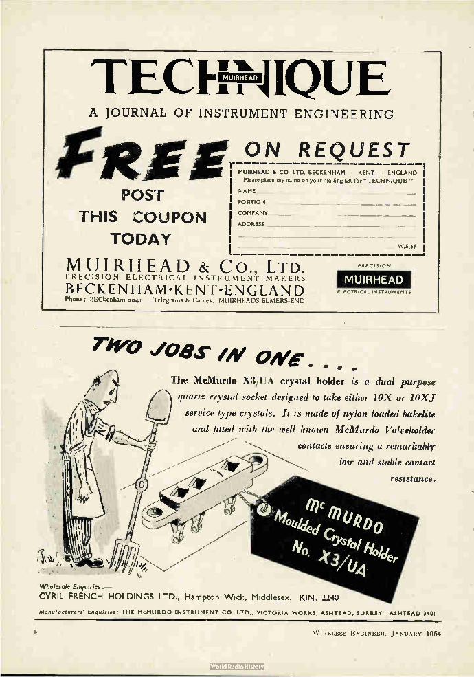
TWO %/OAS'S IN 44
The McMurdo X3/liii crystal holder is a dual purpose
quartz crystal socket designed to take either 10X- or 10XJ
service type crystals. It is made of nylon loaded bakelite
and jilted with the well known McMurdo Valve/wider
contacts ensuring a remarkably
low and stable contact
resistance.
Wholesale Enquiries:—
CYRIL FRENCH HOLDINGS LTD., Hampton Wick, Middlesex. KIN. 2240
Manufacturers' Enquiries: THE McMURDO INSTRUMENT CO. LTD.. VICTORIA WORKS, ASHTEAD, SURREY. ASHTEAD 3401
4 W IRELESS ENGINEER, JANUARY 1954
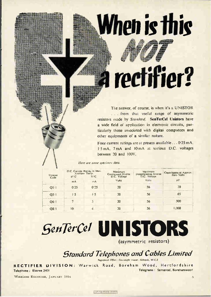
i) C. Current Rating in Max. Ambient Temp.
55°C. 71°C. - - mA mA
Unistor Code
QI'I
03 I
Q6'1
Qi1 1
The answer, of course, is when it's a UNISTOR
. . . from that useful range of asymmetric
resistors made by Standard. SenTerCel Unistors have
a wide field of application in electronic circuits, par-
ticularly those associated with digital computors and
other equipments of a similar nature.
Four current ratings are at present available ... 0•25 mA,
1.5 mA, 7mA and 10 mA at various D.C. voltages
between 20 and 100V.
Here are some specimen data.
Maximum Maximum Continuous Inverse 1 Instantaneous Inverse
D.C. Voltage • D.C. Voltage
Volts
Capacitance at Approx. Zero Volts
Volts of'
025 025 20 56
l'5 1'5 20 56
7 3 1 20 56
Hi 4 20 56
20
65
500
1,000
senTèrce/ UNISTORS (asymmetric resistors)
5tandard Telephones and Cables Limited Registered Office: Connaught 1-1.0a,. Aldwych. W.C. 2
RECTIFIER OIVISI ON: Warwick Road, Boreham Wood, Hertfordshire Telephone: Elstree 2401 Telegrams : Sentercel. Borehamwoo,'
W IRELESS ENGINEER, JANUARY 1954

for unfailing activity
eds.e. SUBMINIATURE
QUARTZ CRYSTAL UNITS
•
•
-
Type BA, frequency change not exceeding 0.01% from 0°C to + 70°C
Type DA, frequency change rot exceeding 0.01% from — 30°C to + 45°C
Type EA, frequency change not exceeding 0.002% from + 65 C to + 80'C
For further details please apply to :-
SALFORD ELECTRICAL INSTRUMENTS LTD PEEL WORKS • SILK STREET • SALFORD 3 • LAMS
A Subsidian of THE GENERAL ELECTRIC CO. LTD. OF ENGLAND
Q.C. 500
Frequency range
10.000 Kc s to 16.000 Kc s
999(0(096iè99S(0(0(09SS(iio(0(09Gt616099999SiE09(0(09199(09(09t0999996199(099999999999(099996IG.99999(0
New McGraw-Hill Publications
Television Broadcasting By H. Chinn
A practical manual for radio engineers, operations personnel and other interested in the
technical aspects of television broadcasting. It covers in detail the equipment, facilities, and
techniques involved in the running of a television studio—incorporating such topics as lighting,
staging, television, recording, and colour television equipment. Although the book assumes
the reader to be acquainted with radio fundamentals, it gives valuable insight into the whole
field of television without involving advanced mathematics and theories.
9 x 6 inches 700 pages 75 shillings
Techniques of Television Servicing By Rudy Bretz
This thoroughly practical book describes the equipment and materials used in the production o
Television programmes. The techniques and 'tools of the trade' are outlined in order that Cameras,
Microphones, Switching Equipment, Graphic Materials, Scenery, Make-up and Lighting may be
used to the greatest possible effects. Together with details of these production elements is a
great deal of professional advice on their use . . . what they can do and what they cannot do.
This volume should be invaluable to the studio technician in solving his many difficulties, whilst
at the same time the informal advice—the methods of achieving various effects—will assist
the creative man in obtaining the maximum effect with his equipment in the Studio and Outdoors.
9 x 6 inches 500 pages 80 shillings
McGraw- Hill Publishing Co Ltd • McGraw- Hill House • EC4
6,(0999661(0(09E0996e9999(0999(0t09999(0999999(09(ii199(09999999999(0(iii(0999r5/619e516i1999W099fiè99(0
W IRELESS ENGINEER, JANUARY 1954
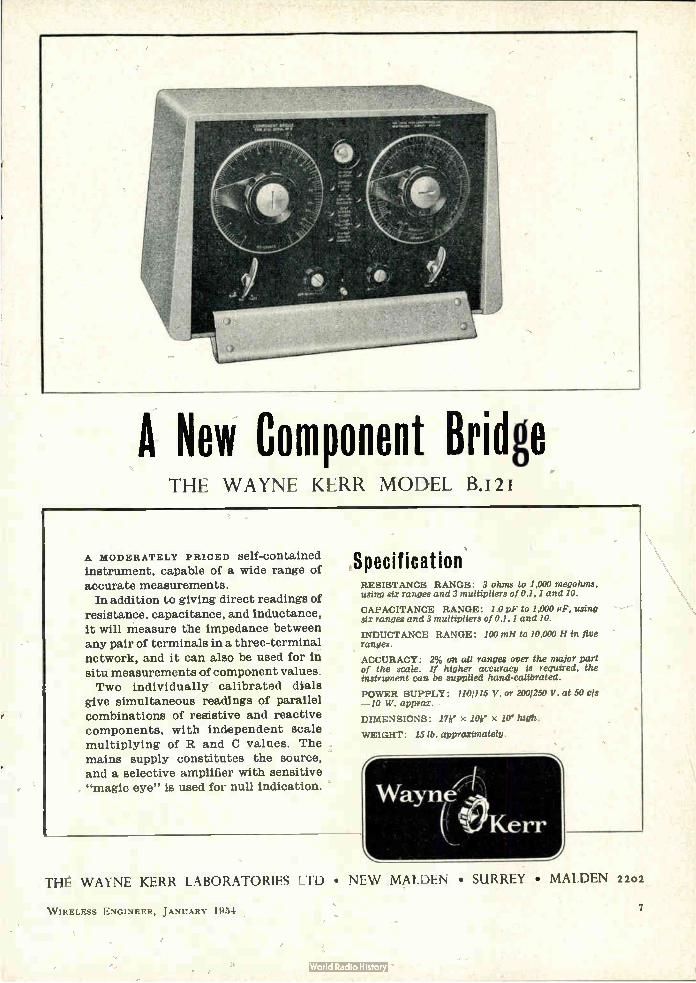
A New Component Bridge THE WAYNE KERR MODEL B.12
A MODERATELY PRICED self-contained
instrument, capable of a wide range of
accurate measurements. In addition to giving direct readings of
resistance, capacitance, and inductance, it will measure the impedance between any pair of terminals in a three-terminal network, and it can also be used for in situ measurements of component values.
Two individually calibrated dials give simultaneous readings of parallel
combinations of resistive and reactive components, with independent scale multiplying of R and C values. The
mains supply constitutes the source, and a selective amplifier with sensitive "magic eye" is used for null indication.
Specification RESISTANCE RANGE: 3 ohms to 1,000 megohms, using six ranges and 3 multipliers of 0.1, 1 and 10.
CAPACITANCE RANGE: 1.0 pF to 1,000 pF using six ranges and 3 multipliers of 0.1, 1 and 10.
INDUCTANCE RANGE: 100 mH to 10,000 H in five ranges.
ACCURACY : 2% on all ranges over the major part of the scale. If higher accuracy is required, the instrument can be supplied hand-calibrated.
POWER SUPPLY: 1101115 V. or 2001250 V. at 50 cls —10 W. approx.
DIMENSIONS : 17e x lorX 10 het. WEIGHT : 15 lb. approximately.
Wayne (( ertKerr
-••••
THE WAYNE KERR LABORATORIES LTD • NEW .MALDEN • SURREY • MAI,DEN 2202
W IRELESS ENGINEER, JANUARY 1954 7
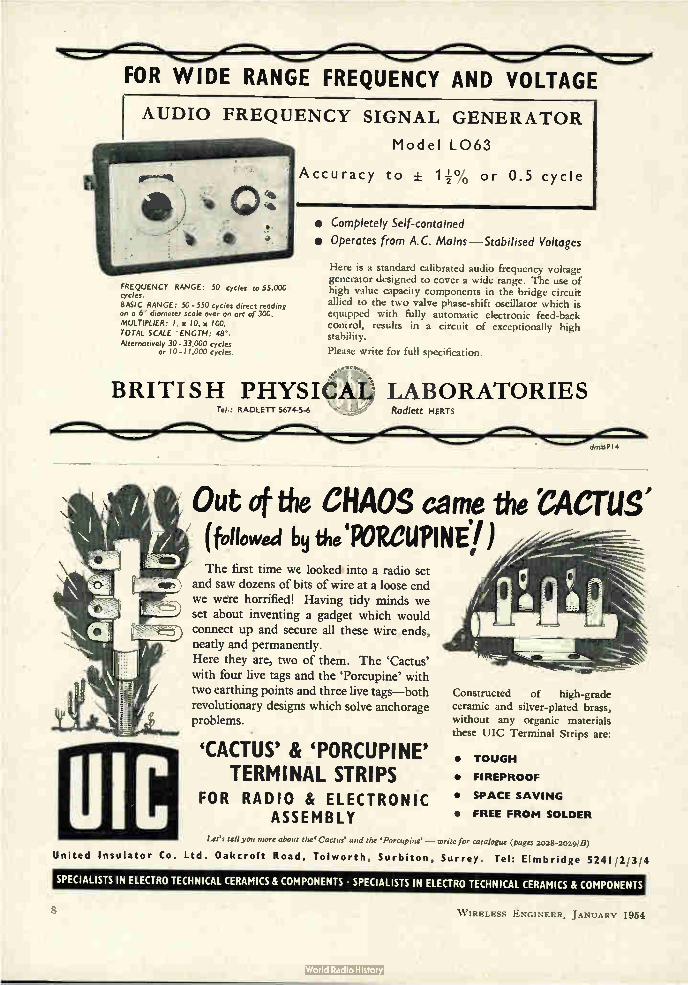
FOR WIDE RANGE FREQUENCY AND VOLTAGE
AUDIO FREQUENCY SIGNAL GENERATOR
Model L063
Accuracy to + 1+% or 0.5 cycle
FREQUENCY RANGE: 50 cycles to 55,000 cycles. BASIC RANGE: 50-550 cycles direct reading on a 6" diameter scale over an arc of 300. MULTIPLIER: I, x 10, x 100. TOTAL SCALE ENGTH: 48". Alternatively 30-33,000 cycles
or W-11,000 cycles.
• Completely Self-contained
• Operates from A.C. Mains—Stabilised Voltages
Here is a standard calibrated audio frequency voltage generator designed to cover a wide range. The use of high value capacity components in the bridge circuit allied to the two valve phase-shift oscillator which is equipped with fully automatic electronic feed-back control, results in a circuit of exceptionally high stability.
Please write for full specification.
BRITISH PHYSICAL LABORATORIES
Insulator United
RADLETT 5674-5-6 Radlett HERTS
Out of the CHAOS carne the 'CACTUS' (followed by the 'PORCUPINE7) The first time we looked; into a radio set
and saw dozens of bits of wire at a loose end we were horrified! Having tidy minds we set about inventing a gadget which would connect up and secure all these wire ends, neatly and permanently. Here they are, two of them. The 'Cactus'
with four live tags and the 'Porcupine' with two earthing points and three live tags—both revolutionary designs which solve anchorage problems.
'CACTUS' & 'PORCUPINE' TERMINAL STRIPS
FOR RADIO & ELECTRONIC ASSEMBLY
Constructed of high-grade ceramic and silver-plated brass, without any organic materials these UIC Terminal Strips are:
• TOUGH
• FIREPROOF
• SPACE SAVING
• FREE FROM SOLDER
Let's tell you more about she Cactus' and the Porcupine' — write for catalogue (pages 2028-2029/B)
Co. Ltd. Oakcroft Road, Tolworth, Surbiton, Surrey. Tel: Elmbridge 5241 2'3 /4
SPECIALISTS 1N ELECTRO TECHNICAL CERAMICS & COMPONENTS • SPECIALISTS IN ELECTRO TECHNICAL CERAMICS & COMPONENTS
W IRELESS ENGINEER, JANUARY 1954
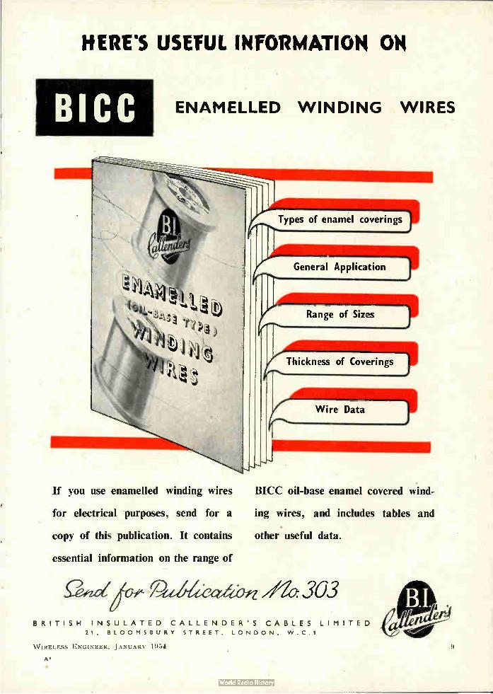
HERE'S USETUL INFORMATION OH
BICC ENAMELLED WINDING WIRES
If you use enamelled winding wires
for electrical purposes, send for a
copy of this publication. It contains
essential information on the range of
Types of enamel coverings
General Application
Range of Sizes
Thickness of Coverings
Wire Data
BICC oil-base enamel covered wind-
ing wires, and includes tables and
other useful data.
Peed thbn //le 303 BRITISH INSULATED CALLENDER'S CABLES LIMITED
21, BLOOMSBURY STREET , LONDON , W .C .1
W IREI Ess ENGINEER, .1 ANCARV 1954
A"
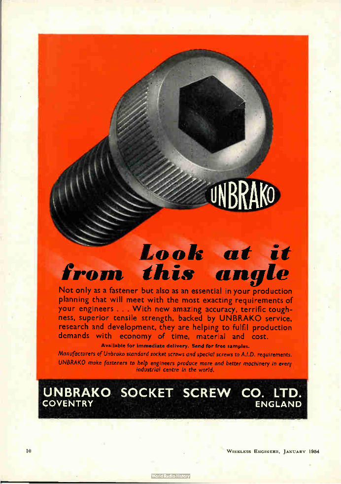
Look at it from this angle Not only as a fastener but also as an essential in your production planning that will meet with the most exacting requirements of your engineers . . . With new amazing accuracy, terrific tough-ness, superior tensile strength, backed by UNBRAKO service, research and development, they are helping to fulfil production demands with economy of time, material and cost.
Availatne for immediate delivery. Send for free samples.
Manufacturers of Unbrako standard socket screws and speck,' screws to A.I.D. requirements.
UNBRAKO make fasteners to help engineers produce more and better machinery in every
UNBRAKO SOCKET SCREW CO. LTD. COVENTRY ENGLAND
10 W IRELESS ENGINEER. JANUARY 1954
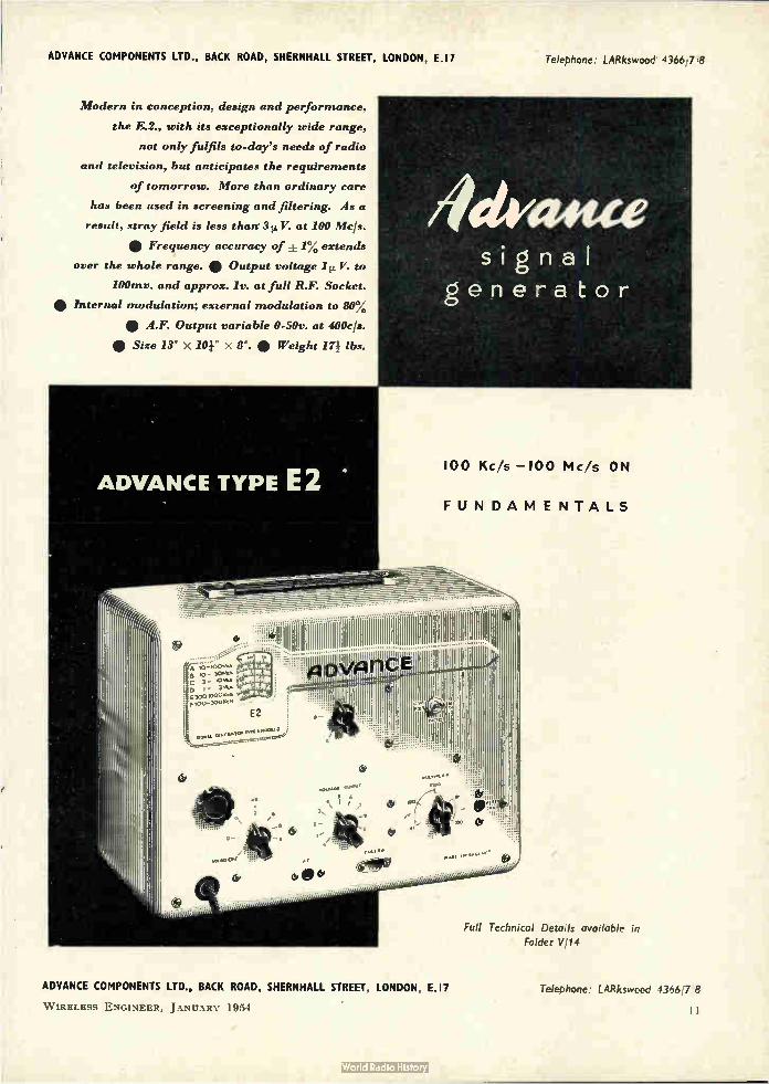
ADVANCE COMPONENTS LTD ., BACK ROAD, SHERNHALL STREET, LONDON, E.I 7 Telephone: LARkswood 4366,7 8
Modern in conception, design and performance,
the E.2., with its exceptionally wide range,
not only fulfils to-day's needs of radio
and television, but anticipates the requirements
of tomorrow. More than ordinary care
has been used in screening and filtering. As a
result, stray field is less than 3p.V. at 100 Mc/s.
• Frequency accuracy of ± 1% extends over the whole range. • Output voltage 1 V. to
100mv. and approx. lv. at full R.F. Socket.
e Internal modulation; external modulation to 80% e A.F. Output variable 0-50v. at 400c/s. e Size 13" X 101" X 8". e Weight 14 lbs.
signal
generator
ADVANCE TYPE E 100 Kc/s —100 Mc/s ON
FUNDAMENTALS
_
111011111111O O OI. I, I ......... . .. Hill ...... e .0- 30.. C 3 - ¡ID I - II E 300.000Kr» F 100- 3001./.
E2
....... !! .
.0•06. S 6
Ss 3, 1 •
Od,
'
b'
b -
o b
Full Technical Details available in Folder VI14
ADVANCE COMPONENTS LTD., BACK ROAD, SHERNHALL STREET, LONDON, E.I7
W IRELESS ENGINEER, J ANUARY 1954
Telephone: LARkswood 4366,7 8
I I

PHASE MEASURING EQUIPMENT TYPE IIX103
THIS equipment has been developed and manufactured by Airmec Limited from a General Post Office Research
Branch design. It was primarily intended for the measurement of the loop phase-shift and gain of feedback repeaters over the frequency range 50 kc/s-20 Mc/s, but it is equally suitable for the measurement of these quantities in amplifiers, filters, equalisers and other four terminal networks.
Full details of this or any other Airmec instrument will be forwarded gladly upon request.
AIIIMEC LIMITED HIGH WYCOMBE — BUCKINGHAMSHIRE — ENGLAND
TEL: HIGH WYCOMBE 2060 CABLES: AIRMEC HIGH WYCOMBE
ereeeieaedpe„
AIR
DIELECTRIC
TRIMMER (Protected by Acetate Case)
o L. E DEVELOPMENTS CO. LTD. 1 If CLVERSTON, NORTH LANCS.
Tel. ULVERSTON 3306.
Type approved, Cat. A No. 464
Capacities from 4 to 70pF in vol-tages of 500 and 1000 D.C. Width 16.5mm. Length 22mm. Acetate duk cover optional. Insulation over 10,000 megohms. Power factor less than .001.
I 2
Its all plain sailing at G-G-L
1 In 1 1 1 1 1 1 1 1 e
• sum
"
Modern machinery and methods keep capstan and automatic produc-tions and sheet metal pressings flowing to you on time, at a price you will like.
GRIFFITHS, GILBART, LLOYD & CO., LTD
Emplre Works, Park Road, Birrnmgham 18
Tel : Northern 6221
W IRELESS ENGINEER, JANUARY 1954
• • • • • • • • •
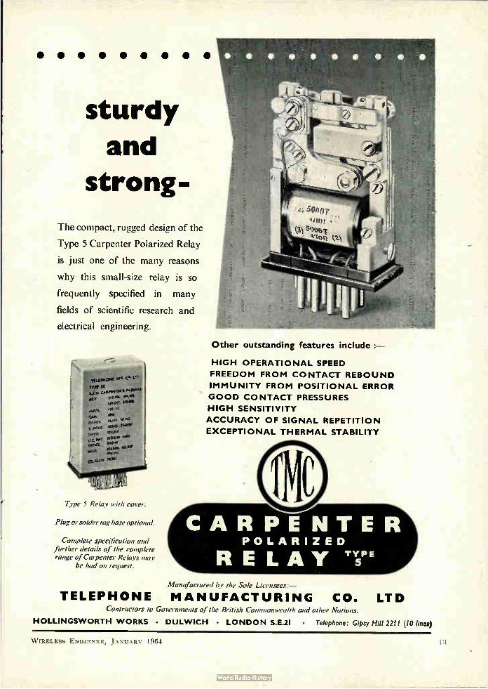
sturdy
and
strong-
The compact, rugged design of the
Type 5 Carpenter Polarized Relay
is just one of the many reasons
why this small-size relay is so
frequently specified in many
fields of scientific research and
electrical engineering.
TT:Ifie"Sted S' L".
'SI ile
µJO 511./
$ oroc are slaw rt,g4 peen
.45 O'ff‘t u> Ole« ORG a ..uow *le
Type 5 Relay with cover.
Plug or solder tag base optional.
Complete specification and further details of the complete range of Carpenter Relays may
be had on request.
Other outstanding features include :—
HIGH OPERATIONAL SPEED
FREEDOM FROM CONTACT REBOUND
IMMUNITY FROM POSITIONAL ERROR
GOOD CONTACT PRESSURES
HIGH SENSITIVITY
ACCURACY OF SIGNAL REPETITION
EXCEPTIONAL THERMAL STABILITY
Manufactured bu the Sole ijcens ;:,e, —
TELEPHONE MANUFACTURING CO. LTD Contractors to Governments of the British Commonwealth and other Tlations.
HOLLINGSWORTH WORKS • DULWICH LONDON S.E.2I • Telephone: Gipsy Hill 2211 (10 lines)
W IRELESS ENGINEER, JANUARY 1954
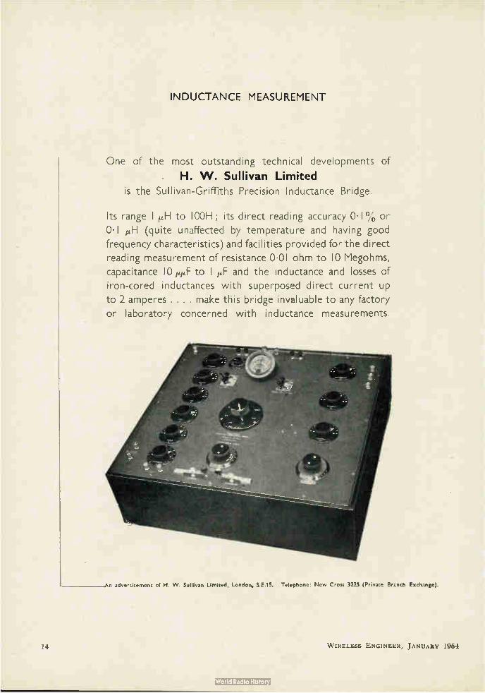
INDUCTANCE MEASUREMENT
One of the most outstanding technical developments of
. H. W. Sullivan Limited is the Sullivan-Griffiths Precision Inductance Bridge.
Its range 1 1./H to 100H ; its direct reading accuracy 0.1% or
0.1 p,H (quite unaffected by temperature and having good
frequency characteristics) and facilities provided for the direct
reading measurement of resistance 0.01 ohm to 10 Megohms,
capacitance 10 peF to 1 !if and the inductance and losses of
iron-cored inductances with superposed direct current up
to 2 amperes . . . . make this bridge invaluable to any factory
or laboratory concerned with inductance measurements.
An advertisement of H. W. Sullivan Limited, London, S.E.15. Telephone: New Cross 3225 (Private Brcnch Exchange).
14 W IRELESS ENGINEER, JANUARY 1954
WIRELESS ENGINEER
The Journal of Radio Research and Progress ESTABLISHED 1923
Managing Editor: HUGH S. POCOCK, M.1.E.E. Editor: W. T. COCKING, M.I.E.E. Technical Editor: Professor G. W. O. HOWE, D.Sc., LL.D., M.I.E.E.
Editorial Advisory Board: P. A. T. BEVAN, B.Sc., M.I.E.E. (British Broadcasting Corporation); F. M. COLEBROOK, B.Sc., A.C.G.I. (National Physical Laboratory); Professor E. B. MOULLIN, Sc.D., M.I.E.E.; A. H. MUMFORD, 0.B.E., B.Sc.(Eng.), M.I.E.E. (G.P.O. Engineering Department); R. L. SMITH-ROSE, D.Sc., Ph.D., M.I.E.E.
(Department of Scientific and Industrial Research)
Volume 31 • Number I
CONTENTS
JANUARY 1 9 5 4
Editorial: Ferrite-Core Inductors 1
Oscillator Characteristic Equation byhY. L. Talekar .. 3 • •
Voltage-Reference Node
by Jacob Shekel .. . 6
H.F. Direction Finding
by S. B. Smith and H. G. Hopkins, B.Sc., Ph.D. 11
Valve and Receiver Noise Measurement at V.H.F. by N. Houlding, B.Sc. Tech. .. 15
Correspondence .. 27
New Books 27
Standard-Frequency Transmissions .. 28
Abstracts and References. Nos. 1-293 A.1-A.22
Published on the fifth of each month
Annual Subscription: Home and overseas £2 7s. Od; Canada and U.S.A. $7.50 (Including Annual Index to Abstracts and References)
Editorial, Advertising and Publishing Offices: Dorset House, Stamford Street, London,S.E.1
Telephone: Waterloo 3333 (60 lines) Telegrams: Wirenger, Sedist, London
BRANCH OFFICES AT BIRMINGHAM • MANCHESTER AND GLASGOW
for more efficient V HF communications equipment
30 TPYOW [ AR'. WATTS OUT PUT
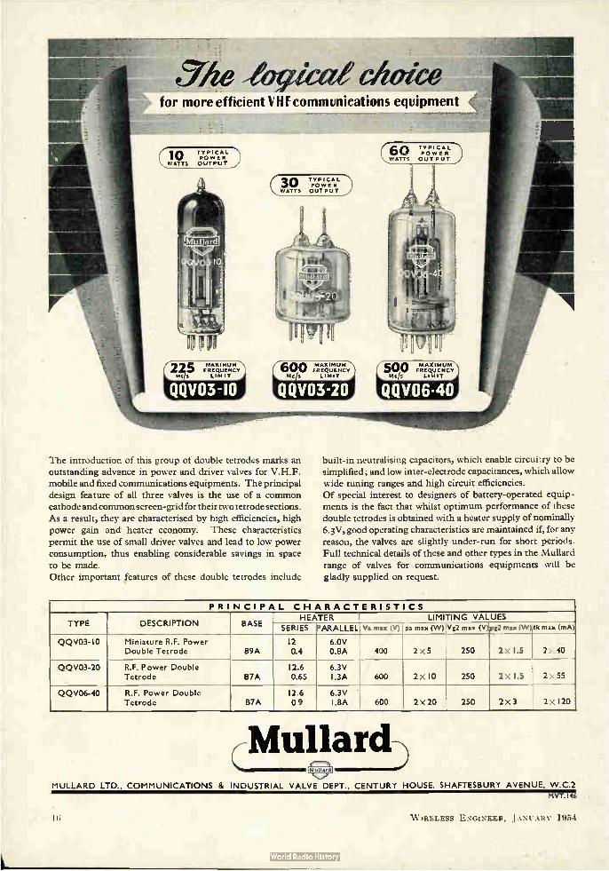
The introduction of this group of double tetrodes marks an outstanding advance in power and driver valves for V.H.F. mobile and fixed communications equipments. The principal design feature of all three valves is the use of a common cathode and common screen-grid for their two tetrode sections. As a result, they are characterised by high efficiencies, high power gain and heater economy. These characteristics permit the use of small driver valves and lead to low power consumption, thus enabling considerable savings in space to be made. Other important features of these double tetrodes include
built-in neutralising capacitors, which enable circuitry to be simplified; and low inter-electrode capacitances, which allow wide tuning ranges and high circuit efficiencies. Of special interest to designers of battery-operated equip-ments is the fact that whilst optimum performance of these double tetrodes is obtained with a heater supply of nominally 6.3V, good operating characteristics are maintained if, for any reason, the valves are slightly under-run for short periods. Full technical details of these and other types in the Mullard range of valves for communications equipments will be
gladly supplied on request.
PRINCIPAL CHARACTERISTICS
TYPE DESCRIPTION . BASE HEATER LIMITING VALUES
SERIES PARALLEL Va max (V) pa max (W) Vg2 max (V) pg2 max (W) Ik max (mA)
2> 40
2x55
QQV03-1-0 Miniature R.F. Power Double Tetrode B9A
12 0.4
6.0V 0.8A 400 2 x 5 250
250
2 x 1.5
2x 1.5 QQV03-20 R.F. Power Double
Tetrode B7A 12.6 0.65
6.3V I.3A 600 2 x 10
QQV06-40 R.F. Power Double Tetrode B7A
12.6 09
6.3V ' I.8A 600 2x20 250 2x3 2 x 120
Mullard MULLARD LTD., COMMUNICATIONS & INDUSTRIAL VALVE DEPT., CENTURY HOUSE, SHAFTESBURY AVENUE, W.C.2
MVT.I46
W IRELESS ENGINEER, JANUARY 1954
WIRELESS ENGINEER
Vol. 31 JANUARY 1954 NO. 1
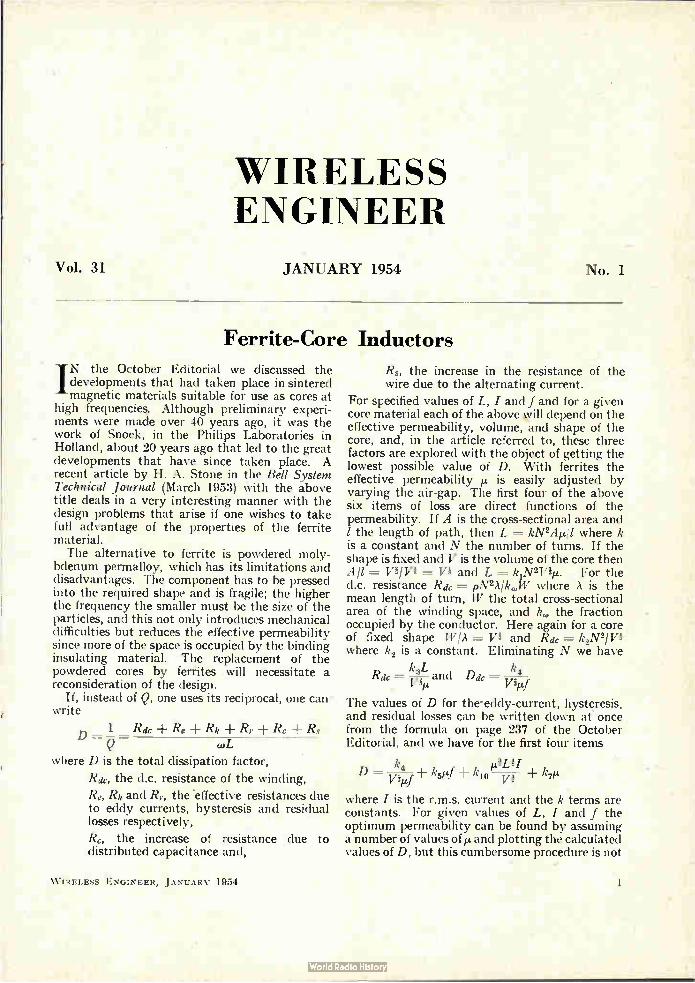
Ferrite-Core Inductors
IN the October Editorial we discussed the developments that had taken place in sintered magnetic materials suitable for use as cores at
high frequencie. Although preliminary experi-ments were made over 40 years ago, it was the work of Snoek, in the Philips Laboratories in Holland, about 20 years ago that led to the great developments that have since taken place. A recent article by H. A. Stone in the Bell System Technical Journal (March 1953) with the above title deals in a very interesting manner with the design problems that arise if one wishes to take full advantage of the properties of the ferrite material. The alternative to ferrite is powdered moly-
bdenum permalloy, which has its limitations and disadvantages. The component has to be pressed into the required shape and is fragile; the higher the frequency the smaller must be the size of the particles, and this not only introduces mechanical difficulties but reduces the effective permeability since more of the space is occupied by the binding insulating material. The replacement of the powdered cores by ferrites will necessitate a reconsideration of the design.
If, instead of Q, one uses its reciprocal, one can - write
Rdc ± Re ± Rh Rr Rc Rs D =-
coL
where D is the total dissipation factor,
Rdc, the d.c. resistance of the winding,
Re, Rh and Rr, the effective resistances due to eddy currents, hysteresis and residual losses respectively,
Rc, the increase of resistance due to distributed capacitance and,
W IRELESS ENGINEER, JANUARY 1954
Rs, the increase in the resistance of the wire due to the alternating current.
For specified values of L, I and f and for a given core material each of the above will depend on the effective permeability, volume, and shape of the core, and, in the article referred to, these three factors are explored with the object of getting the lowest possible value of D. With ferrites the effective permeability it. is easily adjusted by varying the air-gap. The first four of the above six items of loss are direct functions of the permeability. If A is the cross-sectional area and 1 the length of path, then L = kN2411 where k is a constant and N the number of turns. If the shape is fixed and V is the volume of the core then All = = Vi and L = k,N2Viµ. For the d.c. resistance Ra, c = pN2AlkoN where A is the mean length of turn, W the total cross-sectional area of the winding space, and k,„ the fraction occupied by the conductor. Here again for a core of fixed shape W/A Vi and Rdc = k2N2/Vi where k2 is a constant. Eliminating N we have
k L 3 R= —and Ddc = k4 Pp. Pei
The values of D for the•eddy-current, hysteresis, and residual losses can be written down at once from the formula on page 237 of the October Editorial, and we have for the first four items
D = k4 k5 kl0 v ket Vitif
where I is the r.m.s. current and the k terms are constants. For given values of L, I and f the optimum permeability can be found by assuming a number of values of ¡L and plotting the calculated values of D, but this cumbersome procedure is not
necessary if some of the terms are known to be negligibly small, which is usually the case. In the article referred to it is shown that if only Rdc and R, need be considered, then by differentiating with respect to Iz it is found that
k4t k4»74 ¡Lei = ivin i and Dopi = 2 vivi
J -
µopt is found to be the value that makes Re.
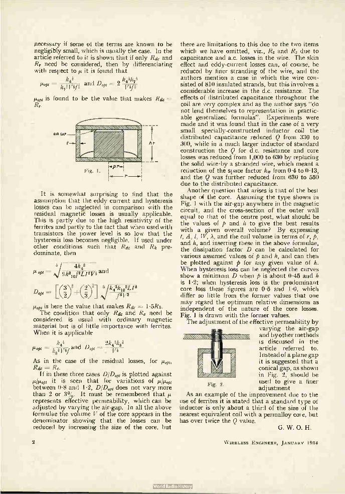
AIR GAP
1.«-P Fig. J. I
re--- r
Rae
It is somewhat surprising to find that the assumption that the eddy current and hysteresis losses can be neglected in comparison with the residual magnetite losses is usually applicable. This is partly due to the high resistivity of the ferrites and partly to the fact that when used with transistors the power level is so low that the hysteresis loss becomes negligible. If used under other conditions such that Ra and Rh pre-dominate, then
5 4k42 t%,/ 9k2i0f2L/2V* and
[G3-)1+(20-1 /5 jk434031.12 f3V3
µopt is here the value that makes Rik= 1.5Rh.
The condition that only Rae and Re need be considered is usual with ordinary magnetic material but is of little importance with ferrites. When it is applicable
k4i 2k4ik4t itnop, „ a d Dopi =
R 51 V 1.1
As in the case of the residual losses, for µel, Rae = Re.
If in these three cases DIDopt is plotted against Alept it is seen that for variations of i.i./p.opi between 0.8 and 1.2, DIDopt does not vary more than 2 or 3%. It must be remembered that p. represents effective permeability, which can be adjusted by varying the air-gap. In all the above formulae the volume V of the core appears in the denominator showing that the losses can be reduced by increasing the size of the core, but
2
Fig. 2.
there are limitations to this due to the two items which we have omitted, viz., Rs and Rs due to capacitance and a.c. losses in the wire. The skin effect and eddy-current losses can, of course, be reduced by finer stranding of the wire, and the authors mention a case in which the wire con-sisted of 810 insulated strands, but this involves a considerable increase in the d.c. resistance. The effects of distributed capacitance throughout the coil are very complex and as the author says "do not lend themselves to representation in practic-able generalized formulas". Experiments were made and it was found that in the case of a very small specially-constructed inductor coil the distributed capacitance reduced Q from 330 to 300, while in a much larger inductor of standard construction the Q for d.c. resistance and core losses was reduced from 1,000 to 630 by replacing the solid wire-by a stranded wire, which meant a reduction of the space factor kw from 0.4 to 0.13, and the Q was further reduced from 630 to 550 due to the distributed capacitance. Another question that arises is that of the best
shape of the core. Assuming the type shown in Fig. 1 with the air-gap anywhere in the magnetic circuit, and the cross-section of the outer wall equal to that of the centre post, what should be the values of p and h to give the best results with a given overall volume? By expressing t, A, 1, W, A, and the coil volume in terms of r, p, and h, and inserting these in the above formulae, the dissipation factor D can be calculated for various assumed values of p and h, and can then be plotted against p for any given value of h. When hysteresis loss can be neglected the curves show a minimum D when p is about 0.45 and h is 1.2; when hysteresis loss is the predominant core loss these figures are 0.5 and 1.0, which differ so little from the former values that one may regard the optimum relative dimensions as independent of the nature of the core losses. Fig. 1 is drawn with the former values. The adjustment of the effective permeability by
varying the air-gap and by other methods is discussed in the article referred to. Instead of a plane gap it is suggested that a conical gap, as shown in Fig. 2, should be used to give a finer adjustment
As an example of the improvement due to the use of ferrites it is stated that a standard type of inductor is only about a third of the size of the nearest equivalent coil with a permalloy coi e, but has over twice the Q value.
G. W. O. H.
W IRELESS ENGINEER, JANUARY 1954

OSCILLATOR CHARACTERISTIC EQUATION
Theory and Experimental Verification
By V. L. Talekar (Department of Physics, Dungar College, Bikaner, India)
SUMMARY. An equation representing the oscillation characteristics of a triode-oscillator circuit is theoretically developed, involving differential coefficients of the dynamic resistance of the triode. It is experimentally verified using a paralled-fed short-wave Hartley oscillator, and almost complete agreement is shown. Some interesting features of the oscillation characteristics are discussed and the constants of the triode and the tank circuit used are deduced therefrom.
Introduction
THE study of the oscillation characteristics1,2 of an oscillator circuit is of great importance from the standpoint of its performance and
the dynamic stability of the oscillations generated. When the oscillations are being set up and are gradually moving towards the steady state, the dynamic anode resistance ra of the triode, and therefore the anode conductance ga cannot be regarded as constant under the circumstances, as supposed in the elementary theory leading to a first-degree equation connecting the anode current with anode voltage for a given operating bias. The object of the present paper is to develop theoretically a second-degree equation represent-ing oscillation characteristics involving the first differential coefficient of ra and to show that this equation agrees with the experimentally obtained curves, except in a portion on the positive va side.
Equation of Oscillaton Characteristic The anode current /a of a triode in an oscillatory
circuit may be expressed as some function of anode voltage Va and grid bias Vg by the following relation, called the oscillation characteristic by Appleton1,2
Ja =-- yl,(V a,V g) (1)
where /a ---- /0 ± ia
Va = V 0 ± Va
Vg = Vgo ± Vg
Io, V o, Vgo representing the steady values and ia, va, vg the oscillatory components. To deter-mine the above function y6, use may be made of Taylor's series expansion.3 Thus we have the expression for the oscillatory component of anode current in a triode with a resistance load Ra in its anode circuit,
(2)
F2ra 8 ra 2
a . . r a Vg -F Ra 2(ra .Ra)3" Sva Vg
MS accepted by the Editor, March 1953.
W IRELESS ENGINEER, JANUARY 1954
where µ is amplification factor of the triode, treated as constant. This equation may now be applied to a triode functioning as an oscillator; e.g., with a tank circuit inserted between the anode and filament. Under these circumstances we have,
Vg = — OCVa . • . . . . .. (4)
a being a positive constant less than one, and va and vg being respectively the oscillatory anode potential and the grid feedback voltage in anti-phase, as required to sustain the oscillations in the tank circuit. Also Ra is now the effective impe-dance of the tank circuit at resonance.
Treating ra as variable and its first derivative as constant under the operative conditions, so that
saya
Sva2
the coefficient of vg3 in equation (3) becomes 2
6 (ra Ra)5 (2ra — Ra) C ra) 8va
The ratio of this coefficient to that of vg2 in the same equation is
= 3(ra ± Ra)2 (2ra — Ra) (8-r2, ova
— 0 • (5)
and
IL 3 ra —„ 12ra ova
when the impedance of the tank circuit is matched to the dynamic anode resistance of the triode. This ratio being inversely proportional to ra, which is of the order of some thousands, we might neglect the third-degree and subsequent high-power terms in comparison.
(6ra 2 3r a (2ra — Ra) U v )
[6(rall-F Ra) a
82ra} vgs] — ra (ra Ra) 8va2 ' • • (3)
3
Retaining the terms up to second degree in the expansion (3) and adding the steady anode current,
/0 = S (Vo, Vg0)
we have from (4)
/a = /0 . (r a + Ra) Va
1,2c(21 r a Sr.}
2(ra ± Ra)3 Sva . va2
.. (6)
(7)
For the impedance of the tank circuit at resonance,
Ra = 47r2f2 La2
where La is the inductance of anode coil and R the series resistance in the tank circuit oscillating at frequency f. Substituting the above value of Ra in equation (7) we obtain finally the oscillation characteristic (i.e., the function 96 explicitly in terms of va) as
Ia = 10 — k ra + 471-2 f2 La2 1 R )
ILO(
y.2CC2 ra 3ra
477.2f2 La2)3 Sva • va 2 ea ±
From equation (9), it is clear that the shape of oscillation characteristic des-cribed by the function tk must approxi-mate to a parabolic curve. The various constants occurring in its equation must necessarily depend on the operating conditions of the oscillator as defined by relations (4), (5), (6) and (8).
2
The constants of the tank circuit used were as follows:
Wavelength A = 80 metres. Coefficient of grid feedback voltage cc = 0•54. Inductance of the anode coil La = 18.58 p.H.
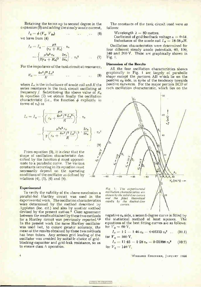
Oscillation characteristics were determined for four different steady anode potentials, 60, 100, 140 and 200 V. These are graphically shown in Fig. 1.
Discussion of the Results
All the four oscillation characteristics shown graphically in Fig. 1 are largely of parabolic shape except the portions AB which lie on the positive va side, in spite of the tendency towards positive skewness. For the major portion BCD of each oscillation characteristic, which lies on the
—200 —160 —120 —80 —40
Experimental
To verify the validity of the above conclusion a parallel-fed Hartley circuit was used in the experimental work. The oscillation characteristics were determined by the method described by Appleton (loc. cit.) and also by another method devised by the present author.4 Close agreement between the results obtained by these two methods for a Hartley circuit was previously reported.4,4 In the present work the same Hartley oscillator was used but, to ensure greater accuracy, the mean of the results obtained by these two methods has been taken. Any serious grid loading of the oscillator was avoided by suitable choice of grid-blocking capacitor and grid-leak resistance, so as to ensure class A operation.
4
Fig. 1. The experimental oscillation characteristics are shown by the solid-line curves and the fitted theoretical results by the dashed-line
curves.
A4
AI A2 A3 ao
i/a (yours) —a-
negative va side, a second-degree curye is fitted by the statistical method of least squares. The equations of the best fitting curves are as follows: for Vo = 60 V,
/a = 11 — 1.46 va — 0.02333 va2 .. (10.1)
for Vo = 100 V,
/a = 11.45 — 1.28 va — 0.01398 va2 (10.2)
for Vo = 140 V,
W IRELESS ENGINEER, JANUARY 1954
/a 22.05 — 0.864 v. — 0.00731 va2 (10.3)
for Vo = 200 V,
/a = 33.8 — 1.015 va — 0.00650 va2 (10.4)
where la is expressed in milliamperes and va in volts.
These are shown as dotted curves over the corresponding experimental characteristics. The agreement between the experimental and the fitted second-degree curves, as defined by general equation (9), is extremely close in each case. In spite of uncertain factors like overheating éf the valve, etc., the validity of equation (9) to re-present the oscillation characteristic of an oscillator is thus established. The equation (9) may be used to determine the
value of Sra/Sva for the triode under oscillating conditions. Let a denote ratio of the coefficient of va2 to the square of that of va in equations (10). Then using equation (9),
ra x 10 -3 âra — .. 2(ra ± 477.2f2La2/R) • 8va (11.1)
and assuming the impedance of the tank circuit to be matched to the dynamic resistance of the triode, resulting in maximum power in the tank circuit,
10-3 Sra (11.2)
The values of o as determined from the first three of equations (10) are 0.011, 0.009 and 0.010 giving the mean value of Sra/8va = 40 ohms per volt, within the range of voltage used on the anode. This value may be taken to represent the order of magnitude, since power in the tank circuit may not be quite maximum under the working con-ditions. Incidentally, it may be mentioned that the above values of a obtained from equations (10), which represent the experimental results, justify the assumption as regards the constancy of Srai8va and hence the relation (5).
Some Features of Oscillation Characteristics We note from equation (9) that /a passes
through a maximum corresponding to a certain voltage va'. Differentiating (9) and equating to zero we have,
8ra (ra 4,2f2 La2/R)2iim ra. (12.1)
ova
and under the matched condition,
4ra I6ra Va' = — —
ji.af OVa .. (12.2)
Since 8rai&va is already evaluated and va' can be read off from the relevant experimental oscil-lation characteristic, the relations (12) may be used to find ra under the given operating condition.
W IRELESS ENGINEER, JANUARY 1954
As seen from the figure, these maximum points for the four curves lie on a straight line C1 C2 C3 C4. This point is also verified from relations (10) which lead to the following equation for this line:
Ia = — 7.8 — 1.014 va .. (13.1)
giving the intercepts p = OP = 7.7 V and q = OQ = 7-8 mA. It may, however, be noted that for the oscillation characteristics corresponding to very small values of Vo, maxima cannot lie on this line but should fall on a smooth curve 0C0C, passing through the origin 0, since in the ultimate stage the smallest oscillation characteristic will vanish, merging in the point O. However, long before this stage is reached the oscillations will cease. Thus we might regard the locus of maxima as one continuous curve 0 Co C1 C2 C3 C4 having the line given by equation (13.1) as its asymptote-. As a first approximation, this curve may be treated as a part of a hyperbola whose equation is found, with the help of (13.1), to be,
p2/a2 2p2e. = q2 va2
From this we get: (i) for the initial bent portion 04 of the curve,
neglecting /a2 in comparison to 2q,
qva2 = 2p2
(ii) for that part of the curve which is nearly straight,
. . (13.2)
— q — —va{1 L-4,2}
.. (13.3) q Va2
where va is large compared with p. This finally degenerates into the straight line given by (13.1) for comparatively very large values of va. Rela-tions almost identical with (13.2) and (13.3) have been empirically obtained recently by Singh.6 Thus the equations (13) completely describe in
parts the locus of maximum of oscillation charac-teristics under various operating conditions. A physical interpretation may be given to the curve O CoCiC2C3C4 by taking its gradient at a point as a measure of the dynamic stability of oscilla-tions in the valve circuit operating under con-ditions represented by that point. The inverse of this gradient, which then is interpreted as the total impedance of the oscillator (the triode and the tank circuit taken together) is seen to diminish at first as the operating point moves up the curve, and then to become constant after reaching an oscillation characteristic of a certain value of Vo. This corresponds to the region where the straight portion of the curve begins. This stage, therefore, represents the optimum total impedance which has the smallest value, and thus the beginning of the dynamic stability of oscillations of a given frequency. From this point of view, it is unprofit-able to operate the oscillator at a higher anode
5

potential than this optimum value since dynamic stability of oscillations does not improve further. The asymptote QC4, therefore, may be looked upon as the optimum impedance line of the oscillator for the frequency f. The optimum im-pedance is given by tan 0, where 0 is the angle between the asymptote and the axis of anode current.
REFERENCES
E. V. Appleton. Phil. Mag. 1921, Vol. 42, p. 201.
Appleton, Watt and Herd. Proc. Roy. Soc. 1926, Vol. 111, p. 672.
' R. S. Glasgow. "Principles of Radio Engineering," 1936 (First edition) McGraw-Hill, p. 340.
V. L. Talekar, V. L. Curt. Sci. 1947, Vol. 16, p. 308.
V. L. Talekar. Sci. and Cult. 1949, Vol. 14, p. 431.
' T. P. Singh. Sci. and Cull. 1951, Vol. 17, p. 170.
VOLTAGE-REFERENCE NODE its Transformations in Nodal Analysis
By Jacob Shekel (Scientific Department, Ministry of Defence, Israel.)
SUMMARY.—This paper describes a general method of analysing linear networks by nodal analysis, without specifying the node to which all voltages are referred. When the reference node is specified, or when the voltage-reference node is changed, the admittance matrix of the network undergoes certain transformations. The method is applied to valve circuits, where it enables a simpler approach to earthed-grid or earthed-anode stages, or circuits where no electrode is earthed.
Introduction W HEN a network is analysed by nodal equations,42,3 it is necessary to choose one of its nodes as a reference node, and the
voltages of all other nodes are measured (or defined) relative to this special node. A network with n nodes is analysed by n — 1 independent equations, and may be represented by a square admittance matrix of order (n — 1) x (n — 1). This paper discusses the transformation of this matrix due to a change of the reference node, and also proposes a method of treating networks without specifying the reference node at all. The outlined method has a special application in
analysing valve circuits. The usual procedure is to represent a valve by a passive network and internal voltage or current sources. When matrix algebra is applied,4$5 the treatment follows that of two-terminal-pair networks; the earthed-cathode, earthed-grid and earthed-anode stages need special derivation of the matrix components. In the proposed method, an n-electrode valve is treated as an n-terminal net-work, and the derived general transformations are applied to represent change of earthing point.
"Indefinite" Admittance Matrix ' Consider a network with n nodes. Let I be a column matrix, whose ith component I is the external current entering the ith node. Let Ilk denote the current from node i to node k through the i—k branch. —Iij, I ---= O.) Applying Kirchhoff's Current Rule to the ith
node,
MS accepted by the Editor, March 1953
ikj=
It =1
Summing the equations for all n nodes,
= 0 (i, k 1, 2. .. n) i h
The elements under the double summation cancel out in pairs, leaving
-= 0 . (1)
Let V be the column matrix whose ith com-ponent Vi is the voltage of the ith node, relative to an arbitrary reference voltage. (The latter may be the voltage of any node, a combination of some of them, or any other voltage.) Since only voltage differences determine the network currents, the latter must be invariant to the addition of an arbitrary voltage Vo to all the V.
In linear networks, I and V are related linearly: / = Y V • • • • (2)
where Y is a square matrix of order n x n. Put all components of V equal to zero, except
Vi, then YiiVi
(YsiVi) = Yii)Vi
and, by (1)
Yi) Vj = 0.
As this is to be true for any Vi,
Yii =O .. • (3)
W IRELESS ENGINEER, JANUARY 1954

Suppose now that an arbitrary voltage Vo is added to all the components of V. The current into the ith node will then be
= Yik(Vk + V0) Y ik)V 0,
and if the currents are to be invariant to the addition of any Vo,
Yik = 0 .. (4)
Equations (3) and (4) show that the sum of any row and column of the matrix Y is zero. This matrix, which relates the currents with voltages that are referred to an undefined reference point, will be termed ̀ the indefinite admittance matrix'. It evidently is a singular matrix and, as the solu-tion of network problems usually calls for an inversion of the matrix, some transfounation will be necessary.
General Transformation
A general method for impedance matrix trans-formations is described by Kron.6 His results, when applied to admittance matrices, are as follows7:
Let the 'old' voltages (before the transforma-tion) V be described as a linear combination of 'new' voltages V',
• • V =_•. AV' .. . • (5) (A may be a rectangular matrix, so that V and V' do not necessarily have the same number of components.) To keep the form for power (P = ItV) invariant,
'new' currents /' must be defined by
= . . (6) where At is the transpose of A; i.e., the matrix A with its rows and columns interchanged.
Finally, to keep the admittance equation (2) invariant, the 'new' admittance matrix must be defined by
Y' = AtY A
This general transformation will now be applied to particular cases pertaining to change of reference node.
• • (7)
Specifying the Voltage-Reference Node
Suppose node 4 of a four-node network is chosen as the voltage-reference node. (The dis-cussion may easily be extended to the general case of an n-node network, and it seems un-necessary to present the derivation in general terms.) The voltages are then defined by
= Vi — T.7.4 (/ = 1, 2, 3) (8) For convenience, 174 is taken equal to zero, and (8) becomes
WIRELESS ENGINEER, JANUARY 1954
Vi = V'i (z = 1, 2, 3) }
V4 =
In matrix notation, (13) is the -same as
1 0 0 0 1 0 0 0 1 0 0 0
The corresponding transformation of the admit-tance matrix is
V = AV', where A ----
Y' = AtY A =
X
Y' .=
Y ll
Y 21
Y 31
Y 41
Y ll
Y 21
Y 31
Y 12
Y 22
Y 32
Y 42
Y 12
Y 22
Y 32
1 0 0 0 0 1 0 0 0 0 1 0
Y 13 Y 14
Y 23 Y 24
Y 3â Y 34
Y 43 Y 44
Y 13
Y 23 \\ • •
Y 33
X
(9)
.. (10)
1 0 0 0 1 0 0 0 1 0 0 0
This proves the following theorem: When any node is specified as the voltage-
ref erence node, the corresponding row and column are to be omitted from the indefinite admittance matrix.
Changing the Voltage-Reference Node
Once the admittance matrix is given in a definite form (with the reference node specified), it may be desirable to choose a:different node for reference. This may be carried out in two steps: first, the matrix is brought to the indefinite form, and then the new reference node is specified. The first step is treated below. (The second step was described in the preceding section.)
Let us again take a 4-node network, described by a 3 x 3 matrix, with node 4 as a reference node; and let us define the new voltages V' by
Vi = V'i — V 4 (1 = 1, 2, 3) . . (12)
In matrix notation, this is
1 0 0 — 1 V = AV', where A= 0 1 0 — 1 .. (13)
0 0 1 — 1
The transformation of the admittance matrix is then
Y' = AtY A
X Y ll
Y 21
Y 31
Y 12
Y22
Y 32
1 o o 1
Y 13
Y 23
Y 33
0 0 1 0 0 1
— 1 — 1
1 0 0 x • 0 1 0 0 0 1
— 1 — 1 — 1
7

Y' =
Y11 Y21 Y31
Y12 Y22 Y32
Yll — Y21 — Y31 — Y12 — Y22 — Y32
We have thus proved the theorem: To bring the definite admittance matrix to
indefinite form, one row and one column are to be added, whose elements are such that they com-plete the sum of each row and column to zero.
Short-Circuiting Two Nodes
A similar type of transformation, though not dealing directly with the reference node, may be mentioned here.
Suppose that in a 4-node network, described by a 4 x 4 admittance matrix, nodes 3 and 4 are short-circuited together. This may be represented by introducing 'new' voltages V'
(i =1 2, 3) }
In matrix notation
V = AV', with A -----
1 0 0 0 1 0 0 0 1 0 0 I
giving a new admittance matrix
I '0 0 0 Y' AtY A = CI 1 0 0
0 0 1.1
Yll Y12 Y13 Y14
X Y21 Y22 Y23 v Y24 31 Y32 Y33 Y34
Y41 Y42 Y43 Y44
Y12 Y22
Y41 Y32 + Y42
Y' Yll Y21
Y31 +
.. (16)
1 0 0 0 1 0
X 0 0 1 0 •0 1
Yl 3 Y23 Y33
— Y13 — Y23 — Y33
- Yll — Y12 — Y13 — Y21 — Y22 — Y23 — Y31 — Y32 — Y33
3 3
Yii i=i j=1
(14)
Application to Valves
• There are two general methods of approach to linear valve circuits (small-signal approximation). In one method, the valve is represented by a passive network, to which internal voltage or current sources have been added. The second method,2,8 which is more readily applicable to matrix methods, represents the valve by an unsymmetric admittance (or impedance) matrix. The general (n ± 1) electrode valve (not count-
ing the heater), with the cathode as the voltage-ref erence node, is described by an n x n admittance matrix8
(15) Yi, = — .. (18)
In the simplest case, a triodepperating in class A, let the grid and anode be numbered 1 and 2 respectively, then
0 0 .= (19)
gm ga (gm is the mutual conductance, and ga is the reciprocal of the anode resistance ra). The indefinite matrix is obtained by completing
each row and column to zero, as in Equation (14):
Y' = gm go — gm — ga .. (20) — gm — ga ga
This matrix is the starting point for calculating earthed-grid or earthed-anode stages, by omitting the row and column corre-sponding to the earthed electrode. When the triode is con-
nected as a diode, the internal resistance depends on the connection:
1. If the grid is connected to the cathode, this corresponds to earthing terminal 1 of (19). Crossing out the first row and column leaves a conductance ga.
2. When the grid is connected to the anode, row 1 is added to row 2, and column 1 to column 2, giving a conductance ga ± gm.
(The values of ga and gm in both cases are different, due to different steady voltages on the grid.)
Y13 + Y14
Y23 + Y24 Y33 + Y34 + Y43 + Y44
Theorem: When any two nodes are short-circuited together, the corresponding rows of Y are added together to form one row, and the corresponding columns are added together to form one column. Had node 4 been an 'isolated node' [see node 4
in Fig. 3(a)] shorting it to any other node would have had no effect on the network, so that we may formulate the following corollaries:
1. A row and column of zeros correspond to an isolated node.
2. Any n-node network may be treated as an m-node one (m > n), by adding m — n rows and columns of zeroes to the admittance matrix.
.. (17)
8 W IRELESS ENGINEER, JANUARY 1954
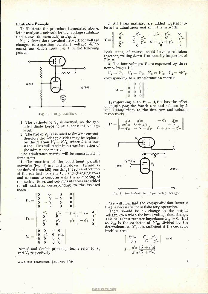
Illustrative Example To illustrate the procedure formulated above,
let us analyse a network for d.c. voltage stabiliza-tion, shown (in essentials) in Fig. 1.
Fig. 2 shows the equivalent network for voltage changes (disregarding constant voltage differ-ences), and differs from Fig. 1 in the following points:
"Fig. 1. Voltage stabiliser.
1. The cathode of V2 is earthed, as the gas-filled diode keeps it at a constant voltage level.
2. The grid of V2 is assumed to draw no current, therefore the voltage divider may be replaced by the relation V4 = kVi, where k is a con-stant. This will result in a transformation of the admittance matrix.
The admittance matrix will be constructed in three steps.
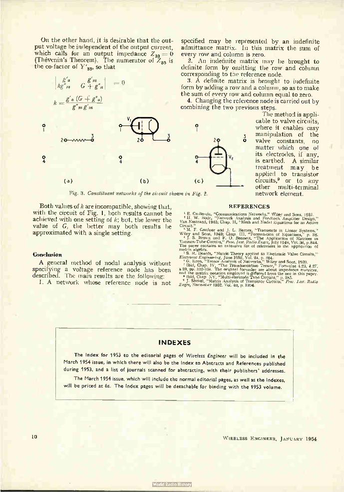
1. The matrices of the constituent parallel networks (Fig. 3) are written down. Yb and 17c are derived from (20), omitting the row and column of the earthed node (in Ye), and changing rows and columns to conform with the numbering of the nodes. Rows and columns of zeroes are added to all matrices, corresponding to the isolated nodes.
Ya =
Yb
Yc =
0 0 0 O G — G O — G G 0 0 0
O O o o
g'a g" — g'm — g'a
— g'a — g'm g'm g'a
0 0 0 0 o g"a O g"m 0 0 0 0 0 0 0 0
o o o O
Primed and double-primed g terms refer to and V2 respectively.
Vi
2. All three matrices are added together to form the admittance matrix of the network.
gpa ern em 0
O G + g"a — G g"m — g'a — G — g'm G ± g'a g'm
Both steps, of course, could have been taken together, writing down Y at once by inspection of Fig. 2.
3. The four voltages V are expressed by three new voltages V',
= V'1, V2 = V'2, V3 = V'3, V4 =
corresponding to a transformation matrix
1 0 0 0 1 0 0 0 1 k0 0
Transforming Y to Y' = AIYA has the effect ,of multiplying the fourth row and column by k and adding them to the first row and column respectively:
Y
Y'
il=
g'a g'm kg"m G -I- g"a — g'a — G - g'm
— g'a — g'm — G
G - F g'a - g'm
Fig. 2. Equivalent circuit for voltage changes.
We will now find the voltage-division factor k that is necessary for satisfactory operation. There should be no change in the output
voltage, even when the input voltage does change. This calls for a transfer impedance Z31 = 0. But as Z31 is the co-factor of Y'1 3 divided by the determinant of Y', it is sufficient if the co-factor itself be zero:
kg"m G g"a — g'a — G — g'm
k — (G ± ea) g'm (G g'm)
= 0
W IRELESS ENGINEER, JANUARY 1954 9
On the other hand, it is desirable that the out-put voltage be independent of the output current, which calls for an output impedance Z33 -= 0 (Thévenin's Theorem). The numerator of Z33 is the co-factor of r 33, so that
g'a I kg"m G + g"al
g'a (G -1«: g"a)
o
o 4
k— g g,.
3
=
o 4
(a) (b)
specified may be represented by an indefinite admittance matrix. In this matrix the sum of every row and column is zero.
2. An indefinite matrix may be brought to definite form by omitting the row and column corresponding to the reference node.
3. A definite matrix is brought to indefinite form by adding a row and a column, so as to make the sum of every row and column equal to zero.
4. Changing the reference node is carried out by combining the two previous steps.
The method is appli-cable to valve circuits, where it enables easy
3 manipulation of the o valve constants, no
matter which one of its electrodes, if any, is earthed. A similar treatment may be applied to transistor circuits,° or to any other multi-terminal network element.
o
(c)
Fig. 3. Constituent networks of the citcuit shown in Fig. 2.
Both values of k are incompatible, showing that, with the circuit of Fig. 1, both results cannot be achieved with one setting of k; but, the lower the value of G, the better may both results be approximated with a single setting.
Conclusion
A general method of nodal analysis without specifying a voltage reference node has been described. The main results are the following:
1. A network whose reference node is not
REFERENCES
a E. Guillemin, "Communications Networks," Wiley and Sons, 1931. a H. W. Bode, "Network Analysis and Feedback Amplifier Design,"
Van Nostrand, 1945; Chap. II, "Mesh and Nodal Equations for an Active Circuit."
M. F. Gardner and J. L. Barnes, "Transients in Linear Systems," Wiley and Sons, 1949; Chap. III, "Formulation of Equations," p. 38. a J. S. Brown and F. D. Bennett, "The Application of Matrices to
Vacuum-Tube Circuits," Proc. Inst. Radio Engrs, July 1948, Vol. 36, p.844. The paper contains an extensive list of references to the application of matrix algebra.
S. R. Deards, "Matric Theory applied to Electronic Valve Circuits," Electronic Engineering, June 1952, Vol. 24, p. 264. ' G. Kron, "Tensor Analysis of Networks," Wiley and Sons, 1939. Ibid, Chap. IV, "The Transformation Tensor," Formulae 4.23, 4.27;
4.39, pp. 102-104. The original formulae are about impedance matrices, and the matrix notation employed is different from the one in this paper. a Ibid, Chap. XV, "Multi-electrode Tube Circuits," p. 385. " J. Shekel, "Matrix Analysis of Transistor Circuits," Proc. Inst. Radio
Engrs, November 1952. Vol. 40, p. 1394.
INDEXES
The Index for 1953 to the editorial pages of Wireless Engineer will be included in the
March 1954 issue, in which there will also be the Index to Abstracts and References published
during 1953, and a list of journals scanned for abstracting, with their publishers' addresses.
The March 1954 issue, which will include the normal editorial pages, as well as the Indexes,
will be priced at 6s. The Index pages will be detachable for binding with the 1953 volume.
lii W IRELESS ENGINEER, JANUARY 1954
H.F. DIRECTION FINDING Comparison of C. W. and Pulsed Transmissions
By S. B. Smith,* M.I.E.E., and H. G. Hopkins,f B.Sc., Ph.D., M.I.E.E. (Marconi's Wireless Telegraph Co., Ltd., and Radio Research Station, Slough)
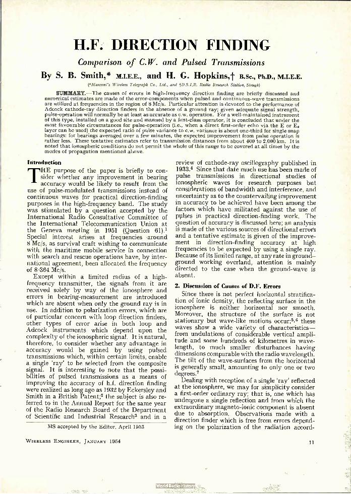
SUMMARY.— The causes of errors in high-frequency direction finding are briefly discussed and numerical estimates are made of the error-components when pulsed and continuous-wave transmissions are utilized at frequencies in the region of 8 Mc/s. Particular attention is devoted to the performance of Adcock cathode-ray direction finders in the absence of a ground ray; given adequate signal strength, pulse-operation will normally be at least as accurate as c.w. operation. For a well-maintained instrument of this type, installed on a good site and manned by a first-class operator, it is concluded that under the most favourable circumstances for pulse-operation (i.e., when a direct first-order echo via the E or Es layer can be used) the expected ratio of pulse variance to c.w. variance is about one-third for single snap bearings: for bearings averaged over a few minutes, the expected improvement from pulse operation is rather less. These tentative estimates refer to transmission distances from about 400 to 2,000 km. It is noted that ionospheric conditions do not permit the whole of this range to be covered at all times by the modes of propagation mentioned above.
Introduction
THE purpose of the paper is briefly to con-sider whether any improvement in bearing accuracy would be likely to result from the
use of pulse-modulated transmissions instead of continuous waves for practical direction-finding purposes in the high-frequency band. The study was stimulated by a question accepted by the International Radio Consultative Committee of the International Telecommunication Union at the Geneva meeting in 1951 (Question 61).1 Special interest arises at frequencies •around 8 Mc/s, as survival craft wishing to communicate with the maritime mobile service in connection with search and rescue operations have, by inter-national agreement, been allocated the frequency of 8.364 Mc/s. Except within a limited radius of a high-
frequency transmitter, the signals from it are received solely by way of the ionosphere and errors in bearing-measurement are introduced which are absent when only the ground ray is in use. In addition to polarization errors, which are of particular concern with loop direction finders, other types of error arise in both loop and Adcock instruments which depend upon the complexity of the ionospheric signal. It is natural, therefore, to consider whether any advantage in accuracy would be gained by using pulsed transmissions which, within certain limits, enable a single 'ray' to be selected from the composite signal. It is interesting to note that the possi-bilities of pulsed transmissions as a means of improving the accuracy of h.f. direction finding were realized as long ago as 1932 by Eckersley and Smith in a British Patent;2 the subject is also re-ferred to in the Annual Report for the same year of the Radio Research Board of the Department of Scientific and Industrial Research3 and in a
MS accepted by the Editor, April 1953
W IRELESS ENGINEER, JANUARY 1954
review of cathode-ray oscillography published in 1933.4 Since that date much use has been made of pulse transmissions in directional studies of ionospheric waves for research purposes but considerations of bandwidth and interference, and uncertainty as to the countervailing improvement in accuracy to be achieved have been among the factors which have militated against the use of pulses in practical direction-finding work. The question of accuracy is discussed here; an analysis is made of the various sources of directional errors and a tentative estimate is given of the improve-ment in direction-finding accuracy at high frequencies to be expected by using a single ray. Because of its limited range, at any rate in ground— ground working overland, attention is mainly directed to the case when the ground-wave is absent.
2. Discussion of Causes of D.F. Errors
Since there is not perfect horizontal stratifica-tion of ionic density, the reflecting surface in the ionosphere is neither horizontal nor smooth. Moreover, the structure of the surface is not stationary but wave-like motions occur;2,8 these waves show a wide variety of characteristics— from undulations of considerable vertical ampli-tude and some hundreds of kilometres in wave-length, to much smaller disturbances having dimensions comparable with the radio wavelength. The tilt of the wave-surfaces from the horizontal is generally small, amounting to only one or two degrees.7
Dealing with reception of a single 'ray' reflected at the ionosphere, we may for simplicity consider a first-order ordinary ray; that is, one which has undergone a single reflection and from which the extraordinary magneto-ionic component is absent due to absorption. Observations made with a direction finder which is free from errors depend-ing on the polarization of the radiation accord-
11
ingly show comparatively slow bearing deviations (lateral deviation) corresponding to reflection at a large-scale sloping surface on which are super-posed rapid fluctuations due to scattering from the fine structure. It is convenient to note here that the lateral deviation introduced by a given angle of tilt at the reflecting surface increases with the angle of elevation of the ray arriving at the re-ceiver; that is, bearing error increases with the height of reflection, with order of reflection, and with decreasing distance of the transmitter. An additional effect which causes trouble when observing a ray of higher order than the first is the scattering occurring at the ground reflection point or points. The scattering due to the ionospheric fine-structure, which has already been mentioned, results in radiation being received over a finite range of angle; scattering at the ground reflection point increases this cone-angle and consequently the magnitude of the rapid bearing fluctuations.
Suppose now, as usually happens in practice, that conditions allow of more than one mode of propagation between transmitter and receiver. For example, there may be two or more orders of reflections from the F layer, a single-order reflec-tion in which the extraordinary ray is not negligible in intensity compared with the ordinary, or reflections from both the E and F layers. If continuous-wave signals are in use these various components will not be resolved in time and consequently the direction finder intercepts at any instant two or more narrow cones of radiation, neither of which, in general, will be centred in the great-circle plane between transmitter and re-ceiver. Neglecting the effect of the ̀ coning' for the moment, consider two plane waves of comparable amplitude arriving at slightly different azimuths. The observed bearing will depend on the angular separation of the rays and on their relative phases and amplitudes. The largest deviations occur when the waves are in antiphase and for a limited range of phase angle the deviation may amount to many times the angular separation of the rays; for the remainder of the phase-range the deviation is in the opposite sense and of the order of half the magnitude of the azimuthal separation of the rays. These wave-interference errors, due to the simul-taneous reception of more than one ray, result in a considerable scatter of the bearings; they con-tribute to the rapid component of bearing fluctua-tions. To the causes of error discussed above must be added those remaining after local calibration has provided corrections for certain instrumental effects and for imperfections of the site in the immediate neighbourhood of the direction finder. These residual errors include observational errors, polarization errors, and errors arising from radia-tion scattered from features many wavelengths distant from the direction finder.
12
3. Comparison of Pulse and C.W. Direction Finding
It has been shown above that errors in high-frequency direction finding using continuous waves can arise from the following causes:
(i) Observational (human element). (ii) Instrumental (including polarization errors,
and those arising from the site close to the direction finder).
(iii) Distant site errors. (iv) Lateral deviation in the ionosphere. (v) Wave interference due to 'coning' of each
ray and between different propagational modes.
In the following paragraphs the relative import-ance of these various sources of error will be assessed quantitatively. A statistical approach will be used, a variance (or mean-square) figure being attached to each class of error for c.w. and pulse transmissions. This approach is convenient for, if the assumption is made that the various error-classes are independent of each other, the overall variance is the sum of the component class-variances. The complexity and variability of propagation conditions render it difficult to assign specific values under certain of the head-ings; however, this has been attempted by refer-ence to the published literature which, it may be noted, deals mainly with reception conditions in England. In making estimates, two distinct methods of observation have been borne in mind: the first, in which a single instantaneous bearing is taken; and the second, in which the mean of, say, 10 such snap bearings taken over a period of 5 minutes is utilized. It is assumed that a well-maintained fixed U-type Adcock cathode-ray direction finder is installed on a good site8 and is used by a skilled operator. Attention has been concentrated on distances in excess of about 400 km; it will, however, be possible to arrive at certain limited conclusions relating to much shorter distances when the ground-ray is present, and also when loop direction finders are in use. There is no point in considering cases where the ionospheric signal reaches the receiver by other than normal modes since, when these break down, direction finding using c.w. or pulse transmissions is without value.
(i) Observational Errors Except in very adverse circumstances the
standard deviation of a single bearing (for a skilled operator) will be less than a degree8 with c.w. operation; if the mean of a number of bearings is taken there will be a corresponding reduction. There will be some increase in observational error when the bearing is fluctuating rapidly. It will, therefore, be assumed that variances of 1 (lee and zero refer to a single observation and multiple observations respectively in c.w. operation.
W IRELESS ENGINEER, JANUARY 1954
With pulse operation the figure of 1 deg2 quoted above may be somewhat reduced; the variance of the mean of a number of observations will still approximate to zero. It should be noted that the increased bandwidth necessary may increase inter-ference from stations on neighbouring frequencies (and, therefore, observational error) unless ade-quate transmitter power is available.
(ii) Instrumental Errors It is assumed that the direction-finding station
is carefully maintained and frequently calibrated by means of a local transmitter. The residual errors in this class then arise from
(a) changes in the instrument and its immediate surroundings occurring since the most recent cali-bration, (b) defects in calibratión technique due to the proximity of the tránsmitter, (c) uncertainty of the appropriate instrumental correction to apply when the dominant mode of propagation (and, therefore, elevation-angle) is not known, and (d) polarization errors. The major contribution is probably from (a) on
a site of high conductivity. With c.w. operation it is estimated that these
various factors together introduce a variance of 1 or 2 deg2 for single bearings on a site of high conductivity. Little advantage is gained by averaging a- number of bearings. For poor con-ductivity sites, higher variances for a single bearing will be observed but averaging the results will tend to eliminate this contribution from the polarization-error component.
Pulse operation can be expected to give little improvement from ray-selection. If, however, the site is of poor conductivity some advantage will be gained by using a low-angle ray due to the reduc-tion in polarization error; however, the improve-ment will be slight when averaging of bearings over a few minutes is permissible.
(iii) Distant Site Errors This effect is estimated to contribute, with
c.w. operation, a variance of about 1 deg2 for single and averaged bearings on a good site in the band 5-10 Mc/s;10,11 the effect is more important at the lower frequencies of the h.f. band. No improvement would be expected from pulse
operation.
(iv) Lateral Deviation , A figure of about 2 deg2 may be taken for this effect with c.w. operation for day-time working and about 4 deg2 for night-time. 12 This figure is assumed to apply equally to single snap observa-tions and to the mean of a number of observations over a 5-minute period since lateral deviation represents a slowly varying component of variance.
In the case of pulse operation, if the range of
W IRELESS ENGINEER, JANUARY 1954
transmission and ionospheric conditions is such that propagation by a first-order E or Es reflection is possible then this ray would naturally be chosen. In these circumstances it is estimated that the variance contribution would be approxi-mately 0.5 deg2; but if no such echo is available the higher angle of elevation of the other rays will result in a negligible improvement compared with c.w. working. As in the case of c.w. operation the estimated variances refer both to single and averaged snap bearings.
(y) Wave Interference With c.w. operation, the errors due to wave
interference represent the major contribution to the rapidly-varying errors. A representative figure for the variance of a single snap bearing is taken to be about 4 deg2, although this shows wide variations depending on the complexity of the received radiation. For snap bearings averaged over a period of 5 minutes the variance contribution will be approximately 0.5 deg2. When a single mode is selected by pulse opera-
tion there is left mainly the variance contribution due to 'coning.' For first order E or F echoes the variance will be small both for single and averaged bearings.7 An upper limit of 0.5 deg2 is assigned to this contribution.
4. Conclusions (a) The Table on the next page summarizes the
information given in the previous section relating to the components of variance at a frequency in the region of 8 Mc/s for a well-maintained U-Adcock cathode-ray direction finder installed on a good site and used by a first-class operator. In con-sidering the Table it must be remembered that the various estimates given are of necessity rather rough and that they refer to ionospheric reception at distances greater than 400 km. The Table—as indeed the paper in general—relates to conditions commonly noted in the United Kingdom. It can-not, unfortunately, be assumed that all the data are representative of conditions in other parts of the world and throughout the sunspot cycle.
(b) The Table shows that under normal con-ditions, pulse-operation with adequate transmitter power appears capable of providing bearings at least as accurate as those obtainable with c.w. working. At ranges from the transmitter such that ground and ionospheric waves are comparable in intensity, errors on c.w. working will be high and might, if pulsed transmissions are used instead, be reduced by ground-ray selection to a variance of about 2-4 deg2. This figure applies to an Adcock system, but an improvement due to ground-ray selection would be expected also for loop direction finders which might well be in use in ships or aircraft during rescue operations. When
13

no ground-ray is present and an Adcock direction finder is in use, the Table shows that in the most favourable circumstances for pulse-working (i.e., when a direct first-order echo via the E or Es layer of adequate strength is receivable) the expected ratio of pulse to c.w. variances is about one-third for single snap bearings corresponding to a ratio of about 0.6 in standard deviation: for snap bearings averaged over a few minutes à slightly smaller improvement is indicated. It must again be
power, the median minimum range may vary between 1,400 km in winter and 600 km in summer.
Acknowledgment The paper is published by permission of
Marconi's Wireless Telegraph Co., Ltd., and the Director of Radio Research of the Department of Scientific and Industrial Research.
Variance (deg2)
Cause of error
(i) Observational
(ii) Instrumental
(iii) Distant site errors
(iv) Lateral deviation
(v) Wave interference
Totals
Continuous Wave
Single snap
bearing
1-2
2 (day) 4 (night)
4
9-10 (day) 11-12 (night)
Mean of 10 snap bearings in 5
minutes
o
1
2 (day) 4 (night)
0-5
Pulse
Single snap
bearing
0-1
1-2
1
0.5 (1E or 1E8 in use, otherwise, as for
C.W.)
0-0.5
4-5 (day) 2-5-5 6.5 (night) (1E or 1E8 in use)
Mean of 10 snap bearings in 5
minutes
o
0-5 (1E or 1E8 in use, otherwise, as for
C.W.)
0-0.5
2.5-3 (1E or 1E,, in use)
emphasized that these figures are tentative and that any deterioration of the observer's ability, and of the site and equipment from the high standards indicated in the Table will reduce any potential advantages of pulse operation relative to c.w.
(c) It is outside the scope of this paper to discuss whether the range of circumstances in which the improvement is likely to be obtained is worth the increased complexity of apparatus, higher demands on operating skill, and the cost involved in money and spectrum space. It may be mentioned, however, that in the United King-dom on about 8 Mc/s during day-time, first order E or Es reflections are generally receivable in the range 400-2,000 km. At night the low-angle first-order echoes are from Es and the smallest range of transmission available by this mode will vary seasonally and from night to night: although the upper limit of 2,000 km may be achieved throughout the year, given adequate transmitter
REFERENCES
International Radio Consultative Committee, Documents of Vlth Plenary Assembly, Geneva, 1951, Vol. 1, p. 131.
British Patent No. 397524, Marconi's Wireless Telegraph Co., Ltd., T. L. Eckersley and S. B. Smith.
3 Radio Research Board, Annual Report, H.M. Stationery Office, 1932.
R. A. Watson Watt, J. F. Herd and J. H. Bainbridge Bell. "The Cathode-Ray Oscillograph in Radio Research", H.M. Stationery Office, London, March 1933.
5 J. A. Pierce and H. R. Mimno. "The Reception of Radio Echoes from Distant Ionospheric Irregularities", Phys. Rev., 1940, Vol. 57, p. 95.
'G. H. Munro. "Travelling Disturbances in the Ionosphere", Proc. Royal Soc., (A), 1950, Vol. 202, p. 208.
E. N. Bramley and W. Ross. "Measurements of the Direction of Arrival of Short Radio Waves Reflected at the Ionosphere", Proc. Royal Soc., (A), 1951, Vol. 207, p. 251.
' W. Ross and F. Horner. "The Siting of Direction Finding Stations", Radio Research Special Report No. 22, HM. Stationery Office, London, 1952, Code No. 47-29-22.
• S. de Walden and J. C. Swallow. "The Relative Merits of Presentation of Bearings by Aural-Null and Twin-Channel Cathode-Ray Direction-Finders", Proc: Insta elect. Engrs, 1949, Vol. 96, Pt. III, p. 307.
" W. Ross. "Site and Path Errors in Short-Wave Direction Finding", J. Insta elect. Engrs, 1947, Vol. 94, Pt. III, p. 108.
"W. Ross. "The Estimation of the Probable Accuracy of High-Frequency Radio Direction-Finding Bearings", J. Insta elect. Engrs, 1947, Vol. 94, Pt. IIIA, p. 722. "W. Ross. "Lateral Deviation of Radio Waves Reflected at the
Ionosphere", Radio Research Special Report No. 19, H.M. Stationery Office, London, 1949, Code No. 47-29-19.
14 W IRELESS ENGINEER, JANUARY 1954
VALVE AND RECEIVER NOISE MEASUREMENT AT V.H.F.
By N. Houlding, B.Sc. Tech. (Radar Research Establishment, Malvern, Worcs.)
SUMMARY.—Techniques for the measurement of noise factor, valve noise and other parameters required in the investigation of receiver noise performance are described. Sources of error, and the precautions required to minimize them, are discussed. New equipment giving improved experimental accuracy is described.
Experimental results on noise generators and measurements of valve noise are included.
1. Introduction M ETHODS of noise measurement have been described in a number of earlier papers,L2,3 and the techniques to be described in this
paper are very similar. However, it is thought that a record of methods which have been used at T.R.E. over a number of years, during which time there have been numerous investigations of the accuracy, will be of value to other workers, in view of the growth of interest in the subject in late years.
General definitions will be found in a recent paper.4
2. Methods of Measurement
2.1. Noise Factor Absolute Methods
A CV172 tungsten-filament diode has been used as the standard noise source. This valve gives true saturated noise from about 1,000 cis to 100 Mc/s. An alternative type, the CV2171 on a B7G base, is now available. The correct conditions of measurement of noise
factor are that the receiver should be operated at an ambient temperature of 17°C (290°K = To) with a dummy aerial, or source, at the same tem-perature. In practice this is not always easy to achieve, and some correction must be applied. It is not possible to allow fór this correction very precisely and when absolute accuracy is required it is desirable that the temperature should be not very different from the standard. The noise out-put from the receiver may be expressed thus: Noise output = Receiver noise + kTB.M
V kTB.M
where: k = Boltzmann's constant
T = Temperature of source, degrees Kelvin
B -= Noise bandwidth of the receiver
M = Power gain.
The noise factor is measured by finding the in-
MS accepted by the Editor, February 1953
W IRELESS ENGINEER, JANUARY 1954
crease in available noise from the source which is required to double the noise ou tput. Hence, using a saturated noise diode feeding a source resistance RA, if the diode current required is Id
V ± kTI3111 Id B.RAM
where e = electron charge. Assuming that the receiver noise is independent
of ambient temperature, the noise factor N at the standard temperature To is:
4
V N = 1 ± kroBM
Hence N = 1 + 2eIdRA T 4kTo To
. . (1)
2e And for To = 290°K; 4kTo= 0.0200
for Id in mA and RA in ohms. In practice, the dependence of receiver noise on
temperature is not known. Therefore, for cross-check measurements, when it is not possible to work at a temperature close to To, it is better to quote the temperature of measurement and give the result as
2eldRA T N (at temperature T) x ° • . (2)
4kTo T For operational purposes, the measurement should always be made with the source at temperature To, and the receiver at normal operating temperature. The receiver noise output must be measured
before the second detector, and it is necessary to be able to measure a given increase in this noise output (usually to double the mean-square voltage). Four methods have been used for this
measurement: (a) In theoretical investigation, special valve
tests, etc., a test amplifier, with sufficient gain to swamp the noise from succeeding stages, is con-nected to a special amplifier which is terminated by a square-law anode-bend detector. The special amplifier is built into a rack and
15
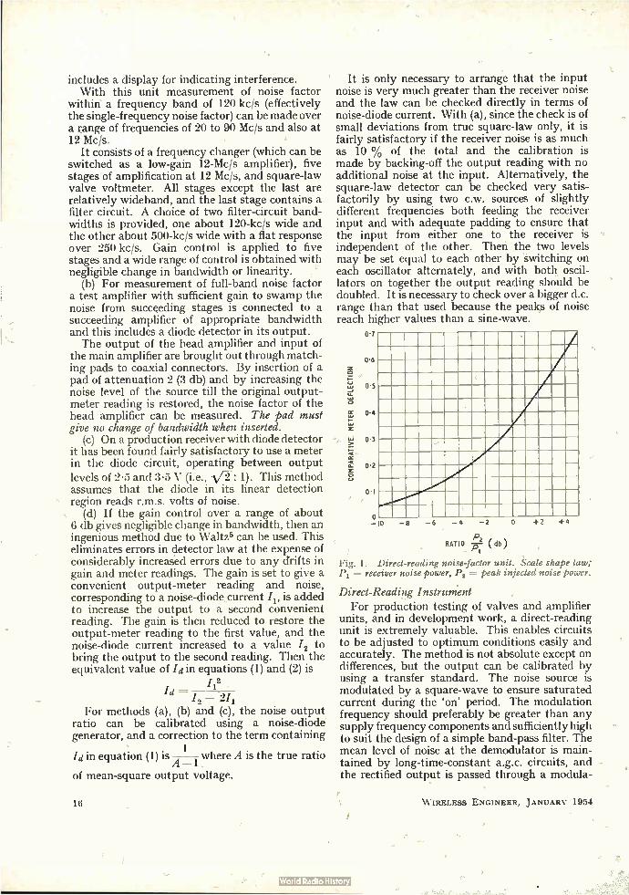
includes a display for indicating interference. With this unit measurement of noise factor
within a frequency band of 120 kcis (effectively the single-frequency noise factor) can be made over a range of frequencies of 20 to 90 Mc/s and also at 12 Mc/s.
It consists of a frequency changer (which can be switched as a low-gain 12-Mc/s amplifier), five stages of amplification at 12 Mc/s, and square-law valve voltmeter. All stages except the last are relatively wideband, and the last stage contains a filter circuit. A choice of two filter-circuit band-widths is provided, one about 120-kc/s wide and the other about 500-kc/s wide with a flat response over 250 kcis. Gain control is applied to five stages and a wide range of control is obtained with negligible change in bandwidth or linearity.
(b) For measurement of full-band noise factor a test amplifier with sufficient gain to swamp the noise from succeeding stages is connected to a succeeding amplifier of appropriate bandwidth and this includes a diode detector in its output. The output of the head amplifier and input of
the main amplifier are brought out through match-ing pads to coaxial connectors. By insertion of a pad of attenuation 2 (3 db) and by increasing the noise level of the source till the original output-meter reading is restored, the noise factor of the head amplifier can be measured. The pad must give no change of bandwidth when inserted.
(c) On a production receiver with diode detector it has been found fairly satisfactory to use a meter in the diode circuit, operating between output levels of 2.5 and 3.5 V (i.e., Vi : 1). This method assumes that the diode in its linear detection region reads r.m.s. volts of noise.
(d) If the gain control over a range of about 6 db gives negligible change in bandwidth, then an ingenious method due to Waltz5 can be used. This eliminates errors in detector law at the expense of considerably increased errors due to any drifts in gain and meter readings. The gain is set to give a convenient output-meter reading and noise, corresponding to a noise-diode current I, is added to increase the output to a second convenient reading. The gain is then reduced to restore the output-meter reading to the first value, and the noise-diode current increased to a value /2 to bring the output to the second reading. Then the equivalent value of 'din equations (1) and (2) is
12 Id — 12 — 2/1
For methods (a), (b) and (c), the noise output ratio can be calibrated using a noise-diode generator, and a correction to the term containing
1 Id in equation (1) is A-1 where A is the true ratio
of mean-square output voltage.
16
It is only necessary to arrange that the input noise is very much greater than the receiver noise and the law can be checked directly in terms of noise-diode current. With (a), since the check is of small deviations from true square-law only, it is fairly satisfactory if the receiver noise is as much as 10 % of the total and the calibration is made by backing-off the output reading with no additional noise at the input. Alternatively, the square-law detector can be checked very satis-factorily by using two c.w. sources of slightly different frequencies both feeding the receiver input and with adequate padding to ensure that the input from either one to the receiver is independent of the other. Then the two levels may be set equal to each other by switching on each oscillator alternately, and with both oscil-lators on together the output reading should be doubled. It is necessary to check over a bigger d.c. range than that used because the peaks of noise reach higher values than a sine-wave.
COMPARATIVE METER DEFLECTION
07
06
05
04
03
02
0.1
—2 0 +2 +4 —10 —8 —6 —4
P2 \ RATIO -E7, di 3)
Fig. 1. Direct-reading noise-factor unit. Scale shape law; P, = receiver noise power, P, = peak injected noise power.
Direct-Reading Instrument For production testing of valves and amplifier
units, and in development work, a direct-reading unit is extremely valuable. This enables circuits to be adjusted to optimum conditions easily and accurately. The method is not absolute except on differences, but the output can be calibrated by using a transfer standard. The noise source is modulated by a square-wave to ensure saturated current during the 'on' period. The modulation frequency should preferably be greater than any supply frequency components and sufficiently high to suit the design of a simple band-pass filter. The mean level of noise at the demodulator is main-tained by long-time-constant a.g.c. circuits, and the rectified output is passed through a modula-
W IRELESS ENGINEER, JANUARY 1954

tion-frequency band-pass filter to a further rectifier feeding a d.c. meter. The depth of modulation of the noise at the input to the demodulator, and hence the output meter reading, is inversely proportional to receiver noise. By suitable choice of levels, the meter cali-
bration gives a scale which is approximately linear in decibels (Fig. 1). A discrimination of 1 % in noise factor is readily obtained by careful filtering to avoid flicker due to noise components.
If the modulation frequency is low, considerable filtering may be required to give freedom from meter flicker with a consequent long-time-constant of meter. This is due to the change in spectrum of noise after rectification giving an increase in noise density at low frequencies.
Balanced System
In measuring the noise factor of an i.f. amplifier which is to be used with balanced mixers, the
5.7V
DIODE ANODE CURRENT CONTROLS
250V
stage of an amplifier, usually the first. The pad attenuator method [2.1 (b)] gives a true measure-ment of the noise factor of stages preceding the pad, but it is not very practical when the output has to be padded up at the input to the attenuator (to ensure that the attenuator is giving true readings), since this padding may affect the noise factor. However, if the attenuator pad is cali-
STRAYS
equivalent circuits (b) including strays Fig. 2. Noise diode circuit (a), and (j) T
0:50—f and (c) for calculation.
STRAYS
noise generator should be connected to either mixer and an identical impedance connected to the other. Reversing the connections gives a check on the symmetry of the unit. The true noise factor, assulning the asymmetry is not due • to any asymmetry in available power transfer (e.g., different losses at i.f. in the mixers) is then given by:
N N1N2 N1 + N2 N1+ N2 ' 4
where N1 is the noise factor calculated from the formula (1) for the first connection neglecting the second mixer, and N2 that calculated for reversed connections. This can be shown as follows:
N2 N N — 1
1 ± 1 ± R2 R2 R1
where R1 and R2 are the transformed source resistances at the grid.
b\r = R2 and the rest follows. N2 Ri
Hence:
2.2. Partial Noise Factors
For experimental investigations it is sometimes desirable to measure the noise factor of a separate
W IRELESS ENGINEER, JANUARY 1954
CV2i7,
CHOKE
SCREENING BOX
SUBSTANDARD METER 0- I o mA
RE CHOKE
(a)
rL ecrooimF
7 UR2 R,
_
+J)
TO RECEIVER
UNDER TEST
R,
( b) (c)
brated under true working conditions, results are accurate and it is not then necessary to arrange for an accurate match at the input to the attenuator provided there is no bandwidth change. A more convenient method is to switch off the
stage or stages to be measured and replace these by a passive network of the same output impe-dance. The ratio Y' of the two noise outputs then gives:
N —1 Y'l
where N1 is the noise factor of the early stage or stages,
N is the overall noise factor, and M 1 is the available power gain of the early
stages. In practice, 1/M1 is usually negligible, and
N(1 — y i ,) (3)
If 1111 is known, then N2 may be calculated from
N2 =-- (N — + 1 .. (4)
= NA/1/1"
2.3. Noise-Diode Generator The circuit used is shown in Fig. 2. Although
there are certain precautions to be taken to avoid
17

errors, this arrangement has been found to give satisfactory results and gives much greater flexibility for various applications than other methods which might be adopted for special experimental work. '
For measurements of noise factor, the series resistor can be changed to obtain variation of noise factor with source resistance. This series resistance is usually mounted in the input circuit of the receiver on experimental amplifiers, but it can also be arranged as a mount of the same physical dimensions as a mixer crystal. It is then possible to measure noise factor of a unit which is connected to a crystal mixer, and very properly include the effect of any i.f. losses in the mixer. It is advisable to blow air on this resistor to keep its temperature close to ambient when making actual measurements.
If the temperatures of the two resistors are T1 and T2, the noise factor is given by:
R12 (T, — To R1 N 0.02Id 1 121 R
•± T2 TO R2
TO RI ± R2) where ía is in milliamperes, R in ohms. Possible errors with this measurement arise from the following causes:
(a) Noise diode not perfectly saturated or impedance not high' compared with RI.
(b) Transit time and lead inductance effects in the noise diode.
(c) Differences in bandwidth for thermal noise and diode noise at the input.
(d) Differences between d.c. and r.f. impedances of R1 and R2 or errors in measurement of resistance values. Shunting effect of circuit losses in parallel with RI. Lead inductances in series with R1 and capacitance in parallel with R2.
(e) Errors due to the cable and plugs between R1 and R2. To minimize all these errors the following pre-
cautions are necessary:— (a) Operate with an anode voltage of at least
150. At this voltage the anode resistance of the CV172 is of the order of 105 ohms with a current of 10 mA.
(b) The 'lead inductance' effects occur chiefly in the thin filament and cannot be eliminated in a valve of this type. The correction factor is approximately of the form*:
i2E = 2eIddf( 1 •2 )
or, i22 ek4 2eIddf(1 2Af2)
Experimental tests have been made on very
• The symbol .3 12 is used for mean-square value of x.
18
few samples, but these showed that A was variable between samples, and that a correction of about 1% may be required at 30 Mc/s and 10% at 100 Mc/s. This effect is strictly due to the dis-tributed nature of the diode, which is approxi-mately equivalent to an open-circuited line. No tests have been made with anode earthed, and the output and load impedance connected one to the centre and the other to the common ends of the heater, thereby simulating a transmission line diode. The transit time is negligible up to 100 Mc/s
with 150 V on the anode. (c) With R1 = 72 ohms, the frequency response
of the diode circuit is such that the attenuation is less than 1% at ± 5 Mc/s. The error is therefore negligible for receiver bandwidths less than 10 Mc/s.
(d) The error in R1 is mainly due to the coil losses in parallel, and this error can be allowed .for. The resistor type used for R2 is an R.M.A.16 for values of R2 less than 500 ohms and an I.R.C.-type MPMt for values of R 2 between 500 and 2,000 ohms. Experiments at 45 Mc/s showed the shunt-ing capacitance to have negligible effect and it is believed that the r.f. resistance is equal to the d.c. value to better than 1% with short leads. If higher source impedances are required in measure-ment, it is necessary to use a transformer. If the coil L1 is connected at the diode anode terminal, and the circuit is resonant at these terminals the lead inductance in series with R1 has negligible effect on the available power at the end of the cable. If there is appreciable lead inductance, then .adjustment of L, to give maxirlium noise output will give error in the same way as shown in (b) above. However, although correct adjustment of L1 gives a known result for the available power from the cable, it is then necessary to know the series resistance R1' of the transformed impedance to be used in the term expressing the attenuation due to R2, and the true available power becomes:
(2eIddfRi 4 (RI' R2))
(e) A low-loss close tolerance cable such as UR21 should be used. The error in noise factor due to cable and plug mismatches will be in proportion to the transformation ratio of R1 (or Z1) through these, when R2 R1 and will be zero when R2 = 0. A half-wavelength cable is worth while if measurements are all at the same frequency, and it is not convenient to use a very short cable. The attenuation will be about 1% at 50 Mc/s. Even when precautions (a) to (e) are taken
additional errors may arise due to experimental
t This is a resistor originated by the International Resistor Co. of U.S.A., and is designed for low end-to-end capacitance.
W IRELESS ENGINEER, JANUARY 1954
2 To RI R2
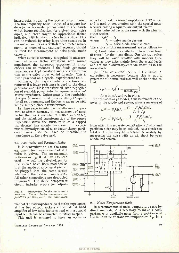
inaccuracies in reading the receiver output meter. The low-frequency noise output of a square-law detector is inversely proportional to the band-width before rectification, for a given total noise input, and there might be appreciable flicker indicated with bandwidths less than 2 Mc/s. This can be reduced by using large time constants in the meter circuits or a well-damped meter move-ment. A meter of sub-standard accuracy should be used for measurement of noise-diode anode current. When extreme accuracy is required in measure-
ment of noise factor variations with source impedance, the numerous experimental cross-checks can be reduced if the diode generator impedance is kept constant and the transforma-tion to the valve input varied directly. This is quite practical on a special experimental unit.
Similarly, the experimental corrections are reduced if a lower resistance is used in the diode generator and this is transformed, with negligible loss of available power, into the required equivalent source impedance. Unfortunately, the bandwidth of a quarter-wave transformer is hardly adequate for all requirements, and the loss is excessive with simple lumped-circuit transformers.
In these experiments it is usually more impor-tant to obtain accuracy in measurement of noise factor than in knowledge of source impedance, and the calculated transformation of the source impedance (from the turns ratio of a tapped transformer) has mainly been used. In experi-mental investigations of noise-factor theory parti-cular pains must be taken to measure the impedance at the valve grid.
2.4. Shot Noise and Partition Noise It is convenient to use the same
equipment for measurement of shot noise in valves. The arrangement is shown in Fig. 3. A unit has been used in which the valveholders for test valves have been modified so that the anode or screen-grid pin can be plugged into the same socket whatever the valve connections. All other connections are decoupled to ground. The diode comparator circuit includes means for adjust-
Fig. 3. Arrangement for shot-noise meas-
urements. The test holder connections are
paralleled for B7G, BBA, etc., valve bases.
ANODE s y
tgPELY1 °
ig22z = F022eIg2
Ia
from which the separate contributions of shot and partition noise may be calculated. As a check the total shot noise may be measured separately by measuring the noise with an r.f. short between anode and screen.
noise factor with a source impedance of 72 ohms, and is used in conjunction with the special noise receiver having a square-law output meter.
If the noise output is the same with the plug in either socket, then .1oF2 =-- Id where /a = valve anode current
Id = noise-diode anode current. The errors in this measurement are as follows:—
(a) Lead inductance effects. These have been discussed for the noise diode. For the test valve they will be much smaller with modern type valves as they arise mainly from the actual leads and not the filamentary-cathode effect, as in the noise diode.
(b) Finite slope resistance ra of the valve. A correction is necessary because this is not a generator of thermal noise as well as shot noise, so that
1 Ia,F2 = Id(1
0 .020Idra)
Id is in mA and ra in ohms. For tetrodes or pentodes, a measurement of the
noise in the anode and screen, gives a measure of
(1 — F02)422eIa ia 2E = F 022da
./a Ig2
(1 — F o2)Id2eIg2
ctiMie WPALT-ANODE
VOLTS 1"—o-
nee SCREEN VOLTS
00000 •
«T" •-41-6-0
0-1
-II---
- II-
SOCKETS:QQQQ9j9
CATHODE VOLTS
5CJ
72n
) Tee
DIODE o ANODE
SUPPLY
72n
ment of the load impedance, so that the impedances at the two output sockets are equal. A head amplifier of low-noise factor is used with a coaxial input which can be connected to either output.
This unit is arranged to have an optimum
W IRELESS ENGINEER, JANUARY 1954
HEATER D1OD SUPPLY FILAMENT SUPPLY
CeeetTL
2.5. Noise Temperature Ratio In measurements of noise temperature ratio by
direct methods, it is necessary to make a com-parison with available noise from a resistance of the same value at standard temperature To. It is
19
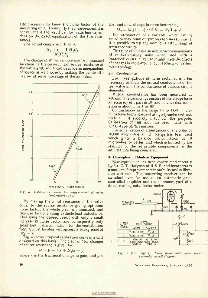
also necessary to know the noise factor of the measuring unit. To simplify the measurement it is convenient if the result can be made less depen-dent on the exact equalization of the two resis-tances. The actual comparison then is:
(N1 + t1 — 1)M1/31
N2M2B2
The change of N with source can be minimized by choosing the correct mean source resistance at the valve grid, and B can be made as independent of source as we choose by making the bandwidth narrow at some late stage of the amplifier.
NOISE TEMPERATURE RATIO
30
25
2.0
I 5
I 0
/
56011 /
/
/ /
/ /
376 El
249.n.
\1/4///
/
///
/
/
50 75
POWER OUTPUT METER READING
100
Fig. 4. Calibration curves for measurement of noise temperature ratio.
By making the input resistance of the valve equal to the source resistance giving optimum noise factor, the whole error is minimized, and this can be done using cathode-lead inductance. This gives the desired result with only a small increase in noise factor and consequently only small loss in discrimination, for the contribution from 11 must be observed against a background of (N1— 1).
Fig. 4 shows a typical calibration curve of a unit designed on this basis. The error in t for changes of source resistance is given by:
St = (t — 1)x N2(x — y)
where x is the fractional change in gain, and y is
20
the fractional change in noise factor; i.e.,
M 2 M 1(1 ± x) and N1 = N2(1 + y)
By introduction of a variable, which can be tuned to maximum output on each measurement, it is possible to use the unit for a 10: 1 range of resistance values.
This type of unit is also useful for measurements of radio-frequency noise when used with a 'matched' crystal mixer, as it minimizes the effects of changes in radio-frequency matching (or rather, mismatching).
2.6. Conductance
For investigations of noise factor it is often necessary to know the mutual conductance of the test valve and the conductance of various circuit elements. Mutual conductance has been measured at
750 c/s. The balancing resistors of the bridge have an accuracy of 1 part in 104 and balance discrimin-ation is about 1 part in 10.1.
Conductances in the range 10 to 1,000 micro-mhos have been measured using a Q-meter method, with a unit specially made for the purpose. Calibration of this unit has been made with I.R.C.-type MPM resistors. For equalization of admittances of the order of
10,000 micromhos an r.f. bridge has been used which gives a balance discrimination of 10 rnicromhos, or better, and which is limited by the stability of the adjustable components in the admittances being compared.
3. Description of Modern Equipment New equipment has been constructed recently
by Mr. C. T. Hodgson of R.R.E. and incorporates a number of improvements in stability and calibra-tion methods. The measuring receiver can be switched over for use as an automatic gain-controlled amplifier and then becomes part of a direct-reading noise-factor meter.
TO RECEIVER UNDER TEST
5-BANK SWITCH POSITION
2-BANK SWITCH POSITION
NORMAL CALIBRATE
I VI HEATER OFF V3 ON
2 V1 HEATER ON V2 ON V1 HT. ON V2 + V3 ON
3 OUTPUT METER OUTPUT METER SHUNTED SHUNTED
Fig. 5 (and right). Noise diode and meter shunt calibrator circuit diagram.
W IRELESS ENGINEER, J ANUARY 1954
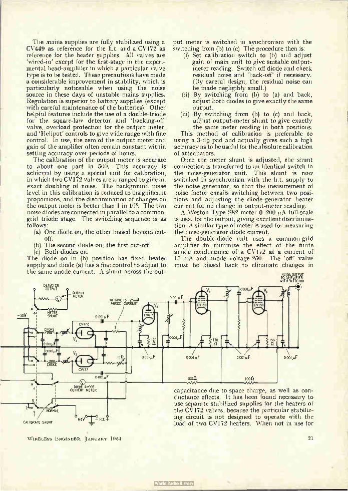
The mains supplies are fully stabilized using a CV449 as reference for the h.t. and a CV172 as reference for the heater supplies. All valves are `wired-in' except for the first-stage in the experi-mental head-amplifier in which a particular valve type is to be tested. These precautions have made a considerable improvement in stability, which is particularly noticeable when using the noise source in these days of unstable mains supplies. Regulation is superior to battery supplies (except with careful maintenance of the batteries). Other helpful features include the use of a double-triode for the square-law detector and 'backing-off' valve, overload protection for the output meter, and 'Helipot' controls to give wide range with fine control. In use, the zero of the output meter and gain of the amplifier often remain constant within setting accuracy over periods of hours. The calibration of the output meter is accurate
to about one part in 500. This accuracy is achieled by using a special unit for calibration, in which two CV172 valves are arranged to give an exact doubling of noise. The background noise level in this calibration is reduced to insignificant proportions, and the discrimination of changes on the output meter is better than 1 in 103. The two noise diodes are connected in parallel to a common-grid triode stage. The switching sequence is as follows:
(a) One diode on, the other biased beyond cut-off.
(b) The second diode on, the first cut-off. (c) Both diodes on.
The diode on in (b) position has fixed heater supply and diode (a) has a fine control to adjust to the same anode current. A shunt across the out-
-30V
DETECTOR OUTPUT
METER SHUNT
CHOKE
o•oolpfT
CV172
TO GIVE 15 -25mA ANODE CURRENT
0.001»F
CHOKE
3 L I
2to / NORMAL
CALIBRATE SHUNT
CVI72
DIODE ANODE CURRENT METER
63 o
— H.T. -I-
put meter is switched in synchronism with the switching from (b) to (c) The procedure then is:
Set calibration switch to (b) and adjust gain of main unit to give suitable output-meter reading. Switch off diode and check residual noise and `back-off' if necessary. (By careful design, the residual noise can be made negligibly small.)
(ii) By switching from (b) to (a) and back, adjust both diodes to give exactly the same output.
(iii) By switching from (b) to (c) and back, adjust output-meter shunt to give exactly the same meter reading in both positions.
• This method of calibration is preferable to using a 3-db pad and actually gives such a high accuracy as to be useful for the absolute calibration of attenuators. Once the meter shunt is adjusted, the shunt
connection is transferred to an identical switch in the noise-generator unit. This shunt is now switched in synchronism with the h.t. supply to the noise generator, so that the measurement of noise factor entails switching between two posi-tions and adjusting the diode-generator heater current for no change in output-meter reading. A Weston Type S82 meter 0-200 full-scale
is used for the output, giving excellent discrimina-tion. A similar type of meter is used for measuring the noise-generator diode current. The double-diode unit uses a common-grid
amplifier •to minimize the effect of the finite anode conductance of a CV172 at a current of 15 mA and anode voltage 250. The 'off' valve must be biased back to eliminate changes in
o.004LF
(i)
o.00/imF
looll
Cv'38
NOISE OUTPUT TO AMPLIFIER WITH DETECTOR
capacitance due to space charge, as well as con-ductance effects. It has been found necessary to use separate stabilized supplies for the heaters of the CV172 valves, because the particular stabiliz-ing circuit is not designed to operate with the load of two CV172 heaters. When not in use for
W IRELESS ENGINEER, JANUARY 1954 21

calibration, this unit supplies heater and anode voltages for test amplifier units. The circuit diagram is given in Fig. 5. The test-amplifier units used in experiments
on particular valve types are designed to give sufficient gain to swamp the noise of the main amplifier. The bias supplies to the first stage can be adjusted externally—either as cathode resistor or grid voltage, and a switch is fitted in the cathode return for use when neutralizing the grid—anode capacitance. The anode current of the test valve can be monitored separately. The input circuit contains a small tuning capacitor on the grid for measurements of capacitance-detuning effects, as well as enabling a high-Q low-loss coil to be used. The input coil is wound with a range of tapping points for changes of source impedance at the grid.
Fig. 6. Direct-reading unit including the noise diode modulator, main i.f. amplifier, square-law and linear detector, a.g.c. circuits and modulation
amplifier.
CV2I27
ertikû
With the direct-reading test set it is possible to measure the effect of circuit changes, and changes of valve operating conditions, with ease and precision.
Outline circuit diagrams of the equipment are given in Fig. 6.
4. Experimental Results 4.1. Diode Noise Generator
Fig. 7 shows experimental results for the 'saturated' slope resistance of a CV172 at different operating currents and voltages. Figs. 8 and 9 show anode-current control characteristics for the CV2171 and CV172 (different presentations). The effect of lead inductance (of rather the
distributed nature of the diode) has been measured on two samples in terms of the transformation of aniade—cathode conductance. If Ga is the total
100ft
DICiDE ANODE CURRENT
7211 CABLE
1.000pF HEAD AMPLIFIER UNDER TEST
+.200V
1.000p
FILAMENT SUPPLY
+ ooV
.50a
kft A.G.C.
MANUAL GAIN
CONTROL
oV
MAIN I.F. AMPLIFIER
TO CONTROL GRIDS OF ACVI58 AMPLIFIERS
CV 40
1.
FINAL TAGE OF F. AMPLIFIER (Poo
15011
6e An 00140
INTERNAL OR SUBSTANDARD OUTPUT METER \
-CV492
OUTPUT METER SET ZERO
ISBkft
e iÉa L.
SET SQ.LAW
SIGNAL
SET ZERO
—5V
R F. CHOKE
CHOKE
CV 40
son
A/4e n 25011 68..
SET SQ,LAW CURRENT
--eLtd1
184
-150V
CV 138
470kft
470 kO
BRIDGED T FILrER I kc/s
-2M11 " n
*Oka
iJtAAA-,
0.02µF
270kft
o•oo2p.F
—150V
150kft 15o k 47011
ALTERNATSE TIME CONSTANTS
FOR METER
P. CHOKE
200V
220kft
OUTPUT 1ETER 0-5,4
5kO
—,50V
W IRELESS ENGINEER, JANUARY 1954
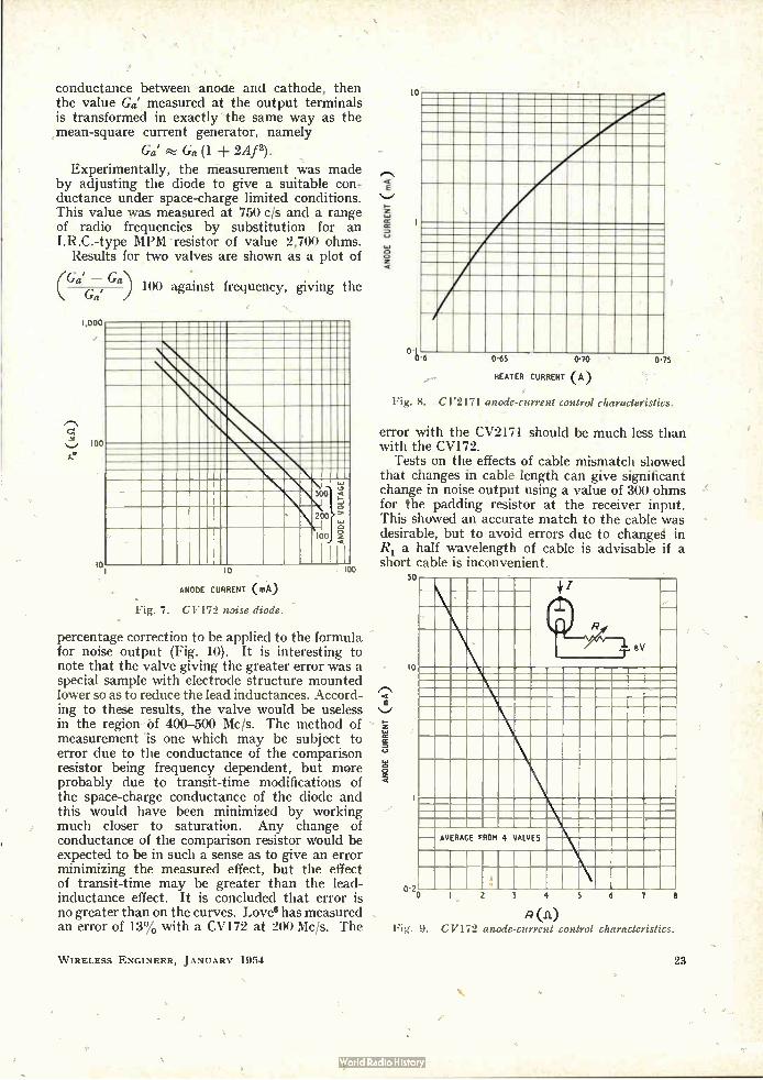
conductance between anoae and cathode, then the value Ga' measured at the output terminals is transformed in exactly the same way as the mean-square current generator, namely
Ga' Ga (1 ± 2Af2).
Experimentally, the measurement was made by adjusting the diode to give a suitable con-ductance under space-charge limited conditions. This value was measured at 750 c/s and a range of radio frequencies by substitution for an I.R.C.-type MPM resistor of value 2,700 ohms.
Results for two valves are shown as a plot of
(Ga' — Ga) Ga'
100 against frequency, giving the
1,000
100
10
300 `2 lo zoo
10
ANODE CURRENT (mA)
o Ioo 2
I I 100
-Fig. 7. CV172 noise diode.
percentage correction to be applied to the formula for noise output (Fig. 10). It is interesting to note that the valve giving the greater error was a special sample with electrode structure mounted lower so as to reduce the lead inductances. Accord-ing to these results, the valve would be useless in the region óf 400-500 Mc/s. The method of measurement is one which may be subject to error due to the conductance of the comparison resistor being frequency dependent, but more probably due to transit-time modifications of the space-charge conductance of the diode and this would have been minimized by working much closer to saturation. Any change of conductance of the comparison resistor would be expected to be in such a sense as to give an error minimizing the measured effect, but the effect of transit-time may be greater than the lead-inductance effect. It is concluded that error is no greater than on the curves. Love6 has measured an error of 13% with a CV172 at 200 Mc/s. The
W IRELESS ENGINEER, JANUARY 1954
ANODE CURRENT ( mA)
10
0.1 0,5 0-65 0'70 0-75
HEATER CURRENT (A)
Fig. 8. G V2171 anode-current control characteristics.
error with the CV2171 should be much less than with the CV172.
Tests on the effects of cable mismatch showed that changes in cable length can give significant change in noise output using a value of 300 ohms for the padding resistor at the receiver input. This showed an accurate match to the cable was desirable, but to avoid errors due to change g in R1 a half wavelength of cable is advisable if a short cable is inconvenient.
ANODE CURRENT (mA)
50
10
AVERAGE FROM 4 VALVES
2 3 4 5
(11)
6 7 e
Fig. 9. CV172 anode-current control characteristics.
23

4.2. Noise Factor
It has been found that results over a period of years with different observers have been consistent to about ± 3% with exceptions due to traceable causes. The main sources of experimental devia-tions are meter errors, error in the reading of the square-law output meter (now very small), and the effects of temperature. It is advisable to check the noise-generator resistors at regular intervals.
DISTRIBUTED ADMITTANCE
• -100
10
CV 172
SPECIAL VERSION £I683
0 I
PERCENTAGE CHANGE IN GA'
Fig. • 10 (above). CV172, measurement of transformation of diode conductance at output
terminals; GA =112700 mhos.
Fig. 11 (right). Variations of mutual con-ductance with time (CV139). •
10
A
10,200
e'N
Cross-checks made in 1944 against the 10,100 signal-generator method gave agreement E
within 2%. This is not considered \-• reliable evidence of absolute accuracy, for the signal-generator method involves such a lot of calibration that it is not possible to avoid the suspicion of having suspended investigations of accuracy once reasonable agreement has been reached.
Cross-checks against the hot-lamp method7 were made in 1944. Various discrepancies between the two methods were found depending upon whichever figure for lamp temperature was used, namely:—Maker's figures, calculated figures, or measured figures using an optical pyrometer. The pyrometer indicated end-cooling effects of the filament and the measurement of temperature was very difficult due to the glass background. Thè conclusion reached was that comparison with a noise diode enables measurement of the mean-
24
poise temperature of the lamp filament for that particular frequency to be made.
4.3. Shot Noise and Partition Noise The accuracy of these measurements has been
found to be worse than expected. It is probable that real variations in valve noise are the chief cause of the experimental differences noted. In particular, when results are transformed into equivalent noise-resistance values, the value of mutual conductance is involved, and it is doubtful whether this is sufficiently stable (because of valveholder and cathode temperature effects) to justify expectation of consistency in equivalent noise resistance to better than 5%. ' For any careful investigation it is recommended that particular care be taken to stabilize the valve operating conditions, and to allow a period of warming up. Typical effects with a CV139 are shown in Fig. 11.
Experimentally it has been found that the deviations in measured noise resistance are as much as 5% over a period of days. Cross-checks have been made with other workers who used different methods and lower frequencies, and differences of 10 to 20% have been observed. On the whole, our results have given the lowest values, but no exhaustive investigation of the discrepancies has been made. The measurement using the substitution method gives consistent
A mim m.lb•
••••••-...
10.0000 10
TIME AFTER SWITCHING ON (MINUTES)
8 C 9,4300 -9,200
9,700 9,100
159'600 - 9,000
results over a short period and it is possible to check circuit errors (excluding valve lead-inductance effects) by comparing two noise diodes.
Experimental results in Tables 1, 2 and 3 show that the shot noise in modern high-slope valves is significantly greater than the theoretical value quoted by Harris.8 This is believed to be due to the distortion of the field in the grid—cathode region with these valves, in which the grid wire is comparable with the pitch and the grid—
W IRELESS ENGINEER, JANUARY 1954
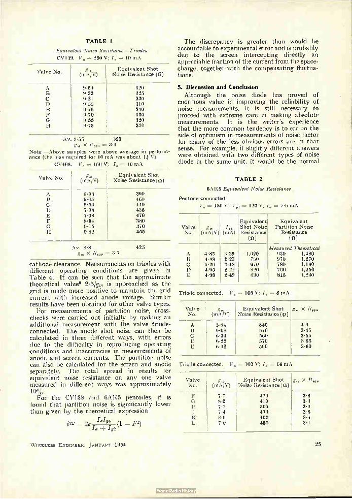
TABLE 1
Equivalent Noise Resistance-Triodes
CV139. V. = 250 V; I. = 10 mA
Valve No. (mA/V) Equivalent Shot
Noise Resistance (a)
zo•L
Jtri
cnto
> 9.60 9-33 9.21 9-55 9.75 9.70 9.55 9.75
320 325 330 310 340 330 320 320
Av. 9.55 325 g,,, x R... 3.1
Note:-Above samples were above average in perform-ance (the bias required for 10 mA was about 11 V).
CV408. V. = 15QV; I. = 10 mA
Valve No. gm (mA/V)
Equivalent Shot Noise Resistance (a)
xcv.
.1t4
cnto
›- 8-93 9.05 9-56 7-98 7.08 8.94 9.15 9.82
390 460 440 435 479 180 370 455
Av. 8.8 425 g„, x R„.. = 3.7
cathode clearance. Measurements on triodes with different operating conditions are given in Table 4. It can be seen that the approximate theoretical values 2.5/gm is approached as the grid is made more positive to maintain the grid current with increased anode voltage. Similar results have been obtained for other valve types.
For measurements of partition noise, cross-checks were carried out initially by making an additional measurement with the valve triode-connected. The anode shot noise can then be calculated in three different ways, with errors due to the difficulty in reproducing operating conditions and inaccuracies in measurements of anode and screen currents. The partition noise can also be calculated for the screen and anode separately. The total spread in results for equivalent noise resistance on any one valve measured in different ways was approximately 10%. For the CV138 and 6AK5 pentodes, it is
found that partition noise is significantly lower than given by the theoretical expression
= 2e /a/g2 (1 F2)
icy + .42
The discrepancy is greater than would be accountable to experimental error and is probably due to the screen intercepting directly an appreciable fraction of the current from the space-charge, together • with the compensating fluctua-tions. _
5. Discussion and Conclusion Although the noise diode has proved of
enormous value in improving the reliability of noise measurements, it is still necessary to proceed with extreme care in making absolute measurements. It is the writer's experience that the more common tendency is to err on the side of optimism in measurements of noise factor for many of the less obvious errors are in that sense. For example, if slightly different answers were obtained with two different types of noise diode in the same unit, it would be the normal
TABLE 2
6AK5 Equivalent Noise Resistance
Pentode connected.
= 180 V; Vg2 = 120 V; I. = 7.5 mA
Equivalent Equivalent Valve g„, Igg Shot Noise Partition Noise No. (mA/V) (mA) Resistance Resistance
(a) (n)
Measured Theoretical A 4.85 3-39 1,620 930 1,480 B 4.88 2-23 750 970 1,270 C 5-26 2.48 670 780 1,180 D 4-95 2.22 820 760 1,250 E 4-98 2-42 830 815 1,260
Triode connected. V. = 105 V; I. = 8 mA
Valve No.
g„, (mA/V)
Equivalent Shot Noise Resistance ( a )
g„, x R..„
A 5-84 840 4-9 B 6.08 570 3-45 C 6.34 560 3.55 D 6.22 570 3.55 E 6-12 590 3.60
Triode connected. V. = 100 V; I. = 14 mA
Valve No.
gm (mA/V)
Equivalent Shot Noise Resistance ( a )
g„, x R..„
F 7.7 470 3-6 G 8-0 410 3-3 H 7.7 505 3.9 J 7.4 470 3.5 K 8.6 400 3.4 L 7-0 450 . 3.1
W IRELESS ENGINEER, JANUARY 1954 25
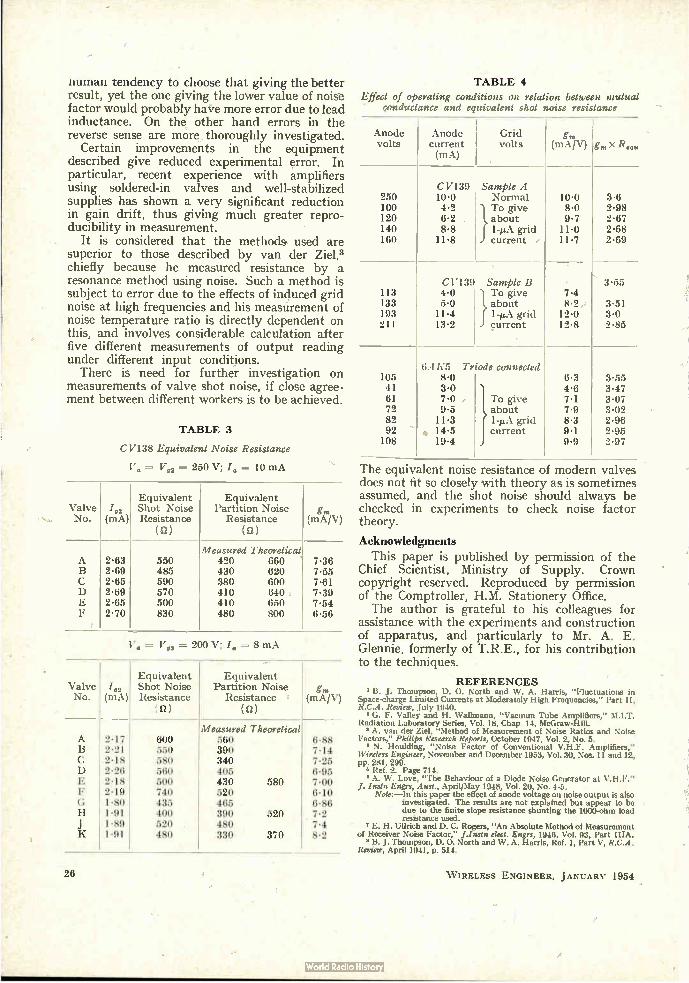
numan tendency to choose that giving the better result, yet the one giving the lower value of noise factor would probably have more error due to lead inductance. On the other hand errors in the reverse sense are more thoroughly investigated.
Certain improvements in the equipment described give reduced experimental error. In particular, recent experience with amplifiers using soldered-in valves and well-stabilized supplies has shown a very significant reduction in gain drift, thus giving much greater repro-ducibility in measurement.
It is considered that the methods used are superior to those described by van der Zie1,3 chiefly because he measured resistance by a resonance method using noise. Such a method is subject to error due to the effects of induced grid noise at high frequencies and his measurement of noise temperature ratio is directly dependent on this, and involves considerable calculation after five different measurements of output reading under different input conditions. There is need for further investigation on
measurements of valve shot noise, if close agree-ment between different workers is to be achieved.
TABLE 3
CV138 Equivalent Noise Resistance
V„ = V„ = 250 V; I„ = 10 mA
Equivalent Equivalent Valve /92 Shot Noise Partition Noise g„, No. (mA) Resistance Resistance (mA/V)
(0) (n)
Measured Theoretical A 2.63 550 420 660 7.36 B 2.69 485 430 620 7.55 C 2.65 590 380 600 7-61 D 2.69 570 410 640 7-39 E 2-65 500 410 650 7.54 F 2.70 830 480 800 6.56
V „ = 1(02 = 200 V; 1,, = 8 mA
Valve No.
./0 (mA)
Equivalent Shot Noise Resistance ; n )
Equivalent Partition Noise
Resistance (n)
g„, (mA/V)
Measured Theoretical A 2-17 600 560 6.88 B 2.21 550 390 7.14 C 2.18 580 340 7-25 D 2.26 560 405 6.95 E 2.18 500 430 580 7.00 F 2.19 740 520 6.10 G 1.80 435 465 6.86 H 1.91 400 390 520 7.2 J 1.89 520 480 7.4 K 1.91 480 330 370 8.2
26
TABLE 4
Effect of operating conditions on relation between mutual - conductance and equivalent shot noise resistance
Anode volts
Anode Grid current volts (mA)
(mA/V) g„,x R„,,
250 100 120 140 160
113 133 193 211
CV139 10.0 4-2 6.2 . 8.8
11.8
Sample A Normal To give about 1-eA. grid current
10.0 8.0 9.7
11.0 11•7
CV139 4.0 5.0 11.4 13.2
Sample B }To give about 1-µA grid current
7.4 8-2
12-0 12-8
3.6 2.98 2.67 2.68 2.69
3.55
3-51 3.0 2-85
105 41 61 72 82 92
108
6.4K5 8-0 3-0 7.0 9.5
11-3 • 14.5
19.4
Tr "ode connected
1 To give about 1-µA grid current
6.3 4.6 7.1 7.9 8-3 9.1 9.9
3.55 3.47 3.07 3.02 2.96 2.95 2.97
The equivalent noise resistance of modern valves does not fit so closely with theory as is sometimes assumed, and the shot noise should always be checked in experiments to check noise factor theory.
Acknowledgments This paper is published by permission of the
Chief Scientist, Ministry of Supply. Crown copyright reserved. Reproduced by permission of the Comptroller, H.M. Stationery Office. The author is grateful to his colleagues for
assistance with the experiments and construction of apparatus, and particularly to Mr. A. E. Glennie, formerly of T.R.E., for his contribution to the techniques.
REFERENCES ° B. J. Thompson, D. O. North and W. A. Harris, "Fluctuations in
Space-charge Limited Currents at Moderately High Frequencies," Part II, R.C.A. Review, July 1940.
G. F. Valley and H. Wallmann, "Vacuum Tube Amplifiers," M.I.T. Radiation Laboratory Series, Vol. 18, Chap 14, McGraw-Hill. " A. van der Ziel, "Method of Measurement of Noise Ratios and Noise
Factors," Philips Research Reports, October 1947, Vol. 2, No. 5. N. Houlding, "Noise Factor of Conventional V.H.F. Amplifiers,"
Wireless Engineer, November and December 1953, Vol. 30, Nos. 11 and 12, pp. 281, 299. 5 Ref. 2. Page 714. ° A. W. Love, "The Behaviour of a Diode Noise Generator at V.H.F."
J. Instn Engrs, Aust., April/May 1948, Vol. 20, No. 4-5. Note:-In this paper the effect of anode voltage on noise output is also
investigated. The results are not explained but appear to be due to the finite slope resistance shunting the 1000-ohm load resistance used.
° E. H. Ulrich and D. C. Rogers, "An Absolute Method of Measurement of Receiver Noise Factor," J.Instn elect. Engrs, 1946, Vol. 93, Part IIIA. ° B. J. Thompson, D. 0. North and W. A. Harris, Ref. 1, Part V, R.C.A.
Review, April 1941, p. 514.
WIRELESS ENGINEER, JANUARY 1954
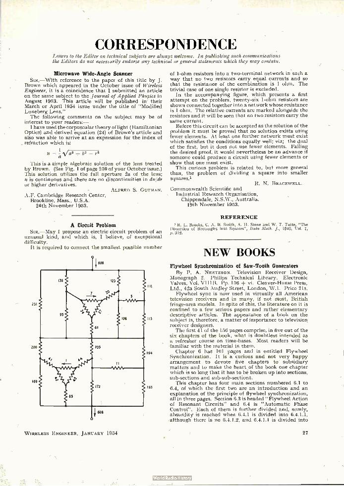
CORRESPONDENCE Letters to the Editor on technical subjects are always welcome. In publishing such communications the Editors do not necessarily endorse any technical or general statements which they may contain.
Microwave Wide-Angle Scanner SIR,—With reference to the paper of this title by J.
Brown which appeared in the October issue of Wireless Engineer, it is a coincidence that I submitted an article on the same subject to the Journal of Applied Physics in August 1953. This article will be published in their March or April 1954 issue under the title of "Modified Luneberg Lens." The following comments on the subject may be of
interest to your readers:— I have used the corpuscular theory of light (Hamiltonian
Optics) and derived equation (24) of Brown's article and also was able to arrive at an expression for the index of refraction which is:
n =-Iva' + b2 — r2 a
This is a simple algebraic solution of the lens treated by Brown. (See Fig. 1 of page 250 of your October issue.) This solution utilizes the full aperture 2a of the lens; n is continuous and there are no discontinuities in dnidr or higher derivatives.
ALFRED S. GUTMAN. A.F. Cambridge Research Center,
Brookline, Mass., U.S.A. 24th November 1953.
A Circuit Problem SIR,—May I propose an electric circuit problem of an
unusual kind, and which is, I believe, of exceptional difficulty.
It is required to connect the smallest possible number
231
209
168
W IRELESS ENGINEER, JANUARY 1954
of 1-ohm resistors into a two-terminal network in such a way that no two resistors carry equal currents and so that the resistance of the combination is 1 ohm. The trivial case of one single resistor is excluded.
In the accompanying figure, which presents a first attempt on the problem, twenty-six 1-ohm resistors are shown connected together into a network whose resistance is 1 ohm. The relative currents are marked alongside the resistors and it will be seen that no two resistors carry the same current.
Before this circuit can be accepted as the solution of the problem it must be proved that no solution exists using fewer elements. At least one further network must exist which satisfies the conditions equally well; viz; the dual of the first, but it does not use fewer elements. Failing the desired proof, it would nevertheless be an adva,nce if someone could produce a circuit using fewer elements or show that one must exist.
This curious problem is related to, but more general than, the problem of dividing a square into smaller squares.'
R. N. BRACEWELL. Commonwealth Scientific and
Industrial Research Organisation, Chippendale, N.S.W., Australia.
19th November 1953.
REFERENCE
R. L. Brooks, C. A. B. Smith, A. H. Stone and W. T. Tutte, "The Dissection of Rectangles intd Squares", Duke Math. J., 1040, Vol. 7, p. 312.
NEW BOOKS Flywheel Synchronization of Saw-Tooth Generators By P. A. NEETESON. Television Receiver Design,
Monograph 2. Philips Technical Library. Electronic Valves, Vol. VIIIB. Pp. 156 vi. Cleaver-Hume Press, Ltd., 42a South Audley Street, London, W.1. Price 21s.
Flywheel sync is now used in virtually all American television receivers and in many, if not most, British fringe-area models. In spite of this, the literature on it is confined to a few serious papers and rather elementary descriptive articles. The appearance of a book on the subject is, therefore, a matter of importance to television receiver designers. The first 41 of the 156 pages comprise, in five out of the
six chapters of the book, what is doubtless intended as a refresher course on time-bases. Most readers will be familiar with the material in them.
Chapter 6 has 101 pages and is entitled Flywheel Synchronization. It is a curious and not very happy arrangement to devote five chapters to subsidiary matters and to make the heart of the book one chapter which is so long that it has to be broken up into sections, sub-sections and sub-sub-sections.
This chapter has four main sections numbered 6.1 to 6.4, of which the first two are an introduction and an explanation of the principle of flywheel synchronization, all in three pages. Section 6.3 is headed "Flywheel Action of Resonant Circuits" and 6.4 is "Automatic Phase Control". Each of them is further divided and, surely, absurdity is reached when 6.4.1 is divided into 6.4.1.1, although there is no 6.4.1.2, and 6.4.1.1 is divided into
27
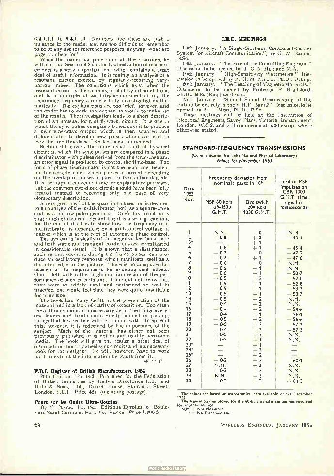
6.4.1.1.1 to 6.4.1.1.9. Numbers like these are just a nuisance to the reader and are too difficult to remember to be of any use for reference purposes; anyway, what are page numbers for? When the reader has penetrated all these barriers, he
will find that Section 6.3 on the flywheel action of resonant circuits is a very important one which contains a great deal of useful information. It is mainly an analysis of a resonant circuit excited by regularly-recurring very-narrow pulses. The conditions which exist when the resonant circuit is the same as, is slightly different from, and is a multiple of an integer-plus-one-half of, the recurrence frequency are very fully investigated mathe-matically. The explanations are too brief, however, and the reader has to work harder than he should to make use of the results. The investigation leads to a short descrip-tion of an unusual form of flywheel circuit. It is one in which the sync pulses energize a tuned circuit to produce a near sine-wave output which is then squared and differentiated to develop new pulses which are used to lock the line time-base. No feedback is involved.
Section 6.4 covers the more usual kind of flywheel circuit in which the sync pulses are compared in a phase discriminator with pulses derived from the time-base and an error signal is produced to control the time-base. The form of phase discriminator is not the usual one, being a multi-electrode valve which passes a current depending on the overlap of pulses applied to two different grids. It is, perhaps, a convenient one for explanatory purposes, but the common two-diode circuit should have been fully treated instead of receiving only one page of very elementary description. A very great deal of the space in this section is devoted
to an analysis of the multivibrator, both as a square-wave and as a narrow-pulse generator. One's first reaction is that much of this is irrelevant but it is a wrong reaction, for the end of it all is to show how the frequency of a multivibrator is dependent on a grid-control voltage, a matter which is at the root of automatic phase control. The system is basically of the negative-feedback type
and both static and transient conditions are investigated in considerable detail. It is shown that a disturbance, such as that occuring during the frame pulses, can pro-duce an oscillatory response which manifests itself as a distorted edge to the picture. There is no adequate dis-cussion of the requirements for avoiding such effects. One is left with rather a gloomy impression of the per-formance of such circuits and, if one did not know that they were so widely used and performed so well in practice, one would feel that they were quite unsuitable for television! The book has many faults in the presentation of the
material and in a lack of clarity of exposition. Too often the author explains in unnecessary detail the things every-one knows' and treats quite briefly, almost in passing, things that few readers will be familiar with. In spite of this, however, it is redeemed by the importance of the subject. Much of the material has either not been previously published or is not in any readily accessible media. The book will give the reader a great deal of information about flywheel sync circuits and is a necessary book for the designer. He will, however, have to work hard to extract the information he wants from it.
W. T. C.
F.B.I. Register of British Manufacturers 1954 26th Edition. Pp. 952. Published for the Federation
of British Industries by Kelly's Directories Ltd., and Iliffe & Sons, Ltd., Dorset House, Stamford Street, London, S.E.1. Price 42s. (including postage).
Cours sur les Ondes Ultra-Courtes By Y. PLAcE. Pp. 185. Editions Eyrolles, 61 Boule-
vard Saint-Germain, Paris Ve, France. Price 1,300 fr.
28
MEETINGS
13th January. "A Single-Sideband Controlled-Carrier System for Aircraft Communication", by G. W. Barnes, B.Sc.
18th January. "The Role of the Consulting Engineer." Discussion to be opened by T. G. N. Haldane, M.A.
19th January. "High-Sensitivity Wattmeters." Dis-cussion to be opened by A. H. M. Arnold, Ph.D., D.Eng.
20th January. "The Teaching of Magnetic Materials." Discussion to be opened by Professor F. Brailsford, Ph.D., B.Sc.(Eng.) at 6 p.m.
25th January. "Should Sound Broadcasting of the Future be entirely in the V.H.F. Band?" Discussion to be opened by A. J. Biggs, Ph.D., B.Sc.
These meetings will be held at the Institution of Electrical Engineers, Savoy Place, Victoria Embankment London, W.C.2, and will commence at 5.30 except where otherwise stated.
STANDARD-FREQUENCY TRANSMISSIONS
(Communication from the National Physical Laboratory)
Values for November 1953
Date 1953 Nov.
1 2 3* 4 5 6 7 8 9 10 11 12 13 14 15 16 17 18 19 20 21 22 23* 24* 25* 26 27 28 29 30
Frequency deviation from nominal: parts in 1C'
MSF 60 kc s 1429-1530 G.M.T.
Droitwich 200 kc/s
1030 G.M.T.
Lead of MSF impulses on GBR 1000
G.M.T. time signal in
milliseconds
N.M. 08
0.8 07 0.7 0.6 0.6 06 0.5 0.5 0.5 0.5 0.5 0.4 0.4 0.4 0-5 0.5 0.4 0.5 0.5
- 0- .3 N.M. - 0.3 N.M. - 0.2
o 2
+ 1 + 1 O
+ 2 + 2 + 2 + 3 + 2 + 3 + 2
N.M. - 43.4
- 45- .4 - 47 2 - 47.6 N.M. N.M. - 50.7 - 520 - 52-8 - 53.2 - 53.7 N.M. N.M. - 546 - 56.1 - 56-6 - 572 - 57.3 N.M. N.M.
- 60- 1 N.M. N.M. N.M. - 64.3
The values a.re based on astronomical data available on 1st December 1953. The transmitter employed for the 60-kc/s signal is sometimes required
for another service. N.M. = Not Measured.
* = No Transmission.
WIRELESS ENGINEER, JANUARY 1954
ABSTRACTS and REFERENCES Compiled by the Radio Research Organization of the Department of Scientific and Industrial
Research and published by arrangement with that Department.
The abstracts are classified in accordance with the Universal Decimal Classification. They are arranged within broad subject sections in the order of the U.D.C. numbers, except that notices of book reviews are placed at the ends of the sections. U.D.C. numbers marked with a dagger (t) must be regarded as pro-visional. The abbreviations of journal titles conform generally with the style of the World List of Scientific Periodicals. An Author and Subject Index to the abstracts is published annually; it includes a selected
list of journals abstracted, the abbreviations of their titles and their publishers' addresses.
Acoustics and Audio Frequencies
Aerials and Transmission Lines
Automatic Computers
Circuits and Circuit Elements
General Physics
Geophysical and Extraterrestrial Phenomena Location and Aids to Navigation .. Materials and Subsidiary Techniques
Mathematics ..
Measurements and Test Gear
Other Applications of Radio and Electronics Propagation of Waves
Reception ..
Stations and Communication Systems Subsidiary Apparatus
Television and Phototelegraphy
Transmission
Valves and Thermionics
Miscellaneous
PAGE A
1
2
3
6
8
10
11 12
16
16
17 18
18
19
20
20
21
22
22
U.D.C. NUMBERS
A new section has been introduced covering the general technique of electromagnetic waves, oscillations and pulses (i.e., transmission lines and circuits), as distinct from specific applications to telecommunications. The new section is numbered 621.37, with subdivisions. Full details of the new classification, and of the numbers which become obsolete as a' result of its introduction, are given in PE Note 535, obtainable from The International Federation for Documentation, Willem Witsenplein 6, The Hague, Netherlands, or from The British Standards Institution, 2 Park Street, London, W.1, England.
Section 621.396.67, dealing with Aerials, has been modified and expanded; details of the new classification are given in PE Note 519.
Section 621.396.96, with subdivisions, has been intro-duced to cover Radar; details of the new classification are given in PE Note 518.
NEW SUBJECT SECTION
A section headed Automatic Computers introduced.
ACOUSTICS AND AUDIO FREQUENCIES
534.231 1 Acoustic Radiation Pressure of Plane Compressional
Waves.—F. E. 13orgrus. (Rev. mod. Ph's., July 1953, Vol. 25, No. 3, pp. 653-664.) See 1878 of 1953.
534.44: 681.142: 519.272.1 The Correlatograph.—Bennett. (See 58.)
2
534.793 3 The Audibility of Nonsinusoidal Variations of Pitch.—
E. Zwicker. (Funk n. Ton, July 1953, Vol. 7, No. 7, pp. 342-346.) A recording audiometer was used in investigations of the limit of audibility of pitch variations due to modulation by triangular or rectangular pulses. The results obtained are shown graphically, together with comparative results for 4-cis sinusoidal f.m.
534.833.4 : 534 321.9-14 4 Thermal Investigations on the Absorption of Ultrasonic
Waves in Liquids.—S. Parthasarathy, D. Srinivasan & S. S. Chan. (Z. Phys., 31st July 1953, Vol. 135, No. 4, pp. 395-402.) Measurements of the heat generated in various organic liquids exposed to ultrasonic radiation of frequencies between 340 and 660 kc/s indicate that the absorption coefficient over this range has the values given by the Stokes-Kirehhoff formula.
534.8334 : 534.321.9-14 5 The Relation of the Temperature Effect, produced by
Ultrasonic Waves in Liquids, to the Absorption Coefficient.
W IRELESS ENGINEER, JANUARY 1954
has been
—S. Parthasarathy, D. Srinivasan & S. S. Chari. (Z. Phys., 31st July 1953, Vol. 135, No. 4, pp. 403-405.) Measurements indicated that at 5 Mc/s the quantity of heat produced was proportional to the coefficient of absorption for 13 out of 17 organic liquids tested. At 15 Mc/s the quantity of heat produced in 6 liquids was constant and not proportional to the coefficient of absorption. See also 2543 of 1953.
534.84 6 Subjective Comparison of Concert Halls.—T. Somer-
ville. (B.B.C. Quart., Summer 1953. Vol. 8, No. 2, pp. 125-128.) A piece of music with a wide range of tone colour and loudness was recorded, using an omni-directional microphone, in St. Andrew's Hall, Glasgow, the Usher Hall, Edinburgh, the Royal Festival Hall, London, and the Civic Hall, Wolverhampton. Excerpts from the records were presented in a random order to 119 listeners, who were asked for opinions as to (a) tone quality, (b) definition (the ability to hear the majority of the instruments), (c) overall preference. Only groups of skilled listeners gave results having statistical signifi-cance. The only valid results of the analysis show a preference for St. Andrew's Hall, with the Royal Festival Hall second.
534.843 7 The Interpretation of Directional-Characteristic
Diagrams of Sound Emitters and Receivers.—N. Meyer. (Funk u. Ton, Aug. 1953, Vol. 7, No. 8, pp. 398-404.) A method is shown of calculating the effect of the directional characteristic of the source (e.g. voice), the
A.1

receiver (e.g. microphone) and the reverberation characteristics of the hall, on the characteristics of the sound transmitted. A practical example is analysed.
621.395.623.7.001.4 8 Conditions for Acoustic Testing of Loudspeakers.-
P. Chavasse & R. Lehmann. (Ann. Télécommun., July 1953, Vol. 8, No. 7, pp. 226-237.) To specify the acoustic quality of a loudspeaker the following charac-teristics should be determined: (a) frequency response, (b) directivity, (c) harmonic and intermodulation distor-tion, (d) impedance as a function of frequency, (e) efficiency, (f) transient response. Specifications for the test chamber and measurement apparatus are suggested and a critical review is made of measurement methods.
621.395.625.3 9 Studies on Magnetic Recording: Part 2-Field Con-
figuration around the Gap and the Gap-Length Formula. -W. K. Westmijze. (Philips Res. Rep., June 1953. Vol. 8, No. 3, pp. 161-183.) Analysis is given for heads with (a) infinite gap, (b) thin gap, (c) semi-infinite gap. Part 1: 3471 of 1953.
621.395.625.3 10 Correction of Freguenéy-Response Variations caused
by Magnetic-Head Wear.-K. Singer & M. Rettinger. (J. Soc. Mot. Pict. Telev. Engrs, July 1953, Vol. 61, No. 1, pp. 1-7.) Wear on a magnet recording head reduces the front-gap to pole-face depth and thereby produces an increase of the gap reluctance. This results in a higher effective bias flux, which tends to attenuate the high frequencies. By reducing the bias current the optimum frequency response can be restored. The rela-tions between the frequency response, head inductance and bias current are shown graphically and the change in sensitivity with change in head inductance is also given.
621.395.625.3: 621.385.832 • 11 Electron-Beam Head for Magnetic Tape Playback.-
A. M. Skellett, L. E. Leveridge & J. W. Gratian. (Electronics, Oct. 1953, Vol. 26, No. 10, pp. 168-171.) A reproducing head which is responsive to the instantaneous value of the magnetic flux rather than to its rate of change has a composite magnet system compris-ing a core structure external to a small c.r. tube (length about 3 in.) with the pole pieces inside the tube and serving to deflect the beam over a split-target signal electrode. The tape record runs over the smoothly curved wings of the core. Typical frequency response curves are shown.
681.84/.85 12 Design Interrelations of Records and Reproducers.-
H. I. Reislcind. (Proc. Instn Radio Engrs, Aust., Aug. 1953, Vol. 14, No. 8, pp. 196-200: Trans. Inst. Radio Engrs, Feb. 1952, No. PGA-5.) The dimensional characteristics of the groove in 33j- and 45-r.p.m. gramophone records are discussed in relation to the recording characteristics. The quality of the reproducer pickup is assessed from intermodulation-distortion measurements made using a 400/4 000-c/s intermodula-tion signal recorded at various levels.
AERIALS AND TRANSMISSION LINES
621.315.212.4: [621.395 -I- 621.397.24 13 The Coaxial Cable of the New Italian Communication
Network.-R. Monelli. (Alta Frequenza, April 1953, Vol. 22, No. 2, pp. 72-97.) The cable system described handles both telephone and television transmissions. Specifications, test methods and preliminary performance figures are given.
A.2
621.372.8 14 Determination of Reflection Coefficients and Insertion
Loss of a Waveguide Junction.-G. A. Deschamps. (J. apPl. Phys., Aug. 1953, Vol. 24, No. 8. pp. 1046-1050.) A short-circuit in one of the waveguides is dis-placed by equal steps of, say, A/8 and the corresponding reflection coefficients are measured in the other wave-guide, their values, when plotted on the complex plane, falling on a circle. The required parameters are found from the position of points on an image circle derived by application of a bilinear transformation correspond-ing to the characteristics of the junction.
621.372.8 15 Pipe-Lines' for Microwaves.-(Elect. Rev., Land.,
3rd July 1953, Vol. 153, No. 1, pp. 15-18.) Investigations of multichannel communication and power transmission along tubular waveguides are briefly reviewed. Practical applications are discussed.
621.396.67 : [621.397.5 + 621.396.97.029.6 16 Combined Transmitting Aerials for Television and
U.S.W. Broadcasting: Part 2.-W. Berndt. (Telepinhen Zig, Aug. 1953, Vol. 26, No. 101, pp. 268-279.) De-coupling between the vision and sound transmitters is considered. Eight different aerial-feeding arrangements are discussed. Two practical arrangements of combined television-u.s.w. aerials on one 30-m mast are illustrated and the mismatch/frequency and decoupling/frequency characteristics are shown graphically. Part I: 37 of 1953.
621.396.674.3.029.62/.63 17 Television Aerials of the Future.-F. R. W. Strafford.
(Wireless World, Nov. 1953, Vol. 59, No. 11, pp. 506-508. Correction, ibid., Dec. 1953, Vol. 59, No. 12, p. 580.) A discussion of problems to be faced in designing aerials for reception over frequency bands 1-5 (television and vhf. sound), taking into account that horizontally as well as vertically polarized transmissions will be used. Difficulties in respect of propagation losses and energy collection at the higher frequencies are indicated. Possible alternatives are (a) a wide-band array covering the whole frequency range, (b) separate arrays for selected frequency bands, all permanently connected to the receiver via isolating networks, (c) separate arrays with switching arrangements. U.S.A. experience is referred to. •
621.396.677 18 Gain, Effective Area and Gain Efficiency of Directional
Aerials, and Methods for their Determination.-G. F. Koch. (Teletunlien Zig, Aug. 1953, Vol. 26, No. 101, pp. 292-308.) A critical survey of the methods used for the determination of gain shows that gain efficiency cannot exceed 100%, though gain efficiencies up to 180% have been reported.
621.396.677.3 19 A New Approach to the Design of Super-directive
Aerial Arrays.-A. Bloch, R. G. Medhurst & S. D. Pool. (Proc. Instn elect. Ewers, Part III, Sept. 1953, Vol. 100, No. 67, pp. 303-314.) The current distribution required for maximum directivity of an array with a finite number of elements and any specified geometrical configuration is completely defined by the self- and mutual resistances of the elements, and by the 'resistance-voltage' component of the voltage across the terminals of each element, this component varying over the array in a specified manner. The maximum gain of the array is expressed either as a double sum containing the mutual conductances between the individual elements multiplied by trigonometrical factors depending on their spacing, or as an expression identical, except for a numerical factor, with that for the distant field of the array. This
W IRELESS ENGINEER, JANUARY 1954

theory has been applied to the numerical calculation of certain simple arrays. Directivities greater than those obtained by conventional design methods can be achieved without excessive losses, for arrays of a given size. This was confirmed by experiments on a 75-Mcis four-element array.
621.396.677.32.029.63 20 A New Type of Aerial Radiating Longitudinally.-
.1. C. Simon & G. Weill. (Ann. Radioélect., July 1953, Vol. 8, No. 33, pp. 183-193.) The theory of end-fire radiation due to variations in phase velocity along a dielectric-rod aerial (1244 of 1953) is developed and the design of all-metal aerials on this principle is discussed. Using a rod of length 4 A with coaxial disks of different diameter at regular intervals along it, a gain of 16 db with s.w.r. < 1.5 was maintained throughout the frequency range 1.7-? kMc/s Values of gain and main-lobe width are given for aerials of length 4, 6, 20 and 80 A.
621.396.677.83 21 Tuned Microwave Reflectors.-S. Freedman. (Radio
& Telev. News, Radio-Electronic Engng Section, Aug. 1953, Vol. 50, No. 2, pp. 13-15, 27.) A flat reflector is provided with specially shaped phase-shifting ends which are tuned by appropriate dimensioning according to the frequency employed and the desired angle of reflection. The resultant phase shift increases the efficiency of the reflector to that of an infinite plane. The relations between efficiency, frequency and direction of reflection are shown graphically. Design considerations are discussed.
AUTOMATIC COMPUTERS
681.142 22 Computing Bit by Bit or Digital Computers Made
Easy.-A. L. Samuel. (Proc. Inst. Radio Engrs, Oct. 1953, Vol. 41, No. 10, pp. 1223-1230.) An introduction to the subject, with explanations of the specialized terminology.
681.142 23 Can Machines ThinkP-M. V. Wilkes. (Proc. Inst.
Radio Engrs, Oct. 1953, Vol. 41, No. 10, pp. 1230-1234; Discovery, May 1953, Vol. 14, No. 5, pp. 151-154.) A general survey of the capabilities and limitations of digital computers.
681.142 24 Computers and Automata.-C. E. Shannon. (Proc.
Inst. Radio Engrs, Oct. 1953, Vol. 41, No. 10, pp. 1234-1241.) Recent developments in the field of automata and non-numerical computers are reviewed; some typical machines, including games-playing machines, are described. A comparison is made between the operation of computers and of the brain.
681.142 25 Fundamentals of Digital Computer Programming.-
W. H. Thomas. (Proc. Inst. Radio Engrs, Oct. 1953, Vol. 41, No. 10, pp. 1245-1249.) The process of programming is explained in relation to a typical but simplified stored-programme computer, using 8 basic instructions. Elementary arithmetical and logical computation are illustrated. The ability of the computer to modify its own programme is demonstrated.
681.142 26 Influence of Programming Techniques on the Design
of Computers.-G. M. Hopper & J. W. Mauchly. (Proc. Inst. Radio Engrs, Oct. 1953, Vol. 41, No. 10, pp. 1250-
W IRELESS ENGINEER, JANUARY 1954
1254.) New techniques are discussed which take advantage of the high-speed checked operation of the computer to perform the routine work of programming.
681 I 1.2 27 Analogue vs. Digital Computers- A Comparison.-
M. Rubinoff. (Proc. Inst. Radio Engrs, Oct. 1953, Vol. 41, No. 10, pp. 1254-1262.) The operation of analogue computers is described. The problem of simulation in real time is used as a basis for comparing analogue and digital computers in respeót of speed, accuracy, con-venience, etc. The mathematical operations discussed include addition, subtraction, multiplication, division, evaluation of polynomials and other functions, extrac-tion of square roots, and solution of differential equations.
681.142 28 The System Design of the IBM Type 701 Computer.-
W. Buchholz. (Proc. Inst. Radio Engrs, Oct. 1953, Vol. 41, No. 10, pp. 1262-1275.) Attention is directed specially to the new features of this machine, which include improved arithmetic and logical facilities and the control of the extensive input and output arrange-ments directly from the stored programme. 18-bit instructions cover 33 distinct operations.
681.142 29 Engineering Description of the IBM Type 701 Computer.
-C. E. Frizzell. (Proc. Inst. Radio Engrs, Oct. 1953, Vol. 41, No. 10, pp. 1275-1287.) A detailed description is given of this high-speed computer for large-scale scientific work. A complete installation includes analytical control unit, es. storage unit, magnetic-tape and magnetic-drum readers and recorders, punched-card reader, alphabetic printer, punched-card recorder, power distribution unit and power supply unit. A note on maintenance is included. See also 28 above.
681.142 30 The Arithmetic Element of the IBM Type 701 Computer.
-H. D. Ross, Jr. (Proc. Inst. Radio Engrs, Oct. 1953, Vol. 41, No. 10, pp. 1287-1294.) A storage circuit gibing a 1-ps delay is described; its output is at either +10V or -30V. Used in conjunction with direct-coupled diode switching, this arrangement leads to simplifications in shifting registers and in performing division -and testing for zero in the accumulator.
681.142 31 The SWAC [National Bureau of Standards Western
Automatic Computer]-Design Features and Operating Experience.-H. D. Huskey, R. Thorensen, B. F. Ambrosio & E. C. Yowell. (Proc. Inst. Radio Engrs, Oct. 1953, Vol. 41, No. 10, pp. 1294-1299.) This high-speed computer uses a Williams-tube main storage system, an auxiliary magnetic-drum storage system, and punched-card input and output systems. A review is presented of problems solved by the computer during the preceding year. For a less detailed account .see Tech. News Bull. nat. Bur. Stand., Oct. 1953, Vol. 37, No. 10, pp. 145-150.
681.142 32 SEAC [National Bureau of Standards Eastern Auto-
matic Computer].-S. Greenwald, R. C. Haueter 8c S. N. Alexander. (Proc. Inst. Radio Engrs, Oct. 1953, Vol. 41, No. 10, pp. 1300-1313.) A comprehensive description (see also 385 of 1951) is given of this computer, which has been in operation almost continuously since the spring of 1950. It is a synchronous machine, operat-ing ale 1 Mc/s. It has been expanded from its original form, with increase in the number of thermionic valves from about 750 to 1 300, and of Ge diodes from about 10 500 to 16 000. Circuit modifications include the introduction of a.c. coupling using pulse transformers.
A.3
681.142 88 Electronic Circuits of the NAREC [Naval Research
Laboratory Computer].-P. C. Sherertz. (Proc. Inst. Radio Engrs, Oct. 1953, Vol. 41, No. 10, pp. 1313-1320.) Crystal diodes are used where practical for all nonlinear functions in this digital computer, thermionic valves being iised only for inversion or amplification. All circuits are designed to provide low-impedance output signals whose maximum and minimum levels are held to prescribed potentials. The circuits are packaged in standard 4-valve plug-in units. See also Elect. Engng, N.Y., Feb. 1951, Vol. 70, p. 111 (Gridley & Sarahan).
681.142 34 Diagnostic Programmes for the ILLIAC [University of
Illinois' digital computer].-D. J. Wheeler & J. E. Robertson. (Proc. Inst. Radio Engrs, Oct. 1953, Vol. 41, No. 10, pp. 1320-1325.) A detailed description is given of a 'leapfrog' programme for detecting faults; this ensures that every component of the computer is tested under all the different conditions of use.
681.142 35 The Logistics Computer.-R. S. Erickson. (Proc. Inst.
Radio Engrs, Oct. 1953, Vol. 41, No. 10, pp. 1325-1332.) Construction and operation of a digital computer for logistics research are described. Consideration of the particular requirements for this work led to a design incorporating high-speed magnetic-tape (in addition to punched-tape) input and output equipment, fixed-sequence operation, magnetic-drum storage with capacity for 180 000 decimal digits, and plug-board programming.
681.142 36 The Remington Rand Type 409-2 Electronic Computer.
-L. P. Crosman. (Proc. Inst. Radio Engrs, Oct. 1953, Vol. 41, No. 10, pp. 1332-1340.) Construction and operation are described of a machine of moderate size, for accounting purposes, using 1 476 thermionic valves and 1 128 cold-cathode gas diodes. Programming is directed by means of plug-boards. There are 40 calculat-ing-,teps and 6 special steps; each step is automatically tested by a reverse process. A 'reproduce' feature is included. •
681.142 37 The Design of the Bendix Digital Differential Analyzer.
-M. Palevsky. (Proc. Inst. Radio Engrs, Oct. 1953, Vol. 41, No. 10, pp. 1352-1356.) "The error reduction scheme employed by the Bendix Digital Differential Analyzer, which utilizes both ternary intercommunica-tion between integrators and trapezoidal integration, is described. A device for the variation and automatic resetting of initial conditions is discussed together with an example illustrating its operation. Finally, techniques employed for minimizing the size of the computer are considered."
681.142 88 Theory of Logical Nets.-A. W. Burks & J. B. Wright.
(Proc. Inst. Radio Engrs, Oct. 1953, Vol. 41, No. 10, pp. 1357-1365.) Two-valued logic is applied to the study of digital-computer circuits. A 'logical net' is an array constructed from a 'stroke element', representing circuit components performing logical functions, and a 'delay element', representing storage components. Various types of net are defined, their properties are correlated with those of the associated set of equations, and a study is made of the operations they can perform. The classi-fication of digital-computer circuits in this system is discussed.
681.142 89 Dynamic Circuit Techniques used in SEAC and
DYSEAC.-R. D. Elbourn & R. I'. Witt. (Proc. Inst.
A.4
Radio Engrs, Oct. 1953, Vol. 41, No. 10, pp. 1380-1387.) The circuits of these digital computers are standardized on the basis that Ge diodes are used for all logical operations, delay lines for storage, and thermionic valves for amplification. Manufacture is simplified by using only two types of plug-in unit.
681.142 40 The Design of Logical OR-AND-OR Pyramids for
Digital Computers.-S. E. Gluck, H. J. Gray, Jr, C. T. Leondes & M. Rubinoff. (Proc. Inst. Radio Engrs, Oct. 1953; Vol. 41, No. 10, pp. 1388-1392.) Recent improvements in design technique are described, leading to reduction of number of diodes required, reduction of voltage and power requirements, and speeding up of operation. Basic considerations involved in the choice of elements are discussed.
681.142 41 A Survey of Digital Computer Memory Systems.-
J. P. Eckert, Jr. (Proc. Inst. Radio Engrs, Oct. 1953, Vol. 41, No. 10, pp. 1393-1406.) A survey limited to systems whose reaction time is shorter than human reaction time.
681.142 42 The Logical Principles of a New Hind of Binary Counter.
-W. H. Ware. (Proc. Inst. Radio Engrs, Oct. 1953, Vol. 41, No. 10, pp. 1429-1437.) Auxiliary temporary storage in a binary counter is provided, during intervals over which the main storage element is in a state of change, by elements having the same time-indefiniteness as the main storage elements. This leads to a device which has 'true' and 'false' ranks of storage elements. The basic device is generalized to one with four modes of operation, and the rules of number formation are discussed. Appli-cation to a computer is described.
681.142 43 Combined Reading and Writing on a Magnetic Drum.-
J. H. McGuigan. (Proc. Inst. Radio Engrs, Oct. 1953, Vol. 41, No. 10, pp. 1438-1444.) A technique is described which uses a single head for storing information and read-ing it back. Design of a suitable amplifier for this method of operation is discussed. The process can be performed with successive cells at the repetition rate of 60 000/sen. The technique extends the use of magnetic drums to data processing as well as storage.
681.142 44 Coded Decimal Number Systems for Digital Computers.
-G. S. White. (Proc. Inst. Radio Engrs, Oct. 1953, Vol. 41, No. 10, pp. 1450-1452.) "From the very large numbers of possible ways of coding the 10 decimal digits into sets of binary elements, a restricted group of number systems is presented as being particularly adaptable for representing the decimal digits in digital computers. As an example, one number system of this group is presented which permits the construction of a very simple addition circuit."
681.142 45 An Electromagnetic Clutch for High Accelerations. -
S. M. Oster & L. D. Wilson. (Proc. Inst. Radio Engrs, Oct. 1953, Vol. 41, No. 10, pp. 1453-1455.) Unidirectional and bidirectional models are discussed of a clutch with many possible applications in the digital-computer field.
681.142 46 A Survey of Analog-to-Digital Converters.-H. E.
Burke, Jr. (Proc. Inst. Radio Engrs, Oct. 1953, Vol. 41, No. 10, pp. 1455-1462.)
W IRELESS ENGINEER, JANUARY 1954

681.142 47 An Analog-to-Digital Converter for Serial Computing
Machines.—H. J. Gray, Jr, P. V. Levonian & M. Rubinoff. (Proc. Inst. Radio Engrs, Oct. 1953, Vol. 41, No. 10, pp. 1462-1465.) A two-stage process is used, the analogue number being first converted into a 'reflected-binary' or 'cyclic' code numbér, which is then converted into the binary form as a time sequence with the least significant digit first.
681.142 48 Effectiveness of Two-Step Smoothing in Digital Control
Computers.—R. E. Spero. (Proc. Inst. Radio Engrs, Oct. 1953, Vol. 41, No. 10, pp. 1465-1469.) The use of a digital computer as an element in a control system, to smooth observational data, is discussed. Analysis is presented for a two-stage system, in which the first stage has a high data-handling rate and short smoothing time while the second has a low data-handling rate and a long smoothing time.
681.142 49 An Input-Output Unit for Analog Computers.—P. R.
Vance & D. L. Haas. (Proc. Inst. Radio Engrs, Oct. 1953, Vol. 41, No. 10, pp. 1483-1486.) A device is described which operates as a curve-follower type of function generator to provide an input unit, or as an X-Y recorder when used as output unit.
681.142 50 Application of Electronic Differential Analyzers to
Engineering Problems.—C. A. Meneley & C. D. Morrill. (Proc. Inst. Radio Engrs, Oct. 1953, Vol. 41, No. 10, pp. 1487-1496.)
681.142 51 The Solution of Partial Differential Equations by
Difference Methods using the Electronic Differential Analyzer.—R. M. Howe & V. S. Haneman, Jr. (Proc. Inst. Radio Engrs, Oct. 1953, Vol. 41, No. 10, pp. 1497-1508.)
681.142: 621.396.822 52 Analog Computing Applied to Noise Studies.—R. R.
Bennett. (Proc. Inst. Radio Engrs, Oct. 1953, Vol. 41, No. 10, pp. 1509-1513.) Methods suitable for studying both linear and nonlinear systems are discussed.
681.142 53 EDVAC Drum-Memory Phase System of Magnetic
Recording.—D. Eadie. (Elect. Engng, N.Y., July 1953, Vol. 72, No. 7, pp. 590-595.)
681.142 54 Dead Programmes for a Magnetic Drum Automatic
Computer.—W. L. van der Poel. ( A ppl. sci. Res., 1953, Vol. B3, No. 3, pp. 190-198.) Breakdown due to a wrong instruction can be prevented by blocking part of the magnetic-drum memory for writing, and placing in this 'dead' part standard sub-programmes which occur fre-quently.
681.142 55 Electrical Analogues.—G. Liebmann. (Brit. J. appl.
Phys., July 1953, Vol. 4, No. 7, pp. 193-200.) Description of the principles, operation and applications of analogue techniques using conducting paper, the electrolyte tank, resistive networks, or networks with both resistive and reactive components.
681.142: 33 56 Economic Analogs.-0. J. M. Smith. (Proc. Inst.
Radio Engrs, Oct. 1953, Vol. 41, No. 10, pp. 1514-1519.)
W IRELESS ENGINEER, JANUARY 1954
Discussion of the possibilities of using analogue computers of various types for solving problems of commerce, industry, etc.
681.142 : 512 57 Elements of Boolean Algebra for the Study of Informa-
tion-Handling Systems.—R. Serrell. (Proc. Inst. Radio Engrs, Oct. 1953, Vol. 41, No. 10, pp. 1366-1380.) Terminology, symbols, definitions, and proofs of basic theorems of Boolean algebra are given as a preliminary to the use of this algebra for studying methods of mini-mizing the number of physical elements required in information-handling or computing systems. The method is illustrated by examples of design of computer circuits.
681.142: 519.272.1 : 534.44 58 The Correlatograph.—W. R. Bennett. (Bell Syst. tech.
I., Sept. 1953, Vol. 32, No. 5, pp. 1173-1185.) A paper-tape-recorder analogue device for the continuous display of the short-term correlation function by means of a time/time-lag/correlation-factor plot (x-y-intensity) is described. It was designed for the analysis of 200-c/s-4-kc/s signals in a magnetic-tape recording. The electro-mechanical design is based on the a.f. spectrograph [3517 of 1946 (Koenig et al.)].
681.142: 538.221 59 A Myriabit Magnetic-Core Matrix Memory.—J. A.
Rajchman. (Proc. Inst. Radio Engrs, Oct. 1953, Vol. 41, No. 10, pp. 1407-1421.) Description of an experimental information-storage system providing random access to any one of 10 000 bits in a few microseconds. The system is an extension of that previously described by Papian (2258 of 1952). Details are given of the cores, which are of ferromagnetic ceramic material and of diameter 0.054 in., and of the operation of the array.
681.142: 621.318.5 60 Machine Aid for Switching Circuit Design.—C. E.
Shannon & E. F. Moore. (Proc. Inst. Radio Engrs, Oct. 1953, Vol. 41, No. 10, pp. 1348-1351.) An experimental special-purpose non-numerical computer for analysis of relay circuits has as its input a relay circuit together with the specification the circuit is intended to satisfy. The analyser checks the circuit against the specification, makes systematic attempts to simplify the circuit by removing redundant contacts, and establishes lower limits for the numbers and types of contact needed to satisfy the specifications. This method is compared with the method in which the same operations are performed by coding them on a general-purpose digital computer.
681.142: 621.374.5 61 The Mercury-Delay-Line Storage System of the ACE
Pilot Model Electronic Computer.—E. A. Newman, D. O. Clayden & M. A. Wright. (Proc. Instn elect. Engrs, Part II, Aug. 1953, Vol. 100, No. 76, pp. 445-452.)
681.142: 621.375.3 62 The Magnetic Amplifier as an Analog Computer
Component.—L. J. Caig. (Proc. Inst. Radio Engrs, Oct. 1953, Vol. 41, No. 10, pp. 1477-1482.)
681.142: 621.376.332 63. An A.M.-F.M. Electronic Analog Multiplier.—W. A.
McCool. (Proc. Inst. Radio Engrs, Oct. 1953, Vol. 41, No. 10, pp. 1470-1477.) A multiplier is described in which frequency deviation and carrier amplitude are made respectively proportional to the two quantities to be multiplied. The product is obtained by means of a Foster-Seeley discriminator. Stabilization is provided by means of feedback. The long-term error is .< 1% of full-scale output.
A.5.

681.142: 621.395.34 84 Electronic Computers and Telephone Switching.—
W. D. Lewis. (Proc. Inst. Radio Engrs, Oct. 1953, Vol. 41, No. 10, pp. 1242-1244.) A discussion of the possibility of using digital-computer techniques in automatic telephone switching systems.
681.142: 621.395.34 85 An Automatic Telephone System employing Magnetic
Drum Memory.—W. A. Malthaner & H. E. Vaughan. (Proc. Inst. Radio Engrs, Oct. 1953, Vol. 41, No. 10, pp. 1341-1347.) The DIAD (drum information assembler and dispatcher) system is described. A capacitive scanner acts as a commutator for conveying signals from subscribers' sets to storage on magnetic drums. These signals are combined with permanently stored information, processed in accordance with built-in programmes, and used to control call-switching circuits. The technical feasibility of the system has been demon-strated by large-scale laboratory experiments.
681.142: 778.3 86 Photographic Techniques for Information Storage.—
G. W. King, G. W. Brown & L. N. Ridenour. (Proc. Inst. Radio Engrs, Oct. 1953, Vol. 41, No. 10, pp. 1421-1428.) Storage devices with capacities of 107-109 bits and useful access times can be produced by means of photo-graphic techniques. The difficulty that rapid erasing and rewriting are not possible with photographic media is overcome by providing a small auxiliary unit such as a magnetic-drum store. Flying-spot scanners can be used for reading.
CIRCUITS AND CIRCUIT ELEMENTS
621.314.2.012.3 67 Audio Transformer Design Charts. —T. Halabi. (Elec-
tronics, Oct. 1953, Vol. 26, No. 10, pp. 193-194, 196.)
621.314.22.015.7 88 The Design of a Peaking Transformer.—A. B. Thomas.
(J. Brit. Instn Radio Engrs, Oct. 1953, Vol. 13, No. 10, pp. 486-489.) Reprint. See 2233 of 1953.
621.314.222.026.444: 621.384.612 69 A Wide-Band High-Power Radio-Frequency Trans-
former.—L. U. Hibbard, W. Raudorf & L. Riddiford. (J. sci. Instrum., July 1953, Vol. 30, No. 7, pp. 245-250.) Detailed description of a transformer forming part of the r.f. system of the Birmingham synchrotron (2092 of 1953). It is designed for operation from a push-pull amplifier and will deliver 10 kVA throughout the fre-quency range 0.2-10 Mc/s with a duty cycle of 1 sec in every 10 sec.
621.314.7: 621.375.427 70 A Crystal-Triode Push-Pull Amplifier.— J . I. Missen.
(G.E.C. J., July 1953, Vol. 20, No. 3, pp. 144-150.) The amplifier described uses two point-contact transistors and is capable of delivering up to 420 mW output power at an efficiency of 28%. A powes gain of 12 db at 10% harmonic distortion is obtained.
621.314.7-713 71 Kerosene-Cooled Transistors.—J. E. Maynard & R. L.
Brock. (Electronics, Oct. 1953, Vol. 26, No. 10, pp. 202, 204, 206.) The temperature rise in the contact regions of a point-contact transistor is considerably reduced by cir-culating kerosene around the junctions; circulation is maintained by the natural convection currents set up.
621.318.4.011/.012 72 The Design of High-Q Iron-Cored Inductors.—N. H.
Crowhurst. (Electronic Engng, Nov. 1953, Vol. 25, No.
A.6
309, pp. 478-482.) Design charts are presented for in-ductors not carrying d.c.; the attainment of maximum Q requires the reduction of overall losses, including those due to core magnetization, to a minimum. For data on inductors carrying d.c., see 1096 of 1951.
621.318.435.3: 621.314.12 73 The Study of a Magnetic Inverter for Amplification of
Low-Input-Power D.C. Signals.—E. H. Frost-Smith. (Proc. Instn elect. Engrs, Part II, Aug. 1953, Vol. 100, No. 76, pp. 362-371. Discussion, pp. 371-375. Digest, ibid., Part III, Sept. 1953, Vol. 100, No. 67, p. 318.) The principle of operation of the magnetic inverter differs from the conventional magnetic amplifier in that the load current corresponds to the even-harmonic m.m.f.'s present in the asymmetrically excited iron-core system. Power gains up to 108 can be obtained with time constants of about 1 sec, when operating at 50 c/s; the zero stability is within 10-18 W.
621.318.57: 621.314.63 • 74 Semiconductor Diode Gates.—L. W. Hussey. (Bell
Syst. tech. J., Sept. 1953, Vol. 32, No. 5, pp. 1137-1154.) The general properties of gate circuits are discussed and a simple design analysis of transmission-type and switching-type gates is given. The results of an experimental check are noted, and the suitability of point-contact and junction-type rectifiers for different purposes is discussed.
621.319.43 : 621.317.3 75 Study and Evaluation of the Microphony due to
Vibration of the Plates of a Variable Capacitor.—E. Briganti. (Poste e Telecomunicazioni, Aug. 1953, Vol. 21, No. 8, pp. 363-368.) Capacitance variations due to vibrations are investigated by observing the resulting distortion, the latter being evaluated from the ratio between the third harmonic and the fundamental when a signal of amplitude about 100 V is applied. This ratio is expressed as a function of the Q of the measuring circuit, details of which have been given previously [1035 of 1943 (Brunetti & Greenough)]. The effect of variations of supply voltage is shown in curves.
621.372 76 The Fundamental Theorem of Electrical Networks.—
J. L. Synge. (Quart. appl. Math., July 1953, Vol. 11, No. 2, p. 215.) A fuller proof is given than that presented in the original paper (347 of 1952).
621.372 77 Application of Complex Symbolism to Linear Variable
Networks.—A. P. Bolle. (Tijdschr. ned. Radiogenoot., July 1953, Vol. 18, No. 4, pp. 231-246. In English.) The theory developed is based on frequency domain analysis. Equations are derived for networks containing one linear variable element the value of which varies periodically and is capable of being developed in a Fourier series. The usefulness of these equations for computations of magnetic and dielectric modulators and amplifiers is indicated.
621.372.413 78 The Utilization of Degenerate Modes in a Spherical
Cavity.—M. R. Currie. (J. appl. Phys., Aug. 1953, Vol. 24, No. 8, pp. 998-1003.) Formulae are derived for calculating the coupling coefficients between an arbitrary number of modes excited simultaneously in a cavity resonator. The perfect symmetry of the sphere gives rise to a high degree of degeneracy, i.e., many independent field configurations with the same natural frequency. Experiments on a spherical cavity gave results in good agreement with the theory. Practical coupling devices discussed include irises, loops and small volumes of conductor placed within the cavity. See also 825 of 1952 (Lin).
W IRELESS ENGINEER, JANUARY 1954
621.372.413 79 Microwave Cavity Resonators. Some Perturbation
Effects and their Applications.-S. K. Chatterjee. (J. Brit. Instn Radio Engrs, Oct. 1953, Vol. 13, No. 10, pp. 475-484.) First-order perturbation theory is used to examine the change in resonance frequency and Q of a cavity due to a small deformation of the wall. An expres-sion is derived for the coupling coefficient between the two degenerate modes H„ and E11; in the absence of perturbation these two modes can co-exist. Applications of the theory to measurements of dielectric properties, study of ferromagnetic resonance, etc., are described. 33 references.
621.372.5 80 Simplification of the Tensor Analysis of Networks.-
J. Thouzéry. (Radio tech. Dig., Édn franç., 1953. Vol. 7, No. 3, pp. 145-161.)
621.372.5 81 Power and Efficiency of Passive Quadripoles.-C.
Bordone & G. G. Sacerdote. ( Alta Frequenza, April 1953, Vol. 22, No. 2, pp. 98-107.) Families of circle diagrams are used to study the output power, efficiency, insertion loss and attenuation of quadripoles.
621.372.5.029.64: 538.611 82 Investigation of Nonreciprocal Quadripoles in the
Centimetre Wave Range.-A. A. T. M. van Trier. (Tijdschr. ned. Radiogenoot., July 1953, Vol. 18, No. 4, pp. 211-229.) Devices based on the Faraday rotation of guided waves are investigated [see, e.g., 1233 of 1952 (Hogan)]; a method is developed for determining the quadripole parameters of these devices. A waveguide arrangement adapted for measurements on gyrators is described; results are given for a gyrator using ferroxcube IV E. Factors to be considered in designing gyrators for particular applications are indicated. See also 2890 of 1953.
621.372.54 83 The Design of Zig-Zag Filters.-T. Laurent. (Ericsson
Tech., 1953, Vol. 9, No. 1, pp. 83-108.) Formulae are derived for the computation of a filter with a known distribution of cut-off and peak-attenuation frequencies and given image impedances. The matching conditions between the sections and the method of determining the order of sections in a ladder-network by means of a zig-zag diagram is explained. A numerical example of 1.f. band-pass filter design is given.
621.372.54 84 Old and New Methods for designing Composite High-
Frequency Filter Circuits and their Application to Filter Circuits with Low Relative Bandwidth.-R. Rücklin. (Arch. elekt. übertragung, Aug. 1953, Vol. 7, No. 8, pp. 383-374.) A calculation based on that given by Edelmann for Tchebycheff-type filters (88 of 1952) is used to extend Schienemann's formulae for multistage filters (2016 of 1939) to the case of finite ripples of the response curve. For low relative bandwidths, simple formulae are derived for the form factors and time constarits of the double-circuit stages. As the ripples tend to zero, further simpli-fications can be introduced. Modification of the method is indicated to deal with cases where large ripples are permitted for the sake of selectivity.
621.372.54 : 517.727 85 Practical Calculation of dacobi's 'fin' Elliptic Function,
with Special Reference to the Determination of the Caner Parameter for Filters with Operative Attenuation Characteristics.-V. Fetzer. (Arch. elekt. übertragung, Aug. 1953, Vol. 7, No. 8, pp. 393-401.) Elliptic functions encountered in calculations of Tchebycheff-type filters
W IRELESS ENGINEER, JANUARY 1954
are considered. The method of deriving these functions and hence the attenuation/frequency curve is shown in detail for the case of an antimetrical low-pass filter. Formulae for calculating the functions are tabulated in an appendix.
621.372.54 : 621.372.412 86 Quartz Crystals for Filters.-R. A. Spears. (A.T.E.
J., July 1953, Vol. 9, No. 3, pp. 149-157.) Outline account of the characteristics of crystals and their use in filter networks.
621.372.542.4: 621.396.67 87 Electrical High-Frequency Separating Filter Networks.
-R. Becker. (Telefunken Zig, Aug. 1953, Vol. 26, No. 101, pp. 280-291.) Frequency-separating, diplexer and notch-diplexer networks are described. Two classes of frequency-separating networks are distinguished: (a) networks with series-tuned circuits in parallel (Fsp) and parallel-tuned-circuits in series (Fpg), (b) parallel-parallel (F55) and series-series (F88) tuned-circuit net-works. The former are of the frequency-rejector type, the latter of the frequency-acceptor type. The applica-tion of theory is shown in several numerical examples of design of transmitter h.f. separating filter networks; the results are compared with the observed characteristics.
621.372.6 88 The Necessary and Sufficient Conditions for the Physical
Realizability of a 2m-Rank Field Impedance (Admittance) Matrix, in the Form of a Passive Multipole.-V. A. Taft. (C. R. Acad. Sci. U.R.S.S., 21st May 1952, Vol. 84, No. 3, pp. 499-501. In Russian.) It is proved that every positive real matrix of 2m-rank, where m is a finite integral number, can be physically realized in the form of a passive multipole.
621.373.2.029.65 89 A Critical Review of Researches into Millimetric-Wave
Spark Generators.-M. H. N. Potok. (J. Brit. Instn Radio Engrs, Oct. 1953, Vol. 13, No. 10, pp. 490-497.) Methods using cylindrical and spherical electrodes and arrays of these are discussed; other methods aré men-tioned. Difficulties involved are indicated. 66 references.
621.373.4: 621.316.726 90 Magnetic Control of the Frequency - of Valve Trans-
mitters by means of an Electrodeless Gas Discharge.-B. Koch & H. Neuert. (Z. angew. Phys., July 1953, Vol. 5, No. 7, pp. 249-251.) The tuned-circuit inductor of an oscillator was wound round an argon-filled spherical container in which an electrodeless discharge could be maintained, and a magnetic field was applied parallel to the plane of the coil. The oscillator frequency was found to vary almost linearly over a certain range of field strengths, and was also dependent on the gas pressure in the discharge vessel.
621.373.42.029.4/.51 91 Bridge-Stabilized Ultrasonic Oscillator.-L. W. Erath.
(Electronics, Oct. 1953, Vol. 26, No. 10, pp. 174-175.) Good frequency stability and low harmonic distortion are obtained by arranging a Wien-bridge RC oscillator so that no arm of the bridge is shunted by 'a low impedance. An oscillator with five overlapping ranges covering 1 c/s-120 kc/s is described.
621.373.421.13: 621.372.412 92 Frequency Stability and Accuracy of a Crystal Oscillator.
-E. J. Post & J. W. A. van der Scheer. (Tijdschr. ned. Radiogenoot., July 1953, Vol. 18, No. 4, pp. 183-210.) Properties of crystals relevant to their use for frequency stabilization are reviewed. The occurrence and elimina-tion of crystal oscillations at undesired frequencies are
A.7
discussed. Among the factors causing deviation of frequency from the nominal value, the most important is the circuit arrangement; the requirements for satisfactory crystal oscillator circuits are examined in detail. A table indicates the frequency range, maximum instability, maximum inaccuracy, maximum total frequency devia-tion, and energy output of some known circuits.
621.373.423 : 621.316.726 93 Frequency Stabilization of a Reflex-Klystron Oscillator.
—F. Bruin. ( Appl. sci. Res., 1953, Vol. B3, No. 3, pp. 199-200.) Part of the klystron output is fed to a cylin-drical resonator, one of whose ends is constituted by a diaphragm which is vibrated at about 1 kc/s. The de-tected output from the resonator, which varies with shift of the klystron frequency, is fed to a 1-kcis lock-in amplifier to produce a control voltage which is added to the klystron reflector voltage.
621.373.431 94 The Miller Integrator as Sawtooth-Voltage Generator.
—A. Nowak. (Radio Tech., Vienna, July 1953, Vol. 29, No. 7, pp. 235-240.) The theory of the Miller integrator is discussed and practical circuits of the transitron and sanatron (an integrator with separate controlling valve)
-are given. The choice of components and component values is considered in detail.
621.375.024 95 The Parallel-T D.C. Amplifier: a Low-Drift Amplifier
with Wide Frequency Response.—P. S. T. Buckerfield. (Proc. Instn elect. Engrs, Part II, Aug. 1953, Vol. 100, No. 76, pp. 375-376.) Discussion on 982 of 1953. Please note change in U.D.C. number.
621.375.13.018.756 : 621.314.7 96 : A Transistor Pulse Amplifier using External Regenera-tion.—J. H. Vogelsong. (Proc. Inst. Radio Engrs, Oct. 1953, Vol. 41, No. 10, pp. 1444-1450.) Regenerated pulses having desired waveforms, as required in syn-chronous serial computers, are obtained by means _of a circuit using a point-contact transistor operated as an over-driven amplifier with external feedback. Provision is made for synchronizing the output pulses with a master clock. Transformer coupling provides d.c. restoration.
621.375.221 - 97 Neutralizing Pentodes in Radar I.F. Stages.—J. C.
Tellier. (Electronics, Oct. 1953, Vol. 26, No. 10, pp. 184-186.) The effects of grid-plate capacitance are cancelled without use of additional components, tapped coils or balanced tuned circuits by using as neutralizing capacitor a screen-bypassing capacitor providing slightly less than complete bypassing. Experimental methods are de-scribed for determining the required values of the neutral-izing capacitors for radar and television if, amplifiers.
621.375.3 98 The Magnetic Amplifier.—W. C. Johnson. (Elect.
Engng, N.Y., July 1953, Vol. 72, No. 7, pp. 583-588.) Comparison of the elementary magnetic amplifier with the type using external feedback.
621.375.3 99 Design of Magnetic Amplifiers.—W. Schmidt. (Funk
u. Ton, July 1953, Vol. 7, No. 7, pp. 347-358.) An outline of basic design principles.
621.375.5 100 Nonlinear Capacitors for Dielectric Amplifiers.—G. S.
Shaw & J. L. Jenkins. (Electronics, Oct. 1953, Vol. 26, No. 10, pp. 166-167.) The operation of the dielectric amplifier depends on the variation of dielectric constant with applied voltage. Requirements for materials suit-
A.8
able for high-frequency small-signal applications are discussed. A two-stage amplifier with r.f. power supply and gain of 30 db is briefly described.
621.396.6 101 New Constructional Techniques.—G. W. Dummer
D. L. Johnston. (Electronic Engng, Oct. & Nov. 1953, Vol. 25, Nos. 308 & 309, pp. 417-421 & 456-461.) Survey of modern methods for producing radio equipment, including potting, circuit printing and automatic solder-ing. 61 references. See also 2926 of 1953.
621.3.066.6: 537 102 Radio Research Special Report No. 24. Fundamental
Processes of Electrical Contact Phenomena. [Book Notice]—Jones. (See 122.)
GENERAL PHYSICS
534.01 108 On Interaction of Nonlinear Oscillations.—N. Minorsky.
(J. Franklin Inst., Aug. 1953, Vol. 256, No. 2, pp. 147-165.) General considerations regarding the existence, stability and certain topological rules of selection be-tween several oscillations are outlined. The results are used to investigate the differential equation
e(x2 - 1)* ± [1 (a - cx2) cos 2t]x using the 'stroboscopic' method (2951 of 1951). Some special cases are examined.
535.215 104 The Photoeffect in a Uniform Electric Field.—H.
überall. (Acta phys. austriaca, April 1953, Vol. 7, No. 1, pp. 14-22.) It is shown theoretically that even very high external fields have little effect on the angular distribution of the photoelectrons or on the total effective atomic cross-section.
537.122: [537.291 ± 538.691 105 Free Electron in an E and H Field.—A. Spork. (Ost.
Z. Telegr. Teleph. Funk Fernsehtech., July/Aug. 1953, Vol. 7, Nos. 7/8, pp. 85-98.) The general equations of motion are obtained for an electron in electric and magnetic fields. Particular cases, for various angles between the field and velocity vectors, are considered.
537.122 : 551.510.535 106 Experimental Studies of the Motions of Slow Electrons
in Air with Application to the Ionosphere.—R. • W. Crompton, L. G. H. Huxley & D. J. Sutton. (Proc. roy. Soc. A, 23rd July 1953, Vol. 218, No. 1135, pp. 507-519.) From experiments on the motion of slow electrons in air, empirical formulae were deduced from which the electronic temperature, collision frequency, drift velocity and the average energy loss per collision (AQ) can be derived.The collision cross-section of molecules of air and nitrogen at electron temperatures up to 2 600°K is directly proportional to the speed of the electrons. The electron collision frequency in the ionosphere up to 94 km is linearly proportional to the pressure. The important result, that ¿IQ is proportional to [(Q - Q0)102 and not to (Q - Q,,), as believed hitherto, where Q is the agitational energy of the electron and Q0 the energy of thermal agitation of the gas molecule, is discussed briefly.
537.224 107 The Case of Charged Density Distribution versus
Semipermanent Polarization as a Basis for Electret Behavior.—W. F. G. Swann. (J. Franklin Inst., Aug. 1953, Vol. 256, No. 2, pp. 167-175.) It is shown that if an electret were composed of ordinary charge distributions, its effects would diminigh by 50% in a day or two; the
W IRELESS ENGINEER, JANUARY 1954
observed effects indicate the existence of a semi-permanent polarization, and can be regarded as arising from a lag in the cancelling action of conductivity.
537.226: 539.11 108 Investigation of the Interaction between an Electron
and a Lattice Oscillator by means of a [one-dimensional] Model.—H. Haken. (Z. Phys., 31st July 1953, Vol. 135, No. 4, pp. 408-430.)
537.226.2/.3 : 546.212 109 The Dielectric Properties of Water in Solutions.—
J. B. Hasted & S. H. M. El Sabeh. ( Trans. Faraday Soc., Sept. 1953, Vol. 49, No. 369, pp. 1003-1011.) Measure-ments have been made of the microwave dielectric constants and losses of water and some aqueous solutions over the temperature range 0-60°C, using methods described by Collie et al. (2508 of 1948). The dielectric constant of water at cm A rises from 5.0 ± 0.5 at 0°C to 5.9 ± 0.5 at 60°C. Results for the solutions are tabulated and their interpretation is discussed.
537.228.1 110 The Linear Piezoelectric Equations of State.—E.
Bechmann. (Brit. J. appl. Phys., July 1953, Vol. 4, No. 7, pp. 210-212.) The different forms of the equations of state obtained from various combinations of stress, strain, electric field, electric displacement and polarization are given in tabular form.
537.311.33 111 Electro-thermal Behaviour of Point Contacts to Semi-
conductors.—A. D. Stuckes. (Proc. phys. Soc., 1st July 1953, Vol. 66, No. 403B, pp. 570-587.) Joule heating effects, due to current flow through a point contact to a semiconductor with no barrier layer, were investigated theoretically and the results were confirmed experi-mentally for tungsten points in contact with sintered disks of MgsTiO4. The values of the contact radius calculated from d.c. and a.c. experiments are in fair agreement, as are the calculated and measured variations with frequency of the impedance to sinusoidal ripple superimposed on steady current. Minor anomalies in the d.c. characteristic are assumed to be due to field emission around the contact.
537.52 112 The Ignition Voltage of Gas Discharges in a Transverse
Magnetic Field over the Pressure Range 10-10-8 Torn-12.• Haefer. (Acta phys. austriaca, April 1953, Vol. 7, No. 1, pp. 52-90.) Experiments were made using a discharge space bounded by coaxial cylinders, with a coaxial magnetic field. A voltage of 2.2 kv was sufficient to start a dischaige at 1.5 x 10⁻⁸ Ton with a suitable magnetic field strength. On the basis of these measure-ments and those of other workers, expressions are derived relating ignition voltage to magnetic field strength, electrode separation (d) and configuration, electrode material, nature and pressure (p) of the gas. Above a critical value of pd (1.07 Torr cm for air) the magnetic field raises the ignition voltage; below this critical value the magnetic field reduces the ignition voltage.
537.525.72 113 The Growth of the High-Frequency Electrodeless
Discharge.—G. Francis & A. von Engel. (Phil. Trans. A, 9th July 1953, Vol. 246, No. 909, pp. 143-180.) The various stages in the growth of electrodeless dis-charges are discussed in detail, with particular considera-tion of electron-multiplication processes, increase of the number of positive ions, and the effect of charges on the wall of the discharge tube. A new experimental technique for measuring the discharge current is described in which the large capacitive current across the external electrodes
W IRELESS ENGINEER, JANUARY 1954
is balanced in a bridge circuit, so that when a discharge occurs the unbalanced voltage, after amplification and rectification, can be used to give a proportionate representation of the value of the discharge current on a c.r.o. For measurement of the growth of the current with time, 11.f. voltage pulses are applied to the discharge tube and the timebase of the c.r.o, is synchronized with the pulses. Oscillograms show how the growth of current depends on the pressure (2-35µ), the nature of the gas (H and He), the excess voltage and the frequency of the applied field (10-20 Mc/s). In the initial stage the properties of the tube walls mainly control the multiplica-tion process and thus the starting field. In the later stages the properties of the gas become importani and so determine the total time of growth of the discharge. For previous work see 2500 of 1949 (Gill & von Engel).
537.533.8: [546.46-31 : 548.55 114 Secondary Electron Emission of Crystalline MgO.—
J. B. Johnson & K. G. McKay. (Phys. Rev., 1st Aug. 1953, Vol. 91, No. 3, pp. 582-587.) Single crystals of MgO in bulk form, cleft along the (100) plane were used. The maximum secondary-emission ratio is about 7 at room temperature and with a bombarding voltage of about 1.2 kV. No correlation between conductivity and yield was established. Increase in temperature led to a decrease in yield. The most probable energy of emission is about 1 eV. Theoretical considerations based on band theory support these observations.
537.56 115 Collisional Effects and the Conduction Current in an
Ionized Gas.—K. C. Westfold. (Phil. Mag., July 1953, Vol. 44, No. 354, pp. 712-724.) A first approximation to the transport equation for the conduction current in a binary ionized gas is derived. The collision damping factor derived is a weighted mean of the electron and ion collision frequencies, which is 4/3 times the electron collision frequency. Corresponding approximations made to the equations of conservation, motion and thermal energy, when combined with Maxwell's equations, yield a set of equations for the investigation of the interactions between an ionized gas in motion and the associated radiation field. The results are applicable to the solar atmosphere and the H I, H II and lower ionosphere regions.
538.122 116 The Magnetic Fields Produced by Uniformly Magnetized
Ellipsoids of Revolution.—H. J. Peake & N. Davy. (Brit. J. appl. Phys., July 1953, Vol. 4, No. 7, pp. 207-209.) Formulae, graphs and tables are given for the numerical evaluation of the field strengths in the equa-torial plane and on the magnetic axis of prolate and oblate spheroids.
538.24: 548.55 117 The Influence of Domain Structure on the Magnetiza-
tion Curves of Single Crystals.—E. W. Lee. (Proc. phys. Soc., 1st July 1953, Vol. 66, No. 403A, pp. 623-630.) Néel's model for the domain structure of a single crystal of iron in the form of a strip parallel to the (110) direction was used in the calculation of magnetization curves. The IIH curves depend explicitly on the width of the crystal. Comparison between the calculated curve and experimental results for a 3.85% Si/Fe crystal shows good agreement, particularly at low field values.
538.52 118 Induction Phenomena consequent on the Movement of
Material in Primary Magnetic Fields, and their Experi-mental Applications: Part 1—Experimental Bases.— H. Hinteregger. (Acta. phys. austriaca, April 1953, Vol. 7, No. 1, pp. 1-13.) Discussion of 'unipolar induc-
A.9
tion', using this term in its broad original meaning, viz., induction of electricity due to movement of material in a magnetic field. Simple experiments demonstrating the basic phenomena are described.
538.521 119 Induction in a Conducting Sheet by a Small Current-
Carrying Loop.— J . R. Wait. (Appl. sci. Res., 1953, Vol. B3, No. 3, pp. 230-236.) Analytical solutions are derived for the cases where the loop axis and the plane of the conducting sheet are (a) mutually perpendicular, (b) parallel. The results are applicable to problems of electrical shielding and prospecting.
538.56: 517.9 120 An Identity leading to a Solution of Kirchhoff's Problem
for Damped Waves.—É. Durand. (C. R. Acad. Sci., Paris, 28th Sept. 1953, Vol. 237, No. 13, pp. 647-649.)
539.232: 537.311.1 121 Electron Currents in Thin Oxide Films on Aluminium.—
A. Charleshy. (Proc. phys. Soc., 1st July 1953, Vol. 66, No. 403B, pp. 533-541.) At low electric-field intensities, the electron current in films formed on Al in suitable electrolytes depends on the temperature and on the hyperbolic sine of the product of the field strength and a constant dependent on barrier dimensions. The oxide-film barrier height and trough-to-peak width are 0.61 eV and 1.1-1.4 A respectively. The theoretical current/ voltage curves given show good agreement with experi-mental results. The origin of the electron current and the presence of trapped charges in the oxide layer near the electrolyte surface are discussed.
.537 : 621.3.066.6 122 Radio Research Special Report No. 24. Fundamental
Processes of Electrical Contact Phenomena. [Book Notice]—F. L. Jones. Publishers: H.M. Stationery Office, London, 1953, 3s. (Govt Publ., Lond., July 1953, p. 27.) For a summarized account see Beama J., Sept. 1953, Vol. 60, No. 195, pp. 293-295.
GEOPHYSICAL AND EXTRATERRESTRIAL PHENOMENA
521.038: 537.525 123 Conditions for the Occurrence of Electrical Discharges
in Astrophysical Systems.—J. W. Dungey. (Phil. Mag., July 1953, Vol. 44, No. 354, pp. 725-738.) Theoretical considerations of a large ionized mass of gas in motion show that neutral points of the magnetic field are un-stable, so that a small perturbation will start a dis-charge. The orbits of particles in the field are considered; particles with very large energies may be involved. Such discharges may account for aurorae and may also occur in solar flares and the interstellar gas.
523 5 124 The Length of Ionized Meteor Trails.—L. A. Manning,
O. G. Villard, Jr, & A. M. Peterson. (Trans. Amer. geophys. Union, Feb. 1953, Vol. 34, No. 1, pp. 16-21.) The length of the meteor ionization column is defined as the distance between the most widely separated points along the trail from which normal-incidence radio reflections can be obtained, using a radar system of prescribed characteristics, A statistical study is made of the length distribution of trails, based on measure-ments made at two observation stations spaced 100 km apart and operating with a c.w. output power of about 1 kW on 23 Mc/s. The mean trail length found was 25-30 m; meteors up to the sixth magnitude were detected.
A.10
523.8: 621.396.822 125 Cosmic Origin of Radiation at Radio Frequencies.—
F. Hoyle. (Nature, Loud., 15th Aug. 1953, Vol. 172, No. 4372, pp. 296-297.) Discussion of possible ways in which r.f. radiation from stellar sources may be produced.
523.854: 621.396.822 126 Some Fundamental Results and Problems of Radio
Astronomy.—H. H. Klinger. (Funk u. Ton, July 1953, Vol. 7, No. 7, pp. 359-368.) A clear and concise survey of measurement techniques is given, together with a discussion of the theories of the origin of r.f. radiation from the sun and the radio stars. The results of measure-ments of the line emission of interstellar hydrogen on a wavelength of 21 cm are briefly discussed in relation to the problem of the structure of the Milky Way.
537.56 127 Collisions' Effects and the Conduction Current in an
Ionized Gas.—Westfold. (See 115.)
538.71 128 Note on a Proposed Three-Component Aeromagneto-
meter.—V. B. Gerard. (N.Z. J. Sci. Tech., July 1953, Vol. 35, No. 1, pp. 1-3.) By identifying stars photo-graphed with a small nonmagnetic camera mounted on the fluxgate gimbal mechanism of a total-force aero-magnetometer, it is possible to firid the magnetic declina-tion and dip.
551.5: 621.396.11 129 Conference on Radio Meteorology.—(Proc. Inst.
Radio Engrs, Oct. 1953, Vol. 41, No. 10, pp. 1534-1541.) Summaries are given of 61 papers for presentation at the conference at the University of Texas, November 1953.
551.510.535 130 Exploring the Ionosphere by means of Rockets.—E.
Burgess. (Electrom( Engng, Nov. 1953, Vol. 25, No. 309, pp. 469-470.) Summaries are given of papers presented at a conference held at Oxford under the auspices of the Royal Society.
551.510.535 131 The Charge on the Ionosphere.—J. A. Chalmers.
(J. atmos. terr. Phys., July 1953, Vol. 3, No. 6, pp. 345-346.) The total charge on the inner side of the iono-sphere is shown to be zero.
551.510.535 132 Study of the Ionospheric D. Region using Partial
Reflections.—F. F. Gardner & J. L. Pawsey. (J. atmos. terr. Phys., July 1953, Vol. 3, No. 6, pp. 321-344.) 2.28-Mc/s pulse-echo observations were made with a transmitter of peak power 1 kW and with the receiver located where the noise leyel was very low. Results showed that below the E layer there were two reflection regions, (a) a region of greater electron density around 90 km extending up to the normal E layer, and having minimum ionization at noon, (b) a region around 70 km where a distinct ionized layer forms during the day, attains a maximum ionization at noon and disappears at night. In echoes from this region both magneto-ionic components were present, the extraordinary being the stronger. The ratio of the two magneto-ionic components of a discrete echo at a particular range was, within the uncertainty of observation, independent of fading, but varied with time of day and from day to day. From this ratio the collision frequency and electron density for this range of heights were determined.
551.510.535 133 Two Cases of Large F2-Region Disturbance associated
with Small Magnetic Disturbance.—B. Hardwick. (J.
W IRELESS ENGINEER, JANUARY 1954

atmos. terr. Phys., July 1953, Vol. 3, No. 6, pp. 347-349.) During Oct. 26-27, 1947, at Canberra and Brisbane, and, to a lesser extent, at other places in this area of the world, hourly values of f0F2 and h'F2 showed departures from monthly median values typical of those observed during a considerable magnetic storm. The days in question were international quiet days. Two other, though less striking, cases have been found from analysis of the records.
551.510.535 134 The Distribution of F2 Region-Ionization at High
Latitudes.-J. C. W. Scott. (J. atmos. terr. Phys., July 1953, Vol. 3, No. 6, pp. 289-294.) The linear relation foF2 a bs between critical frequency and sunspot number is found to hold with reasonable accuracy in the Arctic. Contour charts of a and b have been prepared in coordinates of latitude and longitude for fixed hours and months. Typical examples are shown, and the general features, particularly the effects of the auroral zone and geographical factors, are pointed out.
551.510.535 : 523.74 135 Some Statistical Results on the Phenomena associated
with Ionospheric Storms.-D. NV. G. Chappell, L. B. Hainsworth & I. M. Moorat. (J. atmos. terr. Phys., July 1953, Vol. 3, No. 6, pp. 301-320.) Data covering the years 1941-1949 on (a) foF2, (b) height of maximum ionization of the Fg layer, and (c) absorption in lower layers, were analysed to determine the probability that a particular day will be a storm day for a given set of solar conditions. A day is considered to be a storm day if the mean variation of these three parameters studied separately in relation to the effects of sunspots, M regions and solar flares, is such as would cause a 10% fall in m.u.f. or a 10% rise in lui. Positive results were obtained only for the parameter foF2. Except for storms associated with M regions at sunspot minimum, the probability that a given day will be a storm day does not exceed 0-5 for the first day of a storm but may reach 0-7 on subsequent days. It is concluded that only during the sunspot minimum period can ionospheric storms be forecast on solar data alone.
551.510.535 : 523.78 136 The Ionosphere during the Partial Solar Eclipse
observed at Buenos Aires, 20th August 1952.-1. Ranzi. (Alta Frequenza, April 1953, Vol. 22, No. 2, pp. 59-71.) The decrease in the number of free electrons in the F1 layer during the eclipse was mainly due to ion recombina-tions. A simultaneous decrease in the Fg layer was preceded by an appreciable increase. The two layers were clearly separated, indicating a high recombination coefficient above the F layer. Rapid decrease of the critical frequencies of both layers was observed during the occultation of two sunspots.
551.510.535: 537.122 137 Experimental Studies of the Motions of Slow Electrons
in Air, with Application to the Ionosphere.-Crompton, Huxley & Sutton. (See 106.)
551.510.535: 621.396.11 138 Typical Scattering of Radio Waves by Electron Clouds
in the Sporadic-E Layer.-W. Becker. (Arch. elekt. (Jbertragung, Aug. 1953, Vol. 7, No. 8, pp. 375-378.) The three main types of scattering deduced by Eckersley (2881 of 1940) from fixed-frequency observations are confirmed by specially selected records of swept-frequency echo soundings made at Lindau.
551.578.11 139 The Relation between Rain Current and Rate of Rain-
fall.-A. C. Best. (J. atmos. terr. Phys., July 1953, Vol.
W IRELESS ENGINEER, JANUARY 1954
3, No. 6, pp. 285-288.) Consideration of the drop-size distribution in rain (2215 of 1950 and Quart. J. R. met. Soc., 1950, Vol. 76, p. 302) leads to a relation very similar to the first of Simpson's formulae (Geophys. Mem. No. 84).
551.594.2 140 The Effective Separation of Discharging Points. -
J. A. Chalmers. (J. atmos. terr. Phys., July 1953, Vol. 3, No. 6, pp. 346-347.) The effective separation, i.e. that spacing of points in rectangular array which would give the same current density as actually occurs with an earth-connected point in discharges of atmospheric electricity, is 11 m for high field strength.
551.594.5 141 The Aurorae.-V. C. A. Ferraro. (Advances Phys.,
July 1953, Vol. 2, No. 7, pp. 265-320.) General character-istics of aurorae are described and the connection between aurorae and both solar activity and geo-magnetism is shown. The auroral spectrum is discussed and various theories of the aurora are critically reviewed.
561.594.6 142 An Investigation of Whistling Atmospherics.-L. R. O.
Storey. (Phil. Trans. .1, Ilth July 1953, Vol. 246, No. 908, pp. 113-141.) A comprehensive report of an experimental and theoretical study of whistling atmo-spherics, at frequencies <15 kcis is given. Whistlers may or may not be preceded by ordinary atmospherics, produced by lightning strokes at a distance of 2 00Q km. The diurnal and annual variations of the properties of both types were investigated. Explanatory theory of their origin advanced by Eckersley (958 of 1935) is developed. Measurements of the degree of dispersion indicate an electron density in the upper atmosphere considerably larger than expected. This result is explained on the assumption that electrons are falling in from outside, and this might account for the relation between the occurrence of whistlers and magnetic activity.
LOCATION AND AIDS TO NAVIGATION
621.396.93 143 Some Practical Measurements of the Relative Per-
formances of a Cyclical Phase-Comparison Type of Direction-Finder and a II-Adcock Instrument.-H. G. Hopkins & E. N. Bramley. (Proc. Instn elect. Engrs, Part III, Sept. 1953, Vol. 100, No. 67, pp. 263-267.) Simultaneous bearing observations were made with a c.r. U-Adcock çlirection finder and a multi-aerial wide-aperture instrument (PV2) using cyclical differential measurement of phase. The transmitters observed operated in the range 8-12 Mc's and were located at distances between 750 and 1 500 km. In the analysis of the data. where particular attention was paid to the rapidly varying component of the bearing changes, the spread of bearings was, in general, significantly greater with the Adcock direction finder. The superiority of the PV2 instrument was, by inference, due to the relatively large aerial spacing. Although the Adcock direction finder gave the better performance in the presence of interfering signals, a higher proportion of observations were lost with it owing to deep fades.
621.396.93: 621.396.677 144 The Calculation of Wave-Interference Errors on a
Direction-Finder employing Cyclical Differential Measure-ment of Phase.-W. C. Bain. (Proc. Instn elect. Engrs, Part III, Sept. 1953, Vol. 100, No. 67, pp. 253-261.) Expressions are derived for the mean-square error due to wave interference as the phase difference between
A.11
two incident rays varies, and also for the case where the bearing separation of the two rays varies. From the expressions obtained, graphs are constructed showing the variation of r.m.s. error (a) with system aperture, (b) with amplitude ratio of incident waves, (c) with bearing separation of rays, (d) with angle of elevation of the weaker ray. The corresponding errors for an Adcock direction finder are also plotted for comparison. When angles of elevation of the two rays are the same, apertures greater than 20 A will be required to give a substantial reduction in these errors, but where the angles of eleva-tion differ, apertures of 4A will give sufficient error reduction.
621.396.93: 621.396.677 145 Effective Polarization on Elevated-Aerial Direction
Finders.—D. W. G. Byatt. (Marconi Rev., 3rd Quarter 1953, Vol. 16, No. 110, pp. 128-133.) In general no simple standard-wave error can be quoted for an elevated aerial of U-Adcock or similar type due to the rotation of the plane of polarization. Field conditions at an elevated receiving aerial have been investigated, using a transmitter at different heights operating on 130 Mc/s. For an H-type aerial system at a height 4A a signal tends to preserve its original plane of polarization for angles of incidence below •-•-• 20°. If the reflecting surface is of high conductivity and permittivity the corresponding angle is 6°.
621.396.92.088 146 The Octantal Error in a Phase-to-Amplitude Conversion
Circuit.—D. H. Shinn & D. W. Watson. (Marconi Rev., 3rd Quarter 1953, Vol. 16, No. 110, pp. 121-127.) The two direct currents derived in the conversion circuit for operating the bearing meter of the Marconi vhf. d.f. equipment Type AD200, are not exactly proportional to the sine and cosine of the phase angle between the 25-c/s input voltages. Analysis shows that the error involved is approximately octantal, depends on the phase difference and the amplitude ratio of the input voltages, and has a maximum value of 3.16'. Operating conditions are chosen such that this error cancels most of that due to aerial spacing.
621.396.933 : 526 147 The Use of Loran for Survey Work in the Pacific.—
J. O. Clarke. (J. Inst. Nay., July 1953, Vol. 6, No. 3, pp. 307-312.) The errors likely to occur in loran fixes are discussed. Loran was found particularly useful in survey work between Japan and New Guinea.
621.396.96: 534.241 148 Audar.—R. H. James. (Electronic Engng, Nov. 1953,
Vol. 25, No. 309, pp. 451-455.) An audio system designed to demonstrate radar principles is described. 1-ms pulses of sound of frequency 6 kc/s are radiated by a highly directional loudspeaker, which also serves as receiver for echo signals. These are rectified and used to provide a conventional c.r.o. display of either p.p.i. or range-amplitude type. The loudspeaker is rotated at 3 r.p.m. A 6-in, metal corner reflector can be detected at 25 ft. Range resolution is about 6 in. and angular resolution a few degrees.
621.326.96: 621.372.54 149 Filters for Detection of Small Radar Signals in Clutter.—
H. Urkowitz. (J. app!. Phys., Aug. 1953, Vol. 24, No. 8, pp. 1024-1031.) Signal/clutter ratio is defined as the ratio of the peak signal to the r.m.s. value of the clutter. The synthesis is studied of a linear filter with a frequency characteristic such that the signal/clutter ratio is a maximum at its output; such a filter is inserted before the second detector to improve reception of small signals. The frequency characteristic of the optimum
A.12
filter is given by the conjugate of the voltage spectrum of the transmitted pulse divided by the power spectrum of the clutter. The influence of such filters on signal/ noise ratio and the influence of the second detector on signal/clutter and signal/noise ratios are also discussed.
621.396.962.3: 621.396.822 150 Detection of Pulse Signals in Noise.—D. G. Tucker &
J. W. R. Griffiths. (Wireless Engr, Nov. 1953, Vol. 30, No. 11, pp. 264-273.) Methods described by previous workers are reviewed; the coherent detector, modified rectifier circuits, phase-modulation display, pulse-to-pulse integration, pulse-to-pulse correlation and optimum filtration are discussed. Visual display methods of interest apart from c.r.o, methods include the chemical recorder. For conditions where the pulse can just be detected, these methods give better results than the method of extracting the signal envelope by plain rectification.
621.396.963: 621.314.7 151 Transistorized Radar Scope Display Unit.—R. S.
Markowitz. (Electronics, Oct. 1953, Vol. 26, No. 10, pp. 182-183.) By substituting four point-contact transistors and a crystal 'diode for four thermionic valves, an airborne display unit has been produced having a power consumption one tenth that of the standard unit.
621.396.969: 527 152 The Use of Radar for Preventing Collisions at Sea.—
F. J. Wylie. (J. Inst. Nay., July 1953, Vol. 6, No. 3, pp. 271-281. Discussion, pp. 281-293.) Discussion of the problem of applying the international regulations for preventing collisions at sea when one or both ships have radar equipment.
621.396.969: 551.594.21 153 The Radar Detection of Dangerous Storms.—R. E.
Perry. (J. Inst. Nay., July 1953, Vol. 6, No. 3, pp. 238-239.) Technical data are tabulated of equipment in regular use at Entebbe airport. With an operating frequency of 9.32-9.5 kMc/s and a peak pulse power of 10 kW, moderately large thunderclouds can be detected at ranges up to about 80 miles, while larger storm formations may be detectable at ranges up to 120 miles.
621.396.969.34 154 New Airfield Radar Equipment.—( Wireless World,
Nov. 1953, Vol. 59, No. 11, pp. 547-548.) Brief descrip-tion of Decca Type-424 equipment, which provides most of the facilities offered by a full-scale G.C.A. The parabolic cylinder-type scanner is 14 ft across and rotates at 24 r.p.m. The magnetron generator gives a peak pulse output of 30 kW at 3.2 cm A; pulse lengths of 04 and 0.5 as are available. Maximum range is 25 miles.
MATERIALS AND SUBSIDIARY TECHNIQUES
535.215: 546.78 155 The Photoemission of Tungsten in the Region of
Predicted Schottky Deviations.—E. E. Buder, J. J. Ruddick & A. H. Weber. (Phys. Rev., 1st Aug. 1953, Vol. 91, No. 3, pp. 561-566.) Experimental evidence has been obtained for the existence of quasi-periodic devia-tions of the photoemission with variation of the applied electric field, as predicted by Guth & Mullin (2766 of 1941).
535.215.1/.5 : 621.383.4 156 Infrared Photo-conductors.—R. A. Smith. (Advances
Phys., July 1953, Vol. 2, No. 7, pp. 321-369.) Work carried out, mainly since 1947, on semiconductor
W IRELESS ENGINEER, JANUARY 1954
research and cell development for the 1.5-10-p, range, is reviewed and discussed. The group PbS, PbTe, and PbSe is considered in detail and compared with Ge and Si. The photoconductivity of (a) compounds involving S, Se or Te, (b) intermetallic compounds, and (c) the elements Ge, Si, Te, Sn, Sb, is discussed and theory of the photo-effects in the PbS group of substances is presented.
535.215.5: 537.29 157 Interpretation of Photoconductivity Experiments at
High Field Strengths.—D. Curie. (C. R. Acad. Sci., Paris, 12th Oct. 1953, Vol. 237, No. 15, pp. 791-794.) Strong photocurrents observed by Kallmann & Kramer (3438 of 1952) with ZnS phosphors are discussed. The theoretical study of electroluminescence shows that, even at field strengths much lower than those causing breakdown, `avalanches' of electrons are produced due to ionization at donor levels.
535.37 : 546.86 158 Research on Luminescent Antimony Oxide.—J. Janin
& R. Bernard. (C. R. Acad. Sci., Paris, 12th Oct. 1953, Vol. 237, No. 15, pp. 798-800.) Properties of S13,03 with and without Mn are investigated.
537.226.2 159 The Dielectric Constant of a Liquid containing Spherical
Particles.—S. H. M. El-Sabeh & J. B. Hasted. (Proc. phys. Soc., 1st July 1953, Vol. 66, No. 403B, pp. 611-612.) The results of dielectric-constant determinations at wavelengths of 1.26-9.2 cm for 5% and 10% solutions of lustrex latex (a suspension of spherical particles of polystyrene in dilute soap solution) agree with Lewin's theory (2139 of 1947). ,
537.311.31 160 Increased Electrical Resistance and Thermoelectric
Power due to Lacunae in Metals.—F. Abelès. (C. R. Acad. Sci., Paris, 12th Oct. 1953, Vol. 237, No. 15, pp. 796-798.) The changes of resistance and thermoelectric power due to lattice defects are evaluated in terms of electron moments and impurity concentrations, using a simple model according to which the metal consists of an electron gas obeying Fermi-Dirac statistics.
537.311.33 161 Semiconductor Statistics.—P. T. Landsberg. (Proc.
phys. Soc., 1st July 1953, Vol. 66, No. 403A, pp. 662-663.) The theoretical derivation of the number of electrons in impurity centres by the free-energy argument, or equivalent, is to be preferred to the approach using the Fermi-Dirac distribution function. See also 18 of 1953 and 1960 of 1953 (Guggenheim).
537.311.33 162 Current Carrier Mobility Ratio in Semiconductors.—
L. P. Hunter. (Phys. Rev., 1st Aug. 1953, Vol. 91, No. 3, pp. 579-581.) A method is proposed for measuring the ratio of electron mobility to hole mobility directly, using a single sample of either p- or n-type conductivity. The logarithm of resistivity is plotted as a function of the reciprocal of absolute temperature. The approxi-mately linear portions of the two branches of the curve are extrapolated to their intersection. If r is the ratio of the resistivity at the intersection point to the measured resistivity at the same temperature, the quantity [1/(r — 1) — r] gives the mobility ratio for p-type samples, and its reciprocal the corresponding ratio for n-type samples. With reasonable care r can be determined to within about 0.5%.
537.311.33 168 On the Temperature Dependence of the Mobility of
Electrical Charge Carriers in Semiconductors.—E. D.
W IRELESS ENGINEER, JANUARY 1954
Devyatkova, Yu. P. Maslakovets, L. S. Stilbans & T. S. Stavitskaya. (C. R. Acad. Sci. U.R.S.S., 1st June 1952, Vol. 84, No. 4, pp. 681-682.) A new law, u = A T-3, for the temperature dependence of the mobility u of charge carriers was found as a result of an investigation of the temperature dependence of the Hall coefficient and the conductivity of PbSe. This law applies in the region from 20 to 500°C, which is above the estimated Debye temperature of —50°C. This result is not in agreement with existing theory of the interaction of electrons with the thermal vibrations of the lattice.
537.311.33: 534.39 164 Modulation of the Electrical Resistivity of Germanium
by a High-Frequency Stationary Acoustic Wave.—G. Mayer. (J. Phys. Radium, July/Sept. 1953, Vol. 14, Nos. 7/9, p. 492.) An experiment is described in which a rod of n-type Ge is made to vibrate in resonance with a 1.05-Mc/s quartz resonator. When d.c. is passed through the rod, the output contains a component alternating at the frequency of the vibrations. From the magnitude and phase of this signal deduçtions can be made regarding the variation of the number of conduc-tion electrons with the applied pressure and the noise spectrum in semiconductors.
537.311.33 : 538.632 165 Diffusion Currents in the Semiconductor Hall Effect.—
R. Landauer & J. Swanson. (Phys. Rev., 1st Aug. 1953, Vol. 91, No. 3, pp. 555-560.) When a magnetic field is applied across a semiconductor sample, it tends to deflect all charge carriers in the same direction. Under certain circumstances a gradient in carrier concentration is set up, thus giving rise to diffusion currents, whose magnitude depends on the recombination velocity at the surface and on the lifetime of the excess carriers in the interior. Assuming small magnetic fields, formulae are derived giving the Hall coefficient in the general case. Circular and rectangular cross-sections are considered. The possibility of measaring the lifetime of excess carriers in near-intrinsic semiconductors on the basis of Hall-effect measurements alone is discussed.
537.311.33: 546.289 166 n-Type Surface Conductivity on p-Type Germanium.—
W. L. Brown. (Phys. Rev., 1st Aug. 1953, Vol. 91, No. 3, pp. 518-527.) A positive charge on the surface of a p-type Ge crystal induces a net negative space charge within the crystal adjacent to the surface. This space charge consists of ionized acceptor atoms and also, under certain conditions, of electrons. When electrons are present they provide a layer of n-type conductivity below the p-type Ge surface. Experimental evidence for the existence of such layers on the p-type region of some n -p-n transistors is presented, the layer of electrons forming an additional conducting path or channel across the p-type material between the two n-type ends. The conductance and capacitance of some channels were measured and compared with values derived from simple theory.
537.311.33: 546.289 167 Evaporation of Copper from Germanium.—GI Finn.
(Phys. Rev., 1st Aug. 1953, Vol. 91, No. 3, pp. 754-755.) Experiments show that (a) the number of acceptors introduced is greater when heating takes place in a He atmosphere, and (b) the evaporation of Cu from a Ge specimen corresponds, within experimental error, to the loss of acceptors as given by Hall-effect measurements.
537.311.33 : 546.289 168 Oxygen-Induced Surface Conductivity on Germanium.
—E. N. Clarke. (Phys. Rev., 1st Aug. 1953, Vol. 91,
A.13
No. 3, pp. 756-757.) Experiments are described, the results of which can be interpreted in terms of the build-up of a thin oxide layer on the Ge surface.
537.311.33: 546.289: 535.34: 535.61-15 169 Injected Absorption in Germanium.—A. F. Gibson.
(Proc. phys. Soc., 1st July 1953, Vol. 66, No. 403B, pp. 588-596.) The modification of infrared absorption by carrier injection was observed in n-type Ge crystals. The effect was investigated theoretically and experi-mentally as a function of wavelength, injected current, current frequency and other parameters, and good agreement was found between the basic theory and experimental results. The possible use of light beams in place of the collector and emitter contacts in a 'light triode', and the design of Ge modulators, are discussed briefly.
537.311.33: 546.289: 548.55 1,70 Thermally Induced Acceptors in Single Crystal
Germanium.—R. A. Logan. (Phys. Rev., 1st Aug. 1953, Vol. 91, No. 3, pp. 757-758.) When precautions were taken to avoid Cu contamination, rapid quenching was still accompanied by formation of acceptor centres throughout the sample, but the cause of formation was not determined.
537.311.33: 546.289 : 621.396.822 171 A Simpler Explanation for the Observed Shot Effect in
Germanium Filaments.—A. van der Ziel. (J. appl. Phys., Aug. 1953, Vol. 24, No. 8, p. 1063.) An explana-tion of the effect [2035 of 1953 (Mattson & van der Ziel)] is advanced which does not conflict with Hall-effect observations on such filaments and which is based on the assumption that hole and electron traps play only a minor part. The theory is supported by experimental results.
537.311.33: 546.46-31 172 The Electrical Conductivity and Thermoelectric Power
of Magnesium Oxide.—R. Mansfield. (Proc. phys. Soc., 1st July 1953, Vol. 66, No. 403B, pp. 612-614.) Report of measurements on sintered specimens of MgO which indicate that it is a defect semiconductor.
537.311.33: 621.316.86 173 Nonlinear Semiconductor Resistors.—F. A. Schwertz
& J. J. Mazenko. (J. appl. Phys., Aug. 1953, Vol. 24, No. 8, pp. 1015-1024.) A phenomenological theory for the nonlinear //V characteristic exhibited by a granular aggregate of SiC is based on the assumption that the resistance is located mainly at the grain contacts. Constants appearing in the equation derived for the characteristic have values depending on the concentra-tion of impurities, the elastic constants and the grain shape. The validity of the equation is supported by experimental results. The theory should apply equally well to aggregates of other semiconductors over the pressure ranges in which the grains behave as elastic bodies.
537.312.8: 669.14.018.583 174 The Change of Electrical Resistance of Single Crystals
of Transformer Steel in a Magnetic Field.—T. D. Zotov & Ya. S. Shur. (C. R. Acad. Sci. U.R.S.S., 1 lth Sept. 1952, Vol. 86, No. 2, pp. 267-269. In Russian.) An observed anomalous variation, of opposite sign to that usually obtained with ferromagnetic materials, can be explained on the basis of the electronic and crystallo-graphic parameters of the material.
538.221 175 A Review of New Magnetic Phenomena.—R. E. Alley,
Jr. (Bell Syst. tech. J., Sept. 1953, Vol. 32, No. 5, pp.
A.14
1155-1172.) A simple account is given of magnetic phenomena as observed in ferrites at frequencies up to u.h.f. Domain-wall motion, dimensional resonance, ferromagnetic resonance, the Faraday effect and the effect of transverse fields on wave propagation are discussed. Applications noted include the gyrator, a one-way transmission system at uhf., the polarization circulator and the measurement of magnetic field strength. 28 references.
538.221 176 Effect of a Demagnetizing Field on Magnetic Viscosity.
—R. V. Telesnin & E. F. Kuritsyna. (C. R. Acad. Sci. U.R.S.S., 21st May 1952, Vol. 84, No. 3, pp. 477-478. In Russian.) Experimental results indicate that magnetic viscosity is a function of the magnetic characteristics depending on the geometry, not on the material, of the sample.
538.221 177 Thermal Effects accompanying Magnetization of a
Ferrimagnetic Material.—L. F. Bates & N. P. R. Sherry. (Proc. phys. Soc., 1st July 1953, Vol. 88, No. 403B, pp. 609-610.) The large thermal changes which occur in ferroxcube IV when taken through a hysteresis cycle are explained adequately in terms of the magneto-caloric effect of Weiss and Forrer. Domain-boundary phenomena do not appear to make a significant contribu-tion to the energy changes.
538.221 178 Developments in Sintered Magnetic Materials.—J. L.
Salpeter. (J. Brit. Instn Radio Engrs, Oct. 1953, Vol. 13, No. 10, pp. 499-575.) Reprint. See 3334 of 1953.
538.221 179 Ferromagnetic Domain Walls in Ferroxdure.—H. P. J.
Wijn. (Physica, July 1953, Vol. 19, No. 7, pp. 555-564.) A study is made of the magnetic spectrum of ferroxdure samples in which the ratio of the contributions of wall displacements and domain rotations to the initial per-meability is varied. Evidence is found of a resonance of domain walls.
538.221 180 Investigation of Ferromagnetic Resonance in a CrTe
Alloy—T. M. Perekalina. (C. R. Acad. Sci. U.R.S.S., 21st May 1952, Vol. 84, No. 3, pp. 475-476. In Russian.)
538.221 181 Temperature Dependence of Magnetic Viscosity of
Fe-Ni Alloys.—E. F. Kuritsyna. (C. R. Acad. Sci. U.R.S.S., 1st June 1952, Vol. 84, No. 4, pp. 687-688. In Russian.) The relaxation times r of wires of (a) invar (35% Ni), (b) hypernic (50% Ni) and (c) permalloy (78.5% Ni) were measured at temperatures from 80 to 673°K for a change in the applied field of 0.5 oersted for (a) and (b) and 0.1 oersted for (c). r is approximately constant for both (a) and (b) but increases with tempera-ture in sample (c). The results are discussed in relation to Telesnin's laws (2409 of 1951).
538.221 : 548.55 182 The Preparation in Sheet Form of Large Single Crystals
of Silicon-Iron of Predetermined Orientation for Magnetic Purposes.—R. G. Martindale & D. A. Langford. (Proc. Instn elect. Engrs, Part II, Aug. 1953, Vol. 100, No. 76, pp. 417-426.)
538.221 : 621.3.042.14 188 The Assessment of Core Material Variability.—M. O.
Williams. ( A.T.E. J., July 1953, Vol. 9, No. 3, pp. 120-133.) The meaning of complex permeability, complex reluctivity and loss parameter of ferromagnetic
W IRELESS ENGINEER, JANUARY 1954
cores is discussed. Statistical methods used in the assessment of core material variability are described, with examples, and their application to the determination of realistic tolerances and adjustment of design speci-fications is indicated.
538.221 : 621.318.2 184 Oxidic Permanent Magnets with Preferred Orientation.
—H. Fahlenbrach. (Elekirotech. .Z., Edn A, 1st July 1953, Vol. 74, No. 13, pp. 388-389.) A short report of investigations carried out by the author, in collaboration with W. Heister, on ceramic magnetic materials com-posed mainly of Ba0.6Fe10,. Results similar to those reported by Rathenau et al. (751 of 1953) were obtained.
538.221 : 669.862.5.721 185 Gadolinium-Magnesium Alloys with High Gadolinium
Content: Preparation and Magnetic Properties.—F. Gaume-Mahn. (C. R. Acad. Sci., Paris, 5th Oct. 1953, Vol. 237, No. 14, pp. 702-704.)
538.222 188 Paramagnetic Resonance Absorption in Metals.—
S. A. Altshuler, V. Ya. Kurenev & S. G. Salikhov. (C. R. Acad. Sci. U.R.S.S., 1st June 1952, Vol. 84, No. 4, pp. 677-679. In Russian.)
546.23 187 The Supply of Selenium.—(Beama J., July 1953,
Vol. 60, No. 193, pp. 223-227.) Extracts from 'Review of the Technical and Economic Position of Selenium', B.E.A.I.R.A. Technical Report Z/T90, by A. M. Cassie. The supply of Se is discussed and its principal uses are considered. It is recommended that economies in the use of Se be made, particularly by using alternative materials wherever possible, and that a search for as yet untapped sources be made.
546.28 + -546.289] : 532.61 188 The Surface Tension of Liquid Silicon and Germanium.
—P. H. Keck & W. Van Horn. (Phys. Rev., 1st Aug. 1953, Vol. 91, No. 3, pp. 512-513.) Results of measure-ments by the drop-weight method gave 600 dynes/cm for Ge and 720 dynes/cm for Si at their freezing points.
546.28 + 546.289] : 539.32 189 Measurement of Elastic Constants at Low Temperatures
by Means of Ultrasonic Waves — Data for Silicon and Germanium Single Crystals, and for Fused Silica.— H. J. McSkimin. (J. appl. Phys., Aug. 1953, Vol. 24, No. 8, pp. 988-997.)
621.314.634 190 Direct-Current Characteristics of the Selenium Rectifier:
Part 1 — Theory of Rectification.—M. Tomono. (J. phys. Soc. Japan, July/Aug. 1953, Vol. 8, No. 4, pp. 477-483.) A model of a barrier layer, consisting of a p-type and an n-type semiconductor with an intermediate insulating film, is considered in the development of a new theory of rectification which is valid over a large range of applied voltage.
621.315.612 191 Ceramic and Dielectric Properties of the Stannates.—
W. W. Colleen. (J. Amer. ceram. Soc., 1st July 1953, Vol. 36, No. 7, pp. 207-214.) Measurements made on ceramic compounds of the stannates of Zn, Cu, Cd, Fe++, Fe+++ and Mn show that they are semiconductors. The stannates of Ba, Ca, Sr, Mg, Bi, Pb, Co and Ni were also investigated. Their dielectric constants, at 1 Mc/s, range from 12 (SrSn0s) to 101 (NiSn0„) and their power factors from near zero (CaSn0s) to 0.0456 (NiSn08). The use of the stannates in BaTiOs bodies is discussed briefly.
W IRELESS ENGINEER, JANUARY 1954
621.315.612 192 Dielectric Bodies in the Quaternary System BaTiO3-
BaSn03-SrSn03-CaSn08.—W. W. Coticen. (J. Amer. ceram. Soc., 1st July 1953, Vol. 36, No. 7, pp. 215-221.) Disks of various compositions in this quaternary system containing from 3 to 60 mole % stannate werè prepared and their dielectric properties were investigated. Of those containing more than 30 mole % stannate only those high in CaSnO, content were investigated, the others being too refractory for normal commercial use. The effect of stannate addition to BaTiO, was to decrease the Curie temperature and broaden the Curie peak. Dielectric constant values of 2.3-2-8 x 10⁸ at 1 kcis and low positive temperature coefficients up to 55°C were obtained with a 3 mole % stannate addition while a 6 mole % Ba- Sr- or CaSnO, addition gave a dielectric constant of 5-6 x 10⁸ at 1 kc/s between 26 and 65°C. Negative temperature coefficients were obtained with 10-60 mole % stannate additions.
621.315.612.4 193 Measurement of Permittivity of Mixed Barium and
Strontium Titanate in 3000-Mas Region.—H. Iwayanagi. (J. phys. Soc. Japan, July/Aug. 1953, Vol. 8, No. 4, pp. 525-530.) The permittivity was determined by observing the resonance of a sample inserted in a water-filled cavity resonator or in a waveguide window. The dependence of the permittivity on temperature (20-100°C), frequency (2.2-3.5 IcMc/s), and on the relative proportions of Ba and Sr, was investigated.
621.315.612.4: 537.228.1 194 Ferroelectric Properties of Some Crystals.—G. A.
Smolenski. (C. R. Acad. Sci. U.R.S.S., 11th Aug. 1952, Vol. 85, No. 5, pp.. 985-987. In Russian.) The per-mittivities of SrTiO, and solid solutions of CdTiOs, investigated in the region between 2°K and 300°K, exhibit maxima near 60°K; the maximum for PbTiO, occurs near 500°C. This, and the results of previous investigations (2548 of 1950 and 155 of 1952) show that piezoelectric vibrations in the solid solutions can exist over a temperature range above the Curie point, determined by the internal stresses.
621.315.612.4: 546.431.824-31 195 Double Hysteresis Loop of BaTiO3 at the Curie Point.
—W. J. Merz. (Phys. Rev., 1st Aug. 1953, Vol. 91, No. 3, pp. 513-517.) Application of an electric field to BaTiO, shifts its Curie temperature upward; hence, when an a.c. field is applied to a crystal at temperatures around the Curie temperature, the crystal becomes alternately ferroelectric and paraelectric in the course of a single cycle. The hysteresis loops observed when the crystal is in the ferroelectric state are discussed, and the results used to calculate the constants in the free-energy expression proposed by Devonshire (663 of 1950) 'and Slater (2188 of 1950).
621.315.612.4: 548.55 196 Some Electrical Properties of Strontium Titanate. —
A. Linz, Jr. (Phys. Rev., 1st Aug. 1953, Vol. 91, No. 3, pp. 753-754.) Curves show (a) d.c. conductivity as a function of temperature, and (b) permittivity and loss angle as functions of temperature and frequency. The permittivity of the single-crystal specimen is 20% higher than that previously reported for sintered specimens. The activation energy deduced from conductivity is very close to that for slightly reduced TiO, crystals.
621.315.612.6: 536.7 197 Thermodynamic and Kinetic Properties of Glasses.—
R. O. Davies & G. O. Jones. (Advances Phys., July 1963, Vol. 2, No. 7, pp. 370-410.)
A.15

621.315.618.015.5: 546.226.161-1 198 Dielectric Breakdown of Sulphur He»fluoride.-
C., N. Works & T. W. Dakin. (Elect. Engng, N.Y., July 1953, Vol. 72, No. 7, p. 624.) Summary only. Anorhalies in the breakdown-voltage/electrode-spacing and the breakdown-voltage/pressure curves are discussed.
MATHEMATI CS
517.512.2 199 Summation of Fourier Series by means of the Laplace
Transformation.-P. A. Mann. ( A rch. elekt. übertragung, Aug. 1953, Vol. 7, No. 8, pp. 390-392.) A method is described which is particularly useful for calculating the response of a linear network to a nonsinusoidal periodic input.
517.525.2 200 The Chebyshev Approximation Method.-P. R. Clement.
(Quart. appl. Math., July 1953, Vol. 11, No. 2, pp. 167-183.) The method is presented in a form useful for physicists and engineers. Properties of Tchebycheff polynomials are discussed in detail. Applications to the theory of aerials, filters and directional couplers are indicated briefly. 31 references.
517.9 201 The Nature of Solutions of a Rayleigh-Type Forced-
Vibration Equation with a Large Coefficient of Damping. -P. Brock. (J. appl. Phys., Aug. 1953, Vol. 24, No. 8, pp. 1004-1007.) A method is described in which the forced-vibration equation is converted to a form involving a cubic function which is replaced, as an approximation, by a composite function formed of linear elements.
519: 53 202 A Set of Principles to Interconnect the Solutions of
Physical Systems.-G. Kron. (J. appl. Phys., Aug. 1953, Vol. 24, No. 8, pp. 965-980.) Procedure is indicated for solving problems involving large and complicated physical systems by splitting the system into smaller component systems; the method avoids the necessity for solving large numbers of simultaneous equations or finding the inverse of large matrices.
MEASUREMENTS AND TEST GEAR
621.317.3 : 621.387 208 Neon Tube Measuring Device.-H. E. Styles. (Wireless
World, Nov. 1953, Vol. 59, No. 11, pp. 549-552.) A simple circuit is considered comprising a high resistance R in series with a neon tube, the latter shunted by a capaci-tance. When a voltage (greater than a threshold value depending on the striking potential of the tube) is applied to the series combination, the tube flashes at a rate proportional to the mean current through R. The arrangement can be used for measurement of high resistance, high voltage, or leakage current at high voltage
621.317.332 204 Measuring Impedance of High-Frequency Resistors.-
C. L. Wellard. (Electronics, Oct. 1953, Vol. 26, No. 10, pp. 176-179.) Methods suitable for measurements in the frequency range 2-400 Mc/s are discussed. The unknown resistor is connected across a coaxial-type resonator tuned by a micrometer spindle, and the voltage across the resistor is detected and measured. The impedance is determined with an error <5%. See also 457 of 1953 (Bady).
621.317.336.029.64 : 537.52 205 Methods of Measuring the Properties of Ionized Gases
at High Frequencies: Part 4-A Null Method of Measuring
A.16
the Discharge Admittance.-L. Gould & S. C. Brown. ( J. appl. Phys., Aug. 1953, Vol. 24, No. 8, pp. 1053-1056.) The admittance of a gas discharge is determined by measuring the ratio of the power transmitted through a microwave cavity to the incident power as a function of signal frequency near the resonance frequency of the cavity. Part 3: 463 of 1953.
621.317.373.029.4/.51 200 Phase-Angle Measurements at A.F.-R. C. Moses.
(Radio & Telev. News, Radio-Electronic Engng Section, July 1953, Vol 50, No. 1, pp. 12-13, 21.) A precision phase-shifter, comprising an RC network in series with the circuit under test, is adjusted to give a net zero phase-shift on the c.r.o. screen. From the values of R and C the phase angle can be calculated with an error z<2% in the range 20 c/s-100 kc/s. The circuit diagram, including component values, of the phase shifter is given.
621.317.4: 538.221 207 Measuring Methods for some Properties of Ferroxcube
Materials.-C. M. van der Burgt, M. Gevers & H. P. J. Wijn. (Radio tech. Dig., Édn franç., 1953, Vol. 7, No. 3, pp. 115-135.) See 3060 of 1953.
621.317.7 : 061.4(435.3) 208 Instruments and Equipment for the Measurement of
Electrical Quantities.-W. Hunsinger. (Z. Ver. dtsch. Ing., 1st July 1953, Vol. 95, No. 19, pp. 633-640.) A survey of new electrical measurement instruments shown at the 1953 Hanover Technical Fair. 132 references are given to papers on instrument design and measurement techniques.
621.317.7: 621.372.412 209 A Polarity Indicator for Quartz Crystals.-H. L.
Hammatt. (Electronic Engng, Nov. 1953, Vol. 25, No. 309, pp. 464-465.) A simple arrangement is de-scribed for testing which face of a crystal becomes positive on compression. The circuit uses two thyratrons fed through a common anode resistor, so that when one fires, on receiving a pulse from the crystal, the other is prevented from firing. The construction of a suitable crystal holder is illustrated.
621.317.7 : 621.397.2: 621.396.822 210 Signal-Noise Meter Checks TV Links -R. Moffett.
(Electronics, Oct. 1953, Vol. 26, No. 10, pp. 164-165.) Description of portable equipment for measuring the signal/noise ratio of studio-to-transmitter links, coaxial lines, etc. The test procedure is to modulate the carrier at 60-300 c/s and to balance the signal as received against the signal after passage through an attenuator followed by an amplifier with low-frequency cut-off at I kc/s. Measurements on a 7-kMcis relay path are reported.
621.317.7.029.65 : 535.417 211 The Fabry-Perot Interferometer at Millimetre Wave-
lengths.-W. Culshaw. (Proc. phys. Soc., 1st July 1953, Vol. 66, No. 403B, pp. 597-608.) The design and opera-tion of an interferometer for wavelengths around 8 mm are discussed. The reflectors are constructed from A/4 sheets of dielectric. Extremely sharp fringes have been obtained. Measurements of dielectric constants and losses made with the interferometer are in agreement with values obtained by other methods. The possible use of the interferometer for the accurate determination of the velocity of e.m. waves, and also for length measurements, is considered briefly.
621.317.727 : 621.317.77 212 Oblique Coordinates and the A.C. Potentiometer.-
J. E. Parton. (Beama J., July 1953, Vol. 60, No. 193,
W IRELESS ENGINEER, JANUARY 1954

pp. 211-219.) An introduction to the application of oblique (120°) coordinates to three-phase system calcu-lations is given. An oblique-coordinate a.c. potentio-meter excited from three-phase mains and equipment for measuring the phase angles of three-phase mains voltages, are described and discussed.
621.317.729 213 Capacitively Coupled Field Mapper.-E. O. Gilbert &
E. G. Gilbert. (Elect. Engng, N.Y., July 1953, Vol. 72, No. 7, pp. 600-605.) The mapper uses resistive Teledeltos paper and a coupling capacitor. Tlie coupling capacitor is formed by the resistive paper and a parallel coupling electrode of Al foil. A displacement current through the coupling capacitor sends a current into the paper whose distribution represents Poisson's equation. A null-type measurement circuit and probe for plotting the equipotential lines are required. Circuit problems and errors are considered in detail.
621.317.73 214 A Valve Megohmmeter.-M. G. Scroggie. ( Wireless
World, Nov. 1953, Vol. 59, No. 11, pp. 516-521.) A detailed description is given of an arrangement for measuring resistances up to >101e Cl. A known voltage is used to pass current through the unknown resistance in series with a known standard resistance, and the voltage drop across the latter is indicated by means of a two-valve voltmeter using cathode-follower connections.
621.317.738 215 Two probe-Typo [earth-] Capacitance Meters.-
L. Medina. (Proc. Instn Radio Engrs, Aust., Aug. 1953, Vol 14, No. 8, pp. 193-195.) The instruments described have a range of 50 pF and operate at 2 Mc/s. The first is designed for a substitution method of measurement, a calibrated variable capacitor being incorporated in the probe; the other gives a direct reading on a calibrated moving-coil meter, and is intended for use in the mass production of electronic equipment.
621.317.75: [621.3.018.78 -I-- 621.396.822 216 A Simplified System of Wave Analysis for Production
Testing.-W. P. Buuck. (Gen. Radio Exp., July 1953, Vol. 28, No. 2, pp. 1-7.) A practical guide to the operation of the distortion and noise meter Type 1932-A in conjunction with a c.r.o. for rapid testing and adjust-ment of communication equipment.
621.317.755: 512.99 217 Study of a Vectorial Analyser.-J. van Geen. (Radio
tech. Dig., Édn franc., 1953, Vol. 7, No. 3, pp. 137-144.) Fuller version of paper noted in 3372 of 1953.
621.317.755 : 621.316.722.029.42/.43 218 Oscilloscope Voltage Calibrator.-A. B. Kaufman.
(Radio & Telev. News, Radio-Electronic Engng Section, July 1953, Vol.• 50, No. 1, pp. 15-16, 31.) Details are given of a unit delivering a calibrated square-wave output of up to 50 V peak-to-peak with a 6-120-V r.m.s. input in the frequency range 1 c/s-20 kc/s. The regulator valve providing the voltage reference is operated at 105 V and the overall error is <4%.
621.317.755: 621.317.61 219 A Locus-Diagram Oscillograph for Audio Frequencies.
-W. Dietrich. (Funk u. Ton, Aug. 1953, Vol. •7, No. 8, pp. 405-413.) The oscillograph, designed for operation in the range from 50 c/s to 20 kc/s, is described, and circuit diagrams, with component values, are given for the principal units. A phase-shifter circuit producing a constant shift of 90° is incorporated. Measurements on two- and four-pole networks can be made to within ±4%, phase angles to within ±5°.
W IRELESS ENGINEER, JANUARY 1954
621.317.755: 621.317.74.018.782.4 220 An Experimental Delay Distortion Scanner.-W. J.
Albersheim. (Bell Lab. Rec., July 1953, Vol. 31, No. 7, pp. 256-261.) See 2286 of 1952 (Hunt & Albersheim).
621.317.76 221 The Periodmeter.-R. G. Barker & G. L. Connon.
(Wireless Engr, Nov. 1953, Vol. 30, No. 11, pp.274-275.) The instrument described measures instantaneously the period of each cycle of an input signal, and displays the information on a c.r. tube as the height of the spot above a base line, which may be offset from the screen. Pulses derived from the input signal by limiting, differentiating and delaying are used to actuate the vertical-scan generator, while a separate timebase is used for the horizontal scan. In a particular model, full-scale deflection can be obtained for a change of 60 c/s in the frequency of a signal of mean frequency 10 kc/s. The arrangement can be applied to the detection of pulse signals in noise (see 150 above).
621.385.001.4: 534.1 222 Acceleration Effects on Electron Tubes.-F. W.
Stubner. (Bell Syst. tech. J., Sept. 1953, Vol. 32, No. 5, pp. 1203-1229.) Instruments for simulating mechanical shock and vibration and for the measurement of their effects on valves are described; accelerometers particularly are discussed. The mechanical design requirements of reliable valves are examined and several U.S.A. test reports and specifications are noted.
OTHER APPLICATIONS OF RADIO AND ELECTRONICS
534.88: 526.956.5: 537.528 223 Practical Application of the Under-Water Spark as
Sound-Pulse Generator for Echo Sounding.-H. H. Rust & H. Drubba. (Z. angew. Phys., July 1953, Vol. 5, No. 7, pp. 251-252.) Sparks between sintered metal blocks (10 mm x 8 mm cross-section) 0-3 mm apart were used to produce sound pulses, of duration about 1 ms, which were directed through the bottom plates of the research ship Gauss of the German Hydrographical Institute. An available 30-kc/s magnetostliction-type hydrophone was used to receive echoes from the sea bed. A typical echogram is given for a depth of about 35 m. For spark-produced pulses a different type of hydrophone would probably be more suitable than that actually used.
621.3.029.63/.64 :4)01.891 224 Applications of Microwaves in Scientific Research.-
H. H. Klinger. (J. Franklin Inst., Aug. 1953, Vol. 256, No. 2, pp. 129-146.) An outline is given of the uses of waveguides, cavity resonators, transit-time valves, etc., in spectroscopy, biology, astrophysics, physical optics and nuclear physics.
621.38.001.8: 786.6 225 Simulating Piano Tones Electronically.-L. Katz.
(Electronics, Oct. 1953, Vol. 26, No. 10, pp. 155-157.) Description of an instrument in which phase-shift oscillators and distortion amplifiers are used to simulate the tonal effects of the piano.
621.384.622.2 226 The 15-Million Electron-Volt Linear Electron Acceler-
ator for Harwell.-C. F. Bareford & M. G. Kelliher. (Philips tech. Rev., July 1953, Vol. 15, No. 1, pp. 1-26.) An illustrated account of the design and construction. The corrugated waveguide is 6 m long and is divided into two equal sections. A 3-kMc/s, 1-8-MW-pulse-power magnetron is used as .the power source.
A.17
621.385.833 227 Focusing of High-Energy Particles by Grid Lenses:
Part 2—Lens Errors.—M. Y. Bernard. (J. Phys. Radium, July/Sept. 1953, Vol. 14, Nos. 7/9, pp. 451-458.) Part 1: 3387 of 1953.
621.387.424 228 Measurement of the Dead Time of a G-M Counter and
of the Secondary Emission from the Cathode by the Method of Delayed Coincidences.—E. Picard & A. Rogozinski. (J. Phys. Radium, July/Sept. 1953, Vol. 14, Nos. 7/9, pp. 445-1450.)
PROPAGATION OF WAVES
621.396.11 : 535.42 229 On the Theory of Diffraction of the Electromagnetic
Wave by Mountains.—K. Furutsu. (J. phys. Soc. Japan, July/Aug. 1953, Vol. 8, No. 4, pp. 500-524.) Equations for the field strength of the diffracted wave are derived for the case when the change in the surface curvature of the mountain is small over a distance of one wave-length. The use of vector notation simplifies the calcu-lations. A general field-strength equation, taking into account free-space propagation and reflected or diffracted waves, is obtained.
621.396.11 : 551.5 230 Conference on Radio Meteorology.—(Proc. Inst. Radio
Engrs, Oct. 1953, Vol. 41, No. 10, pp. 1534-1541.) Summaries are given of 61 papers for presentation at the conference at the University of Texas, November, 1953.
621.396.11 : 551.510.535 : 621.317.353 231 Alternative Developments of the Theory of Radio-
Wave Interaction.—L. G. H. Huxley. (Proc. roy. Soc. A, 23rd July 1953, Vol. 218, No. 1135, pp. 520-536.) The new expression obtained by Crompton, Huxley & Sutton (106 above) for elQ, the average energy lost by an electron in a collision, is applied to the development of an alternative theory of radio-wave interaction. Appli-cation of this theory gives results in better agreement with experimental results (1220 of 1950) than is the case when the hitherto accepted expression for LIQ is used.
621.396.11.029.45: 551.594.6 232 A Study of Individual Radio Atmospherics Received
Simultaneously at Two Places.—P. W. A. Bowe. (Phil. Mag., Aug. 1953, Vol. 44, No. 355, pp. 833-840.) An extension of earlier observations (1760 of 1951) by the simultaneous recording of atmospherics at Cambridge and Aberdeen is reported. In addition to the equipment used previously, a radio direction-finder was used to locate the sources of the atmospherics. The values of the propagation factors for 1 000 km for the four frequencies studied show that the attenuation at 0.6 kc/s is less than at 3-5 kc/s. The results for 7-5 and 5 kc/s appear to indicate that attenuation is less in winter than in summer.
621.396.11.029.64 233 Oceanic Duct and its Effect on Microwave Propagation.
—L. J. Anderson & E. E. Gossard. (Nature, Lond., 15th Aug. 1953, Vol. 172, No. 4372, pp. 298-300.) The results of field strength measurements in the X and S microwave bands were plotted against X, a criterion for trapping, expressed in terms of meteorological para-meters. Good agreement was obtained between the observed and predicted trends for field strength at wind speeds higher and lower than 15 m.p.h. and for positive and negative air-sea temperature differences.
A.18
62l.3I 284 Radio Propagation Survey.—C. B. Wooster & F. R.
Tew. (A. T.E. J., April 1953, Vol. 9, No. 2, pp. 74-79.)' The importance of surveys as a preliminary to the establishment of a multichannel radio system is indicated. Path attenuation and its measurement are discussed. A mobile survey unit is illustrated.
621.396.81.029.5: 621.3.012.3 285 Ground-Wave Propagation Curves for Frequencies from
150 kas to 10 Mcls.—G. Millington & J. C. Thackray. (Marconi Rev., 3rd Quarter 1953, Vol. 16, No. 110, pp. 109-120.) The curves given were used in revising those prepared by the C.C.I.R. Field-strength contours for different distances are shown on a logarithmic frequency scale, field strength being plotted in db relative to 1 µV/m. A set of five graphs covers five values of earth conductivity, including that for propagation over sea. The method of constructing the curves is described.
621.396.812.3.029.64 236 A Statistical Study of Selective Fading of Super-high
Frequency Radio Signals.—R. L. Kaylor. (Bell Syst. tech. J., Sept. 1953, Vol. 32, No. 5, pp. 1187-1202.) The results of a statistical analysis of 50 000 path-loss/ frequency records, made over a period of two months, are shown graphically. Measurements were made over a 30.8-mile path, using a frequency sweep from 3-75 to 4.15 kMc/s and a single frequency of 4.19 kMc/s. The ground reflection coefficient over the path was <0.1. Deep fading, caused by multipath transmission, is frequency selective; deep selective fading is ordinarily accompanied by a 6-10-db signal depression over a band of several hundred megacycles; correlation between the fading of two signals decreases with the frequency separation. Hence frequency diversity offers a practical means of avoiding fading effects if a sufficiently large frequency separation is chosen.
RECEPTION
621.376.332.029.6 287 Linear Discriminator for Ultra-high Frequencies.—
H. Familier. (Ann. Radioélect., July 1953, Vol. 8, No. 33, pp. 211-221.) The operation of a hybrid-T discriminator circuit for a microwave relay is analysed and the harmonic distortion introduced by an a.m. component in the klystron input is calculated. Thermal expansion of the waveguide may cause an unwanted phase shift far greater than that due to carrier-frequency instability. Methods of adjustment for distortion correction are discussed and variations of the basic discriminator circuit are reviewed.
621.396.62: 621.396.96 238 On the Interference of Pulse Trains.—K. S. Miller &
R. J. Schwarz. (J. appl. Phys., Aug. 1953, Vol. 24, No. 8, pp. 1032-1036.) Problems arising from the undesired overlapping, or time coincidence, of pulses from separate pulse trains are considered. The coinci-dence time fraction is determined for two pulse trains with (a) a fixed initial phase and (b) a randomly varying initial phase. The coincidence time fraction is then determined for these cases if only pulse coincidences equalling or exceeding a specified interval are considered. Some problems involving more than two pulse trains are briefly discussed.
621.396.621 : 621.376.56 289 Decoding Processes for Pulse-Code Modulation.—
K. Steffenhagen. ( Nachr Tech., July 1953, Vol. 3, No. 7, pp. 310-314.) Theory is given of decoding by means of a series arrangement of parallel RC and RLC circuits.
W IRELESS ENGINEER, JANUARY 1954
621396.621 : 621.396.822 240 The Reception of Weak Amplitude-Modulated Signals
with Linear Detection.-G. Fontanellaz. (Tech. Mitt. schweiz. Telegr.-TelephVerw., 1st July 1953, Vol. 31, No. 7, pp. 177-181. In German.) Analyses presented by Rice (2169 of 1945 and back references) and Goldman (2007 of 1949) are applied in deriving an approximate formula for the signal/noise ratio of weak signals, in terms of carrier amplitude, modulation depth, I.f. and h.f. bandwidth, and receiver noise factor.
621.396.621 : 621.396.822: 621.395.625.3 241 The Synchronous Magnetic Recorder and its Appli-
cations: Part 1 - Theory.-G. Suryan. (J. Indian Inst. Sci., July 1953, Vol. 35, No. 3, Section A. pp. 193-203.) The problem of detecting weak signals in the presence of noise is discussed. The theory of the drum recorder is given. By rotating the drum at a frequency which is equal to or a simple fraction of the periodicity of the wanted signal, and using a long narrow pick-up head, an improved signal/noise ratio is obtained. This ratio is evaluated and the transmission characteristics of the recorder are considered. A list of applications is given. •
621.396.621 : 621.396.822 : 621.395.625.3 242 The Synchronous Magnetic Recorder and its Appli-
cations: Part 2 - Experimental.-G. Suryan. (J. Indian Inst. Sci., July 1953, Vol. 35, No. 3, Section A, pp. 205-214.) The design of the recorder is described and its performance is discussed and illustrated by records of nuclear resonance signals.
621.396.82.029.53: 621.327.43 248 Radio Interference from Fluorescent Lamps in the
Medium-Wave Band.-W. Brunhart, E. Rohner & L. Sods. (Bull. schweiz. elektrotech. Ver., 11th July 1953, Vol. 44, No. 14, pp. 617-621. In German.) Field-strength measurements were made at 550 kc/s, 1 Mc/s and 1.4 Mc s, of the radiation from 40-W fluorescent lamps and cold-cathode lamps supplied by six • well-known manufacturers. The spatial field distribution at 550 kcjs, the relative magnitudes of receiver interference in the range 0.1-30 Mcis (one lamp only) and the effect of lamp fittings were investigated. An attenuation of up to 20 db was obtained with lamps fitted with a metal-mesh screen.
STATIONS AND COMMUNICATION SYSTEMS
621.372.015.3 244 Typical Transients associated with Fundamental Trans-
mission Functions.-A. Walther & J. Ddrr. ( Arch. elekt. übertragung, Aug. 1953, Vol. 7, No. 8, pp. 379-386.) The transient response is calculated and shown graphically for pulse, step, square-wave and sine-squared signals, for fundamental transmission functions selected so that numerical values can be obtained by means of Bessel functions. Deterioration of the waveforms results from the repetition of the signals in long-distance systems, unless the phase characteristic is straightened by addition of an all-pass system. Phase-characteristic straightening can only be used to a limited extent for reducing distortion, because it gives rise to precursory signals.
621.376.018.78: 621.396.826 245 Harmonic Distortion due to Echo Signals. Conditions
for an Amplitude-Modulated Wave.-E. G. Hamer & R. G. Medhurst. (Wireless Eugr, Nov. 1953, Vol. 30, No. 11, pp. 276-280.) Approximate formulae given previously [2890 of 1952 (Hamer)] are modified to take account of cases where either the ratio of echo to main signal is not small or the modulation depth m approaches
W IRELESS ENGINEER, JANUARY 1954
unity. Maximum values of second-harmonic distortion occur when m = 0.87, and of third-harmonic distortion when m = 0.91. Comparison is made between f.m. and a.m. conditions; for f.m. exact solutions can be obtained.
621.376.3 248 A Note on the Armstrong System of Frequency Modu-
lation.-N. N. Biswas & S. K. Chatterjee. (J. Indian Inst. Sci., July 1953, Vol. 35, No. 3, Section B, pp. 119-124.) The degree of amplitude modulation produced is determined as a function of the modulating frequency and modulating voltage, using Wheeler's 'zero frequency-carrier' concept (3297 of 1941). The relation between the degree of amplitude modulation and the percentage of harmonic distortion is shown graphically.
621.376.3: [621.395.43 621.396.41 247 Echo Distortion in the F.51. Transmission of Frequency-
Division Multiplex.--R. G. Medhurst. (Proc. Inst. Radio Engrs, Oct. 1953, Vol. 41, No. 10, pp. 1520-1521.) Discussion .and extension of the work reported by Albersheim & Schafer (2022 of 1952). Please note change in U.D.C. number.
621.376.3: 621.396.41 248 Calculation of the Spectrum for Multichannel Direc-
tional Radio Links with Frequency Modulation.-G. Bosse. (Frequenz, Aug. 1953, Vol. 7, No. 8, pp. 239-244.) Systems in which the radio carrier is modu-lated by the output from a multichannel telephony system are considered. To simplify the calculation, the modulating voltage is taken as equivalent to a suitably limited Gaussian noise voltage, an approximation which improves as the number of channels increases. A general method is given for calculating the spectrum of an oscillation frequency modulated by a noise voltage, and explicit formulae are derived for the case where phase deviation is the same at all modulating frequencies. Spectral energy distribution is shown graphically for usual values of phase deviation.
621.376.5 249 Some Aspects of the Spectrum of Modulated Pulses.- -
V. N. Rao. (J. Indian Inst. Sci., July 1953, Vol. 35, No. 3, Section B, pp. 125-136.) Fitch's method (2619 of 1948) of deriving the spectrum of modulated pulses is discussed and a modified method is described. Two distinct types of spectrum for p.f.m. and p.ph.m. systems are found, the one accompanied and the other unaccompanied by p.w.m. These are compared with the c.w. frequency and c.w. phase modulation spectra. The distortion with different methods of demodulation is examined and curves for the harmonic distortion in the case of p.w.m. are given.
621.376.54 250 Pulse Duration Modulation.-H. T. Peretko. (Radio &
Telev. News, Radio-Electronic Engng Section, July 1953, Vol. 50, No. 1, pp. 8-11, 27.) P.w.m. characteristics are discussed, and a circuit diagram and details are given of an experimental modulator and demodulator. The pulse repetition rate is 10000/sec and the modulation is applied to the trailing edge.
621.39: 394.4 251 The Provision of Communications for the Coronation of
Her Majesty Queen Elizabeth IL-S. M. E. Rousell, E. B. M. Beaumont & B. H. Moore. (P.O. elect. Engrs' J., July 1953, Vol. 46, Part 2, pp. 71-78.) An account of the extensive network of communications set up by the Post Office to cover the organization, control, broad-casting, television and press reporting of the coronation ceremony and the associated festivities.
A.19
621.39.001.11 252 Information Theory.-A. M. Andrew. (Electronic
Engng, Nov. 1953, Vol. 25, No. 309, pp. 471-475.) "The concept of information as a measurable quantity is explained and the unit of information is defined. Com-munication over a noisy channel is considered and Shannon's expression for the capacity of a continuous channel perturbed by white Gaussian noise is quoted and its implications discussed. The connection between information and entropy is outlined. The theory has applications in the evaluation of the efficiencies of modulation methods and in connection with nervous transmission, reaction time and sensory prosthesis."
621.39.001.11 253 The Application of Information Theory to Data-
Transmission Systems, and the Possible Use of Binary Coding to increase Channel Capacity.-J. F. Coales. (Proc. Instn elect. Engrs, Part III, Sept. 1953, Vol. 100, No. 67, pp. 291-302.) Provided a small delay for coding and decoding and some loss of fine structure in the received signal can be accepted, some of the time wasted when the input signal is changing at a rate less than the maximum can be used to integrate changes in input signal over a given interval; the integrated change is then transmitted in the following interval. In this way, the bandwidth can be reduced. Alternatively, the time saved can be used for the transmission of other quantities. The number of metrons transmitted can be increased by a factor of the order of 4 for an increase of proper scale-unit of less than 50%. By limiting the total change in input signal that can be transmitted in one interval, a further saving can be effected.
621.39.001.11 254 On the Capacity of a Discrete Channel: Part 1.-
S. Muroga. (J. phys. Soc. Japan, July/Aug. 1953, Vol. 8, No. 4, pp. 484-494.) An expression is derived for the capacity of a communication channel disturbed by noise. Numerical examples are given.
621.395 -I- 621.397.24] : 621.315.212.4 255 The Coaxial Cable of the New Italian Communication
Network.-Monelli. (See 13.)
621.396.61/.62.029.62: 621.376.3](436) 256 V.H.F.-F.M. Broadcasting in Austria.-0. Koton.
(Radio Tech., Vienna, July 1953, Vol. 29, No. 7, pp. 228-230.) Technical details of a 1-kW f.m. transmitter and superheterodyne f.m. receiver, for operation in the 88-108-Mc/s band, are given. Conventional circuits are used. A rising characteristic for the higher audio frequencies (± 13 db at 15 kc/s) gives an improved signal/ noise ratio of the radiated signal.
621.396.65 257 Path Testing for Microwave Radio Routes.-R. D.
Campbell. (Elect. Engng, N.Y., July 1953, Vol. 72, No. 7, pp. 571-577.) The effect of aerial height on received field strength is discussed and actual results are compared with calculations based on knife-edge diffrac-tion and on smooth-earth theory. Variations in atmo-spheric refraction are allowed for by assuming a variable effective earth radius. C.w. test equipment for the range 3.8-4.2 kMc/s and tests made under normal propagation conditions on paths between New York and Atlantic City and between Atlantic City and New Egypt, are described and discussed. Limitations of the use of c.w. transmissions for such tests are pointed out.
621.396.932 258 Marine-Radio and New Commercial Radio Equipment
of the Nationalized Industry.-E. Hüttmann. (Nachr-
A.20
Tech., July 1953, Vol. 3, No. 7, pp. 296-295.) Technical survey of marine radio equipment made in Eastern Germany.
621.396.932.029.62 259 Survey of the U.S.W. Harbour, Coastal and Waterways
Radio Service with Special Reference to Present-Day Problems.-W. Kroniager. (Funk u. Ton, Aug. 1953, Vol. 7, No. 8, pp. 419-424.)
621.398: 621.396.712 260 Remote-Control System for F.M. Broadcasting. \
Tidmore. (Electronics, Oct. 1953, Vol. 26, No. 10, pp. 138-142.) Details are given of the system in use at the WPPA transmitter at Pottsville, Pa, where the operate-control unit is located at the a.m. transmitter site 10 miles from the remotely controlled f.m. trans-. mitten The control operates over two telephone lines, one of which handles metering arrangements, while the other carries switching pulses and audio tones for tuning the remote transmitter.
SUBSIDIARY APPARATUS
621-526 261 Design Methods for Control Systems.-H. E. Weber.
(Z. angew. Math. Phys., 15th July 1953, Vol. 4, No. 4, pp. 233-260.) The Nyquist-diagram method of analysing feedback systems is discussed; stability problems can be simplified by using a method based on the attenuation/ frequency and phase/frequency characteristics. The speed control of a d.c. motor is considered as an example.
621.311.6: 621.387 262 Fast-Response High-Current Thyratron Power Supplies
for Inductive Loads.-J. H. Burnett. (Elect. Engng, N.Y., July 1953, Vol. 72, No. 7, pp. 627-630.) "Several methods for energizing loads such as fields of large motor generators, solenoids, magnetic clutches, and electro-magnets are discussed, including the half-wave circuit with an optimum value of capacitance in parallel with the load. This method provides the fastest response for the equipment required.'
621.311.8: : 621.396.65: 621.397.2 283 Standby Generating Plant for the Manchester-Edin-
burgh Television Radio-Relay Link.-R. C. Marshman. (P.O. elect. Engrs' J., July 1953, Vol. 46, Part 2, pp. 89-92.) Description of equipment, driven by an i.c. engine, which automatically restores the supply voltage at unattended relay stations in case of mains failure for more than two seconds. The sets are given daily test runs, remotely controlled from attended stations.
621.355 284 Electric Batteries: Recent Patents.-L. Jumau. (Rev.
gén. Elect., July 1953, Vol. 62, No. 7, pp. 323-334.) Discussion of improvements in Leclanché-type cells, alkaline batteries, cells with dished plates or with bipolar electrodes, Hg0 cells and Weston standard cells.
TELEVISION AND PHOTOTELEGRAPHY
535.65 265 A Determination of Subjective White under Four
Conditions of Adaptation.-W. N. Sproson. (B.B.C. Quart., Autumn 1953, Vol. 8, No. 3, pp. 176-192.) A detailed account is given of experiments to determine the area on the chromaticity diagram which is accepted as white by the statistical average of colour-normal observers; the results are important from the point of view of colour balance in colour-television systems. Two
W IRELESS ENGINEER, - JANUARY 1954

methods were used, one involving a tricolorimeter with three projectors associated respectively with red, green and blue filters, and the other involving a single projector with appropriate colour filters.
621.397.2: 621.311.8: 621.396.65 266 Standby Generating Plant for the Manchester-Edin-
burgh Television Radio-Relay Link.—Marsh man. (See 263.)
621.397.2 : 621.317.7 : 621.396.822 Signal-Noise Meter Checks TV Links.—Moffett.
210.)
621.397.5 268 16-mm Projector for Pull-Storage Operation with an
Iconoscope Television Camera.—E. C. Fritts. (J. Soc. Mot. Pict. Telev. Engrs, July 1953, Vol. 61, No. 1, pp. 45-51.) The modifications to a 16-mm projector include a faster pull-down, operating at 24 frames/sec, and a special optical system which, in combination with a rotating-disk shutter, provides adequate illumination within blanking time. Operational facilities are also described. The problem of the 24/30 frames/sec con-version is discussed.
267 (See
621.397.5 269 1953 (Issue No. 2) S.M.P.T.E. Television Test Films:
Operating Instructions.—( J. Soc. Mot. Pict. Telev. Engrs, July 1953, Vol. 61, No. 1, pp. 52-58.) The seven tést sections are described and their use in the detection of alignment and electrical adjustment errors in receivers is discussed briefly.
621.397.5 : 535.623/.624 270 American Colour Television.—( Wireless World, Nov.
1953, Vol. 59, No. 11, pp. 524-526.) A short account of the N.T.S.C. compatible system, in which the colour signals are transmitted on a subcarrier simultaneously with the brightness signal on the main carrier, the overall channel width (including sound) being 6 Mc/s.
621.397.5(41) : 621.397.3 271 An Outline of the British Television System: Part 1—
Generating the Picture Waveform.—D. Wray. (P.O. elect. Engrs' J., July 1953, Vol. 46, Part 2, pp. 59-64.) The first of three articles. The general principles applied in the development of the picture signal are explained, the processes of scanning and synchronization are de-scribed and also the operation of a television camera. Studio equipment and procedure are noted briefly.
621.397.6 272 Conversion of Television Standards.—A. V. Lord.
(B.B.C. Quart., Summer 1953, Vol. 8, No. 2, pp. 108-124.) The principles and operation of a television standards converter are described -fully, with particular reference to the equipment used at Cassel for conversion from the 819-line to the 405-line standard. See also 2469 of 1953 and 2902 of 1952.
621.397.6(436) 273 Experimental Television Equipment at the Technische
Hochschule, Vienna.—R. Just. (Radio Tech., Vienna, July 1953, Vol. 29, No. 7, pp. 231-234.) General descrip-tion of 625-line equipment, with block diagrams of transmitter, camera and receiver.
621.397.61 2'74 Low-Level-Modulation Vision Transmitters, with Special
Reference to the Kirk O'Shotts and Wenvoe Stations.— E. McP. Leyton, E. A. Nind & W. S. Percival. (Proc. Instn elect. Engrs, Part III, Sept. 1953, Vol. 100, No. 67, pp. 269-285. Discussion, pp. 285-290.) The questions of
W IRELESS ENGINEER, JANUARY 1954
choice of modulation system, and electrical position of the modulated amplifier are discussed. The increase in overall efficiency obtainable, with consequent reduction in the amount of equipment required and in operating costs, led to the choice of a low-level modulation system. Calculations of valve performance are made, and the design of wide-band r.f. circuits considered. Triple-tuned coupling circuits, which give a useful increase in overall bandwidth, were selected. The construction and opera-tion of the Kirk o'Shotts and Wenvoe transmitters, which differ only in operating frequency, are described with block and circuit diagrams. Metal rectifiers were used throughout the power-conversion equipment. See also 568 of 1953.
621.397.62 : 535.88 275 A Large-Screen Television Projector.—J. Haantjes &
C. J. van Loon. (Philips tech. Rev., July 1953, Vol. 15, No. 1, pp. 27-34.) An illustrated account of a projector designed to give pictures 3 x 4 m from a c.r.-tube image 72 x 96 mm. The c.r. tube, the optical system and the 50-kV d.c. power-supply unit are described briefly. The dissipation at the c.r.-tube screen is 25 W; air-jet cooling is used.
621.397.62 : 535.88 276 A Method of Increasing the Average Picture Brightness
in Projection Television.—L. B. Johnson. (Mullard tech. Commun., July 1953, Vol. 1, No. 4, pp. 95-103.) "By applying a form of a.g.c. in the vision channel, a con-siderably higher initial setting of the contrast control is permissible, resulting in a substantial increase in the average picture brightness over a complete programme."
621.397.621.2 : 621.373.43 277 A Direct-Drive Line-Timebase Circuit.—K. E. Martin.
(Mullard tech. Commun., July 1953, Vol. 1, No. 4, pp. 99-103.) A line-scan circuit for a rectangular picture tube is described. The deflection coils are connected directly in the anode circuit (190 V) of the output pentode so that only a small autotransformer for the h.v. supply is re-quired. This supply is derived from the fly-back pulse and has an effective source impedance of 6.5 Mn. A variable-resistance shunt across the boost capacitor pro-vides a simple and effective width control. Constructional details and component specifications are given.
621.397.82 : 551.510.535 278 Interference to Television via Sporadic E on May 17,
1953.—T. W. Bennington. (B.B.C. Quart., Autumn 1953, Vol. 8, No. 3, pp. 169-175.) Interference from several European stations was observed between about 1300 and 1800 G.M.T., on 45-Mc/s television and the accompanying 41.5-Mc/s sound. Contours are plotted showing the approximate distribution of sporadic E over Europe at hourly intervals from 1000 to 1900 G.M.T. on this day; these distributions account fairly well for the interference experienced. Estimates based on Slough records are given for the percentage of total time during which such interfering propagation is likely to occur.
TRANSMISSION
621.376.32 279 Investigations on the Serrasoid Modulator. — H.
Schfinfelder. (Funk u. Ton, July 1953, Vol. 7, No. 7, pp. 333-341.) The theory of operation is given and illustrated by experimental results. See also 1846 of 1953 (Paulsen).
621.376.32 : 621.315.612.4 280 Capacitor-Modulated Wide-Range F.M. System.—M.
Apstein & H. H. Wieder. (Electronics, Oct. 1953, Vol. 26,
A.21

No. 10, pp. 190-J92.) Operation of the modulator circuit described is based on the voltage dependence of a BaTiO, capacitor in the oscillator tank circuit. The capacitor is transformer-coupled to the circuit to prevent overheating of the dielectric. Frequency deviations up to 2% are obtained with carrier frequencies of 50-500 Mc/s.
621.396.61 : 621.396.712 281 Unattended Broadcasting Transmitters.—W. J. Morcom.
(Marconi Rev., 3rd Quarter 1953, Vol. 16, No. 110, pp. 134-140.) The best arrangements for reliability 'of service appear to be: (a) for high-power installations, operation of two transmitters in parallel, with automatic switching so that the loss in signal strength due to failure of one transmitter is only 3 db; (b) for low-power stations, operation of three transmitters in parallel with no auto-matic switching and a consequent power loss in the balancing resistance in the event of failure. Suitable combining networks are illustrated. Special features of transmitter design and the functions of monitoring circuits are noted.
VALVES AND THERMIONICS
621.314.632 : 546.289 282 Some Thermal Properties of Point-Contact Germanium
Diodes.—J. R. Tillman & J. C. Henderson. (Phil. Mag., July 1953, Vol. 44, No. 354, pp. 677-696.) The isothermal inverse-voltage/current characteristics of several types of point-contact Ge diodes were determined experimentally. On the assumption, the validity of which is discussed, that these characteristics can be used to determine the temperature of the barrier layer, other thermal charac-teristics were investigated. The results were compared with theoretical results obtained for a simple model of the diode and qualitative agreement was found. The steady-state 17// curve is in good agreement with the observed characteristic curve and this is taken as a confirmation of the view that turnover is largely the result of self-heating, as also deduced by Bennett & Hunter (1531 of 1951).
621.314.7 283 Transistors: Theory and Application: Part 8—Small-
Signal Transistor Operation.—A. Coblenz & H. L. Owens. (Electronics, Oct. 1953, Vol. 26, No. 10, pp. 158-163.) Various methods of analysing transistor operation are explained and compared. Power gain and other para-meters are discussed. Part 7: 3523 of 1953.
621.314.7.002.2 284 Production Techniques in Transistor Manufacture.—
J. D. Fahnestock. (Electronics, Oct. 1953, Vol. 26, No. 10, pp. 130-134.) Illustrated account of processes used at the R.C.A. factory at Harrison. Temperature and timing details are given for different steps in the preparation of the Ge. A rapid method of testing barrier resistance is described.
621.383.4 : [546.817.231 546.817.241 285 Lead-Telluride and Lead-Selenide Infrared Detectors.
—T. S. Moss. (Research, Loud., July 1953, Vol. 6, No. 7, pp. 258-264.) The method of preparation, the construc-tion and properties of PbSe and PbTe photoconductive cells are described.
621.385.001.4 : 534.1 288 Acceleration Effects on Electron Tubes.—Stubner.
(See 222.)
621.385.029.6 287 Statistical Theory of the Magnetron (Static Condition).
—G. Ya. Lyubarski & L. E. Pargamanik. (C. R. Acad. Sci. U.R.S.S., 21st May 1952, Vol. 84, No. 3, pp. 491-494. In Russian.) A theory is developed by considering
A.22
an electron cloud as an ideal gas in statistical equilibrium in a cylindrical magnetron with a plane anode, and the results are compared with those obtained from Hull's theory (Phys. Rev., 1924, Vol. 23, p. 112). Agreement with experimental results is obtained for the electron-gas temperature and the anode characteristic of the magnetron. For small currents the state of the electron gas and the magnetron working conditions can be deter-mined for a given external magnetic field, applied potential difference and emission current.
621.385.029.6 : 538.691 : 530.12 288 Relativistic Electron Trajectories in the Planar Mag-
netron.—F. 011endorff. (Elektrotech. u. Maschinenb., 15th May 1953, Vol. 70, No. 10, pp. 213-216.) The equa-tions of motion of the electrons in a space-charge-free planar magnetron are developed from the Lagrangian function of relativistic mechanics, and a nonlinear differential equation of the second order is derived for the electron mass as a function of time; this equation can be solved in closed form by means of elementary functions. The electron motion depends largely on a parameter y, which in the limiting case of small velocities can be represented as the ratio of the magnetic drift velocity to the velocity of light. Only in the case y < 1 are electron paths of cycloid type obtained. When y > 1 the electron paths differ completely from those typical of the classical magnetron. The various path types to be expected are shown graphically as dependent on the value of y.
621.385.029.6 : 621.373.42:1 289 Investigation of an Interdigital Line used as Anode
Circuit for an U.H.F. Magnetron Oscillator.—A. Leblond. (Ann. Radioélect., July 1953, Vol. 8, No. 33, pp. 194-210.) A more detailed description is given of the con-struction and operation of a special interdigital structure [2187 of 1953 (Leblond et al.)]. In this a cylindrical metal wall (called a 'ceiling') lies close to the outer face of the segments so that the e.m. field developed is purely trans-verse. Field equations are derived from which the upper cut-off wavelength can be calculated. The dimensions of five such structures are given, with their calculated and measured wavelengths, and performance curves of a magnetron operating on 11.2-cm À are shown.
621.385.832 : 621.395.625.3 290 Electron-Beam Head for Magnetic Tape Playback.—
Skellett, Leveridge & Gratian. (See 11.)
MISCELLANEOUS
621.3.017.7 291 Temperature Prediction in Electronic Design.—P. J.
Selgin & B. K. Hawes. (Elect. Mfg, Oct. 1952, Vol. 50, No. 4, pp. 116-119, 376, 378.) Formulae and charts are given which are useful for calculating the temperature of electronic equipment when the power dissipation is known.
621.39 : 061.4 292 German Radio Show.—J. E. Cope. (Wireless World,
Oct. 1953, Vol. 59, No. 10, p. 471.) A brief note on the Düsseldorf exhibition. High-quality reproduction was a noticeable feature of the radio receivers, many of which were for f.m. Pre-production television receivers were also shown. See also Fernmeldetech. Z., Oct. 1953, Vol. 6, No. 10, pp. 490-492.
621.39: 061.4(435.3) 293 Radio, Television and Electroaconstic Engineering.—
W. Althans. (Z. Ver. dtsch. Ing., 1st July 1953, Vol. 95, No. 19, pp. 641-646.) A survey of new apparatus shown at the 1953 Hanover Technical Fair. 94 references.
W IRELESS ENGINEER, JANUARY 1954
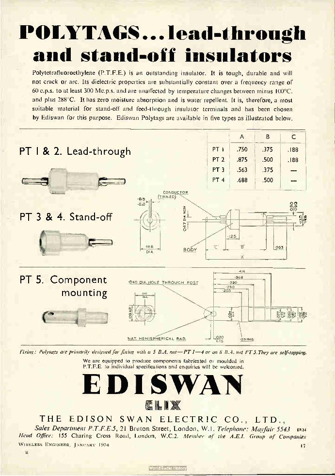
POLYTAGS ...lead-through and stand-off insulators Polytetrafluoroethylene (P.T.F.E.) is an outstanding insulator. It is tough, durable and will
not crack or arc. Its dielectric properties are substantially constant over a frequency range of
60 c.p.s. to at least 300 Mc.p.s. and are unaffected by temperature changes between minus 100°C.
and plus 288°C. It has zero moisture absorption and is water repellent. It is, therefore, a most
suitable material for stand-off and feed-through insulator terminals and has been chosen
by Ediswan for this purpose. Ediswan Polytags are available in five types as illustrated below.
A
PT I & 2. Lead-through
PT 3 & 4. Stand-off
DIA.
PT .750 .375 .188
PT 2 .875 • .500 .188
PT 3 .563 .375
PT 4 .688 .500
CO NDUCTOR (1-4vel gp)
00 c0
Pt.?
BODY
• 125
'C'
0 dt In 04
063
PT 5. Component mounting
•,040 DIA. HOLE THROUGH POST
NAT. HEMISPHERICAL RAD.
414
.368 •290
•250 .203
.020
o
031 RAD.
Fixing: Polytags are primarily designed for fixing with a 5 B.A. nut—PT 1-4 or an 8 B.A. nut PT 5. They are self-tapping,
We are equipped to produce components fabricated or moulded in P.T.F.E. to individual specifications and enquiries will be welcomed.
E D I SWAN III
THE EDISON SWAN ELECTRIC CO., LTD., Sales Department P.T.F.E.5, 21 Bruton Street, London, W.I. Telephone: Mayfair 5543 ER24
Head Office: 155 Charing Cross Road, London, W.C.2. Member of the Group of Companies
W IRELESS ENGINEER, JANUARY 1954 17

ADAMS BROS. & BURNLEY LTD.
PRESSINGS & FABRICATIONS
Elmgrove Road • Harrow • Middlesex
Telephone: Harrow 6411 (5 lines)
LAMINATIONS • MOTOR HOUSINGS • MICROPHONE COMPONENTS
BROOKES adiSedS
mean DEPENDABLE frequency control
• Illustrated above are Left: Type G2 Crystal Unit Frequency 50 kris.
Right: Type GI Crystal I ,,,r Frequency 100 A,'
Wpi BROOKES
ALL Brookes Crystals are made to
exacting standards and close tolerances.
They are available with a variety of bases and
in a wide range of frequencies. There is a
Brookes Crystal to suit your purpose— let us
have your enquiry now.
Brookes Crystals Ltd. Suppbers to Mmostry of Supply, Home , 8.8.0 etc.
EARLSWOOD STREET, LONDON, S.E.10
Telephone: GREenwich 1829
Grams: Xtals, Green, London. Cables: Xtals, London
The items illustrated show
only a few of the electrical components manufactured
by us for the electrical trade in our self-contained
factory. We manufacture
our own Press Tools; Fabrications, Spinnings,
Assemblies, and are able
to undertake all kinds of Metal Finishes.
Economically
produced with
Multi-tool set up
.10111111011111111111111111111111111111111111111111111111111111111111111111111111111111111111111111111M THE WORLD'S GREATEST BOOKSHOP EE
I :e1 1E5 _
• FOIL SOOK,S• = _ = = —
= Neer and necondhanit hooks on every subject. Large = :--". Technical dept. Stock of orer 3 'Wilton 1.01UPIMPN. 1::.
= 119-1U, CHARING CROSS ROAD, LONDON, W.C.2 Le- Gerrard 5660 5660 (16 lines) * Open 9-6 (inc. Sat.)
Company with tax loss
wanted to purchase.
Box 2474, do "Wireless -Engineer"
Technical Instructor (Broadcasting) required Ls, the Nigerian
Government an contract for two tows of 12-15 months. Possibilities
of permanency. Salary, etc., according to experience in scale £1,170
rising to £1,269 a year. Outfit allowance £60. Free passages for
officer and wife, and assistance towards cost of children's passages
or grant up to £150 annually for their maintenance in this country.
Liberar leave on full salary. Candidates must have been employed
at the B.B.C. Technical Training School at Evesham and have
reached Grade C Minus or above.
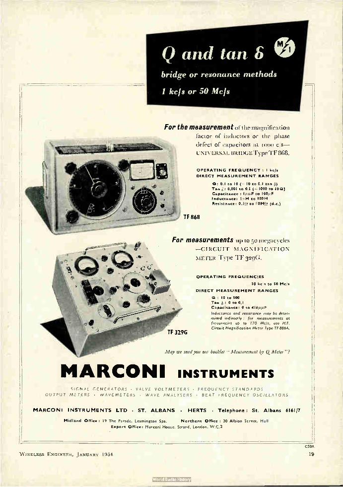
Q and tan S e bridge or resonance methods
1 kcjs or 50 Mcfs
For the measurement of the magnification factor of inductors or the phase
defect of capacitors at moo c/s—
t -NI VERSAL BRIDGE Type TF 868.
OPERATING FREQUENCY : I kcis
DIRECT MEASUREMENT RANGES
Q: 0.1 to 10 ( 10 to C.I tan 3)
Tan : 0.001 to 0.1 ( 1000 to 10Q)
Capacitance to I00, ,F
Inductance: I/ ,H to 100H
Resistance: 0.IU to 10M!! (d.c.)
TF 868
For measurements up to 50 megacycles — CIRCUIT MAGNIFICATION
METER Type TF 329G.
OPERATING FREQUENCIES
50 kc s to 50 Mc/s
DIRECT MEASUREMENT RANGES
Q : 10 to 500
Tan 0 to 0.1
Capacitance: 0 to 416,ttie
Inductance and resistance may be deter-
mined indirectly far measurements at
frequencies up to I 7CI Mc/s. use H.F.
Circuit Magnification Meter Type TF 886A.
May we send you our booklet " Measurement In. 0 Meter"?
MARCONI INSTRUMENTS SIGNAL GENERATORS • VALVE VOL TME TER S • FREQUL NC Y STANDARDS
OUTPUT METERS • WAVEMETERS • WAVE ANALYSERS • BEAT FREQUENCY OSCILLATORS
MARCONI INSTRUMENTS LTD • ST. ALBANS • HERTS • Telephone: St. Albans 6161 7
Midland Office 19 The Parade, Leamington Spa. Northern Office : 30 Albion Street, Hull
Export Office: Marconi House. Strand, London. W.C.2
W IRELESS ENGINEER, JANUARY 1904 C5OR
19

APPOINTMENTS—The engagement of persons answering these advertisements must be made through the local office of the Ministry of Labour and National Service, etc., if the applicant is a man aged 18-64 or a woman 18-59 inclusive, unless he or she or the employer is
excepted from the provisions of The Notification of Vacancies Order, 1951.
THE ENGLISH EI.ECTRIC CO. LTD., LUTON, vacancies for the following technical stall on an interest., • high priority defence project.
( I) SENIOR RADAR ENGINEERS Applicants should have a sound theoretical background and have had considerable experience in the operation, maintenance and modification of experimental radar systems in the field.—Ref. 1190A.
(2) ELECTRONIC TRIALS ENGINEERS Applicants should have experience of high frequency communication equipment and be prepared to accept responsibility for its installation and subsequent trial at locations in the U.K. other than Luton.—Ref. 456P.
(3) ELECTRONIC TRIALS ASSISTANTS Successful applicants will become members of trials teams under the leadership of Electronic Trials Engineers and will be required to assist in the installa-tion and subsequent trial of I-1.P. Communication equipment —Ref. 456R.
(4) ELECTRONIC LABORATORY ASSISTANTS Applicants should have experience of the preparation (from circuit diagrams) of information for the drawing office and production departments.—Ref. 10660.
(5) RADAR ASSISTANTS Applicants will be required to assist senior radar en-gineers in the operation, maintenance and modification of experimental radar systems in the field.—Ref.1190B.
(6) ELECTRONIC LABORATORY ASSISTANTS (TRIALS) Applicants should have experience of the preparation of radar equipment for field trials, for which a sound basic knowledge of radar circuitry is essential, and special knowledge of radar equipment A.A. No. 3 Mk. 7 would be an advantage.—Ref. 1066E.
Salaries are appropriate to the qualifications and experience necessary for the various positions which are permanent and progressive. A staff pension scheme operates and housing assistance will be provided for suitable applicants for posts (I). (2), (3) and (6). Applications to Dept. C.P.S., 336 7 Strand, W.C.2, and quoting appropriate Reference Number.
Applications are invited for a number of senior
positions in the Guided Weapon field. Posts arc
permanent and will be offered to suitable applicants
who have either at least five years experience in
industry or are Graduates with two or more years
experience.
Salaries will be commensurate with experience
and advancement will depend upon original con-
tribution and enthusiasm for the work.
The following positions are available:
(a) Physicist with experience in electronics.
(b) Circuit Engineer capable of original circuit
development and familiar with low fre-
quency circuit design and miniaturisation,
(c) Servo Engineer experienced in design and
development of light electrically controlled
servomechanism.
Apply Box AC8567I, Samson Clarks, 57/61
Mortimer Street, London, W.I
FERGUSON RADIO
CORPORATION LTD.
oilers exceptional opportunities to Draughtsmen wish-
ing to make their career in the world of electronics,
television and radio. Candidates preferably experi-
enced in the Radio and Television industries, must
have knowledge of mass-production methods and
workshop practice. Familiarity with Ministry require-
ments an advantage. Good Salaries; Pension scheme.
Well-equipped Drawing Offices and good working
conditions.
Apply: Employment Manager,
Ferguson Radio Corporation Ltd.
Great Cambridge Road. Enfield, Middlesex.
E. K. Cole. Ltd.. Southend-on-Sea, require for their development laboratories. Senior and Junior Engineers, Electronic Engineers, and a Nucleonic Physicist. Applicants should be experienced in the design and development of either R.F. side of television receivers, car radio or nucleonic instruments and should have degree or equivalent qualification. Apply stating age, qualifications and experience, to Personnel Manager.
RADAR ENGINEERS
NIARCONI'S WIRELESS TELEGRAPII co. LTD.. CHELMSFORD
have vacancies for:
TWO SENIOR ENGINEERS
to take charge of the development of eentimetric radar projects.
Specialist knowledge of radar transmitters and modulators or radar receivers and allied equipment is essential.
These are appointments of considerable responsibility carrying appropriate remuneration.
VACANCIES ALSO FOR:
DEVELOPMENT ENGINEERS
to assist in the design and development of radar transmission, reception and display equipment.
Applicants should have had some experience in all or part of this field.
Attractive salaries paid in these positions which offer excellent opportunities for advancement.
Write to Dept. C.P.S., 336/7 Strand, London, W.C.2 quoting reference number S.A .35.
21) I • '• • K. \h\ 1951
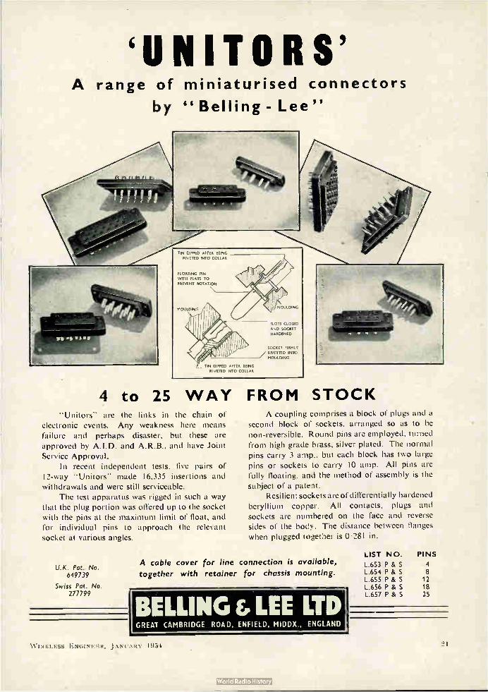
`UNITORS' A range of miniaturised connectors
by "Belling - Lee"
TIN DIPPED AFTER BEING RivETED INTO COLLAR
FLOATING PIN WITH FLATS TO
PREVENT ROTATION
MOULDING
4 to 25 WAY FROM STOCK
TIN DIPPED AFTER BEING RI, UN", INTO COLLAR
"Unitors" are the links in the chain of electronic events. Any weakness here means failure and perhaps disaster, but these are approved by A.I.D. and A.R.B., and have Joint Service Approval.
In recent independent tests, five pairs of I2-way "Unitors" made 16,335 insertions and withdrawals and were still serviceable.
The test apparatus was rigged in such a way that thé plug portion was offered up to the socket with the pins at the maximum limit of float, and for individual pins to approach the relevant socket at various angles.
U.K. Pat. No. 649739
Swiss Pot. No. 277799
MOULDING
SLOTS CLOSED
AND SOCKET HARDENED
SOCKET FIRMLY
RIVETTED INTO MOULDING
A coupling comprises a block of plugs and a second block of sockets, arranged so as to be non-reversible. Round pins are employed, turned
from high grade brass, silver plated. The normal pins carry 3 amp., but each block has two large pins or sockets to carry 10 amp. All pins are fully floating, and the method of assembly is the subject of a patent.
Resilient sockets are of differentially hardened beryllium copper. All contacts, plugs and
sockets are numbered on the face and reverse sides of the body. The distance between flanges
when plugged together is 0.281 in.
A cable cover for line connection is available,
together with retainer for chassis mounting.
BELLING &LEE LTD GREAT CAMBRIDGE ROAD. ENFIELD, MIDDX., ENGLAND
LIST NO. PINS
L.653 P & S 4 L.654 P & S 8 L.655 P & S 12 L.656 P & S 18 L.657 P & S 25
W IRELESS ENGINEER, .1 ANCARY 1954
Physicists and Development Engineers required for Research and Development work on Cold Cathode Tubes.
Apelicants should preferably hold a degree in physics or engineer-ing, or the equivalent, and have had at least two years' experience on Gas Discharge Tubes. Salary range £600 to £1.000 depending on qualifications and experience. Write giving full details to the Personnel Officer, Ericsson TelePhOnes, Ltd., Beeston. Nottingham. (Reference LE/).)
University Graduates in Electrical Engineering, Physics or Chemistry, are offered employment in the Capacitor LaboratorY of a large firm of communications engineers in East London. Previous experience is not wessary and the field covered Includes fundamental work on Dielectrics and Capacitor design. Con-sideration will be given to non-University Graduates who are eligible as Graduates of the Institution of Electrical Engineers. Applications should be addressed to the Personnel Department, Standard Telephones & Cables, Ltd., North Woolwich,London,E.16
Electronic Engineers are required by The English Electric Co.. Ltd., Luton, for work on a high priority defence project. Applicants will be required to undertake the engineering of circuitry already developed, which involves close liaison with, and the progressing of work through, the drawing office and production department. Applicants with experience of the engineering of radar and;or aircraft electronics for production will be especially welcome. The Posts are permanent and progressive and a staff pension scheme is in operation. Applications to Dept. C.P.S., 336/7 Strand, W.C.2, quoting ref. 1211.
Research Assistant required, to work on Speech Studies and
Psycho-Acoustics. Applicant, who should have some experience
in research and have knowledge of electric circuits, will be able to
work for his Ph.D. degree. Salary £400 p.a. Applications should
be addressed to Dr. E. C. Cherry, Imperial College, South Kensing-
ton, S.W.7.
Ericsson Telephones. Ltd.. have a number of vacancies in their Research Laboratories in connection with Electronic Switching and Computing. The posts will carry starting salaries between £600 and £1,000 according to age and experience.
(a) Electronic circuit designers of all grades. Applicants should
have a degree, or equivalent, and several years' experience In the design of electronic circuits. (Reference LE/1.)
(b) Electronic equipment engineers with experience in the layout and mechanical design of electronic instruments and equip-ment in the radio, radar or communication fields. They will be required to co-operate with the circuit designers in the early stages and may ultimately be responsible for develop-ment to the production stage. (Reference LE/2.)
Applicants, who should be British born and between 25 and 35 Years of age, should write, quoting the reference above and giving details of age, experience, academic or other training, and required starting salary, to the Personnel Officer, Ericsson Telephones, ¡Id.. Beeston, Nottingham.
Senior Microwave Engineers arc required by The English Electric
Co., Ltd., at Luton, for work on a high priority defence project.
Applicants should have a good theoretical background to degree
standard and experience of design or engineering of microwave
equipment for development work on aerial and receiving systems.
This work includes investigations of new methods of construction
with a view to miniaturization and weight reduction, the design of
new components and engineering to the production stage. Success-
ful applicants will be required to take charge of a group and to be
responsible for one or more aspects of the system. The Pests arc
permanent and progressive and a staff pension scheme is in operation.
Applications to Dept. C.P.S., 336/7 Strand, W.C.2. quoting ref.
1160B.
Qualified Mechanical Engineer required, age not over 35, with some knowledge of radio and electrical engineering and with an aptitude for experimental work to act as second in charge of newly formed Development Department at a factory in the West Midlands. The maximum salary for this post is £1,100 per annum and the starting salary will be calculated according to the tinalifications and experience of the successful applicant. Box 24). c,o Engineer.
EXPERIENCED RADIO TESTERS AND INSPECTORS
Required for production of communication and radio apparatus.
Also instrument makers. wirers and assemblers for factory test
apparatus. Apply Personnel Manager, E. K. Cole, Ltd., Eke.,
Works, Malmesbury, Wilts.
G.E.C. Stanmore Laboratories urgently require an Engineer oi
Physicist to investigate novel wave guide techniques. Candidates
should have practical experience and good theoretical knciwledge in
this field. Applications should be made in writing to the Staff
Manager (Ref. WE, RCM). The Grove. Stanmore Common. Stan-
more, Middx., stating age, qualifications and experience,
Macleans. Ltd.. Great West Road, Brentford, Middx., have a vacancy for a qualified mechanical or electrical engineer, preferably' Degree or Higher National Certificate, with electronic experience. Applicant must have experience of plant operation and factory engineering allied to electronic control of processes. Post offer, excellent opportunity to man with progressive outlook. Age 30 to 40. Pension and Profit Participation Scheme. Salary dependent upon experience and qualifications. Write giving fullest details of age, qualifications and experience and salary required, to the Per-sonnel Manager.
The G.E.C. Stanmore Laboratories invite applications for the following vacancies for work on guided missile research. canteen facilities, sick fund and pension scheme. Holidays a average.
i. Senior Graduate with 1st or 2nd class Honours Degree or equivalent qualifications required to work on the planning and assessment of complex trials on airborne radar. Previous experience in radar work highly desirable. (Ref. WE; LMKB.1).
ii. Graduate aged about 30 with good degree or equivalent quali-fications required for responsible work on technical flight trials of airborne radar. Previous experience of similar work and of
flying is very desirable. There is also a junior post vacant for a man with similar qualifications. Both these posts together with (i) above involve some travelling within the United Kingdom. (Ref. WE, EMKB.2).
Applications should be made in writing to the Staff Manager, G.E.C. Stanmorc Laboratories. The Grove, Stanmorc Common. Stanmorc, Middx., stating age, qualifications and experience ;Ind quoting the appropriate reference.
MARCONI INSTRUMENT CO., LTD.
ST. ALBANS
Vacancies exist for both Senior and Junior Electronic
Engineers with this well-known Company. The vacancies.
which arise from an expansion of the Company's business,
cover a large field. Applications are particularly welcomed from
young Graduate Engineers who have had some industrial
experience. For the junior vacancies the minimum technical
qualifications required is the City and Guilds Final Certificaie
in telecommunications. The posts arc both pensionable and
permanent.
Applications, which will be treated with the strictest confidence.
should be sent to Dept. C.P.S., 336/7 Strand. London, W.C.2.
Quoting Ref. No. S.A.34A.
W IRELESS ENGINEER, j AN Li ARV 1954

Grinding Mullard 'Ticonal' permanent magnets to required size.
MAGNETIC MATERIALS Extensive research and manufacturing facilities have established Mullard as the leading producers of magnetic materials. They were the first, for example, to introduce Ferroxcube, the world's most efficient magnetic ferrite; Ticonal' anisotropic permanent magnets, renowned for their high
stability and high energy output; and Magnadur, an entirely new type of permanent magnet with the insulating properties of a ceramic. The wealth of experience gained from these developments is
available to all users of magnetic materials through the Mullard advisory service. An enquiry to the address below will put a team of specialised engineers at your disposal.
' TICONAL ' PERMANENT MAGNETS • MAGNADUR (Formerly Ferroxdure)
PERMANENT MAGNETS • FERROXCUBE MAGNETIC CORE MATERIAL
111ULLARD I PD.. 1..,”1”,,NLN I IIJVISION , CLN II XV I OIS V, ,̀P AI- 1 SBI kV AVI-NUE, LONDON, W.C.2.
W IRELESS ENGINEER, JANUARY 1954 23

MUREX 6SINCOMAXe MAGNETS ARE USED IN
INSTRUMENTS
The high magnetic stability and
strength of 'Sincomax' magnets
makes a robust job even of a
sensitive Microammeter. In this
application as in many others
Murex Sintered Magnets con-
tinue to give accurate and
reliable service.
Photograph by me tesy cf E.I.C. (H Il ngton) Glaseow
MUREX LIMITED (Powder Metallurgy Division) RAIN HAM • ESSEX • Rainham, Essex 3322
London Sales Office: Central House, Upper Woburn Place, W.C.I. Euston 8265
POLYTHENE
H. F. EQUIPMENT Harvey Electronics
Limited
announce their new
BULK ERASER Trade
for 1" Magnetic Tape. Ideal for quick e ninqvuiitreides
cleaning of all j" standard tape enabling each recording to commence with an absolutely clean tape. Send for pcmphlet and full details from: PRICE Clo. 15s.
HARVEY ELECTRONICS LTD., 273, FARNBOROUGH ROAD, FARNBOROUGH, HANTS.
Tel.: Farnborough 1120 LONDON Office: 59. Union Street S.E.1. Tel HOP 4567
PAGE
Adams Bros. & Burnley. Ltd.. 18 Advance Components, Ltd. 11 Aimee, Ltd. 12 Amplex Appliances (Kent) Ltd 24 Appointments 18, 20, 99
Belling & Lee, Ltd. 21 British Insulated Callender's Cables, Ltd. 9 British Physical Laboratories 8 "Brookes Crystals, Ltd. 18 Hullers, Ltd. Cover ii
Edison Swan Electric Co., Ltd., The 17
Ferranti, Ltd 3 Foyle, W. & G, Ltd 18
(AMBYTHENE BRAND)
ENQUIRIES INVITED FOR
SPECIAL MOULDINGS OF
COMPONENTS
AMPLEX APPLIANCES (KENT) LTD. 19 DARTMOUTH ROAD, HAYES, BROMLEY, KENT.
(RAVensbourne 5531)
All export enquiries to
ANTEX LTD., 3 TOWER HILL, LONDON, E.C.3
Index to Advertisers
PAGE
Griffiths, Gilbart, Lloyd & Co., Ltd. 12
Harvey Electronics, Ltd 24 Hunt, A. H. (Capacitors), Ltd. Lover iv
Lyons, Claude, Ltd 1
Marconi Instruments, Ltd 19 McGraw-Hill Publishing Co., Ltd 6 McMurdo Instrument Co., Ltd. 4 Muirhead & Co., Ltd. 4 Mullard, Ltd. 16, 23 Murex, Ltd 24
emak
Rubber 13onders, Ltd.
Salford Electrical Instruments, Ltd 6 Standard Telephones & Cables, Ltd. 5 Sullivan, H. W., Ltd 14
Telegraph Condenser Co, Ltd., The Cover iii Telephone Mfg. Co., Ltd. 13
Unbrako Socket Screw Co., Ltd. 10 United Insulator Co., Ltd 8
Oxley Developments Co., Ltd 12 Wayne Kerr Laboratories, Ltd., The
Printed in Great Briiain for the Publishers, Biffe & Sons. Ltd., Dorset House. Stamford Street, London, S.E.1, at The Baynard Press by Sanders Phillips & Co., Ltd., Chryssell Road. London, S.W.9.
2:1 W IRELESS ENGINEER, JANUARY 1954
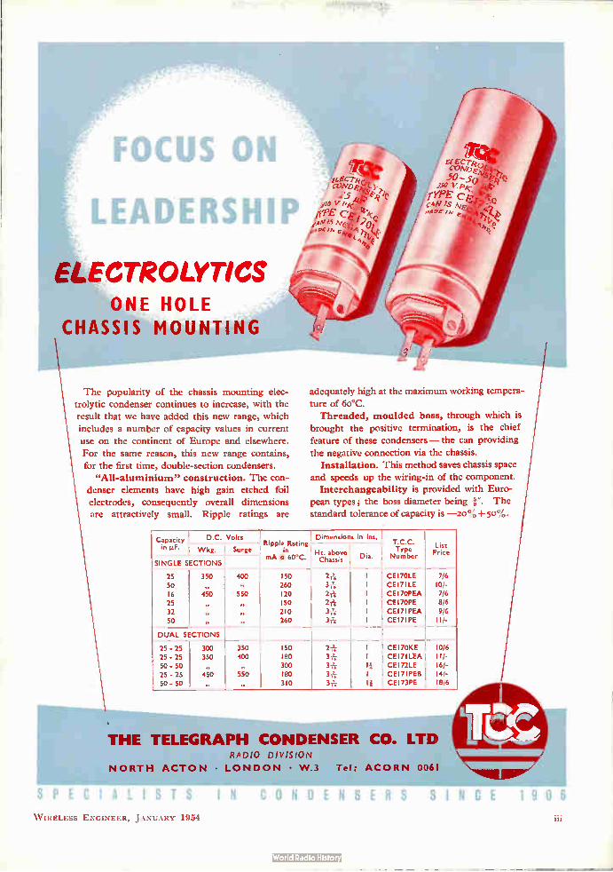
gell3:ityrilfgliçe
FOCUS ON
LEADERShae
ELECTROLYTICS ONE HOLE
CHASSIS MOUNTING
The popularity of the chassis mounting elec-trolytic condenser continues to increase, with the result that we have added this new range, which includes a number of capacity values in current
use on the continent of Europe and elsewhere. For the same reason, this new range contains,
for the first time, double-section condensers. "All-aluminium" construction. The con-
denser elements have high gain etched foil electrodes, consequently overall dimensions are attractively small. Ripple ratings are
etcri, f (CND e:
25 j10
PPE
,ntjtis\Ez.
,voe
/ a EC Tie COA7 LE 50-5
250
'TYPE C c4N N .,4De
adequately high at the maximum working tempera-ture of 60°C. Threaded, moulded boss, through which is
brought the positive termination, is the chief
feature of these condensers — the can providing the negative connection via the chassis.
Installation. This method saves chassis space and speeds up the wiring-in of the component.
Interchangeability is provided with Euro-pean types; the boss diameter being r. The standard tolerance of capacity is —20% +5o%.
Capacity
in Pf•
D.C. Volts 1 Ripple Raung
n
mA ,/ 60 C.
I 50 260 I 20 150 210 260
Dimensions
El 'haabs:isve
2-4 3izi 2* 217,. 3-1g 3*
in Ins. T.C.C. TYPa
Number
List Price Wkg. Surge
Dia. SINGLE SECTIONS
400
..
550 ,
99
,. 1
25 50 16 25 32 50
350
Re
450 9*
99
,.
I I I I I I
CE I 70LE CE17ILE CEI7OPEA CEI7OPE CE171PEA CE17IPE
7/6 10/-7/6 8/6 9/6 11/-
DUAL SECTIONS
25 - 25 300 350 150 21} I CE170KE 10/6
25 - 25 350 400 I 80 3* I CE17 1 LEA 1 U-
50 - 50 300 3it II CE I72LE 16/-
25 - 25 450 550 180 3-A; I CE171PE8 14/-50 - 50 310 3 T' 1 i CE I 73PE 18/6
THE TELEGRAPH CONDENSER CO. LTD RADIO DIVISION
NORTH ACTON • LONDON • W.3 Tel: ACORN 0061
SPECIALIST_
W IRELESS ENGINEER, JANUARY 1951
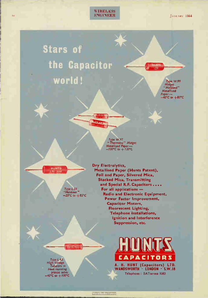
WIRELESS ENGINEER JANUARY 1954
Type L.51 "Moldseal" —25°C to +85°C
Type L.43 High Voltage
Tubulars in Heat resisting
plastic tubes —40°C to -- I00°C
Type W.99 Midget "Moldseal"
Metallised Paper--40°C to +85°C
"Thermetic" Midget • 41111111111 . Type W.97
Metallised Paper--100°C to + I20°C
Dry Electrolytics,
Metallised Paper (Hunts Patent),
Foil and Paper, Silvered Mica,
Stacked Mica, Transmitting
and Special R.F. Capacitors ....
For all applications —
Radio and Electronic Equipment,
Power Factor Improvement,
Capacitor Motors,
Fluorescent Lighting,
Telephone Installations,
Ignition and Interference
Suppression, etc.
,11111r,k, CAPACITORS
A. H. HUNT (Capacitors) LTD. WANDSWORTH • LONDON • S.W.I8
Telephone : BATtersea 1083
Copyright © 2022 FDOKUMEN