Radio resource allocation in fixed broadband wireless networks
Upload
khangminh22Category
view
0download
0
WIRELESS ENGINEER
DECEMBER 1956
Vol. 33 No. 12 • THREE SHILLINGS AND SIXPENCE
101

Regd Trade Mark
AM COVERAGE
5-220 Mcis in 8 ranges. CVV or 400 cis sine/square wave modulation. Accuracy 1%. Provision for spot frequency calibration.
FM COVERAGE
65-120 Mc/s. Accuracy 1%. Maximum deviation 150 Kc/s.
Sole Proprietors and Manufacturers
WIDE BAND
SIGNAL GENERATOR Type T.F.M.
The design of this new Wide Band Signal Generator,
operating throughout on fundamentals, is the out-come of considerable research and development work to meet the stringent requirements imposed by new fre-
quency modulation and commercial television stations.
Fully descriptive
brochure available on request
OUTPUT
Minimum (about ittV) to 100
mV continuously variable with decade multiplier. Force output
250 mV.
OUTPUT IMPEDANCE
80f2. 2000, balanced 80f.1 and 300i2, isolated unbalanced 80i2.
OPERATING VOLTAGES
100-120V, 200-260V. 50-60 cis
A.C. mains.
LIST PRICE
The frequency bands have been chosen in such a manner as to ensure maximum con-venience when servicing and aligning T.V. and F.M. receivers.
Provision has been made for spot R.F. frequency calibra-tion.
Facilities are provided to ensure adequate discrimina-tion throughout the very wide frequency band covered by the instrument.
Sine and square wave audio frequency modulation pro-vided.
The instrument is fitted with an R.F. carrier level meter.
A double-ratio slow-motion mechanism, together with interpolation dial, enables the instrument to be set with a high degree of accuracy. On the F.M. range an internal phasing control enables the modulating signal to be applied to the X-plates of an oscillograph to produce a picture of a discriminator response curve.
DIMENSIONS
151 x 104 x 10 in. approx. with lid closed.
£89 WEIGHT: 16 lb. approx.
AUTOMATIC COIL WINDER E, ELECTRICAL EQUIPMENT CO LTD
AVOCET HOUSE • 92-96 VAUXHALL BRIDGE ROAD LONDON • S.W.I
Telephone: VICtorin 3404 (9 lines)
W IRELESS ENGINEER, DECEMBER 1956
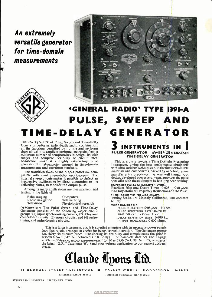
An extremely versatile generator
for time-domain measurements
'GENERAL RADIO' TYPE 139I-A
PULSE, SWEEP AND
TIME-DELAY GENERATOR The new Type 1391-A Pulse, Sweep and Time-Delay Generator performs, individually and in combination, all the functions described by its title and performs them all well; its excellent performance results from a minimum number of compromises in design. Its wide ranges and complete flexibility of circuit inter-connection make it a highly satisfactory pulse generator for laboratories engaged in time-domain measurements and waveform synthesis.
The transition times of the output pulses are com-patible with most present-day oscilloscopes. The internal sweep circuit makes it possible to. deflect an inexpensive oscilloscope by direct connection to the deflecting plates, to monitor the output pulse.
Among its many applications are measurement and testing in the fields of:
Echo ranging Computers Radio navigation Telemetering Television Physiological research
DESCRIPTION The Pulse, Sweep and Time-Delay Generator consists of the following major circuit groups: (1) input synchronizing circuits, (2) delay and coincidence circuits, (3) sweep circuits, and (4) pulse-timing and pulse-forming circuits.
3 INSTRUMENTS IN I PULSE GENERATOR SWEEP GENERATOR
TIME-DELAY GENERATOR
This is truly a complete Time-Domain Measuring Instrument, giving the best performance obtainable with ultra-modern techniques plus the finest obtainable materials and components, backed by over forty years manufacturing experience. A very well thought-out design, developed over several years, provides the pulse specialist with the equipment he has long been seeking. SUPERIOR PULSE CHARACTERISTICS: Excellent Rise and Decay Times: 0-025 ± 0-01 esec. No Duty-Ratio or Frequency Restrictions on the Pulse. HIGH BASIC TIMING ACCURACY: Timing Scales are Linearly Calibrated, and accurate to 1 3/4 . WIDE RANGES OF:
PULSE DURATION: 0-05 SCC.
PULSE REPETITION RATE: 0-250 kc. TIME DELAY: I ¡sec—l1 SCC.
DELAY REPETITION RATE: 0400 i(C.
OUTPUT IMPEDANCE: 0-600 ohms.
This is a large instrument, and it is supplied complete with its necessary power supply (not illustrated), arranged at choice for bench or rack operation. The Generator proper has thirty-six vacuum tubes. Considering its flexibility and completeness the price is reasonable—£1,047 net delivered (U.K. only). For complete data see the 13-page article in "GENERAL RADIO EXPERIMENTER" for May 1956 (Vol. 30, No. 12), or request the latest "G.R." Catalogue '0'. Send your written application to our nearest address, please.
elautie tents 76 OLDHALL STREET LIVERPOOL • VALLEY WORKS • HODDESDON
Telephone: Central 4641 2 Telephone: Hoddesdon 3007 (4 line.)
W IRELESS ENGINEER, DECEMBER 1956
HERTS
A

°le) ------ RADIO SERVICE ENGINEER
Valuable aids to the
120 PAGE POCKET BOOKLET
1911 Valves Mt,
1: 120 page pocket-size booklet gives summarised data i.e. characteristics, operating conditions, base diagrams relating to Ferranti valves and cathode ray tubes. Included also is a comprehen-sive valve equivalents list. Free copy supplied on request.
7elevlsion Tubes Iike
TECHNICAL
HANDBOOK
This Handbook contains the fullest
information about all types of Ferranti valves
and cathode ray tubes. Complete data such
as physical details, base connections, ratings,
operating conditions, etc. Price 7/6.
Send now for both publications to:—
[RIM TI LTD
Tit H\tt H t‘DrI9OK
IAIMS ky•
Ci> HOOF FR\
GEM MILL • CHADDEMTON • OLDHAM • LANCASHIRE
London Office: KERN HOUSE, 36 KINGSVVAY, W.C.2.
FEI63
9 W IRELESS ENGINEER, DECEMBER 1956
ei/4'eY , •,,7,,,Y,, / ee),-)„,:e
/
7,1 ' f '5' ,e 'fi4 ›. ii'/' >X'
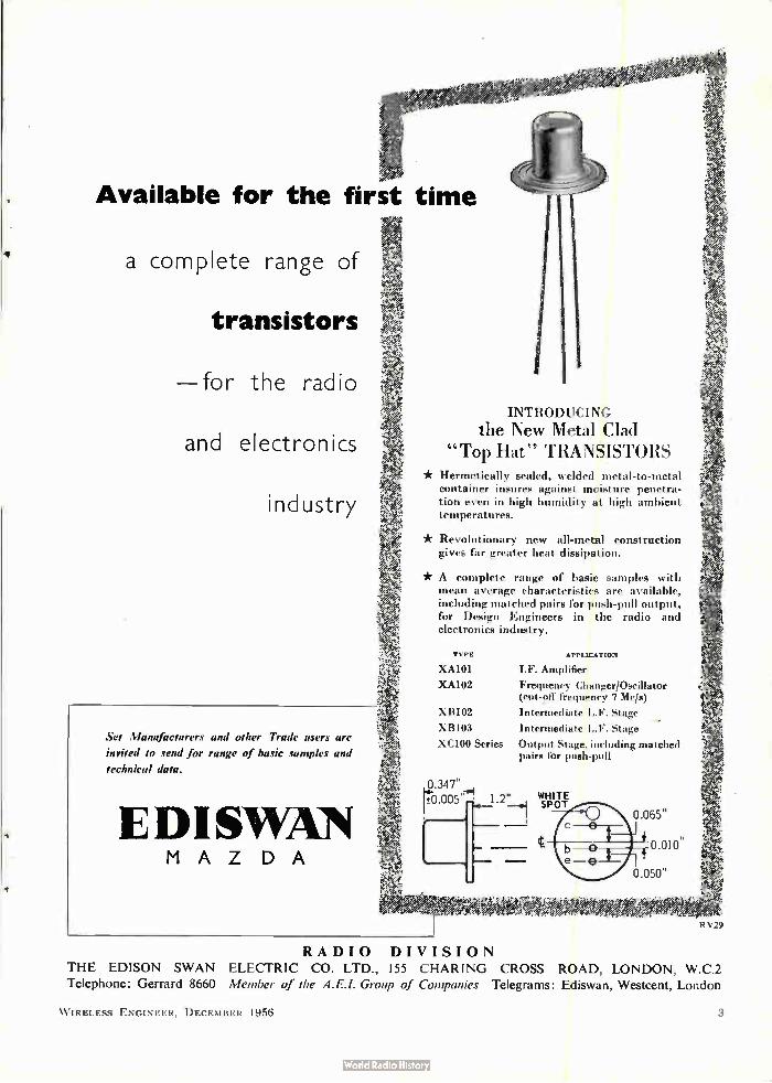
Available for the first time
a complete range of
transistors
—for the radio
and electronics
industry
Set Manufacturers and other Trade users are
invited to send for range of basic samples and
technical data.
EDISWIN MAZDA
:e
INTRODUCING
the New Metal Clad "Top Hat" TRANSISTORS
* Hermetically sealed, welded metal-to-metal container insures against moisture penetra-tion even in high humidity at high ambient temperatures.
* Revolutionary new all-metal construction gives far greater heat dissipation.
* A complete range of basic samples with mean average characteristics are available, including matched pairs for gush-pull output, for Design Engineers in the radio and electronics industry.
TYPE APPLICATION
XA101 I.F. Amplifier
XA102 Frequency Changer/Oscillator (cut-off frequency 7 Mc/s)
XBIO2 Intermediate L.F. Stage
XB103 Intermediate L.F. Stage -
XC100 Series Output Stage, including matched pairs for push-pull
0.347" rei ±0.005,
we-7 'e4e.
.2.. WHITE —11 SPOT
•
*e. ,fe eee
0.050"
WeeedeeeeeeeeeWeek 4;e4:4'4.g • ee" edeeee • e'4 ' RV29
RADIO DIVISION
THE EDISON SWAN ELECTRIC CO. LTD., 155 CHARING CROSS ROAD, LONDON, W.C.2
Telephone: Gerrard 8660 Member of the A.E.I. Group of Companies Telegrams: Ediswan, Westcent, London
WIRELESS ENGINEER, DECEMBER 1956 3

1
for radio
ceramics
I
r4rii
STEATITE & PORCELAIN PRODUCTS LTD. Stourport-on-Severn, Worcestershire. Telephone : Stourport Ill. Telegrams : Steatain, Stourport SP88
4 W IRELESS ENGINEER, DECEMBER 1956

h ,Qopc Reafh-erode
amplifiers TYPE: 5A/170K Heater Voltage: 6.3 V Nominal Current: 0.3 A Mutual Conductance: 16.5 mA/V Input Capacitance: 7.9+0.6 pF Output Capacitance: 2.9±0.4 pF Max. Direct Anode Voltage: 210 V Max. Direct Anode Dissipation: 3.3 Max. Direct Screen Voltage: 175 V Max. Direct Screen Dissipation: 0.9 Max. Direct Cathode Current: 25 mA
The 5A/170K is a beam power tetrode of small physical size developed to meet the demand for a wide-band amplifier valve operating at high frequencies. With a very high figure of merit and almost twice the gain/bandwidth product of conventional high gain pentodes, the 5A/170K is designed for use in any application where a wide-band amplifier is required e.g. radio links, carrier telephony, etc. It is economical on heater power and possesses a remarkably low equivalent noise resistance which is improved even further when the valve is triode connected. To ensure good electrical contact under all conditions the valve pins are gold plated, and both the design and rigid control of manufacturing processes combine to make a very high quality valve with a long and trouble-free life.
Standard Telephones and Cables Limited VALVE AND TRANSISTOR SALES DEPARTMENT
efl CONNAUGHT HOUSE • 63 ALDWYCH • LONDON W.C.2.
WIRELESS ENGINEER, DECEMBER 1956 5

THE A2293 is a new low impedance triode
particularly suitable as the series valve in
stabilised power packs. List price 27/-.
For further details write to the G.E.C. Valve & Electronics Dept.
GENERAL ELECTRIC CO. LTD., MAGNET HOUSE, KINGSWAY, LONDON.
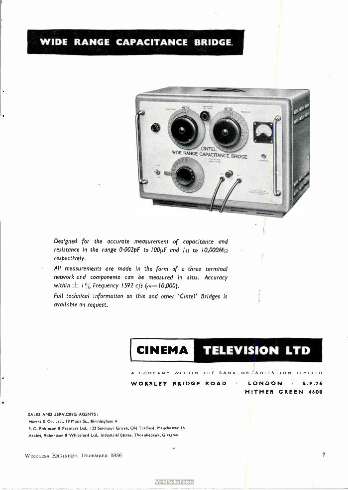
WIDE RANGE CAPACITANCE BRIDGE.
CINTEL WIDE RANGE CAPACITANCE BRIDGE
Designed for the accurate measurement of capacitance and
resistance in the range 0.002pF to 100.t.F and le to 10,000Ale
respectively.
All measurements are made in the form of a three terminal
network and components can be measured in situ. Accuracy
within ± 1% Frequency 1592 cls (a)=-10,000).
Full technical information on this and other `Cintel' Bridges is
available on request.
CINEMA TELEVISION LTD
A COMPANY WITHIN THE RANK ORGANISATION LIMITED
WORSLEY BRIDGE ROAD LONDON S.E.26
HITHER GREEN 4600
SALES AND SERVICING AGENTS:
Hawnt & Co. Ltd.. 59 Moor St., Birmingham 4
F. C. Robinson & Partners Ltd., 122 Seymour Grove, Old Trafford, Manchester 16
Atkins, Robertson & Whiteford Ltd.. Industrial Estate, Thornliebank, Glasgow
W IRELESS ENGINEER, DECEMBER 1956
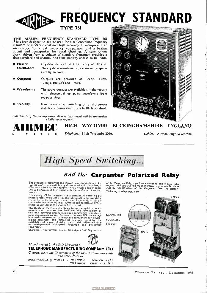
FREQUENCY STANDARD TYPE 761
THE AIRMEC FREQUENCY STANDARD TYPE 761 I has been designed to fill the need for a self-contained frequency standard of moderate cost and high accuracy. It incorporates an oscilloscope for visual frequency comparison, and a beating circuit and loudspeaker for aural checking. A synchronous clock, driven from a voltage of standard frequency provides a time standard and enables long time stability checks to be made.
• Master Oscillator:
• Outputs:
• Waveform:
• Stability:
Crystal-controlled at a frequency of 100 kc/s. The crystal is maintained at a constant tempera-ture by an oven.
Outputs are provided at 100 c/s, I kc/s, 10 kc/s, 100 kc/s and I Mc/s.
The above outputs are available simultaneously with sinsusoidal or pulse waveforms from separate plugs.
Four hours after switching on a short-term stability of better than I part in 106 is obtained.
Full details of this or any other Airmec instrument will be forwarded gladly upon request.
HIGH WYCOMBE
•IMITED Telephone: High Wycombe 2060.
BUCKINGHAMSHIRE ENGLAND
High Speed Switch
Cables: Airmec, High Wycombe
um/ /he Carpenter Polarized Relay
The problem of preserving the correct time relationships in the operation of remote switches by short-duration dc. impulses. is effectively solved by the Carpenter Relay which is highly sensi-tive and operates at high speed with the minimum of contact bounce.
It is equally efficient whether it is a question of operating the switch directly by closing a mechanical contact in the energizing circuit (as in the simpler remote control systems), or by the consecutive operation of many relays in complicated electronic switching units (as in the latest radar systems).
The ability of the Carpenter Relay to operate quickly on ex-tremely short impulses has facilitated the development of electronic counting circuits (analogue computors) requiring a rapid change-over contact for comparing two different voltage levels—the construction of electronic stimulators for physio-logical treatment and biological research, requiring the availability of several electrical pulses with adjustable time relationships—and high-speed Telegraph and Teleprinter equipment.
Therefore, if your project involves High-Speed Switching, details
Manufactured by the Sole Licensees:
TELEPHONE MANUFACTURING COMPANY LTD Contractors to the Government of the British Commonwealth
and other Nations HOLLINGSWORTH WORKS . DULWICH . LONDON S.E.21
TELEPHONE : GIPSY HILL 2111
of the Carpenter Relay's pert ormance cannot fail to be of value to you ; and you will find much to interest you in our Brochure F35 16, "Applications of the Carpenter Polarized Relay".
Write us, or telephone, now.
CARPENTER
POLARIZED
RELAYS
8 WIRELESS ENGINEER, DECEMBER 1956

Photographs of <Eclipse' magnets are reproduced by courtesy of the manufacturers James Neill & Com-pany (Sheffield) Limited.
The remarkable efficiency of these 'Eclipse' magnets is due to their composite construction, using
'Araldite' to bond the component parts. The manufacturers of these magnets state that they use 'Araldite'
because it enables them to produce shapes and sizes otherwise impracticable, to ensure that the magnets
cannot be taken apart and to avoid bolted assemblies. 'Araldite' provides a bond which is truly permanent,
and its strength is proved by the fact that facing and boring operations and also grinding are carried out
after bonding.
'Araldite' epoxy resins llave a remarkable range of characteristics and uses.
They are used
* for bonding metals, porcelain, glass etc.
* for casting high grade solid insulation.
* for impregnating, potting or sealing electrical windings and components.
'Araldite'
* for producing glass fibre laminates.
* for producing patterns, models, jigs and tools.
* as fillers for sheet metal work.
* as protective coatings for metal, wood and ceramic surfaces.
epoxy resins Araldite' is a registered trade name
Aero Research Limited A Ciba Company • Duxford • Cambridge • Telephone: Sawston 2121 AP. 264-190
11:L.1.1 1.:NC.I NI I I: 1)1 1 \11 .,1 I: 1951i 9
whatever the aerial
liter er s (1
BICC CELLULAR POLYTHENE
TIV DOWNLEAD
BICC make television dowrleads to meet every requirement.
Publication No. 357, giving full details of our
up-to-date range of cellular polythene types, is available
on request.
BRITISH INSULATED CALLENDER'S CABLES LIMITED
21 BLOOMSBURY STREET, LONDON, W.C.I.
\ ESS HN(iINEER, I )I.:CENI It 1956
•4
r4
11,\q1.1 1.111:\1,111 ‘\11 1111,
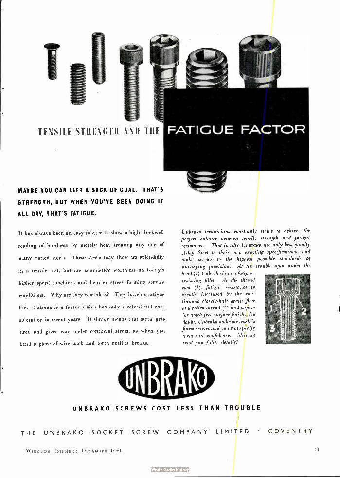
MAYBE YOU CAN LIFT A SACK OF COAL, THAT S
STRENGTH, BUT WHEN YOU'VE BEEN DOING IT
ALL DAY, THAT'S FATIGUE.
It has always been an easy matter to show a high Rockwell
reading of hardness by merely heat treating any one of
many varied steels. These steels may show up splendidly
in a tensile test, but are completely worthless on today's
higher speed machines and heavier stress forming service
conditions. Why are they worthless? They have no fatigue
life. Fatigue is a factor which has only received full con-
sideration in recent years. It simply means that metal gets
tired and gives way under continual stress, as when you
bend a piece of wire back and forth until it breaks.
linbrako technicians constantly strive to achieve the
perfect balance between tensile strength and fatigue resistance. That is why Unbraki, use only best quality
Alloy Steel to their own exacting specifications, and
make screws to the highest possible standards of
unvarying precision. At the trouble spot under the
head (1) Unbrako have a fatigue-resisting fillet. At the thread
root (3), fatigue resistance is
greatly increased by the con-
tinuous closely-knit grain flow
and rolled thread (2) and super-ior notch -free surface finish. No
doubt, L7 nbrako make the world's
finest screws and you can sprcify
them with confidence. May we send you fuller details?
UNBRAKO SCREWS COST LESS THAN TROUBLE
THE UNBRAKO SOCKET SCREW COMPANY LIMITED • COVENTRY
WIRELESS ENGINEER, DECEIIIIER 195(i

rConsistency of Performance
ur3ELIIK.In 13"Tr" fflUE"_Él..1V1
Sweltering in superheated steam may be some people's way of achieving
perfection—Welwyn find this method ideal for ensuring it. For to test
their hermetic sealing, Welmet metal film resistors undergo a Turkish Bath treatment
in a pressure of two atmospheres. A drastic test indeed, but it proves beyond all doubt
whether the vital gold-platinum alloy element is effectively protected. And it's
part and parcel of the quality control that Welwyn practise
with all their products.
ouy. MANUFACTURERS OF
W ELWYN ELECTRICAL COMPONENTS
PROPERTIES OF THE WELMET INCLUDE:
A load stability of 0.1"„
No resistance change under tropical conditions
A rating of I watt at 70 C
A range of values from 0000 to I Mt/
Selection tolerances of ± I 0/), ±2% and
The maximum voltage is defined only by the dissipation
WELWYN ELECTRICAL LABORATORIES LTD • BEDLINGTON • NORTHUMBERLAND
On Admiralty, Ministry of Supply (A.I.D. approved) and Post Office Lists
W IRELESS ENGINEER, DECEMBER 1956
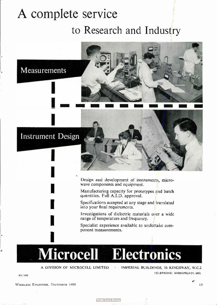
A complete service to Research and Industry
Design and development of instruments, micro-wave components and equipment.
Manufacturing capacity for prototypes and batch quantities. Full A.I.D. approval.
Specifications accepted at any stage and translated into your final requirements.
Investigations of dielectric materials over a wide range of temperature and frequency.
Specialist experience available to undertake com-ponent measurements.
Nlicrocell Electronics A DIVISION OF MICROCELL LIMITED • IMPERIAL BUILDINGS, 56 KINGSWAY, W.C.2
TELEPHONE: BISHOPSGATE 6801 2811C 7899
W IRELESS ENGINEER, DECEMBER 1956 13
P. B. COW & CO. LTD. RUBBER MANUFACTURING SPECIALISTS FOR EVERY INDUSTRY. INDUSTRIAL DIVISION: .470 STREATHAM HIGH RD. S.W.1 6. TEL. POL 44111
rot a rode
smoofh response curve
You need a PHILIPS dual-cone
loudspeaker s (Made in Holland)
CCEILEI
LI&
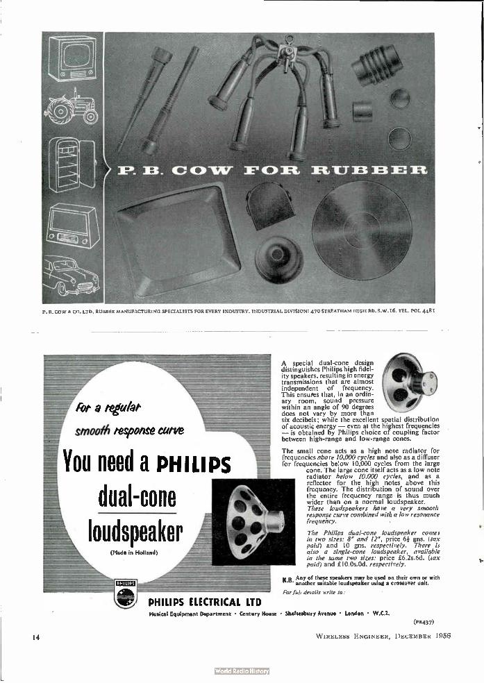
A special dual-cone design distinguishes Philips high fidel-ity speakers, resulting in energy transmissions that are almost independent of frequency. This ensures that, in an ordin-ary room, sound pressure within an angle of 90 degrees does not vary by more than six decibels; while the excellent spatial distribution of acoustic energy — even at the highest frequencies — is obtained by Philips choice of coupling factor between high-range and low-range cones.
The small cone acts as a high note radiator for frequencies above 10,000 cycles and also as a diffuser for frequencies be!ow 10,000 cycles from the large
cone. The large cone itself acts as a low note radiator below 10,000 cycles, and as a reflector for the high notes above this frequency. The distribution of sound over the entire frequency range is thus much wider than on a normal loudspeaker. These loudspeakers have a very smooth response curve combined with a low resonance frequency.
The Philips dual-cone loudspeaker comes in two sizes: 8 and 12, price 6¡ gns. (tax paid) and 10 gns. respectively. There is also a single-cone loudspeaker, available in the same two sizes: price £6.2s.6d. (lax paid) and £10.0s.0d. respectively.
y .p . Any of these speakers may be used on their own or with " another suitable loudspeaker using a crossover unit.
r, Tub details It rile to:
PHILIPS ELECTRICAL LTD Musical Equipment Department • Century House • Shaftesbury Avenue • London • W.C.2.
(FR437)
W IRELESS ENGINEER, DECEMBER 1956 14
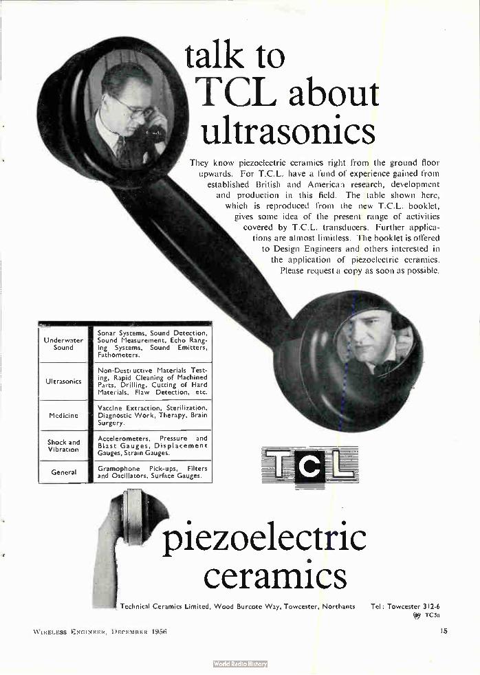
talk to TCL about ultrasonics
They know piezoelectric ceramics right from the ground floor upwards. For T.C.L. have a fund of experience gained from
established British and American research, development and production in this field. The table shown here,
which is reproduced from the new T.C.L. booklet, gives some idea of the present range of activities
covered by T.C.L. transducers. Further applica-tions are almost limitless. The booklet is offered
to Design Engineers and others interested in the application of piezoelectric ceramics.
Please request a copy as soon as possible.
Underwater Sound
Sonar Systems, Sound Detection, Sound Measurement, Echo Rang-ing Systems, Sound Emitters, Fathometers.
ultrasonics
Non-Destructive Materials Test-ing, Rapid Cleaning of Machined Parts, Drilling, Cutting of Hard Materials, Flaw Detection, etc.
Medicine Vaccine Extraction, Sterilization, Diagnostic Work, Therapy, Brain Surgery.
Shock and Vibration
Accelerometers, Pressure and Blast Gauges, Displacement Gauges, Strain Gauges.
General kb
Gramophone Pick-ups, Filters and Oscillators, Surface Gauges. ,--,
'4* pezoelectri i c •
ceramics Technical Ceramics Limited, Wood Burcote Way, Towcester, Northants Tel: Towcester 312-6
I"C 5a
\\ I I< ELESS ENGINEER, DECEMBER 1956 I 5
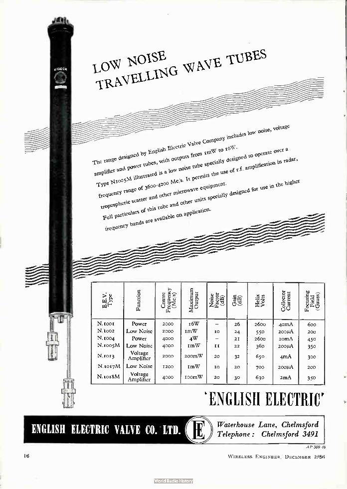
rTRANELLIG AVE TUBES LO OIS
he range deY Eish c 'Valve Company includes low noise, voltage
m ifie w with outPuts ftorn Ile to iegi •
Type Nroo5M. illustrated is a low noie tube specially designed to operate over a
T signed b ngl lectr
frequency range of 36o0-42oo Mc s. It permits the use of t.f. amplification
aplr and poer tubes, in radar,
Full particulars of this tube and other units specially designed for use in the 1-ligher tropospheric scatter and other microwave equipment.
frequencY ds are available on applicatio ban n.
41' 300 10
Function
Cent
re
Frequency
(Mc, s)
Maximum
Output
-- z He
lix
Volt
s
I
Coll
ecto
r Cu
rren
t
Focusing
Fiel
d (Gauss)
N . 1 o o 1 N.1002
N.1004
N. too5M
N. to r 3
N. to t 7M
N.tot8M
Power
Low Noise
Power
Low Noise
Voltage Amplifier
Low Noise
Vo Voltage Amplifier
2000
2000
4000 4000
2000
1200
4000
I6W
rmW
4W ImW
200MW
IMW
toomW
—
to
—
t t
20
IO
20
26
24
2 I
22
32
20
30
2600
550 2600
360
650
700
630
4omA
2001.1A
20MA
2001.IA
4mA
200IIA
2MA
600
200
450 350
300
200
350
'ENGLISH ELECTRIC'
16 W IRELESS ENGINEER, DECEMBER 1956
WIRELESS ENGINEER
The Journal of Radio Research and Progress
ESTABLISHED 1923
Managing Editor: HUGH S. POCOCK, M.1.E.E. Editor: W. T. COCKING, M.I.E.E.
Technical Consultant: Professor G. W. O. HOWE, D.Sc., LL.D., M.I.E.E., Hon.M.Brit.I.R.E.
Editorial Advisory Board:
H. M. BARLOW, B.Sc.(Eng.), Ph.D.(Science), M.I.E.E., M.I.Mech.E. (Pender Professor of Electrical Engineering, University College, London); E. B. MOULLIN, M.A., Sc.D., M.I.E.E. (Professor of Electrical Engineering, University of Cambridge) ; A. H. MUMFORD, 0.B.E., B.Sc.(Eng.), M.I.E.E. (G.P.O. Engineering Department); A. R. A. RENDALL, Ph.D., B.Sc., M.I.E.E. (British Broadcasting Corporation);
R. L. SMITH-ROSE, C.B.E., D.Sc., Ph.D., M.I.E.E. (Department of Scientific and Industrial Research)
Volume 33 Number 12
CONTENTS DECEMBER 1956
Free Oscillations in Simple Distributed Circuits
by A. B. Hillan, M.Eng. 279
Nyquist's Stability Criterion
by E. A. Freeman, B.Sc. and J. F. Meredith, B.S( 290
N-Terminal Networks
by A. Bloch, Dr.-Ing., M.Sc. .. 295
Correspondence 301
New Books 301
Standard-Frequency Transmissions 302
Abstracts and References. Nos. 3599-3902 A.263-A.284
Index to Articles and Authors. Vol. 33, January to December 1956
Published on the fifth of each month Annual Subscription: Home and overseas £2 9s. Od.; Canada and U.S.A. $7.50
(Including Annual Index to Abstracts and References)
Published by Biffe & Sons Ltd.
Editorial, Advertising and Publishing Offices: Dorset House, Stamford Street, London, S.E.1
Telephone: Waterloo 3333 (60 lines) • Telegrams: Wirenger, Sedist, London
BRANCH OFFICES AT BIRMINGHAM • MANCHESTER AND GLASGOW
RATING UP TO 2 kW
FREQUENCY RANGE . . . . 2 1(c/s to 2 Mc/s
H.F. POWER TRANSFORMERS
H.F. power transformers of outstanding effi-
ciency are the latest additions to the Mullard
range of high quality components designed
around Ferroxcube magnetic cores.
Utilising the unique characteristics of Ferrox-
cube to the full, Mullard H.F. transformers are
smaller, lighter, and less costly than trans-
formers using alternative core material s. These
advantages are particularly marked in trans-
formers required to handle powers of up to 2kW, between the frequency range 2kc/s to 2Mc/s.
Mullard transformers are already finding wide
-use in applications as diverse as ill trasonic H.F.
power generators and aircraft power packs
operating from an aircraft's normal A.C. sup-
ply. In the latter application, the low leakage
field of Ferroxcube can eliminate the need for external screening, thereby reducing the size
and weight of the transformer even further.
As with all Mullard high quality components,
these H.F. power transformers are designed and
built to engineers' individual specifications.
Write now for details of the complete range of components available under this service.
Mullard Ticonal' permanent magnets
Magnadur ceramic magnets
Ferroxcube magnetic cores
M ULLARD LTD • COMPONENTS DIVISION • M ULLARD HOUSE • TORRINGTON PLACE • WC I
MCIA
18 W IRELESS ENGINEER, DECEMBER 1956
WIRELESS ENGINEER
Vol. 33 DECEMBER 1956 No. 12
FREE OSCILLATIONS IN SIMPLE DISTRIBUTED CIRCUITS
By A. B. HiIlan, M.Eng., A.M.I.E.E. (The Atomic Weapons Research Establishment, Aldermaston)
SUMMARY.—The paper deals with the calculation of waveforms which occur when a progressive wave in a transmission line impinges on a terminating circuit. The method of calculation is used to determine the waveforms occurring in certain simple distributed circuits when in free oscillation.
1. Introduction
MUCH contemporary work involves the study and measurement of phenomena occurring in circuits containing dis-
tributed elements. It is clear that a knowledge of the behaviour of simple distributed circuits is a prerequisite for such work. The object of this paper is to outline the basic principles governing the behaviour of uniform transmission lines and to illustrate their application by the study of the behaviour of some distributed circuits when in free oscillation.
In the general sense, a distributed circuit may be taken to mean any circuit in which transit times cannot be neglected. In a lumped or point circuit an analysis can be carried out on the assumption that the effect of a voltage or current impressed in any branch of the circuit will be felt instantaneously in all other branches, without introducing errors greater than a required maximum. When this assumption introduces excessive errors, the transit times of the effects must be considered and the circuit is then regarded as being distributed. Aerial systems and transmission lines are examples of such circuits, but it will be realized that, under certain condi-tions, other circuit elements such as valves must be included.
In this paper, attention will be confined to the study of a linear passive distributed circuit con-sisting of a finite length of uniform transmission line terminated at each end by a simple point
MS accepted by the Editor, June 1956
W IRELESS ENGINEER, DECEM BER 1956
circuit. If such a network is driven at some point by a sinusoidal source, the voltage and current everywhere are sinusoidal and can be readily reproduced at any point by substituting an appropriate lumped circuit. This similarity in behaviour of lumped and distributed circuits when in forced sinusoidal oscillation is due simply to the property of sinusoids that the sum of any number of sinusoids of the same frequency is sinusoidal, regardless of the phase relations of component waves. If the driving waveform is other than sinusoidal no such correspondence in behaviour results. The fundamental differences between lumped
and distributed circuits are well illustrated by considering free oscillations in the systems. As is well known, a simple lossless lumped circuit of inductance and capacitance, when in free oscilla-tion, produces sinusoidal voltage and current waveforms, independently of how the energy was initially stored in the circuit. A corresponding form of simple lossless distributed circuit when in free oscillation produces more complicated waveforms dependent on the manner of storage of energy initially. The calculation of waveforms in such a circuit is the basic problem considered, but the method used is applicable to more complicated circuits.
Attention is given to two basic forms of dis-tributed circuit, to be referred to as circuits A and B. These are: Circuit A: A uniform lossless transmission line
with a pure inductance at one end and an open-circuit at the other.
279
Circuit B: A uniform lossless transmission line with a pure capacitance at one end and a short-circuit at the other.
As the behaviour of the circuits is affected by the manner of storage of the energy initially, a further distinction will be made as follows:— Case I: Energy initially stored in the lumped-
circuit component (i.e., inductance for circuit A and capacitance for circuit B).
Case II: Energy initially stored in the dis-tributed-circuit element (i.e., the transmission line).
Finally, the effect of circuit losses introduced by the insertion of resistances will be given for certain simple cases. The extension of the method of analysis to deal with more complicated circuits is discussed briefly.
Before proceeding to the first analysis a brief résumé of the properties of transmission lines relevant to the problems considered will be given.
21 Vo
41
i1";
vo
152
1-54
A
IR2
IRS
4, 2
Iwo
DISTANCE
TIME
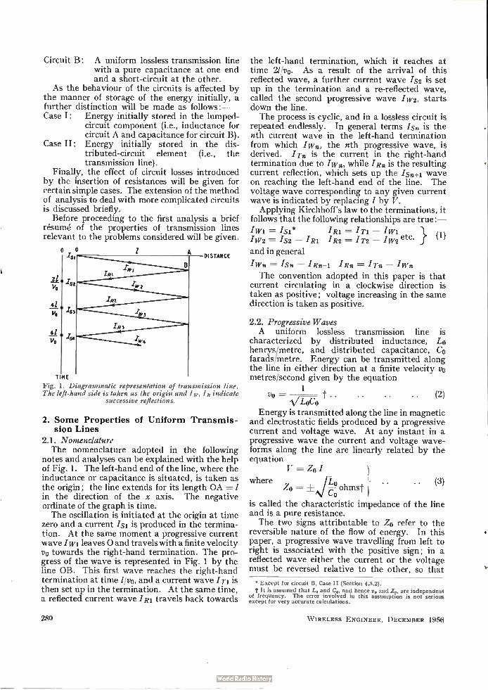
Fig. . Diagrammatic representation of transmission line. The left-hand side is taken as the origin and Ia., I R indicate
successive reflections.
2. Some Properties of Uniform Transmis-sion Lines
2.1. Nomenclature The nomenclature adopted in the following
notes and analyses can be explained with the help of Fig. 1. The left-hand end of the line, where the inductance or capacitance is situated, is taken as the origin; the line extends for its length OA = in the direction of the x axis. The negative ordinate of the graph is time. The oscillation is initiated at the origin at time
zero and a current /si is produced in the termina-tion. At the same moment a progressive current wave /wi leaves 0 and travels with a finite velocity vo towards the right-hand termination. The pro-gress of the wave is represented in Fig. 1 by the line OB. This first wave reaches the right-hand termination at time //vo, and a current wave 'Ti is then set up in the termination. At the same time, a reflected current wave Ini travels back towards
280
the left-hand termination, which it reaches at time 2//vo. As a result of the arrival of this reflected wave, a further current wave Is2 is set up in the termination and a re-reflected wave, called the second progressive wave /w2, starts down the line. The process is cyclic, and in a lossless circuit is
repeated endlessly. In general terms /so is the nth current wave in the left-hand termination from which /wo, the nth progressive wave, is derived. I Tn is the current in the right-hand termination due to /wo, while /Ro is the resulting current reflection, which sets up the iso-o. wave on reaching the left-hand end of the line. The voltage wave corresponding to any given current wave is indicated by replacing / by V.
Applying Kirchhoff's law to the terminations, it follows that the following relationships are true:—
/wi = = —
IW2 = — 'Ri I R2 = 1T2 — . TW2 etc. (1)
and in general
/wo = /so — /Ro-i 'Rn = I Tn — IWn
The convention adopted in this paper is that current circulating in a clockwise direction is taken as positive; voltage increasing in the same direction is taken as positive.
2.2. Progressive Waves A uniform lossless transmission line is
characterized by distributed inductance, Lo henrys/metre, and distributed capacitance, Co farads/metre. Energy can be transmitted along the line in either direction at a finite velocity vo metres/second given by the equation
1
Vo t • • VLOCO
.. (2)
Energy is transmitted along the line in magnetic and electrostatic fields produced by a progressive current and voltage wave. At any instant in a progressive wave the current and voltage wave-forms along the line are linearly related by the equation
V = Zo I
where ZO = ohmst ) • •
Co Ln • • (3)
is called the characteristic impedance of the line and is a pure resistance. The two signs attributable to Zo refer to the
reversible nature of the flow of energy. In this paper, a progressive wave travelling from left to right is associated with the positive sign; in a reflected wave either the current or the voltage must be reversed relative to the other, so that
• Except for circuit B, Case II (Section 4.3.2).
t It is assumed that L,, and C., and hence u. and Z„, are independent of frequency. The error involved in this assumption is not serious except for very accurate calculations.
W IRELESS ENGINEER, DECEMBER 1956
•
the negative sign applies. Thus Vw. = Zo. /w.
(4) and VR. =H Zo). 'Rn }
2.3. Reflection When the line is absorbing power from a source,
it accepts energy at the same rate as would a physical resistance + 4. This energy is propagated along the line at the appropriate rate and delivered to the termination. Hence at the termination the line acts as a source of energy having an internal impedance of Zo ohms. Now consider the effect of an open-circuit
termination: it cannot accept power and, hence, all the incident energy must be reflected. This means that the reflected wave must be equal in magnitude to the incident wave. For an incident current wave /w., the incident voltage wave is Vw. = Zo./wa. Since the termination is unable to support a current wave, the current in the reflected wave must reverse; i.e.,
'Rn — IWts • • (5) The voltage in the reflected wave is then
VR. = (— 4)./Rn = VRn. = VWn (6) Thus the voltage wave is reflected without reversal of sign and so the voltage at the termina-tion is
VT. -- VWn + V Rn = 2VWn
2.4. Thévenin's Theorem It can now be seen that at the above termina
tion the line behaves as a source of power having an internal impedance Zo and open-circuit voltage 2Vw., Vwn being the voltage in the wave arriving at the termination. The waveforms in any termination can be determined by applying Thévenin's theorem and deriving the equivalent circuit shown in Fig. 2. The use of this equivalent circuit enables /T., and hence all other wave-forms, to be calculated. The same considera-tions apply to the cal-culation of Is2, 1.S3, etc., from the reflected waves returning to the left-hand end.
vra
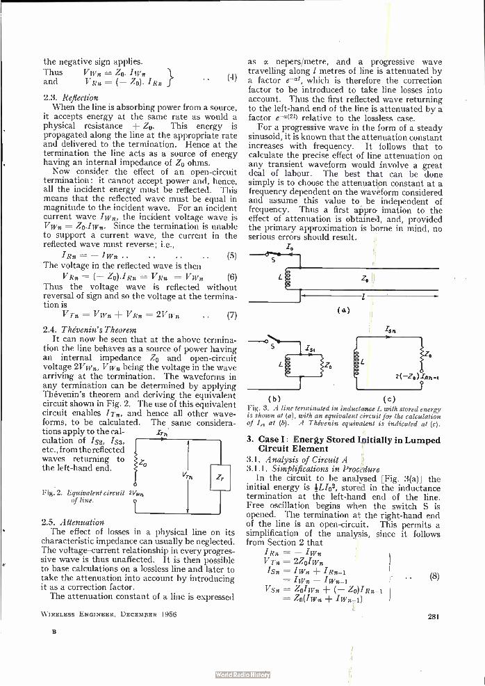
Fig. 2. Equivalent circuit 2V,v„ of line.
• (7)
2.5. Attenuation The effect of losses in a physical line on its
characteristic impedance can usually be neglected. The voltage-current relationship in every progres-sive wave is thus unaffected. It is then possible to base calculations on a lossless line and later to take the attenuation into account. by introducing it as a correction factor. The attenuation constant of a line is expressed
W IRELESS ENGINEER, DECEMBER 1956
as a nepers/metre, and a progressive wave travelling along 1 metres of line is attenuated by a factor e-ca, which is therefore the correction factor to be introduced to take line losses into account. Thus the first reflected wave returning to the left-hand end of the line is attenuated by a factor e-ct( 21) relative to the lossless case. For a progressive wave in the form of a steady
sinusoid, it is known that the attenuation constant increases with frequency. It follows that to calculate the precise effect of line attenuation on any transient waveform would involve a great deal of labour. The best that can be done simply is to choose the attenuation constant at a frequency dependent on the waveform considered and assume this value to be independent of frequency. Thus a first approximation to the effect of attenuation is obtained, and, provided the primary approximation is borne in mind, no serious errors should result.
/,,
o
o o
(a.)
( b ) ( c )
Fig. 3. A line terminated in inductance L with stored energy is shown at (a), with an equivalent circuit for the calculation of I„ at (b). A Thévenin equivalent is indicated at (c).
3. Case I: Energy Stored Initially in Lumped Circuit Element
3.1. Analysis of Circuit A 3.1.1. Simplifications in Procedure
In the circuit to be analysed [Fig. 3(a)] the initial energy is 4L/02, stored in the inductance termination at the left-hand end of the line. Free oscillation begins when the switch S is opened. The termination at the right-hand end of the line is an open-circuit. This permits a simplification of the analysis, since it follows from Section 2 that
Rn = — IWn
V Tn = 24IWn
'Sn = IWn ± 'Rn-1 = IWn —
V sn = ZoIWn ZO)IRn-1
= Zo(IWn IWn-1)
(8)
281
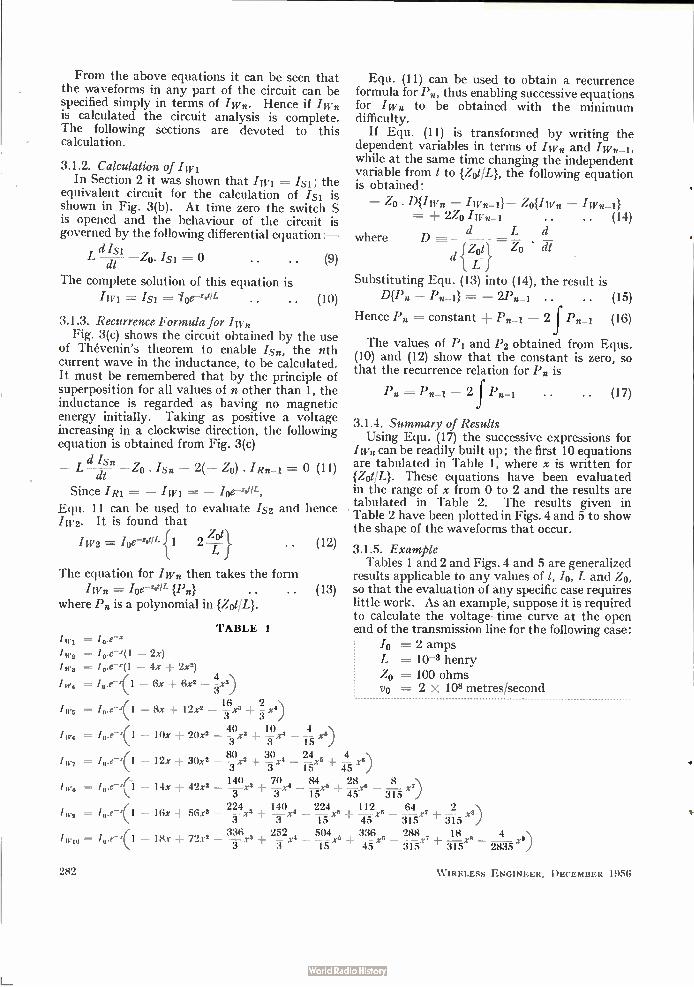
From the above equations it can be seen that the waveforms in any part of the circuit can be specified simply in terms of /wn. Hence if /wn is calculated the circuit analysis is complete. The following sections are devoted to this calculation.
3.1.2. Calculation of /14,1 In Section 2 it was shown that /wi = 'si; the
equivalent circuit for the calculation of /si is shown in Fig. 3(b). At time zero the switch S is opened and the behaviour of the circuit is governed by the following differential equation :—
L dIsi z,o. = 0 (9) dt
The complete solution of this equation is
/wi = /si = /oe-zotiL .. (10)
3.1.3. Recurrence Formula for Iw. Fig. 3(c) shows the circuit obtained by the use
of Thévenin's theorem to enable 'Sn, the nth current wave in the inductance, to be calculated. It must be remembered that by the principle of superposition for all values of n other than 1, the inductance is regarded as having no magnetic energy initially. Taking as positive a voltage increasing in a clockwise direction, the following equation is obtained from Fig. 3(c)
Ld Isn Zo. Is. - 2(- Zo) . I Rn_i = 0 (11) dt
Since II?' = -IWi = - Ine-2JIL
Equ. 11 can be used to evaluate IS2 Iw2. It is found that
/w2 = /0e-hig• - 2
The equation for Iwn then takes the form /wn = Ioe-zelL {P.}
where P. is a polynomial in {Zot/L}.
1„,,
.1 W2
I er,
/w,
TABLE 1
= I o.e-.(1 - 2x) = I 0.e-2(1 - 4x ± 2x2)
=- 10.e-(1 - 6x ± 6x2 -1x.)
= 10.e-<1 - 8x 12x6 — L36x3 x4)
40 10 /0.e--"( 1 — 10x + 20x2 — - x s xi — -14-5 e)
3
= /„.e-.(1 — 12x + 30x6
= /o — 14x + 42x6
10.e-<1 - 16x -1 56x6
/w ,„ =- 10.e- - 18x 72x6
282
and hence
(12)
where
Equ. (11) can be used to obtain a recurrence formula for P., thus enabling successive equations for IWn to be obtained with the minimum difficulty.
If Equ. (11) is transformed by writing the dependent variables in terms of /wn and /wn-1, while at the same time changing the independent variable from t to {Zot/L}, the following equation is obtained:
- Z0 . D{/wn - iwn-i}- 4{/wn - iwn-i} = 24 /wn_i • • .. (14)
d L d D =
Z • cW
Substituting Equ. (13) into (14), the result is D{P. - = - 2P (15)
Hence P. = constant + Pn_i - 2 f Pr,' (16)
The values of Pi and P2 obtained from Equs. (10) and (12) show that the constant is zero, so that the recurrence relation for P. is
Pn = P n-1 - 2f P n-1 .. (17)
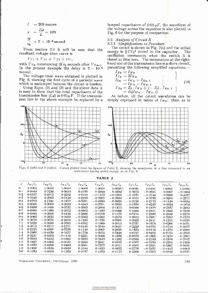
3.1.4. Summary of Results Using Equ. (17) the successive expressions for
/wn can be readily built up; the first 10 equations are tabulated in Table 1, where x is written for {Zot/L}. These equations have been evaluated in the range of x from 0 to 2 and the results are tabulated in Table 2. The results given in Table 2 have been plotted in Figs. 4 and 5 to show the shape of the waveforms that occur.
3.1.5. Example Tables 1 and 2 and Figs. 4 and 5 are generalized
results applicable to any values of 1, lo, L and 4, (13) so that the evaluation of any specific case requires
little work. As an example, suppose it is required to calculate the voltage-time curve at the open end of the transmission line for the following case:
2 amps L = 10-3 henry Zo 100 ohms vo = 2 x 10⁸ metres/second
80 30 24 — —3 x6 + s x's — 15 - x6 + -4- x6)
45
140 3 3 70 84 28 8 ) x + s -x4 — —x6 + --x6 — — x7 15 45 315
224x6 i 140x4 224 112 e 64 + 321 5 x8) 3 3 15 x5 4- 45 x — 315x7 336 3 252 4 504, 5 336 6 288 7 _t_ 18 xe 4 ,te
1- X 3 x 3 15 Y 1 45 x 3 r5x ' 315 2835 )
W IRELESS ENGINEER, DECEMBER 1956
1
21 Vo
= 200 metres
= -Zot = lost
= 2 x 10⁻⁶ second
From Section 2.1 it will be seen that the resultant voltage-time curve is
V VT2 VT3 + etc.,
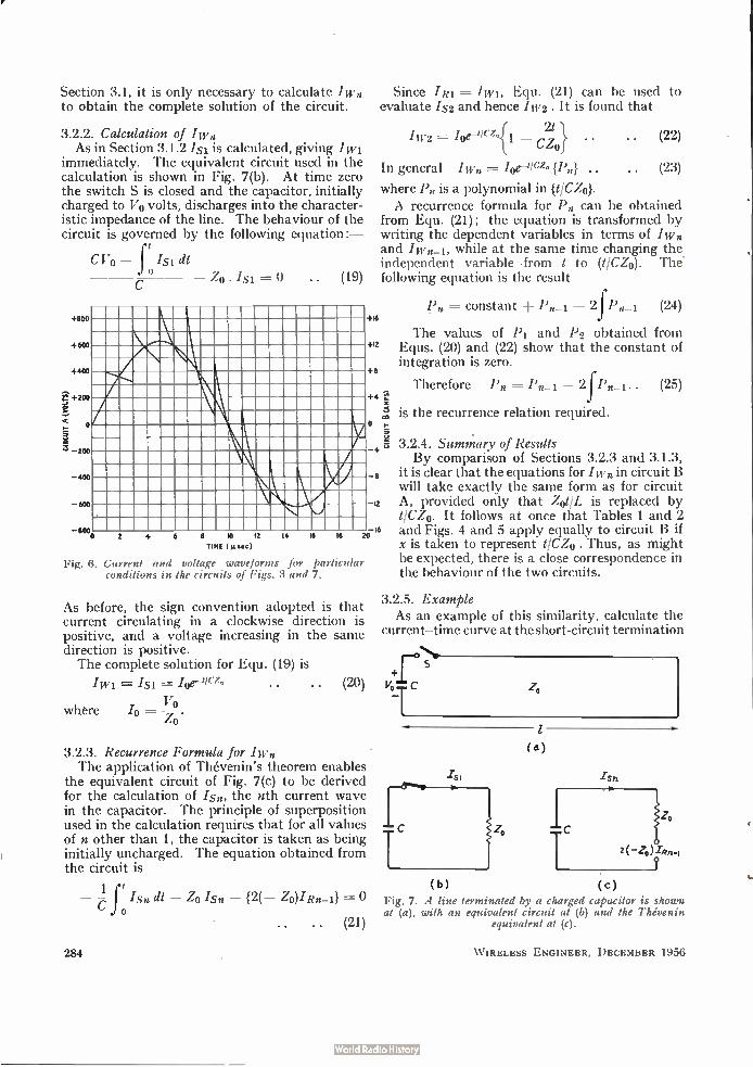
with VTn commencing 2//v0 seconds after Vin-i• In the present example the delay is 2 x 10⁻⁶ 'second. The voltage-time wave obtained is plotted in
Fig. 6, showing the first cycle of a periodic wave which is undamped because the circuit is lossless.
Using Equs. (2) and (3) and the above data it is easy to show that the total capacitance of the transmission line (Col) is 0-01µ F. If the transmis-sion line in the above example be replaced by a
+1.0
+05
lo
o
¡W4
lumped capacitance of 0.01 µF, the waveform of the voltage across the capacitor is also plotted in Fig. 6 for the purpose of comparison.
3.2. Analysis of Circuit B 3.2.1. Simplifications in Procedure The circuit is shown in Fig. 74> and the initial
energy is C1702 stored in the capacitor. The oscillation commences when the switch S is closed at time zero. The termination at the right-hand end of the transmission line is a short-circuit, permitting the following simplified equations:-
Rn = IWn ITn =21Wn
= 'Rn-! IWn IWn-1
VSn = Zo • IWn (- Zo) • 'Rn-1 -= Zo(Iwn, -
As before, all the circuit waveforms can be simply expressed in terms of Iwn; thus, as in
+1.0
+0.5
ro
o
eso es io is 20 -(150 05 I 0 X
Figs. 4 (left) and 5 (right). Curves plotted from the figures of Table 2, showing the waveforms inductance having stored energy, as in Fig. 3.
TABLE 2
in a line
(18)
connected to an
X 1;1,2110 I w311, 1w41.1, 1w5110 1w7110 ler8110 Tw,110 1w1011, 0 1-0000 1-0000 1-0000 1.0000 1.0000 1-0000 1 1.0000 1-0000- 1-0000 1-0 000 0-1 0-9048 0-7238 0-5610 0.4150 0.2848 0-1692 0.0672 -0.0221 -0.0997 -0l664 0-2 0-8187 0-4912 0-2292 0.0240 -0-1323 -02468 -03257 -0.3748 -0.3989 -0.4027 0.3 0-7046 0.2963 -00148 -02l93 -0.3397 -O•3953 -04021 -0.3735 -0.3204 -0.2517 0.4 0.6703 0.1341 -0.1877 -0-3251 -0.4050 -0.3826 -03128 -02173 -0-1120 -00084 0-5 0-6065 0-0000 -0.3033 -04043 -03791 -0•2830 -0-1558 -00245 0-0934 0.1878 0-6 0-5488 -0.1098 -0-3732 -0-3995 -0.2994 -0.1475 0-0086 0-1410 0.2357 0.2883 0.7 0.4966 -0.1986 -0.4072 -0.3562 -0.1933 -0-0088 0.1469 0.2511 0.2983 0-2938 0.8 0-4493 -0.2696 -04l34 -0-2888 -0.0798 0-1129 0.2434 0.2996 0-2888 0.2279 0-9 0-4066 -0-3253 -03985 -0-2082 0-0282 0.2072 0-2942 0.2931 0-2263 0-1219 1.0 0.3679 -0.3679 -0-3679 -0-1226 0.1226 0.2698 0.3025 0-2441 0-1320 0-0030 1•1 0.3329 -0-3995 -0.3262 -0.0392 0.1989 0-3010 0-2757 0.1674 0.0266 -0.1051 1.2 0.3012 -0.4217 -0•2771 0-0410 0.2549 0-3037 0.2229 0-0772 -0-0734 -0.1877 1.3 0.2725 -0.4360 -0-2235 0.1119 0.2907 0.2826 0.1533 -0-0144 -0-1570 -0-2399 1-4 0.2466 -0.4439 -0-1677 0.1729 0.3074 0.2428 0-0757 -0.09-79 -0.2154 -0.2528 1.5 0.2231 -0.4462 -0.1116 0-2231 0-3068 0.1896 -0-0028 -0-1665 -02474 -02367 1-6 0.2019 -04442 -0•0565 0-2622 0-2915 0.1282 -0-0769 -02i93 -0.2576 -0.2002 1.7 0-1827 -0-4385 -0-0037 0-2904 0-2641 0.0635 -0.1397 -0•2459 -02394 -0.1356 1-8 0.1653 -0-4298 0.0463 0.3081 0.2272 -0.0011 -01907 -0.2551 -0l967 -0.0660 1-9 0.1496 -04189 0-0928 0-3164 0-1835 -0-0622 -0.2276 -0.2457 -0.1442 0.0093 2.0 0.1353 -0-4059 0.1353 0.3157 0.1353 -0-1173 -0-2496 -0•2203 -0.0846 0.0737
W IRELESS ENGINEER, DECEMBER 1956 283
Section 3.1, it is only necessary to calculate /wn to obtain the complete solution of the circuit.
3.2.2. Calculation of Iwo As in Section 3.1.2 Is is calculated, giving /wi
immediately. The equivalent circuit used in the calculation is shown in Fig. 7(b). At time zero the switch S is closed and the capacitor, initially charged to Vo volts, discharges into the character-istic impedance of the line. The behaviour of the circuit is governed by the following equation :—
+800
+600
+400
+200
-200
400
-600
CVO — f Is i dl Zo . = 0 (19)
-800 14 16 18
Since I Ri = /wi, Equ. (21) can be used to evaluate Is2 and hence /11,2 . It is found that
{ 21 /w2 ----- /oe-gicze i _ (22) CZ0} •
In general /w. = oe-'/e {P.} .. (23)
where P. is a polynomial in {t/C4}. A recurrence formula for P. can be obtained
from Equ. (21) ; the equation is transformed by writing the dependent variables in terms of /wn and iwn_i, while at the same time changing the independent variable from t to (t/C4). The' following equation is the result
+16
+12
+8
+4 1,1!
= constant ± — 2 Pn-i. (24)
The values of P1 and P2 obtained from Equs. (20) and (22) show that the constant of integration is zero.
Therefore Po I =-- in_i — 2 P._1.. (25)
''"-•5 is the recurrence relation required. o
4 3
2 4 6 8 10 12
TIME (µ.4.)
20
Fig. 6. Current and voltage waveforms for particular conditions in the circuits of Figs. 3 and 7.
As before, the sign convention adopted is that current circulating in a clockwise direction is positive, and a voltage increasing in the same direction is positive. The complete solution for Equ. (19) is
/si . . • • (20)
where /o = V-9. Z0
3.2.3. Recurrence Formula for Iwo The application of Thévenin's theorem enables
the equivalent circuit of Fig. 7(c) to be derived for the calculation of /s., the nth current wave in the capacitor. The principle of superposition used in the calculation requires that for all values of n other than 1, the capacitor is taken as being initially uncharged. The equation obtained from the circuit is
1 — - J 'so dl — Zo Iso — {2(— Zo)/x._1} C o
.. (21)
3.2.4. Summary of Results By comparison of Sections 3.2.3 and 3.1.3,
8 it is clear that the equations for /wn in circuit B will take exactly the same form as for circuit
12 A, provided only that Zot/L is replaced by t/CZo. It follows at once that Tables 1 and 2
16 and Figs. 4 and 5 apply equally to circuit B if x is taken to represent t/C4 . Thus, as might be expected, there is a close correspondence in the behaviour of the two circuits.
3.2.5. Example As an example of this similarity, calculate the
current-time curve at the short-circuit termination
_Fr es
vo c
(b)
-rsn
(c) Fig. 7. A line terminated by a charged capacitor is shown at (a), with an equivalent circuit at (b) and the Thévenin
equivalent at (c).
284 W IRELESS ENGINEER, DECEMBER 1956

for the following case :—
Vo = 200 volts C = 2 x 10⁻⁷ farad Zo = 50 ohms vo = 150 x 106 metres/second 1 = 150 metres
therefore /0 = 4 amps
and x — = 1051 — CZ('
2/
vo
The resulting current-time curve is given by Fig. 6 simply by changing the ordinate scale as shown. The total inductance of the transmission line
can be readily shown to be 5 x 10⁻⁵ henry. If the transmission line in the above example is replaced by this lumped inductance, the current-time curve in the inductance is given by the sinusoid in Fig. 6 in conjunction with the second ordinate scale.
= 2 x 10⁻⁶ second
4. Case II: Energy Stored Initially in the Transmission Line
4.1. Introduction The first problem to arise is the method of
representation of the line as a source of power when the energy is initially uniformly distributed along the line as electrostatic or magnetic energy. The experience gained in the preceding sections sug-gests that Thévenin's theorem could again be used. When a termination is placed across the line,
energy begins to flow from the line into the termination. However, the application of Thévenin's theorem leads to a first progressive wave which travels away from the termination. This apparent contradiction is resolved if the limitations of the principle of superposition are borne in mind. In fact the equations can be veri-fied directly by showing that the total energy in the system remains constant.
4.2. Analysis of Circuit A 4.2.1. Initial Procedure The circuit to be considered is shown as Fig.
8(a); initially the line is charged to a voltage Vo, and at time zero the switch S is closed. The open-circuit termination at the right-hand
end of the line allows Equ. (8) (Section 3.1.1) to apply to this problem as well. For the purpose of calculating /si, Thévenin's theorem is used to replace the line by a generator having an internal impedance of Zo ohms and an open-circuit voltage Vo volts. For the calculation of 'S2 and subsequent waves the principle of superposition requires that the line be regarded as initially un-charged, so that the technique used in the preceding sections will then apply.
W IRELESS ENGINEER, DECEMBER 1956
(b)
4.2.2. Calculation of /wi As before, /wi = isi, so that /si must first be
calculated; the equivalent circuit of Fig. 8(b) is derived for this purpose. Using the same con-vention of signs as previously, the equation obtained is
c//s — — — Zo • — vo=o
dt The solution of this equation is
IW1= IS1= — jo {1 — e—Z0119
Vo where /0 = .
Zo
.. (26)
(27)
4.2.3. Recurrence Formula for Iwn s
he shown in Fig. 8(c). As in Section 3.1.3, the follow-ing equation •is obtained:
The circuit for calculating Is is nuivalent i
— Z1.... —dt — 0 Isn — 2( — Zo)/Rn_i = 0
Since /Ri = — /wi, this equation can be used to solve for 1S2 and /11,2. It is found that
/w2 ---- + /0 [1 — e-zd/L{1 -I- 2Zot }1 L J• • (29)
The general equation for /wn, is of the form
/w„ = (— 1)n 10 [1 — e-zelL {13,}] (30)
where P. is a polynomial in got/L}.
Equ. (28) can be used to obtain a recurrence formula for P., by expressing the dependent variables in terms of /w. and iwn-1, while changing the independent variable from t to {Zot/L}. The result obtained is
P. = constant — Pn_i ± 2f Pn-i
By comparing Pi and P2 obtained from Equs. (27) and (29) the constant is evaluated as 2. Hence the required recurrence relation is
Pn = 2 — Pn-i + 2 f Pn-i • • .. (31)
r S Zo
(4)
(28)
1S2
Vo
c) Fig. 8. Line with stored energy and terminated by an
inductance (a) and its equivalent circuits (b) and (c).
285

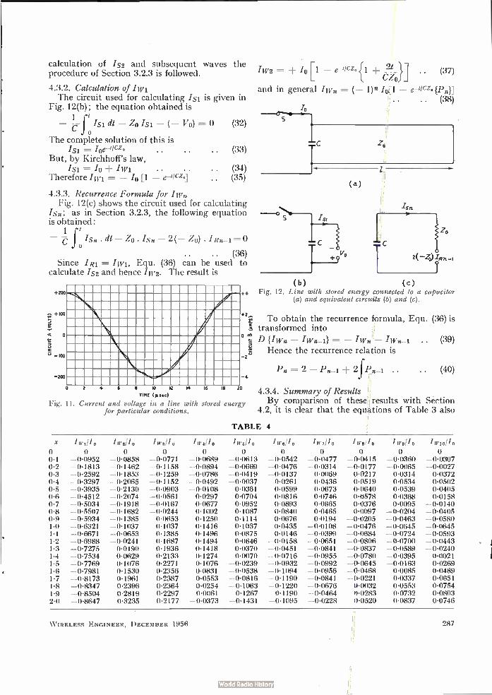
4.2.4. Summary of Results By the use of Equ. (31) successive expressions
for /wn can be built up rapidly. The equations up to Iwo are tabulated in Table 3 where x is written for Zot/L. These equations have been evaluated in the range of x from 0 to 2 and the results are tabulated in Table 4; these figures have also been plotted as the curves of Figs. 9 and 10.
+0-5
o
05
1,3
AYE
1 00
+01
To
01
OES 1.5 20
15
yie
Ivib
Figs. 9 (above) and 10 (below). Curves plotted from the figures of Table 3, showing the waveforms in a line having stored energy and terminated by an inductance, as in Fig. 8.
—4(1 — e-3) •
+I[1 — e-3(1 + 2x)] —4[1 — e-x(1 2x2)]
±/0[1 — e-<1
/w, = —/,[1 —
lw, = +41 —
'W? —111 —
= +141 — e-<1
= —/,[1 — e-3(1
+4[1 — e-<1
'W8
'w10 =
286
TABLE 3
It is interesting to note that the end case L = corresponds to the application of a short-circuit to the line. In this case /wn reduces to (— 1)n.4).
4.2.5. Example As an example of the application of the results
obtained, suppose it is required to calculate the voltage waveform at the open-circuit termination of the line for the following case:—
V0 = 200 volts. Other data as in Section 3.1.5.
The voltage—time waveform obtained is plotted in Fig. 11, showing the first cycle of an undamped periodic curve approximating to a cosine wave. Again following Section 3.1.5, if the line is
replaced by a lumped capacitance of 0.01 tiF initially charged to 200 volts, the voltage wave-form across the capacitor is the cosine curve shown in Fig. 11.
4.3. Analysis of Circuit B 4.3.1. Initial Procedure The circuit to be analysed is shown as Fig.
12(a); at time zero the external circuit driving a steady current /0 through the transmission line is interrupted by opening the switch S. The short-circuit termination at the right-hand
end of the line permits the application of Equ. (18) (Section 3.2.1) to this problem. For the purpose of applying Thévenin's theorem
to the line as a source of energy it is necessary to determine the voltage developed at the left-hand end of the line under these conditions if the termination there is an open-circuit. It is clear that at time zero, the current .To at this termina-tion must in this case fall instantly to zero; this necessitates a progressive current wave as a negative step function — /0 with an associated voltage step of — Vo. The equivalent circuit for the line is thus a generator of open-circuit voltage — Vo and internal impedance Zo ohms. For the
2x — 2x2 - - 3x
4x2 — -8 x3 ± x4)] 3 3
16 3 6 4 4 ± 2x — 4x3 s-x — àx isx
16 _4 — x4)1 15x , 45
36 26 44 20 ± 2x — 6x2 -à x3 — s x4 -I- ¡se — +
48 4 44, 96 , 64 48 + 8x- — ax- s x- — 1-5x- + 45x0 3,e7
64 68 184 160 ± 2x — 8x2 -à x3 — x4 ± -is x5 — x6
3T85x7)1 ± 2 XS1
315
— x — — x315 315 28435x9)1 176 7 14 0
W IRELESS ENGINEER, DECEMBER 1956
14 16 18
calculation of .1,52 and subsequent waves the procedure of Section 3.2.3 is followed.
4.3.2. Calculation of /In The circuit used for calculating isi is given in
Fig. 12(b) ; the equation obtained is 1
- c-- f 0 'si dl - Zo Isi - (- Vo) = 0 (32)
The complete solution of this is Isi -= /0e-ticzo (33)
But, by Kirchhoff's law, 'si = Io Iwi (34)
Therefore /Nil = - /0 [1 - e-'Io] (35)
4.3.3. Recurrence Formula for Iw„ Fig. 12(c) shows the circuit used for calculating
/s.; as in Section 3.2.3, the following equation is obtained:
1 - 7- f Isn dt - Zo. 'Sn - 2(- Zo) • /R.-1.
o .. (36)
Since I Ri = Iwi, Equ. (36) can be used to calculate .42 and hence IW2. The result is
+200
+100
o
s
200
o
IW2 = '0[1 e-tICZ. {1 c21zon (37)
and in general /w. = (- 1)/e 41 - {Pn)]
(38)
zo
V°
(a)
'Sn
2( -20)-Tan
( h) (c) +4 Fig. 12. Line with stored energy œnnected to a capacitor
(a) and equivalent circuits (b) and (c).
+2 .7,
0
-2 '7;
2 4 6 8 10 12
TIME µsec)
Fig. 11. Current and voltage in a line with stored energy for particular conditions.
4
20
To obtain the recurrence formula, Equ. (36) is transformed into
D {Iwn - = - Iwn - .. (39)
Hence the recurrence relation is
= 2 - Pn_i + 2f Pn-i • • .. (40)
4.3.4. Summary of Results By comparison of these results with Section
4.2, it is clear that the equations of Table 3 also
TABLE 4
X IwzlIo 1w311, lw4110 Iw511 0 Iwollo Iw711.0 Iwo lo Iwo/lo
o o o 0-1 -0-0952 -0-0858 -0-0771 -0-0689 -0-0613 -0-0542 -0-0477 -0-0415 -0-0360 -0.0307 0-2 -0-1813 -0-1462 -0-1158 -0-0894 -0-0669 -0.0476 -0-0314 -0-0177 -0-0065 -0-0027 0.3 -0-2592 -0-1853 -0-1259 -0.0786 -0.0419 -0-0137 0-0069 0-0217 0-0314 0-0372 0.4 -0-3297 -0-2065 -0-1152 -0.0492 -0-0037 0-0261 0-0436 0-0519 0-0534 0-0502 0-5 -0-3935 -0.2130 -0-0903 -0-0108 0-0361 0-0599 0-0673 0-0640 0-0539 0-0405 0-6 -0-4512 -0-2074 -0-0561 0-0297 0-0704 0-0816 0-0746 043578 0-0368 0-0158 0.7 -0-5034 -0-1918 -0-0167 0-0677 0-0952 0-0893 0-0665 0.0376 0-0095 -0.0140 0•8 -0-5507 -0.1682 -0-0244 0-1002 0-1087 0-0840 0-0465 0-0097 -0-0204 -0-0405 0.9 -0-5934 -0-1385 0-0653 0-1250 0-1114 0-0676 0-0194 -0-0205 -0-0463 -0-0580 1-0 -0-6321 -0-1037 0-1037 0-1416 0-1037 0-0435 -0-0108 -0-0476 -0-0645 -0-0645 1.1 -0-6671 -0-0653 0-1385 0-1496 04)875 0-0146 -0.0399 -0-0684 -0-0724 -0.0593 1-2 -0-6988 -0.0241 0-1687 0-1494 0-0646 -0-0158 -0-0651 -0.0806 -0.0700 -0.0443 1-3 -0.7275 0-0190 0-1936 0-1418 0-0370 -0-0451 -0-0841 -0-0837 -0-0589 -0-0240 1-4 -0-7534 0-0629 0-2133 0-1274 0-0070 -0-0716 -0-0955 -0,0780 -04)395 0-0021 1-5 -0-7769 0-1076 0-2271 0-1076 -0-0239 -0-0932 -0-0992 -0-0645 -0-0163 0-0269 1.6 -0-7981 0-1530 0-2356 0-0831 -0.0538 -0-1094 -0-0956 -0-0468 0-0085 0-0489 1.7 -0-8173 0-1961 0.2387 0-0553 -0-0816 -0-1190 -0-0841 -0-0221 0-0337 0-0651 1-8 -0-8347 0-2396 0-2364 0-0254 -0-1063 -0-1220 -0-0676 0-0032 0-0553 0-0754 1-9 -0-8504 0-2819 0-2297 -0-0061 -0-1267 -0-1190 -0-0464 .3•0283 0-0732 0-0803 2-0 -0-8647 0-3235 0-2177 -0-0373 -0-1431 -0-1095 -0-0228 0-0520 0-0837 0-0746
-
W IRELESS ENGINEER, DECEMBER 1956 287
hold for circuit B, provided x is taken to represent t/CZo. It follows that the results given in Table 4 and in Figs. 9 and 10 also apply.
It can be noted in passing that for the end case C = 0, the formula for iwn reduces simply to
/wn = (— 1)n/0 . . (41)
4.3.5. Example To demonstrate the similarity of behaviour of
the two circuits, suppose it is required to calculate the current-time curve for the short-circuit termination in the following case :—
/0 = 4 amps. Other data as in Section 3.2.5.
The waveform of Fig. 11 is the solution obtained, provided that the ordinate scale is changed as indicated. The cosine curve in Fig. 11 then shows the waveform obtained in a 50-µ1-1 inductance if this is used to replace the line in the above problem.
aZo AA»
1
a o
(a.)
z,
4.4. Comparison of Case I and Case II Since the only difference between Case I and
Case II is the method of initial storage of energy it is to be expected that the circuit waveforms obtained will bear some close relationship to each other.
If the equations of Tables 1 and 3 are examined, it will be found that
1— /0 /wi] = [iwi] .. (42) Case I Case II
Also [/wn — iwn-1] Case I
It follows that the two sets of equations are rigidly interrelated.
= [Iwn iwn-1] (43) Case II
5. Effect of Additional Circuit Components 5.1. Introduction
In this section the effect of the introduction of certain modifications to the circuits previously analysed will be considered. The method of analysis used is the same as that employed in previous sections; for this reason the examples chosen will not be analysed in detail, but the results obtained will be discussed briefly.
5.2. Effect of Power Dissipation 5.2.1. Effect of Losses in the Line
Losses in transmission lines have been con-sidered in Section 2.5. It should be stressed that line losses will produce a cumulative attenuation of progressive waves as the number of reflections increases, even though the waves be regarded as
bzo mathematical fictions.
z, Vo
Q
(c)
z,
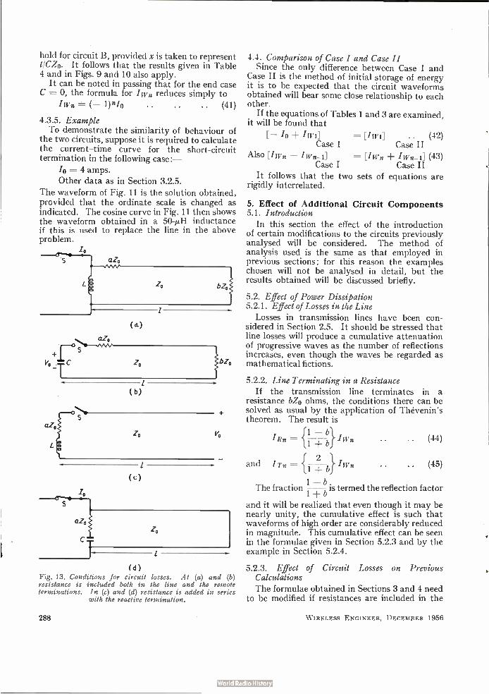
(d) Fig. 13. Conditions for circuit losses. At (a) and (b) resistance is included both in the line and the remote terminations. In (c) and (d) resistance is added in series
with the reactive termination.
288
5.2.2. Line Terminating in a Resistance If the transmission line terminates in a
resistance bZ0 ohms, the conditions there can be solved as usual by the application of Thévenin's theorem. The result is
and
{ 1 — b} i, 'Rn =-- 1+ bwn
I Tn I wn 2
1 — b The fraction is termed the reflection factor
and it will be realized that even though it may be nearly unity, the cumulative effect is such that waveforms of high order are considerably reduced in magnitude. This cumulative effect can be seen in the formulae given in Section 5.2.3 and by the example in Section 5.2.4.
5.2.3. Effect of Circuit Losses on Previous Calculations
The formulae obtained in Sections 3 and 4 need to be modified if resistances are included in the
(44)
(45)
W IRELESS ENGINEER, DECEMBER 1956
ro
line terminations. The circuits considered are redrawn in Fig. 13 to include a resistance aZo in series with the left-hand termination in every case, and a resistance bZ0 in series with the right-hand termination for the first two cases. Analysis of these circuits give the results outlined in Table 5.
It will be seen that the presence of the termina-tion bZo only influences the amplitudes of succes-sive waves. The inclusion of aZo influences wave shape as well as amplitude, since the factor a appears in the recurrence formulae. It will be noticed that in the last two cases the integration constant in the recurrence formulae is a function of n.
Free oscillations for Case II operation with purely resistive terminations are an end case of these results; i.e., by taking L = 0 for circuit A and C = oo for circuit B.
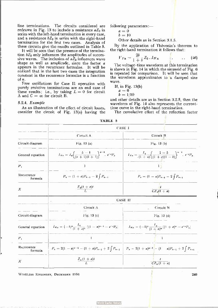
5.2.4. Example As an illustration of the effect of circuit losses,
consider the circuit of Fig. 13(a) having the
following parameters:— a = 0 b = 10
Other details as in Section 3.1.5.
By the application of Thévenin's theorem to the right-hand termination it follows that:
2b VT:2 -1—± —b Lo • W n .. (46)
The voltage—time waveform at this termination is shown in Fig. 14 in which the sinusoid of Fig. 6 is repeated for comparison. It will be seen that the waveform approximates to a damped sine wave.
If, in Fig. 13(b) a = 0
b = 1/10 and other details are as in Section 3.2.5, then the waveform of Fig. 14 also represents the current-time curve in the right-hand termination. The cumulative effect of the reflection factor
TABLE 5
Circuit diagram
General equation
PI
Recurrence formula
X
Circuit A
Fig. 13 (a)
CASE I
Circuit B
Fig. 13 (b)
n-1
0{ (a +b )(bl± 1)} . =
1 — b °
(1 ± a){( 1 4)( 1 —
= (1 -± a)P„_, — 2 f P„_,
}ro - 1
. e-'P„
P„ = (1 — a)P„_, — 2 .1.
Z,)(1 a)1
CZ0(1 ± a)
Circuit diagram
CASE II
Circuit A
Fig. 13 (c)
, Circuit B
General equation I w„ = (-1)"(1 + °a). [(1 a)" -1
PI 1
Fig. 13 (d)
I w„ = (-1), (1 -I- a)" [(1 ± a)" —
Recurrence formula
X
„ = 2(1 — a)" -2 — (1 + a)P.--1+ 2 f P„ = 2(1 + a). -1 — (1 — a)P„_,± 2 f P„_,
Z, (1 ± a)1
CZ,(1 + a)
W IRELESS ENGINEER, DECEMBER 1956 289
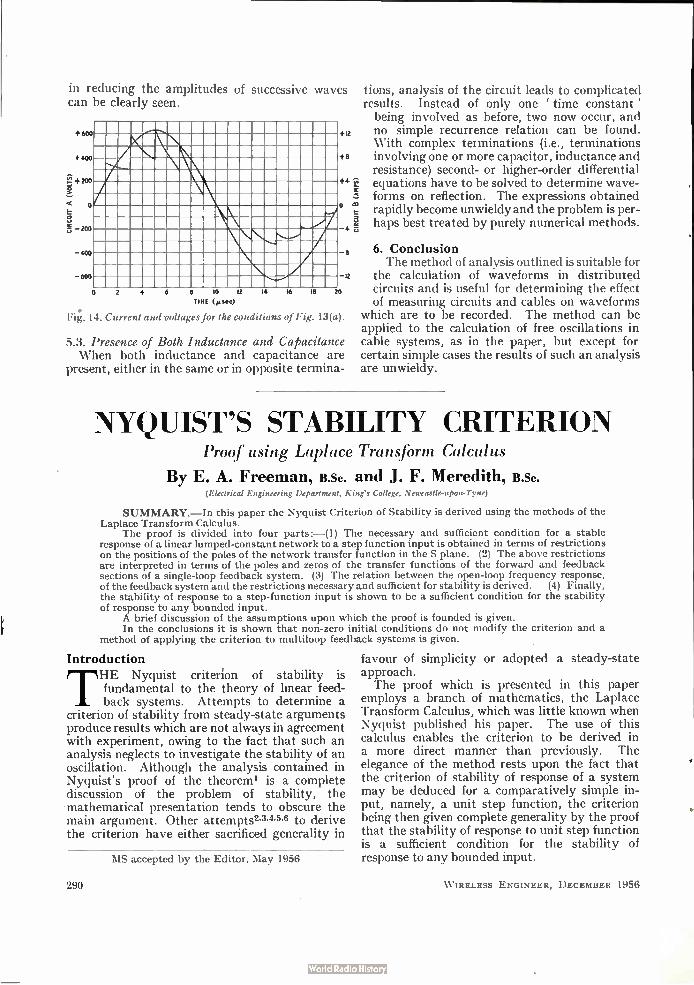
in reducing the amplitudes of successive waves can be clearly seen.
+600
+400
o
600
—400
0 2 4 6 10 12
TIME (»sec) •
Fig. 14. Current and voltages for the conditions of Fig. 13(a).
16 18
+12
+8
+4171
0 ‘I2
e
12
20
5.3. Presence of Both Inductance and Capacitance When both inductance and capacitance are
present, either in the same or in opposite termina-
lions, analysis of the circuit leads to complicated results. Instead of only one ' time constant' being involved as before, two now occur, and no simple recurrence relation can be found. With complex terminations (i.e., terminations involving one or more capacitor, inductance and resistance) second- or higher-order differential equations have to be solved to determine wave-forms on reflection. The expressions obtained rapidly become unwieldy and the problem is per-haps best treated by purely numerical methods.
6. Conclusion The method of analysis outlined is suitable for
the calculation of waveforms in distributed circuits and is useful for determining the effect of measuring circuits and cables on waveforms
which are to be recorded. The method can be applied to the calculation of free oscillations in cable systems, as in the paper, but except for certain simple cases the results of such an analysis are unwieldy.
NYQUIST'S STABILITY CRITERION Proof using Laplace Transform Calculus
By E. A. Freeman, B.Sc. and J. F. Meredith, B.Sc. (Electrical Engineering Department, King's College, Newcastle-upon-Tyne)
SUMMARY.—In this paper the Nyquist Criterion of Stability is derived using the methods of the Laplace Transform Calculus.
The proof is divided into four parts:—(1) The necessary and sufficient condition for a stable response of a linear lumped-constant network to a step function input is obtained in terms of restrictions on the positions of the poles of the network transfer function in the S plane. (2) The above restrictions are interpreted in terms of the poles and zeros of the transfer functions of the forward and feedback sections of a single-loop feedback system. (3) The relation between the open-loop frequency response, of the feedback system and the restrictions necessary and sufficient for stability is derived. (4) Finally, the stability of response to a step-function input is shown to be a sufficient condition for the stability of response to any bounded input.
A brief discussion of the assumptions upon which the proof is founded is given. In the conclusions it is shown that non-zero initial conditions do not modify the criterion and a
method of applying the criterion to multiloop feedback systems is given.
Introduction
THE Nyquist criterion of stability is fundamental to the theory of linear feed-back systems. Attempts to determine a
criterion of stability from steady-state arguments produce results which are not always in agreement with experiment, owing to the fact that such an analysis neglects to investigate the stability of an oscillation. Although the analysis contained in Nyquist's proof of the theoreml is a complete discussion of the problem of stability, the mathematical presentation tends to obscure the main argument. Other attempts2•345•6 to derive the criterion have either sacrificed generality in
MS accepted by the Editor, May 1956
290
favour of simplicity or adopted a steady-state approach. The proof which is presented in this paper
employs a branch of mathematics, the Laplace Transform Calculus, which was little known when Nyquist published his paper. The use of this calculus enables the criterion to be derived in a more direct manner than previously. The elegance of the method rests upon the fact that the criterion of stability of response of a system may be deduced for a comparatively simple in-put, namely, a unit step function, the criterion being then given complete generality by the proof that the stability of response to unit step function is a sufficient condition for the stability of response to any bounded input.
W IRELESS ENGINEER, DECEMBER 1956
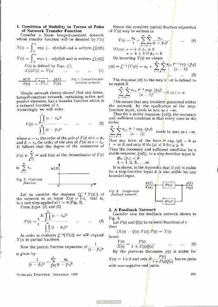
1. Condition of Stability in Terms of Poles of Network Transfer Function Consider a linear lumped-constant network
whose transfer function will be denoted by F(s)
X(s) = f o exp. (— st)x(t)dt and is written ,C{x(t)}
Y(s) = f o exp. (— st)y(t)dt and is written ey(t)}
F(s) is defined by Equ. (1).
X (s)F (s) = Y(s) • • (1)
Y(t) Fig. I. Linear lumped-constant network. F(s)
X(s) Y(s)
Simple network theory shows7 that any linear, lumped-constant network, containing active and passive elements, has a transfer function which is a rational function of s. Accordingly we will write
n (s _
F(s)= ' (2)
A=1
where a= rÀ the order of the pole of F(s) at s = p, and /3 = rd, the order of the zero of F(s) at s It follows that the degree of the numerator of
F(s) is ro and that of the denominator of F(s) 4, =I
rn is rA•
A=1
Fig. 2. Unit-step function.
o t
Let us consider the response LC-1 [Y(s)]) of the network to an input X(s) = 1/s; that is, to a unit step applied at t = 0 (Fig. 2). From Equs. (1) and (2)
K (s _
Y(s) S
A=1 In order to evaluate £-1{ Y(s)} we will expand
Y(s) in partial fractions.
• (3)
1 Now the partial fraction expansion of
(s — PA)" is given by
. a 1 ah --
k=1
W IRELESS ENGINEER, DECEMBER 1956
Hence the complete partial fraction expansion of Y(s) may be written as
A=1 k=1
Where w =-- k if p, v ---= k 1 if p,
On inverting Y(s) we obtain Ilt
avA. tu-1 exp. (p,€) At) = L-1 {Y(S)} ± 24 2, A= I k= I (w — 1)!
(5) The response y(t) to the step input is defined to
be stable if nt cc
tu-1 exp. (p,t) .0 as t -> (v — 1)! (Do
A=1 k=1
This means that any transient generated within the network, by the application of the step-function input, tends to zero as t-)- oo. Thus for a stable response, {y(t)}, the necessary
and sufficient condition is that every term in the series
A= I k=
Now any term of the form tg exp. (pt) -> 0 as t co if and only if Re. (p) < 0 for it >. O. Thus the necessary and sufficient condition for a stable response, {y(t)}, to a step-function input is
Re. (p,) < A = 1, 2, 3,....m.
It is shown, in the Appendix that if y(t) is stable for a step-function input it is also stable for any bounded input.
m a at,A
. (4) (s pA)u
m (tux tu-1 exp. (p,t)
tends to zero as t->oo. (v 1)!
Fig. 3. Single-loop feedback network.
.x(z> P(s)
Q(s)
2. A Feedback Network Consider now the feedback network shown in
Fig. 3. Let P(s) and Q(s) be rational functions of s
then
y(t)
{X(s) — Q(s) Y(s)) P(s) = Y(s)
hence Y(s) P(s) X (s) 1 ± P(s)Q(s)
By the previous discussion y(t) is stable for P(s)
X(s) = 1Is if and only if ±p(s)Q(s) has no poles
with non-negative real parts.
(6)
291
P(s) Poles of 1 P(s)Q(s) occur when
(1) 1 ± P(s)Q(s) = 0. This condition may be satisfied with
(a) P(s) and Q(s) both finite, (b) P(s) a pole of order tit and Q(s) a zero of order 0, (c) P(s) a zero of order y and Q(s) a pole of order
y, if the resulting order of the zero of {1 + P(s)Q(s)} is greater than y.
(2) P(s) has a pole, if (a) {1 ± P(s)Q(s)} finite at the s for which P(s)
has a pole, (b) P(s)Q(s) has a pole of smaller order than the
pole of P(s). This can occur if, and only if, Q(s) has at least a simple zero at the s for which P(s) has a pole.
If P(s) and Q(s) have no zeros for finite s in the positive half s- plane, then the necessary and
P(s) sufficient condition for a pole of
1 +P(s)Q(s) that {1 ± P(s)Q(s)} = 0 with P(s) and Q(s) both finite.
Let us denote P(s)Q(s) by G(s).
is
3. Geometrical Interpretation In order to determine the nature of the zeros of
{1 ± G(s)}, consider the following theorem8. If f(z) is a function of the complex variable
z =x+ jy and is meromorphic inside a closed contour C, and is not zero or infinity at any point on the contour, then
1 r f'(z)dz = N — P
27rj f(z) where N = Number of zeros of f(z) within C P = Number of poles of f(z) within C
{zero} of order r being counted as r{zeros A pole poles} •
The contour C is traced in an anti-clockwise direction.
If we let f(z) W, Equ. (7) becomes
27rj f r W 1 dW
- = N — P . . . .
Where the contour C in the z-plane is mapped into the contour r in the W-plane by the trans-formation W = f(z). W may be written W = R exp. (0) Substituting this in Equ. (8) we obtain 1 r
27r j p
f(z) being a continuous function of (x jy)
f
• (7)
(8)
dO = N — (9)
= the change in argument of f(z) as the contour C is traced once in the counter-clockwise direction.
292
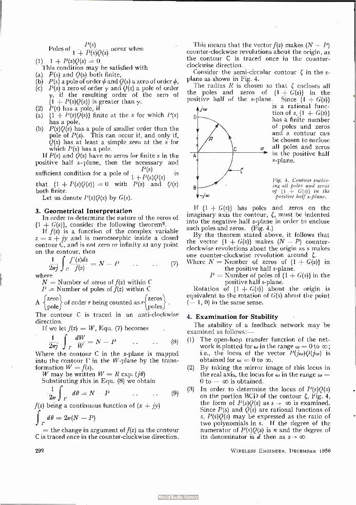
This means that the vector f(z) makes (N — P) counter-clockwise revolutions about the origin, as the contour C is traced once in the counter-clockwise direction.
Consider the semi-circular contour Z in the plane as shown in Fig. 4. The radius R is chosen so that Z encloses all
the poles and zeros of {1 ± G(s)} in the positive half of the s-plane. Since {1 + G(s)}
is a rational func-iw tion of s, {1 + G(s)}
has a finite number of poles and zeros and a contour can be chosen to enclose all poles and zeros in the positive half s-plane.
D
7/0
o.
Fig. 4. Contour enclos-ing all poles and zeros of [1 G(s)] in the positive half s-plane.
If {1 ± G(s)} has poles and zeros on the imaginary axis the contour, Z, must be indented into the negative half s-plane in order to enclose such poles and zeros. (Fig. 4.) By the theorem stated above, it follows that
the vector {1 ± G(s)} makes (N — P) counter-clockwise revolutions about the origin as s makes one counter-clockwise revolution around Z. Where N = Number of zeros of {1 + G(s)} in
the positive half s-plane. P =- Number of poles of {1 ± G(s)} in the
positive half s-plane. Rotation of {1 G(s)} about the origin is
equivalent to the rotation of G(s) about the point (— 1, 0) in the same sense.
4. Examination for Stability The stability of a feedback network may be
examined as follows :— (1) The open-loop transfer function of the net-
work is plotted for co in the range co = Oto co ; i.e., the locus of the vector P(jw)Q(jw) is obtained for w = 0 to oo.
(2) By taking the mirror image of this locus in the real axis, the locus for cd in the range 7» = 0 to — co is obtained. In order to determine the locus of P(s)Q(s) on the portion BCD of the contour Z, Fig. 4, the form of P(s)Q(s) as s oo is examined. Since P(s) and Q(s) are rational functions of s, P(s)Q(s) may be expressed as the ratio of two polynomials in s. If the degree of the numerator of P(s)Q(s) is n and the degree of its denominator is d then as s—> oo
(3)
W IRELESS ENGINEER, DECEMBER 1956
0 if d > n P(s)Q(s) -, co if n > d
(K if n = d K being a constant.
If n > d the locus of P(s)Q(s), when s is on the portion BCD of the contour, degenerates to a point. If n < d, the locus of P(s)Q(s), when s is on the portion BCD of the contour, is given by KRn-d
exp. {(n - d)j0} since s = R. exp. (0); -e/2 < O <i/2 on the portion BCD of the contour
n - Thus the locus of P(s)Q(s), makes d 2 counter-
clockwise revolutions about the origin as the portion BCD of the contour is traversed. The necessary and sufficient condition for the
stability of y(t) is that the vector, {P(s)Q(s)}, make P revolutions around (- 1, 0) in the positive sense as the contour is traversed once in the negative sense.
5. Discussion In this section, the assumptions which have
been made in the analysis will be considered in more detail. (1) In order to examine a system for stability
using the method described in the paper, it is necessary that both P(s) and Q(s) have no zéros in the finite part of the positive half s-plane. This means that there is no finite frequency at which either P(ja)) or Q(ja)) produce infinite attenuation. In any prac-tical system this condition is always satisfied.
(2) The statement that a contour can be chosen to enclose all the poles and zeros of {1 + G(s)} in the positive half s-plane requires that {1 ± G(s)} shall have no poles or zeros at
Isl co• (a) Poles of {1 + G(s)} at I si = cc
If {1 ± G(s)} has a pole at s = so then G(s) has a pole at s = so.
G(s) is defined by the equation G(s) X(s) = Y(s) where X(s) = £{Input to Network} = £{x(t)} and Y(s) = £{0utput of Network} -{Ly(1)}.
In order that Y(s) exist,
i.e. that f o exp. (- st)y(t)dt converges, it is
necessary and sufficient that
-› 0 as Isi oo
.•.G(s) -> Constant, or Zero as IsI -> co
since G(s) is a rational function of s. Thus G(s) and therefore {1 ± G(s)} has not
a pole at infinity. Similarly P(s) and Q(s) have not poles at infinity.
(b) Zeros of {1 + G(s)} at is! = co If G(s)-> 0 as s -> oo then {1 ± G(s)}-› 1.
W IRELESS ENGINEER, DECEMBER 1956
If G(s) -> - 1 as s co then {1 ± G(s)} 0; that is, (1 G(s)) has a zero at infinity.
If (1 G(s)} has a zero at infinity then
P(s) }(i.e., the transfer function of the feed-1 G(s) back network) has a pole at infinity.
Since f G( F(s) a rational function of s it s)
P(s) follows from (a) that {1 G(s)} cannot have a
pole at infinity. Hence {1 ± G(s)} cannot have a zero at
infinity. Thus a contour, may be drawn to enclose all
the poles and zeros of (1 G(s)) in the positive half s-plane. The transfer function of any practical network
falls to zero as frequency tends to infinity. Thus {1 ± G(s)} 1 as Is' co and therefore G(s)
0 as s -> co. Thus, in any practical net-
work, Y(s) exists.
6. Conclusions (1) Non-Zero Initial Conditions The analysis in this paper has assumed initial
conditions of the network to be zero. That the existence of non-zero initial conditions does not modify the criterion of stability may be seen from the following argument:—
It is shown (in Appendix) that, with zero initial conditions, a network which has a stable response to a step-function input has a stable response for any bounded input. Consider such a network. At t = 0 let a bounded input be applied to the net-work, initial conditions being zero; the form of this input being such that after a time to the conditions in the network constitute a desired set of initial conditions. At the instant to let the bounded input be reduced to zero and a second bounded input applied. The input to the system from t = 0 to t-->cc is a bounded input. Thus the response is stable, by definition. Hence the response between t = to and co is stable.
(2) Multiloop Feedback Networks In deriving the criterion, it has been assumed
that the networks P(s) and Q(s) were not them-selves feedback networks. However, the criterion can still be applied when either or both of the networks are feedback networks. For example:— Suppose P(s) is an unstable feedback network,
and Q(s) is a non-feedback network. Let us examine the stability of the feedback network shown in Fig. 5. Lei P(s) be represented by the feedback network shown in Fig. 6.
293

P(s) = 1 + 1(s)m(s)
The transfer function of the feedback network shown in Fig. 5 is :—
P(s)' 1(s)
1 ± P(s)Q(s) = 1 ± 1(s){Q(s) m(s)}
Thus, in order to examine this network for stability, the locus of 1(s){Q(s) m(s)} is obtained in the normal way. More complicated feedback systems may be
broken down and examined for stability in a similar manner.
y(t)
1(s)
P(s) X(s)
Q(s)
Fig. 6. Feedback network P(s).
Fig. 5. Unstable feed-Y(s) back network P(s)
stabilized by auxili-ary loop.
m(s)
Acknowledgments The authors are indebted to Professor J. C.
Prescott of King's College, Newcastle-upon-Tyne, for the facilities placed at their disposal, to Mr. F. J. U. Ritson of the Electrical Engineering Department, for his encouragement, and to Dr. J. D. Weston of the Mathematics Department, King's College, for his valuable advice on the mathematical presentation of the paper.
REFERENCES H. Nyquist, "Regeneration Theory", Bell Syst. Tech. J., 1932,
Vol. 11, p. 126. ▪ J. C. West, "The Nyquist Criterion of Stability", Electronic
Engineering, 1950, Vol. 22, p. 169. $ D. G. Reid, "The Necessary Conditions for Instability of Electrical
Circuits", Wireless Engineer, 1937, Vol. 14, p. 588. • E. Peterson, J. G. Kreer and L. A. Ware, "Regeneration Theory
and Experiment", Proc. Inst. Radio Engrs, 1934, Vol. 22, P. 1191, ° G. S. Brayshaw, " Regeneration in Linear Amplifiers", Wireless
Engineer, 1937, Vol. 14, p. 597. • R. S. Rivlin, "The Stability of Regenerative Circuits", Wireless
Engineer, 1940, Vol. 17, P. 298. H. W. Bode, "Network Analysis and Feedback Amplifier Design",
D. Van Nostrand Co., 1945. o E. C. Titchmarsh, "Theory of Functions", Oxford, 1939.
APPENDIX
System Stability for any Bounded Input Theorem
If F(t) and G(t) have absolutely convergent Laplace transforms f(s) and g(s) respectively, then f(s)g(s) is the Laplace transform of the function:—
,
J.0 F (r)G (t — r)dr fo F(t — T)G(T)dr.
It has been shown that the response y(t) of a system to a step-function input is stable if the transfer function F(s) of the system has no poles with non-negative real parts. We require to prove that this condition is sufficient for the stability of response to any bounded input.
Proof Let F(s) be the transfer function of the system Then Y(s) = F(s)X(s)
294
where Y(s) and X(s) are defined at the beginning of the paper. The response to a unit step function input; X(s) = 1/s
is h(s) given by h(s) = 1 ls . F(s). F(s) = sh(s) . . • (I)
where ,C-1{h(s)} = y(t) y(t) being stable by definition and given by
az,A tv-1 exp. (pAt) y(t) = a, -I-
(v — 1)! A=1 h=1
where v = k if PA e o = (k -F 1) if pA =
with Re. (pA) < = 1, 2, 3, .. m.
Now Y(s) = F(s)X(s) = sh(s)X(s) from 1
el{sh(s)X(s)) = g(t) where eg(t)) = Y(s).
g(t) being therefore the response of the system to an arbitrary input el{X(s)}
d r -.-g(t) = te'[h(s)x(s)]}
d -(fl y(t — r)x(r)dr dt o
(by the theorem stated above)
= v'(t — r)x(r)dr x(t)y(r)) ' . d
where y'(t — r) {y(t — r)}
Now y(t) and x(t) are bounded functions of t (by definition).
Hence g(t) is bounded if r y'(t — r)x(r)dr o
is bounded. m
y(t) a. ± avte-i exp. (pAt) (v — 1)!
A=1 I =1 ma
a,,,,,tv-2 exp. (pAt){pAt (v — 1))
(v — 1)! A --I It=1
=
In order to show that f o x(r)y'(1 — •r)clr is bounded
we require to show that
fo ilx(r)(t — r)k exp. {pA(t — T)}dt is bounded as t --> co Consider the integrand
ke(l') (e — r)k exp. {PA(t — T))1= ix(T)11(t — r)k exp. {aA(t — r)}1 1 exp. {jwA(t — r)}1
but lx(t — r)1< N. Since the input is bounded (by definition).
Thus lx(r)11(t — r)k exp. (0-A(t — r))1< N1(t — r)k exp. {.7À(t— T)}I.
Now f UWdr < f (r) dr.
It Thus f 0 A x(t)(t — r)k exp. {pA(t — T)}dT < f oN A I (t — r)k
exp: {a À(t — r)}1dr = N A f (t — r)k exp. (t7A(t — r))dr.
Since the integrand is essentially positive.
But f o (t — r)k exp. (CA (1— r)}dr tends to a constant as
t op for all crA < O.
Since all crA terms are negative (by definition) the theorem is established.
WIRELESS ENGINEER, DECEMBER 1956
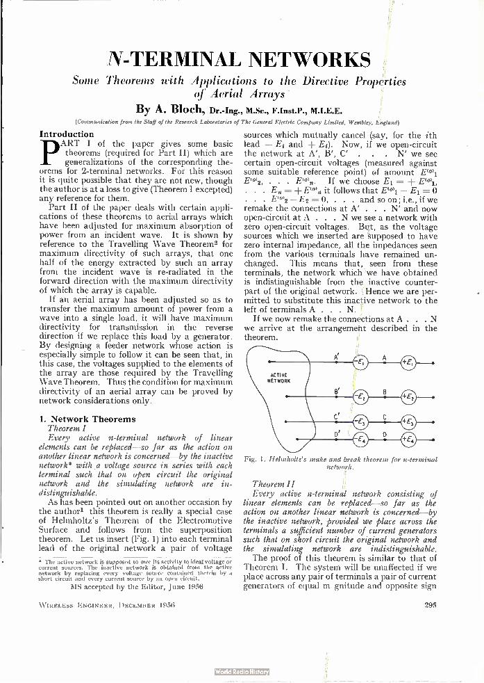
N-TERMINAL NETWORKS Some Theorems with Applications to the Directive Properties
of Aerial Arrays
By A. Bloch, Dr.-Ing., M.Sc., F.Inst.P., M.I.E.E. (Communication from the Staff of the Research Laboratories of The General Electric Company Limited, Wembley, England)
Introduction pART I of the paper gives some basic theorems (required for Part II) which are generalizations of the corresponding the-
orems for 2-terminal networks. For this reason it is quite possible that they are not new, though the author is at a loss to give (Theorem I excepted) any reference for them.
Part II of the paper deals with certain appli-cations of these theorems to aerial arrays which have been adjusted for maximum absorption of power from an incident wave. It is shown by reference to the Travelling Wave Theorem2 for maximum directivity of such arrays, that one half of the energy extracted by such an array from the incident wave is re-radiated in the forward direction with the maximum directivity of which the array is capable.
If an aerial array has been adjusted so as to transfer the maximum amount of power from a wave into a single load, it will have maximum directivity for transmission in the reverse direction if we replace this load by a generator. By designing a feeder network whose action is especially simple to follow it can be seen that, in this case, the voltages supplied to the elements of the array are those required by the Travelling Wave Theorem. Thus the condition for maximum directivity of an aerial array can be proved by network considerations only.
1. Network Theorems Theorem I Every active n-terminal network of linear
elements can be replaced—so far as the action on another linear network is concerned—by the inactive network* with a voltage source in series with each terminal such that on open circuit the original network and the simulating network are in-distinguishable. As has been pointed out on another occasion by
the author' this theorem is really a special case of Helmholtz's Theorem of the Electromotive Surface and follows from the superposition theorem. Let us insert (Fig. 1) into each terminal lead of the original network a pair of voltage
• The active network is supposed to owe its activity to ideal voltage or current sources. The inactive network is obtained from the active network by replacing every voltage source contained therein by a short circuit and every current source by an open circuit.
MS accepted by the Editor, June 1956
W IRELESS ENGINEER, DECEMBER 1956
sources which mutually cancel (say, for the ith lead — Ei and -I- Ei). Now, if we open-circuit the network at A', B', C' . . . N' we see certain open-circuit voltages (measured against some suitable reference point) of amount E(0)1 E0)2, . . . E(0).. If we choose El = E`")1, . . . E.= ± E101n it follows that Eel — E, = . . . E(0)2 — E2 = 0, . . . and soon; i.e., if we remake the connections at A' . . . N' and now open-circuit at A . . . N we see a network with zero open-circuit voltages. But, as the voltage sources which we inserted are supposed to have zero internal impedance, all the impedances seen from the various terminals have remained un-changed. This means that, seen from these terminals, the network which we have obtained is indistinguishable from the inactive counter-part of the original network. Hence we are per-mitted to substitute this inactive network to the left of terminals A . . . N.
If we now remake the connections at A . . . N we arrive at the arrangement described in the theorem.
Fig. 1. Helmholtz's make and break theorem for n-terminal network.
Theorem II Every active n-terminal network consisting of
linear elements can be replaced—so far as the action on another linear network is concerned—by the inactive network, provided we place across the terminals a sufficient number of current generators such that on short circuit the original network and the simulating network are indistinguishable. The proof of this theorem is similar to that of
Theorem I. The system will be unaffected if we place across any pair of terminals a pair of current generators of equal magnitude and opposite sign
295
(in parallel to each other). We shall now apply a whole system of such current generator-pairs in the following way:
First, we inactivate the network from the point of view of the load by applying short-circuiting straps across a sufficient number of terminals. By doing this we reduce the voltages across any pair of relevant terminals to zero but, of course, we also destroy completely the impedance relations seen by the load across these terminals. However, if we now substitute for each of these short-circuiting straps a current generator carry-ing exactly the same current as was flowing in the short circuit, then we have still the same current distribution that led to the disappearance of the terminal voltages; but we have also—on account of the infinite impedance of these current generators—restored the original impedance relations. Let us call the set of current generators thus introduced the positive set. We parallel now each current generator by another one carry-ing exactly the same amount of current in the other direction. These current generators form the negative set. The application of the positive set made the active network as seen from the load indistinguishable from the inactive network; the application of the negative set restores the original activity and, indeed, if we now short-circuit the active network it is seen immediately that these current generators will supply currents of the correct amount and direction. The two procedures—insertion of series voltage
generators or parallel-current generators can be used in a suitable mixed fashion to convert the active network into an inactive network. The subsequent application of the corresponding set of cancelling generators will then lead to the appropriate equivalent circuit. The following should be noted:
(a) Corresponding to the choice of voltage-reference point different voltages will be required for these voltage sources.
(b) Different sets of straps can be applied for short circuiting, leading to different sets of current generators (e.g., in the case of a 3-terminal net-work we can apply short circuits either between terminals 1-2 and 2-3, or between 2-3 and 3-1)*.
(c) If the equivalent circuit is required only from the point of view of a specific load—or a specific group of loads--it may not be necessary to apply a full set of cancelling generators; hence it may be possible to fulfil specific requirements with equivalent circuits of a simpler kind. A trivial example is the case where certain terminals of the active network are never used by the groups of loads considered. Less trivial is the case where the loads use all terminals but where the nature
•These different sets of generators are, of course, derivable from each other by linear combination.
296
of the loads forbids currents between certain groups of terminals. In such a case the voltages between that group of terminals (or' the short-circuit currents flowing between them) may be ignored. An example is the case of a 4-terminal network with 2-terminal loads that are only capable of connection to terminals 1-2 or 3-4. Any potentials between terminals 1-4 or 2-3 can then be ignored.
Conjugate Networks By a conjugate network we understand a net-
work which is obtained from another network (the 'original' network) by replacing each element of impedance Z' = R' jX1 by an element of impedance Z" = Z'* = R' — j X' .
It is evident that any impedance or admittance measured between any terminals of the original network is by this process changed to its con-jugate value.
Theorem III Of all inactive loads that can be attached to an
active n-terminal network the network forming its conjugate counterpart will extract maximum power.
Using Theorem I the terminal voltages of the active network can be written as
E(i'k = E(°)k — E In Znk • • • • (1)
where Znk is the impedance matrix relating the currents In from the n terminals of the inactive network to the voltages Ek (measured against the agreed reference point) produced thereby at these terminals.
Multiplying this equation by ik* and summing over all terminals we obtain the power output as the real part of
W = EkE(ekik* — EanInIk*Znk • • (2)
The currents In in this equation are quite generally determined by the requirement
Inineenk = Eek .. (3)
where eenk is the impedance matrix of the load between the terminals n and k. In the present case
2.(1)nk = Znk* .. (4) If the currents vary, as the result of load
changes, say lk by 81k, W varies by SW, and if the theorem is correct, the real part of this variation should be zero. Now SW = L'kE(0)nSik* — Ek/nZnk(48/k* S/n/k*)
• • (5) But, as Znk= Zkn it is seen that n and k are here interchangeable dummy indices and the second term in this equation can be written as S/k/n*. This makes it the conjugate of the first term and the bracket must therefore be real. Any real contribution to the double sum must therefore
W IRELESS ENGINEER, DECEMBER 1956
come from the real part Rnk of Znk. Hence we can write for the real part SW, of SW
SW, = ReZkE(o'kS/k* — Rei'nEk2Rnk/n8/k* . . (6)
But from equations (1), (3) and (4) we can write
Eek = En/n(Znk Znk*) = 2rn/nRnk. .
Hence equation (6) can be written
SW, = ReL'kDo'kUk* — ReEkDekS/k* . .
which is indeed identically zero for all values Dek. As Equ. (7) is an essential stepping stone to
Equ. (8) it is seen that the converse theorem, properly formulated must also be true. If an active linear network (impedance matrix Ziik) delivers maximum power into a load, the currents in this condition being denoted by I,z, then the impedance matrix ZDnk of this load must be such that when ' tested' with these currents it cannot be distinguished from Znk*, i.e.,
InInZenk = EnInZnk* (n = 1, 2 . . . N) (9)
If Equ. (9) is to hold for all possible sets of currents In (i.e., all possible sets of voltages Den) then
'nk = Znk* •
For a single set of currents In arising from a single set of voltages E'en Equ. (9) leaves considerable freedom for Zwnk. A case of special interest is that where we impose the additional condition that the matrix Z'z'nk only contains diagonal elements; this leads to the so-called 'driving point impedances' discussed in the following Section.
(7)
(8)
Driving Point Impedance and Equivalent Two-Terminal Loading Quite often the terminals of the multi-terminal
network can be grouped in pairs (for convenience, say, n pairs) so that the members of each pair carry equal but opposite currents. If such a net-work is connected to other networks through a corresponding number of transmission lines we may ask, what are the impedances which the multi-terminal network offers to these trans-mission lines? These impedances are commonly called the
driving-point impedances and their inverse the driving-point admittances. Their values are given by
Z`d'ic = Ek
1k = 1i-
, Yek = 1 k = EEYlk Ek Ek
.. (10)
.. (11)
where the values /i and Ei are the currents and voltages appearing at terminal pair i.
It will be noted that Z"-'k and Yel'k are not
W IRELESS ENGINEER, DECEMBER 1956
constants of the multi-terminal network but depend on the values of /i or E. Thus, for in-stance, even a purely resistive network with an admittance matrix [Gik] will lead to complex values of 17(d)k if the values of Ei are not all in phase with Ek•
In order to provide optimum loading for a multi-terminal network according to Theorem III we have to use as load another multi-terminal network which is the conjugate of the first net-work. It is possible to replace this network by 2-terminal networks (one for each pair of ter-minals) provided these 2-terminal networks carry the same currents as the network they are going to replace. This will be the case if the input admittance of each 2-terminal network is equal to the corresponding driving point admittance of the conjugate network. For a sa of open-circuit voltages Doi and a purely resistive matrix Gk this leads to the equivalent 2-terminal admittances
LE(eiGik rek = Dek
. . (12)
as with this particular load, all the terminal voltages Ei,Ek will be exactly one half of the original open-circuit voltages Dei. The left-hand side of the equation will change to its conjugate value if the values Emei, E(ek are replaced by their conjugate counterparts.
PART II Application to Absorption, Re-Radiation and Directive Properties of Aerial Arrays
A plane electromagnetic wave transports through each unit area of its wave front a certain amount of power; if an aerial is provided to receive it we can give an indication of the amount of power extracted from the wave by quoting the cross-sectional area of the wave-front through which this power has passed. This area is called the absorption area of the aerial and its magnitude depends evidently on the loading of the aerial. If the aerial is optimally loaded in the sense used in Part I, it will have its maximum absorption area. From the point of view of the theorems of Part
I, an aerial array constitutes an n-pair terminal network in which the terminal currents and voltages are related by an impedance matrix
[Zik] = [Rik ± igik] The optimum load for this aerial array consists
therefore of a network with an impedance matrix
[rik] = [Z*ik] = [Rik — /Wile] . . (13) It will be noticed that such a load will cause the
aerial to have maximum absorption area for any direction of the incident radiation, though the size of this area will, in general, vary with this direction. If [G k] is the reciprocal matrix to
297
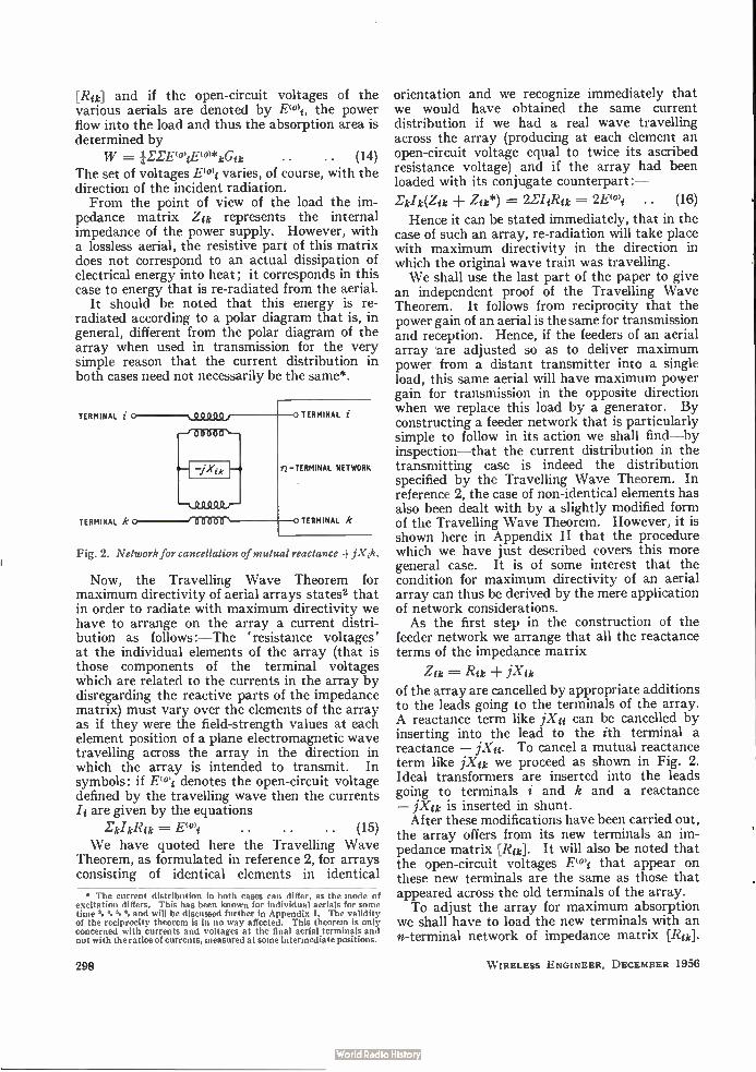
[Rik] and if the open-circuit voltages of the various aerials are denoted by E1°)i, the power flow into the load and thus the absorption area is determined by
W = ILTEwiE("kGsk .. (14) The set of voltages E°11 varies, of course, with the direction of the incident radiation. From the point of view of the load the im-
pedance matrix Zuc represents the internal impedance of the power supply. However, with a lossless aerial, the resistive part of this matrix does not correspond to an actual dissipation of electrical energy into heat; it corresponds in this case to energy that is re-radiated from the aerial.
It should be noted that this energy is re-radiated according to a polar diagram that is, in general, different from the polar diagram of the array when used in transmission for the very simple reason that the current distribution in both cases need not necessarily be the same*.
TERMINAL
TERMINAL k
TERMINAL
TERMINAL NETWORK
TERMINAL k
Fig. 2. Network for cancellation of mutual reactance jXati.
Now, the Travelling Wave Theorem for maximum directivity of aerial arrays states2 that in order to radiate with maximum directivity we have to arrange on the array a current distri-bution as follows :—The 'resistance voltages' at the individual elements of the array (that is those components of the terminal voltages which are related to the currents in the array by disregarding the reactive parts of the impedance matrix) must vary over the elements of the array as if they were the field-strength values at each element position of a plane electromagnetic wave travelling across the array in the direction in which the array is intended to transmit. In symbols: if E(0'i denotes the open-circuit voltage defined by the travelling wave then the currents /i are given by the equations
lerkRik . . . . (15) We have quoted here the Travelling Wave
Theorem, as formulated in reference 2, for arrays consisting of identical elements in identical
The current distribution in both cases can differ, as the mode of excitation differs. This has been known for individual aerials for some time and will be discussed further in Appendix I. The validity of the reciprocity theorem is in no way affected. This theorem is only concerned with currents and voltages at the final aerial terminals and not with the ratios of currents, measured at some intermediate positions.
298
orientation and we recognize immediately that we would have obtained the same current distribution if we had a real wave travelling across the array (producing at each element an open-circuit voltage equal to twice its ascribed resistance voltage) and if the array had been loaded with its conjugate counterpart:—
Li/ea Zik*) 2E/Ri 2E(ei .. (16)
Hence it can be stated immediately, that in the case of such an array, re-radiation will take place with maximum directivity in the direction in which the original wave train was travelling. We shall use the last part of the paper to give
an independent proof of the Travelling Wave Theorem. It follows from reciprocity that the power gain of an aerial is the same for transmission and reception. Hence, if the feeders of an aerial array .are adjusted so as to deliver maximum power from a distant transmitter into a single load, this same aerial will have maximum power gain for transmission in the opposite direction when we replace this load by a generator. By constructing a feeder network that is particularly simple to follow in its action we shall find—by inspection—that the current distribution in the transmitting case is indeed the distribution specified by the Travelling Wave Theorem. In reference 2, the case of non-identical elements has also been dealt with by a slightly modified form of the Travelling Wave Theorem. However, it is shown here in Appendix II that the procedure which we have just described covers this more general case. It is of some interest that the condition for maximum directivity of an aerial array can thus be derived by the mere application of network considerations. As the first step in the construction of the
feeder network we arrange that all the reactance terms of the impedance matrix
Zik = Rik ± iXik of the array are cancelled by appropriate additions to the leads going to the terminals of the array. A reactance term like jXii can be cancelled by inserting into the lead to the ith terminal a reactance — PC«. To cancel a mutual reactance term like jXik we proceed as shown in Fig. 2. Ideal transformers are inserted into the leads going to terminals i and k and a reactance — jXik is inserted in shunt.
After these modifications have been carried out, the array offers from its new terminals an im-pedance matrix [Rik]. It will also be noted that the open-circuit voltages rei that appear on these new terminals are the same as those that appeared across the old terminals of the array. To adjust the array for maximum absorption
we shall have to load the new terminals with an n-terminal network of impedance matrix [Rucl•
W IRELESS ENGINEER, DECEMBER 1956
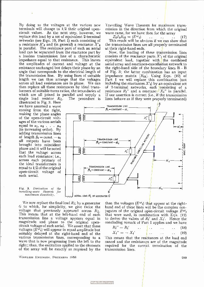
By doing so the voltages at the various new terminals will change to 1/2 their original open-circuit values. As the next step, however, we replace this load by a set of equivalent 2-terminal networks (see Equ. 10, Part I) each consisting of a resistance Kic and (in general) a reactance X'ic in parallel. The resistance part of such an aerial load can be separated from the reactance part by a lossless transmission line of a characteristic impedance equal to that resistance. This leaves the amplitudes of current and voltage at the resistance unchanged but delays their phase by an angle that corresponds to the electrical length of the transmission line. By using lines of suitable length we can thus arrange that the voltages across all load resistances are in phase. We can then replace all these resistances by ideal trans-formers of suitable turns ratios, the secondaries of which are all joined in parallel and supply a single load resistor RL. The procedure is illustrated in Fig. 3. Here we have assumed a wave coming from the right, making the phase angles of the open-circuit volt-ages of the various aerials equal to al, az . an
(in increasing order). By adding transmission lines of length fl i = const. — oci all outputs have been brought into coincident phase and it will be noted that the voltage across each load resistance; i.e., across each primary of the ideal transformers is equal to 1/2 of the original open-circuit voltage of each aerial.
Fig. 3. Derivation of the travelling-wave theorem for
maximum directivity.
Travelling Wave Theorem for maximum trans-mission in the direction from which the original wave came, for we have then for the array
kl lc% = (Etei) . . . . .. (17) This result will be obvious if we can show that
the transmission lines are all properly terminated at their right-hand ends. Now, the loading of these transmission lines
consists of the reactance parts X'i of the original equivalent load, together with the combined aerial array and reactance-cancellation network to the right-hand side of the boundary lines B — B of Fig. 3; the latter combination has an input impedance matrix [Roc]. Using Equ. (10) of Part I we will replace this combination (not including the reactances X'i) by an equivalent set of 2-terminal networks, each consisting of a resistance Ri" and a reactance Xi" in parallel. If our assertion is correct (i.e., if the transmission lines behave as if they were properly terminated)
TRANSMISSION LINE
/431 CONSTANT— °el
TRANSMISSION LINE 1.4-733 CONSTANT —
AERIAL LOAD RL OR GENERATOR G
We now replace the final load RL by a generator G to which, for simplicity, we give twice the voltage that previously appeared across RL. This means that at the left-hand end of each transmission line a voltage appears equal in magnitude and phase to the original open-circuit voltage of each aerial. We assert that these voltages (E10 >1) will appear in equal amplitude but suitably delayed at the right-hand end of the various transmission lines, corresponding to a wave that is now progressing from the left to the right; thus, the excitation applied to the elements of the array will be exactly as required by the
W IRELESS ENGINEER, DECEMBER 1956
0(2
oc,
E
then the voltages (E101i) that appear at the right-hand end of these lines will be the complex con-jugates of the original open-circuit voltage E(0)i that were used, in combination with Equ. (12) to derive the values of Ri' and Xi'. Hence the concluding remark of Part I applies and we have
Ri" . . (18) . . . . . .
= — Xi' . . . . . . (19)
This means that the reactances at the load end cancel and the resistances are of the magnitude required for the correct termination of the transmission lines.
299
APPENDIX I The Current Distribution in Aerial Arrays for
Reception and Transmission That the current distribution in the receiving case will,
in general, differ from the current distribution in the transmitting case can be seen as follows: We cut the connection between the aerials and the
feeder network and apply Theorem I. In the receiving case there will then be an equivalent network consisting of the passive aerials and in series with each aerial terminal a voltage generator (voltages E0r)1, Dan 2 . . . .E0n.). If we remake the connection, the excitation supplied by these generators will be responsible for the feeder currents and hence for the currents in the aerials. To change from reception to transmission we place a
generator in series with the final load resistance of the feeder network. Cutting the feeder network from the aerials we can, according to Theorem I, replace it by a passive network which, in this case, is identical with the feeder network as it was used before in the receiving case; in series with each feeder pair is a voltage generator (volt-ages En, E(°1),. . . E (e),.). If we remake the connection we have the same network configuration as in the receiving case, only now with voltages E(*oi instead of Et') in the generators. Now, the current distribution in the first case is determined by the impedance matrix that arises from the addition of the impedance matrix Zr«)„k of the aerial system and the impedance matrix Z(1),* of the feeder system, together with the ratios of the voltages EC), : .E(*r)2 : Ev'n, . . . Eon,,. The current distri-bution in the second case is determined by the same impedance matrix and by the ratios of the voltages Eon, : E002 : . . . De),.. The first set of these voltage ratios is a property of the aerials only, the second set is a property of the feeder network only. In general, we car not expect these two sets and the results to be identical. An alternative and also very instructive way of looking
at the same problem is as follows: Assume the individual elements of the array to be
connected to a common feeder network with a 2-terminal output to which we have joined an impedance—the load of the array. Let us place in series with this load a voltage source (E,) of such strength that it just balances the open-circuit voltage of the network. The current through the load will then be zero but the currents in the individual elements of the array will not be zero. We will call the resultant current distribution the 'idling distribution'*. We now add another voltage source (E,) in series with the first one which just cancels it and thus brings the array back to its normal loaded state. But source (E,) by itself causes in the array a current distribution of the shape of the 'transmiaing di rt. ibut ion'. Hence the recei ing current dirt. ibutit.n
• This idling distribution is evidently not a property of the array by itself but of the combination 'array feeder network' and direction of incident wave.
is obtained by the superposition of the idling current distribution and the transmitting current distribution. Only when these two current distributions have the same shape (i.e., are proportional to each other) will the receiving distribution be of the shape of the trans-mitting distribution. In general, this cannot be expected and there will then be a corresponding difference between the polar diagrams for re-radiation and transmission.
APPENDIX II
The Travelling Wave Theorem for Arrays with Non-Identical Elements
In reference 2 the problem of non-identical aerials was solved as follows:
Let H = . . .. (Al) the distant field-strength produced by the aerial currents .1„, where h„, denotes a suitable (real) factor of propor-tionality. Introduce modified currents and modified resistances as follows:
. . .. (A2) . . . . (A3)
Assume a constant amplitude e-10 of resistance voltage as in the case of identical aerials and solve as before; i.e.,
= (A4) where [g+ i„,] is the reciprocal matrix to [r÷b„]. To show the equivalence of this procedure to that
described in the present text we rewrite (A3) in matrix notation:
= [1r-IL] • ['I.] • [11.-'] • • (A5) where [h-'] denotes a diagonal matrix with elements h-li . . . h-11. From this follows by inversion
[el.] = [h][gb,j[h] . . (A6) or
e„.= (A7) Hence (A4) can be written
/4- „, =/Jim (A8)
1„ = (A9)
This is, however, also the result of the present procedure as on account of reciprocity the open-circuit voltages of the individual aerials are no longer equal but given by
Ev"), = h,ei0, .. (A10)
or
REFERENCES A. Bloch, Letter to Wireless Engineer, 1943, Vol. 20, pp. 367-8. A. Bloch, R. G. Medhurst, S. D. Pool, Proc. Insta elect. Engrs,
Part III, 1953, Vol. 100, pp. 303-13. ' N. V. Korshenewsky, Zeitschrift für technische Physik, 1929, Vol. 10,
p.604. • F. M. Colebrook, J. last,, elect. Engrs, 1932, Vol. 71, p. 235. • R. Kiry and C. W. Harrison, Proc. Inst. Radio Engrs, 1944, Vol. 32,
p.18. T. Morita, Proc. Inst. Radio Engrs, 1950, Vol. 38, p. 898.
300 W IRELESS ENGINEER, DECEMBER 1956
CORRESPONDENCE Letters to the Editor on technical subjects are always welcome. In publishing such communications the Editors do not necessarily endorse any technical or general statements which they may contain.
Standard-Frequency Transmissions—
Droitwich 200 kcis
SIR,—We are rather disturbed to notice that the usual monthly reports on the accuracy of the Droitwich trans-mitter on 200 kc/s published in Wireless Engineer have not been quoted for the months of September and October.
In view of the fact that a large number of instrument manufacturers rely on Droitwich as their main source of frequency calibration, we would be very much obliged to know the reason why the monthly reports appear to have been discontinued. We might just add that we find Droitwich by far the
most useful of all the standard-frequency transmissions in this country, largely because of the high field strength and also because of the very convenient frequency.
M. I. FORSYTH-GRANT Racal Engineering Ltd.,
Bracknell, Berks. 19th October 1956.
SIR,—When we started publishing results for MSF we decided after consultation with the B.B.C. to include values for Droitwich which we knew to be widely used, although it is not so closely controlled as MSF. There
has, however, been no evidence submitted to us that these values serve any useful purpose and it has been suggested that for those applications for which Droitwich is adequate no corrections are necessary. According to our measurements the frequency is usually within ± 5 parts in 108, and the value we published, with an accuracy of ± 1 part in 108, applied to only a particular time of the day, and was moreover six weeks in retrospect. How-ever, the matter can be reconsidered if a publication in this form is useful and we shall welcome any specific comments on the matter. You will probably be aware of the difficulty of secur-
ing frequency allocations for standard transmissions. We may mention that the closer control of the Droitwich station was considered some years ago but that it was then feared that the frequency would be moved off the round figure which is such a useful feature for standard transmission purposes. This possibility must be borne in mind, as no frequency below 2.5 Mc/s is specifically allocated to such services. Our 60-kcis MSF transmission remains on an experimental basis.
Electricity Division, National Physical Laboratory,
Teddington, Middlesex. 25th October 1956.
NEW BOOKS " Wireless World" Diary 1957
80 pages of reference material, and diary pages of one week to an opening. Size 44 in. X 34 in. Published by T. J. & J. Smith in conjunction with Wireless World, Dorset House, Stamford Street, London, S.E.1. Price, Leather 6s., Rexine 4s. 3d.
Introduction to Printed Circuits By ROBERT L. SWIGGETT. Pp. 112. John F. Rider
Publisher Inc., 480 Canal Street, New York 13. Price $2.70. A brief history of printed circuits is followed by
descriptions of present-day printed-circuit practice on the part of several U.S. manufacturers.
Picture Book of TV Troubles. Vol. 7—Sound Circuits and Low-Voltage Power Supplies By JOHN F. RIDER LABORATORIES STAFF. Pp. 64.
John F. Rider Publisher Inc., 480 Canal Street, New York 13, U.S.A. Price $1.50. Some typical U.S. television receiver h.t. supply and
sound i.f. amplifier and detector circuits are considered from the viewpoint of the effect of component failures on circuit voltages and waveforms.
Analysis of Bistable Multivibrator Operation By P. A. NEETESON. Pp. 82. Philips Technical
Library. Cleaver Hume Press Ltd., 31 Wright's Lane, Kensington, London, W.8. Price 15s. The Eccles-Jordan flip-flop circuit is analysed under
static and dynamic conditions. Chapters are included on trigger sensitivity, triggering speed, waveforms during the complete trigger cycle, design considerations and variations on the fundamental circuit.
Progress in Semiconductors, Vol. 1 Edited by A. F. Gibson, P. Aigrain and R. E. Burgess.
Pp. 220. Heywood & Co. Ltd., Tower House, Southamp-ton Street, London, W.C.2. Price 50s.
WIRELESS ENGINEHR, DECEMBER 1956
L. ESSEN
This volume contains seven articles, all on the physical aspects of transistors rather than on circuit applications. The individual subjects are: Recent advances in silicon; The germanium filament in semiconductor research; Theory of the Seebeck effect in semiconductors; The electrical properties of phosphors; The design of tran-sistors to operate at high frequencies; Photo-magneto-electric effect in semiconductors and Field effect in semiconductors.
NOBEL PRIZE Dr. William Shockley shares the 1956 Nobel prize for
physics with Dr. John Bardeen and Dr. Walter Hauser Brattain. He is well known for his work on solid-state physics at the Bell Telephone Laboratories which led to the development of the transistor. He recently joined Bechman Instruments Inc., where he is in charge of the semiconductor laboratory.
OBITUARY
James Robinson, M.B.E., D.Sc., Ph.D., M.I.E.E., F.Inst.P., died on 21st October at the age of 72. During the 1914-18 war he served in the R.N.V.R. and R.N.A.S. and he developed the crossed-loop direction-finding system which is known by his name. This was embodied in one of the early R.A.F. homing systems. He was equally well known for the Stenode Radiostat
which aroused a great controversy about the physical reality of sidebands in the early '30s. The stenode em-bodied a quartz-crystal resonator as a highly-selective circuit in conjunction with an a.f. amplifier having an inverse frequency characteristic over the range of modulation frequencies.
301
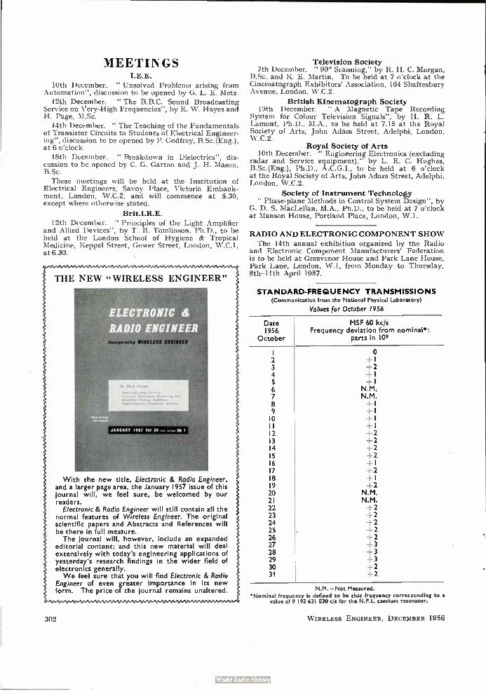
this lee» CM14.,0
j•i1141,•• auelatze• 14••••,.., feu 14stfinto 1.41.01.44,
uào-te«nte•ae Vootoeta 4414ove
MEETINGS I.E.E.
10th December. " Unsolved Problems arising from Automation", discussion to be opened by G. L. E. Metz.
12th December. " The B.B.C. Sound Broadcasting Service on Very-High Frequencies", by E. W. Hayes and H. Page, M.Sc.
14th December. " The Teaching of the Fundamentals of Transistor Circuits to Students of Electrical Engineer-ing", discussion to be opened by P. Godfrey, B.Sc.(Eng.), at 6 o'clock.
18th December. " Breakdown in Dielectrics", dis-cussion to be opened by C. G. Garton and J. H. Mason, B.Sc.
These meetings will be held at the Institution of Electrical Engineers, Savoy Place, Victoria Embank-ment, London, W.C.2, and will commence at 5.30, except where otherwise stated.
Brit.I.R.E.
12th December. " Principles of the Light Amplifier and Allied Devices", by T. B. Tomlinson, Ph.D., to be held at the London School of Hygiene & Tropical Medicine, Keppel Street, Gower Street, London, W.C.1, at 6.30.
•941.4941..4949..
THE NEW "WIRELESS ENGINEER"
ELECTRONIC &
DIO ENGINEER
JANUARY 1967 Vol 34 .. NO 1
With the new title, Electronic & Radio Engineer, and a larger page area, the January 1957 issue of this journal will, we feel sure, be welcomed by our readers.
Electronic & Radio Engineer will still contain all the normal features of Wireless Engineer. The original scientific papers and Abstracts and References will be there in full measure. The journal will, however, include an expanded
editorial content; and this new material will deal extensively with today's engineering applications of yesterday's research findings in the wider field of electronics generally. We feel sure that you will find Electronic & Radio
Engineer of even greater importance in its new form. The price of the journal remains unaltered.
302
Television Society 7th December. " 90° Scanning," by R. H. C. Morgan,
B.Sc. and K. E. Martin. To be held at 7 o'clock at the Cinematograph Exhibitors' Association, 164 Shaftesbury Avenue, London, W.C.2.
British Kinematograph Society 13th December. " A Magnetic Tape Recording
System for Colour Television Signals", by H. R. L. Lamont, Ph.D., M.A., to be held at 7.15 at the Royal Society of Arts, John Adam Street, Adelphi, London, W.C.2.
Royal Society of Arts 10th December. " Engineering Electronics (excluding
radar and Service equipment),' by L. E. C. Hughes, B.Sc.(Eng.), Ph.D., A.C.G.I., to be held at 6 o'clock at the Royal Society of Arts, John Adam Street, Adelphi, London, W.C.2.
Society of Instrument Technology " Phase-plane Methods in Control System Design", by
G. D. S. MacLellan, M.A., Ph.D., to be held at 7 o'clock at Manson House, Portland Place, London, W. 1.
RADIO AND ELECTRONIC COMPONENT SHOW
The 14th annual exhibition organized by the Radio and Electronic Component Manufacturers' Federation is to be held at Grosvenor House and Park Lane House, Park Lane, London, W. 1, from Monday to Thursday, 8th—I lth April 1957.
STANDARD-FREQUENCY TRANSMISSIONS (Communication from the National Physical Laboratory)
Values for October 1956
Date 1956
October
MSF 60 kc/s Frequency deviation from nominal*:
parts in 109
2 3 4
6 7 8 9 o
2 3 4 5 6 7 8 9
20 21 22 23 24 25 26 27 28 29 30 31
o +1 2 j
1 N.M. N.M. +I +1 +1 +1 +2 +2 +2 +2 +1 +2 +1
N.M. N.M.
2 +2 +2 +2 +2 +3 4-3 3 2 2
N.M.= Not Measured.
'Nominal frequency is defined to be that frequency corresponding to a value of 9 192 631 830 c/s for the N.P.L. caesium resonator.
WIRELESS ENGINEER, DECEMBER 1956
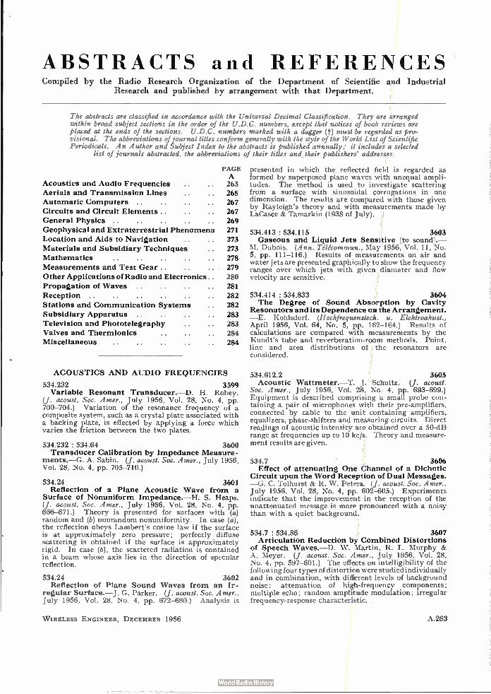
ABSTRACTS and REFERENCES Compiled by the Radio Research Organization of the Department of Scientific and Industrial
Research and published by arrangement with that Department.
The abstracts are classified in accordance with the Universal Decimal Classification. They are arranged within broad subject sections in the order of the U.D.C. numbers, except that notices of book reviews are placed at the ends of the sections. U.D.C. numbers marked with a dagger (t) must be regarded as pro-visional. The abbreviations of journal titles conform generally with the style of the World List of Scientific Periodicals. An Author and Subject Index to the abstracts is published annually; it includes a selected
list of journals abstracted, the abbreviations of their titles and their publishers' addresses.
Acoustics and Audio Frequencies Aerials and Transmission Lines
Automatic Computers .. Circuits and Circuit Elements.. . .
General Physics ..
Geophysical and Extraterrestrial Phenomena Location and Aids to Navigation
Materials and Subsidiary Techniques
Mathematics
Measurements and Test Gear..
Other Applications of Radio and Electronics . .
Propagation of Waves ..
Reception ..
Stations and Communication Systems
Subsidiary Apparatus ..
Television and Phototelegraphy
Valves and Thermionics
Miscellaneous
PAGE A 263
265
267
267
269
271
273
273
278
279
280
281
282
282
283
283
284
284
ACOUSTICS AND AUDIO FREQUENCIES
534.232 3599 Variable Resonant Transducer.—D. H. Robey.
(J. acoust. Soc. Amer., July 1956, Vol. 28, No. 4, pp. 700-704.) Variation of the resonance frequency of a composite system, such as a crystal plate associated with a backing plate, is effected by applying a force which varies the friction between the two plates.
534.232 : 534.64 3600 Transducer Calibration by Impedance Measure-
ments.—G. A. Sabin. (J. acoust. Soc. Amer., July 1956, Vol. 28, No. 4, pp. 705-710.)
534.24 3601 Reflection of a Plane Acoustic Wave from a
Surface of Nonuniform Impedance.—H. S. Heaps. (J. acoust. Soc. Amer., July 1956, Vol. 28, No. 4, pp. 666-671.) Theory is presented for surfaces with (a) random and (b) nonrandom nonuniformity. In case (a), the reflection obeys Lambert's cosine law if the surface is at approximately zero pressure; perfectly diffuse scattering is obtained if the surface is approximately rigid. In case (b), the scattered radiation is contained in a beam whose axis lies in the direction of specular reflection.
534.24 3602 Reflection of Plane Sound Waves from an Ir-
regular Surface.—J. G. Parker. (J. acoust. Soc. Amer., July 1956, Vol. 28, No. 4, pp. 672-680.) Analysis is
W IRELESS ENGINEER, DECEMBER 1956
presented in which the reflected field is regarded as formed by superposed plane waves with unequal ampli-tudes. The method is used to investigate scattering from a surface with sinusoidal corrugations in one dimension. The results are compared with those given by Rayleigh's theory and with measurements made by LaCasce & Tamarkin (1938 of July).
534.413 : 534.115 3603 Gaseous and Liquid Jets Sensitive [to sound].—
M. Dubois. (Ann. Télécommun., May 1956, Vol. 11, No. 5, pp. 111-116.) Results of measurements on air and water jets are presented graphically to show the frequency ranges over which jets with given diameter and flow velocity are sensitive.
534.414 : 534.833 3604 The Degree of Sound Absorption by Cavity
Resonators and its Dependence on the Arrangement. —E. Kohlsdorf. (Hochfrequenztech. u. Elektroakust., April 1956, Vol. 64, No. 5, pp. 162-164.) Results of calculations are compared with measurements by the Kundt's tube and reverberation-room methods. Point, line and area distributions of the resonators are considered.
534.612.2 3605 Acoustic Wattmeter.—T. J. Schultz. (J. acoust.
Soc. Amer., July 1956, Vol. 28, No. 4, pp. 693-699.) Equipment is described comprising a small probe con-taining a pair of microphones with their pre-amplifiers, connected by cable to the unit containing amplifiers, equalizers, phase-shifters and measuring circuits. Direct readings of acoustic intensity are obtained over a 50-dB range at frequencies up to 10 kc/s. Theory and measure-ment results are given.
534.7 3606 Effect of attenuating One Channel of a Dichotic
Circuit upon the Word Reception of Dual Messages. —G. C. Tolhurst & R. W. Peters. (J. acoust. Soc. Amer., July 1956, Vol. 28, No. 4, pp. 602-605.) Experiments indicate that the improvement in the reception of the unattenuated message is more pronounced with a noisy than with a quiet background.
534.7 : 534.86 3607 Articulation Reduction by Combined Distortions
of Speech Waves.—D. W. Martin, R. L. Murphy & A. Meyer. (J. acoust. Soc. A-mer., July 1956, Vol. 28, No. 4, pp. 597-601.) The effects on intelligibility of the following four types of distortion were studied individually and in combination, with different levels of background noise: attenuation of high-frequency components; multiple echo; random amplitude modulation; irregular frequency-response characteristic. .
A.263
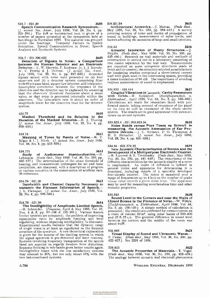
534.7 : 621.39 3608 Speech Communication Research Symposium.—
(J. acoust. Soc. Amer., July 1956, Vol. 28, No. 4, pp. 531-591.) The full or summarized text is given of a number of papers presented at the symposium held at San Diego in November 1955. The material was grouped under the headings: Temporal Factors in Speech Reception; Speech Communication in Noise; Speech Analysis and Synthesis Systems.
534.7 : 621.396.822 3609 Detection of Signals in Noise: a Comparison
between the Human Detector and an Electronic Detector.—C. W. Sherwin, F. Kodman, Jr, J. J. Kovaly, W. C. Prothe & J. Melrose. (J. acoust. Soc. Amer., July 1956, Vol. 28, No. 4, pp. 617-622.) Recorded signals mixed with noise were presented to (a) four observers and (b) a detector system comprising filter with 60-cis pass band, square-law detector, and integrator. Incomplete correlation between the responses of the observers and the detector can be explained by assuming that the observers' threshold fluctuates about a mean value, or that noise is generated internally within the observers. The false-alarm rate is about an order of magnitude lower for the observers than for the detector system.
534.75 3610 Masked Threshold and its Relation to the
Duration of the Masked Stimulus.—E. J. Thwing. (j. acoust. Soc. Amer., July 1956, Vol. 28, No. 4, pp. È06-610.)
534.75 3611 Masking of Tones by Bands of Noise.—R. C.
Bilger & I. J. Hirsh. (J. acoust. Soc. Amer., July 1956, Vol. 28, No. 4, pp. 623-630.)
534.771 3612 Study of Audiometer Standardization.—R.
Lehmann. (Onde élect., May 1956, Vol. 36, No. 350, pp. 466-477.) The determination of the mean threshold of hearing, and measurement techniques for air and bone conduction, are discussed, with a description of progress in various countries in the construction of artificial ears. 39 references.
534.78 : 621.39 3613 Bandwidth and Channel Capacity Necessary to
transmit the Formant Information of Speech.— J. L. Flanagan. (J. acoust. Soc. Amer., July 1956, Vol. 28, No. 4, pp. 592-596.)
534.78 : 621.39 3614 The Intelligibility of Amplitude-Limited Speech.
—H. Schneider. (Frequenz, April & May 1956, Vol. 10, Nos. 4 & 5, pp. 97-106 & 152-161.) Various known limiter systems are compared; the problem of improving signal/noise ratio by amplitude limiting and level regulating, without impairing intelligibility, is discussed. Experimental results indicate that the dynamic range of single tones is at least as significant as the formant structure of the spectrum. A new theoretical explanation is given for the success of the limiting system in which the signal spectrum is pre-distorted and later restored. Systems involving frequency transposition of the speech band are superior as regards freedom from distortion. Separate limiting in sub-bands gives better results again. Intelligibility losses with the less satisfactory systems may amount to 50%, but are only about 10% with the two last-mentioned systems.
A.264
534.83/.84 3615 Architectural Acoustics.—J. Matras. (Onde élect.,
May 1956, Vol. 36, No. 350, pp. 384-415.) A survey covering sources of noise and modes of propagation of sound in buildings, measurement of noise levels, and factors affecting the acoustics of large and small interiors.
534.83 3616 Acoustic Insulation of Heavy Structures. —J.
Pujolle. (Onde élect., May 1956, Vol. 36, No. 350, pp. 435-440.) Research on wall materials and methods of construction is carried out in a laboratory consisting of two rooms separated by the test wall. Measurements are reported on some composite structures made of brick and/or cement; the structure selected as satisfactory for insulating studios comprised a three-leaved cement wall with glass wool in the intervening spaces, providing a mean insulation of 94 dB. The importance of avoiding indirect transmission of sound is emphasized.
534.833 : 534.414 3617 Coupled Vibrations in [acoustic] Cavity Resonators
with Grids.—E. Kohlsdorf. (Hochfrequenztech. u. Elektroakust., April 1956, Vol. 64, No. 5, pp. 160-162.) Calculations are made for resonators faced with per-forated panels, taking account of resonance of the panel on its own as well as resonance of the whole cavity system. The results are in good agreement with measure-ments on several systems.
534.833.4 : 621.395.623.54 3618 Noise Bands versus Pure Tones as Stimuli in
measuring the Acoustic Attenuation of Ear Pro-tective Devices.— J . C. Webster, P. 0. Thompson & H. R. Beitscher. (J. acoust. Soc. Amer., July 1956, Vol. 28, No. 4, pp. 631-638.)
534.84 : 621.374.32 3619 New Acoustic Characterization of Rooms and the
Development of a Multipurpose Electronic Counter. —R. Lamoral & R. Trembasky. (Onde élect., May 1956, Vol. 36, No. 350, pp. 441-449.) The importance of the diffusion characteristics for the acoustic quality of a room is emphasized. An index of diffusion is defined in general terms and apparatus for determining it is described, including details of a specially developed four-decade counter. The index is measured over a range of frequencies up to 4 kcis as the number of peaks whose value exceeds a given mean level. The apparatus may be used for measuring reverberation time and other acoustic properties.
534.843 3620 Sound Level in the Corners and near the Walls of
Closed Rooms in the Presence of Noise.—W. (Hochfrequenztech. u. Elektroakust., April 1956, Vol. 64, No. 5, pp. 158-160.) A simple method of calculation is presented; the results are confirmed by measurements on a room of volume 63 m3, using noise bands of 200-400 and 37.5-75 c/s. The greatest difference in sound level between the corners and the middle of the room was about 9 dB.
534.845 3621 Visual Display of Sound and Ultrasonic Waves.—
F. Canac. (Onde élect., May 1956, Vol. 36, No. 350, pp. 422-427.) See 2291 of 1954.
534.845 3622 The Acoustic Properties of Materials.—T. Vogel.
(Onde élect., May 1956, Vol. 36, No. 350, pp. 428-434.) The analogy between acoustic and electrical phenomena
W IRELESS ENGINEER, DECEMBER 1956
is used to derive an expression for the coefficient of absorption; a method of determining this coefficient is described, based on measurements of incident and reflected sound fields in a specially constructed chamber (see also 2197 of 1953). Comparison with the original work of Sabine relating acoustic quality with reverbera-tion time shows that Sabine's formula is applicable to conditions involving higher absorption coefficients than are encountered in practice.
534.846 3623 Acoustics of the Auditorium at the State Opera
House, Berlin, Unter den Linden.—W. Reichaidt. (Hochfrequenztech. u. Elektroakust., April 1956, Vol. 64, No. 5, pp. 134-144.) Details are given of tests made in connection with the rebuilding of this opera house; diffusivity, clarity and reverberation time were in-vestigated. Measurements made on models were con-firmed by the final results. The reverberation time was made as long as possible, and is longer than that of the building in its previous form.
534.86 546.82 3624 Application of Metal Titanium to the Acoustic
Instruments, in Japan.—T. Hayasaka, K. Masuzawa, S. Nagai & M. Suzuki. (Rep. elect. Commun. Lab., Japan, April 1956, Vol. 4, No. 4, pp. 39-54.)
534.86 : 621.396.712.3 3625 Modern Broadcasting Studios: Marseilles.—J.
Pujolle. (Onde élect., May 1956, Vol. 36, No. 350, pp. 419-421.) A brief description is given of the acoustic treatment of these studios, which include one with a volume of 3 000 m3, having a reverberation time of about 1.5 s, and four smaller studios having reverberation times from 0.5 to 0.8 s.
534.861 : 621.396.813 3626 The Receiving Side of a Radio Broadcast Trans-
mission and its Influence on the Audio-Frequency Bandwidth.—Ebert. (See 3881.)
621.395.616 3627 Full-Range Electrostatic Loudspeakers.—H. J.
Leak & A. B. Sarkar. (Wireless World, Oct. 1956, Vol. 62, No. 10, pp. 486-488. Correction, ibid., Nov. 1956, Vol. 62, No. 11, p. 528.) Discussion of a design using two parallel plastic diaphragms, with resistive coatings on the faces turned away from each other, and a parallel conducting electrcde fixed midway between them. With this arrangement there is no need for a high resistance in the lead to the charged middle electrode. Other advantages are that the diaphragms need not be unreasonably large, and that they form a dust-proof protection for the middle electrode.
621.395.623.8 3628 Experimental Investigation of Sound Coverage
of an Open Space by a Distributed System of Loud-speakers.—B. D. Tartakovski. (C. R. Acad. Sci. U.R.S.S., 1st June 1956, Vol. 108, No. 4, pp. 636-639. In Russian.) The results indicate that the required coverage can be achieved using 20-W loudspeakers with nondirectional characteristics in the horizontal plane, mounted at a height of 5 m and spaced at about 20 m.
AERIALS AND TRANSMISSION LINES
621.372.029.6 : 621.318.134 3629 Waveguide Components with Nonreciprocal
Properties.—Brown & Clarricoats. (See 3666.)
W IRELESS ENGINEER, DECEMBER 1956
621.372.2 -F 621.396.677.3] : 512.3 3630 Application of Chebyshev [Tchebycheff] Poly-
nomials in the Calculation of Step Transitions.— Ya. M. Turover & N. I. Strutinski. (Radiotekhnika i Elektronika, Feb. 1956, Vol. 1, No. 2, pp. 143-161.) Applications to the theory of transmission lines and aerial arrays are discussed.
621.372.2 : 621.315.212 3631 On the Theory of a Coaxial Transmission Line
consisting of Elliptic Conductors.—J. Y. Wong. (Canad. J. Phys., April 1956, Vol. 34, No. 4, pp. 354-361.) Analysis using elliptic-cylinder wave functions is pre-sented for a line in which the inner and outer conductors have confocal cross-sections. The theory is applicable to the shielded-strip line and the rectangular coaxial line as special cases.
621.372.21 : 621.3.015.3 3632 The Capacitor Discharge on the Infinitely Long
Line with Uniform Distribution of Resistance and Capacitance.—F. 1-3Cottcher. (Frequenz, April 1956, Vol. 10, No. 4, pp. 120-125.) Analysis is presented based on a finite source resistance, corresponding to a finite value of current at the instant when the line is connected to the capacitor. Expressions are derived for the voltage and current at any subsequent instant at any point along the line.
621.372.8 3633 Curved Waveguides with Constant Cross-
Section.—B. Z. Katsenelenbaurn. (Radiotekhnika i Elektronika, Feb. 1956, Vol. 1, No. 2, pp. 171-185.) Propagation in a waveguide comprising a straight and a curved section is considered theoretically. If the radius of curvature is sufficiently large, the solution for the field can be obtained approximately by considering a series of straight sections in place of the actual curved guide. The coefficients for the modes satisfy a system of ordinary differential equations of the first order.
621.372.8 3634 Conditions at the Boundary of Imperfectly
Conducting Waveguides.—M. L. De Socio. (R. C. A ccad. naz. Lincei, April 1956, Vol. 20, No. 4, pp. 469-476.) Analysis is presented; expressions derived are compared with those obtained by Baudoux (3151 of 1955).
621.372.8 3635 Transmission Loss due to Resonance of Loosely
Coupled Modes in a Multi-mode System.—A. P. King & E. A. Marcatili. (Bell Syst. tech. J., July 1956, Vol. 35, No. 4, pp. 899-906.) " In a multi-mode trans-mission system the presence of spurious modes which resonate in a closed environment can produce an appre-ciable loss to the princiral mode. The theory for the evaluation and control of this effect under certain con-ditions has been derived and checked experimentally in the particularly interesting case of a TE01 transmission system, where mode conversion to TE„, TE„ ... is produced by tapered junctions between two sizes of waveguide.'
621.372.8 : 538.221 : 538.63 3636 Polarimetric Study of a Ferrite in the 2 000-Mcis
Frequency Band.—P. Loudette & A. Charru. (C. R. Acad. Sci., Paris, 16th July 1956, Vol. 243, No. 3, pp. 251-254.) Measurements were made on a system com-prising three ferrite rods arranged along the axis of a circular waveguide. The rotation of the plane of polarization on application of a longitudinal magnetic field H, and the square of the ellipticity, are plotted
A.265

(a) as functions of H with À as parameter, and (b) as func-tions of A with H as parameter. Corresponding points of inflection are noted.
621.396.67 : 537.226 3637 Some Investigations on Dielectric Aerials: Part
1.—R. Chatterjee & S. K. Chatterjee. (J. Indian Inst. Sci., Section B, April 1956, Vol. 38, No. 2, pp. 93-103.) The radiation field intensity at a distant point due to a circular-section dielectric rod aerial excited in the HE, 1 mode is derived theoretically. General expressions are given for the radiation patterns in two planes of particular interest, and are evaluated for a polystyrene rod of length 3 A and diameter 0.46 A.
621.396.67 : 621.396.822 3638 Induced Thermal Noise in Aerials.—M. L. Levin.
(Zh. tekh. Fir., Nov. 1955, Vol. 25, No. 13, pp. 2313-2318.) Induced fluctuation currents in a thin aerial due to external heated bodies are discussed. Considerable mathematical difficulties arise in the calculation of these currents, owing to the fact that the fluctuation field is not 8-correlated along the aerial. These difficulties are largely avoided by use of the electrodynamic theory of reciprocity. The general formulae so obtained are applied to the following two cases: (a) aerial in an equilibrium radiation field; (b) thermal noise induced by remote bodies.
621.396.67.029.62 : 621.397.7 3639 The Crystal Palace Television Transmitting
Station.—McLean, Thomas & Rowden. (See 3895.)
621.396.674.3 3640 Some Comments on Wide-Band and Folded
Aerials.—E. O. Willoughby. (J. Brit. Instn Radio Engrs, Aug. 1956, Vol: 16, No. 8, pp. 455-462.) Reprint. See 2622 of September.
621.396.677 : 621.397.26 3641 Deviating Aerial Installations for Television
Coverage.—H. Hesselbach. (Frequenz, April 1956, Vol. 10, No. 4, pp. 116-120.) Aerial systems for ensuring reception in obscured or marginal areas are discussed; they are termed active or passive according as they are or are not associated with amplifiers; the passive class includes both simple reflectors and systems with separate receiving and transmitting aerials.
621.396.677.012.12 3642 End-Fire Arrays of Magnetic Line Sources
mounted on a Conducting Half-Plane.—R. A. Hurd. (Canad. J . Phys., April 1956, Vol. 34, No. 4, pp. 370-377.) Expressions are derived for the radiation patterns of arrays of sources such as slots in a perfectly conducting half-plane. The problem is made two-dimensional by assuming the sources to run parallel to the edge of the plane. The variation of beam tilt, beam width and side-lobe level with the array parameters is studied. The theory gives a reasonable representation of the behaviour of corrugated surface radiators embedded in a finite ground plane, provided the distance from the array to the edge is about equal to the array length.
621.396.677.029.6.012.12 3643 Microwave Aerial Testing at Reduced Ranges.—
D. K. Cheng. (Wireless Engr, Oct. 1956, Vol. 33, No. 10, pp. 234-237.) Three methods are presented for deter-mining the appropriate amount of defocus of the primary source for simulating Fraunhofer patterns within the Fresnel zone. The results are plotted and compared.
A.266
621.396.677.3 : 523.7 3644 The Multiple-Aerial Interferometer at the Nançay
Station.—E. J. Blum, A. Boischot & M. Gin. (C. R. Acad. Sci., Paris, 2nd July 1956, Vol. 243, No. 1, pp. 19-22.) A system for locating centres of solar r.f. radiation comprises eight parabolic mirrors of 5m diameter on an east-west base of length 700 m; it operates on 169 Mc/s and has a resolving power of 7.5'. Some records of the passage of r.f. sources are reproduced. A system of 32 aerials on a 1 500-m base is projected, which is to include the present system.
621.396.677.3.012.12 3645 Aerial Pattern Synthesis.—H. E. Selzer. (Wireless
Engr, Oct. 1956, Vol. 33, No. 10, pp. 240-244.) When the Dolph-Tchebycheff distributions are used to deter-mine the feeding coefficients required to produce sharp beams with broadside arrays, the numerical work in-creases with the number of sources. An alternative method is described which uses a special case of a general formula due to Poisson to synthesize extremely sharp patterns. A simple explicit expression is derived for the amplitude of the feeding coefficients which is just as easy to calculate for a large number of terms as for a small number.
621.396.677.83 3646 Theory of Periscopic Aerial Systems.—L. B.
Tartakovski & A. M. Pokras. (Radiotekhnikai Elektrcmika, Feb. 1956, Vol. 1, No. 2, pp. 186-196.) A system com-prising a parabolic radiator and a plane elliptical deflector is investigated theoretically by a method similar to that used previously by Jakes (1243 of 1953). The solution for the field gain nE of the system is obtained in terms of infinite series of Bessel functions; the expression is considerably simplified in the cases of (a) a point source, and (b) uniform distribution of amplitudes over the aperture and coincidence of the radiator aperture with the circular projection of the deflector. 'I, is plotted as a function of a dimensionless parameter m for three different amplitude distributions over the aperture and five different ratios of the diameter of the radiator aperture to that of the deflector projection; the effect of the amplitude distribution is shown to be small. The results obtained are in good agreement with those calculated by Jakes and the experimental results of Drexler (2565 of 1954).
621.396.677.83 3647 • Aerial System with [raised] Reflector.—V. D. Kuznetsov. (Radiotekhnika, Moscow, March 1956, Vol. 11, No. 3, pp. 4-15.) The radiation characteristics of various arrangements of the type used at microwave relay stations, comprising a reflector-type aerial and a raised deflecting reflector, are considered theoretically.
621.396.677.833 3648 The Electromagnetic Field of a Dipole Radiator
located inside a Paraboloidal Reflector.—I. P. Skal'skaya. (Zh. tekh. Fiz., Nov. 1955, Vol. 25, No. 13, pp. 2371-2380.) The case of a dipole arranged per-pendicular to the axis of the paraboloid is considered. The solution given by Pinney (2687 of 1947) in the form of series of Laguerre polynomials is not justified mathematically. A new solution applicable to the whole region inside the paraboloid is obtained which gives the desired field components in the form of complex integrals. This solution is used to determine the field in the limiting case when the wavelength is much smaller than the focal length of the paraboloid.
621.396.677.833 : 523.16 3649 The Gelrge R. Agassiz Radio Telescope of
Harvard Observatory.—Bok. (See 3715.)
W IRELESS ENGINEER, DECEMBER 1956
621.396.677.833.1 3650 Electromagnetic Field of a Linear Radiator
located inside an Ideally Conducting Parabolic Screen [reflector].—G. A. Grinberg, N. N. Lebedev, I. P. Skal'skaya & Ya S. Uflyand. (Zh. eksp. teor. Fiz., March 1956, Vol. 30, No. 3, pp. 528-543.) The field problem considered earlier (2867 of 1954) is re-examincd and a more rigorous solution is derived. This is shown to agree with the geometrical-optics solution at frequencies tending to infinity.
621.396.677.833.2 3651 The Far Field of a Paraboloid of Revolution with
Hertzian Dipole Normal to the Plane of the Aper-ture.—F. Müller. (Hochfrequenztech. u. Elektroakust., April 1956, Vol. 64, No. 5, pp. 155-158.) Calculations show that the power density and field direction are rotationally symmetrical about the axis of the paraboloid; the transverse electric field has zero intensity on the axis.
621.396.677.85 : 621.372.43 3652 Reflection and Transmission at a Slotted Dielec-
tric Interface.—R. E. Collin. (Canad. J. Phys., April 1956, Vol. 34, No. 4, pp. 398-411.) Theory presented by Collin & Brown (2293 of August) is extended to the problem of matching a microwave lens to free space for waves incident obliquely. Calculations show that the reflection coefficient can be reduced from 23% to 5% for angles of incidence up to 30°, for waves of 3-3.28 cm h, the dielectric constant of the slotted medium being 2-56.
AUTOMATIC COMPUTERS
681.142 3653 Trends in Computer Input/Output Devices.—
J. M. Carroll. (Electronics, Sept. 1956, Vol. 29, No. 9, pp. 142-149.)
681.142 3654 Design of Computer Circuits for Reliability.—
W. Renwick. (Electronic Engng, Sept. 1956, Vol. 28, No. 343, pp. 380-384.) Factors influencing the choice of components, and precautions taken during the initial circuit design and mechanical construction of the EDSAC II machine are described.
681.142 3655 A Circuit for Analogue Formation of xyg.—M. J.
Somerville. (Electronic Engng, Sept. 1956, Vol. 28, No. 343, pp. 388-389.) " A quarter squares multiplier, using a triangle carrier waveform in the squaring circuits is extended to give division simultaneously with multi-plication. This is achieved by controlling the slope of the triangle carrier waveform so as to be proportional to the divisor Z."
681.142 : 621.317.729.1 An Automatic Electron Trajectory
Pizer, Yates & Sander. (See 3833.)
681.142(083.7) 3657 I.R.E. Standards on Electronic Computers:
Definitions of Terms, 1956.—(Proc. Inst. Radio Engrs, Sept. 1956, Vol. 44, No. 9, pp. 1166-1173.) Standard 56. I.R.E. 8.S1.
3656 Tracer.—
CIRCUITS AND CIRCUIT ELEMENTS
621.3.002.2 3658 High- Temperature Components.—G. W. A.
Dummer. (Wireless World, Oct. 1956, Vol. 62, No. 10, pp. 510-512.) New materials and methods of production to meet Service demands are briefly described.
W IRELESS ENGINEER, DECEMBER 1958
621.3.049.75 3659 Printed Circuits.—(See 3902.)
621.318.4.045 3660 Winding Method for Coils with Parallel Windings.
—P. von Belatini. (Bull. tech. Univ. Istanbul, 1956, Vol. 9, pp. 10-21. In German.) Theory is presented indicating the purposes for which parallel-wound coils are suited, and practical examples are described.
621.318.57 : 621.314.7 3661 P-N-P-N Transistor Switches.—Moll, Tanenbaum,
Goldey & Holonyak. (See 3899.)
621.318.57 : 621.385 3662 Ten-Channel Time-Division Multiplexer.—H.
Moss & S. Kuchinsky. (Tele-Tech & Electronic Ind., May 1956, Vol. 15, No. 5, pp. 80-82 . . 154.) A ' magnetron' beam-switching tube [3434 of 1955 (Fan)] forms the basis of a 10-contact, single-channel circuit giving switching times of about 0.2 ps. The tube is used in conjunction with a gating system; a gate circuit is described which permits the examination of signals in the microvolt range.
621.319.4 : 621.373.4 3663 Nonlinear D.C.-Tuned Capacitors.—T. W. Butler,
Jr, H. Diamond & L. W. Carr. (Tale-Tech & Electronic Ind., May 1956, Vol. 15, No. 5, pp. 68-69 . . 135.) The design and production of very small tuning capacitors using Ba-Sr titanate ferroelectric dielectrics is described. Examples are given of applications to oscillators for the frequency range 25-400 Mc/s, with c.w. power outputs of 50 mW-3 W.
621.372.011.1 3664 Formulae relating some Equivalent Networks.—
R. J. Duffin & E. Keitzer. (J. Math. Phys., April 1956, Vol. 35, No. 1, pp. 72-82.) Explicit formulae are obtained for the elements of a network without transformers which has the same driving-point impedance as an arbitrary two-loop passive network.
621.372.011.2 3665 An Existence Theorem for Driving-Point Im-
pedance Functions.—N. DeClaris. (J. Math. Phys., April 1956, Vol. 35, No. 1, pp. 83-88.)
621.372.029.6 : 621.318.134 3666 Waveguide Components with Nonreciprocal
Properties.—J. Brown & P. J. B. Clarricoats. (Electronic Engng, Aug. & Sept. 1956,'Vol. 28, Nos. 342 & 343, pp. 328-332 & 376-379.) The mechanism of the non-reciprocal effects occurring when an e.m. wave is pro-pagated through a magnetized material, particularly a ferrite, is discussed; the gyrator, the isolator and the circulator are described.
621.372.029.64 : 538.569.4 3667 Further Aspects of the Theory of the Maser.—
Shimoda, Wang & Townes. (See 3710.)
621.372.412 3668 Variation of the Quality Factor of Piezoelectric
Crystals as a Function of Pressure.—H. Mayer. (C. R. Acad. Sci., Paris, 16th July 1956, Vol. 243, No. 3, pp. 246-249.) Measurements were made on a 100-kcis quartz crystal and on a Rochelle-salt crystal, using apparatus described in J. Phys. Radium, June 1956, Vol. 17, Supplement to No. 6, Phys. appl., pp. 104A-107A. Results are presented as Q/log p curves for values of log p up to 4, where p is in mm Hg. Decrease of pressure below about 10-2 mm Hg does not affect Q value.
A.267

621.372.413 3669 Design of a Toroidal Cavity Resonator by the
Method of Curvilinear Coordinates.-V. L. Patrushev. (Radiotekhnika i Elektronika, Feb. 1956, Vol. 1, No. 2, pp. 162-170.) The application of the formulae derived is illustrated by a calculation of the resonance frequency of a cavity of given dimensions. The calculated value of A = 23.0 cm agrees well with the experimental value of 23.2 cm.
621.372.5 3670 Restrictions on the Shape Factors of the Step
Response of Positive Real System Functions.-A. H. Zemanian. (Proc. Inst. Radio Engrs, Sept. 1956, Vol. 44, No. 9, pp. 1160-1165.) Extension of previous analysis of the transient response of networks (1577 of 1955).
621.372.5 : 537.227 3671 Theory of Nonlinear Coupling in a Novel Ferro-
electric Device.-W. H. Higa. (J. appl. Phys., July 1956, Vol. 27, No. 7, pp. 775-777.) A device which can be used as a modulator or as a frequency divider or multiplier comprises a block of ferroelectric material with electrodes arranged on two pairs of facing sides. On connecting an inductance across one pair of electrodes, a resonant circuit is provided in which the capacitance varies periodically, oscillations being sustained when the frequency of this parametric excitation is twice the resonance frequency of the circuit. Analysis is presented using the Mathieu equation.
621.372.54 3672 The Analysis of Three-Terminal Null Networks.
-T. H. O'Dell. (Electronic Engng, Sept. 1956, Vol. 28, No. 343, pp. 398-400.) A simple method of analysis is presented; the twin-T and bridged-T networks are treated as examples.
621.372.54 3673 By-Pass Filters.-R. O. Rowlands. (Wireless Engr,
Oct. 1956, Vol. 33, No. 10, pp. 238-240.) " By-pass filters are described having three pairs of terminals and in which all frequencies are passed, without distortion, between two of the pairs but only a limited band of frequencies is transmitted between either of these pairs and the third pair of terminals."
621.372.543.3 3674 An Improved Crystal Band-Elimination Filter.-
R. C. Leigh. (A.T.E. J., April 1956, Vol. 12, No. 2, pp. 101-106.) An all-pass network consisting of two filters in parallel is described, suitable for applications in which it is required to transmit a wide frequency range while suppressing one or more narrow frequency bands within the range. Internal impedance transformations eliminate the need for high-ratio transformers.
621.372.56.029.6 : 621.372.8 : 621.318.134 3675 The Field Displacement Isolator.-S. Weisbaum
& H. Seidel. (Bell Syst. tech. J., July 1956, Vol. 35, No. 4, pp. 877-898.) A nonreciprocal device with forward loss about 0.2 dB and reverse loss about 30 dB over a wide band at about 6 kMcis is based on use of a single ferrite slab spaced from the wall of a rectangular wave-guide and having a resistive strip on one face. Optimum field conditions in the waveguide are discussed.
621.372.57 : 621.374.34 3676 Operation of an Amplitude Limiter.-M. E.
Zhabotinski & Yu. L. Sverdlov. (Radiotekhnika i Elektronika, Feb. 1956, Vol. 1, No. 2, pp. 205-212.) Theoretical analysis and experimental evidence suggest
A.268
that the stray capacitance shunting the nonlinear element causes a parasitic phase modulation of the out-put signal and limits the efficiency. A neutralized circuit is shown and design formulae are given.
621.372.632 : 621.314.63 3677 Two-Terminal P-N Junction Devices for
Frequency Conversion and Computation.-Uhlir. (See 3897.)
621.373.421.1 3678 Mutual Synchronization of Three Coupled Oscil-
lators with Weak Couplings.-V. N. Parygin. (Radiotekhnika i Elektronika, Feb. 1956, Vol. 1, No. 2, pp. 197-204.) The system investigated theoretically and experimentally comprises three triode valve oscillators coupled by small capacitors between the grids of the first and second and second and third valves. Approximate expressions are derived for the frequency and amplitude of the oscillations in each oscillator. The regions where mutual synchronization takes place are shown in a 42/4 1 graph, where 4, and 42 are respectively the frequency differences between the first and second and the third and second oscillators.
621.373.421.13 : 621.396.96 3679 Stable Local Oscillator for S-Band Radar.-
W. J. Dauksher. (Electronics, Sept. 1956, Vol. 29, No. 9, pp. 179-181.) A continuous frequency range of 1.3% is obtained using six crystal oscillators tunable over over-lapping ranges of 0.25%. The desired output frequency is obtained by means of harmonic amplifiers.
621.374.3 3680 A Possible Construction of Amplitude Analysers.
-A. M. Bonch-Bruevich. (Zh. tekh. Fis., Nov. 1955, Vol. 25, No. 13, pp. 2397-2398.) A circuit is described by means of which pulses with amplitudes exceeding or lying within certain limits can be counted.
621.374.3 : 621.396.822 3681 Influence of Large Fluctuations on an Electronic
Relay.- V. I. Tikhonov. (Radiotekhnika i Elektronika, Feb. 1956, Vol. 1, No. 2, pp. 213-224.) The probability of untimely triggering by fluctuation voltages is con-sidered theoretically. The cases discussed include the effect of fluctuations on a relay with or without inertia both in the presence and in the absence of regular pulses; the effect on a coincidence-type circuit is also discussed.
621.375.13 3682 Effect of Component Tolerances in Low-
Frequency Selective Amplifiers: some Experimental Results.-N. S. Nagaraja & V. Rajaraman. (J. Indian Inst. Sci., Section B, April 1956, Vol. 38, No. 2, pp. 81-92.) Results obtained previously by analysis [1339 of May (Nagaraja)] have been verified experimentally, using the operational amplifiers of the PREDA analogue computer [24 of January (Biswas et al.)].
621.375.232.3 : 621.3.018.75 3683 Trailing Edge of Pulse in Cathode Follower with
Capacitive Load.-M. L. Volin. (Radiotekhnika, Moscow, March 1956, Vol. 11, No. 3, pp. 63-69.) The decay time of a rectangular pulse at the output of a cathode follower can be shortened by connecting a triode in parallel with the cathode resistor and capacitor and controlling the triode grid voltage via a RC coupling from the anode of the cathode-follower tetrode valve. The circuit constants are such that the triode impedance decreases momentarily at the end of each pulse.
W IRELESS ENGINEER, DECEMBER 1956
621.375.4 : 621.314.7 3684 The Design of Tetrode Transistor Amplifiers.—
J. G. Linvill & L. G. Schimpf. (Bell Syst. tech. J., July 1956, Vol. 35, No. 4, pp. 813-840.) Methods are discussed for determining suitable loads when the two-port parameters of the transistor are known. Charts are presented for determining power gain and input im-pedance as functions of load. Circuits described as examples include a common-base 20-Mc/s video amplifier, a common-emitter 10-Mc/s video amplifier, and if. amplifiers centred at 30 Mc/s and 70 Mc/s respectively. Predicted and measured gains are compared.
621.375.4 : 621.314.7 3685 Servo Amplifiers use Power Transistors.—B. M.
Benton. (Electronics, Sept. 1956, Vol. 29, No. 9, pp. 153-155.) High efficiency in a class-B-type amplifier using Ge power transistors is obtained by providing the collector power by full-wave rectification of the a.c. power supply.
621.375.4 : 621.314.7 : 546.28 3686 Micro-power Qperation of Silicon Transistors.—
Keonjian. (See 3898.)
GENERAL PHYSICS
535.33-1 : 535.417 : 538.569.4 3687 Interferometric Spectroscopy in the Far Infra-
red.—H. A. Gebbie & G. A. Vanasse. (Nature, Lond., 25th Aug. 1956, Vol. 178, No. 4530, p. 432.) The response of a thermal detector to the resultant of two interfering infrared beams was measured using a reflection interferometer with the path difference varied up to 7 mm. The spectral information is displayed in a Fourier transform obtained by analysis of the resultant-intensity/path-difference curve. An instrument with 30-cm aperture has been made for studying atmospheric transmission at submillimetre wavelengths.
537.2 3688 An Extension of the Circle and Sphere Theorems.
—G. Power. (Brit. J. appl. Phys., June 1956, Vol. 7, No. 6, pp. 218-221.) Theory relating to cylinders and spheres immersed in two- and three-dimensional electric fields (e.g. 3555 of 1955) is extended to include certain other boundaries along which either the electric potential or the current function takes a constant value.
537.311.1 3689 On the Bohm-Pines Theory of a Quantum-
Mechanical Electron Plasma.—C. G. Kuper. (Proc. phys. Soc., 1st June 1956, Vol. 69, No. 438A, pp. 492-495.) Analysis indicates that as a result of neglecting certain conditions discussed by Adams (3219 of 1955), the Bohm-Pines theory (1375 of 1954 and back references) may give incorrect results.
537.311.31 537.533 3690 Concerning the Papers by S. E. Khaikin, S. V.
Lebedev, and L. N. Borodovskaya [on effects of high current densities] published in Zh. eksp. teor. Fiz. in 1954-1955.-1. F. Kvartskhava. (Zh. eksp. teor. Fiz., March 1956, Vol. 30, No. 3, pp. 621-623.) Criticism of papers abstracted e.g. in 2992 of 1955 and back references.
537.311.31 3691 Integrals of Interest in Metallic Conductivity.—
D. K. C. MacDonald & L. T. Towle. (Ganad. J. Phys., April 1956, Vol. 34, No. 4, pp. 418-419.)
537.5 : 538.56 3692 Oscillations and Fluctuations in Gas Discharges.
—K. G. Emeleus. (Nuovo Cim., 1956, Vol. 3, Supplement,
W IRELESS ENGINEER, DECEMBER 1956
No. 3, pp. 490-495. In English.) A tentative classifi-cation is made of different forms of disturbance en-countered in gaseous conductors constituted by low-pressure tubes. A distinction is drawn between (a) cases where the gaseous conductor acts as a circuit unit possessing resistance, capacitance and inductance, any of which may be positive or negative, and (b) cases where internal disturbances occur in the gaseous con-ductor which are practically independent of the external circuit. The origin and nature of electron and ion oscillations is discussed.
537.52 : 538.56.029.6 3693 Electrical Breakdown in Argon at Ultra-high
Frequencies.—A. D. MacDonald & J. H. Matthews.— (Ganad. J. Phys., April 1956, Vol. 34, No. 4, pp. 395-397.) Report of measurements made using resonant cavities at a frequency of 2S kMcis, with pressures ranging from 4 x 10- 2 to 200 mm Hg.
537.533 3694 Thermionic Emission, Field Emission, and the
Transition Region.—E. L. Murphy & R. H. Good, Jr. (Phys. Rev., 15th June 1956, Vol. 102, No. 6, pp. 1464-1473.) The combined thermionic and field emission from a metal is studied as a whole; a general expression is derived in the form of a definite integral, relating the emission current to the field, the temperature and the work function. • Modified forms of the Richardson-Schottky and Fowler-Nordheim formulae are shown to be respectively valid over limited regions of low field and high temperature on the one hand and low temperatures and high field on the other. An expression is also derived for the emission current in the transition region.
537.533.8 : 537.226 3695 Secondary Electron Emission from Single
Crystals of Alkali Halide Compounds.—A. R. Shul'man & B. P. Dement'ev. (Zh. tehh. Fiz., Nov. 1955, Vol. 25, No. 13, pp. 2256-2263.) Experiments were carried out which show that the dielectrics investigated differ from metals in respect of the dependence of the coefficient of secondary emission on the energy of the primary electrons and also in respect of the secondary-electron energies, which in this case are approximately uniform.
538.114 3696 Thermodynamic Behavior of an Ideal Ferro-
magnet.—F. J. Dyson. (Phys. Rev., 1st June 1956, Vol. 102, No. 5, pp. 1230-1244.) The free energy of an ideal ferromagnetic lattice is evaluated as a series expansion in powers of the temperature. A mathe-matical formulation for calculating the effect of spin-wave interactions is developed in a separate paper (ibid., pp. 1217-1230).
538.244.2 3697 The Magnetization of a Cylinder by means of a
Coil, taking Account of Magnetic Viscosity.—A. N. Tikhonov & A. A. Samarski. (Zh. tekh. Fiz., Nov. 1955, Vol. 25, No. 13, pp. 2319-2328.) The problem of the magnetization of a conducting cylinder in a magnetic field, when the value of the field is abruptly changed, was solved in a general form by Vvedenski (J. Soc. phys.-chim. russe, 1923, Vol. 55, p. 1). A solution is now given for the case when magnetic after-effects are present. The results are used for determining the coefficients of magnetic permeability and viscosity, and the retarding action of the coil is taken into account by a corresponding change in the boundary condition on the cylinder surface.
A.269
538.3 3698 The Determination of the Electromagnetic Field
inside a Homogeneous and Isotropic Conductor.— A. Tonolo. (R. C. Accad. naz. Lincei, April & May 1956, Vol. 20, Nos. 4 & 5, pp. 403-408 & 556-560.) A new method of integrating Maxwell's equations is presented.
538.3 3699 Field of a Uniformly Charged Disk and Magnetic
Field of a Thin [single-layer] Circular-Cylinder Coil with Contiguous Turns traversed by a Direct Current.—R. Cazenave. (Rev. gén. Elect., May 1956, Vol. 65, No. 5, pp. 301-310.) The field of the uniformly charged disk is used to study that of the coil, by virtue of the magnetic equivalence between the coil and a magnet of the same shape with opposite magnetic poles on the two end faces. Formulae for mutual and self inductance are hence derived.
538.561 : 537.122 3700 Electrodynamics of Moving Media and the
Theory of the Cerenkov Effect.—B. D. Nag & A. M. Sayied. (Proc. roy. Soc. A, 12th June 1956, Vol. 235, No. 1203, pp. 544-551.) " The generalized Frank & Tamm's formula for the total energy radiated as Cerenkov radiation by a swiftly moving charged particle in a medium of dielectric constant e and permeability u has been derived employing the invariance of the phenomenological electrodynamic equations of Maxwell. The scheme is self-consistent, and the idea of the in-detectability of the ether wind is contained in it. It is found that the Cerenkov radiation is ea times larger than that predicted by the Frank & Tamm's formula for ea --- 1. Experiments are suggested to detect strong Cerenkov radiation in highly permeable mediums."
538.561 : 621.373.029.65/.66 3701 Pulsed Coherent Generation of Millimetre Waves
by Nonrelativistic Electron Bunches.—G. A. Askar'yan. (Zh. eksp. teor. Fiz., March 1956, Vol. 30, No. 3, pp. 584-586.) The production of microwaves by bunched electron beams incident on metallic or dielectric anticathodes or by interaction with strong localized fields is briefly discussed and energy relations are stated.
538.566 3702 The Effect of the Surface Curvature of a Convex
Metal Body on the Radiation from a Source on its Surface.—M. L. Levin. (Zit. tekh. Fiz., Nov. 1955, Vol. 25, No. 13, pp. 2395-2396.) The radiation is usually calculated from reflection' formulae derived by replacing the convex surface by a plane. The magnitude of the error thus introduced is estimated.
538.566 : 535.42] 534.26 3703 The Diffraction of a Cylindrical Pulse by a
Half-Plane.—R. D. Turner. (Quart. appl. Math., April 1956, Vol. 14, No. 1, pp. 63-73.) A method of analysis is used which enables the Green's function to be derived. Two transformations and two inversions are involved.
538.566 : 535.42 3704 Diffraction Pattern in the Plane of a Half-Screen.
—L. R. Lewis. (I. app!. Phys., July 1956, Vol. 27, No. 7, pp. 837-838.) Measurements are briefly reported for the case of plane-polarized radiation incident normally on a half-plane and polarized parallel to the diffracting edge. The results are discussed in relation to a formula derived by Andrews (3141 of 1950) and the observations of Harden (88 of 1953).
A.270
538.566 : 535.42 3705 Integro -differential Equations and Babinet's
Principle for Plane Screens with Directional Conductivity.—G. Toraldo di Francia. (R. C. Accad. naz. Lincei, April 1956, Vol. 20, No. 4, pp. 476-480.) Analysis is presented for diffraction by screens formed e.g. of parallel conducting wires. Four cases are dis-tinguished: (a) a finite parallel-wire screen alone; (b) a finite parallel-wire screen surrounded by an infinite nondirectionally conducting screen; (c) a finite aperture surrounded by an infinite parallel-wire screen; (d) a finite nondirectionally conducting screen surrounded by an infinite parallel-wire screen. Cases (a) and (b) are complementary in the sense of Babinet's principle; so also are cases (c) and (d). There is no special relation between cases (a) and (c) or (b) and (d).
538.566 : 537.56 3706 Electromagnetic Radiation from Electron
Plasma.—S. Hayakawa & N. Hokkyo. (Progr. theor. Phys., March 1956, Vol. 15, No. 3, pp. 193-202.) Theory developed by Bohm & Pines (1375 of 1954 and back references) is extended to treat the coupling between longitudinal and transverse plasma oscillations, arising from the quantum fluctuation of electrons interacting with the e.m. field. The theory may provide the explanation of the outbursts of solar r.f. emission.
538.566 : 539.13 3707 Molecular Ringing.—S. Bloom. (J. app!. Phys.,
July 1956, Vol. 27, No. 7, pp. 785-788.) " Semiclassical radiation theory is used to describe the response of an assemblage of two-state molecules driven by an electro-magnetic field. When the field is suddenly removed, the assemblage does not immediately become quiescent; it continues to radiate in diminishing amount. This coherent molecular-ringing radiation persists until the molecular populations return to the values they had at the beginning of the driving pulse. Depending upon the strength and duration of the driving pulse, the ringing radiation may exhibit a delayed peak."
538.566 : 621.372.8 3708 Radiation of Electromagnetic Waves during the
Uniform Motion of Electric Charges near an Inhomogeneity.—V. B. Braginski. (Radiotekhnika i Elektronika, Feb. 1956, Vol. 1, No. 2, pp. 225-232.) The radiation occurring in a nonuniform waveguide in which a given convection current is flowing and the transient radiation due to the passage of finite bunches of charge through ideally conducting grids are considered theoretically using the methods of perturbation theory.
538.569.4 : 621.372.029.64 3709 Theory of Molecular ;-beam] Oscillator and Mole-
cular [-beam] Power Amplifier.—N. G. Basov & A. M. l'rokhorov. (Z/i. eksp. teor. Fiz., March 1956, Vol. 30, No. 3, pp. 560-563.) See 2931 of 1955.
538.569.4 : 621.372.029.64 3710 Further Aspects of the Theory of the Maser.—
K. Shimoda, T. C. Wang & C. H. Townes. (Phys. Rev., 1st June 1956, Vol. 102, No. 5, pp. 1308-1321.) Problems relating to saturation effects and cavity-resonator design for the device discussed previously [e.g. 403 of February (Gordon et al.)] are examined; various types of noise and oscillator frequency shift are considered. The theoretical minimum detectable beam intensity when the maser is used as a spectrometer for the 3-3 ammonia line is about 10° molecules/sec under typical experimental conditions.
W IRELESS ENGINEER, DECEMBER 1956

621.318.3 3711 A General-Purpose Electromagnet. —W .
Sucksmith & S. P. Anderson. (J. sci. Inseam., June 1956, Vol. 33, No. 6, pp. 234-236.) Details are given of a magnet for laboratory purposes, with a soft iron yoke having low residual magnetism and poles of diameter 10 cm, together with a table showing the variation of the field in the centre of the gap with excitation and gap length.
GEOPHYSICAL AND EXTRATERRESTRIAL
PHENOMENA
523.16 3712 Distribution of Radio Stars.—J. G. Bolton. (Obser-
vatory, April 1956, Vol. 76, No. 891, pp. 62-64.) A tentative explanation is given of discrepancies between the distribution derived by Ryle from interferometer measurements at 81 Mc/s and that derived by Pawsey from Mills Cross measurements, also at 81 Mc/s, as discussed at the recent Jodrell Bank symposium.
523.16 3713 The Radio Source near the Galactic Centre.—
B. Y. Mills. (Observatory, April 1956, Vol. 76, No. 891, pp. 65-67.) Recent observations on 3-5 m A with the ' cross' aerial are discussed in relation to earlier ob-servations on 9-4 cm and 21 cm A. The position of the dominant source is shown on a contour map of equivalent brightness temperatures. Alternative models accounting for the observations and involving absorbing H II regions are mentioned; whichever model is assumed, the nucleus of Type-II stars in the Galaxy is not itself detectable as a r.f. source.
523.16 3714 Polarization Measurements on Three Intense
Radio Sources.—R. H. Brown, H. P. Palmer & A. R. Thompson. (Mon. Not. R. asir. Soc., 1955, Vol. 115, No. 5, pp. 487-492.) Measurements have been made on radiation of wavelength 1-9 m from sources in Cygnus, Cassiopeia and Taurus. The results indicate that there is no plane polarized component > 1% and no circularly polarized component > 4% in the flux from the first two of these sources; the corresponding figures for the source in Taurus are 4% and 4% respectively.
523.16 : 621.396.677.833 3715 The George R. Agassiz Radio Telescope of
Harvard Observatory.—B. J. Bok. (Nature Lond., 4th Aug. 1956, Vol. 178, No. 4527, pp. 232-234.) The aerial of this 60-ft instrument is a paraboloid of expanded aluminium-wire mesh with a horn collector at the focus. At a wavelength of 21 cm the angular resolution is about 0-7°, thus the accuracy of setting and following is more than sufficient for research on discrete radio sources. The receiver is a double-conversion superheterodyne comparison radiometer with a 20-channel comb filter at the second conversion frequency. The instrument is to be used both for research and training.
523.5 3716 Some Factors affecting the Radio Determination
of Meteoric Velocities.—D. W. R. McKinley. (Natur-wissenschaften, May 1956, Vol. 43, No. 10, pp. 221-222. In English.) Questions raised by Hoffmeister (409 of February) are discussed further. Deceleration of meteors along the path prior to the point of measurement may be an important factor; techniques for measuring the deceleration over an appreciable path length by the radio amplitude/time method require to be developed. Exist-ing techniques may be failing to detect faint meteors with hyperbolic orbits.
W IRELESS ENGINEER, DECEMBER 1956
523.5 : 621.396.96 3717 Radar Echoes from Meteor Trails under Con-
ditions of Severe Diffusion.—G. S. Hawkins. (Proc. Inst. Radio Engrs, Sept. 1956, Vol. 44, No. 9, p. 1192.) An expression is derived indicating that the power of the echo is proportional to A6 and to R-4, where R is the range. For a given meteor velocity there is a critical height above which the effects of diffusion become serious. A graph shows the critical-height/velocity curves for values of A between 0-5 and 16 m.
523.7 : 621.396.677.3 3718 The Multiple-Aerial Interferometer at the Nançay
Station.—Blum, BoiEchot & Ginat. (See 3644.)
523.72 : 523.78 3719 Radio-Frequency Observations of the Solar
Eclipse of June 30, 1954.—G. Eriksen, O. Hauge & E. Tandberg-Hanssen. (Astrophys. norveg., Aug. 1955, Vol. 5, No. 4, pp. 131-152.) " Radio-frequency power received from the sun at wavelengths of 60 cm and 1-5 m was measured during the solar eclipse of June 30, 1954. The sun was essentially free from active areas, and the eclipse curves obtained have been used to derive models of the radio sun at the two wavelengths. These models give predicted eclipse curves in good agreement with the observed cnes. Comparison has been made with models derived by other investigators on the same wavelengths."
523.746 3720 The Constancy of the Scale of the Relative Sunspot
Numbers.—W. Gleissberg. (Nattewissenschaften, May 1956, Vol. 43, No. 9, p. 196.) Comparison of sunspot numbers with the Greenwich data for sunspot areas over ' several cycles indicates that the proportionality factor between total sunspot area and relative sunspot number increases with the latter, but there is no significant variation of the scale of the relative sunspot number.
550.38 : 523.165 3721 Effective Geomagnetic Equator for Cosmic
Radiation.—J. A. Simpson, K. B. Fenton, J. Katzman & D. C. Rose. (Phys. Rev., 15th June 1956, Vol. 102, No. 6, pp. 1648-1653.) The distribution of the geo-magnetic field extending far from the surface of the earth is investigated by using cosmic-ray particles as probes. Measurements using the neutron intensity from the nucleonic component indicate wide discrepancies be-tween the observations and geomagnetic coordinates derived from surface magnetic-field measurements. Some anomalous observations of cosmic rays can be explained as due to the interaction of the rotating and inclined magnetic dipole field with a highly ionized interplanetary medium. See also 2371 of August (Simpson et al.).
550.385.523.78 3722 Theory of Solar-Eclipse Effects on the Earth's
Magnetic Field.—H. Volland. (J. (limos. terr. Phys., Aug./Sept. 1956, Vol. 9, Nos. 2/3, pp. 131-143. In German.) " The deformation of the S, current during a solar eclipse is represented by a current function S., which is superposed on the S, system and moves with the eclipse. The magnetic field components of S. are computed, and the influence of the part induced in the earth's crust is discussed."
551.5 3723 Upper-Air Density and Temperature by the
Falling-Sphere Method. —F. L. Bartman, L. W. Chaney, L. M. Jones & V. C. Liu. (J. appl. Phys., July 1956, Vol. 27, No. 7, pp. 706-712.) Technique and
A.271
results are described of a method for investigating the atmosphere at heights up to 100 km. A 4-ft nylon sphere with a transponder and aerial is ejected from a rocket near the peak of its trajectory.
551.510.5 : 621.396.11 3724 Turbulent-Mixing Theory applied to Radio
Scattering.—Silverman. (See 3853.)
551.510.534 3725 An Experimental Investigation of the
Band of Ozone in the Solar Spectrum.—C. D. Walshaw & R. M. Goody. (Quart. J. R. met. Soc., April 1956, Vol. 82, No. 352, pp. 177-186.) Mean heights of atmospheric ozone have been investigated over a pericd of two years, using Strong's method (1297 of 1941). A seasonal variation is observed, with a minimum height in summer and a range of 3.4 km.
551.510.534 3726 Determination of the Vertical Distribution of
Ozone from Emission Spectra.—R. M. Goody & W. T. Roach. (Quart. J.R. met. Soc., April 1956, Vol. 82, No. 352, pp. 217-221.)
551.510.535 3727 Electron Density in a Nonisothermal Ionosphere.
—F. Mariani. (Ann. Geofis., Jan. 1956, Vol. 9, No. 1, pp. 43-62.) Continuation of work noted previously (749 of March). The difference in the calculated values of electron density when the earth's curvature is taken into account may be appreciable, especially for the winter; the corresponding difference in critical frequency may amount to 20%-25% for the period just after sunrise. Comparison of calculated and observed values of foF, suggests that a representative model of an F region can be based on the assumption that the temperature varies linearly with height up to the F1/F2 interface and then remains constant. The parabolic law of variation of electron density is acceptable only for heights correspond-ing to reflection frequencies not less than 0.7-0.8 times the critical frequency. A general expression is derived relating temperature, electron density, density of matter, recombination coefficient and absorption coefficient.
551.510.535 3728 Resonance Scattering by Atmospheric Sodium:
Part 1—Theory of the Intensity Plateau in the Twilight Airglow.—J. W. Chamberlain. (J. atmos. terr. Phys., Aug./Sept. 1956, Vol. 9, Nos. 2/3, pp. 73-89.) Numerical results based on theory of radiative transfer are compared with observations by various workers, for a layer scattering solar D-line radiation, observed in the zenith or at zenith distance 75°. Winter observations indicate an absolute bi ightness slightly greater than given by the theory. Abundance of Na appears to vary be-tween 109 (summer) and 1010 (winter) atoms/cm 2 (column).
551.510.535 3729 The Effect of Ambipolar Diffusion in the Night-
Time F Layer.—J. W. Dungey. (J. atmos. (err. Phys., Aug./Sept. 1956, Vol. 9, Nos. 2/3, pp. 90-102.) The effect is examined in the light of recent low estimates of the density of neutral particles in the F layer [e.g. Rocket Exploration of the Upper Atmosphere, 1954, p. 347 (Bates)] and assuming that the rate of loss of electrons is pro-portional to the electron density, N. With certain other simplifying assumptions, N may be expressed as a sum of functions which decay exponentially with time; an approximately parabolic (Chapman) model based on the most slowly decaying of these is discussed. Correlation is found between both f, F and the magnetic C figure and the sunspot-cycle variation of the F-region temperature.
A.272
551.510.535 3730 Observation at Akita of Ionospheric Drift.—Y.
Ogata. (J. Radio Res. Labs, Japan, April 1956, Vol. 3, No. 12, pp. 135-140.) Simultaneous observations of the variations with time of the virtual heights of the E, E, and F layers were made at three observatories in Japan, during the period July—August 1955, mainly at night. Drift velocities of the layers are deduced; the results are presented in the form of histograms.
551.510.535 : [523.3 + 523.7 3731 Lunar Variations of the F2 Layer at Ibadan.—R. A.
Brown. (J. atmos. tar. Phys., Aug./Sept. 1956, Vol. 9, Nos. 2/3, pp. 144-154.) Analysis of h„„ fo and h' determinations for the F2 layer, made at Ibadan from December 1951 to April 1954, shows semidiurnal lunar variations of considerable amplitude; these variations in turn exhibit marked variations of amplitude and phase with season and with time of solar day. Values of the recombination coefficient in the layer, deduced from the luni-solar variations, decrease exponentially with increasing height.
551.510.535 : 523.78 3732 Behaviour of the Ionosphere at Rome during the
Partial Solar Eclipse of 30th June 1954.—P. Dominici. (Ann. Geofis., Jan. 1956, Vol. 9, No. 1, pp. 107-131.) Observed eclipse effects are compared with effects calculated on the assumption that the electrons are produced by photo-ionization and removed by ionic recombination or attachment to neutral atoms and molecules, and that the ionizing radiation is distributed uniformly over the visible disk of the sun. It is deduced that the electron loss rate is consistent with an ionic recombination process in the E and F, layers and with an attachment process in the F2 layer. The attachment and recombination coefficients decrease with increasing height; their variations during the eclipse are related to the vertical movements of the ionosphere. Seasonal variations between effects observed in a number of eclipses are explained in terms of different degrees of superposition of the F, and F2 layers. The existence of secondary minima of electron density is interpreted as indicating that a distinction must be drawn between the ' ionizing' sun and the visible sun. Eclipse effects in the E. layer are also discussed. 62 references.
551.510.535 : 523.78 3733 Recombination and Attachment in the F1 and F2
Layers during the Solar Eclipse of 25 December 1954.—M. E. Szendrei & M. W. McElhinny. (J. atmos. terr. Phys., Aug./Sept. 1956, Vol. 9, Nos. 2/3, pp. 118-130.) Examination of the variations of electron density at Grahamstown in relation to actual, rather than virtual, heights in the F region during the annular eclipse of 25th December 1954 suggests that there combination process is predominant in the F, region; in the F2
region, recombination and attachment coefficients decrease regularly with height. Possible explanations of the separation of the F, and F2 layers are advanced.
551.510.535 : 537.533.1 : 621.396.11 3734 Theory of Nonlinear Effects in the Ionosphere.—
Zhevakin & Fain. (See 3856.)
551.510.535 : 621.3.087.4 3735 Ionospheric Sounding Equipment.—J. O. Cardus.
(Rev. Geofis., Madrid, Oct./Dec. 1955, Vol. 14, No. 56, pp. 285-312.) The characteristics of the ionosphere are briefly reviewed and some soundings obtained at the Tortosa station, inaugurated in 1955, are reproduced. The sounding equipment installed is identical with that used by the Bureau Ionosphérique Français.
W IRELESS ENGINEER, DECEMBER 1956
551.510.535 : 621.396.11 3736 Ionospheric Prediction Methods and the Probable
Sources of Error.-Baral. (See 3854.)
551.510.535 : 621.396.11 3737 Equatorial Ionospheric Absorption.-Skinner &
Wright. (See 3855.)
551.510.535 : 621.396.812.3 3738 Study of the Selective Fading appearing on the
fet-Traces.-Uyeda & Nakata. (See 3863.)
551.594.5 3739 Height Distribution of Auroral Emissions.-
L. Harang. (J. atmos. terr. Phys., Aug./Sept. 1956, Vol. 9, Nos. 2/3, pp. 157-159.)
551.594.5 : 551.508 : 621.397.424 3740 Measurement of Auroral Radiation 3 200 A with
a Photon Counter (Geiger Tube).-E. V. Ashburn. (J. cantos. terr. Phys., Aug./Sept. 1956, Vol. 9, Nos. 2/3, pp. 156-157.) A copper-cathode G-M counter is satis-factory for measuring this radiation.
551.594.6 : 621.396.821 3741 The Level of Interference due to Atmospherics in
the Very-Long-Wave Range, and its Diurnal and Seasonal Variations.-Lauter. (See 3868.)
LOCATION AND AIDS TO NAVIGATION
621.396.96 3742 Radar Echoes from Birds and Insects.-L. L.
Bonham & L. V. Blake. (Sc. Mon., April 1956, Vol. 82, No. 4, pp. 204-209.) General discussion and report of observations confirming Crawford's view (2300 of 1949) that certain otherwise unexplained echoes are in fact due to birds and insects. The quantitative aspects of the phenomena are briefly touched on.
621.396.96 : 621.396.62 : 621.396.822 3743 Technical Possibilities for Noise Reduction in
the Reception of Weak Radar Signals.-H. Borg. (A nn. Télécommun., May 1956, Vol. 11, No. 5, pp. 90-110.) Known systems for detecting a weak signal in the presence of noise are critically reviewed. The optimum-filter method is most generally useful. Correlation methods are not directly applicable to the detection of moving targets, but are best for detecting very weak periodic signals. 40 references.
621.396.96 : 621.397.2 3744 The Transmission of Radar Displays with Com-
pressed Bandwidth.-H. Meinke & H. Groll. (Nach-richtentech. Z., May 1956, Vol. 9, No. 5, pp. 214-221.) Methods using c.r. tubes with line-storage techniques are discussed; the bandwidth can be reduced to 12 kcis. The requirements in respect of scanning precision are stringent, but much less so than with area storage. Special pulses are used for distortion testing. Photo-graphs show original and transmitted displays obtained at Munich using Decca radar equipment on a tower. The possibility of storing the display on magnetic tape is also discussed.
621.396.96.001.362 3745 A Synthetic Radar Trainer.-F. W. Cook. (A.T.E
J., April 1956, Vol. 12, No. 2, pp. 89-100.)
621.396.962.2 : 621.376.3 3746 A Precise New System of F.M. Radar.-M. A. W.
Ismail. (Proc. Inst. Radio Engrs, Sept. 1956, Vol. 44, No. 9, pp. 1140-1145.) A system for measurement of both range and speed of the target uses a sinusoidal rather
W IRELESS ENGINEER, DECEMBER 1956
D
than a symmetrical triangular frequency-modulating waveform. Relatively small frequency deviations are required, and there is no fixed error, hence short ranges can be measured accurately. Brief details are given of an altimeter based on the principles discussed.
621.396.962.3 3747 Maximum Angular Accuracy of a Pulsed Search
Radar.-P. Swerling. (Proc. Inst. Radio Engrs, Sept. 1956, Vol. 44, No. 9, pp. 1146-1155.) " Using a result in the theory of statistical estimation, a lower bound is derived for the standard deviation of regular unbiased estimates of target angular position, for a large class of methods of angular position determination; the lower bound depends on scan rate, pulse repetition rate, beamwidth, beam shape, and signal-to-noise ratio. A similar analysis is made of the limits on angular accuracy imposed by a combination of receiver noise and one particular type of target cross section fluctuation. . . The relation between the estimation of angular position and the problem of target detection is discussed. A graphical presentation of the main results is given."
MATERIALS AND SUBSIDIARY TECHNIQUES
533.5 3748 Ionic Pump with Cold Electrodes, and its
Characteristics.-E. M. Reikhrudel', G. V. Smirnitskaya & A. I. Borisenko. (Radiotekhnika i Elektronika, Feb. 1956, Vol. 1, No. 2, pp. 253-259.) The characteristics of an ionic pump using both an electric and a magnetic field were investigated. Pressures down to 5 x 10⁻⁸ mm Hg have been obtained in particular cases, the normal working range being 10-2 -10-7 mm Hg with air, Ne and He.
535.215 : 537.311.33 3749 Optical and Electrical Measurements on
Caesium-Antimony Layers of Different Composi-tion.-G. Wallis. (Ann. Phys., Lps., 30th April 1956, Vol. 17, Nos. 6-8, pp. 401-4164 Measurements are reported of the optical absorption and temperature dependence of conductivity for Cs-Sb layers produced by a method giving rise to a stratified structure. The absorption measurements were extended beyond the region of photosensitivity into the infrared. Values are derived and discussed for the activation energy. The nature of the particular compound formed and the influence of the crystal structure on the results are con-sidered. The absorption of films of pure Sb and Cs at wavelengths of 400-1 800 met was also measured.
535.215 -I- 535.37 : 546.482.21 3750 Photoconductivity and Luminescence of Poly-
crystalline CdS(Cu).-N. A. Tolstoi, B. T. Kolomiets, O. I. Golikova & M. Ya. Tsenter. (Zh. eksp. teor. Fis., March 1956, Vol. 30, No. 3, pp. 575-576.) Brief report on results of measurements on nine CdS specimens con-taining up to 10-3 g/g Cu and one specimen containing 10-3 g/g Cu and 10-5 g/g Fe. The results are discussed in relation to the degenerate bimolecular recombination mechanism and the two-step excitation mechanism.
535.215 : 546.817.221 : 539.234 3751 Photosensitization of Pbe Films.-R. H. Harada
& H. T. Minden. (Phys. Rev., 1st June 1956, Vol. 102, No. 5, pp. 1258-1262.) Experiments are reported in which evaporated PbS films were treated with 02 and the resulting changes in the photoconductive response were observed. The variations of conductance in the absence and in the presence of illumination are found to be correlated. The photoconduction response time increases monotonically as the film changes from n to p type. The results are interpreted in terms of two oxygen surface states.
A.273

535.37 3752 Excitation and Destruction of Phosphors by H+
Ions.—H. P. Gilfrich. (Z. Phys., 17th April 1956, Vol. 145, No. 2, pp. 241-248.) Measurements have been made of the reduction of luminescence intensity in various inorganic and organic phosphors bombarded by 10-ky H+ ions. The reduction can be expressed by the formula 4/0 -= 1/(1 CN), where N is the number of ions and C is the ' destruction constant'. The value of C drops to about a tenth for each step of the series constituted by organic phosphors, sulphides, oxides and alkali halides; the nature of the activator is significant, but the activator concentration is not.
535.37 3753 Infrared Luminescence of Zinc and Cadmium
Sulphide Phosphors.—P. F. Browne. (J. Electronics, July 1956, Vol. 2, No. 1, pp. 1-16.) Garlick & Dumbleton (3234 of 1954) have observed ZnS luminescence at wavelengths near 1.612; the present author has observed corresponding bands for CdS near 1.8a. A detailed in-vestigation is reported of the origin of these infrared bands and of their kinetic relations with the emission bands at shorter wavelengths and with other phenomena such as luminescence quenching and photoconductivity. A new infrared stimulation band of the visible lumi-nescence of ZnS has been found at about 2.55 a; this may correspond to the single thermal glow peak of these phosphors.
535.376 : 546.472.21 3754 On the Electroluminescence in ZnS Phosphor.—
M. Kimata & T. Nomura. (J. phys. Soc. Japan, April 1956, Vol. 11, No. 4, pp. 466-467.) The interpretation of the light output characteristic for applied a.c. fields of 1 800 V/mm is discussed; the effect of d.c. bias is considered.
535.376 : 546.472.21 3755 The Effect of Electron Traps on Electrolumi-
nescence.—P. D. Johnson, W. W. Piper & F. E. Williams. (J. electrochem. Soc., April 1956, Vol. 103, No. 4, pp. 221-224.) Measurements of the temperature dependence of electro- and thermo-luminescence of ZnS phosphors show that at low temperatures traps may, by field ionization, supply electrons in the region of high field strength; at higher temperatures the traps are thermally emptied, enhancing the field in the barrier region.
535.376 : 621.327.43 3756 The Voltage Drop through Phosphor Screens
and its Bearing on Performance of Cathodolumi-nescent Lamps.—L. R. Koller. (J. electrochem. Soc., April 1956, Vol. 103, No. 4, pp. 214-218.) By using a high-conductivity phosphor, such as ZnO, the major part of the voltage across a c.r. tube is made available for light excitation, thus making possible the construction of mains-voltage lamps.
537.226/.227 : [ 546.431.824-31 546.42.824-31 3757 The Production and the Dielectric and Optical
Properties of Single Crystals of Solid Solutions of Barium and Strontium Titanates.—A. L. Khodakov, M. L. Sholokhovich, E. G. Fesenko & O. P. Kramarov. (C. R. Acad. Sci. U.R.S.S., 1 1 th June 1956, Vol. 108, No. 5, pp. 825-828. In Russian.) Single crystals were prepared from solutions of K2F2 of mixtures of Ba and Sr titanates by evaporation of the K2F2 at the tem-perature of crystallization of the solid solutions and subsequent cooling. The temperature characteristics of e are shown graphically for crystals containing 10% and 50% SrTiO8, respectively, before and after thermal treatment; the latter curves show maxima near the
A.274
temperatures corresponding to the Curie points of polycrystalline specimens. The tan 8/temperature curve for the crystal containing 10% SrTi02, after thermal treatment, is also shown. The magnitude of tan 8 determined at room temperature at a frequency of 108 cis depends on the composition of the crystal and lies between 50 x 10-4 and 500 x 10-4. Other results are tabulated and oscillograms of the polarization hysteresis effect at temperatures between 27° and I39°C in a specimen containing 5% SrTiO, are shown.
537.226/.227 : 546.431.824-31 3758 Influence of Structure on Hysteresis Effects in
BaTiO, Ceramics.—W. Heywang & R. Schüfer. (Z. angew. Phys., May 1956, Vol. 8, No. 5, pp. 209-213.) Difference between the hysteresis loops for coarse-grained and fine-grained material are discussed. Loop constrictions observed with coarse-grained material disappear on prolonged subjection to an alternating field. The relaxation time associated with this effect decreases as the applied alternating field increases and as the grain size increases, and also as the ferroelectric Curie point is approached.
537.226/.227 : 546.431.824-31 3759 Polarization Reversal in the Barium Titanate
Hysteresis Loop.—R. Landauer, D. R. Young & M. E. Drougard. (J. appl. Phys., July 1956, Vol. 27, No. 7, pp. 752-758.) The a.f. hysteresis loop of tetragonal BaTiO, is examined in relation to Merz's finding (445 of 1955) that the rate at which the polarization reverses in an applied field of intensity E is proportional to e-", where a depends on temperature. The switching rate adjusts to variations in the applied field with a time lag whose order of magnitude does not exceed 10-8 sec. The results imply that domains cross the crystal with a speed of the order of that of sound. Increases in dielectric constant measured during switching remain unexplained.
537.226 : 539.215 3760 Effective Dielectric Constant of Heterogeneous
Media.—R. S. Smith. (J. appl. Phys., July 1956, Vol. 27, No. 7, pp. 824-831.) A formula is derived for calculating the effective dielectric constant of powders as a function of particle shape, intrinsic dielectric constant, density of the powder, and the packing properties of elliptical particles. On inserting experi-mentally obtained values for various materials, includ-ing silica and polystyrene, results are obtained in agree-ment with those of other workers for the dielectric constants of the bulk material.
537.311.3 : 538.632 : 539.217 3761 Hall Effect and Conductivity in Porous Media.—
H. J. Juretschke, R. Landauer & J. A. Swanson. (J. appl. Phys., July 1956, Vol. 27, No. 7, pp. 838-839.) Formulae are derived based on the assumption that all the pores are completely surrounded by the conducting material but none of the conducting material is completely surrounded by space.
537.311.31 : 539.23 3762 The Resistivity of Very Thin Metal Films.—G.
Darmois. (C. R. Acad. Sci., Paris, 16th July 1956, Vol. 243, No. 3, pp. 241-243.) Theory accounting for observed variations of resistivity with thickness and temperature is outlined; as the thickness is increased the conduction changes from a two-dimensional to a three-dimensional process.
537.311.31 : 546.57 : 539.234 3763 Variation of Conductivity of Thin Evaporated
Films of Silver with Electrostatic Charging.—A. Deubner & K. Rambke. (Ann. Phys., Lpz., 30th April
W IRELESS ENGINEER, DECEMBER 1956

1956, Vol. 17, Nos. 6-8, pp. 317-328.) Experiments were made with the object of explaining discrepancies between observations reported previously by various workers. The results indicate that the discrepancies are probably due to the magnitude of the effect decreasing as the films age. Some related effects associated with prolonged passage of current are also discussed.
537.311.33 3764 The Electrical Behaviour of Bicrystal Interface
Layers.—H. F. Mataré. (Z. Phys., 17th April 1956, Vol. 145, No. 2, pp. 206-234.) Extension of previous investigations (e.g. 3086 of October). Methods are dis-cussed for preparing bicrystals with desired orientation. A bicrystal with appropriately polarized interface layer exhibits transistor properties similar to those of the n-p-n impurity-containing transistor, with the possibility of improved h.f. performance.
537.311.33 3765 Formation of p-n Junctions in Semiconductors
by the Variation of Crystal Growth Parameters.— H. E. Bridgers. (J. appl. Phys., July 1956, Vol. 27, No. 7, pp. 746-751.) The dependence of the distribution of impurities between liquid and solid phases on the growth rate of crystals grown from a melt and on the amount of stirring is discussed.
537.311.33 3766 Theory of Transport Effects in Semiconductors:
the Nernst Coefficient, and its Relation to Thermo-electric Power.—P. J. Price. (Phys. Rev., 1st June 1956, Vol. 102, No. 5, pp. 1245-1251.) Theory presented previously (1079 of April) is extended to give an expres-sion consistent with that derived by Putley (2028 of 1955) for the complete Nernst coefficient. The information obtainable from experimental values of this coefficient and of the thermoelectric power is discussed in the light of the theory. An estimate is made of the anomaly in the Nernst coefficient due to the phonon drag effect.
537.311.33 : 061.3 3767 Conference on the Theory of Semiconductors.—
G. E. Pikus & Yu. A. Firsov. (Zh. lath. Fie., Nov. 1955, Vol. 25, No. 13, pp. 2381-2394.) Report of a conference held by the U.S.S.R. Academy of Sciences in Leningrad in February 1955. Extensive summaries of the papers read and the discussions are given. The papers are grouped under the following headings: theory of polarons; multi-electron theory of semiconductors; magnetic properties of semiconductors; theory of excitons; theory of mobility and of thermo- and galvano-magnetic effects; theory of liquid and amorphous semiconductors; theory of non-radiative transitions; theory of rectification; catalytic action of semiconductors. The research program decided upon by the conference is given in full.
537.311.33 : 061.3 3768 The Physics of Semiconductor Surfaces.—
C. G. B. Garrett. (Nature, Lond., 25th Aug. 1956, Vol. 178, No. 4530, p. 396.) Brief account of a conference held in Philadelphia in June 1956. The papers are to be published in book form by the University of Pennsylvania Press.
537.311.33 : 535.215 : 621.311.6 3769 Theoretical Considerations governing the Choice
of the Optimum Semiconductor for Photovoltaic Solar-Energy Conversion.—J. J. Loferski. (J. appl. Phys., July 1956, Vol. 27, No. 7, pp. 777-784.) In consequence of the modification of the spectral distri-bution of solar energy due to atmospheric absorption, the optimum value of the semiconductor energy gap for conversion of solar energy ranges between 1.2 and
W IRELESS ENGINEER, DECEMBER 1956
1.6 eV for different times and locations. Possible departures of the p-n-junction rectifier characteristic from that indicated by simple theory may reduce the advantages of these energy-gap values over others in the range 1 l - 2.0 eV. Calculations yield efficiency values for InP, GaAs and CdTe greater than the values predicted for Si, CdS, Se and AlSb.
537.311.33 : 535.37 3770 Theory of Impurity-Centre Electrons: Part 1—
Optical Transitions.—G. Helmis. (Ann. Phys., Lpz., 30th April 1956, Vol. 17, Nos. 6-8, pp. 356-370.) A method of calculating the probability of optical transi-tions at impurity centres is presented.
537.311.33: [ 537.32 + 536.21 3771 On the Thermal Conductivity and Thermoelectric
Power of Semiconductors.—D. ter Haar & A. Neaves. (Advances Phys., April 1956, Vol. 5, No. 18, pp. 241-269). A comprehensive discussion of scattering mechanisms in semiconductors, neglecting the influence of deviations from spherical energy surfaces and of many-electron phenomena, and assuming only one type of carrier to be present. Six temperature ranges are hence distinguished; expressions are derived for the thermal conductivity and thermoelectric power in each range. The theoretical results are in qualitative agreement with such experimental results as are available.
537.311.33 : 537.32 3772 Theory of the Transverse Magneto-thermo-
electric Effect in Semiconductors.—M. Rodot. (C. R. Acad. Sci., Paris, 9th July 1956, Vol. 243, No. 2, pp. 129-132.) The laws governing the variation of the Seeback effect in the presence of a transverse magnetic field are established, starting from Boltzmann's transport equation and assuming dispersion of charge carriers by ionization impurities.
537.311.33 : 537.32 3773 Thermoelectric Properties of the Compound
CrSb2.—N. Kh. Abrikosov & V. F. Bankina. (C. R. Acad. Sci. U.R.S.S., 1st June 1956, Vol. 108, No. 4, pp. 627-628. In Russian.) The temperature coefficient of thermo-electric force of this semiconducting compound varies between - 81 µV/°C at 18°C and - 22 itV/°C at 437°C, the conductivity at these temperatures being 6-40- and 43.6 c1-1.cm- respectively. Results of measurements between these temperatures are tabulated and the effect of a small variation of the composition of the compound on the conductivity and thermoelectric force at 550°C is shown graphically.
537.311.33 : 546.26-1. 3774 Electronic Band Structure of Diamonds.—J. J.
Brophy. (Physica, March 1956, Vol. 22, No. 3, pp. 156-158.) A band structure similar to that found in other group-IV elements is proposed; the differences between the various types of diamond are explained as effects of impurities.
537.311.33 : [ 546.28 + 546.289 3775 Some Defects in Crystals grown from the Melt:
Part 1—Defects caused by Thermal Stresses.—E. Billig. (Proc. roy. Soc. A., lath April 1956, Vol. 235, No. 1200, pp. 37-55.) A study of monocrystals of Ge and Si pulled from the melt under extreme conditions of tem-perature gradient and thermal stress is reported. Reasonable correlation has been obtained between the density of the etch-pits marking the dislocations and characteristics of the ingot such as lifetime of minority carriers, transistor action and the highest inverse voltage that can be sustained at the rectifying point contact. For solid-state devices requiring material of highest
A.275
perfection, the portion near the centre of the ingot is probably most suited. Eight plates showing crystal defects are included.
537.311.33 : [ 546.28 546.289 3776 Note on Hydrogen in Germanium and Silicon.—
J. H. Crawford, Jr, H. C. Schweinler & D. K. Stevens. (J. appl. Phys., July 1956, Vol. 27, No. 7, pp. 839-840.) Crystal-growing techniques for Ge and Si normally involve use of a hydrogen atmosphere; possible mech-anisms of dispersal of the excess hydrogen in these materials are discussed.
537.311.33 : 546.289 3777 Vapor-Phase Crystal Growth of Germanium
from Thermally Decomposed Germane.—M. Davis & R. F. Lever. (J. appl. Phys., July 1956, Vol. 27, No. 7, pp. 835-836.) Single crystals of Ge heated to within 200°C of their melting point (936°C) have been exposed to controlled low pressures of germane (GeH4) and the resulting crystal growths studied. Satisfactory con-ditions were not established for the preparation of p-n junctions by co-deposition of donor elements from their hydrides or by evaporation of acceptor elements. Photomicrographs are reproduced of several types of crystal growth observed.
537.311.33 : 546.289 3778 Slow Surface Reaction on Germanium.—S. R.
Morrison. (Phys. Rev., 1st June 1956, Vol. 102, No. 5, pp. 1297-1301.) " An experimental study of the long decay time levels has shown that the reaction between the levels and the bulk germanium depends on the num-ber of carriers in the germanium, on the oxygen pressure, and exponentially on the temperature. It is therefore suggested that the rate-limiting process is electron transfer over a surface barrier. A simplifie d model, based on this mechanism, yields adequate agreement with the present results and also with those obtained by Kingston."
537.311.33 : 546.289 3779 Annealing of Germanium supersaturated with
Nickel.—P. Penning. (Phys. Rev., 1st June 1956, Vol. 102, No. 5, pp. 1414-1415.) The work of van der Maesen & Brenkman (3589 of 1954) is discussed and a brief report is given of experiments made to determine how the density of Ni acceptor levels changes during the annealing of a supersaturated Ge sample.
537.311.33 : 546.289 3780 Hole Trapping in Germanium bombarded by
High-Energy Electrons.—R. G. Shulman. (Phys. Rev., 15th June 1956, Vol. 102, No. 6, pp. 1451-1455.) From measurements of the time variation of photo-conductivity in n-type Ge specimens previously bom-barded by 3-MeV electrons, the existence of hole traps at a level 0.28 eV above the valence kind was established. Trap densities ranged between 5 x 16 12/cma and 5x 10¹⁴/cm3 in the specimens studied.
537.311.33 : 546.289 3781 Copper in Germanium: Recombination Center
and Trapping Center.—R. G. Shulman & B. J. Wyluda. (Phys. Rev., 15th June 1956, Vol. 102, No. 6, pp. 1455-1457.) Measurements of the time-variation of photo-conductivity of Cu-doped n- and p-type Ge specimens over the temperature range 130°-293°K indicate the presence at the lower temperatures of hole traps in the n-type specimens but not in the p type. Trap concen-trations agree with the concentrations of Cu atoms to within a factor of 2, and are at least 100 times higher than for undoped crystals. The trapping level is 0.2 eV above the valence band. While the capture cross-section
A.276
for holes is independent of temperature, the capture cross-section for electrons is temperature-dependent, as a result, the 0.2 eV Cu level changes from a recom-bination centre at room temperature to a hole trap at lower temperatures.
537.311.33 : 546.289 : 537.29 3782 The Field-Dependence of Electron Mobility in
Germanium.—J. B. Gunn. (J. Electronics, July 1956, Vol. 2, No. 1, pp. 87-94.) Pulse current measurements were made on filaments and rectangular bars of 241.cm n-type Ge with uniform cross-sections of about 0.5 mm 2 Results indicate that the electron drift velocity y be-comes constant for values of electric field strength L between 4.5 x 10³ and 9 x 10³ Vim. At higher values of E, y increases approximately as E°. 134, avalanche multiplication apparently setting in at E = 6.3 ). 104 Vicm.
537.311.33 : 546.289 : 537.312.8 3783 Weak-Field Magnetoresistance of n-Type Ger-
manium.—C. Goldberg & R. E. Davis. (Phys. Rev., 1st June 1956, Vol. 102, No. 5, pp. 1254-1257.) Results of measurements over the temperature range 77°-320°K support the validity of the model which assumes that the energy surfaces are (111) ellipsoids. The most consistent analysis indicates that the mass ratio is nearly constant at about 11.9 in this temperature range but the scattering mechanism is temperature-dependent.
537.311.33 : 546.289 : 539.163 3784 Disintegration of Ge.—B. Crasemann, D. E. Rehfuss
& H. T. Easterday. (Phys. Rev., 1st June 1956, Vol. 102, No. 5, pp. 1344-1346.)
537.311.33 : 546.289 : 541.135 3785 The Anode Behavior of Germanium in Aqueous
Solutions.—D. R. Turner. (J. electrochem. Soc., April 1956, Vol. 103, No. 4, pp. 252-256.) Results of experi-ments indicate that a voltage barrier forms with anodes of n-type Ge but not with p-type. Effects observed during anodic dissolution are consistent with two electrons and two holes being involved for each Ge atom dissolving.
537.311.33 : 546.3-1-28-289 3786 Galvanomagnetic Effects in a Semiconductor
with Two Sets of Spheroidal Energy Surfaces.-M. Glicksman. (Phys. Rev., 15th June 1956, Vol. 102, No. 6, pp. 1496-1501.) " The conductivity, Hall coefficient, and low-field magnetoresistance are calculated for a semiconductor with conduction in two sets of spheroids, one set oriented along [100] directions, the other along [111] directions in reciprocal lattice space. These calculations are used in an analysis of experimental data on alloys of twelve to seventeen percent silicon in germanium. A good fit to the data is obtained assuming such a conduction band, with the shape of the [111] spheroids similar to that found in germanium and the shape of the [100] spheroids like those in silicon. Some interband scattering is introduced to give the observed mobility variation with composition. The calculated energy separations of the [111] and the [100] minima depend strongly on the scattering assumed."
537.311.33 : 546.368.63 : 537.533.8 3787 Secondary Emission from Antimony-Caesium
Cathode at Low Primary-Electron Energies.— E. S. Mashkova. (Radiotelihniha i Elelitronitta, Feb. 1956, Vol. 1, No. 2, pp. 260-261.) Brief report of experimental results. The threshold level for the secondary electron emission was found to coincide with the photoelectric work function; this indicates that the secondary electrons originate in the filled zone of Cs,Sb.
W IRELESS ENGINEER, DECEMBER 1956
537.311.33 : 546.472.21 3788 Adsorption and Surface Potential of Semi-
conductors: Part 2—Surface Vacancies and its Reaction with Oxygen on ZnS.—A. Kobayashi & S. Kawaji. (J. phys. Soc. Japan, April 1956, Vol. 11, No. 4, pp. 369-375.) Part 1: 3299 of 1955.
537.311.33 : 546.48.241.1 3789 Electrical Properties of Cadmium Telluride.—
B. I. Boltaks, P. P. Konorov & O. A. Matveev. (Zh. tehh. Fia., Nov. 1955, Vol. 25, No. 13, pp. 2329-2335.) Experiments have shown a large variation in the values of activation energy for different specimens and also, for some specimens, a decrease of this energy at high temperatures. A possible explanation of these phenomena is given.
537.311.33 : 546.48.241.1 3790 The Dielectric Constant of CdTe.—D. de Nobel &
D. Hofman. (Physica, March 1956, Vol. 22, No. 3, p. 252.) Values of e obtained by measurements on p-type crystals with room-temperature resistivity 1.5 x 10³ D. cm are 10.9 ± 0.3 at 20°K and 11.0 ± 0.3 at 77°K, at frequencies up to 100 kc/s; tan 8 is also tabulated.
537.311.33 : 546.482.21 3791 Evidence for Hole Mobility in CdS.—G. Di. mer
& W. Hoogenstraaten. (Physica, March 1956, Vol. 22, No. 3, p. 172.)
537.311.33 : 546.482.21 : 621.396.822 3792 Electronic Noise in CdS Single Crystals at High
Field Strengths.—K. W. Büer, U. Kümmel & G. Molgedey. (Ann. phys., Lpz., 30th April 1956, Vol. 17, Nos. 6-8, pp. 344-355.) Measurements were made of noise at field strengths in the region of breakdown, using a wide-band amplifier; the frequency range covered was 200 c/s-60 kc/s. The results are discussed in relation to Gisolf's theory of the fluctuations of conduction electrons (667 of 1950).
537.311.33 : [546.682.19 546.682.86 3793 Effective Electron Mass in Indium Arsenide and
Indium Antimonide.—R. P. Chasmar & R. Stratton. (Phys. Rev., 15th June 1956, Vol. 102, No. 6, pp. 1686-1687.) Values derived from measurements of Hall effect and thermoelectric power are discussed briefly.
537.311.33 : 546.682.86 3794 Hall Effect and Electrical Resistivity of InSb in
Strong Magnetic Fields and at High Pressures.— J. Gielessen & K. H. v. Klitzing. (Z. Phys., 17th April 1956, Vol. 145, No. 2, pp. 151-155.) Measurements supplementary to those of Long (161 of January) and Keyes (162 of January) are reported. The variations of Hall coefficient and resistivity with pressure are similar; it is deduced that the number of charge carriers is strongly dependent on the pressure, while the mobility is only weakly dependent.
537.311.33 : 546.811-17 3795 Hall Effect in Gray Tin Filaments.—E. E. Kohnke
& A. W. Ewald. (Phys. Rev., 15th June 1956, Vol. 102, No. 6, pp. 1481-1486.) Continuation of previous experiments [2330 of 1955 (Ewald & Kohnke)] on wires of diameter 0.1 mm. Measurements were made over the temperature range from 70° to 270°K. Expressions are derived for the temperature dependence of the charge-carrier mobilities and the energy gap, and a value is hence deduced for the effective carrier mass. There is no indication of extremely high mobility ratios such as those found in InSb.
W IRELESS ENGINEER, DECEMBER 1956
537.311.33 : 621.396.822 3796 Electronic Noise in Semiconductors.—K. M. van
Vliet & J. Blok. (Physica, March 1956, Vol. 22, No. 3, pp. 231-242.) The presence of three sources of fluctua-tions is deduced from the continuity equation for one independent variable; these fluctuations are briefly considered. A matrix equation is derived, from which the variances and covariances of several stochastic variables can be calculated if all generation and recom-bination probabilities are known.
538.1 : 538.22 3797 Theory of Ferro-, Para- and Ferri-magnetism.—
N. S. Akulov. (C. R. Acad. Sci. U.R.S.S., 1st June 1956, Vol. 108, No. 4, pp. 603-606. In Russian.)
538.22 3798 Magnetic Properties of Colloidal Nickelous
Oxide.—J. T. Richardson & W. O. Milligan. (Phys. Rev., 1st June 1956, Vol. 102, No. 5, pp. 1289-1294.) Measurements of the magnetic susceptibility over the temperature range 4°-550°K are reported. The results indicate that this material may have ferromagnetic properties.
538.22 3799 Ferrimagnetism of Mn4N.—R. Juza & H. Puff.
(Naturwissenschaften, May 1956, Vol. 43, No. 10, p. 225.) A b if note on the structure and magnetic properties of the material; the effects of substituting C for the N and Cu for the Mn are discussed.
538.22 : 621.318.134 3800 An Antiferromagnetic Transition in Zinc Ferrite.
—J. M. Hastings & L. M. Corliss. (Phys. Rev., 15th June 1956, Vol. 102, No. 6, pp. 1460-1463.) From neutron diffraction measurements over the temperature range 2.7°-300°K it is inferred that Zn ferrite undergoes a transition from a paramagnetic to an antiferromagnetic state at around 9°K. A model consisting of an anti-ferromagnetic alternation of ferromagnetic ' bands ' is discussed in relation to the observed line intensities.
538.221 3801 Temperature Dependence of the Hall Coefficients
in some Copper Nickel Alloys.—F. E. Allison & E. M. Pugh. (Phys. Rev., 1st June 1956, Vol. 102, No. 5, pp. 1281-1287.)
538.221 3802 Domain Structure as affected by the Uniaxial
Ferromagnetic Anisotropy induced in Cubic Solid Solutions.—M. Yamamoto, S. Taniguchi & K. Aoyagi. (Phys. Rev., 1st June 1956, Vol. 102, No. 5, pp. 1295-1297.) Experimental evidence indicates that the perminvar-type properties of Co-Ni alloys are due to stabilization of the domain walls by uniaxial anisotropy induced when the material is cooled slowly from above its Curie temperature in the absence of an external magnetic field.
538.221 3803 New Magnetic Anisotropy.—W. H. Meiklejohn &
C. P. Bean. (Phys. Rev., 1st June 1956, Vol. 102, No. 5, pp. 1413-1414.) Exchange anisotropy resulting from an interaction between ferromagnetic cobalt particles and a coating of antiferromagnetic cobaltous oxide has been observed.
538.221 3804 New Low-Temperature Ferromagnets.—A. N.
Holden, B. T. Matthias, P. W. Anderson & H. W. Lewis. (Phys. Rev., 15th June 1956, Vol. 102, No. 6, p. 1463.)
A.277

Large positive susceptibilities and ferromagnetic re-manence have been observed in complex cyanides of elements of the 3d transition group at very low temperatures.
538.221 3805 Powder Patterns and Magnetization Processes in
High-Coercivity Alnico Magnets.—A. Kussmann & J. H. Wollenberger. (Z. angew. Phys., May 1956, Vol. 8, No. 5, pp. 213-216.) The existence of domain structure has been demonstrated by means of the Bitter technique in oriented alnico specimens with a coercive force of 670 oersted. The patterns form stripes roughly in the direc-tion of the magnetic field applied during the cooling process.
538.221 : 536.631 3806 Specific Heat of a Magnetite Crystal at Liquid
Helium Temperatures.—J. S. Kouvel. (Phys. Rev., 15th June 1956, Vol. 102, No. 6, pp. 1489-1490.)
538.221 : 536.7 3807 Components of the Thermodynamic Functions
of Iron.—R. J. Weiss & K. J. Tauer. (Phys. Rev., 15th June 1956, Vol. 102, No. 6, pp. 1490-1495.)
538.221 : 546.73.241 3808 Note on the Ferromagnetism of CoTe.—E.
Uchida. (J. phys. Soc. Japan, April 1956, Vol. 11, No. 4, pp. 465-466.) The conclusions drawn previously (488 of February) are shown to be unjustified; the magnetic behaviour found is explained on the basis that CoTez (1-00 < x < 1.20) is a eutectic mixture of metallic Co and a nonmagnetic compound CoTe 1.20.
538.221 : 621.318.134 3809 Nickel Copper Ferrites for Microwave Appli-
cations.—L. G. Van Uitert. (J. appl. Phys., July 1956, Vol. 27, No. 7, pp. 723-727.) Materials with relatively high density and high d.c. resistivity (> 109 ill.cm) can be prepared by sintering Ni-Cu ferrites having a defici-ency of Fe combined with small additions of Mn or Co. Magnetic saturation at room temperature varies linearly with Cu content. An anomalous break in the d.c.-resistivity/composition curve occurs at the point where the Cu/Ni ratio is 1: 2.
546.82 : 534.86 3810 Application of Metal Titanium to the Acoustic
Instruments, in Japan.—T. Hayasaka, K. Masuzawa, S. Nagai & M. Suzuki. (Rep. elect. Commun. Lab., Japan, April 1956, Vol. 4, No. 4, pp. 39-54.)
549.514.51 : [539.31 ± 537.226 3811 Anelasticity and Dielectric Loss of Quartz.—
R K. Cock & J. H. Wasilik. (J. appl. Phys., July 1956, Vol. 27, No. 7, pp. 836-837.) Additional experimental evidence is presented indicating that the effects reported by Cook & Breckenridge (1838 of 1954) and Stuart (1474 of May) are caused by the same physical mechanism.
621.3.035.4 3812 The Linearity of Electrolytic Impedances.—G. S.
Buchanan & F. Gutmann. (C. R. Acad. Sci., Paris, 23rd July 1956, Vol. 243, No. 4, pp. 374-378.) It has been observed that the conductance of an electrolyte measured at a given frequency is totally independent of the presence or absence of a field at a different frequency. This phenomenon is explained as resulting from the presence of a double layer which introduces a capacitance so large that its reactance is negligible in comparison with the series resistance of the solution, even at very low frequencies.
A.278
621.3.066.6 3813 Electrical Contacts.—J. T. Pender. (Elect. J., 6th
April 1956, Vol. 156, No. 4060, pp. 1064-1068.) Aspects of theory, design and choice of materials are discussed. See also ibid., pp. 1069-1071.
621.315.61 : 539.16 3814 Impact of High-Energy Radiation on Dielectrics.
—A. E. Javitz. (Elect. Mfg, June 1955, Vol. 55, No. 6. pp. 85-104.) A survey of the mechanical and electrical effects of particle irradiation on various dielectri( materials, particularly plastics. •
621.315.612.4 : 546.431.824-31 3815 Antimonates as Additives to Barium Titanate
Dielectric Bodies.—W. W. Coffeen. (J. Amer. cerarn. Soc., 1st April 1956, Vol. 39, No. 4, pp. 154-158.) Additions of the antimoniates of Na, Li, Ba, Sr and Pb to BaTiO3 caused depression of the Curie peak; dielectric constants of 2 000 or less were observed for these com-pounds, showing little variation with temperature. Addition of Mg,S13,07 produced a marked downward shift in the temperature of the Curie peak.
621.315.613.1 3816 X-Ray Diffraction Studies of some Mica Species
of India.—N. S. Nampoothiry & R. V. G. S. Rao. (J. Indian Inst. Sci., Section A, April 1956, Vol. 38, No. 2, pp. 100-107.)
621.315.616 : 621.396.822 3817 Some Recent Studies of Random Noise between
Metals and Dielectrics.—S. I. Reynolds. (J. appl. Phys., July 1956, Vol. 27, No. 7, pp. 728-734.) Experi-ments supplementary to those described previously [e.g. 3478 of 1952 (Bauss & Boyer)] were made to determine the origins of noise in thin layers of poly-meric insulating materials. Application of a direct voltage of 300 V to dry films was sufficient to give rise to a steady noise voltage if the electrodes were not in intimate contact. Noise observed on reversing a voltage up to 1 425 V applied to a two-phase dielectric ceased when the current reached its steady value. The methods described are useful for detecting ionization in very small voids.
621.791.3 : 546.28 3818 Five Metal Hydrides as Alloying Agents on
Silicon.—M. V. Sullivan & J. H. Eigler. (J. electrochem. Soc., April 1956, Vol. 103, No. 4, pp. 218-220.) The hydrides of Ti, V, Zr, Nb and Ta are found to be effective as fluxes in soldering contacts to both tt- and p-type Si.
MATHEMATICS
517.632 3819 Inverse Laplace Transforms expressed as
Neumann Series.—E. Cambi. (J. Math. Phys., April 1956, Vol. 35, No. 1, pp. 114-122.)
517.9 3820 On the Classification of the Ordinary Differential
Equations of Field Theory.—P. Moon & D. E. Spencer. (Quart. app!. Math., April 1956, Vol. 14, No. 1, pp. 1-10.)
517.9 : 681.142 3821 Extension of Field of Application of Relaxation
Methods of Computation.—B. E. Knight: D. N. de G. Allen. (Nature, Lond., 25th Aug. 1956, Vol. 178, No. 4530, pp. 433-434.) The possibilities of solving linear and nonlinear partial differential equations by relaxation methods, using computers, are discussed.
W IRELESS ENGINEER, DECEMBER 1956
MEASUREMENTS AND TEST GEAR
53.087.9 3822 A Semi-automatic Pen-Recorder Chart Analyser.
-C. W. Spencer & G. H. Bazzard. (J. sci. Instrum., June 1956, Vol. 33, No. 6, pp. 228-229.) The contact arm of a multi-contact switch connected to a pulse generator is made to follow the chart trace. Counters brought into circuit by the moving switch arm record pulse counts proportional to the time the trace is between pre-selected levels.
531.761 529.7 + 621.3.018.41 (083.74) 3823 Standards of Time and Frequency.-G. M.
Clemence. (Science, 6th April 1956, Vol. 123, No. 3197, pp. 567-573.) Basic concepts are reviewed. Problems involved in the concurrent use of an atomic and an astronomical standard are discussed. See also 1153 of April.
621.317.3 : 537.311.33 3824 Contactless Method for the Estimation of
Resistivity and Lifetime of Semiconductors.-H. K. Henisch & J. Zucker. (Rev. sci. Instrum., June 1956, Vol. 27, No. 6, pp. 409-410.)
621.317.3.029.63 : 621.396.822 3825 Noise Measurements in the 3-cm Waveband
using a Hot Source.-H. Sutcliffe. (Proc. Instn elect. Engrs, Part B, Sept. 1956, Vol. 103, No. 11, pp. 673-677.) " The method discussed uses the noise power produced in a waveguide termination at temperatures up to 600°C as a standard source of low-level power. A suitable type of hot source and associated waveguide and detecting circuits are described. Some experimental results are given of measurements on the effective temperature of a gas-discharge tube used as a secondary standard source."
621.317.32 : 621.396.621 : 621.376.3 3826 Measurements of Interference Radiation from
F.M. Receivers, carried out in Switzerland by a Group of Experts of the International Electrotech-nical Commission Subcommittee 12-1 (Radio Communications-S.C. Measurements).-J. Meyer de Stadelhofen. (Tech. Mitt. schweiz.Telegr.-TelephVerw., 1st April 1956, Vol. 34, No. 4, pp. 158-166. In French.) Measurements were made on 14 f.m. receivers from six different countries, using various methods, the main features of which are tabulated. Measurements at distances of 30, 10 and 3 m give practically equivalent results. The Seright-Anderson method, in which the measurements are made at a distance of 3 m, is probably most suitable for standardization.
621.317.6 : 519.272.1 3827 Technique for Approximate Measurement of
Correlation Coefficients.-T. P. Goodman. (J. appl. Phys., July 1956, Vol. 27, No. 7, pp. 773-775.) " This method makes use of simple analog-computing elements to obtain the coefficient of linear regression of one variable on the other. Its use in connection with an oscilloscope display of the two variables is described, and the relation between these displays and the Lissajous figure formed by two sinusoids is discussed. A possible design for a direct-reading correlation meter is suggested."
621.317.6 : 621.396.822 3828 Calculating Noise Level in Radar Receivers.-
D. W. Haney. (Tele-Tech & Electronic Ind., May 1956, Vol. 15, No. 5, pp. 74-75 . . 123.) For a receiver in which the second detector is a valve diode, the r.m.s. noise level is derived simply in terms of equivalent input
W IRELESS ENGINEER, DECEMBER 1956
voltage from the r.f.-input/second-detector-output char-acteristic. The method is based on the theory of Rice for nonlinear detectors (2168 and 2169 of 1945); its application to the present case is justified theoretically and an experimental verification is described.
621.317.7.029.63 : 537.54 : 621.396.822 3829 Absolute Calibration of a Standard-Temperature
Noise Source for Use with S-Band Radiometers.-V. A. Hughes. (Proc. Instn elect. Engrs, Part B, Sept. 1956, Vol. 103, No. 11, pp. 669-672.) " To provide a standard-temperature noise source for use with S-band radiometers, the noise power from the argon discharge tube CV1881 has been calibrated at 2 860 Mcis using radiometer techniques. The absolute value of the effective temperature of the tube with a discharge current of 180 mA, when mounted across a waveguide parallel to the E-plane and properly matched, is 11 140°K (15.73 dB) with a maximum error of 260°K (0.10 dB), and represents a considerable improvement in accuracy over previous measurements. Since this tube shows a high degree of stability and consistency it is suggested that it could be used as an absolute standard of noise source for the measurement of the noise factor of receivers."
621.317.7.087.6 3830 Servo-Operated Recording Instruments.-A. J.
Maddock. (Proc. Instn elect. Engrs, Part B, Sept. 1956, Vol. 103, No. 11, pp. 617-632.) A historical review of these instruments is presented, followed by a detailed discussion of the principal modern types, classified according to the circuit component which is varied to produce balance; this may be a resistor, a capacitor, or an electromagnetic device. Function plotters, scanning recorders and other special types are included.
621.317.715.087 3831 Wide-Amplitude String Galvanometer for Direct
Recording.-L. B. Browder. (Rev. sci. Instrum., June 1956, Vol. 27, No. 6, pp. 363-368.) The use of compliant end supports for the string makes possible an extended frequency range; a string 10 cm long, having a resonant frequency of 230 cis, can be made to vibrate with an amplitude of 2.5 cm.
621.317.725/.726 3832 The Modern Valve Voltmeter and its Uses.-G.
Hitchcox. (Brit. Commun. Electronics, May 1956, Vol. 3, No. 5, pp. 238-242.) The short survey presented includes descriptions of seven modern types of instrument and a guide to the selection of instruments for various appli-cations. The characteristics of 27 instruments, mainly of British manufacture, are tabulated.
621.317.729.1 : 681.142 3833 An Automatic Electron-Trajectory Tracer.-
H. I. Pizer, J. G. Yates & K. F. Sander. (J. Electronics, July 1956, Vol. 2, No. 1, pp. 65-86.) Field measure-ments are made using an electrolytic tank, and the equations of electron motion are hence derived using a specially designed digital computer. The results of the computation are fed back to the tank so that the measur-ing probes automatically trace the required trajectory.
621.317.74 : 621.397.6.001.4 3834 Portable Color-Signal Generator.-J. R. Popkin-
Clurman. (Electronics, Sept. 1956, Vol. 29, No. 9, pp. 170-172.) The circuit described provides a signal including a horizontal synchronizing pulse, a 3 .58-Mcis reference burst and black, colour and white bars.
A.279,
621.317.77 3835 A Fast-Acting Phase-Conscious Indicator.—
D. L. Davies. (Electronic Engng, Sept. 1956, Vol. 28, No. 343, pp. 385-387.) A phase-sensitive rectifier circuit consists of two similar cathode followers connected in parallel and gated by applying to the grids rectangular-waveform voltages of signal frequency, 180° out of phase. In an instrument designed to operate over the frequency range 60 cis-24 kcis, second- and third-harmonic re-jection and quadrature-signal rejection were all > 100/1.
OTHER APPLICATIONS OF RADIO
AND ELECTRONICS
531.768 : 551.51 3836 Transit-Time Accelerometer.—L. M. Jones. (Rev.
sci. Instrum., June 1956, Vol. 27, No. 6, pp. 374-377.) A device is described for measuring the drag acceleration of spheres dropped from rockets, thus permitting the density and temperature of the upper atmosphere to be determined. A bobbin is periodically held and released within a cavity contained in the falling sphere; the time taken for the released bobbin to reach the cavity wall is measured. A range from 5 x 10⁻³ g to 5 g is covered.
535.82 : 621.397.6 3837 Television Microscopy.—W. Kähler. (Optik,
Stuttgart, 1956, Vol. 13, No. 4, pp. 186-191.) Apparatus combining an ordinary microscope with electronic pickup and reproduction of the image is discussed. Both photo-emissive and photoconductive pickup tubes have been used. One of the advantages of the system over the usual optical projection system is that contrast can be controlled to some extent, leading to improved resolution in some cases.
539.172.4 : 621.317.7 : 621-52 3838 Control of Nuclear Reactors.—(Proc. Instn elect.
Engrs, Part B, Sept. 1956, Vol. 103, No. 11, pp. 564-616.) Four papers and discussion dealing with experimental reactors are presented:— The Control and Instrumentation of a Nuclear
Reactor.—A. B. Gillespie (pp. 564-576). The Control of Nuclear Reactors.—R. J. Cox & J.
Walker (pp. 577-589). Nuclear-Reactor-Control Ionization Chambers.—W.
Abson & F. Wade (pp. 590-596). Some Design Aspects of Nuclear-Reactor Control
Mechanisms.—G. E. Lockett (pp. 597-607). Discussion (pp. 607-616).
550.837 : 538.556.2.029.42 3839 Possibility of using the Intrinsic Electromagnetic
Field Impedance of the Earth for investigating its Upper Layers.—A. N. Tikhonov & D. N. Shakhsuvarov. (Bull. Acad. Sci. U.R.S.S., sér. géophys., April 1956, No. 4, pp. 410-418. In Russian.) The use of v.l.f. em. waves for investigating stratified conducting media is considered theoretically and some quantitative calculated results are given.
621.316.825 : 616-7 3840 Thermistor Hypodermic Needle for Sub-
cutaneous Temperature Measurement.—J. Krog. (Rev. sci. Instrum., June 1956, Vol. 27, No. 6, pp. 408-409.)
621.317.39 : 531.77 3841 Potentiometer Tachometer has High Sensitivity.
—G. M. Davidson & M. Pavalow. (Electronics, Sept. 1956, Vol. 29, No. 9, pp. 158-161.) By using a linear potentiometer transducer to feed a differentiating operational amplifier a direct output voltage proportional
A.280
to the input rate is obtained. Rotation in either direction may be measured by using duplicate channels suitably switched.. An accuracy within about 0-5% is obtained without special temperature compensation; the minimum speed measurable is 1/200 rev/min, with a range of 16 000 : 1.
621.327.43 : 535.376 3842 The Voltage Drop through Phosphor Screens
and its Bearing on Performance of Cathodo-luminescent Lamps.—Koller. (See 3756.)
621.365.55 3843 The Electric Field of a Dielectric Heating Work
Circuit.—N. H. Langton & E. E. Gunn. (J. Brit. Instn Radio Engrs, Aug. 1956, Vol. 16, No. 8, pp. 414-424.) A theoretical investigation is made of work circuits in which the lower capacitor plate is larger than the upper; the fringing effect and the relation between specimen and capacitor-plate dimensions are studied. Some experiments on field plotting using an electrolytic analogue are described.
621.383.5 : 531.745 3844 Balloon-Borne System for tracking the Sun.—
H. D. Edwards, A. Goddard, Jr, M. Juza, T. Maher & F. Speck. (Rev. sci. Instrum., June 1956, Vol. 27, No. 6, pp. 381-385.) Photoelectrically controlled apparatus weighing 125 lb is described, capable of pointing a 20-lb load at a predetermined elevation and azimuth with an accuracy of ± 15'. Results of balloon flights attaining an altitude > 100 000 ft are given.
621.384.6 : 621.319.339 3845 Some Problems on the Design and Construction
of Nuclear-Physics Particle Accelerators for Particle Energies of a few MeV.—K. Simonyi. (Nuovo Cum., 1956, Vol. 3, Supplement, No. 3, pp. 345-362. In German.) Particles of energies down to 0-03 MeV are useful for research and practical applications. The range of applications corresponding to different ranges of energy values is shown graphically; for energies up to a few MeV, direct accelerators with cascade or Van de Graaff generators are used. A model with a Van de Graaff generator developed at Budapest is described. The same material is presented in two consecutive papers, in German, in Acta tech. Acad. Sci. hungaricae, 1956, Vol. 15, Nos. 1/2, pp. 191-204.
621.384.612 3846 Storage-Ring Synchrotron: Device for High-
Energy Physics Research.—G. K. O'Neill. (Phys. Rev., 1st June 1956, Vol. 102, No. 5, pp. 1418-1419.) Increased energy is made available, in an accelerator with a strong, well focused external beam, by means of two 'storage rings' comprising focusing magnets with straight sections built near the accelerator and operated at a high fixed field strength. Each ring contains a set of foils shaped so as to prevent the beams striking the inflectors.
621.385.83 : 621.386.1 3847 Electron Optics of X-Ray Tubes and the Design
of Unbiased Sharply-Focusing Cathodes.—A. R. Lang & D. A. G. Broad. (Brit. J. appl. Phys., June 1956, Vol. 7, No. 6, pp. 221-226.)
621.385.833 3848 Investigation of Nonrotationally Symmetrical
Electrostatic Electron Optical Lenses.—R. F. Whitmer. (J. appl. Phys., July 1956, Vol. 27, No. 7, pp. 898-815.) Analysis is presented for a two-cylinder lens.
W IRELESS ENGINEER, DECEMBER 1956
621.385.833 3849 Practical Realization of a Magnetic Four-Pole
Lens for Very-High-Frequency Particles.-A. Septier. (C. R. Acad. Sci., Paris, 9th July 1956, Vol. 243, No. 2, pp. 132-135.) A lens for focusing 50-MeV protons, with a focal length variable between 0.8 and 3 m, uses an electromagnet with four pole pieces formed by portions of circular cylinder.
621.387.4 : 621.374.32 3850 A Direct-Reading Counting-Rate Ratio Meter.-
H. Miwa. (J. phys. Soc. Japan, April 1956, Vol. 11, No. 4, pp. 458-462.) A nonlogarithmic instrument for deter-mining the ratio between two radiation-counting rates comprises a sawtooth voltage generator whose output is proportional to the period of one pulse train and is used to modulate the height of rectangular pulses synchronized with the second pulse train.
621.398 3851 Bandwidth Requirements of F.M./F.M. Tele-
metering.-J. C. Carpenter, Jr. (Tele-Tech & Electronic Ind., May 1956, Vol. 15, No. 5, pp. 79 . . 147.)
621.385.833 3852 Handbuch der Physik, Band 33: Korpuskular-
optik. [Book Review]-S. Flügge (Ed.). Publishers: Springer, Berlin, 1956, 702 pp., D.M. 122.50. (Nature, Lond., 11th Aug. 1956, Vol. 178, No. 4528, pp. 285-286.) A comprehensive treatment of the optics of chargid particles and of the electron microscope.
PROPAGATION OF WAVES
621.396.11 : 551.510.5 3853 Turbulent - Mixing Theory applied to Radio
Scattering.-R. A. Silverman. (J. appl. Phys., July 1956, Vol. 27, No. 7, pp. 699-705.) Scattering due to refractive-index fluctuations in the troposphere and ionosphere is discussed using statistical theory developed by Obukhov (1928 of 1949) and applied by Krasil'nikov (2024 of 1949). For the ionospheric case, the theoretical results are in order-of-magnitude agreement with the observed scattered power if the refractive-index fluctua-tions are attributed to electron-density fluctuations produced by turbulent mixing at the lower edge of the E layer. For the tropospheric case, order-of-magnitude agreement is obtained, except for the summer months, by attributing the refractive-index variations to tem-perature variations. Humidity and its fluctuations are important during the summer and at low scattering heights. The results are compared with those obtained by Villars & Weisskopf (244 of January).
621.396.11 : 551.510.535 3854 Ionospheric Prediction Methods and the Probable
Sources of Error.-S. S. Baral. (Indian J. Phys., April 1956, Vol. 30, No. 4, pp. 189-205.) Methods in current use for forecasting ionospheric characteristics are reviewed. An indication is given of the reduction of errors to be expected as greater accuracy is achieved in forecasting sunspot numbers and diurnal and seasonal variations, and in estimating geographical variations.
621.396.11 : 551.510.535 3855 Equatorial Ionospheric Absorption.-N. J. Skinner
8t R. W. Wright. (J. atmos. terr. Phys., Aug./Sept. 1956, Vol. 9, Nos. 2/3, pp. 103-117.) Vertical-incidence absorption measurements made at Ibadan during the period December 1953-December 1954 are studied. Nondeviative absorption appears to vary inversely with frequency; total absorption varies as (cos X)", where X is the sun's zenith distance and n is about 0.7. These
W IRELESS ENGINEER, DECEMBER 1956
variations are accounted for by assuming that the non-deviative absorption takes place in a Chapman-type D layer at a level where the electron collision frequency is of the same order as the angular frequency of the explor-ing signal. The frequency and seasonal variations at Singapore are similar to those at Ibadan.
621.396.11 : 551.510.535 : 537.533.1 3856 Theory of Nonlinear Effects in the Ionosphere.-
S. A. Zhevakin & V. M. Fain. (Zh. esp. teor. Fiz., March 1956, Vol. 30, No. 3, pp. 518-527.) A theory of the Luxemburg and other nonlinear effects is developed on the basis of work noted in 79 of January (Fain). The self-demodulation effect [e.g. 1167 of 1954 (Cutolo); could be utilized in an experimental determination of the effective electron-collision frequency.
621.396.11.029.51.08 3857 Low-Frequency Ground Waves. Equipment for
the Measurement of the Phase Change with Distance.-G. E. Ashwell & C. S. Fowler. (Wireless Engr, Oa. 1956, Vol. 33, No. 10, pp. 245-250.) " The equipment described was developed to investigate the phase change with distance of a low-frequency wave passing over ground of finite conductivity and, in particular, the changes that occur near a boundary between grounds of different conductivities or across a coastline. The method employs a u.h.f. link between a fixed monitor station and a mobile measuring station to provide a reference signal against which the phase of the low-frequency signal is compared at the measuring station. The equipment is capable of operating over distances of up to 50 km and measures the phase to an accuracy of 2° at a frequency of 127.5 kcis."
621.396.11.029.53/.55 : 523.78 3858 Sweep-Frequency Oblique-Incidence Experi-
ments over a Distance of 1 320 km.-H. G. Müller. (J. atmos. terr. Phys., Aug./Sept. 1956, Vol. 9, Nos. 2/3, pp. 155-156.) A preliminary note giving the main results of an investigation into the effects of the solar eclipse of 30th June 1954 on propagation between Lindau and Helsinki.
621.396.11.029.55 3859 An Estimate of the Size of the Antipodal Area in
Short-Wave R a iio Propagation.-H. A. Whale. (J. atmos. terr. Phys., Aug./Sept. 1956, Vol. 9, Nos. 2/3, pp. 159-161.) From measurements made at Seagrove, Auckland, N.Z., of the elevation and bearing angles of arrival of transmissions on a frequency of 14.975 Mc/s from Slough, England, it is deduced that the antipodal area was about 550 km in radius, centred on the geo-metric antipodal point.
621.396.11.029.6 3860 Extended Transmission Ranges at Metre, Deci-
metre and Centimetre Wavelengths.-H. Poeverlein. (Z. angew. Phys., May 1956, Vol. 8, No. 5, pp. 244-254.) A survey of typical modes of propagation giving rise to extended-range reception; over 60 references.
621.396.11.029.64 3861 Radio Transmission Experiments of Microwaves
over the Sea.-M. Onoue, M. Nenohi, R. Usui & H. Irie. (J. Radio Res. Labs, Japan, April 1956, Vol. 3, No. 12, pp. 141-147.) Measurements of signal strength and direction of arrival for transmissions on a frequency of 9.375 kMc/s, over a distance of 77 km during the period September 1954-September 1955 are reported. Duct propagation is indicated.
A.281
621.396.11.029.65 : 535.343.4 3862 Measurement of Atmospheric Attenuation at
Millimeter Wavelengths.—A. B. Crawford & D. C. Hogg. (Bell Syst. tech. J., July 1956, Vol. 35, No. 4, pp. 907-916.) Technique is described in which a variable-frequency oscillation from a klystron generator is radiated from a horn aerial and reflected back by a pair of spaced corner reflectors whose relative reflecting properties are known. Absorption measurements in the wavelength range 5-6 mm are reported; the results are in good agreement with Van Vleck's theory of oxygen absorption (3098 of 1947).
621.396.812.3 : 551.510.535 3863 Study of the Selective Fading appearing on the
fct- Traces.—H. Uyeda & Y. Nakata. (J. Radio Res. Labs, Japan, April 1956, Vol. 3, No. 12, pp. 119-133.) Records of the variation of critical frequency with time for the F2 and E, layers show evidence of selective fading caused by interference between waves reflected from the sides of ripples in the layers. The mechanism of the fading and its bearing on layer structure are discussed.
RECEPTION
621.396.621 : 621.376.3 : 621.3 I 7.32 3864 Measurements of Interference Radiation from
F.M. Receivers, carried out in Switzerland by a Group of Experts of the International Electro-technical Commission Subcommittee 12-1 (Radio Communications—S.C. Measurements).—Meyer de Stadelhofen. (See 3826.)
621.396.621 : 621.376.33 3865 F.M. Receiver Design.—L. W. Johnson. (Wireless
World, Oct. 1956, Vol. 62, No. 10, pp. 497-502.) Methods are reviewed for improving the capture ratio of f.m. receivers, with the object of overcoming multipath, co-channel and other types of interference. The bandwidth required in the circuits following the limiter depends on the desired capture ratio as well as on the frequency deviation. Principles developed at the Massachusetts Institute of Technology are explained and their appli-cation in receiver design is illustrated. Desirable characteristics can be obtained by use of wide-band modifications of the ratio detector in conjunction with preceding limiters. Use of the Type-6BN6 gated-beam valve simply as a limiter is recommended. Locked-oscillator and counter-type detectors are also discussed.
621.396.621.54 3866 Alignment Problems with Tuned Circuits in
Superheterodyne Receivers.—W. Rotkiewicz. (Hoch-frequenztech. u. Elektroakust., April 1956, Vol. 64, No. 5, pp. 144-154.) Design formulae are derived for the r.f. and oscillator circuits. A method is developed in which the alignment errors are analysed first and the tuned circuits are then calculated. The interaction between a fixed-tuned primary and a variable-tuned secondary circuit is considered in relation to the alignment.
621.396.82 621.397.82 3867 Radio and Television Interference.—M. Smith.
(J. Brit. Instn Radio Engrs, Aug. 1956, Vol. 16, No. 8, pp. 444-449. Discussion, pp. 449-452.) " A survey is given of the principle causes of interference to domestic radio and television; methods of detection and suppres-sion of the various types of interference are also described, with particular reference to the work of the British Post Office investigating branch."
621.396.821 : 551.594.6 3868 The Level of Interference due to Atmospherics
in the Very-Long-Wave Range, and its Diurnal
A.282.
and Seasonal Variations.—E. A. Lauter. (Z. Met., April 1956, Vol. 10, No. 4, pp. 110-121.) Measurement procedure and definitions are discussed on the basis of observations of the frequency distribution of atmos-pherics at Kühlungsborn and the geographical distri-bution of the sources. Observations made over the period 1952-1954 on frequencies of 14, 27 and 48 kc/s are analysed and correlated with ionospheric propagation conditions. Results indicate that in winter the frequency dependence of the propagation conditions is the pre-dominating influence on the diurnal variation of the atmospherics level, whereas in summer the approach of the disturbance centres is more important. Interdiurnal variations, twilight effect and solar-flare effect are mentioned briefly.
621.396.822 : 621.317.6 3869 Calculating Noise Level in Radar Receivers.—
Haney. (See 3828.)
621.396.822 : 621.396.62 : 621.396.96 3870 Technical Possibilities for Noise Reduction in
the Reception of Weak Radar Signals.—Borg. (See 3743.)
STATIONS AND COMMUNICATION SYSTEMS
621.39 : 534.7 3871 Speech Communication Research Symposium.—
(See 3608.)
621.39 : 534.78 3872 The Intelligibility of Amplitude-Limited Speech.
—Schneider. (See 3614.)
621.39 : 534.78 3873 A Development of the Collard Principle of
Articulation Calculation.—D. L. Richards & R. B. Archbold. (Proc. lnstn elect. Engrs, Part B, Sept. 1956, Vol. 103, No. 11, pp. 679-691.)
621.39 : 534.78 3874 Bandwidth and Channel Capacity Necessary to
transmit the Formant Information of Speech.— J. L. Flanagan. (J. acoust. Soc. Amer., July 1956, Vol. 28, No. 4, pp. 592-596.)
621.39.001.11 3875 A New Interpretation of Information Rate.—
J. L. Kelly, Jr. (Bell Syst. tech. J., July 1956, Vol. 35, No. 4, pp. 917-926.)
621.39.001.11 3876 Interference Stability of Systems with Correcting
Codes.—V. I. Siforov. (Radiotekhnika i Elektronika, Feb. 1956, Vol. 1, No. 2, pp. 131-142.) Relations are derived connecting the interference stability of communi-cation systems with the parameters of the correcting codes used.
621.395.97 : 621.395.82 3877 The Influence of Long-Wave Transmissions on
High-Frequency Diffusion of Programs on Overhead Telephone Lines.—R. Kallen. (Tech. Mitt. schweiz. Telegr.-TelephVerw., 1st April 1956, Vol. 34, No. 4, pp. 145-157. In German.) An investigation was made of the possibility of improving signal/noise ratio while retaining the use of ordinary unstranded conductors. Both from theoretical considerations and from measurements, it appears that artificial balancing of the overhead lines would be ineffective. Arrange-ments for obtaining the best inherent symmetry are indicated.
W IRELESS ENGINEER, DECEMBER 1956
621.396.41 : 621.376.55 3878 New Developments in Time-Sharing Multiplex
Systems for Regional [radio] Telephone Links.— L. J. Libois. (Electronique, April 1956, No. 113, pp. 18-23.) For short-distance links, time-sharing systems with up to 24 channels are suitable. An a.m, carrier of 2 kMcis or a f.m. carrier of 7 kMc/s is used in conjunction with p.p.m. The pulse waveform is symmetrical about zero, thus there is no d.c. component; this waveform is advantageous as regards signal/noise ratio. Appropriate transmitting and receiving equipment is outland; a common aerial is used. The performance is adequate for transmission over some hundreds of km, using a number of sections. Systems of this type have been provisionally standardized by the C.C.I.R.; a link is installed between Bagnères-de-Bigorre and the Pic du Midi, about 15 km away.
621.396.65.029.62 : 621.396.41 3879 A Long-Distance V.H.F. Radio Link.—P.
Brocklesby & P. Robinson. (A.T.E. J., April 1956, Vol. 12, No. 2, pp. 78-88.) Four separate radio links on frequencies between 40 and 50 Mc/s are provided over a 200-mile path between the Shetlands and Norway, the path attenuation being 155 dB with 20 dB fading. Twelve f.m. carrier channels and four service channels are available, with a maximum modulation frequency of 12.2 kc/s.
621.396.712.3 : 534.86 3880 Modern Broadcasting Studios: Marseilles.—
Pujolle. (See 3625.)
621.396.813 : 534.861 3881 The Receiving Side of a Radio Broadcast Trans-
mission and its Influence on the Audio-Frequency Bandwidth.—W. Ebert. (Tech. Mitt. schweiz. Telegr.-TelephVerw., 1st April 1956, Vol. 34, No. 4, pp. 166-171. In German.) The effect of the different parts of the trans-mission chain on reproduction quality, previously dis-cussed by Furrer et al. (1787 of 1949), is re-assessed in relation to f.m. v.h.f. systems. The loudspeaker still constitutes the most critical element from the point of view of bandwidth. It seems unlikely that any sub-stantial improvement of quality would result if the a.f. transmission band were increased from 10 to 15 kc/s, except in the case of receivers equipped with suitable loudspeaker combinations.
621.396.93 : 621.396.6 3882 Generation of Transmission and Local-Oscillator
Frequencies in [mobile] Transmitters and Receivers. —F. Lang. (Bull. schweiz. elektrolech. Ver., 12th May 1956, Vol. 47, No. 10, pp. 458, 467-475.) Frequency-stability requirements are formulated on the basis of an examina-tion of the effects of instability on signal/noise ratio and transmission quality. Only f.m. and ph.m. systems for the frequency band 30-500 Mc/s are considered. Methods of deriving the transmission frequency from quartz oscillators are outlined. Problems connected with channel switching and with the production of parasitic frequencies are discussed.
621.396.93.029.51 : 621.314.7 3883 Transistor-Operated Personnel Paging System.
—(Brit. Commun. Electronics, May 1956, Vol. 3, No. 5, pp. 252-253.) The system comprises a 25-W transmitter, crystal-controlled on any one of up to 50 channels and feeding a loop surrounding the building, together with up to 50 pocket-size selective transistor receivers. The frequency band used is 75-87 kc/s; channel separation is 250 c/s. Apparatus serving a similar purpose is described in Wireless World, Nov. 1956, Vol. 62, No. 11, pp. 520-521.
W IRELESS ENGINEER, DECEMBER 1956
621.396.931.029.62 3884 Mobile Radio Development.—J. R. Humphreys.
(Wireless World, Oct. 1956, Vol. 62, No. 10, pp. 481-485.) The problem of channel congestion in the 71.5-88 and 156-184-Mc/s bands in the U.K. is reviewed with reference to the impending reduction of the upper limit to 174 Mc/s. Frequency stability, permitted power, geographical spacing of stations and the use of split channels are discussed in relation to equipment design for a suggested basic channel spacing of 25 kc/s.
621.396.933 3885 Symposium on Aeronautical Communications.—
(Trans. Inst. Radio Engrs, May 1956, Vol. CS-4, No. 2, pp. 3-143.) The text is given of 17 papers presented at a symposium held at Utica, New York, in November 1955. Abstracts of most of these papers are given in Proc. Inst. Radio Engrs, July 1956, Vol. 44, No. 7, pp. 954-955.
SUBSIDIARY APPARATUS
621.311.6 : 537.311.33 : 535.215 3886 Theoretical Considerations governing the Choice
of the Optimum Semiconductor for Photovoltaic Solar Energy Conversion.—Loferski. (See 3769.)
621.311.6 : 621.373.52 : 621.397.6 3887 C.R.T. Power Supply uses Transistor Oscillator.
—P. M. Toscano & J. B. Heffner. (Electronics, Sept. 1956, Vol. 29, No. 9, pp. 162-165.) A 12.5-kc/s positive-feedback oscillator using a Ge transistor provides an output voltage which is doubled, rectified and stabilized at 10 kV. A collector supply of — 30 V is the only external power required. For 1-mA output current the overall efficiency is 64%.
621.314.6 3888 Characteristics for Half-Wave Rectifier Circuits.
—H. A. Enge. (Electronic Engng, Sept. 1956, Vol. 28, No. 343, pp. 401-406.) " Voltage regulation character-istics, form factor, first harmonic, and peak current values are given for half wave rectifiers with common type loads. All in non-dimensional variables."
621.314.63 : 546.28 3889 Silicon Junction Power Diodes.—D. E. Mason,
A. A. Shepherd & W. M. Walbank. (J. Brit. Instn Radio Engrs, Aug. 1956, Vol. 16, No. 8, pp. 431-441.) Simplified semiconductor theory is presented and a description is given of three main methods of making p-n junction diodes and of the properties of the diodes. Advantageous features and appropriate applications of these rectifiers are indicated.
621.316.722.1 : 621.311.6 3890 Wide-Range Voltage Stabilizers.—F. A. Benson
& L. J. Bental. (Electronic Eugng, Sept. 1956, Vol. 28, No. 343, pp. 390-394.) A unit is described, based on a circuit by Admiraal (863 of 1954), which gives a stabilized output voltage adjustable within the range 0-300 V, with maximum load current of 180-200 mA; the stabilization ratio is about 2 000.
TELEVISION AND PHOTOTELEGRAPHY
621.397.242 3891 The Broadcasting House/Crystal Palace Tele-
vision Link.—A. R. A. Rendall & S. H. Padel. (Proc. Instn elect. Engrs, Part B, Sept. 1956, Vol. 103, No. 11, pp. 644-650. Discussion, pp. 663-666.) This 9-mile link uses two 0.975-in, coaxial cables and provides two
A.283
channels in each direction, only one of which is required initially. The system is d.s.b. a.m., and the carrier frequency is 15 Mc/s. The performance of the link is given in terms of the amplitude and differential-delay characteristics, transient response, linearity and signal/ noise ratio.
621.397.6.001.4 : 621.317.74 3892 Portable Color-Signal Generator.—Popkin-
Clurman. (See 3834.)
621.397.62 : 535.623 : 621.385.832 3893 The 'Apple' Television System.—(Proc. Inst.
Radio Engrs, Sept. 1956, Vol. 44, No. 9.) Fuller details of the receiver described previously (3232 of October) are given in the following three papers: A New Beam-Indexing Color-Television Display
System.—R. G. Clapp, E. M. Creamer, S. W. Moulton, M. E. Partin & J. S. Bryan (pp. 1108-1114). A Beam-Indexing Color Picture Tube—the Apple
Tube.—G. F. Barnett, F. J. Bingley, S. L. Parsons, G. W. Pratt & M. Sadowsky (pp. 1115-1119).
Current Status of Apple Receiver Circuits and Com-ponents.—R. A. Bloomsburgh, W. P. Boothroyd, G. A. Fedde & R. C. Moore (pp. 1120-1124).
621.397.621.2 : 535.623 : 621.385.832 3894 An Analysis of Focusing and Deflection in the
Post-Deflection-Focus Colér Kinescope.—C. P. Carpenter, C. W. Helstrom & A. E. Anderson. (Trans. Inst. Radio Engrs, Oct. 1955, Vol. ED-2, No. 4, pp. 1-7.) Colour-television picture tubes are considered in which an array of parallel wires close to the phosphor screen is used for focusing the beam and for deflecting it up and down to produce the colour changes. Expressions are derived for the deflection sensitivity and the focusing properties; the variation over the grid plane is shown by contour maps. The theoretical results are supported by observations.
621.397.7 : 621.396.67.029.62 3895 The Crystal Palace Television Transmitting
Station.—F C McLean, A. N. Thomas & R. A. Rowden. (Proc. Instn elect. Engrs, Part B, Sept. 1956, Vol. 103, No. 11, pp. 633-643. Discussion, pp. 663-666.) Factors underlying the siting, planning and design of the station are indicated and an account is given of steps taken to attain a high standard of reliability. The self-supporting aerial tower has a total height of 668 ft; the radiating elements are single dipoles for the upper half of the aerial and double dipoles for the lower half; aerial performance figures are given. For a shorter account see 2896 of September.
621.397.82 + 621.396.82 3896 Radio and Television Interference.—Smith. (See
3867.)
VALVES AND THERMIONICS
621.314.63 : 621.372.632 3897 Two-Terminal P-N Junction Devices for Fre-
quency Conversion and Computation.—A. Uhlir, Jr.
(Proc. Inst. Radio Engrs, Sept. 1956, Vol. 44, No. 9, pp. 1183-1191.) " Design principles for semiconductor diodes are derived from the analysis of idealized p-n junctions. The analysis gives the superheterodyne con-version matrix and the large-signal admittance in terms of the small-signal diffusion admittances. Structures that minimize minority-carrier storage give minimum conversion loss under matched conditions in converting a high frequency to a low frequency, and are useful in logic circuits of computers. Examples are the emitter-base diode of a transistor and a small bonded or point contact. Amplification and improved power-handling capabilities can be obtained in converting a low frequency to a high frequency, if the geometry favors storage of minority carriers near the junction. Such structures can also be used as pulse amplifiers."
621.314.7 : 546.28 : 621.375.4 3898 Micro-power Operation of Silicon Transistors.—
E. Keonjian. (Tele-Tech & Electronic Ind., May 1956, Vol. 15, No. 5, pp. 76-78 . . 142.) Characteristics are presented for Si transistors at power levels of a few µW over the temperature range — 25° to 75°C. An experimental two-stage audio amplifier is described having an output power of 10 µW, with overall gain of 37 dB within ± 3 dB over the range 20 c/s-20 kcis; current consumption is 65 µA from a supply of 1.5 V.
621.314.7 : 621.318.57 3899 P-N-P-N Transistor Switches.—J. L. Moll, M.
Tanenbaum, J. M. Goldey & N. Holonyak. (Proc. Inst. Radio Engrs, Sept. 1956, Vol. 44, No. 9, pp. 1174-1182.) Discussion of the design, manufacture and electrical characteristics of Si transistors with a > 1, for switching purposes. Over the high-impedance portion of the characteristic the impedance depends chiefly on the capacitance of the junctions, which is of the order of tens of pF. Over the low-impedance portion, the slope resistance is a few ohms Suitable methods of manu-facture include combinations of solid diffusion and alloy-ing. Possible applications to function generators, relays, etc., are mentioned.
621.385.832 : 621.397.62 : 535.623 3900 The Apple' Television System.—(See 3893.)
621.385.832 : 621.397.621.2 : 535.623 3901 An Analysis of Focusing and Deflection in the
Post-Deflection-Focus Color Kinescope.—Carpenter, Helstrom & Anderson. (See 3894.)
MISCELLANEOUS
621.3.049.75 3902 Printed Circuits.—(Tele-Tech & Electronic Ind.,
Dec. 1955, Vol. 14, No. 12, pp. 68 . . 149.) This issue is a special one devoted largely to printed circuits; papers are given on the production of individual com-ponents and sub-assemblies, edge-dip soldering, assembly systems and special laminates; a directory of U.S.A. firms manufacturing printed circuits and related products is included.
ABSTRACTS AND REFERENCES INDEX
The Index to the Abstracts and References published throughout 1956 is in course of
preparation and will be available with the March 1957 issue. Subscribers will receive the
Index automatically. As usual, a selected list of the journals scanned for abstracting, with
publishers' addresses, will be included.
A.284 W IRELESS ENGINEER, DECEMBER 1956
Vol. 33
INDEX Wireless Engineer 1956
MONTH PAGE
A BSTRACTS AND REFERENCES (See I-I Special Index to be published with March
1957 issue) Adcock Direction Finder, W. C. Bain .. Jan. 20 Aerial Pattern Synthesis, Herbert E. Salzer Oct. 240 Testing at Reduced Ranges, Microwave,
David K. Cheng .. .. Oct. 234 Aerials, Parabolic Cylinder, K. Foster .. Mar. 59 Amplifier, The Transistor, (Editorial) Feb. 31;
(Correspondence) .. Apr. 103 Amplifiers, Disc-Seal Triode, G. Craven .. Aug. 179 Amplitude Limitation in LC Oscillators, Ziya
Akçasu .. June 151 Angwin, Col. Sir Arthur Stanley, Hon.
Membership, I.E.E. .. Mar. 76 Arrival Angle of H. F. Waves, A. F. Wilkins
and C. M. Minnis . . .. .. Feb. 47 Attenuators with Mismatched Terminations,
J. Altshuler Nov. 257
D ACK-SCATTER Ionospheric Sounder, E. D. R. Shearman and L. T. J. Martin Aug. 190
Bainbridge-Bell, L. H., Obituary .. .. Sept. 228 Bifilar-T Trap (Editorials) Apr. 77, May 105;
(Correspondence) July 175, 177, .. Sept. 226 BOOKS AND TECHNICAL PUBLICATIONS: ASLIB Year Book, 1956-57 Nov. 277 Abacs or Nomograms, A. Giet Nov. 277 Abstracts and References Index, I.R.E.
1946-53 .. .. Feb. 55 Amplitude Modulation, Edited by Alex-
ander Schure .. Sept. 228 Analysis of Bistable Multivibrator Opera-
tion, P. A. Nteteson .. Dec. 301 Analysis of Electric Circuits, William H. Middendorf (Review) .. Nov. 277
Antennen und Ausbreitung, K. Franz and H. Lassen .. . . .. Oct. 251
B.B.C. Handbook 1956 .. .. Feb. 55 Blocking Oscillators, Edited by Alexander
Schure British Plastics Year Book 1956 .. BRITISH STANDARDS:
Basic Characteristics of Radio Service Selection and Intercommunication Systems for Civil Aircraft .. Nov. 278
Code of Practice on the use of Electronic Valves .. .. Aug. 202
Colour Codes for Connections in Radio and Allied Electronic Equipment .. May 130
Contactors when supplied separately or in Combination with Other Gear .. Aug. 202
Fixed Paper-Dielectric Capacitors for D.C. for use in Telecommunication and Allied Electronic Equipment .. Aug. 202
Glossary of Terms Relating to Automatic Digital Computers .. .. May 130
Memorandum on the Design 'of Electrical Apparatus having Double Insulation Nov. 277
Methods of Testing Vulcanized Rubber Nov. 277 Performance of Power Transformers
(not exceeding 2 kVA rating) for Radio and Allied Electronic Equipment .. May 130
Terminology of Internal Defects in Castings as Revealed by Radiography Nov. 278
Terms Relating to the Performance of Measuring Instruments .. May 130
Sept. 228 Sept. 228
MONTH PAGE
Thin Vulcanized Fibre Sheets (Including Leatheroid) for Electrical Purposes .. Nov. 278
Varnished Cotton Cloth Sheet and Tape for Electrical Purposes . Nov. 278
Year Book 1956 .. .. Aug. 202 CABMA Register 1956-57 .. Oct. 251 Color Television Engineering, John W. Wentworth .. Oct. 251
Color Television Standards, Edited by Donald G. Fink .. .. Apr. 104
Commercial Broadcasting in the British West Indies, Central Rediffusion Services May 130
Co-Operative Electrical Research .. Nov. 277 Correcting Television Picture Faults, John
Cura and Leonard Stanley .. .. Oct. 251 Das Ohr als Nachrichtenempfanger, R.
Feldtkeller and E. Zwicker .. Sept. 227 Die Laplace-Transformation und ihre Anwendung in der Regelungstechnik, R. Herschel (Review).. .. Mar. 75
Distribution of Radio Brightness on the Solar Disk: Interstellar Hydrogen,
Electrical Interference, A. P. Hale Electrical Who's Who 1956-57 .. Electronic and Radio Engineering, F. E. Terman (Review)
Electronic Transformers and Circuits, Reuben Lee (Review) ..
Electronics, A. W. Keen .. F. M. Explained, E. A. W. Spreadbury Frequency Modulation Engineering,
Christopher E. Tibbs and G. G. Johnstone (Review) ..
Fundamentals of Television Engineering, Glenn M. Glasford
Guide to Broadcasting Stations 1956-1957 (9th Edn)
Hi-Fi from Microphone to Ear, G. Slot .. Hi-Fi Loudspeakers and Enclosures, Abraham B. Cohen ..
High Vacuum Technique, J. Yarwood Impulstechnik, Dr. F. Winckel (Review) .. Instruments for Measurement and Control, Werner G. Holzbock
Introduction to Color TV, M. Kaufman and H. Thomas ..
Introduction to Distributed Amplification, Harry Stockman • • • • • •
Introduction to Printed Circuits, Robert L. Swiggett
Les Antennes, L. Thourel Mathematische Methoden in der Hoch-
frequenztechnik, Klaus Pifeschl (Review) Metal Transfer between Palladium and
Silver Contacts at Low Inductance, J. Riddlestone
Mobile Manual for Radio Amateurs,
Nov. 277 May 130 Sept. 228
May 130
Mar. 75 Apr. 104 Feb. 55
Nov. 277
Oct. 251
Sept. 228 Nov. 277
Apr. 104 Apr. 104 Mar. 75
Feb. 55
Apr. 104
Nov. 277
Dec. 301 Nov. 277
June 156
Sept. 228
Feb. 55
Multivibrators, Edited by Alexander Schure .. Apr. 104
NATIONAL BUREAU OF STANDARDS: Amplitude and Phase Curves for Ground-Wave Propagation in the Band 200 cis to 500 c/s, James R. Wait and H. Herbert Howe Nov. 278
W IRELESS ENGINEER, DECEMBER 1956 a

Copper Wire Tables .. Guide to Instrumentation Literature, W. G. Brombacher, Julian F. Smith and Lyman M. van der Pyl
Electron Physics Tables, L. Marton, C. Marton and W. G. Hall
Protection against Betatron-Synchrotron Radiation up to 100 Million Electron Volts .. • • • • • • • •
Units and Systems of Weights and Measures, Lewis V. Judson ..
Worldwide Radio Noise Levels expected in the Frequency Band 10 Kilocycles to 100 Megacycles, W. Q. Crichlow, D. F. Smith, R. N. Norton and W. R. Corliss
Noise, A. van der Ziel (Review) Nomograms of Complex Hyperbolic Func-
tions, Jorgen Rybner (Review) .. Ondes Centimétriques: Lignes-Circuits-
Antennes, G. Goudet and P. Chavance (Review) ..
Picture Book of TV Troubles: Vol. 5, Horizontal Output and H-V Circuits; Vol. 7, Sound Circuits and Low-Voltage Power Supplies (John F. Rider) Sept. 228,
Practical Radio Servicing, William Marcus and Alex Levy ..
Principles of Radio, E.M.I. Institute Wall Charts .. • • • •
Proceedings of 11th General Assembly of U.R.S.I. (International Scientific Radio Union) .. .. May 130,
Proceedings of Radio-Electronics-Tele-vision Manufacturers' Association on Automation
Proceedings of the Symposium on Printed Circuits ..
Progress in Semiconductors, Vol. 1, A. F. Gibson, P. Aigrain and R. E. Burgess ..
R.F. Transmission Lines, Edited by Alexander Schure
Radio Amateurs' Handbook, A.R.R.L. Radio and Electronic Components, Vol. 1, Fixed Resistors, Feb. 55; Vol. 2, Vari-able Resistors and Potentiometers, G. W. A. Dummer
Radio Operating Questions and Answers (12th Edn), J. L. Hornung and A. A. McKenzie ..
Radio Receiver Laboratory Manual, Alex. W. Levey
Radio Research 1955 Radio Valve Data (5th Edn) Robertson Guide to Screw Thread Forms Scattering and Diffraction of Radio Waves,
J. R. Mentzer .. .. • .. Services' Textbook of Radio, Vol. 3,
Electronics, J. Thomson Solution of Problems in Telecommunica-
tions, C. S. Henson .. Stable Synchronous Detector for Audio-
Frequency Measurements, P. G. Kendall Standard Capacitors, N.P.L. Static and Dynamic Electron Optics, P. A.
Sturrock Studien über einkreisige Schwingungs-systeme mit Zeitlich verfinderlichen Elementen, Dr. Sc. Techn. Bruno Rudolph Gloor
Study_ of the Double Modulated F.M. Radar, Mahomed Abd-El Wahab Ismail
TV Repair Questions and Answers: Vol. 5, Sound and Low Voltage Circuits, Sidney Platt
MONTH PAGE
Aug. 202 Taschenbuch der Hochfrequenztechnik, H. Meinke and F. W. Gundlach (Review).. Sept. 227
Television Engineering: Vol. 2, Video-Aug. 202 Frequency Amplification, S. W. Amos
and D. C. Birkinshaw .. Sept. 227 Nov. 278 Television Principles and Practice (2nd
Edn), F. J. Camm .. Feb. 55 Time-Saving Network Calculations, H.
Nov. 278 Stockman .. .. Oct. 252 Transistor Electronics, A. W. Lo, R. O.
Nov. 278 Endres, J. Zawels, F. D. Waldhauer and Chung-Chih Cheng (Review) .. .. Mar. 75
Udstráling Gennem Dielektriske Kugle-og Cylinderskaller, M. G. Andreasen .. Oct. 252
Vacuum Valves in Pulse Technique, P. A. Aug. 202 Neeteson (Review). . . . . . .. Feb. 55 May 130 Vierpoltheorie und Frequenztransformation,
Torbern Laurent .. Oct 251 May 130 Wireless& Electrical Trader Year Book 1956 Apr. 104
Wireless Servicing Manual (9th Edn), W. T. Cocking .. .. Sept. 227
June 156 Wireless World Diary 1957 .. .. Dec. 301 Bullard, Sir Edward C., Retiring Director
N.P.L. Mar. 74 By-Pass Filters, R. O. Rowlands .. .. Oct. 238
Dec. 301 nATHODE-FOLLOWER Oscillators, RC,
May 130 (Correspondence) . . .. .. May 129 Circuits with Non-Linear Resistance, A.
May 130 Liebetegger Jan. 24 Clutter on Radar Displays, J. Croney .. Apr. 83 Compatible Colour-Television, J. Haantjes
July 177 and K. Teer, Jan. 3, Feb. 39 Constant-Frequency Oscillators, A. S.
Gladwin, Jan. 13; (Correspondence) Apr. 103 Aug. 201, Sept. 227
Control System, Klystron, R. J. D. Reeves, Feb. 55 June 135, July 162, .. .. Aug. 184
CORRESPONDENCE: Dec. 301 Bifilar-T Trap, W. Proctor Wilson, July
177; Richard F. Burns .. .. Sept. 226 Sept. 228 Constant-Frequency Oscillators, L. B. May 130 Lukaszewicz, Aug. 201; A. S. Gladwin .. Sept. 227
Dual of Kirchhoff's Branch-Current Rule, S. R. Deards .. Oct. 251
Electrostatic Loudspeakers, T. C. Nuttall Mar. 74 Nov. 277 Equivalent Equalizer Circuits, H. J.
Orchard .. Jan. 54 High-Stability Oscillators, Janusz
Feb. 55 Groszkowski; W. B. Bernard; Norman Lea Jan. 53
Sept. 228 New Rejector Circuit, H. J. Orchard .. July 175 Nov. 277 Non-Linearity Distortion, D. C. Suther-Sept. 228 land, W.T.C. .. Apr. 103 Nov. 277 Practical Transistor Circuits, D. L.
Johnston .. .. Apr. 103 May 130 RC Cathode-Follower Oscillators, P. J.
Baxandall; F. E. J. Girling, E. F. Good, Apr. 104 S. W. Noble ..
Saturable-Reactor Frequency Divider, Oct. 252 D. A. Bell
Standard-Frequency Transmissions—Droit-Sept. 228 wich 200 kc/s, M. I. Forsyth-Grant; L. Essen Oct. 252 Transient Response Calculation, O. P. D.
Cutteridge Feb. 55 X-Ray Production by Magnetron, A. C.
Wesley .. • • Counter, High-Frequency Electronic, A. V.
Lord and S. J. Lent ..
MONTH PAGE
Oct. 252
Feb. 55 D .F. Plotting Aid, H. G. Hopkins Detectability of Signals in Noise,
J. W. R. Griffiths Diodes, Electron Trajectories in Coaxial, R.
Nov. 277 Dehn
May 129
Jan. 54
Dec. 301
Jan. 29
Jan. 29
Sept. 220
July 173
May 118
Jan. 10
W IRELESS ENGINEER, DECEMBER 1956
MONTH PAGE
Direction Finder, Adcock, W. C. Bain .. Jan. 20 Disc-Seal Triode Amplifiers, G. Craven .. Aug. 179 Distortion, Non-Linearity, (Editorial) Jan. 1;
(Correspondence) .. Apr. 103 Distributed Circuits, Free Oscillations in
Simple, A. B. Hillan .. Dec. 279 Dual of Kirchhoff's Branch-Current Rule
(Correspondence) .. Oct. 251
E-LAYER, Oblique Transmission by Meteoric, R. Naismith .. July 159
EDITORIALS: Bifilar-T Trap, May 105; (Correspondence)
July 177, Sept. 226 Electrostatic Loudspeaker Again, Mar. 57;
(Correspondence) .. Mar. 74 Janet Sept. 203 New Rejector Circuit, Apr. 77; (Corre-
spondence) .. July 175 Non-Linearity Distortion, Jan. 1; (Corre-
spondence) .. Apr. 103 Television Picture Quality July 157 Transistor Amplifier, Feb. 31; (Corre-
spondence) .. .. Apr. 103 Electron Trajectories in Coaxial Diodes,
R. Dehn Jan. 10 Electrostatic Loudspeaker Again (Editorial)
Mar. 57; (Correspondence) Mar. 74 " Engineer" Centenary Jan. 19 Equivalent Equalizer Circuits (Corre-
spondence) .. Feb. 54 Errors in Bridge Measurements, C. G. Mayo
and J. W. Head .. Nov. 265 Exhibition: Electronic Instruments, E.M.I. Nov. 276 Mechanical Handling .. .. • • Mar. 76
, National Radio 1956, Review.. • • Oct. 229 , Physical Society 1956, Review • • June 131 , R.E.C.M.F. 1957 . • Dec. 302
FERRITES, I.E.E. Convention on, .. Oct. 252 Filters, By-Pass, R. O. Rowlands •. Oct. 238
, Optimum RC, J. W. R. Griffiths •. Nov. 268 , Waveguide, M. H. N. Potok .. • • Apr. 79 Fluctuation Norse, F. J. Hyde — .. Nov. 271 Free Oscillations in Simple Distributed
Circuits, A. B. Hillan . . .. Dec. 279 Frequency Divider, Saturable-R .eactor, (Cor-
respondence) . . .. Feb. 54 — Stability, Oscillator, A. S. Gladwin .. Sept. 209
(-1.LOW-DISCHARGE Tubes, F. A. Benson and L. J. Bental
Ground Waves, Low-Frequency, G. E. Ashwell and C. S. Fowler
Group-Delay Measurements, C. J. Heuvelman and A. van Wee!
H.F. Waves, Arrival Angle of, A. F. Wilkins and C. M. Minnis
High-Frequency Electronic Counter, A. V. Lord and S. J. Lent ..
High Stability Oscillators (Correspondence) .. Honours, New Year .. Howe, Professor G. W. O., Faraday Medal
Award.. , Elected Hon. Member Brit.I.R.E.
I.E.E. Awards.. — Convention on Ferrites I.R.E., L. C. Jesty elected Fellow .. Impedance Concept, The, C. G. Mayo and
J. W. Head, Apr. 96, Transformers, J. Willis and N. K. Sinha
Ionospheric Scatter: Janet (Editorial) .. Sounder, Back-Scatter, E. D. R.
Shearman and L. T. J. Martin
W IRELESS ENGINEER, DECEMBER 1956
Feb. 33
Oct. 245
May 107
Feb. 47
Sept. 220 Feb. 53 Feb. 55
Mar. 76 Nov. 276
MONTH PAGE
JANET (Editorial) .. .. Sept. 203 Jesty, L. C., Elected Fellow I.R.E. .. Mar. 74
KIRCHHOFF'S Branch-Current Rule, Dual of, (Correspondence). . • • Oct. 251
Klystron Control System, R. J. D. Reeves, June 135, July 162, .. Aug. 184
LINE Transmission Circuits, E. D. Fitton and R. E. Howland .. .. ..
Lockspeiser, Sir Ben, Retiring Secretary
Logarithmic Receivers: Clutter on Radar Displays, J. Croney .. .. ..
Loudspeaker, Electrostatic, (Editorial) Mar. 57; (Correspondence) . ..
Low-Frequency Ground Waves, G. E. Ashwell and. C. S. Fowler ..
June 143
Mar. 74
Apr. 83
Mar. 74
Oct. 245
M SF Standard Frequencies Expressed in Terms of the Caesium Resonance, L.
Essen .. .. July 178 Measurement [of Fluctuation Noise] at Very
Low Frequencies, F. J. Hyde .. Nov. 271 of Phase Change with Distance: Low-
Frequency Ground Waves, G. E. Ashwell and C. S. Fowler
, Phase-Angle, C. H. Vincent .. Measurements, Errors in Bridge, C. G. Mayo
and J. W. Head .. —, Group-Delay, C. J. Heuvelman and
A. van Weel Mechanical Handling Exhibition .. Megaw, Dr. Eric C. S., Obituary .. Melville, Prof. H. W., New Secretary D.S.I.R. Meteoric E-Layer, Oblique Transmission by,
R. Naismith Scatter: " Janet", (Editorial) Microwave Aerial Testing at Reduced Ranges,
David K. Cheng .. Vehicle-Speed Indicator, G. W. G.
Microwaves, Scattering of, by Long Dielectric Cylinders, Albert W. Adey
Mismatched Terminations, Attenuators with, J. Altshuler
XT-TERMINAL Networks, A. Bloch .. IN National Physical Laboratory, New
Director .. National Radio Exhibition 1956, Review .. New Rejector Circuit (Editorials) Apr. 77,
May 105; (Correspondence) July 175, 177, Sept. 226 Year Honours .. .. Feb. 55 Nobel Prize, Dr. W. Shockley Dec. 301 Noise, Fluctuation, F. J. Hyde .. Nov. 271
, Visual Detectability of Signals in, J. W. R. Griffiths.. .. May 118
Non-Linear Resistance, Circuits .with, A. Liebetegger Jan. 24
Non-Linearity Distortion (Editorial) Jan. 1; (Correspondence) .. Apr. 103
Nyquist's Stability Criterion, E. A. Freeman and J. F. Meredith .. Dec. 290
Mar. 76 nBITUARY: Bainbridge-Bell, L.H. Oct. 252 ‘...1 —: Megaw, Dr. Eric C. S. .. Mar. 74 —: Robertson, N. C.
—: Robinson, James May 121 —: Whitehead, Stanley Sept. 204 : Wright, G. M. .. .. .. Sept. 203 Oblique Transmission by the Meteoric E-
Layer, R. Naismith .. .. Aug. 190 Optimum RC Filters, J. W. R. Griffiths
Oct. 245 May 113
Nov. 265
May 107 Mar. 76 Mar. 76 Mar. 74
July 159 Sept. 203
Oct. 234
Mar. 66
Nov. 259
Nov. 257
Dec. 295
Mar. 74 Oct. 229
Sept. 228 Mar. 76 Mar. 76 Dec. 301 May 128 Oct. 252
July 159 Nov. 268

MONTH PAGE Oscillations, Free, in Simple Distributed
Circuits, A. B. Hillan .. Dec. 279 Oscillator Frequency Stability, A. S. Gladwin Sept. 209 Oscillators, Amplitude Limitation in LC,
Ziya Akçasu , Constant-Frequency, A. S. Gladwin, Jan. 13; (Correspondence) Aug. 201, .. Sept. 227 , High-Stability, (Correspondence) - .. Feb. 53 , RC Cathode-Follower, (Correspondence) May 129
PARABOLIC Cylinder Aerials, K. Foster.. Parallel-T RC Network, G. V. Buckley..
Phase-Angle Measurement, C. H. Vincent .. Physical Society's Exhibition, Review .. Plotting Aid, D.F., H. G. Hopkins .. Poisson's Formula: Aerial Pattern Synthesis,
Herbert E. Salzer.. Polarization Errors: Adcock Direction Finder,
W. C. Bain Propagation: Back-Scatter Ionospheric
Sounder, E. D. R. Shearman and L. T. J. Martin ..
RC Cathode-Follower Oscillators (Corre-spondence) Filters, Optimum, J. W. R. Griffiths ..
— Network, Parallel-T, G. V. Buckley .. R.E.C.M.F. Exhibition, 1957 R.I.C. Technical Writing Premium Awards.. Radar Displays, Clutter on, J. Croney Redifon: " Janet", (Editorial) Rejector Circuit, New, (Editorials) Apr. 77,
May 105; (Correspondence) July 175, 177, Robertson, N. C., Obituary .. Robinson, James, Obituary ..
Q ATURABLE-REACTOR Frequency Divider (Correspondence)
Scatter: Ionospheric, " Janet", (Editorial) . . Scattering of Microwaves by Long Dielectric
Cylinders, Albert W. Adey Shockley, Dr. W., Nobel Prize Smith-Rose, Dr. R. L., Acting Director, N.P.L. Sounder, Back-Scatter Ionospheric, E.D.R.
Shearman and L. T. J. Martin Spectrum of Television Signals, D. A. Bell
and G. E. D. Swann ..
ADEY, ALBERT W . AKCASU, ZIYA ALTSHULER, J. .. ASHWELL, G. E. and FOWLER, C. S. • •
BAIN, W . C. .. BELL, D. A. and SWANN, G. E. D. BENSON, F. A. and BENTAL, L. J. DENTAL, L. J. with BENSON, F. A. BLocit, A. . BUCKLEY, G. V. ..
CHENG, DAVID K. COURT, G. W . G. CRAVEN, G... CRONEY, J...
DEHN, R.
ESSEN, L.
FITTON, E. D. and HOWLAND, R. E. FOSTER, K. .. FOWLER, C. S. with ASHWELL, G. E. FREEMAN, E. A. and MEREDITH, J. F.
GLADWIN, A. S.
• • .
June 151
Mar. 59 July 168 May 113 June 131 July 173
Oct. 240
Jan. 20
Aug. 190
May 129 Nov. 268 July 168 Dec. 302 Apr. 104 Apr. 83 Sept. 203
Sept. 226 Mar. 76 Dec. 301
Feb. 54 Sept. 203
Nov. 259 Dec. 301 Mar. 74
Aug. 190
Nov. 253
MONTH PAGE Stability Criterion, Nyquist's, E. A. Freeman
and J. F. Meredith .. Dec. 290 Standard-Frequency Transmissions, Jan. 30,
Feb. 56, Mar. 76, Apr. 104, May 128, June 156, July 178, Aug. 202, Sept. 228, Oct. 252, Nov. 278, Dec. 302; (Corre-spondence .. .. Dec. 301
Standard-Frequency Transmissions: Expres-sed in Terms of Caesium Resonance, L. Essen .. .. July 178
Sutherland, Prof. G. B. B. M., New Director
TECHNICAL Writing Premium Awards, Television: Bifilar-T Trap (Editorials) Apr.
77, May 105; (Correspondence) July 175, 177, , Compatible Colour-, J. Haantjes and K. Teer, Jan. 3, .. Picture Quality (Editorial) .. . . Signals, Spectrum of, D. A. Bell and
G. E. D. Swann • • • • • • Thomson, Dr. J., New Appointment Transient Response Calculation (Corre-
spondence) Transformers, Impedance, J. Willis and N. K.
Sinha Transistor Amplifier, (Editorial) Feb. 31;
(Correspondence) . . • • . . Transmission Circuits, Line, E. D. Fitton
and R. E. Howland .. Triode Amplifiers, Disc-Seal, G. Craven ..
ArnEsoSn: aGndlor.-IpsBcheanrdei Tubes,. F. A.
Visual Detectability of Signals in Noise, J. W. R. Griffiths
Vehicle-Speed Indicator, Microwave, G. W. G. Court .. .. Mar. 66
Mar. 74
Apr. 104
•
W AVEGUIDE Filters, M. H. N. Potok.. Whitehead, Dr. Stanley, Obituary ..
-Wireless Engineer", The New .. Wright, G. M., Obituary ..
X -RAY
Production by Magnetron (Corre-spondence) . . . .
INDEX TO AUTHORS MONTH PAGE .. Nov. 259 .. June 151 .. Nov. 257 .. Oct. 245
Jan. 13, GRIFFITHS, J. W. R. May 118,
HAANTJES, J. and TEEN, K. .. HEAD, J. W. with MAYO, C. G. HEIIVELMAN, C. J. and VAN W EEL, A.
d
Jan. 3, Apr. 96, May 121,
Jan. 20 Nov. 253 Feb. 33 Feb. 33 Dec. 295 July 168
Oct. 234 Mar. 66 Aug. 179 Apr. 83
Jan. 10
July 178
June 143 Mar. 59 Oct. 245 Dec. 290
Sept. 209
HILLAN, A. It..... HOPKINS, H. G. HOWLAND, R. E. with FITTON, E. D. HYDE, F. J.
LENT, S. J. with LORD, A. V. LIEBETEGGER, A. LORD, A. V. and LENT, S. J. ..
Sept. 226
Feb. 39 July 157
Nov. 253 May 128
Jan. 29
Sept. 204
Apr. 103
June 143 Aug. 179
Feb. 33
May 118
Apr. 79 May 128 Dec. 302 Oct. 252
Jan 29
MONTH PAGE Dec. 279 July 173 June 143 Nov. 271
MARTIN, L. T. J. and SHEARMAN, E. D. R. MAYO, C. G. and HEAD, J. W. .. Apr. 96, May 121, MEREDITH, J. F. with FREEMAN, E. A. .. MINNIS, C. M. with W ILKINS, A. F.
NAISMITH R. ..
PoToE, M. H. N.
REEVES, R. J. D. ROWLANDS, R. O.
Sept. 220 Jan. 24 Sept. 220
Aug. 190 Nov. 265 Dec. 290 Feb. 47
July 159
Apr. 79
.. June 135, July 162, Aug. 184 Oct. 238
Oct. 240 Aug. 190 Sept. 204 Nov. 253
Jan. 3, Feb. 39
. • May 113
• • May 107 • • Feb. 47 • . Sept. 204
• • . • • • • • SALZER, HERBERT E..
n SHEARMAN, E. D. R. a .d MARTIN, L. T. J. SINHA, N. K. With W ILLIS, J. SWANN, G. E. D. with BELL, D. A. ..
TEEN, K. With HAANTJES, J. ..
Nov. 268 VINCENT, C. H...
Feb. 39 W EEL, A. VAN with HEUVELMAN, C. J. Nov. 265 W ILKINS, A. F. and MINNIS, C. M. .. May 107 W ILLIS, J. and SINHA, N. K. ..
W IRELESS ENGINEER, DECEMBER 1956
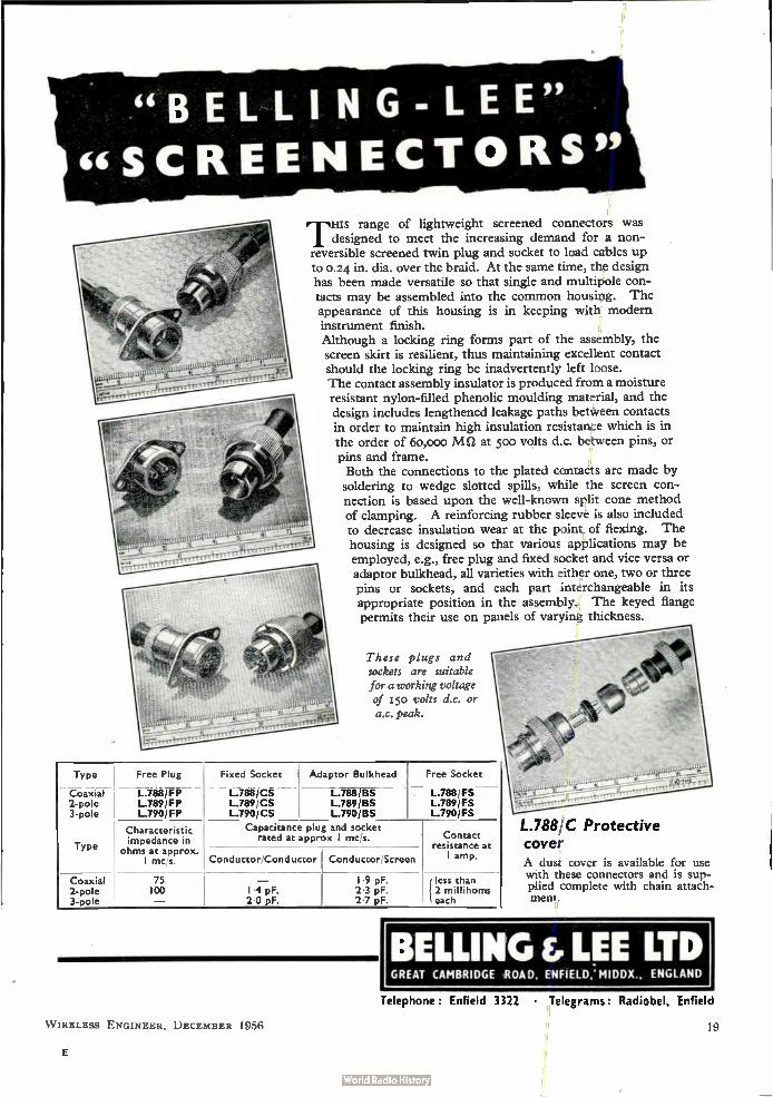
of lightweight screened connectors was I designed to meet the increasing demand for a non-reversible screened twin plug and socket to load cables up to 0.24 in. dia, over the braid. At the same time, the design has been made versatile so that single and multipole con-tacts may be assembled into the common housing. The appearance of this housing is in keeping with modern instrument finish. Although a locking ring forms part of the assembly, the screen skirt is resilient, thus maintaining excellent contact should the locking ring be inadvertently left loose. The contact assembly insulator is produced from a moisture resistant nylon-filled phenolic moulding material, and the design includes lengthened leakage paths between contacts in order to maintain high insulation resistance which is in the order of 6o,000 MS/ at 500 volts d.c. between pins, or pins and frame. Both the connections to the plated contacts are made by soldering to wedge slotted spills, while the screen con-nection is based upon the well-known split cone method of clamping. A reinforcing rubber sleeve is also included to decrease insulation wear at the point of flexing. The housing is designed so that various applications may be employed, e.g., free plug and fixed socket and vice versa or adaptor bulkhead, all varieties with either one, two or three pins or sockets, and each part interchangeable in its appropriate position in the assembly. The keyed flange permits their use on panels of varying thickness.
These plugs and sockets are suitable for a working voltage of 550 volts d.c. or a.c. peak.
Type
Coaxial 2-pole 3-pole
Type
Free Plug
L.788/FP L.789/FP L.790/FP
Characteristic impedance in
ohms at approx. I mcfs.
Coaxial 2-pole 3- ole
75 100
Fixed Socket Adaptor Bulkhead Free Socket
L.788/CS L.788/BS L.789/CS L.789/BS L.790/CS L.790/13S
Capacitance plug and socket rated at approx I mc's.
Conductor/Conductor Conductor Screen
I .7pF. 2.0 F.
I 9 pF. 2 3 pF 2 7 pF
L.788/FS L.789/FS L.790/FS
Contact resistance at I amp.
less than 2 millihoms each
L.788:C Protective cover A dusz cover is available for use with these connectors and is sup-plied complete with chain attach-ment.
BELLING & LEE LTD GREAT CAMBRIDGE ROAD, ENFIELD: MIDDX., ENGLAND
Telephone : Enfield 3322 • Telegrams: Radiobel, Enfield
WIRELESS ENGINEER, DECEMBER 1956
E
Type P 50 Plug Cylindrical bakelite case. Nickel plated metal parts. Ideal for amplifiers and other applications where concentric cable is used.
reliability
Igranic Plugs and Jacks have always had a justifiable reputation for dependability. For radio, television, office appliances and the hundred and one industrial plug-in applications demand has hitherto outstripped supply. NOW, with increased production facilities, Igranic Plugs and Jacks are available again for manufacturers to whom only the best is good enough.
Midget Jack. P 73 Moulded bakelite. Suitable for switching-in high fre-quency circuits. Capacity between springs eliminated. Silver contacts, one hole fixing, perfect contact.
delivery
INN
Type P 40 Plug Moulded bakelite. Nickel plated metal parts. Especi-ally suitable for extension speakers, headphones and similar application.
IGRANIC ELECTRIC COMPANY LIMITED HEAD OFFICE & WORKS BEDFORD London and Export Office VICTORIA STATION HOUSE 191 VICTORIA STREET LONDON SVVI GRAMS IGRANIC LONDON
Bran,h Offices BIRMINGHAM BRISTOL CARDIFF EAST ANGLIA GLASGOW LEEDS MANCHESTER NEWCASTLE SHEFFIELD
A METAL INDUSTRIES GROUP COMPANY
An
introduction to
the mechanism
and application
of
computers
20
10152/P2812
A new book for technicians, engineers and students
By T. E. Ivan
A non-mathematical introduction to the mechanism and application of
computers employing valves and transistors. Both digital and analogue
computers are covered, the bulk of the book being devoted to
describing their circuitry, while their rapidly developing applications in
industry, commerce and science are also outlined. In a final chapter
the future evolution of computers is discussed. 165 pp. Illustrated.
PRINCIPLES AND
APPLICATION
NOW READY 25s. net BY POST 25s. 9d.
from your bookseller Published by Iliffe and Sons Limited Dorset House Stamford Street London S.E.I
WIRELESS ENGINEER, DECEMBER 1956

Life Itne munication
„ N ek ee.
-:-'- - `.- 4•••••,..
»e.
1-;41 :efeFe‘._
,eie.eekt
World wide radio-communication began with Marconi's Transatlantic messages in 1901. Since then Marconi research and development have led to every major advance in technique. Marconi equipment today, operating at all frequencies, covers a very wide field of both long and short range radio-telegraph and radio-telephone requirements. Marconi VHF multi-channel equipment can provide for as many as 48 telephone channels and is largely superseding land-fine or cable routes on grounds of efficiency, economy and, where terrain is difficult, ease of installation and maintenance.
MARCONI Complete Communication Systems
Surveyed, Planned, Installed, Maintained
MARCONI'S WIRELESS TELEGRAPH COMPANY LIMITED, CHELMSFORD, ESSEX LG I
W IRELESS ENGINEER, DECEMBER 1956 21
A NEW WIDE BAND TWO CHANNEL
OSCILLOSCOPE MODEL DE103A D.C. to 10 Mcis
For the display of two high frequency variables sim-ultaneously and under exactly comparable conditions. Ideal for monitoring input and output waveforms of
a wide variety of electronic equipment.
a. Is
4. -i; An Improved
Wide Band
W D.C. Oscilloscope
Model DE103A
DOUBLE GUN CRT 6" diameter flat faced with illuminated graticule.
SWEEP SPEEDS continuously variable calibrated times from 0•2 sec to 2 ;sec per 10 cm on each channel.
TIME MEASUREMENT by direct reading dial in microseconds gives average accuracy of better than 5 per cent.
TRIGGERING circuitry of improved design operates from either negative- or positive-going pulses of great variety, and up to repeti-tion rates of 250 kc/s. Full screen sweeps from pulses as small as 50 mV.
REPETITIVE sweeps also available.
X SHIFT facilities enable the two traces to be aligned in any desired manner.
X AMPLIFIER with 3-step attenuator gives gain of 100 over D.C.-500 kc s.
Y AMPLIFIERS provide two channels with identical rise times of 0035 jlsec without overshoot. Response D.C. to 10 Mc s ( — 3dB). Sensitivity-125 mV cm pk-pic.
VOLTAGE CALIBRATED for measurement of input signals to 5 per cent accuracy.
SIGNAL DELAY AND CATHODE FOLLOWER PROBE units available.
SINGLE SHOT CAMERA with f i.s
NA ÇARD lens.
See what you measure! 1 9 AVENUE ROAD
BELMONT, SURREY VIOilani 9161/2
Manufacturers of all types of
INSTRUMENT CASES & CHASSIS in all METALS
GENERAL SHEET METAL WORK
for the Trade
HASE nRODUCTS
¡pea+ LTD
27 PACKINGTON RD., SOUTH ACTON, W.3 Acorn 1153-4 and at LEEDS
Quartz Crystals of any shape and size cut and ground precisely to specification and coated, if required, with
Gold, Silver, Aluminium, etc.
ED « BROOKES
Brookes Crystals Ltd. suppliers to Ministry of Supply, Home Office, B.B.C., etc. 181/3 TRAFALGAR ROAD, LONDON, S.E.I0
Phone: GREenwich 1828 Grams: Ruts, Green, London
W IRELESS ENGINEER, DECEMBER 1956

The VARIAC is the original on-load infinitely-variable vol-tage-adjusting transformer, and the only one employing "DURA-TRAK" (Reg'd.) i.e. tracks treated in accordance with U.K. Patent No. 693,406, which pro-duces a coating of precious metal alloy on the brush track, elimina-ting the possibility of deteriora-tion due to oxidation, much re-ducing contact resistance, en-suring increased life and economy in maintenance, and improved resistance to accidental short-circuits or serious temporary overloads.
All VARIACS have two current ratings. The rated current is limited by the heating of the core: this amount of current may be drawn at any setting of the dial. The maximum current rating is limited only by the current carry-ing capacity of the brushes and wire. This current may be up to 55% higher than the rated current, and can be drawn only
at voltages near to the input voltage, or near zero, since at these positions there is little auto-transformation and core heating is therefore negligible. When the " overvoltage "
feature is used, or when the VARIAC is used to feed a load of varying impedance, the current is limited to the rated current.
Bearing the above facts in mind, the correct VARIAC for any particular application may be selected from the table given opposite. Cut this announce-ment out and use it as a rapid selection guide.
For complete, profusely illus-trated data on the entire line of 1 - phase and 3 - phase and "special" VARIAC Transformers, request our new 3-colour Broch-ure Form 424-UK, as well as our special Price List Form VSP-56/16. Your request should be sent to our nearest Works.
\
"VARIAC"
Classification
CURRENT RATINGS (Amperes)
115 v. OPERATION 230 v. OPERATION
Rated (0-135 v. Output)
Maximum (0-115 s Output I
Raced (0-270 v. Output)
Maximum (0-230 v Output)
200-B
V-2
V-5: V5-H
V-6: V6H
V-10: V-10-H
100Q: 100-R
V-20: V2OH
V-30-H
50A: 50-B
1.0
2.0
5.0
6.0
10.0
15.0
20.0
- 40.0
1.5
3.0
7.5
7.5
130
17.5
26.0
- 45.0
-
-
2.0
3.0
4.0
8.0
8.0
15.0
20.0
-
-
2.6
3.75
5.2
9.0
10.4
17.5
31.0
M-2 M-5
M-I0
60-V
2.0
5.0 10.0
5.0
3.0
73 110 For use on 350-1200 cols.
7.5 For use on 400-2600 cis.
IIIWIM _
muumuu, unniummormmummtimiiiiMilimmilMimiErRounnmEnumnillinnilinfilintrinniumillinilliinnuonmmuummiliMulimmumninnim
FORTIPHONE
SUBMINIATURE A.F. TRANSFORMERS
PROTOTYPE SERVICE FOR
EQUIPMENT DESIGNERS
Prototypes of special windings can be supplied quickly at a nominal development charge. It is recommended that designers first establish the approximate circuit re-quirements with a multi-ratio transformer (such as types MM-IA or B), and then take the nearest of the 36 single-ratio standard windings (samples are available from stock).
Having established the limiting values for size, inductance, d.c. saturation or resistance, as the case may be, a discussion with our engineers is helpful in arriving at an optimum design, and the most suitable finish.
Details of this prototype service, with design notes on transformers and trans-ductors, and data on our standard range, will be sent on request.
FORTIPHONE, LTD.- COMPONENT DIVISION
92, Middlesex Street, London, E.1.
x,„„„„„„..„,„„ 1111 111111111111 ill11111,1111111111111,11.111111,1111I11111111
This table refers only to single winding toroidally-wound VARIACS and does not include double wound types (Types 70 and 80) or ganged assemblies, or 3-phase types, etc.
elaube ifpon$ Lb. 76 OLDHALL STREET • LIVERPOOL 3 • LANCS • TEL: CENTRAL 4641
VALLEY WORKS • HODDESDON HERTS • TEL: HODDESDON 1007
eed-fhwee REGD. TRADE MARK
"PERMATIP"
"PER1 D ABIT" INSTRUMENTS
FOR
GREATER SOLDERING
EFFICIENCY •
The soldering bit which maintains its face indefinitely without attention. 25 models available for mains or low voltage supply. Bit sizes 332 to 3/8 inch. Full details in booklet S.P.I 7 from sole manufacturers:-
LIGHT SOLDERING DEVELOPMENTS LTD. 106 GEORGE ST., CROYDON, SURREY
Telephone: CROydon 8589
W IRELESS ENGINEER, DECEMBER 1956 23
APPLICATIONS
are invited for pensionable posts as
EXAMINERS in the PATENT OFFICE
to undertake the official scientific, technical and legal work in
connection with Patent applications. There is a small number
of similar posts in the Ministry of Supply.
Age at least 21 and under 35 years on 1st January 1956, with
extension for regular Forces' service.
Candidates must have 1st or 2nd class Honours in Physics,
Chemistry, Mechanical or Electrical Engineering or in Mathe-
matics, or an equivalent qualification (e.g. A.M.I.M.E.,
A.M.I.C.E., A.M.I.E.E., A.R.I.C.), but for a limited number of
vacancies candidates with 1st or 2nd class honours degrees in
other subjects—scientific or otherwise—will be considered.
Candidates over 28 and under 35 on 1st January 1956, will,
exceptionally, be admitted without these requirements if they
have specially relevant experience.
Starting pay for 5-day week of 42 hours in London between
£605 and £1,120 (men) according to post-graduate (or equivalent)
experience and National Service. Maximum of scale £1,345.
Women's pay above £605 somewhat lower but being improved
under equal pay scheme. Good prospects of promotion to
Senior Examiner rising to £2,000 (under review) and reasonable
expectation of further promotion to Principal Examiner.
Application form and further particulars from Civil Service
Commission, Scientific Branch, 30 Old Burlington Street,
London, W.1, quoting S128/56 and stating date of birth.
Selection Board sits at intervals, as required.
Early application advised and in any case not later ilia,:
31st December 1956.
GOLD COAST LOCAL CIVIL SERVICE
POSTS AND TELECOMMUNICATIONS DEPARTMENT
Vacancies for Engineers (BCD108/13/03), Wireless Engineers (BCD108/13/04), 5nd Master, Telecommunications Engineering School (BCD108/13/07).
Appointments, either pensionable in salary range £825-£1,630 p.a. or contract in salary range £1,13042,020 plus temporary addition of £29 15s. p.a. Gratuity £12 10s, for each month of satisfactory service in contract appointments. Free passages for officer, wife and three children under 13 years. Quarters, if available, at reasonable rentals. Generous leave.
Candidates should have passed or be exempt from the examinations of the Institution of Electrical Engineers and have had two years' practical experience in the Engineering Depart-ment of the British Post Office or with a large telecommunica-tions equipment manufacturer.
I. Engineers. Candidates should preferably possess more than the minimum qualifications above and have wide knowledge and experience of telecommunications practice and administra-tion. Experience of power generation and distribution an advantage. To take charge of a telecommunications engineering district involving responsibility for installation and maintenance of overhead and underground telegraph apparatus.
2. Wireless Engineers. Candidates should also have had considerable experience with H.F. and V.H.F. fixed and mobile equipment, and air and sea navigational aids. Experience of power generation and transmission an advantage. To take charge of Wireless Engineering Division or be Assistant to Engineer in charge involving installation and maintenance of medium H.F. and V.H.F. W/T and Ft/T stations operated by Posts and Telecommunications, Police and Civil Aviation Departments.
3. Master, Telecommunications Engineering School. Candi-dates should also have had five additional years' experience in telecommunications engineering, and some experience of teach-ing. To be responsible for training of junior technical staff in telecommunications subjects, and to assist Principal of the school in administration and discipline.
Write Director of Recruitment, Colonial Office, London, S.W.1, giving age, qualifications and experience and quoting appropriate reference number.
NORTHERN POLYTECHNIC
DEPARTMENT OF PHYSICS
SHORT LECTURE COURSES
Transistor Circuits: Part I Tuesdays at 7.15 p.m.
Four lectures beginning 15th January 1957. Part II Tuesdays at 7.15 p.m.
Six lectures beginning 12th February 1957.
Radio-Frequency Noise Techniques: Mondays at 7.15 p.m. Six lectures beginning 25th February 1957.
Technology of Cold Cathode Valves: Thursdays at 7.15 p.m. Six lectures beginning 28th February 1957.
Enquiries should be addressed to the Head of Department of Physics, Northern Polytechnic, Holloway, N.7. Telephone: NORth 1686.
MULLARD RESEARCH LABORATORIES
invite applications from senior graduate scientists or engineers
with experience in C.R.T. development. The post carries sub-
stantial responsibility in a newly-formed group concerned with
the study and design of storage tubes for direct view display
and other purposes.
Excellent salary and conditions of employment, including Life
Assurance and Superannuation scheme, will be offered to the
successful applicant. Apply in writing to Mr. G. A. Taylor,
Personnel Officer, Mullard Research Laboratories, Cross Oak
Lane, Salfords, near Redhill, Surrey, quoting ref. CHT. (S).
Flight Trials Department of Smiths Aircraft Instruments Ltd.
have vacancies for staff to be responsible for installation and
flight test observer work on Auto controls and Flight Systems.
Immediate senior positions can be taken up by qualified
Engineers, interested in flying, with experience in light Electro-
Mechanical Engineering field, such as Gyroscopes, Electronics,
Radar, Navigational Aids, Servo-Systems, etc. Consideration
will also be given to Graduates, without previous experience,
who have completed National Service.
Candidates must be prepared to travel in the United Kingdom
and abroad.
Apply to Divisional Personnel Manager, Smiths Aircraft
Instruments Limited, Bishop's Cleeve, nr. Cheltenham, quoting
reference 85/EN/15.
THE COLLEGE OF AERONAUTICS
Applications are invited for the appointment of Lecturer in the Department of Aircraft Electrical Engineering. Salary dependent on qualifications and experience within a range rising to £1,200 per annum with F.S.S.U. and family allowance. A university degree or equivalent in engineering or physics is desirable and candidates should preferably (though not essen-tially) have experience of one of the following: (a) electrical machine design, (b) aircraft electrical installations, or (c) elec-trical power systems. Successful candidate will be required to lecture at post-graduate level on aircraft and G.W. power systems and to assist in the equipping and supervision of laboratories. Opportunities exist for private research work. Applications (quoting reference EP/L) giving full particulars and the names of three referees should be forwarded to the Recorder, The College of Aeronautics, Cranfield, Bletchley, Bucks, from whom further particulars may be obtained.
-4 W IRELESS ENGINEER, DECEMBER 1956
Government of Sierra Leone Radio Engineer—Posts and Telegraphs Department
Duties include executive control of the Radio Section; responsibility for maintenance and installation of R.T. and W.T. networks; H.F. and V.H.F. systems; point-to-point circuits; broadcasting system and ancillary equipment; marine and police radio apparatus, fixed and mobile. Implementation of a programme development scheme planned in the VHF/RT field.
Pensionable appointment in salary range £1,006 to £1,652
p.a. or contract appointment £1,138 to £1,857 p.a. Commencing salary depending on qualifications and experience. Contract gratuity, £37 10s, for each three months' satisfactory service. Quarters, if available, at reasonable rental. Generous leave.
Free passages for officer, wife and two children or £75
allowances for each of two children maintained outside Sierra Leone. Candidates should be A.M.I.E.E. or be exempted from the
Institution's examinations and should have had experience in the field of Radio Engineering.
Write Director of Recruitment, Colonial Office, London, S.W.1, giving age, qualifications and experience, quoting BCD108/15/04.
BOOKS WANTED—WIRELESS ENGINEER
JANUARY, 1950 MARCH, 1950
FEBRUARY, 1950 OCTOBER, 1952
Please send details, price, etc.,
to Box No. 4620, go Wireless Engineer.
Technical Officer (Radio/Radar Duties) required by East Africa
High Commission Meteorological Dept. for tour of 30/36 months.
Commencing salary according to qualifications and experience
in salary scale (including inducement pay) £813 rising to £1,341
a year. Appointment either (a) on pensionable terms subject to
a probationary period of two years or (b) on contract with
gratuity at rate of 13} per cent of total emoluments drawn.
Outfit allowance £30. Free passages. Liberal leave on full
salary. Candidates should possess Higher National Certificate
or City and Guilds Final Certificate (5-year Group Course in
relevant subjects) or General Certificate of Education at
Advanced Level in physics and mathematics. Experience of
operation and maintenance of ground radar equipment is
essential and acquaintance with radio sonde and telecommunica-
tion techniques is desirable. Duties include operation and
maintenance of meteorological electronic and radio equipment,
ionospheric sounders, " SFERICS " and diesel plant. Write to
the Crown Agents, 4 Millbank, London, S.W.I. State age,
name in block letters, full qualifications and experience and
quote M313/43739/W.I.
E.M.I. ELECTRONICS LTD.
Engineering Development Division
DIGITAL DATA PROCESSING SYSTEMS. The line
communication problems emanating from the application of
digital data handling techniques to specific systems have resulted in the following vacancies:—
Senior Line Communication Engineer. A qualified telephone engineer having at least eight years' experience in system design and switching techniques, is required to lead a small line communication team within the Digital
Computer Division of the Company. This post calls for an engineer of above average capabilities and evidence
will be required of original work.
Junior Communication Engineer. Several vacancies exist for qualified junior engineers to work on the ancillary
equipment of a digit data processing system. Experience in video and switching techniques is required, although training will be given in the application of transistor and
magnetic cores to these problems. Applications should be made with full details to EL/E.18
Personnel Department, E.M.I. Electronics Ltd., Hayes, Middx.
•
•
STEEL SHELVING
100 bays of brand new adjustable STEEL SHELVING, 72" high x 34" wide x 12" deep, stove enamelled bronze green. Sent knocked down, 6-shelf bay— £3 15s. Od. Sample delivered free. N. C. BROWN LTD., EAGLE STEELWORKS,
HEYWOOD. LANCS. Telephone 69318.
•
BROADCASTING ENGINEERS
Applications are invited from racfio engineers for eventual
appointment as broadcasting engineers in the Government
broadcasting services of Colonial and Oversea Territories.
Applicants should be over the age of 28 and be Graduates oi
the Institution of Electrical Engineers or in possession of an
Engineering Degree or Diploma recognized as granting exemption
from the Institution's examination. Experience in the radio
industry or in the radio branches of Her Majesty's Services for
at least two years is necessary, but applicants need not have
experience directly related to broadcasting.
Successful applicants will receive operational training in the
B.B.C., and at any time within two years after initial engagement
they will be required to take up contract appointments with a
Colonial or Oversea Government in any part of the world as
broadcasting engineers. Choice of territory will be given where
possible, but it is not guaranteed.
Total emoluments during training in the U.K.: £880 per
annum. Salary on appointment to a Colonial territory will not
be less than £1,000 per annum.
Apply Director of Recruitment, Colonial Office, London,
S.W.I, giving age, qualifications and experience, quoting
BCD96/02.
W IRELESS ENGINEER, DECEMBER 1956 , .5
TECHNICAL BOOKS A large selection of books on Radio and Electronics and all branches of Electrical Engineering always in stock. Catalogues available. Please state
interests.
SCIENTIFIC AND TECHNICAL LENDING LIBRARY
Annual Subscription from LI I7s. 6d.
H. K. LEWIS & Co. Ltd. 136 Gower Street, London, W.C.I
Telephone: EUSton 4282 (7 lines) Business hours :-9 a.m. to 5.30 p.m. Saturdays to I po:.
THE COLLEGE OF AERONAUTICS
Applications are invited for the appointment of Lecturer in the Department of Aircraft Electrical Engineering. A university degree in physics or electrical engineering is desirable, together with experience in telecommunications, radar, microwave tech-niques or allied subjects. A knowledge of aeronautical applica-tions would be an added qualification but is not essential. Salary dependent on qualifications and experience within a range rising to £1,200 per annum with F.S.S.U. and family allowance. Successful candidate will be required to lecture at a post-graduate level on aircraft and G.W. guidance systems and to assist in the equipping and supervision of laboratories. Opportunities exist for private research work. Applications (quoting reference ER/L) giving full particulars and the names of three referees should be forwarded to the Recorder, The College of Aero-nautics, Cranfield, Bletchley, Bucks, from whom further particulars may be obtained.
1:111iniuniuniunumuminuninumummiunimmuunion
g THE WORLD'S GREATEST BOOKSHOP
ES • FOR. BOO,,.. E
45 New and secondhand Books on every subject. Large a E Technical dept. Stock if over three million volumes. E
119 -125 CHARING CROSS ROAD, LONDON, W.C.2 H È Gerrard 5660 (16 lines) * Open 9-6 (inc. Sat.) = E 111111W11111111a111111111111aiaallIldffill1111111111aalllalffill111111111111111111111111111111111111111111alinalliM1111,m;
Index to Advertisers PAGE
Aero Research, Ltd 9 Airrnec, Ltd Anderton Springs, Ltd Appointments Vacant 24,25,26 Automatic Coil Winder & Electrical Equipment Co., Ltd., The Cover ii
Belling & Lee, Ltd 19 British Insulated Callender's Cables, Ltd 10 Brookes Crystals, Ltd 22 Brown, N. C., Ltd 25
Chase Products, Ltd 22 Cinema Television, Ltd 7 Cow, P. B. & Co., Ltd 14
Edison Swan Electric Co., Ltd 3 Elgar Trading, Ltd 26
IMPROVE YOUR
TELEVISION
RECEPTION
Explains how
to get
the best
from a
televisimu:
receivéle ............................................................................. ,•• .................................................................................. ......................................................... ...........
By John Cura and Leonard Stanley. Gives a clear and
comprehensive explanation of the functions of the various
controls on a television set with precise instructions on how
to operate these controls to obtain the best results on
the screen. Also covers interference and tells how it may
be minimized or eliminated and the choice and installation
of aerials and Band III converters.
Illustrated by over 100 "tele-snaps"
Published by Iliffe & Sons Ltd.,
Dorset House, Stamford St., London, SE I
112 pp. 5s net BY POST 5s 4c1
from your
bookseller
ELGAR SILVER PRODUCTS
Full range of silver preparations for silvered condenser manu-
factures and other applications in electronics.
Elgar Laboratories (Elgar Trading Ltd.), 240 High Street,
London, N.W.10.
English Electric Valve Co., Ltd
26 Ferranti, Ltd. 2 Fortiphone, Ltd 23 Foyle, W. & G., Ltd 26
General Electric Co., Ltd., The 6
Igranic Electric Co., Ltd Iliffe & Sons, Ltd. 20, 26
Lewis, H. K. & Co., Ltd 26 Light Soldering Developments, Ltd 23 Lyons, Claude, Ltd. 1, 23
Marconi's Wireless Telegraph Co., Ltd 21 Microcell, Ltd 13 Mallard, Ltd 18
Write for DATA SHEETS to Dept. 4.3, ANDERTON
SPRINGS LTD., BINGLEY
Telephone: 2388. 2351 & 2226 Telegrams: Circlips. Bingley
A.K.b., appeoreo
PAGE PAGE 16 Multicore Solders, Ltd Cover iv
Nagard, Ltd 22
Philips Electrical, Ltd 14
Standard Telephones & Cables, Ltd 5 20 Steatite & Porcelain Products, Ltd 4
Technical Ceramics, Ltd 15 Telegraph Condenser Co., Ltd., The....Cover ni Telephone Mfg. Co., Ltd 8
Unbrako Socket Screw Co., Ltd It
Welwyn Laboratories, Ltd 12
26
Printed in Great Britain for the Publishers, Iliffe & Sons, Ltd., Dorset House, Stamford Street, London, S.E.1 by W. P. Griffith & Sons, Ltd., London and Bedford.
WIRELESS ENGINEER, DECEMBER 1956
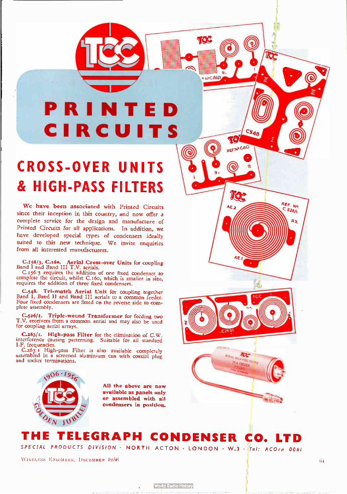
/Is
PRINTED CIRCUITS
CROSS-OVER UNITS
& HIGH-PASS FILTERS We have been associated with Printed Circuits
since their inception in this country, and now offer a
complete service for the design and manufacture of
Printed Circuits for all applications. In addition, we
have developed special types of condensers ideally
suited to this new technique. We invite enquiries from all interested manufacturers.
C.I56/3, C.16o. Aerial Cross-over Units for coupling Band I and Band III T.V. aerials.
C.156,3 requires the addition of one fixed condenser to complete the circuit, whilst C.166, which is smaller in size, requires the addition of three fixed condensers.
C.548. Tri-match Aerial Unit for coupling together Band I, Band II and Band III aerials to a common feeder. Four fixed condensers are fitted on the reverse side to com-plete assembly.
C.526/1. Triple-wound Transformer for feeding two T.V. receivers from a common aerial and may also be used for coupling aerial arrays.
C.263/x. High-pass Filter for the elimination of C.W. interference causing patterning. Suitable for all standard I.F. frequencies.
C.263 High-pass Filter is also available completely assembled in a screened aluminium can with coaxial plug and socket terminations.
0 06 "i9s6,
All the above are now available as panels only or assembled with all condensers in position.
THE TELEGRAPH CONDENSER CO. LTD SPECIAL PRODUCTS DIVISION • NORTH ACTON • LONDON • W .3 • Tel: ACOrn 0061
W IRELESS ENGINEER, DECEMBER 1956
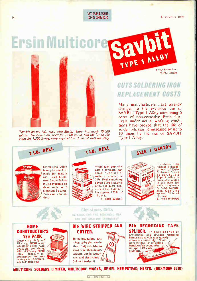
IV
WI RELESS ENGINEER )1.:CEMBER 1956
The bit on the left, used with Savbit Alloy, has made 10,000 joints. The centre bit, used for 1,000 ¡oints, and the bit on the right for 7,500 joints, were used with a standard tin/lead alloy.
set.
Savbit Type 1 Alloy is supplied on 7 lb. Reels for factory use. Ersin Multi-
core 5-core Solder is also available on these reels in 6 alloys and 9 gauges. Prices on applica-tion.
HOME CONSTRUCTOR'S . 11.1118P
2/6 PACK Contains 19 ft. of 18 s.w.g. 60/40 alloy wound on a reel. Also available containing 40 ft. of 22 s.w.g. 60/40 alloy — specially re-commended for sol-dering printed circuits. 2/6 each (subject).
British Patent Nos. 700763, 721881
CUTS SOLDERING IRON
REPLACEMENT COSTS
Many manufacturers have already changed to the exclusive use of SAVBIT Type 1 Alloy containing 5 cores of non-corrosive Ersin flux. Tests under actual working condi-tions have proved that the life of solder bits can be increased by up to 10 times by the use of SAVBIT Type 1 Alloy.
When each operative uses a comparatively small quantity of solder at a time, the 1 lb. Reel containing Savbit Type 1 Alloy is often the most con-venient size. Contain-ing approx. 170 ft. of 18 s.w.g.
I5/- each (subject)
su£ crte"" In addition to the normal 4 specifi-cations of Ersin Multicore 5-core Solder, Savbit Type I Alloy is nowalso available in this pack for service engineers or radio enthusi-asts. Contains .ipprox. 53 ft. of 18 s.w.g. 51- each (subject)
Christmas Gifts SLITABLE FOR THE TECHNICAL MAN
AND THE AMATEUR ENTHUSIAST
Bib WIRE STRIPPER AND
CUTTER.
Strips insulation; cuts
ires; splits plastic twin
flex. Adjustable to
(subject). 3/6 each (s ///: &Ulm.
thicknesses. most wire An ideal gift for handy-
men and electricians.
1*4 Bib RECORDING TAPE
SPLICER. This device enables professional and amateur recording enthusiasts to edit tape quickly, accurately and easily. Soon pays for itself by affording considerable economies in tape. 18/6 each - (subject).
• ›e.!--
MULTICORE SOLDERS LIMITED, MULT1CORE WORKS, HEMEL HEMPSTEAD, HERTS. (BOXMOOR 3636)
Copyright © 2022 FDOKUMEN