Evaluating the gnu software radio platform for wireless testbeds
12
University of Paderborn Computer Networks Group Evaluating the GNU Software Radio platform for wireless testbeds Stefan Valentin, Holger von Malm, Holger Karl {stefanv|holgervm|holger.karl}@upb.de February 2006 Technical Report TR-RI-06-273 Technical report
Transcript of Evaluating the gnu software radio platform for wireless testbeds
University of Paderborn
Computer Networks Group
Evaluating the GNU Software Radioplatform for wireless testbeds
Stefan Valentin, Holger von Malm,
Holger Karl
{stefanv|holgervm|holger.karl}@upb.de
February 2006
Technical Report TR-RI-06-273
Technical report

Abstract
Software Defined Radios (SDR) can provide the protocol engineer with wireless test-beds that are fully programmable at the DLC, MAC and PHY. The benefit of thisflexibility highly depends on the performance and usability of the specific SDR. In thispaper we study the performance and implementational cost of a wireless testbed based ona specific SDR, the GNU Software Radio (GSR) [1]. We implemented a complete trans-ceiver chain [2] which we characterize by implementation complexity. Further, we measurethe performance of the testbed running this chain. We found that the GSR platform sup-ports the programmer with a sophisticated SDR programming environment, resulting inlow implementational cost. However, this benefit has to be paid for by overhead andsome runtime environment idiosyncrasies, resulting in a low system performance.

1 INTRODUCTION
1 Introduction
Experiments with wireless communication systems can show whether all significant parame-ters, e.g. related to the scenario or the wireless channel, were taken into account in systemdesign and simulation. Wireless testbeds enable such experimentation.
Besides producing stable and reproducible results, such a testbed should allow changesof the experimental setup. This requires modification of system parameters and adaptingfunctionality to experimental needs. Such adaptation is easily possible for higher protocollayers that are implemented in software, e.g. routing or transport layer protocols. Adapt-ing functions at lower protocol layers that are implemented in or are heavily supported byhardware (such as Physical layer (PHY) and Data Link Control layer (DLC) functions) isnontrivial or impossible with standard equipment. As an example, enhancing 802.11 by anoptimized multi hop scheme via changing the Medium Access Control (MAC) or accessingkey PHY parameters is an impossible or very time-intense task on standard 802.11 devices.Hence, to support lower-layer wireless protocol engineering, a more flexible testbed platformis necessary. Such a platform is provided by the Software Defined Radio (SDR) approach [3].
SDR, also called Software Radio, refers to an architecture for wireless communicationdevices where only Radio Frequency (RF) and signal conversion functions are implementedin hardware. All further functions, e.g. modulation, are software implemented, maximizingflexibility and enabling the construction of wireless testbeds that are programmable at thePHY, DLC, and MAC. Such SDR testbeds also support protocol engineers optimizing higherlayers of the stack by adapting to PHY and MAC parameters (cross-layer optimization), sincehere these parameters are easily accessible or controllable.
However, the benefit of this flexibility depends on how the protocol engineer is supportedby the underlying SDR platform. The first important criteria here is the performance of theSDR, which hast to suit the targeted scenario. Further, due to the massive increase of softwarefunctions in an SDR (compared to a hardware-based radio) a sophisticated programmingenvironment is needed to handle the complex system. Thus, the second important criteria isthe programmer’s productivity achieved with the programming environment. The resultingdevelopment cost and testbed performance are thus highly correlated to the structure andimplementation of the specific SDR platform.
In this paper, we evaluate whether a specific SDR implementation, the GNU SoftwareRadio (GSR), is suitable for constructing testbeds and how it supports the protocol engineeraccording to these two criteria. To characterize the type of wireless testbeds for which GSRis suitable and the development cost of such a testbed, we analyze both SDR performanceand overhead of a practical protocol implementation: a full PHY and DLC transceiver chain.The GSR platform was chosen because this open source project combines an up-to-date SDRdevelopment environment with freely available and low-cost hardware designs [1].
Although performance is an important parameter, it is not the key aspect for constructingwireless testbeds with SDR. Since in an SDR the programmer can choose which componentsof the communication systems are included in the testbed, complexity can be limited byincluding only the functions that are relevant for the experiment. For example, for testingan optimized 802.11 MAC protocol it may not be necessary to include the 802.11 encryptionschemes in the testbed. This enables a trade off between the available performance of theunderlying SDR system and the needed functionality of the system. Hence, in addition to the
Copyright at University ofPaderborn. All Rights reserved.
TR-RI-06-273 Page 1
2 SOFTWARE DEFINED RADIO PLATFORMS
performance aspect we rather focus on usability and productivity of the GSR programmingenvironment and how this affects implementation complexity.
The next section surveys the SDR approach and the GSR platform. In Section 3 theimplemented testbed is described. Experimental setup, methodology, and results related tothe performance measurements are presented in Section 4. We finally conclude the paper andoutline future work.
2 Software defined radio platforms
In this section we introduce the architecture and basic approach of SDR, describe the GSRplatform and programming environment, and discuss how this is helpful for a wireless testbedimplementation.
2.1 SDR – architecture and programming environments
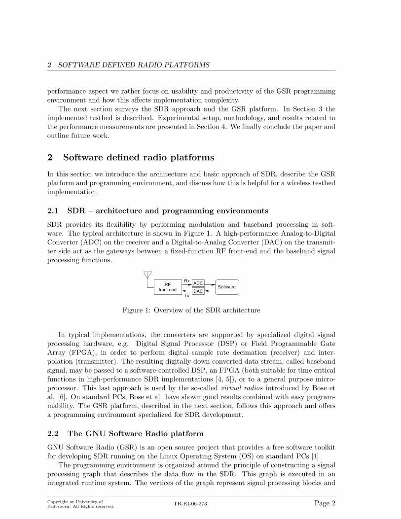
SDR provides its flexibility by performing modulation and baseband processing in soft-ware. The typical architecture is shown in Figure 1. A high-performance Analog-to-DigitalConverter (ADC) on the receiver and a Digital-to-Analog Converter (DAC) on the transmit-ter side act as the gateways between a fixed-function RF front-end and the baseband signalprocessing functions.
SoftwareADC
DAC
RFfront end
Tx
Rx
Figure 1: Overview of the SDR architecture
In typical implementations, the converters are supported by specialized digital signalprocessing hardware, e.g. Digital Signal Processor (DSP) or Field Programmable GateArray (FPGA), in order to perform digital sample rate decimation (receiver) and inter-polation (transmitter). The resulting digitally down-converted data stream, called basebandsignal, may be passed to a software-controlled DSP, an FPGA (both suitable for time criticalfunctions in high-performance SDR implementations [4, 5]), or to a general purpose micro-processor. This last approach is used by the so-called virtual radios introduced by Bose etal. [6]. On standard PCs, Bose et al. have shown good results combined with easy program-mability. The GSR platform, described in the next section, follows this approach and offersa programming environment specialized for SDR development.
2.2 The GNU Software Radio platform
GNU Software Radio (GSR) is an open source project that provides a free software toolkitfor developing SDR running on the Linux Operating System (OS) on standard PCs [1].
The programming environment is organized around the principle of constructing a signalprocessing graph that describes the data flow in the SDR. This graph is executed in anintegrated runtime system. The vertices of the graph represent signal processing blocks and
Copyright at University ofPaderborn. All Rights reserved.
TR-RI-06-273 Page 2

3 TESTBED IMPLEMENTATION
the edges are the data flow between them [7]. Signal processing blocks are functional entitiesimplemented in C++ which operate on infinite data streams flowing from a number of inputports to a number of output ports specified per block. There are primitive signal processingblocks and hierarchical signal processing blocks, which may aggregate both primitive andhierarchical blocks. GSR provides a large and growing software library of individual signalprocessing routines as well as complete signal processing blocks. Signal graphs can be easilyconstructed using the object-oriented script language Python.
The runtime system provides dynamic buffer allocation and scheduling according to fixedor dynamic I/O rates of the blocks. The scheduler supports signal graph modifications atruntime. The underlying runtime system can be controlled from Python, meaning that signalgraphs can be changed or information can be extracted from the blocks. Furthermore, theenvironment provides integration of the SDR with the host OS. This enables e.g. to use theSDR as a component of a standard Unix pipeline or utilizing Inter-Process Communication(IPC) for soft real-time signal visualization.
While GSR is hardware-independent, it directly supports hardware front ends via specificsource and sink signal blocks. Due to its high integration in GSR and low cost, we focus onthe so-called Universal Software Radio Peripheral (USRP) front end designed by Ettus et al.[8]. The USRP consists of one mainboard and up to 2 Rx and 2 Tx daughterboards. Whilethe mainboard performs ADC & DAC conversion, sample rate decimation/interpolation, andinterfacing, the daughterboards contain fixed RF front ends or direct interfaces to the main-board’s ADC & DAC. The mainboard is connected via the USB2.0 bus to a PC running theactual GSR. Although the mainboard is able to process signals of up to 64MHz bandwidth,the data rate of the USB2.0 bus limits the bandwidth of the base band signal to 8 MHz.
3 Testbed implementation
To evaluate this framework’s usability and performance, we implemented a wireless testbedon the GSR platform. The testbed contains wireless basic DLC functions and, since onlybaseband interpolation and conversion is performed at the USRP, all PHY functions on thebaseband signal. The full source code of this testbed is available on the project web page [2].
An important design decision is how to distribute this functionality to the different layersof the GSR environment. We decided to implement time-critical PHY and DLC functions(e.g. modulation, framing) in distinct signal blocks; further DLC protocol functions areimplemented at the Python layer. Thus, signal blocks can be reused in the sender andreceiver graph and the basic DLC functions have full control over the graphs.
3.1 DLC protocol implementation
Automatic Repeat Request (ARQ) and MAC functions are implemented at the Python layerof GSR within the DLC control script. We chose the most simple protocols, i.e., Send-and-wait and ALOHA. Figure 2 shows the resulting DLC frame.
The Python DLC control script includes the protocol and graph control functions forboth, transmitter and receiver. If the script is in transmission mode, the protocol parametersframe size N and the CRC result C are exchanged between the Python DLC control scriptand the signal graph at runtime (Figure 3). Furthermore, the script passes and extracts
Copyright at University ofPaderborn. All Rights reserved.
TR-RI-06-273 Page 3

3 TESTBED IMPLEMENTATION
Dest. Send.addr.addr.
Type Seq.# Payload EFD
1 11 1 1
N
FEC
4
checksumCRC
Figure 2: DLC frame layout with CRC and FEC extensions (field lengths in Bytes)
payload to/from the signal graphs and includes functions for graph construction and USRPsetup. The total length of the DLC control script is 342 lines, which is, for example, 235 linesless than the ALOHA example in the popular OMNeT++ simulator.
3.2 Transmitter signal graph
The transmitter graph is established and passed to the GSR runtime environment if a frameis passed to the DLC control script. The graph is structured in signal blocks as shownin Figure 3. Its separation was chosen to reflect functional entities of the typical wirelesstransmission and, as stated above, to enable reuse of the blocks in the transmitter andreceiver graphs.
C
controlscript
Gausslow pass polation
Inter− PreambleNRZ
FMTo
USRPGain USRPsink
Signal graph
FECCRCFrameSource
N
DLC
Figure 3: Transmitter signal graph and DLC control script
The transmission path starts at the Source block where a data stream is received from theDLC script. From this payload the Frame block takes N − 9 Bytes and constructs the DLCframe. The 32-bit checksum is calculated in the CRC block, which we have implementedusing standard library functions [9], and added to the frame resulting in a total frame lengthof N Bytes (Figure 2). We further implemented an FEC convolution coding block basedon Karn’s FEC library [10]. After encoding, the frame is extended by the synchronizationpreamble followed by NRZ channel coding. The resulting digital signal is interpolated andpassed to the Gaussian Minimum Shift Keying (GMSK) modulation scheme, which is imple-mented in the Gauss and Fm blocks. These blocks contain the Gaussian low pass filter andthe frequency modulation functions. Finally, the modulated digital signal is multiplied bythe gain factor G and passed to the USRP sink block from which it is transmitted via theUSB bus to the USRP.
Copyright at University ofPaderborn. All Rights reserved.
TR-RI-06-273 Page 4
4 PERFORMANCE STUDY
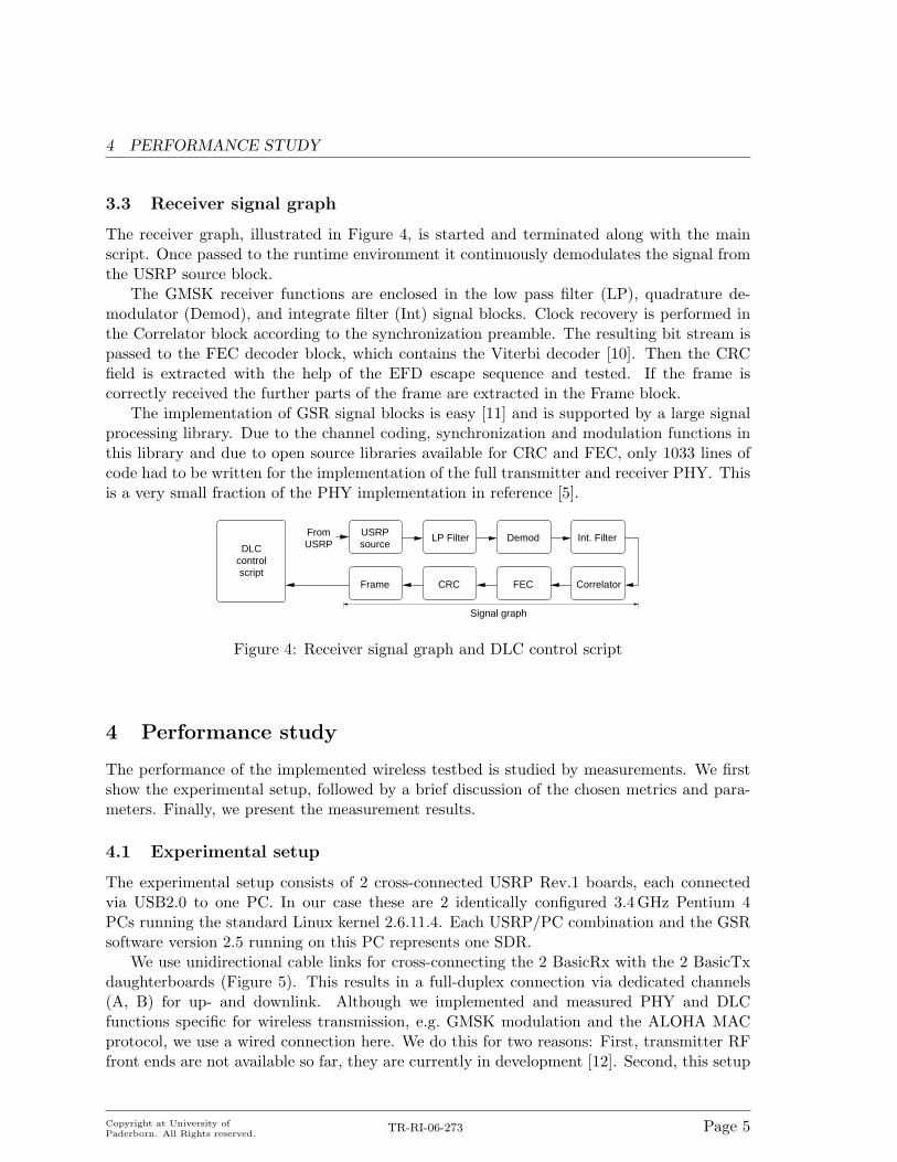
3.3 Receiver signal graph
The receiver graph, illustrated in Figure 4, is started and terminated along with the mainscript. Once passed to the runtime environment it continuously demodulates the signal fromthe USRP source block.
The GMSK receiver functions are enclosed in the low pass filter (LP), quadrature de-modulator (Demod), and integrate filter (Int) signal blocks. Clock recovery is performed inthe Correlator block according to the synchronization preamble. The resulting bit stream ispassed to the FEC decoder block, which contains the Viterbi decoder [10]. Then the CRCfield is extracted with the help of the EFD escape sequence and tested. If the frame iscorrectly received the further parts of the frame are extracted in the Frame block.
The implementation of GSR signal blocks is easy [11] and is supported by a large signalprocessing library. Due to the channel coding, synchronization and modulation functions inthis library and due to open source libraries available for CRC and FEC, only 1033 lines ofcode had to be written for the implementation of the full transmitter and receiver PHY. Thisis a very small fraction of the PHY implementation in reference [5].
Correlator
sourceDLCcontrolscript
USRPFrom
Signal graph
LP Filter Demod Int. Filter
CRCFrame FEC
USRP
Figure 4: Receiver signal graph and DLC control script
4 Performance study
The performance of the implemented wireless testbed is studied by measurements. We firstshow the experimental setup, followed by a brief discussion of the chosen metrics and para-meters. Finally, we present the measurement results.
4.1 Experimental setup
The experimental setup consists of 2 cross-connected USRP Rev.1 boards, each connectedvia USB2.0 to one PC. In our case these are 2 identically configured 3.4 GHz Pentium 4PCs running the standard Linux kernel 2.6.11.4. Each USRP/PC combination and the GSRsoftware version 2.5 running on this PC represents one SDR.
We use unidirectional cable links for cross-connecting the 2 BasicRx with the 2 BasicTxdaughterboards (Figure 5). This results in a full-duplex connection via dedicated channels(A, B) for up- and downlink. Although we implemented and measured PHY and DLCfunctions specific for wireless transmission, e.g. GMSK modulation and the ALOHA MACprotocol, we use a wired connection here. We do this for two reasons: First, transmitter RFfront ends are not available so far, they are currently in development [12]. Second, this setup
Copyright at University ofPaderborn. All Rights reserved.
TR-RI-06-273 Page 5

4 PERFORMANCE STUDY
Figure 5: Experimental setup using 2 cross-connected USRP, each board is linked to oneLinux PC via the USB2.0 bus
enables us to evaluate the performance of the testbed as such without having to contend withany experimental uncertainties or side effects of the wireless channel.
4.2 Metrics and parameterization
In the given setup, one performance metric is Round Trip Time (RTT). We measure RTTas the time that elapses from the start of sending one DLC frame from one SDR to anotherto the complete reception of an acknowledgment DLC frame of the same size. Since RTT ismeasured between the DLC layers of the sender and the receiver the full testbed is included.The transceiver chains of both directions are identical. In such a symmetrical system theRTT comprises twice the latencies at the transceiver signal graphs, the time to communicatebetween PC and USRP and the actual signal propagation delay. The RTT is further studiedby measuring the latency, i.e. time between input and output, of each signal block. Theresults for RTT and block latencies shown in the next subsection are both normalized totime in ms per bit.
In addition to the basic system parameters discussed in Section 2 and 3 we chose thefollowing parameters for the performance measurement: Total length of a DLC frame ischosen to be N = 1000 Bytes, FEC convolution coding is performed at a code rate 1/2. Forthe GMSK modulation scheme we chose a symbol time of 10 µs and 30 kHz for the bandwidthof the Gaussian filter, and G = 8000 for the gain factor.
4.3 Results
Figure 6 shows the histogram of the RTT between the DLC layers of the 2 SDR. The meanof the 706 samples is RTT = 3.14 ms and the standard deviation is 0.11ms. From this we cancalculate the mean throughput. We assume that no pipelining occurs in the system, which isreasonable since the Send-and-wait ARQ protocol transmits packets sequentially and thereis no parallelization in the transceiver themselves. Hence, in this symmetrical system, themean throughput is 2/RTT = 636Bits/s.
Copyright at University ofPaderborn. All Rights reserved.
TR-RI-06-273 Page 6

4 PERFORMANCE STUDY
2 2.2 2.4 2.6 2.8 3 3.2 3.4 3.60
100
200
300
400
500
600
Round trip time [ms]
Occ
uran
ces
Figure 6: Histogram of the DLC to DLC Round Trip Time (RTT) per bit
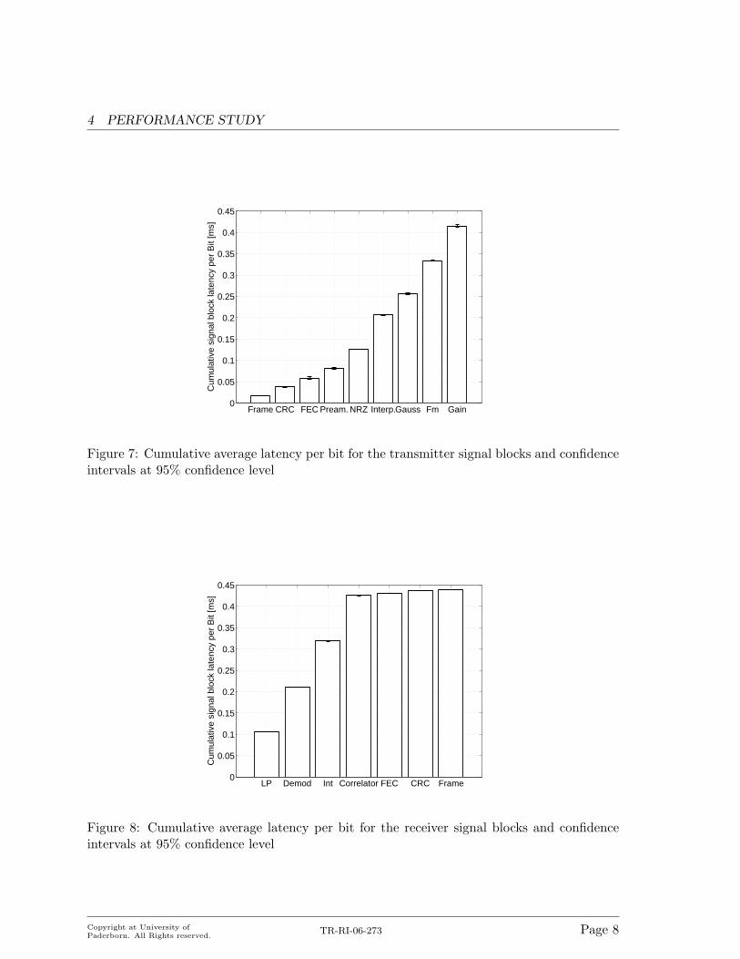
The measurement results of the block latencies are shown in Figure 7 and 8. The signalblocks are shown on the x-axis and ordered according to their position in the signal graphs(blocks resulting in zero latency are not included). Both figures show cumulative values (theresult for the actual block is always added to the sum of the results for the preceding blocks).The results for the transmitter signal blocks show that most time is consumed by interpolationand modulation functions (Interp., Gauss and Fm blocks). At the last block, the total latencyof the transmitter signal graph adds up to ∆Ttx = 0.42 ms. In the receiver signal graph, filter,demodulation, and correlation are the most time-intensive functions. The block latency sumsup to ∆Trx = 0.44 ms. Hence, the total delay caused by the latency of all signal blocks fortransmitting 2 packets (e.g., data and acknowledgment) is 2× (∆Ttx + ∆Trx) = 1.72 ms.
Thus, calculating the signal blocks causes 55% of the measured RTT. Relative to thetotal RTT the propagation delay and delays due to USB bus transfer and USRP calculationscan be neglected. Thus, the 45% of the RTT not spent calculating signal blocks is overheadcaused by the GSR runtime environment and Python control scripts.
The low performance, compared to the symbol time, is caused by two reasons. First, inthe DLC implementation the most simple and inefficient ARQ protocol Send-and-wait hasbeen used. This inhibits benefits due to pipelining since only one DLC frame is handled bythe transceiver chain at the same time. Allowing even 2 instead of only one outstandingunacknowledged packets would increase efficiency by a factor of about two. Compared to ahardware based system, it bears to mention that the somewhat unusual ratio of low raw datarate vs. high processing overhead in an SDR system need some getting used to. The secondreason for the low performance is that the filter blocks of the employed GMSK implementationsuffer from a limitation of the GSR framework [13]. Filters in GSR do not produce outputunless they are entirely filled. That is, if a filter has M taps, it will not produce data unlessthere are at least M samples to work with. Due to this reason the filter blocks permanentlysuffer from buffer underruns which cause constant underutilization of the system.
Copyright at University ofPaderborn. All Rights reserved.
TR-RI-06-273 Page 7
4 PERFORMANCE STUDY
Frame CRC FEC Pream. NRZ Interp.Gauss Fm Gain0
0.05
0.1
0.15
0.2
0.25
0.3
0.35
0.4
0.45C
umul
ativ
e si
gnal
blo
ck la
tenc
y pe
r B
it [m
s]
Figure 7: Cumulative average latency per bit for the transmitter signal blocks and confidenceintervals at 95% confidence level
LP Demod Int Correlator FEC CRC Frame0
0.05
0.1
0.15
0.2
0.25
0.3
0.35
0.4
0.45
Cum
ulat
ive
sign
al b
lock
late
ncy
per
Bit
[ms]
Figure 8: Cumulative average latency per bit for the receiver signal blocks and confidenceintervals at 95% confidence level
Copyright at University ofPaderborn. All Rights reserved.
TR-RI-06-273 Page 8

5 CONCLUSIONS AND FUTURE WORK
5 Conclusions and future work
Comparing GSR to other SDR platforms [4, 5, 6] we can conclude the following: First, theperformance achieved by the implemented testbed is low. Therefore, the system is not suit-able for real time testbeds in the MBit range. Performance is limited by the programmingenvironment and the inefficient filter functions of the GSR signal processing library (Sec-tion 4.3). Several projects on this SDR show that throughput is much higher if this problemcan be circumvented [14]. However, such circumvention strategies are not immediately ap-plicable to a wireless protocol testbed. Currently, they are a better fit with streaming dataprocessing. This issue requires further work. Since GSR is a lively project with an activecommunity, one can speculate that the range of available functions will increase quickly. Thiscommunity, however, is currently not a typical networking community, as witnessed also bythe specific performance problems of communication protocols.
Our second conclusion is, that the testbed programmer is supported by a sophisticatedprogramming environment. We found that this results in low preparation and implementationtime and low program complexity. Compared to high-performance SDR testbeds, e.g. [5],the resulting code is short (1375 lines to implement a full PHY & DLC transceiver testbed),modular, and OS and hardware independent. These properties enable to easily share theimplemented transceiver blocks with the development community which extends the GSRfunction library and further reduces development time.
To sum up: The arguments in favor of GSR are its low cost, its large flexibility, itseasy-to-use and rich programming environment, and its vibrant community. The main disad-vantage is that the programming environment is not perfectly suitable to handling protocols.Therefore, there is a specific price to pay for flexibility when using the GSR in its currentform. Whether this price, in terms of performance, for high flexibility and usability of thetestbed is reasonable depends on the experimental needs. One possible approach to dealwith limited performance is to adapt the testbed complexity to the needed time base. Forexample, reducing calculation complexity by prolonging symbol time may be an adequateapproach if only slow-fading channels are of interest.
This remedy notwithstanding, the essential limitations are the programming and runtimeenvironment’s idiosyncrasies. We will look at modifying the scheduler and at increasing theinput filter performance. Further we are interested in integrating GSR as a network device inthe OS protocol stack, e.g. enabling to pass IP packets to the SDR. With these modifications,GSR should become an even more powerful testbed for wireless protocol prototyping.
Copyright at University ofPaderborn. All Rights reserved.
TR-RI-06-273 Page 9
REFERENCES
References
[1] “GNU Radio – GNU FSF project,” Retrieved Feb. 2, 2006 from http://www.gnu.org/software/gnuradio/.
[2] Computer Networks Group University of Paderborn, “Project web page: Evaluating theGNU Software Radio platform for wireless testbeds,” http://wwwcs.upb.de/cs/gsr.html, Feb. 2006.
[3] J. Mitola, “The software radio architecture,” IEEE Communications Magazine, vol. 33,no. 5, May 1995.
[4] J. Glossner, M. Moudgill, and D. Iancu, “The Sandbridge SDR communications plat-form,” in Joint IST Workshop on Mobile Future and the Symposium on Trends inCommunications (SympoTIC’04), Oct. 2004, pp. II–IX.
[5] Signalion GmbH, “SORBAS 101: signalion software radio based protyping system,”Retrieved Feb. 2, 2006 from http://www.signalion.com, 2005.
[6] V. Bose, M. Ismert, M. Welborn, and J. Guttag, “Virtual radios,” IEEE Journal onselected Areas in Communications, vol. 17, no. 4, Apr. 1999.
[7] E. Blossom, Exploring GNU Radio, Nov. 2004.
[8] D. Shen, The USRP Board, Aug. 2005.
[9] D. Walker, “Boost CRC libary,” Retrieved Feb. 2, 2006 from http://www.boost.org/libs/crc.
[10] P. Karn, “Forward error correcting codes,” Retrieved Feb. 2, 2006 from http://www.ka9q.net/code/fec.
[11] E. Blossom, How to Write a Signal Processing Block, Jan. 2005.
[12] Ettus Research LLC, “USRP sales,” Retrieved Feb. 2, 2006 from http://www.ettus.com.
[13] J. Lackey, “GMSK python modules for GNU Software Radio,” Retrieved Feb. 2, 2006from http://noether.uoregon.edu/∼jl/gmsk/.
[14] GNU Radio, “HowtoHdTv,” Retrieved Feb. 2, 2006 from http://comsec.com/wiki?HowtoHdTv.
Copyright at University ofPaderborn. All Rights reserved.
TR-RI-06-273 Page 10