Practical-Wireless-1936-02-S-OCR.pdf - World Radio History
184
Practical and Amateur Wireless, February 1st, 193g. INSIDE ! AN EFFICIENT H.F. UNIT a GEORGE NEWNES Patiatticni Vol.J. 7 .Co. 1-.6. "kbruary 1st, 1956. WHITELEY ELECTRICAL NADIO CO., LTD., MANSFIELD, NOTTS.
-
Upload
khangminh22 -
Category
Documents
-
view
0 -
download
0
Transcript of Practical-Wireless-1936-02-S-OCR.pdf - World Radio History

Practical and Amateur Wireless, February 1st, 193g.
INSIDE ! AN EFFICIENT H.F. UNIT
a GEORGENEWNESPatiatticni
Vol.J. 7 .Co. 1-.6."kbruary 1st, 1956.
WHITELEY ELECTRICAL NADIO CO., LTD., MANSFIELD, NOTTS.

PRACTICAL AND AMATEUR WIRELESS February 1st, 1936
7he ewCOSSORSEVEN STAGE BATTERY
SUPERHETMODEL 376B
ANTI -FADING
PENTAGRIDFREQUENCY CHANGER
SPECIFICATION INCLUDESSeven Stages, Anti -fading circuit, with Penta-grid Frequency Changer, Variable -mu H.F. Pen.I.F. Amplifier, Dcuble Diode Det., High SlopePlwer Driver aid Class "B" output. SingleKn'b tuning, sloping detachable Scale. Four-way combined On.Off,Wavechange and pick-upSwitch. Volume Control, 8" Moving CoilSpeaker. Cabinet with accommodation forsuitable Accumulatr and Battery.
PRICE £9.19.0(ex -chair.. of Batteries)
H.P. Terms : 171- deposit and 12 monthly payments of 17/-,or, 40:- deposit and is monthly payments of 15/-.
Prices do not apply in I.F.S.
CLASS 'B' OUTPUT
MOVING COILLOUD SPEAKER
THIS Superhet sets an entirely new and higher stand-ard in Battery Superhet performance. It incorporatesmany refinements usually found only in mains
models, and consists of a 7 Stage Superhet circuit of aspecial Anti - fading type. A Pentagrid FrequencyChanger, a Variable -Mu H.F. Pentode I.F. Amplifier, aDouble Diode second detector, and High Slope PowerDriver, together with a fine Moving Coil speakermatched to Class "B" output, combine to give thecomplete answer to your most critical demands. Butgo to your usual wireless shop and hear it for yourself.
THIS COUPON BRINGS FULL DETAILS
COUPON To A. C. COSSOR LTD., Melody Dept.,Highbury Grove, London. N.5.
Please send me freeof charge, literaturegiving full particu-lars of the newCossor 7 StageBattery SuperhetReceiver Model 37613
L.177.
Name
Address
PRAC. 1/2/55
&&)

Mr. F. J. CAMM'S MONITOR THREE!NEXT week's Special Enlarged
Issue will be devoted to theinterests of the beginner and
will deal especially with the require-ments of the newcomer to radio.
A Blueprint will be presentedFree and will deal with the construc-tion of Mr. F. J. Camm's MonitorThree, a simple and cheap three-valver specially designed for begin-ners, and which may be m. ditieciTriaccordance with articles to be givensubsequently, until it is convertedinto an Efficient Five -Valve Superhet.No components need be scrappedand the additions will cost only atrifling sum.
In addition to articles on One.valve and Crystal Receivers, there willbe a complete and up-to-date Chartof Modern Wireless Circuit Symbolsand various Facts and Formulae.Future issues will also devote aconsiderable amount of space to thenewcomer, and articles will be givenin simple language so as to bring thebeginner right into line with theexperimenter who has been followingbroadcasting since its inception.
These new features will be addi-tional to those which we provide,week by week, for the more experi-enced experimenter.
All the usual features, such asthe Short-wave Section, Wrinkles,etc., will also be included and theconstructor will find the simpleShort-wave Three receiver an admir-able set for commencing experimentson the short waves, whilst theadvanced experimenter will also find
February 1st, 1936 PRACTICAL AND AMATEUR WIRELESS
A SIMPLE & EFFICIENT H.F. UNIT "E60GE
ractiCc
Technical Staff:W. J. Celaney, H. J ,Barton Chapple, Wh.Sch.,
B.Sc., A.M.I.E.E., Frank Preston.
ROUND the WORLDthis a valuable receiver for
VOL. VII. No. 170. Felruary 1st, 1930.
of WIRELESSthe Listen to Marseilles
ALTHOUGH it was expected to bringthe Marseille -Realtor high - power
broadcasting station into operation by theend of 1935, the station is still carrying outits initial tests. They may be heardnightly on 400.5 metres (740 ke/s) betweenG.M.T. 23.00 and 01.00 at the end of theday's programme.Both Early and Late
BRUSSELShas extended its broadcasts
and is now on the air on Sundaysfrom G.M.T. 06.30 until midnight ; onweekdays the stations work from G.M.T.06.30-09.00, and from midday to midnight
purpose.New Saarbruecken Station
THE reception of broadcasts from RadioNice Juan-les-Pins (France) has been
wiped out in the British Isles through theadvent of the new 17 -kilowatt Saarbruecken(Germany) station using the ,same channel,namely, 240.2 metres (1,249 kc/s). TheGerman transmitter is on the air,claily fromG.M.T. 10.55 until roughly (MT. 2130.In addition to its own progranimes it relaysalso broadcasts from Deutschlandsenderand other German stations. The call is :Hier Reichiice.ader Saarbriteekelt.Alternative Broadcasts for Prague
PRAGUE (II), which so far has beenusing the old 5 -kilowatt Strasnice
station for the purpose of a second pro-gramme to listeners in the capital, is tobe given a 100 -kilowatt transmitter, inorder that these entertainments may be
ALSO NEXT WEEK !
FREE BLUEPRINT OF Mr. F. J.1 CAMM'S " MONITOR " THREE
AND CONSTRUCTIONAL DE-TAILS OF THE " PREFECT " I
S. -W. THREE
A Highly Efficient Short-waveReceiver for the Beginner.
Full Constructional Details willbe given in Next Week's Greatly
Enlarged Number.
heard beyond the frontiers. The wavelengthis 249.2 metres (1,204 kc/s).
France's New Provincial StationIT is expected that the new 90 -kilowatt
transmitter which the French State haserected at Realtor, near Marseilles, will beon the air regularly by now. It will takeover the channel used by the existingstation, namely, 400.5 metres (749 kc/s), awavelength shared with Pori, a smallFinnish transmitter.
Alterations to Spanish StationsALTHOUGH no new transmitters have
been built, certain changes have beenrecently made in the power of the Spanishstations. EAJ7, Madrid, on 274 metres,now broadcasts on 10 kilowatts ; SevilleEAJ5 (410.4 m.), on 5.5 kilowatts ; Bar-celona, EAJ1 (377.4 m.), on 7.5 kilowatts;San Sebastian, EAJ8 (238.5 m.), onthe other hand, has been brought down to1 kilowatt.Is Breslau First on the Air Daily ?
GERMAN stations for some months havebeen vieing with each other in estab-
lishing early broadcasts. Breslau at presenttops the list with a popular concert atG.M.T. 04.00 daily, and a weather forecastthirty minutes later.New Musical Signal
BERLIN,with the advent of the new
year, has improved its interval signalto make it of greater use to instrumen-talists. The letter B in morse (-...) isbroadcast on a tone giving the normal A ;then follows a stroke on a gong, one octavelower.The Berlin 1936 Radio ExhibitionIN view of the fact that the Olympic
games are expected to attract largenumbers of foreign visitors to Berlin, the1936 Radio Show will be held betweenAugust 28th and September 6th.
Daily Television Transmissions
FROMJanuary 15th the Berlin Witzleben
television transmitter resumed itsdaily broadcasts (except Wednesdays andSaturdays) between G.M.T. 11.30-12.30,16.00-19.00, and from 21.00-23.00. Visionis on 6,772 metres, and sound on 7,053metres.

618 PRACTICAL AND AMATEUR WIRELESS
ROUND the WOVariety from Morecambe
EXCERPTS from the variety bill will bebroadcast from the Winter Gardens,
Morecambe, on February 5th, but nodetails are yet available.
Air Force BandTHE Band of H.M. Royal
well', Lincolnshire,broadcasts for thefirst time from theLeeds studios onFebruary 6th. Thisfamous militaryband is well knownto Midland listeners,who have often heardit broadcast in thedays when Lincoln-shire was part of theMidland Region:
" After Sunset "
"AFTERSUN-
SET " is thetitle of a programmeto be broadcast fromthe Western Region-al on February 3rd,in which relays willbe taken from con-trasting evening en-tertainments in theWest Country.Listeners will firsthear a sing -song fromthe BlackboroughHouse Home forWayfarers then thedog watch from aship in Bristol Har-bour, and, lastly,cabaret from thePump Room, Bath.
Musical MelangeMARTYN WEBSTER will present, on
January 29th, another musical mél-ange on the lines of " Love is in the AirAgain." It is entitled " What's in aName ? ", and a bachelor's reverie, in whichhe recalls names of places and girls, willprovide the cues for vocal and instrumentalnumbers. There are four soloists-Ray-mond Newell, Webster Booth, Mavis Ben-nett -Levin, and Jack Wilson, the pianist.Reginald Burston will conduct the B.B.C.Midland Orchestra and Revue Chorus.The House Next Door
FORthe second of his talks in this series,
to be given on February 5th, MooreRaymond has chosen a shilling -a -nightlodging house in Birmingham, with animaginary address, 79, Shard Lane. Hewill give a realistic picture of the occupants.Mr. Raymond, who came to this countryfrom Australia, was a London journalist andradio critic, and is now working in the Mid-lands as a free-lance. He wrote the radioburlesque " The Marmalade Mystery."Sunday Afternoon ConcertsA LIGHT programme by Jan Berenska
and his Orchestra will be relayedfrom the Pump Room, Leamington Spa,on February 2nd. The vocalist is ArthurWilkes, a native of Birmingham nowresident in Manchester. He was tenor layclerk at the Birmingham Cathedral beforeleaving to take up an appointment inManchester Cathedral.
A studio recital follows ; it is devoted to
College at Gran -
L
Air Force
I)
February 1st, 1936
LID of WIRELESS (contd.)
INTERESTING and TOPICALPARAGRAPHS
Alm
the songs of Wilfrid Sanderson, and isgiven by Mark Mellers, the Nottinghambaritone.
SKATING CHAMPIONS LISTEN IN
=
a
Albert Enders and Sadie Cambridge, World's Professional Pair Skating Champions, who come fromAustralia, keep a Pye receiver in their dressing -room.
aMINI1111.
EVE THIS !PROBLEM No. 176.
Hayes built the £4 Superhet 4 recentlydescribed in PRACTICAL AND AMATEUR WIRE-LESS, but wax eurptised to find that LondonNational tuned in at good volume at 261metres-its normal wavelength-and also atapproximately 450 metres. Further testsshowed that other stations transmitting onwavelengths between 200 and approxi-mately 300 metres tuned in at their correctwavelength setting, and also at points between400 and 560 metres. He tested the coils butfound that these were in order. What wasthe trouble ? Three books will be awarded forthe first three correct solutions opened.Address your envelope to the Editor, PRAC-TICAL AND AMATEUR WIRELESS, Gee. Newnea,Ltd., 8-11, Southampton Street, Strand, 7;
London, W.C.2. Envelopes must be markedProblem No. 17d in the bottom left-handcorner, and must be posted to reach this office ;not later than the ilTst post Mondgy, Februaryr d, HMO.
Solution to No. 175.Carlton was using an external wave -change switch,
one of its terminals being connected to the junc-tion of the medium and long -wave grid windings in theusual manner, and the other terminal to earth. Whenswitched to medium waves the grid of the H.F. valvewas joined to earth through the medium -wave windingand switch and, therefore, no bias could be applied tothe valve. A condenser of, approximately, .1 mfd.should be connected between the wave -change lead ofthe coil and the switch terminal or the switch should bejoined across the ends of the long -wave winding.
The following three readers successfully solvedProblem No. 174, and books are accordingly beingforwarded to them :
J. Tollerton. 22, Oole Rd., Cleethorpes, Lines;R. Ellis, 2, Wrentham Estate,- Old Tiverton Rd.,Exeter, Devon; J. W. Bearon, 38, Maxwell St., Crewe.
Concert from GloucesterIN this concert, which is to be relayed from
the Guildhall at Gloucester, CyrilJackson will conduct the Gloucester Mad-rigal Singers, which he founded, in ninepart -songs, and Eda Kersey and HerbertSumsion will play the Bach Sonata in Afor Violin and Pianoforte. The Singers,
who have broadcastseveral times, wereformed in 1929 andspecialise in Tudormusic. Dr. LeeWilliams, himself anenthusiastic Madri-galist, gave themhis warm support,and they have givena number of " period"concerts. Mr. Sum-sion is Organist andMaster of theChoristers a tGloucesterCathedral.This broadcast wil begiven in the MidlandRegional programmeon January 30th.
" 1066 and AllThat "
THE second act of" 1066 and All
That," presented bythe BirminghamRepertory TheatreCompany, will berelayed from the Mid-land Regional on
--opened at thattheatre in Christmasweek. /Reginald Ar-kell based the playon the well-knownbook and also wrote
the lyrics. The music is by Alfred Reynolds.There have been previous Midland broad-casts of Act 2 and of the whole play. In thisperformance James Hayter takes the part of" The Common Man," formerly taken byHugh E. Wright, and Charles Victor is thecompere. The scenes include Henry VIII(Stephen Murray) playing musical chairs withhis wives ; Guy Fawkes (Hilary Wontner)being tried for failing to blow up theHouses of Parliament ; and Charles IIand Nell Gwynn (played by Donald Ecclesand Curigwen Lewis respectively). Theproducer is Herbert M. Prentice.
" Rhythms Round the World "
THISis the title of a programine which
will be given by the B.B.C. WelshOrchestra, conducted by Reginald Redman,on February 5th. This is another pro-gramme in the series in which we travelround the world giving representativerhythms from various countries. Startingfrom our own country with the March" Knightsbridge," which has become thesignature tune of " In Town Tonight," wejourney through most of the Europeancountries and reach the Far East by way ofRussia. Usually the B.B.C. have broughtlisteners back home by way of Hawaii andAmerica, but this time, owing to the pro-gramme being shorter than usual, weshall finish up in Japan with the Dance ofthe Wolves from Gustav Holst's JapaneseSuite. The tunes in this suite are authenticand were supplied to the composer by theJapanese dancer Michio Ito for whomthe suite was written.

February 1st, 1936 PRACTICAL AND AMATEUR WIRELESS 619
A VISUAL TUNING DEVICEA Description of the "Tuneon" Indicator, and How It Can be Wired Into a Receiver
N interesting device whichhas been on the marketfor some considerable
gi; 1 time and shows signs of increas-ing in popularity is the - Tune-on " Indicator, which is, as itsname implies, a neon -filled tubefor tuning purposes. Beforedescribing how the TuneonIndicator can be wired into areceiver, it may be interestingto ascertain why such a deviceis needed.
I It is well known to radioamateurs that the older type ofnon -selective receiver normallytuned to a signal has a verywide spread, or skirt, on eitherside of the carrier frequency,due to the damping of the tunedcircuits. The effect of this" side -band spread " is to givea tuning characteristic of theshape shown in Fig. 1. Withsuch a tuned circuit it willbe seen that -a signal may
be considerably off tune and yet thevoltage across the coil may not vary verygreatly for a wide band of audio frequencies.Thus it is immaterial, from the point ofview of quality of reproduction, whetherthe dial is dead in tune on the station ornot, and an error on either. side of the correcttuning point will not give a very greatdifference in audible response of the differ-ent audio frequencies.
Such a receiver, in a locality where thesignal strength from a local station issufficiently strong to allow such a reducedsensitivity as would wipe out receptionon any other station, would be quite ade-quate for quality reception without anycritical tuning. Under modern conditions,however, this state of affairs very seldomis possible. The modern receiver, in orderto pick up a number of stations free frominterference from each other, is usuallymade with selective tuned circuits, and theaddition of automatic volume control,designed with the object of enablingreception of all these stations at ap-proximately equal strength, considerablycomplicates the matter of tuning. It is theintroduction of automatic volume controlwhich really necessitates some form ofvisual tuning device.
TOpR8L0OUSH STAGE'S
PS MFG)
R/ MAX' VALUE'20, 000 - 80.000/2
Fig. 3.-A typical circuit for th Neon Indicator.
The Function of A.V.C.Automatic volume control is simply a
means of suppressing the sensitivity of thereceiver to a given pre -determined level sothat any signal which would normally beapplied to the detector above this levelmust be diminished in strength by therequired amount. The sensitivity of an
TUNE POINT
PREERC,E,IVITR,S,IENDETECTOR WHENAUDIO OUTPUT FROM
REQUniACCENIVATIIVO HIGHER
sensmVITY OfIrg WITH /A VG
A VC LEVEL
FONT 3°°°.G/Y/NO CORRECT FREQUENCY
CHARACTER/STIC
Figs. 1 and 2. --Showing the difference in re-sponse of a single circuit tuner and a selectivetype of tuner, showing the necessity of proviiing
a visual indicator.
effective automatic volume control (A.V.C.)receiver must necessarily therefore be high,or only the strongest stations will bereceived at all.
The A.V.C. is effected by the carrierwave of the received signal, and if thisexceeds a certain voltage the result is todamp down, so to speak, the H.F. ampli-fying valves when the set is tuned exactlyto the carrier frequency. At this point theaudible frequency response, which deter-mines the quality of reproduction, is afunction of the design of tuned circuits(neglecting distortion in the L.F. amplifier),and the shape of the tuning resonance curveis shown above in Figs. 1 and 2.
Now supposing the set is slightly offtune; the effect ofthis is to reduce thecontrol action on thehigher frequencies inthe side band, and thewhole shape of thefrequency responsecurve is changed,resulting in over-emphasis of the highfrequencies and a dis-torted output in whichthe signal becomesexceedingly shrill andunpleasant to listento. The better theA.V.C., the worse thiseffect, and it is notalways easy to judgeby ear or by thetuning dial when sucha receiver is dead ontune. Here is where
the visual tuning device comes in, andhence the reason for the introduction ofthe Tuneon Indicator
How the Tuneon Indicator OperatesThe Tuneon Indicator, supplied by
the General Electric Company, Ltd., con-sists of a neon -filled tube containing threeelectrodes, two short and one much longer.The long electrode is the cathode, and thetwo short electrodes may be described asanodes. In operation, a luminous glowcreeps up the tube round the long cathodeas the signal approaches its correct tuningpoint, reaching a maximum when the set isdead on tune. One short electrode anodeis used to employ an increasing voltage,depending upon the signal, and the othershort electrode (tickler anode) is used togive the tube a pre-set voltage so as tofacilitate starting up of the glow.
It is not a difficult matter to apply theTuneon Indicator to a receiver, where it isnormally inserted in what is virtuallya potentiometer circuit in conjunction withone of the controlled variable -mu valves.A typical circuit is shown in Fig. 3. Inthis circuit it will be seen that a fallinganode current in the controlled valveintroduces a rising voltage across theTuneon, and when the anode current of thecontrolled, valve rises to the order of 1.5milliamp. the glow completely covers thelong electrode. The Tuneon should, there-fore, be used in a valve anode circuit wherethere is at least 1.5 plilliamp. change, inthe valve anode current between thestrongest station with full A.V.C. voltsand the weakest station before A.V.C.has commenced. The length of glowobtained on the strongest station can becontrolled by a resistance RI in series withthe anode, which should be made either inthe form of a tapped resistance or a semi -variable pre-set type, the maximum valuedepending upon the maximum H.T. voltageobtainable. This resistance R1 accom-modates the normal variations betweentubes and valves, but once adjusted for agiven set of valves and Tuneon Indicator,no further adjustments are required untilthe valves or tube are replaced. Theresistance should never be reduced belowa value sufficient to give a full lengthglow on the strongest station required.If excessive brightness of glow is allowedunder this condition then the life of theTuneon may be appreciably shortened.
A further resistance R2 should be insertedin circuit if, as will usually be the case.the range of current variation obtained
(Continued overleaf)121
H.T.-
Fig. 4.-An alternative method of arrangingthe circuit.

620 PRACTICAL AND AMATEUR WIRELESS
(Continued from previous page)from the valve is greater than that requiredby the Tuneon. This resistance may be afixed one. The third resistance shown,R3, is inserted in series with the third,or tickler electrode, and the positive H.T.line. The value of this resistance determinesthe amount of initial glow before a signalis indicated.
As would normally be anticipated witha gas discharge device depending for itsaction on the ionisation of an inert gas,there is to be expected a material variationbetween tube and tube, and the strikingvoltage may vary over a considerablerange. This, however, may largely be
taken up by the intelligent use of thevariable resistance RI.
AdvantagesSome of the advantages of the Tuneon
Indicator over other forms of visual tuningdevice are that it does not occasion acomplete shut -down of the receiver shoulda failure occur in the neon tube or itsassociated circuit. When a meter deviceis employed this is necessarily placed inseries with the anode circuit of one or otherof the valves, and should an open circuitoccur in the meter this would result in abreakdown of reception unless shunted bya resistance in some way. With the neon
February 1st, 1936
tube the only part of the associated circuitin series with the valve is a resistancewhich could be so made that the dangerof its breakdown is negligible: Also themovement of a column of light, such asin the Tuneon Indicator, is attractive,and even though other devices to simplifytuning were included in the receiverdesign, there is no doubt that the appear-ance of a receiver fitted with the Tuneonis improved by the moving column of lightwhich it gives.
For convenience in fitting, the TuneonIndicator is usually supplied with a verysmall four -pin base for which sockets arereadily obtainable on the market.
A Compact Twin -gang Condenser AssemblyTHE great advantage of the twin -gang
condenser about to be described isits compactness. It has one -hole
fixing, and thus can be removed from theset in a few seconds, without the necessityof unscrewing brackets, etc., from the base-board. The completed component can beclearly seen in the photograph, and thevarious constructional details are shownin the drawing.
The chief components required (probablyalready to hand) are as follows. First, aslow motion disc -drive, of the patternshown in the photograph. Second, twosolid dielectric condensers of equal capacity,either .0003 or .0005 as desired. Theseshould preferably be of the type having anut on the end of the spindle for the fixtureof the pig -tail. Some fairly stout sheetbrass or aluminium will also be required tomake a supporting bracket, some thinnergauge copper or aluminium for the screen,and four set screws with nuts. From thethicker gauge sheet, cut out the strip to theshape and size given in the sketch, butleaving the marking and drilling of thebushing hole A until after bending the stripinto bracket form. This hole A should thenbe drilled to coincide with that in the maindisc -drive bracket. As different condenserspindles vary in length, it may be foundnecessary to deviate from some of thedimensions given, and it will be best tocheck up the distances required for thecondensers it is proposed to use.
Assembling the PartsOne of the condensers should then be
taken, and an additional nut screwed on tothe spindle end, just sufficient to form a
The complete twin -gang assembly.
flat face, and solder should then be run into fix to the spindle. Fit this condenser tothe disc -drive, making sure that anyterminal screw which is connected to thefixed vanes clears the bracket, otherwisethe condenser will be shorted and resultswill be nil. One or two washers placed overthe condenser bush will give the necessaryspacing should this trouble occur. Theterminal screws referred to are marked Bin the side view. With the second con-denser fitted to the constructed bracket(again taking care as to clearance ofterminal screws) loosely fasten to the maindisc drive bracket by two set screws, asshown. The elongated holes allow thespindle of the rear condenser to be pushedup against the soldered nut of the front one,when the two should then be sweatedtogether, both sets of moving vanes beingfirst turned full in. The set screws can thenbe tightened up.
It now only remains to construct thescreen from the thinner sheet of aluminiumor copper and fit it between the two
SLOT TO CLEARCONDR. SPINDLE
condensers by means of the remaining setscrews, and the component is completed.Two trimmer condensers will, of course, benecessary to match up the circuit, and thesemight be old neutrodyne condensers fixedat convenient positions on the baseboard,but as close as possible to their respectivecondenser.
The twin -gang condenser described wasmade up by the writer for use in a portable,where very little space was available, andgave a very good performance. A certainamount of loss occurs, of course, due to thesolid dielectric condensers, and it cannot beexpected to give results equal to commercialmidget twin -gang condensers, which areair spaced, and which have been advertisedin these pages from time to time.
NEXT WEEK!FREE FULL4IZE BLUEPRINT
OFF.J.CAMM'S MONITOR THREE!Specially Designed for Beginners
DISC TYPE DRIVE
CONDR. SPINDLESOLDERED TO NUT.
SET SCREWSFOR SCREEN.
FIXING HOLESELONGATEDTO ALLOW FORADJUSTMENT 2Y,OF CONDENSERFOR SOLDERING
SUPPORTING BRACKET FOR SECOND CONtIRAND STRIP FROM WHICH IT IS FORMED. -BUSHING HOLE A SHOULD BE DRILLED OUTAFTER BENDING THE STRIP, AND SHOULD BECONCENTRIC WITH BUSHING HOLE IN MAIN
BRACKET OF DISC DRIVE
Full constructional details for making a twin -gang condenser.

February 1st, 1936 PRACTICAL AND AMATEUR WIRELESS
' rebt 8vAice,4
cu,qiteri
0
OFS1/4(
'
As was outlined in the. previous articleof this series, I propose to deal thisweek with the construction of a
voltmeter which will enable the servicemanor amateur to measure either A.C. voltagesirrespectiye of their frequency, or D.C.voltages, without appreciably loading thecircuit to which it is connected. In fact, thecurrent taken to operate the meter is sosmall as to be negligible under ordinarycircumstances, and this is best illustratedby stating that the meter connected acrossa gramophone pick-up, for instance, willindicate the voltage developed at thepick-up terminals, and, if a constant.frequency record is played, the character-istic curve of the pick-up may be plotted.
I have no doubt that many of my readersregard the valve -voltmeter as a highlycomplicated piece of apparatus, so difficultto calibrate and operate that it would bequite out of the question to construct one,far less use it. I will therefore endeavourto touch lightly on the theory governingthe operation of the type of valve -voltmeterwhich is to be constructed, in order thatthis impression may be dispelled and a veryuseful instrument added to the equipmentof every keen reader.
Most readers will be aware of the factthat the grid of a valve used as an anode -bend detector is biased negatively until nocurrent flows in its anode circuit. Now,if a voltage be applied to the grid circuitin opposition to the grid -bias voltage, i.e.,positive to grid and negative to filamentcircuit, a certain percentage of the negativebias will be cancelled out and current willcommence to flow in the anode circuit.The magnitude of this current will begoverned by the reversed voltage applied,and if we connect an appropriate D.C.milliamp. range of our universal meter inthe anode circuit of the valve we shall beable to measure this voltage by calibratingthe milliammeter in terms of the appliedvoltage.
Alternating VoltageWhen an alternating voltage is applied to
the grid of an anode bend detector valvethe negative ..half -cycles are suppressedbecause the valve is so heavily biased thatno further change in anode current can takeplace with an increase of negative volts,but the positive half -cycles reduce thenegative bias in precisely the same way asa steady positive direct voltage, and theanode current of the valve will rise insympathy.
621
FOR THE
EXPERIMENTERSERVICING SETS FOR PROFIT
In this Sixth Article of the Series, Constructional Details of a Simple Valve=voltmeter for the Serviceman are Given
It will thus be seen that it is quite easyto connect up a suitable valve in such away that the application of positive voltagesto its grid will produce visible indicationsof current through a meter connected in itsanode circuit. When a given alternatingvoltage is applied to the grid, exactlyidentical indications will be obtained onthe anode milliammeter, no matter whetherthe frequency of the applied voltage is50 cycles from the mains or an extremelyhigh frequency generated by a wirelesstransmitter. Of course, there are limitationsto the frequency accuracy of a valve -voltmeter, but as the limitations are setby the grid -filament capacity of the valveused, the shortness of the wiring to it, andsimilar factors, an ordinary receiving valvewill operate quite satisfactorily in thisrespect over -a range of frequencies from 50to 1,500,000 cycles per second, a range morethan sufficient to meet the needs of themajority of my readers.
The valve chosen for this valve -voltmeteris the Marconi or Osram P2, because withan anode voltage of 50 volts and 9 voltson the grid the characteristics will allowus to measure 5 volts D.C. or A.C. without
VOLTSINPUT
METERVv, 1110-020, 100n
1Mr1 01 ref:,
G.B.9v
SCREENINGBOX 5 PANEL
Fig. 1 (aboae)-T he theoretical cir-cuit of the valve -voltmeter describedin this article, andFig. 2 (right) thecompleted instru-ment in its screenedbox showing thespace left for thecalibration chart.
50v
T
running into positive grid current. It mayseem unnecessary to provide a " grid -baseof 9 volts in order to measure a change ofonly 5 volts, but my readers will rememberthat a R.M.S. voltage of 5 volts A.C. haspeaks which are 1.404 times the magnitudeof the R.M.S. volts which we are to measure,and the voltage will actually rise to 7 voltspeak. Therefore, by allowing a grid baseof 9 volts we effectively prevent the flowof grid current within the range of ourinstrument.
If we wished to measure, say, 50 voltsdirectly, we should require a valve whichneeded at least 70 volts grid bias to stopanode current flowing and a correspondinglyhigher anode voltage. This would obviouslybe impracticable with any battery -drivenvalve, and so we must incorporate someform of potential divider to multiply theinitial voltage range of our instrument.Reference to Fig. 1 will show that thevoltage we wish to measure is appliedacross a I -megohm potentiometer, theslider of which is connected to the gridof the valve. It will be seen that if theslider is turned to the end of the potentio-meter which is connected to input terminalG, the whole of the external voltage appliedis received by the ''grid of the P2 valveand therefore our calibration will be direct,but if we set the slider half -way down theresistance element only half the appliedvoltage will be received by the grid of thevalve and our calibration will be doubled.This is extremely convenient and it hasbeen found possible to extend the rangeof the instrument to read 50 volts quiteeasily by this means.
(Continued overleaf)
01 mid

622
FOR THE EXPERIMENTER(Continued from previous page)
Setting the ZeroThe next point of interest in the circuit
is the method adopted for setting thezero " of the valve -voltmeter. It will
be appreciated that as we increase thegrid bias on our P2 valve its anode currentwill fall, and as it will be very difficult toread on the milliammeter in its anodecircuit the exact point when the currentfalls to zero, it will be more convenient toselect an arbitrary point on the scale, say,the first small division, or .01 milliamp. andset the meter to read this value before wecommence to take readings. For thispurpose we must use a grid -bias batteryand select a negative tapping which willreduce the anode current to approximatelythe value we require, and then make ourfinal adjustment by rotating the 25 -ohm
25.n POTENTIOMETER
UPPERLOWER
UNSPILLABLE
2v ACCUMULATO
HT.-
H.T. BATTERY
GB -
PRACTICAL AND AMATEUR WIRELESS
with the milliammeter to 50 volts positiveH.T. This resistance provides a meansof limiting the current taken by the valvewhen grid bias is removed or neutralisedby an applied voltage. If we look at thecharacteristic curves of a P2 valve we shallfind that with no volts on the grid and 50volts -positive on the anode the anodecurrent will rise to approximately 12 m/A.This would obviously be greater than wecould read on the 0-1 m/A. scale of ouruniversal meter and, furthermore, would bea fairly heavy load on the small capacityH.T. battery we intend to use. If, however,we include a resistance in the anode circuitof the valve we can cut down the anodecurrent which will flow for low values ofgrid bias without affecting the grid circuitor the maximum range of our meter in anyway. Also, by making this resistancevariable we have an easy method of arrabg-
EON-OFF" SWITCH
G.B. BATTERY
Mn POTENTIOMETER
UPPERLOWER
H T+ GB+
Fig. 3.-The full wiring plan for the valve -voltmeter.
potentiometer across the filament circuitof the valve, which gives us a final controlover a range of 1 volt positive to 1 voltnegative. Fortunately a P2 valve with50 volts on its anode and 9 volts negative'on its grid is almost biased to " cut-off "'and the filament potential divider will befound to give ample adjustment.
Coming next to the anode circuit of thevalve we see that a variable resistanceof 20,000 ohms is connected in series
ing that our millianimeter shall read exactly1 milliamp. when the maximum voltagewe wish to measure is applied to thegrid circuit of the P.2. As will be seenfrom Fig. 3, the 20,000 -ohm resistance ismounted on a bracket 'On the baseboard,as it is unnecessary to adjust this con-tinually and, provided it is set at thecommencement of calibration or measure-ment, all further adjustment is carried outby the external controls.
February 1st, 1936
Constructional DetailsThe foregoing would appear to explain
all the major technical details of the meter,and we can proceed with the constructionaldetails.
The whole apparatus is mounted on ametal panel and wooden baseboard, whichshould be inserted, as shown in Fig. 2, intoa metal screening box in order that thereadings obtained on the meter areunaffected by stray H.F. fields. The sizeof the screening -box is governed by the sizeof the H.T. battery and unspillable accumu-lator which the constructor wishes toincorporate, and hard and fast dimensionsare, therefore, not given. At this junctureit may as well be mentioned that the valve -voltmeter will work' quite satisfactorilywithout the complete screening box pro-vided that extremely high accuracy is notrequired, but in all cases the metal panelshould be retained. This introduces slightcomplications because three of the terminalsto be mounted on this panel are not at earthpotential and it will, therefore, be necessaryto insulate their stems by suitable insulatingbushes. Also the 1-megohm and 25 -ohm
LIST OF PARTS REQUIRED FOR VALVE -VOLTMETER.
1 Screening Box (see text).1 Panel (metal) and baseboard to fit above.1 60 -volt H.T. Battery.1 9 -volt G.B. Battery.1 2 -volt unspillable Accumulator.1 1 megohm Potentiometer (ungraded and
with insulated spindle).1 20,000 ohmWire-wound Variable Resistance
(with insulated spindle).1 Mounting Bracket for above.1 25 -ohm Filament Rheostat.1 4 -pin baseboard -mounting Valve -holder.2 0.01 mfd. Fixed Condensers.1 " On -off " Switch.4 Terminals (three with insulating bushes for
meta/ panel).Connecting Wire, Screirs, etc.
potentiometers should be of the type whosespindles are not connected to the rotatingcontact. Suitable components are made by,Reliance and other manufacturers. Alter-natively, the spindles could also be insulatedby suitable bushes, but this system is notquite so satisfactory, as the screening isimpaired, by bringing "live " spindlesthrough the panel.
The remainder of the constructional workand wiring is straightforward, and if theexplanatory drawings are followed carefully;no difficulty should be experienced inconstructing the valve -voltmeter.
All thattraik remains is to calibrate the1-megohtn' potentiometer and to set andcalibrate the meter, and this procedure, to-gether with some of the uses of the meter,will be dealt with in the next article of thisseries.
Radio Grass WidowsX the city of San Francisco, it is reportedI
that a number of women, whose hus-bands devote the bulk of their leisure timeto amateur experimental transmission orlistening on short waves, propose to estab-lish an exclusive club in which they can findcounter attractions.
Installation of Radio LinzTHE 17 -kilowatt station at Rosenhuegel,
which previous to the opening of thenew high -power transmitter broadcast theVienna programmes, has now been dis-mantled and transferred to Linz. It hasbeen entirely brought up to date, and willtake over its service on 231.8 metres
HERE and THERE(1,294 kc/s), a wavelength common to otherAustrian relays.
The Czechs Plan Something Big !THE Czech Government has earmarked
the sum of twenty-seven millionkronen for the improvement of the broad-casting system. A sew 60-100 kilowatttransmitter is to W installed at Prague asa second station ; the Prague II (Strasnice)5 -kilowatt plant to be maintained as astand-by in case of emergency. A similar
transmitter is to be erected near Uzhorod,and a new 100 -kilowatt station built northof Neutra, to extend the area now coveredby Bratislava. Finally, Brno is to be givena 40 -kilowatt transmitter. Possibly, alsosmaller relays may be installed at Carlsbadand Budweis.
Farthest NorthMOSCOW reports good reception of
broadcasts from a 1 -kilowatt stationwhich has been erected on the TaimirPeninsula, on a site near Cape Chelyuskin,possibly the most Northern station inSiberia, and is destined to provide newsbulletins and entertainments to the scat.tered population in the Arctic Circle.

February 1st, 1936 PRACTICAL AND AMATEUR WIRELESS 623
:,77-41-14 A .PAGE OF PRACTICAL HINTS
SUBMI
YOURIDEA
READERSWRINKLESPreventing Meter Leads Breaking
HERE is a dodge for preventing the wirein meter leads breaking off where they
join the test points. Obtain an old lampsocket and remove the springs from the
A dodge for pre-venting meter leads
breaking.
two plungers. Pull these out a little andslip one over each lead. Push one into theend of each test prod and twist the springslightly so that it grips. The springsprevent the leads from bending too sharply,and I find they now last for months.-W. TAYLOR (Derry).
A Fuse HintTO test the anode current taken by a
valve under working conditions in a setthe milliammeter should be inserted in theplate circuit of the valve on the H.T. sideof any transformers, resistances, etc., con-nected to it. This often means breaking,in turn, the leads from H.T. positive toeach valve-a lengthy and exasperatingprocess.
The following idea has been incorporatedwith great success in a number of sets, and
A useful fuse -board arrangement.
serves several useful purposes. On a stripof plywood mount as many fuse -holders,of the flashlight bulb type, as there arevalves in the set, and mount this so that itis accessible when the set is working.
All the terminals on one side are con-nected together and to H.T.1- . Theterminals on the other side are wired up toeach valve and form convenient anchoragesfor wire -ended decoupling resistances. Alength of twin flex is connected to themilliammeter and crocodile clips soldered tothe other ends. To obtain the anodecurrent reading of any valve it is then onlynecessary to take out the fuse, connectthe appropriate clips (coloured red andblack) to the two terminals of the holder,and switch on the set.
THAT DODGE OF YOURS !Every Reader of " PRACTICAL AND
AMATEUR WIRELESS" must haveI originated some little dodge which would
interest other readers. Why not pass it onto us? We pay. ..C1-10-0 for the best wrinkle
I submitted, and for every other item publishedI on this page we will pay half -a -guinea. Turn
that idea of yours to account by sending itin to us addressed to the Editor, " PRAC-TICAL AND AMATEUR WIRELESS,"
I George Newnes, Ltd., 8-11, SouthamptonStreet, Strand, W.C.2. Put your name andaddress on every item. Please note that everynotion sent in must be original. Mark
/ envelopes "Radio Wrinkles." Do NOTi enclose Queries with your Wrinkle.3=411=1.11111114
In addition, if a fault develops anywhere,and the set will not work, all the valvesand current -carrying components can bequickly tested by this means-often a mostvaluable asset.-A. B. C. (Liverpool).
An Easily -made MicrophoneACARBON -BUTTON type microphone
can be very easily and cheaply made,using paper for the diaphragm. All that isrequired is a block of wood 2in. by nin.by I lin., a piece of good hand -made drawing
1
24"
Marking out the wood block for a simplemicrophone.
paper such as " Whatmans," the micro-phone button, and its mounting. Theblock of wood is cut to the conventionaloctagonal shape, and a hole lfin. diameterdrilled through it, as shown in the sketch.To make the diaphragm cut a piece of thepaper about 4in. by 4in. and " damp -stretch " it over one end of the block.This is done by thoroughly soaking thepaper in water and pulling until it has beenstretched in every , direction asmuch as it will go. While it isstill damp fix it round the edgesof the block with thinglue, and allow it to dryunder pressure for abouttwelve hours.
When dry, it will befound that the paper istightly stretched overthe hole in the block.Trim off the surplus paperround the edges and care-fully make a small hole inthe centre of the diaphragm.By means of hard cardboardor leather washers attach thebutton, which must also be
THE
HALF -GUINEA
PAGE
firmly mounted at the back. Cover up theback of the microphone with wood orcardboard, and bring out the two wiresfrom the button to terminals or sockets.The microphone can then be mounted onone of the many stands which have beendescribed in this paper, and connected tothe set in the usual way.
This microphone has been found to giveas good quality, and to be slightly moresensitive than a metal diaphragm micro-
-k"
A section oran easily -made
microphone.
phone with the same button, while it ismuch simpler and cheaper to make.-WILLIAM MUIRHEAD (Falkirk).
A Multi -contact Rotary SwitchTHE accompanying sketch shows a
multi -contact rotary switch I havedevised from some spare toggle switches,an old potentiometer casing, a bush andspindle from an old reaction condenser, anda circular piece of brass. The sketch showsthe constructional details clearly.
As there are a number of different typesof toggle switches, and single and doublepole on -off types, a multi switch of thiskind could be made up to suit a dozendifferent requirements that are alwayscropping up in wireless construction.-JOSEPH SUTCLIFFE (Salford).
NEXT WEEK ! Full-size Blue-print of Mr. F. J. Camm's MonitorThree ! Specially Designed for
Beginners.
TO66LESWITCHES.
StalwrelaItaUsetE
SPINDLE & BUSHFROM OLD CONDENSER
BAKELITE CASE FROMW FOTENTIOMETFA
Two views of a multi -contact switch.

624 PRACTICAL AND AMATEUR WIRELESS February 1st, 1936
Resistance, Inductance andDo You Know What these Much -used Terms Mean and their Signi-ficance in the Design and Construction of Wireless Sets ? ThisArticle Tells You in Simple Language. By FRANK PRESTONCapacity
THE terms forming the title of thisarticle are used so frequently in allwireless work that the constructor
is apt to take them too much forgranted without understanding their mean-ing and importance. When you talk ofohms, megoluns, microfarads, micro -micro -farads, henries, millihenries, and microhen-ries, do you know exactly what is meant,and do you know the importance of keepingresistance, inductance, and capacity in theirright places ? If you do, the following willprobably not prove very helpful to you ; ifyou do not, it should give you a clearer in-sight into wireless -set construction.
Resistance, Current, and VoltageLet us consider resistance first, because
this is perhaps most easily understood.By resistance we mean the oppositionwhich any wire or material offers to thepassage of an electric current through it.Thus, each material-more especially each
RESI5TANCE
CAPACITYINDUCTANCE
Fig. 1.-Aonly ; when it is coiled it has inductance (andresistance), and when it is cut in two and thetwo halves placed close together there is capacity
between them.
metal-has a particular specific resistance,by which is meant its resistance relativeto a standard. Thus, the specific resistanceof aluminium is 2.83 ; brass, 7.0 ; copper,1.7 ; platinum, 10 ; zinc, 5.8, and so on.The actual resistance of a piece of metal,however, depends not only upon thespecific resistance, but upon the crosssection and length. It is obvious that athin wire must offer a higher resistancethan a thick one of the same material,because its conducting path is narrower.
It may not at once be apparent, but it isa fact that resistance, current, and voltagein a circuit are all allied, one being dependentupon the other two. This fact is governedby the well-known formula known as Ohm'sLaw, due to the discoverer. The formula
Ereads where I is the current flowing,
RE is the voltage or electro-motive forcecausing the current to flow, and R is theresistance in circuit. The mathematicalaspect of this formula need not be con-sidered here because it will be amplycovered in another article entitled "SimpleWireless Arithmetic," in a later issue.
Changing Resistance into Inductanceand CapacityNow we may turn our attention away
from resistance for a moment, and con-sider the other two terms to which referencehas previously been made-inductance andcapacity. Those are most easily understoodby considering a length of wire and makingreference to Fig. 1. When the wire is in astraight length it has resistance only
(actually there is a negligible proportionof inductance), but if the wire is madeinto a coil or helix it has both resistance andcapacity, whereas if it is cut in two and thetwo lengths placed parallel to each otherand a small distance apart, capacity existsbetween them. This is probably the sim-plest method of noticing the relationshipbetween the three expressions.
Units of MeasurementBefore going farther it might be de-
sirable to consider the units used in themeasurement and definition of the propertieswhich are being described. Resistance, aswe have seen, and as most readers know,is measured in ohms, but it is often moreconvenient to speak in terms of millions ofohms, since it would be rather unwieldy towrite, say, 5,000,000 ohms. Thus, the termmegohm is used, and 1 megohm is equiva-lent to 1,000,000 ohms.
The unit of capacity is the farad, but thisis far too high for most wireless purposes,so we work in millionths of farads, ormicrofarads. Even a microfarad is too largea unit for manypurposes, and this isthereforesplit up again into millionths, which areknown as micro-microfarads. Thus, 25micro-microfarads is the same as .000025microfarad or .000000000025 farad.
A similar splitting -up has to be carriedout in the unit of inductance-the henry.
HT*H.F.C.
A -COUPLINGCONDENSER
E H.T.-
Fig. 2.-A condenser used for coupling twovalves, as indicated in this circuit, acts as acomplete insulator to the D.C. supply fromthe high-tension battery. but offers a low
resistance to H.F. currents.
Here we have millionths of henries, or micro -henries, and, though not very often used,thousandths of henries or millihenries. Sum-ming up the above we see that micro -micro -means one billionth, micro means onemillionth, milli means one thousandth, andmeg. or mega means one million.
The Importance of InductanceInductance is often wrongly understood,
but an idea of the meaning of the term canbest be grasped by considering it as being theresistance to alternating or high -frequencycurrent. No matter how a length of wireis coiled its resistance to D.C., which isgoverned by Ohm's Law, does not change,but its resistance (impedance or reactanceis a more correct term) to alternatingcurrents alters vastly. For example, the
length of wire used for the average highfrequency choke has a resistance to directcurrent of about 300 ohms, whilst itsinductance may be approximately 250,000microhenries. This means that its impedanceto low -frequency currents having a fre-quency of 1,000 cycles per second (equiva-lent to the highest note of the human voice)is 1,500 ohms, whilst the impedance tocurrents of 1,000,000 cycles per second (thefrequency equivalent to a wavelength of300 metres) is 1,500,000 ohms. Thesefigures are not necessarily perfectly accurate,but are sufficiently so for our presentpurpose.
Function of L.F. ChokesA similar position exists with regard to
low -frequency chokes, for a choke rated at,say, 20 henries would have an approximateD.C. resistance of 250 ohms. But the impe-dance of the choke to an A.C. current at 50cycles would be about 6,000 ohms, or 12,000ohms if the frequency were doubled.These examples show one important useof inductance : an inductance coil or chokecan be designed to provide an easy pathfor direct current whilst offering a con-siderable resistance to alternating currents,or, by using a smaller inductance value,to offer a comparatively low impedanceto low -frequency alternating currents anda high impedance to high -frequency cur-rents. It will have been gathered from theforegoing that the impedance of a chokeincreases with inductance and frequency,and vice versa ; it is important to rememberthis simple fact.
The Effect of CapacitySo far we have said very little about
capacity, but this generally indicates theproperty of a condenser for storing elec-tricity, just as the capacity of a watertank indicates the amount of water thatthe tank will hold. Thus, a 1-mfd. con-denser will hold twice as much as a .5-mfd.condenser, and so on. This particularproperty of capacity is used to only asmall extent in wireless practice, however,
DECOUPLING DECOUPLINGCONDENSER.. RESISTANCE. t
KB
Fig. 3.-A decoupling condenser provides aperfect barrier to direct current, but has acomparatively low resistance to low -frequency
currents.
and the main point to consider is that a.condenser offers infinite resistance to directcurrent (it can be considered as an almostperfect insulator, in fact), but it does notprevent the passage of alternating or highfrequency current. This can readily be
(Continued on page 638)

February 1st, 1936 PRACTICAL AND AMATEUR WIRELESS 625
THE MOST SUCCESSFUL ELECTRICAL WORK OF THE YEAR
4 Volumes ...1,480 Pages
Over 2,300 Photographs,Drawings, Diagrams, etc.
A Few of the2,000 Articles
Broadcasting : Complete Process inOutline
Bus -Bars in Power WorkCables for All PurposesCinema Plant : Modern Design and
OrganisationCircuits : The Main Varieties Ex-
poundedClocks, Electric : A Modern Develop-
mentConfectionery Works, Electricity inDaylight LampDistribution of Electricity : Modern
MethodsEarths and Earthing SystemElectricity : Its Nature and ActionElectrolysis : Its Industrial ApplicationsFaults and Fault LocationHeaters and HeatingMathematics for Electrical EngineersMercury Arc RectifiersNeon Tube and Neon LightingPower Factor and its CorrectionQuantum Theory of EnergyRadio -Gramophone Electrical EquipmentResistance in D.C. CircuitsStage LightingTelevision : The PrinciplesTraction, Electric : Principles End
EquipmentTrolley -Bus, TheUltra -Violet Light ApparatusVacuum Cleaners
If YOU Work inAny Branch of the
Electrical Industry
YOU NEED THIS NEW BOOKThe FIRST and ONLY one of its kind
TheElectrical Encyclopedia
A Handbook of Modern Electrical
Practice for the Working Electrician
General Editor : S. G. Blaxland StubbsAssociate Editors: Arthur Arnold, A.M.I.E.E., A.M.I.Mech.E., Editor of " The Power Engineer:*R. A. Baynton, B.Sc. (Eng.) A.C.G.I. Philip Kemp, M.Sc. (Tech.), M.LE.E.E., Mem. A.I.E.E., Headof the Polytechnic School of Engineering. S. 0. Pearson, B.Sc., A.M.I.E.E. S Austen Stigant,
M.I.E.E., F.Am.I.E.E. G. W. Stubbings, B.Sc, (Lend.), F. Inst.P., A.M.I.E.E.
THIS comprehensive work contains sound, up-to-date,authoritative information written by experts in everybranch of the profession, and covers thousands of
problems and questions of everyday work.The rapid development of electrical technology means anenormous increase of opportunities for the electrical engineerwho keeps abreast of advancing knowledge. YOU can seizethese new opportunities NOW by the aid of " The ElectricalEncyclopedia." Whatever your particular subject or job youwill find that this work will add to your efficiency, aid youradvance in your profession and secure certain SUCCESS.
Just sign and post theform at right and onacceptance we will sendyou these four volumes,carriage paid, to ex-amine for one weekfree. You may eitherreturn them to us, car-riage forward, within 8days, to end the matter,or you may keep themon the very easyterms outlined. Mr
SPECIAL " PRACTICAL WIRELESS " FREE EXAMINATION FORMTo the WAVERLEY BOOK CO., LIMITED,
96 and 97, Farringdon Street, LONDON, E.C.4.Please send me, carriage paid, for seven days FREE Examination, " The
ELECTRICAL ENCYCLOPEDIA," complete in four volumes. It is under-stood that I may return the work on the eighth day after I receive it and thatthere the matter ends. If I keep the books I will send you on the eighth day aFirst Payment of 2s. 6d., and, beginning thirty days after, thirteen further monthlypayments of 5s. each and a final one of 6s., thus completing the purchase price.(Price for Cash on the eighth day, 70s.).
Name
Address
Occupation State if householderParent's Signaturerequired under 21 Date
Pr.W.5 PLEASE FILL IN ALL PARTICULARS ASKED.

626 PRACTICAL AND AMATEUR WIRELESS
Two Drydex H.T. bat-teries. (Above) a triplecapacity battery, and(right) a standard 120
volts battery.
WHEN the purchase of a new car iscontemplated the question ofupkeep and running expenses is
one of the first to be considered, since theanswer to this generally enables one todecide whether or not one can affordthe car. In radio, unfortunately, thecorresponding question is rarely given theattention it deserves ; probably the reasonis that the cost is so much less, and that thedifference in running expense betweenvarious receivers is also less. But if thematter is considered on a basis of percentagedifference between, say, a three -valvereceiver with S.G. and pentode stages and afive -valve superhet with frequency -changerand push-pull output the result might besurprising to many.
A Two -valve Battery SetSuppose we examine a few figures in order
to obtain more definite results. In the firstplace we might take as an example a two -valve battery receiver with detector andpentode valves intended for loud -speakeroperations. In order to ensure a reasonableoutput from this, 120 volts H.T. will beessential, and the total current consumption-assuming the use of a high -efficiencypentode giving an output of about 500milliwatts-will be about 7 m/A for thepentode and 1 m/A for the detector, or 8 m/Aaltogether. A set of this kind could beoperated from a battery of the lower -capacity type having a rated discharge of6-8 m/A costing about 7s. 6d., and about300 hours' service would be obtained. Onthe other hand, use could be made or asuper -capacity battery rated at about12 m/A discharge and costing approxi-mately 10s. 6d. When using the largerbattery costing only about 40 per cent.more, however, the hours of useful servicewould be just about doubled ; the saving inexpense when using the larger battery isevident.
Economy of Super -capacity BatteriesIf the receiver were a three-valver with an
average current consumption of, say,12 mA. the economy effected by using thelarger battery would be still more pro-nounced, since the life of a normal -capacitybattery would be relatively short. Forexample, the cheaper battery would have auseful life of only about 120 hours, whilstthe other could be expected to last for atleast 320 hours. In other words, therunning costs, so far as H.T. is concerned,are only very slightly higher for a set taking12 m/A and operated from a super -capacitybattery than for the smaller set when usedwith a battery of normal or standardcapacity.
unningill
!I
11 1111 111111
1111111
February lsi, 191
ostsA Simple Explanation of the methods of determining
the Amount of Power, and Hence the Cost of RunningVarious types of Receiver. The Question of Ensuring
Economy is Also Considered
As to actual costso f high - tensioncurrent when the
receiver is normally used 25 hours perweek, and when using a battery at itsaverage rated output, a useful life of abouttwelve weeks can be expected. This meansthat a two -valve set of the type first referredto would cost 2s. 6d. per month for H.T.current when operated from a normal -capacity battery, or about ls. 9d. whena super -capacity battery were used.
The larger receiver would cost approxi-mately 5s. per month when using% normal -capacity battery, or less than 3s. 6d. permonth with the super -capacity battery. Inestimating the cost of battery current forother types of receiver a, fairly closeapproximation can be obtained by assumingthat a life of at least 300 hours should beobtained when the battery is operated at itsaverage rated output, whilst 600 hours is asafe estimate when it is operated at about" two-thirds load." The saving is stillgreater when using a battery of largerrelative capacity, because the length ofservice is not proportional to the capacityof the battery, but almost to the square ofthe capacity. This means that a battery of,say, 5,000 milliampere -hours' capacitywould last very nearly four times as longas one of 2,500 milliampere hours on thesame load. It might be mentioned,incidentally, that milliampere -hour ratings
A Siemens Standard 108 volts bat4ry.
are of little value in computing the probablelife of the battery, since so much dependsupon the regularity of use, maximumcurrent at any time, and several otherfactors, and the above figures aro usedmerely to illustrate the point in question.Special Cases
A receiver with a class B or Q.P.P.output stage is extremely economical ofcurrent in proportion to the output whichit gives, but can be expensive to run if thebattery is not correctly chosen. It isfrequently thought because the average H.T.consumption is only about 10 milliamps.,that a battery intended to supply thisoutput is perfectly satisfactory. This isfar from correct, because the maximumcurrent consumption may be as high as30 milliamps, although such a current isdrawn only for a very few seconds per hour.In order to cope with these " peaks " the
battery employed should have a ratedoutput of at least 16 m/A if economy is tobe considered. With a battery of such arating a useful life of 4 to 6 months is tobe expected, and thus, taking the price of a120 -volt, 20 m/A battery as 15s., the costper month will average 3s. 6d., which islittle more than the cost of current for anormal three valve receiver with pentodeoutput when used with a 12 m/A battery.
AccumulatorsOne of these forms of supply becomes a
practical essential if a continuous currentin excess of about 20 milliamps. is required,especially where economy must be con-sidered. The eliminator will be consideredlater after dealing with mains -operatedreceivers, so we are left to consider theadvantages of accumulators. The normaltype of lead -plate accumulator is bestknown and is ideal when there are goodfacilities for charging, but it is rather anuisance if the accumulator has to becarried for some distance to the chargingstation. The price varies according tocapacity rating, but an average figure is6s. per 10 -volt section. Having a capacityof about 5,000 milliampere -hours, suchaccumulators will give a discharge of20 milliamps. for about 250 hours. Thusthe battery will give about three months'service per charge, the latter costing about2s. per 60 volts. When a discharge rateup to, say, 40 milliamps. is required it isbest to use accumulators having a capacityof 10,000 milliampere -hours and costingabout 12s. per 10 volts. Such batteries.will run for at least six months at 20milliamps., or for between two and threemonths at double the output, and cost alittle more for charging.
(To be continued)
The Siemens Super Radio 50 volts- H.T. battery.

February 1st, 1936 PRACTICAL AND AMATEUR WIRELESS 627
n lour avelen thCats and Mice
TIME has come, the walrus said, to talkof many things, and one of the things
Of which I wish to speak this week is cats,if Yon will allow me to be ungrammatical.I read the other day that cats and micehaVe- actually got in the news. One wan-dered into the apparatus at Radio-Nor-mandie the other day and the short circuitwhich resulted caused a small fire. It is notkriown what happened to the cat, but I willrefrain from making the obvious joke aboutits whiskers ; and a mouse ate the insulationoff the mains transformer of a set owned by*a.."reader. When he switched on, I aminformed that the mouse had about 350volts to help its digestion. I hope this itemOf news will not inspire the many buddinginventors who frequently write to me to'design special mouse -traps of which thehome radio forms the integral part.
" Wanted-a Volume Control "A. J. C., of Sutton, writes : " In reply
to your article in PRACTICAL ANDAMATEUR WIRELESS Of January 4th, Vol.7, No. 172, you write Wanted-A VolumeControl.'
" Well, I wish to state that I have had
it
More abort cats-one caused a small fire atRadio-Normandie the other day.
a volume control in use from November,1931.
The potentiometer called for, and stillin use to -day, is made by Claude Lyons,Ltd.. 76, Oldhall Street, Liverpool, or 40,Buckingham Gate, London, and is sold inmany resistances from 100 ohms to 50,000ohms. One in use is 4,000 ohms, type M4,for two variable -mu valves.
I have nothing but praise for thispotentiometer, as I had several potentio-meters, which were not all they shouldhave been.
"'This potentiometer has been in constantuse since November, 1931. and has doneall and above what a good potentiometershould do. They are not dear, about5s. 6d. each. C. Lyons also stock the
Hum-Dinger,' which is another finearticle.
" The usual ' I have no connection withC. Lyons, Ltd.,' etc.
" Trusting you will try one of thesepotentiometers yourself, and find what agood job they are."
Flo ods -A CompensationACHEERFUL correspondent who refuses
to have this high spirits submergedeven by floods tells me that he has beenliving in his bedroom for some time as the
By thermion
water has entered the ground floor of hisdemesne and the furniture Is afloat. Hemanaged to retrieve the wireless set andrigged it up in the bedroom aforesaid. Henoticed a marked improvement in receptionwhich he puts down to the improved earthprovided by the water. At last, he says,he is sure that he has got a good earth.
The Luxembourg EffectCAN'T anything be done about the
" Luxembourg effect " ? I heard aman say the other day : " What's the goodof buying a good or expensive set if everystation is to be ruined by a background ofadvertising announcements ? This is anexaggeration, but trade is bound to beaffected by people buying cheaper " local "receivers unless the trade make someappearance of " doing something about it "and not just saying " For technical reasonsit can't be helped."
DebatesTHE B.B.C. announce that there are to
to hearit. A recent debate completely ruined anevening for me. I had asked a friend roundfor a quiet evening and switched on thewireless. We had not listened to much ofthe debate before it became obvious thaton that subject we could not agree. Weparted at the end of the evening mortalenemies. Unfortunately, he is one of thosepeople who becomes abusive in the heat ofargument.
Tuning DialsIT is many moons since I stated that the
tuning dial should be dispensed with.Since that day the manufacturers seem tohave gone even more whole-heartedly intothe question of devising intricate andelaborate tuning devices, and I must saythat I am intrigued by some of the schemeswhich have been produced. However, Istill maintain that the tuning scale is notan ideal device for the location of stations.But, unfortunately, many listeners stillseem to want a wireless receiver to dothings outside its capabilities. They wantthis station and that station at all timesof the day or night, without first consideringwhether or not the receiver is suitable forthe reception of that station. Consequently,there is much searching and manipulationof the controls in an endeavour to makea very weak signal audible, and it seemsthat if the tuning dial is crammed full of thenames of stations it gives the user an addedsense of superiority. My ideal receiveronly gets two stations, and there is no tuningdial. A simple switch has two positionsmarked National and Regional, and I hearnothing but these. But the quality isastounding to those who are used to themore usual type of reception, and there isno reaction or other artifice for bringingup the strength of more or less inaudiblestations. Two flatly -tuned H.F. stages feed
a diode which feeds a super -power outputstage with 500 volts H.T., delivering at maxi-mum over 6 watts. A volume control isfitted, and normally the output is adjustedto about 2 watts level. After using thisno member of my household would bebothered with a tuning dial and varioustuning adjusters, and I am sure that theproduction of a commercial receiver witha neat row of buttons, limited to no morethan half a dozen, would have an appealto those who are interested in good qualitysignals. What about it, manufacturers ?
Portable TroublesIT is a long time since I saw a portable
which had broken down due to accumu-lator fumes. This was a very commoncomplaint in the early days of broadcasting,but seems to have died out quite con-siderably of recent years. The fumes fromthe accumulator play upon the finer wires inthe receiver (such as the frame aerial),and corrosion sets in with eventual breakage.This trouble generallyZmakes itself evidentby crackling noises which increase steadilyin intensity. If you have a portable inwhich the accumulator is of the " freeacid " type, and this is enclosed in amongstthe wiring or near the frame aerial, youshould take steps to avoid the trouble.A very simple and efficient dodge is to fita short length of rubber tubing to thevent cap of the accumulator and lead thisout through a hole in the side of the case.Alternatively, the adjacent parts may bepainted with anti -sulphuric paint, or athin sheet of glass may be supported abovethe accumulator to prevent the fumes fromcoming into contact with the wires. Thefirst arrangement is the most efficient.
Incompetent Radio DealersI HAVE written on this subject before,
but I am constantly being reminded ofthe lack of elementary radio knowledgeand equipment by so-called service en-gineers, dealers, and their assistants. Itseems that a large number of these peoplehave not the slightest idea how to check atuning coil or a transformer, and about all
At last he has a good earth.
they seem capable of doing is applying avoltmeter to the terminals of the high- andlow-tension batteries. Even then they arefrequently very uncertain as to the exactmeaning of the readings which they obtain,and either forget all about the variationin voltage which occurs when the batteryis " loaded," or otherwise use a low -re-sistance meter which is itself an appreciable
(Continued overleaf)

628
(Continued from previous page )
" load." There is no excuse whatever forany professional wireless engineer totolerate cheap and inefficient meters to -day,for perfectly reliable ones can be bought' atreasonable prices, and they are made bynearly every instrument maker. I stronglyrecommend every person engaged in theservice business to obtain-if he alreadydoes not possess one-a reliable multi-purpose test meter which is suitable formeasuring both A.C. and D.C. After that,I recommend him to learn how to use itcorrectly, and to study the makers' litera-ture. When he has mastered that side ofthe business, he might invest in a goodresistance and capacity bridge and a localoscillator ; these must be used still moreskilfully, but practice makes perfect !
All About FogIN this interesting feature programme
(Regional, February 3rd,) an endeavourwill be made to portray some of the manyactivities of the public services in' theirefforts to reduce to a minimum the incon-venience which fog causes to the public.
Can't anything be done about the Luxembourgeffect ?
On laud, sea, and air, life is held up, butgreat efforts are made to overcome thedangers and delays which we all know onlytoo well.
In the air the difficulties can be partlyovercome by means of wireless telegraphy,and on the sea, ships can find their positionsby means of kilo sounding apparatus andby means of wireless telegraphy, as in thecase of aeroplanes ; but the danger to largeand well-equipped vessels as well as to thesmaller fishing vessels remains considerable.On land, the railway and undergroundcompanies, as well as the omnibus andtram companies, are hard at work to keeptheir services running ; and indirectly, fogaffects the Post Office, the electric light andpower supplies, as well as numerous varie-tiefi of business firms.
All these difficulties and the steps takento counteract them will be illustrated andexplained in this programme, listeners towhich will realise that, although in timesof fog they may feel themselves abandonedto the whim of nature, there are in actualfact large and efficient organisations doingeverything in their power to enable them tocontinue life with as little interruption andinconvenience as possible. The programmehas been devised and will be produced by'Robin Whitworth.
Conquest of the AirWHO owns the air ? Does the future
of aviation depend on subsidy ?Can air-raid precautions ever be effective ?These are a few of the many questions whichthe layman asks himself about aviation,and a series of talks, beginning on February11th, in the National programme, hasbeen arranged in which these questions will.be discussed by leading authorities. Tointroduce this series a feature programmehas been arranged, which will show how froman isolated pioneer's experiment with man-
PRACTICAL AND AMATEUR WIRELESS. February 1st, 1936
H.F. TransformersIF good selectivity is to be obtained with/ only two tuned stages, it is advisable
I to employ H.F. transformer couplingbetween the aerial and the first valve,;
; and'also between the first valve and the I: detector. This type of coupler is generallyless efficient than the tuned grid type,
: however, unless the coils are very welldesigned. In the cheaper type of H.F.;
; transformer it is often found that theefficiency is very hiw, and thereforereaders are advised to use well -tried ;
; components of well-known make. Itwould seem that the most difficult point
I in the construction of H.F. transformersis the'size and disposition of the primarywinding, and in several cheap sampleswhich we have tested it has been foundthat efficiency is low on one or other ofthe wavebands. Coils that have provedsatisfactory on the medium wavebandhave been inefficient on the long wave-band, and tics versa. This is almostinvariably due- to the use of a commonprimary winding for both wavebands.;To obtain best results it is desirable to :have separate primary windings for the
; two bands, with a switch to short-circuitthe long -wave section at the same timeas the long -wave section of the gridwinding. This procedure complicates the!switching, of course,, but will, in mostcases, prove worth while. -
_
£4 Superhet Addition; A FEW readers have written to ask us
whether they can substitute aClass B output stage in the £4 Superhet Iin place of the pentode stage. This sub-stitution is not recommended as thesensitivity , would be greatly loweredthereby ; the amplification obtained froma Class stage is much lower than that
; obtainable from a good pentode stage.If a Class B ValVe is to be used in the,
; output stage, it should be preceded by a: triode driver. The existing pentode could
be used as a driver valve if desired; but?it would be necessary to connect itspriming, grid (centre pin) to approxi-mately 60 volts and reduce its bias voltage
; to 6 or 72 volts. Used in this manner in iconjunction with a correctly -matched ;driver transformer and Class B valve good :results should be obtained. This modifica-tion would reduce the total ILT. currentconsumption, but would increase the L.T.consumpt
: Class B ConsumptionWHEN using Class B valves a reliable
dry or wet H.T. battery should; be used, as the small type of dry battery- has too low .a current output to satis-factorily feed this type of valve ; thisprecaution also applies in cases where apower pentode or super -power valveemployed. Another point worth notingin connection with Class B and Q.P.P.valves is their L.T. consumption, which,in some cases, is .4 amp. If used in afour -valve set the total L.T. consumptioncan therefore be of the order of .8 amp.and the small mass -plate accumulatorbecomes unsuitable. For sets of thistype it is advisable to use a large multiple -plate accumulator.
lifting kitee, the science of aviation hasreached the complexity and importanceof to -day. The history of aviation is apeculiarly interesting and exciting one.The programme will describe in turn thereckless and immensely valuable experi-ments of the early pioneers, the amazinglyrapid development during the war, and thealmost equally rapid organisation andexpansion which has continued from theend of the war to the present day. Finally,mention will be made of some of theproblems, still to be overcome, which havearisen from man's conquest of the air.
Films and TelevisionF these columns recently we drew atten-
tion to the concern slvwn by theCinematograph Exhibitors' Associationtowards the televising of films. It is nowlearned that a new standard contractbetween the film renters and exhibitors isunder consideration, and this contains aclause to the effect that there is to be a banon the televising of films until the expiryof three months after exhibition in Britishcinemas. This veto, which by all accounts
A radio debate spoiled my evening.
seems certain of adoption, will produce anawkward situation' for the in theprovision of suitable programme material.It is hoped, however, that a suitablearrangement will be effected, and in themeantime further effort is being made toeffect improvements in direct pick-upscanners, so that all forms of studio subjectscan be televised without the necessity ofemploying subject matter from films.
The Television CableHE installation of the new co -axial/ cable between London and Birming-
ham is now well in hand, and if anticiPatedhopes are realized this will be capable ofhandling signals with a frequency extendingup to one million. Apart from multipletelephonic communications on the one line,and its use for television programmedistribution, the idea is already beingmooted abroad that it could he employed asa visiotelephony link between the two cities.Then not only will subscribers from specialbooths be able to converse with oneanother, but they will have the addedadvantage of being able to see one another'sfeatures in the form of television pictures.For certain business matters and ondomestic anniversaries this will be of greatvalue,, and if properly exploited shouldprove quite remunerative to the PostOffice.
FREE BLUEPRINTOF THE
MONITOR THREENEXT WEEK!
Specially Designed for Beginners.

February 1st, 1936 PRACTICAL AND AMATEUR WIRELESS
, .
Substitutes andReplacements
There are Many ways in which. Expense may be Saved, and a ReceiverProbably Improved, by Using Alternative Parts when a Breakdown Occursor when Opportunity Arises. Some Interesting Schemes are here Discussed
By W. J. DELANEY
MANY listeners are under the impres-sion that when a component orvalve breaks down or develops a
fault, a similar item must be obtained asa replacement. In general, this statementis perfectly true, but with a little carefulthought it is often possible to utiliseanother component or valve with a viewto subsequent changes in some other partof the circuit, so that the general schemeMay be improved or modified in order totake advantage of some new idea. Asimilar state of affairs exists when anopportunity is presented for the acquisitionof some component which at the momentmay not be of any use in the receiver, andit may be used as a substitute with a viewto some future sche e.
It is, of course, wise to make suchsubstitutions and xchanges when thetheoretical knowled which you possessis insufficient to enable a full understandingof such change to be obtained, but thefollowing notes will give some idea of thepossibilities of the scheme.
BreakdownsLet us deal first with breakdowns which
might occur and prevent a receiver fromworking. In general, the only componentswhich are likely to suddenly break downand prevent reception are those acrosswhich a difference in potential exists, or,in other words, those which are carrying acurrent. In the average receiver these willconsist of the coils, chokes, and trans-
, formers. A . breakdown of a componentin an anode circuit will prevent signals,
-
and in this position we find chokes andtransformers-components which are gener-ally found to fail when an excess currentis passed. Under normal conditions, there-fore, a breakdown will indicate that anexcessive current has been passed, andbefore carrying out any replacement anexamination should be made to ascertainthe cause of the breakdown.
When this has been located and the
'Fig. 1.-An H.F. choke may be replaced by aresistance in most circuits without marring the
performance.
fault *remedied, a new component will beindicated, and it. may so happen that asimilar item is not readily obtainable. Inthe case of an H.F. choke a resistance maybe included in many cases with very littleloss of efficiency, and the only generaltrouble will be found in a reduced voltage
G.B.
Fig. 2.-An L F. transformzr primary may break down. It may be 'repr',Accd by a resistanceand condenser as shown here.
629
,47.e3'cP.24='a".e;'cidzi4cAVISTEDWIRE
INSULATEDirs SLEEVING
BWIREARE ...WV, NSULATEuWIRE BRASS TUBE SLEEVING
Fig. 3.-As a substitute for a broken condenser,one of the schemes shown above may be employed.
on the valve. In many cases this may beremedied in a very few moments by con-necting the H.T. lead from that valve to ahigher tapping on the H.T. battery, orconnecting it to the nfaximum. H.T. positivelead. For normal reaction circuits thevalue of the substitute resistariobe found critical, and_forrtaany types ofH.F. coupling also the resistance will befound to function as well as the choke,except, perhaps, on the lower wavelengthranges.
Transformers and ResistancesIn the case of a transformer breakdown
it may be safely taken for granted thatonly the primark will be found faulty,`-a,s- "`there is no current ofaany magnitudeflowing through the seceffdary. Tempor-arily, the secondary could be used in the,anode circuit, but such a course is notrecommended in \;:iew of the fact that it isnot designed for the passage of a steadyD.C. Therefore, in order to enable recep-tion to be carried out, a resistance may beplaced in the anode lead, with a couplingcondenser between the anode and the gridof the following valve, the secondaryremaining in its original position, but nowserving as a grid leak in the form of achoke. It may even be found that resultsare improved by this scheme. If desired,subsequent modification would consist onlyof a resistance in place of the transformersecondary, thus substituting R.C. couplingfor transformer coupling.
Where a resistance has failed, it maygenerally be. found that only anotherresistance may be used in its place, althoughin the case of a decoupling resistance it maybe taken for granted that an H.F. choke willanswer the same purpose, but will permitthe application of a higher voltage to thevalve. This point should therefore beborne in mind when making this sub-stitution.
Condensers and ValvesA condenser of one value may generally
be replaced by a component of anothervalue for temporary listening purposes,although if the condenser "forms part ofthe main tuning circuits it is possible forganged tuning schemes to be put out ofalignment. A temporary expedient in sucha case may be to alter the necessary trimmersfor the time being, or until a correct valueof component may be obtained. If thefaulty condenser is of a low value, atemporary condenser may be readily con-structed by twisting together a length ofwire, the capacity varying according to thethickness of the wire, the insulation thick-ness, and the length of the wire. Twoalternative schemes are also shown inFig. 3. It may even be found that byadopting one of these schemes in place cfa condenser already in use a much morecritical value is found, with consequentimproved performance.
(Continued on page 632)

ti
1
$
II
I
III1
1
1
1
1
1
630 PRACTICAL AND AMATEUR WIRELESS
.1641.11,1411110, ..sms
Fig. 1.-A rear view of the completed
IF you are ite possessor of a good two -or three -valve straight " receiver, thisH.F. unit will no doubt appeal to you,
as its purpose is to overcome many of thesnags which are now present with a largemajority of the simple sets. By straightsets I mean those of the detector and L.F.variety.
While most of the owners of such setsseem very happy and content with theresults they obtain, they have to admitthat they could do with a little extrapulling power-just to bring one or. twoforeigners up to scratch-while theselectivity, of course, is not all that itcould be. But the old set is too good toscrap or else it is a question of time and'trouble to build a new otio It is for theselisteners that this simph H.F. unit hasbeen designed. By its m not oily willthe range and selectivity c your .eceiverbe improved, but there will be less fiddlingabout with the reaction control and pushingthe set to its utmost, with the' attendantloss of quality.
H.F. unit.
1.11,141011.0.11111M11111111,451,,MM
February 1st, 1936 February 1st, 1936
A SIMPLE H.F.Constructional Details are Here Given of a Simple Unit for Adding an H.F. Stage to, a Straight Three-valvei,
PRACTICAL AND AMATEUR WIRELESS 631
General ConsiderationsIn designing the unit, the first thing
that -had to be considered was ease ofattachment to any existing receiver.Secondly, it *tad to he capable of handlinga powerful signal without distortion, .forthose living near'.'. a transmitter, andthirdly, it had to gave a reasonable degreeof amplification without being sufficientlysensitive to set up background noises andinstability under ,,Vodinus conditions.
The first requirement is dealt with in thefollowing manner. Fig. 3 shows the circuitof an H.F. stage in which a very popularform of coupling is used, namely, " tuned ,
grid," and you will also notice that two.. coils are used, one for the aerial circuit, andone for the coupling.
Such an arrangement is quite usual inreceivers employing one or more"Stagesof H.F. amplification but in this instancewe already have, an aerial coil in thereceiver.
As the unit haS to he simple, we candispense with the 'present aerial coil in the
KT.+
I-1 Ti
i'44reledidmew,
LT
4:
Fig. 3.-An H.F. stage e -;^y..,:).,7 .',,red -grid coupling. ,
set as the aerial coilin the unit, and usethe aerial coil as thetuned grid coil and provide another milfor the aerial circuit of the unit. Forafter all, the output of the unit is identicalto the signals received in the aerial, onlymore powerful; therefore, 'there seems no,reason why the output should not be takento the aerial terminal of the receiver.
The CircuitOn referring to Fig. 6,!Which shows the
actual circuit of the H.F. unit, you willnote that it is the same as Fig. 3, with theexception that no tuned -grid coupling coilis provided, as the aerial coil in the receiverWill now serve its purpose.
The second item, handling a powerfulsignal, is taken care of by using a Mazdavariable mu H.F. pentode, which can copewith a very large input without the fear
7c) AER/AI.Co,.c: /AI,PecE/yek,
By L.
eacsAge7.;',
HT -/-/.20k"
Orvtond Sparks-%
of /iistortion, whilethe variable' 'mu
. characteristics allow"a very satisfactory form of voltune controlto be obtained, together with other ad-vantages.
The third requirenfent 'efent ampli-fication without backgro e, is settledby using only one :Sta, mplificati on .Bearing in mind the fact that only signalsreaching the aerial with a certain strengthare really wofth amplifying, it will befound that the single valve will give -verysatisfactory. results.
.Fr0/11 Fig. 6 will be seen that the aCrialcircuit emplo3fs- one of the latest WeariteP.I.O. coils, which is of the iron -coredtype, and is designed to eliminate V break-through'? 'effects; a valuable asset for thoseoperating near a transmitter.
Bias is provided by means of the 9 -voltC.B. battery, the- voltage being controlled
BLACK
To e.:=LerwTERM/ONSET
//-
Goo.3454,)4fAip
Fig. 4.-The wiring diagram 301 this interesting and efficient unit.
., NM. Pao.; am. NE.1.1411.,741111. ANEW 1411111.1.1.
LIST OF COMPONENTS FOR H.F. UNITOne type P.I.C. Tuning Coil (Wearite). One 50,000 -ohm Potentiometer Volume ControlOne .0005 mfd., type No. 4, Tuning Condense- 'Erie).
(Polar). One Screened H.F. Cl-_,ke (type HFP) (Wearite).One S.M. Dial (panel mounting type) Polarl. One baseboard, trpv .7. -pin Valveholder (W4L).One .0005 mfd. Fixed Condenser (Graham Fa.).-ishl. One woolen baseboard, lOin. by 7in.Two I mfd. type 9200 Fixed Condensers .12ubilier ,. One wooden panel (10in. by 7in.).One pre-set Condenser, .0003 mfd. .Ward and
Goldstone). One crocodile Clip (Bulgin).One Terminal Mount (Belling Lee). Flex Wire, Screws, etc.Two Terminals (type R-A. E.) iBelting Lee). One Var.-Mu. H.F. Pentode, type VP. 215Two G.B. Battery Clips (No. 1) li3utgin). \ ' M a zda ).
Anwe piMI.,411111011.11111.41.1115.1Milapalii...,4111Pol.MN.M11. 4Mh. 1.1.111.11.Mlir,1.01.1,410.1./1/111,41M4 .11111P -a
Fig. 2.-A three-quarter front view of
by the 50,000 -ohm Erie potentiometerVwhich allows a very smooth adjustment to
e obtained. As usual, in a circuit of thistype, the coils are not connected direct toearth, but are anchored to one 'side of the1 mfd. fixed condenaer.-
In the anode circuit of the V.P.215 isinserted a reliable H.F. choke. As it isnepessary that this component must beefficient a choke of well-known makesuph as the Wearite H.F.P. should be used.
he ofitput from the valve is fed to thereceiver through the small fixed condenserC.3, which acts..:as the coupling condenser,and prevents. the passage of any directcurrent fro w.. the H.T. on the anode. Somuch for the actual circuit. Now let ussee how the unit is connected to a receiver.
Connecting the UnitThere is °illy One point to watch:
the unit showing the panel arrangement.
Practically every receiver has the commonnegative connected to the earth circuit,that is, the L.T. and H.T. negatives arejoined to the earth terminal. This arrange-ment is desirable as it simplifies couplingbetween the unit and the receiver.
Four leads are provided. Black, red,green and blue. First bean, remove theearth wire from the receiver and connectit to the Ehterminal on the unit. andthen do likee with the aerial lead. Nowconnect the Rack wire to the earth terminalon the receiver, the blue to the portitivaL.T. terminal on the accumulstor, therec One to the I20 -volt tapping in the
supply and the green to a 60= or 7(f-voas tapping. 'Tiile vacant terminal on C.3must ngw be conneeted to the aerial terminalon th64"ecciver or,.bett6/ still, the associatedterminal on the set s aerial coil, 'in ease
(COntintieJ oterleaf.)
7E/NINGCorvo'R.
IA/,rY/-IVECHA/t-s--Tj SW..
Fig. 5.--Uss this diagram for marking out the
1.1.11411.,1411.1.1../.114=.....W, mmg./..mo,,.0,11.MNOi1401 HMO ,..:i1.010. r.m .1., Awn. ,ff/01.41=.11.01M11.41...1.111Y11.,.
I/OL CONTROL
-
e. Amiwo.mrveas,..assr
I
I
I
I
I
III

632 PRACTICAL AND AMATEUR WIRELESS February 1st, 1936
A SIMPLE H.F. UNIT(Continued from previous page)
condensers are inserted between the coiland the aerial terminal. The unit is nowready for use, so, with the bias control setsomewhere near its maximum, commenceto tune in by adjusting the tuning con-densers on both the unit and the receiver.The reaction control will be used in thenormal manner, but you will not need touse it as much as before.
It Will be noticed that no switch has beenprovided as the L.T. should be controlled
120 V
RED
0003MFG
VC.
60-70V+ HIGREEN
30.000OHMS GB+ 9V.
0003MFD
ToAERIAL
COIL INRV"?
ToLt÷
BLUE
ToE TERMINAL
ON SETBLACK
Fig. 6.-The theoretical circuit diagram of theH.F. unit.
by the switch on the receiver. 'However,if you have a spare switch handy:it can befitted between the negative filamentterminal on the valve -holder and theearth terminal. Another point is, it isadvisable * pull out the positive plug inthe G.B. battery when the unit is not inuse. The lead and clip on the aerial seriescondenser is provided to allow the con-denser to be shorted out when the longwaves are being received, as it is not likelyto be required for that wave -band.
SUBSTITUTES AND REPLACEMENTS(con:m*4 from page 4529)
In the case of valves there is not thesame latitude, although it is possible tomake preparations for circuit modificationat a future date. For instance, take thecase of a straight three receiver of thedetector and two L.F. arrangement inwhich a valve breaks down. In obtaining anew valve one of the S.G. type could beobtained and used in the present detectorstage. If the L.F. valve was the faultyvalve, a change round should be made toenable the S.G. valve to be used in thedetector'valve-holder. The necessary extraitems could then be obtained at odd timesand the circuit eventually converted toan S.G. detector -power arrangement withincreased range and volume.
Old -type coils will certainly be replacedby modern components, and no attemptshould be made to obtain out-of-date co'because they were originally used.majority of manufacturers to -day sudiagram with the coil showing the ctions and wiring details, and it isdifficult matter to incorporate this inexisting circuit. The improvement will bewell worth the expenditure involved, andit may even be said that such a courseshould be adopted with all receivers inwhich the coil is two years old or more.
TELEVISION NOTESThe Physical Society Exhibition
THIS year's Physical Society Exhibitionwas ffdly up to past standards, but
general regret was expressed by the com-mittee's ruling that no television exhibitswould be allowed. In other years demon-strations of this science have been featuredby various firms and the only approachtowards a practical exhibit of this naturewas a working model of a cathode-ray tube.A line scan was shown without any I,*m ofpicture modulation. With the tuf runbright it was possible to notice a trIlee offlicker at scanning speeds of 25 per sound,but it is conceded that when modulation isapplied the degree of apparent flickereduces very considerably. This is somewhat similar to the mains hum present ina radio set. When not tuned to a stationthe hum is heard distinctly, but when thebroadcast is heard the hum disappearscompletely or is noticed only as a faintbackground.
be encouraged during the early days of theservice.
Revival of Television InventionsALTHOUGH the official' figures for
patent applications during 1935 havenot yet beep revealed, it is estimated thatover 36,000 were made. This is up 'tonormal average, although about a thousandle.ss than 1934. A leading patent agentreports that there has been a marked revivalof activity in televisi ' ventions,ticularly on the recei ' with a viewto securing bright, .ffic pictures free
interference.
SequelBritish film industry,. or at least
ertain sections of it, still seem to beantagonistic towards any idea that theB.B.C. should use up-to-date films 'fortelevisiw. Surely this situation has arisenas a result of a misunderstanding on the
Here is the largest cathode-ray tube made in England, with Dr. J. B. Kramer, of the G.E.C.,who have just produced it, indicating the frosted end upon which a l2in. 9in. picture of anycolour is viewed. No other apparatus save amplifier comprises the picture receiver: while at thestudio a special camerF -,chich develops the artist's photograph immediately it has secured it,
projects it to the transmitter, and then resensitises its endless film.
Being Up -to -DateALTHOUGH not in a position to make
any tests in order to ascertain localconditions for ultra -short -wave -high -defini-tion television reception, it has beenannounced that a block of flats in' Londonoffers as an extra inducement to would-bepurchasers ,the advantage -c-e;- wiNd fortelevision reception." This seems a trifletoo previous althougifthe idea is one whichshould commend itself to builders once theB.B.C. service is in full swing, Synonymous
ith this comes the information that tele-on sets are shortly to be installed in aber of hotels and railway stations in the
tern part of the United States of America.e manufacturers of the sets arc said to be
responsible for the scheme, and no doubtthey feel that it will enable travellers tobecome acclimatised to the service offered,while the.tiine factor is not a pressing one.It is equivalent to the free televiewingrooms proposed for this country, and should
part of the exhibitors acrd film companies.It was never intended that long featurefilms should be included in any high -definition klevision programme in thepresent state of the art's development.This would only give an unnecessary eyestrain unless the film was produced speciallyfor television. The intention of the B.B.C.was to televise trailers or excerpts fromfilms and these shorts would be an excellentfree advertisement for the film proper,Oust the same as single play acts or a vaude-ti4e turn broadcast on the normal soundwavelengths. No doubt the film trade willappreciate this point ere long, but, in anycase:, the. B.B.C. can secure a largenumber of interest films which have beenmade as " shorts " by the Post Office FilmUnit. Added to- this there are the filmswhich have been made by various Empiregovernments and commercial interests, lugare ideally suited to the requirements Ofpresent-day, television pictures.
ray,..

February 1st, 1936 PRACTICAL AND AMATEUR WIRELESS 633
THE SET FOR MODERN CONDITIONSA WESTINGHOUSEN2 DESIGN
FOR AMATEUR CONSTRUCTORS
14 STARREDFEATURES4: 1. Designed by Westiaghousc Engineers.$(2. 3 -valve " reflex " superhet giving 5 -valve
Performance.1( 3. Universal operation on A.C. or D.C.
Mains.-It 4. WESTECTOR 2nd detector.-pc 5. WESTINGHOUSE Metal Rectifier fol-
H T. Supply.4t8. Automatic Volume Control.4( 7. High Selectivity.
* 8. Good Quality.* 9. 3 -watts output.* 10. Very low " hum " level.* 11. Reception of at least eight stations during
daylight.* 12. Reception of most Continental stations
during darkness.* 13. All components specially chosen for
reliability and efficiency.* 14. Just as safe as an A.C. Receiver. Chassis
at earth potential.
Send for book giving full technicaland constructional details. Startbuilding this fine set now. Fill in theCoupon and send V- P.O. to
We:tinlhone Brake & Signal Cc.,82, York Road, King's Cross, London, N.1.
Name
Address
Pract. W. 11236111
Switch off ! .. If sopranosbore you, why listen ? Here is a storyof a girl who was absolutely base. You
are bound to be interested.
DAUGHTEROF
SATANTHE WORST BOOK
OF THE YEARThis is a novel of -a girl wholistened in to Life without payingher licence. She wanted everythingfor nothing, and she nearly got it !Bad CONNECTIONS howeverbrought her to EARTH, andshe was eventually ensnared in theCOILS of sin. You will be en-thralled . . . and you will laugh !
From Your LibraryFor Goodness Sake
Read it !NEWNES
and PreferenceFor many
of us, pricemarks a
boundary ; but no limit need be
set to the enjoyment horn one's
pipe. Price andpreference can
be reconciled.Hosts 01 smokers
who firstconsidered cost, now
"till up' with "Airman"lOr choice.
mixTURtF A V< ENAVY CUT
NAVY CUT.DE-1.UXE11.
!Imam'alltMaNTOBACCOS
PA 44J

634 PRACTICAL AND AMATEUR WIRELESS February 1st, 1936IIIMM111.01,111101
FROM STUDIO TO LISTENER. -2.The Principles of Transmission and Details of a Simple Transmitting
Given in This Article. By IDRIS EVANS.
Ivarious stages through which thethe first article of this series the
Isound, or its. electrical equivalent,
Ipasses before reaching the listener wereI discussed in brief, and a description of
the first component in the series-themicrophone-was given. The carbon
I microphone was dealt with, as this is thetype most commonly used by home-
! constructors. It is pointed out, however,that the B.B.C. favours the moving -coil
g microphone, but readers need not trouble! about the principle of operation of this
type at the moment ; a brief descriptionof this will be given when discussing mov-
! coil speakers in a later. article.
, The Carrier WaveAs previously mentioned, the low or
audible -frequency vibrations producedin the microphone are carried from thetransmitter to the receiver by means ofthe carrier wave-a high-speed electricalvibration. At this juncture most stu-dents are naturally apt to ask why the
TUNINGCONDENSER
a
a
a
a
a
a
I
$
Circuit are
that this ripple is only slightly less at thefar end than at the end which is jerked.If the rope is moved slowly, however,the ripple will not be produced, and therope movement at the end remote fromthe hand will be negligible.
Fig. l.-Showing the output circuit of themicrophone.
ACCUMULAroR
Fig. 2.-A simple oscillator circuit.
low -frequency vibrations in the micro-phone circuit cannot be amplified andfed direct to the aerial and transmittedthrough space. Low -frequency electricalvibrations can, of course, be passed alonga wire as is exemplified in the land linetelephone system, but unfortunatelytransmission through space cannot beeffected so easily ; the following simplemechanical analogy will help the readerto understand why the high -frequencycarrier is necessary.Mechanical Analogy
If a long length of rope is tied to a postand its free end is held in the hand andis given a sudden jerk, the section of therope near the hand will follow the move-ment of the latter, but towards the endof the rope the movement will occura short time after the movement of thehand. The resultant effect will be theproduction of a ripple along the wholelength of the 'rope, and it will be noted
14141/E HOLDER
FIXED CONDENSER.1146-1
In the same way, if the electricalvibration in the transmitting aerial israpid, the ripples formed in the surround-ing air (or ether) will travel a long distancewithout becoming reduced in strength,whereas with a slow vibration (low fre-quency) the ripple is negligible and canonly be detected at a short distance from -its source. The ripples produced by thehigh -frequency electrical vibrations areknown as electro-magnetic . waves, andthe distance between the crests of thesewaves is known as wavelength-a term Icommonly known to all listeners.
VelocityThe distance travelled by the ripple
or wave in one second is equal to !300,000,000 metres per second ; this is Iknown as the velocity of the wave, and gis equivalent to the velocity of light. As !the circumference of the earth is much Iless than 300,000,000 metres it willtherefore be clear that for all practical
g
purposes transmission and reception are Iinstantaneous.
As each electrical vibrationor oscillation produces one Iripple or wave, the frequency -of the oscillation multiplied bythe length of the wave will be I
TO equal to the velocity, and as -the velocity is 300,000,000
metres per second, frequency multiplied Iby wavelength is equal to 300,000,000. gIt will therefore be seen that frequency !and wavelength (as marked on the tuningscale of the receiver) are interdependent- ge.g., 300 metres is equivalent to &frequency !of 1,000,000 cycles per second, or 1,000 kilo- Icycles-kilocycles are commonly referred -to as kcis. The wavelengths normally used Ifor broadcasting lie between approxi- Imately 200 and 2,000 metres, but muchlower wavelengths are now being used !for special long-distance broadcasts andexperimental work ; these are known as gthe short and ultra -short wave -bands. !High wavelengths between 2,000 and30,000 metres are also utilised, mostly -for long-distance telegraphic communica-tion.
I
a
Producing OscillationsThere are several methods of producing I
high -frequency vibrations for trans-mission work, but the valve oscillator !is the one most commonly used nowadays : Ithe spark, arc, and alternator methodsare gradually falling into disuse and will !not, therefore, be discussed in this short Iseries.
(Continued on page 637)
TO AERIALLEAD.,
ACCUMULATOR-t
0 0
0 0 0 0"..- BATTERY
Fig. 3.-Showing the simplest type of transmitter.
Cat
EARTH LEAD
February 1st, 1936 PRACTICAL AND AMATEUR WIRELESS
IN spite of the fact that the number ofcomponents in a short-wave set isusually small when compared with
those in a normal broadcast receiver, thefact remains that a. percentage of thesecomponents is special to this wave -band,and the beginner finds it necessary to payout hard cash when building his first short-wave receiver.
It is the purpose of this article to suggestways and means of adapting normal receivercomponents so that, in the early stages,they can be substituted for the theoreticallycorrect parts pending the gradual purchaseof the orthodox components.
The tuning condenser is of paramountimportance, and if this is to be an adaptedcomponent a small well -made condenser
- should be chosen. A small tuning condenseris preferable, first because of the smaller" mass " of metal, and also because of itsgreater solidity and consequent lessertendency tq variation due to vibration.
An air -spaced reaction condenser, pos-sibly fitted with a pigtail, should provesuitable in this position, and a similarcomponent, dismantled and rebuilt .withdouble spacing forms an ideal band -spreadcomponent. These points are illustratedin Figure 5.
Chokes and Valve -holdersShort-wave chokes are perhaps the most
elementary parts as far as construction isconcerned, the major parts consisting ofwire and a former. The latter may bepaxolin, ebonite, or bakelite, the formertwo being the easiest to procure. About an
Fig. I.-Easily made but efficient coil formersmsg be made from paxolin tube and ordinary
valve bases.
'inch in diameter is suitable, a length oftwo inches of this being necessary. Thewinding may be continuous or sectionwound, enamelled or silk -covered wire ofabout 34 s.w.g. being both convenient andsuitable. As a rough guide a choke consistingof 125 turns of 34 s.w.g. enamelled or silk -covered wire (11in. winding length) on aninch diameter former has an inductance of200 microhenries.
An Article Dealing With the Adaptation of Ordinary Componentsfor Short-wave work for Experimental Purposes
Valve -holders can be a source of trouble,but here again if well -made components,areused, or adapted, trouble from faulty con-tacts should be non-existent. Figure 4shows a W.B. horizontal type valve -holder in which the top has been sawn off(after removal of the sockets) thus makinga low -loss component. The normal " verti-cal" type may be treated in the samemanner, and they are suitable either forcoils or valves. Small pillars of ebonitewill in some cases assist in shortening thewiring and thus 'Increase efficiency.
Coil ConstructionAs to the coils, ribbed formers may be
bought (threaded) for 2s. 3d., or paxolin
Co-R ae RA:96,E,e/0,eesse.o/ev /42..rir/o/v
METAL I*'4SNEejaL0E.PEL) 7b
XAVA,49LE
2111111211111111
Fig. 2.-Friction drives for condensers andsimilar panel controls.
tubes may be used. The latter can bemounted on old valve bases (Fig. 1),provided that the inside diameter is approxi-mately correct, nuts and. bolts or stoutthread binding being used for fixing pur-poses. Enamelled wire of 20 s.w.g. is suit-able for the spaced grid winding, and thereaction may be a bunched winding of thin,insulated wire.
Possibly the constructor possesses oneof the old type slow-motion dials illustratedin Figure 3. Their only disadvantage istheir appearance, and as this is relatively un-important, the smooth movement, absenceof backlash, and high reduction ratio makethem ideal for tuning or band -spreading.If insulated extension spindles are used inconjunction with this type of dial, tuningbecomes a comparatively simple operation,conspicuous by its lack of hand capacity,even with minimum shielding, and even
635
ultra -modern tuning devices have fewadvantages to offer over a system of thiskind.
Previous articles in this paper have dealtwith slow-motion dials, and possibly one ormore of the suggestions might be of useif no spare dial is at hand.
Fig. 3.-A removable slow-motion drive and someexamples of extension spindles.
Control Knobs and SwitchesAt least two manufacturers list 2in.
diameter knobs, and these are an extremelyuseful size. They afford much better gripthan the smaller variety, and in effectthey are similar to a very low ratio, slow-motion dial. Figure 2 illustrates a remov-able knob, which will convert a 2in. dialto a 4-1 reduction control, the small knobis pressed in slightly, when in use, thus keep-ing the sin. diameter rubber or cork discin contact with the sloping aide of the2in. knob.
Chassis ConstructionOpinions differ as to the amount of
screening necessary, but whatever is re-quired may be made at home from alu-minium sheet. If a chassis is to be con-structed, 1/16in. material is the thinnestthat should be used, but for normal screen-ing 1/32in. material will prove to headequate, and it can be easily shaped.
For the really non -mechanical menmetallised paper should prove a boon. Thismay be glued on a wooden chassis or tocardboard when intended for screens, andproviding it does not have to carry anycurrent it should prove to be quite capableof separating the stray capacities.
With reasonably accurate constructionflexible couplings for spindles may seemsuperfluous, but if the constructor feels thatthey are advisable it is possible to purchasethem for as low as 6d. each.
The suggestion for a home-made coupling
(Continued overleaf)
4.

636 PRACTICAL AND AMATEUR WIRELESS
(Continued from previous page)
is to use a piece of stout rubber tubingabout an inch long, the ends being clampedor bound if there is any tendency to slip.
Small Metal PartsSome constructors may not be aware of
the fact that small metal parts may bepurchased. Amongst the comprehensivelist available is sheet tin plate, insulatingand bushing washers, plain and lockingwashers, shaft couplings, threaded rod,soldering tags, and brown bakelite sheet.These items are necessary at certain times,
especially from the point of view of economy.Incidentally, it is often worth while dis-mantling obsolete parts for the sake of theterminals and other metal parts so obtained.
The question of 'phones versus loud -
speaker is a personal one, but apart fromthe question of convenience the formerappears to score on many points. It isobviously easier to read a weak signal on'phones than on a loud -speaker; one canlisten -in independent of any (normal) out-side noise, and less power is needed toproduce equivalent volume. In conjunctionwith the latter a comparatively small H.T.
Fig. 4.-(right) Con-verting a well-knowntype of valve -holder ;;=;;;;n;for short-wave work.
February 1st, 1936
they are almost sure to be weak afterseveral years storage. It is possible to getthese re -magnetised and generally over-hauled, and a few firms do this for a reason-able figure, and any 'phones entrusted totheir care should prove to be eminentlysuitable for short-wave work.
Fixed condensers hardly seem worth thetrouble of making, but if the constructordecides to build one of the air -spaced type
which are achieving popularity,it may be of interest to knowthat two plates over -lapping foran area of one square inch and
- "'WIMP 4)'11!1
Fig. 5. (left)- Thevanes in a condensermay beNouble spacedto reduce the capacityand make the conden-ser suitable for short-
wave work.
voltage is sufficient, and the lower currentensures longer life for the battery.
It is, of course, essential that the 'phonesbe sensitive. Possibly some of the 'phonesused in " crystal " days are available, but
' ' nuatiler.111
spaced 1/50in. (half millimetre) apart, -havea capacity of approximately 25 micro-microfarads (.000025 mfd.).
In conclusion it should be pointed out thatthese adaptations (apart from the tuningdial suggestion), are intended only astemporary measures. They may prove quiteserviceable and efficient, but in the majorityof cases it will probably be found that the -substitution of properly designed andmanufactured components (as funds permit)will improve reception to a considerabledegree.
International ConferenceSO many mushroom stations,
in particular in SouthAmerica, have made their
appearance during the pasttwelve months that in many in-stances the more serious ones arein danger of being crowded outand some drastic steps are to betaken to protect their interests.
An International Conference, to whichrepresentatives of all broadcasting asso-ciations will be invited to attend, is totake place in February at Paris. There,amongst other radio matters, experts willbe asked to devise a plan for the allot-ment of channels to short-wave trans-mitters, in a - way similar to that intro-duced at Lucerne for the stations workingOn the medium- and long -wave channels.' If the different nations interested in thematter can agree as to the allocation of the,wavelengths and secure the authority oftheir respective governments, it would bepossible to evolve a plan which wouldgive a better all-round allotment than atpresent exists.
The number of official short-wave stationsis growing daily, and, in consequence, it isessential that some steps should be takento secure, so far as possible, clear channels,not only for the old stagers, but also for thenewcomers. In the meantime, one countryat least, Bolivia, has taken measures tocheck an outcrop of mushroom transmitterswhich was threatening to get out of hand.No transmitting licences are granted to
r --Leaves frorn. a
I Short-wave Log Iany stations, barring experimentalamateurs working in a restricted band,unless the power of the transmission exceeds500 watts ; failing this, it must remove toan ordinary broadcast channel.
CT1AA, Lisbon, which was working formany months on 31.25 metres, appears tohave lowered its wavelength to secure abetter position. It is to be found now on31.09 metres (9,650 ke/s), just under theRome (12R03) station, which is next onthe dial. CT1AA, easily identified by thefamiliar cuckoo call, maintains a regulartri-weekly schedule of transmissions,namely, Tuesdays, Thursdays, and Satur-days, between G.M.T. 21.00-24.00. Do notbe misled by the call Radio Colonial,which you might mistake for that of theParis short -waver ; it is always followed byeither the call letters CT1AA (say-tay-oono-ah-ah) or the word Lisboa.
There are but few regular broadcasts inthe Portuguese language on the air, theonly two others being PRA8,Pernambuco,and PRF5, Rio de Janeiro, of whichdetails were published in PRACTICAL. ANDAMATEUR WIRELESS (January 18th).
New Spanish StationLast week I picked up test
transmissions by a new stationon, roughly, 45.32 metres, whichwould appear to be situatednear Madrid. So far, I havenot secured full particulars, butthe call included the name ofPhilips-Iberica. Has any otherlistener logged this transmission?
The signals were very strong, and announce-ments were made in several languagesunfortunately, I came in at the end of thetest and missed some which may havegiven details such as wavelength, power,and locality.Cali and Bogota
A new South American station has madeits appearance on the ether ; it is HJ5ABG,Cali, which is reported to be a 500-watter.You should find it on favourable nights, inthe amateur waveband, on 41.946 metres(7,150 kc/s). It was recently heard inLondon.
Occasionally, reports are received ofbroadcasts picked up in the British Islesof HJN, Bogota (Colombia), which stylesitself the Radioeneisora Nacional, on49.42 metres (6,070 kc/s). It works dailyfrom G.M.T. 23.00-02.30. If veri's aredesired, reports should be addressed toSenior Luis Ramirez Arana, Jefe delServicio de Inalambricos, Ministerio deCorreos y Telegrafos, Bogota, Colombia.The dial reading is a fraction above Vienna(OER2).

February 1st, 1936 PRACTICAL AND AMATEUR WIRELESSi441.41111M,114Mil1410.114!"!I 1.M.14=4,1/1/1011.0.1.1M414111
LEAVES FROM ASHORT-WAVE LOG
.0.0=111.04M00.041!111/41101041.10.11411104.1041.0104.111.0.11.061114
Halifax (Nova Scotia)DURING the week under review, CJHX
(formerly VE9HX), Halifax (NovaScotia), was captured at excellent
strength on 49.1 metres (6,110 kc/s), thechannel used by Daventry GSL. The pro-gramme was one from the Canadian RadioCommission, and was simultaneously broad-cast by Bo wmanville (CRCX), on 49.26metres (6,090 keis), part of it having been re-layed from the N.B.C. Network. On mostnights it was possible to tune in one or otherof these Canadian short -wavers.Musical Interval Signals
In view of the fact that short-wavestations, similarly to those on the broadcastband, are adopting some kind of musicalinterval signal to identify themselves totheir listeners, I have been compiling anindex which has already proved itself ofconsiderable assistance on many occasions.It is a simple matter to take a small ringloose-leaf file, obtainable at most cheapstores, and in it enter under differentheadings the name, wavelength, andfrequency of stations using certain signals.As an instance, I have such headings as :bird calls (such as VK2ME, CT1AA, andso on), bugle calls, carillons (chimes),metronomes, closing signals (given in full),gongs, bells (divided into number of notesand combinations of notes, etc.). Ithappens frequently that the call of thestation is not received, but that an intervalsignal is picked up. Incidentally, as thesame file serves for medium- and long -wavetransmitters, its helpfulness is increased.A few minutes only are needed to trace theinterval signal, and if by chance more thanone station uses it, the wavelength orfrequency indicated will always permitidentification.
With the number of stations increasing,as it does, every month, one cannot equiponeself with too many aids to assist intracing the source of a broadcast, and this,frequently, is far from easy on the higherfrequencies.
r4111110M.11.1.1541010.1111.4110.11i1.1=1.1.M.I.IP114110.11.117
Most listeners will be accustomed tothe effect produced in the receiver when!
I the reaction condenser is rotated too farj -a rushing noise is set up, and a whistle:is heard when tuned to a station. When!this happens the valve to which the !reaction condenser is connected is said jto be in a state of oscillation. The
I valve has, in fact, become a miniature!j transmitter, and if it is connected to theaerial circuit, radiation will occur and
I interference will be caused to neighbour-ing receivers ; this interference takes the jform of a whistle. Fig. 2 shows the sim-
I plest form of oscillating circuit-this is!$ known as the Hartley circuit.
Before transmission of intelligible!sounds can be effected it is necessary toj control the duration of the high -fre-quency waves. In the telegraph trans -
I mitter this is done by means of a key ;the diagram of the simplest form of j
!transmitter is shown in Fig. 3. Byj depressing and releasing the key at regular
intervals the oscillations are set in motion j! and stopped in unison with the keymotion. In a telephone transmitter the !microphone takes the place of the key, j
!and the low -frequency vibrations fromIthe former are superimposed on the high- Ifrequency oscillations.
BEGINNER'S SUPPLEMENT.(Continued from page 634.)
I
001110MM. 0.108,1 14
DIFFICULTIES EXPERIENCED IWITH THE £4 SUPERHET
ANN P=M0.010(1411100.11/0114M01141111.114111.0.101141011.11.1.0111.114
WE have received hundreds ofsatisfactory reports concerning the£4 Superhet, and it would
therefore seem that the majority of con-structors have not experienced any diffi-culty in the construction and operationof this set. A few snags have been met withby some readers, however, especially inconnection with the I.F. transformers.The positions of the leads in the latermodels are not the same as those of theones used in our laboratory receiver, andseveral constructors have written to askus whether they should ignore the positionof the leads and wire in accordance withthe markings on the bottom baseplate, orvice -versa. The baseplate markings shouldbe adhered to in all cases, and it isadvisable to ascertain that there is con-itztoity between P and HT leads, andbetween G and GB leads before screwingthese components down. Another precau-tion is necessary : an insulated screw-driver should be used for trimming pur-poses, or a small insulated bush should bedropped into the trimming holes beforeinserting a metal screwdriver.
TrimmingTrimming is proving a troublesome
procedure to some readers, but this shouldnot present any difficulties even if anoscillator is not available. C2 trimmershould be set at approximately * of a turnfrom the full -in (clockwise rotation) posi-tion, and the I.F. trimmers should berotated in an anti -clockwise direction untilat least half -way out. A .station shouldthen be tuned in at approximately 250metres and C2 adjusted slightly until thecorrect wavelength reading is obtained onthe dial. The tuning control should thenbe rotated to approximately 500 metresand another station tuned in. If it is foundthat stations tune high at this setting, itwill indicate that the I.F. transformertrimmers require to be rotated in an anti-clockwise direction. A setting of C2 andthe I.F. trimmers should 'be found atwhich all stations on the medium wave-band tune at the correct wavelength settingon the specified Polar tuning drive. Insome cases it is found that the capacityof the long -wave padding condenser isinsufficient, and therefore it is suggestedthat the connection of a .0001 mfd. or a.0002 mfd. fixed condenser across theexisting .0004 mfd. be tried.
L.T. LeadsSome readers have queried the filament
wiring. Twisted wires are shown in thewiring diagram, and the querists havetraced these and state that they are notcorrectly wired. It is not intended that theconstructor should trace every twist of theflex between the valve -holder pins. Eachset of filament pins is marked + and -respectively, and constructors should wirethese pins accordingly-positive LH topositive, and negative (-) to negative ofeach valve in turn.
Constructors should also definitely ascer-tain that the tuning condenser is of the465 kc/s Superhet type ; C2 section shouldhave much smaller moving vanes than Cl.
It is therefore advisable to remove thescreening can of this component and care-fully examine the vanes before commenc-ing the wiring. If the condenser has alreadybeen mounted the can may easily be liftedif the four fixing screws (two each side) areremoved.
637
THOUSANDS BUILT9rto-Seoth 1936=d
UP-TO-DATE 11
SENSITIVE S.G.3. KITTHE latest Pete -Scott Kit Set
triumph ! This wonderfulreceiver is the last word in sensi-tivity and selectivity, in highMoiety reproduction undermodern broadcasting con-ditions, as the thousandswho have built it will testify.Build it and see for yourself ! 2 gang Air Dielectric
Tuning Condenser Automatic Grid Bias Full Vision Slow
Motion Tuning Detector, S.G., Pen-
tode Valves COMES TO Modern Air -spaced YOU FOR
CoilsKIT Bent!A CASH or C.O.D. 25/.
Carriage PaidOr 2:6 down and 9 monthly Pay-
ments of 4/ -Comprises ail parts, including ready -drilled chassis
and panel, less Valves, Speaker and Cabinet.
KIT "B"','° KIT " CT " KIT " CC "t rich set of As -A" but Inched- As "A" but includ.
valves less speaker valves and Pilo- ing valves and Pete -and cabinet. Cash Scott Walnut Table Scott Walnut Can-oe C. 0. D. Carr. Cabinet, leas speaker. .solette Cabinet, lessPaid. 52;19,9, or Cash or C.O.D. Car- speaker. Cash or3,- Dorn and 11 riage Paid, £3/1479, C.O.D. Can. Paid,monthly payments or 12 monthly 93/19/3,or;12 month -of U.S. payments of 6/9. ly payments of 7,3.
POST THIS COUPON NOWFOR FREE BLUEPRINT!!PETO-SCOTT CO., LTD.. 77. Pr.W12, City Road, London,E.C.1, TO.. Clcrkenuell 9406/7,
Please send me full details and FREE BLUEPRINT ofthe Pete -Scott 1936 Up -to -Date Sensitive 5.0.3.
NAME
ADDRESS
MIMINIIMMEMMENIME Eat.: 1919Pr.W12. I
IT PAYS TO BUYTHE BEST
WIDEVISIONPRECISIONDIAL.Built particularly forShort Wave tuningpurposes whereaccuracy and smoothness of movement areessential. tree from backlash with 22:1slow-motion ratio.
No. 973. Price 10/8d.
SHORT WAVEWAVE H.F. CHOKE.Eddystone patent design with no inetal orshorted wire loop at ends to cause losses.Greatest efficiency, small size and lightweight for mounting in wiring.
_No. 1010. 5-180 metres. Price 2/-.
STRATTON & CO., LTD.,Bromsgrove Street, BIRMINGHAM.Loxtdot Bemire Depot: Webb's Radio Stores, 14, Soho
Street, Oxford Street, W.I.
EDDYSTONESHORT WAVE COMPONENTS

638 PRACTICAL
THE PYE MATCHED DIPOLEAERIAL .10.111.00.1.411...14.01,10.4.410.111.5014
An Interesting Aerial Kit Designed Especially for Use with All -wave Receivers
IT is often found that the commercialtype of receiver which has beendesigned for " all -wave " use will
function much more satisfactorily on theshort wavelengths when a special type ofaerial is employed. It is difficult for theaverage listener to arrange to erect twoaerials, and thus it is generally found thatthe standard type of broadcast aerial isfitted and the results on the short wavesnaturally fall off and the maximum per-formance is not obtained from the receiver.
A Novel IdeaTo meet this case Messrs. Pye have
developed an interesting kit which isprimarily designed for use with their" Empire " receivers, and which permitsof the advantages of both types of aerial tobe obtained. As may be seen from theillustration below, the kit comprises alength of twisted lead (of the unscreenedtype) and a special impedance -matching
transformer for attachment to the receiver,The makers instructions regarding thisaerial may briefly be summarised asfollows : The aerial should be erected ashigh as possible and clear of houses, trees,etc. It is looped at the centre and joinedby means of an insulator and all supportingleads must consist of rope. On no accountshould wire be used. The two ends of thespecial lead are attached to the centre pointof the split aerial, or, in other words, thetwin lead passes from the receiver and risesto a certain level, when the two ends areseparated and pass outwards on a levelin opposite directions.
Directional EffectsAn aerial of this type is, of course,
strictly directional, the pick-up beinggreatest in directions at right angles to thehorizontal portion. When erecting thistype of aerial, therefore, it is necessaryfirst to ascertain the direction of the mostimportant short-wave station which it isdesired to hear, so that this directionaleffect may be used to good purpose. Whereno definite station is required, it mayprove worth while to arrange the aerial sothat America, for instance, will be given
a good opportunity of being received asagainst stations in the direction of India,etc. Listeners abroad who wish to receivethe Empire transmissions should arrangefor maximum reception from the British Islesand so on. At the receiver a small unit isfitted to the cabinet side, and the two plugsat the end of the twisted lead are insertedinto sockets on top of the transformer.The two leads from the bottom of the trans-former are inserted in the aerial and earthterminals of the receiver, and the normalearth lead is inserted into the socket onthe dipole earth plug.
Using Both SchemesA switch is mounted on the base of the
transformer and two positions are markedDipole and T Aerial, and when this switchis adjusted the aerial is automatically con-verted from one type of aerial to the other,without the necessity of modifying anyconnections.
This is the complete.4.1.0 Aerial Kit referred to
in
Pye
this article.
When a weak station is received it isworth while trying both positions of theswitch, but generally on and around 25metres it will be found that best reception,will be obtained when the dipole arrange-ment is in use. At 50 metres and abovemaximum results will be obtained withthe T aerial arrangement, that is, with thetwo ends joined together. In the case of thelatter arrangement experiments may betried in tuning it by connecting a very lowminimum capacity condenser in series withthe lead to the receiver. On rotating thiscondenser a point should be found at whichappreciable increase of strength is obtainedon a weak station. If, however, no suchincrease is observed, then a small coil(50 to 70 turns of 34 s.w.g. s.c.c. wireclose wound on a lin. former) may be in-serted also in series and the experimentrepeated.
The price of the complete equipment is25/-, and it may be obtained from allaccredited Pye agents or direct from themakers.
AND AMATEUR WIRELESS February 1st, 1936
RESISTANCE, INDUCTANCE ANDCAPACITY
(Continued from page 624)
appreciated by considering for a momentthe fixed condenser, generally having acapacity of .0002 mfd., which is connectedbetween the anode of an H.F. valve andthe tuned -grid coil of the detector, asshown in Fig. 2. The condenser has toprevent the passage of current from II.T.+to earth and H.T.-, but it has to providean easy path for the signal currents. Andthe impedance of a .0002-mfd. condenserto a current having a frequency of 1,000,000cycles per second, or 1,000 kc/s, is only800 ohms, which is negligible in a circuitof this nature.The Bypass Condenser
The same idea holds good when con-sidering a bypass condenser used in ananode-decoupling circuit, as shown inFig. 3. The purpose of this condenseris to provide an easy path to earth forlow -frequency currents, but at the sametime it must, of course, act as a completebarrier to the high-tension current, forotherwise the H.T. supply would be short-circuited. A capacity of 2mfd. is com-monly used, and the resistance of such acondenser to a frequency of 1,000 cyclesis only about 80 ohms. If the capacitywere halved the impedance would bedoubled, and also if the frequency wereonly 500 cycles the impedance would bedoubled ; alternatively, the impedancewould be half the value mentioned if thefrequency were doubled. It can be seenfrom this that the effect of a condenser isthe opposite of that of a choke or induct-ance.Combined Inductance and Capacity
Although capacity, inductance, and re-sistance have been considered as existingalone, it is usual to find that componentshave two or all three of these properties.This may lead to difficulties, and that iswhy we have so-called non -inductivecondensers, non -inductive resistances, andlow -capacity chokes. If a condenser usedin a high -frequency circuit had an appre-ciable inductance it would offer a muchhigher impedance than it should and itsuseful effect might be nil. In the samemanner, if a grid -bias resistance in a mainsreceiver were inductive it would offer toogreat an impedance to high -frequency oralternating currents passing through it,with a result that instability or other formof trouble would arise.Choke Effect Nullified
Then again, if the capacity between theturns of a choke were other than extremelysmall the effect of the choke might easilybe nullified, because the capacity wouldallow an easy passage to the alternatingcurrents which it is the purpose of the choketo check.
There is only one part of the circuitwhere inductance and capacity must beused together, this being in the tuningportion. Here, a variable condenser isconnected in parallel with the inductance,or tuning coil, so that the impedance ofthe circuit can be varied. Actually, theobject is not simply to vary the impedanceof the circuit, but to keep this at a maximumfor any particular wavelength or frequency.This subject is too lengthy to be dealtwith adequately in this article, so we mustleave it after stating merely the elementaryfacts.
FREE BLUEPRINT OF F. J. CAMM'SMONITOR THREE IN NEXT WEEK'S ISSUE!

February 1st, 1936 PRACTICAL AND AMATEUR WIRELESS
IMPRESSIONS ONTHE WAX
By T. ONEARM
Sandler's SerenadesSANDLER'S name is associated with
numerous serenades, and for hislatest he has recorded the serenade
from " Hassan." That he regards this asa classic may be gauged from the fact thathe has coupled it with Tschaikowsky's" None But the Weary Heart," and it isa safe assertion that both will find asready a welcome as his lighter pieces. Thenumber of the record is Columbia DB1616.
Robert McEachern, of " Flotsam andJetsam " fame, sings in his deep bass voice" Old Stay at Home " and Speed " onhis latest record, Columbia DB1618.
A NoveltyANOVELTY in Columbia's January
list is a record entitled simply" Bugles." It is an authentic
rendering by the' 2nd Battalion of theKing's Light Infantry of Bugle Calls andFanfares, introducing " Light Cavalry,"" Marching thro' Georgia," and other tunespopular with regimental bands, and windingup with the Shropshires' own march.Army men, and the thousands who an-nually visit the various tattoos, wherebugles and fanfares are always a strongfeature, will be interested in this record,Columbia FB1247.
HumourFOLLOWING up the success of their
previous issue, with its list of leadingcomedians, Columbia again present
more famous names that createlaughs in their popular Is. 6d. series.Clapham and Dwyer do their " Day'sBroadcasting " skit on Columbia FB1242,Flanagan and Allen their " New M.P. "on Columbia FB1241, Haver and Lee raisethe wind with their " Smash and GrabRaid " on Columbia FB1243, whileNorman Long's " Anything Can HappenNowadays " and " Wot For," on ColumbiaFB1245, are cockney cameos in his funniestvein.
" Theatre Memories "THE Yacht Club Boys, appearing in
the current musical film'" Thanks aMillion," sing four snappy songs
on Columbia FB1237-8, whilst "TheatreMemories " on Columbia FB1239-40, recallHarry Welchman in his best-known songsfrom " Rose Marie," " Desert Song,"" New Moon," etc.
Songs of the BackwoodsESTABLISHED by their broadcasts
and gramophone records, the RockyMountaineers have been nicknamed
" The B.B.C. Hill Billies." Their songsare those of the backwoods and the singersthemselves are authentic Canadians. Their
- latest recordings are " Little Red CabooseBehind the Train," coupled with " RedRiver Valley " (a famous landmark inNorth America) and " In 1992 " (anamusing peep into the future) on ColumbiaFB1249.
Betty Balfour was one of Britain's firstbig stars in pictures, and she is introducedon Columbia FB1225 this month singing" One Way Street " and " Londonola,"both numbers coming from her recentfilm " Squibs." Stanley Holloway is alsoin the film, and does his famous " Beef-eater" number from his record ColumbiaDX603.
1.1111.1NM,114111=41411.004111011!1.114111.114110.0.=00111141.1.
REPLIES IN BRIEFThe following replies to queries are given
- abbreviated form either because of non-compliancewith our rules, or because the pointraised isnot of Igeneral interest.
St t;;;; ,141.;0,11.11111.11M.11.04M11.41.11.(141114,41114110.11.1.010.!
H. C. (Southall). We regret that there lb no blue-print for this particular receiver, and the issue in whichit was described is now out of print.
W. A. C. (King's Cross). Blueprints cost is. each,but there are many types of three -valve set. If youcould give further details we may be able to suggesta suitable receiver, or you may be able to select onefrom the list of blueprints included in each issue.
A. K. (Hawick). If sufficient interest is shown in thespeaker in question we may publish further details.
A. H. M. (Acton). The valve is no longer on themarket. The filament was rated at 1.5 volts and theH.T. at about 80 volts.
S. M. (Blendon). The circuit Intricacies using theseparate valves you mention would render the circuitless inefficient and more difficult to put into goodworking condition than when using the combinationvalves. We do not agree with your suggestion, andmany readers who previously thought as you do havebeen converted upon trying one of the receivers inquestion.
H. T. P. (Wooldon). You cannot put a voltage -dropping resistance in the A.C. supply leads. Theonly alternative is to use another Mains transformerbuilt to deliver 210 volts from the 240 -volt supplyand rated to give the_correct current for the mainsunit. Is there no tapping point on the mains primarywinding ?
J. W. A. (Newton Mearns). We would consider thatyour speaker is defective. The output valve deliversan output of 1 watt, which, should be ample. Thespeaker must, of course, -be matched to the valve,and the required load is 7,500 ohms:
E. W. T. (Leytonsfone). As we pointed out on page545 the tapping point on the primary is terminal No. 8.We reiterate our previous remarks, and cannot enterfurther into this discussion. If you wish for confirma-tion we suggest you communicate with the makers ofthe coils.
H. J. C. (Edinburgh 12). We regret -that we cannotsuggest what is wrong, but it is o-lopvions that there issome mistake in your wiring or a, 'fanny component.You should certainly hear a click when making theH.T. circuit, and the ,speaker which we specified wasmentioned as it gives suitable results in this particularreceiver. It is true you could use any speaker, but bestresults will be obtained with the specified parts andspeaker.
D. W. (Rhondda).. We regret that we nnot giveyou the coil -winding details. We hope toPpublish anarticle on the subject in the near future,
EASY PAYMENTS"THERE'S NO PLACE LIKE HOLMES."SPEAKERS _ MonthlyDeposit.
Deposit. PaymentsW.B. DUPLEX 84/. 7/8 11 of 7/8W.B. SENIOR .. 42/. 4/7 9 of 4/7W.B. JUNIOR 82/6 415 7 of 4/5BLUE SPOT .. .. 19/6 2/8 7 of 2/8ROLA F. 720 . . 35/- 3/10 9 of 3/10
Any make of. Speaker supplied.
KIT SETSLISSEN Skyscraper 3, with valves .. 60/- 518 11 of 5/8GRAHAM PARISH STENTORIAN A. 34/8 3/10 9 of 3/10GRAHAM PARISH Solway Super .. 50/- 4/7 11 of 4/7E.T.S. OCEANIC 3 .. 57- 11 of 5/
S.W. ADAPTOR .. .. 52/6 4/10 11 of 4/10
ACCESSORIES of merit and fine nine.8 VALVES SSED.P. . ref- 3/6 '7 of 3/6ATLAS ELIMINATOR T. 16/.30 .. 66/6 6/. 11 of 6/4AVOMINOR METER . . 401- 5/6 7 of 5/6B.T.H. LATEST PICK-UP .. 40/. 415 9 of 4/5
PARTS FOR ANY SET. ANY MAKE OF SPEAKER.New good, obtained for every order.
Send us a list of parts or valves you require or any speaker or set youmay select and we will forward you a definite quotation. Ten years'advertiser in the IVireless Press. Thousands of satisfied customers.
H. W. HOLMES :NEW ADDRESS :
333, EUSTON ROAD, LONDON, N.W.1.'Phone Museum 1414.
THE FAMOUS H.J.B. VOICE
MICRNever in thehistory of Radiohas such value beenoffered to thePublic.
H. J.BENNETT
PHONEIncorporating
Heayberd Transformer.Voice and Song clearlyreproduced from anyreceiver.
10/6 Post Free.Trade Eny,firic4
Invited.287, PENTONVILLEROAD, KING'S X.
'Phone Terminss 4876.
639
Let Us Send You
This 40 -Page
Booklet -Free
LPN,\TIi3NAI(XT.RESpONDENCE St
It g'ves full, information regarding variousI.C.S. Courses of Instruction in Radio work.
The Radio industry is progressing withamazing rapidity. Only by knowing thoroughlythe basic principles can pace be kept with it.I.C.S, Instruction includes American broad-casting as well as British wireless practice. Itis a modern education, covering every depart-ment of the industry.
OUR COURSESIncluded in the I.C.S. range are Courses
dealing with the Installing of radio sets and,in particular, with their Servicing, which to -dayintimately concerns every wireless dealer andhis employees. The Equipment Course givessound instruction in radio principles andpractice.
There is also a! Course for the WirelessSalesman. This, in addition to inculcating theart' of salesmanship, provides that knowledgewhich enables the salesman to hold his ownwith the most technical of his customers.
Then there are the Preparatory Courses forthe City and Guilds and I.W.T. Exams.
We will be pleased to send you details andfree advice on any or all of theSe subjects.Just fill in, and post the coupon, or write inany other way.
a., ...a.
International Correspondence Schools, Ltd.,Dept. 94, International Buildings,
Kingsway, London, W.C.2.
Without cost, or obligation, 'please send me your" Radio" booklet of information about the CoursesI have marked X
)::( COMPLETE RADIO1:1 RADIO SERVICING
RADIO EQUIPMENT1:( RADIO SERVICING AND SALESMANSHIP):( WIRELESS ENGINEERING)1 EXAMINATION (state which)
Name ,lye
Address

640 PRACTICAL AND AMATEUR WIRELESS February 1st, 1936
LETTERS FROM READERSThe Editor does notnecessarily agree withopinions expressed by his
correspondents.m.
Midget CoilsSIR,-I noticed that you published my
letter concerning my " Midget " coilin the issue for January 4th, and I now givea few details of its construction.
The coil former is a piece of thin card-board tube, in. diameter and tin. long,and is wound with 50 turns, tapped at the25th turn, which is at_ E. The wire used wastaken from an old 'ffinsformer, and is veryfine and shellacked. The turns are " pile "wound and are only about kin. in width
Al A2
Fig. 2 (above).-Circuit diagram ofMr. Tucker's three -valve receiver.Valves-P.M.20X, P.M.IL.F., P.M.202S.P. Transformers-(l) Mar, (2)Ferranti 4.F.8: Resistances-GrahamFarish. Condensers-Graham Farishand T.C.C. Coils-Own make.Speaker-W.B. Stentorian.Fig. I (right).-Diagram showing
coils and detector stage.
when finished. This coil of 50turns, when used with a .0005tuning condenser in an old-fashioned det. and 2 L.F. setusing'condenser controlled reaction, with ameg. grid leak and .0002 grid condenserin parallel, will tune in nearly every stationfrom 2oa to 400 metres, all at loud -speakerstrength. This coil is No. 1 in the accom-panying sketch (Fig. 1).
The No. 2 coil is composed of 75 turnsof the same wire but wound on a 1 kin.tube, and tapped at the 25th turn, which isearth, the start of the 25 turns goes toreaction, the end of 75 turns going to thegrid.
No. 3 is the long -wave coil, and is woundon a 2in. tube. It has 60 turns for reactionand 100 turns for the grid. After the turnsare wound on, the ends are cleaned andsoldered to a short piece of 24 D.C.C. wire.
The three coils are then mounted on topof one another with an intervening card-board strip, the three earths are coupled
gether and soldered to the main earth.here is no break -through with this method
mounting.Six sockets are now fixed at the side of
the cabinet, and two plugs with two piecesof flex complete the connections, as shown,and tuning -is simplicity itself.
Some years ago, it was pointed Out in anarticle that the efficiency of a coil variesin proportion to the width of its winding,
All letters must be accom-panied by the name andaddress of the sender -(notnecessarily for publica-
tion.)
and I have always found coils having anarrow width of windings give muchsuperior, results to any other. The coilsare fixed in the cabinet and secured to thesockets, as. illustrated.
Fig. 2 shows the theoretical circuitdiagram of the set. I am using at present.I can tune in 40 to 50 stations any eveningon this set, every one at full strength andstations such as the Regionals, Athlone,Luxembourg, etc., in broad daylight. Forthis set I use an A.C. eliminator, 150
volts, 35 milliamps, which Irixf made myself. The tone is well150. balanced and the quality is excel-
lent, the volume being equal tothe average mains set. SometimesI put another super -power valvein parallel with the present oneand the volume then is largeenough to fill a cinema and thequality is fine.
The coils are shown connectedto their sockets, the flex leadscompleting the circuits with plugs.
The in-termediateeoi I enablesm e t otune in
coca
the North Reg., Athlone, etc., at fullstrength. There may be some featuresin this design of interest, such as L.T.going to earth, coils, grid leak, A.1., etc.They all have their respective merits andjoin together in making an excellent set.-WM. TUCKER (Swansea).Back Number of " A.W." Wanted
SIR,-I shall be very glad if you canput me in touch with any reader
who has a spare copy of Amateur TV irele48,No. 648.-H. BAKER, 30, Harrow Road,Barking, E.
Component PricesSIR,-As a regular reader and a proudpossessor of one of your receivers, may
I make a suggestion ?' Accompanying allyour excellent receivers is a column headed
List of Parts." This column, I think,plays a great part to the constructor, andI suggest that it would be a good plan ifthe prices, or approximate prices, wereinserted after each item. This, I think,would save constructors from searching forprices, and perhaps purchasing cheap orinferior parts, and damaging the qualityof reproduction. - Join* W. LEECH(Llandudno).
(What do other readers think?-En.)
Activity on the 160 -metre BandSIlt,-It will be interesting to all short-
wave amateurs to know that the 160 -metre amateur band is again very active.
From station G2JG I had the great'pleasure to contact and pass on the greet-ings for the new year to a good numberof amateur stations, the last being G6SRfrom Scotland, this was at about 4 a.m.Although a 'radio dealer, like many othershort-wave amateurs I find time after thelong hours of the day in the shop to giveto my hobby, short-wave radio. ' It reallyis a break from the BCL class and stimu-lates a new interest, one I shall be veryreluctant to give up. One can pick upalmost at will any of the ordinary broad-cast stations, but what a thrill to pick upan American amateur and to learn heis only working on low power. The Wstations are luckier than most of theEnglishmen because they seem to be ableto get high -power tickets much easierthan us, but still we claim the biggesthonours here, as we get out on very lowpower, and get just as much of a thrill asthe Yanks do.-W. T. COOPER, (2AYB),Walthamstow.
RADIO CLUBSAND SOCIETIES
Club Reports should not exceed 200 words in lengthand should be received First Post each Mondaymorning for publication in the following week's issue.NEWPORT AND DISTRICT S.W. RADIO CLUB
ASHORT-WAVE radio club, known as the Newportand District Short-wave Society, has been formed
Its Newport, Monmouthshire.The society will welcome heartily any PRACTICAL
AND AMATEUR WIRELESS readers who are short-waveenthusiasts and membership is open t o all those readerswho live in Monmouthshire or near thereto. There isno subscription.
Monthly meetings are to be held at the QueensHotel, Newport, whereat there will be discussionsand lectures on points of interest to all members.
I shall be glad to hear from those interested in thesearrangements and invite them to write to me at theundermentioned address.-R. V. Allbright (G2JL).Hon. Sec., 2, Palmyra Place, Newport, Mon.SPHERE S.W. CLUB.
()WING to its increasing membership the aboveclub is having to look for bigger quarters. The
club now possesses a receiving licence, thus enablingexperiments to be carried out with different typesof circuits and aerials. For those interested in morsean instruction class isbeing inaugurated. A heartywelcome is offered to any new member. The member-ship fee : 5s. per year, which may be paid quarterly.-Hon. Sec. : G. Walker, 33, Napier Road, Thortibury,Bradford, Yorks.SHORT-WAVE RADIO AND TELEVISION SOCIETY
(THORNTON HEATH)A (MEETINQ. of this society was held at St. Paul's
Hall, Norfolk Road, on Tuesday the 14th ult.under the chairmanship of Mr. R. E. G. Copp.
The subject of the evening was a talk and demon-stration by Mr. 0. L. Crossley, M.P.S., on 5 -metrereceivers. Mr. Crossley said that the idea that5 -metre Waves were quasi -optical had had to. berevised in view of the long distances over which thesewaves had been received and the theory now receivingattention is that there is another ionised layer abovethe. Heaviside and Appleton layers. Apart fromlong-distance communication in the U.S.A., G5CV has
'radiated a signal from the top of Mount Snowdonwhich was picked up over 200 miles away and 0651,in Birmingham was received over 100 miles away.In both these cases the optical distance was veryconsiderably shorter than the distance received.
Mr. Crossley then gave the diagram of his receiverand also demonstrated its capabilities. The meetingclosed with a vote of thanks to Mr. Crossley.
The Hon. Secretary is Mr. Jas. T. Webber, 368,Brigstock Road, Thornton Heath.
The Editor will be pleased to consider articles of apractical nature suitable for publication in PRACTICALAND A3IATEUR WIRELESS. Such articles should lewritten on one side of the paper only, and ithould containthe name and address of -the sender. Whilst the Editordoes not hold himself responsible for manuscripts, everyeffort will be made to return them if a stamped andaddressed envelope is enclosed, 411 correspondenceintended for the Editor should be addressed : The Editor,PRACTICAL AND AMATEUR: WIRELESS, Ceo. Newnes,Ltd., 8-11, Southampton Street, Strand, W.C.2.
Owing to the rapid progress in the design of wirelessapparatus and to our efforts to keep our readers in touchwith the latest developments, we give no warranty thatapparatus described in our columns is not the subjectof letters patent.

February 1st, 1936
N/
ac 'of!)
PRACTICAL AND AMATEUR WIRELESS 641
S3COMPONENTS TESTED IN OUR NEW LABORATORY
H.M.V. All -Wave ReceiverHIS MASTER'S VOICE " announce
the release of their first all -wavereceiver, which is a six -valve (includingrectifier) A.C. mains -operated instrument.It is capable of receiving programmesbroadcasting on the short-wave rangebetween 16.7 metres and 141 metres with-out any gaps, in addition to stations on themedium and long wavebands.
Priced at 17j guineas the instrument hasan undistorted output of three watts, andincorporates many useful features toensure easy location of short-wave stations.These include an "aeroplane type tuningdial, four separate tuning scales (each beingcalibrated in wavelengths), the mediumand long wavebands also bearing the stationnames. In addition, another scale calibra-ted in degrees is situated in the centre of themain scales. A fine tuning knob moves apointer against this latter scale, thusenabling it to act as a vernier adjustmentand providing duplex tuning controls.
Other important' features of this instru-ment include separate tone controls for bassand treble, and a waveband indicator whichshows visually which waveband is in use.
Westinghouse A.C.-D.C. Three -ValveSuperhetAN interesting constructional booklet
has now been released by the makersof the Westinghouse Metal Rectifier, givingfull details of an interesting universal mains,type superhet. The booklet costs ls., andis complete with a full-size wiring and panel -drilling diagram. The circuit employed inthis receiver is of the triode -pentode,variable -mu, Westector, and L.F. pentodetype, with the mains section completed bymeans of an H.T.10 rectifier but, of course,without a mains transformer. The mainnovelty lies in the fact that the second valve(the variable -mu pentode) functions bothas the intermediate -frequency amplifierand as a low -frequency amplifier, the recti-fied signals from the Westector being fedback to this particular stage. The couplingis entirely resistance -capacity and thuslosses are reduced and the Westector andthe valve are enabled to operate at maxi-
mum efficiency. Refinements in the circuitconsist of A.V.C. volume control on theoutput stage, and a wavelength calibrateddial. The receiver is strictly of the " one -knob " type, the only controls on the panelconsisting of tuning, wavechange, volumecontrol, and on -off switch. The approximatecost/of all the components, including valvesand loud -speaker, is £14 10s. The bookletmay' be obtained on application to theWestinghouse Brake Company, at 82,York Road, King's Cross, London, N.1.
Telsen Test MetersTHE value of a test meter is now
apparent to every listener, andalthough it was at one time only theexperimenter who could afford a goodmeter, it is now possible for every listener,no matter how modest his means, to obtainan instrument of the utmost value in thecorrect and most economical operation ofa radio receiver. The two meters shownat the foot of this page are taken from theTelsen range of components, and that onthe left is the multimeter designed for useon A.C. or D.C., and giving readings from0 to 8 and from 0 to 16 volts for L Tcircuits, up to 240 volts for H.T. circuits,and current readings up to 300 m/A.There are, of course, numerous applicationsfor an instrument of this nature, suchas continuity tests, valves, and circuittests, and to facilitate the various con-nections which may have to be made theinstrument is supplied with twin flexibleleads fitted. with. pin connections to whichspade ends (supplied with the instrument)may be readily attached. The case isfinished in walnut shade bakelite and theprice is 12s. 6d. (ref. No. W.520). Theremaining instrument is a three -rangemeter, giving direct readings from 0 to 9volts, from 0 to 180 volts, and from0 to 30 m/A. It is thus suitable for use inthe measurement of H.T., L.T., and G.B.batteries, and for the reading of certaincircuit currents. The resistance is notsufficiently high to enable it to be used forthe measurement of eliminator outputs nordetector voltages under working conditions,but it will be found an extremely usefulmeter for all normal requirements for thebattery user. The price is 68. 6d.
Two of the Telsen Meters mentioned in the above report. That onthe left is of the A.C.-D.C. type, whilst on the right is an efficient
3 -range meter obtainable for 6s. 6d.
"I'm better connectedthan most,"
Said Miss Rudy 0. SOIL"I can boastA Pure FLUXITE
strain
Which indicates &air.
It
it ;Os
I note have a eery highpost." Ara)
See that FLUXITE is always by you-in thehouse - garage - workshop - wherever speedysoldering is needed. Used for 30 years ingovernment works and by leading engineers andmanufacturers. Of Ironmongers-in tins, 4d.,8d., 1/4 and 2/8.Ask to see the FLUXITE SMALL -SPACESOLDERING SET-compact but substantial-complete with full instructions, 7/6.Write for Free Book on the art of " soft " solder-
ing and ask for Leaflet on CASE -HARDENINGSTEEL and TEMPERING TOOLS with
FLUXITE.
TO CYCLISTS! Your wheels will NOTkeen round and true unless the spokes are tiedwith fine wire at the crossings AND SOL-DERED. This makes a much strongerwheel. It's simple-with FLUXITE-butIMPORTANT.
THE FLUXITE GUNis always ready to putFluxite on the solder-ing job instantly. Alittle pressure placesthe right quantity onthe right spot and onecharging lasts for ages.
ALL MECHANICS WILL HAVE\ )12'Price 1/6.
FLUXITEIT SIMPLIFIES ALL SOLDERING
FLUXITE LTD. (Dept. W.P.) DRAGON WORKS,BERMONDSEY STREET, S.E.1.
We specialise in the supply of all good qualityRadio sets, components, and accessories.Send list of requirements and keen quotation
will be sent promptly.
W.B. STENTORIAN 36SCash Price £2 2 0 or 2/8 with order and
11 most lily payments of 41 -
CASH & C.O.D. ORDERS DESPATCHEDBY RETURN POST. PRICE LIST FREE.
Estd; 1925 THE NPAIROVA:L1977
LONDON RADIO SUPPLYCOMPANY
II,OAT LANE.NOBLE STREEFLONDON,E.C.
44#4,0 RADIO GRAM
704/CA B INF T S65 POLISHED2c/.
"CABINET F011'aufNo Middle Profits.
Famous maker offers finest RadioFurniture. As supplied to B.B.C.,a quality and value impossible tobetter. Beautifully baud -polishedGUARANTEED Piamptoneaeousti.11y.
DIRECT-on FREE TRIAL(or 101- monthly)
LIST FREE ! From makers
Ink
P4;440 OCIttpi CKETT'S
1 Cabinet (P.R.) Works, Albion Road, JtBesleyheath. near London.

All -Wave Unipen (pentode)Two -valve : Blueprints, 1s. each.Four -range Super Slag. Two (I),
Pen) _Three -valve : Blueprints, 1s. each.Select one Battery Three (D, 2 LF
(trans.))Alpha Q.P.P. Three (D,Q.P.P.)Ferrocart Q.P.P. Hi-Mag Three
(SG, 1), Q.P.P.)Sixty -Shilling Three (I), 2 LF
(R.C. & trans)) ..Leader Three (SG, D, Pow.) ..Summit Three (HF Pen, D, Pen)All -Pentode Three (H.F. Pen, D
(pen), Pen) .. . .Hall -Mark Three (SG, T), Pow.)Hall -Mark Cadet (V, LF, Pen
(B.C.))F. J. Camm's Silver Souvenir (HF
Pen, D (pen), Pen) (All -waveThree) ..
Genet Midget (D, 2 LF (trans))Cameo Midget Three (D, 2 LF
(trans))1936 Sonotone Three -Four (14
Pen, HF Pen, WestectorPen)
Battery All -wave Three (D, 2 Lk'(R.C.))
FoUr-valve : Blueprints, Is. each.Fury Four (2 SG, D, Pen) . -Beta Universal Four (SG, D, LF
Cl. - 15.4.33Nucleon Class B Four (SG, D
(SO), LF, Cl. B) 6.1.34Fury Four Super (SG, SG, 1), Pen)Battery Hall -Mark 4 (HF Pen, D,
Posit Pull) 2.2.33F. J. Carom's Superformer (SG,
SO, D, Pen) .. .. 12.10.35
Mains OperatedTwo -valve : Blueprints, 1s. each.A.C. Twin (D (pen), Pen) .. 22.4.33A.C.-D.C. Two (SG, Power) .. 7.10.33Selection A.C. Radiogram Two
(1), Pow.) . 29.4,33
Three -valve : Blueprints, Is. each.Double -Diode -Triode Three (HF
Pen, D.O.T., Pen) ..D.C. Ace (SG, D, Pen)A.C. Three (SG, D, Pen) ..A.C. Leader (HF Pen, 1), Power)D.C. Premier (111? Pen, D, Pen)Ubique (HF Pen, D (Pen), Pen)..Armada Mains Three (HF Pen, D,
Pen) -F. J. Camm's A.C. All -Wave Silver
Souvenir Three (HF, Pen, D,Pen)
" Allwave " A.C. Three (i),(B.C.))
A.C. 1936 Sonotone (HE Pen, HiPen, Westector,-Pen)
Four -valve: Blueprinb,-1s. each.A.C. Fury Four (SG, SG, D, Pen)A.C. Fury Four Super (SG, SG, D,
Pen)A.C. Hall -Mark (HF Pen, D, Push -
Pull)Universal Hall -Mark (HF Pen, 5,
Push -Pull)
642 PRACTICAL AND AMATEUR WIRELESS
Practical and Amateur WirelessBLUEPRINT SERVICE
PRACTICAL WIRELESS.STRAIGHT SETS. Battery Operated
One -Valve : Blueprints, ls. each.Date of Issue. No. of
Blueprint.14.10.33 PW31A
11.8.31 PW361)
PW 1025.3.33 PW 14
25.3.33 PW15
2.12.33 PW34APW35
18.8.34 PW37
22.9.34 PW39PW41
23.3.35 PW48
13.4.35 PW40June '35 PM1
8.6.35 PW51
17.8.35 PW53
31.8.33 PW55
PW11
PW17
PW34BPW34C
PW46
PW57
PWI81'W31
PW19
10.6.33 PW2315.7.33 PW2516.9.33 PW297.4.34 PW35C
31.3.31 PW35B28.7.34 PW3GA
18.8.34 PW38
11.5.35
17.8.35
31.8.35
25.2.33
9.2.35SUPERHETS.
Battery Sets : Blueprints, 1s. each.£5 Superhet (Three valve)F. J. Camm's 2 -valve superhet
(two valve) 13.7.33F. J. Carom's £4 Superhet 4 .. 16.11.35
Mains Sets : Blueprints, Is. each.A.C. £5 Superhet (three valve) ..B.C. £5 Superhet (three valve) .. 1.12.31Universal £5 Superhet (three
valve)F. J. Camm's A.C. £4 Superhet 4 7.12.35F. J. Camm's Universal £4 Super.
het 4SHORT-WAVE SETS.
Two -valve : Blueprints, 1s. each.Midget Short-wave Two (1), Pen)Three -valve : Blueprints, Is. each.Experimenter's Short-wave Three
(SG, 0, Power) ..PORTABLES.
Three -valve : Blueprints, 1s. each.Atom Lightweight Portable (SG,
.11, Pen)Four -valve : Blueprints, 1s. each.Featherweight -Portable Four (SG,
D, Cl. B)
15.12.34
11.1.30
15.9.31
23.9.33
2.6.31
6.5.33
PW50
PW54
PW56
PW20
PW34D
PW45
PW47
PW40
PW52PW58
PW43PW42
PW44PW59
l'AV60
W38A
PW30A
PW36
PW12
MISCELLANEOUS.S.W. Converter -Adapter ( valve) 23.2.35 WISA
AMATEUR WIR,LESS AND WIRELESS MAGAZINE.CRYSTAL SETS.
Blueprints, 6d. each.Four -station Crystal Set .. - AW4271934 Crystal Set .. .. AW444150 -mile Crystal Set .. - A W450
STRAIGHT SETS. Battery Operated.One -valve : Blueprints, 1s. each.B.B.C. Special One -valuer .. -Twenty -station Loud -speaker
One -valuer (Class B) -Two -valve : Blueprints, Is. each.Melody Ranger Two (D, Trans) ..Full -volume Two (SG, Det, Pen)Iron -core Two (D, Trans)Iron -core Two (D, Q.P.P.)B.B.C. National Two with Lucerne
Coil (I), Trans) ..Big -power Melody Two with
Lucerne Coil (SG, Trans) ..Lucerne Minor (D, Pen)
AW387
AW449
- AW388- AW392AW395
.118.33 AW396
- AW377A
Three -valve : Blueprints, 1s. each.P.T.P. Three (Pentode -Triode -
Pentode) June '35Class -B Three (D, Trans, Class B) 22.4.33New Britain's Favourite Three
(D, Trans, Class B) 15.7.33Home -Built Coil Three (SG, D,
Trans) .. 14.10.33Fan and Family Three (D, Trans,
Class B) .. 25.11.33£5 5s. 3.0.3 (SG, D, Trans) .. 2.12.331934 Ether Searcher: Baseboard
Model (SG, D, Pen) ..1934 Ether Searcher: Chassis
Model (SG, D, Pen)Lucerne Ranger (SG, D, Trans)Cossor Melody Maker with Lucerne
CoilsP.W.H. Mascot with Lucerne Coils
(D, Re, Trans)3Iullard Master Three with
Lucerne Coils .. -£5 5s. Three : De Luxe Version
(SG, D, Trans) ..Lucerne Straight Three (D, RC,
Trans) .. -All Britain Three (HF Pen, D, Pen) -" Wireless League Three (HF
Pen, D, Pen) .. .. 3.1.34Transportable Three (SG, D, Pen) -£6 Gs. Radiogram (D, RC, Trans) Apr. '33Simple tune Three (SG, D, Pen).. June, '33C.B. Three (D, LF, Class B) -Economy -pentode Three (SG, D,
Pen) _ Oct. '33"W.M." 1931 Standard Three
(SG, D, Pen) .. -£3 3s. Three (SG, D, Trans) .. Mar. '34Iron -core Band-pass Three (SG, I),
QP21) .. June '341935 £6 Os. Battery Three (SG, D,
Pen) .. -Graduating to a Low -frequency
Stage (D, 2LF)
Four -valve : Blueprints, Is. 6d. each.65/- Four (SO, D, RC, Tram) .. -" A.W." Ideal four (2S0, 111, Pen) 16.9.332 H.F. Four (280, D, Pen) .. -Crusaders' A.V.C. 4 (211F, D,
QP21) .. 18.8.34(Pentode and Class -B Outputs for
above: blueprints 6d. each) .. 25.8.31Quadradyne (2SG, D, Pen)Calibrator (SG, I), RC, Tram) ..Table Quad (SG, D, RC, Trans)Calibrator de Luxe (SG, D, RC,
Trans) _ . -Self-contained Four (SG, D, LF.,
Class -B) Aug. '33Lucerne Straight Four (SG, D, LF,
Trans) -£5 5s. Battery Four (HF, D,
2LF) Feb. '35The ILK. Four .. Mar. '35
Five -valve : Blueprints, 1s. 6d. each.Super -quality Five (2HF, D, RC,
Trans) . . . 2111y '33New Class -B Five (2S0, D, LF,
Class 13) .. Nov. '33Class -B Quadradyne (2SG, D, LI',
Class IS) .. Dec. '331935 Super Five (Battery Super -
het) .. '
AW338AAW426
WM380AW386
AW304
AW404
AW410AW412
20.1.34 AW417
- AW419- AW422
- AW423
- AW337A
AW424
19.5,34 AW435
AW437AW448
AW451WM271
W31318W111327WM333
WM337
WM351WM354
W51362
WM371
WM378
A W370A W402AW421
AW445
AW445AWM273W3I300WM303
WM316
WM331
WM350
WM3811131.384
W31320
W31340
W31344
W51379
February 1st, 1936
These blueprints are full size. Copies of appro-priate issues containing descriptions of these setscan in most cases be obtained as follows :-" Practical Wireless " at 4d., " Amateur Wireless"at 4d., " Practical Mechanics " at 7)d., and" Wireless Magazine" at 1/3, post paid. Indexletters " P.W." refer to " Practical Wireless " sets," P.M." to " Practical Mechanics " sets, " A.W."refer to " Amateur Wireless" sets, and " W.M."to " Wireless Magazine " sets. Send (preferably),a postal order (stamps over sixpence unacceptable)to " Practical and Amateur Wireless " BlueprintDept., Geo. Newnes, Ltd., 8-11, Southampton
Street, Strand, W.C.2.
Mains Operated.Two -valve : Blueprints, is. each.Two-valve:Mains Short -waver (D,
Pen) A.C. - AW453" W.M." Band -spread Short -waver
(D, Pen) A.C./D.C. Aug. '34 WM368" WM." Longwave-Converter - WM380Three -valve : Blueprints, Is. each.Emigrator (SG, D, Pen), A.C. - W-31352
Four -valve : Blueprints, Is. 6d. each.Gold Coaster (SO, 3.), RC, Trans)
W3I292Trickle Charger Jan. 5, '35 AW462
MISCELLANEOUS.Enthusiasts Power Amplifier (1/6) June '35 WM387Newstyle Short-wave Adaptor (1/ -)June '35 W51388
Mains Operated.Two -valve : Blueprints, Is. each.Consoleetrie (D, Pen) A.C... 23.9.33 AW403Economy A.C. Two (D, Trans)A.C. - W31286Three -valve : Blueprints, Is. each.Home -lover's New All -electric
Three (SG, D, Tram) A.C. - AW383S.G. Three (SG. D, Pen) A.C. .. 3.6.33 AW390A.C. Triodyne (SG, D, Pen) A.C. 19.8.33 AW399A.C. Pentaquester (HF, Pen, D,
Pen) A.C. _ 23.6.31 AW439D.C. Calibrator (Se., D,
Pen) D.C. .. July '33 WM323Simplicity A.C. Radiogram (SG,
D, Pen) A.C. . Oct. '33 W31338Six -guinea A.C./D.C. Three (HI',
Pen, D, Trans) A.C./D.C. - WM364Mantovani A.C. Three (ILE, Pen,
D, Pen) A.C. Nov. '34 WM374Four -valve : Blueprints, 1s. 6d. each.A.C./D.C. Straight A.V.C.4 (2
11F, D, Pen) A.C./D.C... 8.9.34 AW446A.C. Quadradyne (2 SG, D, Tram)
W31279All Metal Four (2 SO, D, .Pen) .. July '33 31329" W.M." A.C./D.C. Super Four .. Feb. '35 W31332Harris Jubilee Radiogram .. May '35 W3I386
SUPERHETS.Battery Sets. Blueprints, ls. 6d. each." W.M." Stenodo .. _ .. - 13'31373Modern Super Senior . . .. - W31375Mains Sets : Blueprints, ls. 6d. each.1934 A.C. Century Super, A.C. .. 10.3.34 AW425Seventy-seven Super A.C. - WM305" W.M." D.C. Super, D.C. .. May '33 W31321Merrymaker Super, A.C. .. .. Dee. '33 WM345Heptode Super Three, A.C. .. May '31 WM359" W.M." Radiogram Super A.C. - W31366" W.M." Stenode, A.C. .. - Sep. '34 WM3701935 A.C. Stenode _ .. Apl. '35 WM385
PORTABLES.Four -valve : Blueprints, Is. 6d. each.Midget Class -B Portable (SG, 1.),
L.F, Class B) .. 20.5.33 AWS89Holiday Portable (SG, D,
Class 13) 1.7.33 AW393Family Portable (HF, I), RC,
Trans) .. 22.9.34 AW447Town and Country Four (SG, D,
RC, Tram) _ W31282Two H.F. Portable (2 SG, D,
QP21) .June '34 W3I363Tycrs Portable (SO, D, 2 Trans) Aug. '34 W31367
SHORT-WAVERS-Battery Operated.One -valve : Blueprints, 1s. each.S.W. One -valve converter (price Gd.) -S.W. One -valve for America -Roma Short -waver
Two -valve : Blueprints, 1s. each.Home-made Coil Two (D, Pen) ,. 14.7,31 AW440
Three -valve : Blueprints, Is. each.World -ranger Short-wave 3 (I),
RC, Trans) ..Experimenter's 5 -metre Set (D,
Trans, Super-regen) 30.6.34Experimenter's Short -waver Jan. 19, '35Short-wave Adapter .. _Dec. 1, '34Superhet, Converter .. Dee. 1, '34The Carrier Short -waver .. July '35
Four -valve : Blueprints, Is. 6d. each.A.VS . Short-wave World Beater
(HF Pen, D, BC, Trans) .. 2.6.34Empire Short -waver (SO, D, RC,
Trans) - '
Standard Four -valve Short -waver Mar. '35
AW329AW429AW452
AW333
AW438AW4GIA W456AW457W31390
AW436
W31313WM383

February 1st,
I
I
1936 PRACT1tAL AND AMATEUR WIRELESS 643
It a postal reply is desired, a stamped addressed envelope must beenclosed. Every query and drawing which is sent must bear the nameand address of the sender. Send your queries to the Editor, PRACTI-CAL AND AMATEUR WIRELESS, Geo. Newnes, Ltd., 8-11, South-
ampton Street, Strand, London, W.C.2.
m1,4Mol NIIIINNIE0114111.04
SPECIAL NOTEWe wish to draw the reader's attention to thefact that the Queries Service is intended only -for the solution of problems or difficultiesarising from the construction of receiversdescribed in our pages, from articles appearingin our pages, or on general wireless matters.We regret that we cannot, for obvious reasons-
(1) Supply circuit diagrams of completemulti -valve receivers.
(2) Suggest alterations or modifications ofreceivers described in our contem-poraries.
(3) Suggest alterations or modifications tocommercial receivers.
(4) Answer queries over the telephone.(5) Grant interviews to querists.
Please note also that queries must be limitedto two per reader, and all sketches and draw-ings which are sent to us should bear thename and address of the sender.
Adding an H.F. Stage" I have a two -valve A.C. receiver (det.
and pen.), but find that the selectivity andrange is not adequate for my present needs.I think the best improvement would be toadd an H.F. stage, preferably var. mu, andshould be glad if you could recommend ablueprint or issue in which the constructionof such a unit was given. Any other detailswould be appreciated."-B. T. R. (Penge).
ALTHOUGH the addition of an H.F.stage is not normally a difficult
matter, as yours is an A.C. receiver, thereare one or two difficulties. Firstly, it is tobe taken for granted that the mains sectionhas been designed to deliver the outputvoltage and current required by the presenttwo valves. An extra valve would imposea further load on the mains section, which,if unaltered, would probably result inreduced supplies to the remaining two valveswith consequent loss of power. Secondly,there may be no provision for an additionalheater winding on the transformer and afurther load may result in a drop in voltage.These facts depend, of course, upon theregulation properties of the mains trans-former and the general circuit arrangements.It will thus probably be found desirable tobuild the H.F. unit complete with its ownmains section, but we have not previouslydescribed a unit of this type.A Portable and Reaction
" I have built the Goodwill Portable, andwhilst this proves admirable in most respectsthere is one point upon which I should likeadvice. On medium waves volume andquality are all that can be desired, but on thelong waves the reaction control does notfunction satisfactorily. I have increasedthe H.T. on the detector valve, changed thevalve, but cannot get the same reaction
control as is obtained on the medium waves.What can you suggest ? "-.I. E. T. (West -cliff -on -Sea).IF the frame aerial is examined it will be
found that there are three separatewindings. One is the medium -wave gridwinding, one the long -wave loading coil,and one the reaction winding. This isarranged in between the two grid windings,and thus produces coupling between bothcoils. When trouble such as you haveexperienced is found the usual cure isto move the reaction winding bodilytowards the long -wave section, and thismay generally be accomplished withoutdifficulty. The spacing may be foundcritical, but there should be a positionwhere a given number of turns will providesmooth reaction control on both bands., Inthe event of reducing the reaction effect onthe medium waves, a further turn or twoshould be wound on the reaction winding.Dipole Aerial
" Would I gain anything by making myaerial into a centre -tapped or dipole arrange-ment for use with my Silver Souvenirreceiver ? I find results very good takenas a whole, but the lower short-wave rangesdo not come up to the remaining wave-bands and I feel that this is due to the aerial.I should be glad if you could suggest somedevice to avoid using two different aerialsfor this receiver."-G. B. (Watford).IF you wish to avoid aerial changing
(which is undoubtedly the most efficientway of overcoming your difficulty) youcould compromise by adopting a dipoleaerial. The article on page 638 may proveof assistance to you.A Conclusive Test
" My three -valve receiver recently gavevery much reduced signal strength, and Isearched everywhere for the trouble. Afterfailing to trace it I switched on again andnoticed a still further falling off and even-tually signals ceased altogether. I only owna cheap dual -reading meter, but when Ijoined this in each anode circuit I foundthere was only a kick on the needle in thefirst L.F. stage and no direct reading. Doesthis indicate that the transformer primaryhas gone ? If so, why does the needlekick when I connect it in circuit ? "-F. L.(Aberdeen).
THE needle kick is no doubt due to acondenser charging effect, but if
there is no steady current reading withvarying H.T. and G.B. voltages the indica-tion is definitely that the primary or otheranode component has broken down. If
you are' using a parallel -fed transformerdevice, or if there is a decoupling condenserin the anode circuit, it would be possible toobtain a kick on some types of meter whenthe circuit was switched on, but without awiring diagram we cannot state whetheror not this is definitely the case. It maybe possible that the transformer primaryis broken in such a manner that a smalldischarge takes place when the H.T. circuitis made, and this discharge caused abreakdown of the insulation causing thebroken ends of the wire to open and thusbreak the circuit. A new transformer isindicated.Interference Elimination
" I am running a three-phase rotaryconverter in the house, and I find badinterference on the domestic broadcastreceiver. I often want the converter onwhile the family are listening in, but haveso far failed' to find any device to use withthe set to stop the trouble. What is the bestway of doing this at the lowest expense andwithout interfering with the internal arrange-ments of the receiver ? "-H. B. I. (Brighton)
ANETWORK of condensers of suitablerating should be fitted to the
converter and you will no doubt find itessential to employ no less than six of thesecondensers arranged in " bridge " forma-tion. Capacities and actual connectionswill depend upon the particular piece ofapparatus and it will, in view of the lackof particulars which you supply, be pre-ferable to write to one of the firms whospecialise in interference -reducing apparatusfor details of a suitable unit.Screened Transformer Primary
" I have a rather old mains transformer,and in view of the hum difficulties which Iam experiencing I have come to the conclu-sion that the transformer primary is respon-sible. I think it would solve the difficultyif this were screened. Is it practicable tocarry out such screening on the transformerwithout dismantling, and if so, what is thebest way ?-B. H. F. (Newport).IT will depend upon the method of winding
whether or not you can carry out youridea. If the windings are overwound oneupon the other you will undoubtedly find theprimary is on the inside immediately nextto the core, and under such conditions itwould not be practicable to carry out thescreening. If, on the other hand, thewindings are carried on separate bobbins,arranged vertically on the core, eachseparate winding being placed side byside, then it is possible to screen theprimary in either of the following ways.A thin piece of copper foil may be cut toslide between the former carrying theprimary and the remaining formers, butthe foil must not be complete-that is tosay, a small slot should be left to permitthe coils to couple inductively. An alter-native scheme is to remove all of the bobbinsand to replace them with the L.T. windingsinterposed between the primary and theH.T. secondary winding.,..41410141.11. MEM MIMI NM.
The coupon on page 644 must beattached to every query.
W.143.1MB.1.11,00.101,,MINNI=11...10.1,41111101
THE ONE AERIAL FORTHE MODERN SETINVISIBLE
AERIALPIX LONDON SF 1
Highly efficient, self adhesivealuminium strip-giveswonderful pick-up clear ofinterference-fixed in a jiffy
I without tools-just press itand it sticks.

644 PRACTICAL AND AMATEUR WIRELESS February 1st, 1936
Miscellaneous AdvertisementsAdvertisements are accepted for thesecolumns at the rate of 3d. per word. Wordsin black face and'or capitals are chargeddouble this rate (minimum charge 3/- perparagraph). Display lines are charged at6/- per line. All advertisements must beprepaid. All communications should beaddressed to the Advertisement Manager."Practical and Amateur Wireless,"8, Southampton Street, Strand, London.
RECEIVERS, COMPONENTS ANDACCESSORIES
Surplus, Clearance or Secondhand, etc.
PREMIER SUPPLY STORES
PREMIER SUPPLY STORES
PREMIER SUPPLY STORESA LL previous bargains advertised are still available.
1. Send 3d. for large illustrate3catalogue includingBargain Supplement.
WATCH for next week's special announcement.
PREMIER SUPPLY STORES20-22, High St.. Clapham, 8.W.4 ('Phone: Macaulay2381), and 105, Fleet St., E.C.4 (next door to Anderton'sHotel). 'Phone : Central 2833.
WESTERN ELECTRIC MIKES, 1/9 each. Listprice, 21/-. Transformer to match, 1/3 each.
4 mid. B.I.C. Electrolytic condensers, 450 volts work-ing, 1/8 each, and 500 clearance lines. Catalogues 3d.each.-J. Bearfield, 105, Upper Street, London, N.1.
HIGHEST possible allowance made on your oldset or components in part exchange for any new
set or Peto-Scott kit.-R. Wigfield, Furlong Road,Goldthorpe, Yorks.
VAUXHALL.-T.C.C. 4 and 8 raids. Electrolyticcondensers, 550, 3/-; 500 v., 2/6.
WAUXHALL.-T.C.C. condensers, tubular, non -inductive, 0.1, 6d. ; 50 mid., 50v. working, 1/6 :
50 mid., 15v., 1/3; 0.05, 60.; 0.002, 0.0002, 0.001,0.0001, 4d. each.
VUXHAA LL.-T.C.C. mica 0.002. 2,000 volt test,10d. ; 0.0001, 6d. ; 0.001, 0.01, 1/-; 1 mid.
Mansbridge, 1/3.VAUXHALL.-Resistances by well-known manufac-
turers, 1 -watt type, 6d. each; all values.VAUXHALL.-Colvern G.1, 0.2, 0.3, or G.1, 6.2
V and 0.8. superhet. type, 30/-; Colpaks, £2/4.VAUXHALL.-Volume controls. Erie, Colvern.
Centralab, 2/- ; with switch, 3/- , all values, from2,000 to 2 meg., Benjamin, class " B " transformers,1-1i to 1, 6/6.
VAUXHALL.-Polar station named scales, for hori-zontal dials, latest settings; 1/9 each.
VAUXHALL.-Polar Midget 3 -gang condensers,straight or superhet, 8/0 ; Polar full vision, hori-
zontal or Arcuate dial and drives, 4/6.VAUXHALL.-Centre tapped iron cored L.F. trans -
formers, bases, terminals, 110 k/c ; 6/6 guaran-teed.
AUXHALL.-Set manufacturers' surplus, skeletonV type Westinghouse rectifiers, H.T.8, 0/6; H.T.9,
113.10, 10/-; complete with fixing brackets; Westec-tors, W.4, W.X.6, 5/9.
VAUXHALL -Guaranteed for twelve months ;mains energised, 2,500 or 6,500 field coil, 10in.
cone, 17/6; 7in. cone, 12/6.VAUXHALL.-Permanent magnets, universal, suit-
able for Class " B " power or pentode, 7in. cone,16/6; 10in. cone, 22/-.
VAUXHALL.-The above complete with hum -bucking coils; state power or pentode trans-
former ; immediate delivery./AU XHALL.-B.T.R. Minor, 16/6; Senior needle
. V armature, 29/-; Radiophone, 14/6; others from10/-.
VUXHAA LL.-B.T.H. Truspeed gramophone motor30/- ; Universal D.C./A.C., 47/6 : sealed cartons.
jAUXHALL.-Collaro 32 model, 32/6; UniversalV model, 47/6 ; complete unit, A.C. 200-250v., first
quality pick-ups and volume control, 48/-.VAUXHALL.-T.C.C. 200 mfd., 10 -volt, 2/6. Con-
tinental valve holders for Universal valves, withterminals, 90.
VAUXHALL.-Clix valve holders, terminals, 7 -pin,90., 5 -pin, 70., W.B. 5 -pin 4d. ; baseboard
mounting, 6d. ; post paid 2/6 or over, or c.o.d.VAUXHALL.-Hivac Valves, all types Mains and
Battery in stock for immediate delivery.VAUXHALL UTILITIES, 163a, Strand, W.C.2,
over Denny's, the Booksellers. Temple Bar9338. Send postcard for lists free.
NEW RECEIVERS, COMPONENTS,AND ACCESSORIES
301_ SHORT-WAVE CONVERTER ADAPTORS.Guaranteed. Metal Cabinet. 1 G3 metres.
U se with your present set. Descriptive leallet free.B ENNETT TELEVISION CO., REDHILL.
MORE G. W. BARGAINSSPECIAL PURCHASES
Special offer, 134 only ORMOND CLASS 83Battery Receivers, housed in magnificent grainedwalnut cabinet ; fitted with two matched P.M.speakers and covering wave range of 200/550metres and 1,000/2,000 metres ; has alternativeaerial tappings, plugs for gramophone pick-up,provision for extension speaker; fitted withMallard valves, C.A.V. battery and Exide accumu-lator. Cabinet size 231ins. wide x Huns. wide x91ins. Brand new and fully guaranteed in sealedcartons. List price 87/10/-; our Price 84/6/-,carriage paid.50 only Ormond A.C./D.C. Mains Receivers completewith 3 Mallard Valves and Barretter, MovingCoil Speaker, Wave range 200-550 and 1,000-2,000 metres. Provision for Extension Loud-speaker and Gramophone Pick-up. Brand newand fully guaranteed, in sealed cartons, listed81/10/-, our price 84/10/-, carriage paid. -
Cash with order or deposit and balance C.O.D.Money refunded if not satisfactory within 7 days.
G. W. RADIO, 7, Chapel Street, Lamb'sConduit Street,:London, W.C.1.
'Phone ; Holborn 4434.
YgliciNEERS!EARNING
ARE nLEff THAN 110OU PER WEEK?
If so, you cannot afford to carry on Yithout reading our 268 -page Handbook. The book explains clearly and definitelymany ways of carving out a successful career. Among otherthings it explains the Services of our unique AppointmentsDepartment, outlines Home -study Courses in all branches ofCivil, Mechanical, Electrical, Motor, Aero, Wireless, "Talkie,"Engineering, Building, Govt. Employment, etc., aud givesdetails ,A B.Sc., A.M.I.C.E., A.M.I.E.E., A.M.I.Mech.E.,
A.M.I.A.E., A.M.I.W.T., A.M.I.R.E.,G.P.O., MATRIC., and all Exams. WeGuarantee -" NO PASS-NO FEE."Whether you be an old hand ore buddingapprentice, get this book to-day-FREE and POST FREE. BRITISHINSTITUTE OF ENGINEERING TECH-
NOLOGY.
409, Shakespeare House. 17 19, Strati ordPlace, London, W.I.
NEW RECEIVERS, COMPONENTSAND ACCESSORIES
SHORT WAVE SETS.-Canadian 5 valve short-wave superhets with medium -wave band. Ultra
selective and powerful. Complete with 6in. movingcoil speaker in handsome cabinet. A.C. mains, £12.Free delivered in U.K.-Dickson Radio Inc., 216,Earl's Court Rd., London, S.W.5. Fla. 1860.
CLARIONVALVES.-All brand new; battery types
2 -volt, 11.2, HL.2, L.P.2, 1/9 ; super powerP.2, 2/6 ; screens and L.F. pentodes, 3/9 ; A.C. mains,4 -volt, 1 -amp., general purpose, 3/3 ; power, 4/- ;screens and L.F. pentodes, 4/6 ; full -wave rectifiers,3/6; postage paid, cash with order, or C.O.D. over10/ -.-Clarion Valves, Dept. 2, 885, Tyburh Road,Erdington, Birmingham.
MISCELLANEOUSREPAIRS to Moving Coil Speakers, Cones and Coils
fitted or rewound. Fields altered. PricesQuoted including Eliminators. Loud -speakers Re-paired, 4/-. L.F. and Speech Transformers, 4/- PostFree. Trade -invited. Guaranteed Satisfaction.Prompt Service, Estimates Free. L.S. Repair Service5, Balham Grove, London, S.W.12. Battersea 1321'
L. ORMOND SPARKS, Late Technical Staff AmateurWireless and Wireless Magazine, is still THE
CONSTRUCTOR'S CONSULTANT. Technical Queries1/- each. Blueprint alterations, Theoretical Diagramsand Plan Drawings quoted by return. Stampedenvelope requested with all letters.It, Plicebeth Road, Brockley, S.E.4. 'Phone, Lee Green1271.
FREE ADVICE BUREAUCOUPON :
This coupon is available until February 8,I 1936, and must be attached to all letters con-
trailing queries., PRACTICAL AND AMATEUR WIRELESS,
1/2/36. ;
RADIO CLEARANCE63, RICH HOLBORN, W.C.1.
TEL : HOLBORN 4631Owing to increase of business we have found it necess-ary to remove to larger and more spacious premises atNumber 63, High Holborn. All orders in future shouldbe sent to this Address. All orders to the value of 10',or over, carriage paid in United Kingdom. Ordersunder 10 - must be accompanied by a reasonable amountof postage.
" SPECIAL" "SPECIAL"701_ LISSEN 4 -VALVE A.C. SET complete in
Cabinet with Valves and P.M. MovingCoil Speaker, Aerial tested. Few only.
601_LISSEN 4 -VALVE D.C. SET complete 16
" Cabinet with Valves and Moving CoilSpeaker, Aerial tested. Few only.105/- 4 -VALVE A.C. SET. 200 to 250 volts.
By well-known proprietary manufac-turer. Mallard Valves, Moving Coil Speaker, BandPass tuned, in handsome Walnut Cabinet. Brandnew, boxed. H.P. terms can be arranged on application.70,_
-4 -VALVE A.C. MAINS CHASSIS. 200 to 250
volts. By well-known proprietary manu-facturer. Mallard Valves, Moving Coil Speaker, BandPass tuned. Brand new.00 - LISSEN 4 -VALVE A.C. CHASSIS. 200 to
250 volts, complete with Valves, aerialtested. Few only.
via LISSEN 4 -VALVE D.C. MAINS CHASSIS.1.0 Complete with Valves, aerial tested.
Few only.70,_ LISSEN 100 STATIONS SET. Complete in
Cabinet with Valves and P.M. MovingCoil Speaker, aerial tested. Few only.32 fa LISSEN SKYSCRAPER 3 -VALVE BATTERY
w CHASSIS. Aerial tested, with Valves.21/. LISSEN SKYSCRAPER PATTERN CHASSIS.
Aerial tested, less Valves.f2 J6 LISSEN 2 -VOLT BATTERY VALVES. L2
Metallised. Brand new, boxed.3i6LISSEN 2 -VOLT CLASS B VALVES. Type
BB220 A. Brand slew, boxed.
011iLISSEN RECTIFYING UNITS. Complete
with Valves, input 100 to 250 volts, Out-put 250 volts, 60 31/A. Brand new, in sealed cartons.01_ UTILITY 3 -GANG MIDGET CONDENSERS.
Straight or Superlict with 110 k/c section,fully screened.
2/11BRITISH RADIOPHONE 3 -GANG SUPER -
HET CONDENSERS. With 110 kicOscillator section, unsereened. Wonderful bargain.
va 8 MFD and 4 MFD DRY ELECTROLYTICw DEMERS. By well-known manufacturer.
450 volt working, 500 volt peak, brawl new.
3,_'
LISSEN HANDSOME WALNUT TABLE CAM -NET. With provision for Speaker, cut out
front for Lissen Band Pass 3 Kits. Few only left.Wonderful bargain.
1716HANDSOME WALNUT FLOOR MODEL
CONSOLE CABINET. An unrepeatablebargain.1/11 LISSEN CENTRE TAP OUTPUT CHOKES.
Brand new, boxed. List price, 7/6.ifg LISSEN INTERVALVE SMOOTHING CHOKES.Brand new, boxed. List price, 7/6.
9dLISSEN HF By-pass UNIT. List 0/6. Brandnew, boxed.
1/11LISSEN 3 -GANG SUPERHET COILS.Mounted on base, complete with Switch,
unscreened, brand new.6d. DRILLED METAL CHASSIS. 3 -Valve type,
gri 1 WATT RESISTANCES. All sizes, by well -4.11.1 known manufacturer.
TUBULAR CONDENSERS. All sizes up to6d .1. By well-known manufacturer.1/. 1 MFD CONDENSER. 500 volt working.
ir_ 4 MFD POST OFFICE TYPE MANSBRIDGE.250 volt working.
216 4 MFD PAPER CONDENSERS. 750 volt test.
HIVAC VALVES. Complete range in stock. Sendfor lists.
RADIO CLEARANCE63, HIGH HOLBORN, W.C.1.
TEL : HOLBORN 4631.
NEW RECEIVERS, COMPONENTS,AND ACCESSORIES
BANKRUPT Bargains. List free. All brand newgoods. Latest type Amplion 5v. A.C. superhets,
£7/10/0. Ever Ready A.C. superhet model 5002,7 gns. Burgoyne Fury 4v., £5. I will allow £5 foryour old set against a Mallard MU35 at 12 gns., or£3/10/0 against a new Mallard MB3A battery set at8 gns. Three only KB model 383 left at 10 gns.Burgoyne A.C./D.C. radiogram, 1936 15 gn. model,10 gns. Electric soldering irons, 1/4. Electric irons,3/9. Cycle dynamo sets, 9/6. Large stock valves of allkinds, speakers, eliminators, and components. Youwill not buy cheaper. Following goods secondhand ingood order. Telsen 6v. A.C. superhet, as new, £4/15/0.Clarkes Atlas S.G., 3v. A.C. set with M.G., 45/0. Botlicomplete and ready to use. Carriage extra.-Butlin,6, Stanford Avenue, Brighton, Sussex. Preston 4030.
I.

February 1st, 1936 PRACTICAL AND AMATEUR WIRELESS iii
BIRMINGHAM RADIOMARTW. NIGHTINGALE (G5NI)
ANNOUNCESquality goods at lowest prices consistent with a
square deal.
Ho ADIOMART.-Bargain parcel value 301-, contain-ing binocular HFC, 4 750v. test condensers, 6
resistances, 4 valveholders, .0003, .0005 variable,electrolytic condenser, etc., 5,-. Traders' parcel,£4/10/0 value, 10/-.
RADIOMART.-Telsen 7/6. Ace transformers madefor leading Company, boxed, 1/11.
RADIOMART.-Ball-bearing air -spaced condensers ;World's finest manufacturers 4 -gang, 3 -gang
superhet, 1/11.RADIOMART.-Non-inductive condensers by lead-
ing makers, T.C.C., Dubilier, etc., 0.5, 0.25,0.1, 0.02, 0.005, 3d.
RADIOMART.-Astoundingoffer electrolytic con-
densers, world-famous maker, 4+4 mfd. (separate)500v. working, 1/6.
RADIOMART.-Genuine 15/6 Frost potentio-meters, wire -wound, tapered, 10,000 ganged
to 50,000 ohms, 1/6.RADIOMART.-Lissen 2 -gang coils, 12-2,000 metres,
switched and screened, nothing else required toconvert SG3 to all -wave, 12/6.
ADIOMART.-Lissen 3 -gang bandpass superhetR coils, 4/6; 3 -gang bandpass Tuned grid, 6/11.All with circuits.
RADIOMART.-A mplion, 3/6 ; screened H.F.choke, 1/11 ; Iron -cored binocular, screened, 2/3.
climax binocular, 1/3. Telsen, 1/11.RADIOMART.-Utility 2 -gang .0005 Uniknob with
large disc drive, 3/11. Ditto, single, with disc., 2/3.RADIOMART.-Lissen 30hy., 40 ma., chokes, 2/-;
20 by., 100 ma., 2/11. Lissen eliminator chokes,1/3.D ADIOMART.-Igranic tapered potentiometers
1-ineg. with 3 -point switch, 2/-. Centralab,1-ineg., 1/6.
RADIOMART.-2 gross roundhead woodscrews,assorted, 9d. Solder tags, 6d. ; resincore solder,
lift, 6d.
RADIOMART.-Pushbackconnecting wire, ready
tinned and sleeved, 6yds., 6d. Heavy, forheaters, 9d.
ADIOMART.-Screened iron -cored selective dual -n, range coils, with reaction ; circuit diagrams, 2/11.RADIOMART.-Non-inductive tubulars, 1,500 v.,
0.01, 0.02, 0.04, 0.05, 0.1, 63. ; 0.2, 0.25, 8d. ;0.5, 9(1.
RA DI OMA RT. -LI,,;en 6 -way battery leads, withplugs, 6d. Belling -Lee safety mains plug and
socket, 6d.RADIOILART.-Insulated terminals, Belling -Lee,
black, Telsen, red, black, ld. Telsen 0.0003presets, 9d.
RADICOLkRT.-Transformers B.T.H. speaker ; suitall moving coils, 2/11. Manufacturers push-pull,
1/11.RA DIODIART. -Fuses, Telsen 1 -amp., 3-
amp., 2d. Telsen, 100 ma., 23.RADIOMART. -T els e n latest differentials, .0003,
1/3 ; .00015, 1/-. Radiogrand transformers, 2/9.RADIOMART.-Special.DIOMART.-Special. Four assorted Telsen
grid-leaks, 5d. ; twelve various wire -endedresistances, 2/6.n ADIOMART.-Milliammeters ; flush 2:in., 5/9;
21in. 6/9. All ranges above 25 m.a.RA DI ()NIA RT. -T.C.C. bias electrolytics, 50 mfd.,
50 v., 1/9 ; 25 raid., 25 v., 1/3 ; 15 intd., 100 v.,1/- ; 6 mfd., 50 v., 6d.
RADIOMART.-Caution : Beware of coilforms, etc ,moulded in cheap bakelite. Our coils and formers
are guaranteed efficient.RA DI OMA RT -4-pin interchangeable short-wave
coils ; set 3. Cover 15-100 metres, latest ribbedformer, 7/9.
RADIOMART.-1 iin. ribbed short-wave coil forms ;valveholder type, loloss, 4 -pin, 1/6. 6 -pin, 1/9.
Threaded for winding, 23. extra.RADIOMART.-Utility 8/6 microdisc dials, fitted
famous micro high reduction, only perfect short-wave dial, 3/11.
RADIO -MART. -Short-wave H.F. chokes, 9d. Wire-less World states : " Very efficient -100 to below
10 metres."RADIOMART.-Utility microvariables 15, 40 minfd.,
1/- ; 465 kc/s litz wound LF.'s, 5/6.nA DIOMART.-Radiophone super ceramic in-
sulated short-wave condensers, .00016, 3/6 ;series gap, 3/9.RADIOMART,-Continental A.C. valves, 4/6,
IIPT, VMSG, ACSG, ACII, ACHL,PT4. Most American types, A.C.Pen., 516.
RADIOMART.-2 v. types, H.F. detector, L.F.,2/3 ; LP2, P2, 2/9 ; Supower, 3/3 ; VMPT, HPT,
5/6 ; Class B, 4/6 ; S.G., VMSG, 51-.
RADIOMARTOrders over 6/- post free. Enquirers must enclose
stamp.Catalogues; general catalogue gives hundreds of
bargains; short-wave illustrated catalogue also givesdiagram of efficient transmitter and receiver ; eachI'd. Pair 3d., post free.
THE SQUARE DEALERS15. John Bright St., 22, Summer Row ; mail -orders : 44,Holloway Head, Birmingham. Telephone : Midland 3254
ELECTRADIXHOME RECORDING is interesting on your gramophone. Costis low. New acoustic sets, complete outfits in carton de luxe,21'-. No. 2 Mivoice, 12/6. Junior, 7/6. Electric recordingTurntables, 115/... Recorders, type K, 716. CM Trackers, screwti averse, 716. Spiral Drive, F type. 4/6. Cutter needles, Diamond
jewel, 7/6.Rayeraft outfit, with relay and amplifier, 45!... Photo -Celle, for sound on Film, Television and Ray Work,B.T.P., 15/-; R.C.A., 251-; G.E.C., 25/- to £3108.Beck Angle Prisms, mounted in carrier, 5,1. Micro-meter adjusters for lens, 1/-. Eyepieces with prismand leases for photo -cell inspection, 12/6.1,000 DYNAMOS OF ALL SIZES IN STOCK.
Note this special Bargain !TYPE " C " FOR BUNGALOW,YACHT OR CELL CHARGING.
el140 watt Enclosed Dynamo, 12;20 v.12 amps, Ball Bearings, Vee Pulley,Type C, 25!-. Marine type Switch-board with Ammeter. maximumand Ininirmun Auto Cutout mainSwitch and Fuses, Field Regulator,25/- or 47/6 the pair.DOUBLE CURRENT GENERATORS.D.C., 600 volts, 100 toa, and 6volts 3 amp,, 40/-.
ROTARY CONVERTERS. For A.C. sets on D.C. mains. 90 wattsoutput with filter. All in silence cabinet. E. D. Co., as new, £7.Full guarantee.CIRCUIT BREAKERS replace fuses now. Magnet Trip OverloadSwitches, A.C. or D.C. mains, 1 to 4 amps, ,6;7 6 amps, 101-;10 snips, 12/- ; 15 amps, 14/-; 20 amps, 161, Trips may beremote controlled.SPEAKER BARGAIN. Special Bargain line for 5/-. Just theextra speaker you want for tone balance or to another room.New Siemens Table Magnet Cone in sealed carton, 5/- only.FREQUENCY TEST RECORD. New Multirange Model, 9 bands,23 to s,nn cycles for checking your responses. 23.MICROPHONES for all purposes. Usuallysold at 3,6. Our price has always been1,, We have supplied thousands.A NEW PRACTICAL HOME MICRO-PHONE for broadcasting at home. It, isa general-purpose, robust mike, with solidbakelite body, back terminals, frontmetal grille. No. U. Ness design, finelyfinished, 5/8. No. ILL Special in solidbrass body, unequalled at the price onspeech and music, 7/6.FLOOR STANDS. 26in., 12/6 ; 37M-,15'- : 4Sin., 11316.PEDESTAL. TABLE No. 12 is 13in. high, 18/6." N "W. No. 11 TABLE MIKE. This ie a splendid micro-phone for speech and 111.1C. The bakelite case, containing atin. mike and transformer, is on a bronze pedestal, detachable forsling. Switch and plug lilted. Unrivalled for quality and price,
Send for February Bargain List "...V."
ELECTRADIX RADIOS218, UPPER THAMES STREET, E.C.4
Tdephovc: Central 4611.
VALVESTHE VALVE WITHTHE SIX MONTHSGUARANTEE!
STONEHAM ROAD, LONDON, E.S. 'Phone: Clissold 6607
RECEIVERS, COMPONENTS ANDACCESSORIES
Surplus, Clearance or Secondhand, etc.
THE following unused set manufacturers' Surplus ;all goods guaranteed perfect; immediate delivery.
MAGNAVOX speakers complete with hum -buckingcoil, output transformers, etc. DC152
cone), 22/6. DC154 (7in. cone), 16/-. All with 2,500or 6,500 ohms fields.
WESTINGHOUSE rectifiers, HT8, 9/6. HT9,10/-. HT10. LT5, LT4, 10/9. Regentone
transformers for 13T8 or HT9, with 4v. 4 amp. LTwinding, 7/-. Eliminators, first-class make. Out-puts 150v. 25 ma., SG and Detector. AC type withWestinghouse rectifier, 25/-. AC type with .5 amptrickle -charger, 30/-. DC type, 12/6.
DUBILIER or TCC dry electrolytic condensers8 mfds. or 4 mfds., 500v. working, 50 mfds., 50v.,
200 mfds., 10v., 3/3. 50 rads., 15v., and 15 mfds., 100v.,2/3. 50 mfds., 12v., 2/-. TCC type " M " condensers,any value up to .001 mfds., 6d. Erie resistances, 1watt type, 7d., 2 watt, 1/2, 3 watt, 1/9. Send forcomprehensive list.
CONVERSION Units for converting D.C. Receiversto A.C. Mains operation up to 80 watts, £2 each.
WARD, 46, Farringdon Street, London, E.C.4.Telephone : Holborn 9703.
MISCELLANEOUSRESISTANCES.-1 dozen good sizes, 1 -watt
metallised, 1/6. 1,000v. 2 mfd. Helsby, 3 for 1/10.Bakelite -cased, 4 odd., 1/1 ; 1 mfd.,115, Ridley Road, E.S.
lA/ WONDERFUL VALUE. Parcel of
vcom-
ponents. All new. Useful stock for service.SPECIAL LINE. Limited quantity. Radiophone
3 -gang .0005 condensers, 8/-. Double reading volt-meters, 7,500 ohms, 1/4.-Herberts, 1, Essex Road,Leytonstone, E.11.
RECEIVERS, COMPONENTS ANDACCESSORIES
Surplus, Clearance or Secondhand, etc.
SOUTHERN RADIO'S WIRELESS BARGAINS,ALL GOODS GUARANTEED NEW AND
SENT POST PAID.SPEAKERS. -Blue Spot 1935 Series, with Universal
Transformers to match any circuit, 99 P.M., 24/6;45 P.M., 20/-; 32 P.M. in exquisite cabinet, 42/6(List, 87/6) ; Celestion Soundex Permanent Magnet,11/-; Telsen Permanent Magnet Speakers, 16/-.Telsen Units, 2/9.
ISSEN KITS, ALL NEW IN SEALED CARTONSAND COMPLETE. With Specified Valves.
Lissen Skyscraper 3 -Valve Battery Kits, 42/- each(List, 77/6). Lissen BAND PASS 3 -Valve BatteryKits, 62/6 (List, 99/6). Lissen ALL -WAVE 4 -ValveBattery its, 65/- (List, £5/12/6).
DEEMARK SHORT-WAVE ADAPTOR KIT.Complete with all accessories for adapting set
for 14-150 Metres, 20/-. Superhet Short-wave Con-vertor Kit, 20/-
.mULLARD M.B.3. THREE -VALVE BATTERYSETS. Complete with 3 Mullard Pentode
Valves, Permanent Magnet Speaker, Batteries andAccumulator. Contained in handsome walnut cabinet,£5/7/6 (List, 8 guineas). In original sealed cartons.
E.C. A.C./D.C. 3 -VALVE RECEIVERS. RingLI Valves. Universal Mains and Voltage, Completein exquisite Cabinet, ready to plug-in, £4 (List 17/15).Not a midget.
HOUSE TELEPHONES. A SPECIAL BARGAIN,BRAND NEW ONE -HAND TELEPHONES.
Complete on stand, with or without Automatic Dials.Cost £4 each to manufacture, 10/- each.
ELIMINATORS.-Regentone 1935 Series. A.C.Mains, 200/250 volts, Type W5a, complete with
trickle charger, 39/6 ; Wla (less trickle charger -carries 30 milliamps), 33/-. Wle (less trickle charger),30/-. Telsen Latest Model A.C. Eliminators withtrickle charger for 10, 20 or 30 milliamps, 45/- (List£4/15/-).
CONDENSERS. -Lotus 0.0005. Fully screened,with trimmers, escutcheons, dials and knob.
3 -gang, 11/-, 2 -gang, 7/3. DYBLOCK SINGLE, 0.0005,complete with all accessories, 4/-. TELSEN SINGLEVARIABLE CONDENSERS, 0.0005, 2/3 ; Plessy4 -gang Superhet fully screened with trimmers, 7/3.Igraine, 1 mfd., 1/3, 2 mfd., 1/9.
COILS.-Igranic Superhet Coil, set of four (1 Osc.,2 I.F. with Pigtails, 1 I.F. plain), 9/- per set
(List, 50/-). Varlet Square Peak Coils, B.P.5, complete,2/3. Telsen Iron -core Coils, W349 midget size, 4/6 each.
THE following Telsen Components in originalsealed cartons at sacrifice prices :-
A CE L.P. TRANSFORMERS. -5/1, 2/9 ; BinocularA H.F. Chokes, 2/-; Standard Screened II.F.Chokes, 2/-; ACE MICROPHONES (P.O.) withTransformers, 5/- each. This Microphone can be usedwith any radio set and is a very efficient article." 'rRU-OHM " RESISTANCES, 1 watt wire ends,
1 colour coded and marked, 36 on card, assortedcapacities, 7/6 per card.A MERICAN VALVES. -A full range of valves forA all American sets at 7/- per valve.SOUTHERN RADIO BARGAIN PARCELS.-
We are offering the following parcels of mixedcomponents at a fraction of their value. The itemscomprise up-to-date Radio parts, new and perfect,which are too varied to be advertised individually :-C / PARCEL -Contains modern componentsJ I"' valued at 20/-, including Resistances,Condensers, Coils, Wire, etc. Circuits of modernReceivers included with each parcel.
20/- PARCEL -This is known as the "smalltrader's" parcel, and contains a wonderful
selection of components valued at 85/-. We havesupplied this parcel to hundreds of Traders for re -saleat a profit.SOUTHERN RADIO, 323, EUSTON ROAD,
LONDON, N.W.1 (near Warren Street Tube).'Phone : Museum 6324,SOUTHERN RADIO Branches at 271-275, High
Road, Willesden Green, NAVA° ; 46, Lisle Street,W.C.2. All Mail Orders to 323, Euston Road, London,N.W.1.
NEW RECEIVERS, COMPONENTS,AND ACCESSORIES
ALL -WAVE A.C. Five, £9/9/0. Novo Radio,St. John Street, Newcastle -on -Tyne 1.
HULBERT for Quality Surplus Speakers.
HULBERT. All speakers previously advertisedstill available. All are brand new and made
by one of the best-known British makers of high-grade moving -coil speakers. Prices from 10/6. AllMusic lovers interested in realistic reproductionshould write for list of amazing bargains. Repeatorders are coming in daily.HULBERT, 6, Conduit Street, W.1.
VALVES by well-known manufacturer. Completerange of Battery, A.C. Mains, Rectifiers. Brand
new stock with six months' guarantee. 2 volt : Detector2/3, Power 2/9, Screen Grid, Pentode, H.F. Pentode5/-. Write for other prices to : Dulei Electrical Co.I td., 7. Lizard Street, London. V -C.1.

iv PRACTICAL AND AMATEUR WIRELESS February 1st, 1936
Takin6 o Seaplane for a Ride./
IMPERIAL AIRWAYS have recently designed a ccniposite aircraft for crossingthe Atlantic, which is a combination of two machines-a large aircraft ascending
with a smaller machine mounted upon the upper suriace of its wings, the latter beinglaunched in mid-air for ocean flight. This most interesting development is an attemptto solve the problem besetting all long-distance aircraft carrying a full load. The
story of this British endeavour will be found in the February PRACTICAL MECHANICS,the famous magazine dealing with the latest marvels of science and invention.
Other special features in the February PRACTICAL MECHANICS include-
Steam Turbines, Scale Model Supermarine 5.6.B., Petrol -driven Model Biplane, Finding
Longitude at Sea, British Architectural Freaks, Hints about Hobbies, Working Model SteamEngines, Synchronised Photo -flash Bulbs, Ice-Flying's Gravest Risk, Sun Motors, Model
Railways, An Efficient 3 -valve Battery Receiver.
FEB. 1
OS*(15/14ACTCAl Akt(itNUMBER
George Newnes,1,1(1.
Published every Wednesday by GEORGE NEWNES, LIMITED, 8-11, Southampton Street, Strand, London, W.C.2, and Printed in Great Britain by THE NEwNEsPEARSON PRINTING CO., LTD.,Exmoor Street, London, W.10. Sole Agents for Australia and New Zealand: GORIDON GOTCH, LTD. South Africa: CENTRALNEWS AGENCY, LTD. Practcal and Amateur Wireless can be sent to any part of the World, post free, for 17s. Sd. per annum; six months, 8s. 10d.
Registered at the General Post Office as a newspaper and for the Canadian Magazine Post.
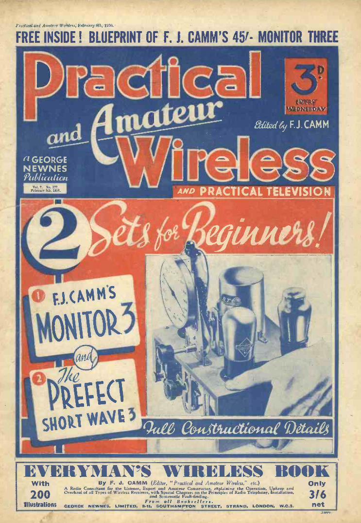
I radical and Amateur Wireless; February Sth, 1934.
FREE INSIDE ! BLUEPRINT OF F. J. CAMM'S 451- MONITOR THREE
EVERYMAN'S WIRELESS BOOKWith
200Illustrations
By F. J. CAMM (Editor, "Practical and Amateur Wireless," etc.)A Radio Consultant for the Listener, Expert and Amateur Constructor, explaining the Operation, Upkeep andOverhaul of all Types of Wireless Receivers, with Special Chapters on the Principles of Radio Telephony, Installation,
and Systematic Fault-finding.From all Booksellers.
GEORGE NEWNES, LIMITED, 841, SOUTHAMPTON STREET, STRAND, LONDON, W.C.2.
Only
3/6net
A ovT

ii PRACTICAL AND AMATEUR WIRELESS February 8th, 1936
CossonBATTERY VARIABLE -MuH.F. PENTODE 210 V.P.T.
T H E high mutual conductance and theunique construction of this Cossor
Battery Pentode permit of very high stableamplification. A worthy typa from a most
V.P.T. - incommon with all Ccssor Valves - owes its
popularity to its strict conformity to publishedcharacteristics-assured by rigorous adherenceto laboratory principles during every stage ofmanufacture, and the use of the famous CossorMica Bridge.
Filament Volts - 2
Filament Current (amps.) - .1
Mut. Conductance - 1.1m.a./v.Max. Anode Volts - 150
Max. Aux. Grid Volts - - 80
PRICE 13'G
KINGS Of 1HE MR
CONSISTENT EFFICIENT DEPENDABLE
British Made by A. C. Cossor Ltd., Highbury Grove, London, N.S.5439

February 8th, 1936 PRACTICAL AND AMATEUR WIRELESS 645
SPECIAL BEGINNER'S NUMBER11.11.1111111111111=1
Technical Staff:W. J. Delaney, H. J Barton Chapala, Wh.Sch.,
B.Sc., A.M.I.E.E., Frank Preston.
VOL. VII. No. 177. February 8th, 1936.
ROUND the WORLD of WIRELESSThe " Monitor" and the "Prefect"THIS issue is specially prepared for
the beginner, and the two re-ceivers-Mr. F. j. Camm's MonitorThree and his Prefect Short-waveThree-represent the quintescence ofsimplicity. They are backed by hispersonal guarantee of free advice, andfree service, if the receiver fails tofunction. As Mr. Camm says in hisarticle on another page, the Monitorforms the spear -point of a series ofarticles which will enable the reader tolearn as he builds, and thus put him onthe right road to an absorbing hobbyand a lucrative career. Later articleswill show how the Monitor may beadapted and added to. They will alsoshow how an extra H.F. stage may beadded, how it may be converted intoa superhet, how to add visual tuningand automatic volume control, and soon. Each article will be complete initself, but the series has been carefullyand progressively planned so that thebeginner, whilst adding to the receiver,also implements his knowledge.
1- If you have a friend who would beinterested in radio you will, of course,tell him about this new series withoutany prompting from us.`Austria's New Relay(1rHE small 2 -kilowatt transmitter at,11 Dornbirn, which has been working on231.8 metres (1,294 kc/s), is to see its powerincreased to 6 kilowatts. The wavelengthis shared with Klagenfurt and Linz.
'France's High -power Station;CCORDING to an official statement
.M published by the Ministry of Postsand Telegraphs, the regional transmitters ofa power from 60 to 120 kilowatts alreadyin operation are those of Strasbourg, Lille,iLyons, Marseilles, Nice -Corsica and ParisP.T.T. The high -power station at ToulouseMuret will be brought into action at Easter.
An Early News BulletinLISTENERS who understand French or
German may now hear the Radio -Luxembourg daily news bulletin timed to bebroadcast at G.M.T. 07.00.Egypt Increases the Broadcast Net-
workIT is reported from Paris that a broad-
casting station is to be built at Assiout,and that a small transmitter, working on
222.5 metres (1,348 kc/s), is to be installedin the neighbourhood of Cairo to provide analternative programme. Similar plant willalso be erected at Alexandria.
Palace for Transmitter and StudioTHE Bangkok broadcasting station,
working on 250 metres (1,200 kc/s),operated by the Siamese Government, ishoused in the Palace of Phya Thai, on the
ACHIEVEMENT !It is now patent to everyone that the" Practicaland Amateur Wireless " policy of designing its
i editorial contents absolutely for the home-! constructor (expert or amateur) has placed i
this journal in a position of unassailable 1
?pre-eminence.ORIGINALITY !
isIt merely a statement of fact that our newpolicy and our new outlook has been respon- isible for a great revival in Wireless Con- i
1 struction during the past 3 years. We cani justly claim to have entirely altered the; course of home construction and to have L,
brought it to its present high standard. The ;Wireleis Constructor's Encyclopedia; ourData sheets; our Handy Gauge; our ?;
Spanners ; our Tool Kit ; our Encyclopediaof Practical Mechanics ; our Transfer print !System ; our Guarantee ; our Solos Specifica-tion, the metallised chassis system-are but
i a few of the milestones which have markedour previous issues and which have been :
; eagerly read by the hundreds of thousands ;of home -constructors who constitute our
1:regular readers. It is a source of extremet gratification to us to observe that so many of 7,
; our ideas have been and are being generallyadopted. ;
CONFIDENCE ! ;
Every reader places extreme confidence in iour circuits (carefully produced in our well. ;equipped laboratories) because they are
4 backed by a free advice guarantee to function ;according to our claims. Readers may now 'build a receiver with that same confidenceas when purchasing a ready-made receiver.
' SERVICE!We make no charge for answering readers'queries. Every reader of this paper mayfreely avail himself of this unique service inthe knowledge that accurate advice will bespeedily, helpfully, and cheerfully forth.coming." PRACTICAL AND AMATEUR WIRELESS"
LEADS AND SHOWS THE WAY!
outskirts of the capital. Transmissions are-given in the Siamese and English languagesdaily between noon and 15.30 G.M.T., andon Saturday afternoons between G.M.T.14.00-15.00. Occasionally relays of pro-grammes are made from Manila, HongKong, and Batavia (N.E.I.).
Alterations in WavelengthsCOME changes have recently been made
in the channels used by Europeantransmitters. Archangel (U.S.S.R.) hasadopted the wavelength of 857.1 metres350 kc/s), as against 512 metres (586 kc/s) ;the Finmark (Norway) station works on857 metres (345 ke/s), instead of 859.6metres (349 kc/s), and Radio -Midi, atBeziers, on 209.9 metres (1,429 Ws), areduction of 9 metres.
Late French Cabaret BroadcastsEVERY alternate Saturday Poste Op
l'Ile de France, Paris, on 222.6 metres(1,348 kc/s), relays a special performancefrom the popular Sheherazade in the Frenchcapital.
High -power Station at Buenos AiresLEl, Radio El Mundo, on 280.4 metres
(1,070 kc/s), which so far has beenworking on 50 kilowatts, is to see its powerincreased within the next three months byfifty per cent. The station is on the airnightly until G.M.T. 04.00, and is fre-quently heard in the British Isles.
Record Broadcast from the " QueenMary"WHEN Great Britain's crack liner '
carries out her first trip to New Yorkon May 27th next, listeners may expect tohear a daily broadcast, as she crosses theAtlantic. Some twenty odd microphonepoints are to be installed to permit relaysfrom various parts of the vessel, and onefeature will be a forty-five minute conductedtour, with a running commentary by Mr.John Snagge. The B.B.C. is sending forthis purpose a number of its officials who willbe in charge of the broadcasts. It is possiblethat we may also pick up relays from theliner through Continental and U.S.A.stations, as authority has also been grantedto several countries to place their own com-mentators on board.
Call It A DayTHE activities of some U.S.A. stations is
such that they remain on the airthroughout the twenty-four hours of theday and night. There are at least twelvetransmitters which never close down ; ofthese stations the most likely to be pickedup in Great Britain are WNEW, Newark(New Jersey), 239.9 metres (1,250 kc/s) ;1 kilowatt ; and WHN, New York, 296.9metres (1,010 kc/s) 1 kilowatt.

646 PRACTICAL AND AMATEUR WIRELESS February 8th, 1936
OUND the WOB.B.C., Dance OrchestraIN connection with the forthcoming fourth1 anniversary of the B.B.C. Dance Or-chestra, the B.B.C. announces importantchanges in the constitution of this orchestraand the programmes performed by it.In order that, from Monday, March 16th,Henry Hall may be able to develop in all hisbroadcasts a new type of entertainmentprogramme, in which, of course, dancemusic will play the leading part, the
rLD of WI
INTERESTING and TOPICALPARAGRAPHS
A.^.....0.1.MN..141111101,141101.0.40.11.68..1.001... NM.
Programme CorrespondenceCORRESPONDENCE about programme
matters forms one of the main linksbetween the B.B.C. and the listeningpublic, and -is always given careful atten-tion. Any suspicion that may exist among
H.M. THE KING AT THE MICROPHONE
His Majesty King Edward VIII, when Prince of Wales, broadcasting an appeal for funds inconnection with the Jubilee Trust.
orchestra is to be enlarged to twenty-oneplayers, and will be reinforced regularlyby a special group of singers, and from timeto time by the services of celebrity artists.
Sir Hamilton HartyTHE B.B.C. announces that, owing to
pressure of workoSir Hamilton Hartyis obliged to postpone the series of talkswhich he was to have given in March, underthe title of " The Reflections of a Musician."The series of Keyboard Talks will now becontinued until Easter. Mr. Harold Samuelis giving the first six in this, series.
Some Temperature !oN the occasion of the first French tele-
vision transmission at Paris recently,the heat generated by the electric lightswas such that within a very short time theviolins and other wooden instruments werequite out of tune. Musicians consider thatunless some cooling system can be installed,it will be impossible to use certain instru-ments in television studios.
Russia's Big PlanTHE Soviet Authorities, anxious to
extend their broadcast network, areconsidering the replacement of twentyexisting stations by transmitters of from100-150 kilowatts. Of these it is plannedto install fifteen in European Russia andfive in Asia.
listeners that letters are thrown unreadinto wastepaper baskets can be at oncedispelled. On the contrary, all comment isof interest, and above all the B.B.C. isanxious to have the views of people wholisten regularly and carefully. Constructivecriticism which takes into account thegreat variety of tastes to be considered isparticularly welcome.
Recorded ProgrammesTHE use of specially recorded material
in programmes continues to increase.The original recording equipment used bythe B.B.C. has been supplemented by theaddition of machinery specially designed toenable events or speeches, which cannotbe- broadcast at the time they occur, orwhich warrant reproduction at a betterlistening hour, to be cut, edited, and repro-duced as a summarised impression of thewhole. This method of presentation isbeing employed in an increasing degree,especially as a means of illustrating newsbulletins..
The work has been further facilitated bythe addition of a mobile recording unit,which has made it possible for such eventsas the return of H.R.H. the Duke ofGloucester from the Antipodes, and theelection of the Lord Mayor at the Guildhallto be reproduced in summarised form inthe evening programmes on the day oftheir occurrence.
ELESS (Contd.)" Christopher Columbus " BroadcastTHE B.B.C. announces that, owing to
the impossibility of securing adequaterehearsals, due to the pressure of work onthe Chorus entailed by the general altera-tion of programmes, the special concertperformance of " Christopher Columbus,"by Darius Milhaud, announced for Feb-ruary 5th at Queen's Hall, will not takeplace. It is hoped that it will be possibleto perform this important new workduring the 1936-1937 season.
Italy Cuts Down ProgrammesWITH a view to an economy in electrical
current, all broadcasting stations inItaly have curtailed their daily trans-missions, and on most evenings it will befound that the studios sign off shortly afterG.M.T. 22.00. As a rule the main eveningprogramme is advanced one hour, andconcerts, operatic performances, and so on,are timed to begin at G.M.T. 19.30. Muchof the time is devoted to the broadcast ofnews bulletins.
The Two U.S.A. Networks
AT the -end of 1935, the National Broad-casting Company possessed eighty-
nine transmitters in seventy different cities,the Network being connected by sometwenty thousand miles of telephone cable.The aggregate power of the stations was1,723.9 kilowatts. The Columbia Broad-casting System consists of ninety-eighttransmitters installed in ninety-six cities ortowns.
The Voice of South AfricaTHE most powerful station of the South
African system is ZTJ, Johannesburg(15 kW), on 465.1 metres (645 kc/s). Everyweekday it is on the air with two sessions,namely, G.M.T. 09.00-10.00, and from14.00-21.00 ; on Sundays, in addition to themorning broadcast, the station transmitsfrom 12.15-15.15, and from 17.30-20.00.The short-wave relay works on 49.2 metres(6,097 ke/s).
IIVEPROBLEM No. 177.
Walters thought he would try home -broad-casting, using his receiver and a cheapmicrophone he had procured. He was toldby his dealer to connect the microphoneto the pick-up terminals of the set, but whenthis was done he was surprised to find thatL.F. instability was experienced. The receiverworked satisfactorily in conjunction with apick-up. Why did the microphone produceinstability ? Three books will be awarded
i for the first three correct solutions opened.Address your envelope to the Editor, PRACTICALAND AMATEUR WIRELESS, Geo. Newnes, Ltd.,8-11, Sbuthampton Street, Strand, London,W.C.2. Envelopes must be marked ProblemNo. 177 in the bottom left-hand corner, andmust be posted to reach this office not laterthan the first post Monday, February 10th,
; 1936.
Solution to Problem No. 176.Hayes had used a straight two -gang condenser
instead of the specified 465 K.c. superhet type. Themoving vanes of the oscillator section of the superhettype are smaller than those of the straight .0005 mfd.section.
The following three readers successfully solvedProblem No. 175 and books are accordingly beingforwarded to them :
J. Platts, 56, Cowlishaw Rd., Hunters Bar. Sheffield11 ; J. D. Stuart Martin, 14, Wolverhampton Road,Stafford ; W. A. Roberts, 1, BeLston Road, Childwall,Liverpool 16.

February 8th, 1936 PRACTICAL AND AMATEUR WIRELESS 647
At, Ideal Three -valve Receiver Designed for Use on the Short-wave Band. It is Simple to Build, Simple toOperate, and may be Relied Upon to Provide Splendid Results under all Normal Conditions
AS has been mentioned elsewhere, thisnumber is devoted to the interests ofthe beginner or newcomer to radio
receiver construction. It has been fullyappreciated that there are many who havein the past been listeners only, but who nowwish to learn something more of, the intri-cacies of receiver construction and whowish to find out just " how it works." The" Monitor " receiver described on otherpages is intended for the listener who onlywishes to obtain reception on the ordinarybroadcasting bands, but, as no doubt manyreaders are aware, there is a vastly moreinteresting field to be explored on otherwavelengths. The ordinary broadcasts takeplace from 200 metres upwards, but it ispossible to employ wavelengths whichextend down to centimetres, although, ofcourse, such minute wavelengths are onlyemployed in the research laboratories.
From 10 metres up to, say, 100 metresthere may be heard the tongues of everynation, broadcasting not only programmesof a musical nature, but also radiatingspecial talks for colonial inhabitants, experi-menters carrying out interesting tests andtrials, and on certain wavebands theremay be heard the thrills of the police radiocars in the United States of America. Thereis no knowing just what may be heard at
,BUILD THIS SIMPLE ii RECEIVER AND MAKE
ACQUAINTANCE WITH THEi MARVELS OF THE SHORT
WAVES
any time of the day or night, and thelistener with a short-wave receiver which issufficiently powerful is in the same positionas the man with an immense bran -tub --hecan delve into it at odd moments, and theprize which he will acquire may be insignifi-oant or may reach an enormous value.
Timing PossibilitiesUnfortunately, the average listener has
become so used to experiments carried outon unsuitable apparatus that he has foundthat short-wave tuning is difficult, and theword has been passed along that short-wavework is not worth while. Why is it thatbad news always travels so widely, whilstgood news never gets passed along ? How-ever, when a correctly -designed short-wavereceiver is employed it will be found thatit is no more difficult to tune than a standardbroadcast receiver, and there are one or twoartifices which may be employed in thedesign of such a set which will make it eveneasier to operate. There are, however,certain vagaries in the short-wave spherewhich render it necessary to use a short-wave set with discretion. For instance,the sun and darkness can affect the short-wave signal, whereas a standard signal on
By F. J. CAMM
a wavelength of 500 metres or so is not soaffected. Thus, certain wavelengths willbe found to be " dead " during the hours ofdaylight, whilst during the hours of dark-ness it will be found that these wavelengthstravel over immense distances in spite ofthe small power used, and signals whichcould formerly be heard in the daylight willno longer be received. By designing theshort-wave receiver with an adjustabletuning circuit, however, it is possible toobtain a number of separate tuning elementswhich will permit of the receiver being used
DON'T BE OUT -OF -DATE --BUILD THIS SHORT-WAVE
SET WITHOUT DELAY !!... . ..... .
under all conditions, and thus there is amuch wider field obtainable.
The Circuit of the " Prefect."Let us now see how these points have
been covered in the design of the Prefect "receiver. Dealing firstly with the tuningarrangements, it is admitted that a verysmall movement of a normal tuning con-denser is required in order accurately tolocate a station,although thereason for thiswill not be goneinto here. Butpractically everylistener is familiarwith a vernier
adjustment, and it is possible to employ ascheme which amounts almost to a micro-meter adjustment of the tuning circuits ofa short-wave receiver, and yet does notentail any difficult operations in finding thestations. If you glance at the illustrations ofthe " Prefect " receiver you will see that thepanel carries three separate variable con-densers. One of these is employed in thenormal manner for reaction purposes, butthe remaining two are joined together inparallel. That is to say, the larger condenserhas its two terminals joined to two terminalson a very small condenser mounted nearto it. The size or capacity of this smallercondenser has been so chosen that it coversonly an extremely small range, very littlemore, in fact, than is obtained when themain tuning condenser is turned throughone small degree. Thus, the main con-denser may be turned through this smalldistance, and the smaller condenser thenturned through a complete revolution;this spreads out the stations which arecovered by the larger condenser. Fromthis spreading -out action, the combinationof the two tuning condensers is known as a" band -spread tuner," and it brings to theshort-wave receiver all the advantages ofnormal tuning. To make everything quitesimple for the operator the main tuningcondenser in the " Prefect " is fitted with a
; THE FIRST COMPLETE VOLUME
TELEVISION & SHORT-WAVEHANDBOOK EDITION
3/6, or 3110 by post from George Newnes,8 II, Southampton Street, Strand, W.C.2.
Fig. 1.-The complete receiver. In thisillustration the Microfuse is not shown, but it was subsequently
fitted at the rear edge, so that in the event of renewal it is easily accessible.

648 PRACTICAL AND AMATEUR WIRELESS February 8th, 1936
slow-motion knob, and it is thus possibleto explore every part of the tuning scale inthe most accurate manner and it is almostimpossible to miss a station which is withinrange of the receiver.
A Well -tried ArrangementThe actual valve combination in the
" Prefect " follows the well -tried detectorand two L.F. arrangement, and it has beenfound that this is productive of reallyexcellent results under all normal con-ditions. The coil which is used is ofthe six -pin type and a special holder isemployed so that any other six -pin coilmay be inserted. The listener may acquirea complete set of these coils to cover allhis requirements. Coupling between thefirst and second valve is by means of whatis known as resistance -capacity -coupling,and this ensures good quality, whilst anL.F. transformer of sound design is employedbetween the second and third valves.Thus a really good signal may be expected
4. .0 EASY TO BUILD AND
EASY TO USE
at the loud -speaker, free from any circuitdistortion and of sufficient power to providegood entertainment value. A five -waybattery cable is employed and a separateH.T. voltage is provided so that the mostsuitable operating conditions of the detectorstage may be located.
It will be noticed by experienced ama-teurs that no aerial condenser has been fitted,and the reason for this is that the receiverhas been designed for the beginner to short-wave reception. My advice under suchconditions is that a special short-wave
' aerial be fitted, and experiments carriedout with a view to finding the most suitabletype of aerial for all average conditions.Where it is desired to employ this receiverin conjunction with a standard broadcastaerial of large dimensions, it will be neces-
. sary to fit a condenser between the aeriallead and the aerial terminal, in order toobtain smooth reaction and to provide goodsignal strength. An air -spaced condensershould be used for this purpose, and itshould be mounted on a bracket fittedinside the rear of the cabinet. The controlknob may then be adjusted as requiredfor various wavelengths to provide therequired degree of aerial damping.
Constructional WorkThe actual construction of this receiver
is extremely simple, and it may be under-
taken by the youngest member of the family.The chassis is of metallised plywood andmay be obtained from Messrs. Peto-Soott.It measures only 10in. long by 6-lin. wide,and is provided with two runners at thesides measuring 2iin. in height. To com-plete the chassis a further strip of the samewood is placed across the rear, upon whichthe terminals are mounted. At the frontno wooden strip is employed, but the
apart. The centre of the coil -holder holeis 3iin. from the rear edge and 2in. from theside of the chassis. When these holeshave been drilled a kin. drill should be usedto drill the six holes in the upper surfaceof the chassis, and the same size drill shouldbe used to drill the rear strip for theterminals. Finally, a kin. hole should bedrilled in the centre of the rear stripthrough which to pass the battery cable.
THEORETICAL CIRCUITR2
SemooOHMS
C.5
mri2Hr ÷/
Fig. 2.-All the essential features may be seen in this illustration.
reaction condenser which is mounted inthis position is fitted to a special metalcomponent mounting bracket.
Having obtained the chassis, the con-structional work may be commenced, andthe first task is to drill four large holesupon which to mount the valve -holders and
SUITABLE FOR ALLWAVE -BANDS
the coil holder. For the latter a hole lfin.in diameter is required, and for the valve -holders the hole must be lin. in diameter.The positions of these holes may be ascer-tained from the wiring diagram which isprinted on page 650. The centre holes forthe valve -holders may be positioned asfollows : V3 is lkin. from the edge of thechassis and 2in. from the rear edge. Theremaining two holders are exactly 2in.
Fig. 3.-Here is the receiverduring construction, showingthe method of mounting thecoil -holder and L.F. trans-
former.
Mounting the ComponentsBefore placing the component mounting
brackets in position, the coil holder shouldbe attached on the under side of the chassis,taking care that the sockets are centrallydisposed in the hole. Next, the threevalveholders should be screwed in position,again making quite certain that the socketsclear all the edges of the chassis to avoiddifficulties at a later stage. Now lay thechassis upside down on the table or work-bench, and screw the Niclet transformerin its approximate position. There is noneed to measure the exact position of this,and it may be placed anywhere near theposition indicated in the wiring !diagram.Next obtain two kin. countersunk No. 4screws (or similar dimensions) and screwthese into the under surface of the chassis.It should be noted particularly that thewooden chassis which are employed inour receivers are only metallised onthe upper surface, and if you endea-vour to employ a metal chassis or make upone, there is every possibility of doingdamage, due to short-circuits and inter-connections which are not intended. Thetwo wood screws just mentioned, forinstance, are only anchor points and thusif the under surface is metallised, thesescrews become joined together. The same
SHORT-WAVE TUNING ASSIMPLE AS A CRYSTAL SET
thing will apply if the screws are longenough to project to the metallised surfaceon the other side of the chassis, and thusthey should not be any longer than kin.One of these screws is attached close to thevalveholder for valve No. V2, whilst theother is placed close to the L.F. trans-former fixing screw. Three similar screwsare now attached to the upper side of thechassis, one next to the Microfuse holder,

February 8th, 1936 PRACTICAL AND AMATEUR WIRELESS 649
one next to the bracket which supports theon/off switch, and one in approximately thecentre of the upper surface. These screwsare marked M.B. on the wiring diagramand simply indicate that wires attached tothem are in contact with the metal surface.
Next serew the bracket to the centre ofthe front edge of the chassis on the under-side and mount the Dilecon reaction con-denser on this bracket, locking it in positionwhen the spindle is in from the lower edge,as indicated on the front of panel layout,below. Screw the Belling -Lee type Rterminals in position, as indicated by theletters A, E, LS+ and LS-, and then com-
434"
spread condenser, and attach the holderfor the Microfuse. The variable con-denser is attached to the J.B. slow-motiondial, and in the ordinary way this shouldbe held in position on the front of thecabinet. If, however, it is desired to makethis a fixture to the chassis, a strip ofwood must be cut and recessed to hold downthe slow-motion dial. This may be cutfrom any old piece of wood so long as iteffectively holds the dial in position. Nowmount switch and band -spread condenserand complete the wiring, soldering the leadsto the screw heads marked M.B. if possible.If, however, you cannot solder, or feel that
10"Fig. 4.-These dimensions will enable you to drill the cabinet front or the panel. The maker's template
should be employed when marking out the hole for the escutcheon.
mence the wiring on the underside. It willbe noted that at the moment there are nobrackets or large components on the uppersurface of the chassis, and this method ofconstruction enables the chassis to be laidconveniently on the table or work -bench,s.nd greatly facilitates the wiring operations.Ca-ry out as much wiring as is possiblewithout passing wires through the variousholes, and when this part of the work hasbeen completed, attach the battery cordsto the various points and turn the chassisover.
An Alternative SchemeNow screw the two component brackets
into position for the switch and band -
your soldering is not effective, you cantwist a loop of the wire below the head ofthe screw before it is driven right home,but do not tighten it so much that the wirebreaks through the metal surface and thusinterrupts the electrical circuit.
Testing OutPlug in the coil which is specified for
this receiver, and which covers a wave-band from 24 to 52 metres, plug in the threevalves as follows : D210 in V1, L210in V2, and P215 in V3, and connect theH.T. battery plugs into the H.T. batterywith H.T.2 in the 120 -volt socket, andH.T.1 in the 60 -volt socket. G.B.+ isnow inserted into the positive socket of
the bias battery, G.B.-1 into the 4.5 -voltsocket, and G.B. -2 into the 7.5 -volt socket.Pull out the on/off switch and the receiverwill be ready for station location.
The following Short-wave informationwill no doubt prove of use to constructorsof this receiver.
On the 10 -metre BandFor those who are interested in 10 -metre
DX, let it be known that there exists a1935-1936 Andes -Amazon expedition which,provided with radio equipment, will keepin touch with Ecuador, as and whenpossible. A Long Island (New York)amateur, holder of call sign W2DPQ, isoperator, and that messages will be trans-mitted at frequent intervals at HC1FG,Rio Bamba, Ecuador. This station, operat-ing on 45.31 metres (6,620 kc/s) will re-broadcast them with a power of 2 kilowatts.El Prado has been installed for some timeand transmits a regular programme everyFriday between G.M.T. 02.30-04.40. Itpossesses a woman announcer giving outcall alternately in Spanish and English.
MAKE CERTAIN YOU OB-TAIN ONLY THE SPECIFIEDPARTS AND SO AVOID
DISAPPOINTMENT
Although the regular Moscow short-wavebroadcasts are sent out on 50 metres,RW59, on 24.99 metres (12,005 lo/s), hasnot been closed down. It is still usedoccasionally for broadcasts to the U.S.A.,and recently was heard handling a specialtransmission simultaneously broadcast forthe same purpose by RKI, Moscow, on19.88 metres (15,090 kc/s). There is also analternative channel on 19.95 metres(15,000 ke/s). As a rule, these two fre-quencies are used for morning trans-missions.
That Moscow proposes to develop these" all -world " broadcasts .is strengthenedby the rumour that a 120 -kilowatt stationis under consideration.
Another item of news which reaches meis that Japan proposes to install a 50 -kilo-watt station at, or near, Tokyo, for trans-mission of radio programmes to Europe.
Another high -power short -waver whichwe may expect to hear this year is the35 -kilowatt transmitter which the Czechshave under construction at Podebrady,near Prague ; so far, any programmesdestined to listeners on the other side ofthe Atlantic Ocean have had to be sentthrough foreign channels.
Paris Colonial TransmittersAlthough they are less heard than their
British and German confreres, the ParisColonial transmitters FYA are on the airfor a large number of hours daily. Sofar the power has been limited to 10
LIST OF COMPONENTS FOR THE "PREFECT" BAND -SPREADS.W. THREE
One 6 -pin S.W. Coil, type S.P.C. (B.T.S.).One .00025 popular log tuning condenser, type
1040 (J.B.).One dual -ratio S.M. drive, type 2092 (1.13.).One 15 mmfd. band -spread condenser, type 2140
(J.B.).One .0003 mfd. Dilecon reaction condenser (J.B.).One Niclet L.F. transformer (ratio 1: 5), type
D.P.22 (Varley).Three 4 -pin valve -holders, type U.H./4 (B.T.S.).One 6 -pin S.W:coil base, type S.P.B. (B.T.S.).Two fixed condensers (.0002 mfd. and .01 mid.),
type 300 (T.C.C.).
Three 1 -watt resistances (50,000 ohms, 1 megohmand 3 megohms) (Dubilier).
One S.W. choke, type H.F.3 (Wearite).One 60 mA. Microfuse and holder (Microfuse).Four type R terminals (Aerial, Earth and L.S.--
and L.S.-) (Belling Lee).One 5 -way battery cord (30in.) (Belling Lee).Three " Bow -spring " wander plugs (G.13.1-,
G.B.-1 and G.B.-2) (Belling Lee).One pair G.B. battery clips, type No. 5 (Bulgin).One Junior on/off switch, type S.38 (Bulgin).Three component -mounting brackets (Peto-
Scott)
One Metaplex chassis (loin. X 6$in. with 2linrunners (Peto-Scott).
Three valves (D210, L210, and P215) Hivac.
ACCESSORIESOne 120 -volt H.T. battery.One 9 -volt G.B. battery.One 2 -volt L.T. accumulator.One W.B. Stentorian 36/3 loud -speaker and pair
of headphones.One cabinet.

650
kilowatts and in consequence it is moredifficult to pick them up than their powerfulneighbours. From G.M.T. 09.00-10.00 on25.23 metres (11,880 kc/s), France broad-casts to New Caledonia ; on the samechannel from 16.15-20.00 to Madagascar,the Reunion Islands, and from 20.00-23.00to the French Soudan, Senegal, Ivory Coast,Dahomey, and French Equatorial Africa.On 19.68 metres (15,243 kc/s) specialbroadcasts are made from G.M.T. 11.55-16.00 for French residents in Indo China,and on 25.6 metres (11,720 kc/s) fromG.M.T. 23.15-06.00 the transmissions aredestined to Central and South America.News bulletins are given out at fixed periodsin English, French, Arabic, Italian, Spanish,Portuguese, and German. In the course ofa few weeks we may expect to log a morepowerful transmission on a higher portionof the band, as the 100 -kilowatt station isnearing completion and will be testingshortly on 48.82 metres (6,145 kc/s).
Cuban StationsOf the Cuban stations at present CO9GC,
Santiago, on 48.78 metres (6,150 kc/s) isthe one which is the easiest to log. It isrun by any important concern and givesout in its call that it is the SantiagoExperimental Short-wave Station. In-terval signal: bugle call. Both Spanishand English languages used. There aremany Santiagos in the world, but this oneis in Cuba.
Above 50 metres, signals have beencoming in freely and at good volume ; it isa portion of the band often neglected, butwhich so frequently reveals surprises.
IDEAL FOR THE BEGINNERAND A USEFUL SHORT.WAVE SET FOR THE " OLD
HAND "
HJIABE, Medellin, Colombia, a 1 kilo -wetter on 50.59 metres (5,930 kc/s), justabove Moscow, is on the ether nightly,and on some nights when favourable con-ditions obtain might be mistaken for oneof the more powerful Yanks. HRN,Tegucigalpa, Honduras, on 51.06 metres(5,875 kc/s), La Voz de Honduras, wasanother entry in the log.
Particulars culled from an announce-ment included the information that thetransmissions were made from G.M.T.22.00-03.00 daily, and that an Englishhour, for U.S.A. listeners, was givenregularly on Mondays at G.M.T. 02.00.In true N.B.C. fashion, we were told that :Your announcer is Paul Jones. HRN issandwiched between YV8RB, Bar-quisimeto, 51.02 metres (5,880 kc/s), andYV5RMO, Maracaibo, 51.28 metres (5,850kc/s), both installed in Venezuela.
In the same band a search should bemade for a new station which has justbeen opened in Guatemala City, namely,TGS on 52.26 metres (5,740 kc/s). Thedetails given are that it uses a metronomeas an interval signal. This may at firstsight appear to be scanty data for identi-fication, but, on the other hand, most ofthe South Americans use bells, gongs, orother musical gadgets, and the tick -tookon that part of the band at least shouldbe quickly recognised.
Full details for using this receiver will begiven in next week's issue, together withsome details of the best types of aerial andthe most suitable listening times for variouswavelengths.
L 5 -r E
PRACTICAL AND AMATEUR WIRELESS February 8th, 1936
WI ING DIAG,' AM OF THE"PREFECT" ]BAND SPREAD S.,W. THREE
GB* 6
GB -
5GB 2
tgi:L5"='° 4
V3
0
V2 V.1t0 po
0 00
`k @@) ,1).0MB
© 0Qo
0 aC,
0a
L 5 -
11,1111111111N
Fig. 5.-This diagram .shows all the wiring Jetalls, anJ is slightly under half siz-c.

February 8th, 1936 PRACTICAL AND AMATEUR WIRELESS 651
A Simple D.C. Trickle Charger.This Article Deals with the
and Inexpensive Unit.
TRICKLE, charger for use on D.C.mains is a very simple piece ofapparatus, and, unlike the type
required for A.C. supplies, does not involvethe use of a mains transformer and rectifier.The average D.C. or direct current supply is,in itself, a satisfactory source of energy forrecharging accumulators, providing somesuitable means of regulating the flow ofcurrent are employed.
Before considering the construction ofthe charger about to be described, it is
necessary to make sure whether yourhouse electrical supply is D.C. or A.C.If it is the latter, then this unit will notbe of the slightest use to you, as it isdesigned solely for use on D.C. supplies.Should you not be too sure, then it wouldbe advisable to inquire at the local supplycompany's office or examine the supplymeter, on which you should find thenecessary details.
The advantages of a D.C. trickle chargerare many. In the first place, it is veryinexpensive to make ; it can be so arrangedthat the charging can be carried out withoutany extra cost for current ; any size cellcan be charged at a high or low currentrating, without harm to the apparatus orcomplicated alterations and, lastly, it canquite easily be adapted to pass the requiredoutput for H.T. accumulators.
Simple ConstructionA glance at Figs. 1, 2 and 3 will show that
the unit is both compact and simple, andthat all it consists of is a lamp in serieswith one side of the mains, a lamp -holder,a fuse -holder, an on -off switch, four yardsof good twin flex, a two -pin plug or anadaptor, and two spade terminals. All therequired parts need not cost more thanfive or six shillings. If one desires to beeconomical, the lamp, which I will refer tolater, can be connected, by means of alength of flex and an adaptor, to the unitand so placed in the room that it is usedfor illumination purposes, thus allowingeither the light or the charging to 'lifeobtained for the cost of the other. Atrickle charger is really intended tomaintain the L.T. cell or cells in a fully -charged condition, and it is usual to adjustthe' charging rate and period, so that thesame number of ampere -hours (one ampereflowing for one hour) are put into theaccumulator, if such an expression can beused, as those taken out by the filamentsof the valves during the hours the receiveris in use. For example : If the total currentrequired by all the valves is, say, .4.amperes, and the receiver is used for, say,four hours a day, then the discharge is
Construction of an Easily- madeBy L. ORMOND SPARKS I
it is necessary to insert in the circuit someform of resistance, so rather than employelements formed with resistance wire,which, bearing in mind the current whichwill be flowing, might be rather incon-venient and more troublesome, use is madeof an ordinary carbon filament or Robertsonlamp.
By adopting this method, a fairly steadyregulation is obtained, and it is not reallynecessary to embody a meter to indicatethe current flowing, as a lamp of known
Fig. 1.-This illustration gives a good idea ofthe compact arrangement of the completed D.C.
trickle charger
equivalent to .4 x 4 ampere -hours or 1.6amp. -hours.
Current RegulationTo obtain the desired current regulation,
Fig. 2.-Underside of baseboard of the D.C.trickle charger, showing the wiring connections;
wattage will only pass a certain current ;therefore, it is quite an easy matter toselect a lamp capable of passing the currentrequired for the output. While a carbonfilament lamp, owing to its characteristics,is the most satisfactory, any type of lampcan be used, provided that its operatingvoltage is the same as that of the mainssupply concerned.
All lamps have a certain wattage ratingbut, as some makes of carbon filamentlamps are rated by their candle power, Oletable below, which shows the currentpassed by lamps of various wattage andcandle power, will be found handy forreference.
Carbon Filament.200/260 volt. Wattage. Current Amps.
8 Candle Power 36 .18 to .1516 66 .33 to .2732 136 .68 to .56
Other LampsVoltage according to supp y :
40 at 200 Volts60 IP .375 .35
100 .6
For other voltages, it is quite an easymatter to calculate the current for a givenwattage by using the formula :Current x Voltage, or, turning it about,
Current= WattVoltage.
Charging RateWhile it is not necessary to determine
the exact number of hours a cell should beon charge, it is advisable to keep an eye onthings and not overcharge, particularlyif the charging current is high, otherwisethe life of the cell will suffer. A low charg-ing rate for a long, period is the most satis-factory method. Most makers of accumu-lators usually state the charging rate fortheir products, but a safe way is to notexceed one tenth of the actual capacityof the cell. If the capacity is 20 ampere -hours, then the charging rate should notexceed 2 amperes, and that should only be
(Continued on Dore 674)

652 PRACTICAL AND AMATEUR WIRELESS
mini Advantages ofHome ConstructionThe Constructor Scores Over the User of a Ready-made Receiver,
not only Financially, but Due to the Fact that his Set can bekept Up to Date with the Minimum of Trouble. By "THERMION"
MANY regular readers of PRACTICALAND AMATEUR WIRELESS are keenconstructors and would no more
think of using a readY-made receiver thanthey would of giving up wireless as a hobby.They appreciate the many advantages of thehome -constructed receiver, and have foundthese out in the course of their long-experience. But, as this issue is a specialone for beginners, and will be read bythousands of new readers and prospectivewireless enthusiasts, it will be useful to themto be acquainted with some of the pointswhich have been proved during manyyears of wireless experimenting and con-struction.
Initial CostA number of years ago a home -
constructed receiver was obviously a good'deal cheaper than one which could bebought ready made, but this advantage isless evident to -day, although it still appliesjust as forcibly. Nevertheless, if one looksat the catalogues of receiver manufacturers,one finds .that three -valve battery sets canbe obtained £7, complete withvalves, batteries and speaker, whilst anaverage price for-a four -valve receiver isabout £10. It is a fact that, when the pricesof home -constructed receivers described inthis journal are determined, they are oftennot very much lower than those mentioned ;there is generally a saving of one or twopounds, but this does not look veryimpressive.
We must look a little, furtlfer to see justhow much is saved by home construction.In the first place, the accessories used forthe home-made set are generally of ratherbetter quality, and in the second, therunning costs are generally lower.Additionally, however, the latest types ofconstructor receiver are more advanced inthe way of circuit design than are thecurrent .models of commercial receivers-which were probably designed at least ayear ago. This is not a reflection on themanufacturers, for it is inevitable that they
should make their plans, andensure ample stocks, well inadvance of the time that thereceivers will be on sale to thepublic.
A Typical Example
February 8th, 1936
The Hall Mark Cadet, a low-priced receiverAs an example, reference designed for quality reproduction.
might be made to the ex-tremely popular " Superhet " which,complete in every detail, costs rather lessthan £10. The price is comparable withthat of the average four -valve commercialreceiver, but the set is at least equal inquality and performance to most ready-made five- or six -valve superhets costingat least twelve guineas ! As has beenpointed out in these pages before, thenumber of valves is not necessarily anycriterion of performance, and a well -designed four-valver is often far superior toa receiver with six valves used in a differentcircuit.
bully GuaranteedThe arguments put forward above are
generally applicable to every type of home -constructor receiver described in thisjournal, and you need only examine thespecifications of different types of receiverto see how really true these argumentsare.
There is another very important pointwhich concerns receivers built accordingto designs published in PRACTICAL ANDAMATEUR WIRELESS, which is that they areguaranteed for an indefinite period, and if aset built exactly according to the publisheddetails fails to give the results claimed it isserviced free of charge. Compare this withthe $0 -day (maximum) guarantee givenwith the best commercial receivers !-comment would be superfluous.
Keeping Abreast of DevelopmentsWhen the constructor builds a receiver he
uses components which are easily inter-changeable, and they can be used time aftertime in many receivers without the slightest
difficulty. They are pro-vided with terminals and'generally some " universal "form of mounting so thatthey can be attached to a
metal chassis, awooden chassis ora baseboard. Butit is nearly alwaysa practical im-possibility to dis-
mantle acommercialreceiverand to use
N, the parts inanotherset; theyare oftenheld inplace b yrivets,and their
The Centaur Three, asimple and efficient receiver inwhich baseboard mounting of
components is used.
characteristics are such that the componentsare suitable only for one particular circuit.
This means that when a commercialreceiver becomes out of date it must bescrapped and a new one bought. As newmodels are introduced each year, thismeans that-in order to have a modernset at all times-a new receiver must bebought each year. It is true that the oldone can be " traded in " in part exchange,but this involves a very heavy loss, for ayear -old instrument originally bought forsay, 12 guineas, would not be worth'more than about £4 in the second-handmarket.
Contrast this state of affairs with thatapplying to the home constructor ; as soonas his set becomes obsolescent, or immed-iately a new form of circuit or new device'becomes available, he can _dismantle theexisting set and use a large percentage ofthe components in a new one. The resultis that the change costs him from a fewshillings to a couple of pounds, according tothe exact nature of the new set.
In setting forth a few of the advantagesof home construction no mention has beenmade of the inestimable amount of enjoy-ment and interest which is to be gainedfrom making one's own receiver, althoughthis is a point of considerable importance,especially to the man with mechanicalinclinations. To such a person the enjoy-ment to be gained by carrying out theconstructional work is far greater than anywhich could be obtained from merely.listening to broadcasts.
Correcting FaultsYet another item on which the con-
structor scores is when the receiver developssome slight fault. This may be due tonothing more serious than a loose con-nection, a strained switch contact or acomponent which has become damaged inuse, but the owner of a commercial set cando little to rectify it. The constructor, onhe other hand, having made the set, knows
just where every component is, so that he isin a position easily to find what is wrongand to put it right.. Manufacturers ofcommercial receivers invariably employ atrained staff of service engineers, buttime is lost in awaiting the arrival of anengineer after writing to the Service Depart-ment, in addition to which it is the generalpractice to make a charge for the servicesof an engineer when he is called to the house.The alternative, if the set is in its guaranteeperiod, is to return, or have it returned tothe makers-probably just because a valvehas " gone," or because a connecting wirehas come adrift.

February 8th, 1936 PRACTICAL AND AMATEUR WIRELESS
A COO D FCFOR BUILT
BATTEA
NDATIOND NG ANY
SET
SPECIFIED for "PRACTICAL WIRELESS"
BATTERY RECEIVER IN THIS ISSUE!!If you are building or operating a battery set you can getsatisfactory results only if the H.T. supply is adequate.H.T. current is the life -blood of the set.
A Milnes H.T. Supply Unit will keep that life-givingcurrent circulating strongly and vigorously. No off-colourdays, no gradual languishing into feebleness. A MilnesUnit will keep your battery set perpetually young becauseit is the only H.T. battery in the world which starts eachday's and every day's listening at full voltage.
The Milnes Unit never has a chance to run down becauseby means of a simple, reliable and ingenious series -parallelswitch, it recharges automatically from the L.T. wheneverthe set is not in use.
A Milnes Unit is not only the most efficient-it is also themost economical form of H.T. supply. Sole running costs-for H.T. and L.T.-are the charging of one L.T. cell perweek-a few pence at most.
Use a Milnes Unit and end H.T. troubles and expense.
POST THE COUPON TO -DAY FORFREE DESCRIPTIVE BOOK.
I.F.S. EnquiriesCnly to Kelly &Shiel, Ltd., 46,Fleet St., Dublin.All other enquiriesto Milnes RadioCo., Ltd., ChurchSr., Bingley, Ykr.
MILNES RADIO CO., LTD., CHURCH ST.,BINGLEY, YORKS.
Please send me your Free Book about the Milne, Unit.No obligation.
NAME
STREET
TOWN
COUNTY P.3.PLEASE WRITE IN BLOCK LETTERS
Stick coupon to envelope flap to avoid loss.MN 1= MI WIN a MIMI MI IN a-- a MOa .....
653
dlitedckw_iyat &peast64MAKE'n s6ett me set !For the best possible performance from your short-waveset incorporate these Formo short-wave components !Exhaustive tests for efficiency and reliability preceded theirmanufacture and thousands of delighted short-wave con-structors enthusiastically endorse their outstanding quality !
SHORT-WAVE VARIABLECONDENSERHas die-cast rotor and stator vanes ona spindle insulated with ceramicmaterial. The bank of vanes ismounted on a ceramic base, resultingin extremely low minimum 3,6capacity. Maximum capacity.00016 mfd.
Snail dual ratio drive and 616escutcheon suitable for theabove. Complete
FORMO SINGLE SHORT-WAVE COIL STANDDesigned to accommodate any oneof the single Formo plug-in short-wave coils as illustrated. Extreme-ly low -loss construction, 1Frequentite ceramic insu-lation being used through-out. Price
FORMO SHORT-WAVE COILSAre wound on formers of Frequentiteceramic material. Undoubtedly themost efficient short-wave coils available.Designed to plug into the Formo singleor 2 -way coil stands. Type B 12/25metres. Type C 25/5o metres, 3,6Type D 38/502 metres. Each
TWO-WAY SHORT-WAVECOIL STANDAccommodates two Formo shortwave coils and so avoids con-stant coil changing. Frequentiteceramic insulation used through-out. Either of the two coils canbe switched in or out at will by
means of theswit ch 2,6incorpor-ated Price
Auxil iarySwitch (forfilament and'phones - to -speaker), of.
extra
POST THIS COUPON NOW !Messrs. Formo Products, Ltd.,
Masons Hill, Bromley, Kent.Dear Sirs,
I enclose tsd. for Beautifully Illustrated Short -Wave Circuits andWiring Diagrams.Name
Address

654 PRACTICAL AND AMATEUR WIRELESS
`No Battery canequal this for
Value ! '
RED
TRIANGLE
120 volts
BATTERIESFOR WIRELESS
Other Drydex Batteries :
Drydex Super -Life' - 120 volts - 10/6
Drydex Texet' - 120 volts - 61 -
For wireless LT get the EXIDE 'INDICATOR'BATTERY. It tells you in time the time to
recharge.
* From Exide Service Stations and all reputabledealers. Exide Service Stations give service on everymake of battery. EXIDE BATTERIES, Exide Works,
Clifton Junction, near Manchester.
February 8th, 1936
CONDENSERSSPECIFIED FOR-F. J. CAMM'S
MONITORTHREE
POLAR "COMPAX"CONDENSERSSolid dielectric condenserfor tuning or reaction.Bonded rotor vanes.
ONE .0005 REQUIRED
PRICE 216Also made in .0003, .00015, .0001,and .00005. Price 2/6 each.
POLARDIFFERENTIALCONDENSERSA solid dielectric condenser of greatutility and moderate price. Con-structed with insulated spindle.
ONE .00015 REQUIRED
Also made in .0003 and .0001.Price 3/- PRICE 31-
Send for fully illustrated Polarcatalogue of Polar and N.S.F.
Components.
WINGROVE & ROGERS, LTD.,188/189, STRAND, LONDON, W.C.2.
'Phone : Temple Bar 2244.
Works: Old Swan, Liverpool.
G)D. S4:3

February 8th, 1936 PRACTICAL AND AMATEUR WIRELESS 655
Simple Crystal ReceiversMANY listeners rely upon a
crystal receiver when the accumu-lator is being charged, and in
certain parts of the country the ordinaryvalve receiver is not popular owing to thedifficulty of obtaining facilities for batterycharging. Many schoolboys find that thecrystal receiver may be included as part ofthe school kit for use in the dormitoryduring the evenings, and for use undersimilar conditions many listeners adopt thecrystal set in order to avoid annoyingothers with a programme which is only ofappeal to them at the moment. With themodern high -power broadcasts it is reallysurprising what results can be obtained
316"
Fig. 1.-How to wind asimple coil for use in acrystal receiver, and, inset,
how the ends of the wire areI
anchored.
with the crystal receiver if it is correctlydesigned, and in view of the small powerwhich is available it is essential to reducelosses to a minimum.t The design and construction of a crystal
receiver should, of course, be taken as thefirst step in wireless theory and practice,and there is nothing better for the new-
- comer to radio than to build such a receiverand graduate through the various stagesintroduced by the one-valver, the two-valver, and so on, in order to make fullacquaintance with the various principlesinvolved.
The Tuning Coil, The tuning coil is naturally of simple
design, although it is necessary to arrangefor selectivity as well as for sensitivity.The absence of reaction windings and othercomplications reduces the design to simpledetails, and efficiency may be still furtherincreased if the long -wave winding is alsoomitted. In most parts of the countryto -day there is a local National andRegional, and thus, with the choice of thesetwo programmes available, there is no needfor long -wave reception. The long -waveNational radiates practically the sameprogramme as the short-wave National, and`the Regional provides the alternative pro-
rtl.M.0411.111.0.1M1,1111/11.04111.111.011101HEINAMINNEIN
1011
Although Despised by ManyListeners To -day, the Crystal Re-ceiver is Extremely Valuable asa Stand-by and for Use UnderCertain Conditions. ConstructionalDetails of Some Simple but EfficientReceivers are Given in this Article
By W. J. DELANEYitlr.11.4M1.411!11.1=W1.111.111.1041.114M041.11.0411111
grainme. In view of the usual short rangeof reception, it is not worth while fitting along -wave coil in the hope of hearing long -wave distant stations, and if the selectivityis ample there are a number of medium -wave foreigners which may be heard underfavourable circumstances.
The simplest coil will consist of a solenoidor a single layer coil wound on a largediameter former. A coil which may beguaranteed to give good all-round resultswill be made up as shown in Fig. 1. Thisconsists of a 3iin. length of 3in. diameterpaxolin or ebonite tube, and on this iswound 40 turns of No. 20 gauge double -cotton -covered wire, or D.C.C. wire as it is
(1.1=0.04MH
IF YOU AREA BEGINNER I
BUILD ONE OF THESECRYSTAL RECEIVERS AND I
BECOME ACQUAINTEDWITH WIRELESS RECEIVER .!
PRINCIPLES.1041M4141111104.4)4111004i0.11114110411./0.1.4111.M11.11MIHHIM
called for short. The ends of the wire areanchored as shown in the small inset draw-ing, and to give the coil universal applicationtapping points are made as shown in Fig. 2.A strip of thin cardboard or a matchstickis placed over the wire when the fourthturn has been placed in position, and thefifth turn is wound over the matchstick.A further four turns are wound, the match-
AERTL
APERIODICCOUPLING.
Fig. 3.-A complete crystal .0005 tncci,receiving circuit employing the coil TUNING
shown in Fig. 4. CONDENSER.
stick is slid along the wire and the tenthturn is wound over the match. This processis continued until the twentieth turn isreached, after which the remaining twentyturns are wound without moving the match-stick. After the end of the wire is anchoredthe cotton on the wire over the matchstick
Fig. 4.-A more efficient type of coil having a separ-ate aerial winding.
is scraped away and the bare wire is usedfor tapping on the aerial. A crocodile clipis attached to the aerial terminal and usedto make the connection, whilst the crystaland headphones are wired, as shown inFig. 3. The headphones should have aresistance of 2,000 or 4,000 ohms, and itpays to get the best you can afford.
Alternative CoilsWhere the cost is deemed worth while
the coil may be improved by winding aseparate coil for the aerial circuit, and theefficiency will depend upon the method ofwinding this coil. The coupling between itand the remaining or tuned coil should beonly inductive, but it is almost impossibleto obtain such a coupling in practice. Themost suitable method of arranging that the
(Continued on 'next page)
Fig. 2.-This diagram showshow the wire is passed over amatchstick in order to facili-tate the malting of tapping
points.
CRYSTALDETECTOR

656
(Continued from previous page)
capacity coupling is removed is to use avery thin wire for the primary and toarrange this a short distance from thesecondary or tuned winding, and also toendeavour to make the thin wire comeopposite the spaces between the turns ofthe thick wire. The diagram Fig. 4 showsthe arrangement, and the matchsticksshould each be nicked slightly with a pen-knife in order to make the thin wire lay inthe correct position. Alternatively, thethin wire may be wound on the thick wireso that the wire falls in the spaces betweenthe thick wire, as shown in Fig. 5.
Fig. 5.-An alternative method of including anaerial winding on a simple coil.
The CrystalThe sensitivity of the entire receiver will
depend upon the detector, and there aremany different forms from which to selectone. For actual signal strength one of theproprietary brands which were at one timeso popular (and which are prepared fromnatural galena) will prove best, but thedifficulty with these is the location of asensitive spot. When the contact point (orcat's -whisker) is placed on the crystalsignals may or may not be obtained, andin practice it is found that the point hasto be moved about in different directionsand different pressures employed in orderto get the best results. Much valuable timemay be wasted in this manner and animportant item may be missed. Therefore,a permanent type of detector should beemployed and undoubtedly the old car-borundum crystal will be found hard tobeat. This is preferably employed with asmall potential applied to it through abattery and potentiometer, and the com-plete circuit is shown in Fig. 7. To save theexpense of buying a proper centre -tappedpotentiometer the following wrinkle maybe adopted. Obtain an H.B. pencil ofstandard size and carefully split it along itsentire length without, however, breakingthe lead. Wrap round each end and in the
AL
APERIODIC COUPLINGCOI.L
PRACTICAL AND AMATEUR WIRELESS February 8th, 1936
centre a few turns of bare copper wire, andtake these to terminals mounted on a smallpiece of wood. A loop of the wire may bepassed through the wood in these threepositions in order to hold the pencil firmlyon the wood. Next, from a piece of brass,cut a thin strip of sufficient length toenable it to be mounted by a screw at oneend of the wooden baseboard and to moveto the wrapped ends of the pencil, rubbingacross the bared lead (Fig. 6). A flash -lampbattery may then be joined to the terminals,as shown, and the movement of the brassarm will enable any desired potential fromnegative to positive to be applied to thecrystal and a suitable position easily found.The contact with the crystal will be foundeasy to obtain if a standard three -holerazor blade is screwed to the wooden base -
Fig. 6.-How to make up a simple potentiometerfrom a pencil.
board. The screw may be tightened untilthe blade makes a sufficiently firm contactwith the crystal.1.41.0.EMNIMP.0.4).!..M.114MINNEMN1411WINIMO.1.110.10i
BUILD A CRYSTAL SET-! IT FORMS A USEFUL
TEACHER AS WELL AS ASTAND-BY RECEIVER !
How To To Use The ReceiversThe idea underlying the tapping points
on the coils described is to enable the mostsuitable degree of selectivity to be obtained,and it is only necessary to connect the aerialclip to one of the tapping points and thento turn the tuning condenser until a signalis heard, Then, if there is any interferencefrom another station, the clip should beplaced on one of the tapping points nearerto the earth end of the coil. When the clipis placed higher up the coil greater volumewill be obtained, but the selectivity willnot be so high.
POTENTIOMETERit cARBoauNoumCRYSTAL
RTH
FLASH LAMPBATTERY
PHONES
0005 mgd Fig. 7.-.,111 efficient crystalTUNINGCONDENSER. receiver employing a carborundum
crystal and the potentiometershown in Fit. 6.
LOOKING BACK WITHTHE SCRAPBOOKS
FOUR months' work on one programmeof an hour's duration sounds prettyheavy going for the B.B.C., but
such ambitious relays as Leslie Baily'sScrapbooks, which need absolute andcomplete accuracy, demand collection ofquite three times as much material as isever used.
Patient reference to books in the BritishMuseum, the careful combing of newspapercuttings, old gramophone records to betraced, the seemingly well-nigh impossiblesearch for characters from years gone by,and the recording of such events as cannotbe given direct from the studio, are a fewof the things to be done.
Small BeginningsLike so many ideas which catch on like
wildfire, the Scrapbooks came from smallbeginnings. One day Leslie Baily happenedto stroll along Oxford Street and, having anhour or two to spare, visited the film " Kingof Jazz." In this events were showncoming out of the leaves of an enormousbook as they turned over. Mr. Bally satup and took notice. Several miscellanyprogrammes had already been produced bythe B.B.C., and he now suggested that thesame scheme might well be adopted with awider appeal, and the items linked up bythe idea of each coming from the page of abook.
He set to work and assembled material,odd information, scenes of unusual type andrecords, and the whole was soon weldedinto the first experimental Scrapbookprogramme and relayed from NorthRegiogal in 1932. It was well received andthree more of a similar character followed.
Mr. Baily, however, was not entirelysatisfied. He felt that there should be acentral theme to pull the whole thingtogether. At the same time he had beenbusy with another programme : As JrMight Have Been,', a reconstruction ofevents of thirty years previous. Now itoccurred to him to amalgamate the two.A general scheme for the Scrapbookswould be provided, and the public's loveof looking back catered for.
Hotfoot he rushed off to see the VarietyDirector, who, delighted with the suggestion,promised to give it a trial-cautiouslyadding, " merely as an experiment.".
Charles Brewer, recently transferred toLondon, had been connected with Mr.Baily when he produced for him in Birming-ham, and so they formed a new partnership.
Finding the CharactersFor the first programme the year 1910
was selected and for the next four monthswork went forward. Ideas were exchanged,material sorted, and then Mr. Baily wrotethe script, while Charles Brewer completelyundertook the production side. Whenthe items had been more -or -less mappedout.the problem was to find people to takepart and then the fun began.
Film stars and actresses were the biggeststumbling block, for if they were stillworking they coyly explained that it wouldbe bad policy to give away their ages byadmitting that they had been the vogue atleast twenty years before. If retired theywere often difficult to find. Ida Crispiwas an actress of the period and after muchdelay she was finally located in a hotel atNottingham. Luckily she was enthusiasticat the thought of a return to public life.

February 8th, 1936 PRACTICAL AND AMATEUR WIRELESS
SUBMI
YOURIDEA
657
A PAGE OF PRACTICAL HINTS
A Novel Lock -switchTHIS simple switch is made with four
strips of springy brass, and the lockis of the type which works both ways.
ACC
AONSET
ON SET.
S OFBRASS
5 PR INGS
BENDHERE
SCREWHOLE
An automatic lock -switch for a radio cabinet.
When the key is placed in the lock andis turned to the left, the set is switched off,and the aerial and earth are connectedtogether. When the key is turned to the`right it switches the L.T. on and theaerial and earth are disconnected. This isa very handy arrangement where there arechildren who tamper with your receiver.-A. J. MARTIN (Balham).
A Vibrationless Speaker MountingTHE accompanying sketch shows a
vibrationless speaker mounting, whichwill cure many cases of boom and micro -phonic howl. The sketch is self-explanatory,the strips of insulating material being either
CLAMPS
WOODENBAFFLE.
INSULATINGMATERIAL.
An effective method of elimin-ating vibration in a loud-
speaker mounting.
sponge rubber or thick felt. The fixingclamps are also fitted on blocks of insulationMaterial.-G. MACKIE (Aberdeen).
414011011HINEHIMERiHNIIRGRRINSMOG!HOIMISOMNIONNS4M11
THAT DODGE OF YOURS !Every Reader of " PRACTICAL AND
AMATEUR WIRELESS" must haveoriginated some little dodge which wouldinterest other readers. Why not pass it onto us ? We pay £1-10-0 for the best wrinklesubmitted, and for every other item publishedon this page we will pay half -a -guinea. Turnthat idea of yours to account by sending itin to us addressed to the Editor, " PRAC-TICAL AND AMATEUR WIRELESS,"George Newnes, Ltd., 8-11, SouthamptonStreet, Strand, W.C.2. Put your name andaddress on every item. Please note that everynotion sent in must be original. Markenvelopes " Radio Wrinkles." Do NOTenclose Queries with your Wrinkle.
Simple Switch ConstructionSMALL switches, made as shown in the
sketch, are extremely cheap, con-sisting of a small piece of scrap tinplate,two nuts and bolts, and a few brass paperfasteners. The ends of the fasteners arebent over in opposite directions after push-ing through the ebonite, or other material.
The switch arm consists of three smallstrips of tinplate fastened together at oneend by a 6BA bolt, which passes throughall three strips which are cut successively
PAPERFASTENER,
LEADS SOLDERED ON .-"Y-
A'n easily -,made stud switch.
short, as shown. The bolt serves ' asa pivot, being passed through a hole inthe switch -board andsecured by a nut. Ifdesired, washers maybe used between thestrips to act asspacers, but these arenot essential. Thefree end of the longeststrip has a small brasscheese -headed boltpassed through it andis fixed with a nut,The head of the boltshould be roundedwith a file. The stripsfor switch arm neednot be more than lin.long, and the whole isextremely compact.-M. D. ARMITAGE(Goole).
Pilot Lamp for a Pick-upMY radio set stands in a rather dark
corner, and finding some difficultyin setting the pick-up in the first groove ofthe record, I fixed a small fuse -holder andbulb at the edge of the turntable which wasswitched on and off by the brake lever, thebulb being connected to one of the valves.The accompanying sketch shows the ar-rangement quite clearly.-W. J. BROOKER(Abinger Common).
FUSE HOL5 BULB
I
TURNTABLE
SCREW BACK-)-OR ASCONTACT
WIRES THROUGHOLE IN MOTOR -
BOARD TO L.T.OR HEATER
A simple arrange-ment for providinga pilot -light for a
pick-up.
An Induction Coil from a Trans-formerAN old or burnt -out transformer may
easily be converted into a smallinduction coil, which works very efficiently,owing to the closed magnetic circuitemployed. It should be of the type inwhich the primary and secondary windingsare side by side. The primary winding isreplaced by as much No. 22 or 24 S.W.G.enamelled wire as possible. Owing to theclosed magnetic circuit, there are no free "poles produced to operate a circuit breaker.It will be found, however, that there is asufficiently strong field in the position in-dicated on the diagram. The armature canbe taken from an old electric bell, and thiswill fit underneath the coil, as indicated.-R. H. BARKER (Hull).
LAMINATEDCORE
PRIMARY COILREWOUND
WITH THICK WIR
OUTPUT
into r
SOFT fIRON
SECONDARYIIS CONNECTED
IN SERIES.
BRASS
CANSCO2NDENSEROR LARGER
A method of making an induction coil from an old transformer.

658
One of the many Heayberd eliminators. Manytypes are available, and inexpensive trickle chargers
are available from the same makers.
PRACTICAL AND AMATEUR WIRELESS
IN addition to dry batteries, there arethree other standard methods of ob-taining high-tension current : from
H.T. accumulators of the lead type, fromspecial accumulators which can be chargedfrom an L.T. accumulator, and from aneliminator fed from the mains supply.
A Special H.T. UnitThe second type of accumulator
mentioned, and of which the foremostexample is the Milnes H.T. unit, is obtain-able in two amp. -hour ratings, and isprovided with a self-contained switch bymeans of which the separate sections canbe wired in parallel for purposes of charging.This can then be carried out by means ofan ordinary 6 -volt accumulator. Thelatter must, of course, be charged, but it ismuch easier to carry than a complete H.T.assembly and costs very little. Therecommended method is to keep the six -volt accumulator attached to the unitand to switch over to the " charge "position when the set is out of use. This isequivalent to trickle charging an L.T.accumulator and ensures that the batteryis always up to its work. The H.T. unit isvirtually everlasting, and is therefore bothconvenient and economical in the longrun. The six -volt accumulator may alsobe used to feed the valve filaments (bytapping off different two -volt sections)and should be charged once a month, asusual.
If a 2 -volt accumulator is alreadyavailable it is necessary only to obtaintwo similar cells which can be wired inseries with it. Alternatively, Milnes Radiocan supply a complete 6 -volt battery
February 8th, 1936
RunningCosts111 111111 1
1111111111111
1111111111111
111111111
Concluded from Last Week, This Article Deals With Special H.T,Units, the Low-tension Supply and Mains- and Eliminator -
Operated Receivers
(tapped every 2 volts) which is ideal forthe purpose.
The Low-tension SupplyTurning now to the cost of low-tension
current, it will be seen that this, also, islargely dependent upon the ampere -hourcapacity of the L.T. battery, since themajority of charging stations now have afixed rate for all two -volt accumulators,this ranging from 4d. to 8d. A three -valve set taking .5 amp. (.2 amp. for the
S.G. ,and pentode valves, and .1 amp. forthe detector) can be operated for 100hours, or four weeks at the average hoursper week taken above, from an accumulatorwith a capacity of 50 ampere -hours, or forhalf this length of time from an accumulatorrated at 25 ampere -hours. There is animportant point to be considered in thisrespect, however, when using the type
of accumulator whichis now so popular andwhich is known as the" mass - plate " type,because this has two
The Atlas Model T10/30 battery eliminator which operates fro;n200 -250 -volt A.C. mains of 40-120 cycles.
ampere -hour ratings ; one of these is forslow discharge and the other for discharge athe so-called 100 -hour rate. In most casesit is the latter which must be taken intoaccount, since the slow -discharge capacityapplies only when the current taken is lessthan, say, .2 amp. In using this type ofaccumulator it is a good plan to choose abattery which will give just about 100hours' service at the current consumptionof the set. This means that the batterywill last for about one month on each
One of the popular,economical, and almosteverlasting M i Inc sH.T. units. These canbe obtained in varioustypes and can becharged from a 6 -voltaccumulator, the charg-ing being carried outwhen the set is not
being used.
charge, and it tends to ensure that it willbe charged once a month. It is alwayswise to have the accumulator charged atsuch intervals so as to keep it in its bestcondition, and to ensure the longestpossible life-which should be severalyears.Charging Costs
In the case of a receiver which takesmore than .5 amp. it is better to buy anaccumulator of the normal -plate type andof such a capacity that it will give aboutfour -weeks' service per charge. Thus, ifthe receiver has four valves arranged as
An excellent trickle charger for keeping the L.T. battery in good condition.Operating from any A.C. supply between 200 and 250 volts, it gives anoutput of I amp. at 2, 4 or 6 volts. This Ferranti Unit costs £2 15s. Od.

February 8th, 1936 PRACTICAL AND AMATEUR WIRELESS 659
two H.F. valves taking .15 amp. each, adetector taking .1 amp. and a class Bvalve taking .4 amp., an 80 -ampere -houraccumulator will be most suitable andeconomical, since it will last for 100 hours.The cost of a good accumulator or thiscapacity is about £1, whilst the price ofone of half the capacity is about Ils. 6d.If we take the life of the battery, as fouryears the larger one costs 5s. per year andthe smaller one about 3s. per year. Butthe cost of charging the first will be 6s. ayear (taking the average cost per chargeas 6d.) and of the second 12s. From thisit is evident that the larger accumulatoris more than justified, and the differencein price is thus wiped out in less than twoyears.
Mains -receiver Running CostsIn dealing with a mains set the running
costs are entirely different and invariablymuch less. For example, a three -valvemains receiver with an undistorted outputof 3 watts need not take more than 60 m/Aof H.T. at 250 volts, whilst the L.T.consumption amounts to 4 amps. at4 volts (1 amp. each for the heaters ofthe receiving and rectifying valves). Todetermine the consumption in standardunits it is necessary to consider the powerrequired in terms of watts, one watt beingequal to 1 volt at 1 amp., and the numberof watts being found by multiplying thevoltage by the current in amps. Thus,the H.T. wattage of the set taken as anexample is 250 times 60/1,000, or 15 watts,and the L.T. consumption is 4 times 4, or16 watts. This means that the totalconsumption is 31 watts, which is thepower taken from the rectifier. But as theefficiency of a transformer and rectifiercombined is not generally greater thanabout 80 per cent., the calculated wattagemust be increased by f, so that it becomesnearly 40 watts.
Now one unit of power is 1,000 watts perhour, and therefore it will be consumed bythis set in 25 hours. The cost of electricpower varies in different localities fromid. to 9d. per unit, but `if we take thehigh average of 6d. per unit we see that the
An Ekco power unit. There are models from£.1 12s. 6d. upwards, and in almost every type for
A.C. or D.C.
total cost of running the receiver worksout at only. 6d. a week.A High-grade Radiogram
At the other end of the scale we mightconsider an A.C. radiogram with automaticrecord changer and an output of 5 watts orso. There would probably be five valves plusrectifier, and the receiving valves wouldtake, say, 120 m/A at 500 volts in H.T.
,n.immm mmink paimmommt mimp.,mnomin .1.114,41.0.4 mw
MAKE A START ONTHE SHORT WAVES.
BUILD THE
66 PREFECT"N11.01111.111411111.14111M11.MW 11Mr11.1,.11.41M.11111104 1.1.04111.11.
The L.T. consumption would be 4volts 1 amp. for the first four valves,4 volts 2 amps. for the output valve, and4 volts 2.5 amps. for the rectifier. If theaverage consumption of the record changeris taken at 50 watts, the total consumptionis 50 watts, plus 34 watts L.T., plus 500times 120/1,000, or 60 watts for H.T., weget a grand total of 144 watts, to which
must be added 36 watts for " loss " inthe transformer, thus bringing the figureto 180 watts. Again with power at 6d.per unit, the 'complete instrument could beused for nearly six hours for 6d., so thatthe cost per week would be under 2s. 6d.Even this figure is based on the assumptionthat the gramophone portion is constantlyin use, whereas in practice it would probablybe used for a comparatively short time,4nd the estimated cost of running couldbe reduced to, at most, Is. 6d. a week.D.C. and Universal Receivers
The consumption of a D.C. or universalreceiver is,rather more difficult to computethan that of an A.C. set, since voltage -dropping and regulating devices are in-corporated which themselves " consume "a certain amount of power. The simplestmethod of determining the number ofwatts they take is to insert an ammeteror watt -meter in series with one of themains leads. If the current is known, thewattage can be found by multiplying thisby the mains voltage. For example, if thecurrent passed is .2 amp and the mainsvoltage is 220, the wattage is .2 multipliedby 220, or 44 watts.
It is interesting to record, in passing,that Bulgin have recently introduced avery convenient device for recording theconsumption of any type of mains receiver,A.C. or D.C. This consists of a watt -meterfitted with a 5 -amp. plug and a correspond-ing socket. The meter is inserted into themains -supply point and the plug from theset is inserted into the socket on it. Whenthe set is switched on the meter gives adirect reading in watts.Eliminators
Reference has previously been made tothe use of battery eliminators, so we maynow consider the question of running costswhen using one of these. Actually, themethod of calculation is exactly the sameas that applied in the case of an A.C.receiver ; the H.T. current is multipliedby the voltage output of the rectifier,allowance being made for the loss in themains transformer (in an A.C. instrument),or by the mains voltage in the case of D.C.
A Useful Combination ToolTHE following is a brief description of a
handy combination tool which I havejust made. The tool can be used as amarking -gauge with either a steel point orpencil, and it will also mark out circles,on baffle boards, or paper for cones or coilspeakers.
A wire reel or bobbin is sawn halfthrough lengthwise, the central hole beingcut out square to take a length of hardstripwood tin. square. The square holemust be accurately cut so that the slidingbobbin is just gripped when the two halvesare nearly closed together. An adjustableearth clip-the kind used for fixing roundwater pipes-or a hosepipe clip is fittedround the reel, as shown. If it is not wideenough to fit nicely against the flanges itcan be secured with a short nail on eachside ; otherwise the clip will slip aboutwhen setting the slider. Alternatively, anail can be pressed into a hole boredthrough one side of the reel.
Near one end of the slider a hole is madeto take a nail for marking wood or ebonite,though a steel point will be required forsatisfactory use on steel, or for fine work.About tin. farther from the end, anotherhole is made for a pencil, the two holes
being connected by a saw -cut. A kin.screw is fitted between the holes, at theside, and the nut can be sunk into the woodto prevent its turning with the screw. Asmall piece of brass, or a washer, can be sol-dered into the slot in the screw head sothat it can be tightened without a screw-driver. The slider can be marked off infractions of an inch and millimetres, andthe other end drilled to take the scriber.A small cork closes the opening.
PENCIL SCALE
FOR CLOSE WORK
Another nail or steel point is fitted intothe underside of the reel for use whenmarking circles, and its distance from theedge can be allowed for when used withthe scale.
If a fairly large slider is made, say offin. square wood, a safety razor blade maybe fixed to the end with small brads andwashers when it is desired to cut outpaper cones. The sketch shows the com-pleted tool.-J. EVANS.
STEEL PEG/F REQUIRED This illustration shows all the
constructional features of thenovel combination tool.

660 PRACTICAL AND AMATEUR WIRELESS February 8th, 1936
READING A CIRCUIT DIAGRAMIT is surprising how many constructors
there are, even among those who havebuilt two or three receivers, who are
still unable to follow intelligently atheoretical circuit diagram. Apparentlythe main reason for this is that these peoplelook at a rather complicated circuit, see amass of lines and symbols, and immediatelyconsider the whole matter hopeless. But ifthey were first of all to examine carefully,step by step, a simpler type of circuit, andto study the chief features in turn, theywould very soon find that the matter wasnot really complicated or involved.
Advantages of a Theoretical CircuitThere are doubtless a few readers who
feel that it would be a waste of time to
H.FC. 8-----j TUNING.
. CONDENSER.
-----i----:4---
REACTIONCONDENSER
Any Constructor Can Easily Followa "Theo" after a Little Practice ifhe First Understands the Fundamen-tals, which are Here Described
! By FRANK PRESTONINPM11114=1.114M11111.04111.11IMPOIM.0.1111.111111.1411.1011411M0110Mi
There are many methods of learning, butI think that the simplest is to start byexamining the circuit for a single -valvereceiver, such as that represented byFig. 1, where different kinds of line areused for different connections. You willsee, for example, that the filament circuit
I I
NIPHOC:ES
L:T.+
-Ctrsc(-* >L:r.-ON/OFFSWITCH
Fig. 1.-The circuit of a single valve set, in which the principal sub -circuits are indicatedby different kinds of line.
bother about learning to read a circuitdiagram, because the majority of thecircuits described in this journal areillustrated by pictorial circuits and wiring.plans. On the other hand, however, manyreaders constantly write to say that thepictorial diagrams are useless for thembecause so much time is wasted in tracingthrough them to find the most importantfeatures.
The fact is that a theoretical circuitshows at a glance every detail of thereceiver or component referred to, andenables anyone who understands thisform of representation to grasp the arrange-ment in a, few seconds. Besides, a pictorialdiagram tells the user nothing whateverabout the type of coils or transformersused, since terminal connections only aregiven and the windings might be arrangedin one of dozens of ways. The same ideaapplies even to valveholders, for even ifthe connections to them are clearly shownit is not possible to tell what kind of valveis intended to fit the holder, especiallysince most types are -now available withseven -pin bases.
Sub -division SimplifiesBut sufficient has been said concerning
the utility and value of " theo's," as theyare popularly called, and it is time that weproceeded to learn more about them.
is represented by full lines, while brokenlines are used for the grid -circuit con-nections, and dot -dash lines for the anodecircuit. This form of representation makesit easier to understand that the complete
44!
DETEcToRi
L t
G.13.'1.00 \6
- -> HT.+
circuit is built up from what we might callsub -circuits, which is an important fact tobe noted.The Filament Circuit
Let us look at the filament circuit first,for this is the simplest, carrying only directcurrent (D.C.). There is simply one wirefrom the L.T.+ terminal to one filamentterminal of the valveholder, another to theearth terminal, and a third to the secondfilament terminal from L.T.-, this onepassing through the on -off switch ; thelatter, of course, simply serves to break thecircuit and prevent the flow of current whenthe set is out of use. Now we can examinethe grid circuit (broken lines), and we seethat it really extends from the gridterminal of the valve, through the gridcondenser, to the grid coil, and back againto the filament circuit and earth. It willalso be noted that there is a certain over -
AN ARTICLEI SPECIALLY WRITTEN
FOR BEGINNERSSee also Page 671
lapping of the grid and filament circuits,and this fact is brought out by showingtwo connections from the bottom of thegrid coil and earth, to the filament. In theparticular circuit shown, there is anothergrid -filament circuit of lesser importance,this comprising the grid -leak, which isjoined between the grid and the positivefilament lead.
In the particular circuit under considera-tion, there is really a fourth circuit-theaerial -to -earth circuit-which merely em-braces a winding of the coil, this beingconnected between the aerial and earthterminals. Very often this circuit iscombined with the grid circuit by joiningthe aerial to a tapping on the grid coil, oreven by connecting it through a pre-setcondenser to the Upper end of the grid coil.
From Anode to Filament.The anode circuit (shown by dot -dash
(Continued on page 662)
L.E TRANSFORMER
BATTERY
aSIM=MIMEM
Fig. 2.-This is the theoretical circuit for a simple 3.F. amplifier, and sub -circuitsore indicated in the same manner as in Fig. 1.

February 8th, 193 6 PRACTICAL AND AMATEUR WIRELESS
A NEW ALL -WAVE RECEIVERInteresting Details of a Newly -released H.M.V. Mains Receiver
THE design of receivers for operationon the short-wave bands as well ason the broadcast {bands is now
becoming more efficient, and there are nowa number of such receivers on the market.The utility of such receivers now needs noemphasis, and the inclusion of the shortwaves provides a much wider field of enter-tainment, as well as providing muchinteresting experiment with regard to thedesign of the aerial and earth system.The new H.M.V. receiver, as may be seenfrom the illustration below, bears verylittle difference in appearance from anormal broadcast receiver, and no addi-tional tuning complications have beenincorporated for the short-wave bands.The tuning dial is the most novel externalpart of the receiver, and this is calibratedfor five separate wavebands. Two pointerstravel over this dial, and the longer of theseis coloured black and indicates the actual
The CircuitThe circuit is of very interesting design
and incorporates a number of interestingfeatures. The aerial is fed into a tuningunit consisting of four individually screenedcircuits, each having its own trimmingcondenser. One of these tuned circuitsfrom each tuning unit is selected by thewave -band switch and connected acrossthe main tuning condenser. This systemof individual tuned circuits is adoptedthroughout the H.F. circuits of the receiver,the circuits not in use being suitablyswitched or shorted to prevent the deadspots experienced with some short-wavereceivers.
The grid of the first H.F. valve is con-nected to the first tuning unit and thencetransformer coupled to the mixer valve.The resultant intermediate frequency , of460 kc/s is fed through the primary of thefirst I.F. transformer.
This illustration of the new H.M.V. Model 480 receivershows the novel full -vision 'dial which assists greatly in easy
logging on the short as well as the broadcast wavelengths.
wavelength to which the receiver is tuned,whilst the second hand (which is colouredred) travels over an inner scale which ismarked in degrees, and this is used inconjunction with a small knob which isconcentric with the main tuning controlin order to provide a vernier setting.
The ControlsThe remainder of the controls on the
panel consist of a waveband selector, avolume control, and tone controls-of whichthere are two.. One of these provides forthe attenuation of the higher frequencies,whilst the other controls the bass or lowerfrequencies, and thus it is possible toadjust the reproduction in order to removeinterference from atmospherics as well asto obtain a musical balance to suit theindividual or the particular surroundings.The range of control is adequate for allnormal purposes, and the reproductionmay be balanced over very wide limits.The mains on/off switch is mounted on theleft-hand side of the cabinet in an incon-spicuous manner and permits the remainingcontrols to be grouped in the most con-venient manner.
The secondary of the transformer isconnected to the combined I.F. amplifierand A.V.C. driver valve, which furtheramplifies the signal and passes it throughthe second I.F. transformer to a double -diode -triode valve, which rectifies the I.F.signal, amplifies the rectified L.F., andprovides A.V.C. voltage. The L.F. portionof the double -diode -triode is coupled to thepentode output valve by the resistancecapacity method.
The bass tone control consists of a varia-tion in coupling capacity between the lasttwo valves.
The treble tone control comprises aseries of condensers connected across theoutput transformer.
The total consumption of the receiver isapproximately 90 watts, and the maximumundistorted output is 3 watts. The speakeris, of course, of the energised moving -coiltype, and sockets are provided at the rearfor the connection of additional loud-speakers. Provision is made for the useof a gramophone pick-up, and the wave-lengths covered on the four wavebands are16.7 to 50, 46 to 141, 185 to 560 and 750 to2,250 metres. The price is 171 guineas.
WIDEVISIONPRECISIONDIALBuilt particularly forShort Wave tuningpurposes whereaccuracy and smoothness of movement areessential. Free from backlash with 22 : 1slow-motion ratio.
No. 973. Price 10/8d.
661
SHORT WAVEWAVE H.F. CHOKE.Eddystone patent design with no metal orshorted wire loop at ends to cause losses.Greatest efficiency, small size and lightweight for mounting in wiring.
No. 1010. 6-180 metres. Prise 2/-.
STRATTON & CO., LTD..Bromsgrove Street, BIRMINGHAM.London St, r tee Depot Webb's Radio Stores, 14, Soho
Street, Oxford Street, W.I.
MYST()NSHORT WAVE COMPONENTSmow
practicalL. wireless KIT
ALL, CR ANY, OF THE _COMPONENTSSUPPLIED EXACT TO SPECIFICATION.
MONITOR 3COMPLETE KIT (-7hatt=k") £2,2.6Valves 32/6 extra. Batteries 20/6 extra.1 B.T.S. Monitor Coil .
1 POLAR 0.0005 me'. Convex Condenser ..1 J.B. Airplane Drive ..1 POLAR 0.00015 mF. Differential Condenser ..4 T.M.C. Fixed Condensers2 DUBILIER Fixed Resistances1 BULGIN HF9 H.F. Choke ..1 BULGIN " Senator " L.P. Transformer ..2 BULGIN Switches, 822, 836
BELLING -LEE, Sockets, Plugs, Spades ..CLIX Valve Holders ..PETO-SCOTT Metallised Chassis and 4 Brackets
5 02 65 93 03 92 036 02 92 111 34 1
PREFECT S.W.3COMPLETE KIT (1"UalsZtt2Te:k") £2.13.0Valves, 12/3 extra. Batteries, 20/6 extra.1 B.T.S. SPC Coil with SPB Coil BaseI J.B. Type 1040 0.00025 nil,- Tuning Condenser1 J.B. Type 2092 Dual Ratio S.M. Drive ..1 J.B. Type 2140 15 mmF. Bandspread Condenser1 J.B. 0.0003 mF. " Dilecou " Reaction Condenser1 VARLEY DP22 " Niclet " L.F. Transformer3 B.T.S. UH/4 4 -pin Valve Holders ..2 T.C.C. Type 300 lilted Condensers3 DUBILIER 1 Watt Fixed Resistances ..1 WEARITE Type HF3 8.W. Choke ..1 MICROFUSE 60 mA. Fuse and Fuse Holder..
BELLING -LEE Terminals, Plugs, Battery Cord2 BULGIN No. 5 Battery Clips1 BULGIN 838 Junior On/Off Switch
PETO-SCOTT Metaplex Chassis with 3 Brackets
SIMPLE H.F. UNIT
6 35 06 63 92 67 63 02 63 03 61 03 4:0 40 1014 0
cordriTTE £1 :17 :10 11 ael:ter al 3/0
Lightweight Headphones (Foreign), 6/9 r er pair
SCIENTIFIC SUPPLY STORES(WIRELESS) LTD., 126, Newington Causeway,LONDON, S.E.I. Phone : 1101' 1800.

662 PRACTICAL AND AMATEUR WIRELESS February 8th, 1936
READING A CIRCUIT DIAGRAM(Continued from page 660)
lines) is an important one, and extends fromthe anode or plate of the valve, throughthe H.F. choke, 'phones and high-tensionbattery, back to the filament. The high-tension negative lead is generally joineddirectly to the low-tension negative terminal,but in Fig. 1 two lines are indicated toshow the duplication of the circuit at thispoint. It may not be quite clear to somereaders why the anode circuit should beshown as extending to the filament, but itshould be understood that the currentfrom the high-tension battery flows fromthe filament of the valve to the anode,through the choke and 'phones, and backto the positive terminal of the H.T. battery.
There is another branch of the anodecircuit which extends from the anode tothe reaction winding on the coil, throughthis and the variable reaction condenser tothe filament and earth. This may beconsidered as a separate circuit in onerespect, because it carries high -frequencycurrents only, whereas the other circuitcarries (theoretically) no H.F., but onlylow- or audio -frequency current and thedirect current from the filament to theanode.
A Switching PointNearly all of the sub -circuits described
could be further subdivided if desired, butthis is not generally necessary, and if weconsidered this aspect now it might possiblyload to a certain amount of confusion.There is, however, one point which shouldbe explained, for it is one which is oftenmisunderstood ; the point is that thebreaking of the filament circuit by theswitch also effectively breaks the H.T.circuit. This is because the filamentcannot " emit " H.T. current if it is notheated. Thus, when the filament isswitched off the high-tension supply is alsoswitched off ; this is true in the simplecircuit we have considered, but it does notapply in certain other instances, one ofwhich will be dealt with later.
The L.F. CircuitLet us now look at the circuit of a simple
type of transformer -coupled low -frequencyamplifier in which a pentode valve is used.This is shown in Fig. 2, where different
types of line are used to correspond withthose shown in Fig. 1. The primary wind-ing of the low -frequency transformerreplaces the 'phones and is connected tothe two terminals shown in the anodecircuit of Fig. 1 ; the terminal marked Ais joined to the anode (through the H.F.choke, as a matter of fact), and thatmarked H.T. is joined to the positiveterminal of the H.T. battery, through afixed resistance, which is used for de -coupling. The transformer terminalmarked G is connected to the grid of thepentode, as might be expected, and thatmarked G.B. is connected to a tapping onthe grid -bias battery. The anode of thevalve is connected, through the primary
)+111 -
LT+
vo-o.
Fig. 3.-The theoretical circuit of a typicalH.F. amplifying stage.
windings of the loud -speaker transformer,to H.T.+, and the auxiliary grid-whichis situated between the main or controlgrid and the screening grid-is also joinedto H.T.+. The screening grid is generallyconnected to the filament inside the valve,although in some valves an externalconnection must be made.
It will be appreciated that only one setof batteries is used, and that the sameL.T. terminals feed both valves, the H.T.battery supplying them both in like manner.
H.F. AmplificationThe circuit of a high -frequency amplify-
ing valve is similar in principle to the twoother circuits with which we have dealt,
and a typical arrangement is shown inFig. 3, where the same three kinds of lineare used. This circuit comprises an aerial -earth circuit, a grid circuit consisting of acoil and a condenser, a filament circuit,an anode circuit, a filament circuit, and thescreening -grid circuit, the latter beingshown in thin lines.
When the H.F. stage is fitted in front ofthe detector stage, shown in Fig. 1, theaerial and earth leads are transferred to.the H.F. amplifier, and the lead from the'anode circuit of the H.F. pentode marked
to A " replaces the aerial lead to thedetector -valve tuning coil. It is thescreening -grid circuit which must receivemost attention, because this is differentfrom the arrangements previously men--tioned. As will be seen, the H.T. supplyfor the screening grid is obtained from thejunction of two fixed resistances which forma potentiometer, and the appropriatevoltage is obtained by proper choice of the,two resistance arms." But as these two'resistances in series are constantly inparallel with the H.T. leads a means must'be provided of preventing the leakage of,current through them when the set isswitched off; unlike the valve, the resist-ances pass current whether the valvefilament is heated or not.
A Three-point On -off SwitchThe method of preventing this waste
of current is to use a three-point on -offswitch, as shown in Fig. 3, of which oneterminal is joined to H.T.-, another toL.T.-, and the third to the earth line-which is joined to the valve filaments.This switch actually breaks both H.T. andL.T. circuits, so that the fixed poten-tiometer is isolated when the set is switchedoff. Although the switch is shown incircuit with the H.F. valve only, it would,in practice, replace that shown in Fig. 1when the set combined all three of thestages to which reference has been made:
It has not, of course, been possible torefer to every kind of circuit in use, but itwill be appreciated that every circuit;'however complex, is based on variouscombinations of those discussed. Conse-quently, once the general principles out-lined have been grasped there should be nodifficulty in gaining sufficient proficiencyto follow any arrangement.
BROADCASTSTO SCHOOLS
ACCORDING to a recent B.B.C.announcement, some three hundredand eighty-one thousand pamphlets
have been issued in connection with the1936 Spring Term Broadcasts to Schools.Designed to aid the listening pupil in hisfollowing of the respective broadcast ,
courses, the pamphlets with their notes.abundant photographs, and other illus-trations are in themselves a lesson and anentertainment. While the pamphlets havealways been attractively produced, thepresent issue shows an even greater wee, lthof detail and care in preparation Ilanhitherto.
Regional GeographyThe Regional Geography pamphlet,
covering ten broadcasts on China andJapan, affords a particularly good exampleof A first-class aid to listening, since itcontains not only climatic, population,agricultural, and relief maps of the districts,but also a series of photographs of thepeople, customs, cities, and landscapes dealt
with by the broadcasters. The geographylessons of the listening children are thus
Jack Edge, the comedian, seems to recognise thevoice of a fellow artist as he listens to his new
Pye Portable.
vitalised by these real impretsions of thecountries about which they are learning.
All the three History pamphlets areillustrated 'by photographs and reproductionsof old prints and engravings, while in theTracing History Backwards pamphlet theold is contrasted with the new to consider-able effect. Miss Rhoda Power, who writesa foreword to the British History pamphlet,'defines the proper working of school broad-casting probably as well as it has ever beendefined when she says : " My part at themicrophone is to try to make the historyin these lessons come to life. Your partat the loud -speaker is not only to listen,but to try to see with your ears as clearlyas you see with your eyes when you go tothe pictures."
German and French LessonsBoth the Junior German and Junior
French pamphlets have their texts inter-spersed with photographs, poems, songs,and humorous pictures, the whole beingdesigned to make these lessons as enter-taining to young listeners as they areinstructive. Songs and poems are alsoincluded in the German section of theBroadcasts for Secondary Schools pamph-let.

February 8th, 1936 PRACTICAL AND AMATEUR WIRELESS 663
n Llour avelen thMake and Break !
SN'T it funny how the wireless has madeIsome tunes and yet killed others? I
have lost all interest in Rachmaninov'sPrelude and Liszt's Hungarian Rhapsody.I heard a record of the Rhapsody made, ifI remember rightly, by some Italian vocalistswhom I do not know. They recorded a vocalarrangement and I am still wonderingwhether it was meant to be fun or not.If it was meant to be funny, it was veryfunny, but if it was meant to be serious, itwas extremely funny.What's the Difference ?
HONESTLY I cannot tell the differencebetween some of the skilled kerbstone
violinists and the f1,000 -per -concert super -highbrow violinist who, for hours and hours,plays tuneless sounds which are merelyexamples of instrumental and digitalacrobatics. It is all a matter of hick, Isuppose. To them that hath, more shall
I can S2C no difference between the streetmusician and the super highbrow.
be given unto them. Personally I believein the music and not in the individual.Anyone can croon; thousands of peoplecan play the violin really well.
Drop in LicencesAS we approach the 8,000,000 total
licence figures the rate of increaseis naturally showing a tendency to slow up.The Post Office has just issued the figuresfor December and these show a greaterdecrease, if you will permit the paradox,than was expected. During December894,856 licences expired and 940,964 newlicences were issued. Thus, -the increasefor the month is only 46,108 as comparedwith 119,565 in December, 1934, and101,722 in December, 1933.
The approximate totals of current licencesin force on December 31st last were :
PaidLicences
Free for.the Blind
England and Wales 6,685,000 38,450Scotland .. .. 610,000 4,700Northern Ireland .. 77,000 650
7,372,000 43,800
The increase in licences during the wholeof 1935 amounted to 635,600 ; for 1934the increase was 805,950, and for 1933it was 729,973.
Television Viewing RoomsAT a recent B.B.C. Press Conference
Sir Noel Ashbridge and Mr. GeraldCock outlined the present state of progress
By thermion
in the projected television service. Heexplained that work is being pushed forwardat the Alexandra Palace, but the site isnot yet ready for the installation of thetransmitting equipment by E.M.I. andBaird. It is hopefully anticipated thatsufficient progress will have been made toenable the first tests to be carried out inMarch. Tests and experiments will occupyat least two months, and Sir Noel said that,barring snags, there may be a regulartelevision service starting in June. It isproposed to have three one -hour trans-mission periods each day, namely, 3 to 4p.m., 6.15 p.m., to 7.15 p.m., and 9.30 p.m.to 10.30 p.m. Film and direct televisionwill be employed, but it is not intendedat the moment to transmit long films,although it is possible that excerpts maybe made from current film releases. It isproposed to give the public an opportunityof seeing for themselves what televisionwill be like, and for this purpose viewing -rooms will be established in various partsof London; one will probably be in theWest End, and others may be located insome of the Big Stores and the NewsTheatres. The service range of theAlexandra Palace transmitters will beapproximately twenty-five miles radius,and no steps will be taken to establishother stations for at least a year.
" The Abyssinians have the war wellin hand "
THIS remark was heard a short time agoby a short-wave listener to Addis
Ababa. The American announcer wasmaking tests, and concluded with amessage to his wife to say that he wouldshortly be returning to New York as " TheAbyssinians had the war well in hand."
Mr. J, C. Hodson, of Ever Ready Radio,Ltd., manufacturers of the all -wave setused on this occasion, said that it wasquite possible to get programmes fromdistant stations such as Addis Ababa asclearly and loudly as British transmissions
Added -RealismTHE B.B.C. apparently .spends a great
deal of time, thought, and hard cashin the improvement of the transmissions,and anyone who has visited the studiosrecently will have noticed the new micro-phones which are now in more or lessgeneral use. But how -many experimentersor designers are engaged in a quest at thesame time to keep pace with the improve-ment in the transmissions ? New tuningsystems and new arrangements of oldcircuits does not justify the word " develop-ment," and I have only met one amateurwho spends practically every Spare momentin trying out some new type of coupling. Isthere any better arrangement than push-pull-either of the ordinary transformer -coupledtype or of the paraphase or inverted -phase type ? I do not think there is asingle commercial receiver on the market
in which any coupling is employed forwhich greater claims are made than forthe above schemes. Yet surely we havenot reached finality in this direction.Not many moons ago I heard that theB.B.C. employed only resistance -capacitycouplings in the low -frequency monitoringcircuits, and yet on a recent visit I foundpush-pull was being employed, and trans-former coupling was in use. Does thisrepresent a development or a retrogradestep ? I cannot imagine the latter, yetwe are told that the iron losses are terriblein an -ordinary transformer. What aboutbattery coupling, which at one time wasstated to have great promise ? The circuitdeveloped by Major Prince, and generallyreferred to as the trigger circuit, was alsoacclaimed and was found to be capable ofgreat things at the time. Yet these couplingshave died. I would suggest that allamateurs who also have an interest inquality reproduction spend some time inreading through the various patent specifica-tions at the Patent Office, or otherwisefamiliarise themselves with various coup-lings, and carry out experiments with aview to improving the L.F. circuits. Thereis obviously room for improvement, andwho knows what might be discovered byan at present unknown experimenter ?
A Knowing ParrotI LEARN from a daily paper that a parrot1 at Kingston -on -Thames insists that thewireless should be switched on for thechildren's hour, and when he hears " Hello !children," replies, " Hello, dear," but talksand chamber music snake him shout," Don't like it, shut up." This must indeedbe a knowing parrot, and I should very
How do your pets like the wireless?
much like to meet it. After all, a journalistis in large part a parrot, and must repeat inmany cases what he is taught. As oneparrot to another we might have a friendlyconversation. Perhaps he would be goodenough to read my notes and give me hiscomments. How do your pets like the wire-less ?
Music from Bits of Glass andMetal
FROM molten glass and little bits ofmetal comes music to thrill a million
homes ! How often when you sit listeningto the pure notes issuing from the speakerof your radio set do you think of the" wonder " already so commonplace in ourtwentieth century existence ? How oftendo you think of those marvels of ingenuity,those little pieces of glass and metal which

664 PRACTICAL AND AMATEUR WIRELESS
have made it possible for stars to shinenightly in your drawing -room ? This factwas brought home to me last week whenI visited the five huge factories of A. C.Cossor, Limited, at Highbury. In anafternoon tour of these vast rooms I waspractically struck dumb with the wonderfulintricacies of the machinery with whichCossor valves are made ; of the amazinglyslick movements of the workers, performingmiracles of dexterity every minute of theday.
Some of the girls are able, with a defttwist of the finger, to fix an infinitesimalspring through a hole as big as a pin andunder a " filament " wire as thick as ahuman hair. Dozens of other microscopicoperations are necessary before the valveis ready to conjure music from the air-dozens of little pieces have to be placedthe right number of "thousandths of aninch " apart before the valve can passall the stringent tests to which it issubjected. The most amazing thing aboutthese girls of the nimble finger is that eachof the fiddly little adjustments must bemade with gloves on, for it is fatal to avalve if the tiniest particle of grease ormoisture is left inside. I always thoughtthat radio was a man's game, but half anhour in Cossor's valve works convincedme that it is definitely the other way about.
One of the machines fascinated me verymuch for the thing was almost human.It had hands, mechanical hands whichlifted bits of glass about as naturally as Icould. For some obscure reason the robotmachine is called the " footmaker," andit is used for manufacturing the glass footon which all the valve parts (" electrodes,"murmurs the expert) are mounted. There
of which, the " escalator," subjects thefinished valve to characteristic stabilisa-tion. This mammoth machine is called anescalator because it is rather similar inprinciple to a moving stairway, only insteadof carrying passengers, it has countlessvalves plugged into each step. Anotherthing that impressed me was the hydrogenoven. This is a long cylinder with afurnace inside through which all the metalvalve parts are passed. They emergepurified from the other end, and are oncemore whisked off for assembly.
Loud Buzzing Noise in HouseTHE following appeared in' the Carpenter
and Builder : " LOUD BUZZINGNOISE IN HousE.-I am troubled in my
He has a buzzing all over the house causedby the reaction battery next door
Using Eliminatorsii A READER wrote to us the other day i
complaining that he was not Iigetting sufficient volume from his three- i
valve receiver, which, he mentioned, was iI being supplied with H.T. from a 15-m/A !Ieliminator. The valves used were of the iindirectly -heated type, the last one beinga power type of well-known make.
i
I Naturally, we informed the reader that his ii eliminator was unsuitable for supplying i! his mains valves, as the normal currentI consumption of the output valve alone ii was nearly twice the rated output of his i
eliminator ; the unit he was using wasI designed for supplying battery -type valves
of the low -consumption type. Very few 1ibattery eliminators are suitable for i
I supplying mains valves, and they are ii likely to become damaged if used for this !! purpose. If a mains power or pentode- i
output valve is employed the mains unit ishould have an output of 40 to 60 m/A. 1
Mains Unite(-)N. the other . hand, mains units 1V designed for supplying mains i
1
valves should not be used in conjunction Iwith battery -type valves, otherwise the ilatter are liable to become damaged owing i
I to the application of excessive voltage to !1 their anodes. The majority of mains iI units, or power packs as they are some-i times called, designed for supplying mains
valves have an output of approximately1200 volts at 60 m/A. The H.T. consump-i tion of the average battery receiver is less I
than 30 m/A., and the required anode iI voltage less than 150 volts. If only 30 ii m/A. are taken from the unit the output !
voltage is liable to rise to 250 volts, and, II therefore, valve damage is almost certain i1. to occur.
I Trickle Charging-/ IT an A.C. mains supply is available in iI / the home the accumulator can be- charged very cheaply. All that is neces- Ic sary is a rectifier and a suitable trans-' former ; the L.T. type of metal rectifier
is very suitable for this purpose. When! the supply is D.C., however, charging an
accumulator is an expensive procedure,i as some form of resistor has to be used to
drop the voltage to the required value.I In the A.C. charger the transformer drops
!i the voltage and very little loss is experi-
enced.I If it can be arranged to do the necessaryf charging during the evening when theilights are on, however, one of the lamps
normally used for lighting purposes canI also be used as the resistor in the charger,i The positive main lead should be joined to
house by a strong buzzing noise which is .1one of the lamp sockets, the other lamp
continuous all day and night. At times it -socket to the positive terminal of theis so strong that it prevents me using my I accumulafor, and the negative terminal ofbattery wireless set and it affects our nerves i lead. The lamp can then be mounted
the accumulator to the negative mainsbadly. It is not confined to any one place,and I believe the source of trouble is from 1 where required and the leads madea reaction battery in the house next door. i sufficiently long to reach the accumulator.I have no electricity in my house. Can A 100 -watt, 200 -volt lamp connected inIanyone suggest the best method to counter- 1 this manner to 200 volt mains will provideact this nuisance ? "-From Carpenter and i a charging current of approximately .5Builder, January 17th, 1936. amp.
Well I 1,110.0.11=100100411111.4111./1=0001141.111/1110411111.0.111.M11.1141M.MINJ
February 8th, 1936
Mechanical RadioKNOW an experimenter who has a son
-1 at present in the early school age.He gave him one of the well-knownmechanical constructional toys for aChristmas present, and although only onemonth has passed, I found on callinground the other day that the major portionof this toy has now been included in theradio outfit. The result was not onlyinteresting but very amusing, and thefollowing will give you an idea of the setas it appeared to me. I was shown intothe drawing -room as usual, and nothingappeared to differ from my previous visit.Radio is my friend's one pleasure in life,and, after the usual family greetings, I saidcasually, " How's the radio ? " At thismy friend turned to the receiver, andinstead of operating the usual tumblerswitch at the side of the cabinet in theusual manner, I was surprised to see himtake out a key from his pocket. I naturallyimmediately thought that he had beenforced to lock the set against the inter-ference of his son, but was surprised thenext minute to see him turn to a smallcupboard in the opposite corner of theroom. He stopped and did something withthe key, and I heard a faint whirring startin the cupboard. He then turned to meand, with a smile, said, " What stationwould you like to hear ? " Thinking therewas some joke on, I replied airily, " Stutt-gart," and he simply pointed to the set,and I was surprised to see the dial lightsuddenly burst into light, and a medley ofquiet sounds came from the speaker.These gradually steadied down, and thenmusic burst forth. I waited, with someimpatience and, when the music ceased, wassurprised to hear the well-known voice ofthe announcer at Stuttgart. Yet my friendhad not touched the set. He then said," What now ? " and in an endeavour totrace the stunt, said "Poste Parisien," andapparently without doing anything the setautomatically tuned itself to this station,very little noise being heard as the setpassed through the tuning range. At firstI was astounded, but when I was shown" the works," I must admit that his sonwill one day slang his father for stealingall his toys. In the cabinet was a mostamazing collection of wheels, motors, andpulleys, all connected in a novel mannerto drive a motor in the radio cabinet.The tuning condenser was simply beingdriven from a distance, and an automatic
Liszt's Hungarian Rhapsody leaves me cold nowthat I have heard it so of ten.
quenching device was thrown across thespeaker when the condenser started tomove. He had a number of studs con-nected to an arrangement which acted inthe manner of a time -switch, and thisturned off the motor at the end of a pre-determined period, and he had arrangedfor the reception of tfearly a dozen stationsin this manner. But what a waste ofenergy ! Still, I suppose this is an outletfor the mechanical bent which lies dormantin most of us.

editors to issue from time to time care-fully prepared special issues of theirpapers to appeal to particular interests,and in this issue I have included specialfeatures of interest to those who are takingup radio for the first time. If you are aregular reader of this paper I have no needto implore you to tell your friends aboutit, nor do I need to offer you a packet oftoffee or some other trifle in order tosecure your interest. The tendrils whichhold my readers are, I am gratified to know; not of theeffeminate kind which need to be revived by palliatives,artifices, and tautological rhetoric. As a regular readeryou will know of the services which this journal hasfaithfully rendered tohome constructors andto home construction.The " Wireless Construc-tor's Encyclopaedia," the" Television and Short..wave Handbook " (thefir s t authoritativebook on television-written in popular lan-guage), our Free GiftSteel Spanners, ourPocket Tool Kits, ourHome Constructors'Steel Drill Gaugeand Wire Strip-per, our Free GiftData Sheets,"Everyman'sWireless Book,"" T h e Encyclo-pmclia of PopularMechanics"-these are but afew of the high-class productionsissued in free gift form toour readers. I cannot im-modestly claim that anew interest was brought to homeconstruction when this journal wasissued, but I am naturally flatteredto observe the general adoption
A Sound Combination of Cheap-ness, Simplicity, and Reliability
The Spear -point of a Progres-sive Series-The Easy Wayto an Absorbing Hobby and
a Lucrative Profession.
February 8th, 1936 PRACTICAL AND AMATEUR WIRELESS
EASY TO BUILD -
665
oniforSPECIALLY DESIGNED
FOR BEGINNERS
By F. J. CAMMAND GUARANTEED !
A REMARKABLE RECEIVER FOR 45f..1
AM addressing this article particularly to the be- of many of the schemes sponsored by this journal. Theseginner, and in that class I must necessarily include schemes were introduced to make available to the readerthose many thousands of new readers who make their in easily consultable form all of the available knowledge
acquaintance with PRACTICAL AND AMATEUR WIRELESS required by him for an intelligent understanding of thisfor the first time with this issue. It is customary for absorbing hobby.
As a new reader it is important that' -. - - - - - - - - you should know that this journal standsbehind every receiver built from designsLEARN
AS YOUBUILD'
published in its pages, with the only 'proviso that the parts specified be used.This is the first journal to issue a guaranteeof this sort. If a receiver made from oneof our designs fails to work, we are de-lighted to adjust and test it for you. Thisis a service of which, many beginners haveavailed themselves, and the inevitable
result has been that our receivers have attained unassail-able renown and reputation. Readers have not failedto tell their friends about our free service, and this hasformed one of the finest national advertising media
which it is possible for anyjournal to possess.
This Free Service is aug-mented by our Free AdviceBureau. We answer yourquestions free of charge, andwe reply promptly and fully,and sympathetically attendto all our readers' diffi-culties. I have always feltthat a reader who is en-couraged by an article inthis journal to build one
of our receiversshould obtain theservice which he getsfrom the manufac-turer of a commercialreceiver. In takingthis personal interestin every receiver builtfrom our designs, andby instituting our un-rivalled free technicaladvice bureau, homeconstructors through-out the world now
look to this journal as theleading authority, and wehave obtained our rewardin the leading position whichI am encouraged to thinkwe have attained by merit.

666 PRACTICAL AND AMATEUR WIRELESS February 8th, 1936 February 8th, 1936 PRACTICAL AND AMATEUR WIRELESS
it A EINE M EC KIVUPrior to the publication of this journal nearly all receivers were
of the baseboard type, and it was this journal which sponsoredthe metallised chassis which is now almost universally adopted. Infact, I think I can lay claim to having introduced it many yearsbefore this journal commenced publication. Metal chassis are notpopular with amateurs because of the difficulty they sometimesexperience in cutting large holes in them. The metallised woodenchassis, however, is equal in every way to the metal chassis, andthat system has been selected for my Monitor.
Every year many thousands of new recruits join the ranks ofhome constructors. They endeavour to gain their fundamentalsin radio technique by building a simple receiver before graduat-ing to more complicated designs. The technical press has in alarge measure neglected this large influx, and except for a fewdesigns tucked away without splash or glamour, the beginner hashad to grope his way. Left neglected and to his own devicesthe beginner falteringly attains success with his first receiver aftermany expensive mistakes, and in some cases forsakes the hobbyas being beyond his pocket and his ken.
I have received many thousands of letters during the past threeyears pointing out that the technical press ignored this largeincrement of beginners, and the urge is now upon me toencourage, expand, and develop the constructor market byturning my attention to them. My urge takes the practicalform of the Monitor Three, of which a full-size blueprint isgiven in this issue. This blueprint is but the spear -point,for it will form the basis of a weekly series of articles, each ofwhich will show how the veriest beginner may adapt, imple-ment, and modify the Monitor Three so that he may addautomatic volume control, visual tuning, an extra H.F. stage,Class B output, and so on. Thus will the beginner learn as hebuilds. The weekly articles will tell him how to convert the
el IA \\
55o 80o50o o'' ''. 1000
450/ *.izoo
40o .1400
35e 1600
300 . ISoo25a .200o
zoo
I
It OUR LEADING DESIGNE
667'
.4111.1.ffS. -.01,,,.......41.11MVN..,H.....=.,14NNIP' AM .11W,
$
VALVE.
1
I
GUARANTEED
THE MONITOR!
LIST OF COMPONENTS
I Wirelesstai---)
> UARANTEE
Oat
3" : One coil (13.T.S.) Three valve -holders : two 4 -pin, one 5 -pin (Clix).One .0005-mfd. Compax condenser (Polar). Your component brackets (Peto-Scott).One airplane drive (J.B.). Six plugs : H.T.-, H.T.1, H.T.2, G.B.+, G.B.-1,One .00015 -mid. differential reaction condenser Polar). (Belling -Lee).Four fixed condensers : .5 mid., .1 mid.. .002 mid., .0003 Two spades : L.T.-, L.T.+ (Belling -Lee).
mfd. (T.M.C.). One metallised chassis, 8in. by 6in. by 21in. (Peto-Scott).Two fixed resistances : 40,000 ohms, 1 megohm (Dubilier). Three valves : 210VPT, 210Det., 220HPT (Cossor).One H.F. choke. type HF9 (Bulgin). 120 -volt H.T. battery (Drydex).One Senator L.F. transformer (Bulgin).One three-point switch, 836 (Bulgin). 9 -volt G.B. battery (Drydex).One two -point switch, S22 (Bulgin). 2 -volt accumulator (Exide).Three socket strips : All/E, LiS, PM (Belling -Lee'. Speaker, Stentorian, Model 36'S (W.B.).
8 It
Front elevation and cabinet -mounting dimnsions.
G.B.-2
HIGH -EFFICIENCY COIL PENTODE OUTPUT VALVE DETECTOR
1
e
The Veriest Beginner Can MakeThe Monitor
Monitor Three into a superhet, or into a radiogram, and they areparticularly designed in carefully planned progressive stages.
The serial interest of which the Monitor Three is the precursor !will, I am positive, be the best means of gaining a sound and 1
exhaustive knowledge of radio and of starting the beginner on an Iabsorbing hobby or a lucrative career. This new series willaugment, not replace, the existing policy which has been found so
successful. I would ask all readers, and particularly beginners, toco-operate with me in this scheme, and I welcome their suggestions Iin order that it may be brought to successful fruition.
The Monitor is an ideal receiver for beginners, for it is inconceiv- Iable that the veriest novice will make a mistake with it. There areno tricky adjustments, no expensive components, and it can be madein an evening. Most important of all, it costs only 45s. to build.In spite of its simplicity, however, it is just possible that a faultycomponent may get into stock, and r realise that [a beginner in suchcircumstances may blame either himself or the design. I ask you, itherefore, to let me come to the rescue. If, after carrying out theinstructions given in this issue, the receiver fails to work, to let me test !.
and adjust the receiver for you. This service to beginners I shallgladly undertake, and free of charge. If there is any other way in Iwhich my practical assistance may be rendered, let me know. Myoffer expresses my confidence in the design, and my desire to encouragerather than to disappoint. Let me help you if you strike the slightestdifficulty.
made with the simplest of tools and the fewest possible wires areused to connect the various
to run. Also it is small in size and easily handled. It may beAnother important point about the Monitor is that it is cheap
(Continuedcomponents.overleaf)
WAVECHANGE SWITCH DIFF REACT CONDR. ON -OFF SW.,
,=. 41..,14emso.a.m. vmm. NNW 41.i MMOKlif

668 PRACTICAL AND AMATEUR WIRELESS February 8th, 1936
0003
The Simple Circuit.You do not neces-
sarily need to study this, for theIF.= blueprint gives its practical in-
terpretation(Continued from previous page)
The majority of three -valve receiverscannot easily be improved or convertedinto four- or five-valvers, but the MonitorThree design has been carefully thought outwith a view to making it suitable in itsexisting form as a reliable little three-valver for the beginner and also as thenucleus for an ambitious five-valver.
The Circuit ArrangementReaders who are acquainted with theo-
retical diagramo will note that the circuitarrangement consists of a tuned aerialstage using an H.F. pentode valve, choke -resistance coupled to a triode detector,this in turn being parallel -fed transformercoupled to a pentode output valve. Thisarrangement is not as selective as the twotuned circuit type, of course, but selectivityis adequate for most requirements, andan additional tuned circuit can be addedat a later date if found desirable. Thestraight detector, two L.F. circuit arrange-ment could have been used, of course, butthis does not lend itself as well as thechosen arrangement to later modificationsand additions, and the quality of repro-duction obtainable from a straight three isinferior to that obtainable from theMonitor. This is due to the fact that inmost straight three receivers having adetector as first valve. the latter is notfully loaded by the aerial; in the Monitorthe aerial feeds into an H.F. stage whichamplifies the input before the detector isreached. The amplification obtained fromthe untuned stage is not quite equal to thatobtainable from a fully -tuned stage, ofcourse, but a very useful degree of ampli-fication is, nevertheless, obtained. Anothercause of bad quality in the detector twoL.F. type of battery set is the overloadingof the first L.F. valve; this valve is notused in the Monitor and, therefore, acommon source of distortion is removed.
Current EconomyA study of the characteristics of the valves
used will indieate that their H.T. currentconsumption is very low, and, therefore,the receiver can satisfactorily be suppliedfrom the small type of dry H.T. battery.If the instructions given at the end of thisarticle are carefully followed the totalconsumption will only be approximately6 p14,.. This is, of course, well within thelimits of the low -capacity dry battery,but if an eliminator or a large -capacity
MEG°Ri
r+z
H.T.tt
0.8
battery is available, there is no reason whythese should not be used. The 10 to 12m.A. 120 -volt type of eliminator shouldprove quite satisfactory. The L.T. con-sumption is also reasonably low-.4 amp.to be exact-and therefore a low capacity
THE MONITORCARRIES
ITS DESIGNER'SGUARANTEE !
accumulator may be used for supplyingthe filament current. If the set is usedfor two to three hours a day, a 20 A.H.accumulator should last about ten days.Constructional Work
As the small number of components usedare easily accessible no difficulty should be
experienced with the constructional workand wiring. The first job should be themounting of the valve -holders and socketstrips. A lin. drill is suitable for thevalve -holder holes; and a fin. drill may beused for the socket strip holes, althoughthe actual size of the latter is not critical.After the valve -holders have been screweddown, the sub -baseboard components shouldbe mounted and the wiring of these com-pleted as far as possible. When fixing thesub -baseboard component )brackets careshould be taken to use short screws so thatthere is rio possibility of their piercing themetallised surface-in the case of thereaction condenser bracket connectionbetween the bracket and the metallisedsurface of the baseboard could cause seriousdamage. After the underneath componentshave been carefully fixed and the variousconnecting wires joined up, the tuning coiland tuning condenser can be mounted.In the case if these two components it isessential that their mounting bracketsbe in good contact with the metallisedsurface of the chassis, as several of theinternal wires of the coil are joined to thescreening can, and the moving vanes of thetuning condenser are joined to the coil andearth terminal via the mounting bracketand the chassis metallised covering. Thewiring of these last two components cannow be completed, and the airplane drivelocked to the spindle of the tuningcondenser. ,
Battery LeadsAfter the wiring has been carefully
checked and found to be in order, thebattery, aerial -earth, and loud -speakerleads may be connected to their respectivesockets and terminals and the receiver isready for switching on. If a milliammeteris available it is suggested that this beconnected between the H.T.- lead and theH.T.- socket of the battery so that thecurrent consumption may be checked.As mentioned before, a reading of 6 to7 milliamps. should be registered if every-thing is in order. The G.B.+, G.B. - 1, and,G.B.-2 plugs should be inserted in the+
and 4i sockets of the G.B. battery re-spectively, the H.T. H.T.-F 1, and H.T. +2
(Continued on page 670)
Under -chassis view of the Monitor.

February 8th, 1936 PRACTICAL AND AMATEUR WIRELESS 669
PETO-SCOTT PILOT AUTHOR KITSEXACT TO SPECIFICATION
-941to-Slcott 1936UP-TO-DATE SENSITIVE S.C.3 KIT
SEND for FREE BLUEPRINTThe latest Peto-ScottHit Set triumphThe last word in Sen-sitivity, selectivity,andhigh fidelity repro-duction under modernbroadcasting condi-tions. 2 gang Air Di-
electric Condenser Automatic Grid
BiasFull Vision SlowMotion Tuning
Detector, S.G., Pentode Valves Modern Air -spaced CoilsK IT ,s A comprising alt
parts, includingready drilled chassis and panel,less Valves, Speaker, Cabinet.Cash or C.O.D. Carriage Paid, 85/ -or 2/6 down and 9 monthly paymentsof 4/-.KIT " B " with valves. Cash or C.O.D. Carr. Paidor 5/- Deposit and 11 monthly payments of 5/6.
2211919,
-Pew Scott 1936 UNIVERSALSHORT - WAVE
ADAPTOR - CONVERTER KITSEND FOR FULL DETAILS COVERS 13-80 METRES -
and FREE BLUEPRINTConverts your existing batteryor A.C. Receiver for operationon short waves, with NO altera-tions, bringing you Americadirect, programmes from allover the world. Two hours tobuild . . . a life-tinie of world-wide radio entertainment I
KIT "A" CASH OR C.O.D.Carriage Paid £1 :19 : 6
Or 2/6 down and 10 monthly payments of 4/3.All parts for building, including Full-size Blue-print and assembly instructions, less Cabinet.
SPEAKER BARGAINManufacturers stock of BRAND NEW PermanentMagnet Moving -Coil Speakers at less than cost. 6 -in.Cone. Large magnet and complete with input trans-former suitable for Power, Super -Power or Pentode.Cash or C.O.D. Carriage Paid 1016
B.T.S. BANDSPREAD OCEANICSHORT-WAVE 3
DELIVERY FROM STOCKThe latest B.T.S. Short Wave Kitfor the beginner. Simple to build,simple to operate. Incorporatesefficient Band Spreading system,
enabling you to tune -inlong-distance Short Wavestations nearly as easilyas London. Every kitsupplied complete withBlueprint and copy of"The Short Wave Con-structor."OTriode detector, am-
plifier and output valves. OB.T.S. Triple range coil. Range 12-80 metres. No Coil changing.Ready Drilled Aluminium Chassis and Panel.
1% SH,, CKIT £8A
Carriage Paid.D £,2 :15:0Or 5/- down and 12 monthly payments of 5/-.
Send for Full Details and Free Blueprint.
STE NTORIANSEN 10A
Model 368 P.M..:ahem. Suitablefor any output and incorporating im-proved Microlode device. Cash orC.O.D. Carriage Paid, 12/2/0, or yours
for 2/6 down, balancein 11 monthly posy-mente of 4/-.W.B. StentorianJunior M odel 362.Cash or C.O.D. Carr.Paid, 11/12/6. or 2/6down and 11 monthlypayments of 8/-.
Amp Other Speaker on Easy Terms. Send for Lisle.
IMPORTANT MOT AUTHOR KITS are only oblainable direct from Pets -Scott. We can supply any Kitfeatured in this ,ournal during the past three years. Miscellaneous Components, Parts,
Kits, Finished Receivers or Accessories for Cash or C.O.D. or H.P. on our own system of Easy Payments. Sendus a list of your wants. We will quote you by return. C.O.D. orders value over 10/- sent carriage and post chargespaid (GREAT BRITAIN ONLY). Hire purchase terms are NOT available to Irish and Overseas Customers.
IMMEDIATE DELIVERY-CASH-CO.D.or H.F!
MONITOR 3These are The Parts Used by Mr. F. J. CAMMand Containei in PILOT AUTHOR KIT "A"Any item supplied separately. Orders over 101- sent
C.O.D.-carriage and post free.g a. d.
1 Pete -Scott Drilled Metaplex chassis, r a 6' a 21' 21 B.T.S. Monitor cod.. ..
Polar Compax condenser ..1 J.H. Airplane drive1 Polar cliff. reaction condenser ..4 T.M.C. tubular condensers.. ..2 Dubilier 1 -watt fixed resistance, .1 Bulgin H.F. choke, type 11.F.21 Bulgin L.F. transformer ..1 Bulgin 3 -point switch ..1 Bulgin 2 -point switch3 Belling Lee socket strips3 Clix valveholders4 Peto-Scott Component brackets ..6 Belling Lee Bowspring plugs ..2 Belling Lee spades ..Connecting wire, screws, flex
25
42a6
1221
HIT " A " CASH OR C.O.D. Carriage Paid 12 5
.HO1 VALVESSet
.D .of 3 Cossor Valves as specified. Cash or
Carriage Paid 21/12/8, or 5/9 downand 5 monthly payments of 5/9.
KIT66 A I, 45/-
CASH OR C.O.D. Carr. Pd.
Author's Kit of First Specifiedparts, including Ready DrilledMetaplex Chassis, less Valves,
Cabinet and Speaker.
Balance in 6 monthly payments of 7/-.
KIT " s.As for Kit " but including set-off 3 speci-feed valves, less Speaker and Cabinet. Cash it
a or C.O.D. Carriage Paid 23/17/6. Or 10/- deposit and 10p trLthlyParyzentz of 7/0
C.O.D. PARCELComprising B.T.S. Monitor Coil. Polar CASH OR
Chassis, 4 Component Brackets, and all 18/6C.O.D.Compax Condenser. J.B.Airplane drive.
Peto-Scott Ready Drilled Metaplex
necessary connecting wire, wood screws CARRIAGEand flex. Cash or C.O.D. Carriage Paid, 18/6. PAID.
ANY ITEM SUPPLIED SEPARATELY-ORDERS OVER 10 / -
SENT C.O.D. CARRIAGE AND POST CHARGES PAID
PREFECT SHOR-l'EF "
K I T E2:15:0WAVTE A "These are the Parts Used by Mr. F. J. CAMMand Contained in PILOT AUTHOR KIT "A"Any item supplied separately. Orders over 101- sent
C.O.D.-carriage and post free. s1 PETO-SCOTT Drilled ?detester chassis, 50's fie,
with 24- runners 81 B.T.S. 6 -pin short-wave coil .. .. 41 I.E. Popular log condenser .
1 J.B. Dual ratio drive ..1 J.B. Bandspread condenser .. .. 81 J.B. Dilecon reaction condenser'.. S1 VARLET Niclet L.F. transformer3 B.T.S. 4 -pin valveholders ..1 B.T.S. 6 -pin Short-wave coil base ..
DUBILIER 1 -watt resistances .. .. 81 WEARITE Short-wave H.F. choke 81 MICROFUSE 60 ma. fuse and holder .. .. 14 BELLING LEE type " R " terminals .. 11 BELLING LEE 5 -way battery cord, 30im3 BELLING LEE Bowspring wander plugs
on -off switchPETO SCOTT Component mounting brackets .. 1
2 T.C.C. Fixed condensers, type 300 22 BULGIN O.B. battery clips, No. 5
, Connecting wire, screws, flex .. 2
105
KIT " A " CASH OR C.O.D. Carriage Paid .. SE 15
VALVES : Set of 3 Illvac Valves as specified, Cashor C.O.D., 12/3. Postage 13d. extra.
Ericsson's HEADPHONESThe most famous headphones on themarket. Receivers and headbands areof aluminium. Extremely light andcomfortable in use. Wound to 4,000ohms resistance. 12/6Per Pair Carriage Pohl
NEW
Cosmocord PICK-UPMODEL 27(1. Entirely SENDnew product designed togive high fidelity repro-duction with largedistortioniess output. In.corporates specialmethod of frictionlessarmature suspension.
Attractive Mottled bakelite finish. Supplied complete ONLYwith volume control, screened leads and combinedpick-up arm rest and needle cops.
CASH OR C.O.D. Ei 7 6CARRIAGE PAID
or 5/- deposit and balance in 6 monthly payments of 5/-.
including set of 3 epecified. valves, less, Speaker, a
Headphones and Cabinet.Cash or C.O.D. Carriage Paid. 18/7/13. or 10/-deposit and 7 monthly I
a payments of 9/3.
CASH OR C.O.D. CARR, PD.Author's Kit of First Specifiedparts, including Ready -drilledMetaplex Chassis, less Valves,Cabinet, Speaker and Head-phones.
Balance in 7 monthly payments of 7/9.
; KIT "B" KIT "C"TFT Kitb
I including valves andPete - Scott Walnutfinished Cabinet, lessspeaker and headphones.
I Cash or C.O.D. Carriageg Paid. FA/6/9, or 12/8
deposit and 7 monthlyLacnents of 12/:.
C.O.D. PARCELComprising B.T.S. 6 -pin Short -Wave
(ASH ORCoil and Base Od.B. 15 rnmf. Bandspreadcondenser 3 B.T.S. Short -Wave valve- C.O.D.
holders. Wearite Short -Wave H.F.Choke. Peto-Seott Ready -drilled Meta- 22/6plex Chassis. 3 component brackets,
CARRIAGEand all necessary connecting wire, woodscrews and flex. Cash or C 0.D. Carriage PAID
Paid, 22/6
POST THIS COUPON NOW
PETO-SCOTT CO., LTD., 77 Pr.W.13, City Road, London. E.G.'.TsL : Clerkenwell 5406/7.
Please send me CAS11/0.0.D.DI.P. ...ADDRESS
Please also send me FREE BLUEPRINT of
Pr.W.13
rflwy 4 Post -i4 QUidta-CASH7C.O.D.-EASIWAY

,er670 PRACTICAL AND AMATEUR WIRELESS February 8th, 1936
,THE MONITOR is A MASTER RECEIVER!(Continued from page 668)
plugs in the -, 36-, and 120 -volt sockets of the H.T.battery, and the L.T.- and L.T.-1- spades shouldbe joined to the -- and + terminals of the L.T.accumulator.
It should be noted that on the blueprint afixed condenser having a capacity of .0002 mfd.is shown, but in the list of components a con-denser of .002 mfd. is specified. The latter value iscorrect and the blueprint should he modified bystriking through one of the noughts. It may bementioned that this is not a draughtsman's error,but is a change in design which was effected afterthe preparation of the blueprint, and after thereceiver had been given a special test with a numberof alternative valves. In the case of some makesof valve it was found that the .0002 mfd. condenserwas suitable, but in certain cases instability wasexperienced on the long -wave band. Subsequentlyit was found that the larger value gave completestability with practically all valves which weretried, and thus it was thought desirable to specifythis capacity instead of the original smaller value.
Aerial DampingTo reduce aerial damping it may be found
desirable to include a fixed condenser of .0001mfd. or a pre-set with a maximum capacity of.0003 mfd. in the aerial lead. This is especiallythe case when a long aerial is used, and theaerial lead should simply be attached to oneterminal on this condenser and the other terminaljoined to the aerial terminal on the Monitor.
Many constructors will no doubt find that thereaction in this receiver does not function in theusual way, and it is naturally not so good as whena special reaction winding is coupled to the detector
grid circuit and connected to the detector anode.However, as the receiver is brought up to datefrom time to time in accordance with subsequentarticles, the normal reaction arrangements will
be brought into use, but the present schemewill be found very useful in bringing into moreprominence those stations which, without thecontrol, would be very weak.
In this illustration the condenser drive has been removed to show how the condenser is mounted.
WE have already mentioned in thesepages certain of the GrahamFarish products, and recently
referred to the range of valves which maynow be obtained from this firm. One pointof interest in connection with the short-wave valves which we did not mention wasthe fact that the connection to the cap onthis valve is not the anode connection asis usually the case, but is joined to thecontrol grid. In a short-wave receiver itis essential to reduce all sources of loss to aminimum, and as the signals arrive at thegrid it is obviously necessary to make quite
INTERESTING GRAHAMFARISH VALVES AND I.
COMPONENTS
certain that they pass through the valveand so receive the necessary rectificationand amplification. Any leakage path fromthe grid to earth will result in not only aweakening of the signal, but if the leak issufficiently large in complete absence of
weak signals. In the ordinary type of valvethe grid connection is placed on the valvebase, and many experimenters are familiarwith the device adopted to avoid loss bysawing acrgss the valve base and the valve -holder so as to form an air barrier betweenthe valve legs. Realising this source ofloss, Messrs. Graham Farish have taken thegrid connection to the top of the valve, andthus the leading -out wire is removed fromproximity to the other electrode wires, andthe connection from grid to tuning circuitmay be considerably reduced in length andlosses avoided by placing the valve in ahorizontal position, and otherwise designingthe circuit to take full advantage of thisnovel method of construction.
Other Interesting ItemsAmongst the remaining interesting com-
ponents in the Graham Farish and Formoranges may be mentioned t'ae Sensity coilsand the special tuning devices. Some oft hese may be seen in the group of com-ponents which is reproduced herewith, andit will be seen that the coils are availablein various types from a single element to aganged unit complete with filament andradiogram switch. These coils are ofxtremely small dimensions and cost 5s.
each. They may also be obtained completewith a chassis base in which is incorporateda wave -change switch, and the price in thiscase is 6s. 6d. An additional 2s. is chargedfor a filament and radiogram combined \switch.
The short-wave coils seen in the centreof the group are wound on a ceramic former,and again the coils may be obtained as asingle unit, or as a complete ganged unitcomplete with wave -change and filament,and 'phones -to -speaker switch. These coilsare 3s. 6d. each, whilst the small standupon which to mount the coils costs ls. .
For a two-way coil stand the price is2s. 6d.

February 8th, 1936 PRACTICAL AND AMATEUR WIRELESS 671
--Wireless Shorh.andVariab/e Ma Gmtode. urnsr-icde
*lamsPeritade.
/12a ensDoubleDr ode
Class "6" Half -WaveRectifier.
Battery /77a er? s /Main 5110i -ode 1/0/ode Oc a'e
Pen/Y.7.nd or Pe4ta 57 re d
71; TVariable Diff React. Preset Collor
Condensers. Condr. Condr. H PC.
FrameAerial.,
Earth.
The Above Chart
A-Anode, or plate.A.C.-Alternating current.A or AE-Aerial.A.F.-Audio frequency.A.G.C.-Automatic gain control.A.T.C.-Aerial tuning condenser.A.T.I.-Aerial tuning inductance.A.V.C.-Automatic volume control.B.A.-British Association.D.O.T. unit-Board of Trade unit.C.C.C.-Closed circuit (or secondary) condenser (or
S.T.C.)C.C.I.-Closed circuit (or secondary) inductance (or
I S.T.I.)..cm.-Centimetre.C.P.-Candle power.C.W.-Continuous waves.D.C.-Direct current.D.C.C.-Double cotton covered.
I db-decibel.D.E.-Dull emitter.D.P.-Difference of potential.D.P.D.T.-Double pole, double throw.
lull- WaveRectifier.
mauls7-Te ode
Pentode
/nth ,ertlyHeated
Rec fetter.
/Rau? sTr/le 0/Ode
T rode
F Dust Core H.FCnoke. Choke. Transformer
1,K1Suer tc hiss, lase. knrrnals. 6.8
L.T.
SingleDiodeTitrode
LFTransformer
Phones.
shows the Various Symbols which are Used inRead the Article on Page 660
AB
QUANTITIESAmplification factorCapacity ..Current ..Conductance ..Dielectric constantEfficiency ..Energy .
E.M.F. (voltage) ..Frequency ..Impedance ..Magnetic fluxMagnetic flux density B
/A
17
E
EVIATIONSD.P.S.T.-Double pole, single throw.D.S.C.-Double silk covered.D.X.-Long distance.E.-Earth.E.M.F.-Electro-motive force.F.-Filament.G.-Grid.G.13.-Grid bias, or grid battery.G.C.-Grid condenser.G.L.-Grid leak.H.F.-High frequency (same as radio frequency).H.P.-Horse power.H.R.-High resistance.MT.-High tension.LC.-Intermittent current.I.C.W.-Interrupted continuous waves.I.F.-Intermediate frequency.I.P.-In primary (of transformer) ; start of primary.LS. -In secondary (of transformer):; start of secondarykw.-Kilowatt.L.F.-Low frequency (same as audio frequency).L.R.-Low resistance.L.S.-Loud-speaker.
SYMBOLSMagnetic fieldPower ..Period timePhase angleQuantity ..Resistance .. .
Resistivity (specific resistance).Reactance ..Self-inductance
Ampere ..Ampere hour
UNITS
HP
AAh
MainsSireened Gra.
Doable.Diode
DoubleDiode
Fen Lode.
trig Doable
Mode Pen/odertleseode
Resistance. VariableResistance.
May Cod Crystal or Wire CrossL.S. Rectifier. Joined. Over.
Drawing a Wireless Circuit.
L.T.-Low tension.infd.-Microfarad.inhy.-Microhenry.
0.P.-Out primary (of transformer); end of primary.0.8.-Out secondary (of transformer) ; end of second-
ary.P.-Plate, or anode.P.D.-Potential difference (same as D.P.).Pot.-Potentiometer.P.V.-Power valve.Q.A.V.C.-Quiet automatic volume control.Q.P.-P.-Quiescent push-pull.R.F.-Radio frequency (same as high frequency).R.M.S.-Root-mean-square value.S.C.C.-Single cotton covered.S.I.C.-Specific inductive capacity.S.P.-Series parallel.S.P.D.T.-Single pole, double throwS.P.S.T.-Single pole, single throw.S.S.C.-Single silk coyered.S.W.G.-Standard wire gauge.T.T.-Tonic train.
Coulomb ..FaradHenryOhmVoltWattWatt hour ..
MegaMicroMilliKilo
PREFIXES
CFHS2Vw
wb.
mK

672 PRACTICAL AND AMATEUR WIRELESS February 8th, 1936
0011.010110411111.1104MW14=1.4101,0411110=.01MINHIM.0.1.04MPINIM.041Wil. .1.10.01111.4)=414.111r1E.O.M1-04111,4=4101111.04M0a1.1=.
$
FROM STUDIO TO LISTENER -3.The Various Methods of Modulation are Discussed this Week.
By IDRIS EVANSIN the simple transmitting circuit
described last week a key was usedto interrupt the high -frequency waves.
The interruption of the continuity of thewaves results in a similar interruption ofthe current in the receiving aerial, and if
&45H
mission. A device is used at the trans-mitting end for interrupting the con-tinuous high-speed oscillations at regularintervals, independent of the trans-mitting key. By breaking the transmittingcircuit 800 to 1,000 times per second; the
DOT
CON 7-HvvousWAVE
DASH
/NTERRUPTED
1
C. W
itII a predetermined code isused at the trans-
mitting end (e.g., morse), this can bedecoded by the listener at the receivingend. Neither the human ear nor the loud-
I speaker cone can vibrate at the high speedof these waves, however, and therefore
! they cannot be heard unless specialmeasures are taken at the receiving end.
In a straight receiver reception of thesecontinuous waves can be effected by
Iadvancing the setting of the reactioncondenser until the detector valve is
! oscillating ; this process is generallyreferred to by listeners as " obtainingreaction." Beyond this oscillation orreaction point speech and music is notintelligible, but high-pitched morse signalswill be heard, especially on the short-
! wave bands. It is worth noting at thisIstage that the majority of superhet re-
ceivers are unsuitable for the reception ofI continuous -wave signals as a reaction
condenser is not incorporated, and,i therefore, when buying a receiver for
reception of morse care should be taken toIchoose one having an effective reaction
control.Interrupted C.W.
Readers who have listened on the short-, wave bands will have noticed that sonicj morse stations can be heard without
having the receiver in a state of oscillation,1 i.e., before the reaction plop occurs.I These stations usually have a musical
note, and use what is called the inter -1 rupted continuous -wave method of trans-iliaita11,11111.411110411110.111100.04.41ENIMMIMMEM
fixSPEECH
Fig. 1. - (left)Showing methodsof modulationusing for thepurpose of ex-planation the dotsand dashes of theMorse Code andspeech variations.
Fig. 2.-(below)Direct modulationwith microphonefed into the grid
circuit.
speaker or 'phone at the receiving endwill vibrate at this audible frequency anda musical note will be heard as long asthe transmitting key is kept depressed.This method of transmission is verycommonly used for ship -to -ship and ship -to -shore transmission, and has super-seded the older spark method.Telephony
The process of transmitting code inthe form of dots and dashes representingletters of the alphabet is known astelegraphy, as distinct from telephony-the process of transmitting speech andmusic. For telephony transmissiona microphone must be substituted for themorse key. The audible frequency vibra-tions from the microphone (correspondingwith the original sound waves producedby the artist's voice) are then super-imposed on the high-speed continuouswaves, as shown in Fig. 1. What actuallyhappens is that the low -frequency vibra-tions passing through the microphonecircuit add and substract themselves tothe continuous high -frequency vibrations,thereby producing a variation of theamplitude or height of the radiated wave,height variation occurring in accordancewith the original sound -wave variations.
Referring to Fig. 1, AB represents aperiod when no sounds are picked up bythe microphone. When a sound is receivedthe electrical equivalent of this (producedby the microphone) changes the heightof the high -frequency carrier wave asdepicted by XC, and as the sound de-creases the carrier current decreases tothe minimum value XD. An imaginaryline joining maximum ttnd minimumpoints BCDE represents the sound pickedup by the microphone.
Direct ModulationThe simplest method of superimposing
the speech electrical vibration on thehigh -frequency carrier is to connect themicrophone directly in the transmitting
141m.0.11,41111.mipit.10....m.i.m.<11..M.../14).110.0.1Ne41.11.,,41100111ttlmisolm.).04111.j

February 8th, 1936 PRACTICAL AND AMATEUR WIRELESS 673r1.1.00111.0.01mri 11=IIIIIIIIM041414MNI.M111411,1101,lin1=100.1110401.0.1.1.01111M.0411M41,=.14.1.. ,411..1M,1141M.141M.011M.1=0.0.110.0041M.1411.4111,41M.114=. 411.1,41141111MII.0.110.11.10.1.1.11.111
aerial circuit, as shown in Fig. 3, but this amethod can only be adopted for very lowpowers. Fig. 2 shows the method of ....
connection commonly adopted in small _..-__-_--
itransmitters.----
Ll. is placed sufficiently near L2 to__.-
I enable the valve to oscillate ; it will be INIII /noted that the circuit is similar to thatof a one -valve reacting detector receiver.
I The speech currents are fed into the .----,
oscillating circuit via the microphone--_--------:....-....
transformer T-this is a somewhat _...--
similar type of component to the L.F. _.....-----
1 transformer, commonly known to lis- Iteners, except that the primary to
I secondary turns ratio is slightly different. m oi. Indirect Modulation
1The direct methods of modulationI described above are unsuitable for high-
Ij power transmitters, and in the latter! indirect modulation should be employed.$ With this method the microphone is fed
into an amplifier which increases the! strength of the speech vibrations beforeI passing them on to another valve which,j in turn, controls the output of the! oscillator valve. This controlling valveI is generally referred to as the modulator,j and its method of operation will be
described in the next article of the series.EARTH
Fig. 3-Direct modulation with microphone connec ed in aerial circuit..11/.1110.11.11141=1.11.0MNII1.1.1411,MOINFIVIWINIEN/411.40.611.11KI.111..1 1.1114MMII.11 mom.. Is ,,4411.1./..W1 .1101041114m=01.14Mmt
BOOKS RECEIVED.m. Ow.
"THE LIFE OF KING GEORGE V"IN the annals of the British Throne no sovereign has1 been held in greater affection than the late King.The love and esteem he commanded during his life willremain in the hearts of his people long after his death,and a memento of his glorious reign will be treasuredin every home.
To -day 'a most beautiful memorial book, " The Lifeof King George V," is published for our readers. Ittells the story of his unstinted devotion to his subjects ;of a reign that saw the world transformed. Writtenin moving language, you will read of his boyhood; hisyouth as a sailor; the early death of the Duke ofClarence that made him heir -apparent; his marriage tohis cousin, then Princess May ; and his accession to thethrone.
Superbly illustrated on every page, the story unfoldsthrough the years that brought Women's Suffrage, theWorld War, the Conquest of the Air, Talking Films andRadio, Speed, the Jubilee, and the King's last illness.
" The Life of King George V " also includes mostimpressive photographs taken specially for this work atthe funeral procession in London and Windsor.
You can obtain this magnificent all -photogravurerecord for only sixpence, at your newsagent's and book-stall. It is a complete pictorial panorama of a greatand glorious reign.TALKS FOR DISCUSSION GROUPS
THE B.B.C. has just issued the " Talks for Dis-cussion Groups " pamphlet, which is the latest
one in the series published each term in connectionwith the talks arranged on three evenings a week, from7.30 to 8 p.m., for the purpose of group discussion.The series to be broadcast between now and Easter are :on Mondays, " Galsworthy's Plays " ; on Tuesdays, aseries entitled " If Plato lived again " ; and on Thurs-days, " The Public Social Services."
The talks on Galsworthy's plays will be given by Mr.Eric Gillett, who will discuss the plays not only from thedramatic point of view, but also for their psychologicalsignificance.
The speaker for the talks on Plato will be Mr.R. II. S. Grossman, who is engaged in teaching Philo-sophy in Oxford. In his study of Plato he has beenimpressed with the similarity between the world Illwhich Plato lived and the world to -day. Mr. Cross -man will talk about modern Authoritarian States, thestruggle of democracy for survival, the relationship ofpropaganda and education, the significance of theChristian tradition in modern civilisation, and so on.
A special pamphlet has been prepared containingessays by Professor Sir Alfred Zimmern and Mr.R. H. S. Grossman, and other material which will helplisteners to understand better the background of thesetalks. It is obtainable at any B.B.C. office, price three-pence, by post, fourpenee.
LATHE -WORK FOR AMATEURSby F. j. CAMM
1/- or 1/2 by post fromGoo. Newnes, Ltd., 8-1I. Southampton
Street, Strand, W.0 .2.
Over seven million homes now have radiosets. More and still more trained men areneeded to make and maintain this huge numberof radio installations. Many specialised andhighly -paid positions are open to the men witha thorough knowledge of modern radio.
Sales and Serviceour training.Student " A. E. A." writes : " I owe so much to
you that I write to tell you I now hold a position asSales and Service Manager. The comprehensiveknowledge imparted to me by your splendid systemand untiring personal attention have adequatelyprepared me for the very stiff task ahead."
Other students write as follows :-"Lie engaged me at a big increase in salary. I
couldn't have got this situation without your help."-A. G. (Finchley.)
" The position was only obtained because I mentionedyour Course."-J. 0. M. (Beds.)
" I have obtained fresh employment at a muchhigher salary, through giving particulars of yourCourse which I am taking."-F. J. G. (Surrey).
" I am indebted to you for this situation, as withoutthe Technical Course I should not have lasted fiveminutes in Service Work."-W. S. C. (Milford Haven).
" I have much pleasure in announcing an increasein salary and promotion."-J. A. (Ilford).
" Since enrolling with you I have taken over practi-cally all the battery set work for a local dealer."-J. T. (Dundee).
" I am now working at - and am pleased to saythat I could not have obtained the job without theCourse."-J. M. (London).
Manager in six months . . thanks to
rGechnical £.1 Commercial
RADIO COLLEGED CROMWELL HOUSE aHIGH. HOLBORN LONDON W.C.ITelephone Chancery 705f 67055
Are you content to remain an onlooker whilst othersseize the highly -paid jobs ? Are you wasting precioushours when you should be preparing for well -paidemployment and an assured future?
We can train you for a successful radio career andintroduce you to employers or teach you how to earnmoney in your spare time. We have helped others ;we can help you. Many of our students are now inwell -paid regular employment, whilst others areearning good money in their spare time, solely as aresult of our training.
Our Home Study Courses are praised and recom-mended by leading Radio Manufacturers and theTechnical Press. We specialise in radio and all ourCourses are conducted by. Radio Experts withpractical knowledge of the qualifications that lead tosuccess, employment and a good income.
Why iog along in the same old rut?Why fear the consequences of losingYour job? Why waste your valuablespare time?
FREE Take the first step tosuccess by sending at
once for your free copy of Radio as aCareer," which tells how you can earn moremoney by becoming a qualified radio expert.
POST COUPON BELOW- - -To: T. & C. RADIO COLLEGE,
I Cromwell House, High Holborn. London, W.C.1.
Please send me free copy of your book IIdescribing yofir training and telling me how I
I can make more money.
I Name
Address 1
P.R. 34. Post in unsealed envelope-Id. stamp

674 PRACTICAL AND AMATEUR WIRELESS February 8th, 1936
As they say at Clapham Junction:
r''.:FT
;IN .......
..........
BETTER BUY CAPSTAN,
theyre blended better- theyre Wills's.
L._
CAPSTAN CIGARETTECIGARETTESPLAIN OR CORK TIPPED
ii
,!!!!!!!!WItIttaiRiat..okrimpdi,:
C C 4 9 0 11
hi
...
10 for 6d.20 for 11'1/2d.
A SIMPLE D.C. TRICKLE CHARGER(Continued from page 651)
applied for ten hours. Another point,which is sometimes overlooked by thosecarrying out accumulator charging at home,is the fact that the liquid or electrolytein the cell gradually becomes less, untilits level is below that of the top of theplates. Such a state is harmful to the cell,and the level should be raised to about aquarter of an inch above the plates by theaddition of distilled water. On no accountshould acid be added.
Simple ConstructionAs regards the construction of the trickle
charger, there is very little to be said.A standard 64in. x 3iitn. switch block isused for the base, six holes being drilledto allow the necessary connections to bemade to the components, and two, onethrough each end, for the mains and theaccumulator leads.
The fuse -holder, lamp -holder, and switchare screwed to the face of the block, in thedesired positions, and connected in themanner indicated by the wiring diagram,Fig. 1. Before the red and black spadeterminals can be fixed to the free ends of
C SUPPLY
el) LAMP
70 L. T ACCUMULATOR
e'Pr. m 0 0 +TUMBLER SWITCH 'V -USE
Fig. 3.-Theoretical circuit diagram of the D.C.trickle charger.
the accumulator leads, it is absolutelyessential to determine which is the'negativeand which is the positive. There are severalways of doing this, and one of the followingmethods can be used, provided a littlecare is taken. Insert the mains plug, and,after making sure that the accumulatorleads are not touching, switch on. Theleads can now be placed on a moistenedpiece of " pole " indicating paper, keepingthe ends of the leads about two inches apart.The negative wire will cause the paper toturn red. Another method is to apply theleads to the clean surface of a cut potato,when the negative wire will produce violentfrothing, and the positive will cause thesurface of the potato to turn green. Ifthese methods cannot be applied, then theleads can be inserted in a vessel, not metal,filled with water, taking care to keepthe ends apart as in the previous tests.The negative will produce a steady streamof bubbles.
When the polarity has been determined,the red and black spade terminals should befitted to their respective wires, and themains plug or adaptor marked in a perma-nent manner to make sure that it willalways be inserted in the same way in theholder. If these precautions are not taken,serious harm can be caused to the accumu-lator if the polarity of the leads is reversed.
For charging H.T. accumulators, it isnecessary to reduce the current output with-out lowering the voltage below a certainfigure. The same method of using a lampcan be employed, but instead of using a200 -volt lamp on a 200 -volt supply, one ofhalf the voltage should be used, namely100 volt. See that the accumulator terminalsand the spade connectors are kept clean andbright. Always switch off before handlingoutput leads. Always remember that youare dealing with the mains voltage. Makesure that the vent plug in the accumulatoris clear, to allow easy escape of gases.

February 8th, 1936 PRACTICAL AND AMATEUR WIRELESS
Super One -valveReceivers
Some Interesting Details of Old and New Receivers in Which a Very HighStandard of Performance is Obtained from a Single Valve
IN the early days of broadcasting, whenvalves and other components werevery expensive items, it became the
practice of amateur experimenters to devisecircuits and arrangements by which theperformance of the usual single valvereceiver could be improved. Only the veryrich could afford two valves and theassociated parts, and yet at that time onevalve arranged in the orthodox mannergave a very good performance, as the highdegree of selectivity which is now demandedwas not required. There were only a fewstations, and the range of frequencies whichwere broadcast covered such a small band(comparatively) that high fidelity was notneeded and thus it was possible to utiliseschemes which to -day could not betolerated.
A single valve set must, of necessity,employ rectification, and although a crystaldetector may be incorporated for thispurpose, the loss of reaction makes such acombination rather inefficient. Fig. 1
shows a standard one -valve circuit, and thisis no different from the earliest circuitexcept in so far as may concern the reactionarrangements and the characteristics ofthe old components. It would appear that
Fig. 1.-The circuit of a standard one -valvereceiver.
such a scheme could not be elaboratedupon, and the only improvement whichwas found possible in such a straight-forward circuit was the application ofexcessive . reaction. Actually, of course,the term reaction was not applied, but theaction was known as regeneration,' and byapplying this in a certain manner thecircuit known as the Armstrong Super -regenerative circuit was brought into useand the modification may be seen in Fig. 2.Here two special coils are included in theearth side of the circuit, but many experi-menters have found it difficult to obtain*able working conditions with this exceptfor short-wave work and the arrangementis not very popular for broadcast reception.
Reflex CircuitsIt was found in the early days that an
ordinary type of valve could handle twoseparate types of current, and no doubtevery listener to -day knows that thecurrents which are received by the aerial
are known as high -frequency (or H.F.)currents, whilst after the detector stagethe currents are known as low -frequency(or L.F.) currents. The differences betweenthese two currents are so marked that thetwo may pass along a circuit withoutmixing, and this led to the developmentof what was known as a reflex circuit inwhich one valve did the work of two. Tokeep down the cost a crystal detector wasemployed in the early reflex circuit fordetection and the valve acted as an H.F.and an L.F. amplifier. Fig. 3 shows the
F
O L 2005 Ilia
LI
000s
1.3 La,
Z-A super -regenerative one -valve
HIV
675
Fig. 3.-This circuit depicts a one -valve and crystalreflex arrangement giving greatly improved results.
through the valve. From the anode theynow pass to the headphones or loud -speaker,and thus with one valve and a crystal wehave obtained a circuit which is virtuallya " three valve " arrangement, namelyH.F., detector, and L.F.
/ 2 3 4Built uBobbin
4 B.A. Boll -
) L.2500 Turns 600 Turns36 S.W.G. 36 5.w .GEnamelled Enamelled
receiver, with constructional details of the quenching coilsL3 and L4.
main circuit details of such an arrangement,and it will be seen that the signals arefed into the valve in the usual way, butthey pass out at the anode into the crystaldetector circuit and from there are fedthrough a transformer in the usual manner,but the secondary ofthe transformer is in-cluded in the valvegrid circuit, so thatthe L.F. currents arethen taken back
00
H
OHTtl
Combined ValvesSuch an arrangement will still be found
very useful to -day, although quality isnot up to the standard of a modern straightreceiver, and the loss of reaction may be
(Continued overkaf)
FTRANSFORMER
IC>
C>
0 /L .F.TRANSFORMER
Fig. 4.-A development of Fig. 3, in which a valve takes the Place of the crystal detector.

676 PRACTICAL AND AMATEUR WIRELESS February 8th, 1936
(Continued from previous page)found vital. An improvement is obtainedif the crystal is replaced by a valve, whenthe circuit of Fig. 4 is adopted, but herethe H.F. stage will probably be foundunstable with the majority of modernvalves, and in view of the low cost of suchvalves there is very little saving in expensewith this circuit. In the old days, of course,when the valve cost over this was animportant matter.
The production of modern valves of the
HF C.HOKE
built up with this valve as the main factor.The circuit is shown in Fig. 5, together witha pictorial diagram of the arrangement,but it should be pointed out that the lay -outmay follow any desired scheme and thecircuit is thus ideal for the beginner whowants something better than an ordinaryone -valve set. A receiver of this type maybe relied upon to provide loud -speakerreception of a number of stations, althoughselectivity will not rise to very high limitsunless a good modern iron -core tuning coil
CLASS 13LE TRANSFORMER
Fr 0140
Fig. 5.-A theoretical circuit of aone -valve receiver utilising a" triple" valve. This is known asa Driver and Class B valve and forms
a very novel and efficient circuit.multi -electrode type has, however, broughtus once more into the field of " super "receivers, not as expense savers, but purelyas experimental apparatus of real scientificinterest in. which standard principles may
OUT PUTTRANSFORMER
11,4ENAM101.1141M10.1.0010.11MININ
BUILD THE MONITORSIMPLE THREE.
i VALVER-(See page 665) I-i
be adopted without " stunts " and withoutloss of efficiency.
There is at present on the market abattery valve in which the elements aredivided to form the essentials of twoseparate valves, namely a driver and aclass B amplifier. Normally this is in-tended for use after a detector stage, but areally remarkable little one-valver may be
0C>IC>C>
I.F.,TRANSFMR
H T
Nibs ';
To MA/N5' ' L TRANSFORMER
AERIAL.
TUNINGCONDENSER
EARTH
HT-LT-
Lif68#as
is employed, and then it may be founddesirable in the vicinity of a high -powerbroadcasting station to use a band-passtuner or a wave -trap with the resultantloss of signal strength. The degree of losswill, of course, depend upon the actuacircuit which is employed.One -valve Superheterodyne
There is no counterpart of this particularreceiver for the mains user, but in thisrespect the listener with mains supplyfacilities may build a much more ambitiousreceiver in which, although only one valveis used, the set employs a full superhetero-dyne circuit, and a circuit which has beendeveloped by R. D. Washburne in theU.S.A. is shown in Fig. 7. It will be seenthat the valve is of the type known as a" triode -pentode " and this has beenproduced especially for the superhet typeof receiver. In the circuit in question thearrangement which is followed is perfectlystandard and the pentode section acts asfirst detector, and then, by utilising acoupling coil in the cathode circuit, a localoscillation is fed into the pentode section,and the usual special shaped ganged con-denser is employed for tuning both this andthe aerial coil. The intermediate frequencywhich is produced by this means is thenfed to an ordinary I.F. transformer, thesecondary of which is joined to the triodesection of the dual-purpose valve, and fromthe anode of this part of the valve the signalis conveyed to headphones or loud speaker.The important additional superhet featureswhich are incorporated in this particular
( .,
REACTIONCON
DR. H.F CHOKE
}& g. ".-'
I-...., Jo kait%
OUTPUTTRANSFORMER
Fig. 6.-The pictorial representation of the arrangement shown in Fig. 5.
circuit are the reaction arrangements onthe aerial circuit and on the I.F. trans-former circuit and these are claimed toprovide greatly increased signal strength.There are, unfortunately, no suitable coilsat present on the market, although thecircuit may be built up from perfectlystandard components by ignoring thereaction components which are indicatedby broken lines. In this case the H.T. isapplied direct to the suppressor grid of thepentode section and to the primary of theI.F. transformer as indicated by the chainlines in the diagram. The layout of sucha circuit is not critical and no doubt thecircuit will prove of interest to beginnerand " old -hand " alike.
DRIVERTRANSFORMER
PC>
GANGED
CR/0 LEAK dt.. CONDENSER
rvA "17HFC
Jr--
05C COIL
-1's- -
H T1-
- -0HT
LS ORHEADPHONES
0
;<=> j Fig. 7.-A one -valve receiver which employs the superhet principle. The--- J braken lines indicate reaction circuits in the signal and intermediate -frequency
stages.
H.Td
C B-
L 3
3
L rt
H-
a+
THE WIRELESS ENCYCLOPEDIACONSTRUCTOR'SBy F. J. CAMM 1 ition 54th
(Editor of" Emetic:id awl Amateur Ed1=net.Wireless')
Wireless Construction. Terms and Definitionsexplained and illustrated in concise, clear
language.From all Booksellers, or by post 516 from GeorgeNewnes, Ltd., 8-Il, Southampton Street, Strand,
London. W.C.2.

February 8th, 1936 PRACTICAL AND AMATEUR WIRELESS...(.1.11.1114..101.1
TELEVISION NOTESi,...,......I.M..).M1INH......m..mq,.....a.1...1.14.).0.4...14MIN........,..........,...,....lst
A French InventorASSOCIATED with the development of
the new French television serviceis the inventor Barthelemy, whose systemis the one at present being sponsored by theGovernment. Although it is claimed thatthe results obtained from the studios in theRue de Grenelle are very satisfactory, theinventor is taking steps to carry outimprovements.
Barthelemy is of the opinion, however,that the received images are the best in theworld so far, a statement which it is hopedwill soon be challenged by this country.Because of his rheumatism the inventor iscompelled to go about on crutches, but thisin no way affects his enthusiasm for thework he is now undertaking.
C.R. Tube RequirementsIN investigating the problems of tele-
vision many readers are anxious toknow, in brief, what are the requirementsof a good cathode-ray tube suitable forreproducing television pictures on thefluorescent screen. This is difficult tosummarise in a few words, but, first of all,it is necessary to ensure the formation of agood beam of electrons directed from theincandescent cathode as a result of therelatively high voltage applied to the orificed
WATCH OUR PAGESFOR NEWS OF THE
LATEST TELEVISION !
DEVELOPMENTS.
anode. This beam must be capable of beingfocused on to the screen into a circularspot of very small diameter, so that. whenformed finally it is no larger than the sizenecessary just to accommodate the numberof scanning lines required in the depth ofscan available. The deflecting of thisbeam in two directions at right angleswithout any trace of distortion must nextbe watched in order to ensure that thepicture formed on the screen is perfectlyrectangular and even ; that is, the low -frequency and high -frequency scanningstrokes must be truly linear in action.Next comes the modulation of the intensityof the beam of electrons so that the result-ing intensity of the spot as seen by theobserver looking in, can be made to varyfrom black to white through all the halftone values.in accordance with the incomingsignal voltage impressed on the controlelectrode. Another important point con-cerns the choice of a fluorescent materialof suitable colour which is pleasing to theeye, and has just sufficient lag to overcomeany effects of flicker arising from thepicture repetitive rate. Apart from theseimportant details it is necessary to payattention to such practical points as tubeconstruction with as large a screen as possi-ble consistent with low cost of production,mechanical strength, long working life,and complete freedom from mechanicalor electrical failure. Although at first sightit may seem impossible to achieve all thesepoints, it is known that intensive develop-ment work has been made in this connectionby some firms, and it is confidently antici-pated that when placed on the marketthese new type cathode-ray tubes will beof a very high standard and give littletrouble to the user.
A Special LampQUITE apart from the lamps required
in the studio when working withdirect pick-up scanners, attention has to bepaid to the source of light necessary foruse in conjunction with film projectorswhen these machines are adapted to workin conjunction with mechanical or electronicscanners to produce high -definition tele-vision signals. Particular interest is, there-fore, attached to an advance made byPhilips in connection with what is termedan ultra high-pressure mercury vapourlamp. With this device it is possible toproduce an illumination rivalling that of apowerful arc lamp, yet the source of" glow is only a tiny quartz tube. The
677
lamp calls for a very high working voltage,while with ordinary cameras or projectorshutters it must be fed with alternatingcurrent which is synchronised both forphase and periodicity with the shutters.This is because of the low thermal inertia,but as far as film projectors for televisionare concerned the shutter mechanism isremoved, although the intermediate filmcamera still retains this device when takingfilm scenes.Mayfair Parties
PLANS are already well ahead for thefirst Mayfair television party. This
is to be staged in the home of Lady Sels-don, wife of the chairman of the originaltelevision committee. The cabinet accom-modating the receiving and reproducingequipment, together with the screen, are tobe let into the drawing -room wall so as toharmonise with the decorative scheme. Thisis probably the forerunner of other parties.
SIPAGAIN COMPONENTS CHOSEN
Produced by specialists and preferred by experts,therefore Mr. F. J. Camm has once again
-EXCLUSIVELY SPECIFIED-B.T.S. Components for the most vital portions of the
MONITOR 3 I I PREFECT S.W.3B.T.S. MONITOR COIL
Mr. F. .1. Cammrelied on B.T.S.to make a goodjob of the mostvital componentin his new set-the specially de-signed coil. Con-structed of highquality materialsand wound care-fully to specifica-tion - it ensuressuccess of yourMonitor 3. Sup-plied with col-oured leadsfor easy 5/.connecting.
EACHDotted portion shows metal screening can.
Send for Lists of B.T.S. Components & Short Wave Adaptor/Converters
B.T.S. 6 -PIN Short Wave COILWound with hard drawncopper a ire, accuratelyspared to give correct dis-tributed self -capacity. Type 4/6BYC,'1-,7 metres.
EACH.
B.T.S. 6 -PIN Short Wave COIL BASEFor use with B.T.S. 6 -pin "*._Coils. :locketsmounted onspecial low -lossinsulators. 2/- 4..04Type STD. EACH
B.T.S. 4 -pin VALVEHOLDERSSpecial low -I c se insulatingmaterial. Sih er-platedsockets ofspecial designensuring firmslip. Type 1711.1 EACH
1 /-
B.T.S. Ultra Short WaveTUNING CONDENSER67 timid. Type U VC/677/6. Condenser bracket
Type UB 1,/- extra.
B.T.S. TRIMMING CON-DENSER, any capacity upto 40 voids. Type UTC.
2/9
B.T.S. VOLUME CONTROLCarbon track 25,000-000,000 ohms, 3/6. Wire -wound 1,000-50,000 ohms.
3/9 sad 4/3
B.T.S. Short Wave AERIAL KITA specially designed half -wave doublet aerialessential to perfect S.W. reception. Suppliedcomplete with coupling unit and instructions.Current Feed or Voltage Feed Types. 21/-
B.T.S. Ultra Short WaveH.F. CHORE Type UR'No. 1. ic-loo metre, 1/6No. 2. 1-70 metres 1/ -
Obtainable from ALL GOODDEALERS. In cases of diffi-culty send direct, with nameand address of nearest
dealer.
BRITISH TELEVISION SUPPLIES LTD., Faraday Ho., 8-10 Charing Cross Rd., London, W.C.2.Telephone: Temple Bar 0134.
ti

678 PRACTICAL AND AMATEUR WIRELESS
Let Us Send You
This 40 -Page
Booklet -Free
It gives full information regarding variousI.C.S. Courses of Instruction in Radio work.
The Radio industry is progressing withamazing rapidity. Only by knowing thoroughlythe basic principles can pace be kept with it.I.C.S. Instruction includes American broad-casting as well as British wireless practice. Itis a modern education, covering every depart-ment of the industry.
OUR COURSESIncluded in the I.C.S. range are Courses
dealing with the Installing of radio sets and,in particular, with their Servicing, which to -dayintimately concerns every wireless dealer andhis employees. The Equipment Course givessound instruction in radio principles andpractice.
There is also a Course for the WirelessSalesman. This, in addition to inculcating theart of salesmanship, provides that knowledgewhich enables the salesman to hold his ownwith the most technical of his customers.
Then there are the Preparatory Courses forthe City and Guilds and I.W.T. Exams.
We will be pleased to send you details andfree advice on any or all of these subjects.Just fill in, and post the coupon, or write inany other way.
International Correspondence Schools, Ltd.,Dept 94, International Buildings,
Kingsway, London, W.C.R.
Without cost, or obligation, please send me your" Radio " booklet of information about the CoursesI have marked X
n COMPLETE RADIOn RADIO SERVICING1:2( RADIO EQUIPMENTla RADIO SERVICING AND SALESMANSHIP WIRELESS ENGINEERINGla EXAMINATION (state which)
Name Ajo
Address
February 8th, 1936
LETTERS -FROM READERSThe Editor does notnecessarily agree withopinions expressed by his
correspondents.
Blueprint WantedSIR, -Is it possible that one of your
readers might have an unwanted blue-print of the " Super Century 60 " of theyear 1932 ? If so, I shall' be very gladif he would communicate with me at theaddress given below. -L. A. BENSON, HotelLamont, Wilmington Square, Eastbourne.
The A.C. Penta-QuestaSIR, -A few months ago I wrote to you
about the A.C. Penta-Questa, and as Ihave been so delighted with the set I feelduly bound to tell you about it. In fact,I think the set would suit 90 pe; cent. ofyour readers who want to build an A.C.set. It is very selective on both bands,but what I am so pleased about is the finequality and volume. The only alterationsI have made are an A.C.V.P.1 for theA.C.T.P. I find the variable -mu H.T.Pen. a great help in not overloading, andI have a Ferranti A.F.5 transformer.The reaction is the smoothest I have evermanaged to get in any set. I experiencedsome bad hum, but by turning the mainstransformer on its side I have completelycured it.
In all modern mains sets I noticethat 50-mfd. condensers are used to de -couple the cathode bias, but I find thatif I use more than 2 mfd. I get -distor-tion and booming, so I am keeping to 2mfd.
The coils I am using are Telsen Twin -Matched Iron -Cored W.478, which aremuch better than the coils specified.Superhets may have their uses, but Icannot endure their absence of top notesand their accentuation of the bass. Someof my friends have very expensive models,and they are all alike in that they giveone a headache, and speech is most unreal.-GEo. W. JOHNS (Holloway).
[All Superhets are not the same. Have youheard the reproduction of the £4 Superhet orthe £5 Superhet designed in the P. & A. W.laboratories ?-En.]
A 10 -metre Log from BlackpoolSIR, -In view of the present interest
shown in 10 -metre reception, I encloseherewith two logs, hoping they will be ofinterest to other readers. December 22nd(14.30 to 16.00), W3ENX, W8CRA,W3AIR, W2TP, W3BPH, W2AIW,W8IIL, W8AGU, W2AOG, W3PC,W2HFS, W8MWL, W9BQM, W2DTB,W2FWK, G2NH, W9NY, W1BUX.
December 29th (14.30 to 16.30), W8AN,W2CDL, W8CXC, W3AIR, W1AF,W3SI, W3ENX, W2HFS, W2BCR,W2DC, W1CBZ, W2DYK, W4MR,W1CTV, W9NFM, W9ABE, W1AEF,W2BEF, W9BPU, W8IXM.
I use an outdoor aerial 50ft, long, andmy set is an o -v -1.-H. STANBOROUGH(Blackpool).
Short-wave Listeners Please NoteSIR, -The reception of unconventional
and experimental transmissions fromthe amateur stations is undoubtedly, tothe beginner, extremely interesting, but incommon with other enthusiasts in this dis-trict I am amazed at the contents of themajority of logs which you have recently
All letters must be accom-panied by the name andaddress of the sender (notnecessarily for publica-
tion).
published. One may tune in these localG stations and the more powerful Americanamateurs with monotonous regularity, andI fail to see how such reports can possiblybe of any interest to the majority of yourreaders. Let us have readers' logs by allmeans, but please confine them to real DX.Looking through some of these logs I amreally surprised that our attention has notbeen drawn to the possibility of receivingthe Empire Stations or Zeesen !
Regarding overcrowding on the amateurbands, surely this is half the fun. I onceheard an American Q.R.P. amateur remarkwhen discussing Q.R.M. on his frequency," I don't mind, old man; if there was noQ.R.M. there would be no amateurs trans-mitting." It is a pity such a spirit is notuniversal. From a listening point of view,I consider the present conditions are ideal,it is an accomplishment to log a DXstation through heavy Q.R.M.
In any case, there can be no restrictionof amateur transmissions unless yourreaders imagine the bands being allotted toa select few with 9 kilocycle separation. -R. F. HEWSON (Abingdon -on -Thames).
An Amplifier for the Deaf !
SIR,-In a recent number of PRACTICAL
AND AMATEUR WIRELESS, you werekind enough to remember that usuallyforgotten section of the community -deafpeople. I am sure that the efforts of. yourstaff and self must have enabled many ofthem to emerge from their depressing worldof terrible silence to the enjoyment of socialintercourse. Only those who are or havebeen deaf can form any idea what thismeans, and he thanks of all who saw thearticle were Tnost certainly rendered to youeven if not in actual words. Since you haveshown your sympathy in such a practicalway I am wondering if you can be per-suaded to extend that sympathy just alittle farther ? My suggestion is that youpublish in PRACTICAL AND AMATEURWIRELESS a suitable circuit comprising,say, a two -valve amplifier, with micro-phone and head -phones, capable of beingused at a family gathering round the table,or at a small meeting, in order to ensurethat the deaf ones shall enjoy the pleasureof taking part in the general conversation.Many of us who are able to hear speech andmusic only by the aid of wireless arepossessed of components which would helpin producing the amplifier, and we wish toescape being tied to the broadcast receiver.What we would like is something which wecould take with us when visiting friends oron similar missions. In these days of wide-spread electric -grid systems, I think thata circuit devised for mains operation wouldbe preferred. It certainly would in mycase, as I have a H.T.8, Westinghousemetal rectifier, a Heayberd mains trans-former with filament heating winding-4 + 4- and many condensers suit-able for mains operation.-" SOCIAL EXILE"(Sedlescombe, Sussex).
[We do not think a mains amplifier isdesirable as the reproducer is to be in contactwith the head of the user, in view of thepossibility of accidents. However, we willbear your request in mind and probably pro-duce a " deaf " aid in the future. -ED.]

February 8th, 1936 PRACTICAL AND AMATEUR WIRELESS
Jamming on the 40 -metre BandSIR,-I have followed with some interest
the correspondence about jammingon the 40 -metre amateur band, and Ishould like to endorse the views of A. E.Millinchip (Hartlebury). Some amateurtransmitters, who are members of theR.S.G.B., seem to consider membershipof that admirable organisation the " cure-all " for any " grouch " whatever onamateur matters , but if the R.S.G.B. isall that these over -enthusiastic membersseem to consider, why is it so helpless inthis matter Y If the R.S.G.B. is as influen-tial as it is said to be, why cannot it dosomething to obtain for amateurs a biggerplace in the 40 -metre band, or in some otherway take steps to alleviate the horribleQRM on this band ?
Some of your correspondents seem tothink the whold business is a local onethat can be adjusted by mutual courtesyon the part of other local " hams," butthis is definitely not the case. For example,I listened on the band in question on aSunday recently from 15.45 G.M.T. to16.30 G.M.T., and during that time I heardnumerous G stations, some of which couldjust be identified, others almost obliteratedby QRM. That the QRM was not localis proved by the fact that nearly all the G'sI logged were heard to complain about it(as far apart as Kendal and Henley-on-Thames, to mention two).
Now, gentlemen of the R.S.G.B., let ushave some constructive suggestions.-F. W. T. ATKIN (Sheffield).
Swansea Readers Please NoteSIR,-I have -been a keen short-wave
enthusiast for the past twelve months,and would be glad to get in touch withany other Swansea reader who would like toco-operate with me on short-wave work.Many thanks for PRACTICAL AND AMATEURWramEss, which has been a splendid help.-R. F. ARMSTRONG, " Blairgowrie," Cas-well Road, Bishopston, Swansea.
(Continued overleaf)
CUT THIS OUT EACH WEEK.
-THAT when two L.F.stages are employedin a receiver it is preferable to vary the type ofL.F. coupling in order to avoid distortion.-THAT where two L.F. transformers areemployed it is preferable to employ two differentmakes unless it can be ensured that the com-ponents are free from objectionable resonances.-THAT when screening leads in an unstablereceiver, the grid leads should not be screenedunless absolutely essential in view of the riskof loss of signal strength.-THAT a smooth form of reaction controlmay be fitted to many receivers by includinga variable resistance across the reaction wind-ing, and fitting a fixed reaction condenser onthe baseboard.-THAT there are many other similar reactioncontrols available which are smooth and noise-less.-THAT ordinary wire netting (provided thatthe joints are soldered) forms an effective H.F.screen and will prove invaluable for screeninga room in which delicate H.F. measurementshave to be carried out.
The Editor will be pleased to consider articles of aoractical nature suitable for publication in PRACTICALAND AMATEUR 'WIRELESS. Such articles should bewritten on one side of the paper only, and should containthe name and address of the sender. Whilst the Editordoes not hold himself responsible for manuscripts, etieryeffort will be made to return them if a stamped andaddressed envelope is enclosed. All correspondenceintended for the Editor should be addressed : The Editor,PRACTICAL AND AMATEUR WIRELESS, Geo. Names,Ltd., 8-11, Southampton Street, Strand, W .G.2.
Owing to the rapid progress in the design of wirelessapparatus and to our efforts to keep our readers in touchwith the latest developments, we give no warranty thatapparatus described in our columns is not the subjectof letters patent.
IN
679
EXCLUSIVELY SPECIFIED
BY MR. CANON
Read this message fromMr. F. J. Camm, Editor of"Practical Wireless" :-
" You have surpassed yourselveswith this new ' Stentorian' speaker.I thought you had reached theapogee when you introduced the' Microlode ' last year ; but to thispresent speaker, which I have sub-mitted to test, I unhesitatinglyaccord full marks for a rich andentrancing quality in tone, and foran even greater sensitivity for agiven input than was obtainableeven from your past high standard ofspeaker.
" I feel that your Engineers mustalways be at work striving after theapparently unattainable and attainingit. Good sales to you ! "
co---"-_ -
To any receiver, new or old, thisunique loud -speaker brings a trulyamazing improvement in perform-ance. Never before have such sensi-tivity, marvellous " transient " re-sponse, and wide frequency rangebeen available at " commercial "prices. Ask your dealer to demon-strate today, and hear for yourself
PRICES1936
STENTORIAN.Cabinet Models.
36S 63/-36J . 49/6368 29/6
If you are a regular reader of " PracticalWireless " you will have noticed thatfor every important receiver describedsince August last Mr. Carom has speci-fied the use of a 1936 Stentorian. Hehas many makes and types from whichto choose. Have you realised howsignificant is this consistent selectionof this one instrument ?
If you would understand the reason,ask your dealer to demonstrate a 1936Stentorian. When you hear the extravolume, cleaner reproduction, andbrilliant realism this supremely modernspeaker brings, you will know that Mr.Camm's preference is based on in-controvertible fact.
Chassis Models.Senior .. 42/-Junior .. 32/6Baby .. 23/6Midget .. 17/6Duplex.. 84/-ENI/W 70/-
1936 STENTORIANPERMANENT MAGNET MOVING -COIL SPEAKERS.
WHITELEY ELECTRICAL RADIO CO., LTD. (Technical Dept.), MANSFIELD, NOTTS.

16. 680 PRACTICAL AND AMATEUR WIRELESS February 8th, 1936
Designers Choose ClixBecause :-
All Clix components, in addition to giving Perfect Contact, are easy to wire:for instance, the centre socket of the 5 -pin and two sockets of the 7 -pinvalveholders are made longer than the others this reduces the possibilityof short-circuits and adds to the ease of wiring. The Clix range of Base-board and Chassis Mounting Valveholders includes the types illustrated.Types V.5, and V.7, were designed to comply with the essentials in shortend ultra -short-wave work. The whole of the technical Press recommendthem.
(V. 5.)
MR. F. J. CAMM CHOOSES. USESAND RECOMMENDS CLIX
Specified for the
" MONITOR 3Clix Standard Type (V.1.)
4 -pin 8d. 5 -pin 9d.
Recommended for the
,,
91
Clix Short-wave Type (V.5.)with low -loss, ceramic base4 -pin 7d. 5 -pin 8d.
Clix Baseboard Type (VI.)4 -pin 1/6. 5 -pin 1/7
The Wireless World" said :-" Tested in a short-wave set this newvalveholder was found to be very
(V. 7) satisfactory.. . It was fitted, also,Vin an ultra -short-wave set, and, again
the performance was exemplary.'
FOLDER "N" FREE ON REQUEST
"PREFECT S.W. THREE
LECTRO LINX LIMITED, ip Lon79a, ROCHESTER ROW, LONDON, S.W.1
ON OCTOBER 12th, 1935every reader of this journal was presented with a Short -Wave Hand-book, and in it was described a "Short-wave ConverterlAdaptor"-An'Ultra Short-wave Converter" and a "Short -Wave Three Valver." For
all this apparatus Hivac Valves received "Solus" Specification.
In this issue you have further proof of the high efficiency of HivacValves for Short -Wave work -because MR. F. J. CAMM again SpecifiesHivac; this time for his
Nik CTHE SCIENTIFI
/ PILL vi/ E
BRITISH MADE
" PREFECT S.W. THREE "These are the Valves you need:
D.210 3/9d. L.210 3/9d. P.215 4/9d.A Complete Set of Valves for only 12/3.
For those who decide to build the "Monitor Three" werecommend' with every confidence the following types.
V.P.215 10/6d. D.210 3/9d. Y.220 10/6d.A Complete Set of Valves for only 24/9d.
Fit Hivac - Maintain Efficiency and Save 25%on Valve costs.
Hivac Valve Guide "N" Free on Request.
High Vacuum Valve Co., Ltd., 113-117, Farringdon Road, London, E.C.1.
LETTERS FROM READERS(Continued from previous page)
Club Membership Soughta reader of your journal. I
should be glad to know whetherthere is a short-wave radio club or societyin Brighton.-N. FREEDMAN, 8, WesternRoad, Brighton.
[Perhaps readers would like to get intotouch with Mr. Freedman.-ED.]
A Suggested Rearrangement ofWavelengthsSIR,-The poor spacing of radio stations
on the long -wave band has frequentlybeen commented upon in PRACTICAL ANDAMATEUR WIRELESS. It will be observedthat only three stations have a completelong -wave channel to themselves. Fewstations can be tuned in free of interferenceor powerful whistles at present, but withina year or so, if the present plan is followed,the interference will be greatly increased.Lahti will increase its power to 220 kW.Reykjavik to 100 kW (heterodyningDroitwich), Warsaw to 200 kW, Oslo(perhaps) to 150 kW, Paris to 150 kW, andBerlin to 150 kW. Also room must befound for the 150 kW plant being con-structed at Madrid. I have evolved awavelength plan which I believe willwork if put into practice, and which Ibelieve would be readily acceptable to allpowers concerned, except possibly Russia.Even the latter country would be benefitedin that Moscow 1 would be free underthis plan from the bad jamming which itendures at present from Paris, and wouldalso save the station 'from inaudibility,due to heterodyning when the 220 kWLahti station starts transmitting.
Ration.
Brasov (Romania)Kaunas (Lithuania)
f Kootwijk (Holland)
Fa cr in kW Frequencyin 1 yea. time. pin W..
.. 150 151
.. 7 155
.. 100 160 )1 Novosibirsk (Russia) 100 160 j
Lahti .. .. . , 220 169Moscow I .. .. 500 179Radio Paris .. .. 150 188Berlin .. .. .. 150 197
(Iceland) . . 100 (?) 20.6Madrid (Spain) .. 150 206
{Reykjavik
Droitwich .. .. 150 215Minsk (Russia) .. 35 215Motala 150 224Warsaw .. 200 234
f Kalundborg .. 60 2441 Kharkov .. 20 244 j
Leningrad .. 100 253J Luxembourg 150 2621 Tiflis .. .. 35 262f Oslo .. .. 150 (1) 2711 Tashkent .. 25 271 j
Moscow II .. 100 280
There seems to be far fewer disadvantagesto this plan than to the present one,remembering the future power increasesand the necessity for finding a channel forMadrid. A separation of 9 kc/s has beenadhered to in all cases, except that ofKaunas, and a 10 he/s separation has beenallowed between Moscow and Lahti, andon either side of Warsaw. Possibly itwould be better to synchronise Reykjavikwith Leningrad rather than with Madrid,but the Russian wavelengths suffer mostunder the plan as it is.
I should like to have other readers'criticisms of this wavelength plan. Itseems to me to be the fairest compromisepossible at present, but, of course, I amunaware of difficulties of administration,etc., which might prevent its adoption.-
BOXALL (Erith).

February 8th, 1936
RADIO CLUBSAND SOCIETIES
PRACTICAL AND AMATEUR WIRELESS
Lint Reports should not exceed 200 words is telly( hand shoo! d be reeei red First Post cacti. MondaylitOrnillg !or publication in the following week's issue.
THE CARDIFF AND DISTRICT SHORT-WAVE CLUBA VERY successful meeting of the above Society
was held at 'the Barry's Hotel, St. Mary St.,Cardiff, on Thursday, January 23rd, at which theattendance, including several well-known amateurtransmitters, was forty. It was decided at this meetingthat the name should be changed from " The CardiffAmateur Transmitters Society " to that given above.The question of future procedure was discussed, itbeing decided to start morse practice at the nextmeeting, February 6th, when the instructor will beMr. W. Sutton. All- readers of PRACTICAL ANDAMATEUR WIRELESS, especially those interested inshort-wave work, are cordially invited to attend thismeeting which will be held at the Barry's Hotel,St. Mary Street, Cardiff. The Hon. See., Mr. H. H.Phillips, 132, Clare 'Road, Cardiff, will be pleased togive any further information to anyone interested.
NORTH MANCHESTER RADIO SOCIETY (NORTH-ERN HEADQUARTERS. BRITISH LONG-DIS-TANCE LISTENERS CLUB)THE North Manchester Radio Society, the largest
Society of its kind in Manchester, caters for allradio enthusiasts, from the beginner to keen " DX "and short-wave enthusiasts. Meetings are held everyFriday commencing at 8 p.m., at which lectures anddemonstrations are given of the latest receivers, com-ponents, etc., by representatives of the various manu-facturers. On meeting nights the room is open for theuse of members from 7 p.m., and for those interestedmorse instruction is given from 7.30 to 8 p.m. Besidesthe usual routine of meetings, visits are made to placesof interest from time to time. There is also an interest-ing social side, which includes dances, whist drives,suppers, etc. The first dance of the Society is beingheld at the "Ritz," Manchester, on February 19th,tickets ls. 6d. each. All Interested in radio are welcomett the Society's meetings, which are held at the BritishLegion, Elms Street, Bury New Road, Whitefield,Near Manchester. Further particulars can be obtainedfrom the Secretary, Art'. R. Lawton, 10, Dalton Avenue,Thatch Leach Lane, Whitefield, Near Manchester.
SHORT-WAVE RADIO AND TELEVISION SOCIETY(THORNTON HEATH)THE weekly meeting of this Society was held at
Paula Hall, Norfolk Road, on Tuesday, January21st. The programme for the evening consisting of atalk by Mr. B. R. Arnold on 5 -metre receivers.
He began by describing his own 5 -metre receiver,comprising a detector which was of the self -quenchingtype. The detector circuit was the conventionalSplit-Colpitts. his was followed by one stage of low -frequency amplification-transformer coupled. Mr.Arnold had experimented with several types of aerialsand had found that a simple directive aerial produceda pronounced gain in signal strength on reception.
Particulars of future programmes, etc., can beobtained front the Roil. Secretary, Mr. J. T. Webber368, Brigstock Road, Thorntcn Heath, Surrey.
PETERBOROUGH SHORT-WAVE SOCIETYa meeting the above Society, held at the
Museum, Peterborough, on Wednesday, January15th, particulars were given of the Boyce ReceptionCup contest. The President, Mr. L. Neaverson(05NX), presided and urged the members to supportthe contest which lasts from January 18th until Febru-ary 18th. Competitors moat produce confirmationsof what they consider their best twelve receptionreports for the period of the contest, and they must besubmitted to the competition secretary (Mr. C. Boyce,:19, Craig St., Peterborough), by April 18th. Thewinner will hold the cup for three months and he willalso receive a certificate, as will the runner-up. ThePresident, and the donor (Mr. C. Boyce) will act asjudges, and members holding transmitting licences(radiating aerials) are not eligible to compete. Ajunk sale was held, half of the proceeds going to theSociety. There was also a morse class. Hon. Secretary,Mr. H. E. Daft, 31, Eastfield Road, Peterborough.
INTERNATIONAL. SHORT-WAVE CLUB (MAN-CHESTER CHAPTER)MEETINGS of the above club are held every Tues-
day, except the last in the month, at TheBritish Legion Club, Long Street, Middleton, Lanes.,at 8.0 p.m. PRACTICAL AND AMATEUR WIRELESSreaders will be given a welcome, and will find some -I fling of interest at every meeting. Recently a memberbrought along a 5 -metre receiver, and members hadan opportunity of listening on that band. A trans-mitting member had his transmitter working, andline reception was obtained. Members are now con-structing receivers for use at the club, and someinteresting discussions take place ou the type of circuit,etc. Morse instruction is given at 7.30 p.m. by agroup of efficient operators. Future attractionsinclude, on February 18th, a demonstration of a wholerange of Zenith receivers, at prices from 19 to 100guineas. Further details can he obtained by writingto the Secretary, IL Wild, 1, Elm Street, Middle-ton. Lancs., enclosing a 1),.d. stamp for reply.
681
RADIO BULGIN PRODUCTSSAFETY IN
HE HOME
LIST hic, P27Mahogany ha Re-lit 0 FUSE -PLUS with in- 2,Cereal double -Pole fuses. Fits COMPLETEall t we -pin 5.A. WITHt,), suslet s. FUSES
PUSH-PULLSWITCHES
Incorporated alt.1specifiedin everyleadinge i refitsince1 9 2 4,and giving sails -faction in hun--dreels of thousandsof sets, this switch'embodies twelve yearsof experience and Con-s t ant improvement.and is the finest of itst y p e. Nickel - silvercontacts.
SCREENED
YOU won't haveany electrical ac-cidents if all yourapparatus is safelyfused, so that firecannot break slitIt's false economyto save a fewpence and runrisks. " FUSE -PLUGS " fit toany apparatus.
SkeletonisedEFFICIENCYEfliCisnor fro,sthe sew 1- n 01beano. ! ,
I.,1,11,
potent, are whatcount, and b.:ea:Liza Wearc never ashanied ofthem, we sell Skele-omis,d components forall the world to see.This skeleton equiva-lent of L.F.12 (below)costs 2t -less. Butyon teas nothing, -
except the case.
5,
1 : 4RATIO
List No. L.F.33 41-EAcR
/ FOR THE"MONITOR 3" AND THE " PREFECT " FHORT WAVE 3
it elharkable 5,1 , 1 , rmoney, this Switch wasused by the designersbecause they wanted ethci-encY comnaetness, and
that they could rely onmBulgin, cud that thesands of constructorsb nil Aims the"PREFECT.'
reliability. They know
SHORT WAVE 3could de likt,wiss
List No.8.221 /3
EACH
H.F. CHOKES
0
Z , No uCTANcl0 2 5 Onsoiudi ,...
-..1 eptris5 --02 mwoE 1
' It F,CM0KE
This popular model is aStandard to the indus-try. It is fully screened,and has all inductanceof 250,000 PH_ and asell - capacity of only2.5 4r. ,ur . Aluminium -finished frosted case, andlocked terminals. Re-sistance, 400,0,
List No. 3,'6H.F.9 EACH
The KEY to Better
For mains or bat-teries, 3 amp.250 v. max.,complete with key.CANNOT heoperated without.the. key.
Reception..You lock your doors,your ear, your wine -
cupboard, yourvaluables. Lock up
.your radio, andavoid unauthoriseduse and tampering.Never
again needthe accumulator be
List No. mysteriously d
3.124 charged " on its
3/- each
Just WIRE-and SKILL
Tuning coils look so simple.Remove the can, and thereis-just wire, and SKILL.Our knowledge (which youcan't see) has made thesebetter than the rest. Bybuying a make which youcan trust pots will get thatdifference. The verdict ofthousands is: BITLGIN FORCOILS. Wo make coils tocover from 5 metres to2,000 metres.Bulgin Dual- Bulgin Dust -Wave Coils, Wave Coils200.550 awl are made for1,000 -2,000 chassis ormetres. baseboardThey aro fixing. Ascreened, and type f ordo NOT in- every set antiteract. MB- every u s e ,eiency of the fromhighest order. 4, 6 to 6 6
NICKEL
Small. butcertain inaction, iteau bofitted to;.10 pawl].
ALLOY
TRANSFORMERS
List No. 8.381 Wd.EACH
Because this "MONITOR3" is a. qualit y re-ceiver, the (lest ne I sused this Bulgin L.F.Transformer. It givesstraight - lino amplifica-tion from below 50 .toover 8,000 cycles, andhas a turns ratio of1 4. Although small.it leads, and sets tostandard that is un-approselied.
List No. L.F.12 6EACH
FmAERIALARRESTERS
-4E-L 2,
YOU CAN RELY ON BULGINI mmutity from damagedepends on astir pretsth-lions. Many Valussets have been rn1.,by a tmospherie deco,iliseharges, but ha .1proper arresters bcuefitted, no harm wouldhave resulted.YOU CAN RELY ON BULGIER
List No. L.1,Aerial Arresterwith protectedinternal dis-charge gap, Price:cud low -loss 0/.insulator. 4-
COMPLETE,
List No. L.2,Aerial Arresterwith gap, andreplaceable in-ternal fuse forset lead-in.Low loss Primunder all 1/6conditions. 10/
COMPLETE
BULGINRADIO COMPONENTS
To Messrs. A. F. Bulgin & Co., Ltd.,Abbey Road, Barking, Essex.
s rd me yaur complete Catalogs,: Na.155 " N," for whieli I enclose 3d. stamps.
NAME
.11)1111ESS
(Please useBlock Letters.)
SEND THIS COUPON NOW!
Advert. of A. F. BULGIN & CO., LTD., BARKING, ESSEX. RI P pleway 3474(3 lines)Showrooms: 64, HOLBORN VIADUCT, E.C.1. CENtral 2751.
BULDIN PUBLICITY
set

682 PRACTICAL AND AMATEUR WIRELESS
COMPONENTS TESTED IN OUR NEW LABORATORY
Drydex Battery ChangesTHE Drydex Texet " carton has been
redesigned to bring it into line withthe carton used for the standard " RedTriangle " range of batteries, and all" Texet " batteries are now being sent outin the new carton.
Another change recently adopted in orderfurther to popularise the use of Drydexspecial sizes is the fitting of a special labelwhich indicates the receivers for whichthe particular battery is suitable-e.g.Type H.1100 bears a label signifying thatthe battery is suitable for Murphy : B.24and B.25.
Dubilier Oil -immersed CondensersFOR television purposes and also for use
.in connection with certain types ofhigh -voltage receivers and amplifiers, somespecial oil -immersed condensers have beenproduced by Messrs. Dubilier. Amongstthese is a 10 mfd. 750 -volt D.C. workingmodel, priced at 17s. The general appear.ance and make-up of this condenser willfollow the lines of the range of 951 con-densers already on the market.
Some of the Dubilier Type 950 and 951condensers.
Bennett MicrophoneANEW low-priced microphone has been
produced by H. J. Bennett, of 287,Pentonville Road, King's Cross, which, issuitable for use with practically any typeof broadcast receiver or amplifier. Theunit is of the carbon type, provided withan additional diaphragm of special construc-tion, and this has an over-all diameter of2iin. A rectangular metal box is used tohouse the microphone, and a centralopening measuring 2lin. by 1 lin. is cutat the front and protected with a piece ofmetal gauze. A metal ring 6in. in diametersupports the microphone through threesprings, and the assembly is mounted on avertical support which is fitted to a metaland wood base, inside which a specialmatching transformer is mounted. Thesecondary and primary windings are broughtout, to separate terminals so that theinstrument may be biased and connectedto any type of receiver with a minimum of
trouble. The base of the microphone iscovered with felt to prevent damage to anypolished surface upon which it may beplaced. Used correctly, this type of micro-phone is capable of exceedingly goodresults for either speech, instrumental, ororchestral music, and the price is only10s. 6d.
New Ferranti BrochureWE recently mentioned that a new range
of all -wave sets had been producedby Messrs. Ferranti, and we have nowreceived a copy of the new brochure,R108, which gives particulars of thecomplete range. The list gives fairly com-plete information regarding the variousmodels, together with a most interestinganalysis of the advantages of all -wavereception and the vital reasons why all -wave radio is so worth while in these days.A smaller booklet is also available, showingall the models in colour, and it may beobtained upon application to the RadioWorks, Moston, Manchester. For the benefitof new readers we may mention that thesereceivers range in price from 9 guineasto 17 guineas, and are designed for use onall wavebands from 19 to 51 metres, aswell as the normal broadcast wavebandsof 200 to 550 and 900 to 2,000 metres.
McCarthy Radio Ltd.AN interesting range of all -wave re-
ceivers is now obtainable fromMcCarthy Radio Ltd., and these are obtain-able in chassis form so that they may beincluded in any desired cabinet to harmonisewith an individual furnishing scheme.The chassis are of metal construction, andamongst the types obtainable may bementioned an eight -valve superhet, withpush-pull output stage, at £11, and a four -valve battery band-pass superhet at £4 5s.The chassis are complete with circuitdiagrams and instruction sheets and valves.A copy of the leaflet describing thesechassis may be obtained on applicationto McCarthy Radio Ltd., at 44a, West -bourne Grove, London, W.2.
Philco All -wave All -mains SixpHILCO announce a full range of their
new Empire Six All -wave A.C./D.C.Mains Models 290. The Baby Grandmodel (recently introduced at 17 guineas)is now supplemented by a Concert Grandand two radiogram types.
The Concert Grand at 21 guineas isextremely good value. It has the Philcopatent -inclined sounding board and anllin. speaker in a beautifully -shaped walnutcabinet. The handsome radiograms arebuilt with twin speakers and are note-worthy for their high standard of receptionand reproduction. The one model has anautomatic record changer and is listed at44 guineas. The other model (withoutrecord changer) is 38 guineas.
Mervyn Short - wave Converter -adaptorMERVYN SOUND AND VISION CO.,
LTD., announce that a new short-wave converter -adaptor will shortly beplaced on the market at 42s. without valve.Further details will betiVen in due course.
February 8th, 1936
New Polar Compax CondenserMESSRS. WINGROVE AND ROGERS
announce that in future a specialCompax condenser will be obtainablewith a maximum capacity of .00095.The condenser has been designed primarilyfor use in certain types of rejector circuit,but there are, no doubt, many opportunitiesfor using a variable of this particularrating. The price is 3s.Grampian P.A. Components
ANEW range of public address com-ponents is announced by Grampian
Reproducers, Ltd. These include a mains -energised speaker rated at 9-12 watts,and selling at £6 15s. Amongst othermodels is a special extension speaker inleatherette case costing 3 guineas. Includedin the complete amplifying equipment is auniversal mains amplifier complete withmicrophone and speaker listed at 20guineas. There are also complete outfitsfitted with A.C. or clockwork -driven turn-tables. The address of Grampian Repro-ducers is Kew Gardens, Surrey.Telsen CoilsIN addition to the well-known dual -range
(unscreened) types of coil obtainablefrom the Telsen Company, there are someinteresting screened coils of the air -core andi,the powder -iron core type. A pair of thelatter are shown in the illustration belowand these may be obtained in various com-binations. For a simple H.F. detectorcircuit, a pair of these coils may he used fortuning the S.G. or aerial circuit and thedetector -grid circuit, in which case a reac-tion winding is included in the latter. Foruse in a simpler type of.circuit, two of thecoils may be used for band-pass tuning, thereaction again being applied to the secondcoil. For the construction of a very simplesuperhet the pair of coils may be obtainedfor use as an aerial circuit tuner and anoscillator, in which case the latter coil is notprovided with an iron core. The coils mayalso be obtained in sets of three coveringcombinations of the above arrangements.An I.F. transformer is also obtainabledesigned in a similar manner and is intendedfor use with the superheterodyne com-bination. The novelty in these coils lies inthe square screening can and the high base -plate which houses a most efficient switchingsystem. The operating rod is provided witha substantial " position lock " and a circularindicating plate showing clearly at a glancejust what range is in use. A pair of coils, asillustrated, costs 12s., whilst a set of three -costs 18s., for use either in a band-passdetector or a superbet combination.
An Ideal Book for the Beginner!
Everyman's Wireless BookBy F. J. CAMM
3/6 or 3/10 by post from Ceo. Nevines, Ltd.,8-11, Southampton Street, Strand, W.C.2.
Telsen matched iron -core coils, type W478.

February 8th, 1936
YOU CAN greatly increase theentertainment value of yourpresent set-in fact, you canenjoy all the advantages of anexpensive all -wave set by justattaching this guarantee 1 De -Luxe " Micro " model.
UNIT SHORT-WAVE CONVERTER:o your A.C. or Batteryset, without alteration.Wavelength range, 12 to70 metres. Full visionscale, 100 to 1 tuning.Aerial coupler for adjueT -ing aerial to set. Change-over switch allows instantchange from short -wavesto normal broadcast.Simple connectings andoperating instructions witheach unit. No nerd todisconnect leads atter oncefitted.Price complete with coits60s. l' weal alldealers Srdirect.
Free: Leaflet " N " of r Ithis and et her models. jou/ Cash or C.O.D.
UNIT RADIO ci.Ppoz.;0.347, City Road, London, E.C.1.
PRACTICAL AND AMATEUR WIRELESS 68 3
MICROFU GOLD FILM FUSES20 Stock Ratings
Type F.2, Suitable for Batterysets. 150 rn/A blows at 300m/A. Resistance 7f ohms.
Specified for the Voltage 260 Volts D.C.Type F.2, suitable for Maine
"PREFECT sets. 500m/A blows at I amp.Resistance 11 ohms 260 Volts
S.W. THREE" D.C. .1 m
Now/A, available 2 m/ A,4/FYou need one Type F2. USES 6d. HOLDERS 6d.
60m/A Fuse and Holder.MICROFUSES Ltd., 4, Charterhouse Bldgs.,Goma Rd., London E.C.1. 'Phone: CLC 4049. is..
I"; 1
Ili P.
r i
1
i1 F. J. CAMM'S1
1 The designer'sPREFECT : Specifications:
IS W 3" R " TypeTerminals:Aerial, Earth andL.S.-I- and L.S.-Four at 3d. each 1 , -
Battery Cord :One 5 -way . . 2 . -
" Bow -Spring "Wander Plugs :
; G.B.-1 ;G.B.-2 .
Three at 1Y. each 41
3/41
Spade Terminal,No. 1246.
Socket Strip,No. 1047.
BELLING - LEE IFor a good job well done
Plug,No. 1112.
" R " Type,:o. 1003.
F. J. CAM M'S
MONITORTHREE
" Bow -Spring " s. d.Wander Plugs:H.T.-; H.T.+1;H.T.-F2; G.B.+ ;G.B.-1 ; G.B.-2Six at 11d. .. .. 9
Socket Strips:; L S ; P, U.
Three at 9d... .. 2 . 3
Spade Terminals :
Iwo at 6d. .. 1 . -
4 /
BatteryCord
SEND THIS COUPON
BELLING & LEE LTDCAMBAIOCA 505FRIA: PO. E.qln MI001
Please send, free. poor complete Catalogue,Rocha Connections."
Name
Address
I Pr W 8736
FOR THE PREFECT S.W. THREESse any
955 ,* 4000
This set as well as being exceedingly simple to build is outstanding in
performance. The J.B. components chosen are as follows
Popular Log (.00025)...Two Ratio Slow Motion Dial ...Bandspread Condenser (15 mmf.)
" Dilecon " Condenser (.0003) ...
5,-6'6
FOR THE MONITOR THREEAlso described in this issue, is chosen the famous J.B. Airplane dial. Price, 519
JACKSON BROS. (London) LTD., 72, ST. THOMAS STREET, S.E.1 Telephone Hop 1837

684 PRACTICAL AND AMATEUR WIRELESS February 8th, 1936
Practical and Amateur WirelessBLUEPRINT SERVIC
PRACTICAL WIRELESS.STRAIGHT SETS. Battery Operated
One -valve : Blueprints, is. each.Date of Issue. No. of
Blueprint.All -Wave Unipen (pentode) .. 14.10.33 PW31ATwo -valve : Blueprints, 1s. each.Four -range Super Mag. Two (D,
Pen) .. Three -valve . Blueprints, 1s. each.Seleetone Battery Three (D, 2 L.F
(trans.)) ..Alpha Q.P.P. Three (D, Q.P.P.)Ferrocart Q.P.P. Hi-Mag Three
(SG, D, Q.P.P.)Sixty -Shilling Three (H, 2 LF
(R.C. & trans.) ..Leader Three (SG, D, Pow.) ..Summit Three (HF Pen, D, Pen)Ail -Pentode Three (ELF. Pen, D
(pen), Pen)Hail -Mark Three (SG, D, Pow.)Hall -Mark Cadet (D, LF, Pen
F. J. Camm's Silver Souvenir (HFPen, D (pen), Pen.) (All -waveThree)
Genet Midget (D, 2 LF (trans)) ..Cameo Midget Three (D, 2 LF
(trans)) . ..1936 Sonotone Three -Four (HF
Pen, HF Pen, Westect or
11.8.31
25.3.33
25.3.33
2.12.333.3.34
18.8.34
22.9.34
23.3.35
13.4.35June '35
8.6.35
17.8.35Battery All -wave Three (D, 2 LF
(R.C.)) . 31.8.35
Four -valve : Blueprints, 1s. each.Fury Four (2 SG, D, Pen)Beta Universal Four (SG, D,
Cl. B) . .. 15.4.33Nucleon Class B Four (SG, D
(SG), LF, Cl. B) . 6.1.34Fury Four Super (SG, SG, D, Pen) - -
Battery Hall -Mark 4 (HF Pen, 0,Push Pull) . 2.2.35
F. J. Camm's Superformer (SG,SG, D, Pen) .. .. 12.10.35
Mains OperatedTwo -valve: Blueprints, 1s. each.A.C. Twin (D (pen), Pen) . 22.4.33A.C.-.D.C. Two (SG, Power) .. 7.10.33Selection A.C. Radiogram Two
(D, Pow.) .. . 29.4.33Throe -valve : Blueprints, is. each.Double -Diode -Triode Three (lir
Pen, D.D.T., Pen) . 10.0,33D.C. Ace (SG, 0, Pen) .. 13.7.33A.C. Three (SG, D, Pen) .. . 16.0.33A.C. Leader (HF Pen, D, Power) 7.4.34D.C. Premier (HF Pen, 1), Pen) 31.3.84Ubique (HF Pen, D (Pen), Pen) .. 28.7.34Armada Mains Three (HF Pen, D,
Pen) .. . 18.8.34F. J. Camm's A.C. All -Wave Silver
Souvenir Three (HF Pen, 1),Pen) - . .. 11.3.33
" Allwave " A.C. Three (D, 2LF(R.C.)) . 17.8.35
A.C. 1936 Sonotone (HF*ien, HFPen, Westector, Pen) .. .. 31.8.35
F. J. Camm's Monitor Three .. 8.2.36Four -valve : Blueprints, 1s. each.A.C. Fury Fopr (SG, SG. 1), Pen) 25.2.33A.C. Fury Four Super (SG, SO, I),
Pen) . . 1.9t2.31A.C. Hall -Mark (HF Pen, E, Push -
Pull)Universal Hall -Mark (HF Pen, D,
Push -Pull) 0.2.33
PW3GD
PW10PW14
PW15
PW34APW35PW37
PW30PW41
PW48
PW49PM1
PW51
PW53
PWS5
PW11
PW17
PW34BPW34C
PW46
PW.57
PW18PW31
PW19
PW23PW25PW211
PW35CPW35BPW36A
PW38
PW50
PW54
PW50PW61
PW20
PW34D
PW45
PW47
SUPERHETS.Battery Sets : [Blueprints, 1s. each.£5 Superhet (three valve)F. J. Camm's 2 -valve superhet
(two valve) .. .. 13.7.35F. J. Camm's £4 Superhet 4 .. 16.11.35
Mains Sets : Blueprints, Is. each.A.C. £5 Superhet (three valve) ..D.C. £5 Superliet (three valve) .. 1.12.34Universal £5 Superhet (three
valve) .. . .. 15.12.34F. J. Camm's A.C. £4 Superhet 4 7.12.35F. J. Camm's Universal £4 Super -
het 4 .. 11.1.36
SHORT-WAVE SETS.Two -valve: Blueprints, Is. each.Midget Short-wave Two ( I), Pen) 15.9.34Three -valve : Blueprints, 1s. each.Experimenter's Short-wave Three
(SG, D, Power) .. 23.9.38
PORTABLES.Three -valve Blueprints, 1s. each.Atom Lightweight Portable (SG,
D, Pen) .. . 2.6.34Four -valve : Blueprints, 1s. each..Featherweight Portable Four (SG,
D, LF, Cl. B) 6.5.33
MISCELLANEOUS.S.W. Converter -Adapter (valve) 23.2.35
PW40
PW52P11,58
PW43PW42
PW44PW59
rwoo
W38A
PW30A
PW12
W48A1P
AMATEUR WIRELESS AND WIRELESS MAGAZINE.CRYSTAL SETS.
Blueprints 6d. each.Four -station Crystal Set . AW4271934 Crystal Set . . 4.8.34 AW444150 -mile Crystal Set . - AW450
STRAIGHT SETS. Battery OpsrateiOne -valve : Blueprints, 11. each.B.B.C. Special One-valverTwenty -station Loud -speaker
One-valver (Class B)
Two -valve: Blueprints, 1s. each.Melody Ranger Two (D, Trans) ..Full -volume Two (SO, Det, Pen) 17.6.33Iron core Two (I), Tram) ,. -Iron -core Two (D, Q.P.P.) .. 12.8.33B.B.0 National Two with Lucerne
Coil (D, Trans)Big -power Melody Two with
Lucerne Coil (SG. Trans)Lucerne Minor (I), Pen)
Three -valve : Blueprints, is. each.P.T.P. Three (Pentode -Triode -
Pentode) June '35Class -B Three (D, Trans, Class B) 22.4.33New Britain's Favourite Three
(D, Trans, Class B) . 15.7.33Home -Built Coil Three (SG, D,
Trans) .. .. 14.10.33Fan and Family Three (D, Trans,
Class B) .. 25.11.33£5 5s. 8.0.3 (SG, D, Trans)" .. 2.12.331934 Ether Searcher: Baseboard
Model (SG, D. Pen) .. .. 20.1.341934 Ether Searcher : Chassis
Model (SG, D, Pen) .. .. 3.2.34Lucerne Ranger (SG, 0, Trans)CosscooirlsMelody Maker with Lucerne
. . . -
AW387
AW449
AW38SAW392AW395AW396
AW377A
AW338AAW426
W31389A W386
AW394
AW404
AW410AW412
AW417
AW419A W422
AW423
These blueprints are full size. Copies of appro-priate issues containing descriptions of these setscan in most cases be obtained as follows:-"Practical Wireless " at 44., " Amateur Wireless "at 4iL, " Practical Mechanics " at nal., and" Wireless Magazine " at 1/3, post paid. Indexletters " P.W." refer to " Practical Wireless " sets," P.M." to " Practical Mechanics " sets, " A.W."refer to " Amateur Wireless " sets, and " W.M."to " Wireless Magazine " sets. Send (preferably),a postal order (stamps over sixpence unacceptable)to " Practical and Amateur Wireless " BlueprintDept., Geo. Newnes, Ltd., 8-11, Southampton
Street, Strand, W.C.2.
P.W.H. Mascot with Lucerne Coils(D, RC, Tram)
17.3.34Mullard Master Three withLucerne Coils .. .
£5 5s. BeLuxe Version(SG, D, Trans)
Lucerne Straight *Three (D,.
All Britain Three (HF Pen, D, Pen)" Wireless League" Three (HF
Pen, D, Pen) .. . .. 3.1.34Transportable Three (SG, D, Pen) -£6 6s. Radiogram (D, RC, Trans) Apr. '33Simple tune Three (SG, D, Pen).. June, '33C.B. Three (D, LF, Class B) . -Econom-entode Three SG D,Phn) ...........Oct. '33" W.M." 1934 Standard Three
(SG, D, Pen) . . -£3 3s. Three (SG, 1.), Trans.) .. Mar. '31Iron -core Band-pass Three (SG, D,
QP21) June, '311935 £6 63. Battery Three (SG, Li,
Pen) . , . Oct. '31Graduating
........Oct.a Low-frequeney
Stage (D, 2LF) Jan. '35
Four -valve : Blueprints, Is. 6d. each.85/- Four (SG, D, RC, Trans) . -" A.W." Ideal four (2SG, D, Pen) 16.9.332 H.F. Four (2SG, D, Pen) .. -Crusaders' A.rc. 4 (211F, I),
QP21) . 18.8.31(Pentode and Class -13 Outputs for
above: blueprints Oct. each) .. 25.8.31Quadradyne (280, D, Pen) .. -Calibrator (SG, D, RC, Trans) .. Oct. '32Table Quad (SG. D, RC. Trans) -Calibrator de Luxe (SO, D, RC,
Tram) .. Apr. '33Self-contained Four (SG, D, LF,
Class -B)A'1* '33Lucerne Straight Four (SG; D,
Trans) .. . -£5 5s. Battery Four (HF, D.,
21.1i) .. Feb. '35The ILK. Four .. Mac. '35
Five -valve : Blueprints, 1s. 611. each.Super -quality Five (211F, 1), RC,
Trans) .. . . May '33New Class -B Five (2SG, *1), I.F,
Class B) Nor. '33Class -B Quadradyne (2S0, D,
1935 Super Five (BatteryDec. '33Class B)
het) .. .. Jan. '35
AW337A
AW42.4
AW435
AW437AW448
AW451WM271WM3I8WM327W31333
WM337
WM351WM354
WM362
WM371
W31378
AW370AW402AW421
AW445
AW445AWM273WM300831303
W11316
WM331
WM350
WM3S1831384
WM320
W3I340
W31344
WM37'd
Mains Operated.Two -valve : Blueprints, 1s. each.;Two -valve Mains Short -waver (D,
Pen) A.C. 10.11.31 AW453" W.M." Band -spread Short -waver
(D, Pen) A.C./D.C. .. Aug. '34 WM608" W.M." Long -wave Converter ... Jan. '35 WM38UThree -valve : Blueprints, Is. each.Emigrator (SG, D. Pen), A.C. - 11-M352Four -valve : Blueprints, Is. 64. eacb.Gold Coaster (SO, D, RC, Trans)
. Any. '32 W31292Trickle Charger _ Jan.5,'35 AW46
3 6IT IS WITH REGRET THAT WE HAVETO ANNOUNCE that owing to the unpre-cedented demand for some of our newer typesthere is liable to be delay in the execution oforders during the next few weeks. This appliesparticularly to the Universal Range and to PublicAddress Output Valves.
THE 362 RADIO VALVE CO., Ltd.,Stoneham Works, Stoneham Road,
Northwold Road, Upper Clapton, LONDON, E.5.'Phone: CLISSOLD 6607.
The Story of a Gracious King
"TIE LIFE OFKING GEORGE VCommemorating a Great and Glorious Reign
Profusely illustrated in
Gravure including HistoricFuneral Photographs 6D
On Sale
at all Newsagents andBookstalls
Published by George Newnes, Lid., &IL Southampton Street, Strand, W.C.2.

Ansummer
February 8th, 1936 PRACTICAL AND AMATEUR WIRELESS 685
011ERIFS anzt'ENWIRIES
The Frequency Changer" I have built a superhet from home-made
coils and following, as near as I could, thearrangement used in your £4 model. Ihave found that I cannot get any results atall, and I have sent the valves to the makersfor test and they have reported that theyare in order. Can you suggest any possibilityfor the failure of the receiver to work ?I appreciate that you have very little togo on as the receiver is home-made, butanything you have found to cause troublein this type of receiver may be of assistanceto me in tracing my difficulties."-H. U.(Maidenhead).
WE note that the valves have beenchecked and that the circuit is wired
correctly. The failure to get any results maybe due to inaccurate trimming adjust-ments or failure of the frequency -changingstage to work. We presume that you havecarefully trimmed all the necessary circuitsand are certain that the trouble is not dueto the fact that all the tuned circuits areadjusted to different positions, and, there-fore, we suggest that you check the con-nections and voltages applied to the fre-quency -changer. It is essential that theoscillator section shall oscillate, but if itoscillates too fiercely it will prevent recep-tion, as also will be the case if it fails tooscillate. Perhaps this information willenable you to trace the trouble.
Pick-up Leads" I have been trying to get my radiogram
working, but cannot make certain regardingthe pick-up connections and most suitablearrangement for this component. I havetried short and long'leads, and there appearsto be no difference in results, but there is afaint background whistle all the time. Ido not get this on radio reception, and thequality on gramophone is not as good asradio. Can you suggest anything ? "-B. E. E. (Bristol).
THE fact that you mention a faint whistleleads us to suppose that you have not
broken the grid circuit when connectingthe pick-up, although you give no detailsat all concerning the circuit arrangementsof the complete apparatus. You areprobably including the pick-up in the gridcircuit in addition to the normal tuning coil,and thus are getting a certain amount ofH.F. interaction due to coupling betweenthe present H.F. circuit and tuning coilsand the long pick-up leads. The grid circuitshould be broken and a change -over switchfitted so that the tuned circuits are cut outwhilst the pick-up is in use. It may befound worth while also to reverse the con-
nections to the secondary terminalsof the L.F. transformer.
Split Connections" I find great difficulty in getting reception
of my two -valve set free from scratches.The set is old, but I keep it well dusted andmust admit that it has given great satis-faction for the past four years. I am stillusing the same components, includingvalves, but there is a peculiar scratchybackground the whole time, and I findthis sometimes increases when anyonewalks near the set. Are the valves wornout and could they cause the trouble ? "-F. T. (Wiggenhall).
AS the receiver is old it is possible thatcoils and valves are fitted with'split
pins for connecting purposes. With time, thespringiness has gone out of these and theyare making poor contact. The pins shouldVM1.41.10.1.101.01INNIININNI11111.11411
_ RULESWe wish to draw the reader's attention to thefact that the Queries Service is intended onlyfor the solution of problems or difficultiesarising from the construction of receiversdescribed in our pages, from articles appearingin our pages, or on general wireless matters.We regret that we cannot, for obviot; Ireasons-
(1) Supply circuit diagrams of completereceivers.
(2) Suggest alterations or modifications toreceivers described in our contem-poraries.
(3) Suggest alterations or modifications tocommercial receivers.
(4) Answer queries over the telephone.(5) Grant interviews to querists.
Please note also, that queries must be limitedto two per reader, and all sketches and draw-ings which are sent to us should bear thename and address of the sender.It a postal reply is desired, a stamped addressed envelopemust be enclosed. Send your queries to the Editor,PRACTICAL AND AMATEUR WIRELESS. Geo. Newnes,Ltd., 8-11,Boutbamptsu Street, Strand, London. W.C.E.
NM/01MM 11MNIMMIIMMII41.01.114=0011!"=1100411041.1
be opened out slightly with a penknifeor similar implement, and they shouldalso be cleaned at the same time with afine piece of emery cloth. It would alsobe as well at the same time to make quitecertain that all terminal connections aretight and that no soldered connections havebecome loose. It would, no doubt, be worthwhile to obtain modern valves and perhapsalso to modernise the circuit.
(Continued from Column 3.)H. I.. C. (Edinburgh). We regret that we cannot
offer any solution without further details. There isobviously some faulty component or valve, and weshould be pleased to help you if you could give anymore complete data.
J. B. (Sale). The .25 megohm resistance in theaerial circuit is the " stopper " resistance referred toin the article in ,question.
A. H. P. (St all Heath). We do not know of any bulbof the type you mention, but a 1.5 -watt lam is obtain-able from almost any electrical store, and may beused for the purpose. The fuse wire need only beincluded in one lead, although. you will probably find itpreferable to use a twin fuse connector with a 1 amp.fuse in each lead.
TIMM 14104111.011114M11,411111.1M0111M141.1 MOM01M111
REPLIES IN BRIEFThe following replies to queries are given in 1
abbreviatedform either because of non-compliancewith our rules, or because the point raised is not ofgeneral interest.
.11.1.4111101 N111.1.1=.4 14M1/11.04M01141110411.111.04M1.01111111E.
M. B. (Southampton). The noise may be due to afaulty valve or component. Have the valves tested,and test each stage of the receiver in order to locate thefaulty part.
W. K. (Woolwich). It would appear that the wiringis incorrect, or the component is faulty. It should notmodify the tuning as you suggest. In view of theremaining faults we think the oscillator section isfaulty, either through defective coils or wrong voltage(probably due to a faulty component).
J. R. (West Stanley). We regret that we have nodetails of a circuit to suit the parts mentioned by you.
A. J. D. (Hereford). We are sorry we have nodetails of a set using the coils in question.
J. E. P. (Towyn). In view of your test it wouldappear that it Is the detector valve which is at fault.We advise you to have this tested.
H. B. (Marton). We regret that we have no details ofthe coils in question. The makers should be able tosupply you with this information.
A. M. (Edinburgh). The arrangement is quite inorder and is, in fact, the recognised method of makingextension -listening points with a push-pull stage.
F. W. N. (Crayford). Write direct to theR.S.G.B., at53, Victoria Street, London, S.W.1.
C. W. (Salford 6). Write direct to the EnglishAgent, E. J. Forbat, 28, Southampton Street, Strand,London, W.C.2.
R. H. (Erie). You could not add to the set atpresent. An H.F. stage would not improve matters,and we would suggest that you obtain the necessaryparts to convert it into a superhet.
J. S. C. (Leicester). The effect was due to "earthinduction," and the conversation was heard throughthe earth of your receiver. It may be remedied byusing an alternative earth connection, or probably byfitting a counterpoise earth. You may find that thetelephone earth is close to your own earth connection,and in that case you should remove yours to a moredistant point.
H. J. 8. (Starbeck). We advise you to communicatewith the makers of your receiver as you may be damag-ing the valves or other components due to the removedlead.
D. R. (Woodford Green). An article on the subjecthas been given in our issue (see page 247, May 11th,1935). Addresses may be obtained from the RadioAmateurs' Call Book, obtainable from F. L. Postle-thwaite, 41, Kinfauns Road, Goodmayes, Essex.
S. M. (Edgehill). The arrangement in questionshould function quite satisfactorily,' but you mustbeware of H.T. on the grid of the L.F. valve. A1 to 1 transformer would probably be found desirablefor coupling purposes.
J. M. (Lisboa). Cannot understand your letter.The £4 superhet is, of course, complete. It is notintended as an all -wave receiver.
8. S. (Beaumaris). Sorry, but we have no book suchas you require. Your suggestions will, however, becarefully borne in mind. Many thanks for yourappreciation.
N. D. (Reath). Regret we cannot furnish details of atransmitter. An article on the transmitting licencewill shortly be published.
M. B. (Anstey). Aluminium could certainly beemployed, but you must bear in mind that the under-side of our type of chassis is insulated and, therefore,you must be careful when mounting components inthis position.
D. MeC. (St. Johnston, Londonderry). A relay mustbe employed as the signal strength is insufficient. Itmay also be necessary to fit a rectifier between theoutput circuit and the recorder.
F. O. A. (Tottenham). A suitable add-on H.F.'unit was described in last week's issue. We regretthat we cannot give constructional details for an H.P.transformer.
H. E. H. (Andover). We cannot give you the advicein view of the lack of details concerning the coils.Certain types of coil are already provided with awinding which may be used for a link windineand 'wetherefore suggest that you communicate with themakers for further details.
C. F. S. (Portuguese East Africa). We regret thatwe cannot recommend any individual commercialreceiver and we have no details of conditions in yourPart of the world. We have not described a suitableall -wave superhet which you could construct yourself,and we suggest you- write to various English manu-facturers for details of their products which aredesigned for use in the colonies.
(Continued at foot of preceding column.)
SPECIFIED for F. J. CAMM'S MONITOR THREEThe one aerial for themodern setSelf-adhesive aluminiumstripGives wonderful pick-uprust press it and it sticksPIX INVISIBLE
AERIPIX, LOIDON, S.E.1.
Double /6Length uf

686 PRACTICAL AND AMATEUR WIRELESS February 8th, 1936
THE PREMIER SUPPLY STORESHave pleasure in announcing an enormous extension of premises. We have acquired a magnificent Factory andWarehouse, with a floor space of 20,000 ft., making our total floor space over an acre in extent. This has becomenecessary owing to the enormous growth of our business, far in excess of the generous arrangements we have alreadymade. We trust that the increased range of goods and speedier service will be to your satisfaction. The Managementtakes this opportunity of thanking the many thousands of Patrons for their valued support in past years.All goods guaranteed perfect. Manufacturers' Surplus. Carriage paid over 5/- ; under 5/- postage 6d. extra. I.F.S.and Abrcad, carriage extra. Orders under 5/- cannot be sent C.O.D. Send 3d. for the most Comprehensive Illustrated
Valve and Component Catalogue in the Trade, and save pounds.VARIABLE CONDENSERS SHORT WAVE COMPONENTS TRANSFORMERS -Continued
Premier Eliminator Kits, all incorporating Westing-house Rectifiers, high quality Mains Transformers andChokes. Generous Smoothing and Decoupling Con-densers and Resistances. 120 volts 20 m.a., 20/. ; withTrickle Charger, 28/.. 150 volts 30 MA. with 4v. 3-4a.C.T.L.T., 25/. ; with Trickle Charger, 32/6. 250 volts60 m.a. with 4v. 3-5a. C.T.L.T., 30/.. 300 volts 60 m.a.with 4v. 3-5a. C.T.L.T., 37/6. 200 volts 100 ma. with4v. 3-5a. C.T.L.T., 42/6.Premier L.T. Charger Kits all incorporate Westing-house Rectifiers.2 to 6 volts at amp. 14/6 2 volts at :t amp. 11/-2 to 6 at 1 17/6 30 at 1 37/62 to 6 at 2 27/6 50 at 1 50/ -The following lines 6d. each or 5/. per dozen :-4-, 5 -or 7 -pin Baseboard or 4-, 5-, or 7 -pin Chassis MountingValve Holders, American Valve Holders, I watt resis-tances, wire end every value ; tubular wire end Con-densers, 1,500 volt, every value up to 0.5, 3 amp. ;2- or 3 -point Switches ; Cyldon Double Trimmers ;6 yds. Systoflex ; I, 1.5, 2 or 2.5 mm. I yd. 7 -wayCable ; 9ft. resin cored Solder ; 6 yds. push -back Con-necting Wire ; 2in. Knobs. Any type and quantity ofInstrument Wire can be supplied from stock.
AMPLIFIERSPREMIER Super Public Address Amplifier. incor-porating the new 6B5 Valve (see Wireless World,"July 15), 10 -watt model, all AC, enormous gain, phaseinversion, £7 7s. with valves ; 20 -watt model, £10 10s.Suitable Speakers in stock. Premier Soldering Irons,200-250 volts ; consumes 0.2 amps, 2/6.High-grade Push -Pull Input Transformers. 4/6 each.High-grade Intervalve Transformers, 3/6 each.
Voltra Intervalve Transformers, 1/9 each. FerrantiA.F.3 Transformers, 8/11. Moving Coil Multi RatioOutput Transformers, 2/6 each. 1-I or 2-I OutputTransformers, 2/6 each. Microphone Transformers,50-I and 100-I, 2/6 each. Telsen 1.75-I RadiograndTransformers, 2/9. Telsen Class B Driver Trans-formers, 2/9. Cossor *. Class B Driver and OutputTransformers, 2/6 either type. Standard Tele-phones Class B Driver Transformer, 1/6.
POTENTIOMETERSBy best manufacturers. 200, 350, 500, 1,000, 2,500,5,000, 8,000, 10,000, 15,000, 25,000, 50.000, 100,000,250,000, 500,000, 1 meg. 2/- each. 5,000, 10,000,15,000, 100,000, 500,000, 1 meg. with switch, 2/.each. Dual Potentiometers: 10,000 and 50,000;5,000 and 50,000; 5,000 and 100,000; 10,000 and100,000 ; with switch, 1/6 each.
METERSBritish -made Moving Iron Meters. Flush mounting,2:" diameter. 0-10, 0-20, 0-30, 0-50, 0-100, 0-150,0-250, 0-500, milliamps ; 0-I, 0-3, 0-5 amps. Allread AC and DC, 5/9 each. Moving Coil Milliammeters.B.E.S.A., first grade. 0-1 M.A., 2 diameter, 18/6.0-I M.A.. 35" diameter, 22/6. All Meters flush mount-ing bakelite cases.
Utility 0.0005 2 -gang bakelite dielectric, semi -shieldedcondenser, Slow Motion and Uniknob Trimmer, 3/11.Utility 0.0005 3 -gang fully screened with Trimmers andIlluminated Disc Drive, 7/6. American 0.0005 3 -gangwith Trimmers, 3/-. Polar Star (manufacturer's type),3 -gang, 0.0005, fully screened with Trimmers, 5/6.Polar 0.0005 with slow motion, 3/11. Lissen 2 -gang0.0005 with Front Trimmer and Disc Drive, 5/11.Bakelite Reaction and Tuning Condensers, 0.0001,0.00015, 0.0002, 0.0003. 0.0005, 0.00075. 9d. each.Preset Condensers, any value, 6d. each.
LOUDSPEAKERSPERMANENT MAGNET. Moving Coil Speakers allfitted with output transformers. Magnavox 254. 7"diameter, 16/6. Magnavox 252, 9" diameter, 22/6.Blue Spot 29 PM, 8" diameter, 15/. ; without trans-former, 12/6. Energised Moving Coil Speakers, all fittedwith output transformers (unsuitable for battery sets).Kolster Brandes, 7" diameter, 1,500, 2,000 or 2,500 ohmfields, 7/9. Whiteley Boneharn, 8" diameter, 2,500 ohmfield, 9/11. Magnavox DC 154, 7" diameter, 2,500 ohmfield, 4 watts, 12/6. Magnavox DC 152 Magna, 9"diameter, 2,500 or 5,000 ohm fields, 6 watts, 37/6.B.T.H., 8" diameter, 1,500 or 7,500 ohm fields, 8/6.AC Energised Units for any of the above Speakers, 10/-.B.T.H. matched pairs, 1,500 and 7,500 ohms (1,500ohm Speaker as choke, 7,500 ohm in parallel with H.T.supply). 15/6 pair. AC Energising Kit, 12/6 extra.Magnavox 6v. Field Model, 6 watts. 12/6. Large typeOrmond Cone Units, 3/6.
FIXEDElect rol yt ics.T.C.C. :
8mf. 650v. (surge) 4/-4mf. 650v. (surge) 4/-15mf. 50v 1/-15mf. 100v. 1/-50mf. 12v 1/-
Dubilier4mf. 500v8mf. 500v8-4 mf. 500s50mf. 50e12mf. 20v25mf. 25v
U.S.A. :4, 8, or 12mf. 530v.
peak .....each.100mf. 12v.8 4mf. 500v. peak4---4mf. 500s. peak 1/68--8mf. 500v. peak 2/612- 8mf. 500v. peak 2/612 , 4mf. 500v. peak 2/6
CONDENSERSPaper Types.Dubilier :
4mf. 500v. working 4/-4mf. 800v. working 6/-2mf. 750v. working 3/-4mf.1000v. working 10/64mf.2000v.working 13/ -
Western Electric :3/- 4mf. 250v. working 2/-3/- 2mf. 250v. working 1/-4/- I mf. 250v. working 6d.1/9 4mf. 350v 2/66d. 2mf. 350v working 1/61/- CONDENSER BLOCKS
All 250 volts workingDubilier :
1/9 2+2-]-2mf 2/-1/3 2+2-1-1-; I + I mf. 2/62/3 H.M:V. :
41 I -I I-FI -1-.5 + .51-.5mf 1/6
Lissen :4+4f I-Elmf 3/ -
DIALSClarion Moving Light Slow Motion Dial, with 2"knob. Ideal for Short Waves, 2/-. Simplicon FullVision Slow Motion Dial, 2/-. Utility Disc Drive,complete with 2" knob. Ideal for Short Waves, 2/-.
MICROPHONES3 Guinea model with stand and transformer, singlebutton type, 19/6. Western Electric type on base, withtransformer. 4/6. Home Broadcaster Microphone, lowpriced two -button type with transformer, 7/6. CarbonMicrophone with transformer, in handsome Bakelitecase, 10/6.
H.F. AND L.F. CHOKESPremier Screened H.F. Choke. 100-2000 metres, 1'6each. Premier Screened H.F. Choke, for Short Waves,10.200 metres, 1/6 each. Premier Short Wave H.F.Choke. 10-200 metres, 9d. Premier Mains H.F. Choke,carry I amp., 1/6.
PREMIER SMOOTHING CHOKES.25 M.A., 20 henrys 2/9 250 M.A., 15 henrys 20/--40 M.A., 30 henrys 4/- 60 M.A., 80 henrys60 M.A., 40 henrys 5/6 2,500 ohm for Spea-5/6150 M.A., 40 henrys 10/- ker Replacement
Enormous Selection of theFinest Quality
Premier Short Wave Tuning condensers (S.L.F.),complete Ceramic Insulation. Silver Sprayed BrassVanes. Noiseless Pigtail. 0.00016, 0.0001, 2/9 each.Double-spaced, 0.00005, 0.000015, 0.000025, 3/- each.Premier all -brass Short Wave condensers, 0.00015 withintegral slow motion, 3/9. British Radiophones, allbrass, 2 -gang short-wave condensers, 0.00015, eachsection, 5/6 each. Ormond, 0.00025, O.K. for ShortWaves, marvellous value, 1/6 each. With slow motion,2/- each. Ormond, 0.00025, slow motion condensers,all brass, super value, 2/6. Ormond, 0.00025 with specialLogging Dial, ideal for band setting, 2/- each. ShortWave* Reaction Condensers, all brass, integral SlowMotion, 0.00015, 2/9 each.Polymet Midget : Mica Condensers. with wire ends,0.00002, 0.00003, 0.00004, 0.00005, 6d. each.Premier Super Short Wave Coils, with circuit, 4- and6 -pin type. 13-170 metres. Set at 4, either type, 7/-.Premier Low Loss, 4- and 6 -pin ribbed formers, 15"diameter, finest quality, 1/- each.Please note that only the very highest grade Plasticmaterial is used in the manufacture of Premier ShortWave Coils and Formers.Premier Short Waave Valve Holders, Steatite Insulation4-, 5- and 7 -pin, chassis type, 6d. each. Baseboard, 8d.each. Reliable Morse Keys with Code engraved onBakelite base, 2/-. Reliable Short Wave Coils, 4 -pintype, 14-150 metres with circuit, 4/- set of 3.
WORLD-FAMOUSCONTINENTAL VALVES
Mains Types.ACHL. ACL. Screen Grid. Variable Mu. I, 3 and 4watt directly heated Output Pentodes. H.E. Pentodes.Variable Mu H.F. Pentodes. Double Diode Triodes.Diode Tetrodes. 250 volts 60 m.a. Full -wave Recti-fiers. All 4/6 each. 20 volt 18 amp. AC/DC types.Screen Grid. Variable Mu. H. HL. Power. Pentodes.All 4/6 each.350 volt 120 m.a. Full Wave Rectifiers. 500 volt120 ma. Full Wave Rectifiers. 2/ watt indirectlyheated Pentodes. 2 watt indirectly heated Power25 watt directly heated Power. All 5/6 each.2 volt Battery types. H.F. L.F., 2/3. Power. Low Con-sumption Power. Super Power, 2/9. Screen Grid. Vari-able Mu. 4- or 5 -pin Pentodes. Variable Mu., H.F.Pentodes. H.F. Pentodes, Class B Valves. All 5/- each.American Types : 250, 210, 245, 47, 46, 24, 35, 37, 51,55. 57, 58, 80, 6A7, 2A7, 2A5, 27, 77, 78, 281. All4/6 each.
All the following super quality American types,Hytron Brand, 6/6 each: I A6, IC6, 2A5, 2A6, 2A7.2B7, 6A4, 6A7, 6B7. 6C6. 6F7. 12A5, 19, 24A, 26,27, 30, 31, 32, 33, 34, 35/51, 36, 37, 38, 39/44, 41,42, 43, 45, 46, 47, 49, 6D6, 53, 55, 56, 57, 58, 59, 75,76, 77, 78, 79, 85, 89, 6A6, 83, 5Z3. 25Z5. 12Z3, IV.All output valves can be supplied in matched pairs atno extra charge.
100,000 Valves in Stock.
WIRE -WOUND RESISTANCES4 watts, any value up to 50,000 ohms, 1/- each. 8 wattsup to 100,000 ohms, 1/6 each. 15 watts up to 50,000ohms, 2/- each. 25 watts up to 50,000 ohms, 2/6 each.15- and 25 -watt Resistors can be supplied semi -variable at 6d. extra. 1,000 ohms, 150 m.a. semi -variable Resistance, 2/-. 1,000 ohm. 250 m.a. Resist-ance tapped for any number of 0.18 amp. valves, 3/6.800 ohm 350 m.a. tapped resistance, 2/-.
TRANSFORMERSPremier Mains Transformers have tapped Primaries,and C.T., L.T.'s Engraved Terminal Panels, with N.P.Terminals. All windings paper interleaved. CombinedH.T.8 and H.T.9, 4v. I -2a. and 4v. 3-4a., 10/-. West-inghouse Rectifier, 8/6 extra. H.T.I0 with 4v. 1-2a.and 4v. 3-4a.' 10/-. Westinghouse Rectifier, 9/6 extra.250±250v. 60 ma. with 4v. 1-2a., 4v. 2-3a.,4v., 3-4a., 10/.. 300+300v. 60 m.a. with 4v. I -2a.4v. 2-3a., 4v. 3-4a. 10/.. 350-1-350v. 150 MA. with4v. 1-2a., 4v. 2-3a., :Iv. 3-4a.,12/6. Auto Transformers,tapped, 100v., II0v., 200v., 220v., 240v. Step up ordown, 100 watts, 10/. 50 watts, Manufacturer'stype Transformers, 350i -350v. 120 MA. with 4v. 1-2a.,4v. 2-3a., 4v. 3-4a.,10/6. 500-1-500v. ISO m.a. with4v. 2-3a., 4v. 2-3a., . 2-3a., 4v. 3-4a., 19/6. 500+500v.200 ma. with 4v. 2-3a., 4v. 2-3a., 4v. 3-5a. and 5v. 3a,for American Rectifier, 25/-. Valve Rectifier, 6/6 extra.1,000-1-1,000v. 250 m.a. with 4v, 3a., 4v. 3a., 39/6, orwith 2 G.U.I's, 59/6.
COILSLissen 3 -gang Band Pass Screened Coils, completewith switching and blueprint, 6/11. Lissen All -wave2 -gang Screened Coils for Screened Grid Tuned H.F.stage ; and Detector, 12 to 2,000 metres. Completecircuit diagram supplied, 12/6. Selective Iron CoredCoils circuit, 2/11 each. Varley Band Pass AerialCoils, B.P.5, 2/9. Varley Band Pass Transformer,B.P.B. 2/6.Special Offer. Set of three Lissen Band PassScreened Coils with Switching, Utility 3 -gangCondenser and Illuminated Disc Drive, 4 -valve Chassisand Valve holders and blueprint, 14/6 the lot.
GRAMOPHONE MOTORSB.T.H. Truespeed Induction type, A.C. only; 100-250 volts, 30/, D.C. ditto, 42/6. Collaro GramophoneUnit, consisting of A.C. Motor, 100-250 volts, highquality Pick-up and volume control, 45/-. CollaroMotor only, 30/-. Collaro Universal GramophoneMotor, 100-250 volts, A.C.-D.C., with high qualityPick-up and volume control, 67/6. Collaro UniversalMotor only, 49/6. Edison Bell Double Spring Motors,including Turntable and all fittings, 15/-.
PICK-UPSCosmocord Pick-ups, with arm and volume control,wonderful value, 10/6 each. Cosmocord Pick-up only,fits any gramophone tone arm, 4/6,
20-22, HIGH STREET, CLAPHAM, LONDON, S.W.4. (H°1174,:=P.'" ) MACAULAY 238112.165 & 165A, FLEET ST., E.C.4. (117;:is3.°77fo-ri:P.1-) CENTRAL 2833. (Next door to Anderton's Hotel)
ALL POST ORDERS TO HIGH STREET, CLAPHAM.

February 8th, 1936
Miscellaneous AdvertisementsAdvertisements are accepted for thesecolumns at the rate of 3d. per word. Wordsin black face and/or capitals are chargeddouble this rate (minimum charge 3/. perparagraph). Display lines are charged at6/- per line. All advertisements must beprepaid. All communications should beaddressed to the Advertisement Manager," Practical and Amateur Wireless,"8, Southampton Street, Strand, London.
PRACTICAL AND AMATEUR WIRELESS 687
RECEIVERS, COMPONENTS ANDACCESSORIES
Surplus, Clearance or Secondhand, etc.
SOUTHERNRADIO'S WIRELESS BARGAINS,
ALL GOODS GUARANTEED NEW ANDSENT POST PAID.SPEAKERS. -Blue Spot 1935 Series, with Universal
Transformers to match any circuit, 99 P.M., 24/6 ;Celestion Soundex Permanent Magnet, 11/- ; TelsenPermanent Magnet Speakers, 16/, Telsen Unita, 2/9.
LISSEN KITS, ALL NEW IN SEALED CARTONSAND COMPLETE. With Specified Valves.
Lissen Skyscraper 3 -Valve Battery Kits, 42/- each(List, 77/6). Lissen BAND PASS 3 -Valve BatteryKits, 62/6 (List, 99/6).
DEEMARK SHORT-WAVE ADAPTOR KIT.Complete with all accessories for adapting set
For 14-150 Metres, 20/-. Superhet Short-wave Con-vertor Kit, 20/-.
MULLARD M.B.3. THREE -VALVE BATTERYSETS. Complete with 3 Mullard Pentode
Valves, Permanent Magnet Speaker, Batteries andAccumulator. Contained in handsome walnut cabinet,£5/7/6 (List, 8 guineas). In original sealed cartons.
E.C. A.C./D.C. 3 -VALVE RECEIVERS. RingValves. Universal Mainsand Voltage. Complete
in exquisite Cabinet, ready to plug-in, £3119/6 (List£7/15). Not a midget.
HOUSE TELEPHONES. A SPECIAL BARGAIN,BRAND NEW ONE -HAND TELEPHONES.
Complete on stand, with or without. Automatic Dials.Cost £4 each to manufacture, 10/- each.
ELIMINATORS.-Regentone 1935 Series. A.C.Mains, 200/250 volts, Type W5a, complete with
trickle charger, 39/6; Wla (less trickle charger -carries 30 milliamps), 33/-. Wlc (less trickle charger),30/-. Telsen Latest Model A.C. Eliminators with,trickle charger for 10, 20 or 30 milliamps, 45/- (List£41151-).
CONDENSERS. -Lotus 0.0005. Fully screened,with trimmers, escutcheons, dials and knob.
3 -gang, 11/-, 2 -gang, 7/3. DYBLOCK SINGLE, 0.0005,complete with all accessories, 4/-. TELSEN SINGLEVARIABLE CONDENSERS, 0.0005, 2/3 ; Plessy4 -gang Superhet fully screened with trimmers, 7/3.Igranic, 1 mfd., 1/3, 2 mfd., 1/9.
COILS.-Igranic Superhet Coil, set of four (1 Osc.,2' I.F. with Pigtails, 1 I.F. plain), 9/- per set
(List, 50/-). Varley Square Peak Coils, B.P.5, complete,2/3. Telsen Iron -core Coils, W349 midget size, 4/6 each.
THE following Telsen COmponents in originalsealed cartons at sacrifice prices :-
A CE L.F. TRANSFORMERS. -5/1, 2/9 ; BinocularA H.F. Chokes, 2/- Standard Screened H.F.Chokes, ai-' ACE MICROPHONES (P.O.) withTransformers, 5/- each. This Microphone can be usedwith any radio set and is a very efficient article." MR -IT -OHM" RESISTANCES, 1 watt wire ends,
1 colour coded and marked, 36 on card, assortedcapacities, 7/6 per card.
AMERICAN VALVES. -A full range of valves forall American sets at 7/- per valve.
SOUTHERN RADIO BARGAIN PARCELS. -We are offering the following parcels of mixed
components at a fraction of their value. The itemscomprise up-to-date Radio parts, new and perfect,which are too varied to be advertised individually :__5
valuedPRC
E Containsin sincluding
gn rerzoanneenetss,
Condensers, Coils, Wire, etc. Circuits of modernReceivers included with each parcel.201 PARCEL. -This
Thisisknown sthe
"smalltrader's"parcel, and a wonderfulselection
of components valued at 85/-. We havesupplied this parcel to hundred.9 of Traders for re -saleat a profit.COUTHERN RADIO, 323, EUSTON ROAD,S LONDON, N.W.1 (near Warren Street Tillie).Phone: Museum 6324.SOUTHERN RADIO Branches at 271-275, High
Ltoad, Willesden Green, N.W.10 ; 46, Lisle Street,W.C.2. All Mail Orders to 323, Euston Road, London,N.W.1.
ALL goods advertised in last week's issue stillavailable.
WARD, 46, Farringdon Street, London, E.C.4.Telephone: Holborn 9703.
WANTED, good modern radio sets, parts, etc.spot cash paid; exchanges; bring or send. -
University Radio Ltd., 142, Drummond Street,Euston, London, N.W.1.
WESTERN ELECTRIC MIKES, 1/9 each. Listprice, 21/-. Transformer to match, 1/3 each.
4 mfd. B.I.C. Electrolytic condensers, 450 volts work-ing, 1/8 each, and 500 clearance lines. Catalogues 3d.
Bearfleld, 105, Upper Street, London, N.1.
RYALL'S RADIO280, High Holborn,LONDON, W.C.I
Tel.: Hol. 3529Now London's lowest prices and best value,we guarantee to pack safely to stand post,note postage extra, enquiries stamp.Knock -out Prices.-B.T.H. Energised Speakers, withPentode transformers, 2,500 ohm field, fitted hum -bucking coil; 7/6 each.Valve Holders, good quality, chassis type. 5 -pin, 3d.;7 -pin, 4d.; and 5 -pin baseboard with terminals, 4d.Telsen Chokes, 1511 40 m.a., 3/-; 2011 15 m.a., outputchoke, 2/-; 4011 4 m.a., 1/-.Hellesens 8 mt. dry Electrolitic, 350 v.w., 450 v. peak,1/6 each. TCC type 802 wet 8 mf., 2/-. B.I.C. 8 x 4 mf.275 v.w. can be reversed without damage, 1/9 each.TCC Mica Tag Condensers, at 2d. each, .0005, .001.TCC non -inductive tubular condensers, .01, .02,.04, .05 and .1 at 6d. each. TCC 2 mf. and 200 v.w.electrolitie, 9ii. TCC tubular, .25, 9d. .5, 9d.Ryall's Resistors, wire ends, suitable for any positionwhere a 1 -watt resistance is specified. In sizes : 100,150, 250, 300, 400, 450, 500, 1,000, 2,000, 5,000,10,000, 15,000, 20,000, 25,000, 30,000, 40,000, 50,000,75,000, 100,000, 150,000, 25,000, 1 meg., 1 meg.,2 meg. values in ohms, 4d. each.Volume Controls, Centralab type, 250,000 less switch,1/-.TCC bias type Electrolitic, 15 mf. 100 v., 9d. each.6 mf. 50 v., 3d. 25 mf. 25 v., 9d. 50 mf. 50 v., 1/3.Telsen Class B Output Transtormets, 35-1, etc. ; 2/6each, unused.Cossor L.P. Transformers, shrouded, with terminals,listed 10/6, ratio 3-1, 3/6 each, nickel core; one ofthe best.Special offer of Heayberd Moving Coil Meters, unused,in ranges 0-15 ma., 0-25 0-30 ma., 0-50 mat.panel mounting flush, bronze or nickel, and baseboardmounting with side terminals, 10/-.Collars AC Induction Gramophone Motors, unused,with auto' stop. Model 32, 30/-; Model 34, 25/-; orcomplete with pick-up and volume control, 40/-.Smoothing Chokes, Stalloy type, 4011 60 ma. resist-ance, 500 ohms, 3/3. Nickel core chokes, 50 li 50 Ma.resistance, 400 ohms, 2/3.British -made Soldering Irons, guaranteed, complete,with flex and adaptor, 200/250v. AC or DC, 3/- each.Many New Lines, stock of wholesaler, retired frombusiness. Teisen .0004 mica condensers, 2d. Telsenstandard screened HF chokes, 1/4. Telsen twin all -wave screened HF chokes, 1/8. Telsen HE chokes,small type, 150,000 microhenrys, 9d.Telsen Preset Condensers, .0001 and .001, 9d. each.Telsen .0001, .00015 reaction condensers, and Telsen.00015 differential reaction condensers, all 6d. each.Telsen power pentode chokes, 3/-.Dubilier .1 Condensers in tin cases, 500 v. AC working,9d. each. Ferranti mica condensers with terminals,.00025 and .0001, 9d. each.Preh 30 ohms Resistance on porcelain panel type,make excellent humdingers, 6d. each; also striptype forbaseboard mounting, 6 ohms, 6d. each. Regenstat10 watt (100 v. 100 m.a.), variable resistances suitableany eliminator, etc., 1/6 each ; listed 7/6. Preh10 watt variable resistances, 1/6 each. Detex HFChokes, 8d., 6/- doz.Bulgin Grid Bias Clips, No. 2, 2d. each, or 1/6 dozen.Standard grid leak clips, Id. each, 9d. dozen. Redand black flex, 15 yds., 1/-, or 72 yds. 3/6. Formoplugs, suit average jack, 6d. each.Varley Class B Output Chokes, 5/6. RI class B drivers,double ratio, DY37, 7/6 ; DY39, 1-1, 4/6. Multitoneclass B drivers, 1-1, 3/-. Multitone Puchokes, 3/-.RI Difeed transformers, 3/6. Wearite senior class Bdrivers, universal ratios, 6/6 ; junior type, 4/-.Metal Chassis, extra strong, 12 x 6/ x 31, 8d., postage 7d.Westectors for AVC voltage doubling, 3/6. FITS, 7/9.Watmel binocular DX2 HF chokes, 1/6. Polar 4 -gangstraight type midget, screened, etc., 12/3; 2 -gangmidget, 6/9.Special offer of 1 watt Colour Coded Resistances withwire ends, made by one of the best-known manufac-turers, price 2d. each in sizes only 2,500, 7,500, 9,000,10,000, 30,000, 40,000, 50,000, 150,000, 300,000,1 meg.High Voltage Condensers by well-known manufac-turer, 4 inf. 750 v. working, 6/-; 2 mf. 650 v. working,2/- ; 1 mf. 500 v. raw D.C. working, 1/- each or 8/- doz.Mahoganite Panels, 10 x 10 or 9 x 9, 1/- each or 8/ -dozen. Loud speaker silks, 6d. each or 4/6 dozen.Telsen .0004 Fixed Mica Condensers, 2d. each or1/6 dozen packet. Telsen Pentode tone correctors, 1/-.Good Class 7 -pin Baseboard Valve Holders, WB Type,6d. each or 3/6 dozen. Systoflex 11 mm., 1/- dozenor 71d. for 6. Red topped fuse bulbs for 2 v. valves,2d. each or 1/- per dozen. 5 -pin Baseboard Valveholders,3/6 dozen or 2/91 gross lots. Ryall's Resistors, 2/6 perdozen one size or 7/6 per 1 gross assorted. Telsen4 -point P.P. Switches, 6d. or 4/6 dozen.
RYALUS RADIO280, High Holborn,LONDON, W.C.I
BIRMINGHAM RADIOMART
SHORT-WAVE SPECIALISTSProprietor, G5NI. Manager, G2AK. Staffed byexperienced transmitting amateurs. Obviously wecan serve you better.
SPECIAL offer, British Radiophone 8 -valve colonialall -wave chassis, B.V.A. valves, A.V.C., Shadow -
graph tuning, 6in. airplane dial, Magnavox Magna121n. Speaker, fitted for Gramophone and transposedAerial. Six only, £9 17e. 6d.
CAUTION : Beware of coilforms, etc., moulded incheap bakelite. Our coils and formers are guaran-
teed efficient.4PIN Interchangeable short-wave coils ; set 3.
Cover 15-100 metres, latest ribbed former, 7/9.1].IN. ribbed short-wave coil forms ; valveholder.2- type, loloss, 4 -pin, 1/6. 6 -pin, 1/9. Threaded
for winding. 2d. extra.UTILITY 8/6 microdisc dials, fitted famous micro
high reduction, only perfect short-wave dial,3/11.SHORT-WAVE H.E. chokes, 9d. Wireless World
states : " Very efficient -100 to below 10 metres."TILITY microvariables 15, 40 =add., 1/- ; 465l' 5
kcJs litz wound I.F.'s, 5/6.D ADIOPHONE super ceramic insulated short -11, wave condensers, .00016, 3/6 ; series cap, 3/9, -
CONTINENTAL A.C. valves, 4/6, VMPT, HPT,VMSG, ACSG, ACH, ACHL, PT4. Most Ameri-
can types, A.C.Pen., 5/6.
2V.types, H.F. detector, L.F., 2/3 ; LP2, P2, 2/9
Supower, 3/3 ; VMPT, HPT, 5/6 ; Class B, 416 ;S.G., VMSG, 5/-.
BARGAINparcel value 30/-, containing binocular
HFC, 4 750v. test condensers, 8 resistances,4 valveholders, .0003, .0005 variable, electrolyticcondenser, etc., 5/-. Traders' parcel, £4/10'0 value,10/-. '
TELSEN 7/6, Ace transformers made for leadingCompany, boxed, 1/11.
BALL -BEARING air -spaced condensers ; World'sfinest manufacturers 4 -gang, 3 -gang superhet,
1/11.NON -INDUCTIVE condensers by leading makers,
T.C.C., Dubiller, etc., 0.5, 0.25, 0.1, 0.02, 0.005,3d.
ASTOUNDING offer electrolytic condensers, world-famous maker, 4+4 mfd. (separate) 500v.,
working, 1/6.GENUINE 15/6 Frost potentiometers, wire -wound,
tapered, 10,000 ganged to 50,000 ohms, 1/6.LISSEN 2 -gang coils, 12-2,000 metres, switched
and screened, nothing else required to convertSG3 to all -wave, 12/6.
LISSEN 3 -gang bandpass superhet coils 4/6 ; 3 -gangbandpass Tuned grid, 6/11. All with circuits.
AMPLION, 3/6 ; screened H.F. choke, 1/11 ; Iron -cored binocular, screened, 2/3. Climax binocu-
lar, 1/3. Telsen, 1/11.UTILITY 2 -gang .0005 Uniknob with large disc
drive, 3/11. Ditto, single, with disc., 2/3.ISSEN 30hy., 40 ma., chokes, 2/- ; 20 by., 100 ma.,
La 2/11. Lissen eliminator chokes, 1/3.IGRANIC tapered potentiometers 1-meg., 1-meg.1 with 3 -point switch, 2/-. Centralab, 1-meg., 1/6.
GROSS roundhead woodscrewe, assorted, 9d.2Solder tags, 6d. ; resincore solder, 9ft., 6d.
PUSHBACKconnecting wire, ready tinned and
sleeved, 6yds., 6d. Heavy, for heaters, 9d.SCREENED iron -cored selective dual -range coils,
with reaction ; circuit diagrams, 2/11.NON -INDUCTIVE tubulars, 1,500 v., 0.01, 0.02,
0.04, 0.05, 0.1, 6d. ; 0.2, 0.25, 8d. ; 0.5, 9d.j ISSEN 6 -way battery leads, with plugs, 6d.La Belling -Lee safety mains plug and socket, dd.
INSULATEDterminals, Belling -Lee, black, Telsen,
red, black, 10. Telsen 0.0003 presets, 9d.TRANSFORMERS B.T.H. speaker : suit all moving
coils, 2/11. Manufacturers push-pull, 1/11.
FUSES,Telsen 1 -amp., 1 -amp., 3 -amp., 2d. Telsen,
100 ma., 2d.TELSEN latest differentials, .0003, 1/3 ; .00015, 1/-.
Radiogrand transformers, 2/9.SPECIAL. Four assorted Telsen grid -leaks, 50. ;
twelve various wire -ended resistances, 2/6.MILLIAMMETERS ; flush 21in., 5/9 ; 21in. 6/9.
mAll ranges above 25 a., visual tuning, d/9.T.C.C. etc., bias electrolytics, 50 mfd., 50 v., 1/9 ;
25'mfd., 25 v., 1/3 ; 15 mfd., 100 v., 1/-; 6 mid.,50 v., 6d.
RADIOMARTOrders over 6/- post free. Enquirers must enclose
stamp.Catalogues ; general catalogue gives hundreds of
bargains ; short-wave illustrated catalogue also givesdiagram of efficient transmitter and receiver ; each14d. Pair 3d., post free.
THE SQUARE DEALERS19, John Bright St., 22, Summer Row ; mail -orders : 44,Holloway Head,Birmingham. Telephone : Midland 3254
r.

TEL : HOLBORN 4631Owing to increase of business we have icurd it neeece-ary to remove to larger and more spacious premises atNumber 63, High Holborn. All or:!:::s in !uture shouldbe sent to this ACdress. All orders :o the value of 10/-,or over, carriage paid in United Kingdom. Ordersunder 10:- must be accompanied by a reasonable :mountof postage.
" SPECIAL" "SPECIAL"70/. LISSEN 4 -VALVE A.G. SET complete in
Cabinet with Valves and P.M. MovingCoil Speaker, Aerial tested. Few only.160,_ LISSEN 4 -VALVE D.C. SET complete in
Cabinet with Valves and Moving CoilSpeaker, Aerial tested. Few only.
105/. 4 -VALVE A.G. SET. 200 to 250 volts.By well-known proprietary manufac-
turer. Mallard Valves, Moving Coil Speaker, BandI Pass tuned, in handsome Walnut Cabinet. BrandI new, boxed. II.P. terms can be arranged on application.'IMF 4 -VALVE A.C. MAINS CHASSIS. 200 to 250
41, " volts. By well-known proprietary manu-facturer. Mullard Valves, Moving Coil Speaker, BaudPass tuned. Brand new.fic5/_ LISSEN 4 -VALVE A.C. CHASSIS. 200 to`l " 250 volts, complete with Vahles, aerialtested. Few only.WTIR LISSEN 4 -VALVE D.C. MAINS CHASSIS.r `4' Complete with Valves, aerial tested.Few only.
LIMN 100 STATIONS SET. Complete ini "Ff Cabinet with Valves and P.M. Moving
aerial tested. Few only.am LINEN SKYSCRAPER 3 -VALVE BATTERY,104.V CHASSIS. Aerial tested, with Valves.
LISSEN SKYSCRAPER PATTERN CHASSIS.Aerial tested, less Valves.
216LIMN 2 -VOLT BATTERY VALVES. L2
Metallised. Brand 'new, boxed.3LISSEN 2 -VOLT CLASS B VALVES. Type`d 'vi BB220 A. Brand new, boxed..8,11 LISSEN RECTIFYING UNITS. Complete
with Valves, input 100 to 250 volts, Gilt: -put 250 volts, CO M/A. Brand new, in sealed cartons.61_ UTILITY 3 -GANG MIDGET CONDENSERS.
Straight or Superhet with 210 k/c section,fully screened.21 1 BRITISH RADIOPHONE 3 -GANG SUPER -
HET CONDENSERS. With 110 k/cOscillator section, unscreened. Wonderful bargain.-filg 8 MFD and 4 MFD DRY ELECTROLYTIC. CON-
DENSERS By well-known manufacturer.450 volt working, 500 volt peak, brand new.
3,_'
LISSEN HANDSOME WALNUT TABLE CAM -NET, With provision for Speaker, cut out
front for Lissen Band Pass 3 Kits. Pew only left.Wonderful bargain.
171gHANDSOME WALNUT FLOOR MODEL CON-*" SOLE CABINET. An unrepeatable bargain.
1111 LISSEN CENTRE TAP OUTPUT CHOKES.Brand new, boxed. List lame, 4/6.
LISSEN INTERVALVE SMOOTHING CHOKES.Brand new, boxed. List price, 7/0.
9dLIMN HF By-pass UNIT. List 5;1. Brandnew, boxed.
LISSEN 3 -GANG SUPERHETCOILS.4/ a Mounted on bass, complete with Switch,
unscreened, brand new.Ad. DRILLED METAL CHASSIS. 3 -Valve typo,Anisad. 1 WATT RESISTANCES. All sizes, by well-
knownIF" manufacturer.
6c1
TUBULAR CONDENSERS. All sizes up to.1. By well-known manufacturer.If. 1 MFD CONDENSER. 500 volt working.
1 4 MFD POST OFFICE TYPE MANSORIDGE.- 250 volt working.
4 MFD PAPER CO7IDENSER3. 750 volt test.
688 PRACTICAL AND AMATEUR WIRELESS February 8th, 1936
RADIO CLEARANCE63, HIGH HOLBORN, W.C.1.
21/-
1/6
HIVAC VALVES. Complete range in stock. Sendfor lists.
3,_LISSEN SPEAKER CABINET, with baffle board,brand new, boxed.2 -FANG CONDENSERS, unscreened.
3,11 LISSEN 3-GANGS,'H CONDENSER, 126 k/csection, with alai.
BRYCE MAINS TRANSFORMERS.
8/11 250.0.250 80 m.a., 202 volts 2.5 amp., 202[
volts 4 amp.gli/6 350.0.350 volts 120 ma., 202 volts 2.5 amp.;al 202 volts 4 amp.11/6 350.0.350 150 m.a., 202 volts 2.5 amp., 202
volts 4 amp., 202 volts 2 amp.17,6 500.0.500 volts 150 ma., 202 volts 2.5 amp.,202 volts 6 amp., 202 volts 2 amp., 202
volts 2 amp.101 H.T.8 Transformer, 250 volts 60 Ma.,202 volts 4 amp.
Ditto, with H.T.8 Metal Rectifier.1716All the above transformers are first class manufacture,brand new, fully shrouded.
RADIO CLEARANCE63, HIGH HOLBORN, W.C.1.
TEL : HOLBORN 4631
-EASY TERMS--We specialise in the supply of allgood quality Radio sets, components, Aand accessories. Send list of re- Aquirements and keen quotation will A
ke tent promptly.
CASH & C.O.D. ORDERS DESPATCHED 4BY RETURN POST. PRICE LIST FREE. 4
Estd. 1925 THE NATIONAL 1977 4
LONDON RADIO SUPPLYCOMPANY
II,OAT LANE -NOBLE STREET- LONDON.E.C.
S
OINIGIYONEERSI,p,RE,u EARNING
LEST THAN 1 10 PER WEEK?If so, you cannot afford to carry on without reading our 268 -page Handbook. The book explains clearly and definitelymany ways of carving, out a successful career. Among otherthings It explains the Services of our unique AppointmentsDepartment, outlines Home -study Courses in all branches ofCivil, Mechanical, Electrical, Motor, Aero, Wireless, "Talkie,"Engineering, Building, Govt. Employment, eta, and givesdetails oi B.Sc., A.M.I.E.E. A.M.I.Mech.E.,
A.M.I.A.E., A.M.I.Wm.T., A.M.I.R.E.,G.P.O., MATRIC., and all Exams. WeGuarantee-" NO PASS-NO FEE."Whether you be an old hand or a buddingapprentice, get this book to-doe-FREE and POST FREE. BRITISHINSTITUTE OF ENGINEERING TECH-
NOLOGY.
999, Shakespeare House, 17 19, StratfordPlace, London, W.1.
G.W.R.'s LATESTBARGAINS
ORMONDRECEIVERSAT NEARLY HALF-PRICE
We have purchased the entire stack ofthe well-known ORMOND CLASS B.
RECEIVERS.
This low consumpt ion set is housed in magnificentgrained WALNUT CABINET. Fitted with TWOmatched MOVING -COIL Speakers, and coverswave range of 200/550 and 1,000/2,000 metres.Provision is made for PICK-UP and EXTENSIONSPEAKER, complete with MULLARD VALVES,C.A.V. Battery and EXIDE Accumulator.Size of cabinet, 24ins. long x 1 tins. x 10ins.Brand New and Fully Guaranteed in Maker's
Own Cartons.
SPECIAL 14 DAYS' OFFERA3/1916 (List £7110:-)
50 only Ormond A.C./D.C. Mains Receiverscomplete with 3 Milliard Valves and Barretter,Moving -Coil Speaker, Wave range 200/550 and1,000/2,000 metres. Provision for ExtensionLoudspeaker and Gramophone Pick-up. Brandnew and fully guaranteed, in sealed cartons,listed 57/101-, our price 54/10/-, carriage paid.Cash with order or deposit and balance C.O.D.Money refunded if not satisfactory within 7 days.
G. W. RADIO,7, Chapel Street, Lamb's Conduit Street,
London, W.C.1.Phone : Holborn 4131.
PATENTS AND TRADEMARKS.KINGS PATENT AGENCY, LTD. k Director B. T.
King, C.LM.E., Regd. Patent Acent C.B., U.S.A.and Canada). Advice. Handbook atfil Comorliations free.50 years' refs. -146a, Queen Victoria Strcel, E.C.4.
Phone: City 6161.
RECEIVERS, COMPONENTS ANDACCESSORIES
Surplus, Clearance or Secondhant, etc.
VAUXHALL.-T.C.C. 4 and 8 mitts. Electrolyticcondensers, 530, 3/-; 500 v., 2/6.
VAUXHALL.-T.C.C. condensers, tubular, non -inductive, 0.1, 6(1. ; 60 mfd., 50v. working. I In ;
50 mfd., 15v., 1/3 ; 0.05, 6d. ; 0.002, 0.0002, 0.001,0.0001, 4d. each.
VAUXHALL.-T.C.C. mica 0.002, 2,000 volt lest.10d. ; 0.0001, 6d. ; 0.001, 0.01, 11-; 1 mfd.
Mansbridge, 1/3.VAUXHALL.-Resistances by well-known manacle -
V Duets, 1 -watt type, 6d. each ; all values.VAUXHALL.-Colvein 0.1, G.2, G.3, or 0.1, 0.2
and G.8. superhet. type, 30/-; Colpaks. £2/1.VAUXHALL.-Volume controls, Erie, Colvern,
Centralab, 2/-; with switch, 3/-; all values, limn3,000 to 2 meg., Benjamin, class " B " transformers,1-11; to 1, 6/6.
VAUXHALL.-Polar station named scales, for bori-zontal dials, latest settings; 1/9 each.
VAUXHALL.-Polar Midget 3 -gang condensers,straight or superhet, 8/9 ; Polar full vision, hori-
zontal or Arcuate dial and drives, 4/6.VAUXHALL.-Centre tapped iron cored L.F. t ra ns-
formers, bases, terminals, 110 k/c; 6/6 guaran-teed.
VAUXHALL.-Set manufacturers' surplus, skeletontype Westinghouse rectifiers, H.T.8. 9/6; H.T.II,
H.T.10, 10/-; complete with fixing brackets; Westee-tors, W.4, W.X.6, 5/9.
VAUXHALL.-Guaranteed for twelve months:mains energised, 2,500 or 6,500 field coil, 10in.
cone, 17/6; Tin- cone, 12/6.VAUXHALL.-Permanent magnets, universal, stilt-
ablev for Class " B " power or pentode, 7in. cone,16/6; 10In. cone, 22/-.
VAUXHALL.-The above complete with hum -bucking coils; state power or pentode trans-
former ; immediate delivery.VAUXHALL.-B.T.H. Minor, 16/6; Senior needle
armature, 29/-; Radiophone, 14/6 ; others from10/-.
VAUXHALL.-B.T.H. Truspced gramophone motor30/- Universal D.C./A.C., 47/6: sealed cartons.
VAUX.VALL.-Collaro 32 model, 32/6; Universalmodel, 47/6; complete unit, A.C. 200-250v., first
quality pick-ups and volume control, 48/-.VAUXHALL.-T.C.C., 200 mfd., 10 -volt, 2/6. Con-
tinental valve holders for Universal valves, withterminals, 9d.
AUXHALL.-Clix valve holders, terminals, 7 -pin,V Od., 5 -pin, 7d., W.B. 5 -pin 41d. ; baseboard
mounting, 6d.; post paid 2/6 or over, or c.o.d.VAUXHALL.-Hivac Valves, all types Mains and
Battery in stock for immediate delivery.VAUXHALL UTILITIES, 163a, Strand, W,C.2,
over Denny's, the Booksellers. Temple Bar9338. Send postcard for lists free.
HEADPHONES.-Brown, B.T.H.- Sterling,Nesper, Siemegs, Ericsson, etc., 2,000 ohms
2,d1 : 4,000 ohms, Postage 6d. Guaranteed.-Kodesh, 56, Barnsbury Street, London, N.1.
NEW RECEIVERS, COMPONENTSAND ACCESSORIES
BANKRUPT Bargains. List free. All goods new.Amplion A.C. 12 gn. superhets, 17/10. Radio-
gram listed 21. gas., £14/10. Burgoyne Radiogram,A.C./D.C., listed 15 gas. 1936, 10 gas. Fury 4 v.A.C./D.C., £5. Table radiogram, A.C., listed 11 gas..for £7/10. Large stock valves all types. Electricirons, 3/9. 2-, 3- and 4 -gang condensers, 2/9. J.B.aeroplane S.W. dials, 4/9. Transformers, Telsen, 2/9.Dual coils, 1/4. Resistances, 1 watt, 6d. TelsenI.C. coils, 4/-. Celestion M.C. speakers, Soundex,10/6; larger type, 16/6; Amplion, 15/-, 17/6, and22/6. Amplion pick-ups, complete, 14/6. Large stockcomponents. Write for quotations.-Butlin, 6, Stan-ford Avenue, Brighton. Preston 4030.
RECTIFYING VALVES. -2,000 v. Half Wave 510/6. Full Wave 500 v., 120 mA., 5/-. 350 v.,
120 mA., 4/6. 250 v., 60 mA., 2/6, post free. All fullyguaranteed-Pis, 118, Southwark Street, S.E.I.
ALL -WAVE A.C. Five, £9/910. Novo Radto,St. John Street, Newcastle -on -Tyne 1.
H ULBERT for Quality Surplus Speakers.
HULBERT. All speakers previously advertisedstill available. All are brand new and made
by one of the best-known British makers of high-grade moving -coil speakers. Prices from 10/6. AllMusic lovers interested In realistic reproductionshould write for list of amazing bargains. Repeatorders are coming in daily.HULBERT, 6, Conduit Street, W.I.
VALVES by well-known manufacturer. Completerange of Battery, A.C. Mains, Rectifiers. Itrand
new stock with six months' guarantee. 2 volt : Detector2/3, Power 2/9, Screen Grid, Pentode, H.F. Pentode5/-. Write for other prices to : Dulci Electrical Co.Ltd., 7, lizard Street, London, E.C.1.30,- tHuaOraRTnt-WAVEeed.metaCiOtclaVME PmTeOt
metres.Use with your present set. Descriptive leaflet free.BENNETT TELEVISION CO.. REDHILL.

February 8th, 1936 PRACTICAL AND AMATEUR WIRELESS.
MERVYN1936 SNORT -WAVE
CONVERTER - ADAPTERAdd popular shoA-wave reception to your pre -Sent set -and tour the World. America. Italy,Australia, etc., on your own speaker.
SPECIFICATION.100-1 dual ratio slow-motion tuning, 13-52 metres,switching wave -change. Brass tuning condensers.Slow reaction control Complete in metal case.
PRICE 42/ -For A.C. Mains or Battery (without valve).
Send for free descriptive leaflet.
MERVYN SOUND & VISION CO., LTD.,4, Holborn Place, London, W.C.1.
Engineers'Guidecontaining the widestchoice of engineeringcourses in the worldOutlines The T.I.G.B.'s up-to-date home -study Courses in Wireless, Electrical andMechanical Engineering, etc. Shows bowto become A.M.I.E.E., A.M.I.W.T.A.Rad.A., etc., and how to qualifyfor a well -paid post. Traininguntil Successful Guaranteed.WRITE NOW for Free Guide.THE TECHNOLOGICAL INSTI-TUTE OF GREAT BRITAIN,42, Temple Bar House, London,E.C.4. (Founded 1917. 19,000Successes.)
1111
IRK
13200LOURE
ToSticassTHE FAMOUS H.J.B. VOICE
MICRNever in thehistory of Radiohas such value beenoffered to thePublic.
H. J.BENNETT
PHONEincorporating
Heayberd Transformer.Voice and on clearlyreproducei from anyreceive;.
10/6 Post Free.Trade Enyairies
Invited./87, PENTONVILLE
ROAD, KING'S X.Phone ; Terminal 4875.
PRICEMOD. 276 2716PATENT PENDING
THE NEWCOSMOCORD
PICK-UPFRICTIONLESS ARMATURE SUSPENSION
PLEASE IVEITE FOE EASY TEEMSCOSMOCORD, LTD.-ENFIELD-MIDDSX.
dn94
ad 50/-WEEKLYyota -ealati
Charge accumulators in your sparetime
Complete Charger, incorporatingWestinghouse Metal Rectifiers.Will charge 94 accumulators weekly.Trade Price £4 . 4 . 0
Send for full particulars.M.P.R. ELECTRICAL CO., ROMFORD, ESSEX.
NEW RECEIVERS, COMPONENTS,AND ACCESSORIES
CLARION VALVES. -All brand new ; battery types2 -volt, I.2, HL.2, L.P.2, 1/9 ; super power
P.2, 2/6 ; screens and L.F. pentodes, 3/9 ; A.C. mains,4 -volt, 1 -amp., general purpose, 3/3 ; power, 4/-;screens and L.F. pentodes, 4/6 ; full -wave rectifiers,3/6 ; postage paid, cash with order, or C.O.D. over10/ -.-Clarion Valves, Dept. 2, 885, Tyburn Road,Erdington, Birmingham.
A LCO ELIMINATORS AND CHARGERS. 4 H.T.taps., 120/150 v., 20/30 m.a., 18/-. With
charger, 25/-. Charger alone, 7/6, I amp., 11/-.Westinghouse rectifiers. Years guarantee. Complete.Details free. -P. St 1). Radio, 1, Goodinge Road, N.7.
UNIVERSAL RADIO BARGAINS.-CelestionSoundex Moving Coils, 9/11. Cosmocord rick -
Ups, with Ann and Volume Control, 9/11. TelsenEliminators, with Trickle, 30/-. Electric SolderingIrons, 2/6. Stat Class B Transformers, 2/3. MullardM.B.3 Battery Receivers, complete, 5 Gns. All -WaveBattery Sets, 6 Gns. Mains, ditto, 8 Gus. K.B.Universal Mains Snparliet Consoles (List 19 Gns.),£10/5/0. Above are all brand new and in originalcartons. Thousands of other bargains. Stamp forlist.-" UNIVERSAL," 04, Grove Vale, East Dulwich.S.E.22.
MISCELLANEOUS
REPAIRS to Moving Coil Speakers, Cones and Coilsfitted or rewound. Fields altered. Prices
Quoted including Eliminators. Loud -speakers Re-paired, 4/-. L.F. and Speech Transformers, 4/- PostFree. Trade invited. Guaranteed Satisfaction.Prompt Service, Estimates Free. L.S. Repair Service,5, Balham Grove, London, S.W.12. Battersea 1321.
MOVIES At Home. How to make your ownCinema Projector. Particulars free.-Movic-
scope, 2, Pear Tree Green, Doddinghurst, Essex.
D EPAIRS.-Moving Coil Speakers. Complete Re-winding Service for Transformers, etc. Receivers
Repaired. Trade Discount.-Weedon's Radio RepairService, 262, Romford Road, London, E.7. Maryland1782.
HOME CONSTRUCTORS of Coils, Chokes andTransformers should send for Catalogue. -
Lumen Electric Co., Litherland, LivErpool, 21.CAMM'S PREFECT S.W.3, Complete Specified
Kit, 40/-. MONITOR THREE, 35/-, complete.Cash. C.O.D. Easieway. Bargain List Free.-Melfo-Rad, Queen's Place, Hove. (Trade supplied).
BIC INTRODUCTORY OFFER.Suitable valves for each kit by well-known manu-
facturers included at the kit price to all purchasers ofone of our new low-priced home construction kits.
" AIR CUB " short-wave, 13-55 metres, band -spread, dual -band switching, 125. 6d. All -wave,13-2,000 metres, 186. 6d.
" LITTLE SCOUT " short-wave banclspread III,dual -band 15-55 metres, 221. 6d. All -wave 13-2,000metres, 30/, Continental III, 180-2,000- metres,15s. 6d.
"AIR CUB " dual -band 15-55 metres, s. -w, adaptors,band -spread, 10$. 6d. Superhet s. -w. convertor, ditto,18s. 6d.
" SCOUT " two -note constructor's valve buzzerL.1`. oscillator kit, for morse practice, 12s. 6d. Morsekeys (adjustable), 3s.
EXCEPTIONAL COMPONENT VALUES.Speaker units,2s. 11d. L.F. transformers, Is. 11d.
Utility 2 -gang .0005, with illuminating drive, 3s. 6d.H.M.V. 4 x .0005, 21. 11d. Lissen 3 x .0005, 35. 9d.Ormond, combined reaction and tuning control,illuminated S.M. drive, .0005 -1-. 0003 mfd. condensersincluded, 25. 3d. Microphone Bargains, WesternElectric (list 21s.), 18. 9d. 100/1 transformers,1s. 3d. The two complete in attractive stand, 4s. 3d.Utility .0003-5, tuning and reaction condensers, 8d.
Short -Wave Bargains, 4 -pin plug in coils, aerial, andreaction, 13-26 metres, 22-47, 41-94, 2s. ; 7(1-170,150-325, 250-500, 2s. 6d.; 400-800, 1,100-2,000, 3s.6 -pin (with grid windings), 6d. extra. S.M. tuningcondensers, .00015, .00016, .00025 mfd. each, 2s. 11d.;with steatite end plates, 4s. 6d.; direct drive, 3s. 6d..00015 reaction, 8d. (1 watt resistors, all sizes, 3d.).Enclose also 3d. stamps for complete lists. Will saveyou pounds. Terms, Cash or C.O.D. Post: componentsover 105., post free. All Kits Is. Anglo-American RadioDistributing Corporation (Dept. 7), 1, Lower JamesSt., Piccadilly Circus, London, W.I. (Gerrard 3040).
tt FREE ADVICE BUREAU1 COUPON
This coupon is available until February 15, iI
1936, and must be attached to all letters con-taining queries.
PRACTICAL AND AMATEUR WIRELESS, t812/36.
4. . ....... :
MICROPHONES-For Home Broadcasting, etc., etc.
TABLE HOME BROADCAST.ING MIRE, No. " N.W." 11,containing transformer, switch andplugs; is a marvellous productionat a low price. Bakelite squarebody on bronze base. Worth 2guineas. Only 15/, Lesdix No.10B Pedestal. 10in. high, 12/6;Lesdix Superior, No. 12BB. Ring,14id. Pedestal, 16/6. Low prices,all purposes. We are makers andcarry the tiggest and most variedstock in England. "14-WERICSSON PEDESTAL 11TRANSMITTERS, 12in. high,with mouthpiece, as illustrated.Standard model, 4/6. Post 9d.AMPLIFIERS. We can supplyfrom stock 3 6 or 10 watt Mainsor Battery Amplifiers in portable or chassis form atlowest prices. Special Election Public Address orDance Band Portable with Mike and speaker, aElX.PORTABLE P.A. OUTFITS. Professional modelfor any mains, D.C. or A.C. New, in cabinet withvalves, mike, speaker and cables. Ready for use onspeech or dance band, 6 watts, £12. PortableGramo. type, ditto, with turntable, pick-up andmike £15. Large Set for 16 watts output, with 4speakers, £25.PUBLIC ADDRESS SPEAKERS, with ToneCorrect Horn and Slings. New Perm. Mag. M.C., 15waits without distortion, 24in. Flare, 40in. long,.48/13/0.COIL TURN COUNTERS, for check-ing the number of turns up to 9,999 ondial. Soiled, 1/3 each.HOME RECORDING on your Crain&can be done by anyone with a gramo- kjij-ast.. nuephone. Complete sets, with accessories, 1.11,14 OM.in carton. De Luxe, 21 / -; No. 2 Mivoice, 12/6;Junior, '7/6. For Electric Recording Electric MotorTurntables. 25 /-. Tracker Recording Carriers No. 2C.M. Screw -thread Traverse, 7/6; Type F. Central.Spiral Drive, 4/6. Recording Pick-ups: Type X,12/6; Jewel Sutter Needles, mounted diamond. 7/6.METERS. All ranges and sizes in stock.
THE DIX-IlIPANTA. This is awonderfully versatile pocket moving -iron multi -range meter for service onA.C. jobs. No projecting terminals.THREE racers of .volts: 0-7-5.0-150, 0-300. Used for MILLIAMPSreads 0-121 m.a. and 0-75 m.a. In19/6 black bakelite case. Mea-
sures only 21in. by 25in.ROTARY CONVERTERS byE. D. Co. New A.C. to D.C. 90watts. £7, £16. D.C. to D.C. 12-v.to 500-v., 200 m.a., 75/.: ditto to350 ma., in cabinet, 95/..
EXTRA SPEAKERS for E/.. These new 2,000ohm Table Model Siemens are going quickly, so hurryup. Tones your boomer. Just the Speaker for anextension. New, only 5 /-PARCELS of experimental odd Coils.Magnets, Wire Chokes, Condensers,Switches, Terminals, etc., post tree,10 lb., 7/-; 7 lb.. 51-.CHARGERS, SWITCHES AND RHEO-STATS. A range of ahnost all sizes andcapacities. New. We shall be glad of specifiedinquiries for any type of switehgear.
February Bargain List " N " now ready.ELECTRADIX RADIOS,
218, Upper Thames Street, E.C.4.c,,aind 4611.
RECEIVERS, COMPONENTS ANDACCESSORIES
Surplus, Clearance or Secondhand, etc.HIGHEST possible allowance made on your 'old
set or components in part exchange for any newset or Peto-Scott kit. Bargains :-Peto-Scott " Super -former kit, £2/7/6, " Fury 4," £2/12/6. Lists free.R. Wigfield, Furlong Road, Goldthorpe, Yorks.
ADVERTISEMENT INDEX PageBelling & Lee, Ltd... .. 683Bennett, H. J. Inside Back CoverBritish Institute of Engineering Technology .. 688British Television Supplies, Ltd. .. 4177Bulgin, A. F., & Co. 681Cosmocord, Ltd. .. .. Inside Back CoverCossor, A. C., Ltd. .. .. Inside Front CoverElectradix Radios .. .. Inside Back CoverFormo Products ..Exide Batteries .. .. 654G.W. Radio. .. .. .. .. .. 688General Electric Co., Ltd. .. .. .. Back CoverHigh Vacuum Valve Co., Ltd. .. .. .. 680International Correspondence Schools, Ltd. .. 678Jackson Bros.. Ltd. .. . 683Kings Patent Agency, Ltd. .. .. 688Lectro Linx, Ltd. ... 680London Radio Supply 'Co. .. . .. 688M.P.R. Electrical Co. .. Inside Back CoverMervyn Sound & Vision Co., Ltd. Inside Back CoverMicrofuse, Ltd. . .. .. .. 683Milnes Radio Co., Ltd. .. .. .. 653Peto-Scott Co., Ltd. .. .. 669Pix . 685Premier Supply 'Stores .. . 686Ryall's Radio . .. .. .. 687Scientific Supply Stores .. .. 661Stratton & Co., Ltd. .. .. .. 661362 Radio Valve Co., Ltd. .. ..Technical & Commercial Radio College .. .. 673Technological Institute of Gt. Britain Inside Back CoverUnit Radio .. .. .. .. .. .. 683Whiteley Electrical Radio Co., Ltd. . 679Wills, W. D. & H. 0... .. .. 674Wingrove & Rogers, Ltd. .. .. 654

iv PRACTICAL AND AMATEUR WIRELESS February 8th, 1936
OT vIcnnnhi INTCY:13..M,At2
FOR EFFICIENTSHORT WAVE nsra
CONVERSIONkyr+
IIT
AMC' U"II'le:.1=74 n=1Typical Frequency Changer Circuit, illustrating OSRAMX.41 Triode Hexode Valve (suitable for short waves).
CHARACTERISTICS
Heater VoltsHeater Current
TYPE X41 TYPE X31
1.2 0.3 amp.250 Max.
80 max.150 max.12
5501.25 megohm0.26 mmfd. 0.046 mmfd.
Anode VoltsScreen VoltsOscillator Anode VoltsOscillator Grid Peak Volts Conversion ConductanceConversion ImpedanceOsc. Grid -Control Grid CapacityControl Grid -Anode Capacity
Price each: 201 -WRITE FOR NEW OSRAM VALVE GUIDE
MADE INENGLAND
: VeSold by All Radio Dealers
TRIODE HEXODESTYPE TYPE
X41 X31The Triode Hexode is a frequency changerfor superheterodyne receivers, designed toovercome various causes of trouble inherentin other forms of combined Detector -oscilla-tor, particularly on reception of short wave-length signals.
It is made in two forms :
OSRAM X41 for A.C. Mains Sets.OSRAM X31 for DC -AC Receiversand Car Radio.
The Triode Hexode offers the following ad-vantages:
I.
2.
Almost complete absence of inter -action betweenTriode (oscillator) and Hexode (mixer) sections.
High conversion gain due to high Impedance.This also means less damping on the tuned circuit.
3. High mutual conductance in Oscillator section.This assists in simplifying coil design and by reduc-tion of coupling required reduces " squeggering"and uneven oscillation.
OSRAM VALVES -DESIGNED TO ASSIST THE DESIGNERAdvt. of The General Electric Co., Ltd., Magnet House, Kingsway, London, W.C.2.
Published every Wednesday by GEORGE NEWNES, LIMITED, 8-11, Southampton Street, Strand, London, W.C.2, and Printed in Great Britain by THE NEWNES &PEARSON PRINTING CO., LTD., Exmoor Street, London, W.10. Sole Agents for Australia and New Zealand : GORDON Sr GOTCH, LTD. South Africa : CENTRALNEWS AGENCY, LTD. Practical and Amateur Wireleo can be sent to any part of the Woad, post free, for 17s. 8d. per annum; six months, 8s. 10d.
Registered at the General Post Office as a newspaper -sad for thee Canadian Magazine' Pbst.

Practial and Amateur Wirelesz February 15th, 1936
MOMTOR AND PREFECT -LEADING SETS OF THE SEASON
Mr Camm's Choice
WHITEL11(6 STENTORIANELECTRICAL RADIO CO., LTD., MANSFIELD NOTTS J
ADVT.

ii PRACTICAL AND AMATEUR WIRELESS February 15th, 1936
CossonBATTERY VARIABLE -Mu
.F. PEN TODE 210 V.P.T.
T H E high mutual conductance and theunique construction of this Cossor
Battery Pentode permit of very high stableamplification. A worthy type from a mostcomprehensive range, the 210 V.P.T.- incommon with all Ccssor Valves-owes its
popularity to its strict conformity to publishedcharacteristics-assured by rigorous adherenceto laboratory principles during every stage ofmanufacture, and the use of the famous CossorMica Bridge.
Filament Volts - 2
Filament Current (amps.) - .1
Mut. Conductance - 1.1 m.a./v.Max. Anode Volts - 150Max. Aux. Grid Volts - - 80
PRICE 1316
KINGS OF lhE AIR
CONSISTENT EFFICIENT DEPENDABLE
ilcitish Made by A. C. Cossor Ltd., Highbury Grove, London, N.S.8462 iM

February 15th, 193 6 PRACTICAL AND AMATEUR WIRELESS 689
THE LEADING WIRELESS WEEKLY
)ract
Technical Staff:W. J. Delaney, H. J Barton Chapple, Wh.Sch.,
B.Sc., A.M.I.E.E., Frank Freston.
VOL. VII. No. 178, February 15th, 1936.
ROUND the WORLD of WIRELESSThe Best German Dance BandIN order to ascertain the popularity of the
numerous dance bands of which theperformances are broadcast by the Deutsch-landsender, the authorities organised aplebiscite amongst home and foreignlisteners. As a result the Barnabas vonGeczy Orchestra, so often heard in thedance hour, topped the list.
Listen to LahtiIT is reported that the inauguration of the
Finnish 220 -kilowatt transmitter wasofficially carried out on January 25th ; thestation, which relays the Helsinki pro-grammes, works on 1,807 metres (166 kc/s).
Proposed Move of P.T.T. GrenobleIN view of its proximity to the city,I broadcasts from the 15 -kilowattGrenoble transmitter are not covering therequired area. It is therefore proposedto transfer the station to a more suitablesite and to increase its power to 50 kilo-watts. The channel used is 514.6 metres(583 kc/s).
Station in a Bomb -proof ShelterTHE Posen transmitter is installed in an
underground cellar, which formed partof a theatre built during the period of theGreat War. So far relays have been takenfrom Warsaw by cable ; it is now plannedas a stand-by in case of emergency, to useas air link on the long channel.
Alterations in Wavelengths
AS it has been found necessary to avoidinterference caused by the new
German 17 -kilowatt Saarbruecken trans-mitter, Radio COte d'Azur (Juan-les-Pins)has reduced its wavelength from 240.2metres (1,249 kc/s) to 235.1 metres (1,276kc/s), and now occupies a channel used byboth Stavanger and Christiansand (Norway).Another change to note is that of Poste del'Ile de France, Paris, now working on219.6 metres (1,366 ke/s), as against itspfevious wavelength of 222.6 metres(1,348 kc/s).
Somewhat Misleading !DURING the past few days the '60 -kilo-
watt P.T.T. station at Nice -le Brague,has been giving out the call : Ici Nice -Coted'Azur, Station d'Etat, which would leadlisteners to believe that they are receiving
the privately -owned Nice-Cannes-Juan-les-Pins broadcasts. It should be rememberedthat the former is on 253.2 metres (1,183kc/s), and the latter on 235.1 metres(1,276 kc/s).
Charity BroadcastsCERTAIN German studios have intro-
duced a new feature in their pro-grammes ; it consists of request itemschosen by listeners. The only conditionenforced is that anybody wishing the trans-mission of a selected number should makea donation to the Nazi Winter Welfaret....041114111..04,11.4 IeiSe
ON OTHER PAGES
Making Simple ComponentsThe A B C of the SuperhetReaders' Wrinkles ..The All -Important Aerial ..Further Notes on the £4 Superhet. .Thermion's Notes .. .
The Monitor Three ..The Prefect Three .
The Graham-Farish Discovery :S.W.3
Beginners' Supplement .
Short -Wave SectionClub Notes .
Readers' Letters ..Facts and Figures ..Queries and Enquiries
Page691693695696698699702704
708708709712714716717
LIM.1141110.11./11.....1.111111i11414=1.041.11.4111.110.0.01.1141
Fund. As Berlin, in the course of a fewdays, was favoured with 1,200 requestsand monetary gifts, to satisfy subscribersit is initiating a special series of concerts.
A Record of RecordsALTHOUGH on several occasions broad-
casts from Europe have been relayedto many parts of the world, there appearslittle doubt that the description of the lateKing George's funeral was heard by moreforeign countries than any other trans-mission hitherto made. Running com-mentaries were carried out by English,German, French, Flemish, Dutch, Italian,and Japanese observers, and were re-broadcast by stations in Algeria, ArgentineRepublic, Austria, Belgium, Czecho-Slovakia, Denmark, Egypt, France, Ger-many, Holland, Hungary, Italy, Japan,
Manchukuo, Norway, Poland, Sweden,Switzerland, and the United States. Inaddition, through the Daventry Empireservice, the ceremony was heard by listenersin all the British Dominions and Coloniesoverseas.
Long, Medium, and Short WavesALTHOUGH attempts have been made
at various times to introduce astandard classification, it is generallyaccepted that long waves are those from1,000 metres upwards, medium from aslow as 50 to 600 metres, short from 50 to10 metres, and ultra shorts below. Inactual broadcasting the waves are com-prised between roughly 200 and 600 metres,with a band borrowed from other services,namely, 600 to 1,000 metres.
Radio -minded NationsUNTIL recently Denmark easily held its
position in the list of countriespossessing the greatest number of listenersper thousand head of population. Thefigure of 157.8 per 1,000 is now beingseriously contested by Great Britain with157.4, and it is expected that within thenext few months the British Isles willsecure the envied record.
Musical Broadcasts from U.S.S.R.ALTHOUGH the Moscow transmitters
are usually associated with talks, itshould be borne in mind that transmissionsof orchestral and vocal concerts, relays ofoperatic performances, and other outsidebroadcasts, are regularly carried out dailyfrom G.M.T. 15.30 by the high -power stationworking on 1,744 metres. No foreign talksare broadcast before G.M.T. 21.05, afterthe chiming of the Kremlin bells.
February and March AnniversariesBOTH months in the past have recorded
interesting events. Alessandro Voltawas born on February 19th, 1745, and diedon March 5th, 1827. The former month in1857 also saw the birth of the famousGerman inventor, Professor H. Hertz, andthat of Sir William Preece in 1834, anothercelebrated pioneer. George Simon Ohm,a famous contributor to electric sqienc:,was born on March 6th, 1787, and on March27th, 1899, the English Channel was firstspanned by radio.

690 PRACTICAL AND AMATEUR WIRELESS
OUND the WORLOrgan RecitalTWO organ broadcasts come from
Bristol in the near future, one fromthe Regent Theatre, by Colin Howson, onFebruary 20th, and the other from theColston Hall, Bristol, by Arthur J. Baker,on February 21st.
Programme ReactionFREQUENTLY, considerable
is expressed inthe reaction to B.B.C.programmes. It mayinterest listeners toknow that the radioprogramme for 1935-which headed thefan -mail at Broadcast-ing Mouse was CharlesBrewer's ChristmasPatty. This evokedmore than 600 lettersof appreciation. Theyear 1936 appears tohave started well, foran unheralded andunadvertised pro -gramme, conceivedand carried out byStanford Robinsonand the Theatre Or-chestra, received 400letters. It was astraightforward musi-cal programme called" Victorian Melodies."This reaction is all themore surprising, forwhereas the ChristmasParty had a mul-titudinous appeal," Victorian Melodies "had a single themeand yet called forthan immediate andlarge response from listeners.
interest
With the aid of their necan receive many interest
Pounds of ValvesACONSIGNMENT of wireless valves,
weighing 1,3741b., was recently sentby air from Holland to Australia. Thetransport charges were £1,000.
Carl Rosa at WolverhamptonTHE Royal Carl Rosa Opera Company
had its last Midland broadcast atNottingham. Its next visit is to the GrandTheatre, Wolverhampton, from which itwill be heard in Act 2 of Gounod's " Faust."Keith Douglas is the conductor, and thethree chief parts are Parry Jones as Faust,Kingsley Lark as Mephistopheles, andHelen Ogilvie as Marguerite. This broad-cast will be given in the Midland Regionalprogramme on February 22nd.
Concert of Contemporary MusicADISTINGUISHED foreign composer
whose work will be broadcast thismonth is Signor G. Francesco Malipiero,the well-known Italian composer. Twoshort music dramas of his will be performedat the Contemporary Music Concert onFebruary 21st in the B.B.C. Concert Hall.One is entitled " Philomela and the In-fatuated Lover "-a fantastic story fromthe German of R. St. Hoffmann; the otheris " Le Baruffe Chiozzotte "-a modernsetting of the Goldoni comedy which pro-vided the libretto for the opera bySinigaglia.
February 15th, 193 6
of WIRELESS (Contd.)
INTERESTING and TOPICALPARAGRAPHS
Famous OrchestrasT' fifteenth recital in the series ofgramophone records from famous
orchestras will be given on February 16th
THE NEW H.M.V. RECEIVER
on February 16th, when they will give LordDunsany's " Three Moods of Fame." Thisplay was specially written for broadcastingand had a London production by LanceSieveking. The Birmingham producer isOwen Reed. Thea Holme will take thepart of Fame, which comes too late for onepoet, is never seen at all by another(although a poem of his wiitten on a £5 notesells for 150 guineas after his death),
and to a third arriveswith all the embarrass -
a ment of modern pub -Hefty in full blast.David Tree, who playsthe poet in the secondepisode, is a son ofViola Tree and grand-son of Sir HerbertBeerbohm Tree.Caroline Bayly, whois also in the cast, wastrained at the OldVic.
w " His Master's Voice" All -wave Receiver, these four listeners find that theying Short-wave programmes from all parts of the globe, in addition to an abundance
of medium- and long -wave broadcasts.
from the Western Regional, and in thisseries, which covers music from all over theworld, we have now reached Hungary. Mostof the items will be by the Budapest Phil-harmonic Orchestra.
Variety from BirkenheadAN excerpt from the variety bill (details
of which are not yet available) willbe relayed from the Argyle Theatre,Birkenhead, on February 19th.
Music -hallJOHN SHARMAN produces a further
music -hall programme on February'15th. These music -hall radio productionsare popular with listeners to the Saturdaynight programmes and have been restoredto their fortnightly basis. The producerhas secured the now popular mouth -organband led by Borrah Minnevitch, who soamused audiences at the Piccadilly Theatreduring the season of music -hall at thatvenue. In support is the popular comedian,Will Fyffe, and Bertha Willmott, the radiocomedienne, who started her career withPhilip Ridgeway in the Ridgeway Parade.Further artists will be announced later.
Oxford Repertory CompanyTHIS company, of which Stanford Holme
1 has been in charge at the OxfordPlayhouse for nearly six years, first broad-cast last summer in Neville Coghill's shortplay, " The Tudor Touch." They willvisit the Midland studios for the first time
Follies from Hali-fax
LISTENERS w h ohave enjoyed the
summer -time broad-casts by the ArcadianFollies from Blackpoolmay have wonderedwhat this popularconcert party doeswith itself in the win-ter time. In fact, itgoes on tour, but theNorthern microphonewill track them downat the Palace Theatre,Halifax, on February20th, from which theFollies are to broad-
cast in the evening.
93 BE 11-11S!PROBLEM No. 178.
Jones built a three -valve receiver, butwhen the valves were switched on he wasannoyed to find that the programmes weredrowned by a piercing whistle. This whistledisappeared when the grid of the output valvewas touched, however. What was the trouble,and what remedy should be applied ? Threebooks will be awarded for the first threecorrect solutions opened. Address your en.velope to the Editor, PRACTICAL AND AMATEURWIRELESS, Geo. Newnes, Ltd., 8-11, South-ampton Street, Strand, London, W.C.2. En-velopes must be marked Problem No. 178 in
I the- bottom left-hand corner, and must beposted to reach this office not later than thefirst post Monday, February 17th, 1936.
. ... . .. Solution to Problem No. 177.
Walters had omitted to screen the microphone fromthe speaker. Unless a screen is used, or the micro-phone and speaker are kept a good distance apart; thespeech or music emanating from the speaker will bepicked up by the microphone and instability willoccur.
The following three readers successfully solvedProblem No. 178 and books are accordingly being for-warded to them :
J. W. Weston, 17, Magdalen Avenue, Wells Road,Bath; N. Wilkinson, Holly Well Cottage, Faddiley,Nantwich, Cheshire ; J. H. Frederick, 37, HartingtonStreet. Chatham, Kent

Fig. 1.-H.F. chokes can be wound on an eboniteformer made as shown, or one built up from shellacked
cardboard discs.
COMPONENTS for home constructionare now so cheap and reliable thatlittle or nothing is to be gained
financially by making them. Nevertheless,there is considerable interest in real homeconstruction-that is, not only assemblingthe parts, but also making them-and muchto be learned by making at least a few ofthe simpler parts. The function of thecomponents can always be followed morefully if their form of construction is clearlyunderstood, and this is one excellent reasonwhy all readers are advised to make one ortwo components for experimental use.
Of the simple components which can bemade without the need for special apparatusor instruments, mention might be made oftuning coils (old favourites with mostreaders of this journal), high -frequencychokes, fixed resistances and fixed con-densers. The essential details required forthe construction of these items will be given,it being assumed that readers have at leasta slight knowledge of practical work.
Coil DataMany designs for particular types of
tuning coil have been given in the past, so inthis case it is proposed to detail the mostimportant points and to give a small tableso that coils can be made for any ordinary
COIL WINDING TABLE
Mean Diam.of Former
(in.)
M.W.32 S.W.G.
Enam.
Reaction36 S.W.G.
Enam.
L.W.36 S.W.G.
Enam.
1
11 7590
100 22000
300
1} 68 80 2002 56 75 16521 50 70 150
purpose, using materials which are on hand,or which can easily be obtained. A coilintended to cover the two wavebands of200 to 600 metres, and 900 to 2,000 metres(approximately) requires to have an induc-tance of 2,200 microhenries altogether, andthe medium -wave winding should have aninductance of 167 microhenries. Theseactual figures may be ignored for themoment, because the constructor could notpossibly make coils exactly to the specifica-tion without the use of comparatively -expensive testing and measuring apparatus.For this reason, it is never wise to attempt touse home-made coils in conjunction witha gang condenser; in nearly every caseaccurate trimming would be impossible.
The most convenient winding arrange-ment for simple types of coil is one of thoseindicated in Fig. 4. In one case use ismade of cardboard impregnated with shellacor a paxolin former, fitted with spacingwashers of the same material ; in the othercase a ribbed ebonite former is employed,the long -wave and reaction windings beingaccommodated in notches filed in the ribs.The most important points to bear in mind
February 15th, 1936 PRACTICAL AND AMATEUR WIRELESS
2.'11 MakingSimple
ComponentsThe Principal Details of Construc-tion are Given for Coils, Chokes
Condensers and ResistancesBy FRANK PRESTON
are that the medium -wave winding consistsof side -by -side turns near one end of theformer, the reaction and long -wave windingsare pile wound in sections, and that thereaction winding is placed between the othertwo, but rather nearer to the long -wave thanthe medium -wave section. The dimensionsgiven are applicable to coils wound onformers of any diameter from about lin. to2in. but for larger diameters it is betterslightly to increase the distances betweenthe windings.
Important Points 1
The table reproduced on this page showsthe appropriate number of turns for long -wave, medium -wave and reaction windingsfor formers of a few different sizes, on theassumption that 32 -gauge enamelled wire isused for the medium -wave section, and36 -gauge enamelled wire for the reactionand long -wave sections. It should beobserved that the mean diameter of the
METALFOIL.
4MICA002 in
OVERLAP.
Fig. 3.-These illustrations show the chief con-structional details for fixed condensers.
long -wave and reaction windings differsaccording to the type of former used, eventhough both formers
`I,DI AMhave the same overall
GRID
CONDENSER.
PLATE.
EARTH
Fig. 4. -Two generalforms of construction fordual -range coils. Wind-ing data is given in thetable on this page, and, CUM +V-01it should be noted thatall turns must be wound in the same direction.
SILK COVEREDEUREKA WIRE.
691
TWOWASHERS.
FIBRE STRIC!CORNERSROUNDED.
Fig. 2.-Showing a simple method of makingfixed resistances. Note that the wire is woundbackward and forward on the fibre strip.
See the table for resistance -wire data.
diameter. This is because lin.-deep slotsre made in the ribbed former, thus reducing
the average diameter of the winding bytin. When the paxolin former is used,however, the average diameter is increasedby about *in. This point should be bornein mind, and slight allowances made whenusing the table.
In the majority of instances it will berequired to have tappings on either one orboth of the windings, but this does notaffect the numbers of turns indicated, andtappings can be made as required for thecircuit in which the coil will be used.
Two Types of H.F. ChokeHigh -frequency chokes can be made
quite easily in various ways, one of whichis suggested in Fig. 1. There is a groovedebonite rod, lin. in overall diameter andhaving slots kin. deep. A saw cut is madelengthwise down the former, and thisprovides a simple means of passing the wirefrom one slot to the next. A good detector -circuit, or reaction choke can be made bywinding a total of 1,200 turns on the former,these being roughly divided between the,six slots. The wire should be 36 -gaugeenamelled, and the ends should be solderedto lengths of thin rubber -covered flex,which can be used ,for making connectionwith terminals or with other components.If the choke is intended to be used in theanode circuit of an S.G.-type valve thenumber of turns should be increased toabout 2,000, although following the samegeneral form of construction.
ScreeningThe ebonite former shown could not
normally be made without having recourseto a small lathe, and for this reason itmight be beyond many readers. It could,however, be built up from discs of ebonite,or even from discs of cardboard which havebeen well impregnated with shellac. Thediscs may be held together by passing alength of 4 B.A. screwed brass rod downthe centre, and clamping them tightly
(Continued on ne7-t page)
MEDIUMWAVE
MINDING
REACTION
LONGWAVE
WINDING
DIAM
MEDIUMWAVE
WINDING
EACTION
LONGWAVE
WINDING
Ye (O'DEEP)

'692 PRACTICAL AND AMATEUR WIRELESS
MAKING simpix COMPONENTS(Continued from previous page)
with nuts or terminal heads. Should itbe desired to screen the choke, this canbe done by using an aluminium canisternot less than lfin. in diameter and 2iin.long; there are certain shaving -soaptubes which are suitable.: The formershould be attached to the centre of the lidby means of a 4 B.A. screw tapped intothe ebonite, or by means of the centralscrewed rod, after which it is necessary onlyto fit the lid in place to have a well -screenedcomponent. The connections can be madeby means of lengths of flex passing throughholes in the lid, or the complete screenedchoke can be attached to an ebonite bailsplate.
Special Bias ResistancesFixed resistances can be bought so
cheaply that it is rarely worth while tomake them, but there are instances whena non-standard value is required-particu-larly in the case of a bias resistance for apower or super -power valve. The con-struction is then fully justified, and can becarried out as shown in Fig. 2, where itwill be seen that a length of resistance wireis wound on a strip of fibre fitted with twoterminals, under the heads of each of whichare two washers. The method is to deter-mine the gauge and length of wire requiredfrom the accompanying table, and thencarefully to scrape away the insulation fora distance of about fin. at one end of thewire and to clamp this between the twowashers on one of the terminals. The wireshould then be wound on to the fibre strip,spacing the turns fairly well ; after windingto one end continue winding towards theother end, going backward and forwarduntil all the wire has been used. Afterthis, the end should be bared and clamped
under the washers on the second terminal.It should be added that the object in wind-ing backward and, forward is to make thecomponent almost completely non -induc-tive.
Maximum CurrentIt is not recommended that resistances
of more than 2,000 ohms should be homemade, because the construction becomestedious, due to the comparatively greatlength of wire required. Additionally, itis not wise to attempt the use of wire ofsmaller gauge than 38, because it is thenso thin that it cannot be handled veryeasily. A point which should be stressedis that the wire should not be stretchedwhen winding, for this would alter theresistance per yard, and might have apronounced effect when, say, five yardsof wire were used. It should also be men-tioned that, in using the table, it is a goodplan to use wire which is rated to carryrather more than the maximum currentwhich will be passed through the resistance ;by this means the component is preventedfrom becoming more than slightly warm.As a matter of fact the maximum currentratings given are for a normal temperaturerise of 100 degrees Centigrade, which isnot excessive if the resistance is not placedtoo close to fixed condensers or other partswith wax filling.
Making Fixed CondensersFixed condensers in capacities up to
.002 mfd. or so can be made quite easilyby interleaving sheets of copper or tinfoilwith sheets of mica .002in. thick, thisbeing a standard thickness for mica.Using plates and micas of the dimensionsshown in Fig. 3, a capacity of approximately.00015 mfd., .0005 mfd., .001 mfd. and.002 mfd. can be obtained by using two,four, seven or fourteen pieces respectively
February 15th, 1936
of foil. As the capacity is proportional tothe area of overlap of the plates and alsoto the number of plates used (actually, tothe number of facing surfaces of plates),pro rata capacities can be obtained byvarying one or other of these factors inproportion.
The simplest method of constructionis to cut the mica and foil to size with sharpscissors, being careful that the mica is notsplit or damaged in the process, and thenlightly to coat one piece of foil with verythin shellac varnish. Next, this fbil shouldbe laid in position on a mica, and a secondmica placed over it and pressed firmlydown so as to avoid air bubbles between thefoil anckhe mica. The complete condenser-can then be built up by following thisprocedure ; care must be taken, however,that varnish is applied only to the surfaceswhich overlap, for if it were applied allover the foil there would be bad contactbetween the various end tabs. After allthe strips have been assembled the con-denser should be placed under a weightedboard and allowed to remain until thevarnish has thoroughly set. It can thenbe mounted on a strip of ebonite by passingterminals through the foil end tabs andcovering them with a strip of copper orbrass before the terminal nuts are tighteneddown. Alternatively, if copper foil isused, the tabs can be soldered togetherround their edges, and flexible leadsattached.
EUREKA RESISTANCE WIRE TABLE
Ohms CarryingCurrent
Gauge per yd. Capacitym/A.
32 7.35 47034 10.128 37036 14.84 28038 23.8 190
ARE COMMERCIAL SETSHOTTED UP TOO MUCH?High Efficiency is One Thing and Consistent Performance Over a Long Period ofService is Another. It is in the Latter Respect that, according to Our Contributor,
the Home Constructor Often Scores Over the Purchaser of a Factory -built Set
EVERYONE who has been intimatelyconnected with radio receivers, bothof the home -built and factory -made
types, since the very beginnings of broad-casting, is ready to admit, and even towonder at, the very high standard ofefficiency which has been attained by thecommercially -built article. This highstandard, which shows itself in range,selectivity, and output, almost amazing intheir degree, is often put forward as anargument to belittle the value of homeconstruction as applied to radio receivers.
While not for one moment admitting thatanything which can be produced in amodern mass -assembly factory cannot bereproduced, and even excelled, by theknowledgeable amateur who possesses inaddition good craftsmanship and a reason-able outfit of tools and instruments, it isprobably true that a large proportion ofhome constructors, by reason of lack ofexperience and limited equipment, mustinevitably content themselves with a some-what lower standard of initial efficiencythan that observed in many commercialreceivers.
Please note the stress placed upon theword " initial " in the last paragraph.signs are not wanting that, at any rate so
far as some set manufacturers are con-cerned, the high efficiency achieved bythe sets on the test bench, and experiencedby the ultimate purchaser when theinstrument is first installed in his home,is due to a careful " hotting up " of eachreceiver during the final stages of manu-facture and adjustment, and there is noassurance that this high efficiency is likelyto be maintained over a lengthy period ofservice.
Individual Testing of ComponentsThat each individual 'component should
be separately tested and, if need be,especially designed for the, receiver ofwhich it is to form a part, is good andperfectly legitimate practice ; and thateach completed set should be lined up andadjusted to maximum efficiency beforedispatch is also reasonable. But it appearsto be the practice of many set manu-facturers to adjust their sets with theparticular valves which will be sold withthem, and, in cases where two valvesof the same type are employed in onereceiver, to mark each of these two valveswith the number of the valve -holder inwhich it is to be placed. Thus, in a setemploying a vari-mu H.F. pentode as
radio -frequency amplifier and anotheras intermediate -frequency amplifier, orin a set having two identical intermediate -frequency valves, one will be markedNo. 1 and the other No. 2.
A set adjusted to maximum efficiencywith these valves in their correct positionsmay give sensitivity, selectivity, and overallperformance of a very high order. Butwhat will happen in a few months' time,or in a year's time, when it is foundnecessary to replace the original valves ?Will new valves taken at random from thestock of the local radio shop give the sameperformance as the selected valves withwhich the set was originally adjusted ?It seems hardly likely that they will.
Now consider the position of the amateurconstructor. Whether he produces a setof his own design, or whether he followsone of the designs published in PRACTICALAND ABIATEUR WIRELESS, he will be dealingwith major components, and also valvesand other renewable units obtained fromstock in the ordinary way. It is wellknown that what are called " manufacturingtolerances," that is to say, the limits ofaccuracy either in dimensions or character-istics which products must not exceed ifthey are to pass the standard factoryinspection, are, in some cases, fairly wide.But experience has shown that in no, casewill a reputable manufacturer allow toler-ances so wide that reasonable efficiency isimperilled. Moreover, the law of averages,will usually see to it that errors on the lowside in certain components are more or lessbalanced out by errors on the high sidein others, with the result that the homeconstructor can rely upon a pretty high
(Continued on page 707)

February 15th, 1936
A view of Mr. F. J. Camm's two -valve superhet,showing the simple layout of components.
THE title of this article seems to besingularly appropriate because thereare three distinct parts of the super -
het, which might well be referred to asA, B, and C. These are : the frequency -changer, which includes the first detector ;the intermediate -frequency amplifier ; andthe second detector. Generally, of course,there is a low -frequency amplifier after thesecond detector, but this does not affect thesuperhet principle, because it is just thesame as that used in any other type ofreceiver.
Changing the FrequencyThe whole idea of the superhet is that the
frequency of the signals received is changedbefore being amplified and detected. Thus,no matter whether the frequency (generallyreferred to as wavelength) of the trans-mission it is desired to receive is 1,500 kilo-cycles (200, metres), 500 kilocycles (600metres) or 150 kilocycles (2,000 metres) itis changed to a standard frequency, whichmay be 110, 150 or 465 kilocycles. Thelast-mentioned frequency is now mostgenerally used because it has been provedto be most suitable.
First the signal is received as a fluctuatinghigh -frequency current, and then it is mixedwith another high -frequency current ofdifferent frequency so that the result isanother entirely different frequency, knownas the intermediate frequency. After thefrequency has been changed, the signal is ofsimilar form to that originally striking theaerial, and amplification can be carried outjust as it is in a " straight " receiver.
Simple AnalogiesIt is the changing of the frequency which
generally puzzles the beginner, but there isa very simple analogy which explains thematter rather well. When travelling in acar or 'bus one hears the regular " burr "of the engine and exhaust, but whenanother vehicle is being passed the soundseems to undergo a change, with a resultthat a kind of " bub-bub-bub " noise isheard. This is not the sound that the othervehicle is making, but a " mixture " of thesounds made by the two vehicles, and maybe referred to as a " beat " note, forobvious reasons. A similar effect is oftennoticed when listening to an organ ; whena low-pitched chord is being played it isoften possible to hear a periodic thump-ing " noise, which is quite apart from thesound of the individual notes forming thechord. This, again, is a beat note.
It is not now difficult to imagine two
PRACTICAL AND AMATEUR WIRELESS
4
693
The ABC of theSuperhet
The Principle of the Superheterodyne Circuit has Been Explainedin These Pages More Than Once, but for the Express Benefit of
New Readers it is Described Here in a New Form
frequencies which are higher than anywhich are audible combining to form abeat note of different frequjoy fromeither of the originals. An example ofthis is to be found in a receiver which
is made to oscillate, for when the receiver istuned very near to the wavelength or fre-quency of a transmission, a whistleis heard ;that whistle is a beat note. It can also benoticed that the pitch of the whistle risesas the set is tuned away from the trans-mission, while it vanishes as the accuratetuning position is reached.
Two Valves in OneA very similar process takes place in the
frequency -changer of a superhet, whichgenerally consists of a pentagrid or similartype of valve. This valve is really twovalves in one, and the first portion acts asa kind of detector operating at the fre-quency of the received signals, while theother is an oscillator which generatesoscillations of a different frequency. Whenthese two frequencies are combined insidethe valve, or in the external circuits of thevalve, a beat note is produced. By alteringthe frequency to which the oscillator istuned the beat note can be made to haveany desired frequency.
In the case of a modern superhet usingan intermediate -frequency amplifier work-ing at 465 kilocycles, the oscillator is tunedto a frequency of 465 kilocycles higher thanthat of the first detector, with a result thatthe beat note is of this frequency. Thechief difficulty in this respect is of that
tuning the first detector and oscillatortogether so that the frequency differencebetween them always remains constant.To permit of this the tuning coil used in theoscillator circuit is made with a smallerinductance than that in the input circuit,and that section of the gang condenser whichoperates in conjunction with the oscillatorcoil has specially -shaped vanes. In addition,it is sometimes necessary to use additionalseries and parallel fixed or pre-set condensersto ensure that the frequency difference holdsgood regardless of the wavelength or fre-quency of the station it is desired to receive.
The I.F. AmplifierThe output from the frequency -changer
is at the beat or intermediate frequencyand must be passed to a high -frequency-amplifying valve, which is known as theI.E. valve. The coupling is by means ofso-called intermediate -frequency trans-formers, which are no more than pairs ofcoils coupled together and tuned to, say,465 kilocycles. Each of these coils is pro-vided with a pre-set variable condenser bymeans of which the coils can be adjusted totune to the exact frequency required whilethe set is in operation. In many casesprovision is also made for moving the twotransformer coils towards, or away from,each other and by this means the selectivityof the circuits can be varied. Anothermethod sometimes used is to allow for theiron -dust core which passes through thecoils to be moved, and this produces asimilar effect.
This illustrationshows the compactassembly of the£5 Superhet
Three.

0000
0 -
0- -
0-0
-0-
0-
000
0 0
0 0
0 0
0 0
0 0
0 0
0 0
0 0
0 0
.0-
00
00
0 0
0 0
0 0
0 0
0 0
0 0
0 0
O. 0
0 0
0 0
0
Prac
tical
cuad
mat
or W
irel
ess
SE
RV
ICE
DA
TA
SH
EE
T N
? 11
41M
.I.M
..0.0
.11.
11=
.0.1
154,
4111
11.1
1=4
1.01
1101
11.0
!0.1
1.11
.411
.10.
111.
1.11
41.0
1
iFU
LL
-SIZ
E B
LU
EPR
INT
S O
F A
LL
" P
RA
CT
ICA
L
iA
ND
AM
AT
EU
R W
IRE
LE
SS"
RE
CE
IVE
RS
AR
EA
VA
ILA
BL
E.
SEE
PA
GE
718
..1
1000
0.14
NP
O.1
10.1
1i11
411.
0.04
1M.
1.0=
./AM
.14M
.114
1110
4,11
0.1/
410.
.=1.
,....
/4,.1
14//0
11...
1111
1140
C
MJ
bo
Top
of
Cha
ssis
Vie
w
App
roxi
mat
e V
olta
ge R
eadi
ngs
App
roxi
mat
eV
oltm
eter
- to
E.
=to
1=
40 v
olts
.+
to 2
=75
vol
ts.
+to
3=
115
volts
.ac
ross
a a
nd b
=2
volts
.P
P
0 0
0 0
0 .0
0 0
0 0
0 0
0 -0
0 0
Mill
iam
met
er
Cur
rent
Rea
ding
sco
nnec
ted
at x
1=
1 m
.A.
x2=
11-
m.A
.
x 3
=10
1m
.A.
x4=
13 m
.A.
00
0 0
0 0
. 0 0
0 0
0 0
0 0
0 0
0 0
0 0
0 0
0 0
0 0
0 0.
0 0
FOR
TH
EA
LL -
WA
VE
TH
RE
E
Und
ersi
de ©
f C
hass
is
App
roxi
mat
e R
esis
tanc
eR
eadi
ngs
L.F
. Tra
nsfo
rmer
.O
hmm
eter
con
nect
ed a
cros
s P
and
HT
=75
0 oh
ms
!Vf t
G a
nd G
B=
4,00
0 oh
ms
0 0
0 0
00
-0-
-0-
0-
O O
0 m r -
CA

February 15th, 1936 PRACTICAL AND AMATEUR WIRELESS 695
A PAGE OF PRACTICAL HINTS
SUBMI
YOURIDEA.
READERSConverting a Switch
ASIMPLE method of converting a plainon -off switch to single pole change-
over is shown in the accompanying sketch.One blade is removed, the terminal topreplaced and the blade secured with anadditional nut. This blade should be spacedsufficiently to allow of the moving partbreaking contact with one blade before
Converting an "on -off" switch.
touching the other. The centre contactis taken via the - fixing bush or a length offlex soldered to the metal end-piece.-E. PARKER (London, S.E.).
A Rectifier from a Pick-upAHEAVY output can be taken from this
cheap mechanical rectifier. An old10,000 -ohm pick-up, maim transformer,and a neon lamp are the principal require-ments. The movement of the armature isslackened to give ample play, and the pick-up is then fixed to a piece of ebonite, as inthe sketch below, and an input of about30 volts is taken from the transformerprimary tappings to it.
About 4ins. of 18 S.W.G. copper wire isinserted in the needle hole, the exact lengthto give resonance or maximum deflectionhaving to be determined experimentally.A 0.5mfd. condenser is fixed in series to
Details of a mechanical rectifier made from a pick-up.
THAT DODGE OF YOURS !Every Reader of " PRACTICAL AND j
AMATEUR WIRELESS" must haveoriginated some little dodge which wouldinterest other readers. Why not pass it on Ito us ? We pay £1-10-0 for the best wrinklesubmitted, and for every other item published Ion this page we will pay half -a -guinea. Turnthat idea of yours to account by sending it Iin to us addressed to the Editor, " PRAC- jTICAL AND AMATEUR WIRELESS,"George Newnes, Ltd, 8-11, Southampton jStreet, Strand, W.C.2. Put your name andaddress on every item. Please note that every jnotion sent in must be original. Mark 9
envelopes " Radio Wrinkles." Do NOTenclose Queries with your Wrinkle.
correct the phase of vibration which isfound by observing it in the light of theneon lamp. The correct value is when adistinct gap is seen in the vibrating wire.The A.C. input is connected by a flexiblewire to the needle holder, while D.C. istaken from the spring contact at the end ofthe vibrator. This consists of 1 Dn. of 28S.W.G. wire, fixed on an adjustable clamp.When a choke is used in the output, spark-ing can be eliminated by adjusting thecontact pressure.-J. M. Scorr (Aberdeen).
Aerial and Earth Contact PlatesTHERMION'S note recently on " Tangled
Wires " prompts me to forward thefollowing " Wrinkle," which has removedmy last pair of loose wires, gives entiresatisfaction, and at the same time allows
A novel arrangement of aerial and earth contactplates for a radio cabinet.
madam with the dust pan to pull the setforward without fear of doing any damage.Wires from the A and E terminals on the setare taken along the bottom rail, pass throughtwo small screw eyes, and then down theback of the two legs, and are soldered to
LATHE WORK FOR AMATEURSBy F. J. CAMM.
11- Or 1/2 by post fromGEORGE NEWNES, LTD., 8/11. Southampton St.,
Strand, W.C.2.
THE
HALF -GUINEA
PAG E
the gliding castors at the bottom. The actualaerial and earth leads are soldered to twosmall brass plates, about liin. square,which are loosely screwed to the floorwith a layer or two of rubber (old cycletube) underneath. The reason for notscrewing the plates down tightly is to allowthe rubber to act as springs, and thereforemake better contact. Any unevenness ofthe floor can be made good by slippingextra pieces of rubber under the lowestcorner. -Am. J. MASSON (Aberdeen).
Condenser Calibration .THIS instrument is for finding the capa-
city of a fixed or variable condenserwhen the markings have become defaced,or when a home: made condenser is to bebrought to a definite capacity. The coilsA.B. are wound in opposite directions, toproduce opposite polarity in iron poles,
The wiring and theoreticaldiagrams of a useful unitfor ascertaining thecapacities of condensers.
and should, if possible, be taken from an oldbell. They are fastened eccentrically to theshallow chassis and must be clamped downvery tightly. The steel needle has a loopof thick copper wire (18 s.w.g.), at one endand contact is also made at the other end.It is then firmly clamped between twopieces of hard wood which are secured to thechassis like the coil unit A.B. The L.shaped copper contacts are fastened to apiece of ebonite or similar low -loss materialto prevent leakage. The screen in front ofthe magnet is to prevent the needle sticking.
To use the instrument a condenser ofknown capacity is placed across the ter-minals X and Y. (Be careful to preservepolarity when testing electrolytics.) Havingtaken the reading on the meter, the con-denser of unknown capacity is substitutedfor the first, and the capacity of the firstbeing known, the capacity of the second isworked out by direct comparison of thereadings. For example, if a condenserof 2mfd. capacity gives a reading of 9 m.A,and the other a reading of 4.5 m.A, thecapacity of it is obviously lmfd. For moreaccurate results in minute capacities agalvanometer could be used, and the higherthe frequency of the A.C. current, the moreaccurate the result will be.-A. M. WILDING(Wallasey).

696 PRACTICAL AND AMATEUR WIRELESS February 15th, 1936
The All-important AerialIN the early days of broadcasting the
amateur spent considerable time andmoney in putting up the best possible
aerial, and it would appear from an examina-tion of the majority of back gardens in thesedays that it is now regarded as the minorpart of the wireless receiving equipment.There is, however, a very important pointconnected with the aerial, and one which isoften lost sight of. Those listeners who workin offices or factories where they have oppor-tunities of discussing the reception ofvarious stations from time to time may
WIRE
PULLEY
WIRE SHOULD BE USEDFOR ATTACHING PULLEYTo MAST. THE PULLEY SHOULDBE WELL GREASED.
Fig. 1.-A simple but important part of theaerial system.
have noticed that where two listeners areresident in the same locality and havesimilar receivers it often occurs that onelistener will hear a certain station clearly atregular times, whereas the other listenercannot hear the station at all, or at best canonly obtain weak reception from this par-ticular station. This appears to thelistener to be unaccountable, as the receiversmay be absolutely identical and thelisteners may even live in the same street.How, then, can this difficulty be explained ?An examination of the aerials would prob-ably reveal the fact that one was erectedin one direction, whilst the other wassuspended in such a manner that it formeda right angle with the first aerial. Theexplanation lies in the fact that a singlewire suspended in the air will possess definitedirectional properties, and these may beemployed to increase the efficiency of areceiver or to make up for some defect incertain directions.
Aerial InsulationDealing with the question of the aerial
from the very beginning, it is-or shouldbe-well known that the aerial is the mostvital link between the transmitter andreceiver, and the question of insulation mustbe considered before anything else. Theusual chain of insulators which at one timewas considered essential now seems to beomitted, and in many cases it is found thatthe aerial wire is attached direct to thesupporting rope or wire. This is bound tolead to loss of signal strength, which,although perhaps not noticeable on thelocal station, is certainly of very greatimportance when considering distantstation reception. Therefore, if you havenot yet erected the aerial, or have put upa more or less temporary affair, obtain adozen china insulators and attach thesetogether to form a string of at least sixfor each end of the aerial. The egg type isthe simplest and strongest, although if youare considering short-wave reception one ofthe special glass or similar insulators maybe used in place of the egg type. Attach
Some of the Points of Interest in II Connection with the Receiving I
Aerial which are Often Over- 1I looked, and Hints on obtaining I
Improved Performance
By W. J. DELANEY
the insulators as shown in Fig. 2 and usegood hemp rope, or, alternatively, galva-nised wire such as is sold for clothes lines.Rope is, however, preferable, and the typesold for clothes lines may be relied upon tostand up to a certain amount of atmosphericcorrosion, etc.
Aerial DirectionNow before erecting a pole in the garden,
consider the direction of various stationswhich it is desired to hear. A map will beof assistance in this connection, and itmust be remembered that the signals whichstrike the aerial at right -angles will be theweakest, whilst those which are in thedirection of the free end of the aerial willbe strongest. If this point is first con-sidered you may find that it is not possible
CoppEcrMETH00
/NcoaaEcrMETHOD
ATTACHING INSULATORSFig. 2.-This illustration shows how the
standard egg insulators should be attached.
to put up a supporting mast which willprovide the desired effect, and thus thealternative will be to erect a non -directional(or vertical) aerial, or improve the efficiencyof the high -frequency stages in the receiverHaving decided upon this point, the mss.may be erected, and here it pays to spenda little money upon a good scaffold pole,and not to make do with lengths of two -by-
two or similar timber tied together withstring so that they will fall at the slightestgale and probably result in the loss of anyimportant transmission at a critical moment.Creosote the lower end of the pole,rand foradded protection adopt the dodge of
wrapping a length of tin or similar materialround the pole so that half of the metal isin the ground and half out of the ground.Alternatively, the pole may be set intoconcrete, which is poured into a large -diameter pipe whilst the pole is supportedin the centre of this. It will be found thatrot generally takes place at the groundlevel, and this dodge prevents an earlybreakage due to damp.
Aerial HeightThe height of the aerial must be chosen
with as much care as its insulation anddirection, and it will invariably be foundthat best results are obtained when the endremote from the receiver is higher than thereceiver end. Again, remember that heightmust be considered not above the actualground level, but above the various earthedbodies in the proximity of the aerial. Thus,although a 30ft. pole may be placed at thefoot of a 50ft. garden, if an outhouse orother building runs half the length of thegarden and is 20ft. high (with the aerialpassing over this) the effective height ofthe aerial is only 10ft.
If telephone wires, high -voltage distribu-tion wires, or other electrical apparatus is inthe proximity of the aerial the wire mustbe arranged as nearly as possible at rightangles to avoid interference, and one of thescreened cables will probably be foundessential to reduce the interference.
Where the wire approaches the house along supporting rope should be employedso that the aerial may be led down to thereceiver without coming closer to the walls,gutters, etc., than about 18in. to 2ft.To maintain the wire steady and preventfading caused by the wire approaching the
(Continued on page 707)iNcoRREc-r
CORRECT
A SLOPINGDOWN- LEAD/5 ADVISABLE.
Fig. 3.-Do not run the lead-in wire parallel tothe house.
Fig. 4.-A good aerial arrangement, utilising a counterpoise instead of an earth connection.

February 15th, 1936 PRACTICAL AND AMATEUR WIRELESS 697
Kit A.716"Kit B. I5.0.0Same as Kit " A " but including setof specified and specially matched
Graham Farish Ring Valves.
EUROPE.. AFRICA.. AMERICA.. AUSTRALIA.. ASIA
You ' short-wave ' fans !Ever read " Radio Contact " ? It'sone of the brightest, most informa-tive journals ever published dealingwith modern radio I Contents ofNo. 3 include full technical descrip-tion of the " Discovery " ShortWave S.G. Three, together witharticles and general topics on radio." Radio Contact " costs only 4d.Read it once and you'll read itREGULARLY ! If any difficultyin obtaining, send coupon belowenclosing 3?,d.-to cover cost andpostage.
To the pleasure of constructing and the joy of anticipation is added the final MARVELof SUPERLATIVE PERFORMANCE ! Distance means nothing to the wonderful" Discovery " Short Wave S.G. THREE ! Programmes from New Zealand, Moscow,Honolulu, America and other distant stations " come through " with truly astonishingclarity and vividness. That, in a word, is the PROMISE of the " Discovery " ShortWave S.G. Three ; and that is the PERFORMANCE you can confidently expect !The " Discovery " Short Wave Three will give you a new outlook-a new angle-on the affairs of this amazing world. Build it-and open the door to a new thrillwhich must be experienced to be believed.
POST THIS COUPON TO -DAY!Messrs. Graham Farish, Ltd., Dept. D. t, Bromley, Kent.A. Please send me a copy of " Contact " No. 3, for which I enclose 51c1. in stamps.B. Please send me details of your Hire Purchase Arrangements for the " Discovery "
Short Wave S.G. Three.C. Please send me details of your " Quest " Short Wave Two.
Cross out items not required.
NAME
ADDRESS

698 PRACTICAL AND AMATEUR WIRELESS February 15th, 1936
FURTHER NOTES on
the £4 SUPERHET 4Some Important Details concerning the Correct Adjustment of the Receiver,Especially in Relation to the Frequency -changing Stage, are here given
THE large number of £4 superhetswhich have now been made up, andan analysis of the various queries
which have been received, has enabled usto localise the difficulties which aremet with in the building and operation ofa superheterodyne receiver of this nature.Apart from minor difficulties connectedwith the use of defective components, itwould appear that the major portion ofthe troubles met with are due to the factthat the frequency -changing stage does notfunction in the correct manner, in spite ofthe use of the specified components and thespecified method of connection. Thegeneral cause of this trouble may be tracedto the fact that the wrong voltage is appliedto the oscillator section owing to the useof a defective H.T. battery, or when thereceiver is employed with a battery elimina-tor which is unsuitable for this particularreceiver.
11.8.
NOTE: CONDENSERS
3
WIRE THROUGH HERE
EXTRAON BP 87 TO
CONDENSERBE DISCONNECTED-
MFO OR LARGER
Testing for OscillationTo test whether the oscillator portion of
the heptode is oscillating, connect amilliammeter in the oscillator anode lead.As, however, the H.T. plus 1 lead suppliesthe screen -grid of the I.F. valve and thesecond detector anode, as well .as theoscillator anode of the pentagrid, it isPreferable to fit an additional H.T. plus leadfor the oscillator anode to make this test.
The method of doing this is shown inthe above illustration. The lead throughhole 3 to terminal 3 on the B.P.87 isremoved, and 3 on the B.P.87 connectedto the negative terminal on the milliam-meter, and the positive terminal of the
milliammeter to plus 80/100 volts H.T.An extra by-pass condenser, having acapacity of 0.1 mfd. or larger should beconnected between 3 on the B.P.87 andearth. Note the reading on the milliam-meter, which should be between 1 and 2milliamps, then touch terminal 5 or connectit to earth. If the oscillator portion isfunctioning satisfactorily the meter readingwill increase, but if the. oscillator part isnot oscillating the meter reading will notchange. If no oscillation is occurring,increase the oscillator anode voltage untilit does, but if it will not oscillate with 100volts, some other cause must be sought,such as poor insulation in the oscillatorgrid circuit, or too low a resistance for theoscillator grid leak.
The test for oscillation should be repeatedat various_ points on the tuning scale tomake sure that oscillation occurs over thewhole range.
C5 d C6 NOT SHOWNMILL/ A/IME TER
This illustration showsthe modifications nwes-sary to include themilliammeter in theoscillator stage as de-scribed in this article.
EXTRA 1,,T1 -1.8A080 TO /00 V.
An Alternative MethodIf a milliammeter is not available
another receiver (a straight circuit, not asuperhet) can be used to detect whetherthe oscillator is functioning. A temporaryone -valve set made from odd parts will doquite well, provided that it can be made tooscillate and cover the desired tuningrange. This test is made as follows :-
The straight circuit receiver is made tooscillate, and then the tuning control ofthe superhet is varied until a whistle isheard in the loud -speaker or phones attachedto the straight set. This whistle is due tothe beat note between the oscillationsproduced by the oscillating straight set and
those from the oscillator in the superhet.Once a whistle has been detected, tuneboth sets a few degrees higher or lower,keeping the whistle audible, and in this waytest over the whole tuning range of thesuperhet to see that the oscillator functions.If no whistle can be detected, and one iscertain that the straight set is oscillating,it is a fairly certain indication that theoscillator in the superhet is faulty in someway. All the Duo-Nicore oscillator coilsare tested before despatch, and unless acomplete break has occurred in the winding,it is unlikely that the coils are faulty. Itshould be pointed out that the high resis-tance of the reaction winding (terminals1 and 3 on the BP.87), approximately 100ohms, is due to this winding being woundwith Eureka resistance wire, to avoidspurious oscillation, and does not indicatea faulty coil.Ganging Hints
If the oscillator is found to be satisfactory, incorrect ganging may be the cause of poorresults. The I.F. transformers must betuned to 465 kc/s, but due to the neces-sarily wide range of variation possible onthe trimmers, it is possible, unless the trim-ming is carried out carefully, to tune theI.F. circuits to some other frequency.
It is best to line up the I.F. amplifier bymeats of a test oscillator and output meterif these can be borrowed or hired, but ifthese are not available the I.F. frequencycan be ascertained by noting the stationupon which second channel whistles areheard, the aerial coupling being altered togive a strong second channel. (When the,receiver is correctly ganged the secondchannel interference is negligible.)
The aerial should be connected toterminal 5 on the BP.80 coil through a.0001 mfd. pre-set condenser. Set thewave -change switch to long waves. If thereceiving location is near the Londonstations, London National (1,149 kc/s) willcause a loud whistle on Motala (216 ke/s)the frequency difference being 933 kc/s,which is about exactly double the desiredintermediate frequency of 465 kc/s. Lis-teners near North National and WestNational can use the same method ofdetermining the intermediate frequency.
If the whistle does not come on or nearMotala, the I.F. trimmers and oscillatorparallel long -wave padder should be varieduntil the whistle is obtained within a fewdegrees of this point.
The trimming operation should be carriedout carefully. If results are poor, or noth-ing can be heard at all, do not make hastyindiscriminate adjustments to the trimmers,for the likelihood is that this will result inthe trimming adjustments being thrownso far out that it will be necessary to returnthe components to have their trimmers re-adjusted. Most I.F. transformer makers,for example, test these components in areceiver with stray capacities similar tothose in the average receiver, so that largealterations to the trimmers should not benecessary.
The. Growth of WirelessTHE spread of radio throughout the
world is such that to -day, accordingto official figures published at Berne, thereare now 35,700 transmitters in operation.Of these roughly 7,700 broadcast entertain-ments.
At the Top of the Band
BROADCASTSfrom the 16 -kilowatt
-station at Wilno (Poland) on 559.7metres (535 kc/s), are shortly likely tosuffer interference, inasmuch as the new20 -kilowatt Bolzano (Italy) transmitter is
HERE and THEREexpected to take the air towards the middleof March. Two powerful stations canhardly share the same channel withoutcausing trouble.Electricity in the HomeFROM recent figures published it would
appear that of 11,336,376 homes inGreat Britain, 6,073,706 possess an electricalsupply, representing 53.6 per cent. of the
total, and in effect the lowest in Europe.Switzerland is specially favoured, inasmuchas only one per cent. of her dwellings do notpossess electric light, hence the rarity ofcrystal sets in that country.B.B.C. Midland Orchestra
THERE are two evening concerts bythe B.B.C. Midland Orchestra during
the week. Reginald Burston conducts onFebruary 17th, when the light music ischosen from the works of Midland com-posers. On February 19th, when LeslieReward conducts, the programme includesGrieg's Lyric Suite.

February 15th, 1936 PRACTICAL AND AMATEUR WIRELESS 699'
n LjourWavelengthEffect of Radio on Health
ACCORDING to a daily paper, a well-known radiologist indicated at a
demonstration that people who said thatbroadcasting bored them to death mightbe nearer to the truth than they supposed.He said that there must be a certain amountof effect (Whatever that may mean) fromordinary wireless transmissions both onanimals and human beings. He said thata friend of his whose aerial once fell downfound field mice lying beside it, and it washis opinion that wireless rays had affectedthose mice. Most of my neighbours seemto have receivers capable of putting outabout I kilowatts distorted output.
Have Two Speakers in One RoomIF you are getting a bit tired of the tone
of your, set, try the experiment ofhaving two loud -speakers in the room.Only recently I have listened to thebroadcasts from two loud -speakers --one
Have two loud -speakers in the room.
low in tone and the other high. This wasobtained with the aid of condensers anda transformer. It gets away from thedirectional effect and sounds much morerealistic-perhaps because it overcomes thebad acoustics of the normal sitting -room.
Rude Letters to the EditorWENT in to see the Editor the other day,
I but he did not seem his usual cheeryself. His blood pressure seemed to berising rapidly and just as I was slinking outof the office before I caught a packet hehanded me a letter with a peremptory" Read this ! " It was a letter from areader who had failed to make one of hisreceivers work. Mr. Camm, as I thinkgenerously, had asked the reader to sendthe receiver in. I say generously, becauseif I had received this particular letter Ishould have felt like punching the reader'shead. After I had perused the aforesaidscurrilous document, he led me gently bythe arm into the laboratory and asked meto endeavour to tune in a station on theaforesaid receiver. Although it was con-nected up and switched on, the set was deadsilent. Removing the cover of the variablecondenser, Mr. Camm exhibited the reasontherefor. The drive was not locked ! Thisreader had been struggling for months withthis receiver and Mr. Camm later invitedthe reader to attend a demonstration. Thereader arrived still in a truculent frame ofmind. Mr. Camm had left the receiver withthe dial still loose, and demonstrated thatwhen locked the receiver worked satis-factorily. Of course apologies were madeand accepted. Another reader built his
By thermion
£4 Superhet, and after a dealer had juggledabout with the thing, for three days sentit in to Mr. Camm, talking a lot of rotabout Second harmonics and displayed that,like many radio dealers, he knew somethingless than nothing about the subject. Thewhole trouble with this particular receiverwas that instead of using a two -gangsuperhet condenser a straight two -gangcondenser had been used. Mr. Cammthereupon got into touch with the dealer,asking that he might have. the reader'sname and address, since, knowing thewiles of radio dealers, it occurred to himthat this dealer had damned the designerand the set rather than give away to ourreader the fact that he was incompetent.When the reader visited the Editor it wasexplained to him how important it was todeal with wireless retailers who knewsomething about it. There are still,fortunately, many dealers who have gradu-ated from the early days of constructionand who do not make such stupid andelementary mistakes. This particulardealer was anxious to unload some old -typevariable condensers which, not having anoscillator section, were quite unsuitablefor a superhet. The guarantee behind allPRACTICAL AND. AMATEUR WIRELESS re-ceivers is your safeguard if you use thespecified parts. If you allow yourself tobe misled by an incompetent dealer thereis nothing more to be said.
Another Source of InterferenceISEE that a new use for wireless is being
I tried in France. At the moment it isin the experimental stage only, but if itdevelops, I wonder what effect it will haveon increasing interference, which is alreadybad enough. Experimental cars areequipped with combined transmitter-receivers-of low power, I suppose andhope-and the transmitter is connectedto the normal horn button. Thus, insteadof giving a blast on the horn to advise thedriver of the car in front that you wishto overtake, you simply press the buttonand so transmit a wireless carrier wave,which is heard by the other driver throughthe medium of a small loud -speaker or pairof 'phones. Presumably a special wave-length is. being used for the " wirelesshooter," but nevertheless I should imaginethat interference will still present a,- difficultproblem. Not only will drivers hear
hoots " which are not given, but users ofreceivers connected to aerials near to theroadside will have their programmespunctuated with pips and squeaks.
The scheme is interesting technically,but it appears to me that it will be anexpensive matter to fit a car with a " trans-ceiver " and the necessary appurtenances.Besides, what is to happen in the case ofcars already fitted with car -radio equip-ment ? Interference must then be ofparamount importance. I believe that itis suggested that this method of giving
" audible warning of approach " maybecome compulsory eventually. Much asI appreciate reasonable silence, I sincerelyhope that legislation of this nature will notspread to old England.
Meddling with MusicIT is really surprising how it is possible to
meddle with music, if I might use theterm. In a modern receiver, if it is designedto take full advantage of the presentsystem of transmission, a cut-off must beprovided to avoid side -band splash andheterodyne whistles caused by stationsoverlapping. The result of this is to impairthe musical reproduction due to loss ofhigh notes, but in many commercialreceivers arrangements are made to putback these high notes by means of resonantcircuits on the L.F. side, and it seems to bea mystery to many how you can put backsomething which has been taken away inthis manner. What actually happens, ofcourse, is that after rectification the variousmusical harmonics are over -emphasised bythe tone control arrangements, and theseimpart a brilliance to the reproduction,although, of course, the top notes whichhave been lost cannot be regained. CertainAmerican receivers seem to be nothingelse but a network of such cut-offs andresonant circuits, and it is really surprisingwhat a fine balance of reproduction seemsto be obtained. Naturally, however, forreal quality nothing must be lost from theoriginal transmission, and thus the fullwaveform must be retained.
Wireless Telephones ?LOTS of listeners are greedy. They want
their receivers to pick up all the Regionalprogrammes equally well when the Regionalscheme is intended more or less for localservice. Some years ago there was a
I know some people whom radio seems to havesent mad.
device called, I believe, the Electrophonewhich enabled telephone subscribers for asmall annual sum to be able to listen -in tovarious theatre programmes. There arethose who believe that the listener to -day -is allowed far We, much licence and thathis efforts to receive all of the British andContinental programmes should be curtailed,and that the average listener has ho rightto go abroad for his entertainment. Theyenvisage a time when the home radioinstallation will consist of a piece ofapparatus like the automatic telephone, a
(Continued overleaf)

700 PRACTICAL AND AMATEUR WIRELESS February 15th, 1936
(Continued from previous page)
limited number of stations being availableby turning a selector dial. Personally, Ihope not. Radio is one of the few thingswhich is not unnecessarily restricted. Letus have a little freedom left in this country.If you agree with me, signify your approvalin the usual manner. If you disagree withme I know my readers well enough to feelcertain that they will express their dis-approval also in the usual manner.
Radio Plays. H. (Beckenham) writes : " I was
pleased to note that you are keen onradio plays. You can be assured that yourtaste is not depraved, and obviously youhave a quality set. I consider plays thebest form of entertainment and most playsbroadcast are first class ; my only com-plaint being that one hour is too short.
I think you would be right in saying;that'the majority of the receivers of thosefriends of yours who dislike plays are in-ferior in speech. They probably like musicbecause most music covers a multitude oferrors in reproduction to the untrainedear. I also think, with certain exceptions,that the majority of the mass-producedsets of to -day are also inferior in speechreproduction.
On my own set, built for quality, everyvoice is perfectly distinguishable anda perfect delight to listen to. It is usuallyan eye (or ear ?) opener to people whohear it.
So I say more plays and still more playsand longer ones and, if necessary, scrapHenry Hall and his atrocities and spendthe money on plays I "
" Since it was a Crystal Set "WENT into a friend's elaborate wireless
I den. It was a wonderful place with a10 -watt " rack " amplifier for recording,short-wave set, and quality local receiver.He amused me by saying that he " had hadthe set since it was a crystal set." Which
" I had it when it was a crystal set.'
is perfectly true, because he started witha small crystal set, and with the aid ofPRACTICAL AND AMATEUR WIRELESS, hasadded bits here and there until he has thiswonderful station. That shows just one ofthe advantages of building your own set.
A Big TaskTHE structural alterations to that sec-
tion of the Alexandra Palace which isto be the B.B.C.'s television headquartersis proceeding apace, but it is proving asomewhat more difficult task than was an-ticipated originally. The Palace itself wasopened in 1875 with the object of being aNorth London rival to the Crystal Palace,at Sydenham. During building operationsproblems arose in consequence of theslipping sub -soil and gravel of MuswellHill and a similar situation has been facedby the B.B.C. architects. Undoubtedly,the most important engineering task is inconnection with the erection of the ultra -short -wave aerial mast over one of thetowers, as this is to be 300ft. high. Both the
Speaker HumAtrouble often experienced withenergised speakers is hum. If I
hum occurs after the grid circuit ofthe output valve has been short-circuitedit can generally be traced to the speaker,High-priced instruments are fitted withhum -bucking coils, but these are seldomfound on the cheaper type of speaker.It is not a difficult matter to add a hum -bucking coil, however; it should consistof the same number of turns as the speechcoil, and should be wound around thefield winding in series with the speechcoil, with the turns wound in oppositedirection to those of the latter. If anL.F. choke and a 4 mfd. condenser ofsuitable rating is available, the hum canbe eliminated without adding a hum -bucking coil, by smoothing the energisingcurrent before it reaches the speakerfield winding. This is done by connect-ing the choke between the field windinglead and the rectifier output lead, andthen connecting the condenser betweenthe junction of the choke and fieldwinding and H.T.-. This method appliesin cases where the speaker field is beingused as a smoothing choke.L.F. Transformers
THE selectivity of a superhet is mainly Igoverned by the number of inter-
mediate frequency stages used and thedegree of coupling between the primaryand secondary windings of the trans-formers. During the past twelve monthsvariable selectivity transformers havecome into prominence. In this type oftransformer one of the windings is ;movable so that the distance betweenthe two windings may be varied to suitindividual requirements. When thecoupling is decreased beyond a certain 7,
point, however, the quality of reproduc-tion invariably suffers, and therefore it isadvisable to use fairly tight coupling ifgood quality is desired. Readers whopossess receivers having fixed I.F. trans-formers can easily improve the degree ofselectivity at the expense of sensitivityand quality by pushing the two windings ;farther apart, care being taken not tobreak the internal connecting wireswhen this is being done. Selectivity canalso be greatly improved by adding an iextra intermediate frequency stage, or 4even by adding an extra I.F. transformeronly.Quality ReproductionIF realistic reproduction is desired,
however, it is advisable to dispensewith the intermediate frequency stage.This can be done by means of a change-over switch, wired in such a manner thatthe I.F. valve can be brought into usewhen distant station reception is desired.If this arrangement is used in a batteryset, economy of L.T. may be effected byarranging a switch contact to break thefilament circuit of the I.F. valve when thechange -over is being made. This addi-tional switch is not recommended inmains operated sets, however, as a risein the heater voltage would occur if theheater circuit of the unwanted valvewere broken, and therefore the remainingvalves would be over -rim.
foundations and lower part of the brickworkhave had to be strengthened to bear theweight of the aerial array. This last-namedis understood to be a number of dipolesarranged to give equal signal radiation inevery direction over the radius encompassedby the service.
High Quality
THEcolumns of this paper have from
time to time stressed the fact thaton the ultra -short waves it is possible tosecure very high quality sound owing tothe absence of a narrow side band limitation.The point was confirmed a few days agoby Sir Noel Ashbridge in connection withthe sound accompaniment of the high -definition television transmissions. In-cidentally, it was also revealed that anew system of modulation is to be em-ployed so that quite an interesting situationwill arise when listeners tune in to thesetransmissions, and compare them with thequality now obtained on the medium andlong waves.
Torment of JazzANEW block of flats has as an added
attraction wireless installed-no inde-pendent receivers are allowed. There isonly one programme and no alternative.the idea being that if the man next dooris listening to the same programme as youare, there is no interference or, at least, not
The torment of being forced to listen to jazz.
so much as if he were listening to a differentprogramme. The walls must be prettythin, and suppose you didn't want tolisten and switched off the set, you wouldbe forced to continue listening, as everyother set in the block would be audible.I can imagine no worse fate than beingforced to listen to jazz when you wanteda quiet snooze in your favourite arm -chair.
London Fifty Years AgoTHE B.B.C. will produce in the National
programme on February 20th aninteresting broadcast dealing with Londonlife fifty years ago. So much is writtenof progress and happier times that Mr.Moray McLaren of the B.B.C. Talks Depart-ment conceived the idea of approachingLondoners in all walks of life who remem-ber the " good old days " more than fiftyyears ago. The programme is verydefimtely biased in favour of the `-` goodold days." There will be no attempt tointroduce well-known people ; rather, itis the idea to seize on anyone representativeof a certain type which definitely preferredthe London of fifty years ago. No nameswill appear in the programme, and therewill be no announcements. Preceding eachchampion of Victorian London there willbe music suited to the type of speaker.
A small piece of the curtain may be raisedby revealing that a grand specimen of thelate Victorian cab -driver has been dis-covered driving a taxi. One of his remarkswill be that he much preferred the smell ofthe horses to the poisonous petrol fumes of

February 15th, 1936 PRACTICAL AND AMATEUR
Selected and Specified for the
"PREFECT SHORT WAVE 3 "SUPER
SENSITIVE
Three resistances-one price 120,2,000 and 4,000
ohms.
12'6
TELEPHONES
No wonder the designerof the " Prefect ShortWave 3" featuresEricsson Telephones asindispensable.
They are simply perfectfor the 100 per cent.functioning of this fineset.
Wonderfully sensitive,comfortable in wear, andvery pure in tone, theyhave come to be regardedas standard for the keenshort-wave enthusiast'sequipment.Hook them up to your" Prefect Short Wave 3."
At all good radio dealers.If you have any diffi-culty in procuring, write
direct to :-
ERICSSON TELEPHONES, LTD.67-73, Kingsway, London, W.C.2, Eng. Telephones: 3271/3 Holborn.
WIRELESS 701
Building with theBEST to get the
or imoi*IMBEST resultsINli
InvN
A four -million -pound plant to convert coal into oil! . . .
that is the great undertaking that is changing Bilton, anorth -country village, into a thriving industrial centre.No room for make -shift measures here. Results dependon having the best-the best of brains, the best of work-manship and the best of materials. There is a moralhere for set constructors. Building with the best mustbring you the best results. So make T.M.C.-HYDRACondensers the foundations of your newset. Their extra reliability, accuracyand uniformity are indispensable.
THE FOUNDATIONSOF A GOOD SET ARE-
HYDRACONDENSERSMACE IN ENGLAND
25,u.F
""ING VOLTA
tvIA038" C. "44
Write for Catalogue
T.M.C.-HARWELL (SALES) LTDBritannia House, 233 Shaftesbury Ave., London, W.C.2
(A few doors from New Oxford Street)Telephone: Temple Bar 0055 (3 lines)
Made -TELEPHONE MANUFACTURINO.Co,Ltd

702 PRACTICAL AND AMATEUR WIRELESS February 15th, 1936
EASY TO BUILD-
MORE ABOUT THISSPECIAL:
RECEIVERBy F. J. CAMM
THIS week I give a Point -to -Point Wiring Diagramof the Monitor Three, a full-size Blueprint forwhich was given last week. I give this Point -to -
Point Diagram so that the beginner can adopt someorderly sequence in the construction. This is far prefer-able to starting anywhere in the set.
The Monitor will, when connected up to its batteries,burst into song if I may use the phrase. If it does not,may bremind you of my promise of last week to test andadjust it for you. There is just one point which I shouldlike to make clear about this. I have unfortunatelyfound that dishonest wireless dealers are sending theircustomers' receivers in to me for free service, but arepassing along a charge to.the reader. Iwish to advise the reader to deal with medirect, and I hope that such dealers will takethis straight tip that I must refuse to servicereceivers received from them. My guaranteeapplies only to readers, and I have my ownmethods of ascertaining whether the applica-tion for my service is bona fide, even thoughan innocuous looking letter arrives on ordin-ary notepaper !
One or two readers have raised the pointas to whether the Monitor will work onan indoor aerial. Most of these letterscome from beginners, and the Monitoris their first receiver. They tell methat another set is already installed intheir homes and that they wish tooperate the Monitor from their bedroomor their den. Naturally their parentsobject to the erection of a second aerial,and for some unearthly reason object totwo sets being operated from one aerial.Fortunately there are excellent tapeaerials, such as Pix, on the market on which "theMonitor will give excellent results. I have personallytried the Monitor on a Pix aerial, both on theground floor and on the first floor, and find that it yieldsuniformly excellent results. I can thoroughly recommendit. Many other readers desire to know whether they canuse a Milnes H.T. unit. Here again the reply is in the
-AND GUARANTEED !
affirmative. I can only speak in terms of praise of thisexcellent source of H.T. supply. You will find it mosteconomical in use and silent.
My post indicates that many hundreds of readers havealready decided to build the Monitor. School teachershave decided to let their pupils build it during Handcraftclasses, and many parents have decided to make theirmechanically -minded children a present of a kit of parts.Next week I shall show how the design may be carried a
LIST OF COMPONENTSOne coil (B.T.S.).One .0005-mfd. Compax condenser (Polar).One airplane drive (LB.).One .00015 mfd. differential reaction condenser (Polar).Four fixed condensers : .5 mfd., .1 mfd., .002 mfd., .0003 mfd.
(T.M.C.).Two fixed resistances : 40,000 ohms, 1 megohm (Dubilier).One H.F. choke, type HF9 (Bulgin).One Senator L.F. transformer (Bulgin).One three-point switch, S36 (Bulgin).One two -point switch, S22 (Bulgin).Three socket strips : A/E, L/S, P/U (Belling -Lee).
This is the complete Monitor in its first stage.Subsequent articles will show how to add to it.
Three valve -holders : two 4 -pin, one 5 -pin (Clix).Four component brackets (Peto-Scott).Six plugs : H.T.-, H.T.1, H.T.2, G.B.+, G.B.-1, G.B.-2
(Belling -Lee).Two spades : L.T.-, (Belling -Lee).One metallised chassis, 8in. by bin. by 24in. (Peto-Scott).Three valves : 210VPT, 210Det., 220HPT (Cossor).120 -volt H.T. battery.9 -volt G.B. battery.2 -volt accumulator (Exide).One " Pix " Indoor Aerial.Speaker, Stentorian, Model 36/S (W.B.).

February 15th, 1936 PRACTICAL AND AMATEUR WIRELESS 703
step farther, and I shall include a Service Data Sheetshowing how the beginner may measure up the variousvoltages, resistances, and currents, and thus to check overthe circuit to ensure that it operates as I intend that itshall be operated.
EconomyThe reaction control is the most important part of a
receiver of this nature, and thus it is essential that it shalloperate in a smooth and easy manner. By far the greatestfactor in the operation of this control is the value of thehigh tension which is applied to the screen of the S.G.valve, or; in other words, the voltage at H.T. T. Isuggest that you insert this plug intothe socket on the battery marked 36volts, for a start, and should you findthat with the characteristics of yourparticular valye the control is notideal, move the plug above andbelow this point in order to selectthe most suitable voltage. Remem-
No. 1. -Filament+ of V1 to filament+ of V2.No. 2. -Filament + of V2 to filament + of V3.No. 3. --Filament- of V1 to filament- of V2.No. 4. -Filament- of V2 to filament- of V3.No. 5.-H.F. choke to C4.No. 6.-H.F. choke to moving vanes of reaction
condenser.No. 7.-C4 to grid leak Rl.No. 8. -Grid leak to filament+ of V2.No. 9. -Grid leak to grid of V2.No. 10. -Grid of V2 to P.U. socket.No. 11. -Plate of V2 to Cfi.No. 12. -Plate of V2 to R2.No. 13. -Plate of V2 to C5.No. 14.-05 to Con. of L.F. transformer.No. 15.-C6 to E of L.F. transformer.No. 16.-E of L.F. transformer to M.B. bolt.No. 17.-G of L.F. transformer to grid of V3.No. 18.-R2 to centre socket of V3.No. 19. -Centre socket of V3 to L.S. socket.No. 20. -Plate socket of V3 to L.S. socket.No. 21.-L.S. socket to H.F. choke.No. 22.-M.B. bolt to filament- of V3.No. 23. -Filament- of V1 to wave -change
switch.No. 24. -Screening grid socket of Vi to C3.No. 25.-C3 to E socket.No. 26.-E socket to M.B. bolt.No. 27. -Filament- of V2 to on -off switch.No. 28.-H.F. choke to cap of Vl.No. 29. -Grid of V1 to white lead of coil.No. 30. -Fixed vanes of tuning condenser to
white lead of coil.No. 31. -Yellow lead of coil to wave -change
switch.No. 32. -Brown lead of coil to fixed vanes of
reaction condenser.No. 33. -Blue lead of coil to wave -change switch.No. 34. --Black lead of coil to A socket.No. 35.-H.T.2 lead to L.S. socket.No. 36.-G.B.-1 lead to P.U. socket.No. 37.-L.T.- lead to on -off switch.No. 38.-L.T.-+ lead to filament+ of V3.No. 39.-H.T.- lead to E of L.F. transformer.No. 40.-G.B.-2 lead to G.B. of L.F. trans-
former.No. 41.-H.T.1 lead to screening grid of VI.No. 42.-G.B.+ lead to M.B. bolt.
I was Given Free withWeek's Issue.
11
- A Blueprint of this ReceiverLast
ber, however, that by using a lower voltage the totalcurrent consumption will be decreased and an economymay thus be effected. But as with all simple receiversthe earth connection is of very great importance, andtherefore some tests should be made in order to find themost suitable arrangement in each individual listener'scase.
POINT, TO POINT WIRINGDIAGRAM OF E L CAMM'S
MONITOR
// /
/4 Z:\ /..11
1
1 k
p:DT T
t- -
''''C.- 4::s. i+, Z....4..,)- - - - I "-- "-# --.,
L'Ifil'j':.;.
/I ." --/ 4 ..-:; - ,,
.gf..sfWst---s-Iii3:-.Z- t= .s.-Lss- .. C"-' (" ...) 0\11 ' 1.
.--r ---151.-_-_-t-A--------" . N ' 1 16Oj- -r---fIrlIA - 728 ', - ....f.-; /,
52 /
0 .-r°7:MB.
30 _
51
/
II a
,1
1-I
Ii 1/4
i
.,
. i,
40
(0)
- ,- 1
f.)c '
/ , 1-I
36 :
MB.
i 1 'i .1
25
1
i
i
i
-..!..- 24--
1% s%.......
1 -1
12li ,
I 1
...,
1 , - si 8
-I- II'-L.-'2,- =xi- .1,:-..-
.14,
, N1t3 -
1- - - -
27 P' --.77"Ll'"
- - -1
- -
"-F,---1
..,
et 7.I .1', %I
\-.-
231:1
F-:
___r_ , : -0
...r.:_- _ _..., 0S4. Ill.:_.

704 PRACTICAL AND AMATEUR WIRELESS February 15th, 1936 February 15th, 1936 PRACTICAL AND AMATEUR WIRELESS 705Onnol
a
a
OPERATINGNOTES
i.-Rear view of the receiver ready for testing.
AN aerial must be joined to the aerialterminal, and it is here that probablythe greatest difficulty will be encoun-
tered. If this is your first receiver, andthere is no aerial erected at your house,you must erect a wire to serve the purpose,whilst if you already have an aerial whichis used for normal broadcast reception, youwill find that for certain wavelengths thiswill probably be quite suitable. In generalit may be taken that the aerial should notbe unduly large, and if the standard hori-zontal wire arrangement is employed, atotal length of 30ft. will be sufficient.
The most efficient arrangement, however,will consist of a vertical wire (preferably 18 or20 gauge copper) held about 18in. from thewalls of the house. It is possible to obtainspecial supports to facilitate the erectionof this type of aerial, and one of the princi-pal features of this vertical arrangementis that it is non -directional. With thehorizontal wire it will be found that signalsfrom one direction may be heard at greaterstrength than those from another direction,and this is due to the fact that the electricalimpulses travelling through the atmosphereare more easily picked up when they strikethe length of the wire at a certain angle,depending on the arrangement of the wire.Consequently, by erecting the aerial in avertical position, signals from all directionsare more or less equally received, and many
-
LIST OF COMPONENTSOne 6 -pin S.W. coil, type S.P.C. (B.T.S.).One .00025 popular log tuning condenser, type
1040 (J.B.).One dual -ratio S.M. drive, type 2092 (J.B.).One 15 mnafd. band -spread condenser, type 2140
(.1.13.)One .0003 mfd. Dilecon reaction condenser (J.13.).One Niclet L.F. transformer (ratio 1 : 5), type
D.P.22 (Varley).Three 4 -pin valve -holders, type U.H./4 (B.T.S.).One 6 -pin S.W. coil base, type S.P.B. (B.T.S.).Two fixed condensers (.0002 mfd. and .01 mfd.),
type 300 (T.C.C.).
of the difficulties of station location areeliminated. The earth, too, must beefficient, and a good buried plate should beemployed. Having connected the aerialand earth leads, a pair of headphones or aloudspeaker should be joined to the L.S.terminals, and if this is your first attempt atshort-wave reception you will no doubtfind it preferable to use the headphones fora start in order to hear very weak signalsand thus obtain some idea of the sharpnessof tuning which is to be expected on ashort-wave set.
Tuning -in the SignalsBefore commencing to locate signals it is
necessary to remember that on certain ofthe short wavebands the effects of light anddarkness play a great part in the distanceover which a signal will travel, and thus thelistening times must be chosen accordingto the stations which it is desired to hear.The coil which is specified in the list ofcomponents covers the waveband from24 to 52 metres, and this is of the greatestuse during the hours of darkness when themajority of listeners are able to devotetheir leisure hours to listening. Signalson this band Wity be obtained right up tothe dawn, and the number of stations whichmay be heard will prove greater than onthe normal broadcast band. In most partsof England it will be found possible to tune
Testing the Receiver and Some Intresting Details of Stations Likelyto be Heard on this Set
in one of the Empire transmissions fromDayentry, as well as one of the, Zeesenradiations. These two stations transmitspecial programmes to the Colonies andutilise a number of different wavelengths atdifferent hours according to the particularcolony for which the transmission is in-tended. The English transmissions aregenerally referred to as " No. 3 transmis-sion " or " No. 1 transmission," etc., andcareful note should be made of the call
missions are given in the table included inthis article, and once these have been re-ceived, a note should be made of the actualsetting of the main tuning condenser andthe band -spread dial in order that theymay be located in future, and a calibrationchart may be drawn up.
To commence with the tuning -in opera-tion, therefore, choose a time about 10o'clock at night, with the specified coil, andwhen the set has been switched on, turn the
THE RETICAL CIRCUITR2
Sg000OHMS
Fig. 2. -The simple arrangement which is employed in the Prefect 3.
letters, which are clearly announced as" G.S.F.-F for fading,'-' or " G.S.G.-Gfor greeting," and so on. Similarly theZeesen transmissions use the call lettersDJ, followed by a further letter accordingto the particular wavelength. Thus youwill find DJB, DJQ, DJN, and so on.Some of the more regularly -received trans -
FOR THE " PREFECT " BAND -SPREAD S.W. THREEThree 1 -watt resistances (50,000 ohms, 1 megohm
and 3 megohms) (Dubilier).One S.W. choke, type H.F.3 (Wearite).One 60m/A Microfuse and holder (Microfuse).Four type R terminals (Aerial, Earth and L.S.-l-
and L.S.-) (Belling Lee).One 5 -way battery cord (30iia.) (Belling Lee).Three " Bow -spring " wander plugs (G.B.+,
G.B.-1 and G.B.-2) (Belling Lee).One pair G.B. battery clips, type No. 5 (Bulgin).One Junior on/off switch, type S.38 (Bulgin).Three component -mounting brackets (Pew -
Scott).
One Metaplex chassis (10in. x with Uzi.runners (Peto-Scott).
Three valves (D210, L210, and P215) Hivac.
ACCESSORIESOne 120 -volt H.T. battery.One 9 -volt G.B. battery.One 2 -volt L.T. accumulator.One W.B. Stentorian 36/J loud-grzaks: and pair
of headphones.One cabinet.
H.T'-2
1111111111MMIll
central control knob so thatthe number 10 on the dial isin the centre of the escut-cheon window, and then holdthe lower control knob (re-action) with the right hand,and the left-hand control (theband -spread condenser) withthe left hand. Carefullyturn the right-hand knobuntil the set goes into oscilla-tion, as will be shown by asudden " plop " in thespeaker, and then turn itback slowly until the " plop "occurs again, but this timemuch fainter. The receiver,
is then in its most sensitivecondition, and the left-hand control shouldbe turned slowly from minimum to maxi-mum, or, in other words, from the positionwhere the single vane is " all out," until itis entirely enmeshed between the two fixedvanes. There is no stop in either position, andtherefore the control knob should be markedin some way so that it may be identified.One of the special Eddystone small dials(type 1027), costing Is. 3d., will no doubtbe found by many listeners to be a valuableaddition to this particular condenser,although the ordinary type of knob willanswer quite satisfactorily if an indicatingmark is made on it. This may be done bythe constructor by simply drilling a one -sixteenth hole near the edge of the knob andfilling this with Chinese white, and scribinga short line on the panel or cabinet frontand filling this similarly.
Critical SettingsAs the band -spread condenser is turned
it will be found that stations will be tunedin and out almost as broadly as with astandard broadcast condenser, although inmany cases, even in spite of the smallnessof this condenser, the stations will be heardonly over an extremely small distance ofthe dial. When the condenser has beenmoved throughout its entire capacity, themain tuning control should be turned overa degree or so, and the band -spread con-denser again turned through its capacity.In this way the entire range of the maincondenser is split up into a number ofseparate sections, and this greatly simplifiesthe tuning operation. The whole time thereaction condenser must be kept just shortof the oscillation point, and it will be foundthat when advanced too far a whistle willbe heard instead of any speech or music,
Fig. 3. -This illustration showsthe simplicity of the constructional
work.
and the reaction condenser must then beslackened off until speech is resolved. Forthe reception of continuous wave morsesignals, of course, the reaction must be setso that the signal is heterodyned, and thenote of transmission may then be adjustedto provide the clearest readable signal.
Experiment with the earth connection -and remember that in some cases it may befound that better results are obtainedon some wavelengths without an earth -although in general this will indicate thatthe earth is inefficient, or that undue capa-city is existing between the aerial lead andsome earthed body.
Important Short-wave TransmissionsThe following short-wave transmissions
should be received on most evenings under
IMPORTANT STATIONS WHICHMAY BE HEARD
ON THE 24-50 METRE WAVEBANDWAVE- CALLLENGTH STATION SIGN(metres)
24.83 Lisbon (Portugal) . CT1CT25.0 Moscow (U.S.S.R.). Re-
lays No. 2 Station . RW5925.23 Paris, Radio - Coloniale
(France) . FYA25.27 Pittsburg (U.S.A.). (Re-
lays KDKA) W8XIC25.29 Empire Broadcasting .. GSE25.42 Rome (Italy) .. 2R025.45 Boston, Mass. (U.S.A.) .. W1XAL25.49 Zeesen (Germany) DJD25.53 Empire Broadcasting GSD25.57 Eindhoven (Holland) . PHI25.6 Paris, Radio - Colonial()
(France). (Colonial Sta-tion E -W) FYA
30.43 Madrid (Spain) .. EAQ31.13 Rome (Italy) . 211031.28 Sydney (Australia) . VK2ME31.28 Philadelphia, Pa. (U.S.A.).
(Relays WCAU) WSXAU31.36 Bombay (India) VUB31.38 Zeesen (Germany) DJA31.45 Zeesen (Germany) DJN31.48 Schenectady, N.Y. (U.S.A.) '
(Relays WY W2XAF31.54 Melbourne(AustGr) alia) .. VK3ME31.55 Empire Broadcasting GSB31.58 Rio de Janeiro (Brazil) .. PRF532.88 Budapest (Hungary) .. HAT438.48 Radio Nations, Prangins
(Switzerland) HBP48.86 Pittsburg, Pa. (U.S.A.) .. W8XK49.1 Empire Broadcasting .. GSL49.18 Chicago, Ill. (U.S.A.) .. W9XF49.2 Johannesburg (S. Africa) ZTJ49.3 Rome (Italy) .. .. 211049.42 Vienna Experimental .. OER249.5 Philadelphia, Pa. (U.S.A.)
(Relays WCAU) W3XAU49.59 Empire Broadcasting .. GSA49.83 Zeesen (Germany) DJC 't50.0 Moscow (U.S.S.R.). (Re-
lays No. 1 Station) .. 11W59
normal conditions on the Prefect, and willserve as indicating settings for the variouswavelengths and thus enable other stationsto be located according to their actualwavelength. The times of transmissionvary in each case.
THE WIRELESS CONSTRUCTORS'
ENCYCLOPIEDIA(Editor of Pr.:zeal and Amateur Edition 5i...et.By F. J. CAMM 4th
W treiess")
Wireless Construction. Terms, and Definitions explainedand illustrated in concise. clear language.
From all Booksellers., or by post 5/6 from GeorgeNewnes, Ltd., 8-1 x Southampton Street, Strand,
London, W.C.a.
I
a
a

706 PRACTICAL AND AMATEUR WIRELESS
IT is a very interesting hobby to studythe various types of short-wave receiverwhich are produced by the amateur
as well as by the various commercial houseswhich supply both complete receivers andcomponent parts. Some of the interestingschemes which are introduced for theelimination of the losses which are soserious on short waves range from thecutting away of insulating material withdrills and saws in order to increase theleakage path, to the adoption of specially -compounded material designed to have avery high insulation factor. In addition tothe difficulties involved in the eliminationof losses in the components and circuitdesign, however, there still remains thevalves which have to be employed, andwith many at present on the market littlecan be done in the way of improvementhere. Thus, many steps taken by anamateur may even be rendered null andvoid when the necessary valve is pluggedinto its holder.
The " Ring " ValveIn the Graham Farish " Discovery" we find
that in addition to the adoption of all themore usual expedients, such as the elimina-tion of poor dielectric material and the in-clusion of the special low -loss insulation forcoil formers, etc., the makers have intro-duced also a special valve manufactured bythemselves especially for the specific purposeof avoiding losses in the standard type of ashort-wave receiver.
Thus, we find that the circuit employedin this new receiver consists of what isgenerally referred to as an " S.G. Three,"that is, a screen grid H.F. stage, followedby a detector and L.F. stage. This circuitis built up on a baseboard with a verticalscreen to separate the H.F. and detectorstages, and the valve employed in the H.F.stage is placed in such a position that thegrid is in one section and the anode is inthe other, together with the tuning con-denser and coils for each section occupyingtheir respective places. This particularmethod of construction is only renderedpossible by the fact that the valve is madeupon unorthodox lines, and instead of theanode being taken to the terminal on topof the valve, the grid is joined to thisterminal, whilst the anode is joined to theusual anode pin on the four -pin base. Thelatter is manufactured from special insulat-ing material known as Frequentite, and thisis the material which is also employed forthe coils, coil bases, and the valve -holderfor the H.F. valve.
The Tuning CircuitsThe tuning circuits are of the H.F.
transformer type, whilst sew" te formers
February 15th, 1936
The GRAHAM FARISHDISCOVERY 3
Full Details and Test Report of the New Short-waveReceiver Designed in the Graham Farish Laboratories
This illustration showsthe attractive cabinetwhich is supplied forthe Discovery Three.
enable wave -changing to be carried out.The tuning condensers have been designedespecially for use on the short waves and adie-cast assembly with the special insulatingmaterial for a supporting plate renderslosses practically negligible in these circuits.
Coupling between the detector and outputvalve is by means of one of the Graham-Farish " Max " transformer, and a specialoutput circuit is employed to enable head-phones to be employed. To improvereproduction, an,c1 to eliminate certainfaults generally .experienced when head-phones are worn with a receiver of this type,a special by-pass is included in the outputanode circuit-.
A complete kit for this receiver may beobtained from the makers for 72s. 6d., andwith valves the cost is £5.Test Report
A complete kit was tested under thenormal test conditions and the receiver
gave a very good account of itself. TheH.F. stage was certainly found to pull itsweight, and it enabled smooth reaction tobe obtained throughout the entire scaledue to the removal of aerial dampingwhich so often causes trouble when adetector stage is coupled direct to the aerial.Throughout the tests the reaction wasfound perfectly controllable and actedexactly as in a normal broadcast receiver.
The actual aerial which is used playedonly a small part in the results obtained,but it was certainly found that it had lesseffect than is usual with a short-wavereceiver. A vertical arrangement did,however, prove of most use, principally onaccount of its non -directional effects andbecause it could be well supported clear ofthe wall and thus reduce the aerial -earthcapacity. On the 21 to 50 -metre bandresults were most profuse, and in additionto many broadcast programmes, commercialand amateur transmissions were picked up.On the shorter waves from 12 to 25 metresit was possible to hear the Pittsburgtransmission almost whenever it wasrequired and the only difficulty-if suchit can be called-is to remember when thesetransmissions may be heard. In thisconnection it must be remembered thatduring certain hours it is almost impossibleto hear certain transmissions due to theeffects of the sun, and thus listening timesmust be carefully chosen according to thewavelength which is required.
The neat arrangement of the parts, and the simple wiring of the receiver are shown here.

February 15th, 1936 PRACTICAL AND AMATEUR WIRELESS 707
ARE COMMERCIAL SETS HOTTEDUP TOO MUCH?
(Continued from page 692)standard bf overall efficiency in the set hebuilds. That efficiency will not tnateriallyalter if and when, for any reason, he findsit necessary to make replacements.
"Practical and AmateurWireless" SetsIt is, of course, on this basis that the
PRACTICAL AND AMATEUR WIRELESS setsare designed and published, and that theabove arguments are substantiated isproved by the fact that performanceguarantees can be given for these designs.
The implication of this state of affairswould seem to be that the home -built set,constructed of standard parts obtainedfrom stock, and adjusted to the best of thebuilder's ability, should be an efficientand reliable apparatus which, moreover,will give consistent performance throughoutits life even though all renewable partsare replaced as and when necessary fromthe ordinary retailer's stock. On theother hand, there is always a possibilitythat the commercial set, although givingperhaps a more spectacular performancewhen new, will begin to fall off in efficiencyafter a few months because it has been" tuned up," so to speak, to the lasthair's breadth, and that, at any rate whennew valves are fitted, the overall efficiencyis not likely to exceed greatly, if at all,that of the more conservatively -ratedhome -built counterpart.
THE ALL-IMPORTANT AERIAL(Continued from page 696)
walls, a stand-off insulator should beemployed.
To carry the wire into the house a specialinsulated tube should be employed, andunder all these conditions the aerial maybe relied upon to give perfect reception.
PrecautionsIt must be remembered, however, that a
50ft. aerial suspended 30ft. above the groundand used with, say, a five=or six -valve set
Creosoteda
Fig, 5.-One method of preventing mastbreakage due to damp.
two or three miles from a main B.B.C.station will cause great difficulty in regardto the elimination of such a station. Thus,it is necessary to bear in mind the receiverwith which the aerial is going to be em-ployed, and it may be found in such casesthat a vertical wire, held away from thewalls, and fitted at the upper end with acapacity pick-up (such as one of the com-mercial devices now readily obtainable)will prove better than the usual or orthodoxaerial on account of the fact that it is non -directional.
PETO-SC TTEVE RYT H I NRADIO-CASC.O.D.COD, or EASY TERMS
IMMEDIATE Of all makes of Speakers, Eliminators, Kits, Pick -Ups, Testing Meters, Receivers, for
DELIVERY CASH,t C 0.D., or H.P. PILOT AUTHOR KITS are only obtainable direct fromo -Scott. We can supply any Kit featured in this iournal during the past 3 years.
13 to 52 METRES on yourPRESENT SET for
37'6THIS AMAZINGSHORT WAVE ADAPTORwill make your set an all -waveset, bringing you programmesfrom every corner of the world.Wonderfully efficient and inexpensive.Here is the latest up-to-the-minutedesign of the foremost short-waveexperts. Simply plugs into almost anyA.C. or batteryreceiver . . .therCa nothing
more to do I Incorporates 100: 1 ratioaerial tuning and slow-motion reaction.Ready mumbled on aluminium chassis (asillustrated) and 2 coils, covering13-26 and 24-52 metres. Cash 37/6or C.O.D. Carriage Paid.Or 5/- down and 7 monthly payments of 5/-.Extra coils 46-96 and 90-190 metres 4/6 each.
Pao S' 5 -VALVE BatterySNORT -WAVE SUPERIIET KIT
SEND FOR FREE BLUEPRINTand FULL DETAILS12
80METRES
VITALFEATURES
NO COIL CHANGING TRIPLE WAVE-
LENGTH COILS PENTODE OUTPUT SPECIAL NOISE -
FREE OSCILLATORMIXING CIRCUIT
STAMPED METALCHASSIS
5 B.V.A. VALVES WITH SIMPLE -TO -
BUILD " INSTRUC-TIONS
011,,
KIT "A"E4:10:0
Cash or C.O.D. Carr. Pd.Or 7/6 deposit and 11monthly payments of8/3. All parts for build-ing, less valves andcabinet.KIT " B." As for Kit " A,'but with valves, less cabinetCash or C.O.D. CarriagePaid, 67/1/6. or 12 monthlypayments of 13/-.
B T.S. SHORTWAVE COMPONENTS
SHORT-WAVECOILS
4 -pin, No. 1, 13-26.No. 2, 24-62 metres,4/- ea. No. 346-96, No. 4, 00-
190 metres, 4/6 ea. 6 -pin, TypeSPA, 13-26, SPC, 24-32 metres,4/8 ea. SPD, 46-96 metres, 5/- ca.
TRIMMING CONDENSER
Rigidly constructedensuring completeabsence of crackle.TypayTa 2/9 ea.
INTERMEDIATEFREQUENCY UNIT
For high definitiontelevision reception(sound) on superhetre -elvers. TypeCIF/12. 9/6 ea.
OSCILLATORCOIL andHOLDER.Mounted on low -Ices former. Metalparts silverplated. Completewith base. TypeVO 4/3 ea.
Send 3d. in stamps for the new B.T.S. Magazine," TheShort Wave Constructor, containing diagramsandinstruc-Hans for 3 new S. W. circuits, and complete lists of B.T.S.Short and Ultra -Short Wave Components.Component orders over 30/- available on Easy Terms.
Model Hs P.M. speaker. tmitablefor any output and incorporating im-proved Microlode device. Cash orC.O.D. Carriage Paid, 432/2/0, or youis
for 2/8 down, balancein 11 monthly pay-ments of 4/-.W.B. StentorianJunior Model 361.Cash or C.O.D. Carr.Paid, 51/12/6. or 2/8down and 11 monthlypayments of 3/,
Ana Oil,,- 'Wakes on shwa Tem'. Sped for r.iaO,
SendD.T.H. PEZOLECTRIC POWER PICK-UP. Cash or C.O.D.4,6" Carriage Paid. 12/2/0. Balance in 11 monthly pay- .6../mente of 47, only
PILOT AUTHOR KITSAny item supplied separately. Orders over 10/ sea'
C.O.D.-carriage and post free.
MONITOR 3KITCIA" CASH or C.O.D.
Car riage Paid. £2:5:0Author's Kit of First Specifiedparts, including Ready DrilledMetaplex Chassis, less Valves,
Cabinet and Speaker.Balance in 6 monthly
payments of 7/-.ri;IT" 6 R including- :71'71KIT butIllpeaker
and Cabinet. :; Cash or C.O.D. Carriage Paid 28/17/6. Or 10/- deposit andp 10 monthly payments of 7/6.
Set of 3 Cossor Valves, as specified1 J.B. Airplane Drive ..1 Ready Drilled Metaplex Chassis ..B.T.S. Monitor Coil as specified ..
6 s. d... 1 12 6.. 5 9.. 2 9
C.O.D. PARCELComprising 0 B.T.S. Monitor Coil. 0 Polar CASH ORCompax Condenser. J.B. Airplane drive. C.O.D.
0 Peto-Scott Ready Drilled Metaplex 186Chassis, 4 Component Brackets, all necess- CARRIAGEary connecting wire, wood, screws and flex. PAID.--e--a--4PREFECT...07;3KIT "A" Ms,:ii:grecitiat£2:15:0Author's Kit of First Specifiedparts, including Ready -drilledMetaplex Chassis, less Valves,Cabinet, Speaker, and Head-
phones.anBalce in 7 monthly payments of 719.-r- - - - -
1," KIT B " As fr.? : V KIT C " 2r tiuitt
'including set of 3 specified S ott Walnut finished Cabi-A, but valves and Peto.
valves, less Speaker, Head I m, et less speaker and bead -Is phones and Cabinet. Cash or I cash or C0,1).4C.O.D. Carriage Paid.' &117/8,1!Carriage Paid. 64/6/9, or I"or 10/- deposit and 7 monthly1 1 12/6 deposit and 7 monthly(payments of 9/3. payments of 12/,L.---
s. d.Set of 3 Hivae Valves. as specified 1 B.T.S. 6 -pin Short -Wave Coil and base..1 J.B. Dual Ratio Drive ..1 J.B. 13 mmfd. Bandspread Condenser..1 Ready Drilled Metap'ex Chassis3 B.T.S. Short-wave Valveholders
C.O.D. PARCELComprising B.T.S. G -pin Short -WaveCoil and Base0J.13. 15 mmfd. Bandspreadcondenser 3 B.T.S. Short -Wave valve -holders. Wearite Short -Wave H.F.Choke. Pato-Scott Ready -drilled Meta-plex Chassis. 3 component brackets,and all necessary connecting wire, woodscrews and flex.
126Caa3
CASH ORC.O.D.
22/6CARRIAGE
PAID.--4£4 SUPERHET 4
BATTERY VERSIONKIT " A " MT C.O.D.£4/4/0Author's Kit of first specified parte, Including SENDready -drilled Metaplex Chassis, less valves,cabinet and speaker. 7/6Balance in 11 monthly payments of 7/9. ONLY1 Set of 4 first specified valves, 12/11/0 or 0 monthly payments of 9/3.
POST THIS COUPON NOW,PETO-SCOTT CO., LTD., 77 Pr.W. 14, City Road, London,E.C.1. Tel.: Clerkenwell 9406/7,
Please send me CASH/C.O.D./11.P
NAME.
ADDRESS
. Pr. W.14.
1 min interested InPlease send me Full Particu'ars without obligation.11c

708 PRACTICAL AND AMATEUR WIRELESS February 15th, 1936
rINIM4/411M.11i1.141/111.141=1.4
I
I
I
I
FROM STUDIO TO LISTENER -4.Further Methods of Modulation, and Brief Details Concerning the Radiation of
Electro-magnetic Waves are Given in This Article of the Series.By IDRIS EVANS
THE simple method of connecting themicrophone direct in the aerialcircuit, or in the grid circuit of the
oscillator valve, as explained last week,can only satisfactorily be used in verylow -powered transmitters. When highpower has to be employed, what is knownas indirect modulation must be used.
Choke ControlThe most commonly used method is
that which is dependent on choke control.The circuit of a simple choke-
:T
controlled transmitter isshown in Figs. 1 and 2. In
this type of transmitter the low -frequencyvibrations from the microphone are
I applied via the microphone transformeri to the grid of what is termed a modulator! valve, this valve being coupled to the
oscillator. Wireless experts are not alli agreed concerning the exact action of this
form of control, but at this point thebeginner need not worry himself undulyconcerning the technicalities involved.The following simple explanation isprobably the most easily understood.A study of the diagrams will indicate thatthe anode current of both valves passesthrough the low -frequency choke Ll.The speech vibrations cause a variationof the grid potential of the valve to whichthe microphone is connected (the modu-lator), and thus the anode current of thisvalve will vary accordingly. The resultantvarying voltage is also applied to theanode of the oscillator valve, however,and therefore the high-speed oscillationsproduced by this valve will be variedin amplitude by the low -speed speechvariations, and modulation will beeffected, as explained last week.
type would get over -heated. By usinga low -powered oscillator to feed largeamplifying valves in this manner nodifficulty is experienced in modulating thehigh -frequency oscillations with speech ormusic for telephony transmissions, or instopping them for transmission of tele-graphy.
We have now briefly covered the variousstages between the microphone and thetransmitting aerial-microphone to low -frequency amplifier in the studio, byland -line to the modulator, oscillator andamplifier at the transmitting station-but before we commence studying the
Fig. 1.-Theoreti-cal diagram of thetransmitter shown
in Fig. 2.
stages of the receiver a brief descriptionof what happens between the trans-mitting and receiving aerials will be given.
RadiationIn one of the earlier articles of this
series it was explained that the high-speed oscillations passed to the trans-mitting aerial produce ripples in thesurrounding air. These ripples, or electro-magnetic waves, as they are termed,radiate outwards in all directions and hitthe receiving aerials within range. All
EARTH
CONDENSER
O B. BATTERY
bmartn
the waves from transmitters within range Iof the receiver hit the receiving aerial, ofcourse, but unless the latter is tuned tothe same wavelength as that of thetransmitted waves (e.g. by means of thereceiver tuning condenser) the currentinduced in the receiving aerial will bevery low. From this it will be seen thatthe efficiency of the tuner in the receiveris of great importance if only one stationis to be heard at a time. The variousmethods adopted to ensure efficienttuning, with consequent effective separa-tion of the stations, will be discussed nextweek.
FadingThere are many things that affect the
radiation of electro-magnetic waves, chiefamongst these being the fact that theearth has a curved surface. As electro-magnetic waves are propagated in astraight line it would seem that trans-mission over long distances would beimpossible as the earth is by no means aperfect conductor. In the early days ofwireless, transmission of signals across theAtlantic was considered to be a fantasticdream until reception in Canada ofsignals sent out from England was actuallyaccomplished. Long-distance transmis-sion is possible owing to the existence ofa layer of gas, known as the HeavisideLayer, above the surface of the earth.When the transmitted waves hit thislayer they are reflected back to earth andthis process of radiation and reflectioncontinues until all the energy of the waveis expended.
In the daytime the sun has a markedeffect on the gas layer and reflection isconsequently poor. After sunset reflec-tion improves and the range of the trans-mitter is therefore increased. During thecontinued process of reflection over longdistances at night time the wave becomesdistorted, however, causing what is com-monly known as fading. Up to thepresent it has not been found possible toeliminate this fading, although specialprecautions can be taken in the receiverto counteract its effect to a certain extent.
Ideal for the BeginnerF. J. CAMM'S
EVERYMAN'S WIRELESS BOOK2nd Edition.
283 Pages and over 200 Illustrations. Now 318or 3/10 by post, from George Newnes, Ltd..
8-11, Southampton Street, Strand, W.0.2.
H. PC
OSCILLATOR "/10DULATOR
C BBATTERY
ronrt
MICROPHONETRANSFORMER
/g\itt1
i
Fig. 2.-A simple choke -controlled transmitter.ilM11401114141MNPIMINI4M.M11.04111MOMIKUMIIPM1.11 10414141140.M.04MINNIMPO1141111.11.111.00.0111.111.00/.041041.W11M01M.141M41.MIHN041.(1
Master OscillatorIn very high -power transmitters the
method of connecting the oscillator valveto the aerial circuit is unsatisfactory.The output from the oscillator must beamplified by large valves having a veryhigh voltage on their anodes, and in caseswhere exceptionally high power is neces-sary these output valves have to be ofthe' water-cooled type as the air-cooled
)0- TO Er+)....7..0(HL 77r:

AP'
PRACTICAL AND AMATEUR WIRELESSFebruary 15th, 193 6
W1111111111144
MANY experimenters fail to realisethe scope that the application ofscreening, and a general break-
away from standard amateur practice,offers to those who care to tackle thesubject.
In the following notes are a few ideasrelative to chassis design, which may bemodified to suit individual requirements.Dimensions are not given, because these
L.S.OUTPUT
A
709
SHORT WAVE I,
SECTION '
CHASSIS DESIGNAn Article Dealing Chiefly with Inter -stage Screening in
By A. W. MANN
noticed that twin screens are shown withan air space between the H.F. and detectorscreens. This may appear to be unneces-sary, but nevertheless is a feature of sounddesign. A single screen, whilst apparentlysufficient, suffers the disadvantage that itacts as a coupler between the two stages,instead of a screen. As one stage consistsof a regenerative detector, the fundamentalsof the idea will be obvious. As shown,screens are bolted at one end to the panel,whilst the far ends are open.Separate Screening Boxes
In Fig. 2 another arrangement in which
MULTIPLEiftEliNe..- LEAD
"PHONESOUTPUT
0o o0
FUSEHOLDER 0 0,
2na L FTOR R CG UNITc OPEN
/st L F
PRE-SETCOMDR
H.F.
BRACKET t METAL. CONTACTPANEL SWITCH
Fig. 1.-The lay -out of a four -valve short -Wave receiver, showing the inter -stage screening.
FIXEDCONDR
H.FC ZT\PRE SETCOMDR
SCREEN r
SCREEN
LET.
H F C
REACT/ONCONDI?
will be governed in individual instances bythe size and shape of the components it islesired to use.
A Four-valverFig. 1 shows the plan view of a four -
valve TRF receiver chassis, complete withnter-stage screening, using a sheet alumin-um or plywood chassis lined on the face side.n the latter instance with copper foil.The screens, however, should be cut from20 -gauge aluminium sheet.
Before purchasing materials for construc-tion, lay out the various components on asheet of drawing -paper pinned to a drawing -board. Having decided on the exactLayout, mark round each component ; also*mark screen positions on the plan. Ifpossible, arrange matters so that standardsize panels may be used.
Fit panel brackets in every instance andthus ensure freedom from intermittentcontact noises, crackles, etc., and test forontinuity between earth, screens, chassis,
and between chassis bolts, chassis, and earthrespectively.
Referring again to Fig. 1, it will be
the H.F.H.F. and detector stages are containedin separate screening boxes is shown.
Plug-in coils and dual -range tuners ofsmall dimensions are now standardised andin common use, and thus screening problemsare greatly simplified, due to the fact thatinteraction caused MULTIPLEby widely -spread- LEADing magnetic fieldsare minimised,owing to the fieldspread of moderncoils being veryrestricted.
Care in theplacing and arrang-ing of coils and
Fig. 2.-Another sug- Agested lay -out for a Frfour -valve short-wavereceiver in which r.0separate screening boxes 5are used for the H.F.
and detector stages.
Short-wave Receivers.
other components in gelation to eachother should, however, be exercised, andwhen screening-i.e. shields, coil cans,etc., are used, the associated tuning coilsshould be as far as possible from thescreening, and at least at a distance equalto the diameter of the coil.
Screened leads which inter -connect stagesother than those at earth potential aremost desirable in the interests of stabilityand efficiency, especially when one or moreH.F. stages are used.
If it is desired to incorporate individually -screened coils, or tuners, use an experimentalformer, and by cut -and -try methods deter-mine the exact number of turns, spacing ofturns, and spacing between windings, inorder to cover the desired wavebands andto obtain smooth reaction and generalstability.
The Advantages of ScreeningTo obtain the full benefits of screening,
coils and screens should be chosen and coilwinding undertaken with the idea of thewhole forming a complete unit, and extraturns will be necessary in order to over-come range reduction due to screening.It is important also to use comparativelylarge diameter screens, allowing at leastlin. clearance between coil and wall ofscreening can.
A number of dual -wave and all -wavetuner units, covering the S.W. and B.W.bands, are now available and worthy ofconsideration by those who wish to buildshort-wave and all -wave receivers with aminimum of trouble and expense. In someinstances the coil units are screened. Whenusing these types, make quite certain thatperfect contact exists between chassis andscreening base, also between screening canand screening base. Test for continuity,also touch screening can ; if this is alivewith H.F., see that it is earthed straightaway. Another point, see that all cans
(Continued overleaf)
OUTPUT
PRE-SETCOMDR.
C
(FUSEHOLDER
R.C.0 UNIT SCREENING BOXESWITH LIDS
H. P."STAGE
DUAL -RANGECOIL -
L F T
DEr.STAGE
0 .
0
DUAL -RANGECoiL
IVO REACT/ON

710 PRACTICAL AND AMATEUR WIRELESS February 15th, 1936
(Continued from previous page)are vertically mounted ; otherwise trackingand calibration will be drastically upset.
Whilst on this subject, just a few pointersrelative to grid condensers. Do not mountthem directly on the chassis, but at leastone inch .from it, to avoid undesirablecapacity effects, and insulate baseboardvalve -holders from the chassis, if used.
DX WorkFor serious DX work and amateur com-
munication purposes, a carefully -designedand efficiently -screened TRF receiver isworth while, unless one desires crystalsuper -selectivity. Pre -detector volumecontrol, band -spread tuning, and a realisa-tion that the aerial and system of couplingit does matter are, a sound foundation onwhich to base design when funds are limited.When hyper -selectivity is required, thesuperhet is, of course, the thing.
It is generally accepted that any oldaerial will meet short-wave requirements,and whilst it is true that a rough and readyarrangement will pick up short-wave signals,it is equally true that a well -designed aerial,which is, after all, a comparatively cheapaffair to erect, will do the job much better.
Getting back to short-wave sets, it isnoticeable that results in terms of stationlogs, which always make interesting"reading, are obtained in most instances byusers of simple apparatus, which do notincorporate H.F. amplification, or at mostone stage of tuned or untuned S.G. H.F.
Baseboard AssemblySimple circuits are still popular, and their
popularity is in some measure due to theuse of chassis construction. The writer isaware that a number of experimenters stillfavour baseboard constructional methods,but the fact remains, however, that base-board construction is a retrograde methodwhen taking into account the screeningbenefits of a metal or metallised chassis,and the resultant shortening of wiringmade possible.
That baseboard assembly allows com-ponent and wiring modifications to becarried out with a minimum of trouble isadmitted, but usually the experimenter isnot pushed for time. Grid condensers andleaks may be mounted above the chassis,and if R.C.C. coupling is used, a suitableholder can be made which will enable quickchanging to be carried out by simplyuplifting the chassis. By fitting the correctvalues of resistances and condensers accord-ing to preceding valve used at the start,such changes will be unnecessary, unlessvalve tests are under way.Chassis Pointers
Users of straight receivers are advisedto adopt the practice of totally screening theset in a metal cabinet, making quite surethat the latter is effectively earthed. Directsignal pick-up on coils and set wiring willthus be considerably reduced, and thegeneral efficiency improved. These remarksalso apply to H.F. receivers, but whilst
inter -stage screening of H.F. and detectorstage is desirable, there is no point inscreening between L.F. stages.
When considering screening, rememberthat energy loss, or damping, is a mostimportant consideration, therefore lowresistance material must be used in order toreduce such losses; and whilst aluminiumand copper are effective for high -frequencyscreening, they are ineffective for low -frequency screening, sheet iron being mostsuitable.
One other point worth remembering isthat shielding correctly applied will resultin negligible electrostatic losses comparedwith magnetic field losses. Screening,therefore, is, if correctly applied, un-doubtedly a great advantage.
Chassis construction is not difficult, butwhen integral screens, screening boxes, etc..are to be incorporated, drawings should bemade beforehand, and adhered to in orderto avoid waste and expense.
Every component, screen, etc., should befirmly bolted to the chassis, and continuitytests run. Build experimental sets with thesame care and attention to detail devotedto permanent jobs.
To those who care to study screening andits applications, various ideas will suggestthemselves. Experimenting with a view toimproving the apparatus when measured interms of results, efficiency, and practicalexperience will prove to be well worthwhile.
A Mixed LogDURING the past two or
three weeks conditionswere so variable that
on some nights there was nodifficulty in logging stations inCentral and South America ;on others even the nearestContinental short wavers
.1=1.114M11.1111111
['Leaves from aShort-wave Log
showed signs of flutter, andreception of some of the most powerfulwas poor. Taking all in all it was amixed log, and possibly on account of theunexpected catches it proved an interest-ing period.
The number of transmitters operatingin the New World is such that one mayalways expect to catch the strains of arumba or tango after midnight, but it is acurious fact that although when weather
- conditions are favourable for DX work,and broadcasts from a comparatively greatdistance provide good signals, whereasthere may be several operating in thesame band, in neighbouring districts, it isseldom that many from one locality areheard.
One of the first to be bagged on a recentnight was TI2PG, San Jose, where awoman announcer was calling Radio CostaRica ; the wavelength was 46.8 metres(6,410 kc/s), and the time G.M.T. 02.00.For an hour an English broadcast wasgiven. The advertised times are G.M.T.23.00-04.30 on Wednesdays and Saturdays.Somewhat below, a newcomer appeared,namely, HI4V or HI4D, Santo Domingo(Dominican Republic) on 46.51 metres(6,450 kc/s), a station which styles itselfLa Voz de la Marina. It was logged atG.M.T. 22.30. As the signals faded outit was impossible to ascertain how long thebroadcast lasted. I am told that, as arule, the studio closes down with the SteinSong.
YV12RM, Maracay, Venezuela, on 47.62metres (6,300 kc/s), although not recentlyestablished, does not appear to have beenreported in the British Isles. Its call:Emisora Vienticuatro de Julio, either refers
1111141.101104 4101/41W414111104=1.1141111.41.11
to the address of the station or to thecommemoration of one of the periodicalrevolutions in which South America sofrequently indulges. The reading is justabove HIZ, Santo Domingo (47.48 metres,6,315 kc/s), previously heard this winter.
Russian TransmissionsNo doubt when you have searched for
stations you will have found, possibly toyour surprise, a number of Russian com-mercial telephony transmitters. In par:ticular, around 20-25 metres during the pastfew months they have been particularlyactive. RKI, Moscow (25 kW.), on 19.94metres (15,040 ke/s), is heard daily workingwith RIM, Tachkent (20 kW.), 19.67metres (15,252 kc/s). RIR, Tiflis(15 kW.), on 29.76 metres (10,080 kc/s)may be heard in communication withMoscow and Tachkent between G.M.T.12.00-16.00 every day. RIO, Bakou(15 kW.), 29.5 metres (10,170 kc/s), willbe picked up in the early morning, namely,between G.M.T. 04.00-08.00, a time whenmost U.S.S.R. medium -wave broadcastingstations are on the air with their newsbulletins. Finally, RKR, Novosibirsk(15 kW.), on 23.33 metres (12,860 kc/s),works at midday, and RTZ, Irkutsk(20 kW.), on 20.28 metres (14,790 kc/s),starts calling Moscow at G.M.T. 14.30. Bythe way, RW59, Moscow, on 50 metres, isnow on the air everinight from G.M.T. 19.00-23.00 with its international programme.
Cuban StationsOf the distant broadcasts recently
received, the Cuban stations have beenfound well to the fore. Although there
now exist quite a numberwho, forsaking the true statusof amateur, put out aregular programme, the betterheard are the following :-
CO9GC, Santiago, callingitself the Santiago Experimen-tal Short-wave Station, on48.78 metres (6,050 kc/s), andwhich works from ,G.M.T.
22.00-04.00, using a bugle as aninterval signal. COCD, Havana, a 250-watter on 48.94 metres (6,130 ke/s),which relays the medium -wave CMCD ofthe same city, has a woman announcer andis usually a strong signal between G.M.T.01.00-02.30 ; on Sundays the station onlyworks from G.M.T. 17.00-21.00 at present.Announcements are made in Spanish,English, and occasionally in French.
Somewhat lower in the scale, COCH,Havana, on 31.8 metres (9,430 kc/s),namely, just below PLV, Bandoeng, hasalso been logged this winter. Its call isEstacion LOCH, de Onda Coda, and thetimes are roughly the same as for the otherstations. Chimes were heard betweenitems, and also a clock striking the hours.
Finally, CO9JQ, Camaguey, on 36.59metres (8,200 kc/s), is a newcomer, whosechoice of channel is erratic, as it has alsobeen reported on 34.62 metres (8,665 kc/s).It transmits daily between G.M.T. 01.00-02.00, and closes down with a gramophonerecord of a melody announced as "Over theWaves."
Empire TransmittersYou may have noticed how carefully the
B.B.C. announcers give out the call signsof the Daventry Empire transmitters. Inorder that there should be no confusion, aword is given to indicate the last letter. Itmay be of interest to listeners to make anote of them. They are : GSA (A foraerial) ; GSB (broadcasting) ; GSC (cor-poration) ; GSD (Daventry) ; GSE (Em-pire) ; GSF (fortune) ; GSG (greeting) ;GSH (home) ; GSL (Island) ; GSJ (justice) ;GSK (king) ; GSL (liberty).

February 15th, 1936 PRACTICAL AND AMATEUR WIRELESS 711
RANDOMi JOTTINGS I
1.1.001/.1M01/.11,4111MII.M.1 $4110411111.1.11.1114=1.14111MICSM.1111.
New Radio Station for GuidingAircraftACCORDING to a recent report, South-
ampton is to have a direction -findingwireless station, and it is understood thatthe Air Ministry have decided to begin workshortly. The new station, which will besituated at Eastleigh, will enable flyers, whoat the moment have to rely upon the bear-ings given by the Portsmouth station, theSouthern area control, to keep in directtouch with Southampton.
Apart from the area control station,Southampton will be one of the first muni-cipal airports in the country to have atransmitting and receiving station of itsown. The new development will be a greatboon to the four air lines operating fromthe airport, which was opened only threeyears ago. It will make safe landingpossible in almost any weather.
A girl worker, in the Ferranti Radio works atMosto n, winding 'an audio transformer on aspecially designed compressed -air turbine -driven
machine.
Wireless for the BlindAGENEROUS sporting offer has been
received by the British " Wirelessfor the Blind " Fund, which was inaugu-rated by the present King six yearsago. On Christmas Day Lord Sankeybroadcast an appeal for the Fund, askingthe public to contribute £12,000 for theinstallation of wireless in the homes ofthe blind throughout the country. About£6,000-half the amount 'required-wasactually received.
With a view to making good the deficit,the maker of the offer agrees to add afifty per cent. bonus to every furtherdonation received till the total sum reachesthe required £12,000. Thus, so far as theFund is concerned, every shilling nowsubscribed will automatically becomeeighteenpence, and every pound will be-come thirty shillings.
The person who has made this generousoffer, which should eventually total £2,000,wishes to remain anonymous.
ONLY EXPERIENCE CAN BRING
DEPENDABILITY OF PRODUCT
T.ALL - BRITISH
CONDENSERS
THE TELEGRAPH CONDENSER COMPANY LIMITED.WALps. FARM ROAD N ACTON LONDON W 3
VW 8427

712 PRACTICAL AND AMATEUR WIRELESS February 15th, 1936
RE S.TESTED COMPONENTS
Produced by specialists and preferred by ex-perts, there fore Mr. Camm has once again
EXCLUSIVELY SPECIFIEDB.omponents for the
MONITOR 3B.T.S.MONITOR COILMr. F. d. Camm reliedon B.T.S. to make a goodjob of the most vitalcomponent in his new set-the specially designedcoil. Constructed of highquality materials andwound carefully to specifi-cation-it ensures successof your Monitor 3. Sup-plied with colouredleads for easy 5/.connecting EACHDotted portion shows metalscreening can.
PREFECT S.W.36-PI N
COILWound withbard drawncopper wire,spaced for cor-
rect distributedself - capacity.Type B.P.C. 22-47 metres m
Each
COIL BASEFor B.T.S. 6 -pinCoil. Low -loss in-sulators. TypeB.P.B. 2/- each
4 -pin Short WaveV'HOLDERS
Low -loss insulatingmaterial. Type U114
1t- each
Send jor lists of B.T.S. Short Wave Obtainable from ComPonents-
DEALERS. In cases ofdifficulty send direct,with name and address
of nearest dealer.
BRITISH TELEVISION SUPPLIES ILTDFaraday Ho., 8-10, Charing Cross Rd., London, W.C.2'Pitons: Tee,. Bar 0134-5. 'Grans: Tdmieto, Lesquare, London.
We specialise in the supply of all goodquality Radio sets, components, andaccessories. Send list of requirementsand keen quotation will be sent promptly
Cash and C.O.D. Orders Despatched by Return of Poet.W.B.
STENTORIANSPEAKERS
36.SCash Price £2/2/0, or2/6 with order and 11monthly payments of 4/-
304Cash Price Al / 2/6,or 2/6 with order and11 monthly paymentsof 3 /-.
Payment Number MonthlyCash with of Instal-
PICK- PS Price Order Months meat.B.T.H. Piece Electric 42/- 2/6 11 4/-Mareoniphone 25 .. 32/6 2/6 11 3/ -All makes of pick-ups supplied. Illustrated pricelists available. ALL CARRIAGE PAID
Estd. 1925 THE NATIONAL 1977
LONDON RADIO SUPPLYCOMPANY
II,OAT LANE NOBLE STREET'LONDCN,E-('
VALVESTHE VALVE WITHTHE SIX MONTHSGUARANTEE!
STONEHAM ROAD, LONDON. E.5, 'Phone: Clissold 6607
RADIO CLUBSAND SOCIETIES
Club Reports should not exceed 200 words in lengthand should be received First Post each Mondaymorning for publication in the following week's issue.SLADE RADIO SOCIETY
ON Thursday, January 16th, Mr. H. C. Taylor, of theJoseph Lucas Limited Research Laboratories,
gave an illustrated lecture upon automobile equip-ment. This included a demonstration of various head-lamps and the special flat top beam fog lamp,
He brought with him many examples of' dynamos,starters, automatic starting and voltage controlcomponents which had sections cut out in order that theinterior might be seen. He also demonstrated the newwind tone matched horns.-Hon. Secretary, Chas.Game, 40, West Drive, Heathfield Park, Handsworth,Birmingham, 20.
BRITISH SHORT-WAVE LEAGUETHE formation of an organisation, to be known as the
above, is being considered by several enthusiasticshort-wave listeners, with the object of providing ameans whereby the listener may learn of his fellowmembers' DX activities and share his tuning tipsthrough the medium of the League's monthly booklet.The latter, under the title " British SWL Review,"will contain news on BC and commercial 'phone stationsoperating below 100 metres, amateur activities by aprolific DXer, long lists of station QRAs, identificationnotes, photo, SWL card and correspondence exchangebureau, and other matter likely to prove of interest tothe listener. This booklet is already being produced,and it will constitute the official organ of the proposedLeague. Anyone interested is invited to addresscomments or suggestions to the British Short -WaveLeague, Ridgewell, Essex.
PLYMOUTH RADIO AND TELEVISION SOCIETYTHE first meeting of the Plymouth Radio and
Television Society took place on January 23rd,and the second meeting on Tuesday, February 4th,at Plymouth Chambers, at which several prospectivemembers were present.-J. H. Light (Hon. Sec.),4, Peverell Terrace, Peverell, Plymouth.
BIDEFORD AND DISTRICT S.W. SOCIETYTHOSE interested in short-wave radio in N. Devon
are invited in get in touch with Mr. E. K. Jensen,secretary of the Bideford and District Short-waveSociety, 5, Furzebeam Terrace, East -the -Water,Bideford. Meetings are held fortnightly on Mondaysat the Red House Cafe, The Quay, Bideford, and thesociety has two transmitting members in its Chair-man, G6F0, and 2ADJ.
PROPOSED SOCIETY FOR WEST WIRRALAN amateur Transmitting and Short -Wave Club is
to be formed in the district of Hoylake, WestKirby, Grange, and Heswall. Anyone interested isinvited to write to the Hon. Secretary, stating theirparticular interests in radio. All members of the
Radio Society of Great Britain are automaticallyadmitted, whilst certain qualifications are required ofother applicants.
Hon. Secretary, B. O'Brien, " Coldy," Irby Road,Heswall, Cheshire.
WEST LONDON RADIO SOCIETYQIXTY-ONE persons were present at The inaugural
meeting of the West London Radio Society,which was held at Ealing Town Hall, on Wednesday,January, 15th. The proceedings were opened with ademonstration of a modern all -wave superhet, kindlyloaned by Messrs. Lissen, Ltd. This was followed bythe election of the President, Mr. Douglas Walters,G5CV, and other officers. A novel feature was thenintroduced when the newly -elected President returnedto his residence at Chiswick, and gave his PresidentialAddress over "the air." His transmission was receivedat excellent strength, and provided a very appropriateconclusion to the evening's activities.
Those interested are asked to communicate with theHon. Sec., Mr. H. A. Williamson, 22, Camborne Avenue,West Ealing, W.13, from whom full particulars of thesociety's activities may be obtained.
SHORT-WAVE CLUB FOR WORSLEY !TT is proposed to form a short-wave club in the
Worsley district of Manchester, and interestedreaders in the vicinity are asked to write for particularsto Mr. R. Sears, 9, Douglas Road, Worsley, MancheSter.
AMATEUR TRANSMITTING IN SHEFFIELD/TEETINGS are now Deing held in Sheffield by
IVI local members of the Radio Society of GreatBritain. Morse practice is being arranged, and it ishoped to extend this service on the amateur wave-bands. Anyone interested is asked to communicatewith Mr. A. Pemberton (G2J V), 57, Tillotson Road,Sheffield, 8.
EXETER AND DISTRICT WIRELESS SOCIETYPARTICITLARS of the spring programme of this
Society are given below.February 17th. Some Mysteries of Wireless. By
Mr. H. A Bartlett, GSQA. (1) As a professional operator.(2) As an amateur transmitter.
February 24th. A Surprise Rent. By Mr. K. C.Harvey.
March 2nd. A GREAT ATTRACTION. 5 -MetreWork with Demonstration. By Mr. W. B. Sydenham,B.Sc., G5SY. (The H.R. for District No. 6).
March 9th. Open.March 18th. Ultra -short Waves and Measurements.
By Mr. R. C. Lewes, M.I.W.T., G5ZV.March 23rd. A.C. Mains. By Mr. L. Cornish,
of Exeter City Electricity Department.March 30th. A Demcrastrafion of the Latest Sets.
By Mr. F. J. Thorn.April 6th. The Theory and Practice of Loud -Speaker
Design. By Mr. D. R. Barber, B.Sc. A. Inst. P.Members are requested to attend all lectures if
possible. All meetings are held at the Y.M.C.A., HighStreet, Exeter, at 8 p.m. on Mondays. Annual Sub-scription, 5s. Entrance Fee, le. 6d. Lower rates forjuniors under seventeen years of age. W. J. Ching,lion. Sec., 9, Sivell Place, Heavitree, Exeter.
OUR FHEAYBERD BATTERY
CHARGERSTHE operation of charg-
ing car or wirelessaccumulators is greatlysimplified by installing aHeayberd Battery Charger,and a folder giving par-ticulars of these units hasjust been issued by F. C. Heayberd and Co., 10,Finsbury Street, London, E.C.2. The HeayberdCharger Models A.0.3 and A.0.5 have beenspecially designed to meet the requirements of allmotorists, and those desiring to charge their ownwireless batteries. Home charging with efficientapparatus ensures that the accumulator receivesproper care and attention, and is always fully chargedwhen required. All Heayberd Chargers are fitted withmetal rectifiers and, if preferred, constructors canbuild their own battery charger from a special kit ofparts, particulars and prices of which are given inthe folder.
1936 STENTORIAN SPEAKERSIF you examine one of the latest Stentorian speakers
you will observe several important improvements,which result in the remarkable performance given bythis instrument. For instance, the larger " Mansfield "magnet increases sensitivity, and a larger and improved" Microlode " device extends the frequency range.The extreme accuracy with which the " Whiteley "speech coil and former are positioned in the gap islargely responsible for the noticeable clearness ofreproduction. Interested readers should write for acopy of a descriptive folder which has just been issuedby the Whiteley Electrical Radio Co., Ltd., RadioWorks, Mansfield, Notts.
WEARITE COMPONENTSTN the new season's catalogue recently issued by1 Wright and Weaire, Ltd., 740, High Road, Totten-ham, N.17, all of this firm's most popular lines aregiven, and also several new components such as
Wearite " Iron Cored Coils, Unigen Coils, Potentio-meters with and without mains switch, Short-wave
EE CATALOGUE SETo save renders trouble, me undotake to send on
catalogues of any of our advertisers. Merely state, ona postcard, the names of 0145 firms from whom yourequire catalogues, and address it to "Catalogue,"PRACTICAL AND AMATEUR WIRELESS, Geo. Newnes,Ltd., 8-11, Southampton St., Strand, London, W.C.2.'Where advertisers make a charge, or require postage,this should he enclosed with applications for catalogues.No other correspondence whatsoever should be enclosed.
VICECoils, and Test Apparatus.The new " Unigen " dual -range coil is designed foruniversal use in sets, andis an extremely compactand efficient unit. Thenew iron -cored coils, typeI.C., are the firm's latestdevelopment in high -
efficiency coils, the use of the iron dust cores allow-ing a considerable reduction in size. The screeningcans are only liin. square, and the complete rangemeets the requirements of all sets, whether" straight " or superhet. New volume controls includea range of wire -wound potentiometers, and a carbon -type control having a carbon element of new design.This control is obtainable with or without mains switch.Amongst the new short-wave components are low -losscoils, H.F. chokes, and coil formers. Various testingunits and meters are also included in the catalogue,
-which is priced at 3d.
PHILCO'S SHORT-WAVE BOOKLETON account of its popularity and the heavy demand
that still continues, this booklet, " GloriousAdventure at Home," has now been fully revised andextended to twenty-four pages. The second editionis available to the public either direct from Philco,or through Philco dealers at 2d. a copy.
Publication coincides with the announcement byPhilco of a universal Empire Six and an Empire Five,which complete a range of Philco all -wave receiversand radiograms extending in price from 15 to 100guineas. It describes in detail the new world of enter-tainment available to short-wave listeners, tells theromantic history of short-wave development, explainsin simple language the technicalities and terms con-nected with transmission and reception, and includesa very useful world -map of broadcast and experimentalshort-wave stations, together with an up-to-date listshowing their frequencies and wavelengths. Otherfeatures include advice on aerial construction, a timeconversion log, an alphabetical list of long and medium -wave stations, and interesting radio illustrations fromdistant lands.

February 15th, 1936 PRACTICAL AND AMATEUR WIRELBS
IOW 14111.04M.1.11111. NI1.14111041101.111=0111M0.1041N
1 TELEVISION NOTES31.41..11411111.1.M11.1=1.0.0011.111,M. 1.41.04111=.11111111.INNIMWHINJ
Two Distinct FormsALTHOUGH it is agreed on all sides
that television will be applied inmany industrial directions as soon asfurther improvements are effected, there aretwo distinct forms which will make theirbow to the public this year. First of allthere is the service to the home, whichintensive research within the last two yearshas now made possible. Apart from thenatural development of old methods ofscanning, the perfection of the electronscanner in its two well-known forms, forscanning outdoor and indoor scenes, theimprovements in large cathode-ray tubescapable of reproducing pictures on theirfluorescent screens of a size and brightnesssufficient to give sustained entertainmentvalue, together with the practical applica-tion of a new technique in ultra -shortwaves as a transmitting medium, areamongst the items which have contributedto this stage of advance.
Distinct from the home, however, will bethe initiation of big -screen television in thecinema. The fundamental problems of thisform of entertainment have been solved,but the particular method which will beused generally has yet to be settled. Oneidea is to use back projection front amodulated light source and a scanner withreflecting surfaces. Another favours themethod of intermediate film projectionwhereby the signals are recorded on stan-dard 35 -millimetre film and after rapidphotographic processing are passed througha standard film projector on to the screenin the normal manner. Thirdly is the pro-jection type cathode-ray tube, whichtheoretically is the simplest method, butwhich is not in such an advanced stage ofdevelopment as the two other schemes.
In confirmation of this cinema aspectcomes the official report that yet anothercinema in London, the News Cinema nowin process of construction in LeicesterSquare, is to include television as part of itspublic programme. It is to open in April,and two screens are being provided, onefor ordinary film projection and the otherfor television. At first it is anticipated thatthe television screen will be used for trans-mitting film sequences, and later it is hopedto project direct news.
Another Zworykin Invention
VLADIMIRZWORYKIN is not content
to rest on his achievements in thetelevision world with his Iconoscope andnew electron multiplier, for, according toinformation from America, both he and aDr. Morton, of R.C.A., have developed anddemonstrated what they term a " thirdeye." This is an electron tube having afluorescent screen as an artificial retina.This surface is sensitive to both the infra-red and ultra -violet ends of the spectrum.Whereas the normal human eye is said tocover a range of 6,500 to 3,500 Angstromunits, the artificial eye extends from 13,000to 1,800 units: As it is claimed that thedevice can be used both as a telescope anda microscope in its ultimate finished form,it will prove a great aid in medicine,biology, astronomy, aviation, naval andmilitary operations. Those micro-organisms which can only be seen in amicroscope with very intense light, or withthe aid of special stains which quite fre-quently kill them, can now be illuminatedby infra -red rays which reveal tissue andcell -structure details not seen readily byvisible light.
CAPSTAN CIGARETTESPLAIN OA CORK TIPPED
:.C.49313
yr4.ffiko...................................
713
10 for 6d.20 for 11,hd.
.gieg-tuitih
'BETTER BUY CAPSTAN,
theyre blended better- theyre Wills's
TEMP& .. ; ..
-as the daughter said to herfather

714 PRACTICAL AND AMATEUR WIRELESS February 15th, 1936
Let Us Send You
This 40 -Page
Booklet -Free
- INTERN,vrIONAtSf_
X11,N1a- 1.011,,14
It gives full information regarding variousI.C.S. Courses of Instruction in Radio work.
The Radio industry is progressing withamazing rapidity. Only by knowing thoroughlythe basic principles can pace be kept with it.I.C.S Instruction includes American broad-casting as well as British wireless practice. Itis a modern education, covering every depart-ment of the industry.
OUR COURSESIncluded in the I.C.S. range are Courses
dealing with the Installing of radio sets and,in particular, with their Servicing, which to -dayintimately concerns every wireless dealer andhis employees. The Equipment Course givessound instruction in radio principles andpractice.
There is also a Course for the WirelessSalesman. This, in addition to inculcating theart of salesmanship, provides that knowledgewhich enables the salesman to hold his ownwith the most technical of his customers.
Then there are the Preparatory Courses forthe City and Guilds and I.W.T. Exams.
We will be pleased to send you details andfree advice on any or all of these subjects.Just fill in, and post the coupon, or write inany other way.
Nom ma memo
International Correspondence Schools, Ltd.,Dept. 94, International Buildings,
Kingsway, London, W.C.2.
Without cost, or obligation, please send me your" Radio " booklet of information about the CoursesI have marked X
rt COMPLETE RADIOin RADIO SERVICINGin RADIO EQUIPMENT1E1 RADIO SERVICING AND SALESMANSHIPEl WIRELESS ENGINEERINGEl EXAMINATION (state which
ddress
LETTERS FROM READERSThe Editor does notnecessarily agree withopinions expressed by his
correspondents.
Reception of W8XKQIR,-With reference to " Leaves from a
S.W. Log." It is of interest to knowthat W8XK is operating on 13.92 metres.Personally, both my son and I received thisstation last week and that averaging fromR2 -R8 on peaks. In fact he has been quiteas good- as, and at times better than, the19 -metre band station when this has beenworking. All reception was on an M.C.loud -speaker.
It may interest other readers to know thatBandoeng, on 29 metres, is a worth -whilestation on Sundays, between 1 and 3 p.m. ;it was coming in at R9 up to close down.The receiverlused is modified in the H.F.stage to take an Eddystone H.F. 6 -pintransformer and pentode output in thefinal stage.-W. D. A. KING (Sheffield).
Back Numbers Wanted !SIR,-I am in need of a back number ofPRACTICAL WIRELESS, dated January
21st, 1933, which contains details of tan-tulum strip charging. Perhaps one of yourreaders could iepply me and I should bevery grateful.-W. HINES (183, StringeLane, WillenhalloStaffs).
" Practical and Amateur Wireless,"dated January 26th, 1935ANUMBER of readers are in need of a
copy of the above issue of PRACTICALAND AMATEUR WIRELESS. Will any readerwho has a spare copy please forward it tothis office ?
" For the Experimenter " : A Cor-rection
reference to my series ofarticles entitled " For the Experi-
menter-Servicing Sets for Profit," I wouldlike to point out a draughtsman's unfor-tunate error which has occurred in Fig. 3 ofPart 1. Readers will notice that the 10milliamp. shunt must be omitted whencalibrating the meter for voltages. This10 m.A shunt should only be paralleledacross the meter when calibration is in
-CLIPS
CLIPS
5WIT-15,000n VARIABLE
RESISTANCE
5,000a.WVV1/44,
BATTERY
0-1IIILLIAHMETER
The corrected calibration set-upfor voltage ranges.
progress for the 100 m.A range, as explainedin the text. Regretting any inconveniencethis may have caused readers.-" TESTENGINEER."
All letters must be accom-panied by the name andaddress of the sender (notnecessarily for publica-
tion).
Charging from D.C. Mainsyour issue of 28/12/35 I
noticed an inquiry for charging fromD.C. mains. Your reply to A. L. E. P.(E.12) is to the point, but maybe yourquerist would care to have fuller details.Accordingly I enclose a sketch of an arrange-ment which I have found very effectiveduring the last eight months. I have neverbeen (up to the time of writing) without
0.30 VOLTS..w-MAINS,2
CROCODILE CLIPS ON2ND ACCUMULATORLEADS FOR CHARGEOR CONNECTION TO SET
ETLi+LI--DPC.0SWITCH
2NDUllkTOR
1STACCUMUlATOR
An effective method of charging fromD.C. mains.
L.T., and this method has many advan-tages. The sketch is self explanatory. Itis important to find the correct polarity ofthe mains leads before connecting up, andthis can be ascertained by dipping the mainsleads into a glass of salt water, the onegiving most bubbles off being the negative.Keep the leads well apart, and always plugthem in correctly. For twelve -hours' chargeyou receive twelve hours L.T. for threevalves at .4 amp.-H. F. CALDWELL(West Hartlepool).
" Amateur Wireless," No. 560
SIR'I shall be greatly obliged if one of
your readers could supply me with acopy of AMATEUR WIRELESS for March 4th,1933 (No. 560).-ED. McNs.m. (8, GrantonStreet, Glasgow, C.5).
An Appreciation from South AfricaSIR,-As a reader of your excellent
journal for the last two years, I thinkit is about time I wrote and told you whata godsend PRACTICAL AND AMATEURWIRELESS is to us out here. The dealershere do not seem to be of much assistance,so we have to rely on your journal for all ourknowledge.
Like so many other Colonial readers, Iwould like to see a really efficient S.W.set built especially for Colonial use. I shouldsuggest a four -valve with an untuned H.F.,pentode or S.G. stage, S.G. detector, L.F.and pentode output. Both mains and bat-tery set designs would be necessary as manydistricts are without a mains supply. I

Febivary 15th, 1936' PRACTICAL AND AMATEUR WIRELESS 715
notice' several South African readers, havesuggested six and seven -valve circuits, butI am sure that for the average person theinitial cost of the components and the highmaintenance charges would make such a setprohibitive.
I wish PRACTICAL AND AMATEUR WIRE-LESS all the success it deserves in 1936.-W. M. BLACKETT (Capetown, S. Africa).Our S.W. One-Valver : A Good
Log
SIR,-After having tried two and three -
valve short -wavers I decided to buildthe one-valver described in your issue forSeptember 14th, 1935, and I am very'pleased with the results. The followinglog may interest other readers
Commercial : 2R0, DJA, DJ13, DJC,DJN, RW59, GSL, GSB, W2XAF, OER2.
Amateurs : G2HT, G2, G2SM, G5CJ,G6WR, G2NJ, G6TR, G2HG, G6A8,G6IA, G6FH, GSGC, G6ZQ, G5TP, G5WK,G5KJ, G2XC, G2NF, G6P7, G2XC, G6TB,G6LX, G2UZ, G6GO, G2MF, G50I, EIHG,G200, G6WU, G2IL, G2CT, WIKJ,W3WJ, G2ZT, G6A5, G2TA, G6PL, G5TT,G5XG, G2AX, G5YY, EI7G.
I also received a few more unidentifiedcommercial transmissions. -M. POLIMENI(New Malden).Radio Philips-Iberica S.A.E.
SIR, -The writer of " Leaves from aShort-wave Log " inquires re a new
spanish station. The details of thisstation are as follow :-
Radio Philips-Iberica S.A.E., Paseode las Delicias 71, Madrid. Man an-nouncer. Languages : Spanish, Dutch,German, French, and English. Announcedwavelength 44 to 45 metres. Reportsrequested. I might add that they verifypromptly by card. -E. A. A. HARDWICK(Misterton, Somerset).Charging Accumulators
SIR, -Referring to Mr. Bolton's letterunder the above heading in your issue
of January 25th, may I, in deference to your
CUT THIS OUT EACH WEEK.
-- THAT when using headphones with a short-wave receiver, much of the difficulty of hand -capacity effects may be removed by incorporatingan H.F. choke in each 'phone lead.-THAT it is sometimes found that erratictuning effects may be traced to the use of adefective earth connection arising through waterand gas pipes.--THAT in the above event it will prove ofadvantage to use a buried separate earth, evenif the lead is long.-THAT it is possible to employ two metalrectifiers for the separate functions of recti-fication and A.V.C.--THAT where heater supplies are importantthe above arrangement will enable subsequentL.F. amplification to be more usefully employed.-THAT precautions must be taken regardingthe H.F. currents after a metal rectifier, andeffective H.F. filtering is generally essential.- -THAT long leads to the pick-up switch maygenerally be rendered free from trouble if anH.F. choke and by-pass condenser are connectednear the actual valve -holder.
The Editor will be pleased to consider articles of apractical nature suitable for publication in PRACTICALAND AMATEUR WIRELESS. Such articles should bewritten on one side of the paper only, and should containthe name and address of the sender. Whilst the Editordoes not hold himself responsible for manuscripts, everyeffort will be made to return them if a stamped andaddressed envelope is enclosed. All correspondenceintended for the Editor should be addressed : The editor,PRACTICAL AND AmATEint WIRELESS, Geo. Newnes,
8-11, Southampton Street, Strand, W .C.2.Owing to the rapid progress in the design of wireless
apparatus and to our efforts to keep our readers in touchwith the latest developments, we give no warranty thatapparatus described in our columns is not the subjectof letters patent.
less technically -minded readers; offer amild word of criticism.
To my mind, your correspondent'slengthy discrimination between simul-taneously grasping the live circuit endsafter disconnecting the accumulator, andaccidentally touching one main of a "leaky"system, has confused the issue. Wheredoes Mr. Bolton find support for his con-tention that the latter is the real danger ?
In the first case, if we assess the resistanceof the human body at a figure between2,000 and 3,000 ohms (fair average limits)and place it in series with a lamp of 625ohms resistance on a 250 -volt supply, asimple calculation shows that anythingfrom 180 to 200 odd volts may be droppedacross the body. Surely not a mild shockfor some unsuspecting mortal !
Secondly, leakage on any electrical systemis a measure of the insulation resistance ofthat system to earth. Assuming this value
for any one main to be as low as 625 ohms(a very low figure from an engineer's pointof view), then a person, solidly earthed,touching the other main receives a shockcomparable to the previous case.
I think, therefore, it ought to be realisedthat placing one's hands across a break inan otherwise closed circuit may involveanything but a " mild " shock if theremaining resistance in circuit is sufficientlylow ; while contact with any one maindepends for its results on two things,viz., the insulation resistance of theother main to earth, and the type of contactthe body makes with "ground.
A person standing on a dry wooden flooris perfectly safe in touching one main ofany lighting system. But a person graspingthe open ends of an otherwise closed circuithas no guarantee of immunity even thoughhe be suspended in mid-air !-JAMES J.BEVERIDGE (Glasgow).
INEXCLUSIVELY SPECIFIED
by Mr. CammIf you are a regular reader of " Practical Wireless "you will have noticed that for every importantreceiver described since August last Mr. Camm hasspecified the use of a 1936 Stentorian. He hasmany makes and types fromHave you realised how significant is this con=sistent selection of this one instrument ?
If you would understand the reason, ask yourdealer to demonstrate a 1936 Stentorian. Whenyou hear the extra volume, cleaner reproduction,and brilliant realism this supremely modemspeaker brings, you will know that Mr. Camm'spreference is based on incontrovertible fact.
Read this message from thedesigner of the " MonitorThree " and the " Prefect
S.W. Three."" Every constructor owes your
engineers a debt of gratitude foryour 1936 'Stentorian. Once againthey have beaten their best -excel-lent precision workmanship, evenwider frequency, response, higherdegree of magnetic flux, entrancingtone at which the most critical couldnot cavil -and, above all, outstand-ing sensitivity.
" Can there be a better speaker ?"
To any receiver, new or old, this unique loud -speakerbrings a truly amazing improvement in performance.Never before have such sensitivity, marvellous " tran-sient" response, and wide frequency range beenavailable at " commercial " prices. Ask your dealerto demonstrate to -day, and hear for yourself !
1936 STENTORIANCab ipei Models.
Cho. le Moths.SeniorJunior . .BabyMidgetDuplex ;
63/-49;6291t3
42/-:12/623/617/684/-70/-
1936 STENTORIANPERMANENT MAGNET MOVING -COIL SPEAKERS.
WHITELEY ELECTRICAL RADIO CO. LTD. (Technical Dept.), MANSFIELD. NOTTS.

716 PRACTICAL AND AMATEUR WIRELESSYR,
COMPONENTS TESTED IN OUR NEW LABORATORY
Three New Marconiphone ReleasesTHE Marconiphone Company announce
the release of three new receivers asfollows :
Model 238, a four -valve receiver of the" straight " type, having the standardand well -tried S.G., detector, and pentodecircuit, with a valve rectifier for the mainssupply. This receiver gives an output of3 watts undistorted and cost 8 guineas.
The second is Model 237, which is exactlysimilar so far as the circuit arrangement isconcerned, but it is housed in a differentcabinet, finished in midnight blue leather-ette with a mother-of-pearl timing scale ina chromium escutcheon. The controls areof chromium, and triangular bevels at thebottom of the front edges also carry simplechromium decorations. The price is also8 guineas.
Model 245A is a radio -gramophone, inwhich the chassis is similar to the abovemodels, with the addition of the gramo-phone section. The cabinet is of figuredwalnut, and the price is 16 guineas.
Battery " Packs "-A New IdeaTO meet any difficulties that might be
experienced by the trade in supplyingthe correct batteries for those wirelessreceivers which are now being sent out bymany manufacturers without batteries,the Exide Company has"Exide and Drydex Pack," which consistsof a set of Exide and Drydex batteriessuitable for a particular receiver, the" pack " being clearly labelled with thename of the receiver or receivers for whichthe contents are suitable, and bearing aclear indication of the inclusive list price.
Four types of " pack " have now beenissued, the details being :Full Descrip-ion of Setand Model.
Exide.L.T.
Prices. d.
DrydexH.T.
Prices. d.
DrydexG.B.
Combined List.Price Priced.
A. EkcoB.86
PLF5 13 0 H. 1114 14 3 r - 27 3
B. Philco255
CZ3 11 0 H. 1104 14 6 - 25
27
6
4C. Cossor436B
DAIG 11 0 H. 1079 15___
6 11.1001 10d.
10(1.
1). AerodyneSnipeUltra
Battery" 77 "Cossor
380
,I)FG 8 6 EL 1006 7 6 H. 1001 18 10
'Indicates Grid Bias incorporatel in H.T.
W. Andrew Bryce & Co.-Changeof Address
THE entire northern works of the abovecompany, formerly situated at Bury,
Lanes., together with the London office,have now been moved to larger premisesat North Road, Burnt Oak, Edgware,Middlesex, where special departments havebeen planned for dealing independentlywith coil winding, mains transformers, andchokes and condensers. All communica,tions should, therefore, be sent to theEdgware address in the future.
" Radio Amateur Call Book "THE Winter 1935 edition of the above
magazine is now obtainable fromF. L. Postlethwaite, of 41, Kinfauns Road.
February 15th, 1936
Goodmayes, Ilford, price 6s. post freeThis book, as many readers are aware,contains full details of the various amateurtransmitters in all parts of the world,giving, where the information is available,the full postal address of each one. Inaddition, it contains much useful informa-tion regarding call signs, the letters usedfor each country for identification purposes,etc. The " Q code, Who's Who on theShort Waves, High -frequency Press andWeather Reports, and other interestinginformation is included in the book, whichconsists of 320 pages, and should be in thepossession of every DX enthusiast.
B.T.S. " Adaband "WE are asked by Messrs. British
Television Supplies to point outthat the price given by them in a recentadvertisement of the battery -operated" Adaband " Unit was incorrectly givenas 4 guineas. This should have been5 guineas.
A.C. Units for D.C. SetsTHE change -over in certain localities
from D.C. supplies to A.C. mainsleads many listeners to difficulties regardingthe supply of the D.C. receiver which theywill already possess. In certain districts,of course, the local authorities make arrange-ments to supply such apparatus as isrequired to enable the receiver to function,but in cases an allowance only is made andthe user must provide the necessary equip-ment. There are also cases where a listenermay acquire D.C. apparatus for use at avery low figure, and the only difficulty isto be found in the operation of this from anA.C. supply. Special A.C. units are nowobtainable from Messrs. Holiday &
Hemmerdinger, of HolmerWorks, Dolefield, BridgeStreet, Manchester, whichhave been supplied toseveral districts where thechange -over has been car-ried out. The necessaryunit is obtainable for anyspecified load, and utilisesvalve rectification, with anefficient smoothing circuitconsisting of a large chokeand a by-pass capacitytotalling 16 mfd. Theentire unit is. enclosed in amesh cage and fitted withinput and output leads.
As an indication of the types and priceswe may mention the smaller units up to
100 m/A loading costing £2 17s. 6d., andthe large unit, rated at 450 in/A, costing£7. Between these ranges are many avail-able types, and quotations may be obtainedfor larger models.
New Bulgin Mains ConnectorsTWO new mains connectors have recently
been produced by Mess: s. Bulgin,and these, unlike the earlier models, areprovided with three pins in order to comeinto line with the more recent methods ofhouse wiring. Under the new schemes, ofcourse, the third connection is for earthpurposes, and one of the I.E.E. regulationslays down that all metal casing of electricalapparatus must be joined to a separatecable, which must be earthed. The newBulgin plug, shown on the left in theillustration below, has these three pinsarranged in such a manner that they mayonly be connected in the correct manner(one pin being of larger diameter, and theplug being provided with an ebonite ribwhich passes along a slot in the socket),and this may be employed in the abovemanner. The socket may be attached toany suitable mains equipment, such as aradio receiver or a radiogram, and theplug may be fitted with a three -wire cablejoined to the mains socket of the housesupply.
The other component in the illustrationis a two -pole connector, with the pin portionfitted with a metal bracket so that it maybe attached to the chassis of a radioreceiver, and the plug portion is identicalin other respects to that of the previously -mentioned connector, except that onlytwo sockets are employed.
An important feature of these two plugsis that the plug portion is provided with anenlarged end, which will permit of the plugbeing inserted into a hole in a cabinet ormetal box, and will necessitate the removalof the mains supply (by withdrawing theplug) before access may be gained to theinterior, and thus will comply with afurther regulation of the I.E.E. now inforce, or about to be introduced.
The first type of plug costs 2s. 3d., whilstthe second is 2s.
A New IndustryNOW that cathode-ray tubes of quite
large sizes-a 15in. diameter bulb isnecessary for a picture approximately12ins. wide by 9ins. deep-are being used fortelevision, a new industry has arisen inconnection with the making of the glassbulbs. These are long and narrow at one endto accommodate the electrode system andthen open out in conical fashion to an almostflat -faced but circularly -bounded frontscreen. These tubes can be " blown " in onepiece, and it is interesting to note that themanufacture is still undertaken by skilledcraftsmen using their unaided lungs for theblowing operation. It is stated that goodsamples cannot be secured by mechanicalmethods or automatic air blast.
The two new Bulgin mains connectors which are reviewed on this page.

February 15th, 1936 FRAC I ICAL AND AMATEUR WIRELESS 717
Class B Amplification" I attach a circuit of my receiver which
does not give loud enough signals. What isthe most suitable way of increasing thevolume ? I thought of adding class B orQ.P.P., but am not certain regarding thebest way of adding this. Perhaps you couldgive me your valued advice."-F. E.(Birmingham).
ASyour circuit already employs threeL.F. stages, it would not be advisable
to add a class B stage to this, and if youintend to adopt such an output stage itwould be preferable to remove the presentoutput stage, and to make the penultimatestage the Class B driver. However, we donot think this would give any, appreciableincrease in volume, as in view of yoursituation it would appear that you will onlyexperience lack of volume on distantstations and not on the local. Therefore,it is clear that you need an improvementin the H.F. stages in order that distantsignals may fully load the present outputstage.
Anode -circuit Switching" I wish to modify my commercial
receiver so as to reduce the volume on thelocal stations. There is no volume controlon the set and I do not wish to interferewith the wiring to such an extent that Ican fit a control, but I thought that I couldswitch out the first L.F. stage as shown inmy sketch herewith. Is there any objectionto this arrangement, or can you suggest aMore satisfactory method of carrying outthe desired reduction in strength ? "-H. V.(Barnet).
THE arrangement which you show con-sists simply of a transfer of the anode
connection of the first L.F. valve to thesecond L.F. valve, and whilst this wouldcertainly effect the desired reduction instrength, there is a serious drawback to thearrangement. Unless the receiver is firstswitched off, the operation of your suggestedswitch will result in the breaking of theanode circuit whilst current is flowing, andin view of the fact that there is an L.F.transformer in this circuit it will be possibleto damage the output valve, due to thesurge which will probably be produced bythe sudden breaking of the anode circuit.It is bad practice to break an anode leadwithout first switching off, and we do nottherefore favour your idea. The simplestway of carrying out the volume control isto fit a differential reaction condenser on abracket at the rear or on the side of thecabinet and to connect one set of fixedplates to the aerial terminal and the otherset of fixed plates to the earth terminal.
NQUIRIESThe aerial should then be removedfrom the present aerial terminal andjoined to the moving plates of thedifferential condenser, when theoperation of the control knob on this
component will permit of perfectly smoothcontrol from the maximum to minimumvolume. The capacity of the condensershould be .0003 mfd.
H.F. Leakage" I have built a receiver on the lines of the
Superformer, but with several alterationsto make it suit my own requirements. Ifind that there is a very high-pitched whistlewhen the receiver is tuned to long waves,although on medium waves the results arenot too bad. The whistle seems to start atabout 900 metres and gets more intensiveas I turn to the top of the long -wave scale.Can you suggest anything which may becausing this and a cure for it ? "-F. H.(Cardiff).
RULESWe wish to draw the reader's attention to thefact that the Queries Service is intended onlyfor the solution of problems or difficultiesarising from the construction of receiversdescribed in our pages, from articles appearingin our pages, or on general wireless matters.We regret that we cannot, for obvious reasons-
(1) Supply circuit diagrams of completereceivers.
(2) Suggest alterations or modifications toreceivers described in our contem-p iorar es.
(8) Suggest alterations or modifications tocommercilareceivers.
(4) Answer queries over the telephone.(5) Grant interviews to querists.
Please note also, that queries must be limitedto two per reader, and all sketches and draw-ings which are sent to ui should bear thename and address of the set der.G a postal reply is desired, a sewn! :d addressed envelopemust be enclosed. Send your ,aeries to the Editor,PRACTICAL AND AMATEUR WPLELESS, Gee. Newnes,Ltd., 5-11, Southampton Street, Strand, London, W .C.2.
NE111,01/10.11011.1104111.1.1.1111,111=IMMI.111040.11.11111.01.M.
WITHOUT a circuit diagram it is notpossible to ascertain whether there
is any mistake in the circuit arrangement,but it would appear that the trouble is dueto leakage of the H.F. currents into theL.F. circuits. The particular values ofcomponents which you are using may bethe cause of the instability only settingin at certain frequencies. Have you ananode by-pass condenser from the anodeof the detector valve to earth ? The valueof this may prove critical in your particularcircuit and you should experiment withvarious values. It may be found that a valueas high as .002 mfd. is required, althoughhigh note loss will their be experienced.
VThe coupon on cover iii must be
attached to every query
it REPLIES IN. BRIEF IThe following replies to queries are given in I
abbreviated form either because of non-compliancewith our rules, or because the poi nt raised is not ofgeneral interest.
E. T. C. (Watford). You cannot carry out thescheme outlined by you in view of the fact that theH.T. positive lead would be joined to the grid of theL.F. valve. A 1 to 1 L.F. transformer could be usedas a coupling component to overcome this difficulty.
L. B. (Barden Mill). The coil in question wouldtune approximately from 20 to 40 metres.
L. 8. (Leicester). The A.C. unit could be employedwith your meter, or you could use an old triode valveas an ordinary half -wave rectifier for the purpose ofmaking A.C. measurements.
F. J. C. (Catterick Camp). It would appear thatyour headphones are wrongly connected. Perhapsthey were modified for some purpose previously, wherea lower D.C. resistance was required. The two head-pieces should be in series, and as the markings may notbe correct the individual components should betested by passing the usual current through them andtesting the strength of the magnet. The connectionsshould be made so as to increase the magnetism.
L. A. F. (No Address). The converter could certainlybe adapted for use with A.C. supplies by arrangingfor the necessary heater and H.T. connections.
E. C. (Glarstang). There are many different schemesfor the purpose mentioned by you, but a circuitdiagram would be necessary before we could suggestthe most suitable arrangement in your particularcase.
H. 8. W. (Thornton Heath) and R. C. (Belfast). Youhave probably omitted the usual tone control acrossthe L.S. terminals, and thus are not actually receivinga deficiency of bass but an over -accentuation of thehigher notes. Connect a .01 mfd. condenser and a10,000 ohms resistance in series across the speakerand this will probably remedy your trouble. Fordetails of the licence, inquire at your local Post Office.
L. G. C. (Norwich). Your eliminator may beunsuitable, and we suggest before carrying out anyfurther tests that you try the receiver with a drybattery. It is possible that some modification maybe required to the H.T. supply leads in order to preventinstability, which may be causing your troubles.
F. H. (Barking). Your aerial may be unsuitable.Try removing it entirely, and if, then, the set willoscillate you will know that the present arrangementis unsuitable, either on account of undue length orexcessive capacity to earth.
A. M. (Harlesden). It would appear that the by-passcondenser on the receiver side of the choke is defectiveand Is shorting the H.T. supply to earth. Removethis condenser and see if it remedies matters. If so,a new condenser Is indicated.
A. E. C. (Northfield). We regret that we cannotgive you any information on the circuit, and suggestyou communicate direct with the manufacturers.
W. B. (Leeds). The connections are correct but itwill probably be necessary either to break the gridconnection entirely, so that the radio portion of thereceiver is removed when gramophone reproductionis required, or to fit an H.F. choke and by-pass con-denser in the loads to the pick-up. A single -polechange -over switch is the most suitable modification,and will cut out the radio side entirely.
J. K. (Liverpool). It would appear that the firmin question are no longer in business.
F. C. S. N. (Edgbaaton). The majority of valverectifiers are designed to give their rated output whenloaded with a 4 mfd. fixed condenser, and the use ofa larger one may result in damage to the valve. Onthe receiver side of the smoothing choke any capacitymay be used, and the most popular arrangement isto employ an 8 mfd. electrolytic.
0. W. (Safford). We have no details of the com-ponent and suggest you communicate direct with themakers concerning the unusual use to which you wishto put it.
E. S. (Dagenham). We have no details of theparticular American receiver, and cannot thereforesuggest the most suitable modification. Ifthe Englishrepresentatives cannot help you, we regret that weare not in a position to do so.
A. H. K. (Lancaster). We are sorry that we cannothelp you without further details. From your briefremarks it would appear that the rectifier has becomedamaged.
F. T. (Bristol). It is not possible to give you fulltransformer winding details from the informationsupplied. We refer you to back issues, in which thesubject of transformer design has been dealt with.
H. B. (Shepherds Bush). The insulated wire wouldbe preferable, and if the sheet of zinc is sufficientlylarge it will definitely be an improvement. A betterscheme would be to use a large mat of copper gauze.
THERE NO MYSTERY THE PIXABOUT
It is a variable condenser specially designed to enable anyone to balance the capacity of theaerial circuit, and so obtain optimum selectivity on any set. Over a movement of tins.the range is from .000004 to .000167 mf. (Faraday House Test Report), giving easyadjustment for hair -line tuning.BRITISH PIX CO., LTD., 118, Southwark Street, 5.E.1,
WITHHANDY HOLDER
2/6

718 PRACTICAL AND AMATEUR WIRELESS February 15th, 1936
ELECTRADIXROTARY CONVERTERS. For A.C.set on D.C. mains. 90 watts outputwith filter. All in silence cabinet.E. D. Co., as new, 90 watts, 27.Full guarantee.DYNAMOS, CHARGING OR LIGHT-ING. 240 watt Enclosed Dynamo,12 20 v. 12 amps. Ball Bearings,Yee Pulley, Type C. SWITCHBOARD(Marine type) with Ammeter, maxi-mum and minimum Auto Cut-out
mainswitch and fuses, FieldRegulator, etc., 50/-.DOUBLE CURRENTGENERATORS, D.C., 600volts 100 111.a., and 6 volts
- 3 amps, 40/,CHARGERS, H.T. and L.T.,
off A.C. Metal cased, Transf. and Rectifier, 2, 4 and 6 volts, 900ma., 60, 90 and 120 volts 100 m.a., complete, 37/6. Larger,6 volts 2 amps. All in steel case, 57/6.X-RAY VACUUM DISCHARGE TUBES, only 10/. each. BrandNew Government Hospital .Surplus. 7' dia. bulb. Big solidTungsten electrodes. Emission Guaranteed. Cost 25. Sale 10/-,LIGHT AND RAY CELLS. Selenium Rsycraft. 21/-; Kingston.15/-; Raycraft outfit with relay and amplifier, 45/-. Photo -Cells,for sound on Film, Television and Ray Work, B.T.P., 15/-R.C.A., ; G.E.C., 25/- to 2310s. Beck Angle Prisms, mountedin carrier, 5/8. Micrometer adjusters for lens, Eyepieces withprism and lenses for photo -cell inspection, 12/6. Service SetHeadlamps with Battery Holder, Tds.HOME RECORDING APPARATUS. Our machine -made accuracy -cut Trackers are the cheapest on the market. Centre -drive worm,Type F, 4/6. Leadscrew traverse Spindle, Type C.M.. 7/6, ortilted Cutter Pick-up, 21/, Sapphire Needles, 3/6. Diamond, 7/6.Blank Discs, 4/- doz.
RECORDING. -Complete AcousticSets de Luxe, 21//-; No. 2, 12/6
3. Junior type, 7;13 each, complete in" carton.
THE SUPERSEDER makes H.T.from your L.T. 2 -volt battery.rectified and smoothed. Three tap-pings. Lasts indefinitely. A boon -List £3 15s. New, guaranteed, 37/6 -
REPS. -Horse and Signal, from 4/6. Sounder Buzzers, 5/-. Head-phones, 2/6 pair. Bells, best British desk, 2/, Moms Trans-formers, 3/6. 1 mid. Condensers, 4r1. Telescopes, naval, 25/- and17/6. Mains Motor., 15/-. 250 -watt Dynamos, 25/-.PARCELS of experimental odd coils, magnets,wire, chokes, condensers, switches, terminals,etc., post free, 10 lbs., 7/-; 7 lbs., 51-. 1,000other Bargains In New Sale List "N."
ELECTRADIX RADIOS218, UPPER THAMES STREET, E.C.4
Telephone: Central 4611.
BARGAIN1936 SiG.3 CHASSISAT LESS THAN COST PRICELIST PRICE, OUR BARGAIN PRICE£4.4.0WE have purchased and
offer you at less thancost price the whole of aleading manufacturer'ssupplies of 19365.0.3 Chassis.Each brand newand tested onBritish and ForeignBroadcasts beforedispatch. Circuitcomprises : Screened -Grid H.F., Detector andPentode Output Valves. 111;Screened wave -wound "'-coils. 2 -Gang Air DielectricCondenser. Metal Chassis. Only ch,xxIs only as illus.9 ma. H.T. consumption. Illuminated !rated, Inc valves.and wavelength Calibrated Dial. Wave range 200-2,000metres. High quality components.With black escutcheon and control knobs,less Valves. Batteries and Cabinet.Cash or C.O.D. Carriage Paid 37/6Or fitted in table model cabinet with S.G., Det., and PentodeOutput Valvea, less Speaker and Batteries, 23/17/6, or 7/ -down and 11 monthly payments of 7/3.
PAVILION STRa 3 RECEIVERComplete in Table Consolette Cabinet withDet., L.F. and Power Valves, Speaker andBatteries. READY TO PLAY. Cash or
1
C.O.D. Carriage Paid 22 : 2: 0, or 5/- depositand 8 monthly payments of 5/3.
W.B. SPEAKERS 2W.5/,.1935W.B.Senior,1935
B
Standard, in cabinet,30/-. W.E. P.M.4, Q.P.P., 25/-. R. & A. Victor,30/-. R. & A. Multimu, 20/-. R. & A. Alpha,30/, Magnavox Energised 2,500.5,000, 7,000-7,600 ohms, 27/6. Manufacturers P.M. 10/0.
WEARITE 2 -gang Coil Unit w*1" L.Q"W.T.,with switch and complete with circuit diagram,brand new' in manufacturer'. carton, 7/6.Guaranteed by the Makers.
NEW TIM ES SALES CO.M,,,P:ZiaiL.urt.7Est. 1924
Practical and Amateur WirelessBLUEPRINT SERVICE
PRACTICAL WIRELESS.STRAIGHT SETS. Battery Operated
One -valve : Blueprints, le. each.Date of Issue. No. of
131neprint.All -Wave Unipen (pentode) .. 14.10.33 PW31ATwo -valve : Blueprints, I s. each.Four -range Super Mag. Two (D,
Pen) .. 11.8.34
Three -valve : Blueprints, 1s. each.Selectone Battery Three (D, 2 L.F
(trans.))Alpha Q.P.P. Three (D, Q.P.P.)Ferrocart Q.P.P. Hi-Mag Three
(SG, D, Q.P.P.)Sixty -Shilling Three (D, 2 LF
(R.C. & trans.) ..Leader Three (SG, D, Pow.) ..Summit Three (BF Pen, D, Pen)All -Pentode Three (H.F. Pen, D
(pen), Pen) ..Hall -Mark Three (SG, D, Pow,)Hall -Mark Cadet (D, LF, Pen
F. J. Camm's Silver Souvenir (HFPen, D (pen), Pen.) (An -waveThree)
Genet Midget (D, 2LF (trans)) ..Cameo Midget Three (D, 2 LF
(trans)) . _ 1936 Sonotone Three -Four (HF
Pen, HF Pen, Westector,Pen) ..
Battery All -wave Three (D, 2 LF
Four -valve : Blueprints, 1s. each.Fury Four (2 SG, D, Pen)Beta Universal Four (SG, D,
Cl. B) . .. 15.4.33Nucleon Class B *Four (SG, D
(SG)F,
LF Cl. B)Fury our Super (SG, SG, D, Pen)
6.1.34
Battery Hall -Mark 4 (RP Pen, ID,Push Pull) .. . 2.2.35
F. J. Camm's Superformer (SG,SG, D, Pen) .. .. 12.10.35
Mains OperatedTwo -valve : Blueprints, Is. each.A.C. Twin (D (pen), Pen) .. 22.4.33A.C.-.D.C. Two (SG, Power) .. 7.10.33Selection A.C. Radiogram Two
(D, Pow.) .. 29.4.33Three -valve : Blueprints, Is. each.Double -Diode -Triode Three (HF
Pen, D.D.T., Pen) .. .. 10.6.33D.C. Ace (SG, D, Pen) .. .. 15.7.33A.C. Three (SG, D, Pen) .. 10.9.33A.C. Leader (HF Pen, D, Power) 7.4.34D.C. Premier (HF Pen, D, Pen) 31.3.34Ubique (HF Pen, D (Pen), Pen) .* 28.7.34Armada Mains Three (HF Pen, D,
F. J. amm's A.C. SilverSouvenir Three (HF Pen, D,Pen) ..
" Allwave " A.C. Three (D, 2LF(B.C.))
A.C. 1936 Sonotone (HF Pen, HFPen, Westector, Pen)
F. J. Camnfli.Monitor Three ..Four -valve : BRieprints,. 1s. each.A.C. Fury Four (SG, SG, D, Pen)A.C. Fury Four Super (SG, SG, D,
Pen) .. .
A.C. Hall -Mark (HF Pen, D, Push -Pull)
Universal Hall -Mark (HF Pen, D,Push -Pull)
SLIP E R ET&Battery Sets : IBluePrints, 1s. each.£5 Superhet (three valve) F. J. Camm's 2 -valve superhet
(two valve) .. . .. 13.7.35P. J. Camm's £4 Superhet .4 .. 16.11.35Mains Sets : Blueprints, Is. each.A.C. £5 Superhet (three valve) ..D.C. £5 Superhet (three valve) .. 1.12,34Universal £5 Superhet (three
valve) .. 15.12.34F. J. Camm's A.C. £4 Superhet 4 7.12.35F. J. Canon's Universal £4 Super -
hot 4 .. 11.1.3G
SHORT-WAVE SETS.Two -valve : Blueprints, 1s. each.Midget Short-wave Two (D, Pen)Three -valve : Blueprints, 1s. each.Experimenter's Short-wave Three
(SG, D, Power) ..
PORTABLES.Three -valve : Blueprints, 1s. each.Atom Lightweight Portable (SG,
D, Pen) ...Four -valve : Blueprints, 1s. each
Featherweight Portable Four (SG,Li, LP, Cl. B)
25.3.33
PW30D
PW10PW14
25.3.33 PW15
2.12.33 PW34A3.3.34 PW35
18.8.34 PW37
22.9.34 PW39PW41
23.3.35 PW48
13.4.35 PW49June '35 PM1
8.6.35 PW51
17.8.35 PW53
31.8.35 PW55
- PW11
PW17
PW34BPW34C
PW46
PW57
PW18PW31
PW19
PW23PW25PW29
PW35CPW35BPW36A
18.8.34 PW38
11.5.35 PW50
17.8.35 PW54
31.8.35 PW508.2.36 PW61.
25.2.33 PW20
10.2.34 PW34D
- PW45
9.2.35 PW47
PW40
PW52PW58
PW43PW42
PW44PW59
PW60
15.0.34 W38A
23.9.33 PW30A
2.6.34 PW36
6.5.33 PW12
These blueprints are full size. Copies of appro-priate issues containing descriptions of these setscan in most cases be obtained as follows :-" Practical Wireless " at 44., " Amateur Wireless "at 4d., "Practical Mechanics" at 7)d., and"Wireless Magazine" at 1/3, post paid. Indexletters " P.W." refer to " Practical Wireless " sets," P.M." to " Practical Mechanics " sets, " A.W."refer to " Amateur Wireless " sets, and " W.M."to " Wireless Magazine " sets. Send (preferably),a postal order (stamps over sixpence unacceptable)to " Practical and Amateur Wireless " BlueprintDept., Geo. Newnes, Ltd., 8.11, Southampton
Street, Strand, W.C.2.
MISCELLANEOUS.S.W. Converter -Adapter (1 valve) 23.2.35 PW4SA
AMATEUR WIRELESS AND WIRELESS MAGAZINE.CRYSTAL SETS.
Blueprints 6d. each.Four -station Crystal Set .. -- AW4271934 Crystal Set .. .. .. 4.8.34 AW444150 -mile Crystal Set .. .. - AW450
STRAIGHT SETS. BatteryOne -valve : Blueprints, Is. each.B.B.C. Special One-valverTwenty -station Loud -speaker
One-valver (Class B)
Two -valve: Blueprints, 1s. each.Melody Ranger Two (D, Trans) .Full -volume Two (SG, Det, Pen) 17.6.33Iron core Two (D, Tram) .. -Iron -core Two (D, Q.P.P.) .. 12.8.33B.B.0 National Two with Lucerne
Coil (D, Trans)Big -power Melody Two with
Lucerne Coil (SG, Trans) ..Lucerne Minor (D, Pen)
Operated
AW387
AW449
AW388AW392AW395AW396
AW377A
- AW338A- AW420
Three -valve : Blueprints, Is. each.P.T.P. Three (Pentode -Triode -
Pentode) . .June '35Class -B Three (D, Trans, Class B) 22.4.33New Britain's Favourite Three
(D, Trans, Class B) . 15.7.33Home -Built Coil Three (SG, 11.,
Trans) .. .. 14.10.33Fan and Family Three (D, Trans,
Class B) .. 25.11.33£5 5s. 5.0.3 (SG, D, Trans) .. 2.12.331934 Ether Searcher: Baseboard
Model (SG, D, Pen) 20.1.341934 Ether Searcher : Chassis
Model (SG, D, Pen) .. . , 3.2.34Lucerne Ranger (SG, D. Trans)Cossor Melody Maker with Lucerne -P.W.H. Mascot with Lucerne Coils
(D, RC, Tram) 17.3.34Mullard Master Three with
Lucerne Coils ..£5 Cs. Three : De Luxe Version
(SG, D, Trans) 19.5.84Lucerne Straight Three (D, RC,
W51389AW380
AW394
AW404
AW110AW412
AW417
AW119AW 122
AW423
AW3rA
AW424
AW435
- AW437All Britain Three (HF Pen, D, Pen) - AW448" Wireless League" Three (HF
Pen, D, Pen) .. .. 3.1.34 AW451Transportable.Three (SG, 0, Pen) - WM271£6 Os. Radiogram (D, RC, Trans) Apr. '33 WM318Simple tune Three (SG, D, Pen).. June, '33 W31327C.B. Three (D, LF, Class B) - WM333Economy -pentode Three (SG, D,
Pen) Oct. '33 W31337" W.M. 1934 Standard Three
(SG,£3 3s. Three (SG, D, Trans) .. Mar. '34 W.01354Iron -core Band-pass Three (SG, D,
QP21) .. June, '34 W1,13621935 £6 6s. Battery Three (SG, D,
Pen) .. Oct. '34 WM371Graduating to a Low -frequency
Stage (D, 2LF) .. Jan. '35 WM378
Four -valve : Blueprints, is. 6d. each.65/. Four (SG, D, RC, Trans) . -" A.W." Ideal four (2SG, D, Pen) 16.9.332 H.F. Four (2SG, D, Pen) .. -Crusaders' A.V.C. 4 (211F, D,
QP21) .. 18.8.34 AW445(Pentode and Class -B Outputs for
above: blueprints 6d. each) .. 25.8.34 AW445AQuadradyne (2SG, D, Pen) - W31273Calibrator (SG, D, BC, Trans) .. Oct. '32 WM300Table Quad (SG, D, RC, Trans) - WM303Calibrator de Luxe (SG, D, RC,
Trans) . Apr. '33 WM316Self-contained Four (SG, D, LF,
Class -B) . .. Aug. '33 W11331Lucerne Straight Four (SG, D, LF,
Trans) - W31350£5 5s. Battery Four (HF, 1),
2LF) Feb. '35 WM381The H.B. Four Mar. '35 W/11384
A W370A W402AW421

February 15th, 1936 PRACTICAL AND AMATEUR WIRELESS 719
Miscellaneous AdvertisementsAdvertisements are accepted for thesecolumns at the rate of 3d. per word. Wordsin black face and/or capitals are chargeddouble this rate (minimum charge 3/- perparagraph). Display lines are charged at6/- per line. All advertisements must beprepaid. All communications should beaddressed to the Advertisement Manager,"Practical and Amateur Wireless,"8, Southampton Street, Strand, London.
RECEIVERS, COMPONENTS ANDACCESSORIES
Surplus, Clearance or Secondhand, etc.
PREMIER SUPPLY STORESPREMIER SUPPLY STORESPREMIER SUPPLY STORES
ALL previous bargains advertised are still available.Send 3d. for large illustrated catalogue including
Bargain Supplement.WATCH for next week's special announcement.
PREMIER SUPPLY STORES20-22, High St., Clapham, S.W.4 ('Phone: Macaulay2381), and 165, Fleet St., E.C.4 (next door to Anderton'sHotel). 'Phone: Central 2833.
VAUXHALL.-T.C.C. 4 and 8 mfds. Electrolyticcondensers, 550, 3/-; 500 v., 2/6.
VAUXHALL.-T.U.C. condensers, tubular, non -inductive, 0.1, 6d. ; 50 mfd., 50v. working, 1/6 ;
50 mfd., 15v.,1/3; 0.05, 6d.; 0.002, 0.0002, 0.001,0.0001, 4d each.
VAUXHALL.-T.C.C. mica 0.002, 2,000 volt teat,10d. ; 0.0001, 6d. ; 0.001, 0.01, 1/- ; 1 mfd.
Mansbridge, 1/3.Vj'AUXHALL.-Resistances by well-known manufac-V turers, 1 -watt type, 6d. each ; all values.
AUXHALL.-Colvern G.1, G.2, G.3, or G.1, G.2V and GS. superhet. type, 30/ ; Colpaks, £2/4/..
VAUXHALL-Volume controls, Erie, Colvern,Centralab, 2/- ; with switch, 3/-; all values, from
3,000 to 2 meg., Benjamin, class " B " transformers,1-11 to 1, 6/6.
VAUXHALL.-Polar station named scales, for hori-zontal dials, latest settings : 1/9 each.
VAUXHALL.-Polar Midget 3 -gang condensers,straight or superhet. 8/9 ; Polar full vision, hori-
zontal or _Arcuate dial and drives, 4/6.VAUXHALL.-Centre tapped iron cored L.F. trans -
formers, bases, terminals, 110 k/c ; 6/6 guaran-teed.
VAUXHALL.-Set manufacturers' surplus, skeletontype Westinghouse rectifiers, H.T.8, 9/6; H.T.9,
H.T.10. 10/- ; complete with fixing brackets ; Westec-tors, W.4, W.X.6, 5/9.
j'AUXHALL.-Guaranteed for twelve months :V mains energised, 2,500 or 6.500 field coil, 10in.
cone, 17/6 ; 7in. cone, 12/6.VAUXHALL.-Permanent magnets, universal, suit-
able for Class " B " power or pentode, 7in. cone,-16/6 ; 10in. cone, 22/-.
VAUXHALL.-The above complete withVhum-bucking coils ; state power or pentode trans-former ; immediate delivery.
VAUXHALL.-B.T.11. Minor, 16/6 ; Senior needlearmature, 29/- ; Radiophone, 14/6 ; others from
10/,VAUXHALL.-B.T.H. Truspeed gramophone motor
30/- Universal D.C./A.C., 47/6 ; sealed cartons.VAUXHALL.-Collaro 32 model, 32/6 ; Universal
model, 47/6 ; complete unit, A.C. 200-250v., firstquality pick-ups and volume control, 48/-.
VAUXHALL.-T.C.C., 200 mfd. 10 -volt, 2/6. Con-tinental valve holders for Universal valves, with
terminals, 9d.VAUXHALL.-Clix valve holders, terminals, 7 -pin,
9d., 5 -pin, 7d., W.B. 5 -pin, 4id. ; baseboardmounting, 6d. ; post paid 2/6 or over, or c.o.d.
VAUXHALL.-Hivac Valves, all types Mains andBattery in stock for immediate delivery.
VAUXHALL UTILITIES, 163a, Strand, W.C.2,V over Denny's, the Booksellers. Temple Bar
9338. Send postcard for lists free.WANTED, good modern radio sets, parts, etc.
spot cash paid; exchanges; bring or send.-University Radio Ltd., 142, Drummond Street,Easton, London, N.W.1.
HIGHEST possible allowance made on your oldset or components in part exchange for any new
set or Peto-Scott kit. Bargains :-Peto-Scott " Super -former" kit, £2/7/0, "Fury 4," £2/12/6. Lists free.
Wigfield, Furlong Road, Goldthorpe, Yorks.BANKRUPT Bargains. List free. All goods new.
Highest allowances in part exchange againstMallard Mu 35 and MB3A sets. Get my offer. Amp -lion 5v AC latest 12gn. superhets £7/10/0. BurgoyneFury 4v AC/DC, £5 ; Radiogram, 15gn., AC/DC,lOgns. Table radiogram, AC, £7/10/0. Large stockcalves. All types AC, universal. American, etcVery low prices. Electric irons, 3/9. Soldering irons,1/4. Dual coils, 1/4. MC speakers from 10/6. Getmy price for anything radio. Butlin, 6 StanfordAvenue, Brighton. Preston 4030.
N.T.S. BARGAINS in
LUCKY DIP PARCELSEach of these " LUCKY DIP " parcels contains avariety of useful BRITISH components, each ofwhich is either brand new or shop soiled only.We guarantee that every component is a genuineconstructor's component and must not be confusedwith the multitude of manufacturers' surplus orrejects which are at present on the market. Eachparcel contains components to a list value of atleast four times the price we ask.
ORDER NOW-LIMITED STOCKSThis parcel contains a .00 05 sir -spaced variable condenser, an L.F.
transformer, a binocular choke, 2resistances, 6 terminals, 1 fixed con-
denser, 3 valveholders, and It blueprints. Total ListValue Set-.
No.Tits parcel contains a screened coil,an L.F. transformer, a'2 mfd. con-denser, a reaction condenser, a UsedNO.2 condenser, a fixed resistance 6. ter-
mitntle, end 6 blueprints. Total List Valits-30/.,
Postage6d. extra.
if 6Postage
6d. extra.This parcel comprises a 2 gang
3screened coil unit with witch, anair spaced ;variable condenser, ao vernier dial, an L.F. transformer,
a 2 mfd. condenser, a mansbridge type .25 mfd. con-denser, a grid leak, a fixed condenser, 2 component __,mounting brackets, a reaction condenser, an electrolytic ,.,`,"'''_,/_°_.condenser, and 6 blueprint& Total List Value -42/6. "' ''''"
This parcel comprises a 3 gangecreened coil unit with switch, aslow motion illuminated drive, 2No.4 .0005 air spaced toning condensers,
3 volume control, 1 4 mfd. mansbridge condenser,1 L.F. transformer, 1 differential reaction condenser,1 R.F. choke, 12 terminals, 3 fixed condensers, 3 fixedresistances, 2 component mounting brackets and 6blueprints. Total List Valise -85/-.
6
Postage9d. extra.
FREE with each PARCELEach of the above parcels contains a FREE GIFT of 6 Blueprintsgiving all the information necessary for building --1. 3 -Valve S.C. set. 2. 3 -Valve straight 3.3. Class B. 4 -Valve set. 4. Short-wave Adaptor:V. AC/DC Short-wave Superhet 6. 4 -Valve Battery Short-wave
Converter. Set.
Each of these circuits has been carefully designed, and ire have bails andtested them to ensure that they are both 100% efficient and easy to
assemble and build.
NEW TIMES SALES Co.56, LUDGATE HILL, LONDON, E.C.4
EST. 1924.
THE FAMOUS H.J.B. VOICE
MICRNever in thehistory of Radiohas such value beenoffered to thePublic.
H. J.BENNETT
'Phone: Te
PHONEIncorporating
Heayberd Transformer.Voice and Song clearlyreproduced from anyreceiver.
10/6 Post Free.Trade Enquiries
Invited.287, PENTONVILLE
ROAD, KING'S X.rminus 4876.
FOVLESBooksellers to the World
New and secondhand books on every subject.Catalogues free on mentioning interests.
119-125 CHARING CROSS ROAD, LONDON, W.C.2Telephone: Gerrard 5660 (12 lines)
MISCELLANEOUSAMM'S PREFECT S.W.3, Complete SpecifiedC Kit, 40/-. MONITOR THREE, 35f., complete.
Cash. C.O.D. Easieway. Bargain List Free.-2delfo-Rad, Queen's Place, Hove. (Trade supplied).
RADIO CLEARANCE63, H ICH HOLBORN, W.C.1.
TEL : HOLBORN 4631Owing to increase of business we have found it neces-sary to remove to larger and more spacious premises atNumber 63, High Holborn. All orders in future shouldbe sent to this Address. All orders to the value of 10'-.or over, carriage paid in United Kingdom. Ordersunder 10 - must be accompanied by a reasonable amountof postage.
" SPECIAL " "SPECIAL"70,_ LISSEN 4 -VALVE A.C. SET complete in
Cabinet with Valves and P.M. MovingCoil Speaker, aerial tested. Few only.601. LISSEN 4 -VALVE D.C. SET complete in
Cabinet with Valves and Moving CoilSpeaker, aerial tested. Few only.
105,- 4 -VALVE A.C. SET. 200 tq 250 volts.By well-known proprietary manufac-
turer. Mallard Valves, Moving Coil Speaker, BandPass tuned, in handsome Walnut Cabinet. Brand .new, boxed. B.P. terms can be arranged on application.
4 -VALVE A.C. MAINS CHASSIS. 200 to 250uf" volts. By well-known proprietary manu-facturer. Mallard Valves, Band Pass .tuned. Brandnew.66,_ LISSEN 4 -VALVE A.C. CHASSIS. 200 to
250 volts, complete with Valves, aerialtested. Few only.
LISSEN 4 -VALVE D.C. MAINS CHASSIS.Complete with Valves, aerial tested.
Few only.LISSEN 100 STATIONS SET. Complete in
Cabinet with Valves and P.M. MovingColl Speaker, aerial tested. Few 'only.
32,6LISSEN SKYSCRAPER 3 -VALVE BATTERY
CHASSIS. Aerial tested, with Valves.21/. LUMEN SKYSCRAPER PATTERN CHASSIS.
Aerial tested, less Valves.
2,6 LIMN 2 -VOLT BATTERY VALVES. L2Metallised. Brand new, boxed.
3,6 LISSEN 2 -VOLT CLASS B VALVES. TypeBB220 A. Brand new, boxed.
8,11LISSEN RECTIFYING UNITS. Complete
with Valves, input 100 to 250 volts, Out-put 250 volts, 60 31/A. Brand new, in sealed cartons.
5rUTILITY 3 -GANG MIDGET CONDENSERS.- Straight or Superhet with 110 k/c section,
fully screened.BRITISH RADIOPHONE 3 -GANG SUPER -
HET CONDENSERS. With 110 k/cOscillator section, unscreened. Wonderful bargain.
8 MFD and 4 MFD DRY ELECTROLYTIC CON-DENSERS. By well-known manufacturer.
450 volt working, 500 volt peak, brand new.LISSEN HANDSOME WALNUT TABLE CABI-
NET. With provision for Speaker, cut outfront for Lissen Band Pass 3 Kits. Few only left.Wonderful bargain.
HANDSOME WALNUT FLOOR MODEL CON-SOLE CABINET. An unrepeatable bargain.
1/11LINEN CENTRE TAP OUTPUT CHOKES.
Brand new, boxed. List price, 7/6.LISSEN INTERVALVE SMOOTHING CHOKES.
I" Brand new, boxed. List price, 7/6.LISSEN HF By -Pass UNIT. List 5/6. Brand
new, boxed.
1/11 LISSEN 3 -GANG SUPERHET COILS.Mounted on bass, complete with Switch,
unscreened, brand new.6d. DRILLED METAL CHASSIS. 3 -Valve type. '
47/6
2/11
2/6
17/6
6d.6d.11-1/-216
1 WATT RESISTANCES. All sizes, by well.known manufacturer.
TUBULAR CONDENSERS. All sizes up to.1. By well-known manufacturer.
1 MFD CONDENSER. 500 volt working.
4 MFD POST OFFICE TYPE MANSBRIDGE.250 volt working.
4 MFD PAPER CONDENSERS. 750 volt test.
HIVAC VALVES. Complete range in stock. Sendfur livt,..
31_' LISSEN SPEAKER CABINET, with baffle boardsbrand new, boxed.2 -GANG CONDENSERS, unscreened.2111
3,11LISSEN 3-GANG S/H CONDENSER, 126 k/c
m section, with dial.BRYCE MAINS TRANSFORMERS.8111 250.0.250 80 ma. 202 volts 2.5 amp., 202
volts 4 amp.6,6 350202volts 4 amp.
.0.350 volts 120 m.a. 202 volts 2,5 amp.,
0 5035.0.3 150 mo., 202 volts 2,11/6 volts 4 amp., 202 volts 2amp.2.5 amp., 20
17,6 500.0.500 volts 150 ma., 202 volts 2.5 amp.,
volts 2 amp.volts 6 amp., 202 volts 2 amp., 202
8,11 H.Ti8. Transformer, 250 volts GO m.a.,I 202 volts 4 amp.
17,6 Ditto, with H.T.8 Metal Rectifier.
All the above transformers are first class manufacture,brand new, fully shrouded.
RADIO CLEARANCE63, HIGH HOLBORN, W.C.I.
TEL : HOLBORN 4631.

720 PRACTICAL AND AMATEUR WIRELESS February 15th, 1936
BIRMINGHAM RADIOMART
SNORT -WAVE SPECIALISTSProprietor, GSNI. Manager, G2AK. Staffed byexperienced transmitting amateurs. Obviously wecan serve you better.
SPECIALoffer, British Radiophone 8 -valve colonial
all -wave chassis, B.V.A. valves, A.V.C., Shadow -graph tuning, bin. airplane dial, Magnavox Magna12in. Speaker, fitted for Gramophone and transposedAerial. Six only, £9 17s. Od.
AUTION : Beware of conforms, etc., moulded inC cheap bakelite. Our coils and formers are guaran-teed efficient.A -PIN interchangeable short-wave coils ; set 3."T. Cover 15-100 metres, latest ribbed former, 7/9.
1IN. ribbed short-wave coil forms ; valvehoidcrJ 2 type, loloss, 4 -pin, 1/6, 6 -pin, 1/9. Threadedfor winding, 2d. extra.
UTILITY 8/6 microdisc dials, fitted famous microhigh reduction, only perfect short-wave dial,
3/11.ellORT-WAVE H.F. chokes, 9d. Wireless WorldLI states : " Very efficient -100 to below 10 metres."
TILITY microvariables 15, 4Q mmfd., 1/. ; 465U 5kc/s litz wound I.F.'s, 5/6.
RADIOPHONE super ceramic insulated short-wave condensers, .00016, 3/6 ; series cap, 3/9.
CONTINENTAL A.C. valves, 4/6, VMPT, HPT,VMSG, ACSG, ACH, ACHL, PT4. Most Ameri-
can types, A.C.Pen., 5/6.-)V. types, H.F. detector, L.F., 2/3 ; LP2, P2, 2/9 ;
Supower, 3/3 ; VMPT, HPT, 5/6 ; Class B, 4/6 ;S.G., VMSG, 5/-.
BARGAIN parcel value 30/-, containing binocularHFC, 4 750v. test condensers, 6 resistances,
4 yalveholders, .0003, .0005 variable, electrolyticcondenser, etc., 5/-. Traders' parcel, £4/10/0 value,10/-.
TELSEN 7/6, Ace transformers made for leadingCompany, boxed, 1/11.
BALL -BEARING air -spaced condensers ; World'sfinest manufacturers 4 -gang, 3 -gang superhet,
1/11.NON -INDUCTIVE condensers by leading makers,
T.C.C., Dubilier, etc., 0.5, 0.25, 0.1, 0.02, 0.005,3d.
ASTOUNDING offer electrolytic condensers, world-famous maker, 4+4 mid. (separate) 500v.,
working, 1/6.GENUINE 15/6 Frost potentiometers,
tapered, 10,000 ganged to 50,000 ohms, 1/6.LISSEN 2 -gang coils, 12-2,000 metres, switched
and screened, nothing else required to convert503 to all -wave, 12/6.
LISSEN 3 -gang bandpass superhet coils, 4/6 ; 3 -gangbandpass Tuned grid, 6/11. All with circuits.
AMPLION, 3/6 ; screened H.F. choke, 1/11 ; Iron -cored binocular, screened, 2/3. Climax binocu-
lar, 1/3. Telsen, 1/11.UTILITY 2 -gang .0005 Uniknob with large disc
drive, 3/11. Ditto, single, with disc., 2/3.LISSEN 30hy., 40 ma., chokes, 2/- ; 20 hy., 100 ma.,
2/11. Lissen eliminator chokes, 1/3.
IGRANICtapered potentiometers 1-meg., 1-meg.
with 3 -point switch, 2/-. Centralab, i-meg., 1/62GROSS roundhead woodscrews, assorted, 91
Solder tags, 6d. ; resincore solder, Oft., 6d.
PUSHBACICconnecting wire, ready tinned and
sleeved, 6yds., 6d. Heavy, for heaters, 9d.SCREENED iron -cored selective dual -range coils,
with reaction ; circuit diagrams, 2/11.NON -INDUCTIVE tubulars, 1,500 v., 0.01, 0.02,
0.04, 0.05, 0.1, 6d. ; 0.2, 0.25, &I. ; 0.5, 9d.ISSEN 6 -way battery leads, with plugs, 6d.
L Belling -Lee safety mains plug and socket, 6d.INSULATEDT terminals, Belling -Lee, black, Telsen,
red, black, ld. Telsen 0.0003 presets, 9d.TRANSFORMERS B.T.H. speaker ; suit all moving
coils, 2/11. Manufacturers push-pull, 1/11.
FUSES,Telsen 1 -amp., 1 -amp., 3 -amp., 2d. Telsen,
100 ma., 2d.TELSEN latest differentials, .0003, 1/3; .00015, 1/-
Radiogrand transformers, 2/9.SPECIAL. Four assorted Telsen grid -leaks, 5d. ;
twelve various wire -ended resistances, 2/6.MILLIAMMETERS ; flush 21in., 5/9 ; 211n., 6/9.
All ranges above 25 m.a., visual tuning, 6/9.T.C.C., etc., bias electrolytics, 50 mid., 50 v., 1/9 ;
25 mid., 25 v., 1/3 ; 15 mid., 100 v., 1/. ; 6 mid.,50 v., 6d.
RADIOMARTOrders over 6/- post free. Enquirers must enclose
stamp.Catalogues ; general catalogue gives hundreds of
bargains ; short-wave illustrated catalogue also givesdiagram of efficient transmitter and receiver each11d. Pair 3d., post free.
THE SQUARE DEALERS19, John Bright St., 22, Summer Row ; mail -orders' 44,Holloway Head,Birmingham, Telephone: Midland 3254
G.W.R.'s LATESTBARGAINS
ORMONDRECEIVERSAT NEARLY HALF-PRICE
ORMOND CLASS B RECEIVERS
This low consumption set is housed in magnificentgrained WALNUT CABINET. Fitted with TWOmatched MOVING -COIL Speakers, and coverswave range of 200/550 and 1,000/2,000 metres.Provision is made for PICK-UP and EXTENSIONSPEAKER, complete with MULLARD VALVES,C.A.V. Battery and EXIDE Accumulator.Size of cabinet, 24ins. long x llins. x 10ins.Brand New and Fully Guaranteed in Maker's
Own Cartons.
SPECIAL 14 DAYS' OFFER43/19/6 (List £7/10/-)
55 only Ormond A.C./D.C. Mains Receiverscomplete with 3 Mallard Valves and Barretter,Moving -Coil Speaker, Wave range 200/550 and1,000/2,000 metres. Provision for ExtensionLoudspeaker and Gramophone Pick-up. Brandnew and fully guaranteed, in sealed cartons,listed 57/10/-, our price 64/10/-, carriage paid.Cash with order or deposit and balance C.O.DMoney refunded if not satisfactory within 7 days.
G. W. RADIO,7, Chapel Street, Lamb's Conduit Street,
London, W.C.1.'1 /tone: Holborn 4431.
EASY PAYMENT"THERE'S NOSPEAKERSW.B. DUPLEX ..W.B. SENIORW.B. JUNIORBLUE SPOT ..ROLA F. 720 ..
PLACE LIKE HOLMES."Monthly
Deposit. PaymentsSC- 7,8 11 of 7/842/- 4/7 9 of 4/782/6 4/5 7 of 4/619/6 2,8 7 of 2/835/- 3/10 9 of 8/10
Any make of speaker supplied.KIT SETS.LISSEN Skyscraper 3, with valves .. 60' -GRAHAM PARISH STENTORIAN A. 84'8GRAHAM PARISH Sensitity Super 50/-MTS. OCEANIC 3 .. 551-B.T.S. B.W. ADAPTOR 52/8
3 104,75/-4,10
11 of 5/89 of 3/10
11 of 4/711 of 5/-11 of 4/10
ACCESSORIES of merit and fine value.3 VALVES S.O.D.P. 251- 3/8 7 of 3;8ATLAS ELIMINATOR T. 10/30 .. 89'6 6/- 11 of 6'4AVOMINOR METER 40/- 5/6 7 of 5/8B.T.R. LATEST PICK-UP . 40'- 4/5 9 of 4/5
PARTS FOR ANY SET. *ANY MAKE OF SPEAKER.New goods obtained for every order.
Rend u, a fist of parts or rakes you require or any speaker en set youmay select and we will forward you a definite quotation. Ten yearsadvertiser in the Wireless Prete. Thousands of satisfied customers.
H. W. HOLMES :NEW ADDRESS :
333, EUSTON ROAD, LONDON, N.W.1.'Phone Museum 1414.
NGINEERINGOPPORTUNITIE1'
EE!This unique Hand -book shows
the easy way to secureA . M .I.C.E.. A.M.I.Meob.E ,A. M .I.E .E., A. BS .I. A . E .,A.M.I.W.T., A.M.1.R.E., andsimilar qualifications.WE GUARANTEE -
NO PASS -NO FEE.Details are given of over 150
Piplorna Courses in all branches,,f Civil, Mech., Elec., motor.Aerw, Radio and TelevisionEngineering, Building, Govern-ment Employment, etc.
Write for this enlighteningHand -hook t,, -ley FREE end post free.British Institute of Engineering Technology,409, Shakespeare Rouse, 17, 18, 19, Stratford Place, W.I.
RECEIVERS, COMPONENTS ANDACCESSORIES
Surplus, Clearance or Secondhani, etc.
SOUTHERN RADIO'S WIRELESS BARGAINS,ALL GOODS GUARANTEED NEW AND
SENT POST PAID.SPEAKERS.-Celestion Soundex Permanent Magnet,
11/-; Telsen Permanent Magnet Speakers, 16/-.Telsen Units, 2/9.
LISSEN KITS, ALL NEW IN SEALED CARTONSAND COMPLETE. With Specified Valves.
Lissen Skyscraper 3 -Valve Battery Kits, 42/- each(List, 77/6). Lissen BAND PASS 3 -Valve BatteryKits, 62/6 (List, 99/6).
DEEMARK SHORT-WAVE ADAPTOR KIT.Complete with all accessories for adapting set
for 14-150 Metres, 20/-. Superhet Short-wave Con-vertor Kit, 20/-.
MULLARD M.B.3. THREE -VALVE BATTERYSETS. Complete with 3 Mallard Pentode
Valves, Permanent Magnet Speaker, Batteries andAccumulator. Contained in handsome walnut cabinet,£5/7/6 (List, 8 guineas). In original sealed cartons.
A.C./D.C. 3 -VALVE RECEIVERS. RingValves. Universal Mains and Voltage. Complete
in exquisite Cabinet, ready to plug-in, £3119/6 (List£7/15). Not a midget.
HOUSE TELEPHONES. A SPECIAL BARGAIN,BRAND NEW ONE -HAND TELEPHONES.
Complete on stand, with or without Automatic Dials.Cost £4 each to manufacture, 10/- each.
ELIMINATORS.-Regentone 1935 Series. A.C.Mains, 200/250 volts, Type W5a, complete with
trickle charger, 39/6 ; Wla (less trickle charger -carries 30 milliamps), 33/-. Wlc (less trickle charger),30/-. Telsen Latest Model A.C. Eliminators withtrickle charger for 10, 20 or 30 milliamps, 45/- (List14/15/-).
ONDENSERS.-Lotus 0.0005. Fully screened,C with trimmers, escutcheons, dials and knob.3 -gang, 11/-, 2 -gang, 7/3. DYBLOCK SINGLE, 0.0005,complete with all accessories, 4/-. TELSEN SINGLEVARIABLE CONDENSERS, 0.0005, 2/3.
COILS.-Igranic Superhet Coll, set of four (1 Osc.,2 I.F. with Pigtails, 1 I.F. plain), 9/- per set
(List, 50/-). Varley Square Peak Coils, B.P.5, complete,2/3. Telsen Iron -core Coils, W349 midget size, 4/6 each.
THE following Telsen Components in originalsealed cartons at sacrifice prices:
ACE L.F. TRANSFORMERS. -5/1, 2/9 ; BinocularFEE. Chokes, 2/- Standard Screened B.F.
Chokes, 2/-; ACE MICROPHONES (P.O.) withTransformers, 5/- each. This Microphone can be usedwith any radio set and is a very efficient article." pRIJ-011M " RESISTANCES, 1 watt wire ends,
1 colour coded and marked, 36 on card, assortedcapacities, 7/6 per card.
AMERICAN VALVES. -A full range of valves forall American sets at 7/- per valve.
SOUTHERN RADIO BARGAIN PARCELS.-We are offering the following parcels of mixed
components at a fraction of their value. The itemscomprise up-to-date Radio parts, new and perfect,which are too varied to be advertised individually :-
5 / PARCEL. -Contains modern componentsvalued at (20/-, including Resistances,
Condensers, Coils, Wire, etc. Circuits of modernReceivers included with each parcel.SOUTHERN RADIO, 323, EUSTON ROAD,
LONDON, N.W.1 (near Warren Street Tube).'Phone : Museum 6324.
SOUTHERNRADIO Branches at 271-275, High
SRoad, Willesden Green, N.W.10 ; 46, Lisle Street,W.C.2. All Mail Orders to 323, Euston Road, London,N.W.1.
THE following unused set manufacturers' Surplus;all goods guaranteed perfect; immediate delivery.
MAGNAVOX speakers complete with hum -buckingcoil, output transformers, etc. DC152 (gin.
cone), 22/43. DC154 (7in. cone), 16/-. All with 2,500or 6,500 ohms fields.
vVESTINGHOUSE rectifiers, HT8, 9/6. 11T9,10/-. HT10, LT5, LT4, 10/9. Regentone
transformers for HT8 or HT9, with 4v. 4 amp. LTwinding, 7/, Eliminators, first-class make. Out-puts 150v. 25 ma., SG and Detector. AC type withWestinghouse rectifier, 25/-. AC type with .5 amptrickle -charger, 30/-. DC type, 12/6.
DITBILIER or TCC dry electrolytic condensers8 mfds. or 4 mfds., 500v. working, 50 mfds., 50v.,
200 mfds., 10v., 3/3. 50 mfds., 15v., and 15 mfds., 100v.,2/3. 50 mfds., 12v., 2/-. TCC type " M " condensers,any value up to .001 mfds., 6d. Erie resistances, 1watt type, 7d,, 2 watt, 1/2, 3 watt, 1/9. Send forcomprehensive list.
CONVERSION Unita for converting D.C. Receiversto A.C. Mains operation up to 80 watts, £2 each..ARD, 46, Farringdon Street, London, E.C.4.\W
Telephone: Holborn 9703.
NEW RECEIVERS, COMPONENTS,AND ACCESSORIES
ALL -WAVE A.C. Five, 19/9/0. Novo RadioSt. John Street, Newcastle -on -Tyne 1.
HULBERT for Quality Surplus Speakers. AllMusic Lovers shonld write for List of amazing
bargains. Prices from 8/6 brand new. Made by bestknown British maker. -Hulbert, 6, Conduit Street,W.1.

February 15th, 1936 PRACTICAL AND AMATEUR WIRELESS
" What's wrong withmy Set I can'tMinh,"
Moaned a wireless'enthusiast namedSpinh,
" The values are brandneto-"
Said his friend" verytrue,
But FLUX 1 TE'S theone ' missing link.' "
See that FLUXITE is always by you -in thehouse -garage -workshop -wherever speedysoldering is needed. Used for 30 years ingovernment works and by leading engineers andmanufacturers. Of Ironmongers -in tins, 4d.,8d., 1/4 and 2/8.Ask to see the FLUXITE SMALL -SPACESOLDERING SET -compact but substantial -complete with full instructions, 7/6.
Write for Free Book on the art of " soft "soldering and ask for Leaflet on CASE-HARDENING STEEL and TEMPERINGTOOLS with FLUXITE.
TO CYCLISTS! Your wheels will NOTkeep round and true unless the spokes are tiedwith fine wire at the crossings AND SOL-DERED. This makes a much strongerwheel. Its simple -with FLUXITE-hutIMPORTANT.
THE FLUXITE GUNis always ready to putFluxite on the solder-ing job instantly. Alittle pressure placesthe right quantity onthe right spot and onecharging lasts for ages.
Price 1/6.
ALL MECHANICS W/LL HAVEN
FLUXITEIT SIMPLIFIES ALL SOLDERING
VI_ UN IT E LTD. (Dept.W.P.) DRAGON WORKS,BERMONDSEY STREET, S.E.1.
/C,,,A I NE HT S
6 POLISHEDQR401 'CABINET FOR,"/I.
better. Beautifully band -polished !a quality and value impossible toFurniture. As supplied to B.B.C.,Famous maker offers finest Radio
No Middle Profits,
GUARANTEED Piano -toneacoustically.
DIRECT -on FREE TRIAL(or 10/- monthly)
LIST FREE ! From makersOIIICKE,TTSCabinet (P.R.) Works, Albion Road,
sealemeatn, near London.
GEARYS' LEAD AGAINThe new- five -valve universal " LOTUS COM-PACT," giving medium and long waves,illuminated aeroplane dial calibrated in metres,energised moving -coil speaker, 3 pentodes,British type Triotron valves, no flexible resist-ance, operates on full voltage, giving increasedefficiency, consumption only 5o watts. Givestruly wonderful results from British andmany foreign stations. Size ro x 8} x 7in.,suitable for A.C. orD.C. mains, any 3f1112 CARR.
U PAIDvoltage.
Cash with order or C.O.D.
J. J. GEARY & SONS,196, Canterbury Road, W. Croydon.
MISCELLANEOUSREPAIRS. -Moving Coil Speakers. Complete Re-
winding Service for Transformers, etc. ReceiversRepaired. Trade Discount.-Weedon's Radio RepairService, 262, Romford Road, London, E.7. Maryland
782.
iii
RECEIVERS, COMPONENTS ANDACCESSORIES
Surplus, Clearance or Secondhand, etc.
MILDMAY RADIO Offers The Following BrandNew Bargains. All in sealed boxes.
14 tE,tGerjo3Narh.DC maineunits, Type D.C.1.
15/- RADIOPHONE
listete 301/v.i.th
37/6 EACkOle Loatesatertgre2,A omarmains
lators.4,6olittcuwniitul!
TELSEN Screened Iron Core Coils,V. pDia Type
coils,iron core, type W.349.
2/6 TELSEN Class " B " Driver transformers.2/6, Telsen Class " B " Output trans-
lormers.
2/3 TE"9Elaree All Wavechokes.Hi6,enrandar- Screen I; chokes.
/- Telsen Short Wave 11F chokes screened. 1/6,l's.en Standard 11F chokes.
each. Telsen Tubular. Tag. and Fixed Mica411U Condensers. Spaghetti and 1 Watt resistors.7 -pin, also 4 -pin holders, Grid leaks. All sizes andvalues.ALLLDMAY RADIO EXCHANGE, 6 tt 8 Pentonville
Road, London, N.1.SHORT WAVE on a crystal set. Full buildinginstructions and crystal 1/2 post paid.-ltadiomair,Tanworth-in-Arden, Warwickshire. - '
NEW RECEIVERS, COMPONENTS,AND ACCESSORIES
CLARION VALVES. -All brand new; battery types11P' 2 -volt, II.2, HL.2, L.P.2, 1/9 ; super powerP.2, 2/6 ; screens and L.F. pentodes, 3/9 ; A.C. mains,4 -volt, 1 -amp., general purpose, 3/3 ; power, 4/-;screens and L.F. pentodes, 4/6 ; full -wave rectifiers,3/6 ; postage paid, cash with order, or C.O.D. over10/ -.-Clarion Valves, Dept. 2, 885, Tyburn Road,Erdington, Birmingham.
UNIVERSAL RADIO BARGAINS.-CelestionSoundex Moving Coils, 9/11: CoMnocord Pick -
Ups, with Arm and Volume Control; 9/11. TelsenEliminators, with Trickle, .30/a, Eleekie SolderingIrons, 2/6. Stal Class B Transformers, 2/3. MullardM.B.3 Battery Receivers, complete, 5 Gns. All -WaveBattery Sets, 6 One. Mains, ditto, 8 Gns. K.B.Universal Mains Superhet Consoles (List 19 Gus.),£10/5/0. Above are all brand new and in originalcartons. Thousands of other bargains. Stamp forlist.-" UNIVERSAL," 94, Grove Vale, East Dulwich,S.E.22.
MISCELLANEOUSREPAIRS to Moving Coil Speakers, tones and Coils
fitted or rewound. Fields altered. PricesQuoted including Eliminators. Loud -speakers Re-paired, 4/-. L.F. and Speech Transformers,' 4/- PostFree. Trade invited. Guaranteed. Satisfaction.Prompt Service, Estimates Free. L.S Repair Service,5, Balham Grove, London, S.W.12. Battersea 1321.
BIC INTRODUCTORY OFFER.Suitable valves for each kit by well-known manu-
facturers included at the kit price to all purchasers ofone of our new low-priced home construction kits.
" AIR CUB " short-wave, 15-55 metres, band -spread, dual -band switching, 12s. 6d. All -wave,13-2,004) metres, 18s. 6d.
" LITTLE SCOUT " short-wave -lamdspread III,dual -band 15-55 metres, 22s. Of; -All-wave 13-2,000metres, 30/-. Continental III, 180-2,000 metres,15s. 6d.
" AIR CUB " dual -band 15-55 metres, s. -w. adaptors,band -spread, 10s. 6d. Superhet s. -w. convertor, ditto,18s. 6d.
" SCOUT " two -note constructor's valve buzzerL.F. oscillator kit, for morse practice, 12s. 6d. Morsekeys (adjustable), 3s.Enclose also 3d. stamps to -day for complete lists.Hundreds of component bargains covering every need.Will.ave you pounds.
MONITOR 3 KITS 27/6PREFECT BAND -SPREAD S.W. III KITS, 30s.Really good kits, including grey eellulosed pressedsteel chassis, ready drilled exact to specification.
.Includes specified B.T.S. coils, Polar drives,- etc.Terms : Cash or C.O.D. Post : Kits, Is. Componentsover 10s. post free. Anglo-American Radio Distri-buting Corporation (Dept. e), 1 Lower James St.,Pict:Wily Circus, London, W.1. (Gerrard 3040).
FREE ADVICE BUREAU
i This coupon is available until Februazy 22,1936, and must be attached to all letters con.
tabling queries.PRACTICAL AND AMATEUR WIRELESS,
15/2/36.,COUPON
The Specified ValveholdersFor The
"MONITOR 3"Clix Standard
Type (V.1.)4 -pin - 8d.5 -pin - 9d.
SpecifiedBecause :-All Clix components, inaddition to giving PerfectContact, are easy to wire ;for instance, in Clix Chas-sis Mounting Valveholdersthe centre socket of the5 -pin and two sockets ofthe 7 -pin type are madelonger than the others;this reduces the possibilityof short-circuits and addsto the ease of wiring.
Mr. F. J. Cammis a firm believer in theefficiency of all Clixtypes of Valveholders,he consistently specifies
,;
Latest List N" free
LECTRO LINX LIMITED,79a, Rochester Row, London, S.W.1
ULTRA S.W. COILSThe coils are wound with 14g.copper wire, heavily silver-plated. The mean diameteris r. A Frequentite base isused for mounting purposes.No. 1020. 3 -turns, 1/6.
4 -turns, 1/6.5 -turns, 1/7.6 -turns, 1/8.8 -turns, 1/10.
ULTRA SHORT-WAVE H.F.CHOKES
These chokes are single layer space woundon DL -9 formers, and have an exceedingly lowself -capacity.No. 1011. D.C. Resistance 1.3 ohms. Price 1/3.No. 1021. D.C. Resistance 1.4 ohms. Pries 1/3.EDDYSTONE MICRODENSER
No. 900.For Ultra Short Wavesfrom 5-10 metres, DL -9insulation. Low - series
resistance athigh frequen-cies. Noiselessoperation.
15 m.mfd., 3/9.40 m.mfd., 4/3.100 m.mfd., 5/-.
STRATTON & CO., LTD.,Bromsgrove St. BIRMINGHAML tulou Service Depot: Webb's Radio Stores,
14, Soho Street, Oxford Street, W 1.
DYSHORT WAVE COMPONENTS

iv PRACTICAL AND AMATEUR WIRELESS February 151n, 1936
THE life of King Ed',. _..J as Prince of Wales is e record of worthyachievement, of work well done and an intensi. eagerness to servehis people. At home and abroad, in the humble cottage, in trade
and industry, his sincerity has gained for him that same love anddevotion that was bestowed by all upon the late King.
"HIS MAJESTY KING EDWARD VIII" is a book which tells thestory of his life from his birth at White Lodge in Richmond Park, onJune 23rd, 1894. It tells of schooldays, of the robust atmosphereof Dartmouth, of his life at Oxford University as an ordinary under-graduate, of his work during the war, of his visits to every part othe Empire and South America, and of his splendid social service. ON SALE
FFIDAY,Profusely illustrated in photogravure, it is a book that you must FEB. 14
have in your home. Make sure of it to-day-hours of most interesting Published by 01 all NewsagentsGeorge Newnes, Ltd.,reading and many beautiful photographs. London, W.C.2.and Bookstalls.
Published every Wednesday by GEORGE NEWNES, LIMITED, 841, Southa pton Street, Strand, London, W.C.2, and Printed in Great Britain by THE NEWNESPEARSON PRINTING Co., LTD., Exmoor Street, London, W.10. Site Agent for Australia and New Zealand : GORDON .1( tOTCIT, LTD. South Africa : CENTRALNEWS AGENCY, LTD. Practical and Amateur Wireless can be sent t any part of the World, post free, for 17s. .d. per aproan ; six months, Ss. 10d.
Registered at the General Post Office a newspaper and for the Canadian Alagazine Pot.

Prue(fro, and Amateur Wireless, February 22nd, 1936.
THE MONITOR -THE 2ND STAGE !
" GEORGEN EWNESAddication,
Vol. 7, No. 179.I elnuary 22nd, 1932.
'w
......................,THE HOME MECHANIC ENCYCLOPAEDIAWith By F. J. .CAMM (Editor of " Practical Mechanics " etc.) Only
An up-to-date and comprehensive guide to the Mechanical, Scientific and Technical Interests of the day-with expert articles on627 Aircraft, Television, Models, Astronomy, Electricity, Photography, Chemistry, Woodwork, Motor Cars, Wireless, Home Cinema, etc., etc. 3/6From all booksellers or 4 - post free from --
Illustrations GEORGE NEWNES, LIMITED, 8-11, SOUTHAMPTON STREET, STRAND, LONDON, W.C.2. net40.... ..............w.
OVT

11 PRACTICAL AND AMATEUR WIRELESS February 22nd, 1936
bnuiuminil11111
11111011MMini=
Illustration shows model 368. Models 363 and 369A are generally similar.
COSSORHIS Cossor Receiver is
I available in three splendidModels. All incorporate thelatest "Super-Ferrodyne" de-velopments. Their selectivityis exceptionally good. Due tothe Cossor H.F. Pentodes inH.F. stage and Detector stages,a high degree of distortionlessamplification is assured. Allmodels are fitted with full-sized
RADIOMoving Coil Loud Speakerscarefully matched to give aquality of reproduction whichis really magnificent-rich, clearand true-to-life. Other CossorReceivers are illustrated anddescribed in our catalogue -send coupon to -day.
To A. C. COSSOR LTD., Melody Dept., Highbury Grove, London, N.5.Please send me, free of charge, a copy of your latest catalogue in fullcolour giving details of Cossor Receivers and Radiograms.
Namc
Address
B29 PRAC. 22/20i.
ThreeSplendid Models
Battery Model 363With Variable -mu H.F. Pentode, H.F.Pentode Detector, Economy PentodeOutput. Super -selective iron -cored coils.Provision for Pick-up and ExtensionSpeaker. 8" MovirgCoil Speaker. Price £6.15s.
(without batteries)H.P. Terms: 3:- deposit andts monthly payments of 13!-.
A.C. Model 368With Variable -mu H.F. Pentode, H.F.Pentode Detector, Triode Power output.Heavy duty Rectifier. Super -selectiveiron -cored coils. 8" energised MovingCoil Speaker. Provision for pick-up andextension speaker. For A. C. Mains200:250 volts
.adjust -
Price g,811sable 40troo cycles.-
H.P. Terms: 14'6 deposit and12 monthly payments of 14,6.
D.C./A.C. Model 369AUniversal type. Variable -mu H.F. Pen-tode, H.F. Pentode Detector, Super-power output, indirectly heated Rectifier.Super -selective iron -cored coils. 8"energised Moving Coil Speaker. ForD.C. zoo ;250 volts (adjustable) andA.C. 2co/250 volts (ad-justable) 50-r oo cycles. £8.8s.PriceH.P. Terms : 14/6 deposit and12 monthly payments of t4/6.
Prices do not apply in I.F.S.
Ccrk 5492

February 22nd, 1936 PRACTICAL AND AMATEUR WIRELESS
F. J. CAMM'S MONITOR
721
TOP OF ITS CLASS!
racticc
Technical Staff:W. J. Delaney, H. J. Barton Chap*, MAIO.,
B.Sc., Frank Prestan.
VOL. VII. No. 179. Februari 224 1930.
ROUND the WORLD of WIRELESSRadio for the London Fire Brigade
XPERIMENTS are being carried outin radio transmission from carsJ-4
equipped with apparatus to permit com-munication with headquarters when thebrigades are dealing with fires. Thiswould supplement the telephone systemnow existing between H.Q. and the variousstations.
Improved Reception of U.S.A.Broadcasts
THE recently resumed series of B.B.C.broadcasts featuring Five Hours Back
from the U.S.A. have demonstrated theprogress made in the reception of trans-atlantic transmissions during the past fewmonths. At the B.B.C. Tatsfield stationthree separate receivers coupled to threedifferent aerials are used to pick up thebroadcast, and by this means much fadinghas been eliminated.
Round -the -World RadioPREPARATIONS are being completed1 by the B.B.C. for a special celebrationof Empire Day in May. Not only shall webe taken round the Empire, but may begiven as an " extra " a relay of a broadcastfrom the new Radio Jerusalem station.
Proposed Move of Radio -ParisWITH the inclusion in the French State
Network of the new P.T.T. high -power Paris station, the Authorities areseriously thinking of transferring thetransmitter of Radio -Paris to a site incentral France and thus provide a long -waverelay for the whole country.
Radio Television and Publicity Pro-grammes
TN view of the cost of the new televisionI service in France, a suggestion has beenmade to the Ministry of Posts and Tele-graphs to defray a portion of the expensesby organising sponsored televised pro-grammes, at least during the months inwhich experimental tests are to be made.Offers from publicity firms have alreadybeen made, by which the Government canbe guaranteed a fixed monthly revenue ofhalf a million francs !
Interesting StatisticsACCORDING to figures published in the
United States of America, it iscomputed that at present there are
56,221,784 radio receiving sets in theworld. Of these North America alone owns25,632,881, with Europe a close secondpossessing 22,897,981. Asia is representedby 2,553,396, of which Japan's share is2,190,040. South America, notwithstand-ing its great number of stations, can onlyshow 1,088,374, and Africa is last on thelist with 209,201.
Proposed Television Transmissionsin Sweden
FOLLOWING the example of Germany,England, and France, Sweden is
shortly to have its first television service.
1ON OTHER PAGES I
1 Fage 1
1 A Useful Valve -Voltmeter 723a Simple Wireless Arithmetic 725
For The Experimeter .. 727Practical Television .. .. 730
1 On Your Wavelength .. 7311 The Monitor-Second Stage 735
1
Modern Coil Connections .. 737Beginners Supplement .. 738
! Short -Wave Section .. .. 7411 Readers' Letters .. . 744
Impressions on the Wax .. 745Club Notes .. .. .. . 747 ,Queries and Enquiries .. 749
I
I
1
Tho Svenska Radioaktiebolaget has erectedtwo transmitters at Stockholm and willshortly carry out tests.
The Salzburg Music FestivalTHIS annual festival will take place in
the period July 25th -August 31st,and as in previous years the most importantconcerts and operatic performances will bebroadcast through most European andAmerican transmitters. Four of the lead-ing conductors have already been engagedfor the Festival; they are Toscanini,Weingartner, Bruno Walter and Monteux.
Another Station for ParisRADIO MIDI (Bezierg), is to close down
shortly and the plant transferred tothe French capital. It has been acquired
by a Paris daily, Paris Soir, which is thethird newspaper to own a private broad-casting station. The Radio Midi trans-mitter will be re -erected at Rueil-Malmaison. Whether it will be allowed towork on its wavelength of 209.9 metres(1,429 ke(s) is a moot point, as the channelis very close to that used by the EiffelTower, considering the respective sitesof the stations. The power employed is300 watts.
Radio Telegrams to YachtsON 163.3 metres, the channel used by
coast stations for calling ships, theG.P.O. transmits telegrams in telephonyat specified times, for the benefit of yachtowners whilst cruising The service iscarried out by all post office coast stationswith the exception of those at Rugby andPortishead.
Nearly 7i Million British ListenersWITH a total population in Great
Britain and Northern Ireland ofroughly forty-six million inhabitants, theBritish Isles can boast of nearly 7i millionlicensed listeners. Taking an average offour persons to each receiver, we canassume that thirty million people hear theB.B.C. programmes daily.
At the Bottom of the Band
FREQUENTLYbelow the Bournemouth
and Plymouth channel (203.5 metres),broadcasts may be occasionally picked outof the welter of small Belgian and Spanishstations working on wavelengths between201 and 203 metres. Of these the Belgianare the most frequently heard, and fromtheir calls may be identified as RadioWallonie (Binche) on 201.8 metres,Chiltelineau-Charleroi, Radio Anvers(Antwerp) on 201.1 metres, which havedifferent time schedules.
Viennese NightsWITH the New Year, the Austrian
stations have extended their dailytransmission until midnight, and offer,from roughly G.M.T. 22.25, dance musicrelayed from the most popular hotels,restaurants, and palais de danse in thecapital. In addition, on certain nights avisit is made to some of the resorts of thePrater, the " Earl's Court " of Vienna.

722 PRACTICAL AND AMATEUR WIRELESS February 22nd, 1936
OUND the WOFestival Choral Society's Concert
THE Birmingham Festival ChoralSociety is one of the oldest musical
societies in Birmingham, having beenfounded ninety-one years ago, and it hasnearly 200 active members. For its annualconcert this year, to be broadcast onFebruary 20th from the Midland Regional,
I 11) LD of WIINTERESTING and TOPICAL
PARAGRAPHS
give a programme in the evening ofFebruary 27th. This combination has hadcontracts for resident seasons at Chel-tenham and Malvern. It was begun by
THE NEW COSSOR ALL -MAINS SET.
Eddie Hapgood, the well-known back of the Arsenal football team, and Internationalcaptain, tunes in on his new Cossor receiver. This Is an all -mains model (367) and
is priced at 9i guineas.
the City of Birmingham Orchestra hasbeen engaged, and the work to be given isDvorak's cantata " The Spectre's Bride."Harold Gray is the conductor. The soloistsare May Blyth (soprano), Parry Jones(tenor), and Watcyn Watcyns (bass)
" Blackbirds " in CarlisleTHOSE two popular coloured comedians,
Battie and Porter, who scored such ahit in " Blackbirds," head the varietybill at Her Majesty's Theatre, Carlisle, onFebruary 26, when an excerpt from theshow will be broadcast to Northernlisteners.
" I Remember "IN the series of personal recollections
from Wales and the South West, thefifth talk will be given by E. J. Plaisted inthe Western Regional programme onFebruary 22nd. Mr. Plaisted has foughttwo Parliamentary Elections : the Isle ofThanet in 1929, and Salisbury in theGeneral Election last November. He workedin the coal -mines for twenty-five yearsand has been unemployed for five years.Mr. Plaisted possesses a voice with unusualvibrations, and it was always a source ofamusement to his parents in his childhoodwhen the sound of his voice caused objectsto vibrate in sympathy. In his own words :" When I came near the bath in my homemy voice invariably made the bath giveforth a terrific rumble."
Dance MusicDILLY GAMMON and his Star Players,
a recent addition to broadcastingdance bands in the Midland region, will
Billy Gammon and Ken Lancey. Threeof the members-Ken Lancey, Al Brownand Jim Donnelly-also form a vocaltrio.
Debate on Land Settlement
THEquestion whether land settlement
offers an effective alternative to massunemployment has been brought intoprominence by the talks given by S LBensusan after a rural survey of theMidland counties. Under the chairmanshipof Lord Phillimore; this question is to bediscussed at the microphone in the Midlandregional programme on February 21st. Mr.Bensusan leads off, for .the affirmative, andis seconded by Robert Aldington, J.P.,who farms in the Vale of Evesham, and hascontested the Evesham Division in theLabour interest. For the negative, thefirst speaker is a. well-known authority onagricultural economics, C. S. Orwin,Director of the Research Institute of OxfordUniversity, author of a number of books,and a former President of the AgriculturalSection of the British Association. Hisseconder, F. S. Milligan, comes from theNorth. He has had experience of urbanunemployed at a social service centre onMerseyside.
Rugby Town BandTHIS popular band, which was founded
sixty years ago, will give a programmeof marches and overtures ; William Comptonwill conduct. One of the oldest Midlandbroadcasters, Charles Dean, of Birmingham,is to sing a group of baritone solos. Justbefore the band concert, which will be given
EL SS (Contd.)on February 28th, one of the popularoriginal entertainments by Ronald Gourley,who is a Warwickshire man, will be broad-cast.
Cinema Organ RecitalTHIS relay of a cinema organ, which is
to be broadcast on February 24th,is a new feature in Midland programmes.The Forum Theatre, Coventry, was openedabout sixteen months ago, and Lew Harris,then at the Commodore, Southsea, wasappointed organist. Mr. Harris, who isto give this recital, studied under ReginaldFoort Bournenaouth. In childhood hewas keenly interested in music, but onleaving school he qualified as a marineengineer and draughtsman, and it was notuntil he was twenty-two that he became aprofessional musician as pianist -leader ofthe resident dance orchestra at the EmpressRooms, Portsmouth. In the days of theBritish Broadcasting Company, he broad-cast two pianoforte recitals from theBournemouth station.
Music -hall MemoriesMIRIAM FERRIS, the popular music -
hall artist who has been well knownin radio for many yerkrs, will, on February22nd, produce the second of her amusingprogrammes called " Music -hall Memories."The idea of these programmes is based onMiriam's unique connection with Savoy Hilland early radio. They entail considerableresearch work. This versatile artist firsthas to find out what Savoy Hill music -hallstars will be available on a certain dateand then to discover what material theyused in those far-off days. After arrangingher programme-with frequent disappoint-ments owing to cancellations-she, eventu-ally, writes up her commere material andpresents it to the Variety Director at St.George's Hall. As a rule the whole pro-gramme is perfectly balanced and a gem ofproduction, for Miriam Ferris knows hermusic -hall from " gods " to stage door.She will have the assistance of Alma Vane,now so well known for her " All GirlsTogether " parties, Tommy Handley, Jean'Allistone, Foster Richardson, John Rorke,and Florence Oldham.
THISPROBLEM No. 179.
Jackson built a 465 kcis superhet, but wasdisappointed to find that the selectivity wasnot as good as he had expected. What stepsshould he take to improve the selectivity ?Three books will be awarded for the firstthree correct solutions opened. Address yourletters to the Editor, PRACTICAL A1ID AMATEUR,WIRELESS, Geo. Newnes, Ltd., 8-11, South-ampton Street, Strand, London, W.C.2.Envelopes must be marked Problem No. 179in the bottom left-hand corner, and must be
, posted to reach this office not later than the firstt post Monday, February 24th, 1930.
. or s. O.. .00
Solution to Problem No. 178.The whistle which troubled Jones was due to the
fact that the internal wiring of the L.F. transformerwas reversed. Reversal of the external leads to theG. and G.B. terminals of this component shouldprovide a remedy.
The following three readers successfully solvedProblem No. 177, and books are accordingly beingforwaialed to them : William Eastham, 172, Welling-ton Rd., Eccles, Manchester ; G. Wooldridge, TheLimes, South Rd., Stourbridge. Wores ; J. A. Milton,45, Tyzack Rd., Sheffield 8.

February 22nd, 1936
Fig. I.-The com-plete instrumentbeing placed in theneat carrying case.
MANY constructorspurchase a simpletype of voltmeter
in order to make varioustest readings of bat-teries under workingconditions and also in orderto ascertain whether or notthe valves in a receiver arereceiving the correct workingpotentials. But a voltmeter,or a measurer of voltages,can be made to perform avery much greater servicethan this, provided thatit is designed in a certain manner. In acheap meter, the visible indication of thevoltage applied across the ends is carriedout by the movement of a piece of ironsuspended in a magnetic field, and, owingto the fact that the resistance of a meter ofthis type is very low, a high current ispassed and thus in many circuits and tests afalse reading is obtained.
better class of instrument employs amoving coil connected to the pointer, andthis particular type of instrument is woundto -a very high resistance and thus operateswith a very small current. Consequently,it has a much greater field of utility and canbe used under more general conditions.There are, however, certain conditionsunder which even an instrument of this
/0 000 .04/4.AIVVVVVV\,
//vioar,
/a 000 c2zm15
PRACTICAL AND AMATEUR WIRELESS 723
An EfficientValve - VoltmeterAn Easy -to -build Portable Type of Meter which hasMany Useful Applications to the Keen Experimenter
nature is of littleuse, and then it isessential to call toaid the valve volt-meter, in which themeasurement ofvoltage is carriedout by applying itto the grid circuitof a valve andmeasuring thechange in anodecurrent.
How it OperatesFor the benefit of
those to whom thistype of instrumentis not familiar, itmay be brieflystated that a valvegives a certainemission oF currentwhen the filament,grid, and anodevoltages are adjus-ted to definite
values. Any change in any one of thesevoltages will result in a change in thecurrent flowing in the anode circuit, and itis found that by maintaining the filamentand anode voltages constant and changingthe applied grid voltage, it is possible, by asimple law, to ascertain the degree of changein such voltage simply by the change inthe anode current.
The usual difficulty with such an instru-ment is to maintain a constant setting ofthe anode current with a deterioratingH.T. or L.T. supply, and this is one of thedefects which has been overcome in theinstrument now being described. This hasbeen developed in the Graham FarishLaboratories and, in view of the novelty ofthe complete arrangement, we thought that
3/0o/n/7--1-14,a-cH
WET:ER /6NTFig. 2.-Theoretical circuit of the valve voltmeter.
2 /lira
0 Z 7-
0 Z.74
readers would be interested in the design,and accordingly we have made arrangementsto publish the full wiring diagram andconstructional details.
A Portable InstrumentFrom the photographic illustrations it
will be seen that a neat carrying case isprovided, and this may be obtained, withthe necessary internal supporting structure,direct from Messrs. Graham Farish. Thevalve which is employed is of the screen -grid type, and it has been found that this
(Continued overleaf)
/0,000 0//alif427iliETER,4N0AvAtr..17vache
L.T.
A
, /4000omsfs
DIAL Imiir.
400ZI.Mm-METER.
IS)
Fig. 3.-Wiring diagram showing all theconnections.

724 PRACTICAL AND AMATEUR WIRELESS
Fig. 4.-This sketch shows the front of the instrument and the connecttonsto the input and loading terminals.
may be employed with a varying screenvoltage to compensate for the falling H.T.supply, as well as to set the meter to zerofor use when taking measurements. Novalve -holder is specified for this valve, andit is simply held on the bottom of thecabinet by means of a strip of brass or other
bent across the ceramic base of thevalve and screwed direct to the woodencabinet base. The leads from the valve aresoldered direct to the valve legs and theterminal cap, and to sithplify constructionthese connections should be made beforethe valve is placed in position.
The small L.T. battery is held in positionon the upper shelf, whilst the H.T. batterymust be retained by means of a clip con -
February 22nd, 1936
structed from a stripof brass or aluminium.This . may be madeup to any individualidea, provided thatit holds the batteryfirmly in place. and,as this will not needrenewing very often,there is no necessityto introduce any formof quick release.
The Dial LightIn order to facili-
tate easy reading, theoriginal model is pro-vided with a smallbulb enclosed in ametal screen arrangedat such an angle thatthe light is thrownon to the face of the
meter. This light isoperated from theL.T. battery and, inview of the verysmall capacity of this
battery, it is essentialthat the additionalload imposed by thelamp shall be extreme-ly low. A special bulbmust, therefore, beemployed, and on no
LIST OF PARTS FOR USEFULVALVE -VOLTMETER
One " Laurence " cabinet (Graham Farish).One SWG2 short-wave valve (Graham Fairish')One 10,000,ohm combined potentiometer
and 3 -point switch (Dubilier).One milliammeter type M.C.1 (Bulgin).One terminal mount " Pop " with two
terminals (Graham Farish).One Formo clip mount (Formo).Two 2-mfd. fixed condensers (Graham Farish).One 10,000 -ohm Olunite resistance and
holder (Graham Farish).One low -consumption dial light (Graham
Farish).One 2 -volt dry cell, type Gel-Cel PRP3
(Exide).One H.T. battery, Type X.325 (Exide).Wire, strip, brass, screws, etc.
account should a pocket lamp bulb beused for the purpose.
Using the VoltmeterThe meter may be employed for
measuring the output voltages of amplify-ing stages, pick-up characteristics, valvecharacteristics, and numerous other pur-poses where it is essential that the additionalload of the measuring instrument must beextremely small. The source to be measuredis joined to the two clips, and the readingobtained on the meter is used as the basisfor computing the voltage applied acrossthe clips. In the instrument as describedthe maximum reading is 2 volts, and it is,therefore, necessary to ascertain roughlythe magnitude of- the applied voltage inorder that suitable adjustments may bemade to accommodate any voltage which isin excess of that shown by the meter. Forthis purpose, the anode circuit is brokenand two terminals are provided on the frontof the instrument. Normally, for the lowranges these terminals will be kept bridgedby means of a piece of wire, and in theoriginal model this is mounted on a smallstrip of paxolin provided with two lugs, sothat it may easily be slipped into theterminals and held in position. Resistancesmay be similarly mounted for inclusion inthis part of the circuit in order to modifythe range, and a number may be madeup on small strips and kept handy, witha suitable indication on the paxolin stripto indicate the difference in the meterreading. A calibration chart would be veryuseful with this instrument in order toavoid working out each range, and thesemay be included in the form of a smallbooklet kept with the instrument.
To Track That Fault-to learn howa wireless receiver works, obtain
EVERYMAN'SWIRELESS BOOKby F. J. Camm, 5/-, or 5/6 by post fromGeorge Newnes, Ltd., 8-11, Southamp-
ton Street, Strand, London, W.C.2.
" Tale Twisting "WEST COUNTRY folk who had such
extraordinary experiences to telllisteners in the programme called " TaleTwisting " on January 29th last will comeagain to the microphone on February 26th,to tell of the adventures they have had inthe interval. Honest John Plym is flyingback from the Pacific so as to be in timeto spin his latest yarn, and perhaps theitem of greatest West Country interestwill be the story of King Arthur and whathe did with the Round Table. " TaleTwisting " will be repeated on February27th in the Regional programme.
Theatre VarietyARELAY of a variety bill on February
26th from Aston Hippodrome willbe preceded by reminiscences of the historyof this theatre, which has been a home ofvariety since 1908. The Aston Hippodromeis under the same ownership as the CoventryHippodrome, and Charles Shadwell, whoconducts the orchestra at the latter theatrefor broadcasting, is also in charge of themusic at the Aston theatre. The residentconductor is Ernest Moss. The theatrehas recently been renovated so as to provideup-to-date amenitiet...hnt-without sacri-ficing the intimate atmosphere of the oldmusic -hall. In the variety bill to be broad-cast, Henschel Henlere is the Chief turn.
PROGRAMME NOTES
" The Dreaming Man "
THISis the title of a play, by Leonard
Crabtree, which will be broadcastfrom the Regional on March 5th, and fromthe National on March 6th. The spiritof the play is very similar to the nowfamous radio comedy " Matinee." In thiscase, a rather Wellsian character, the sametype of man as the hero of " The PurplePileus," rather disgruntled with his lifeboth domestically and otherwise, ex-periences in an intermittent dream onesummer afternoon a more complete wishfulfilment of worldly success than most ofus are able to conjure up in similar dreams.The audience goes with him in the impossibleand entertaining situations which hisdreaming mind conjures up, as he leaps towealth and power without having to under-go any of the intermediate processes whichare unavoidable in the world of real fact.The producer, Lance Sieveking, is going totreat the play in somewhat the same manneras he treated his radio version of " Emil andthe Detectives," where the nightmare inthe train attracted so much attention amonglisteners. The fact that the hero is dreamingwill be conveyed in a most convincingmanner.
" Nets in the Sea "THE second talk in the series called " Nets
in the Sea," under the general editor-ship of Lieutenant W. B. Luard, willbe givenon February 28th in the Western Regionalprogramme. This series of talks deals withWest Country fishing. In Cornwall thereare about two thousand men employed invarious forms of fishing, of which the pil-chard dift fisheries, the herring fishery,long -lining, and shell fishing (crab, lobster,and crayfish) are undoubtedly among thebest known.
Police MusiciansTHIRTY-FOUR Yorkshire police con-
stables, constituting the Military Bandof the City of Sheffield Police, will broad-cast from the Leeds studios on February25th. The band was originally formed as abrass band ; it passed out of existenceduring the War, and in 1926 was reorganisedas a military combination. In 1933 MajorF. S. James, the Chief Constable, securedthe appointment of E, W. Hesse, of theSeaforth Highlanders, as bandmaster. Sincethen the band has progressed and now ranksas one of the country's leading, militarybands. Sir Henry Coward, Sheffield's" Grand Old Man " of music, has alwaystaken a keen interest in the band, and hason several occasions acted as its " guest "conductor.
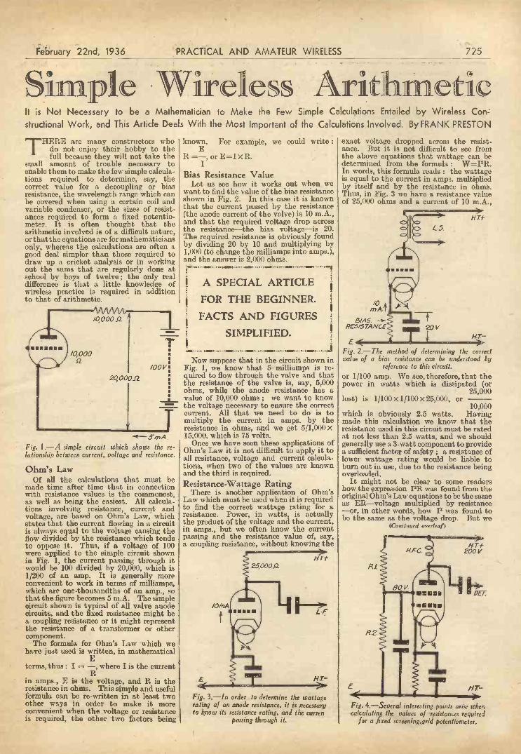
February 22nd, 1936 PRACTICAL AND AMATEUR WIRELESS 725
Simple Wireless ArithmeticIt is Not Necessary to be a Mathematician to Make the Few Simple Calculations Entailed by Wireless Con-structional Work, and This Article Deals With the Most Important of the Calculations Involved. By FRANK PRESTON
THERE are many constructors whodo not enjoy their hobby to thefull because they will not take the
small amount of trouble necessary toenable them to make the few simple calcula-tions required to determine, say, thecorrect value for a decoupling or biasresistance, the wavelength range which canbe covered when using a certain coil andvariable condenser, or the sizes of resist-ances required to form a fixed potentio-meter. It is often thought that thearithmetic involved is of a difficult nature,or that the equations are for mathematiciansonly, whereas the calculations are often agood deal simpler than those required todraw up a cricket analysis or in workingout the sums that are regularly done atschool by boys of twelve; the only realdifference is that a little knowledge ofwireless practice is required in additionto that of arithmetic.
Fig. 1.-A simple circuit which shows the re-lationship between current, voltage and resistance.
Ohm's LawOf all the calculations that must be
made time after time that in connectionwith resistance values is the commonest,as well as being the easiest. All calcula-tions involving resistance, current andvoltage, are based on Ohm's Law, whichstates that the current flowing in a circuitis always equal to the voltage causing theflow divided by the resistance which tendsto oppose it. Thus, if a voltage of 100were applied to the simple circuit shownin Fig. 1, the current passing through itwould be 100 divided by 20,000, which is1/200 of an amp. It is generally moreconvenient to work in terms of milliamps,which are one -thousandths of an amp., sothat the figure becomes 5 m.A. The simplecircuit shown is typical of all valve anodecircuits, and the fixed resistance might bea coupling resistance or it might representthe resistance of a transformer or othercomponent.
The formula for Ohm's Law which wehave just used is written, in mathematical
Eterms, thus : I = -, where I is the current
Rin amps., E is the voltage, and R is theresistance in ohms. This simple and usefulformula can be re -written in at least twoother ways in order to make it moreconvenient when the voltage or resistanceis required, the other two factors being
known. For example, we could write :
R =-, or E x R.I
Bias Resistance ValueLet us see how it works out when we
want to find the value of the bias resistanceshown in Fig. 2. In this case it is knownthat the current passed by the resistance(the anode current of the valve) is 10 m.A.,and that the required voltage drop acrossthe resistance-the bias voltage-is 20.The required resistance is obviously foundby dividing 20 by 10 and multiplying by1,000 (to change the milliamps into amps.),and the answer is 2,000 ohms.',NM ,..(4.104 14MH 141NEM.....04 . '41;
A SPECIAL ARTICLE
FOR THE BEGINNER.
FACTS AND FIGURES
SIMPLIFIED.
Now suppose that in the circuit shown inFig. 1, we know that 5 milliamps is re-quired to flow through the valve and thatthe resistance of the valve is, say, 5,000ohms, while the anode resistance has avalue of 10,000 ohms ; we want to knowthe voltage necessary to ensure the correctcurrent. All that we need to do is tomultiply the current in amps. by theresistance in ohms, and we get 5/1,000 x15,000, which is 75 volts.
Once we have seen these applications ofOhm's Law it is not difficult to apply it toall resistance, voltage and current calcula-tions, when two of the values are knownand the third is required.Resistance -Wattage Rating
There is another application of Ohm'sLaw which must be used when it is requiredto find the correct wattage rating for aresistance. Power, in watts, is actuallythe product of the voltage and the current,in amps., but we often know the currentpassing and the resistance value of, say,a coupling resistance, without knowing the
E
Fig. 3.-in order to determine the wattagerating of an anode resistance, it is necessaryto know its resistance rating, and the curren
passing through it.
exact voltage dropped across the resist-ance. But it is not difficult to see fromthe above equations that wattage can bedetermined from the formula : W=PR.In words, this formula reads : the wattageis equal to the current in amps, multipliedby itself and by the resistance in ohms.Thus, in Fig. 3 we have a resistance valueof 25,000 ohms and a current of 10 m.A.,
/0rt7A-
13/.45.RESISTANCE
EFig. 2.-The method of determining the correctvalue of a bias resistance can be understood by
reference to this circuit.or 1/100 amp. We see, therefore, that thepower in watts which is dissipated (or
25,000lost) is 1/100 X 1/100 X 25,000, or
10,000which is obviously 2.5 watts. Havingmade this calculation we know that theresistance used in this circuit must be ratedat not less than 2.5 watts, and we shouldgenerally use a 3 -watt component to providea sufficient factor of safety ; a resistance oflower wattage rating would be liable toburn out in use, due to the resistance beingoverloaded.
It might not be clear to some readershow the expression PR was found from theoriginal Ohm's Law equations to be the sameas ER-voltage multiplied by resistance-or, in other words, how P was found tobe the same as the voltage drop. But wo
(Continued overleaf)
L5.
20V
Fig. 4.-Severa! interesting points arise whe;calculating the values of resistances required
for a fired screening.grid potentiometer.

/26 PRACTICAL AND AMATEUR WIRELESS
SIMPLE WIRELESS ARITHMETIC(Continued from previous page)
saw that the voltage drop (E) is equal to Imultiplied by R., and if also we multiplythis by I we get the expression PR.
Finding the Wavelength RangeNow let us turn to another simple piece
of arithmetic which is not difficult to follow.Suppose it is required to find the highestwavelength that can be reached when acoil of 2,200 microhenries (a typical long -wave coil) is used in parallel with a .0005-mfd. tuning condenser. The wavelengthis found by using the equation : wavelength
1,884A/L x C where L is the inductanceof the coil in microhenries, and C is thecapacity of the condenser in microfarads,the wavelength being in metres. We havefirst of all to multiply together the induct-ance and capacity, and then to find thesquare root of the result, and finally tomultiply this by 1,884. Taking the firststep we get 2,200 x .0005, or
2,200 x 510,000
which works out to 22/20 ; when this ismultiplied by 1,884 we get as the result2,082.4, this being the wavelength inmetres.
If the required wavelength and coilinductance were known, the correct capacitycould be found by reversing the calculation,and in the same manner the correct induct-ance could be determined from a knowledgeof the wavelength and capacity. Thesecalculations are slightly more involved,however, and since it is rarely necessaryto use them, we will not consider themfurther.
Screening -grid PotentiometersIn the opening paragraph mention was
made of finding the values of resistancerequired in forming a fixed potentiometer,
and this is a problem which often crops upin connection with an S.G. valve of whichthe screening grid is supplied from a poten-tiometer as shown in Fig. 4. If thescreening grid did not pass any current,the two resistances would have valuespropoPtional to the maximum supply vol-tage and the voltage required. In otherwords, if the H.T. supply delivered a voltageof 200 and 80 volts was required for thescreening grid, the upper resistance, markedR.1, could have a value of 60,000 ohmsand the lower one, marked R.2, a value of40,000 ohms. Alternatively, values of30,000 and 20,000 ohms could be used. Itwill be seen from this that the first step isto decide upon the approximate totalresistance with a mains set a maximumvalue of 50,000 ohms is generally suitable,and with a battery set, 100,000 ohms canbe used successfully.
In the above assumption of no currentwe simply made the lower resistance ofsuch a value that its proportion to thetotal was the same as the proportionbetween the required voltage and the totalH.T. voltage -2 to 5, but let us see whatwould happen if the screening grid passed1 m/A. The voltage drop occasioned bythe upper resistance would be 1/1,000multiplied by, say, 30,000, or 30, andthus, the voltage actually applied to thescreening grid would be 80 less 30, or only50 volts. Consequently, either the resistancemarked R.1 must be reduced in value, orthat marked R.2 must be increased. Thisapparent peculiarity is due to the factthat the cathode screening -grid circuit is inparallel with the lower resistance, thusreducing its effective value. It is possibleto evolve an equation from which theexact values of resistance could be deter-mined, but it is generally better for thenon -mathematical constructor to use trial -and -error calculations, and working onthe lines indicated above, until suitablevalues are found.
capacity is 1/.0005 + 1/.0003
which is1/8
or.0015
which00158is .0002-mfd. approximately.
February '22nd,' 1936
Series and Parallel ResistancesIn dealing with resistance calculations
above we did not consider the effect ofconnecting resistances in series and inparallel. If resistances are placed in seriesthe effective value is, as might be supposed,equal to the sum of the resistances. Thus,if resistances of 500, 1,000, and 20,000ohms were joined in series, the total valuewould be 21,500 ohms. When they arejoined in parallel the result is entirelydifferent, and the effective resistance ofthe combination is, mathematically speak-ing, equal to the reciprocal of the sum ofthe reciprocals. This expression is simpli-fied if written :
Total R - 1
1/R1 + 1/R2 - 1/R3etc. This means that if the three resis-tances mentioned above were connectedin parallel the effective value could befound by adding together : 1/500, 1/1,000,and 1/20,000, which equals 61/20,000, andreversing this to 20,000/61, which givesthe result as a,pproximately 330 ohms.It will be noticed that this is less thanthe value of the smallest resistance.
Condensers in Series and, ParallelWhen two or more condensers are used
together the effective capacity is foundby reversing the methods described inrespect of resistances. Thus, when con-densers are joined in parallel, the totalcapacity is equal to the sum of the capaci-ties of the individual components. Whencondensers are in series the resultingcapacity is equal to the reciprocal of thesum of the reciprocals. If, for example, a.0005-mfd. condenser is connected in serieswith one of .0003-mfd., the resultant
1
Popular Radio TurnsEDGAR WALLACE'S " On the Spot,"
" Mrs. Buggins Sees Stars," and the" Air -do -Wells " were the three most popu-lar radio turns of the week ending December14th according to the results of the secondof the competitions organised by the RadioCo-operative Advertising Committee.
A play has again come out on top ; inthe first competition Clemence Dane's " ABill of Divorcement " received by far themost votes. Radio comedians, who in thefirst week were accused of being dull andout of date, have made a triumphantcome -back. More than 25 per cent. of theentrants favoured Variety performances, andspecially commended the comedians.
Old-fashioned dance music was preferredto jazz ; Geraldo's orchestra in " DancingThrough " and Hamer's in " Old TimeDance Tunes " had three times as manyvotes as Ambrose, Henry Hall, and JackPayne. This apathy for modern dancemusic may be due to the fact that thebest time for broadcasters was clearlyestablished as between 8 p.m. and 9 p.m.,when all the five most popular turns wereon the air. Light classical music was muchappreciated, particularly that in " The Tableunder the Tree."
Lord Snowden's account of Keir Hardiewas the most popular talk. Otherwisethere was little enthusiasm for talks or thenews, though a number of women chose theannouncement of the safety of the threegirl hikers as the happiest turn. Severallisteners regarded broadcast services asthe most important item of the week.
HERE and THERE
B.B.C. Symphony Orchestra toVisit Leicester
THE B.B.C. Symphony Orchestra, underthe direction of Adrian Boult, will
appear twice in the provinces in the springbefore starting on its Continental tour toParis, Zurich, Vienna, and Budapest.
Its first visit will be to Leicester onMarch 11th, when Dr. Boult will conductan attractive programme. Opening withWeber's Overture to " Euryantbe," a pieceof romantic music that time has not robbedof its freshness and appeal, the orchestrawill then play Beethoven's ' Sixth Sym-phony (the " Pastoral "), which will be themain item in the programme. In thesecond part, modern music will be repre-sented by four numbers from GustavHolst's " The Planets," and Ravel's" Pavane " and " Bolero," all of whichworks will afford the full B.B.C. SymphonyOrchestra every opportunity to exhibit itsfine qualities. The four Planets chosen areMars, Mercury, Saturn, and Jupiter, repre-senting the contrasting moods of ferocity,sprightliness, serenity, and joviality. Mid-
land music -loverswill welcome espec-ially this opportunity .of admiring onceagain the B.B.C.Symphony Orches-tra's rendering of" Bolero," which isbeing played on thisoccasion in responseto a general demand.This brilliant orches-tral" tour de force"brings a well-chosenprogramme to a fit-ting close.
Here is Stanelli,of Horn-chestra fame, listening to
his Cossor radiogram.

February 22nd, 1936 PRACTICAL AND AMATEUR WIRELESS 727
THE previous article in this seriesdealt with the theoretical considera-tions and constructional work neces-
sary in the manufacture of a simple type ofvalve -voltmeter, and it is now proposed toshow the method by which this instrumentmay be calibrated, and a scale produced toenable voltages of any frequency to beread on the 0-1 milliammeter incorporatedin the multi -range meter.
It will be observed that we have provideda space on the front panel of the instrumentor a calibration scale to be gummed on,
EXPERIMENTERSERVICING SETS FOR PROFIT
7-A Method of Calibration, and Some of the Uses of the Valve -Voltmeter
Described Last Week are Dealt With in this Seventh Article of the Series
voltage, as their voltage will remainreasonably constant with a current drainof 24 milliamperes, over the short periodwhich we shall use to make measurements.The accumulator or dry cells, and the250 -ohm potentiometer, should be con-nected up as shown in Fig. 3, but theactual connection to one terminal of thevoltage supply should only be made whencalibration is in progress in order to limitthe current drain imposed and maintainthe voltage as stable as possible.
Connections and AdjustmentsNow connect the H.T., L.T., and G.B.
batteries to the valve -voltmeter, makingsure that the switch is " off " before doingso, and connect the milliamp. terminalsof the universal meter to the " meter "
terminals of the valve -volt -
H.F.
II
gm=Ot
mfd.
DEL,
Fig. 1.-Method of measuring the voltagedeveloped across a tuned circuit.
and also, that a circular white paper scaleis to be gummed to the panel under theknob of the 1-megohm multiplier poten-tiometer. Alternatively, if the surface ofthe panel is matt -finished aluminium, it isquite possible to omit these paper scaledand draw the calibration points on themetal itself in Indian ink, afterwardscovering the markings with a coat ofcolourless cellulose lacquer.
Before we commence calibration -it willbe necessary to' procure a 6 -volt accumu-lator, and a 250 -ohm variable potentiometer.If it is inconvenient to get a 6 -volt accu-mulator, four large -capacity dry cellsmay be used to supply the calibration
VALVE0 VOLTMETERE
meter. The positive terminalof the universal meter shouldbe connected to the " meter "terminal of the valve -volt-meter which is connected in-ternally to the H.T. positiveplug, and the switch shouldbe set at 1 m.A. The multi-plier potentiometer is thenrotated in a fully anti-clockwise direction, i.e., toratio 1, and the 20,000 -ohmvariable anode resistancemounted on the base -boardset until the whole of theresistance element is incircuit. Now switch on thevalve -voltmeter, and it willbe noticed that the pointer ofthe universal meter gives alittle " kick" and then returnsto a very low reading on the
VALVE
VOLTMETER
6v ACCUMULATOR
1.6w s
ACC LIR -Foci
INPUT orV/VOLTMETER
Fig. 3.-Theoretical circuit of the calibrationapparatus.
scale. It might be thought that the 25 -ohmzero -adjusting potentiometer on the frontpanel should now be set so that zero wasactually indicated on the milliammeter, butthis is not the case, owing to difficulty inascertaining the exact setting at whichthe milliammeter reads zero. A much moresatisfactory method, and the one adoptedin this case, is to adjust the 25 -ohm poten-tiometer until the pointer of the milli -ammeter reads .02 milliamp., or, in thecase of the Ferranti instrument used bythe writer, to the first small division on thescale. This point will now become thezero point for the voltage scale of thevalve -voltmeter, and the meter shouldalways be checked before making measure-ments to ensure that, under the foregoingconditions, a true zero is indicated.
The valve -voltmeter should now beswitched off, the multi -range meter dis-connected, and its 10 -volt D.C. range
(Continued overleaf)
250nPOTENTIOMETER
Fig. 2.-Adjusting the zero reading.
MULTI -RANGEMETER

728 PRACTICAL AND AMATEUR WIRELESS
FOR THE EXPERIMENTER(Continued from previous page)
connected across the leads from ourcalibrating voltage supply marked G andE, and the 250 -ohm potentiometer varieduntil exactly 5 volts (or half -scale deflection)is registered. Then re -connect the universalmeter to the " meter " terminals of thevalve -voltmeter and the calibration leadsG and E to their appropriate input ter-minals as shown in Fig. 2. Switch on thevalve -voltmeter, and it will be found thatthe pointer of the universal meter willnow give a reading somewhat higher thanthe zero reading which we previously se-lected. By rotating the 20,000 -ohm resist-ance on the baseboard until the universalmeter reads exactly 1 milliamp., the scalewill be set to read 5 volts between .02 iiiilli-amps. and 1 milliamp. It may be advisablenow to disconnect the calibration voltageby removing one of the leads from theaccumulator, or dry batteries, and to notethat the pointer of the milliammeter fallsimmediately to our previously selected zeroposition. If it does not do so, a slightreadjustment of the zero -adjusting poten-tiometer will be necessary. The internal20,000 -ohm resistance will not need re-setting unless the characteristics of the
I. F. TRANSFORMER
Fig. 4.-The meter is connected to the points X X,across the secondary of the I .F . transformer
nearest the second detector.
P2 valve change considerably, and with thelimited periods of use which we are likelyto give the instrument, the life of the valveshould be almost indefinite. It has alsobeen found that the replacement of the'valve has very little effect on the calibrationof the instrument, provided the instrumentis reset for zero and maximum readingswhenever it is necessary to make thisreplacement.Checking the Deflections
All that remains now is to make a noteof the deflections given by the milliammeterfor various voltages between 0 and 5 voltsapplied to the input terminals, 'and toobtain these readings the required voltageis selected by adjustment of the 250 -ohmpotentiometer with the 10 -volt range of theuniversal meter connected across leads Gand E and then noting the deflection givenby the milliammeter when this voltageis applied to the valve -voltmeter. Somereaders may care to plot a graph of thesereadings, and so be able to measure inter-mediate values directly,. but I have foundthat the valve -voltmeter calibration isnearly linear, and a chart prepared in thesame way as the capacity chart describedand illustrated in Part 4 of this series isquite suitable.
Having prepared the graph or chart itonly remains to calibrate the multiplierpotentiometer. This is quite a simple matter,and should present no difficulty. Firstapply 5 volts to the input terminals of thevalve -voltmeter so that a full-scale deflec-tion is given by the milliammeter, thenrotate the multiplier knob in a clockwisedirection until the milliammeter indicates2.5 volts in accordance with our calibrationchart. Mark the position of the multiplierpointer and call it X2, then if the pointer isleft in this position all the readings obtainedon the valve -voltmeter will be multipliedby two, and we have extended our range to10 volts maximum. Again rotate the multi-plier knob until 0.83 volts io indicated andmark this point X6. This extends the
FOR THE NEW READER.
Previous articles in this serieshave dealt with a D.C. Multi -Range Meter ; Adapting it forreading A.C. Voltages ; and theConstruction of a Simple Valve -
voltmeter.
I
MINN.< )011R 1411004=1111414=11.11.M1
range to 30 volts maximum, and all readingsobtained with the multiplier knob in thiposition must be multiplied by six. Finally,carefully rotate the multiplier until 0.5volts are indicated, and mark this point X10.We shall now have extended the scale to50 volts maximum, and all readings mustbe multiplied by ten.
Using the Valve -voltmeterThe calibration is now complete, and we
can start to make use of the valve -volt-meter. It will not be out of place here todescribe a few of the more obvious of itsuses, although later articles in this serieswill describe it in use in conjunction withother apparatus. It will find its majorapplication in the measurement of voltagesin circuits where the current flowing istoo small to actuate any other type of volt-meter ; for instance, it will measure thevoltage developed by a steady signalacross the load resistance of a diode detector-a very useful guide to A.V.C. efficiency.Also it will measure accurately the voltagedeveloped by a signal of any frequency
I,
le
trr
MARVELSof
MODERNSCIENCE
By F. J. CammAn about television, helicopters,streamlining, harnessing theinvisible ray, etc., etc., with thelatest pictures of all the newestand most thrilling inventions.
From all Booksellers
Only 3'6 netGEORGE NEWNES, LIMITED
77;
February 22nd, 1936
across the secondary circuit of an outputtransformer.
To measure the radio -frequency voltagesacross tuned circuits it will be necessaryto prevent the H.T. voltages from reachingthe grid of the P2 valve, and mica con-densers of .01 mfd. capacity should alwaysbe connected in series with the input ter-minals before making measurements inany circuit where D.C. currents are alsoflowing. When measuring A.C. voltagesexisting across, say, the anode resistance 'of an L.F. amplifier, the capacity of thecondensers should be increased to as largea value as possible, though care shouldbe taken to see that the insulation of thecondensers chosen is high. Fig. 1 willshow the connections to the valve -volt-meter when measuring the H.F. voltagedeveloped across a tuned circuit, in thiscase the tuned -grid coil of an H.F. amplifier,and it will be noticed that the G "terminal is connected to the high potentialend of circuit and the " E " terminal toearth. This procedure should always befollowed wherever possible because it isadvisable to keep the metal case of thevalve -voltmeter at earth potential toeliminate stray pick-up effects. The valve -voltmeter connected as shown in Fig. 1
ANODE FEEDRESISTANCE
LARGE CAPACITY
o VALVE
VOLTMETER
Fig. 5.-Measuring the A.C. volts developedacross an anode feed resistance.
will actually measure the H.F. voltagepresented to the grid of the detector valveif the set is tuned to a powerful local station,and by experimenting with the voltagesapplied to the H.F. valve and, incidentally;by making any modifications to the aerialcoupling coils, etc., it is possible- to seethe result of such experiments as a gain orloss in voltage. The I.F. and frequency -changer circuit of a superheterodyne could,also be experimented with using the meter'connected across the secondary of thel,I.F. transformer nearest to the secondsdetector (Fig. 4), and, if the magnificationis not too great, it is possible to measurethe amplification of a valve, and itscoupling components, by first adjusting'the voltage across its grid, circuit by anH.F. volume control to 0.5 volts, then'transferring the valve -voltmeter to thecoil in the anode circuit of the same valveand again measuring the voltage. If thereading given is, say, 45 volts, then thestage gain is
45-F. or 90.
Many other uses will no doubt be apparentto the experimenter, but a fuller descriptionof the use:, of the instrument will be givenwhen we have constructed an L.F. andH.F. oscillator to provide the energyrequired to make our measurements. TheL.F. oscillator will be the subject of thenext article.

February 22nd, l936 PRACTICAL AND AMATEUR WIRELESS
362Would members of the public taking ad-
vantage of our FREE TECHNICALADVICE SERVICE please bear in mindthat we are able to make a much moreaccurate diagnosis of their troubles if acircuit diagram, no matter how rough, issent with the enquiry.
THE 362 RADIO VALVE CO. LTD.STONEHAM WORKS, E.5.
Chssold 6607.
The Story of a Gracious King
"THE LIFE OFKING GEORGE VCommemorating a Great and Glorious Reign
Profusely illustrated in
Gravure including HistoricFuneral Photographs 6D
Y5
On Sale
at all Newsagents andBookstalls
Published by George N,spnes, Led. 841, Southampton Street, Strand, W.C.2.
729
USE5\:091-touse
METALRECTIFIERS
AND " INSURE" YOUR POWER SUPPLYNo fragile filaments to
burn or wear out. Noth-ing to break. No replace-ments. Constant output.You can rely on Westing-
house Metal Rectifiers
111
" The All Metal Way, 1936 "contains full details of, andcircuits for use with, thesereliable rectifiers. A 3d.stamp to Dept. P.R.A. willbrin4 you a copy.Westinghouse Brake &
Signal Co., Ltd.,82, York Road, King's Cross,
London, N.1.
TWO COMPLETE WORKSon. Practical Electrical Engineering !
Here are two practical works for everyone engaged orinterested in the electrical industry. Each is entirelycomprehensive, written by experts tamous in their re-spective spheres, and fully illustrated by drawings, photo-graphs, tables and diagrams --post coupon now for treedescriptive leaflets.
THE ELECTRICAL EDUCATOREdited by Sir Ambrose Fleming, M.A., D.Sc., F.R.S. Complete in 3 handsomelybound volumes containing over r,000 text illustrations and over too plates and foldedinsets. Contributions by eminent authorities are included, amongst whom may be men-tioned Sir W. Bragg, Sir R. Hadfield, and R. Farraday Proctor. The work deals completelywith the application of electricity to all fields of industry and special sections deal with theproblems of wireless engineers. As textbook or reference work it is absolutely indispensable.
ELECTRICAL WIRING & CONTRACTINGEdited by H. Marryat, M.I.E.E., M.I.Mech E The theory and practice of electricalwiring and contracting is here completely treated in 7 convenient pocket -sized volumes.Experts in every branch place their specialized knowledge at your disposal, the resultingwork being not only practical but eminently authoritativo. This is recognized as thestandard work for this field-one which offers complete instruction in the simplest andclearest manner imaginable.
THE NEW ERA PUBLISHING CO., LTD.12-14, NEWTON ST., HOLBORN, LONDON, NifV.C.2
Post the Coupon TO -DAY
I To:
II
MIN I11 ME =I In MI Or
THE NEW ERAPUBLISHING Co., Ltd.,12-14, Newton Street,Holborn, London, W.C.2
Please send me by return, freeand postpaid, your descriptiveleaflets on
THE ELECTRICALEDUCATOR,
andELECTRICAL WIRINGAND CONTRACTING
Whilst this request is free ofall obligation, please send meat the same time full particularsof how I may secure theseworks on outsof.income terms.
Strike out the book not required.
Name
Address
P.A.N% . 10.
Itr. ma nit in - ammammaa

730 PRACTICAL TELEVISION February 22nd, 1936
THE TWO TELEVISION STANDARDS-IBy "CRITIC"
THE publication of the TelevisionCommittee's report dealing withthe chosen site for the first high -
definition television station in London,namely, the Alexandra Palace, together withthe information that the two companieswho are to supply the transmitting equip-ment (that is. Baird Television, Ltd., andMarconi-E.M.I Television, Ltd.) are towork on quite different standards, hasprovoked considerable discussion. Thishas centred very primarily round the wholequestion of these two different standards.
went value of television, it is a commonpractice (although in my opinion a wrongcomparison) to compare the results withmodern talking films. In any cinema thedetail which is observed on the screendepends very primarily upon the pictureillumination provided by the arc lampand optical system, the photographic grainof the film itself and, lastly, upon themechanical precision with which the record-ing and reproducing processes work. TheSociety of Motion Picture Engineers pub-lished in March, 1934, the standard of
2 41=11mmm
345 1=1.1.mM
6789 IlMirmemmi
Two Scanning SchemesIn the case of the former the system
adopted is a picture definition of 240 linesscanned in sequence at 2.5 picture traversalsper second and 25 complete frames persecond. With the latter, however, it isproposed to use as a standard 405 -linedefinition, 25 pictures per second interlacedto give 60 frames per second each of2021 lines. It is further stated that theCommittee have satisfied themselves thattelevision sets can be constructed capableof receiving both sets of transmissions(they will be radiated alternately) withoutunduly complicated or expensive adjust-ment. The tenders submitted by thecompanies have been accepted, and eachfirm has furnished the technical informationregarding the characteristics of the tele-vision signals radiated, so as to facilitatethe design of receiving equipment capableof picking up these signals.
At first sight these rather bald factsappear quite satisfactory, but actuallythey have been instrumental in promotingmany discussions, primarily in connectionwith the reason for " interlacing " and howsuch scanning operates, and also whetherthe higher line standard is a reasonableproposition at the moment.
The object of the scanning process isto dissect the scene or object to be televisedinto a series of lines sufficiently great innumber that quite small detail will berecognisable in the received picture, assum-ing perfection in the scanners, amplifiers,radio transmitter, radio receivers, and finalpicture reproducers. Any form of ampli-tude or phase distortion in a single linkof this chain of events will naturally marthe picture, but this is a factor which lendsitself to remedy, once the technique whichis involved is mastered.
Cinema ComparisonIn assessing the pictorial or entertain
Fig. 1.-A nine line scangreatly exaggerated, showinghow an orthodox sequential
scan is built up.
performance laid down by the ProjectionPractice Committee in the following terms :" If the projector is in first-class conditionand the intermittent movement and picturegate are properly adjusted, the picturejump should 'not exceed one-third of oneper cent. of the picture height."
This standard can be interpreted literallyin one or two ways. First of all, if the pro -
2
3
4
5
jector is in first-class condition, then work-ing to the standard limits, an otherwiseperfect picture is blurred to the extent ofone-third of one per cent. or, in otherwords, any object which is so small thatit occupies only one three hundredth ofthe total picture height is blurred intonon -recognition. This precision is reallyan extremely good one, for taking, say, ascreen 15ft. high the non -recognisable
6Fig. 3.-The second or inter-mediate section of an inter- 7calated scan, where, on thecompletion of the final linetrace, both time bases trip 0
together.
9
414
object only represents three -fifths of aninch. Furthermore, when seated in acinema the audience is occupied in dis-cerning (and no doubt enjoying) thecentral figure or figures, together with theaction portrayed and the story beingunfolded, and has little thought for suchminute details as have been quoted.
Conversion to TelevisionThe human element must, and will, play
an important part in assessing the valueof a television picture in terms of linedefinition, so if we convert the cinemastandard to one of television, the limitis a loss of detail identity to the extentof one-third of one per cent., that is asingle scanning line in a complete pictureof 300 -line definition (this being the re-ciprocal of one-third of one per cent.).When the Television Committee producedits report, their recommended minimumstandard was given as 240 lines, which isonly 20 per cent. below the cinema limitjust explained.
Communication ChannelQuite apart from this, however, there is
the all-important point of whether thewavelength which is to be used for theradiation of the television signals, that is6.6 metres, is capable of accommodatinga line definition standard which is in excessof 240 lines. While it is impossible to arriveat a hard and fast form of calculationto obtain the frequency spread involvedin a complete television signal, it is asimple matter to bee how the limitingfactors impose conditions which must notbe exceeded if satisfactory results are toaccrue.
Considering for a moment a picture builtup of alternate pure white and blackstrips, the scanning spot or exploringaperture will just fail to reproduce theeffect or become blind in the televisionsense when the spot size is equal to thewidth of two strips (one black and onewhite). The actual response will be the
Fig. 2.-Showing how thefirst section of an intercal-ated scan is built up in asimilar manner to the ortho-
dox, or sequential, system.
average of these two extremes and a greycolour will be seen. When this conditionoccurs, it can be said that the extremefrequency limit has been reached. Taking asan example, therefore, a picture repetitionfrequency of 25 per second, picture ratioof four horizontal to three vertical and240.line horizontal dissection, the limitingfrequency becomes 240 x (240 x 4/s) x 25which equals 1,920,000 or 1.92 megacycles.
5

February 22nd, 1936 PRACTICAL AND AMATEUR WIRELESS
n lour avden731
A Danger SignalI SEE that music from one of the popular11 French stations is being heard by thesignalmen in boxes on the Great WesternRailway between Paddington and HighWycombe-and this in spite of the factthat there are no receivers in the signalboxes. The trouble is said by experts to bedue to leakage from rediffusion wiresattached to telephone poles near Wembley.\ It seems rather hard on the railway officialsthat even when at work they are unable toescape from the " plugging " of somebody'ssoap or some other item which is beingmentioned in the English programmes fromthis particular station. Imagine the plightof a signalman, anxiously awaiting an " allclear " signal, but who receives instead aninjunction from the announcer to takeGreen Pills, or who is confronted by the" strains of a crooner. It must be enoughto make him set all the signals at dangeror to send the Cheltenham Flyer to Margate !
Assistance from a ClubAT a certain church in the Midlands
the acoustics were so bad thatit was found that only the front fewpews were within range of the pulpit,and the padre, being one of the moderngo-ahead ministers, decided that a goodpublic-address equipment would proveextremely valuable. He also conceived theidea of fitting a standard receiver in thevestry so that on occasions when there wasno service in the church he could pick uprelayed services and similar items andbroadcast them in the church. To obtainthe money to purchase the necessaryapparatus he hit on the original idea (?)of holding a bazaar.
The mothers met, and over the parochialcup of tea they decided that it would be an" ungodly act to place such a moderninvention in, the precincts of the church"and refused to help with the bazaar.Luckily there was a broad-minded reader ofPRACTICAL AND AMATEUR WIRELESS in the
A crooner in the signal box.
district and he came to the aid -of thepadre by collecting discarded apparatusfrom the local club members, and a reallyexcellent piece of apparatus is now installed.
" Calling All Cars "I WAS trying out a new short -waver theI other night and whilst on the lowerranges I picked up a transmission fromPolice Headquarters in an American city,giving directions to a patrol car regardinga certain -suspicious car in .a shoppngcentre. It was most thrilling, but I failed
By thermion5
to hear the scream of the syren or themagic words of the movies " Calling allcars."Quoth a Reader
MY remarks sometimes seem to upsetsome people, although others must
take my writings to bed with them. Hereis a short and to -the -point epistle from Mr.A. Jones, of Leicester : " I read yourremarks about not being able to tell thedifference between a highbrow violinist anda street musician, and I think you have avery poor taste for music. You owe asincere apology to the street musician.P.S.-But I agree with you about crooners."But what about this from Mr. G. Gay, ofHereford. He says : " I was pained toread your remarks on violinists in thecurrent issue (sorry to have caused you anypain), but I know you are-from yourremarks-extremely unmusical and thusunfortunate. (Am I unmusical ?) I havestudied the violin and have played firstviolin in the best amateur orchestras inLondon and Leeds, and also in dancecombinations, and I can assure you thatthe difference between street musicians anda 0,000 concert violinist is very real. Doyou know that it takes ten years or moreof hard work-eight hours a day-to playthe simplest of things really well ? (Yes,I do, and so do many poor folk who live inflats. There should be a law against it !)Street violinists would not be on the streetif they were any good (I seem to have heardof such misfortune). I have heard all theleading violinists and many street ' mu-sicians,' but my only reactions to the latterare ones which make me think of rat poison.Well, this is only a small part of what Ifeel when I ',hear and read remarks suchas yours, and I think you ought to give usnews of the B.B.C., etc.-talk of somethingyou understand." The italics are mine !And that's that.The Foundations of Music
THE other day a radio critic tabulatedthe " for and against " letters which
he has received. I was not surprised to seethat there was an unanimous vote againstcrooners and the Foundations of Music(why do the B.B.C. continue to lay thesevery heavy foundations ? They must bethe most unpopular feature of all thebroadcast programmes. Although I didsee a letter in a book the other day praisingthem-from Sacheverell Sitwell) ; but I wassurprised to see a heavy vote against HenryHall, mentioning particularly the Glee Clubwith its " churchy atmosphere."
Those Junk PartsMEMBERS of the Technical Staff are
constantly telling me of those readerswho write to ask for a wiring plan suitablefor, using a number of components whichthey bought cheaply at a junk shop.Sometimes the letters are accompanied byrather crude sketches of the coils and
similar components, but otherwise there isnothing to guide those genii whose work itis to design some of those excellent receiversthat are products of the PRACTICAL ANDAMATEUR WIRELESS laboratories. Theyhave therefore asked me to refer to thismatter in these notes, in the hope that theymay reach the eyes of a large number of" junk -shop " merchants. The fact of thematter is that second-hand and discardedcomponents are rarely of any real practicalvalue to anyone except those who arecapable of designing a complete set ; tothe inexperienced constructor they are oftenworse than useless, since they may resultin damaged valves and other good com-ponents due to incorrect use.
I should, of course, point out that theFree Advice Service offered so willinglyby this journal does not apply to theprovision of complete wiring diagrams ordesigns for receivers. Such a servicecould not operate satisfactorily, becausedesigns must be thoroughly tested beforethey are offered to the public, and it isobvious that the hard-working TechnicalStaff could not possibly make up, test,modify, and re -design those hundreds ofsets a day for which readers ask ! Itmight be asked why the policy of thisjournal is to refrain from giving wiringplans for untried receivers. The reasonis that every PRACTICAL AND AMATEURWIRELESS receiver is covered by a veryvaluable guarantee, and the Editor hasrightly considered it most undesirable topass on to any reader details of an instru-ment which has not been fully tested andwhich cannot be guaranteed to functionin a perfectly satisfactory manner, withoutthe need for further experiment by theconstructor. Therefore, dear readers, donot be annoyed if, in reply to your query,you receive a letter politely informing youthat the Technical Staff cannot undertaketo supply wiring diagrams and lists ofcomponents for a seven -valve all -wavesuperhet, to be built from parts taken froman old set, or a three -valve mains receiver
A gift from the local rad'o fans.
with A.V.C. constructed from a collectionof components bought for five shillingsin Farringdon Market.
Believe me, it does pay-and pay well-to buy new and guaranteed componentsin the first place, if only because these canbe used over and over again with fullassurance that they will not let you down.
My Quality SetANUMBER of readers have written
for details of my quality receiverwhich I mentioned in these notes recently.
(Continued overleaf)

T1.
732 PRACTICAL AND AMATEUR WIRELESS
(Continued from previous page)
I regret that I cannot supply a diagramof this set, but in brief the arrangement isas follows : The H.F. stages are notcontrolled by any A.V.C. system, althoughI am using variable -mu valves. There arecertain features to be obtained in thistype of valve which render it suitable whenbiased [to ra certain point, and I havethem so adjusted. The tuned circuitsemploy converted commercial coils inwhich the self-contained wave -changeswitches are employed for the purpose ofbringing into circuit pre -Set condenserswhich are adjusted for the two local stations.This scheme has already been mentionedin these pages and forms a, very usefuldomestic control which avoids all complica-tions regarding the wavelengths of stations,etc. The detector is a double -diode valvewith diodes strapped together, and theoutput is a push-pull stage employing
Hearing American broadcasts.
resistance -capacity coupling. A home- ;made mains section is employed, the mainstransformer being wound especially forthis set and delivers 500 volts. The ;panel controls are only two in number,namely, the station selector switch (whichhas three positions, on or off, National andRegional) and a volume control. Acoloured light indicator is used to shoW the ;
listener to which station the set is tuned-a device copied from the Science Museumreceiver.
Sequential SmoothingSEEKERS after " perfection " might be
interested in a scheme which I triedout in a set I recently built for experiment,and which seems to be an absolute certaintywith regard to the elimination of hum-that bugbear of the majority of mainsreceivers. I was trying to locate the varioussources of hum in mains sets and had comedown to some really peculiar points. Thefinal arrangement which I incorporatedwas so good that it enabled me to dispensewith the usual 50 mfd. smoothing con-denser in the bias circuit of a D0.24 valveand to use a 1 mfd. in its place withoutthe faintest sound from the speaker(other than the signals, of course). The setwas provided with a weak H.F. amplifierso that only the locals could be heard,and when tuned to a point midway betweenthe National and Regional it was definitelyimpossible to hear even the faintest humwhen the head was placed right up againstthe loud -speaker. This was an energisedmodel provided with hum -bucking coil,and the scheme which was adopted wasto use 'smoothing circuits in series, andwhich I think could very well be termed" sequential smoothing." The output valverequired 400 volts H.T., and to obtain thisfrom the 450 volts output from the elimin-ator, I used a standard high -inductancesmoothing choke. From this point theoutput valve was fed, and the H.T. leadto the remaining valves was passed throughthe field of the speaker. From this pointthe first L.F. valve was fed, and the H.T.for the earlier valves was again classed
S.W. SuperhetsTHE straight type of short-wave :
receiver, with or without an H.F.stage, seems to be the most widely used 2by listeners. There are many superhetsavailable, but these have not yet attainedthe popularity they enjoy in the medium- ;long -wave class. This may be mainlydue to the question of price, as the simplestraight set is cheaper than the superhettype. It is probable, however, that the e
main advantage of the straight set is itsability to pick up continuous wave morse :signals. The majority of superhet short -
I wave sets cannot do this, their reception :being limited to telephony, interrupted e
; continuous wave morse, and spark morse.For this reason home constructors experi-menting "with short-wave superhets forthe first time are inclined to think thatthe straight receiver is much moresensitive.
There is no doubt, however, that thesuperhet is the ideal type of receiver forshort-wave listening, provided that it hasbeen carefully designed and is being cor-rectly operated. It is a very easy matter Ito provide reaction in the intermediate -frequency stage in order to enable thelistener to receive continuous wave morsewhen desired ; the simplest method isprobably the connection of a short lengthof insulated flex to the cap terminal ofthe I.F. valve. The free end of this shouldthen be allowed to rest on or near theG. and G.B. terminals of the precedingintermediate -frequency transformer. Bythis means a feed -back takes place fromthe anode to the grid circuit of the I.F.valve and oscillation occurs which canbe controlled by the I.F. valve bias volumecontrol.
Baseboard ScreensWHEN a metallised chassis has been
in use for a lengthy period, orhas been handled so often that the surface thas become dirty, bad contact betweenthe various earth return points some-times occurs. When this trouble is ;
suspected the metallised surface screwsshould be joined together by means ofordinary connecting wire. This is par-ticularly advisable if the metallising isused for conducting direct current. The ;same warning applies to thin foil coveredchassis ; the metallising or foil providesan effective H.F. screen, but cannot berelied upon to provide a perfect path fordirect current after prolonged use. If ;the above -mentioned precaution is taken,however, the wooden chassis of thefoil -covered or metallised type is much ;more suitable for the home -constructorthan the all -metal type commonly usedin commercial sets.
Class B and Q.P.P.IF a high tension eliminator is used for
supplying a Class B or Q.P.P.receiver it should be of the type thatgives a constant output voltage regardlessof the current consumption of the set.Some of the modern eliminators have asufficiently good regulation to give thenecessary steady voltage, but in -manycases the addition of a stabiliser isnecessary.
February 22nd, 1936
through a standard smoothing choke.Each of these smoothing circuits wascompleted -by the usual 8 mfd. electrolytic,and it seemed that the additional expenseof the chokes was fully justified. Perhapsother experimenters would like to carryout some trials on these lines.
Running CostsWHEN an A.C. eliminator is provided
with a trickle charger the consump-tion of L.T. must be added to that of H.T.For example, suppose that the receiver hasfour valves taking .5 amp. L.T. and isused for 25 hours a week. The weeklywatt-hour consumption will be 12.5, andthis is therefore the amount of power drawnfrom the charger by the accumulator ;approximately the same amount of powermust be taken from the charger, and thus,allowing for the loss in the rectifier andmains transformer, the power taken fromthe mains will be about 16 watt-hours. Inany case, however, the cost of A.C. currentwhen using an eliminator is almost negli-gible, and can be measured in pence permonth. When only H.T. is taken fromthe eliminator the cost may well amountto a matter of pence only in the courseof a whole year.
Radio and ArchitectureTHAT radio is making its presence felt
in the realm of architecture wasbrought to the fore a week or so 'ago whena committee of the Royal Institute ofArchitects presented a report dealing withwireless reception in flats. It stated thatall the technical difficulties have beensolved, and showed how by treating a blockof flats as a whole instead of in sections,good radio could be obtained by everytenant. A common aerial with shieldedfeeder lines, and suitable matching trans-formers screened from any likely source ofelectrical interference, is the best way oftackling the problem. The remarkable partof the whole report, however, lies in thesuggestion that in all new flats provisionshould be made for special circuits whichwould enable television reception to beundertaken. The suggestion is an admirableone, and will no doubt bear fruit in the nearfuture.
LitvY
11111111F
The Foundations of Music are getting deeper.
A Bad SlipALL readers of this journal are no doubt
familiar with the light sensitiveproperties of selenium, for in the early daysof television it was applied at the trans-mitting end in order 'to' achieve cruderesults. Its sluggish action eventuallycaused it to be discarded for this work, butwhere the time factor is not of such import-ance selenium is still employed. In thisconnection a Sunday newspaper recentlymade a bad slip in describing an instrumentwhich enables the blind to read ordinaryprinted type by converting each letter ofthe alphabet into distinct sounds. It wasstated that a ray of light working on the" solignum " principle, passes under thelines of type.

February 22nd, 1936 PRACTICAL AND AMATEUR WIRELESS 733
A PAGE OF PRACTICAL HINTS
SUBMI
OURIDEA
A Multi -valve Test -adaptorHERE is a very simple and inexpensive
adaptor, which will enable tests tobe carried out with any standard 4- or 5 -pinbase valve whilst under working condi-tions.
A simple multi -valve test -adaptor.
It is made from a base of a 5 -pin valveand a 5 -socket valve holder, and a fewsockets and " banana " plugs.
Carefully make two holes one above theother (and a little to the'side of the " legs ")to each leg, and two extra ones for thecentre pin in the valve base, each holebeing large enough to take a " socket."Insert the sockets, and join each lowersocket to their respective pins with shortpieces of wire. Next take a valve -holderand join the rest of the sockets to the corre-sponding sockets in the holder. It is bestto use insulated wire so that -when thevalve -holder is placed in position no shortcircuiting will take place. The holder canbe held in position with a little pitch froman old H.T. battery. Take a banana plugfor each socket, pair them up, and jointogether with 2in. or so of flex. Two extraconnections can be made with doublebanana plugs at the ends, with longer leadsand either spade or crocodile ends forconnecting to the appropriate meter. Thetwo plugs are required to couple socketswhen reading voltages. With this device,both voltage and consumption can betested in anode, grid, cathode, and heatersof any valve whilst working by puttingthe meter leads in the correct sockets,after withdrawing coupling leads. Asimilar unit can be made to test 7 -pinbase valves.-V. R. SALES (Gt. Yarmouth).
Automatic Switch for a Pick-up
MOSTpick-ups have a rest, and through
this rest a small hole must be drilled.An ebonite rod is placed in this hole so thatit projects from the top about /in. Theother end rests on the middle spring of atriple contacting piece, which is builtup with three thin brass strips and a piece oftin. ebonite as shown in the sketch.These three strips are screwed or riveted
.k..../.11.0111.111.0.111141.10.114111111.114111.1.11110.011.M.11
i THAT DODGE OF YOURS !Every Reader of " PRACTICAL AND -
! AMATEUR WIRELESS " must have Ioriginated some little dodge which wouldinterest other readers. Why not pass it on /i to us ? We pay £1.10.0 for the best wrinkle
11 submitted, and for every other item published
1
on this page we will pay half -a -guinea. Turnthat idea of yours to account by sending it
A in to us addressed to the Editor, " PRAC.I TICAL AND AMATEUR WIRELESS,"
George Newnes, Ltd., 8-Il, SouthamptonStreet, Strand, W.C.2. Put your name and Ii address on every item. Please note that everynotion sent in must be original. Mark
'.' envelopes " Radio Wrinkles." Do NOTI enclose Queries with your Wrinkle.il.....4=1414110410.16.11.011.0.1.11!114Mr11.041011413
to the pieces of ebonite, and it will beseen that one of the three contacting piecesis shorter than the other two. At theends of the strips are soldered pieces ofsilver wire to obtain a better contact.The whole is then screwed to the bottomof the gramophone board so that the eboniterod just rests lightly on the middle contact-ing piece. The shorter contacting piece isbent downwards so that it engages with the
SCREENEDLEADS
TO PRECEDINGVALVE
MIMI %lb_
1111111,f;r0.00Hoit
4
I -eWitiammeliztamm.'1,-011111.11m04/01111111iniP1.0011114011/111
TO G.B.- Iii
TO GRIDOF VALVE
TO G.15.-
5 LVEP,CONTACTS.
middle piece when the pick-up is off itsrest. When the pick-up is replaced on therest the middle contacting piece disen-gages with the top contacts, and engageswith the bottom one.
The middle contact is wired (as shortas possible to prevent picking up any hum)to the grid of an L.F. valve. The topshort contact is wired to one of the pick-upleads, the bottom contact being connectedto the broken end of the grid circuit.The other pick-up wire is joined per-manently to the 14 volts G.B. tapping or(in a mains set) through an appropriateresistance to earth. When the pick-upis -lifted off its rest and placed on a record,the contacts are set for the L.F. amplifier,and when the pick-up is replaced on therest, the contacts are set for radio control.-L. E. LESSEL (Putney).
THE WIRELESSENCYCLOPEDIACONSTRUCTOR'S
By F. J. CAMM 11 4th e(Edatur qf " Presettral and Amateur Edition al 'net.Wireleu")Wireless Construction, Terms and Definitionsexplained and illustrated in concise, clear
language.From all Booksellers, or bp post 5/6 from GeorgeNewnes, Ltd., 8-1l, Southampton Street, Strand,
London, W.C.2.
A simple automaticswitching device for a
pick-up.
PAYNTER (East
A Reisz-type Carbon MicrophoneTHE simple microphone shown in the
accompanying sketches is of thetransverse current type and, besides beinginexpensive, is far superior as regardsfrequency response and sensitivity to thecarbon -button type. The sketches shouldmake the construction clear. The part Cis cut from fin. deal and the terminalsfixed in it. Part B is the same size as C,but a cavity is cut in it 2ins. by liins. to adepth of tin. at each end, but curvingupwards to a depth of fin. at the centre.The carbons, which may be obtained froman old torch battery, are wedged in at eachend. The granules may be obtained fromElectradix Ltd.
A plywood cover (A) holds the diaphragminto place. This diaphragm is of fine linenand should be stretched as much as possibleover the cavity before glueing into place ;this is to raise its natural vibration fre-quency as high as possible. After thecavity is filled almost to the top with carbon
granules a thin layer ofcotton wool is placed overthe carbon rods and thegranules` in direct con-tact with them, beforethe diaphragm is fixed,so as to prevent vibra-tion at this point. Thecompleted " microphonemay be enamelled whiteand suspended in theusual way. It shouldbe fed to the amplifierthrough a step-uptransformer, an ordinaryintervalve transformerbeing quite suitable forthe purpose.-DouoLAs
Ham).
24
DIAPHRAGM COTTON WOOL PLYWOODCARBON GRANULES COVER
lararious3 TWIDTEANKEED lir /1
NUTS /TERMINALS
WIRESCONNECTINGCARBONS TOTERMINALS
An easily -made carbon microphone.

0 -O
.0
0. -
04>
OA> 00 A> O O 0 O A/ A. A/ A> A/ A> 0 A> <> 0 A. A. A> 0 0 A/ A/
00 0
0 0 0 0 A> A> 0 11 A> 0 0 A.
ract
icaU
dnut
te"W
irele
ss
A/
A. A> O A. A> A> 0 <. A. 0 A> 0 41 0 A/
A> 0 0
SE
RV
ICE
DA
TA
SH
EE
T N
? 18
10M1.0.0110(MMINWI.MMW(MMO.I.M11.0.1.114MMOOM.04EMNIOM1414.011.101 WNW ,AMMINMEMOORM.,MMEW(NMEWI.MMVAIMINWI.MMW
.MEM141
FUL
L-S
IZE
BL
UE
PRIN
TS
OF
AL
L "
PR
AC
TIC
AL
AN
D A
MA
TE
UR
WIR
EL
ESS
"R
EC
EIV
ER
S A
RE
AV
AIL
AB
LE
.SE
E P
AG
E 7
48.
101
Top
of
Cha
ssis
Vie
w
FOR
TH
EM
ON
ITO
R T
HR
EE
1111
101V
Und
ersi
de o
f C
hass
is
App
roxi
mat
e V
olta
ge R
eadi
ngs
App
roxi
mat
e C
urre
nt R
eadi
ngs
Mill
iarn
met
er c
onne
cted
at x
1=1.
1 m
.A.
X2=
11 m
.A.
" X
3=7
m.A
.V
oltm
eter
-to
E
+ to
1=
120
volts
.
+ to
2=
60 v
olts
.
-1-
to 3
=11
5 vo
lts.
-1-
to 4
=12
0 vo
lts.
0-0
App
roxi
mat
e.. R
esis
tanc
e R
eadi
ngs
Coi
lO
hmm
eter
con
nect
ed a
cros
s w
hite
lead
s an
d sc
reen
ing
can
-17
ohm
s.
0 0 0 0 0 0 0 V..0 J V 0.
(
Ohm
met
er c
onne
cted
acr
oss
whi
te le
ads
and
yello
w le
ad=
3 oh
ms.
Ohm
met
er c
onne
cted
acr
oss
blac
k le
ad a
nd s
cree
ning
can
-16
ohm
s.O
hmm
eter
con
nect
ed a
cros
s bl
ack
lead
and
blu
ele
adoh
m.
Ohm
met
er c
onne
cted
acr
oss
brow
n le
ad a
nd s
cree
ning
can
=11
ohm
s.
L.F
. Tra
nsfo
rmer
Ohm
met
er c
onne
cted
acr
oss
G a
nd G
B -
2,25
0 oh
ms.
Con
. and
E-7
50 o
hms.
;:e40
-:t-
61,
0 0
0 0
0 0 0 6
O.
C.
4 4.
;41

February 22nd, 1936 PRACTICAL AND AMATEUR WIRELESS 735
EASY TO BUILD-
lionitorTHE SECOND STAGE
By F. J. CAMM-AND GUARANTEED !
This week we describe how to Modify the Novel Monitor Receiver in order to Proceed a Stage Farther inthe Development of this Interesting Educational System of Construction, and Notes are given concerning the
Future Developments
THOSE readers who have built the Monitor willundoubtedly have found that they now possessa really efficient little three -valve receiver which,
under average conditions, will give all that is desiredin the way of broadcast reception. Obviously, in sucha simple form it cannot be expected to provide stationseparation of the order of 9 kc/s, nor can it be expectedto deliver sufficient volume to fill a small hall. Forgeneral use, in the average home, however, it will in itspresent condition fulfil the role of the domestic receiver.The idea underlying the design of this receiver, as waspointed out in our issue dated February 8th last, was totake a small more -or -less standard arrangement, whichwould be capable of development by easy stages, untila really powerful modern superhet would be obtained,and the various stages would provide really soundideas concerning the function of the circuit andcomponents. Thus, we may at this point considerthe next step in the conversion of the Monitor, and asmay be seen from the illustrations accompanying thisarticle, there are still only three valves in use, but thedesign of the tuning circuits and the general arrange-ment of the chassis has now been improved, and ahigher standard of performancewill be obtained.
The CircuitThe fundamental circuit is still
unaltered, and the combinationof screen -grid, detector, andpentode stages re-mains. It will beseen, however, thatthe grid circuit of thedetector stage is nowprovided with a com-plete tuning circuitconsisting of a coiland condenser, andthis addition will pro-vide greater select-ivity. The incorpor-ation of any tuned circuitin a receiver may belikened to the use of a graduatedsieve, and it permits only a certainband of frequencies to pass-thenarrowness of the band beingdependent upon the design of thecoil and the arrangement of theremainder of the circuit.
In addition to this increased selectivity, however,there will be a slight increase in volume in view of thefact that the coil which is employed is wound in theform of a high -frequency transformer, and the secondarywinding (which is joined in the grid circuit of thedetector valve) is larger than the primary winding(which is included in the anode circuit of the H.F. valve),and thus there will be a step up in the voltage which istransferred from primary to secondary. It will thus heseen that the modifications now introduced will result inthe acquisition of a more powerful receiver without anyincrease in running costs, and to enable full advantage tobe taken of the improvements in tuning a control hasalso been included, so that the benefits of volumecontrol may be obtained and the local station thus keptwithin the limits set by the output valve to avoiddistortion due to overloading.
The New ComponentsBefore purchasing the extra components which are
The second stage in the developmentof the Monitor Receiver.

-736 PRACTICAL AND AMATEUR WIRELESS February 22nd, 1936
required for the modifications it is necessary first toconsider to what stage you ultimately wish to take thereceiver. In its final stage it will incorporate the superhetprinciple, but it is, as has been pointed out in the intro-ductory articles, possible to leave the receiver at anystage and it will be complete in that form. Themodifications which are introduced this week will demandthat a new chassis is obtained, in addition to an extracoil and a further tuning condenser. The coil shouldbe ordered complete with a specialchassis which is designed to accom-modate three of these coils. Therewill thus still be room for a further coilat a later date, and this may take theform of a similar coil or a specialoscillator circuit coil. If you do notintend to carry the design any fartherafter this week you will need only atwo -gang condenser, but if you desireto proceed farther, you should obtain athree -gang model to avoid the scrapping 0020151
of any part at some future date. The 011present single condenser which is inuse should be placed on one side forthe time being, but it will, togetherwith the two -point on -off switch, whichis also dispensed with for the timebeing, be required later on.
In making your choice of circuit youwill be guided in your selection of thecorrect type of three -gang condenser.If you wish to proceed to dip superhetreceiver, you should obtain a three -gangsuperhet condenser having a specially -shaped oscillator tracking section,designed' for use on an intermediatefrequency of 465 kc/s, and this sectionshould be at the rear of the condenser-that is, farthest from the operating spindle. If, however,you do not wish to make a superhet but would desire toincorporate a band-pass tuning circuit, the three -gangcondenser must be of the " straight " type. As men-tioned previously, however, if you are content to retainthe receiver in the form described this week, only a two -gang model will be needed. A volume control must alsobe obtained, and this will be mounted on a bracketin place of one of the switches now used, and the three-point switch is now employed for switching on and offthe battery circuits in order to break the G.B. circuit andavoid waste through the volume control potentiometer.Constructional Work
The modifications now incorporated will necessitate
THEORETIC
the use of a new chassis and this will have to be drilledin accordance with the Wiring Diagram which will begiven next week.
In spite of the increase in selectivity which has nowbeen obtained, it must not be assumed that finality hasbeen reached. In very congested areas it may be foundthat a number of distant stations are lost on wavelengthsclose to the local high-powered stations, but this diffi-culty will be overcome quite definitely in the final stages
AL CIRCUIT OF THE MONITOR -2nd STAGEH:rtHT 2
C.5
5Ri
5
C>c> C6o .0005mrd
R34C1000.o.
S8015A1 G 5 mktAIS.8
C.7.000Imrd
L. S.
HT-
77.-
k LT.+
R.4G.Br2
ea -IG.B r3
of the receiver. For instance, in the next stage to whichthe receiver is to be taken a further tuned circuit willbe added to introduce band-pass tuning, and, as mostamateurs are now aware, this will provide adequateselectivity for practically every case, although it doesnot surpass that obtained in the superhet arrange-ment.
No Further ChassisIt may also be mentioned at this point that no further
modification to the chassis will be required, as all futurecircuit alterations may be carried out with the receiverin its present arrangement. The final arrangementof the controls will form a symmetrical layout, using thebrackets already employed.
LIST OF COMPONENTSOne coil (B.T.S.).One .0005-mfd. Compax condenser (Polar).One airplane drive (LB.).One .00015. mfd. differential reaction condenser (Polar).Four fixed condensers : .5 mfd., .1 mfd., .002 mfd., .0003 mU.
(T.M.C.).Two fixed resistances 40,000 ohms, 1 megohm (Dubilier).One H.F. choke, type .HF9 (Bulgin).One Senator L.F. transformer (Bnlgin).One three-point switch, 836 (Bulgin).One two -point switch, 522 (Bulgin).Three socket strips : A/E, L,S, P 'U (Belling -Lee).
ADDITIONAL COMPONENTSOne Monitor coil, with special 3 -coil chassis (B.T.S.).One two -gang .0005 mfd. condenser (Polar), orOne three -gang .0005 mfd. condenser (Polar), orOne three -gang superhet 485 ke/s condenser (Polar). (See Text.)One .0001 mfd. fixed condenser (T.M.C.).
REQUIRED
Three valve -holders : two 4 -pin, one 5 -pin (Clix).Four component brackets (Peto-Scott).Six plugs }Ia.-, H.T.1, H.T.2, G.B.-1, G.B.-2
Two spades : L.T.- (Belling,Lee).One metallised chassis, 8in. by Bin. by Skin. (PetcosSeett).Three valves : 210VPT, 210Det., 220HPT (Cosner).120 -volt H.T. battery.9 -volt G.B. battery.2 -volt accumulator (Exide).One " Pix " Indoor Aerial.Speaker, Stentorian, model 38/8 (W.B.)
FOR THE MONITOR 3 -2nd STAGEOne .5 megohm 1 watt resistance (Dubilier).One H.F. choke, type H.F.9 (Bulgin).One 50,000 ohm volume control (Polar).One metallised chassis, 12in. by 10in. with 3in. runners (Pete -
Scott).
A._

February 22nd, 1936 PRACTICAL AND AMATEUR WIRELESS
Modern CoilConnections -4An Article dealing with Short-wave Units, Permeability Tuners,and General Mechanical Constructions such as Coil Mountings,Incorporated Switchgear, and Screening Cans. By C. V. COLLE
OWING to the fact that most tuningcoils for home construction pur-poses are fitted with terminals,
which in turn must be screened, the screen-ing cans have to be removable, in order toallow the terminals to be accessible. Apresent tendency is to dispense withterminals, and to provide bottom solderinglugs such as on set -makers' coils.
Stripped UnitsWhere the home constructor can make
neat soldered joints these stripped unitsoffer definite advantages, in that they are'less costly, are slightly more compact (thediameter of the screening can may be re-duced without a noticeable loss ofefficiency), and possess lower dielectricand capacity losses due to the smalleramount of insulating material and metalused in their construction.
A number of firms supplying strippedtypes of coils arrange them, where required,on switch chassis, thus obviating onesource of difficulty to constructors possessingonly limited kits of tools. It will be per-ceived that the alternative use of a separateswitch allows more ambitious constructorsto arrange the control knobs in a sym-metrical manner, assuming such is nototherwise possible.
Switch mechanism, which forms anintegral part of a coil kit, is often sand-wiched between the coils and the receiverchassis. In the event of a high resistancecontact developing due to oxidisation ordirt at the contact points it is obvious thecomplete coil assembly must be removed,a somewhat laborious proceeding. Easyinspection and accessibility of vulnerableradio components is an essential in theinterests of service work on a modern com-mercial receiver, and hence constructorsare enjoined, where possible, to follow asimilar method of assembly, even if thisnecessitates a larger degree of initial labourin fitting a separate switch.
These remarks apply, of course, par-ticularly to the stripped tuning units,because the majority of coil assembliesfor constructors still embrace their ownswitch mechanisms,,and cannot be obtainedin the form indicated. There. are alreadyindications that component manufacturersare to list an increasing number of stripped -type coils without switches which will beequally suitable for home construction,and small set -makers' purposes (the massproduction companies usually make theirown coils).
Screening CansMetal screening cans average about
three dozen in sizes and in gauge fromabout 18 to 24 s.w.g. The most popularfixing method is to attach two eye -screwsby rivets to opposite sides of the can, andpars the screwed portions through corre-sponding holes in the metal chassis, thelatter acting as the base of the can and
thereby completely enclosingthe coihunit. The coil itselfis attached to the chassisby a single screw engagingwith a screwed flat brassstrip which rests in twoslots made near the bottomof the coil former.
Another scheme whereby both can andcoil are mounted simultaneously is to pro-vide a cupped metal base and indent around recess in it, as well as one in thetop of the can, so that the projecting metalfits into the inside spaces at the ends of thecoil former. With this latter method thecan and base are permanently lockedtogether to prevent the coil becoming loose.The coil ends are joined to tags projectingthrough holes in the cupped base or flexleads are fixed prior to canning."
Switch ConstructionReverting to the question of switching,
there seems a definite trend towards theuse of the flat disc type, a number of makesof which have recently appeared in theradio market. The contacts are attachedto each disc in circular formation, andedgewise to each other, resulting in acompact and low capacity construction.Numbers of these switch units are con-trolled by a single knob, each switch beingmounted immediately facing (and usuallybelow) the coil it is intended to wave -change. Apart from the low capacityconstruction, it is obvious that, by isolatingeach group of contacts; stray H.F. couplingscan be reduced to a mininum, particularlyas simple vertical screens can be intro-duced between successive switch units torender the effect absolute.
Commercial set -makers naturally employa multitude of different switch constructionsfor use in H.F. circuits, but it seems that
In this tuner the variable condenser has beeneliminated and tuning is carried out by thevariation in inductance caused by the iron core.
This is the Varley permeability tuner.
737
A B.T.S. intermediate -frequency tuningunit in which the condensers and coil former
are mounted on a ceramic base.
with the introduction of all -wave sets theswitch specifications will become morestringent, and eventually lead to the adop-tion of a type substantially as described.
Short-wave CoilsShort-wave coils must be mounted as
close as possible to their respective switchesin order to avoid undesirable capacityeffects, and thereby restricted wave -range coverage. Also, owing to the highradio frequencies covered, the H.F. coilfields spread to a far greater extent than onbroadcast frequencies. Close screeningby the aid of round or square metal canscannot therefore be tolerated.
The difficulty is overcome by employingvery small short-wave coils and metalscreening compartments rather than in-dividual canisters. Ceramic coil formerssuch as " Frequentite " are extensivelyused, but ribbed ebonite and moulded low -loss material are equally in evidence.
Most of the all -wave sets introduced atthe last Radiolympia were arranged toinclude only one signal circuit, and anoscillator section for short-wave operation.Owing to the latter circuit " taking charge "of tuning, the aerial section being com-paratively flat, close matching of the twocoils in their respective spheres was notessential.
In the more ambitious 1936 receivers,attempts will be made to eliminate the" image " response of each station at thealternative dial position by providing twoor more signal coil circuits in addition to theoscillator. Hence the time is not far distantwhen short-wave coils will be made inmatched sets, representing a new standardof precision in receiver mass production.
Permeability TuningThe new system of permeability tuning,
as introduced to readers of this journal inthe June 24th, 1933, issue, has not yet found aplace for itself in commercial receiver design,despite the lapse of two and a half years.
Among the various patents grantedon permeability tuners those ofPolydoroff, Varley, and S. G. Brownare outstanding by reason ofcommercialisation. Those firms
controlling the patents in question havealready evolved practical tuners, whichhave in turn been incorporated in a fewspecialised published receiver designs.
The present high cost of permeabilitytuning units has somewhat restricted theirpopularity, apart from the question ofrendering gang condensers redundant. It
(Continued on page 739)

738 PRACTICAL AND AMATEUR WIRELESS February 22nd, 1936
I
I
I
I
I
Ii
I
I
I
I
FROM STUDIO TO LISTENER -5The High -frequency Amplifier of the Receiver is Briefly Described this
By IDRIS EVANS
LAST week it was explained that theripples produced by the trans-mitter strike the receiving aerial,
and if this is tuned to the same wave-length as the transmitter a current willflow in the aerial circuit of the receiver.Unless the transmitter is very near to thereceiver, however, these currents are veryweak, and therefore in most cases it isfound necessary to amplify them beforepassing them on to the detector, or, tobe more correct, the de -modulator. Thereare many receivers in use which do nothave a high -frequency amplifier, the aerialbeing connected to the detector stage.This form of connection is only recom-mended when the receiver is in closeproximity to the transmitter, however, asapart from the fact that many of thedistant stations are missed, the qualityof reproduction suffers unless a reasonablystrong signal is applied to the detector ;this is especially true of the modern typeof diode detector.
SelectivityThe term selectivity is well known to
most readers as that applied to theability of a receiver to separate stations.
I Generally speaking, the selectivity of areceiver can be improved by adding atuned H.F. amplifying stage ; that is, bymaking the signal picked up by the aerialpass through more than one tuned circuitbefore feeding it to the detector. It willtherefore be realised that the use of ahigh -frequency stage serves the doublepurpose of amplifying the weak aerialcurrents and providing an improveddegree of selectivity.
The H.F. StageThe H.F. amplifying stage consists of
a variable tuning condenser connectedacross a fixed tuning coil joined to anamplifying valve, this in turn beingcoupled through another tuned condenserand coil combination to the detectorvalve. The effective size (capacity) ofthe condenser is varied by rotating thetuning control, and an easy method oftuning the receiver to the same wave-length as the desired incoming signal isthereby provided. It is pointed out atthis juncture, however, that tuning canalso be effected by varying the effectivesize of the coil (inductance), keeping thesize of the condenser fixed. This wasactually done in the earlier type of receiverand is done at present in what are knownas " permeability tuners."
Aerial CouplingThere are two main methods of coupling
the aerial -earth system to the first tunedcircuit of the H.F. amplifying valve ;these are shown in Figs. 1 and 2. Fig. 2indicates the tap method, in which theaerial lead is directly connected to one
Week
of the turns of the coil forming the firsttuned circuit. This method is verysatisfactory provided that the aerial
Fig. 1.-Showing aerial transformer coupling.
lead is tapped to a suitable point on thecoil. In the older type of coil it wascustomary to provide one tap near thelower end of the medium -wave winding ;this gave satisfactory results on themedium -wave band, but provided verybroad tuning on long waves. If the tapmethod of connection is adopted, achange -over switch should be fitted asshown, so that the best tapping point onboth long- and medium -wave windings is
transformer 0this case the a
utilised.Fig. 1 indicates the
method of coupling. Inaerial lead is notdirectly con -nected to the firsttuned coil, trans-ference being ob-tained by passingthe aerial currentthtough an un-tuned windingplaced near thetuned winding.With this methodof connectiongreat care mustbe taken to pro-vide the correctdegree of coup-ling between thetwo windings,this being doneby placing themthe correct dis-tance apart and
using the correct number of turns in theprimary untuned winding. It is advisableto short circuit a section of this windingby means of a switch if best results areto be obtained.
Band-pass CouplingIn some receivers it will be noticed
that the first valve is preceded by twotuned circuits-that is, two tuning con-densers working in conjunction with two.coils. The extra tuned circuit is em-ployed to improve selectivity, for aspreviously mentioned selectivity isgoverned to a great extent by the numberof tuned circuits used. These two circuitsare coupled together by means of a smallcoupling coil or a small condenser, andthe combination is known as a band-passcoupler. The term band-pass is appliedto this form of coupler because a definiteband of frequencies can be passed, thewidth of the band (or in other words thespread of the received signal) beinggoverned by the size of the couplingelement (coil or condenser) between thetwo tuned circuits constituting the cqm-plete coupler.
H.F. ValvesUntil about eight years ago the ordinary
triode type of valve was used as an H.F.amplifier, and unless great precautionswere taken in the design of the completestage, instability was experienced and theactual amplification obtained was verylow. In many of the old types of receiveremploying this type of H.F. valve, theonly advantage obtained from the use ofan H.F. stage was that of improvedselectivity.
The advent of the screen -grid valveconsiderably improved matters, as withthis type of valve a high degree of amplifi-cation can be obtained before instabilityoccurs. The modern H.F. pentode is afurther improvement on the screen -gridtype of H.F. amplifier, and by using theformer in conjunction with suitablecomponents a remarkable degree of high -frequency amplification is obtainable.To obtain the full benefit of this type ofamplifying valve, however, it is necessaryto screen the components, especially thecoils preceding the valve from thosefollowing it ; inadequate screening resultsin instability.
TO,ZIE;PiAz.
Zyw/vset:wog/Nu-ER
0.(41/EC//A/V6Es -91,//7G/1
.54,e77/,...51v/rc/".4/YoC. 0./VZ2ENSE/2
Fig. 2.-Tap method of aerial coupling. jo."

February 22nd, 1936 PRACTICAL AND AMATEUR WIRELESS
MODERN COIL CONNECTIONS(Continued from Doge 737)
is a matter of considerable interest to setconstructors to learn the reasons for theevolution of this class of tuner. The merefact that tuning by means of moving ironcores in and out of H.F. coils is a logicalstep from fixed iron -cored coils is nojustification ;or incentive in itself forscrapping existing apparatus.Advantages Offered
Permeability tuning must, therefore, offeradvantages which normal tuning schemesdo not possess. A dual -range coil of fixedinductance values, when tuned by a stan-dard variable condenser, usually exhibitsa variable response over each waveband.On the medium waveband, for instance, thesensitivity or amplification is highest at thebottom end of the range, decreasing as thewavelength is increased. With regard toselectivity, this takes the opposite course,being low at the low -dial settings andincreasing with wavelength.
An examination of the dynamic resistancecurve of a typical tuning coil shows that thisfalls with increasing wavelength. On theother hand, the H.F. equivalent seriesresistance, which represents selectivity,decreases with increase of wavelength.When it is considered an increase in dy-namic resistance represents higher amplifi-cation and a decrease in H.F. resistancehigher selectivity, it will be seen the twofactors are diametrically opposed.
The provision of a constant L/R ratiorepresents the ideal condition of operation,as its attainment would lead to sensiblyconstant sensitivity and selectivity. Theo-retically, by dispensing with the normaltuning condensers and linking up the move-ment of the tuning dial with that of themovable cores, the desired effect is achieved.Variation in wavelength is accomplished bygradual change of coil inductance, the ironcores merely increasing or decreasing thelines of force in the H.F. field surroundingthe coils. Constancy of H.F. resistance andhence selectivity may be judged in thefollowing manner. From the minimumwavelength, with the cores removed, to thepoint of maximum wavelength, with thecores fully inserted, the inductance increasesin value from 3.5 to five times. Commencingat the lowest tuning point, each coil withoutits core will possess a certain H.F. resistance,depending on its physical construction andlosses due to surrounding materials.
When the cores are moved say, halfway,in, the coils will increase in inductance,which in itself is sufficient to increase theirH.F. resistance. At the same time theincrease in wavelength tends to counteractthese H.F. losses for the reasons previouslygiven, the net result being a fairly constantH.F. resistance value throughout thetuning range.Amplification Factor
With regard to the dynamic impedanceor amplification factor, this is maintainedat a constant level by the action of the coilin increasing its inductance and the corre-sponding lower losses of the powder -ironcore with decrease of frequency (that is,increase in wavelength).
To be strictly accurate' a theoreticallyperfect permeability -tuned coil assumesthat circuit and associated valve losses willbe constant at all receiving frequencies.The fact remains, however, that some ofthese losses vary with frequency, par-ticularly when stray capacitative couplingsproduce slight regenerative effects betweenH.F. stages. Furthermore, there arecertain technical grounds for stating thatpermeability tuning does not lend itselfto band-pass couplings.
PETO-SCOTT739
EVERYTHINR ADIO-CASHC.O.D. or EASY TERM
IMMEDIATEDELIVERY
B.T.S. INTERNATIONALWITH
ASSEMBLYINSTRUC-TIONS &FULL SIZEBLUEPRINT
SHORT WAVE 2 KITA different 2 -valve short-waver-the number of stations obtainableon this remarkable set wil !amaze you!
KIT "A" 12:12:6Cash or C.O.D. Carriage Paid.
Or 5/- down and 11 monthly pay-ments of 5/-.
Containsevery partfor build-ing, in -eluding 2coils, 13-92 metres,wiring,as.sembli ng
and operating instructions and full size blueprint, less valves.Set of 2 H1VAC valves, 9;3 extra.
This remarkable two-valver has a range never before accreditedto this number of valves, and will bring you programmes fromall over the world.
Send coupon below with 3.1. in stamps for the B.T.S. "SHORT-WAVE CONSTRUCTOR" Magazine, which fully describesthe above and TWO other amazing short -wavers.
LISSEN S.W.3FREE BLUEPRINT WITH EVERY KIT
A new easy -to -build Band Spread tuningS.W. Receiver. Range 13 to 55 metres. Com-plete Kit of components, including ready -drilledchassis and condenser plate, 3 valves and full in-structions. Cash or C.O.D. Carriage Paid, 33,0/3.Balance in 11 monthly payments of 8/6. DOWN
B.T.S. ADAPTORRECEIVE AMERICA DIRECTThe famous B.T.S. SHORTWAVE ADAPTOR on EASYTERMS. Simply plugs intoyour present battery or A.C.Mains set. The only adaptor atthe price, incorporating 100-1ratio aerial tuning and slow-motion reaction : for use eitheras Plug-in or Superhet ShortWave Adaptor. Walnut finishedCabinet illustrated.
READYWith 2 plug-in ASSEMBLEDcoils, 13-26 and
224;g2k 001,7 et7: 521696 and 90.190metres, 4/6 each. Cash or C.O.D.
Carriage Paid.
and 11monthlypay-
mentsof 5/-.
NEWCosmocord PICK-UP
MODEL 276. Entirely new,and designed to give highfidelity reproduction withlarge distortionless output.Incorporate. special methodof frictionless armature sus-
pension. Attractive Mottled bakeliteComplete with volume control, screened
leads and combined pick-up arm rest and needle cups. el 7 .CASH OR C.O.D. CARRIAGE PAID, ek
or 5/. deposit and balance in 5 monthly payments of Si,GAREARD A.C.6 Induction ELECTRIC MOTOR. Com-
plete with 12in. turntable, Unit Plate and fullyautomatic Switch. For A.C. maim only. Cash oriC.O.D. Z/0Carriage Paid, 01/2/6.Balance in 11 monthly payments of 4/-. downnARRARD No. 30 Double Sprrag MOTOR.,sv plete with 121n. Plush -covered Turntable, Brake, Speed In-dicator, Patent Winding Crank. Will play sides of a 12in. 2/6record
at one wind. Cash or C.O.D. Carriage Paid, 21/5/0.Balance in 10 monthly payments of 2/0. down
SEND
5I-ONLY
MODEL A.0.12 (illustrated). A.C.200/250 volts, 50/100 cycles. 120volts at 12 m.a. 4 tappings. Cashor C.O.D. Carr. Paid, 30/, or 2/6 downand 10 monthly payments of 3/..MODEL A.C.25. 3 H.T. tappings25 ma. at 150-v. A.C. 200,250-v.50;100 cycles. Westinghouse rei titer.Cash or C.O.D. FLU/A
Carriage Paid. 12/916, or 5/- down and 10monthly payments of 5/,MODEL M.A. 10/30. With 3 -amp. TrickleCharger for 2L.i. Accumulators. For A.C.2001250-v. 50/100 cycles. Westinghouse rectifier.4 tappings. Output 30 ma. at 150-v. Cash orC.O.D. Carriage Paid, 22 /19 /6, or 5/- downand 11 monthly payments of 6/6.MODEL D.C.25. 3 H.T. tappings. Output 25ma. at 150-v. For D.C. mains. Cash or C.O.D.Carriage Paid. 21/716, or 2/6 down and 11 monthly nzYmen
Of all makes of Speakers, Eliminators, Kits, Pick -Ups, Testing Meters, Receivers, forCASH, 0.0,1)., or H.P. PILOT AUTHOR KITS are only obtainable direct fromPete -Scott. We can supply any Kit featured in this journal during the past 3 years.
PILOT AUTHOR KITSMONITOR 3KIT gsA99 CASH or C.O.O.
Carriage Paid. Z2 : 5:0Author's Kit of First Specified parts, YOURS FORincluding Ready Drilled Metaplex Chassis,
. 7,6less Valves, Cabinet and Speaker.Balance in 6 monthly payments of 7:- ADDITIONAL COMPONENTS
as specified in this issue:s. d.
11
1656
1 Peto-Scott Ready -Drilled Metaplex Chassis 10' >a 10' -1 Polar Midget 2 -gang Condenser (Straight Type) ..OR 1 Polar Midget 3 -gang Condenser:(Straight or Super het
Type) ..1 B.T.S. Monitor 3 Anode Coil as specified1 B.T.S. Switch Chassis, type 1S, as specified ..
T.M.C.1 -0001 mid. Tubular Condenser ..1 Dubilier .5 meg. Resistance
1 Polar 50,000 ohms Potentiometer
C.O.D. PARCELa4
ComprisingIB.T.S.Monitor 3A Coill)Polar CASH ORCompax Condenser. J.B. Airplane drive. C.O.D.
Peto-Scott Ready Drilled Metaplex 18/6Chassis, 4 Component Brackets, all neces- CARRIAGEary connecting wire, wood screws and flex. PAID.
PREFECT SHORT 3KIT "A" ursrrag% c.poaa Z2:15:0Author's Kit of First Specified parts, YOURS FORincluding Ready -drilled Metaplex 7,6Chassis, less Valves, Cabinet, Speakerend Headphones.
Balance in 7 monthly payments of 7/9.
C.O.D. PARCELComprising B.T.S. 6 -pin Short -Wave CASH ORCoil and Base. J.B.15 mmf. Bandspreadcondenser. 03 B.T.S. Short -Wave valve -holders. Wearite Short -Wave B.F. 22/6Choke. Peto-Scott Ready -drilled Meta-plex Chassis. 3 component brackets, CARRIAGIand all necessary connecting wire, wood PAID.screws and flex.
14 SUPERHET 4BATTERY VERSION
ACSH OR C.O.D. 14,410KIT "A" CARRIAGE ' PAIDAuthor's Rit of first specified components only.Or 7/6 down and 11 monthly payments of 7/9.
A.G. MAINS VERSIONKITCASH OR C.O.D. 01216CARRIAGE PAIDAuthor's Kit of first specified parts..Or 17/6 down and 11 monthly payments of 18/6.
v, Scow 1936 UP-TO-DATESENSITIVE S.G. 3 KIT.2 -gang Air Dielectric Tuning
Condenser..Automatic Grid Bias.Full Vision Slow-motion
ODTeunitecntgo.r, S.G., PentodeValves.
Modern Air -spaced CoilsKIT "A" 35/ -Cash or C.O.D. Carr. P aid,or 216 down and 0 month-ly payments of 4/..
Coupon Brings Full Details and Free Blueprint
POST THIS COUPON NOWPETO-SCOTT CO., LTD., 77 Pr.W. 19, -City Road, London,E.C.1 Tel. Clerkenwell 9400/7.
Please send me CASH/C.O.D./H.P
NAME
ADDRESS
I am also interested in
Pr. W. 25
Please send me full details without obligation.

740
?°\1EpRo E IV sr
"G tose.;;Ardr417/21114MINGIE
AMPPrig/MI 111161PART11441111.711%.Pial
ORMAwaihwe. - _imam
STUDY AT HOME IN YOUR SPARE TIME -I
SIGNS of the TIMES- The Budget has restoredPOLICE OPPORTUNITIES.
,The Air Force is to be increased..AVIATION MUST DEVELOP.
Pay Cuts have been restored.,.
CIVIL SERVICESuitable to both macs. Ages 151 to 21.
G.P.O. ENG. DEPT.CUSTOMS AND EXCISE, INSPECTOR OF TAXES, Etc.ENO EXPERIENCE REQUIRED. OPEN EXAMS.
.MATRICULATION ..,
... -There arc many ways of commencing a career, but Matricu,lotion is the jumping off board for all the best ones.
We prepare candidates for all
INSTITUTE EXAMS.Technical, Accountancy, Secretarial, Insurance, etc.
ENGINEERS ANDDRAUGHTSMENAll Branches-Employers arc advertising for them.
'TELEPHONY, RADIO and MOTOR ENGINEERINGare expanding rapidly. There are Iota of vacancies.
Our postal courses will make you eligible. Advice on allcareers free.
Also ask for our New Book (Free of charge)
THE HUMAN MACHINESecrets of Success
YOU CAN HAVE A COLLEGE TRAININGIN ALMOST ANY CAREER FOR A FEW
SHILLINGS MONTHLYAccountancy Exams. MatriculationAdvertising and Sales Metallurgy,,.' Management Mining, all subjectsA.M.I. Fire E. Exam. Mining. ElectricalApplied Mechanics Engineering -
Army Certificates Motor EngineeringAuctioneer: and getate Motor Trade- Agents - - Municipal & CountyAviation Engineering EngineersBanking Naval ArehitechireBader, Pattern MakingBook-keeping, Accountancy Police, Special Course
and Modern Business Preceptors, College ofMethods Pumps and Pumping
B.Se. (Eng.) MachineryB.Sc. (Estate Management) Radio Service EngineeringBuilding, Arehitertnre and Radio Communication
Clerk of Works Road Making andCambridge Senior School Maintenance
Certificate Salesmanship.Civil Engineering SanitationCivil Service Secretarial Exams.All Commercial Sabierte Ship -buildingCommercial Art Shorthand (Pitman's)Concrete and Structural Structural Engineering
Engineering Surveying 'Draughtsmanship, all branches Teachers of HandicraftsEngineering, all branches, Telephony and Telegraphy
subjects and examinations Transport Inst. Exams,General Education Weights & MeasuresG.P.O. Eng. Dept. InspectorHeating & Ventilating WeldingIndustrial Chemistry Wireless TelegraphyInsurance and TelephonyMathematics Works Managers
If you do not see your own requirements- above, write to us on any 'subject.
Dept.
ffile,--__,
tjj - .../
V. .,....-L-.r.o.,.... ,t,vr :- ft...a -
104, THE BENNETT COLLEGE. SHEFFIELD
PRACTICAL AND AMATEUR WIRELESS February 22nd, 1936
The New Twin -SpeakerMcMichael Radiogram
McMICHAEL RADIO, LTD., haverecently released their new radio-gram (Model 365), which is
designed to provide critical listeners withan instrument of unquestioned quality andreliability, with every worth -while refine-ment of 1936 technique.
Externally, the design of the new modelfollows the style initiated in the firm'shighly popular 15 -guinea twin -speakersuperhet (Model 135). The inlaid walnutcabinet is bow -fronted in shape, supportedon gracefully curved legs and although ofvery generous dimensions, has none of theexcessive solidity frequently encountered.Thus, whilst not ultra -modern, it isthoroughly in harmony with the surround-ings of the home in which it will be placed.Particular care has been taken over theconstruction and detail finish of the cabinet,and it is interesting to note thatits genuine piano -finish is ob-tained by an entirely new processcombining the virtues of bothcellulose 'and french polish, onwhich an ordinary wax -polish _can be used by the housewife;this process, used by pianomanufacturers, is here employedfor the first time in this countryfor a radio cabinet.
e CircuitThe circuit is a five -valve
eight -stage band-pass A.C.superhet fitted with full A.V.C.,and the constant -gain couplingsystem giving uniform perform-ance over both wave -bands.Multiple valves are employedin conjunction with seven tunedcircuits, and an elaborate mains -static filter which gives excep-tionally quiet operatibn, whileover 4 watts undistorted outputis supplied to the extra largetwin -stereophonic speakers. Thesuccessful McMichael Giant Dialis, of course, a prominentfeature, this time ten inches indiameter, is fitted with colour -changing illumination for thetwo wavebands, the motor turn-table on the opposite side ofthe cabinet being recessed inharmony with the dial. Thehigh quality turntable and pick-up are provided with a separatesystem of overhead floodlighting-a most useful innovation-while thevolume control, operating on both radioand gramophone, is tone -compensated toa new degree of efficiency.
Model 365 possesses exceptional tone,high range and selectivity, extreme sim-plicity of operation, and a new low-levelof background noise, while its cabinet workis above reproach.Specification
Circuit.-Five-valve (including rectifier)eight -stage superselective band-pass A.C.superhet employing seven tuned circuits,full A.V.C., mains static suppression andmultiple valves. The valve sequence com-prises a. triode -pentode frequency -changer,an H.F. pentode for I.E. amplification,followed by a distortionless double -diode
triode for A.V.C. second detection, andfirst stage of L.F. amplification ; theoutput is a high -power pentode, while thelast valve is a heavy duty H.T. rectifier.
Constant -gain Couplings.-The band-passinput circuits are specially arranged toprovide substantially level gain from topto bottom of the scale, and operate in con-junction with an efficient image -suppressiondevice.
Controls.-Four only-tuning, wave -change -gram., volifme and tone-neatlydisposed round the tuning dial. Thetuning dial is 10in. in diameter, with twoconcentric scales, calibrated in both stationnames and wavelengths ; the medium -wave scale alone is 22in. in circumference,and all names are three times larger thanusual ; red and green illumination for thedifferent wavebands simplifies tuning still
This illustration of the new McMichael twin -speaker radiogram shows the fine lines of the
cabinet work, and the giant dial.
further, and greatly improves appearance.Twirl, stereophonic moving -coil speakers.-
Reproduction from the two carefullybalanced energised speakers-an extralarge unit for middle and low frequencies,and a second unit for treble-is remarkablyfine and very uniformly distributed.
Undistorted output.-Over 4 watts, muchabove average and enough for a small hall ;this is a great aid in the rendering of heavypassages and gramophone records.
Volume Control.-Very efficiently tonecompensated to preserve a constant musicalbalance at all volumes ; the tone control isof the wide -range type with even gradation.
Gramophone Equipment.- High -qualitypick-up and electric motor.
Price. -28 guineas.

February 22nd, 1936 PRACTICAL AND AMATEUR WIRELESS 741
k .\\\ 411\111111111111/1/4
0 Y\\"'
MANY listeners have probably found,when using a short-wave receiverfor the first time, that much
difficulty is occasioned by what are looselytermed " hand capacity " effects, butwhich should more correctly be describedas " body capacity " effects. Owing to thevery high frequencies which are dealt within a short-wave receiver it is usually foundthat the, H.F. currents are not stopped orblocked so easily as they are in a broadcastreceiver, and it is to this that the troublesmay be traced. For the benefit of newreaders or those to whom the above state-ment may be rather obscure it may bestated quite aiefly that the frequency ofthe normal broadcasting stations rangesdownward from about 1,500 kilocycles,whilst the short waves will vary in fre-quency from 6,000 kilocycles upwards(50 metres and below), and thus there isa much greater risk of leakage as distinctfrom actual stoppage.
We will assume, for the purpose of thisarticle, that the short -waver consists ofa straight receiver, as the superhet typeof apparatus requires different treatment,due to the change in frequency LT-which takes place: TheKT*
LS
sr*
HT- H 7 -LT- L T -
Fig. 2.-The output circuit of an S.W. set and theinput circuit of an L.F. amplifier.
receiver may or may not employan H.F. stage, but it may be ignoredfor the purposes of this article, as theH.F. currents must be passed alongto the detector stage in order to providean audio signal for subsequent amplification,and it is usual to provide adequate insula-tion on this side of the circuit to ensurethat the maximum transfer of thesecurrents takes place without loss.
The Detector AnodeThus; we arrive at the point where a
large H.F. supply is fed to the grid of thedetector stage, and we must assume thatthe tuning circuit is so arranged that thereis no loss and complete rectification takesplge. At the anode circuit there will thusbe present a rectified signal oscillation,
SHORT WAVESECTION 1
THE S. -W. OUTPUT CIRCUITIn Some Respects the Output Arrangements of the Short-wave Receiver Differ from NormalBroadcast Apparatus, and Some Interesting Points are Here Discussed. By W. J. DELANEY
in which will be found a fairly large per-centage of H.F., and in the interests ofgood theory this must be stopped at thispoint, or, if you prefer it, diverted directto earth. What happens if this is notdone 1 Firstly, the presence of H.F.
111111111111tllllll UIIIII I II II
1111111111111111111111111111111
Fig. 1.-An output scheme which will be foundvery valuable for headphone work.
Fig. 5.-The correct method of wiring the detectoranode circuit to ensure correct H.F. by-passing.
currents in the L.F. circuits will lead toall sorts of instability and distortion,although the latter is generally unim-portant in a normal short-wave receiver,It will, however, become of greater im-portance when television transmissions areconsidered. Jumping from the detectorstage to the output stage, let us assumethat the H.F. currents have leaked rightthrough the set and are to be found atthe output valve anode circuit. Whatdifference will this make to the operationof the receiver ? Any experimenter who
HT.t.
r
L .1
Fig. 3.-How to couple the circuitsshown in Fig, 2.
has used a pair of headphones with a short-wave set may have noticed that sometimeswhen wearing the 'phones it is impossibleto hear stations which are heard on thespeaker when this is in circuit, or, alter-natively, that it is absolutely impossibleto obtain any signals whilst the headphonesare being worn. In most cases this willbe due to the H.F. currents at this point,and it will be found that there is a form offeed -back from the output to the detectorstage, due to the capacity effects of thebody to earth, and very little transfer ofsignal takes place through the L.F. circuit,
H.F. FiltersAs an experiment the listener can in-
corporate high degrees of insulation to thedetector stage (using old glass dishes, etc.,to avoid capacity losses to earth) and thenconnect a coil in series with the 'phonesand couple this to the detector tunedcircuit. It will, in almost every case, befound possible to obtain strong oscillationby this method, providing proof of thepresence of the H.F. currents. Accuratetuning with headphones under such con-ditions is impossible. Assuming the useof a good short-wave choke in the anodecircuit of the detector stage, a by-passcondenser to earth should be adequate tostop, the passage of these currents, butwhere maximum results are required thefollowing precautions will be found desir-
HT?'
I:1 TRANSFORMER
P.U.
Fig. 4.-An alternative method of coupling thecircuits shown in Fig. 2.
able and may be arranged on a veryinexpensive basis. Firstly, in the detectoranode circuit, the usual H.F. choke shouldbe sectional wound on the highest insula-tion material which can be found, and shouldbe joined direct to the anode terminal(Fig. 5). If you cannot afford to buy oneof the modern H.F. chokes wound on aceramic base, wind your own on a glasstube, using a dab of Chatterton's Compoundto retain the ends, and splitting the windingup into a number of smsyll sections. Thechoke should be as compact as it is possibleto make it without introducing too large aself -capacity. This is where the commercialcomponent will score, on account of thefact that a special wave -wound arrange -
(Continued on page 743)

742 PRACTICAL AND AMATEUR WIRELESS February 22nd, 1936
Let Us Send You
This 40 -Page
Booklet Free
It gives full information regarding variousI.C.S. Courses of Instruction in Radio work.
The Radio industry is progressing withamazing rapidity. Only by knowing thoroughlythe basic principles can pace be kept with it.
Instruction includes American broad-casting as well as British wireless practice. Itis a modern education, covering every depart-ment of the industry.
OUR COURSESIncluded in the I.C.S. range are Courses
dealing with the Installing of radio sets and,in
.particular, with their Servicing, which to -day!intimately concerns every wireless dealer andhis employees. The Equipment Course givesSound instruction in radio principles andpractice.
There is also a Course for the WirelessSalesman. This, in addition to inculcating" the
iart of salesmanship, provides that know edge.which enables the salesman to hold his ownwith the most technical of his customers.
Then there are the Preparatory Courses fOrthe City and Guilds and I.W.T. Exams.l We will be pleased to send you details and
free advice on any or all of these subjects.Bust fill in, and post the coupon, or write inany other way.%In Mon =
International Correspondence Schools, LW.,Dept. 94, International Buildings,
Kingsway, London, W.C.2.
Without cost, or obligation, please send me your" Radio " booklet of information about the CoursesI have marked X
I:( COMPLETE RADIO RADIO SERVICINGJ RADIO EQUIPMENTCI RADIO SERVICING AND SALESMANSHIP
WIRELESS ENGINEERINGtI EXAMINATION wiitch)
- Name - ... . ..A
bares: .10 - - .....
B.T.S. Ultra- and Shortwave Components
Some Details of a Most Interesting Range of Components Designed to Fill a SpecificNeed of the Short-wave Listener
IN our various articles on short-wavereception we have dealt with thesubject of losses which are often in-
curred owing to the use of apparatus whichis not designed for the purpose. Thedistinction between the design of apparatusused on the short- and ultra -short wave-lengths is almost as great as the differencesbetween standard broadcast apparatus andnormal short-wave components, and inthe illustration below may be seen some ofthe specially -designed ultra -short-waveitems selected from the B.T.S. range. Asmay be seen in this illustration, no eboniteor other rubber -base material is employedfor insulation purposes, and to make per-fectly certain of the highest efficiency fromthe point of view of insulation a new ceramicmaterial is employed and this is known inthese components as " Megacite." Thishas a high -power factor and extremely lowlosses and may be used right down to2 or 3 metres without any difficulty inmany parts of the circuit.
which the primary winding is wound. This,also, is provided with an adjustable controlon the top so that the degree of couplingbetween primary and secondary may beadjusted to provide the necessary band-width determined by the apparatus inwhich the unit is employed. Thus, forsound reception it may be loosened toprevent interference between adjacentsignals, whilst for vision reception it maybe set to provide a wide response curveand so avoid side -band losses. The designof the coils is such that a band -width of2.5 megacycles (2,500 kilocycles) may beobtained. The price of this particularcomponent is 9s. 6d.
Condenser AdjustmentsThe variable condenser seen in the back-
ground is also fitted with silver-platedvanes and the Megacite end -plates, but themost interesting feature in this componentis the large adjustable metal bush which isfitted to the centre spindle, and which may
An interesting group of short-wave components in which every precaution has been taken to avoidlosses. These B.T.S. components are characterised by silver-plated metal parts and ceramic material
for, insulation purposes.
H.F. ResistanceIn addition to this use of Megacite, the
makers of these components have alsocarefully studied the question of high -frequency resistance in those componentswhere H.F. currents may be found, and asa result we find that all metallic surfacesof this nature are silver-plated, and thisextends not only to inductances and othercoil windings, but also to the plates of thesmall condensers, the valve sockets andterminals. It may thus be taken forgranted that all of this apparatus will befound highly satisfactory in the construc-tion of short- and ultra -short-wave receiversor transmitters.
Amongst the items shown in the illustra-tion may be seen a special I.F. unit and thisis to be seen in the centre of the group. Apiece of the Megacite material carries twospecial low -loss air -dielectric trimming con-densers which are provided with slottedheads on the upper surface of the Megacite,and adjustment may be made by means ofa screwdriver -shaped piece of wood. Thesecondary winding of the I.F. transformeris carried on a tubular former of Megacite,and inside this is a smaller former upon
be seen close to the left-hand plate in theillustration. This adjusts the tension on thespindle and thus makes it a simple matter toprovide just that degree of friction whichwill enable the condenser to be operatedthrough any type of drive but will stillpermit of perfect contact being made, andcomplete elimination of noises whilst therotor is moving. The extended spindle willenable any number of these condensers tobe ganged together, and there will be nolikelihoodof the weight of the moving vanescausing the setting to vary, due to vibration.The price of this condenser is 78. 6d.
Other ItemsAmongst the remaining items are the
tuning coil and oscillator coil, a trimmingcondenser and padding condenser, an H.F.choke and two valve -holders. The trimmingand padding condensers will be foundextremely useful for other purposes, al-though they are intended primarily for usein a superhet circuit. These two con-densers may be obtained with practicallyany capacity, the trimming condenser upto 40 mfds. and the padding condenser upto .0002 mfds.

February 22nd, 1936 PRACTICAL AND AMATEUR WIRELESS
SHORT-WAVE SECTION(Continued from page 741)
ment may be incorporated. The by-passcondenser should also be joined to theanode terminal, and the other side of thiscondenser should be joined to cathode orto the negative filament leg of the valve -holder.
As a further part of the filter, a secondcondenser should be joined from the otherside of the choke direct to the nearestearthed point in the receiver, and both ofthese by-pass condensers should be of themica -dielectric type, as it has been foundon experiment that a number of peculiartuning effects have been traced to 4./17*the tubular type of condenser. - Los
Fig. 6.-A simple method of testing the efficiencyof the H.F. arrangements.
Isolating the 'PhonesTheoretically, no H.F. currents should
now be experienced in the L.F. circuits,but as a further precaution it is worth whileto provide a good choke on each side ofthe 'phone or loud -speaker terminals, againarranging for good components, and thistime taking into account the anode currentwhich may be passing. As the valve willbe of the power type there will be probablya fairly heavy current flowing, and thusthe component does not come within thesame category as the detector choke. Toconstruct your own is not so difficult here,and 100 turns of 24 D.C.C. on a lin. ebonite,paxolin, or glass former will be found quitesuitable. The first choke should again bejoined direct to the anode terminal on thevalve -holder, whilst the second choke shouldbe joined direct to the positive loud -speakeror 'phone terminal (Fig. 1). A fixedcondenser should be joined between anodeand earth, and again mica should beemployed for the dielectric, whilst thecapacity may be found to be critical, andthus some experiment should be carriedout with a view to finding the most suitablevalue for the valves and circuit in use.
Using Two SetsSome readers have built a simple short-
wave set and wish to increase the strengthof signals by adding the L.F. stages ofanother broadcast receiver. They haveasked whether it is possible to use thepick-up terminals on the standard set forthe purpose. In Fig. 2 the output circuitof the average short-wave set is shown bythe side of the pick-up circuit generallyemployed, from which it will be seen thatif the L.S. and pick-up terminals aredirectly connected, the H.T. will be appliedto the grid of the L.F. valve, or, if theterminals are reversed, the H.T. supplywill be short-circuited. The two pieces ofapparatus may, however, be coupled in avery simple manner either by an L.F.transformer or by a resistance -capacitycoupling unit as shown in Figs. 3 and 4. Thetransformer should be of low ratio to avoidoverloading the first valve in the amplifyingchain, whilst if an R.C. unit is made upthe resistance in the anode circuit willhave to be of low value to avoid a seriousreduction in the H.T. applied to thevalve.
c.c.495E_
743
As theu say in Auchtermuchty:
CAPSTAN' CIGARETTESPLAIN OR CORK TIPPED
10 for ad,20 for11V.d.
As

744 PRACTICAL AND AMATEUR WIRELESS
LETTERS FROM READERSThe Editor does notnecessarily agree withopinions expressed by his
correspondents.
Our Simple Short -waverSIR, -I recently constructed the simple
short-wave receiver, particulars ofwhich were published in the issue ofSeptember 14th, 1935, and below is ashort log of some of the stations I havereceived :-
W8XK, W2XE, 2R0, WIAXL, EAQ,CTIAA, HBL, VK2ME, W2AXF, PRF5,LKJI.
To this circuit I have added anothervalve, and it is now possible to obtainquite a strong signal. Instead of the fixedcondenser in series with the tuning con-denser, I use a pre-set condenser. -D. LEVEY(Leek, Staffs).
A Good Log on 40 Metresnoticed from time to time
various reports in your paper withregard to Amateur " S.W." Transmission,etc., I thought the following might be ofinterest. The receiver in use is a simple2 -valve (o -v-1) with very short aerial andearth.
Heard on 40 metres on January 4thto 6th were the following : W3QE, W2ISZ,W8OZU, W1QG, WIRY, WlLIE, W1H00,W2HTO, W8NPR, W1JNL, W3DAJ,W8FSM, W3EOG, W5CGQ, W9DMF,W2CP, W3AUF, W2BVS, W3CDG,W1DEK, W3EPR, W8AUP, W8FIP,
1 WJIEO, W8LED, W1BBS, W80QF,W3BUY, W2IOP, W2NTR, W2ABX,W1FH, W3DFX, WIHYV, W9TBW,W3CGG.
It should be mentioned, of course, thatthe above were " all C.W." I have alsonoticed :recently in your columns requestsfrom readers for articles dealing withamateur transmission.
I beg to agree on this matter. Simpleand easily understood articles on thisphase of radio would, I am sure, be verywelcome to a considerable number of yourreaders.
Thanking you for a very fine weekly,of which I have been a regular reader since1924.-S. GEOFFREY WOOD (Rotherham).
Club Membership Wanted
Sin,-I have tried for some -time to find
a wireless club in this vicinity, butwithout success. If there is such a clubin this district I shall be glad if the secretarywill get in touch with me at the addressgiven below. -J. R. WATSON (158, RunleyRoad, Luton, Beds.).
Jamming on the 40 -metre Band
SIR,-Re the letter from A. E. Millinehip
(Hartlebury) on the subject of " 40 -metre Jamming," may I respectfullysuggest that if the above -mentioned gentle-man considers 40 metres too crowded, whynot do the most obvious thing -use the160-, 80-, 20-, 10-, or 5 -metre bands. Whyuse 40 metres ?
In all sincerity I think it is quite possibleto carry out a 100 per cent. QSO on 40metres if good operating is employed. Ifone takes a percentage of stations workingon the 40 -metre band on Sunday mornings,I am convinced that the 10 -watt amateurswill be found to be about 70-80 per cent.of the total. I am sure there are com-paratively few QRO telephony transmitters
All letters must be accom-panied by the name andaddress of the sender (notnecessarily for publica-
tion).
who use the 40 -metre band for work onSunday mornings.
In conclusion, may I add that patienceis a virtue, and good operating an absolutenecessity. To grouse is the most obviousway out ; why not try to do something ?-H. J. CRATER, G2LU (Coventry).
An Unusual Circuit
SIR,-Your readers may be interested to
know of the unusual circuit I use.The set is a HF.D.LF. mains receiver,which I use for local station quality recep-
H.T
I
.41 000/H.F.TO
frIFD
son
TO REACTION
01FIFO
000//IF° TO L.F:
combined diodedetector.
tion with a diode detector. When foreignstations are required, however, a turn ofthe switch, indicated in the accompanyingdiagram, changes over to power-gridetection with reaction, giving increasedsensitivity. -J. L. SHAW.
The 40 -metre Band
SIR,-It would seem that your corre-
spondent " A. E." has been mis-informed in regard to several mattersaffecting the amateur transmitter and thefacilities which he may enjoy. In thefirst place, I must point out that there aresix bands from which he may choose andnot the 40 -metre band, as he -appears tothink. Some of these offer ample accom-modation but are comparatively neglected.Secondly, whilst it is generally admittedthat most transmitters are members ofR.S.G.B., which is the only organisationwhich looks -after their interests, never-theless there is no sort of compulsionwhereby non-members are penalised." A.E." stands exactly the same chance ofobtaining his transmitting licence, whetherhe is a member of R.S.G.B. or not.
While not wishing to take up yourspace unnecessarily, I do, however, thinkthat one or two observations on the stateof affairs on 40 metres might not be outof place from an old timer.
The reasons for the congestion can beroughly summarised as under :-
I. Stations using unnecessarily highpower to effect local contacts which wouldbe much more reliable on one of the otherbands. The 100 -watt phone station on aSunday morning working over twentymiles is a pest.
2. The reluctance to use the portion ofthe band between 7,200 and 7,288 kc/s
A circuit for a and power -grid
February 22nd, 1936- - -- -
owing to its not being in harmonic relation-ship with the 14 me. (20 -metre) band. Acrystal between these limits will, therefore,not " double " into the other band.
3. The general disinclination to workduring the week and boldly tackle theproblem of interference to broadcastlisteners when this occurs.
4. The over -modulated, unstabilised, andbad quality " telephony " emanating frommany foreign stations, particularly inFrance.
- 5. Many of the transmissions now takingplace on open aerials are unnecessary, andcould be quite as easily and efficientlyconducted with an artificial aerial.
6. The general lack of interest in the160 -metre and 10 -metre bands, plus thetendency of certain stations to use theirapparatus for conducting a species of familyparty on the air, instead of getting downto the serious experimental work for whichtheir licences were granted.
I agree there is something wrong, butlike poverty, war, disease, and thehundred -and -one other problems of life,the remedy is in the hands of the victims,waiting to be applied. -ARTHUR 0. MILNE,G2MI (Maidstone).
(This correspondence is now closed. -ED.).
A S.W. Log from Chingford
SIR,Having regularly read with great
interest the logs of other readers,I have never yet seen one from this district,so I append a short log of stations I haverecently received. On 40 metres andupwards, W3AL, W8XK, W3XL, W2XE,W9XF, WEN, VE9BJ, YVQ, YV6RV,HJ4ABE, HJ3AB1, HJIABB, HCRLRW72, EA8AB. The amateurs are toonumerous to mention, and on Sundaymornings on 40 metres it is simply thesurvival of the fittest. My receiver is asimple 3-valver, using 6 -pin home-madecoils, and all components came out of thejunk box. I should like to see a biggershort-wave section in your excellent paper.7--F. ANDREWS (Chingford).
CUT THIS OUT EACH WEEK.
--THAT when a tone filter is included in acircuit to compensate for very selective tuners,a switch should be included to eliminate thedevice for gramophone record reproduction.--THAT where bare copper wires are em-ployed for short-wave tuners on the ultra -shortwavelengths, cleanliness must be observed toavoid H.F. losses.-THAT for the above reason certain com-mercial coils are now wound with silver-platedwire to avoid corrosion.-THAT where a spark -gap is provided on theaerial lead, some form of protection frommoisture should be fitted.-THAT if the above precaution is not takennoises and loss of signal strength may beobtained due to leakage across the gap.-THAT where incurable H.F. instability isexperienced the H.F. valve may be suspectedof oscillation.-THAT to test for the above fault a simian: -meter should be included in the anode circuitand the grid terminal earthed. The meterreading will be increased when this is done if
i the valve is oscillating.
The Editor will be pleased to consider articles of opractical nature suitable for publication in PRecricsi,AND AMATEUR WIRELESS. Such articles should bewritten on one side of the paper only, and should containthe name and address of the sender. Whilst the Editordoes not hold hisses!! responsible for manuscripts, everyeffort will be made to return them if a stamped andaddressed envelope is enclosed. All correspondenceintended for the Editor should be addressed: The Editor,PRACTICAL AND AMATEUR WIRELESS, Geo. Nesenes,Ltd., 8-11, Southampton Street, Strand, W.C.2.
Owing to the rapid progress in the design of wirelessapparatus and to our efforts to keep our rerulere in touchwith the latest development*, we give no svarranty thatapparatus described in our columns is not the subjectof Liters patent.
a

February 22nd, 1936
H.M.V. RecordsTHE series of short plays presented
in triple bill form and grouped underthe title of " To -night at 8.30 " is
having extraordinary success at thePhoenix Theatre, London. Gertrude Law-rence and. Noel Coward have recordedscenes from three of the plays, " ShadowPlay," " Red Peppers " and " FamilyAlbum" on H.M.V. C2815-7. They werespecially rewritten by the author forgramophone recording. " Red Peppers "is, perhaps, the best of three unusualrecords.
From the FilmsANEWCOMER to the film world is
Lily Pons, the operatic soprano,and she has recorded two of the
songs from her new film, " I Dream TooMuch," on H.M.V. DA1456.
Frances Day's record of " Me and MyDog," from her film " Public NuisanceNo. 1 " on H.M.V. BD323, is sung in herown inimitable style, and mention mustalso be made of Robert Ashley, the youngbaritone, who is yet another B.B.C. dis-covery. His numbers, " Thanks a Millionand " Moon for Sale," on H.M.V. BD315are from the film, " Thanks a Million."
King George's Last Message to HisPeople
IN the past, the real personalities of ourSovereign Ruler have been known tofew. With this generation it is different.
King George will always be with us. Hissimplicity and kindliness, his devotion toduty and his steadfast faith in his peopleare there for all to hear in a record of hislast Christmas Day Message. The numberof the record is H.M.V. RCS2811 and theprofits made by " His Master's Voice "from its sale are being given to charitiesnominated by the late King.
" Dance of the Hours "ARECORDING that should make its
appeal is the " Dance of the Hours "from Ponchielli's " La Giaconda."
This is one of the best-known pieces ofoperatic ballet music and is played by theBoston Orchestra (composed of selectedplayers from the Boston Symphony Or-chestra) on H.M.V. 02812.
Gigli the famous tenor has recorded" Plaisir d'amour," coupled with themournful " Elegie " by Massenet, onH.M.V. DB2530, and Miliza Korjus, the" Swedish Nightingale," sings two Italiansongs, " Funiculi, Funicula " and " LaDanza " by Rossini on H.M.V. C2813.
Dancing TimeJACK HYLTON'S ORCHESTRA is
well to the fore with "She shall haveMusic " and " Do the Runaround " on
H.M.V. BD5017, also " My First Thrill "and " May all Your Troubles be LittleOnes" on H.M.V. BD5018, all of which arefrom their new film " She shall have Music."
Noel Coward's latest tunes " You werethere " and " Family Album " waltz fromhis new show " Tonight at 8.30 " are played
PRACTICAL AND AMATEUR WIRELESS
by the Phoenix Theatre Orchestra onH.M.V. BD5019. The first of these hasa vocal refrain sung by Sam Browne.Decca
HANDEL'S " Samson Overture " ap-pears in this month's list playedby the Queen's Hall Orchestra,
conducted by Sir Henry J. Wood, onDecca K812. I think you will like this.
A record which has no scholarly preten-sion is Mozart's " Serenata Notturno " onDecca K810-11. It is extremely wellplayed by the Boyd Neel String Orchestra.
745
ColumbiaTHREE new records in this month's list
form an important addition to theColumbia folk dance repertoire.
" The Long Eight," " Pipers Fancy," " TheFirst of April," " The Dressed Ship,"" Welsh Reel" and " Rhif Wyth " are,thetunes which are played in correct dancetempo. The numbers of the records areColumbia DB1621-3.
" Music when Soft Voices Die," " Love'sPhilosophy," " I Dare Not Ask a Kiss" and'"The Jealous Lover," are the titles which'belong to a little group of Roger Quiltersongs that Columbia have just issued.They are settings by Quilter (who himselfaccompanies on the piano) of poems writtenby Shelley, Herrick, and the Earl ofRochester, and their interpreter is Mark'Raphael, the singer. The number of thisrecord, which will appeal to many, isColumbia DB1602.
How
ears
Believe it or not, there are in use this minuteliterally hundreds of old moving -iron horn typespeakers. Their owners like the " purity of tone(lack of bass). The absurdly narrow frequencyrange, appalling resonances, and violent " coloura-tion " are not consciously noticed ; and until thoselisteners hear a good modern speaker for a fewminutes they will never realise the true reason for ,
their lack of interest in the broadcast programmes.This is an extreme instance of the common
phenomenon known as " aural tolerance." Youare not proof against it. Nobody is. You mayeven now be satisfied with radio reproduction farinferior to that which your set could give with aW.B. 1936 Stentorian simply because your ear hasbecome accustomed to; the present imperfections.
Make this test. Ask yourself " Am I delightedwith my set's reproduction ? " " Do I get vividlife -like entertainment from my radio, as distinctfrom merely treating it as a pleasant backgrotindaccompaniment ' to other activities ? "
If you cannot honestly answer " yes," go straightto your radio dealer and ask to hear a W.B. 1936Stentorian loudspeaker. Afterwards, in the in-tervals between listening to the vivid presentationof broadcast items which it brings you, you can
reflect on " aural tolerance "-andthe pleasure of which it has cheatedyou for so long.
1936 STENTORIAN CHASSISMODELS.
Senior 42/-la iyo r 32/6
23/6Midget .. 17/6Stentorian Duplex .. 84/ -Type EM/W .. .. .. ' 70/ -
CABINET MODELS.36S (Senior)363 (Junior) 49/636B (Baby) 29/6
1936 STENTORIANWHITELEY ELECTRICAL RADIO CO., LTD. (Technical Dept.), MANSFIELD, NOTTS.Sole Agents in I.F.S., Kelly & Shiel, Ltd., 47, Fleet Street, Dublin.

746 PRACTICAL AND AMATEUR WIRELESS
COMPONENTS TESTED IN OUR NEW LABORATORY
Bulgin Community Aerial CouplerTN the past the experimenter has found.I. it often necessary to arrange for separateaerials in order that the standard familyreceiver could be used in one ,room whilsthe experimented in another with a differentreceiver. It is difficult to arrange forseparate aerials to prevent interaction, andalso to avoid making the house look like asmall transmitting station, and thus thenew aerial coupler introduced by Messrs.Bulgin will be found especially welcomein such instances.
.In many modern
................
r.
A diagrammatic view of the new Balginmulti -set aerial coupler.
homes it is now the custom to provide aseparate receiver in the kitchen, with alarger receiver in the drawing -room, forinstance, and perhaps an experimental orshort-wave receiver in another room, andthis new coupler will enable alt these setsto be operated from one aerial withoutinterference. As may be seen from theillustration, the device consists of anebonite base and screening can, inside whichis an inductive unit with separate capacitors.Separate tapping points are provided andfive terminals are fitted. A shielded lead-in is taken from the aerial to terminal No. 1,and from the remaining terminals screenedleads are taken to the aerial terminals onthe additional receivers, 'kith an earth leadto the fourth terminal to complete thecircuit. If the receivers are placed neareach other and the length of the additionalaerial lead is less than twelve feet, thescreening may not be found necessary.The coupler is effective over a wavebandfrom 20 to 2,000 metres, and the price is 5s.Screened cable for use with the couplermay be obtained for 6d. per coil, or 2s. 3d.for fifteen feet.
Cosmocord Pick-up
THErecently -introduced 5s. pick-up
which was reviewed in our issue datedDecember 28th last, has been tested witha number of amplifiers and records andfound to give every satisfaction. The armclamp which is provided enables it to bemounted on practically every type ofstandard acoustic gramophone arm, andno difficulties will be experienced fromrattle or looseness at this point. The lengthof lead provided may be twisted round thearm or passed through a hole in the motorboard for connection to the amplifier orreceiver, and it was not found necessaryin the majority of cases to screen this lead.With one or two receivers, however, it wasfound desirable to pass the lead through alength of metal braiding and to tie this tothe carrier arm, afterwards earthing themetal parts. With the majority of simplebroadcast receivers this will not be neces-sary unless the lead from the pick-up tothe receiver is of undue length. The weightof the pick-up is not sufficient to cause anyundue wear and it was found, in fact, thatit was lighter than certain acoustic instru-ments. The actual weight is slightly over4 ozs., but this may, of course, be reduced,if desired, by fitting a counterweight onthe rear of the carrier arm. The responsecurve is, to all intents and purposes, straightwhen used with a good amplifier, and it isnot essential to fit any form of tone com-pensator. The slight rise in the character-istic at the lower end of the scale compen-sates for the reduced recording strength ofthe lower frequencies, and thus produces awell-balanced bass response, whilst a dropwhich is not sharply accentuated at theupper end of the scale helps to reduce tosome extent the surface noise or needlescratch. The volume produced by this neatlittle component is sufficient to enable it tobe satisfactorily employed with a two -valvebattery amplifier.
Two New Mullard ValvesTHE introduction of two new valves by
the Mullard Wireless Service Co., Ltd.,is a further contribution to the developmentof battery -operated receivers. TheP.M.22D, listed at 13s. 6d., is a high -sensitivity output pentode, and has beendesigned to take the fullestconsumption of anode cur-rent (the rated figure is lessthan half that of Class " B "or Q.P.P. valves).
The operating data, etc.,is given below :-
Operating DataFilament voltage
2.0 voltsFilament current
0.3 amp.Max. anode voltage
150 voltsMax. aux. grid voltage
150 voltsBase Connections
Standard B.V.A. 5 -pinbase.
The second valve whichwill be released with theP.M.22A is a battery double -
February 22nd, 1936
diode which will be known as the 2.D.2.The price of this new valve is 5s. 6d.
The most interesting feature of the2.D.2 is its indirectly -heated cathode whichpermits the application of delayed automaticvolume control, a refinement unobtainablewith the directly -heated type of batteryvalve in which diodes are embodied.
It was designed essentially for qualityreceivers and will be largely employed in
those sets usingthe P.M.22D intowhich it can bedirectly fed with-out an inter-mediate stage.
Like the outputpentode, the 2.D.2i s exceptionallyeconomical, itsfilament con-sumption being nomore then 0.09amp. The valveis fitted with thestandard B.V.A.5 -pin base.
Both theP.M.22D and the2.D.2 will begenerally releasedin a few weeks.
Ediswan PowerValveANEW power
output valvehas just been re-leased b y theEdiswan Com-pany, and isshown o n t h eIt isknown as theE.S.100 and, asmay be seen, is
of the high -voltage type designed for usein public address amplifiers or in high -quality home receivers in which the advan-tage of a very large output is to be takeninto account when receiving high qualitysignals at moderate volume. The questionof handling peak voltages has, of course,often been mentioned in these pages, andmany listeners prefer to employ a very largepower stage, although it is only operatedat low volume. In this way one may relyall the time upon obtaining the utmostperfection in response, irrespective of thecharacter of the received signal. Thespecial 4 -pin base is fitted, and it is recom-mended that the valve be employed in a
(Continued on opposite page)
A new power output valveproduced by the Ediswan
Company.
This illustrationshows the neat appearance of the
new Avo oscillator.

February 22nd, 1936
FACTS AND FIGURES(Continued from opposite page)
vertical position, although if certain pre-cautions are taken it may be used whenmounted horizontally. The valve becomesvery hot whilst working, and thus ampleventilation is required. The main char-acteristics are as follows :-
Filament volts ..Filament currentMaximum anode voltageImpedanceAmplification factor -
Maximum dissipation ..Optimum load; approx.A.C. power output, ap-
prox. .. 30 wattsList Price, £10 10s.
63 amps1,000 volts1,750 ohms
100 watts7,000 ohms
PRACTICAL AND AMATEUR WIRELESS
Characteristic curves and full operatingdetails can be obtained from the RadioDivision, The Edison Swan Electric Co.,Ltd., 155, Charing Cross Road, London,W.C.2.
Avo OscillatorTHE illustration on page 746 shows the
oscillator which has been producedby the Automatic Coil Winder Company,and which was reviewed in our issue datedJanuary 25th last. This particular instru-ment is now being tested in our laboratoriesand is being found very satisfactory inevery way. It is very neat and compact,the actual dimensions being only 6in. by4in. by 3in. The price is £5 10s. completewith shielded lead, valve, and self-containedH.T. and LT. batteries.
RADIO CLUBSAND SOCIETIES
Club Reports should not exceed 200 words in lengthend should he received First Post each Mondaymorning for publication in the following week's issue.
THE RADIO, PHYSICAL AND TELEVISION SOCIETYMEMBERS of this society from all parts of London
had the pleasure of hearing a lecture entitled" Advances in Receiver Technique," given by Messrs.L. A. Moxon, B.Sc., A.C.G.I., and J. E. Marshall,M.E.N.G., at a meeting held on Friday, January 24th.
Mr. Marshall, in introducing the lecturer, indicatedsome of the problems encountered by the designersof modern receivers, and Mr. Moxon outlined the waysin which these problems are being tackled. He dealtlucidly with the superhet circuit and its pitfalls. " Thechief fault of this circuit," he said, " is image inter-ference, whichtakes the form of whistles. The remedy,"he explained, " is pre -detector selectivity." Theadvent of ganged condensers enabled many tunedcircuits to be used together, and the screen -grid valvesolved other problems.
A.V.C. was dealt with fully and lucidly, while pro-blems, such as noise suppression, valve noises, and in-terference, were explained. Full particulars of thesociety may be obtained from the Hon. See., M. E.Arnold, 12, Nassau Road, Barnes, S.W.13.
THE SURREY RADIO CONTACT CLUBTHE Surrey Radio Contact Club, which was formed
last autumn, has met with a ready responsefrom enthusiastic amateurs.
Funned as it was with the definite object of bringingtogether those transmitters and listeners who sofrequently spoke and listened to each other " onthe air " but rarely met in person, it was thought thatit would attract but few members. HoWever, itspolicy of having no " figureheads," having a com-mittee composed of three active transmitters andtwo " A.A. men, and of providing a programmekeeping the members in touch with the latest technicaladvances seems to be popular with a large number ofamateurs.
Recent lecturers have been Mr. H. L. O'Heffernan,GSBY, a well-known transmitter, and also a memberof the club, who gave a talk on " Five -Metre Trans-mitters and Receivers." On December 10th Mr.P. G. A. H. Voigt, well-known P.A. and microphone
technician, visited the club, and at the last meetingon January 14th, so that the members should havethe latest information possible, Mr. Edwards, of the362 Valve Co. lectured on the new R.F. pentoderecently introduced by his company.
Apart from these regular meetings, visits have beenmade to the Physical Society's Exhibition on January8th, and to the Ongar Radio Station on January 12th,and arrangements are being made for visits to theWestern Electric Co.'s theatre and to the Dolls HillResearch Station of the G.P.O. A suitable locationfor a club transmitter is being sought, and if possible aclub entry will take part in the A.R.R.L. D.X. Testnext March.
Visitors to the club are cordially welcomed, andshould communicate with the Secretary, Mr. E. C.Taylor, of No. 35, Grant Road, Addiscombe.
A CLUB FOR WYTHALL !IT is proposed to start a Radio Society in the Holly-
woodI and Wythall District, nr. Birmingham,and interested readers in this district are invitedto write to I. Qulton (2AGV), " Jesmond-Dene,"Shawhurst Lane, Hollywood, Er. Birmingham.
THE CROYDON RADIO SOCIETY.MEMBERS had been waiting for just such an
opportunity as happened at a recent meetingIn St. Peter's Hall, South Croydon. It was a Questionnight, and it was soon apparent that many teasingtopics had been saved for the occasion. For instance,Mr. J. T. Haynes, a new member, discussed twoaerials which did not " play the game." In otherwords, they disobeyed all the rules. The first onebegan all wrong by fixing itself to a water pipe at thetop of the house ; then it travelled downstairs to theset in the dining -room. Earthing of the receiver waseffected normally to a water pipe in the cellar, so thataerial and earth were attached to the same system.Mr. Haynes insisted that the aerial must be earthed asdescribed to get the best results. The second aerialalso contravened the tradition of the old school.Its lead-in shocked members by trailing along a walland ending at its pole with no insulator. Even so itgave better results than another aerial on the samepole properly insulated. Mr. Chubb then described hiscircuit, and how it was affected by substituting awire -wound resistance for a choke. Mr. P. G. A. S.Voigt's loud -speaker demonstration, postponed fromJanuary 21st, took place on Tuesday, February 18th,and many PRACTICAL AND AMATEUR WIRELESS readerswere able to attend the meeting-Hon. Pub. Sec.,E. L. Cumbers, Maycourt, Campden Road, S. Croydon.
OUR FREE CATALOGUE SERVICECOSSOR RADIOA VERY attractive book-
let has just beenissued by A. C. Cossor,Ltd., which gives full de-tails of their very compre-hensive range of wirelessreceivers. There is a setfor every purpose andevery pocket. For example, there are the super-ferrodyne models for battery or mains operation ;battery and A.C. mains superhets ; and a fine rangeof radiograms. The receivers range in price from £515s.to £14 14s., and the radiograms from £16 16s. to 55guineas. There are sixteen pages of information,together with full colour illustrations, printed on artpaper, and a complete specification of each model isgiven. A postcard addressed to A. C. Cossor, Ltd.,Publicity Dept., B29, Highbury Grove, London, N.5,will bring you a copy of this booklet, post free.
MARCONI VALVES AND RECEIVERSTHE Marconiphone Company have recently issued
two new catalogues, one dealing entirely with thelarge range of valves bearing the Marconi trade mark,and the other describing the various types of Marconi -phone receivers. The valve catalogue gives, inaddition to a complete guide to each valve, with allcharacteristics tabulated, a comparative table of Mar-coni equivalents and various technical details, suchas valve -holder connections, various A.V.C. circuits
To save readers trouble, we undertake to send oncatalogues of any of our advertisers. Merely state, ona postcard, the names of the firms from whom. yourequire catalogues, and address it to "Catalogue,"PRACTICAL AND AMATEUR WIRELESS, Geo. ¬es,Ltd., 8-11, Southampton St.. Strand, London, W.C.2.Where advertisers make a charge, or require postage,this should be enclosed with applications for catalogues.No other correspondence whatsoever should be enclosed.
push-pull arrangements,and so on. The receivercatalogue is fully illus-trated and describes all thepresent types of receivers,which range from a£712s. 6d. battery receiverto a fifty -two -guinea nine -
valve automatic radio-gram. The list also includes details of cabinet loud-speakers and the new Marconiphone gramophonepick-up. The lists may be obtained free from RadioHouse, Tottenham Court Road, London, W.I., ordirect from this office:
FULL 0' POWER BATTERIESPULL particulars of the complete range of these
batteries suitable for battery set users are givenin a compact little booklet (No. 667), issued by SiemensElectric Lamps and. Supplies, Ltd., 38 and 39, UpperThames Street, London, E.C.4. In the single capacitytype there are two series, the " Cadet," which issuitable for modest sets requiring from 6 to 7 milliamps.of H.T. current, and the " Standard," designed for themore ambitious' receiver taking up to 10 milliamps.Where space and weight are of little Importance,there is the power and triple capacity series, whichis recommended for a discharge rate of 10 to 20milliamps. There is also the super radio batteryintended for use where a discharge rate of from 15 to30 milliamps is required.
747
ELECTRADIXYour voice amplified from yourradio set to loudspeaker.
5/- BUTTON MICRO.,PHONES for all purposes.Usually sold at 3/6.Our price has always
llfbgen 1/-. We havesupplied thousands.N.W. No. 11 TABLE MIKE.This is a splendid Microphone forspeech and music. The bakelitecase. containing a 2in. mike andtransformer, is on a. bronzepedestal, detachable for sling.Switch and plug fitted. Unrivalled
for quality and price, 151-. Other types : Lesdix No.10B Pedestal. 10in. high, 12/6; Lesdix Superior No.12BB Ring, 14in. Pedestal, 18/8. Hand Mikes in 2in.case, No. 11 at 5/6; Superior type No. 11A, 7/6.Eilsel public address and band Mike (Reisz principle).55/... Ask for Illustrated MikeList of 25 models. Our famousPARTS for making your own mike.Carbon Granules in glass capsule:Grade 1, 8d.; No. 2, '1/-; No. 3,line, 1/6; No. 4. extra fine, 21-;Black Blocks, 4d.; Diaphragms,6.1.; Button in Wu. hard woodcase, with 2in. mica diaph.. 2/6;Ditto, mounted on pedestal, 3/6.AMPLIFIERS. We can supplyfrom stock 3, 6, or 10 watt mainsor Battery Amplifiers in portableor chassis term at lowest prices.Special A.C. or D.C. Public Addressor Dance Band Portable with mikeand speaker.HOME RECORDING IS THELATEST HOBBY. House record-ing on your Gramo. can be done by N.W. No. 21anyone with a gramophone. Complete sets, with acces-sories, in carton. De Luxe, 21/-; No. 2 Mivoice, 12'6;Junior, 7/6. For Electric Recording: Electric MotorTurntables, 25/-. Tracker Recorder Carriers : No. 2C.M. Screw -thread Traverse, 7/6; Type F. CentralSpiral Drive, 4/6. Recording Pick-ups Type K. 12/6;
Jewel Cutter, mounted diamond,7/6. DYNAMOS. CHARG-
SWITCHBOARD (Marine
and minimum Auto Cut-outmain Switch and Fuses, Field
ING OR LIGHTING. 240watt Enclosed Dynamo, 12(20v,12 amps., Ball Bea, logs. YeePulley, Type C.
type), with Ammeter. ma ximum
Regulator, etc., 50/-.DOUBLE CURRENT GENERATORS. D.C., 600volts. 100 and 6 volts 3 amps., 40/-.CRYSTAL SETS are still popular for perfect, quiet,personal reception._ All -Wave" Permanent DetectorSet, 5/6.HEADPHONES for short-wave work, 2,000 or4,000 ohms, 4/6.
Send for New Illus. Bargain List "N." Free.ELECTRADIX RADIOS,
218, UPPER THAMES ST., LONDON. E.C.4.'Phone: Central 4611.
EASY TERMSEverything Radio supplied on the lowest terms. Sendlist of requirements for quotation by return. Prompt 4delivery.Cash mod C.O.D. Orders Despatched by Return of Pail. 4
W.B. STENTORIAN 436.8
Cash Price £212.0. or 42/8 with order and 11monthly payments of 4;4
36.JCash Price Z1 2 '6. 4or 218 with eerie a n11 monthly paymentsof 3/-.
)1'
ROLA L.S. Unitssupplied on sitnilarterms.
10. VALVES (every type supplied)44Det. and Power, any make. Cash price A
St .5.0, or 51- with order and 5 monthly payments '11of 4/S. ALL CARRIAGE PAID 4
Estd. 1925 THE NATIONAL 1977 4
LONDON RADIO SUPPLYCOMPANY
11.0AT LANE -NOBLE STREET- LONDON.E-C-2
BRITISH SHORT WAVE LEAGUE&British organisation catering exclusively teethe Short Wave _
listener through the medium of its own publication, the" BRITISH S W L REVIEW "
a booklet full of interesting data for the DXer, up.to-date newson Broadcasting, Amateur and commercial stations, long listof station addresses, signals and slogans, new QM1,s, how tocollect them, Postal indentificallon Service, SWL, thole andcorrespondence exchange Bureau, etc., etc.BUY YOUR COPY NOW and JOIN the B.S.W.L. Yr!, 60.or 64d. by Poet from the publishers :-BRITISH SHORT WAVE LEAGUE - - Ridgewell, Eases.
PATENTS AND TRADEMARKS.WINGS PATENT AGENCY. LTD. (Director: B. T.
King. C.I.M.E., Regd. Patent Agent C.D.. U.S.A.and Canada). Advice, Handbook and Consultations free.50 years' refs. -146a, Queen Victoria Street. E.C.4.
-Phone : City 6161.

Y48 PRACTICAL AND AMATEUR WIRELESS February 22nd, 1936
Practical and Amateur WirelessBLUEPRINT SERVICE
PRACTICAL WIRELESS.STRAIGHT SETS. Battery Operated
One -Valve : Blueprints, ts. each.Date of Issue. No. of
Blueprint.All -Wave Unipen (pentode) . 14.10.33 PW31ATwo -valve : Blueprints, ts. each.Four -range Super Mag. Two (D,
Pen) .. 11.8.34 PW36DThree -valve : Blueprints, is.Selectone Battery Three (D, 2 LF
(trans.)) .. . - PW10
MISCELLANEOUS.S.W. Converter -Adapter (1 valve) 23.2.35 PW48A
AMATEUR WIRELESS AND WIRELESS MAGAZINECRYSTAL SETS.
Blueprints, ed. each.Four -station Crystal Set .. AW4271934 Crystal Set AW444150 -mile Crystal Set - AW450
Alpha Q.P.P. Three (D,Q.P.P.).. 25.3.33 PW14 STRAIGHT SETS. Battery Operated.Ferrocart Q.P.P. Hi-Xag Three One -valve : Blueprints, is. each.
(SG, D, Q.P.P.).. . .. 25.3.33 PW15 B.B.C. Special One-valver --- AW387Sixty -Shilling Three (D, 2 LF Twenty -station Loud -speaker
(R.C. & trans.)) . .. .. 2.12.33 PW34A One-valver (Class B) .. ., - AW449Leader Three (SG, D, Pow.) .. PW35Summit Three (BF Pen, D, Pen) 18.8.34All -Pentode Three (HF Pen, D
PW37 Two -valve : Blueprints, is. each.(pen), Pen) . 22.9.34
.(8C1,PW39 Melody Ranger Two (D, Trans) - AW388
Hall -Mark Three I), Pow.) PW41 Full -volume Two (SG, Pet, Pen) - AW392Hall -Mark Cadet (D, LF, Pen Iron -core Two (D, Trans) .. - AW395
(R.C.)) - 23.3.35 PW48 Iron -core Two (D, Q.P.P.) .. 12.8.33 AW396F. J. Camm's Silver Souvenir (HF B.B.C. National Two with Lucerne
PSn, D (pen), Pen) (All -wave Coil (D, Trans) AW377AThree) .. .. 13.4.35 PW49 Big -power Melody Two with
Genet Midget (I), 2 LF (trans)) .. June '35 PM1 Lucerne Coil (SG, Tram) . AW338ACameo Midget Three (D, 2 LF Lucerne Minor (D, Pen) .. A W426
(trans)) . 8.0.35 PW511936 Sonotone Three -Four (HF
Pen, HF Pen, Westector,Pen) .. .. 17.8.35 PW53
Three -valve : Blueprints, is. each.P.T.P. Three (Pentode -Triode -
Battery All -wave Three (D, 2 LF Pentode .. June '35 WM389(B.C.)) 31.8.35 PW55 Class -B Three (D, Tram, Class B) 22.4.33 AW386
The Monitor 8.2.36 PW01 New Britain's Favourite ThreeFour -valve : Blueprints, ts. each.Fury Four (2 SG, D, Pen) .. -Beta Universal Four (SG, D, LF,
CI. It) .. 15.4.33Nucleon Class B Four (SG, D
(SG), LF, Cl. B) . 6.1.34Fury Four Super (SG, SG, *D, Pen) -Battery. Hall -Mark 4 (HF Pen, D,
Push Pull) .. . 2.2.35F. J. Camm's Superformer (SG;
SG, D, Pen) .. 12.10.33
PW11
PW17
PW34BPW34C
PW40
PW57
(D, Tram, Class B) 15.7.33Home -Built Coil Three (SG, D,
Tram) .. .. 14.10.33Fan and Family Three (D, Trans,
Class B) _ 25.11.33£5 5s. S.G.3 (SG, D, Tram) .. 2.12.331934 Ether Searcher: Baseboard
Model (SG, D, Pen) 20.1.341934 Ether Searcher: Chassis
Model (SG, D, Pen)Lucerne Ranger (SG, D, Trans) ..Cossor Melody Maker with Lucerne
AW304
AW404
AW410AW412
AW417
AW419AW422
Mains Operated Coils AW423Two -valve : Blueprints, is. each. P.W.H. Mascot with Lucerne CoilsA.C. Twin (D (pen), Pen).. .. 22.4.33 PW18 (D, RC, Trans) AW337AA.C.-D.C. Two (SG, Power) .. 7.10.33 PW31 Mallard Master Three withSelection A.C. Radiogram Two Lucerne Coils .. AW424
(D, Pow.) .. 29.4.33 PW19 £5 5s. Three : De Luxe VersionThree -valve : Blueprints, ts. each. (SG, D, Tram) .. 19.5.31 AW435Double -Diode -Triode Three (HF
Pen, D.D.T., Pen) .. .. 10.6.33 PW23Lucerne Straight Three (D, RC,
Trans) AW437D.C. Ace (SG, D, Pen) .. 15.7.33 PW25 All Britain Three (HF Pen, D, Pen) AW448A,C. Three (SG, D, Pen) .. . 16.9.33 PW29 " Wireless League " Three (HFA.C. Leader (HF Pen, D, Power) 7.4.34 PW35C Pen, D. Pen) .. 3.1.34 AW451D.C. Premier (HF Pen, D, Pen) 31.3.34 PW35B Transportable Three (SG, D, Pen) WM271Ubique (HF Pen, D (Pen), Pen).. 28.7.34 PW36A £6 6s. Radiogram (D, RC, Trans) Apr. '33 WM318Armada Mains Three (HF Pen, D,
Pen) .. .. 18.8.34 PW38Simple tune Three (SG, D, Pen) .. June, '33C.D. Three (D, LF, Class B)
WM327WM333
1'. J. Camm's A.C. All -Wave SilverSouvenir Three (HF Pen, D,Pen) . 11.5.35 PW50
Economy -pentode Three (SG, D,Pen) .. .. Oct. '33
" WM." 1934 Standard ThreeW51337
" Allwave " A.C, Three (D,(R.C.)) . .. 17.8.35
*Pen,PW54
(SG, D, Pen) ..£3 3s. Three (SG, D, Trans) .. Mar. '34
W51351WM354
A.C. 1936 Sonotone (HF HFPen, Westector, Pen) .. 31.8.35 PW56
Iron -core Band-pass Three (SG, D,QP21) . . June '34 WM382
Four -valve : Blueprints, is. each.A.C. Fury Four (SG, SG, D, Pen) 25.2,33A.C. Fury Four Super (SG, SG, D,
Pen) .. -PW20
PW34D
1935 £6 Os. Battery Three (SG, D,Pen) ..
Graduating to a Low -frequencyStage (D, 2LF)
W31371
W31378AC. Hall -Mark (IF Pen, D, Push -
Pull)Universal Hall -Mark (HF Pen, b,
PW45 Four -valve : Blueprints, Is. 6d. each.Push -Pull) 9.2.35 PW47 65/- Four (SG, D, RC, Trans) . - AW370
SUPER HETS.Battery Sets : Blueprints, Is. each.£5 Superhet (Three valve)F. J. Camm's 2 -valve Superhet
(two valve) 13.7.35F. J. Camm's £4 Superhet 4 .. 16.11.35
PW40
PW52PW58
" A.W." Ideal four (2SG, D, Pen) 16.9.33. -2 H.F. Four (2S0, D, Pen) .
Crusaders' A.V.C. 4 (2HF, D,QP21) .. 18.8.34
(Pentode and Class -B Outputs forabove: blueprints 6d. each) .. 25.8.34
Quadradyne (280 D, Pen) .. -
AW402AW421
AW445
AW445AWM273
Mains Sets : Blueprints, ts. each. Calibrator (SO, B, RC, Tram) WM300A.C. £5 Superhet (three valve)D.C. £5 Superhet (three valve) .. 1.12.34Universal £5 Superhet (three
PW43PW42
Table Quad (SG, D, RC, Tram)..W31303Calibrator de Luxe (SG, D, R,
. -Trans) .. . W51316valve) .. .. 15.12.34
F. J. Camm's A.C. £4 Superhet 4 7.12.35PW44PW59
.Self-contained Four (SG, D, LF,Class -B) Aug. '33 WM331
F. J. Camm's Universal £4 Super -het 4 .. 11.1.36 PW60
Lucerne Straight Four (SG, D, LF,. -Tram) . . W31350
SHORT-WAVE SETS.Two -valve : Blueprints, ts. each.Midget Short-wave Two (D, Pen) 15.9.34 PW38A
£5 5s. Battery Four (HF, D,2LF) Feb. '35
The H.H. Four .. Mar. '35WM381W111384
Three -valve : Blueprints, is. each.Experimenter's Short-wave Three
(SG, D, Power) .. 23.9.33 PW30A Five -valve : Blueprints, Is. 6d. each.Super -quality Five (2HF, D, RC,
PORTABLES. Trans) .. .. May '33 WM320Three -valve : Blueprints, ts. each.Atom Lightweight Portable (SG,
D, Pen) .. .. 2.6.34Four -valve : Blueprints, is. each.
PW313
New Class -B Five (280, D, LF,Class B) Noe. '33
Class -B Quadradyne (280, D, LF,Class B) _ Dec. '33
WM340
WM344Featherweight Portable Four (SG,
P. LF, Cl. B) 6.5.33 PW121935 -Super Five (Battery Super -
het) .. WM379
These blueprints are full size. Copies of appro-priate issues containing descriptions of these setscan in most cases be obtained as follows :-" Practical Wireless " at 4d.," Amateur Wireless "at 4d., " Practical Mechanics " at 70., and" Wireless Magazine " at 1/3, post paid. Indexletters " P.W." refer to " Practical Wireless " sets," P.M." to " Practical Mechanics " sets, " A.W."refer to " Amateur Wireless " sets, and "W.M."to " Wireless Magazine " sets. Send (preferably)a post al order (stamps over sixpence unacceptable)to " Practical and Amateur Wireless " BlueprintDept., Geo. Newnes, Ltd., 8-11, Southampton
Street, Strand, W.C.2.
Mains Operated.Two -valve : Blueprints, ts. each.Consolectric Two (D, Pen) A.C... 23.9.33 AW403Economy A.C. Two (D, Trans)A.C. - WM286Three -valve : Blueprints, ts. each.Home -lover's New All -electric
Three (SG, D, Trans) A.C. ., - AW383S.G. Three (SG, D, Pen) A.C. 3.6.33 AW390A.C. Triodyne (SG, D, Pen) A.C. 119.8.33 AW399A.C. Pentaquester (HF, Pen, D,
Pen) A.C. - 23.6.34 AW439D.C. Calibrator (SO, D, Push-pull
Pen) D.C. July'33 WM328Simplicity A.C. Radiogram (SG,
D, Pen) A.C. . Oct. '33 W31338Six -guinea A.C./D.C. Three (HF,
Pen, D, Trans) A.C./D.C. - W51364Hantovani A.C. Three (H.F, Pen,
D, Pen) A.C. Nov. '34 WM374Four -valve : Blueprints, Is. 6d. each.A.C./D.C. Straight A.V.C.4 (2
HF, D, Pen) A.C./D.C... .. 8.9.34 AW446A.C. Quadradyne (2 SG, D, Tram) -A.C. WM279.All Metal Four (2 SG, D, Pen) .. July '33 WM329" W.M." A.C./D.C. Super Four Feb. '35 WM382Harris Jubilee Radiogram - .. May '35 WM386
SUPERHETS.Battery Sets. Blueprints, 1s. 6d. each." W.M." Stenode - WM373Modern Super Senior .. - WM375Mains Sets : Blueprints, is. 6d. each.1034 A.C. Century Super A.C. 10.3.34Seventy-seven Super A.C. -" W.M." D.C. Super D.C. .. May '33Merrymaker Super A.C. Dec. '33Heptode Super Three, A.C. .. May '34" W.M." Radiogram Super A.C... -" W.51." Stenode, A.C. .. Sep. '341935 A.C. Stenode.. dpi. '35
PORTABLES.Four -valve : Blueprints, is. 6d. each.Midget Class -B Portable (SG, D,
L.F, Class B) .. 20.5.33Holiday Portable (SG, D, LF,
Class B) .. 1.7.33Family Portable .611F, *111, RC,
Trans) .. .. 22.9.34Town and Country Four (SG, D,
RC, Trans) .. -Two H.F. Portable (2 SG, D,
QP21) June '34Tyers Portable (SG, D, 2 Trans) Aug. '34
AW425WM305W11321WM345W31359WM366WM370W31385
AW389
AW393
AW447
W31282
WM363W31367
SHORT-WAVERS-Battery Operated.One -valve : Blueprints, ts. each.S.W. One -valve converter (price 6d.) - AW329S.W. One -valve for America - AW429Roma Short -waver - AW452Two -valve : Blueprints, is each.Home-made Coil Two (D, Pcn) .. 14.7.34 AW440Three -valve: Blueprints, Is. each.World -ranger Short-wave 3 (D,
RC, Tram) .. , - AW355Experimenter's 5 -metre Set (D,
Trans, Super-regen) ., 30.6.34 AW438Experimenter's Short -waver Jan.19, '35 AW463Short-wave Adapter . Dec. 1, '34 AW456Superhet, Converter .. Dec.1, '34 AW457The Carrier Short -waver .. July '35 WM390Four -valve : Blueprints, is. 6d. each.A.W. Short-wave World Beater
(HF Pen, D, RC, Tram) - 2.6.34 AW430Empire Short -waver (SG, D, RC,
Trans) .. - WM313Standard Four -valve Short -waver Mar. '35 W31383
Mains Operated.Two -valve : Blueprints, Is. each.Two -valve Mains Short -waver (D,
Pen) A.C. AW453" W.M." Band -spread Short -waver
(D. Pen) A.C./D.C. .Aug '34 WM368" W.M." Long -wave Converter .. - WM380Three -valve : Blueprints, ls. each.Emigrator (SG, D, Pen), A.C. - WM352Four -valve : Blueprints, Is. 6d. each.Gold Coaster (SG, D, BC, Tram)
A.C. - W51292
MISCELLANEOUS.Enthusiasts Power Amplifier (1/6) June'35Newstyle Short-wave Adaptor (1/-) June'35Trickle Charger .. .. Jan. 5, '35
WM387WM388AW462

February 22nd, 1936 PRACTICAL AND AMATEUR WIRELESS
Valves and Volume" I have fitted a new valve to my set
but am disappointed with the results whichI have obtained. The set is a two-valverand has been very good for a long timewith a PM2DX and a PM1LF. The latterhad gone soft and when I bought a newone I got a PM202, which is supposed togive more than twice the volume. Can youtell me why it doesn't, please? "-B. L. P.(Leicester).
THE new valve will certainly give agreater output than the valve you had
at first, but only when it is fully loaded. Thisis a very important point, and if youexamine the characteristics of the twovalves you will find that the amplificationfactor of the new valve is actually lessthan that of the first valve, but, on theother hand, it will handle a much greatersignal. Thus, if you had, say, a four -valveset you would find that in order to preventoverloading the L.F. type of valve youwould have to keep the volume turnedwell down and would only obtain a totaloutput of about 100 milliwatts withoutdistortion. If, however, you kept thesame receiver but replaced the L.F. valveby the PM202 you would find that youcould then increase the volume and couldput much more into the valve withoutdistortion, and so obtain an output of300 milliwatts. With your present two -valveset, however, you cannot fully load thePM202 and thus cannot take advantage ofthe valve characteristics. If you wantgreater volume you should fit an S.G.valve before the present detector in orderto obtain the extra load for the outputvalve. The H.F. unit which was describedin last week's issue will prove very suitablefor this purpose.
Extension Speaker Problem" I have fitted an extension speaker circuit
to each room in my house and have noticeda rather peculiar point in one room. I haveused a single extension wire, with a separatelead in each room from the speaker to earth.In this particular room I find that the removalof the earth lead from the speaker makes nodifference whatever, and the signals are justas loud as when it is joined. Can you explainthis ? "-G. B. (Dover).
THE indication is that the earth connec-tion in this particular room is ineffec-
tive and you are probably using a gas pipeor some other pipe which, owing to paintat the joint, is not in good contact with theearth and thus the only earth connectionto this speaker is of a capacity type, andso when the lead is removed you do notobtain a drop in signal strength. If there
LFER1ESENQUIRIES
749
is no better earth in this room, youwill probably find that signal strengthmay be improved at this point byrunning a separate earth wire intoanother room, or even back to the
receiver.
A Quality Receiver" Can you recommend from your blue-
prints a design which will enable me to builda set to give a fair number of stations withquality as the first consideration ? I do notwant a whole crowd of stations at alltimes, but simply to hear the B.B.C. stationsat really good volume and with the bestquality without unnecessary expense. Therseently-described Paraphase amplifier andH.F. unit would be too ambitious for me."-B. U. P. (Crewe).1.1,41.M.0.111.111,MNPIIIM.114111111.11...41111140111MMIM011.02
RULESWe wish to draw the reader's attention to the Ifact that the Queries Service is intended onlyfor the solution of problems or difficulties Iarising from the construction of receiversdescribed in our pages, from articles appearingin our pages, or on general wireless matters.We regret that we cannot, for obvious reasons- I
I (1) Supply circuit diagrams of completemulti -valve receivers.
(2) Suggest alterations or modifications ofreceivers described in our contem- Iporaries. a
i (3) Suggest alterations or modifications to Icommercial receivers.
!
!(4)Answer queries over the telephone.
(5) Grant interviews to querists.Please note also, that queries must be limitedto two per reader, and all sketches and draw-ings which are sent to us should bear thename and address of the sender.It a postal reply is desired, a stamped addressed envelope
V must be enclosed. Send your queries to the Editor,PRACTICAL AND AMATEUR WIRELESS, Gee. Newnes, ILtd,. S-11, Southampton Street, Strand, London, W.C.Q.
IN view of your remarks we think theA.C. or Universal Hall -Mark receiver
will prove most suitable. This particularreceiver employs a push-pull output stageand may be relied upon to give really goodvolume and quality.
Unavoidable Hum" I have built a battery receiver to one of
your designs. Every part is as specified andthe set is wired exactly in accordance withyour blueprint, and the only departurefrom your specification is in the valves, ofwhich I have used three of my own whichare practically identical in characteristics.I have fitted the set in the top part of a radio-gram cabinet and the eliminator is on thelower shelf behind the M.C. speaker. Thereis a loud hum all the time and I have movedthe eliminator away from the speaker with-out effect. Is it possible to explain the causeof this hum and how to get rid of it ? "-V. E. W. (Sudbury).
THE trouble is no doubt due to theeliminator, and this point may be
confirmed in the simplest manner by
removing the eliminator and using a drybattery for the H.T. supply. If the noiseceases you will know that the mains unitis causing the trouble and that it is not dueto earth induction or some other source.If it persists, try a new earth, and also movethe lead-in wire and speaker leads in casethey are picking up the hum from mainssupply wires inside the walls or beneath thefloor. If the hum ceases when the mainsunit is, removed, you will have to modifythe circuit, by fitting more complete de -coupling or by earthing the containing caseof the eliminator. This should be in aniron box, or the position so modified thatthe internal transformer and choke do notintroduce coupling with any of the inductivecomponents in the receiver.
Coil Details" Can you explain the meaning of P and +
on the coil diagram I am sending, and whatis the meaning of the winding marked Aerialor Reaction ? Can you give me any otherdetails of the coil."-W. E. W. (Wolver-hampton).
THE winding which is marked Reactionor Aerial is a small winding included
on the majority of coils which are designedto have what might be termed universalapplication. The winding may thus beemployed for aerial coupling when the coilis used as an aerial coil, or may be used forreaction purposes when it is desired tocouple the aerial direct to the grid winding.This is known as the secondary winding,and the primary winding may be employedin the anode circuit of the H.F. valve whenthe coil is used as an H.F. transformer.In such a case the points marked P andpositive are connected respectively to theanode or plate of the H.F. valve and to H.T.positive.
Remagnetising Headphones" I have a pair of 4,000 -ohm headphones,
and should like to know if I can remagnetisethem by connecting the leads to a 230 -voltD.C. mains supply with a 60 -watt bulb inseries as a safeguard. Perhaps you couldlet me know of a better method if you do notapprove of this. Also could you kindly giveme the name of a firm from which I couldobtain stalloy suitable for headphonediaphragms."-W. C. W. (Dudley).
HE method of remagnetising may prove1 suitable, but care would have to be taken
not to burn out the fine wire winding by thecurrent which is passed. Thus, a goodmeter should also be included in circuit toavoid this difficulty. A better arrangementwould be to remove the bobbins carrying thepresent windings, and to put anotherwinding over the magnet poles which wouldcarry a much higher current. You willprobably find that it will be cheaper andsnore satisfactory to send the headphonesto a good repair depot for remagnetising.Stalloy diaphragms may be obtained fromadvertisers in this journal.
The coupon on cover iii must be iattached to every query
L1491,11.00.1.1110411041.011.1.11.1/.141111.111.1=0.0i0./.1.1=1.1i
SPECIFIED for F. J. CAMM'S MONITOR THREEpp( INVISIBLE
AERIPIX, LONDON, S.E.1.
The one aerial for themodern setSelf-adhesive aluminiumstripGives wonderful pick-uprust press it and it sticks
Double raLength 6

750 PRACTICAL AND AMATEUR WIRELESS February 22nd, 1936
Be E s. .SHORT WAVE
the Best
WAVE COMPONENTSProduced by Specialists -Preferred by Experts
I SHORT WAVE COILS4 -PIN. No. 1 13-26, No. 2 BET of 424-52 metres, 4/- each. No. 3 16f.46-96, No. 4 90-195 metres4/6 each.
I6 -PIN. Type SPA 13.26, SPC SET of 324-52 metres. 4/6 each. 8" 13/646-96 metres. 5/.. each.COIL BASES For B.T.S. Coils. Baseboardor sub -chassis mounting. 4 -pia, Type 4CE,1/6 each. 6 -pin, Type 8PB, 2/- each.
Dottedlirashowsmetalfereeni101 on.
ALL WAVE H.F. CHOKE (Screened)An efficient choke giving maximum chokingeffect from 10-2000 metres. Comprises amulti layer winding specially arranged on aneight slotted machined low loss former reduc-ing self -capacity to negligible proportions.Enclosed in an effective non -inductivescreen -preventing field inter- 4/6action.' Type 112.
EACH
AGAIN SPECIFIED for the
B.T.S. SWITCH CHASSIS. Rigidly construc-ted of Aluminium. Ready Drilled and
complete with terminals 6/6and multi -contact switch
Type M.MONITOR 3 ANODE OR AERIALCOIL. Supplied with coloured =/.leads for easy connecting. ea'
' Send for lists of B.T.S. Short Wave Obtainable from Components.
ALL GOODDEALERS. In rases ofdifficult?, scud direct,with noose and address
of nearest dealer.
BRITISH TELEVISION SUPPLIES LTD.Television and Short li awe 44pecialies
Faraday Ho., 8-10, Charing Cross Rd., London, W.C.2'Phone: Tern. Bar 0134-5. 'Grams: Telcview, ',square, London.
ULTRA S.W. COILSThe coils are wound with 14g.copper wire, heavily silver-plated. The mean diameteris r. A Frequentite base isused for mounting purposes.No. 1020. 3 -turns, 1/8.
4 -turns, 1/6.5 -turns, 1/7.6 -turns, 1/8.8 -turns, 1/10.
ULTRA SHORT-WAVESHORT-WAVE H.F.CHOKES
hose chokes are single layer space woundou DL -9 formers, and have an exceedingly lowself -capacity.No. 1011. D.C. Resistance 1.3 ohms. Price 1/3:No. 1021. D.C. Resistance 1.4 ohms. Prise 1/3.EDDYSTONE MIORODENSER
No. 900.For Ultra Short Wavesfrom 5-10 metres, DL -9insulation. Low - series
resistance athigh frequen-cies. Noiselessoperation.
15 m.mfd., 3/9.40 m.mfd., 4/3.100 m.mfd., 5/..
STRATTON & co., LTD.,Grornegrove St., BIRMINGHAMLondon Service Depot: Webb's Radio Stores,
14, Soho Street, Oxford Street, W.1.
E STOWSHORT WAVE COMPONENTS
ri11.1.1111.41ifAMNPM1100111.1.
I REPLIES IN BRIEF 1The folknoing replica to queries are given in
abbreviated form either because of non-compliancewith our rules, or because the point raised is not ofgeneral interest.
1110111.11110MMIHMW/li JA. J. M. (Balham)-, It is possible that your receiver
has some whistle-prt venting device which will preventsatisfactory reception with the converter, and wetherefore advise you to communicate with the makersconcerning the suitability of the receiver.
W. L. (Henley-on-Thames). You do not give thetype number of your new coil. We cannot reprintyour diagram, and therefore you should enclose astamped addressed envelope in order that your diagrammay be returned to you suitably modified.
R. R. (Chiswick). Theoretically, the only modifi-cation will be to replace the existing valves by D.C.valves, but you will probably find that the circuit willrequire to be re -designed in view of the higher effi-ciency of the mains valves and the Instability whichmight result from the present circuit, design.
L. H. (Belfast). Your eliminator may be unsuitablefor this particular receiver. Communicate with themakers of the set and give details of the eliminator.
W. K. (Glodwick). We do not know of any book,but suggest you follow our Beginner's Supplement andobtain the " Wireless Constructor's Encyclopaedia."
0. S. (Handsworth). We have no receiver employingthe parts from the sets you mention. We suggest,however, that you build the £5 Superhet Three or the£4 Superhet Four, disposing of your present sets asthey stand and obtaining the necessary new parts forone of the above receivers.
R. N. (Barnsbury). You cannot expect to obtainresults until the various circuits are trimmed. Youshould follow the instructions given in the issue inwhich the construction was described.
W. W. (Dundee). It would appear that the long -wave padding condenser is not sufficiently Large or thatthe coils are defective in some respect. Try theaddition of a fixed condenser in parallel with thepadding condenser.
J. 8. (Hull). We regret that we do not know of anyEnglish agent for the American receiver in question.
T. R. (Paisley). The components you have wouldhe of no use in the £4, Superhet Four, and you shouldtherefore obtain the specified parts.
W. H. B. (Chelmsford). Unfortunately there is noway of reducing the height of this receiver as everyavailable inch has been cut in the original design.Would not the £4 Superhet be more suitable ?
H. F. R. (Belfast). Write to the MarconiphoneCompany, at Tottenham Court Road, London, W, fordetails of the mains power unit. We are not able toadvise you concerning this matter.
P. C. (Leicester). We have no modern set using theparts listed by you, but Blueprint 11.3 describes a two-valver which utilises the coil you have.
B. W. H. (Sandbach). Your circuit IS perfectly inorder except that the grid leak of the detector valveshould be joined direct from the grid to the L.T.positive terminal and not in parallel with the gridcondenser. Your H.T.1 lead may quite possibly befound unnecessary, and it could be joined to H.T.3without ill -effect.
A. R. C. (Edinburgh). Your receiver was notdesigned by us, but was described in a contemporaryand you should, therefore, communicate direct withthe publication concerned.
G. B. (Berkhamsted). We could not give all thecharacteristics of the valves mentioned by you andsuggest that you write to the makers for copies of theirvalve guides in which such information will be found.
A. E. S. (Ballingarry). The I.F. transformers are ofthe 405 kc/s type.
R. S. B. (Edgbaston). The Wearite Unigen coilwould be suitable for your use. A short-wave adaptorcould certainly be used with this set with every satis-faction.
H. G. S. (Bristol). The resistance in the H.T.negative lead is all that is necessary. You cannotinclude the resistance in tjie transformer lead as shownby you as there is no current at that point.
J. 1. (Leicester). Your circuit may be wronglywired, and we suggest you check it with the manufac-turers' blueprint.
L. W. M. (Newton Abbot). If the adaptor is satis-factory as a separate unit you could certainly combinethe entire apparatus on one baseboard.
R. T. (Bramley). The valve is of Osram or Marconimanufacture and is to be found in the Osram orMarconi valve guide. The type No. is X21.
A. C. W. (Bury). It is definitely not successful tocombine the two valve functions as you mention. Aseparate driver must be employed to obtain the fullresults of the Class B amplifier. 'You can employ theparallel -fed or the direct -fed arrangement as youdesire.
E. S. (H.M.T. " Lyminge "). The total current is 18to 20 m/A and naturally depends upon the grid -biasapplied to the output valve.
R.T.C. (Birmingham). Your trimming adjustmentsare obviously incorrect, and we advise that you re-adjust as described in our issue last week.
0. M. (Slough). A resistance may be joined acrossthe heater winding, but should not be necessary if thetransformer has good regulation. A value of .5 ohmsis required, but it would be worth while to ping in thevalve and measure the voltage on the valve. It willno doubt be very little higher than 4 volts.
8. S. (Bristol 5). It is not possible to design coils toindividual requirements, and many more details would
be required to enable us to comply with your particularrequest.
T. R. (Denbigh). Your arrangement Is perfectlysound, and the only snag is that the current deliveredby the transformer winding is only .5 amps. Thus youwill probably find that the valve will be underworked.It may thus be advisable to omit the resistances, whenthe increased current load on the winding will result ina voltage drop and thus the valve will receive moreor less its correct values. The winding may heat up,however, and, therefore, measurements should be takenwith the valve in circuit.
W. B. (Willesden Green). Our series of articles onServicing can be recommended. We do not know ofany other data on the subject which may be classifiedas ' general."
J. A. R. (Nr. Hull). A very selective set is required,preferably a superhet. Alternatively a good wave -trap or Droitwich suppressor may be used. Thebatteries could be used, but they would last a veryshort time and would be uneconomical.
M. 0. (Berkhamsted). The howl is quite normal andis the result of applying too much reaction. It wouldappear that you are trying to force the receiver beyondits normal scope, and an H.F. stage is indicated if youwish to obtain greater volume on the distant stationswith which reaction is now necessary.
A. N. (Knutaford). A certain amount of heat isunavoidable, and it is only necessary to make certainthat the makers' wattage dissipation figure is not beingexceeded.
D. J. W. (Hoye). We cannot give you any indicationof the present-day value, but think that an advertise-ment in your local paper would enable you easily to sellthe receiver in order to construct a more modern set.
A. B. (Wigan). You could certainly adopt a simpleH.F. and detector stage, but in order to obtain goodquality the H.F. stage should not be omitted. Yourband-pass coil unit is quite suitable, although side -band cutting should be avoided if possible. Weregret that we cannot understand your last queryconcerning valves.
L. W. (Harringay). Messrs. Wearite sell a wave -trap suitable for your needs. The price is 7s. 6d., andthe coils included are of the iron -core type.
T. H. A. (Leyburn). The wire required is immaterial,but you will no doubt find that 24 or 26 D.C.C. for thegrid winding and 30 or 32 for the reaction windingwould be suitable.
IN. E. R. (Lewes). We are sorry that we cannotrecommend a set in which the components could beincluded. It would be preferable to dispose of thereceiver as it stands and to buy new parts with theproceeds and build a modern receiver.
A. A. B. (Barnes). If the pick-up is joined in thedetector -grid circuit the volume should be quitesatisfactory. We cannot recommend any modificationas it is a commercial receiver, and probably themay be able to suggest something.
E. J. S. (Wimbledon Chase). We have no details ofthe circuit and cannot suggest whether an' outputcircuit is provided for. Similarly, we cannot suggestthe fault on the gramophone side. Communicatedirect with the makers, whose address is Cromwell(Southampton), Ltd., 32-33, Brinton's Terrace,Southampton.
C. H. W. (Handsworth). The design of the amplifierwill govern the low -note response. We do not advisetone adjusters for the purpose, but careful arrange-ment of the L.F. couplings and the correct load for theoutput valve.
K. M. T. (Sparkhill). Your speaker will probablybe quite satisfactory, and without an actual test ofyours and the specified component we cannot state.definitely which will prove the better.
J. O'H. (Birmingham). The 5-1 transformer may beused in place of the one you have broken.
D. B. G. (Probus). The Q.P.P. stage should beadopted, but a proper Q.P.P. transformer should beobtained.
G. M. (Aberdeen). We suspect a by-pass condenserto be faulty. This, on switching on, acts normallyand the maximum H.T. is applied to the valves. Whenthese are fully heated, however, the extra currentcauses the condenser to break down and this shortsthe H.T., resulting in a low H.T. on the valves andreduced volume.
H. L. C. (Corstorphine). The extra lead on thespeaker is intended for H.T. when a push-pull stage isemployed and, therefore, should be ignored at present.The difference in volume on the stations is due to thefact that the National is of much lower power and theeffect is thus quite normal.1
S. A. B. (Parson's Green). We have no short-waveset using the valves mentioned by you.
A. C. R. (W.2). The whistle filter could probably beincluded in some other part of the circuit to avoid thedifficulty, but a full circuit diagram would be necessaryin order to advise you concerning the most suitableposition. The L.F. transformer could be parallel -fedto provide a bass resonance, or you could experimentwith old L.F. transformers and condensers to providea tone compensator for the pick-up alone. Fulldetails cannot be given here.
G. 0. (SIONBH). The list of abbreviations, etc.,given in a recent issue has probably proved of use toyou.
F. E. T. (Reading). We cannot understand thedevice you mention, and suggest you communicatedirect with the makers of the receiver.
H. W. (New Maiden). The items advertised arequite reliable, provided they are used in the methodintended by the makers.
B. T. (Burnley). You only need replace the valvesfor the battery supply, but it is possible thatthe varionsvoltage -dropping resistances in circuit will have to bereduced in size unless you intend to use a 250 -volt H.T.supply.

February 22nd, 1936 PRACTICAL AND AMATEUR WIRELESS 751
THE PREMIER SUPPLY STORESTHE LARGEST RADIO MAIL ORDER HOUSE IN THE WORLDAll goods guaranteed perfect. Manufacturers' Surplus. Carriage paid over ; under 5/- postage 6d. extra. I.F.S. and Abroad, carriageextra. Orders under 5/- cannot be sent C.O.D. Send 3d. for the most Comprehensive Illustrated Valve and Component Catalogue in the Trade.
and save pounds.
VARIABLE CONDENSERSUtility 0.0005 2 -gang bakelite dielectric, semi -shieldedcondenser, Slow Motion and Uniknob Trimmer, 3/11.Utility 0.0005 3 -gang fully screened with Trimmers andIlluminated Disc Drive, 7/6. American 0.0005 3 -gangwith Trimmers, 3/-. Polar Star (manufacturer's type),3 -gang, 0.0005, fully screened with Trimmers. 5/6.Polar 0.0005 with slow motion, 3/11. Lissen 2 -gang0.0005 with Front Trimmer and Disc Drive, 5/11.Bakelite Reaction and Tuning Condensers, 0.0001,0.00015, 0.0002, 0.0003, 0.0005, 0.00075. 9d. each,Preset Condensers, any value, 6d. each.
LOUDSPEAKERSPERMANENT MAGNET. Moving Coil Speakers allfitted with output transformers. Magnavox 254, 7"diameter, 16/6. Magnavox 252, 9" diameter, 22/6.Blue Spot 29 PM, 8" diameter, 15/-; without trans-former, 12/6. Energised Moving Coil Speakers, all fittedwith output transformers (unsuitable for battery sets).Kolster Brandes, 7" diameter, 1,500, 2,000 or 2,500 ohmfields, 7/9. Whiteley Boneham. 8" diameter, 2,500 ohmfield, 9/11. Magnavox DC 154, 7" diameter, 2,500 ohmfield, 4 watts, 12/6. Magnavox 152, 2,500 ohms, 9ins.17/6. Magnavox DC 152 Magna, 9" diameter, 2,500or 5,000 ohm fields. 6 watts, 37/6. B.T.H., 8" diameter,1,500 or 7,500 ohm fields, 8/6. AC Energised Unitsfor any of the above Speakers, 10/, B.T.H. matchedpairs, 1,500 and 7,500 ohms (1,500 ohm Speaker aschoke, 7,500 ohm in parallel with H.T. supply), 15/6pair. AC Energising Kit, 12/6 extra. Magnavox 6v.Field Model, 6 watts, 12/6. Large type Ormond ConeUnits, 3/6.Conversion Units for D.C. Sets on A.C. Mains 40 watt25/-, 80 watt 35/-.
FIXED CONDENSERSElect rolytics. Paper Types.T.C.C. : Dubilier :
8mf. 650v. (surge) 9/- 4mf. 500v. working 4/-4mf. 650v. (surge) 4/- 4mf. 800v. working 6/-15mf. 50v 1/- 2mf. 750v. working 3/-15mf. 100v. 1/- 4mf.1000v.working 10/650mf. I 2v 1/- 4mf.2000v.working 13/-
Dubilier : Western Electric:4mf. 500v... 3/- 4mf. 250v. working 2/-8mf. 500v 3/- 2mf. 250v. working 1/-8+4 mf. 500v 4/- lmf. 250v. working 6d.50mf. 50v 1/9 4mf. 350v 2/612mf. 20v 6d. 2mf. 350v working 1/625mf. 25v... 11- CONDENSER BLOCKS
U.S.A.:4, 8, or 12mf. 530v.
peak each 1/9100mf. I2v. 1/38+4mf. 500v. peak 2/34+4mf. 500s, peak 1/68+ 8mf. 500v. peak 2/612+8mf. 500v. peak 2/612+4mf. 500v. peak 2/6
All 250 volts workingDubilier
2+2+mf 2/-2+2+1
2+1+ Imf 2/6
H.M.V. :4-1-1+1+1+.5+.5+
.5mf. 1/6Lissen :
4+4+l+lmf 3/ -
DIALSClarion Moving Light Slow Motion Dial, with 2"knob. Ideal for Short Waves, 2/, Simplicon FullVision Slow Motion Dial, 2/-. Utility Disc Drive,complete with 2" knob. Ideal for Short Waves, 2/-.
MICROPHONES3 Guinea model with stand and transformer, singlebutton type, 19/6. Western Electric type on base, withtransformer, 4/6. Home Broadcaster Microphone, lowpriced two -button type with transformer, 7/6. CarbonMicrophone with transformer, in handsome Bakelitecase, 10/6.
H.F. AND L.F. CHOKESPremier Screened H.F. Choke, 100-2000 metres, 1/6each. Premier Screened H.F. Choke, for Short Waves,10-200 metres, 1/6 each. Premier Short Wave H.F.Choke, 10-200 metres, 9d. Premier Mains H.F. Choke,carry I amp., 1/6.
PREMIER SMOOTHING CHOKES.25 M.A.. 20 henrys 2/9 250 M.A., 15 henrys 20/-40 M.A., 30 henrys 4/- 60 M.A., 80 henrys60 M.A., 40 henrys 5/6 2,500 ohm for Spea- 5/6/50 M.A., 40 henrys 10/- ker Replacement
SHORT WAVE COMPONENTSEnormous Selection of the
Finest QualityPremier Short Wave Tuning condensers (S.L.F.),complete Ceramic Insulation. Silver Sprayed BrassVanes. Noiseless Pigtail. 0.00016, 0.0001, 2/9 each.Double-spaced, 0.00005, 0.000015, 0.000025, 3/- each.Premier all -brass Short Wave condensers, 0.00015 withintegral slow motion, 3/9. British Radiophones, allbrass, 2 -gang short-wave condensers, 0.0001.5, eachsection, 5/6 each. Ormond. 0.00025, O.K. for ShortWaves, marvellous value, 1/6 each. With slow motion,2/- each. Ormond, 0.00025, slow motion condensers,all brass, super value, 2/6. Ormond, 0.00025 with specialLogging Dial, ideal for band setting, 2/- each. ShortWave Reaction Condensers, all brass, integral SlowMotion, 0.00015, 2/9 each.Polymet Midget : Mica Condensers, with wire ends,0.00002, 0.00003, 0.00004, 0.00005, 6d. each.Premier Super Short Wave Coils, with circuit, 4- and6 -pin type. 13-170 metres. Set at 4, either type, 7/-.Premier Low Loss, 4- and 6 -pin ribbed formers, I#"diameter, finest quality, 1/- each.Please note that only the very highest grade Plasticmaterial is used in the manufacture of Premier ShortWave Coils and Formers. -
Premier Short Waave Valve Holders, Steatite Insulation4-, 5- and 7 -pin, chassis type, 6d. each. Baseboard, 8d.each. Reliable Morse Keys with Code engraved onBakelite base, 2/-. Reliable Short Wave Coils, 4 -pintype, 14-150 metres with circuit, 41. set of 3.
WORLD-FAMOUSCONTINENTAL VALVES
Mains Types.ACHL. ACL. Screen Grid. Variable Mu. 1, 3 and 4watt directly heated Output Pentodes. H.F. Pentodes.Variable Mu H.F. Pentodes. Double Diode Triodes.Diode Tetrodes. 250 volts 60 ma. Full -wave Recti-fiers. All 4/6 each. 20 volt 18 amp. AC/DC types.Screen Grid. Variable Mu. H. HL. Power. Pentodes.All 4/6 each.350 volt 120 MA. Full Wave Rectifiers. 500 volt120 m.a. Full Wave Rectifiers. 21 watt indirectlyheated Pentodes. 2 watt indirectly heated Power21 watt directly heated Power. All 5/6 each.2 volt Battery types. H.F. L.F., 2/3. Power. Low Con-sumption Power. Super Power,2/9. Screen Grid. Vari-able Mu. 4- or 5 -pin Pentodes. Variable Mu., H.F.Pentodes. H.F. Pentodes, Class B Valves. All 5/- each.American Types: 250, 210, 245, 47, 46, 24, 35, 37, 51,55, 57, 58, 80, 6A7, 2A7, 2A5, 27, 77, 78, 281. All4/6 each.
All the following super quality American types.Hytron Brand, 6/6 each: IA6, IC6, 2A5, 2A6, 2A7,2B7, 6A4, 6A7, 6B7. 6C6, 6F7, 12A5, 19, 24A, 26,27, 30, 31, 32, 33, 34, 35/51, 36, 37, 38, 39/44, 41,42, 43, 45, 46, 47, 49, 6D6. 53, 55, 56, 57, 58, 59, 75.76, 77, 78, 79, 85, 89, 6A6, 83, 5Z3, 25Z5, I2Z3, IV.All output valves can be supplied in matched pairs atno extra charge.
WIRE -WOUND RESISTANCES4 watts, any value up to 50,000 ohms, 1/- each. 8 wattsup to 100,000 ohms, 1/6 each. 15 watts up to 50,000ohms, 2/. each. 25 watts up to 50,000 ohms, 2/6 each.15- and 25 -watt Resistors can be supplied semi -variable at 6d. extra. 1,000 ohms, 150 m.a. semi -variable Resistance, 2/-. 1,000 ohm, 250 m.a. Resist-ance tapped for any number of 0.18 amp, valves, 3/6.800 ohm 350 MA. tapped resistance, 2/,
TRANSFORMERSPremier Mains Transformers have tapped Primaries,and C.T., L.T.'s Engraved Terminal Panels, with N.P.Terminals. All windings paper interleaved. CombinedH.T.8 and H.T.9, 4v. 1-2a. and 4v. 3-4a., 10/-. West-inghouse Rectifier, 8/6 extra. H.T.10 with 4v. I -2a.and 4v. 3-4a., 10/, Westinghouse Rectifier. 9/6 extra.250+250v. 60 MA. with 4v, 1-2a., 4v. 2-3a.,4v., 3-4a., 10/-. 300+300v. 60 MA. with 4v. I -2a.,4v. 2-3a., 4v. 3-4a., 10/-. 350+350v. 150 m.a. with4v. I -2a., 4v. 2-3a., 4v. 3-4a.,12/6. Auto Transformers,tapped, 100v., 110v., 200v., 220v., 240v. Step up ordown, 100 watts, 10/- ; 50 watts, 7/- Manufacturer'stype Transformers, 350+350v. 120 m.a. with 4v. 1-2a.,4v. 2-3a., 4v. 3-4a., 10/6. 500+500v. 150 m.a. with4v. 2-3a., 4v. 2-3a., 4v. 2-3a., 4v. 3-4a., 19/6. 500+500v.200 ma. with 4v. 2-3a., 4v. 2-3a., 4v. 3-5a. and 5v. 3a.for American Rectifier, 25/-. Valve Rectifier, 6/6 extra.1,000+1,000v. 250 m.a. with 4v. 3a., 4v. 3a., 39/6, orwith 2 G.U.I's, 59/6.
TRANSFORMERS -ContinuedPremier Eliminator Kits, all incorporating Westing-house Rectifiers, high quality Mains Transformers andChokes. Generous Smoothing and Decoupling Con-densers and Resistances. 120 volts 20 m.a., 20/- ; withTrickle Charger, 28/-. 150 volts 30 m.a with 4v. 3-4a.C.T.L.T.. 25/- ; with Trickle Charter, 31/6. 250 volts60 m.a. with 4v. 3-5a. C.T.L.T., 30/-. I50v. 50 m.a. 4v.3-4a.27/6, with Trickle Charger, 35/... 300 volts 60 m.a.with 4v. 3-5a. C.T.L.T., 37/6. 200 volts 100 m.a. with4v. 3-5a. C.T.L.T., 42/6.Premier L.T. Charger Kits all incorporate Westing-house Rectifiers.2 to 6 volts at amp. 14/6 2 volts at I amp. 11/-2 to 6 at I 17/6 30 at I 37/62 to 6 at 2 27/6 50 at I 50/ -The following lines 6d. each or 5/- per dozen :-4-, 5 -or 7 -pin Baseboard or 4-, 5-, or 7 -pin Chassis MountingValve Holders, American Valve Holders, I watt resis-tances, wire end every value ; tubular wire end Con-densers. 1,500 volt, every value up to 0.5, 3 amp. ;2- or 3 -point Switches ; Cyldon Double Trimmers ;6 yds. Systoflex ; I, 1.5, 2 or 2.5 mm. 1 yd. 7 -wayCable ; 9ft. resin cored Solder ; 6 yds. push -back Con-necting Wire ; 2in. Knobs, 4in. Dials. Any type andquantity of Instrument Wire can be supplied from stock,
AMPLIFIERSPREMIER Super Public Address Amplifier. incor-porating the new 6135 Valve (see - Wireless World...July 15), 10 -watt model, all AC, enormous gain, phaseinversion, £7 7s. with valves ; 20 -watt model, £10 10s.Suitable Speakers in stock. Premier Soldering Irons,200-250 volts ; consumes 0.2 amps, 2/6.High-grade Push -Pull Input Transformers, 4/6 each.High-grade Intervalve Transformers, 3/6 each.
Voltra Intervalve Transformers, 1/9 each. FerrantiA.F.3 Transformers, 8/11. Moving Coil Multi RatioOutput Transformers, 2/6 each. I -I or 2-I OutputTransformers, 2/6 each. Microphone Transformers,50-I and 100-I, '1/6 each. Telsen 1.75-1 RadiograndTransformers, 2/9. Telsen Class B Driver Trans-formers, 2/9. Cossor Class B Driver and OutputTransformers, 2/6 either type. Standard Tele-phones Class B Driver Transformer, 1/6.
POTENTIOMETERSBy best manufacturers, any size available from 500 ohmto I meg. with or without switch 2/-.Dual Potentiometers : 10,000 and 50,000; 5,000and 50,000; 5,000 and 100,000 10,000 and100,000 ; with switch, 1/6 each.
METERSBritish -made Moving Iron Meters. Flush mounting,2'4" diameter. 0-10, 0-20, 0-30, 0-50, 0-100, 0-150,0-250, 0-500 milliamps ; 0-1, 0-3, 0-5 amps. Allread AC and DC, 5/9 each. Moving Coil Milliammeters,B.E.S.A., first grade. 0-1 M.A., 21- diameter, 18/6.0-I M.A., 31" diameter, 22/6. All Meters flush mount-ing bakelite cases.
COILSLissen 3 -gang Band Pass Screened Coils, completewith switching and blueprint, 6/11. Lissen All -wave2 -gang Screened Coils for Screened Grid Tuned H.F.stage ; and Detector, 12 to 2,000 metres. Completecircuit diagram supplied, 12/6. Selective Iron CoredCoils circuit 2/11 each. Varley Band Pass AerialCoils, B P.7, 2/9. Varley Band Pass Transformer,B.P.8, 2/6.Special Offer. Set of three Lissen Band PassScreened Coils with Switching, Utility 3 -gangCondenser and Illuminated Disc Drive, 4 -valve Chassisand Valve holders and blueprint, 14/6 the lot.
GRAMOPHONE MOTORSB.T.H. Truespeed Induction type, A.C. only; 100-250 volts, 30/-. D.C. ditto, 42/6. Collaro GramophoneUnit, consisting of A.G. Motor, 100-250 volts, highquality Pick-up and volume control, 45/-. CollaroMotor only, 30/, Collaro Universal GramophoneMotor, 100-250 volts, A.C.-D.C., with high qualityPick-up and volume control, 67/6. Collaro UniversalMotor only, 49/6. Edison Bell Double Spring Motors,including Turntable and all fittings. 15/-.
PICK-UPSCosmocord Pick-ups, with arm and volume control.wonderful value. 10/6 each. Cosmocord Pick-up only.fits any gramophone tone arm, 4/6
20-22, HIGH STREET, CLAPHAM, LONDON, S.W.4. ("'"Iv:d7'!''') MACAULAY 238112.165 & 165A, FLEET ST., E.C.4. (Houg:tf,!,z.-;:.P.-.) CENTRAL 2833. (Next door to Anderton's Hotel)
ALL POST ORDERS TO HIGH STREET, CLAPHAM.

752 PRACTICAL AND AMATEUR WIRELESS February 22nd, 1936
Miscellaneous AdvertisementsAdvertisements are accepted for thesecolumns at the rate of 3d. per word. Wordsin black face and/or capitals are chargeddouble this rate (minimum charge 3/- perparagraph). Display lines are charged at6/- per line. All advertisements must beprepaid. All communications should beaddressed to the Advertisement Manager," Practical and Amateur Wireless,"8, Southampton Street, Strand, London.
RECEIVERS, COMPONENTS ANDACCESSORIES
Surplus, Clearance or Secondhand, etc.
vAUXHALL.-T.C.C. 4 and 8 mfds. Electrolyticcondensers, 550, 3/-; 500 v., 2/6.
VAUXHALL.-T.C.C. condenser:, tubular, non -inductive, 0.1, Gd.; 50 lad., 50v. working, 1/6;
60 mfd., 15v., 1/3 ; 0.05, 6d.; 0.002, 0.0002, 0.001,0.0001, 4d each.
VAUXHALL.-T.C.C. mica 0.002, 2,000 volt test,10d. ; 0.0001, Gd.; 0.001, 0.01, 1/- ; 1 mfd.
Mansbridge, 1/3.VAUXHALL. -Resistances by well-known manufac-
I urers, 1 -watt type, 6d. each; all values.VAUXHALL.-Colvern G.1, 0.2, 0.3, or 0.1, G.2
and G.8. snperhet. type, 30/; Colpaks. £2141-.VAUXHALL.-Volume controls, Erie, Colvern,
Centralab, 2/-; with switch, 3/- all values, from3,000 to 2 meg., Benjamin, class " 13" transformers,1-li to 1, 6/6.
VAUXHALL. -Polar station named scales, for hori-zontal dials, latest settings: 1/9 each.
VAUXHALL. -Polar Midget 3 -gang condensers,straight Or superhet, 8/9 ; Polar full vision, hori-
zontal or Arcuate dial and drives, 4/6.VAUXH ALL. -Centre tapped iron cored L.F. trans -
formers, bases, terminals, 110 k/c ; 6/6 guaran-teed.
VAUXHALL. -Set manufacturers' surplus, skeletontype Westinghouse rectifiers, H.T.8, 9/6; H.T.9,
11.T.10. 10/- complete with fixing brackets; Westec-tors, W.4, 5/0.
VAUXHALL. -Guaranteed for twelve months :mains energised, 2,500 or 6.500 field coil, 101n.
cone, 17/6 ; 7in. cone, 12/6.
VAUXHALL.-Permanedtmagnets, universal, suit-
able for Class " B " power or pentode, 7in. cone,1(I/6; 10In. cone, 22/-.
JAUXHALL.-The above complete with hum -V bucking roils; state power or pentode trans-
former ; immediate delivery.VAUXHALL.-B.T.H. Minor, 1.616; Senior needle
armature, 29/-; Radiophone, 14/6; others from10/-.
VUXHAA LL.-B.T.H. Truspeed gramophone motor30/- ; Universal D.C./A.C., 47/6 ; sealed cartons.
VAUXHALL.-Collaro 32 model, 32/6 ; Universalmodel, 47/6 ; complete unit, A.C. 200-250v., first
quality pick-ups and volume control, 48/-VAUXHALL.-T.C.C., 200 mfd. 10 -volt, 2/6. Con-
tinental valve holders for Universal valves, withterminals,
VAUXHALL.-Clix valve holders, terminals, 7 -pin,9d., 5 -pin, 7d., W.B. 5 -pin, 41d.; baseboard
mounting, Gd.; post paid 2/6 or over, or c.o.d.VAUXHALL.-Hivac Valves, all types Mains and
Battery in stock for immediate delivery.VAUXHALL UTILITIES, 163a, Strand, W.C.2,
over Denny's, the Booksellers. Temple Bar9338, Send postcard for lists free.
ORMOND RECEIVERS as advertised in last week'sissue still available..w. Radio, 7, Chapel St., Lamb's Conduit St.,G London, W.C.1.
BANKRUPT BARGAINS. -List free. All newgoods. Roister Brandes model 383, 1936. 19 gn.
7v. superheta A.C./D.C., 10 gas. Cossor S.G. 3v. D.C.console sets, £4/7/6. Burgoyne Fury, 4v. A.C./D.C.sets, £4/17/6. Amplion 5v. A.C. superhets, latest,12 gn. models, £7/10/0. Very high part exchangeoffers on Mullard MU35 6v. A.C./D.O. superhets andMB3A battery sets. Get my quote. Large stock ofreplacement valves and components. Quotations perreturn.-Butlin, 6, Stamford Avenue, Brighton.Preston 4030.
NEW RECEIVERS, COMPONENTS,AND ACCESSORIES
ALL -WAVE A.C. Five, 0/9/0. Novo Radio,St. John Street, Newcastle -on -Tyne 1.
HULBERT for Quality Surplus Speakers. AllMusic Lovers should write for List of amazing
bargains. Prices from 8/6 brand new. Made by bestknown British maker. -Hulbert, 6, Conduit Street,W.1.
BARGAIN PARCELS.fINLY QUARTER OF LIST PRICE. NEW TIMES%." SALES CO. offer the following parcels ofuseful British components at an extremely lowprice. Each part is entirely brand new or shop soiledonly. We guarantee that every component is a genuineconstructor's component and must not be confusedwith the multitude of manufacturers' surplus orrejects which are at present on the market. Eachparcel contains components to a list value of at leastfour times the price we ask.
5/ PARCEL (post 6d. / extra). Contains an, -air -spaced variable condenser, an L.F. trans-
former, a binocular choke, 2 resistances, 6 terminals,1 fixed condenser, 3 valveholders, and 6 blueprints.
Total List Value 20/-..
7/6 PARCELco !).irteci.transformer,etra). aColtanisribsrli.dsgacreuepda
condenser, a reaction condenser, a fixed condenser,a fixed resistance, 6 terminals, and 6 blueprints.
Total List Value 30/-.
1 0/6PARCELscreenedp ocsot dil
unit withra). Containss,ot asi21-gaaig
spaced variable condenser, a vernier dial, an L.F.transformer, a 2 mfd. condenser, a Mansbridge type.25 mfd: condenser, a grid leak, a fixed condenser,a reaction condenser, an electrolytic condenser,and 6 blueprints. Total List Value 42/6.
20/-PARCELgnng extra). wTtoiliataawinist dal., Sa-
slow motion illuminated drive, 2 .0005 air spacedtuning condensers, 1 volume control, 1 4 mfd. Mans -bridge condenser, 1 L.F. transformer, 1 differentialreaction condenser, 1 H.F. choke, 12 terminals, 3fixed condensers, 3 fixed resistances, 2 componentmounting brackets and 6 blueprints.
Total List Value 85/-.FREE WITH EACH PARCEL. Each of the above
parcels contains a FREE GIFT of 6 Blueprints,giving all the information necessary for building :-3 -Valve S.G. set. 3 -Valve straight 3. Class B. 4 -Valveset. Short-wave Adaptor. AC/DC Short -WaveSuperhet Converter. 4-Valve!Battery Short-wave set.Each of these circuits has beets carefully designed, andwe have built and tested them to ensure that they are both100 per cent. efficient and easy to assemble and build.VALVES: Reliable British battery type valves at halfprice. Parcels of 3, Det., L.F., and Power. List price13/-. Our Bargain Price 7/6. S.G., Det. and Power(19/9d.), Our 'Bargain Price 9/6. S.G., Det. andPentode (24/0d.), Our Bargain Price 12/6.
NEWTIMESSALESCo.56, Pr -W.9. LUDGATE HILL, =
EST. 1924.
RECEIVERS, COMPONENTS ANDACCESSORIES
Surplus, Clearance or Secondhand, etc.
SHORT WAVE on a crystal st. Full buildinginstructions and crystal 1/2 post' paid.-Radiomail,Tanworth-in-Arden, Warwickshire.
ALL goods advertised in last week's issue stillavailable.
WARD, 46, Farringdon Street, London, E.C.4.Telephone : Holborn 9703.
MISCELLANEOUSSUITABLE valves for each kit by well-known
manufacturers included at the kit price to Initialpurchasers of one of our new low-priced home con-struction kits.
"AIR CUB," Short-wave, 19-55 metres, band -
spread, 12/6. All -wave, 10-2,000 metres, 18/6." Little Scout," short-wave bandspread III,15-55 metres, 22/8. "Straight" Super III, 180-2,000metres, 15/8. Short-wave adaptors, 10/8. Every kitcomplete with metal chassis and sundries. EVERYKIT WITH VALVES, a real double bargain; orderearly and secure. Cash or C.O.D. post 1/-. Enclose also3d. stamp:: for complete component lists.
ANGLO AMERICAN RADIO DISTRIBUTINGCORPORATION (Dept. 9), 1, Lower James
Street, Piccadilly Circus, London, W.1.
E GINEERSF 4,
68PAGES
HERE'S YOUR OPPORTUNITYAND OUR GUARANTEE!
We are prepared to' coach you forrecognised Examinations such asA.M.LMech.E., A.M.1.E.E.,A.M.1.W.T.,' A.M1.A.E., 0.P.O., etc.,under our definite Guarantee of " NOPASS -NO FEE." This is your oppor-tunity to get out of the " hammer andfile brigade "and to:commence earning
real money. Full particulars will be found in the l93t editionof " ENGINEERING OPPORTUNITIES." This book givesdetails of all Engineering Examinations and outlines Home -Study Courses in all branches of Civil, Mech., Else., Motor,Aero, and Radio Engineering, Television, Building, ate, Sendfor your copy of the book to -day -FREE,
BRITISH INSTITUTE OF ENGINEERING TECHNOLOGY409, SHAKESPEARE HOUSE, 17/19, STRATFORD PLACE,
OXFORD ST., LONDON, W.1.
LIMIER 4 -VALVE D.C. MAINS CHASSIS.Complete with Valves, aerial tested.
Few only.LISSEN 100 STATIONS SET. Complete in' Cabinet with Valves and P.M. Moving
Coil Speaker, aerial tested. Few only.LISSEN SKYSCRAPER 3 -VALVE BATTERY
CHASSIS. Aerial tested, with Valves.
211LISSEN SKYSCRAPER PATTERN CHASSIS.
" Aerial tested, less Valves.216 LIMN 2 -VOLT BATTERY VALVES. L2
Metallised. Brand new, boxed.LISSEN 2 -VOLT CLASS B VALVES. Type
11B220 A. Brand new, boxed.LISSEN RECTIFYING UNITS. Complete
with Valves, input 100 to 250 volts, Out-put 250 volts, GO M/A. Brand new, in sealed cartons.
5 / UTILITY 3 -GANG MIDGET CONDENSERS.1" Straight or Superhet with 110 k/c section,
fully screened.
2/11
3/68/11
BRITISH RADIOPHONE 3 -GANG SUPER -HET CONDENSERS. With 110 k/c
Oscillator section, unscreened. Wonderful bargain.2/6 8 MFD and 4 MFD DRY ELECTROLYTIC CON-
DENSERS. By well-known manufacturer.450 volt working, 500 volt peak, brand new.
3 - LISSEN HANDSOME WALNUT TABLE CABI-, NET. With provision for Speaker, cut out
front for Lissen Band Pass 3 Kits. Few only left.Wonderful bargain.
HANDSOME WALNUT FLOOR MODEL CON-SOLE CABINET. An unrepeatable bargain.
1/6 LISSEN INTERVALVE SMOOTHINGs CHOKES.Brand new, boxed. List price, 7/6.
cm LIMN HF By -Pas; UNIT. List 5/6. Brand.osil new, boxed.1/11 LINEN 3 -GANG GUPERHET COILS.
Mounted on bass, complete with Switch,unscreened, brand new.6d. DRILLED METAL CHASSIS. 3 -Valve type.
6d 1 WATT RESISTANCES. All sizes, wel.-known manufacturer.ftd TUBULAR CONDENSERS. All sizes up tc
gliml .1. By well-known manufacturer.1 MFD CONDENSER. 500 volt working.
17/61/11 LISSEN CneEwNTillExeTAPLiOtUprrceUT7ip6H OK ES.
RADIO CLEARANCE63, HIGH HOLBORN, W.C.1.
TEL : HOLBORN 4631Owing to ;nerease of business we have found it neces-sary to remove to larger and more spacious premises atNumber 63, High Holborn. All orders in future shouldbe sent to this Address. Al! orders to the value of 10 -.or over, carriage paid in United Kingdom. Ordersunder 101- must be accompanied by a reasonable ameuntof postage.
"SPECIAL" "SPECIAL"70,_ LISSEN 4 -VALVE A.G. SET complete In
Cabinet with Valves and P.M. MovingColl Speaker, aerial tested. Few only.
601_' LISSEN 4 -VALVE D.C. SET complete inCabinet with Valve. and Moving Coil
Speaker, aerial tested. Few only.105/ -4 -VALVE A.C. SET. 200 to 250 volts:
By well-known proprietary manufac-turer. Mullard Valves, Moving Coil Speaker, BandPass tuned, in handsome Walnut Cabinet. Brandnew, boxed. H.P. terms can be arranged on application.
75ir- 4 -VALVE A.C. MAINS CHASSIS. 200 to 250f volts. By well-known proprietary manu-facturer. Mullard Valves, Band Pass tuned. Brandnew.661_ LISSEN 4 -VALVE A.C. CHASSIS. 200 to
250 volts, complete with Valves, aerialtested. Few only.
47/6
32/6
1f.1f_ 4 MFD POST OFFICE TYPE MANSBRDGE.
250 volt working.2/6 4 MFD PAPER CONDENSERS. 75 volt test.
HIVAC VALVES Complete range in stock. Sendfor lists.3/ LISSEN SPEAKER CABINET, with baffle board,/ " brand new, boxed.
2 -GANG CONDENSERS, unscreened.2/113/11
LISSEN 3 -GANG 8/H CONDENSER, 126 k/csection, with dial.
BRYCE MAINS TRANSFORMERS,8/11250.0.250 80 MA. 202 volts 2.5 amp., 202
volts 4 amp.9/6 350.0.350 volts 120 m.a. 202 volts 2.5 amp..202 volts 4 amp.
0.0.350 150 MA., 202 volts 2.5 amp,, 20211/6 35volts4 amp., 202 volts 2 amp.
17/6 500.0.500 volts 150 m.a., 202 Notts 2.5 amp.,
volts 2 amp.volts 6 amp., 202 volts 2 amp., 202
8/11 H.T.8. Transformer, 250 vows 60 m.a.,202 volts 4 amp.
Ditto, with H.T.8 Metal Rectifier.17/6All the above transformers are first class manufacture,brand new, fully shrouded.
RADIO CLEARANCE63, HIGH HOLBORN, W.C.1
TEL HOLBORN 4331

--february 22nd, 1936 PRACTICAL AND 'AMATEUR
BIRMINGHAM RADIOMART
SHORT-WAVE SPECIALISTSProprietor, G5NI. Manager, G2AK. Stiffed byeipezienced transmitting amateurs. Obviously wecan serve you better.
QPECIAL offer, British Radiophone 8 -valve colonial0 all -wave chassis, B.V.A. valves, A.V.C. Shadow -graph tuning, 6in. airplane dial, Magnavox Magna12in. Speaker, fitted for Gramophone and transposedAerial. Six only, £9 17s. 6d.
CAUTION : Beware of coilforms, etc., moulded incheap bakelite. Our coils and formers are guaran-
teed efficient.A -PIN interchangeable short-wave coils; set 3.'T Cover 15-100 metres, latest ribbed former, 7/9.
IIN. ribbed short-wave coil forms ; valveholderIQ" type, loloss, 4 -pin, 1/6, 6 -pin, 1/9. Threadedfor winding, 2d. extra.
TTILITY 8/6 microdiso dials, fitted famous microt. high reduction, only perfect short-wave dial,3/11.
SORT -WAVE B.F. chokes, 9d. Wireless Worldstates : " Very efficient -100 to below 10 metres."
UTILITY microvariables, 15, 40 mmfd., 1/-; 465kc/s Fitz wound I.F.'s, 5/6.
ADIOPAONE super ceramic insulated short-wave condensers, .00016, 3/6 ; series cap, 3/9.
CONTINENTAL A.C. valves, 4/6. VMPT, HPT,VMSG, ACSG, ACH, ACHL, PT4. Most Ameri-
can types, A.C.Pen., 5/6.2v. types, H.F. detector, L.F., 2/3 ; LP2, P2, 2/9 ;
Supower, 3/3 ; VMPT, HPT, 5/6 ; Class B, 4/6 ;S.G., 'MSG; 5/-.
BARGAIN
parcel value 30/-, containing binocularB HFC, 4 750v. test condensers, 6 resistances,4 valveholders, .0003, .0005 variable electrolyticcondenser, etc., 5/-. Traders' parcel, £4/10/0 value,10/-.
TELSEN 7/6, Ace transformers made for leadingCompany, boxed, 1/11.
BALL -BEARING air -spaced condensers; World'sfinest manufacturers 4 -gang, 3 -gang superhet,
1/11.NON -INDUCTIVE condensers by leading makers
T.C.C., Dubilier, etc., 0.5, 0.25, 0.1, 0.02, 0.005,3d.
ASTOUNDING offer electrolytic condensers, world -famous maker, 4+4 mid. (separate)
working, 1/6.GENUINE 15/6 Frost potentiometers, wire -wound,
tapered, 10,000 ganged to 50,000 ohms, 1/6.L1SSEN 2 -gang coils, 12-2,000 metres, switched
and screened, nothing else required to convertSi13 to all -wave, 12/6.
LISSEN 3 -gang bandpass superhet coils, 4/6 ; 3 -ganghandpass Tuned grid, 6/11. All with circuits.
A MPLION, 3/6; screened H.F. choke, 1/11; Iron -/A cored binocular, screened, 2/3. Climax binocu-lar, 1/3. Telsen, 1/11.
UTILITY 2 -gang .0005 Uniknob with large discdrive, 3/11. Ditto, single, with disc., 2/3.
LISSEN 30hy., 40 ma., chokes, 2/- ; 20 hy., 100 ma.,2/11. Lissen eliminator chokes, 1/3.
TGRANIC tapered potentiometers +-meg., 1-meg.1 with 3 -point switch, 2/-. Centralab, +-meg., 1/6.
2GROSS roundhead woodscrews, assorted, 90.Solder tags, Od. ; resineore solder, 9ft., 6d.
PUSHBACK connecting wire, ready tinned andsleeved, °yds., 6d. Heavy, for heaters, 9d.
SCREENED iron -cored selective dual -range coils,with reaction ; circuit diagrams, 2/11.
NON -INDUCTIVE tubulars, 1,500 v., 0.01, 0.02,0.04, 0.05, 0.1, 60. ; 0.2, 0.25, 8d. ; 0.5, 9d.
1 ISSEN 6 -way battery leads, with plugs, 6d.Belling -Lee safety mains plug and socket, 6d.
NSULATED terminals, Belling -Lee, black, Telsen,I red, black, ld. Telsen 0.0003 presets, 9d.TRANSFORMERS B.T.H. speaker ; suit all moving
1 coils, 2/11. Manufacturers push-pull, 1/11.FUSES, Telsen )-amp., 1 -amp., 3 -amp., 2d. Telsen,
100 ma., 2d.TELSEN latest differentials, .0003, 1/3 ; .00015, 1/-.
Radiogrand transformers, 2/9.SPECIAL. Four assorted Telsen grid -leaks, 5d. ;
twelve various wire -ended resistances, 2/6.MILLIAMMETERS : flush 2tin., 5/0; 6/9.
Alt ranges above 25 m.a., visual tuning, 6/9.etc., bias e]ectrolyties, 50 mfd., 50 v., 1/9;
1 25 mfd., 25 v., 1/3 ; 15 mfd., 100 v., 1/-; 6 mfd.,50 v., 6d.
RADIOMARTOrders over 6/- post free. Enquirers must enclose
stamp.Catalogues ; general catalogue gives hundreds of
bargains; short-wave illustrated catalogue also givesdiagram of efficient transmitter and receiver ; each11d. Pair 3d., post free.
THE SQUARE DEALERS10, John Bright St., 22, Summer Row ; mail -orders : 44,Holloway Head.Birminglia tn. Telephone: Midland 3254
WIRELESS
RECEIVERS, COMPONENTS ANDACCESSORIES
Surplus, Clearance or Secondhand, etc.
SOUTHERN RADIO'S WIRELESS BARGAINS,ALL GOODS GUARANTEED NEW AND
SENT POST PAID.SPEAKERS.-Celestion Soundex Permanent Magnet,
11/-; Telsen Permanent Magnet Speakers, 16/-.Telsen Units, 2/9.
LISSEN KITS, ALL NEW IN SEALED CARTONSAND COMPLETE. With Specified Valves.
Lissen Skyscraper 3 -Valve Battery Kits, 42/- each(List, 77/6).
DEEIVIARICSHORT-WAVE ADAPTOR KIT.
Complete with all accessories for adapting setfor 14-150 Metres, 20/-. Superhet Short-wave Con-vertor Kit, 20/-.
MULLARD M.B.3. THREE -VALVE BATTERYSETS. Complete with 3 Mullard Pentode
Valves, Permanent Magnet Speaker, Batteries andAccumulator. Contained in handsome walnut cabinet£5/7/6 (List; 8 guineas). In original sealed cartons.
G.E.C. A.C./D.C. 3 -VALVE RECEIVERS. RingValves. Universal Mains and Voltage. Complete
in exquisite Cabinet, ready to plug-in, £3/19/6 (List£7/15). Not a midget.
HOUSE TELEPHONES. A SPECIAL BARGAIN,BRAND NEW ONE -HAND TELEPHONES.
Complete on stand, with or without Automatic Dials.Cost £4 each to manufacture, 10/- each.
ELIMINATORS.-Regentone 1935 Series. A.C.Mains, 200/250 volts, Type W5a, complete with
trickle charger, 39/6 ; Wla (less trickle charger -carries 30 milliamps), 33/-. Wle (less trickle charger),30/, Telsen Latest Model A.C. Eliminators withtrickle charger for 10, 20 or 30 milliamps, 45/- (List£4/15/-).
CONDENSERS. -Lotus 0.0005. Fully screened,with trimmers, escutcheons, dials and knob,
3 -gang, 11/-, 2 -gang, 7/3. DYBLOCK SINGLE, 0.0005.complete with all accessories, 4/-. TELSEN SINGLEVARIABLE CONDENSERS, 0.0005, 2/3.
COILS.-Igranic Superhet Coil, set of four (1 Om,2 I.F. with Pigtails, 1 I.F. plain), 9/- per set
(List, 50/-). Varley Square Peak Coils, B.P.5, complete,2/3. Telsen Iron -core Coils, W349 midget size, 4/6 each.
Tfollowing Telsen Components in originalI sealed cartons at sacrifice prices :-A CE L.F. TRANSFORMERS. -5/1, 2/9 ; Binocular
H.F. Chokes, 2/- Standard --Screened H.E.Chokes, 21-; ACE MICROPHONES (P.O.) withTransformers, 5/- each. This Microphone can be usedwith any radio set and is a very efficient article." MRUE-OHM " RESISTANCES, 1 watt wire ends,
colour coded and marked, 36 on card, assortedcapacities, 7/6 per card.
AAMERICAN VALVES. -A full range of valves forall American sets at 7/- per valve.
SOUTHERN RADIO BARGAIN PARCELS.-We are offering the following parcels of prised
components at a fraction of their value. The itemscomprise up-to-date Radio parts, new and perfect,which are too varied to be advertised individually :-
5/ PARCEL. -Contains modern components,- valued at 20/-, including Resistances,Condensers, Coils, Wire, etc. Circuits of modernReceivers included with each parcel.SOUTHERN RADIO, 323, EUSTON ROAD,
LONDON; N.W.1 (near Warren Street Tube).'Phone : Museum 6324.SOUTHERN RADIO Branches at 271-275, High
Road, Willesden Green, N. W.10 ; 46, Lisle Street,W.C.2. All Mail Orders to 323, Euston Road, London,N.W.1.
WANTED, good modern radio sets, parts, etc.,spot cash paid; exchanges; bring or send. -
University Radio Ltd., 142, Drummond Street,Euston, London, N.W.1.
HIGHEST possible allowance made on your oldset or components in part exchange for any new
set or Peto-Scott kit. Lists free. It. Wigfield, FurlongRoad, Goldthorpe, Yorks.
HEADPHONES, Brown. B.T.H., Sterling, Nesper,Brunet, Siemens, Ericsson, G.E.C. 2000 ohms, 2/6.
4000 ohms, 5/-. Postage 6d. Guaranteed. Kodesh,56, Barnsbury St., Lehdon, N.1.
HOME CONSTRUCTORS of Coils, Chokes andTransformers should send for list Leiner)
Electric Co., Litheriand, Liverpool 21.
NEW RECEIVERS, COMPONENTSAND ACCESSORIES
ALCO ELIMINATORS AND CHARGERS. 4 H.T.taps. 120/150 v., 20/30 18/-. With
charger, 25/-. Charger alone, 7/6, } amp., 11/-.Westinghouse rectifiers. Years guarantee. Complete.Details free. -P..@ D. Radio, 1, Goodinge Road, N.7.
CLARION VALVES. -All brand new; battery typesV 2 -volt, 11.2, H.L.2, L.P.2, 1/9; super power,P.2, 2/0 ; screens and L.F. pentodes, 3/9 ; A.C. mains,4 -volt, 1 -amp., general purpose, 313; power, 4/-;screens and L.F. pentodes, 4/6; full -wave rectifiers,3/6; postage paid, cash with order, or C.O.D. over10/ -.-Clarion Valves, Dept. 2, 885, Tyburn Road,Erdiligt on, Birmingham. -
iii
MISCELLANEOUS
REPAIRS to Moving Coil Speakers, Cones and Coilsfitted or rewound. Fields altered. Prices
Quoted including Eliminators. Loud -speakers Re-paired, 4/-. L.F. and Speech Transformers, 4/- PostFree. Trade invited. Guaranteed, Satisfaction.Prompt Service, Estimates Free. L.S. Repair Service,5, Balham Grove, London, S.W.12. Battersea 1321.
CIVI'S PREFECT S.W.3, Complete SpecifiedKit, 40/, MONITOR THREE, 35/-, complete,
Cash. C.O.D. . Easieway. Bargain List Free.-Melfo-Rad, Queen's Place, Hove. (Trade supplied.)
REPAIRS. -Moving Coil Speakers. CompleteRe -winding Service for Transformers, etc.
Receivers Repaired. Trade Discount.-Weedon'sRadio Repair Service, 262, Romford Road, London,E.7. Maryland 1782.
VALVES
by well-known manufacturer. CompleteVrange of Battery, A.C. Mains, Rectifiers. Brandnew stock with six months' guarantee. 2 volt : Detector2/3, Power 2/9, Screen Grid, Pentode, H.F. Pentode5/-. Write for other prices to : Dulci Electrical Co..Ltd., 7, Lizard Street, London, E.C.1.
FIFTY TESTED WIRELESS CIRCUITS, by F. J.Camm, 2s. 6d. -This handbook contains every
modern circuit. complete with instructions for assem-bling, component values, and notes on operation.Obtainable at all Booksellers and Newsagents. -GeorgeNewnes, Ltd., 8-11, Southampton Street, Strand,London, W.C.2.
MORE THRILLING THAN FICTION.-Newnes'Wide World Library contains the finest true -life
travel and adventure books, great literature and ex-hilarating reading. Each 2s. 6d, net from all Book-sellers. -George Newnes, Ltd., 8-11, SouthamptonStreet, Strand, London, W.C.2.
PERPLEXITIES AND TA NTALISERS.-" TheStrand Problems Boi5k " is the finest collection of
puzzles of all kinds ever assembled, mathematical,geographical, literary -acrostics and codes, by W. T.Williams (Tantalus) and G. 11. Savage. Only 2s. 6d.net from all Booksellers. -George Newnes, Ltd.,8-11, Southampton Street, Strand, London, W.C.2.rVERYMAN'S WIRELESS BOOK, by F. J. Camm.
3s. 6d. net. An invaluable book of referenceexplaining the operation, upkeep and overhaul of alltypes of wireless receiver. 200 illustrations. Fromall Booksellers and Newsagents. -George Newnes,Ltd., 8-11, Southampton Street, Strand, London,W.C.2.
TELEVISION.-NewnesTelevision and Short-
wave Handbook by F. J. Camm, deals authori-tatively with Scanning Systems (Drums, MirrorScrews, Discs, etc.), Neon Lamps, The Cathode -RayOscillograph, How to Build Short-wave and Ultra -short -wave Receivers. Fully illustrated. 3s. ed. net.From your bookseller. -George Newnes, Ltd., 8-11,Southampton Street, Strand, London, W.C.2.
THE PRACTICAL MOTORIST'S ENCYCLOP/E-DIA, by F. J. Camm. Is. 6c1. not. A lucid
exposition of the principles, upkeep and repair ofevery part of the car. 442 illustrations. From book-sellers everywhere. -George Newnes, Ltd., 8-11,Southampton Street, Strand, London, W.C.2.
FREE ADVICE BUREAUCOUPON
,i#
t This coupon is available until February 29, ;I 1936, and must be attached to all letters con-
taining queries.PRACTICAL AND AMATEUR WIRELESS,
22/2/30.: ?
ADVERTISEMENT INDEXPage
Bennett College, Ltd. .. . .. .. 740British Institute of Engineering Technology .. 752British Shortwave League - .. .. .. 747British Television Supplies, Ltd .. .. . 750Cossor, A. C., Ltd. .. .. .. Inside Front CoverElectradix Radios .. .. .. .. 747International Correspondence Schools . 742King's Patent Agency, Lt.d. .. .. 747London Radio Supply Co. .. .. .. 747New Era Publishing Co., Ltd. .. .. 729New Times Sales Co. .. .. .. 752Peto-Scott Co., Ltd... .. .. 739Pix .. 749Premier Supply Stores .. .. 751Stratton & Co., Ltd. .. .. .. .. 750362 Radio Valve Co., Ltd. .. ..
....729
Westinghouse Brake & Signal Co., Ltd. 729Whiteley Electrical Radio Co., Ltd... .. ... 745Wills. W. D. & H. 0... .. .. 743

iv PRACTICAL ANO AMATEUR WIRELESS February 22nd, 1936
riceBeautifulColouredArt Plate
THE VICKERS " WELLESLEY" MONOPLANE.
Special Contents of the MARCH Issue :WINGS OVER HAWAII. An Inter -Island Service.COLONEL "BILLY" BISHOP, V.C. His Career.SABOTAGE IN THE BLUE ?
Recent Air Mysteries in U.S.A.MY MOST THRILLING FLIGHT. By Captain Doyle.BOMB -PROOF CITIES OF THE FUTURE.Best Topical and Historical Air Pictures.
In The March
POPULAR
IF ILLY II 1%1 6MONTHLY
The National Aviation MagazineNow on Sale at all Newsagents
and Bookstalls.
Book of
96 LATEST ROAD MAPSand
64 PAGES OF GAZETTEER
Elm&C. Arthur Pearson. Ltd. George Neu;nes, 1.1 d .
Fits TheCoat
1.s -elusively pradkerdbq Jahn Bartho?owno.0 Son, Ltd., the
famous Map-natkrrs.
HERE is a wonderful opportunity for everyMotorist, Motor -cyclist and Cyclist to
possess the very latest Complete Section Maps ofthe British Isles at Bargain Price. All roadsclassified by the Ministry of Transport, the sideroads, short cuts, new arterial roads and bypassesare clearly shown, together with railways, levelcrossings, stations, churches, inns, contours,historical features, etc.
In addition you are given 64 pages of Gazetteer.The book fits the coat pocket.Be sure to take advantage of this magnificent
ALMOST -A -GIFT OFFER. Full particulars in
On Sale Feb. 21st at all Newsagents and Bookstalls
Published every Wednesday by GEORGE NEWNES, LIMITED, 8-11, Southampton Street, Strand, London, W.C.2, and Printed in Great Britain by THE NEwNRS &PEARSON PRINTING CO., LTD., Exmoor Street, London, W.10. Sole Agents for Australia and New Zealand : GORDON & GOTCH, LTD. South Africa :-CENTRALNEWS AGENCY, LTD. Practical and Amateur Wireless can be sent to any part of the World, post free, for 17s. Bd. per annum; six months, Ss. 10d.
Registered at the General Post °thee as a newspaper and for the Canadian Magazine Post.

Pructical anti Amateur It irelres, February 29th, 1936.
DEVELOPING THE MONITOR-"EZ"
8riziedey F.J. CAM M
(I GEORGEN EWNESAdificaticn,
Vol. 7. No. 180.L February 29th, 1936.
gah:11: L.F. AMPLIFIERS7/
Mr. Camm's Choice1936 cTENTORIAN
WHITELEY ELECTRICAL RADIO CO., LTD., MANSFIELD NOTTSAMT.

ii
1;1 '1i111111.10if:,
PRACTICAL AND AMATEUR WIRELESS February 29th, 1936
milimaffilnul
v.
Illustration shows model 368. Models 363 and 369A are generally similar.
COSSORTHIS Cossor Receiver isavailable in three splendid
Models. All incorporate thelatest "Super-Ferrodyne" de-velopments. Their selectivityis exceptionally good. Due tothe Cossor H.F. Pentodes inH.F. stage and Detector stages,a high degree of distortionlessamplification is assured. Allmodels are fitted with full-sized
HAMMMoving Coil Loud Speakerscarefully matched to give aquality of reproduction whichis really magnificent-rich, clearand true-to-life. Other CossorReceivers are illustrated anddescribed in our catalogue -send coupon to -day.
To A. C. COSSOR LTD., Melody Dept., Highbury Grove, London, N.5.Please send me, free of charge, a copy of your latest catalogue in fullcolour giving details of Cossor Receivers and Radiograms.
Name
Address
B,29 MAC. 29/2/;8.
ThreeSplendid Models
Battery Model 363With Variable -mu H.F. Pentode, H.F.Pentode Detector, Economy PentodeOutput. Super -selective iron -cored coils.Provision for Pick-up and ExtensionSpeaker. 8' MovingCoil Speaker. Price £6.15s
(without batteries) .H.P. Terms: 13,'- deposit and
t monthly payments of 11',
A.C. Model 368With Variable -mu H.F. Pentode, H.F.Pentode Detector, Triode Power output.Heavy duty Rectifier. Super -selectiveiron -cored coils. 8" energised MovingCoil Speaker. Provision for pick-up andextension speaker. For A. C. Mains200,250 volts adjust-able 40/100 cycles. X8.8s.Price -
H.P. Terms: 14'6 deposit and12 monthly payments of 14,6.
D.C./A.C. Model 369AUniversal type. Variable -mu H.F. Pen-tode, H.F. Pentode Detector, Super-power output, indirectly heated Rectifier.Super -selective iron -cored coils. 8"energised Moving Coil Speaker. ForD.C. zoo/25o volts (adjustable) andA .C. 2c 0/250 volts (ad-justable) 50 -too cycles. &813s.
PriceH.P. Terms : 1416 deposit and12 monthly payments of 14/6.
Prices do not apply in I.F.S.
fm 852t

February 29th, 1936 PRACTICAL AND AMATEUR WIRELESS 753
THE LEADING WIRELESS WEEKLY!
ract
Technical Staff:W. J. Delaney, H. J. Berton Chapel., Wh.Sch.,
B.Sc., A.M.I.E.E., Frank Preston.
VOL. VII. No. 180. February 29th, 1936.
ROUND the WORLD of WIRELESSNetherlands East Indies
BATAVIA and other Java concerts maybe heard in Europe through the short-
wave Bandoeng transmitters. In view of thenetwork established by the N.I.R.O.M. overtwenty thousand listeners in the Nether-lands East Indies are given a broadcastservice. Most of the musical transmissionsconsist of Javanese, Chinese, and Arabicmelodies.
Turkey Up to DateTHE programmes of the Istanbul and
Angora broadcasting stations aredaily assuming a more Western character.The latest feature is a dance hour withtangos and foxtrots, and the transmissionof adaptations of German, English, andFrench musical comedies.
Tri-lingual Announcers WantedFOR the numerous studios in its network,
Italy is searching for announcers whocan speak, in addition to their nativelanguage, English, French, and German.In these circumstances they may be of themale sex !
Tastes DifferIN contradiction to Germany. Polish1 listeners are appealing to the studiosto give them more frequent relays of dancemusic from restaurants in which the bandsplay up-to-date melodies. Arrangementsare being made to broadcast the cabaretturns given at the principal Warsaw nightclubs.
Broadcast Music and AnaestheticsAFAMOUS Swiss surgeon, Dr. Rusca,
contends that from experience derivedfrom 2,400 operations, he has found thatpatients, whilst being put under the influ-ence. of an anesthetic, reap considerablebenefit by listening to suitable musicbroadcasts. The wearing of headphones,wherever possible, distracts their attentionfrom the operating table and the attendantsurgeons and nurses.
Polish " Ham " Saves ShipwreckedCrewAN experimental amateur in Myslowitz
(Poland) recently picked up an S 0 Scall from the Soviet steamer Lozinski,which had been wrecked on a reef near theisland of Sakhalin. The radio operatorhad sent out calls for several days but had
received no reply. Passing the informationover to the post office authorities, theamateur secured help from the SovietAuthorities with the result that the crewand passengers were rescued within a fewhours.
More Work for the PostmanSO far the French broadcast licence -
holder has been asked to pay his taxmonthly. Owing to the forgetfulness oflisteners in this respect the Authorities
If you are a cyclist you are sure to beinterested in the great new Weekly," THE CYCLIST," just out, price 2d.,and published every Wednesday.
Edited by cyclists for cyclists, it is thecomplete journal for all wheelers,whether you are a club member or acasual rider. It will keep you fullyinformed on everything that is new incycling. Its experts will examine, test,and describe new machines, fitments, andinventions. It will contain up-to-the-minute sports features, authoritativeclub reports, and practical articles wellillustrated with diagrams and photo-graphs.
Buy a copy to -day from your news-agent, and read of the WONDERFULCELEBRATION OFFER to readers.You are presented with a 200 -page volume-NEWNES' " EVERY CYCLIST'SHANDBOOK " at a Special PrivilegePrice. It contains everything thata cyclist could possibly wish to know-a practical book packed from coverto cover with hundreds of illustra-tions. It is cloth bound and will lastindefinitely.
Additionally, Every Reader is Insuredagainst Accidents !
have decided to adopt the German method,namely, collection of the moneys by thepostman on his rounds.
Second High -power Station forSwedenAN order has been given to the Tele-
funken works for the erection, nearMalmo, of a 100 -kilowatt transmitter, ofthe same model as at present operating atBerlin, Hamburg, Breslan. Langenberg,and Muehlacker. The station .is not onlydestined to give a good service to South
Sweden, but also to provide entertainmentfor listeners in other parts of Europe.
Putting a Bulge in BulgariaWORK on the 100 -kilowatt station
has already been started on a siteat Vakarel, some twenty-five miles fromSofia.. It is also planned to install two relays,of which one will be built at Stara -Zagora,and the other at Varna or Bourgas, on theBlack Sea coast.
Competition in BarcelonaALTHOUGH, as a rule, the EAj1
Union Radio station is mentioned.Barcelona possesses a 3 -kilowatt transmitterworking on 293.5 metres, and operated bythe Catalan Radio Association. Its poweris shortly to be increased by fifty per cent.The call sign is EAJ15.
Holland Will Also TeleviseTHE Philips experimental television
transmitter at Eindhoven (Holland)which, for some time, has been testing on7 metres, has been brought up to date,and is now carrying out further experi-ments on 350 lines high -definition.
Proposed Police TransmitterAT a recent meeting of the Chief Con-
stables of Sussex, a scheme was putforward to install a central station for theuse of the entire county, which wouldmaintain communication with all stationsand wireless equipped cars. Although nosite has yet been selected, it is expectedthat it would be erected in the immediateneighbourhood of Brighton.
Radio for Mount Everest Expedition
U. W.R. SMIJTH-WINDHAM, of the
Royal Corp of Signals, the wirelessofficer of the Expedition, will establishstations at various camps in order thatintercommunication may be made possible.Weather reports, news bulletins, and in-structions will be broadcast daily from themain base headquarters, some 18,000 feetabove sea level.
New Interval SignalsHAMBURG, for the opening of its
broadcasts, has now adopted afan are of trumpets, giving the reveille ofthe German Navy. Bremen, for its owntransmissions' may be identified by a fewbars of an oldFrisian folk song.

754 PRACTICAL AND AMATEUR WIRELESS
ROUND the WORLD of WIB.B.C. Symphony Concerts
THE Leningrad conductor, Nikolai Malko,will conduct Symphony No. 3 by
Dmitri Shostakovitch at the B.B.0 Sym-phony Concert on March 18th. ThisSymphony is known as " May Day,"while No. 2 was " October." Shostakovitchis thirty, lives in Leningrad, and is perhapsthe best-known of the younger Russian com-posers. His music may be taken to be anexpression of political faith ; he has beencalled the " composer -laureate " of theSoviet State. He believes that " there canbe no music without ideology," and isfond of quoting Lenin, who said that" music is a means of unifying broadmasses of people."
Bransby WilliamsBRANSBY WILLIAMS will again he
heard by his many followers onFebruary 27th in the Regional programme,when he will broadcast a selection fromfavourites with both his music -hallaudiences and radio listeners, such as" Devil .May Care," " 'Is Pipe," TheCaretaker " and other well-known sketches.
Brass Band FestivalIN accordance with usual practice Midland
is relaying the concert by massed bandswhich closes the Leicester Brass BandFestival at the De Montfort Hall. Thisyear the entries number about eighty; thefestival is one of the best known in thecountry. All the proceeds go to LeicesterRoyal Infirmary, for which over £1,400has been raised. It is hoped that thisyear's festival will realise £200. C. A.Anderson is the conductor of the concertto be relayed. This broadcast will begiven in the Midland Regional programmeon March 7th.
Variety from DoncasterAN excerpt from the variety bill will
be broadcast from the Grand Theatre,Doncaster, on March 4th. The bill includesJohn Baracchi and his Cuban RhythmBand, Peel and Curtis (patter act), WalterAmmer (comedian), and Leslie Childs(impressionist and mimic).
Blues Singer for B.B.C. DanceOrchestra
IF Henry Hall's prognostication is correct-and he is generally credited with
sound judgment of the public taste-a new" star " will shortly illumine the worldof dance music. She is Vivienne Brooks,contralto, still in her 'teens, blues singer,and a proficient pianist. But it is onaccount of her vocal ability that HenryHall has given her a place in the enlargedB.B.C. Dance Orchestra as from March 16thnext, and listeners are to have a foretasteof her talent on February 29th, when shetakes part in Henry Hall's Hour.
A Circus Story
S°'THING of the romance associatedwith the circus will be brought to
the microphone in the Northern Irelandprogramme on March 3rd in a new kindof variety programme under the title " Asa Matter of Fact." This is a circus storyby Jack Loudan, and it will be presentedpartly in the farm of a story told by thenarrator, partly in dialogue, and partlyby the introduction of real circus itemsintroduced at various points in the narra-tion. The production is by Wilkinson and
INTERESTING and TOPICALPARAGRAPHS
the programme will be repeated on theRegional wavelength on March 5th.
Berlioz ConcertASPECIAL Berlioz concert will be
given on March 4th (National) at theQueen's Hall, when Sir Hamilton Harty
February 29th, 1936
ELESS (contd.)of a " baritone " voice, will grace thecast, and listeners will be pleased to welcomeback Marjery Wyn, who has been wearingthe principal boy's costume with greatefficiency and beauty in Edinburgh. Theremainder of the cast will be as before,including Hindle Edgar, Brian Lawrence,'Claude Gardner, and Ronald Hill. Thisbroadcast is interesting as it uses manyscripts and numbers submitted by -listenersthemselves.
PHILCO CAR RADIO IN A WELL-KNOWN FILM
An interesting shot from the United Artists film, " The Ghost Goes West," featuring Robert Donat withJean Parker at the wheel of an Alvis Sports car, which is equipped with a dual -wave Philco car radio.
will conduct " La Grande Messe desMorts " and the " Syirnphonie Funebre."Berlioz is still one of the most discussedcomposers. His ideas about music weregrandiose and dramatic ; he was a masterof orchestral effects (his " Treatise " is oneof the most famous books on the subject)and he was very fond of bizarre and unusualcombinations of instruments. He dreamedof a vast orchestra with thirty pianos,hundreds of violins, and every possiblekind of percussion instrument. In the" Grande Messe " he wrote important partsfor an unusual number of kettle -drums.The " Messe " is rarely heard in thiscountry, so that the news that it is to bebroadcast will be welcomed by admirersof Berlioz, who was one of the most originaland remarkable romantic figures of thenineteenth century.
Air -do -WellsTHE " Air -do -Wells," the popular radio
concert party, give more per-formances on February 28th and 29th.Effie Atherton, the bright star of thisparty, will still be in Chicago, but her placeis to be taken by the brilliant north -country comedienne, Marion Dawson,known to music -halls in the north for her" dame " performances. Marjorie Stede-ford, the clever Australian singer possessed
51:3 OLVE 11111 [IS !PROBLEM No. 180.
Tonskins decided to construct a simple three -valve receiver for the reception of the tenlocal medium -wave stations and Droitwieh.He had been told that reaction has a tendencyto spoil quality so he decided to omit thereaction condenser. When the set was switchedon, however, he was disappointed to find thatquality, especially on the long -wave hand, wasworse than he had normally obtained from his told three -valve set. Why was this ? Threebooks will be awarded for the first, three correctsolutions opened. Address your letters to theEditor, PRACTICAL AND ADIATEI7R WIRELESSGeo. Newnes, Ltd., 8.11, Southampton St.,Strand, London, W.C.2. Envelopes must bemarked Problem No.. 180 in the bottom left-hand corner, and must be posted to reachthis office not later than the first post Monday,March 2nd, 1938.
Solution to Problem No. 179.The selectivity of asuperhet can be improved by
loosening the coupling between the primary andsecondary windings of the intermediate frequencytransformers. This can be done by pushing the twowindings farther apart.
The following three readers successfully solvedProblem No. 178, and books are accordingly beingforwarded to them : H. Trafford, 44, Chesson Rd.,West Kensington, W.14; Bertram Southall, 28, -GreatBridge Street, West Bromwich;, C. Mellanby, Bunga-low, Penpenmaen, N. Wales.

February 29th, 1936
akingPRACTICAL AND AMATEUR WIRELESS 755
WE are constantly receiving in-quiries from readers who requireconstructional details of a low -
frequency amplifier which can be used tooperate a loud -speaker from a gramophonepick-up, or which is suitable for use inconjunction with a simple microphone.Complete details of simpler types ofamplifier have not been published hitherto,and it will therefore be useful to a largenumber of readers to have full particularsof two or three suitable units. This articlewill be confined entirely to amplifiers of a
.F. Amplifiers-1111..N.4110. NM. ',MOPE MT.
Constructional Details of a Few Easily"made Amplifiers which can be Used I
11 with a Receiver, Pick-up, or Micro -Iphone. By FRANK PRESTON
NOW 14.1.)61.01=111.0.11MHPIIMNI01101141Mol
It should be noticed that only one terminalis fitted to one of the terminal mounts, thisbeing for an earth connection. When theamplifier is required to operate directly from
HT+ LT+ Li- HT-
simple nature, because more advanceddesigns have been described very fully inthe past.
An Ultra -simple Arrangementthe simplest type of amplifier for what
might be called universal " use is thatshown in Fig. 1. This is battery operated,employs a pentode valve, and can be fedequally well from a small battery receiver,pick-up, or microphone unit withoutalteration. It will be seen that there arevery few components required, and thatthey are mounted on a small woodenbaseboard. The parts used are: onebaseboard measuring 6in. by 8in. ; oneW.B. 5 -pin baseboard -mounting valve -holder ; four Belling -Lee twin terminalmounts ; seven terminals, two markedInput, two marked P.U., two marked L.S.and one marked Earth; one T.C.C. .01-mfd.fixed condenser (type 40), one .25-megohmDubilier 1 -watt grid leak ; one VarleyD.P.24 low -frequency choke ; one pairBulgin G.B. battery clips ; one Bulginpush-pull on -off switch, one Peto-Scottcomponent bracket, one Cossor pentodevalve. 220 H.P.T., or 220 P.T. (see laternote) : flex and wander plugs.
ConnectionsThe positions of the few components can
clearly be seen in Fig. 1, and no difficultyshould be experienced in mounting themand wiring up according to the illustration.
able when thereceiver which
Fig. 1.-The simplest type ofbattery amplifier without volumecontrol. Tone control can beobtained by connecting a.0003 -mid. pre-set condenser to
the points marked x and y.
a pick-up or from a micro-phone-provided with itsown input transformer andbattery, of course-a 220H.P.T. valve is to be pre-ferred, because this has ahigh amplification factorand will permit of fairlygood loud -speaker results.The same valve is also suit -unit is to be used after ais not fitted with an L.F
stage, or which gives an output which isinsufficient for the satisfactory operation ofa loud -speaker. On the other hand, if theoutput from the receiver is fairly good, the220 P.T. valve should be used, because thisgives less amplification, but is able tohandle a larger input. It should be madequite clear, however, that the amplifier isnot suitable for use after a set with apentode output valve, or which alreadyprovides good speaker -strength reception.It could be used in the latter case only byreplacing the pentode by a super -powervalve such as the Cossor 230 X.P.
G.B. VoltageThe correct grid -bias voltage should,
of course, be chosen according to the valveemployed, and is -4.5 volts for the H.P.T.,-7.5 volts for the P.T., or -15 volts forthe X.P., assuming in every ease the use of120 volts high tension. The latter can besupplied by an H.T. battery, but aneliminator or super -capacity battery is very desirable when using the super -powervalve.
Power SupplyIn order to use the amplifier with a
receiver, the two terminals marked Inputshould be connected in place of the 'phonesor speaker, connecting the terminal markedA in Fig. 1 to that terminal which is joinedto the anode of the last valve in the set.If a pick-up or microphone is to be usedthis component should be joined to theterminals marked P.U., when the othertwo terminals previously mentioned shouldbe left disconnected. The terminal markedE should, for preference, be connected toan earth lead in every case when using apick-up or microphone. The method ofconnecting the flexible leads is obvious,since they are attached to the batteryterminals indicated.
When the amplifier is to be used with areceiver it will be desired to employ the
HrkiePtfr. Picx-LIP L.5 2
e
LJ 1
0607ENT/OMETER26 Aisa
H T-
r wT G
INPUT
1:3L F
FreAnsF
PU OR MIG
220H PToP22OPT
H
LT-
HT
Fig. 2.-A simple pentode amplifierwith radiogram switch and volumecontrol. Tone control can be effected,if desired, by connecting a .0003 mfd.pre-set condenser between the points
marked x and y,
same H.T. and L.T. suppliesfor both, and this can be donesimply by connecting the flex-ible leads to the same bat-teries ; in this case, however,the earth terminal should beleft free, because an earth -return will be obtained auto-matically through t h ebatteries.
(Continued overleaf

756 PRACTICAL AND AMATEUR WIRELESS February 29th, 1936
(Continued from previous page)
Including a Volume ControlA rather more advanced type of amplifier
of very similar type is shown in Fig. 2, buthere the L.F. choke is replaced by a 1 : 3or 1 : 5 low -frequency transformer, such asthe Ferranti type A.F.3, which actuallY hasa ratio of 1 :3.5. Additionally, the gridleak and condenser are replaced by a Polar-N.S.F. .25-megohm potentiometer, which ismounted on a second component bracket.There is also a radiogram change -overswitch-the Bulgin rotary snap switch issuitable-and this is mounted on the samebracket as the on -off switch.
This amplifier is particularly suitable foruse after a short-wave receiver or other setnot fitted with a power or pentode outputvalve, and when the maximum degree ofamplification is required. The method ofconnecting the unit is as described for theprevious arrangement, although it will oftenbe found that greater amplification on pick-up and microphone can be obtained byconnecting the appropriate component tothe terminals marked Input, leaving theactual pick-up terminals disconnected.By doing this the step-up ratio of thetransformer is utilised, so that greatervolume is obtained. This idea is esnee'allyuseful when the pick-up or mici Tohoneemployed is not of a very sensitive pattern.
When using a pentode valve in either ofthe circuits described, it might be found thatreproduction is somewhat high pitched.The tone can be " mellowed,' and a fairdegree of tone control obtained by con-necting a .0003-mfd. pre-set condenserbetween the points marked X and Y. Thetone may then be lowered by increasing thecapacity of this condenser.
Increased AmplificationNeither of the amplifiers described above
will give a very high degree of amplificationcombined with good quality, and if theamplifier is being built particularly for usewith a gramophone pick-up or microphone,it will be better to use two valves in thearrangement shown in Fig. 3. This is acombination of the circuits of Fig. 1 and 2,with the addition of a second valve. Theinput circuit consists of an L.F. choke and.01-mfd. fixed condenser, and these feed intoa Cossor 210 L.F. valve, which is, in turn,coupled to the output valve Cossor 220 P.-through the Ferranti transformer, or asimilar component of another make, usedin the second circuit. Again the componentsare mounted on a flat wooden baseboard,but this time it measures approximately10in. by 6in. The correct G.B. voltagesfor the two valves, for 120 volts high ten-sion, are -3 volts for G.B.-1 and -6 voltsfor G.B.-2.
It should be noted in mounting thecomponents that the transformer and chokeare placed fairly well apart, and that theyare mounted with their cores at right -anglesin order to prevent the possibility of low -
frequency instability. The on -off switchis mounted on one component bracket, andthe volume control is mounted on a secondbracket of the same type.
'Points to Watch- If is rare -that any difficulty is experienced
operating amplifiers of thesirup o dealt with, but there are a fewpoints whic d be b4"21e in mind if goodquality is to 13 -e' -obtained, and if low -frequency oscillation is to be entirelyavoided. The main point is that a goodhigh-tension battery must be employed, andit is equally important that the accumulatorshould be well able to supply the currentrequired. The latter point scarcely arisesif the amplifier is being operated alone, butif used in conjunction with a receiver, itshould receive its full measure of attention.The reason is that if the accumulator usedwith the set were chosen so that its capacitywas just sufficient for the original set, itwould be unable to supply the additionalcurrent needed without a voltage drop and,possibly, without damaging the battery.
.1MFD
PU.OR
11,11C.
Should there be any doubt on this score it iswell worth while to obtain a separateaccumulator especially for the additionalvalves.
Another important point is that the pick-up 2r microphone leads should be properlyscreened, especially if they are more than afew feet in length, the screen being earth -connected. It is also important, in the caseof a microphone, that this should be as faraway from the loud -speaker as possible, orthat it should be 'screened from it by meansof a sheet of card or other non -resonantmaterial. The reason for this is that ifsound from the speaker should strike thediaphragm of the microphone a veryunpleasant " ringing " or booming "sound would be created, and there would bedistortion.
No mention has been made of the loud-speaker to be used, but it is naturallyimportant that this should be of suitabletype. It is best to use one with a tappedtransformer, so that it can be used equallywell whether it is in the anode circuit of apentode or triode valve.
2
INPUT4T
LFC
'IMF()
POTENT/OM TER-25ME6
PKg-UP
0
HT.+
220
Om- OCPSWITCH
IDwwim- LT+
LT-147-
L.S.
6.8O
2PowrON -OFF
SW.
HT+ LT* LT- H.77-
Fig. 3.-Circuit diagram and constructionaldetails of the two -valve amplifier described.
" Measureless to Man "
"MEASURELESS TO MAN" is the
title of a programme which willbe given from Gough's Caves, Cheddar,on March 2nd. Excavations show thatthe caves have been occupied by manfrom the Palaeolithic Age. In a fissureleading to the underground river a skeletonknown as " The Cheddar Man," more than10,000 years old, was discovered. " TheCheddar Man " must have found thetemperature in his home always to hisliking, for in winter the caves are warmand in the summer cool, the temperaturevarying about one degree. In the broadcastwe shall hear of the history and recent
1.40.11.1IMPi.M111111/1.0.0.
PROGRAMME NOTES&WPM...MN N=1,...11.10.IMI,141111.11410..11 .461. .1.1041,,
explorations and the Cheddarbe sung.
A Swansea Night
SWA1\'SEA is represented in the St.
David's Week programmes by a" Swansea Night " on February 27th.This will consist of a series of OutsideBroadcasts culminating in a choral andorchestral concert relayed from the Brang-'wyn Hall. The programme will begin withan introductory talk by the Mayor of
Swansea from the Brangwyn Hall, afterwhich listeners will be switched over tothe Gorse Mission Hall, Cwmbwrla, tohear the Swansea Police Band. This will
('carols mill be followed, by a Welsh programme fromLandore given by the Swansea and DistrictRoyal Male Choir ; followed by the Pentre-poeth School Choir, from the Gorse MissionHall; and finally, to complete the circle,listeners will hear the second part of" Elijah " sung by the Swansea OrpheusChoral Society, with Isobel Baillie.(soprano),Margaret Tann Williams (contralto), HenryWendon (tenor), and William Parsons(bass -baritone), relayed from the BrangwynHall..

February 29th, 1936 PRACTICAL AND AMATEUR WIRELESS 757
Moderno
ising theSpeakerOpening
In this Article the Author Explains an Effective Method of Excluding Dust fromthe Speaker Fret, and for Improving the Appearance of a Radio Cabinet
IN the design of speaker frets, as incor-.porated in the cabinet work of modernwireless receivers, the tendency has been,
almost without exception, to discard any-thing that could be described as ornate.While it may be argued that an open fret,backed with fabric or gauze, forms aninexpensive method of covering the loud-speaker opening it must also be rememberedthat it forms in many cases the means ofingress of fully 50 per cent. of the dustwhich accumulates in the interior of theset. While this objection is perhaps notserious, as witness the number of setsthat are so fitted, it was chiefly for thisreason that the writer endeavoured to finda method whereby the speaker openingcould be closed when the set was not work-ing. This, of course, as a problem presentsno difficulties, as a door or pair of doorswould serve the purpose, but such fitmentsdo not lend themselves to modern treat-ment in this particular instance, and furthertheir opening would entail the operationof what in effect would be another control.The arrangement illustrated serves the pur-pose without the objections mentioned..While it is recognised that one or otherof the particular methods of operationmentioned may be unsuitable in some cases,various suggestions are made upon whichmodifications may be based.
Briefly, the idea is as follows. In thefirst place, the speaker opening in thecabinet needs to be either square or rect-angular in shape, and this opening is fittedwith hinged shutters, or flaps, which arelinked together in such a manner that theyopen and close in unison. The operationof the shutters is controlled by a rod whichis actuated by a lever, and one end of thislever rides on a cam operated by the " on -off," switch spindle, being so arranged thatthe shutters are made to open when theswitch is set to the " on " position. Anidea of the finished appearance of a set sotreated may be gathered by referring toFig. 1, which shows the metal shutters inthe closed position.
It is not necessary to make the shuttersof metal as they will be equally satisfactoryif made in wood, although, of course, certainmetal fittings will also be required.
Alterations to Convert an ExistingSetWhere a new set is being built it is easy to
bear in mind the special requirementsentailed by fitting the shutters, but where itis fhtended to convert an existing set,certain modifications will be necessary.These include the cutting away of the exist-ing fret, and reshaping the opening on squarelines. Where the present shape makes suchan alteration necessary, the job should beneatly carried out in such a manner thatthe sides of the opening are square witheach other. It may also be that the baffleboard will require setting back from theinside front face of the cabinet so as toprovide working clearance for the shutteroperating rod. This can be done by
Fig. 5.-Section through a speaker opening show-ing the operating mechanism for the shutters.
Fig. 2 (left).-A completed shutter. Fig. 3 (right).-Section of a woodenformer for shaping the embossed shutters.
mounting the board onrubber pads, or byframing the edge of itto give the desiredclearance. The remain-ing point is that theswitch spindle may re-quire extending to affordthe means of mountingthe operating cam on it.
Making the PartsThe first question to
consider is the shutters,
Fig. 1.-Front view of a cabinet fitted with ashuttered speaker opening.
and if it is decided to make them ofmetal the finishing treatment will have abearing on the material used. Aluminiumlends itself to easy working, and can bepolished, but in this condition it will notmatch any plated metal work. Where aplated finish is desired brass should beused. A completed shutter is shown in Fig.2, and it will be noticed that the centre isembossed with a simple design. This willprovide a little relief and also act as astiffener. While at first sight this mayappear a difficult job, in reality it is not so,providing that a wooden former is made,as shown in section in Fig. 3. One pieceof plywood of a suitable thickness is cutout to the shape of the design, and extendsto the top edge of the rebate on which thecork strip is cemented. The piece that iscut out of the centre of the plywood isreduced by an equal amount all round toprovide clearance for the metal. Thesepieces of plywood are securely pinned incorrect register on to the faces of twopieces of smooth stout board, and a narrowstrip is similarly fixed along the front edgeof the board holding the smaller piece ofplywood.
In effect this arrangement makes a form-ing, die, and it should be pointed out thatclearances between the edges of the ply-wood on the scale shown should be main-tained in order to avoid excessive drawingof the metal. The completed board should,when finished, be equal in width to that ofthe shutter, while in length, they should beslightly less than the opening in the cabinet,minus two thicknesses of metal. As theends and sides of the wood will be made toserve a definite purpose care must be takento finish them square and parallel. Do notselect metal that is of too heavy a gauge.No. 22 S.W.G. is suitable if brass is used,although the gauge may be increasedslightly for aluminium. Both should beof a soft quality or be rendered soft byannealing before working up.
Cut the metal about half an inch widerthan the finished shutter to allow plentyfor the reduction which will occur afterforming, and also to allow for turningup the ends. After the metal is cut, layit one piece at a time between the halves ofthe wooden die and squeeze the wholeevenly together in a vice. A woodworker'svice will probably be best for the purpose,but a uniform distribution of pressure willbe obtained from a small engineer's patternvice if the boards of the die are backed upwith thicker pieces of wood. After having
(Continued overleaf)

758 PRACTICAL AND AMATEUR WIRELESS February 29th, 1936
(Continued from previous page)
formed the metal, finish up the sides flushwith the edges of the die and notch awaythe corners adjacent to the rebate so thatthe ends may be bent down, and afterwardsfinished as shown. Keep the lugs to whichthe link bar is attached as short as possible.
Attaching the ShuttersMark out the holes for the hinge -rod
so that they are accurately in line inrelationship to the top, and uniform on
right angles to the bar may consist of aseparate piece riveted on. The lengthof this slot is such that the pin in the linkbar on which it operates can travel back-wards as the shutters close without foulingthe end. A guide fitted to the operatingbar embraces the link bar to prevent anytendency of the pin to bind in the slot.The bottom of this guide, which is U-shaped,butts against the link bar when the shuttersare in the open position, as in Fig. 5. Atthe lower end the link bar is guided in a
Holes fa' /Pods debledmkyreake.,Fig. 4.-A side strip of the speaker opening.
all shutters. Drill them so that the rodwill lay close to the inside of the bend,and position the holes in the lugs so thatthey are identical. Hardwood stripsmitred at the corners with which to framethe top and sides of the speaker openingcan next be prepared, a side strip beingshown in Fig. 4. These strips are attachedto the cabinet with screws inserted from theinside. After having fixed them temporarily,mark the side strips off for the hinge pins,and remove and drill holes half waythrough of a suitable diameter. Thesepins consist of pieces of 3/32in. or kin.diameter brass rod extending right acrossthe opening, and into the holes on eitherside. In arranging the position of theshutters the lower or corked edge of thetop one should overlap the top edge ofthe one immediately below.
The link bar is made from stiff brassstrip about kin. wide and 1/16in. or 3/32ins.thick. Pitch the holes to match up withthose in the lugs when arein the closed position. Rivets passingthrough each lug are burred over, but nottoo tightly to cause binding, when the baris in position. Make the operating barof similar material ; the slotted end at
narrow U-shaped saddle screwed to thecabinet. The length of the operating barwill depend upon the position of theswitch. One point not made clear in theillustration is that the bar is maintainedin an upward direction by means of a lighttension spring.
Operating MechanismThis means that before the operating
lever is attached the shutters will take upa closed position. At this stage the assemblymust work freely when the lower end ofthe operating rod is pulled. As will be seenfrom a glance at Fig. 6 the operatingmechanism is of a simple character. Abossed cam -plate of the shape shownattached to the switch spindle, operatesa lever, having a follower end, and of asuitable length to pick up the slot in thelower end of the operating bar, which ispivoted from a bracket attached to thecabinet.
that no definitedimensions can be given as the distancefrom the centre of the switch to the operatingrod is the decisive factor, but if the camis given a rise of a kin. it is not a difficultmatter to arrange the fulcrum of the lever
in such a posision as to cause the end ofthe lever engaging with the slot to movethe distance required to operate theshutters when the follower end is raisedby the cam. When arranged as shown,the operating assembly is with the switchset in the Off " position. Thus it isapparent that by turning the switchspindle in the direction of the arrow theoperating rod will be pulled downwardcausing the shutters to open. As mentionedearlier some types of rotary switches, orat least those operated by a rotary orsemi -rotary motion, may necessitate anextension spindle before the cam can befixed. It is suggested that the best methodof effecting this alteration would be tomount the switch on a. bracket farther backon the chassis, and to fit the cam in front
Fig. 6.-De-tails of thesimple oper-ating mechan-ism. When thelever is in theposition shownthe shutters are
closed.
'videSIbtfteeee,pce94
CA1,771479,-1
6
of it, using a double -bossed cam plate toform the connector between the originalspindle and the extension.
Where the shutter parts are made fromwood a small brass bracket will form theeye for the rod on one end, aftd a longerone at the opposite end can be made toserve the same purpose and also form thelug. The bottom of one shutter will bemade to clear the top of the next one, anda bead fitted to the lower edge of each canbe utilised to form a false rebate.
AN INTRODUCTION TOAMATEUR TRANSMISSION
A Short Article of Special Interestto Prospective Amateur Transmitters
The Artificial Aerial LicenceBEFORE applying for a radiating licence
it is usual for the amateur to firstapply for an Artificial Aerial Licence.
This licence permits experiments withtransmitters using a non -radiating aerial.
Fig. 1.-A simple artificial aerial.
COnsiderable insight into transmitterdesign and operation can be gained, and atthe same time the amateur is more likelyto be able to get a full licence later on.Serious experimenters will have no difficultyin obtaining the licence if they carefullystudy the following notes. Applications
should be made to the Engineer -in -Chief,Radio Section, G.P.O., London.
Artificial AerialsAn artificial aerial consists of a closed
circuit containing inductance, capacity, andresistance. It is adjusted to impose a loadsimilar to that of an outdoor aerial, at thesame time absorbing the high -frequencycurrents, so that there is no appreciableradiation.
A diagram of a simple artificial aerial isgiven in Fig. 1. The condenser may be.0005 mfd., the coil five turns, for both 7megacycle (40 metre) and 14mc. (20 metre)bands, and about twenty turns for the1.7 me. (160 metre) band. R is a non -inductive resistance of about 20 ohms.the function of the resistance is to convertthe H.F. energy into heat.
The coil is tightly coupled to the anodecoil of the transmitter. At this stage signalsmay be conveniently monitored on thereceiver. A bulb or high -frequency ammeter(hot wire, or thermo-coupled types) may beused instead of R to give a visual indicationof the H.F. current present.
ValvesIt is suggested that in the initial experi-
ments battery valves should be used. Thereceiver and transmitter may then be iso-lated, and interaction effects will not occur.
For self-excited transmitters valves of theLP2 or P2 types are suitable. For crystalcontrolled transmitters, pentodes are moresuitable and a Pen. 220A has been used withsome success. With 120 volts on the anode apower of 2 watts is obtained which is quitesufficient for these experiments.
OSCILLATOROR POWERAMPLIFIER/
Catvg0FLEX AA
Fig. 2.-A link coupledaerial.
It must be emphasised that an artificialaerial must always be used, and the termsof the licence strictly adhered to.
It may be found convenient sometimes,especially when experimenting with tele-phony, to have the artificial aerial and.monitoring equipment in the next room.This may be done with a link coupled aerial,as shown in Fig. 2.
Coil ConnectionsA one -turn coil is tightly coupled to the
transmitter plate coil, and connected byflex to another single turn coil tightlycoupled to the artificial aerial, and provided
(Continued on page 778)
ar.

ff
February 29th, 1936 PRACTICAL AND AMATEUR WIRELESS
rut 84gitce,4culA/Mas --
%,;'
IN this article particulars are given of aninstrument which will fulfil the needs ofboth the service -man autl the amateur
when investigating problems connectedwith L.F. amplifiers the apparatus is quitesimple if the principles governing its work-ing are understood.
All my readers have, no doubt, heard theweird whistles and groans which can beproduced by an oscillating detector valvewhen tuned to a carrier -wave, and willremember that as a carrier -wave is tuned inthe pitch of the note varies from a high-pitched squeak to a deep bass note, vanish-ing at silent point " and then rises again,finally to vanish as a high-pitched squeakagain. This heterodyne note as it is calledwould, therefore, appear to cover all theaudio frequencies, and should be ideal forloud -speaker testing, as we can pick outwhatever note we like from the wholemusical scale and play it on our loud-speaker for as long as we like while we makeadjustments.
However, if all the readers of PRACTICALAND AMATEUR WIRELESS were to attempt totest their loud -speakers and L.F. amplifiersby heterodyning their local station with anoscillating detector valve the Postmaster -General would soon become annoyed, evenhad the neighbours not taken the law intotheir own hands before then.
Using a Fixed " Carrier Wave "What we must do is to provide our own
fixed carrier -wave ". and mix it with a" carrier -wave " whose frequency can bevaried to produce the heterodyne note werequire in a way which will not interferewith our neighbours. Those readers whohave constructed superheterodyne re-ceivers will know that when we mixin the grid circuit of a detector valve theoutput from two valves oscillating at radiofrequencies we produce a third frequency,i.e., the intermediate frequency which isequal to the difference between the twoseparate frequencies. For instance, a200 kc,'s carrier -wave mixed with a 310 kc/scarrier -wave and then rectified will producea frequency of 110 kc/s, which is known asthe intermediate frequency, or I.F.
Now suppose we make our two " carrierwaves " oscillate on frequencies com-paratively close together, say, for instance,300 kc/s and 301 kc/s, we shall produce afrequency of 1 kc. or 1,000 cycles whichwill, after rectification, be, audible in a pairof headphones or loud -speaker. Suppose
759
'FOR THE
EXPERIMENTERSERVICING SETS FOR PROFIT
8.-The Construction of a " Beat Frequency" Variable L.F. Oscillator forTesting Amplifiers
now we wish to alter the pitch of this noteand increase its frequency to 2,000 cycles,we must merely re -tune one of our " carrierwaves " so that the difference between thetwo is 2,000 cycles.
Hartley OscillatorsIn the instrument described in this
article the two"carrier -waves"are produced bytwo Hartley oscil-lators, one with itsfrequency fixed atapproximately 300kc/s, and the othervariable between300 kc/s and 310kc/s, thus givingus an audible rangeof frequencies be-tween 0 and 10,000cycles which willcover the band ofaudio - frequenciesusually consideredadequate for goodreproduction.
Reference to thecircuit diagram(Fig. 1) will showthat the Hartleyoscillators are con-structed from cen-tre -tapped plug-incoils tuned in one case by fixed condensersof .001 mfd. and .0005 mfd. connected inparallel, and in the other by a pre-setcondenser of .002 mfd. maximum capacityr
Fig. 2.-The Caldwelltype B coil and holder.
and Loud -speakers
with a variable condenser of .0001 mfd.. inparallel. The output from the anodes ofthe two oscillators is taken via air -spacedtrimming condensers of 7m/mfd. maximumcapacity to the grid circuit of a detectorvalve in whose anode circuit the audio -frequency note appears. This audio -fre-quency component is developed across anL.F. choke and fed through a 2 mfd. by-pass condenser to a 25,000 -ohm potentio-meter, which acts as a, volume control andenables us to adjust the audio -frequencyoutput to the voltage required.
The values of the components have beenso selected that the range of 0-10,000cycles is covered by rotation of the .0001mfd. variable condenser, and any deviationfrom the specified coils will result in failureto obtain the full range of the instrument.The coils chosen are Gambrell " Efficiency "Inductances, Range B, and they may beobtained from Messrs. Gambrel Bros. andCo. Ltd., of Merton Road, Southfields,84.18, together with suitable base-board mounting holders with , an extrafitment to make connection with the centretap terminal which is on the side of the coil(see Fig. 2). A further reason for the choiceof these coils is that their constructionrenders them reasonably free from induc-tance variation owing to temperaturerise and fall, and this helps to prevent theoscillators from wandering from theirpre -selected frequency.
The three " Hivac L210 valves are alsoconsidered to be most satisfactory for thepurpose, but good results can be obtainedwith other medium -impedance triode valves,
(Continued overleaf)
T Tt
GAMED. COIL TYPE 'I'(CENTRE -TAPPED)
7µµfd
ilL.F.CHOKE
GAMBREL!. COIL TYPES'
7µµfd (CENTRE -TAPPED)
"r" .001 -0005fd Add
O
000Iafd
\SCREENING BOX
(SHOWN DOTTED)
5 Ma
HlyAC.
LEIO
I..EARTH
"LOINHIYAC -0001 41C12µfd
PRES a,
000lµfd
5 Htt
OUTPUT
Fig 1.-Theoretical diagram of the L.P. oscillator.
I.SWITCH
Ott

760
FOR THE EXPERIMENTERiContinned front pro jOUS page)
PRACTICAL AND AMATEUR WIRELESS February 29th, 1936
FigL.
though the voltage output from the instru-ment will be affected bx.the valve chosenas detector.Screening Box
The three -compartment screening boxis not a standard component, and must beMade in accordance with the dimensions'shown in Fig. 3. The construction of such aIbex may not be outside the capabilities ofsome of my readers, but in the event of any'difficulty being experienced, many of theadvertisers in this journal will, no doubt,
LIST OF PARTS REQUIRED FOR THEL.F. OSCILLATOR.
Two " Efficiency " inductances, Range B. Messrs. iGambrell Bros. and Co., Ltd.
One .0001 mfd. variable condenser, with slow-motion drive. The Premier Supply Stores.
; One .002 mfd. (maximum) Formodensor "pre-set condenser. Graham-Farish, Ltd.
Two 7 mmfd. air -dielectric pre-set condensers.Bulgin. Type S.W.53.
: One .001 mfd. fixed condenser; One .0005 mfd.
Two .0001 mfd. T.C.C., Dubi-One .0003 mfd. lier, etc.One 2 mfd.
Bulgin Mini Two .5 megohm fixed resistances 1tiature Half-' One 2 megohm watt Wire-- ended.: One 25,000 ohms output control. Bulgin,
Type V.C.46.i One L.F. choke, 40 henries. The Premier Supplyt Stores.One toggle " on -off " switch. Bulgin, Type
S.80.T.; One three -compartment screening box. See text.i Three 4 -pin baseboard mounting valve -holders.:
Bulgin, Type V.H.19.Wire, baseboards, systoflex, etc.
.71 Three " Hivac " valves, Type L210. The HighVacuum Valve Co., Ltd.
. 3.- The completeF. oscillator and
screening box.
be pleased to quote for theconstruction of a suitablecontainer, or alternatively,I shall be pleased to supplythe name of the manufac-turer who constructed theoriginal model. The pro-vision of a screening boxexactly as shown is anessential in order to preventinteraction between the tworadio -frequency oscillators,which would otherwiseprevent "extremely lowfrequencies from being pro-duced owing to the tendencyfor the two oscillators topull into step when tunedto nearly the same fre-quency.
There are two otherpoints to be watched whenconstructing the apparatus,
viz :-the necessity for insulating the com-ponents which are brought out through thescreening box. Suitable insulating bushesshould be procured for the spindles of the.0001 mfd. variable condenser, the outputvolume control, and the output terminalwhich is connected to the slider of the volumecontrol. Actually, in the original model,both output terminals have insulatingbushes, but this is purely for the sake ofuniformity of appearance. It will be seenthat none of the aforementioned pointsare at earth potential and, in the case of the.0001 mfd. variable condenser, failure toinsulate the spindle will short-circuit theH.T. battery.Checking Connections
Reference to the drawings, and particu-arly to the wiring diagram in Fig. 4,should enable the constructional work to becompleted, and then the connections should
be carefully checked over with the aid ofthe resistance meter previously described,to ensure that everything is in order beforeconnecting the batteries. Emphasis is laidon this point because the oscillator valvesare self -biased by their grid leaks, andfailure of these valves to commence oscillat-ing when switched on may cause damageto their filaments. It is also worth whileto make certain that the insulating bushespreviously mentioned are really efficient,and this can be done by placing the fila-ment- switch in the " on ' position andjoining the terminals of the resistancemeter . firstly between the H.T. positivelead and the screening box, and thenbetween the junction of the 2-mfd. outputcondenser and the 25,000 -ohm I volumecontrol and the screening boi. 'In thefirst instance there should be no deflectionat all, and in the second the meter shouldread 25,000 ohms if the bushes are satis-factory. Before the second test is madethe volume control should be rotated to themaximum position, or fully in a clock-wise direction.
If everything is found to be in order thevalves may be inserted, the batteries col -fleeted, and we are ready to commence thesetting and calibration of the instrument.This, together with several useful applica-tions of the instrument, will form thesubject of the next article in this series.
Ideal for the BeginnerF. J. CAMM'S
EVERYMAN'S WIRELESS BOOK2nd Edition.
283 Pages and over 200 Illustrations. Now 3/6.or 3/10 by post, from George Newnes, Ltd..
8-11, Southampton Street, Strand. W C.2.
H.T+ 1 HT.- 1 LT.+SMN
L/-it I
OZIof4PIV.
I) . SET1
0.x
ED -
r1
CM0. o 00
96
I;C4 W;7,00
I coil.
Of°UMBItIllNHSCOIL
.4- 0 00 2M1141
00
0
0 Ns\0 LF CHOKE
,...,..
0
il5 a
7.......fdm'
-1- IOLIO!,,fd /
11 I 1 0001.445Mn.
SCREENING 80X-,,
6 ® 114 r f VAIMLEus on51VIT,
..._MIM.=05,000172*.fd _1.1--,s-a-&-tif OPUT CON ROL
Fig. 4. --The wiring diagram of the L.F.oscillator. OUTPUT/
The " Queen Mary " Radio StationOF all the liners plying between the
Old and the New Worlds, the" Queen Mary " will boast of the mostcomplete equipment. In all she willpossess eleven aerials, and for her sole usewill dispose of thirty-two wavelengths.Of these nine will be used for radiatingtelephony transmissions. We may lookforward to her first trip across the Atlanticin May next, when short-wave listeners inall Continents will no doubt do their bestto pick up her signals." Music into Play "SONGS or incidental music appearing
in radio plays have been used byCyril Wood as the basis of a new seriesof programmes entitled " Music IntoPlay." On looking through the plays thathave been broadcast from the West Regionduring the last few years Mr. Wood hasbeen astonished to find how much musichas been used, and he has conceived the
HERE and THERE.,:
714 NM( lAIM 1.4.1 11=11.1 M. 1411. FM... Ma
idea of starting a new series of extractsfrom the plays, consisting not only of thebest of the music, but also of the scenesfor which the music was written. Theseries will, therefore, fill a dual purpose.
Light EntertainmentON February 26th, in the Midland
Regional programme, Owen Reed isproducing a short sketch entitled " Quits,"by Olive M. Popplewell, of Malvern,author of a number of plays, including" The Pacifist," which was recently broad-cast. " Quits " is a duologue between afamous middle-aged actress and one of herpupils. The parts are taken by IreneMalin, of Leicester, who has broadcastdramatic recitals, and Helen Hayes, who
spent some years in Egypt, and while therebroadcas tfrom Cairo. Preceding the sketchthere is a light entertainment to which thecontributors are Brenda Hart, a Birming-ham crooner ; Ralph Birch, a Derbypianist ; and Heeley and Matthews, aMidland duo who specialise in Old Englishsongs.
£10 Tithe of £100 PrizeACORNISH woman who recently won
a £100 prize in a competition runby the Radio Co-operative Advertising Com-mittee has announced her intention of send-ing a tenth of the amount as a thank -offeringto the British " Wireless for the Blind "Fund.
" Western Cabaret "
"WESTERN CABARET " No. 4 will
come from the Walton ParkHotel, Clevedon, on March 7th. whenlisteners will hear Reginald Williams'Futurist Band.
.....A '

February 29th, 1936
oc-1
10-01*THE
PRACTICAL AND AMATEUR WIRELESS
O
THE SPLENDID NEW CYCLING WEEKLY 2.THE millions of cyclists on our roads have long
awaited a paper such as THE CYCLIST," justout. A complete journal for all wheelmen--andedited by cyclists for cyclists !
It keeps you fully informed on everything that isnew in cycling. Its experts will examine, test anddescribe new machines, fitments and inventions. Itcontains up-to-the-minute sports features, authori-tative club reports and practical articles generouslyillustrated with special diagrams and photographs.
It is the cyclist's very own paper-as you will see toyour great satisfaction when you get your copy. Awonderful twopennyworth !
NEWNES' EVERY CYCLIST'S HANDBOOKAt Special Privilege Price
GET "THE CYCLIST" NOW !aOnfdahl:avigseLs
761
POLARand
Specified for
F. J. CAM M'S
MONITOR
POLAR 'MIDGET' CAR CONDENSERSSteel frame Ball -bearing shaft.Sections matchedwithin per cent.or 1 mmfd., which -
2 Gang 11/-3 Gang 16/6
3 Gang Superhet (465 kc.)16/6
ever is the greater. also made inTrimmers operated 4 Gang 22/ -
from top. 4 Gang Superhet 22J-gt When ordering your condenser for this
circuit 465 k.c., T.F. must be mentioned.
POLAR N.S.F. VOLUME CONTROLSSpecial carbon element. Silent inoperation. Insulated spindle. Typesfor every circuit.
50,000 ohms (without Switch) - 4/EN
ThPcomplete range includes -5,000 and 10,000 ohms torELF. Circuits. 10,000ohms. Straight law.50,000, 100,000 ohms, },I and 2 megohms for L.P.Circuits.
wilhotet WinSwitch Switch
4/- 5/ -
Send for fully illustrated Polarcatalogue of Polar and N.S.F.
Components.
r_WINGROVE
& ROGERS, LTDmmirmomm,
188/189, STRAND, LONDON, W.C.2.'Phone : Temple Bar 2244.
Works : Old Swan, LiiYorpool,8512

762 PRACTICAL AND AMATEUR WIRELESS February 29th, 1936
A Versatile InstrumentALTHOUGH the famous Ohm's Law
has been repeatedly described andis now known by every radio experi-
menter, and probably nearly every listener,it is not realised by many how the know-ledge of this formula will very often save notonly a lot of worry and doubt, but evenexpense. The relationship between volts,resistance, and current enables certainfactors to be ascertained with very littledifficulty, and we have shown in variousarticles how the value of a resistance maybe ascertained by joining it across a voltagesupply and by similar methods havedescribed how to test other small com-ponents. There is, however, another veryimportant application of this small formulawhich will be of great assistance to usersof small mains units especially, and alsoto other readers who are desirous of findingout how certain parts of a receiver arefunctioning.
The Effect of LoadThe majority of mains units are rated to
MILLIAMMETER
COUPLINGCOMPONENT
H T.+.HI+
HT.-
HT: -
Fig. 1.-A meter connected as shown by the dottedlines would generally give a false reading. Thecircuit may, however, be considered as shown on theright, and a milliammeter may be used to ascertainthe voltage; "a" is the valve resistance.
deliver a certain voltage at a certain current.That is to say, a unit might be stated todeliver 150 volts at 25 milliamps. Thisparticular unit need not, however, berestricted to this current if for any reasona larger drain is required. Owing to therelationship between current and voltage,however, if any larger current drain isimposed the voltage output wig be lowerthan 150 volts. Similarly, if The unit isemployed with a small receiver in whichthe total anode current requirements areonly of the order of, say, 10 milliamps., thevoltage will be in excess of 150. The actualdifference between the voltage at differentcurrents depends upon what is known asthe regulation of the unit, and in somemodern types of instrument, especiallythose designed for use with Q.P.P. orClass B valves, this regulation is extremelygood and very little difference in voltageexists over very wide limits of current. Oncheap and old pattern instruments, however,the difference may be very great. Suppose alistener has such a unit joined to a receiverwhich is just fully loading the unit and hedesires to ascertain whether the voltageapplied to his valves is correct. Obviouslyhe would join a voltmeter across thepoints where the measurement was required.
Although Measuring Instruments areGenerally Expensive Items, practically iall Testing may be carried out withthe aid of a Milliammeter and a know-ledge of Ohm's Law as Explained Here
By W. J. DELANEY
From what we have just seen, however,any excess load will vary the voltage, andif a cheap voltmeter having a very lowresistance is used for the measurement, avery considerable error will exist in thereading.
The Detector StageIt is very often desired to measure the'
voltage applied to the detector valve, andas this is generally only a matter of a fewmilliamps., the effect of connecting a lowresistance across it will be to give a veryserious error indeed. How, then, can wefind the actual voltage delivered by a smallmains unit, or applied to a detector valve,or take similar readings if we cannotafford to purchase a good high -resistancevoltmeter ? If we obtain a good milli -ammeter we can, by ascertaining thecurrent which is flowing, obtain a fair ideaof the output. A good milliammeter maybe obtained much more cheaply than agood voltmeter, and by obtaining a meterhaving a full scale deflection of, say,2 milliamps. it will be possible to utilise shuntresistances (as has already been explainedin these pages) to obtain higher readings.A meter of this description could, forinstance, be joined in the negative H.T.lead, with a suitable shunt to enable it toread somewhere about the total currentwhich is used, when, from the abovereasoning, we may obtain a very fair ideaof the voltage output. If, for instance, itis found that the total current is only10 milliamps., and the unit is rated at150 volts, with 25 milliamps, it wouldbe worth while to add a further resist-ance across the output terminals of themains unit in order to bring up thetotal current drain to 25 milliamps. andthus give you a fair assurance of obtainingthe correct 150 volts. Similarly, byincluding the milliammeter in the anodecircuit of the detector valve and notingthe current passing, it is possible from astudy of the valve -maker's characteristics
CELL
INSULATING PRODSSLEEVING
STIFFWIRE
Fig. 2.-How a milliammeter may be used for testpurposes over a wide range.
to ascertain within close limits the H.T.applied to the valve. In the output stagethe combination of grid bias applied andanode current passing, will also enable youto ascertain the voltage. Correct grid bias,with a low anode current, will indicate lowH.T. voltage, and vice versa.
Checking CircuitsThe same simple instrument may also be
employed for the purpose of checking theefficiency of tuning circuits or of adjustingganged circuits, simply by including it in theanode circuit and adjusting for the maxi-mum deflection. That is to say, if a tunedcircuit is being tested against another
Ski
PRODS°
Fig. 3.-This diagram shows how the meter may beused with a high voltage for testing components, etc.
known one, the local station would betuned in and the total current reading inthe anode circuit of the detector valvenoted. The new coil would be thenincluded and tuned to the local, and thecurrent reading compared with that ob-tained with the previous circuit. Simi-larly, for adjusting ganged circuits, eachsection could be connected in turn and theappropriate readings noted.
By remembering the relationship betweenthe three different sources previouslymentioned, it is also possible to ascertainvalues which in the ordinary way wouldperhaps be unreadable. For instance, ifthe meter be employed with a voltage inseries and the circuit under examination beisolated and connected so that the resistancemay be ascertained, upon re -connecting thecircuit and including the meter in series inorder to ascertain the normal currentflowing, the voltage applied could easily beworked out.
There are many other uses to which themilliammeter can be put, and it should thusbe the first item which the experimenterobtains.
r111.1114111.1141MMOMMIHIAM.IIIMA141101.11411111,11..1.11/41=104,
IWIRELESS ON MOUNT EVEREST
WE think our readers will be interestedto learn that Messrs. Stratton and.
Co., of Birmingham, have been favouredwith an order for the wireless equipment tobe used on the forthcoming Mount EverestExpedition led by Mr. Hugh Ruttledge.It consists of two short-wave C.W. trans-mitters with the necessary receiving equip-ment to maintain contact between thebase camp and the outside world. There arealso six Eddystone 5 -metre transceiversfor inter -communication between theadvance parties, and it is worth noting thatthis is the first occasion on which radio isto be used for communication between thevarious camps.

February 29th, 1936 PRACTICAL AND AMATEUR WIRELESS. 763
n qourWavelengThe Radio EarFROM that wonderful country whence
comes the " tall "fstory and the rumoursof marvellous developments which aregoing to revolutionise the world's standardof living, I have now received details of astill more ingenious invention-one whichI am sure will end for all time more domesticstrife, and if, after this invention comesinto use the Divorce Courts do not closedown-then I'm a Dutchman. Listento the following description of this epoch-making discovery. Firstly, it is so micro-scopic that it fits into the human earBut not only that, it is linked by a1" magnetic loop " with the ordinary radioreceiver, and the wearer simply walksacross to the receiver and switches offthe loud -speaker. Thenceforward, the pro-grammes are audible only in the RadioEar, and thus other members of thedomestic circle will not be offended by thequotations of " fat cows " whilst fatherfollows carefully the latest market prices(or, perhaps, the first three home in theUnderwood Stakes). However, there maybe a strain of truth in the description ofthe invention, and I can see that it willdo much to alleviate- the tension whichat present exists broadcastwhich appeals only to one member of the
There will be no more family squabbles over theradio.
family circle. Personally, I prefer a plugof cotton wool in my ears whilst themajority of my neighbours listen to theprogrammes.
Quality from RecordsAPPARENTLY there are still some
listeners who really pay great atten-tion to the musical balance and othertechnical details of the programmes whichare received, although from my experiencethe average listener now switches on thereceiver at the first available moment andleaves it blaring away through the remainderof the time that he is at home. However,this listener writes me as follows :-
" Can you tell me why it is that the tonequality of broadcast gramophone recordsis so much superior to the same items whenbroadcast direct ?
" I find that no matter whether it is asymphony orchestra, string quartet, piano-forte, organ or soloist, the same thingapplies, and whilst there always seemsmore power from records, my receiver ismuch less ready to blast ' when theseare being broadcast. For instance, take
Knightsbridge.' I have heard this played
By thermion
by several different bands, but none hassucceeded in putting it over with thefamiliar full clear tone we are used to hearingas a prelude to ' In Town Tonight.'
" Probably you will find fault withmy receiver. If you do, I can't blameyou, but I have had the same thing onother receivers.
" A friend of mine had a five -pin valvegiven him and found that it had got onetoo many pins for him to get it in his set,so he has amputated one and now wantsto know why it (the valve) refuses tofunction. This is not a query-only ashort story."
Well, I think I can answer this query,although I may be wrong. At the B.B.C.studios the gramophone pick-ups (orshould it be picks -up ?).are connected tospecial tone -compensating circuits andthese restore some of the balance whichhas to be upset in order to accommodatethe recording on the standard recordspacing. The percentage modulation thusis not actually so great as is employed whena band is actually playing in the studio,and this accounts for the difference in thebalance. Actually, of course, the verylower frequencies are not produced soheavily from the record as from the originalband or orchestra. Which reminds me,have you ever succeeded in playing arecord through your own pick-up with thesame degree of fidelity as that whichis obtained by the B.B.C. on their records ?
The last paragraph of the above reader'sletter certainly shows that there are stillsome clever people about, and I should notbe at all surprised that that is a trueepisode.
Foreign LanguagesTHERE was a time when I thought
of the wonders which were to berevealed when I possessed a wireless receiverwhich would span the earth. I thoughtof the fascination of hearing the variouslanguages of the nations and the interestwhich might be awakened by the variousmusical items of the inhabitants of theworld. Alas, after using an " all -worldreceiver " for a few weeks, I realise thatthere is no place like home. Apart fromthe fact that the majority of the speechwhich is heard is unintelligible to me, allthe stations, no matter in what country,seem to have to devote nine -tenths of theirprogramme time to the playing of gramo-phone records, and the choice seems alwaysto rest between cinema organs and jazzbands. From the farthest parts of theglobe I hear " Blues I Love to Sing " or" The Music Goes Round and Round "(and incidentally so does my head). Evenif I turn to countries nearer home, I amenjoined to avoid night starvation ordrink black tea in order to enjoy life.I'm tired of hearing the foreign languages,and it is very soothing to hear our ownannouncers, with their gentle university
accents reminding me that the " Weathahand News follows in one moment."
Crooners ad infinitumCOME weeks ago I welcomed the newst..3 (in our much -maligned daily papers)that crooning was dying. It was too goodto be true, however, and the cure wouldappear to be worse than the curse. In theplace of the crooner (who was generallyapparently a youth inspired with thespirit of the muse) we are now hearingchoirs and glee clubs. Some of the well -trained choirs are all very well (in church)but others are completely untrained andsound absolutely unrehearsed. If this isthe progress of civilisation, then I am offto the depths of darkest Africa.
Added EnjoymentAT a recent big fight a spectator
created a mild sensation by listeningto the running commentary on a smallportable, whilst he watched the perform-ance of the combatants in the ring. Atfirst sight it seems a really excellentidea for anybody who does not know toomuch about the game to listen to theopinions of an expert sitting at the actualring -side to add to the enjoyment whichis obtained from the actual witnessingof the event. I do not know how powerfulthe portable was, but I am wondering howhe managed to overcome the sound of the.blows and the shouting of the crowd-and they are not a particularly quietcrowd at a big fight.
Wireless ExpertsI LIKE to hear from other readers regard-
ing their experiences, and from aletter I have received from Mr. Millinchip,of Hartlebury, he has experienced many ofthe trials which beset the local expertand repairer. This is what he tells me,amongst other things :-
" Looking through your PRACTICAL AIMAMATEUR WIRELESS of January 18th, Ifound Curious Receives Faults,' a veryinteresting article, and, of course, roundhero we have to put our own sets right,most of them battery sets, and some people
I'm tired of hearing foreign languages.
are so wooden -headed that they even putthe H.T.-in the H.T. +, and then comeand ask me what's the matter with theirset. Now I know that you know all aboutwireless and that no doubt you would callme wooden -headed if I asked you what waswrong with some of the sets that we try
(Continued overleaf)

764 PRACTICAL AND AMATEUR WIRELESS February 29th, 1936(Continued from previous page)
to put right, and at last put right after aweek or so. Curious little faults thatwould just please you, ' Thermion.' Here'sone. A chap here made up a three -valveset ; it went well, so he decided to metallisethe baseboard to bring it up to date, andto *aye having all the battery leads outsidethe cabinet, he joined these terminals on anebonite block and screwed the block
I'm going where I shall be free from crooners.
no s"und ; no nothing ! So I took it back.Coming away from the shop I suddenlythought of the two wires from the reaction.I went back, pulled the two wires, and therethe wire had broken inside the rubbercovering through twisting the reactionround so much. Two more wires andeverything was O.K. Then there's the otherchap. You tell .him the transformer hasgone and put in another to make himbelieve it, tell him it will cost him 5s.He takes the set away without the newtransformer, goes to the wireless shop andasks what's wrong, leaves the set. Theyfit him up with two or three new valvesand a transformer, somewhere round £1(cheap valves, etc.). But he pays, ofcourse ; he doesn't believe you. Oh no !it was the valves that were gone."
Wireless for the BlindAN unknown benefactor who recently
offered to add a 50 per cent. " bonus 'to any donation given to the British
" Wireless for the Blind " Fund has alreadybeen called upon to pay varying amountstotalling £750. The items ranged fromthree -halfpence in the case of a threepennygift (in stamps) to £500 on an anonymous£1,000 donation. The offer followed thebroadcast appeal made on Christmas Dayby Lord Sankey, who asked for £12,000with which to install wireless in the homesof blind people throughout the country.Up to the end of January, only half thissum had been received at the Fund'sheadquarters at 226, Great Portland Street,London.
When it seemed that the hopes of sometwo thousand. blind persons anxiouslylooking forward to having wireless thisyear would be doomed to disappointment,the committee of the Fund received thepresent unexpected offer. It is backed by
S.G. Detectors
guarantees to cover a 50 per cent. bonuson all further donations till the aggregatereaches £12,000, the amount required forthis year's programme. Within a few hoursof. the publication of the offer, a renewedflow of gifts began to reach the Fund'soffices. They soon amounted to £500, onwhich a " bonus "of £250 was automaticallypaid. During the past week -end, thereceipts were substantially increased by
underneath the baseboard. Well, nothing ; QINCE the advent of the high -frequency ; an anonymous donation of £1,000, supple -doing, so he brought the set here ; we : k.) pentode this type of valve has : mented by a £500 " bonus."tried, but no sound. We tried for a week ; s become increasingly popular as a detectorthen we took the block off. It went well, ; in simple three -valve receivers, and in : A Remarkable Recordput it back, no sound. Had another go : this position it provides a higher degree THIS month the Columbia Companyat it and found that the two screws holding ; of amplification than the normal type of ; introduce their -first record by Egonthe block went right through the base- I triode detector. To obtain optimum I , Petri, the famous pianist, consideredboard and were touching the terminal in results from the pentode, however, it iss by most to be the legitimate successor ofthe block. Of course, it's little things ; essential to apply the correct voltages to I the great Busoni, under whose guidancelike these that makes the chap that brought I the anode and screen-this type of valve f Petri developed his art. A remarkablethe set say nasty thingeabout you. Another i is more critical than the triode in this i feature of this record is the new fidelityone. This set was tuned by a coil with respect. A mistake commonly made is of tone, due to a successful experimentthe reaction coil inside it. This small : the application of excessive voltage to the carried out in their laboratory. It wasreaction coil turned round and was joined t screening grid ; a voltage of between the placing of a single screen at a particularby two pieces of rubber -covered wire.
1 15 and 30 volts is sufficient in most eases.: angle that secured such astonishing results,They took it to a wireless shop because it In battery -operated receivers this vol- ; and the -recording took place with thewent off just when the news came on. tage can best be obtained by connecting I acoustics defined by the new discovery:The wireless shop sent it to me. Well, : the screening grid by means of a flexible f Petri plays Busoni's arrangement of Bizet'sI had it all to bits. It was no good ; ; lead to the requisite H.T. battery socket- i " Carmen ' music as a Fantasia. The
: this is preferable to the use of a series Iresistance to cut down the voltage to the ; \
; required value. In a mains receiver this I \ 6;\method cannot be adopted, however, fand therefore a potentiometer or a fixed
: series resistance may be used. Another :method, which is used in some com-mercial receivers, is the connection of thedetector screening grid to the cathode ofthe output valve. This cathode is usuallyabout 15 volts positive with respect to thecathode of the detector, and therefore a
; positive voltage of 15 volts is applied to: the detector screening grid.
Oscillator CoilsWE have recently tested many super -
het receivers which have failed tofunction owing to failure of the pentagridfrequency changer to oscillate. In somecases this has been due to a defective
1 valve, but there have also been instances: where this lack of oscillation has been
due to the reaction winding of the oscillatorcoil being reversed. This trouble caneasily be remedied by reversing theexternal leads to the reaction winding.
; A further source of trouble in this con-: nection is the oscillator grid -leak ; if; this has too low a value the valve will not: oscillate. As previously mentioned in
these notes the best method to test for; oscillation is to connect a milliammeterI in the H.T.- lead of the receiver, noting
the current consumption before and after: the oscillator reaction winding has beent short-circuited by means of a piece of; wire. If the oscillating circuit is in order
an increase in the current reading shouldbe obtained when the wire is connected
; across the reaction winding.
Adjusting I.F. FrequencyIF an oscillator is availible it is a very1 easy matter correctly to adjust theI.F. transformers of a superhet. Thetwo oscillator leads should be connectedto the cap of the pentagrid valve and the
; earth terminal respectively. After settingi the oscillator control to the correct
frequency setting, the I.F. transformertrimmers should be adjusted until maxi-mum volume is obtained in the speaker.
; If the oscillator is of a type that does nottune to a fundamental frequency of
; 465 kc/s, a second harmonic should be; used when testing 465 kc/s receivers, and: the oscillator should be set to 232.5 kcjs.a ... So
Listening to the Big Fight commentary.
number of this record, which is remarkablein a fullness in bass and clarity in theupper register, is Columbia LX462.
Film Stars' Ideal Homes1 HOME -LOVERS and film enthusiasts
1 I alike will welcome news of a remark-; able display now being organised for the; Daily Mail Ideal Home Exhibition, which
opens at Olympia, Kensington, W., on; March 24. About 60,000 square feet of
space at this ever -popular event will bedevoted to a feature entitled " Homes of
; the Film Stars," in which rooms from thehomes of the leading British and American
; stars of the screen will be reproduced andI furnished in full scale and in authentic.
detail.Each room will be reproduced and
furnished by a leading firm of decorators; and furnishers. In many instances the; stars are lending their personal belongings,f so that the rooms will reflect the intimate.; atmosphere of their originals. For example
Mr. Ronald Colman's library, with itswealth of fine oak panelling, will show howthe famous screen actor's taste has re-mained true to the land of his birth, whileMr. Clark Gable's beautifully proportioned
I living -room shows the owner's taste forfine antiques and restful decoration insubdued colourings.
From her home in Beverly Hills, Cali-f fornia, Miss Constance Bennett has sent
details of an upstairs sitting -room which is: charmingly original in style. Also, from
Miss Grace Moore's villa in the Riviera a: bedroom and a dinin
interest and charm willof much
shown. Thebedroom, in which the predominatingcolours are silver, ivory and dull blue, isfurnished with eighteenth -century Venetian
1, pieces.

February 29th, 1936 PRACTICAL AND AMATEUR WIRELESS 765
A PAGE OF PRACTICAL HINTS
ABbilYOUR
EA
1E,A. e Rh ,N4Ti&te*tA Simple Microphone
THE construction of this simple micro-phone is clearly shown in the accom-
panying sketch. The microphone buttonwas bought for 3d., and the diaphragm
CAOUTHPIECERDBOARD
kY
+i
RUCROPHONEWn0;CARBON
Xs.
CARDBOARDWASHER
STALLOY ORFERROTYPEDIAPHRAGM
STOUTETAL BRACKET
Part sectional view showing the construction of asimple microphone.
used was obtained from an old pair ofheadphones, but a disc cut from a piece offerrotype would be suitable. It is drilledin the, centre to take the mike button, andis clamped between two pieces of wood,the latter having holes drilled in them witha radius tin. less than that of the dia-phragm. The third piece of wood, holdingthe mouthpiece, is screwed to these, andthe three are screwed to the baseboard.Eight screws should be used to clamp thediaphragm. One terminal is connected tothe front of the button, and the other to therear part via the bracket.-R. G. YENNING(Porthcawl).
Vernier Adjustment for a Tuning DialTHE accompanying sketch shows a
method of obtaining a vernier adjust-ment on a short-wave tuning dial. Thestation may be tuned in, then a slight pres-
PAETHOD
TYPEWRITERRUBBER
METALBRAC NETS
DIAL
METHOD13.
A handy vernier device for a tuning dial.
THAT DODGE OF YOURS !Every Reader of " PRACTICAL AND g
! AMATEUR WIRELESS" must haveoriginated some little dodge which wouldinterest other readers. Why not pass it onto us? We pay £1-10-0 for the best wrinkle
I Isubmitted, and for every other item publishedon this page we will pay half.a.guinea. Turn
I that idea of yours to account by sending itin to us addressed to the Editor, PRAC-TICAL AND AMATEUR WIRELESS,"George Newnes, Ltd., 8-11, Southampton g
Street, Strand, W.C.2. Put your name and !address on every item. Please note that every g
notion sent in must be original. Mark
enclose Queries"Radio Wrinkles." Do NOT
Queries with your Wrinkle..10.M.01,401110.01.11.1411011
sure on the eraser can be made for fineadjustment. It requires a small piece ofstrip. brass bent in either manner shown,and a typewriter eraser. The eraser is fixedto the bracket and the bracket to thepanel by a small nut and bolt. Method
B " can be used with a small dial.-P. BARRAUD (Teddington).
A Coupling HintNVIIEN making couplings and collars it
is a good idea to drill the spindlehole a little to one side of true centre (i.e.,
HOLE DRILLEDECCENTRICALL Y
A useful coupling hint.
eccentrically). The fixing screw hole isthen drilled in the thickest part. Thisallows for more threads for the clampingscrews, a definite advantage over the moreusual method, and the slight weakening ofthe coupling is negligible.-E. PARKER(London, S.E.).
Variable -selectivity I.F; TransformerTHE following is a description of a simple
method of adding a variable selec-tivity device to practically any I.F. coilof similar construction ; it may be ofinterest to add that the I.F. coils so adaptedwere of the home-made type as describedsome months ago in PRACTICAL ANDAMATEUR WIRELESS.
The first operation is to cut the Paxolintube holding the coils in two pieces, asshown. The coils themselves are fixed tothe tube with thick shellac varnish. Thebase is drilled and countersunk to hold thetwo upright lengths of 4BA threaded rod ;these two pieces may be approximatelynin. long above the base. The lower coilis fixed to the base on its tube as formerly.A piece of tin. ebonite is then cut to theshape shown in the lower figure and drilledat either end with 4BA clearance holes,their centres being the same distance apart
as the brass rods ; a 4BA clearance holeis also drilled in the centre of the ebonite.A piece of strip brass, tin. or tin. by *in.is then drilled in a similar fashion and a4BA nut soldered over the centre hole ;this strip is then bolted to the ebonite asshown.
A small piece of wood dowelling aboutlin. long is then drilled axially for 4BAclearance and fixed in the end of the secondI.F. coil mounting tube ; the coil is thenfixed to the ebonite block with two longthin brass screws countersunk into theebonite. A stout piece of brass strip about
wide is then bolted across the top ofthe two screwed uprights and has a 4BAclearance hole drilled through its centre.The top coil assembly must, of course,be previously slid over the two guide rods.To vary the distance between the twocoils a short piece of 4BA threaded rodis placed through the top brass strip,locknutted on either side, and screwed
4 braBRASS ROD
NUTSOLDEREDTO BRASS
STRIP
SHIELD
1111111111111,
trteinue!ergiers.
LOOS NUTS
BRASS STRIP
EBONITE
WOODENMOUNTINGFOR COIL
4BA BRASSROD
EBONITE
EBONITE
HOLES
C1111K0111CMAR;d211111111%112."'-
OSVEDIRN645AEITRODs
BRASS STRIP
PLAN -TOP COIL MOUNT
A method of adding a variable -selectivity device toan I.F. transformer.
into the nut on the movable coil mounting.The coil screen is drilled to give ample
clearance for this rod and placed over thecoil. An ebonite knob completes the job.
If screwing tackle is available, smootherworking might possibly be obtained byusing plain brass rods for the uprights,and screwing them at either end. Thearrangement previously described, however,works perfectly and may be constructedwithout any special tools beyond theaverage wireless constructor's equipment.-J. HADDON (Cricklewood).
THE FIRST COMPLETE VOLUME
ITELEVISION & SHORT-WAVEHANDBOOK EDITION
316, or 3/10 lur post from George Newne"
s. Lid; 8/11, Southampton Street, Strand, W.C.2. 1

II
III
$
I
IIII
II
II
II
$
I
1
1
I
I
II
I
I
1
766
oem.o.er tiewef viiiiivammemn -114111.001111.11*.
Three-quarterear view of e
Moni tor-sw,ofstage.
PRACTICAL AND AMATEUR 'WIRELESS February -291h, 1936 February 29th, 1936 .PRACTICAL AND AMATEUR, ,WIRELESS .767L__
... __..
_ ._..--,,..,,,A....;..... ..... ,m0...., ,,....,,... ,IMM11411100.MK14111.011111l14111111.!, ..6.14=004111111KIM.Imimillippkoamanmirlmaabimatpvil .1.0, I ...... ?....,,. .111.v MNI.11.....1.1...1111.111011.0061n 11.110(101. Nit NMI NINIKIIMM(V11WAIMIENIK11=.11.11.0.111111W NM: PlEfflME, , AMR ,10111.( NMI ,1.1hIffMti,...IPeNIA14110110M111111111.....v...Dirva...1 pf./....1.3.M.11111YM114............t Yaw
1
I
1.., i
RELIMINARY details of the secondstage of the Monitor Three weregiven last week, and it is probable
that many readers have already boughtthe necessary additional components andcommenced the constructional work. Thereceiver in its original form is an ideallittle set for reception of the local stationsand a few of the more powerful continentals,but the selectivity cannot be expected tobe quite as good as that obtainable froman S.G. three -valuer having two or moretuned stages.
Circuit ArrangementIn the second stage of the receiver an
additional coil and tuning condenser is
4"
fbr ;vie reR
EASY TO BUILD -
incorporated; this addition improves theselectivity and the sensitivity, and as theL.F. amplifier has been carefully designedthe quality of reproduction is also verygood. An H.F. transformer has been chosento couple the H.F. pentode to the detector,as this provides a higher degree of selectivitythan the untapped tuned grid couplingcommonly used in cheap receivers. Astudy of the diagram will indicate thatthe reaction condenser has now beentransferred to the anode circuit of thedetector valve. In this position a bettercontrol is obtained than when the condenseris joined to the cap of the first valve, as inthe original version of the set. In orderto obtain optinstun results froni the firstvalve it was also decided to add a biasvoltage volume control. By judicioususe of this control in conjunction with the
34'81
1 /2"fr.
0 iforCONSTRUCTIONAL DETAIL.OF THE SECOND STAGE OiTHE MONITOR THREE ARE
GIVEN THIS WEEK ..!;
By F. j. CAMM
reaction condenser most of the worth-while stations may easily be separated.We have found, however, that in someof the very congested areas a two -tunedstage receiver, however good it may be,does not entirely meet local ;requirements._Readers in these areas need not be deterred -from building the set in its present form,however, as the necessary addition-anextra coil-to make it sufficiently selectivewill only cost a few shillings, and thewiring details for this additional refinementwill be given neat week.
Coil Chassis -
Readers are advised to mount theiroriginal Monitor coil on the new chassisbefore commencing constructional work.The chassis will be received from. thesuppliers with the new coil wired to thecorrect switch and terminal strip tags.The -original Monitor coil should be mountedover the hole nearest the control knob ofthe new coil chassis. The leads passingthrough the holes in the side of the
On the left isgiven the fully -dimensionedlayout diagramfor the controls,which will be
useful in drillingthe panel or
cabinet front,
- GUARANTEED !
black lead attached toterminal 1. The blue and,yellow leads which were con-nected to the wave -changeswitch in the original versionof the set -should then besoldered to the first two tags(nearest the control knob) ofthe multiple switch attachedto the new coil chassis ; itwill be noted. that the third, fourth,and fifth tags of . this switch areconnected to the metal chassis and theyellow and blue leads of the second coil.In order to avoid interaction betweenthe leads of the two coils, they should bekept apart. The brown lead is not madeuse of now, and therefore it should. be cutshorter and tucked inside the coil former.
ConstructionAfter the coil has been mounted and the
wiring carefully checked, the coil chassismay be mounted on the metaplex chassis,together with the tuning condenser. It is
conjunction with the diagram on the next page will assistyou in wiririf the receiver.
should be pulled in and passed through pointed. out, however, that a piece of meta.,the large hole in the coil chassis. The plea plywood equivalent in thickness towhite leads should then be soldered to the M. the basebOard must be placed underneathinternal tag joined to terminal 2, and. the. .: the gang condenser in order that the latter
may be at the correct. height for the air-plane drive. Normally the chassis of thegang condenser metallisedsurface of the baseboard and thereforeno -connection is necessary between themoving vanes of the condenser and thecoils as the metallised surface providesthe necessary return path. Owing to theaddition of the wooden support referred toabove it is necessary, in the case of theMonitor, to snake a con section between thecondenser chassis and the coil chassis in
The theoreticalcircuit is givenon the right andall componentvalues have beenfilled in' to assistthose who preferto study thetheoretical pointsincorporated in
the receive
This illustration in
hree-quarter front view. of the Monitor.
order to ensure an effective path betweencoil and condenser.
The valve -holder holes have been care-fully placed so that there is sufficient roomleft on thelchaSsis for another two valvesand the extra components required for thefinal stage of the set. The layout has beenso arranged, however, that the chassislooks quite symmetrical in its existingform, as shown in the accompanyingillustrations. The additional valves andcomponents will be mounted between theexisting detector and H.F. valves and theback of the chassis, and will be so placedthat the extra leads required will not beof excessive length. Readers who intendfollowing the various stages to the last oneneed not, therefore, have any worriesconcerning the appearance of the finalversion-this will be very pleasing andsymmetrical.
(Continued overleaf)
0 C.6(=> -0003 mr-d
C301514 ,C?cp--00
o, 000.0.
5 midCs
O
-00054d
R.45Q000n
H:17. I
HT2
I
I
I
I
I
I
I
I
GGH61-1-:7:131::::21+1 111
G.E*3
,t .;.1.4 41MI....M. ...1.....1111,./MISH 1411=41.1.511.011, /4/01 NNW UMW/ t,.....,..../.1..104011.14101041111.1141Mq14101..11... ......1.1..11-../1.1411111M0000011MIP NM.IMM1111.111/11.1141MHNIIMINM.1.11.1.11.11041.11411111411.1141,11.11.11.,...."...1..t.Minj

II
III
$
I
IIII
II
II
II
$
I
1
1
I
I
II
I
I
1
766
oem.o.er tiewef viiiiivammemn -114111.001111.11*.
Three-quarterear view of e
Moni tor-sw,ofstage.
PRACTICAL AND AMATEUR 'WIRELESS February -291h, 1936 February 29th, 1936 .PRACTICAL AND AMATEUR, ,WIRELESS .767L__
... __..
_ ._..--,,..,,,A....;..... ..... ,m0...., ,,....,,... ,IMM11411100.MK14111.011111l14111111.!, ..6.14=004111111KIM.Imimillippkoamanmirlmaabimatpvil .1.0, I ...... ?....,,. .111.v MNI.11.....1.1...1111.111011.0061n 11.110(101. Nit NMI NINIKIIMM(V11WAIMIENIK11=.11.11.0.111111W NM: PlEfflME, , AMR ,10111.( NMI ,1.1hIffMti,...IPeNIA14110110M111111111.....v...Dirva...1 pf./....1.3.M.11111YM114............t Yaw
1
I
1.., i
RELIMINARY details of the secondstage of the Monitor Three weregiven last week, and it is probable
that many readers have already boughtthe necessary additional components andcommenced the constructional work. Thereceiver in its original form is an ideallittle set for reception of the local stationsand a few of the more powerful continentals,but the selectivity cannot be expected tobe quite as good as that obtainable froman S.G. three -valuer having two or moretuned stages.
Circuit ArrangementIn the second stage of the receiver an
additional coil and tuning condenser is
4"
fbr ;vie reR
EASY TO BUILD -
incorporated; this addition improves theselectivity and the sensitivity, and as theL.F. amplifier has been carefully designedthe quality of reproduction is also verygood. An H.F. transformer has been chosento couple the H.F. pentode to the detector,as this provides a higher degree of selectivitythan the untapped tuned grid couplingcommonly used in cheap receivers. Astudy of the diagram will indicate thatthe reaction condenser has now beentransferred to the anode circuit of thedetector valve. In this position a bettercontrol is obtained than when the condenseris joined to the cap of the first valve, as inthe original version of the set. In orderto obtain optinstun results froni the firstvalve it was also decided to add a biasvoltage volume control. By judicioususe of this control in conjunction with the
34'81
1 /2"fr.
0 iforCONSTRUCTIONAL DETAIL.OF THE SECOND STAGE OiTHE MONITOR THREE ARE
GIVEN THIS WEEK ..!;
By F. j. CAMM
reaction condenser most of the worth-while stations may easily be separated.We have found, however, that in someof the very congested areas a two -tunedstage receiver, however good it may be,does not entirely meet local ;requirements._Readers in these areas need not be deterred -from building the set in its present form,however, as the necessary addition-anextra coil-to make it sufficiently selectivewill only cost a few shillings, and thewiring details for this additional refinementwill be given neat week.
Coil Chassis -
Readers are advised to mount theiroriginal Monitor coil on the new chassisbefore commencing constructional work.The chassis will be received from. thesuppliers with the new coil wired to thecorrect switch and terminal strip tags.The -original Monitor coil should be mountedover the hole nearest the control knob ofthe new coil chassis. The leads passingthrough the holes in the side of the
On the left isgiven the fully -dimensionedlayout diagramfor the controls,which will be
useful in drillingthe panel or
cabinet front,
- GUARANTEED !
black lead attached toterminal 1. The blue and,yellow leads which were con-nected to the wave -changeswitch in the original versionof the set -should then besoldered to the first two tags(nearest the control knob) ofthe multiple switch attachedto the new coil chassis ; itwill be noted. that the third, fourth,and fifth tags of . this switch areconnected to the metal chassis and theyellow and blue leads of the second coil.In order to avoid interaction betweenthe leads of the two coils, they should bekept apart. The brown lead is not madeuse of now, and therefore it should. be cutshorter and tucked inside the coil former.
ConstructionAfter the coil has been mounted and the
wiring carefully checked, the coil chassismay be mounted on the metaplex chassis,together with the tuning condenser. It is
conjunction with the diagram on the next page will assistyou in wiririf the receiver.
should be pulled in and passed through pointed. out, however, that a piece of meta.,the large hole in the coil chassis. The plea plywood equivalent in thickness towhite leads should then be soldered to the M. the basebOard must be placed underneathinternal tag joined to terminal 2, and. the. .: the gang condenser in order that the latter
may be at the correct. height for the air-plane drive. Normally the chassis of thegang condenser metallisedsurface of the baseboard and thereforeno -connection is necessary between themoving vanes of the condenser and thecoils as the metallised surface providesthe necessary return path. Owing to theaddition of the wooden support referred toabove it is necessary, in the case of theMonitor, to snake a con section between thecondenser chassis and the coil chassis in
The theoreticalcircuit is givenon the right andall componentvalues have beenfilled in' to assistthose who preferto study thetheoretical pointsincorporated in
the receive
This illustration in
hree-quarter front view. of the Monitor.
order to ensure an effective path betweencoil and condenser.
The valve -holder holes have been care-fully placed so that there is sufficient roomleft on thelchaSsis for another two valvesand the extra components required for thefinal stage of the set. The layout has beenso arranged, however, that the chassislooks quite symmetrical in its existingform, as shown in the accompanyingillustrations. The additional valves andcomponents will be mounted between theexisting detector and H.F. valves and theback of the chassis, and will be so placedthat the extra leads required will not beof excessive length. Readers who intendfollowing the various stages to the last oneneed not, therefore, have any worriesconcerning the appearance of the finalversion-this will be very pleasing andsymmetrical.
(Continued overleaf)
0 C.6(=> -0003 mr-d
C301514 ,C?cp--00
o, 000.0.
5 midCs
O
-00054d
R.45Q000n
H:17. I
HT2
I
I
I
I
I
I
I
I
GGH61-1-:7:131::::21+1 111
G.E*3
,t .;.1.4 41MI....M. ...1.....1111,./MISH 1411=41.1.511.011, /4/01 NNW UMW/ t,.....,..../.1..104011.14101041111.1141Mq14101..11... ......1.1..11-../1.1411111M0000011MIP NM.IMM1111.111/11.1141MHNIIMINM.1.11.1.11.11041.11411111411.1141,11.11.11.,...."...1..t.Minj

768 PRACTICAL AND AMATEUR WIRELESS February 29th, 1936(Continued from previous page)
A one -inch drill should be used for thevalve -holder holes, and although the sizerequired for the terminal strip holes is notvery critical, a lin. drill will be found quitesuitable. As emphasised in most of ourprevious constructional articles the pinsof the valve -holder must be placed centrallyin the hole in order to avoid a short-circuitto the metallised surface of the baseboard.After the holders and terminal strips havebeen mounted, the components on theunderside of the chassis may be screweddown and the wiring commenced. As thespindles of the volume control and thereaction condenser are not in contact withany of the terminals it will not be necessaryto insulate the mounting brackets of thesecomponents from the metallised surfaceof the baseboard, although as an additionalsafeguard this may be done.
WiringThe wiring should not present any
difficulties as the components are wellspaced and the connecting leads are clearlyshown on the wiring diagram.
LIST OF COMPONENTSOne coil (B.T.S.).One .0005-mfd. Compax condenser
(Polar).One airplane drive (J.B.).One .00015 mfd. differential reaction
condenser (Polar).Four fixed condensers : .5 mfd.,
.1 mfd., .002 mfd., .0003 mfd.(T.M.C.).
Two fixed resistances : 40,000 ohms,1 megohm (Dubilier).
One H.F. choke, type HF9 (Bulgin).One Senator L.F. transformer (Bulgin)One three-point switch, S36 (Bulgin).One two -point switch, S22 (Bulgin).
; Three socket strips: A/E, L/S, P/U(Belling -Lee).
Three valve -holders : two 4 -pin, one5 -pin (Clix).
Four component brackets (Peto-Scott).Six plugs : H.T.-, H.T.1, H.T.2,
G.B. -1-, G.B.-1, G.B.-2 (Belling -Lee).
; Two spades : L.T.-F, L.T.- (Belling -Lee).
One metallised chassis, 8in. by 6in.by 2 ,in. (Peto-Scott).
Three valves : 210VPT, 210Det.,220HPT (Cossor).
F. 120 -volt H.T. battery.9 -volt G.B. battery.2 -volt accumulator (Exide).One " Pix " Indoor Aerial.Speaker, Stentorian, model 36/S (W.B.)
ADDITIONAL COMPONENTSREQUIRED
One Monitor coil, with special 3 -coilchassis (B.T.S.).
One two -gang .0005 mfd. condenser(Polar), or
One three -gang .0005 mfd. condenser(Polar), or
One three -gang superhet 465 kc/scondenser (Polar). (See Text.)
One .0001 mfd. fixed condenser(T.M.C.).
One .5 megohm 1 watt resistance(Dubilier).
One H.F. choke, type H.F.9 (Bulgin).One 50,000 ohm volume control
(Polar).One metallised chassis, 12in. by 10in.
with 3in. runners (Peto-Scott).
WIRING DIAGRAM OFTEE MONITOR' 2nc Stage
0
EMI I I
1(3,1
.0005MFO..CI
76 CAP OF V/
0
78
6.8-350,000 04315 Rit
WOoDesvactaN6 PIECE _34" TH/CirSUPPORT/NG CONDENSER.
Pa(UARANTEElIfFIVER
4. E. P/cx-Up
Al 8= METALL/5ED BASEBOARD,
L.S.

PRACTICAL AND AMATEUR WIRELESS 769February 29th, 1936
11lAll 11111
0 \\00 /O
0 0
MANY readers write to our Free AdviceBureau to ask how they may use ashort-wave converter or adapter in
conjunction with a superhet of eitherhome-made or commercial type. In somecases we have to reply that this cannot bedone without modifying the existingreceiver in some manner, and in otherinstances it would be impossible to give all
A ODE LEADTO HFC
TO CATHODE& EARTHLEAD
HEATERLEADS
Fig. 2.-The connection required for the 7 -pinplug when using a mains -operated adapter.
the necessary information in the form of aletter. It is proposed, therefore, to coverthe subject fairly completely here, so thatthose who contemplate the use of thescheme referred to above will be able totell exactly what modification will beinvolved. It must be made quite clear thatthe diagrams given on this page are intendedfor use by those who have a fair experience
.of constructional work, and it should bepointed out that practical wiring ,diagramscannot be supplied. At the same time, a gooddeal of the informatfon will apply toexisting adapters, such as have beendesCribed in previous issues of this journal,which can be modified very simply and atpractically no expense.
Replacing the DetectorThe usual type of short-wave adapter
comprises a simple leaky -grid, detectorcircuit, and it is designed to replace thedetector valve in a " straight " receiver,or the second detector in a superhet.Unfortunately, however, when used with asuperhet it means that all those valveswhich precede the second detector are outof use, the final short-wave arrangementnormally having only two valves. In otherwords, the owner of a powerful superhet ofthe broadcast type is in precisely the sameposition-as far as short-wave reception isconcerned-as the possessor of the mosthumble two -valve, det.-L.F. receiver.
For purposes of explanation the circuitof a modern, well -designed adapter isshown in Fig. 1, and it will be seen thatthis is fitted with a four -pin adapter plugwhich replaces the detector valve in thenormal course of events. By a happycoincidence, however, this adapter can, in
PENTA6R/DYALVE HOLDER
OMB
SHORT WAVE__SECTION
USING AN S.W. ADAPTER OR CONVERTERWITH A SUPERHET
Details are Given for Replacing the Frequency -changer of the Broadcast Superhet bya Standard Type of S.W. Adapter.
certain circumstances, be used equallyeffectively as a converter, since all that isnecessary is to set the reaction so that thevalve will oscillate over the full range ofthe tuning condenser. When the valve iscaused to oscillate in this manner thearrangement automatically becomes thatof an autodyne frequency -changer exceptthat there is no inductive load in the anodecircuit which can be tuned to a suitableintermediate frequency.
A Better SchemeBut if the adapter can be used merely as
a replacement for the frequency changer inthe broadcast superhet, the intermediate -frequency amplifier, as well as the seconddetector and power valve, can be success-fully employed. The first I.F. transformercan be used to provide the necessary tunedload, with the result that the short-wave
plug and the anode lead. In order to makethe alterations quite clear the three leadsconcerned are numbered in Fig. 1 so thatthey correspond in both' cases. Since thereare only three leads to be taken to theseven -pin valve -holder, it might be con.sidered simpler to use a couple of ordinarywander plugs for the filament leads marked1, 2 and 3, and this would be quite satis-factory.
General Circuit DataThere is no need to describe the general
circuit shown in Fig. 1 in detail because it isgiven merely as a typical example, but afew notes may be useful. A high -frequencypentode is used in the leaky -grid circuit,and is fed from a standard type of short-wave coil-either single- or multi -range.Reaction is normally controlled by the.0002-mfd. variable condenser, but a fine
.11 0:1111-001,
MJ22
S0200'
AVARPZU6
P7FIA
2 F2o.
Fig. 1.-A convenient adapter circuit with (inset) a method of using it as replacement for a pentagridfrequency -changer.
superhet has precisely the same numberof valves as the broadcast receiver. Inorder that the adapter can be used as anefficient converter in the manner outlivedabove it is desirable that the intermediatefrequency at which the broadcast setoperates should be either 110 or 150 kc/s,since the autodyne arrangement does notfunction satisfactorily at a high intermediatefrequency.
The slight modification required to makethe adapter suitable for use with a modernsuperhet having a battery -operated penta-grid frequency changer, is shown inset inFig. 1, where it may be seen that a seven -pin adapter plug is used in place of thefour -pin plug fitted as standard. Thefilament leads from the short-wave fre-quency changer are taken to two of thepins on the plug, whilst the anode or platelead is connected to the corresponding pinon the plug-No. 7. It is clear that thepentagrid must be removed from the valve -holder, its place being taken by the adapter
control can be obtained by means of the50,000 -ohm potentiometer which feeds thescreening grid. A .00016-mfd. condenseris shown for tuning, this being of thestandard type, and fitted with a goodslow-motion drive. Incidentally, it is worth
O.CASTcH.FC
SW.N.A. C.
7- P/N ADAPTERPLUG
PENTADR/DVALVE
HOLDER,
O °0 0
F/LANEHfS,0
Fig. 3.-This skeleton circuit shows how aconverter can be used in the same manner as the
adapter shown in Fig.].

770 PRACTICAL AND AMATEUR WIRELESS February 29th, 1936
Also, the same method can be followed inthe case of a mains -operated converter.
The methods described above are thesimplest of those possible which are entirelysatisfactory, and they have the advantagethat the broadcast receiver need not bealtered in any way. They also have theadvantage that the current consumptionof the short-wave arrangement is approxi-mately the same as that obtaining whenreceiving normal broadcast matter. Thelatter point is of particular importance in amains -operated receiver, whether it be A.C.,D.C. or universal, because the current -supply components such as mains trans-former, ballast resistances, and barretterare accurately designed for one particularvoltage and current. There is the additionaladvantage that the standard on -off switchis operative just the same whether thereceiver is used alone or with the converter.
pointing out that an adapter employing at node valve could be modified in the mannerdescribed and would function quite well.For Mains Operation
When the broadcast superhet is of themains -operated type a mains -type adaptercould be used in a similar manner to thatdescribed for the battery set. The onlydifference is that four connections mustbe made to the seven -pin plug; two forthe heater leads, one for the anode, andone for the cathode. Should the adapterbe provided with a variable -mu volumecontrol it will generally be found betterto take the cathode lead directly to theearth line of the set; this will be theearth terminal except in those few caseswhere a condenser is included in the earthlead, in which case the lead may be joinedto the metal or metallised chassis. Wherethere is a variable -mu volume control inthe set which acts upon the frequencychanger as well as upon the I.F. amplifier,
/.F-,CO/ L
SO 000
-000/ IVO.
/00000
.000/6PIFO.
this can be used as before, although itseffect may not be so pronounced. In usingthe cathode connection shown in Fig. 2,however, it will probably be found necessaryto set the volume control to its " maximum"position.
Modifying a ConverterSo far we have considered the modifica-
tion of an adapter only, but similar con-ditions obtain when using a converter.The modifications required, however, areof a somewhat different nature, and themethod shown in Fig. 3 should be followed.As may be seen, the H.T. lead is not used,and the broadcast -type H.F. choke andcoupling condenser are left " in the air " ;instead, a lead is taken froth the junctionof the two chokes to the anode pin of theseven -pin adapter -plug, the two filamentleads being attached to the plug as before.The result of this alteration is that thegeneral circuit arrangement becomes iden-tical in principle with that shown in Fig. 1.
H.T./20 V
AERIAL OR
00056100 TERM
P7F0
GniHT-LT -
Fig. 4.-An erperimental frequency changer and I.F. amplifier to use prior to a battery superhet.
Double Frequency ChangingIt is sometimes desired to have a more
ambitious short-wave circuit, and there isnot very much difficulty in this when theset is battery -operated, but with a mainsset it would be necessary to provide aseparate power -supply unit for the converter.The circuit of one advanced type of con-verter is shown in Fig. 4, and this is intendedfor use in conjunction with the completesuperhet. The converter comprises apentagrid frequency -changer as well as anI.F. amplifier and is intended for connection" before " the broadcast superhet. Thismeans that the complete short-wavereceiver has two frequency -changing circuitsand two I.F. amplifiers. A point which isoften of great importance, however, is thatthe converter can be used with a superhetworking on an intermediate frequency of465 kc/s. The circuit shown in Fig. 4 isgiven rather as an experimental arrange-ment than as one which has been exten-sively tested.
IdentificationThe question of identification
of a transmitter is not alwayseasy ; note that I say " trans-mitter " and not " broadcast," asthere is, as you will see, a vastdifference. In most instances itis not a difficult matter to tracethe origin of a broadcast as,especially in the case of shortwaves, the call or some other usefulindication is frequently given. On theother hand, we may find. the transmissionon a particular channel which does notcoincide with any usually associated withthe city or country from which the broad-cast emanates. As an example, commercialstations are brought into action for therelay of a special programme destined to aoreign country. But the matter is some-
times further complicated by the fact thata foreign channel may be used for the samepurpose. As an illustration, take a Christ-mas programme originating at Oslo, whichthe Norwegians had specially prepared forthe benefit of their Nationald engaged in thewhale -fishing industry in the AntarcticCircle. It was picked up on a frequencywhich did not tally with any used by theJelOy short-wave transmitters. In effect,it was paised by cable to PHI, Hilversum,by special arrangement, in view of thepower of the plant and the directivity ofits aerials. No wonder some difficulty wasexperienced in identifying the transmitter,although there was never any doubt as tothe ?minimally of the broadcast.
_ Another troublesome factor which affectsssessors of short-wave receivers or con-
verters working on the superhet principle
rLeaves from aShort-wave Log j
is the presence of the second condenser dialreading, which on many occasions leads oneto believe at the outset that the sametransmission is being carried out on twodifferent channels and that one is a relayof the other. It is only by making, sure ofthe true channel that an accurate calibra-tion chart can be made. The two settingswill differ greatly in the matter of degreesaccording to the frequency band in whichthe station operates. On the higherfrequencies the readings are close to oneanother ; as you get towards the 40 -50 -metre band you will find the separation amatter of several degrees.
Canadian BroadcastsIn the 49 -metre band three Canadian
broadcasts were also picked up at goodstrength during the month of January.CJHX, Halifax (Nova Scotia), on 49.1metres (6,110 kc/s), relaying a programmefrom the Lord Nelson Hotel in that port,and later taking a concert from the C.R.C.station at Montreal ; CRCX, Bowmanville(Ontario), on 49.26 metres (6,090 kc/s),which is the main Canadian Radio Com-mission short-wave transmitter ,and throughwhich it is possible to hear concerts emanat-ing ' from Toronto and other Canadian
cities. On weekdays it operatesfrom G.M.T. 22.30-04.30, and onSundays starts at G.M.T. 16.45,to finish as on other days. CJRO,Winnipeg, on 49.5 metres (6,060kc/s), although taking the C.R.C.transmissions, would appear to bemore of an experimental nature.The time schedule is daily
G.M.T. 23.00-04.00, Saturdays G.M.T.20.00-05.00, and on Sundays fromG.M.T. 21.00-02.30. Generally speaking,for the reception of Canadian broadcastsit is better to try for Halifax, with, as asecond string, Bowmanville. The formeris, on most favourable nights an easycapture.
Akaki (Abyssinia)Much misleading information has been
published regarding the stations possessedby the Ethiopian Authorities at AddisAbaba, that it is good to be told that thereis, as a matter of fact, only one installationworking at Akaki, fifty miles north of theAbyssinian capital. The calls and channelsare : ETA, 16.42 metres (18,270 Ice 's) ;ETB, 25.09 metres (11,960 kc/s) ; ETD,39.37 metres (7,620 kc/s), and ETG,51.02 metres (6,880 kc/s). As I have beenasked to state to whom reports should besent, here is the address : Mr. F. Hammer,Ingenieur en Chef, Ministere des Postes,Telegraphes et Telephones, P.O. 283,Addis Ababa, Ethiopia. It is given inFrench-the diplomatic language-as Ipresume that, like me, you do not speakor write Amharic I

February 29th 1936 PRACTICAL AND AMATEUR WIRELESS 77i
Strauss Waltz in GipsyStyle
IMPRTHE waltzes of JohannStrauss have hadmany settings, from
" ' ' ' ' ' Decca F5859. Arthur Tracy
ESSIONS ON THE WAX two uitable numbers.I js at
mosterybest in these
By T. ONEARM : Brunswickmilitary bands to mouth- THIS company haveorgan. A novelty in this produced an interest -month's Columbia list isStrauss's " Tales from the Vienna Woods,"played in gipsy style by Rode and hisTziganes on Columbia FB1265.
Armando di Piramo, the Italian conductor,who recently made a successful recordingof " Souvenir d'Ukraine " and " Impres-sione d'Oriente," makes another fine recordthis month with " Two Guitars " (a Russiangipsy air) and a " Hungarian Caprice,"by Ferraris, on Columbia DB1619. He issupported by an orchestra of pickedmusicians.
VarietyT'o popular Columbia Is. 6d. seriesvariety stars includes, this
month, Fred Astaire singing andstep -dancing in his greatest successes from
Gay Divorce," " Flying Down to Rio "and " Putting on the Ritz "-on threeColumbia records -Columbia FB1255-7.The same list is also strong in humour -Clapham and Dwyer do their " Making aTalkie " mess-up on Columbia FB1259,Naughton Wayne, star of " 1066 and AllThat," indulges in his " Nonchalant Non-sense " on Columbia FB1258, while NormanLong is topical in " On the Day thatChelsea went and won the Cup ' and
Ten Pahnds Dahn " on Columbia FB1263.Billy Mayerl, Debroy Somers's Bandplaying " Liebestraum " on ColumbiaFB1262, an organ medley by SidneyTorch on Columbia FB1261, and saxophonesolos from Howard Jacobs, are other artistsin this popular series.The Rocky Mountaineers
WITH some half -dozen or so broad-casts behind them, the RockyMountaineers have become one
of the best -liked turns on the air. Theirrecords, too, are enjoying a great vogue,the carefree spirit of their radio programmescoining over faithfully on the wax. Fortheir latest they have done " Springtime inthe Rockies," " On a Good Old-timeStraw Ride," " They outthe Old Pine Tree,"and " When it's Harvest Time "-all onone record, Columbia FB1268, in the ls. 6d.series.
Cochran's New ShowIN connection with C. B. Cochran's new
show, " Follow the Sun," come recordsof the show from Columbia, dis-
tinguished in one instance by the presenceof the composer, Arthur Schwartz, whoprovides a fine piano medley on ColumbiaFB1269. Hildegarde sings the big hitfrom the show, " Love is a Dancing Thing "(coupled with " Thanks a Million ") onColumbia FB1266.
" Moon For Sale " and " Mine Alone "(from the film " I Live For You ") are LesAllen's latest recordings on ColumbiaFB1278.
Turner Layton's recordings for themonth are " On Treasure Island," coupledwith " Sailing Home with the Tide," onColumbia FB1275, and " Homestead " and
As Long as our Hearts Are Young " onColumbia FB1267.
DeccaTHIS company have this month
released what they consider to bethe first practical record ever to
be made of our National Anthem. It isplayed by the Boyd Neel String Orchestra,
conducted by Boyd Neel. Two renderingsappear on each side of the record, one sidebeing a duplicate ,of the other side.
The first rendering is half of the verseplayed loud and stately. A blank spacefollows and then comes the second rendering-the complete verse played In the present-day official tempo, common to all ceremonialoccasions -that is, in slow time -beginningquietly and ending loudly. The numberof this record is Decca .M500 and it is pricedat 2s. 6d. You must listen to theStreet Singer's version of " On TreasureIsland " and " Marilou " recorded on
ing novelty in the wayof records, which is called " The Magic Disc."It consists of a running commentary on arace, which can be played on the gramo-phone. There are six horses, only one ofWhich can win. The result is unknown untilthe end, when it is announced by the com-mentator, and there are ten prices for eachhorse. The price of the record is 2s. 6d.
The Boswell Sisters have made a recordingin this month's list of the popular comedysong " The Music Goes 'Round andAround " coupled with " I'm Gonna SitRight Down and Write Myself a Letter" onBrunswick 02142.
PETO-SCOTTEVERYTHIN.
RADIO -CASHC.O.D. or EASY TERMS
IMMEDIATE Of all makes of Speakers, Eliminators, Kits, Pick -Ups, Testing Meters, Receivers, tOrCASH, C.O.D., or H.P. PILOT AUTHOR KITS are only obtainable direct from
DELIVERY Peto-Scott. We can supply any Kit featured in this journal during the past 3 years.
-'Peto-S'cort 1936 SVPOI.ITIZ-E-ADAPTOR CONVERTER KIT
SEND FOR FULL DETAILS COVERS 13.80 METRESand FREE BLUEPRINT
KIT "A" £1 :19:6Cash or C.O.D. Carr. Pd.Or 2/6 down and 10monthly payments
of 4/3.Comprises all parts forbuilding, with full-size
blueprint, assembly,and operating instruc-tions, less cabinet.
WITH CABINETCash or C.O.D.Carriage Paid.£211.010, or 12monthly pay -'flouts of 416.
Converts your existing battery or A.C. setfor operation on the short waves, with no
alterations, bringing you programmes from allover the world. Two hours to build -a life-time of world-wide entertainment!
1936RADIO
ACCESSORIES 136MIFC0 ROTAMETER, 9 ranges for 100 tests on mains
or battery tecelyers. Cash orC.O.D. CarriagePaid, £11918.Balance in 10 monthly payments of 8/-.ROTHERMEL P1E20 ELECTRIC PICK-UP, Model SA.61, Art Steel Bronze Finish. Cash orC.O.D. CarriagePaid, 22/2/0.Balance in 11 monthly payments of 4/-.DECO K.10120 ELIMINATOR and TRICKLE CHARGER, A.C. Mains 200-230v., 40-89 cycles. SendAdjustable output and variable screen grid tappings. 0.3amp. charger for 2v. accumulators. Cash or C.O.D.Carriage Paid. 22/12/6. OnlyBalance in 10 monthly payments of 5//8.D E GE NT 0 N E ELIMINATOR. V.P.30 for A.O. Mains. Fend 100/230v., three tappings : 10, 20, 20 ma. WithL.T. Charger 2 v., .5 amp. Sash or C.O.D. CarriagePaid, M/12/8.Balance in 10 monthly payments of 5/8. MI
Model 365. New improved Micro -lode device, giving extended fre-
quency range. Per-fectly matches anyoutput. Cash orC.O.D. CarriagePaid, A2/210, or2/6 deposit and 11monthly paymentsof 4/-.
Send
2/6onlySend
2/6only
5/-
5/-
W.B. Stentorian Junior Model36.1. Cash or C.O.D. Carriage Paid,41/12/6, or 2/6 down and 11 monthlypayments of 3/..W.B. Stentorian Baby Model 36B. Cash or
C.O.D. Carriage Paid, .4113/13. or 2:6 down and 10monthly payments of 2/6.
ROLA F 820 PIT. SPEAKER. Dustpront construction.Suitable for all outputs and fitted with universal
transformer. Cash et C.O.D. Carriage Paid, aim&Balance In U monthly payments of 8/-.D IM SPOT POPULAR P.M. SPEAKER. UniversalB
matching transforms. Cash or C.O.D, CarriagePaid, 19/8.Balance in 8 monthly payments of 8/8.
Send
2/6OnlySend
2/6Only
LOT AUTHOR KITSMONITOR 3-ORIGINAL VERSION -KIT si A If CASH or C.O.D. £2 : 5 : 0
Carriage PaidAuthor's Kit of First Specified parts, YOURS FORincluding Ready Drilled Metaplex Chassis,less Valves, Cabinet and Speaker.Balance in 6 monthly payments of 71- 7 6I KIT " B " 33
sApsecZedKttly"enk.ie. Babe!: bacelurdma.ngd 7atbilt. ICash or C.o.D. Carriage Paid, 23/17/13. or 10,'- down and I10 monthly payment's o* 7/6.
2nd VERSIONComplete Kit of Components to build the second version ofthe Monitor 3, Including all additional components with2 -gang straight type condenser, less valves.
CASH OsCPOAIDii £3 :17: 6
Or 101- deposit and 10 monthly payments of 716As above, but with 3 -gang straight or superhet type condenserinstead of 2 -gang. Cash or C.O.D. Carriage Paid, 1413/ -Or 12/6 deposit and 7 monthly payments of 11/-.
a. a.1 Peto-Seott Ready -drilled Metaplex Chassis, 12'x10rx3'.... 4 02 B.T.B. Monitor 3 Coils (Anode and Aerial) 10 01 B.T.S. Coil Chassis, complete with terminals and switch 6 6
Cash or C.O.D. Carriage Paid ddl -0 0
PREFECTws....v.ETKIT "A" Cgr"ri:grecif2. £2 :15 :0Author's Kit of First Specified parts, YOURS FORincluding Ready -drilled MetaplexChassis, less Valves, Cabinet, Speakerand Headphones. 716
Balance in 7 monthly payments of 7/9KIT " B " Canker Paid' £3 : 7 : 3
Or 101- down and 7 monthly payments of 9/3KIT "L'" r it.5a. Z4 : 6 :9
Or 12/6 down and 7 monthly payments of 121-
£4 4 VERSIONSKIT 4i A C.O.D. £4 : 4 : 0
Or 716 dawn and 11 monthly payments of 719
POST THIS COUPON NOWPETO-SCOTT CO., LTD., 77, Pr.W. 16, City Road, London,E.O.I. Tel.: Clerkenwell 9406/7.West End Showrooms: 62 (Pr.W.16), High Holborn, Loadon,
Please send me CASH/C.O.D./B.P.-
NAME ...-
ADDRESS
Pr.W.10
I am interested inPlease send me lull details without obligation
Zneseaseeeeeesnas MMMMMM 111.11N1/11111111 ********* NI

I Describing the Process of 1De-modulation orTypes of Rectifier. By
iTHE high -frequency oscillations picked
up by the receiving aerial and1 amplified by the high -frequency
amplifier (as mentioned in last week's! article) are too rapid to cause vibration
of the receiving telephone or loud -speakeri diaphragm. Before the speech or musicpassed to the microphone in the trans-
! miffing studio can be reproduced at thereceiving end it is necessary to separate
I the low -frequency speech currents from1 the high -frequency carrier wave. The
correct term for this process of separation! is de -modulation (the opposite to the
process of mixing or modulation in the
70AERIALA 17%/N/NG CO/L.
I
-I-TO
TUN/NOCONDENSER
772 PRACTICAL AND AMATEUR WIRELESS February 29th, 19364NMil.M.01101,1=1.04111101.M.0.0.110011010.1141111M111011.1111.011.1).M.04M104M011.....M.0...0.1Wt.1,....11410.001 .174:41M.1)4MP
FROM STUDIO TO LISTENER -6Rectification, with Details of VariousIDRIS EVANS
being similar to that produced in crystalmetal combinations. It is not yet .clearly understood why the crystal allowscurrent to pass in one direction and notin the other, and as there are so manyconfusing explanations given, it is notintended to try to explain its actionhere.
The circuit arrangement of a simplecrystal detector receiver is shown inFig. 1. The high -frequency oscillationsare passed from the tuned circuit com-prising the tuning condenser and coilto the crystal, which has the effect of
CRYSTALDETECTORn=,
0PHONES
F leEDCONDENSER
1 transmitter), but it is commonly knownas detection or rectification, and the
! portion of the receiver which fulfils this1 function is commonly known as the
detector stage.
The Crystal DetectorAny conductor which allows current
! to pass more easily in one direction than1 in the other will act as a rectifier. Severaldevices have been tried to produce the
: required rectifying effect, such asI the coherer and magnetic detectors in thei early years of wireless, and more recently
the crystal and valve rectifiers. Theearlier types will not be discussed here,
j as they are no longer used in practice,but as the crystal detector still enjoys
1 a certain 'amount of popularity amongbeginners it will be briefly described.
! It is found that certain crystalline1 substances form a conducting path whenj in contact with other substances, the
resistance of which is different for1 different directions of current. Somej crystals require a metal contact (e.g.,
carborundum), whereas others workI better when in contact with another typej of crystal (e.g., bornite and zincite). It is
probable that experiments with variousI crystal -metal combinations produced themost recent addition to the various
!I rectifier types-the Westector. ThisI constitutes a series of metal plates makingcontact with oxidised plates, the result
Fig. 1.-Wiring diagram and theo-retical circuit for a simple crystal
receiver.
cutting the lower half of each oscillation,as shown at B in Fig. 2. Referringagain to Fig. 1, it will be noted that acondenser is connected across the tele-phone. The purpose of this componentis to smooth out the very rapid pulsesshown at B in Fig. 2, leaving the com-paratively slow pulses shown at C.These pulses represent the sound at thetransmitting end, and are sufficientlyslow to enable the telephone diaphragmto vibrate, thereby reproducing theoriginal sound.
The Valve DetectorMost readers will probably have
noticed that the current, consumptionof the receiver can be reduced by pluggingthe G.B. - lead of the output valve into ahigher socket of the G.B. battery, and apoint can be reached at which the anodecurrent taken by the output valve isreduced to zero. This effect is producedbecause the voltage applied to the gridregulates the anode current passed by thevalve, and can be made use of when avalve is to be used as a detector.
Anode Bend RectificationIf a fixed negative voltage is applied
to the grid of the detector valve so thatthe anode current is nearly zero when u,signal is being received, the positivehalf of the high -frequency oscillationpassed on from the aerial or the high -
frequency amplifying stage will have theeffect of reducing the negative voltage 1on the grid, and therefore the anodecurrent will rise. When the negative -half of the oscillation comes along, Ihowever, the grid cannot be made more jnegative as maximum negative voltagelis being applied from the grid bias 1battery, and therefore the negative half joscillation will have little effect on theanode current. The result of this is the fformation of rapid pulsation of plate jcurrent, as shown at B in Fig. 2. Byconnecting a condenser having a capacity 1of approximately .0003 mfd. between the janode of the valve and the filamentcircuit, these rapid pulsations can be Ismoothed, resulting sin the low -speedpulsations shown at C. These willoperate a telephone diaphgram or maybe passed through an amplifying stageto a loud -speaker. The absence of the -above -mentioned smoothing condenser 1results in distortion, and thereforeunless a differential condenser is used, thereaction condenser must not be left at 1minimum setting during reception, unless, jof course, a fixed condenser is also con- :nected across anode and filament of the 1detector valve.Grid Rectification
The anode -bend method of rectifica- Ition described above is not very commonlyused nowadays owing to its lack of !sensitivity to weak signals ; what is Iknown as grid rectification is morecommonly employed. With this method !a fixed condenser is joined between the Idetector -tuned circuit and the grid, and a.a high -resistance leak is connected between !the grid and filament of the detector. IWhen a positive alternation is passed to -the grid from the aerial, negative electrons !are attracted to the grid condenser, and Ithis becomes negatively charged. Thenegative alternation will not attract !any electrons, and therefore the negative Icharge on the grid condenser will not be -affected. Successive oscillations will Itherefore tend to make the grid more I
A
11
I
Fig. 2. --Showing the effect produced by /Ixdetector.
negative, thus producing a cumulative 1reduction of anode current. A high jresistance is connected between the grid -and filament so that the negative charge Ion the grid can leak away. If this leak jhas too high a value the negative chargeon the grid will become excessive and 1anode -bend rectification will also occurwith resultant distortion.
AM, NIMPINMI NM. V.W1 ,MOPINM114.11M1111101.0.11.1HNININ=1,10.0.1.11.My

February 29th, 1936 PRACTICAL AND AMATEUR WIRELESS
NEW LAPEL MICROPHONE
ENGECEERS of The Brush DevelopmentCompany, Cleveland, Ohio, have just
introduced a lapel microphone that permitslecturers and after -dinner speakers tomove about on the platform-from reading -desk to maps, charts, exhibits, etc., withoutinterfering in any way with the response.This new microphone, known as the BL1,Ia extremely small-only lain. byI lin. in cross section, by :in. thick.It weighs less than 1 ounce and isprovided with an ingenious hooking attach-ment that enables it to be fastened secure I yto the clothing. Exceedingly satisfactoryreproduction is secured without requirinthe speaker to raise his voice above norms o Iconversational levels. Special cushioningof 'the internal members and the use of aprotecting rubber jacket on the case ensuresquiet operation. The company reportsthat there is no interference from breathingnoises, cable rattling, the rub of clothing.etc. All the advantages of Brush soundcell operation are secured in the BL1.The instrument is furnished complete with15 feet of light -weight rubber -coveredshielded cable. Additional details can beobtained from The Brush DevelopmentCompany, Cleveland, Ohio, or from Messrs.R. A. Rothermel, Ltd., Canterbury Road,London, N.W.6.
A NOVEL WAVE -CHANGESWITCH LIGHT
IN our issue dated January 18th last wepublished a reader's suggestion for
carrying out the operation of wave -changingin conjunction with the change in colour ofthe dial light and an illustration of the
/A4rbz..orE.c)COL/FY ER.
BULB liozozesThe amended wiring diagram for the wave-darge
switch light.
reader's switch mechanism was given.Unfortunately, the arrangement which wassuggested would not function withoutslight alteration in the wiring. Theamended illustration is given above, fromwhich it will be seen that in order to enablethe dial lights also to change over whenthe coil switching is carried out, the batterysupply must be included in the position nowindicated. It should be noted that thebattery supply should be that which isemployed for the valves, and thus the twoleads which are shown joined to thebattery should actually be taken to thefilament terminals on one of the valve -holders. The on/off switch of the receiverwill then disconnect the L.T. supply fromthe dial lights. If a separate battery isemployed for these lights, however, anadditional on/off switch must be includedin the lead to enable the lamps to beswitched off when the receiver is not in use.
773
As they say on the slopes of the Snit3,6erq :
4-4#40
.askaahatiLA
'BETTER BUY CAPSTAN,
theyre blended better- they're Wills's.
CAPSTAN CIGARETTESPLAIN OR CORK TIPPED
10 fur 6d.i20 for 11v2d

774 PRACTICAL TELEVISION
February 29th, 1936, Vol. 2. No. 22.
THE TWO TELEVISION STANDARDS -2By CRITIC
Modulation FrequencyWHILE there is no definite standard
for -the percentage of the ultra -short -wave carrier frequency
which can be used as the limiting modulationfrequency, the present practice is one of 5per cent. Using the wavelength of 6.6metres recommended by the TelevisionAdvisory Committee, that is a frequency of45.45 megacycles, 5 per cent. of this is 2.27megacycles, which accommodates the limit-ing frequency of the 240 -line picture dealtwith last week and has a small margin tospare.
On the same calculation 405 lines, 25pictures per second, with a picture ratioof five horizontal to four vertical, (theE.M.I. standard), has a limiting frequencyof very nearly 5.1 megacycles, which isright outside the modulation band whichcan be accommodated on 6.6 metres. Thecorrect wavelength, to give full measure tothe benefits conferred by this high linedefinition, is about 3 metres, this furnishinga spare margin of the order given to the240 -line case. It is therefore reasonableto state that the proposed ultra-short-
ave accommodating channel which is tobe employed for the initial high -definitiontests, while suiting admirably a 240 -linepicture and giving rein to the full efficiencypossible, will not show to full advantagethe higher line definition of 405 lines,Another Important Point
Yet another point arises in connectionwith limiting factors for the initial high -definition service, being brought about bythe fact that the detail along the scanninglines in the direction of scan is limited bythe frequency of the amplifiers, particularlythose associated with the radio transmitteritself. This is of greater considerationthan an appreciation of the improvementin vertical detail brought about by anincrease in the number of horizontalscanning lines.
Taking the round figure of 2 megacyclesas the frequency channel width, then thenumber of horizontal elements per line at
2,000,00025 pictures per second is for a240 x 25240 -line- picture, that is 333 elements.But in a 4 by 3 ratio picture of 240 linesthe required elements are 240 x 4/3-, whichis 320, therefore the horizontal and verticaldetail are almost the same, thus giving aproperly balanced television picture. With405 lines, however, this ratio becomes0.39, assuming a 5 by 4 picture, and thpicture detail balance is in consequenceupset very considerably.Scanning Spot Size
Coming now to the size of the actual spotof fluorescence on the cathode-ray tubescreen if overlap is to be avoided betweenlines, every increase in the number of linesfur the picture reproduction means a decreasein spot size. This is not the simple matterit seems if a sharp, truly focused spot isrequired. With a reasonable -sized picture,.say 12ins. by 9ins., the spot size is 0.04ins.-and 0.025in. for the two standards which
have been chosen by the Committee. On,the other hand, the amateur experimenterwill no doubt desire to use smaller cathode-ray tubes on the score of initial costs andpossible replacements. Therefore with,say, a picture of 4ins. by 3ins. these twosizes now become 0.013in. and 0.008in.
Complication does not stop here, how-ever, for it is stated that the higher linedefinition which it is proposed to use willbe interlaced scanning, that is 2024 linesat 50 frames per second.
62
73
8
February 29th, 1936
scanning distance, however, the L.F. timebase trips " and, assuming an instan-taneous -return, the scanning spot on thescreen will move vertically upwards, asshOwn by the dotted line. The second orintermediate scan is now carried out asin Fig. 3, where, on completion of the finalline trace, both time bases trip togetherand the double sequence of events startsall over again. The combined effect of thisintercalated scan really amounts to theinsertion of one series of lines between theother as shown in Fig. 4, and owing tothe first " trip " taking place after half ascanning line was completed, then theo-retically the two sets of lines should justfit one between the other.
An extremely accurate control of thescanning frequencies is necessary, other-wise there is a dithering or shimmeringaction between the two sets of scansionlines, and this' may become a far moredistressing effect to watch than anysuggestion of a straight flicker. Judgedfrom the point of view of the actual user
dilmol=01,
4
9 M=1,
5
The Orthodox MethodThe building up of do orthodox sequential
field of scansion lines is now no doubtfamiliar to readers, but a glance at Fig. 1which was given in last week's issue willserve to recall what is done. The line 1is very slightly inclined in the direction ofits trace (shown very exaggerated in Fig. 1for clarity of explanation). A rapidhorizontal flyback occurs at the end of thetrace when the process is repeated insequence so that each line is contiguous toits immediate neighbour. At the end ofthe scan both L.F. and H.F. time basestrigger together and the flyback is madeto the point of origin, for the process torepeat itself twenty-five times per second.
Coming now to the other scheme, whichresults in 2024 lines repeated 50 times persecond, it should be mentioned that theterm " interlaced " is not the correct oneto use. The term " intercalated," however,which was used in one of the originalpatents describing the idea, leaves no doubtas to the schemes, and for the sake ofclarity, therefore, the expression " inter-calated " should always be used in prefer-ence to " interlaced."
IntercalatingIn order to produce an intercalated scan
of 405 lines worked 2024 lines 50 framesper second, the L.F. time base pulsegenerator must work at a frequency whichis twice the normal 25 pictures per secondstandard. The lines of successive scansionsare. then displaced vertically from eachother by one-half the distance between thelines. This will be made clear by a referenceto the diagrams. Taking, for the purposeof illustration, a nine -line scan greatlyexaggerated, then in Fig. 2 is shown howthe first set of lines is built up in a mannersimilar to the sequential system.
When line 5 is half -way across its total
Fig. 4.-The result of com-bining the arrangements shownin Figs. 2 and 3 (given last'week), showing the insertion ofone series of lines between the
other.
of television apparatus, therefore, thedecision to work on two standards has notmade his task easier, but these points willbe capable of investigation when theservice starts, and readers can then judgethe facts impartially for themselves.
TELEVISION NOTES
Those Olympic GamesIN order to whet the appetites of those
who desire to know how television canbe applied to the portrayal of sportingevents, preparations are now being under-taken by the German Postal Ministry, inconjunction with the organising committeeof this year's Olympic Games, so that themost important events can be televised.This will be the first occasion on which sucha transmission has been attempted on high -definition standards, although, exteriorscenes have been shown in a crude form onthe thirty -line and multi -zone basis. Thestandard of definition is to be one of 180lines, 25 pictures per second, and althoughno definite decision has yet been arrivedat it is hoped to use direct electronicscanners for the purpose. If this does notmaterialise then the Post Office inter-mediate film van will come into action.
Programme DistributionAT a recent company meeting held in
Glasgow the chairman stated thatthe distribution of television programmesby wire was being watched carefully witha view of applying it to relay systems. Atthe moment this is not feasible owing tothe complete mutilation of the signal by thecharacteristics of the ordinary telephonewire.

February 29th, 1936
RADIO CLUBSAND SOCIETIES
Club Reports should not exceed 200 words in lengthand should he received First Post each Mondaymorning for publication in the lune wiii4 week's issue.
PRACTICAL AND AMATEUR WIRELESS 775
THE SHEFFIELD SHORT-WAVE CLUBTHE above club has reopened after the Christmas
recess, and five meetings have been held up tothe present. On January 22nd Messrs. Stones demon-strated to us the G.E.C. Overseas 6 Superhet AllwavcSet. Many American stations were heard. Morsepractice is given each week to those who require it. OnFebruary 5th the Secretary demonstrated someinteresting apparatus, including an oscillator, andflashing neon capacity and resistance measurer.New members are welcome and are invited to writeto Mr. D. H. Tomlin, 32, Moorsyde Avenue, Sheffield, 10,for particulars. The meetings are held every Wed-nesday at 8 o'clock in the Wharucliffe Hotel, WestStreet, Sheffield.
THE CROYDON RADIO SOCIETY'THAT technical talks are popular was proved by the
good attendance at the meeting on Tuesday,February 11th, in St. Peter's Hall, S. Croydon. Theoccasion was a lecture by Sir. R. Bettridge, of theMarconiphone Co., on " More about Valves." Par-ticularly interesting was his account of why the triodehexode was preferred to the more usual heptode as afrequency changer. For one thing, it avoided " pulling "or interaction between the circuits. The triodehexode had other uses, such as in a modulated oscillatoror beat -frequency oscillator.
Low loading was also interesting enough, dealingas it did with the system whereby more power couldbe obtained from a pair of output valves. Forinstance, a pair of P.X.25a valves in parallel, normallygiving 17 watts, could, by the low -loading method, bepersuaded to give 32 watts.
There were plenty of other valves to talk about.Mr. Bettridge preferred the double diode as a detectorby itself and not incorporated with a double -diodetriode. The double -diode H.F. pentode did quitea lot of work. Its pentode performed H.F. amplifica-tion, its diode the detection, and its pentode alsofunctioned for L.P. amplification. In addition toall that, the diode was performing A.V.C.
An ever -popular loud -speaker night takes place onTuesday, March 3rd, and.interested PRACTICAL ANDAMATEUR WIRELESS readers are invited to attendand to bring along any loud -speakers for comparison.-Hon. Pub. Sec., E. L. Cumbers, Maycourt, CampdenRoad, S. Croydon.
BRADFORD SHORT-WAVE CLUBTHE above club, which was formerly the " Sphere
Short-wave Club," now holds its meetings atBradford Moor Council School every Friday evening.The club will be pleased to arrange demonstrations ofreceivers, and short-wave equipment with any firmwho cares to send along the apparatus.
We also welcome new members, and anyone inter-ested. All communications to be addressed to theSecretary, G. Walker, 33, Napier Road, Thornbury,Bradford, Yorks.
SOUTHEND AND DISTRICT RADIO AND SCIENTIFICSOCIETY
AT a meeting held at the society's headquarters,Cotgrove's Restaurant, 16, High Street, Southend,
on January 31st, Mr. W. D. Davies, of Ekco Works,gave an interesting lecture entitled " The Mouldingof Synthetic Resins." The lecturer described thechemical constituents of various moulding materials,such as bakelite and beetle, and gave details of theprocess of manufacture from the preparation ofmoulding powders to the pressing of the finished articles.He also described the tests carried out on mouldedinsulating materials. A large number of syntheticresin products were exhibited, ranging in size fromcaps for tooth -paste tubes to bakelite draining boardsand tables. An interesting film illustrating the manu-facture of Beetle products was shown by courtesyof the manufacturers concerned.
A series of lectures on Television has been arrangedand the Hon. Secretary, Mr. F. S. Adams, of " Chippen-ham," Eastern Avenue, Southend-on-Sea, will bepleased to hear from prospective members. Thesociety is fully licenced for experimental transmission,and is now affiliated to the Radio Society of GreatBritain.
LEICESTER AMATEUR RADIO SOCIETYON February 4th this society held a loud -speaker
evening, which proved highly popular. Besidesentries from a dozen members, we were indebted to thevarious makers for the opportunity of hearing theEpoch Domino, Ferranti M1 Plus, Magnavox 60,Rola G12, and W.B. Duplex.-Hon. Sec., W. Winder,Lutterworth Road, Leicester.
OUR FREE CATALOGUE SERVICECLIX CONNECTORS
NO constructor shouldbe without the latest
Clix lists, which describeand illustrate various smallitems without which noreceiver is complete. Thereare, for instance, in addi-tion to the well-knownvalve -holders of the chassis -mounting type, such smallparts as aerial and earth socket strips; pick-up andloud -speaker socket strips ; mains selector plates ;plugs and sockets of various types (which, incidentally,may be obtained plain or with various markings en-graved thereon). These lists may be obtained onapplication to Lectrolinx, Ltd., of 79a, Rochester Row,London, &W.1.
B ROADCASTER TRADE ANNUALTHE well-known reference work and guide, "The
1936 Broadcaster Radio and GramophoneTrade Annual," has just been published by " TheBroadcaster and Wireless Retailer" of 29, BedfordStreet, London, W.C.2, at 5s., post free. It is dividedinto four major parts. The first deals with tradeorganisation, the second with radio service and alltechnical matters of concern to the retailer, the thirdis a commercial and legal guide, and the fourth containsthe directories.
The technical section, apart from reference matter,contains what Is, in effect, a thirty -page book oservicing. In simple terms, this deals with the subjectfrom the " A B C " stage to a complete systematictest system. For quick reference, general test notes onboth components, and subjects such as A.V.C., are givenin encyclopaedia form.
Articles in the technical section deal with theTelevision Report, the Baird and E.M.I.-Marconitelevision systems, and the British Standards Institu-tion's recommendations for interference suppression.The third section covers In an equally comprehensiveway, commercial and legal matters of moment toretailers. New articles deal with service accounts, andthe motor van records obligatory under the TrafficAct. Other pages deal with every subject from theShop Acts to the P.R.S. and Phonographic PerformanceLicences, and from the " Industry at Law " to the" Pool " and Philips -Mallard Licences.
KABI COMPONENTSINCLUDED in the latest list of Kabi components
are duplex carbon potentiometers, multi -contactswitches, precision wire -wound potentiometers, andvarious types of Q.M.B. and toggle switches. There isalso a useful range of midget wire -wound potentio-meters, of the 2, 3 or 1 watt types and ranging
To save readers trouble, ,re undertake to send oncatalogues of any of our advertisers. Sternly state, ona postcard, the names of the firms from whom clawrequire catalogues, and address it to " Catalogue,"PRACTICAL AND AMATEUR WIRELESS, Ge0, Erases,Ltd., 8-11, Southampton St., Strand, London, IV.C.2,IV here advertisers make a charge, or require postage,this should be enclosed with applications for catalogues.No other correspondence whatsoever should be enclosed.
from 75 to 300,000 ohms.The complete list orseparate leaflets of anyof these components canbe obtained from F. W.Lechner and Co., Ltd.,61, Spencer Street, Clerk-etovell, London, E.C.1.
BELLING -LEE RADIO CONNECTIONSWHEREVER there are wireless sets Belling -Lee
connections will be in evidence, due to thedependability of these well-known fittings. A handybooklet of pocket size Is available giving full particularsof the complete range of Belling -Lee connections,including plug -top valve connectors, indicating ter-minals of the non -rotating type, twin -terminals.wander -plugs, battery cords, plugs and sockets, andmains input -connectors. A series of Belling -leepick-ups is also Included in the list, together withinterference suppressors and H.F. mains chokes. Theaddress is Belling -Lee, Ltd., Cambridge Arterial Road,Enfield, Middlesex.
ROLA SPEAKERSTHESE speakers are well known for their remarkable
fidelity of reproduction which in the result ofseveral years ofresearch work. Particulars of a com pleterange of these speakers are given in an attractivefolder issued by The British Rola Co., Ltd., MinervaRoad, Park Royal, London, N.W.10. Included in therange are various permanent -magnet and field -excitedmodels, ranging in price from 25s. to 358.; a Class Bspeaker amplifier unit; universal extension speakers,and the new Rola High Fidelity Speaker, G.12, whichis specially designed for greater power -handling capa-city, and is intended for use in theatre and publicaddress systems. Several new and important featuresare embodied in this instrument which is available foreither D.C. or A.C'. working.
DUBILIER CONDENSERSTHE latest list issued by the Dubiller Condenser
Co. gives particulars of various types of con-denser ranging from the small " postage stamp " typeat 6d. to the large oil -immersed paper -dielectriccondensers which cost as much as 30s. In this largerange of types may be found electrolytics, mica -dielectric condensers, block condensers, and othertypes which are found necessary in the constructionof battery or mains receivers. In addition there aredetails of the various types of resistances with currentratings ; the standard colour code ; Spirohm wire -wound resistances ; metallised volume controls ; carsuppressors and anti -interference devices. The list, isfree from Dubilier Condenser Co., Ltd., Dueon Works.Victoria Road, North Acton, London, W.3.
B.1: S.--------ACKNOWLEDGEDTHE BEST
..Producedb
deurcedeby SyExpe
Specialists-Preferred ts.1
AGAIN SPECIFIED for the -
Do: redI neshatalms
mescreening con.
) MONITOR 3B.T.S. SWITCH CHASSIS. Rigidly. ai -
led of Aluminium, Ready Drilledcomplete with terminalsand molt[ -contact switch 6/6
Type H.MONITOR 3 ANODE OR AERIALCOIL. Supplied with coloured Mi.:cads for easy connecting.
ALL -WAVE H.F. CHOKE(With Pigtail).
Fully screened to eliminate any exterbalfield. Wound on machined ebonite bobbinminding, in individual slots of eight toensure low overall self -capacity. 6' screenedpigtail. Waveband 10,4000 metres.natural wavelength 2,600 ....3/6
Type 109.
Slow -Motion REACTION CONDENSERA condenser providing an extmeriedegree of accuracy, the B.T.S.slow ,
Reaction Condenser has a vcrn4.r 1..10 : 1, attaining perfc-ip- n..,action. Constnicted from I.with ball -bearing spindle,pointer. Special low.,material end -plates. Cap.,.0002 mid. Type RQe
Obtainable from all Dealers. In cases ofdifficey-senddirect.Send 341. in stamps
for " THE SHORTW AVE CONSTRUC-TOR," the nem B.T.S.Magazine containing 3
latest S.11". Circuits.
BRITISH TELEVISION SUPPLIES LIT'Telezislon and Short Ware Specialids
Faraday Ho., 8-10, Charing Cross Rd., London, W.C.?'Phone: Tem. Bar 0134-5. 'Crams: Tekutem Lesenare, Lonh
E LECTRAD IX1,000 DYNAMOS of all SIZES in STOCK.
Note this specialBargain I
Type "C" for BUNGALOW,YACHT or CELL CHARGING,140 watt Enclosed Dy tam, ,,12/20 v. 12 amps. BattBearings, Vee Pulley, TypeC, 25/-. Marine type Switch-
board with Ammeter, maximum and minimum AutoCutout main Switch and Fuses, Field Regulator, 25/-or 47/6 the pair. DOUBLE CURRENT GENERATORS,D.C., 600 volts, 100 rata, and 6 volts 3 amps. 40/-.ROTARY CONVERTERS. For A.C. sets on D.C.mains. 90 watts output with filter. All in silencecabinet. E. D. Co., as new, 17. Full guarantee.ELECTRIC TOOLS-A.C. induction motor, flex andplug, 1/25 h.p., 2,800 revs., 18/-; 1/10 h.p. ditto withpulley, fan cooled, 1,500 revs., 36/-. Motor -grindersditto, double ends, fitted two emery wheels, 21,-.Light A.C. Drill 4llbs. to }dn. hole, 40/-. All withflex and plug. Electric Water Pumps, A.C. or D.C.,120 galls. per hour to 0 ft., 67/6. Twin Electric AirCompressors, 8510s.
Feb. March Bargain List " IV " Tree.
ELECTRADIX RADIOS,218, Upper Thames Street, London, E.C.1.
Telephone : CENtral 4611
tr/,)
RADIO GRAM
8.507 TSagy POLISHEDelg ftool "CABINET FORwur
No Middle Profits.Famous maker offers finest Radio iyfyiFurniture. As supplied to B.B.C.,a quality and value impossible tobetter. Beautifully hand -polishedGUARANTEED Piano -toneacoustically.
DiRECT-on FREE TRIAL(or 10:- onthly)
LIST FREE ! From makers

776 PRACTICAL AND AMATEUR WIRELESS
LETTERS FROM READERSThe Editor does notnecessarily agree withopinions expressed by his
correspondents.
Stations VE9HX and SPWSIR,-It may interest you to know thatsome of the news in the article " Leaves
from a Short-wave Log " published in theissue of January 18th is inaccurate. Thewriter says that VE9HX has no identifica-tion signal, whereas they actually use afour -chime signal every fifteen or thirtyminutes, coupled to the call " CHNSHalifax." Furthermore, their QSL card,just received, gives the power as 200 watts,and not 500. The writer also states thatSPW now operates regularly, but this iswrong, for this station has ceased broad-casting for the present.
Stations recently heard and confirmedby QSL card include :-YV8RB, YV1ORSC,HI1J. HIZ, HI4D, VE9DN, OAX4D,HC2RL, COCH, JVP, JVH, JVM, CJRX,TGX, HJ4ABC, TIPG, TIRCC, LSX,,XECR, the Abyssinian ETB, W4XB,HJ1ABG, HP5B, YVQ, CRCX, PLP,PMN, HJ1ABE, HJ4ABA, HJ3ABH,HJ4ABE, PRA8, COCO, COLD, etc.The receiver used was an 0-v-2.
In conclusion, I would like to add thatanyone interested in short-wave receptionin my district will be welcomed to my denat any time if they care to call at theaddress given below.-FRANCIS A. BEANE'(Ridgewell, Essex).Returning Borrowed Issues !
SIR,-In the issue of PRACTICAL ANDAMATEUR WIRELESS for February 15th,
page 714, I notice an enquiry for backnumbers of this journal. I may say Ihave been a reader since No. 1, and butfor one or two copies which I have lentto experimenters which they have failedto return I have the complete issuesnumerically filed. I shall be only toopleased to lend any reader a back number,Provided they will return unmutilatedwhen finished with. I find the issues inquestion, viz. January 21/33, inquired forby Mr. links, and also the first combinedissue, January 26/35, are intact.-A.NICKLEN (Huddersfield).
[Where one reader has been good enoughto loan copies of this journal, we think it istoo bad that these copies are not returnedwhen finished with. We hope the readersconcerned will take note.-ED.]A Good D.X. Log
SIR,-We, the undersigned, have pleasurein furnishing a report of reception at
this station over a period of a half -an -hourbetween 2.30 a.m. and 3 a.m. recently.
A world tour was planned and signalswere received from Australia, N. and S.America, Europe, and Asia. TheAustralian and South American catcheswere commercial CW stations-namely,VJP and LST, whereas with the other
" continents, both 'phone and CW werelogged, also European and Americanamateurs were heard on the 40 m. band.
The receiver used is a straight three usingAmerican valves, and is mains operated.
Complete log of stations received on thistour were as follows : VJP, Australia ;LST, South America; WQO, North America ;WIV, North America ; VEC, Canada ;RKB, U.S.S.R. ; RAT2, U.S.S:R. ; GEK,( ?) ;VAS, Canada ; W8XK, North America ;11.2XAF, North America ; DJC, Germany.
All letters must be accom-panied by the name andaddress of the sender (notnecessarily for publica-
tion).
All these stations were CW commercialwith the exception of the last three, whichare broadcast stations. In conclusion,,weshould like to voice the opinion of many ofyour readers in this locality, that the Short -Wave Section should be greatly extended.-K. H. Coox and E. J. BUCHAN (Westcliff-on-Sea).
Back Number of" Amateur Wireless"Wanted
SIR,-I shall be very pleased if anyreader could supply me with a copy
of Amateur Wireless dated 10th November,1934.-J. G. ANDERsoN, 1, Longford Road,Southport, Lancs.
Charging AccumulatorsSIR,-In reference to Mr. Robert Bolton'sremarks 'in January 25th issue of
PRACTICAL AND AMATEUR WIRELESS, Ishould like to point out that he is mistakenin his belief that a human body across the" mains" (as indicated in his diagram)would cause a dead short-circuit, and giverise to an unknown, presumably large,quantity of current.
Some time ago I performed an experi-ment to prove that the resistance of mybody to an electrical current was verylarge. For this purpose I used a 100 -voltH.T. battery (capable of supplying a steadycurrent of 10 mA !), a 25,000 -ohms variableresistance and a milliammeter (0-15 mA), allbeing connected in series with my handsthrough a pair of large electrodes. Goodcontact between my hands and the elec-trodes was ensured by the use of a strongaqueous solution of sodium chloride (20%Nace).
It was found that the maximum currentobtainable with the H.T. battery at the100 -volt tapping (accuracy of voltmeter -=± 10%; 400 ohms per volt) and with theseries resistance reduced to zero was about5 mA with the electrodes held loosely, andabout 9.0 mA when gripped tightly.
This means that the resistance of mybody when wet, from hand, to hand, is100 ohms (taking the mean current as7 mA's), i.e., 14,300 ohms.
If, therefore, I accidentally " shorted "Mr. Bolton's 250 -volt mains, the currentthrough my body would only be 250
amp., i.e., 17.5 milliamps.Your correspondent describes a .4 amp.
shock through a lamp as " a mild shock."I agree that the shock is mild, but ventureto suggest that such a shock is only a17.5 milliamps one, even assuming thelamp to be shorted by a conductor ofzero resistance. In order to obtain a 0.4amp. shock, the supply would have to be
.250 X 0175 volts, i.e., 5,725 volts !-D. N.PARKINSON (Oxford).
Philips Iberica (Madrid)
SIR,In your " Leaves from a Short-
wave Log," recently you asked ifreaders have heard Philips Iberica testing.I have heard him four times on a wave-length of 44.8 m. I sent reports threetimes and received verification cards.
14,300
Februeiry 29th, 1936
I heard another Spanish station testingfrom 23.00 to 23.45 on 28/1/36 on about46 m. All announcements were in Spanishand reports were to be sent to Madridwhen announcing. Mention was made ofTelephonica or Telegraphica, Madrid. Ihave also been receiving CO9GC regularlyat good strength for the last fortnight on48.7 m.-ABBEY ANDERSON (Selkirk).
On the Short WavesSIR,-I read with interest the report of
a new Spanish short-wave stationin a recent issue of PRACTICAL ANDAMATEUR WIRELESS.
This station I picked up on Friday, the10th ult. At 23.15 G.M.T., String Band(Records)-R8. At 23.31 G.M.T., song-" I am in Love." The announcer gaveout call sign in Spanish : " Montana,Madrid ! Attention ! La Banda ! Hallo,English listeners ; Spanish Short-waveExperimental Station. We are testing ourmodulation. We kindly ask you forreports."
Whilst on the subject of short waves,quite a number of Venezuelan stations areon the 46-52 metre band every evening.but I notice most of them do not give outtheir call signs and chimes at the precisetimes except in the case of YV6RV,46.01 m.
Last week a very strong signal came infrom CO9CG, 48.79 m., and at 22.50-23.00G.M.T. he gives out short-wave reports fromlisteners in English. Moscow on 45 metresis also on the air Wednesdays and Satur-days at intervals of every half -minute,before 21.40 G.M.T.
I have also two official verification cardsfrom ETB, Imperial Ethiopian RadioStation Telegraph and Telephone Trans-mitter, Akaki, 8 kilometres south AddisAbaba, 38-44 E, 08 59 00 N.
Call Sign Frequency WavelengthETA 18.270 16.42ETB 11.955 25.09ETD 7.620 39.37ETG 5.880 51.02
Antennae power max. 3.5 kW. Nodirectional antennae. Broadcast only onspecial occasions.-T. W. Moss (Exeter).
CUT THIS OUT EACH WEEK.
3111.6
-THAT the term " push-pull " is applied :oany stage in which two valves are fed withthe same signal but with a difference of ISdegrees in the phase.-THAT there are many various schemes tarobtaining the above out -of -phase signals, andthe centre -tapped transformer is the simplest.-THAT in certain ganging adjustments it ispreferable to arrange for certain of the circuitsto have very little effect on the tuning, and thus lofacilitate the remaining adjustments.-THAT care should be excercised when choos-ing an H.F. choke for coupling purposes, or foruse in the anode circuit of an S.G. or pentode Ivalve.-THAT where it is found necessary to usea wire -wound resistor it may be made non -inductive by dividing the winding into twohalves and connecting these so that the windingdoubles back upon itself.
The Editor will be pleased to consider articles of 'apractical nature suitable for publication in PRACTICALAND AMATEUR WIRELESS. Such articles should bewritten on one side of the paper only, and.should containthe name and address of the sender. Whilst the Editordoes not hold himself responsible for manuscripts. everyeffort will be made to return them if a stamped andaddressed envelope is enclosed. All correspondenceintended for the Editor should be addressed : The Editor,PRACTICAL AND AMATEUR WIRELESS, Geo. Newnes,Ltd., 8-11, Southampton Street, Strand, W .C.2.
Owing to the rapid progress in the design of wirelessapparatus and to our efforts to keep our readers in touchwith the latest developments, we give no warranty thatapparatus described in our columns is not the subject ofletters patent.

February 29th, 1936 PRACTICAL AND AMATEUR WIRELESS
COMPONENTS TESTED IN OUR NEW LABORATORY
Raymart S.W. AccessoriesEVERY experimenter appreciates the
value of a short-wave condenser andtuning dial which has been developedsolely for short-wave work, and the illustra-tion on this page shows one of these itemsfrom the Raymart range. The condenserpossesses the advantage that it may bemounted on the baseboard in any desiredposition, and the tuning dial may then beattached to the panel without the necessityfor making up packing pieces or mountingbrackets. The base of the condenser is ofsteatite, offering maximum insulation,and in spite of the large amount of metal
.4 very efficientshort-wave condenserselected from the Raymart
range.
in the end plates, these are of such a sizeand shape that it is not included withinthe field of the condenser and thus does notlead to loss. A pigtail connection isprovided for connection between the rotorspindle and the framework, which should,of course, be employed as the low -potentialreturn connection. All nuts are providedwith locking washers to avoid any difficultyduo to looseness through vibration, etc.,and the stator section is mounted directon the steatite base, with projectingsoldering lugs for connection' purposes.The illustration shows the single unit,having a maximum capacity of .00015xifd., but it is also available in a dual unit
having two matched sections. The insula-tion is of such a high degree that thecondenser may safely be used on circuitsat potentials up to 1,000 volts. The singleunit costs 4s. 6d. and the double unit 5s.
New Philco All -wave AerialTHE widespread interest now manifest
in all -wave radio reception againemphasises the importance of an efficientaerial, for without this e den the mostcarefully -designed receiver cannot giveanything like the performance of which it iscapable. Moreover, reception on variouswavebands calls for an aerial of variablecharacteristics.
To ensure maximum performance fromtheir sets and those of other makes, Philcoare now producing special British -madeall -wave aerial kits. The automatic aerialselector type for Philco all -wave models is22s. 6d., and that for all other models27s. 6d., which include% a receiver trans-former to compensate for the absence of anautomatic aerial selector as fitted to Philcoreceivers.
The new Philco type is claimed to be thefirst standard aerial suitable for satisfactoryoperation on wavebands covering wave-lengths between 13 and 3,000 metres.The aerial proper combines (a) a I -waveshort-wave aerial and (b) inverted " L "long -wave aerial which can be varied inLength.
Signals picked up by either aerial sectionare conveyed to the receiver by means of alow -impedance transposed transmission line,which conveys signals to the receiver withpractically no loss, contrary to the usualtype of aerial lead-in. In addition, thetransmission line, by means of its con-struction and method of use, eliminatespractically all man-made static radiatingfrom rotating equipment such as motorcars, vacuum cleaners, refrigerators, and80 OIL
The aerial is an improvement even overprevious Philco aerials, especially in thatan additional resonating circuit has beenincorporated with the automatic reactanceswitching device, so that an actual increasein signal strength is secured over nearlyall parts of the long and medium wave-bands, which also employ the low -impedancetransmission line.
Bulgin Condenser MicrophoneTHERE are various features to be
considered in the design of a micro-phone, and many experimenters prefer the
777
condenser type on the grounds of goodquality reproduction and freedom frombackground noises. This type of micro-phone is, as its name implies, practicallya condenser, consisting of two platesseparated by an air space. One plate formsone electrode and is generally designed sothat it may be stretched, and it is in thisthat the principal points in design have tobe considered. A natural resonance mustbe either avoided entirely, or at leastmade so that it is outside the normalfrequency range, whilst the prevention ofnodes must also be considered. In theBulgin microphone which is illustratedbelow, the diaphragm is of a special metaland is firmly clamped round the periph6ry,with spacing washers arranged on a flangein the metal casing to provide a separationfrom the fixed electrode of only a fewthousandths of an inch. The case is of castaluminium and is provided with threeslots round the edges so that elastic cordor similar material may be passed throughfor suspension purposes. It is importantto bear in mind that, in view of the smallcapacity effect which is employed, unduelengths of twisted lead must not be em-ployed between the microphone and theamplifier. Accordingly, it is recommendedthat a special two -stage amplifier be con-structed and housed in a small case inwhich the microphone is mounted, and leadsfrom the amplifier may then be taken to anyadditional apparatus. The makers of themicrophone supply a diagram of a suitableamplifier for this purpose. The micro-phone has a practically straight-lineresponse from below 50 cycles up to over6,000 cycles, and no artificial colourationis introduced. Much depends, of course,upon the design of the " head amplifier "or, in other words, the amplifier to whichthe microphone is directly connected
Our artist's impressiOn of the Bulgin condensermicrophone, showing the slots for the suspension.
and the maker's instructions should bestrictly adhered to with regard to the feedresistance and the general circuitcharacteristics. The price of the micro-phone (List No. Ml) is 35s.
WHY NOT CHOOSE THE BEST? *HYVOLTSTAR ALL. WAVE SUPERHET FIVEConsisting of 8 stages. Covering all Wave Bands from18-2,000 Metres. lEYVOLTSTAIL Universal AU Waves AllMains A.C./D.C. Models are supreme in every respect, even workingefficiently on 100 volt D.C. plants. Quality of tone, beauty of appear-ance, and the sound construction assure purchasers of a consistentlyhigh performance of entertainment. The famous OSTAR-OANZ 11.y.Valves fitted.Price of Model illustrated : Chassis 13 Ons. Table Model 17 One.Radiogram 23 Ons. Console Radiogram 28 Ons. ConsoleRadiogram with Automatic Record Changer 32 Ons.Send for our New Illustrated CATALOGUE and read the many interest-ing specifications of all our models. All models obtainable in CHASSISForm-and can be had ON APPROVAL. Deterred terms or PARTEXCHANGE arranged. Write to Dept. "C."
UNIVERSAL HIGH VOLTAGE RADIO, LTD.,28-29, Southamnton Street. Strand. W.C.2. Telephone: TEMple Bar 4985 and 8608.
AN UNSOLICITED tTESTIMONIAL
aft December, 1935.Dear Sirs,-I acknow-ledge safe receipt and tgood order of my set. t.
, It is performing very !f satisfactorily indeed.
May I congratulateyou on the accurac of
, decidedvertising. as I 1!, to obtain this !
set on your literature!alone. I have no re-
grets. I have been a t" listener in " since t1923, and have a fullappreciation of your
;,-let.--11. T. B.
WHY NOT BUILD THE MOSTUP-TO-DATE SET?Universal All Wave KITS for EMPIRE
RECEPTION, Kit Constructors will gain vastknowledge from our FREE Blueprints.3 -Valve All-WaveReceiver Kit,19-2,0000m.,.£5/0/13.(Valves £2/9/6 extra.) 3 Pentode 4 -Valve AllWave Receiver Kit 20-2,000m., £61210. ( Valves£3/TIO extra.) 6 -Valve All Wave Super Kit,13-2,000m., £91219. (Valves £511213 extra.)
Amplifier Kits from ... £31916.S.W. Adaptor Kit ... £2/1419.
Speakers 35/-, Cabinets 2 One.Generous Hire Purchase Terms Arranged.
LET US MODERNISE YOUR OLD RECEIVEROld Receivers, including Home Made models, con-verted into up-to-datp, models for a small cost. De-tails from Conversion Dept. Results simply amazing.,
EUGEN FORBAT (Dept. ' C "1,28/29, Southampton St., London. W.C.2.Telephone: TEMple. Bar 4985 00,1 8608.

778 PRACTICAL AND AMATEUR WIRELESS
" What's ferono tellsmy Set 1 caretthink,"
Moaned a wireless-enthnsiast namedSpink,
" The valves are brandneve---"
Said his Mend-" term
Bat FLUX1TE'S Ikeone ' missing link."'
See that FLUXITE is always by you-in thehouse-garage-workshop-wherever speedysoldering is needed. Used for 30 years ingovernment works and by leading engineers andmanufacturers. Of Ironmongers -4n tins, 4d.,8d., I/ 4 and 2/8.Ask to see the FLUXITE SMALL -SPACESOLDERING SET-compact but substantial-complete with full instructions, 7/6.
Write for Free Book on the art of " soft "soldering and ask for Leaflet on CASE.HARDENING STEEL and TEMPERINGTOOLS with FLUXITE.
TO CYCLISTS! Your wheels will NOTkeep round and true unless the spokes are tiedwith fine wire at the crossings AND SOL-DERED. This makes a much strongerwheel. Its simple-with FLUXITE-butIMPORTANT.
THE FLUXITE GUNis always ready to putFiuxite on the solder-ing iob instantly. Alittle pressure placesthe right quantity onthe right spot and onecharging lasts for ages.
Price 116.
ALL MECHANICS WILL HAVE
FLUXITEIT SIMPLIFIES ALL SOLDERING
I L L'RITE LTD. (Dept.W.P.) DRAGON WORKS,BERMONDSEY STREET, S.E.1.
INTERCHANGEABLE COILS.New low loss formers of DL -9 high frequencyinsulation. Rigidly made and each coilmatched. First- class results assured. 4 -pincoils have two 'windings. 6 -pin throe windings.No. 959 6 -pin Set of 4 12-170 metres Price 16f -No. 932 4 -pin Price 14 j's
U n iver-sal S.W.Valve -holder
A low loss bolder for above or below base-board use. The valve enters the contactsfrom either side. There is no measurableincrease of self capacity to that already inthy valve base. DL -9 R.F. dielectric, onepiece noiseless contacts.No. 1015 4 -pin 1/3d. No. 1016 5 -pin 1/5d.
No. 1024 7 -pin 1/8d.STRATTON & CO._t LTD.,
7BromscroveStreet, BIRMINGHAM.
I :oloon Service Depot: Webb's Radio Storey.14. Soho Street, Oxford Street, 11.1.E D v
cmSHORT WAVE COMPONENTS
r_1410114110.0.011. 41=1.1 PilH.141111.11111.1,MMi MINN
REPLIES IN BRIEFThe following replies to queries are given in
II abbreviated fortn either because of non-compliancewith our rules, or because the point raised is not of Igeneral interest.
F. W. F. (Birmingham). A vertical wire with thespecial arrangement you mention will no doubt provemost suitable in view of the non -directional effects.A good buried earth is advisable, preferably in the formof a mat of copper or zinc gauze. The flex may betaken from a lampholder or a mains -power socket.Any good aerial -earth switch may be employed,preferably of the double -pole change -over type. Plainholes through the window frames are in order, butebonite tubing should be adopted for the aerial lead,or a commercial lead-in tube obtained.
J. B. Jnr. (Birmingham). A suitable unit may beobtained from the Electrodynamic Construction Co.,of 7, Palatine Buildings, Victoria Street, Manchester.
W. H. L. (Penzance). The B.F. unit was probablyincorrectly designed or made and should certainly have.improved selectivity. The total current shown wouldbe quite correct, as the meter would give the meanreading and not the various intermediate values givenby the fluctuating Class B anode current.
T. D. (Swansea). A fuse may be included in theH.T. negative lead, and if you do not wish to interferewith the wiring, a special wander plug, incorporatinga fuse, may be obtained from Messrs. Belling and Lee.This should be used in place of the present H.T.negative plug.
F. S. (Plymouth). We cannot supply a diagram ofthe oscillator, but hope to describe suitable apparatusin a later issue.
A. C. La R. (Amsterdam). The arrangement shownas A in your letter is correct and the reproduction maybe affected by the general circuit design. Have youconsidered the fitting of a tone control ?
R. D. G. (Kilburn). 'You cannot use the eliminatorfor charging purposes as the output is much too low.
R. J. (Liverpool). It would not be practicable touse the valve in question for a one-valver. Therewould be no useful way of applying reaction and thiswould be very important in a one -valve set.
W. B. (Londonderry). It would be quite feasible tothe H.T. unit, and a permanent magnet speaker
may be used. Any well-known make will be foundSuitable.
R. H. (Erith). We have no complete details of theset, but various articles have been given from time totime on the design of this type of receiver.
W. B. (E.C.2). It would appear that you are usingyour present output valve in the correct manner andyour speaker is accurately matched. Thus, themaximum undistorted output is obtained. Thecomparisons you make are not correct as the push-pull stage, fbr instance, has a very much lower amplifi-cation and would, in addition, require a very muchgreater input fully to load it. It is also possible thatthe increased high -note response of the pentode givesan effect of greater power.
P. W. (Dublin). You could not change the two sets,and we can only guarantee the Monitor if you make itwith the specified parts. None of the parts of yourpresent set could be used in the Monitor with satis-faction.
J. R. (N.4). The 210 VPT valve is obtainable eitherwi th a 4 -pin base or a 7 -pin base, and for the receiver inquestion you should obtain the former. If the 7 -pinmodel is obtained it will be necessary to fit a 7 -pinvalveholder.
P. T. (Manchester). The best plan in your case is tomount small padding condensers across each section, oracross the section which fails to hold in matching, andto arrange for these to be operated from the panel.Variables could be used, or ordinary pre-sets with a holein the panel to enable a screwdriver to be applied to theslotted knobs on these components.
S. T. (Manchester). It would not be wise to carryout the method of modification mentioned by you inview of the fact that the primary winding has to bedesigned by taking into account the total wattage loadof the transformer and thus the voltage outputs wouldbe modified. Resistance loads would be required tobring the new loads up to those for which the trans-former was designed. It is not possible to give thelength of the wire owing to lack of essential details ofthe winding.
W. C. (Welling). If the H.T. voltage is too low theapplication of bias would result in reduced volume.This would also result if the bias you are applying is toogreat. The possibility of the bias battery beingwrongly marked must not be overlooked.
W. T. (Doncaster). You could use the speaker withthe set ill question, but a triode valve would have to beused in place of the present output pentode in order tofeed the Class B stage correctly.
F. W. W. (Stourbridge). Back numbers are obtain-able from this office, price 4d.
J..V. C. (Ely). It should only be necessary to con-nect a 2-mfd. fixed condenser to the anode of the outputvalve and to join your extension speaker between thiscondenser and earth. As, however, we have no detailsof the circuit employed in your set we advise you tocommunicate with the makers, asking for a circuitdiagram, or whether the arrangement mentioned aboveis applicable tot his part icular set .
February 29th, 1936
J. B. H. (S.E.2). There are many efficient types ofindoor aerial on the market, and we can confidentlyrecommend the Pix tape aerial. 'This would answeryour requirements as it may be stuck on the wall, andwill be inconspicuous. No nails or screws need be driveninto the walls to hold this in place.
R. C. (Highbury). Do not attempt to make theconversion. You will come up against various snagsand the receiver should definitely be entirely re -builtusing the mains valves in question.
A. R. T. (Balham). The Monitor may certainlybe recommended for your friends and it should givethe utmost satisfaction. You can modify it from timeto time as mentioned in our subsequent- articles.
F. G. (Gorleston). Selectivity would be quiteadequate in your locality, unless you experience severeinterference from ships.
Y. P. (Cardiff). Any local dealer can supply theanti -interference aerial outfit.
AN INTRODUCTION TO AMATEURTRANSMISSION
(Continued from page 758)
the flex is not longer than about 15ft. almostall the R.F. will be transferred to the aerialwithout radiation taking place.
The receiver is placed near the aerial, andif signal strength is not sufficient a shortaerial may be used on the receiver. Couplingthe aerial to the plate coil by means of acondenser is not recommended.
All would-be transmitters are advised tojoin the Radio Society of Gt. Britain.Members can get free advice from a special-section of the society which deals withartificial aerials, and at the meetingsamateurs can meet and discuss difficulties,etc.
Newly -licensed artificial aerial trans-mitters are allowed to work on 1.7, 7 and14 mc. (160, 40, 20 metres), and it is worthpaying a good deal of attention to the 1.7me. band, for while such long distances orDX work cannot be covered as on otherbands (when the full licence has beenobtained) there is less interferenceon this band, and reliable working up to150 miles is possible with 10 watts input,while the U.S.A. and Canada have beenworked on this band.
In the next article of this series the self-excited type of transmitter will be discussed.
EASY TERMSdelivery.
Everything Radio supplied on the lowest terms. Send IIlist of requirements for quotation by return. Prompt 4Cash and C.O.D. Orders Despatched by Return of log 4
W.B. STENTORIAN i36.S
Cash Price £21210, or 42,'6 with order and 11 Amonthly payments of 4/ - ii
36.JCash Price £112/6.'of 3 / -.or 2/6 with order and A11 monthly payments IROLA L.S. Units 4supplied ou similar'
terms.4
VALVES (every type supplied) 4S.G., Del. and Power, any make. Cash price A
kir £1.5.0, or 5:- with order and 5 monthly payment,P of 4/6. ALL CARRIAGE PAID 4
Estd. 1925 THE NATIONAL 1-11'77,, , 1'PHONE 1 A
LONDON RADIO SUPPLYCOMPANY
11,0AILANENOBLE STREET -LONDON, .C.2
VALVETHE VALVE WITHTHE SIX MONTHSGUARANTEE!
STONEHAM ROAD, LONDON, E.5. 'Phone : Cliesold 8607.

February 29th, 1936 PRACTICAL AND AMATEUR WIRELESS 779
DI/E1?1ESNWIRIES
Short-wave Aerial Circuit" I cannot trace an H.F. choke in the
catalogue for use in the aerial circuit of theshort-wave set. Is any special componentnecessary ? Also can I use an untuned S.G.stage in the circuit."-J. L. (Haslemere).
YOU can certainly adopt the arrangementmentioned, but we do not advise any
departure from our published specifications.The H.F. choke may be any standard com-ponent, and it is not a special item designedfor the purpose. In place of the choke aresistance may be employed and is, in fact,adopted by some designers. You should,however, in this particular case adopt thechoke specified in our list of parts.
Energising Current" I am building a mains set as on the
circuit which is enclosed with my letter, butam doubtful regarding the speaker field.This has a resistance of 6,500 ohms, but Icannot afford to waste so much voltage acrossthis, as my mains section only delivers anoutput of 300 volts. Would it not bepermissible to connect a special iron -corechoke in parallel with the field so that thetotal voltage drop is reduced without losingthe smoothing of the field ? "-G. F.(Barnstaple).
THE arrangement referred to, namely, con-necting a choke in parallel with a field
may often be adopted in the H.T. smoothingcircuit, but in the specific case you mentionwe are afraid that nothing- but disappoint-ment would result. Firstl, the high resist-ance of the field would mean that a similarlyhigh value of choke would have to beparalleled to leave a moderate value foravoiding undue voltage drop. The resultof this would be that the current flowingthrough the field would be rather on the lowside, and thus the energising current wouldfall very much short of that recommendedby the makers. The result of this wouldbe that the sensitivity of the speaker wouldfall off, and thus you would probably findthat a small permanent magnet speakerwould be more sensitive.
Using an Eliminator"I note in to -day's issue of ' Practical
and Amateur Wireless' that you pointout that an eliminator may be unsuitablefor the £4 Superhet. I think your readerswho contemplate making this receiverwould welcome more partieUlars about thispoint, especially as this set. seems a ratherdifficult one to tune up correctly."-II. W. T. (Hitchin).
FIRSTLY, we cannot agree that thereceiver is difficult to tune up. It is
certainly tedious to some, but manyconstructors will agree that this- act oftuning -up is the most interesting part- ofthe actual making up and using of the set.However, that is perhaps a personalpreference. With regard to the eliminatorprobleth, you will see that there are twoH.T. positive connections to be made tothis receiver, and one of these suppliesthe Screening grids of the first two valves.
If the eliminator is fitted with anoutput marked S.G. or 60-80 volts,it might be found on using thistapping for the H.T.1 supply that
instability would be introduced. It isfor this reason that we state that aneliminator might prove unsuitable. If itis essential to use an existing mains unitwhich gives inferior results, the variouspoints which are connected to the H.T.1tapping should be connected throughdecoupling resistances to the H.T.2 line,with condensers joined to earth in theusual manner to complete the circuit.In any case where disappointment ariseswhen a mains unit is employed, the receivershould be tested with a dry battery, with410.01141=414M111}/M14134=104=1.0.1111111141.1.111M{1404111.0,
i RULES 1
iWe wish to draw the reader's attention to the iifact that the Queries Service is intended onlyfor the solution of problems or difficulties 1
arising from the construction of receiversdescribed in our pages, from articles appearing 1.I
iIn our pages, or on general wireless matters.We regret that we cannot, for obvious reasons-
1 (1) Supply circuit diagrams of complete 1receive -re.
i (2) Suggest alterations or modifications to ireceivers described hi our contem-poraries.
(3) Suggest alterations or modifications to ai commercial receivers.v (4) Answer queries over the telephone.
(5) Grant interviews to querists. IPlease note also, that queries must be limited ito two per reader, and all sketches and draw- 2
ings which are sent to us should bear the Iname and address of the sender.II a postal reply is desired, a stamped addressed envelopsmust be enclosed. Send your queries to the Editor,
1i PRACTICAL AND AMATEUR WIRELESS, Geo. Rearnes,I Ltd.. 8-11, Southampton Street, Strand, London, W.C.C.
Iiimmoimssommimmilismnicismiimomsistmansouoimitil
the correct voltages, in order to narrowdown the cause of the difficulty, i.e.,whether the receiver is at4fault, or the mainsunit.
Chassis Construction" I want to replace my present two -valve
set with the Monitor 3 and should like toknow whether the two valves I have maybe employed. They are PMIHL andPM2A. Also, having never used a metalbase, would you kindly give elementaryinstructions how a beginner can avoidserious blunder, such as short circuit, etc. ?Must the metal be cut clear away from thescrewed parts, and it is not understood whysome connecting wires go straight to MB,e.g. No. 26, although it is assumed in thiscase that there is an external earthing wire,or isn't there ? "-A. W. P. (Orpington).THE characteristics of your valves are
not the same as those of the specifiedcomponents, but they could be employed.We could not guarantee that you wouldobtain the same performance with thissubstitution. With regard to the chassis,this is not entirely metal, but consists of awooden framework which is sprayed withmetal under pressure, thus imparting to theentire surface a complete film of metal.This is conductive so far as H.F. currentsare concerned, and will also carry a certainamount of ordinary D.C., but it should notbe relied upon for this latter purpose. Inthe case of the mounting brackets it issometimes necessary to scrape away the
metal surface, but such instructions arealWays given in our constructional articles,and in the Monitor no such scheme has tobe adopted. You can screw down allcomponents with perfect confidence; andthe only precaution (as mentioned in thearticle) is in connection with the mountingof the bracket on the under side, of thechassis which accommodates the reactioncondenser. The screws used to hold thisbracket in position must be short so thatthey do not penetrate the wood and makecontact with the metal surface on top.The points marked M.B. are commonearth points, and connection at thesepoints is made by passing a bolt throughthe chassis or fixing a loop of wire beneatha screw head. An ordinary earth connec-tion is employed and is joined to the earthterminal in the usual manner.
The Duplex Coil" I am building your short-wave three as
described in the `Television and Short-waveHandbook,' but although I have obtainedall of the components easily, I cannot getthe Duplex coil and eight -pin holder. Everyshop I have been in have told me that theyhave never heard of it, so I would be muchobliged if you would tell me what firm makesthem, and the prices."-R. T. (Brockley,S.E.4.)
THE Duplex coil is manufactured byMessrs. J. J. Eastick and Sons, or
Eelex House, 118, Bunhill Row, London,E.C.1. The price of the coil is 2s. 6d.,and the special eight -pin coil holder costsIs. 6d.
Fitting a Pick-up" I have a five -valve portable suiteasa
type wireless set about three and a haltyears old. There is no place to lit a pick-upand I would like to know how I can useone."-A. F. (Godalming).
IF you do not wish to open the receiverand connect the appropriate terminal
and switch for the pick-up, the simplestsolution is to obtain one of the pick -uadapters which is plugged into the valve -holder, and the valve is then insertedinto the adapter. Terminals are providedon the adapter for the purpose of connecting -the pick-up. Alternatively, if you wish tomake a permanent connection, one sideof the pick-up should be joined to a grid(depending upon the volume required andthe sensitivity of the pick-up) and the otherside of the pick-up should be connectedto a tapping on the grid -bias battery;The voltage employed will depend upon thevalve and the valve -makers' instructionsshould be followed.
£5 Superhet
F.B.(HARROGATE) and others.-The
issue in which a description was givenof the modification necessary for coilsother than'those specified in the receiveris now entirely out of print, and we regretthat we are unable to supply any backnumbers or additional information regard-ing this matter. In any case, it is pointedout that the Telsen coils are now obtainablefrom the new Telsen Company at FitzgeorgeStreet, Manchester 9,
FREE ADVICE BUREAU
This coupon is available until March 7,1930, and must be attached to all letters con-
taining queries.PRACTICAL AND AMATEUR WIRELESS,
I 29/2/36,
COUPON

780 PRACTICAL AND AMATEUR WIRELESS February 29th, 1936
Miscellaneous AdvertisementsAdvertisements are accepted for thesecolumns at the rate of 3d. per word. Wordsin black face and 'or capitals are chargeddouble this rate (minimum charge 3/- perParagraph). Display lines are charged at6/- per line. All advertisements must beprepaid. All communications should beaddressed to the Advertisement Manager,
Practical and Amateur Wireless,"8, Southampton Street, Strand, London,
RECEIVERS, COMPONENTS ANDACCESSORIES
Surplus, Clearance or Secondhand, etc.
PREMIER SUPPLY STORESPREMIER SUPPLY STORES
PREMIER SUPPLY STORESALT, previous bargains advertised are still available.
Send 3d. for large illustrated catalogue includingi;arain Supplement.
WORLD Famous Continental Valves, mains type.4/6 each H.L., L.; screen grid ; variable rust
screen grid ; I, 3 and 4 watt A.C. output directly heatedpentodes; 250 -volt 60 m.a. full wave rectifiers,V.M.H.P., D.E.T., diode tetrodes ; A.C., D.C. types,20 volts, 0.18 amp., filaments ; screen grid ; variablemu screen grid ; H., H.L., power and pentodes.
THE Following Types, 5/6 each: 350v. 120 111.a.,full wave rectifiers, 500v. 120 m.a., full wave
rectifiers, 2* watt indirectly heated pentodes.L,VOLT H.F., L.F., 2/3; power, lowconsumption
power, super power, 2/9; screen grid, variableum screened grid, 5- or 4 -pin pentodes, y.M.U.P.,H.F.P., Class B, 5/..
THE Following American Types. 4/6; 250. 210, 245,47, 46, 24, 35, 51, 57, 58, 53, 37, 80. 6A7, 2A7.
27, 77, 78, 2A5, 281; all other American types, 6/6each.
PREMIERKit of Parts for 1 Valve 14/150 metres
receiver or adaptor, complete with coils, chassis,and circuit, 12/6.
SPEC1AL Offer. Bargain Parcels. Every parcel isamazing value, being genuinely worth several
times its cost; available in 5/-,10,'-, 20/- Parcels.LISSENGanged Bandpass Coils, set of 3 with inte-
gral switching, 6/11, or complete with 4v. chassis.Valveholders, 3 -Gang Condenser and Drive, 14/6,Circuit supplied.
PREMIER SUPPLY STORES20-22, High St., Clapham, S.W.4 ('Phone: Macaulay2381), and 165, Fleet St., E.C.4 (nest door to Andert OWEHotel). 'Phone : Central 2833.
VAUXHALL.-Polar Midget 3 -gang condensers.straight or superhet., 8/9 ; Polar full vision,
horizontal or Arcuate dial and drives, 4/6.AUXHALL.-Polar station named scales, for
V horizontal dials, latest settings ; 1/9 each.VAUXHALL.-Flat, sheet aluminium. hard rolled.
18 gauge. 12in. x 12in., 2,16 ; 18 x 18, 5/-. Othersizes pro rata.
VAUXHALL.-Set manufacturers' surplus, skeletontype Westinghouse rectifiers, 11.1'.8, 9/0 :
It T.10, 10/-; complete with fixing brackets ; 'Westee-tors, W.4, W.X.6, 5/9.
VAUXHALL.-Erie Resistances and other well-known makes. 1 watt types, all values, 6d. each.
VAUXHALL.-T.C.C. electrolytic condensers, 8mfd. and 4 mfd., 550 volt, 3/- ; 500 volt, 2/6 ;
450 volt, 2/5.VAUXHALL.-T.C.C. condensers, tubular, non -
inductive, 0.1, 6d.; 50 mfd., 50v. working. 1/6;50 mfd., 15v., 1/3 ; 0.05, 6d. ; 0.002, 0.0002, 0.001,0.0001, 4d. each.
VAUXHALL -TCC mica 0.002. 2,000 volt test,10d. ; 0.0001, 4d., 0.001, 0.01, 1/-; 1 rut& Mains -
bridge, 1/3.VAUXHALL.-Centre-tapped, iron -cored I.F. trans-
formers. Mounted on bases, with terminals,110 kc/s, 6/6.
VAUXHALL.-Colvern G.1, 0.2, (1.3, or Cl.. G.2and G.8 superhet. type, 30/- ; Colpaks, £2/4.
VAUXHALL.-Volume controls, Erie, Colvern,Centralab, 2/-; with switch, 3/- ; all values, from
:;,000 to 2 meg. ; Benjamin, class " B " transformers,1-11- to 1. 6/6.
VUXHAA LL.-B.T.H. Minor, 16/6: Senior needlearmature, 29/- , Piczo-Electric, 33/9.
VAUXHALL.-B.T.H. Truspeed gramophonemotors, 30/-; Universal D.C./A.C., 47/6; sealed
cartons.VAUXHALL.--Collaro 32 model. "2'6; Universal
model, 47/8 ; complete unit, A.C. 200-250v.,first quality pick-ups and volume control, 4S,'-.
VAUXHALL.-T.C.C., 200 lad., 10 -volt. 3/-; Con-tinental valve holders for Universal valves, with
terminals, Od.VAUXHALL.-Clix valve holders, terminals. 7 -pin
90. ; 5 -pin 7d., W.B. 5 -pin 4-jd. ; baseboardmounting, 6d.; post paid 2/6 or over, or c.o.d.
VAITXHALLUTILITIES, 163a, Strand. W.C.2.
over Denny's the Booksellers. Temple Bar9338. Send postcard for lists free.
GOLDEN OPPORTUNITY!
I HALL MARK 3 KITS IVI:NguiCi TO CLEAR 27/6ONLY A FEW LEFT. Send your Order NOWfor a Hall MarIe 3 Kit, as described in " PracticalWireless " Dec. 8th, 1934. One of the mostsuccessful of Mr. F. J. Cumin's circuits.
FREE BLUEPRINT EACH KITComplete Kit of guaranteed MATCHED and TESTEDcomponents, including Peto-Scott ready drilled Meta-plex chassis, less valves and cabinet. Original price,45/-, TO CLEAR 27/6 Cash or C.O.D. carriage paid,or 5/- down and 5 monthly payments of 5/-.If' required, with set of 3 BRITISH valves, Cash orC.O.D., carriage paid, £2 85. 3d., or 10 monthlypayments of 5/3.
NEW TIMES SALES C0.5434,Pri7.220.,Vca.`,,e.
EASY PAYMENT"THERE'S NO PLACE LIKE HOLMES."SPEAKERSW.B. DUPLEX ..W.B. SENIORW.B. JUNIORBLUE SPOT ..ROLA E. 720
KIT SETSLISSEN Skyscraper 3, with valves .. 5'6GRAHAM FARISH STENTORIAN A. 34 8 3,10GRAHAM PARISH Senhty Super .. 4r7B.T.S. OCEANIC 3 .. 55:-B.T.S. S.W. ADAPTOR .. .. 52,6 4'10
MonthlyPayments11 of 7/89 of 4/77 of 4/57 of 2,89 of 3/10
11 of 5/69 of 3/10
11 of 4/711 of 5/-11 of 4/10
ACCESSORIES of merit and line value.3 VALVES S.G.D.P. 25,- 3'5 7 of 3/6ATLAS ELIMINATOR T. 10;:v .. 69;6 6'- 11 of 6/4AVOMINOR METER .. 40;- 5'6 7 of 516B.T.H. LATEST PICK-UP . 401- 4'5 9 of 45
PARTS FOR ANY SET. 'ANY MAKE OF SPEAKER.New goods obtained for every order.
Send us a list of parts or valves you require or any speaker or set youmay select and we trill forwasyl you a definite quotation. Ten yearsadvertiser in the TVi,eless Perm Thousand, of satisfied otsfinners.
H. W. HOLMES :NEW ADDRESS
333, EUSTON ROAD, LONDON, N.W.1.'Phone MItserma 1414.
ENGINEERIN4opPoRru \IMES
-,
Deposit.84;- 7/8
. 42,- 4/732,8 4/5
. 19'6 2/835/- 3'10
Any make of speaker supplied.
NGINEERINGOPPORTUNITIES'
FREE!This unique Hand -book shows
the easy way to secureA.M.I.C.E., A.M1.Meeb.E.,A.M.I.E.E.,A.M.I.A.EA.M.I.W.T., A.M.I.R.E., toolsimilar qualifications.WE GUARANTEE-" NO PASS-NO FEE."
iietails are given of over 1501,;,,lowa Courses in all branches
PROFESSOR .. Civil. Mech., Elee, Motor.Aero., Radio and Television
tvl- LOW Engineering, Building, Govern-ment Employment. etc.
Writ er this eillighteuiu, Hand Boole to -day FREE and post ties.British Institute of Engineering Technology,
1409,Shakespeare House, 17, 18, 19, Stratford Place, W.I.
RECEIVERS, COMPONENTS ANDACCESSORIES
Surplus, Clearance or Secondhani, etc.
THE following unused set manufacturers' Surplus;all goods guaranteed perfect; immediate delivery.
MAGNAVOX speakers complete with hum -buckingcoil, output transformers, etc. DC152 (gin.
cone), 22,6. DC154 (7in. colic), 10/-. All with 2,500or 6,500 ohms fields.
REGENTONE transformers for 11T8 or HT9, with4v. 4 amp. L.T. winding, 7/-. Eliminators, first-
class make. Outputs 150v. 25 ma., S.G. and Detector.A.C. type with Westinghouse rectifier, 25/-. A.C. typewith .5 amp. trickle charger, 30/-. D.C. type, 12/6.
DUBILIER or TCC dry electrolytic condensers8 mfds. or 4 mfds., 500v. working, 50 mfds.. 50v..
200 mfds., 10v., 3/3. 50 mfds., 15v., and 15 mfds., 100v.,2/3. 50 mfds., 12v., 2/-. TCC type " M " condensers,any value up to .001 mfds., 6d. Erie resistances, 1watt type, 78., 2 watt, 1/2, 3 watt, 1/9. Send forcomprehensive list.rIONVERSION. Units for converting D.C. Receivers
to A.C. Mains operation up to 80 watts, £2 each.WARD, 40, Farringdon Street, London, E.C.4.
Telephone ; Holborn 9703.
BIRMINGHAM RADIOMARTSHORT-WAVE SPECIALISTS
Proprietor, G5NI. Manager, G2AK. Staffed byexperienced transmitting amateurs. Obviously weCan serve you better.
CUTIOA
N : Beware of conforms, etc., moulded incheap bakelite. Our coils and formers are guaran-
teed efficient.A -PIN interchangeable short-wave coils; set 3.-I' Cover 15-100 metres, latest ribbed former, 7/9:
i1 IN. ribbed short-wave coil forms: valveholder:f type, lolcas, 4 -pin, 1/6. 6 -pin, 1/9. Threaded
for winding, 2d. extra.UTILITY 8/6 microdise dials, fitted famous micro
high reduction, only perfect short-wave dial,3,11.SHORT-WAVE H.F. chokes, 9d. Wireless World
states : " Very efficient -100 to below 10 metres."TTILITY microvariables 15, 40 maid:, 11- ; 101.1
mmfd., 1/3 ; 465 kcis litz wound I.F.'s, 5/6.RADIOPHONE super ceramic insulated short-
wave condensers, .00016, 3/6 ; series cap, 3/9.CONTINENTAL A.C. valves, 4/6, VMPT, HPT,
VMSG, ACSG, ACH, ACHL, 1'T4. Most Amer l-ean types, A.C.Pen. 5/6.
2 types, H.F. detector, L.F., 2/3; LP2, P2, 2/1);Supower, 3/3; VMPT, HPT, 5/6; Class )3, 4/6;
S.G., VMSG, 5/-.BRGAIN parcel value 30/-, containing binocular
RFC, 4 750v. test condensers, 6 resistances.4 valveholders, .0003, .0005 variable, electrolyticcondenser, etc., 5/-. Traders' parcel, £4/10/0 value,
SPECIAL. Set Lissen 3 -gang superhet coils, twoLissen I.F.'s, 3 -gang superhet condenser; value
03/- for 10/-.ABINETS. Climax horizontal set and speakerC cabinets, 2/11. Vertical, 3/9. Part postage 60.
extra. Ekco chromium set stands, 12/6.ffiELSEN 7/6, Ace transformers made for leading1 company, boxed, If
ALL -BEARING air -spaced condensers ; World'sB finest manufacturers 4 -gang, 3 -gang superhet.1,11.
NON -INDUCTIVE condensers by leading makers.T.C.C., Dubilier, etc., 0.5, 0.25, 0.1, 0.02, 0.005,
A STOUNDING offer electrolytic condensers, 4+4A mkt. (separate) 500v., working, 116. 8+.8 nlid..3,6; 8+16 mfd., 3/11.
GENUINE 15/6 Frost potentiometers, wire -wound.tapered, 10,000 ganged to 50,000 ohms, 1/6.
1 ISSEN 2 -gang coils, 12-2,000 metres, switched1_4 and screened, nothing else required to convertSW; to all -wave, 12/0.I ISSEN 3 -gang bandpass superhet coils, 4/6 ; 3 -gangL. bandpass Tuned grid, 6/11. All with circuits.
A"'LI°N,3/6; screened H.F. choke, 1/11 Iron:
cored binocular, screened, 2/3. Climax binocu-lar. 1/3. Telsen, 7/11.
UTILITY2-gang .0005 Uniknob with large disc
Udrive, 3/11. Ditto, single, with disc, 2/3.LISSEN 3011y., 40 ma., chokes, 2/- ; 20 hy., 100 ma..
2/11. Lissen eliminator chokes, 1/3.TGRANIC tapered potentiometers -j-meg., 1-meg.1 with 3 -point Centralab, i-meg., 1/6. GI1088 roundhead woodscrevis, assorted, Oil.L., Solder tags, 6d. ; resincore solder, 9ft. Gd.DUSHBACK connecting wire, ready ;Dined and
sleeved, 6yds., 6d. Heavy, for heaters, 9d.SCREENED iron -cored selective dual -range coils.
with reaction; circuit diagrams, 2/11.NON -INDUCTIVE tubulars, 1,500 v., 0.01, 0.0.2.
0.04, 0.05, 0.1, 6d.; 0.2, 0.25, 8d.; 0.5, 91LISSEN 6 -way battery leads, with plugs, 60.
Belling -Lee safety mains plug and socket, 6d.TRANSFORMERS B.T.H. speaker; suit all moving-
cEos, ils, 2/11. Manufacturers push-pull, 1/11.Telsen 1 -amp., 3 -amp., 2d. 'Beason,
100 ma., 2d.TELSEN latest differentials, .0003, 1/3; .00015, 1,' .
Badiogrand transformers, 2/9.SPECIAL, Four assorted Telsen grid -leaks. 5d.:
twelve various wire -ended resistances, 2/6.MILLIAMMETERS ; flush 2ain.,' 5/9 ; 2fin.. 6/9.
All ranges above 25 rma., visual tuning, 6/9.TC.C. etc., bias electrolytic*. 50 mfd., 50 v., 1/9
25 mfd., 25 v., 1/3 ; 15 mid., 100 v., 1/-; 6 Intel.,50 c., 6d.
RADIOMARTOrders over 6/. post free. Enquirers must enclose
stamp.Catalogues; general catalogue gives hundreds of
bargains; short-wave illustrated catalogue also givesdiagram of efficient transmitter and receiver; each
Pair 3d., post free.
THE SQUARE DEALERS19, John Bright St., 22, Summer Row ; mail -orders :Holloway Head, Birmingham. Telephone: Midland 3251.
MISCELLANEOUSREP AIRS to Moving Coil Speakers, Cones and Coils
fitted or rewound. Fields altered. PricesQuoted including Eliminators. Loud -speakers lie -paired, 4/.. L.P. and Speech Transformers, 4/- PostFree: Trade invited. Guaranteed. Satisfaction.Prompt Service. Estimates Free. L.S. Repair Service,1, Haitian) Grove, London, S.W.12. Battersea 1321.

February 29th, 1936 PRACTICAL AND AMATEUR WIRELESS iii
RADIO CLEARANCE63, HIGH HOLBORN, W.C.1.
TEL.: HOLBORN 4631Owing to increase of business we have found it neces-sary to remove to larger and more spacious premises atNumber 63, High Holborn. All orders in future shouldbe sent to this Address. All orders to the value of 10/ -or over, carriage paid in United Kingdom. Ordersunder 10/- must be accompanied by a reasonable amountof postage.
"SPECIAL" "SPECIAL"701_"' LISSEN 4 -VALVE A.C. SET complete in
Cabinet with Valves and P.M. MovingCoil Speaker, aerial tested. Few only.OW- LISSEN 4 -VALVE D.C. SET complete in
Cabinet with Valves and Moving CoilSpeaker, aerial tested. Few only.106,- 4 -VALVE A.C. SET. 200 to 250 volts.
By well-known proprietary manufac-turer. Mullard Valves, Moving Coil Speaker, BandPass tuned, in handsome Walnut Cabinet. Brandnew, boxed. H.P. terms can be arranged on application.79m LUMEN BAND PASS 3 BATTERY SETS.
1. Complete in handsome Walnut Cabinets,Iron Cored Coils, Band Pass tuned, P.M. Moving CoilSpeaker. Brand new.
6816FEW ONLY LISSEN ALL WAVE 4's. Com-
plete in Cabinet with P.M. Moving CoilSpeaker. Brand new.75],_ 4 -VALVE A.C. MAINS CHASSIS. 200 to 250
I volts. By well-known proprietary manu-facturer. Mallard Valves, Band Pass tuned. Brandnew.
55f. LISSEN 4 -VALVE A.C. CHASSIS. 200 to250 volts, complete with Valves, aerial
tested. Few only.
47,6 LISSEN 4 -VALVE D.C. MAINS CHASSIS.Complete with Valves, aerial tested.
Few only.
70,- LISSEN 100 STATIONS SET. Complete inCabinet with Valves and P.M. Moving
Coil Speaker, aerial tested. Few only.32112 LISSEN SKYSCRAPER 3 -VALVE BATTERY
I. CHASSIS. Aerial tested, with Valves.21-LISSEN SKYSCRAPER PATTERN CHASSIS.
Aerial tested, less Valves.
2/6 LISSEN 2 -VOLT BATTERY VALVES. L2Metallised. Brand new, boxed.
36 LISSEN 2 -VOLT CLASS B VALVES. TypeBB220 A. Brand new, boxed.
8/11 LISSEN RECTIFYING UNITS. Completewith Valves, inputian
new,0t o
inn50
sealede
cartons.Out-
put 250 volts,UTILITY 3 -GANG MIDGET CONDENSERS.5/ - Straight or Superhet with 110 k/c section,
fully screened.2/11 BRITISH RADIOPHONE kg"GlgPE111;Oscillator section, unscreened. Wonderful bargain.
I 8 MFD and 4 MFD. DRY ELECTROLYTIC CON-DENSERS. By well-known manufacturer.
450 volt working, 500 volt peak, brand new.ell LISSEN HANDSOME WALNUT TABLE CABI-
NET. With provision for Speaker, cut outfront for Lissen Band Pass 3 Kits. Few only left.Wonderful bargain.um HANDSOME WALNUT FLOOR MODEL CON -
IV SOLE CABINET. An unrepeatable bargain.
1,11LISSEN CENTRE TAP OUTPUT CHOKES.
Brand new, boxed. List price, 7/6.m LISSEN INTERVALVE' SMOOTHING CHOKES.f 10 Brand new, boxed. List price, 7/6.
VI"LISSEN HF By -Pass UNIT. List 5/6. Brandnew, boxed.
1/11LISSEN 3 -GANG SUPERHET COILS.Mounted oil base, complete with Switch,
unscreened, brand new.od. DRILLED METAL CHASSIS. 3 -Valve type.
ad 1 WATT RESISTANCES. All sizes, by well -1.64. known manufacturer.cid TUBULAR CONDENSERS. All sizes up tolufs .1. By well-known manufacturer.
1 MFD CONDENSER. 500 volt working.
Vf_ 4 MFD POST OFFICE TYPE MANSBRIDGE.250 volt working.
216 4 MFD PAPER CONDENSERS. 750 volt test.
MAC VALVES. Complete range In stock. Sendfor lists.2111 2 -GANG CONDENSERS, unscreened.
3/1-1 LISSEN 3 -GANG S/H CONDENSER, 126 k/csection, with dial.
BRYCE MAINS TRANSFORMERS.81,11 250,0.250 80 m.a. 202 volts 2.5 amp., 202
volts 4 amp.9rQ 350.0.350 volts 120 m.a. 202 volts 2.5 amp.,g. 202 volts 4 amp.
11/6350.0.350 150 m.a., 202 volts 2.5 amp., 202volts 4 amp., 202 volts 2 amp.
17m 500.0.500 volts 150 m.o., 202 volts 2.5 amp.,s 202 volts 6 amp., 202. volts 2 amp., 202volts 2 amp.
8111 H.T.S Transformer, 250 volts 60 m.a., 202 volts 4 amp.
1716 Ditto, with II.T.8 Metal Rectifier.
10/6 et)oMmPpLrEi L 139 aNnrPsEuRpeHLTt A SCSoEn ltd1eBnsLeYr.,
126 k/c. Oscillator Section, Set of Ganged Superhet(Continued at the top of column two)
(Continued from the foot of column one)Coils with Switch and two 126 k/c I.F. Transformers.A wonderful bargain.
1 LISSEN INTERMEDIATE FREQUENCYTRANSFORMERS. 126 kc/s. Brand new,
boxed. List price 8/6.
2,11 LmErtelsR.ONFuCit?yRE!ree0SnCeldL.LALOaRndC0.1eLwS:
boxed. List price 12/6.All the above transformers are first class manufacture,brand new, fully shrouded.
2/1
RADIO CLEARANCE63, HIGH HOLBORN, W.C.1.
TEL: HOLBORN 4631.
RECEIVERS, COMPONENTS ANDACCESSORIES
Surplus, Clearance or Secondhand, etc.
SOUTHERN RADIO'S WIRELESS BARGAINS,ALL GOODS GUARANTEED NEW AND
SENT POST PAID.SPEAKERS.-Celestion Sonndex Permanent Magnet,
11/- Telsen Permanent Magnet Speakers, 16/-.Telsen Units, 2/9.
ISSEN KITS, ALL NEW IN SEALED CARTONSL. AND COMPLETE. With Specified Valves.Lissen Skyscraper 3 -Valve Battery Kits, 42/- each(List, 77/6).
DEEMARKSHORT-WAVE ADAPTOR KIT.
Complete with all accessories for adapting setfor 14-150 Metres, 20/-. Superhet Short-wave Con-vertor Kit, 20/-.
IVIULLARD M.B.3. THREE -VALVE BATTERYSETS. Complete with 3 Mullard Pentode
Valves, Permanent Magnet Speaker, Batteries andAccumulator. Contained in handsome walnut cabinet,£5/7/6 (List, 8 guineas). In original sealed cartons.
GE.C. A.C./D.C. 3 -VALVE RECEIVERS. RingValves. Universal Mains and Voltage. Complete
in exquisite Cabinet, ready to plug-in, £3119/6 (List£7/15). Not a midget.
HOUSE TELEPHONES. A SPECIAL BARGAIN,BRAND NEW ONE -HAND TELEPHONES.
Complete on stand, with or without Automatic Dials.Cost £4 each to manufacture, 10/- each.
ELIMINATORS.-Regentone 1935 Series. A.C.Mains, 200/250 volts, Type W5a, complete with
trickle charger, 39/6 ; Wla (less trickle charger-carries 30 milliamps), 33/-. WU (less trickle charger),30/-. Telsen Latest Model A.C. Eliminators withtrickle charger for 10, 20 or 30 milliamps, 45/. (List£4/15/-).
CONDENSERS.-Lotus 0.0005. Fully screened,with trimmers, escutcheons, dials and knob,
3 -gang, 11/-, 2 -gang, 7/3. DYBLOCK SINGLE, 0.0005,complete with all accessories, 4/-. TELSEN SINGLEVARIABLE CONDENSERS, 0.0005, 2/3.
COILS.-Igranic Superhet Coil, set of four (1 Osc.,2 I.F. with Pigtails, 1 I.F. plain), 9/- per set,
(List, 50/-). Varley Square Peale Coils, B.P.5, complete,2/3. Telsen Iron -core Coils, W349 midget size, 4/6 each.
THE following Telsen Components in originalsealed cartons at sacrifice priees
A CE L.F. TRANSFORMERS. -5/1, 2/9 ; BinocularA H.F. Chokes, 2/- Standard Screened H.F.Chokes, 2/-; ACE MICROPHONES (P.O.) withTransformers, 5/- each. This Microphone can be usedwith any radio set and is a very efficient article.
"TRUE -OHM " RESISTANCES, 1 watt wire ends,
colour coded and marked, 36 on card, assortedcapacities, 7/6 per card.
AMERICAN VALVES.-A full range of valves forall American sets at 7/- per valve.
SOUTHERN RADIO BARGAIN PARCELS.-We are offering the following parcels of mixed
components at a fraction of their value. The itemscomprise up-to-date Radio parts, new and perfect,which are too varied to be advertised individually :-aPARCEL.-Contains modern components
/"valued at 20/-, including Resistances, Condensers,Coils, Wire, etc. Circuits of modern Receivers includedwith each parcel.SOUTHERN RADIO, 323, EUSTON ROAD,
LONDON, N.W.1 (near Warren Street Tube).'Phone : Museum 6324.SOUTHERN RADIO Branches at 271-275, High
Road, Willesden Green, N.W.10 ; 46, Lisle Street,W.C.2. All Mail Orders to 323, Euston Road, London,N.W.1.WIESTERN Electric Microphones, 1/9 each, trans-VY former to match, 1/3 Post free ; and 500 clear-
ance lines, catalogues 3d. each.-J. Bearfield, 105,Upper Street, London, N.1.SHORT WAVE on a crystal set. Full buildinginstructions and crystal 1/2 post paid.-Radiomail,Tanworth-in-Arden, Warwickshire.
HEADPHONES,Brown. B.T.H., Sterling, Nesper,
Brunet, Siemens, Ericsson, G.E.C. 2000 ohms, 2/6.4000 ohms, 5/-. Postage 6d. Guaranteed. Kodesh,56, Barnabury St.. London, N.1." El" LECTRO DYNAMO" ROTARY CONVERTER
E., for A.C. Set on D.C. Mains, 250 Volts D.C.230 Volt A.C. in Silent Cabinet as new. Cost £14,accept £6.10.0, or nearest offer.-Meadows, FallingsPark, Wolverhampton.
WANTED, good modern radio sets, parts, etc.,spot cash paid; exchanges; bring or send.-
University Radio Ltd., 142. Drummond Street,Euston, London, N.W.1.
DANKRUPT BARGAINS.-List free. All new goodsonly. Get my exchange offer on Mullard MU35
6v. A.C./D.C. superhets and MB3A battery sets.Ormond Class B 3v., 65/-. Alba S.G. 3v. M.C., 77/6.Amplion 5v. A.C. superhets, £7/10/0. Roister Brandes19 gn. A.C./D.C. 7v. superhets, 10 gas. BurgoyneFury 4v. A.C./D.C., £4/17/6. Cossor D.C. S.G. 3v.console, 85/-. Burgoyne table A.C. radiograms, £7110/0.Ferguson 6v. A.C./D.C. allwave, £7/10/0. 8v. Push-pull allwave, 11 gas, Truphonic latest 12 gn. allwavesuperhet, £9117/6. Everready model 5002 A.C. superhet,£7. Truphonic 5v. Battery superhet 10 gn. models, £7.Second-hand Marconi A.C. 7v. superhet, O.K., £3/17/6.Large stock all kinds of valves, components. I willquote for anything.-Butlin, 6, Stanford Avenue,Brighton.
HIGHEST possibleeallowance made on your oldset or components in part exchange for any new
set or Peto-Scott kit. Lists free. It. Wigfield, FurlongRoad, Goldthorpe, Yorks.
MISCELLANEOUS.P.O. Surplus Condensers. 2 mfd. 500v. wk., 1/9;
4 mfd., ditto, 3/- 2 mfd. 800v. wk., 2/3 ; 4 mfd.ditto, 3/9 ; 2 mfd. 1,000v. wk., 3/3 ; 4 mfd. ditto, 4/9 ;postage 4d. or C.O.D.-De-Ware, 364, Fulham Road,S.W.10.
VALVES.-By well-known manufacturer. Com-plete range of Battery, A.C. Mains, Rectifiers.
Brand new stock with six months guarantee. 2 volt:Detector, 2/3, Power 2/9. Screen Grid, Pentode, H.F.Pentode 5/-. Write for other prices to : Dulci Elec-trical Co., Ltd., 7, Lizard Street, London, E.C.1.
UNIVERSAL Radio Bargains.-Celestion SoundexMoving Coils, 9/11. Cosmocord Pick-ups with
Arm and Volume Control, 9/11. Goldring, ditto, 8/11.Ace Mikes, 4/11. Telsen Speaker Units, 1/11. 8 Gn.Battery sets, complete for 5 Gns. 12 Gn. UniversalMains Superhets for 7 Gns. All brand new and inoriginal cartons. Thousands of other bargains. Stampfor lists,-" UNIVERSAL," 94, Grove Vale, EastDulwich, S.E.22.
REPAIRS.-Moving Coil Speakers. CompleteRe -winding Service for Transformers, etc.
Receivers Repaired. Trade Discount.-Weedon'sRadio Repair Service, 262, Romford Road, London,E.7. Maryland 1782.
YOUCAN USE YOUR SPARE TIME to Start
Mail Order Business that quickly brings you afull time income. Follow the lead of others who aroaveraging £12 per week net profits. Get away from adrudging routine job-Join the big -money class. Noprevious experience necessary. Few pounds capital onlyneeded. No samples or outfits to buy ; no rent, ratesor canvassing. New method makes success certain.Write to -day for FREE BOOKLET to Business ServiceInstitute (Dept. 599c), 6, Carmelite Street, London,E.C.4.
SUITABLE valves for each kit by welt-knounmanufacturers included at the kit price to initial
purchasers of one of our new low-priced home con-struction kits,
AIR CUB," Short-wave, 19-55 metres, band -spread, 12/6. All -wave, 10-2,000 metres, 18/6.
" Little Scout," short-wave bandspread III,15-55 metres, 22/0. " Straight " Super III, 180-2,000metres, 15/6. Short-wave adaptors, 10/8. Every kitcomplete with metal chassis and sundries. EVERYKIT WITH VALVES, a real double bargain; orderearly and secure. Cash or C.O.D. post 1/-. Enclose also3d. stamps for complete component lists.
ANGLO AMERICAN RADIO DISTRIBUTINGCORPORATION (Dept. 9), 1, Lower James
Street, Piccadilly Circus. London, W.1.
NEW RECEIVERS, COMPONENTS,AND ACCESSORIES
CLARION VALVES.-All brand new; battery types2 -volt, 11.2, H.L.2, L.P.2, 1/9; super power,
P.2, 2/6 ; screens and L.F. pentodes, 3/9 ; A.C. mains,4 -volt, 1 -amp., general purpose, 3/3 ; power, 4/- ;screens and L.F. pentodes, 4/6 ; full -wave rectifiers,3/6; postage paid, cash with order, or C.O.D. over10/ -.-Clarion Valves, Dept. 2, 885, Tyburn Road,Erdington. Birmingham.
ALL -WAVE A.C. Five, £9/9/0. Novo Radio,St. John Street, Newcastle -on -Tyne 1.
IJULBERT for Quality Surplus Speakers. AllMusic Lovers should write for List of amazing
bargains. Prices from 8/6 brand new. Made by bestknown British maker.-Hulbert, 6, Conduit Street,W.1.
ADVERTISEMENT INDEXPage
British Institute of Engineering Technology .. 780British Television Supplies, Ltd. .. .. .. 775Cossor, A. C., Ltd. .. .. .. Inside Front CoverElectradix Radios .. .. .. 775Eugen Forbat .. .. .. .. 777Fluxite, Ltd. .. ..General Electric Co., Ltd. :: Bock CoverHolmes, H. W. . .. .. 780London Radio Supply Co .. .. 778New Times Sales Co. .. .. 780Peto Scott Co., Ltd. .. .. 771Picketts .. .. .. 775Stratton & Co., Ltd. . .. 778362 Radio Valve Ltd. .. 778Wills, W. D. 8i H.
Co.,d...773
Wingfove & Rogers, Ltd. .. 761

iv PRACTICAL AND AMATEUR WIRELESS February 29th, 1936
NO,
411LnlIAlthi IIAITDITT,i2At
FOR BATTERY SHORT WAVE
FREQUENCY osrattiCONVERSION :44t:LE.4 alveS
Sold by All Radio Dealers
X21 7
TC 3
pF
01,uF
BLps100,0000
A V C025M0
Typical Circuit illustrating OSRAM X 21, as Frequency Changer
H.T.4.120/150
KT .1- 40/70,
100,0000
CHARACTERISTICS
Filament VoltsFilament CurrentAnode VoltsScreen VoltsOscillator Anode VoltsOscillator Grid Peak SwingControl Grid VoltageConversion Conductance
2.0 max.0 1 amp.
150 max.40-7040-90
10v A.C.0 to -9
At Egl = 0240 micromhos
Conversion Impedance 200,000 ohms.Total Cathode Current 1.9-7.0 mA max.
dependent on conditions of use.
Price each : 1816
WRITE FOR OSRAM VALVE GUIDE
HEPTODE TYPE X21
The OSRAM X21 is a variable Mu Heptodedesigned to give a satisfactory conversionconductance with low H.T. and filamentcurrent consumptions.
Due to the small interaction between theoscillator and mixer sections the type isapplicable to short wave operation in additionto medium and long Broadcast bands.
With si.=Jable operating voltages and oscilla-tor coil design, the valve will operate as anefficient frequency changer down to 15 metres,or by a slight increase in H.T. current downto 12 metres.
The variable mu characteristics enable the X21to be connected in a suitable circuit to giveAutomatic Volume Control if desired.
OSRAM VALVES FOR A BATTERY SUPERHET
TYPE VS24 Variable Mu Screen Tetrode-H.F. AMPLIFIER.
X21 Variable Mu Heptode-FREQUENCY CHANGER.
VP21 Variable Mu Screen Pentode - I.F. AMPLIFIER
HD22 Double Dicide Triode-DETECTOR A.V.C. &L.F.
PT2 Output Pentode - POWER.
QP2I Double Pentode for Q.P.P. circuits - POWER.
f t
ft
OSRAM VALVES - DESIGNED TO ASSIST THE DESIGNERAdvt. of The General Electric Co., Ltd., Magnet House, Kingsway, London, W.C.2.
Published every Wednesday by GEORGE NEWNES, LIMITED, 8-11, Southampton Street, Strand, London, W.C.2, and Printed in Great Britain by THE NEWNES ,tPEARSON PRINTING CO., LTD., Exmoor Street, London, W.I0. Sole Agents for Australia and New Zealand : GORDON & GOTCH, LTD. South Africa : CENTRALNuws AGENCY, LTD. Practical and Amateur Wireless can be sent to any part of the World, post free, for 17s. 8d. per annum ; six months, 8s. 1O,L
Registered at the General Post Office as a newspaper and for the Canadian Magazine Post.


![The Parrot [1936]](https://static.fdokumen.com/doc/165x107/6333183ba6138719eb0a744a/the-parrot-1936.jpg)