Tribological Issues in the Tube Hydroforming Process—Selection of a Lubricant for Robust Process...
9
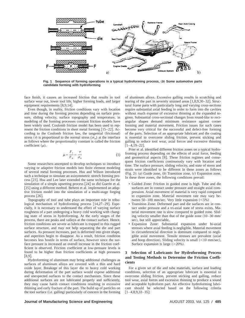
Muammer Koc ¸ Department of Mechanical Engineering, University of Michigan, Ann Arbor, MI 48109 Tribological Issues in the Tube Hydroforming Process—Selection of a Lubricant for Robust Process Conditions for an Automotive Structural Frame Part In this paper, an overall review of tribological issues in the tube hydroforming process is presented. Guidelines for the selection of lubricants under the hydroforming process conditions are summarized following a description of existing testing methods and appa- ratus. A methodology of combined experiments and FEA was presented to determine the coefficient of friction in the hydroforming process in addition to selecting a proper lubri- cant for a given part and process design. Experimental results showed that thickness of the final part at critical regions, amount of axial feeding and axial force are strong indicators of lubricant performance whereas effect of lubrication on the part flatness, corner radius formation and box dimensions are found to be negligible. @DOI: 10.1115/1.1580526# 1 Introduction The tube hydroforming process ~THF! has recently found a wide application opportunity in the automotive industry, and is of increasing interest to other industries as well. The increased inter- est stems in part from the fact that, through the THF process, manufacturers are able to produce complex shaped parts with lightweight and fewer welds, Fig. 1. Advantages of hydroforming include potentially reduced tooling costs, reduced finishing costs on formed parts, excellent material utilization, fewer operations, and improved part quality. In the tube hydroforming process, a blank tube, straight or preformed, is shaped in a die cavity through the application of hydraulic internal pressure and simultaneous axial compressive forces from both ends as depicted in Fig. 1. More details about the basics of hydroforming process can be obtained from @1–4#. In this paper, a general review of the tribological system in the tube hydroforming process is presented in Section 2. In Section 3, general industrial guidelines for the selection of an appropriate lubricant for a given hydroforming application are provided. Re- cently developed laboratory testing apparatus at various research institutes and their principles are explained in Section 3. Results of the experimental work for hydroforming of a structural auto- motive frame part using different lubricants are presented in Sec- tion 4. Finally, a methodology for determining the friction coeffi- cient comparing FEA simulation results with experimental findings is described in Section 4. 2 Tribological System in Hydroforming One of the various important part, process and tooling param- eters of hydroforming process is the tribological system. Tribo- logical system in hydroforming consists of the following elements or factors: ~a! Surface conditions of tube and die, ~b! contact area and associated state of stress, ~c! pressure, ~d! sliding velocity, ~e! tube and die materials and their mechanical properties, ~f! die coating, ~g! positioning of the parting line, and ~g! lubricant. Since most of the above factors are embedded and difficult to change once a hydroforming system ~i.e., part, tooling and process! is designed and manufactured, the overall performance of the tribo- logical system can be controlled and tailored to the desired con- ditions by selecting an appropriate lubricant for a given case. An appropriate lubricant can effectively ~a! separate work-piece and die surfaces to protect die surfaces, ~b! reduce interface friction, ~c! help material flow to achieve complete cavity filling, ~d! obtain parts with required thickness specifications ~reduce thinning!, ~e! prolong die life by reducing wear and contact stresses @5–10#. Effect of friction and different lubricants on formability and extend of protrusion height of a hydroformed part was described in various studies beginning in the 1970’s @11#. Limb and his team performed bulge forming of tubes of different materials with changing wall thickness. They reported that increasing the internal pressure gradually during the application of axial load gives the best results on thinning and complete filling. Thickening of tube wall at feeding zone was also mentioned due to the friction be- tween tube and die surface. In addition, experimentation of differ- ent lubricants such as PTFE film, colloidal graphite and Rocol R.T.D. spray were carried out. In case of insufficient lubrication, low Tee protrusion heights were obtained as well as a bulged protrusion area resulted instead of a fully formed and flat area. With proper lubrication, it was reported that a flatter bulging of the Tee protrusion was obtained. Later, Limb et al. used oil as pressurizing medium in their experiments to investigate the form- ing of copper, aluminum, low carbon steel and brass Tee-shaped tubular parts @12#. Results of lubricant and material evaluations were reported in terms of protrusion height attainable. As reported by Ahmed et al., Hutchinson carried out experimental studies to investigate the effect of different lubricants on bulging of tubes @13#. In hydroforming, boundary lubrication governs the friction con- ditions. As the internal pressure increase, the area of contact at the interface also increases and sticking friction may become domi- nant. When the lubrication film is thick to separate asperities on the tool and workpiece, friction is low ~thick film regime!. But, this leads to rough surface conditions on the formed part as plastic deformation of the workpiece surface is limited. When, the lubri- cation film is thin, asperities on tool and workpiece have an in- creased contact. While this leads to formed parts with better sur- Contributed by the Manufacturing Engineering Division for publication in the JOURNAL OF MANUFACTURING SCIENCE AND ENGINEERING. Manuscript received November 2001; Revised December 2003. Associate Editor: S. Schmid. 484 Õ Vol. 125, AUGUST 2003 Copyright © 2003 by ASME Transactions of the ASME
-
Upload
independent -
Category
Documents
-
view
2 -
download
0
Transcript of Tribological Issues in the Tube Hydroforming Process—Selection of a Lubricant for Robust Process...

s iscessppa-ne thebri-ss ofngess,
Muammer KocDepartment of Mechanical Engineering,
University of Michigan, Ann Arbor, MI 48109
Tribological Issues in the TubeHydroforming Process—Selectionof a Lubricant for Robust ProcessConditions for an AutomotiveStructural Frame PartIn this paper, an overall review of tribological issues in the tube hydroforming procespresented. Guidelines for the selection of lubricants under the hydroforming proconditions are summarized following a description of existing testing methods and aratus. A methodology of combined experiments and FEA was presented to determicoefficient of friction in the hydroforming process in addition to selecting a proper lucant for a given part and process design. Experimental results showed that thicknethe final part at critical regions, amount of axial feeding and axial force are stroindicators of lubricant performance whereas effect of lubrication on the part flatncorner radius formation and box dimensions are found to be negligible.@DOI: 10.1115/1.1580526#
n
n
uo
t
i
fit
a
n
ibo-on-An
d
dbed
thrnalthebebe-fer-coln,
gedea.ofas
rm-peds
rtedto
es
n-t themi-on
sticri-in-sur-
h
1 IntroductionThe tube hydroforming process~THF! has recently found a
wide application opportunity in the automotive industry, and isincreasing interest to other industries as well. The increased inest stems in part from the fact that, through the THF procemanufacturers are able to produce complex shaped partslightweight and fewer welds, Fig. 1. Advantages of hydroformiinclude potentially reduced tooling costs, reduced finishing coon formed parts, excellent material utilization, fewer operatioand improved part quality. In the tube hydroforming processblank tube, straight or preformed, is shaped in a die cavity throthe application of hydraulic internal pressure and simultaneaxial compressive forces from both ends as depicted in FigMore details about the basics of hydroforming process canobtained from@1–4#.
In this paper, a general review of the tribological system intube hydroforming process is presented in Section 2. In Sectiogeneral industrial guidelines for the selection of an approprlubricant for a given hydroforming application are provided. Rcently developed laboratory testing apparatus at various reseinstitutes and their principles are explained in Section 3. Resof the experimental work for hydroforming of a structural autmotive frame part using different lubricants are presented in Stion 4. Finally, a methodology for determining the friction coefcient comparing FEA simulation results with experimenfindings is described in Section 4.
2 Tribological System in HydroformingOne of the various important part, process and tooling par
eters of hydroforming process is the tribological system. Triblogical system in hydroforming consists of the following elemeor factors:~a! Surface conditions of tube and die,~b! contact areaand associated state of stress,~c! pressure,~d! sliding velocity,~e!tube and die materials and their mechanical properties,~f! diecoating,~g! positioning of the parting line, and~g! lubricant. Sincemost of the above factors are embedded and difficult to cha
Contributed by the Manufacturing Engineering Division for publication in tJOURNAL OF MANUFACTURING SCIENCE AND ENGINEERING. Manuscript receivedNovember 2001; Revised December 2003. Associate Editor: S. Schmid.
484 Õ Vol. 125, AUGUST 2003 Copyright ©
ofter-ss,withgstss,
, aghus
. 1.be
hen 3,atee-archultso-ec--al
m-o-ts
nge
once a hydroforming system~i.e., part, tooling and process! isdesigned and manufactured, the overall performance of the trlogical system can be controlled and tailored to the desired cditions by selecting an appropriate lubricant for a given case.appropriate lubricant can effectively~a! separate work-piece andie surfaces to protect die surfaces,~b! reduce interface friction,~c! help material flow to achieve complete cavity filling,~d! obtainparts with required thickness specifications~reduce thinning!, ~e!prolong die life by reducing wear and contact stresses@5–10#.
Effect of friction and different lubricants on formability anextend of protrusion height of a hydroformed part was descriin various studies beginning in the 1970’s@11#. Limb and his teamperformed bulge forming of tubes of different materials wichanging wall thickness. They reported that increasing the intepressure gradually during the application of axial load givesbest results on thinning and complete filling. Thickening of tuwall at feeding zone was also mentioned due to the frictiontween tube and die surface. In addition, experimentation of difent lubricants such as PTFE film, colloidal graphite and RoR.T.D. spray were carried out. In case of insufficient lubricatiolow Tee protrusion heights were obtained as well as a bulprotrusion area resulted instead of a fully formed and flat arWith proper lubrication, it was reported that a flatter bulgingthe Tee protrusion was obtained. Later, Limb et al. used oilpressurizing medium in their experiments to investigate the foing of copper, aluminum, low carbon steel and brass Tee-shatubular parts@12#. Results of lubricant and material evaluationwere reported in terms of protrusion height attainable. As repoby Ahmed et al., Hutchinson carried out experimental studiesinvestigate the effect of different lubricants on bulging of tub@13#.
In hydroforming, boundary lubrication governs the friction coditions. As the internal pressure increase, the area of contact ainterface also increases and sticking friction may become donant. When the lubrication film is thick to separate asperitiesthe tool and workpiece, friction is low~thick film regime!. But,this leads to rough surface conditions on the formed part as pladeformation of the workpiece surface is limited. When, the lubcation film is thin, asperities on tool and workpiece have ancreased contact. While this leads to formed parts with better
e
2003 by ASME Transactions of the ASME
Journal of
Fig. 1 Sequence of forming operations in a typical hydroforming process, „b… Some automotive partscandidate forming with hydroforming
,ar
i
ncp
a
t
g
ht
r
an
t
nd
nsies
re-ect-rnersesingtingnding
o-ing-dandws
ieom-edbe-
on-Ma-lid-
ialentli-
ingl toceundri-ria
face finish, it causes an increased friction that results in tsurface wear out, lower tool life, higher forming loads, and largequipment requirements@8,9,14#.
Even though, in reality, friction conditions vary with locatioand time during the forming process depending on surface psure, sliding velocity, surface topography and temperaturemodeling of the forming processes constant friction models hbeen widely used. Coulomb friction model has been used toresent the friction conditions in sheet metal forming@15–22#. Ac-cording to the Coulomb friction law, the tangential~frictional!stress~t! is proportional to the normal stress (sn) at the interfaceas follows where the proportionality constant is called the frictcoefficient~m!.
m5Ft
Fn5
t
sn(1)
Some researchers attempted to develop techniques to introvarying or adaptive friction models into finite element modeliof several metal forming processes. Hsu and Wilson introdusuch a technique to simulate an axisymmetric stretch formingcess@23#. Hsu and Lee later extended the same technique forsimulation of a simple upsetting process@24# so did Guerin et al.@25# using a different method. Behren et al. implemented an adtive friction model into the simulation of a multi-stage forginprocess@26#.
Topography of tool and tube plays an important role in triblogical mechanism of hydroforming process@14,27–29#. Espe-cially, it is necessary to understand the effect of varying surfroughness of a part undergoing a heavy cold working with chaing state of stress in hydroforming. At the early stages ofprocess, there are peaks and valleys at the contact surface. Hfriction conditions are severe as lubricant is trapped in this rugsurface structure, and may not help separating the die andsurfaces. As pressure increases, part is deformed into given sand asperities begin to disappear. As a result, friction condibecomes less hostile in terms of surface, however since theface pressure is increased an overall increase in the friction cficient is observed. Friction coefficient at low-pressure levelsfound to be higher than friction coefficients at high pressu@8,9#.
Hydroforming of aluminum may bring additional challengessurfaces of aluminum alloys are covered with a thin and hoxide layer. Breakage of this layer die to heavy cold workiduring deformation of the part surface would expose additioand unexpected surfaces to the contact mechanism. Sinceadditional surfaces are not lubricated properly and sufficienthey may cause harsh contact conditions resulting in excesthinning and early fracture of the part. The build up of particlesthe tool surface~i.e. galling! particularly of concern in the forming
Manufacturing Science and Engineering
ooler
nres-
inve
ep-
on
ducegedro-the
ap-g
o-
ceng-heence,edpartape,ionsur-oef-ises
asrdg
nalhesetly,siveon
of aluminum alloys. Excessive galling results in scratching atearing of the part in severely strained areas@1,8,9,30–32#. Struc-tural frame parts with particularly long and varying cross-sectiorequire substantial axial feeding in order to form into die cavitwithout much expense of excessive thinning at the expandedgions. Substantial cross-sectional changes from round-like to rangular shapes demand minimum resistance against coforming and material movement. Friction issues for such cabecome very critical for the successful and defect-free formof the parts. Selection of an appropriate lubricant and die coais essential to overcome sliding friction, prevent sticking agalling to reduce tool wear, axial forces and excessive thinn@1–4,19–22#.
Prier et al. identified different friction zones on a typical hydrfroming process depending on the effects of axial force, feedand geometrical aspects@8#. These friction regimes and consequent friction coefficients continuously vary with location antime. The surface pressure, sliding velocity, and state of stressstrain were identified to be different in these zones as follo~Fig. 2!: ~a! Guide zone,~b! Transition zone,~c! Expansion zone.In these three zones, the following conditions prevail:
• Guided Zone: Friction in guided zone is high. Tube and dsurfaces are in contact under pressure and straight axial cpression. Axial movement of material is very rapid comparto expansion zone. Material movement rate may varytween 50–100 mm/sec. Very little expansion~,5%!
• Transition Zone: Deformed part and die surfaces are in ctact under pressure and a tri-axial state of stress exists.terial movement rate is slow compared to guided zone. Sing velocity smaller than that of the guide zone~10–30 mm/sec!, but still appreciable,
• Expansion Zone: Substantial expansion under bi-axstresses where axial feeding is negligible. Material movemin circumferencial direction is dominant compared to neggible axial movement. Tensile stresses are prevalent~axialand hoop direction!, Sliding velocity is small~,10 mm/sec!,Surface expansion is large~.20%!.
3 Selection of Lubricants for Hydroforming Processand Testing Methods to Determine the Friction Coeffi-cients
For a given set of die and tube materials, surface and loadconditions, selection of an appropriate lubricant is essentiaovercome sliding friction, prevent sticking and galling, redutool wear, axial forces and excessive thinning to produce a soand acceptable hydroform part. An effective hydroforming lubcant should be selected based on the following crite@1–4,8,9,33–35#:
AUGUST 2003, Vol. 125 Õ 485

486 Õ Vol. 125, AU
Fig. 2 Schematic of hydroforming of a simple bulge, and various friction zones in atypical hydroforming process
i
t
g
o
u
,-
totihcn
li
hennalwerap-ely-
dryg on
odsubehe
ept-tus
d byse ofheds-ofa-
withmea-
theingnro-bri-
andro-g-
aria-a
ionape
• Performance during bending, pre-forming and hydroformstages: Lubricity to reduce sliding friction between toolinand tube surface
• Durability under high pressure values up to 6–15 ksi attube-to-tooling interface to prevent sticking and galling
• Minimum abrasivity to reduce tool wear• Compatibility with hydroforming fluid, rust prevention me
dium, cutting fluids and other environmental requiremenIncompatible lubricants would increase the frequency ahence the cost of filtering of the forming fluid. It may damathe hydraulic system.
• Ease of application: Automation of the lubricant applicatiis essential for reducing the cost per part and for a consisuse
• Ease of removal: Cleaning with washing fluids. There shonot be any residues left on the part as these may adveraffect post-hydroform operations like welding and cutting
• Cost: Considering all aspects such as lubricant cost per papplication and removal system cost and cost of washingids, cost of filtering the forming medium, etc.
There are many lubricants that are used currently or thoughbe suitable for hydroforming operations. These lubricants canbroadly classified as follows:~a! Dry lubricants: borax-basedsoap based or polymer-based,~b! Wet lubricants: oil-based, waterbased,~c! Paste lubricants. Dry lubricants are usually found tomore effective in terms of performance to reduce friction aincrease tool life@30–32#. Their application can be automatedyield consistent lubrication thickness with proper instrumentatiSuch an application system even can be installed just afterrolling operation. This would result in a clean and cost effectlubrication practice as it could eliminate one of the steps indroforming shop floor. Savings in terms of shop floor spacleaning, safety, process delays, compatibility with environmeregulations, and etc. should be considered as further advantagdry lubricants@33–35#. Drying time is very crucial for dry lubri-cants as inappropriate dry time and environment may causeonly ineffective lubrication but also be harmful to the hydrausystem. Moreover, their removal requires special washing flu
GUST 2003
ngg
he
-ts:nde
ntent
ldsely
art,flu-
t tobe
bendon.
ubevey-e,tal
es of
noticds.
They are found to be more expensive than wet lubricants wdrying time, application and removal process and their origicosts are added. On the other hand, cost of wet lubricants is lothan dry lubricants. They are relatively easy to remove. But,plication of wet lubricants requires care, and is not completsuitable for automation. Compatibility with forming fluids is another issue. Most importantly, they do not perform as well aslubricants do. Hence, a compromise must be made dependinthe part complexity and quality requirements@8,9,33–35#.
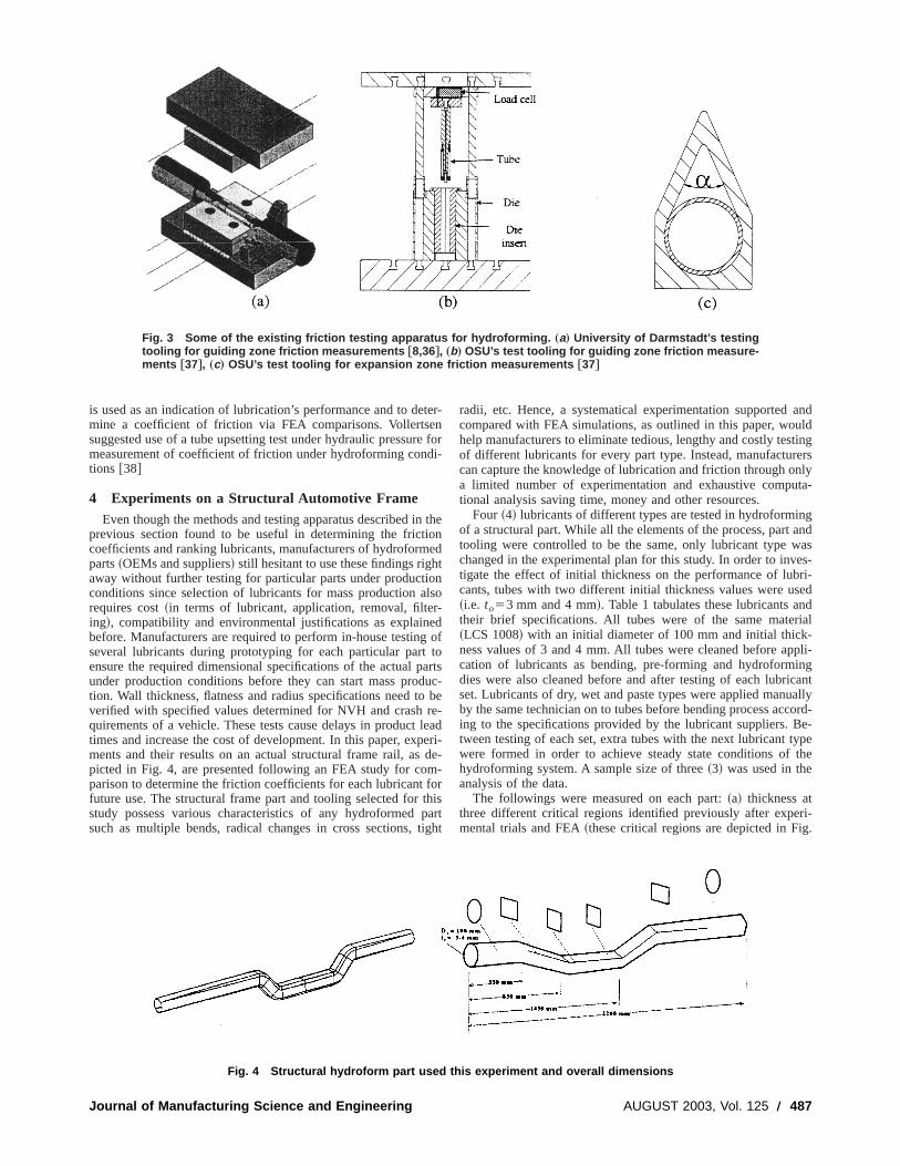
Until recent years, there have not any reported testing methor equipment development to measure or evaluate friction in thydroforming process. In order to facilitate the modeling of tprocess, usually a friction coefficient~in case of hydoforming andsheet metal forming processes, Coulomb friction coefficient! hasto be assumed in FEA. In order to determine reasonably accable friction coefficients, various testing methods and apparafor each regime have been already developed or suggestevarious institutes as of today. Schmoeckel demonstrated the ufriction testing in a guided zone where basically a tube is pusat various sliding velocity through a round die cavity while presurized internally@8,36#. Figure 3 depicts the basic schematicthis apparatus. Friction coefficients of different lubricants and mterials under internal pressure levels could then be obtainedsuch a method. Dohmann suggested a Tee-shape tooling tosure friction coefficient at transition and expansion zones@9#.Other researchers conducted pin-on-disk or twist tests to rankperformance of different lubricants suggested for hydroformapplications@33,34#. As a result, all parameters affecting frictioconditions should be improved for an overall success in hydforming. Dalton proposed the use of a square die to rank lucants according to their performance at calibration zone@33#. Al-tan and his group at OSU have been developing toolingtesting methods covering all friction regimes in the tube hydforming process. Their first tooling is very similar to the one sugested and used by Schmoeckel. Their second tooling is a vtion of Dohmann’s method and tooling. In this one, they utilizetooling with a pear shaped die cavity instead of a Tee protrus@37#. Height and thickness variation along dome of the pear sh
Transactions of the ASME
Journal
Fig. 3 Some of the existing friction testing apparatus for hydroforming. „a… University of Darmstadt’s testingtooling for guiding zone friction measurements †8,36‡, „b… OSU’s test tooling for guiding zone friction measure-ments †37‡, „c… OSU’s test tooling for expansion zone friction measurements †37‡
rd
no
i
reg
do
p
m
t
anduldtingersnlyta-
gandases-ri-ed
ndrial-pli-
ngcantallycord-e-
ypethe
ri-g.
is used as an indication of lubrication’s performance and to demine a coefficient of friction via FEA comparisons. Vollertsesuggested use of a tube upsetting test under hydraulic pressumeasurement of coefficient of friction under hydroforming contions @38#
4 Experiments on a Structural Automotive FrameEven though the methods and testing apparatus described i
previous section found to be useful in determining the fricticoefficients and ranking lubricants, manufacturers of hydroformparts~OEMs and suppliers! still hesitant to use these findings righaway without further testing for particular parts under productconditions since selection of lubricants for mass production arequires cost~in terms of lubricant, application, removal, filteing!, compatibility and environmental justifications as explainbefore. Manufacturers are required to perform in-house testinseveral lubricants during prototyping for each particular partensure the required dimensional specifications of the actual punder production conditions before they can start mass protion. Wall thickness, flatness and radius specifications need tverified with specified values determined for NVH and crashquirements of a vehicle. These tests cause delays in producttimes and increase the cost of development. In this paper, exments and their results on an actual structural frame rail, aspicted in Fig. 4, are presented following an FEA study for coparison to determine the friction coefficients for each lubricantfuture use. The structural frame part and tooling selected forstudy possess various characteristics of any hydroformedsuch as multiple bends, radical changes in cross sections,
of Manufacturing Science and Engineering
ter-ne fori-
thenedtonlso-dof
toartsuc-be
re-leaderi-de--
forhisparttight
radii, etc. Hence, a systematical experimentation supportedcompared with FEA simulations, as outlined in this paper, wohelp manufacturers to eliminate tedious, lengthy and costly tesof different lubricants for every part type. Instead, manufacturcan capture the knowledge of lubrication and friction through oa limited number of experimentation and exhaustive computional analysis saving time, money and other resources.
Four ~4! lubricants of different types are tested in hydroforminof a structural part. While all the elements of the process, parttooling were controlled to be the same, only lubricant type wchanged in the experimental plan for this study. In order to invtigate the effect of initial thickness on the performance of lubcants, tubes with two different initial thickness values were us~i.e. to53 mm and 4 mm!. Table 1 tabulates these lubricants atheir brief specifications. All tubes were of the same mate~LCS 1008! with an initial diameter of 100 mm and initial thickness values of 3 and 4 mm. All tubes were cleaned before apcation of lubricants as bending, pre-forming and hydroformidies were also cleaned before and after testing of each lubriset. Lubricants of dry, wet and paste types were applied manuby the same technician on to tubes before bending process acing to the specifications provided by the lubricant suppliers. Btween testing of each set, extra tubes with the next lubricant twere formed in order to achieve steady state conditions ofhydroforming system. A sample size of three~3! was used in theanalysis of the data.
The followings were measured on each part:~a! thickness atthree different critical regions identified previously after expemental trials and FEA~these critical regions are depicted in Fi
Fig. 4 Structural hydroform part used this experiment and overall dimensions
AUGUST 2003, Vol. 125 Õ 487

r
sn
a
v.i
t
ger
es atro-
ialre,om-
rethod
rcepro-re-
e-oxde-anyrall
l
LS-erehesl, a
calesshen-
chale-on
t
4!, ~b! difference between part and tube length,~c! flatness atvarious regions,~d! corner radii at various locations on the pa~e! box dimensions~height and width!, and ~f! amount of axialforce. Thickness measurements were performed using an usonic device. For verification, some parts were cut into sectioand measurements with a micrometer were conducted at theregions. Both methods were found to give similar results withideviation of 3–4%. Rest of the measurements was performeding the ultrasonic measurement method as it was found tofriendly and faster. Flatness, box height and width and radius msurements were performed on a CMM machine. The lengthinitial tube and final part were the easiest to measure. It wrecorded to compare the amount of total axial feeding for eachIn addition to the above responses, the followings were achecked and recorded for comparison purposes:~a! application oflubricants and associated difficulties and problems,~b! cleaning oflubricant after hydroforming, and~c! die galling and residues ondie surfaces.
Experimental Results. Figure 5 illustrates the thickness mesurement comparison at Regions B, C, D for four~4! lubricants onparts with two different initial thickness values~i.e. to53 and 4mm!. Around 100 thickness measurements with ultrasound dewere conducted on webs and tension flanges at each regionaverage and the lowest values of these readings for each lubrat each region were compared here. Dry lube~Lube 2! offered theleast amount thinning compared to the rest of the lubricants aregions. Water-based wet lubricant~Lube 1! comes after dry luberegarding the thinning performance. Effect of lubricant on t
Table 1 List of lubricants used in the experiments
# Type Specifications
Lube 1 Wet Water based, pre-emulsified, contains solidlubricant, chlorine & sulfur free
Lube 2 Dry Water based, air dried, contains pressureresistant substances
Lube 3 Wet Synthetic, water soluble, high viscosityLube 4 Paste Off-white paste form, can be diluted with wa
488 Õ Vol. 125, AUGUST 2003
t,
ltra-ns,ameaus-beea-ofas
set.lso
-
iceThecant
all
he
final part thickness becomes more visible on parts with larinitial thickness value~i.e., 4 mm! compared to parts with 3 mmof initial wall thickness. Lubricants 2 and 1 not only provided thleast amount of thinning but also the least variation of thicknesall regions. Hence, they are more likely to provide a robust pduction process than other lubricant tested.
Figure 6 depicts the effect of lubricant performance on axforce requirement and feeding capability. As seen from this figuparallel and in accordance with what observed on thickness cparison charts, Lube 2~dry lube! offers the largest axial feedingcapability ~when total of right and left axial feeding values acompared! while requiring the least amount of axial force on bocylinders. This is exactly what should be expected from a golubricant with low coefficient of friction. Similarly, Lube 2 wouldbe the second best option in terms of feeding capability and forequirements. Similar to thickness comparisons, thicker tubesvides a better discrimination of lubricants as axial force measuments on parts with (to53 mm) are very close to each other rgardless of cylinder, Fig. 6. Comparison of deviations in bwidth & height, flatness and corner radius with respect tosigned or desired values at several regions did not revealindication of a superior lubricant over others, hence only oveaverage values of these responses are presented in Fig. 7.
Prediction of Coefficient of Friction „m… Comparing the Ex-perimental and FEA Results. FEA of the same experimentaconditions~i.e., geometry, material, loading! were conducted forcomparison purposes. Three-dimensional, explicit FEA codeDYNA was used for computer simulations. Shell elements wused in modeling of the structural part while dies and puncwere assumed to be rigid. Figure 8 illustrates the FE modetypical forming sequence~bending, preforming and calibrationstages! as well as thinning and thickness distributions on a typisimulated final part. Table 2 presents the material and procconditions used in the simulations. All conditions were kept tsame except friction coefficient. As seen in Fig. 8, critical expasion regions were verified with FEM simulations. After easimulation, minimum thickness values at three different criticregions~B, C, and D! were compared with experimental measurments in accordance with the flow diagram in Fig. 9. Comparis
er
Fig. 5 Comparison of minimum thickness measurements in regions B, C, and D for respective lubricants. Tubeswith two different initial thickness values „3 and 4 mm … were tested. Lubricant 2 offers the least amount ofthinning when all regions and different initial tube thickness conditions are considered.
Transactions of the ASME

Jou
Fig. 6 „a & b… Comparison of axial force readings for respective lubricants on parts with two different initial tubethickness values. „c… Comparison of punch positions „not real feeding … for parts with initial thickness of 4 mm. Lube 2performs the best in terms of the smallest force requirements and largest total axial feeding capability.
ed.
ck-lue
of the minimum predicted thickness (tc) and minimum measuredthickness (te) values at three different critical regions~B, C andD! was used to determine an appropriate coefficient of friction~m!for the respective lubricant, Fig. 9. Comparisons at individual n
rnal of Manufacturing Science and Engineering
ar-
row zones and minimum of the overall regions were performWhenever a coefficient of friction~m! in FEA resulted in thicknesspredictions within 5–10% error with respect to measured thiness values, respective~m! was accepted as a representative va
Fig. 7 Comparison of „a… overall box dimension „height and width … deviation at all regions. „b… Comparison offlatness at Region B and Region C „c… Comparison of overall radius deviation at all regions. None of these measure-ments indicates a clear result.
AUGUST 2003, Vol. 125 Õ 489

490 Õ Vo
Fig. 8 „a… FE Model, „b, c, d… forming sequence, „e… thinning and „f … thickness distributions on a typicalfinal part
om-
c-
ffi-u-ed in
for the lubricant used in that set of testing. Satisfactory matchof thickness predictions at these three different but critical regiwas found to be reasonably and practically enough to estimatevalue of ~m!. Note that value of~m! may slightly differ betweendifferent FEA codes depending on their element type, solutmethod and most importantly selected contact algorithm. Henc
l. 125, AUGUST 2003
ingnsthe
ione, a
cross-check is required to see whether, under similar circustances, predicted~m! would result in the same thickness preditions using different FEA software.
Through this trial and error scheme, a narrow range for coecient of friction ~CoF! for each lubricant was estimated as tablated in Table 3. Such predicted CoF ranges, then, can be us
Fig. 9 Methodology used to predict coefficient of friction based on measurement values and FEA results
Table 2 Material and process conditions used in FEA of the hydroform part
Material Conditions Process Conditions
K 480 Mpa t, sec 0 1 2 3 8 16 20n 0.16 Pi, MPa 0 6 20 30 80 100 130
YS 200 Mpa daleft , mm 0 5 11 35 64 75 82Do 100 mm daright , mm 0 7 12 48 82 104 110to 3 & 4 mm Faleft , kN Max. 2800 kN
Lo 2200 mm Faright , kN Max. 2800 kN
Transactions of the ASME

a
y
tt
r
lt
sth
c
n
v
r
l
i
g
r
.
ip
rer
re
m-
lic
ned
n
t
r
or
on
. J.
ndro-
g:eb-
nJ.
le
ionE
exer.
n,’’ J.
ofon-
ec-e-
to-
the
nd--
g
-
ighe
g-
ion
future hydroforming simulations involving that particular lubrcant or a similar one as almost no quantitative tribological datavailable for hydroforming process.
5 Discussion and ConclusionsBefore, stating the conclusions for this study, it is necessar
indicate that thickness predictions with FEA are usually lowthan actual measurements as FEA gives a lower bound soluSuch an observance was also made in other studies as repor@18–22#. As a result, the followings can be concluded from thstudy: ~a! Deviations in flatness, box dimensions and radius wrespect to designed values were not found to be a good indicaof lubricant performance in hydroforming of this particular pa~b! Thickness comparison of critical expansion regions aamount of total axial feed are discriminative and good indicatioof lubricant performance~c! Dry lube was found to result in leasthinning amount for the structural part used as an example instudy. Wet and paste lubes almost lead to similar thinning vato each other. Only Lube 1 of wet lubes slightly performed bethan others.~d! When all aspects of lubrication including cosapplication, removal, compatibility, overall die life, hydraulic sytem life, etc. as explained in section 2, dry lubricant would bechoice of application for this case, and may be for many otsimilar parts.~e! Wet Lube 1 could be the second choice asprovides ease of application and removal as well as compatibwith other working fluids in the hydroforming system.~f! As sucha structural part shape, cross-sections and dimensions arecommon in the automotive applications, selection of lubricant aother aspects explained above can be also applied to otherwhen other specific information is not available.~g! Use of FEAalong with experimental findings not only offer determinationfriction coefficients, which is difficult to predict otherwise, bualso would eliminate experimental try outs in the future for paof the similar material, lubricant and geometry.
On the other hand, it has to be remembered that friction cotions in metal forming processes vary with location and time ding the forming of a part as a function of contact pressure, slidvelocity, surface roughness and temperature. Therefore it isdifficult to model and introduce such a model into the FE analyor other numerical solutions. As indicated before, some reseaers attempted to implement such variable or adaptive frictmodels into computer simulations of simple metal forming pcesses such as upsetting, axisymmetric forming and rolling@23–26#. Finally, development and use of environmentally-friendlybricants should be another vital aspect during selectionlubricant@31,39–41# in addition to other factors mentioned in thmanuscript.
References@1# Koc, M., and Altan, T., 2001, ‘‘An Overall Review of the Tube Hydroformin
~THF! Technology,’’ J. Mater. Process. Technol.108~3!, pp. 384–393.@2# Dohmann, F., and Bieling, P., 1991, ‘‘Theoretical Basis and Applications
High Pressure Forming,’’ Bleche Rohre Profile,38~5!, pp. 379–385.@3# Dohmann, F., and Hartl, C., 1994, ‘‘Liquid Bulge Forming as a Flexible P
duction Method,’’ J. Mater. Process. Technol.45, pp. 377–382.@4# Dohmann, F., and Hartl, C., 1998, ‘‘Hydroforming Components for Autom
tive Applications,’’ Fabricator, February, 30–38.@5# Wilson, W. R. D., 1997, ‘‘Tribology in Cold Metal Forming,’’ASME J. Manuf
Sci. Eng.,119, pp. 695–698.
Table 3 Predicted coefficient of friction after comparison ofexperimental measurements and FE simulations planned in ac-cordance with scheme outlined in Fig. 8
# Type Predicted Coefficient of Friction
Lube 1 Wet 0.08–0.09Lube 2 Dry 0.04–0.05Lube 3 Wet 0.12–0.14Lube 4 Paste 0.19–0.22
Journal of Manufacturing Science and Engineering
i-is
toerion.ed inisithtiont.ndnstthisuestert,-heerit
ility
veryndases
oftrts
di-ur-ingerysisrch-iono-
u-of
s
of
o-
o-
@6# Schey, J. A., 1983,Tribology in Metalworking, Friction, Lubricant and Wear,ASM, Metals Park, Ohio.
@7# Le, H. R., and Sutcliffe, M. P. F., 2002, ‘‘Measurements of Friction in StrDrawing Under Thin Film Lubrication,’’ Tribol. Int.,35, pp. 123–128.
@8# Prier, M., and Schmoeckel, D., 1999, ‘‘Tribology of Internal High PressuForming,’’ Proc. of Int’l Conf. on Hydroforming, Stuttgart, Germany, Octobe12–13.
@9# Meyer, W., and Dohmann, F., 1997, ‘‘Tribology in Internal High PressuForming’’ ~in German!, Blech Rohre Profile, 36–39, October.
@10# Kraan, D. J., 1981, ‘‘Metal Forming Oils,’’ Tribol. Int.,14, February, pp. 29.@11# Limb, M. E., Chakrabarty, J., Garber, S., and Mellor, P. B., 1973, ‘‘The For
ing of Axisymmetric and Asymmetric Components from Tube,’’Proceedingsof the 14th Int’l. M.T.D.R. Conference, pp. 799–805.
@12# Limb, M. E., Chakrabarty, J., Garber, S., and Roberts, W. T., 1976, ‘‘HydrauForming of Tubes,’’ Sheet Metal Industries, November, pp. 418–424.
@13# Ahmed, M., and Hashimi, M. S. J., 1997, ‘‘Comparison of Free and RestraiBulge Forming by FEM Simulation,’’ J. Mater. Process. Technol.,63, pp.651–654.
@14# Zu, Z. M., and Dean, T. A., 2000, ‘‘A Study of Surface Topography, Frictioand Lubricants in Metal Forming,’’ Int. J. Mach. Tools Manuf.,40, pp. 1637–1649.
@15# Sofuoglu, H., and Gedikli, H., 2002, ‘‘Determination of Friction CoefficienEncountered in Large Deformation Processes,’’ Tribol. Int.,35, pp. 27–34.
@16# Harycki, R. M., Gasper, K. E., Wagoner, R. H., 1994, ‘‘A New Method foRanking Sheet Metal Lubricants,’’ Metal Forming Magazine, November.
@17# Lazzarotto, L., Dubar, L., Oudin, J., 1998, ‘‘A Selection Methodology fLubricating Oils in Cold Metal Forming Processes,’’ Wear,215, pp. 1–9.
@18# Klocke, F., Beck, T., and Sweeney, K., 2002, ‘‘Examples of FEM Applicatiin Manufacturing Technology,’’ J. Mater. Process. Technol.,120, pp. 450–457.
@19# Singh, H., 1999, ‘‘Simulation of Hydroforming Process,’’Proc. Of AutomotiveTube Conference, Detroit, MI, US, April 26–27.
@20# Koc, M., and Altan, T., 2002, ‘‘Application of Two-Dimensional~2D! FEA forExpansion of Tubular Parts and Sections via Hydroforming Process,’’ IntMach. Tools Manuf., March.
@21# Koc, M., Allen, T., Jirathearanat, S., and Altan, T., 2000, ‘‘Use of FEA aDesign of Experiments to Establish Design Guidelines for Simple Hydformed Part,’’ Int. J. Mach. Tools Manuf.,40, pp. 2249–2266.
@22# Srinivasan, T. M., Shaw, J., and Thompson, K., 1998, ‘‘Tubular HydroforminResults,’’ SAE paper 980448, Intl. Congress and Exposition, Detroit, MI, Fruary.
@23# Wilson, W. R. D., Hsu, T. C., and Huang, X. B., 1995, ‘‘A Realistic FrictioModel for Computer Simulation of Sheet Metal Forming Process,’’ ASMEEng. Ind.,117, May, pp. 202–209.
@24# Hsu, T. C., and Lee, C. H., 1997, ‘‘Refined Friction Modeling for SimpUpsetting,’’ ASME J. Manuf. Sci. Eng.,119, pp. 563–570.
@25# Guerin, J. D., Bartys, H., Dubais, A., and Oudin, J., 1995, ‘‘FE Implementatof a Generalized Friction Model: Application to a Upsetting-Sliding Test,’’ Fin Analysis and Design,31, pp. 193–207.
@26# Behren, A., and Schofetall, H., 1998, ‘‘2D and 3D Simulation of ComplMultistage Forging Process by Use of Adaptive Friction Coefficient,’’ J. MatProcess. Technol.,80–81, pp. 298–303.
@27# Lee, B. H., Kim, Y. T., and Wagoner, R. H., 2002, ‘‘Modeling of the FrictioCaused by Lubrication and Surface Roughness in Sheet Metal FormingMater. Process. Technol.,6244, pp. 1–4.
@28# Steinhoff, K., Rasp, W., and Pawelski, O., 1996, ‘‘DevelopmentDeterministic-Stochastic Surface Structures to Improve the Tribological Cditions of Sheet Forming Processes,’’ J. Mater. Process. Technol.,60, pp. 355–361.
@29# Rasp, W., and Wichern, C. M., 2002, ‘‘Effects of Surface Topography Dirtionality and Lubrication Condition on Frictional Behavior During Plastic Dformation,’’ J. Mater. Process. Technol.,125–126, pp. 379–386.
@30# Story, J. M., Jarvis, G. W., Murtha, S. J., 1993, ‘‘Issues and Trends in Aumotive Aluminum Sheet Forming,’’ SAE Publ #Sp-944, pp. 1–25.
@31# Rao, K. P., and Wei, J. J., 2001, ‘‘Performance of a New Dry Lubricant inForming of Aluminum Alloys Sheets,’’ Wear,249, pp. 86–93.
@32# Erdemir, A., and Fenske, G. R., 1998, ‘‘Clean and Cost-effective Dry Bouary Lubricants for Aluminum Forming,’’ SAE Special Publication, NO. SP1350, pp. 9–17.
@33# G. Dalton, 1999, ‘‘The Role of Lubricants in Hydroforming,’’Automotive TubeConference, Detroit, MI, April 26–27.
@34# Morgan, B., and Brownbeck, P., 2000, ‘‘Lubricant Interaction in Hydroforminof Tubes,’’ Hydroforming Journal~supplement to Journal of Tube and Pipe!,March, pp. 14–16.
@35# Simonetti, C., 2000, ‘‘Why Are You Lubricating On-site,’’ Fabricating Equipment News, October, pp. 55–57.
@36# Schmoeckel, D., Hielscher, C., Huber, R., and Prier, M., 1997, ‘‘Internal HPressure Forming at PtU’’~in German!, PtU der Technischen HochschulDarmstadt.
@37# Ngaile, G., Tibari, K., and Altan, T., 2000, ‘‘Progress in Tube HydroforminFormability, Friction and Design Guidelines,’’Proc. Int’l Conf. on Innovationsin THF Tech., Troy, MI, June 13–14.
@38# Vollertsen, F., and Plancak, M., 2002, ‘‘On Possibilities for the Determinat
AUGUST 2003, Vol. 125 Õ 491

ib
tial
2,J.
of the Coefficient of Friction in Hydroforming of Tubes,’’ J. Mater. ProcesTechnol.,125–126, pp. 412.
@39# Eickemeyer, J., Vogel, H. R., Reichert, J., and Rehm, M., 1996, ‘‘Some Trlogical and Environmental Aspects in Metal Drawing,’’ Tribol. Int.,29~3!,pp. 193.
492 Õ Vol. 125, AUGUST 2003
s.
o-
@40# Adhvaryu, A., and Erhan, S. Z., 2002, ‘‘Epoxidized Soybean Oil as a PotenSource of High-temperature Lubricants,’’ Ind. Crops and Prod.,15, pp. 247.
@41# Yoshimura, H., Torikai, S., Nishimura, T., Nonishi, T., and Inouchi, N., 200‘‘Application of Wheat Flour Lubricants to the Press-forming Process,’’Mater. Process. Technol.,125–126, pp. 375.
Transactions of the ASME