TREBALL FIN AL D E MÀSTER - UPCommons
120
Treball realitzat per: Gerard-Josep Alcalde Gascón Dirigit per: Joan Ramon Casas Rius Climent Molins Borrell Màster en: Enginyeria de Camins, Canals i Ports Barcelona, 26 de Juny de 2020 Departament d’Enginyeria Civil i Ambiental PQ3W9G0723554900108970J TREBALL FINAL DE MÀSTER An Approach to design criteria for long-span floating bridges
-
Upload
khangminh22 -
Category
Documents
-
view
0 -
download
0
Transcript of TREBALL FIN AL D E MÀSTER - UPCommons
Treball realitzat per: Gerard-Josep Alcalde Gascón
Dirigit per: Joan Ramon Casas Rius Climent Molins Borrell
Màster en: Enginyeria de Camins, Canals i Ports
Barcelona, 26 de Juny de 2020
Departament d’Enginyeria Civil i Ambiental PQ3W9G0723554900108970J TR
EBAL
L FIN
AL D
E M
ÀSTE
R
An Approach to design criteria for long-span floating bridges

GERARD-JOSEP ALCALDE GASCÓN
AN APPROACH TO DESIGN CRITERIA FOR LONG-SPAN FLOATING BRIDGES
I
Index
INDEX ................................................................................................................................................... I INDEX OF TABLES ................................................................................................................................ III INDEX OF FIGURES ............................................................................................................................... V ACKNOWLEDGMENTS ......................................................................................................................... IX ABSTRACT ........................................................................................................................................... X RESUMEN ........................................................................................................................................... XI RESUM .............................................................................................................................................. XII 1. INTRODUCTION ........................................................................................................................... 1 2. OBJECTIVES ................................................................................................................................. 2 3. STATE OF THE ART ....................................................................................................................... 3
3.1. BRIDGES IN DEEP WATER AREAS .......................................................................................................... 3 3.1.1. Introduction ....................................................................................................................... 3 3.1.2. Offshore engineering ......................................................................................................... 3
3.2. BRIDGE SOLUTIONS FOR DEEP WATERS ................................................................................................. 7 3.2.1. Suspension bridges ............................................................................................................ 8 3.2.2. Floating bridges ............................................................................................................... 11 3.2.3. Floating suspension or cable-stayed bridge ..................................................................... 12 3.2.4. Pontoon bridge combined with a cable stayed bridge .................................................... 15 3.2.5. Pontoon bridge combined with a submerged floating tunnel at mid-fiord ..................... 15
3.3. PLACES REQUIRING A SOLUTION FOR DEEP WATER CROSSINGS ................................................................ 16 3.3.1. The E39 project ................................................................................................................ 16 3.3.2. The Messina strait ........................................................................................................... 18 3.3.3. Scotland and Northern Ireland bridge ............................................................................. 19
3.4. CONCLUSIONS .............................................................................................................................. 21 4. TECHNOLOGY COMPARISON AND ALTERNATIVE SELECTION. A CASE STUDY ............................. 22
4.1. INTRODUCTION ............................................................................................................................. 22 4.2. STUDY SPECIFICATIONS AND DESIGN ASSUMPTIONS .............................................................................. 22 4.3. SOGNEFJORD INFORMATION ............................................................................................................ 23
4.3.1. Physical data .................................................................................................................... 24 4.3.2. Meteorological data ........................................................................................................ 24 4.3.3. Deck section ..................................................................................................................... 29 4.3.4. Extreme events ................................................................................................................ 30
4.4. BRIDGE LAYOUT ............................................................................................................................ 31 4.4.1. Cable-stayed bridge ......................................................................................................... 31 4.4.2. Suspension bridge ............................................................................................................ 33
4.5. PRELIMINARY BRIDGE DESIGN .......................................................................................................... 34 4.5.1. General considerations for both designs ......................................................................... 34 4.5.2. Cable-stayed bridge ......................................................................................................... 41 4.5.3. Suspension bridge ............................................................................................................ 52
4.6. PRELIMINARY PONTOON DESIGN ....................................................................................................... 59 4.6.1. Evaluation of the loads at the pontoons .......................................................................... 60 4.6.2. Tension leg platform (TLP) ............................................................................................... 75 4.6.3. Tethered spar-buoy .......................................................................................................... 82 4.6.4. Anchoring ........................................................................................................................ 89
GERARD-JOSEP ALCALDE GASCÓN
AN APPROACH TO DESIGN CRITERIA FOR LONG-SPAN FLOATING BRIDGES
II
4.7. ECONOMIC COMPARISON OF THE ALTERNATIVES .................................................................................. 95 4.8. DISCUSSION ................................................................................................................................. 96
4.8.1. Conclusions obtained from the other alternatives ........................................................... 98 4.8.2. Design criteria for long-span floating bridges ............................................................... 100
5. CONCLUSIONS .......................................................................................................................... 101 5.1. FUTURE RESEARCH LINES ............................................................................................................... 103
6. REFERENCES ............................................................................................................................. 104 ANNEX 1. OPTIMIZATION OF THE SPAR-BUOY ANCHOR POSITION .................................................... 109 ANNEX 2. ALTERNATIVE BLUEPRINTS ................................................................................................ 131
GERARD-JOSEP ALCALDE GASCÓN
AN APPROACH TO DESIGN CRITERIA FOR LONG-SPAN FLOATING BRIDGES
III
Index of tables
Table 1: Load coefficients ........................................................................................................... 23 Table 2: Material coefficients ..................................................................................................... 23 Table 3: Current data for a return period of 50 years ................................................................ 24 Table 4: Wave parameters ......................................................................................................... 25 Table 5: Tower-span ratio of the longest cable-stayed bridges ................................................. 32 Table 6: Results cable dimensioning for cable-stayed bridge ..................................................... 44 Table 7: Results cable prestressing force for cable-stayed bridge ............................................. 45 Table 8: Area needed in the tower to bear the axial forces in the cable-stayed bridge ............ 46 Table 9: Design of the towers for the cable-stayed bridge ........................................................ 47 Table 10: Loads transferred to the platform .............................................................................. 47 Table 11: Longitudinal and transversal stiffeners design. Measures in mm .............................. 49 Table 12: Volume of the different parts. Cable-stayed bridge with steel pylons ....................... 50 Table 13: Volume of the different materials. Cable-stayed bridge with steel pylons ................ 51 Table 14: Weight of the different materials. Cable-stayed bridge with steel pylons ................. 51 Table 15: Volume of the different parts. Cable-stayed bridge with concrete pylons ................. 51 Table 16: Volume of the different materials. Cable-stayed bridge with concrete pylons .......... 51 Table 17: Weight of the different materials. Cable-stayed bridge with concrete pylons ........... 51 Table 18: Area needed in the tower to bear the axial forces ..................................................... 52 Table 19: Loads transferred to the platform .............................................................................. 52 Table 20: Longitudinal and transversal stiffeners design. Measures in mm .............................. 54 Table 21: Volume of the different parts. Suspension bridge with steel towers ......................... 58 Table 22: Volume of the different materials. Suspension bridge with steel towers .................. 58 Table 23: Weight of the different materials. Suspension bridge with steel towers ................... 58 Table 24: Volume of the different parts. Suspension bridge with concrete towers ................... 58 Table 25: Volume of the different materials. Suspension bridge with concrete towers ............ 58 Table 26: Weight of the different materials. Suspension bridge with concrete towers ............. 58 Table 27: Response requirements. (Obtained from [38]) ........................................................... 60 Table 28: Horizontal forces acting on the top of the towers. Loads in [MN] ............................. 62 Table 29: Main cable reaction on the towers ............................................................................. 63 Table 30: Longitudinal wind force on the steel towers for the suspension bridge .................... 63 Table 31: Transversal wind force on the steel towers for the suspension bridge ...................... 63 Table 32: Longitudinal wind force on the concrete towers for the suspension bridge .............. 64 Table 33: Transversal wind force on the concrete towers for the suspension bridge ............... 64 Table 34: Forces at the pontoon due to the different forces for the concrete towers .............. 64 Table 35: Forces at the pontoon due to the different forces for the steel towers ..................... 65 Table 36: Reactions of the suspension bridge with steel towers at the pontoon ...................... 65 Table 37: Reactions of the suspension bridge with concrete towers at the pontoon ................ 65 Table 38: Dimensions of the cable-stayed towers. [m] .............................................................. 67 Table 39: Longitudinal wind force on the concrete towers for the cable-stayed bridge ........... 69 Table 40: Transversal wind force on the concrete towers for the cable-stayed bridge ............. 70 Table 41: Longitudinal wind force on the steel towers for the cable-stayed bridge .................. 70 Table 42: Transversal wind force on the steel towers for the cable-stayed bridge ................... 70 Table 43: Forces transmitted to the pontoon on the cable-stayed bridge with concrete towers. Towers 2 and 5 ........................................................................................................................... 73 Table 44: Forces transmitted to the pontoon on the cable-stayed bridge with concrete towers. Towers 3 and 4 ........................................................................................................................... 73 Table 45: Forces transmitted to the pontoon on the cable-stayed bridge with steel towers. Towers 2 and 5 ........................................................................................................................... 74
GERARD-JOSEP ALCALDE GASCÓN
AN APPROACH TO DESIGN CRITERIA FOR LONG-SPAN FLOATING BRIDGES
IV
Table 46: Forces transmitted to the pontoon on the cable-stayed bridge with steel towers. Towers 3 and 4 ........................................................................................................................... 74 Table 47: Loads on the top of the platforms for the design in the longitudinal direction. ........ 76 Table 48: Loads on the top of the platforms for the design in the transversal direction. .......... 76 Table 49: Tension at the cables due to the difference in vertical loads ..................................... 77 Table 50: Cable design for the TLP ............................................................................................. 79 Table 51: Scheme of the TLP with the different design parameters .......................................... 79 Table 52: Geometry of the TLP for the suspension bridge ......................................................... 80 Table 53: Forces on the TLP for the suspension bridge .............................................................. 80 Table 54: Volume of the different materials. TLP for the suspension bridge ............................. 80 Table 55: Weight of the different materials. TLP for the suspension bridge .............................. 80 Table 56: Geometry of the TLP for the cable-stayed bridge ....................................................... 81 Table 57: Forces on the TLP for the cable-stayed bridge ........................................................... 81 Table 58: Volume of the different materials. TLP for the cable-stayed bridge .......................... 81 Table 59: Weight of the different materials. TLP for the cable-stayed bridge ........................... 81 Table 60: Loads on the top of the platforms for the ULS design in the longitudinal direction. . 82 Table 61: Loads on the top of the platforms for the ULS design in the transversal direction. ... 82 Table 62: Loads on the top of the platforms for the SLS design in the longitudinal direction. .. 82 Table 63: Loads on the top of the platforms for the SLS design in the transversal direction. .... 82 Table 64: Loads on the top of the platforms for the SLS_4 combination. .................................. 83 Table 65: Bending moments at the centre of gravity of the spar-buoy (Combination SLS_4) ... 83 Table 66: Bending moments at the centre of gravity of the spar-buoy (Combination SLS_3) ... 84 Table 67: Spar-buoys design. Units in [m] .................................................................................. 86 Table 68: Forces on the spar-buoy for the different solutions ................................................... 86 Table 69: Design tension at the anchor cables for the cable-stayed bridge ............................... 87 Table 70: Design tension at the anchor cables for the suspension bridge ................................. 87 Table 71: Volume of the different materials. Spar-buoy for the different solutions. [m3] ......... 88 Table 72: Weight of the different materials. Spar-buoy for the different solutions. [ton] ......... 88 Table 73: Required suction piles for the 3rd tower pontoon in the cable-stayed bridge with TLP .................................................................................................................................................... 91 Table 74: Required suction piles for each pontoon in the suspension bridge ............................ 91 Table 75: Required suction piles for each pontoon in the cable-stayed bridge ......................... 92 Table 76: Driven piles design for the cable-stayed bridge with TLP solution ............................. 94 Table 77: Driven piles design for the suspension bridge with TLP solution ............................... 94 Table 78: Material prices ............................................................................................................ 95 Table 79: Bridge cost of each alternative [M€] .......................................................................... 95 Table 80: Pontoon cost of each alternative [M€] ....................................................................... 95 Table 81: Total cost of each alternative [M€] ............................................................................. 95 Table 82: Summary of alternatives ............................................................................................. 96 Table 83: Forces on the pontoon for the cable design. [MN] ................................................... 109 Table 84: Design forces on the pontoon for the cable design, considering the vertical component of the initial tension at the cable. [MN] ................................................................................... 110 Table 85: Optimum position of the cable anchors for the tower 1 of the suspension bridge .. 118 Table 86: Optimum position of the cable anchors for the tower 2 of the suspension bridge .. 118 Table 87: Position of the cable anchoring for the suspension bridge ...................................... 118 Table 88: Boundary conditions for the spar buoy cable anchoring of the cable-stayed bridge. .................................................................................................................................................. 121 Table 89: Optimum position of the cable anchoring for the pontoons in the cable-stayed bridge. [m] ............................................................................................................................................ 129 Table 90: Position of the cable anchoring for the suspension bridge ...................................... 129
GERARD-JOSEP ALCALDE GASCÓN
AN APPROACH TO DESIGN CRITERIA FOR LONG-SPAN FLOATING BRIDGES
V
Index of figures
Figure 1: Akashi-kaikyo bridge (Japan) ......................................................................................... 3 Figure 2: Nordhordland bridge (Norway) ..................................................................................... 3 Figure 3: Annual offshore installations by country and cumulative capacity (MW) [4] ............... 4 Figure 4: Offshore wind floating foundation concepts. Source: National Renewable Energy Laboratory .................................................................................................................................... 5 Figure 5: Conventional fixed steel-jacket structure [6] ................................................................ 5 Figure 6: Concrete gravity-based structure [6] ............................................................................. 5 Figure 7: Tension leg platform [12] .............................................................................................. 7 Figure 8: Structural components of a suspension bridge [14] ...................................................... 8 Figure 9: Suspension bridge classification by number of spans [14] ............................................ 9 Figure 10: Suspension bridge classification by continuity of the stiffening girders [14] .............. 9 Figure 11: Suspension bridge classification by type of suspenders [14] .................................... 10 Figure 12: Suspension bridge classification by type of cable anchoring [14] ............................. 10 Figure 13: Nordhordland pontoon bridge in Norway ................................................................. 11 Figure 14: Load distribution schemes [24] ................................................................................. 13 Figure 15: Kurushima-kaikyo bridge ........................................................................................... 13 Figure 16: San Francisco - Oakland bay bridge ........................................................................... 14 Figure 17: Proposed alternative of a pontoon bridge with a cable-stayed bridge [26] .............. 15 Figure 18: Pontoon bridge with entering a submerged floating tunnel at mid-fiord [26] .......... 15 Figure 19: E39 road and the fiords that it crosses ...................................................................... 16 Figure 20: Span ranges for the most common bridge types [32] ............................................... 17 Figure 21: Map of the Messina strait .......................................................................................... 18 Figure 22: Messina strait on a general map of Italy ................................................................... 18 Figure 23: Scotland-Northern Ireland bridge alternatives .......................................................... 19 Figure 24: Scotland-Northern Ireland Northern bridge seabed ................................................. 20 Figure 25: Scotland-Northern Ireland Southern bridge seabed ................................................. 20 Figure 26: Subsea tunnel in the Hong Kong-Zhuhai-Macao bridge [36] ..................................... 20 Figure 27: Cable-stayed section in the Hong Kong-Zhuhai-Macao bridge [36] .......................... 20 Figure 28: Sognefjord idealized topography ............................................................................... 24 Figure 29: Image of the E39 close to the Sognefjord. Source: Google Maps ............................. 29 Figure 30: Scheme of the deck superstructure ........................................................................... 29 Figure 31: Seismic map of Norway. ag40Hz [m/s2] ........................................................................ 30 Figure 32: Protecting barrier for the pontoons. (source [41]) .................................................... 31 Figure 33: Queensferry crossing in Edinburgh (United Kingdom) .............................................. 32 Figure 34: Erqi Yangtze River Bridge in Wuhan (China) .............................................................. 32 Figure 35: Cable-stayed bridge layout ........................................................................................ 32 Figure 36: Suspension bridge layout .......................................................................................... 33 Figure 37: Standard deck cross-section ...................................................................................... 34 Figure 38: Deck stiffened cross-section ...................................................................................... 35 Figure 39: Deck cross-section in the anchorages ....................................................................... 35 Figure 40: Deck cross-section with superstructure .................................................................... 35 Figure 41: EN1990. Table A2.6. Design values of actions for use in the combination of actions for the SLS. ....................................................................................................................................... 38 Figure 42: EN1990. TableA2.1. recommended values of ! factors for road bridges ................. 38 Figure 43: EN1990. Table A2.4. Design values of actions for use in the combination of actions for the ULS. ...................................................................................................................................... 40 Figure 44: Stay cable arrangement: Fan system ......................................................................... 41 Figure 45: Stay cable arrangement: Semi-fan system ................................................................ 41 Figure 46: Stay cable arrangement: Harp system ....................................................................... 41
GERARD-JOSEP ALCALDE GASCÓN
AN APPROACH TO DESIGN CRITERIA FOR LONG-SPAN FLOATING BRIDGES
VI
Figure 47: Stabilizing measures for multi-span cable-stayed bridges. (a) Rigid pylons; (b) Tie-down piers; (c) Tie-cables; (d) Horizontal top stay; (e) Crossover stay cables ........................... 42 Figure 48: Vertical reaction at the cables for SLS_7. FEM model ............................................... 43 Figure 49: Vertical reaction at the cables for SLS_1. FEM model ............................................... 43 Figure 50: Scheme of the 150mm2 strand formed by 7 wires of 5,23mm ................................. 45 Figure 51: Scheme of the smallest cable formed by 15 strands ................................................. 45 Figure 52: Scheme of the biggest cable formed by 35 strands ................................................... 45 Figure 53: Cable-stayed bridge steel towers .............................................................................. 48 Figure 54:Cable-stayed bridge concrete towers ......................................................................... 48 Figure 55: Scheme of the steel towers cross-section for the cable-stayed bridge ..................... 49 Figure 56: Scheme of the concrete towers cross-section for the cable-stayed bridge .............. 50 Figure 57: Suspension bridge steel tower .................................................................................. 53 Figure 58: Suspension bridge concrete tower ............................................................................ 53 Figure 59: Scheme of the steel towers cross-section for the suspension bridge ....................... 54 Figure 60: Scheme of the concrete towers cross-section for the suspension bridge ................. 55 Figure 61: Scheme of the suspension bridge with the parameters for the cable design ........... 56 Figure 62: PPWS main cable ....................................................................................................... 57 Figure 63: PPW Strand ................................................................................................................ 57 Figure 64: Load transfer to the main cable and to the towers ................................................... 61 Figure 65: Loads on the tower and reactions on the pontoon ................................................... 61 Figure 66: SAP2000 FEM model of the cable-stayed bridge ....................................................... 66 Figure 67: Deck weight. 180kN/m .............................................................................................. 68 Figure 68: SIDL. 15,2kN/m .......................................................................................................... 68 Figure 69: Live loads. 52kN/m .................................................................................................... 68 Figure 70: Transversal wind on the deck .................................................................................... 69 Figure 71: Vertical wind on the deck .......................................................................................... 69 Figure 72: Longitudinal wind on the concrete towers ................................................................ 70 Figure 73: Transversal wind on the concrete towers ................................................................. 70 Figure 74: Longitudinal wind on the steel towers ...................................................................... 71 Figure 75: Transversal wind on the steel towers ........................................................................ 71 Figure 76: Parameters of the beam ............................................................................................ 72 Figure 77: General scheme of the bending moments ................................................................ 72 Figure 78: Bending moments at the cable-stayed bridge between two anchorings. [kNm] ...... 72 Figure 79: General TLP scheme with its parts ............................................................................ 75 Figure 80: Steel TLP cross-section of a cylinder with a diameter of 10 metres .......................... 76 Figure 81: Steel TLP cross-section of a cylinder with a diameter of 23 metres .......................... 76 Figure 82: Scheme of the forces in the pontoon with the four cables ....................................... 78 Figure 83: Scheme of the torque generated by the cables ........................................................ 78 Figure 84: Scheme of the forces acting on a floating structure. (source [51]) ........................... 84 Figure 85: General element tilted (Source [51]) ......................................................................... 84 Figure 86: Spar-buoy scheme front view .................................................................................... 85 Figure 87: Spar-buoy scheme plan view ..................................................................................... 85 Figure 88: Render of the cable-stayed bridge with steel towers and concrete TLP platforms. General view. .............................................................................................................................. 96 Figure 89: Render of the cable-stayed bridge with steel towers and concrete TLP platforms. General view with detail on the pontoons. ................................................................................ 97 Figure 90: Render of the cable-stayed bridge with steel towers and concrete TLP platforms. View of the towers .............................................................................................................................. 97 Figure 91: Render of the cable-stayed bridge with steel towers and concrete TLP platforms. Detail of the pontoons. ............................................................................................................... 97 Figure 92: Different variables for the anchor line design ......................................................... 110
GERARD-JOSEP ALCALDE GASCÓN
AN APPROACH TO DESIGN CRITERIA FOR LONG-SPAN FLOATING BRIDGES
VII
Figure 93: Scheme and nomenclature of the anchor cables front view ................................... 111 Figure 94: Scheme and nomenclature of the anchor cables plan view .................................... 111 Figure 95: Optimization of the anchoring position for the suspension bridge with steel towers. Failure of T2. Tower 1. x1=250m. .............................................................................................. 113 Figure 96: Optimization of the anchoring position for the suspension bridge with concrete towers. Failure of T2. Tower 1. x1=250m. ................................................................................. 113 Figure 97: Optimization of the anchoring position for the suspension bridge with steel towers. Failure of T2. Tower 2. x1=680,5m. ........................................................................................... 114 Figure 98: Optimization of the anchoring position for the suspension bridge with concrete towers. Failure of T2. Tower 2. x1=680,5m. .............................................................................. 114 Figure 99: Optimization of the anchoring position for the suspension bridge with steel towers. Failure of T1. Tower 1. x1=250m. .............................................................................................. 115 Figure 100: Optimization of the anchoring position for the suspension bridge with concrete towers. Failure of T1. Tower 1. x1=250m. ................................................................................. 115 Figure 101: Optimization of the anchoring position for the suspension bridge with steel towers. Failure of T1. Tower 2. x1=680,5m. ........................................................................................... 115 Figure 102: Optimization of the anchoring position for the suspension bridge with concrete towers. Failure of T1. Tower 2. x1=680,5m. .............................................................................. 116 Figure 103: Optimization of the anchoring position for the suspension bridge with steel towers. Tower 1. x1=250m. .................................................................................................................... 116 Figure 104: Optimization of the anchoring position for the suspension bridge with concrete towers. Tower 1. x1=250m. ....................................................................................................... 117 Figure 105: Optimization of the anchoring position for the suspension bridge with steel towers. Tower 2. x1=680,5m. ................................................................................................................. 117 Figure 106: Optimization of the anchoring position for the suspension bridge with concrete towers. Tower 2. x1=680,5m. .................................................................................................... 117 Figure 107: Scheme of the cable-stayed bridge with the tower nomenclature used in this section .................................................................................................................................................. 119 Figure 108: Scheme and nomenclature of the anchor cables front view ................................. 120 Figure 109: Scheme and nomenclature of the anchor cables plan view .................................. 120 Figure 110: Optimization of the anchoring position for the cable-stayed bridge with steel towers. Tower 2. x1=217,5m. ................................................................................................................. 122 Figure 111: Optimization of the anchoring position for the cable-stayed bridge with concrete towers. Tower 2. x1=217,5m. .................................................................................................... 122 Figure 112: Optimization of the anchoring position for the cable-stayed bridge with steel towers. Tower 4. x1=72,5m. ................................................................................................................... 123 Figure 113: Optimization of the anchoring position for the cable-stayed bridge with concrete towers. Tower 4. x1=72,5m. ...................................................................................................... 123 Figure 114: Optimization of the anchoring position for the cable-stayed bridge with steel towers. Tower 5. x1=717,5m. ................................................................................................................. 123 Figure 115: Optimization of the anchoring position for the cable-stayed bridge with concrete towers. Tower 5. x1=717,5m. .................................................................................................... 124 Figure 116: Optimization of the anchoring position for the cable-stayed bridge with steel towers. Tower 2. x1=217,5m. ................................................................................................................. 124 Figure 117: Optimization of the anchoring position for the cable-stayed bridge with concrete towers. Tower 2. x1=217,5m. .................................................................................................... 125 Figure 118: Optimization of the anchoring position for the cable-stayed bridge with steel towers. Tower 4. x1=72,5m. ................................................................................................................... 125 Figure 119: Optimization of the anchoring position for the cable-stayed bridge with concrete towers. Tower 4. x1=72,5m. ...................................................................................................... 125
GERARD-JOSEP ALCALDE GASCÓN
AN APPROACH TO DESIGN CRITERIA FOR LONG-SPAN FLOATING BRIDGES
VIII
Figure 120: Optimization of the anchoring position for the cable-stayed bridge with steel towers. Tower 5. x1=717,5m. ................................................................................................................. 126 Figure 121: Optimization of the anchoring position for the cable-stayed bridge with concrete towers. Tower 5. x1=717,5m. .................................................................................................... 126 Figure 122: Optimization of the anchoring position for the tower 3 of the cable-stayed bridge with steel towers. ..................................................................................................................... 127 Figure 123: Optimization of the anchoring position for the tower 3 of the cable-stayed bridge with concrete towers. .............................................................................................................. 127 Figure 124: Optimization of the anchoring position for the cable-stayed bridge with steel towers. Tower 2. x1=217,5m. ................................................................................................................. 127 Figure 125: Optimization of the anchoring position for the cable-stayed bridge with concrete towers. Tower 2. x1=217,5m. .................................................................................................... 128 Figure 126: Optimization of the anchoring position for the cable-stayed bridge with steel towers. Tower 4. x1=72,5m. ................................................................................................................... 128 Figure 127: Optimization of the anchoring position for the cable-stayed bridge with concrete towers. Tower 4. x1=72,5m. ...................................................................................................... 128 Figure 128: Optimization of the anchoring position for the cable-stayed bridge with steel towers. Tower 5. x1=717,5m. ................................................................................................................. 129 Figure 129: Optimization of the anchoring position for the cable-stayed bridge with concrete towers. Tower 5. x1=717,5m. .................................................................................................... 129
GERARD-JOSEP ALCALDE GASCÓN
AN APPROACH TO DESIGN CRITERIA FOR LONG-SPAN FLOATING BRIDGES
IX
Acknowledgments
During the last years I have been very lucky to find people that has helped and supported me in those years at the university. It has been a long trip with its ups and downs, but they have always been there when I have needed them. First, I would like to thank my family for all their support. You have been there in the good and bad moments and have helped me with everything that was in your hands to make the best possible college experience. I would also like to appreciate the help of Olga Lopez, you have help me grow in all those years and arrive where I am today. During this project you have been there when I felt stuck or frustrated and when I had any issues. Moreover, you have corrected me some parts of the writing and helped me to solve some problems of the project. Also, I acknowledge the help of Joan Ramon Casas and Climent Molins, thank you for tutoring this project that I presented you and you have worked really hard to help me finish it. Joan Ramon, thank you for your dedication to this project with meetings almost every week and sharing with me all your knowledge in bridge engineering. Climent, thank you for support on the design of pontoons and for simplifying the issues that I found in the project. At the beginning of the project we did not expected the circumstances that we have found, but we have overcome them, and you have helped me achieve all my goals with this project.
GERARD-JOSEP ALCALDE GASCÓN
AN APPROACH TO DESIGN CRITERIA FOR LONG-SPAN FLOATING BRIDGES
X
Abstract
Several places have crossings where the current bridge technologies are not suitable to provide feasible solutions. This project has studied different solutions to this problem and, as a result, provides some guidance criteria on how to design singular bridges for those special crossing locations. A state-of-the-art review of the innovations in bridge and offshore engineering has been carried out with the objective to combine this two fields to provide a floating bridge solution for large and deep water-crossings. Little literature on the topic was available and it was decided to carry out an in-depth study of this topic. Not only the combination of both technologies to find a proper solution was studied but also the necessity of this kind of bridges, and it was found that there are singular places where only this technology is able to provide a solution. With the objective of studying the feasibility of long-span floating bridges, a solution for the Sognefjord in Norway, a fiord with water depths up to 1250 metres and a coast to coast distance of more than 3700 metres, has been studied comparing different bridge and pontoon technologies. Twelve different alternatives were studied to compare different technologies and materials, and the effects of those in final cost of the structure. A final study of the different alternatives and their advantages and disadvantages based on the total construction cost is carried out. Finally, a set of design criteria for long-span floating bridges is obtained. Key words: Floating bridge, pontoon, bridge engineering, offshore engineering, foundations
GERARD-JOSEP ALCALDE GASCÓN
AN APPROACH TO DESIGN CRITERIA FOR LONG-SPAN FLOATING BRIDGES
XI
Resumen
Diversos lugares tienen cruces donde las tecnologías de puentes actuales no son viables para proporcionar una solución. Este proyecto estudia diferentes soluciones a este problema y, como resultado, proporciona unos criterios orientativos sobre el diseño de puentes singulares para estos cruces en localizaciones especiales. Se ha hecho una revisión del estado del arte de las novedades tanto en ingeniería de puentes como en ingeniería offshore con el objetivo de combinar estos dos campos para proporcionar una solución que consista en un puente flotante para cruces largos y con aguas profundas. La bibliografía en este campo es escasa y por ello se decidió hacer un estudio en profundidad de este tema. Se decidió no solo estudiar la combinación de estas dos tecnologías sino además determinar si este tipo de puentes eran necesarios y si hay lugares que aprovecharían las posibilidades que ofrecen. De este estudio se dedujo que hay lugares en los cuales la solución estudiada en este proyecto es la única que proporciona una solución viable. Con el objetivo de estudiar la viabilidad de los puentes flotantes de gran luz se ha decidido estudiar una solución para el Sognefjord en Noruega, un fiordo con profundidades de hasta 1250 metros y una distancia entre costas de más de 3700 metros. Para este caso se han estudiado doce alternativas distintas comparando el uso de distintos tipos de puentes, materiales para las torres y tecnologías en los pontones con el objetivo de comparar su efecto en el coste final de la estructura. Se ha desarrollado un estudio final de las alternativas valorando sus ventajas y desventajas respecto el coste final de la construcción. Finalmente, se ha proporcionado un conjunto de criterios de diseño para puentes flotantes de gran luz. Palabras clave: Puente flotante, pontón, ingeniería de puentes, ingeniería offshore, cimentaciones
GERARD-JOSEP ALCALDE GASCÓN
AN APPROACH TO DESIGN CRITERIA FOR LONG-SPAN FLOATING BRIDGES
XII
Resum
En diversos llocs tenen encreuaments on les tecnologies actuals de ponts no són viables per proporcionar una solució. Aquest projecte estudia diferents solucions a aquest problema i, com a resultat, proporciona uns criteris orientatius sobre el disseny de ponts singulars per a aquests encreuaments en localitzacions singulars. S’ha fet una revisió de l’estat de l’art de les novetats tant en enginyeria de ponts com en enginyeria offshore amb l’objectiu de combinar aquests dos camps per proporcionar una solució que consisteixi en un pont flotant per a grans encreuaments i amb aigües profundes. La bibliografia en aquest camp és escassa i per això es va decidir fer un estudi en profunditat d’aquest tema. Es va decidir no només estudiar la combinació d’aquestes dues tecnologies sinó a més a més determinar si aquest tipus de ponts eren necessaris i si hi ha llocs que aprofitarien les possibilitats que ofereixen. D’aquest estudi es va deduir que hi ha llocs en els quals la solució estudiada en aquest projecte és l’única que proporciona una solució viable. Amb l’objectiu d’estudiar la viabilitat dels ponts flotants de gran llum s’ha decidit estudiar una solució per al Sognefjord en Noruega, un fiord amb profunditats de fins a 1250 metres i una distància entre costes de més de 3700 metres. Per a aquest cas s’han estudiat dotze alternatives distintes comparant l’ús de diferents tipus de ponts, materials per a les torres i tecnologies als pontons amb l’objectiu de comparar el seu efecte al cost final de l’estructura. S’ha desenvolupat un estudi final de les alternatives valorant els seus avantatges i inconvenients respecte al cost final de la construcció. Finalment, s’ha proporcionat un conjunt de criteris de disseny per a ponts flotants de gran llum. Paraules clau: Pont flotant, pontó, enginyeria de ponts, enginyeria offshore, fonaments
GERARD-JOSEP ALCALDE GASCÓN
AN APPROACH TO DESIGN CRITERIA FOR LONG-SPAN FLOATING BRIDGES
1
1. Introduction
Roads provide an easy way for people to move from one point to another. Nevertheless, sometimes the connection of two points can be complicated due to the orography: deep valleys or water crossings are just some of the issues for which a usual road might not be a proper solution. Bridges appeared thousands of years ago to provide a solution for those crossings where a usual road was not feasible. It has evolved through the years and in the last two centuries there has been a huge improvement in the bridge engineering sector introducing new materials like reinforced and prestressed concrete, high resistance steels and composed materials. In addition to the new materials, new bridge technologies have been introduced such as suspension and cable-stayed bridges. Nevertheless, for some long crossings and deep-water crossings the current technologies are not suitable to provide a feasible solution. The limitation of the span-length of the bridge is one important issue because if the bridge has to cover a higher distance, it will require the construction of pylons, that sometimes might be challenging. Given the difficulty to build a bridge in certain places with long and deep-water crossings some other less effective alternatives have been used such as ferries. The Norwegian and Canadian fiords or the North Channel in United Kingdom are just some examples. Nevertheless, the appearance of new technologies both in bridge and offshore engineering might be combined to provide solutions to these complex crossings, that were previously unfeasible. The technologies used for offshore wind farms and in the oil sector might be used as foundations for places where the depth of the water makes unfeasible the construction of a pylon founded on the seabed. Few projects have studied these technologies and therefore, little literature about this topic is available. Given its possibilities, some countries, such as Norway, are investing in the study of these alternatives to provide a solution to water crossings that a few years ago seemed impossible. Several projects in Norway consider these technologies as feasible in current projects. In this project a research of these technologies and its feasibility for this kind of projects will be conducted. These bridges require an interdisciplinary work between bridge and offshore engineering, therefore a study of the current literature of these topics will also be done. In addition to this, it will also be studied different places where this kind of bridges could be helpful. In order to study the problems that might appear in a project of this kind, one case scenario is going to be studied and different alternatives are going to be considered with the objective of finding the proper solution for this case. Finally, given the lack of literature about long-span floating bridges, there are no design criteria for these bridges, therefore, this project will provide a design criterion for these bridges based on the results obtained from the project studied.
GERARD-JOSEP ALCALDE GASCÓN
AN APPROACH TO DESIGN CRITERIA FOR LONG-SPAN FLOATING BRIDGES
2
2. Objectives
There are several large and deep-water crossing in the world without a fast and simple solution. The combination of the new technologies developed both in offshore and bridge engineering could offer a solution for these crossings. After realizing these possibilities, this project will study the feasibility of these new technologies. Firstly, a study of the state-of-the-art will be carried out to learn about the current technologies available and the possibilities that these ones offer, added to a study of the places where these solutions might be useful. Once the study of the state-of-the-art is finished, a case study will be developed to see the feasibility of these technologies in a project and the issues that can be derived from using them instead of the usual methodologies previously used. Then, it will be provided which is the proper solution for the case study based on a cost criterium. Finally, from the case-study will also be studied which characteristics of the project can be a disadvantage for certain solutions or an advantage for others and then some design criteria will be deduced. With this project the objectives that are going to be covered are:
- Study of the new technologies for deep and large crossings - Study of the new technologies in offshore and bridge engineering - Evaluation of the places where these technologies might be useful - Evaluate the different alternatives for one specific project and propose the most
adequate solution - Choose the proper solution for the case study based on a cost criterium - Identify the issues that might appear for each technology - Provide design criteria for long-span floating bridges
GERARD-JOSEP ALCALDE GASCÓN
AN APPROACH TO DESIGN CRITERIA FOR LONG-SPAN FLOATING BRIDGES
3
3. State of the art
3.1. Bridges in deep water areas
3.1.1. Introduction
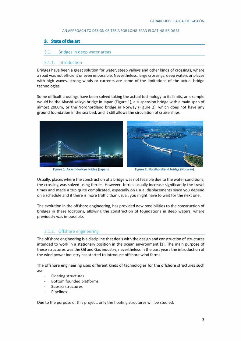
Bridges have been a great solution for water, steep valleys and other kinds of crossings, where a road was not efficient or even impossible. Nevertheless, large crossings, deep waters or places with high waves, strong winds or currents are some of the limitations of the actual bridge technologies. Some difficult crossings have been solved taking the actual technology to its limits, an example would be the Akashi-kaikyo bridge in Japan (Figure 1), a suspension bridge with a main span of almost 2000m, or the Nordhordland bridge in Norway (Figure 2), which does not have any ground foundation in the sea bed, and it still allows the circulation of cruise ships.
Figure 1: Akashi-kaikyo bridge (Japan)
Figure 2: Nordhordland bridge (Norway)
Usually, places where the construction of a bridge was not feasible due to the water conditions, the crossing was solved using ferries. However, ferries usually increase significantly the travel times and made a trip quite complicated, especially on usual displacements since you depend on a schedule and if there is more traffic than usual, you might have to wait for the next one. The evolution in the offshore engineering, has provided new possibilities to the construction of bridges in these locations, allowing the construction of foundations in deep waters, where previously was impossible.
3.1.2. Offshore engineering
The offshore engineering is a discipline that deals with the design and construction of structures intended to work in a stationary position in the ocean environment [1]. The main purpose of these structures was the Oil and Gas industry, nevertheless in the past years the introduction of the wind power industry has started to introduce offshore wind farms. The offshore engineering uses different kinds of technologies for the offshore structures such as:
- Floating structures - Bottom founded platforms - Subsea structures - Pipelines
Due to the purpose of this project, only the floating structures will be studied.
GERARD-JOSEP ALCALDE GASCÓN
AN APPROACH TO DESIGN CRITERIA FOR LONG-SPAN FLOATING BRIDGES
4
3.1.2.1. Brief history of the offshore engineering
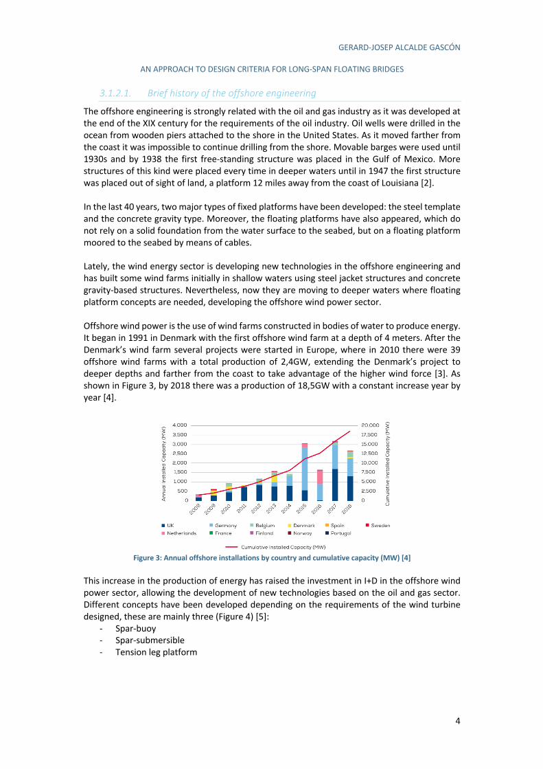
The offshore engineering is strongly related with the oil and gas industry as it was developed at the end of the XIX century for the requirements of the oil industry. Oil wells were drilled in the ocean from wooden piers attached to the shore in the United States. As it moved farther from the coast it was impossible to continue drilling from the shore. Movable barges were used until 1930s and by 1938 the first free-standing structure was placed in the Gulf of Mexico. More structures of this kind were placed every time in deeper waters until in 1947 the first structure was placed out of sight of land, a platform 12 miles away from the coast of Louisiana [2]. In the last 40 years, two major types of fixed platforms have been developed: the steel template and the concrete gravity type. Moreover, the floating platforms have also appeared, which do not rely on a solid foundation from the water surface to the seabed, but on a floating platform moored to the seabed by means of cables. Lately, the wind energy sector is developing new technologies in the offshore engineering and has built some wind farms initially in shallow waters using steel jacket structures and concrete gravity-based structures. Nevertheless, now they are moving to deeper waters where floating platform concepts are needed, developing the offshore wind power sector. Offshore wind power is the use of wind farms constructed in bodies of water to produce energy. It began in 1991 in Denmark with the first offshore wind farm at a depth of 4 meters. After the Denmark’s wind farm several projects were started in Europe, where in 2010 there were 39 offshore wind farms with a total production of 2,4GW, extending the Denmark’s project to deeper depths and farther from the coast to take advantage of the higher wind force [3]. As shown in Figure 3, by 2018 there was a production of 18,5GW with a constant increase year by year [4].
Figure 3: Annual offshore installations by country and cumulative capacity (MW) [4]
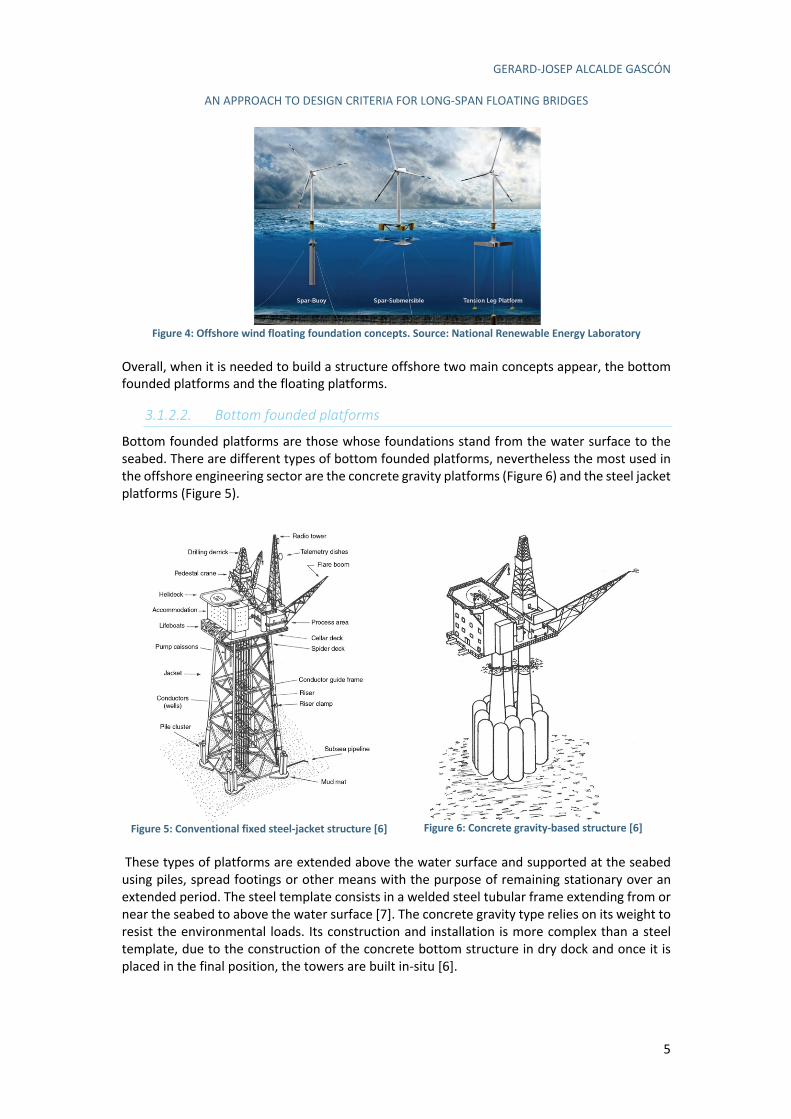
This increase in the production of energy has raised the investment in I+D in the offshore wind power sector, allowing the development of new technologies based on the oil and gas sector. Different concepts have been developed depending on the requirements of the wind turbine designed, these are mainly three (Figure 4) [5]:
- Spar-buoy - Spar-submersible - Tension leg platform
GERARD-JOSEP ALCALDE GASCÓN
AN APPROACH TO DESIGN CRITERIA FOR LONG-SPAN FLOATING BRIDGES
5
Figure 4: Offshore wind floating foundation concepts. Source: National Renewable Energy Laboratory
Overall, when it is needed to build a structure offshore two main concepts appear, the bottom founded platforms and the floating platforms.
3.1.2.2. Bottom founded platforms
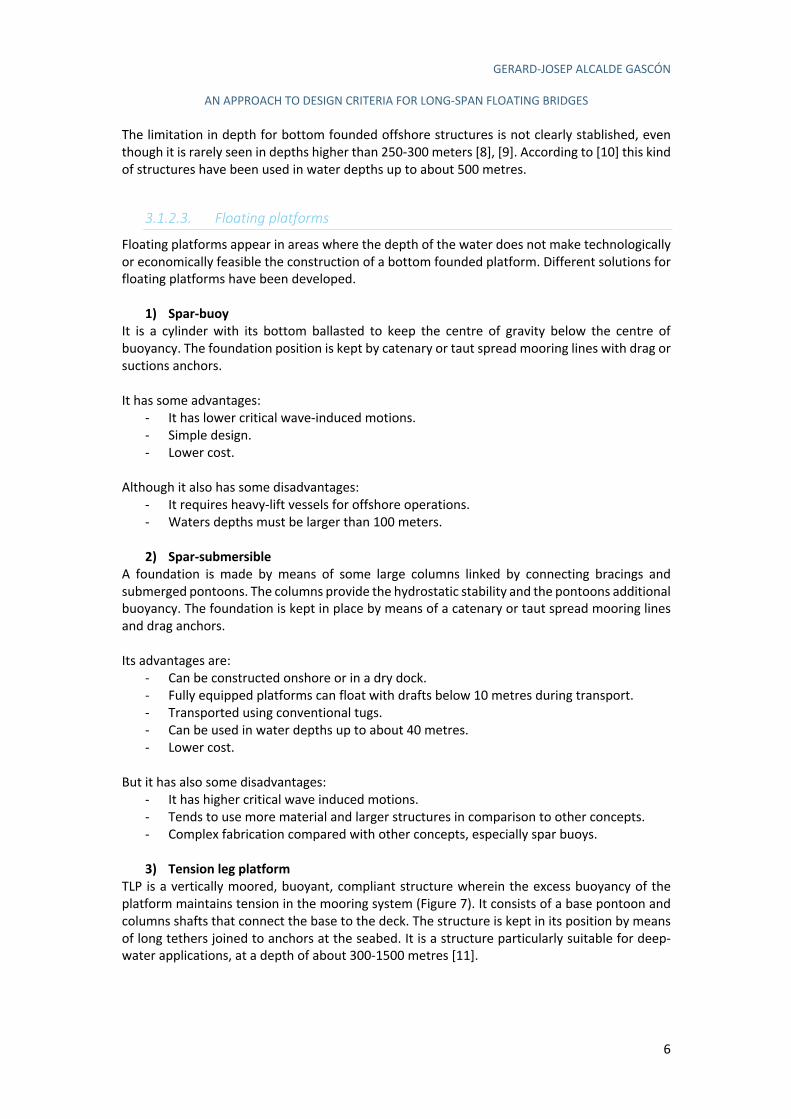
Bottom founded platforms are those whose foundations stand from the water surface to the seabed. There are different types of bottom founded platforms, nevertheless the most used in the offshore engineering sector are the concrete gravity platforms (Figure 6) and the steel jacket platforms (Figure 5).
These types of platforms are extended above the water surface and supported at the seabed using piles, spread footings or other means with the purpose of remaining stationary over an extended period. The steel template consists in a welded steel tubular frame extending from or near the seabed to above the water surface [7]. The concrete gravity type relies on its weight to resist the environmental loads. Its construction and installation is more complex than a steel template, due to the construction of the concrete bottom structure in dry dock and once it is placed in the final position, the towers are built in-situ [6].
Figure 5: Conventional fixed steel-jacket structure [6]
Figure 6: Concrete gravity-based structure [6]
GERARD-JOSEP ALCALDE GASCÓN
AN APPROACH TO DESIGN CRITERIA FOR LONG-SPAN FLOATING BRIDGES
6
The limitation in depth for bottom founded offshore structures is not clearly stablished, even though it is rarely seen in depths higher than 250-300 meters [8], [9]. According to [10] this kind of structures have been used in water depths up to about 500 metres.
3.1.2.3. Floating platforms
Floating platforms appear in areas where the depth of the water does not make technologically or economically feasible the construction of a bottom founded platform. Different solutions for floating platforms have been developed.
1) Spar-buoy
It is a cylinder with its bottom ballasted to keep the centre of gravity below the centre of buoyancy. The foundation position is kept by catenary or taut spread mooring lines with drag or suctions anchors. It has some advantages:
- It has lower critical wave-induced motions. - Simple design. - Lower cost.
Although it also has some disadvantages:
- It requires heavy-lift vessels for offshore operations. - Waters depths must be larger than 100 meters.
2) Spar-submersible
A foundation is made by means of some large columns linked by connecting bracings and submerged pontoons. The columns provide the hydrostatic stability and the pontoons additional buoyancy. The foundation is kept in place by means of a catenary or taut spread mooring lines and drag anchors. Its advantages are:
- Can be constructed onshore or in a dry dock. - Fully equipped platforms can float with drafts below 10 metres during transport. - Transported using conventional tugs. - Can be used in water depths up to about 40 metres. - Lower cost.
But it has also some disadvantages:
- It has higher critical wave induced motions. - Tends to use more material and larger structures in comparison to other concepts. - Complex fabrication compared with other concepts, especially spar buoys.
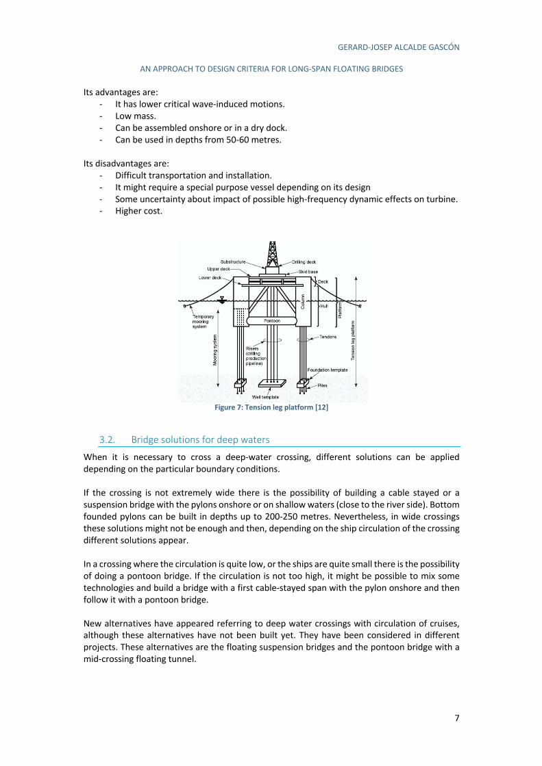
3) Tension leg platform
TLP is a vertically moored, buoyant, compliant structure wherein the excess buoyancy of the platform maintains tension in the mooring system (Figure 7). It consists of a base pontoon and columns shafts that connect the base to the deck. The structure is kept in its position by means of long tethers joined to anchors at the seabed. It is a structure particularly suitable for deep-water applications, at a depth of about 300-1500 metres [11].
GERARD-JOSEP ALCALDE GASCÓN
AN APPROACH TO DESIGN CRITERIA FOR LONG-SPAN FLOATING BRIDGES
7
Its advantages are: - It has lower critical wave-induced motions. - Low mass. - Can be assembled onshore or in a dry dock. - Can be used in depths from 50-60 metres.
Its disadvantages are:
- Difficult transportation and installation. - It might require a special purpose vessel depending on its design - Some uncertainty about impact of possible high-frequency dynamic effects on turbine. - Higher cost.
Figure 7: Tension leg platform [12]
3.2. Bridge solutions for deep waters
When it is necessary to cross a deep-water crossing, different solutions can be applied depending on the particular boundary conditions. If the crossing is not extremely wide there is the possibility of building a cable stayed or a suspension bridge with the pylons onshore or on shallow waters (close to the river side). Bottom founded pylons can be built in depths up to 200-250 metres. Nevertheless, in wide crossings these solutions might not be enough and then, depending on the ship circulation of the crossing different solutions appear. In a crossing where the circulation is quite low, or the ships are quite small there is the possibility of doing a pontoon bridge. If the circulation is not too high, it might be possible to mix some technologies and build a bridge with a first cable-stayed span with the pylon onshore and then follow it with a pontoon bridge. New alternatives have appeared referring to deep water crossings with circulation of cruises, although these alternatives have not been built yet. They have been considered in different projects. These alternatives are the floating suspension bridges and the pontoon bridge with a mid-crossing floating tunnel.
GERARD-JOSEP ALCALDE GASCÓN
AN APPROACH TO DESIGN CRITERIA FOR LONG-SPAN FLOATING BRIDGES
8
Floating suspension bridges take the technologies developed for the offshore platforms in the oil, gas and wind energy sectors and adapt it to create a floating pylon foundation. Thanks to the floating foundations it is possible to build a pylon at a depth where previously was not. A pontoon bridge with a mid-crossing floating tunnel is another proposed solution. It consists in a pontoon bridge where, at the middle of the crossing, the road descends into a floating tunnel. This solution allows the cruise ships to circulate above the tunnel. These alternatives are further investigated.
3.2.1. Suspension bridges
3.2.1.1. Definition and brief history
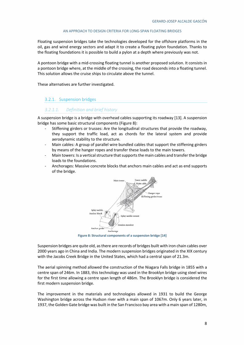
A suspension bridge is a bridge with overhead cables supporting its roadway [13]. A suspension bridge has some basic structural components (Figure 8):
- Stiffening girders or trusses: Are the longitudinal structures that provide the roadway, they support the traffic load, act as chords for the lateral system and provide aerodynamic stability to the structure.
- Main cables: A group of parallel wire bundled cables that support the stiffening girders by means of the hanger ropes and transfer these loads to the main towers.
- Main towers: Is a vertical structure that supports the main cables and transfer the bridge loads to the foundations.
- Anchorages: Massive concrete blocks that anchors main cables and act as end supports of the bridge.
Figure 8: Structural components of a suspension bridge [14]
Suspension bridges are quite old, as there are records of bridges built with iron chain cables over 2000 years ago in China and India. The modern suspension bridges originated in the XIX century with the Jacobs Creek Bridge in the United States, which had a central span of 21.3m. The aerial spinning method allowed the construction of the Niagara Falls bridge in 1855 with a centre span of 246m. In 1883, this technology was used in the Brooklyn bridge using steel wires for the first time allowing a centre span length of 486m. The Brooklyn bridge is considered the first modern suspension bridge. The improvement in the materials and technologies allowed in 1931 to build the George Washington bridge across the Hudson river with a main span of 1067m. Only 6 years later, in 1937, the Golden Gate bridge was built in the San Francisco bay area with a main span of 1280m,
GERARD-JOSEP ALCALDE GASCÓN
AN APPROACH TO DESIGN CRITERIA FOR LONG-SPAN FLOATING BRIDGES
9
which remained for several years as the longest suspension bridge in the world and was a reference. The failure of the Tacoma bridge in 1940 due to a subsequent torsional mode of vibration made crucial the wind-resistant design in the suspension bridges and the importance of aerodynamic effects in this long-span bridges. Humber and Severn bridges in the UK were designed taking aerodynamic and slender shapes in the stiffening deck. At the end of the XX century, a huge improvement in the suspension bridges appeared and allowed the construction of the Great Belt East Bridge in Denmark, with a centre span of 1624m. Moreover, thanks to the improvement in the offshore engineering, it was built the Akashi-Kaikyo bridge, with a 1991m long centre span is currently the longest suspension bridge in the world [14]. The Akashi-kaikyo is one of the most technologically advanced suspension bridge in the world and it introduced a different approach to the main to side span ratio, with a relation of a-2a-a [15].
3.2.1.2. Classification
Suspension bridges can be classified by different properties such as number of spans, continuity of stiffening girders, types of suspenders and types of cable anchoring. Following there is a brief description of each one [14]. Number of spans
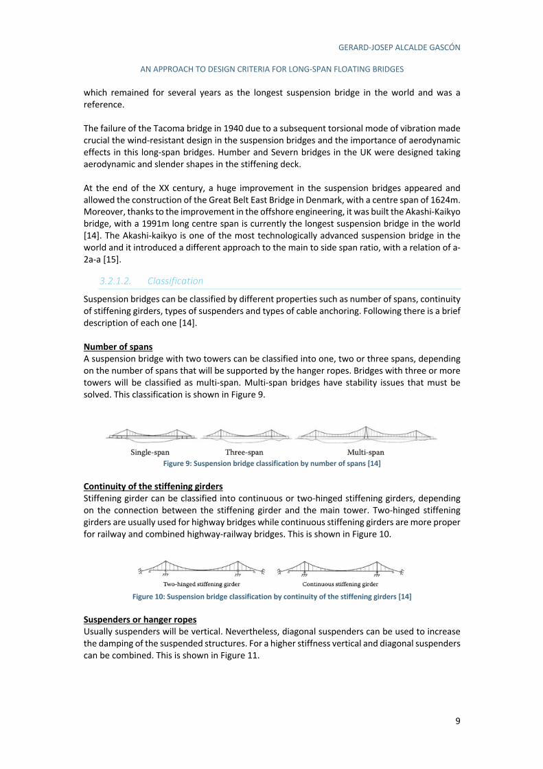
A suspension bridge with two towers can be classified into one, two or three spans, depending on the number of spans that will be supported by the hanger ropes. Bridges with three or more towers will be classified as multi-span. Multi-span bridges have stability issues that must be solved. This classification is shown in Figure 9.
Figure 9: Suspension bridge classification by number of spans [14]
Continuity of the stiffening girders
Stiffening girder can be classified into continuous or two-hinged stiffening girders, depending on the connection between the stiffening girder and the main tower. Two-hinged stiffening girders are usually used for highway bridges while continuous stiffening girders are more proper for railway and combined highway-railway bridges. This is shown in Figure 10.
Figure 10: Suspension bridge classification by continuity of the stiffening girders [14]
Suspenders or hanger ropes
Usually suspenders will be vertical. Nevertheless, diagonal suspenders can be used to increase the damping of the suspended structures. For a higher stiffness vertical and diagonal suspenders can be combined. This is shown in Figure 11.

GERARD-JOSEP ALCALDE GASCÓN
AN APPROACH TO DESIGN CRITERIA FOR LONG-SPAN FLOATING BRIDGES
10
Figure 11: Suspension bridge classification by type of suspenders [14]
Cable anchoring
It can be classified into externally anchored and self-anchored. The most common are the externally anchored, where the main cable is anchored to a massive concrete block. In the self-anchored, the main cable is secured to the stiffening girder and does not need an anchorage. The self-anchored systems transfer the main cable tension into a compression axial force into the girders. This is shown in Figure 12.
Figure 12: Suspension bridge classification by type of cable anchoring [14]
3.2.1.3. Advantage and disadvantages suspended bridges
The suspension bridges have several advantages, but they also have some disadvantages with respect to other type of bridges, what creates some limitations in its design [16]. Some of the advantages of a suspension bridge are:
- It allows larger span lengths than any other type of bridge. - It requires less material than other types of bridges what reduces the total cost. - The area below the bridge is free during almost all the construction and therefore, the
waterway can remain open. - It deals quite well with earthquakes - The bridge deck can have some sections replaced to increase the bridge capacity. - The maintenance is relatively easy.
Even though, it also has some disadvantages such as:
- It does not bear properly heavy punctual loads. - It is necessary to provide enough stiffness or an aerodynamic profile to the deck in order
to prevent the vibration of the deck under high winds. - The failure of one suspender can be enough to cause the entire collapse. - May require an extensive foundation work. - Its relatively low stiffness makes it more difficult to carry heavy rail traffic due to its high
live loads. Given these advantages and disadvantages a suspended bridge is an interesting alternative but it is not always the best option, moreover some difficulties in the design and construction feasibility arise due to its long main span. The main concern with the suspension bridges is its dynamic behaviour. Following the study of [17] the optimum main span length of a suspension bridge is of 900m, therefore, even it is possible to design suspension bridges with longer main span length it will be far from the optimal design.
GERARD-JOSEP ALCALDE GASCÓN
AN APPROACH TO DESIGN CRITERIA FOR LONG-SPAN FLOATING BRIDGES
11
3.2.2. Floating bridges
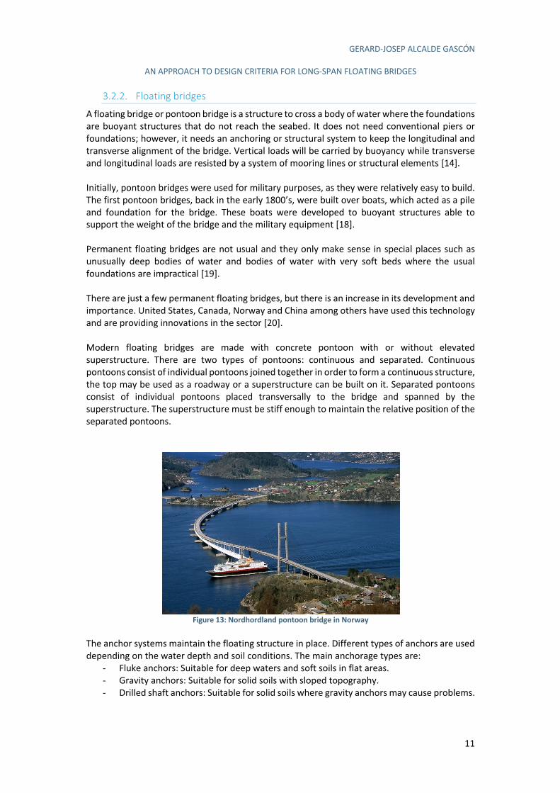
A floating bridge or pontoon bridge is a structure to cross a body of water where the foundations are buoyant structures that do not reach the seabed. It does not need conventional piers or foundations; however, it needs an anchoring or structural system to keep the longitudinal and transverse alignment of the bridge. Vertical loads will be carried by buoyancy while transverse and longitudinal loads are resisted by a system of mooring lines or structural elements [14]. Initially, pontoon bridges were used for military purposes, as they were relatively easy to build. The first pontoon bridges, back in the early 1800’s, were built over boats, which acted as a pile and foundation for the bridge. These boats were developed to buoyant structures able to support the weight of the bridge and the military equipment [18]. Permanent floating bridges are not usual and they only make sense in special places such as unusually deep bodies of water and bodies of water with very soft beds where the usual foundations are impractical [19]. There are just a few permanent floating bridges, but there is an increase in its development and importance. United States, Canada, Norway and China among others have used this technology and are providing innovations in the sector [20]. Modern floating bridges are made with concrete pontoon with or without elevated superstructure. There are two types of pontoons: continuous and separated. Continuous pontoons consist of individual pontoons joined together in order to form a continuous structure, the top may be used as a roadway or a superstructure can be built on it. Separated pontoons consist of individual pontoons placed transversally to the bridge and spanned by the superstructure. The superstructure must be stiff enough to maintain the relative position of the separated pontoons.
Figure 13: Nordhordland pontoon bridge in Norway
The anchor systems maintain the floating structure in place. Different types of anchors are used depending on the water depth and soil conditions. The main anchorage types are:
- Fluke anchors: Suitable for deep waters and soft soils in flat areas. - Gravity anchors: Suitable for solid soils with sloped topography. - Drilled shaft anchors: Suitable for solid soils where gravity anchors may cause problems.

GERARD-JOSEP ALCALDE GASCÓN
AN APPROACH TO DESIGN CRITERIA FOR LONG-SPAN FLOATING BRIDGES
12
The anchoring of the bridge can be made in two different ways: - End-anchored: The anchorage is done from the pontoon to the seabed, it would
correspond to a TLP platform. - Side-anchored: The bridge is laterally stiffened with anchor cables.
Floating bridges provide a good solution for water-crossings where the water is deep and wide, but the currents are not quite fast, the winds not too strong and the waves not too high [14]. This is why they are good solutions for lakes and fiords (Figure 13).
3.2.3. Floating suspension or cable-stayed bridge
A floating suspension bridge is a quite new concept in bridge engineering. On the one hand, several suspension bridges have been built in the past years and its technology is well known nowadays as it has been previously shown. Multi-span suspension bridges take this technology one step further and allow the bridge to cover longer distances. On the other hand, floating bridges are not as usual, but they have also been largely studied. Nevertheless, combining these technologies had not been considered until the case of the Bjørnafjord, a fiord crossing in the E39 project in Norway. This concept takes the actual technology to its limits, and it has required the work of several experts across the world. Vegvesen (the Norwegian road administration) states that the technology needed for the different fiord crossing, including the floating multi-span suspension bridge technologies will not be available until 2022 [21]. Given the singularity of this kind of structure there is few information available in the technical literature. Even though, it is possible to study this structure taking information of two different fields:
- Offshore engineering: For the technology used in the piles and foundations. - Multi-span suspension bridge: For the technology required in the long-span bridge
construction. In the next chapters, the most relevant information on the multi-span suspension technology will be shown, as the offshore engineering technology has already been explained previously.
3.2.3.1. Multi-span floating suspension bridge
A multi-span suspension bridge consists in a suspension bridge of multiple spans. Multi-span suspension bridges were widely used in the initial development of suspension bridges in the 19th century when the allowable span length was relatively short, and therefore they were necessary to cross major rivers [22]. These old bridges had span lengths no much longer than 100 meters. With the development of the technologies required for the suspension bridges, a span length longer than 1000 meters was allowed, hence multi-span bridges were not necessary in the majority of solutions. Lately, the development of the technology has made feasible the construction of a bridge to overcome a crossing of 4-5km long, with special requirements of vertical clearance and wind and current speed. Nevertheless, for these lengths, conventional suspension bridges of one
GERARD-JOSEP ALCALDE GASCÓN
AN APPROACH TO DESIGN CRITERIA FOR LONG-SPAN FLOATING BRIDGES
13
span, are not feasible, there appears the necessity of multi-span suspension bridges, as they provide a solution to a crossing of a few kilometres. Multi-span suspension bridges have some difficulties on its design as for instance:
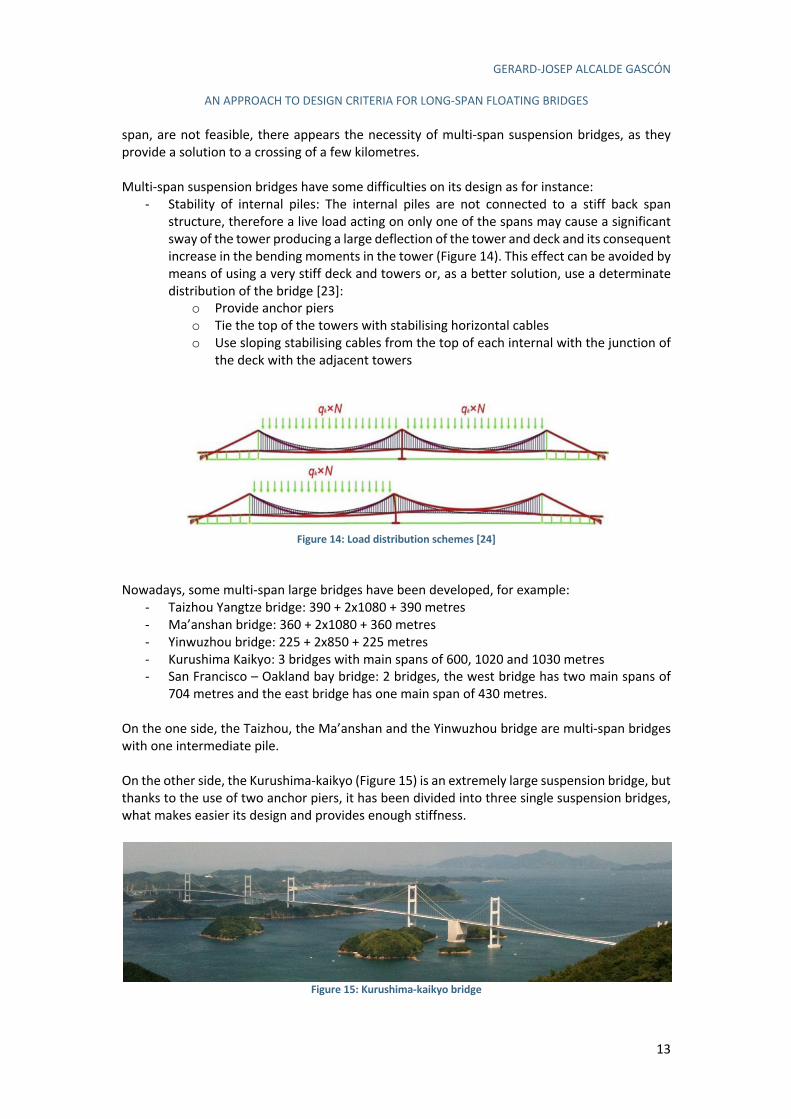
- Stability of internal piles: The internal piles are not connected to a stiff back span structure, therefore a live load acting on only one of the spans may cause a significant sway of the tower producing a large deflection of the tower and deck and its consequent increase in the bending moments in the tower (Figure 14). This effect can be avoided by means of using a very stiff deck and towers or, as a better solution, use a determinate distribution of the bridge [23]:
o Provide anchor piers o Tie the top of the towers with stabilising horizontal cables o Use sloping stabilising cables from the top of each internal with the junction of
the deck with the adjacent towers
Figure 14: Load distribution schemes [24]
Nowadays, some multi-span large bridges have been developed, for example:
- Taizhou Yangtze bridge: 390 + 2x1080 + 390 metres - Ma’anshan bridge: 360 + 2x1080 + 360 metres - Yinwuzhou bridge: 225 + 2x850 + 225 metres - Kurushima Kaikyo: 3 bridges with main spans of 600, 1020 and 1030 metres - San Francisco – Oakland bay bridge: 2 bridges, the west bridge has two main spans of
704 metres and the east bridge has one main span of 430 metres. On the one side, the Taizhou, the Ma’anshan and the Yinwuzhou bridge are multi-span bridges with one intermediate pile. On the other side, the Kurushima-kaikyo (Figure 15) is an extremely large suspension bridge, but thanks to the use of two anchor piers, it has been divided into three single suspension bridges, what makes easier its design and provides enough stiffness.
Figure 15: Kurushima-kaikyo bridge
GERARD-JOSEP ALCALDE GASCÓN
AN APPROACH TO DESIGN CRITERIA FOR LONG-SPAN FLOATING BRIDGES
14
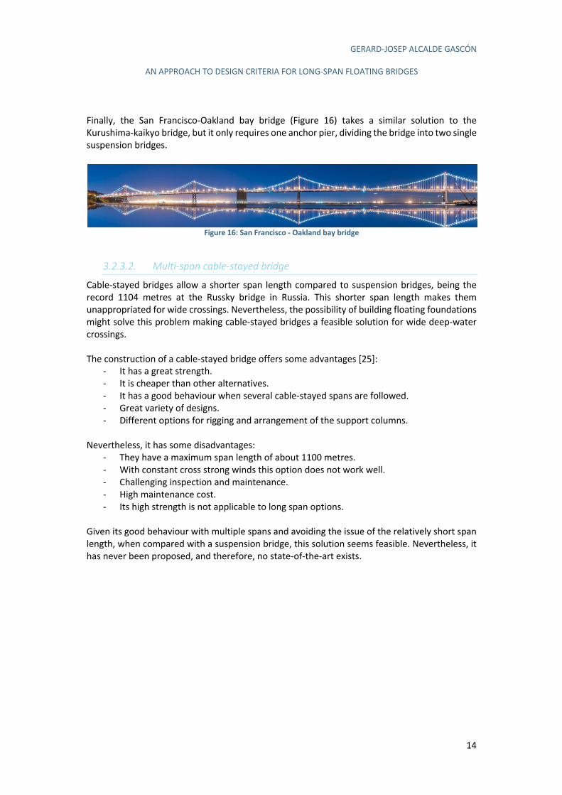
Finally, the San Francisco-Oakland bay bridge (Figure 16) takes a similar solution to the Kurushima-kaikyo bridge, but it only requires one anchor pier, dividing the bridge into two single suspension bridges.
Figure 16: San Francisco - Oakland bay bridge
3.2.3.2. Multi-span cable-stayed bridge
Cable-stayed bridges allow a shorter span length compared to suspension bridges, being the record 1104 metres at the Russky bridge in Russia. This shorter span length makes them unappropriated for wide crossings. Nevertheless, the possibility of building floating foundations might solve this problem making cable-stayed bridges a feasible solution for wide deep-water crossings. The construction of a cable-stayed bridge offers some advantages [25]:
- It has a great strength. - It is cheaper than other alternatives. - It has a good behaviour when several cable-stayed spans are followed. - Great variety of designs. - Different options for rigging and arrangement of the support columns.
Nevertheless, it has some disadvantages:
- They have a maximum span length of about 1100 metres. - With constant cross strong winds this option does not work well. - Challenging inspection and maintenance. - High maintenance cost. - Its high strength is not applicable to long span options.
Given its good behaviour with multiple spans and avoiding the issue of the relatively short span length, when compared with a suspension bridge, this solution seems feasible. Nevertheless, it has never been proposed, and therefore, no state-of-the-art exists.

GERARD-JOSEP ALCALDE GASCÓN
AN APPROACH TO DESIGN CRITERIA FOR LONG-SPAN FLOATING BRIDGES
15
3.2.4. Pontoon bridge combined with a cable stayed bridge
A pontoon bridge combined with a cable-stayed bridge (Figure 17) solves the problem of the deep depth by means of a cable stayed bridge with the pylon onshore and followed by a pontoon bridge. The cable-stayed bridge would allow a clearance below the deck enough for the ships, and the pontoon bridge would allow the crossing of a wide water body without any bottom founded foundations.
Figure 17: Proposed alternative of a pontoon bridge with a cable-stayed bridge [26]
3.2.5. Pontoon bridge combined with a submerged floating tunnel at mid-fiord
A pontoon bridge with a submerged floating tunnel at the middle of the crossing (Figure 18) is a new proposal derived from the E39 project in Norway. As an alternative to the previous options that leaves a navigable clearance below the deck, in this option the road descends a certain height, leaving an under-keel clearance enough for ship navigation above it. This solution would use known technology for the pontoon bridge, but it would require the development of new technology for the floating tunnel, which is not yet available.
Figure 18: Pontoon bridge with entering a submerged floating tunnel at mid-fiord [26]
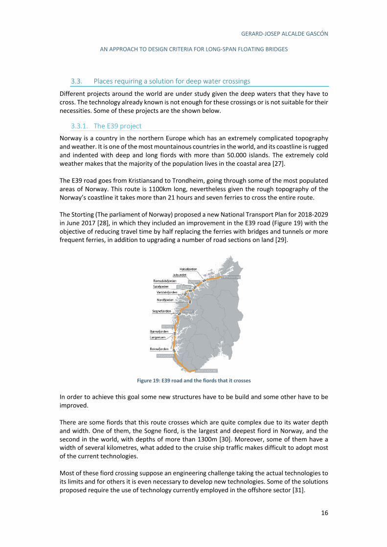
GERARD-JOSEP ALCALDE GASCÓN
AN APPROACH TO DESIGN CRITERIA FOR LONG-SPAN FLOATING BRIDGES
16
3.3. Places requiring a solution for deep water crossings
Different projects around the world are under study given the deep waters that they have to cross. The technology already known is not enough for these crossings or is not suitable for their necessities. Some of these projects are the shown below.
3.3.1. The E39 project
Norway is a country in the northern Europe which has an extremely complicated topography and weather. It is one of the most mountainous countries in the world, and its coastline is rugged and indented with deep and long fiords with more than 50.000 islands. The extremely cold weather makes that the majority of the population lives in the coastal area [27]. The E39 road goes from Kristiansand to Trondheim, going through some of the most populated areas of Norway. This route is 1100km long, nevertheless given the rough topography of the Norway’s coastline it takes more than 21 hours and seven ferries to cross the entire route. The Storting (The parliament of Norway) proposed a new National Transport Plan for 2018-2029 in June 2017 [28], in which they included an improvement in the E39 road (Figure 19) with the objective of reducing travel time by half replacing the ferries with bridges and tunnels or more frequent ferries, in addition to upgrading a number of road sections on land [29].
Figure 19: E39 road and the fiords that it crosses
In order to achieve this goal some new structures have to be build and some other have to be improved. There are some fiords that this route crosses which are quite complex due to its water depth and width. One of them, the Sogne fiord, is the largest and deepest fiord in Norway, and the second in the world, with depths of more than 1300m [30]. Moreover, some of them have a width of several kilometres, what added to the cruise ship traffic makes difficult to adopt most of the current technologies. Most of these fiord crossing suppose an engineering challenge taking the actual technologies to its limits and for others it is even necessary to develop new technologies. Some of the solutions proposed require the use of technology currently employed in the offshore sector [31].
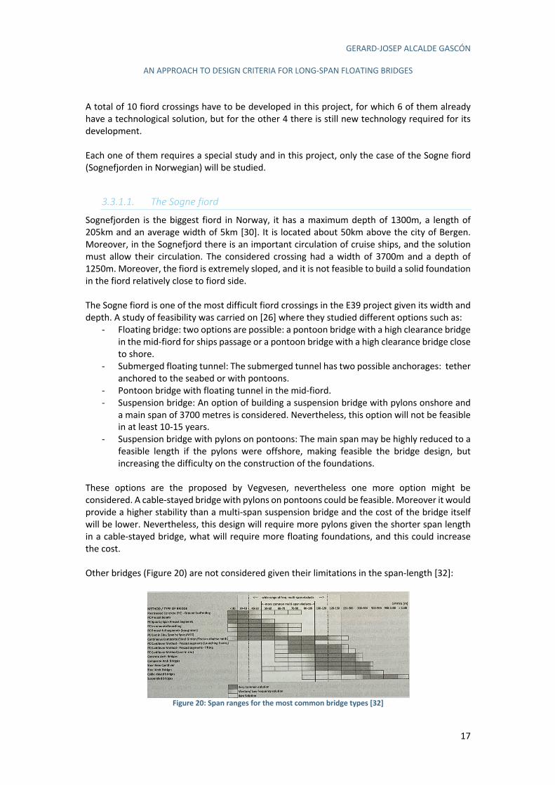
GERARD-JOSEP ALCALDE GASCÓN
AN APPROACH TO DESIGN CRITERIA FOR LONG-SPAN FLOATING BRIDGES
17
A total of 10 fiord crossings have to be developed in this project, for which 6 of them already have a technological solution, but for the other 4 there is still new technology required for its development. Each one of them requires a special study and in this project, only the case of the Sogne fiord (Sognefjorden in Norwegian) will be studied.
3.3.1.1. The Sogne fiord
Sognefjorden is the biggest fiord in Norway, it has a maximum depth of 1300m, a length of 205km and an average width of 5km [30]. It is located about 50km above the city of Bergen. Moreover, in the Sognefjord there is an important circulation of cruise ships, and the solution must allow their circulation. The considered crossing had a width of 3700m and a depth of 1250m. Moreover, the fiord is extremely sloped, and it is not feasible to build a solid foundation in the fiord relatively close to fiord side. The Sogne fiord is one of the most difficult fiord crossings in the E39 project given its width and depth. A study of feasibility was carried on [26] where they studied different options such as:
- Floating bridge: two options are possible: a pontoon bridge with a high clearance bridge in the mid-fiord for ships passage or a pontoon bridge with a high clearance bridge close to shore.
- Submerged floating tunnel: The submerged tunnel has two possible anchorages: tether anchored to the seabed or with pontoons.
- Pontoon bridge with floating tunnel in the mid-fiord. - Suspension bridge: An option of building a suspension bridge with pylons onshore and
a main span of 3700 metres is considered. Nevertheless, this option will not be feasible in at least 10-15 years.
- Suspension bridge with pylons on pontoons: The main span may be highly reduced to a feasible length if the pylons were offshore, making feasible the bridge design, but increasing the difficulty on the construction of the foundations.
These options are the proposed by Vegvesen, nevertheless one more option might be considered. A cable-stayed bridge with pylons on pontoons could be feasible. Moreover it would provide a higher stability than a multi-span suspension bridge and the cost of the bridge itself will be lower. Nevertheless, this design will require more pylons given the shorter span length in a cable-stayed bridge, what will require more floating foundations, and this could increase the cost. Other bridges (Figure 20) are not considered given their limitations in the span-length [32]:
Figure 20: Span ranges for the most common bridge types [32]
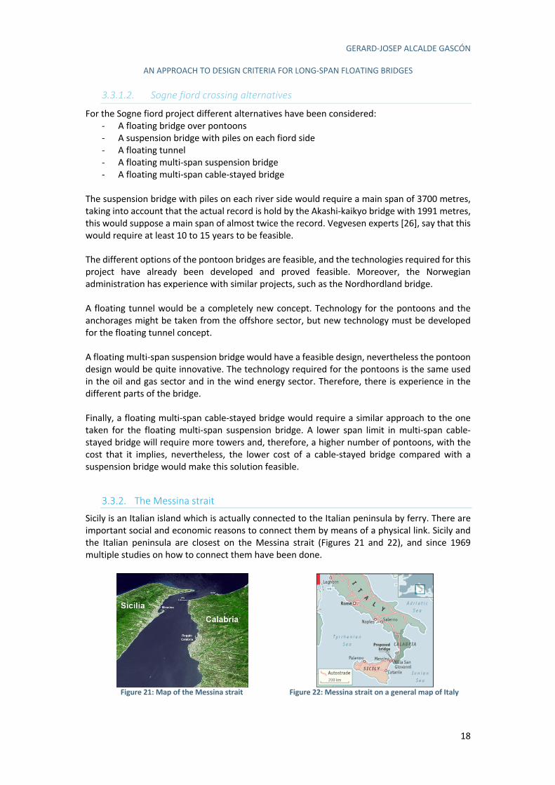
GERARD-JOSEP ALCALDE GASCÓN
AN APPROACH TO DESIGN CRITERIA FOR LONG-SPAN FLOATING BRIDGES
18
3.3.1.2. Sogne fiord crossing alternatives
For the Sogne fiord project different alternatives have been considered: - A floating bridge over pontoons - A suspension bridge with piles on each fiord side - A floating tunnel - A floating multi-span suspension bridge - A floating multi-span cable-stayed bridge
The suspension bridge with piles on each river side would require a main span of 3700 metres, taking into account that the actual record is hold by the Akashi-kaikyo bridge with 1991 metres, this would suppose a main span of almost twice the record. Vegvesen experts [26], say that this would require at least 10 to 15 years to be feasible. The different options of the pontoon bridges are feasible, and the technologies required for this project have already been developed and proved feasible. Moreover, the Norwegian administration has experience with similar projects, such as the Nordhordland bridge. A floating tunnel would be a completely new concept. Technology for the pontoons and the anchorages might be taken from the offshore sector, but new technology must be developed for the floating tunnel concept. A floating multi-span suspension bridge would have a feasible design, nevertheless the pontoon design would be quite innovative. The technology required for the pontoons is the same used in the oil and gas sector and in the wind energy sector. Therefore, there is experience in the different parts of the bridge. Finally, a floating multi-span cable-stayed bridge would require a similar approach to the one taken for the floating multi-span suspension bridge. A lower span limit in multi-span cable-stayed bridge will require more towers and, therefore, a higher number of pontoons, with the cost that it implies, nevertheless, the lower cost of a cable-stayed bridge compared with a suspension bridge would make this solution feasible.
3.3.2. The Messina strait
Sicily is an Italian island which is actually connected to the Italian peninsula by ferry. There are important social and economic reasons to connect them by means of a physical link. Sicily and the Italian peninsula are closest on the Messina strait (Figures 21 and 22), and since 1969 multiple studies on how to connect them have been done.
Figure 21: Map of the Messina strait
Figure 22: Messina strait on a general map of Italy
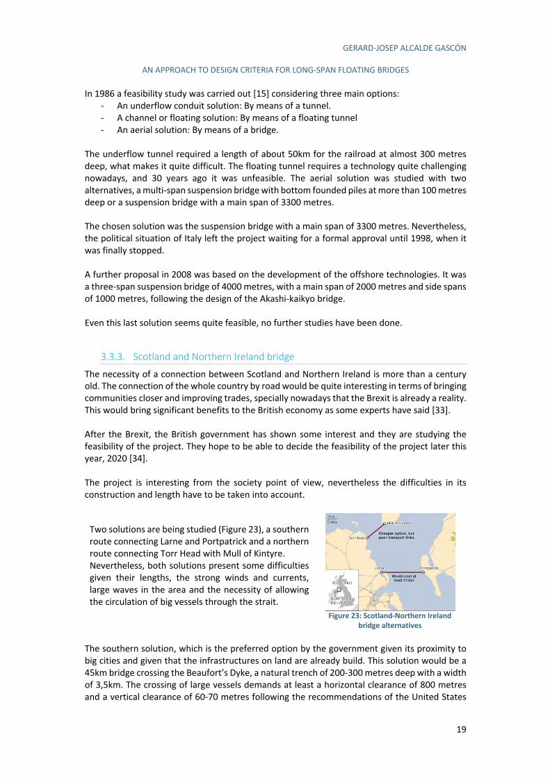
GERARD-JOSEP ALCALDE GASCÓN
AN APPROACH TO DESIGN CRITERIA FOR LONG-SPAN FLOATING BRIDGES
19
In 1986 a feasibility study was carried out [15] considering three main options: - An underflow conduit solution: By means of a tunnel. - A channel or floating solution: By means of a floating tunnel - An aerial solution: By means of a bridge.
The underflow tunnel required a length of about 50km for the railroad at almost 300 metres deep, what makes it quite difficult. The floating tunnel requires a technology quite challenging nowadays, and 30 years ago it was unfeasible. The aerial solution was studied with two alternatives, a multi-span suspension bridge with bottom founded piles at more than 100 metres deep or a suspension bridge with a main span of 3300 metres. The chosen solution was the suspension bridge with a main span of 3300 metres. Nevertheless, the political situation of Italy left the project waiting for a formal approval until 1998, when it was finally stopped. A further proposal in 2008 was based on the development of the offshore technologies. It was a three-span suspension bridge of 4000 metres, with a main span of 2000 metres and side spans of 1000 metres, following the design of the Akashi-kaikyo bridge. Even this last solution seems quite feasible, no further studies have been done.
3.3.3. Scotland and Northern Ireland bridge
The necessity of a connection between Scotland and Northern Ireland is more than a century old. The connection of the whole country by road would be quite interesting in terms of bringing communities closer and improving trades, specially nowadays that the Brexit is already a reality. This would bring significant benefits to the British economy as some experts have said [33]. After the Brexit, the British government has shown some interest and they are studying the feasibility of the project. They hope to be able to decide the feasibility of the project later this year, 2020 [34]. The project is interesting from the society point of view, nevertheless the difficulties in its construction and length have to be taken into account.
Two solutions are being studied (Figure 23), a southern route connecting Larne and Portpatrick and a northern route connecting Torr Head with Mull of Kintyre. Nevertheless, both solutions present some difficulties given their lengths, the strong winds and currents, large waves in the area and the necessity of allowing the circulation of big vessels through the strait.
Figure 23: Scotland-Northern Ireland bridge alternatives
The southern solution, which is the preferred option by the government given its proximity to big cities and given that the infrastructures on land are already build. This solution would be a 45km bridge crossing the Beaufort’s Dyke, a natural trench of 200-300 metres deep with a width of 3,5km. The crossing of large vessels demands at least a horizontal clearance of 800 metres and a vertical clearance of 60-70 metres following the recommendations of the United States
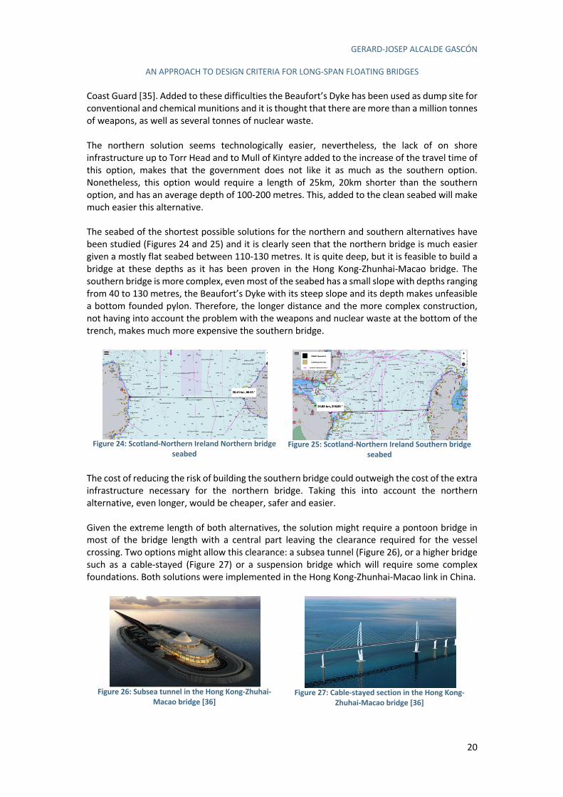
GERARD-JOSEP ALCALDE GASCÓN
AN APPROACH TO DESIGN CRITERIA FOR LONG-SPAN FLOATING BRIDGES
20
Coast Guard [35]. Added to these difficulties the Beaufort’s Dyke has been used as dump site for conventional and chemical munitions and it is thought that there are more than a million tonnes of weapons, as well as several tonnes of nuclear waste. The northern solution seems technologically easier, nevertheless, the lack of on shore infrastructure up to Torr Head and to Mull of Kintyre added to the increase of the travel time of this option, makes that the government does not like it as much as the southern option. Nonetheless, this option would require a length of 25km, 20km shorter than the southern option, and has an average depth of 100-200 metres. This, added to the clean seabed will make much easier this alternative. The seabed of the shortest possible solutions for the northern and southern alternatives have been studied (Figures 24 and 25) and it is clearly seen that the northern bridge is much easier given a mostly flat seabed between 110-130 metres. It is quite deep, but it is feasible to build a bridge at these depths as it has been proven in the Hong Kong-Zhunhai-Macao bridge. The southern bridge is more complex, even most of the seabed has a small slope with depths ranging from 40 to 130 metres, the Beaufort’s Dyke with its steep slope and its depth makes unfeasible a bottom founded pylon. Therefore, the longer distance and the more complex construction, not having into account the problem with the weapons and nuclear waste at the bottom of the trench, makes much more expensive the southern bridge.
Figure 24: Scotland-Northern Ireland Northern bridge
seabed
Figure 25: Scotland-Northern Ireland Southern bridge
seabed The cost of reducing the risk of building the southern bridge could outweigh the cost of the extra infrastructure necessary for the northern bridge. Taking this into account the northern alternative, even longer, would be cheaper, safer and easier. Given the extreme length of both alternatives, the solution might require a pontoon bridge in most of the bridge length with a central part leaving the clearance required for the vessel crossing. Two options might allow this clearance: a subsea tunnel (Figure 26), or a higher bridge such as a cable-stayed (Figure 27) or a suspension bridge which will require some complex foundations. Both solutions were implemented in the Hong Kong-Zhunhai-Macao link in China.
Figure 26: Subsea tunnel in the Hong Kong-Zhuhai-
Macao bridge [36]
Figure 27: Cable-stayed section in the Hong Kong-
Zhuhai-Macao bridge [36]
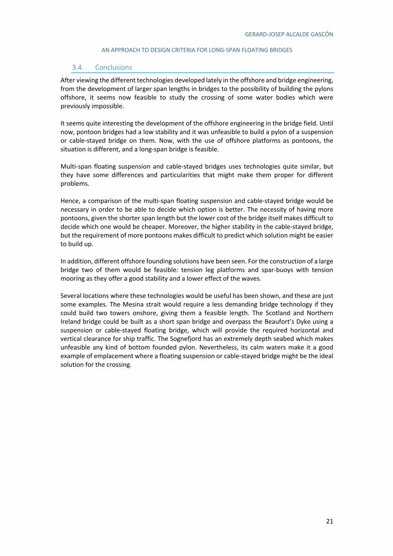
GERARD-JOSEP ALCALDE GASCÓN
AN APPROACH TO DESIGN CRITERIA FOR LONG-SPAN FLOATING BRIDGES
21
3.4. Conclusions
After viewing the different technologies developed lately in the offshore and bridge engineering, from the development of larger span lengths in bridges to the possibility of building the pylons offshore, it seems now feasible to study the crossing of some water bodies which were previously impossible. It seems quite interesting the development of the offshore engineering in the bridge field. Until now, pontoon bridges had a low stability and it was unfeasible to build a pylon of a suspension or cable-stayed bridge on them. Now, with the use of offshore platforms as pontoons, the situation is different, and a long-span bridge is feasible. Multi-span floating suspension and cable-stayed bridges uses technologies quite similar, but they have some differences and particularities that might make them proper for different problems. Hence, a comparison of the multi-span floating suspension and cable-stayed bridge would be necessary in order to be able to decide which option is better. The necessity of having more pontoons, given the shorter span length but the lower cost of the bridge itself makes difficult to decide which one would be cheaper. Moreover, the higher stability in the cable-stayed bridge, but the requirement of more pontoons makes difficult to predict which solution might be easier to build up. In addition, different offshore founding solutions have been seen. For the construction of a large bridge two of them would be feasible: tension leg platforms and spar-buoys with tension mooring as they offer a good stability and a lower effect of the waves. Several locations where these technologies would be useful has been shown, and these are just some examples. The Mesina strait would require a less demanding bridge technology if they could build two towers onshore, giving them a feasible length. The Scotland and Northern Ireland bridge could be built as a short span bridge and overpass the Beaufort’s Dyke using a suspension or cable-stayed floating bridge, which will provide the required horizontal and vertical clearance for ship traffic. The Sognefjord has an extremely depth seabed which makes unfeasible any kind of bottom founded pylon. Nevertheless, its calm waters make it a good example of emplacement where a floating suspension or cable-stayed bridge might be the ideal solution for the crossing.
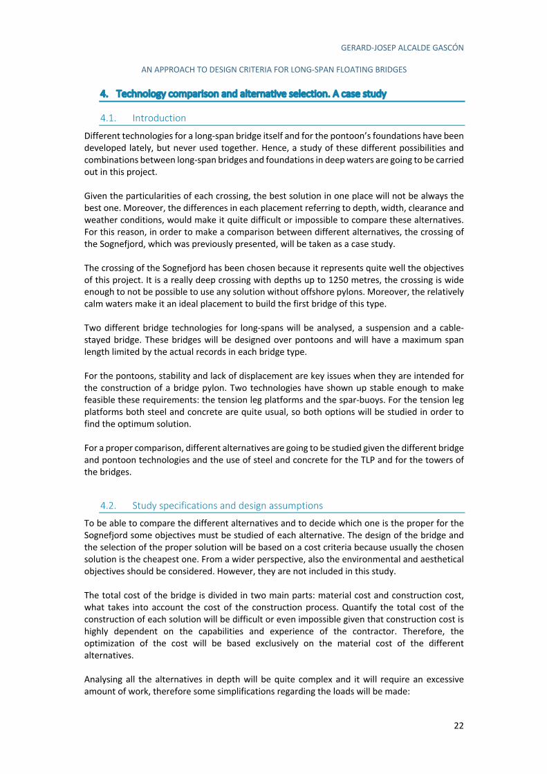
GERARD-JOSEP ALCALDE GASCÓN
AN APPROACH TO DESIGN CRITERIA FOR LONG-SPAN FLOATING BRIDGES
22
4. Technology comparison and alternative selection. A case study
4.1. Introduction
Different technologies for a long-span bridge itself and for the pontoon’s foundations have been developed lately, but never used together. Hence, a study of these different possibilities and combinations between long-span bridges and foundations in deep waters are going to be carried out in this project. Given the particularities of each crossing, the best solution in one place will not be always the best one. Moreover, the differences in each placement referring to depth, width, clearance and weather conditions, would make it quite difficult or impossible to compare these alternatives. For this reason, in order to make a comparison between different alternatives, the crossing of the Sognefjord, which was previously presented, will be taken as a case study. The crossing of the Sognefjord has been chosen because it represents quite well the objectives of this project. It is a really deep crossing with depths up to 1250 metres, the crossing is wide enough to not be possible to use any solution without offshore pylons. Moreover, the relatively calm waters make it an ideal placement to build the first bridge of this type. Two different bridge technologies for long-spans will be analysed, a suspension and a cable-stayed bridge. These bridges will be designed over pontoons and will have a maximum span length limited by the actual records in each bridge type. For the pontoons, stability and lack of displacement are key issues when they are intended for the construction of a bridge pylon. Two technologies have shown up stable enough to make feasible these requirements: the tension leg platforms and the spar-buoys. For the tension leg platforms both steel and concrete are quite usual, so both options will be studied in order to find the optimum solution. For a proper comparison, different alternatives are going to be studied given the different bridge and pontoon technologies and the use of steel and concrete for the TLP and for the towers of the bridges.
4.2. Study specifications and design assumptions
To be able to compare the different alternatives and to decide which one is the proper for the Sognefjord some objectives must be studied of each alternative. The design of the bridge and the selection of the proper solution will be based on a cost criteria because usually the chosen solution is the cheapest one. From a wider perspective, also the environmental and aesthetical objectives should be considered. However, they are not included in this study. The total cost of the bridge is divided in two main parts: material cost and construction cost, what takes into account the cost of the construction process. Quantify the total cost of the construction of each solution will be difficult or even impossible given that construction cost is highly dependent on the capabilities and experience of the contractor. Therefore, the optimization of the cost will be based exclusively on the material cost of the different alternatives. Analysing all the alternatives in depth will be quite complex and it will require an excessive amount of work, therefore some simplifications regarding the loads will be made:
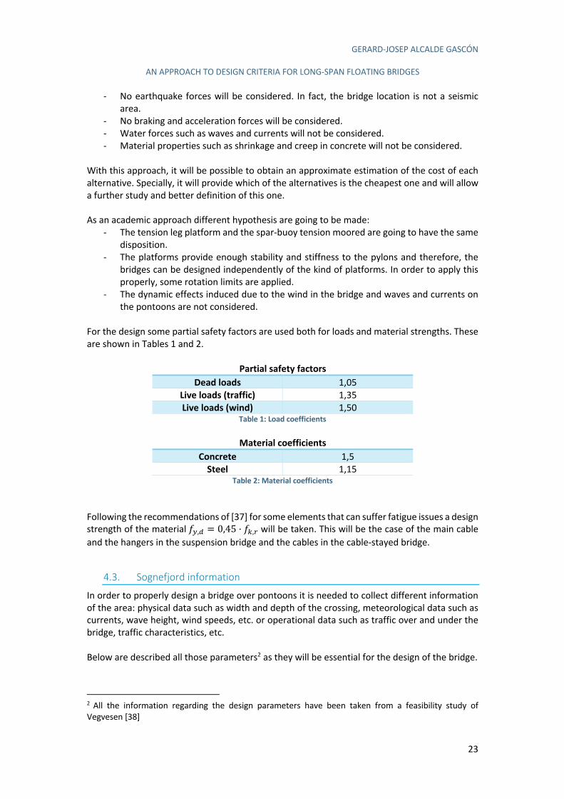
GERARD-JOSEP ALCALDE GASCÓN
AN APPROACH TO DESIGN CRITERIA FOR LONG-SPAN FLOATING BRIDGES
23
- No earthquake forces will be considered. In fact, the bridge location is not a seismic area.
- No braking and acceleration forces will be considered. - Water forces such as waves and currents will not be considered. - Material properties such as shrinkage and creep in concrete will not be considered.
With this approach, it will be possible to obtain an approximate estimation of the cost of each alternative. Specially, it will provide which of the alternatives is the cheapest one and will allow a further study and better definition of this one. As an academic approach different hypothesis are going to be made:
- The tension leg platform and the spar-buoy tension moored are going to have the same disposition.
- The platforms provide enough stability and stiffness to the pylons and therefore, the bridges can be designed independently of the kind of platforms. In order to apply this properly, some rotation limits are applied.
- The dynamic effects induced due to the wind in the bridge and waves and currents on the pontoons are not considered.
For the design some partial safety factors are used both for loads and material strengths. These are shown in Tables 1 and 2.
Partial safety factors
Dead loads 1,05 Live loads (traffic) 1,35 Live loads (wind) 1,50
Table 1: Load coefficients
Material coefficients
Concrete 1,5 Steel 1,15
Table 2: Material coefficients Following the recommendations of [37] for some elements that can suffer fatigue issues a design strength of the material "!,# = 0,45 · "$,% will be taken. This will be the case of the main cable and the hangers in the suspension bridge and the cables in the cable-stayed bridge.
4.3. Sognefjord information
In order to properly design a bridge over pontoons it is needed to collect different information of the area: physical data such as width and depth of the crossing, meteorological data such as currents, wave height, wind speeds, etc. or operational data such as traffic over and under the bridge, traffic characteristics, etc. Below are described all those parameters2 as they will be essential for the design of the bridge.
2 All the information regarding the design parameters have been taken from a feasibility study of
Vegvesen [38]
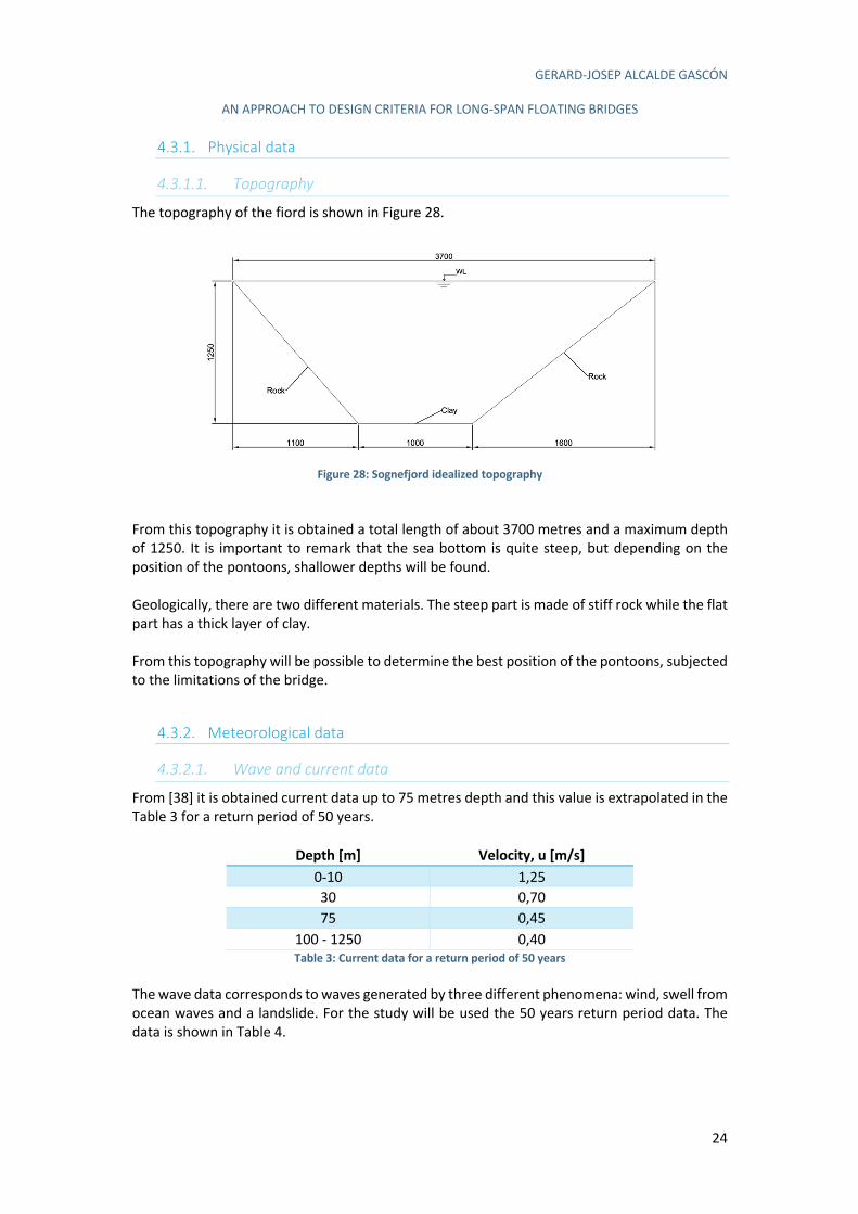
GERARD-JOSEP ALCALDE GASCÓN
AN APPROACH TO DESIGN CRITERIA FOR LONG-SPAN FLOATING BRIDGES
24
4.3.1. Physical data
4.3.1.1. Topography
The topography of the fiord is shown in Figure 28.
Figure 28: Sognefjord idealized topography
From this topography it is obtained a total length of about 3700 metres and a maximum depth of 1250. It is important to remark that the sea bottom is quite steep, but depending on the position of the pontoons, shallower depths will be found. Geologically, there are two different materials. The steep part is made of stiff rock while the flat part has a thick layer of clay. From this topography will be possible to determine the best position of the pontoons, subjected to the limitations of the bridge.
4.3.2. Meteorological data
4.3.2.1. Wave and current data
From [38] it is obtained current data up to 75 metres depth and this value is extrapolated in the Table 3 for a return period of 50 years.
Depth [m] Velocity, u [m/s]
0-10 1,25 30 0,70 75 0,45
100 - 1250 0,40 Table 3: Current data for a return period of 50 years
The wave data corresponds to waves generated by three different phenomena: wind, swell from ocean waves and a landslide. For the study will be used the 50 years return period data. The data is shown in Table 4.
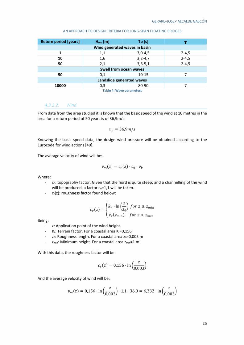
GERARD-JOSEP ALCALDE GASCÓN
AN APPROACH TO DESIGN CRITERIA FOR LONG-SPAN FLOATING BRIDGES
25
Return period [years] Hmo [m] Tp [s] g Wind generated waves in basin
1 1,1 3,0-4,5 2-4,5 10 1,6 3,2-4,7 2-4,5 50 2,1 3,6-5,1 2-4,5
Swell from ocean waves
50 0,1 10-15 7 Landslide generated waves
10000 0,3 80-90 7 Table 4: Wave parameters
4.3.2.2. Wind
From data from the area studied it is known that the basic speed of the wind at 10 metres in the area for a return period of 50 years is of 36,9m/s.
)& = 36,9-// Knowing the basic speed data, the design wind pressure will be obtained according to the Eurocode for wind actions [40]. The average velocity of wind will be:
)'(1) = 3%(1) · 3( · )& Where:
- c0: topography factor. Given that the fiord is quite steep, and a channelling of the wind will be produced, a factor c0=1,1 will be taken.
- cr(z): roughness factor found below:
3%(1) = 45% · ln 8
11(9 ";<1 ≥ 1')*
3%(1+,-)";<1 < 1')*
Being: - z: Application point of the wind height. - Kr: Terrain factor. For a coastal area Kr=0,156 - z0: Roughness length. For a coastal area z0=0,003 m - zmin: Minimum height. For a coastal area zmin=1 m
With this data, the roughness factor will be:
3%(1) = 0,156 · ln 81
0,0039
And the average velocity of wind will be:
)'(1) = 0,156 · ln 81
0,0039· 1,1 · 36,9 = 6,332 · ln 8
10,0039
GERARD-JOSEP ALCALDE GASCÓN
AN APPROACH TO DESIGN CRITERIA FOR LONG-SPAN FLOATING BRIDGES
26
Horizontal wind force (Wind in transversal direction)
The wind force will be found as:
A.,/ = 812· B · )&09 · 31(1) · 32 · C%12
Where:
- 3
0· B · )&0: Pressure of the wind due to its speed [N/m2]
- B: Air density 1,25kg/m3 - Cf: Force coefficient of the element considered. It is computed below. - Aref: Application area of the wind force. It is the area of the solid exposed to the wind
projected on the plane perpendicular to the wind force direction. - ce(z): Exposition coefficient:
31(1) = 5%0 · D3(0 · ln0 811(9 + 7 · 54 · 3( · ln 8
11(9G
Where: - kl: Turbulence factor, for this case 1,0.
Then:
31(1) = 0,1560 · D1,10 · ln0 8700,0039
+ 7 · 1,0 · 1,1 · ln 8700,0039
G = 4,863
And:
A.,/ = 812· 1,25 · 36,909 · 4,863 · 32 · C%12
The force coefficient for the deck will be computed as:
32,/ = 2,5 − 0,3 · JKℎ15
M = 2,5 − 0,3 · 8193 + 29
= 1,36
Where: - heq: Is the equivalent height of the deck, which is 3 metres, but it is necessary to add the
height of the live loads over the bridge, which is defined as 2 metres. - B: Width of the deck, which is 19 metres.
Cf,x is limited to 1,3 ≤ 32,/ ≤ 2,4, with a value of 1,36 is inside this range. For the deck wind force an additional 2 metres have to be added to the Aref due to the effect of the road traffic on the deck. The force on the deck, due to the transversal wind will be:
A.,! = 812· 1,25 · 36,909 · 4,863 · 1,36 · 5 = 28,145O/-
P6,7 = QR, STUV/W
GERARD-JOSEP ALCALDE GASCÓN
AN APPROACH TO DESIGN CRITERIA FOR LONG-SPAN FLOATING BRIDGES
27
In case that there was no traffic, the Aref will be the projected area of the deck added to the parapets, as the parapets are 1,35 metres high, the total Aref will be 4,35 m2. This situation must be taken into account in the ULS combinations in which the bridge will be close to traffic due to an extreme wind event. The transversal wind force for this situation will be:
A.,! = 812· 1,25 · 36,909 · 4,863 · 1,36 · 4,35 = 24,485O/-
P6,7 = QT, TRUV/W
Vertical wind force
This load will be considered upwards or downwards depending on which one is most unfavourable. The vertical wind force will be computed as:
A.,8 = 812· B · )&09 · 31(1) · 32,8 · C%12,8
Where: - Cf,z: Is the force coefficient in the vertical direction, which will be taken as ±0,9
Then, it will be:
A.,8 = 812· 1,25 · 36,909 · 0,1560 · D1,21 · ln0 8
700,0039
+ 7,7 · ln 8700,0039
G · (±0,9) · 19
P6,9 = ±YZ, RZUV/W
Horizontal wind force (Wind in longitudinal direction)
The longitudinal wind force is considered to be a fraction of the transversal wind multiplied by a reduction factor. For a solid deck, as the one designed in this project, it is stablished to have a reduction to the 25% of the transversal wind force plus the reduction factor, which will be:
1 − [7
3( · ln \11(] + 7
^ · _ D`
`(1)G
And
_ D`
`(1)G = 0,230 + 0,182 · ln D
``(1)
G
Where:
- c0: Topography factor. Taken as 1,1; as previously defined. - L: Length where the longitudinal wind is acting. It will be taken as the whole length of
the bridge, 3700 metres. - L(z): Turbulence length, for z=70 metres, it will be:
`(70) = 300 · \1200
]:= 300 · 8
702009
(,;<
= 201,3-
- z: Height of the deck. - a: Coefficient depending on the environment. In this case, a = 0,38
GERARD-JOSEP ALCALDE GASCÓN
AN APPROACH TO DESIGN CRITERIA FOR LONG-SPAN FLOATING BRIDGES
28
Then:
_ D`
`(1)G = 0,230 + 0,182 · ln D
3700201,3
G = 0,760
1 − [7
3( · ln \11(] + 7
^ · _ D`
`(1)G = 1 − b
7
1,1 · ln \ 700,003] + 7
c · 0,760 = 0,705
The wind speed acting on the longitudinal direction is lower than in the transverse direction given the channelling effect produced on the fiord. This added to the quite steep slopes on the sides of the fiord, will make that the wind in the longitudinal direction is much lower. No data has been found related to this magnitude, but as an approximation it will be taken a maximum speed of 20% the speed in the transversal direction, with a maximum longitudinal speed of 7,4m/s. Then the force due to the longitudinal wind will be:
A.,! = 0,705 · 0,25 · 812· 1,25 · 7,409 · 4,863 · 1,36 · 5 = 0,205O/-
P6,= = Z, QZUV/W
Wind forces on the deck summary
Then the forces acting on the deck will be:
P6,= = Z, QZUV/W
P6,7,>?@AABC = QR, STUV/W
P6,7,DE>?@AABC = QT, TRUV/W
P6,9 = ±YZ, RZUV/W
Wind force on the towers
The wind force on the towers will have a longitudinal and a transversal component, depending on the wind direction. For the transverse wind force it will be computed as in the deck but with a force coefficient cf=2,1. Therefore the force on the towers will be:
A.,! = 812· 1,25 · 36,909 · 0,1560 · D1,10 · ln0 8
10,0039
+ 7 · 1,0 · 1,1 · ln 81
0,0039G · 2,1 · C%12
For the longitudinal wind force it will be computed with the same equation shown above, as long as the geometry is exactly the same. Nevertheless, given that the wind in the longitudinal direction is quite lower than in the transversal direction, the same wind speed that was used for the longitudinal wind force on the deck has been taken.
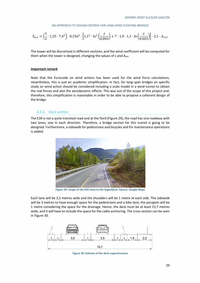
GERARD-JOSEP ALCALDE GASCÓN
AN APPROACH TO DESIGN CRITERIA FOR LONG-SPAN FLOATING BRIDGES
29
A.,/ = 812· 1,25 · 7,409 · 0,1560 · D1,10 · ln0 8
10,0039
+ 7 · 1,0 · 1,1 · ln 81
0,0039G · 2,1 · C%12
The tower will be discretized in different sections, and the wind coefficient will be computed for them when the tower is designed, changing the values of z and Aref. Important remark
Note that the Eurocode on wind actions has been used for the wind force calculations, nevertheless, this is just an academic simplification. In fact, for long span bridges an specific study on wind action should be considered including a scale model in a wind tunnel to obtain the real forces and also the aerodynamic effects. This was out of the scope of this project and, therefore, this simplification is reasonable in order to be able to propose a coherent design of the bridge.
4.3.3. Deck section
The E39 is not a quite transited road and at the fiord (Figure 29), the road has one roadway with two lanes, one in each direction. Therefore, a bridge section for this transit is going to be designed. Furthermore, a sidewalk for pedestrians and bicycles and for maintenance operations is added.
Figure 29: Image of the E39 close to the Sognefjord. Source: Google Maps
Each lane will be 3,5 metres wide and the shoulders will be 1 metre at each side. The sidewalk will be 3 metres to have enough space for the pedestrians and a bike lane, the parapets will be 1 metre considering the space for the drainage. Hence, the deck must be at least 15,7 metres wide, and it will have to include the space for the cable anchoring. The cross section can be seen in Figure 30.
Figure 30: Scheme of the deck superstructure
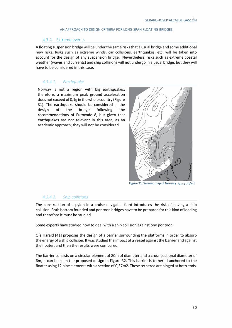
GERARD-JOSEP ALCALDE GASCÓN
AN APPROACH TO DESIGN CRITERIA FOR LONG-SPAN FLOATING BRIDGES
30
4.3.4. Extreme events
A floating suspension bridge will be under the same risks that a usual bridge and some additional new risks. Risks such as extreme winds, car collisions, earthquakes, etc. will be taken into account for the design of any suspension bridge. Nevertheless, risks such as extreme coastal weather (waves and currents) and ship collisions will not undergo in a usual bridge, but they will have to be considered in this case.
4.3.4.1. Earthquake
Norway is not a region with big earthquakes; therefore, a maximum peak ground acceleration does not exceed of 0,1g in the whole country (Figure 31). The earthquake should be considered in the design of the bridge following the recommendations of Eurocode 8, but given that earthquakes are not relevant in this area, as an academic approach, they will not be considered.
Figure 31: Seismic map of Norway. ag40Hz [m/s2]
4.3.4.2. Ship collisions
The construction of a pylon in a cruise navigable fiord introduces the risk of having a ship collision. Both bottom founded and pontoon bridges have to be prepared for this kind of loading and therefore it must be studied. Some experts have studied how to deal with a ship collision against one pontoon. Ole Harald [41] proposes the design of a barrier surrounding the platforms in order to absorb the energy of a ship collision. It was studied the impact of a vessel against the barrier and against the floater, and then the results were compared. The barrier consists on a circular element of 80m of diameter and a cross-sectional diameter of 6m, it can be seen the proposed design in Figure 32. This barrier is tethered anchored to the floater using 12 pipe elements with a section of 0,37m2. These tethered are hinged at both ends.
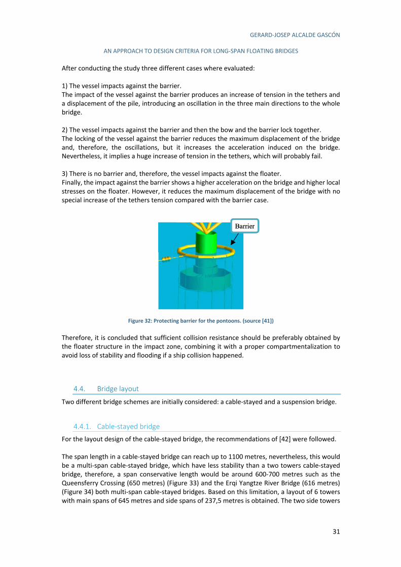
GERARD-JOSEP ALCALDE GASCÓN
AN APPROACH TO DESIGN CRITERIA FOR LONG-SPAN FLOATING BRIDGES
31
After conducting the study three different cases where evaluated: 1) The vessel impacts against the barrier. The impact of the vessel against the barrier produces an increase of tension in the tethers and a displacement of the pile, introducing an oscillation in the three main directions to the whole bridge. 2) The vessel impacts against the barrier and then the bow and the barrier lock together. The locking of the vessel against the barrier reduces the maximum displacement of the bridge and, therefore, the oscillations, but it increases the acceleration induced on the bridge. Nevertheless, it implies a huge increase of tension in the tethers, which will probably fail. 3) There is no barrier and, therefore, the vessel impacts against the floater. Finally, the impact against the barrier shows a higher acceleration on the bridge and higher local stresses on the floater. However, it reduces the maximum displacement of the bridge with no special increase of the tethers tension compared with the barrier case.
Figure 32: Protecting barrier for the pontoons. (source [41])
Therefore, it is concluded that sufficient collision resistance should be preferably obtained by the floater structure in the impact zone, combining it with a proper compartmentalization to avoid loss of stability and flooding if a ship collision happened.
4.4. Bridge layout
Two different bridge schemes are initially considered: a cable-stayed and a suspension bridge.
4.4.1. Cable-stayed bridge
For the layout design of the cable-stayed bridge, the recommendations of [42] were followed. The span length in a cable-stayed bridge can reach up to 1100 metres, nevertheless, this would be a multi-span cable-stayed bridge, which have less stability than a two towers cable-stayed bridge, therefore, a span conservative length would be around 600-700 metres such as the Queensferry Crossing (650 metres) (Figure 33) and the Erqi Yangtze River Bridge (616 metres) (Figure 34) both multi-span cable-stayed bridges. Based on this limitation, a layout of 6 towers with main spans of 645 metres and side spans of 237,5 metres is obtained. The two side towers
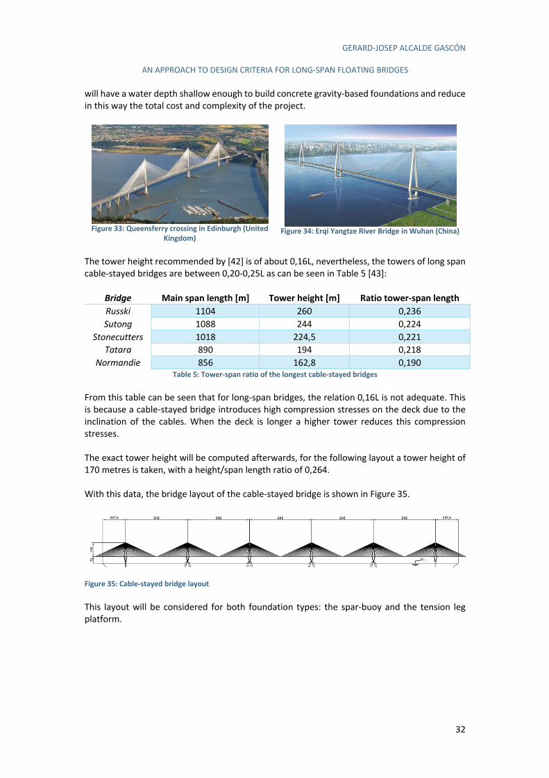
GERARD-JOSEP ALCALDE GASCÓN
AN APPROACH TO DESIGN CRITERIA FOR LONG-SPAN FLOATING BRIDGES
32
will have a water depth shallow enough to build concrete gravity-based foundations and reduce in this way the total cost and complexity of the project.
Figure 33: Queensferry crossing in Edinburgh (United
Kingdom)
Figure 34: Erqi Yangtze River Bridge in Wuhan (China)
The tower height recommended by [42] is of about 0,16L, nevertheless, the towers of long span cable-stayed bridges are between 0,20-0,25L as can be seen in Table 5 [43]:
Bridge Main span length [m] Tower height [m] Ratio tower-span length
Russki 1104 260 0,236 Sutong 1088 244 0,224
Stonecutters 1018 224,5 0,221 Tatara 890 194 0,218
Normandie 856 162,8 0,190 Table 5: Tower-span ratio of the longest cable-stayed bridges
From this table can be seen that for long-span bridges, the relation 0,16L is not adequate. This is because a cable-stayed bridge introduces high compression stresses on the deck due to the inclination of the cables. When the deck is longer a higher tower reduces this compression stresses. The exact tower height will be computed afterwards, for the following layout a tower height of 170 metres is taken, with a height/span length ratio of 0,264. With this data, the bridge layout of the cable-stayed bridge is shown in Figure 35.
Figure 35: Cable-stayed bridge layout This layout will be considered for both foundation types: the spar-buoy and the tension leg platform.

GERARD-JOSEP ALCALDE GASCÓN
AN APPROACH TO DESIGN CRITERIA FOR LONG-SPAN FLOATING BRIDGES
33
4.4.2. Suspension bridge
For the suspension bridge a similar procedure as for the cable-stayed bridge will follow, taking as a reference the recommendations of [42]. Taking as a reference other large three span suspension bridges, a maximum main span length must be placed at about 2000 metres. The relation between the main span and the lateral ones in large three span bridges is about two times larger the main span. Therefore, to cover the fiord with a symmetrical design, a proposal might be a main span of 1905 metres, with lateral spans of 897,5 metres. This would follow the ratio previously mentioned and would be enough to cover the width of the fiord. With respect to the tower’s height [42] stablishes a usual height of about 0,2L. Nevertheless, the tower height must be calculated to be as close as possible to the shape of a funicular curve under the self-weight of the cable and the weight of the deck. Therefore, the tower height will be computed further when the cross section is decided, as the weight of the deck must be considered. In order to propose a first layout of the suspension bridge a tower height of 300 metres is decided. Taking this height, the suspension bridge layout is shown in Figure 36.
Figure 36: Suspension bridge layout This layout will be considered for both the spar-buoy and the tension leg platform.
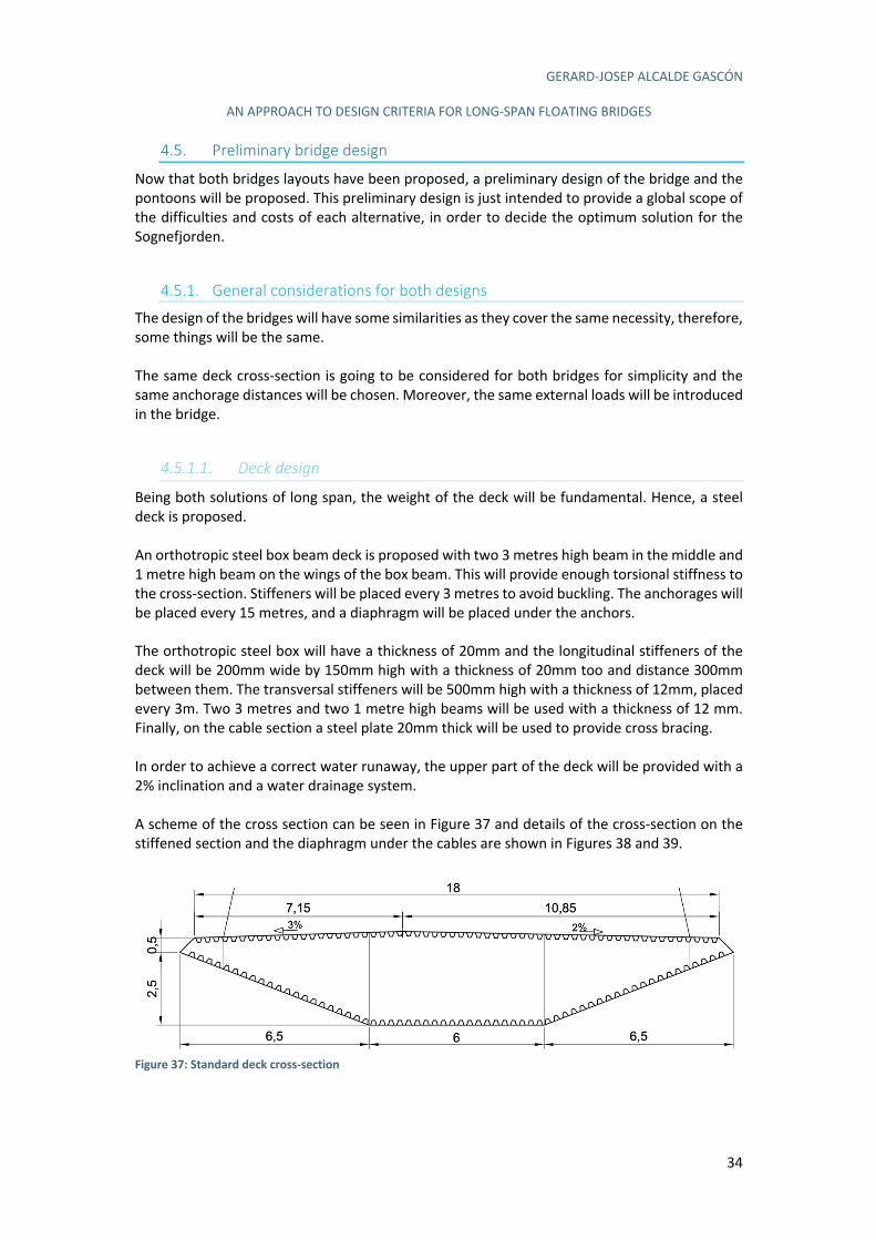
GERARD-JOSEP ALCALDE GASCÓN
AN APPROACH TO DESIGN CRITERIA FOR LONG-SPAN FLOATING BRIDGES
34
4.5. Preliminary bridge design
Now that both bridges layouts have been proposed, a preliminary design of the bridge and the pontoons will be proposed. This preliminary design is just intended to provide a global scope of the difficulties and costs of each alternative, in order to decide the optimum solution for the Sognefjorden.
4.5.1. General considerations for both designs
The design of the bridges will have some similarities as they cover the same necessity, therefore, some things will be the same. The same deck cross-section is going to be considered for both bridges for simplicity and the same anchorage distances will be chosen. Moreover, the same external loads will be introduced in the bridge.
4.5.1.1. Deck design
Being both solutions of long span, the weight of the deck will be fundamental. Hence, a steel deck is proposed. An orthotropic steel box beam deck is proposed with two 3 metres high beam in the middle and 1 metre high beam on the wings of the box beam. This will provide enough torsional stiffness to the cross-section. Stiffeners will be placed every 3 metres to avoid buckling. The anchorages will be placed every 15 metres, and a diaphragm will be placed under the anchors. The orthotropic steel box will have a thickness of 20mm and the longitudinal stiffeners of the deck will be 200mm wide by 150mm high with a thickness of 20mm too and distance 300mm between them. The transversal stiffeners will be 500mm high with a thickness of 12mm, placed every 3m. Two 3 metres and two 1 metre high beams will be used with a thickness of 12 mm. Finally, on the cable section a steel plate 20mm thick will be used to provide cross bracing. In order to achieve a correct water runaway, the upper part of the deck will be provided with a 2% inclination and a water drainage system. A scheme of the cross section can be seen in Figure 37 and details of the cross-section on the stiffened section and the diaphragm under the cables are shown in Figures 38 and 39.
Figure 37: Standard deck cross-section
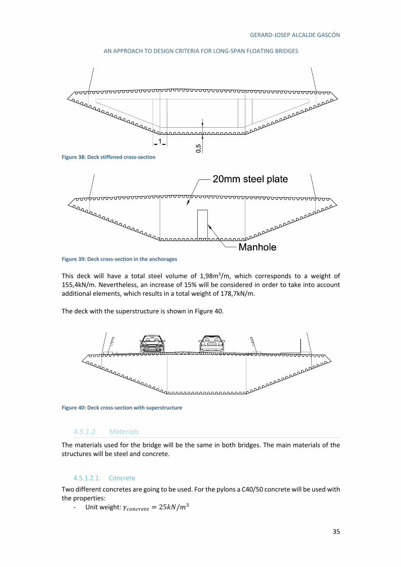
GERARD-JOSEP ALCALDE GASCÓN
AN APPROACH TO DESIGN CRITERIA FOR LONG-SPAN FLOATING BRIDGES
35
Figure 38: Deck stiffened cross-section
Figure 39: Deck cross-section in the anchorages This deck will have a total steel volume of 1,98m3/m, which corresponds to a weight of 155,4kN/m. Nevertheless, an increase of 15% will be considered in order to take into account additional elements, which results in a total weight of 178,7kN/m. The deck with the superstructure is shown in Figure 40.
Figure 40: Deck cross-section with superstructure
4.5.1.2. Materials
The materials used for the bridge will be the same in both bridges. The main materials of the structures will be steel and concrete.
4.5.1.2.1. Concrete
Two different concretes are going to be used. For the pylons a C40/50 concrete will be used with the properties:
- Unit weight: dGH*G%1I1 = 255O/-;
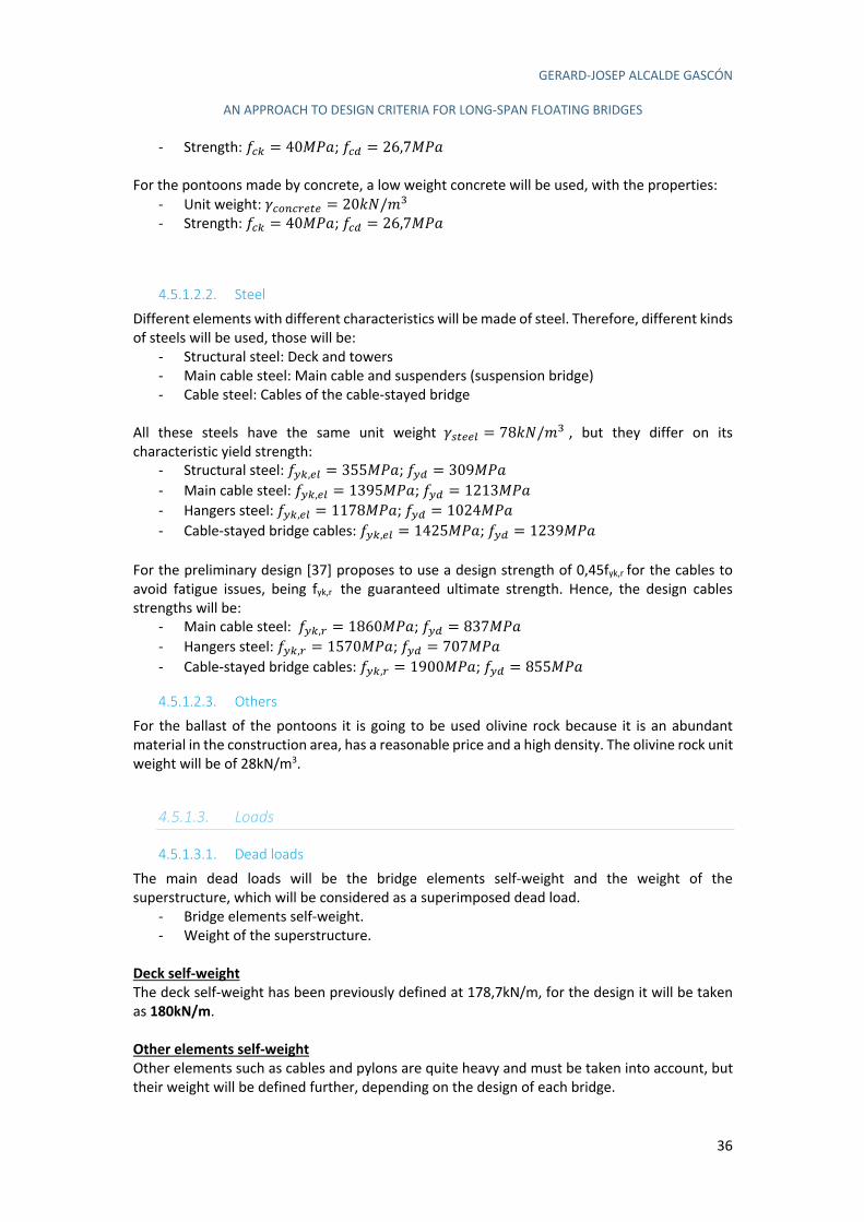
GERARD-JOSEP ALCALDE GASCÓN
AN APPROACH TO DESIGN CRITERIA FOR LONG-SPAN FLOATING BRIDGES
36
- Strength: "G$ = 40efg; "G# = 26,7efg For the pontoons made by concrete, a low weight concrete will be used, with the properties:
- Unit weight: dGH*G%1I1 = 205O/-; - Strength: "G$ = 40efg; "G# = 26,7efg
4.5.1.2.2. Steel
Different elements with different characteristics will be made of steel. Therefore, different kinds of steels will be used, those will be:
- Structural steel: Deck and towers - Main cable steel: Main cable and suspenders (suspension bridge) - Cable steel: Cables of the cable-stayed bridge
All these steels have the same unit weight dJI114 = 785O/-; , but they differ on its characteristic yield strength:
- Structural steel: "!$,14 = 355efg; "!# = 309efg - Main cable steel: "!$,14 = 1395efg; "!# = 1213efg - Hangers steel:"!$,14 = 1178efg; "!# = 1024efg - Cable-stayed bridge cables:"!$,14 = 1425efg; "!# = 1239efg
For the preliminary design [37] proposes to use a design strength of 0,45fyk,r for the cables to avoid fatigue issues, being fyk,r the guaranteed ultimate strength. Hence, the design cables strengths will be:
- Main cable steel: "!$,% = 1860efg; "!# = 837efg - Hangers steel: "!$,% = 1570efg; "!# = 707efg - Cable-stayed bridge cables: "!$,% = 1900efg; "!# = 855efg
4.5.1.2.3. Others
For the ballast of the pontoons it is going to be used olivine rock because it is an abundant material in the construction area, has a reasonable price and a high density. The olivine rock unit weight will be of 28kN/m3.
4.5.1.3. Loads
4.5.1.3.1. Dead loads
The main dead loads will be the bridge elements self-weight and the weight of the superstructure, which will be considered as a superimposed dead load.
- Bridge elements self-weight. - Weight of the superstructure.
Deck self-weight
The deck self-weight has been previously defined at 178,7kN/m, for the design it will be taken as 180kN/m. Other elements self-weight
Other elements such as cables and pylons are quite heavy and must be taken into account, but their weight will be defined further, depending on the design of each bridge.

GERARD-JOSEP ALCALDE GASCÓN
AN APPROACH TO DESIGN CRITERIA FOR LONG-SPAN FLOATING BRIDGES
37
Superstructure weight
The superstructure will be made of different elements: 1. Pavement
In steel bridges where the weight is a key issue, a pavement with a thickness of 20mm can be used. The weight of the pavement will be around 20kN/m3, which will let it in 0,4kN/m2 or 7,6kN/m.
2. Parapets, lights, water drainage system and others Several elements will constitute the superstructure of the bridge and it is quite difficult to consider the weight of all of them. An approximate value of 0,4kN/m2 or 7,6kN/m is considered. This will let a total superimposed dead load of 15,2kN/m.
Deck weight and permanent loads
The load that will be carried by the cables of both bridges will be the correspondent to the deck self-weight and the superstructure. It will be 195,2kN/m. Taking into account the partial safety factors for permanent loads it will be 263,5kN/m.
4.5.1.3.2. Live loads
The live loads on the bridge will correspond to the vehicles, bicycles and people circulating over the bridge. The live loads will be computed following the requirements of the Eurocode on traffic load on bridges [45]. As a simplification only the combination of all the lanes with the distributed load will be considered. Given that the width of the road, 10 metres, 3 virtual lanes must be considered. Therefore, the main lane will have a distributed load of 9kN/m2, and the other two lanes will carry a load of 2,5kN/m2. The sidewalk will carry a load of 5kN/m2. This gives a total live load on the deck of 52kN/m. Taking into account the load coefficients it will be 78kN/m. The other elements of the bridge will depend on the solution chosen, cable-stayed or suspension, and therefore they will be developed separately.
4.5.1.3.3. Wind loads
The wind loads have been previously computed for the deck, as a summary, the forces obtained are shown below. Due to transversal wind the loads are:
P6,7 = QR, TQUV/W
The vertical load on the deck will be: P6,9 = ±YZ, RZUV/W
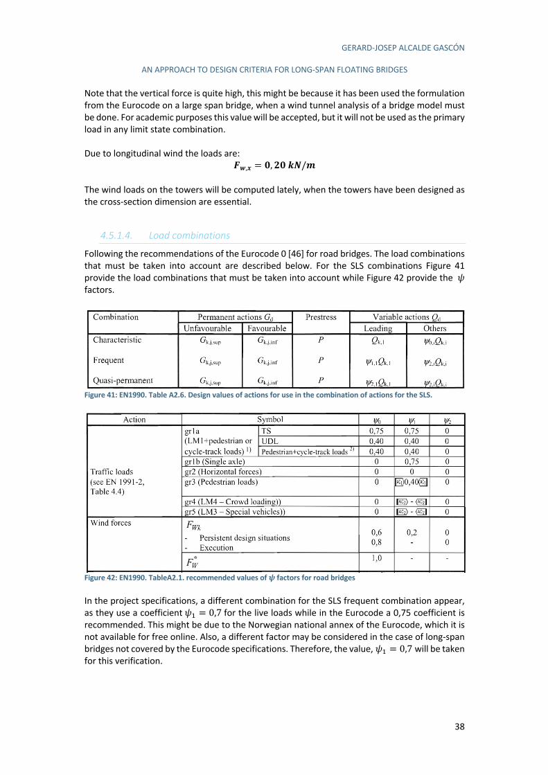
GERARD-JOSEP ALCALDE GASCÓN
AN APPROACH TO DESIGN CRITERIA FOR LONG-SPAN FLOATING BRIDGES
38
Note that the vertical force is quite high, this might be because it has been used the formulation from the Eurocode on a large span bridge, when a wind tunnel analysis of a bridge model must be done. For academic purposes this value will be accepted, but it will not be used as the primary load in any limit state combination. Due to longitudinal wind the loads are:
P6,= = Z, QZUV/W
The wind loads on the towers will be computed lately, when the towers have been designed as the cross-section dimension are essential.
4.5.1.4. Load combinations
Following the recommendations of the Eurocode 0 [46] for road bridges. The load combinations that must be taken into account are described below. For the SLS combinations Figure 41 provide the load combinations that must be taken into account while Figure 42 provide the h
factors.
Figure 41: EN1990. Table A2.6. Design values of actions for use in the combination of actions for the SLS.
Figure 42: EN1990. TableA2.1. recommended values of ! factors for road bridges In the project specifications, a different combination for the SLS frequent combination appear, as they use a coefficient h3 = 0,7 for the live loads while in the Eurocode a 0,75 coefficient is recommended. This might be due to the Norwegian national annex of the Eurocode, which it is not available for free online. Also, a different factor may be considered in the case of long-span bridges not covered by the Eurocode specifications. Therefore, the value, h3 = 0,7 will be taken for this verification.
GERARD-JOSEP ALCALDE GASCÓN
AN APPROACH TO DESIGN CRITERIA FOR LONG-SPAN FLOATING BRIDGES
39
The Eurocode 0 says that the longitudinal and transversal wind forces are due to the wind blowing in different directions and, normally, they are not simultaneous. Nevertheless, the vertical wind can result from the wind blowing in a wide range of directions and it must be considered acting simultaneously with any of the other two forces if it is unfavourable and considerable. For this bridge, the vertical wind is considerable, and as it must be considered upwards and downwards it will be unfavourable. Therefore, the combinations including wind will be always longitudinal and vertical wind or transversal and vertical wind. Then the SLS combinations considered are:
- SLS_1: DL + SIDL + LL - SLS_2: DL + SIDL + (WT + WV) - SLS_3: DL + SIDL + (WL + WV) - SLS_4: DL + SIDL + 0,7LL - SLS_5: DL + SIDL + 0,2 (WT + WV) - SLS_6: DL + SIDL + 0,2 (WL + WV) - SLS_7: DL + SIDL
Where:
- DL: Dead Loads. Correspond to the self-weight of the deck. - SIDL: Super Imposed Dead Load. Correspond to the weight of the superstructure
elements such as the pavement and the parapets among others. - LL: Live loads. Correspond to the traffic, cyclists and pedestrian loads. - Wi: Wind loads. Correspond to the wind force acting on the towers and deck. The sub
index makes reference to the direction of the wind, being “T” for transversal wind, “L” for longitudinal wind and “V” for vertical wind.
SLS_1, SLS_2 and SLS_3 correspond to the characteristic combinations, SLS_4, SLS_5 and SLS_6 correspond to the frequent load combinations and SLS_7 correspond to the quasi-permanent load combination. Note that in SLS_1 the wind loads must be considered with a h3 = 0,6, and in SLS_2 and SLS_3, the live loads must be considered with a h3 = 0,75. Nevertheless, it has only been considered the leading variables, this is because the bridges designed are out of the scope of the Eurocode as they are long-span singular bridges. The recommendations of the Eurocode have been followed, but some modifications have been applied given the singularity of the project. As for example, not consider the simultaneous effect of the wind and the live loads in the whole span, as they will seldom occur. For the ULS combinations Figure 43 provide the necessary combinations and the d values.
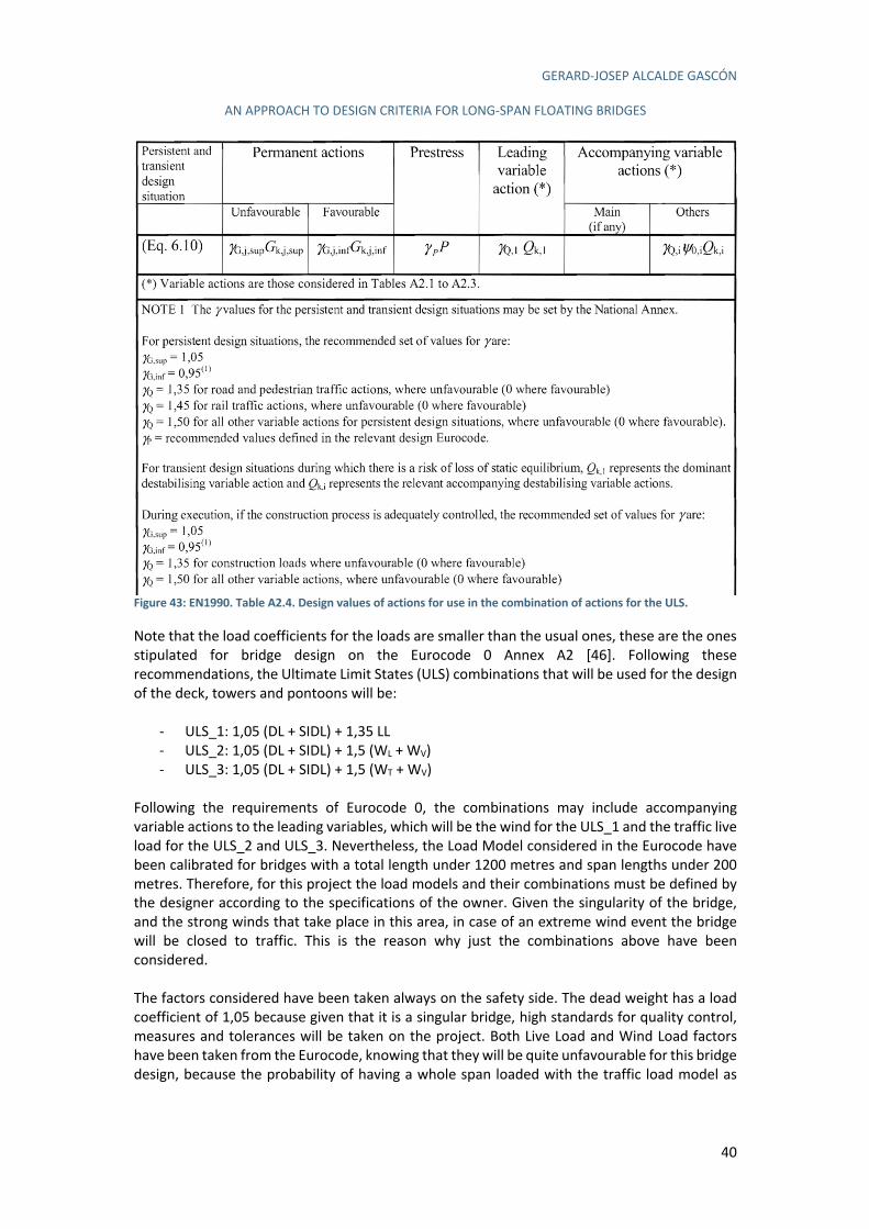
GERARD-JOSEP ALCALDE GASCÓN
AN APPROACH TO DESIGN CRITERIA FOR LONG-SPAN FLOATING BRIDGES
40
Figure 43: EN1990. Table A2.4. Design values of actions for use in the combination of actions for the ULS. Note that the load coefficients for the loads are smaller than the usual ones, these are the ones stipulated for bridge design on the Eurocode 0 Annex A2 [46]. Following these recommendations, the Ultimate Limit States (ULS) combinations that will be used for the design of the deck, towers and pontoons will be:
- ULS_1: 1,05 (DL + SIDL) + 1,35 LL - ULS_2: 1,05 (DL + SIDL) + 1,5 (WL + WV) - ULS_3: 1,05 (DL + SIDL) + 1,5 (WT + WV)
Following the requirements of Eurocode 0, the combinations may include accompanying variable actions to the leading variables, which will be the wind for the ULS_1 and the traffic live load for the ULS_2 and ULS_3. Nevertheless, the Load Model considered in the Eurocode have been calibrated for bridges with a total length under 1200 metres and span lengths under 200 metres. Therefore, for this project the load models and their combinations must be defined by the designer according to the specifications of the owner. Given the singularity of the bridge, and the strong winds that take place in this area, in case of an extreme wind event the bridge will be closed to traffic. This is the reason why just the combinations above have been considered. The factors considered have been taken always on the safety side. The dead weight has a load coefficient of 1,05 because given that it is a singular bridge, high standards for quality control, measures and tolerances will be taken on the project. Both Live Load and Wind Load factors have been taken from the Eurocode, knowing that they will be quite unfavourable for this bridge design, because the probability of having a whole span loaded with the traffic load model as
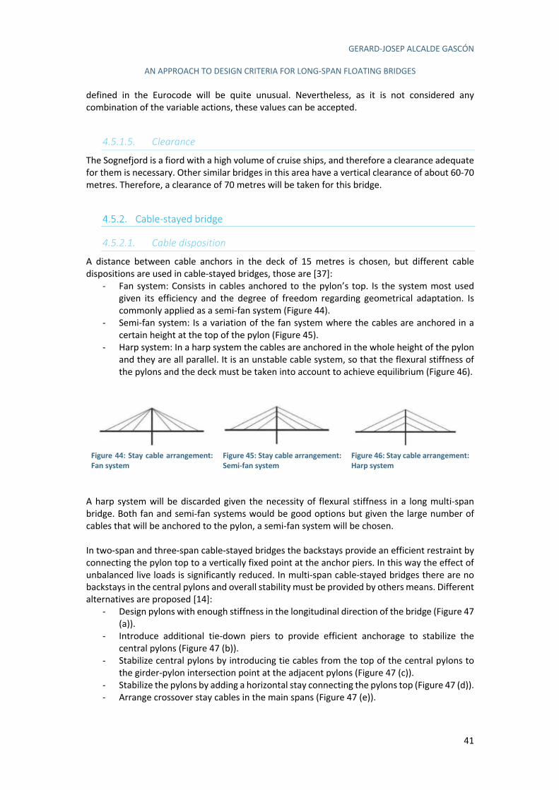
GERARD-JOSEP ALCALDE GASCÓN
AN APPROACH TO DESIGN CRITERIA FOR LONG-SPAN FLOATING BRIDGES
41
defined in the Eurocode will be quite unusual. Nevertheless, as it is not considered any combination of the variable actions, these values can be accepted.
4.5.1.5. Clearance
The Sognefjord is a fiord with a high volume of cruise ships, and therefore a clearance adequate for them is necessary. Other similar bridges in this area have a vertical clearance of about 60-70 metres. Therefore, a clearance of 70 metres will be taken for this bridge.
4.5.2. Cable-stayed bridge
4.5.2.1. Cable disposition
A distance between cable anchors in the deck of 15 metres is chosen, but different cable dispositions are used in cable-stayed bridges, those are [37]:
- Fan system: Consists in cables anchored to the pylon’s top. Is the system most used given its efficiency and the degree of freedom regarding geometrical adaptation. Is commonly applied as a semi-fan system (Figure 44).
- Semi-fan system: Is a variation of the fan system where the cables are anchored in a certain height at the top of the pylon (Figure 45).
- Harp system: In a harp system the cables are anchored in the whole height of the pylon and they are all parallel. It is an unstable cable system, so that the flexural stiffness of the pylons and the deck must be taken into account to achieve equilibrium (Figure 46).
Figure 44: Stay cable arrangement: Fan system
Figure 45: Stay cable arrangement: Semi-fan system
Figure 46: Stay cable arrangement: Harp system
A harp system will be discarded given the necessity of flexural stiffness in a long multi-span bridge. Both fan and semi-fan systems would be good options but given the large number of cables that will be anchored to the pylon, a semi-fan system will be chosen. In two-span and three-span cable-stayed bridges the backstays provide an efficient restraint by connecting the pylon top to a vertically fixed point at the anchor piers. In this way the effect of unbalanced live loads is significantly reduced. In multi-span cable-stayed bridges there are no backstays in the central pylons and overall stability must be provided by others means. Different alternatives are proposed [14]:
- Design pylons with enough stiffness in the longitudinal direction of the bridge (Figure 47 (a)).
- Introduce additional tie-down piers to provide efficient anchorage to stabilize the central pylons (Figure 47 (b)).
- Stabilize central pylons by introducing tie cables from the top of the central pylons to the girder-pylon intersection point at the adjacent pylons (Figure 47 (c)).
- Stabilize the pylons by adding a horizontal stay connecting the pylons top (Figure 47 (d)). - Arrange crossover stay cables in the main spans (Figure 47 (e)).
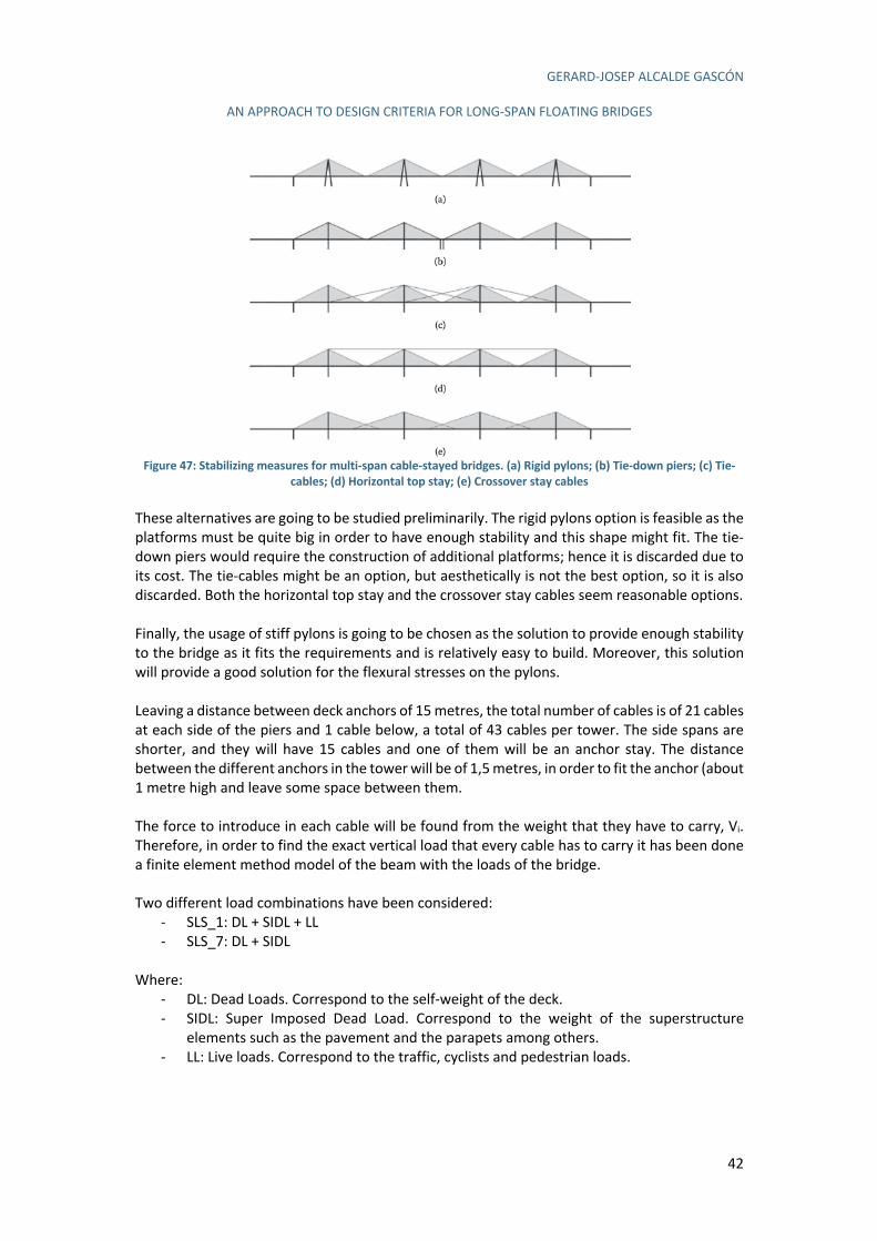
GERARD-JOSEP ALCALDE GASCÓN
AN APPROACH TO DESIGN CRITERIA FOR LONG-SPAN FLOATING BRIDGES
42
Figure 47: Stabilizing measures for multi-span cable-stayed bridges. (a) Rigid pylons; (b) Tie-down piers; (c) Tie-
cables; (d) Horizontal top stay; (e) Crossover stay cables These alternatives are going to be studied preliminarily. The rigid pylons option is feasible as the platforms must be quite big in order to have enough stability and this shape might fit. The tie-down piers would require the construction of additional platforms; hence it is discarded due to its cost. The tie-cables might be an option, but aesthetically is not the best option, so it is also discarded. Both the horizontal top stay and the crossover stay cables seem reasonable options. Finally, the usage of stiff pylons is going to be chosen as the solution to provide enough stability to the bridge as it fits the requirements and is relatively easy to build. Moreover, this solution will provide a good solution for the flexural stresses on the pylons. Leaving a distance between deck anchors of 15 metres, the total number of cables is of 21 cables at each side of the piers and 1 cable below, a total of 43 cables per tower. The side spans are shorter, and they will have 15 cables and one of them will be an anchor stay. The distance between the different anchors in the tower will be of 1,5 metres, in order to fit the anchor (about 1 metre high and leave some space between them. The force to introduce in each cable will be found from the weight that they have to carry, Vi. Therefore, in order to find the exact vertical load that every cable has to carry it has been done a finite element method model of the beam with the loads of the bridge. Two different load combinations have been considered:
- SLS_1: DL + SIDL + LL - SLS_7: DL + SIDL
Where:
- DL: Dead Loads. Correspond to the self-weight of the deck. - SIDL: Super Imposed Dead Load. Correspond to the weight of the superstructure
elements such as the pavement and the parapets among others. - LL: Live loads. Correspond to the traffic, cyclists and pedestrian loads.

GERARD-JOSEP ALCALDE GASCÓN
AN APPROACH TO DESIGN CRITERIA FOR LONG-SPAN FLOATING BRIDGES
43
Following the recommendations of [37], as it is a preliminary design, the design strength of the materials has been as 0,45fyk,r. For the tensioning of the cables the combination SLS_7 has been considered, with this a minimum deflection of the deck under self-weight is achieved. For the cable dimensioning the combination SLS_1 has been considered, as they must be dimensioned for the maximum load that will happen in the bridge. Note that it is an SLS combination, instead of a ULS because the characteristic strength of the steel has been reduced to its 45%. This analysis has been done using the software SAP2000 and we get as a result a reaction of 2928kN for the SLS_7 combination (Figure 48) and 3708kN for the SLS_1 combination (Figure 49) on the intermediate spans, which will be used for all the cables. As there are two planes of cables, these loads will be distributed equally on them giving a vertical reaction on the cables of 1464kN and 1854kN respectively. Note that the results at the extremes of the beam have been discarded given that they do not represent the behaviour of the spans that we are studying in this project. The bridge will start in an approximation span, and therefore, the first span studied in this project will have a similar behaviour to the results in the middle. In the following figure can be seen the results from the model.
Figure 48: Vertical reaction at the cables for SLS_7. FEM model
Figure 49: Vertical reaction at the cables for SLS_1. FEM model Each cable will have a different angle, a, depending on the height of its anchor, hi,anchor, and the horizontal displacement, xi,anchor:
a) = arctan Jℎ),K*GLH%m),K*GLH%
M
With this angle found, the tension in each cable, Ti, will be:
n) =o)
sin(a))
And the horizontal force, Hi, will be:
r) =o)
tan(a))
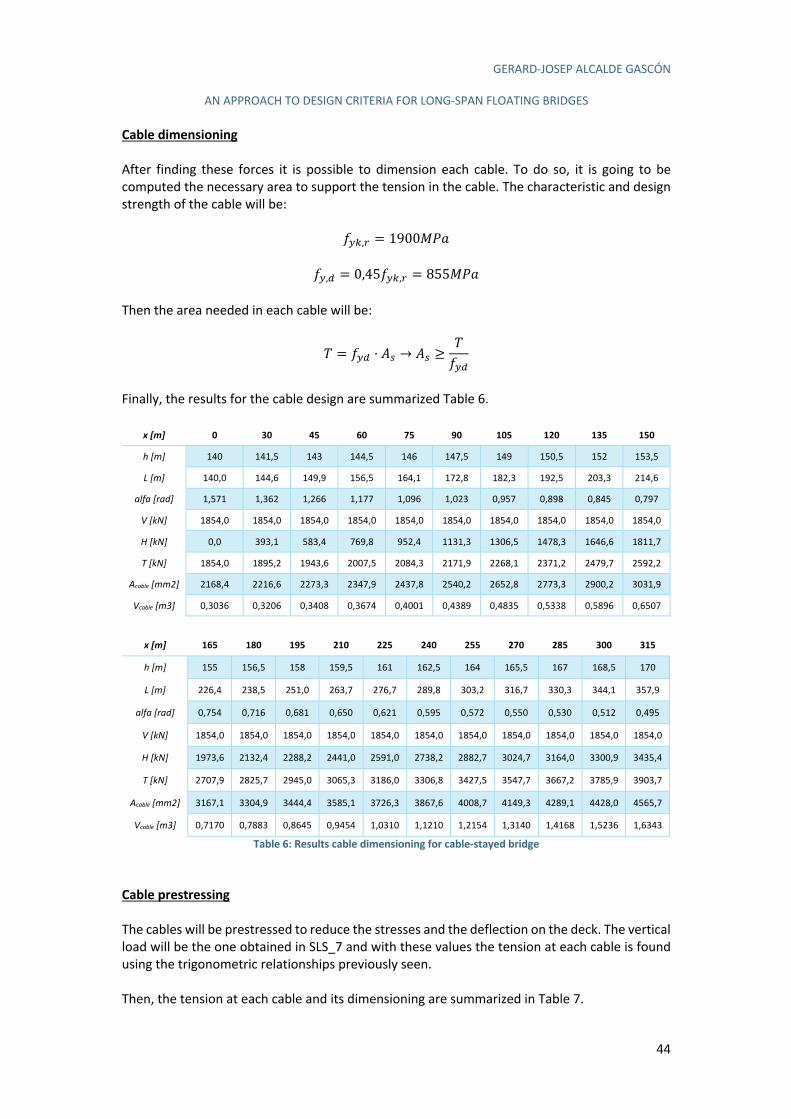
GERARD-JOSEP ALCALDE GASCÓN
AN APPROACH TO DESIGN CRITERIA FOR LONG-SPAN FLOATING BRIDGES
44
Cable dimensioning
After finding these forces it is possible to dimension each cable. To do so, it is going to be computed the necessary area to support the tension in the cable. The characteristic and design strength of the cable will be:
"!$,% = 1900efg
"!,# = 0,45"!$,% = 855efg Then the area needed in each cable will be:
n = "!# · CJ → CJ ≥n"!#
Finally, the results for the cable design are summarized Table 6.
x [m] 0 30 45 60 75 90 105 120 135 150
h [m] 140 141,5 143 144,5 146 147,5 149 150,5 152 153,5
L [m] 140,0 144,6 149,9 156,5 164,1 172,8 182,3 192,5 203,3 214,6
alfa [rad] 1,571 1,362 1,266 1,177 1,096 1,023 0,957 0,898 0,845 0,797
V [kN] 1854,0 1854,0 1854,0 1854,0 1854,0 1854,0 1854,0 1854,0 1854,0 1854,0
H [kN] 0,0 393,1 583,4 769,8 952,4 1131,3 1306,5 1478,3 1646,6 1811,7
T [kN] 1854,0 1895,2 1943,6 2007,5 2084,3 2171,9 2268,1 2371,2 2479,7 2592,2
Acable [mm2] 2168,4 2216,6 2273,3 2347,9 2437,8 2540,2 2652,8 2773,3 2900,2 3031,9
Vcable [m3] 0,3036 0,3206 0,3408 0,3674 0,4001 0,4389 0,4835 0,5338 0,5896 0,6507
x [m] 165 180 195 210 225 240 255 270 285 300 315
h [m] 155 156,5 158 159,5 161 162,5 164 165,5 167 168,5 170
L [m] 226,4 238,5 251,0 263,7 276,7 289,8 303,2 316,7 330,3 344,1 357,9
alfa [rad] 0,754 0,716 0,681 0,650 0,621 0,595 0,572 0,550 0,530 0,512 0,495
V [kN] 1854,0 1854,0 1854,0 1854,0 1854,0 1854,0 1854,0 1854,0 1854,0 1854,0 1854,0
H [kN] 1973,6 2132,4 2288,2 2441,0 2591,0 2738,2 2882,7 3024,7 3164,0 3300,9 3435,4
T [kN] 2707,9 2825,7 2945,0 3065,3 3186,0 3306,8 3427,5 3547,7 3667,2 3785,9 3903,7
Acable [mm2] 3167,1 3304,9 3444,4 3585,1 3726,3 3867,6 4008,7 4149,3 4289,1 4428,0 4565,7
Vcable [m3] 0,7170 0,7883 0,8645 0,9454 1,0310 1,1210 1,2154 1,3140 1,4168 1,5236 1,6343
Table 6: Results cable dimensioning for cable-stayed bridge
Cable prestressing
The cables will be prestressed to reduce the stresses and the deflection on the deck. The vertical load will be the one obtained in SLS_7 and with these values the tension at each cable is found using the trigonometric relationships previously seen. Then, the tension at each cable and its dimensioning are summarized in Table 7.
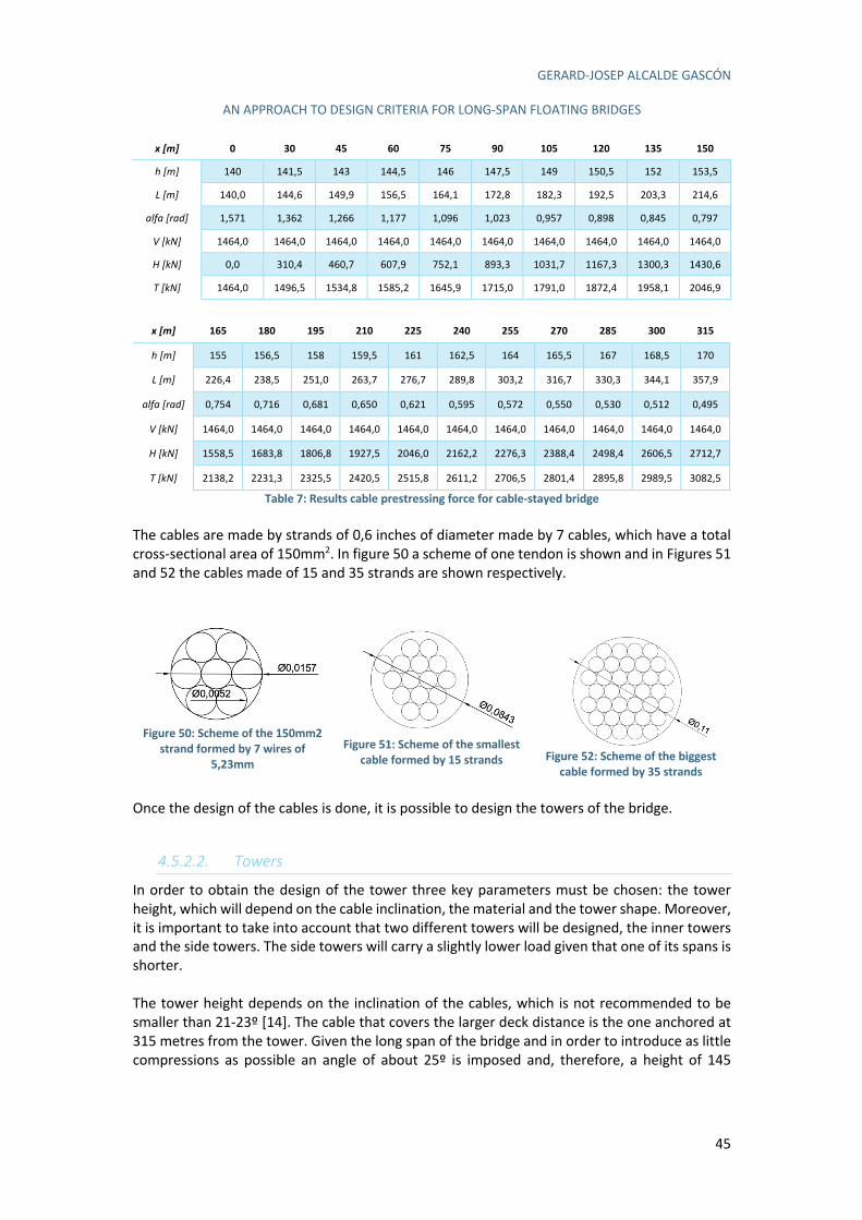
GERARD-JOSEP ALCALDE GASCÓN
AN APPROACH TO DESIGN CRITERIA FOR LONG-SPAN FLOATING BRIDGES
45
x [m] 0 30 45 60 75 90 105 120 135 150
h [m] 140 141,5 143 144,5 146 147,5 149 150,5 152 153,5
L [m] 140,0 144,6 149,9 156,5 164,1 172,8 182,3 192,5 203,3 214,6
alfa [rad] 1,571 1,362 1,266 1,177 1,096 1,023 0,957 0,898 0,845 0,797
V [kN] 1464,0 1464,0 1464,0 1464,0 1464,0 1464,0 1464,0 1464,0 1464,0 1464,0
H [kN] 0,0 310,4 460,7 607,9 752,1 893,3 1031,7 1167,3 1300,3 1430,6
T [kN] 1464,0 1496,5 1534,8 1585,2 1645,9 1715,0 1791,0 1872,4 1958,1 2046,9
x [m] 165 180 195 210 225 240 255 270 285 300 315
h [m] 155 156,5 158 159,5 161 162,5 164 165,5 167 168,5 170
L [m] 226,4 238,5 251,0 263,7 276,7 289,8 303,2 316,7 330,3 344,1 357,9
alfa [rad] 0,754 0,716 0,681 0,650 0,621 0,595 0,572 0,550 0,530 0,512 0,495
V [kN] 1464,0 1464,0 1464,0 1464,0 1464,0 1464,0 1464,0 1464,0 1464,0 1464,0 1464,0
H [kN] 1558,5 1683,8 1806,8 1927,5 2046,0 2162,2 2276,3 2388,4 2498,4 2606,5 2712,7
T [kN] 2138,2 2231,3 2325,5 2420,5 2515,8 2611,2 2706,5 2801,4 2895,8 2989,5 3082,5
Table 7: Results cable prestressing force for cable-stayed bridge The cables are made by strands of 0,6 inches of diameter made by 7 cables, which have a total cross-sectional area of 150mm2. In figure 50 a scheme of one tendon is shown and in Figures 51 and 52 the cables made of 15 and 35 strands are shown respectively.
Figure 50: Scheme of the 150mm2
strand formed by 7 wires of 5,23mm
Figure 51: Scheme of the smallest
cable formed by 15 strands
Figure 52: Scheme of the biggest cable formed by 35 strands
Once the design of the cables is done, it is possible to design the towers of the bridge.
4.5.2.2. Towers
In order to obtain the design of the tower three key parameters must be chosen: the tower height, which will depend on the cable inclination, the material and the tower shape. Moreover, it is important to take into account that two different towers will be designed, the inner towers and the side towers. The side towers will carry a slightly lower load given that one of its spans is shorter. The tower height depends on the inclination of the cables, which is not recommended to be smaller than 21-23º [14]. The cable that covers the larger deck distance is the one anchored at 315 metres from the tower. Given the long span of the bridge and in order to introduce as little compressions as possible an angle of about 25º is imposed and, therefore, a height of 145
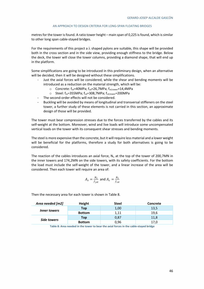
GERARD-JOSEP ALCALDE GASCÓN
AN APPROACH TO DESIGN CRITERIA FOR LONG-SPAN FLOATING BRIDGES
46
metres for the tower is found. A ratio tower height – main span of 0,225 is found, which is similar to other long span cable-stayed bridges. For the requirements of this project a l shaped pylons are suitable, this shape will be provided both in the cross section and in the side view, providing enough stiffness to the bridge. Below the deck, the tower will close the tower columns, providing a diamond shape, that will end up in the platform. Some simplifications are going to be introduced in this preliminary design, when an alternative will be decided, then it will be designed without these simplifications.
- Just the axial forces will be considered, while the shear and bending moments will be introduced as a reduction on the material strength, which will be:
o Concrete: fck=40MPa; fcd=26,7MPa; fcd,tower=14,4MPa o Steel: fck=355MPa; fcd=308,7MPa; fcd,tower=200MPa
- The second-order effects will not be considered. - Buckling will be avoided by means of longitudinal and transversal stiffeners on the steel
tower, a further study of these elements is not carried in this section, an approximate design of those will be provided.
The tower must bear compression stresses due to the forces transferred by the cables and its self-weight at the bottom. Moreover, wind and live loads will introduce some uncompensated vertical loads on the tower with its consequent shear stresses and bending moments. The steel is more expensive than the concrete, but it will require less material and a lower weight will be beneficial for the platforms, therefore a study for both alternatives is going to be considered. The reaction of the cables introduces an axial force, Ni, at the top of the tower of 200,7MN in the inner towers and 174,2MN on the side towers, with its safety coefficients. For the bottom the load must include the self-weight of the tower, and a linear increase of the area will be considered. Then each tower will require an area of:
CJ =M!2"#
and CG =M!2$#
Then the necessary area for each tower is shown in Table 8.
Area needed [m2] Height Steel Concrete
Inner towers Top 1,00 13,5 Bottom 1,11 19,6
Side towers Top 0,87 11,8 Bottom 0,96 17,0
Table 8: Area needed in the tower to bear the axial forces in the cable-stayed bridge
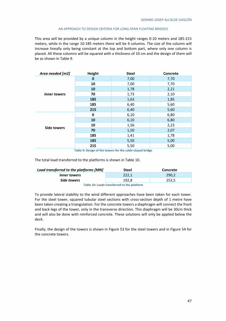
GERARD-JOSEP ALCALDE GASCÓN
AN APPROACH TO DESIGN CRITERIA FOR LONG-SPAN FLOATING BRIDGES
47
This area will be provided by a unique column in the height ranges 0-10 meters and 185-215 meters, while in the range 10-185 meters there will be 4 columns. The size of the column will increase lineally only being constant at the top and bottom part, where only one column is placed. All these columns will be squared with a thickness of 10 cm and the design of them will be as shown in Table 9.
Area needed [m2] Height Steel Concrete
Inner towers
0 7,00 7,70 10 7,00 7,70 10 1,78 2,21 70 1,73 2,10
185 1,63 1,85 185 6,40 5,60 215 6,40 5,60
Side towers
0 6,10 6,80 10 6,10 6,80 10 1,56 2,23 70 1,50 2,07
185 1,41 1,78 185 5,50 5,00 215 5,50 5,00
Table 9: Design of the towers for the cable-stayed bridge The total load transferred to the platforms is shown in Table 10.
Load transferred to the platforms [MN] Steel Concrete
Inner towers 222,1 290,2 Side towers 192,8 252,5
Table 10: Loads transferred to the platform To provide lateral stability to the wind different approaches have been taken for each tower. For the steel tower, squared tubular steel sections with cross-section depth of 1 metre have been taken creating a triangulation. For the concrete towers a diaphragm will connect the front and back legs of the tower, only in the transverse direction. This diaphragm will be 30cm thick and will also be done with reinforced concrete. These solutions will only be applied below the deck. Finally, the design of the towers is shown in Figure 53 for the steel towers and in Figure 54 for the concrete towers.
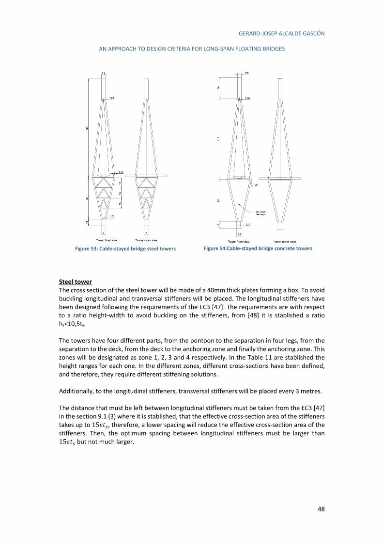
GERARD-JOSEP ALCALDE GASCÓN
AN APPROACH TO DESIGN CRITERIA FOR LONG-SPAN FLOATING BRIDGES
48
Figure 53: Cable-stayed bridge steel towers
Figure 54:Cable-stayed bridge concrete towers
Steel tower
The cross section of the steel tower will be made of a 40mm thick plates forming a box. To avoid buckling longitudinal and transversal stiffeners will be placed. The longitudinal stiffeners have been designed following the requirements of the EC3 [47]. The requirements are with respect to a ratio height-width to avoid buckling on the stiffeners, from [48] it is stablished a ratio hs<10,5ts. The towers have four different parts, from the pontoon to the separation in four legs, from the separation to the deck, from the deck to the anchoring zone and finally the anchoring zone. This zones will be designated as zone 1, 2, 3 and 4 respectively. In the Table 11 are stablished the height ranges for each one. In the different zones, different cross-sections have been defined, and therefore, they require different stiffening solutions. Additionally, to the longitudinal stiffeners, transversal stiffeners will be placed every 3 metres. The distance that must be left between longitudinal stiffeners must be taken from the EC3 [47] in the section 9.1 (3) where it is stablished, that the effective cross-section area of the stiffeners takes up to 15tuJ, therefore, a lower spacing will reduce the effective cross-section area of the stiffeners. Then, the optimum spacing between longitudinal stiffeners must be larger than 15tuJ but not much larger.
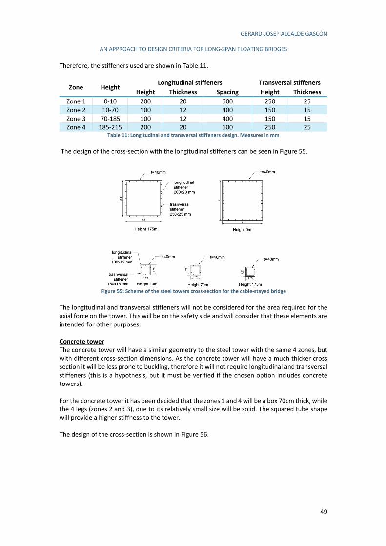
GERARD-JOSEP ALCALDE GASCÓN
AN APPROACH TO DESIGN CRITERIA FOR LONG-SPAN FLOATING BRIDGES
49
Therefore, the stiffeners used are shown in Table 11.
Zone Height Longitudinal stiffeners Transversal stiffeners
Height Thickness Spacing Height Thickness
Zone 1 0-10 200 20 600 250 25 Zone 2 10-70 100 12 400 150 15 Zone 3 70-185 100 12 400 150 15 Zone 4 185-215 200 20 600 250 25
Table 11: Longitudinal and transversal stiffeners design. Measures in mm The design of the cross-section with the longitudinal stiffeners can be seen in Figure 55.
Figure 55: Scheme of the steel towers cross-section for the cable-stayed bridge
The longitudinal and transversal stiffeners will not be considered for the area required for the axial force on the tower. This will be on the safety side and will consider that these elements are intended for other purposes. Concrete tower
The concrete tower will have a similar geometry to the steel tower with the same 4 zones, but with different cross-section dimensions. As the concrete tower will have a much thicker cross section it will be less prone to buckling, therefore it will not require longitudinal and transversal stiffeners (this is a hypothesis, but it must be verified if the chosen option includes concrete towers). For the concrete tower it has been decided that the zones 1 and 4 will be a box 70cm thick, while the 4 legs (zones 2 and 3), due to its relatively small size will be solid. The squared tube shape will provide a higher stiffness to the tower. The design of the cross-section is shown in Figure 56.
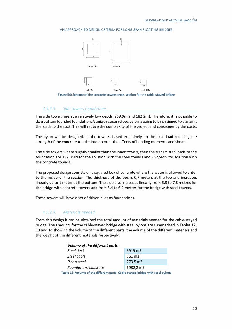
GERARD-JOSEP ALCALDE GASCÓN
AN APPROACH TO DESIGN CRITERIA FOR LONG-SPAN FLOATING BRIDGES
50
Figure 56: Scheme of the concrete towers cross-section for the cable-stayed bridge
4.5.2.3. Side towers foundations
The side towers are at a relatively low depth (269,9m and 182,2m). Therefore, it is possible to do a bottom founded foundation. A unique squared box pylon is going to be designed to transmit the loads to the rock. This will reduce the complexity of the project and consequently the costs. The pylon will be designed, as the towers, based exclusively on the axial load reducing the strength of the concrete to take into account the effects of bending moments and shear. The side towers where slightly smaller than the inner towers, then the transmitted loads to the foundation are 192,8MN for the solution with the steel towers and 252,5MN for solution with the concrete towers. The proposed design consists on a squared box of concrete where the water is allowed to enter to the inside of the section. The thickness of the box is 0,7 meters at the top and increases linearly up to 1 meter at the bottom. The side also increases linearly from 6,8 to 7,8 metres for the bridge with concrete towers and from 5,4 to 6,2 metres for the bridge with steel towers. These towers will have a set of driven piles as foundations.
4.5.2.4. Materials needed
From this design it can be obtained the total amount of materials needed for the cable-stayed bridge. The amounts for the cable-stayed bridge with steel pylons are summarized in Tables 12, 13 and 14 showing the volume of the different parts, the volume of the different materials and the weight of the different materials respectively.
Volume of the different parts Steel deck 6919 m3 Steel cable 361 m3 Pylon steel 773,5 m3 Foundations concrete 6982,2 m3
Table 12: Volume of the different parts. Cable-stayed bridge with steel pylons
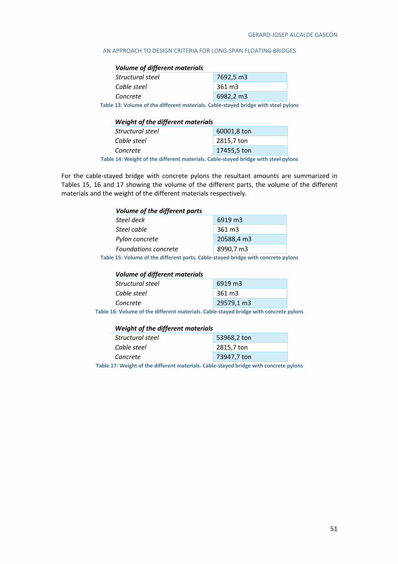
GERARD-JOSEP ALCALDE GASCÓN
AN APPROACH TO DESIGN CRITERIA FOR LONG-SPAN FLOATING BRIDGES
51
Volume of different materials Structural steel 7692,5 m3 Cable steel 361 m3 Concrete 6982,2 m3
Table 13: Volume of the different materials. Cable-stayed bridge with steel pylons
Weight of the different materials Structural steel 60001,8 ton Cable steel 2815,7 ton Concrete 17455,5 ton
Table 14: Weight of the different materials. Cable-stayed bridge with steel pylons For the cable-stayed bridge with concrete pylons the resultant amounts are summarized in Tables 15, 16 and 17 showing the volume of the different parts, the volume of the different materials and the weight of the different materials respectively.
Volume of the different parts Steel deck 6919 m3 Steel cable 361 m3 Pylon concrete 20588,4 m3 Foundations concrete 8990,7 m3
Table 15: Volume of the different parts. Cable-stayed bridge with concrete pylons
Volume of different materials Structural steel 6919 m3 Cable steel 361 m3 Concrete 29579,1 m3
Table 16: Volume of the different materials. Cable-stayed bridge with concrete pylons
Weight of the different materials Structural steel 53968,2 ton Cable steel 2815,7 ton Concrete 73947,7 ton
Table 17: Weight of the different materials. Cable-stayed bridge with concrete pylons
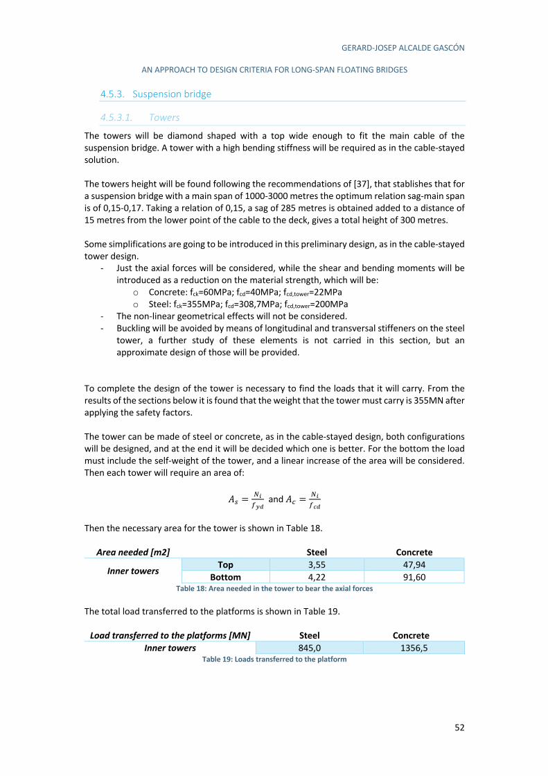
GERARD-JOSEP ALCALDE GASCÓN
AN APPROACH TO DESIGN CRITERIA FOR LONG-SPAN FLOATING BRIDGES
52
4.5.3. Suspension bridge
4.5.3.1. Towers
The towers will be diamond shaped with a top wide enough to fit the main cable of the suspension bridge. A tower with a high bending stiffness will be required as in the cable-stayed solution. The towers height will be found following the recommendations of [37], that stablishes that for a suspension bridge with a main span of 1000-3000 metres the optimum relation sag-main span is of 0,15-0,17. Taking a relation of 0,15, a sag of 285 metres is obtained added to a distance of 15 metres from the lower point of the cable to the deck, gives a total height of 300 metres. Some simplifications are going to be introduced in this preliminary design, as in the cable-stayed tower design.
- Just the axial forces will be considered, while the shear and bending moments will be introduced as a reduction on the material strength, which will be:
o Concrete: fck=60MPa; fcd=40MPa; fcd,tower=22MPa o Steel: fck=355MPa; fcd=308,7MPa; fcd,tower=200MPa
- The non-linear geometrical effects will not be considered. - Buckling will be avoided by means of longitudinal and transversal stiffeners on the steel
tower, a further study of these elements is not carried in this section, but an approximate design of those will be provided.
To complete the design of the tower is necessary to find the loads that it will carry. From the results of the sections below it is found that the weight that the tower must carry is 355MN after applying the safety factors. The tower can be made of steel or concrete, as in the cable-stayed design, both configurations will be designed, and at the end it will be decided which one is better. For the bottom the load must include the self-weight of the tower, and a linear increase of the area will be considered. Then each tower will require an area of:
CJ =M!2"#
and CG =M!2$#
Then the necessary area for the tower is shown in Table 18.
Area needed [m2] Steel Concrete
Inner towers Top 3,55 47,94 Bottom 4,22 91,60
Table 18: Area needed in the tower to bear the axial forces The total load transferred to the platforms is shown in Table 19.
Load transferred to the platforms [MN] Steel Concrete
Inner towers 845,0 1356,5 Table 19: Loads transferred to the platform
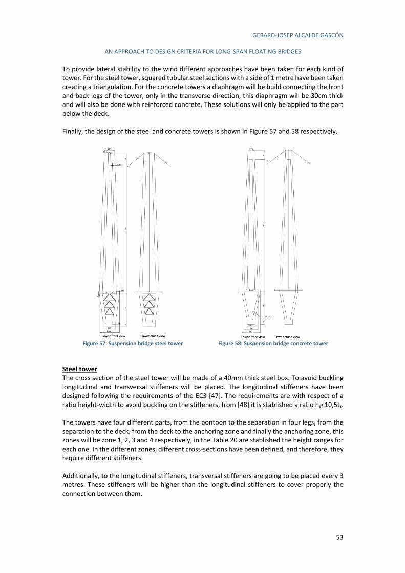
GERARD-JOSEP ALCALDE GASCÓN
AN APPROACH TO DESIGN CRITERIA FOR LONG-SPAN FLOATING BRIDGES
53
To provide lateral stability to the wind different approaches have been taken for each kind of tower. For the steel tower, squared tubular steel sections with a side of 1 metre have been taken creating a triangulation. For the concrete towers a diaphragm will be build connecting the front and back legs of the tower, only in the transverse direction, this diaphragm will be 30cm thick and will also be done with reinforced concrete. These solutions will only be applied to the part below the deck. Finally, the design of the steel and concrete towers is shown in Figure 57 and 58 respectively.
Figure 57: Suspension bridge steel tower
Figure 58: Suspension bridge concrete tower
Steel tower
The cross section of the steel tower will be made of a 40mm thick steel box. To avoid buckling longitudinal and transversal stiffeners will be placed. The longitudinal stiffeners have been designed following the requirements of the EC3 [47]. The requirements are with respect of a ratio height-width to avoid buckling on the stiffeners, from [48] it is stablished a ratio hs<10,5ts. The towers have four different parts, from the pontoon to the separation in four legs, from the separation to the deck, from the deck to the anchoring zone and finally the anchoring zone, this zones will be zone 1, 2, 3 and 4 respectively, in the Table 20 are stablished the height ranges for each one. In the different zones, different cross-sections have been defined, and therefore, they require different stiffeners. Additionally, to the longitudinal stiffeners, transversal stiffeners are going to be placed every 3 metres. These stiffeners will be higher than the longitudinal stiffeners to cover properly the connection between them.
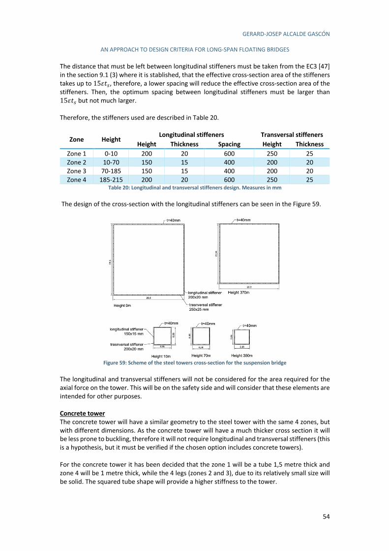
GERARD-JOSEP ALCALDE GASCÓN
AN APPROACH TO DESIGN CRITERIA FOR LONG-SPAN FLOATING BRIDGES
54
The distance that must be left between longitudinal stiffeners must be taken from the EC3 [47] in the section 9.1 (3) where it is stablished, that the effective cross-section area of the stiffeners takes up to 15tuJ, therefore, a lower spacing will reduce the effective cross-section area of the stiffeners. Then, the optimum spacing between longitudinal stiffeners must be larger than 15tuJ but not much larger. Therefore, the stiffeners used are described in Table 20.
Zone Height Longitudinal stiffeners Transversal stiffeners
Height Thickness Spacing Height Thickness
Zone 1 0-10 200 20 600 250 25 Zone 2 10-70 150 15 400 200 20 Zone 3 70-185 150 15 400 200 20 Zone 4 185-215 200 20 600 250 25
Table 20: Longitudinal and transversal stiffeners design. Measures in mm The design of the cross-section with the longitudinal stiffeners can be seen in the Figure 59.
Figure 59: Scheme of the steel towers cross-section for the suspension bridge
The longitudinal and transversal stiffeners will not be considered for the area required for the axial force on the tower. This will be on the safety side and will consider that these elements are intended for other purposes. Concrete tower
The concrete tower will have a similar geometry to the steel tower with the same 4 zones, but with different dimensions. As the concrete tower will have a much thicker cross section it will be less prone to buckling, therefore it will not require longitudinal and transversal stiffeners (this is a hypothesis, but it must be verified if the chosen option includes concrete towers). For the concrete tower it has been decided that the zone 1 will be a tube 1,5 metre thick and zone 4 will be 1 metre thick, while the 4 legs (zones 2 and 3), due to its relatively small size will be solid. The squared tube shape will provide a higher stiffness to the tower.
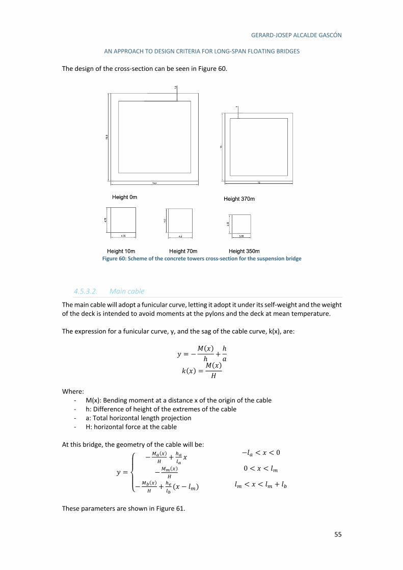
GERARD-JOSEP ALCALDE GASCÓN
AN APPROACH TO DESIGN CRITERIA FOR LONG-SPAN FLOATING BRIDGES
55
The design of the cross-section can be seen in Figure 60.
Figure 60: Scheme of the concrete towers cross-section for the suspension bridge
4.5.3.2. Main cable
The main cable will adopt a funicular curve, letting it adopt it under its self-weight and the weight of the deck is intended to avoid moments at the pylons and the deck at mean temperature. The expression for a funicular curve, y, and the sag of the cable curve, k(x), are:
v = −e(m)ℎ
+ℎg
5(m) =e(m)r
Where:
- M(x): Bending moment at a distance x of the origin of the cable - h: Difference of height of the extremes of the cable - a: Total horizontal length projection - H: horizontal force at the cable
At this bridge, the geometry of the cable will be:
v =
⎩⎪⎨
⎪⎧ −N%(/)
Q+ L%
4%m
−N&(/)Q
−N'(/)Q
+ L(4'(m − {')
−{K < m < 0
0 < m < {'
{' < m < {' + {&
These parameters are shown in Figure 61.
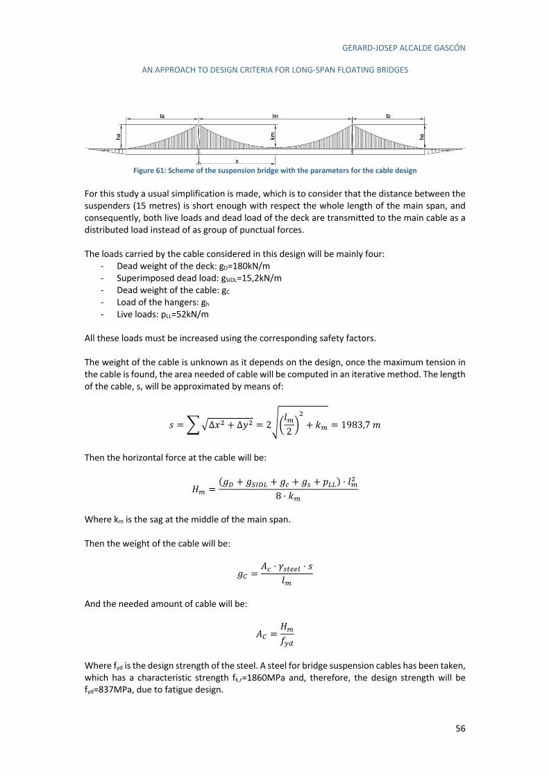
GERARD-JOSEP ALCALDE GASCÓN
AN APPROACH TO DESIGN CRITERIA FOR LONG-SPAN FLOATING BRIDGES
56
Figure 61: Scheme of the suspension bridge with the parameters for the cable design
For this study a usual simplification is made, which is to consider that the distance between the suspenders (15 metres) is short enough with respect the whole length of the main span, and consequently, both live loads and dead load of the deck are transmitted to the main cable as a distributed load instead of as group of punctual forces. The loads carried by the cable considered in this design will be mainly four:
- Dead weight of the deck: gD=180kN/m - Superimposed dead load: gSIDL=15,2kN/m - Dead weight of the cable: gC - Load of the hangers: gh - Live loads: pLL=52kN/m
All these loads must be increased using the corresponding safety factors. The weight of the cable is unknown as it depends on the design, once the maximum tension in the cable is found, the area needed of cable will be computed in an iterative method. The length of the cable, s, will be approximated by means of:
/ =|}∆m0 + ∆v0 = 2�8{'2 9
0
+ 5' = 1983,7-
Then the horizontal force at the cable will be:
r' =(ÄR + ÄSTRU + ÄG + ÄJ + ÅUU) · {'0
8 · 5'
Where km is the sag at the middle of the main span. Then the weight of the cable will be:
ÄV =CG · dJI114 · /
{'
And the needed amount of cable will be:
CV =r'"!#
Where fyd is the design strength of the steel. A steel for bridge suspension cables has been taken, which has a characteristic strength fk,r=1860MPa and, therefore, the design strength will be fyd=837MPa, due to fatigue design.
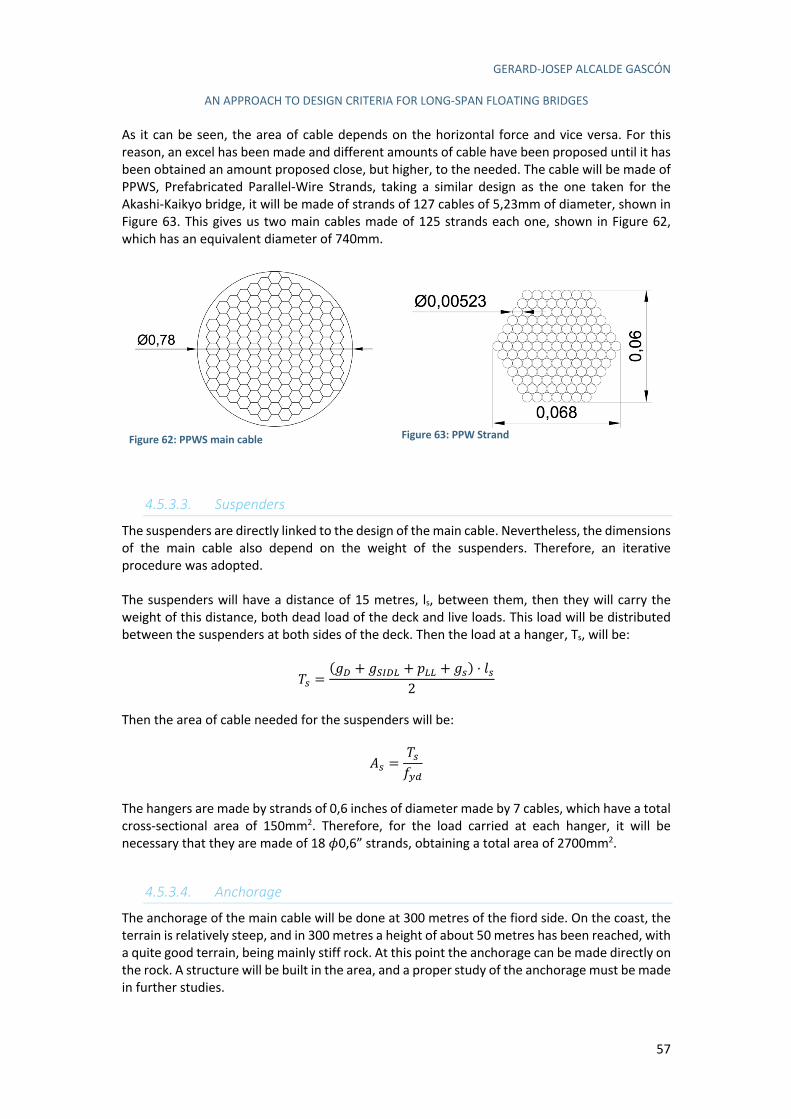
GERARD-JOSEP ALCALDE GASCÓN
AN APPROACH TO DESIGN CRITERIA FOR LONG-SPAN FLOATING BRIDGES
57
As it can be seen, the area of cable depends on the horizontal force and vice versa. For this reason, an excel has been made and different amounts of cable have been proposed until it has been obtained an amount proposed close, but higher, to the needed. The cable will be made of PPWS, Prefabricated Parallel-Wire Strands, taking a similar design as the one taken for the Akashi-Kaikyo bridge, it will be made of strands of 127 cables of 5,23mm of diameter, shown in Figure 63. This gives us two main cables made of 125 strands each one, shown in Figure 62, which has an equivalent diameter of 740mm.
Figure 62: PPWS main cable
Figure 63: PPW Strand
4.5.3.3. Suspenders
The suspenders are directly linked to the design of the main cable. Nevertheless, the dimensions of the main cable also depend on the weight of the suspenders. Therefore, an iterative procedure was adopted. The suspenders will have a distance of 15 metres, ls, between them, then they will carry the weight of this distance, both dead load of the deck and live loads. This load will be distributed between the suspenders at both sides of the deck. Then the load at a hanger, Ts, will be:
nJ =(ÄR + ÄSTRU + ÅUU + ÄJ) · {J
2
Then the area of cable needed for the suspenders will be:
CJ =nJ"!#
The hangers are made by strands of 0,6 inches of diameter made by 7 cables, which have a total cross-sectional area of 150mm2. Therefore, for the load carried at each hanger, it will be necessary that they are made of 18 _0,6” strands, obtaining a total area of 2700mm2.
4.5.3.4. Anchorage
The anchorage of the main cable will be done at 300 metres of the fiord side. On the coast, the terrain is relatively steep, and in 300 metres a height of about 50 metres has been reached, with a quite good terrain, being mainly stiff rock. At this point the anchorage can be made directly on the rock. A structure will be built in the area, and a proper study of the anchorage must be made in further studies.
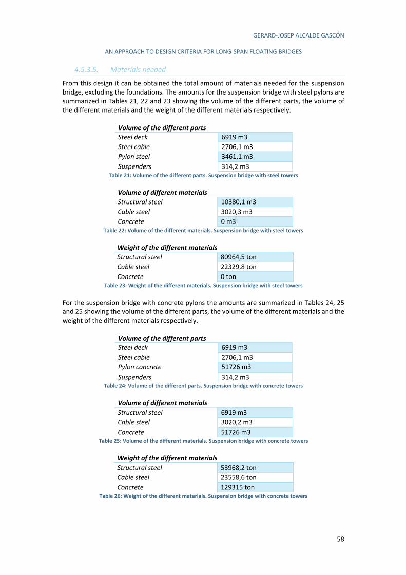
GERARD-JOSEP ALCALDE GASCÓN
AN APPROACH TO DESIGN CRITERIA FOR LONG-SPAN FLOATING BRIDGES
58
4.5.3.5. Materials needed
From this design it can be obtained the total amount of materials needed for the suspension bridge, excluding the foundations. The amounts for the suspension bridge with steel pylons are summarized in Tables 21, 22 and 23 showing the volume of the different parts, the volume of the different materials and the weight of the different materials respectively.
Volume of the different parts Steel deck 6919 m3 Steel cable 2706,1 m3 Pylon steel 3461,1 m3 Suspenders 314,2 m3
Table 21: Volume of the different parts. Suspension bridge with steel towers
Volume of different materials Structural steel 10380,1 m3 Cable steel 3020,3 m3 Concrete 0 m3
Table 22: Volume of the different materials. Suspension bridge with steel towers
Weight of the different materials Structural steel 80964,5 ton Cable steel 22329,8 ton Concrete 0 ton
Table 23: Weight of the different materials. Suspension bridge with steel towers For the suspension bridge with concrete pylons the amounts are summarized in Tables 24, 25 and 25 showing the volume of the different parts, the volume of the different materials and the weight of the different materials respectively.
Volume of the different parts Steel deck 6919 m3 Steel cable 2706,1 m3 Pylon concrete 51726 m3 Suspenders 314,2 m3
Table 24: Volume of the different parts. Suspension bridge with concrete towers
Volume of different materials Structural steel 6919 m3 Cable steel 3020,2 m3 Concrete 51726 m3
Table 25: Volume of the different materials. Suspension bridge with concrete towers
Weight of the different materials Structural steel 53968,2 ton Cable steel 23558,6 ton Concrete 129315 ton
Table 26: Weight of the different materials. Suspension bridge with concrete towers
GERARD-JOSEP ALCALDE GASCÓN
AN APPROACH TO DESIGN CRITERIA FOR LONG-SPAN FLOATING BRIDGES
59
The main elements of the suspension bridge excluding the foundations have been already designed. Now, the design of the pontoons for the foundations is carried out.
4.6. Preliminary pontoon design
Two different pontoon are designed: a tethered spar buoy and a tension leg platform. Both alternatives offer enough stability for the foundations of the bridge with an optimal buoyancy capacity and a good rotational stiffness. The main difference in their behaviour is in how they achieve the rotational stiffness. While the spar-buoy has a ballast in its bottom, placing the centre of gravity much below than the centre of buoyancy providing a huge stability, the TLP uses tensioned anchors which attach the platform to the seabed and avoid the movement of the platform. The design of the pontoon can be quite complex, especially regarding the dynamic effects induced by waves and currents. Moreover, to ensure enough stability the bending moments transferred to the top of the platform by the deck and the effects of wind and other transversal and longitudinal forces must be known. In this preliminary design some simplifications will be made, as the only purpose is to evaluate which alternative is cheaper and for this reason some simplifications are made:
- Currents and wave effects and other dynamic effects are not considered. - Fatigue is not going to be evaluated, except on the cables used for stabilization of the
pontoons. In order to design the pontoons, the first thing we need to do is to know the loads acting on the pontoon. Three main loads are acting on the pontoon:
- Shear forces due to the wind and traffic loads on the deck. - Bending moments also produced by the wind and traffic loads. - Axial load due to the weight of the traffic and the bridge itself.
These loads need a further study, and they will be different for the suspension and the cable-stayed bridge. In each of these alternatives, they will be different for the steel and for the concrete alternative. Three different load cases will be analysed. The project specifications have two requirements related with the pontoons, which are:
- For an SLS combination taking only the wind as a variable load, the rotation about the longitudinal axis of the bridge must not be higher than 0,5º.
- For an SLS combination taking as only variable the 70% of the traffic load, the rotational angle at support must not be higher than 1,91º.
These requirements must be considered during the design of the pontoons and will be the base of the design for the tethered spar-buoy pontoon. An in-depth study of how the loads on each bridge typology are transmitted to the pontoons is carried out below.
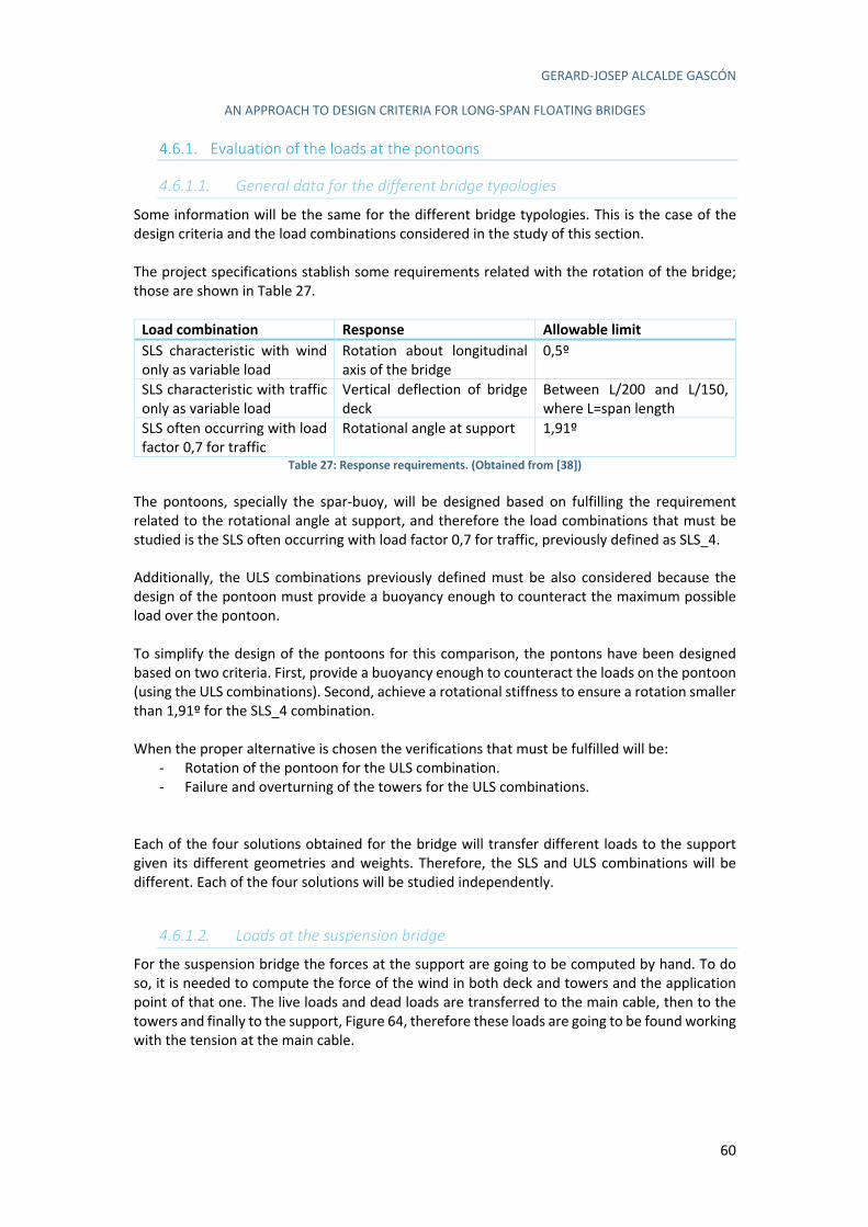
GERARD-JOSEP ALCALDE GASCÓN
AN APPROACH TO DESIGN CRITERIA FOR LONG-SPAN FLOATING BRIDGES
60
4.6.1. Evaluation of the loads at the pontoons
4.6.1.1. General data for the different bridge typologies
Some information will be the same for the different bridge typologies. This is the case of the design criteria and the load combinations considered in the study of this section. The project specifications stablish some requirements related with the rotation of the bridge; those are shown in Table 27.
Load combination Response Allowable limit
SLS characteristic with wind only as variable load
Rotation about longitudinal axis of the bridge
0,5º
SLS characteristic with traffic only as variable load
Vertical deflection of bridge deck
Between L/200 and L/150, where L=span length
SLS often occurring with load factor 0,7 for traffic
Rotational angle at support 1,91º
Table 27: Response requirements. (Obtained from [38]) The pontoons, specially the spar-buoy, will be designed based on fulfilling the requirement related to the rotational angle at support, and therefore the load combinations that must be studied is the SLS often occurring with load factor 0,7 for traffic, previously defined as SLS_4. Additionally, the ULS combinations previously defined must be also considered because the design of the pontoon must provide a buoyancy enough to counteract the maximum possible load over the pontoon. To simplify the design of the pontoons for this comparison, the pontons have been designed based on two criteria. First, provide a buoyancy enough to counteract the loads on the pontoon (using the ULS combinations). Second, achieve a rotational stiffness to ensure a rotation smaller than 1,91º for the SLS_4 combination. When the proper alternative is chosen the verifications that must be fulfilled will be:
- Rotation of the pontoon for the ULS combination. - Failure and overturning of the towers for the ULS combinations.
Each of the four solutions obtained for the bridge will transfer different loads to the support given its different geometries and weights. Therefore, the SLS and ULS combinations will be different. Each of the four solutions will be studied independently.
4.6.1.2. Loads at the suspension bridge
For the suspension bridge the forces at the support are going to be computed by hand. To do so, it is needed to compute the force of the wind in both deck and towers and the application point of that one. The live loads and dead loads are transferred to the main cable, then to the towers and finally to the support, Figure 64, therefore these loads are going to be found working with the tension at the main cable.
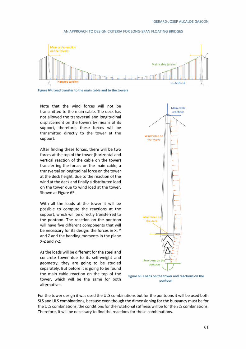
GERARD-JOSEP ALCALDE GASCÓN
AN APPROACH TO DESIGN CRITERIA FOR LONG-SPAN FLOATING BRIDGES
61
Figure 64: Load transfer to the main cable and to the towers
Note that the wind forces will not be transmitted to the main cable. The deck has not allowed the transversal and longitudinal displacement on the towers by means of its support, therefore, these forces will be transmitted directly to the tower at the support. After finding these forces, there will be two forces at the top of the tower (horizontal and vertical reaction of the cable on the tower) transferring the forces on the main cable, a transversal or longitudinal force on the tower at the deck height, due to the reaction of the wind at the deck and finally a distributed load on the tower due to wind load at the tower. Shown at Figure 65. With all the loads at the tower it will be possible to compute the reactions at the support, which will be directly transferred to the pontoon. The reaction on the pontoon will have five different components that will be necessary for its design: the forces in X, Y and Z and the bending moments in the plane X-Z and Y-Z. As the loads will be different for the steel and concrete tower due to its self-weight and geometry, they are going to be studied separately. But before it is going to be found the main cable reaction on the top of the tower, which will be the same for both alternatives.
Figure 65: Loads on the tower and reactions on the
pontoon
For the tower design it was used the ULS combinations but for the pontoons it will be used both SLS and ULS combinations, because even though the dimensioning for the buoyancy must be for the ULS combinations, the conditions for the rotational stiffness will be for the SLS combinations. Therefore, it will be necessary to find the reactions for those combinations.
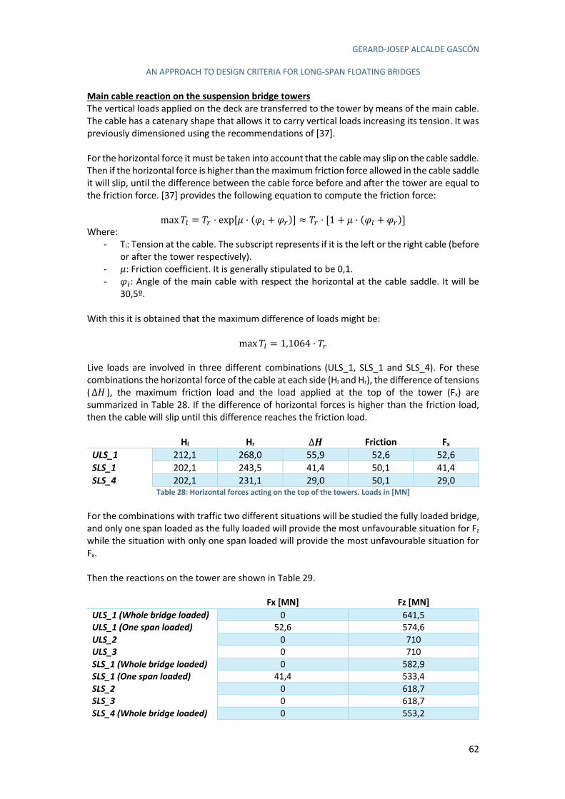
GERARD-JOSEP ALCALDE GASCÓN
AN APPROACH TO DESIGN CRITERIA FOR LONG-SPAN FLOATING BRIDGES
62
Main cable reaction on the suspension bridge towers
The vertical loads applied on the deck are transferred to the tower by means of the main cable. The cable has a catenary shape that allows it to carry vertical loads increasing its tension. It was previously dimensioned using the recommendations of [37]. For the horizontal force it must be taken into account that the cable may slip on the cable saddle. Then if the horizontal force is higher than the maximum friction force allowed in the cable saddle it will slip, until the difference between the cable force before and after the tower are equal to the friction force. [37] provides the following equation to compute the friction force:
maxn4 = n% · exp[á · (à4 + à%)] ≈ n% · [1 + á · (à4 + à%)] Where:
- Ti: Tension at the cable. The subscript represents if it is the left or the right cable (before or after the tower respectively).
- á: Friction coefficient. It is generally stipulated to be 0,1. - à): Angle of the main cable with respect the horizontal at the cable saddle. It will be
30,5º. With this it is obtained that the maximum difference of loads might be:
maxn4 = 1,1064 · n% Live loads are involved in three different combinations (ULS_1, SLS_1 and SLS_4). For these combinations the horizontal force of the cable at each side (Hl and Hr), the difference of tensions (∆r ), the maximum friction load and the load applied at the top of the tower (Fx) are summarized in Table 28. If the difference of horizontal forces is higher than the friction load, then the cable will slip until this difference reaches the friction load.
Hl Hr Ƌ Friction Fx
ULS_1 212,1 268,0 55,9 52,6 52,6 SLS_1 202,1 243,5 41,4 50,1 41,4 SLS_4 202,1 231,1 29,0 50,1 29,0
Table 28: Horizontal forces acting on the top of the towers. Loads in [MN] For the combinations with traffic two different situations will be studied the fully loaded bridge, and only one span loaded as the fully loaded will provide the most unfavourable situation for Fz while the situation with only one span loaded will provide the most unfavourable situation for Fx. Then the reactions on the tower are shown in Table 29.
Fx [MN] Fz [MN] ULS_1 (Whole bridge loaded) 0 641,5 ULS_1 (One span loaded) 52,6 574,6 ULS_2 0 710 ULS_3 0 710 SLS_1 (Whole bridge loaded) 0 582,9 SLS_1 (One span loaded) 41,4 533,4 SLS_2 0 618,7 SLS_3 0 618,7 SLS_4 (Whole bridge loaded) 0 553,2
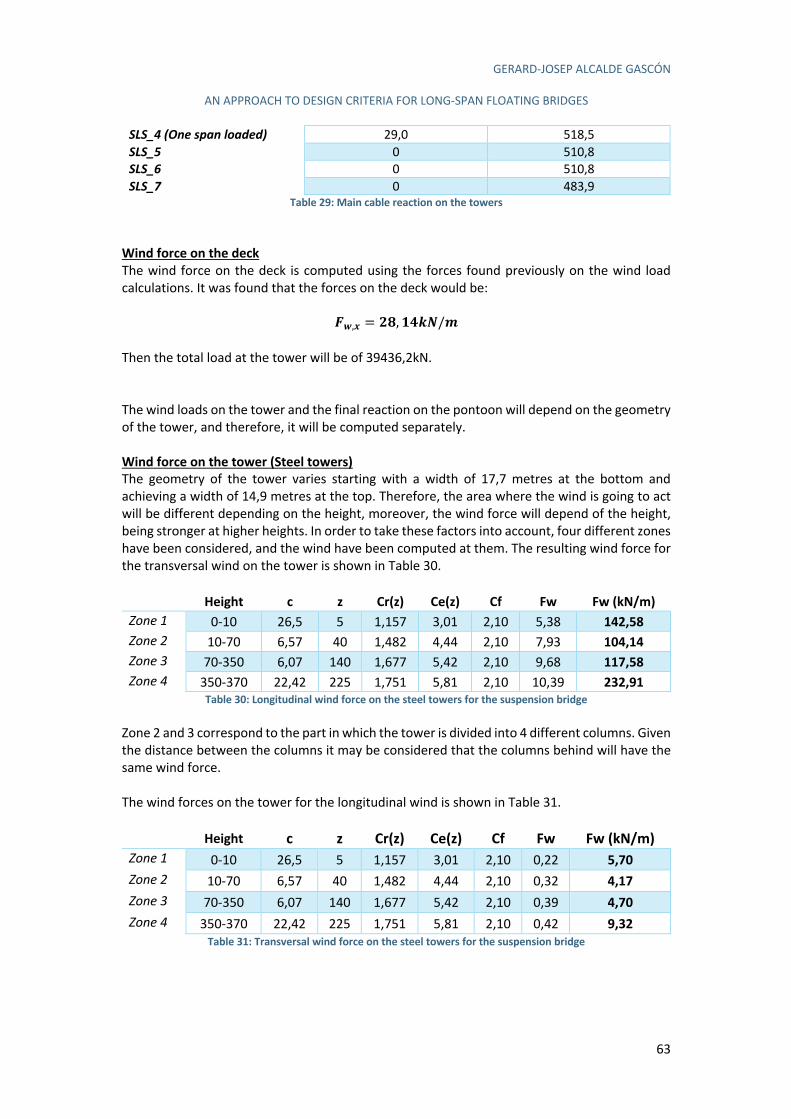
GERARD-JOSEP ALCALDE GASCÓN
AN APPROACH TO DESIGN CRITERIA FOR LONG-SPAN FLOATING BRIDGES
63
SLS_4 (One span loaded) 29,0 518,5 SLS_5 0 510,8 SLS_6 0 510,8 SLS_7 0 483,9
Table 29: Main cable reaction on the towers Wind force on the deck
The wind force on the deck is computed using the forces found previously on the wind load calculations. It was found that the forces on the deck would be:
P6,= = QR, STUV/W
Then the total load at the tower will be of 39436,2kN. The wind loads on the tower and the final reaction on the pontoon will depend on the geometry of the tower, and therefore, it will be computed separately. Wind force on the tower (Steel towers)
The geometry of the tower varies starting with a width of 17,7 metres at the bottom and achieving a width of 14,9 metres at the top. Therefore, the area where the wind is going to act will be different depending on the height, moreover, the wind force will depend of the height, being stronger at higher heights. In order to take these factors into account, four different zones have been considered, and the wind have been computed at them. The resulting wind force for the transversal wind on the tower is shown in Table 30.
Height c z Cr(z) Ce(z) Cf Fw Fw (kN/m)
Zone 1 0-10 26,5 5 1,157 3,01 2,10 5,38 142,58
Zone 2 10-70 6,57 40 1,482 4,44 2,10 7,93 104,14
Zone 3 70-350 6,07 140 1,677 5,42 2,10 9,68 117,58
Zone 4 350-370 22,42 225 1,751 5,81 2,10 10,39 232,91
Table 30: Longitudinal wind force on the steel towers for the suspension bridge Zone 2 and 3 correspond to the part in which the tower is divided into 4 different columns. Given the distance between the columns it may be considered that the columns behind will have the same wind force. The wind forces on the tower for the longitudinal wind is shown in Table 31.
Height c z Cr(z) Ce(z) Cf Fw Fw (kN/m) Zone 1 0-10 26,5 5 1,157 3,01 2,10 0,22 5,70
Zone 2 10-70 6,57 40 1,482 4,44 2,10 0,32 4,17
Zone 3 70-350 6,07 140 1,677 5,42 2,10 0,39 4,70
Zone 4 350-370 22,42 225 1,751 5,81 2,10 0,42 9,32
Table 31: Transversal wind force on the steel towers for the suspension bridge
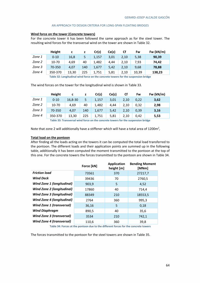
GERARD-JOSEP ALCALDE GASCÓN
AN APPROACH TO DESIGN CRITERIA FOR LONG-SPAN FLOATING BRIDGES
64
Wind force on the tower (Concrete towers)
For the concrete tower it has been followed the same approach as for the steel tower. The resulting wind forces for the transversal wind on the tower are shown in Table 32.
Height c z Cr(z) Ce(z) Cf Fw Fw (kN/m)
Zone 1 0-10 16,8 5 1,157 3,01 2,10 5,38 90,39
Zone 2 10-70 4,69 40 1,482 4,44 2,10 7,93 74,42
Zone 3 70-350 4,07 140 1,677 5,42 2,10 9,68 78,88
Zone 4 350-370 13,30 225 1,751 5,81 2,10 10,39 138,23
Table 32: Longitudinal wind force on the concrete towers for the suspension bridge The wind forces on the tower for the longitudinal wind is shown in Table 33.
Height c z Cr(z) Ce(z) Cf Fw Fw (kN/m)
Zone 1 0-10 16,8-30 5 1,157 3,01 2,10 0,22 3,62
Zone 2 10-70 4,69 40 1,482 4,44 2,10 0,32 2,98
Zone 3 70-350 4,07 140 1,677 5,42 2,10 0,39 3,16
Zone 4 350-370 13,30 225 1,751 5,81 2,10 0,42 5,53
Table 33: Transversal wind force on the concrete towers for the suspension bridge Note that zone 2 will additionally have a stiffener which will have a total area of 1200m2,
Total load on the pontoon
After finding all the loads acting on the towers it can be computed the total load transferred to the pontoon. The different loads and their application points are summed up in the following table, additionally it has been computed the moment transmitted to the pontoon at the top of this one. For the concrete towers the forces transmitted to the pontoon are shown in Table 34.
Force [kN]
Application
height [m]
Bending Moment
[MNm]
Friction load 73561 370 27217,7 Wind Deck 39436 70 2760,5 Wind Zone 1 (longitudinal) 903,9 5 4,52 Wind Zone 2 (longitudinal) 17860 40 714,4 Wind Zone 3 (longitudinal) 88349 210 18553,5 Wind Zone 4 (longitudinal) 2764 360 995,3 Wind Zone 1 (transversal) 36,16 5 0,18 Wind Diaphragm 890,5 40 35,6 Wind Zone 3 (transversal) 3534 210 742,1 Wind Zone 4 (transversal) 110,6 360 39,8
Table 34: Forces at the pontoon due to the different forces for the concrete towers The forces transmitted to the pontoon for the steel towers are shown in Table 35.

GERARD-JOSEP ALCALDE GASCÓN
AN APPROACH TO DESIGN CRITERIA FOR LONG-SPAN FLOATING BRIDGES
65
Force [kN] Application
height [m]
Bending Moment
[MNm]
Friction load 73561 370 27217,7 Wind Deck 39436 70 2760,5 Wind Zone 1 (longitudinal) 952,4 5 7,13 Wind Zone 2 (longitudinal) 16788 40 999,7 Wind Zone 3 (longitudinal) 88514 210 27654,4 Wind Zone 4 (longitudinal) 3112 360 1677,0 Wind Zone 1 (transversal) 38,09 5 0,29 Wind Zone 2 (transversal) 671,5 40 39,99 Wind Zone 3 (transversal) 3540 210 1106,2 Wind Zone 4 (transversal) 124,5 360 67,08
Table 35: Forces at the pontoon due to the different forces for the steel towers These results can be summed up in Table 36 for the suspension bridge with steel towers and in Table 37 for the suspension bridge with concrete towers.
Fx [MN] Fy [MN] Fz [MN] Mx-z [MNm] My-z [MNm]
ULS_1 (All) 0 0 776,5 0 0 ULS_1 (Span) 52,61 0 709,6 0 19464,9 ULS_2 9,77 0 845,0 0 1820,3 ULS_3 0 295,6 845,0 49,1 0 SLS_1 (All) 0 0 717,9 0 0 SLS_1 (Span) 41,38 0 668,4 0 15311,9 SLS_2 6,51 0 753,7 0 1213,5 SLS_3 0 197,1 753,7 32,7 0 SLS_4 (All) 0 0 688,2 0 0 SLS_4 (Span) 28,97 0 653,5 0 10718,4 SLS_5 1,30 0 645,8 0 242,7 SLS_6 0 39,42 645,8 6,55 0 SLS_7 0 0 618,9 0 0
Table 36: Reactions of the suspension bridge with steel towers at the pontoon
Fx [MN] Fy [MN] Fz [MN] Mx-z [MNm] My-z [MNm]
ULS_1 (All) 0 0 1288,0 0 0 ULS_1 (Span) 52,61 0 1221,2 0 19464,9 ULS_2 6,86 0 1356,5 0 1226,6 ULS_3 0 224,0 1356,5 34542,3 0 SLS_1 (All) 0 0 1229,5 0 0 SLS_1 (Span) 41,38 0 1180,0 0 15311,9 SLS_2 4,57 0 1265,3 0 817,7 SLS_3 0 149,3 1265,3 23028,2 0 SLS_4 (All) 0 0 1199,8 0 0 SLS_4 (Span) 28,97 0 1165,1 0 10718,4 SLS_5 0,91 0 1157,4 0 163,5 SLS_6 0 29,86 1157,4 4605,6 0 SLS_7 0 0 1130,4 0 0
Table 37: Reactions of the suspension bridge with concrete towers at the pontoon
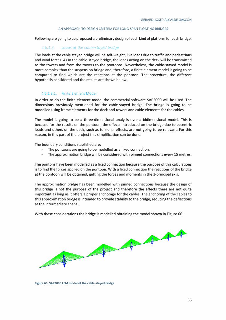
GERARD-JOSEP ALCALDE GASCÓN
AN APPROACH TO DESIGN CRITERIA FOR LONG-SPAN FLOATING BRIDGES
66
Following are going to be proposed a preliminary design of each kind of platform for each bridge.
4.6.1.3. Loads at the cable-stayed bridge
The loads at the cable stayed bridge will be self-weight, live loads due to traffic and pedestrians and wind forces. As in the cable-stayed bridge, the loads acting on the deck will be transmitted to the towers and from the towers to the pontoons. Nevertheless, the cable-stayed model is more complex than the suspension bridge and, therefore, a finite element model is going to be computed to find which are the reactions at the pontoon. The procedure, the different hypothesis considered and the results are shown below.
4.6.1.3.1. Finite Element Model
In order to do the finite element model the commercial software SAP2000 will be used. The dimensions previously mentioned for the cable-stayed bridge. The bridge is going to be modelled using frame elements for the deck and towers and cable elements for the cables. The model is going to be a three-dimensional analysis over a bidimensional model. This is because for the results on the pontoon, the effects introduced on the bridge due to eccentric loads and others on the deck, such as torsional effects, are not going to be relevant. For this reason, in this part of the project this simplification can be done. The boundary conditions stablished are:
- The pontoons are going to be modelled as a fixed connection. - The approximation bridge will be considered with pinned connections every 15 metres.
The pontons have been modelled as a fixed connection because the purpose of this calculations is to find the forces applied on the pontoon. With a fixed connection the reactions of the bridge at the pontoon will be obtained, getting the forces and moments in the 3-principal axis. The approximation bridge has been modelled with pinned connections because the design of this bridge is not the purpose of the project and therefore the effects there are not quite important as long as it offers a proper anchorage for the cables. The anchoring of the cables to this approximation bridge is intended to provide stability to the bridge, reducing the deflections at the intermediate spans. With these considerations the bridge is modelled obtaining the model shown in Figure 66.
Figure 66: SAP2000 FEM model of the cable-stayed bridge
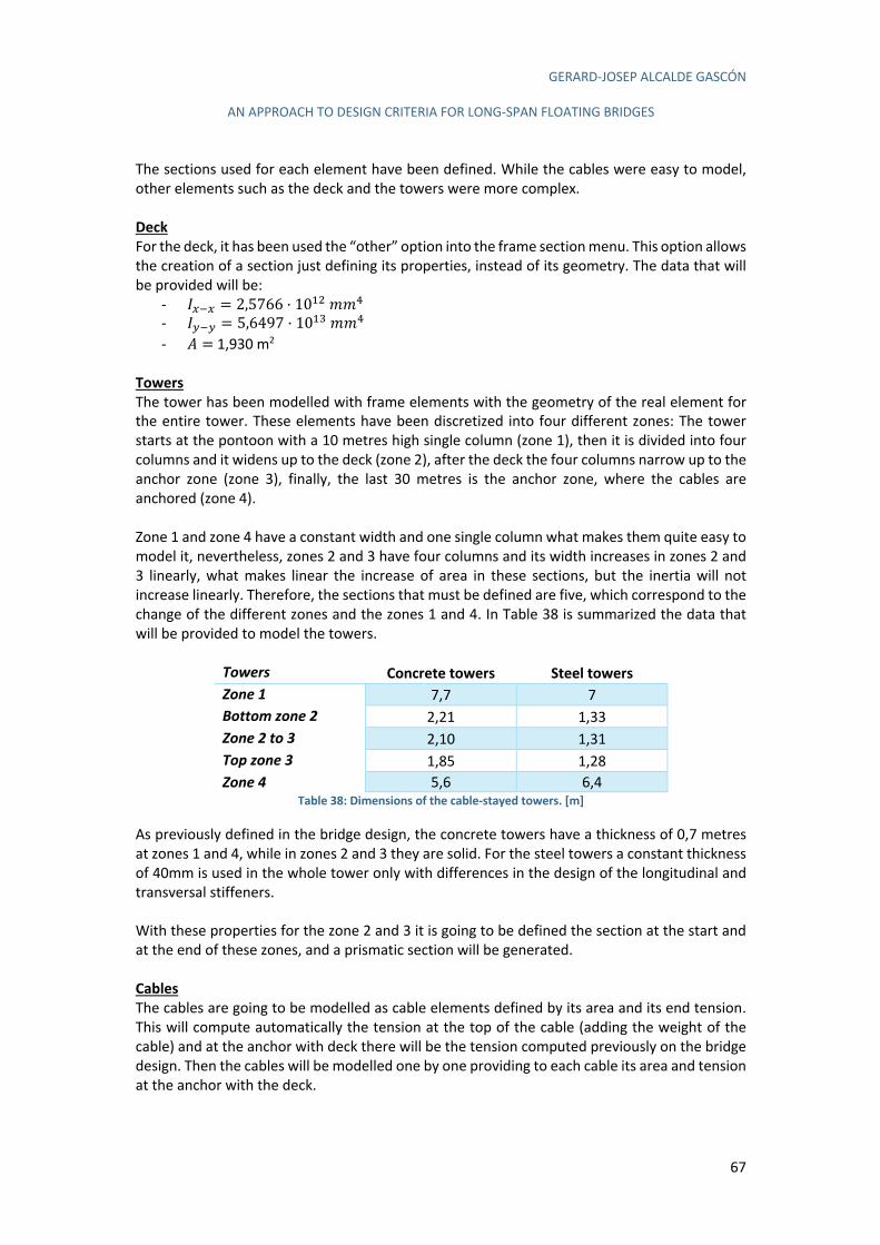
GERARD-JOSEP ALCALDE GASCÓN
AN APPROACH TO DESIGN CRITERIA FOR LONG-SPAN FLOATING BRIDGES
67
The sections used for each element have been defined. While the cables were easy to model, other elements such as the deck and the towers were more complex. Deck
For the deck, it has been used the “other” option into the frame section menu. This option allows the creation of a section just defining its properties, instead of its geometry. The data that will be provided will be:
- å/W/ = 2,5766 · 1030--X - å!W! = 5,6497 · 103;--X - C =1,930 m2
Towers
The tower has been modelled with frame elements with the geometry of the real element for the entire tower. These elements have been discretized into four different zones: The tower starts at the pontoon with a 10 metres high single column (zone 1), then it is divided into four columns and it widens up to the deck (zone 2), after the deck the four columns narrow up to the anchor zone (zone 3), finally, the last 30 metres is the anchor zone, where the cables are anchored (zone 4). Zone 1 and zone 4 have a constant width and one single column what makes them quite easy to model it, nevertheless, zones 2 and 3 have four columns and its width increases in zones 2 and 3 linearly, what makes linear the increase of area in these sections, but the inertia will not increase linearly. Therefore, the sections that must be defined are five, which correspond to the change of the different zones and the zones 1 and 4. In Table 38 is summarized the data that will be provided to model the towers.
Towers Concrete towers Steel towers
Zone 1 7,7 7 Bottom zone 2 2,21 1,33 Zone 2 to 3 2,10 1,31 Top zone 3 1,85 1,28 Zone 4 5,6 6,4
Table 38: Dimensions of the cable-stayed towers. [m] As previously defined in the bridge design, the concrete towers have a thickness of 0,7 metres at zones 1 and 4, while in zones 2 and 3 they are solid. For the steel towers a constant thickness of 40mm is used in the whole tower only with differences in the design of the longitudinal and transversal stiffeners. With these properties for the zone 2 and 3 it is going to be defined the section at the start and at the end of these zones, and a prismatic section will be generated. Cables
The cables are going to be modelled as cable elements defined by its area and its end tension. This will compute automatically the tension at the top of the cable (adding the weight of the cable) and at the anchor with deck there will be the tension computed previously on the bridge design. Then the cables will be modelled one by one providing to each cable its area and tension at the anchor with the deck.

GERARD-JOSEP ALCALDE GASCÓN
AN APPROACH TO DESIGN CRITERIA FOR LONG-SPAN FLOATING BRIDGES
68
4.6.1.3.2. Loads on the model
The loads that are going to be applied on the model are the previously mentioned. Below are shown each of them. The self-weight of the bridge has been applied as a distributed load because the section was not feasible to model it on the software, as previously mentioned. Then the self-weight of the deck has been modified to 0 in the software and a distributed load of 195,2kN/m has been applied. This 195,2kN/m is the self-weight of the deck and the superimposed dead load, Figure 67 and 68.
Figure 67: Deck weight. 180kN/m
Figure 68: SIDL. 15,2kN/m
The live load, with a value of 52kN/m, Figure 69, has been modelled span by span, this is because for the load combinations it must be studied the most unfavourable combination and for the pontoons this will be when the load is applied only on one of the spans of the bridge.
Figure 69: Live loads. 52kN/m
The wind load is more complex to apply because of the different values and acting points of this force. A similar discretization as the one taken for the suspension bridge is going to be taken in the cable-stayed bridge. Computing the wind load at the deck and the towers due to the longitudinal and transversal forces. The transversal wind load at the deck, Figure 70, will be:
P6,= = QR, STUV/W
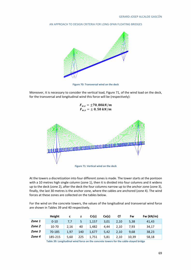
GERARD-JOSEP ALCALDE GASCÓN
AN APPROACH TO DESIGN CRITERIA FOR LONG-SPAN FLOATING BRIDGES
69
Figure 70: Transversal wind on the deck
Moreover, it is necessary to consider the vertical load, Figure 71, of the wind load on the deck, for the transversal and longitudinal wind this force will be (respectively):
P6,9 = ±YZ, RZUV/W
P6,9 = ±Z, çZUV/W
Figure 71: Vertical wind on the deck
At the towers a discretization into four different zones is made. The tower starts at the pontoon with a 10 metres high single column (zone 1), then it is divided into four columns and it widens up to the deck (zone 2), after the deck the four columns narrow up to the anchor zone (zone 3), finally, the last 30 metres is the anchor zone, where the cables are anchored (zone 4). The wind forces at these zones are collected on the tables below. For the wind on the concrete towers, the values of the longitudinal and transversal wind force are shown in Tables 39 and 40 respectively.
Height c z Cr(z) Ce(z) Cf Fw Fw (kN/m)
Zone 1 0-10 7,7 5 1,157 3,01 2,10 5,38 41,43 Zone 2 10-70 2,16 40 1,482 4,44 2,10 7,93 34,17 Zone 3 70-185 1,97 140 1,677 5,42 2,10 9,68 38,23 Zone 4 185-215 5,60 225 1,751 5,81 2,10 10,39 58,18
Table 39: Longitudinal wind force on the concrete towers for the cable-stayed bridge
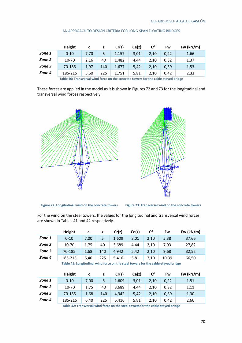
GERARD-JOSEP ALCALDE GASCÓN
AN APPROACH TO DESIGN CRITERIA FOR LONG-SPAN FLOATING BRIDGES
70
Height c z Cr(z) Ce(z) Cf Fw Fw (kN/m)
Zone 1 0-10 7,70 5 1,157 3,01 2,10 0,22 1,66 Zone 2 10-70 2,16 40 1,482 4,44 2,10 0,32 1,37 Zone 3 70-185 1,97 140 1,677 5,42 2,10 0,39 1,53 Zone 4 185-215 5,60 225 1,751 5,81 2,10 0,42 2,33
Table 40: Transversal wind force on the concrete towers for the cable-stayed bridge These forces are applied in the model as it is shown in Figures 72 and 73 for the longitudinal and transversal wind forces respectively.
Figure 72: Longitudinal wind on the concrete towers
Figure 73: Transversal wind on the concrete towers
For the wind on the steel towers, the values for the longitudinal and transversal wind forces are shown in Tables 41 and 42 respectively.
Height c z Cr(z) Ce(z) Cf Fw Fw (kN/m)
Zone 1 0-10 7,00 5 1,609 3,01 2,10 5,38 37,66 Zone 2 10-70 1,75 40 3,689 4,44 2,10 7,93 27,82 Zone 3 70-185 1,68 140 4,942 5,42 2,10 9,68 32,52 Zone 4 185-215 6,40 225 5,416 5,81 2,10 10,39 66,50
Table 41: Longitudinal wind force on the steel towers for the cable-stayed bridge
Height c z Cr(z) Ce(z) Cf Fw Fw (kN/m)
Zone 1 0-10 7,00 5 1,609 3,01 2,10 0,22 1,51 Zone 2 10-70 1,75 40 3,689 4,44 2,10 0,32 1,11 Zone 3 70-185 1,68 140 4,942 5,42 2,10 0,39 1,30 Zone 4 185-215 6,40 225 5,416 5,81 2,10 0,42 2,66
Table 42: Transversal wind force on the steel towers for the cable-stayed bridge
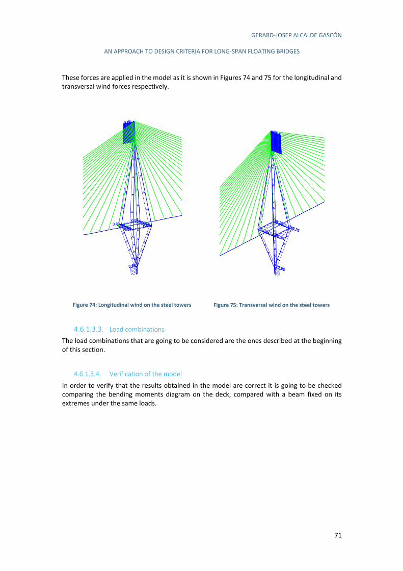
GERARD-JOSEP ALCALDE GASCÓN
AN APPROACH TO DESIGN CRITERIA FOR LONG-SPAN FLOATING BRIDGES
71
These forces are applied in the model as it is shown in Figures 74 and 75 for the longitudinal and transversal wind forces respectively.
Figure 74: Longitudinal wind on the steel towers
Figure 75: Transversal wind on the steel towers
4.6.1.3.3. Load combinations The load combinations that are going to be considered are the ones described at the beginning of this section.
4.6.1.3.4. Verification of the model
In order to verify that the results obtained in the model are correct it is going to be checked comparing the bending moments diagram on the deck, compared with a beam fixed on its extremes under the same loads.
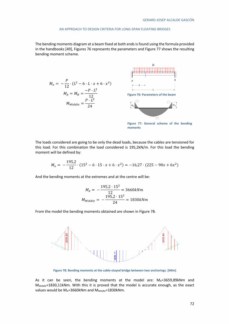
GERARD-JOSEP ALCALDE GASCÓN
AN APPROACH TO DESIGN CRITERIA FOR LONG-SPAN FLOATING BRIDGES
72
The bending moments diagram at a beam fixed at both ends is found using the formula provided in the handbooks [49], Figures 76 represents the parameters and Figure 77 shows the resulting bending moment scheme.
e/ =−f12
· (`0 − 6 · ` · m + 6 · m0)
eY = eZ =−f · `0
12
eN)##41 =f · `0
24
Figure 76: Parameters of the beam
Figure 77: General scheme of the bending moments
The loads considered are going to be only the dead loads, because the cables are tensioned for this load. For this combination the load considered is 195,2kN/m. For this load the bending moment will be defined by:
e/ =−195,212
· (150 − 6 · 15 · m + 6 · m0) = −16,27 · (225 − 90m + 6m0) And the bending moments at the extremes and at the centre will be:
eY =−195,2 · 150
12= 36605O-
eN)##41 =−195,2 · 150
24= 18305O-
From the model the bending moments obtained are shown in Figure 78.
Figure 78: Bending moments at the cable-stayed bridge between two anchorings. [kNm]
As it can be seen, the bending moments at the model are: MA=3659,89kNm and MMiddle=1830,11kNm. With this it is proved that the model is accurate enough, as the exact values would be MA=3660kNm and MMiddle=1830kNm.
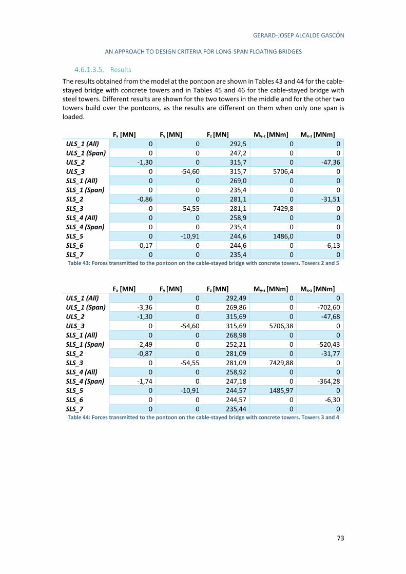
GERARD-JOSEP ALCALDE GASCÓN
AN APPROACH TO DESIGN CRITERIA FOR LONG-SPAN FLOATING BRIDGES
73
4.6.1.3.5. Results The results obtained from the model at the pontoon are shown in Tables 43 and 44 for the cable-stayed bridge with concrete towers and in Tables 45 and 46 for the cable-stayed bridge with steel towers. Different results are shown for the two towers in the middle and for the other two towers build over the pontoons, as the results are different on them when only one span is loaded.
Fx [MN] Fy [MN] Fz [MN] My-z [MNm] Mx-z [MNm]
ULS_1 (All) 0 0 292,5 0 0 ULS_1 (Span) 0 0 247,2 0 0 ULS_2 -1,30 0 315,7 0 -47,36 ULS_3 0 -54,60 315,7 5706,4 0 SLS_1 (All) 0 0 269,0 0 0 SLS_1 (Span) 0 0 235,4 0 0 SLS_2 -0,86 0 281,1 0 -31,51 SLS_3 0 -54,55 281,1 7429,8 0 SLS_4 (All) 0 0 258,9 0 0 SLS_4 (Span) 0 0 235,4 0 0 SLS_5 0 -10,91 244,6 1486,0 0 SLS_6 -0,17 0 244,6 0 -6,13 SLS_7 0 0 235,4 0 0 Table 43: Forces transmitted to the pontoon on the cable-stayed bridge with concrete towers. Towers 2 and 5
Fx [MN] Fy [MN] Fz [MN] My-z [MNm] Mx-z [MNm]
ULS_1 (All) 0 0 292,49 0 0 ULS_1 (Span) -3,36 0 269,86 0 -702,60 ULS_2 -1,30 0 315,69 0 -47,68 ULS_3 0 -54,60 315,69 5706,38 0 SLS_1 (All) 0 0 268,98 0 0 SLS_1 (Span) -2,49 0 252,21 0 -520,43 SLS_2 -0,87 0 281,09 0 -31,77 SLS_3 0 -54,55 281,09 7429,88 0 SLS_4 (All) 0 0 258,92 0 0 SLS_4 (Span) -1,74 0 247,18 0 -364,28 SLS_5 0 -10,91 244,57 1485,97 0 SLS_6 0 0 244,57 0 -6,30 SLS_7 0 0 235,44 0 0 Table 44: Forces transmitted to the pontoon on the cable-stayed bridge with concrete towers. Towers 3 and 4

GERARD-JOSEP ALCALDE GASCÓN
AN APPROACH TO DESIGN CRITERIA FOR LONG-SPAN FLOATING BRIDGES
74
Fx [MN] Fy [MN] Fz [MN] My-z [MNm] Mx-z [MNm]
ULS_1 (All) 0 0 205,62 0 0,14 ULS_1 (Span) 0 0 160,34 0 0 ULS_2 -0,57 0 228,81 0 -14,41 ULS_3 0 -25,37 228,81 2619,15 0 SLS_1 (All) 0 0 186,24 0 0 SLS_1 (Span) 0 0 152,70 0 0 SLS_2 -0,38 0 198,35 0 -9,58 SLS_3 0 -35,07 198,35 5371,65 0 SLS_4 (All) 0 0 176,18 0 0 SLS_4 (Span) 0 0 152,70 0 0 SLS_5 0 -7,01 161,83 1074,32 0 SLS_6 0 0 161,83 0 -1,84 SLS_7 0 0 152,70 0 0
Table 45: Forces transmitted to the pontoon on the cable-stayed bridge with steel towers. Towers 2 and 5
Fx [MN] Fy [MN] Fz [MN] My-z [MNm] Mx-z [MNm]
ULS_1 (All) 0 0 205,62 0 0,05 ULS_1 (Span) -1,54 0 182,98 0 -331,58 ULS_2 -0,57 0 228,81 0 -14,54 ULS_3 0 -25,37 228,81 2619,19 0 SLS_1 (All) 0 0 186,24 0 0 SLS_1 (Span) -1,14 0 169,47 0 -245,61 SLS_2 -0,38 0 198,35 0 -9,68 SLS_3 0 -35,07 198,35 5371,75 0 SLS_4 (All) 0 0 176,18 0 0 SLS_4 (Span) -0,80 0 164,44 0 -171,92 SLS_5 0 -7,01 161,83 1074,34 0 SLS_6 0 0 161,83 0 -1,91 SLS_7 0 0 152,70 0 0
Table 46: Forces transmitted to the pontoon on the cable-stayed bridge with steel towers. Towers 3 and 4
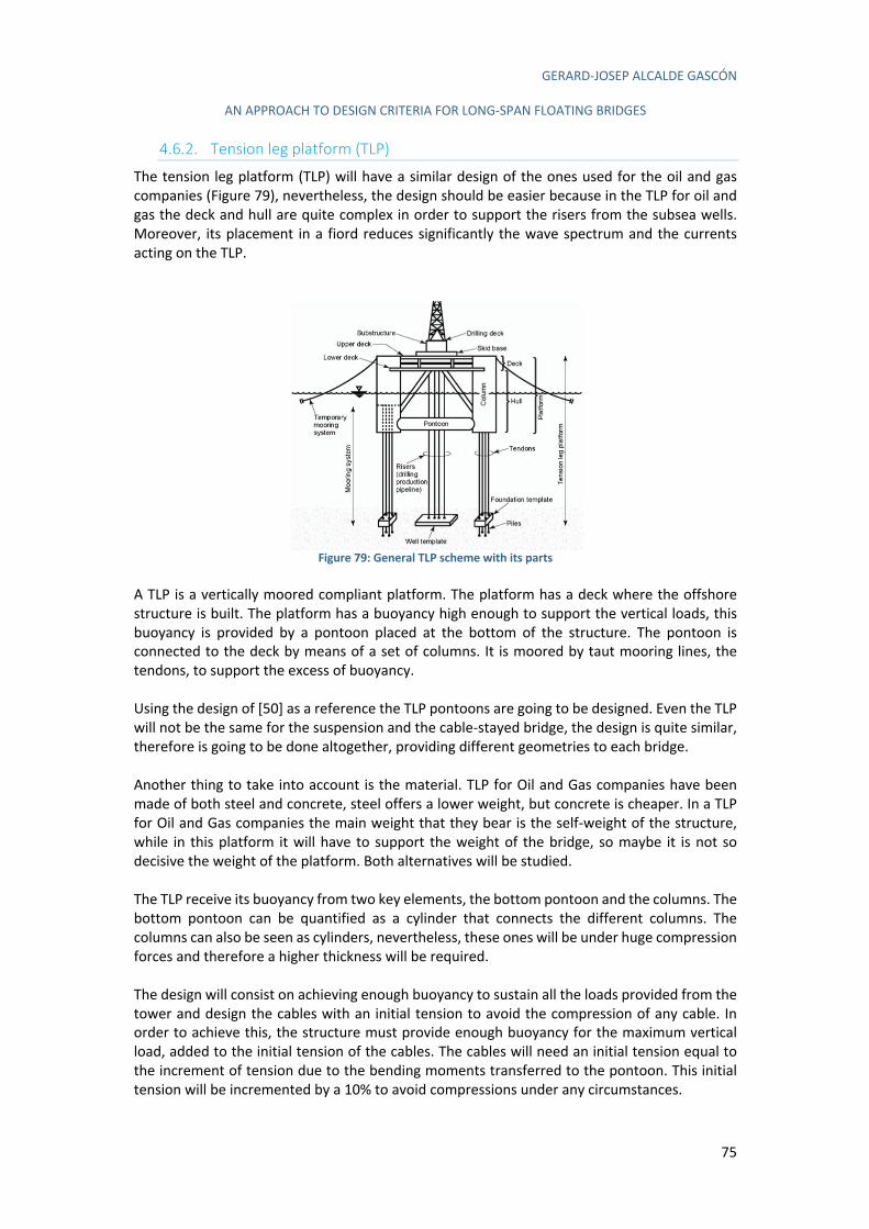
GERARD-JOSEP ALCALDE GASCÓN
AN APPROACH TO DESIGN CRITERIA FOR LONG-SPAN FLOATING BRIDGES
75
4.6.2. Tension leg platform (TLP)
The tension leg platform (TLP) will have a similar design of the ones used for the oil and gas companies (Figure 79), nevertheless, the design should be easier because in the TLP for oil and gas the deck and hull are quite complex in order to support the risers from the subsea wells. Moreover, its placement in a fiord reduces significantly the wave spectrum and the currents acting on the TLP.
Figure 79: General TLP scheme with its parts
A TLP is a vertically moored compliant platform. The platform has a deck where the offshore structure is built. The platform has a buoyancy high enough to support the vertical loads, this buoyancy is provided by a pontoon placed at the bottom of the structure. The pontoon is connected to the deck by means of a set of columns. It is moored by taut mooring lines, the tendons, to support the excess of buoyancy. Using the design of [50] as a reference the TLP pontoons are going to be designed. Even the TLP will not be the same for the suspension and the cable-stayed bridge, the design is quite similar, therefore is going to be done altogether, providing different geometries to each bridge. Another thing to take into account is the material. TLP for Oil and Gas companies have been made of both steel and concrete, steel offers a lower weight, but concrete is cheaper. In a TLP for Oil and Gas companies the main weight that they bear is the self-weight of the structure, while in this platform it will have to support the weight of the bridge, so maybe it is not so decisive the weight of the platform. Both alternatives will be studied. The TLP receive its buoyancy from two key elements, the bottom pontoon and the columns. The bottom pontoon can be quantified as a cylinder that connects the different columns. The columns can also be seen as cylinders, nevertheless, these ones will be under huge compression forces and therefore a higher thickness will be required. The design will consist on achieving enough buoyancy to sustain all the loads provided from the tower and design the cables with an initial tension to avoid the compression of any cable. In order to achieve this, the structure must provide enough buoyancy for the maximum vertical load, added to the initial tension of the cables. The cables will need an initial tension equal to the increment of tension due to the bending moments transferred to the pontoon. This initial tension will be incremented by a 10% to avoid compressions under any circumstances.
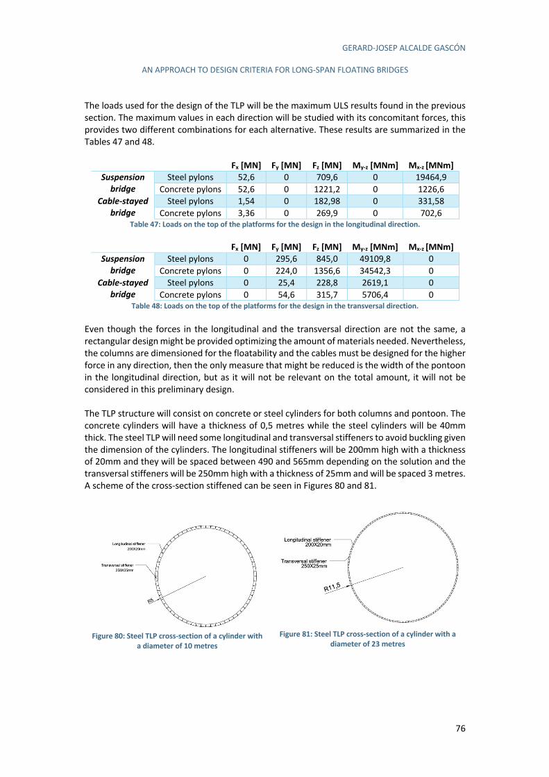
GERARD-JOSEP ALCALDE GASCÓN
AN APPROACH TO DESIGN CRITERIA FOR LONG-SPAN FLOATING BRIDGES
76
The loads used for the design of the TLP will be the maximum ULS results found in the previous section. The maximum values in each direction will be studied with its concomitant forces, this provides two different combinations for each alternative. These results are summarized in the Tables 47 and 48.
Fx [MN] Fy [MN] Fz [MN] My-z [MNm] Mx-z [MNm] Suspension
bridge Steel pylons 52,6 0 709,6 0 19464,9
Concrete pylons 52,6 0 1221,2 0 1226,6 Cable-stayed
bridge Steel pylons 1,54 0 182,98 0 331,58
Concrete pylons 3,36 0 269,9 0 702,6 Table 47: Loads on the top of the platforms for the design in the longitudinal direction.
Fx [MN] Fy [MN] Fz [MN] My-z [MNm] Mx-z [MNm]
Suspension bridge
Steel pylons 0 295,6 845,0 49109,8 0 Concrete pylons 0 224,0 1356,6 34542,3 0
Cable-stayed bridge
Steel pylons 0 25,4 228,8 2619,1 0 Concrete pylons 0 54,6 315,7 5706,4 0
Table 48: Loads on the top of the platforms for the design in the transversal direction. Even though the forces in the longitudinal and the transversal direction are not the same, a rectangular design might be provided optimizing the amount of materials needed. Nevertheless, the columns are dimensioned for the floatability and the cables must be designed for the higher force in any direction, then the only measure that might be reduced is the width of the pontoon in the longitudinal direction, but as it will not be relevant on the total amount, it will not be considered in this preliminary design. The TLP structure will consist on concrete or steel cylinders for both columns and pontoon. The concrete cylinders will have a thickness of 0,5 metres while the steel cylinders will be 40mm thick. The steel TLP will need some longitudinal and transversal stiffeners to avoid buckling given the dimension of the cylinders. The longitudinal stiffeners will be 200mm high with a thickness of 20mm and they will be spaced between 490 and 565mm depending on the solution and the transversal stiffeners will be 250mm high with a thickness of 25mm and will be spaced 3 metres. A scheme of the cross-section stiffened can be seen in Figures 80 and 81.
Figure 80: Steel TLP cross-section of a cylinder with
a diameter of 10 metres
Figure 81: Steel TLP cross-section of a cylinder with a
diameter of 23 metres
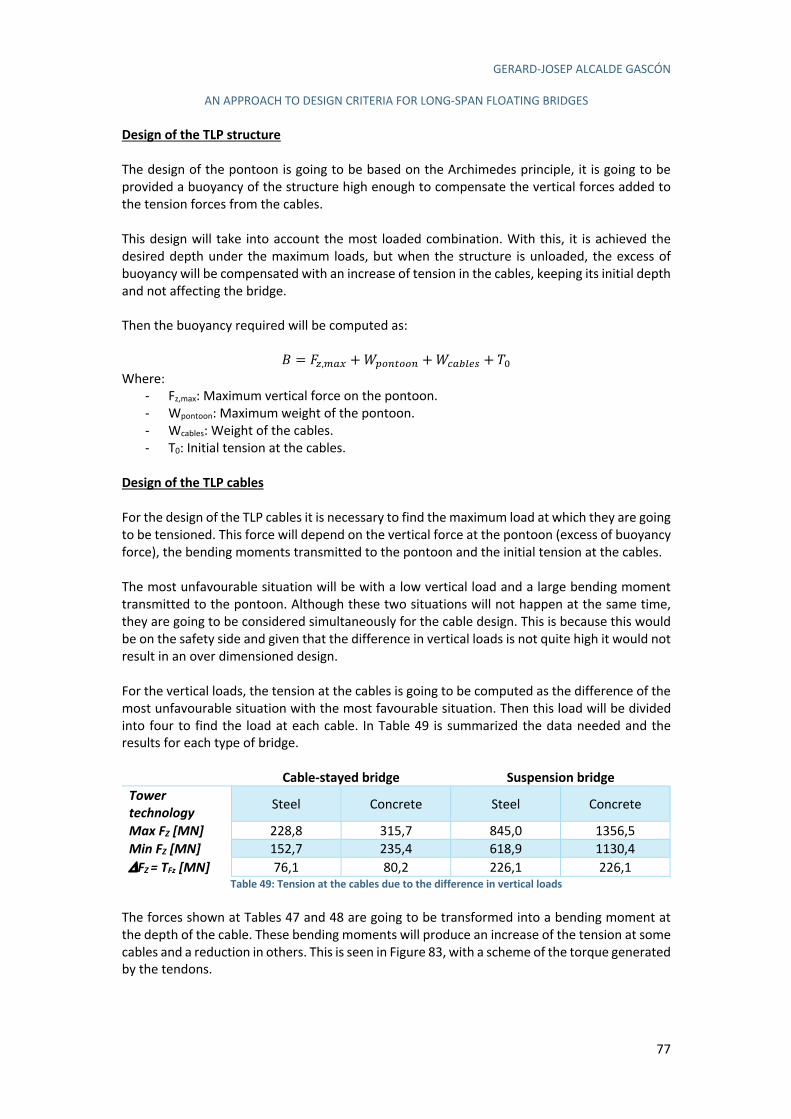
GERARD-JOSEP ALCALDE GASCÓN
AN APPROACH TO DESIGN CRITERIA FOR LONG-SPAN FLOATING BRIDGES
77
Design of the TLP structure
The design of the pontoon is going to be based on the Archimedes principle, it is going to be provided a buoyancy of the structure high enough to compensate the vertical forces added to the tension forces from the cables. This design will take into account the most loaded combination. With this, it is achieved the desired depth under the maximum loads, but when the structure is unloaded, the excess of buoyancy will be compensated with an increase of tension in the cables, keeping its initial depth and not affecting the bridge. Then the buoyancy required will be computed as:
K = A8,'K/ +é[H*IHH* +éGK&41J + n( Where:
- Fz,max: Maximum vertical force on the pontoon. - Wpontoon: Maximum weight of the pontoon. - Wcables: Weight of the cables. - T0: Initial tension at the cables.
Design of the TLP cables
For the design of the TLP cables it is necessary to find the maximum load at which they are going to be tensioned. This force will depend on the vertical force at the pontoon (excess of buoyancy force), the bending moments transmitted to the pontoon and the initial tension at the cables. The most unfavourable situation will be with a low vertical load and a large bending moment transmitted to the pontoon. Although these two situations will not happen at the same time, they are going to be considered simultaneously for the cable design. This is because this would be on the safety side and given that the difference in vertical loads is not quite high it would not result in an over dimensioned design. For the vertical loads, the tension at the cables is going to be computed as the difference of the most unfavourable situation with the most favourable situation. Then this load will be divided into four to find the load at each cable. In Table 49 is summarized the data needed and the results for each type of bridge.
Cable-stayed bridge Suspension bridge
Tower technology Steel Concrete Steel Concrete
Max FZ [MN] 228,8 315,7 845,0 1356,5 Min FZ [MN] 152,7 235,4 618,9 1130,4 DFZ = TFz [MN] 76,1 80,2 226,1 226,1
Table 49: Tension at the cables due to the difference in vertical loads The forces shown at Tables 47 and 48 are going to be transformed into a bending moment at the depth of the cable. These bending moments will produce an increase of the tension at some cables and a reduction in others. This is seen in Figure 83, with a scheme of the torque generated by the tendons.
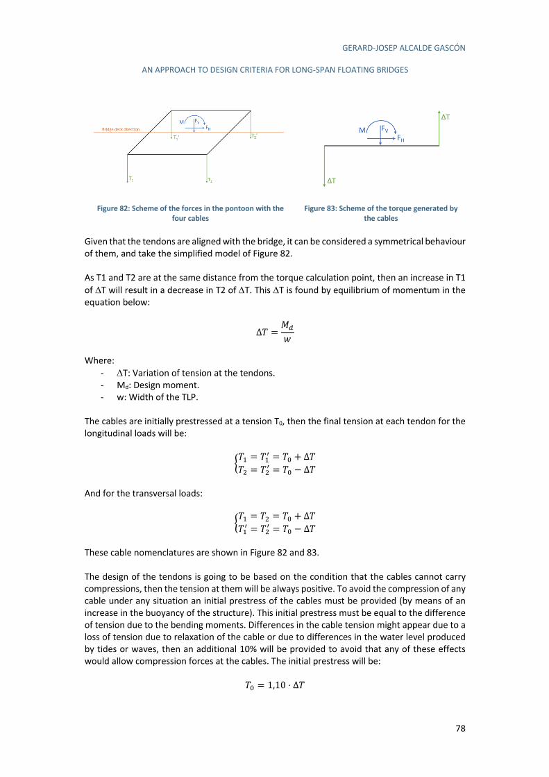
GERARD-JOSEP ALCALDE GASCÓN
AN APPROACH TO DESIGN CRITERIA FOR LONG-SPAN FLOATING BRIDGES
78
Figure 82: Scheme of the forces in the pontoon with the four cables
Figure 83: Scheme of the torque generated by the cables
Given that the tendons are aligned with the bridge, it can be considered a symmetrical behaviour of them, and take the simplified model of Figure 82. As T1 and T2 are at the same distance from the torque calculation point, then an increase in T1 of DT will result in a decrease in T2 of DT. This DT is found by equilibrium of momentum in the equation below:
Δn =e#
ê
Where:
- DT: Variation of tension at the tendons. - Md: Design moment. - w: Width of the TLP.
The cables are initially prestressed at a tension T0, then the final tension at each tendon for the longitudinal loads will be:
ën3 = n3\ = n( + Δnn0 = n0\ = n( − Δn
And for the transversal loads:
ën3 = n0 = n( + Δnn3\ = n0\ = n( − Δn
These cable nomenclatures are shown in Figure 82 and 83. The design of the tendons is going to be based on the condition that the cables cannot carry compressions, then the tension at them will be always positive. To avoid the compression of any cable under any situation an initial prestress of the cables must be provided (by means of an increase in the buoyancy of the structure). This initial prestress must be equal to the difference of tension due to the bending moments. Differences in the cable tension might appear due to a loss of tension due to relaxation of the cable or due to differences in the water level produced by tides or waves, then an additional 10% will be provided to avoid that any of these effects would allow compression forces at the cables. The initial prestress will be:
n( = 1,10 · ∆n
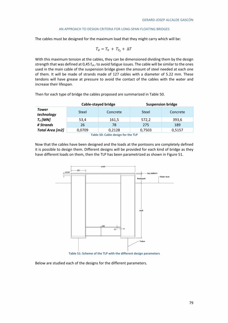
GERARD-JOSEP ALCALDE GASCÓN
AN APPROACH TO DESIGN CRITERIA FOR LONG-SPAN FLOATING BRIDGES
79
The cables must be designed for the maximum load that they might carry which will be:
n# = n( + n]) +∆n With this maximum tension at the cables, they can be dimensioned dividing them by the design strength that was defined at 0,45 fyk,r to avoid fatigue issues. The cable will be similar to the ones used in the main cable of the suspension bridge given the amount of steel needed at each one of them. It will be made of strands made of 127 cables with a diameter of 5.22 mm. These tendons will have grease at pressure to avoid the contact of the cables with the water and increase their lifespan. Then for each type of bridge the cables proposed are summarized in Table 50.
Cable-stayed bridge Suspension bridge
Tower technology Steel Concrete Steel Concrete
Td [MN] 53,4 161,5 572,2 393,6 # Strands 26 78 275 189 Total Area [m2] 0,0709 0,2128 0,7503 0,5157
Table 50: Cable design for the TLP Now that the cables have been designed and the loads at the pontoons are completely defined it is possible to design them. Different designs will be provided for each kind of bridge as they have different loads on them, then the TLP has been parametrized as shown in Figure 51.
Table 51: Scheme of the TLP with the different design parameters
Below are studied each of the designs for the different parameters.
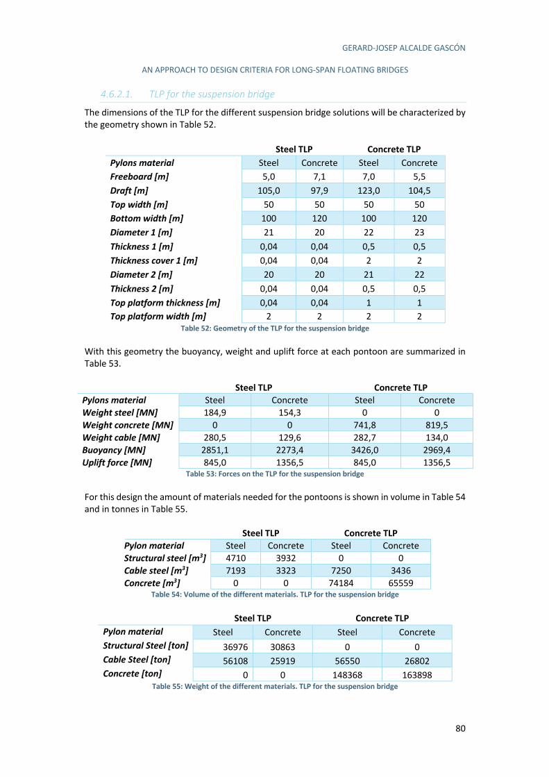
GERARD-JOSEP ALCALDE GASCÓN
AN APPROACH TO DESIGN CRITERIA FOR LONG-SPAN FLOATING BRIDGES
80
4.6.2.1. TLP for the suspension bridge
The dimensions of the TLP for the different suspension bridge solutions will be characterized by the geometry shown in Table 52.
Steel TLP Concrete TLP
Pylons material Steel Concrete Steel Concrete Freeboard [m] 5,0 7,1 7,0 5,5 Draft [m] 105,0 97,9 123,0 104,5 Top width [m] 50 50 50 50 Bottom width [m] 100 120 100 120 Diameter 1 [m] 21 20 22 23 Thickness 1 [m] 0,04 0,04 0,5 0,5 Thickness cover 1 [m] 0,04 0,04 2 2 Diameter 2 [m] 20 20 21 22 Thickness 2 [m] 0,04 0,04 0,5 0,5 Top platform thickness [m] 0,04 0,04 1 1 Top platform width [m] 2 2 2 2
Table 52: Geometry of the TLP for the suspension bridge With this geometry the buoyancy, weight and uplift force at each pontoon are summarized in Table 53.
Steel TLP Concrete TLP
Pylons material Steel Concrete Steel Concrete Weight steel [MN] 184,9 154,3 0 0 Weight concrete [MN] 0 0 741,8 819,5 Weight cable [MN] 280,5 129,6 282,7 134,0 Buoyancy [MN] 2851,1 2273,4 3426,0 2969,4 Uplift force [MN] 845,0 1356,5 845,0 1356,5
Table 53: Forces on the TLP for the suspension bridge For this design the amount of materials needed for the pontoons is shown in volume in Table 54 and in tonnes in Table 55.
Steel TLP Concrete TLP
Pylon material Steel Concrete Steel Concrete Structural steel [m3] 4710 3932 0 0 Cable steel [m3] 7193 3323 7250 3436 Concrete [m3] 0 0 74184 65559
Table 54: Volume of the different materials. TLP for the suspension bridge
Steel TLP Concrete TLP
Pylon material Steel Concrete Steel Concrete Structural Steel [ton] 36976 30863 0 0 Cable Steel [ton] 56108 25919 56550 26802 Concrete [ton] 0 0 148368 163898
Table 55: Weight of the different materials. TLP for the suspension bridge
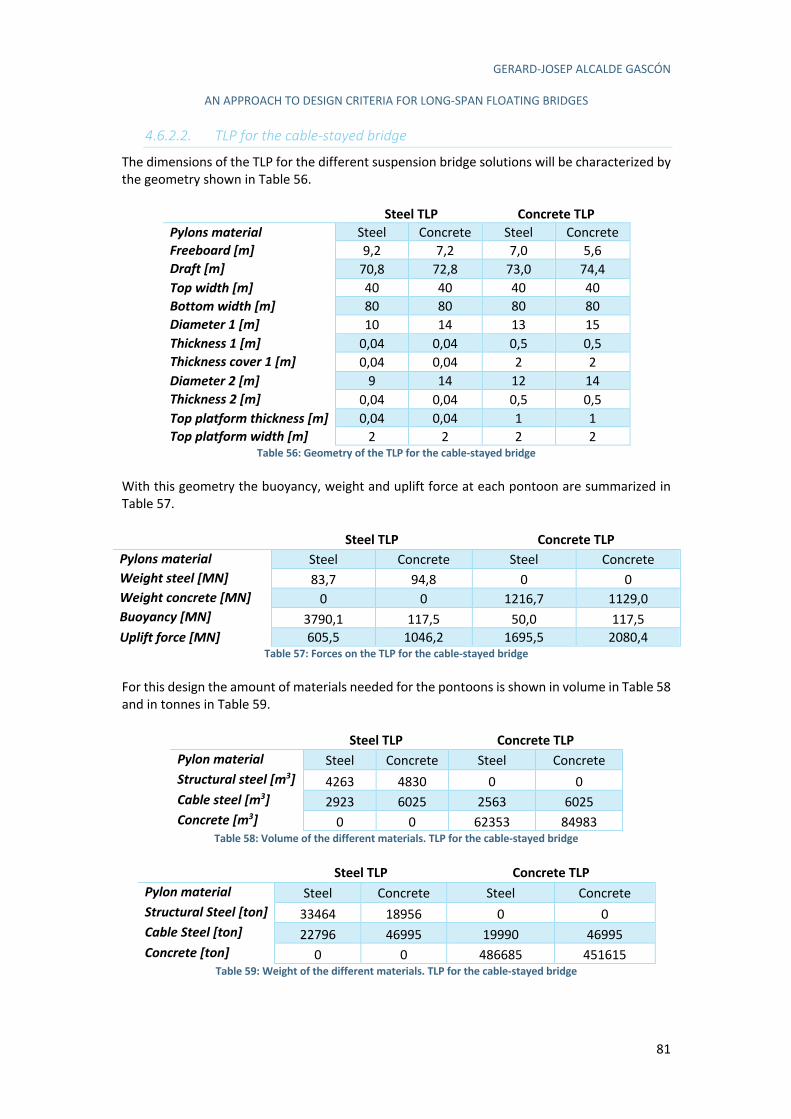
GERARD-JOSEP ALCALDE GASCÓN
AN APPROACH TO DESIGN CRITERIA FOR LONG-SPAN FLOATING BRIDGES
81
4.6.2.2. TLP for the cable-stayed bridge
The dimensions of the TLP for the different suspension bridge solutions will be characterized by the geometry shown in Table 56.
Steel TLP Concrete TLP
Pylons material Steel Concrete Steel Concrete Freeboard [m] 9,2 7,2 7,0 5,6 Draft [m] 70,8 72,8 73,0 74,4 Top width [m] 40 40 40 40 Bottom width [m] 80 80 80 80 Diameter 1 [m] 10 14 13 15 Thickness 1 [m] 0,04 0,04 0,5 0,5 Thickness cover 1 [m] 0,04 0,04 2 2 Diameter 2 [m] 9 14 12 14 Thickness 2 [m] 0,04 0,04 0,5 0,5 Top platform thickness [m] 0,04 0,04 1 1 Top platform width [m] 2 2 2 2
Table 56: Geometry of the TLP for the cable-stayed bridge With this geometry the buoyancy, weight and uplift force at each pontoon are summarized in Table 57. Steel TLP Concrete TLP
Pylons material Steel Concrete Steel Concrete Weight steel [MN] 83,7 94,8 0 0 Weight concrete [MN] 0 0 1216,7 1129,0 Buoyancy [MN] 3790,1 117,5 50,0 117,5 Uplift force [MN] 605,5 1046,2 1695,5 2080,4
Table 57: Forces on the TLP for the cable-stayed bridge For this design the amount of materials needed for the pontoons is shown in volume in Table 58 and in tonnes in Table 59.
Steel TLP Concrete TLP
Pylon material Steel Concrete Steel Concrete Structural steel [m3] 4263 4830 0 0 Cable steel [m3] 2923 6025 2563 6025 Concrete [m3] 0 0 62353 84983
Table 58: Volume of the different materials. TLP for the cable-stayed bridge
Steel TLP Concrete TLP
Pylon material Steel Concrete Steel Concrete Structural Steel [ton] 33464 18956 0 0 Cable Steel [ton] 22796 46995 19990 46995 Concrete [ton] 0 0 486685 451615
Table 59: Weight of the different materials. TLP for the cable-stayed bridge

GERARD-JOSEP ALCALDE GASCÓN
AN APPROACH TO DESIGN CRITERIA FOR LONG-SPAN FLOATING BRIDGES
82
4.6.3. Tethered spar-buoy
The tethered spar-buoy is an intermediate concept between a pure spar-buoy and a tension leg platform. While a pure spar-buoy bases is stability exclusively on the equilibrium of momentum, given that the centre of gravity is much lower than the centre of buoyancy, the tethered spar-buoy introduces tethers in the upper part of the buoy which avoids the displacement of the platform and reduces the pitch. The design of the spar buoy will be relatively similar to the tension leg platform. The ULS combinations will be used to design a structure that provides enough buoyancy to compensate the vertical forces. Afterwards, the SLS combinations will be used to determine the rotational stiffness of the pontoon, using the limitations provided in the project specifications. The forces on the pontoon are the ones shown in section 4.6.1.3.5. A summary of the most important forces for this design is shown in Tables 60 and 61 for the ULS combinations.
Fx [MN] Fy [MN] Fz [MN] My-z [MNm] Mx-z [MNm] Suspension
bridge Steel pylons 52,6 0 709,6 0 19465
Concrete pylons 52,6 0 1221 0 1227 Cable-stayed
bridge Steel pylons 1,54 0 183 0 331,6
Concrete pylons 3,36 0 269,9 0 702,6 Table 60: Loads on the top of the platforms for the ULS design in the longitudinal direction.
Fx [MN] Fy [MN] Fz [MN] My-z [MNm] Mx-z [MNm]
Suspension bridge
Steel pylons 0 295,6 845,0 49110 0 Concrete pylons 0 224,0 1357 34542 0
Cable-stayed bridge
Steel pylons 0 49,1 228,8 7350 0 Concrete pylons 0 78,3 315,7 10438 0
Table 61: Loads on the top of the platforms for the ULS design in the transversal direction. The results for the SLS combinations are summarized in Tables 62 and 63.
Fx [MN] Fy [MN] Fz [MN] My-z [MNm] Mx-z [MNm] Suspension
bridge Steel pylons 41,4 0 668,4 0 15312
Concrete pylons 41,4 0 1180 0 15312 Cable-stayed
bridge Steel pylons 1,14 0 169,5 0 245,6
Concrete pylons 2,49 0 252,2 0 520,4 Table 62: Loads on the top of the platforms for the SLS design in the longitudinal direction.
Fx [MN] Fy [MN] Fz [MN] My-z [MNm] Mx-z [MNm]
Suspension bridge
Steel pylons 0 197,1 753,7 32740 0 Concrete pylons 0 96,2 1265 13394 0
Cable-stayed bridge
Steel pylons 0 35,1 198,4 5372 0 Concrete pylons 0 54,6 281,1 7430 0
Table 63: Loads on the top of the platforms for the SLS design in the transversal direction. First it is going to be computed the necessary buoyancy of the pontoon. The pontoon must support the weight of the bridge, the vertical loads transferred to the pontoon (wind and traffic), the self-weight of the pontoon, the weight of the taut mooring cables and the tension that these ones will project in the vertical direction. This is summarized in the following equation.
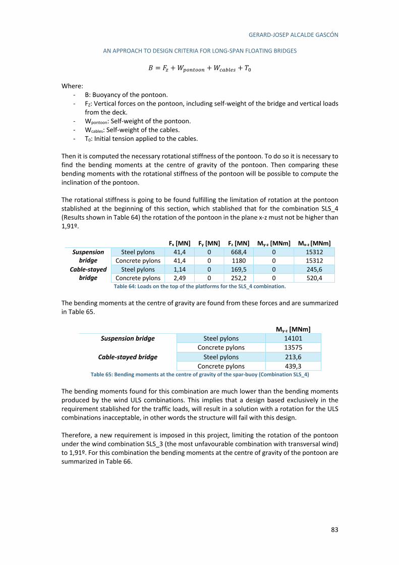
GERARD-JOSEP ALCALDE GASCÓN
AN APPROACH TO DESIGN CRITERIA FOR LONG-SPAN FLOATING BRIDGES
83
K = A8 +é[H*IHH* +éGK&41J + n( Where:
- B: Buoyancy of the pontoon. - FZ: Vertical forces on the pontoon, including self-weight of the bridge and vertical loads
from the deck. - Wpontoon: Self-weight of the pontoon. - Wcables: Self-weight of the cables. - T0: Initial tension applied to the cables.
Then it is computed the necessary rotational stiffness of the pontoon. To do so it is necessary to find the bending moments at the centre of gravity of the pontoon. Then comparing these bending moments with the rotational stiffness of the pontoon will be possible to compute the inclination of the pontoon. The rotational stiffness is going to be found fulfilling the limitation of rotation at the pontoon stablished at the beginning of this section, which stablished that for the combination SLS_4 (Results shown in Table 64) the rotation of the pontoon in the plane x-z must not be higher than 1,91º.
Fx [MN] Fy [MN] Fz [MN] My-z [MNm] Mx-z [MNm] Suspension
bridge Steel pylons 41,4 0 668,4 0 15312
Concrete pylons 41,4 0 1180 0 15312 Cable-stayed
bridge Steel pylons 1,14 0 169,5 0 245,6
Concrete pylons 2,49 0 252,2 0 520,4 Table 64: Loads on the top of the platforms for the SLS_4 combination.
The bending moments at the centre of gravity are found from these forces and are summarized in Table 65.
My-z [MNm]
Suspension bridge Steel pylons 14101 Concrete pylons 13575
Cable-stayed bridge Steel pylons 213,6 Concrete pylons 439,3
Table 65: Bending moments at the centre of gravity of the spar-buoy (Combination SLS_4) The bending moments found for this combination are much lower than the bending moments produced by the wind ULS combinations. This implies that a design based exclusively in the requirement stablished for the traffic loads, will result in a solution with a rotation for the ULS combinations inacceptable, in other words the structure will fail with this design. Therefore, a new requirement is imposed in this project, limiting the rotation of the pontoon under the wind combination SLS_3 (the most unfavourable combination with transversal wind) to 1,91º. For this combination the bending moments at the centre of gravity of the pontoon are summarized in Table 66.
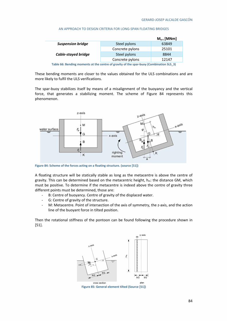
GERARD-JOSEP ALCALDE GASCÓN
AN APPROACH TO DESIGN CRITERIA FOR LONG-SPAN FLOATING BRIDGES
84
My-z [MNm]
Suspension bridge Steel pylons 63849 Concrete pylons 25101
Cable-stayed bridge Steel pylons 8844 Concrete pylons 12147
Table 66: Bending moments at the centre of gravity of the spar-buoy (Combination SLS_3) These bending moments are closer to the values obtained for the ULS combinations and are more likely to fulfil the ULS verifications. The spar-buoy stabilizes itself by means of a misalignment of the buoyancy and the vertical force, that generates a stabilizing moment. The scheme of Figure 84 represents this phenomenon.
Figure 84: Scheme of the forces acting on a floating structure. (source [51]) A floating structure will be statically stable as long as the metacentre is above the centre of gravity. This can be determined based on the metacentric height, hm: the distance GM, which must be positive. To determine if the metacentre is indeed above the centre of gravity three different points must be determined, those are:
- B: Centre of buoyancy. Centre of gravity of the displaced water. - G: Centre of gravity of the structure. - M: Metacentre. Point of intersection of the axis of symmetry, the z-axis, and the action
line of the buoyant force in tilted position. Then the rotational stiffness of the pontoon can be found following the procedure shown in [51].
Figure 85: General element tilted (Source [51])
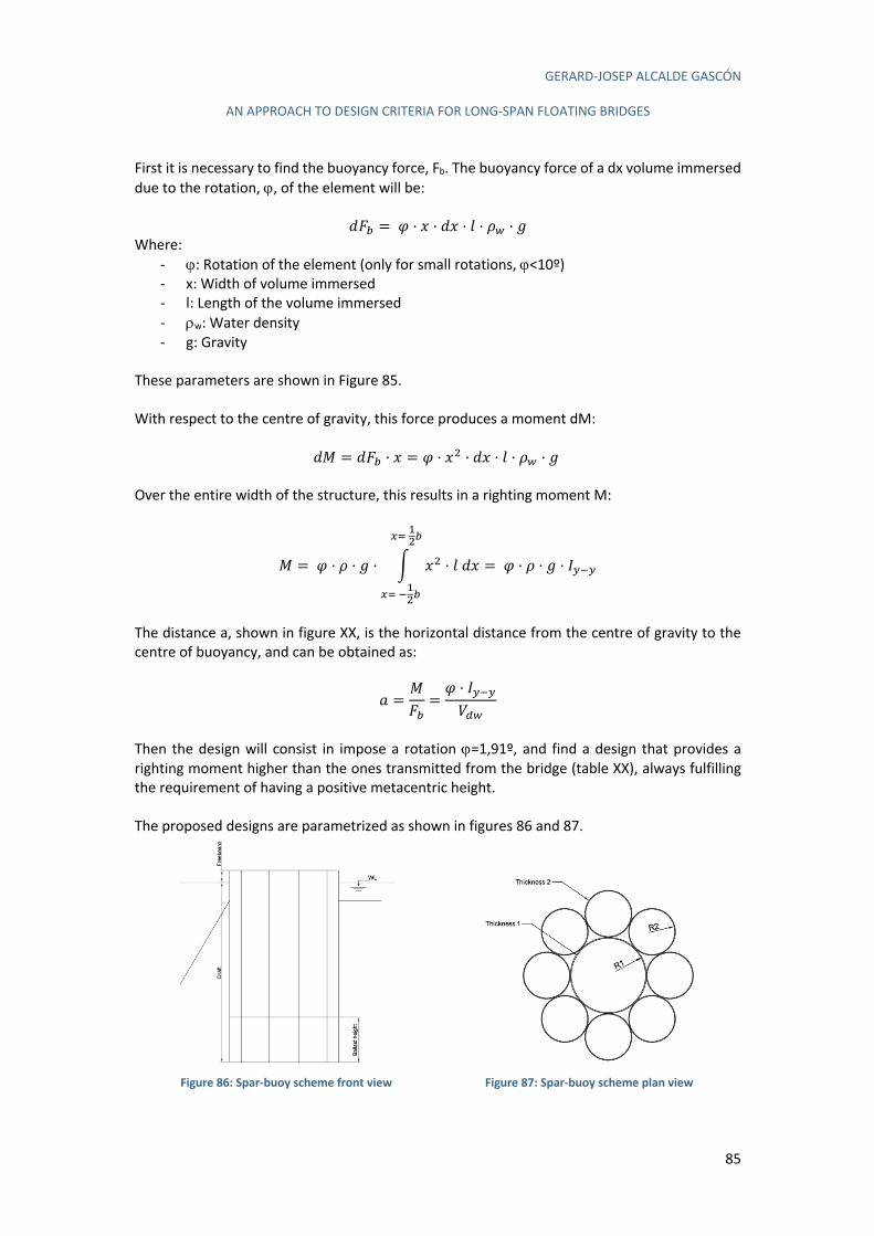
GERARD-JOSEP ALCALDE GASCÓN
AN APPROACH TO DESIGN CRITERIA FOR LONG-SPAN FLOATING BRIDGES
85
First it is necessary to find the buoyancy force, Fb. The buoyancy force of a dx volume immersed due to the rotation, j, of the element will be:
íA& = à · m · ím · { · B. · Ä Where:
- j: Rotation of the element (only for small rotations, j<10º) - x: Width of volume immersed - l: Length of the volume immersed - rw: Water density - g: Gravity
These parameters are shown in Figure 85. With respect to the centre of gravity, this force produces a moment dM:
íe = íA& · m = à · m0 · ím · { · B. · Ä Over the entire width of the structure, this results in a righting moment M:
e = à · B · Ä · ì m0 · {ím
/^30&
/^W30&
= à · B · Ä · å!W!
The distance a, shown in figure XX, is the horizontal distance from the centre of gravity to the centre of buoyancy, and can be obtained as:
g =eA&=à · å!W!o#.
Then the design will consist in impose a rotation j=1,91º, and find a design that provides a righting moment higher than the ones transmitted from the bridge (table XX), always fulfilling the requirement of having a positive metacentric height. The proposed designs are parametrized as shown in figures 86 and 87.
Figure 86: Spar-buoy scheme front view
Figure 87: Spar-buoy scheme plan view
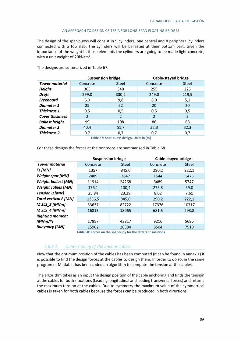
GERARD-JOSEP ALCALDE GASCÓN
AN APPROACH TO DESIGN CRITERIA FOR LONG-SPAN FLOATING BRIDGES
86
The design of the spar-buoys will consist in 9 cylinders, one central and 8 peripheral cylinders connected with a top slab. The cylinders will be ballasted at their bottom part. Given the importance of the weight in those elements the cylinders are going to be made light concrete, with a unit weight of 20kN/m3. The designs are summarized in Table 67.
Suspension bridge Cable-stayed bridge
Tower material Concrete Steel Concrete Steel Height 305 340 255 225 Draft 299,0 330,2 249,0 219,9 Freeboard 6,0 9,8 6,0 5,1 Diameter 1 25 32 20 20 Thickness 1 0,5 0,5 0,5 0,5 Cover thickness 2 2 2 2 Ballast height 99 108 86 68 Diameter 2 40,4 51,7 32,3 32,3 Thickness 2 0,7 0,7 0,7 0,7
Table 67: Spar-buoys design. Units in [m] For these designs the forces at the pontoons are summarized in Table 68. Suspension bridge Cable-stayed bridge
Tower material Concrete Steel Concrete Steel Fz [MN] 1357 845,0 290,2 222,1 Weight spar [MN] 2489 3647 1644 1475 Weight ballast [MN] 11914 24268 6489 5747 Weight cables [MN] 176,1 100,4 275,3 59,0 Tension 0 [MN] 25,84 23,29 8,02 7,61 Total vertical F [MN] 1356,5 845,0 290,2 222,1 M SLS_3 [MNm] 33637 82722 17376 10717 M SLS_4 [MNm] 16813 18065 681,5 293,8 Righting moment [MNm/º] 17857 43817 9216 5686 Buoyancy [MN] 15962 28884 8504 7510
Table 68: Forces on the spar-buoy for the different solutions
4.6.3.1. Dimensioning of the anchor cables
Now that the optimum position of the cables has been computed (it can be found in annex 1) it is possible to find the design forces at the cables to design them. In order to do so, in the same program of Matlab it has been coded an algorithm to compute the tension at the cables. The algorithm takes as an input the design position of the cable anchoring and finds the tension at the cables for both situations (Leading longitudinal and leading transversal forces) and returns the maximum tension at the cables. Due to symmetry the maximum value of the symmetrical cables is taken for both cables because the forces can be produced in both directions.
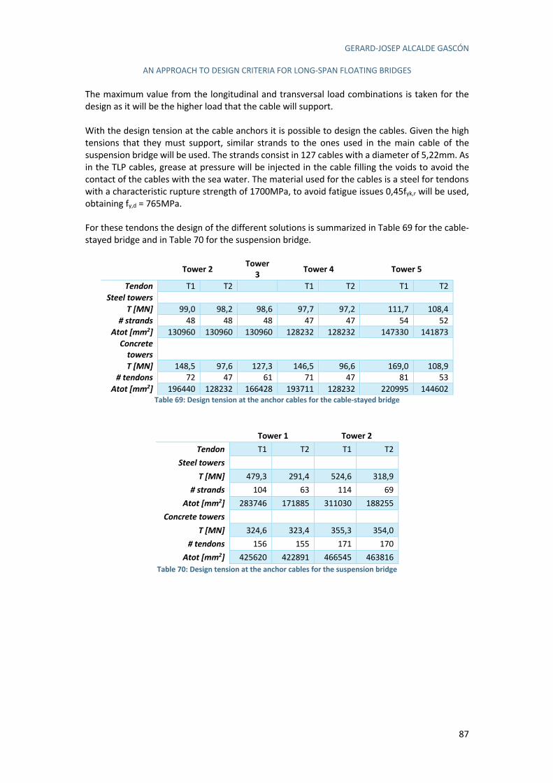
GERARD-JOSEP ALCALDE GASCÓN
AN APPROACH TO DESIGN CRITERIA FOR LONG-SPAN FLOATING BRIDGES
87
The maximum value from the longitudinal and transversal load combinations is taken for the design as it will be the higher load that the cable will support. With the design tension at the cable anchors it is possible to design the cables. Given the high tensions that they must support, similar strands to the ones used in the main cable of the suspension bridge will be used. The strands consist in 127 cables with a diameter of 5,22mm. As in the TLP cables, grease at pressure will be injected in the cable filling the voids to avoid the contact of the cables with the sea water. The material used for the cables is a steel for tendons with a characteristic rupture strength of 1700MPa, to avoid fatigue issues 0,45fyk,r will be used, obtaining fy,d = 765MPa. For these tendons the design of the different solutions is summarized in Table 69 for the cable-stayed bridge and in Table 70 for the suspension bridge.
Tower 2
Tower
3 Tower 4 Tower 5
Tendon T1 T2 T1 T2 T1 T2
Steel towers
T [MN] 99,0 98,2 98,6 97,7 97,2 111,7 108,4
# strands 48 48 48 47 47 54 52
Atot [mm2] 130960 130960 130960 128232 128232 147330 141873
Concrete towers
T [MN] 148,5 97,6 127,3 146,5 96,6 169,0 108,9
# tendons 72 47 61 71 47 81 53
Atot [mm2] 196440 128232 166428 193711 128232 220995 144602 Table 69: Design tension at the anchor cables for the cable-stayed bridge
Tower 1 Tower 2
Tendon T1 T2 T1 T2
Steel towers
T [MN] 479,3 291,4 524,6 318,9
# strands 104 63 114 69
Atot [mm2] 283746 171885 311030 188255
Concrete towers
T [MN] 324,6 323,4 355,3 354,0
# tendons 156 155 171 170
Atot [mm2] 425620 422891 466545 463816
Table 70: Design tension at the anchor cables for the suspension bridge
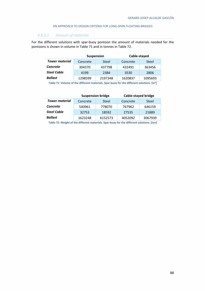
GERARD-JOSEP ALCALDE GASCÓN
AN APPROACH TO DESIGN CRITERIA FOR LONG-SPAN FLOATING BRIDGES
88
4.6.3.2. Amount of materials
For the different solutions with spar-buoy pontoon the amount of materials needed for the pontoons is shown in volume in Table 71 and in tonnes in Table 72.
Suspension Cable-stayed
Tower material Concrete Steel Concrete Steel Concrete 304370 437798 432491 363456 Steel Cable 4199 2384 3530 2806 Ballast 1298599 2197348 1620837 1095693
Table 71: Volume of the different materials. Spar-buoy for the different solutions. [m3]
Suspension bridge Cable-stayed bridge
Tower material Concrete Steel Concrete Steel Concrete 540961 778070 767962 646159 Steel Cable 32753 18592 27535 21889 Ballast 1623248 6152573 4052092 3067939
Table 72: Weight of the different materials. Spar-buoy for the different solutions. [ton]
GERARD-JOSEP ALCALDE GASCÓN
AN APPROACH TO DESIGN CRITERIA FOR LONG-SPAN FLOATING BRIDGES
89
4.6.4. Anchoring
Both TLP and spar buoys require an anchoring for the cables. These cables support a huge tension and, therefore, the anchoring to the terrain is usually a critical part of the pontoon design. The anchoring will depend on different parameters, but an essential one is the soil material. Soft soils will require different technologies than a stiff soil. The fiord geological profile shows a rock steep sides and a flat clay seabed. Then an in-depth study of each solution must be done. On the one side the TLP require vertical cables, what will imply that the anchorage will be made both on the rock steep slope or in clay seabed depending on the pontoon. On the other side, the spar-buoy anchorage cables can be leaned avoiding the anchorage at the rock and the difficulties that it implies. The anchorage at the clay seabed can be solved by means of suction caissons, that are widely used technology for this soil material and provide a good solution. Nevertheless, the anchorage at the rock it is going to be quite difficult for three reasons:
- The anchorage will work at tension, not at compression. - The fiord side is quite steep, what will make really difficult the installation of any
anchorage system and might require some previous preparation of the terrain. - The depths of the fiord are extreme what makes any operation complex.
Given these difficulties has been chosen to use driven piles for the anchorage on the rock. Then after studying the fiord layout the suction caissons can be used for all the cable anchoring of the spar-buoys to the seabed and for the cable anchoring of the TLP corresponding to the tower 3 of the cable-stayed solution, while the driven pile solution will be used exclusively on the TLP solutions for the towers 2, 4 and 5 of the cable-stayed solution and for all the towers in the suspension bridge solution. A study of each system and the design for the different solutions is going to be carried below.
4.6.4.1. Suction Caisson
The anchoring of the pontoons to the seabed will be done by means of suctions caissons, which is a large cylindrical structure, usually made of steel, open at its base and closed at the top. The design consist in carrying the permanent load with the submerged weight of the anchor and the load variations due to tides and waves is carried by the friction and suction of the caisson [38]. Suction caissons offer a range of advantages over other anchoring methods such as drag anchors. The accuracy in the positioning of the caisson and the possibility to remove it are just some of the advantages that it offers. The suction caisson is a structure well-known in the offshore sector after more than 25 years using it in different projects. The depth of this particular project in Norway, should not be a special issue as suction caissons have been installed in water depths up to 1500 metres. The installation of a suction caisson is quite complex, and it is based in two phases. Firstly, the suction caisson penetrates in the soil by its self-weight. When the self-weight penetrating phase has finished the suction-assisted penetration phase begins, where a suction is applied
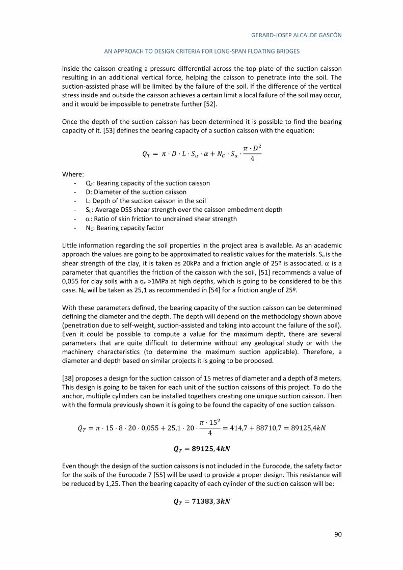
GERARD-JOSEP ALCALDE GASCÓN
AN APPROACH TO DESIGN CRITERIA FOR LONG-SPAN FLOATING BRIDGES
90
inside the caisson creating a pressure differential across the top plate of the suction caisson resulting in an additional vertical force, helping the caisson to penetrate into the soil. The suction-assisted phase will be limited by the failure of the soil. If the difference of the vertical stress inside and outside the caisson achieves a certain limit a local failure of the soil may occur, and it would be impossible to penetrate further [52]. Once the depth of the suction caisson has been determined it is possible to find the bearing capacity of it. [53] defines the bearing capacity of a suction caisson with the equation:
î_ = ï · ñ · ` · ó` · a + OV · ó` ·ï · ñ0
4
Where:
- QT: Bearing capacity of the suction caisson - D: Diameter of the suction caisson - L: Depth of the suction caisson in the soil - Su: Average DSS shear strength over the caisson embedment depth - a: Ratio of skin friction to undrained shear strength - NC: Bearing capacity factor
Little information regarding the soil properties in the project area is available. As an academic approach the values are going to be approximated to realistic values for the materials. Su is the shear strength of the clay, it is taken as 20kPa and a friction angle of 25º is associated. a is a parameter that quantifies the friction of the caisson with the soil, [51] recommends a value of 0,055 for clay soils with a qc >1MPa at high depths, which is going to be considered to be this case. NC will be taken as 25,1 as recommended in [54] for a friction angle of 25º. With these parameters defined, the bearing capacity of the suction caisson can be determined defining the diameter and the depth. The depth will depend on the methodology shown above (penetration due to self-weight, suction-assisted and taking into account the failure of the soil). Even it could be possible to compute a value for the maximum depth, there are several parameters that are quite difficult to determine without any geological study or with the machinery characteristics (to determine the maximum suction applicable). Therefore, a diameter and depth based on similar projects it is going to be proposed. [38] proposes a design for the suction caisson of 15 metres of diameter and a depth of 8 meters. This design is going to be taken for each unit of the suction caissons of this project. To do the anchor, multiple cylinders can be installed togethers creating one unique suction caisson. Then with the formula previously shown it is going to be found the capacity of one suction caisson.
î_ = ï · 15 · 8 · 20 · 0,055 + 25,1 · 20 ·ï · 150
4= 414,7 + 88710,7 = 89125,45O
òa = RôSQç, TUV
Even though the design of the suction caissons is not included in the Eurocode, the safety factor for the soils of the Eurocode 7 [55] will be used to provide a proper design. This resistance will be reduced by 1,25. Then the bearing capacity of each cylinder of the suction caisson will be:
òa = YSöRö, öUV
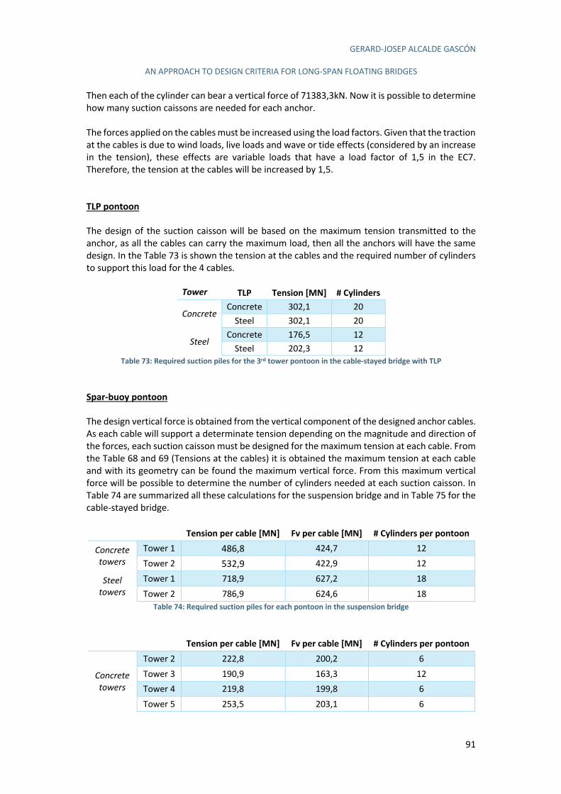
GERARD-JOSEP ALCALDE GASCÓN
AN APPROACH TO DESIGN CRITERIA FOR LONG-SPAN FLOATING BRIDGES
91
Then each of the cylinder can bear a vertical force of 71383,3kN. Now it is possible to determine how many suction caissons are needed for each anchor. The forces applied on the cables must be increased using the load factors. Given that the traction at the cables is due to wind loads, live loads and wave or tide effects (considered by an increase in the tension), these effects are variable loads that have a load factor of 1,5 in the EC7. Therefore, the tension at the cables will be increased by 1,5. TLP pontoon
The design of the suction caisson will be based on the maximum tension transmitted to the anchor, as all the cables can carry the maximum load, then all the anchors will have the same design. In the Table 73 is shown the tension at the cables and the required number of cylinders to support this load for the 4 cables.
Tower TLP Tension [MN] # Cylinders
Concrete Concrete 302,1 20
Steel 302,1 20
Steel Concrete 176,5 12
Steel 202,3 12 Table 73: Required suction piles for the 3rd tower pontoon in the cable-stayed bridge with TLP
Spar-buoy pontoon
The design vertical force is obtained from the vertical component of the designed anchor cables. As each cable will support a determinate tension depending on the magnitude and direction of the forces, each suction caisson must be designed for the maximum tension at each cable. From the Table 68 and 69 (Tensions at the cables) it is obtained the maximum tension at each cable and with its geometry can be found the maximum vertical force. From this maximum vertical force will be possible to determine the number of cylinders needed at each suction caisson. In Table 74 are summarized all these calculations for the suspension bridge and in Table 75 for the cable-stayed bridge.
Tension per cable [MN] Fv per cable [MN] # Cylinders per pontoon Concrete towers
Tower 1 486,8 424,7 12 Tower 2 532,9 422,9 12
Steel towers
Tower 1 718,9 627,2 18 Tower 2 786,9 624,6 18
Table 74: Required suction piles for each pontoon in the suspension bridge
Tension per cable [MN] Fv per cable [MN] # Cylinders per pontoon
Concrete towers
Tower 2 222,8 200,2 6 Tower 3 190,9 163,3 12 Tower 4 219,8 199,8 6 Tower 5 253,5 203,1 6
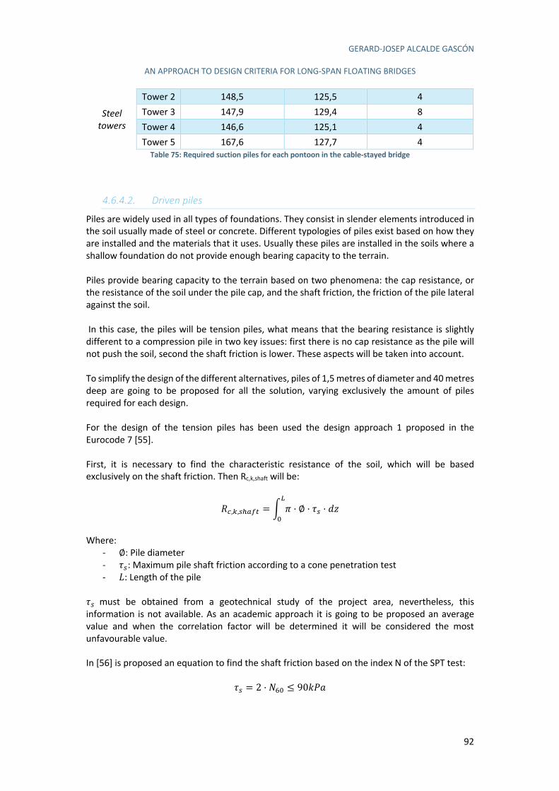
GERARD-JOSEP ALCALDE GASCÓN
AN APPROACH TO DESIGN CRITERIA FOR LONG-SPAN FLOATING BRIDGES
92
Steel towers
Tower 2 148,5 125,5 4 Tower 3 147,9 129,4 8 Tower 4 146,6 125,1 4 Tower 5 167,6 127,7 4
Table 75: Required suction piles for each pontoon in the cable-stayed bridge
4.6.4.2. Driven piles
Piles are widely used in all types of foundations. They consist in slender elements introduced in the soil usually made of steel or concrete. Different typologies of piles exist based on how they are installed and the materials that it uses. Usually these piles are installed in the soils where a shallow foundation do not provide enough bearing capacity to the terrain. Piles provide bearing capacity to the terrain based on two phenomena: the cap resistance, or the resistance of the soil under the pile cap, and the shaft friction, the friction of the pile lateral against the soil. In this case, the piles will be tension piles, what means that the bearing resistance is slightly different to a compression pile in two key issues: first there is no cap resistance as the pile will not push the soil, second the shaft friction is lower. These aspects will be taken into account. To simplify the design of the different alternatives, piles of 1,5 metres of diameter and 40 metres deep are going to be proposed for all the solution, varying exclusively the amount of piles required for each design. For the design of the tension piles has been used the design approach 1 proposed in the Eurocode 7 [55]. First, it is necessary to find the characteristic resistance of the soil, which will be based exclusively on the shaft friction. Then Rc,k,shaft will be:
õG,$,JLK2I = ì ï · ∅ · ùJ · í1U
(
Where:
- ∅: Pile diameter - ùJ: Maximum pile shaft friction according to a cone penetration test - `: Length of the pile
ùJ must be obtained from a geotechnical study of the project area, nevertheless, this information is not available. As an academic approach it is going to be proposed an average value and when the correlation factor will be determined it will be considered the most unfavourable value. In [56] is proposed an equation to find the shaft friction based on the index N of the SPT test:
ùJ = 2 · Ob( ≤ 905fg
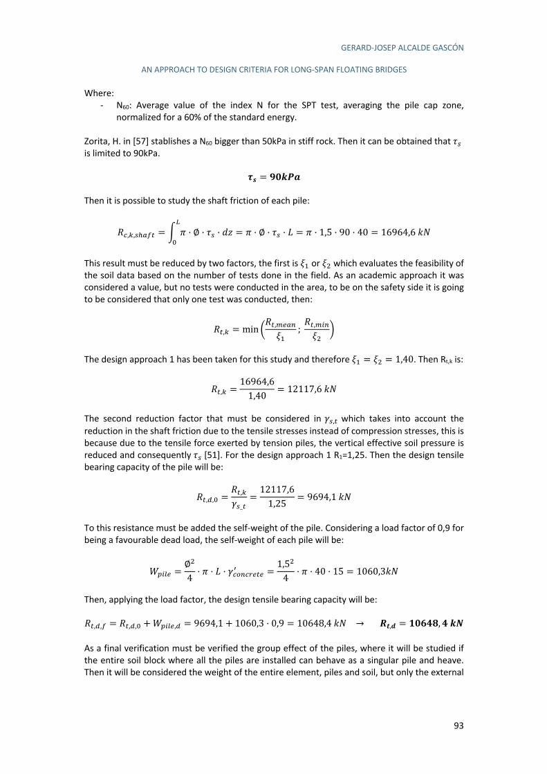
GERARD-JOSEP ALCALDE GASCÓN
AN APPROACH TO DESIGN CRITERIA FOR LONG-SPAN FLOATING BRIDGES
93
Where: - N60: Average value of the index N for the SPT test, averaging the pile cap zone,
normalized for a 60% of the standard energy. Zorita, H. in [57] stablishes a N60 bigger than 50kPa in stiff rock. Then it can be obtained that ùJ is limited to 90kPa.
ûc = ôZUü†
Then it is possible to study the shaft friction of each pile:
õG,$,JLK2I = ì ï · ∅ · ùJ · í1U
(= ï · ∅ · ùJ · ` = ï · 1,5 · 90 · 40 = 16964,65O
This result must be reduced by two factors, the first is °3 or °0 which evaluates the feasibility of the soil data based on the number of tests done in the field. As an academic approach it was considered a value, but no tests were conducted in the area, to be on the safety side it is going to be considered that only one test was conducted, then:
õI,$ = min 8õI,'1K*°3
; õI,')*°0
9
The design approach 1 has been taken for this study and therefore °3 = °0 = 1,40. Then Rt,k is:
õI,$ =16964,61,40
= 12117,65O
The second reduction factor that must be considered in dJ,I which takes into account the reduction in the shaft friction due to the tensile stresses instead of compression stresses, this is because due to the tensile force exerted by tension piles, the vertical effective soil pressure is reduced and consequently ùJ [51]. For the design approach 1 R1=1,25. Then the design tensile bearing capacity of the pile will be:
õI,#,( =õI,$dJ_I
=12117,61,25
= 9694,15O
To this resistance must be added the self-weight of the pile. Considering a load factor of 0,9 for being a favourable dead load, the self-weight of each pile will be:
é[)41 =∅0
4· ï · ` · dGH*G%1I1\ =
1,50
4· ï · 40 · 15 = 1060,35O
Then, applying the load factor, the design tensile bearing capacity will be: õI,#,2 = õI,#,( +é[)41,# = 9694,1 + 1060,3 · 0,9 = 10648,45O → £>,e = SZ§TR, TUV As a final verification must be verified the group effect of the piles, where it will be studied if the entire soil block where all the piles are installed can behave as a singular pile and heave. Then it will be considered the weight of the entire element, piles and soil, but only the external
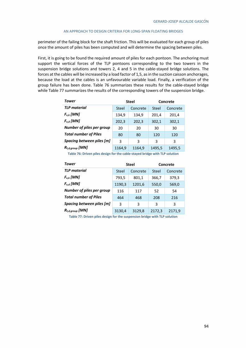
GERARD-JOSEP ALCALDE GASCÓN
AN APPROACH TO DESIGN CRITERIA FOR LONG-SPAN FLOATING BRIDGES
94
perimeter of the failing block for the shaft friction. This will be evaluated for each group of piles once the amount of piles has been computed and will determine the spacing between piles. First, it is going to be found the required amount of piles for each pontoon. The anchoring must support the vertical forces of the TLP pontoons corresponding to the two towers in the suspension bridge solutions and towers 2, 4 and 5 in the cable-stayed bridge solutions. The forces at the cables will be increased by a load factor of 1,5, as in the suction caisson anchorages, because the load at the cables is an unfavourable variable load. Finally, a verification of the group failure has been done. Table 76 summarizes these results for the cable-stayed bridge while Table 77 summarizes the results of the corresponding towers of the suspension bridge.
Tower Steel Concrete TLP material Steel Concrete Steel Concrete Fv,k [MN] 134,9 134,9 201,4 201,4 Fv,d [MN] 202,3 202,3 302,1 302,1 Number of piles per group 20 20 30 30 Total number of Piles 80 80 120 120 Spacing between piles [m] 3 3 3 3 Rt,d,group [MN] 1164,9 1164,9 1495,5 1495,5
Table 76: Driven piles design for the cable-stayed bridge with TLP solution
Tower Steel Concrete TLP material Steel Concrete Steel Concrete Fv,k [MN] 793,5 801,1 366,7 379,3 Fv,d [MN] 1190,3 1201,6 550,0 569,0 Number of piles per group 116 117 52 54 Total number of Piles 464 468 208 216 Spacing between piles [m] 3 3 3 3 Rt,d,group [MN] 3130,4 3129,8 2172,3 2171,9
Table 77: Driven piles design for the suspension bridge with TLP solution
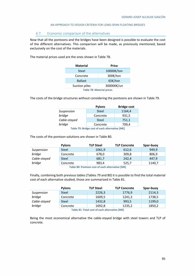
GERARD-JOSEP ALCALDE GASCÓN
AN APPROACH TO DESIGN CRITERIA FOR LONG-SPAN FLOATING BRIDGES
95
4.7. Economic comparison of the alternatives
Now that all the pontoons and the bridges have been designed is possible to evaluate the cost of the different alternatives. This comparison will be made, as previously mentioned, based exclusively on the cost of the materials. The material prices used are the ones shown in Table 78.
Material Price
Steel 10000€/ton Concrete 300€/ton
Ballast 65€/ton Suction piles 300000€/un
Table 78: Material prices The costs of the bridge structures without considering the pontoons are shown in Table 79.
Pylons Bridge cost
Suspension bridge
Steel 1164,4 Concrete 931,5
Cable-stayed bridge
Steel 751,1 Concrete 709,4
Table 79: Bridge cost of each alternative [M€] The costs of the pontoon solutions are shown in Table 80.
Pylons TLP Steel TLP Concrete Spar-buoy
Suspension bridge
Steel 1061,9 612,6 949,9 Concrete 678,0 309,8 806,9
Cable-stayed bridge
Steel 681,7 242,4 447,9 Concrete 983,4 525,7 1140,7
Table 80: Pontoon cost of each alternative [M€] Finally, combining both previous tables (Tables 79 and 80) it is possible to find the total material cost of each alternative studied, those are summarized in Table 81.
Pylons TLP Steel TLP Concrete Spar-buoy
Suspension bridge
Steel 2226,3 1776,9 2114,3 Concrete 1609,5 1241,3 1738,5
Cable-stayed bridge
Steel 1432,8 993,5 1199,0 Concrete 1692,8 1235,2 1850,2
Table 81: Total cost of each alternative [M€] Being the most economical alternative the cable-stayed bridge with steel towers and TLP of concrete.
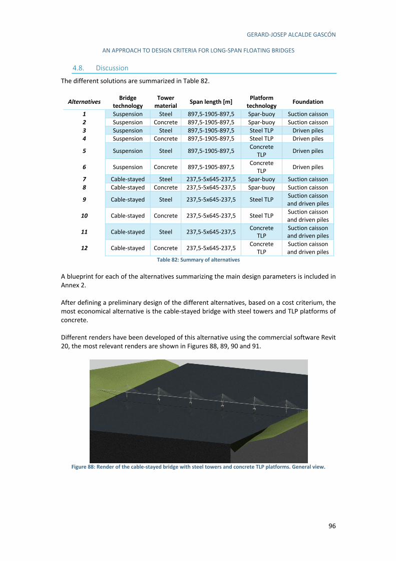
GERARD-JOSEP ALCALDE GASCÓN
AN APPROACH TO DESIGN CRITERIA FOR LONG-SPAN FLOATING BRIDGES
96
4.8. Discussion
The different solutions are summarized in Table 82.
Alternatives Bridge
technology
Tower
material Span length [m]
Platform
technology Foundation
1 Suspension Steel 897,5-1905-897,5 Spar-buoy Suction caisson
2 Suspension Concrete 897,5-1905-897,5 Spar-buoy Suction caisson
3 Suspension Steel 897,5-1905-897,5 Steel TLP Driven piles
4 Suspension Concrete 897,5-1905-897,5 Steel TLP Driven piles
5 Suspension Steel 897,5-1905-897,5 Concrete
TLP Driven piles
6 Suspension Concrete 897,5-1905-897,5 Concrete
TLP Driven piles
7 Cable-stayed Steel 237,5-5x645-237,5 Spar-buoy Suction caisson
8 Cable-stayed Concrete 237,5-5x645-237,5 Spar-buoy Suction caisson
9 Cable-stayed Steel 237,5-5x645-237,5 Steel TLP Suction caisson
and driven piles
10 Cable-stayed Concrete 237,5-5x645-237,5 Steel TLP Suction caisson
and driven piles
11 Cable-stayed Steel 237,5-5x645-237,5 Concrete
TLP
Suction caisson
and driven piles
12 Cable-stayed Concrete 237,5-5x645-237,5 Concrete
TLP
Suction caisson
and driven piles Table 82: Summary of alternatives
A blueprint for each of the alternatives summarizing the main design parameters is included in Annex 2. After defining a preliminary design of the different alternatives, based on a cost criterium, the most economical alternative is the cable-stayed bridge with steel towers and TLP platforms of concrete. Different renders have been developed of this alternative using the commercial software Revit 20, the most relevant renders are shown in Figures 88, 89, 90 and 91.
Figure 88: Render of the cable-stayed bridge with steel towers and concrete TLP platforms. General view.
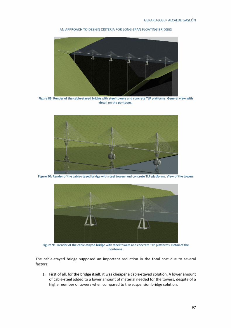
GERARD-JOSEP ALCALDE GASCÓN
AN APPROACH TO DESIGN CRITERIA FOR LONG-SPAN FLOATING BRIDGES
97
Figure 89: Render of the cable-stayed bridge with steel towers and concrete TLP platforms. General view with
detail on the pontoons.
Figure 90: Render of the cable-stayed bridge with steel towers and concrete TLP platforms. View of the towers
Figure 91: Render of the cable-stayed bridge with steel towers and concrete TLP platforms. Detail of the
pontoons.
The cable-stayed bridge supposed an important reduction in the total cost due to several factors:
1. First of all, for the bridge itself, it was cheaper a cable-stayed solution. A lower amount of cable-steel added to a lower amount of material needed for the towers, despite of a higher number of towers when compared to the suspension bridge solution.
GERARD-JOSEP ALCALDE GASCÓN
AN APPROACH TO DESIGN CRITERIA FOR LONG-SPAN FLOATING BRIDGES
98
2. Secondly, although a bridge with steel towers was more expensive than one with concrete towers, the reduction in weight would be beneficial for the design of the pontoons.
3. After studying the whole structure, an additional advantage has been found. In fact, for the cable-stayed bridge the towers were slenderer and therefore the wind forces were lower, thus deriving on a lower effect on the pontoon design forces. Therefore, despite the higher cost on the bridge with steel towers, the cost of the whole bridge is lower.
Finally, the cheapest alternative uses concrete TLP pontoons. On the one side, the TLP was studied with two different materials, concrete and steel because the weight of the concrete might require a much bigger pontoon that would counteract the higher price of the steel. Nevertheless, it has resulted that the concrete structure did not have such a high weight to counteract the higher price of the steel. On the other side, it was also studied a spar-buoy as a pontoon solution. The spar-buoy has a relatively low cost of the structure, nevertheless, the anchor lines were much bigger increasing its prize over the one of the TLP solution. Several simplifications have been adopted along this work, as an academic approach. They must be considered in further developments, because of their influence on the final cost. Some of the most relevant simplifications that might be studied in-depth are:
- Verification of the displacements of the pontoons, specially the TLP platforms. - ULS and SLS verification of the bridge structure
Moreover, although the cable-stayed bridge with steel towers and concrete TLP platforms is the most economic option, the cost of preparing the steep rock for the driven piles might be quite high and difficult and it might increase the total cost over the one of the spar-buoy solution.
4.8.1. Conclusions obtained from the other alternatives
Despite not being the optimal economic solution for this particular case, important conclusions can be obtained from the remaining 11 alternative solutions.
1. The suspension bridge has a higher price than the cable-stayed bridge. The amount of steel for the cable in the suspension bridge is very big, with a high cost. The suspension bridge, despite of having less towers, given its higher span length, has a higher cost for the towers, because they must be much bigger and require more material. At the end, the total cost of the towers is almost twice the one for the cable-stayed solution.
2. The larger size of the suspension bridge results in higher forces on the bridge elements
due to the wind actions. This added to the higher weight load transferred to the pontoons results in a pontoon design more complex than the required for the cable-stayed solutions. Similar to what happened with the towers, the suspension bridge, despite of having less pontoons, the higher loads on them require a much expensive solution. This is not counteracted by the increase of price due to the higher number of pontoons in the cable-stayed solution.
3. With respect to the material of the towers it has been studied if the reduction in weight
of the steel towers counteract the bigger cost of the material compared with concrete towers. The use of steel towers resulted in a decrease of 70-80% of the tower weight which had a reduction effect in the total weight of the bridge of 40% in the suspension
GERARD-JOSEP ALCALDE GASCÓN
AN APPROACH TO DESIGN CRITERIA FOR LONG-SPAN FLOATING BRIDGES
99
bridge and 25% in the cable-stayed bridge. This results on an increase in the cost of the bridge structure of 25% in the suspension bridge and only 6% in the cable-stayed bridge. Nevertheless, regarding to the cost of the pontoons, opposite results were obtained with an increase of about 30% in the suspension bridge but a reduction of about 25% in the cable-stayed bridge.
There is one big difference between the steel tower design of the suspension and the cable-stayed bridge, given the limitations in the plates thickness and the weight the towers had to support. The cable-stayed bridge towers were more slender than the concrete towers, while in the suspension bridge it happened the opposite. One of the most difficult design criteria to meet in the design of the pontoons is having small rotations of the tower in the transversal direction, and one of the main forces producing this rotation was the wind. Therefore, a slender design of the towers will produce a higher impact on the total cost of the structure than a smaller weight of the towers. For the cable-stayed bridge the higher strength of the steel allowed slender towers than concrete, resulting on a smaller cost of the whole structure. From this, two conclusions are obtained:
1. It is better to build slender rather than light towers and the usage of high strength materials such as high resistance concrete or steel is quite beneficial if the surface of the tower is reduced.
2. Given that the main force comes from the wind, provide an aerodynamic shape to the towers will reduce the forces transmitted to the pontoons.
The design criteria regarding the towers is mainly based on a slender and aerodynamic shape, more than on the criteria of reducing their weight. For the TLP and spar-buoy pontoons, additional conclusions can be also deduced. It has been seen that the cost of anchor cables is high, being about 50% of the pontoon cost. Therefore, any reduction in the anchor cables would reduce significantly the cost of the structure. This reduction can be done reducing the forces at the pontoon (slender and aerodynamic towers and deck) or optimizing the position of the anchor cables to maximize its efficiency. Another important conclusion has been that the moments at the pontoon destabilizes the pontoon and it is complex to reduce this effect. In the spar-buoy this effect has been solved with incredibly high amounts of ballast, while in the TLP it resulted in an increase of the anchor cables section. Finally, it has been seen that while the vertical forces are relatively easy to compensate the horizontal forces introduce large displacements and increase the complexity of the project significantly. As a final conclusion can be stated that slender and aerodynamic towers will have a high impact on the pontoon design as it will reduce the horizontal forces at the pontoon. The concrete TLP resulted in a lower cost for the cable-stayed bridge than the spar-buoy. Nevertheless, the TLP did not take into account any displacement verifications or design based on horizontal loads and it is likely that when these factors were considered, the cable section will increase or could even be unfeasible because the cables are vertical and need a displacement to introduce a horizontal reaction into the structure. Then it can be concluded that when the SLS verifications will be carried out, most probably, the cost of the TLP solutions will increase significantly. Finally, the anchor lines need to be anchored to the seabed. While an anchoring to a sand, silt or clay soil is relatively easy with the use of suction caissons, if the seabed is rock the anchorage becomes much more complex. The anchorage for a rock seabed can be done with driven piles, but the project increases its complexity when building at more than 1000 metres deep. The
GERARD-JOSEP ALCALDE GASCÓN
AN APPROACH TO DESIGN CRITERIA FOR LONG-SPAN FLOATING BRIDGES
100
suction caisson solution is easier than the driven piles and it has been widely used in the last years. Then it can be concluded, that, if possible, is always better to anchor the pontoons in sand, silt or clay soil rather than in rock, although this last solution is also technically feasible.
4.8.2. Design criteria for long-span floating bridges
From the results and discussion in the previous sections, some recommendations for the design of long-span floating bridges can be obtained.
1. First, it is recommended to design a cable-stayed bridge rather than a suspension bridge. Despite of the lower amount of pontoons for the suspended solution, the bigger towers introduce larger loads on the pontoons and makes more difficult the design of the pontoons, ending up in a more complex and expensive solution.
2. The weight of the towers is not as important for the design of the pontoons as it was
thought at the beginning of this work. In fact, what really influences the design of the pontoon are the horizontal forces and the moments transmitted. Therefore, in order to reduce these forces, it is recommended to use slender and aerodynamic towers resulting on a lower static and dynamic effects from the wind action. Although this can be only achieved with materials (steel or concrete) with higher strengths and more expensive, the reduction of the cost of the pontoons compensates this cost overrun.
3. With respect to the pontoons, the spar-buoys are better solutions because of its
flexibility in the anchoring position. As previously mentioned, it is likely that the cost of the TLP anchor cables will increase significantly when the displacement checks are imposed. In addition, the inadaptability of the anchoring position makes difficult to use the TLP alternative. Then it would be recommended to use a spar-buoy pontoon when the seabed is not uniform and it would require the construction of driven piles, but for a uniform seabed where suction caissons could be used for the TLP platforms, a further study of which alternative is better must be carried out.
4. If a spar-buoy platform is used, it is recommended to do an in-depth study of the
anchoring position because the cost of the anchor cables is about 10-20% of the total cost of the materials. Therefore, maximizing the efficiency of the anchor cables can reduce significantly the costs.
5. Finally, with respect to the anchoring system, it will be preferably to anchor the cables
into sand, silt or clay soil where the suction caissons can be used. The suction caisson allows to anchor with a high reliability, and it is relatively easy to install it at high depths. Nevertheless, the driven piles, are not especially designed to work in tension and the installation at high depths can be also quite difficult.

GERARD-JOSEP ALCALDE GASCÓN
AN APPROACH TO DESIGN CRITERIA FOR LONG-SPAN FLOATING BRIDGES
101
5. Conclusions
After an in-depth study about the available and new technologies for floating bridges several conclusions have been reached. First of all, there has been a review of the existing state-of-the-art solutions and it has been revealed that large improvements have been done both in bridge and offshore engineering. On the one side, bridge engineering is constantly increasing the main span length of the different types of bridges and introducing new materials that allow new designs at lower costs. On the other side, offshore engineering has evolved with the oil sector developing floating structures such as the TLP platforms, but in the last years with the introduction of the offshore wind farms the usage of the spar-buoy platforms has increased. These two platform technologies might be helpful in the construction of bridges where towers founded in very deep waters are not feasible. The combination of the bridge and offshore engineering innovations could be an alternative for locations where there was no feasible solution up to now. Despite the advantages that these bridges could offer for certain locations, there are still few studies or projects dealing with them. The places where a bridge founded on offshore platforms (floating bridge) would be helpful have also been studied, and even though it is a very singular design and its cost will be quite high, this is the only feasible solution in these places. This is the case of the Norwegian or Canadian fiords that are very deep or large water crossings with a really deep area, as happens in the Messina strait or in the North Channel. Another possibility for this solution would be really long bridges that require a high clearance in the middle for big vessels. Once it was discovered that a floating bridge could be the proper solution for singular water crossings, it was studied which solutions fitted the most with the requirements of this particular locations. Several alternatives were considered: cable-stayed or suspension bridge, steel or concrete towers, spar-buoy or TLP platforms, both in concrete or steel. To decide on the best alternative it was decided to study one particular case. Although being reduced to just one particular case, the results obtained can be worth used in the definition of a set of design criteria for long-span floating bridges. After studying different places for the case study, it was decided that the Sognefjord in Norway was a good emplacement where this kind of bridge will be a proper solution. Then 12 different alternatives were studied for this emplacement. For each of the alternatives there has been provided a preliminary design of the bridge and the pontoon in order to find which of the alternatives is the cheapest based exclusively on the material cost. When all the designs were defined, the final conclusion was that the cheapest alternative was the cable-stayed bridge with steel towers and concrete TLP platforms. From this main result different conclusions can be also found. First, a cable-stayed bridge was cheaper for two main reasons: it needs less steel for the cables and despite having more towers, they are smaller and require less material. Second, although a steel tower is more expensive, its weight is lower, and this provides an easier and cheaper design of the pontoons. Finally, it was discovered that two main factors affected the design of the pontoons: on the one side, the effect of the wind in the towers(both static and dynamic) had a huge impact on the pontoon design and therefore, a slenderer and aerodynamic design of the steel towers allowed the usage of smaller pontoons. On the other side, the lower weight of the tower decreased the centre of gravity of the whole
GERARD-JOSEP ALCALDE GASCÓN
AN APPROACH TO DESIGN CRITERIA FOR LONG-SPAN FLOATING BRIDGES
102
structure, a key factor for the spar-buoy that required less ballast, and therefore a smaller pontoon. When designing the anchorages for the foundations different conclusions were deducted. First of all, an optimization of the anchorage position was done to require the minimum possible amount of steel for the cables. It can be concluded from this optimization that the cables connecting the pontoon to the coast could be simplified as only one cable, as the optimum position of both cables was the same. Secondly, it has been deduced that the anchorage at places were the soil material is rock is quite complex, especially if the soil is steep. For this case, even if the TLP were the cheapest alternative, the costs of preparing the terrain to build driven piles at the rock may increase the costs with respect to the suction caisson anchorage and make the alternative with the spar-buoys the better solution for this project. From this, is concluded that it is better to have the anchorages in sand, silt and clay soils rather than in rock, but if required, an anchorage at rock might be also technically feasible. Finally, from all this study some design criteria were obtained, these are summarized as:
- A cable-stayed bridge would be a better solution than a suspension bridge given the smaller towers and its effect on the pontoons.
- The key design parameter of the towers must be a slender and aerodynamic design rather than a light design prioritising high strength materials over the cost of them.
- Spar-buoys platforms will offer more flexibility in places where the seabed is made of both rock and sand, silt or clay soils.
- For a spar-buoy platform, it is recommended to optimize the anchoring position to maximize the efficiency of the cables given its high price with respect to the total cost of the project.
- TLP platforms are cheaper and are suitable for places with low horizontal forces. - The use of spar-buoy or TLP pontoons need a further study for each particular project. - The use of suction caissons is preferable to the use of driven piles; therefore, it will be
preferable to anchor the cable to sand, silt or clay soils. As a final conclusion from the project, it can be stated that a long-span floating bridge is a feasible solution for singular places where the depth of the water makes unfeasible the construction of any other type of foundation.
GERARD-JOSEP ALCALDE GASCÓN
AN APPROACH TO DESIGN CRITERIA FOR LONG-SPAN FLOATING BRIDGES
103
5.1. Future research lines
This project has achieved the objectives that it had, nevertheless, a further research can be done in order to study more in-depth this topic that could offer several advantages in the future. Some future research lines are provided in this section.
1. In this project some simplifications have been made, but a further study where the ULS and SLS verifications are carried out should be done considering the stresses and the deflection both in the towers and in the deck.
2. It has been seen that the TLP platforms had vertical tendons, a verification of the displacements for the horizontal loads should be done and determine if it supposes an increase in the platform costs.
3. The platforms should also be verified for the ULS considering the water forces and the load transmitted from the tower.
4. It was determined that the use of driven piles in the rock would suppose a substantial increase in the cost, but it was not quantified. A further study might be done to determine the feasibility of this solution.
5. In order to provide general design criteria for long-span floating bridges it must be studied more alternatives that consider: different water depths, different span lengths, different tower designs (heights, shapes, materials, etc. ), different deck cross-sections, different pontoon designs, etc.
GERARD-JOSEP ALCALDE GASCÓN
AN APPROACH TO DESIGN CRITERIA FOR LONG-SPAN FLOATING BRIDGES
104
6. References
[1] Offshoreenineering, "Offshoreengineering.com," [Online]. Available:
https://offshoreengineering.com/. [Accessed 11 December 2019]. [2] National Academies of Sciences, Engineering, and Medicine, Industry, Strengthening the
Safety Culture of the Offshore Oil and Gas, Washigton, D.C., 2016. [3] Environmental and energy study institute, "eesi.org," October 2010. [Online]. Available:
https://www.eesi.org/files/offshore_wind_101310.pdf. [Accessed 27 January 2020]. [4] Wind Europe, "Offshore wind in Europe," 2019. [5] International Renewable Energy Agency (IRENA), "Floating foundations: A game changer
for offshore wind power," 2016. [6] PetroWiki, "petrowiki.org," 2 June 2015. [Online]. Available:
https://petrowiki.org/Fixed_steel_and_concrete_gravity_base_structures. [Accessed 27 January 2020].
[7] American Petroleum Institute, Recommended Practice for Planning, Designing and Constructing Fixed Offshore Platforms. Working Stress Design. API RP 2A-WSD, Washington: API Publishing Services, 2000.
[8] DrillingFormulas.com, "Drilling Formulas," 2 February 2017. [Online]. Available: http://www.drillingformulas.com/floating-offshore-structures-offshore-structure-series/. [Accessed 31 January 2020].
[9] K. Aas-Jakobsen, S. E. Jakobsen, K. Karlrud and F. Fredriksen, "Deep sea foundations for strait crossings," in Strait Crossings, Bergen , 2013.
[10] TU Delft, "TU Delft," [Online]. Available: https://www.tudelft.nl/onderwijs/opleidingen/masters/ode/msc-offshore-dredging-engineering/msc-programme/specialisations/bottom-founded-offshore-structures/. [Accessed 31 January 2020].
[11] The constructor, Civil Engineering Home, "The constructor, Civil Engineering Home," [Online]. Available: https://theconstructor.org/structures/types-of-offshore-concrete-structures/15415/. [Accessed 31 January 2020].
[12] American Petroleum Institute, Planning, designing and constructing tension leg platforms, Washington: API Publishing Services, 2010.
[13] The Editors of Encyclopaedia Britannica, "Encyclopaedia Britannica," [Online]. Available: https://www.britannica.com/technology/suspension-bridge. [Accessed 29 January 2020].
[14] W.-F. Chen and L. Duan, Bridge Engineering Handbook. Superstructure design, Boca Raton: CRC Press, 2014.
[15] R. Calzona, Storia ed evoluzione del progetto del ponte sullo streto di Messina, Roma: Tipografia del genio civile, 2008.
[16] N. Regoli, "Future of Working," [Online]. Available: https://futureofworking.com/8-advantages-and-disadvantages-of-suspension-bridges/. [Accessed 29 January 2020].
[17] J. Sarker and T. Manzur, "Optimum dimensions of suspension bridges considering natural period," in IOSR Journal of mechanical and civil engineering, 2013.
[18] Think Defence, “Think Defence,” 11 December 2011. [Online]. Available: https://www.thinkdefence.co.uk/2011/12/uk-military-bridging-floating-equipment/. [Accessed 28 January 2020].

GERARD-JOSEP ALCALDE GASCÓN
AN APPROACH TO DESIGN CRITERIA FOR LONG-SPAN FLOATING BRIDGES
105
[19] S. Lewis, "Engineering News-Record," 20 February 2018. [Online]. Available: https://www.enr.com/articles/44013-the-10-longest-floating-bridges-in-the-world. [Accessed 28 January 2020].
[20] S. Tattoni, Pontoon bridges, Milan, 2016. [21] T. C. H. R. E. C. o. t. f. f. crossings, "Vegvesen.no," October 2019. [Online]. Available:
https://www.vegvesen.no/_attachment/2044359/binary/1348191?fast_title=Choice+ of+technology+for+fjord+crossings+-+The+E39+Coastal+Highway+Route.pdf. [Accessed 11 December 2019].
[22] Collings and David, "State-of-the-art review of the design and construction of multiple-span suspension bridges," 2016.
[23] N. Hussain, "Design and construction of sea-crossing bridges - A review," in Multi-Span Large Bridges, Leiden, CRC Press, 2015, pp. 17-26.
[24] A. Chen, R. Ma and X. Zhang, "Recent achievements in the design and construction of multi-span cable supported bridges in China," in Multi-Span Large Bridges, Leiden, CRC Press, 2015, pp. 93-102.
[25] Connect Us, "connectusfund.org," 29 March 2019. [Online]. Available: https://connectusfund.org/6-advantages-and-disadvantages-of-cable-stayed-bridges. [Accessed 3 February 2020].
[26] Statens vegvesen, “A feasibility study - How to cross the wide and deep Sognefjord,” 2011. [27] Woldometers, "worldometers.info," [Online]. Available:
https://www.worldometers.info/world-population/norway-population/. [Accessed 3 December 2019].
[28] N. T. P. 2018-2029, 2017. [Online]. Available: https://www.regjeringen.no/contentassets/7c52fd2938ca42209e4286fe86bb28bd/en-gb/pdfs/stm201620170033000engpdfs.pdf. [Accessed 3 December 2019].
[29] Vegvesen, "Staten Vegvesen," 3 December 2019. [Online]. Available: https://www.vegvesen.no/en/roads/Roads+and+bridges/Road+projects/e39coastalhigh wayroute. [Accessed 3 December 2019].
[30] Sognefjord, "Visit Norway," 2019. [Online]. Available: https://www.visitnorway.es/que-ver-en-noruega/noruega-de-los-fiordos/sognefjord/. [Accessed 3 December 2019].
[31] T. C. H. R. E. C. o. t. f. f. crossings, "Statens vegvesen," October 2019. [Online]. Available: https://www.vegvesen.no/_attachment/2044359/binary/1348191?fast_title=Choice+of+ technology+for+fjord+crossings+-+The+E39+Coastal+Highway+Route.pdf. [Accessed 3 December 2019].
[32] P. Pacheco, "Multi-span large decks - the organic prestressing impact," in Multi-Span Large Bridges, Leiden, CRC Press, 2015, pp. 103-124.
[33] W. Lewis, "The Conversation," 11 February 2020. [Online]. Available: https://theconversation.com/scotland-northern-ireland-bridge-how-to-make-it-a-reality-131577. [Accessed 18 February 2020].
[34] BBC, "BBC," 10 February 2020. [Online]. Available: https://www.bbc.com/news/uk-scotland-south-scotland-49661019. [Accessed 18 February 2020].
[35] U.S. Department of Homeland Security, "United States Coast Guard," [Online]. Available: https://www.dco.uscg.mil/Our-Organization/Assistant-Commandant-for-Prevention-Policy-CG-5P/Marine-Transportation-Systems-CG-5PW/Office-of-Bridge-Programs/Bridge-Guide-Clearances/. [Accessed 18 February 2020].
[36] Hong Kong Highways Department, "Hong Kong-Zhuhai-Macao Bridge," [Online]. Available: https://www.hzmb.hk/eng/about_overview_01.html. [Accessed 18 February 2020].

GERARD-JOSEP ALCALDE GASCÓN
AN APPROACH TO DESIGN CRITERIA FOR LONG-SPAN FLOATING BRIDGES
106
[37] N. J. Gimsing and C. T. Georgakis, Cable Supported Bridges. Concept and Design., Chichester: Wiley, 2012.
[38] Statens Vegvesen, “Sognefjorden feasibility study of floating bridge,” 2013. [39] Ministerio de fomento, Instrucción sobre las acciones a considerar en el proyecto de
puentes de carretera, Madrid: Centro de publicaciones Secretaria General Técnica Ministerio de Fomento, 2012.
[40] European committee for standarization, Eurocode 1: Actions on structures - Part 1-4: General actions - Wind actions, Brussels, 2010.
[41] O. Harals Moe, Y. Sha and J. A. J. Veie, “Analysis of tether anchored floating suspension bridge subjected to large ship collisions,” in X International conference on structural dynamics, Rome, 2017.
[42] J. Manterola, Puentes. Apuntes para su diseño, cálculo y construcción, Madrid: Colegio de Ingenieros de Caminos, Canales y Puertos, 2006.
[43] Asian Institute of Technology, "Drnaveedanwar," [Online]. Available: http://drnaveedanwar.net/wp-content/uploads/2016/02/1.-Modeling-of-Cable-Stayed-Bridges.pdf. [Accessed 11 February 2020].
[44] Ministerio de Fomento, Instrucción sobre las acciones a considerar en el proyecto de puentes de carretera, Madrid: Secretaria general técnica ministerio de fomento, 2012.
[45] European committee for standarization, Eurocode 1: Actions on structures - Part 2: Traffic loads on bridges, Brussels, 2003.
[46] European committee for standarization, Eurocode - Basis of structural design, Brussels, 2005.
[47] European comitee for standarization, Eurocode 3 - Design of steel structures - Part 1-5: Plated structural elements, Brussels, 2006.
[48] C. Hendy and D. Iles, Guidance notes on best practice in steel bridge construction, Berkshire: The Steel Construction Institute, 2015.
[49] A. Perez-Garcia and A. Guardiola-Villora, “Formulario para vigas y pórticos,” in Prontuario y Herramientas Informáticas para Cálculo de Estructuras, Madrid, Inter Técnica Ediciones, 2012, p. Chapter 3.
[50] I.-B. Almeland, “TLP technology experiences in the north sea used as foundations for a bridge tower,” in Strait Crossings, Bergen, 2013.
[51] Delft University of Technology, Manual Hydraulic Structures, Delft, 2018. [52] G. Houlsby and B. Byrne, “Design procedures for installation of suction caissons in clay and
other soils,” in Calculation Procedures for Installation of Suction Caissons, Oxford, 2004. [53] Y. Bai and W.-L. Jin, Marine Structural Design, Amsterdam: Butterworth-Heinemann, 2015. [54] Geotechnical info .com, “GEOTECHNICAL INFO .COM,” [Online]. Available:
http://www.geotechnicalinfo.com/bearing_capacity_factors.html. [Accessed 28 May 2020].
[55] European committee for standarization, Eurocode 7: Geotechnical design - Part 1: General rules, Brussels, 2004.
[56] Ministerio de fomento, Guía de cimentaciones en obras de carretera, Madrid, 2002. [57] H. Zorita, Manual didáctico de estructuras II, Madrid: Lulu, 2015. [58] J. Veie and S. Holtberget, "Three span floating suspension bridge crossing the Bjørnafjord,"
in Multi-Span Large Bridges, Leiden, CRC Press, 2015, pp. 195-196.
GERARD-JOSEP ALCALDE GASCÓN
AN APPROACH TO DESIGN CRITERIA FOR LONG-SPAN FLOATING BRIDGES
107
[59] C. Cid, A. Baldomir, S. Hernandez and M. Cid, "Optimum size, position and number of cables in cable-stayed bridges," in HPSM/OPTI, Siena, 2016.