Transportation Engineering-II MODULE 1 2020
81
Transportation Engineering-II MODULE 1 2020 1 MODULE – 1 RAILWAY ENGINEERING A French mechanic, named Nicholas Joseph Cugnot, was the first man to invent and construct a steam locomotive in the year 1769. The first public railway in the history of world was opened for traffic on 27 th September 1825 in England. Characteristics of railways: (i) The railways are the biggest undertaking in the world. They employ many people and carry out considerable turnover. (ii) The railways exist practically in all the parts of the world. (iii) The railways are the cheapest in preference to other modes of transport. (iv) The railways require the least amount of power as compared to their weight. (v) The direction of movement is controlled and the vehicles are not at liberty to deviate from the rails. (vi) The railways alone can carry lots of people quickly and safely through big towns full of crowded streets. (vii) As compared to other modes, it is better to travel in a train for making long journeys, carrying a lot of heavy things.
-
Upload
khangminh22 -
Category
Documents
-
view
4 -
download
0
Transcript of Transportation Engineering-II MODULE 1 2020
Transportation Engineering-II MODULE 1 2020
1
MODULE – 1
RAILWAY ENGINEERING
A French mechanic, named Nicholas Joseph Cugnot, was the first man to invent and
construct a steam locomotive in the year 1769. The first public railway in the history of world
was opened for traffic on 27th September 1825 in England.
Characteristics of railways:
(i) The railways are the biggest undertaking in the world. They employ many people and carry
out considerable turnover.
(ii) The railways exist practically in all the parts of the world.
(iii) The railways are the cheapest in preference to other modes of transport.
(iv) The railways require the least amount of power as compared to their weight.
(v) The direction of movement is controlled and the vehicles are not at liberty to deviate from
the rails.
(vi) The railways alone can carry lots of people quickly and safely through big towns full of
crowded streets.
(vii) As compared to other modes, it is better to travel in a train for making long journeys,
carrying a lot of heavy things.

Transportation Engineering-II MODULE 1 2020
2
COMPARISON BETWEEN RAILWAYS AND HIGHWAYS
Characteristics Railways Highways
1. Tractive Resistance
Tractive resistance of a steel
wheel on a steel rail is less,
nearly one fifth to one sixth of
pneumatic tyre on highways
Tractive resistance of
pneumatic tyre on highways is
5 to 6 times greater than that
of railway vehicles on steel
rails
2. Load handling capacity Railway can handle heavier
loads at high speeds
Load handling capacity of
road vehicles is low
3. Right of entry
Movement of vehicles is
according to schedule and
hence right of entry is not free
to all
Roads are free and flexible and everybody has right to ingress
or egress
4. Operational controls
Essential in the form of
signalling and interlocking for
safe and efficient movement
of trails as per schedule
No rigid controls are required
in road transport
5. Gradient
To sustain heavier loads at
high speeds on railways, the
gradient should be minimum
Steeper gradients as compared
to railway track can be
provided
6. Construction and
maintenance cost
The establishment and
maintenance cost of railways
is much higher than roads
Its cost of construction and
maintenance is comparatively
less
7. Origin and destination In railways starting and
destination points are fixed
Not fixed. This mode provides
door to door service
8. Time consumption
For long distances it is
cheaper and convenient
though little more time
consuming
This is best suited for short
distances
Transportation Engineering-II MODULE 1 2020
3
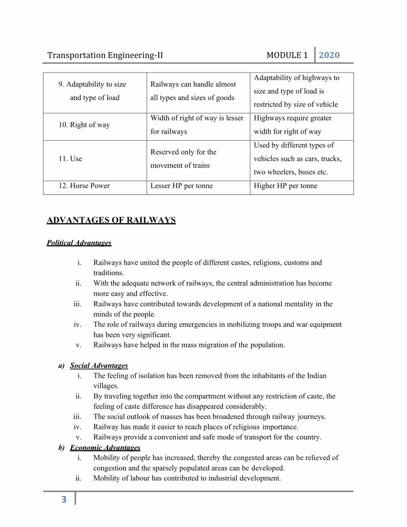
9. Adaptability to size
and type of load
Railways can handle almost
all types and sizes of goods
Adaptability of highways to
size and type of load is
restricted by size of vehicle
10. Right of way Width of right of way is lesser
for railways
Highways require greater
width for right of way
11. Use
Reserved only for the
movement of trains
Used by different types of
vehicles such as cars, trucks,
two wheelers, buses etc.
12. Horse Power Lesser HP per tonne Higher HP per tonne
ADVANTAGES OF RAILWAYS
Political Advantages
i. Railways have united the people of different castes, religions, customs and
traditions.
ii. With the adequate network of railways, the central administration has become
more easy and effective.
iii. Railways have contributed towards development of a national mentality in the
minds of the people.
iv. The role of railways during emergencies in mobilizing troops and war equipment
has been very significant.
v. Railways have helped in the mass migration of the population.
a) Social Advantages
i. The feeling of isolation has been removed from the inhabitants of the Indian
villages.
ii. By traveling together into the compartment without any restriction of caste, the
feeling of caste difference has disappeared considerably.
iii. The social outlook of masses has been broadened through railway journeys.
iv. Railway has made it easier to reach places of religious importance.
v. Railways provide a convenient and safe mode of transport for the country.
b) Economic Advantages
i. Mobility of people has increased, thereby the congested areas can be relieved of
congestion and the sparsely populated areas can be developed.
ii. Mobility of labour has contributed to industrial development.

Transportation Engineering-II MODULE 1 2020
4
iii. During famines, railways have played a vital role in transporting food and
clothing to affected areas.
iv. Growth of industries has been promoted due to transportation of raw materials
through railways.
v. Speedy distribution of finished products is achieved through railways.
vi. Railways provide employment to millions of people and thus help in solving the
unemployment problems of the country.
c) Techno-Economic Advantages
i. Cost saving in transportation of long haul bulk traffic.
ii. Energy efficiency.
iii. Environment friendliness.
iv. Higher safety.
v. Efficient land use and ease in capacity expansion.
INDIAN RAILWAYS
Indian Railways is operated by the Ministry of Railways. It manages the fourth-largest railway
network in the world by size, with 121,407 kilometers of total track over a 67,368-kilometre
route. There are four gauges in India: Metre gauge, Narrow gauge, Broad gauge and Standard
gauge. Currently, unigauge project is in progress to convert all tracks to broad gauge.
Indian Railways is divided into several zones, which are further sub-divided into divisions. The
number of zones in Indian Railways increased from six to eight in 1951, nine in 1952 and sixteen
in 2003. Each zonal railway is made up of a certain number of divisions, each having a divisional
headquarters. There are a total of sixty-eight divisions. Each of the sixteen zones is headed by a
general manager who reports directly to the Railway Board. The zones are further divided into
divisions under the control of divisional railway managers (DRM).
History of Indian Railway
On 1st of August, 1849 the Great Indian Peninsular Railways Company was established in India.
On 17th of August 1849, a contract was signed between the Great Indian Peninsular Railways
Company and East India Company. As a result of the contract an experiment was made by laying
a railway track between Bombay and Thane (56 Kms).

Transportation Engineering-II MODULE 1 2020
5
• On 16th April, 1853, the first train service was started from Bombay to Thane.
• On 15th August, 1854, the 2nd train service commenced between Howrah and Hubli.
• On the 1st July, 1856, the 3rd train service in India and first in South India commenced
between Vyasarpadi and Walajah Road and on the same day the section between
Vyasarpadi and Royapuram by Madras Railway Company was also opened.
Subsequently construction of this efficient transport system began simultaneously in different
parts of the Country. By the end of 19th Century 24752 Kms. of rail track was laid for traffic. At
this juncture the power, capital, revenue rested with the British. Revenue started flowing through
passenger as well as through goods traffic.
DEVELOPMENT OF THE INDIAN RAILWAY
The development of Indian railways can be broadly split up into five stages:
1. The old guarantee system
2. State construction and ownership
3. The modified guarantee system
4. Nationalization
5. Integration and regrouping
1. The old guarantee system (1849-1869): Eight companies entered into contract with East
India Company for running the railways. Shareholders were relieved of all risk and they
were given expectation to receive certain profit over and above the guaranteed interest.
The ultimate right of purchase and full powers of supervision vested with the
government.
2. State construction and ownership (1869-1882): Government purchased existing
railways and constructed new lines, since the administration of railway companies was
not upto the standard.

Transportation Engineering-II MODULE 1 2020
6
3. The modified guarantee system (1882-1924): Various small princely states of India,
existing at that time, contributed to the extent of about 12165 km to 41279 km of railway
lines owned by the government of India at that time.
4. Nationalization (1924-1944): The whole railway lines were nationalized during the
period 1924-1944, based on recommendation Acworth Committee.
5. Integration and regrouping (1944-1966): After independence, with integration of
different princely states, the Indian Government Railways, the largest public sector
undertaking of the country was formed. Again the whole railway was divided into a
number of zones.
ROLE OF INDIAN RAILWAYS IN NATIONAL DEVELOPMENT
Indian Railways has successfully played the role of the prime carrier of goods and
passengers in Indian subcontinent. It is a principal constituent of nation’s transport
infrastructure. Main roles being
• Helps to integrate fragmented markets and thereby stimulates the emergence of a modern
market economy.
• It connects industrial production centres with markets as well as sources of raw materials
thereby favouring industrial development.
• Promotes rapid agricultural growth.
• Provides rapid, reliable and cost effective bulk transport to energy sector.
• Links people with places, enabling large scale, rapid and low cost movement of people
across the length and breadth of the country.
• It is a symbol of national integration and a strategic instrument for enhancing our defence
preparedness.
• Indian railways have a workforce of over 13.6 lakhs, thus being one of the largest
employment providers in India.
• Social costs in terms of environment damage or degradation are significantly low.
• Rail construction costs approximately six times lower than road for comparable levels of
traffic.

Transportation Engineering-II MODULE 1 2020
7
• Railways contribute to a major part in country’s GDP through employment generation,
freight collection, e-catering services etc
• Railways are an agent of urbanization
• Helps in transportation of raw materials and finished goods
• Railways supports its employees in the education of children, medical treatment, housing
etc
• Encouraged tourism by providing special tourist coaches, special trains (eg: Palace-on-
Wheels).
CLASSIFICATION OF INDIAN RAILWAYS
Railway board has classified Indian Railway lines on the basis of importance of route, traffic
carried and maximum permissible speed on the routes, into the following 3 main categories:
1) Trunk routes
2) Main lines
3) Branch lines
1) Trunk routes: Six routes on BG and 3 routes on MG are classified as trunk routes by
Railway Board.
Specifications are:
No Items BG MG
1. Ballast Cushion 25 cm below sleeper 25 cm below sleeper
2. Degree of curvature 7.5o Suitable degree
3. Design speed for new track 160 kmph 100 kmph
4. Maximum permissible speed 120 kmph 80 kmph
5. Rail section 52 kg/m 37.2 kg/m
2) Main lines: All lines other than trunk routes carrying 10 Gross Million Tonne (G.M.T.)
per annum or more for B.G. and 2.5 G.M.T. or more for M.G. and whose maximum

Transportation Engineering-II MODULE 1 2020
8
permissible speed allowed is 100 kmph for BG and 75 kmph for MG are classified as
main lines Railway Board. The specifications are:
No Items BG MG
1. Design speed for new track 120 kmph 75 kmph
2. GMT per annum ≥ 10 ≥ 2.5
3. Maximum permissible speed 100 kmph 75 kmph
4. Rail section 52 kg/m 37.2 kg/m
5. Track laying period 20 years
30 years
3) Branch Lines: All lines other than trunk routes carrying less than 10 G.M.T. per annum for
B.G. and less than 2.5 G.M.T. or more for M.G. and whose maximum permissible speed
allowed is less than 100 kmph for BG and less than 75 kmph for MG are classified as main
lines Railway Board.
CLASSIFICATION BASED ON SPEED CRITERIA
Based on speed criteria, BG lines are divided into following 5 groups:
1) Group ‘A’ Lines
2) Group ‘B’ Lines
3) Group ‘C’ Lines
4) Group ‘D’ Lines
5) Group ‘E’ Lines
1) Group ‘A’ Lines: Trunk routes where trains are running or are meant for running at a
speed of 160 kmph or more.
2) Group ‘B’ Lines: These are routes on which maximum running speed is 130 kmph.
3) Group ‘C’ Lines: They consist of all suburban routes of Mumbai, Calcutta and Delhi.
4) Group ‘D’ Lines: All other routes in country where maximum permissible speed at
present is 100 kmph

Transportation Engineering-II MODULE 1 2020
9
5) Group ‘E’ Lines: The other routes and branch lines where permissible speed limits are
less than 100 kmph
STRENGTH OF INDIAN RAILWAY
• Large volume of goods and passenger traffic is handled for long distances.
• Steel wheels on steel rails cause low tractive resistance.
• In terms of land use, more efficient than roadways.
• Energy efficient mode of transport, causing less pollution.
• In densely populated regions, rapid transit systems and suburban trains are used.
• Well established organization with skilled and trained personnel.
• Good backing to central government in terms of finance.
• It is a self reliant system with respect to major equipments.
WEAKNESS OF INDIAN RAILWAY
• Large portion of infrastructure is overaged.
• Resource constraint in all respect.
• Technology lags in certain infrastructure.
RECENT DEVELOPMENTS IN INDIAN RAILWAYS
Over various times, Indian Railways had introduced advanced types of train facilities.
• Modernization of conventional railway track through various measures such as upgrading
standards of track components, achieving uniformity in gauge etc.
• Switching over to electric and diesel traction from steam traction.
• Automation in signaling and train control systems including track circuiting all major
routes.
• Adoption of latest technologies in track evaluation, maintenance and modernization.
• Switching over gradually to computerization for all customer services such as booking,
ticketing, reservation, cancellation etc.
• Promotion of passenger facilities and amenities on stations and in trains.

Transportation Engineering-II MODULE 1 2020
10
• Promotion of container services.
• Introduction of various fast and superfast trains on all important routes and introduction
of deluxe/luxurious trains for attracting tourism.
RAILWAYS FOR URBAN TRANSPORTATION- MODERN DEVELOPMENTS
LRT& MRTS
LRT – Light Rail Transit
LRT is a mode of urban transportation utilizing predominantly reserved but not necessarily grade
separated right of way. Electrically propelled rail vehicles operate singly or in trains. Light rail
transit (LRT) is a medium capacity mode of mass rapid transport which straddles between the
heavy capacity Metro rail and the low capacity bus services. It is a form of rail transit that
utilizes equipment and infrastructure that is typically less massive than that used for heavy rail
modes i.e. metro rail or subway. In the case of LRT, the trains run along their own right-of-way
and are often separated from road traffic. Stops are generally less frequent, and the vehicles are
boarded from a platform. LRT may be at grade or grade separated
Advantages
• environment-friendly
• .quality of life and travel improved.
• moderate maintenance costs.
• exclusive right of way and fixed route.
• no air pollution and less noise in neighbourhood.
• avoids traffic congestion through segregation.
• easily blended with urban and natural environment.
Disadvantages
• high construction cost
• creates aesthetic concerns in certain locations
• problems of parking for large number of LRT riders
• have lower operational flexibility

Transportation Engineering-II MODULE 1 2020
11
MRTS- Mass Rapid Transit System (underground, subway, elevated railway, metro or
metropolitan railway)
It is a passenger transport system in an urban area with a high capacity and frequency, and grade
separation from other traffic. Unlike buses or trams, rapid transit systems are electric
railways that operate on an exclusive right-of-way, which cannot be accessed by pedestrians or
other vehicles of any sort, and which is often grade separated in tunnels or on elevated railways.
Modern services on rapid transit systems are provided on designated lines
between stations typically using electric multiple units on rail tracks, although some systems use
guided rubber tires, magnetic levitation, or monorail. The stations typically have high platforms,
without steps inside the trains, requiring custom-made trains in order to minimize gaps between
train and platform.
Usually they run in tunnels in the city centre and sometimes on elevated structures in the outer
parts of the city. They can accelerate and decelerate faster than heavier, long-distance trains.
TUBE RAILWAYS
Tube railways are deeper than underground railway, usual depth being 27.45m.
The section of a tube railway is completely circular and stations are of the cylindrical
form. The section of the tunnel in which the railway lines are laid is circular, therefore
these are known as tube railways.
Main aim is to avoid the interference due to pipe lines of gas, seepage, water etc. These
railways are generally laid even below the sea or river beds.
Following are the main characteristics of tube railways:
• The railway stations of tube railways are of cylindrical shape.
• Only electric locomotives are used to avoid the smoke and the ventilation
problems.

Transportation Engineering-II MODULE 1 2020
12
• To get an entrance to the tube railway, normally lifts are used. But now escalators
are used.
• Automatic signaling is provided for efficient working.
• Automatic ticket issuing machines are to be installed to save time.
• For tube railway, safety devices are provided. The mechanism is such that the train
cannot start until all the doors are closed.
HIGH SPEED TRACKS
High speed tracks are the tracks which allow operation of trains at speeds more than 120
kilometers per hour. These are the requirements of today, due to:
• there is a rapidly increasing demand of transportation
• running of heavy loads at faster speeds safely and economically between the two major
terminal stations
• better productivity
• provide better services to customer
The high speed trains can be classified in two categories:
• high speed tracks: where the speeds are over 120 kilometers per hour and are up
to 250 kilometers per hour
• super high speed tracks: where the speeds are above 250 kilometers per hour
The development of high speed tracks requires:
• modified traction like diesel and electric traction instead of steam traction
• Modernization of present track to higher standards.
The development of super high speed tracks requires:
• advanced traction efforts
• track modernization.

Transportation Engineering-II MODULE 1 2020
13
The development of high speed tracks consists of:
• modernization of track
• use of better designed rolling stock
• adopting superior type of traction
• better telecommunication and signaling arrangements
• modern techniques of maintenances
For attaining high speeds, electric traction plays an important role. The advantages of electric
traction are:
• Exerts great tractive effort since torque is uniform.
• Repairs and renewals are very few.
• Donot use energy while standing.
• Ready for service at any time.
• Handles heavy volume at higher speeds.
• Trains can be accelerated quickly.
• No smoke, hence suitable for underground operations.
• Potential danger of fire is not there.
• With electric traction, there is no wear of rails and rolling stock.
Modernization of track includes maintaining structural strength requirements and geometric
requirements.
Structural strength requirements include measures like using heavier rail sections which are wear
resistant. All measures to improve strength, durability and stiffness of rail sections should be
followed. Geometric requirements include using BG track, flat curves, gentle gradients etc.
MAGLEV (Magnetic Levitation)
Maglev (Magnetic Levitation) is one of the costliest system, which uses the magnetic forces for
levitation, guidance and propulsion.
There are two technologies for magnetic levitation

Transportation Engineering-II MODULE 1 2020
14
• Electromagnetic Suspension (EMS)
• Electrodynamic Suspension (EDS)
It has wheel support paths and coils are provided on the two sides. The beams on either side
encompass the coils. These are known as the propulsion coils as well as there is levitation and a
guidance coil. Propulsion, levitation & guidance coils are used for the movement of the vehicle
over these support paths and as soon as vehicle takes a higher speed, it will get lifted from the
base, about 10 cm and it will be moving into the air. This creates some gap between this and the
base of the vehicle. The train does not levitate until it reaches 80 kilometer per hour.
Lateral guidance is achieved with the help of super conducting magnets on train and levitation
coils on sides. When the side of the train nears the side of the guide way, the super conducing
magnet on the train induces a repulsive force from the levitation coils on the side closer to the
train and an attractive force from the coils on the farther side. This keeps the train in the center of
the guideway.
For propulsion, an alternating current is ran through electromagnet coils on the guide walls of the
guide way and this creates a magnetic field that attracts and repels the superconducting magnets
on the train and propels the train forward. Braking is accomplished by sending an alternating
current in the reverse direction.

Transportation Engineering-II MODULE 1 2020
15
TRACK ALIGNMENT
The direction and position given to the centerline of the railway track on the ground is called the
track alignment.
The horizontal profile includes straight path, circular curves & transition curves.
The vertical profile includes gradients and vertical curves.
NECESSITY FOR GEOMETRIC DESIGN
The need for proper geometric design of a track arises because of the following considerations:
(a) To ensure the smooth and safe running of trains
(b) To achieve maximum speeds
(c) To carry heavy axle loads
(d) To avoid accidents and derailments due to a defective permanent way
(e) To ensure that the track requires least maintenance
(f) For good aesthetics

Transportation Engineering-II MODULE 1 2020
16
BASIC REQUIREMENTS OF GOOD ALIGNMENT
An ideal alignment should fulfill the following requirements:
1) Purpose of track: The alignment of track should be done keeping in view the basic
purpose or purposes it is going to serve. In general, the railways serve the following
purposes:
a. Transportation services: carry passenger and goods traffic
b. Political and strategic: connecting points for defence purposes
c. Linking of centres: linking of two trade centres
d. To open up new tracks
e. Shortening existing track
2) Feasibility: For aligning a railway line, it is necessary to carryout feasibility study so that
the proposed track alignment melts all technical requirements and also fits in well with
general planning of the country.
3) Economy: The track alignment should be economical when following factors are given
due consideration:
a. Selecting shortest possible route
b. Minimizing initial construction cost by avoiding loose earth slopes, rock-cuttings,
drainage crossings etc.
c. Minimizing maintenance cost by avoiding deep cutting, very high banks, long
viaducts, tunnels and heavy gradients which cause heavy wear on rails and rolling
stock.
d. Minimizing operation expenses or transportation cost by providing easy gradients,
avoiding unnecessary rises and adopting shortest direct route.
4) Safety: The track should be so aligned that it gives safety to traffic operations. To
achieve this, curves and gradients should be properly designed, and stability of natural
slopes, embankments and cut-slopes should be considered. Foundations of embankments
should be properly maintained.
5) Aesthetic aspects: The aesthetic aspect should be kept in view for comfortable and
pleasant journey. This can be achieved by avoiding the view of borrow pits, use of
transition curves etc or by keeping the track through beautiful natural surroundings.

Transportation Engineering-II MODULE 1 2020
17
FACTORS AFFECTING SELECTION OF GOOD ALIGNMENT
Following factors are considered in the selection of good alignment:
1) Obligatory or control points
2) Traffic
3) Gauge selection
4) Geometric standards
5) Topography
6) Economy
7) Other considerations
1) Obligatory or control points:
It can be classified into two categories:
a) Points through which a track must pass
b) Points through which a track should not pass
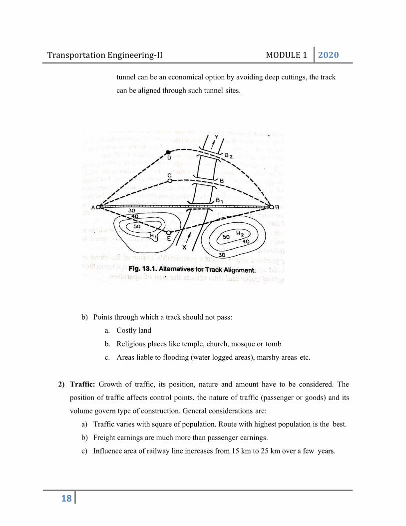
a) Points through which a track must pass
a. Important towns and cities: It is desirable that track alignment passes
through places of social, commercial, political and defence importance. In
fig, if A and B are two main cities and between A and B, there are towns
C, D and E. If alignment passes through any of these intermediate towns,
there will be a slight increase in the length of track, i.e, length increases
from AB1B to AEC or ACB or ADC. Based on cost-benefit analysis,
alignment can be selected.
b. Major bridges or river crossings: the construction of major bridges over
large rivers is a costly affair. The route ACB should be selected if bridge
B exists and B1 does not exist.
c. Hill passes or saddles: To avoid unnecessary requirements of deep cuttings
or high banks or tunnels or viaducts, the existing passes or saddles should
be connected, whenever crossing the hills.
d. Site for tunnels: Though passing of a track through tunnel should be
avoided as far as possible but in case off high and thin ridges when a
Transportation Engineering-II MODULE 1 2020
18
tunnel can be an economical option by avoiding deep cuttings, the track
can be aligned through such tunnel sites.
b) Points through which a track should not pass:
a. Costly land
b. Religious places like temple, church, mosque or tomb
c. Areas liable to flooding (water logged areas), marshy areas etc.
2) Traffic: Growth of traffic, its position, nature and amount have to be considered. The
position of traffic affects control points, the nature of traffic (passenger or goods) and its
volume govern type of construction. General considerations are:
a) Traffic varies with square of population. Route with highest population is the best.
b) Freight earnings are much more than passenger earnings.
c) Influence area of railway line increases from 15 km to 25 km over a few years.

Transportation Engineering-II MODULE 1 2020
19
3) Gauge selection: increase in width of gauge increases initial cost but it also increases
load carrying capacity and speed of trains.
4) Geometric standards: Some points to be considered are:
• Ruling gradient and minimum radius should be considered
• long lengths of straight portion should be provided in between two reverse curves
• curves should be avoided at bridges, stations etc.
• effect of rise and fall of ground should be considered
5) Topography: If topography of country is such that use of steep gradients is unavoidable,
then in such cases the alignment of the track is made by the special ways to reducethe
rate and cost of high gradients. For alignment, topography can be classified as:
a) Valley alignment
b) Cross country alignment
c) Mountain alignment
6) Economy: different alignments are analysed from cost point of view and best alignment
which gives maximum annual return is selected.
Annual.return = Gross.revenue − Annual.running.exp enses
Investment
7) Other considerations:
a) Geological formation should be studied
b) Effect of flood and climate should be studied
c) Track should cross road at right angles
d) Station sites should be on level ground
e) Availability of construction materials
f) Political considerations such as avoiding foreign country.

Transportation Engineering-II MODULE 1 2020
20
RAILWAY SURVEYS
The various engineering surveys which are carried out for the choice of route of a new railway
line can broadly be divided into the following categories:
1) Reconnaissance survey
2) Preliminary survey
3) Location survey
4) Railway electrification survey
1) Reconnaissance survey:
Main objectives are:
1) to obtain general knowledge of the whole territory
2) To obtain information regarding the salient features of the territory
Importance of reconnaissance survey: A number of possible alternative routes between
two points can be worked out. Personal factors play an important role in the
reconnaissance survey. The successful conduct entirely depends on the personal qualities
of the engineer such as his training and experience, his capacity of observation and
interpretation.
Information gathered in reconnaissance survey: A reconnaissance survey can broadly
be divided into two categories:
1. Traffic reconnaissance survey
2. Engineering reconnaissance survey
Traffic reconnaissance survey: This consists of collection of the information regarding
the following:
a) The general character of the country and the extent of cultivation;
b) Information regarding the local industries and religious festivals;
c) The general condition as regards prosperity of people in the locality and density of
population and its distribution;
d) The probable amount of traffic to be served by new railway line;
e) The probable new traffic lines to be opened up to join large centres of trade;
f) Nature and volume of exports and their destination;
g) The amount of imports and centres of their distribution;

Transportation Engineering-II MODULE 1 2020
21
h) Possibilities of development of industries as a result of the new railway line;
i) Visiting all trade centres and consultation with prominent citizens and local authorities
regarding the most suitable route for the railway;
j) Standard of construction required for carrying the probable traffic;
k) Study of the existing means of transport
Engineering reconnaissance survey: This consists of collection of information regarding
the following:
a) Physical features of the country;
b) The surface formation of the ground;
c) Nature of soil and its classification;
d) Streams and rivers of the immediate vicinity, especially those which are likely to cross
the proposed railway line;
e) Positions of hills and lakes;
f) Samples of water from wells, rivers, etc. so as to ascertain weather the water is suitable
for use in locomotive or not;
g) Availability of materials and labour for use during construction.
3) Preliminary Survey:
Object of preliminary survey: To conduct survey work along alternative routes found out
by reconnaissance survey and to decide most economical route. Thus, in preliminary
survey, all the possible routes of railway line are critically studied, examined and
analysed.
Importance of preliminary survey: It decides the final route and recommends only one
particular route in preference to other alternative routes. Thus, it should be carried out
with great precision as it affects the alignment of the final route.
4) Location Survey:
Object of location survey: The main object of location survey is to carry out the detailed
survey along the route which has been found and fixed as the most economical route
from the data of the preliminary survey.

Transportation Engineering-II MODULE 1 2020
22
Importance of location survey: Location survey establishes the central line of the actual
track to be laid and hence as soon as the location survey is completed, the construction
work is started. Thus, end of the location survey is the beginning of the actual laying of
new railway line.
Work of location survey: It is carried out in two stages: 1. Paper location 2. Field
location 1. Paper location: The final route selected is put up on paper and details such as
gradient, curves, contours, etc. are worked out. All the working drawings are prepared,
even of minor structures such as signal cabins. After the paper location is over, the field
work is started and the centre-line of the track is fixed.
2. Field location: The field location transfers paper location on the ground. Moreover, It
gives all the requirements of the construction engineer such as bench- marks, levels,
measurements, etc. The centre-line pegs are driven at every 300 metres along the centre-
line of the track.
Instruments for location survey:
Instruments used are theodolite, precise level and steel tape.
5) Railway Electrification Survey:
It is classified into two categories:
a) Cost cum feasibility survey; and
b) Foot by foot survey.
a) Cost cum feasibility survey: It is quick electrification survey for the proposed route to
examine major engineering installations which may have a bearing on the cost of
electrification. The scope of survey is as under:
i) Civil works: It includes examination of heavy over line structures like
flyovers, road over bridges etc and tunnels to find whether they require
major or minor modification to permit erection of overhead equipment.
ii) Signalling and telecommunication works: It includes required
modification to existing installations for General Power Supply.
iii) Modification to track crossings
b) Foot by foot survey: On acceptance of a project report, foot by foot detailed surveys are
required for the preparation of working drawings for the electrification.

Transportation Engineering-II MODULE 1 2020
23
COMPONENT PARTS OF RAILWAY TRACK
The Typical components are:
a) Rails
b) Sleepers (or ties)
c) Fasteners
d) Ballast (or slab track)
e) Subgrade
Typical cross-section of railway track
a) Rails- The rails on the track can be considered as steel girders for the
purpose of carrying axle loads.
b) Sleepers (or ties)- Members laid transverse to rails on which the rails are supported
and fixed, to transfer loads from rails to ballast and subgrade below
c) Fasteners- these are used to keep rails in proper position
d) Ballast (or slab track)- Granular material, usually broken stone or brick, kankar,
gravel or sand placed below and around sleepers to transmit load from sleepers to
formation. It also permits drainage.
e) Subgrade- naturally occurring soil prepared to receive ballast, sleepers and rails
for constructing railway track.

Transportation Engineering-II MODULE 1 2020
24
RAILWAY TRACK CROSS-SECTIONS

Transportation Engineering-II MODULE 1 2020
25

Transportation Engineering-II MODULE 2 2019
1
MODULE – 2 PERMANENT WAY
PERMANENT WAY (RAILWAY TRACK)
The completed track or a railway line is known as permanent way. The
combination of rails fitted on sleepers and resting on ballast and subgrade is called the
railway track or permanent way.
Sometimes temporary tracks are also laid for conveyance of earth and materials
during construction works. The name permanent way is given to distinguish the
final layout of track from these temporary tracks.
Requirements of an ideal permanent way
1. The gauge should be correct and uniform.
2. Minimum friction between wheels of the train and rails.
3. The rail should be in proper level. In a straight track – two rails must be at the same
level. On curves – the outer rails have proper superelevation and there should be
proper transition at the junction of a straight and curve.
4. Adequate provisions for easy renewals and replacements.
5. Track should be strong, low in initial cost as well as maintenance cost.
6. Track should be resilient and elastic in order to absorb shocks and vibrations of
running track.
7. Gradient should be even and uniform.
8. Track should have enough lateral strength
9. Drainage facility should be perfect.
10. Precautions to avoid occurrence of creep
11. The alignment should be correct, i.e., it should be free from kinks or irregularities.

Transportation Engineering-II MODULE 2 2019
2
Capacity of a railway track
Capacity of a railway (track capacity) is the hourly capacity of the track to handle
the trains safely or in other words it is the number of trains that can be run safely on a
track per hour.
Gauges in railway track
Gauge:- Clear distance between inner or running faces of two track rails. The distance
between the inner faces of a pair of wheels is called the “wheel gauge”.
Different Gauges in India
Type of gauge Gauge width
1. Standard Gauge or Broad Gauge(B.G.) 1.676 m
2. Metre Gauge (M.G.) 1.0m
3. Narrow gauge (N.G.) 0.762 m
4. Light Gauge (L.G.) 0.610 m
Selection of Gauge
1. Cost of construction – There is little increase in the initial cost if we select a
wider gauge due to the following reasons.
a. The cost of bridges, tunnels, station buildings, staff quarters, signals, cabins
and level crossings is the same for all the gauges.
b. The cost of earth work, ballast, sleepers, rails, etc. would proportionally
increase with increase in gauge width.
2. Volume and nature of Traffic – Greater traffic volume and greater load carrying
capacity, the trains should be run by a better traction technique or by better
locomotives. For heavier loads and high speed, the wider gauges are required.
3. Development of the areas – Narrow gauges can be used to develop the thinly
populated areas by joining the under developed areas with developed or urbanised
areas.
4. Physical features of the country – Use of narrow gauge is warranted in hilly
regions and in plain also when high speed is not required and the traffic is light
N.G. is the right choice.

Transportation Engineering-II MODULE 2 2019
3
5. Speed of movement – the speed of train is almost proportional to the gauge.
Speed is the function of wheel diameter which in turn limited by the gauge. The
wheel diameter is generally 0.75 times that of the gauge.
Uniformity of Gauges
Gauge to be used in a particular country should be uniform throughout as far as
possible. The uniformity of gauges results in the following advantages:
1. The delay, cost and hardship in transhipping passengers and goods from the
vehicles of one gauge to another is avoided.
2. As the transhipping is not required, there is no breakage of goods.
3. Difficulties in loading and unloading are avoided and labour expenses are saved.
4. Large sheds to store goods are not required.
5. Surplus wagons of one gauge cannot be used on another gauge. This problem will
not arise if gauge is uniform.
6. Locomotives can be effectively used on all the tracks if a uniform type of gauge is
adopted.
7. During military movement, no time is wasted in changing personnel and
equipment from one vehicle to another if gauge is uniform.
RAILS
The rails on the track can be considered as steel girders for the purpose of carrying
axle loads.
Rails are made of high carbon steel to withstand wear and tear
Flat footed rails are mostly used in railway track.
Functions of rails
1. It should bear stresses developed due to heavy axle vertical loads, lateral and
braking forces and thermal stresses.
2. To provide a hard and smooth and unchanging surface for passage of heavy
moving loads with a minimum friction between the steel rails and steel wheels.

Transportation Engineering-II MODULE 2 2019
4
3. Transmit load to sleepers and consequently reduce pressure on ballast and
formation below.
4. The rail material used is such a way that it gives minimum wear to avoid
replacement charges and failures of rails due to wear.
Requirements of rails
1. The bottom of head and top of foot of rails should be so shaped as to enable the a
fish plates to transmit the vertical load efficiently from the head to the foot at rail
joints.
2. The centre of gravity of rail must lie approximately at the mid height of rail, so
that maximum tensile and compressive stresses are almost same.
3. Rails should be capable of withstanding lateral forces.
4. The head must be sufficiently deep to allow for an adequate margin of vertical
wear.
5. Web of rails should be sufficiently thick to bear the load coming on it and should
provide adequate flexural rigidity in horizontal planes.
6. Foot should be wide enough so that rails are stable against overturning, especially
on curves.
7. The tensile strength of the rail piece should not be less than 72 kg/m2
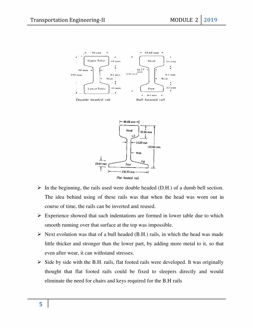
Types of Rail sections
1. Double headed rails (D.H. rails)
2. Bull headed rails (B.H. rails)
3. Flat footed rails (F.F rails)
Transportation Engineering-II MODULE 2 2019
5
In the beginning, the rails used were double headed (D.H.) of a dumb bell section.
The idea behind using of these rails was that when the head was worn out in
course of time, the rails can be inverted and reused.
Experience showed that such indentations are formed in lower table due to which
smooth running over that surface at the top was impossible.
Next evolution was that of a bull headed (B.H.) rails, in which the head was made
little thicker and stronger than the lower part, by adding more metal to it, so that
even after wear, it can withstand stresses.
Side by side with the B.H. rails, flat footed rails were developed. It was originally
thought that flat footed rails could be fixed to sleepers directly and would
eliminate the need for chairs and keys required for the B.H rails

Transportation Engineering-II MODULE 2 2019
6
But, it was observed that heavy train loads caused the foot of the rails to sink in to
the wooden sleeper, making the spikes work loose. To remedy this steel bearing
plates are introduced, between the sleeper and rail
In India, flat footed rails are commonly used
Flat Footed rails (F.F rails)
Merits:-
1. They have more strength and stiffness both vertically and laterally than B.H. rails
2. No chairs and keys are required.
3. Fitting of rails with sleepers are simpler, so they can be easily laid and re laid.
4. In points and crossings the arrangements are simpler than B.H. rails.
Demerits:-
1. The fitting get loosened more frequently than in case of B.H. rails
2. The strengthening of bent rails, replacing of rails and de hogging of battered rails
are difficult.
Bull headed rails (B.H. rails)
Merits:-
1. The rails are easily disconnected from sleepers as they have no direct connection
with the latter.
2. The heavy chairs with larger bearing on sleepers give longer life to wooden
sleepers and greater stability to the track.
Demerits:-
1. They have less strength and stiffness
2. They require heavy maintenance cost.
Selection of rails
A rail designated by its weight per unit length. Various factors considered in deciding
weight of rails are
1. Speed of trains
2. The gauge of track

Transportation Engineering-II MODULE 2 2019
7
3. The axle load and nature of traffic
4. Type of rails
5. Spacing of sleepers
Length of rails
The rails of larger length are preferred to smaller length of rails, because they give
more strength and economy for a railway track. The length of rail is governed by the
following factors.
1. Length of the rail is so chosen that the manufacturing cost is most reasonable.
2. It depends upon the transportation facilities, so only those lengths of rails are
possible which can be transported by longest wagons available on the railways.
3. More length of the rail, more will be the gap required for expansion of rails.
Corrugated and roaring rails
In some places, the heads of rails are found to be corrugated rather than smooth
and straight, when the vehicles pass over such rails, a roaring sound is created.
The corrugations consist of minute depressions on the surface of rails.
They are usually created at places where either brakes are applied or trains are
start.
FAILURE OF RAILS
Factors influencing
Axle load of locomotive
Constant reversal of stresses
Defects in manufacture
Design of rail joints
Rail length
Rail quality
Rail section
Rail welding
Speed of trains

Transportation Engineering-II MODULE 2 2019
8
Types of rail failures
Crushed head
Transverse fissure
Split head
Horizontal fissure
WEAR OF RAILS
Wear of rails is caused by the movement of a number of wheels of the vehicle.
Classification of wear based on location:
1. Wear on the top or the head of rail:
The metal from the top of the rail flows and form projections known as burs. The
causes for this type of wear include:
Rails worn out due to abrasion of rolling wheels over it.
Heavy wheel loads concentrated on very small area resulting in flow of
metal from top.
Impact of heavy loads.
Grinding action of sand particles between rails and wheels.
Corrosion action of metal rails, especially near sea.
Metal on top starts burning during starting or when brakes are applied to
moving trains.
2. Wear of rails at the end of the rail :
It is much greater than wear on the top
Cause
The blow imparted to the ends of the rails during the jumping of wheels of
the vehicles at the expansion gap.
Effects
1. The fish plate and fish balls become loose
2. Contact surface between rails and sleepers get worn out.

Transportation Engineering-II MODULE 2 2019
9
3. Sleepers at the expansion joint are depressed due to the settlement of
ballast at these points.
3. Wear of rail on the sides of the head of rail
This is the most destructive type and occurs on tracks laid on curves.
Causes
1. Due to the curvature, the pressure due to centrifugal force cause grinding
action of wheel flanges on the inner side of the head of outer rail.
2. Vehicles do not bend to the shape of the curvature while moving over a curve
and this results into the biting of the inner side of head of outer rail by the
wheel flanges
3. Slipping action of the wheel on the curves.
Methods to reduce the wear of rails
Use of special alloy steel
Good maintenance of track
Reduction of expansion gap
Exchange of inner and outer rail on curves.
Introducing check rails all the way round the inner rail and parallel to it.
Use of lubricating oil.
Use of head hardened rails
(allowing the rail to pass through an isometrical treatment plant)
Measuring wear of rails
Following are the two methods for measuring wear:
Rail is removes and its weight is measured. Compare it with original weight.
Prescribed permissible limit of wear in India is 5%.
A correct profile of head of rail is obtained by suitable equipment and this is
compared with the profile of new rail.

Transportation Engineering-II MODULE 2 2019
10
CREEP OF RAIL
The longitudinal movement of rails in a track is known as creep. The value varies
from 0-130 mm per month. Creep can be noted by
1. Closing of successive expansion spaces at rain joints in the direction of creep.
2. Opening out of joints at the points from where the creep starts.
3. Marks on rail flanges and webs made by the scratching as the rails slide.
Causes of Creep
I. Brakes
The creep is developed due to forces that come into action when the train is starting
or stopping by application of brakes. During starting operations, the wheels push the
rails backward and during stopping operations, the wheels push the rails forward.

Transportation Engineering-II MODULE 2 2019
11
II. Wave Theory / Wave Action
The creep is developed due to the wave motion of wheels on rails. Due to the
movement of the wheel loads on the rail, the rail deflects as a continuous beam and
crests are formed at the supports. When the wheels of the vehicle strike against these
crests, creep is developed.
III. Percussion theory
According to this theory, impact of rail wheel ahead of the joints gives rise to the
creep in rails.
As the wheels of the moving train leave the trailing rail at the joint, the rail gets
pushed forward causing it to move longitudinally in the direction of traffic, and that
is how creep develops. Though the impact of a single wheel may be nominal, the
continuous movement of several wheels passing over the joint pushes the facing or
landing rail forward, thereby causing creep.
IV. Changes in temperature
Creep may also develop due to unequal expansion and contraction of rails owing to
the changes in temperature. The creep is more rapid during hot weather.. And also

Transportation Engineering-II MODULE 2 2019
12
influenced by variation of location of track(exposed track or track in shady
surroundings)
V. Unbalanced traffic
In single line system if heavy traffic runs in both direction creep is almost balanced
.otherwise (heavy traffic only in one direction) will cause creep.
Measurement of Creep
Creep can be measured with the help of a device called creep indicator. It consists of two
creep posts, which are generally rail pieces that are driven at 1 km intervals on either side
of the track. For the purpose of easy measurement, their top level is generally at the same
level as the rail. Using a chisel, a mark is made at the side of the bottom flange of the rail
on either side of the track. A fishing string is then stretched between the two creep posts
and the distance between the chisel mark and the string is taken as the amount of creep.
Methods of correcting creep
1. Pulling back of the rail method: rails are pulled back equal to the amount of
creep, either by manpower or with the help of jacks.
2. Use of creep anchors: creep anchors consist of cast-iron pieces which are made to
grip the rail. These are placed behind the sleepers for every third or fourth sleeper.
This arrangement prevents the movement of the rails because the sleepers which
are embedded in the ballast will also have to move, if creep has to take place.
3. Use of steel sleepers: Steel sleepers are provided with fittings which donot easily
allow the creep to occur and they also have a good grip with the ballast to resist
their movement in the ballast.
KINKS IN RAILS
The lateral movement of ends of the rails out of its original position is called kinks.
Causes of formation of kinks are:
1) Loose packing at joints
2) Defect in gauge and alignment

Transportation Engineering-II MODULE 2 2019
13
3) Defect in cross level at joints
4) Uneven wear of rail head, where kinks are formed at joints
Kinks produce the following undesirable effects:
1) Cause unpleasant jerks in vehicles
2) Due to uneven wear of rail heads, kinks appear at places other than the joints and
obstruct smooth running of trains.
3) A series of kinks are seen at curves due to which defect in gauge, alignment and
camber may occur. This sometimes causes serious risk in turning operations of
trains.
Measures to remove kink include:
1) Correcting alignment at curves and joints
2) Proper packing at joints
3) Proper maintenance of track periodically in respect of cross levels, gauge,
alignment, welding of worn out portions etc.
SLEEPER
Functions of sleeper
1. It should support the rails firmly and evenly.
2. Maintain the gauge of the track correctly
3. Distribute the weight coming on the rail over a sufficiently larger area of the ballast.
4. To act as an elastic medium between the rails
5. Help the easy replacement of rails fastenings , without seriously disturbing the traffic.
6. Permit insulation of the track for electrical sections.
7. Maintain the track at proper grade.
8. Maintain the alignment of the track

Transportation Engineering-II MODULE 2 2019
14
Types of sleepers
1. Longitudinal sleepers: it is the earliest form and consists of slabs of stones or
pieces of timber placed parallel to the rails. Cross pieces were provided at intervals
to maintain the correct gauge of track. This type of sleepers is discarded now since
the running of train is not smooth, cost is more and noise created is more.
2. Transverse sleepers/ cross sleepers: First introduced in Britain in 1835. Sleepers
are placed at right angles to rails. They are universally adopted and remove
disadvantages of longitudinal sleepers.
Requirements of Sleeper
1. Initial and maintenance cost should be as low as possible.
2. Fastening should not be complicated in design.
3. Weight of sleeper should be moderate.
4. Sleeper should possess sufficient bearing area below rail seat and over ballast.
5. Sleeper should be such that it is possible to readjust and maintain the gauge correctly.
6. Should be capable to resist to shocks and vibrations due to fast moving vehicles.

Transportation Engineering-II MODULE 2 2019
15
7. Sleeper material should not interfere with the working of track circuits.
8. Sleepers should not break during the packing of the ballast.
9. It should not move forward during the passage of trains.
10. It should possess antitheft quality.
11. It should withstand derailment without excessive damage.
12. Should be easy to manufacture, transport and lay.
SLEEPER DENSITY AND SPACING OF SLEEPERS
Sleeper density is the number of sleepers per rail length. It is specified as (M + x) or
(N + x), where M or N is the length of the rail in metres and x is a number that varies according
to factors such as:
(a) axle load and speed,
(b) type and section of rails,
(c) type and strength of the sleepers,
(d) type of ballast and depth of ballast cushion, and
(e) nature of formation.
If the sleeper density is M+ 7 on a broad gauge route and the length of the rail is 13 m, it
implies that 13 + 7 = 20 sleepers will be used per rail length of the track on that route. The
number of sleepers in a track can also be specified by indicating the number of sleepers per
kilometre of the track, for example, 1540 sleepers/km. This specification becomes more relevant
particularly in cases where rails are welded and the length of the rail does not have much bearing
on the number of sleepers required. The spacing of sleepers is fixed depending upon the sleeper
density. Spacing is not kept uniform throughout the rail length. It is closer near the joints because
of the weakness of the joints and impact of moving loads on them. There is, however, a
limitation to the close spacing of the sleepers, as enough space is required for working the
beaters that are used to pack the joint sleepers.
Materials for cross sleepers
Following materials are used for the cross-sleepers on the Indian Railways:
1) Timber or wooden sleepers

Transportation Engineering-II MODULE 2 2019
16
2) Steel sleepers
3) Cast-iron sleepers
4) Concrete sleepers
BALLAST
Functions of Ballast
1. To provide a hard and level bed for sleepers to rest on
2. To hold the sleepers in place during the passage of trains
3. To transmit and distribute the load from the sleepers to the formation.
4. To allow for maintaining correct track levels.
5. To protect the surface of formation from the direct exposure to sun, frost or rain
6. To form an elastic bed
7. To drain the water immediately and keep the sleepers in dry condition.
8. To discourage the growth of vegetation.
9. To resist the lateral , longitudinal and vertical displacement of the track

Transportation Engineering-II MODULE 2 2019
17
Requirements of Ballast
1. It should be possible to maintain the required depth of the material in order to
distribute uniformly the weight of passing train on the ground
2. The nature of the ballast material should be such that it should provide sufficient
grip to sleepers to prevent their horizontal movement.
3. Material should be elastic in nature.
4. The ballast material should not be brittle, but should possess sufficient
compressive strength.
5. Should not allow rain water to accumulate.
6. Should be cheap and easily available.
7. Should not have any chemical action on rails and sleepers.

Transportation Engineering-II MODULE 2 2019
18
8. Easily workable and should be durable.
CONING OF WHEELS
The flanges of the wheels are not made flat but it is in the shape of cone with a
slope of about 1 in 20. As the wheels are set on the axle there is some chance for that
lateral movement between the flanges of the wheels and the rails. So without coning, the
flanges would cause a slight but sudden shock to the sides of the rails. Thus the coning of
wheels is mainly done to maintain the vehicle in the centre position with respect to the
track.
Behaviour of the coned wheels on straight level track
On straight and level tracks the flanges of the wheel have equal circumferences.
Behaviour of the coned wheels on curved track
When the wheels move along a curve, the outer wheel has to cover a greater
distance than that of inner rail. The vehicle also has a tendency to move sideways towards
the outer rail, the circumference of the flange of outer wheel will be greater than that of
inner wheel. This will help the outer wheel to cover a longer distance than the inner
wheel.

Transportation Engineering-II MODULE 2 2019
19
Disadvantages of Coning of Wheels
1. Smooth riding is produced by the coning of wheels, but the pressure of the
horizontal component near the inner edge of the rail has a tendency to wear the rail
quickly.
2. The horizontal component tends to turn the rail outwards and hence the gauge is
sometimes widened.
3. If no base plates are provided, the sleepers under the outer edge of the rail are
damaged.
These can be overcome by tilting of rails. i.e. the rails are not laid in flat. They are
tilted inwards. Tilting of rail is made by the use of inclined base plate, i.e. the slope of the
base plate is 1 in 20, same as the slope of the coned surface of the wheel.
Advantages of tilting of rails
1. Uniform wear of the head of rail
2. Maintain the gauge properly
3. Increase the life of rails and sleepers.

Transportation Engineering-II MODULE 2 2019
20
BALLASTLESS TRACK
Ballastless track or slab track is a type of railway track in which the traditional elastic
combination of ties/sleepers and ballast is replaced with a rigid construct of concrete or
asphalt.
In ballastless track, the rails are rigidly fastened to a special type of concrete ties/sleepers
that are themselves set in concrete. Ballastless track therefore offer a high consistency in
track geometry, the adjusting of which is not possible after the concreting of the super
structure. Therefore ballastless track must be concreted within a tolerance of 0.5 mm.
Advantages of ballastless track:
Highly consistent track geometry
Larger life span
Reduced need for maintenance
Fewer deformations and smooth running
Better and controlled drainage
Easier to clean
Disadvantages of ballastless track
High cost of initial construction
Impossibility of adjusting or correcting track geometry once concrete has been set
Necessity of stable infrastructure since no adjustments can be made to the super
structure
Higher noise emissions
Longer repair times when the concrete slab is damaged

Transportation Engineering-II MODULE 2 2019
21
RAIL FASTENINGS
A joint is made between two rails and this incidentally forms the weakest part of
the track. Many fastenings are found out to make this joint as much efficient as much
possible.
Requirements of an ideal rail fastening
1. Should be capable of absorbing shocks and vibrations.
2. Should give protection to sleeper against action of horizontal and vertical forces.
3. Should give sufficient insulation in case of electrified sections.
4. Should resist creep
5. Should be capable of securing gauge at first assembly and maintain gauge.
6. Should be cheap
7. Should consist of less number of components
8. Should be durable
9. Should be easy to fix and adjust
10. Should be non corrosive
11. Should have sufficient strength to resist damage due to derailment
12. Should be designed to remove only by special tools
13. Should keep rail in correct position, level and alignment
14. Should not affect the rail or sleeper adversely in any respect
15. Should not be too rigid
16. Should possess adequate strength to resist lateral forces
17. Should possess high torque resistance
Types of fastenings
Fish plates
Spikes, Fang bolts and hook bolts
Chairs & keys
Bearing plates

Transportation Engineering-II MODULE 2 2019
22
FISH PLATES
Rails at the ends are connected by a pair of fish plates per rail and joint using fish
bolts and nuts. In India we use 4 fish bolts and length of fish plate should not be less than
457mm (4457mm). Fish plates are provided between the bottom of head of rail and top of
foot of rail. The shape of the fish plate is given so that they do not come into contact with
the web of rail.

Transportation Engineering-II MODULE 2 2019
23
SPIKES, FANG BOLTS AND HOOK BOLTS
Spikes are used to hold the rails to the wooden sleepers. They can be used with or
without bearing plates below the rails.
A good spike should fulfill the following requirements:
1. Hold the rail in position
2. It should be cheap
3. Easily fixed and removed
4. Properly maintain the gauge.
Types of spikes
Dog spikes: Section of spike is square and lower end is blunt, pointed or chisel-
shaped.
Screw spikes/ coach screws: holding power is double that of dog spike. The head
is circular with square projection. The sides are tapered and provided with threads.
It resists lateral thrust better than dog spike, but is costly.
Round spikes: These spikes have blunt ends and length varies according to the
gauge.

Transportation Engineering-II MODULE 2 2019
24
Elastic spikes: S steel spring and specially shaped head are provided in these
spikes. These provisions give a better grip with the foot of the rail and it results in
reduced wear and tear of rail, less noise and less creep.
Fang bolts are used as alternative to round spikes. They are more effective but difficult
to fix and remove. So they are not commonly used.
Hook bolts are used to fix the sleepers to girders of the bridges. The rails are as usual
fixed with sleepers by means of dog spikes or screw spikes. The holes are bored in
sleeper and the head of the hook-bolt grips with the flange of the girder. Two hook bolts
are adequate for each sleeper.

Transportation Engineering-II MODULE 2 2019
25
CHAIRS & KEYS
Chairs are used to hold the rails (double headed and bull headed) in position. It is
made of cast iron. It is used to distribute the load from the rails to the sleepers. It consists
of two jaws and a rail seat. The web of the rail is tightly held against the inner jaw of the
chair and a key is driven between rail and outer jaw of chair.
Key is used to keep the rail in proper position. Key may be made of wood or metal
and they may be either straight or tapered. Common metal used for making key is steel.

Transportation Engineering-II MODULE 2 2019
26
BEARING PLATES
Bearing plates are the chairs for flat footed rails. It made of cast iron, rot iron or
steel. The bearing plates may be either flatted or canted (given in a slope). As turnouts do
not have any cant, flat bearing plates are provided under the sleepers.
Canted bearing plates, a cant of 1 in 20 corresponding to tilting of rail is
incorporated and have a recess in the middle of the rail seat to prevent rocking of the rail
in its seat.
GEOMETRIC DESIGN OF RAILWAY TRACK
A railway track on a straight is an ideal condition. But the curvature is to be provided
invariably on railway track due to various reasons such as connecting important points,
avoiding obstructions etc.
Geometric design of a railway track discusses all those parameters which affect the
geometry of the track. These parameters are as follows:
1. Gradients in the track, including grade compensation, rising gradient, and falling
gradient

Transportation Engineering-II MODULE 2 2019
27
2. Curvature of the track, including horizontal and vertical curves, transition curves,
sharpness of the curve in terms of radius or degree of the curve, cant or superelevation on
curves, etc.
3. Alignment of the track, including straight as well as curved alignment.
It is very important for tracks to have proper geometric design in order to ensure
the safe and smooth running of trains at maximum permissible speeds, carrying the
heaviest axle loads. The speed and axle load of the train are very important and
sometimes are also included as parameters to be considered while arriving at the
geometric design of the track.
Types of curves
Broadly divided as
- Horizontal curves: provided for smooth change in direction
- Vertical curves: provided when a rising gradient is followed by falling gradient or
vice-versa or when a rising or falling gradient is increased or decreased.
General classification of curves
- Simple curves
- Compound curves
- Parabolic curves
- Transitional curves
Designation of curves
Curves on the railways are generally circular i.e. such curve should have same
radius on every portion of it. A simple curve is either designated by its degree or by its
radius. The degree of a curve (D) is the angle subtended at its centre by a 30.5 m or 100 ft
arc. 𝐷 = 1720⁄𝑅
R= radius in m
For 10 curve R = 1720m

Transportation Engineering-II MODULE 2 2019
28
SUPER ELEVATION
When a train moves round a curve, it is subjected to centrifugal force acting radially
away from the centre of the curve. To counteract the effect of centrifugal force, the level of the
outer rail is raised above the inner rail by a certain amount to introduce the centripetal force.
Thus the elevation of outer rail above the inner rail at a horizontal curve is known as super
elevation or cant.
W= weight of moving train
P= Centrifugal force
G= Gauge of track in m
e= Super elevation in cm
α=Angle of inclination
S= Length of inclined surface
Objects of super elevation
1. Ensures smooth and safe movements of passengers and goods on track
2. To introduce centripetal force to counteract the effect of centrifugal force and hence faster
movement of trains on curves is permitted.
3. It prevents derailment and reduces creep as well as side wear of rails.
4. To provide equal distribution of wheel loads on two rails and hence there will be no
tendency of track to move out of position.
5. It results in decrease of maintenance cost of track. 𝑮𝑽𝟐
e= super elevation in cm
V = speed in km/ hr
𝒆 =
𝟏. 𝟐𝟕 𝑹
Transportation Engineering-II MODULE 2 2019
29
G = gauge in m
R = radius of curve in m
Maximum value of super elevation = 1 𝑔𝑎𝑢𝑔𝑒 10
Maximum super elevation for broad gauge = 1 𝑥 1.67 = 0.167m = 16.7 cm 10
Maximum super elevation for meter gauge = 1 𝑥 1 = 0.1m = 10cm 10
Maximum super elevation for narrow gauge = 1 𝑥 0.76 = 0.076 m = 7.6cm 10
Equilibrium Cant or equilibrium super elevation
When the lateral forces and wheel loads are almost equal the cant is said to be in
equilibrium.
Factors affecting super elevation
1) Frictional resistance: frictional resistance between rails and wheels will have some effect
on super elevation.
2) Coning of wheels
3) Body of vehicle: in derivation of equation, body of vehicle is assumed to be rigid. But in
actual practice, it is provided with compressive springs inorder to minimize the effect of
impact.
4) Weighted average: super elevation is calculated only for a particular speed whereas in
actual practice, different trains with different speeds will be travelling on track. Hence
super elevation should be such as to accommodate these variations. Hence weighted
average speed is taken.
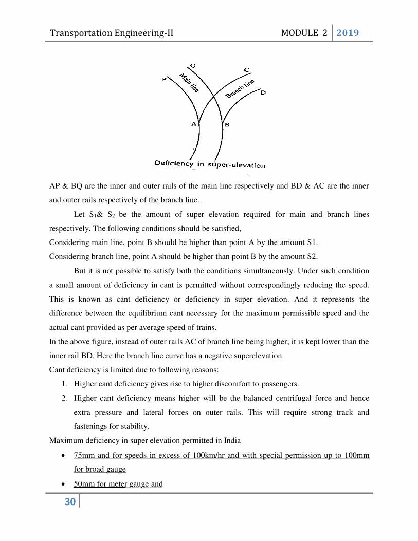
Cant deficiency
Under certain circumstances it is not possible to provide the equilibrium cant. In the
figure a branch line diverges from a main line.
Transportation Engineering-II MODULE 2 2019
30
AP & BQ are the inner and outer rails of the main line respectively and BD & AC are the inner
and outer rails respectively of the branch line.
Let S1& S2 be the amount of super elevation required for main and branch lines
respectively. The following conditions should be satisfied,
Considering main line, point B should be higher than point A by the amount S1.
Considering branch line, point A should be higher than point B by the amount S2.
But it is not possible to satisfy both the conditions simultaneously. Under such condition
a small amount of deficiency in cant is permitted without correspondingly reducing the speed.
This is known as cant deficiency or deficiency in super elevation. And it represents the
difference between the equilibrium cant necessary for the maximum permissible speed and the
actual cant provided as per average speed of trains.
In the above figure, instead of outer rails AC of branch line being higher; it is kept lower than the
inner rail BD. Here the branch line curve has a negative superelevation.
Cant deficiency is limited due to following reasons:
1. Higher cant deficiency gives rise to higher discomfort to passengers.
2. Higher cant deficiency means higher will be the balanced centrifugal force and hence
extra pressure and lateral forces on outer rails. This will require strong track and
fastenings for stability.
Maximum deficiency in super elevation permitted in India
75mm and for speeds in excess of 100km/hr and with special permission up to 100mm
for broad gauge
50mm for meter gauge and

Transportation Engineering-II MODULE 2 2019
31
40mm for narrow gauge.
Theoretical cant – actual cant = cant deficiency
SPEED OF TRAINS
In India, maximum speeds achieved by locomotives are as follows:
For BG: 96 kmph
For MG: 72 kmph
For NG: 40 kmph
With modernization of Indian Railways and use of electric traction, it has been now
possible to attain train speeds upto 160 kmph on BG routes and upto 100 kmph on MG
routes.
Speed of trains on curves
The safe speed of train while passing over a curvature depends on several factors such as
gauge of train, super elevation, the provision or absence of transition curve, weight of trains etc.
Hence various countries have developed certain empirical formula for obtaining the maximum
speed.
The empirical formulas used in India are:
For B. G & M.G; 𝑉 = 4.4 √𝑅 − 70
For N.G ; 𝑉 = 3.6 √𝑅 − 6 with maximum value = 50 kmph
V = maximum speed in kmph
R = radius of curve in m
If transition curves is not provided then:
For BG and MG: speed = 0.80V.
For Narrow Gauge: speed= 0.80 V subject to a maximum of 40 kmph
GRADIENTS
The rate of rise or fall of the track is known as gradient. It is expressed as the ratio of
vertical to horizontal, i.e. 1 in n or percent.
Gradients are provided to meet the following objectives:
(a) To reach various stations at different elevations

Transportation Engineering-II MODULE 2 2019
32
(b) To follow the natural contours of the ground to the extent possible
(c) To reduce the cost of earthwork
Types of gradients
The following types of gradients are used on the railways:
(a) Ruling gradient
(b) Pusher or helper gradient
(c) Momentum gradient
(d) Gradients in station yards

Transportation Engineering-II MODULE 2 2019
33
GRADE COMPENSATION ON CURVES
Curves provide extra resistance to the movement of trains. If a curve is situated on a
ruling gradient, total resistance would be addition of resistance due to curvature and resistance
due to ruling gradient. Inorder to avoid resistances beyond certain limit, the gradients on curves
are reduced and such reduction is known as grade compensation on curves. As a result, gradients

Transportation Engineering-II MODULE 2 2019
34
are compensated to the following extent on curves:

Transportation Engineering-II MODULE 2 2019
35
(a) On BG tracks, 0.04 per cent per degree of the curve or 70/R, whichever is minimum
(b) On MG tracks, 0.03 per cent per degree of curve or 52.5/R, whichever is minimum
(c) On NG tracks, 0.02 per cent per degree of curve or 35/R, whichever is minimum
where R is the radius of the curve in metres. The gradient of a curved portion of the section
should be flatter than the ruling gradient because of the extra resistance offered by the curve.
TRANSITION CURVES
As soon as a train commences motion on a circular curve from a straight line track, it is
subjected to a sudden centrifugal force, which not only causes discomfort to the passengers, but
also distorts the track alignment and affects the stability of the rolling stock. In order to
smoothen the shift from the straight line to the curve, transition curves are provided on either
side of the circular curve so that the centrifugal force is built up gradually as the superelevation
slowly runs out at a uniform rate.
The following are the objectives of a transition curve:
(a) To decrease the radius of the curvature gradually in a planned way from infinity at the
straight line to the specified value of the radius of a circular curve in order to help the vehicle
negotiate the curve smoothly.
(b) To provide a gradual increase of the superelevation starting from zero at the straight
line to the desired superelevation at the circular curve.
(c) To ensure a gradual increase or decrease of centrifugal forces so as to enable the
vehicles to negotiate a curve smoothly.
(d) To create smooth running and imparts comfort to the passengers.
Requirements of an Ideal Transition Curve:
The transition curve should satisfy the following conditions:

Transportation Engineering-II MODULE 2 2019
36
(a) It should be tangential to the straight line of the track, i.e., it should start from the
straight part of the track with a zero curvature.
(b) It should join the circular curve tangentially, i.e., it should finally have the same
curvature as that of the circular curve.
(c) Its curvature should increase at the same rate as the superelevation.
(d) The length of the transition curve should be adequate to attain the final
superelevation, which increases gradually at a specified rate.
Types of Transition Curves:
The different types of transition curves are:
a) Euler's spiral
b) Cubical spiral
c) Bernoulli's lemniscate
d) Cubic parabola
e) S-shaped transition curve
Euler's spiral:
This is an ideal transition curve, but is not preferred due to mathematical complications.
Cubical spiral:
This is also a good transition curve, but quite difficult to set on the field.

Transportation Engineering-II MODULE 2 2019
37
Bernoulli's lemniscates:
In this curve, the radius decreases as the length increases and this causes the radial
acceleration to keep on falling.
Cubic parabola:
Indian Railways mostly uses the cubic parabola for transition curves. The equation of the
cubic parabola is:
Y= perpendicular off set of transition curve at a distance x from commencement of curve
X= distance of any point on the tangent from the commencement of the curve.
R= Radius of circular curve
L= total length of transition curve.
S-shaped transition curve:
In an S-shaped transition curve, the curvature and superelevation assume the shape of two
quadratic parabolas. Instead of a straight line ramp, an S-type parabola ramp is provided
with this transition curve.
This curve is desirable in special conditions—when the shift is restricted due to site
conditions.
The Railway Board has decided that on Indian Railways, transition curves will normally be
laid in the shape of a cubic parabola.
Length of transition curve
The length along the centre line of track from its meetings point with the straight to that of
the circular curve is the length of the transition curve. For Indian Railways, this length is
foundout by applying following formulas:
1) L = 7.20e
2) L = 0.073 D*Vmax
3) L = 0.073 e*Vmax
The greatest of the above three is adopted.
L = length of TC in m
e = actual super elevation in cm
D = cant deficiency for maximum speed in cm

Transportation Engineering-II MODULE 2 2019
38
Vmax = maximum speed in kmph
Shift:
𝑆 =
𝐿2
24𝑅
Transportation Engineering-II MODULE 3 2019
1
MODULE – 3
RAILWAY OPERATION AND CONTROL
POINTS AND CROSSING
Introduction
A tongue rail may be either straight or curved. Straight tongue rails have the advantage that they
are easily manufactured and can be used for right-hand as well as left-hand turnouts. However,
trains get jolted while negotiating with tongue rail turnouts because of the abrupt change in the
alignment. Straight rails are normally used for l-in-8.5 and l-in-12 turnouts on Indian Railways.
Curved tongue rails are shaped according to the curvature of the turnout ft the toe to the heel of
the switch. Curved tongue rails allow for smooth trains, but can only be used for the specific
curvature for which they are Curved switches are normally used for 1 -in-16 and 1-in-20 IRS
(Indian Standard) turnouts on Indian Railways.
Length of Tongue Rails
The length of a tongue rail from heel to toe varies with the gauge and the switch. The longer the
length of the tongue rail, the smoother the entry to the switch because of the smaller angle the
switch rail would make with the fixed heel divergence. The longer length of the tongue rail,
however, occupies too much layout space in station yards where a number of turnouts have to be
laid in space. The length of the tongue rail should be more than the rigid wheel a four-wheeled
wagon to preclude the possibility of derailment in case the move from their position when a train
is running on the switch.
CROSSING
A crossing or frog is a device introduced at the point where two gauge faces across each other to
permit the flanges of a railway vehicle to pass from one tract to another (Fig. below). To achieve
this objective, a gap is provided from the throw to the nose of the crossing, over which the

Transportation Engineering-II MODULE 3 2019
2
flanged wheel glides or jumps. In order to ensure that this flanged wheel negotiates the gap
properly and does not strike the nose, the other wheel is guided with the help of check rails. A
crossing consists of the following components, shown in Fig. below.
(a) Two rails, point rail and splice rail, which are machined to form a nose. Tic point rail
ends at the nose, whereas the splice rail joins it a little behind the nose. Theoretically, the
point rail should end in a point and be made as thin as possible, but such a knife edge of
the point rail would break off under the movement of traffic. The point rail, therefore, has
its fine end slightly cut off form a blunt nose, with a thickness of 6 mm (1/4"). The toe of
the blunt nose is called the actual nose of crossing (ANC) and the theoretical point
where the gauge faces from both sides intersect is called the theoretical nose of crossing

Transportation Engineering-II MODULE 3 2019
3
(TNC). The 'V rail is planed to a depth of 6 mm (1/4") at the nose and runs out in 89 mm
to stop a wheel running in the facing direction from hitting the nose. (b) Two wing rails
consisting of a right-hand and a left-hand wing rail that converge to form a throat and
diverge again on either side of the nose. Wing rails are flared at the ends to facilitate the
entry and exit of the flanged wheel in the gap. (c) A pair of check rails to guide the wheel
flanges and provide a path for them, thereby preventing them from moving sideways,
which would otherwise may result in the wheel hitting the nose of the crossing as it
moves in the facing direction.
(b) Types of Crossings A crossing may be of the following types. (a) An acute angle
crossing or 'V crossing (b) An obtuse or diamond crossing. (c) A square crossing (
Square crossing
For manufacturing purposes, crossings can also be classified as follows.
• Built-up crossing
• Cast steel crossing
• Combined rail and cast crossing
NUMBER AND ANGLE OF CROSSING A crossing is designated either by the angle the
gauge faces make with each other or, more commonly, by the number of the crossing,

Transportation Engineering-II MODULE 3 2019
4
represented by N. There are three methods of measuring the number of a crossing, and the value
of N also depends upon the method adopted. The methods are illustrated below.
Centre line method: This method is used in Britain and the US. In this method, N is measured
along the centre line of the crossing.
Right angle method: This method is used on Indian Railways. In this method, N is measured
along the base of a right-angled triangle. This method is also called Coles method. Cot α/2 – N =
N /1/2 or N = 1/2 Cot α/2
Cot α = N /1 or N = Cot α
Isosceles triangle method: In this method, N is taken as one of the equal sides of an isosceles
triangle.
Sin α/2 = ½ /N or N = 1/2N Cosec α/2 = 2N N = ½ Cosec α/2
Transportation Engineering-II MODULE 3 2019
5
The right angle method used on Indian Railways, in which TV is the cotangent of the angle
formed by two gauge faces, gives the smallest angle for the same value of N. To determine the
number of a crossing-on site, the point where the offset gauge face of the turnout track is 1 m is
marked. The distance of this point (in metres) from the theoretical nose of crossing gives N.
Arrangement by which different routes either parallel or diverging are connected
and the means for the train to move from one route to another are known as points and
crossing. In the case of railways because the wheels are provided with flanges inside the
direction of movement and diversions of vehicle another track are controlled
automatically by the wheel flanges rather than the driver as the case of road. The problem
of diversion of train from one to another track is called points and crossing.
Turn out
They are the simplest combination of points and crossing. The object of turnout is
to provide facility for the safe movement of trains in either direction for both the track.
Parts of turnout
1. A pair of points or switches
2. A pair of stock rails
3. A vee crossing
4. Two check rails
5. A lead rails
6. Switch tie plate
7. Studs or stops
8. Bearing plate, single chairs, stretcher bars
9. Operating tools like rods, cranks, lever etc.
10. Locking system including locking box lock bar plunger bar etc.
Principle of turnout
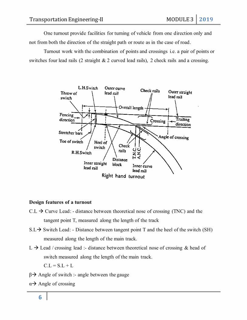
Transportation Engineering-II MODULE 3 2019
6
One turnout provide facilities for turning of vehicle from one direction only and
not from both the direction of the straight path or route as in the case of road.
Turnout work with the combination of points and crossings i.e. a pair of points or
switches four lead rails (2 straight & 2 curved lead rails), 2 check rails and a crossing.
Design features of a turnout
C.L → Curve Lead: - distance between theoretical nose of crossing (TNC) and the
tangent point T, measured along the length of the track
S.L→ Switch Lead: - Distance between tangent point T and the heel of the switch (SH)
measured along the length of the main track.
L → Lead / crossing lead :- distance between theoretical nose of crossing & head of
switch measured along the length of the main track.
C.L = S.L + L
β→ Angle of switch :- angle between the gauge
α→ Angle of crossing

Transportation Engineering-II MODULE 3 2019
7
d→ heel divergence / clearance
R0→ radius of outer curve of turn
R → radius of central line of turn
G→ Gauge of track
N → Number of crossing
D→ Distance between theoretical nose of crossing and tangent point of crossing curve
Cot α = N
C.L = 2 GN
R = Ro- 𝐺
2 𝑅0 = 2𝐺𝑁2 + 1.5 𝐺 𝑆. 𝐿 = √2𝑅0𝑑
L= C.L- S.L
Track Structure
Broad gauge routes have been grouped into 5 broad categories based on speed
criteria. Group A, Group B and Group C
Group A → Speed limit upto 160Kmph
B → 130Kmph
C→ Subarban Section
D→ 100Kmph
Meter Guage routes are also
Group ----
,, R1
,, R2
,, R3
,, S
Functions of Track
Broad Gauge

Transportation Engineering-II MODULE 3 2019
8
Used for heavier loads and high speed
Narrow Gauge
Used to develop thinly populated area by joining the under developed areas with
developed area or urbanised area.
Used in hilly regions will steep gradients and sharp curves. And in plains where
high – speed is not required. Light traffic.
Stations and Yards
Station Yards
A yard is defined as the system of tracks laid usually on a level within defined limits for
various purposes such as storing of vehicles, making up rails, despatch of vehicle and for other
purposes over which movements are not authorised by time table
Classification of station yard
Passenger yards
For the safe movement of passengers and vehicles.
Goods yards
They provide facilities for receiving loading and uploading of goods and movement of
goods vehicles.
Locomotive yard
These are used for cleaning repairing, servicing, watering, oiling etc. of locomotives.
Marshalling yards
It is said to be a machine to receive, break up, re form and despatch trains. In other
words, a marshalling yard is one where trains and other loads are received, sorted out and new
trains formed and despatched onwards to their destinations.
Important functions
1. Reception 2. Sorting 3. Departure
Siding for each functions are also provided. Various sidings are
Reception siding, Sorting siding, Departure siding
Types of Marshalling yards

Transportation Engineering-II MODULE 3 2019
9
A marshalling shard can be constructed any of the following type depending upon the
ground contours
Flat yards
Here all the sorting work is done by means of locomotive, so there is more power
consumption.
Gravitation yard
The tracks are laid at such a gradient that the wagons can move off under the action of
gravity.
Hump Yards
Humps or summits or artificial hills are provided and wagons are pushed upon a hump by
the engine. The wagons are then allowed to move in to the sidings down the hump under the
action of gravity. It is the most economical type since no power is required to move the vagons.
Signalling
Signalling consist of systems devices, signals means by which trains are operated
efficiently.
Objects of Signalling
1. To provide facilities for efficient movement of train
2. To ensure safety between two or more trains which cross or approach each other path.
3. To provide facilities for the maximum utility of the track.
4. To provide facilities for safe efficient shunting operations.
5. To guide the trains movement during maintenance and repair of track
6. To safeguard the train at converging and give bidirectional indications at diverging
functions.
Types of signals on the basis of characteristics
Operational characteristics
- Detonating Signals
- Hand signal
- Fixed signals
Functional characteristics

Transportation Engineering-II MODULE 3 2019
10
- Stop / semaphore type
- Shunting signal
- Coloured light signal
Locational Characteristics
Reception signal
Interlocking
Mechanical relationship established between various levers operating the signals
and points through mechanical or electrical agencies such that contrary effects are not at
all possible in the working of signal mechanism.
Method of Interlocking
- Tappes and locks system
- Key system
- Route Relay system
Track Circuiting
It function to indicate the presence of train on the track showing whether the track
is occupied or clear is known as track circuiting.
Principles of track circuiting
The ends of the rails forming the circuits are isolated by using insulated rail joints.
The ends of rail of one side are connected to the two terminal of the battery while the
Transportation Engineering-II MODULE 3 2019
11
other end is connected to an electromagnet called relay, which is in energised condition
when there is no vehicle on the track. This normal electrified track is known as primary
circuit. The presence of the train short circuit the relay which get de energised breaking
the secondary circuit connected with the signal. And ensures that the necessary signal
should go to danger indication.

Transportation Engineering-II MODULE 3 2019
12
Control of train movements
Basic object of signalling is to control the movement of train to ensure the safety by
preventing accidents. For this purposes various methods are found out. Some of which are
1) Absolute Block system / space interval
2) Automatic Block system/ automatic signalling
3) Centralised traffic control system
Absolute Block system
Absolute Block System is extensively use on incline railways. The entire track is divided
into block sections separated by block stations. Block station means station provided with block
instruments in pairs. These instruments are used to show whether the section ahead is clear or
preserved for a train. All block sections are linked in series both telegraphically for operation of
block and telephonically for verbal exchange of information. The bock station is under the
charge of station master – and the block section is under the joint charge of two adjacent block
stations.
Working procedure
1. The signal man at A draws the attention of signal man at B and ask whether the section is
clear or not
2. If the section is clear at B, the signal man at B acknowledges the signals and operates the
key and handle in the key box indicating line clear.
3. This information is displayed at both station the signal boxes.
4. The signal man at A lowers his starting signal and allows the train to proceed towards B
5. As soon as the train leave the signal man at sends a signal to the signal man at B
indicating train entering the section.

Transportation Engineering-II MODULE 3 2019
13
6. The signal man at B acknowledges the signal and places the block indicates as train on
line position.
7. The signal man at B operates the home signal at B.
8. The station master at B then sends a message to the next station ahead and procedure is
repeated.
9. As soon as the train leaves the stations and has passed the starting signal at B the Station
master at B brings his block instrument in the normal position. This gives train out of
section signal at A.
Automatic Block System
It is an improvement on absolute block system and avoids the possibility of accident due
to the signals are operated by trains itself. An electric current is conveyed through the track and
when a train occupies that particular track. The current puts the signal at danger position until the
train has gone for ahead. The electricity is transmitted either through overhead lines or through a
third rail. The former system is known as catenory system. And the current is obtained through a
device called pantograph. In the latter case a metal contact shoe which slides along the charged
3rd rail provided outside the running rails. And electric current is transmitted through is metal
shoe.
Advantages
1. The number of signalmen required is less and hence the operating costs are reduced.
2. As human factor is eliminated the value of factor of safety is increased.
3. There is considerable increase in the capacity of the vehicle.
Centralised Traffic control System (CTC System)
A central control room is provided from which the points and signals are controlled.
Points and signals are suitably interlocked and an illuminate diagram is provided in the control
room to study the movement of the train. The person controlling the panel is known as
dispatcher. The dispatcher makes all the arrangement for crossing points and signals. The duty of
the driver is nearly to respect the different indications given by the signals.
Advantages
1. Increase the track capacity
2. As the signal cabines are not required great saving in staff.

Transportation Engineering-II MODULE 3 2019
14
3. The dispatcher can arrange the train movement in advance and is free to do other works
in the office.
4. Points and signals are operated in 2 seconds by means of thumb.
5. The system is capable of detecting the defects in the track.
RAILWAY STATION
It is the selected place on a railway line, where trains halt for one or more of the following
purposes.
1. For exchange of passengers
2. For exchange of goods
3. For control of train movements
4. For crossing
5. For overtaking
6. For detaching engines and staff
7. For taking diesel or coal and water for locomotives
Requirements of a Railway Station
1. Public Requirements
2. Traffic requirements
3. Requirements of locomotive department
4. General requirements
Public Requirements: The station should provide all the facilities for the public such as:
• A booking office for tickets.
• Goods and passenger platforms with or without shed.
• Proper arrangement for drinking water.
• Suitable lighting and ventilation.
• Waiting rooms and retiring rooms.
• Sanitary arrangements and waiting rooms.
Transportation Engineering-II MODULE 3 2019
15
• Other facilities like public telephone, refreshment room, fax/ telefax facilities, telegraph
office, inquiry office etc.
• Provision of refrigerators for cold drinking water in hot weather.
• Microphones to announce the arrival and departure of trains and also for communicating
to the public the changes in time schedule, platform number etc.
• Provision of big display boards for train schedule and changes if any.
• Guides from railways dept. to guide illiterate passengers.
Traffic requirements
• Signals
• Recording of movement of trains
• Sufficient no of sidings
Locomotive Requirements
• Proper arrangements for supply of fuel and water
• Arrangements for cleaning, examining, inspecting and maintaining the locomotives
Requirements for development of railways
• Easy and comfortable approach roads to stations
• Installation of clocks, guide map, separate boards for arrival and departure of trains
• Availability of coolies on the platforms
• Escalators, mini theatre , big waiting halls, under ground passages etc.,
RAILWAY STATIONS – CLASSIFICATION
• OPERATIONAL CLASSIFICATION
• BLOCK STATION
• NON – BLOCK STATION
• SPECIAL STATION
• FUNCTIONAL CLASSIFICATION
• WAYSIDE STATION
• JUNCTION STATION
• TERMINAL STATIONS
• OPERATIONAL CLASSIFICATION
• BLOCK STATION

Transportation Engineering-II MODULE 3 2019
16
• Block sections which are sort of compartments into which the railway line is divided,
are established so as to safely space the trains behind each other.
• The ‘Block stations’ are made at the ends of block section and are equipped with
signals which demarcate the limits of block section.
• Here driver has to obtain an authority to proceed
Class A: Such a station is one where the Line Clear indication for the block may
not be given unless the line where the train is to be received is clear at least for up
to the starter signal (or, in some cases, for at least 400m ahead of the home
signal). These are stations where many trains normally run through without
stopping at a high speed, hence the need for the safety margin to prevent accidents
in cases of trains overrunning signals. [4/00]
Class B: Such a station is one where the Line Clear indication may be given
before the section of the line within the station has been cleared for reception of a
train. Branch lines and routes with lower running speeds fall into this category.
Class C: This is a station (or block hut) marking an end of a block section, with
light traffic or where no trains are booked to stop, such as an intermediate block
post. (Sometimes these stations exist only in the form of a signal cabin that
controls the approach to another station.) Permission to approach may not be
given for a train unless the whole of the last preceding train has passed complete
at least 400m beyond the home signal and is known to be continuing on its
journey.
NON – BLOCK STATION OR CLASS D STATION: This is a station which does not
form the boundary of a block section but which does form a stopping place for trains.
Trains are stopped by various ad hoc arrangements prescribed in view of the local
conditions -- the driver may simply know to stop the train there, or it may be flagged
down on demand, etc. Also known as anon-block station or flag station.
SPECIAL STATION:Stations which are not covered under A, B, C & D classes.
FUNCTIONAL CLASSIFICATION
• WAYSIDE STATION
• Arrangement is made to cross an up & a down train

Transportation Engineering-II MODULE 3 2019
17
• For overtaking of slower trains by the faster trains
JUNCTION STATION:
• The branch line meets the main line & hence the arrangements are made:
• to facilitate the interchange of traffic between main & branch lines
• to clean & repair the vehicles of the trains which terminate at the junction
TERMINAL STATIONS
• The station at which a railway line or one of its branches terminates or ends is known as
the terminal station
• Additional arrangements such as facilities to reverse the engines, number of sidings,
examination pits etc are to be provided.

Transportation Engineering-II MODULE 3 2019
18