Transportation Engineering – II - Professor Rajesh Bhagat
60
Transportation Engineering – II Prof. Rajesh Bhagat Civil Engineering Department Y.C.C.E.,Nagpur B. E. (Civil Engg.) M. Tech. (Enviro. Engg.) GCOE, Amravati VNIT, Nagpur Experience & Achievement: ➢ Selected Scientist, NEERI-CSIR, Govt. of India. ➢ GATE Qualified Three Times. ➢ Selected Junior Engineer, ZP Washim. ➢ Three Times Selected as UGC Approved Assistant Professor. ➢ Assistant Professor, P.C.E., Nagpur. ➢ Assistant Professor, Cummins College of Engg. For Women (MKSSS, Nagpur) Mobile No.:- 8483002277 / 8483003474 Email ID :- [email protected] Website:- www.rajeysh7bhagat.wordpress.com
-
Upload
khangminh22 -
Category
Documents
-
view
1 -
download
0
Transcript of Transportation Engineering – II - Professor Rajesh Bhagat
Transportation Engineering – II
Prof. Rajesh BhagatCivil Engineering Department
Y.C.C.E.,Nagpur
B. E. (Civil Engg.) M. Tech. (Enviro. Engg.)
GCOE, Amravati VNIT, Nagpur
Experience & Achievement:
➢ Selected Scientist, NEERI-CSIR, Govt. of India.
➢ GATE Qualified Three Times.
➢ Selected Junior Engineer, ZP Washim.
➢ Three Times Selected as UGC Approved Assistant Professor.
➢ Assistant Professor, P.C.E., Nagpur.
➢ Assistant Professor, Cummins College of Engg. For Women (MKSSS, Nagpur)
Mobile No.:- 8483002277 / 8483003474 Email ID :- [email protected]
Website:- www.rajeysh7bhagat.wordpress.com
2
Unit-V
1) Airport Layout and Classification: Terminal area, aircraft parking and parking
systems, unit terminal concept, aprons, hangers, International airports layout,
helipads and heliports.
2) Visual Aids: Airport marking and lighting for runways, taxiways and other areas.
3) Air Traffic Control: Need, networks, control aids, instrumented landing systems,
advances in air traffic control.
3
Unit-VI
Tunnels: Alignment, surveys, cross section of highway & railway tunnels, tunneling
methods in hard rock and soft grounds, tunnel lining, drainage, ventilation and lighting
of tunnels, advances in tunneling techniques, tunnel boring machines, case studies.
4
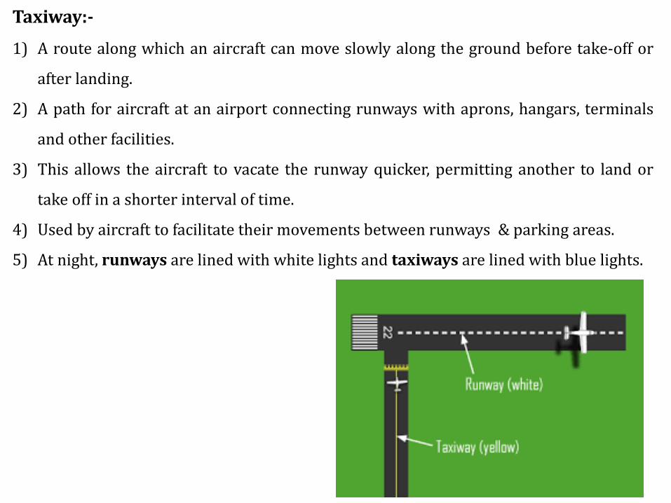
Taxiway:-
1) A route along which an aircraft can move slowly along the ground before take-off or
after landing.
2) A path for aircraft at an airport connecting runways with aprons, hangars, terminals
and other facilities.
3) This allows the aircraft to vacate the runway quicker, permitting another to land or
take off in a shorter interval of time.
4) Used by aircraft to facilitate their movements between runways & parking areas.
5) At night, runways are lined with white lights and taxiways are lined with blue lights.
5
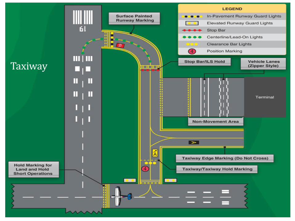
Taxiway
6
Aprons:-
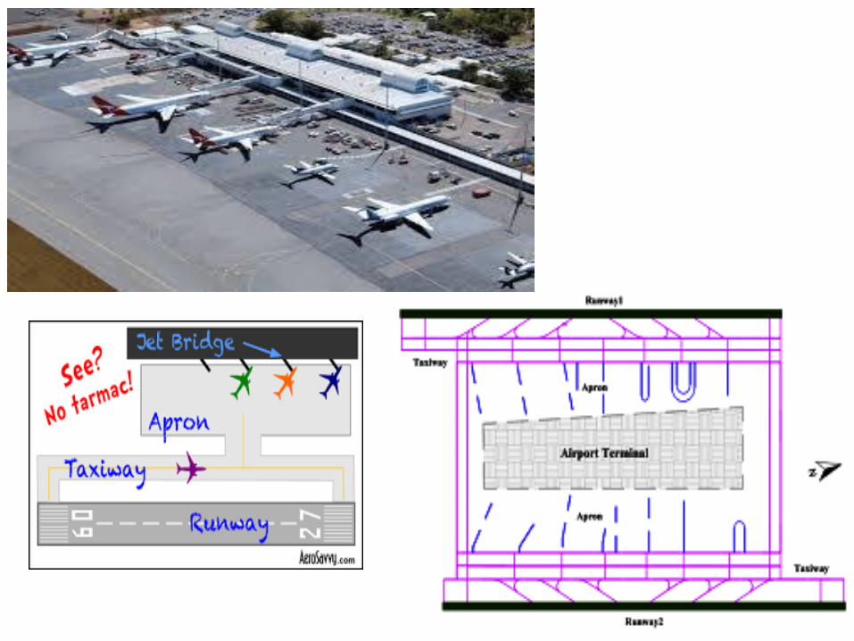
1) Apron is the area of an airport where aircraft are parked, unloaded or loaded,
refueled, or boarded.
2) Although the use of the apron is covered by regulations, it is more accessible to
users than the runway or taxiway. However, the apron is not usually open to the
general public and a license may be required to gain access.
3) It is located close to the terminal building or hangars.
4) The size of apron depends on:
a) Type of aircraft.
b) Number of Gate Positions.
c) Aircraft Parking System.
7
8
Types of Aprons:-
Terminal Aprons and Ramps
1) Aircraft parking positions, also called aircraft gates or aircraft stands, on the
terminal apron or ramp are sized for the geometric properties of a given design
aircraft, including wingspan, fuselage length and turning radii.
2) Both the FAA and ICAO recommend minimum clearances between any part of an
aircraft and other aircraft or structures in the apron area.
Holding Aprons
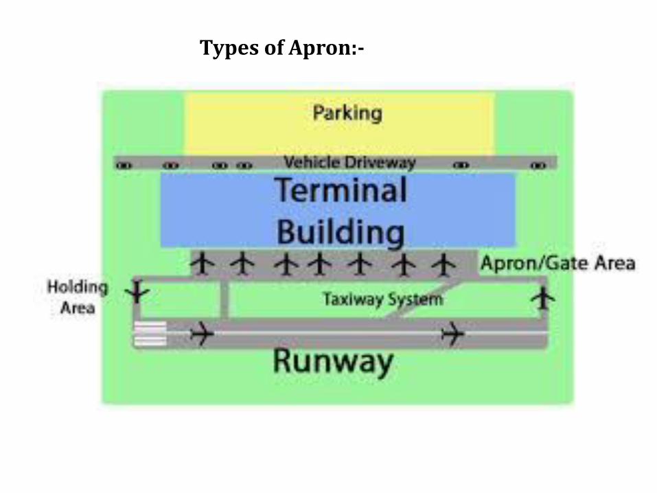
1) Holding aprons, holding pads, run-up pads, or holding bays as they are sometimes
called, are placed adjacent to the ends of runways.
2) The areas are used as storage areas for aircraft prior to takeoff.
3) They are designed so that one aircraft can bypass another whenever this is
necessary.
9
Types of Apron:-
10
Hangar:-
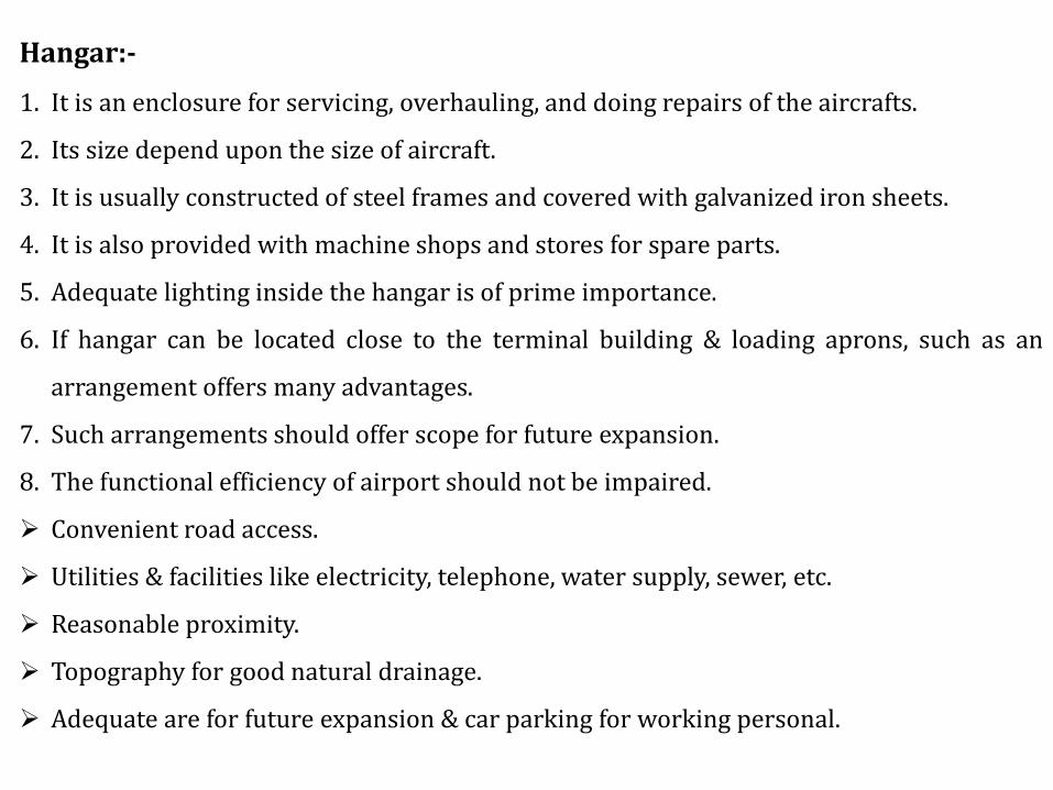
1. It is an enclosure for servicing, overhauling, and doing repairs of the aircrafts.
2. Its size depend upon the size of aircraft.
3. It is usually constructed of steel frames and covered with galvanized iron sheets.
4. It is also provided with machine shops and stores for spare parts.
5. Adequate lighting inside the hangar is of prime importance.
6. If hangar can be located close to the terminal building & loading aprons, such as an
arrangement offers many advantages.
7. Such arrangements should offer scope for future expansion.
8. The functional efficiency of airport should not be impaired.
➢ Convenient road access.
➢ Utilities & facilities like electricity, telephone, water supply, sewer, etc.
➢ Reasonable proximity.
➢ Topography for good natural drainage.
➢ Adequate are for future expansion & car parking for working personal.
11
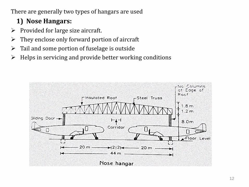
There are generally two types of hangars are used
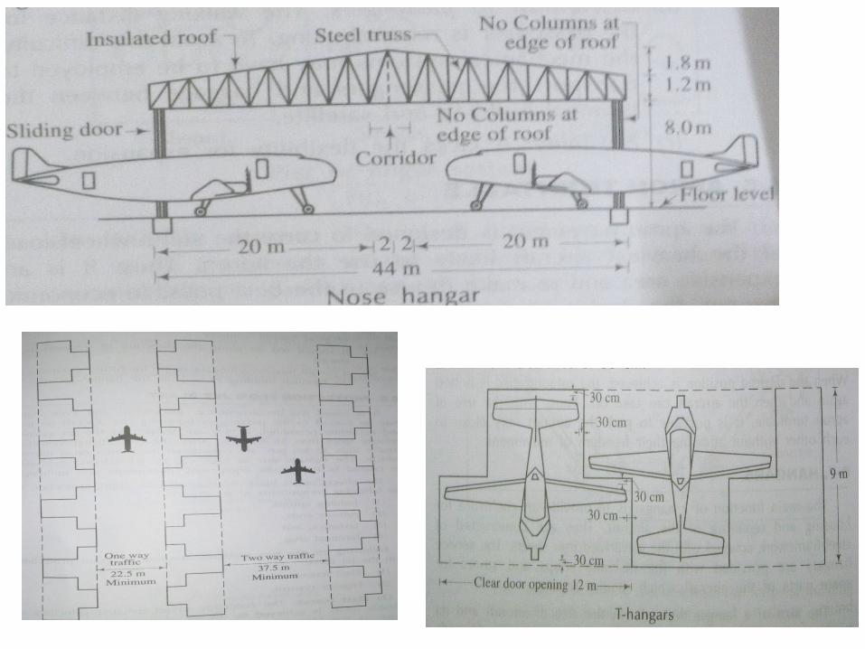
1) Nose Hangars:
➢ Provided for large size aircraft.
➢ They enclose only forward portion of aircraft
➢ Tail and some portion of fuselage is outside
➢ Helps in servicing and provide better working conditions
12
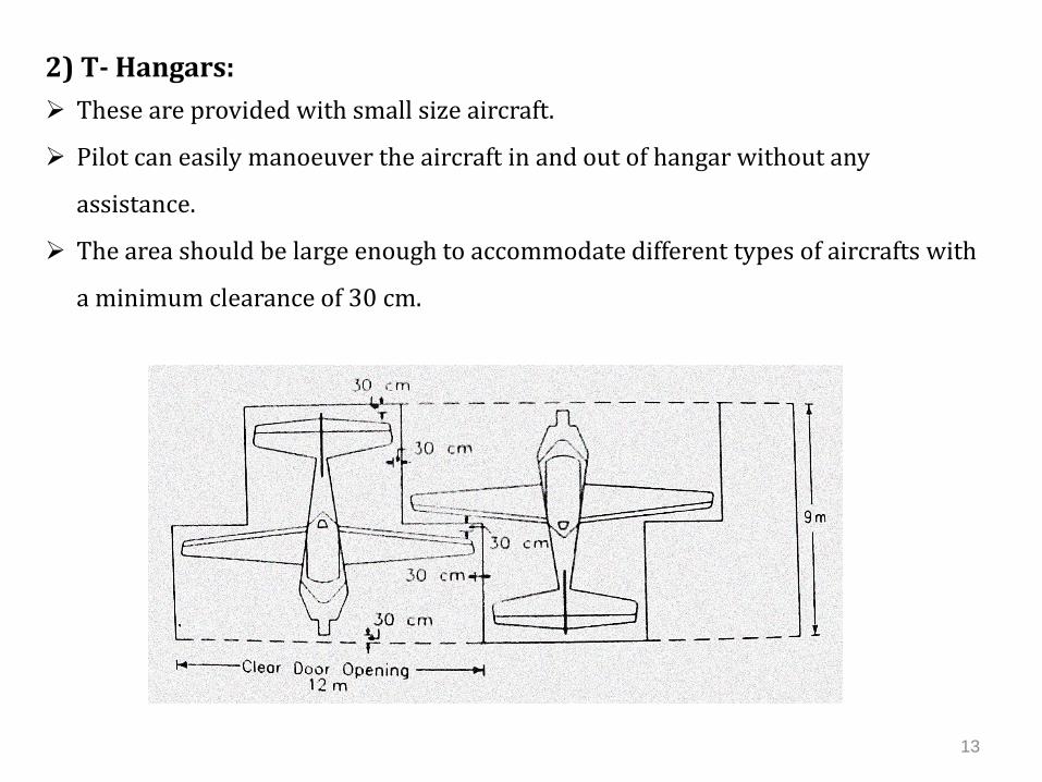
2) T- Hangars:
➢ These are provided with small size aircraft.
➢ Pilot can easily manoeuver the aircraft in and out of hangar without any
assistance.
➢ The area should be large enough to accommodate different types of aircrafts with
a minimum clearance of 30 cm.
13
14
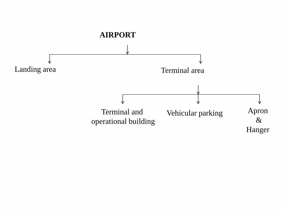
Terminal area
AIRPORT
Landing area
Terminal and
operational buildingVehicular parking Apron
&
Hanger
15
Terminal Area
1) It is the portion of the airport other than the landing area.
2) It serves as a focal point for the activities on the airport.
3) It includes terminal and operational buildings, vehicle parking area, aircraft
service hangars, etc.
Terminal Building
1) The purpose of airport building is to provide shelter and space for the various
surface activities related to the air transportation.
2) Terminal building usually refers to a building mainly, used for passenger,
airline and administration facilities
3) planned for the maximum efficiency, convenience and economy
16
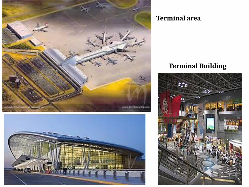
Terminal area
Terminal Building
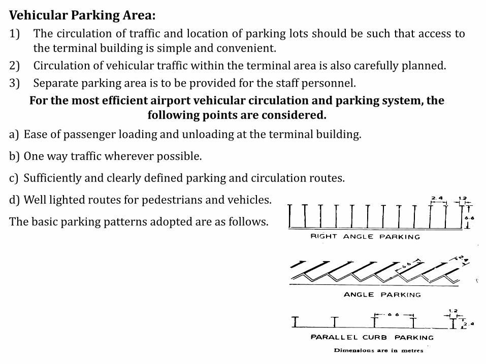
Vehicular Parking Area:
1) The circulation of traffic and location of parking lots should be such that access tothe terminal building is simple and convenient.
2) Circulation of vehicular traffic within the terminal area is also carefully planned.
3) Separate parking area is to be provided for the staff personnel.
For the most efficient airport vehicular circulation and parking system, the following points are considered.
a) Ease of passenger loading and unloading at the terminal building.
b) One way traffic wherever possible.
c) Sufficiently and clearly defined parking and circulation routes.
d) Well lighted routes for pedestrians and vehicles.
The basic parking patterns adopted are as follows.
17
18
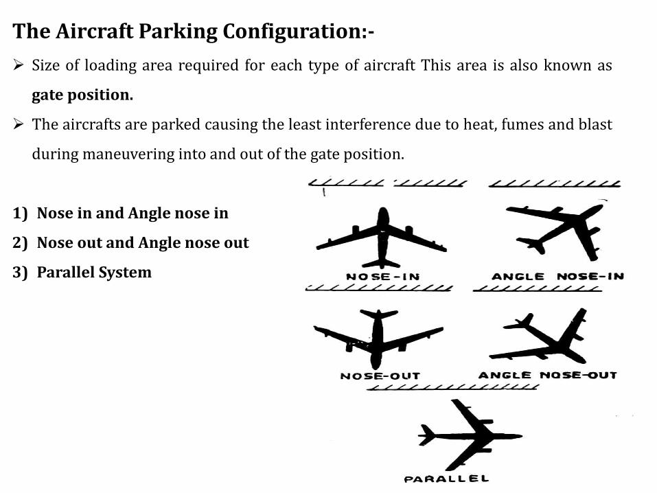
The Aircraft Parking Configuration:-
➢ Size of loading area required for each type of aircraft This area is also known as
gate position.
➢ The aircrafts are parked causing the least interference due to heat, fumes and blast
during maneuvering into and out of the gate position.
1) Nose in and Angle nose in
2) Nose out and Angle nose out
3) Parallel System
19
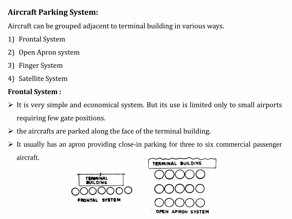
Aircraft Parking System:
Aircraft can be grouped adjacent to terminal building in various ways.
1) Frontal System
2) Open Apron system
3) Finger System
4) Satellite System
Frontal System :
➢ It is very simple and economical system. But its use is limited only to small airports
requiring few gate positions.
➢ the aircrafts are parked along the face of the terminal building.
➢ It usually has an apron providing close-in parking for three to six commercial passenger
aircraft.
20
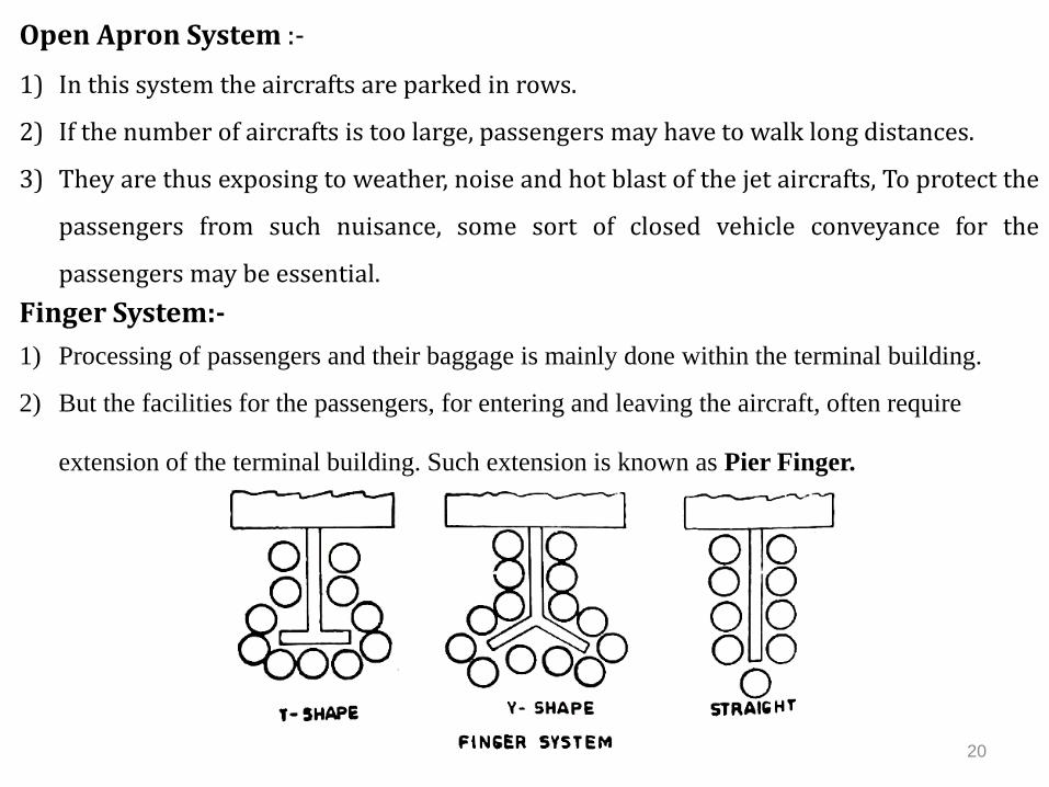
Open Apron System :-
1) In this system the aircrafts are parked in rows.
2) If the number of aircrafts is too large, passengers may have to walk long distances.
3) They are thus exposing to weather, noise and hot blast of the jet aircrafts, To protect the
passengers from such nuisance, some sort of closed vehicle conveyance for the
passengers may be essential.
Finger System:-
1) Processing of passengers and their baggage is mainly done within the terminal building.
2) But the facilities for the passengers, for entering and leaving the aircraft, often require
extension of the terminal building. Such extension is known as Pier Finger.
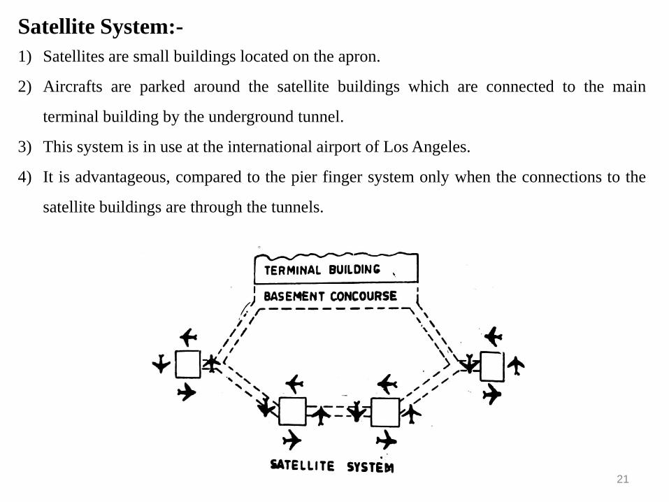
Satellite System:-
1) Satellites are small buildings located on the apron.
2) Aircrafts are parked around the satellite buildings which are connected to the main
terminal building by the underground tunnel.
3) This system is in use at the international airport of Los Angeles.
4) It is advantageous, compared to the pier finger system only when the connections to the
satellite buildings are through the tunnels.
21
22
22
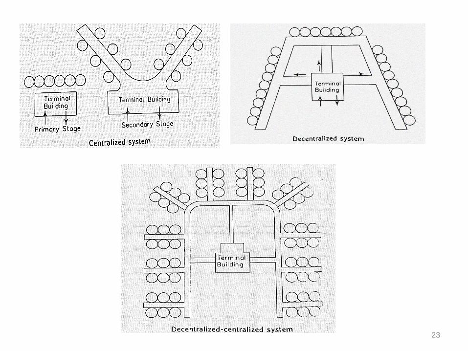
Concept of Planning of Terminal Building:-
There are two concepts of planning of the terminal building for commercial airport:-
1) Centralization
2) Decentralization
Centralization : In centralized plan, All passengers, baggage and cargo are funneled through
a central building and are then dispersed to the respective aircraft positions.
Decentralization : In decentralization plan, the passengers and baggage arrive at the point
near the departing plane. All airline functions are carried out adjacent to the departing
plan.
23

Unit Terminal Concept :-1) In past 20 years, the air traffic has increased by many folds that the centralized
concept has become inoperative.
2) The decentralized-centralized concept also known as “Unit Terminal Principle” now
becoming popular in the design of air terminals.
3) This system involves planning of terminal area in such a manner that facilities are
provided in units of manageable size providing minimum walking distances from
the kerbside to gate positions
24
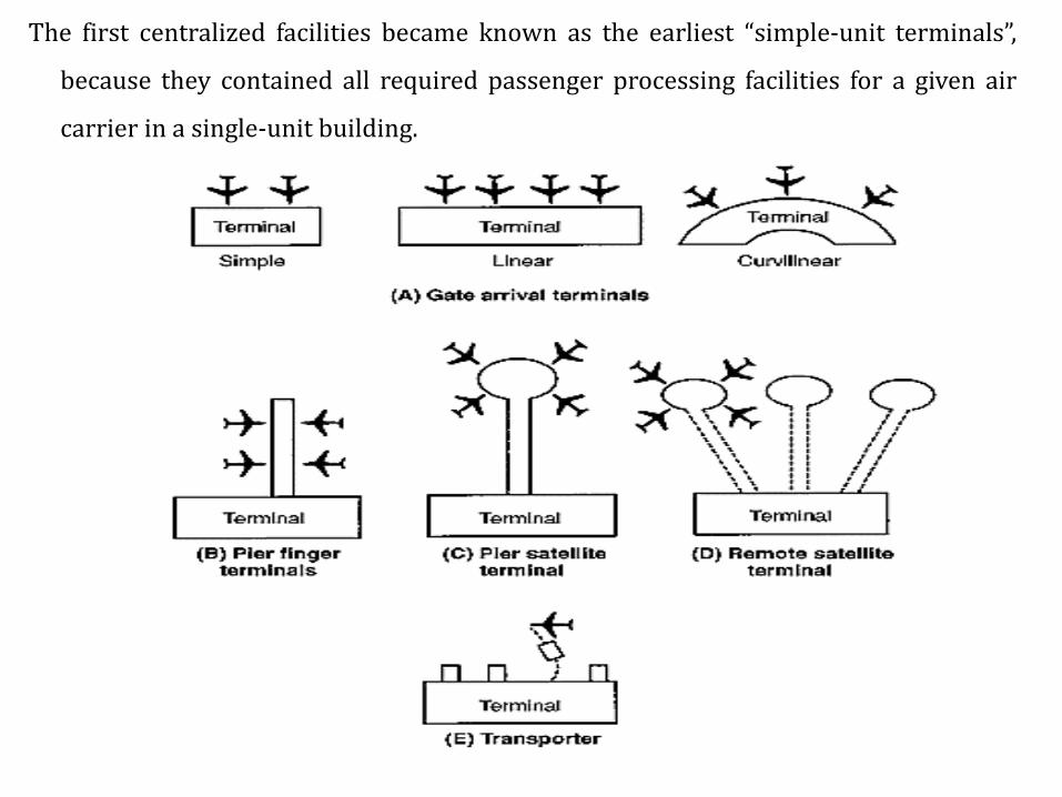
The first centralized facilities became known as the earliest “simple-unit terminals”,
because they contained all required passenger processing facilities for a given air
carrier in a single-unit building.
Airport Layout:-
The layout of an airport mainly depends on basic patterns or configuration of
runways. Following are the characteristics of a well planned airport layout.
1. It grants maximum functional efficiency with the minimum utilization of space.
2. It has adequate space for the loading aprons.
3. It has sufficient terminal building facilities.
4. It provides excellent control tower visibility.
5. The cost of construction is minimum.
6. The operations of landing, Taxiing and take-off of the aircraft are carried out
smoothly without interfering with each other.
7. The overall arrangement of the components is such that the future expansion is
easily permitted
26
27
27
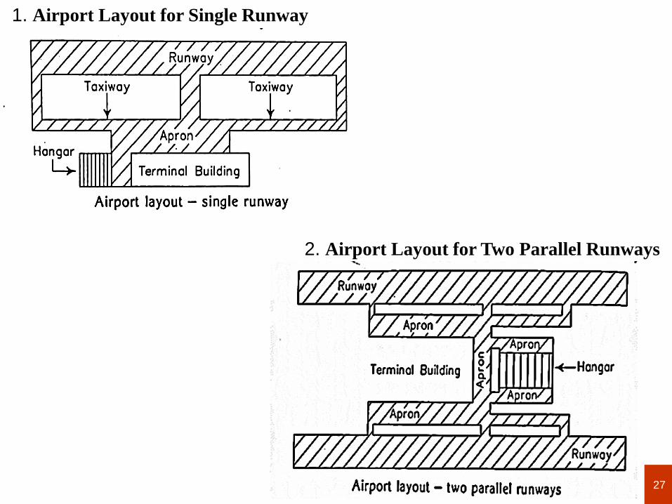
1. Airport Layout for Single Runway
2. Airport Layout for Two Parallel Runways
28
28
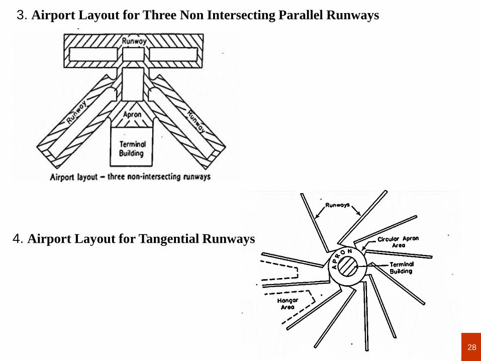
3. Airport Layout for Three Non Intersecting Parallel Runways
4. Airport Layout for Tangential Runways
29
29
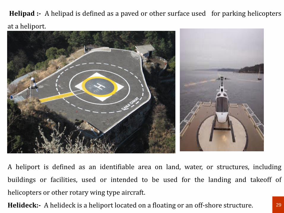
Helipad :- A helipad is defined as a paved or other surface used for parking helicopters
at a heliport.
A heliport is defined as an identifiable area on land, water, or structures, including
buildings or facilities, used or intended to be used for the landing and takeoff of
helicopters or other rotary wing type aircraft.
Helideck:- A helideck is a heliport located on a floating or an off-shore structure.
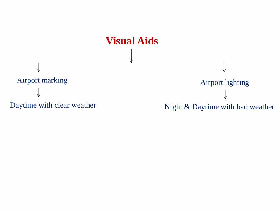
Visual aids :-
Visual aids are installed at the airport to achieve the following purposed:
1) To avoid accidents during landing of the aircraft.
2) To convey to the pilot the ground to air visual information required during
landing .
3) To direct the pilot to make the landing of the aircraft to the landing area only.
4) To enable the pilot to locate and identify the particular feature specified by the
making.
5) To provide safety to the persons and properties.
6) To maintain an orderly flow of aircraft without any congestion.
7) To satisfy the visual requirements for take-off and taxiing.
30
31
Visual Aids
Airport marking Airport lighting
Daytime with clear weather Night & Daytime with bad weather
Airport Marking
➢ For assisting the pilots in guiding the aircraft on the runways and taxiways.
➢ The pavements are marked with lines and numbers.
➢ These airport marking are of benefits to the pilot.
The airport markings are divided into the following groups :
a) Runway Marking
b) Taxiway Marking
c) Runway and Taxiway shoulder marking
d) Apron Marking
e) Wind direction indicator
f) Landing direction indicator
32
Runway Markings:-
Following markings are made on the runways
1. Runway centre-line marking
2. Runway edge stripes
3. Runway numbering
4. Touch down zone marking
5. Threshold marking
6. Displaced threshold marking
34
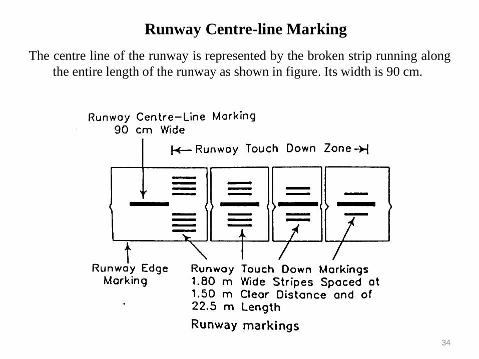
Runway Centre-line Marking
The centre line of the runway is represented by the broken strip running along
the entire length of the runway as shown in figure. Its width is 90 cm.
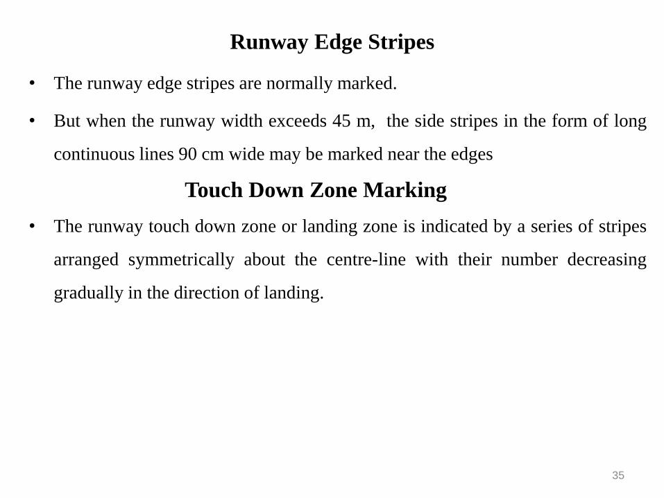
• The runway edge stripes are normally marked.
• But when the runway width exceeds 45 m, the side stripes in the form of long
continuous lines 90 cm wide may be marked near the edges
Touch Down Zone Marking
• The runway touch down zone or landing zone is indicated by a series of stripes
arranged symmetrically about the centre-line with their number decreasing
gradually in the direction of landing.
35
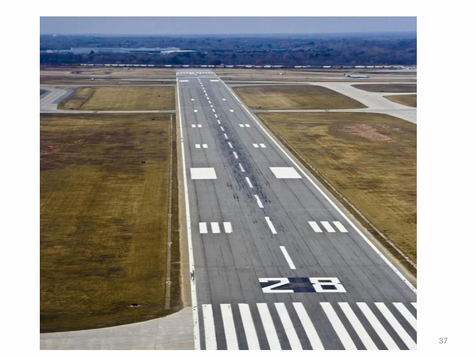
Runway Edge Stripes
Runway Numbering
• The end of each runway is marked with a number which indicates
the magnetic azimuth, i.e. the angle measured in the clockwise
direction from the north of the runway in the direction of the
landing. Thus, the east end of the east-west runway would be
marked 27 (for 270 ° and the west end 9 (for 90°) as shown in
figure.
36
37
Threshold Marking
38
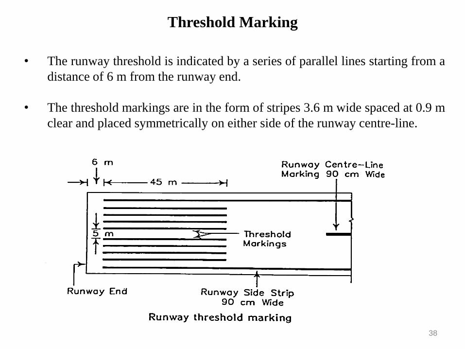
• The runway threshold is indicated by a series of parallel lines starting from a
distance of 6 m from the runway end.
• The threshold markings are in the form of stripes 3.6 m wide spaced at 0.9 m
clear and placed symmetrically on either side of the runway centre-line.
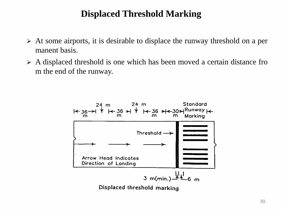
Displaced Threshold Marking
39
➢ At some airports, it is desirable to displace the runway threshold on a per
manent basis.
➢ A displaced threshold is one which has been moved a certain distance fro
m the end of the runway.
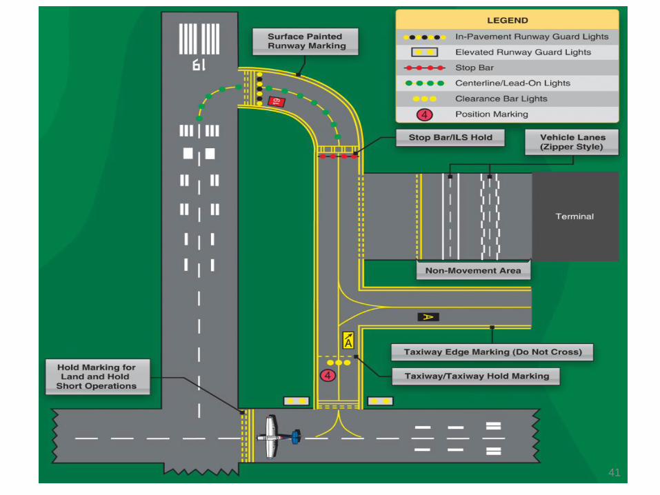
Taxiway Marking
1) A single continuous 15 cm yellow stripe is used to mark the centre line of the
taxiway.
2) At the intersections of the taxiways with the runway ends, the centre line of the
taxiway is terminated at the edge of the runway.
3) All other intersections of the taxiways with runways, the centre line of the
taxiway is extended to the centre line of the runway.
4) A holding line marking is painted at all the intersections of the paved taxiways
with runways.
5) At the taxiway intersection, the centre line markings of the taxiway continue
through the intersection area.
40
41
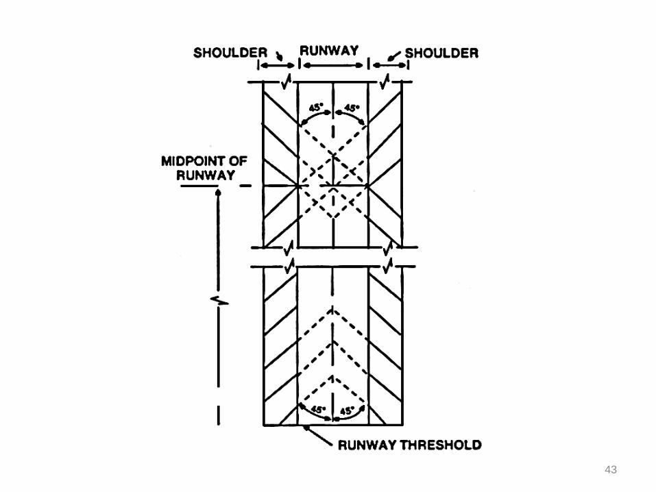
Shoulder Marking
1) The shoulders on the edges of a runway and taxiway are paved but they are
not capable of withstanding loads
2) A paved blast pad about 45 m to 60 m in length is provided adjacent to the
runway end to prevent erosion of the soil.
3) The paved area of the blast pad is not designed to support the aircraft loads ,
but it may have the appearance of being so designed.
4) The paint used is yellow.
5) Runway shoulders are marked with diagnol stripes each having a width of
90 cm.
6) The taxiway and holding apron shoulders are marked with stripes at right
angles to the direction of travel of aircraft.
7) The blast pad is marked with V shaped or chevron pattern marks.
42
43
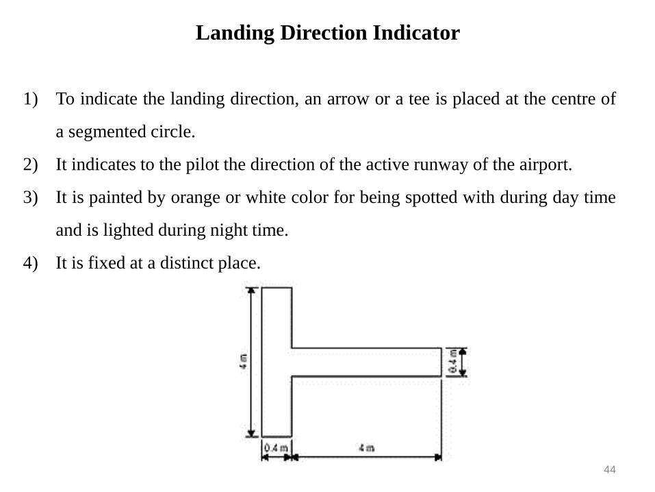
Landing Direction Indicator
1) To indicate the landing direction, an arrow or a tee is placed at the centre of
a segmented circle.
2) It indicates to the pilot the direction of the active runway of the airport.
3) It is painted by orange or white color for being spotted with during day time
and is lighted during night time.
4) It is fixed at a distinct place.
44
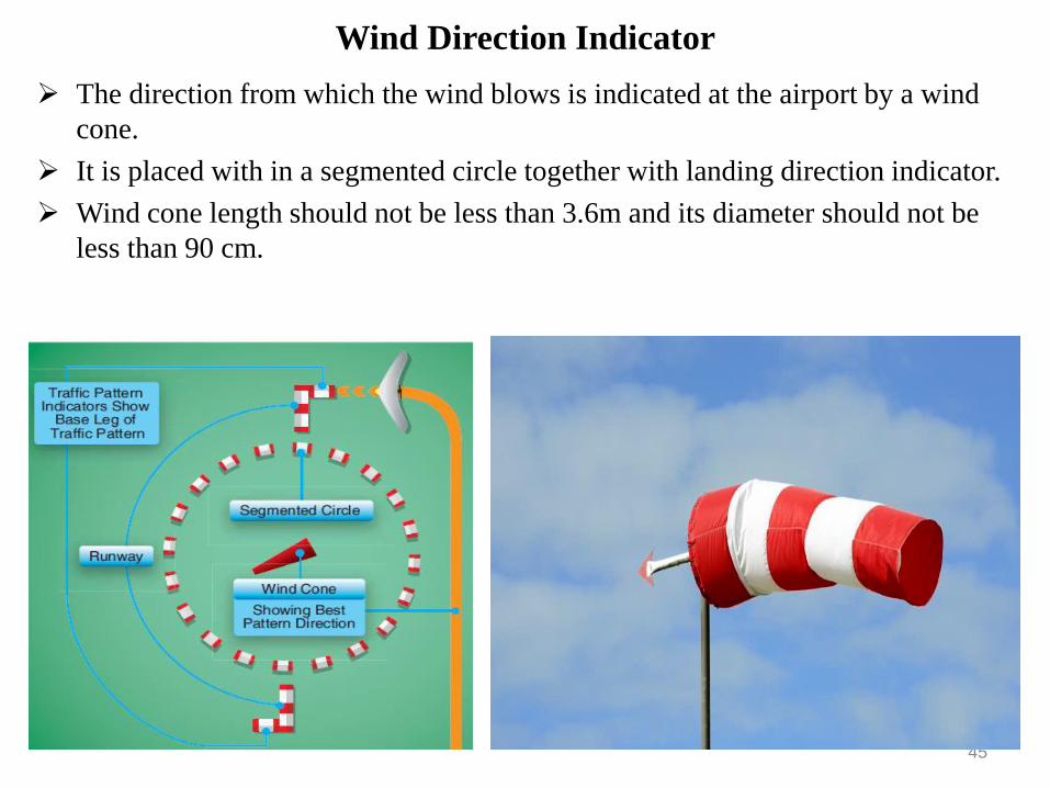
Wind Direction Indicator
➢ The direction from which the wind blows is indicated at the airport by a wind
cone.
➢ It is placed with in a segmented circle together with landing direction indicator.
➢ Wind cone length should not be less than 3.6m and its diameter should not be
less than 90 cm.
45
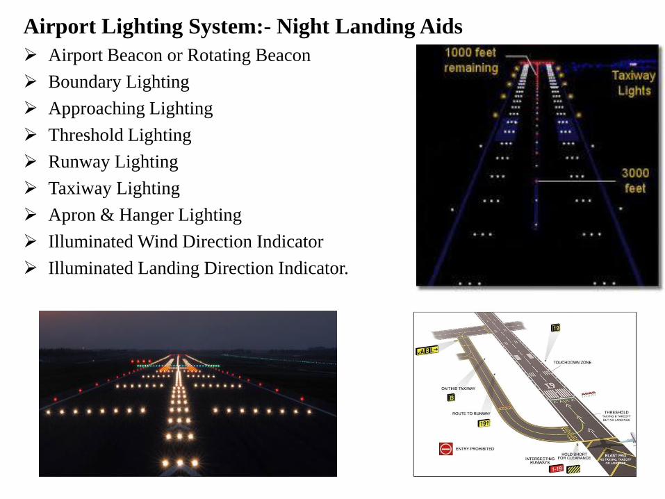
Airport Lighting System:- Night Landing Aids
➢ Airport Beacon or Rotating Beacon
➢ Boundary Lighting
➢ Approaching Lighting
➢ Threshold Lighting
➢ Runway Lighting
➢ Taxiway Lighting
➢ Apron & Hanger Lighting
➢ Illuminated Wind Direction Indicator
➢ Illuminated Landing Direction Indicator.
46
Airport Lighting System:- Night Landing Aids
➢ Airport Beacon or Rotating Beacon
➢ Boundary Lighting
➢ Approaching Lighting
➢ Threshold Lighting
➢ Runway Lighting
➢ Taxiway Lighting
➢ Apron & Hanger Lighting
➢ Illuminated Wind Direction Indicator
➢ Illuminated Landing Direction Indicator.
47
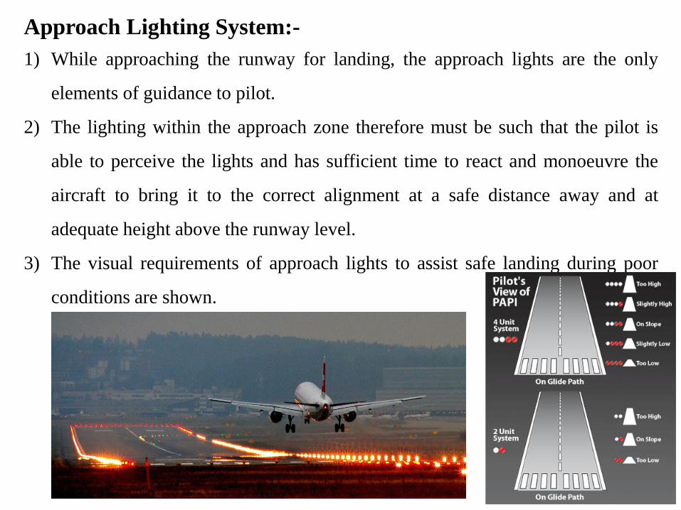
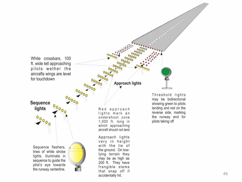
Approach Lighting System:-
1) While approaching the runway for landing, the approach lights are the only
elements of guidance to pilot.
2) The lighting within the approach zone therefore must be such that the pilot is
able to perceive the lights and has sufficient time to react and monoeuvre the
aircraft to bring it to the correct alignment at a safe distance away and at
adequate height above the runway level.
3) The visual requirements of approach lights to assist safe landing during poor
conditions are shown.
48
49
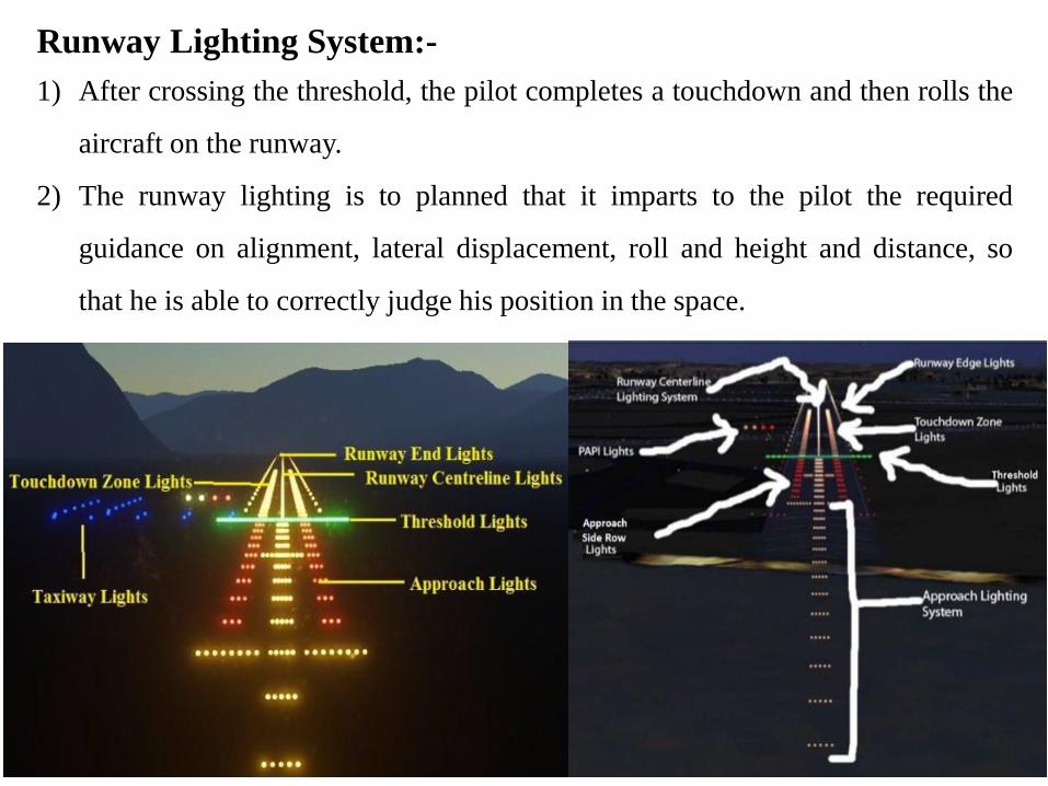
Runway Lighting System:-
1) After crossing the threshold, the pilot completes a touchdown and then rolls the
aircraft on the runway.
2) The runway lighting is to planned that it imparts to the pilot the required
guidance on alignment, lateral displacement, roll and height and distance, so
that he is able to correctly judge his position in the space.
50
Air Traffic Control:-
The need of air traffic control:
1) To safeguard life & property.
2) To expedite the traffic movements.
3) No congestion & no delay.
Air Traffic Control grouped as below:
a) Airport Traffic Control: To guide aircraft while take or landing. Movement
on taxiway & apron.
b) Airway Traffic Control: Movement of aircraft in the air.
c) Airway Communication: Conveying of airway & weather information to the
pilot during the flight.
d) Nor-airway Traffic Control: Personal flying is done by a large number of
people. In such cases, the movement of aircraft, not flying along the airway,
must be regulated to prevent interference to the main air traffic.
51
Air Traffic Control Network:-
The network for controlling the air traffic can be divided into three parts as
below:
1) Control Within Terminal Area:
➢ Done form the airport control tower which is located in the terminal area.
➢ The control tower is nerve centre of an airport.
➢ Controller directs the movement of aircraft on the ground and in the air within the
airport zone.
➢ Information like airport condition, airway traffic, visibility, speed & direction of
ground winds, barometric pressure & other relevant information are provided to
pilot for safe operation.
2) Control Over Airways:
3) Airways Communication:
52
Air Traffic Control Network:-
The network for controlling the air traffic can be divided into three parts as
below:
1) Control Within Terminal Area:
2) Control Over Airways:
➢ The control is provided by a number of Air Route Traffic Control Centers (ARTC)
➢ In India, ARTC are provided at Bombay, Madras, Calcutta, Nagpur, Ahmadabad,
Delhi & Jodhpur. Each centre controls a certain geographic area & thus cover the
entire area of country.
➢ ARTC is mainly concerned with flights under Instrumental Flight Rules (IFR)
conditions & not under Visual Flight Rules (VFR)
3) Airways Communication:
53
Air Traffic Control Network:-
The network for controlling the air traffic can be divided into three parts as
below:
1) Control Within Terminal Area:
2) Control Over Airways:
3) Airways Communication:
➢ This is usually done through flight service stations.
➢ These stations are located at the airports and also along the airways.
➢ To communicate air traffic control messages between the ARTC & enroute aircraft.
➢ To give certain information to the pilot, before and during the flights, regarding the weather
change navigational aids, airports that are out of use & the procedure at a particular airports
etc.
54
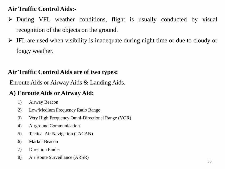
Air Traffic Control Aids:-
➢ During VFL weather conditions, flight is usually conducted by visual
recognition of the objects on the ground.
➢ IFL are used when visibility is inadequate during night time or due to cloudy or
foggy weather.
Air Traffic Control Aids are of two types:
Enroute Aids or Airway Aids & Landing Aids.
A) Enroute Aids or Airway Aid:
1) Airway Beacon
2) Low/Medium Frequency Ratio Range
3) Very High Frequency Omni-Directional Range (VOR)
4) Airground Communication
5) Tactical Air Navigation (TACAN)
6) Marker Beacon
7) Direction Finder
8) Air Route Surveillance (ARSR)55
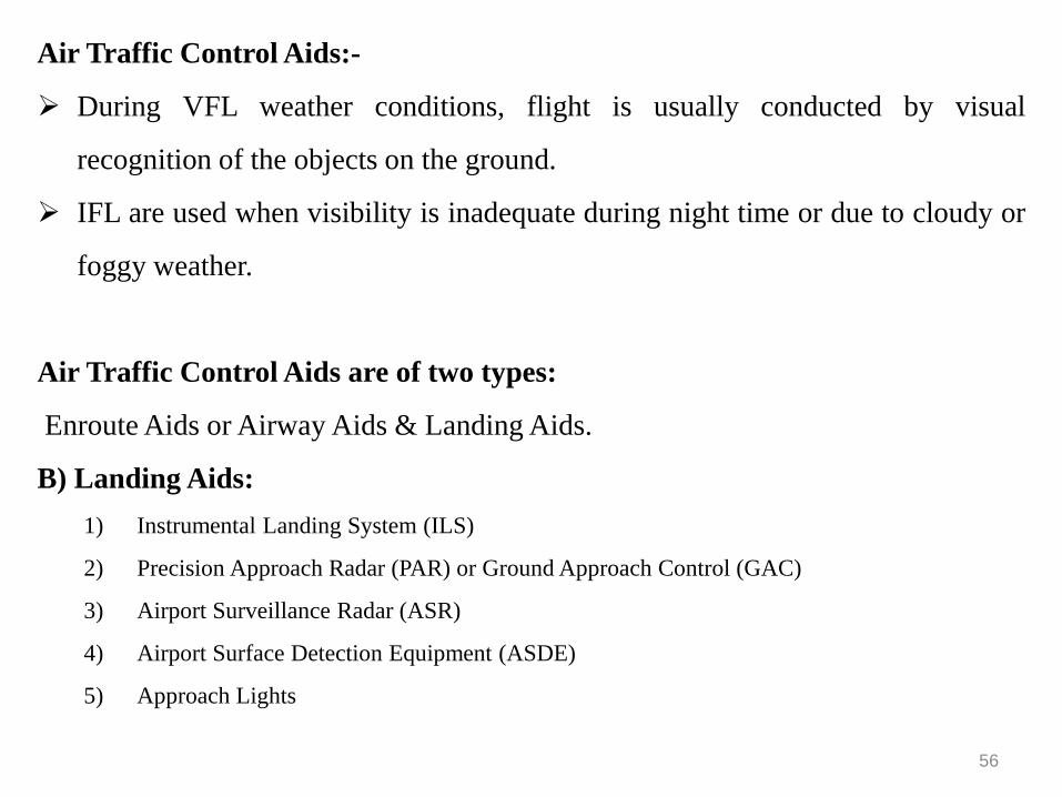
Air Traffic Control Aids:-
➢ During VFL weather conditions, flight is usually conducted by visual
recognition of the objects on the ground.
➢ IFL are used when visibility is inadequate during night time or due to cloudy or
foggy weather.
Air Traffic Control Aids are of two types:
Enroute Aids or Airway Aids & Landing Aids.
B) Landing Aids:
1) Instrumental Landing System (ILS)
2) Precision Approach Radar (PAR) or Ground Approach Control (GAC)
3) Airport Surveillance Radar (ASR)
4) Airport Surface Detection Equipment (ASDE)
5) Approach Lights
56
57
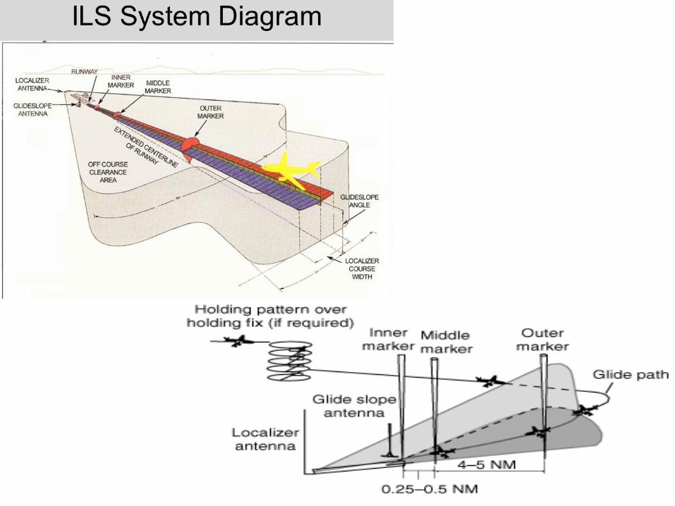
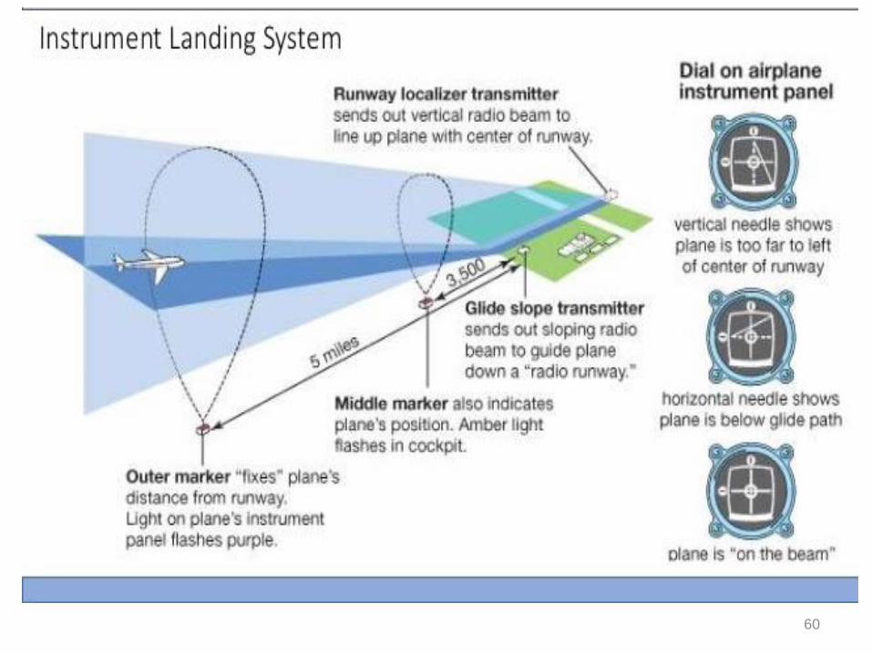
Aircraft Lands Under I.L.S.:- Instrumental Landing System
1) Aircraft is brought to the holding fix by means of enroute aids.
2) It is taken over by control tower.
3) If two or more aircrafts have reached the holding point simultaneously, they are detained by
control tower and directed to keep moving round in space with a vertical separation of at least
300m.
4) After every 2 minutes, the airport control tower directs the aircraft at the bottom of the stack to
move out for final approach to the airport.
5) As the aircraft slides out from the bottom step, it is picked up by the localiser.
6) The localiser provide the alignment guidance along the centre line of the runway. The glide slope
facility provide guidance for the angle of approach.
7) As the aircraft passes over the outer and middle marker, the pilot receivers a high pitched steady
tone and also finds a visual indications in the cokpit. These markers define the specific distance of
the aircraft from the runway threshold along the localiser course.
8) As the aircraft crosses over the middle marker, the pilot changes over from the instrumental to
visual flight system.
9) Now the approach and runway lighting assist the pilot in visual landing.
58
59
60