Transparent control flow transfer between CPU and Intel FPGAs
55
FACULDADE DE E NGENHARIA DA UNIVERSIDADE DO P ORTO Transparent control flow transfer between CPU and Intel FPGAs Daniel Miranda Silva Malafaia Granhão Mestrado Integrado em Engenharia Eletrotécnica e de Computadores Supervisor: João Paulo de Castro Canas Ferreira July 11, 2019
-
Upload
khangminh22 -
Category
Documents
-
view
0 -
download
0
Transcript of Transparent control flow transfer between CPU and Intel FPGAs

FACULDADE DE ENGENHARIA DA UNIVERSIDADE DO PORTO
Transparent control flow transferbetween CPU and Intel FPGAs
Daniel Miranda Silva Malafaia Granhão
Mestrado Integrado em Engenharia Eletrotécnica e de Computadores
Supervisor: João Paulo de Castro Canas Ferreira
July 11, 2019

c© Daniel Miranda Silva Malafaia Granhão, 2019

Resumo
Com o aumento da dificuldade em melhorar o desempenho e eficiência em sistemas computa-cionais, aumenta também a atenção que é dada a plataformas de computação heterogéneas. Estasplataformas criam a possibilidade de se usar hardware dedicado, com o objetivo de se aceleraraplicações de software. Apesar disto, para que uma aplicação aproveite os recursos disponíveisnestas plataformas é necessário que a mesma seja escrita de novo, usando um processo complexoe demorado.
O objetivo deste trabalho é investigar mecanismos transparentes que permitam a transferênciado controlo de execução entre um CPU e uma FPGA, que contém um acelerador, particularmenteno contexto de Computação de Alto Desempenho (HPC). Tal mecanismo poderá ser acopladocom ferramentas transparentes de análise e tradução para hardware, o que permitirá que softwarecomum aproveite a existência de aceleradores de forma transparente (sem qualquer intervençãohumana).
Neste trabalho, um novo mecanismo é proposto, que usa o ptrace, uma chamada de sistemaLinux, para tomar controlo total de uma aplicação em software, e transferir de forma transparenteo seu controlo de execução para um acelerador. O mecanismo é implementado sobre uma novaplataforma híbrida da Intel chamada Xeon+FPGA, que combina no mesmo circuito integrado umprocessador Xeon e uma FPGA Arria 10, enquanto partilham a memória principal. O protótipoimplementado foi testado usando duas aplicações exemplo: um encriptador AES 256 em modoCTR, e um multiplicador de matrizes em vírgula flutuante de precisão simples.
Quando comparado com uma proposta anterior, os resultados mostram que o mecanismo pro-posto introduz um atraso adicional que não ultrapassa os 1,1 ms, mas apresentando a grandevantagem de permitir que seja aplicada a transferência transparente do controlo de execução aqualquer função, o que antes não era possível.
i

ii
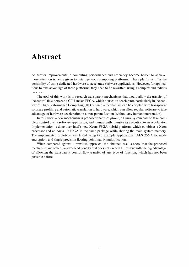
Abstract
As further improvements in computing performance and efficiency become harder to achieve,more attention is being given to heterogeneous computing platforms. These platforms offer thepossibility of using dedicated hardware to accelerate software applications. However, for applica-tions to take advantage of these platforms, they need to be rewritten, using a complex and tediousprocess.
The goal of this work is to research transparent mechanisms that would allow the transfer ofthe control flow between a CPU and an FPGA, which houses an accelerator, particularly in the con-text of High-Performance Computing (HPC). Such a mechanism can be coupled with transparentsoftware profiling and automatic translation to hardware, which can allow regular software to takeadvantage of hardware acceleration in a transparent fashion (without any human intervention).
In this work, a new mechanism is proposed that uses ptrace, a Linux system call, to take com-plete control over a software application, and transparently transfer its execution to an accelerator.Implementation is done over Intel’s new Xeon+FPGA hybrid platform, which combines a Xeonprocessor and an Arria 10 FPGA in the same package while sharing the main system memory.The implemented prototype was tested using two example applications: AES 256 CTR modeencryption, and single-precision floating point matrix multiplication.
When compared against a previous approach, the obtained results show that the proposedmechanism introduces an overhead penalty that does not exceed 1.1 ms but with the big advantageof allowing the transparent control flow transfer of any type of function, which has not beenpossible before.
iii

iv

Agradecimentos
Gostaria de agradecer a várias pessoas sem as quais não conseguiria ter terminado esta dissertaçãocom sucesso.
Em primeiro lugar, agradeço ao professor João Canas Ferreira, que orientou este trabalho, portodo o seu apoio e orientação. A sua confiança no meu trabalho permitiu que o desenvolvesse deforma independente. Agradeço também pela sua disponibilidade, para discutir e partilhar ideias,que permitiu um progresso fluído do trabalho ao longo destes meses.
Agradeço à minha namorada, a Joana Macedo, por estar sempre ao meu lado e nunca deixarde acreditar de mim, principalmente quando eu começo a perder a esperança.
Da mesma forma agradeço à minha Mãe e aos meu Avós, que toda a minha vida me apoiarame me levaram até ao ponto onde estou hoje. Espero poder contar com eles e eles comigo duranteos muitos anos que estão para vir.
Não posso terminar sem também agradecer aos membros do C.P.G. pela amizade e por todosos anos que passamos juntos.
Daniel Granhão
v

vi

Contents
1 Introduction 11.1 Context . . . . . . . . . . . . . . . . . . . . . . . . . . . . . . . . . . . . . . . 11.2 Motivation . . . . . . . . . . . . . . . . . . . . . . . . . . . . . . . . . . . . . . 21.3 Objectives . . . . . . . . . . . . . . . . . . . . . . . . . . . . . . . . . . . . . . 21.4 Contributions . . . . . . . . . . . . . . . . . . . . . . . . . . . . . . . . . . . . 41.5 Structure of the Report . . . . . . . . . . . . . . . . . . . . . . . . . . . . . . . 4
2 Background and Literature Review 52.1 CPU-Accelerator Interface . . . . . . . . . . . . . . . . . . . . . . . . . . . . . 52.2 Transfer Mechanism . . . . . . . . . . . . . . . . . . . . . . . . . . . . . . . . 6
2.2.1 Embedded Platforms . . . . . . . . . . . . . . . . . . . . . . . . . . . . 62.2.2 HPC Platforms . . . . . . . . . . . . . . . . . . . . . . . . . . . . . . . 7
2.3 Accelerator Memory Access . . . . . . . . . . . . . . . . . . . . . . . . . . . . 82.4 Target Platform - Xeon-FPGA . . . . . . . . . . . . . . . . . . . . . . . . . . . 92.5 Conclusion . . . . . . . . . . . . . . . . . . . . . . . . . . . . . . . . . . . . . 12
3 Transparent Control Flow Transfer Mechanism 153.1 Problem Description . . . . . . . . . . . . . . . . . . . . . . . . . . . . . . . . 153.2 Proposed Mechanism . . . . . . . . . . . . . . . . . . . . . . . . . . . . . . . . 16
3.2.1 The ”Manager” Process . . . . . . . . . . . . . . . . . . . . . . . . . . 173.2.2 Control Flow Transfer . . . . . . . . . . . . . . . . . . . . . . . . . . . 183.2.3 Transfer Code Injection . . . . . . . . . . . . . . . . . . . . . . . . . . 193.2.4 Executing Injected Code . . . . . . . . . . . . . . . . . . . . . . . . . . 213.2.5 Architecture . . . . . . . . . . . . . . . . . . . . . . . . . . . . . . . . . 223.2.6 Final Considerations . . . . . . . . . . . . . . . . . . . . . . . . . . . . 22
4 A Framework for Transparent Acceleration 254.1 Framework Description . . . . . . . . . . . . . . . . . . . . . . . . . . . . . . . 25
4.1.1 Manager Implementation . . . . . . . . . . . . . . . . . . . . . . . . . . 254.1.2 Injected Code . . . . . . . . . . . . . . . . . . . . . . . . . . . . . . . . 27
4.2 Case Studies . . . . . . . . . . . . . . . . . . . . . . . . . . . . . . . . . . . . . 274.2.1 Case 1 - AES 256 CTR Mode Encryption . . . . . . . . . . . . . . . . . 284.2.2 Case 2 - Matrix Multiplication . . . . . . . . . . . . . . . . . . . . . . . 32
5 Conclusions and Future Work 355.1 Conclusions . . . . . . . . . . . . . . . . . . . . . . . . . . . . . . . . . . . . . 355.2 Future Work . . . . . . . . . . . . . . . . . . . . . . . . . . . . . . . . . . . . . 36
References 37
vii

viii CONTENTS

List of Figures
1.1 Transparent Acceleration Example . . . . . . . . . . . . . . . . . . . . . . . . . 3
2.1 CLA Architecture . . . . . . . . . . . . . . . . . . . . . . . . . . . . . . . . . . 72.2 Accelerator Memory Access Main Alternatives . . . . . . . . . . . . . . . . . . 82.3 Xeon-FPGA Platform Internal Block Diagram . . . . . . . . . . . . . . . . . . . 92.4 Xeon-FPGA Platform Memory Hierarchy . . . . . . . . . . . . . . . . . . . . . 10
3.1 Adding a Breakpoint to a Hot Spot . . . . . . . . . . . . . . . . . . . . . . . . . 173.2 Transfer Code Injection Alternatives . . . . . . . . . . . . . . . . . . . . . . . . 203.3 Manager and Target Address Space Represented with Transfer Code . . . . . . . 213.4 Proposed Approach High-level Architecture . . . . . . . . . . . . . . . . . . . . 22
4.1 CTR Mode of Operation . . . . . . . . . . . . . . . . . . . . . . . . . . . . . . 284.2 AES 256 CTR Mode Encryption Accelerator Simplified Architecture . . . . . . . 304.3 AES 256 CTR Encryption Average Execution Time and Acceleration for Different
Data Sizes . . . . . . . . . . . . . . . . . . . . . . . . . . . . . . . . . . . . . . 314.4 Matrix Multiplication Accelerator Simplified Architecture . . . . . . . . . . . . 334.5 Matrix Multiplication Average Execution Time and Acceleration for Different
Square Matrix Sizes . . . . . . . . . . . . . . . . . . . . . . . . . . . . . . . . . 34
ix

x LIST OF FIGURES

List of Tables
4.1 Data Fields of Configuration File . . . . . . . . . . . . . . . . . . . . . . . . . . 264.2 CSRs of AES 256 CTR Encryption Accelerator . . . . . . . . . . . . . . . . . . 294.3 CSRs of Matrix Multiplication Accelerator . . . . . . . . . . . . . . . . . . . . 32
xi

xii LIST OF TABLES

Acronyms and Symbols
AES Advanced Encryption StandardAFU Accelerator Functional UnitAPI Application Programming InterfaceASE Accelerator Functional Unit Simulation EnvironmentASLR Address Space Layout RandomizationBBB Basic Building BlocksCPU Central Processing UnitCSR Control/Status RegisterDMA Direct Memory AccessFPGA Field-Programmable Gate ArrayGPP General Purpose ProcessorGPU Graphics Processing UnitHPC High-Performance ComputingHW HardwareMPF Memory Properties FactoryOPAE Open Programmable Acceleration EngineQPI QuickPath InterconnectRPU Reconfigurable Processing UnitSW Software
xiii


Chapter 1
Introduction
1.1 Context
With each step taken towards higher processing power in computing systems, new problems arise,
and the harder further development becomes. Recently it has been said that ”Moore’s law1 is dead”
[1, 2] and although that might be arguable, there is no denying that the shrinking of transistors can
not go on ad infinitum. This fact and the realization that processor frequencies cannot continue to
be increased, as they lead to much higher power consumption, are two of the reasons for increased
interest in heterogeneous computing platforms.
Heterogeneous platforms combine computing blocks which have different architectures, each
based on distinct computational models. Usually, specialized processing capabilities are combined
so that each task is executed more efficiently. This generally leads to higher processing power
while decreasing consumed energy overall. The use of this type of approach is thought to be one
of the ways in which current and future big improvements in efficiency can be achieved. These
platforms can combine common von Neumman General Purpose Processors (GPPs), Graphics
Processing Units (GPUs), Field-Programmable Gate Arrays (FPGAs) and Application Specific
Integrated Circuits. The most common type of configuration is when a GPP is used as the Central
Processing Unit (CPU) and the other units act as co-processors/accelerators that are only used to
compute specific tasks, which are executed with much higher efficiency than if they were executed
by the GPP.
FPGAs are integrated circuits which can be reconfigured after manufacturing and are espe-
cially interesting in the context of heterogeneous systems and of acceleration using co-processors.
They can be configured to accelerate a specific task, which can be done by exploring its parallel
nature, and later be reconfigured to accelerate a completely different task. The recent acquisition
of one of the biggest FPGA manufacturers (Altera) by Intel for 16.7 billion USD [3] shows that
Intel sees a future where FPGAs provide a valuable contribution to computing platforms.
In the context of High-Performance Computing (HPC), acceleration using co-processors is
starting to gain traction, but is still little used. The improvements in performance, and especially
1The inference that the number of transistors in integrated circuits doubles every two years
1

2 Introduction
the reduction of consumed power, are always important, but even more for this kind of computing
platforms, as the need for cooling already represents a massive chunk of the total operation cost.
Several companies that own and operate data centers started in the last few years to include FPGAs
as accelerators in their systems [4, 5, 6] and GPUs have also been available.
1.2 Motivation
Although the use of accelerators and heterogeneous platforms can lead to much greater energy
efficiency in several contexts such as HPC [7, 8], it also brings some problems that have yet to be
solved.
On the one hand, the development of software applications that take advantage of the existence
of the accelerators is more complex and cumbersome. Specifically, if the accelerator is an FPGA,
the circuit of the accelerator needs to be designed from the ground up to be later configured in the
FPGA. The skills needed to design such accelerators are missing from the skill set of the common
software developer and, in general, this design process takes more time and demands exhaustive
testing, even when being conducted by someone with experience. The emergence of high-level
synthesis tools, which allow in some cases the automatic generation of accelerators from almost
regular software code, help attenuate this problem, but their utilization provides mixed results and
still requires specific care with hardware related issues.
On the other hand, the lack of backward compatibility further hinders the wide adoption of
accelerators. Any older application that was not designed to make use of a specific accelerator
will not take advantage of it. In many cases, it is not even possible to try and adapt the source code
of the application because only the binaries are available. Such is the case when applications are
proprietary. Furthermore, an application developed to use a specific accelerator will probably not
be compatible with other types of accelerators unless support for them was specifically thought
out at the design stage.
Due to these reasons, it is highly desirable to attain an automatic method of running applica-
tions on heterogeneous systems. When accelerators are available they should be used transpar-
ently, that is, without the software developers previously taking the accelerator into account and
without introducing any permanent changes to the software that would later impede its use on
different hardware and accelerators.
1.3 Objectives
In order for acceleration in heterogeneous platforms to be carried out transparently, there are three
main mechanisms that must be implemented, which depend on each other to some degree.
The first is a profiling mechanism that can automatically detect the portions of an application
that are good candidates for being accelerated. Commonly called ”hot spots”, they usually consist

1.3 Objectives 3
Program
Profiling Accelerator ConfigurationGPP
Accelerator
All transparentto developer
t
Figure 1.1: Transparent Acceleration Example
of repetitive sequences of computations that are especially taxing on the CPU and could be com-
puted in parallel by an accelerator. This mechanism must produce a description of these blocks
that is consumed by the other two mechanisms.
Then, there must be a mechanism that uses the previously generated description, and can
transparently generate all configurations needed for a specific accelerator to perform the same
computations as the portions of the application it will replace. The accelerator can be a GPU, in
which case the configuration is software targeted at GPUs, but can also be an FPGA, and in that
case the configuration is more complex, as it is a description of a hardware circuit.
Finally, the third mechanism is the transparent control flow transfer between the CPU and
an accelerator. This mechanism must use the description of which pieces of software should be
accelerated and transfer the execution to the appropriate accelerator. For that, it must also rely on
some information on how the accelerator was implemented in order to use the interface it provides.
Together, they may allow a computing platform to behave as represented in figure 1.1. When
an application is executed, in the beginning, it will run as usual, but in the background, a profiling
task will be executed that can automatically detect the hot spots. The accelerator will also be
configured in the background when the profiling finishes. Then, a sudden rise in performance can
be noticed, because an accelerator will start to be used to accelerate some parts of the application.
This work focuses on only one of these mechanisms. It is the transparent control flow transfer
that is investigated. Therefore, for its implementation and evaluation purposes, the detection of hot
spots and configuration of corresponding accelerators can be made in a non-transparent fashion,
as these problems are assumed as solved. Indeed, approaches to these issues in embedded systems
have been addressed [9, 10, 11, 12].
To summarize, the main objective of this thesis is to research mechanisms that allow the trans-
parent transfer of the control flow between a CPU and an FPGA, which houses an accelerator,
particularly in the context of HPC.
The presented results were obtained on resources hosted at the Paderborn Center for Parallel
Computing (PC2) in the Intel Hardware Accelerator Research Program (HARP2). Specifically, a

4 Introduction
new platform developed by Intel is used in this work. It combines a Xeon CPU and an Arria 10
FPGA in the same integrated circuit, both sharing the main system memory, and connected with
several high bandwidth interfaces.
1.4 Contributions
The main contributions of this work are:
• Proposal of a new transparent control flow transfer mechanism which works on top of the
Linux operating system. Unlike previous approaches, this mechanism is not limited to the
acceleration of functions provided by shared libraries.
• Development of a framework that implements the proposed mechanism on a new Intel plat-
form which combines a high-performance CPU and an FPGA in the same integrated circuit
(Intel Xeon+FPGA).
• Study and evaluation of the framework and mechanism using two case studies: AES 256
CTR mode encryption and single precision floating-point matrix multiplication.
1.5 Structure of the Report
This report is structured as follows. In chapter 2 the related literature is reviewed, and context on
the underlying Intel platform will be provided. Chapter 3 will present the problem and propose a
new transparent control flow transfer mechanism. In chapter 4, the implementation of the proposed
mechanism is described and its performance evaluated. Finally, in chapter 5, conclusions are taken
and recommendations are given on future work.

Chapter 2
Background and Literature Review
Previous research on acceleration using co-processors exists for some time and goes as far back
as the 1980s [13, 14, 15, 12]. Despite this, most of the investigation on this topic consists on
the development of dedicated accelerators in conjunction with applications that make use of such
accelerators, in a process commonly called HW/SW co-design. This approach is application and
platform specific and does not try to attain transparent acceleration. Efforts towards achieving a
mechanism that displays this characteristic appeared only more recently.
The following sections start by a revision of the types of interfaces between CPU and acceler-
ator, followed by a review of previously proposed mechanisms that are used to transfer the control
flow between a CPU and an accelerator, and also of the type of memory access capabilities of the
accelerator. Then, some background is provided on the Intel Xeon-FPGA platform and related
tools.
2.1 CPU-Accelerator Interface
In the literature, the interface that the CPU uses to communicate and exchange data with an ac-
celerator can be classified in one of two major categories, which are directly related to the hetero-
geneous platform architecture. One is when the accelerator is directly coupled to CPU’s pipeline.
Some times the accelerator behaves as an alternative to the main Arithmetic Logic Unit. A rep-
resentative example of this approach is described in [10]. This has the advantage of a reduced
overhead in the communication between the CPU and the accelerator. On the other hand, the
design of the accelerator becomes dependent on the CPU’s design. Additionally, unless the CPU
was specifically designed to accept an accelerator in this form, for example by presenting a custom
instruction (CI) port, the CPU’s hardware needs to be adapted to the accelerator as well.
The other alternative is to have the accelerator be a peripheral as in [11]. This alternative
approach is more portable and allows for more complex accelerators that are not subject to the
CPU’s pipeline restrictions, but presents larger overheads in the communication between the CPU
and the accelerator.
5

6 Background and Literature Review
2.2 Transfer Mechanism
Any mechanism that transfers the control flow between a CPU and an accelerator must use the
interface between them to first transfer input data from the CPU to the accelerator, and later to
transfer the outputs from the acceleration back to the CPU. For this work, the most interesting
aspect about a control flow transfer mechanism is if whether or not it is transparent. A brief
reference to this characteristic was made in section 1.2, but now it is important to define it more
precisely in order to properly evaluate the different previous research approaches.
In the context of this work, transparency is a characteristic that control flow transfer mecha-
nisms can present. A transparent transfer mechanism is one that allows for the transparent accel-
eration of a program. If a program is transparently accelerated, then the program itself does not
need to be specifically designed to be accelerated, and, therefore, the programmers that developed
the application do not have to know about the existence of an accelerator.
The most common approach to the implementation of control flow transfer mechanisms re-
mains non-transparent. Many times applications are designed from the ground up to be acceler-
ated by partitioning tasks to each computing device, which is a complex and cumbersome task
as already stated. In these situations, the transfer mechanism is usually directly embedded in the
design of both the software and the accelerator.
The following sub-sections summarize some representative previously proposed approaches
for transparent control flow transfer mechanisms. They are split into two distinct categories ac-
cording to the type of platforms they are applicable to: embedded platforms and HPC platforms.
Although it is likely that any approach applicable to embedded platforms will not be directly appli-
cable to HPC, they may provide inspiration on how this problem can be addressed for the present
and future works.
2.2.1 Embedded Platforms
Bundled Execution of Recurring Traces The co-processor BERET is an accelerator that is
tightly coupled to a CPU and allows the efficient execution of small and atomic instruction traces.
The control flow transfer approach proposed in [10] makes use of a compilation process that tags
the instructions in which hot spots begin. When the program is being executed, whenever the
program counter reaches a tagged instruction this is detected because the processor’s fetch stage
contains a table with all tagged instructions. Then, an entry trigger is sent to the BERET hardware
along with the corresponding trace configuration address, which was also added to the binary by
the compiler. BERET then retrieves the configuration bits using the instruction cache. When
BERET ends executing, an exit trigger is launched and control is given back to the CPU, that
resumes from the fetch stage. This means that the CPU stalls while BERET runs.
The transfer mechanism in this approach relies on information provided by the compilation
step, which includes some form of binary profiling capabilities, to be able to know when the
transfer should be initiated. This approach is transparent but its implementation implies the re-
design of some parts of the CPU.

2.2 Transfer Mechanism 7
Figure 2.1: CLA Architecture (from [11])
Custom Loop Accelerator In [11] the target software is analyzed so that Megablocks, which
are repetitive instruction traces, can be extracted. Megablocks are then accelerated by a Recon-
figurable Processing Unit (RPU) that is configured to perform the same computations. Figure 2.1
presents the architecture of the approach.
The Local Memory Bus (LMB) injector is the block with more relevance to this work. It is
responsible for triggering the transfer of the control flow between the GPP and RPU and achieves
this by monitoring and controlling the contents of the instruction bus. When an address that is
associated with the start of a Megablock is detected, the LMB injector changes the instruction
so that a subroutine that handles the transfer is called. This routine is called Communication
Routine (CR) by the authors and it starts by sending the contents from the GPP’s registers to the
RPU. It then sends a start signal and when the RPU execution ends, it is also responsible for
reestablishing the GPP registers with the computed results and resuming the program. While the
RPU is computing, the GPP stalls.
This is yet another approach which is only practical in the context of embedded platforms.
Despite this, the idea of changing the program dynamically is interesting. This allows all the code
responsible for interfacing with an accelerator to be put together inside a routine. Transferring
execution to an accelerator becomes as simple as managing to get that routine to be executed
instead of the hot spot. In this mechanism, the way a transfer is initiated is somewhat similar to
the previous one. In BERET, the processors own fetch stage is modified so that tagged instructions
trigger the acceleration. In this case, an instruction bus supervisor performs that same job.
2.2.2 HPC Platforms
Shared Library Interposing Shared Library Interposing consists of replacing shared library
calls. This was proposed in [16] as a way to transparently transfer the control flow between a CPU
and an accelerator by having accelerated versions of shared library functions replace the original
ones. Shared libraries consist of pre-compiled code that can be reused. These can be linked to an
executable at run-time, allowing for reduced program size and lower memory use.

8 Background and Literature Review
CPU
CPU'sInternalMemory
Accelerator
High Latency
External Memory
CPU
CPU'sInternalMemory
Accelerator
Accelerator'sInternalMemory
Low Latency
CPU
SharedInternalMemory
Accelerator
(a) External Memory (b) Internal Memory (c) Shared Memory
Low Latency
Figure 2.2: Accelerator Memory Access Main Alternatives
Several mechanisms that would allow shared library interposing are studied and one was cho-
sen to be implemented. It consists of setting the LD_PRELOAD environment variable on the Linux
operating system, which essentially allows choosing which shared libraries will be linked to the
application at run-time. A shared library is loaded instead of the original that contained the func-
tion to be accelerated. The new shared library contains code which handles the transfer of the
control flow to an accelerator and back.
This mechanism is different from the other examples because it doesn’t target embedded plat-
forms. Although very simple, it allows for a very flexible implementation, remains transparent,
and is applicable to HPC. For example, the loaded shared library can follow a policy for when it
should execute the needed computations on software, or in one of several available accelerators.
The great disadvantage of this approach is the limitation of only being able to accelerate hot spots
contained inside shared library functions. It is not possible to transfer the control flow to an ac-
celerator when the hot spot is in a static library or local function. Ideally, the execution of any
arbitrary block of code should be able to be transferred to an accelerator.
2.3 Accelerator Memory Access
How and if memory can be accessed by an accelerator plays a major role in how much speed up
the accelerator can provide. The greatest speedups occur when many computations can be made in
parallel and, for this to happen, the inputs for these computations need to be readily available. To
avoid the overhead of transferring all necessary data to an accelerator before beginning execution,
fast access to the memory where the data resides is important. Ideally, the more memory accesses
can be done at the same time, the better. The main alternatives are represented in figure 2.2 and
are external memory, internal memory, and shared memory. If external memory is used, probably
any gains that would be obtained by the use of the accelerator are lost due to the large memory
access overheads. If memory internal to the accelerator is used such as in [17], then it is necessary

2.4 Target Platform - Xeon-FPGA 9
Xeon E5-2600 v4 Arria 10 FPGA
QPI
PCIe 3.0 x8
PCIe 3.0 x8
HSSIQPI PCIe 3.0 x24
DDR4x4
Figure 2.3: Xeon-FPGA Platform Internal Block Diagram
to transfer all data necessary to an acceleration before it begins, which can be a considerable
overhead but usually limited and much smaller than the external memory one. The other option is
to share the memory with the CPU. The memory shared can be the main memory as in the example
figure and then all memory is shared [10], or secondary memories are used and in that case, only
a portion of the memory is shared [15].
2.4 Target Platform - Xeon-FPGA
The target Xeon-FPGA hybrid platform was developed by Intel and combines in the same pack-
age a high-performance Xeon processor and an Arria 10 GX 1150 FPGA. The two devices are
connected by high bandwidth links. The platform’s internal block diagram is present in figure 2.3.
The processor is a Xeon E5-2600 v4 and presents 14 cores with Intel’s Hyper-Threading tech-
nology, meaning that a total of 28 threads can run concurrently. The processor’s microarchitecture
is Broadwell. As for connectivity, the Xeon presents four DDR4 memory controllers, one QPI co-
herent link, and 24 lanes of PCI-Express 3.0. QuickPath Interconnect (QPI) is an Intel proprietary
technology used to interconnect different processors. It provides low-latency and coherent access
to a shared address space which is achieved through a directory-based home snoop coherency pro-
tocol. QPI’s transfer speeds are up to 9.6 GT/s. Recently, this platform has already been upgraded
to use a Skylake Xeon SP6138 processor, which has available six DDR4 memory controllers. Also
QPI has been upgraded to UltraPath Interconnect (UPI), which reaches speeds of 10.4 GT/s. In the
upgraded versions, as stated in [18], due to the existence of two available UPI slots on the Xeon
processor, a setup could be used in which two Xeon+FPGA platforms are connected together and
behave as one.
The Arria FPGA present in the target platform is connected to the Xeon also with a QPI link
and two PCI-Express 3.0 x8 links. As just stated, the QPI link provides coherent access to shared
memory space, which means that the FPGA shares the memory with the processor in a cache
coherent fashion. This allows the FPGA to access data seamlessly whether it resides in cache or

10 Background and Literature Review
Figure 2.4: Xeon-FPGA Platform Memory Hierarchy (from [19])
in memory, which leads to fewer overheads where data location is discovered and removes the
need for redundant data storage or DMA. The FPGA also features an external high-speed serial
interface that can be used for example as a network port. Besides being a large FPGA, which
has available 1.115.000 logic elements, it also features hard single-precision floating point units,
which is uncommon in FPGAs.
For accelerators to access memory, they use the Core Cache Interface (CCI-P) which abstracts
the platform physical links (PCI-Express and QPI) [19]. The Intel FPGA Interface Unit (FIU) is
a block of logic statically configured on the FPGA which connects to the Xeon processor with the
stated existing links and offers the CCI-P interface to the accelerators present in the FPGA. FIU
has the task of mapping both PCI-Express x8 links and the QPI coherent link to the CCI-P interface
in a way that an accelerator sees a single logical connection with a capacity equal to the sum of
the three link’s capacities. Accelerators actually see four virtual channels: VL0, VH0, VH1 and
VA. The first three map one to one the each one of the interfaces, therefore granting control over
which physical interface is used. The last virtual channel maps to all the three physical interfaces.
Accelerators should remain platform independent if they use mainly the VA virtual channel. In
this channel a de-multiplexer is used to route requests to all the physical links.
A diagram of the platform memory hierarchy can be found in figure 2.4. When an accelerator
requests a memory access, it can be served by one of three components: the FPGA cache (A.1), the
processor cache (A.2) or the SDRAM (A.3). The FPGA cache is inside the processor’s coherence
domain and offers the highest bandwidth but is only used when requests are sent via the QPI link.
When VA is used there is the chance that requests are mapped to one of the PCI-Express links
when the FPGA cache could service the request, in which case a latency penalty is incurred. If the
FPGA cache can not service a request, then the processor cache is used. Of course, this one has a
higher latency than the FPGA cache. Finally, if the processor cache also can not service a request
then the SDRAM is used, which has an even bigger and the highest access latency.

2.4 Target Platform - Xeon-FPGA 11
A performance comparison between two representative platforms, one being a predecessor to
the one being targeted in this work, is made in [20]. The predecessor is also based on a QPI link
to provide coherent memory access to the FPGA in a fashion very similar to the one previously
described. The difference between the two is that this previous version has the FPGA on another
socket in the same board, which should perform worse than the targeted platform. This approach
is compared to a more traditional PCI-based one, in which the FPGA accesses the main memory
through DMA and has its own private memory. The authors came to the conclusion that if appli-
cations are carefully designed to hide memory access latency, then the PCI-based approach can
catch up to the QPI approach in most scenarios, but the latter has a large advantage in fine-grained
(<4KB) communication latency, being up to two orders of magnitude faster in those scenarios.
Given that the platform targeted in this work displays an architecture very similar to the previous
implementation, with some improvements such as having the FPGA even closer to the CPU, this
platform should have the same if not even greater advantage when compared to the traditional
PCI-based approach.
The use of accelerators implemented in the FPGA is done using OPAE, which is a software
layer that was developed with the goal of simplifying the integration of FPGA devices into soft-
ware applications [21]. It encompasses several software tools, drivers for interaction with Intel
FPGAs and user-space APIs that allow applications to take advantage of accelerators. On the
CPU, OPAE sits on top of the operating system. On the FPGA, there are two main components:
the FPGA Interface Manager (FIM) and the Accelerator Function (AF). FIM is a static region in
the FPGA that is responsible for infrastructure tasks, such as energy consumption, temperature
management, and partial reconfiguration. The AF is an area of re-configurable logic in which new
logic functions can be implemented.
At the current time, OPAE provides APIs in C, C++, and Python. They are all very similar and
allow the discovery, allocation, access, and management of accelerator resources. For example, the
typical flow that a C programmed application would have to follow in order to acquire ownership
and access an accelerator is represented in figure 4 of [21]. First, an application must create a
fpga_properties object that allows the specification of the desired characteristics for an accelerator.
Then, the function fpgaEnumerate() must be called with the properties object as an argument and
it possibly returns tokens, which identify accelerator instances. Calling the function fpgaOpen()
grants ownership over the instance that a given token identifies, and finally access to the accelerator
is granted. Once ownership is obtained it is necessary to map accelerator registers to user space
and allocate shared memory space. Only then computations can be made on the accelerator.
Several processes can share an accelerator by calling the function fpgaOpen() and opt for non-
exclusive access. It is also possible for several operating systems running on virtual machines to
use OPAE and concurrently use and share an FPGA.
Bundled with OPAE is also the Intel Accelerator Functional Unit (AFU) Simulation Envi-
ronment (ASE), which is a simulator for OPAE designs. It runs using two processes. One is the
simulation of the AFU RTL, thus simulating the computations made by the FPGA. The other com-
municates with the software that would use the accelerator in the FPGA. This setup allows for a

12 Background and Literature Review
much faster development of both the software and AFU hardware.
The CCI-P interface that was mentioned earlier is a purposefully simple and basic interface
which provides no guarantee on the order by which any memory access requests are processed.
It also expects the accelerator to request accesses to physical memory addresses. To tackle these
hurdles, Intel provides its FPGA Basic Build Blocks (BBB) [22]. As the name hints, this is a
collection of blocks and they can be used to transform the CCI-P interface. One of the blocks is
the Memory Properties Factory (MPF) and it can be configured to provide these and other features:
• VTP - Virtual to physical translation of addresses for read and write requests
• ROB - A reorder buffer which returns read responses in the order they were requested
• WRO - Guarantees that write and reads to the same address are completed with respect to
the order they were requested
• PWRITE - Offers partial write functionality, which is implemented as a read-modify-write
Other blocks present in the Intel BBB are MUX and ASYNC. MUX allows multiple acceler-
ators compliant with the CCI-P interface to be connected to the same CCI-P instance. ASYNC
is a block that handles clock crossing, which allows accelerators with lower clock frequencies to
be attached to the CCI-P interface. All these features provided by Intel BBB may or may not be
needed by each specific accelerator so they are added to each design only when strictly necessary,
which allows for significant reductions of FPGA occupied area.
2.5 Conclusion
Although there is research regarding the topic of transparent transfer of control flow for accel-
eration purposes, there is yet to appear a practical solution that would allow wider adoption of
heterogeneous computing platforms. Most of the efforts towards achieving this goal appear to be
focused on embedded systems. Such as in HPC but for slightly different reasons, they too benefit
from higher computing efficiency but their nature allows for a much more fine-grained control
over the design of any transfer mechanism. A solution for transparent control flow transfer in the
context of HPC seems to be further away.
The most promising past work applicable to HPC seems to be the shared library interposing
mechanism. It was proven to work over Linux, one of the most used operating systems in that
segment, which runs on the top 500 supercomputers in the world [23]. The main problem with
this approach is the lack of support for transferring execution to an accelerator when hot spots are
not constrained inside shared library functions.
The architecture of the Intel hybrid Xeon+FPGA platform is in a middle ground between
the two alternatives presented in section 2.1. Compared to a loosely-coupled accelerator-CPU
architecture, the accelerator is much closer to the CPU, allowing both to share the same view to
the main memory through a high bandwidth link. This means that it is not necessary to transfer

2.5 Conclusion 13
all data from the CPU to the accelerator prior to its operation as well as transferring all the results
back only at the end. Compared to the tightly-coupled alternative, the accelerator is also close to
the CPU but not directly coupled to its pipeline. This means that it does not suffer from the same
drawback: limited accelerator complexity.

14 Background and Literature Review

Chapter 3
Transparent Control Flow TransferMechanism
3.1 Problem Description
This work aims at researching transparent control flow transfer mechanisms that can be applied
to HPC. Although not all HPC platforms run Linux, the vast majority run some version of this
operating system. Thus, only transfer mechanisms applicable to applications that run on Linux are
considered. Taking this into account, previous work on this topic that targets embedded platforms
can only eventually provide some inspiration on how to proceed.
It is also assumed that a software application binary executable is the target for acceleration and
that there is available in the platform some software interface for applications to take advantage of
available accelerators. A possible solution must meet some requisites:
• The software application must be stopped when it reaches the beginning of a code block
considered a hot spot.
• When that happens, all data necessary for acceleration to begin must be transferred to an
accelerator and a run order must be issued.
• After the accelerator concludes its execution of the hot spot, output results must be pulled
from the accelerator and the software application resumed, as if the hot spot was executed
in software.
• No intervention should be required from the user. All needed information should be obtained
from transparent profiling of the application.
The use of shared library interposing [16] manages to fulfill these requisites using a simple
approach. As a hot spot can only be a routine from a shared library, replacing the shared library
stops the application from executing the hot spot when the routine is called, and code that handles
the control flow transfer is executed instead. This includes the transfer of some data prior to
15

16 Transparent Control Flow Transfer Mechanism
accelerator execution. As long as the new routine behaves similarly to the original one, the original
software is later resumed as if the hot spot was computed in software.
In order for the mechanism to support the transfer of the control flow not only when hot spots
can be shared library routines, but also other code blocks, such as a loop, an approach different
from shared library interposing must be conceived.
In this work, only single-threaded applications are considered for acceleration targets. Ac-
celerating multi-threaded applications is expected to be a considerably more complex research
task that is left for future work. However, it would be advantageous if a proposal for a transfer
mechanism is extensible in that regard.
3.2 Proposed Mechanism
The main idea is to develop an approach which takes advantage of the Linux system call ptrace.
This system call provides a process with the ability to observe and take complete control over the
execution of another process. The process that takes control is called the ”tracer”, and the process
that is controlled is called the ”tracee”. This system call is commonly used by debuggers in order
to insert breakpoints and trace a program’s execution.
A process becomes a tracee after the tracer attaches to it. From that moment until the tracer
detaches, it will stop executing every time a signal is delivered. Signals are a Linux communication
primitive used for different processes to communicate with each other. They work almost as
notifications that processes receive and act upon. The tracer can observe and control the tracee
by waiting for such moments, and then read and modify the contents of the tracee’s memory and
processor registers. Finally, the tracer can resume the tracee’s execution and wait for the next
time it stops. It can also purposefully only let the tracee run a single instruction or even insert a
breakpoint on which the tracee will return control to the tracer.
The system call prototype is:
1 l ong p t r a c e ( enum _ _ p t r a c e _ r e q u e s t r e q u e s t , p i d _ t pid ,2 vo id ∗ addr , vo id ∗ d a t a ) ;
This single interface allows all the mentioned functionality. Depending on the value of request,
the other arguments have different purposes. There are dozens of possible requests, but the most
important for this work are:
• PTRACE_PEEKTEXT - reads a word from the tracee’s memory
• PTRACE_POKETEXT - writes a word to the tracee’s memory
• PTRACE_GETREGS - copies the tracee’s registers
• PTRACE_SETREGS - changes the tracee’s registers
• PTRACE_CONT - resumes execution of a stopped tracee

3.2 Proposed Mechanism 17
0x3a
0x2v
0xe2
0xb1
0x9e
0x5b
0x12
0x42
0x13
0x83
...
...
0x3a
0x2v
0xcc
0xb1
0x9e
0x5b
0x12
0x42
0x13
0x83
...
...
HotSpot
Figure 3.1: Adding a Breakpoint to a Hot Spot
• PTRACE_SINGLESTEP - same as PTRACE_CONT but the tracee executes only one instruc-
tion before control is given back to the tracer
It is evident that this system call allows very fine-grained control over a process’s execution.
This makes it powerful but also has the disadvantage of making its use very dependent on the
specific underlying processor architecture.
3.2.1 The ”Manager” Process
Using ptrace, a new process, the ”manager”, has the responsibility of controlling the program
to be accelerated, the ”target”. The manager process can then stop the target before it reaches
a hot stop, and transfer the control flow to an accelerator that performs the same computations.
When the accelerator finishes, the state of the target process is set up as if the software routine had
just executed, and the target’s execution is resumed, thus allowing the requisites for successfully
transferring the control flow to be met.
Depending on the local configuration of the Linux security module Yama, the manager may
have to be executed with administrative privileges so that it will be able to attach to an already
running target [24]. When this is the case and the user is not an administrator of the system, the
manager won’t be able to attach to a running target but can fork and launch the target as its child
process, and then attach to it later.
For the manager to get the target to stop when hot spots have been reached, it can insert
breakpoints. The insertion of breakpoints in the target process is relatively simple and is analogous
to how debuggers insert breakpoints into processes being debugged. The manager uses ptrace to

18 Transparent Control Flow Transfer Mechanism
rewrite the beginning of each hot spot with a trap instruction, such as represented in figure 3.1.
A trap instruction is simply a special invalid instruction, which sends to process into kernel mode
when executed. Once inside kernel mode, the kernel sends a SIGTRAP signal back to the process.
If the target was not being traced, it would automatically terminate. Because it is being traced by
the manager, the delivery of the signal causes it to stop and the manager regains control, just as
intended.
Using the described strategy could allow many other types of hot spots to be transferred to an
accelerator in a transparent fashion. The acceleration of a routine should be simpler, but it should
also be possible to accelerate other hot spots such as loops. Accelerating routines can be as simple
as setting the breakpoint on the function call, and when the accelerator finishes, resuming the
target after that call. It does not make a difference if the routine is from a shared library or a local
one. Accelerating loops can be more difficult. Adding the breakpoint works in the same way, but
a loop can have more than one exit point, which makes it harder for the manager to know where
the target should resume once the accelerator finishes. One way this problem can be solved is by
executing the last iteration of the loop in software, as proposed in [25]. That way the manager
does not have to know from which instruction the target must resume.
3.2.2 Control Flow Transfer
Once the target is stopped because it reached a breakpoint previously inserted by the manager, the
control flow must be transferred to an accelerator. It is necessary to transfer all the data that the
accelerator needs to start operating. In the case of the Xeon+FPGA platform, this typically consists
of some static data, which can be directly written to accelerator control/status registers (CSRs),
but also larger data structures, whose addresses are also written to CSRs but are only later directly
accessed by the accelerator while it is operating. Once the accelerator starts working, the CPU
can either perform some part of the computations while cooperating with the accelerator or simply
busy-waits for the accelerator to finish. The two case studies performed in this work implement
the latter case. Any results generated by the accelerator that are not at that point already written
in memory can then be read from CSRs. It is assumed that there is an API that provides a set
of routines that allow communicating with available accelerators. In the case of the Xeon+FPGA
platform, OPAE provides its API as described in chapter 2.
The manager could use the OPAE API to transfer data that it gets from the target using ptrace.
However, this method presents a problem. If it is the manager that uses OPAE, then it is the man-
ager that will become the owner of the used accelerator. This means that in case an accelerator uses
virtual addressing to access the main memory, the translation from virtual to physical addresses
will be applied to addresses of the manager process, instead of the target. This is a problem be-
cause the two processes have different address spaces. Although other platforms might be used in
which this would not be a problem, the majority of them should work in a similar fashion, so it is
unfeasible to have the manager communicating directly with available accelerators.
Although it is not obvious how it can be achieved, it must be the target process to use the
OPAE API for the aforementioned reason. The target executable could be modified in order to

3.2 Proposed Mechanism 19
achieve this, but that approach creates problems because it would result in a lower portability level
of the target application, which is not desirable. Depending on the modification that would be
introduced into the binaries, it could stop the executable from being run on any machine that does
not have an accelerator available.
The solution is to inject the control flow transfer code into the target at run-time. In this
way, any modifications introduced are temporary and it can be the target to request the use of an
accelerator. In a way, shared library interposing manages to ”inject” the code responsible for the
transfer at the application startup. Once the code is injected, the manager can run it every time it
gains control after a breakpoint is reached in the target.
To sum up, once the manager attaches to the target, it is responsible for the following tasks:
• The code that handles the transfer of execution to an accelerator must be injected into the
target process.
• A breakpoint in the form of a trap instruction must be inserted at the beginning of every hot
spot in the target’s program.
• When the target reaches a breakpoint, it must make sure the code that was injected is exe-
cuted.
• When the accelerator finishes its execution, it must resume the target as if the control flow
had never been transferred to the accelerator
3.2.3 Transfer Code Injection
Three alternatives that use ptrace were considered for a mechanism capable of injecting the code
responsible for the transfer of control flow to the accelerator. Here they are compared and reasons
for choosing one over the others are presented.
Inject over existing code As was previously explained, ptrace allows to change the tracee’s
memory without any restrictions. The first alternative, which is the most naive, is the first rep-
resented in figure 3.2. In stage 1, the target had just reached a breakpoint and control was given
to the manager. The manager would then have to copy a block of code of the size of the transfer
code so that it can be later restored, and write the transfer code over the existing, already saved
code. This is represented in stage 2. A new breakpoint would have to be inserted at the end of
this code to ensure control is eventually given back and the target would be resumed. When the
target stops on that new breakpoint, stage 3 is reached. Finally, the target’s code would have to be
restored to its initial state and the instruction pointer changed to point to the end of the hot spot.
In this approach, the transfer code is injected only when needed and must be removed after the
accelerator is used. Thus, this approach suffers from a big disadvantage: it is very inefficient to
write the transfer code in the target process and restore it after acceleration every time a hot spot
is reached. The introduced overhead would probably cancel any potential gains obtained from the
acceleration.

20 Transparent Control Flow Transfer Mechanism
...
...
rip
...
rip
...
...
rip
... ...
...
rip
1 432
...
...
rip
...
rip
...
...
rip
... ...
...
rip
Inject overexisting code
Inject on allocated memory
...
...
rip
...
rip
...
...
rip
... ...
...
rip
Shared libraryloading
Hot spotTransfer code Transfer code
Hot spot
mmap
dlopen
Allocatedmemory Transfer code
dlopen
Transfer code Transfer code
mmap
Figure 3.2: Transfer Code Injection Alternatives
Inject on allocated memory In order to avoid unnecessary modifications to the target’s program
that imply that the transfer code would have to constantly be written and erased from the target,
ideally, the chosen approach should inject the transfer code only once in some unused memory
location of the target process. In this second alternative, this is achieved as represented in the
middle row of figure 3.2. Stage 1 represents the state of the target when the manager has just
attached and the instruction pointer is in a random place. The manager should write in the target
a call to the mmap system call, which allows creating a new mapping in the process memory. The
code that is overwritten must be previously saved to be later restored. The arguments of the system
call must also be set so that the new memory block is executable. In stage 2 the call to mmap is
represented and stage 3 shows the state of the target after the execution of mmap. A new block
of memory is available and the final step is to write the transfer code into that free executable
memory space. This approach is much more efficient than the first as the injection only happens
once. Although changes are being introduced to the target application, this approach remains
transparent because they are only made in memory and are not permanent.
Shared library loading This is yet another approach which allows the injection of the transfer
code to be made only once. In this approach, the transfer code must be compiled as a shared
library. It is very similar to the previous one but instead of injecting a call to mmap, it is a call to
dlopen. This is a function that allows to dynamically load shared libraries on demand. There is a

3.2 Proposed Mechanism 21
Manager process
Shared librarywith transfer code
Offset
transfer()
0x420
0x620
...
...
0x000Target process
Shared librarywith transfer code
Offset
transfer()
0x220
0x420
...
...
0x000
Different address spaces
Can be learned from process
/proc/<pid>/mapsfile
Figure 3.3: Manager and Target Address Space Represented with Transfer Code
problem because dlopen is a function that is part of libdl, the dynamic linking library, which may
not have been loaded by the target application. The solution is to use libc’s implementation, called
__libc_dlopen_mode, which should be in the target process.
In practice, the advantage of this approach over the mmap one, it that the transfer code is
already loaded when the single call to dlopen is complete and removes that responsibility from the
manager. Although calling dlopen is not as simple as making a mmap system call, this approach
was preferred overall. Calling dlopen was achieved in the same way as the injected code was
executed when needed. This is described in section 3.2.4.
3.2.4 Executing Injected Code
By using dlopen to load the transfer code into the target’s process, one difficulty is introduced.
Linux implements a security technique called Address Space Layout Randomization (ASLR).
ASLR is used to prevent memory corruption vulnerabilities from being exploited by randomizing
the position where each area of a process memory is located. In practice, this means that dlopen
will load the transfer code to a random position in the target’s memory. In order to be able to
execute the previously injected code when the target reaches a hot spot, the manager must know
where that code is.
One way to overcome the problem ASLR introduces is proposed in [26]. The idea is that Linux
provides a pseudo-filesystem named proc which allows kernel data structures to be accessed. Each
running process has a dedicated folder inside proc named with its own process identifier. One of
the files that each process has in its folder is the maps file. This file describes every region of

22 Transparent Control Flow Transfer Mechanism
ptraceManagerProcess
Xeon CPU Arria 10 FPGA
Intel FPGA Drivers
OPAE C Library
TargetProcess
FPGA Interface Manager
Accelerator
CCI-P
Xeon+FPGA
Figure 3.4: Proposed Approach High-level Architecture
contiguous virtual memory that the process has mapped. By using this file, the manager can
parse its contents and learn the position where the shared library was loaded. This in itself does
not solve the problem because the manager needs to know where a certain function is inside the
shared library. To solve this, the manager can also load the shared library with the transfer code
so that it can learn the offset from the start of the library to where the transfer code is located. As
long as both processes have loaded the same version of a shared library, this offset should remain
the same and the manager has discovered which address it should make the target jump to when a
hot spot is reached. A diagram that illustrates this concept is present in figure 3.3.
3.2.5 Architecture
In figure 3.4 there is a block diagram representing this architecture when the mechanism is applied
in the Xeon+FPGA platform. Two processes are represented, one being the manager and the other
the target. As an example, the OPAE C Library is also represented being called by the target
process. The target application does not originally have any code that calls routines in this library.
It is the manager that alters the target process by injecting code as previously described.
3.2.6 Final Considerations
Compared to the only previously identified proposed mechanism which could be applied in HPC
scenarios, the mechanism here proposed is not limited to only transferring the control flow to an
accelerator when a hot spot is contained inside a shared library function. This means that other
types of hot spots, such as static libraries or even local functions can be accelerated, which is
an important advantage. Furthermore, although it is not implemented in this work, it should be

3.2 Proposed Mechanism 23
possible to apply this mechanism to arbitrary blocks of code not restricted to entire functions, such
as loops.
Although only single-threaded applications are being considered as possible acceleration tar-
gets, ptrace can be used with multiple threads and it works on a thread by thread basis. That is,
each thread must be attached individually. A manager that would support multiple threads could
probably maintain a collection of threads being managed, at the cost of increased complexity and
overheads added to each one. Another option is to have multiple managers, each one controlling
only a portion of the threads being accelerated.
One downside of the proposed approach is the introduction of a larger overhead. Having the
manager stop the target, reading and writing to its memory, every time a hot spot is reached, is
expected to have a negative impact on the overall performance of this mechanism that will likely
put it behind shared library interposing when compared while doing shared library calls acceler-
ation. Specifically how much worse it fares is evaluated in chapter 4. The proposed mechanism
is also much more complex. On top of this, Linux only allows each process to be traced by one
tracer. This means that the target will not be able to be debugged whenever it is being transpar-
ently accelerated, as the manager will already be attached to it. Finally, one last disadvantage of
the proposed approach is that it is highly dependent on which specific processor this is being used
and also on the application binary interface.

24 Transparent Control Flow Transfer Mechanism

Chapter 4
A Framework for TransparentAcceleration
A basic framework was developed which implements the previously described transparent control
flow transfer mechanism. For now, it relies on offline manual configuration of parameters such as
which routines to accelerate, its arguments, among others. However, in the future, this could be
coupled with profiling tools which could provide the same set of parameters. This framework was
applied to two applications, namely AES 256 encryption in CTR block cipher mode of operation
and matrix multiplication. The results are here evaluated and performance is compared with the
shared library interposing mechanism.
4.1 Framework Description
The developed implementation of the mechanism described in chapter 3 consists of a framework
that presents the following features:
• Supports the transparent control flow transfer of a hot spot function.
• The configuration uses a single hot spot description json file.
• The decision to accelerate the hot spot can be taken at run-time based on input data (set in
the same description file).
• Automatic fallback to software in case accelerator is already in use or otherwise unavailable.
4.1.1 Manager Implementation
The configuration file is both read during the compilation of the manager application and at the
start of its execution. It comprises of all the information that the manager needs. The most impor-
tant fields are shown in table 4.1 alongside a basic description.
When performing the compilation of the manager process, the configuration file is used for
several steps. First, a new version of the manager source code is generated automatically. This
25

26 A Framework for Transparent Acceleration
Table 4.1: Data Fields of Configuration File
Field DescriptiontargetName Name of the target executable
functionName Name of the function to be acceleratedfunctionArgs Array describing each one of the function argumentsaccLibString Name of the shared library containing the transfer codeaccLibPath Path to the shared library containing the transfer code
accHeaderPath Path to the header file of the shared libraryaccFunctionName Name of the function containing the transfer code
new version includes the header file of the shared library that contains the transfer code as well as
the name of the function inside that library that must be called. This is used so that the manager
can load the same library and obtain the offset to the transfer function as described in section 3.2.4.
The name of the software function to be accelerated is also used to find out all the places in
the target’s binary from where that function is called. For this, the command line tool objdump
is used to disassemble the target’s binary and its outputs are parsed in order to automatically find
the address of every call instruction that targets that specific function. These addresses are then
added to a copy of the configuration file which is later loaded at run-time by the manager. The
command line tool nm is also used to find out the address where the function to be accelerated is
located. This is also added to the copy of the configuration file and is used by the manager to run
the software version in case the arguments reveal that it is not worth it to use the accelerator. It is
also used for the same purpose when the accelerator is not available. All these steps are performed
automatically by a script.
When the manager runs, it starts by loading the new version of the json configuration file,
which was generated during the compilation phase. From there, it learns the thresholds that specify
when it should transfer the execution to the accelerator or let the hot spot execute on software. It
also learns the address of the software function and the addresses where that function is called.
Any future profiling and tracing mechanism that might be used in the scope of this framework
is subject to the requirement of being able to correctly fill the fields of this description file. This
is the only configuration that the transfer mechanism needs. Although the current specification
of the description file only supports one function to be executed in the FPGA, it should be easily
extensible to accommodate an arbitrary number of functions. Its a matter of replicating the data
specific to the function for each one of the other functions.
The automatic fallback to software feature is being triggered by a specific return of the function
that handles the control flow transfer. When this specific return value is detected, the manager
knows it was not possible to use the FPGA to execute the hot spot and proceeds to make the target
process execute the original software function, using the same mechanism it uses to call the control
flow transfer function. This mechanism is described in section 3.2.4.

4.2 Case Studies 27
4.1.2 Injected Code
The accelerator interface and the code that is injected into the target process are highly dependant
on each other. Although there are other possible configurations, especially if other platforms are
used, in the specific case of the Xeon+FPGA, communication originating from software that is
destined to an accelerator in the FPGA, must be made through accelerator CSRs. Thus, it is
expected that accelerators present an interface in the form of a collection of CSRs, and the code
that is injected into the target process transfers data to and from these CSRs. As previously stated,
data that has a variable length is directly accessed by the FPGA. The injected code must provide
the address where such data is located in memory beforehand.
For the acceleration to be carried out transparently, it is convenient that the accelerator is
capable of accessing the memory using virtual addressing. Otherwise, multiple addresses had to
be provided as a contiguous buffer previously allocated in software might be stored in physical
memory as multiple non-contiguous blocks. As explained in section 2.4, Intel BBB provides the
VTP block, which can translate virtual addresses to physical ones. The VTP block is currently
available in two alternative implementations. One implements the translation of addresses in the
FPGA fabric, and another sends translation requests to software. Both were tested and translating
addresses directly in the FPGA was found to have the advantage of being up to 44 times faster, at
the expense of requiring that all memory buffers be pinned by the software before the FPGA can
access them. The software translation alternative does not require any treatment of buffers that
will be accessed by the FPGA. In the implemented examples, complete hardware translation was
chosen as the overhead of translating the addresses in software was prohibitive. The transfer code
which is injected into the target process handles the pinning of the buffers. When pinning buffers
for FPGA use, only entire virtual pages can be pinned. The current implementation is limited as
it assumes that the target software allocates every data structure that needs to be accessed by the
FPGA aligned to the virtual page size.
4.2 Case Studies
Two accelerators were developed in RTL to be used as examples to evaluate this framework and
measure the overheads introduced by the proposed transparent control flow transfer mechanism.
These accelerators are used to accelerate two distinct software applications, which were not pre-
viously prepared to take advantage of the accelerators.
To evaluate the proposed mechanism, both applications were also transparently accelerated
using shared library interposing, and the performance of both mechanisms is compared. The
code present in the accelerated versions of the shared libraries is the same as the one injected by
the proposed mechanism. The main aspect that needs to be characterized is the overhead that the
proposed approach introduces when compared against shared library interposing. This comparison
can only be made while using applications that have their hot spots inside a shared library routine
because only the proposed mechanism can be applied to hot spots inside routines other than ones

28 A Framework for Transparent Acceleration
Figure 4.1: CTR Mode of Operation (from [27])
that belong to shared libraries. No comparison is made specifically against the use of a non-
transparent control flow transfer mechanism, as shared library interposing will behave exactly in
the same way. This is assuming that the code that is loaded instead of the original function is the
same as the one that would be already present in the target application in the non-transparent case.
For both applications, the average execution times and respective acceleration factors of dif-
ferent configurations are measured for a range of input data sizes. For each single input data size,
the presented values result from the average of many executions. The number of executions was
varied so that the time it took to measure every single average remained approximately the same,
therefore, fewer executions were performed when the input data sizes were larger. Also, another
comparison is made between the proposed framework with no acceleration threshold configured
and the proposed framework when the optimal threshold is configured.
The time taken by the injection step, which only happens once at the beginning, was also
measured for each example application to see if it stops the target process for enough time that it
might cause noticeable problems.
4.2.1 Case 1 - AES 256 CTR Mode Encryption
Advanced Encryption Standard (AES) is an encryption specification used all over the world. It is
a symmetric key algorithm which can encrypt and decrypt blocks of a fixed 128 bits size with the
same key, which can have a variable length. In order to encrypt information larger than the 128 bits
sized block, block cipher modes of operation can be used. These specify how block ciphers should
be applied to larger data segments in order for the encryption to remain secure. One of them is
the Counter mode or CTR. This specific mode is characterized for allowing both encryption and
decryption steps to be computed in parallel. A block diagram showing how CTR mode encryption
works is in figure 4.1. In this mode, a counter is used to feed one or more AES encryption blocks,
which results in a pseudo-random sequence. Performing the XOR between the input data and this
pseudo-random sequence produces a sequence of bits which can only be transformed back to the
original data by knowing both the key used by the AES block and the initial counter state, or by

4.2 Case Studies 29
cracking the AES encryption standard. Usually, the initial value from which the counter starts is
called the initialization vector or IV.
The developed accelerator expects the software running in the CPU to write in its CSRs several
arguments that it needs to start operating. They are detailed in table 4.2. Each one of the CSRs is
64 bits wide, so they can hold an entire memory address. As for the initialization vector, which is
128 bits wide, two registers are used to hold it. The key is 256 bits wide, so four registers are used
to hold it. There is also a CSR used to run the accelerator when the rest of the CSRs are valid.
Table 4.2: CSRs of AES 256 CTR Encryption Accelerator
Address Function0 Virtual address of source buffer1 Virtual address of destination buffer2 Buffer length in multiples of cache line size3 Run signal4 Initialization vector (bits 0 to 63)5 Initialization vector (bits 64 to 127)6 Key (bits 0 to 63)7 Key (bits 64 to 127)8 Key (bits 128 to 191)9 Key (bits 192 to 255)
This accelerator is based on an open source, previously designed AES 256 encryption core,
which can be found in [28]. This core presents a pipelined architecture, which can encrypt one
128-bit data block per clock cycle. It also presents an input to output latency of 29 clock cycles in
its 256 key size variant.
To feed this AES core, address generators were developed which make use of the source and
destination addresses available in the CSRs. They go through the buffers sequentially, stopping
momentarily when too many memory access requests are in flight or when the input and output
buffers start to fill up. A simplified block diagram representing the accelerator architecture is in
figure 4.2. Blocks from Intel BBB were used, specifically VTP and ROB from MPF. As stated in
section 2.4, ROB guarantees that the responses to read requests are delivered back to the accel-
erator in the same order as the requests were issued. As the accelerator has access to the entire
512-bit cache line, which holds up to four 128 bit data blocks, four AES 256 cores were used in
parallel. For simplification purposes, this design assumes that only multiples of the cache line size
can be used as length for the data to be encrypted.
As the transfer of all the data that is to be encrypted is managed by the accelerator in the
FPGA itself, the transfer code, which is injected in the target application, only has to wait for the
accelerator to finish. In this platform, no interrupt mechanism is available, so the software running
on the CPU must spin-wait until a CSR of the accelerator signals that the accelerator finished. An
Intel SSE2 pause instruction was used in this spin-wait loop in order to signal the CPU that this
loop is, in fact, spin-waiting, which is recommended in [29] in order to reduce the processor power
consumption and to avoid memory ordering issues.
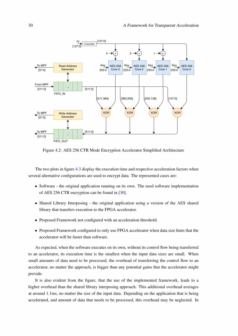
30 A Framework for Transparent Acceleration
...
FIFO_IN
From MPF
Read AddressGenerator
To MPF
[511:0] [511:0]
[511:384] [383:256] [255:128] [127:0]
...
FIFO_OUT
[511:0]To MPF
Write AddressGenerator
To MPF
[57:0]
[57:0]
[511:0]
AES 256Core 3
AES 256Core 2
AES 256Core 1
AES 256Core 0
XOR XORXORXOR
Counter
Key255:0
Key255:0
Key255:0
Key255:0
IV [127:0]
[127:0]
+ + +123
Figure 4.2: AES 256 CTR Mode Encryption Accelerator Simplified Architecture
The two plots in figure 4.3 display the execution time and respective acceleration factors when
several alternative configurations are used to encrypt data. The represented cases are:
• Software - the original application running on its own. The used software implementation
of AES 256 CTR encryption can be found in [30].
• Shared Library Interposing - the original application using a version of the AES shared
library that transfers execution to the FPGA accelerator.
• Proposed Framework not configured with an acceleration threshold.
• Proposed Framework configured to only use FPGA accelerator when data size hints that the
accelerator will be faster than software.
As expected, when the software executes on its own, without its control flow being transferred
to an accelerator, its execution time is the smallest when the input data sizes are small. When
small amounts of data need to be processed, the overhead of transferring the control flow to an
accelerator, no matter the approach, is bigger than any potential gains that the accelerator might
provide.
It is also evident from the figure, that the use of the implemented framework, leads to a
higher overhead than the shared library interposing approach. This additional overhead averages
at around 1.1ms, no matter the size of the input data. Depending on the application that is being
accelerated, and amount of data that needs to be processed, this overhead may be neglected. In

4.2 Case Studies 31
0 0.5 1 1.5 2 2.5Data Size (bytes) 105
0
1
2
3
4
5
6
7
8
9
10
11A
vera
ge E
xecu
tion
Tim
e (n
secs
)106
FPGA Shared Library InterposingFPGA Proposed MechanismFPGA + Software Proposed MechanismSoftware
(a) Average Execution Time vs. Data Size
0 0.5 1 1.5 2 2.5Data Size (bytes) 105
0
1
2
3
4
5
6
Ave
rage
Acc
eler
atio
n
FPGA Shared Library InterposingFPGA Proposed MechanismFPGA + Software Proposed Mechanism
(b) Average Acceleration vs. Data Size
Figure 4.3: AES 256 CTR Encryption Average Execution Time and Acceleration for DifferentData Sizes
this case, it is worthwhile to transfer the execution to the FPGA when data sizes are over 40KB
and shared library interposing is being used, and the same can only be said when data sizes are
over 70KB in the case of the proposed framework. It is worth noticing that if the original software
ran faster, these thresholds would become further apart from each other, and the additional over-
head of the proposed mechanism would be much more noticeable. If the software was slower, the
overhead would have less impact.
When a threshold over which the FPGA is used is chosen wisely, in this case, that is 32500
bytes, a lower penalty has to be paid for using this framework when small data sizes are used.
Although the AES encryption is completely computed in software, the mechanism continues to
introduce some overhead. This value was chosen empirically in order to begin using the FPGA as
soon as it was worth it when raising the data size.
A sudden additional overhead can be observed when the FPGA is being used to encrypt more
than 125KB of data. This is noticeable both when the proposed mechanism is used as well as
when it is not. The exact reason that causes this phenomenon to occur is unknown, but it is
possibly related to the memory access mechanism. As this threshold is almost half of the size of
the CPU level 2 cache, which has 256KB, and the level 2 cache is the one that the FPGA connects
to, the additional delay might be related to cache management. Further investigation would be
required in order to know for sure.
Another measurement that was performed was the time the injection takes to complete. The
target application is stopped while the injection is taking place, which may or may not be relevant.
The average injection time in this example was measured at 15,3 ms. This amount of time will
probably not affect the application in any negative way unless the application is subject to hard

32 A Framework for Transparent Acceleration
real-time constraints. It is unlikely that real-time applications, which could be affected by an
additional delay of about 15ms, would be running over Linux, but if indeed that is the case, the
time at which the injection phase takes place could become a concern.
4.2.2 Case 2 - Matrix Multiplication
The other example accelerator that was implemented is a matrix multiplication accelerator. Matrix
multiplication is used in a wide array of scientific applications, such as simulations, image and
signal processing, optimization problems, among many others.
In this example, the CSRs which the software uses to transfer input data to the accelerator
are depicted in table 4.3. This accelerator expects matrix A to be stored in row-major order and
matrix B in column-major order. This was a design decision taken with the goal of reducing
design complexity. Expecting the input matrices to be stored this way allowed the accelerator to
be designed faster.
Table 4.3: CSRs of Matrix Multiplication Accelerator
Address Function0 Virtual address of input matrix A1 Virtual address of input matrix B2 Virtual address of output matrix C3 Run signal4 M - number of lines of matrix A5 N - number of columns of matrix B6 K - number of columns of matrix A and lines of matrix B
The software-only implementation used for this comparison is CBLAS. This is a C implemen-
tation of the Basic Linear Algebra Subprograms, which provides a large collection of routines
oriented at vector and matrix operations. There are several levels of these routines, the first level
containing scalar and vector operations, the second matrix-vector operations and the third matrix-
matrix operations. The third level routine SGEMM (Single precision floating General Matrix
Multiply) allows the computation expressed in 4.1 and is the one used as the software version.
SGEMM : C = αAB+βC (4.1)
The software routine which is accelerated has more functionality than the example accelerator,
allowing the result of the multiplication to scaled by a factor of α and to be added to a β -scaled
version of the output matrix. It also allows specifying the order in which each matrix is stored,
which is important so that matrix A can be fed in row-major and B in column-major order. In this
example, the SGEMM routine is only used with α set to 1 and β to 0.
The architecture of this accelerator follows the same pattern as the previous example. Data is
requested using an address generator, which sequentially requests the appropriate addresses from

4.2 Case Studies 33
...
FIFO_IN_BFrom MPF
Read AddressGenerator
To MPF
[511:0]
...
FIFO_OUT
To MPF
Write AddressGenerator
To MPF
[57:0]
[57:0]
[511:0]
...
FIFO_IN_A[511:0]
[511:0]
MAC MAC MAC MAC...x16
+ +...x8
+ +...x4
+ +
+
[511:0]
[511:0]
[31:0]
Figure 4.4: Matrix Multiplication Accelerator Simplified Architecture
matrix A and B. In this case, data is stored in two separate input buffers, one for each of the
matrices. This data is then fed into the hard single-precision floating point units of the Arria 10
FPGA. Several levels of these units were used. The first consists of sixteen multiply-accumulate
units which multiply elements from both input matrices and accumulate with previous results until
the end of a matrix line is reached. The outputs of these units are connected into other levels of
floating point units, but this time they are adders. Together they form an adder tree. The result
of the addition of the outputs of all multiplication units is then stored in an output buffer, and
later a write request to a position in the output matrix is sent with that result. The described
architecture is represented in figure 4.4. Such as it was the case with the AES encryption example,
this accelerator expects the input data to always be a multiple of the cache line size. In this case
that is 512 bits, which corresponds to 16 single-precision floating point values. It is important
to notice that this accelerator was designed only as an example to be used while evaluating the
performance of the control flow transfer mechanism implementation. It is definitely possible to
design a much more efficient matrix multiplication accelerator. One possible way to improve the
performance of the accelerator would be to use a blocked algorithm which can significantly reduce
the penalties incurred while accessing memory which is not cached. This is the case because
matrix multiplication uses the same data multiple times, which does not happen with the AES
encryption example that simply needs the data the be read and written sequentially.
In this example, the same MPF configuration was used, with VTP and ROB enabled. The
same version of VTP was also used, which means this accelerator implementation suffers from

34 A Framework for Transparent Acceleration
0 200 400 600 800 1000Square Matrix Size (N*N)
103
104
105
106
107
108
109
Ave
rage
Exe
cutio
n T
ime
(nse
cs)
FPGA Shared Library InterposingFPGA Proposed MechanismFPGA + Software Proposed MechanismSoftware
(a) Average Execution Time vs. Square Matrix Size
0 200 400 600 800 1000Square Matrix Size (N*N)
0
0.2
0.4
0.6
0.8
1
1.2
1.4
Ave
rage
Acc
eler
atio
n
FPGA Shared Library InterposingFPGA Proposed MechanismFPGA + Software Proposed Mechanism
(b) Average Acceleration vs. Square Matrix Size
Figure 4.5: Matrix Multiplication Average Execution Time and Acceleration for Different SquareMatrix Sizes
the same limitation. That is, all the buffers that are accessed by the FPGA must be virtual-page
aligned by the software application so that the injected code can easily pin them for FPGA access.
The two plots in figure 4.5 were obtained in a fashion very similar to the ones presented for the
AES encryption example. Execution time and respective acceleration values were measured for
several implementations that match the ones in AES encryption, but now for matrix multiplication.
Squared input matrices were used in all measured runs.
Although the curves are very distinct from the previous example, the important aspects related
to the relationship between the different alternatives, are the same. As expected, software contin-
ues to be the fastest alternative when small matrices, up until 256 by 256, are used. From that point
on, multiplying the matrices on the FPGA is faster. The use of the proposed mechanism continues
to introduce a measurable overhead when compared with shared library interposing. In this exam-
ple, that overhead is about 0.6 ms, almost half of the one measured in the AES encryption example.
This means that the overhead introduced by the proposed mechanism can vary considerably.
In this example, setting a threshold for the accelerator to be used also improves the perfor-
mance of the framework when small matrix sizes are being multiplied. Due to the overhead intro-
duced by the mechanism, the optimal threshold is not 256 by 256 matrix size, but even earlier at
160 by 160. This value was also empirically discovered.
Just as in the previous example, the time injection takes to complete was also measured. In this
example, it was measured at 16,8 ms. This represents a rise of 9,8%, but the overhead introduced
continues to be negligible unless in an uncommon real-time application. This rise in injection time
is thought to be caused by factors not directly related to the injection of code, such as operating
system tasks.

Chapter 5
Conclusions and Future Work
5.1 Conclusions
This work had the goal of researching transparent control flow transfer mechanisms, particularly
those applicable to HPC platforms, as the new Intel Xeon+FPGA. To achieve this goal, a new
mechanism was proposed, which harnesses the power of ptrace, to take complete control over an
application and transparently transfer its execution to an accelerator.
The proposed mechanism was implemented and its performance quantified while running on
real hardware, a Xeon+FPGA platform provided by Intel. The results obtained during the course
of this research, clearly show that ptrace could be used to implement a transparent control flow
transfer mechanism without some of the limitations that previous mechanisms present. Shared
library interposing was the most promising idea that was previously proposed, but suffered from
the limitation of only being able to be applied to hot spots inside shared library functions. It was
demonstrated that the mechanism proposed by this work is applicable to other types of functions,
such as local or static library ones.
Several downsides were also identified in the proposed mechanism. For one, the approach is
extremely architecture dependent, but this could be worked around by adding dedicated support
for multiple architectures. Another is that it inhibits the possibility of debugging the software
being accelerated. This could not be a problem as acceleration could be turned off to allow for
application debugging. On top of this, and maybe the worst disadvantage of the proposed mech-
anism is the overhead penalty that its use implies. This overhead could or could not be important
depending on the specific situation at hand. On the evaluated examples, this additional overhead
reached 1.1ms, but could certainly reach higher values while accelerating different applications or
running on different hardware. Only knowing how much time is spared by using a specific accel-
erator can this overhead be considered negligible or harmful. For example, on applications that
when ran on an accelerator, have their execution time reduced by several seconds, this mechanism
will be worth using. It is worth noting that HPC applications usually have a high running time, or
else HPC would not be used.
35

36 Conclusions and Future Work
5.2 Future Work
Taking into account the place where this work is left off, the following tasks are recommended as
the next important steps towards practical transparent control flow transfer:
• Further characterize the proposed framework and mechanism. This work found that the
overhead introduced by the proposed mechanism can vary from as low as 0.6 ms to as much
as 1.1 ms. It is important to research how much this overhead can vary by applying it to
other applications.
• Incorporate transparent binary profiling, tracing and accelerator configuration tools into the
current framework. This task would result in a complete transparent acceleration framework
which could allow applications to be accelerated without any human intervention aside from
choosing to enable the framework in the first place.
• Add support for multi-threaded applications. The proposed framework only supports single-
threaded applications, which is a significant limitation given that nowadays most applica-
tions are composed of multiple threads. Adding this feature would allow each thread to use
different available accelerators and eventually would also allow several threads to share the
same accelerator.
• Improve the framework by adding support for hot spots to be any generic block of code.
This would increase the complexity of the mechanism but it would no more be limited to
accelerate hot spots that are inside functions. For example, a lengthy loop running outside
of any function could also be transparently accelerated. This would also heavily rely on the
capabilities of the transparent binary profiling tool.
• Integrate a scheduling mechanism which could reconfigure available accelerators when cer-
tain configurations are expected to be needed.
The implementation developed during the course of this research is only a proof of concept.
Further research is needed in order to achieve a practical implementation of the proposed mecha-
nism.

References
[1] Elie Track, Nancy Forbes, and George Strawn. The End of Moore’s Law. Computing inScience and Engineering, 19(2):4–6, 2017. doi:10.1109/MCSE.2017.25.
[2] M. Mitchell Waldrop. More Than Moore, 2016. Last accessed: 2019-02-18. URL: https://www.nature.com/news/the-chips-are-down-for-moore-s-law-1.19338, arXiv:Nature,2016,530(7589):144., doi:10.1038/530144a.
[3] Barb Darrow. Intel’s $16.7 Billion Purchase of Altera Is Official, 2015.Last accessed: 2019-02-02. URL: http://fortune.com/2015/12/28/intel-completes-altera-acquisition/.
[4] Amazon. Amazon EC2 F1 Instances, 2017. Last accessed: 2019-03-24. URL: https://aws.amazon.com/ec2/instance-types/f1.
[5] Silvia Gianelli. Baidu Deploys Xilinx FPGAs in New Pub-lic Cloud Acceleration Services, 2017. Last accessed: 2019-01-25. URL: https://www.xilinx.com/news/press/2017/baidu-deploys-xilinx-fpgas-in-new-public-cloud-acceleration-services.html.
[6] Xilinx. Huawei, Alibaba and Inspur Announce Xilinx Solutions forChina’s Data Centers, 2018. Last accessed: 2019-02-02. URL:https://forums.xilinx.com/t5/Xilinx-Xclusive-Blog/Huawei-Alibaba-and-Inspur-Announce-Xilinx-Solutions-for-China-s/ba-p/899427.
[7] Jeremy Fowers, Greg Brown, Patrick Cooke, and Greg Stitt. A performance and energycomparison of FPGAs, GPUs, and multicores for sliding-window applications. In FPGA’12 Proceedings of the ACM/SIGDA international symposium on Field Programmable GateArrays, pages 47–56, 2012. doi:10.1145/2145694.2145704.
[8] Prabu Thiagaraj, Benjamin Stappers, Jayanta Roy, Michael Keith, and Mitchell Mick-aliger. FPGA processing for High Performance Computing, 2015. Last ac-cessed: 2019-04-03. URL: https://emit.tech/wp-content/uploads/2015/10/EMiT2015_Thiagaraj.pdf.
[9] Frank Vahid, Greg Stitt, and Roman Lysecky. Warp processing: Dynamic translation ofbinaries to FPGA circuits. Computer, 41(7):40–46, 2008. doi:10.1109/MC.2008.240.
[10] Shantanu Gupta, Shuguang Feng, Amin Ansari, Scott Mahlke, and David August. Bundledexecution of recurring traces for energy-efficient general purpose processing. Proceedings
37

38 REFERENCES
of the 44th Annual IEEE/ACM International Symposium on Microarchitecture - MICRO-44 ’11, page 12, 2011. URL: http://dl.acm.org/citation.cfm?doid=2155620.2155623, doi:10.1145/2155620.2155623.
[11] Nuno Paulino, João Canas Ferreira, and João M.P. Cardoso. Architecture for transparent bi-nary acceleration of loops with memory accesses. In Lecture Notes in Computer Science (in-cluding subseries Lecture Notes in Artificial Intelligence and Lecture Notes in Bioinformat-ics), volume 7806 LNCS, pages 122–133, 2013. doi:10.1007/978-3-642-36812-7_12.
[12] Takaaki Miyajima, David Thomas, and Hideharu Amano. A Toolchain for Dynamic Func-tion Off-load on CPU-FPGA Platforms. Journal of Information Processing, 23(2):153–162,2015. doi:10.2197/ipsjjip.23.153.
[13] Philip W. Diodato, Jonathan A. Fields, Mark E. Thierbach, and Mean Sea Tsay. The Designof an IEEE Standard Math Accelerator Unit. IEEE Journal of Solid-State Circuits, 1985.doi:10.1109/JSSC.1985.1052426.
[14] M. Ernst, B. Henhapl, S. Klupsch, and S. Huss. FPGA based hardware acceleration forelliptic curve public key cryptosystems. Journal of Systems and Software, 70(3):299–313,2004. doi:10.1016/S0164-1212(03)00075-X.
[15] Yangsu Kim, Kyuseung Han, and Kiyoung Choi. A Host-Accelerator Communication Ar-chitecture Design for Efficient Binary Acceleration. International SoC Design Conference,pages 361–364, 2011. doi:10.1109/ISOCC.2011.6138785.
[16] Tobias Beisel, Manuel Niekamp, and Christian Plessl. Using shared library interposing fortransparent application acceleration in systems with heterogeneous hardware accelerators.Proceedings of the International Conference on Application-Specific Systems, Architecturesand Processors, pages 65–72, 2010. doi:10.1109/ASAP.2010.5540798.
[17] Mingjie Lin, Shaoyi Chen, Ronald F. Demara, and John Wawrzynek. ASTRO: Synthesiz-ing application-specific reconfigurable hardware traces to exploit memory-level parallelism.Microprocessors and Microsystems, 39(7):553–564, 2015. URL: http://dx.doi.org/10.1016/j.micpro.2015.03.005, doi:10.1016/j.micpro.2015.03.005.
[18] Timothy Prickett Morgan. A peek inside that Intel Xeon-FPGA hybrid chip, 2018.Last accessed: 2019-02-03. URL: https://www.nextplatform.com/2018/05/24/a-peek-inside-that-intel-xeon-fpga-hybrid-chip/.
[19] Intel Corporation. Acceleration Stack for Intel R© Xeon R© CPU with FPGAs Core CacheInterface (CCI-P) Reference Manual. Technical report, Intel, 2018.
[20] Young-kyu Choi, Jason Cong, Zhenman Fang, Yuchen Hao, Glenn Reinman, and PengWei. A quantitative analysis on microarchitectures of modern CPU-FPGA platforms. Pro-ceedings of the 53rd Annual Design Automation Conference on - DAC ’16, pages 1–6,2016. URL: http://dl.acm.org/citation.cfm?doid=2897937.2897972, doi:10.1145/2897937.2897972.
[21] Enno Luebbers, Song Liu, and Michael Chu. Simplify Software Integrationfor FPGA Accelerators with OPAE (white paper). Last accessed: 2019-02-06. URL: https://01.org/sites/default/files/downloads/opae/open-programmable-acceleration-engine-paper.pdf.

REFERENCES 39
[22] Intel Corporation. Intel FPGA Basic Building Blocks (BBB). Last accessed: 2019-04-21.URL: https://github.com/OPAE/intel-fpga-bbb.
[23] Bryan Lunduke. Linux and Supercomputers, 2018. Last accessed: 2019-06-03. URL:https://www.linuxjournal.com/content/linux-and-supercomputers.
[24] Yama. Last accessed: 2019-04-27. URL: https://www.kernel.org/doc/html/latest/admin-guide/LSM/Yama.html.
[25] João Bispo, Nuno Paulino, João M.P. Cardoso, and João Canas Ferreira. Transparent runtimemigration of loop-based traces of processor instructions to reconfigurable processing units.International Journal of Reconfigurable Computing, 2013, 2013. arXiv:NIHMS150003,doi:10.1155/2013/340316.
[26] Evan Klitzke. Using Ptrace For Fun And Profit, 2016. Last accessed: 2019-03-05. URL:https://eklitzke.org/ptrace.
[27] M J Dworkin. Recommendation for block cipher modes of operation. Technical re-port, NIST, 2007. URL: https://nvlpubs.nist.gov/nistpubs/Legacy/SP/nistspecialpublication800-38c.pdf, doi:10.6028/NIST.SP.800-38c.
[28] Homer Hsing. AES Core, 2013. Last accessed: 2019-03-19. URL: https://opencores.org/projects/tiny_aes.
[29] Joe Olivas, Mike Chynoweth, and Tom Propst. Benefitting Power and Performance SleepLoops, 2015. Last accessed: 2019-06-22. URL: https://software.intel.com/en-us/articles/benefitting-power-and-performance-sleep-loops.
[30] Kokke. tiny-AES-c, 2019. Last accessed: 2019-05-20. URL: https://github.com/kokke/tiny-AES-c.