Certification of FPGAs - Current Issues and Possible Solutions
17
Certification of FPGAs - Current Issues and Possible Solutions Iain Bate, Philippa Conmy SSEI Research Group, Department of Computer Science, University of York, Heslington, N Yorks., UK Abstract This paper looks at possible applications of Field Programmable Gate Arrays (FPGAs) within the safety critical domain. We examine the potential bene- fits these devices can offer, such as parallel computation and reconfiguration in the presence of failure and also the difficulties which these raise for certification. A possible safety argument supporting the use of basic reconfiguration facilities of PGA to remove Single Event Upsets (SEUs) is presented. We echnique which has the potential to be used to identify areas which are sensitive to SEUs in terms of safety effect, thus allowing optimisation a reprogrammable F also demonstrate a t 1 Introduction of an FPGAs design and supporting our argument. Programmable logic devices such as FPGAs are being increasingly used in the high-integrity and safety-critical domains. However, at present there is a lack of consensus of how FPGAs can be safely deployed and certified. One issue is whether the device should be treated as hardware or software during the certifica- tion process. Another issue is the difficulty in determining the safety effect of Sin- gle Event Upsets, leading to cautious and pessimistic design decisions. In addition, advanced features of FPGAs such as parallelism and reconfiguration in the pres- ence of failure (available on some of the devices) are not being fully exploited. This paper aims to highlight and discuss some of these difficulties and offers po- tential solutions, either using existing methods or via further research. This paper is laid out as follows: Section 2 provides an overview of FPGA fea- tures and possible scenarios for use, Section 3 describes safety and certification is- sues relating to FPGA use, Section 4 presents fragments of a safety argument for the use of cell scrubbing (the most basic form of reconfiguration) and a failure analysis technique which can be used to support that argument, Section 5 presents related work and Section 6 presents conclusions. 2 Overview of FPGA Features There are numerous different types of FPGA currently available from many manu- facturers. In order to avoid confusion this section describes what is meant by the term FPGA for the purposes of this paper. An FPGA is a programmable logic board. At its heart it may have hundreds of thousands of individual logic cells,
-
Upload
independent -
Category
Documents
-
view
3 -
download
0
Transcript of Certification of FPGAs - Current Issues and Possible Solutions

Certification of FPGAs - Current Issues and Possible Solutions
Iain Bate, Philippa Conmy
SSEI Research Group, Department of Computer Science, University of York,
Heslington, N Yorks., UK
Abstract This paper looks at possible applications of Field Programmable Gate Arrays (FPGAs) within the safety critical domain. We examine the potential bene-fits these devices can offer, such as parallel computation and reconfiguration in the presence of failure and also the difficulties which these raise for certification. A possible safety argument supporting the use of basic reconfiguration facilities of
PGA to remove Single Event Upsets (SEUs) is presented. We echnique which has the potential to be used to identify areas
which are sensitive to SEUs in terms of safety effect, thus allowing optimisation
a reprogrammable Falso demonstrate a t1 Introduction
of an FPGAs design and supporting our argument. Programmable logic devices such as FPGAs are being increasingly used in the high-integrity and safety-critical domains. However, at present there is a lack of consensus of how FPGAs can be safely deployed and certified. One issue is whether the device should be treated as hardware or software during the certifica-tion process. Another issue is the difficulty in determining the safety effect of Sin-gle Event Upsets, leading to cautious and pessimistic design decisions. In addition, advanced features of FPGAs such as parallelism and reconfiguration in the pres-ence of failure (available on some of the devices) are not being fully exploited. This paper aims to highlight and discuss some of these difficulties and offers po-tential solutions, either using existing methods or via further research.
This paper is laid out as follows: Section 2 provides an overview of FPGA fea-tures and possible scenarios for use, Section 3 describes safety and certification is-sues relating to FPGA use, Section 4 presents fragments of a safety argument for the use of cell scrubbing (the most basic form of reconfiguration) and a failure analysis technique which can be used to support that argument, Section 5 presents related work and Section 6 presents conclusions.
2 Overview of FPGA Features
There are numerous different types of FPGA currently available from many manu-facturers. In order to avoid confusion this section describes what is meant by the term FPGA for the purposes of this paper. An FPGA is a programmable logic board. At its heart it may have hundreds of thousands of individual logic cells,

2
which can be connected and programmed to perform many different computa-tional tasks. Data is typically input and output via I/O blocks on the edge of the cells (see Fig. 1). Some FPGAs employ Antifuse devices on interconnects, and some use Static random access memory (SRAM). Antifuse routing devices can only be programmed once, whereas SRAM is reprogrammable. Antifuse devices are smaller, and so offer more routing flexibility than SRAM. They are also less susceptible to Single Event Upset (SEU) failures (Nallatech Ltd. 2002). However, any errors that occurred during configuration cannot be fixed in an Antifuse de-vice and the logic cells are still at risk from SEUs.
I/O Block
I/O Block
μprocessor
I/O B
lock
I/O B
lock
Fig. 1. Simplified example of FPGA physical architecture.
Some FPGAs may include additional dedicated devices such as static memory, multipliers and even traditional sequential microprocessors. This assists with tasks that the FPGA hardware is not well suited for. It also means that an FPGA can be used for multiple tasks (e.g. using the microprocessor for one system and the FPGA logic cells for another), thus reducing overall requirements for equipment, power and also costs.
In order to configure an FPGA, a developer must first produce an electronics hardware description written in a high level Hardware Description Language (HDL) (such as Handel-C and VHDL). This is converted into a synthesizable form (e.g. a netlist) which will then be transformed by place and route algorithms to de-termine how it will be configured on the FPGA. Note that the term ‘programming’ is sometimes used to describe the FPGA configuration/re-configuration process even though the code is different in nature. [0]Obviously, issues such as source level design, coding and testing need to be considered for the HDL development
3
process, but most software practices are oriented towards traditional sequential programming. HDL descriptions will need to be treated differently in some in-stances, e.g. when considering reasonable coverage metrics for a concurrent pro-gram.
2.1 Possible Applications of FPGAs
There are many possible uses for an FPGA within a safety critical system. Rather than attempt to enumerate all of these, this section lists some templates of use, and some different approaches to the design and configuration of FPGA devices. These are used as a basis for discussions of the potential benefits of FPGAs, con-sequential certification issues and possible solutions. Note that all these designs could be used in combination with one another, for example IP Cores could be used within a highly configurable monitoring device. A further list of possible uses of FPGAs can be found in (Nallatech Ltd. 2002).
2.1.1 Monitoring System
One possible use of an FPGA is as an external monitoring device. For example, the FPGA might monitor the output from a sensor or an application for anomalies. It could also act as a voting unit for a multi-lane application. One advantage of this is that it is conceptually different to a traditional microprocessor so will have dif-ferent failure characteristics to it, thus avoiding some common mode failures.
If an FPGA is used in this way then there are some obvious considerations, such as the failure rate or trustworthiness of the device (who monitors the moni-tor? Is it trusted to take full authority?) and who it should report a failure to.
2.1.2 Legacy Device Simulation
Another possible use of an FPGA is to simulate a legacy micro-processor. This means certified applications and code originally written for an older processor which can no longer be sourced can still be used. Obsolescence is a particular is-sue in the aviation industry where it can be extremely costly and complex to cer-tify and retrofit a new system. Potentially, new applications could also be written for the simulated processor.
However, there are some potential issues with simulation. For example, whilst the execution timing will be predictable it may be slower or different to the origi-nal. Also, an FPGA implementation will have different failure characteristics to the original, and be particularly susceptible to SEUs.

4
2.1.3 Highly Parallel Calculations
FPGAs are by their nature able to perform many parallel computations. This makes them ideally suited for certain types of calculations such as fast Fourier transforms (Choi et al. 2003), at which they perform better than alternatives run-ning on traditional processors (Bondhugula et al. 2006). However, by increasing parallelism, power dissipation is also increased. Therefore methods such as those in (Choi et al. 2003) have been developed in order to try and reduce this.
Another possible form of parallel computing is to have multiple applications running on the device, either within the logic cells or by using the extra peripheral de
cross con-tamination of data and other interference in accessing shared resources.
2.1.4 Reconfigurable Applications
ten-tially increase the robustness of a system to failure and hence enhance safety.
2.1.5 ASIC Replacement
r example is given in (K
vices for other applications. Both of these uses of an FPGA can cause difficulties for a safety analyst. In
terms of failure analysis of a single application with multiple threads potentially running on different types of hardware there are concerns about data and clock synchronisation, as well as some issues of overall complexity. In addition, if mul-tiple applications are sharing the device an analyst will need to consider
Another aspect of FPGAs is that some are re-configurable both prior to operation and during operation (unless they are Antifuse devices). Much research has been undertaken into exploring different types of reconfiguration e.g. (Hanchek and Dutt 1998, Emmert et al. 2000). These papers have a common aim – moving and/or changing the connections between logic cells in order to avoid a broken connection or cell. Many different methods have been proposed with various trade-offs required, such as some cells being set aside as backups and the main functions being paused (missing cycles), if reconfiguration takes place during op-eration. Despite these disadvantages, using dynamic reconfiguration can po
One other use of FPGAs is as an alternative to designing and manufacturing an Application Specific Integrated Circuit (ASIC). An ASIC chip is custom designed for a specific purpose. Using an FPGA in this way is cheaper than manufacturing bespoke chips if only a small volume of chips is required. It is also quicker to pro-duce a working system. One example of this type of use is bespoke processor de-sign such as that described in (Glavinic et al. 2000). Anothe
umar et al. 2006) for a low-cost cipher breaking system. An FPGA suffers from different failures to an ASIC (it has more circuits which
are sensitive to SEUs – see section 3.1). This may be beneficial (as a conceptually

5
different implementation) or disadvantageous (the FPGA may not be as tolerant to certain environmental conditions as an ASIC). A further downside is that the FPGA will be significantly slower than a dedicated ASIC.
2.1.6 Use of IP Cores
design, and analysis required to ensure un-wanted functionality is not triggered.
3 FPGA Safety Analysis and Certification
on-sequence of exploiting potential benefits). We also suggest possible solutions.
3.1 Single Event Upsets
activated. A categorisation of SEUs can be found in (Graham et al. 20
porarily interrupt the normal operation of an FPGA, and Single Event Transients
Semiconductor Intellectual Property Cores (IP Cores) are reusable units of circuit design. These can be used in multiple designs and have the advantage that they provide Off The Shelf (OTS) solutions for many common functions. However, like all OTS solutions there are some disadvantages. Whilst the IP Core netlists are provided, they can be too large to easily assess for failures or unwanted behav-iour. Also the IP Core may not provide the exact functionality required leading to additional work to integrate it into a
The previous section described how FPGAs are configured and gave multiple ex-amples of how they may be deployed, summarising some of the related pros and cons. This section discusses in more detail difficulties that may be encountered when attempting to certify and analyse an FPGA (some of which are a direct c
Single Event Upset (SEU) is the term used to describe a temporary flip in the state of a logic cell. It can be caused by events such as a burst of radiation or by other more gradual physical failures e.g. corrosion (Isaac 2004). A cell affected by an SEU will require resetting or reconfiguring to return it to the desired state. An ex-ample of an SEU might be that one configuration bit for a multiplexer is flipped from 0 to 1. This would mean that the wrong mux output is selected, leading to many possible issues such as the incorrect output at the board level. Another ex-ample might be an SEU within a 4 input LUT. In this situation the incorrect value will only be output for one particular combination of inputs. Thus the error may never be
03). A permanent state error in a logic cell is known as a Single Event Latchup
(SEL), this could be fixed by a power cycle or may ultimately be permanent. Two other events of concern are Single Event Functional Interrupts (SEFI), which tem-

6
(SET), which are brief voltage pulses which may have the same effect as an SEU but the cells revert to their desired state without intervention.
In most cases it is impractical to manually analyse the effect of a single event of any type within an FPGA due to the complexity and size of its internal struc-ture. As a result safety analysis is often performed only on the inputs/outputs of the board and techniques and pessimistic approaches, such as Triple Modular Re-dundancy (TMR), are used to mitigate against possible failures and their effects. This is expensive in terms of cost, weight and power and may not even be neces-sary if the effects are limited (Graham et al. 2003). Therefore, if the impact of an SEU can be more effectively managed (either through better safety analysis or reconfiguration) there are potential savings. In addition it may be possible to use FPGAs for more critical systems.
3.2 Related Standards and Guidance
It is assumed that if an FPGA is to be used in a safety-critical or safety-related sys-tem (e.g. automotive, manufacturing, military, or avionics) it will be, at the very least, subject to some safety analysis to determine how it could contribute to sys-tem hazards. Depending on the domain it may also need to be approved or certi-fied prior to use. One difficulty with an FPGA is determining which guidance or standards are most appropriate to help with this, as it combines both electronic hardware and software features. Therefore guidance for hardware will address is-sues such as hardware reliability and vulnerability to environmental factors, but guidance for software development may be needed to address the depth of rigour needed during the FPGA configuration and design process. A recent online dis-cussion between experts came to no consensus on this issue (HISE Safety Critical Mailing List 2008).
3.2.1. 00-56 (Issue 4)
The U.K. defence standard 00-56 (Ministry of Defence 2007) provides guidelines for managing safety in military systems. The most recent version of this standard requires that an As Low As Reasonably Practicable (ALARP) approach be taken when reducing the risks associated with a safety related and safety critical system. This involves identification of hazards, assessment of their risk and identification of appropriate strategies for risk reduction which are commensurate with that risk. It also requires that a safety case be developed which presents an argument and evidence that safety requirements have been met.
However, as discussed in the previous section the application of common man-ual techniques for identification of hazardous failures (such as Failure Modes and Effects Analysis (FMEA)) to an FPGA is impractical. Hence the risk of some fail-ures may be over estimated. Some internal analysis is highly desirable in order to
7
determine the effect of internal failures. A possible method for performing an FMEA style analysis internally to an FPGA is discussed in section 4. Associated with this is the need to link identified failures back to the system level.
3.2.2 IEC 61508
IEC 61508 (IEC 2000) is a general standard which applies to programmable elec-tronics and electronic devices. Section 2 of the standard is dedicated to hardware, whilst section 3 concentrates on software. Both these sections are applicable for an FPGA, which means that the configuration design process, and all related tools will be subject to the same scrutiny as would be expected for the development of normal software.
3.2.3 DO-254/DO178B
DO-254 (RTCA/EUROCAE 2000) provides guidance on Design Assurance of Airborne Electronic Hardware. DO-178B (RTCA/EUROCAE 1992) provides guidance purely for design assurance of software. These standards are listed to-gether here as, from discussions with industrialists, both are being used to assist in the certification of FPGAs within military systems. They are used either in con-junction or separately. There are two problems with this. Firstly, there is no con-sensus as to the most appropriate guidance to use, or combination thereof. Sec-ondly, these are often used (in the authors’ opinion) erroneously in the assumption that they are appropriate replacements for the now superseded military standard 00-54 (Ministry of Defence 1999) which applied to programmable electronics. The idea behind their use is to support a 00-56 style safety case with evidence gathered using the recommended processes in the DO-254/DO-178B guidance. However, using these standards would not assist with the ALARP risk assessment process required by 00-56. The DO-254 and DO178B Design Assurance Level (DAL) assignments are based on assessments of affect to the workload on flight crew and to the safety of occupants (passengers), generally an inappropriate as-sessment for a military situation. The level of rigour and processes applied to the software/hardware is based on the DAL. Therefore, at the very least, a reinterpre-tation of the DAL assignment guidance would be needed to help satisfy 00-56 re-quirements.
3.2 Tools and Languages
As discussed earlier, the tools used during the FPGA configuration process will need to be demonstrated to be fit for purpose. Section 2 described the process used to turn an HDL file into a configuration file for use on an FPGA. The tools used to
8
convert the HDL into a netlist are comparable to a compiler in how they behave, therefore compiler guidance is applicable.
Place and route tools take the netlist and will link sections together in order to meet particular performance criteria. This can mean a lot of trade-offs between different criteria such as power dissipation, timing, and the ability to reconfigure certain sets of cells. It is difficult to provide a single re-usable argument to demon-strate that the algorithms used for place and route will always provide an optimal solution, since techniques such as Genetic Algorithms (GAs) can be used. These will attempt to meet a set of criteria (described as a fitness function) and use ran-domisation during their application. They are designed to simply reach a solution, rather than the best solution. Hence an approach for demonstrating the place-and-route has been applied successfully would be to demonstrate that the output is ac-ceptable on a case by case basis. This can be done statically by resource analysis, using well established methods.
Depending on the behaviour or trustworthiness of the compiler or language it may be necessary to make restrictions on HDL constructs used, similar to a pro-gramming language subset. One aspect to this is to avoid certain coding constructs which may be ambiguously defined in the language standard and hence there is no guarantee of how a compiler will behave when it is used. Another aspect is to avoid constructs which are often the cause of errors, for example using an assign-ment statement in an ‘if’ statement, using dynamic memory, or using a variable before it has been initialised. Further examples of features which make verifica-tion difficult can be found in (Ada HRG Group 1998), this study led to subsets such as SPARK Ada and Ravencpar, and many of the findings are relevant to HDL constructs.
Some work on HDL restrictions has been undertaken e.g. (Stepney 2003, Isaac 2004) but these are not routinely being used during FPGA development. The Alli-ance CAD tool, which uses a VHDL subset, has been used to design a predictable hard real-time processor (Glavinic et al. 2000). This tool was said by the authors to significantly impact on the way they had to design and implement their soft-ware. Therefore it would seem there are legitimate concerns as to how the use of a sub-set would impact FPGA development.
3.3 Lack of Exploitation
Section 2 listed some of the potential uses and benefits of FPGAs. Unfortunately some of these are not being exploited fully due to difficulties during certification. This paper concentrates mainly on the ability to reconfigure an SRAM based FPGA when a failure such as an SEU or broken interconnect is found. This is potentially very powerful, as the safety of the containing system could be better guaranteed, e.g. even in inhospitable conditions which lead to an increased risk of SEUs such as high altitude. There are a few difficulties with using it in a safety-critical device though. First, certification guidance tends to recommend analysis
9
processes which are suitable only for a static configuration, i.e. it is assumed that the structure and layout of the logic cells does not change. There is a (reasonable) fear that re-arranging the interconnects or moving logic to different cells would mean performance requirements are no longer met and potentially hazardous failures are introduced. Second, during a reconfiguration the output from the FPGA device may be interrupted, at least for portions of the device, thus potentially interupting a stream of safety critical data. Finally, once a reconfiguration has taken place there is an issue of ensuring the restarted application is in sync with current input data and other lanes.
There are a few possible ways to ensure safe operation whilst still using reconfiguration. First, reconfiguration need not necessarily mean complex reconnections and movements of cells. At the most basic level ‘scrubbing’ can be used, in other words resetting and reloading an FPGA with the same data to ensure SEUs are removed. A combination of scrubbing and TMR, in which only one lane at a time is scrubbed, can provide an uninterrupted service whilst also protecting against SEUs (Garvie and Thompson 2004). Another alternative is that only a few different static configurations are permitted to be used, and each of these is analysed separately, as is the reconfiguration process. However, given that it is currently difficult to analyse a single configuration internally this may be time consuming. The semi-automated technique discussed in section 4 provides one potential method to assist.
Finally, the incidence rate of SEUs needs to be addressed. In terms of estimating the occurrence of SEUs, a sceptical approach is suggested by (Isaac 2004): ‘As a general rule, the System Safety Engineer should assume these devices only have a reliability of 1x10⁻⁴
(best case from a safety viewpoint) when performing safety analyses. If this is not assumed, then the higher reliability num-ber (e.g. 1x10-24) will be used by program management’. However, this is based on the difficulty in assessing the effect of an SEU, and as discussed in section 3.1, an SEU may not cause a failure or have a safety effect even if it occurs. If better analysis and more mitigating strategies during coding were available a pessimistic stance may not be required. It is of note that work such as (Kowalski et al. 2005, Morgan 2006) has shown that the incidence of SEUs in trials is relatively low.
4 Possible Solutions
used to assess the affects of SEUs, thus underpinning one strand of the argument.
This section first describes a safety argument fragment which could be used to demonstrate that scrubbing cells to mitigate against SEUs is acceptably safe within a suitable system. Then we describe the type of analysis which could be
10
4.1 Safety Argument for SRAM FPGA Scrubbing
Section 3.3 noted that there is a lack of exploitation of the reconfiguration ability of SRAM FPGAs (Antifuse FPGAs do not support this). Reconfiguration can range from simple scrubbing (resetting of logic blocks) to complex on the fly al-terations of interconnects and movement of logic. This paper only examines the former as a starting point for exploitation, but a future aim is to look at complex reconfiguration due to its potential for providing greater safety support, particu-larly in situations where a system is in a highly degraded state, e.g. due to battle damage.
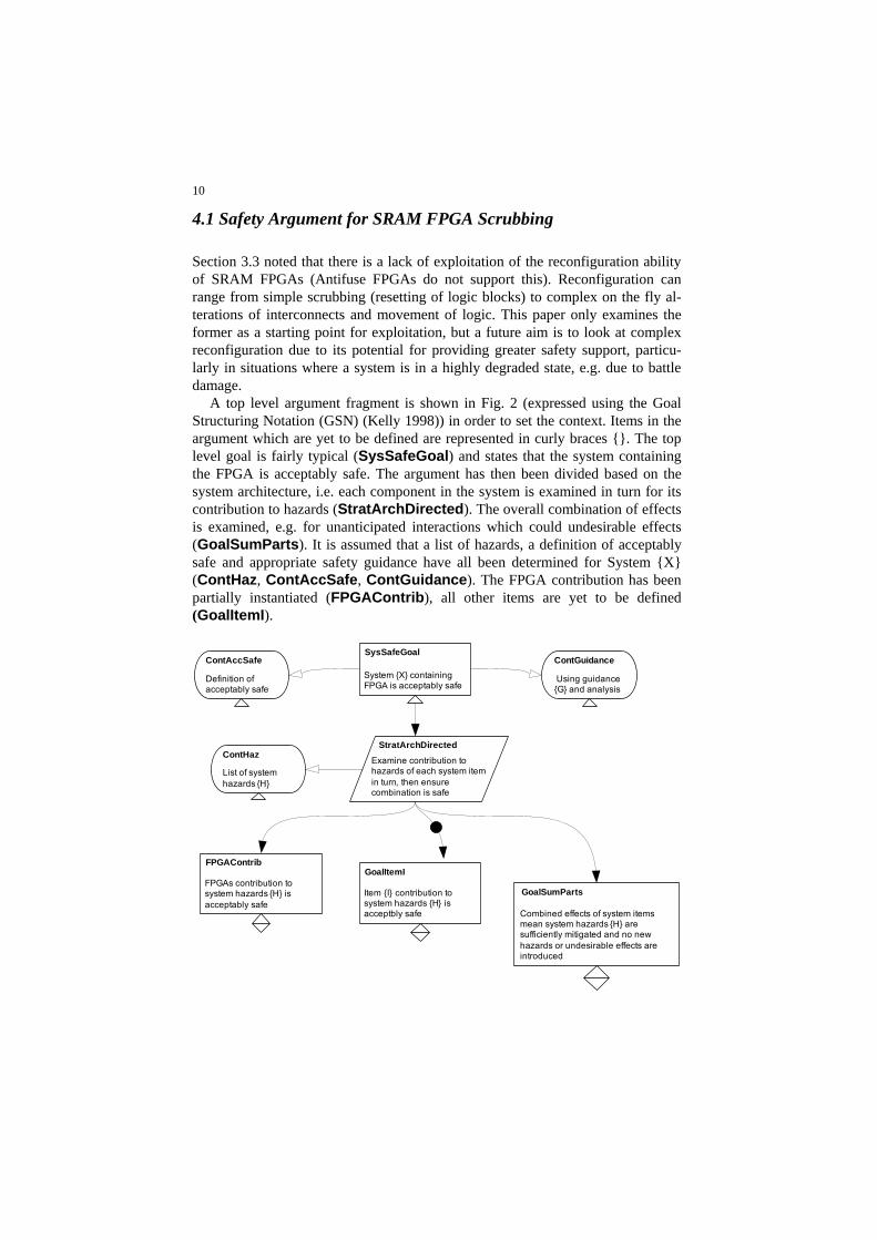
A top level argument fragment is shown in Fig. 2 (expressed using the Goal Structuring Notation (GSN) (Kelly 1998)) in order to set the context. Items in the argument which are yet to be defined are represented in curly braces {}. The top level goal is fairly typical (SysSafeGoal) and states that the system containing the FPGA is acceptably safe. The argument has then been divided based on the system architecture, i.e. each component in the system is examined in turn for its contribution to hazards (StratArchDirected). The overall combination of effects is examined, e.g. for unanticipated interactions which could undesirable effects (GoalSumParts). It is assumed that a list of hazards, a definition of acceptably safe and appropriate safety guidance have all been determined for System {X} (ContHaz, ContAccSafe, ContGuidance). The FPGA contribution has been partially instantiated (FPGAContrib), all other items are yet to be defined (GoalItemI).
SysSafeGoal
System {X} containing FPGA is acceptably safe
StratArchDirected
Examine contribution to hazards of each system item in turn, then ensure combination is safe
ContGuidance
Using guidance {G} and analysis
ContAccSafe
Definition of acceptably safe
ContHaz
List of system hazards {H}
GoalItemI
Item {I} contribution to system hazards {H} is acceptbly safe
GoalSumParts
Combined effects of system items mean system hazards {H} are sufficiently mitigated and no new hazards or undesirable effects are introduced
FPGAContrib
FPGAs contribution to system hazards {H} is acceptably safe
11
Fig. 2. Top level argument.
FPGAReconfigSEU
Effect and incidence of SEUs is acceptably safe
FPGASEL
Existing SELs (permanent faults) have been detected prior to FPGA deployment and have been avoided during place and route
SEUSigDet
Significant SEUs (i.e. those with safety effect) have been determined
SEUOnlineDet
Locations affected by significant SEUs are monitored online.
SEUScrubTolerance
System can tolerate SEU between time of incidence to time of fix.
ScrubSafe
Scrubbing routine is acceptably safe
SELNew
New SELs (permanent faults) occur with acceptable incidence rate, are reported and process is in place to mitigate against their effect
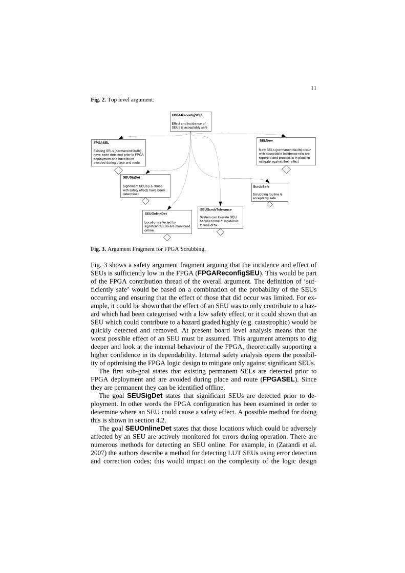
Fig. 3. Argument Fragment for FPGA Scrubbing.
Fig. 3 shows a safety argument fragment arguing that the incidence and effect of SEUs is sufficiently low in the FPGA (FPGAReconfigSEU). This would be part of the FPGA contribution thread of the overall argument. The definition of ‘suf-ficiently safe’ would be based on a combination of the probability of the SEUs occurring and ensuring that the effect of those that did occur was limited. For ex-ample, it could be shown that the effect of an SEU was to only contribute to a haz-ard which had been categorised with a low safety effect, or it could shown that an SEU which could contribute to a hazard graded highly (e.g. catastrophic) would be quickly detected and removed. At present board level analysis means that the worst possible effect of an SEU must be assumed. This argument attempts to dig deeper and look at the internal behaviour of the FPGA, theoretically supporting a higher confidence in its dependability. Internal safety analysis opens the possibil-ity of optimising the FPGA logic design to mitigate only against significant SEUs.
The first sub-goal states that existing permanent SELs are detected prior to FPGA deployment and are avoided during place and route (FPGASEL). Since they are permanent they can be identified offline.
The goal SEUSigDet states that significant SEUs are detected prior to de-ployment. In other words the FPGA configuration has been examined in order to determine where an SEU could cause a safety effect. A possible method for doing this is shown in section 4.2.
The goal SEUOnlineDet states that those locations which could be adversely affected by an SEU are actively monitored for errors during operation. There are numerous methods for detecting an SEU online. For example, in (Zarandi et al. 2007) the authors describe a method for detecting LUT SEUs using error detection and correction codes; this would impact on the complexity of the logic design

12
however. Another common method is to use replication (e.g. TMR) and compare results. As discussed earlier, TMR can be a crude and expensive method for miti-gating against SEUs, hence our suggestion that detection is only targeted at areas of concern. Similarly, if the design has to be made more complex in order to de-tect SEUs it would be sensible to only apply design changes on areas of concern. Note also that SEU significance would need to be re-assessed on any altered logic, i.e. throughout the design process.
The goal SEUScrubTolerance refers to the ability of the system to cope with an SEU from the time of its occurrence until it is fixed. This includes opera-tion from the moment the SEU occurs, its detection, and also a pause in operation whilst the scrubbing routines are run. Note beneath this goal there would need to be evidence of an assessment of the likelihood of SEUs offset against the time taken to fix it.
The goal ScrubSafe examines the scrubbing mechanisms and ensures they are acceptably safe. In other words, the scrubbing routines do not introduce further faults and do remove SEUs.
Finally, it is possible for a SEL to develop in an FPGA system after deploy-ment (SELNew). If one is discovered (either during operation or during a mainte-nance check) then a new logic configuration may be required in order to avoid it, i.e. a new place and route. At present we assume that this type of reconfiguration would be determined offline, even though in principle reconfiguration could be used online. As the argument stands, evidence supporting FPGASEL, SEUOnlineDet and SEUSigDet would need to be renewed if new permanent faults were found, but the other strands of the argument should not be affected.
One concern is that a SEL develops and the FPGA repeatedly runs scrubbing routines to no effect, interrupting operation. In addition it is possible that a SET could trigger the scrubbing routines unnecessarily. The monitor system could be optimised to detect these issues, although there is the concern that this could also be affected by an SEU!
It is possible that no significant SEUs are found. In this ideal situation no scrubbing routines would be required, and hence the related goals would not be needed.
4.2 Failure Analysis of FPGA circuits
This paper has advocated the use of internal analysis of an FPGA in order to de-termine the safety impact and significance of SEUs, however the internal logic of a configured FPGA is extremely large and complex. One semi-automated method of performing safety analysis which may assist is FPTC. This technique annotates design components with failures and assesses how they affect other components (Wallace 2005). Each component can either be a source of a failure, propagate a failure (i.e. pass it on), transform a failure (e.g. a late failure on input may lead to an omission on output), or be a failure sink (i.e. it has no output effect). In order to

13
use this method each component has to be considered in turn as to how it would respond to a set of input failures, which failures it can ignore and which failures it can generate (note that it is up to the analyst to determine the appropriate level for dividing the design into components.). This part of the process cannot be ani-mated. However, once the failures are known these can be fed into a tool which will calculate the flow of failures and hence it can be shown how they will affect a design. The analyst can use these results to assess the acceptability of a design and alter it if necessary. Full failure annotations will only need to be generated for any new or altered components.
4.1.1 FPTC Example
As a simple example consider a latch with a clock (flip flop) as shown in Fig. 4. These items are found within all FPGAs. The latch has two inputs, the clock signal (clk) and d0 (a binary value), and the output q is set to the value of d on the clock signal.
d_latchd0 d
clkq
Comment
clk
Fig. 4. Latch example.
The following table describes how the latch could be broken down into compo-nents for FPTC and shows their respective failures. Once this assessment has been undertaken, the results for each component need to be converted into the correct format for the FPTC tool. Table 1 FPTC Latch Example Components and Failures
Item Failures d0 Value, * The value of d0 may be either correct (indicated by a *) or
incorrect. clk Early, Late, * ignal may arrive early or late or at the correct
d_latch Value, Stale_value, * ponds to the value of q in Fig. 4. If the value of -
Sink
The clock stime. This corresd0 is incorrect then this will be propagated to the latch output. More interestingly, if the clock signal is late then q may not have been updated by the time it is read and hence the transformed failure is “stale_value”. If the clock signal is early then it is possible that d0 will not have been updated and hence the failure is also “stale_value”.
None This has been added as an end point for the tool. The format for th ig. 5. On the
and f both expressio s that no ilure is expected on the input, i.e. d0 is a failure source. On the right hand side
e FPTC failures attached to item d0 is shown in Fleft h side o ns is a set of empty brackets, this indicatefa
14
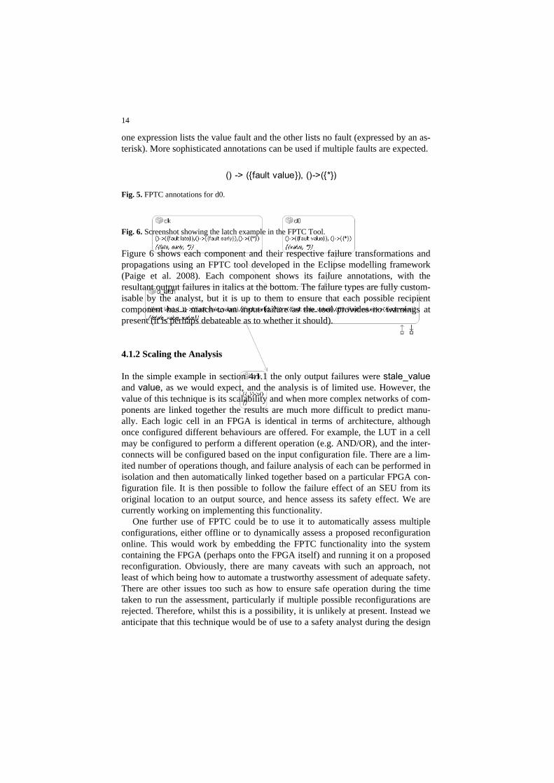
one expression lists the value fault and the other lists no fault (expressed by an as-terisk). More sophisticated annotations can be used if multiple faults are expected.
() -> ({fault value}), ()->({*}) Fig. 5. FPTC annotations for d0.
ch example in the FPTC Tool.
Figure 6 shows each component and their respective failure transformations and propagations using an FPTC tool developed in the Eclipse modelling framework (Paige et al. 2008). Each component shows its failure annotations, with the resultant output failures in italics at the bottom. The failure types are fully custom-isable by the analyst, but it is up to them to ensure that each possible recipient component has a match to an input failure as the tool provides no warnings at present (it is perhaps debateable as to whether it should).
4.1.2 Scaling the Analysis
In the simple example in section 4.1.1 the only output failures were stale_value and value, as we would expect, and the analysis is of limited use. However, the value of this technique is its scalability and when more complex networks of com-ponents are linked together the results are much more difficult to predict manu-ally. Each logic cell in an FPGA is identical in terms of architecture, although once configured dif ple, the LUT in a cell may be configured t ), and the inte
ation file. There are a lim-ach can be performed in
itself) and running it on a proposed reconfiguration. Obviously, there are many caveats with such an approach, not
tomate a trustworthy assessment of adequate safety. how to ensure safe operation during the time
Fig. 6. Screenshot showing the lat
ferent behaviours are offered. For examo perform a different operation (e.g. AND/OR r-
connects will be configured based on the input configurited number of operations though, and failure analysis of eisolation and then automatically linked together based on a particular FPGA con-figuration file. It is then possible to follow the failure effect of an SEU from its original location to an output source, and hence assess its safety effect. We are currently working on implementing this functionality.
One further use of FPTC could be to use it to automatically assess multiple configurations, either offline or to dynamically assess a proposed reconfiguration online. This would work by embedding the FPTC functionality into the system containing the FPGA (perhaps onto the FPGA
least of which being how to auThere are other issues too such as taken to run the assessment, particularly if multiple possible reconfigurations are rejected. Therefore, whilst this is a possibility, it is unlikely at present. Instead we anticipate that this technique would be of use to a safety analyst during the design
15
process and to assess offline reconfigurations, such as those needed to avoid per-manent short/open circuits that have developed during the FPGAs operational de-ployment (SELNew in our safety argument).
5 Related Work
This section briefly describes some existing methods which are used detect SEUs and assess their significance. We compare these with our approach.
In (Sterpone and Violante 2005) the authors use a graphical tool which shows which cells can be affected by an SEU. They then compare this with a TMR archi-tecture (the redundancy is via circuits replicated on the same FPGA) to determine if the SEU can affect more than one lane. If it can then it is assumed to be signifi-cant. The authors note that ‘the choices done during place and route operations influence greatly the impact of SEUs affecting the FPGAs configuration memory‘. Our proposed FPTC analysis approach differs from theirs in that the safety effect of an SEU will be determined, rather than simply assuming it leads to undesired behaviour. It is also applicable to different architectures (not just TMR).
Emmert et al. describe ‘Roving STARs’ (Self-Test Areas) which robustly check for latchups (Emmert et al. 2000). They reconfigure the FPGA cells around any latchups detected and by moving the STARs around during operation they can cover the entire FPGA. However, this technique only detects permanent errors (rather than SEUs) and all latchups are avoided once found, hence it is pessimistic. The testing technique described would be suitable for supporting the goal
y argument. r examining the effects of SEUs is via fault injection and
testing, i.e. a configured and correctly operating FPGA file has a bit flip inserted
with a correct co
Th
tion and the effects of SEUs. We presented a safety argument fragment demon-
FPGASEL in our safetAnother method fo
to simulate an SEU and the effects are observed. An example of this can be found in (Graham et al. 2003) where the authors used two FPGAs, one
nfiguration file and one with a file with a fault injected. Both were executed and the results compared. Where results differed they determined the altered bit to be SEU sensitive. Again, there is a problem here that these results are very pessimis-tic and do not assess the safety effect of the SEU.
6 Conclusions
is paper has described a number of different possible applications of FPGAs within safety critical systems, and also described some of the potential benefits they can offer. It has also discussed some of the difficulties which can be encoun-tered when certifying a system containing an FPGA, particularly if they are using some of its advanced features. The paper has focussed on the issue of reconfigura-

16
strating how FPGA scrubbing could be used to mitigate against significant SEUs. This is the most basic form of reconfiguration available on certain SRAM FPGAs. M
timisation of the FPGA design and configuration to mitigate against SEUs only where necessary. This potentially could lead to various savings in terms of cost, weight and resource usage (e.g. less
equired . However, the research is currently in its early stages.
Acknowledgments The authors would like to thank the Software Systems Engineering Initia-
IEEE Transactions on Computers 47:15-33
itical-archive/2008/0138.html. Accessed 17 Septem-ber 2008
unctional safety of electrical/electronic/programmable electronic safety-related sys-508
Ko. Accessed 17 September
2008
ore complex forms of reconfiguration which have the potential to increase the robustness of a system containing an FPGA (e.g. to reconfigure the device when permanent open/short circuits are discovered) are an area for further examination.
At present FPGA analysis techniques which look for the effects of SEUs do not focus on their possible safety impact and hence pessimistic assumptions have to be made that any SEU which affects the output has a detrimental safety effect. We have described a method which we believe can be adapted to allow the safety ef-fects to be properly assessed and hence allow op
redundancy being r )
tive (SSEI) for their support and funding.
References Ada HRG Group (1998) Guide for the use of the Ada programming language in High Integrity
Systems, ISO/IEC Bondhugula U, Devulapalli A et al (2006) Parallel FPGA-based All-Pairs Shortest-Paths in a
Directed Graph. Proceedings of the 20th IEEE International Parallel and Distributed Proc-essing Symposium. Rhodes Island, Greece, IEEE
Choi S, Govindu G et al (2003) Energy Efficient and Parameterized Designs for Fast Fourier Transform on FPGAs. IEEE International Conference on Acoustics, Speech and Signal Proc-essing
Emmert JM, Stroud CE et al (2000) Dynamic Fault Tolerance in FPGAs via Partial Reconfigura-tion. IEEE Symposium on Field-Programmable Custom Computing Machines
Garvie M, Thompson A (2004) Scrubbing away transients and Jiggling around the permanent: Long survival of FPGA systems through evolutionary self-repair. Proc. 10th IEEE Intl. On-Line Testing Symposium
Glavinic V, Gros S et al (2000) Modelling and Simulation of a Hard Real-Time Processor. Jour-nal of Computing and Information Technology 8:221-233
Graham P, Caffrey M et al (2003) Consequences and Categories of SRAM FPGA Configuration SEUs. Military and Aerospace Programmable Logic Devices International Conference
Hanchek F, Dutt S (1998) Methodologies for Tolerating Cell and Interconnect Faults in FPGAs.
HISE Safety Critical Mailing List (2008) Are FPGAs Software? http://www.cs.york.ac.uk/hise/safety-cr
IEC (2000) Ftems. IEC 61
Isaac TA (2004) Firmware in Safety Critical Subsystems. International System Safety Con-ference, Providence, Rhode Island, USA
Kelly T (1998) Arguing Safety - A Systematic Approach to Managing Safety Cases. University of York. D. Phil. walski JE, Gromov KG et al (2005) High Altitude Subsonic Parachute Field Programmable Gate Array. http://klabs.org/mapld05/presento/154_kowalski_p.ppt

17
Kumar S, Paar C et al (2006) Breaking Ciphers with COPACOBANA - A Cost-Optimized Paral-lel Code Breaker. Cryptographic Hardware and Embedded Systems. Yokohama, Japan
Ministry of Defence (1999) Requirements for Safety Related Electronic Hardware in Defence
Mi ms, Part 1 Re-
Moing, Brigham Young University. MSc.
RT ions in Airborne Systems and Equipment Certi-
RT, RTCA/EUROCAE
ugh SRAM-Based FPGAs. IEEE Transactions on Nu-
Wallace M (2005) Modular Architectural Representation and Analysis of Fault Propagation and
Za iremadi SG et al (2007) Fast SEU Detection and Correction in LUT
Equipment (00-54) (now deprecated). Ministry of Defence, UK nistry of Defence (2007). Safety Management Requirements for Defence Systequirements (00-56). Ministry of Defence, UK rgan KS (2006) SEU-Induced Persistent Error Propagation in FPGAs. Department of Electri-cal and Computer Engineer
Nallatech Ltd (2002) Improved Availability and Reduced Life Cycle Costs of Military Avionics Systems
Paige RF, Rose LM et al (2008) Automated Safety Analysis for Domain-Specific Languages. Workshop on Non-Functional System Properties in Domain Specific Modeling Languages
CA/EUROCAE (1992) Software Consideratfication, DO-178B/ED-12B, RTCA/EUROCAE CA/EUROCAE (2000) Design Assurance Guidance for Airborne Electronic Hardware, DO-254/ED-80
Stepney S (2003) CSP/FDR2 to Handel-C translation, University of York Report YCS-2003-357:57
Sterpone L, Violante M (2005) A New Analytical Approach to Estimate the Effects of SEUs in TMR Architectures Implemented Throclear Science 52:2217-2223
Transformation. Proceedings of the Second International Workshop on Formal Foundations of Embedded Software and Component-based Software Architectures, Elsevier
randi HR, MConfiguration Bits of SRAM FPGAs. 14th IEEE Reconfigurable Architecture Workshop, as-sociated with IPDPS