CPU | 317-4NE12 | Manual - VIPA
184
CPU | 317-4NE12 | Manual HB140 | CPU | 317-4NE12 | GB | 14-40 VIPA System 300S CPU
-
Upload
khangminh22 -
Category
Documents
-
view
0 -
download
0
Transcript of CPU | 317-4NE12 | Manual - VIPA

CPU | 317-4NE12 | ManualHB140 | CPU | 317-4NE12 | GB | 14-40
VIPA System 300S CPU

317-4NE12_000_CPU 317SN/NET,1,GB - © 2014
VIPA GmbHOhmstr. 491074 HerzogenaurachTelephone: +49 9132 744-0Fax: +49 9132 744-1864email: [email protected]: www.vipa.com

Table of contents1 General...................................................................................... 6
1.1 Copyright © VIPA GmbH ................................................... 61.2 About this manual.............................................................. 71.3 Safety information.............................................................. 8
2 Basics..................................................................................... 102.1 Safety information for users............................................. 102.2 Operating structure of a CPU........................................... 102.2.1 General......................................................................... 102.2.2 Applications .................................................................. 112.2.3 Operands...................................................................... 112.3 CPU 317-4NE12.............................................................. 122.4 General data.................................................................... 14
3 Assembly and installation guidelines.................................. 173.1 Overview.......................................................................... 173.2 Installation dimensions..................................................... 183.3 Assembly SPEED-Bus..................................................... 193.4 Assembly standard bus.................................................... 223.5 Cabling............................................................................. 243.6 Installation guidelines....................................................... 27
4 Hardware description............................................................ 304.1 Properties......................................................................... 304.2 Structure........................................................................... 314.2.1 General......................................................................... 314.2.2 Interfaces...................................................................... 314.2.3 Memory management................................................... 334.2.4 Storage media slot ....................................................... 334.2.5 Battery backup for clock and RAM................................ 344.2.6 Operating mode switch................................................. 344.2.7 LEDs............................................................................. 354.3 Technical data.................................................................. 37
5 Deployment CPU 317-4NE12................................................. 455.1 Assembly.......................................................................... 455.2 Start-up behavior.............................................................. 455.3 Addressing....................................................................... 465.3.1 Overview....................................................................... 465.3.2 Addressing.................................................................... 465.4 Hardware configuration - CPU......................................... 495.5 Hardware configuration - I/O modules............................. 495.6 Hardware configuration - Ethernet PG/OP channel......... 505.7 Hardware configuration - SPEED-Bus............................. 525.7.1 Preconditions................................................................ 525.7.2 Proceeding.................................................................... 545.8 Hardware configuration - Communication........................ 545.9 Setting standard CPU parameters................................... 545.9.1 Parametrization via Siemens CPU................................ 545.9.2 Parameters CPU........................................................... 555.9.3 Parameters for DP........................................................ 57
VIPA System 300S CPU Table of contents
HB140 | CPU | 317-4NE12 | GB | 14-40 3

5.9.4 Parameters for MPI/DP ................................................ 585.10 Setting VIPA specific CPU parameters.......................... 595.10.1 Proceeding.................................................................. 595.10.2 VIPA specific parameters............................................ 605.11 Project transfer............................................................... 635.11.1 Transfer via MPI/PROFIBUS...................................... 635.11.2 Transfer via Ethernet................................................... 655.11.3 Transfer via MMC........................................................ 665.12 Access to the internal Web page................................... 675.13 Operating modes............................................................ 705.13.1 Overview..................................................................... 705.13.2 Function security......................................................... 725.14 Overall reset................................................................... 725.15 Firmware update............................................................ 745.16 Reset to factory setting.................................................. 765.17 Slot for storage media.................................................... 775.18 Memory extension with MCC......................................... 785.19 Extended know-how protection...................................... 795.20 MMC-Cmd - Auto commands......................................... 805.21 VIPA specific diagnostic entries..................................... 825.22 Control and monitoring of variables with test functions.. 98
6 Deployment PtP communication........................................ 1006.1 Fast introduction............................................................. 1006.2 Principle of the data transfer.......................................... 1016.3 Deployment of RS485 interface for PtP......................... 1016.4 Parametrization.............................................................. 1046.4.1 FC/SFC 216 - SER_CFG............................................ 1046.5 Communication.............................................................. 1076.5.1 Overview..................................................................... 1076.5.2 FC/SFC 217 - SER_SND............................................ 1086.5.3 FC/SFC 218 - SER_RCV............................................ 1136.6 Protocols and procedures ............................................. 1156.7 Modbus - Function codes .............................................. 1196.8 Modbus - Example communication................................ 124
7 Deployment PROFIBUS communication........................... 1277.1 Overview........................................................................ 1277.2 Fast introduction............................................................. 1277.3 Hardware configuration - CPU....................................... 1287.4 Deployment as PROFIBUS DP master.......................... 1297.5 Deployment as PROFIBUS DP slave............................ 1307.6 PROFIBUS installation guidelines.................................. 1327.7 Commissioning and Start-up behavior........................... 135
8 Deployment Ethernet communication - productive.......... 1378.1 Basics - Industrial Ethernet in automation...................... 1378.2 Basics - ISO/OSI reference model................................. 1388.3 Basics - Terms............................................................... 1398.4 Basics - Protocols.......................................................... 1408.5 Basics - IP address and subnet..................................... 1448.6 Basics - MAC address and TSAP.................................. 146
VIPA System 300S CPUTable of contents
HB140 | CPU | 317-4NE12 | GB | 14-40 4

8.7 Fast introduction............................................................. 1478.8 Commissioning and initialization.................................... 1488.9 Hardware configuration - CPU....................................... 1498.10 Configure connections................................................. 1508.10.1 Overview................................................................... 1508.10.2 Siemens NetPro........................................................ 1518.10.3 Connection type - S7................................................. 1548.10.4 Connection type - Send/Receive............................... 1578.11 Configure Open Communication.................................. 1668.12 NCM diagnostic - Help for error diagnostic.................. 1688.13 Coupling to other systems............................................ 170
9 WinPLC7............................................................................... 1749.1 System conception......................................................... 1749.2 Installation...................................................................... 1749.3 Example project engineering.......................................... 1769.3.1 Job definition............................................................... 1769.3.2 Project engineering..................................................... 1769.3.3 Test the PLC program in the Simulator....................... 1829.3.4 Transfer PLC program to CPU and its execution........ 183
VIPA System 300S CPU Table of contents
HB140 | CPU | 317-4NE12 | GB | 14-40 5

1 General1.1 Copyright © VIPA GmbH
This document contains proprietary information of VIPA and is not tobe disclosed or used except in accordance with applicable agree-ments.This material is protected by the copyright laws. It may not be repro-duced, distributed, or altered in any fashion by any entity (eitherinternal or external to VIPA), except in accordance with applicableagreements, contracts or licensing, without the express written con-sent of VIPA and the business management owner of the material.For permission to reproduce or distribute, please contact: VIPA,Gesellschaft für Visualisierung und Prozessautomatisierung mbHOhmstraße 4, D-91074 Herzogenaurach, GermanyTel.: +49 9132 744 -0Fax.: +49 9132 744-1864EMail: [email protected]://www.vipa.com
Every effort has been made to ensure that the informationcontained in this document was complete and accurate atthe time of publishing. Nevertheless, the authors retain theright to modify the information.This customer document describes all the hardware unitsand functions known at the present time. Descriptions maybe included for units which are not present at the customersite. The exact scope of delivery is described in therespective purchase contract.
Hereby, VIPA GmbH declares that the products and systems are incompliance with the essential requirements and other relevant provi-sions. Conformity is indicated by the CE marking affixed to theproduct.
For more information regarding CE marking and Declaration of Con-formity (DoC), please contact your local VIPA customer serviceorganization.
All Rights Reserved
CE Conformity Declara-tion
Conformity Information
VIPA System 300S CPUGeneralCopyright © VIPA GmbH
HB140 | CPU | 317-4NE12 | GB | 14-40 6

VIPA, SLIO, System 100V, System 200V, System 300V, System300S, System 400V, System 500S and Commander Compact areregistered trademarks of VIPA Gesellschaft für Visualisierung undProzessautomatisierung mbH.SPEED7 is a registered trademark of profichip GmbH.SIMATIC, STEP, SINEC, TIA Portal, S7-300 and S7-400 are regis-tered trademarks of Siemens AG.Microsoft and Windows are registered trademarks of Microsoft Inc.,USA.Portable Document Format (PDF) and Postscript are registered trade-marks of Adobe Systems, Inc.All other trademarks, logos and service or product marks specifiedherein are owned by their respective companies.
Contact your local VIPA Customer Service Organization representa-tive if you wish to report errors or questions regarding the contents ofthis document. If you are unable to locate a customer service centre,contact VIPA as follows:VIPA GmbH, Ohmstraße 4, 91074 Herzogenaurach, GermanyTelefax: +49 9132 744-1204EMail: [email protected]
Contact your local VIPA Customer Service Organization representa-tive if you encounter problems with the product or have questionsregarding the product. If you are unable to locate a customer servicecentre, contact VIPA as follows:VIPA GmbH, Ohmstraße 4, 91074 Herzogenaurach, GermanyTel.: +49 9132 744-1150 (Hotline)EMail: [email protected]
1.2 About this manualThis manual describes the SPEED7 CPU 317-4NE12 of the CPUfrom VIPA. It contains a description of the construction, project imple-mentation and usage.
Product Order no. as of state: CPU-HW CPU-FW DPM-FW CP-FWCPU 317SN/NET 317-4NE12 02 V3.6.0 V3.1.2 V2.1.7
The manual is targeted at users who have a background in automa-tion technology.
The manual consists of chapters. Every chapter provides a self-con-tained description of a specific topic.
Trademarks
Information productsupport
Technical support
Objective and contents
Target audience
Structure of the manual
VIPA System 300S CPU General
About this manual
HB140 | CPU | 317-4NE12 | GB | 14-40 7

The following guides are available in the manual:n An overall table of contents at the beginning of the manualn References with page numbers
The manual is available in:n printed form, on papern in electronic form as PDF-file (Adobe Acrobat Reader)
Important passages in the text are highlighted by following icons andheadings:
DANGER!Immediate or likely danger. Personal injury is possible.
CAUTION!Damages to property is likely if these warnings are notheeded.
Supplementary information and useful tips.
1.3 Safety informationThe system is constructed and produced for:n communication and process controln industrial applicationsn operation within the environmental conditions specified in the
technical datan installation into a cubicle
DANGER!This device is not certified for applications in– in explosive environments (EX-zone)
The manual must be available to all personnel in then project design departmentn installation departmentn commissioningn operation
Guide to the document
Availability
Icons Headings
Applications con-forming with specifica-tions
Documentation
VIPA System 300S CPUGeneral
Safety information
HB140 | CPU | 317-4NE12 | GB | 14-40 8

CAUTION!The following conditions must be met before using orcommissioning the components described in thismanual:– Hardware modifications to the process control system
should only be carried out when the system has beendisconnected from power!
– Installation and hardware modifications only by prop-erly trained personnel.
– The national rules and regulations of the respectivecountry must be satisfied (installation, safety, EMC ...)
National rules and regulations apply to the disposal of the unit!Disposal
VIPA System 300S CPU General
Safety information
HB140 | CPU | 317-4NE12 | GB | 14-40 9

2 Basics2.1 Safety information for users
VIPA modules make use of highly integrated components in MOS-Technology. These components are extremely sensitive to over-vol-tages that can occur during electrostatic discharges. The followingsymbol is attached to modules that can be destroyed by electrostaticdischarges.
The Symbol is located on the module, the module rack or on packingmaterial and it indicates the presence of electrostatic sensitive equip-ment. It is possible that electrostatic sensitive equipment is destroyedby energies and voltages that are far less than the human thresholdof perception. These voltages can occur where persons do not dis-charge themselves before handling electrostatic sensitive modulesand they can damage components thereby, causing the module tobecome inoperable or unusable. Modules that have been damagedby electrostatic discharges can fail after a temperature change,mechanical shock or changes in the electrical load. Only the conse-quent implementation of protection devices and meticulous attentionto the applicable rules and regulations for handling the respectiveequipment can prevent failures of electrostatic sensitive modules.
Modules must be shipped in the original packing material.
When you are conducting measurements on electrostatic sensitivemodules you should take the following precautions:n Floating instruments must be discharged before use.n Instruments must be grounded.Modifying electrostatic sensitive modules you should only use sol-dering irons with grounded tips.
CAUTION!Personnel and instruments should be grounded whenworking on electrostatic sensitive modules.
2.2 Operating structure of a CPU2.2.1 General
The CPU contains a standard processor with internal programmemory. In combination with the integrated SPEED7 technology theunit provides a powerful solution for process automation applicationswithin the System 300S family. A CPU supports the following modesof operation:n cyclic operationn timer processingn alarm controlled operationn priority based processing
Handling of electro-static sensitive modules
Shipping of modules
Measurements andalterations on electro-static sensitive modules
VIPA System 300S CPUBasics
Operating structure of a CPU > General
HB140 | CPU | 317-4NE12 | GB | 14-40 10

Cyclicprocessing represents the major portion of all the processesthat are executed in the CPU. Identical sequences of operations arerepeated in a never-ending cycle.
Where a process requires control signals at constant intervals youcan initiate certain operations based upon a timer, e.g. not criticalmonitoring functions at one-second intervals.
If a process signal requires a quick response you would allocate thissignal to an alarm controlled procedure. An alarm can activate aprocedure in your program.
The above processes are handled by the CPU in accordance withtheir priority. Since a timer or an alarm event requires a quick reac-tion, the CPU will interrupt the cyclic processing when these high-pri-ority events occur to react to the event. Cyclic processing will resume,once the reaction has been processed. This means that cyclic pro-cessing has the lowest priority.
2.2.2 ApplicationsThe program that is present in every CPU is divided as follows:n System routinen User application
The system routine organizes all those functions and procedures ofthe CPU that are not related to a specific control application.
This consists of all the functions that are required for the processingof a specific control application. The operating modules provide theinterfaces to the system routines.
2.2.3 OperandsThe following series of operands is available for programming theCPU:n Process image and peripheryn Bit memoryn Timers and countersn Data blocks
The user application can quickly access the process image of theinputs and outputs PIO/PII. You may manipulate the following typesof data:n individual Bitsn Bytesn Wordsn Double words
Cyclic processing
Timer processing
Alarm controlled pro-cessing
Priority based pro-cessing
System routine
User application
Process image andperiphery
VIPA System 300S CPU Basics
Operating structure of a CPU > Operands
HB140 | CPU | 317-4NE12 | GB | 14-40 11

You may also gain direct access to peripheral modules via the busfrom user application. The following types of data are available:n Bytesn Wordsn Blocks
The bit memory is an area of memory that is accessible by means ofcertain operations. Bit memory is intended to store frequently usedworking data.You may access the following types of data:n individual Bitsn Bytesn Wordsn Double words
In your program you may load cells of the timer with a value between10ms and 9990s. As soon as the user application executes a start-operation, the value of this timer is decremented by the interval thatyou have specified until it reaches zero.You may load counter cells with an initial value (max. 999) and incre-ment or decrement these when required.
A data block contains constants or variables in the form of bytes,words or double words. You may always access the current datablock by means of operands.You may access the following types of data:n individual Bitsn Bytesn Wordsn Double words
2.3 CPU 317-4NE12The CPU 317-4NE12 bases upon the SPEED7 technology. This sup-ports the CPU at programming and communication by means of co-processors that causes a power improvement for highest needs.n The CPU is programmed in STEPÒ7 from Siemens. For this you
may use the SIMATIC Manager or TIA Portal from Siemens. Herethe instruction set of the S7-400 from Siemens is used.
n The CPU has a parallel SPEED-Bus that enables the additionalconnection of up to 10 modules from the SPEED-Bus periphery.While the standard peripheral modules are plugged at the rightside of the CPU, the SPEED-Bus peripheral modules are con-nected via a SPEED-Bus bus connector at the left side of theCPU.
n Modules and CPUs of the System 300S from VIPA and Siemensmay be used at the bus as a mixed configuration.
n The user application is stored in the battery buffered RAM or onan additionally pluggable MMC storage module.
n The CPU is configured as CPU 318-2 (6ES7 318-2AJ00-0AB0/V3.0) from Siemens.
Bit Memory
Timers and counters
Data Blocks
Overview
VIPA System 300S CPUBasics
CPU 317-4NE12
HB140 | CPU | 317-4NE12 | GB | 14-40 12

Please always use the CPU 318-2 (6ES7318-2AJ00-0AB0/V3.0) from Siemens of the hardwarecatalog to project this CPU from VIPA. For the projectengineering, a thorough knowledge of the SiemensSIMATIC Manager and the hardware configurator isrequired!
The CPU has an integrated memory. Information about the capacityof the memory may be found at the front of the CPU. The memory isdivided into the following parts:n Load memory 8Mbyten Code memory (50% of the work memory)n Data memory (50% of the work memory)n Work memory 2Mbyte
– There is the possibility to extend the work memory to its max-imum printed capacity 8Mbyte by means of a MCC memoryextension card.
n The SPEED-Bus is a 32bit parallel bus developed from VIPA.n Via the SPEED-Bus you may connect up to 10 SPEED-Bus mod-
ules to your CPU.n In opposite to the "standard" backplane bus where the modules
are plugged-in at the right side of the CPU by means of single busconnectors, the modules at the SPEED-Bus are plugged-in at theleft side of the CPU via a special SPEED-Bus rail.
Access
Memory
SPEED-Bus
VIPA System 300S CPU Basics
CPU 317-4NE12
HB140 | CPU | 317-4NE12 | GB | 14-40 13
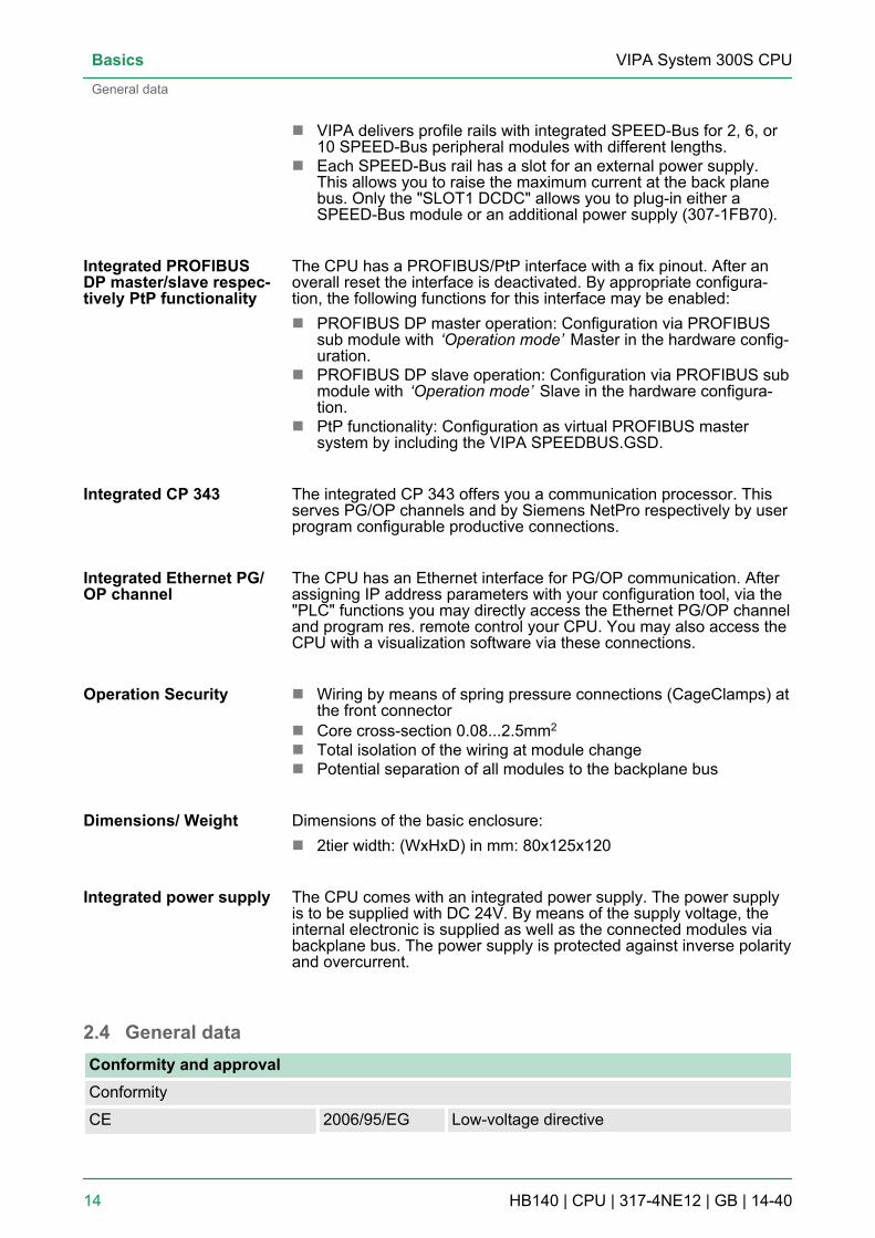
n VIPA delivers profile rails with integrated SPEED-Bus for 2, 6, or10 SPEED-Bus peripheral modules with different lengths.
n Each SPEED-Bus rail has a slot for an external power supply.This allows you to raise the maximum current at the back planebus. Only the "SLOT1 DCDC" allows you to plug-in either aSPEED-Bus module or an additional power supply (307-1FB70).
The CPU has a PROFIBUS/PtP interface with a fix pinout. After anoverall reset the interface is deactivated. By appropriate configura-tion, the following functions for this interface may be enabled:n PROFIBUS DP master operation: Configuration via PROFIBUS
sub module with ‘Operation mode’ Master in the hardware config-uration.
n PROFIBUS DP slave operation: Configuration via PROFIBUS submodule with ‘Operation mode’ Slave in the hardware configura-tion.
n PtP functionality: Configuration as virtual PROFIBUS mastersystem by including the VIPA SPEEDBUS.GSD.
The integrated CP 343 offers you a communication processor. Thisserves PG/OP channels and by Siemens NetPro respectively by userprogram configurable productive connections.
The CPU has an Ethernet interface for PG/OP communication. Afterassigning IP address parameters with your configuration tool, via the"PLC" functions you may directly access the Ethernet PG/OP channeland program res. remote control your CPU. You may also access theCPU with a visualization software via these connections.
n Wiring by means of spring pressure connections (CageClamps) atthe front connector
n Core cross-section 0.08...2.5mm2
n Total isolation of the wiring at module changen Potential separation of all modules to the backplane bus
Dimensions of the basic enclosure:n 2tier width: (WxHxD) in mm: 80x125x120
The CPU comes with an integrated power supply. The power supplyis to be supplied with DC 24V. By means of the supply voltage, theinternal electronic is supplied as well as the connected modules viabackplane bus. The power supply is protected against inverse polarityand overcurrent.
2.4 General dataConformity and approvalConformity
CE 2006/95/EG Low-voltage directive
Integrated PROFIBUSDP master/slave respec-tively PtP functionality
Integrated CP 343
Integrated Ethernet PG/OP channel
Operation Security
Dimensions/ Weight
Integrated power supply
VIPA System 300S CPUBasics
General data
HB140 | CPU | 317-4NE12 | GB | 14-40 14
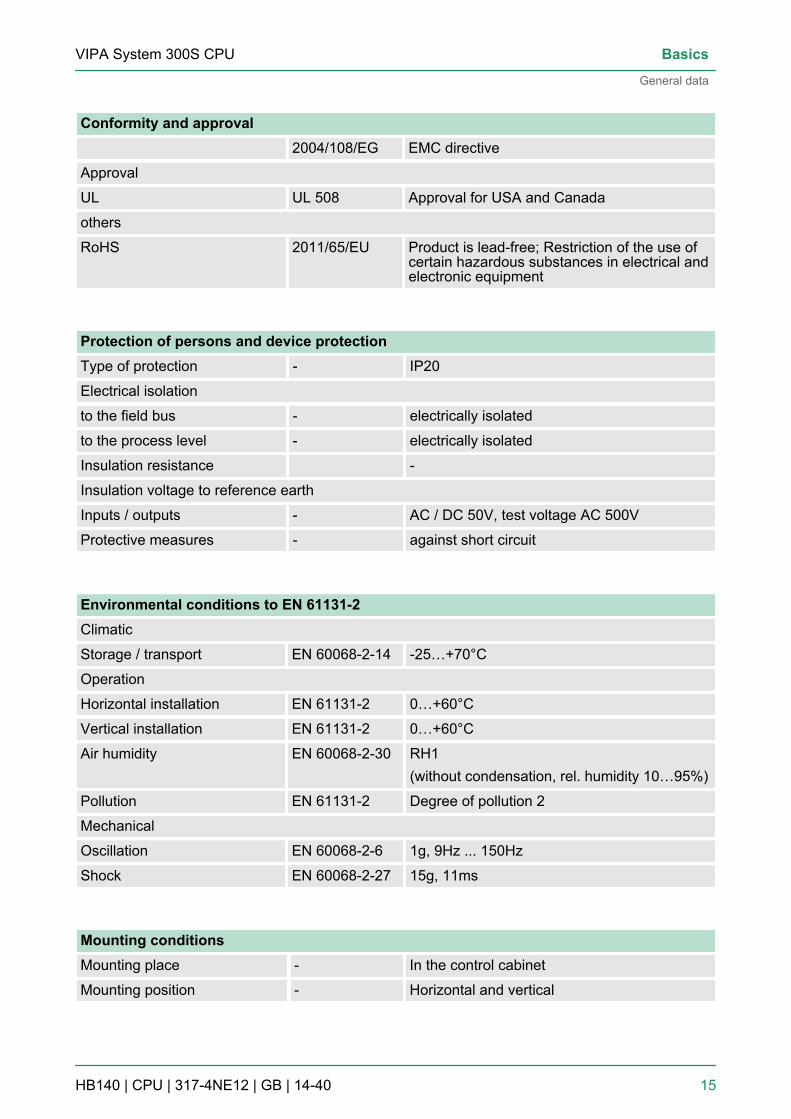
Conformity and approval2004/108/EG EMC directive
Approval
UL UL 508 Approval for USA and Canada
others
RoHS 2011/65/EU Product is lead-free; Restriction of the use ofcertain hazardous substances in electrical andelectronic equipment
Protection of persons and device protectionType of protection - IP20
Electrical isolation
to the field bus - electrically isolated
to the process level - electrically isolated
Insulation resistance -
Insulation voltage to reference earth
Inputs / outputs - AC / DC 50V, test voltage AC 500V
Protective measures - against short circuit
Environmental conditions to EN 61131-2Climatic
Storage / transport EN 60068-2-14 -25…+70°C
Operation
Horizontal installation EN 61131-2 0…+60°C
Vertical installation EN 61131-2 0…+60°C
Air humidity EN 60068-2-30 RH1(without condensation, rel. humidity 10…95%)
Pollution EN 61131-2 Degree of pollution 2
Mechanical
Oscillation EN 60068-2-6 1g, 9Hz ... 150Hz
Shock EN 60068-2-27 15g, 11ms
Mounting conditionsMounting place - In the control cabinet
Mounting position - Horizontal and vertical
VIPA System 300S CPU Basics
General data
HB140 | CPU | 317-4NE12 | GB | 14-40 15

EMC Standard CommentEmitted interfer-ence
EN 61000-6-4 Class A (Industrial area)
Noise immunityzone B
EN 61000-6-2 Industrial area EN 61000-4-2 ESD
8kV at air discharge (degree of severity 3),4kV at contact discharge (degree of severity2)
EN 61000-4-3 HF field immunity (casing)80MHz … 1000MHz, 10V/m, 80% AM (1kHz)1.4GHz ... 2.0GHz, 3V/m, 80% AM (1kHz)2GHz ... 2.7GHz, 1V/m, 80% AM (1kHz)
EN 61000-4-6 HF conducted150kHz … 80MHz, 10V, 80% AM (1kHz)
EN 61000-4-4 Burst, degree of severity 3
EN 61000-4-5 Surge, installation class 3 **) Due to the high-energetic single pulses with Surge an appropriate external protective circuit with lightning protection elements like conductorsfor lightning and overvoltage is necessary.
VIPA System 300S CPUBasics
General data
HB140 | CPU | 317-4NE12 | GB | 14-40 16

3 Assembly and installation guidelines3.1 Overview
This CPU is provided with a parallel SPEED-Bus that enables theadditional connection of up to 10 modules from the SPEED-Busperiphery. While the standard peripheral modules are plugged-in atthe right side of the CPU, the SPEED-Bus peripheral modules areconnected via a SPEED-Bus bus connector at the left side of theCPU.VIPA delivers profile rails with integrated SPEED-Bus for 2, 6 or 10SPEED-Bus peripheral modules with different lengths.
The single modules are directly installed on a profile rail and con-nected via the backplane bus coupler. Before installing the modulesyou have to clip the backplane bus coupler to the module from thebackside. The backplane bus couplers are included in the delivery ofthe peripheral modules.
With SPEED-Bus the bus connection happens via a SPEED-Bus railintegrated in the profile rail at the left side of the CPU. Due to the par-allel SPEED-Bus not all slots must be occupied in sequence.
At slot (SLOT 1 DCDC) you may plug either a SPEED-Bus module oran additional power supply.
You may assemble the System 300 horizontally, vertically or lying.
General
Serial Standard bus
Parallel SPEED-Bus
SLOT 1 for additionalpower supply
Assembly possibilities
VIPA System 300S CPU Assembly and installation guidelines
Overview
HB140 | CPU | 317-4NE12 | GB | 14-40 17

Please regard the allowed environment temperatures:n horizontal assembly: from 0 to 60°Cn vertical assembly: from 0 to 40°Cn lying assembly: from 0 to 40°C
3.2 Installation dimensions2tier width (WxHxD) in mm: 80 x 125 x 120Dimensions Basic
enclosure
Dimensions
Installation dimensions
VIPA System 300S CPUAssembly and installation guidelines
Installation dimensions
HB140 | CPU | 317-4NE12 | GB | 14-40 18

3.3 Assembly SPEED-BusFor the deployment of SPEED-Bus modules, a pre-manufacturedSPEED-Bus rail is required. This is available mounted on a profile railwith 2, 6 or 10 extension slots.
Ordernumber
Number of modulesSPEED-Bus/Standard
bus
A B C D E
391-1AF10 2/6 530 100 268 510 10
391-1AF30 6/2 530 100 105 510 10
391-1AF50 10/0 530 20 20 510 10
391-1AJ10 2/15 830 22 645 800 15
391-1AJ30 6/11 830 22 480 800 15
391-1AJ50 10/7 830 22 320 800 15
Measures in mm
Pre-manufacturedSPEED-Bus profile rail
Dimensions
VIPA System 300S CPU Assembly and installation guidelines
Assembly SPEED-Bus
HB140 | CPU | 317-4NE12 | GB | 14-40 19

1. Bolt the profile rail with the background (screw size: M6), so thatyou still have minimum 65mm space above and 40mm belowthe profile rail. Please look for a low-impedance connectionbetween profile rail and background.
2. Connect the profile rail with the protected earth conductor. Theminimum cross-section of the cable to the protected earth con-ductor has to be 10mm2.
1. Dismantle the according protection flaps of the SPEED-Bus slotwith a screw driver (open and pull down).For the SPEED-Bus is a parallel bus, not every SPEED-Bus slotmust be used in series. Leave the protection flap installed at anunused SPEED-Bus slot.
2. At deployment of a DC 24V power supply, install it at the shownposition at the profile rail at the left side of the SPEED-Bus andpush it to the left to the isolation bolt of the profile rail.
3. Fix the power supply by screwing.
Installation of the pro-file rail
Installation SPEED-Busmodule
VIPA System 300S CPUAssembly and installation guidelines
Assembly SPEED-Bus
HB140 | CPU | 317-4NE12 | GB | 14-40 20

4. To connect the SPEED-Bus modules, plug it between the trian-gular positioning helps to a slot marked with "SLOT ..." and pullit down.
5. Only the "SLOT1 DCDC" allows you to plug-in either a SPEED-Bus module or an additional power supply.
6. Fix the CPU by screwing.
1. To deploy the SPEED7-CPU exclusively at the SPEED-Bus,plug it between the triangular positioning helps to the slotmarked with "CPU SPEED7" and pull it down.
2. Fix the CPU by screwing.
1. If also standard modules shall be plugged, take a bus couplerand click it at the CPU from behind like shown in the picture.Plug the CPU between the triangular positioning helps to the slotmarked with "CPU SPEED7" and pull it down.
2. Fix the CPU by screwing.
Repeat this procedure with the peripheral modules, by clicking abackplane bus coupler, stick the module right from the modulesyou've already fixed, click it downwards and connect it with thebackplane bus coupler of the last module and bolt it.
Installation CPU withoutStandard-Bus-Modules
Installation CPU withStandard-Bus-Modules
Installation Standard-Bus-Modules
VIPA System 300S CPU Assembly and installation guidelines
Assembly SPEED-Bus
HB140 | CPU | 317-4NE12 | GB | 14-40 21

CAUTION!– The power supplies must be released before installa-
tion and repair tasks, i.e. before handling with thepower supply or with the cabling you must disconnectcurrent/voltage (pull plug, at fixed connection switch offthe concerning fuse)!
– Installation and modifications only by properly trainedpersonnel!
3.4 Assembly standard busThe single modules are directly installed on a profile rail and con-nected via the backplane bus connector. Before installing the mod-ules you have to clip the backplane bus connector to the module fromthe backside. The backplane bus connector is delivered together withthe peripheral modules.
Order number A B C390-1AB60 160 140 10
390-1AE80 482 466 8.3
390-1AF30 530 500 15
390-1AJ30 830 800 15
390-9BC00* 2000 Drillings only left 15*) Unit pack: 10 pieces
Measures in mm
For the communication between the modules the System 300S usesa backplane bus connector. Backplane bus connectors are includedin the delivering of the peripheral modules and are clipped at themodule from the backside before installing it to the profile rail.
General
Profile rail
Bus connector
VIPA System 300S CPUAssembly and installation guidelines
Assembly standard bus
HB140 | CPU | 317-4NE12 | GB | 14-40 22
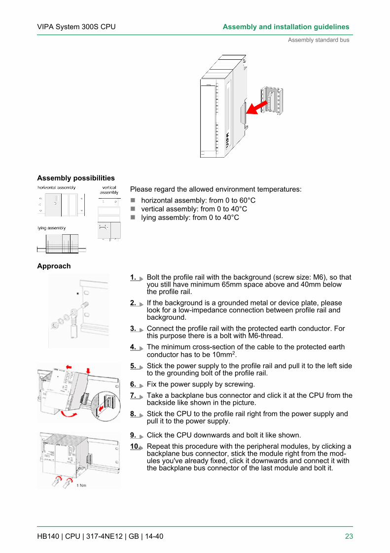
Please regard the allowed environment temperatures:n horizontal assembly: from 0 to 60°Cn vertical assembly: from 0 to 40°Cn lying assembly: from 0 to 40°C
1. Bolt the profile rail with the background (screw size: M6), so thatyou still have minimum 65mm space above and 40mm belowthe profile rail.
2. If the background is a grounded metal or device plate, pleaselook for a low-impedance connection between profile rail andbackground.
3. Connect the profile rail with the protected earth conductor. Forthis purpose there is a bolt with M6-thread.
4. The minimum cross-section of the cable to the protected earthconductor has to be 10mm2.
5. Stick the power supply to the profile rail and pull it to the left sideto the grounding bolt of the profile rail.
6. Fix the power supply by screwing.7. Take a backplane bus connector and click it at the CPU from the
backside like shown in the picture.8. Stick the CPU to the profile rail right from the power supply and
pull it to the power supply.
9. Click the CPU downwards and bolt it like shown.10. Repeat this procedure with the peripheral modules, by clicking a
backplane bus connector, stick the module right from the mod-ules you've already fixed, click it downwards and connect it withthe backplane bus connector of the last module and bolt it.
Assembly possibilities
Approach
VIPA System 300S CPU Assembly and installation guidelines
Assembly standard bus
HB140 | CPU | 317-4NE12 | GB | 14-40 23

3.5 Cabling
CAUTION!– The power supplies must be released before installa-
tion and repair tasks, i.e. before handling with thepower supply or with the cabling you must disconnectcurrent/voltage (pull plug, at fixed connection switch offthe concerning fuse)!
– Installation and modifications only by properly trainedpersonnel!
For the cabling of power supply of a CPU, a green plug with Cage-Clamp technology is deployed. The connection clamp is realized asplug that may be clipped off carefully if it is still cabled.Here wires with a cross-section of 0.08mm2 to 2.5mm2 may be con-nected. You can use flexible wires without end case as well as stiffwires.
1 Test point for 2mm test tip2 Locking (orange) for screwdriver3 Round opening for wires
CageClamp technology(green)
VIPA System 300S CPUAssembly and installation guidelines
Cabling
HB140 | CPU | 317-4NE12 | GB | 14-40 24

The picture on the left side shows the cabling step by step from topview.1. For cabling you push the locking vertical to the inside with a
suiting screwdriver and hold the screwdriver in this position.2. Insert the de-isolated wire into the round opening. You may use
wires with a cross-section from 0.08mm2 to 2.5mm2
3. By removing the screwdriver the wire is connected safely withthe plug connector via a spring.
In the following the cabling of the two variants are shown.
1. Open the front flap of your I/O module.2. Bring the front connector in cabling position.
For this you plug the front connector on the module until it locks.In this position the front connector juts out of the module andhas no contact yet.
3. De-isolate your wires. If needed, use core end cases.4. Thread the included cable binder into the front connector.5. If you want to lead out your cables from the bottom of the
module, start with the cabling from bottom to top, res. from topto bottom, if the cables should be led out at the top.
6. Bolt also the connection screws of not cabled screw clamps.
Front connectors of thein-/output modules20pole screw connec-tion 392-1AJ00
VIPA System 300S CPU Assembly and installation guidelines
Cabling
HB140 | CPU | 317-4NE12 | GB | 14-40 25

7. Fix the cable binder for the cable bundle.
8. Push the release key at the front connector on the upper side ofthe module and at the same time push the front connector intothe module until it locks.
9. Now the front connector is electrically connected with yourmodule.
10. Close the front flap.11. Fill out the labeling strip to mark the single channels and push
the strip into the front flap.
1. Open the front flap of your I/O module.2. Bring the front connector in cabling position.
For this you plug the front connector on the module until it locks.In this position the front connector juts out of the module andhas no contact yet.
3. De-isolate your wires. If needed, use core end cases.4. If you want to lead out your cables from the bottom of the
module, start with the cabling from bottom to top, res. from topto bottom, if the cables should be led out at the top.
5. Bolt also the connection screws of not cabled screw clamps.
40pole screw connec-tion 392-1AM00
VIPA System 300S CPUAssembly and installation guidelines
Cabling
HB140 | CPU | 317-4NE12 | GB | 14-40 26
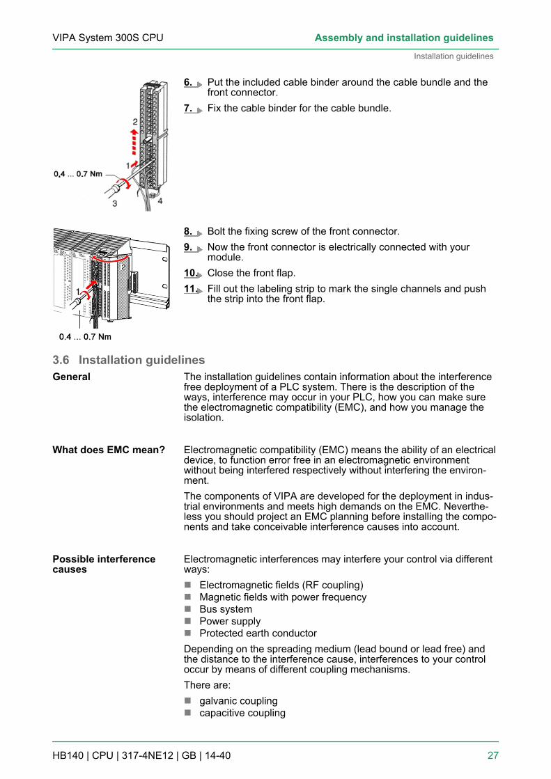
6. Put the included cable binder around the cable bundle and thefront connector.
7. Fix the cable binder for the cable bundle.
8. Bolt the fixing screw of the front connector.9. Now the front connector is electrically connected with your
module.10. Close the front flap.11. Fill out the labeling strip to mark the single channels and push
the strip into the front flap.
3.6 Installation guidelinesThe installation guidelines contain information about the interferencefree deployment of a PLC system. There is the description of theways, interference may occur in your PLC, how you can make surethe electromagnetic compatibility (EMC), and how you manage theisolation.
Electromagnetic compatibility (EMC) means the ability of an electricaldevice, to function error free in an electromagnetic environmentwithout being interfered respectively without interfering the environ-ment.The components of VIPA are developed for the deployment in indus-trial environments and meets high demands on the EMC. Neverthe-less you should project an EMC planning before installing the compo-nents and take conceivable interference causes into account.
Electromagnetic interferences may interfere your control via differentways:n Electromagnetic fields (RF coupling)n Magnetic fields with power frequencyn Bus systemn Power supplyn Protected earth conductorDepending on the spreading medium (lead bound or lead free) andthe distance to the interference cause, interferences to your controloccur by means of different coupling mechanisms.There are:n galvanic couplingn capacitive coupling
General
What does EMC mean?
Possible interferencecauses
VIPA System 300S CPU Assembly and installation guidelines
Installation guidelines
HB140 | CPU | 317-4NE12 | GB | 14-40 27

n inductive couplingn radiant coupling
In the most times it is enough to take care of some elementary rulesto guarantee the EMC. Please regard the following basic rules wheninstalling your PLC.n Take care of a correct area-wide grounding of the inactive metal
parts when installing your components.– Install a central connection between the ground and the pro-
tected earth conductor system.– Connect all inactive metal extensive and impedance-low.– Please try not to use aluminium parts. Aluminium is easily oxi-
dizing and is therefore less suitable for grounding.n When cabling, take care of the correct line routing.
– Organize your cabling in line groups (high voltage, currentsupply, signal and data lines).
– Always lay your high voltage lines and signal respectively datalines in separate channels or bundles.
– Route the signal and data lines as near as possible besideground areas (e.g. suspension bars, metal rails, tin cabinet).
n Proof the correct fixing of the lead isolation.– Data lines must be laid isolated.– Analog lines must be laid isolated. When transmitting signals
with small amplitudes the one sided laying of the isolation maybe favourable.
– Lay the line isolation extensively on an isolation/protectedearth conductor rail directly after the cabinet entry and fix theisolation with cable clamps.
– Make sure that the isolation/protected earth conductor rail isconnected impedance-low with the cabinet.
– Use metallic or metallised plug cases for isolated data lines.n In special use cases you should appoint special EMC actions.
– Consider to wire all inductivities with erase links.– Please consider luminescent lamps can influence signal lines.
n Create a homogeneous reference potential and ground all elec-trical operating supplies when possible.– Please take care for the targeted employment of the grounding
actions. The grounding of the PLC serves for protection andfunctionality activity.
– Connect installation parts and cabinets with your PLC in startopology with the isolation/protected earth conductor system.So you avoid ground loops.
– If there are potential differences between installation parts andcabinets, lay sufficiently dimensioned potential compensationlines.
Electrical, magnetically and electromagnetic interference fields areweakened by means of an isolation, one talks of absorption. Via theisolation rail, that is connected conductive with the rack, interferencecurrents are shunt via cable isolation to the ground. Here you have tomake sure, that the connection to the protected earth conductor isimpedance-low, because otherwise the interference currents mayappear as interference cause.
Basic rules for EMC
Isolation of conductors
VIPA System 300S CPUAssembly and installation guidelines
Installation guidelines
HB140 | CPU | 317-4NE12 | GB | 14-40 28

When isolating cables you have to regard the following:n If possible, use only cables with isolation tangle.n The hiding power of the isolation should be higher than 80%.n Normally you should always lay the isolation of cables on both
sides. Only by means of the both-sided connection of the isolationyou achieve high quality interference suppression in the higherfrequency area. Only as exception you may also lay the isolationone-sided. Then you only achieve the absorption of the lower fre-quencies. A one-sided isolation connection may be convenient, if:– the conduction of a potential compensating line is not possible.– analog signals (some mV respectively µA) are transferred.– foil isolations (static isolations) are used.
n With data lines always use metallic or metallised plugs for serialcouplings. Fix the isolation of the data line at the plug rack. Do notlay the isolation on the PIN 1 of the plug bar!
n At stationary operation it is convenient to strip the insulated cableinterruption free and lay it on the isolation/protected earth con-ductor line.
n To fix the isolation tangles use cable clamps out of metal. Theclamps must clasp the isolation extensively and have well contact.
n Lay the isolation on an isolation rail directly after the entry of thecable in the cabinet. Lead the isolation further on to your PLC anddon't lay it on there again!
CAUTION!Please regard at installation!At potential differences between the grounding points,there may be a compensation current via the isolation con-nected at both sides.Remedy: Potential compensation line
VIPA System 300S CPU Assembly and installation guidelines
Installation guidelines
HB140 | CPU | 317-4NE12 | GB | 14-40 29

4 Hardware description4.1 Properties
n SPEED7 technology and SPEED-Bus integratedn 2Mbyte work memory integrated (1Mbyte code, 1Mbyte data)n Memory expandable to max. 8Mbyte (4Mbyte code, 4Mbyte data)n 8Mbyte load memoryn PROFIBUS DP master integrated (DP-V0, DP-V1)n CP 343 communication processor integratedÄ Chapter 4.3 ‘Technical data’ on page 37– Productive connections via Siemens NetPro– Productive connections via user program– PG/OP connections
n RS485 interface configurable for PROFIBUS DP master respec-tively PtP communication
n Ethernet PG/OP interface integratedn MPI interfacen MCC slot for external memory cards (lockable)n Status LEDs for operating state and diagnosticsn Real-time clock battery bufferedn I/O address range digital/analog 8191byten 2048 timern 2048 countern 16384 flag byte
Type Order number Description317SN/NET 317-4NE12 SPEED-Bus, MPI interface, card slot, real time clock,
Ethernet interface for PG/OP, PROFIBUS DP master,CP 343
CPU 317-4NE12
Ordering data
VIPA System 300S CPUHardware description
Properties
HB140 | CPU | 317-4NE12 | GB | 14-40 30

4.2 Structure4.2.1 General
1 LEDs of the integrated PROFIBUS DP master2 Storage media slot (lockable)3 LEDs of the CPU part4 Operating mode switch CPU5 Twisted pair interface for Ethernet PG/OP channel6 MPI interface7 PROFIBUS DP/PtP interface8 Twisted Pair interface for CP 3439 Slot for DC 24V power supplyThe components 5 - 9 are under the front flap!
4.2.2 Interfaces
CPU 317-4NE12
VIPA System 300S CPU Hardware description
Structure > Interfaces
HB140 | CPU | 317-4NE12 | GB | 14-40 31

The CPU has an integrated power supply:n The power supply has to be provided with DC 24V. For this serves
the double DC 24V slot, that is underneath the flap.n Via the power supply not only the internal electronic is provided
with voltage, but by means of the backplane bus also the con-nected modules.
n The power supply is protected against polarity inversion and over-current.
n The internal electronic is galvanically connected with the supplyvoltage.
9pin SubD jack:n The MPI interface serves for the connection between program-
ming unit and CPU.n By means of this the project engineering and programming hap-
pens.n MPI serves for communication between several CPUs or between
HMIs and CPU.n Standard setting is MPI Address 2.
8pin RJ45 jack:n The RJ45 jack serves the interface to the Ethernet PG/OP
channel.n This interface allows you to program res. remote control your
CPU, to access the internal web site or to connect a visualization.n Configurable connections are not possible.n For online access to the CPU via Ethernet PG/OP channel valid
IP address parameters have to be assigned to this.
9pin SubD jack:The CPU has a PROFIBUS/PtP interface with a fix pinout. After anoverall reset the interface is deactivated. By appropriate configura-tion, the following functions for this interface may be enabled:n PROFIBUS DP master operation
– Configuration via PROFIBUS sub module X2 (DP) with‘Operation mode’ master in the hardware configuration.
n PROFIBUS DP slave operation– Configuration via PROFIBUS sub module X2 (DP) with
‘Operation mode’ slave in the hardware configuration.n PtP functionality
– Using the PtP functionality the RS485 interface is allowed toconnect via serial point-to-point connection to different sourceres. target systems.
– Here the following protocols are supported: ASCII, STX/ETX,3964R, USS and Modbus-Master (ASCII, RTU).
– The activation of the PtP functionality happens by embeddingthe SPEEDBUS.GSD from VIPA in the hardware catalog. Afterthe installation the CPU may be configured in a PROFIBUSmaster system and here the interface may be switched to PtPcommunication.
Power supply X1
MPI interface X2
Ethernet PG/OP channelX5
PROFIBUS/PtP interfacewith configurable func-tionality X3
VIPA System 300S CPUHardware description
Structure > Interfaces
HB140 | CPU | 317-4NE12 | GB | 14-40 32

8pin RJ45 jack:n Communication processor CP 343 for connection to Ethernetn Productive connections via Siemens NetPron Productive connections via user programn PG/OP connections
Number of connections Ä Chapter 4.3 ‘Technical data’on page 37
4.2.3 Memory managementThe CPU has an integrated memory. Information about the capacityof the memory may be found at the front of the CPU. The memory isdivided into the following parts:n Load memory 8Mbyten Code memory (50% of the work memory)n Data memory (50% of the work memory)n Work memory 2Mbyte
– There is the possibility to extend the work memory to its max-imum printed capacity 8Mbyte by means of a MCC memoryextension card.
4.2.4 Storage media slotn As external storage medium for applications and firmware you
may use a MMC storage module (Multimedia card).n The VIPA storage media are pre-formatted with the PC format
FAT16 and can be accessed via a card reader.n After PowerON respectively an overall reset the CPU checks, if
there is a storage medium with data valid for the CPU.n Push the memory card into the slot until it snaps in leaded by a
spring mechanism. This ensures contacting.n By sliding down the sliding mechanism, a just installed memory
card can be protected against drop out.n To remove, slide the sliding mechanism up again and push the
storage media against the spring pressure until it is unlocked witha click.
Communication pro-cessor CP 343 X8
Memory
VIPA System 300S CPU Hardware description
Structure > Storage media slot
HB140 | CPU | 317-4NE12 | GB | 14-40 33

CAUTION!If the media was already unlocked by the spring mecha-nism, with shifting the sliding mechanism, a just installedmemory card can jump out of the slot!
4.2.5 Battery backup for clock and RAMA rechargeable battery is installed on every CPU 31xS to safeguardthe contents of the RAM when power is removed. This battery is alsoused to buffer the internal clock. The rechargeable battery is main-tained by a charging circuit that receives its power from the internalpower supply and that maintain the clock and RAM for a max. periodof 30 days.
CAUTION!Please connect the CPU at least for 24 hours to the powersupply, so that the internal accumulator/battery is loadedaccordingly.After a power reset and with an empty battery the CPUstarts with a BAT error and executes an overall reset. Theloading procedure is not influenced by the BAT error.The BAT error can be deleted again, if once during powercycle the time between switching on and off the powersupply is at least 30sec. and the battery is fully loaded.Otherwise with a short power cycle the BAT error stillexists and an overall reset is executed.
4.2.6 Operating mode switchn With the operating mode switch you may switch the CPU between
STOP and RUN.n During the transition from STOP to RUN the operating mode
START-UP is driven by the CPU.n Placing the switch to MRES (Memory Reset), you request an
overall reset with following load from MMC, if a project thereexists.
VIPA System 300S CPUHardware description
Structure > Operating mode switch
HB140 | CPU | 317-4NE12 | GB | 14-40 34

4.2.7 LEDsAs soon as the CPU is supplied with 5V, the green PW-LED (Power)is on.
RN(RUN)
ST(STOP)
SF(SFAIL)
FC(FRCE)
MC(MMC)
Meaning
green yellow red yellow yellow
Boot-up after PowerON
● BB* ● ● ● * Blinking with 10Hz: Firmware is loaded.
● ● ● ● ● Initialization: Phase 1
● ● ● ● ○ Initialization: Phase 2
● ● ● ○ ○ Initialization: Phase 3
○ ● ● ○ ○ Initialization: Phase 4
Operation
○ ● X X X CPU is in STOP state.
BB ○ X X X CPU is in start-up state, the RUN LED blinksduring operating OB100 at least for 3s.
● ○ ○ X X CPU is in state RUN without error.
X X ● X X There is a system fault. More information maybe found in the diagnostics buffer of the CPU.
X X X ● X Variables are forced.
X X X X ● Access to the memory card.
X BB* ○ ○ ○ * Blinking with 10Hz: Configuration is loaded.
Overall reset
○ BB X X X Overall reset is requested.
○ BB* X X X * Blinking with 5Hz: Overall reset is executed.
Factory reset
● ● ○ ○ ○ Factory reset is executed.
○ ● ● ● ● Factory reset finished without error.
Firmware update
○ ● BB BB ● The alternate blinking indicates that there is newfirmware on the memory card.
○ ○ BB BB ● The alternate blinking indicates that a firmwareupdate is executed.
○ ● ● ● ● Firmware update finished without error.
LEDs CPU
VIPA System 300S CPU Hardware description
Structure > LEDs
HB140 | CPU | 317-4NE12 | GB | 14-40 35

RN(RUN)
ST(STOP)
SF(SFAIL)
FC(FRCE)
MC(MMC)
Meaning
○ BB* BB* BB* BB* * Blinking with 10Hz: Error during Firmwareupdate.
on: ● | off: ○ | blinking (2Hz): BB | not relevant: XLEDs Ethernet PG/OP channel L/A, SThe green L/A-LED (Link/Activity) indicates the physical connection of the Ethernet PG/OPchannel to Ethernet. Irregular flashing of the L/A-LED indicates communication of the EthernetPG/OP channel via Ethernet.If the green S-LED (Speed) is on, the Ethernet PG/OP has a communication speed of 100MBit/sotherwise 10MBit/s.
Dependent on the mode of operation the LEDs show informationabout the state of operation of the PROFIBUS part according to thefollowing pattern:
Master operation
RN(RUN)
ER(ERR)
DE IF Meaning
green red green red
○ ○ ○ ○ Master has no project, this means the interface isdeactivated respectively PtP is active.
● ○ ○ ○ Master has bus parameters and is in RUN withoutslaves.
● ○ BB ○ Master is in "clear" state (safety state). The inputs ofthe slaves may be read. The outputs are disabled.
● ○ ● ○ Master is in "operate" state, this means data exchangebetween master and slaves. The outputs may beaccessed.
● ● ● ○ CPU is in RUN, at least 1 slave is missing.
● ● BB ○ CPU is in STOP, at least 1 slave is missing.
○ ○ ○ ● Initialization error at faulty parametrization.
LEDs PROFIBUS/PtPinterface X3
VIPA System 300S CPUHardware description
Structure > LEDs
HB140 | CPU | 317-4NE12 | GB | 14-40 36

RN(RUN)
ER(ERR)
DE IF Meaning
○ ● ○ ● Waiting state for start command from CPU.
on: ● | off: ○ | blinking (2Hz): BB
Slave operation
RN(RUN)
ER(ERR)
DE IF Meaning
green red green red
○ ○ ○ ○ Slave has no project respectively PtP is active.
BB ○ ○ ○ Slave is without master.
BB* ○ BB* ○ * Alternate flashing at configuration faults.
● ○ ● ○ Slave exchanges data between master.
on: ● | off: ○ | blinking (2Hz): BB
4.3 Technical dataOrder no. 317-4NE12Type CPU 317SN/NET
SPEED-Bus ü
Technical data power supplyPower supply (rated value) DC 24 V
Power supply (permitted range) DC 20.4...28.8 V
Reverse polarity protection ü
Current consumption (no-load operation) 270 mA
Current consumption (rated value) 1.5 A
Inrush current 5 A
I²t 0.5 A²s
Max. current drain at backplane bus 4 A
Power loss 10 W
Load and working memoryLoad memory, integrated 8 MB
Load memory, maximum 8 MB
Work memory, integrated 2 MB
Work memory, maximal 8 MB
VIPA System 300S CPU Hardware description
Technical data
HB140 | CPU | 317-4NE12 | GB | 14-40 37

Order no. 317-4NE12Memory divided in 50% program / 50% data ü
Memory card slot MMC-Card with max. 1 GB
Hardware configurationRacks, max. 4
Modules per rack, max. 8 in multiple-, 32 in a single-rack configuration
Number of integrated DP master 1
Number of DP master via CP 4
Operable function modules 8
Operable communication modules PtP 16
Operable communication modules LAN 8
Command processing timesBit instructions, min. 0.01 µs
Word instruction, min. 0.01 µs
Double integer arithmetic, min. 0.01 µs
Floating-point arithmetic, min. 0.06 µs
Timers/Counters and their retentive charac-teristicsNumber of S7 counters 2048
S7 counter remanence adjustable 0 up to 2048
S7 counter remanence adjustable C0 .. C7
Number of S7 times 2048
S7 times remanence adjustable 0 up to 2048
S7 times remanence adjustable not retentive
Data range and retentive characteristicNumber of flags 16384 Byte
Bit memories retentive characteristic adjustable adjustable 0 up to 16384
Bit memories retentive characteristic preset MB0 .. MB15
Number of data blocks 8190
Max. data blocks size 64 KB
Number range DBs 1 ... 8190
Max. local data size per execution level 510 Byte
Max. local data size per block 510 Byte
BlocksNumber of OBs 24
Maximum OB size 64 KB
Total number DBs, FBs, FCs -
VIPA System 300S CPUHardware description
Technical data
HB140 | CPU | 317-4NE12 | GB | 14-40 38

Order no. 317-4NE12Number of FBs 8191
Maximum FB size 64 KB
Number range FBs 0 ... 8190
Number of FCs 8191
Maximum FC size 64 KB
Number range FCs 0 ... 8190
Maximum nesting depth per priority class 16
Maximum nesting depth additional within anerror OB
4
TimeReal-time clock buffered ü
Clock buffered period (min.) 6 w
Type of buffering Vanadium Rechargeable Lithium Battery
Load time for 50% buffering period 20 h
Load time for 100% buffering period 48 h
Accuracy (max. deviation per day) 10 s
Number of operating hours counter 8
Clock synchronization ü
Synchronization via MPI Master/Slave
Synchronization via Ethernet (NTP) Slave
Address areas (I/O)Input I/O address area 8192 Byte
Output I/O address area 8192 Byte
Process image adjustable ü
Input process image preset 256 Byte
Output process image preset 256 Byte
Input process image maximal 8192 Byte
Output process image maximal 8192 Byte
Digital inputs 65536
Digital outputs 65536
Digital inputs central 1024
Digital outputs central 1024
Integrated digital inputs -
Integrated digital outputs -
Analog inputs 4096
Analog outputs 4096
VIPA System 300S CPU Hardware description
Technical data
HB140 | CPU | 317-4NE12 | GB | 14-40 39

Order no. 317-4NE12Analog inputs, central 256
Analog outputs, central 256
Integrated analog inputs -
Integrated analog outputs -
Communication functionsPG/OP channel ü
Global data communication ü
Number of GD circuits, max. 8
Size of GD packets, max. 54 Byte
S7 basic communication ü
S7 basic communication, user data per job 76 Byte
S7 communication ü
S7 communication as server ü
S7 communication as client -
S7 communication, user data per job 160 Byte
Number of connections, max. 32
Functionality Sub-D interfacesType X2
Type of interface RS485
Connector Sub-D, 9-pin, female
Electrically isolated ü
MPI ü
MP²I (MPI/RS232) -
DP master -
DP slave -
Point-to-point interface -
Type X3
Type of interface RS485
Connector Sub-D, 9-pin, female
Electrically isolated ü
MPI -
MP²I (MPI/RS232) -
DP master yes
DP slave yes
Point-to-point interface ü
VIPA System 300S CPUHardware description
Technical data
HB140 | CPU | 317-4NE12 | GB | 14-40 40

Order no. 317-4NE12Functionality MPINumber of connections, max. 32
PG/OP channel ü
Routing ü
Global data communication ü
S7 basic communication ü
S7 communication ü
S7 communication as server ü
S7 communication as client -
Transmission speed, min. 19.2 kbit/s
Transmission speed, max. 12 Mbit/s
Functionality PROFIBUS masterPG/OP channel ü
Routing ü
S7 basic communication ü
S7 communication ü
S7 communication as server ü
S7 communication as client -
Activation/deactivation of DP slaves ü
Direct data exchange (slave-to-slave communi-cation)
-
DPV1 ü
Transmission speed, min. 9.6 kbit/s
Transmission speed, max. 12 Mbit/s
Number of DP slaves, max. 124
Address range inputs, max. 8 KB
Address range outputs, max. 8 KB
User data inputs per slave, max. 244 Byte
User data outputs per slave, max. 244 Byte
Functionality PROFIBUS slavePG/OP channel ü
Routing ü
S7 communication ü
S7 communication as server ü
S7 communication as client -
Direct data exchange (slave-to-slave communi-cation)
-
VIPA System 300S CPU Hardware description
Technical data
HB140 | CPU | 317-4NE12 | GB | 14-40 41

Order no. 317-4NE12DPV1 ü
Transmission speed, min. 9.6 kbit/s
Transmission speed, max. 12 Mbit/s
Automatic detection of transmission speed -
Transfer memory inputs, max. 244 Byte
Transfer memory outputs, max. 244 Byte
Address areas, max. 32
User data per address area, max. 32 Byte
Point-to-point communicationPtP communication ü
Interface isolated ü
RS232 interface -
RS422 interface -
RS485 interface ü
Connector Sub-D, 9-pin, female
Transmission speed, min. 150 bit/s
Transmission speed, max. 115.5 kbit/s
Cable length, max. 500 m
Point-to-point protocolASCII protocol ü
STX/ETX protocol ü
3964(R) protocol ü
RK512 protocol -
USS master protocol ü
Modbus master protocol ü
Modbus slave protocol -
Special protocols -
Functionality RJ45 interfacesType X5
Type of interface Ethernet 10/100 MBit
Connector RJ45
Electrically isolated ü
PG/OP channel ü
Number of connections, max. 4
Productive connections -
VIPA System 300S CPUHardware description
Technical data
HB140 | CPU | 317-4NE12 | GB | 14-40 42

Order no. 317-4NE12Type X8
Type of interface Ethernet 10/100 MBit
Connector RJ45
Electrically isolated ü
PG/OP channel ü
Number of connections, max. 32
Productive connections ü
Ethernet communication CPNumber of productive connections, max. 64
Number of productive connections by SiemensNetPro, max.
16
S7 connections BSEND, BRCV, GET, PUT, Connection ofactive and passive data handling
User data per S7 connection, max. 32 KB
TCP-connections SEND, RECEIVE, FETCH PASSIV, WRITEPASSIV, Connection of active and passive datahandling
User data per TCP connection, max. 64 KB
ISO-connections SEND, RECEIVE, FETCH PASSIV, WRITEPASSIV, Connection of active and passive datahandling
User data per ISO connection, max. 8 KB
ISO on TCP connections (RFC 1006) SEND, RECEIVE, FETCH PASSIV, WRITEPASSIV, Connection of active and passive datahandling
User data per ISO on TCP connection, max. 32 KB
UDP-connections SEND and RECEIVE
User data per UDP connection, max. 2 KB
UDP-multicast-connections SEND and RECEIVE (max. 16 Multicastgroups)
UDP-broadcast-connections SEND
Ethernet open communicationNumber of connections, max. 8
User data per ISO on TCP connection, max. 8 KB
User data per native TCP connection, max. 8 KB
User data per ad hoc TCP connection, max. 1460 Byte
User data per UDP connection, max. 1472 Byte
HousingMaterial PPE
Mounting Rail System 300
VIPA System 300S CPU Hardware description
Technical data
HB140 | CPU | 317-4NE12 | GB | 14-40 43

Order no. 317-4NE12Mechanical dataDimensions (WxHxD) 80 mm x 125 mm x 120 mm
Weight 440 g
Environmental conditionsOperating temperature 0 °C to 60 °C
Storage temperature -25 °C to 70 °C
CertificationsUL508 certification yes
VIPA System 300S CPUHardware description
Technical data
HB140 | CPU | 317-4NE12 | GB | 14-40 44
5 Deployment CPU 317-4NE125.1 Assembly
Information about assembly and cabling: Ä Chapter 3‘Assembly and installation guidelines’ on page 17
5.2 Start-up behaviorAfter the power supply has been switched on, the CPU changes tothe operating mode the operating mode lever shows.
When the CPU is delivered it has been reset. After a STOP®RUNtransition the CPU switches to RUN without program.
The CPU switches to RUN with the program stored in the battery buf-fered RAM.
n The accumulator/battery is automatically loaded via the integratedpower supply and guarantees a buffer for max. 30 days. If thistime is exceeded, the battery may be totally discharged. Thismeans that the battery buffered RAM is deleted.
n In this state, the CPU executes an overall reset. If a MMC isplugged, program code and data blocks are transferred from theMMC into the work memory of the CPU. If no MMC is plugged, theCPU transfers permanent stored "protected" blocks into the workmemory if available.
n Depending on the position of the operating mode switch, the CPUswitches to RUN, if OB81 exists, res. remains in STOP. Thisevent is stored in the diagnostic buffer as: "Start overall resetautomatically (unbuffered PowerON)".
CAUTION!After a power reset and with an empty battery the CPUstarts with a BAT error and executes an overall reset. TheBAT error can be deleted again, if once during power cyclethe time between switching on and off the power supply isat least 30sec. and the battery is fully loaded. Otherwisewith a short power cycle the BAT error still exists and anoverall reset is executed.
Turn on power supply
Default boot procedure,as delivered
Boot procedure withvalid configuration inthe CPU
Boot procedure withempty battery
VIPA System 300S CPU Deployment CPU 317-4NE12
Start-up behavior
HB140 | CPU | 317-4NE12 | GB | 14-40 45

5.3 Addressing5.3.1 Overview
To provide specific addressing of the installed peripheral modules,certain addresses must be allocated in the CPU. At the start-up of theCPU, this assigns automatically peripheral addresses for digital in-/output modules starting with 0 and ascending depending on the slotlocation. If no hardware project engineering is available, the CPUstores at the addressing analog modules to even addresses startingwith 256. Modules at the SPEED-Bus are also taken into account atthe automatic address allocation. Here the digital I/Os are storedbeginning with address 128 and analog I/Os, FMs and CPs beginningwith address 2048.
5.3.2 AddressingThe CPU 317-4NE12 provides an I/O area (address 0 ... 8191) and aprocess image of the in- and outputs (each address 0 ... 255). Theprocess image stores the signal states of the lower address (0 ... 255)additionally in a separate memory area.The process image this divided into two parts:n process image to the inputs (PII)n process image to the outputs (PIQ)
The process image is updated automatically when a cycle has beencompleted.
Maximally 8 modules per row may be configured by the CPU317-4NE12.For the project engineering of more than 8 modules you may use lineinterface connections. For this you set in the hardware configuratorthe module IM 360 from the hardware catalog to slot 3 of your 1. pro-file rail. Now you may extend your system with up to 3 profile rails bystarting each with an IM 361 from Siemens at slot 3. Considering themax total current with the CPU 317-4NE12 from VIPA up to 32 mod-ules may be arranged in a row. Here the installation of the line con-nections IM 360/361 from Siemens is not required.Further 10 modules at the SPEED-Bus may be connected. CPs andDP masters that are additionally virtual configured at the standard busare taken into the count of 32 modules at the standard bus.
You may access the modules with read res. write accesses to theperipheral bytes or the process image.To define addresses a hardware configuration may be used. For this,click on the properties of the according module and set the wantedaddress.
Backplane busperiphery
Max. number of plug-gable modules
Define addresses byhardware configuration
VIPA System 300S CPUDeployment CPU 317-4NE12
Addressing > Addressing
HB140 | CPU | 317-4NE12 | GB | 14-40 46

CAUTION!Please take care not to configure a double addressassignment at connection via external PROFIBUS DPmasters - required for project engineering of a SPEED-Bussystem! At external DP master systems, the Siemenshardware configurator does not execute an address check!
If you do not like to use a hardware configuration, an automaticaddressing comes into force. At the automatic address allocationDIOs occupy depending on the slot location always 4byte and AIOs,FMs, CPs always 16byte at the standard bus and 256byte at theSPEED-Bus. Depending on the slot location the start address fromwhere on the according module is stored in the address range is cal-culated with the following formulas:Standard-Busn DIOs: Start address = 4×(slot-1)n AIOs, FMs, CPs: Start address = 16×(slot-1)+256SPEED-Busn DIOs: Start address = 4×(slot-101)+128n AIOs, FMs, CPs: Start address = 256×(slot-101)+2048
Automatic addressing
VIPA System 300S CPU Deployment CPU 317-4NE12
Addressing > Addressing
HB140 | CPU | 317-4NE12 | GB | 14-40 47

The following sample shows the functionality of the automaticaddress allocation separated for standard bus and SPEED-Bus:
Example for automaticaddress allocation
VIPA System 300S CPUDeployment CPU 317-4NE12
Addressing > Addressing
HB140 | CPU | 317-4NE12 | GB | 14-40 48

5.4 Hardware configuration - CPUThe configuration of the CPU takes place at the Siemens ‘hardwareconfigurator’ . The hardware configurator is part of the SiemensSIMATIC Manager. It serves for project engineering. The modules,which may be configured here are listed in the hardware catalog. Ifnecessary you have to update the hardware catalog with ‘Optionsè Update Catalog’.For project engineering a thorough knowledge of the SiemensSIMATIC Manager and the Siemens hardware configurator isrequired.
Please consider that this SPEED7-CPU has 4 ACCUs.After an arithmetic operation (+I, -I, *I, /I, +D, -D, *D, /D,MOD, +R, -R, *R, /R) the content of ACCU 3 and ACCU 4is loaded into ACCU 3 and 2. This may cause conflicts inapplications that presume an unmodified ACCU 2.For more information may be found in the manual "VIPAOperation list SPEED7" at "Differences between SPEED7and 300V programming".
In the Siemens SIMATIC Manager the following steps should be exe-cuted:1. Start the Siemens hardware configurator with a new project.2. Insert a profile rail from the hardware catalog.3. Place at ‘Slot’ -Number 2 the CPU 318-2 (6ES7
318-2AJ00-0AB0/V3.0).4. The integrated PROFIBUS DP master (jack X3) is to be config-
ured and connected via the sub module ‘X2 DP’ .
5.5 Hardware configuration - I/O modulesAfter the hardware configuration place the System 300 modules in theplugged sequence starting with slot 4.
Precondition
Proceeding
Hardware configurationof the modules
VIPA System 300S CPU Deployment CPU 317-4NE12
Hardware configuration - I/O modules
HB140 | CPU | 317-4NE12 | GB | 14-40 49

For parametrization double-click during the project engineering at theslot overview on the module you want to parameterize. In theappearing dialog window you may set the wanted parameters. Byusing the SFCs 55, 56 and 57 you may alter and transfer parametersfor wanted modules during runtime. For this you have to store themodule specific parameters in so called "record sets". More detailedinformation about the structure of the record sets is to find in theaccording module description.
For the project engineering of more than 8 modules you may use lineinterface connections. For this you set in the hardware configuratorthe module IM 360 from the hardware catalog to slot 3 of your 1. pro-file rail. Now you may extend your system with up to 3 profile rails bystarting each with an IM 361 from Siemens at slot 3. Considering themax. total current with the VIPA SPEED7 CPUs up to 32 modulesmay be arranged in a row. Here the installation of the line connec-tions IM 360/361 from Siemens is not required.
5.6 Hardware configuration - Ethernet PG/OP channelThe CPU 317-4NE12 has an integrated Ethernet PG/OP channel.This channel allows you to program and remote control your CPU.The PG/OP channel also gives you access to the internal web pagethat contains information about firmware version, connected I/Odevices, current cycle times etc. With the first start-up respectivelyafter an overall reset the Ethernet PG/OP channel does not have anyIP address. For online access to the CPU via Ethernet PG/OPchannel valid IP address parameters have to be assigned to this bymeans of the Siemens SIMATIC Manager. This is called "initializa-tion".
1. Install your System 300S with your CPU.2. Wire the system by connecting cables for voltage supply and
signals.3. Connect the Ethernet jack of the Ethernet PG/OP channel to
Ethernet4. Switch on the power supply.
ð After a short boot time the CP is ready for communication.He possibly has no IP address data and requires an initiali-zation.
Parametrization
Bus extension with IM360 and IM 361
Overview
Assembly and commis-sioning
VIPA System 300S CPUDeployment CPU 317-4NE12
Hardware configuration - Ethernet PG/OP channel
HB140 | CPU | 317-4NE12 | GB | 14-40 50

The initialization via PLC functions takes place with the following pro-ceeding:
Determine the current Ethernet (MAC) address of your EthernetPG/OP channel. This always may be found as 1. address underthe front flap of the CPU on a sticker on the left side.
You get valid IP address parameters from your system administrator.The assignment of the IP address data happens online in the Sie-mens SIMATIC Manager starting with version V 5.3 & SP3 with thefollowing proceeding:1. Start the Siemens SIMATIC Manager and set via ‘Options
è Set PG/PC interface’the access path to ‘TCP/IP -> Networkcard ....’ .
2. Open with ‘PLC è Edit Ethernet Node n’ the dialog window withthe same name.
3. To get the stations and their MAC address, use the [Browse]button or type in the MAC Address. The Mac address may befound at the 1. label beneath the front flap of the CPU.
4. Choose if necessary the known MAC address of the list of foundstations.
5. Either type in the IP configuration like IP address, subnet maskand gateway.
6. Confirm with [Assign IP configuration].ð Direct after the assignment the Ethernet PG/OP channel
may be reached online by these address data. The valueremains as long as it is reassigned, it is overwritten by ahardware configuration or an factory reset is executed.
1. Open the Siemens hardware configurator und configure the Sie-mens CPU 318-2 (318-2AJ00-0AB00 V3.0).
2. Configure the modules at the standard bus.3. For the Ethernet PG/OP channel you have to configure a Sie-
mens CP 343-1 (SIMATIC 300 \ CP 300 \ Industrial Ethernet\CP 343-1 \ 6GK7 343-1EX11 0XE0) always below the reallyplugged modules.
4. Open the property window via double-click on the CP343-1EX11 and enter for the CP at ‘Properties’ the IP addressdata, which you have assigned before.
"Initialization" via PLCfunctions
Assign IP addressparameters
Take IP address param-eters in project
VIPA System 300S CPU Deployment CPU 317-4NE12
Hardware configuration - Ethernet PG/OP channel
HB140 | CPU | 317-4NE12 | GB | 14-40 51

5. Assign the CP to a ‘Subnet’ . Without assignment the IP addressdata are not used!
6. Transfer your project.
5.7 Hardware configuration - SPEED-Bus5.7.1 Preconditions
Since the VIPA specific CPU parameters may be set and the modulesat the SPEED-Bus may be configured, the installation of theSPEEDBUS.GSD from VIPA in the hardware catalog is necessary.The CPU and its SPEED-Bus modules may be configured in a PRO-FIBUS master after installation.
VIPA System 300S CPUDeployment CPU 317-4NE12
Hardware configuration - SPEED-Bus > Preconditions
HB140 | CPU | 317-4NE12 | GB | 14-40 52

The GSD (Geräte-Stamm-Datei) is online available in the followinglanguage versions. Further language versions are available oninquires:
Name LanguageSPEEDBUS.GSD german (default)
SPEEDBUS.GSG german
SPEEDBUS.GSE english
The GSD files may be found at www.vipa.com at the "Service" part.The integration of the SPEEDBUS.GSD takes place with the followingproceeding:1. Browse to www.vipa.com2. Click to ‘Service è Download è GSD- and EDS-Files
è Profibus’3. Download the file Cx000023_Vxxx.4. Extract the file to your work directory. The SPEEDBUS.GSD is
stored in the directory VIPA_System_300S.5. Start the hardware configurator from Siemens.6. Close every project.7. Select ‘Options è Install new GSD-file’.8. Navigate to the directory VIPA_System_300S and select
SPEEDBUS.GSD an.ð The SPEED7 CPUs and modules of the System 300S from
VIPA may now be found in the hardware catalog at PRO-FIBUS-DP / Additional field devices / I/O /VIPA_SPEEDBUS.
Installation of theSPEEDBUS.GSD
VIPA System 300S CPU Deployment CPU 317-4NE12
Hardware configuration - SPEED-Bus > Preconditions
HB140 | CPU | 317-4NE12 | GB | 14-40 53

5.7.2 ProceedingThe embedding of the CPU 317-4NE12 and its modules at theSPEED-Bus happens by means of a virtual PROFIBUS mastersystem with the following approach:1. Perform a hardware configuration for the CPU. Ä Chapter 5.4
‘Hardware configuration - CPU’ on page 492. Since the SPEED-Bus modules are to be linked as a virtual
PROFIBUS system, configure always as last module a SiemensDP master CP 342-5 (342-5DA02 V5.0). Link the DP master to anew PROFIBUS net and switch it to DP master operating mode.
3. To this master system you assign every SPEED-Bus module as"VIPA_SPEEDBUS" slave starting with the CPU. Here the PRO-FIBUS address corresponds to the slot no. Beginning with 100for the CPU. Place at slot 0 of every slave the assigned module
Due to the fact that some SPEED-Bus CPs from VIPA aresimilar in project engineering and parametrization to thecorresponding CP from Siemens, for each SPEED-Bus CPa corresponding Siemens CP is to be placed and linked atthe standard bus.More information about the configuration of the accordingSPEED-Bus module may be found in the accordingmanual.
5.8 Hardware configuration - CommunicationThe hardware configuration of PROFIBUS and PtP is described at thefollowing pages:n PROFIBUS-DP
– Master operation: Ä Chapter 7.4 ‘Deployment as PROFIBUSDP master’ on page 129
– Slave operation: Ä Chapter 7.5 ‘Deployment as PROFIBUSDP slave’ on page 130
n PtP– PtP: Ä Chapter 6.3 ‘Deployment of RS485 interface for PtP’
on page 101n CP 343
– CP 343: Ä Chapter 8.9 ‘Hardware configuration - CPU’on page 149
5.9 Setting standard CPU parameters5.9.1 Parametrization via Siemens CPU
Since the CPU is to be configured as Siemens CPU 318-2 (CPU318-2AJ00 V3.0) in the Siemens hardware configurator, the standardparameters of the VIPA CPU may be set with "Object properties" ofthe CPU 318-2 during hardware configuration. Via a double-click onthe CPU 318-2 the parameter window of the CPU may be accessed.Using the registers you get access to every standard parameter of theCPU.
Parametrization via Sie-mens CPU 318-2AJ00
VIPA System 300S CPUDeployment CPU 317-4NE12
Setting standard CPU parameters > Parametrization via Siemens CPU
HB140 | CPU | 317-4NE12 | GB | 14-40 54

5.9.2 Parameters CPU
The CPU does not evaluate each parameter, which may be set at thehardware configuration. The following parameters are supported bythe CPU at this time:
n Short description: The short description of the Siemens CPU318-2AJ00 is CPU 318-2.
n Order No. / Firmware: Order number and firmware are identical tothe details in the "hardware catalog" window.
n Name: The Name field provides the short description of the CPU.If you change the name the new name appears in the SiemensSIMATIC Manager.
n Plant designation: Here is the possibility to specify a plant desig-nation for the CPU. This plant designation identifies parts of theplant according to their function. Its structure is hierarchicaccording to IEC 1346-1.
n Comment: In this field information about the module may beentered.
n Startup when expected/actual configuration differs: If thecheckbox for ‘Startup when expected/actual configuration differ’ isdeselected and at least one module is not located at its configuredslot or if another type of module is inserted there instead, then theCPU does not switch to RUN mode and remains in STOP mode. Ifthe checkbox for ‘Startup when expected/actual configurationdiffer’ is selected, then the CPU starts even if there are modulesnot located in their configured slots of if another type of module isinserted there instead, such as during an initial system start-up.
n Monitoring time for ready message by modules [100ms]: Thisoperation specifies the maximum time for the ready message ofevery configured module after PowerON. Here connected PRO-FIBUS DP slaves are also considered until they are parameter-ized. If the modules do not send a ready message to the CPU bythe time the monitoring time has expired, the actual configurationbecomes unequal to the preset configuration. Monitoring time forready message by modules [100ms]
n Transfer of parameters to modules [100ms]: The maximum timefor the transfer of parameters to parametrizable modules. If notevery module has been assigned parameters by the time thismonitoring time has expired; the actual configuration becomesunequal to the preset configuration.
Supported parameters
General
Startup
VIPA System 300S CPU Deployment CPU 317-4NE12
Setting standard CPU parameters > Parameters CPU
HB140 | CPU | 317-4NE12 | GB | 14-40 55

n Update OB1 process image cyclically: This parameter is not rele-vant.
n Scan cycle monitoring time: Here the scan cycle monitoring timein milliseconds may be set. If the scan cycle time exceeds thescan cycle monitoring time, the CPU enters the STOP mode.Possible reasons for exceeding the time are:– Communication processes– a series of interrupt events– an error in the CPU program
n Minimum scan cycle time– Is the processing time in the main program, inclusive the
update of the process image shorter than the specified Min-imum scan cycle time, the CPU waits for the expiration of theMinimum scan cycle time, before a new cycle is started.
– By specifying a Minimum scan cycle time cycle times, whichvary very much and also influence the PLC reaction time, canbe compensated.
– The Minimum scan cycle time is configured in ms.– The default entry "0" disables the Minimum scan cycle time.
n Scan cycle load from Communication: This parameter is not rele-vant.
n Size of the process image input/output area: Here the size of theprocess image max. 2048 for the input/output periphery may befixed.
n OB85 call up at I/O access error: The preset reaction of the CPUmay be changed to an I/O access error that occurs during theupdate of the process image by the system. The VIPA CPU ispreset such that OB 85 is not called if an I/O access error occursand no entry is made in the diagnostic buffer either.
n Clock memory: Activate the check box if you want to use clockmemory and enter the number of the memory byte.
The selected memory byte cannot be used for temporarydata storage.
n Number of Memory bytes from MB0: Enter the number of retentivememory bytes from memory byte 0 onwards.
n Number of S7 Timers from T0: Enter the number of retentive S7timers from T0 onwards. Each S7 timer occupies 2bytes.
n Number of S7 Counters from C0: Enter the number of retentive S7counter from C0 onwards.
n Areas: This parameter is not supported.
n Priority: Here the priorities are displayed, according to which thehardware interrupt OBs are processed (hardware interrupt, time-delay interrupt, async. error interrupts).
n Priority: Here the priorities may be specified according to whichthe time-of-day interrupt is processed. With priority "0" the corre-sponding OB is deactivated.
n Active: Activate the check box of the time-of-day interrupt OBs ifthese are to be automatically started on complete restart.
Cycle/Clock memory
Retentive Memory
Interrupts
Time-of-day interrupts
VIPA System 300S CPUDeployment CPU 317-4NE12
Setting standard CPU parameters > Parameters CPU
HB140 | CPU | 317-4NE12 | GB | 14-40 56

n Execution: Select how often the interrupts are to be triggered.Intervals ranging from every minute to yearly are available. Theintervals apply to the settings made for start date and time.
n Start date/time: Enter date and time of the first execution of thetime-of-day interrupt.
n Process image partition: This parameter is not supported.
n Priority: Here the priorities may be specified according to whichthe corresponding cyclic interrupt is processed. With priority "0"the corresponding interrupt is deactivated.
n Execution: Enter the time intervals in ms, in which the watchdoginterrupt OBs should be processed. The start time for the clock iswhen the operating mode switch is moved from STOP to RUN.
n Phase offset: Enter the delay time in ms for current execution forthe watch dog interrupt. This should be performed if severalwatchdog interrupts are enabled. Phase offset allows to distributeprocessing time for watchdog interrupts across the cycle.
n Process image partition: This parameter is not supported.
n Report cause of STOP: Activate this parameter, if the CPU shouldreport the cause of STOP to PG respectively OP on transition toSTOP.
n Number of messages in the diagnostics buffer: Here the numberof diagnostics are displayed, which may be stored in the diagnos-tics buffer (circular buffer).
n Synchronization type: Here you specify whether clock should syn-chronize other clocks or not.– as slave: The clock is synchronized by another clock.– as master: The clock synchronizes other clocks as master.– none: There is no synchronization
n Time interval: Time intervals within which the synchronization is tobe carried out.
n Correction factor: Lose or gain in the clock time may be compen-sated within a 24 hour period by means of the correction factor inms. If the clock is 1s slow after 24 hours, you have to specify acorrection factor of "+1000" ms.
n Level of protection: Here 1 of 3 protection levels may be set toprotect the CPU from unauthorized access.– Protection level 1 (default setting):
No password adjustable, no restrictions– Protection level 2 with password:
Authorized users: read and write accessUnauthorized user: read access only
– Protection level 3:Authorized users: read and write accessUnauthorized user: no read and write access
5.9.3 Parameters for DPThe properties dialog of the PROFIBUS part is opened via a doubleclick to the sub module DP.
Cyclic interrupts
Diagnostics/Clock
Protection
VIPA System 300S CPU Deployment CPU 317-4NE12
Setting standard CPU parameters > Parameters for DP
HB140 | CPU | 317-4NE12 | GB | 14-40 57
n Short description: Here the short description "DP" for PROFIBUSDP is specified.
n Order no.: Nothing is shown here.n Name: Here "DP" is shown. If you change the name, the new
name appears in the Siemens SIMATIC Manager.n Interface: The PROFIBUS address is shown here.n Properties: With this button the properties of the PROFIBUS DP
interface may be preset.n Comment: You can enter the purpose of the PROFIBUS interface.
n Diagnostics: A diagnostics address for PROFIBUS DP is to bepreset here. In the case of an error the CPU is informed via thisaddress.
n Operating mode: Here the operating mode of the PROFIBUS partmay be preset. More may be found at chapter "Deployment PRO-FIBUS Communication".
n Configuration: Within the operating mode "DP-Slave" you mayconfigure your slave system. More may be found at chapter"Deployment PROFIBUS communication".
n Clock: These parameters are not supported.
5.9.4 Parameters for MPI/DPThe properties dialog of the MPI interface is opened via a double clickto the sub module MPI/DP.
n Short description: Here the short description "MPI/DP" for the MPIinterface is specified.
n Order no.: Nothing is shown here.n Name: At Name "MPI/DP" for the MPI interface is shown. If you
change the name, the new name appears in the SiemensSIMATIC Manager.
n Type: Please regard only the type "MPI" is supported by the VIPACPU.
n Interface: Here the MPI address is shown.n Properties: With this button the properties of the MPI interface
may be preset.n Comment: You can enter the purpose of the MPI interface.
n Diagnostics: A diagnostics address for the MPI interface is to bepreset here. In the case of an error the CPU is informed via thisaddress.
n Operating mode, Configuration, Clock: These parameters are notsupported.
General
Address
General
Address
VIPA System 300S CPUDeployment CPU 317-4NE12
Setting standard CPU parameters > Parameters for MPI/DP
HB140 | CPU | 317-4NE12 | GB | 14-40 58

5.10 Setting VIPA specific CPU parameters5.10.1 Proceeding
Except of the VIPA specific CPU parameters the CPU parameteriza-tion takes place in the parameter dialog of the CPU from Siemens.With installing of the SPEEDBUS.GSD the VIPA specific parametersmay be set during hardware configuration. Here the following param-eters may be accessed:n Function RS485 X3 (PtP, Synchronization between DP master
and CPU)n Token Watchn Number remanence flag, timer, countern Priority OB 28, OB 29, OB 33, OB 34n Execution OB 33, OB 34n Phase offset OB 33, OB 34
Since the VIPA specific CPU parameters may be set, the installationof the SPEEDBUS.GSD from VIPA in the hardware catalog is neces-sary. The CPU may be configured in a PROFIBUS master systemand the appropriate parameters may be set after installation.
The GSD (Geräte-Stamm-Datei) is online available in the followinglanguage versions. Further language versions are available oninquires:
Name LanguageSPEEDBUS.GSD german (default)
SPEEDBUS.GSG german
SPEEDBUS.GSE english
The GSD files may be found at www.vipa.com at the "Service" part.The integration of the SPEEDBUS.GSD takes place with the followingproceeding:1. Browse to www.vipa.com2. Click to ‘Service è Download è GSD- and EDS-Files
è Profibus’3. Download the file Cx000023_Vxxx.4. Extract the file to your work directory. The SPEEDBUS.GSD is
stored in the directory VIPA_System_300S.5. Start the hardware configurator from Siemens.6. Close every project.7. Select ‘Options è Install new GSD-file’.8. Navigate to the directory VIPA_System_300S and select
SPEEDBUS.GSD an.ð The SPEED7 CPUs and modules of the System 300S from
VIPA may now be found in the hardware catalog at PRO-FIBUS-DP / Additional field devices / I/O /VIPA_SPEEDBUS.
Overview
Requirements
Installation of theSPEEDBUS.GSD
VIPA System 300S CPU Deployment CPU 317-4NE12
Setting VIPA specific CPU parameters > Proceeding
HB140 | CPU | 317-4NE12 | GB | 14-40 59

The embedding of the CPU 317-4NE12 happens by means of a vir-tual PROFIBUS master system with the following approach:1. Perform a hardware configuration for the CPU. Ä Chapter 5.4
‘Hardware configuration - CPU’ on page 492. Configure always as last module a Siemens DP master CP
342-5 (342-5DA02 V5.0). Connect and parameterize it at opera-tion mode "DP-Master".
3. Connect the slave system "VIPA_SPEEDbus". After installingthe SPEEDBUS.GSD this may be found in the hardware catalogat Profibus-DP / Additional field devices / I/O / VIPA /VIPA_SPEEDBUS.
4. For the slave system set the PROFIBUS address 100.5. Configure at slot 0 the VIPA CPU 317-4NE12 of the hardware
catalog from VIPA_SPEEDbus.6. By double clicking the placed CPU 317-4NE12 the properties
dialog of the CPU may be opened.
The hardware configuration, which is shown here, is onlyrequired, if you want to customize the VIPA specificparameters.
5.10.2 VIPA specific parametersThe following parameters may be accessed by means of the proper-ties dialog of the VIPA CPU.
5.10.2.1 Function RS485 X3Using this parameter the RS485 interface may be switched to PtPcommunication (point to point) respectively the synchronizationbetween DP master system and CPU may be set:
Deactivated Deactivates the RS485 interface.
PtP With this operating mode thePROFIBUS DP master is deacti-vated and the RS485 interfaceacts as an interface for serialpoint-to-point communication.Here data may be exchangedbetween two stations by meansof protocols.
PROFIBUS DP async PROFIBUS DP master operationasynchronous to CPU cycle TheRS485 interface is preset atdefault to PROFIBUS DP async.Here CPU cycle and cycles ofevery VIPA PROFIBUS DPmaster run independently.
Hardware configuration
VIPA System 300S CPUDeployment CPU 317-4NE12
Setting VIPA specific CPU parameters > VIPA specific parameters
HB140 | CPU | 317-4NE12 | GB | 14-40 60

PROFIBUS DP syncIn The CPU is waiting for DPmaster input data.
PROFIBUS DP syncOut The DP master system is waitingfor CPU output data.
PROFIBUS DP syncInOut CPU and DP master system arewaiting on each other and formthereby a cycle.
Default: PROFIBUS DP async
5.10.2.1.1 Synchronization between master system and CPUNormally the cycles of CPU and DP master run independently. Thecycle time of the CPU is the time needed for one OB1 cycle and forreading respectively writing the inputs respectively outputs. The cycletime of a DP master depends among others on the number of con-nected slaves and the baud rate, thus every plugged DP master hasits own cycle time. Due to the asynchronism of CPU and DP masterthe whole system gets relatively high response times. The synchroni-zation behavior between every VIPA PROFIBUS DP master and theCPU may be configured by means of a hardware configuration asshown above. The different modes for the synchronization are in thefollowing described.
In PROFIBUS DP SyncInOut mode CPU and DP master system arewaiting on each other and form thereby a cycle. Here the whole cycleis the sum of the longest DP master cycle and CPU cycle. By thissynchronization mode you receive global consistent in-/ output data,since within the total cycle the same input and output data are han-dled successively by CPU and DP master system. If necessary thetime of the Watchdog of the bus parameters should be increased atthis mode.
In this operating mode the cycle time of the VIPA DP master systemdepends on the CPU cycle time. After CPU start-up the DP mastergets synchronized. As soon as their cycle is passed they wait for thenext synchronization impulse with output data of the CPU. So theresponse time of your system can be improved because output datawere directly transmitted to the DP master system. If necessary thetime of the Watchdog of the bus parameters should be increased atthis mode.
Overview
PROFIBUS DPSyncInOut
PROFIBUS DP SyncOut
VIPA System 300S CPU Deployment CPU 317-4NE12
Setting VIPA specific CPU parameters > VIPA specific parameters
HB140 | CPU | 317-4NE12 | GB | 14-40 61

In the operating mode PROFIBUS DP SyncIn the CPU cycle issynchronized to the cycle of the VIPA PROFIBUS DP master system.Here the CPU cycle depends on the VIPA DP master with the longestcycle time. If the CPU gets into RUN it is synchronized with eachPROFIBUS DP master. As soon as the CPU cycle is passed, it waitsfor the next synchronization impulse with input data of the DP mastersystem. If necessary the Scan Cycle Monitoring Time of the CPUshould be increased.
5.10.2.2 Token WatchBy presetting the PROFIBUS bus parameters within the hardwareconfiguration a token time for the PROFIBUS results. The token timedefines the duration until the token reaches the DP master again. Perdefault this time is supervised. Due to this monitoring disturbances onthe bus can affect a reboot of the DP master. Here with the parameterToken Watch the monitoring of the token time can be switched offrespectively on. Default: On
5.10.2.3 Number remanence flagHere the number of flag bytes may be set. With 0 the value Retentivememory > Number of memory bytes starting with MB0 set at theparameters of the Siemens CPU is used. Otherwise the adjustedvalue (1 ... 8192) is used. Default: 0
PROFIBUS-DP SyncIn
VIPA System 300S CPUDeployment CPU 317-4NE12
Setting VIPA specific CPU parameters > VIPA specific parameters
HB140 | CPU | 317-4NE12 | GB | 14-40 62

5.10.2.4 Phase offset and execution of OB 33 and OB 34The CPU offers additional cyclic interrupts, which interrupt the cyclicprocessing in certain distances. Point of start of the time interval isthe change of operating mode from STOP to RUN. To avoid that thecyclic interrupts of different cyclic interrupt OBs receive a startrequest at the same time and so a time out may occur, there is thepossibility to set a phase offset respectively a time of execution.n The phase offset (0 ... 60000ms) serves for distribution processing
times for cyclic interrupts across the cycle. Default: 0n The time intervals, in which the cyclic interrupt OB should be pro-
cessed may be entered with execution (1 ... 60000ms). Default:OB 33: 500ms, OB 34: 200ms
5.10.2.5 Priority of OB 28, OB 29, OB 33 and OB 34The priority fixes the order of interrupts of the corresponding interruptOB. Here the following priorities are supported: 0 (Interrupt-OB isdeactivated), 2, 3, 4, 9, 12, 16, 17, 24. Default: 24
5.11 Project transferThere are the following possibilities for project transfer into the CPU:n Transfer via MPI/PROFIBUSn Transfer via Ethernetn Transfer via MMC
5.11.1 Transfer via MPI/PROFIBUSFor transfer via MPI/PROFIBUS there is the following interface:n X2: MPI interfacen X3: PROFIBUS interface
The structure of a MPI net is electrically identical with the structure ofa PROFIBUS net. This means the same rules are valid and you usethe same components for the build-up. The single participants areconnected with each other via bus interface plugs and PROFIBUScables. Please consider with the CPU 317-4NE12 that the total exten-sion of the MPI net does not exceed 50m. Per default the MPI netruns with 187.5kbaud. VIPA CPUs are delivered with MPI address 2.
The MPI programming cables are available at VIPA in different var-iants. The cables provide a RS232 res. USB plug for the PC and abus enabled RS485 plug for the CPU. Due to the RS485 connectionyou may plug the MPI programming cables directly to an alreadyplugged plug on the RS485 jack. Every bus participant identifies itselfat the bus with an unique address, in the course of the address 0 isreserved for programming devices.
Overview
General
Net structure
MPI programming cable
VIPA System 300S CPU Deployment CPU 317-4NE12
Project transfer > Transfer via MPI/PROFIBUS
HB140 | CPU | 317-4NE12 | GB | 14-40 63

A cable has to be terminated with its surge impedance. For this youswitch on the terminating resistor at the first and the last participant ofa network or a segment. Please make sure that the participants withthe activated terminating resistors are always power supplied. Other-wise it may cause interferences on the bus.
1. Connect your PC to the MPI jack of your CPU via a MPI pro-gramming cable.
2. Load your project in the SIMATIC Manager from Siemens.3. Choose in the menu ‘Options è Set PG/PC interface’.4. Select in the according list the "PC Adapter (MPI)"; if appropriate
you have to add it first, then click on [Properties].5. Set in the register MPI the transfer parameters of your MPI net
and type a valid address.6. Switch to the register Local connection.7. Set the COM port of the PCs and the transfer rate 38400Baud
for the MPI programming cable from VIPA.8. Via ‘PLC è Load to module’ via MPI to the CPU and save it on
a MMC via ‘PLC è Copy RAM to ROM’ if one is plugged.
Terminating resistor
Approach transfer viaMPI interface
VIPA System 300S CPUDeployment CPU 317-4NE12
Project transfer > Transfer via MPI/PROFIBUS
HB140 | CPU | 317-4NE12 | GB | 14-40 64

1. Connect your PC to the PB-DP jack X3 of your CPU via a MPIprogramming cable.
2. Load your project in the Siemens SIMATIC Manager.3. Choose in the menu ‘Options è Set PG/PC interface’.4. Select in the according list the "PC Adapter (PROFIBUS)"; if
appropriate you have to add it first, then click at [Properties].5. Set in the register PROFIBUS the transfer parameters of your
PROFIBUS net and enter a valid PROFIBUS address. ThePROFIBUS address must be assigned to the DP master by aproject before.
6. Switch to the register Local connection.7. Set the COM port of the PCs and the transfer rate 38400baud
for the MPI programming cable from VIPA.8. Transfer your project via ‘PLC è Load to module’ via PRO-
FIBUS to the CPU and save it with ‘PLC è Copy RAM to ROM’on a memory card if one is plugged.
Transfer via PROFIBUS is available by DP master, if pro-jected as master and assigned with a PROFIBUS addressbefore.Within selecting the slave mode you have additionally toselect the option "Test, commissioning, routing".
5.11.2 Transfer via EthernetFor transfer via Ethernet the CPU has the following interface:n X5: Ethernet PG/OP channeln X8: CP 343 communication processor
So that you may access the Ethernet PG/OP channel you have toassign IP address parameters by means of the "initialization".Ä ‘Assign IP address parameters’ on page 51,
1. For the transfer, connect, if not already done, the appropriateEthernet port to your Ethernet.
2. Open your project with the Siemens SIMATIC Manager.3. Set via ‘Options è Set PG/PC Interface’ the access path to
"TCP/IP ® Network card .... ".4. Click to ‘PLC è Download’ Download ® the dialog "Select
target module" is opened. Select your target module and enterthe IP address parameters of the Ethernet PG/OP channel forconnection. Provided that no new hardware configuration istransferred to the CPU, the entered Ethernet connection is per-manently stored in the project as transfer channel.
5. With [OK] the transfer is started.
Proceeding Transfer viaPROFIBUS interface
Initialization
Transfer
VIPA System 300S CPU Deployment CPU 317-4NE12
Project transfer > Transfer via Ethernet
HB140 | CPU | 317-4NE12 | GB | 14-40 65

System dependent you get a message that the projectedsystem differs from target system. This message may beaccepted by [OK].® Your project is transferred and may be executed in theCPU after transfer.
5.11.3 Transfer via MMCThe MMC (Memory Card) serves as external transfer and storagemedium. There may be stored several projects and sub-directories ona MMC storage module. Please regard that your current project isstored in the root directory and has one of the following file names:n S7PROG.WLDn AUTOLOAD.WLDWith ‘File è Memory Card File è New’ in the Siemens SIMATICManager a new wld file may be created. After the creation copy theblocks from the project blocks folder and the System data into the wldfile.
The transfer of the application program from the MMC into the CPUtakes place depending on the file name after an overall reset or Pow-erON.n S7PROG.WLDis read from the MMC after overall reset.n AUTOLOAD.WLD is read after PowerON from the MMC.The blinking of the MC LED of the CPU marks the active transfer.Please regard that your user memory serves for enough space, other-wise your user program is not completely loaded and the SF LEDgets on.
When the MMC has been installed, the write command stores thecontent of the battery buffered RAM as S7PROG.WLD on the MMC.The write command is controlled by means of the block area of theSiemens SIMATIC Manager ‘PLC è Copy RAM to ROM’. During thewrite process the MC LED of the CPU is blinking. When the LEDexpires the write process is finished.If this project is to be loaded automatically from the MMC with Pow-erON, you have to rename this on the MMC to AUTOLOAD.WLD.
After a MMC access, an ID is written into the diagnostic buffer of theCPU. To monitor the diagnosis entries, you select ‘PLCè Module Information’ in the Siemens SIMATIC Manager. Via theregister "Diagnostic Buffer" you reach the diagnosis window.Information about the event IDs Ä Chapter 5.21 ‘VIPA specific diag-nostic entries’ on page 82.
Transfer MMC ® CPU
Transfer CPU ® MMC
Transfer control
VIPA System 300S CPUDeployment CPU 317-4NE12
Project transfer > Transfer via MMC
HB140 | CPU | 317-4NE12 | GB | 14-40 66

5.12 Access to the internal Web pageThe Ethernet PG/OP channel provides a web page that you mayaccess via an Internet browser by its IP address. The web page con-tains information about firmware versions, current cycle times etc.The current content of the web page is stored on MMC by means ofthe MMC-Cmd WEBPAGE. Ä Chapter 5.20 ‘MMC-Cmd - Auto com-mands’ on page 80
A PG/OP channel connection should be established between PC withInternet browser and CPU 317-4NE12. This may be tested by Ping tothe IP address of the PG/OP channel.
The access takes place via the IP address of the Ethernet PG/OPchannel. The web page only serves for information output. The moni-tored values are not alterable.
CPU with Ethernet-PG/OP
Slot 100VIPA 317-4NE12 V.... Px000068.pkg,SERIALNUMBER 05439
Order no., firmware vers.,package, serial no.
SUPPORTDATA :PRODUCT V3420, HARDWARE V0114, 5679H-V20 ,HX000027.110 , Bx000227 V6420, Ax000086 V1200,Ax000056 V0220, fx000007.wld V1140, FlashFileSystem :V102
Information for support
Memorysizes(Bytes):LoadMem:LoadMem : 2113536,WorkMemCode : 1048576, WorkMemData : 1048576
Information about memory con-figuration, load memory, workmemory (code/data)
OnBoardEthernet : MacAddress : 0020D50144C1, IP-Address : 172.20.120.62, SubnetMask : 255.255.255.0,Gateway : 172.20.120.62
Ethernet PG/OP: Addresses
Cpu state : Run CPU state
FunctionRS485 X2/COM1: MPIFunctionRS485 X3/COM2: DPM-async
Operating mode RS485n MPI: MPI operationn DPM: DP master operation
orPtP: point to point operation
Cycletime [microseconds] : min=0 cur=770 ave=750max=878
CPU cycle time:min = minimalcur = currentmax = maximal
Access to the web page
Requirements
Web page
VIPA System 300S CPU Deployment CPU 317-4NE12
Access to the internal Web page
HB140 | CPU | 317-4NE12 | GB | 14-40 67

Slot 100MCC-Trial-Time: 70:23 Remaining time in hh:mm for
deactivation of the expansionmemory if MCC is removed.
ArmLoad [percent] : cur=67, max=70 Information for support
PowerCycleHxRetries : 29, 0, 0, 0, 0
AutoCompress activated
Slot 201 CPU component:DP master
VIPA 342-1DA70 V3.3.0 Px000062.pkg Name, firmware-version,package
SUPPORTDATA :PRODUCT V3300, BB000218 V5300, AB000068 V4170,ModuleType CB2C0010
Information for support
Cycletime [microseconds] : min=65535000 cur=0 ave=0max=0 cnt=0
CPU cycle time:min = minimalcur = currentmax = maximal
Slot 206 CPU component: CP 343V2.2.7 Px000058.pkg,SUPPORTDATA :Bb000165 V2270, AB000060 V0320, PRODUCT V2270,Hx000003 V1300ModuleType ACDB0000Address Input 1024...1039Address Output 1024...1039
Information for support
VIPA System 300S CPUDeployment CPU 317-4NE12
Access to the internal Web page
HB140 | CPU | 317-4NE12 | GB | 14-40 68

SPEED-BUS
Slot 101 Module at the SPEED-BusVIPA 321-1BH70 V1.0.1 Px000029.pkg Name, firmware-version,
package
SUPPORTDATA :BB000189 V1010, AB000076 V1010PRODUCT V1010, Hx000013 V1000ModuleType 1FC20001Address Input 128...131
Information for support
Slot 102 Module at the SPEED-BusVIPA 322-1BH70 V1.0.1 Px000030.pkg Name, firmware-version,
package
SUPPORTDATA :BB000190 V1010, AB000077 V1000PRODUCT V1010, Hx000014 V1000ModuleType AFD00001Address Input 132...135
Information for support
...
Standard Bus
Standard Bus Modules at the standard busBaudRate Read Mode1, BaudRate Write Mode1 Information for support
Line 1: ModuleType 94F9:IM36x IM interface if exists
Rack 0 /Slot 4 Rack no. / slot
ModuleType:9FC3: Digital Input 32Baseaddress Input 0
Type of moduleConfigured base addressif exists firmware no. andpackage
Rack 0 /Slot 5 ... Rack no. / slot
...
Line 2: ModuleType A4FE:IM36x IM interface if exists
Rack 1 /Slot 4
ModuleType:9FC3: Digital Input 32Baseaddress Input 0
Type of moduleConfigured base addressif exists firmware no. andpackage
Rack 1 /Slot 5 ... Rack no. / slot
VIPA System 300S CPU Deployment CPU 317-4NE12
Access to the internal Web page
HB140 | CPU | 317-4NE12 | GB | 14-40 69

5.13 Operating modes5.13.1 Overview
The CPU can be in one of 4 operating modes:n Operating mode STOPn Operating mode START-UPn Operating mode RUNn Operating mode HALTCertain conditions in the operating modes START-UP and RUNrequire a specific reaction from the system program. In this case theapplication interface is often provided by a call to an organizationblock that was included specifically for this event.
n The application program is not processed.n If there has been a processing before, the values of counters,
timers, flags and the process image are retained during the transi-tion to the STOP mode.
n Outputs are inhibited, i.e. all digital outputs are disabled.n RUN-LED offn STOP-LED on
n During the transition from STOP to RUN a call is issued to thestart-up organization block OB 100. The processing time for thisOB is not monitored. The START-UP OB may issue calls to otherblocks.
n All digital outputs are disabled during the START-UP, i.e. outputsare inhibited.
n RUN-LEDblinks as soon as the OB 100 is operated and for at least 3s, evenif the start-up time is shorter or the CPU gets to STOP due to anerror. This indicates the start-up.
n STOP-LED offWhen the CPU has completed the START-UP OB, it assumes theoperating mode RUN.
n The application program in OB 1 is processed in a cycle. Underthe control of alarms other program sections can be included inthe cycle.
n All timers and counters being started by the program are activeand the process image is updated with every cycle.
n The BASP-signal (outputs inhibited) is deactivated, i.e. all digitaloutputs are enabled.
n RUN-LED onn STOP-LED off
The CPU offers up to 3 breakpoints to be defined for program diag-nosis. Setting and deletion of breakpoints happens in your program-ming environment. As soon as a breakpoint is reached, you mayprocess your program step by step.
For the usage of breakpoints, the following preconditions have to befulfilled:
Operating mode STOP
Operating modeSTART-UP
Operating mode RUN
Operating mode HOLD
Precondition
VIPA System 300S CPUDeployment CPU 317-4NE12
Operating modes > Overview
HB140 | CPU | 317-4NE12 | GB | 14-40 70

n Testing in single step mode is possible with STL. If necessaryswitch the view via ‘View è STL’ to STL.
n The block must be opened online and must not be protected.
1. Activate ‘View è Breakpoint Bar’.2. Set the cursor to the command line where you want to insert a
breakpoint.3. Set the breakpoint with ‘Debug è Set Breakpoint’.
ð The according command line is marked with a circle.
4. To activate the breakpoint click on ‘Debugè Breakpoints Active’.ð The circle is changed to a filled circle.
5. Bring your CPU into RUN.ð When the program reaches the breakpoint, your CPU
switches to the state HOLD, the breakpoint is marked withan arrow and the register contents are monitored.
6. Now you may execute the program code step by step via‘Debug è Execute Next Statement’ or run the program until thenext breakpoint via ‘Debug è Resume’.
7. Delete (all) breakpoints with the option ‘Debugè Delete All Breakpoints’.
n The RUN-LED blinks and the STOP-LED is on.n The execution of the code is stopped. No level is further executed.n All times are frozen.n The real-time clock runs is just running.n The outputs were disabled (BASP is activated).n Configured CP connections remain exist.
The usage of breakpoints is always possible. Switching tothe operating mode test operation is not necessary.With more than 2 breakpoints, a single step execution isnot possible.
Approach for workingwith breakpoints
Behavior in operatingstate HOLD
VIPA System 300S CPU Deployment CPU 317-4NE12
Operating modes > Overview
HB140 | CPU | 317-4NE12 | GB | 14-40 71

5.13.2 Function securityThe CPUs include security mechanisms like a Watchdog (100ms)and a parametrizable cycle time surveillance (parametrizable min.1ms) that stop res. execute a RESET at the CPU in case of an errorand set it into a defined STOP state. The VIPA CPUs are developedfunction secure and have the following system properties:
Event concerns EffectRUN ® STOP general BASP (Befehls-Ausgabe-Sperre, i.e. com-
mand output lock) is set.
central digital outputs The outputs are disabled.
central analog outputs The outputs are disabled.n Voltage outputs issue 0Vn Current outputs 0...20mA issue 0mAn Current outputs 4...20mA issue 4mAIf configured also substitute values may beissued.
decentral outputs Same behavior as the central digital/analogoutputs.
decentral inputs The inputs are cyclically be read by thedecentralized station and the recent valuesare put at disposal.
STOP ® RUN res.PowerON
general First the PII is deleted, then OB 100 iscalled. After the execution of the OB, theBASP is reset and the cycle starts with:Delete PIO ® Read PII ® OB 1.
decentral inputs The inputs are once be read by the decen-tralized station and the recent values areput at disposal.
RUN general The program execution happens cyclicallyand can therefore be foreseen: Read PII ®OB 1 ® Write PIO.
PII: Process image inputs, PIO: Process image outputs
5.14 Overall resetDuring the overall reset the entire user memory is erased. Datalocated in the memory card is not affected. If you have assigned IPaddress data to your CP 343, these remain until there is a new Pow-erON.You have 2 options to initiate an overall reset:n initiate the overall reset by means of the operating mode switchn initiate the overall reset by means of the Siemens SIMATIC Man-
ager
Overview
VIPA System 300S CPUDeployment CPU 317-4NE12
Overall reset
HB140 | CPU | 317-4NE12 | GB | 14-40 72

You should always issue an overall reset to your CPUbefore loading an application program into your CPU toensure that all blocks have been cleared from the CPU.
PreconditionThe operating mode of the CPU is to be switched to STOP. Forthis switch the operating mode switch of the CPU to "STOP".ð The STOP-LED is on.
Overall reset1. Switch the operating mode switch to MRES position for about 3
seconds.ð The STOP-LED changes from blinking to permanently on.
2. Place the operating mode switch in the position STOP andswitch it to MRES and quickly back to STOP within a period ofless than 3 seconds.ð The STOP-LED blinks (overall reset procedure).
3. The overall reset has been completed when the STOP-LED ison permanently.ð The STOP-LED is on. The following figure illustrates the
above procedure:
n Precondition The operating mode of the CPU is to be switched toSTOP. You may place the CPU in STOP by the menu command‘PLC è Operating mode’.
n Overall reset: You may request the overall reset by means of themenu command ‘PLC è Clean/Reset’. In the dialog window youmay place your CPU in STOP state and start the overall reset ifthis has not been done as yet. The STOP-LED blinks during theoverall reset procedure. When the STOP-LED is on permanentlythe overall reset procedure has been completed.
If there is a project S7PROG.WLD on the MMC, the CPU attempts toreload this project from MMC.
Overall reset by meansof the operating modeswitch
Overall reset by meansof the Siemens SIMATICManager
Automatic reload
VIPA System 300S CPU Deployment CPU 317-4NE12
Overall reset
HB140 | CPU | 317-4NE12 | GB | 14-40 73

® The MC LED is on. When the reload has been completed the LEDexpires. The operating mode of the CPU will be STOP respectivelyRUN, depending on the position of the operating mode switch.
The Reset to factory setting deletes completely the internal RAM ofthe CPU and resets this to delivery state. Please regard that the MPIaddress is also set back to default 2! Ä Chapter 5.16 ‘Reset to factorysetting’ on page 76
5.15 Firmware updaten There is the opportunity to execute a firmware update for the CPU
and its components via MMC. For this an accordingly preparedMMC must be in the CPU during the startup.
n So a firmware files can be recognized and assigned with startup,a pkg file name is reserved for each updateable component anhardware release, which begins with "px" and differs in a numberwith six digits. The pkg file name of every updateable componentmay be found at a label right down the front flap of the module.
n After PowerON and CPU STOP the CPU checks if there is a *.pkgfile on the MMC. If this firmware version is different to the existingfirmware version, this is indicated by blinking of the LEDs and thefirmware may be installed by an update request.
The latest firmware versions are to be found in the service area atwww.vipa.com. For example the following files are necessary for thefirmware update of the CPU 317-4NE12 and its components withhardware release 1:n 317-4NE12, Hardware release 1: Px000068.pkgn PROFIBUS DP Master: Px000062.pkgn Ethernet-CP 343: Px000058.pkg
Reset to factory setting
Overview
Latest firmware atwww.vipa.com
VIPA System 300S CPUDeployment CPU 317-4NE12
Firmware update
HB140 | CPU | 317-4NE12 | GB | 14-40 74
CAUTION!When installing a new firmware you have to be extremelycareful. Under certain circumstances you may destroy theCPU, for example if the voltage supply is interruptedduring transfer or if the firmware file is defective. In thiscase, please call the VIPA-Hotline!Please regard that the version of the update firmware hasto be different from the existing firmware otherwise noupdate is executed.
The CPU has an integrated website that monitors information aboutfirmware version of the SPEED7 components. The Ethernet PG/OPchannel provides the access to this web site. The CPU has an inte-grated website that monitors information about firmware version ofthe SPEED7 components. The Ethernet PG/OP channel provides theaccess to this web site. ‘PLC è Assign Ethernet Address’. After thatyou may access the PG/OP channel with a web browser via the IPaddress of the project engineering. Ä Chapter 5.12 ‘Access to theinternal Web page’ on page 67
n Go to www.vipa.comn Click on ‘Service è Download è Firmware’.n Navigate via ‘System 300S è CPU’ to your CPU and download
the zip file to your PC.n Extract the zip file and copy the extracted pkg files to your MMC.
CAUTION!With a firmware update an overall reset is automaticallyexecuted. If your program is only available in the loadmemory of the CPU it is deleted! Save your programbefore executing a firmware update! After the firmwareupdate you should execute a "Set back to factory set-tings". Ä Chapter 5.16 ‘Reset to factory setting’on page 76
1. Switch the operating mode switch of your CPU in positionSTOP. Turn off the voltage supply. Plug the MMC with the firm-ware files into the CPU. Please take care of the correct plug-indirection of the MMC. Turn on the voltage supply.
2. After a short boot-up time, the alternate blinking of the LEDs SFand FC shows that at least a more current firmware file wasfound on the MMC.
3. You start the transfer of the firmware as soon as you tip theoperating mode switch downwards to MRES within 10s.
4. During the update process, the LEDs SF and FC are alternatelyblinking and MC LED is on. This may last several minutes.
5. The update is successful finished when the LEDs PW, ST, SF,FC and MC are on. If they are blinking fast, an error occurred.
Display the Firmwareversion of the SPEED7system via Web Site
Load firmware andtransfer it to MMC
Transfer firmware fromMMC into CPU
VIPA System 300S CPU Deployment CPU 317-4NE12
Firmware update
HB140 | CPU | 317-4NE12 | GB | 14-40 75
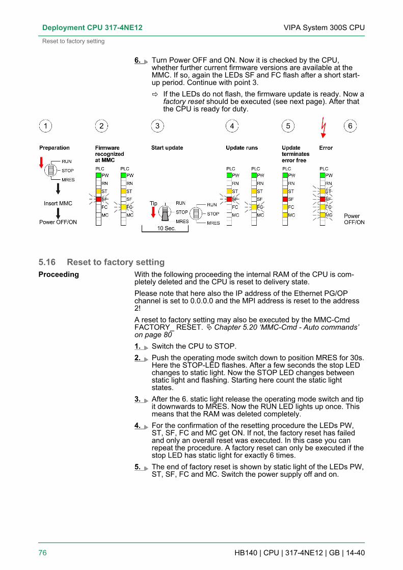
6. Turn Power OFF and ON. Now it is checked by the CPU,whether further current firmware versions are available at theMMC. If so, again the LEDs SF and FC flash after a short start-up period. Continue with point 3.ð If the LEDs do not flash, the firmware update is ready. Now a
factory reset should be executed (see next page). After thatthe CPU is ready for duty.
5.16 Reset to factory settingWith the following proceeding the internal RAM of the CPU is com-pletely deleted and the CPU is reset to delivery state.Please note that here also the IP address of the Ethernet PG/OPchannel is set to 0.0.0.0 and the MPI address is reset to the address2!A reset to factory setting may also be executed by the MMC-CmdFACTORY_ RESET. Ä Chapter 5.20 ‘MMC-Cmd - Auto commands’on page 801. Switch the CPU to STOP.2. Push the operating mode switch down to position MRES for 30s.
Here the STOP-LED flashes. After a few seconds the stop LEDchanges to static light. Now the STOP LED changes betweenstatic light and flashing. Starting here count the static lightstates.
3. After the 6. static light release the operating mode switch and tipit downwards to MRES. Now the RUN LED lights up once. Thismeans that the RAM was deleted completely.
4. For the confirmation of the resetting procedure the LEDs PW,ST, SF, FC and MC get ON. If not, the factory reset has failedand only an overall reset was executed. In this case you canrepeat the procedure. A factory reset can only be executed if thestop LED has static light for exactly 6 times.
5. The end of factory reset is shown by static light of the LEDs PW,ST, SF, FC and MC. Switch the power supply off and on.
Proceeding
VIPA System 300S CPUDeployment CPU 317-4NE12
Reset to factory setting
HB140 | CPU | 317-4NE12 | GB | 14-40 76

The proceeding is shown in the following Illustration:
After the firmware update you always should execute aReset to factory setting.
5.17 Slot for storage mediaAt the front of the CPU there is a slot for storage media. As externalstorage medium for applications and firmware you may use a multi-media card (MMC). You can cause the CPU to load a project auto-matically respectively to execute a command file by means of pre-defined file names.
To the following times an access takes place on a storage medium:n After overall reset
– The CPU checks if there is a project S7PROG.WLD. If existsthe project is automatically loaded.
– The CPU checks if there is a project PROTECT.WLD with pro-tected blocks. If exists the project is automatically loaded.These blocks are stored in the CPU until the CPU is reset tofactory setting or an empty PROTECT.WLD is loaded
– The CPU checks if a MCC memory extension card is put. Ifexists the memory extension is enabled, otherwise a memoryexpansion, which was activated before, is de-activated.
n After PowerON– The CPU checks if there is a project AUTOLOAD.WLD. If
exists an overall reset is established and the project is auto-matically loaded.
– The CPU checks if there is a command file withVIPA_CMD.MMC. If exists the command file is loaded and thecontaining instructions are executed.
– After PowerON and CPU STOP the CPU checks if there is a*.pkg file (firmware file). If exists this is indicated by blinking ofthe LEDs and the firmware may be installed by an updaterequest.
n Once in STOP– If a storage medium is put, which contains a command file
VIPA_CMD.MMC, the command file is loaded and the con-taining instructions are executed.
Overview
Accessing the storagemedium
VIPA System 300S CPU Deployment CPU 317-4NE12
Slot for storage media
HB140 | CPU | 317-4NE12 | GB | 14-40 77

5.18 Memory extension with MCC
There is the possibility to extend the work memory of the CPU. Forthis, a MCC memory extension card is available from VIPA. The MCCis a specially prepared MMC (Multimedia Card). By plugging the MCCinto the MCC slot and then an overall reset the according memoryexpansion is released. There may only one memory expansion beactivated at one time. On the MCC there is the file memory.key. Thisfile may not be altered or deleted. You may use the MCC also as"normal" MMC for storing your project.
To extend the memory, plug the MCC into the card slot at the CPUlabelled with "MCC" and execute an overall reset.
If the memory expansion on the MCC exceeds the maximum extend-ible memory range of the CPU, the maximum possible memory of theCPU is automatically used. You may determine the recent memoryextension via the integrated web page or with the Siemens SIMATICManager at Module Information - "Memory".
CAUTION!Please regard that the MCC must remain plugged whenyou’ve executed the memory expansion at the CPU. Oth-erwise the CPU switches to STOP after 72 hours. TheMCC cannot be exchanged with a MCC of the samememory configuration.
When the MCC memory configuration has been taken over you mayfind the diagnostic entry 0xE400 in the diagnostic buffer of the CPU.After pulling the MCC the entry 0xE401 appears in the diagnosticbuffer, the SF LED is on and after 72 hours the CPU switches toSTOP. A reboot is only possible after plugging-in the MCC again orafter an overall reset.The remaining time after pulling the MCC is always been shown withthe parameter MCC-Trial-Time on the web page.After re-plugging the MCC, the SF LED extinguishes and 0xE400 isentered into the diagnostic buffer. You may reset the memory config-uration of your CPU to the initial status at any time by executing anoverall reset without MCC.
Overview
Proceeding
Behavior
VIPA System 300S CPUDeployment CPU 317-4NE12
Memory extension with MCC
HB140 | CPU | 317-4NE12 | GB | 14-40 78

5.19 Extended know-how protectionBesides the "standard" Know-how protection the SPEED7-CPUs fromVIPA provide an "extended" know-how protection that serves asecure block protection for accesses of 3. persons.
The standard protection from Siemens transfers also protected blocksto the PG but their content is not displayed. But with according manip-ulation the Know-how protection is not guaranteed.
The "extended" know-how protection developed by VIPA offers theopportunity to store blocks permanently in the CPU. At the "extended"protection you transfer the protected blocks into a WLD-file namedprotect.wld. By plugging the MMC and following overall reset, theblocks in the protect.wld are permanently stored in the CPU. You mayprotect OBs, FBs and FCs. When back-reading the protected blocksinto the PG, exclusively the block header are loaded. The block codethat is to be protected remains in the CPU and cannot be read.
Create a new wld-file in your project engineering tool with ‘Fileè Memory Card file è New’ and rename it to "protect.wld". Transferthe according blocks into the file by dragging them with the mousefrom the project to the file window of protect.wld.
Transfer the file protect.wld to a MMC storage module, plug the MMCinto the CPU and execute an overall reset with the followingapproach:
The overall reset stores the blocks in protect.wld permanently in theCPU protected from accesses of 3. persons.
Overview
Standard protection
Extended protection
Protect blocks with pro-tect.wld
Transfer protect.wld toCPU with overall reset
VIPA System 300S CPU Deployment CPU 317-4NE12
Extended know-how protection
HB140 | CPU | 317-4NE12 | GB | 14-40 79
Protected blocks are overwritten by a new protect.wld. Using a PG 3.persons may access protected blocks but only the block header istransferred to the PG. The block code that is to be protected remainsin the CPU and cannot be read.
Protected blocks in the RAM of the CPU may be substituted at anytime by blocks with the same name. This change remains up to nextoverall reset. Protected blocks may permanently be overwritten only ifthese are deleted at the protect.wld before. By transferring an emptyprotect.wld from the MMC you may delete all protected blocks in theCPU.
Due to the fact that reading of a "protected" block from the CPU moni-tors no symbol labels it is convenient to provide the "block covers" forthe end user. For this, create a project out of all protected blocks.Delete all networks in the blocks so that these only contain the vari-able definitions in the according symbolism.
5.20 MMC-Cmd - Auto commandsA command file at a MMC is automatically executed under the fol-lowing conditions:n CPU is in STOP and MMC is stuckn After each PowerON
The command file is a text file, which consists of a commandsequence to be stored as vipa_cmd.mmc in the root directory of theMMC. The file has to be started by CMD_START as 1. command, fol-lowed by the desired commands (no other text) and must be finishedby CMD_END as last command.Text after the last command CMD_END e.g. comments is permis-sible, because this is ignored. As soon as the command file is recog-nized and executed each action is stored at the MMC in the log filelogfile.txt. In addition for each executed command a diagnostics entrymay be found in the diagnostics buffer.
Please regard the command sequence is to be started withCMD_START and ended with CMD_END.
Command Description Diagnostics entryCMD_START In the first line CMD_START is to be located. 0xE801
There is a diagnostic entry if CMD_START ismissing
0xE8FE
WAIT1SECOND Waits about 1 second. 0xE803
WEBPAGE The current web page of the CPU is stored atthe MMC as" webpage.htm".
0xE804
LOAD_PROJECT The function "Overall reset and reload fromMMC" is executed. The wld file located after thecommand is loaded else "s7prog.wld" is loaded.
0xE805
Protection behavior
Change respectivelydelete protected blocks
Usage of protectedblocks
Overview
Command file
Commands
VIPA System 300S CPUDeployment CPU 317-4NE12
MMC-Cmd - Auto commands
HB140 | CPU | 317-4NE12 | GB | 14-40 80

Command Description Diagnostics entrySAVE_PROJECT The recent project (blocks and hardware config-
uration) is stored as "s7prog.wld" at the MMC.Ifthe file just exists it is renamed to "s7prog.old".If your CPU is password protected so you haveto add this as parameter. Otherwise there is noproject written. Example: SAVE_PROJECTpassword
0xE806
FACTORY_RESET Executes "factory reset". 0xE807
DIAGBUF The current diagnostics buffer of the CPU isstored as "diagbuff.txt" at the MMC.
0xE80B
SET_NETWORK IP parameters for Ethernet PG/OP channel maybe set by means of this command. The IPparameters are to be given in the order IPaddress, subnet mask and gateway in theformat x.x.x.x each separated by a comma.Enter the IP address if there is no gatewayused.
0xE80E
CMD_END In the last line CMD_END is to be located. 0xE802
The structure of a command file is shown in the following. The corre-sponding diagnostics entry is put in parenthesizes.
Example 1CMD_START Marks the start of the command sequence (0xE801)LOAD_PROJECT proj.wld Execute an overall reset and load "proj.wld" (0xE805)WAIT1SECOND Wait ca. 1s (0xE803)WEBPAGE Store web page as "webpage.htm" (0xE804)DIAGBUF Store diagnostics buffer of the CPU as "diagbuff.txt"
(0xE80B)CMD_END Marks the end of the command sequence (0xE802)... arbitrary text ... Text after the command CMD_END is not evaluated.
Example 2CMD_START Marks the start of the command sequence (0xE801)LOAD_PROJECT proj2.wld Execute an overall reset and load "proj2.wld" (0xE805)WAIT1SECOND Wait ca. 1s (0xE803)WAIT1SECOND Wait ca. 1s (0xE803)SET_NETWORK172.16.129.210,255.255.224.0,172.16.129.210
IP parameter(0xE80E)
WAIT1SECOND Wait ca. 1s (0xE803)WAIT1SECOND Wait ca. 1s (0xE803)WEBPAGE Store web page as "webpage.htm" (0xE804)DIAGBUF Store diagnostics buffer of the CPU as "diagbuff.txt"
(0xE80B)
Examples
VIPA System 300S CPU Deployment CPU 317-4NE12
MMC-Cmd - Auto commands
HB140 | CPU | 317-4NE12 | GB | 14-40 81
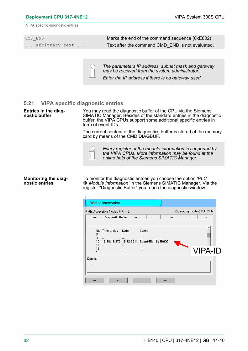
CMD_END Marks the end of the command sequence (0xE802)... arbitrary text ... Text after the command CMD_END is not evaluated.
The parameters IP address, subnet mask and gatewaymay be received from the system administrator.Enter the IP address if there is no gateway used.
5.21 VIPA specific diagnostic entriesYou may read the diagnostic buffer of the CPU via the SiemensSIMATIC Manager. Besides of the standard entries in the diagnosticbuffer, the VIPA CPUs support some additional specific entries inform of event-IDs.The current content of the diagnostics buffer is stored at the memorycard by means of the CMD DIAGBUF.
Every register of the module information is supported bythe VIPA CPUs. More information may be found at theonline help of the Siemens SIMATIC Manager.
To monitor the diagnostic entries you choose the option ‘PLCè Module Information’ in the Siemens SIMATIC Manager. Via theregister "Diagnostic Buffer" you reach the diagnostic window:
Entries in the diag-nostic buffer
Monitoring the diag-nostic entries
VIPA System 300S CPUDeployment CPU 317-4NE12
VIPA specific diagnostic entries
HB140 | CPU | 317-4NE12 | GB | 14-40 82
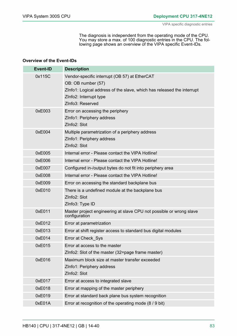
The diagnosis is independent from the operating mode of the CPU.You may store a max. of 100 diagnostic entries in the CPU. The fol-lowing page shows an overview of the VIPA specific Event-IDs.
Overview of the Event-IDs
Event-ID Description0x115C Vendor-specific interrupt (OB 57) at EtherCAT
OB: OB number (57)ZInfo1: Logical address of the slave, which has released the interruptZInfo2: Interrupt typeZInfo3: Reserved
0xE003 Error on accessing the peripheryZInfo1: Periphery addressZInfo2: Slot
0xE004 Multiple parametrization of a periphery addressZInfo1: Periphery addressZInfo2: Slot
0xE005 Internal error - Please contact the VIPA Hotline!
0xE006 Internal error - Please contact the VIPA Hotline!
0xE007 Configured in-/output bytes do not fit into periphery area
0xE008 Internal error - Please contact the VIPA Hotline!
0xE009 Error on accessing the standard backplane bus
0xE010 There is a undefined module at the backplane busZInfo2: SlotZInfo3: Type ID
0xE011 Master project engineering at slave CPU not possible or wrong slaveconfiguration
0xE012 Error at parametrization
0xE013 Error at shift register access to standard bus digital modules
0xE014 Error at Check_Sys
0xE015 Error at access to the masterZInfo2: Slot of the master (32=page frame master)
0xE016 Maximum block size at master transfer exceededZInfo1: Periphery addressZInfo2: Slot
0xE017 Error at access to integrated slave
0xE018 Error at mapping of the master periphery
0xE019 Error at standard back plane bus system recognition
0xE01A Error at recognition of the operating mode (8 / 9 bit)
VIPA System 300S CPU Deployment CPU 317-4NE12
VIPA specific diagnostic entries
HB140 | CPU | 317-4NE12 | GB | 14-40 83

Event-ID Description0xE01B Error - Maximum number of plug-in modules exceeded
0xE020 Error - Interrupt information is not defined
0xE030 Error of the standard bus
0xE033 Internal error - Please contact the VIPA Hotline!
0xE0B0 SPEED7 is not stoppable(Probably undefined BCD value at timer)
0xE0C0 Not enough space in work memory for storing code block (block sizeexceeded)
0xE0CB Error at SSL accessZInfo1: 4=SSL wrong, 5=SubSSL wrong, 6=Index wrongZInfo2: SSL-IDZInfo3: Index
0xE0CC Communication error MPI / SerialZInfo1: Code1: Wrong priority2: Buffer overflow3: Frame format error4: Wrong SSL request (SSL-ID not valid)5: Wrong SSL request (SSL-SubID not valid)6: Wrong SSL request (SSL-Index not valid)7: Wrong value8: Wrong RetVal9: Wrong SAP10: Wrong connection type11: Wrong sequence number12: Faulty block number in the telegram13: Faulty block type in the telegram14: Inactive function15: Wrong size in the telegram20: Error writing to memory card90: Faulty buffer size98: Unknown error99: Internal error
0xE0CD Error at DP-V1 job management
0xE0CE Error: Timeout at sending of the i-slave diagnostics
0xE0CF Timeout at loading of a new HW configuration (timeout: 39 seconds)
0xE100 Memory card access error
VIPA System 300S CPUDeployment CPU 317-4NE12
VIPA specific diagnostic entries
HB140 | CPU | 317-4NE12 | GB | 14-40 84

Event-ID Description0xE101 Memory card error file system
0xE102 Memory card error FAT
0xE104 Memory card error at saving
0xE200 Memory card writing finished (Copy Ram2Rom)
0xE210 Memory card reading finished (reload after overall reset)
0xE21E Memory card reading: Error at reload (after overall reset), file "Protect.wld"too big
0xE21F Memory card reading: Error at reload (after overall reset), file read error, outof memory
0xE300 Internal flash writing finished (Copy Ram2Rom)
0xE310 Internal flash writing finished (reload after battery failure)
0xE311 Internal flash fx0000yy.wld file too big, load failure
0xE400 Memory card with the option memory expansion was plugged
0xE401 Memory card with the option memory expansion was removed
0xE402 The PROFIBUS DP master functionality is disabled. The interface acts fur-ther as MPI interface
0xE403 The PROFIBUS DP slave functionality is disabled. The interface acts furtheras MPI interface
0xE500 Memory management: Deleted block without corresponding entry in BlockListZInfo2: BlockTypeZInfo3: BlockNo
0xE604 Multiple parametrization of a periphery address for Ethernet PG/OP channelZInfo1: Periphery addressZInfo3:0: Periphery address is input, 1: Periphery address is output
0xE701 Internal error - Please contact the VIPA Hotline!
0xE703 Internal error - Please contact the VIPA Hotline!
0xE720 Internal error - Please contact the VIPA Hotline!
0xE721 Internal error - Please contact the VIPA Hotline!
0xE801 CMD - Auto command: CMD_START recognized and successfully executed
0xE802 CMD - Auto command: CMD_End recognized and successfully executed
0xE803 CMD - Auto command: WAIT1SECOND recognized and successfully exe-cuted
VIPA System 300S CPU Deployment CPU 317-4NE12
VIPA specific diagnostic entries
HB140 | CPU | 317-4NE12 | GB | 14-40 85

Event-ID Description0xE804 CMD - Auto command: WEBPAGE recognized and successfully executed
0xE805 CMD - Auto command: LOAD_PROJECT recognized and successfully exe-cuted
0xE806 CMD - Auto command: SAVE_PROJECT recognized and successfully exe-cuted
0xE807 CMD - Auto command: FACTORY_RESET recognized and successfullyexecuted
0xE80B CMD - Auto command: DIAGBUF recognized and successfully executed
0xE80E CMD - Auto command: SET_NETWORK recognized and successfully exe-cuted
0xE8FB CMD - Auto command: Error: Initialization of the Ethernet PG/OP channelby means of SET_NETWORK is faulty
0xE8FC CMD - Auto command: Error: Some IP parameters missing in SET_NET-WORK
0xE8FE CMD - Auto command: Error: CMD_START missing
0xE8FF CMD - Auto command: Error: Error while reading CMD file (memory carderror)
0xE901 Check sum error
0xEA00 Internal error - Please contact the VIPA Hotline!
0xEA01 Internal error - Please contact the VIPA Hotline!
0xEA02 SBUS: Internal error (internal plugged sub module not recognized)ZInfo1: Internal slot
0xEA03 SBUS: Communication error CPU - PROFINET I/O controller:ZInfo1: SlotZInfo2: Status(0: OK, 1: ERROR, 2: BUSSY, 3: TIMEOUT, 4: LOCKED, 5: UNKNOWN)
0xEA04 SBUS: Multiple parametrization of a periphery addressZInfo1: Periphery addressZInfo2: SlotZInfo3: Data width
0xEA05 Internal error - Please contact the VIPA Hotline!
0xEA07 Internal error - Please contact the VIPA Hotline!
0xEA08 SBUS: Parametrized input data width unequal to plugged input data widthZInfo1: Parametrized input data widthZInfo2: SlotZInfo3: Input data width of the plugged module
VIPA System 300S CPUDeployment CPU 317-4NE12
VIPA specific diagnostic entries
HB140 | CPU | 317-4NE12 | GB | 14-40 86
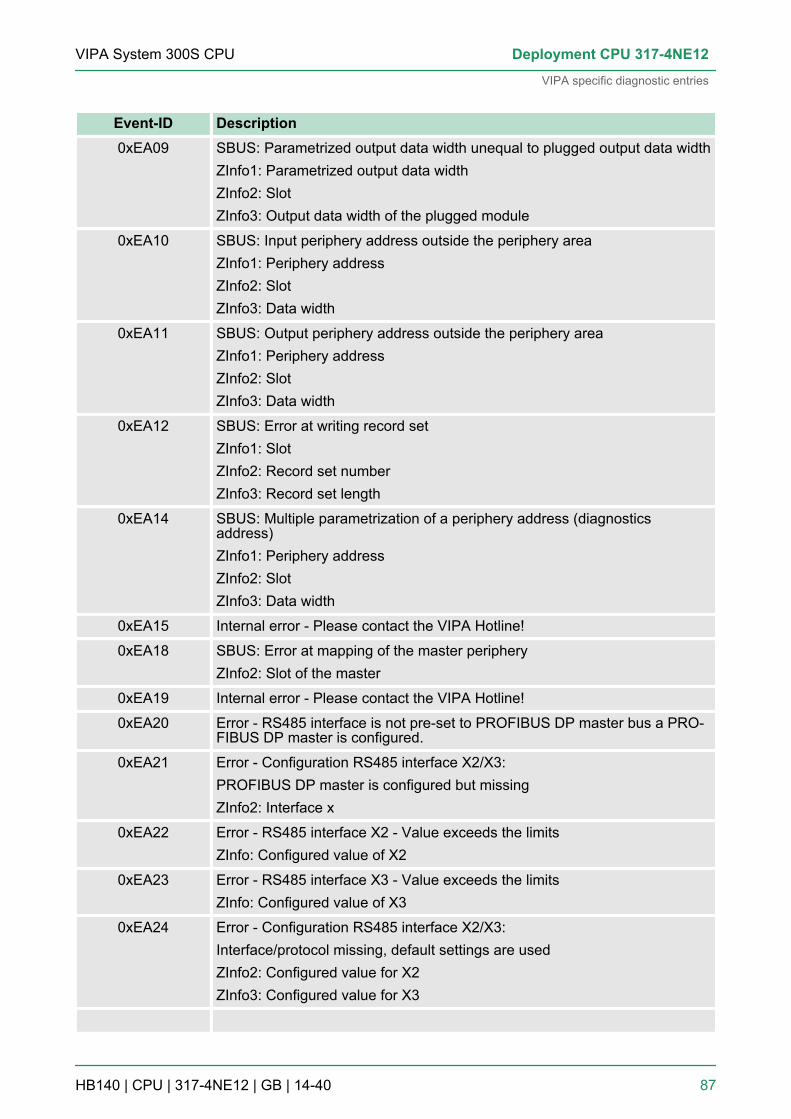
Event-ID Description0xEA09 SBUS: Parametrized output data width unequal to plugged output data width
ZInfo1: Parametrized output data widthZInfo2: SlotZInfo3: Output data width of the plugged module
0xEA10 SBUS: Input periphery address outside the periphery areaZInfo1: Periphery addressZInfo2: SlotZInfo3: Data width
0xEA11 SBUS: Output periphery address outside the periphery areaZInfo1: Periphery addressZInfo2: SlotZInfo3: Data width
0xEA12 SBUS: Error at writing record setZInfo1: SlotZInfo2: Record set numberZInfo3: Record set length
0xEA14 SBUS: Multiple parametrization of a periphery address (diagnosticsaddress)ZInfo1: Periphery addressZInfo2: SlotZInfo3: Data width
0xEA15 Internal error - Please contact the VIPA Hotline!
0xEA18 SBUS: Error at mapping of the master peripheryZInfo2: Slot of the master
0xEA19 Internal error - Please contact the VIPA Hotline!
0xEA20 Error - RS485 interface is not pre-set to PROFIBUS DP master bus a PRO-FIBUS DP master is configured.
0xEA21 Error - Configuration RS485 interface X2/X3:PROFIBUS DP master is configured but missingZInfo2: Interface x
0xEA22 Error - RS485 interface X2 - Value exceeds the limitsZInfo: Configured value of X2
0xEA23 Error - RS485 interface X3 - Value exceeds the limitsZInfo: Configured value of X3
0xEA24 Error - Configuration RS485 interface X2/X3:Interface/protocol missing, default settings are usedZInfo2: Configured value for X2ZInfo3: Configured value for X3
VIPA System 300S CPU Deployment CPU 317-4NE12
VIPA specific diagnostic entries
HB140 | CPU | 317-4NE12 | GB | 14-40 87

Event-ID Description0xEA30 Internal error - Please contact the VIPA Hotline!
0xEA40 Internal error - Please contact the VIPA Hotline!
0xEA41 Internal error - Please contact the VIPA Hotline!
0xEA50 Error - PROFINET configurationZInfo1: User slot of the PROFINET I/O controllerZInfo2: IO-Device-No.ZInfo3: IO-Device slot
0xEA51 Error - There is no PROFINET IO controller at the configured slotZInfo1: User slot of the PROFINET I/O controllerZInfo2: Recognized ID at the configured slot
0xEA53 Error - PROFINET configuration - There are too many PROFINET IOdevices configuredZInfo1: Number of configured devicesZInfo2: SlotZInfo3: Maximum possible number of devices
0xEA54 Error - PROFINET IO controller reports multiple parametrization of aperiphery addressZInfo1: Periphery addressZInfo2: User slot of the PROFINET I/O controllerZInfo3: Data width
0xEA61 ... 0xEA63 Internal error - Please contact the VIPA Hotline!
VIPA System 300S CPUDeployment CPU 317-4NE12
VIPA specific diagnostic entries
HB140 | CPU | 317-4NE12 | GB | 14-40 88
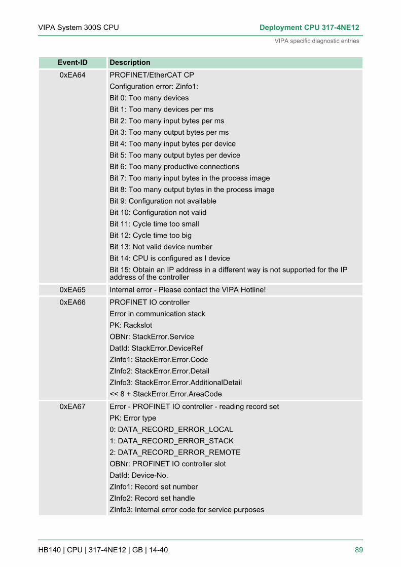
Event-ID Description0xEA64 PROFINET/EtherCAT CP
Configuration error: Zinfo1:Bit 0: Too many devicesBit 1: Too many devices per msBit 2: Too many input bytes per msBit 3: Too many output bytes per msBit 4: Too many input bytes per deviceBit 5: Too many output bytes per deviceBit 6: Too many productive connectionsBit 7: Too many input bytes in the process imageBit 8: Too many output bytes in the process imageBit 9: Configuration not availableBit 10: Configuration not validBit 11: Cycle time too smallBit 12: Cycle time too bigBit 13: Not valid device numberBit 14: CPU is configured as I deviceBit 15: Obtain an IP address in a different way is not supported for the IPaddress of the controller
0xEA65 Internal error - Please contact the VIPA Hotline!
0xEA66 PROFINET IO controllerError in communication stackPK: RackslotOBNr: StackError.ServiceDatId: StackError.DeviceRefZInfo1: StackError.Error.CodeZInfo2: StackError.Error.DetailZInfo3: StackError.Error.AdditionalDetail<< 8 + StackError.Error.AreaCode
0xEA67 Error - PROFINET IO controller - reading record setPK: Error type0: DATA_RECORD_ERROR_LOCAL1: DATA_RECORD_ERROR_STACK2: DATA_RECORD_ERROR_REMOTEOBNr: PROFINET IO controller slotDatId: Device-No.ZInfo1: Record set numberZInfo2: Record set handleZInfo3: Internal error code for service purposes
VIPA System 300S CPU Deployment CPU 317-4NE12
VIPA specific diagnostic entries
HB140 | CPU | 317-4NE12 | GB | 14-40 89

Event-ID Description0xEA68 Error - PROFINET IO controller - writing record set
PK: Error type0: DATA_RECORD_ERROR_LOCAL1: DATA_RECORD_ERROR_STACK2: DATA_RECORD_ERROR_REMOTEOBNo: PROFINET IO controller slotDatId: Device-No.ZInfo1: Record set numberZInfo2: Record set handleZInfo3: Internal error code for service purposes
0xEA69 Internal error - Please contact the VIPA Hotline!
0xEA6A PROFINET IO controllerService error in communication stackPK: RackslotOBNo: ServiceIdentifierDatId: 0ZInfo1: ServiceError.CodeZInfo2: ServiceError.DetailZInfo3: StackError.Error.AdditionalDetail
0xEA6B PROFINET IO controllerVendor ID mismatchPK: RackslotOBNo: PLC ModeDatId: 0ZInfo1: Device IDZInfo2: -ZInfo3: -
0xEA6C PROFINET IO controllerDevice ID mismatchPK: RackslotOBNo: PLC ModeDatId: 0ZInfo1: Device IDZInfo2: -ZInfo3: -
VIPA System 300S CPUDeployment CPU 317-4NE12
VIPA specific diagnostic entries
HB140 | CPU | 317-4NE12 | GB | 14-40 90

Event-ID Description0xEA6D PROFINET IO controller
No empty namePK: RackslotOBNo: PLC ModeDatId: 0ZInfo1: Device IDZInfo2: -ZInfo3: -
0xEA6E PROFINET IO controllerRPC response missingPK: RackslotOBNo: PLC ModeDatId: 0ZInfo1: Device IDZInfo2: -ZInfo3: -
0xEA6F PROFINET IO controllerPN module mismatchPK: RackslotOBNo: PLC-ModeDatId: 0ZInfo1: Device IDZInfo2: -ZInfo3: -
0xEA97 Storage error SBUS service channelZInfo3 = Slot
0xEA98 Timeout at waiting for reboot of a SBUS module (server)
0xEA99 Error at file reading via SBUS
VIPA System 300S CPU Deployment CPU 317-4NE12
VIPA specific diagnostic entries
HB140 | CPU | 317-4NE12 | GB | 14-40 91

Event-ID Description0xEAA0 Emac Error occurred
OBNo: Current PLC modeZInfo1: Diagnostics address of the master / controllerZInfo2:0: None Rx queue is full1: No send buffer available2: Send stream was cut off; sending failed3: Exhausted retries4: No receive buffer available in Emac DMA5: Emac DMA transfer aborted6: Queue overflow7: Unexpected frame receivedZInfo3: Number of errors, which occurred
0xEAB0 Link mode not validOBNo: Current PLC modeZInfo1: Diagnostics address master / controllerZinfo2: Current LinkMode0x01: 10Mbit full-duplex0x02: 100Mbit half-duplex0x03: 100Mbit full-duplex0x05: 10Mbit half-duplex0xFF: Link mode not defined
0xEB03 SLIO error on IO mapping
0xEB10 SLIO error: Bus errorZInfo1: Type of error0x82: ErrorAlarm
0xEB20 SLIO error: Interrupt information undefined
0xEB21 SLIO error on accessing the configuration data
VIPA System 300S CPUDeployment CPU 317-4NE12
VIPA specific diagnostic entries
HB140 | CPU | 317-4NE12 | GB | 14-40 92

Event-ID Description0xEC03 EtherCAT: Configuration error
ZInfo1: Errorcode1: NUMBER_OF_SLAVES_NOT_SUPPORTED2: SYSTEM_IO_NR_INVALID3: INDEX_FROM_SLOT_ERROR4: MASTER_CONFIG_INVALID5: MASTER_TYPE_ERROR6: SLAVE_DIAG_ADDR_INVALID7: SLAVE_ADDR_INVALID8: SLAVE_MODULE_IO_CONFIG_INVALID9: LOG_ADDR_ALREADY_IN_USE10: NULL_PTR_CHECK_ERROR11: IO_MAPPING_ERROR12: ERROR
0xEC04 EtherCAT: Multiple configuration of a periphery addressZInfo1: Periphery addressZInfo2: Slot
0xEC10 EtherCAT: Restoration bus with its slavesOB start Info (Local data) StartEvent and Eventclass: 0xEC10DatID:0xXXYY:XX=0x54 with input address in ZInfo1,XX=0x55 with output address.YY=0x00 Station not available,YY=0x01 Station available (process data)ZInfo1: 0xXXYY (XX=OldState, YY=NewState)ZInfo2: Diagnostics address of the masterZInfo3: Number of stations, which are not in the same state as the master(> 0)
VIPA System 300S CPU Deployment CPU 317-4NE12
VIPA specific diagnostic entries
HB140 | CPU | 317-4NE12 | GB | 14-40 93

Event-ID Description0xEC11 EtherCAT: Restoration bus with missing slaves
OB start Info (Local data) StartEvent and Eventclass: 0xEC11DatID:0xXXYY:XX=0x54 with input address in ZInfo1,XX=0x55 with output address.YY=0x00 Station not available,YY=0x01 Station available (process data)ZInfo1: 0xXXYY (XX=OldState, YY=NewState)ZInfo2: Diagnostics address of the masterZInfo3: Number of stations, which are not in the same state as the master(> 0)
0xEC12 EtherCAT: restoration slaveOB start Info (Local data) StartEvent and Eventclass: 0xEC12DatID:0xXXYY:XX=0x54 with input address in ZInfo1,XX=0x55 with output address.YY=0x00 Station not available,YY=0x01 Station available (process data)ZInfo1: 0xXXYY (XX=OldState, YY=NewState)ZInfo2: Diagnostics of the StationZInfo3: AlStatusCode
0xEC30 EtherCAT: Topology OKOB start Info (Local data) StartEvent and Eventclass: 0xEC30ZInfo2: Diagnostics address of the master
0xEC50 EtherCAT: DC not in SyncZInfo1: Diagnostics address of the master
0xED10 EtherCAT: Bus failureOB start Info (Local data) StartEvent and Eventclass: 0xED10DatID:0xXXYY:XX=0x54 with input address in ZInfo1,XX=0x55 with output address.YY=0x00 Station not available,YY=0x01 Station available (process data)ZInfo1: 0xXXYY (XX=OldState, YY=NewState)ZInfo2: Diagnostics address of the masterZInfo3: Number of stations, which are not in the same state as the master
VIPA System 300S CPUDeployment CPU 317-4NE12
VIPA specific diagnostic entries
HB140 | CPU | 317-4NE12 | GB | 14-40 94

Event-ID Description0xED12 EtherCAT: Failure slave
OB start Info (Local data) StartEvent and Eventclass: 0xED12DatID:0xXXYY:XX=0x54 with input address in ZInfo1,XX=0x55 with output address.YY=0x00 Station not available,YY=0x01 Station available (process data)ZInfo1: 0xXXYY (XX=OldState, YY=NewState)ZInfo2: Diagnostics of the StationZInfo3: AlStatusCode
0xED20 EtherCAT: Bus state change without calling OB86OB start Info (Local data) StartEvent and Eventclass: 0xED20DatID:0xXXYY:XX=0x54 with input address in ZInfo1,XX=0x55 with output address.YY=0x00 Station not available,YY=0x01 Station available (process data)ZInfo1: 0xXXYY (XX=OldState, YY=NewState)ZInfo2: Diagnostics address of the masterZInfo3: Number of stations, which are not in the same state as the master
0xED21 EtherCAT: error in bus state changeOB: 0x00PK: 0x00DatID:0xXXYY:XX=0x54 with input address in ZInfo1,XX=0x55 with output address.YY=0x00 Station not available,YY=0x01 Station available (process data)ZInfo1: 0xXXYY (XX = current state, YY = expected state)ZInfo2: Diagnostics address of the masterZInfo3: ErrorCode:0x0008: Busy0x000B: Invalid Parameter0x000E: Invalid State0x0010: Timeout
VIPA System 300S CPU Deployment CPU 317-4NE12
VIPA specific diagnostic entries
HB140 | CPU | 317-4NE12 | GB | 14-40 95

Event-ID Description0xED22 EtherCAT: Bus state change without calling OB86
OB start Info (Local data) StartEvent and Eventclass: 0xED22DatID:0xXXYY:XX=0x54 with input address in ZInfo1,XX=0x55 with output address.YY=0x00 Station not available,YY=0x01 Station available (process data)ZInfo1: 0xXXYY (XX=OldState, YY=NewState)ZInfo2: Diagnostics of the StationZInfo3: AlStatusCode
0xED30 EtherCAT: Topology MismatchOB start Info (Local data) StartEvent and Eventclass: 0xED30ZInfo2: Diagnostics address of the master
0xED31 EtherCAT: Interrupt Queue OverflowOB start Info (Local data) StartEvent and Eventclass: 0xED31ZInfo2: Diagnostics address of the master
0xED40 ... 0xED4F Internal error - Please contact the VIPA Hotline!
0xED50 EtherCAT: DC not in SyncZInfo1: Diagnostics address of the master
0xED60 EtherCAT: Diagnostics buffer CP:Slave state changePK: 0OB: PLC-ModeDatID 1/2: 0ZInfo1: 0x00YY:YY: New EtherCAT state of the slaveZInfo2: EtherCAT station addressZInfo3: AlStatusCode (EtherCAT specific error code)
VIPA System 300S CPUDeployment CPU 317-4NE12
VIPA specific diagnostic entries
HB140 | CPU | 317-4NE12 | GB | 14-40 96

Event-ID Description0xED61 EtherCAT: Diagnostics buffer CP:
CoE emergencyPK: EtherCAT station address (low byte)OB: EtherCAT station address (high byte)DatID 1/2: Error codeZInfo1: 0xYYZZ:YY: Error registerZZ: MEF byte 1ZInfo 2: 0xYYZZ:YY: MEF byte 2ZZ: MEF byte 3ZInfo3: 0xYYZZ:YY: MEF byte 4ZZ: MEF byte 5
0xED62 EtherCAT: Diagnostics buffer CP:Error on SDO access during state changePK: EtherCAT station address (low byte)OB: EtherCAT station address (high byte)DatID 1/2: SubindexZInfo1: IndexZInfo2: SDO error code (high word)ZInfo3: SDO error code (low word)
0xED70 EtherCAT: Diagnostics buffer CP:Twice HotConnect group foundPK: 0OB: PLC-ModeDatID 1/2: 0ZInfo1: Diagnostics address of the masterZInfo2: EtherCAT station addressZInfo3: 0
0xEE00 Additional information at UNDEF_OPCODE
0xEE01 Internal error - Please contact the VIPA Hotline!
0xEEEE CPU was completely overall reset, since after PowerON the start-up couldnot be finished.
0xEF11 ... 0xEF13 Internal error - Please contact the VIPA Hotline!
VIPA System 300S CPU Deployment CPU 317-4NE12
VIPA specific diagnostic entries
HB140 | CPU | 317-4NE12 | GB | 14-40 97

Event-ID Description0xEFFF Internal error - Please contact the VIPA Hotline!
PK: C-Source module number | DatID: Line number
5.22 Control and monitoring of variables with test functionsFor troubleshooting purposes and to display the status of certain vari-ables you can access certain test functions via the menu item Debugof the Siemens SIMATIC Manager.The status of the operands and the RLO can be displayed by meansof the test function ‘Debug è Monitor’.You can modify and/or display the status of variables by means of thetest function ‘PLC è Monitor/Modify Variables’.
This test function displays the current status and the RLO of the dif-ferent operands while the program is being executed.It is also possible to enter corrections to the program.
When using the test function “Monitor” the PLC must be inRUN mode!
The processing of the states may be interrupted by means of jumpcommands or by timer and process-related alarms. At the breakpointthe CPU stops collecting data for the status display and instead of therequired data it only provides the PG with data containing the value 0.For this reason, jumps or time and process alarms can result in thevalue displayed during program execution remaining at 0 for the itemsbelow:n the result of the logical operation RLOn Status / AKKU 1n AKKU 2n Condition byten absolute memory address SAZ. In this case SAZ is followed by a
"?".The interruption of the processing of statuses does not change theexecution of the program. It only shows that the data displayed is nolonger.
This test function returns the condition of a selected operand (inputs,outputs, flags, data word, counters or timers) at the end of program-execution.This information is obtained from the process image of the selectedoperands. During the "processing check" or in operating mode STOPthe periphery is read directly from the inputs. Otherwise only theprocess image of the selected operands is displayed.
Control of outputs
Overview
‘Debug è Monitor’
‘PLCè Monitor/ModifyVariables’
VIPA System 300S CPUDeployment CPU 317-4NE12
Control and monitoring of variables with test functions
HB140 | CPU | 317-4NE12 | GB | 14-40 98

It is possible to check the wiring and proper operation of output mod-ules.You can set outputs to any desired status with or without a controlprogram. The process image is not modified but outputs are no longerinhibited.
Control of variablesThe following variables may be modified: I, Q, M, T, C and D.The process image of binary and digital operands is modified inde-pendently of the operating mode of the CPU.When the operating mode is RUN the program is executed with themodified process variable. When the program continues they may,however, be modified again without notification.Process variables are controlled asynchronously to the executionsequence of the program.
VIPA System 300S CPU Deployment CPU 317-4NE12
Control and monitoring of variables with test functions
HB140 | CPU | 317-4NE12 | GB | 14-40 99

6 Deployment PtP communication6.1 Fast introduction
The CPU has a PROFIBUS/PtP interface with a fix pinout. After anoverall reset the interface is deactivated. By appropriate configurationthe PtP function (point to point) can be enabled:n PtP functionality
– Using the PtP functionality the RS485 interface is allowed toconnect via serial point-to-point connection to different sourceres. target systems.
– The activation of the PtP functionality happens by embeddingthe SPEEDBUS.GSD from VIPA in the hardware catalog. Afterthe installation the CPU may be configured in a PROFIBUSmaster system and here the interface may be switched to PtPcommunication.
The protocols res. procedures ASCII, STX/ETX, 3964R, USS andModbus are supported.
The parametrization of the serial interface happens during runtimeusing the FC/SFC 216 (SER_CFG). For this you have to store theparameters in a DB for all protocols except ASCII.
The FCs/SFCs are controlling the communication. Send takes placevia FC/SFC 217 (SER_SND) and receive via FC/SFC 218(SER_RCV). The repeated call of the FC/SFC 217 SER_SNDdelivers a return value for 3964R, USS and Modbus via RetVal thatcontains, among other things, recent information about the acknowl-edgement of the partner station. The protocols USS and Modbusallow to evaluate the receipt telegram by calling the FC/SFC 218SER_RCV after SER_SND. The FCs/SFCs are included in the con-signment of the CPU.
The following FCs/SFCs are used for the serial communication:
FC/SFC DescriptionFC/SFC 216 SER_CFG RS485 parameterize
FC/SFC 217 SER_SND RS485 send
FC/SFC 218 SER_RCV RS485 receive
General
Protocols
Parametrization
Communication
Overview FCs/SFCs forserial communication
VIPA System 300S CPUDeployment PtP communication
Fast introduction
HB140 | CPU | 317-4NE12 | GB | 14-40 100

6.2 Principle of the data transferThe data transfer is handled during runtime by using FC/SFCs. Theprinciple of data transfer is the same for all protocols and is shortlyillustrated in the following.n Data, which are written into the according data channel by the
CPU, is stored in a FIFO send buffer (first in first out) with a sizeof 2x1024byte and then put out via the interface.
n When the interface receives data, this is stored in a FIFO receivebuffer with a size of 2x1024byte and can there be read by theCPU.
n If the data is transferred via a protocol, the embedding of the datato the according protocol happens automatically.
n In opposite to ASCII and STX/ETX, the protocols 3964R, USS andModbus require the acknowledgement of the partner.
n An additional call of the FC/SFC 217 SER_SND causes a returnvalue in RetVal that includes among others recent informationabout the acknowledgement of the partner.
n Further on for USS and Modbus after a SER_SND the acknowl-edgement telegram must be evaluated by a call of the FC/SFC218 SER_RCV.
6.3 Deployment of RS485 interface for PtPPer default, the RS485 interface is deactivated. Via hardware configu-ration the RS485 interfaces may be switched to PtP operation (pointto point) via the parameter Function RS485 of the Properties.
Since the VIPA specific CPU parameters may be set, the installationof the SPEEDBUS.GSD from VIPA in the hardware catalog is neces-sary. The CPU may be configured in a PROFIBUS master systemand the appropriate parameters may be set after installation.
Overview
Switch to PtP operation
Requirements
VIPA System 300S CPU Deployment PtP communication
Deployment of RS485 interface for PtP
HB140 | CPU | 317-4NE12 | GB | 14-40 101

The GSD (Geräte-Stamm-Datei) is online available in the followinglanguage versions. Further language versions are available oninquires:
Name LanguageSPEEDBUS.GSD german (default)
SPEEDBUS.GSG german
SPEEDBUS.GSE english
The GSD files may be found at www.vipa.com at the "Service" part.The integration of the SPEEDBUS.GSD takes place with the followingproceeding:1. Browse to www.vipa.com2. Click to ‘Service è Download è GSD- and EDS-Files
è Profibus’3. Download the file Cx000023_Vxxx.4. Extract the file to your work directory. The SPEEDBUS.GSD is
stored in the directory VIPA_System_300S.5. Start the hardware configurator from Siemens.6. Close every project.7. Select ‘Options è Install new GSD-file’.8. Navigate to the directory VIPA_System_300S and select
SPEEDBUS.GSD an.ð The SPEED7 CPUs and modules of the System 300S from
VIPA may now be found in the hardware catalog at PRO-FIBUS-DP / Additional field devices / I/O /VIPA_SPEEDBUS.
Installation of theSPEEDBUS.GSD
VIPA System 300S CPUDeployment PtP communication
Deployment of RS485 interface for PtP
HB140 | CPU | 317-4NE12 | GB | 14-40 102

The embedding of the CPU 317-4NE12 happens by means of a vir-tual PROFIBUS master system with the following approach:1. Perform a hardware configuration for the CPU. Ä Chapter 5.4
‘Hardware configuration - CPU’ on page 492. Configure always as last module a Siemens DP master CP
342-5 (342-5DA02 V5.0). Connect and parameterize it at opera-tion mode "DP-Master".
3. Connect the slave system "VIPA_SPEEDbus". After installingthe SPEEDBUS.GSD this may be found in the hardware catalogat PROFIBUS DP / Additional field devices / I/O / VIPA /VIPA_SPEEDBUS.
4. For the slave system set the PROFIBUS address 100.5. Configure at slot 0 the VIPA CPU 317-4NE12 of the hardware
catalog from VIPA_SPEEDbus.6. By double clicking the placed CPU 317-4NE12 the properties
dialog of the CPU may be opened.
As soon as the project is transferred together with the PLC user pro-gram to the CPU, the parameters will be taken after start-up.
The hardware configuration, which is shown here, is onlyrequired, if you want to customize the VIPA specificparameters.
1. By double clicking the CPU 317-4NE12 placed in the slavesystem the properties dialog of the CPU may be opened.
2. Switch the Parameter ‘Function RS485 X3’ to ‘PtP’ .
n Logical states represented by voltage differences between the twocores of a twisted pair cable
n Serial bus connection in two-wire technology using half duplexmode
n Data communications up to a max. distance of 500mn Data communication rate up to 115.2kbaud
Proceeding
Setting PtP parameters
Properties RS485
VIPA System 300S CPU Deployment PtP communication
Deployment of RS485 interface for PtP
HB140 | CPU | 317-4NE12 | GB | 14-40 103

9pin SubD jack
Pin RS4851 n.c.
2 M24V
3 RxD/TxD-P (Line B)
4 RTS
5 M5V
6 P5V
7 P24V
8 RxD/TxD-N (Line A)
9 n.c.
6.4 Parametrization6.4.1 FC/SFC 216 - SER_CFG
The parametrization happens during runtime deploying the FC/SFC216 (SER_CFG). You have to store the parameters for STX/ETX,3964R, USS and Modbus in a DB.
RS485
Connection
Description
VIPA System 300S CPUDeployment PtP communication
Parametrization > FC/SFC 216 - SER_CFG
HB140 | CPU | 317-4NE12 | GB | 14-40 104

Parameter Declaration Data type DescriptionPROTOCOL IN BYTE 1=ASCII, 2=STX/ETX, 3=3964R
PARAMETER IN ANY Pointer to protocol-parameters
BAUDRATE IN BYTE Number of baudrate
CHARLEN IN BYTE 0=5bit, 1=6bit, 2=7bit, 3=8bit
PARITY IN BYTE 0=Non, 1=Odd, 2=Even
STOPBITS IN BYTE 1=1bit, 2=1.5bit, 3=2bit
FLOWCONTROL IN BYTE 1 (fix)
RETVAL OUT WORD Return value (0 = OK)
All time settings for timeouts must be set as hexadecimal value. Findthe Hex value by multiply the wanted time in seconds with the bau-drate.Example:Wanted time 8ms at a baudrate of 19200baudCalculation: 19200bit/s x 0.008s ≈ 154bit → (9Ah)Hex value is 9Ah.
Here you fix the protocol to be used.You may choose between:1: ASCII2: STX/ETX3: 3964R4: USS Master5: Modbus RTU Master6: Modbus ASCII Master
At ASCII protocol, this parameter is ignored.At STX/ETX, 3964R, USS and Modbus you fix here a DB that con-tains the communication parameters and has the following structurefor the according protocols:
Data block at STX/ETX
DBB0: STX1 BYTE (1. Start-ID in hexadecimal)
DBB1: STX2 BYTE (2. Start-ID in hexadecimal)
DBB2: ETX1 BYTE (1. End-ID in hexadecimal)
DBB3: ETX2 BYTE (2. End-ID in hexadecimal)
DBW4: TIMEOUT WORD (max. delay time between 2telegrams)
Parameters
PROTOCOL
PARAMETER (as DB)
VIPA System 300S CPU Deployment PtP communication
Parametrization > FC/SFC 216 - SER_CFG
HB140 | CPU | 317-4NE12 | GB | 14-40 105

The start res. end sign should always be a value <20, oth-erwise the sign is ignored!With not used IDs please always enter FFh!
Data block at 3964R
DBB0: Prio BYTE (The priority of both partnersmust be different)
DBB1: ConnAttmptNr BYTE (Number of connection trials)
DBB2: SendAttmptNr BYTE (Number of telegram retries)
DBB4: CharTimeout WORD (Char. delay time)
DBW6: ConfTimeout WORD (Acknowledgement delay time )
Data block at USS
DBW0: Timeout WORD (Delay time)
Data block at Modbus master
DBW0: Timeout WORD (Respond delay time)
Velocity of data transfer in bit/s (baud)
04h: 1200baud 05h: 1800baud 06h: 2400baud 07h: 4800baud
08h: 7200baud 09h: 9600baud 0Ah: 14400baud 0Bh: 19200baud
0Ch: 38400baud 0Dh: 57600baud 0Eh: 115200baud
Number of data bits where a character is mapped to.
0: 5bit 1: 6bit 2: 7bit 3: 8bit
The parity is -depending on the value- even or odd. For parity control,the information bits are extended with the parity bit, that amends viaits value ("0" or "1") the value of all bits to a defined status. If no parityis set, the parity bit is set to "1", but not evaluated.
0: NONE 1: ODD 2: EVEN
The stop bits are set at the end of each transferred character andmark the end of a character.
BAUDRATE
CHARLEN
PARITY
STOPBITS
VIPA System 300S CPUDeployment PtP communication
Parametrization > FC/SFC 216 - SER_CFG
HB140 | CPU | 317-4NE12 | GB | 14-40 106

1: 1bit 2: 1.5bit 3: 2bit
The parameter FLOWCONTROL is ignored. When sending RTS=1,when receiving RTS=0.
Return values send by the block:
Errorcode
Description
0000h no error
809Ah Interface not found e. g. interface is used by PROFIBUSIn the VIPA SLIO CPU with FeatureSet PTP_NO only theASCII protocol is configurable. If another protocol isselected the FC/SFC216 also left with this error code.
8x24h Error at FC/SFC-Parameter x, with x:1: Error at PROTOCOL2: Error at PARAMETER3: Error at BAUDRATE4: Error at CHARLENGTH5: Error at PARITY6: Error at STOPBITS7: Error at FLOWCONTROL
809xh Error in FC/SFC parameter value x, where x:1: Error at PROTOCOL3: Error at BAUDRATE4: Error at CHARLENGTH5: Error at PARITY6: Error at STOPBITS7: Error at FLOWCONTROL
8092h Access error in parameter DB (DB too short)
828xh Error in parameter x of DB parameter, where x:1: Error 1. parameter2: Error 2. parameter...
6.5 Communication6.5.1 Overview
The communication happens via the send and receive blocks FC/SFC 217 (SER_SND) and FC/SFC 218 (SER_RCV). The FCs/SFCsare included in the consignment of the CPU.
FLOWCONTROL
RETVAL FC/SFC 216(Return values)
VIPA System 300S CPU Deployment PtP communication
Communication > Overview
HB140 | CPU | 317-4NE12 | GB | 14-40 107

6.5.2 FC/SFC 217 - SER_SNDThis block sends data via the serial interface. The repeated call of theFC/SFC 217 SER_SND delivers a return value for 3964R, USS andModbus via RETVAL that contains, among other things, recent infor-mation about the acknowledgement of the partner station.The protocols USS and Modbus require to evaluate the receipt tele-gram by calling the FC/SFC 218 SER_RCV after SER_SND.
Parameter Declaration Data type DescriptionDATAPTR IN ANY Pointer to Data Buffer for sending data
DATALEN OUT WORD Length of data sent
RETVAL OUT WORD Return value (0 = OK)
Here you define a range of the type Pointer for the send buffer wherethe data to be sent are stored. You have to set type, start and length.Example:Data is stored in DB5 starting at 0.0 with a length of 124byte.DataPtr:=P#DB5.DBX0.0 BYTE 124
Word where the number of the sent Bytes is stored.At ASCII if data were sent by means of FC/SFC 217 faster to theserial interface than the interface sends, the length of data to sendcould differ from the DATALEN due to a buffer overflow. This shouldbe considered by the user program.With STX/ETX, 3964R, Modbus and USS always the length set inDATAPTR is stored or 0.
Return values of the block:
Error code Description0000h Send data - ready
1000h Nothing sent (data length 0)
20xxh Protocol executed error free with xx bit pattern fordiagnosis
7001h Data is stored in internal buffer - active (busy)
7002h Transfer - active
80xxh Protocol executed with errors with xx bit pattern fordiagnosis (no acknowledgement by partner)
90xxh Protocol not executed with xx bit pattern for diagnosis(no acknowledgement by partner)
Description
Parameters
DATAPTR
DATALEN
RETVAL FC/SFC 217(Return values)
VIPA System 300S CPUDeployment PtP communication
Communication > FC/SFC 217 - SER_SND
HB140 | CPU | 317-4NE12 | GB | 14-40 108
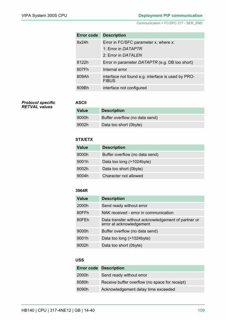
Error code Description8x24h Error in FC/SFC parameter x, where x:
1: Error in DATAPTR2: Error in DATALEN
8122h Error in parameter DATAPTR (e.g. DB too short)
807Fh Internal error
809Ah interface not found e.g. interface is used by PRO-FIBUS
809Bh interface not configured
ASCII
Value Description9000h Buffer overflow (no data send)
9002h Data too short (0byte)
STX/ETX
Value Description9000h Buffer overflow (no data send)
9001h Data too long (>1024byte)
9002h Data too short (0byte)
9004h Character not allowed
3964R
Value Description2000h Send ready without error
80FFh NAK received - error in communication
80FEh Data transfer without acknowledgement of partner orerror at acknowledgement
9000h Buffer overflow (no data send)
9001h Data too long (>1024byte)
9002h Data too short (0byte)
USS
Error code Description2000h Send ready without error
8080h Receive buffer overflow (no space for receipt)
8090h Acknowledgement delay time exceeded
Protocol specificRETVAL values
VIPA System 300S CPU Deployment PtP communication
Communication > FC/SFC 217 - SER_SND
HB140 | CPU | 317-4NE12 | GB | 14-40 109

Error code Description80F0h Wrong checksum in respond
80FEh Wrong start sign in respond
80FFh Wrong slave address in respond
9000h Buffer overflow (no data send)
9001h Data too long (>1024byte)
9002h Data too short (<2byte)
Modbus RTU/ASCII Master
Error code Description2000h Send ready (positive slave respond)
2001h Send ready (negative slave respond)
8080h Receive buffer overflow (no space for receipt)
8090h Acknowledgement delay time exceeded
80F0h Wrong checksum in respond
80FDh Length of respond too long
80FEh Wrong function code in respond
80FFh Wrong slave address in respond
9000h Buffer overflow (no data send)
9001h Data too long (>1024byte)
9002h Data too short (<2byte)
VIPA System 300S CPUDeployment PtP communication
Communication > FC/SFC 217 - SER_SND
HB140 | CPU | 317-4NE12 | GB | 14-40 110

The following text shortly illustrates the structure of programming asend command for the different protocols.3964R
Principles of program-ming
VIPA System 300S CPU Deployment PtP communication
Communication > FC/SFC 217 - SER_SND
HB140 | CPU | 317-4NE12 | GB | 14-40 111

USS / Modbus
ASCII / STX/ETX
VIPA System 300S CPUDeployment PtP communication
Communication > FC/SFC 217 - SER_SND
HB140 | CPU | 317-4NE12 | GB | 14-40 112

6.5.3 FC/SFC 218 - SER_RCVThis block receives data via the serial interface.Using the FC/SFC 218 SER_RCV after SER_SND with the protocolsUSS and Modbus the acknowledgement telegram can be read.
Parameter Declaration Data type DescriptionDATAPTR IN ANY Pointer to Data Buffer for received data
DATALEN OUT WORD Length of received data
ERROR OUT WORD Error Number
RETVAL OUT WORD Return value (0 = OK)
Here you set a range of the type Pointer for the receive buffer wherethe reception data is stored. You have to set type, start and length.Example:Data is stored in DB5 starting at 0.0 with a length of 124byte.DataPtr:=P#DB5.DBX0.0 BYTE 124
Word where the number of received Bytes is stored.At STX/ETX and 3964R, the length of the received user data or 0 isentered.At ASCII, the number of read characters is entered. This value maybe different from the read telegram length.
This word gets an entry in case of an error.The following error messages may be created depending on the pro-tocol:
ASCII
Bit Error Description0 overrun Overflow, a sign couldn’t be read fast enough
from the interface
1 framing error Error that shows that a defined bit frame is notcoincident, exceeds the allowed length or con-tains an additional bit sequence (Stop bit error)
2 parity Parity error
3 overflow Buffer is full
Description
Parameters
DATAPTR
DATALEN
ERROR
VIPA System 300S CPU Deployment PtP communication
Communication > FC/SFC 218 - SER_RCV
HB140 | CPU | 317-4NE12 | GB | 14-40 113

STX/ETX
Bit Error Description0 overflow The received telegram exceeds the size of the
receive buffer.
1 char A sign outside the range 20h ... 7Fh has beenreceived.
3 overflow Buffer is full.
3964R / Modbus RTU/ASCII Master
Bit Error Description0 overflow The received telegram exceeds the size of the
receive buffer.
Return values of the block:
Error code Description0000h no error
1000h Receive buffer too small (data loss)
8x24h Error at FC/SFC-Parameter x, with x:1: Error at DATAPTR2: Error at DATALEN3: Error at ERROR
8122h Error in parameter DATAPTR (e.g. DB too short)
809Ah Serial interface not found res. interface is used byPROFIBUS
809Bh Serial interface not configured
RETVAL FC/SFC 218(Return value)
VIPA System 300S CPUDeployment PtP communication
Communication > FC/SFC 218 - SER_RCV
HB140 | CPU | 317-4NE12 | GB | 14-40 114

The following picture shows the basic structure for programming areceive command. This structure can be used for all protocols.
6.6 Protocols and proceduresThe CPU supports the following protocols and procedures:n ASCII communicationn STX/ETXn 3964Rn USSn Modbus
ASCII data communication is one of the simple forms of dataexchange. Incoming characters are transferred 1 to 1. At ASCII, withevery cycle the read FC/SFC is used to store the data that is in thebuffer at request time in a parameterized receive data block. If a tele-gram is spread over various cycles, the data is overwritten. There isno reception acknowledgement. The communication procedure has tobe controlled by the concerning user application. An accordingReceive_ASCII FB may be found within the VIPA library in the servicearea of www.vipa.com.
STX/ETX is a simple protocol with start and end ID, where STXstands for Start of Text and ETX for End of Text.
Principles of program-ming
Overview
ASCII
STX/ETX
VIPA System 300S CPU Deployment PtP communication
Protocols and procedures
HB140 | CPU | 317-4NE12 | GB | 14-40 115

n Any data transferred from the periphery must be preceded by aStart followed by the data characters and the end character.Depending of the byte width the following ASCII characters can betransferred: 5bit: not allowed: 6bit: 20...3Fh, 7bit: 20...7Fh, 8bit:20...FFh.
n The effective data, which includes all the characters between Startand End are transferred to the CPU when the End has beenreceived.
n When data is send from the CPU to a peripheral device, any userdata is handed to the FC/SFC 217 (SER_SND) and is transferredwith added Start- and End-ID to the communication partner.
n You may work with 1, 2 or no Start- and with 1, 2 or no End-ID.n If no End-ID is defined, all read characters are transferred to the
CPU after a parametrizable character delay time (Timeout).As Start-res. End-ID all Hex values from 01h to 1Fh are permissible.Characters above 1Fh are ignored. In the user data, characters below20h are not allowed and may cause errors. The number of Start- andEnd-IDs may be different (1 Start, 2 End res. 2 Start, 1 End or othercombinations). For not used start and end characters you have toenter FFh in the hardware configuration.Message structure:
The 3964R procedure controls the data transfer of a point-to-point linkbetween the CPU and a communication partner. The procedure addscontrol characters to the message data during data transfer. Thesecontrol characters may be used by the communication partner toverify the complete and error free receipt.The procedure employs the following control characters:n STX: Start of Textn DLE: Data Link Escapen ETX: End of Textn BCC: Block Check Charactern NAK: Negative AcknowledgeYou may transfer a maximum of 255byte per message.
Procedure
3964
VIPA System 300S CPUDeployment PtP communication
Protocols and procedures
HB140 | CPU | 317-4NE12 | GB | 14-40 116

When a DLE is transferred as part of the information it isrepeated to distinguish between data characters and DLEcontrol characters that are used to establish and to termi-nate the connection (DLE duplication). The DLE duplica-tion is reversed in the receiving station.The 3964R procedure requires that a lower priority isassigned to the communication partner. When communi-cation partners issue simultaneous send commands, thestation with the lower priority will delay its send command.
The USS protocol (Universelle serielle Schnittstelle = universal serialinterface) is a serial transfer protocol defined by Siemens for the driveand system components. This allows to build-up a serial bus connec-tion between a superordinated master and several slave systems.The USS protocol enables a time cyclic telegram traffic by presettinga fix telegram length.The following features characterize the USS protocol:n Multi point connectionn Master slave access proceduren Single master systemn Max. 32 participantsn Simple and secure telegram frameIt is essential:n You may connect 1 master and max. 31 slaves at the busn The single slaves are addressed by the master via an address
sign in the telegram.n The communication happens exclusively in half-duplex operation.n After a send command, the acknowledgement telegram must be
read by a call of the FC/SFC 218 SER_RCV.The telegrams for send and receive have the following structure:
Master slave telegram
STX LGE ADR PKE IND PWE STW HSW BCC
02h H L H L H L H L H L
Slave master telegram
STX LGE ADR PKE IND PWE ZSW HIW BCC
02h H L H L H L H L H L
USS
VIPA System 300S CPU Deployment PtP communication
Protocols and procedures
HB140 | CPU | 317-4NE12 | GB | 14-40 117
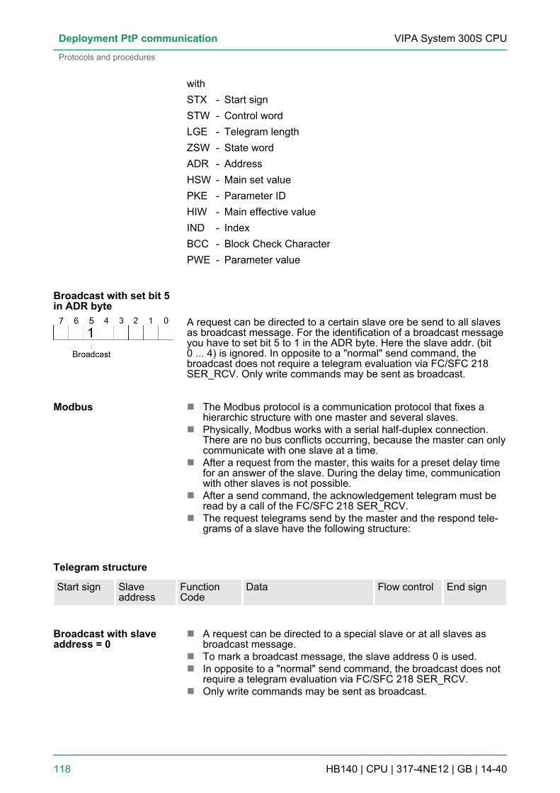
withSTX - Start signSTW - Control wordLGE - Telegram lengthZSW - State wordADR - AddressHSW - Main set valuePKE - Parameter IDHIW - Main effective valueIND - IndexBCC - Block Check CharacterPWE - Parameter value
A request can be directed to a certain slave ore be send to all slavesas broadcast message. For the identification of a broadcast messageyou have to set bit 5 to 1 in the ADR byte. Here the slave addr. (bit0 ... 4) is ignored. In opposite to a "normal" send command, thebroadcast does not require a telegram evaluation via FC/SFC 218SER_RCV. Only write commands may be sent as broadcast.
n The Modbus protocol is a communication protocol that fixes ahierarchic structure with one master and several slaves.
n Physically, Modbus works with a serial half-duplex connection.There are no bus conflicts occurring, because the master can onlycommunicate with one slave at a time.
n After a request from the master, this waits for a preset delay timefor an answer of the slave. During the delay time, communicationwith other slaves is not possible.
n After a send command, the acknowledgement telegram must beread by a call of the FC/SFC 218 SER_RCV.
n The request telegrams send by the master and the respond tele-grams of a slave have the following structure:
Telegram structure
Start sign Slaveaddress
FunctionCode
Data Flow control End sign
n A request can be directed to a special slave or at all slaves asbroadcast message.
n To mark a broadcast message, the slave address 0 is used.n In opposite to a "normal" send command, the broadcast does not
require a telegram evaluation via FC/SFC 218 SER_RCV.n Only write commands may be sent as broadcast.
Broadcast with set bit 5in ADR byte
Modbus
Broadcast with slaveaddress = 0
VIPA System 300S CPUDeployment PtP communication
Protocols and procedures
HB140 | CPU | 317-4NE12 | GB | 14-40 118

Modbus offers 2 different transfer modes. The mode selection hap-pens during runtime by using the FC/SFC 216 SER_CFG.n ASCII mode: Every byte is transferred in the 2 sign ASCII code.
The data are marked with a start and an end sign. This causes atransparent but slow transfer.
n RTU mode: Every byte is transferred as one character. This ena-bles a higher data pass through as the ASCII mode. Instead ofstart and end sign, a time control is used.
The following Modbus Protocols are supported by the RS485 inter-face:n Modbus RTU Mastern Modbus ASCII Master
6.7 Modbus - Function codesModbus has some naming conventions:
n Modbus differentiates between bit and word access; bits = "Coils"and words = "Register".
n Bit inputs are referred to as "Input-Status" and bit outputs as "Coil-Status".
n word inputs are referred to as "Input-Register" and word outputsas "Holding-Register".
Normally the access at Modbus happens by means of the ranges 0x,1x, 3x and 4x.0x and 1x gives you access to digital bit areas and 3x and 4x toanalog word areas.For the CPs from VIPA is not differentiating digital and analog data,the following assignment is valid:0x - Bit area for master output data
Access via function code 01h, 05h, 0Fh
1x - Bit area for master input dataAccess via function code 02h
3x - word area for master input dataAccess via function code 04h
4x - word area for master output dataAccess via function code 03h, 06h, 10h
ASCII, RTU mode
Supported Modbus pro-tocols
Naming convention
Range definitions
VIPA System 300S CPU Deployment PtP communication
Modbus - Function codes
HB140 | CPU | 317-4NE12 | GB | 14-40 119

A description of the function codes follows below.
With the following Modbus function codes a Modbus master canaccess a Modbus slave: With the following Modbus function codes aModbus master can access a Modbus slave. The description alwaystakes place from the point of view of the master:
Code Command Description01h Read n bits Read n bits of master output area 0x
02h Read n bits Read n bits of master input area 1x
03h Read n words Read n words of master output area 4x
04h Read n words Read n words master input area 3x
05h Write 1 bit Write 1 bit to master output area 0x
06h Write 1 word Write 1 word to master output area 4x
0Fh Write n bits Write n bits to master output area 0x
10h Write n words Write n words to master output area 4x
Point of View of "Input" and "Output" dataThe description always takes place from the point of view of themaster. Here data, which were sent from master to slave, up to theirtarget are designated as "output" data (OUT) and contrary slave datareceived by the master were designated as "input" data (IN).
If the slave announces an error, the function code is send back withan "ORed" 80h.
Overview
Respond of the slave
VIPA System 300S CPUDeployment PtP communication
Modbus - Function codes
HB140 | CPU | 317-4NE12 | GB | 14-40 120

Without an error, the function code is sent back.
Slave answer: Function code OR 80h ® Error Function code ® OK
1 word
High-byte Low-byte
The shown check sums CRC at RTU and LRC at ASCII mode areautomatically added to every telegram. They are not shown in thedata block.
Code 01h: Read n bits of master output area 0xCode 02h: Read n bits of master input area 1x
Command telegram
Slave address Function code Address 1. bit Number of bits Check sum CRC/LRC
1byte 1byte 1word 1word 1word
Respond telegram
Slaveaddress
Functioncode
Number ofread bytes
Data 1.byte
Data 2.byte
... Check sumCRC/LRC
1byte 1byte 1byte 1byte 1byte 1word
max. 250byte
03h: Read n words of master output area 4x
Byte sequence in aword
Check sum CRC, RTU,LRC
Read n bits 01h, 02h
Read n words 03h, 04h
VIPA System 300S CPU Deployment PtP communication
Modbus - Function codes
HB140 | CPU | 317-4NE12 | GB | 14-40 121

04h: Read n words master input area 3x
Command telegram
Slave address Function code Address 1. bit Number ofwords
Check sum CRC/LRC
1byte 1byte 1word 1word 1word
Respond telegram
Slaveaddress
Functioncode
Number ofread bytes
Data 1.word
Data 2.word
... Check sumCRC/LRC
1byte 1byte 1byte 1word 1word 1word
max. 125words
Code 05h: Write 1 bit to master output area 0xA status change is via "Status bit" with following values:"Status bit" = 0000h ® Bit = 0"Status bit" = FF00h ® Bit = 1
Command telegram
Slave address Function code Address bit Status bit Check sum CRC/LRC
1byte 1byte 1word 1word 1word
Respond telegram
Slave address Function code Address bit Status bit Check sum CRC/LRC
1byte 1byte 1word 1word 1word
Write 1 bit 05h
VIPA System 300S CPUDeployment PtP communication
Modbus - Function codes
HB140 | CPU | 317-4NE12 | GB | 14-40 122

Code 06h: Write 1 word to master output area 4x
Command telegram
Slave address Function code Address word Value word Check sum CRC/LRC
1byte 1byte 1word 1word 1word
Respond telegram
Slave address Function code Address word Value word Check sum CRC/LRC
1byte 1byte 1word 1word 1word
Code 0Fh: Write n bits to master output area 0xPlease regard that the number of bits has additionally to be set inbyte.
Command telegram
Slaveaddress
Func-tioncode
Address1. bit
Numberof bits
Numberof bytes
Data 1.byte
Data 2.byte
... ChecksumCRC/LRC
1byte 1byte 1word 1word 1byte 1byte 1byte 1byte 1word
max. 250byte
Respond telegram
Slave address Function code Address 1. bit Number of bits Check sum CRC/LRC
1byte 1byte 1word 1word 1word
Write 1 word 06h
Write n bits 0Fh
VIPA System 300S CPU Deployment PtP communication
Modbus - Function codes
HB140 | CPU | 317-4NE12 | GB | 14-40 123

Code 10h: Write n words to master output area 4x
Command telegram
Slaveaddress
Func-tioncode
Address1. word
Numberof words
Numberof bytes
Data 1.word
Data 2.word
... ChecksumCRC/LRC
1byte 1byte 1word 1word 1byte 1word 1word 1word 1word
max. 125words
Respond telegram
Slave address Function code Address 1. word Number ofwords
Check sum CRC/LRC
1byte 1byte 1word 1word 1word
6.8 Modbus - Example communicationThe example establishes a communication between a master and aslave via Modbus. The following combination options are shown:n CPU 31xS as Modbus RTU mastern CPU 21xSER-1 as Modbus RTU slaven Siemens SIMATIC Manager and possibilities for the project
transfern Modbus cable connection
1. Assemble a Modbus system consisting of a CPU 31xS asModbus master and a CPU 21xSER-1 as Modbus slave andModbus cable.
2. Execute the project engineering of the master! For this youcreate a PLC user application with the following structure:n OB 100:
Call SFC 216 (configuration as Modbus RTU master) withtimeout setting and error evaluation.
n OB 1:Call SFC 217 (SER_SND) where the data is send with errorevaluation. Here you have to build up the telegram accordingto the Modbus rules. Call SFC 218 (SER_RECV) where thedata is received with error evaluation.
Write n words 10h
Overview
Approach
VIPA System 300S CPUDeployment PtP communication
Modbus - Example communication
HB140 | CPU | 317-4NE12 | GB | 14-40 124

3. Execute the project engineering of the slave! The PLC userapplication at the slave has the following structure:n OB 100:
Call SFC 216 (configuration as Modbus RTU slave) withtimeout setting and Modbus address in the DB and errorevaluation.
n OB 1:Call SFC 217 (SER_SND) for data transport from the slaveCPU to the output buffer. Call SFC 218 (SER_RECV) for thedata transport from the input buffer to the CPU. Allow anaccording error evaluation for both directions.
Structure for the according PLC programs for master and slave:
VIPA System 300S CPU Deployment PtP communication
Modbus - Example communication
HB140 | CPU | 317-4NE12 | GB | 14-40 125
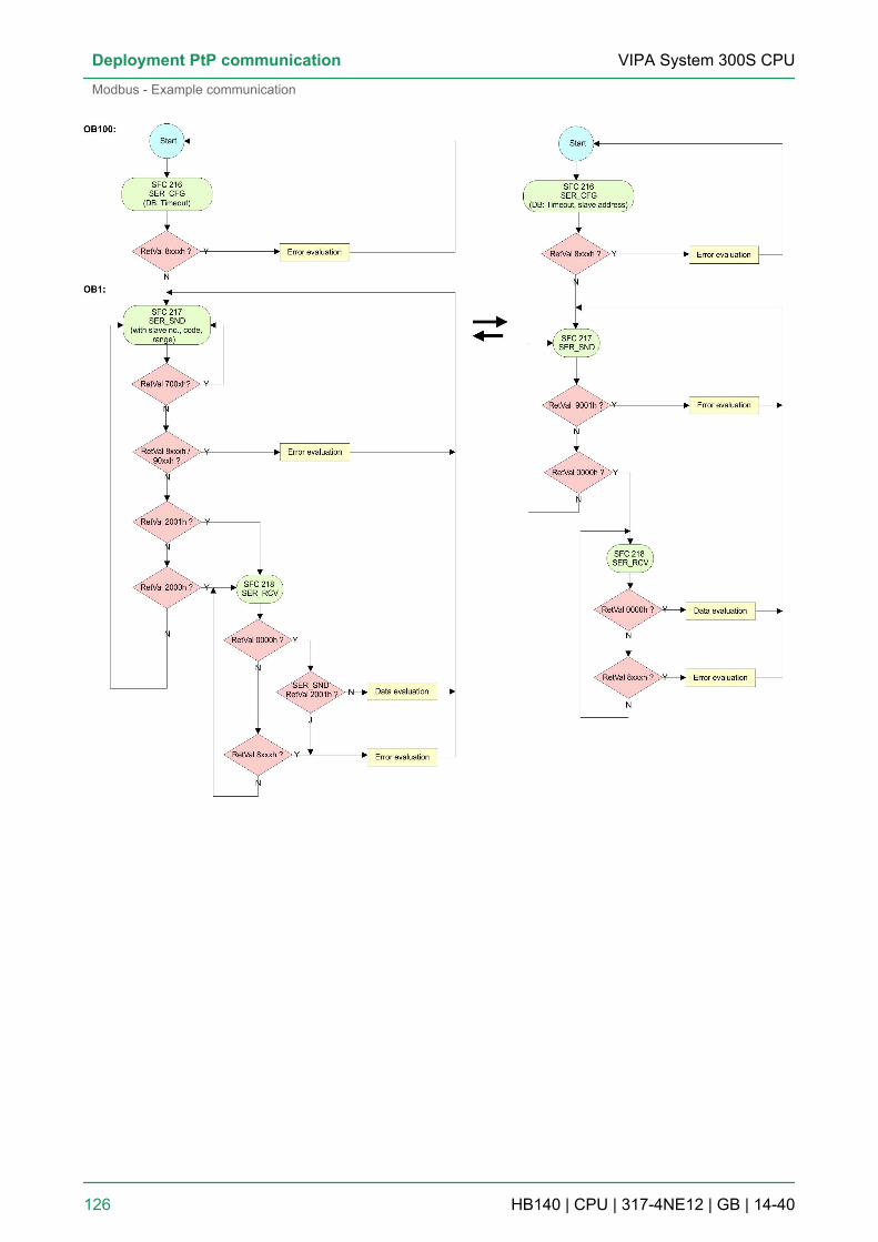
VIPA System 300S CPUDeployment PtP communication
Modbus - Example communication
HB140 | CPU | 317-4NE12 | GB | 14-40 126

7 Deployment PROFIBUS communication7.1 Overview
n PROFIBUS is an international standard applicable to an open andserial field bus for building, manufacturing and process automa-tion that can be used to create a low (sensor-/actuator level) ormedium (process level) performance network of programmablelogic controllers.
n PROFIBUS comprises an assortment of compatible versions. Thefollowing details refer to PROFIBUS DP.
n PROFIBUS DP is a special protocol intended mainly for automa-tion tasks in a manufacturing environment. DP is very fast, offersPlug'n'Play facilities and provides a cost-effective alternative toparallel cabling between PLC and remote I/O. PROFIBUS DP wasdesigned for high-speed data communication on the sensor-actuator level.
n The data transfer referred to as "Data Exchange" is cyclical.During one bus cycle, the master reads input values from theslaves and writes output information to the slaves.
The PROFIBUS DP master is to be configured in the hardware con-figurator from Siemens. Therefore the configuration happens by thesub module X1 (MPI/DP) of the Siemens CPU.After the transmission of the data to the CPU, the configuration dataare internally passed on to the PROFIBUS master part.During the start-up the DP master automatically includes his dataareas into the address range of the CPU. Project engineering in theCPU is not required.
Via the PROFIBUS DP master PROFIBUS DP slaves may be cou-pled to the CPU. The DP master communicates with the DP slavesand links up its data areas with the address area of the CPU.At every POWER ON res. overall reset the CPU fetches the I/O map-ping data from the master. At DP slave failure, the ER-LED is on andthe OB 86 is requested. If this is not available, the CPU switches toSTOP and BASP is set. As soon as the BASP signal comes from theCPU, the DP master is setting the outputs of the connected peripheryto zero. The DP master remains in the operating mode RUN inde-pendent from the CPU.
For the deployment in a super-ordinated master system you first haveto project your slave system as Siemens CPU in slave operationmode with configured in-/output areas. Afterwards you configure yourmaster system. Couple your slave system to your master system bydragging the CPU 31x from the hardware catalog at Configured sta-tions onto the master system, choose your slave system and connectit.
7.2 Fast introductionThe PROFIBUS DP master is to be configured in the hardware con-figurator. Here the configuration happens by means of the submodule X2 (DP) of the Siemens CPU.
PROFIBUS DP
CPU with DP master
Deployment of the DPmaster with CPU
DP slave operation
Overview
VIPA System 300S CPU Deployment PROFIBUS communication
Fast introduction
HB140 | CPU | 317-4NE12 | GB | 14-40 127

For the configuration of the PROFIBUS DP master please follow thefollowing approach:n Hardware configuration - CPUn Deployment as DP master or Deployment as DP slaven Transfer of the complete project to CPUÄ Chapter 5.11
‘Project transfer’ on page 63
In the Siemens SIMATIC Manager the CPU 317-4NE12from VIPA is to be configured asCPU 318-2 (318-2AJ00-0AB00/V3.0)!The integrated PROFIBUS DP master (X3) is to be config-ured and connected via the sub module X2 (DP). TheEthernet PG/OP channel of the 317-4NE12 is always to beconfigured as 1. module after the really plugged modulesat the standard bus as CP 343-1 (343-1EX11) from Sie-mens.
7.3 Hardware configuration - CPUThe configuration of the CPU takes place at the Siemens ‘hardwareconfigurator’ . The hardware configurator is part of the SiemensSIMATIC Manager. It serves for project engineering. The modules,which may be configured here are listed in the hardware catalog. Ifnecessary you have to update the hardware catalog with ‘Optionsè Update Catalog’.For project engineering a thorough knowledge of the SiemensSIMATIC Manager and the Siemens hardware configurator isrequired.
Please consider that this SPEED7-CPU has 4 ACCUs.After an arithmetic operation (+I, -I, *I, /I, +D, -D, *D, /D,MOD, +R, -R, *R, /R) the content of ACCU 3 and ACCU 4is loaded into ACCU 3 and 2. This may cause conflicts inapplications that presume an unmodified ACCU 2.For more information may be found in the manual "VIPAOperation list SPEED7" at "Differences between SPEED7and 300V programming".
In the Siemens SIMATIC Manager the following steps should be exe-cuted:1. Start the Siemens hardware configurator with a new project.2. Insert a profile rail from the hardware catalog.3. Place at ‘Slot’ -Number 2 the CPU 318-2 (6ES7
318-2AJ00-0AB0/V3.0).4. The integrated PROFIBUS DP master (jack X3) is to be config-
ured and connected via the sub module ‘X2 DP’ .
Steps of configuration
Precondition
Proceeding
VIPA System 300S CPUDeployment PROFIBUS communication
Hardware configuration - CPU
HB140 | CPU | 317-4NE12 | GB | 14-40 128

7.4 Deployment as PROFIBUS DP masterThe hardware configuration described before was established.
1. Open the properties dialog of the DP interface of the CPU bymeans of a double-click at ‘DP’ .
2. Set Interface type to "PROFIBUS"3. Connect to PROFIBUS and preset an address (preferably 2)
and confirm with [OK].4. Switch at Operating mode to "DP master" and confirm the dialog
with [OK]. A PROFIBUS DP master system is inserted.ð A PROFIBUS DP master system is inserted:
Now the project engineering of your PROFIBUS DP master is fin-ished. Please link up now your DP slaves with periphery to your DPmaster.1. For the project engineering of PROFIBUS DP slaves you search
the concerning PROFIBUS DP slave in the hardware catalogand drag&drop it in the subnet of your master.
2. Assign a valid PROFIBUS address to the DP slave.3. Link up the modules of your DP slave system in the plugged
sequence and add the addresses that should be used by themodules.
4. If needed, parameterize the modules.5. Save, compile and transfer your project.
Precondition
Proceeding
VIPA System 300S CPU Deployment PROFIBUS communication
Deployment as PROFIBUS DP master
HB140 | CPU | 317-4NE12 | GB | 14-40 129

7.5 Deployment as PROFIBUS DP slaveIn the following the deployment of the PROFIBUS section as "intelli-gent" DP slave on master system is described, which exclusively maybe configured in the Siemens SIMATIC Manager. The following stepsare required:1. Configure a station with a CPU with operating mode DP slave.2. Connect to PROFIBUS and configure the in-/output area for the
slave section.3. Save and compile your project.4. Configure another station with another CPU with operating
mode DP master.5. Connect to PROFIBUS and configure the in-/output ranges for
the master section.6. Save, compile and transfer your project to your CPU.
1. Start the Siemens SIMATIC Manager and configure a CPU asdescribed at "Hardware configuration - CPU".
2. Designate the station as "...DP slave".3. Add your modules according to the real hardware assembly.4. Open the properties dialog of the DP interface of the CPU by
means of a double-click at ‘DP’ .5. Set Interface type to "PROFIBUS".6. Connect to PROFIBUS and preset an address (e.g. 3) and con-
firm with [OK].7. Switch at Operating mode to "DP slave" .8. Via Configuration you define the in-/output address area of the
slave CPU, which are to be assigned to the DP slave.9. Save, compile and transfer your project to your CPU.
1. Insert another station and configure a CPU.2. Designate the station as "...DP master".3. Add your modules according to the real hardware assembly.4. Open the properties dialog of the DP interface of the CPU by
means of a double-click at ‘DP’ .
Fast introduction
Project engineering ofthe slave section
Project engineering ofthe master section
VIPA System 300S CPUDeployment PROFIBUS communication
Deployment as PROFIBUS DP slave
HB140 | CPU | 317-4NE12 | GB | 14-40 130

5. Set Interface: type to "PROFIBUS".6. Connect to PROFIBUS and preset an address (e.g. 2) and con-
firm with [OK].7. Switch at Operating mode to "DP master" and confirm the dialog
with [OK].8. Connect your slave system to this master system by dragging
the "CPU 31x" from the hardware catalog at Configured stationsonto the master system and select your slave system to be cou-pled.
9. Open the Configuration at Object properties of your slavesystem.
10. Via double click to the according configuration line you assignthe according input address area on the master CPU to theslave output data and the output address area to the slave inputdata.
11. Save, compile and transfer your project to your CPU.
VIPA System 300S CPU Deployment PROFIBUS communication
Deployment as PROFIBUS DP slave
HB140 | CPU | 317-4NE12 | GB | 14-40 131

7.6 PROFIBUS installation guidelinesn A PROFIBUS DP network may only be built up in linear structure.n PROFIBUS DP consists of minimum one segment with at least
one master and one slave.n A master has always been deployed together with a CPU.n PROFIBUS supports max. 126 participants.n Per segment a max. of 32 participants is permitted.n The max. segment length depends on the transfer rate:
9.6 ... 187.5bit/s ® 1000m500kbit/s ® 400m1.5Mbit/s ® 200m3 ... 12Mbit/s ® 100m
n Max. 10 segments may be built up. The segments are connectedvia repeaters. Every repeater counts for one participant.
n The bus respectively a segment is to be terminated at both ends.n All participants are communicating with the same transfer rate.
The slaves adjust themselves automatically on the transfer rate.
n As transfer medium PROFIBUS uses an isolated twisted-paircable based upon the RS485 interface.
n The RS485 interface is working with voltage differences. Though itis less irritable from influences than a voltage or a current inter-face. You are able to configure the network as well linear as in atree structure.
n Max. 32 participants per segment are permitted. Within a segmentthe members are linear connected. The segments are connectedvia repeaters. The maximum segment length depends on thetransfer rate.
n PROFIBUS DP uses a transfer rate between 9.6kbit/s and 12Mbit/s, the slaves are following automatically. All participants are com-municating with the same transfer rate.
n The bus structure under RS485 allows an easy connection res.disconnection of stations as well as starting the system step bystep. Later expansions don’t have any influence on stations thatare already integrated. The system realizes automatically if onepartner had a fail down or is new in the network.
The following picture illustrates the terminating resistors of therespective start and end station.
PROFIBUS in general
Transfer medium
Bus connection
VIPA System 300S CPUDeployment PROFIBUS communication
PROFIBUS installation guidelines
HB140 | CPU | 317-4NE12 | GB | 14-40 132

The PROFIBUS line has to be terminated with its rippleresistor. Please make sure to terminate the last partici-pants on the bus at both ends by activating the terminatingresistor.
In PROFIBUS all participants are wired parallel. For that purpose, thebus cable must be feed-through. Via the order number 972-0DP10you may order the bus connector "EasyConn". This is a bus con-nector with switchable terminating resistor and integrated bus diag-nostic.
Dimensions in mm 0° 45° 90°
A 64 61 66
B 34 53 40
C 15.8 15.8 15.8
EasyConn bus con-nector
VIPA System 300S CPU Deployment PROFIBUS communication
PROFIBUS installation guidelines
HB140 | CPU | 317-4NE12 | GB | 14-40 133

To connect this EasyConn plug, please use the standardPROFIBUS cable type A (EN50170). Starting with release5 you also can use highly flexible bus cable:Lapp Kabel order no: 2170222, 2170822, 2170322.With the order no. 905-6AA00 VIPA offers the "EasyStrip"de-isolating tool that makes the connection of the Easy-Conn much easier.
Dimensions in mm
The "EasyConn" bus connector is provided with a switch that is usedto activate a terminating resistor.
[1] 1./last bus participant[2] further participants
CAUTION!The terminating resistor is only effective, if the connector isinstalled at a bus participant and the bus participant is con-nected to a power supply.The tightening torque of the screws to fix the connector toa device must not exceed 0.02Nm!
A complete description of installation and deployment ofthe terminating resistors is delivered with the connector.
Termination with "Easy-Conn"
Wiring
VIPA System 300S CPUDeployment PROFIBUS communication
PROFIBUS installation guidelines
HB140 | CPU | 317-4NE12 | GB | 14-40 134

1. Loosen the screw.2. Lift contact-cover.3. Insert both wires into the ducts provided (watch for the correct
line colour as below!)4. Please take care not to cause a short circuit between screen
and data lines!
5. Close the contact cover.6. Tighten screw (max. tightening torque 0.08Nm).
The green line must be connected to A, the red line to B!
7.7 Commissioning and Start-up behaviorIn delivery the CPU is overall reset. The PROFIBUS part is deacti-vated and its LEDs are off after Power ON.
The DP master can be served with bus parameters by means of ahardware configuration. As soon as these are transferred the DPmaster goes online with his bus parameter. This is shown by the RUNLED. Now the DP master can be contacted via PROFIBUS by meansof his PROFIBUS address. In this state the CPU can be accessed viaPROFIBUS to get configuration and DP slave project.
If the master has received valid configuration data, he switches toData Exchange with the DP Slaves. This is indicated by the DE-LED.
After PowerON respectively a receipt of a new hardware configurationthe configuration data and bus parameter were transferred to the DPmaster. Dependent on the CPU state the following behavior is shownby the DP master:
n The global control command "Clear" is sent to the slaves by themaster. Here the DE-LED is blinking.
n DP slaves with fail safe mode were provided with output telegramlength "0".
n DP slaves without fail safe mode were provided with the wholeoutput telegram but with output data = 0.
n The input data of the DP slaves were further cyclically transferredto the input area of the CPU.
Assembly
Start-up on delivery
Online with bus param-eter without slaveproject
Slave configuration
CPU state controls DPmaster
Master behavior at CPUSTOP
VIPA System 300S CPU Deployment PROFIBUS communication
Commissioning and Start-up behavior
HB140 | CPU | 317-4NE12 | GB | 14-40 135

n The global control command "Operate" is sent to the slaves by themaster. Here the DE-LED is on.
n Every connected DP slave is cyclically attended with an outputtelegram containing recent output data.
n The input data of the DP slaves were cyclically transferred to theinput area of the CPU.
Master behavior at CPURUN
VIPA System 300S CPUDeployment PROFIBUS communication
Commissioning and Start-up behavior
HB140 | CPU | 317-4NE12 | GB | 14-40 136

8 Deployment Ethernet communication - productive8.1 Basics - Industrial Ethernet in automation
The flow of information in a company presents a vast spectrum ofrequirements that must be met by the communication systems.Depending on the area of business the bus system or LAN must sup-port a different number of users, different volumes of data must betransferred and the intervals between transfers may vary, etc. It is forthis reason that different bus systems are employed depending on therespective task. These may be subdivided into different classes. Thefollowing model depicts the relationship between the different bussystems and the hierarchical structures of a company:
Industrial Ethernet is an electrical net based on shielded twisted paircabling or optical net based on optical fibre. Industrial Ethernet isdefined by the international standard IEEE 802.3The net access of Industrial Ethernet corresponds to IEEE 802.3 -CSMA/CD (Carrier Sense Multiple Access/Collision Detection)scheme:n Every station "listens” on the bus cable and receives communica-
tion messages that are addressed to it.n Stations will only initiate a transmission when the line is unoccu-
pied.n In the event that two participants should start transmitting simulta-
neously, they will detect this and stop transmitting to restart after arandom delay time has expired.
n Using switches there is the possibility for communication withoutcollisions.
Overview
Industrial Ethernet
VIPA System 300S CPU Deployment Ethernet communication - productive
Basics - Industrial Ethernet in automation
HB140 | CPU | 317-4NE12 | GB | 14-40 137

8.2 Basics - ISO/OSI reference modelThe ISO/OSI reference model is based on a proposal that was devel-oped by the International Standards Organization (ISO). This repre-sents the first step towards an international standard for the differentprotocols. It is referred to as the ISO-OSI layer model. OSI is theabbreviation for Open System Interconnection, the communicationbetween open systems. The ISO/OSI reference model does not rep-resent a network architecture as it does not define the services andprotocols used by the different layers. The model simply specifies thetasks that the different layers must perform. All current communica-tion systems are based on the ISO/OSI reference model, which isdefined by the ISO 7498 standard. The reference model structurescommunication systems into 7 layers that cover different communica-tion tasks. In this manner the complexity of the communicationbetween different systems is divided amongst different layers to sim-plify the task.The following layers have been defined:n Layer 7 - Application Layern Layer 6 - Presentation Layern Layer 5 - Session Layern Layer 4 - Transport Layern Layer 3 - Network Layern Layer 2 - Data Link Layern Layer - Physical LayerDepending on the complexity and the requirements of the communi-cation mechanisms a communication system may use a subset ofthese layers.
The bit communication layer (physical layer) is concerned with thetransfer of data bits via the communication channel. This layer istherefore responsible for the mechanical, electrical and the proce-dural interfaces and the physical communication medium locatedbelow the bit communication layer:n Which voltage represents a logical 0 or a 1?n The minimum time the voltage is present to be recognized as a
bit.n The pin assignment of the respective interface.
This layer performs error-checking functions for bit strings transferredbetween two communicating partners. This includes the recognitionand correction or flagging of communication errors and flow controlfunctions. The security layer (data link layer) converts raw communi-cation data into a sequence of frames. This is where frame limits areinserted on the transmitting side and where the receiving side detectsthem. These limits consist of special bit patterns that are inserted atthe beginning and at the end of every frame. The security layer oftenalso incorporates flow control and error detection functions. The datasecurity layer is divided into two sub-levels, the LLC and the MAClevel. The MAC (Media Access Control) is the lower level and con-trols how senders are sharing a single transmit channel. The LLC(Logical Link Control) is the upper level that establishes the connec-tion for transferring the data frames from one device into the other.
Overview
Layer 1 - Bit communi-cation layer (physicallayer)
Layer 2 - Security layer(data link layer)
VIPA System 300S CPUDeployment Ethernet communication - productive
Basics - ISO/OSI reference model
HB140 | CPU | 317-4NE12 | GB | 14-40 138
The network layer is an agency layer. Business of this layer is to con-trol the exchange of binary data between stations that are not directlyconnected. It is responsible for the logical connections of layer 2 com-munications. Layer 3 supports the identification of the single networkaddresses and the establishing and disconnecting of logical commu-nication channels. Additionally, layer 3 manages the prior transfer ofdata and the error processing of data packets. IP (Internet Protocol) isbased on Layer 3.
Layer 4 connects the network structures with the structures of thehigher levels by dividing the messages of higher layers into segmentsand passes them on to the network layer. Hereby, the transport layerconverts the transport addresses into network addresses. Commontransport protocols are: TCP, SPX, NWLink and NetBEUI.
The session layer is also called the communication control layer. Itrelieves the communication between service deliverer and therequestor by establishing and holding the connection if the transportsystem has a short time fail out. At this layer, logical users may com-municate via several connections at the same time. If the transportsystem fails, a new connection is established if needed. Additionallythis layer provides methods for control and synchronization tasks.
This layer manages the presentation of the messages, when differentnetwork systems are using different representations of data. Layer 6converts the data into a format that is acceptable for both communi-cation partners. Here compression/decompression and encrypting/decrypting tasks are processed. This layer is also called interpreter. Atypical use of this layer is the terminal emulation.
The application layer is the link between the user application and thenetwork. The tasks of the application layer include the network serv-ices like file, print, message, data base and application services aswell as the according rules. This layer is composed from a series ofprotocols that are permanently expanded following the increasingneeds of the user.
8.3 Basics - TermsA network res. LAN (Local Area Network) provides a link between dif-ferent stations that enables them to communicate with each other.Network stations consist of PCs, IPCs, TCP/IP adapters, etc. Networkstations are separated by a minimum distance and connected bymeans of a network cable. The combination of network stations andthe network cable represent a complete segment. All the segments ofa network form the Ethernet (physics of a network).
In the early days of networking the Triaxial- (yellow cable) or thinEthernet cable (Cheapernet) was used as communication medium.This has been superseded by the twisted-pair network cable due toits immunity to interference. The CPU has a twisted-pair connector.The twisted-pair cable consists of 8 cores that are twisted together inpairs. Due to these twists this system is provides an increased levelof immunity to electrical interference. For linking please use twistedpair cable which at least corresponds to the category 5. Where the
Layer 3 - Network layer
Layer 4 - Transportlayer
Layer 5 - Session layer
Layer 6 - Presentationlayer
Layer 7 - Applicationlayer
Network (LAN)
Twisted Pair
VIPA System 300S CPU Deployment Ethernet communication - productive
Basics - Terms
HB140 | CPU | 317-4NE12 | GB | 14-40 139

coaxial Ethernet networks are based on a bus topology the twisted-pair network is based on a point-to-point scheme. The network thatmay be established by means of this cable has a star topology. Everystation is connected to the star coupler (hub/switch) by means of aseparate cable. The hub/switch provides the interface to the Ethernet.
The hub is the central element that is required to implement a twisted-pair Ethernet network. It is the job of the hub to regenerate and toamplify the signals in both directions. At the same time it must havethe facility to detect and process segment wide collisions and to relaythis information. The hub is not accessible by means of a separatenetwork address since it is not visible to the stations on the network.A hub has provisions to interface to Ethernet or to another hub res.switch.
A switch also is a central element for realizing Ethernet on TwistedPair. Several stations res. hubs are connected via a switch. After-wards they are able to communicate with each other via the switchwithout interfering the network. An intelligent hardware analyses theincoming telegrams of every port of the switch and passes them colli-sion free on to the destination stations of the switch. A switch opti-mizes the bandwidth in every connected segment of a network.Switches enable exclusive connections between the segments of anetwork changing at request.
8.4 Basics - ProtocolsProtocols define a set of instructions or standards that enable com-puter to establish communication connections and exchange informa-tion as error free as possible. A commonly established protocol forthe standardization of the complete computer communication is theso called ISO/OSI layer model, a model based upon seven layerswith rules for the usage of hardware and software Ä Chapter 8.2‘Basics - ISO/OSI reference model’ on page 138The following protocols are used:n Communication connections
– Siemens S7 connections– TCP/IP– UDP– RFC1006 (ISO-ON-TCP)– ISO transport (once H1)
n Open communication– TCP native according to RFC 793– ISO on TCP according to RFC 1006– UDP according to RFC 768
With the Siemens S7 connection large data sets may be transferredbetween PLC systems based on Siemens STEP®7. Here the stationsare connected via Ethernet. Precondition for the Siemens S7 commu-nication is a configured connection table, which contains the definedconnections for communication. Here NetPro from Siemens may beused.
Hub (repeater)
Switch
Overview
Siemens S7 connec-tions
VIPA System 300S CPUDeployment Ethernet communication - productive
Basics - Protocols
HB140 | CPU | 317-4NE12 | GB | 14-40 140

Properties:n A communication connection is specified by a connection ID for
each connection partner.n The acknowledgement of the data transfer is established from the
partner station at level 7 of the ISO/OSI reference model.n At the PLC side FB/SFB VIPA handling blocks are necessary for
data transfer for the Siemens S7 connections.
More about the usage of the handling blocks may be foundin the manual Operation list HB00_OPL_SP7 in chapter"VIPA specific blocks".
VIPA System 300S CPU Deployment Ethernet communication - productive
Basics - Protocols
HB140 | CPU | 317-4NE12 | GB | 14-40 141

TCP/IP protocols are available on all major systems. At the bottomend this applies to simple PCs, through to the typical mini-computerup to mainframes. For the wide spread of Internet accesses and con-nections, TCP/IP is often used to assemble heterogeneous systempools. TCP/IP (Transmission Control Protocol / Internet Protocol) col-lects a various range of protocols and functions. TCP and IP are onlytwo of the protocols required for the assembly of a complete architec-ture.n TCP/IP
– The application layer provides programs like "FTP" and"Telnet" for the PC. The application layer of the Ethernet CP isdefined with the user application using the standard handlingblocks. These user applications use the transport layer withthe protocols TCP or UDP for the data transfer which them-selves communicate via the IP protocol with the Internet layer.
– Besides of the IP address ports are used for the addressing. Aport address should be within the range of 2000...65535.
– Not depending on the used protocol, the PLC needs the VIPAhandling blocks AG_SEND (FC 5) and AG_RECV (FC 6) fordata transfer.
n IP– IP covers the network layer (Layer 3) of the ISO/OSI layer
model.– The purpose of IP is to send data packages from on PC to
another passing several other PCs. These data packages arereferred to as datagrams. The IP doesn't neither guarantee thecorrect sequence of the datagrams nor the delivery at thereceiver.
– For the unambiguous identification between sender andreceiver 32Bit addresses (IP addresses) are used that are nor-mally written as four octets (exactly 8bit), e.g. 172.16.192.11.These Internet addresses are defined and assigned world-wide, thus every user may communicate with all other TCP/IPusers.
– One part of the address specifies the network; the rest servesthe identification of the participants inside the network. Theboarder between the network and the host part is variable anddepends on the size of the network.
– To save IP addresses, so called NAT router are used thathave one official IP address and cover the network. Then thenetwork can use any IP address.
n TCP– TCP bases directly on the IP and thus covers the transport
layer (layer 4) of the ISO/OSI layer model.– TCP is a connection orientated end-to-end protocol and serves
the logic connection between two partners.– TCP guarantees the correct sequence and reliability of the
data transfer. Therefore you need a relatively large protocoloverhead that slows down the transfer speed
– Every datagram gets a header of at least 20Byte. This headeralso contains a sequence number identifying the series. Thishas the consequence that the single datagrams may reach thedestination on different ways through the network.
– Using TCP connections, the telegram length is not transmitted.This means that the recipient has to know how many bytesbelong to a message.
– To transfer data with variable length you may begin the userdata with the length information and evaluate this at thecounter station.
TCP/IP
VIPA System 300S CPUDeployment Ethernet communication - productive
Basics - Protocols
HB140 | CPU | 317-4NE12 | GB | 14-40 142

UDP (User Datagramm Protocol) is a connection free transport pro-tocol. It has been defined in the RFC768 (Request for Comment).Compared to TCP, it has much fewer characteristics. The addressinghappens via port numbers. UDP is a fast unsafe protocol for it doesn'tneither care about missing data packages nor about their sequence.
The TCP transport service works stream orientated. This means thatdata packages assembled by the user not necessarily have to receivethe partner in the same packaging. Depending on the data amount,packages may though come in the correct sequence but differentlypacked. This causes that the recipient may not recognize thepackage borders anymore. For example you may send 2x 10Bytepackages but the counter station receives them as 20Byte package.But for most of the applications the correct packaging is important.Due to this you need another protocol above TCP. This purpose isdefined in the protocol extension RFC1006 (ISO-on-TCP).n RFC1006 describes the function of an ISO transport interface
(ISO 8072) basing upon the transport interface TCP (RFC793).n The basic protocol of RFC1006 is nearly identical to TP0 (Trans-
port Protocol, Class 0) in ISO 8073.n For RFC1006 is run as protocol for TCP, the decoding takes place
in the data section of the TCP package.n In contrast to TCP here the receipt of a telegram is confirmed.n Instead of ports TSAPs are used for the addressing besides of the
IP address. The TSAP length may be 1 ... 16 characters. Theentry may happen in ASCII or Hex format.
n Not depending on the used protocol, the PLC needs the VIPAhandling blocks AG_SEND (FC 5) and AG_RECV (FC 6) for datatransfer.
n Contrary to TCP different telegram lengths can be received usingRFC1006.
With ISO transport connections there is the possibility for programand event controlled communication via Industrial Ethernet. Here datablocks may be exchanged bi-directional. The ISO transport connec-tion offers services for a safety transfer of data by means of config-ured connections. Large data blocks may be transferred by means ofblocking. The transmission reliability is very high by the automaticrepetition, by additional block test mechanisms and by the receiptacknowledgement at the receiver side.n The ISO transport service (ISO 8073 class 4) corresponds to the
transport layer (Layer 4) of the ISO/OSI reference model.n ISO transport connections are exclusively transferred via Indus-
trial Ethernet and they are optimized for the deployment in aclosed manufacturing area.
n The receipt of data is acknowledged by the partner station. Heredifferent telegram lengths may be processed.
n For deployment of the ISO transport connections they must beenabled in the Ethernet properties of the CP within your project.Here there is the possibility to assign the CP to a MAC address.
n The addressing happens by MAC address (Ethernet address) andTSAPs (Transport Service Access Point).
n The data transfer is made by the services SEND/RECEIVE andFETCH/WRITE.
n Not depending on the used protocol, the PLC needs the VIPAhandling blocks AG_SEND (FC 5) and AG_RECV (FC 6) for datatransfer.
UDP
ISO-on-TCP RFC1006
ISO transport (once H1)
VIPA System 300S CPU Deployment Ethernet communication - productive
Basics - Protocols
HB140 | CPU | 317-4NE12 | GB | 14-40 143

In the ‘open communication’ the communication takes place via theuser program by means of handling blocks. These blocks are part ofthe Siemens SIMATIC Manager. You will find these in the ‘StandardLibrary’ at ‘Communication Blocks’ .n Connection-oriented protocols:
Connection-oriented protocols establish a (logical) connection tothe communication partner before data transmission is started.And if necessary they terminate the connection after the datatransfer was finished. Connection-oriented protocols are used fordata transmission when reliable, guaranteed delivery is of partic-ular importance. In general, many logical connections can exist onone physical line. The following connection-oriented protocols aresupported with FBs for open communication via IndustrialEthernet:– TCP native accord. to RFC 793:
During data transmission, no information about the length orabout the start and end of a message is transmitted. However,the receiver has no means of detecting where one messageends in the data stream and the next one begins. The transferis stream-oriented. For this reason, it is recommended that thedata length of the FBs is identical for the sending andreceiving station. If the number of received data does not fit tothe preset length you either will get not the whole data, or youwill get data of the following job.
– ISO on TCP accord. to RFC 1006:During data transmission, information on the length and theend of the message is also transmitted. If you have specifiedthe length of the data to be received greater than the length ofthe data to be sent, the receive block will copy the receiveddata completely into the receive range.
n Connection-less protocol:There is thus no establishment and termination of a connectionwith a remote partner. Connection-less protocols transmit datawith no acknowledge and with no reliable guaranteed delivery tothe remote partner.– UDP accord. to RFC 768:
In this case, when calling the sending block you have tospecify the address parameters of the receiver (IP addressand port number). During data transmission, information onthe length and the end of the message is also transmitted. Inorder to be able to use the sending and receiving blocks firstyou have to configure the local communications access pointat both sides. With each new call of the sending block, you re-reference the remote partner by specifying its IP address andits port number.
8.5 Basics - IP address and subnetExclusively IPv4 is supported. At IPv4 the IP address is a 32bitaddress that must be unique within the network and consists of 4numbers that are separated by a dot. Every IP address is a combina-tion of a Net-ID and a Host-ID and has the followingStructure: xxx.xxx.xxx.xxxRange: 000.000.000.000 to 255.255.255.255
Open communication
IP address structure
VIPA System 300S CPUDeployment Ethernet communication - productive
Basics - IP address and subnet
HB140 | CPU | 317-4NE12 | GB | 14-40 144

The Network-ID identifies a network res. a network controller thatadministrates the network. The Host-ID marks the network connec-tions of a participant (host) to this network.
The Host-ID can be further divided into a Subnet-ID and a new Host-ID by using a bit for bit AND assignment with the Subnet mask.The area of the original Host-ID that is overwritten by 1 of the Subnetmask becomes the Subnet-ID, the rest is the new Host-ID.
Subnet mask binary all "1" binary all"0"
IPv4 address Net-ID Host-ID
Subnet mask and IPv4address
Net-ID Subnet-ID new Host-ID
At the first start-up of the CPU, the Ethernet PG/OP channel and thePROFINET IO controller do not have an IP address.Information about the assignment of IP address data to the EthernetPG/OP channel may be found inÄ Chapter 5.6 ‘Hardware configura-tion - Ethernet PG/OP channel’ on page 50.Information about the assignment of IP address data to the EtherCATconnection may be found in Ä Chapter 8.8 ‘Commissioning and initi-alization’ on page 148
For IPv4 addresses there are five address formats (class A to classE) that are all of a length of 4byte = 32bit.
Class A 0 Network-ID (1+7bit) Host-ID (24bit)
Class B 10 Network-ID (2+14bit) Host-ID (16bit)
Class C 110 Network-ID (3+21bit) Host-ID(8bit)
Class D 1110 Multicast group
Class E 11110 Reserved
The classes A, B and C are used for individual addresses, class D formulticast addresses and class E is reserved for special purposes.The address formats of the 3 classes A, B, C are only differing in thelength of Network-ID and Host-ID.
These addresses can be used as net-ID by several organizationswithout causing conflicts, for these IP addresses are neither assignedin the Internet nor are routed in the Internet. To build up private IP-Networks within the Internet, RFC1597/1918 reserves the followingaddress areas:
Net-ID, Host-ID
Subnet mask
Address at first start-up
Address classes
Private IP networks
VIPA System 300S CPU Deployment Ethernet communication - productive
Basics - IP address and subnet
HB140 | CPU | 317-4NE12 | GB | 14-40 145

Network class from IP to IP Standardsubnet mask
A 10.0.0.0 10.255.255.255 255.0.0.0
B 172.16.0.0 172.31.255.255 255.255.0.0
C 192.168.0.0 192.168.255.255 255.255.255.0
(The Host-ID is underlined.)
Some Host-IDs are reserved for special purposes.
Host-ID = "0" Identifier of this network,reserved!
Host-ID = maximum (binary com-plete "1")
Broadcast address of this net-work
Never choose an IP address with Host-ID=0 or Host-ID=maximum! (e.g. for class B with subnet mask =255.255.0.0, the "172.16.0.0" is reserved and the"172.16.255.255" is occupied as local broadcast addressfor this network.)
8.6 Basics - MAC address and TSAPThere is a unique MAC address (Media Access Control) necessaryfor each CP. Usually a module is labelled with its MAC address by themanufacturer. This address should be used for project engineering ofthe CP. The MAC address has a length of 6bytes. On delivery the firstthree bytes specify the manufacturer. These bytes are assigned bythe IEEE committee. The last 3 bytes may be assigned by the manu-facturer. In a network several stations with the same MAC addressmay not exist. The MAC address may be changed at any time. Youwill get a valid MAC address from your network administrator.n Broadcast address
– The MAC address, with which all bits are set to 1, is:FF-FF-FF-FF-FF-FFThis address is used as Broadcast address and addresses allparticipants in the net.
n Address at first start-up– Each CP of a VIPA CPU has an unique MAC address. This
may be found on a label beneath the front flap.
TSAP means Transport Service Access Point. ISO transport connec-tions support TSAP length of 1...16byte. TSAPs may be entered inASCII format or hexadecimal.
Reserved Host-IDs
MAC address
TSAP
VIPA System 300S CPUDeployment Ethernet communication - productive
Basics - MAC address and TSAP
HB140 | CPU | 317-4NE12 | GB | 14-40 146

Station A Station Bremote TSAP à ISO transport
connectionà local TSAP
local TSAP ß ß remote TSAP
MAC address A MAC address B
An ISO transport connection is specified by a local and a remote con-nection endpoint. The TSAPs of an ISO transport connection mustmatch as follows:n Remote TSAP (in CP) = local TSAP (in destination station)n Local TSAP (in CP) = remote TSAP (in destination station)
8.7 Fast introductionAt the first start-up respectively at an over all reset with an PowerONagain, the Ethernet PG/OP channel and CP 343 do not have any IPaddress. These may only be reached via its MAC address. IPaddress parameters may be assigned to the corresponding compo-nent by means of the MAC addresses, which may be found on labelsbeneath the front flap with the sequence 1. address PG/OP channeland beneath address of the CP 343. The assignment takes placedirectly via the hardware configuration of the Siemens SIMATIC Man-ager.
For the configuration of the CP 343 for productive connections pleasefollow the following approach:n Assembly and commissioningn Hardware configuration - CPUn Configure connections
– Communication connections(Configuration via Siemens NetPro, communication via VIPAhandling blocks)
– Open communication(Configuration and communication happens by standard han-dling blocks)
n Transfer of the complete project to CPU
In the Siemens SIMATIC Manager the CPU 317-4NE12from VIPA is to be configured asCPU 318-2 (318-2AJ00-0AB00 V3.0)!The integrated PROFIBUS DP master (X3) is to be config-ured and connected via the sub module X2 (DP). TheEthernet PG/OP channel of the 317-4NE12 is always to beconfigured as 1. module after the really plugged modulesat the standard bus as CP 343-1 (343-1EX11) from Sie-mens.The CP 343 of the CPU is always to be configured belowthe before configured PG/OP channel also as CP 343-1(343-1EX11).
Address parameters
Overview
Steps of configuration
VIPA System 300S CPU Deployment Ethernet communication - productive
Fast introduction
HB140 | CPU | 317-4NE12 | GB | 14-40 147

8.8 Commissioning and initialization1. Install your System 300S with your CPU.2. Wire the system by connecting cables for voltage supply and
signals3. Connect your CP 343 with Ethernet.4. Switch on the power supply.
ð After a short boot time, the CP is in idle. At the first commis-sioning res. after an overall reset of the CPU, the CP 343and the Ethernet PG/OP channel have no IP address.
Please regard this function is available with CP firmwareversion 1.7.4 and up.
You get valid IP address parameters from your system administrator.The assignment of the IP address data happens online in the Sie-mens SIMATIC Manager starting with version V 5.3 & SP3 with thefollowing proceeding:1. Start the Siemens SIMATIC Manager and set via ‘Options
è Set PG/PC interface’the access path to ‘TCP/IP -> Networkcard ....’ .
2. Open with ‘PLC è Edit Ethernet Node n’ the dialog window withthe same name.
3. To get the stations and their MAC address, use the [Browse]button or type in the MAC Address. The Mac address may befound at the 2. label beneath the front flap of the CPU.
4. Choose if necessary the known MAC address of the list of foundstations.
5. Either type in the IP configuration like IP address, subnet maskand gateway. Or your station is automatically provided with IPparameters by means of a DHCP server. Depending of thechosen option the DHCP server is to be supplied with MACaddress, equipment name or client ID. The client ID is a numer-ical order of max. 63 characters. The following characters areallowed: "hyphen", 0-9, a-z, A-Z
6. Confirm with [Assign IP configuration].
Directly after the assignment the PROFINET IO controlleris online reachable using the set IP address data.Since the IP address data, which were assigned here, aredeleted at PowerOFF, you have to take them to a projectby means of the hardware configuration.
Assembly and commis-sioning
Assign IP addressparameters
VIPA System 300S CPUDeployment Ethernet communication - productive
Commissioning and initialization
HB140 | CPU | 317-4NE12 | GB | 14-40 148

8.9 Hardware configuration - CPUThe configuration of the CPU takes place at the Siemens ‘hardwareconfigurator’ . The hardware configurator is part of the SiemensSIMATIC Manager. It serves for project engineering. The modules,which may be configured here are listed in the hardware catalog. Ifnecessary you have to update the hardware catalog with ‘Optionsè Update Catalog’.For project engineering a thorough knowledge of the SiemensSIMATIC Manager and the Siemens hardware configurator isrequired.
In the Siemens SIMATIC Manager the following steps should be exe-cuted:1. Start the Siemens hardware configurator with a new project.2. Insert a profile rail from the hardware catalog.3. Place at ‘Slot’ -Number 2 the CPU 318-2 (6ES7
318-2AJ00-0AB0/V3.0).4. The integrated PROFIBUS DP master (jack X3) is to be config-
ured and connected via the sub module ‘X2 DP’ .
1. Place for the internal Ethernet PG/OP channel always as 1.module below the really plugged modules a Siemens CP 343-1(SIMATIC 300 \ CP 300 \ Industrial Ethernet \CP 343-1 \ 6GK7343-1EX11 0XE0).
2. Configure the integrated CP 343 of the CPU also as CP 343-1(343-1EX11) but always below the before configured CP 343-1.
3. Open the property window of the CP via double-click on the CP.4. Enter at ‘General’ a device name. The device name must be
unique at the Ethernet subnet.5. On [Properties] for the CP enter the IP address, subnet mask
and gateway and select the wanted subnet.
Precondition
Proceeding
Project engineeringEthernet PG/OP channeland CP 343
VIPA System 300S CPU Deployment Ethernet communication - productive
Hardware configuration - CPU
HB140 | CPU | 317-4NE12 | GB | 14-40 149

8.10 Configure connections8.10.1 Overview
The project engineering of connections i.e. the "link-up" between sta-tions happens in NetPro from Siemens. NetPro is a graphical userinterface for the link-up of stations. A communication connection ena-bles the program controlled communication between two participantsat the Industrial Ethernet. The communication partners may here bepart of the same project or - at multi projects - separated withinrelated part projects. Communication connections to partners outsideof a project are configured via the object "In unknown project" or viadeputy objects like "Other stations" or Siemens "SIMATIC S5 Sta-tion". The communication is controlled by the user program with VIPAhandling blocks. To use this blocks, configured communication con-nections are always necessary in the active station.
The following properties are characterizing a communication connec-tion:n One station always executes an active connection establishment.n Bi-directional data transfer (Send and receive on one connection)n Both participant have equal rights, i.e. every participant may initi-
alize the send res. receive process event controlled.n Except of the UDP connection, at a communication connection the
address of the communication partner is set via the project engi-neering. Here the connection is active established by one station.
n Siemens SIMATIC Manager V 5.3 SP3 or higher and SIMATICNET are installed.
n With the hardware configuration the CP was assigned with IPaddress data by the properties.
Every station outside of the recent project must be config-ured as replacement objects like e.g. Siemens "SIMATICS5" or "other station" or with the object "In unknownproject". When creating a connection you may also choosethe partner type "unspecified" and set the required remoteparameter directly in the connection dialog.
Properties communica-tion connection
Requirements
VIPA System 300S CPUDeployment Ethernet communication - productive
Configure connections > Overview
HB140 | CPU | 317-4NE12 | GB | 14-40 150

8.10.2 Siemens NetProFor the project engineering of connections, a thorough knowledgewith NetPro from Siemens is required! The following passage onlydescribes the basic usage of NetPro. More detailed information aboutNetPro is to be found in the according online manual res. documenta-tion. Start NetPro by clicking on a "net" in the Siemens SIMATICManager or on "connections" within the CPU.The environment of NetPro has the following structure:
1 Graphic net view: All stations and networks are displayed in agraphic view. By clicking on the according component you mayaccess and alter the concerning properties.
2 Net objects: This area displays all available net objects in a direc-tory view. By dragging a wanted object to the net view you mayinclude further net objects and open them in the hardware config-urator.
3 Connection table: The connection table lists all connections in atable. This list is only shown when you highlighted a connectablemodule like e.g. a CPU. You may insert new connections into thistable with the according command.
You receive the following graphical display for every PLC station andtheir component. By selecting the single components, the contextmenu offers you several functions:1 Station: This includes a PLC station with rack, CPU and communi-
cation components. Via the context menu you may configure astation added from the net objects and its concerning componentsin the hardware configurator. After returning to NetPro, the newconfigured components are shown.
2 CPU: A click onto the CPU shows the connection table. The con-nection table shows all connections that are configured for theCPU.
3 Internal communication components: This shows the communica-tion components that are available in your CPU. For the NET-CPUis configured as Siemens CPU, the internal components do notshow the CP. Due to this, the internal CPs of the NET-CPU mustbe configured as external CPs behind the really plugged modules.The CPs are then also shown in NetPro as external CPs (4, 5) inthe station.
4 Ethernet PG/OP channel: The internal Ethernet PG/OP channelmust always be configured as external CP in the hardware config-uration. This CP only serves the PG/OP communication. Configu-rable connections are not possible.
5 The internal CP 343 must always be configured as external 2. CPin the hardware configuration after the Ethernet PG/OP channel.
Work environment ofNetPro
PLC stations
VIPA System 300S CPU Deployment Ethernet communication - productive
Configure connections > Siemens NetPro
HB140 | CPU | 317-4NE12 | GB | 14-40 151

NetPro offers you the option to link-up the communicating stations.You may link-up the stations via the properties in the hardware con-figuration or graphically via NetPro. For this you point the mouse onthe coloured net mark of the according CP and drag and drop it to thenet you want to link. Now the CP is linked up to the wanted net bymeans of a line.
Link up stations
VIPA System 300S CPUDeployment Ethernet communication - productive
Configure connections > Siemens NetPro
HB140 | CPU | 317-4NE12 | GB | 14-40 152

1. For the project engineering of connections, open the connectionlist by selecting the according CPU. Open ‘Context menuè Insert new connection’:n Connection partner (partner station)
– A dialog window opens where you may choose the con-nection partner and the Connection type.
n Specified connection partner– Each station configured in the Siemens SIMATIC man-
ager is listed in the table of connection partner.– These stations are unique specified by an IP address and
a subnet mask.n Unspecified connection partner
– Here the connection partner may exist in the currentproject or in an unknown project.
– Connection jobs to an unknown project must be definedby an unique connection name, which is to be used in theprojects of both stations.
– Due to this allocation the connection remains unspeci-fied.
n All broadcast stations– Exclusive at UDP connections you may send to every
reachable participant.– The receipt of user data is not possible.– The broadcast participants are specified by one port and
one broadcast address at sender and receiver.– Per default, broadcasts that are only serving the Ethernet
communication, like e.g. ARP-Requests (Search MAC <>IP address), are received and accordingly processed.
– For the identification of the broadcast participants withinthe net, you have to define a valid broadcast address aspartner IP during project engineering of a broadcast con-nection.
– Additionally to the broadcast address you have to set acommon port for sender and receiver.
n All multicast stations– By selecting ‘All Multicast stations’ you define that UDP
telegrams have to be sent respectively received by allparticipants of a multicast group.
– In contrast to broadcast here a reception is possible.– For the identification of the multicast participants within
the net, you have to define one valid multicast groupaddress and one port for sender and receiver. The max-imum number of multicast circles, which are supported bythe CP, is identical to the maximum number of connec-tions.
n Connection typesThe following connection types are available for communica-tion:– Siemens S7 connections, Send/Receive connections
(TCP, ISO-on-TCP and ISO transport) for secured datatransfer of data blocks between two Ethernet stations.
– UDP for not secured data transfer of data blocks betweentwo Ethernet stations.
Projecting connections
VIPA System 300S CPU Deployment Ethernet communication - productive
Configure connections > Siemens NetPro
HB140 | CPU | 317-4NE12 | GB | 14-40 153

2. Select the connection partner and the type of connection andconfirm with [OK].ð If activated, a properties dialog for the according connection
opens as link to your PLC user program.
3. After every connection was configured by this way, you may"save and compile" your project and exit NetPro.
8.10.3 Connection type - S7n For data transfer with Siemens S7 connections the FB/SFB VIPA
handling blocks are necessary; the deployment is described in themanual "Operation list" of your CPU.
n At Siemens S7 connections the communication connections arespecified by a connection ID for each communication partner.
n A connection is specified by the local and partner connection endpoint.
n At Siemens S7 connections the TSAPs must be congruent cross-wise. The following parameters define a connection end point:
The following parameters define a connection end point:
Station A Station Bremote TSAP à Siemens
S7 connectionà local TSAP
local TSAP ß ß remote TSAP
ID A ID B
Siemens S7 connection
VIPA System 300S CPUDeployment Ethernet communication - productive
Configure connections > Connection type - S7
HB140 | CPU | 317-4NE12 | GB | 14-40 154

Combination options with deployment of the FB/SFB VIPA han-dling blocks
Connection partner Connection estab-lishing
Connection
specified in NetPro(in the currentproject)
active/passive specified
unspecified in NetPro(in the currentproject)
active specified
passive unspecified
unspecified in NetPro(in the unknownproject)
active/passive specified (connectionname in an otherproject)
VIPA System 300S CPU Deployment Ethernet communication - productive
Configure connections > Connection type - S7
HB140 | CPU | 317-4NE12 | GB | 14-40 155

In the following every relevant parameter of a Siemens S7 connectionis described:n Local connection end point:
Here you may define how the connection is to be established.Since the Siemens SIMATIC Manager can identify the communi-cation options by means of the end points, some options arealready preset and may not be changed.– Establish an active connection:
An established connection is precondition for data transfer. Byactivating the option Establish an active connection the localstation establishes the connection. Please regard not everystation is able to establish a connection. Here the job is to bemade by the partner station.
– One-way:If activated only one-way communication blocks like PUT andGET may be used for communication in the user program.Here the partner station acts as server, which neither maysend active nor receive active
n Block parameters– Local ID:
The ID is the link to your PLC program. The ID must be iden-tical to the ID of the call interface of the FB/SFB VIPA handlingblock.
– [Default]:As soon as you click at [Default], the ID is reset to system gen-erated ID.
n Connection path:In this part of the dialog window the connection path between thelocal and the partner station may be set. Depending on the linkingof the modules the possible interfaces for communication arelisted in a selection field.– [Address details]:
With this button a dialog window is opened, which showsaddress information about the local and partner station. Theparameters may also be changed.
– TSAP:With Siemens S7 connections a TSAP is automatically gener-ated of the connection resource (one-way/two-way) and stateof place (rack/slot respectively system internal ID at PC sta-tions).
– Connection resource:The connection resource is part of the TSAP of the local sta-tion respectively of the partner. Not every connection resourcemay be used for every connection type. Depending on theconnection partner and the connection type the range ofvalues is limited respectively the connection resource is fixspecified.
VIPA System 300S CPUDeployment Ethernet communication - productive
Configure connections > Connection type - S7
HB140 | CPU | 317-4NE12 | GB | 14-40 156
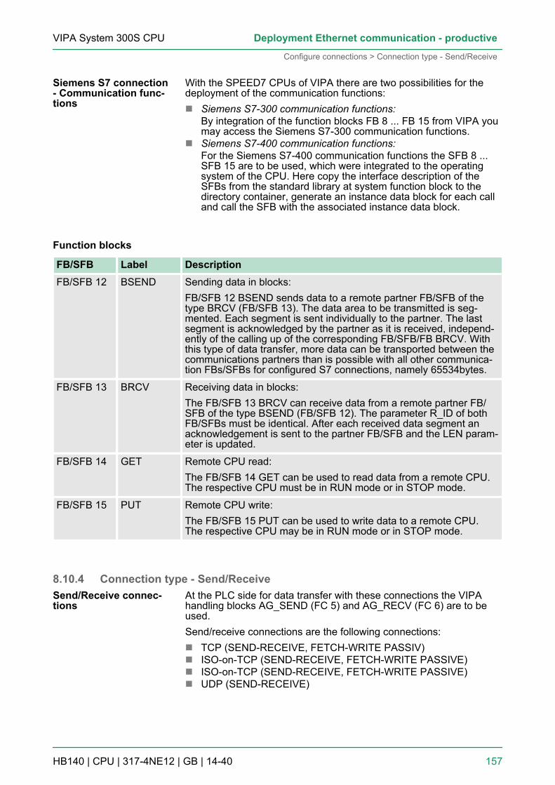
With the SPEED7 CPUs of VIPA there are two possibilities for thedeployment of the communication functions:n Siemens S7-300 communication functions:
By integration of the function blocks FB 8 ... FB 15 from VIPA youmay access the Siemens S7-300 communication functions.
n Siemens S7-400 communication functions:For the Siemens S7-400 communication functions the SFB 8 ...SFB 15 are to be used, which were integrated to the operatingsystem of the CPU. Here copy the interface description of theSFBs from the standard library at system function block to thedirectory container, generate an instance data block for each calland call the SFB with the associated instance data block.
Function blocks
FB/SFB Label DescriptionFB/SFB 12 BSEND Sending data in blocks:
FB/SFB 12 BSEND sends data to a remote partner FB/SFB of thetype BRCV (FB/SFB 13). The data area to be transmitted is seg-mented. Each segment is sent individually to the partner. The lastsegment is acknowledged by the partner as it is received, independ-ently of the calling up of the corresponding FB/SFB/FB BRCV. Withthis type of data transfer, more data can be transported between thecommunications partners than is possible with all other communica-tion FBs/SFBs for configured S7 connections, namely 65534bytes.
FB/SFB 13 BRCV Receiving data in blocks:The FB/SFB 13 BRCV can receive data from a remote partner FB/SFB of the type BSEND (FB/SFB 12). The parameter R_ID of bothFB/SFBs must be identical. After each received data segment anacknowledgement is sent to the partner FB/SFB and the LEN param-eter is updated.
FB/SFB 14 GET Remote CPU read:The FB/SFB 14 GET can be used to read data from a remote CPU.The respective CPU must be in RUN mode or in STOP mode.
FB/SFB 15 PUT Remote CPU write:The FB/SFB 15 PUT can be used to write data to a remote CPU.The respective CPU may be in RUN mode or in STOP mode.
8.10.4 Connection type - Send/ReceiveAt the PLC side for data transfer with these connections the VIPAhandling blocks AG_SEND (FC 5) and AG_RECV (FC 6) are to beused.Send/receive connections are the following connections:n TCP (SEND-RECEIVE, FETCH-WRITE PASSIV)n ISO-on-TCP (SEND-RECEIVE, FETCH-WRITE PASSIVE)n ISO-on-TCP (SEND-RECEIVE, FETCH-WRITE PASSIVE)n UDP (SEND-RECEIVE)
Siemens S7 connection- Communication func-tions
Send/Receive connec-tions
VIPA System 300S CPU Deployment Ethernet communication - productive
Configure connections > Connection type - Send/Receive
HB140 | CPU | 317-4NE12 | GB | 14-40 157

The following parameters define a connection end point:
Station A Station Bremote port: à TCP
connectionà local port
local port ß ß remote port
IP address A IP address B
Station A Station Bremote TSAP à ISO TCP
connectionà local TSAP
local TSAP ß ß remote TSAP
IP address A IP address B
Station A Station Bremote TSAP à ISO transport
connectionà local TSAP
local TSAP ß ß remote TSAP
MAC address A MAC address B
Station A Station Bremote port à UDP
connectionà local port
local port ß ß remote port
IP address A IP address B
Combination options with the different operating modes
Connectionpartner
Connection type Connectionestablishment
Connection Operating mode
specified inNetPro (in currentproject)
TCP / ISO-on-TCP / ISO-Trans-port
active/passive specified SEND/RECEIVE
UDP -
unspecified inNetPro (in currentproject)
TCP / ISO-on-TCP / ISO-Trans-port
active specified SEND/RECEIVE
passive part specified(Port/TSAP)
SEND/RECEIVEFETCH PASSIVEWRITE PASSIVEunspecified
UDP - specified SEND/RECEIVE
unspecified inNetPro (inunknown project)
TCP / ISO-on-TCP / ISO-Trans-port
active specified(connection namein an otherproject)
SEND/RECEIVE
passive SEND/RECEIVEFETCH PASSIVEWRITE PASSIVE
UDP - SEND/RECEIVE
VIPA System 300S CPUDeployment Ethernet communication - productive
Configure connections > Connection type - Send/Receive
HB140 | CPU | 317-4NE12 | GB | 14-40 158

Connectionpartner
Connection type Connectionestablishment
Connection Operating mode
All broadcast sta-tions
UDP - specified(Port, Broadcastaddr.)
SEND
All multicast sta-tions
UDP - specified(Port, Multicastgroup)
SEND/RECEIVE
In the following each relevant parameters of the different connectiontypes are described:n General
In this tab the general connection parameters are listed, whichidentify the local connection end point.– ID
This entry is identical to the entry of the connection table. Thevalue may always be changed. Please also regard to adjustthe ID parameter of the call interface of the FC.
– NameThis field contains the name of the connection. The name isgenerated by the system and may be changed on every time.
– Via CP [Route]Here is the CP listed, which should be used for connection.With the button [Route] the appropriate CP may be selectedfor communication. Do not select the 1. CP of the route forcommunication connections. The 1. CP is always the EthernetPG/OP channel, which does not support configurable connec-tions.
– Active connection establishmentIf activated the connection to the partner is active establishedby the local station. Here the partner is to be specified in thetab ‘Addresses’ . At an unspecified connection the connectionis passive established.
n Block parameters– Here the parameters ID and LADDR for your user program are
shown. Both are parameters, which are to be preset if you usethe FC 5 and FC 6 (AG_SEND, AG_RECEIVE). Pleasealways use the VIPA FCs, which you may receive from VIPA.
n AddressesThe Addresses tab displays the relevant local and remote addressinformation as proposed values. Depending on the kind of com-munication the address information may remain unspecified.– Port
Ports respectively port addresses are defining the access pointto the user application within the station/CPU. These must beunique. A port address should be within the range of2000...65535.
– TSAPISO-on-TCP and ISO transport support TSAP lengths (Tran-sport Service Access Point) of 1...16byte. You may enter theTSAP in ASCII or hexadecimal format. The calculation of thelength happens automatically.
VIPA System 300S CPU Deployment Ethernet communication - productive
Configure connections > Connection type - Send/Receive
HB140 | CPU | 317-4NE12 | GB | 14-40 159
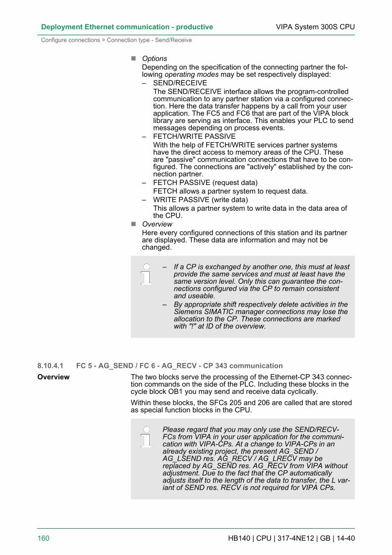
n OptionsDepending on the specification of the connecting partner the fol-lowing operating modes may be set respectively displayed:– SEND/RECEIVE
The SEND/RECEIVE interface allows the program-controlledcommunication to any partner station via a configured connec-tion. Here the data transfer happens by a call from your userapplication. The FC5 and FC6 that are part of the VIPA blocklibrary are serving as interface. This enables your PLC to sendmessages depending on process events.
– FETCH/WRITE PASSIVEWith the help of FETCH/WRITE services partner systemshave the direct access to memory areas of the CPU. Theseare "passive" communication connections that have to be con-figured. The connections are "actively" established by the con-nection partner.
– FETCH PASSIVE (request data)FETCH allows a partner system to request data.
– WRITE PASSIVE (write data)This allows a partner system to write data in the data area ofthe CPU.
n OverviewHere every configured connections of this station and its partnerare displayed. These data are information and may not bechanged.
– If a CP is exchanged by another one, this must at leastprovide the same services and must at least have thesame version level. Only this can guarantee the con-nections configured via the CP to remain consistentand useable.
– By appropriate shift respectively delete activities in theSiemens SIMATIC manager connections may lose theallocation to the CP. These connections are markedwith "!" at ID of the overview.
8.10.4.1 FC 5 - AG_SEND / FC 6 - AG_RECV - CP 343 communicationThe two blocks serve the processing of the Ethernet-CP 343 connec-tion commands on the side of the PLC. Including these blocks in thecycle block OB1 you may send and receive data cyclically.Within these blocks, the SFCs 205 and 206 are called that are storedas special function blocks in the CPU.
Please regard that you may only use the SEND/RECV-FCs from VIPA in your user application for the communi-cation with VIPA-CPs. At a change to VIPA-CPs in analready existing project, the present AG_SEND /AG_LSEND res. AG_RECV / AG_LRECV may bereplaced by AG_SEND res. AG_RECV from VIPA withoutadjustment. Due to the fact that the CP automaticallyadjusts itself to the length of the data to transfer, the L var-iant of SEND res. RECV is not required for VIPA CPs.
Overview
VIPA System 300S CPUDeployment Ethernet communication - productive
Configure connections > Connection type - Send/Receive
HB140 | CPU | 317-4NE12 | GB | 14-40 160
For the communication between CPU and Ethernet-CP 343, the fol-lowing FCs are available:AG_SEND (FC 5)This block transfers the user data from the data area given in SENDto the CP specified via ID and LADDR. As data area you may set aPA, bit memory or data block area. When the data area has beentransferred without errors, "order ready without error" is returned.AG_RECV (FC 6)The block transfers the user data from the CP into a data areadefined via RECV. As data area you may set a PA, bit memory ordata block area. When the data area has been transferred withouterrors, "order ready without error” is returned.
The CP processes send and receive commands independently fromthe CPU cycle and needs for this transfer time. The interface with theFC blocks to the user application is here synchronized by means ofacknowledgements/receipts.For status evaluation the communication blocks return parametersthat may be evaluated directly in the user application.These status displays are updated at every block call.
Do not use cyclic calls of the communication blocks in OB 1. Thiscauses a permanent communication between CPU and CP. Programinstead the communication blocks within a time OB where the cycletime is higher res. event controlled.
If a block is called a second time in the user application before thedata of the last time is already completely send res. received, the FCblock interface reacts like this:AG_SENDNo command is accepted until the data transfer has been acknowl-edged from the partner via the connection. Until this you receive themessage "Order running" before the CP is able to receive a new com-mand for this connection.AG_RECVThe order is acknowledged with the message "No data available yet"as long as the CP has not received the receive data completely.
The following illustration shows a possible sequence for the FCblocks together with the organizations and program blocks in the CPUcycle:
Communication blocks
Status displays
Deployment at highcommunication load
FC call is faster than CPtransfer time
AG_SEND, AG_RECV inthe user application
VIPA System 300S CPU Deployment Ethernet communication - productive
Configure connections > Connection type - Send/Receive
HB140 | CPU | 317-4NE12 | GB | 14-40 161

The FC blocks with concerning communication connection aresummed up by colour. Here you may also see that your user applica-tion may consist of any number of blocks. This allows you to send orreceive data (with AG_SEND res. AG_RECV) event or programdriven at any wanted point within the CPU cycle. You may also callthe blocks for one communication connection several times withinone cycle.
By means of AG_SEND the data to send are transferred from theCPU to an Ethernet CP 343.
Parameter Declaration Data type DescriptionACT INPUT BOOL Activation of the sender
0: Updates DONE, ERROR and STATUS1: The data area defined in SEND with the length LENis send
ID INPUT INT Connection number 1 ... 16(identical with ID of NetPro)
LADDR INPUT WORD Logical basic address of the CP(identical with LADDR of NetPro)
SEND INPUT ANY Data area
LEN INPUT INT Number of bytes from data area to transfer
AG_SEND (FC 5)
Parameters
VIPA System 300S CPUDeployment Ethernet communication - productive
Configure connections > Connection type - Send/Receive
HB140 | CPU | 317-4NE12 | GB | 14-40 162

Parameter Declaration Data type DescriptionDONE OUTPUT BOOL Status parameter for the order
0: Order running1: Order ready without error
ERROR OUTPUT BOOL Error message0: Order running (at DONE = 0)0: Order ready without error (at DONE = 1)1: Order ready with error
STATUS OUTPUT WORD Status message returned with DONE and ERROR.More details are to be found in the following table.
With the 1. call of AG_RECV a receive buffer for the communicationbetween CPU and an Ethernet CP 343 is established. From now onreceived data are automatically stored in this buffer. As soon as aftercalling AG_RECV the return value of NDR = 1 is returned, valid dataare present.Since with a further call of AG_RECV the receive buffer is establishedagain for the receipt of new data, you have to save the previousreceived data.
Parameter Declaration Data type DescriptionID INPUT INT Connection number 1 ... 16
(identical with ID of NetPro)
LADDR INPUT WORD Logical basic address of the CP(identical with LADDR of NetPro)
RECV INPUT ANY Data area for the received data.
NDR OUTPUT BOOL Status parameter for the order0: Order running1: Order ready data received without error
ERROR OUTPUT BOOL Error message0: Order running (at NDR = 0)0: Order ready without error (at NDR = 1)1: Order ready with error
STATUS OUTPUT WORD Status message returned with NDR and ERROR. Moredetails are to be found in the following table.
LEN OUTPUT INT Number of bytes that have been received
The following table shows all messages that can be returned by theEthernet CP 343 after a SEND res. RECV command.
AG_RECV (FC 6)
Parameters
DONE, ERROR,STATUS
VIPA System 300S CPU Deployment Ethernet communication - productive
Configure connections > Connection type - Send/Receive
HB140 | CPU | 317-4NE12 | GB | 14-40 163

A "-" means that this message is not available for the concerningSEND res. RECV command.
DONE(SEND)
NDR(RECV)
ERROR STATUS Description
1 - 0 0000h Order ready without error.
- 1 0 0000h New data received without error.
0 - 0 0000h No order present.
- 0 0 8180h No data available yet.
0 0 0 8181h Order running
0 0 1 8183h No CP project engineering for this order.
0 - 1 8184h System error
- 0 1 8184h System error(destination data area failure).
0 - 1 8185h Parameter LEN exceeds source area SEND.
0 1 8185h Destination buffer (RECV) too small.
0 0 1 8186h Parameter ID invalid (not within 1 ...16).
0 - 1 8302h No receive resources at destination station,receive station is not able to process receiveddata fast enough res. has no receive resourcesreserved.
0 - 1 8304h The connection is not established. The send com-mand shouldn’t be sent again before a delay timeof >100ms.
- 0 1 8304h The connection is not established. The receivecommand shouldn’t be sent again after a delaytime of >100ms.
0 - 1 8311h Destination station not available under the definedEthernet address.
0 - 1 8312h Ethernet error in the CP.
0 1 8F22h Source area invalid, e.g. when area in DB notpresent Parameter LEN < 0
- 0 1 8F23h Source area invalid, e.g. when area in DB notpresent Parameter LEN < 0
0 - 1 8F24h Range error at reading a parameter.
- 0 1 8F25h Range error at writing a parameter.
0 - 1 8F28h Orientation error at reading a parameter.
- 0 1 8F29h Orientation error at writing a parameter.
- 0 1 8F30h Parameter is within write protected 1. recent datablock
- 0 1 8F31h Parameter is within write protected 2. recent datablock
0 0 1 8F32h Parameter contains oversized DB number.
VIPA System 300S CPUDeployment Ethernet communication - productive
Configure connections > Connection type - Send/Receive
HB140 | CPU | 317-4NE12 | GB | 14-40 164

DONE(SEND)
NDR(RECV)
ERROR STATUS Description
0 0 1 8F33h DB number error
0 0 1 8F3Ah Area not loaded (DB)
0 - 1 8F42h Acknowledgement delay at reading a parameterfrom peripheral area.
- 0 1 8F43h Acknowledgement delay at writing a parameterfrom peripheral area.
0 - 1 8F44h Address of the parameter to read locked inaccess track
- 0 1 8F45h Address of the parameter to write locked inaccess track
0 0 1 8F7Fh Internal error e.g. invalid ANY reference e.g.parameter LEN = 0.
0 0 1 8090h Module with this module start address not presentor CPU in STOP.
0 0 1 8091h Module start address not within double word grid.
0 0 1 8092h reference contains type setting unequal BYTE.
- 0 1 80A0h Negative acknowledgement at reading themodule.
0 0 1 80A4h reserved
0 0 1 80B0h Module doesn’t recognize record set.
0 0 1 80B1h The length setting (in parameter LEN) is invalid.
0 0 1 80B2h reserved
0 0 1 80C0h Record set not readable.
0 0 1 80C1h The set record set is still in process.
0 0 1 80C2h Order accumulation.
0 0 1 80C3h The operating sources (memory) of the CPU aretemporarily occupied.
0 0 1 80C4h Communication error (occurs temporarily; a repe-tition in the user application is reasonable).
0 0 1 80D2h Module start address is wrong.
At a reboot of the CP, the output parameters are set as follows:n DONE = 0n NDR = 0n ERROR = 0n STATUS = 8180h (at AG_RECV)
STATUS = 8181h (at AG_SEND)
Status parameter atreboot
VIPA System 300S CPU Deployment Ethernet communication - productive
Configure connections > Connection type - Send/Receive
HB140 | CPU | 317-4NE12 | GB | 14-40 165

8.11 Configure Open Communicationn Connection-oriented protocols establish a (logical) connection to
the communication partner before data transmission is started.n And if necessary they terminate the connection after the data
transfer was finished.n Connection-oriented protocols are used for data transmission
when reliable, guaranteed delivery is of particular importance.n In general, many logical connections can exist on one physical
line.The following connection-oriented protocols are supported with FBsfor open communication via Industrial Ethernet:n TCP/IP native according to RFC 793 (connection types 01h and
11h):– During data transmission, no information about the length or
about the start and end of a message is transmitted.– The receiver has no means of detecting where one message
ends in the data stream and the next one begins.– The transfer is stream-oriented. For this reason, it is recom-
mended that the data length of the FBs is identical for thesending and receiving station.
– If the number of received data does not fit to the preset lengthyou either will get not the whole data, or you will get data ofthe following job. The receive block copies as many bytes intothe receive area as you have specified as length. After this, itwill set NDR to TRUE and write RCVD_LEN with the value ofLEN. With each additional call, you will thus receive anotherblock of sent data.
n ISO on TCP according to RFC 1006:– During data transmission, information on the length and the
end of the message is also transmitted.– The transfer is block-oriented– If you have specified the length of the data to be received
greater than the length of the data to be sent, the receive blockwill copy the received data completely into the receive range.After this, it will set NDR to TRUE and write RCVD_LEN withthe length of the sent data.
– If you have specified the length of the data to be received lessthan the length of the sent data, the receive block will not copyany data into the receive range but instead will supply the fol-lowing error information: ERROR = 1, STATUS = 8088h.
n There is thus no establishment and termination of a connectionwith a remote partner.
n Connection-less protocols transmit data with no acknowledge andwith no reliable guaranteed delivery to the remote partner.
Connection-orientedprotocols
Connection-less pro-tocol
VIPA System 300S CPUDeployment Ethernet communication - productive
Configure Open Communication
HB140 | CPU | 317-4NE12 | GB | 14-40 166

The following connection-oriented protocol is supported with FBs foropen communication via Industrial Ethernet:n UDP according to RFC 768 (with connection type 13h):
– In this case, when calling the sending block you have tospecify the address parameters of the receiver (IP addressand port number).
– During data transmission, information on the length and theend of the message is also transmitted.
– In order to be able to use the sending and receiving blocks firstyou have to configure the local communications access pointat both sides.
– With each new call of the sending block, you re-reference theremote partner by specifying its IP address and its portnumber.
– If you have specified the length of the data to be receivedgreater than the length of the data to be sent, the receive blockwill copy the received data completely into the receive range.After this, it will set NDR to TRUE and write RCVD_LEN withthe length of the sent data.
– If you have specified the length of the data to be received lessthan the length of the sent data, the receive block will not copyany data into the receive range but instead will supply the fol-lowing error information: ERROR = 1, STATUS = 8088h.
Those in the following listed UTDs and FBs serve for "open communi-cation" with other Ethernet capable communication partners via youruser program. These blocks are part of the Siemens SIMATIC Man-ager. You will find these in the "Standard Library" at "CommunicationBlocks". Please consider when using the blocks for open communica-tion that the partner station does not have to be configured with theseblocks. This can be configured with AG_SEND / AG_RECEIVE orIP_CONFIG.
UDTs
FB Label Connection-oriented protocols:TCP native as per RFC 793,ISO on TCP as per RFC 1006
Connectionless protocol: UDPas per RFC 768
UDT 65 TCON_PAR Data structure for assigning con-nection parameters
Data structure for assigningparameters for the local commu-nications access point
UDT 66 TCON_ADR Data structure for assigningaddressing parameters for theremote partner
FBs
FB Label Connection-oriented protocols:TCP native as per RFC 793,ISO on TCP as per RFC 1006
Connectionless protocol: UDPas per RFC 768
FB 63 TSEND Sending data
FB 64 TRCV Receiving data
Handling blocks
VIPA System 300S CPU Deployment Ethernet communication - productive
Configure Open Communication
HB140 | CPU | 317-4NE12 | GB | 14-40 167

FB Label Connection-oriented protocols:TCP native as per RFC 793,ISO on TCP as per RFC 1006
Connectionless protocol: UDPas per RFC 768
FB 65 TCON Establishing a connection Configuring the local communica-tions access point
FB 66 TDISCON Terminating a connection Closing the local communicationsaccess point
FB 67 TUSEND Sending data
FB 68 TURCV Receiving data
8.12 NCM diagnostic - Help for error diagnosticThis page shall help you with the error diagnostics. The followingcheck list shows a number of typical problems and their probablecauses:
Question Remedy with "no"CPU in RUN? n Check DC 24V power supply.
n Set the operating mode switch to position RUN.n Check PLC program and transfer it again.
AG_SEND, AG_RECV in userapplication?
These 2 blocks are required in the user application for the datatransfer between CP and CPU. Both blocks must also be calledwith a passive connection.
Is CP able to connect? n Check Ethernet cable (at a point-to-point connection acrossed Ethernet cable is to be used).
n Check IP address.
Can data be transferred? n Check Port no. for read and write.n Check source and destination areas.n Check if the 2. CP is selected in the route.n Enlarge the receive respectively send buffer defined via the
ANY pointer.
Is the complete data block sentat ISO-on-TCP?
n Check the LEN parameter at AG_SEND.n Set the receive respectively send buffer defined via the ANY
pointer to the required size.
The CP supports the Siemens NCM diagnostic tool. The NCM diag-nostic tool is part of the Siemens SIMATIC manager. This tooldelivers information about the operating state of the communicationfunctions of the online CPs dynamically.The following diagnostic functions are available:n Check operating state at Ethernetn Read the diagnostic buffer of the CPn Diagnostics of connections
The diagnostic tool is started by ‘Windows-START menuè SIMATIC è ... NCM S7 è Diagnostic’.
NCM diagnostics - Helpfor error diagnostics
Siemens NCM S7 diag-nostic
Start NCM diagnostic
VIPA System 300S CPUDeployment Ethernet communication - productive
NCM diagnostic - Help for error diagnostic
HB140 | CPU | 317-4NE12 | GB | 14-40 168

The working surface of the diagnostic tool has the following structure:n The ‘navigation area’ at the left side contains the hierarchical
listed diagnostic objects. Depending on CP type and configuredconnections there is an adjusted object structure in the navigationarea.
n The ‘information area’ at the right side always shows the result ofthe navigation function you chose in the navigation area.
A diagnostic always requires an online connection to the CP you wantto control. For this click at the symbol bar.The following dialog window appears:
Set the following parameters at ‘Destination station’ :n Attachment ..:
Ind. Ethernet TCP/IPn Node addr.:
Enter the IP address of the CPn Rack/slot:
Enter the module rack and slot of the CP 343 that you’ve placedat the 2. slot. Set your PG/PC interface to "TCP/IP -> Networkcard .... ". Via [OK] you start the online diagnostic.
Structure
No diagnostic withoutconnection
VIPA System 300S CPU Deployment Ethernet communication - productive
NCM diagnostic - Help for error diagnostic
HB140 | CPU | 317-4NE12 | GB | 14-40 169

The CP has a diagnostic buffer. This has the architecture of a ringmemory and may store up to 100 diagnostic messages. The NCMdiagnostic allows you to monitor and evaluate the diagnostic mes-sages via the diagnostic object Diagnostic buffer. Via a double clickon a diagnostic message the NCM diagnostic shows further informa-tion.
You execute a diagnostic by clicking on a diagnostic object in thenavigation area. More functions are available via the menu and thesymbol bar.
Please always control the preconditions for an operativecommunication using the check list. Ä ‘NCM diagnostics -Help for error diagnostics’ on page 168
For the aimed diagnostic deployment the following approach is con-venient:1. Start diagnostic.2. Open the dialog for the online connection with , enter connec-
tion parameters and establish the online connection with [OK].3. Identify the CP and check the recent state of the CP via module
status.4. Check the connections for particularities like:
n Connection statusn Receive statusn Send status
5. Control and evaluate the diagnostic buffer of the CP via‘Diagnostic buffer’ .
6. As needed, alter project engineering respectively programmingand restart diagnostic.
8.13 Coupling to other systemsThe operating mode FETCH/WRITE supported at TCP res. ISO-on-TCP can be used for accesses of partner devices to the PLC systemmemory. To be able to use this access also for example for imple-mentation in PC applications you have to know the telegram structurefor orders. The specific headers for request and acknowledgementtelegrams have per default a length of 16Byte and are described atthe following pages.
The organization format is the abbreviated description of a datasource or a data destination in a PLC environment. The availableORG formats are listed in the following table. The ERW-identifier isused for the addressing of data blocks. In this case the data blocknumber is entered into this identifier. The start address and quantityprovide the address for the memory area and they are stored inHIGH-/LOW- format (Motorola-formatted addresses)
Read diagnostic buffer
Approach for diagnostic
Overview
ORG format
VIPA System 300S CPUDeployment Ethernet communication - productive
Coupling to other systems
HB140 | CPU | 317-4NE12 | GB | 14-40 170

Description Type RangeORG identifier BYTE 1...x
ERW identifier BYTE 1...255
Start address HILOWORD 0...y
Length HILOWORD 1...z
The following table contains a list of available ORG-formats. The"length" must not be entered as -1 (FFFFh).
ORG identifier 01h-04h
CPU area DB MB EB AB
ORG identifier 01h 02h 03h 04h
Description Source/destinationdata from/into dataBlock in mainmemory.
Source/destinationdata from/into flagmemory area
Source/destinationdata from/intoprocess image ofthe inputs (PII).
Source/destinationdata from/intoprocess image ofthe outputs (PIQ).
ERW identifier
(DBNO)
DB, from where thesource data isretrieved or to wherethe destination datais transferred.
irrelevant irrelevant irrelevant
Start address
significance
DBB-No., fromwhere the data isretrieved or wherethe data is saved.
MB-No., from wherethe data is retrievedor where the data issaved.
IB-No., from wherethe data is retrievedor where the data issaved.
QB-No., from wherethe data is retrievedor where the data issaved.
Length
significance
Length of thesource/destinationdata block in words.
Length of thesource/destinationdata block in bytes
Length of thesource/destinationdata block in bytes
Length of thesource/destinationdata block in bytes
ORG identifier 05h-07h
CPU area PB ZB TB
ORG identifier 05h 06h 07h
Description source/destination datafrom/into peripheral mod-ules. Input module forsource data, output modulefor destination data.
source/destination datafrom/into counter cells.
Source/destination datafrom/into timer cells.
ERW identifier
(DBNO)
irrelevant irrelevant irrelevant
Start address
Significance
PB-No., from where thedata can be retrieved orwhere it is saved.
ZB-No., from where thedata can be retrieved orwhere it is saved.
TB-No., from where thedata can be retrieved orwhere it is saved.
Length
Significance
Length of the source/desti-nation data block in bytes.
Length of the source/desti-nation data block in words
(counter cell = 1 word).
Length of the source/desti-nation data block in words
(counter cell = 1 word).
VIPA System 300S CPU Deployment Ethernet communication - productive
Coupling to other systems
HB140 | CPU | 317-4NE12 | GB | 14-40 171

ORG identifier 81h-FFhTo transfer data blocks of the number range 256 ... 32768 you mayuse the ORG identifier 81h-FFh. For the setting of a DB No. >255needs a length of one word, the DBNOnew is assembled from the con-tent of the ORG identifier and the DBNO. DBNOnew is created as wordas follows:
DBNOnew
High-Byte Low-Byte
1 x x x x x x x x x x x x x x x ORG identifier (0XXXXXXX) DBNR (XXXXXXXX)
If the highest bit of the ORG identifier is set, the Low-Byte ofDBNOnew is defined via DBNO and the High-Byte of DBNOnew viaORG identifier, where the highest bit of the ORG identifier is elimi-nated. The following formula illustrates this:DBNOnew =256 x (ORG-identifier AND 7Fh) + DBNO
For every FETCH and WRITE the CP generates PLC header forrequest and acknowledgment messages. Normally the length of theseheaders is 16Bytes and have the following structure:
WRITE
Request telegram Remote Station Acknowledgement telegram CPSystem ID = "S5" (Word) System ID ="S5" (Word)
Length Header = 10h (Byte) Length Header =10h (Byte)
ID OP-Code = 01h (Byte) ID OP-Code =01h (Byte)
Length OP-Code = 03h (Byte) Length OP-Code =03h (Byte)
OP-Code = 03h (Byte) OP-Code =04h (Byte)ORG block = 03h (Byte) Ackn. block = 0Fh (Byte)
Length ORG block = 08h (Byte) Length Ack. block = 03h (Byte)
ORG identifier* (Byte) Error no. (Byte)
ERW identifier (Byte) Empty block = FFh (Byte)
Start address (Word) Length empty block = 07h (Byte)
Length (Word) 5 empty bytes attached
Empty block = FFh (Byte)
Transfer of blocks withnumbers >255
Structure of PLC-Header
VIPA System 300S CPUDeployment Ethernet communication - productive
Coupling to other systems
HB140 | CPU | 317-4NE12 | GB | 14-40 172
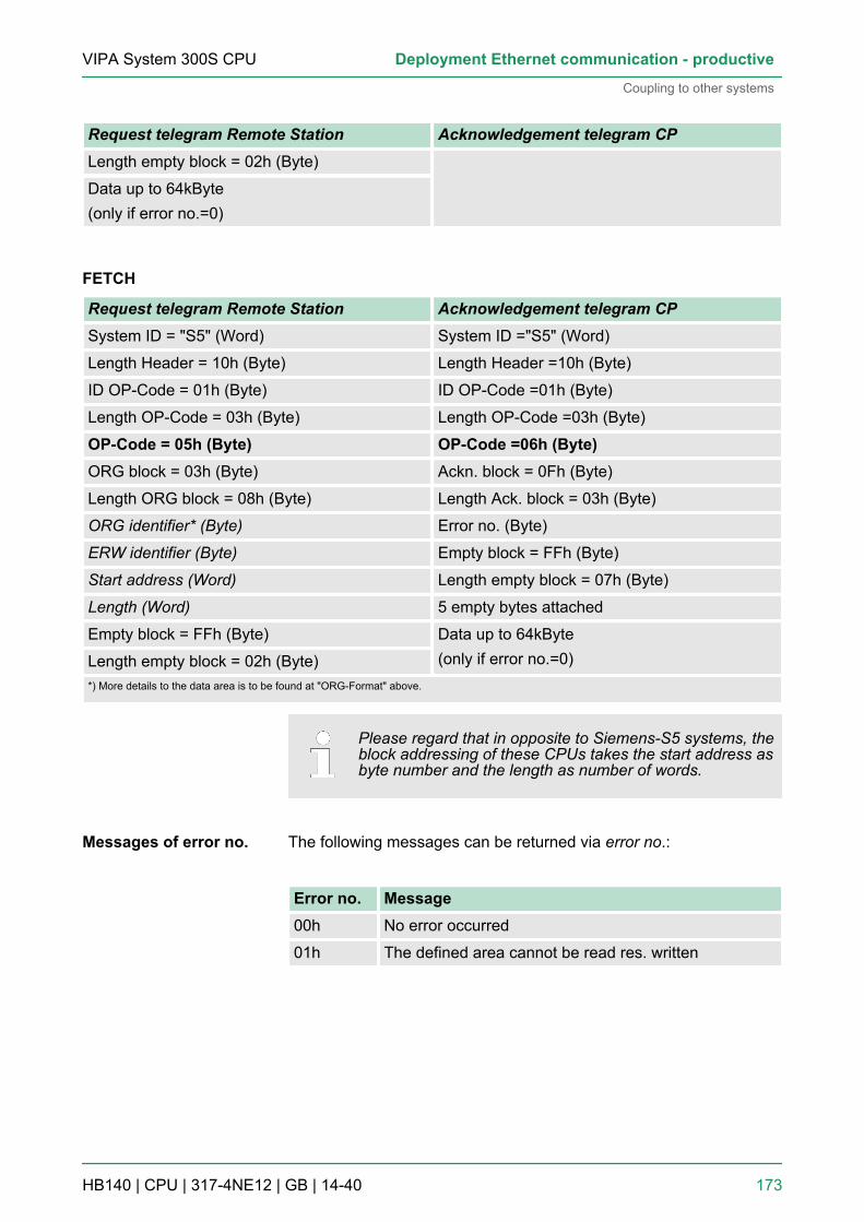
Request telegram Remote Station Acknowledgement telegram CPLength empty block = 02h (Byte)
Data up to 64kByte(only if error no.=0)
FETCH
Request telegram Remote Station Acknowledgement telegram CPSystem ID = "S5" (Word) System ID ="S5" (Word)
Length Header = 10h (Byte) Length Header =10h (Byte)
ID OP-Code = 01h (Byte) ID OP-Code =01h (Byte)
Length OP-Code = 03h (Byte) Length OP-Code =03h (Byte)
OP-Code = 05h (Byte) OP-Code =06h (Byte)ORG block = 03h (Byte) Ackn. block = 0Fh (Byte)
Length ORG block = 08h (Byte) Length Ack. block = 03h (Byte)
ORG identifier* (Byte) Error no. (Byte)
ERW identifier (Byte) Empty block = FFh (Byte)
Start address (Word) Length empty block = 07h (Byte)
Length (Word) 5 empty bytes attached
Empty block = FFh (Byte) Data up to 64kByte(only if error no.=0)Length empty block = 02h (Byte)
*) More details to the data area is to be found at "ORG-Format" above.
Please regard that in opposite to Siemens-S5 systems, theblock addressing of these CPUs takes the start address asbyte number and the length as number of words.
The following messages can be returned via error no.:
Error no. Message00h No error occurred
01h The defined area cannot be read res. written
Messages of error no.
VIPA System 300S CPU Deployment Ethernet communication - productive
Coupling to other systems
HB140 | CPU | 317-4NE12 | GB | 14-40 173

9 WinPLC79.1 System conception
WinPLC7 is a programming and simulation software from VIPA forevery PLC programmable with Siemens STEP®7. This tool allows youto create user applications in FBD, LAD and STL. Besides of a com-fortable programming environment, WinPLC7 has an integrated simu-lator that enables the simulation of your user application at the PCwithout additional hardware. This "Soft-PLC" is handled like a realPLC and offers the same error behavior and diagnostics options viadiagnostics buffer, USTACK and BSTACK.
Detailed information and programming samples may befound at the online help respectively in the online docu-mentation of WinPLC7.
There is also the possibility to use according configuration tools fromSiemens instead of WinPLC7 from VIPA. Here the proceeding is partof this manual.
n Windows XP (SP3)n Windows Vistan Windows 7 (32 and 64 bit)n Windows 8 (32 and 64 bit)
You may receive a demo version from VIPA. Without any activationwith the demo version the CPUs 11x of the System 100V from VIPAmay be configured. To configure the SPEED7 CPUs a license for the"profi" version is necessary. This may be online be received fromVIPA and activated.There are the following sources to get WinPLC7:n Online
– At www.vipa.com in the service area at Downloads a link tothe current demo version and the updates of WinPLC7 may befound.
n CD– SW211C1DD: WinPLC7 Single license, CD, with documenta-
tion in german– SW211C1ED: WinPLC7 Single license, CD, with documenta-
tion in english
9.2 InstallationThe project engineering of a SPEED7 CPU from VIPA with WinPLC7is only possible using an activated "Profi" version of WinPLC7.
General
Alternatives
System requirements
Source
Precondition
VIPA System 300S CPUWinPLC7
Installation
HB140 | CPU | 317-4NE12 | GB | 14-40 174

The installation and the registration of WinPLC7 has the followingapproach:1. For installation of WinPLC7 start the setup program of the corre-
sponding CD respectively execute the online received exe file.2. Select the according language.3. Accept the licensing agreement.4. Set an installation directory and a group assignment and start
the installation.
1. Start WinPLC7.ð A ‘Demo’ dialog is shown
2. Click at [Activate Software].ð The following dialog for activation is shown:
3. Fill in the following fields:n Email-Addr.n Your Namen Serial number
The serial number may be found on a label at the CD case ofWinPLC7.
4. If your computer is connected to Internet you may online requestthe Activation Key by [Get activation key via Internet]. Otherwiseclick at [This PC has no access to the Internet] and follow theinstructions.ð With successful registration the activation key is listed in the
dialog window respectively is sent by email.5. Enter this at ‘Activation code’ and click at [OK].
ð Now, WinPLC7 is activated as "Profi" version.
Installation WinPLC7Demo
Activation of the "Profi"version
VIPA System 300S CPU WinPLC7
Installation
HB140 | CPU | 317-4NE12 | GB | 14-40 175

To find a station via Ethernet (accessible nodes) you have to installthe WinPCAP driver. This driver may be found on your PC in theinstallation directory at WinSPS-S7-V5/WinPcap_... .exe. Execute thisfile and follow the instructions.
9.3 Example project engineering9.3.1 Job definition
In the example a FC 1 is programmed, which is cyclically called bythe OB 1. By setting of 2 comparison values (value1 and value2)during the FC call, an output of the PLC-System should be activateddepending on the comparison result. By setting of 2 comparisonvalues (value1 and value2) during the FC call, an output of the PLC-System should be activated depending on the comparison result.Here it should apply:n if value1 = value2 activate output Q 124.0n if value1 > value2 activate output Q 124.1n if value1 < value2 activate output Q 124.2
n You have administrator rights for your PC.n WinPLC7 is installed and activated as "Profi" version.n One SPEED7 CPU and one digital output module are installed
and cabled.n The Ethernet PG/OP channel of the CPU is connected to your
Ethernet network. Your CPU may be connected to your PC withan Ethernet cable either directly or via hub/switch.
n WinPCap for station search via Ethernet is installed.n The power supply of the CPU and the I/O periphery are activated
and the CPU is in STOP state.
9.3.2 Project engineering1. Start WinPLC7 ("Profi" version)2. Create and open a new project with [Create a new solution].
1. For the call of the hardware configurator it is necessary to setWinPLC7 from the Simulator-Mode to the Offline-Mode. For thisand the communication via Ethernet set "Target: TCP/IP Direct".
2. Double click to ‘Hardware stations’ and here at ‘Create new’ .
Installation of WinPCAPfor station search viaEthernet
Precondition
Hardware configuration
VIPA System 300S CPUWinPLC7
Example project engineering > Project engineering
HB140 | CPU | 317-4NE12 | GB | 14-40 176

3. Enter a station name. Please consider that the name does notcontain any spaces.
4. After the load animation choose in the register Select PLC-System the system "VIPA SPEED7" and click to [Create]. A newstation is created.
5. Save the empty station with [Strg]+[S].6. By double click or drag&drop the according VIPA CPU in the
hardware catalog at ‘CPU SPEED7’ the CPU is inserted to yourconfiguration.
7. For output place a digital output module, assign the startaddress 124 and save the hardware configuration.
Establish online access via Ethernet PG/OP channel:1. Open the CPU-Properties, by double clicking to the CPU at slot
2 in the hardware configurator.2. Click to the button [Ethernet CP-Properties (PG/OP-channel)].
ð The dialog ‘Properties CP343’ is opened.
3. Chose the register ‘Common Options’ .4. Click to [Properties Ethernet].5. Choose the subnet ‘PG_OP_Ethernet’ .6. Enter a valid IP address-and a subnet mask. You may get this
from your system administrator.7. Close every dialog window with [OK].8. Select, if not already done, ‘Target: External TCP/IP direct’ .9. Open with ‘Online è Send configuration to the CPU’ a dialog
with the same name.10. Click to [Accessible nodes]. Please regard to use this function it
is necessary to install WinPCap before!11. Choose your network card and click to [Determining accessible
nodes].ð After a waiting time every accessible station is listed. Here
your CPU with IP 0.0.0.0 is listed, too. To check this theaccording MAC address is also listed. This MAC addressmay be found at a label beneath the front flap of the CPU.
12. For the temporary setting of an IP address select you CPU andclick to [Temporary setting of the IP parameters]. Please enterthe same IP parameters, you configured in the CPU propertiesand click to [Write Parameters].
13. Confirm the message concerning the overall reset of the CPU.ð The IP parameters are transferred to the CPU and the list of
accessible stations is refreshed.14. Select your CPU and click to [Confirm].
ð Now you are back in the dialog "Send configuration".
VIPA System 300S CPU WinPLC7
Example project engineering > Project engineering
HB140 | CPU | 317-4NE12 | GB | 14-40 177
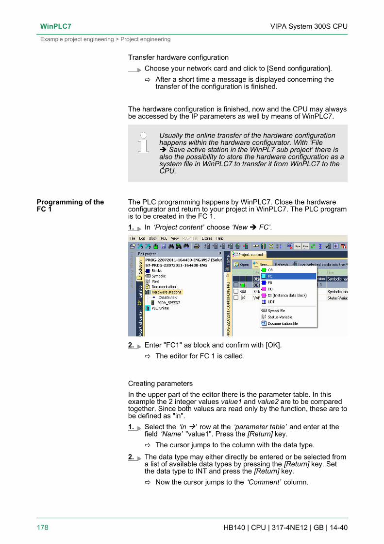
Transfer hardware configurationChoose your network card and click to [Send configuration].ð After a short time a message is displayed concerning the
transfer of the configuration is finished.
The hardware configuration is finished, now and the CPU may alwaysbe accessed by the IP parameters as well by means of WinPLC7.
Usually the online transfer of the hardware configurationhappens within the hardware configurator. With ‘Fileè Save active station in the WinPL7 sub project’ there isalso the possibility to store the hardware configuration as asystem file in WinPLC7 to transfer it from WinPLC7 to theCPU.
The PLC programming happens by WinPLC7. Close the hardwareconfigurator and return to your project in WinPLC7. The PLC programis to be created in the FC 1.1. In ‘Project content’ choose ‘New è FC’.
2. Enter "FC1" as block and confirm with [OK].ð The editor for FC 1 is called.
Creating parametersIn the upper part of the editor there is the parameter table. In thisexample the 2 integer values value1 and value2 are to be comparedtogether. Since both values are read only by the function, these are tobe defined as "in".1. Select the ‘in à’ row at the ‘parameter table’ and enter at the
field ‘Name’ "value1". Press the [Return] key.ð The cursor jumps to the column with the data type.
2. The data type may either directly be entered or be selected froma list of available data types by pressing the [Return] key. Setthe data type to INT and press the [Return] key.ð Now the cursor jumps to the ‘Comment’ column.
Programming of theFC 1
VIPA System 300S CPUWinPLC7
Example project engineering > Project engineering
HB140 | CPU | 317-4NE12 | GB | 14-40 178

3. Here enter "1. compare value" and press the [Return] key.ð A new ‘in à’ row is created and the cursor jumps to ‘Name’ .
4. Proceed for value2 in the same way as described for value1.5. Save the block. A note that the interface of the block was
changed may be acknowledged with [Yes].ð The parameter table shows the following entries, now:
Enter the programAs requested in the job definition, the corresponding output is acti-vated depending on the comparison of value1 and value2. For eachcomparison operation a separate network is to be created.1. The program is to be created as FBD (function block diagram).
Here change to the FBD view by clicking at ‘FBD’ .
2. Click to the input field designated as "<empty>". The availableoperations may be added to your project by drag&drop from thehardware catalog or by double click at them in the hardware cat-alog.
3. Open in the catalog the category "Comparator" and add theoperation ‘CMP==I’ to your network.
4. Click to the input left above and insert value1. Since these areblock parameters a selection list of block parameters may beviewed by entering "#".
5. Type in "#" and press the [Return] key.6. Choose the corresponding parameter of the list and confirm it
with the [Return] key.
VIPA System 300S CPU WinPLC7
Example project engineering > Project engineering
HB140 | CPU | 317-4NE12 | GB | 14-40 179

7. Proceed in the same way with the parameter value2.
The allocation to the corresponding output, here Q 124.0, takes placewith the following proceeding:1. Click to the output at the right side of the operator.
2. Open in the catalog the category ‘Bit logic’ and select the func-tion ‘--[=]’ . The inserting of ‘--[=]’ corresponds to the WinPLC7shortcut [F7].
3. Insert the output Q 124.0 by clicking to the operand.
ð Network1 is finished, now.
Adding a new networkFor further comparisons the operations "CMP>I" at Q 124.1 and"CMP<I" at Q 124.2 are necessary. Create a network for both opera-tions with the following proceeding:1. Move your mouse at an arbitrary position on the editor window
and press the right mouse key.2. Select at ‘context menu è Insert new network’.
ð A dialog field is opened to enter the position and number ofthe networks.
3. Proceed as described for "Network 1".
VIPA System 300S CPUWinPLC7
Example project engineering > Project engineering
HB140 | CPU | 317-4NE12 | GB | 14-40 180
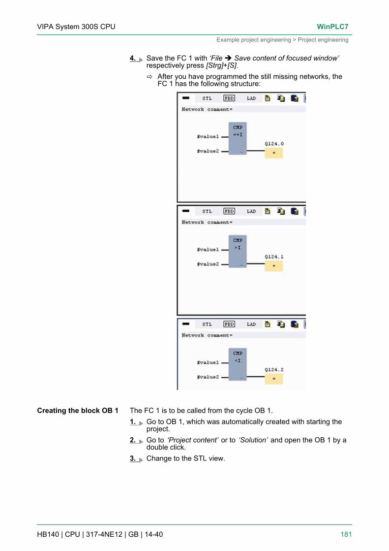
4. Save the FC 1 with ‘File è Save content of focused window’respectively press [Strg]+[S].ð After you have programmed the still missing networks, the
FC 1 has the following structure:
The FC 1 is to be called from the cycle OB 1.1. Go to OB 1, which was automatically created with starting the
project.2. Go to ‘Project content’ or to ‘Solution’ and open the OB 1 by a
double click.3. Change to the STL view.
Creating the block OB 1
VIPA System 300S CPU WinPLC7
Example project engineering > Project engineering
HB140 | CPU | 317-4NE12 | GB | 14-40 181

4. Type in "Call FC 1" and press the [Return] key.ð The FC parameters are automatically displayed and the fol-
lowing parameters are assigned:
5. Save the OB 1 with respectively press [Strg]+[S].
9.3.3 Test the PLC program in the SimulatorWith WinPLC7 there is the possibility to test your project in a Simu-lator.1. Here select ‘Target: Simulator’ .
2. Transfer the blocks to the simulator with [Load all blocks into thePLC].
3. Switch the CPU to RUN, by clicking at ‘RUN’ in the ‘CPUControl Center’ of ‘Edit project’ .ð The displayed state changes from STOP to RUN.
4. To view the process image select ‘Viewè Display process image window’ or click at .ð The various areas are displayed.
5. Double click to the process image and enter at ‘Line 2’ theaddress PQB 124. Confirm your input with [OK]. A value markedby red color corresponds to a logical "1".
6. Open the OB 1.
Proceeding
VIPA System 300S CPUWinPLC7
Example project engineering > Test the PLC program in the Simulator
HB140 | CPU | 317-4NE12 | GB | 14-40 182

7. Change the value of one variable, save the OB 1 and transfer itto the simulator.ð According to your settings the process image changes
immediately. The status of your blocks may be displayedwith ‘Block è Monitoring On/Off’.
A further component of the simulator is the PLC mask. Here a CPU isgraphically displayed, which may be expanded by digital and analogperipheral modules. As soon as the CPU of the simulator is switchedto RUN state, inputs may be activated by mouse and outputs may bedisplayed.1. Open the PLC mask with ‘view è PLC mask’.
ð A CPU is graphically displayed.
2. Double-click to the output module, open its properties dialog andenter the Module address 124.
3. Switch the operating mode switch to RUN by means of themouse.ð Your program is executed and displayed in the simulator,
now.
9.3.4 Transfer PLC program to CPU and its execution1. For transfer to the CPU set the transfer mode to "Target: TCP/
IP-Direct".2. If there are more network adapters in your PC, the network
adapter may be selected via ‘Extras è Select network adapter’.3. For presetting the Ethernet data click to [...] and click to [Acces-
sible nodes].
Visualization via PLCmask
Proceeding
VIPA System 300S CPU WinPLC7
Example project engineering > Transfer PLC program to CPU and its execution
HB140 | CPU | 317-4NE12 | GB | 14-40 183

4. Click at [Determining accessible nodes].ð After a waiting time every accessible station is listed.
5. Choose your CPU, which was provided with TCP/IP addressparameters during the hardware configuration and click to [Con-firm].
6. Close the dialog ‘Ethernet properties’ with [OK].7. Transfer your project to your CPU with ‘PLC è Send all blocks’.8. Switch your CPU to RUN state.9. Open the OB 1 by double click.10. Change the value of one variable, save the OB 1 and transfer it
to the CPU.ð According to your settings the process image changes
immediately. The status of your blocks may be displayedwith ‘Block è Monitoring On/Off’.
VIPA System 300S CPUWinPLC7
Example project engineering > Transfer PLC program to CPU and its execution
HB140 | CPU | 317-4NE12 | GB | 14-40 184