
Transitions in the velocity pattern of lower mobility parallel manipulators
16
Transitions in the velocity pattern of lower mobility parallel manipulators Alfonso Herna ´ndez, Oscar Altuzarra * , Charles Pinto, Enrique Amezua Department of Mechanical Engineering, University of The Basque Country, UPV/EHU, Bilbao 48013, Spain Received 23 February 2007; received in revised form 7 May 2007; accepted 15 May 2007 Available online 9 July 2007 Abstract Lower mobility parallel manipulators are designed to perform tasks that require less than six degrees of freedom. The operational mode is given by the type of screw system spanned by the end-effector’s twist and it is configuration dependent. A change in the dimension of such screw system occurs at singularities; a loss of freedom of the end-effector will make the operation not feasible while a gain of freedom will produce uncontrolled motions. In this contribution the authors show that there are also poses in which, being no quantitative alteration of the freedom of the moving platform, there are changes in the type of its screw system. These changes are viewed as transitions in the velocity pattern of the end-effector. Such transitions can alter the operational motion and produce a problem that should be avoided, but it can be also a useful new operational mode. Because in many industrial applications the operational mode is viewed in terms of the pure trans- lations and the rotations available in the end-effector, the authors have used such concepts to denote the type of motion. In this paper the authors present a procedure to analyze these transitions and present an example. Ó 2007 Elsevier Ltd. All rights reserved. Keywords: Operational modes; Velocity pattern; Parallel manipulators; Lower mobility 1. Introduction The capabilities of a robot are given by the possibilities of motion of its end-effector. For six degrees of freedom (DOF) robots, the end-effector has full ability for spatial motion. In theory, it has the capacity to place an object in any position and orientation. Besides, the robot can transmit the object any velocity con- dition. However, there are plenty of tasks in industry that can be done with less DOFs than six, and hence using more economical devices. This is the motivation for designing lower mobility parallel manipulators. The motion of the robot’s end-effector is not only determined by the number of DOF, but also by the type of motion that can be achieved. In [1], this is shown with the so called motion pattern of the platform, 0094-114X/$ - see front matter Ó 2007 Elsevier Ltd. All rights reserved. doi:10.1016/j.mechmachtheory.2007.05.006 * Corresponding author. Tel.: +34 946014174; fax: +34 946014215. E-mail addresses: [email protected] (A. Herna ´ndez), [email protected] (O. Altuzarra), [email protected] (C. Pinto), [email protected] (E. Amezua). Available online at www.sciencedirect.com Mechanism and Machine Theory 43 (2008) 738–753 www.elsevier.com/locate/mechmt Mechanism and Machine Theory
-
Upload
independent -
Category
Documents
-
view
5 -
download
0
Transcript of Transitions in the velocity pattern of lower mobility parallel manipulators

Available online at www.sciencedirect.com Mechanism
Mechanism and Machine Theory 43 (2008) 738–753
www.elsevier.com/locate/mechmt
andMachine Theory
Transitions in the velocity pattern of lower mobilityparallel manipulators
Alfonso Hernandez, Oscar Altuzarra *, Charles Pinto, Enrique Amezua
Department of Mechanical Engineering, University of The Basque Country, UPV/EHU, Bilbao 48013, Spain
Received 23 February 2007; received in revised form 7 May 2007; accepted 15 May 2007Available online 9 July 2007
Abstract
Lower mobility parallel manipulators are designed to perform tasks that require less than six degrees of freedom. Theoperational mode is given by the type of screw system spanned by the end-effector’s twist and it is configuration dependent.A change in the dimension of such screw system occurs at singularities; a loss of freedom of the end-effector will make theoperation not feasible while a gain of freedom will produce uncontrolled motions. In this contribution the authors showthat there are also poses in which, being no quantitative alteration of the freedom of the moving platform, there arechanges in the type of its screw system. These changes are viewed as transitions in the velocity pattern of the end-effector.Such transitions can alter the operational motion and produce a problem that should be avoided, but it can be also a usefulnew operational mode. Because in many industrial applications the operational mode is viewed in terms of the pure trans-lations and the rotations available in the end-effector, the authors have used such concepts to denote the type of motion. Inthis paper the authors present a procedure to analyze these transitions and present an example.� 2007 Elsevier Ltd. All rights reserved.
Keywords: Operational modes; Velocity pattern; Parallel manipulators; Lower mobility
1. Introduction
The capabilities of a robot are given by the possibilities of motion of its end-effector. For six degrees offreedom (DOF) robots, the end-effector has full ability for spatial motion. In theory, it has the capacity toplace an object in any position and orientation. Besides, the robot can transmit the object any velocity con-dition. However, there are plenty of tasks in industry that can be done with less DOFs than six, and henceusing more economical devices. This is the motivation for designing lower mobility parallel manipulators.
The motion of the robot’s end-effector is not only determined by the number of DOF, but also by thetype of motion that can be achieved. In [1], this is shown with the so called motion pattern of the platform,
0094-114X/$ - see front matter � 2007 Elsevier Ltd. All rights reserved.
doi:10.1016/j.mechmachtheory.2007.05.006
* Corresponding author. Tel.: +34 946014174; fax: +34 946014215.E-mail addresses: [email protected] (A. Hernandez), [email protected] (O. Altuzarra), [email protected] (C. Pinto),
[email protected] (E. Amezua).

A. Hernandez et al. / Mechanism and Machine Theory 43 (2008) 738–753 739
used in the sense of the loci of all the attainable instantaneous screw axes. A complete study of the motioncan be also performed with the analysis of the screw system of the end-effector, i.e. the space of its feasiblemotions. Screw theory has been employed to completely classify the nature of a rigid-body motion. In [2]appeared the first classification of screw systems and its application to the mechanics of manipulators. Sincethen, some references tried to complete the aforementioned classification or argue about its completeness[3–7].
Another approach to obtain some insight on the type of motion of the end-effector is to look at both: thecapacity to produce pure translations, and the possible directions of the angular velocity. That is, to obtain foreach: the dimension of the pure translational space and its basis, and the analogous for the angular velocityfield. This will be called the velocity pattern. In fact, those dimensions have been extensively used to denom-inate the type of motion of parallel manipulators giving them the names of Translational and RotationalDOFs like in [8] or [9] (translatory and rotary in [2]).
Most manipulators are designed for a single operational mode. The dimensions of pure translations andangular velocity fields of the moving platform are usually unaltered by the motion of the manipulator, as wellas the number of DOF. Changes in directions of possible pure translations or the angular velocity are morecommon. They are usually regarded as inconveniences of the topology chosen but they are not catastrophic. Alimited number of manipulators can change their global mobilities and their motion pattern in passing a sin-gular configuration in which a transitory infinitesimal mobility is attained, and they are called kinematotropic[10]. In [11] parallel robots that change not their mobility but their group of motion when crossing such sin-gularities are presented. Manipulators with multiple operational modes can be obtained from such mecha-nisms by adding inputs to control the singularity crossing like in [12].
In this paper we will show the possibility that, in certain poses of the platform, a change in the type of screwsystem spanned by the end-effector’s twist, that we will call type of motion, may occur without going through asingularity of increased mobility. This transition can be analyzed looking into the velocity pattern becausesome rotational capability will be gained or lost at the expense of the ability for some pure translation. Obvi-ously, this alters substantially the possible motion of the platform and hence, will have an influence in theoperation of the robot. In these circumstances, it is possible that either the robot were unable to accomplishwith the intended task, at least instantaneously at that pose, or that new operational modes were possible.Such problems are usually associated to singularities.
Two classes of singularities affect the end-effector’s type of motion. In the first one there is an instantaneousor permanent increment in the DOF of the mechanism affecting the instantaneous freedom of the end-effector.This produces a change of the type of motion of the moving platform because some constraint is lost and thereis an instantaneous gain of a new capability of motion. Such is the case of Increased Mobility [2,13], config-uration space singularity [14], Increased Instantaneous Mobility (IIM) [15] and constraint singularities (a sub-set of IIM) [16]. In the second one there is an unexpected linear dependency among some of the independentvelocity parameters of the end-effector, i.e. a loss of freedom. The transition of the type of motion is a loss ofsome capacity of motion. Such is the case of Inverse Kinematic Singularities [17], Dependent KinematicParameters [13], end-effector singularities [14], and Impossible Output [15,18] or [19]. Closer to the transitionof motion described here are Rotation and Translation Singularities [20–23]. However, in [24] a detailed anal-ysis of these is done with the conclusion that the rotational singularity is a constraint singularity, and that thetranslational singularity is a RO (Direct Kinematic singularity).
The motivation of this research came from the problems detected in the simulation of the control of newtypologies of hybrid parallel kinematic machines. A 2R1T parallel module tool-head working on a 2R tilt-ing table exhibited a global 3T2R motion that was transformed in certain poses to a 2T3R motion type. Insuch poses, a command to perform a pure translational motion in a certain direction (possible a priori)required huge values of input rates exceeding the limits of the controllers and taking the machine to ahalt.
The paper is organized as follows. First, a brief review of the Jacobian analysis used in lower mobility par-allel manipulators is done in order to get from there to the velocity equation used in the paper. Second, thevelocity pattern is defined as well as the procedure to find it. Third, the way to detect the transition of motiontype using the velocity pattern is described. Fourth, an example is solved. And finally, some conclusions aredrawn.
740 A. Hernandez et al. / Mechanism and Machine Theory 43 (2008) 738–753
2. Jacobian analysis of lower mobility parallel manipulators
The conventional Jacobian analysis is a method that uses the velocity vector-loops. They are often stated byderivation of the loop-closure equations that represent the kinematic constraints imposed by the limbs. Thevector loop-closure equation for each limb is given by
f iðx; qÞ ¼ 0; i ¼ 1 . . . L ð1Þ
where fi is a vector that relates the variables that define the pose of the moving platform x with the inputs q,and L is the number of such loops. Upon differentiation of Eq. (1) and assembly in matrix form we obtain
Jx _x ¼ Jq _q ð2Þ
where Jx and Jq are Jacobian matrices, _x ¼ ½ _pT;xT�T is the twist of the platform, being _p the velocity of a pointP in the platform and x the platform’s angular velocity, and _q is the vector of input joint rates.
For lower mobility parallel manipulators the number of generalized coordinates of the platform is F < 6.On the one hand, if the manipulator is fully parallel, the number of velocity vector-loops L is equal to F
and therefore Jq is a square matrix. However, Jx is a F · 6 rectangular matrix. On the other hand, out ofthe 6 variables of the end-effector’s twist only F are independent. The variables in the twist are related by con-straint equations imposed by the topology of the limbs or by passive kinematic chains. These constraint equa-tions can be expressed in matrix form as
0 ¼ Jc _x ð3Þ
where matrix Jc is called the Jacobian of constraints and it is a rectangular matrix, being the number of con-straint equations 6 � F.
2.1. Jacobian analysis with operational velocities
These fundamental equations, Eqs. (2) and (3) can be used in two ways. In the first one, the total twist _x isdivided into an output vector _y defined with F independent variables, i.e. the operational velocities, and a vec-tor with the dependent variables _z. Eq. (3) is used to relate them as follows:
0 ¼ Jc
_y
_z
� �¼ Jc1
Jc2½ �
_y
_z
� �¼ Jc1
_yþ Jc2_z ð4Þ
where Jc1and Jc2
are submatrices of Jc corresponding to the columns that multiply _y and _z, respectively. Thenthe dependent variables are expressed as a function of the operational velocities and introduced in Eq. (2),namely
Jx
_y
_z
� �¼ ½Jx1
� Jx2J�1
c2Jc1� _y ¼ Jq _q ð5Þ
where Jx1and Jx2
are the submatrices of Jx corresponding to _y and _z, respectively. To end, the velocity equa-tion that maps operational velocities to the inputs is
Jy _y ¼ Jq _q ð6Þ
where Jacobians Jy and Jq are square matrices with size F and the singularity analysis is greatly simplified.This is the case of parallel manipulators whose motion pattern is known beforehand or found by applicationof screw theory, but also where it is easy to find the relation between the overall twist _x and the operationalvelocities _y, e.g. translational manipulators such as 3CRR [22,25], spherical manipulators such as 3RRR[26,27], Schonflies’ motion manipulators such as [28], and manipulators with a passive limb that constrainsthe motion [29]. In the latter case, the vector-loop equations are stated for each actuated limb and the con-straints imposed by the passive limb are used to find that relation between overall twist and output.
Jacobians Jy and Jq are the ones used in [17] to do the singularity analysis. The Direct Kinematic singularityoccurs when the Jacobian Jy is singular and implies that nonzero outputs can appear with inputs lockedbecause a dependency among the latter appear. The Inverse Kinematic singularity happens when the Jacobian

A. Hernandez et al. / Mechanism and Machine Theory 43 (2008) 738–753 741
Jq is singular and means that a null output is possible with non zero inputs. An inconvenience of this method isthat for some specific configurations the number of independent variables may not be equal to F, and in manylower mobility parallel manipulators with mixed freedoms it is difficult to identify independent variables fromdependent ones. Moreover, in the process of finding Jy it may occur that Jc2
were not invertible and this doesnot tell us whether this is an Inverse Kinematic singularity, a transition of velocity pattern, or just an error inthe choice of variables.
2.2. Overall Jacobian
The second way to use the fundamental equations is to add the constraint equations, Eq. (3), to the veloc-ity-loop equations, Eq. (2), [30,31]. If Jq is invertible, Eq. (2) can be rewritten as
_q ¼ Ja _x ð7Þ
where matrix Ja is called the Jacobian of actuations. Both Eqs. (3) and (7) can be assembled into the following:_q
0
� �¼
Ja
Jc
� �_x ¼ Jo _x ð8Þ
where the 6 · 6 square matrix Jo is called the overall Jacobian.This approach is very usual in lower mobility parallel manipulators where the operational velocities are hin-
dered by the constraint equations and cannot be openly presented as a function of the overall twist. This isoften the case with parallel manipulators with mixed freedoms.
The singularity analysis is performed using Jacobians Jc and Jo. If det(Jo) is null and the rank of the rect-angular matrix Jc is maintained, Tsai and Joshi say that the pose is an architecture singularity. When the rankof Jc decreases a constraint singularity occurs.
2.3. Velocity equation for the analysis of velocity pattern
An alternative, more adequate to the concepts and procedure used in this paper, is to assemble directly Eq.(3) with Eq. (2). In this case, there is no need to invert Jq. The compiled equation in matrix form is
Jc
Jx
� �_x ¼
0
Jq
� �_q ð9Þ
and the resultant velocity equation is
Jv _x ¼0
Jq
� �_q ð10Þ
where Jacobians Jv and Jq are square matrices. The Direct Kinematic singularity occurs now when the Jaco-bian Jv is singular, moreover the number of equations of dependency among the inputs is equal to its rankdeficiency. The Inverse Kinematic singularity happens when the Jacobian Jq is singular.
Jv is a 6 · 6 square Jacobian for any parallel manipulator, and when it is non-singular it can be inverted toget a velocity equation that maps the overall twist of the end-effector to the inputs
_x ¼ J _q ð11Þ
where J is a direct Jacobian matrix. This Jacobian matrix is not always easy to find analytically. It can also befound numerically, and in those occasions the Jacobian analysis is done pose by pose.In [15] the classification of singularities was performed using a comprehensive velocity equation thatincluded every kinematic variable (input, output and passive). Configurations of Increased Mobility haveto be found with such an equation. Constraint singularities, as defined in [32], are a subset of the singularitiesof Increased Mobility and the same as before applies. However, Impossible Output singularities (IO) can beanalyzed by extracting from the system of equations in Eq. (11) the ones corresponding to the output variables(operational velocities), namely

742 A. Hernandez et al. / Mechanism and Machine Theory 43 (2008) 738–753
_y ¼ JF _q ð12Þ
where a singularity of the Jacobian JF means an IO singularity. But, we still do not know if this singularity isdue to a loss of freedom of the end-effector, or a change in the equations of dependency among the derivativesof the output variables that were expected to be valid for the full cycle operation (and hence a different set ofindependent output variables were needed). In order to do that analysis we have to look at Eq. (11) and followthe procedure below.
3. Velocity pattern
The instantaneous mobility of a mechanism can be found effectively with the velocity equations. But someinsight in the type of motion of the platform is also desirable. One alternative is to analyze the motion pattern[12], another is to find the type of screw system [4]. Our approach is to look at the velocity pattern and use it asa way to represent the platform’s capacity of motion. The number of degrees of freedom of the end-effector, itscapabilities for pure translations and rotations, and their directions define the velocity pattern. Because thesum of the dimensions of the pure translational space and of the rotational field equals the number of degreesof freedom of the end-effector, we will use the term freedom to call them. Translational freedoms will definepossible directions of pure translation of the moving platform. These can be in a single direction, on a plane oftranslations, or a three-dimensional basis. Rotational freedoms define possible directions of the angular veloc-ity of the platform, though not knowing if it will be a pure rotation or a screw motion.
Although the velocity pattern is an instantaneous feature, the mobility and number of translational androtational freedoms are, generally, permanent in the workspace. In fact, when they change in some pose, itis because it is a singular configuration. On the contrary, the directions of pure translation and rotation ofthe platform are often variable in parallel manipulators.
The velocity pattern can be obtained with a procedure that starts with Eq. (11). The direct Jacobian can bedivided into two submatrices JT and JR, corresponding to rows that affect linear and angular velocity, respec-tively. If the full cycle mobility of a non-redundant manipulator is F, Eq. (11) is rewritten as
_p
x
� �6�1
¼JT
JR
� �6�F
_qF�1 ð13Þ
The rotational motion space is analyzed extracting the equations corresponding to angular componentsfrom that system
x ¼ JR _q ð14Þ
The number of rotational freedoms of the platform FR is the rank of matrix JR and the corresponding direc-tions xr are obtained from Eq. (14) in a basis of the rangespace of that matrix.
The condition for pure translation of the end-effector is a null angular velocity x = 0, hence the null spaceof the Jacobian JR serves to find the translational freedoms. The number of translational freedoms of the plat-form FT is (rank(J) � FR), and the corresponding directions of pure translation _pt are solved in the transla-tional part of Eq. (13) upon substitution of a basis _qt of the null space of matrix JR
_pt ¼ JT _qt; t ¼ 1 . . . F T ð15Þ
Therefore, the platform’s velocity pattern is defined by the number of rotational freedoms, FR = rank(JR), andtranslational freedoms, FT = rank(J) � rank(JR), along with the rotational and pure translational directions,xr and _pt respectively.
A similar analysis is possible with the system of constraining wrenches and its reciprocal system, the free-dom system, making use of the theory of screws. In [16,32] these concepts are applied to the singularity anal-ysis of configurations with increased mobility.
The velocity pattern has the very useful information of the number of possible pure translations and theirdirections as well as the notion of the possible directions of the angular velocity. Although it lacks a deeperinformation about the nature of the rotations (either pure or screw), it easily gives insight in the type of motionof the end-effector and can be very useful in analysis and early stages of design. The property that the projection
A. Hernandez et al. / Mechanism and Machine Theory 43 (2008) 738–753 743
of the velocities of all the points of a rigid body onto the angular velocity vector are identical can be exploited todetermine the relation of inputs that can produce pure rotations.
4. Transitions in the velocity pattern
A transition in the velocity pattern occurs when the type of motion of the moving platform changes. Insingular positions these changes involve either a loss or a gain of degrees of freedom. As mentioned in Section1, there are mechanisms where a change in the operational mode is obtained in going through a singularity ofincreased mobility. These kinematotropic mechanisms can change their mobility, their velocity pattern, orboth, but need additional inputs to control the mechanism in the singularity crossing. In this paper we lookat transitions in the velocity pattern without going through IM singularities, and therefore are smoothlyobtained.
These transitions occur in a pose where, being no alteration in the number of DOF of the moving platform,its type of motion changes, e.g. a rotational freedom becomes translational or vice versa. Note that this doesnot make reference to variations in the directions of possible pure translation or rotation of the platform. Infact, this latter is quite usual in lower mobility parallel manipulators, although constant directions are desir-able in design. Obviously, this transition of the type of motion of the moving platform is only possible in lowermobility parallel manipulators.
The procedure to detect the transition is a mere mathematical check of the rank of Jacobians J and JR. Thefollowing two conditions apply. First one is a necessary condition: the rank of the direct Jacobian has to be thesame that the one at non-singular configurations
rankJ ¼ F ð16Þ
Second one is a necessary and sufficient condition, the rank of the rotational Jacobian JR should varyrankJR 6¼ F R ð17Þ
when this rank decreases a rotational freedom is transformed into a translational one, while an incrementmeans the contrary.Finally, in order to get the full information about the transition of type of motion, the Singular ValueDecomposition technique is applied to JR. It provides both the range and null spaces, and the velocity patternof the platform at the pose is obtained with them.
The example in the following section will show that in such a transition, first, the Jacobian Jy in Eq. (6)and Jv in Eq. (10) are not singular and hence it is not a Direct Kinematic Singularity. Second, the Jaco-bian Jq in Eq. (6) or in Eq. (10) is not singular either, and therefore it is not an Inverse Kinematic Sin-gularity. And third, the instantaneous degree of freedom of the mechanism does not increase, and as aconsequence it is not a constraint singularity. However, the Jacobian JF in Eq. (12) is singular, this couldbe considered an IO singularity but the cause is not that the end-effector has lost some freedom. In fact, insuch transition of motion there is a change in the type of motion keeping the degree of freedom of theend-effector.
5. Example
With the following example the authors will show how these transitions can be found, the differences withother singularities, what effects have on the motion, and the impossibility to be found with the conventionalJacobians.
The 3RPS parallel platform is a well known 3 DOF manipulator whose velocity pattern is two rotationaland one translational (see Fig. 1). The double-headed arrows indicate rotational DOFs and a single headedarrow a translational DOF. A pure translation can be obtained in the vertical direction. An angular velocitywhose direction is on the plane indicated with a circle can be also obtained, but we do not have the informa-tion of whether it is a pure rotation or a screw motion. The plane of independent directions of the angularvelocity obtained in the velocity pattern changes of orientation through the motion, but there is no swapbetween rotational and translational DOFs.

Fig. 1. Kinematic model and velocity pattern of a 2 rotational + 1 translational platform of the type 3RPS.
744 A. Hernandez et al. / Mechanism and Machine Theory 43 (2008) 738–753
We will analyze a manipulator, derived from the 3RPS, that it has such changes in the nature of the DOFs.The manipulator chosen keeps two limbs with the topology RPS but the third limb has been changed to a SPRlimb, as shown in Fig. 2. A fixed frame is placed with origin at point O and a moving frame is situated on theplatform with origin at point P.
On the one hand, the loop-closure position equation is stated for every limb relating vector p that positionspoint P with: vectors ai that locate the lower joints Ai of the linear actuators, vectors that go from Ai to Bi
(being si a unit vector in the direction of actuators and qi the length of the actuator), and vectors pbi that placethe upper joints Bi with respect to point P in the platform and are best expressed in the moving frame
p ¼ ai þ qisi � pbi; i ¼ 1; 2; 3 ð18Þ
Differentiating Eq. (18) with respect to time yields
_p ¼ _qi � si þ xi � qisi � x� pbi; i ¼ 1; 2; 3 ð19Þ
where _qi are the actuators’ rates, xi are the angular velocities of the actuators, and x is the angular velocity ofthe platform. If now we dot multiply Eq. (19) by si and simplify wherever possible we get
si � _pþ ½pbi � si� � x ¼ _qi; i ¼ 1; 2; 3 ð20Þ
On the other hand, the revolute joints of the limbs constrain the platform to a 3 DOF motion. Let us considerthe geometrical constraints imposed by each of the revolute joints. These can be formulated taking into ac-count that each linear actuator is parallel to si and perpendicular to each of the revolute joints’ axes ri, namely
0 ¼ ri � qisi ð21Þ
Fig. 2. Kinematic model of a rotational platform.

A. Hernandez et al. / Mechanism and Machine Theory 43 (2008) 738–753 745
First, if we dot multiply Eq. (19) for i = 1,2 by ri and simplify considering that ri is perpendicular to si andparallel to xi we get two constraint equations in terms of velocity
ri � _pþ ½pbi � ri� � x ¼ 0; i ¼ 1; 2 ð22Þ
Second, rewriting Eq. (21) for i = 3
0 ¼ r3 � p� a3 þ pb3ð Þ ð23Þ
and differentiating with respect to time yields
0 ¼ r3 � _pþ ½pb3 � r3� � xþ ðx� r3Þ � ðp� a3 þ pb3Þ ð24Þ
where some simplifications lead to another constraint equation for velocities
0 ¼ r3 � _pþ ½r3 � ðp� a3Þ� � x ð25Þ
Compiling Eqs. (20), (22) and (25) in matrix form gives
rT1 ½pb1 � r1�T
rT2 ½pb2 � r2�T
rT3 ½ a3 � pð Þ � r3�T
sT1 ½pb1 � s1�T
sT2 ½pb2 � s2�T
sT3 ½pb3 � s3�T
266666666664
377777777775�
_p
x
� �¼
0
I
� �� _q ð26Þ
where _q is the vector of the actuators’ rates.This is a velocity equation that maps the twist of the platform to the inputs of the manipulator. In relation
to Eq. (10), the Jacobian Jv is
Jv ¼
rT1 ½pb1 � r1�T
rT2 ½pb2 � r2�T
rT3 ½ a3 � pð Þ � r3�T
sT1 ½pb1 � s1�T
sT2 ½pb2 � s2�T
sT3 ½pb3 � s3�T
266666666664
377777777775
ð27Þ
and the Jacobian Jq is
Jq ¼ I ð28Þ
A rank deficiency in the Jacobian Jv imply a direct kinematic singularity. A rank deficiency of the JacobianJq, is not possible in this manipulator, and hence no singularity in the inverse problem exists.
Alternatively, another approach is a classical velocity equation of the type of Eq. (6) that requires the def-inition of the operational velocities a priori. In this example, the operational velocities are the three compo-nents of the angular velocity, and hence the linear velocity of point P should be express as a function of them.Then, this linear velocity is substituted into Eq. (20) in order to get the reduced velocity equation.
First, we assemble Eqs. (22) and (25) to get an equation like Eq. (4)
rT1
rT2
rT3
264
375 _pþ
½pb1 � r1�T
½pb2 � r2�T
½ða3 � pÞ � r3�T
264
375x ¼ 0 ð29Þ
where x are the operational velocities, _p are the dependent variables, and we call the first Jacobian Jc2 and thesecond Jacobian Jc1. If Jc2 is invertible we can obtain
746 A. Hernandez et al. / Mechanism and Machine Theory 43 (2008) 738–753
_p ¼ �J�1c2 Jc1x ð30Þ
Second, we assemble Eq. (20) in matrix form
sT1
sT2
sT3
264
375 _pþ
½pb1 � s1�T
½pb2 � s2�T
½pb3 � s3�T
264
375x ¼ I _q ð31Þ
and finally we substitute Eq. (30) into Eq. (31) to get
�sT
1
sT2
sT3
264
375J�1
c2 Jc1 þ½pb1 � s1�T
½pb2 � s2�T
½pb3 � s3�T
264
375
264
375x ¼ I _q ð32Þ
where the Jacobian Jy is
Jy ¼ �sT
1
sT2
sT3
264
375J�1
c2 Jc1 þ½pb1 � s1�T
½pb2 � s2�T
½pb3 � s3�T
264
375
264
375 ð33Þ
and the Jacobian Jq is again the identity matrix.A rank deficiency in the Jacobian Jy imply a direct kinematic singularity, while a rank deficiency of Jq is not
possible.If the overall Jacobian approach of Section 2.2 is used, Eq. (8) is defined by the following Jacobians:
Ja ¼sT
1 ½pb1 � s1�T
sT2 ½pb2 � s2�T
sT3 ½pb3 � s3�T
264
375 ð34Þ
Jc ¼rT
1 ½pb1 � r1�T
rT2 ½pb2 � r2�T
rT3 ½ða3 � pÞ � r3�T
264
375 ð35Þ
In order to analyze the velocity pattern we have to obtain a velocity equation like Eq. (11). This can be donewith Eq. (26) but not with Eq. (32).
If we use Eq. (26), the Jacobian Jv must be inverted and postmultiplied by the matrix on the right hand sideto get the direct Jacobian matrix and the new velocity equation
_p
x
� �¼ 1
Jvj jd1 d2 d3
a1 a2 a3
� �_q ¼
JT
JR
� �_q ð36Þ
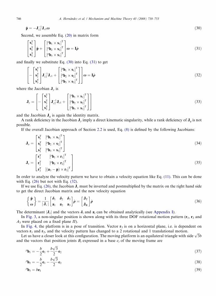
The determinant jJvj and the vectors di and ai can be obtained analytically (see Appendix I).In Fig. 3, a non-singular position is shown along with its three DOF rotational motion pattern (r1, r2 and
A3 were placed on a fixed plane P).In Fig. 4, the platform is in a pose of transition. Vector r3 is on a horizontal plane, i.e. is dependent on
vectors r1 and r2, and the velocity pattern has changed to a 2 rotational and 1 translational motion.Let us have a closer look at this configuration. The moving platform is an equilateral triangle with side
ffiffiffi3p
band the vectors that position joints Bi expressed in a base ei of the moving frame are
pb1 ¼ �b2
e1 þbffiffiffi3p
2e2 ð37Þ
pb2 ¼ �b2
e1 �bffiffiffi3p
2e2 ð38Þ
pb3 ¼ be1 ð39Þ

Fig. 3. Non-singular position and 3 rotational velocity pattern of the platform.
Fig. 4. New motion type: 2 rotational + 1 translational motion.
A. Hernandez et al. / Mechanism and Machine Theory 43 (2008) 738–753 747
The revolute joints 1 and 2 have fixed directions
r1 ¼ffiffiffi3p
2e1 þ
1
2e2 ð40Þ
r2 ¼ �ffiffiffi3p
2e1 þ
1
2e2 ð41Þ
In that configuration revolute joint 3 is on direction
r3 ¼ e2 ð42Þ
linear actuators are on directions
s1 ¼ffiffiffi2p
4e1 �
ffiffiffi6p
4e2 þ
ffiffiffi2p
2e3 ð43Þ
s2 ¼ffiffiffi2p
4e1 þ
ffiffiffi6p
4e2 þ
ffiffiffi2p
2e3 ð44Þ
s3 ¼ �ffiffiffi2p
2e1 þ
ffiffiffi2p
2e3 ð45Þ
Points Ai are vertices of an equilateral triangle with sideffiffiffi3p
a, being vector a3
a3 ¼ ae1 ð46Þ
and in this pose, the position of point P is

748 A. Hernandez et al. / Mechanism and Machine Theory 43 (2008) 738–753
p ¼ ða� bÞe3 ð47Þ
The following geometrical conditions apply on these vectors. Vectors ri are on the same plane, hence
r1 � ðr2 � r3Þ ¼ 0 ð48Þ
and also
ðr2 � r3Þ ¼ ðr3 � r1Þ ¼ ðr2 � r1Þ ð49Þ
Due to symmetrical orientations of pb1 and pb2, and r1 and r2
pb1 � r1¼pb2 � r2 ð50Þ
In addition, the three actuators have the same vertical projection to place the moving platform on a hor-izontal plane
s1 � ðr2 � r1Þ ¼ s2 � ðr2 � r1Þ ¼ s3 � ðr2 � r1Þ ð51Þ
In that configuration, the Jacobian of translations is found with the expressions in Appendix I
JT ¼0 0 0
� 2ffiffi6pða�bÞ9a
2ffiffi6pða�bÞ9a 0ffiffi
2p
3
ffiffi2p
3
ffiffi2p
3
264
375 ð52Þ
and the Jacobian of rotations is
JR ¼
ffiffi6pðaþ2bÞ9ab �
ffiffi6pðaþ2bÞ9ab 0ffiffi
2p
3b
ffiffi2p
3b � 2ffiffi2p
3b
�ffiffi6pða�bÞ9ab
ffiffi6pða�bÞ9ab 0
2664
3775 ð53Þ
It can be observed that the vectors ai that form the Jacobian JR become dependent
a1 þ a2 þ a3 ¼ 0 ð54Þ
The rank of that Jacobian JR has changed from three (in non-singular configurations) to two, and hence thevelocity pattern has lost a rotational DOF. The two-dimensional rangespace is defined by two directions
xr1 ¼ ½ 0 1 0 �T ð55Þxr2 ¼ ½ 1 0 ðb� aÞ=ðaþ 2bÞ �T ð56Þ
That form the plane of rotations PR in Fig. 4 whose direction vector is
lx ¼ ½ ða� bÞ=ðaþ 2bÞ 0 1 �T ð57Þ
Regarding translations, as the nullspace of JR is one-dimensional some translation is possible. A base vec-tor of that null space is
_qt ¼ ½ 1 1 1 �T ð58Þ
that provides the direction of translation as seen in Eq. (15) with the Jacobian of translations of Eq. (52)
_pt ¼ JT
1
1
1
8><>:
9>=>; ¼
ffiffiffi2p
e3 ð59Þ
This condition for singularity does not imply a rank deficiency of Jv, in fact the determinant is
Jvj j ¼ �27
ffiffiffi2p
16ab2 ð60Þ

A. Hernandez et al. / Mechanism and Machine Theory 43 (2008) 738–753 749
and hence the pose is not a Direct Kinematic singularity. In addition, Jq is the identity matrix and thereforethe position is not an Inverse Kinematic singularity.
Regarding the singularity analysis done with the other velocity equations and classifications of singularitiesdescribed in Section 2 the differences found are the following. On the one hand, when the approach used is theclassical velocity equation reduced to a vector of independent output variables _y (Eq. (6)) as shown in Section2.1 we arrive to the following conclusions. The Jacobian Jy in that configuration cannot be obtained becauseJc2 is not invertible. However, we can check that the platform does not move if inputs are locked (as seen inEq. (60)), and hence this is not a Direct Kinematic Singularity. Jq is not singular and therefore is not anInverse Kinematic Singularity.
On the other hand, when the approach that is based in the overall Jacobian is used, the Jacobian of actu-ations Ja
Ja ¼
ffiffi2p
4�ffiffi6p
4
ffiffi2p
2
ffiffi6p
b4
ffiffi2p
b4
0ffiffi2p
4
ffiffi6p
4
ffiffi2p
2�ffiffi6p
b4
ffiffi2p
b4
0
�ffiffi2p
20
ffiffi2p
20 �
ffiffi2p
b2
0
2664
3775 ð61Þ
does not lose rank and therefore is not a configuration of architecture singularity, and the Jacobian of con-straints Jc
Jc ¼
ffiffi3p
212
0 0 0 �b
�ffiffi3p
212
0 0 0 �b
0 1 0 a� b 0 a
264
375 ð62Þ
does not lose rank either and then, it is not a Constraint Singularity. The latter Jacobian identifies the so calledrotational singularities or translational singularities where appropriate, and being non-singular it is not a sin-gular pose of that type either.
The new type of motion acquired can be kept while doing a finite motion as long as the geometrical con-dition of r3 being parallel to the plane P (defined by r1 and r2) is maintained. Therefore, in theory a new oper-ational mode where a pure translation is possible in the vertical direction can be exploited. However, in orderto work in this operational mode, one freedom has to be dedicated to keep this geometrical condition. Hence,only the two other freedoms can be effectively used and produce a 1T1R finite motion. In practice, the tran-sition to this motion is smooth but a very accurate control of the pose is needed to maintain such a geometricalcondition of parallelism. For all this reasons, the use of these transitions of velocity pattern to generate newoperational modes may be impractical.
This motion can take the platform to the position shown in Fig. 5, where r3 is also contained in the planePR as well as the moving platform. Then, a direct kinematic singularity occurs. The rank of Jv decreases andtherefore the three inputs become dependent. To analyze the velocity pattern we should get an equation likeEq. (11). Being Jv singular, we need another choice of inputs that are not dependent in this position. With such
Fig. 5. Direct kinematic singularity and type of motion.

Fig. 6. Constraint singularity, 3 rotational and 1 translational velocity pattern.
750 A. Hernandez et al. / Mechanism and Machine Theory 43 (2008) 738–753
inputs we find the new velocity equation, the new direct Jacobian J, and we observe that the rank of JR alsodecreases and the velocity pattern is 2R1T.
A constraint singularity is shown in Fig. 6. Vectors ri have the same expressions as before (Eqs. (40)–(42)).Vectors pbi are
pb1 ¼ �bffiffiffi3p
2e2 �
b2
e3 ð63Þ
pb2 ¼bffiffiffi3p
2e2 �
b2
e3 ð64Þpb3 ¼ be3 ð65Þ
Special dimensions are needed for this singular configuration. In order to have the reciprocal screws of limbs 1and 2 crossing each other at joint A3 (where the third reciprocal screw is applied), dimension a has to be equalto 2b. Vectors a3 and p are then
a3 ¼ 2be1 ð66Þ
p ¼ b2
e1 þb2
e3 ð67Þ
The Jacobian of constraints can be found using Eq. (35) and results
Jc ¼
ffiffi3p
212
0 b4� b
ffiffi3p
43b4
�ffiffi3p
212
0 b4
bffiffi3p
43b4
0 1 0 b2
0 3b2
2664
3775 ð68Þ
The last row is the sum of the first two, therefore the rank of this Jacobian decreases from three to two. Someconstraint is lost and the platform has then 4 DOF. The analysis of the velocity pattern can be done usingscrew theory and indicates that the instantaneous motion is 3 rotational and 1 translational. An analyticalapproach needs a new velocity equation with one more input. In the analysis of such singularities is necessaryto use velocity equations that contain all kinematic variables of the manipulator as mentioned in Section 2.3.
6. Conclusions
This paper describes a transition in the velocity pattern of the moving platform of lower mobility parallelmanipulators without going through a singularity of increased mobility. This transition does not cause anincrement or reduction of the DOF of the end-effector, but an interchange in their type of motion (transform-ing from rotational to translational or vice versa). This is different from the so called kinematotropic mech-anisms where the transitions in mobility or type of motion occur in crossing a singularity of increasedmobility. Regarding the manipulator performance, this situation may produce problems with the control or
A. Hernandez et al. / Mechanism and Machine Theory 43 (2008) 738–753 751
the actuators. If the manipulator approaches a pose where there is a transition of the type of motion, it is evi-dent that an incorrect chosen twist in the end-effector may require very high inputs. In practice this producesabrupt increments of the inputs that can damage the machine, or simply not move the platform at all. The newtype of motion acquired is generally instantaneous, i.e. dependent on the pose, and should be avoided. How-ever, there are many cases where it becomes permanent for a certain combination of inputs that keep the geo-metrical condition for such transition of velocity pattern. As a consequence this situation could be used tohave a different operational mode. But it will be an operational mode with a reduced mobility because at leastone freedom has to be dedicated to keep the geometrical condition. In practice, a very accurate control of thepose will be needed to maintain such a geometrical conditions and therefore, the use of these transitions ofvelocity pattern to generate new operational modes may be impractical.
The procedure to detect such transitions of velocity pattern is general. Regarding the possibility to findthese transitions in any parallel manipulator, the authors believe that it is not common in fully parallel manip-ulators. The motivation for this research came from some problems detected in the velocity pattern of hybridmanipulators with a parallel module 2R1T and a tilting working table 2R. The resulting relative velocity pat-tern changed in several configurations and restricted the operating workspace.
Acknowledgements
This research work was supported in part by the Spanish Ministerio de Ciencia y Tecnologia (ProjectDPI2005-02207), the FEDER funds of the European Union, and the University of the Basque Country (Pro-ject GIU05/46).
Appendix I
p
n1 ¼ b1 � r1n2 ¼ pb2 � r2
n3 ¼ a3 � pð Þ � r3
m1 ¼ pb1 � s1
m2 ¼ pb2 � s2
m3 ¼ pb3 � s3
d1 ¼ ½n3 � ðm3 �m2Þ� � r1 � r2 þ ½n2 � ðm3 �m2Þ� � r3 � r1 þ ½n1 � ðm3 �m2Þ� � r2 � r3 þ ½n1 � ðn2 � n3Þ� � s3
� s2 þ ½m3 � ðn3 � n2Þ� � r1 � s2 þ ½m3 � ðn1 � n3Þ� � r2 � s2 þ ½m3 � ðn2 � n1Þ� � r3 � s2 þ ½m2 � ðn2 � n3Þ� � r1
� s3 þ ½m2 � ðn3 � n1Þ� � r2 � s3 þ ½m2 � ðn1 � n2Þ� � r3 � s3
d2 ¼ �½n3 � ðm3 �m1Þ� � r1 � r2 � ½n2 � ðm3 �m1Þ� � r3 � r1 � ½n1 � ðm3 �m1Þ� � r2 � r3 � ½n1 � ðn2 � n3Þ� � s3
� s1 � ½m3 � ðn3 � n2Þ� � r1 � s1 � ½m3 � ðn1 � n3Þ� � r2 � s1 � ½m3 � ðn2 � n1Þ� � r3 � s1 � ½m1 � ðn2 � n3Þ�� r1 � s3 � ½m1 � ðn3 � n1Þ� � r2 � s3 � ½m1 � ðn1 � n2Þ� � r3 � s3
d3 ¼ ½n3 � ðm2 �m1Þ� � r1 � r2 þ ½n2 � ðm2 �m1Þ� � r3 � r1 þ ½n1 � ðm2 �m1Þ� � r2 � r3 þ ½n1 � ðn2 � n3Þ� � s2
� s1 þ ½m2 � ðn3 � n2Þ� � r1 � s1 þ ½m2 � ðn1 � n3Þ� � r2 � s1 þ ½m2 � ðn2 � n1Þ� � r3 � s1 þ ½m1 � ðn2 � n3Þ�� r1 � s2 þ ½m1 � ðn3 � n1Þ� � r2 � s2 þ ½m1 � ðn1 � n2Þ� � r3 � s2
a1 ¼ ½r3 � ðs2 � s3Þ� � n1 � n2 þ ½r2 � ðs2 � s3Þ� � n3 � n1 þ ½r1 � ðs2 � s3Þ� � n2 � n3 þ ½r1 � ðr2 � r3Þ� �m2 �m3
þ ½s3 � ðr2 � r3Þ� � n1 �m2 þ ½s3 � ðr3 � r1Þ� � n2 �m2 þ ½s3 � ðr1 � r2Þ� � n3 �m2 þ ½s2 � ðr3 � r2Þ� � n1
�m3 þ ½s2 � ðr1 � r3Þ� � n2 �m3 þ ½s2 � ðr2 � r1Þ� � n3 �m3
752 A. Hernandez et al. / Mechanism and Machine Theory 43 (2008) 738–753
a2 ¼ �½r3 � ðs1 � s3Þ� � n1 � n2 � ½r2 � ðs1 � s3Þ� � n3 � n1 � ½r1 � ðs1 � s3Þ� � n2 � n3 � ½r1 � ðr2 � r3Þ� �m1 �m3
� ½s3 � ðr2 � r3Þ� � n1 �m1 � ½s3 � ðr3 � r1Þ� � n2 �m1 � ½s3 � ðr1 � r2Þ� � n3 �m1 � ½s1 � ðr3 � r2Þ� � n1
�m3 � ½s1 � ðr1 � r3Þ� � n2 �m3 � ½s1 � ðr2 � r1Þ� � n3 �m3
a3 ¼ þ½r3 � ðs1 � s2Þ� � n1 � n2 þ ½r2 � ðs1 � s2Þ� � n3 � n1 þ ½r1 � ðs1 � s2Þ� � n2 � n3 þ ½r1 � ðr2 � r3Þ� �m1 �m2
þ ½s2 � ðr2 � r3Þ� � n1 �m1 þ ½s2 � ðr3 � r1Þ� � n2 �m1 þ ½s2 � ðr1 � r2Þ� � n3 �m1 þ ½s1 � ðr3 � r2Þ� � n1
�m2 þ ½s1 � ðr1 � r3Þ� � n2 �m2 þ ½s1 � ðr2 � r1Þ� � n3 �m2
jJvj ¼ ½n3 � ðm3 �m2Þ� � ½s1 � ðr1 � r2Þ� þ ½n3 � ðm1 �m3Þ� � ½s2 � ðr1 � r2Þ� þ ½n3 � ðm2 �m1Þ� � ½s3 � ðr1 � r2Þ�þ ½n2 � ðm3 �m2Þ� � ½s1 � ðr3 � r1Þ� þ ½n2 � ðm1 �m3Þ� � ½s2 � ðr3 � r1Þ� þ ½n2 � ðm2 �m1Þ� � ½s3 � ðr3 � r1Þ�� ½n1 � ðm3 �m2Þ� � ½s1 � ðr3 � r2Þ� � ½n1 � ðm1 �m3Þ� � ½s2 � ðr3 � r2Þ� � ½n1 � ðm2 �m1Þ� � ½s3 � ðr3 � r2Þ�� ½m2 � ðn3 � n2Þ� � ½r1 � ðs3 � s1Þ� � ½m2 � ðn1 � n3Þ� � ½r2 � ðs3 � s1Þ� � ½m2 � ðn2 � n1Þ� � ½r3 � ðs3 � s1Þ�� ½m3 � ðn3 � n2Þ� � ½r1 � ðs1 � s2Þ� � ½m3 � ðn1 � n3Þ� � ½r2 � ðs1 � s2Þ� � ½m3 � ðn2 � n1Þ� � ½r3 � ðs1 � s2Þ�þ ½m1 � ðn3 � n2Þ� � ½r1 � ðs3 � s2Þ� þ ½m1 � ðn1 � n3Þ� � ½r2 � ðs3 � s2Þ� þ ½m1 � ðn2 � n1Þ� � ½r3 � ðs3 � s2Þ�� ½m3 � ðm2 �m1Þ� � ½r3 � ðr1 � r2Þ� þ ½n3 � ðn2 � n1Þ� � ½s3 � ðs1 � s2Þ�
References
[1] X. Kong, C.M. Gosselin, Type synthesis of 3-DOF PPR-equivalent parallel manipulators based on screw theory and the concept ofvirtual chain, ASME Journal of Mechanical Design 127 (2005) 1113–1121.
[2] K.H. Hunt, Kinematic Geometry of Mechanisms, Clarendon Press, 1978.[3] C.G. Gibson, K.H. Hunt, Geometry of screw systems – 1: Screws: Genesis and geometry, Mechanism and Machine Theory 25 (1)
(1990) 1–10.[4] C.G. Gibson, K.H. Hunt, Geometry of screw systems – 2: Classification of screw systems, Mechanism and Machine Theory 25 (1)
(1990) 11–27.[5] J.M. Rico, J. Duffy, Orthogonal spaces and screw systems, Mechanism and Machine Theory 27 (4) (1992) 451–458.[6] J.M. Rico, J. Duffy, Classification of screw systems – I. one- and two-systems, Mechanism and Machine Theory 27 (4) (1992)
459–470.[7] J.M. Rico, J. Duffy, Classification of screw systems – II. three-systems, Mechanism and Machine Theory 27 (4) (1992) 471–490.[8] W.J. Chen, M.Y. Zhao, J.P. Zhou, Y.F. Qin, A 2T-2R, 4-DoF parallel manipulator, in: CD-ROM Proceedings 2002 ASME DETC/
CIE, Montreal, Canada, DETC2002/MECH-34303, 2002.[9] O. Company, F. Pierrot, A new 3T-1R parallel robot, in: Proceedings of the International Conference on Robotics and Automation,
Tokyo, Japan, 25–27 October 1999, pp. 557–562.[10] K. Wohlhart, Kinematotropic Linkages, Recent Advances in Robot Kinematics, Kluwer Academic Publishers, 1996, pp. 359–368.[11] P. Fanghella, C. Galleti, E. Gianotti, Parallel robots that change their group of motion, Advances in Robot Kinematics, Springer,
2006, pp. 49–56.[12] X. Kong, C.M. Gosselin, P.-L. Richard, Type synthesis of parallel mechanisms with Multiple Operation Modes, in: CD-ROM
Proceedings of IDETC/CIE 2006, Philadelphia, USA, 2006.[13] O. Altuzarra, C. Pinto, R. Aviles, A. Hernandez, A practical procedure to analyze singular configurations in closed kinematic chains,
IEEE Transactions on Robotics 20 (2004) 929–940.[14] F.C. Park, J.W. Kim, Singularity analysis of closed kinematic chains, ASME Journal of Mechanical Design 121 (1999) 32–38.[15] D. Zlatanov, R.G. Fenton, B. Benhabib, Singularity analysis of mechanisms and robots via velocity-equation model of the
instantaneous kinematics, in: Proceedings of the IEEE International Conference on Robotics and Automation, San Diego, USA,1994, vol. 2, pp. 986–991.
[16] D.S. Zlatanov, I.A. Bonev, C.M. Gosselin, Constraint singularities of parallel mechanisms, in: Proceedings of the IEEE InternationalConference on Robotics and Automation, Washington DC, USA, 2002, vol. 2, pp. 496–502.
[17] C. Gosselin, J. Angeles, Singularity analysis of closed-loop kinematic chains, IEEE Transaction on Robotics and Automation 6 (3)(1990) 281–290.
[18] I.A. Bonev, D.S. Zlatanov, C.M. Gosselin, Singularity analysis of 3-DOF planar parallel mechanisms via screw theory, ASMEJournal of Mechanical Design 125 (2003) 573–581.
[19] D. Zlatanov, M. Zoppi, C.M. Gosselin, Singularities and mobility of a class of 4-DOF mechanisms, On Advances in RobotKinematics, Kluwer Academic Publishers, 2004.

A. Hernandez et al. / Mechanism and Machine Theory 43 (2008) 738–753 753
[20] R. Di Gregorio, V. Parenti-Castelli, Mobility analysis of the 3 UPU parallel mechanism assembled for a pure translational motion, in:Proceedings of the IEEE/ASME International Conference on Advanced Intelligent Mechatronics, Atlanta, GA, USA, 1999, pp. 520–525.
[21] R. Di Gregorio, V. Parenti-Castelli, Mobility analysis of the 3 UPU parallel mechanism assembled for a pure translational motion,ASME Journal of Mechanical Design 124 (2002) 259–264.
[22] X. Kong, C.M. Gosselin, A class of 3-DOF translational parallel manipulators with linear input–output equations, in: Proceedings ofthe Workshop on Fundamental Issue and Future Research Directions for Parallel Mechanisms and Manipulators, October 3–4, 2002,Quebec, Canada, 2002, pp. 25–32.
[23] R. Di Gregorio, Determination of singularities in delta-like manipulators, International Journal of Robotic Research 23 (1) (2004)89–96.
[24] D. Zlatanov, I.A. Bonev, C.M. Gosselin, Constraint singularities, 2001, url: http://www.parallemic.org/Reviews/Review005.html.[25] X. Kong, C.M. Gosselin, Type synthesis of 3-DOF translational parallel manipulators based on screw theory, ASME Journal of
Mechanical Design 126 (2004) 83–92.[26] X. Kong, C.M. Gosselin, Type synthesis of 3-DOF spherical parallel manipulators based on screw theory, ASME Journal of
Mechanical Design 126 (2004) 101–108.[27] X. Kong, C.M. Gosselin, Type synthesis of three-degree-of-freedom spherical parallel manipulators, The International Journal of
Robotics Research 23 (2004) 237–245.[28] X. Kong, C.M. Gosselin, Type synthesis of 3T1R 4-DOF parallel manipulators based on screw theory, IEEE Transactions on
Robotics and Automation 20 (2004) 181–190.[29] A. Fattah, A.M. Hasan Ghasemi, Isotropic design of spatial parallel manipulators, The International Journal of Robotics Research
21 (2002) 811–824.[30] L-W. Tsai, S. Joshi, Kinematics and optimization of a spatial 3-UPU parallel manipulator, ASME Journal of Mechanical Design 122
(2000) 439–446.[31] L-W. Tsai, S. Joshi, A comparison study of two 3-DOF parallel manipulators: one with three and the other with four supporting legs,
IEEE Transactions on Robotics and Automation 19 (2003) 200–209.[32] D. Zlatano, I.A. Bonev, C.M. Gosselin, Constraint singularities as configuration space singularities, in: Proceedings of the 8th
International Symposium on Advances in Robot Kinematics, ARK2002, June 24–28, 2002, Caldes de Malavella, Spain, 2002,pp. 25–32.