Lone Star National Bancshares - Texas Inc. - Federal Reserve ...
Upload
khangminh22Category
view
0download
0
I
Transition metal oxofluorides comprising lone pair elements
Synthesis and Characterization
Shichao Hu

II
©Shichao Hu, Stockholm University 2014
ISBN 978-91-7447-890-7
Printed in Sweden by US-AB, Stockholm 2014
Distributor: Department of Materials and Environmental Chemistry, Stockholm University
Doctoral Thesis 2014
Department of Materials and Environmental Chemistry
Inorganic Chemistry
Arrhenius Laboratory
Stockholm University
SE-10691 Stockholm
Sweden
Faculty Opponent
Prof. Jürgen Köhler
Max Planck Institute for Solid State Research, Germany
Evaluation Committee
Prof. Ulrich Häussermann
Department of Materials and Environmental Chemistry
Stockholm University, Sweden
Prof. Vadim Kessler
Department of Chemistry and Biotechnology
Swedish University of Agricultural Sciences, Sweden
Dr. Annika Pohl
Department of Chemistry
Uppsala University, Sweden
Substitute
Dr. Roland Mathieu
Department of Engineering Sciences
Uppsala University, Sweden

III
Dedicated to my family.

IV

V
Abstract
Within the family of transition metal oxochlorides/bromides containing lone
pair elements, the transition metal cations often adopt a low-dimensional
arrangement such as 2D layers, 1D chains or 0D clusters. The reduced di-
mensionality is attributed to the presence of stereochemically active lone
pairs which are positioned in the non-bonding orbital and will not participate
in bond formation and instead act as structural spacers that help to separate
coordination polyhedra around transition metal cations from forming three
dimensional networks. On the other hand, the chlorine and bromine ions also
play an important role to open up the crystal structure because of their low
coordination number. However, fluorine has been rarely used in this concept
due to the difficulties in synthesis.
This thesis is focused on finding new compounds in the M-L-O-F system
(M = transition metal cation, L= p-block lone pair elements such as Te4+
,
Se4+
, or Sb3+
) in order to study the structural character of fluorine. Hydro-
thermal reactions have been adopted instead of conventional chemical
transport reactions that are commonly used for synthesizing compounds in
the M-L-O-(Cl, Br) family. A total of eight new transition metal oxofluo-
rides containing lone pair elements have been synthesized and their struc-
tures have been determined via single crystal X-ray diffraction. Bond va-
lence sum calculations are used to distinguish in between fluorine and oxy-
gen due to their very similar X-ray scattering factors.

VI

VII
List of papers
I. S. Hu, M. Johnsson, “Synthesis and crystal structure of two synthetic
oxofluoride framework compounds – Co2TeO3F2 and Co2SeO3F2”
Dalton Trans. 41 (2012) 12786.
Performed synthesis and structural characterization of the new
compounds. Wrote the first draft of the manuscript.
II. S. Hu, M. Johnsson, “Synthesis and crystal structure of
Fe6Ca2(SeO3)9Cl4 - a porous oxohalide”, Dalton Trans. 42 (2013) 7859.
Performed synthesis and characterization of the new compounds. Wrote
the first draft of the manuscript.
III. S. Hu, M. Johnsson, J.M. Law, J.L Bettis Jr, M.-H. Whangbo,
R.K. Kremer, “Crystal structure and magnetic properties of FeSeO3F -
alternating antiferromagnetic S = 5/2 chains”, Inorg. Chem. 53 (2014)
4250.
Performed synthesis and structural characterization of the new
compounds. Wrote the first draft of the introduction, synthesis and
structural characterization parts in the manuscript.
IV. S. Hu, M. Johnsson, P. Lemmens, D. Schmid, D. Menzel, J. Tapp, A.
Möller, “Acentric Pseudo-Kagome Structures: The Solid Solution (Co1-
xNix)3Sb4O6F6”, Submitted for publication.
Performed synthesis and structural characterization of the new
compounds. Wrote the introduction and structural description in the
manuscript.
V. S. Hu, M. Johnsson, V. Gnezdilov, P. Lemmens, J. Tapp, A. Möller.
“Crystal structure and magnetic properties of the S=1/2 quantum spin
system Cu7(TeO3)6F2 with mixed dimensionality”, Submitted for
publication.

VIII
Performed synthesis and structural characterization of the new
compounds. Wrote the introduction and structural description in the
manuscript.
Publication not included in this thesis.
VI. F. Rabbani, H. Svengren, I. Zimmermann, S. Hu, T. Laine, W. Hao, T.
Åkermark, B. Åkermark, M. Johnsson. “Cobalt selenium oxohalides:
Catalysts for Water Oxidation”, Dalton Trans. 43 (2014) 3984.

IX
Table of Contents
Abstract .......................................................................................................... V
List of papers ............................................................................................... VII
1 Introduction .................................................................................................. 1
1.1 The formation of lone pair distortion ......................................................................2
1.2 Coordination of lone pair cations and lone pair electron – cation distances .....6
1.3 The application of lone pairs in designing novel crystal structures....................8
1.3.1 Non-centrosymmetric materials and properties ............................................9
1.3.2 Low-dimensional crystal structures and related properties....................... 13
1.4 Transition metal Oxofluorides ............................................................................... 18
1.5 Transition metal Oxofluorides containing lone pair cations .............................. 20
1.6 Bond valence sum calculation (BVS) ................................................................... 21
1.7 Aim and scope .......................................................................................................... 23
2 Experimental............................................................................................... 24
2.1 Methodology ............................................................................................................. 24
2.1.1 Chemical Transport Reactions (CTR) .......................................................... 24
2.1.2 Hydrothermal Reaction .................................................................................. 25
2.2 The synthesis procedure .......................................................................................... 26
2.3 Modified synthesis techniques ............................................................................... 28
2.3.1 Synthesis of oxofluorides via low temperature CTR ................................. 28
2.3.2 Synthesis of oxofluorides via hydrothermal reactions .............................. 31
2.4 Characterization ....................................................................................................... 34
2.4.1 Single Crystal X-ray Diffraction (SXRD) ................................................... 34
2.4.2 Powder X-ray Diffraction (PXRD) .............................................................. 34
2.4.3 Scanning electron microscopy (SEM) and energy dispersive X-ray
spectroscopy (EDS) .................................................................................................. 35
3 Results and Discussion ................................................................................ 36
3.1 New compounds in M-L-O-F Family ................................................................... 36
3.1.1 The M2LO3F2 (M= Co, Ni, Mn; L = Se, Te) type of structure ................. 37

X
3.1.2 FeSeO3F: iso-structural with FeTeO3F ........................................................ 38
3.1.3 The CoxNi1-xSb4O6F6 solid solution (x= 0, 0.25, 0.5, 0.75, 1) .................. 39
3.1.4 Terminating fluorine ions: Cu7Te6O18F2 ...................................................... 42
3.1.5 Summary of new compounds in M-L-O-F family ..................................... 43
3.1.6 New oxochlorides synthesized from low temperature CTR ..................... 46
3.2 Mixing fluorine and chlorine .................................................................................. 49
3.2.1 Cu7Te5O15FCl2(OH) ........................................................................................ 50
3.2.2 New compounds synthesized under the “catalysis” of fluorine ............... 51
4 Summary and Conclusions .......................................................................... 54
5 Sammanfattning på svenska ........................................................................ 56
6 Acknowledgment ......................................................................................... 58
7 References ................................................................................................... 60

1
1 Introduction
The p-block cations with ns2np
0 electronic configurations have drawn great
attention from the crystal chemistry point of view, since the ns2 electron pair
that does not participate in bonding is usually stereochemically active and
therefore influences the spatial distribution of the bonding electron pairs,
resulting in distorted coordinations around the central cations. Such unshared
electron pairs and their central cations are often referred to as lone pairs and
lone pair cations, respectively. Some examples of cations carrying a lone
pair are shown in Table 1.1; Sb3+
, Se4+
and Te4+
have been utilized in this
work.
1+ 2+ 3+ 4+ 5+ 6+
2s22p
0 N
3s23p
0 P S Cl
4s24p
0 Ga Ge As Se Br
5s25p
0 In Sn Sb Te I Xe
6s26p
0 Tl Pb Bi Po
Table 1.1: Examples of lone pair cations.
It was suggested by Sidgwick and Powell that lone pairs are equally im-
portant to bonding pairs and that these distribute themselves to minimize
interelectron repulsion [1]
. Later it was realized that the geometries of mole-
cules observed experimentally are much more rational when the particulari-
ties of lone pair electrons were considered. For example, the deviations of
the bond angles in NH3 and H2O from 109.5°, which is the value for a regu-
lar tetrahedron, could be explained by valence shell electron pair repulsion
(VSEPR) theory as proposed by Gillespie and Nyholm in 1957 [2]
. This sug-
gests that a lone pair repels electron pairs more than a bonding pair of elec-
trons does. In addition, Andersson and coworkers proposed from geometrical
analysis that a lone pair occupies a similar volume as oxygen or fluorine
anions, while the distance between a lone pair and central cation is much
shorter than the cation-anion distance [3, 4]
.
As the lone-pair “pushes” the ligands around the central cation toward
one side to form a highly distorted polyhedron, the dipoles originating from

2
the asymmetric coordination would, in some cases, orient in a manner that
gives rise to non-centrosymmetric crystal structures (NCS). The NCS-
compounds have been of significant interest due to the fact that they may
show non-linear optical properties, pyroelectricity and/or ferroelectricity. It
has also been found that the possibility to form materials showing a low-
dimensional crystal structure is greatly enhanced by combining lone pair
cations and halide ions (e.g. Cl- or Br
-) because of the structural terminating
property that is due to the non-bonding electron pairs. Such low-dimensional
compounds may exhibit specific physical properties such as e.g. magnetic
frustration or multiferroic properties. Apparently, lone pair cations may play
an important role in designing functional materials, and it is thus necessary
to understand their formation and consequent coordinations.
1.1 The formation of lone pair distortion
It is well accepted that a lone pair is the key component that leads to the
formation of the cation’s off-centric displacement in its coordination envi-
ronment. However, the mechanism about how and when such distortion
takes place remains unclear and has been addressed over several decades.
Historically, Orgel [5]
explained lone pair distortion through the mixing of
non-bonding s- and p- orbitals. In this model, the distorted coordination
around lone pair cations were explained by the hybridization of s- and p-
orbitals that could not take place on the cation with inversion symmetry
while such orbital mixing can be generated on non-centrosymmetric sites
instead. However, this traditional view has later been shown to be incom-
plete, since in many cases lone pair cations that have the ns2np
0 electronic
configurations do not always exhibit the one-sided coordination, or so called
stereochemical activity. For example, Pb2+
in PbS shows perfectly regular
octahedra, although there is a classic distorted structure in α-PbO, see Figure
1.1.

3
Figure 1.1: The local coordination of Pb2+
(light gray) in (a) PbS and (b) α-PbO.
The sulfur and oxygen atoms are marked in yellow and red, respectively.
Recently, with more and more comprehensive theoretical studies based
on quantum mechanics, the driving force for lone pair formation has been
focused on the interaction of the cation s- and p- orbitals with the oxide ani-
on p-states, instead of pure hybridization of s- and p- orbitals on the cation.
It was Waston and Parker who concluded that lone pair distortions are driven
primarily by cation – oxygen interactions in PbO, according to their compu-
tational work in 1999 [6, 7]
. The calculation and analysis of the electronic
structures of SnO, SnS, SnSe and SnTe has been carried out by Walsh and
Watson [8]
using density functional theory. It was observed that the electron
distribution around the Sn2+
cation was highly asymmetric in the litharge
structure type SnO and became less pronounced in SnS and SnSe, in addition
to becoming almost symmetric in the case of SnTe. Similar trends can also
be found in the Bi2X3 series (X= O, S, Se, Te) where Bi2O3 and Bi2S3 display
lone pair distortions, while BiSe3 and Bi2Te3 do not [9]
. In the case of anti-
mony, all of Sb2O3, Sb2S3 and Sb2Se3 show stereochemically active lone
pairs, while Sb2Te3 does not [10]
. This trend of changes was found to origi-
nate from anion-cation interactions, and the asymmetric electron distribution
exhibits strong anion dependence in the above series. According to density
functional analysis, based on quantum mechanics by Walsh and Waston [11]
in both distorted and undistorted coordination polyhedra, the filled s2
elec-
trons on the cations interact with the anion p-state, forming bonding and
anti-bonding orbitals instead of being chemically inert. However, the distor-
tion only happens when the unoccupied cation p-states hybridize with the
anti-bonding orbitals, resulting in a strong stabilization of the occupied elec-
tronic states, which is accompanied by an asymmetric electron distribution,
see Figure 1.2. Therefore, the stabilization of anti-bonding orbitals is crucial
for the formation of lone pair distortion.

4
Walsh also concluded that it is important for cation s-states to have simi-
lar energy in relation to anion p states, since the anti-bonding orbitals should
have enough components from the cation s states in order to interact with
cation p states, which form the strong stabilization. If there is only weak
contribution from the cation s states, the stabilization will be significantly
weaker. As the stabilization must compensate for the reduced coordination in
distorted structures, the compounds in which the relative energy of lone pair
cation s states and anion p states is too large will not form stereochemically
active lone pairs. This conclusion well explains the trends of lone pair distor-
tion formation in SnX and Bi2X3 series (X= O, S, Se, Te). Since the energy
of anion p states increase by atomic number in chalcogenides, resulting in
weaker contribution from Sn2+
or Bi3+
s states in the anti-bonding orbitals,
the interactions of cation p states and anti-bonding states become less pro-
found, and therefore give rise to a much weaker stabilization of anti-bonding
states, which is why the electron distribution around the lone pair cations is
almost symmetric in compounds such as SnTe, Bi2Se3, Bi2Te3 and Sb2Te3.
Figure 1.2: Energy level diagram of PbO showing the hybridization between Pb 6s
and O 2p states and the interaction of a Pb 6p orbital with anti-bonding Pb 6s – O
2p* state.

5
Figure 1.3: Schematic molecular orbital diagram showing (a) the interaction be-
tween the Pb 6s and O 2p orbitals and (b) the Sn 5s and O 2p [12]
.
A similar conclusion was drawn by Stoltzfus et al. [12]
when they calculat-
ed electronic structures of PbWO4 and β-SnWO4, in which the lone pair cati-
on ns – O 2p bonding states were observed for both slightly distorted Pb2+
coordination and highly distorted Sn2+
coordination, see Figure 1.3. However,
the mixing of lone pair cation s states and oxygen p states is much stronger
in β-SnWO4 than in PbWO4, which leads to a significant change in the coor-
dination around Sn in β-SnWO4. Such destabilization can be reduced by
lowering the symmetry on the Sn2+
site to enable the interaction between the
anti-bonding Sn 5s-O 2p states and Sn 5p orbitals. This interaction produces
a localized, nonbonding state at the top of the valence band that corresponds
closely with the classical notion of a stereochemically active electron lone
pair [12]
. The fact that cation ns – oxygen 2p interaction is much stronger in
β-SnWO4 is due to smaller relative energy between Sn2+
s states and O 2p
states compared to those between Pb2+
s states and O 2p states. The energies
of cation s orbital have been calculated by DFT by Walsh et al. [11]
and
demonstrate that they, in general, increase from a high period to a low period
number in the same group and decrease from left to right in the same period.

6
1.2 Coordination of lone pair cations and lone pair
electron – cation distances
By utilizing previous conclusions from Walsh and Stoltzfus et al., the differ-
ent coordinations of lone pair cations to oxygen in their respective oxides
can be well described. For instance, As3+
and Se4+
are both located in the 4th
period and have a filled 4s orbital with a high energy resulting in small ∆Es-p
i.e. the energy difference between cation ns and oxygen 2p states. The strong
hybridization causes symmetric destabilization, which can be reduced by
lowering the symmetry. The consequent interactions between cation 4p and
anti-bonding states 4s-O 2p produce the asymmetric electron density, which
compensates for the reduced coordination, giving rise to lone pair distribu-
tion. Experimentally, only tetrahedral [LO3E] (L= lone pair cations, E= lone
pair electrons) distorted coordination has been found on As3+
and Se4+
, see
Figure 1.4, confirming the strong stereochemical activity of the lone pairs
explained by the theory outlined above.
Figure 1.4: The [LO3E] coordination of lone pair cations which is typical for e.g.
As3+
, Se4+
and Te4+
.
7
Figure 1.5: The [LO4E] coordination which is common for Te4+
and Sb3+
.
The coordination of lone pair cations in the 5th period starts to change as
the energy of the 5s orbital becomes lower, resulting in larger ∆Es-p and
weaker contribution to anti-bonding states formed by cation ns – oxygen 2p
hybridization. The stability of lone pair distortions is therefore lower in the
5th period than in the 4
th. As a matter of fact, in addition to the classic [LO3E]
coordination, Sb3+
and Te4+
can take the distorted trigonal bipyramidal
[LO4E] coordination with four oxygen anions in see-saw coordination
around the central cation, see Figure 1.5. The less distorted coordination is
due to the weaker stereochemical activity compared to the 4th period lone
pairs, according to the conclusions by Walsh et al. Although Sn2+
is located
in the 5th period as well, it usually takes [LO3E] coordination due to its high-
er orbital energy of 5s than that of Sb3+
and Te4+
.
Figure 1.6: [LO8] coordination where lone pairs are not stereochemically active,
which is typical for Pb2+
and Bi3+
.

8
As the 6s orbital energy is much lower than oxygen 2p states, the coordi-
nations of lone pair cations in the 6th period become more symmetric instead
of having one-sided coordinations. Besides the two previously mentioned
coordinations, [LO3E] and [LO4E] as well as Pb2+
and Bi3+
can take eight-
vertex cubic [LO8] coordination, see Figure 1.6, and PoO2 forms the centro-
symmetric fluorite structure. The lone pair loses its stereochemical activity
and thus is usually called an inert pair in such cases.
Galy et al. has investigated the distances between the lone-pair cation and
the lone electron pairs by analyzing the geometry of a large number of crys-
tal structures, assuming that the cation should be placed at the barycenter of
the coordination polyhedron. The L-E distances were then determined by the
positions of the real ligands, as the lone-pair should be as far away as possi-
ble from them according to valence shall electron pair repulsion (VESPR)
theory. The specific average distances for different lone-pair cations are
shown in Table 1.2.
N3+
1.50
P3+
1.25
S4+
1.46
Cl5+
1.50
Ga1+
0.95
Ge2+
1.05
As3+
1.26
Se4+
1.22
Br5+
1.47
In1+
0.86
Sn2+
0.95
Sb3+
1.06
Te4+
1.25
I5+
1.23
Xe6+
1.49
Tl1+
0.69
Pb2+
0.86
Bi3+
0.98
Po4+
1.06
Table 1.2: Calculated L-E distances taken from Galy et al. [3]
1.3 The application of lone pairs in designing novel
crystal structures
Why have p-element lone pair cations attracted interest when searching for
new compounds? As mentioned in the previous section, one reason is due to
their asymmetric coordination, which enhances the possibility to form non-
centrosymmetric crystal structures and the consequent symmetry-dependent
physical properties. In addition, the likelihood for forming topological low-
dimensional crystal structures increase when combining lone pair cations

9
and halide ions. Such compounds may exhibit specific low-dimensional
properties such as magnetic frustration.
1.3.1 Non-centrosymmetric materials and properties
Figure 1.7: The crystallographic point groups sorted after their relationship with
ferroelectricity, pyroelectricity, piezo-electricity, and SHG.
Crystal structures that are acentric and lack an inversion center are called
non-centrosymmetric. Among the 32 crystallographic point groups, there are
21 acentric point groups, which comprise 11 chiral groups and 10 polar
groups displaying net dipole moments. All crystalline materials found in
those acentric groups, except for 432, may exhibit symmetry dependent
physical properties, see Figure 1.7.

10
1.3.1.1 Second Harmonic Generation and Piezoelectricity
Figure 1.8: Schematic illustration showing the process of second harmonic genera-
tion.
Under normal circumstances the output of light through a medium is line-
ar and as a result most optical phenomena can be described with a linear
refractive index. The phenomenon of frequency doubling was found in the
early 1960’s which means that the input wave generates another wave with
twice the optical frequency and this is called second harmonic generation
(SHG). Specifically, SHG emanate from the process in which two photons
both having the energy E give rise to a single photon with energy of 2E
when passing through a crystal. The first observation of SHG phenomenon
was achieved by Franken et al. in 1961, which was observed from a quartz
crystal pumped by a ruby laser [13]
. Nowadays, frequency conversion is a
common way to convert laser wavelengths to different regions where no
alternative laser sources are available. For example, green light with a wave-
length of 532 nm can be generated by frequency doubling the output of a
neodymium- or ytterbium- based IR 1064 nm laser, see Figure 1.8; many
blue laser systems are based on a frequency-doubled laser from the 900 nm
region.
As was previously mentioned, materials processing a SHG property have
been found in all non-centrosymmetric point groups except for in group 432,
where piezoelectricity behavior has the same symmetry requirements as the
SHG property. Piezoelectricity can be defined as the interaction between
materials’ mechanical and electrical behaviors, which was first discovered in

11
1880 by Jacques and Pierre Curie who found that when they compressed
certain types of crystals including quartz, tourmaline, and Rochelle salt
along certain axes, a voltage was produced on the surface of the crystal [14]
.
To put it simple, when a piezoelectric material is deformed by force, an elec-
tric charge will be generated on its surface, see Figure 1.9. Vice versa, when
a piezoelectric material is subjected to an applied voltage, the macroscopic
shape or size will spontaneously deform. The above two phenomena can be
categorized into direct and converse piezoelectricity, respectively, which
realize the conversion between electrical energy and mechanical energy.
Figure 1.9: Schematic illustration of the piezoelectric effect in quartz.
On the microscopic scale, piezoelectricity results from the charge separa-
tion within a crystal's unit cells. When such a crystal is mechanically de-
formed, the positive and negative charge centers displace by differing
amounts. Thus the difference in charge center displacements results in an
electric polarization within the crystal while the overall crystal remains elec-
trically neutral. It should be noted that this local polarization will be can-
celed if there is an inversion center in the crystal structure that results in zero
macroscopic polarization. Many crystalline materials with non-
centrosymmetric crystal structures exhibit piezoelectric behavior. Such be-
haviors are sometimes strong enough to be used in practical applications e.g.
ultrasound imaging, chemical/biological sensors and even musical instru-
ments.

12
1.3.1.2 Pyroelectricity and Ferroelectricity
Pyroelectricity is the phenomenon that occurs when a spontaneous voltage is
generated from materials that are subjected to heat or cold. The mechanism
underneath this phenomenon is that the polarization of the crystal changes,
which is caused by the slight displacement of certain atoms within crystal
structure during the variation of temperature, see Figure 1.10. The nonzero
macroscopic polarity develops a voltage across the crystal. Pyroelectricity is
different from thermoelectricity in terms of the electric charge. In pyroelec-
tricity, as the temperature of the entire crystal changes, a potential is gener-
ated across the whole pyroelectric crystal, while in thermoelectricity a volt-
age only develops when one part of a crystal is kept at one temperature and
another part at a different temperature. All pyroelectric materials also show
piezoelectric properties, while some piezoelectric materials have a crystal
symmetry that does not allow pyroelectricity. Out of the 20 classes in which
compounds exhibit SHG and piezoelectricity, crystals of 10 classes (1, 2, 3,
4, 6, m, mm2, 3m, 4mm, 6mm) are polar in nature, possessing a dipole and
exhibiting pyroelectricity that shows charge separation even in the absence
of an electric field.
Figure 1.10: Schematic illustrations showing formation of pyroelectricity during a
phase transition.
If the dipole of the crystal can be reversed by applying an electrical field,
the crystal shows ferroelectric properties. Ferroelectric compounds are one
type of special pyroelectric subgroups, and all ferroelectrics simultaneously
show second harmonic generation, pyroelectric and piezoelectric properties [15, 16, 17]
. However, not all pyroelectric materials are ferroelectric. Below a
transition temperature, called the Curie temperature, all ferroelectric and
pyroelectric materials are polar and possess a spontaneous polarization or
electric dipole moment. However, this polarity can be reoriented or reversed,
fully or partially, through the application of an electric field with ferroelec-
tric materials. Complete reversal of the spontaneous polarization is called

13
“switching”. The non-polar phase encountered above the Curie temperature
is known as the paraelectric phase. The direction of the spontaneous polari-
zation conforms to the crystal symmetry of the material while the reorienta-
tion of the spontaneous polarization is a result of atomic displacements. The
magnitude of the spontaneous polarization is greatest at temperatures well
below the Curie temperature. Since the polarization can be reversed at a
normal temperature in some materials, ferroelectricity is useful for the de-
velopment of optical materials and ferroelectric memories [18]
, and can be
applied widely in the device industry.
1.3.2 Low-dimensional crystal structures and related
properties
Figure 1.11: Demonstration of dimensionality: 0D, 1D, 2D and 3D, respectively.
Another main use of lone pairs, from a crystal structure point of view, is to
design low-dimensional compounds. No successful synthetic strategy has
previously been developed with a high probability to form low-dimensional
arrangements of transition metals in crystal structures. With the term low-
dimensional compounds, we usually refer to arrangements of transition met-
al cations in form of e.g. two-dimensional layers, one dimensional chains or
zero-dimensional clusters, see Figure 1.11. The most important component
to form such low dimensional configurations is the terminating species or
spacers that break the connection between transition metal cations i.e. the 3D
M-O-M arrangement (M = transition metal cations). Preferably, such spacers
should form as few bonds as possible. Thus, the p-elements, having stereo-
chemically active lone pairs, are suitable candidates for being the terminat-

14
ing species because the lone pair will not participate in forming chemical
bonds, since those electrons are located in a non-bonding orbital. The lone
pair occupies a similar volume as an oxygen or fluorine anion and helps to
open up the crystal structure. In addition, by also involving large halide ions,
such as chlorine and bromine, which also have low coordination numbers,
the probability of synthesizing a low-dimensional system (in the form of M-
O-L-X, M= transition metal cation, L= lone pair cations, X= Cl- or Br
-) is
significantly enhanced, see Figure 1.12.
Figure 1.12: Schematic illustration for the concept of utilizing lone pairs and halide
ions as chemical scissors to reduce the dimensionality of crystal structures.
There are usually two main structure types in the M-O-L-X family: (i)
layered e.g. Cu3(TeO3)2Br2, Co2TeO3Cl2 and FeTe3O7X (X = Cl, Br) [19, 20, 21]
or (ii) open framework structures e.g. Fe3Te3O10Cl, Ni5(SeO3)4Br2 and
Ni15Te12O34Cl10 [22, 23, 24]
. In the layered compounds, there are strong cova-
lent/ionic bonds within the layers but only weak van der Waal interactions
between the layers. For the family of open frameworks, however, the transi-
tion metal cations usually form one-dimensional, chain-like connections,
although the entire structural framework is three dimensional. The common
feature of these two-type structures is that there is an obvious non-bonding
region made up by the lone pair electrons and the halide ions, where the lone
pairs and halide ions are protruding from the layers or “pore wall” acting as
terminating species, see Figure 1.13. The lone pair cations are usually sepa-
rated from each other but can also polymerize to various arrangements e.g.
isolate dimers, clusters or chains. It is observed that Se4+
is usually isolated,

15
and that Te4+
form dimers or shorter chains, while Sb3+
tends to form com-
plex polymers or cages [25]
.
Figure 1.13: Examples of typical low-dimensional structures: (a) Ni5(TeO3)4Cl2, a
layered compound with the Cl-
(green) and lone pair (black) protruding from the
layers as terminating species; (b) Fe6Ca2(SeO3)9Cl4 having an open framework struc-
ture with channels that the lone-pairs and halide ions are facing.
(b)
(a)

16
The low-dimensional compounds are important, not only because of
their structural features, but also because of the physical properties that
mainly exist in such topologies.
1.3.2.1 High Tc superconductivity
One type of fascinating material, the high temperature superconductor
(HTSC), is also related to low-dimensional crystal structure. Unlike ordinary
metallic superconductors that usually have transition temperatures below 30
K, where they exhibit superconductivity, HTSC behaves differently, with
superconductivity at high temperatures (this normally refers to Tc above 77
K, the temperature of liquid nitrogen). The mechanism of losing resistance in
these two types of superconductors is believed to be very different. The first
superconductor, YBa2Cu3O7, found with Tc > 77 K, has the structure of
stacking by different two-dimensional layers containing [CuO5] square pyr-
amids and rows of [CuO4] squares. It has been suggested that such layers
play important roles for superconductivity, and the similar building units
based on Cu-O planes also exist in many other cuprates HTSC [26, 27]
. So far
no superconducting materials containing a lone-pair cation has been identi-
fied, but the high probability of finding low-dimensional compounds by
utilizing lone pairs can be still considered as one promising way to search for
high Tc superconductive materials.
1.3.2.2 Magnetic frustration
The phenomenon of magnetic order in permanent magnets was known al-
ready by the ancient Greeks. The magnetic moments in a ferromagnet tend to
align in the same direction and therefore result in the easily observed macro-
scopic magnetic moment. The antiferromagnets were discovered much later
since the macroscopic magnetic moment is absent, as the local moments are
aligned in opposite directions and canceled by each other.
Magnetic frustration is a kind of magnetic disorder originating from com-
petition of magnetic interactions. The origin of this complex competition is
very simple and can be illustrated by three spins on a triangular lattice,
where two of the spins are anti-aligned to satisfy their antiferromagnetic
interaction, while the third spin cannot be aligned in a direction opposite to
the other two spins. Therefore, not all interactions can be minimized simul-
taneously and the system does always have a competitive state with non-zero
residual entropy even at absolute zero temperature. The antiferromagnetic
triangle is the simplest case of geometric frustration while the most well-
known real frustrated lattice is the kagome lattice, which is a two-
dimensional network based on triangles sharing corners, see Figure 1.14.

17
Such perfect kagome lattice has been found in several two-dimensional
compounds e.g. [NH4]2[C7H14N][V7O6F18] or ZnCu3(OH)6Cl2 [28, 29]
.
Figure 1.14: (a) Kagome lattice in a traditional Japanese woven basket; (b) The
perfect 2D frustrated lattice of V4+
containing kagome nets found in
[NH4]2[C7H14N][V7O6F18] [28]
.
(a)
(b)
18
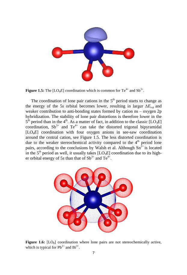
1.4 Transition metal Oxofluorides
Since the area of transition metal oxides has been extensively studied, and a
tremendous number of useful metal oxides have been synthesized and char-
acterized subsequently, several researchers have started to focus their atten-
tion on oxofluorides in which the metal cations coordinate both oxygen and
fluorine anions. At this point, the literature on oxofluorides is still restricted
and the number of oxofluorides is also limited. The reason for this could be
the more complex synthetic route compared to the synthesis of pure oxides
due to the high reactivity of fluorine.
Figure 1.15: The projection view of FeOCl showing two separated layers from
where chlorine ions (green) are protruding.
Figure 1.16: Projection view of FeOF which is a 3D framework structure with fluo-
rine and oxygen (yellow) mixing at the same position.

19
The M-O bonds in metal oxides are actually partly covalent while the M-
F bonds in metal fluorides are almost ionic, thus it is expected that interme-
diate properties between the two different bonding characters can be ob-
served in oxofluorides [30]
. On the other hand, the fluorine anion has the
smallest size and highest electronegativity compared to other halide ions,
which makes the oxofluorides very different from oxochlorides or oxobro-
mides. For instance, M3+
OCl/Br family (M= Fe, Ti, V, Cr) crystallized in
orthorhombic space group Pmnm is a layered system that has been well stud-
ied during the past decades due to their interesting physical properties, such
as electrical and low-dimensional magnetic properties e.g. magnetic frustra-
tion [31, 32, 33]
. The structure is made up of layers that are separated and that
consist of [MO4X2] (X= Cl or Br) octahedra with chlorine/bromine anions
protruding from the layers, see Figure 1.15. However, three-dimensional
framework structures instead of layered compounds were found in the
M3+
OF (M= Fe, Ti, V) family, which crystallize in tetragonal space group
P42/mnm. Unlike FeOCl, in which chlorine or bromine acts as terminating
ions that separate each layers, fluorine in FeOF behaves so similar to oxygen
that the two anions occupy the same position, being the bridge in between
the octahedra in order to build the framework structure, see Figure 1.16.
Some other examples are VOCl3 – VOF3 and CrO2Cl2 – CrO2F2, which
have the same formula but different structures. VOCl3 is a zero dimensional
compound built up by independent [VOCl3] tetrahedra, while VOF3 is a
three-dimensional framework in which the [VOF5] octahedra are connected
only by fluorine bridges. Likewise, CrO2Cl2 consists of isolated [Cr2O4Cl4]
clusters, while in CrO2F2 fluorine acts as the bridge to connect the [Cr2O4F4]
groups forming a 3D-framework. The common feature in these examples is
that chlorine and bromine have lower coordination numbers and act more
like dead-end species, while the smaller fluorine, having stronger electro-
negativity, plays a role more like oxygen in order to connect transition metal
cations. Thus, due to the similarity in between fluorine and oxygen, they
tend to occupy the same crystallographic positions as in the M3+
OF family.
In the case of FeOF, the analysis of the bond valence sum suggests that oxy-
gen is significantly under-bonded, while fluorine is significantly over-
bonded, in the anion position of average structure. Furthermore, its electron
diffraction pattern shows the continuous rods of diffuse intensity running
along certain directions confirming the strong O/F short range ordering.
Such O/F disorder can often exist in some other oxofluoride compounds that
crystallize in high symmetry crystal system e.g. MO3-xFx (M = Nb, Ta, Ti,
Mo, W) family in cubic Pm-3m [34, 35, 36, 37]
.
Having [MOxF6-x] octahedra is one of the main structural features of tran-
sition metal oxofluorides. Such distorted octahedra are locally polar, which
is mainly due to the different bond distances of M-O and M-F. More specifi-

20
cally, due to the much lower energy of fluorine anion’s 2p valence orbitals
compared to the oxygen anion, the transition metal d orbitals mix with oxide
ligands more strongly than fluoride ligands. As a result, the [MOxF6-x] octa-
hedron inherently shows the off-central movement of the transition metal
cation towards the oxide ligands. Therefore, such [MOxF6-x] groups showing
local polarity can be used as building units to design new compounds, which
exhibits a macroscopic dipole moment if it crystallizes in a non-
centrosymmetric space group.
1.5 Transition metal Oxofluorides containing lone
pair cations
Transition metal oxochlorides/bromides containing lone pair cations (i.e. M-
L-O-X family, M=transition metal cations, L= lone pair cations, X= Cl- or
Br-) have been extensively studied during the last ten years due to their low-
dimensional arrangements of metal cations from which many specific phys-
ical properties are derived. However, the literature about M-L-O-F systems
is still very limited and the number of oxofluorides containing the lone pair
cations Se4+
, Te4+
and Sb3+
is extremely small. Only 28 compounds of M-L-
O-F (L= Se4+
, Te4+
, Sb3+
, Bi3+
, Pb2+
, Sn2+
) were found in the Inorganic Crys-
tal Structure Database (ICSD) by using FindIt version 1.9.1, see Table 1.3.
Most of these compounds have a low dimensional connection of transition
metal cations due to the presence of stereochemically active lone pairs.
Some compounds containing Bi3+
or Pb2+
are ferroelectric, since the polari-
ties of such lone pair coordination can be easily be reversed by an external
electric field, which is probably due to the large ionic size of cations and the
weak bonding of anion ligands. Based on the fact that both a [MOxF6-x] octa-
hedron and a lone pair cation show local polarity, the possibility of forming
non-centrosymmetric structures with a macroscopic dipole moment could be
enhanced by using distorted polyhedra as building units. On the other hand,
even if fluorine is less suitable to act as “spacers” compared to chlorine and
bromine, it is still possible to further explore the low-dimensional M-L-O-F
system due to the strong terminating character of lone pair cations.

21
Table 1.3: Compounds in the M-L-O-F system from the ICSD database.
1.6 Bond valence sum calculation (BVS)
Bond valence sum calculation is a useful tool to estimate the oxidation states
and coordination number of the ions. Lone pair cations can take a different
coordination, and to select whether or not a primary bond exists with sur-
rounding anions should be considered carefully. This can be performed by
summing up all possible valence contributions from the surrounding ligands,
and then considering if they should be regarded as belonging to the primary
Compound Author(s) Feature(s)
YSeO3F [38] Lipp, C. Two-dimensional arrangement of Y
NbSeOF7[39] Edwards, A.J. Zero-dimensional arrangement of Nb
FeTeO3F[40] Laval, J.P. One-dimensional arrangement of Fe
GaTeO3F[40] Laval, J.P. One-dimensional arrangement of Ga
CrTeO3F[40] Laval, J.P. One-dimensional arrangement of Cr
ScTeO3F[41] Boukharrata, N.J. One-dimensional arrangement of Sc
InTeO3F[41] Boukharrata, N.J. One-dimensional arrangement of In
InTe2O5F[42] Boukharrata, N.J. One-dimensional arrangement of In
In3TeO3F7[43] Boukharrata, N.J. Open framework structure
TiTeO3F2[44] Laval, J.P. One-dimensional arrangement of Ti
V2Te2O7F2[44] Laval, J.P. One-dimensional arrangement of V
Ta2BiO6F[45] Dihlstroem, K. Zero-dimensional arrangement of Ta
Fe5Bi4O13F[46] Artem, M. A. Pentagonal Cairo lattice, magnetic frustrated
NbBi2O5F[47] Needs, R.L. Two-dimensional arrangement of Nb, ferroelectric
TiBi2O4F2[47] Needs, R.L. Two-dimensional arrangement of Ti, ferroelectric
VBi2O5F[48] Akopjan, A.V. Two-dimensional arrangement of V, anion conductor
ZnBi6P2O14F2[49] Colmont, M. Zero-dimensional arrangement of Zn
FePbO2F[50] Inaguma, Y. Potential magnetic ferroelectric
ScPbO2F[51] Katsumata, T. Potential magnetic ferroelectric
V3Pb5O12F[52] Knyazev, A.V. Zero-dimensional arrangement of V
Nb4Pb3O12F2[53] Savborg, O. Open framework structure
Nb3Pb2O7F5[54] Savborg, O. Two-dimensional arrangement of Nb
Zr3PbO4F6[55] Mikou, A. Zero-dimensional arrangement of Zr
W3Pb5O9F10[56] Abrahams, S.C. One-dimensional arrangement of W, ferroelectric
Ta5Pb3O9F13[57] Savborg, O. Two-dimensional arrangement of Ta
Zr6PbO2F22 [58] Laval, J.P. Three dimensional framework structure
Ta9Pb12O20F29[59] Savborg, O. One-dimensional “block” arrangement of Ta
NbSn6OF15[60] Rakov, I.E. Zero-dimensional arrangement of Nb
22
coordination sphere or not. In addition, bond valence sum calculation can
also help evaluate the accuracy of crystal structure determinations. If the
BVS calculated from bond distances obtained from a crystal structure differ
significantly from the expected oxidation state, it is usually an indication that
the structure determination is not correct. In oxofluorides, as noted previous-
ly, both oxygen and fluorine can occupy the same crystallographic position,
and it is not so straightforward to determine from X-ray data how to assign
which of the elements that actually occupies a certain position. In this case,
bond valence sum calculations can help to make this determination. This is
because the average bond distances of cation-oxygen/fluorine are used,
which means that one of them is over-bonded and the other is under-bonded.
Even if the oxygen and fluorine anions occupy different positions, their very
similar scattering factors make X-ray diffraction difficult as a method to
distinguish between them, and thus bond valence sum calculation becomes
an important tool to help determine the crystal structures of oxofluorides.
The bond valence sum model is an empirical method that was established
by Pauling [61]
and further developed by mainly Brown [62]
. According to this
method, a crystal structure can be described as an arrangement of atoms
connected by bond fluxes between atoms with opposite signs of valences. A
bond valence is assigned to each bond so that the bond valence sum for all
bonds around an atom equals the absolute value of the valence of the atom.
The empirical relationship between bond valence and bond length can be
described by the following equation:
Sij = exp [(r0 - rij) / b] (1)
Where rij is the measured bond distance between cation i and anion j, Sij is
the bond valence, and r0 and b are empirical parameters derived from refined
structures. The symbol ‘b’ is taken as a constant equal to 0.37 Å, in most
cases, and is normally independent of the bond type. Sometimes, large de-
viations of BVS from the absolute valence can appear. For example, if a
hydrogen atom of a hydroxyl group in the structure is not included in the
calculation, the calculated BVS for oxygen anion will be remarkably lower
than the absolute valence of 2.0. This can also help assign the presence of
hydrogen.

23
1.7 Aim and scope
The family of transition metal oxohalides comprising p-block lone-pair ele-
ments (M = Transition metal cation, L= p-block lone pair elements such as
Te4+
, Se4+
, or Sb3+
, X= Cl- or Br
-) has drawn attention recently because of the
high possibility for finding compounds showing topologically low dimen-
sional crystal structures [19, 22]
and the consequent intriguing physical proper-
ties of such systems [72]
. The key feature of these types of compounds is the
lone-pair cations carrying stereochemically active lone-pair electrons. The
lone-pairs are big enough to hinder the transition metal coordination polyhe-
dra from forming three dimensional framework structures. The electrons are
positioned in a non-bonding orbital, which means that they will not form
bonds and therefore act as a terminating species. Another important compo-
nent is the halide ions Cl- or Br
- which typically have low coordination num-
bers and can act as a structural “dead end” as well.
In oxofluorides fluorine plays the role of being a “bridging ion” like ox-
ygen instead of being a terminating species, which is due to their similarities
in size and electronegativity. Thus, the M-L-O-F system can be considered
as a system that is different compared to the M-L-O-(Cl, Br) system. Due to
the various types of [MOxFy] polyhedra observed in the existing transition
metal oxofluorides, it is reasonable to expect a rich variety of intriguing
crystal structures in the M-L-O-F system. In addition, it has been pointed out
that the magnetic exchange interactions through the fluorine ion bridging
between transition metal centers are different from those through oxygen
ions [30]
. Thus, interesting magnetic properties can also be expected in the M-
L-O-F family. However, there has previously been very little work on syn-
thesizing transition metal oxofluorides containing lone pair elements; less
than thirty compounds in this system were found when searching the ICSD
database. The possible reason for this is the unavoidable reaction between
fluorine and the container material for chemical transport reactions. The
purpose of this work has been to explore the M-L-O-F system and find suit-
able synthetic methods.
24
2 Experimental
2.1 Methodology
There are many techniques that have been successfully used to synthesize
oxohalides, some examples are hydrothermal reactions, chemical transport
reactions, solid-state reactions and vapor-solid reactions. Most of the oxoflu-
orides described in this thesis are synthesized from hydrothermal reactions
while the oxochlorides/oxobromides are obtained via chemical transport
reactions.
2.1.1 Chemical Transport Reactions (CTR)
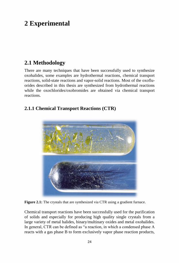
Figure 2.1: The crystals that are synthesized via CTR using a gradient furnace.
Chemical transport reactions have been successfully used for the purification
of solids and especially for producing high quality single crystals from a
large variety of metal halides, binary/multinary oxides and metal oxohalides.
In general, CTR can be defined as “a reaction, in which a condensed phase A
reacts with a gas phase B to form exclusively vapor phase reaction products,

25
which in turn undergo the reverse reaction at a different location of the sys-
tem, resulting in the reformation of A” [63]
. For metal oxochlorides, chlorin-
ating transport agents such as Cl2 and HCl are typically used. The reactions
are usually much more complex than indicated from the overall chemical
equation since various medium gas-phase species are formed during the
transport.
The classical CTR actually takes place in the gradient furnaces, which
have two different temperature end zones. The starting materials vaporize
and the reaction happens at the higher temperature, while crystallization
usually happens at the lower temperature. Single crystals of high quality, and
a size suitable for the determination of the crystal structure by X-ray diffrac-
tion, can be obtained during such a transport process. However, the number
of targeted products is often limited. To obtain a high enough amount of
mono-phase products for physical properties measurements, muffle furnaces
have mainly been used in this work instead of gradient furnaces. The CTR
that takes place in a muffle furnace is very similar to a vapor-solid reaction,
in which the transport-crystallization process happens everywhere, since the
chemical equilibrium can more easily be achieved in the temperature uni-
formed system. Besides, since the temperature zone in the reaction system is
very narrow compared to conventional CTR, the diversity of crystals formed
in vapor solid reactions could be reduced and therefore the possibility of
obtaining the products with mono-phase is enhanced.
2.1.2 Hydrothermal Reaction
Hydrothermal synthesis is one of the most popular methods for preparing
single crystals. It highly depends on the solubility of reactants in hot water
under high pressure. The method has been successfully applied to synthesize
various kinds of inorganic species, including complex oxides, phosphates,
silicates, carbonates and germanates. For oxochlorides/oxobromides, howev-
er, the application of the hydrothermal method is limited due to the large
difference in solubility products in between the oxides and chlo-
rides/bromides of the transition metals and main group elements, which
makes those starting compounds difficult to combine. Fortunately, metal
fluorides usually have much lower solubility in water than chlo-
rides/bromides and thus the possibility to synthesize transition metal oxoflu-
roides containing a lone pair cation is enhanced by using hydrothermal reac-
tions.

26
Figure 2.2: Teflon cylinder and steel autoclave used for hydrothermal synthesis.
2.2 The synthesis procedure
Several new oxochloride compounds have been obtained by chemical
transport reactions, see Table 2.3. Typically, the starting materials (Table
2.1) were ground and mixed in a mortar for several minutes and subsequent-
ly sealed in silicon tubes under a vacuum followed by heating in muffle fur-
naces to a temperature in the range 450 - 550 °C. Some of these oxochloride
compounds were synthesized at a relatively low temperature compared to the
common temperature used in conventional CTR. The synthesis procedures
were modified by injecting a small amount of concentrated hydrochloric acid
into the silica tubes before sealing. The silica tubes were placed in steel au-
toclaves containing a suitable amount of water to compensate for the pres-
sure caused by the vaporization of the acid when heated to 180 - 230 °C.
In most cases, hydrothermal methods have been utilized to synthesize
compounds in the M-L-O-F system (M = Transition metal cation, L= p-
block lone pair elements such as Te4+
, Se4+
, or Sb3+
), see Table 2.2. Typical-
ly, the starting materials, mixed together with small amount of water, were
sealed in a Teflon lined steel autoclave and heated to 180 - 230 °C for 3
days. In some cases, a modified hydrothermal reaction was also used to syn-
thesize a mono-phasic powder for characterization of the physical properties
of new compounds, which were difficult to obtain via CTR. The starting

27
materials where then dissolved in concentrated HF. After the excessive acid
has been removed by evaporation at room temperature, the slurry of mixture
is transferred into an autoclave with a Teflon cylinder, followed by hydro-
thermal treatment at 200 °C for 3 days.
Table 2.1: Starting materials used in the synthesis.
Table 2.2: Starting molar ratios for the synthesis of oxofluorides via hydrothermal
reactions at 230°C.
Chemicals Company Purity
MnF2 Strem chemicals 99%
FeF3 Aldrich 99.5%
CoF2 Strem chemicals 99%
NiF2 Aldrich 99.5%
CuF2 Strem chemicals 99%
FeCl3 Aldrich 97%
CoCl2 Aldrich 98%
NiCl2 Aldrich 98%
CuCl2 Aldrich 97%
Fe2O3 Aldrich powder, <5 micron 99%
CoO ABCR GmbH & Co. KG 99%
NiO Aldrich 99%
CuO Ardrich, powder, <10 micron 98%
TeO2 ABCR GmbH & Co. KG 99%
SeO2 Strem chemicals 99.8%
Sb2O3 Ardrich, powder, <5 micron 99%
MnF2 FeF3 CoF2 NiF2 CuF2 LO2 Sb2O3 Products
2 1.5 Mn2SeO3F2
Powder
2 1.5 FeSeO3F
Single crystals
2 1.5 Co2SeO3F2
Powder
3 2 Co3Sb4O6F6
Single crystals
2 1.5 Ni2SeO3F2
Powder
3 2 Ni3Sb4O6F6
Single crystals
2 1 Cu7Te6O18F2
Single crystals

28
Starting materials Molar
ratios
Transport
agents
Temper-
ature(°C)
Time
(h)
Products
CoO+CoF2+SeO2 1:1:1 HF 200 72 Co2SeO3F2
Single crystals
CoO+CoF2+TeO2 1:1:1 HF 200 72 Co2TeO3F2
Single crystals
NiO+NiCl2+NiF2+TeO2 1:1:2:2 - 550 96 Ni5Te4O11Cl4
Single crystals
NiO+NiCl2+NiF2+TeO2 1:1:4:2 - 500 96 Ni3Te2O5Cl4
Single crystals
CoO+CoCl2+CoF2+TeO2 3:1:1:2 - 550 96 Co5Te4O11Cl4
Single crystals
Fe2O3+SeO2+CaO 1.5:4.5:1 HCl 200 72 Fe6Ca2Se9O27Cl4
Single crystals
Fe2O3+SeO2+CaO 1.5:4.5:1 HBr 200 72 Fe6Ca2Se9O27Br4
Single crystals
Fe2O3+SeO2 1:2 HCl 200 72 H2FeSeClO4
Single crystals
NiO+SeO2 1:1 HCl 200 72 H3NiSeClO4
Single crystals
Table 2.3: List of compounds synthesized from chemical transport reactions.
2.3 Modified synthesis techniques
Both chemical transport reactions (CTR) and hydrothermal reactions have
been modified in order to achieve goals that are difficult to accomplish in
conventional ways. The specific modification and the purposes of applying
those modified methods are discussed in the following sections.
2.3.1 Synthesis of oxofluorides via low temperature CTR
Chemical transport reactions that take place in sealed silica tubes have pre-
viously been used successfully to synthesize transition metal oxohalides
containing lone pair cations [64]
. However, among those only Co2SeO3F2 and
Co2TeO3F2 are oxofluorides as fluorine tends to react with the silica tube at
high temperatures. Considering the high cost of using platinum tubes, we
first attempted CTR (or vapor-solid reaction) at a relatively low temperature
to synthesize compounds in the M-L-O-F family (M = Transition metal cati-
on, L= p-block lone pair elements such as Te4+
, Se4+
, or Sb3+
). However, in
most cases only undeterminable mixed powder was obtained even when a

29
reaction had been tried at different temperatures from 300 to 600 °C. Such
results are very different from that in the synthesis of oxochlorides/bromides,
where various crystalline products can be obtained at different temperature
zones as long as the molar ratios in the starting materials are suitable. The
reason for the unsuccessful synthesis via CTR can be explained as follows: (i)
first of all, metal fluorides usually have much higher melting points than
their respective chlorides, see table 3.4, which means at a relatively low
temperature zone (300 ~ 400 °C) fluorine species are difficult to turn into
their gas phase and therefore could not be transported into the reaction sys-
tem; (ii) once the temperature is raised above 500 °C in order to make the
fluorine source to vaporize, the fluorine species start to react severely with
the silica tube. Since most of fluorine is consumed in reactions with the
tubes, it is reasonable to face the result that there are no determinable target
products formed.
To overcome the above two difficulties in the synthesis of oxofluorides
via the chemical transport reaction, a modified low-temperature CTR was
adopted. The main difference from conventional methods is that a small
amount (~80 µL) of concentrated hydrofluoric acid is injected into silica
tubes (~6 mL) containing starting materials before the tubes are sealed. The
silica tubes are then heated at 200 °C in an autoclave containing a suitable
amount of water, which can generate a counter pressure to prevent the tubes
from the pressure that is caused by the vaporization of conc. HF during the
heating. Consequently, the reactions between fluorine and silica tubes are
significantly reduced, since the reaction temperature has been lowered down
to 200 °C. More importantly, the fluorine species can easily vaporize and
transport, even at such a low temperatures in a reaction, as metal fluorides
dissolve in conc. HF. Meanwhile, hydrofluoric acid also reacts with oxides
in starting materials, forming complex medium fluorine containing species.
By applying this modification, two new oxofluorides, Co2SeO3F2 and
Co2TeO3F2, have successfully been synthesized with nice quality and a big
enough size for structure determination, see Figure 2.3. To our best
knowledge, these are the only two oxofluorides that are synthesized in sealed
silica tubes.

30
Figure 2.3: (a) Light microscope image and (b) SEM image of Co2SeO3F2.
In addition to the advantages for synthesizing oxofluorides, the low-
temperature CTR has proved to be a promising method in searching for new
oxochlorides/bromides at lower temperature zones where conventional CTR
normally does not work well. Several new compounds, such as
Fe6Se9Ca2O27X4 (X=Cl, Br), H2FeSeClO4 and H3NiSeClO4, have been syn-
thesized by using conc. HCl or HBr as transport agents at 200 °C. By con-
trast, the synthesis of Fe6Ca2Se9O27Cl4 has also been conducted via conven-
tional CTR at 200 °C, 450 °C and 500 °C, respectively, with starting materi-
als of Fe2O3, CaCl2 and SeO2 in a stoichiometric molar ratio of 3:2:9. At 450
and 500 °C, the reaction products were found to be a complex mixture and
no single crystals were available for X-ray diffraction, which is probably
because the compound Fe6Ca2Se9O27Cl4 is not stable at a high temperature.
At 200 °C, however, the reaction did not even take place, since most starting
materials remained. Attempts at synthesizing H2FeSeClO4 and H3NiSeClO4
via the common hydrothermal method have been made, however, no solid
products containing the respective transition metals were obtained, which is
probably due to the very high solubility of FeCl3 and NiCl2 in water. On the
other hand, it is also very rare to obtain compounds like H2FeSeClO4 and
H3NiSeClO4, which contain crystal water or hydroxyl via conventional CTR
in the temperature range 350 to 600 °C. The structure description of
Fe6Ca2Se9O27Cl4, H2FeSeClO4 and H3NiSeClO4 will be presented in section
3.

31
2.3.2 Synthesis of oxofluorides via hydrothermal reactions
There is still a mild reaction observed in between fluorine and silica tubes,
although the reaction temperature of the modified CTR has been lowered
down to 200 °C. Only two oxofluorides, Co2SeO3F2 and Co2TeO3F2, have
emanated through this method, and apparently this method is well suited in
the search for new oxochlorides/bromides at low temperatures, even if the
original purpose was to synthesize oxofluorides.
Hydrothermal reactions are one of the most commonly used methods for
synthesizing new inorganic compounds, including both simple and complex
oxides, germanates, silicates, etc. Specific to the focus of this thesis, many
compounds that have a non-centrosymmetric structure, and exhibit fascinat-
ing physical properties, such as second harmonic generation [65]
, ferroelectric
properties [66]
or even multiferroicity [67]
, have successfully been synthesized
via hydrothermal reactions. Some of these compounds are transition metal
oxides containing lone pair cations, which are very much related to the com-
pounds presented in this work. However, almost all those compounds are
oxides and do not contain halide ions. To the best of our knowledge, only
very few oxohalides containing lone pair cations can be synthesized from
hydrothermal reactions, with two examples being Cu2Te2O5Br2 and
Ce2Te7O17X2 (X = Cl, Br) [68]
. The reason can be attributed to the fact that
hydrothermal reactions depend highly on the solubility of the reactants in
water. Since oxides hardly dissolve in water, while metal chlorides/bromides
usually have much higher solubility, it is very difficult to combine them in
one chemical system at the same time. This assumption is also supported by
the results from our attempts to synthesize compounds in a M-L-O-(Cl, Br)
system by utilizing hydrothermal techniques (M = Transition metal cation,
L= p-block lone pair elements such as Te4+
, Se4+
, or Sb3+
), in which mainly
compounds of the M-L-O type could be obtained while Cl- or Br
- remained
in the solution.
When it comes to the synthesis of compounds in the M-L-O-F system,
however, the situation is fortunately different from that of M-L-O-(Cl, Br)
under hydrothermal conditions. As shown in Table 2.4, the solubility of met-
al fluorides in water is much lower than that of their respective chlo-
rides/bromides. In the case of copper and iron, their fluorides have a solubili-
ty that is up to 1000 times lower than that of their respective chlorides. Such
low solubility becomes much closer to that of oxides like TeO2 and Sb2O3 in
water. This fact makes it possible to synthesize compounds in M-L-O-F
through hydrothermal techniques. In the present work, six new compounds
in the M-L-O-F system have been successfully synthesized, see Table 2.2.

32
Figure 2.4: EDS analysis on (a) Cu7Te6O18F2 synthesized at 230 °C and (b) uniden-
tified compound obtained at 200 °C. The data for O and F confirm the presence of
elements but cannot be used for quantitative analysis.
Like chemical transport reactions, the factor of temperature in a hydro-
thermal reaction is also very important, since the solubility of reactants
change with temperature. In this work, the reaction temperature for all those
six new oxofluorides has been set at 230 °C. The main reason for using this
relatively high temperature is that the oxides TeO2 and Sb2O3 both have very
low solubility in water, and it increases at higher temperatures. For example,
there would be a risk for forming phases that do not contain Te or Sb if the
reaction temperature is lower and close to 200 °C. The EDS analysis on the
actual Cu7Te6O18F2 phase was shown in Figure 2.4 (a), indicating the correct
atomic ratio between Cu and Te according to the formula obtained from the
structure solution. However, as shown in Figure 2.4 (b), only trace amounts
of Te was detected in the unknown phase when the synthesis of Cu7Te6O18F2
was carried out at 200 °C, which could be the residual TeO2 powder that
dispersed on the surface. For the synthesis of Co3Sb4O6F6, Ni3Sb4O6F6 and
FeSeO3F, 200 °C was already enough to obtain the target phases, However,
the high temperature is good for forming bigger crystals, which are easier to
separate from the residual powder mixture. In the case of Mn2SeO3F2 and
Ni2SeO3F2, although they are still in the form of powder, even at 230 °C, the
crystallinity would be better than that at a lower temperature, which is good
for collecting high quality powder diffraction data to carry out Rietveld re-

33
finement. Temperatures higher than 230 °C were not attempted considering
the aspect of security.
Metal Halides Melting point (°C) Solubility in Water
(g/100 mL at 20 °C)
MnF2 856 10.6
MnCl2 654 73.9
MnBr2 698 147
FeF3 1000 0.091
FeCl3 306 91.8
FeBr3 200 -
CoF2 1217 1.36
CoCl2 735 52.9
CoBr2 678 112
NiF2 1474 2.56
NiCl2 1001 66.8
NiBr2 963 131
CuF2 836 0.075
CuCl2 498 73
CuBr2 498 126
Table 2.4: List of melting points and solubility of metal halides.

34
2.4 Characterization
2.4.1 Single Crystal X-ray Diffraction (SXRD)
Single-crystal X-ray diffraction was conducted on an Oxford Diffraction
Xcalibur3 system equipped with a sapphire CCD detector and an Oxford
Cryostream crystal cooling system, using graphite-monochromatized Mo Kα
radiation, λ= 0.71073 Å, operated at 50 kV and 40 mA, see Figure 2.5.
Integration of the reflection intensities and absorption correction were
made using the software CrysAlis, supplied by the manufacturers of diffrac-
tometer. The crystal structures of new compounds were solved by direct
methods using the program SHELXS-97 [69]
and refined by full matrix least
squares on F2 using the program SHELXL-97, or refined by full matrix least
squares on F using the JANA 2006 software package [70]
.
Figure 2.5: Single Crystal diffractometer Xcalibur-III.
2.4.2 Powder X-ray Diffraction (PXRD)
PXRD was used to preliminarily investigate the phase purity of powder
samples that were intended for characterization of physical properties. In
some cases, high quality data from PXRD was also used to solve crystal
structures and for Reitveld refinement. The data was collected from a
PANanalytical X’Pert diffractometer equipped with a focusing Johansson Ge
monochromator producing pure Cu-Kα1 radiation, λ= 1.54056 Å, see Figure
2.6.

35
Figure 2.6: Powder diffractometer Panalytical X’Pert alpha1.
2.4.3 Scanning electron microscopy (SEM) and energy
dispersive X-ray spectroscopy (EDS)
The chemical compositions of the synthesis products were determined in a
scanning electron microscope (SEM, JEOL JSB-7000F) equipped with an
energy dispersive spectrometer (EDS), operated at 20 kV. The samples were
placed on a sample holder and covered with a thin layer of elemental carbon
before the analysis. Cobalt was used as an internal standard.

36
3 Results and Discussion
This work, which has focused on finding new transition metal oxofluorides
comprising lone-pair cations, resulted in several new compounds in the M-L-
O-F family (M = Ni2+
, Co2+
, Cu2+
, Mn2+
, or Fe3+
, L= p-block lone pair ele-
ment; Te4+
, Se4+
, or Sb3+
). In addition, a number of new oxochlorides in the
M-L-O-Cl system were found during this search, and they will also be sum-
marized in this section.
3.1 New compounds in M-L-O-F Family
The synthetic experiments resulted in eight new transition metal oxofluo-
rides crystallizing in four new crystal structure configurations, which are
MLO3F2 (M= Mn2+
, Co2+
and Ni2+
, L = Te4+
and Se4+
), CoxNi1-xSb4O6F6 (x=
0, 0.25, 0.5, 0.75 and 1), FeSeO3F and Cu7Te6O18F2. A short list summariz-
ing the unit cell parameters and space groups are shown in Table 3.1.
Space
group
Unit cell dimensions (Å) Unit cell angels (º)
Compound a b c α β γ
Mn2SeO3F2 Pnma 7.50754(8) 10.3566(1) 5.47766(6) - - -
Co2SeO3F2 Pnma 7.2655(8) 10.001(1) 5.3564(6) - - -
Ni2SeO3F2 Pnma 7.1566(1) 9.9239(1) 5.24619(8) - - -
Co2TeO3F2 Pnma 7.3810(5) 10.1936(7) 5.3013(3) - - -
Co3Sb4O6F6 I-43m 8.176(1) - - - - -
Ni3Sb4O6F6 I-43m 8.0778(1) - - - - -
FeSeO3F P21/n 4.9559(5) 5.2023(6) 12.040(2) - 97.87(1) -
Cu7Te6O18F2 P-1 4.9844(2) 9.4724(4) 9.9580(4) 82.318(4) 76.275(4) 78.847(4)
Table 3.1: Crystallographic information for the new oxofluorides synthesized within
this work.
37
Space
group
Unit cell dimensions (Å) Unit cell angels (º)
Compound a b c α β γ
Fe6Ca2Se9O27Cl4 P63/m 12.118(2) - 12.703(4) - - -
H2FeSeClO4 P21/c 6.4476(4) 9.4072(5) 7.8541(4) - 90.883(5) -
H3NiSeClO4 P21/n 8.3756(3) 5.7933(2) 9.6181(3) - 92.209(4) -
Ni5Te4O11Cl4 P21 10.0293(3) 15.9055(5) 10.1725(4) - 110.454(4) -
Ni3Te2O5Cl4 Pna21 16.7001(4) 7.0967(2) 15.6272(4) - - -
Cu7Te5O15FCl2(OH) Pmcn 10.14151(6) 12.00002(7) 14.8846(1) - - -
Table 3.2: Crystallographic information for the new oxochlorides synthesized with-
in this work.
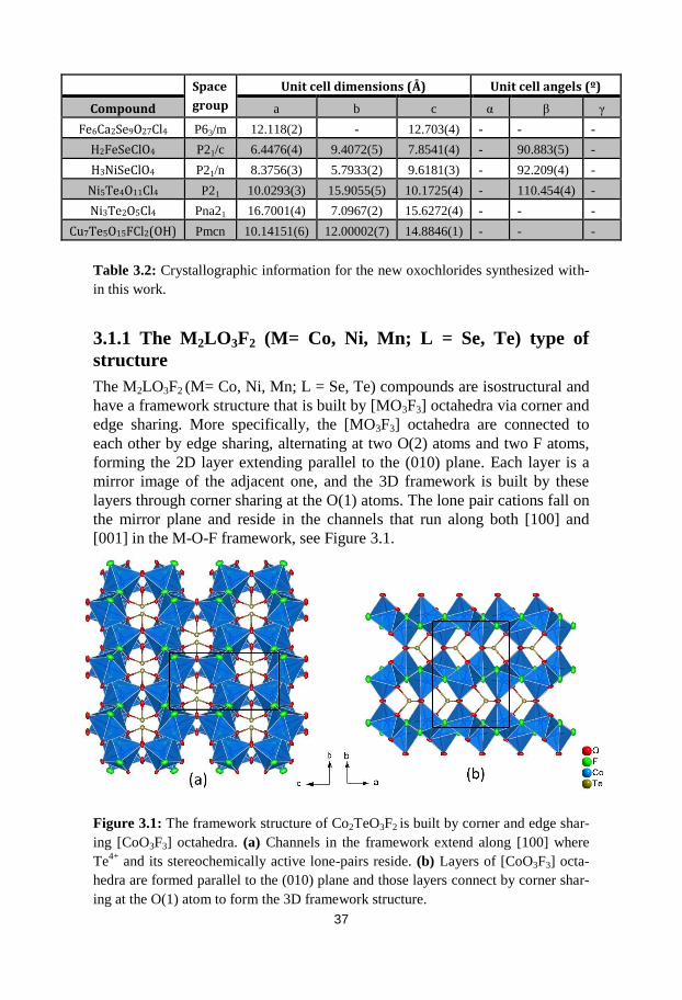
3.1.1 The M2LO3F2 (M= Co, Ni, Mn; L = Se, Te) type of
structure
The M2LO3F2 (M= Co, Ni, Mn; L = Se, Te) compounds are isostructural and
have a framework structure that is built by [MO3F3] octahedra via corner and
edge sharing. More specifically, the [MO3F3] octahedra are connected to
each other by edge sharing, alternating at two O(2) atoms and two F atoms,
forming the 2D layer extending parallel to the (010) plane. Each layer is a
mirror image of the adjacent one, and the 3D framework is built by these
layers through corner sharing at the O(1) atoms. The lone pair cations fall on
the mirror plane and reside in the channels that run along both [100] and
[001] in the M-O-F framework, see Figure 3.1.
Figure 3.1: The framework structure of Co2TeO3F2 is built by corner and edge shar-
ing [CoO3F3] octahedra. (a) Channels in the framework extend along [100] where
Te4+
and its stereochemically active lone-pairs reside. (b) Layers of [CoO3F3] octa-
hedra are formed parallel to the (010) plane and those layers connect by corner shar-
ing at the O(1) atom to form the 3D framework structure.
38
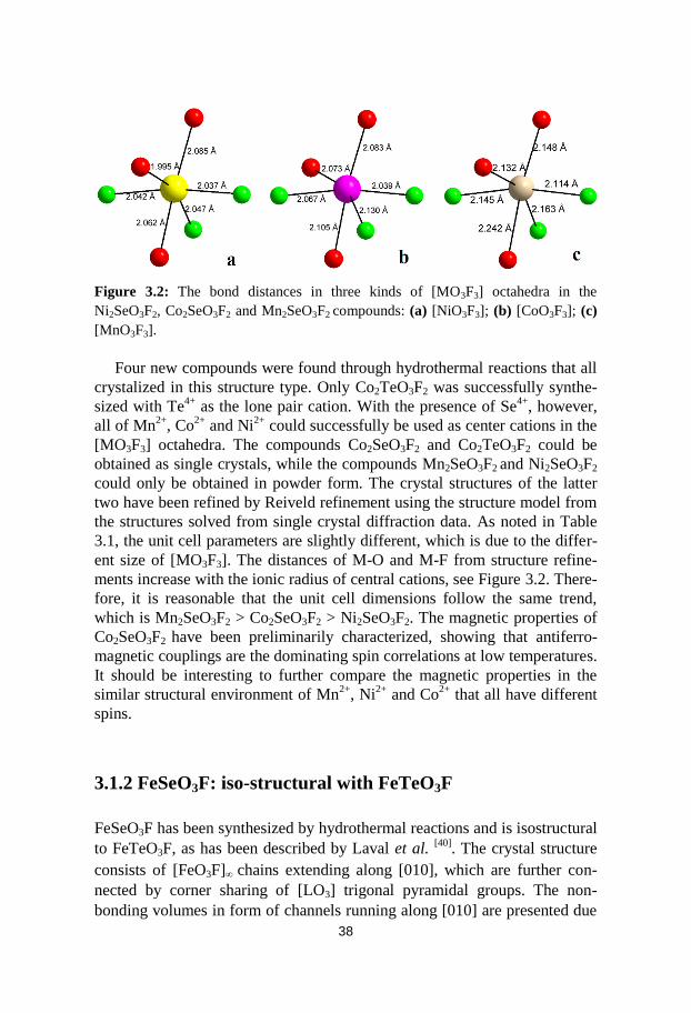
Figure 3.2: The bond distances in three kinds of [MO3F3] octahedra in the
Ni2SeO3F2, Co2SeO3F2 and Mn2SeO3F2 compounds: (a) [NiO3F3]; (b) [CoO3F3]; (c)
[MnO3F3].
Four new compounds were found through hydrothermal reactions that all
crystalized in this structure type. Only Co2TeO3F2 was successfully synthe-
sized with Te4+
as the lone pair cation. With the presence of Se4+
, however,
all of Mn2+
, Co2+
and Ni2+
could successfully be used as center cations in the
[MO3F3] octahedra. The compounds Co2SeO3F2 and Co2TeO3F2 could be
obtained as single crystals, while the compounds Mn2SeO3F2 and Ni2SeO3F2
could only be obtained in powder form. The crystal structures of the latter
two have been refined by Reiveld refinement using the structure model from
the structures solved from single crystal diffraction data. As noted in Table
3.1, the unit cell parameters are slightly different, which is due to the differ-
ent size of [MO3F3]. The distances of M-O and M-F from structure refine-
ments increase with the ionic radius of central cations, see Figure 3.2. There-
fore, it is reasonable that the unit cell dimensions follow the same trend,
which is Mn2SeO3F2 > Co2SeO3F2 > Ni2SeO3F2. The magnetic properties of
Co2SeO3F2 have been preliminarily characterized, showing that antiferro-
magnetic couplings are the dominating spin correlations at low temperatures.
It should be interesting to further compare the magnetic properties in the
similar structural environment of Mn2+
, Ni2+
and Co2+
that all have different
spins.
3.1.2 FeSeO3F: iso-structural with FeTeO3F
FeSeO3F has been synthesized by hydrothermal reactions and is isostructural
to FeTeO3F, as has been described by Laval et al. [40]
. The crystal structure
consists of [FeO3F] chains extending along [010], which are further con-
nected by corner sharing of [LO3] trigonal pyramidal groups. The non-
bonding volumes in form of channels running along [010] are presented due

39
to the occupation of the terminating lone pairs, see Figure 3.3. This can be
considered as a low-dimensional compound because of the [FeO3F] chains
and the absence of a three dimensional Fe-O-Fe or Fe-F-Fe network.
Figure 3.3: (a) The crystal structure of FeSeO3F consists of the [FeO3F] chains
made up of edge-sharing [FeO4F2] octahedra. The chains extend along [010] and are
interconnected by [SeO3] pyramids to form the three-dimensional framework. (b)
Schematic view of two [FeO3F] zigzag chains along [010], which are made up of
[FeO4F2] octahedra by sharing the O–O and F–F edges alternatingly.
Since the bigger radius of Te4+
results in longer Te-O bonds, the different
size of unit cells in FeTeO3F and FeSeO3F can be attributed to the size dif-
ference between [SeO3E] and the [TeO3E] tetrahedra (E designates the ste-
reochemically active lone pairs). It has also been observed for other com-
pounds that Se4+
and Te4+
can replace each other when they both take the
[LO3E] coordination. Examples of such pairs are Co2TeO3F2 – Co2SeO3F2
and Ni5(TeO3)4Cl2 – Ni5(SeO3)4Cl2 [71, 72, 73]
. However, Se4+
has only been
observed with the [LO3E] coordination while Te4+
can accept one or two
extra oxygens as ligands and adopt a seesaw [LO4E], or even an octahedral
[LO5E], coordination; this difference is the reason for why isostructural
compounds with Te4+
and Se4+
are relatively rare.
3.1.3 The CoxNi1-xSb4O6F6 solid solution (x= 0, 0.25, 0.5, 0.75,
1)
The compounds in this solid solution crystallize in the cubic system. The
crystal structure is of a framework type and is made up by corner sharing
[MO2F4] (M= Co and Ni) octahedra via the F atoms, meaning that the O
atoms further connect to the [SbO3] groups.

40
Figure 3.4: Overview of the crystal structure along [100]. The three dimensional
network is made up of corner sharing [CoF4O2] octahedra sharing corners at the F
atoms. The oxygen atoms link further to the [Sb4O6] cages. When taking the stereo-
chemically active lone-pair, E, on the Sb3+
ions into consideration, the Sb4O6 cages
become [Sb4O6E4] supertetrahedra (T2).
The Sb atom bonds to three oxygen atoms to form trigonal pyramidal
units, [SbO3], with aligned orientation. If the stereochemically active lone-
pair E on Sb3+
is also taken into consideration, the coordination polyhedron
becomes a [SbO3E] pseudo-tetrahedron. Four [SbO3E] groups form together
a non-centric [Sb4O6E4] supertetrahedron (T2) of the same type as in Sb2O3 [74]
and CuSb2O3Br [75]
. The lack of inversion center in [SbO3E] should be
considered as a reason for the formation of the non-centrosymmetric crystal
structure. The crystal structure can be described as AB stacking of layers
made up of [MO2F4] octahedra along <100>. The layers have voids where
the [Sb4O6] cages are located, see Figure 3.4. Parallel to (111) the oxygen
and fluorine network form perfect kagome-like layers with a shortest Co-Co distance of 5.781 Å, see Figure 3.5(a). The kagome layers show ABC
stacking along [111], and a projection onto the (111) plane is shown in Fig-
ure 3.5(b). However, such kagome layers are not expected to be magnetical-
ly frustrated since they are connected, and the Co-Co distance within a layer
is too long to have a strong exchange interaction between adjacent Co cati-
ons.

41
Figure 3.5: View of the (111) plane of (CoxNi1-x)3Sb4O6F6. The compound can be
considered as kagome-type layers of isolated [MO2F4] octahedra (a) which are
stacked along [111] in an ABC type of packing (b).
Five synthesis experiments with different Co to Ni molar ratios are made
within the solid solution, and the compositions are confirmed by energy dis-
persive X-ray spectroscopy (EDS) and PXRD. The unit cell parameter
changed gradually with the Co/Ni ratio due to the different size of the
[CoO2F4] and [NiO2F4] octahedra, so that the unit cell parameter follows
Vegard's law with a small positive deviation, see Figure 3.6.

42
Figure 3.6: The unit cell parameter of the different compositions within the solid
solution (CoxNi1-x)3Sb4O6F6 follow Vegard’s law with a small positive deviation.
3.1.4 Terminating fluorine ions: Cu7Te6O18F2
Cu7Te6O18F2 crystalizes in the triclinic centrosymmetric space group P-1. All
four crystallographically different Cu atoms have different coordinations:
[Cu(1)O4] square plane, [Cu(2)O5] square pyramid, [Cu(3)O6] octahedra and
[Cu(4)O4F] trigonal bipyramid. These are connected by corner and edge
sharing to build the framework structure, see Figure 3.7.
Figure 3.7: Overview of the crystal structure of Cu7Te6O18F2 seen along [100]. The
framework is made up by corner and edge sharing of four different kinds of copper
coordinations with O and F atoms.

43
The four crystallographically different copper atoms form a lattice of
pyramids which are located alternatively up and down in layers extending
parallel to the (011) plane. Thus the arrangement of copper can be described
as a semi-2D network where the 2D copper layers are packing along the
[011] direction, see Figure 3.8.
Figure 3.8: (a) Overview of a copper layer, which is built by rows that consist of
two upside-down connected copper-pyramid chains. (b) The pyramid-layers of cop-
per packing along [011].
Another feature of this compound is that the character of the fluorine
atom is not bridging like oxygen but becomes a terminating species like
chlorine and bromine use to be. The bond valence sum calculation gives a
value of 0.39 for fluorine, which is very low and indicates that it is not fully
integrated in the covalent network. The BVS value is close to 1.0 for most
oxofluorides, which indicates that it is normally integrated in the covalent
network. Cu7Te6O18F2 may be the first compound in which fluorine plays
the same role as chlorine/bromine in M-L-O-X systems, where the halide
ions and lone pairs reside together in the non-bonding region.
3.1.5 Summary of new compounds in M-L-O-F family
In total, eight new transition metal cation oxofluorides have been synthe-
sized with Te4+
, Se4+
or Sb3+
as lone-pair cations. Those oxofluorides show a
big variety in how the transition metal cation coordinates with oxygen and
fluorine, see Figure 3.9. A search of the ICSD database yields very few
compounds containing Mn2+
, Co2+
or Ni2+
where both F and O are present in
the coordination environment; the previously found compounds are

44
Mn2(PO4)F[76]
, Mn3(SiO4)F2[77]
, K2Mn2(P2O7)F2[78]
, Na2Co(PO4)F[79]
, Na-
Co(SO4)F[80]
, LiCo(SO4)F[81]
, Li2Ni(PO4)F[82]
, NaNi(SO4)F(H2O)2[83]
,
LiNi(SO4)F[84]
and LiNaNi(PO4)F[82]
. However, an analogue of the [CuO4F]
trigonal bipyramid that is present in Cu7Te6O18F2 was not found in the data-
base. Bond valence sum calculations were performed for all the eight new
oxofluorides, and the values for fluorine in the respective compounds are
shown in Table 3.3. Except for (CoxNi1-x)3Sb4O6F6 and Cu7Te6O18F2, the
BVS values for fluorine ions in the remaining five compounds are above
0.85, which are consistent with the theoretical value 1 showing a full O/F
ordering. Due to the fact that fluorine is a terminating ion, the low BVS val-
ue in the case of Cu7Te6O18F2 is also reasonable. However, the BVS values
of ~0.65 for F in the whole series of (CoxNi1-x)3Sb4O6F6 solid solutions are
somewhat suspicious, since F is the only bridging ion in the framework
structure; in this case the BVS value should be close to 1. Furthermore, the
BVS value for O atoms is ~2.3, which is higher than the expected value of 2.
The over-bonded O, and the under-bonded F, indicate the possibility that the
two atoms may mix on the two different positions. Yet the attempt for refin-
ing the occupancy of O or F at two positions gave values close to 100%,
indicating the full occupancies. Further diffuse scattering was not detected in
the reconstructed reciprocal space, which is commonly observed in electron
diffraction patterns when O/F short range ordering exists [85, 86]
. Therefore,
the present data supports the claim that the O and F positions are fully occu-
pied. The reasons for the deviations in the BVS values need to be further
investigated by neutron diffraction in which O and F have a larger difference
in terms of scattering factor.
Compounds BVS for Fluorine
Mn2SeO3F2 0.91
Co2SeO3F2 0.92
Ni2SeO3F2 0.90
Co2TeO3F2 0.86
FeSeO3F 0.86
Cu7Te6O18F2 0.39
Co3Sb4O6F6 0.67
Ni3Sb4O6F6 0.64
Table 3.3: Bond valence sum calculations for the F atom in the synthesized oxofluo-
rides.
Among these new compounds there are examples of both non-
centrosymmetric and low-dimensional crystal structures, and the reason for
the enhanced possibility to form such compounds is mainly due to asymmet-
ric coordination around lone pair cations that have stereochemically active
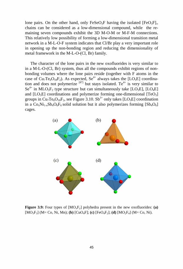
45
lone pairs. On the other hand, only FeSeO3F having the isolated [FeO3F]
chains can be considered as a low-dimensional compound, while the re-
maining seven compounds exhibit the 3D M-O-M or M-F-M connections.
This relatively low possibility of forming a low-dimensional transition metal
network in a M-L-O-F system indicates that Cl/Br play a very important role
in opening up the non-bonding region and reducing the dimensionality of
metal framework in the M-L-O-(Cl, Br) family.
The character of the lone pairs in the new oxofluorides is very similar to
in a M-L-O-(Cl, Br) system, thus all the compounds exhibit regions of non-
bonding volumes where the lone pairs reside (together with F atoms in the
case of Cu7Te6O18F2). As expected, Se4+
always takes the [LO3E] coordina-
tion and does not polymerize [87]
but stays isolated. Te4+
is very similar to
Se4+
in MLO3F2 type structure but can simultaneously take [LO3E], [LO4E]
and [LO5E] coordinations and polymerize forming one-dimensional [TeO3]
groups in Cu7Te6O18F2, see Figure 3.10. Sb3+
only takes [LO3E] coordination
in a CoxNi1-xSb4O6F6 solid solution but it also polymerizes forming [Sb4O6]
cages.
Figure 3.9: Four types of [MOxFy] polyhedra present in the new oxofluorides: (a)
[MO3F3] (M= Co, Ni, Mn); (b) [CuO4F]; (c) [FeO4F2]; (d) [MO2F4] (M= Co, Ni).

46
Figure 3.10: The group of [Te6O18] in which Te4+
simultaneously takes [TeO3E],
[TeO4E] and [TeO5E] coordinations in Cu7Te6O18F2.
3.1.6 New oxochlorides synthesized from low temperature
CTR
In this work, hydrothermal synthesis has proved to be a key synthesis tech-
nique for exploring chemical systems, finding new oxofluorides and getting
phase pure samples while low temperature CTR is a suitable alternative for
synthesizing high quality single crystals once hydrothermal method fails. On
the other hand, low temperature CTR is also a promising technique for ex-
ploring new oxochlorides and oxobromides at a relatively low temperature
range where the common CTR is not available. Three new compounds,
Fe6Ca2Se9O27Cl4, H2FeSeClO4 and H3NiSeClO4 have been synthesized via
the modified CTR at 200 °C. The detailed synthetic procedures have been
mentioned in section 2.
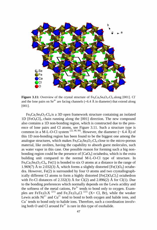
47
Figure 3.11: Overview of the crystal structure of Fe6Ca2Se9O27Cl4 along [001]. Cl-
and the lone pairs on Se4+
are facing channels (6.4 Å in diameter) that extend along
[001].
Fe6Ca2Se9O27Cl4 is a 3D open framework structure containing an isolated
1D [FeO4Cl] chain running along the [001] direction. The new compound
also contains a 1D non-bonding region, which is constructed due to the pres-
ence of lone pairs and Cl atoms, see Figure 3.11. Such a structure type is
common in a M-L-O-Cl system [22, 88, 89]
. However, the diameter (~ 6.4 Å) of
this 1D non-bonding region has been found to be the biggest one among the
analogue structures, which makes Fe6Ca2Se9O27Cl4 close to the micro-porous
material, like zeolites, having the capability to absorb guest molecules, such
as water vapor in this case. One possible reason for forming such a big non-
bonding region could be the presence of [CaO6] octahedra, which is the extra
building unit compared to the normal M-L-O-Cl type of structure. In
Fe6Ca2Se9O27Cl4, Fe(1) is bonded to six O atoms at a distance in the range of
1.969(7) Å to 2.032(3) Å, which forms a slightly distorted [Fe(1)O6] octahe-
dra. However, Fe(2) is surrounded by four O atoms and two crystallograph-
ically different Cl atoms to form a highly distorted [Fe(2)O4Cl2] octahedron
with Fe-Cl distances of 2.332(3) Å for Cl(2) and 2.896(2) Å for Cl(1). Due
to the bonding preferences which normally depends on the Lewis acidity and
the softness of the metal cations, Fe3+
tends to bond only to oxygen. Exam-
ples are FeTe3O7X [21]
and Fe3Te3O10Cl [22]
(X= Cl, Br), while the weaker
Lewis acids Ni2+
and Cu2+
tend to bond to both oxygen and halide ions, and
Cu+ tends to bond only to halide ions. Therefore, such a coordination involv-
ing both O and Cl around Fe3+
is rare in this type of oxohalide.

48
Figure 3.12: Overview of (a) H3NiSeClO4 and (b) H2FeSeClO4 along [010]. The
hydroxyl group and crystal water are protruding from the layers.
Both H2FeSeClO4 and H3NiSeClO4 are layered compounds in which the
hydroxyl groups or crystal water are protruding from the layers in addition to
Cl and Se, see Figure 3.12. Besides the very similar formulas, H2FeSeClO4
and H3NiSeClO4 have the same number of respective non-hydrogen atoms as
well. The BVS values for each atom in both compounds are shown in Table
3.4. According to the BVS calculations, O(1) in H2FeSeClO4 and O(3) in
H3NiSeClO4 have been assigned as crystal water due to the very low BVS
values while O(1) in H3NiSeClO4 has been identified as a hydroxyl group,
which has the medium BVS value between crystal water and a common ox-
ygen anion. The transition metals occupy the unique crystallographic posi-
tion in the respective structure forming of the [FeO5Cl] and [NiO4Cl2] octa-
hedron. The greater amount Cl- in the coordination sphere of Ni
2+ compared
to Fe3+
can be explained since Ni2+
is a weaker Lewis acid. Two [FeO5Cl]
connect to each other by edge sharing through a [O…O] edge, giving rise to
the [FeO4Cl] dimer while the [NiO3Cl] chain is formed by the edge sharing

49
of [NiO4Cl2] through both [O…O] and [Cl…Cl], alternatively. The [FeO4Cl]
dimer and [NiO3Cl] chain are both connected by the isolated [SeO3] group
resulting in the different inner-layer structures in H2FeSeClO4 and
H3NiSeClO4, respectively. Therefore, H2FeSeClO4 can be considered as a
zero-dimensional compound due to the isolated [FeO5Cl] dimers, while
H3NiSeClO4 is actually to be considered as a one-dimensional compound
because of the separated [NiO3Cl] chain-like arrangement.
H2FeSeClO4 BVS H3NiSeClO4 BVS
Se(1) 4.02 Se(1) 3.95
Fe(1) 3.00 Ni(1) 2.01
Cl(1) 0.53 Cl(1) 0.69
O(1) 0.38 O(1) 1.14
O(2) 2.05 O(2) 2.03
O(3) 2.00 O(3) 0.32
O(4) 2.06 O(4) 1.77
Table 3.4: Bond valence sum calculations for the non-hydrogen atoms in
H2FeSeClO4 and H3NiSeClO4, respectively.
3.2 Mixing fluorine and chlorine
In oxohalides of the M-L-O-(Cl, Br) system, the crystal structures are
opened up by the lone pairs that occupy a space similar to an oxygen atom
and also by the halide ions (Cl-, Br
-) that most often form only one bond to a
metal ion and therefore do not contribute to building up a continuous net-
work in the structure. In this work, attempts were made to further modify M-
L-O-Cl types of compounds by involving fluorine in the synthesis in order to
open up for new types of crystal structures by introducing the very electro-
negative fluorine ion that is mainly a network builder like oxygen but has the
charge -1 instead of -2 in combination with a terminating ion like Cl.

50
3.2.1 Cu7Te5O15FCl2(OH)
The new compound Cu7Te5O15FCl2(OH) was synthesized with the presence
of CuCl2 in the starting mixtures under similar hydrothermal conditions as
for the synthesizing of Cu7Te6O18F2. The crystal structure was preliminarily
solved and refined from powder diffraction data collected at ESRF (Europe-
an Synchrotron Radiation Facility). The structure model was also confirmed
by RED (Rotation Electron Diffraction). The presence of fluorine and a hy-
droxyl group in the structure was confirmed by EDS analysis and IR spectra,
respectively. During the structure refinement, the atomic identifications for
the hydroxyl group and fluorine atom were guided by BVS calculations, in
which the oxygen atom in the OH group had a very low BVS value com-
pared to common oxygen atoms, which indicates that the hydrogen atom
should be included in the coordination sphere. On the other hand, the fluo-
rine atom showed the value of 0.85, which is close to the expected value 1.
Figure 3.13: Overview of Cu7Te5O15FCl2(OH) along the [100] direction. The hy-
droxyl groups are protruding from the layers and are also connecting the adjacent
layers.

51
Figure 3.14: Two mirror-related [CuO4FCl] octahedra connect to each other by
corner sharing at an F atom forming a [Cu2O8FCl2] dimer. The F atom is located at
the mirror plane.
The structure of Cu7Te5O15FCl2(OH) can be described as the quasi-2D
layered structure with strong covalent/ionic bonds within the layers. Never-
theless, instead of the very weak van der Waal interactions between the lay-
ers in typical 2D M-L-O-Cl structure, the hydroxyl group is in between the
layers and attached to both Te atoms in adjacent layers, see Figure 3.13. The
Te atoms attached by hydroxyl groups have also been observed in other
compounds e.g. Co3Te2O2(PO4)2(OH)4[90]
. Compared to common M-L-O-Cl
compounds, the feature of this structure is that the fluorine is presented with-
in the layers acting as the bringing ion forming the special Cu-F-Cu connec-
tion, see Figure 3.14. Therefore, the character of fluorine remained as that in
M-L-O-F system instead of occupying the same position with chlorine, alt-
hough chlorine and bromine occupying the same position has often been
observed in the M-L-O-(Cl, Br) family[72,91,92]
.
3.2.2 New compounds synthesized under the “catalysis” of
fluorine
The combination of fluorine and chlorine was also attempted by using chem-
ical transport reactions. Unfortunately, no compounds containing both fluo-
rine and chlorine have been identified. However, the fluorine, to some ex-
tent, acted as the “catalyst” and some new phases in the M-L-O-Cl system
were obtained through the “catalysis” of fluorine in the reaction system.
Ni5Te4O12Cl2 is a 2D layered compound synthesized from the starting
materials of NiO, NiCl2 and TeO2 using a chemical transport reaction at
450°C [72]
. By adding a small amount of additional NiF2, however, a new

52
layered oxochloride Ni5Te4O11Cl4, with a completely different crystal struc-
ture, was obtained instead of Ni5Te4O12Cl2 under the same synthetic condi-
tions. Futhermore, another new phase, Ni3Te2O5Cl4, could be obtained by
further increasing the temperature up to 550°C with NiF2 in the starting ma-
terials. However, only Ni5Te4O12Cl2 was presented without a fluorine source
even at 550 °C, indicating that fluorine, not temperature, is the main reason
that caused the formation of the new phase instead of Ni5Te4O12Cl2. The
detailed mechanism of the role of fluorine is still unclear.
Figure 3.15: Comparisons between (a) single layer of transition metal network and
(b) the layer-packing in Co5Te4O11Cl4 and Ni5Te4O11Cl4.

53
A comparison between the crystal structure of the new phase
Ni5Te4O11Cl4 synthesized at 500 °C and the previously known compound
Co5Te4O11Cl4 [93]
was made because of their similar formula, which indicates
there might be large structural similarities. By showing only the transition
metal network, exactly the same transition metal connection in the single
layer of Ni- and Co-network was observed, see Figure 3.15(a). However, the
different packing of layers can be noted in the side-view of layers, which
shows the extra displacement during the packing in the case of
Co5Te4O11Cl4. One can also note that each layer in Ni5Te4O11Cl4 is actually
the rotational object of the adjacent layer when chlorine atoms are shown for
comparison, see Figure 3.15(b).

54
4 Summary and Conclusions
Several new oxofluorides in the system M-L-O-F (M = transition metal cati-
ons such as Mn2+
, Co2+
, Ni2+
, Fe3+
and Cu2+
, L= p-block lone pair elements
such as Te4+
, Se4+
, or Sb3+
) have been synthesized and structurally character-
ized via single crystal X-ray diffraction.
The synthetic technique
Conventional chemical transport reaction (CTR) was chosen for the syn-
thesis at the initial stage of this work. However, no target phase could be
obtained or identified due to the side reactions between fluorine and the sili-
ca reaction container. The modified synthetic method means that hydrofluor-
ic acid was used as transport agent, which lead to that the transport reactions
take place at a much lower temperature compared to the conventional meth-
od. The modified synthetic route can thus simultaneously both reduce the
side reactions and improve the possibility of forming single crystals of in-
tended compositions which is a great benefit for the crystal structure solution
process. Furthermore, the new method is also suitable in order to explore the
M-L-O-(Cl, Br) system in a relatively low temperature-zone where conven-
tional chemical transport is difficult to reach. Several new compounds were
successfully synthesized from the modified CTR including Co2SeO3F2,
Co2TeO3F2, H2FeSeClO4, H3NiSeClO4 and Fe6Ca2Se9O27Cl4.
Despite the enhanced probability for finding new oxofluorides via low
temperature CTR, it should be noted that the yield of target compounds are
often too low for characterization of physical properties. Therefore, hydro-
thermal reaction was selected as an alternative method to synthesize larger
amounts of new compounds. In fact, a hydrothermal reaction is not the best
method for exploring the M-L-O-(Cl, Br) system due to the very high solu-
bility of metal chlorides/bromides in water. However, fortunately it is feasi-
ble to use hydrothermal reactions to synthesize M-L-O-F types of com-
pounds since the solubility of metal fluorides in water are much lower and
closer to the solubility of the lone-pair element oxides; e.g. the compound
Co2SeO3F2 and its isostructural companions Ni2SeO3F2 and Mn2SeO3F2 were
successfully obtained via hydrothermal reactions. In addition, much larger
crystals of oxofluoride crystals compared to what CTR can yield can easily

55
be synthesized; some examples are Cu7Te6O18F2 and the CoxNi1-xSb4O6F6
solid solution.
The structural features of M-L-O-F compounds
Due to presence of the stereochemically active lone pairs, all eight new
compounds in the M-L-O-F system show non-bonding volumes which are
one dimensional channels in M2LO3F2 (M= Co, Ni, Mn; L = Se, Te),
FeSeO3F, Cu7Te6O18F2 and zero dimensional cages in CoxNi1-xSb4O6F6 solid
solution. However, except for that FeSeO3F contains isolated one dimen-
sional iron chains, the rest of the compounds exhibit three-dimensional tran-
sition metal networks.
The relatively low probability for forming low-dimensional compounds
can be explained by the very different structural character of fluorine com-
pared to chlorine/bromine. Since fluorine has a similar size and electronega-
tivity as oxygen, it plays the role as a bridging ion rather than being termi-
nating. Therefore, unlike chlorine or bromine, which are often found to be in
the non-bonding region together with the lone pairs acting as counter ions,
fluorine tends to be fully integrated into the covalent network and conse-
quently shows a BVS value close to the expected (~ 1.0 vu). However,
Cu7Te6O18F2 is a special case in which fluorine acts exactly in the same way
as chlorine/bromine being a terminating ion that has a low BVS value (~
0.39).
In general despite the fact that fluorine most often is a bridging atom
there is still a high probability that new compounds in the M-L-O-F system
will show low-dimension transition metal arrangements. However, the non-
bonding region that separates the transition metal connection is then only
due to the presence of lone pairs. Relatively small lone pair cations such as
Se4+
or Te4+
usually form one-dimensional tunnel-like regions while bigger
lone pair cations tend to aggregate together forming two-dimensional slabs
that “slice” the transition metal framework into a 2D layered connection.

56
5 Sammanfattning på svenska
Kemiska bindningar utgörs av delade elektronpar. Det finns dock par av
valenselektroner som endast sitter på en jon och inte deltar i kemisk
bindning med någon annan jon; ett sådant elektronpar brukar kallas för ett
ensamt elektronpar eller ett ”lone-pair”. Ett lone-pair upptar ungefär lika stor
volym som en syreatom och påverkar därför utseendet hos en molekyl eller
en kristallstruktur. Om en katjon har ett lone-pair kan den därför få en
ensidig koordination eller medföra att koordinationspolyedern åtminstone är
kraftigt distorderad. Det är emellertid inte alltid som lone-pair elektroner
som inte deltar i bindning tar plats och är stereokemiskt aktiva; tex 6s2 paret
hos Pb2+
och Bi3+
påverkar inte alltid koordinationsgeometrin kring dessa
centralatomer. Den exakta mekanismen för när lone-pair elektroner är
stereokemiskt aktiva eller ej är inte utredd i detalj och har diskuterats under
flera decennier. Dock är de flesta studier överens om att drivkraften för
bildande av stereokemiskt aktiva lone-pairs till stor del beror på samspelet
mellan katjonens s- och p-orbitaler och anjonens p-orbitaler istället för att
det är en ren hybridisering av s- och p-orbitalerna hos katjonen.
Då katjoner har ett stereokemiskt aktivt lone-pair kan den assymetriska
koordinationen detta ger upphov till leda till ike centrosymmetriska
kristallstrukturer vilka ofta visar symmetriberoende fysikaliska egenskaper
såsom optisk frekvensdubbling, piezoelektricitet, pyroelektricitet eller
ferroelektricitet. Dessutom kan sannolikheten att bilda lågdimensionella
kristallstrukturer ökas genom att kombinera lone-pairkatjoner och halidjoner
(oftast Cl- eller Br
-). Med lågdimensionella kristallstrukturer menar vi tex
skiktade strukturer eller strukturer där vissa atomslag sitter i kedjor eller
kluster och ej i tredimesionella nätverk. En del sådana material kan ha
egenskaper som är typiska för lågdimensionella arrangemang av vissa
atomslag; exempel är supraledning och magnestiskt frustrerade material där
det senare innebär att atomerna på grund av topologin hindras att anta
magneiska kopplingar med lång räckvidd såsom ferromagnetiska eller
antiferromagnetiska kopplingar utan sådana kopplingar störs hela tiden av
hur spinkopplingar kan ske i kristallstrukturen på grund av topologin.
I denna avhandling har åtta nya oxofluorider som innehåller lonepairkatjoner
såsom Se4+
, Te4+
eller Sb3+
samt katjoner av olika övergångsmetaller (Cu2+
,
Ni2+
, Co2+
, Fe3+
) syntetiserats med hydrotermalsyntes. Det har tidigare endast
funnits ett fåtal sådana sådan faser beskrivna på grund av att fluor är så
reaktivt och därför lätt reagerar med degelmaterialet i vilket reaktionen

57
utförs. Detta har också lett till att tidigare har endast ett fåtal sådana faser
kunnat framställas i tillräckligt stor mängd för att deras fysikaliska
egenskaper ska ha kunnat studeras. De flesta likande faser som har studerats
har istället inneållit Cl- eller Br
- på grund av att dessa är betydligt mindre
reaktiva än F-. Det är emellertid en viktig skillnad i de kristallstrukturer som
fås då Cl- och Br
- oftast bara bildar en bindning till en metallkatjon i
kristallstrukturen medan fluoridjonen bidrar till att bygga ett tredimensionellt
nätverk och liksom syre kan fluor binda till flera katjoner. Att studera vad
denna skillnad mellan fluridjoner och övriga halidjoner leder till har varit en
motivering för studien. Bland de nya faserna som beskrivs i detta arbete
finns såväl icke-centrosymmetriska som lågdimensionella kristallstrukturer.
58
6 Acknowledgment
I would like to take this opportunity to thank all the people who helped me
with this thesis and supported me in many different ways during my 4-years
staying in Sweden.
First of all, I would like to start by thanking Mats Johnsson, my supervisor,
for accepting me as a PhD student. Thank you so much for giving me this
greatest opportunity to pursue my dreams. Thank you for your understand-
ing, trust and encouragement for letting me carry out my own ideas. And
also it’s not possible to have this thesis without your kind and patient guid-
ance.
I would also like to thank my co-supervisor Lars Eriksson for introducing
me to the world of crystallography and for many valuable discussions when I
had problems solving crystal structures.
I also want to thank my former supervisor in China, Prof. Jinlong Zhang,
who encouraged me to study abroad.
I would like to thank all the people with whom I have collaborated: Reinhard
Kremer (Max Planck Institute), Peter Lemmens (Technische Universität
Braunschweig) and Angela Möller (University of Houston) et al, thank you
so much for your nice measurements and careful interpretations of data. And
Amber Mace, thanks to your great ELF calculation, the lone pairs in my
structure drawing had never looked so beautiful!
I am very thankful to Xiaodong Zou who kindly introduced me to Mats, I
might even not have the chance to come to Stockholm if it weren’t for you.
I am deeply grateful to Sven Hovmöller for telling me many great stories
about Sweden and even the European history from 1500 to present. Further-
more, thank you for telling me how to be a good father. By the way, my
daughter loves ‘Pippi’ you recommended.
Thanks to my two nice roommates: Iwan Zimmermann and Henrik Svengren
for fruitful discussion about science and many other interesting topics. It has

59
been a really wonderful time with you guys! Thanks to Marian Stingaciu and
Faiz Rabbani who were also in the room C528, your help is unforgettable.
I would also like to thank Hong Chen and Yifeng Yun for collecting electron
diffraction data and thank Jie Su and Sumit Konar for collecting PXRD data
at synchrotron facilities. Thanks to Junliang Sun and Leifeng Liu for giving
valuable suggestions about solving tricky crystallographic problems.
I want to thank to Kjell Jansson for teaching me using the SEM and helping
me patiently with many problems. Thanks Wenming Hao, Zoltán Bacsik and
Ocean Cheung for helping me with the BET measurements.
Thanks to the colleagues at MMK: Bin Qian, Chao Xu, Changjiu Xia,
Cheuk-Wai Tai, Daniel Eklöf, Dickson Ojwang, Daqing Cui, Duan Li, Fei
Peng, Feifei Gao, Ge Yin, Guang Han, Haoquan Zheng, Henrik Fahlquist, Ji
Zou, Jianfeng Hu, Jie Liang, Justin Xu, Liang Fang, Ning Yuan, Peng Guo,
Qingpeng Meng, Reji Nedumkandathil, Samrand Shafeie, Tom Willhammar,
Verina Kranak, Wei Wan, Xin Xia, Yanhang Ma, Yang Shen, Yonglei
Wang, Yuan Zhong, Yunchen Wang, Yunxiang Li. It is my honor to meet all
of you!
I also very appreciate the help from Ann-britt Rönnell, Anita Hjelm, Daniel
Emanuelsson, Anna-karin Olsson, Pia Raninen and Hanna Nyholm. Thanks
to Rolf Eriksson for making my computer run smoothly. Specially thank
Ann-britt for finding apartments for me again and again when I first came to
Stockholm.
Finally I reserve my deepest gratitude to my parents, my wife Shuting for
believing in me and supporting me, and to my little angel Ruiya for making
every second in my life more wonderful.

60
7 References
[1] N.V. Sidgwick, H.M. Powell, Proc. R. Soc. A176 (1940) 153. [2] R.J. Gillespie, R.S. Nyholm, Quart. ReV. London 11 (1957) 339. [3] J. Galy, G. Meunier, S. Andersson, A.J. Astrom, J. Solid State Chem. 13 (1975) 142. [4] S. Andersson, Acta Crystallogr. B35 (1979) 1321. [5] L.E. Orgel, J. Chem. Soc. (1959), 3815. [6] G.W. Watson, S.C. Parker, J. Phys. Chem. B. 103 (1999), 1258. [7] G.W. Watson, S.C. Parker, G. Kresse, Phys. ReV. B. 59 (1999) 8481. [8] A. Walsh, G.W. Watson, J. Phys. Chem. B. 109 (2005) 18868. [9] A. Walsh, G. W. Watson, D. J. Payne, R. G. Edgell, J. H. Guo, P. A. Glans, T. Learmonth, K. E. Smith, Phys. Rev. B: Condens. Matter Mater. Phys. 73 (2006) 235104. [10] J. L. F. Da Silva, A. Walsh, H. Lee, Phys. Rev. B: Condens. Matter Mater. Phys. 78 (2008) 224111. [11] A. Walsh, D.J. Payne, R.G. Egdell, G.W. Watson, Chem. Soc. Rev. 40 (2011) 4455. [12] M.W. Stoltzfus, P.M. Woodward, R. Seshadri, J-H. Klepeis, B. Bursten Inorg. Chem. 46 (2007) 3839. [13] P. A. Franken, A. E. Hill, C. W. Peters, G. Wienrich, Phys. Rev. Lett. 7 (1961) 118. [14] J. Curie, P. Curie, Bull. Soc. Min de France. 3 (1880) 90. [15] G.A. Smolenskii, V.A. Bokov, V.A. Isupov, N.N. Krainik, R.E. Pasinkov, I.A. Sokolov, Ferroelectrics and Related, Materials Gor don and Breach Science Publishers: New York (1984).

61
[16] F. Jona, G. Shirane, Ferroelectric Crystals, Pergamon Press: New York (1962). [17] J.F. Nye, Physical Properties of Crystals, Oxford University Press: Oxford, U.K. (1957). [18] S. Ishiwata, Y. Tokunaga, Y. Taguchi, Y. Tokura, J. Am. Chem. Soc. 133 (2011) 13818. [19] R. Becker, M. Johnsson, R. Kremer, P. Lemmens, J. Solid State Chem. 178 (2005) 2024. [20] R. Becker, H. Berger, M. Johnsson, M. Prester, Z. Marohnic, M. Miljak, M. Herak, J. Solid State Chem. 179 (2006) 836. [21] D. Zhang, R.K. Kremer, P. Lemmens, K.-Y. Choi, J. Liu, M.-H. Whangbo, H. Berger, Y. Skourski, M. Johnsson, Inorg. Chem. 50 (2011) 12877. [22] D. Zhang, M. Johnsson, H. Berger, R.K. Kremer, D. Wulferding, P. Lemmens, Inorg. Chem. 48 (2009) 6599. [23] H-L. Jiang, J-G. Mao, Inorg. Chem. 45 (2006) 7593. [24] D. Zhang, M. Johnsson, S. Lidin, R.K. Kremer, Dalton Trans. 42 (2013) 1394. [25] J-G. Mao, H-L. Jiang., F. Kong, Inorg. Chem. 47 (2008) 8498. [26] Ö. Rapp. Supraledning. Göteborg: Almqvist & Wiksell International (1992). [27] Y. Zhao, H. Zhang, T. Zhang, Q. Zhang, Wuli Xuebao 38 (1989) 607. [28] F.H. Aidoudi, D.W. Aldous, R.J. Goff, A.M.Z. Slawin, J.P Attfield, R.E. Morris, P. Lighfoot, Nature Chemistry 3 (2011) 801. [29] Tian-Heng Han, Joel S. Helton, Shaoyan Chu, Daniel G. Nocera, Jose A. Rodriguez-Rivera, Collin Broholm and Young S. Lee, Nature 492 (2012) 406 [30] J.-M. Dance, A. Tressaud, Inorganic Solid Fluorides: Chemistry and Physics, Hagenmuller, P. Ed.; Academic Press: Orlando, FL, (1985). [31] A. Seidel, C. A. Marianetti, F. C. Chou, G. Ceder, P. A. Lee, Phys. Rev. B. 67 (2003) 020405(R).

62
[32] T. Saha-Dasgupta, R. Valenti, H. Rosner, C. Gros, Europhys.Lett. 67 (2004) 63. [33] M. Shaz, S. van Smaalen, L. Palatinus, M. Hoinkis, M. Klemm, S. Horn, R. Claessen, Phys. Rev. B. 71 (2005) 100405. [34] M. Poulain, J. Lucas, R.J.D. Tilley, J. Solid State Chem. 17 (1976) 331. [35] L.K. Frevel, H.W. Rinn, Acta Crystallogr. 9 (1956) 626. [36] K. Vorres, J. Donohue, Acta Crystallogr. 8 (1955) 25. [37] R. Sabatier, M. Wathle, J.P. Besse, G. Baud, J. Inorg. Nucl. Chem. 33 (1971) 1597. [38] C. Lipp, T. Schleid, Z. Anorg. Allg. Chem. 634 (2008) 657. [39] A.J. Edwards, G.R. Jones, J. Chem. Soc. A. (1969) 2858. [40] J.P. Laval, N.J. Boukharrata, P. Thomas, Acta Crystallogr C 64 (2008) i12 [41] N.J. Boukharrata, J.P. Laval, P. Thomas, Acta Crystallogr C 64 (2008) i53. [42] N.J. Boukharrata, J.P. Laval, P. Thomas, Acta Crystallogr C 69 (2013) 460. [43] N.J. Boukharrata, J.P. Laval, Journal of Alloys Compd. 509 (2011) 1517. [44] J.P. Laval, N.J. Boukharrata, Acta Crystallogr C 65 (2009) i1. [45] K. Dihlstroem, A. Westgren, Z. Anorg. Allg. Chem. 235 (1937) 153. [46] A.M. Abakumov, D. Batuk, A.A. Tsirlin, C. Prescher, L. Dubrovinsky, D.V. Sheptyakov, W. Schnelle, J. Hadermann, G.V. Tendeloo, Phys. Rev. B. 87 (2013) 024423. [47] R.L. Needs, S.E. Dann, M.T. Weller, J.C. Cherryman, R.K. Harris, J. Mater. Chem. 15 (2005) 2399. [48] A.V. Akopjan, T.V. Serov, V.A. Dolgikh, E.I. Ardashnikova, P. Lightfoot, J. Mater. Chem. 12 (2002) 1490. [49] M. Colmont, M. Huve, E.M. Ketatni, O. Mentre, Eur. J. Inorg. Chem.
63
5 (2008) 533. [50] Y. Inaguma, J.M. Greneche, M.P. Crosnier-Lopez, T. Katsumata, Y. Calage, J.L. Fourquet, Chem. Mater. 17 (2005) 1386. [51] T. Katsumata, M. Nakashima, H. Umemoto, Y. Inaguma, J. Solid State Chem. 181 (2008) 2737. [52] A.V. Knyazev, N.G. Chernorukov, E.N. Bulanov, Mater. Chem. Phys. 132 (2012) 773. [53] O. Savborg, M. Lundberg, J. Solid State Chem. 57 (1985) 135. [54] O. Savborg, J. Solid State Chem. 57 (1985) 143. [55] A. Mikou, J.P. Laval, B. Frit, Revue de Chimie Minerale 22 (1985) 115. [56] S.C. Abrahams, P. Marsh, J. Ravez, J. Chem. Phys. 87 (1987) 6012. [57] O. Savborg, J. Solid State Chem. 57 (1985) 148. [58] J.P. Laval, B. Frit, Revue de Chimie Minerale 20 (1983) 368. [59] O. Savborg, J. Solid State Chem. 57 (1985) 154 . [60] I.E. Rakov, Yu.E Gorbunova, Yu.V. Kokunov, Yu.N. Mikhailov, Coordination Chemistry (USSR) 19 (1993) 759. [61] L. Pauling, J. Am. Chem. Soc. 51 (1929) 1010. [62] I.D. Brown, The Chemical Bond in Inorganic Chemistry: The Bond Valence Model, Oxford University Press, New York (2002). [63] H. Schäfer, Chemical Transport Reactions, Academic press Inc., New York (1964). [64] H.-L. Jiang, J.-G. Mao, Inorg. Chem. 45 (2006) 7593. [65] C. Sun, C. Hu, X. Xu, J. Ling, T. Hu, F. Kong, X. Long, J. Mao, J. Am. Chem. Soc. 131 (2009) 9486. [66] J. Kim, J. Baek, P.S. Halasyamani, Chem. Mater. 19 (2007) 5637. [67] S. Ishiwata, Y. Tokunaga, Y. Taguchi, Y. Tokura, J. Am. Chem. Soc. 133 (2011) 13818.
64
[68] L. Jian, D. Juan, N.C. Justin, M.V. Eric, E.A-S. Thomas, Inorg. Chem. 51 (2012) 10083. [69] G. M. Sheldrick, Acta Cryst. A64 (2008) 112. [70] V. Petricek, M. Dusek and L. Palatinus. JANA 2006: The Crystallographic Computing System, Institute of Physics: Praha, Czech Republic. [71] S. Hu, M. Johnsson, Dalton Trans. 41 (2012) 12786. [72] M. Johnsson, K.W. Törnroos, P. Lemmens, P. Millet, Chem. Mater. 15 (2003) 68. [73] Y. Shen, J. Mao, H. Jiang, J. Solid State Chem. 178 (2005) 2942. [74] C. Svensson, Acta Cryst. B31 (1975) 2016. [75] Z. Mayerova, M. Johnsson, S. Lidin, J. Solid State Chem. 178 (2005) 3471. [76] J.R. Rea, E. Kostiner, Acta Crystallogr B 28 (1972) 2525. [77] L.P, Zenser, R. Gruehn, M. Weil, Z. Anorg. Allg. Chem. 626 (2000) 871. [78] O.V. Yakubovich, O.K. Mel'nikov, Soviet Physics, Crystallography 36 (1991) 174. [79] F. Sanz, C. Parada, C. Ruiz Valero, J. Mater. Chem. 11 (2001) 208. [80] M. Reynaud, P. Barpanda, G. Rousse, J.N. Chotard, B.C. Melot, N. Recham, J.M. Tarascon, Solid State Sci. 14 (2012) 15. [81] P. Barpanda, N. Recham, J.N. Chotard, K. Djellab, W. Walker, M. Armand, J.M. Tarascon, J. Mater. Chem. 20 (2010) 1659. [82] M. Dutreilh, C. Chevalier, M.E. Ghozzi, D. Avignant, J. Solid State Chem. 142 (1999) 1. [83] M. Ati, L. Dupont, N. Recham, J.N. Chotard, W.T. Walker, C. Davoisne, P. Barpanda, V. Sarou Kanian, M. Armand, J.M. Tarascon, Chem. Mater. 22 (2010) 4062. [84] M. Ramzan, S. Lebegue, R. Ahuja, Phys. Rev., Serie 3. B – Condensed Matter 82 (2010) 125101-1-5.

65
[85] R.L. Withers, F.J. Brink, Y. Liu; L. Noren., Polyhedron 26 (2007) 290. [86] F.J. Brink, R.L. Withers, G. John, G. Thompson., J. Solid State Chem. 155 (2000) 359. [87] J.-G. Mao, H.-L. Jiang, F. Kong, Inorg. Chem. 47 (2008), 8498. [88] H-L. Jiang, J-G. Mao, Inorg. Chem. 45 (2006) 7593. [89] D. Zhang, M. Johnsson, S. Lidin and R.K. Kremer, Dalton Trans. 42 (2013) 1394. [90] I. Zimmermann, R.K. Kremer, M. Johnsson, J. Solid State Chem. 184 (2011) 3080. [91] R. Becker, H. Berger, M. Johnsson, M. Prester, Z. Marohnic, M. Miljak, M. Herak, J. Solid State Chem. 179 (2006) 836. [92] R. Becker, M. Prester, H. Berger, PH. Lin, M. Johnsson, D. Drobac, I. Zivkovic, J. Solid State Chem. 180 (2007) 1051. [93] R. Becker, M. Johnsson, H. Berger, Z. Anorg. Allg. Chem. 633 (2007) 422.
Copyright © 2022 FDOKUMEN