
Transformer protection RET650 Version 2.1 Application manual
288
— RELION® 650 SERIES Transformer protection RET650 Version 2. 1 Application manual
-
Upload
khangminh22 -
Category
Documents
-
view
1 -
download
0
Transcript of Transformer protection RET650 Version 2.1 Application manual
— RELION® 650 SERIES
Transformer protection RET650 Version 2.1 Application manual


Document ID: 1MRK 504 158-UENIssued: March 2019
Revision: AProduct version: 2.1
© Copyright 2016 ABB. All rights reserved

Copyright
This document and parts thereof must not be reproduced or copied without writtenpermission from ABB, and the contents thereof must not be imparted to a third party, norused for any unauthorized purpose.
The software and hardware described in this document is furnished under a license and maybe used or disclosed only in accordance with the terms of such license.
This product includes software developed by the OpenSSL Project for use in the OpenSSLToolkit. (http://www.openssl.org/) This product includes cryptographic software written/developed by: Eric Young ([email protected]) and Tim Hudson ([email protected]).
Trademarks
ABB and Relion are registered trademarks of the ABB Group. All other brand or product namesmentioned in this document may be trademarks or registered trademarks of their respectiveholders.
Warranty
Please inquire about the terms of warranty from your nearest ABB representative.

Disclaimer
The data, examples and diagrams in this manual are included solely for the concept or productdescription and are not to be deemed as a statement of guaranteed properties. All personsresponsible for applying the equipment addressed in this manual must satisfy themselves thateach intended application is suitable and acceptable, including that any applicable safety orother operational requirements are complied with. In particular, any risks in applications wherea system failure and/or product failure would create a risk for harm to property or persons(including but not limited to personal injuries or death) shall be the sole responsibility of theperson or entity applying the equipment, and those so responsible are hereby requested toensure that all measures are taken to exclude or mitigate such risks.
This document has been carefully checked by ABB but deviations cannot be completely ruledout. In case any errors are detected, the reader is kindly requested to notify the manufacturer.Other than under explicit contractual commitments, in no event shall ABB be responsible orliable for any loss or damage resulting from the use of this manual or the application of theequipment.

Conformity
This product complies with the directive of the Council of the European Communities on theapproximation of the laws of the Member States relating to electromagnetic compatibility(EMC Directive 2004/108/EC) and concerning electrical equipment for use within specifiedvoltage limits (Low-voltage directive 2006/95/EC). This conformity is the result of testsconducted by ABB in accordance with the product standard EN 60255-26 for the EMC directive,and with the product standards EN 60255-1 and EN 60255-27 for the low voltage directive. Theproduct is designed in accordance with the international standards of the IEC 60255 series.

Table of contents
Section 1 Introduction....................................................................................................... 111.1 This manual........................................................................................................................................111.2 Intended audience............................................................................................................................ 111.3 Product documentation..................................................................................................................121.3.1 Product documentation set.......................................................................................................121.3.2 Document revision history......................................................................................................... 131.3.3 Related documents......................................................................................................................131.4 Document symbols and conventions...........................................................................................141.4.1 Symbols......................................................................................................................................... 141.4.2 Document conventions...............................................................................................................151.5 IEC 61850 edition 1 / edition 2 mapping..................................................................................... 15
Section 2 Application.........................................................................................................192.1 General IED application...................................................................................................................192.2 Main protection functions............................................................................................................. 202.3 Back-up protection functions....................................................................................................... 202.4 Control and monitoring functions................................................................................................ 212.5 Communication................................................................................................................................ 232.6 Basic IED functions..........................................................................................................................24
Section 3 Configuration.................................................................................................... 273.1 Description of configuration RET650.......................................................................................... 273.1.1 Introduction.................................................................................................................................. 273.1.1.1 Description of A05....................................................................................................................27
Section 4 Analog inputs.................................................................................................... 294.1 Introduction...................................................................................................................................... 294.2 Setting guidelines............................................................................................................................294.2.1 Setting of the phase reference channel..................................................................................294.2.1.1 Example......................................................................................................................................294.2.2 Setting of current channels.......................................................................................................304.2.2.1 Example 1...................................................................................................................................304.2.2.2 Example 2................................................................................................................................... 314.2.2.3 Example 3................................................................................................................................... 324.2.2.4 Examples on how to connect, configure and set CT inputs for most commonly
used CT connections............................................................................................................... 344.2.2.5 Example on how to connect a star connected three-phase CT set to the IED............ 354.2.2.6 Example how to connect delta connected three-phase CT set to the IED...................394.2.2.7 Example how to connect single-phase CT to the IED....................................................... 414.2.3 Relationships between setting parameter Base Current, CT rated primary
current and minimum pickup of a protection IED................................................................ 424.2.4 Setting of voltage channels.......................................................................................................43
Table of contents
1Application manual

4.2.4.1 Example......................................................................................................................................434.2.4.2 Examples how to connect, configure and set VT inputs for most commonly
used VT connections............................................................................................................... 434.2.4.3 Examples on how to connect a three phase-to-earth connected VT to the IED......... 444.2.4.4 Example on how to connect a phase-to-phase connected VT to the IED.....................464.2.4.5 Example on how to connect an open delta VT to the IED for high impedance
earthed or unearthed netwoeks........................................................................................... 484.2.4.6 Example how to connect the open delta VT to the IED for low impedance
earthed or solidly earthed power systems......................................................................... 494.2.4.7 Example on how to connect a neutral point VT to the IED...............................................51
Section 5 Local HMI........................................................................................................... 555.1 Display................................................................................................................................................565.2 LEDs.................................................................................................................................................... 575.3 Keypad............................................................................................................................................... 585.4 Local HMI functionality...................................................................................................................605.4.1 Protection and alarm indication.............................................................................................. 605.4.2 Parameter management ........................................................................................................... 615.4.3 Front communication................................................................................................................. 61
Section 6 Differential protection.....................................................................................636.1 Transformer differential protection T3WPDIF ..........................................................................636.1.1 Application....................................................................................................................................636.1.2 Setting guidelines....................................................................................................................... 646.1.2.1 Restrained and unrestrained differential protection....................................................... 646.1.2.2 Elimination of zero sequence currents................................................................................666.1.2.3 Inrush restraint methods........................................................................................................676.1.2.4 Overexcitation restraint method.......................................................................................... 676.1.2.5 Cross-blocking between phases........................................................................................... 676.1.2.6 External/Internal fault discriminator...................................................................................686.1.2.7 Differential current alarm.......................................................................................................696.1.2.8 Open CT detection...................................................................................................................696.1.2.9 Switch onto fault feature........................................................................................................706.1.3 Setting example...........................................................................................................................706.1.3.1 Introduction.............................................................................................................................. 706.1.3.2 Typical main CT connections for transformer differential protection.......................... 716.1.3.3 Application Examples.............................................................................................................. 726.1.3.4 Summary and conclusions......................................................................................................766.2 Low impedance restricted earth fault protection REFPDIF ................................................... 786.2.1 Identification................................................................................................................................ 786.2.2 Application....................................................................................................................................786.2.2.1 Transformer winding, solidly earthed..................................................................................796.2.2.2 Transformer winding, earthed through zig-zag earthing transformer........................ 806.2.2.3 Autotransformer winding, solidly earthed..........................................................................816.2.2.4 Reactor winding, solidly earthed.......................................................................................... 826.2.2.5 CT earthing direction.............................................................................................................. 836.2.3 Setting guidelines....................................................................................................................... 83
Table of contents
2Application manual

6.2.3.1 Setting and configuration...................................................................................................... 836.2.3.2 Settings......................................................................................................................................84
Section 7 Current protection........................................................................................... 857.1 Instantaneous phase overcurrent protection PHPIOC ............................................................857.1.1 Identification................................................................................................................................857.1.2 Application....................................................................................................................................857.1.3 Setting guidelines....................................................................................................................... 857.1.3.1 Meshed network without parallel line..................................................................................867.1.3.2 Meshed network with parallel line........................................................................................887.2 Four step phase overcurrent protection OC4PTOC................................................................. 897.2.1 Identification................................................................................................................................897.2.2 Application....................................................................................................................................897.2.3 Setting guidelines....................................................................................................................... 907.2.3.1 Settings for each step............................................................................................................. 917.2.3.2 2nd harmonic restrain.............................................................................................................947.3 Instantaneous residual overcurrent protection EFPIOC .........................................................987.3.1 Identification................................................................................................................................997.3.2 Application....................................................................................................................................997.3.3 Setting guidelines....................................................................................................................... 997.4 Four step residual overcurrent protection EF4PTOC ............................................................ 1017.4.1 Identification.............................................................................................................................. 1017.4.2 Application.................................................................................................................................. 1017.4.3 Setting guidelines..................................................................................................................... 1037.4.3.1 Settings for each step (x = 1, 2, 3 and 4)............................................................................ 1037.4.3.2 Common settings for all steps............................................................................................1057.4.3.3 2nd harmonic restrain........................................................................................................... 1067.4.3.4 Parallel transformer inrush current logic.......................................................................... 1067.4.3.5 Switch onto fault logic.......................................................................................................... 1077.4.3.6 Transformer application example...................................................................................... 1087.5 Sensitive directional residual overcurrent and power protection SDEPSDE .....................1117.5.1 Identification............................................................................................................................... 1117.5.2 Application...................................................................................................................................1117.5.3 Setting guidelines...................................................................................................................... 1137.6 Thermal overload protection, two time constants TRPTTR ................................................. 1197.6.1 Identification.............................................................................................................................. 1207.6.2 Application.................................................................................................................................. 1207.6.3 Setting guideline........................................................................................................................ 1217.7 Breaker failure protection CCRBRF.............................................................................................1227.7.1 Identification.............................................................................................................................. 1237.7.2 Application.................................................................................................................................. 1237.7.3 Setting guidelines......................................................................................................................1237.8 Directional underpower protection GUPPDUP........................................................................ 1267.8.1 Identification.............................................................................................................................. 1267.8.2 Application.................................................................................................................................. 1267.8.3 Setting guidelines...................................................................................................................... 127
Table of contents
3Application manual
7.9 Directional overpower protection GOPPDOP .......................................................................... 1317.9.1 Identification...............................................................................................................................1317.9.2 Application...................................................................................................................................1317.9.3 Setting guidelines......................................................................................................................1337.10 Broken conductor check BRCPTOC ........................................................................................... 1367.10.1 Identification.............................................................................................................................. 1367.10.2 Application.................................................................................................................................. 1367.10.3 Setting guidelines......................................................................................................................136
Section 8 Voltage protection..........................................................................................1378.1 Loss of voltage check LOVPTUV .................................................................................................1378.1.1 Identification.............................................................................................................................. 1378.1.2 Application.................................................................................................................................. 1378.1.3 Setting guidelines......................................................................................................................1378.1.3.1 Advanced users settings....................................................................................................... 137
Section 9 Multipurpose protection................................................................................1399.1 General current and voltage protection CVGAPC....................................................................1399.1.1 Identification.............................................................................................................................. 1399.1.2 Application.................................................................................................................................. 1399.1.2.1 Current and voltage selection for CVGAPC function...................................................... 1409.1.2.2 Base quantities for CVGAPC function................................................................................ 1429.1.2.3 Application possibilities....................................................................................................... 1429.1.2.4 Inadvertent generator energization................................................................................... 1439.1.3 Setting guidelines..................................................................................................................... 1449.1.3.1 Directional negative sequence overcurrent protection................................................. 1449.1.3.2 Negative sequence overcurrent protection......................................................................1459.1.3.3 Generator stator overload protection in accordance with IEC or ANSI standards...1479.1.3.4 Open phase protection for transformer, lines or generators and circuit
breaker head flashover protection for generators......................................................... 1499.1.3.5 Voltage restrained overcurrent protection for generator and step-up
transformer............................................................................................................................. 1509.1.3.6 Loss of excitation protection for a generator..................................................................150
Section 10 Secondary system supervision..................................................................... 15310.1 Fuse failure supervision FUFSPVC.............................................................................................. 15310.1.1 Identification.............................................................................................................................. 15310.1.2 Application.................................................................................................................................. 15310.1.3 Setting guidelines..................................................................................................................... 15410.1.3.1 General......................................................................................................................................15410.1.3.2 Setting of common parameters..........................................................................................15410.1.3.3 Negative sequence based.....................................................................................................15410.1.3.4 Zero sequence based.............................................................................................................15510.1.3.5 Delta U and delta I ................................................................................................................. 15610.1.3.6 Dead line detection................................................................................................................ 156
Section 11 Control..............................................................................................................15711.1 Synchrocheck, energizing check, and synchronizing SESRSYN............................................ 157
Table of contents
4Application manual

11.1.1 Identification.............................................................................................................................. 15711.1.2 Application examples................................................................................................................15711.1.2.1 Single circuit breaker with double busbar, external voltage selection....................... 15811.1.2.2 Single circuit breaker with double busbar, internal voltage selection........................ 15811.1.3 Setting guidelines......................................................................................................................15911.2 Apparatus control APC..................................................................................................................16311.2.1 Application.................................................................................................................................. 16311.2.1.1 Bay control (QCBAY).............................................................................................................. 16611.2.1.2 Switch controller (SCSWI)..................................................................................................... 16711.2.1.3 Switches (SXCBR/SXSWI)..................................................................................................... 16811.2.1.4 Reservation function (QCRSV and RESIN)......................................................................... 16811.2.2 Interaction between modules................................................................................................. 17011.2.3 Setting guidelines...................................................................................................................... 17111.2.3.1 Bay control (QCBAY)...............................................................................................................17111.2.3.2 Switch controller (SCSWI)..................................................................................................... 17211.2.3.3 Switch (SXCBR/SXSWI)..........................................................................................................17311.2.3.4 Bay Reserve (QCRSV)..............................................................................................................17311.2.3.5 Reservation input (RESIN).....................................................................................................17311.3 Logic rotating switch for function selection and LHMI presentation SLGAPC................. 17311.3.1 Identification.............................................................................................................................. 17311.3.2 Application.................................................................................................................................. 17311.3.3 Setting guidelines......................................................................................................................17411.4 Selector mini switch VSGAPC...................................................................................................... 17411.4.1 Identification.............................................................................................................................. 17411.4.2 Application.................................................................................................................................. 17411.4.3 Setting guidelines......................................................................................................................17511.5 Generic communication function for Double Point indication DPGAPC.............................17511.5.1 Identification.............................................................................................................................. 17511.5.2 Application.................................................................................................................................. 17511.5.3 Setting guidelines......................................................................................................................17611.6 Single point generic control 8 signals SPC8GAPC...................................................................17611.6.1 Identification.............................................................................................................................. 17611.6.2 Application.................................................................................................................................. 17611.6.3 Setting guidelines...................................................................................................................... 17711.7 AutomationBits, command function for DNP3.0 AUTOBITS................................................. 17711.7.1 Identification...............................................................................................................................17711.7.2 Application.................................................................................................................................. 17711.7.3 Setting guidelines...................................................................................................................... 17711.8 Single command, 16 signals SINGLECMD.................................................................................. 17711.8.1 Identification.............................................................................................................................. 17811.8.2 Application.................................................................................................................................. 17811.8.3 Setting guidelines......................................................................................................................179
Section 12 Logic................................................................................................................. 18112.1 Tripping logic SMPPTRC ...............................................................................................................18112.1.1 Identification.............................................................................................................................. 181
Table of contents
5Application manual

12.1.2 Application.................................................................................................................................. 18112.1.2.1 Three-phase tripping ............................................................................................................ 18212.1.2.2 Single- and/or three-phase tripping.................................................................................. 18212.1.2.3 Single-, two- or three-phase tripping.................................................................................18312.1.2.4 Lock-out................................................................................................................................... 18412.1.2.5 Blocking of the function block.............................................................................................18412.1.3 Setting guidelines..................................................................................................................... 18412.2 Trip matrix logic TMAGAPC..........................................................................................................18412.2.1 Identification.............................................................................................................................. 18512.2.2 Application.................................................................................................................................. 18512.2.3 Setting guidelines......................................................................................................................18512.3 Logic for group alarm ALMCALH................................................................................................ 18512.3.1 Identification.............................................................................................................................. 18512.3.2 Application.................................................................................................................................. 18512.3.3 Setting guidelines..................................................................................................................... 18612.4 Logic for group alarm WRNCALH................................................................................................18612.4.1 Identification.............................................................................................................................. 18612.4.1.1 Application...............................................................................................................................18612.4.1.2 Setting guidelines.................................................................................................................. 18612.5 Logic for group indication INDCALH......................................................................................... 18612.5.1 Identification.............................................................................................................................. 18612.5.1.1 Application...............................................................................................................................18612.5.1.2 Setting guidelines.................................................................................................................. 18612.6 Configurable logic blocks.............................................................................................................18612.6.1 Application.................................................................................................................................. 18712.6.2 Setting guidelines......................................................................................................................18712.6.2.1 Configuration.......................................................................................................................... 18712.7 Fixed signal function block FXDSIGN.........................................................................................18812.7.1 Identification.............................................................................................................................. 18812.7.2 Application..................................................................................................................................18812.8 Boolean 16 to Integer conversion B16I.......................................................................................18912.8.1 Identification.............................................................................................................................. 18912.8.2 Application..................................................................................................................................18912.9 Boolean to integer conversion with logical node representation, 16 bit BTIGAPC.......... 19012.9.1 Identification..............................................................................................................................19012.9.2 Application..................................................................................................................................19012.10 Integer to Boolean 16 conversion IB16....................................................................................... 19112.10.1 Identification.............................................................................................................................. 19112.10.2 Application.................................................................................................................................. 19212.11 Integer to Boolean 16 conversion with logic node representation ITBGAPC.....................19212.11.1 Identification.............................................................................................................................. 19312.11.2 Application.................................................................................................................................. 19312.12 Elapsed time integrator with limit transgression and overflow supervision TEIGAPC...19412.12.1 Identification.............................................................................................................................. 19412.12.2 Application..................................................................................................................................19412.12.3 Setting guidelines..................................................................................................................... 194
Table of contents
6Application manual

12.13 Comparator for integer inputs - INTCOMP...............................................................................19412.13.1 Identification.............................................................................................................................. 19412.13.2 Application.................................................................................................................................. 19512.13.3 Setting guidelines......................................................................................................................19512.13.4 Setting example......................................................................................................................... 19512.14 Comparator for real inputs - REALCOMP.................................................................................. 19612.14.1 Identification.............................................................................................................................. 19612.14.2 Application..................................................................................................................................19612.14.3 Setting guidelines..................................................................................................................... 19612.14.4 Setting example.........................................................................................................................196
Section 13 Monitoring....................................................................................................... 19913.1 Measurement.................................................................................................................................. 19913.1.1 Identification.............................................................................................................................. 19913.1.2 Application..................................................................................................................................19913.1.3 Zero clamping............................................................................................................................20013.1.4 Setting guidelines......................................................................................................................20113.1.4.1 Setting examples................................................................................................................... 20313.2 Gas medium supervision SSIMG................................................................................................. 20713.2.1 Identification..............................................................................................................................20713.2.2 Application..................................................................................................................................20713.2.3 Setting guidelines..................................................................................................................... 20713.3 Liquid medium supervision SSIML.............................................................................................20813.3.1 Identification..............................................................................................................................20813.3.2 Application................................................................................................................................. 20813.3.3 Setting guidelines..................................................................................................................... 20813.4 Breaker monitoring SSCBR..........................................................................................................20813.4.1 Identification..............................................................................................................................20813.4.2 Application................................................................................................................................. 20913.4.3 Setting guidelines...................................................................................................................... 21113.4.3.1 Setting procedure on the IED............................................................................................... 21113.5 Event function EVENT....................................................................................................................21213.5.1 Identification.............................................................................................................................. 21213.5.2 Application.................................................................................................................................. 21213.5.3 Setting guidelines......................................................................................................................21313.6 Disturbance report DRPRDRE...................................................................................................... 21313.6.1 Identification.............................................................................................................................. 21313.6.2 Application.................................................................................................................................. 21413.6.3 Setting guidelines......................................................................................................................21413.6.3.1 Recording times......................................................................................................................21613.6.3.2 Binary input signals................................................................................................................21713.6.3.3 Analog input signals...............................................................................................................21713.6.3.4 Sub-function parameters......................................................................................................21813.6.3.5 Consideration..........................................................................................................................21813.7 Logical signal status report BINSTATREP................................................................................. 21913.7.1 Identification.............................................................................................................................. 219
Table of contents
7Application manual

13.7.2 Application.................................................................................................................................. 21913.7.3 Setting guidelines......................................................................................................................21913.8 Limit counter L4UFCNT................................................................................................................ 21913.8.1 Identification..............................................................................................................................22013.8.2 Application..................................................................................................................................22013.8.3 Setting guidelines..................................................................................................................... 22013.9 Running hour-meter TEILGAPC...................................................................................................22013.9.1 Identification..............................................................................................................................22013.9.2 Application..................................................................................................................................22013.9.3 Setting guidelines..................................................................................................................... 220
Section 14 Metering...........................................................................................................22314.1 Pulse-counter logic PCFCNT........................................................................................................ 22314.1.1 Identification.............................................................................................................................. 22314.1.2 Application.................................................................................................................................. 22314.1.3 Setting guidelines......................................................................................................................22314.2 Function for energy calculation and demand handling ETPMMTR......................................22414.2.1 Identification..............................................................................................................................22414.2.2 Application..................................................................................................................................22414.2.3 Setting guidelines..................................................................................................................... 225
Section 15 Station communication................................................................................. 22715.1 Communication protocols........................................................................................................... 22715.2 IEC 61850-8-1 communication protocol.................................................................................... 22715.2.1 Application IEC 61850-8-1........................................................................................................ 22715.2.2 Horizontal communication via GOOSE for interlocking GOOSEINTLKRCV................... 22915.2.3 Setting guidelines..................................................................................................................... 22915.2.4 Generic communication function for Single Point indication SPGAPC, SP16GAPC..... 22915.2.4.1 Application.............................................................................................................................. 22915.2.4.2 Setting guidelines.................................................................................................................. 22915.2.5 Generic communication function for Measured Value MVGAPC..................................... 22915.2.5.1 Application.............................................................................................................................. 22915.2.5.2 Setting guidelines.................................................................................................................. 22915.2.6 IEC 61850-8-1 redundant station bus communication - PRP............................................23015.2.6.1 Identification.......................................................................................................................... 23015.2.6.2 Application.............................................................................................................................. 23015.2.6.3 Setting guidelines...................................................................................................................23115.3 LON communication protocol.....................................................................................................23215.3.1 Application.................................................................................................................................. 23215.3.2 MULTICMDRCV and MULTICMDSND......................................................................................23315.3.2.1 Identification...........................................................................................................................23315.3.2.2 Application...............................................................................................................................23315.3.2.3 Setting guidelines.................................................................................................................. 23415.4 SPA communication protocol......................................................................................................23415.4.1 Application..................................................................................................................................23415.4.2 Setting guidelines..................................................................................................................... 23515.5 IEC 60870-5-103 communication protocol............................................................................... 236
Table of contents
8Application manual

15.5.1 Application..................................................................................................................................23615.6 DNP3 Communication protocol.................................................................................................. 24215.6.1 Application..................................................................................................................................242
Section 16 Security............................................................................................................ 24316.1 Authority status ATHSTAT........................................................................................................... 24316.1.1 Application..................................................................................................................................24316.2 Self supervision with internal event list INTERRSIG................................................................24316.2.1 Application..................................................................................................................................24316.3 Change lock CHNGLCK................................................................................................................. 24416.3.1 Application................................................................................................................................. 24416.4 Denial of service DOS....................................................................................................................24416.4.1 Application................................................................................................................................. 24416.4.2 Setting guidelines..................................................................................................................... 245
Section 17 Basic IED functions.........................................................................................24717.1 IED identifiers TERMINALID......................................................................................................... 24717.1.1 Application..................................................................................................................................24717.2 Product information PRODINF....................................................................................................24717.2.1 Application..................................................................................................................................24717.2.2 Factory defined settings..........................................................................................................24717.3 Measured value expander block RANGE_XP.............................................................................24817.3.1 Identification..............................................................................................................................24817.3.2 Application..................................................................................................................................24817.3.3 Setting guidelines..................................................................................................................... 24817.4 Parameter setting groups........................................................................................................... 24917.4.1 Application..................................................................................................................................24917.4.2 Setting guidelines..................................................................................................................... 24917.5 Rated system frequency PRIMVAL............................................................................................. 24917.5.1 Identification..............................................................................................................................24917.5.2 Application..................................................................................................................................24917.5.3 Setting guidelines..................................................................................................................... 25017.6 Summation block 3 phase 3PHSUM...........................................................................................25017.6.1 Application..................................................................................................................................25017.6.2 Setting guidelines..................................................................................................................... 25017.7 Global base values GBASVAL....................................................................................................... 25017.7.1 Identification..............................................................................................................................25017.7.2 Application.................................................................................................................................. 25117.7.3 Setting guidelines......................................................................................................................25117.8 Signal matrix for binary inputs SMBI..........................................................................................25117.8.1 Application.................................................................................................................................. 25117.8.2 Setting guidelines......................................................................................................................25117.9 Signal matrix for binary outputs SMBO ....................................................................................25117.9.1 Application.................................................................................................................................. 25117.9.2 Setting guidelines..................................................................................................................... 25217.10 Signal matrix for mA inputs SMMI..............................................................................................25217.10.1 Application..................................................................................................................................252
Table of contents
9Application manual

17.10.2 Setting guidelines..................................................................................................................... 25217.11 Signal matrix for analog inputs SMAI........................................................................................ 25217.11.1 Application..................................................................................................................................25217.11.2 Frequency values....................................................................................................................... 25217.11.3 Setting guidelines..................................................................................................................... 25317.12 Test mode functionality TESTMODE..........................................................................................25717.12.1 Application..................................................................................................................................25717.12.1.1 IEC 61850 protocol test mode.............................................................................................25817.12.2 Setting guidelines..................................................................................................................... 25917.13 Time synchronization TIMESYNCHGEN.................................................................................... 25917.13.1 Application..................................................................................................................................25917.13.2 Setting guidelines..................................................................................................................... 26017.13.2.1 System time............................................................................................................................ 26017.13.2.2 Synchronization..................................................................................................................... 260
Section 18 Requirements.................................................................................................. 26318.1 Current transformer requirements............................................................................................ 26318.1.1 Current transformer classification........................................................................................ 26318.1.2 Conditions.................................................................................................................................. 26318.1.3 Fault current...............................................................................................................................26418.1.4 Secondary wire resistance and additional load.................................................................. 26418.1.5 General current transformer requirements......................................................................... 26518.1.6 Rated equivalent secondary e.m.f. requirements...............................................................26518.1.6.1 Transformer differential protection.................................................................................. 26518.1.6.2 Distance protection...............................................................................................................26618.1.6.3 Breaker failure protection.................................................................................................... 26718.1.6.4 Restricted earth fault protection (low impedance differential)...................................26818.1.7 Current transformer requirements for CTs according to other standards.................. 27018.1.7.1 Current transformers according to IEC 61869-2, class P, PR........................................ 27018.1.7.2 Current transformers according to IEC 61869-2, class PX, PXR (and old IEC
60044-6, class TPS and old British Standard, class X).................................................... 27118.1.7.3 Current transformers according to ANSI/IEEE................................................................ 27118.2 Voltage transformer requirements............................................................................................ 27218.3 SNTP server requirements............................................................................................................272
Section 19 Glossary............................................................................................................273
Table of contents
10Application manual

Section 1 Introduction
1.1 This manualGUID-AB423A30-13C2-46AF-B7FE-A73BB425EB5F v19
The application manual contains application descriptions and setting guidelines sorted perfunction. The manual can be used to find out when and for what purpose a typical protectionfunction can be used. The manual can also provide assistance for calculating settings.
1.2 Intended audienceGUID-C9B8127F-5748-4BEA-9E4F-CC762FE28A3A v10
This manual addresses the protection and control engineer responsible for planning, pre-engineering and engineering.
The protection and control engineer must be experienced in electrical power engineering andhave knowledge of related technology, such as protection schemes and communicationprinciples.
1MRK 504 158-UEN A Section 1Introduction
11Application manual

1.3 Product documentation
1.3.1 Product documentation setGUID-3AA69EA6-F1D8-47C6-A8E6-562F29C67172 v15
IEC07000220-4-en.vsd
Plan
ning
& p
urch
ase
Engi
neer
ing
Inst
allin
g
Com
mis
sion
ing
Ope
ratio
n
Mai
nten
ance
Dec
omm
issi
onin
gD
eins
tallin
g &
disp
osal
Application manual
Operation manual
Installation manual
Engineering manual
Communication protocol manual
Cyber security deployment guideline
Technical manual
Commissioning manual
IEC07000220 V4 EN-US
Figure 1: The intended use of manuals throughout the product lifecycle
The engineering manual contains instructions on how to engineer the IEDs using the varioustools available within the PCM600 software. The manual provides instructions on how to setup a PCM600 project and insert IEDs to the project structure. The manual also recommends asequence for the engineering of protection and control functions, LHMI functions as well ascommunication engineering for IEC 60870-5-103, IEC 61850, DNP3, LON and SPA.
The installation manual contains instructions on how to install the IED. The manual providesprocedures for mechanical and electrical installation. The chapters are organized in thechronological order in which the IED should be installed.
The commissioning manual contains instructions on how to commission the IED. The manualcan also be used by system engineers and maintenance personnel for assistance during thetesting phase. The manual provides procedures for the checking of external circuitry andenergizing the IED, parameter setting and configuration as well as verifying settings bysecondary injection. The manual describes the process of testing an IED in a station which isnot in service. The chapters are organized in the chronological order in which the IED should becommissioned. The relevant procedures may be followed also during the service andmaintenance activities.
The operation manual contains instructions on how to operate the IED once it has beencommissioned. The manual provides instructions for the monitoring, controlling and setting ofthe IED. The manual also describes how to identify disturbances and how to view calculatedand measured power grid data to determine the cause of a fault.
Section 1 1MRK 504 158-UEN AIntroduction
12Application manual

The application manual contains application descriptions and setting guidelines sorted perfunction. The manual can be used to find out when and for what purpose a typical protectionfunction can be used. The manual can also provide assistance for calculating settings.
The technical manual contains operation principle descriptions, and lists function blocks, logicdiagrams, input and output signals, setting parameters and technical data, sorted perfunction. The manual can be used as a technical reference during the engineering phase,installation and commissioning phase, and during normal service.
The communication protocol manual describes the communication protocols supported bythe IED. The manual concentrates on the vendor-specific implementations.
The point list manual describes the outlook and properties of the data points specific to theIED. The manual should be used in conjunction with the corresponding communicationprotocol manual.
The cyber security deployment guideline describes the process for handling cyber securitywhen communicating with the IED. Certification, Authorization with role based access control,and product engineering for cyber security related events are described and sorted byfunction. The guideline can be used as a technical reference during the engineering phase,installation and commissioning phase, and during normal service.
1.3.2 Document revision historyGUID-C8027F8A-D3CB-41C1-B078-F9E59BB73A6C v2.1.1
Document revision/date History
January 2016 First Release
March 2019 Maintenance Release
1.3.3 Related documentsGUID-94E8A5CA-BE1B-45AF-81E7-5A41D34EE112 v4
Documents related to RET650 Document numbers
Application manual 1MRK 504 158-UEN
Commissioning manual 1MRK 504 160-UEN
Product guide 1MRK 504 161-BEN
Technical manual 1MRK 504 159-UEN
Type test certificate 1MRK 504 161-TEN
650 series manuals Document numbers
Operation manual 1MRK 500 125-UEN
Engineering manual 1MRK 511 381-UEN
Installation manual 1MRK 514 025-UEN
Communication protocol manual, DNP3 1MRK 511 374-UUS
Communication protocol manual, IEC 60870-5-103 1MRK 511 377-UEN
Communication protocol manual, IEC 61850 Edition 1 1MRK 511 375-UEN
Communication protocol manual, IEC 61850 Edition 2 1MRK 511 376-UEN
Communication protocol manual, LON 1MRK 511 378-UEN
Communication protocol manual, SPA 1MRK 511 379-UEN
Point list manual, DNP3 1MRK 511 380-UUS
Table continues on next page
1MRK 504 158-UEN A Section 1Introduction
13Application manual

650 series manuals Document numbers
Accessories guide IEC: 1MRK 514 012-UENANSI: 1MRK 514 012-UUS
Cyber security deployment guideline 1MRK 511 382-UEN
Connection and Installation components 1MRK 513 003-BEN
Test system, COMBITEST 1MRK 512 001-BEN
1.4 Document symbols and conventions
1.4.1 SymbolsGUID-2945B229-DAB0-4F15-8A0E-B9CF0C2C7B15 v12
The electrical warning icon indicates the presence of a hazard which couldresult in electrical shock.
The warning icon indicates the presence of a hazard which could result inpersonal injury.
The caution hot surface icon indicates important information or warning aboutthe temperature of product surfaces.
Class 1 Laser product. Take adequate measures to protect the eyes and do notview directly with optical instruments.
The caution icon indicates important information or warning related to theconcept discussed in the text. It might indicate the presence of a hazard whichcould result in corruption of software or damage to equipment or property.
The information icon alerts the reader of important facts and conditions.
The tip icon indicates advice on, for example, how to design your project orhow to use a certain function.
Although warning hazards are related to personal injury, it is necessary to understand thatunder certain operational conditions, operation of damaged equipment may result indegraded process performance leading to personal injury or death. It is important that theuser fully complies with all warning and cautionary notices.
Section 1 1MRK 504 158-UEN AIntroduction
14Application manual
1.4.2 Document conventionsGUID-96DFAB1A-98FE-4B26-8E90-F7CEB14B1AB6 v8
• Abbreviations and acronyms in this manual are spelled out in the glossary. The glossaryalso contains definitions of important terms.
• Push button navigation in the LHMI menu structure is presented by using the push buttonicons.
For example, to navigate between the options, use and .• HMI menu paths are presented in bold.
For example, select Main menu/Settings.• LHMI messages are shown in Courier font.
For example, to save the changes in non-volatile memory, select Yes and press .• Parameter names are shown in italics.
For example, the function can be enabled and disabled with the Operation setting.• Each function block symbol shows the available input/output signal.
• the character ^ in front of an input/output signal name indicates that the signalname may be customized using the PCM600 software.
• the character * after an input signal name indicates that the signal must beconnected to another function block in the application configuration to achieve avalid application configuration.
• Dimensions are provided both in inches and millimeters. If it is not specifically mentionedthen the dimension is in millimeters.
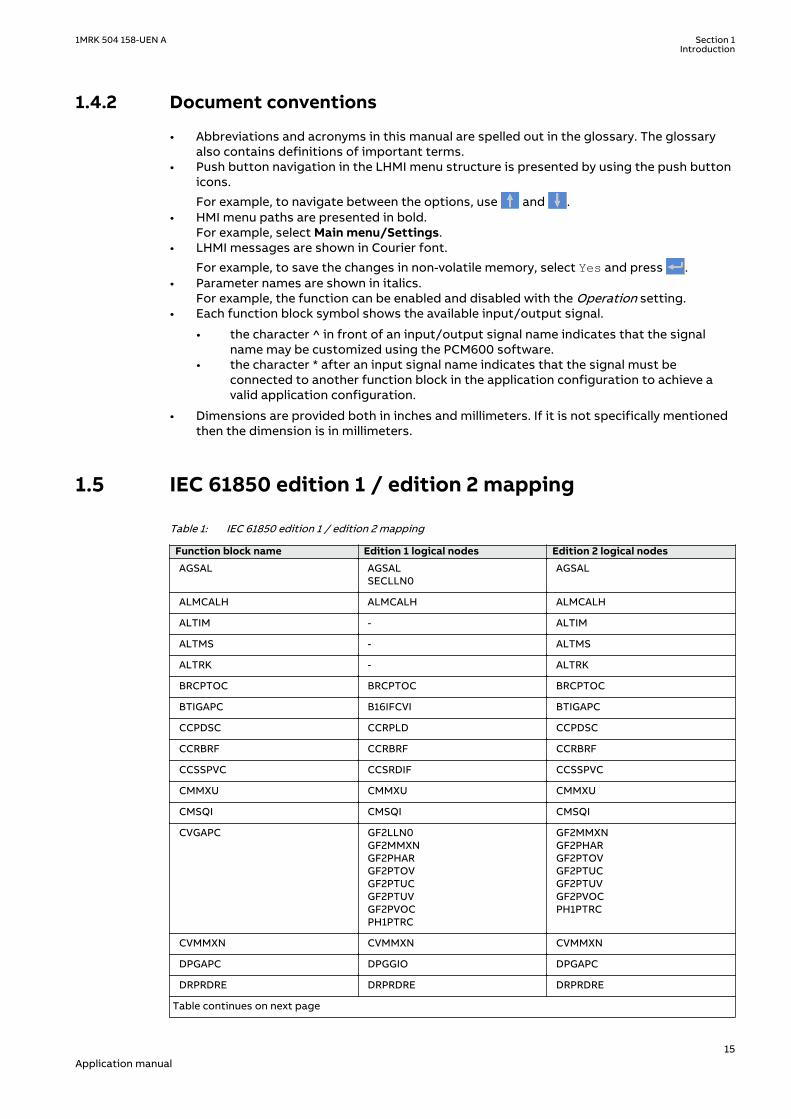
1.5 IEC 61850 edition 1 / edition 2 mappingGUID-C5133366-7260-4C47-A975-7DBAB3A33A96 v3
Table 1: IEC 61850 edition 1 / edition 2 mapping
Function block name Edition 1 logical nodes Edition 2 logical nodes
AGSAL AGSALSECLLN0
AGSAL
ALMCALH ALMCALH ALMCALH
ALTIM - ALTIM
ALTMS - ALTMS
ALTRK - ALTRK
BRCPTOC BRCPTOC BRCPTOC
BTIGAPC B16IFCVI BTIGAPC
CCPDSC CCRPLD CCPDSC
CCRBRF CCRBRF CCRBRF
CCSSPVC CCSRDIF CCSSPVC
CMMXU CMMXU CMMXU
CMSQI CMSQI CMSQI
CVGAPC GF2LLN0GF2MMXNGF2PHARGF2PTOVGF2PTUCGF2PTUVGF2PVOCPH1PTRC
GF2MMXNGF2PHARGF2PTOVGF2PTUCGF2PTUVGF2PVOCPH1PTRC
CVMMXN CVMMXN CVMMXN
DPGAPC DPGGIO DPGAPC
DRPRDRE DRPRDRE DRPRDRE
Table continues on next page
1MRK 504 158-UEN A Section 1Introduction
15Application manual

Function block name Edition 1 logical nodes Edition 2 logical nodes
EF4PTOC EF4LLN0EF4PTRCEF4RDIRGEN4PHARPH1PTOC
EF4PTRCEF4RDIRGEN4PHARPH1PTOC
EFPIOC EFPIOC EFPIOC
ETPMMTR ETPMMTR ETPMMTR
FUFSPVC SDDRFUF FUFSPVC
HZPDIF HZPDIF HZPDIF
INDCALH INDCALH INDCALH
ITBGAPC IB16FCVB ITBGAPC
L4UFCNT L4UFCNT L4UFCNT
LCPTTR LCPTTR LCPTTR
LD0LLN0 LLN0 LLN0
LDLPSCH LDLPDIF LDLPSCH
LFPTTR LFPTTR LFPTTR
LMBRFLO LMBRFLO LMBRFLO
LOVPTUV LOVPTUV LOVPTUV
LPHD LPHD LPHD
LT3CPDIF LT3CPDIF LT3CGAPCLT3CPDIFLT3CPHARLT3CPTRC
MVGAPC MVGGIO MVGAPC
NS4PTOC EF4LLN0EF4PTRCEF4RDIRGEN4PHARPH1PTOC
EF4PTRCEF4RDIRPH1PTOC
OC4PTOC OC4LLN0GEN4PHARPH3PTOCPH3PTRC
GEN4PHARPH3PTOCPH3PTRC
OV2PTOV GEN2LLN0OV2PTOVPH1PTRC
OV2PTOVPH1PTRC
PCFCNT PCGGIO PCFCNT
PHPIOC PHPIOC PHPIOC
PRPSTATUS RCHLCCH RCHLCCHSCHLCCH
QCBAY QCBAY BAY/LLN0
QCRSV QCRSV QCRSV
REFPDIF REFPDIF REFPDIF
ROV2PTOV GEN2LLN0PH1PTRCROV2PTOV
PH1PTRCROV2PTOV
SCILO SCILO SCILO
SCSWI SCSWI SCSWI
Table continues on next page
Section 1 1MRK 504 158-UEN AIntroduction
16Application manual

Function block name Edition 1 logical nodes Edition 2 logical nodes
SESRSYN RSY1LLN0AUT1RSYNMAN1RSYNSYNRSYN
AUT1RSYNMAN1RSYNSYNRSYN
SINGLELCCH - SCHLCCH
SLGAPC SLGGIO SLGAPC
SMBRREC SMBRREC SMBRREC
SMPPTRC SMPPTRC SMPPTRC
SP16GAPC SP16GGIO SP16GAPC
SPC8GAPC SPC8GGIO SPC8GAPC
SPGAPC SPGGIO SPGAPC
SSCBR SSCBR SSCBR
SSIMG SSIMG SSIMG
SSIML SSIML SSIML
SXCBR SXCBR SXCBR
SXSWI SXSWI SXSWI
T3WPDIF T3WPDIF T3WGAPCT3WPDIFT3WPHART3WPTRC
TEIGAPC TEIGGIO TEIGAPC
TEILGAPC TEILGGIO TEILGAPC
TMAGAPC TMAGGIO TMAGAPC
TRPTTR TRPTTR TRPTTR
UV2PTUV GEN2LLN0PH1PTRCUV2PTUV
PH1PTRCUV2PTUV
VMMXU VMMXU VMMXU
VMSQI VMSQI VMSQI
VNMMXU VNMMXU VNMMXU
VSGAPC VSGGIO VSGAPC
WRNCALH WRNCALH WRNCALH
ZCLCPSCH ZCLCPLAL ZCLCPSCH
ZCPSCH ZCPSCH ZCPSCH
ZCRWPSCH ZCRWPSCH ZCRWPSCH
ZCVPSOF ZCVPSOF ZCVPSOF
ZMFPDIS ZMFLLN0PSFPDISZMFPDISZMFPTRCZMMMXU
PSFPDISPSFPDISZMFPDISZMFPTRCZMMMXU
1MRK 504 158-UEN A Section 1Introduction
17Application manual

18

Section 2 Application
2.1 General IED applicationGUID-EB939A4F-1C88-4EB1-A217-571FEF72AC7B v2
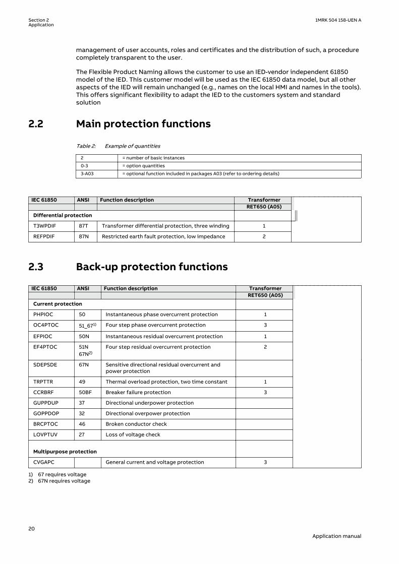
The RET650 provides fast and selective protection, monitoring and control functions for two-and three-winding transformers, autotransformers, generator-transformer units and shuntreactors. The IED is designed to operate correctly over a wide frequency range in order toaccommodate power system frequency variations during disturbances and generator startupand shutdown. Apparatus control for 3 circuit breakers is included.
A fast differential protection function with built-in transformer ratio matching and vectorgroup compensation makes this IED the ideal solution even for the most demandingapplications. Since RET650 has very low requirements on the main CTs, no interposing CTs arerequired. The differential protection function is provided with 2nd harmonic and waveform-blocking restraint features to avoid tripping for magnetizing inrush current, and 5th harmonicrestraint to avoid tripping for overexcitation.
The differential function offers a high sensitivity for low-level internal faults. The unique andinnovative sensitive differential protection feature of the RET650 provides the best possiblecoverage for internal turn-to-turn winding faults, based on the theory of symmetricalcomponents.
A low impedance restricted earth-fault protection function is available as a complimentarysensitive and fast main protection against winding earth faults. This function includes adirectional zero-sequence current criterion for additional security.
Tripping from pressure relief/Buchholz and temperature devices can be implemented throughthe IED's binary inputs, where trip signal conditioning can be performed (pulsing, lockout,additional logics, etc). The binary inputs are thoroughly stabilized against disturbances inorder to prevent incorrect operations due to for example DC system capacitive discharges orDC earth faults.
Versatile phase, earth and zero sequence overcurrent functions with directional capabilityprovide further alternative backup protections. Thermal overload with two time-constants andbreaker failure protection is also available.
A built-in disturbance and event recorder provides valuable data to the user about status andoperation for post-fault disturbance analysis.
One pre-configured package has been defined for the following application:
• Three-winding transformer in single breaker arrangements (A05)
The package is configured and ready for direct use. Analog and control circuits have beenpredefined and other signals need to be applied as required for each application. The pre-configured IED can be changed and adapted to suit specific applications with the graphicalconfiguration tool.
Forcing of binary inputs and outputs is a convenient way to test wiring in substations as wellas testing configuration logic in the IEDs. Basically it means that all binary inputs and outputson the IED I/O modules (BOM, BIM and IOM) can be forced to arbitrary values.
Central Account Management is an authentication infrastructure that offers a secure solutionfor enforcing access control to IEDs and other systems within a substation. This incorporates
1MRK 504 158-UEN A Section 2Application
19Application manual
management of user accounts, roles and certificates and the distribution of such, a procedurecompletely transparent to the user.
The Flexible Product Naming allows the customer to use an IED-vendor independent 61850model of the IED. This customer model will be used as the IEC 61850 data model, but all otheraspects of the IED will remain unchanged (e.g., names on the local HMI and names in the tools).This offers significant flexibility to adapt the IED to the customers system and standardsolution
2.2 Main protection functionsGUID-66BAAD98-851D-4AAC-B386-B38B57718BD2 v12
Table 2: Example of quantities
2 = number of basic instances
0-3 = option quantities
3-A03 = optional function included in packages A03 (refer to ordering details)
IEC 61850 ANSI Function description Transformer RET650 (A05)
Differential protection
T3WPDIF 87T Transformer differential protection, three winding 1
REFPDIF 87N Restricted earth fault protection, low impedance 2
2.3 Back-up protection functionsGUID-A8D0852F-807F-4442-8730-E44808E194F0 v11
IEC 61850 ANSI Function description Transformer RET650 (A05) Current protection
PHPIOC 50 Instantaneous phase overcurrent protection 1
OC4PTOC 51_671) Four step phase overcurrent protection 3
EFPIOC 50N Instantaneous residual overcurrent protection 1
EF4PTOC 51N67N2)
Four step residual overcurrent protection 2
SDEPSDE 67N Sensitive directional residual overcurrent andpower protection
TRPTTR 49 Thermal overload protection, two time constant 1
CCRBRF 50BF Breaker failure protection 3
GUPPDUP 37 Directional underpower protection
GOPPDOP 32 Directional overpower protection
BRCPTOC 46 Broken conductor check
LOVPTUV 27 Loss of voltage check
Multipurpose protection
CVGAPC General current and voltage protection 3
1) 67 requires voltage2) 67N requires voltage
Section 2 1MRK 504 158-UEN AApplication
20Application manual

2.4 Control and monitoring functionsGUID-E3777F16-0B76-4157-A3BF-0B6B978863DE v13
IEC 61850 ANSI Function description Transformer RET650 (A05)
Control
QCBAY Apparatus control 1
LOCREM Handling of LRswitch positions 1
LOCREMCTRL LHMI control of PSTO 1
SLGAPC Logic Rotating Switch for function selection and LHMI presentation 15
VSGAPC Selector mini switch 20
DPGAPC Generic communication function for Double Point indication 16
SPC8GAPC Single Point Generic Control 8 signals 5
AUTOBITS AutomationBits, command function for DNP3.0 3
SINGLECMD Single command, 16 signals 4
I103CMD Function commands for IEC 60870-5-103 1
I103GENCMD Function commands generic for IEC 60870-5-103 50
I103POSCMD IED commands with position and select for IEC 60870-5-103 50
I103POSCMDV IED direct commands with position for IEC 60870-5-503 50
I103IEDCMD IED commands for IEC 60870-5-103 1
I103USRCMD Function commands user defined for IEC 60870-5-103 4
SCILO Interlocking 3
SCSWI Switch Controller 3
SXCBR Circuit Breaker 3
Circuit breaker for 3CB 1
Secondary system supervision
FUFSPVC Fuse failure supervision 1
Logic
SMPPTRC Tripping logic 6
TMAGAPC Trip matrix logic 12
ALMCALH Logic for group alarm 5
WRNCALH Logic for group warning 5
INDCALH Logic for group indication 5
AND, GATE, INV,LLD, OR,PULSETIMER,RSMEMORY,SRMEMORY,TIMERSET, XOR
Basic configurable logic blocks (see Table 3) 40–420
FXDSIGN Fixed signal function block 1
B16I Boolean 16 to Integer conversion 18
BTIGAPC Boolean 16 to Integer conversion with Logic Node representation 16
IB16 Integer to Boolean 16 conversion 18
ITBGAPC Integer to Boolean 16 conversion with Logic Node representation 16
TEIGAPC Elapsed time integrator with limit transgression and overflowsupervision
12
INTCOMP Comparator for integer inputs 12
Table continues on next page
1MRK 504 158-UEN A Section 2Application
21Application manual

IEC 61850 ANSI Function description Transformer RET650 (A05)
REALCOMP Comparator for real inputs 12
Monitoring
CVMMXN,VMMXU, CMSQI,VMSQI, VNMMXU
Measurements 6
CMMXU Measurements 10
AISVBAS Function block for service value presentation of secondary analoginputs
1
SSIMG Gas medium supervision 21
SSIML Liquid medium supervision 3
SSCBR Circuit breaker condition monitoring 9
EVENT Event function 20
DRPRDRE,A1RADR-A4RADR,B1RBDR-B8RBDR
Disturbance report 1
SPGAPC Generic communication function for Single Point indication 64
SP16GAPC Generic communication function for Single Point indication 16 inputs 16
MVGAPC Generic communication function for Measured Value 24
BINSTATREP Logical signal status report 3
RANGE_XP Measured value expander block 66
I103MEAS Measurands for IEC 60870-5-103 1
I103MEASUSR Measurands user defined signals for IEC 60870-5-103 3
I103AR Function status auto-recloser for IEC 60870-5-103 1
I103EF Function status earth-fault for IEC 60870-5-103 1
I103FLTPROT Function status fault protection for IEC 60870-5-103 1
I103IED IED status for IEC 60870-5-103 1
I103SUPERV Supervison status for IEC 60870-5-103 1
I103USRDEF Status for user defined signals for IEC 60870-5-103 20
L4UFCNT Event counter with limit supervision 30
TEILGAPC Running hour-meter 6
Metering
PCFCNT Pulse-counter logic 16
ETPMMTR Function for energy calculation and demand handling 6
Table 3: Total number of instances for basic configurable logic blocks
Basic configurable logic block Total number of instances
AND 280
GATE 40
INV 420
LLD 40
OR 280
PULSETIMER 40
RSMEMORY 40
Table continues on next page
Section 2 1MRK 504 158-UEN AApplication
22Application manual

Basic configurable logic block Total number of instances
SRMEMORY 40
TIMERSET 60
XOR 40
2.5 CommunicationGUID-5F144B53-B9A7-4173-80CF-CD4C84579CB5 v13
IEC 61850 ANSI Function description Transformer RET650 (A05)
Station communication
LONSPA, SPA SPA communication protocol 1
ADE LON communciation protocol 1
HORZCOMM Network variables via LON 1
PROTOCOL Operation selection between SPA and IEC 60870-5-103 for SLM 1
RS485PROT Operation selection for RS485 1
RS485GEN RS485 1
DNPGEN DNP3.0 communication general protocol 1
DNPGENTCP DNP3.0 communication general TCP protocol 1
CHSERRS485 DNP3.0 for EIA-485 communication protocol 1
CH1TCP, CH2TCP,CH3TCP, CH4TCP
DNP3.0 for TCP/IP communication protocol 1
CHSEROPT DNP3.0 for TCP/IP and EIA-485 communication protocol 1
MSTSER DNP3.0 for serial communication protocol 1
MST1TCP,MST2TCP,MST3TCP,MST4TCP
DNP3.0 for TCP/IP communication protocol 1
DNPFREC DNP3.0 fault records for TCP/IP and EIA-485 communication protocol 1
IEC 61850-8-1 Parameter setting function for IEC 61850 1
GOOSEINTLKRCV Horizontal communication via GOOSE for interlocking 59
GOOSEBINRCV GOOSE binary receive 16
GOOSEDPRCV GOOSE function block to receive a double point value 64
GOOSEINTRCV GOOSE function block to receive an integer value 32
GOOSEMVRCV GOOSE function block to receive a measurand value 60
GOOSESPRCV GOOSE function block to receive a single point value 64
MULTICMDRCV/MULTICMDSND
Multiple command and transmit 60/10
FRONT, LANABI,LANAB, LANCDI,LANCD, GATEWAY
Ethernet configuration 1
OPTICAL103 IEC 60870-5-103 Optical serial communication 1
RS485103 IEC 60870-5-103 serial communication for RS485 1
AGSAL Generic security application component 1
LD0LLN0 IEC 61850 LD0 LLN0 1
SYSLLN0 IEC 61850 SYS LLN0 1
Table continues on next page
1MRK 504 158-UEN A Section 2Application
23Application manual

IEC 61850 ANSI Function description Transformer RET650 (A05)
LPHD Physical device information 1
PCMACCS IED configuration protocol 1
SECALARM Component for mapping security events on protocols such as DNP3and IEC103
1
FSTACCS,FSTACCSNA
Field service tool access via SPA protocol over ethernetcommunication
1
ACTIVLOG Activity logging parameters 1
ALTRK Service Tracking 1
SINGLELCCH Single ethernet port link status 1
PRPSTATUS Dual ethernet port link status 1
PRP IEC 62439-3 parallel redundancy protocol 1-P03
2.6 Basic IED functionsGUID-C8F0E5D2-E305-4184-9627-F6B5864216CA v10
Table 4: Basic IED functions
IEC 61850 or functionname
Description
INTERRSIG Self supervision with internal event list
SELFSUPEVLST Self supervision with internal event list
TIMESYNCHGEN Time synchronization module
BININPUT,SYNCHCAN,SYNCHGPS,SYNCHCMPPS,SYNCHLON,SYNCHPPH,SYNCHPPS, SNTP,SYNCHSPA,SYNCHCMPPS
Time synchronization
TIMEZONE Time synchronization
DSTBEGIN,DSTENABLE, DSTEND
GPS time synchronization module
IRIG-B Time synchronization
SETGRPS Number of setting groups
ACTVGRP Parameter setting groups
TESTMODE Test mode functionality
CHNGLCK Change lock function
SMBI Signal matrix for binary inputs
SMBO Signal matrix for binary outputs
SMAI1 - SMAI12 Signal matrix for analog inputs
3PHSUM Summation block 3 phase
ATHSTAT Authority status
ATHCHCK Authority check
AUTHMAN Authority management
FTPACCS FTP access with password
Table continues on next page
Section 2 1MRK 504 158-UEN AApplication
24Application manual

IEC 61850 or functionname
Description
SPACOMMMAP SPA communication mapping
SPATD Date and time via SPA protocol
DOSFRNT Denial of service, frame rate control for front port
DOSLANAB Denial of service, frame rate control for OEM port AB
DOSLANCD Denial of service, frame rate control for OEM port CD
DOSSCKT Denial of service, socket flow control
GBASVAL Global base values for settings
PRIMVAL Primary system values
ALTMS Time master supervision
ALTIM Time management
MSTSER DNP3.0 for serial communication protocol
Table 5: Local HMI functions
IEC 61850 or functionname
ANSI Description
LHMICTRL Local HMI signals
LANGUAGE Local human machine language
SCREEN Local HMI Local human machine screen behavior
FNKEYTY1–FNKEYTY5FNKEYMD1–FNKEYMD5
Parameter setting function for HMI in PCM600
LEDGEN General LED indication part for LHMI
OPENCLOSE_LED LHMI LEDs for open and close keys
GRP1_LED1–GRP1_LED15GRP2_LED1–GRP2_LED15GRP3_LED1–GRP3_LED15
Basic part for CP HW LED indication module
1MRK 504 158-UEN A Section 2Application
25Application manual

26

Section 3 Configuration
3.1 Description of configuration RET650
3.1.1 IntroductionGUID-79B8BC84-4AAB-44E7-86CD-FF63098B009D v1
The basic delivery includes one binary input module and one binary output module, which issufficient for the default configured IO to trip and close circuit breaker. All IEDs can bereconfigured with the help of the ACT configuration tool in the PCM600 engineering platform.The IED can be adapted to special applications and special logic can be developed, such aslogic for automatic opening of disconnectors and closing of ring bays, automatic load transferfrom one busbar to the other, and so on.
The basic IED configuration is provided with the signal matrix, mimic and the applicationconfiguration prepared for the functions included in the product by default. All parametersshould be verified by the customer, since these are specific to the system, object orapplication. Optional functions and optional IO ordered will not be configured at delivery. Itshould be noted that the standard only includes one binary input and one binary outputmodule and only the key functions such as tripping are connected to the outputs in the signalmatrix tool. The required total IO must be calculated and specified at ordering.
The configurations are as far as found necessary provided with application comments toexplain why the signals have been connected in the special way. On request, ABB is available tosupport the re-configuration work, either directly or to do the design checking.
3.1.1.1 Description of A05GUID-62ED3636-147F-409C-9E92-A77E428CB506 v1
Three-winding transformer in single breaker arrangements.
1MRK 504 158-UEN A Section 3Configuration
27Application manual
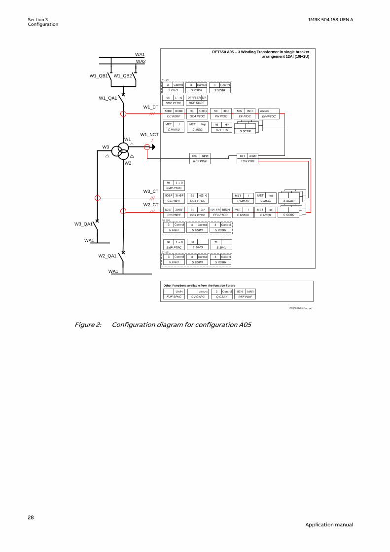
RET650 A05 – 3 Winding Transformer in single breaker
arrangement 12AI (10I+2U)
W2_QA1
W1_QB2W1_QB1
W3_QA1
W1_QA1
Other Functions available from the function library
W1
W2
W3
PH PIOC
50 3I>>
OC4 PTOC
51 4(3I>)
CC RBRF
50BF 3I>BF
OC4 PTOC
51 4(3I>)
CC RBRF
50BF 3I>BF
OC4 PTOC
51 3I>
CC RBRF
50BF 3I>BF
FUF SPVC
U>/I<
SMP PTRC
94 1 → 0
SMP PTRC
94 1 → 0
C MSQI
MET Isqi
C MMXU
MET I
TR PTTR
49 θ>
C MSQI
MET Isqi
Q CBAY
3 Control
S SIMG
63
CV GAPC
2(I>/U<)
SMP PTRC
94 1 → 0
DRP RDRE
DFR/SER DR
REF PDIF
87N IdN/I
C MMXU
MET I
C MMXU
MET I
EF PIOC
50N IN>>
C MSQI
MET Isqi
S SIML
71
WA1
WA2
W1_CT
W1_NCT
W3_CT
W2_CT
WA1
WA1
IEC15000405-2-en.vsd
S SCBRS SCBR
S SCBR
S CILO
3 Control
S CSWI
3 Control
S XCBR
3 Control
S SCBRS SCBR
S SCBR
S CILO
3 Control
S CSWI
3 Control
S XCBR
3 Control
S SCBRS SCBR
S SCBR
S CILO
3 Control
S CSWI
3 Control
S XCBR
3 Control
EF4PTOC
51N/67N
T3W PDIF
87T 3Id/I>
W1_QA1
EF4 PTOC
51N_67N 4(IN>)
W3_QA1
W2_QA1
REF PDIF
87N IdN/I
IEC15000405 V2 EN-US
Figure 2: Configuration diagram for configuration A05
Section 3 1MRK 504 158-UEN AConfiguration
28Application manual

Section 4 Analog inputs
4.1 IntroductionSEMOD55003-5 v10
Analog input channels must be configured and set properly in order to get correctmeasurement results and correct protection operations. For power measuring and alldirectional and differential functions the directions of the input currents must be defined inorder to reflect the way the current transformers are installed/connected in the field ( primaryand secondary connections ). Measuring and protection algorithms in the IED use primarysystem quantities. Setting values are in primary quantities as well and it is important to setthe data about the connected current and voltage transformers properly.
A reference PhaseAngleRef can be defined to facilitate service values reading. This analogchannels phase angle will always be fixed to zero degrees and all other angle information willbe shown in relation to this analog input. During testing and commissioning of the IED thereference channel can be changed to facilitate testing and service values reading.
The availability of VT inputs depends on the ordered transformer input module(TRM) type.
4.2 Setting guidelinesSEMOD55068-1 v1
SEMOD130348-4 v5
The available setting parameters related to analog inputs are depending on theactual hardware (TRM) and the logic configuration made in PCM600.
If a second TRM is used, at least one TRM channel must be configured to getthe service values. However, the MU physical channel must be configured to getservice values from that channel.
4.2.1 Setting of the phase reference channelSEMOD55055-5 v3
All phase angles are calculated in relation to a defined reference. An appropriate analog inputchannel is selected and used as phase reference. The parameter PhaseAngleRef defines theanalog channel that is used as phase angle reference.
4.2.1.1 ExampleSEMOD55055-11 v4
Usually the L1 phase-to-earth voltage connected to the first VT channel number of thetransformer input module (TRM) is selected as the phase reference. The first VT channelnumber depends on the type of transformer input module.
For a TRM with 6 current and 6 voltage inputs the first VT channel is 7. The settingPhaseAngleRef=7 shall be used if the phase reference voltage is connected to that channel.
1MRK 504 158-UEN A Section 4Analog inputs
29Application manual

4.2.2 Setting of current channelsSEMOD55055-16 v5
The direction of a current to the IED is depending on the connection of the CT. Unlessindicated otherwise, the main CTs are supposed to be star connected and can be connectedwith the earthing point to the object or from the object. This information must be set in theIED. The convention of the directionality is defined as follows: A positive value of current,power, and so on means that the quantity has the direction into the object and a negativevalue means direction out from the object. For directional functions the direction into theobject is defined as Forward and the direction out from the object is defined as Reverse. Seefigure 3
A positive value of current, power, and so on (forward) means that the quantity has a directiontowards the object. - A negative value of current, power, and so on (reverse) means a directionaway from the object. See figure 3.
Protected ObjectLine, transformer, etc
ForwardReverse
Definition of directionfor directional functions
Measured quantity ispositive when flowing
towards the object
e.g. P, Q, I
ReverseForward
Definition of directionfor directional functions
e.g. P, Q, IMeasured quantity ispositive when flowing
towards the object
Set parameterCTStarPoint
Correct Setting is"ToObject"
Set parameterCTStarPoint
Correct Setting is"FromObject" en05000456.vsd
IEC05000456 V1 EN-US
Figure 3: Internal convention of the directionality in the IED
With correct setting of the primary CT direction, CTStarPoint set to FromObject or ToObject, apositive quantities always flowing towards the object and a direction defined as Forwardalways is looking towards the object. The following examples show the principle.
4.2.2.1 Example 1SEMOD55055-23 v5
Two IEDs used for protection of two objects.
Section 4 1MRK 504 158-UEN AAnalog inputs
30Application manual

Transformer
protection
Transformer
Line
Line
Setting of current input:
Set parameter
CTStarPoint with
Transformer as
reference object.
Correct setting is
"ToObject"
ForwardReverse
Definition of direction
for directional functions
Line protection
Setting of current input:
Set parameter
CTStarPoint with
Transformer as
reference object.
Correct setting is
"ToObject"
Setting of current input:
Set parameter
CTStarPoint with
Line as
reference object.
Correct setting is
"FromObject"
IEC05000753=IEC05
000753=1=en=Origin
al[1].vsd
IsIs
Ip Ip Ip
IED IED
IEC05000753 V2 EN-US
Figure 4: Example how to set CTStarPoint parameters in the IED
The figure 4 shows the normal case where the objects have their own CTs. The settings for CTdirection shall be done according to the figure. To protect the line the direction of thedirectional functions of the line protection shall be set to Forward. This means that theprotection is looking towards the line.
4.2.2.2 Example 2SEMOD55055-29 v6
Two IEDs used for protection of two objects and sharing a CT.
1MRK 504 158-UEN A Section 4Analog inputs
31Application manual

Transformer
protection
Transformer
Line
Setting of current input:
Set parameter
CTStarPoint with
Transformer as
reference object.
Correct setting is
"ToObject"
ForwardReverse
Definition of direction
for directional functions
Line protection
Setting of current input:
Set parameter
CTStarPoint with
Transformer as
reference object.
Correct setting is
"ToObject"
Setting of current input:
Set parameter
CTStarPoint with
Line as
reference object.
Correct setting is
"FromObject"
IED IED
IEC05000460 V2 EN-US
Figure 5: Example how to set CTStarPoint parameters in the IED
This example is similar to example 1, but here the transformer is feeding just one line and theline protection uses the same CT as the transformer protection does. The CT direction is setwith different reference objects for the two IEDs though it is the same current from the sameCT that is feeding the two IEDs. With these settings the directional functions of the lineprotection shall be set to Forward to look towards the line.
4.2.2.3 Example 3SEMOD55055-35 v6
One IED used to protect two objects.
Section 4 1MRK 504 158-UEN AAnalog inputs
32Application manual

Transformer and
Line protection
Transformer
Line
Setting of current input:
Set parameter
CTStarPoint with
Transformer as
reference object.
Correct setting is
"ToObject"
ReverseForward
Definition of direction
for directional
line functions
Setting of current input:
Set parameter
CTStarPoint with
Transformer as
reference object.
Correct setting is
"ToObject"
IED
IEC05000461 V2 EN-US
Figure 6: Example how to set CTStarPoint parameters in the IED
In this example one IED includes both transformer and line protection and the line protectionuses the same CT as the transformer protection does. For both current input channels the CTdirection is set with the transformer as reference object. This means that the directionForward for the line protection is towards the transformer. To look towards the line thedirection of the directional functions of the line protection must be set to Reverse. Thedirection Forward/Reverse is related to the reference object that is the transformer in thiscase.
When a function is set to Reverse and shall protect an object in reverse direction it shall benoted that some directional functions are not symmetrical regarding the reach in forward andreverse direction. It is in first hand the reach of the directional criteria that can differ. Normallyit is not any limitation but it is advisable to have it in mind and check if it is acceptable for theapplication in question.
If the IED has a sufficient number of analog current inputs an alternative solution is shown infigure 7. The same currents are fed to two separate groups of inputs and the line andtransformer protection functions are configured to the different inputs. The CT direction forthe current channels to the line protection is set with the line as reference object and thedirectional functions of the line protection shall be set to Forward to protect the line.
1MRK 504 158-UEN A Section 4Analog inputs
33Application manual

Transformer and
Line protection
Transformer
Line
Setting of current input
for transformer functions:
Set parameter
CTStarPoint with
Transformer as
reference object.
Correct setting is
"ToObject"
ForwardReverse
Definition of direction
for directional
line functions
Setting of current input
for transformer functions:
Set parameter
CTStarPoint with
Transformer as
reference object.
Correct setting is
"ToObject"
Setting of current input
for line functions:
Set parameter
CTStarPoint with
Line as
reference object.
Correct setting is
"FromObject"
IED
IEC05000462 V2 EN-US
Figure 7: Example how to set CTStarPoint parameters in the IED
4.2.2.4 Examples on how to connect, configure and set CT inputs for mostcommonly used CT connections
SEMOD55055-296 v6
Figure 8 defines the marking of current transformer terminals commonly used around theworld:
In the SMAI function block, you have to set if the SMAI block is measuringcurrent or voltage. This is done with the parameter: AnalogInputType: Current/voltage. The ConnectionType: phase -phase/phase-earth and GlobalBaseSel.
ISec
I Pri
S1 (X1)
P1(H1)
P2(H2)
S2 (X2)
P2(H2)
P1(H1)
x x
a) b) c)
en06000641.vsd
S2 (X2) S1 (X1)
IEC06000641 V1 EN-US
Figure 8: Commonly used markings of CT terminals
Section 4 1MRK 504 158-UEN AAnalog inputs
34Application manual

Where:
a) is symbol and terminal marking used in this document. Terminals marked with a squareindicates the primary and secondary winding terminals with the same (that is, positive)polarity
b) andc)
are equivalent symbols and terminal marking used by IEC (ANSI) standard for CTs. Notethat for these two cases the CT polarity marking is correct!
It shall be noted that depending on national standard and utility practices, the rated secondarycurrent of a CT has typically one of the following values:
• 1A• 5A
However in some cases the following rated secondary currents are used as well:
• 2A• 10A
The IED fully supports all of these rated secondary values.
It is recommended to:
• use 1A rated CT input into the IED in order to connect CTs with 1A and 2Asecondary rating
• use 5A rated CT input into the IED in order to connect CTs with 5A and 10Asecondary rating
4.2.2.5 Example on how to connect a star connected three-phase CT set to theIED
SEMOD55055-352 v10
Figure 9 gives an example about the wiring of a star connected three-phase CT set to the IED.It gives also an overview of the actions which are needed to make this measurement availableto the built-in protection and control functions within the IED as well.
For correct terminal designations, see the connection diagrams valid for thedelivered IED.
1MRK 504 158-UEN A Section 4Analog inputs
35Application manual
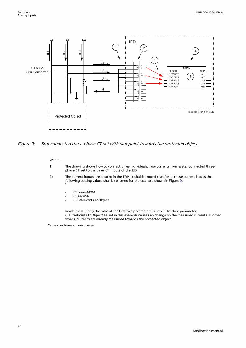
L1
IL1
IL2
IL3
L2 L3
Protected Object
CT 600/5Star Connected
IL1
IL2
IL3
IED
IEC13000002-4-en.vsdx
1 2
3
4
SMAI2
BLOCK
REVROT
^GRP2L1
^GRP2L2
^GRP2L3
^GRP2N
AI3P
AI1
AI2
AI3
AI4
AIN
5
IN
IEC13000002 V4 EN-US
Figure 9: Star connected three-phase CT set with star point towards the protected object
Where:
1) The drawing shows how to connect three individual phase currents from a star connected three-phase CT set to the three CT inputs of the IED.
2) The current inputs are located in the TRM. It shall be noted that for all these current inputs thefollowing setting values shall be entered for the example shown in Figure 9.'
• CTprim=600A• CTsec=5A• CTStarPoint=ToObject
Inside the IED only the ratio of the first two parameters is used. The third parameter(CTStarPoint=ToObject) as set in this example causes no change on the measured currents. In otherwords, currents are already measured towards the protected object.
Table continues on next page
Section 4 1MRK 504 158-UEN AAnalog inputs
36Application manual
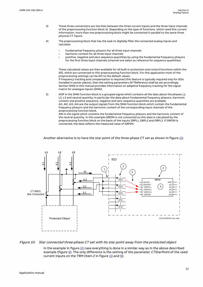
3) These three connections are the links between the three current inputs and the three input channelsof the preprocessing function block 4). Depending on the type of functions, which need this currentinformation, more than one preprocessing block might be connected in parallel to the same threephysical CT inputs.
4) The preprocessing block that has the task to digitally filter the connected analog inputs andcalculate:
• fundamental frequency phasors for all three input channels• harmonic content for all three input channels• positive, negative and zero sequence quantities by using the fundamental frequency phasors
for the first three input channels (channel one taken as reference for sequence quantities)
These calculated values are then available for all built-in protection and control functions within theIED, which are connected to this preprocessing function block. For this application most of thepreprocessing settings can be left to the default values.If frequency tracking and compensation is required (this feature is typically required only for IEDsinstalled in power plants), then the setting parameters DFTReference shall be set accordingly.Section SMAI in this manual provides information on adaptive frequency tracking for the signalmatrix for analogue inputs (SMAI).
5) AI3P in the SMAI function block is a grouped signal which contains all the data about the phases L1,L2, L3 and neutral quantity; in particular the data about fundamental frequency phasors, harmoniccontent and positive sequence, negative and zero sequence quantities are available.AI1, AI2, AI3, AI4 are the output signals from the SMAI function block which contain the fundamentalfrequency phasors and the harmonic content of the corresponding input channels of thepreprocessing function block.AIN is the signal which contains the fundamental frequency phasors and the harmonic content ofthe neutral quantity. In this example GRP2N is not connected so this data is calculated by thepreprocessing function block on the basis of the inputs GRPL1, GRPL2 and GRPL3. If GRP2N isconnected, the data reflects the measured value of GRP2N.
Another alternative is to have the star point of the three-phase CT set as shown in figure 10:
L1
IL1
IL2
IL3
L2 L3
Protected Object
CT 800/1Star Connected
IL1
IL2
IL3
IED
IEC11000026-4-en.vsdx
4 12
3
SMAI2
BLOCK
REVROT
^GRP2L1
^GRP2L2
^GRP2L3
^GRP2N
AI3P
AI1
AI2
AI3
AI4
AIN
5
IN
IEC11000026 V4 EN-US
Figure 10: Star connected three-phase CT set with its star point away from the protected object
In the example in figure 10 case everything is done in a similar way as in the above describedexample (figure 9). The only difference is the setting of the parameter CTStarPoint of the usedcurrent inputs on the TRM (item 2 in figure 10 and 9):
1MRK 504 158-UEN A Section 4Analog inputs
37Application manual
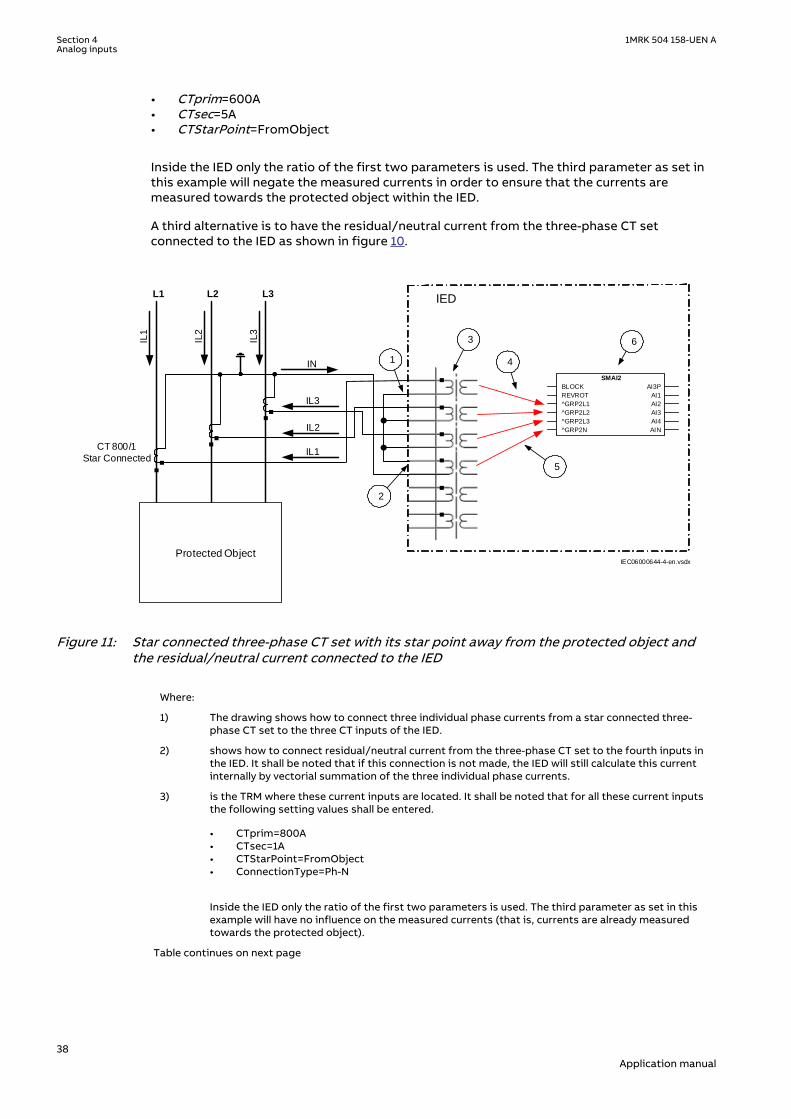
• CTprim=600A• CTsec=5A• CTStarPoint=FromObject
Inside the IED only the ratio of the first two parameters is used. The third parameter as set inthis example will negate the measured currents in order to ensure that the currents aremeasured towards the protected object within the IED.
A third alternative is to have the residual/neutral current from the three-phase CT setconnected to the IED as shown in figure 10.
L1
IL1
IL2
IL3
L2 L3
Protected Object
CT 800/1
Star ConnectedIL1
IL2
IL3
IN
IED
1
3
4
2
5
IEC06000644-4-en.vsdx
6
SMAI2
BLOCK
REVROT
^GRP2L1
^GRP2L2
^GRP2L3
^GRP2N
AI3P
AI1
AI2
AI3
AI4
AIN
IEC06000644 V4 EN-US
Figure 11: Star connected three-phase CT set with its star point away from the protected object andthe residual/neutral current connected to the IED
Where:
1) The drawing shows how to connect three individual phase currents from a star connected three-phase CT set to the three CT inputs of the IED.
2) shows how to connect residual/neutral current from the three-phase CT set to the fourth inputs inthe IED. It shall be noted that if this connection is not made, the IED will still calculate this currentinternally by vectorial summation of the three individual phase currents.
3) is the TRM where these current inputs are located. It shall be noted that for all these current inputsthe following setting values shall be entered.
• CTprim=800A• CTsec=1A• CTStarPoint=FromObject• ConnectionType=Ph-N
Inside the IED only the ratio of the first two parameters is used. The third parameter as set in thisexample will have no influence on the measured currents (that is, currents are already measuredtowards the protected object).
Table continues on next page
Section 4 1MRK 504 158-UEN AAnalog inputs
38Application manual

4) are three connections made in the Signal Matrix tool (SMT), Application configuration tool (ACT),which connects these three current inputs to the first three input channels on the preprocessingfunction block 6). Depending on the type of functions, which need this current information, morethan one preprocessing block might be connected in parallel to these three CT inputs.
5) is a connection made in the Signal Matrix tool (SMT), Application configuration tool (ACT), whichconnects the residual/neutral current input to the fourth input channel of the preprocessingfunction block 6). Note that this connection in SMT shall not be done if the residual/neutral currentis not connected to the IED. In that case the pre-processing block will calculate it by vectorialsummation of the three individual phase currents.
6) is a Preprocessing block that has the task to digitally filter the connected analog inputs andcalculate:
• fundamental frequency phasors for all four input channels• harmonic content for all four input channels• positive, negative and zero sequence quantities by using the fundamental frequency phasors
for the first three input channels (channel one taken as reference for sequence quantities)
These calculated values are then available for all built-in protection and control functions within theIED, which are connected to this preprocessing function block in the configuration tool. For thisapplication most of the preprocessing settings can be left to the default values.If frequency tracking and compensation is required (this feature is typically required only for IEDsinstalled in the generating stations), then the setting parameters DFTReference shall be setaccordingly.
4.2.2.6 Example how to connect delta connected three-phase CT set to the IEDSEMOD55055-392 v7
Figure 12 gives an example how to connect a delta connected three-phase CT set to the IED. Itgives an overview of the required actions by the user in order to make this measurementavailable to the built-in protection and control functions in the IED as well.
For correct terminal designations, see the connection diagrams valid for thedelivered IED.
1MRK 504 158-UEN A Section 4Analog inputs
39Application manual

L1
IL1
IL2
IL3
L2 L3
Protected Object
IED
CT 6
00/5
in D
elta
DA
B C
onn
ecte
d
IL1-IL2
IL2-IL3
IL3-IL1
1 2
3 4
IEC11000027-3-en.vsdx
SMAI2
BLOCK
REVROT
^GRP2L1
^GRP2L2
^GRP2L3
^GRP2N
AI3P
AI1
AI2
AI3
AI4
AIN
IEC11000027 V3 EN-US
Figure 12: Delta DAB connected three-phase CT set
Where:
1) shows how to connect three individual phase currents from a delta connected three-phase CT set tothree CT inputs of the IED.
2) is the TRM where these current inputs are located. It shall be noted that for all these current inputsthe following setting values shall be entered.CTprim=600ACTsec=5A
• CTStarPoint=ToObject• ConnectionType=Ph-Ph
3) are three connections made in Signal Matrix Tool (SMT), Application configuration tool (ACT), whichconnect these three current inputs to first three input channels of the preprocessing function block4). Depending on the type of functions which need this current information, more then onepreprocessing block might be connected in parallel to these three CT inputs.
4) is a Preprocessing block that has the task to digitally filter the connected analog inputs andcalculate:
• fundamental frequency phasors for all three input channels• harmonic content for all three input channels• positive, negative and zero sequence quantities by using the fundamental frequency phasors
for the first three input channels (channel one taken as reference for sequence quantities)
These calculated values are then available for all built-in protection and control functions within theIED, which are connected to this preprocessing function block. For this application most of thepreprocessing settings can be left to the default values.If frequency tracking and compensation is required (this feature is typically required only for IEDsinstalled in the generating stations) then the setting parameters DFTReference shall be setaccordingly.
Section 4 1MRK 504 158-UEN AAnalog inputs
40Application manual

Another alternative is to have the delta connected CT set as shown in figure 13:
L1
IL1
IL2
IL3
L2 L3
Protected Object
IED
CT 8
00/1
in D
elta
DA
C C
onnect
ed
IL3-IL2
IL2-IL1
IL1-IL3
2
3
4
IEC11000028-3-en.vsdx
SMAI2
BLOCK
REVROT
^GRP2L1
^GRP2L2
^GRP2L3
^GRP2N
AI3P
AI1
AI2
AI3
AI4
AIN
1
IEC11000028 V3 EN-US
Figure 13: Delta DAC connected three-phase CT set
In this case, everything is done in a similar way as in the above described example, except thatfor all used current inputs on the TRM the following setting parameters shall be entered:
CTprim=800A
CTsec=1A
• CTStarPoint=ToObject• ConnectionType=Ph-Ph
It is important to notice the references in SMAI. As inputs at Ph-Ph are expected to be L1L2,L2L3 respectively L3L1 we need to tilt 180º by setting ToObject.
4.2.2.7 Example how to connect single-phase CT to the IEDSEMOD55055-431 v7
Figure 14 gives an example how to connect the single-phase CT to the IED. It gives an overviewof the required actions by the user in order to make this measurement available to the built-inprotection and control functions within the IED as well.
For correct terminal designations, see the connection diagrams valid for thedelivered IED.
1MRK 504 158-UEN A Section 4Analog inputs
41Application manual

Protected Object
L1 L2 L3
IED IN
P
INS
INS
2
IEC11000029-4-en.vsdx
4
3
CT
10
00
/1
a)
b)
(+)
(+)
(-)
(-)(+)
(-)
1 SMAI2
BLOCK
REVROT
^GRP2L1
^GRP2L2
^GRP2L3
^GRP2N
AI3P
AI1
AI2
AI3
AI4
AIN
IEC11000029 V4 EN-US
Figure 14: Connections for single-phase CT input
Where:
1) shows how to connect single-phase CT input in the IED.
2) is TRM where these current inputs are located. It shall be noted that for all these current inputsthe following setting values shall be entered.For connection (a) shown in figure 14:CTprim = 1000 ACTsec = 1ACTStarPoint=ToObject For connection (b) shown in figure 14:CTprim = 1000 ACTsec = 1ACTStarPoint=FromObject
3) shows the connection made in SMT tool, which connect this CT input to the fourth input channelof the preprocessing function block 4).
4) is a Preprocessing block that has the task to digitally filter the connected analog inputs andcalculate values. The calculated values are then available for all built-in protection and controlfunctions within the IED, which are connected to this preprocessing function block.If frequency tracking and compensation is required (this feature is typically required only forIEDs installed in the power plants) then the setting parameters DFTReference shall be setaccordingly.
4.2.3 Relationships between setting parameter Base Current, CTrated primary current and minimum pickup of a protection IED
GUID-8EB19363-9178-4F04-A6AC-AF0C2F99C5AB v1
Note that for all line protection applications (e.g. distance protection or line differentialprotection) the parameter Base Current (i.e. IBase setting in the IED) used by the relevantprotection function, shall always be set equal to the largest rated CT primary current among all
Section 4 1MRK 504 158-UEN AAnalog inputs
42Application manual

CTs involved in the protection scheme. The rated CT primary current value is set as parameterCTPrim under the IED TRM settings.
For all other protection applications (e.g. generator, shunt reactor, shunt capacitor andtransformer protection) it is typically desirable to set IBase parameter equal to the ratedcurrent of the protected object. However this is only recommended to do if the rated currentof the protected object is within the range of 40% to 120% of the selected CT rated primarycurrent. If for any reason (e.g. high maximum short circuit current) the rated current of theprotected object is less than 40% of the rated CT primary current, it is strongly recommendedto set the parameter IBase in the IED to be equal to the largest rated CT primary currentamong all CTs involved in the protection scheme and installed on the same voltage level. Thiswill effectively make the protection scheme less sensitive; however, such measures arenecessary in order to avoid possible problems with loss of the measurement accuracy in theIED.
Regardless of the applied relationship between the IBase parameter and the rated CT primarycurrent, the corresponding minimum pickup of the function on the CT secondary side mustalways be verified. It is strongly recommended that the minimum pickup of any instantaneousprotection function (e.g. differential, restricted earth fault, distance, instantaneousovercurrent, etc.) shall under no circumstances be less than 4% of the used IED CT input rating(i.e. 1A or 5A). This corresponds to 40mA secondary for IED 1A rated inputs and to 200mAsecondary for IED 5A rated inputs used by the function. This shall be individually verified for allcurrent inputs involved in the protection scheme.
Note that exceptions from the above 4% rule may be acceptable for very special applications(e.g. when Multipurpose filter SMAIHPAC is involved in the protection scheme).
4.2.4 Setting of voltage channelsSEMOD55055-44 v3
As the IED uses primary system quantities the main VT ratios must be known to the IED. This isdone by setting the two parameters VTsec and VTprim for each voltage channel. The phase-to-phase value can be used even if each channel is connected to a phase-to-earth voltage fromthe VT.
4.2.4.1 ExampleSEMOD55055-47 v2
Consider a VT with the following data:
132 1103 3kV V
EQUATION2016 V1 EN-US (Equation 1)
The following setting should be used: VTprim=132 (value in kV) VTsec=110 (value in V)
4.2.4.2 Examples how to connect, configure and set VT inputs for mostcommonly used VT connections
SEMOD55055-60 v5
Figure 15 defines the marking of voltage transformer terminals commonly used around theworld.
1MRK 504 158-UEN A Section 4Analog inputs
43Application manual

A(H1)
B(H2)
b(X2)
a(X1)
A(H1)
N(H2)
n(X2)
a(X1)
b) c)
A(H1)
N(H2)
dn(X2)
da(X1)
d)
UPri
+ +USec
a)
en06000591.vsdIEC06000591 V1 EN-US
Figure 15: Commonly used markings of VT terminals
Where:
a) is the symbol and terminal marking used in this document. Terminals marked with a square indicatethe primary and secondary winding terminals with the same (positive) polarity
b) is the equivalent symbol and terminal marking used by IEC (ANSI) standard for phase-to-earthconnected VTs
c) is the equivalent symbol and terminal marking used by IEC (ANSI) standard for open deltaconnected VTs
d) is the equivalent symbol and terminal marking used by IEC (ANSI) standard for phase-to-phaseconnected VTs
It shall be noted that depending on national standard and utility practices the rated secondaryvoltage of a VT has typically one of the following values:
• 100 V• 110 V• 115 V• 120 V• 230 V
The IED fully supports all of these values and most of them will be shown in the followingexamples.
4.2.4.3 Examples on how to connect a three phase-to-earth connected VT to theIED
SEMOD55055-87 v8
Figure 16 gives an example on how to connect a three phase-to-earth connected VT to the IED.It as well gives overview of required actions by the user in order to make this measurementavailable to the built-in protection and control functions within the IED.
For correct terminal designations, see the connection diagrams valid for thedelivered IED.
Section 4 1MRK 504 158-UEN AAnalog inputs
44Application manual

L1
IED L2
L3
66
3110
3
kV
V
1
3
2
66
3110
3
kV
V
66
3110
3
kV
V
.
#Not used
5
IEC06000599-4-en.vsdx
4
SMAI2
BLOCK
REVROT
^GRP2L1
^GRP2L2
^GRP2L3
^GRP2N
AI3P
AI1
AI2
AI3
AI4
AIN
IEC06000599 V4 EN-US
Figure 16: A Three phase-to-earth connected VT
Where:
1) shows how to connect three secondary phase-to-earth voltages to three VT inputs on the IED
2) is the TRM where these three voltage inputs are located. For these three voltage inputs, thefollowing setting values shall be entered:VTprim =66 kVVTsec = 110 VInside the IED, only the ratio of these two parameters is used. It shall be noted that the ratio ofthe entered values exactly corresponds to ratio of one individual VT.
6666 3
1101103
=
EQUATION1903 V1 EN-US (Equation 2)
Table continues on next page
1MRK 504 158-UEN A Section 4Analog inputs
45Application manual

3) are three connections made in Signal Matrix Tool (SMT), which connect these three voltageinputs to first three input channels of the preprocessing function block 5). Depending on thetype of functions which need this voltage information, more then one preprocessing block mightbe connected in parallel to these three VT inputs.
4) shows that in this example the fourth (that is, residual) input channel of the preprocessing blockis not connected in SMT tool. Thus the preprocessing block will automatically calculate 3Uoinside by vectorial sum from the three phase to earth voltages connected to the first three inputchannels of the same preprocessing block. Alternatively, the fourth input channel can beconnected to open delta VT input, as shown in figure 18.
5) is a Preprocessing block that has the task to digitally filter the connected analog inputs andcalculate:
• fundamental frequency phasors for all four input channels• harmonic content for all four input channels• positive, negative and zero sequence quantities by using the fundamental frequency
phasors for the first three input channels (channel one taken as reference for sequencequantities)
These calculated values are then available for all built-in protection and control functions withinthe IED, which are connected to this preprocessing function block in the configuration tool. Forthis application most of the preprocessing settings can be left to the default values. However thefollowing settings shall be set as shown here:UBase=66 kV (that is, rated Ph-Ph voltage)If frequency tracking and compensation is required (this feature is typically required only for IEDsinstalled in the generating stations) then the setting parameters DFTReference shall be setaccordingly.
4.2.4.4 Example on how to connect a phase-to-phase connected VT to the IEDSEMOD55055-134 v6
Figure 17 gives an example how to connect a phase-to-phase connected VT to the IED. It givesan overview of the required actions by the user in order to make this measurement available tothe built-in protection and control functions within the IED as well. It shall be noted that thisVT connection is only used on lower voltage levels (that is, rated primary voltage below 40 kV).
Section 4 1MRK 504 158-UEN AAnalog inputs
46Application manual

L1
IED
L2
L3
13.8120
kVV
1
2
#Not Used
13.8120
kVV
.
5
IEC06000600-5-en.vsdx
4
SMAI2
BLOCK
REVROT
^GRP2L1
^GRP2L2
^GRP2L3
^GRP2N
AI3P
AI1
AI2
AI3
AI4
AIN
3
IEC06000600 V5 EN-US
Figure 17: A Two phase-to-phase connected VT
Where:
1) shows how to connect the secondary side of a phase-to-phase VT to the VT inputs on the IED
2) is the TRM where these three voltage inputs are located. It shall be noted that for these threevoltage inputs the following setting values shall be entered:VTprim=13.8 kVVTsec=120 VPlease note that inside the IED only ratio of these two parameters is used.
3) are three connections made in the Signal Matrix tool (SMT), Application configuration tool (ACT),which connects these three voltage inputs to first three input channels of the preprocessingfunction block 5). Depending on the type of functions, which need this voltage information, morethan one preprocessing block might be connected in parallel to these three VT inputs
4) shows that in this example the fourth (that is, residual) input channel of the preprocessing block isnot connected in SMT. Note. If the parameters UL1, UL2, UL3, UN should be used the open delta mustbe connected here.
5) Preprocessing block has a task to digitally filter the connected analog inputs and calculate:
• fundamental frequency phasors for all four input channels• harmonic content for all four input channels• positive, negative and zero sequence quantities by using the fundamental frequency phasors
for the first three input channels (channel one taken as reference for sequence quantities)
These calculated values are then available for all built-in protection and control functions within theIED, which are connected to this preprocessing function block in the configuration tool. For thisapplication most of the preprocessing settings can be left to the default values. However thefollowing settings shall be set as shown here:ConnectionType=Ph-PhUBase=13.8 kVIf frequency tracking and compensation is required (this feature is typically required only for IEDsinstalled in the generating stations) then the setting parameters DFTReference shall be setaccordingly.
1MRK 504 158-UEN A Section 4Analog inputs
47Application manual

4.2.4.5 Example on how to connect an open delta VT to the IED for highimpedance earthed or unearthed netwoeks
SEMOD55055-163 v8
Figure 18 gives an example about the wiring of an open delta VT to the IED for high impedanceearthed or unearthed power systems. It shall be noted that this type of VT connectionpresents a secondary voltage proportional to 3U0 to the IED.
In case of a solid earth fault close to the VT location the primary value of 3Uo will be equal to:
3 0 3 3Ph Ph Ph NU U U- -= × = ×EQUATION1921 V3 EN-US (Equation 3)
The primary rated voltage of an open Delta VT is always equal to UPh-E. Three series connectedVT secondary windings gives a secondary voltage equal to three times the individual VTsecondary winding rating. Thus the secondary windings of open delta VTs quite often have asecondary rated voltage equal to one third of the rated phase-to-phase VT secondary voltage(110/3V in this particular example).
Figure 18 gives overview of required actions by the user in order to make this measurementavailable to the built-in protection and control functions within the IED as well.
L1
IED L2
L3
6.6
3110
3
kV
V
+3Uo
6.6
3110
3
kV
V
6.6
3110
3
kV
V
1
2
4
3
# Not Used
5
IEC06000601-4-en.vsdx
# Not Used
# Not Used
SMAI2
BLOCK
REVROT
^GRP2L1
^GRP2L2
^GRP2L3
^GRP2N
AI3P
AI1
AI2
AI3
AI4
AIN
IEC06000601 V4 EN-US
Figure 18: Open delta connected VT in high impedance earthed power system
Section 4 1MRK 504 158-UEN AAnalog inputs
48Application manual

Where:
1) shows how to connect the secondary side of the open delta VT to one VT input on the IED.
+3U0 shall be connected to the IED
2) is the TRM where this voltage input is located. It shall be noted that for this voltage input thefollowing setting values shall be entered:
3 6.6 11.43VTprim kV= × =
EQUATION1923 V1 EN-US (Equation 4)
110sec 3 110
3VT V= × =
EQUATION1924 V1 EN-US (Equation 5)
Inside the IED, only the ratio of these two parameters is used. It shall be noted that the ratio ofthe entered values exactly corresponds to ratio of one individual open delta VT.
6.63 6.6 3
1101103
×=
EQUATION1925 V1 EN-US (Equation 6)
3) shows that in this example the first three input channel of the preprocessing block is notconnected in SMT tool or ACT tool.
4) shows the connection made in Signal Matrix Tool (SMT), Application configuration tool (ACT),which connect this voltage input to the fourth input channel of the preprocessing function block5).
5) is a Preprocessing block that has the task to digitally filter the connected analog input andcalculate:
• fundamental frequency phasors for all four input channels• harmonic content for all four input channels• positive, negative and zero sequence quantities by using the fundamental frequency
phasors for the first three input channels (channel one taken as reference for sequencequantities)
These calculated values are then available for all built-in protection and control functions withinthe IED, which are connected to this preprocessing function block in the configuration tool. Forthis application most of the preprocessing settings can be left to the default values.If frequency tracking and compensation is required (this feature is typically required only for IEDsinstalled in the generating stations ) then the setting parameters DFTReference shall be setaccordingly.
4.2.4.6 Example how to connect the open delta VT to the IED for low impedanceearthed or solidly earthed power systems
SEMOD55055-199 v6
Figure 19 gives an example about the connection of an open delta VT to the IED for lowimpedance earthed or solidly earthed power systems. It shall be noted that this type of VTconnection presents secondary voltage proportional to 3U0 to the IED.
In case of a solid earth fault close to the VT location the primary value of 3Uo will be equal to:
1MRK 504 158-UEN A Section 4Analog inputs
49Application manual

33
Ph PhPh E
UUo U-
-= =
EQUATION1926 V1 EN-US (Equation 7)
The primary rated voltage of such VT is always equal to UPh-E Therefore, three seriesconnected VT secondary windings will give the secondary voltage equal only to one individualVT secondary winding rating. Thus the secondary windings of such open delta VTs quite oftenhas a secondary rated voltage close to rated phase-to-phase VT secondary voltage, that is,115V or 115/√3V as in this particular example. Figure 19 gives an overview of the actions whichare needed to make this measurement available to the built-in protection and controlfunctions within the IED.
1
L1
IED L2
L3
138
3115
3
kV
V
+3Uo
138
3115
3
kV
V
138
3115
3
kV
V
IEC06000602-4-en.vsdx
# Not Used
# Not Used
# Not Used
SMAI2
BLOCK
REVROT
^GRP2L1
^GRP2L2
^GRP2L3
^GRP2N
AI3P
AI1
AI2
AI3
AI4
AIN
2
3
4
5
IEC06000602 V4 EN-US
Figure 19: Open delta connected VT in low impedance or solidly earthed power system
Section 4 1MRK 504 158-UEN AAnalog inputs
50Application manual

Where:
1) shows how to connect the secondary side of open delta VT to one VT input inthe IED.
+3Uo shall be connected to the IED.
2) is TRM where this voltage input is located. It shall be noted that for this voltageinput the following setting values shall be entered:
1383 138
3VTprim kV= × =
EQUATION1928 V1 EN-US (Equation 8)
115sec 3 115
3VT V= × =
EQUATION1929 V1 EN-US (Equation 9)
Inside the IED, only the ratio of these two parameters is used. It shall be notedthat the ratio of the entered values exactly corresponds to ratio of oneindividual open delta VT.
138138 3
1151153
=
EQUATION1930 V1 EN-US (Equation 10)
3) shows that in this example the first three input channel of the preprocessingblock is not connected in SMT tool.
4) shows the connection made in Signal Matrix Tool (SMT), which connect thisvoltage input to the fourth input channel of the preprocessing function block 4).
5) preprocessing block has a task to digitally filter the connected analog inputsand calculate:
• fundamental frequency phasors for all four input channels• harmonic content for all four input channels• positive, negative and zero sequence quantities by using the fundamental
frequency phasors for the first three input channels (channel one taken asreference for sequence quantities)
These calculated values are then available for all built-in protection and controlfunctions within the IED, which are connected to this preprocessing functionblock in the configuration tool. For this application most of the preprocessingsettings can be left to the default values.If frequency tracking and compensation is required (this feature is typicallyrequired only for IEDs installed in the generating stations) then the settingparameters DFTReference shall be set accordingly.
4.2.4.7 Example on how to connect a neutral point VT to the IEDGUID-E0EE34BE-A9B0-4F4F-9C06-BBBE87AD0017 v1
Figure 20 gives an example on how to connect a neutral point VT to the IED. This type of VTconnection presents secondary voltage proportional to U0 to the IED.
1MRK 504 158-UEN A Section 4Analog inputs
51Application manual

In case of a solid earth fault in high impedance earthed or unearthed systems the primaryvalue of Uo voltage will be equal to:
03
Ph PhPh E
UU U--= =
EQUATION1931 V2 EN-US (Equation 11)
Figure 20gives an overview of required actions by the user in order to make this measurementavailable to the built-in protection and control functions within the IED.
L1 L2 L3
IED
6.6
3100
kV
V
RUo
IEC06000603-4-en.vsdx
# Not Used
# Not Used
# Not Used
Protected Object
SMAI2
BLOCK
REVROT
^GRP2L1
^GRP2L2
^GRP2L3
^GRP2N
AI3P
AI1
AI2
AI3
AI4
AIN
1
2
3
4
5
IEC06000603 V4 EN-US
Figure 20: Neutral point connected VT
Where:
1) shows how to connect the secondary side of neutral point VT to one VT input in the IED.
U0 shall be connected to the IED.
2) is the TRM or AIM where this voltage input is located. For this voltage input the following settingvalues shall be entered:
6.63.81
3VTprim kV= =
EQUATION1933 V1 EN-US (Equation 12)
sec 100VT V=
EQUATION1934 V1 EN-US (Equation 13)
Inside the IED, only the ratio of these two parameters is used. It shall be noted that the ratio of theentered values exactly corresponds to ratio of the neutral point VT.
Table continues on next page
Section 4 1MRK 504 158-UEN AAnalog inputs
52Application manual

3) shows that in this example the first three input channel of the preprocessing block is not connectedin SMT tool or ACT tool.
4) shows the connection made in Signal Matrix Tool (SMT), Application configuration tool (ACT), whichconnects this voltage input to the fourth input channel of the preprocessing function block 5).
5) is a preprocessing block that has the task to digitally filter the connected analog inputs andcalculate:
• fundamental frequency phasors for all four input channels• harmonic content for all four input channels• positive, negative and zero sequence quantities by using the fundamental frequency phasors
for the first three input channels (channel one taken as reference for sequence quantities)
These calculated values are then available for all built-in protection and control functions within theIED, which are connected to this preprocessing function block in the configuration tool. For thisapplication, most of the preprocessing settings can be left to the default values.If frequency tracking and compensation is required (this feature is typically required only for IEDsinstalled in the generating stations) then the setting parameters DFTReference shall be setaccordingly.
1MRK 504 158-UEN A Section 4Analog inputs
53Application manual

54

Section 5 Local HMIAMU0600442 v14
IEC13000239-2-en.vsd
IEC13000239 V2 EN-US
Figure 21: Local human-machine interface
The LHMI of the IED contains the following elements:
• Keypad• Display (LCD)• LED indicators• Communication port for PCM600
The LHMI is used for setting, monitoring and controlling.
1MRK 504 158-UEN A Section 5Local HMI
55Application manual

5.1 DisplayGUID-55739D4F-1DA5-4112-B5C7-217AAF360EA5 v11
The LHMI includes a graphical monochrome liquid crystal display (LCD) with a resolution of 320x 240 pixels. The character size can vary. The amount of characters and rows fitting the viewdepends on the character size and the view that is shown.
The display view is divided into four basic areas.
IEC15000270-1-en.vsdx
IEC15000270 V1 EN-US
Figure 22: Display layout
1 Path
2 Content
3 Status
4 Scroll bar (appears when needed)
The function key button panel shows on request what actions are possible with the functionbuttons. Each function button has a LED indication that can be used as a feedback signal forthe function button control action. The LED is connected to the required signal with PCM600.
Section 5 1MRK 504 158-UEN ALocal HMI
56Application manual

IEC13000281-1-en.vsdGUID-C98D972D-D1D8-4734-B419-161DBC0DC97B V1 EN-US
Figure 23: Function button panel
The indication LED panel shows on request the alarm text labels for the indication LEDs. Threeindication LED pages are available.
IEC13000240-1-en.vsdGUID-5157100F-E8C0-4FAB-B979-FD4A971475E3 V1 EN-US
Figure 24: Indication LED panel
The function button and indication LED panels are not visible at the same time. Each panel isshown by pressing one of the function buttons or the Multipage button. Pressing the ESCbutton clears the panel from the display. Both panels have a dynamic width that depends onthe label string length.
5.2 LEDsAMU0600427 v12
The LHMI includes three status LEDs above the display: Ready, Start and Trip.
There are 15 programmable indication LEDs on the front of the LHMI. Each LED can indicatethree states with the colors: green, yellow and red. The texts related to each three-color LEDare divided into three panels.
There are 3 separate panels of LEDs available. The 15 physical three-color LEDs in one LEDgroup can indicate 45 different signals. Altogether, 135 signals can be indicated since there are
1MRK 504 158-UEN A Section 5Local HMI
57Application manual

three LED groups. The LEDs are lit according to priority, with red being the highest and greenthe lowest priority. For example, if on one panel there is an indication that requires the greenLED to be lit, and on another panel there is an indication that requires the red LED to be lit, thered LED takes priority and is lit. The LEDs can be configured with PCM600 and the operationmode can be selected with the LHMI or PCM600.
Information panels for the indication LEDs are shown by pressing the Multipage button.Pressing that button cycles through the three pages. A lit or un-acknowledged LED is indicatedwith a highlight. Such lines can be selected by using the Up/Down arrow buttons. Pressing theEnter key shows details about the selected LED. Pressing the ESC button exits frominformation pop-ups as well as from the LED panel as such.
The Multipage button has a LED. This LED is lit whenever any LED on any panel is lit. If there areun-acknowledged indication LEDs, then the Multipage LED blinks. To acknowledge LEDs, pressthe Clear button to enter the Reset menu (refer to description of this menu for details).
There are two additional LEDs which are next to the control buttons and . They can,for example, represent the status of a circuit breaker. The LEDs are controlled by the functionblock OPENCLOSE_LED which must be configured to show the status of the breaker.
5.3 KeypadAMU0600428 v17
The LHMI keypad contains push-buttons which are used to navigate in different views ormenus. The push-buttons are also used to acknowledge alarms, reset indications, provide helpand switch between local and remote control mode.
The keypad also contains programmable push-buttons that can be configured either as menushortcut or control buttons.
Section 5 1MRK 504 158-UEN ALocal HMI
58Application manual

1
18
19
7
6
5
4
3
2
8
20
21
22
17161514131211109
23
24
IEC15000157-2-en.vsd
IEC15000157 V2 EN-US
Figure 25: LHMI keypad with object control, navigation and command push-buttons andRJ-45 communication port
1...5 Function button
6 Close
7 Open
8 Escape
9 Left
10 Down
11 Up
12 Right
13 Key
14 Enter
15 Remote/Local
16 Uplink LED
17 Not in use
18 Multipage
19 Menu
20 Clear
21 Help
1MRK 504 158-UEN A Section 5Local HMI
59Application manual

22 Communication port
23 Programmable indication LEDs
24 IED status LEDs
5.4 Local HMI functionality
5.4.1 Protection and alarm indicationGUID-09CCB9F1-9B27-4C12-B253-FBE95EA537F5 v15
Protection indicators
The protection indicator LEDs are Ready, Start and Trip.
The start and trip LEDs are configured via the disturbance recorder.The yellow and red status LEDs are configured in the disturbance recorderfunction, DRPRDRE, by connecting a start or trip signal from the actual functionto a BxRBDR binary input function block using the PCM600 and configure thesetting to Off, Start or Trip for that particular signal.
Table 6: Ready LED (green)
LED state Description
Off Auxiliary supply voltage is disconnected.
On Normal operation.
Flashing Internal fault has occurred.
Table 7: Start LED (yellow)
LED state Description
Off Normal operation.
On A protection function has started and an indication message is displayed.The start indication is latching and must be reset via communication, LHMI orbinary input on the LEDGEN component. To open the reset menu on the LHMI,
press .
Flashing The IED is in test mode and protection functions are blocked, or the IEC61850protocol is blocking one or more functions.The indication disappears when the IED is no longer in test mode and blockingis removed. The blocking of functions through the IEC61850 protocol can bereset in Main menu/Test/Reset IEC61850 Mod. The yellow LED changes toeither On or Off state depending on the state of operation.
Section 5 1MRK 504 158-UEN ALocal HMI
60Application manual

Table 8: Trip LED (red)
LED state Description
Off Normal operation.
On A protection function has tripped. An indication message is displayed if theauto-indication feature is enabled in the local HMI.The trip indication is latching and must be reset via communication, LHMI orbinary input on the LEDGEN component. To open the reset menu on the LHMI,
press .
Flasing Configuration mode.
Alarm indicators
The 15 programmable three-color LEDs are used for alarm indication. An individual alarm/status signal, connected to any of the LED function blocks, can be assigned to one of the threeLED colors when configuring the IED.
Table 9: Alarm indications
LED state Description
Off Normal operation. All activation signals are off.
On • Follow-S sequence: The activation signal is on.• LatchedColl-S sequence: The activation signal is on, or it is off but the indication has not
been acknowledged.• LatchedAck-F-S sequence: The indication has been acknowledged, but the activation
signal is still on.• LatchedAck-S-F sequence: The activation signal is on, or it is off but the indication has
not been acknowledged.• LatchedReset-S sequence: The activation signal is on, or it is off but the indication has
not been acknowledged.
Flashing • Follow-F sequence: The activation signal is on.• LatchedAck-F-S sequence: The activation signal is on, or it is off but the indication has
not been acknowledged.• LatchedAck-S-F sequence: The indication has been acknowledged, but the activation
signal is still on.
5.4.2 Parameter managementGUID-5EE466E3-932B-4311-9FE1-76ECD8D6E245 v9
The LHMI is used to access the relay parameters. Three types of parameters can be read andwritten.
• Numerical values• String values• Enumerated values
Numerical values are presented either in integer or in decimal format with minimum andmaximum values. Character strings can be edited character by character. Enumerated valueshave a predefined set of selectable values.
5.4.3 Front communicationGUID-FD72A445-C8C1-4BFE-90E3-0AC78AE17C45 v10
The RJ-45 port in the LHMI enables front communication.
• The green uplink LED on the left is lit when the cable is successfully connected to the port.• The yellow LED is not used; it is always off.
1MRK 504 158-UEN A Section 5Local HMI
61Application manual

IEC13000280-1-en.vsd
1
2
GUID-AACFC753-BFB9-47FE-9512-3C4180731A1B V1 EN-US
Figure 26: RJ-45 communication port and green indicator LED
1 RJ-45 connector
2 Green indicator LED
The default IP address for the IED front port is 10.1.150.3 and the corresponding subnetworkmask is 255.255.255.0. It can be set through the local HMI path Main menu/Configuration/Communication/Ethernet configuration/FRONT:1.
Do not connect the IED front port to a LAN. Connect only a single local PC withPCM600 to the front port. It is only intended for temporary use, such ascommissioning and testing.
Section 5 1MRK 504 158-UEN ALocal HMI
62Application manual
Section 6 Differential protection
6.1 Transformer differential protection T3WPDIFIP14639-1 v3
6.1.1 ApplicationM16722-3 v9
The transformer differential protection is a unit protection. It serves as the main protection oftransformers in case of winding failure. The protective zone of a differential protectionincludes the transformer itself, the bus-work or cables between the current transformers andthe power transformer. When bushing current transformers are used for the differential IED,the protective zone does not include the bus-work or cables between the circuit breaker andthe power transformer.
In some substations there is a current differential protection relay for the busbar. Such abusbar protection will include the bus-work or cables between the circuit breaker and thepower transformer. Internal electrical faults are very serious and will cause immediate damage.Short circuits and earth faults in windings and terminals will normally be detected by thedifferential protection. Interturn faults are flashovers between conductors within the samephysical winding. It is possible to detect interturn faults if sufficient number of turns areshort-circuited. Interturn faults are the most difficult transformer winding fault to detect withelectrical protections. A small interturn fault including just a few turns will result in anundetectable amount of current until it develops into an earth or phase fault. For this reason itis important that the differential protection has a high level of sensitivity and that it ispossible to use a sensitive setting without causing unwanted operations during externalfaults.
It is important that the faulty transformer be disconnected as fast as possible. As thedifferential protection is a unit protection it can be designed for fast tripping, thus providingselective disconnection of the faulty transformer. The differential protection should neveroperate on faults outside the protective zone.
A transformer differential protection compares the current flowing into the transformer withthe current leaving the transformer. A correct analysis of fault conditions by the differentialprotection must take into consideration changes due to the voltage, current and phase anglecaused by the protected transformer. Traditional transformer differential protection functionsrequired auxiliary transformers for correction of the phase shift and ratio. The numericalmicroprocessor based differential algorithm as implemented in the IED compensates for boththe turn-ratio and the phase shift internally in the software. No auxiliary current transformersare necessary.
The differential current should theoretically be zero during normal load or external faults if theturn-ratio and the phase shift are correctly compensated. However, there are several differentphenomena other than internal faults that will cause unwanted and false differential currents.The main reasons for unwanted differential currents may be:
• mismatch due to varying tap changer positions• different characteristics, loads and operating conditions of the current transformers• zero sequence currents that only flow on one side of the power transformer• normal magnetizing currents• magnetizing inrush currents• overexcitation magnetizing currents
1MRK 504 158-UEN A Section 6Differential protection
63Application manual

The three winding transformer differential protection function can be also usedin variety of application for two winding transformer protection. In suchapplication, it is suggested to set the tertiary winding (W3) rated current andrated voltage to the exact same rating as secondary winding (W2).
6.1.2 Setting guidelinesIP14936-1 v2
M15266-4 v5
The parameters for the Transformer differential protection function are set via the local HMI orProtection and Control IED Manager (PCM600).
6.1.2.1 Restrained and unrestrained differential protectionM15266-289 v10
To make a differential IED as sensitive and stable as possible, restrained differentialprotections have been developed and are now adopted as the general practice in theprotection of power transformers. The protection should be provided with a proportional bias,which makes the protection operate for a certain percentage differential current related to thecurrent through the transformer. This stabilizes the protection under through fault conditionswhile still permitting the system to have good basic sensitivity. The bias current can bedefined in many different ways. One classical way of defining the bias current has been Ibias =(I1 + I2) / 2, where I1 is the magnitude of the power transformer primary current, and I2 themagnitude of the power transformer secondary current. However, it has been found that if thebias current is defined as the highest power transformer current this will reflect the difficultiesmet by the current transformers much better. The differential protection function uses thehighest current of all restrain inputs as bias current. For applications where the powertransformer rated current and the CT primary rated current can differ considerably,(applications with T-connections), measured currents in the T connections are converted to puvalue using the rated primary current of the CT, but one additional "measuring" point isintroduced as sum of this two T currents. This summed current is converted to pu value usingthe power transformer winding rated currents. After that the highest pu value is taken as biascurrent in pu. In this way the best possible combination between sensitivity and security fordifferential protection function with T connection is obtained. The main philosophy behind theprinciple with the operate bias characteristic is to increase the pickup level when the currenttransformers have difficult operating conditions. This bias quantity gives the best stabilityagainst an unwanted operation during external faults.
The usual practice for transformer protection is to set the bias characteristic to a value of atleast twice the value of the expected spill current under through faults conditions. Thesecriteria can vary considerably from application to application and are often a matter ofjudgment. The second slope is increased to ensure stability under heavy through faultconditions which could lead to increased differential current due to saturation of currenttransformers. Default settings for the operating characteristic with IdMin = 0.3pu of the powertransformer rated current can be recommended as a default setting in normal applications. Ifthe conditions are known more in detail, higher or lower sensitivity can be chosen. Theselection of suitable characteristic should in such cases be based on the knowledge of theclass of the current transformers, availability of information on the load tap changer position,short circuit power of the systems, and so on.
The second section of the restrain characteristic has an increased slope in order to deal withincreased differential current due to additional power transformer losses during heavy loadingof the transformer and external fault currents. The third section of the restrain characteristicdecreases the sensitivity of the restrained differential function further in order to cope with CTsaturation and transformer losses during heavy through faults. A default setting for theoperating characteristic with IdMin = 0.3 * IBase is recommended in normal applications. If theconditions are known in more detail, higher or lower sensitivity can be chosen. The selection ofsuitable characteristic should in such cases be based on the knowledge of the class of thecurrent transformers, availability of information on the tap changer position, short circuitpower of the systems, and so on.
Section 6 1MRK 504 158-UEN ADifferential protection
64Application manual
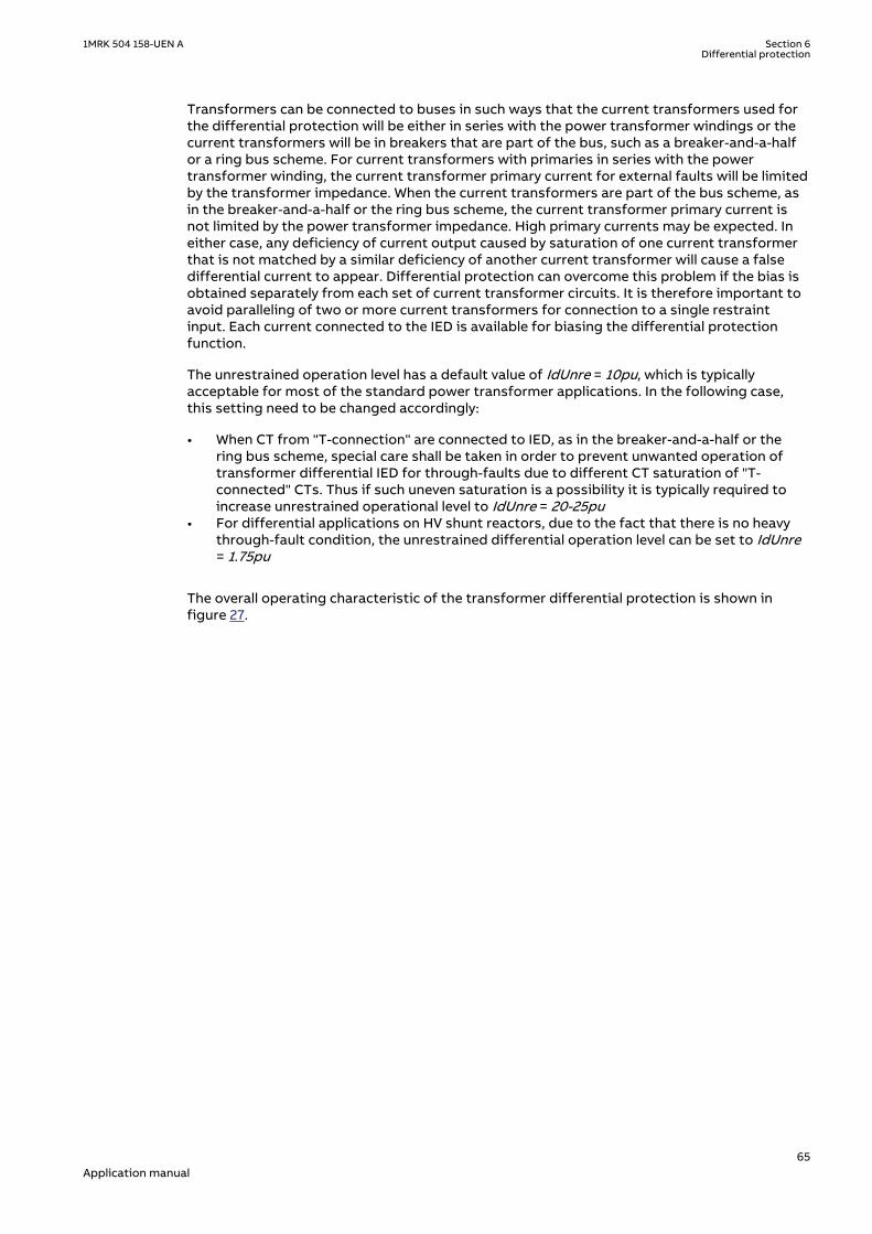
Transformers can be connected to buses in such ways that the current transformers used forthe differential protection will be either in series with the power transformer windings or thecurrent transformers will be in breakers that are part of the bus, such as a breaker-and-a-halfor a ring bus scheme. For current transformers with primaries in series with the powertransformer winding, the current transformer primary current for external faults will be limitedby the transformer impedance. When the current transformers are part of the bus scheme, asin the breaker-and-a-half or the ring bus scheme, the current transformer primary current isnot limited by the power transformer impedance. High primary currents may be expected. Ineither case, any deficiency of current output caused by saturation of one current transformerthat is not matched by a similar deficiency of another current transformer will cause a falsedifferential current to appear. Differential protection can overcome this problem if the bias isobtained separately from each set of current transformer circuits. It is therefore important toavoid paralleling of two or more current transformers for connection to a single restraintinput. Each current connected to the IED is available for biasing the differential protectionfunction.
The unrestrained operation level has a default value of IdUnre = 10pu, which is typicallyacceptable for most of the standard power transformer applications. In the following case,this setting need to be changed accordingly:
• When CT from "T-connection" are connected to IED, as in the breaker-and-a-half or thering bus scheme, special care shall be taken in order to prevent unwanted operation oftransformer differential IED for through-faults due to different CT saturation of "T-connected" CTs. Thus if such uneven saturation is a possibility it is typically required toincrease unrestrained operational level to IdUnre = 20-25pu
• For differential applications on HV shunt reactors, due to the fact that there is no heavythrough-fault condition, the unrestrained differential operation level can be set to IdUnre= 1.75pu
The overall operating characteristic of the transformer differential protection is shown infigure 27.
1MRK 504 158-UEN A Section 6Differential protection
65Application manual

Section 1
Operate conditionally
UnrestrainedLimit
Section 2 Section 3
Restrain
Operate unconditionally
5
4
3
2
1
00 1 2 3 4 5
IdMin
EndSection1
EndSection2restrain current[ times IBase ]
operate current[ times IBase ]
SlopeSection2
SlopeSection3
en05000187-2.vsdIEC05000187 V2 EN-US
Figure 27: Representation of the restrained, and the unrestrained operatecharacteristics
100%Ioperateslope IrestrainD= D ×
EQUATION1246 V1 EN-US (Equation 14)
and where the restrained characteristic is defined by the settings:
1. IdMin
2. EndSection1
3. EndSection2
4. SlopeSection2
5. SlopeSection3
6.1.2.2 Elimination of zero sequence currentsM15266-286 v8
A differential protection may operate undesirably due to external earth-faults in cases wherethe zero sequence current can flow on only one side of the power transformer, but not on theother side. This is the case when zero sequence current cannot be properly transformed to theother side of the power transformer. Power transformer connection groups of the Yd or Dytype cannot transform zero sequence current. If a delta winding of a power transformer isearthed via an earthing transformer inside the zone protected by the differential protectionthere will be an unwanted differential current in case of an external earth-fault. The same istrue for an earthed star winding. Even if both the star and delta winding are earthed, the zerosequence current is usually limited by the earthing transformer on the delta side of the power
Section 6 1MRK 504 158-UEN ADifferential protection
66Application manual

transformer, which may result in differential current as well. To make the overall differentialprotection insensitive to external earth-faults in these situations the zero sequence currentsmust be eliminated from the power transformer IED currents on the earthed windings, so thatthey do not appear as differential currents. This had once been achieved by means ofinterposing auxiliary current transformers. The elimination of zero sequence current is donenumerically by setting ZSCurrSubtrWx=Off or On and doesn't require any auxiliarytransformers or zero sequence traps. Instead it is necessary to eliminate the zero sequencecurrent from every individual winding by proper setting of setting parametersZSCurrSubtrWx=Off or On.
In case of a zig-zag winding, use one of the two following options:
• A delta winding• A wye winding with zero sequence subtraction set to ON
6.1.2.3 Inrush restraint methodsM15266-6 v7
With a combination of the second harmonic restraint and the waveform restraint methods it ispossible to get a protection with high security and stability against inrush effects and at thesame time maintain high performance in case of heavy internal faults even if the currenttransformers are saturated. Both these restraint methods are used by the IED. The secondharmonic restraint function has a settable level. If the ratio of the second harmonic to thefundamental in the differential current is above the settable limit, the operation of thedifferential protection is restrained. It is recommended to set parameter I2/I1Ratio = 15% asdefault value in case no special reasons exist to choose another value.
6.1.2.4 Overexcitation restraint methodM15266-320 v9
In case of an overexcited transformer, the winding currents contain odd harmonic componentsbecause the currents waveform are symmetrical relative to the time axis. As the third harmoniccurrents cannot flow into a delta winding, the fifth harmonic is the lowest harmonic which canserve as a criterion for overexcitation. The differential protection function is provided with afifth harmonic restraint to prevent the protection from operation during an overexcitationcondition of a power transformer. If the ratio of the fifth harmonic to the fundamental in thedifferential current is above a settable limit the operation is restrained. It is recommended touse I5/I1Ratio = 25% as default value in case no special reasons exist to choose anothersetting.
6.1.2.5 Cross-blocking between phasesM15266-317 v7
Basic definition of the cross-blocking is that one of the three phases can block operation (thatis, tripping) of the other two phases due to the harmonic pollution of the differential current inthat phase (waveform, 2nd or 5th harmonic content). In the algorithm the user can control thecross-blocking between the phases via the setting parameter CrossBlockEn. When parameterCrossBlockEn is set to On, cross blocking between phases will be introduced. There are notime related settings involved, but the phase with the operating point above the set biascharacteristic will be able to cross-block the other two phases if it is self-blocked by any of thepreviously explained restrained criteria. As soon as the operating point for this phase is belowthe set bias characteristic cross blocking from that phase will be inhibited. In this way cross-blocking of the temporary nature is achieved. It should be noted that this is the default(recommended) setting value for this parameter. When parameter CrossBlockEn is set to Off,any cross blocking between phases will be disabled.
1MRK 504 158-UEN A Section 6Differential protection
67Application manual

6.1.2.6 External/Internal fault discriminatorM15266-269 v10
The external/internal fault discriminator operation is based on the relative position of the twophasors (in case of a two-winding transformer) representing the W1 and W2 negativesequence current contributions, defined by matrix expression see the technical referencemanual. It practically performs a directional comparison between these two phasors.
In order to perform a directional comparison of the two phasors their magnitudes must behigh enough so that one can be sure that they are due to a fault. On the other hand, in order toguarantee a good sensitivity of the internal/external fault discriminator, the value of thisminimum limit must not be too high. Therefore this limit value (IMinNegSeq) is settable in therange from 1% to 20% of the differential protections IBasecurrent, which is in our case thepower transformer HV side rated current. The default value is 4%. Only if the magnitude ofboth negative sequence current contributions are above the set limit, the relative positionbetween these two phasors is checked. If either of the negative sequence currentcontributions, which should be compared, is too small (less than the set value forIMinNegSeq), no directional comparison is made in order to avoid the possibility to produce awrong decision.
This magnitude check, guarantees stability of the algorithm when the power transformer isenergized. In cases where the protected transformer can be energized with a load connectedon the LV side (e.g. a step-up transformer in a power station with directly connected auxiliarytransformer on its LV side) the value for this setting shall be increased to at least 12%. This isnecessary in order to prevent unwanted operation due to LV side currents during thetransformer inrush.
The setting NegSeqROA represents the so-called Relay Operate Angle, which determines theboundary between the internal and external fault regions. It can be selected in the range from30 degrees to 90 degrees, with a step of 1 degree. The default value is 60 degrees. The defaultsetting 60 degrees somewhat favors security in comparison to dependability. If the user hasno well-justified reason for another value, 60 degrees shall be applied.
If the above conditions concerning magnitudes are fulfilled, the internal/external faultdiscriminator compares the relative phase angle between the negative sequence currentcontributions from the HV side and LV side of the power transformer using the following tworules :
• If the negative sequence currents contributions from HV and LV sides are in phase or atleast in the internal fault region, the fault is internal.
• If the negative sequence currents contributions from HV and LV sides are 180 degrees outof phase or at least in the external fault region, the fault is external.
Under external fault condition and with no current transformer saturation, the relative angle istheoretically equal to 180 degrees. During internal fault and with no current transformersaturation, the angle shall ideally be 0 degrees, but due to possible different negativesequence source impedance angles on HV and LV side of power transformer, it may differsomewhat from the ideal zero value.
The internal/external fault discriminator has proved to be very reliable. If a fault is detected,that is, START signals set by ordinary differential protection, and at the same time theinternal/external fault discriminator characterizes this fault as an internal, any eventualblocking signals produced by either the harmonic or the waveform restraints are ignored.
If the bias current is more than 110% of IBase, the negative sequence threshold (IMinNegSeq)is increased internally.. This assures response times of the differential protection below onepower system cycle (below 20 ms for 50 Hz system) for all more severe internal faults. Even forheavy internal faults with severely saturated current transformers this differential protectionoperates well below one cycle, since the harmonic distortions in the differential currents donot slow down the differential protection operation. Practically, an unrestrained operation isachieved for all internal faults.
Section 6 1MRK 504 158-UEN ADifferential protection
68Application manual

External faults happen ten to hundred times more often than internal ones as far as the powertransformers are concerned. If a disturbance is detected and the internal/external faultdiscriminator characterizes this fault as an external fault, the conventional additional criteriaare posed on the differential algorithm before its trip is allowed. This assures high algorithmstability during external faults. However, at the same time the differential function is stillcapable of tripping quickly for evolving faults.
The principle of the internal/external fault discriminator can be extended to autotransformersand transformers with three windings. If all three windings are connected to their respectivenetworks then three directional comparisons are made, but only two comparisons arenecessary in order to positively determine the position of the fault with respect to theprotected zone. The directional comparisons which are possible, are: W1 - (W2+W3) and W2 -(W1+W3). The rule applied by the internal/external fault discriminator in case of three-windingpower transformers is:
• If any comparison indicates an internal fault, then it is an internal fault.• If any comparison indicates an external fault, then it is an external fault
If one of the windings is not connected, the algorithm automatically reduces to the two-winding version. Nevertheless, the whole power transformer is protected, including the non-connected winding.
6.1.2.7 Differential current alarmM15266-337 v6
Differential protection continuously monitors the level of the fundamental frequencydifferential currents and gives an alarm if the pre-set value is simultaneously exceeded in allthree phases. This feature can be used to monitor the integrity of on-load tap-changercompensation within the differential function. The threshold for the alarm pickup level isdefined by setting parameter IDiffAlarm. This threshold should be typically set in such way toobtain operation when on-load tap-changer measured value within differential function differsfor more than two steps from the actual on-load tap-changer position. To obtain suchoperation set parameter IDiffAlarm equal to two times the on-load tap-changer step size (Forexample, typical setting value is 5% to 10% of base current). Set the time delay defined byparameter tAlarmDelay two times longer than the on-load tap-changer mechanical operatingtime (For example, typical setting value 10s).
6.1.2.8 Open CT detectionM15266-340 v5
The Transformer differential function has a built-in, advanced open CT detection feature. Thisfeature can block the unexpected operation created by the Transformer differential function incase of open CT secondary circuit under normal load condition. An alarm signal can also beissued to station operational personnel to make remedy action once the open CT condition isdetected.
The following setting parameters are related to this feature:
• Setting parameter OpenCTEnable enables/disables this feature• Setting parameter tOCTAlarmDelay defines the time delay after which the alarm signal will
be given• Setting parameter tOCTReset defines the time delay after which the open CT condition
will reset once the defective CT circuits have been rectified• Once the open CT condition has been detected, then all the differential protection
functions are blocked except the unrestraint (instantaneous) differential protection
The outputs of open CT condition related parameters are listed below:
1MRK 504 158-UEN A Section 6Differential protection
69Application manual

• OpenCT: Open CT detected• OpenCTAlarm: Alarm issued after the setting delay• OpenCTIN: Open CT in CT group inputs (1 for input 1 and 2 for input 2)• OpenCTPH: Open CT with phase information (1 for phase L1, 2 for phase L2, 3 for phase L3)
6.1.2.9 Switch onto fault featureM15266-348 v5
The Transformer differential function in the IED has a built-in, advanced switch onto faultfeature. This feature can be enabled or disabled by the setting parameter SOTFMode. WhenSOTFMode = On this feature is enabled. It shall be noted that when this feature is enabled it isnot possible to test the 2nd harmonic blocking feature by simply injecting one current withsuperimposed second harmonic. In that case the switch on to fault feature will operate andthe differential protection will trip. However for a real inrush case the differential protectionfunction will properly restrain from operation.
For more information about the operating principles of the switch onto fault feature pleaseread the Technical Manual.
6.1.3 Setting exampleSEMOD167745-1 v1
6.1.3.1 IntroductionSEMOD167720-5 v6
Differential protection for power transformers has been used for decades. In order to correctlyapply transformer differential protection proper compensation is needed for:
• power transformer phase shift (vector group compensation)• CT secondary currents magnitude difference on different sides of the protected
transformer (ratio compensation)• zero sequence current elimination (zero sequence current reduction) shall be done. In the
past this was performed with help of interposing CTs or special connection of main CTs(delta connected CTs). With numerical technology all these compensations are done in IEDsoftware.
The Differential transformer protection is capable to provide differential protection for allstandard three-phase power transformers without any interposing CTs. It has been designedwith assumption that all main CTs will be star connected. For such applications it is then onlynecessary to enter directly CT rated data and power transformer data as they are given on thepower transformer nameplate and differential protection will automatically balance itself.
These are internal compensations within the differential function. Theprotected power transformer data are always entered as they are given on thenameplate. Differential function will by itself correlate nameplate data andproperly select the reference windings.
However the IED can also be used in applications where some of the main CTs are connected indelta. In such cases the ratio for the main CT connected in delta shall be intentionally set for √(3)=1.732 times smaller than actual ratio of individual phase CTs (for example, instead of 800/5set 462/5) In case the ratio is 800/2.88A, often designed for such typical delta connections,set the ratio as 800/5 in the IED. At the same time the power transformer vector group shallbe set as Yy0 because the IED shall not internally provide any phase angle shift compensation.The necessary phase angle shift compensation will be provided externally by delta connectedmain CT. All other settings should have the same values irrespective of main CT connections.
Section 6 1MRK 504 158-UEN ADifferential protection
70Application manual

6.1.3.2 Typical main CT connections for transformer differential protectionSEMOD167749-5 v3
Three most typical main CT connections used for transformer differential protection areshown in figure 28. It is assumed that the primary phase sequence is L1-L2-L3.
L1IL1
IL1-
IL2
IL2-
IL3
IL3-
IL1
IL1-
IL3
IL2-
IL1
IL3-
IL2
IL1
IL2
IL3
ProtectedTransformer
Winding
CT StarConnected
CT in DeltaDAC Connected
CT in DeltaDAB Connected
IL2
IL3
L2
L3
en06000549.vsd
IEC06000549 V1 EN-US
Figure 28: Commonly used main CT connections for Transformer differential protection.
For star connected main CTs, secondary currents fed to the IED:
• are directly proportional to the measured primary currents• are in phase with the measured primary currents• contain all sequence components including zero sequence current component
For star connected main CTs, the main CT ratio shall be set as it is in actual application. The“StarPoint” parameter, for the particular star connection shown in figure 28, shall be setToObject. If star connected main CTs have their star point away from the protectedtransformer this parameter should be set FromObject.
For delta DAC connected main CTs, secondary currents fed to the IED:
• are increased √3 times (1.732 times) in comparison with star connected CTs• lag by 30° the primary winding currents (this CT connection rotates currents by 30° in
clockwise direction)• do not contain zero sequence current component
For DAC delta connected main CTs, ratio shall be set for √3 times smaller than the actual ratioof individual phase CTs. The “StarPoint” parameter, for this particular connection shall be setToObject. It shall be noted that delta DAC connected main CTs must be connected exactly asshown in figure 28.
For delta DAB connected main CTs, secondary currents fed to the IED:
• are increased √3 times (1.732 times) in comparison with star connected CTs• lead by 30° the primary winding currents (this CT connection rotates currents by 30° in
anti-clockwise direction)• do not contain zero sequence current component
1MRK 504 158-UEN A Section 6Differential protection
71Application manual

For DAB delta connected main CT ratio shall be set for √3 times smaller in RET 670 then theactual ratio of individual phase CTs. The “StarPoint” parameter, for this particular connectionshall be set ToObject. It shall be noted that delta DAB connected main CTs must be connectedexactly as shown in figure 28.
For more detailed info regarding CT data settings please refer to the three applicationexamples presented in section "Application Examples".
6.1.3.3 Application ExamplesSEMOD167854-5 v2
Three application examples will be given here. For each example two differential protectionsolutions will be presented:
• First solution will be with all main CTs star connected.• Second solution will be with delta connected main CT on Y (that is, star) connected sides
of the protected power transformer.
For each differential protection solution the following settings will be given:
1. Input CT channels on the transformer input modules.2. General settings for the transformer differential protection where specific data about
protected power transformer shall be entered.
Finally the setting for the differential protection characteristic will be given for all presentedapplications.
Example 1: Star-delta connected power transformer without on-load tap-changerSEMOD167854-110 v6
Single line diagrams for two possible solutions for such type of power transformer with allrelevant application data are given in figure 29.
Section 6 1MRK 504 158-UEN ADifferential protection
72Application manual

CT 300/5in Delta(DAC)
CT 800/5Star
20.9 MVA69/12.5 kV
YNd1(YDAC)
CT 300/5Star
CT 800/5Star
20.9 MVA69/12.5 kV
YNd1(YDAC)
en06000554.vsdIEC06000554 V1 EN-US
Figure 29: Two differential protection solutions for star-delta connected powertransformer
For this particular power transformer the 69 kV side phase-to-earth no-load voltages lead by30 degrees the 12.5 kV side phase-to- earth no-load voltages. Thus when external phase angleshift compensation is done by connecting main HV CTs in delta, as shown in the right-handside in figure 29, it must be ensured that the HV currents are rotated by 30° in clockwisedirection. Thus the DAC delta CT connection must be used for 69 kV CTs in order to put 69 kV &12.5 kV currents in phase.
To ensure proper application of the IED for this power transformer it is necessary to do thefollowing:
1. Check that HV & LV CTs are connected to 5 A CT inputs in the IED.
2. For second solution make sure that HV delta connected CTs are DAC connected.
3. For star connected CTs make sure how they are stared (that is, earthed) to/from protectedtransformer.
4. Enter the following settings for all three CT input channels used for the LV side CTs see table10.
Table 10: CT input channels used for the LV side CTs
Setting parameter Selected value for both solutions
CTprim 800
CTsec 5
CTStarPoint ToObject
1MRK 504 158-UEN A Section 6Differential protection
73Application manual
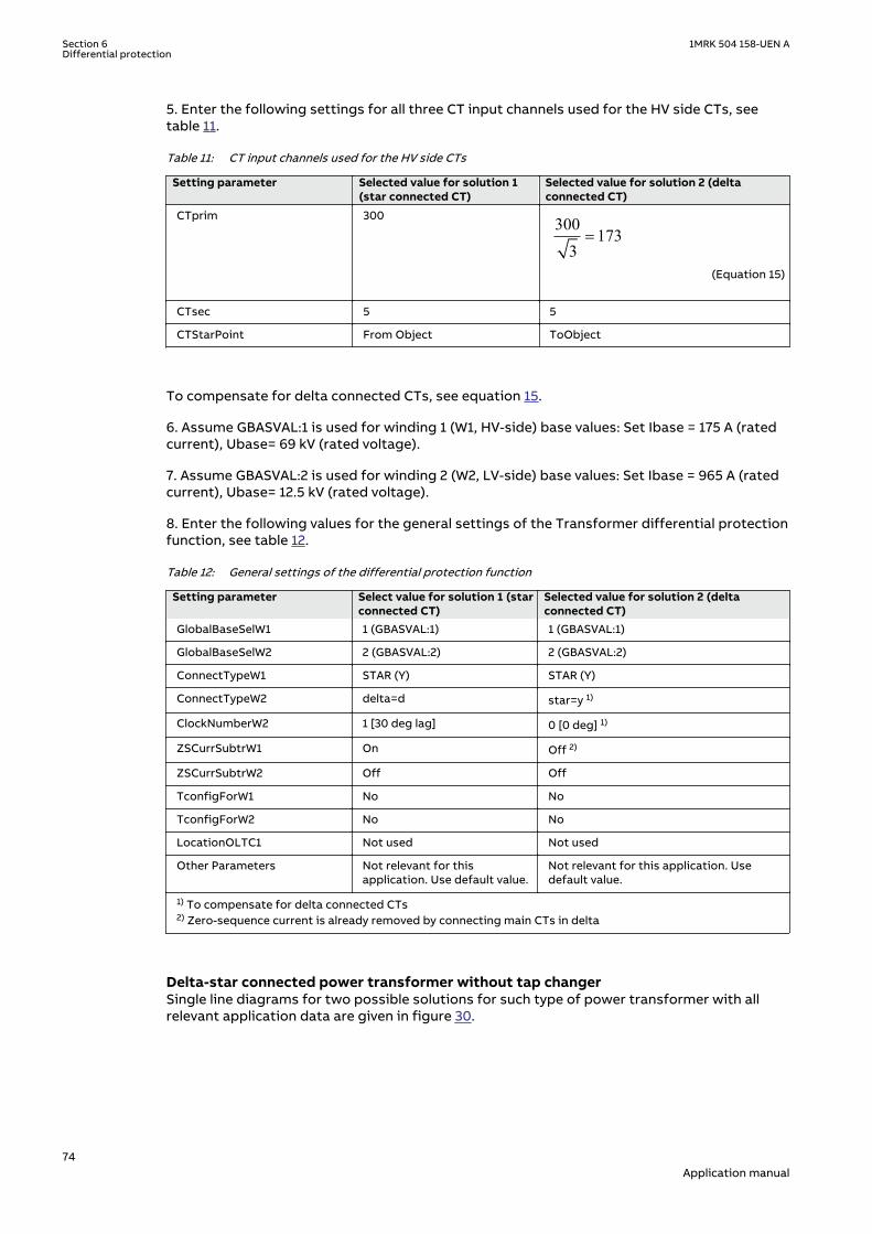
5. Enter the following settings for all three CT input channels used for the HV side CTs, seetable 11.
Table 11: CT input channels used for the HV side CTs
Setting parameter Selected value for solution 1(star connected CT)
Selected value for solution 2 (deltaconnected CT)
CTprim 300 300173
3=
EQUATION1888 V1 EN-US (Equation 15)
CTsec 5 5
CTStarPoint From Object ToObject
To compensate for delta connected CTs, see equation 15.
6. Assume GBASVAL:1 is used for winding 1 (W1, HV-side) base values: Set Ibase = 175 A (ratedcurrent), Ubase= 69 kV (rated voltage).
7. Assume GBASVAL:2 is used for winding 2 (W2, LV-side) base values: Set Ibase = 965 A (ratedcurrent), Ubase= 12.5 kV (rated voltage).
8. Enter the following values for the general settings of the Transformer differential protectionfunction, see table 12.
Table 12: General settings of the differential protection function
Setting parameter Select value for solution 1 (starconnected CT)
Selected value for solution 2 (deltaconnected CT)
GlobalBaseSelW1 1 (GBASVAL:1) 1 (GBASVAL:1)
GlobalBaseSelW2 2 (GBASVAL:2) 2 (GBASVAL:2)
ConnectTypeW1 STAR (Y) STAR (Y)
ConnectTypeW2 delta=d star=y 1)
ClockNumberW2 1 [30 deg lag] 0 [0 deg] 1)
ZSCurrSubtrW1 On Off 2)
ZSCurrSubtrW2 Off Off
TconfigForW1 No No
TconfigForW2 No No
LocationOLTC1 Not used Not used
Other Parameters Not relevant for thisapplication. Use default value.
Not relevant for this application. Usedefault value.
1) To compensate for delta connected CTs2) Zero-sequence current is already removed by connecting main CTs in delta
Delta-star connected power transformer without tap changerSEMOD167854-209 v5
Single line diagrams for two possible solutions for such type of power transformer with allrelevant application data are given in figure 30.
Section 6 1MRK 504 158-UEN ADifferential protection
74Application manual

CT 1500/5in Delta(DAB)
CT 400/5Star
60 MVA115/24.9 kV
Dyn1(DABY)
CT 1500/5Star
CT 400/5Star
60 MVA115/24.9 kV
Dyn1(DABY)
en06000555.vsdIEC06000555 V1 EN-US
Figure 30: Two differential protection solutions for delta-star connected powertransformer
For this particular power transformer the 115 kV side phase-to-earth no-load voltages lead by30° the 24.9 kV side phase-to-earth no-load voltages. Thus when external phase angle shiftcompensation is done by connecting main 24.9 kV CTs in delta, as shown in the right-hand sidein figure 30, it must be ensured that the 24.9 kV currents are rotated by 30° in anti-clockwisedirection. Thus, the DAB CT delta connection (see figure 30) must be used for 24.9 kV CTs inorder to put 115 kV & 24.9 kV currents in phase.
To ensure proper application of the IED for this power transformer it is necessary to do thefollowing:
1. Check that HV & LV CTs are connected to 5 A CT inputs in the IED.
2. For second solution make sure that LV delta connected CTs are DAB connected.
3. For star connected CTs make sure how they are 'star'red (that is, earthed) to/fromprotected transformer.
4. Enter the following settings for all three CT input channels used for the HV side CTs, seetable 13.
Table 13: CT input channels used for the HV side CTs
Setting parameter Selected value for both solutions
CTprim 400
CTsec 5
CTStarPoint ToObject
5. Enter the following settings for all three CT input channels used for the LV side CTs, seetable "CT input channels used for the LV side CTs".
1MRK 504 158-UEN A Section 6Differential protection
75Application manual
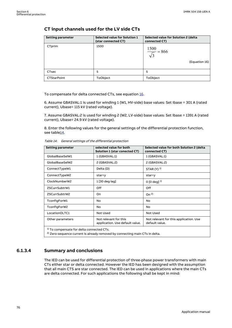
CT input channels used for the LV side CTs
Setting parameter Selected value for Solution 1(star connected CT)
Selected value for Solution 2 (deltaconnected CT)
CTprim 1500 1500866
3=
EQUATION1889 V1 EN-US (Equation 16)
CTsec 5 5
CTStarPoint ToObject ToObject
To compensate for delta connected CTs, see equation 16.
6. Assume GBASVAL:1 is used for winding 1 (W1, HV-side) base values: Set Ibase = 301 A (ratedcurrent), Ubase= 115 kV (rated voltage).
7. Assume GBASVAL:2 is used for winding 2 (W2, LV-side) base values: Set Ibase = 1391 A (ratedcurrent), Ubase= 24.9 kV (rated voltage).
8. Enter the following values for the general settings of the differential protection function,see table14.
Table 14: General settings of the differential protection
Setting parameter selected value for bothSolution 1 (star conected CT)
Selected value for both Solution 2 (deltaconnected CT)
GlobalBaseSelW1 1 (GBASVAL:1) 1 (GBASVAL:1)
GlobalBaseSelW2 2 (GBASVAL:2) 2 (GBASVAL:2)
ConnectTypeW1 Delta (D) STAR (Y) 1)
ConnectTypeW2 star=y star=y
ClockNumberW2 1 [30 deg lag] 0 [0 deg] 1)
ZSCurrSubtrW1 Off Off
ZSCurrSubtrW2 On On 2)
TconfigForW1 No No
TconfigForW2 No No
LocationOLTC1 Not Used Not Used
Other parameters Not relevant for thisapplication. Use default value.
Not relevant for this application. Usedefault value.
1) To compensate for delta connected CTs.2) Zero-sequence current is already removed by connecting main CTs in delta.
6.1.3.4 Summary and conclusionsSEMOD168160-5 v3
The IED can be used for differential protection of three-phase power transformers with mainCTs either star or delta connected. However the IED has been designed with the assumptionthat all main CTS are star connected. The IED can be used in applications where the main CTsare delta connected. For such applications the following shall be kept in mind:
Section 6 1MRK 504 158-UEN ADifferential protection
76Application manual

1. The ratio for delta connected CTs shall be set √(3)=1.732 times smaller than the actualindividual phase CT ratio.
2. The power transformer vector group shall typically be set as Yy0 because thecompensation for power transformer the actual phase shift is provided by the externaldelta CT connection.
3. The zero sequence current is eliminated by the main CT delta connections. Thus on sideswhere CTs are connected in delta the zero sequence current elimination shall be set to Offin the IED.
The following table summarizes the most commonly used star-delta vector groups around theworld and provides information about the required type of main CT delta connection on thestar side of the protected transformer.
IEC vector group Positive sequence no-loadvoltage phasor diagram
Required delta CT connection type on star side of theprotected power transformer and internal vector groupsetting in the IED
YNd1Y
IEC06000559 V1 EN-US
DAC/Yy0
Dyn1
Y
IEC06000560 V1 EN-US
DAB/Yy0
YNd11Y
IEC06000561 V1 EN-US
DAB/Yy0
Table continues on next page
1MRK 504 158-UEN A Section 6Differential protection
77Application manual

IEC vector group Positive sequence no-loadvoltage phasor diagram
Required delta CT connection type on star side of theprotected power transformer and internal vector groupsetting in the IED
Dyn11
Y
IEC06000562 V1 EN-US
DAC/Yy0
YNd5 Y
IEC06000563 V1 EN-US
DAB/Yy6
Dyn5
YIEC06000564 V1 EN-US
DAC/Yy6
6.2 Low impedance restricted earth fault protectionREFPDIF
IP14640-1 v6
6.2.1 IdentificationM14843-1 v5
Function description IEC 61850identification
IEC 60617identification
ANSI/IEEE C37.2device number
Restricted earth-fault protection,low impedance
REFPDIF
IdN/I
SYMBOL-AA V1 EN-US
87N
6.2.2 ApplicationIP14941-1 v1
M13940-3 v11
A breakdown of the insulation between a transformer winding and the core or the tank mayresult in a large fault current which causes severe damage to the windings and the transformercore. A high gas pressure may develop, damaging the transformer tank.
Fast and sensitive detection of earth faults in a power transformer winding can be obtained insolidly earthed or low impedance earthed networks by the restricted earth-fault protection.
Section 6 1MRK 504 158-UEN ADifferential protection
78Application manual

The only requirement is that the power transformer winding is connected to earth in the starpoint (in case of star-connected windings) or through a separate earthing transformer (in caseof delta-connected windings).
The low impedance restricted earth-fault protection REFPDIF is a winding protection function.It protects the power transformer winding against faults involving earth. Observe that singlephase-to-earth faults are the most common fault types in transformers. A sensitive earth-faultprotection is therefore desirable.
A restricted earth-fault protection is the fastest and the most sensitive protection, a powertransformer winding can have and will detect faults such as:
• earth faults in the transformer winding when the network is earthed through animpedance
• earth faults in the transformer winding in solidly earthed network when the point of thefault is close to the winding star point.
The restricted earth-fault protection is not affected, as a differential protection, with thefollowing power transformer related phenomena:
• magnetizing inrush currents• overexcitation magnetizing currents• load tap changer• external and internal phase faults which do not involve earth• symmetrical overload conditions
Due to its features, REFPDIF is often used as a main protection of the transformer winding forall faults involving earth.
6.2.2.1 Transformer winding, solidly earthedM13048-3 v9
The most common application is on a solidly earthed transformer winding. The connection isshown in figure 31.
1MRK 504 158-UEN A Section 6Differential protection
79Application manual

IEC09000109-4-EN.vsd
REFPDIF
I3PW1CT1
I3P
IdN/I
Protected winding
IEC09000109-4-EN V2 EN-US
Figure 31: Connection of the low impedance Restricted earth-fault function REFPDIF fora directly (solidly) earthed transformer winding
6.2.2.2 Transformer winding, earthed through zig-zag earthing transformerM13048-8 v11
A common application is for low reactance earthed transformer where the earthing is throughseparate zig-zag earthing transformers. The fault current is then limited to typical 800 to 2000A for each transformer. The connection for this application is shown in figure 32.
Section 6 1MRK 504 158-UEN ADifferential protection
80Application manual

REFPDIF - 1
I3PW1CT1
I3P
IdN/I
Protectedwinding W1
I3PW2CT1
I3P
IdN/I
REFPDIF - 2
Protected winding W2
Earthingtransformer
IEC09000110-4-EN.vsd
IEC09000110-4-EN V2 EN-US
Figure 32: Connection of the low impedance Restricted earth-fault function REFPDIF fora zig-zag earthing transformer
6.2.2.3 Autotransformer winding, solidly earthedM13048-13 v9
Autotransformers can be protected with the low impedance restricted earth-fault protectionfunction REFPDIF. The complete transformer will then be protected including the HV side, theneutral connection and the LV side. The connection of REFPDIF for this application is shown infigure 33.
1MRK 504 158-UEN A Section 6Differential protection
81Application manual

IEC09000111-4-EN.vsd
Auto -transformer
REFPDIF
I3PW1CT1
I3P
IdN/I
I3PW2CT1
HV (W1)
LV (W2)
IEC09000111-4-EN V2 EN-US
Figure 33: Connection of restricted earth fault, low impedance function REFPDIF for anautotransformer, solidly earthed
6.2.2.4 Reactor winding, solidly earthedM13048-18 v10
Reactors can be protected with restricted earth-fault protection, low impedance functionREFPDIF. The connection of REFPDIF for this application is shown in figure 34.
Section 6 1MRK 504 158-UEN ADifferential protection
82Application manual
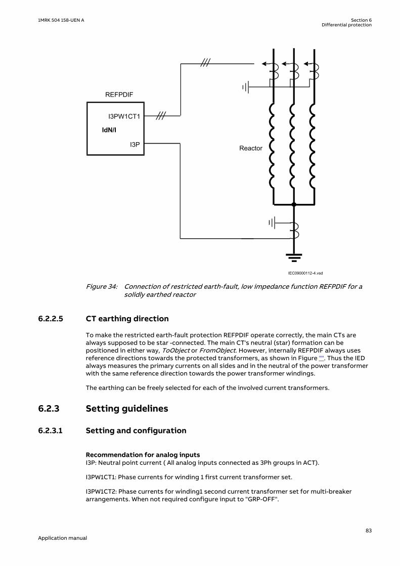
Reactor
REFPDIF
I3PW1CT1
I3P
IdN/I
IEC09000112-4.vsdIEC09000112-4 V2 EN-US
Figure 34: Connection of restricted earth-fault, low impedance function REFPDIF for asolidly earthed reactor
6.2.2.5 CT earthing directionM13048-29 v12
To make the restricted earth-fault protection REFPDIF operate correctly, the main CTs arealways supposed to be star -connected. The main CT's neutral (star) formation can bepositioned in either way, ToObject or FromObject. However, internally REFPDIF always usesreference directions towards the protected transformers, as shown in Figure "". Thus the IEDalways measures the primary currents on all sides and in the neutral of the power transformerwith the same reference direction towards the power transformer windings.
The earthing can be freely selected for each of the involved current transformers.
6.2.3 Setting guidelinesIP14942-1 v1
6.2.3.1 Setting and configurationM13052-3 v3
Recommendation for analog inputsM13052-8 v9
I3P: Neutral point current ( All analog inputs connected as 3Ph groups in ACT).
I3PW1CT1: Phase currents for winding 1 first current transformer set.
I3PW1CT2: Phase currents for winding1 second current transformer set for multi-breakerarrangements. When not required configure input to "GRP-OFF".
1MRK 504 158-UEN A Section 6Differential protection
83Application manual

I3PW2CT1: Phase currents for winding 2 first current transformer set. Used forautotransformers.
I3PW2CT2: Phase currents for winding 2 second current transformer set for multi-breakerarrangements. Used when protecting an autotransformer. When not required, configure inputto "GRP-OFF".
Recommendation for Binary input signalsM13052-17 v7
Refer to the pre-configured configurations for details.
BLOCK: The input will block the operation of the function. Can be used, for example, to blockfor a limited time the operation during special service conditions.
Recommendation for output signalsM13052-21 v8
Refer to pre-configured configurations for details.
START: The start output indicates that Idiff is in the operate region of the characteristic.
TRIP: The trip output is activated when all operating criteria are fulfilled.
DIROK: The output is activated when the directional criteria has been fulfilled.
BLK2H: The output is activated when the function is blocked due to a too high level of secondharmonic.
6.2.3.2 SettingsM13052-28 v12
The parameters for the restricted earth-fault protection, low impedance function REFPDIF areset via the local HMI or PCM600.
Common base IED values for primary current (IBase), primary voltage (UBase) and primarypower (SBase) are set in a Global base values for settings function GBASVAL.
GlobalBaseSel: It is used to select a GBASVAL function for reference of base values.
Operation: The operation of REFPDIF can be switched On/Off.
IdMin: The setting gives the minimum operation value. The setting is in percent of the IBasevalue of the chosen GlobalBaseSel. The neutral current must always be larger than half of thisvalue. A normal setting is 30% of power transformer-winding rated current for a solidlyearthed winding.
CTFactorPri1: A factor to allow a sensitive function also at multi-breaker arrangement wherethe rating in the bay is much higher than the rated current of the transformer winding. Thestabilizing can then be high so an unnecessary high fault level can be required. The setting isnormally 1.0 but in multi-breaker arrangement the setting shall be CT primary rating/IBase.
CTFactorPri2: A factor to allow a sensitive function also at multi-breaker arrangement wherethe rating in the bay is much higher than the rated current of the transformer winding. Thestabilizing can then be high so an unnecessary high fault level can be required. The setting isnormally 1.0 but in multi-breaker arrangement the setting shall be CT primary rating/IBase.
CTFactorSec1: See setting CTFactorPri1. Only difference is that CTFactorSec1 is related to W2side.
CTFactorSec2: See setting CTFactorPri2. Only difference is that CTFactorSec2 is related to W2side.
Section 6 1MRK 504 158-UEN ADifferential protection
84Application manual

Section 7 Current protection
7.1 Instantaneous phase overcurrent protection PHPIOCIP14506-1 v6
7.1.1 IdentificationM14880-1 v4
Function description IEC 61850identification
IEC 60617identification
ANSI/IEEE C37.2device number
Instantaneous phase overcurrentprotection 3-phase output
PHPIOC
3I>>
SYMBOL-Z V1 EN-US
50
7.1.2 ApplicationM12911-3 v5
Long transmission lines often transfer great quantities of electric power from production toconsumption areas. The unbalance of the produced and consumed electric power at each endof the transmission line is very large. This means that a fault on the line can easily endangerthe stability of a complete system.
The transient stability of a power system depends mostly on three parameters (at constantamount of transmitted electric power):
• The type of the fault. Three-phase faults are the most dangerous, because no power canbe transmitted through the fault point during fault conditions.
• The magnitude of the fault current. A high fault current indicates that the decrease oftransmitted power is high.
• The total fault clearing time. The phase angles between the EMFs of the generators onboth sides of the transmission line increase over the permitted stability limits if the totalfault clearing time, which consists of the protection operating time and the breakeropening time, is too long.
The fault current on long transmission lines depends mostly on the fault position anddecreases with the distance from the generation point. For this reason the protection mustoperate very quickly for faults very close to the generation (and relay) point, for which veryhigh fault currents are characteristic.
The instantaneous phase overcurrent protection 3-phase output PHPIOC can operate in 10 msfor faults characterized by very high currents.
7.1.3 Setting guidelinesIP14979-1 v1
M12915-4 v8
The parameters for instantaneous phase overcurrent protection 3-phase output PHPIOC areset via the local HMI or PCM600.
This protection function must operate only in a selective way. So check all system andtransient conditions that could cause its unwanted operation.
1MRK 504 158-UEN A Section 7Current protection
85Application manual
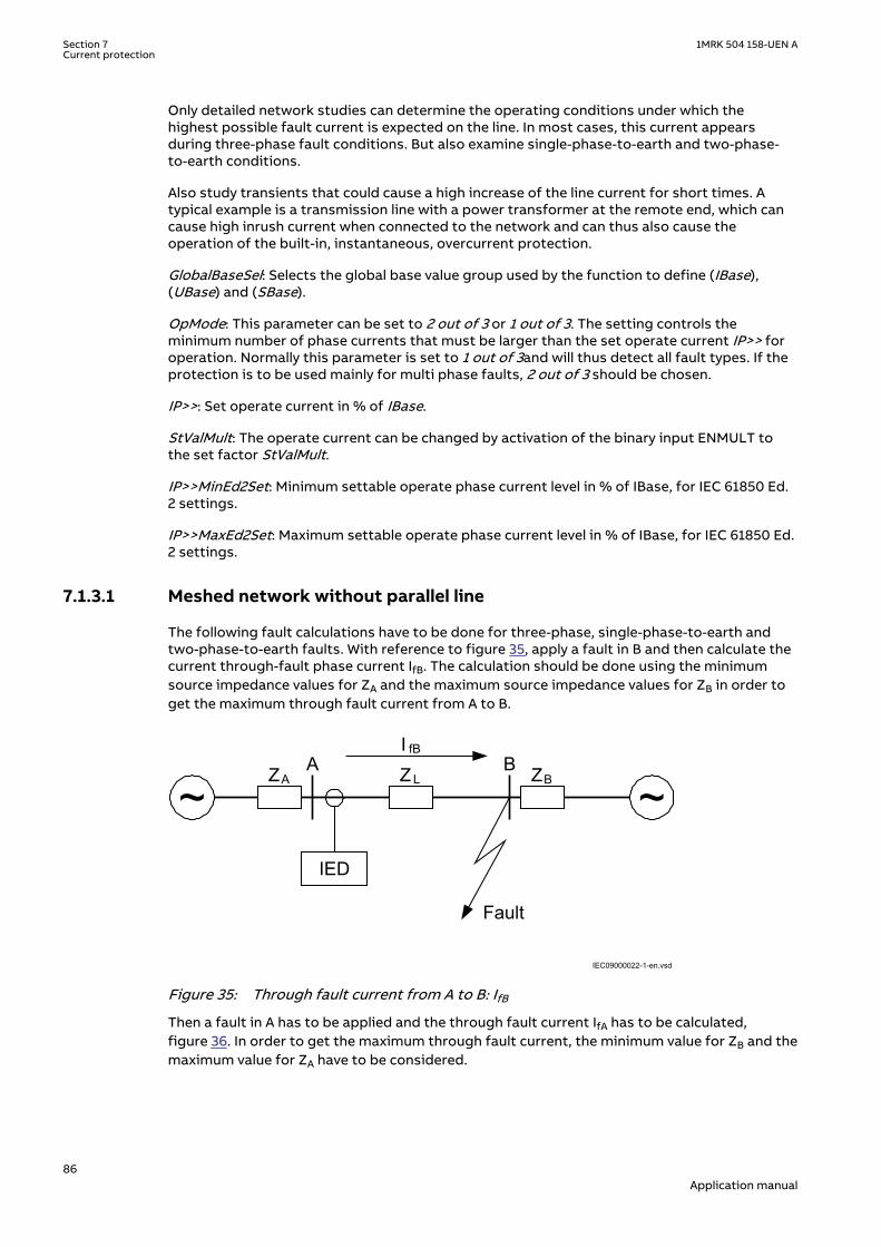
Only detailed network studies can determine the operating conditions under which thehighest possible fault current is expected on the line. In most cases, this current appearsduring three-phase fault conditions. But also examine single-phase-to-earth and two-phase-to-earth conditions.
Also study transients that could cause a high increase of the line current for short times. Atypical example is a transmission line with a power transformer at the remote end, which cancause high inrush current when connected to the network and can thus also cause theoperation of the built-in, instantaneous, overcurrent protection.
GlobalBaseSel: Selects the global base value group used by the function to define (IBase),(UBase) and (SBase).
OpMode: This parameter can be set to 2 out of 3 or 1 out of 3. The setting controls theminimum number of phase currents that must be larger than the set operate current IP>> foroperation. Normally this parameter is set to 1 out of 3and will thus detect all fault types. If theprotection is to be used mainly for multi phase faults, 2 out of 3 should be chosen.
IP>>: Set operate current in % of IBase.
StValMult: The operate current can be changed by activation of the binary input ENMULT tothe set factor StValMult.
IP>>MinEd2Set: Minimum settable operate phase current level in % of IBase, for IEC 61850 Ed.2 settings.
IP>>MaxEd2Set: Maximum settable operate phase current level in % of IBase, for IEC 61850 Ed.2 settings.
7.1.3.1 Meshed network without parallel lineM12915-9 v7
The following fault calculations have to be done for three-phase, single-phase-to-earth andtwo-phase-to-earth faults. With reference to figure 35, apply a fault in B and then calculate thecurrent through-fault phase current IfB. The calculation should be done using the minimumsource impedance values for ZA and the maximum source impedance values for ZB in order toget the maximum through fault current from A to B.
~ ~ZA ZBZ L
A B
IED
I fB
Fault
IEC09000022-1-en.vsdIEC09000022 V1 EN-US
Figure 35: Through fault current from A to B: IfB
Then a fault in A has to be applied and the through fault current IfA has to be calculated,figure 36. In order to get the maximum through fault current, the minimum value for ZB and themaximum value for ZA have to be considered.
Section 7 1MRK 504 158-UEN ACurrent protection
86Application manual
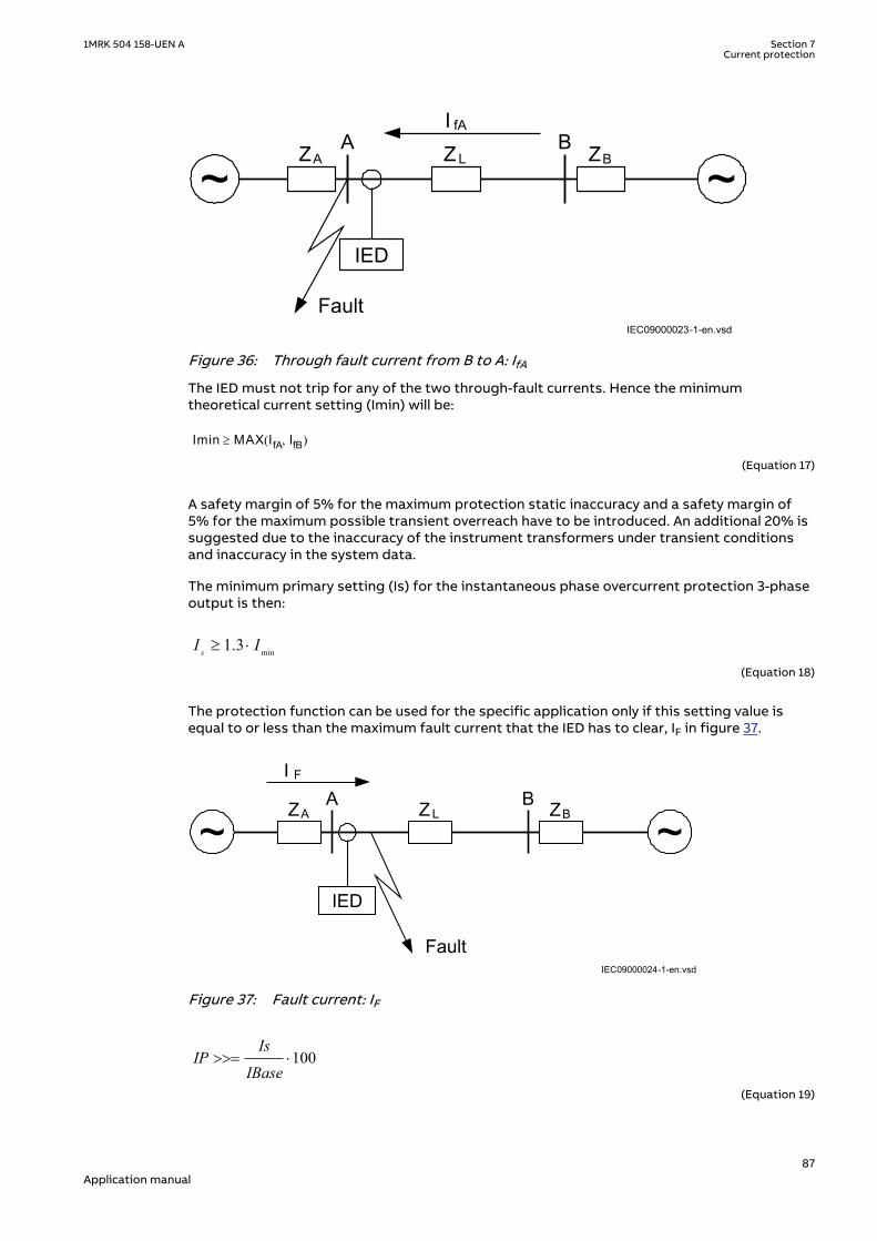
IEC09000023-1-en.vsd
~ ~ZA ZBZ L
A B
IED
I fA
FaultIEC09000023 V1 EN-US
Figure 36: Through fault current from B to A: IfA
The IED must not trip for any of the two through-fault currents. Hence the minimumtheoretical current setting (Imin) will be:
Imin MAX IfA IfB,( )³
EQUATION78 V1 EN-US (Equation 17)
A safety margin of 5% for the maximum protection static inaccuracy and a safety margin of5% for the maximum possible transient overreach have to be introduced. An additional 20% issuggested due to the inaccuracy of the instrument transformers under transient conditionsand inaccuracy in the system data.
The minimum primary setting (Is) for the instantaneous phase overcurrent protection 3-phaseoutput is then:
min1.3sI I³ ×
EQUATION79 V3 EN-US (Equation 18)
The protection function can be used for the specific application only if this setting value isequal to or less than the maximum fault current that the IED has to clear, IF in figure 37.
IEC09000024-1-en.vsd
~ ~ZA ZBZ L
A B
IED
I F
FaultIEC09000024 V1 EN-US
Figure 37: Fault current: IF
100Is
IPIBase
>>= ×
EQUATION1147 V3 EN-US (Equation 19)
1MRK 504 158-UEN A Section 7Current protection
87Application manual

7.1.3.2 Meshed network with parallel lineM12915-34 v6
In case of parallel lines, the influence of the induced current from the parallel line to theprotected line has to be considered. One example is given in figure 38 where the two lines areconnected to the same busbars. In this case the influence of the induced fault current from thefaulty line (line 1) to the healthy line (line 2) is considered together with the two through faultcurrents IfA and IfB mentioned previously. The maximal influence from the parallel line for theIED in figure 38 will be with a fault at the C point with the C breaker open.
A fault in C has to be applied, and then the maximum current seen from the IED (IM ) on thehealthy line (this applies for single-phase-to-earth and two-phase-to-earth faults) iscalculated.
IEC09000025-1-en.vsd
~ ~ZA ZB
ZL1A B
I M
Fault
IED
ZL2
M
CLine 1
Line 2
IEC09000025 V1 EN-US
Figure 38: Two parallel lines. Influence from parallel line to the through fault current: IM
The minimum theoretical current setting for the overcurrent protection function (Imin) will be:
Imin MAX IfA IfB IM, ,( )³
EQUATION82 V1 EN-US (Equation 20)
Where IfA and IfB have been described in the previous paragraph. Considering the safetymargins mentioned previously, the minimum setting (Is) for the instantaneous phaseovercurrent protection 3-phase output is then:
Is ³1.3·IminEQUATION83 V2 EN-US (Equation 21)
The protection function can be used for the specific application only if this setting value isequal or less than the maximum phase fault current that the IED has to clear.
The IED setting value IP>> is given in percentage of the primary base current value, IBase. Thevalue for IP>> is given from this formula:
100Is
IPIBase
>>= ×
EQUATION1147 V3 EN-US (Equation 22)
Section 7 1MRK 504 158-UEN ACurrent protection
88Application manual

7.2 Four step phase overcurrent protection OC4PTOCSEMOD129998-1 v7
7.2.1 IdentificationM14885-1 v5
Function description IEC 61850identification
IEC 60617identification
ANSI/IEEE C37.2device number
Four step phase overcurrentprotection 3-phase output
OC4PTOC
TOC-REVA V2 EN-US
51_67
7.2.2 ApplicationM15335-3 v8
The Four step phase overcurrent protection 3-phase output OC4PTOC is used in severalapplications in the power system. Some applications are:
• Short circuit protection of feeders in distribution and subtransmission systems. Normallythese feeders have radial structure.
• Back-up short circuit protection of transmission lines.• Back-up short circuit protection of power transformers.• Short circuit protection of different kinds of equipment connected to the power system
such as; shunt capacitor banks, shunt reactors, motors and others.• Back-up short circuit protection of power generators.
If VT inputs are not available or not connected, setting parameter DirModex (x= step 1, 2, 3 or 4) shall be left to default value Non-directional.
In many applications several steps with different current pick up levels and time delays areneeded. OC4PTOC can have up to four different, individual settable, steps.The flexibility ofeach step of OC4PTOC is great. The following options are possible:
Non-directional / Directional function: In most applications the non-directional functionality isused. This is mostly the case when no fault current can be fed from the protected object itself.In order to achieve both selectivity and fast fault clearance, the directional function can benecessary.
Choice of delay time characteristics: There are several types of delay time characteristicsavailable such as definite time delay and different types of inverse time delay characteristics.The selectivity between different overcurrent protections is normally enabled by co-ordinationbetween the function time delays of the different protections. To enable optimal co-ordinationbetween all overcurrent protections, they should have the same time delay characteristic.Therefore a wide range of standardized inverse time characteristics are available: IEC andANSI. It is also possible to tailor make the inverse time characteristic.
Normally it is required that the phase overcurrent protection shall reset as fast as possiblewhen the current level gets lower than the operation level. In some cases some sort of delayedreset is required. Therefore different kinds of reset characteristics can be used.
For some protection applications there can be a need to change the current pick-up level forsome time. A typical case is when the protection will measure the current to a large motor. Atthe start up sequence of a motor the start current can be significantly larger than the ratedcurrent of the motor. Therefore there is a possibility to give a setting of a multiplication factor
1MRK 504 158-UEN A Section 7Current protection
89Application manual
to the current pick-up level. This multiplication factor is activated from a binary input signal tothe function.
Power transformers can have a large inrush current, when being energized. This phenomenonis due to saturation of the transformer magnetic core during parts of the period. There is arisk that inrush current will reach levels above the pick-up current of the phase overcurrentprotection. The inrush current has a large 2nd harmonic content. This can be used to avoidunwanted operation of the protection. Therefore, OC4PTOC have a possibility of 2nd harmonicrestrain if the level of this harmonic current reaches a value above a set percentage of thefundamental current.
The phase overcurrent protection is often used as protection for two and three phase shortcircuits. In some cases it is not wanted to detect single-phase earth faults by the phaseovercurrent protection. This fault type is detected and cleared after operation of earth faultprotection. Therefore it is possible to make a choice how many phases, at minimum, that haveto have current above the pick-up level, to enable operation. If set 1 of 3 it is sufficient to havehigh current in one phase only. If set 2 of 3 or 3 of 3 single-phase earth faults are not detected.
7.2.3 Setting guidelinesIP14982-1 v1
M12982-4 v14
When inverse time overcurrent characteristic is selected, the operate time ofthe stage will be the sum of the inverse time delay and the set definite timedelay. Thus, if only the inverse time delay is required, it is important to set thedefinite time delay for that stage to zero.
The parameters for the directional phase overcurrent protection, four steps OC4PTOC are setvia the local HMI or PCM600.
The following settings can be done for OC4PTOC.
GlobalBaseSel: Selects the global base value group used by the function to define (IBase),(UBase) and (SBase).
MeasType: Selection of discrete Fourier filtered (DFT) or true RMS filtered (RMS) signals. RMSis used when the harmonic contents are to be considered, for example in applications withshunt capacitors.
Operation: The protection can be set to On or Off.
AngleRCA: Protection characteristic angle set in degrees. If the angle of the fault loop currenthas the angle RCA, the direction to the fault is forward.
AngleROA: Angle value, given in degrees, to define the angle sector of the directional function,shown in Figure 39.
StartPhSel: Number of phases, with high current, required for operation. The settingpossibilities are: 1 out of 3, 2 out of 3 and 3 out of 3. The default setting is 1 out of 3.
IMinOpPhSel: Minimum current setting level for releasing the directional start signals in % ofIB. This setting should be less than the lowest step setting. The default setting is 7% of IB.
2ndHarmStab: Operate level of 2nd harmonic current restrain set in % of the fundamentalcurrent. The setting range is 5 - 100% in steps of 1%. The default setting is 20%.
Section 7 1MRK 504 158-UEN ACurrent protection
90Application manual

Uref
Idir
IEC09000636_1_vsd
1
2
2
3
4
IEC09000636 V1 EN-US
Figure 39: Directional function characteristic
1. RCA = Relay characteristic angle2. ROA = Relay operating angle3. Reverse4. Forward
7.2.3.1 Settings for each stepM12982-19 v10.1.1
x means step 1, 2, 3 and 4.
DirModex: The directional mode of step x. Possible settings are Off/Non-directional/Forward/Reverse.
Characteristx: Selection of time characteristic for step x. Definite time delay and differenttypes of inverse time characteristics are available according to Table 15.
Table 15: Inverse time characteristics
Curve name
ANSI Extremely Inverse
ANSI Very Inverse
ANSI Normal Inverse
Table continues on next page
1MRK 504 158-UEN A Section 7Current protection
91Application manual

Curve name
ANSI Moderately Inverse
ANSI/IEEE Definite time
ANSI Long Time Extremely Inverse
ANSI Long Time Very Inverse
ANSI Long Time Inverse
IEC Normal Inverse
IEC Very Inverse
IEC Inverse
IEC Extremely Inverse
IEC Short Time Inverse
IEC Long Time Inverse
IEC Definite Time
User Programmable
ASEA RI
RXIDG or RD (logarithmic)
The different characteristics are described in Technical manual.
Ix>: Operate phase current level for step x given in % of IB.
Ix>MaxEd2Set and Ix>MinEd2Set should only be changed if remote setting of operationcurrent level, Ix>, is used. The limits are used for decreasing the used range of the Ix> setting.If Ix> is set outside Ix>MaxEd2Set and Ix>MinEd2Set, the closest of the limits to Ix> is used bythe function. If Ix>MaxEd2Set is smaller than Ix>MinEd2Set, the limits are swapped.
tx: Definite time delay for step x. The definite time tx is added to the inverse time when inversetime characteristic is selected. Note that the value set is the time between activation of thestart and the trip outputs.
kx: Time multiplier for inverse time delay for step x.
IMinx: Minimum operate current in % of IB for all inverse time characteristics, below which nooperation takes place.
txMin: Minimum operate time for all inverse time characteristics. At high currents the inversetime characteristic might give a very short operation time. By setting this parameter theoperation time of the step can never be shorter than the setting. Setting range: 0.000 -60.000s in steps of 0.001s.
IxMult: Multiplier for scaling of the current setting value. If a binary input signal ENMULTx(enableMultiplier) is activated the current operation level is increased by this setting constant.Setting range: 1.0-10.0
Section 7 1MRK 504 158-UEN ACurrent protection
92Application manual

IMinx
Operate time
Current
tx
txMin
IEC10000058
IEC10000058 V2 EN-US
Figure 40: Minimum operate current and operate time for inverse time characteristics
In order to fully comply with the definition of the curve, the setting parameter txMin shall beset to a value equal to the operating time of the selected inverse curve for twenty times the setcurrent pickup value. Note that the operate time is dependent on the selected time multipliersetting kx.
ResetTypeCrvx: The reset of the delay timer can be made as shown in Table 16.
Table 16: Reset possibilities
Curve name Curve index no.
Instantaneous 1
IEC Reset (constant time) 2
ANSI Reset (inverse time) 3
The delay characteristics are described in Technical manual. There are some restrictionsregarding the choice of the reset delay.
For the definite time delay characteristics, the possible delay time setting instantaneous (1)and IEC (2 = set constant time reset).
For ANSI inverse time characteristics, all three types of reset time characteristics are available:instantaneous (1), IEC (2 = set constant time reset) and ANSI (3 = current dependent resettime).
For IEC inverse time characteristics, the possible delay time settings are instantaneous (1) andIEC (2 = set constant time reset).
For the customer tailor-made inverse time delay characteristics (type 17), all three types ofreset time characteristics are available: instantaneous (1), IEC (2 = set constant time reset) andANSI (3 = current dependent reset time). If the current-dependent type is used, settings pr, trand cr must be given.
tResetx: Constant reset time delay in seconds for step x.
tPCrvx, tACrvx, tBCrvx, tCCrvx: These parameters are used by the customer to create theinverse time characteristic curve. See equation 23 for the time characteristic equation. Formore information, refer to Technical manual.
1MRK 504 158-UEN A Section 7Current protection
93Application manual
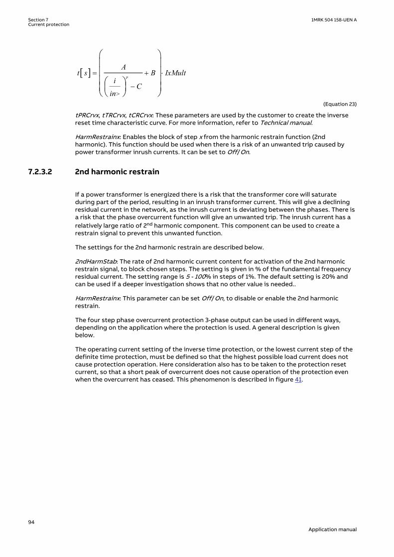
[ ]
>
p
At s B IxMult
iC
in
= + ×
-
æ öç ÷ç ÷ç ÷æ öç ÷ç ÷è øè ø
EQUATION1261 V2 EN-US (Equation 23)
tPRCrvx, tTRCrvx, tCRCrvx: These parameters are used by the customer to create the inversereset time characteristic curve. For more information, refer to Technical manual.
HarmRestrainx: Enables the block of step x from the harmonic restrain function (2ndharmonic). This function should be used when there is a risk of an unwanted trip caused bypower transformer inrush currents. It can be set to Off/On.
7.2.3.2 2nd harmonic restrainM12982-91 v8
If a power transformer is energized there is a risk that the transformer core will saturateduring part of the period, resulting in an inrush transformer current. This will give a decliningresidual current in the network, as the inrush current is deviating between the phases. There isa risk that the phase overcurrent function will give an unwanted trip. The inrush current has arelatively large ratio of 2nd harmonic component. This component can be used to create arestrain signal to prevent this unwanted function.
The settings for the 2nd harmonic restrain are described below.
2ndHarmStab: The rate of 2nd harmonic current content for activation of the 2nd harmonicrestrain signal, to block chosen steps. The setting is given in % of the fundamental frequencyresidual current. The setting range is 5 - 100% in steps of 1%. The default setting is 20% andcan be used if a deeper investigation shows that no other value is needed..
HarmRestrainx: This parameter can be set Off/On, to disable or enable the 2nd harmonicrestrain.
The four step phase overcurrent protection 3-phase output can be used in different ways,depending on the application where the protection is used. A general description is givenbelow.
The operating current setting of the inverse time protection, or the lowest current step of thedefinite time protection, must be defined so that the highest possible load current does notcause protection operation. Here consideration also has to be taken to the protection resetcurrent, so that a short peak of overcurrent does not cause operation of the protection evenwhen the overcurrent has ceased. This phenomenon is described in figure 41.
Section 7 1MRK 504 158-UEN ACurrent protection
94Application manual

Operate current
Current I
The IED does not reset
Line phase current
Time t
Reset current
IEC05000203-en-2.vsdIEC05000203 V3 EN-US
Figure 41: Operate and reset current for an overcurrent protection
The lowest setting value can be written according to equation 24.
ImaxIpu 1.2k
³ ×
EQUATION1262 V2 EN-US (Equation 24)
where:
1.2 is a safety factor
k is the resetting ratio of the protection
Imax is the maximum load current
From operation statistics the load current up to the present situation can be found. Thecurrent setting must be valid also for some years ahead. It is, in most cases, realistic that thesetting values are updated not more often than once every five years. In many cases this timeinterval is still longer. Investigate the maximum load current that different equipment on theline can withstand. Study components such as line conductors, current transformers, circuitbreakers, and disconnectors. The manufacturer of the equipment normally gives the maximumthermal load current of the equipment.
The maximum load current on the line has to be estimated. There is also a demand that allfaults, within the zone that the protection shall cover, must be detected by the phaseovercurrent protection. The minimum fault current Iscmin, to be detected by the protection,must be calculated. Taking this value as a base, the highest pick up current setting can bewritten according to equation 25.
1MRK 504 158-UEN A Section 7Current protection
95Application manual

Ipu 0.7 Iscmin£ ×EQUATION1263 V2 EN-US (Equation 25)
where:
0.7 is a safety factor
Iscmin is the smallest fault current to be detected by the overcurrent protection.
As a summary the operating current shall be chosen within the interval stated in equation 26.
Imax1.2 Ipu 0.7 Iscmink
× £ £ ×
EQUATION1264 V2 EN-US (Equation 26)
The high current function of the overcurrent protection, which only has a short delay of theoperation, must be given a current setting so that the protection is selective to otherprotection in the power system. It is desirable to have a rapid tripping of faults within as largeportion as possible of the part of the power system to be protected by the protection (primaryprotected zone). A fault current calculation gives the largest current of faults, Iscmax, at themost remote part of the primary protected zone. Considerations have to be made to the riskof transient overreach, due to a possible DC component of the short circuit current. The lowestcurrent setting of the most rapid stage, of the phase overcurrent protection, can be writtenaccording to
max1.2 t schighI k I³ × ×
EQUATION1265 V1 EN-US (Equation 27)
where:
1.2 is a safety factor
kt is a factor that takes care of the transient overreach due to the DC component of the fault currentand can be considered to be less than 1.05
Iscmax is the largest fault current at a fault at the most remote point of the primary protection zone.
The operate times of the phase overcurrent protection has to be chosen so that the fault timeis so short that protected equipment will not be destroyed due to thermal overload, at thesame time as selectivity is assured. For overcurrent protection, in a radial fed network, thetime setting can be chosen in a graphical way. This is mostly used in the case of inverse timeovercurrent protection. Figure 42 shows how the time-versus-current curves are plotted in adiagram. The time setting is chosen to get the shortest fault time with maintained selectivity.Selectivity is assured if the time difference between the curves is larger than a critical timedifference.
Section 7 1MRK 504 158-UEN ACurrent protection
96Application manual

en05000204.wmfIEC05000204 V1 EN-US
Figure 42: Fault time with maintained selectivity
The operation time can be set individually for each overcurrent protection.
To assure selectivity between different protections, in the radial network, there have to be aminimum time difference Dt between the time delays of two protections. The minimum timedifference can be determined for different cases. To determine the shortest possible timedifference, the operation time of protections, breaker opening time and protection resettingtime must be known. These time delays can vary significantly between different protectiveequipment. The following time delays can be estimated:
Protection operationtime:
15-60 ms
Protection resettingtime:
15-60 ms
Breaker opening time: 20-120 ms
Example for time coordination
Assume two substations A and B directly connected to each other via one line, as shown in thefigure 43. Consider a fault located at another line from the station B. The fault current to theovercurrent protection of IED B1 has a magnitude so that the protection will haveinstantaneous function. The overcurrent protection of IED A1 must have a delayed function.The sequence of events during the fault can be described using a time axis, see figure 43.
1MRK 504 158-UEN A Section 7Current protection
97Application manual

I> I>
A1 B1 Feeder
Time axis
t=0 t=t1 t=t2 t=t3The faultoccurs
ProtectionB1 trips
Breaker atB1 opens
ProtectionA1 resets
en05000205.vsdIEC05000205 V1 EN-US
Figure 43: Sequence of events during fault
where:
t=0 is when the fault occurs
t=t1 is when the trip signal from the overcurrent protection at IED B1 is sent to the circuit breaker. Theoperation time of this protection is t1
t=t2 is when the circuit breaker at IED B1 opens. The circuit breaker opening time is t2 - t1
t=t3 is when the overcurrent protection at IED A1 resets. The protection resetting time is t3 - t2.
To ensure that the overcurrent protection at IED A1, is selective to the overcurrent protectionat IED B1, the minimum time difference must be larger than the time t3. There are uncertaintiesin the values of protection operation time, breaker opening time and protection resettingtime. Therefore a safety margin has to be included. With normal values the needed timedifference can be calculated according to equation 28.
40 100 40 40 220t ms ms ms ms msD ³ + + + =EQUATION1266 V1 EN-US (Equation 28)
where it is considered that:
the operate time of overcurrent protection B1 is 40 ms
the breaker open time is 100 ms
the resetting time of protection A1 is 40 ms and
the additional margin is 40 ms
7.3 Instantaneous residual overcurrent protection EFPIOCIP14508-1 v3
Section 7 1MRK 504 158-UEN ACurrent protection
98Application manual

7.3.1 IdentificationM14887-1 v4
Function description IEC 61850identification
IEC 60617identification
ANSI/IEEE C37.2device number
Instantaneous residual overcurrentprotection
EFPIOC
IN>>
IEF V1 EN-US
50N
7.3.2 ApplicationM12699-3 v5
In many applications, when fault current is limited to a defined value by the object impedance,an instantaneous earth-fault protection can provide fast and selective tripping.
The Instantaneous residual overcurrent EFPIOC, which can operate in 15 ms (50 Hz nominalsystem frequency) for faults characterized by very high currents, is included in the IED.
7.3.3 Setting guidelinesIP14985-1 v1
M12762-44 v2M12762-4 v4
The parameters for the Instantaneous residual overcurrent protection EFPIOC are set via thelocal HMI or PCM600.
Some guidelines for the choice of setting parameter for EFPIOC is given.M12762-6 v7
GlobalBaseSel: Selects the global base value group used by the function to define (IBase),(UBase) and (SBase).
The setting of the function is limited to the operate residual current to the protection (IN>>).
The basic requirement is to assure selectivity, that is EFPIOC shall not be allowed to operatefor faults at other objects than the protected object (line).
For a normal line in a meshed system single phase-to-earth faults and phase-to-phase-to-earthfaults shall be calculated as shown in figure 44 and figure 45. The residual currents (3I0) to theprotection are calculated. For a fault at the remote line end this fault current is IfB. In thiscalculation the operational state with high source impedance ZA and low source impedance ZBshould be used. For the fault at the home busbar this fault current is IfA. In this calculation theoperational state with low source impedance ZA and high source impedance ZB should beused.
~ ~ZA ZBZ L
A B
IED
I fB
Fault
IEC09000022-1-en.vsdIEC09000022 V1 EN-US
Figure 44: Through fault current from A to B: IfB
1MRK 504 158-UEN A Section 7Current protection
99Application manual

IEC09000023-1-en.vsd
~ ~ZA ZBZ L
A B
IED
I fA
FaultIEC09000023 V1 EN-US
Figure 45: Through fault current from B to A: IfA
The function shall not operate for any of the calculated currents to the protection. Theminimum theoretical current setting (Imin) will be:
Imin MAX IfA IfA,( )³
EQUATION284 V1 EN-US (Equation 29)
A safety margin of 5% for the maximum static inaccuracy and a safety margin of 5% formaximum possible transient overreach have to be introduced. An additional 20% is suggesteddue to inaccuracy of instrument transformers under transient conditions and inaccuracy in thesystem data.
The minimum primary current setting (Is) is:
Is = 1.3 × Imin EQUATION285 V3 EN-US (Equation 30)
In case of parallel lines with zero sequence mutual coupling a fault on the parallel line, asshown in figure 46, should be calculated.
IEC09000025-1-en.vsd
~ ~ZA ZB
ZL1A B
I M
Fault
IED
ZL2
M
CLine 1
Line 2
IEC09000025 V1 EN-US
Figure 46: Two parallel lines. Influence from parallel line to the through fault current: IM
The minimum theoretical current setting (Imin) will in this case be:
Section 7 1MRK 504 158-UEN ACurrent protection
100Application manual

I m in M AX IfA I fB IM, ,( )³
EQUATION287 V1 EN-US (Equation 31)
Where:
IfA and IfB have been described for the single line case.
Considering the safety margins mentioned previously, the minimum setting (Is) is:
Is = 1.3 × Imin EQUATION288 V3 EN-US (Equation 32)
Transformer inrush current shall be considered.
The setting of the protection is set as a percentage of the base current (IBase).
Operation: set the protection to On or Off.
IN>>: Set operate current in % of IBase.
StValMult: The operate current can be changed by activation of the binary input ENMULT tothe set factor StValMult.
7.4 Four step residual overcurrent protection EF4PTOCIP14509-1 v7
7.4.1 IdentificationM14881-1 v5
Function description IEC 61850identification
IEC 60617identification
ANSI/IEEE C37.2device number
Four step residual overcurrentprotection
EF4PTOC 4(IN>)
4 alt4TEF-REVA V2 EN-US
51N_67N
7.4.2 ApplicationM12509-12 v9
The four step residual overcurrent protection EF4PTOC is used in several applications in thepower system. Some applications are:
• Earth-fault protection of feeders in effectively earthed distribution and subtransmissionsystems. Normally these feeders have radial structure.
• Back-up earth-fault protection of transmission lines.• Sensitive earth-fault protection of transmission lines. EF4PTOC can have better sensitivity
to detect resistive phase-to-earth-faults compared to distance protection.• Back-up earth-fault protection of power transformers.• Earth-fault protection of different kinds of equipment connected to the power system
such as shunt capacitor banks, shunt reactors and others.
1MRK 504 158-UEN A Section 7Current protection
101Application manual

In many applications several steps with different current operating levels and time delays areneeded. EF4PTOC can have up to four, individual settable steps. The flexibility of each step ofEF4PTOC is great. The following options are possible:
Non-directional/Directional function: In some applications the non-directional functionality isused. This is mostly the case when no fault current can be fed from the protected object itself.In order to achieve both selectivity and fast fault clearance, the directional function can benecessary. This can be the case for earth-fault protection in meshed and effectively earthedtransmission systems. The directional residual overcurrent protection is also well suited tooperate in teleprotection communication schemes, which enables fast clearance of earthfaults on transmission lines. The directional function uses the polarizing quantity as decidedby setting. Voltage polarizing is most commonly used, but alternatively current polarizingwhere currents in transformer neutrals providing the neutral source (ZN) is used to polarize (IN· ZN) the function. Dual polarizing where the sum of both voltage and current components isallowed to polarize can also be selected.
Choice of time characteristics: There are several types of time characteristics available such asdefinite time delay and different types of inverse time characteristics. The selectivity betweendifferent overcurrent protections is normally enabled by co-ordination between the operatetime of the different protections. To enable optimal co-ordination all overcurrent protections,to be co-ordinated against each other, should have the same time characteristic. Therefore awide range of standardized inverse time characteristics are available: IEC and ANSI.
Table 17: Time characteristics
Curve name
ANSI Extremely Inverse
ANSI Very Inverse
ANSI Normal Inverse
ANSI Moderately Inverse
ANSI/IEEE Definite time
ANSI Long Time Extremely Inverse
ANSI Long Time Very Inverse
ANSI Long Time Inverse
IEC Normal Inverse
IEC Very Inverse
IEC Inverse
IEC Extremely Inverse
IEC Short Time Inverse
IEC Long Time Inverse
IEC Definite Time
User Programmable
ASEA RI
RXIDG (logarithmic)
It is also possible to tailor make the inverse time characteristic.
Normally it is required that EF4PTOC shall reset as fast as possible when the current level getslower than the operation level. In some cases some sort of delayed reset is required. Thereforedifferent kinds of reset characteristics can be used.
For some protection applications there can be a need to change the current operating level forsome time. Therefore there is a possibility to give a setting of a multiplication factor INxMult
Section 7 1MRK 504 158-UEN ACurrent protection
102Application manual
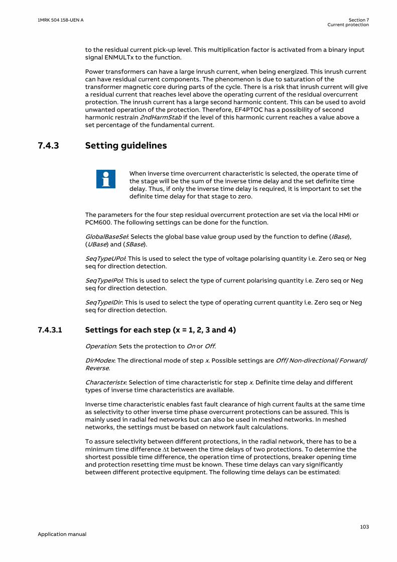
to the residual current pick-up level. This multiplication factor is activated from a binary inputsignal ENMULTx to the function.
Power transformers can have a large inrush current, when being energized. This inrush currentcan have residual current components. The phenomenon is due to saturation of thetransformer magnetic core during parts of the cycle. There is a risk that inrush current will givea residual current that reaches level above the operating current of the residual overcurrentprotection. The inrush current has a large second harmonic content. This can be used to avoidunwanted operation of the protection. Therefore, EF4PTOC has a possibility of secondharmonic restrain 2ndHarmStab if the level of this harmonic current reaches a value above aset percentage of the fundamental current.
7.4.3 Setting guidelinesIP14988-1 v1
M15282-3 v12
When inverse time overcurrent characteristic is selected, the operate time ofthe stage will be the sum of the inverse time delay and the set definite timedelay. Thus, if only the inverse time delay is required, it is important to set thedefinite time delay for that stage to zero.
The parameters for the four step residual overcurrent protection are set via the local HMI orPCM600. The following settings can be done for the function.
GlobalBaseSel: Selects the global base value group used by the function to define (IBase),(UBase) and (SBase).
SeqTypeUPol: This is used to select the type of voltage polarising quantity i.e. Zero seq or Negseq for direction detection.
SeqTypeIPol: This is used to select the type of current polarising quantity i.e. Zero seq or Negseq for direction detection.
SeqTypeIDir: This is used to select the type of operating current quantity i.e. Zero seq or Negseq for direction detection.
7.4.3.1 Settings for each step (x = 1, 2, 3 and 4)M15282-9 v12.1.1
Operation: Sets the protection to On or Off.
DirModex: The directional mode of step x. Possible settings are Off/Non-directional/Forward/Reverse.
Characteristx: Selection of time characteristic for step x. Definite time delay and differenttypes of inverse time characteristics are available.
Inverse time characteristic enables fast fault clearance of high current faults at the same timeas selectivity to other inverse time phase overcurrent protections can be assured. This ismainly used in radial fed networks but can also be used in meshed networks. In meshednetworks, the settings must be based on network fault calculations.
To assure selectivity between different protections, in the radial network, there has to be aminimum time difference Dt between the time delays of two protections. To determine theshortest possible time difference, the operation time of protections, breaker opening timeand protection resetting time must be known. These time delays can vary significantlybetween different protective equipment. The following time delays can be estimated:
1MRK 504 158-UEN A Section 7Current protection
103Application manual

Protection operate time: 15-60 ms
Protection resetting time: 15-60 ms
Breaker opening time: 20-120 ms
The different characteristics are described in the technical reference manual.
tx: Definite time delay for step x. The definite time tx is added to the inverse time when inversetime characteristic is selected. Note that the value set is the time between activation of thestart and the trip outputs.
INx>: Operate residual current level for step x given in % of IB.
INx>MaxEd2Set and INx>MinEd2Set should only be changed if remote setting of operationcurrent level, INx>, is used. The limits are used for decreasing the used range of the INx>setting. If INx> is set outside INx>MaxEd2Set and INx>MinEd2Set, the closest of the limits toINx> is used by the function. If INx>MaxEd2Set is smaller than INx>MinEd2Set, the limits areswapped.
kx: Time multiplier for the dependent (inverse) characteristic for step x.
: Minimum operate current for step in % of IB. Set below INx> for every step to achieve ANSIreset characteristic according to standard. If is set above INx> for any step, signal will reset atcurrent equals to zero.
txMin: Minimum operating time for inverse time characteristics. At high currents, the inversetime characteristic might give a very short operation time. By setting this parameter, theoperation time of the step can never be shorter than the setting.
IMinx
Operate time
Current
tx
txMin
IEC10000058
IEC10000058 V2 EN-US
Figure 47: Minimum operate current and operate time for inverse time characteristics
In order to fully comply with the curves definition, the setting parameter txMin shall be set tothe value which is equal to the operate time of the selected IEC inverse curve for measuredcurrent of twenty times the set current pickup value. Note that the operate time value isdependent on the selected setting value for time multiplier kx.
INxMult: Multiplier for scaling of the current setting value. If a binary input signal (ENMULTx) isactivated, the current operation level is increased by this setting constant.
ResetTypeCrvx: The reset of the delay timer can be made in different ways. The possibilitiesare described in the technical reference manual.
Section 7 1MRK 504 158-UEN ACurrent protection
104Application manual
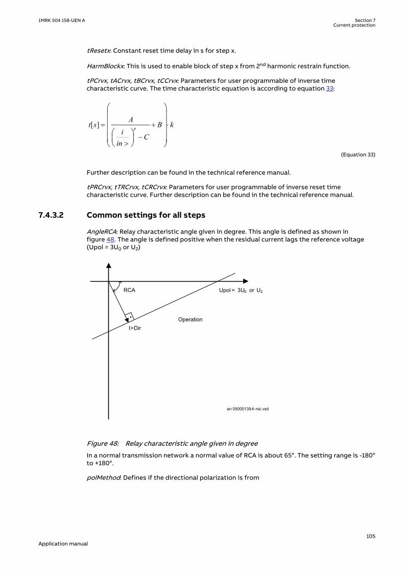
tResetx: Constant reset time delay in s for step x.
HarmBlockx: This is used to enable block of step x from 2nd harmonic restrain function.
tPCrvx, tACrvx, tBCrvx, tCCrvx: Parameters for user programmable of inverse timecharacteristic curve. The time characteristic equation is according to equation 33:
[ ] = + ×
->
æ öç ÷ç ÷ç ÷æ ö
ç ÷ç ÷è øè ø
p
At s B k
iC
inEQUATION1189 V1 EN-US (Equation 33)
Further description can be found in the technical reference manual.
tPRCrvx, tTRCrvx, tCRCrvx: Parameters for user programmable of inverse reset timecharacteristic curve. Further description can be found in the technical reference manual.
7.4.3.2 Common settings for all stepsM15282-81 v9
AngleRCA: Relay characteristic angle given in degree. This angle is defined as shown infigure 48. The angle is defined positive when the residual current lags the reference voltage(Upol = 3U0 or U2)
Upol = 3U0 or U2
I>Dir
RCA
Operation
en 05000135-4-nsi.vsd
IEC05000135 V4 EN-US
Figure 48: Relay characteristic angle given in degree
In a normal transmission network a normal value of RCA is about 65°. The setting range is -180°to +180°.
polMethod: Defines if the directional polarization is from
1MRK 504 158-UEN A Section 7Current protection
105Application manual

• Voltage (3U0 or U2)• Current (3I0 · ZNpol or 3I2 ·ZNpol where ZNpol is RNpol + jXNpol), or• both currents and voltage, Dual (dual polarizing, (3U0 + 3I0 · ZNpol) or (U2 + I2 · ZNpol)).
Normally voltage polarizing from the internally calculated residual sum or an external opendelta is used.
Current polarizing is useful when the local source is strong and a high sensitivity is required. Insuch cases the polarizing voltage (3U0) can be below 1% and it is then necessary to use currentpolarizing or dual polarizing. Multiply the required set current (primary) with the minimumimpedance (ZNpol) and check that the percentage of the phase-to-earth voltage is definitelyhigher than 1% (minimum 3U0>UPolMin setting) as a verification.
RNPol, XNPol: The zero-sequence source is set in primary ohms as base for the currentpolarizing. The polarizing voltage is then achieved as 3I0 · ZNpol. The ZNpol can be defined as(ZS1-ZS0)/3, that is the earth return impedance of the source behind the protection. Themaximum earth-fault current at the local source can be used to calculate the value of ZN asU/(√3 · 3I0) Typically, the minimum ZNPol (3 · zero sequence source) is set. Setting is in primaryohms.
When the dual polarizing method is used it is important that the settingINx>or the product 3I0· ZNpol is not greater than 3U0. If so, there is a risk for incorrect operation for faults in thereverse direction.
IPolMin: is the minimum earth-fault current accepted for directional evaluation. For smallercurrents than this value the operation will be blocked. Typical setting is 5-10% of IBase.
UPolMin: Minimum polarization (reference) polarizing voltage for the directional function,given in % of UBase/√3.
I>Dir: Operate residual current release level in % of IBase for directional comparison scheme.The setting is given in % of IBase and must be set below the lowest INx> setting, set for thedirectional measurement. The output signals, STFW and STRV can be used in a teleprotectionscheme. The appropriate signal should be configured to the communication scheme block.
7.4.3.3 2nd harmonic restrainM15282-90 v5
If a power transformer is energized there is a risk that the current transformer core willsaturate during part of the period, resulting in a transformer inrush current. This will give adeclining residual current in the network, as the inrush current is deviating between thephases. There is a risk that the residual overcurrent function will give an unwanted trip. Theinrush current has a relatively large ratio of 2nd harmonic component. This component can beused to create a restrain signal to prevent this unwanted function.
At current transformer saturation a false residual current can be measured by the protection.Also here the 2nd harmonic restrain can prevent unwanted operation.
2ndHarmStab: The rate of 2nd harmonic current content for activation of the 2nd harmonicrestrain signal. The setting is given in % of the fundamental frequency residual current.
HarmRestrainx: Enable block of step x from the harmonic restrain function.
7.4.3.4 Parallel transformer inrush current logicM15282-97 v5
In case of parallel transformers there is a risk of sympathetic inrush current. If one of thetransformers is in operation, and the parallel transformer is switched in, the asymmetricinrush current of the switched in transformer will cause partial saturation of the transformeralready in service. This is called transferred saturation. The 2nd harmonic of the inrush currents
Section 7 1MRK 504 158-UEN ACurrent protection
106Application manual

of the two transformers will be in phase opposition. The summation of the two currents willthus give a small 2nd harmonic current. The residual fundamental current will however besignificant. The inrush current of the transformer in service before the parallel transformerenergizing, will be a little delayed compared to the first transformer. Therefore we will havehigh 2nd harmonic current initially. After a short period this current will however be small andthe normal 2nd harmonic blocking will reset.
en05000136.vsd
Power System
IN>IN>
IEC05000136 V1 EN-US
Figure 49: Application for parallel transformer inrush current logic
If the BlkParTransf function is activated the 2nd harmonic restrain signal will latch as long asthe residual current measured by the relay is larger than a selected step current level. Assumethat step 4 is chosen to be the most sensitive step of the four step residual overcurrentprotection function EF4PTOC. The harmonic restrain blocking is enabled for this step. Also thesame current setting as this step is chosen for the blocking at parallel transformer energizing.
Below the settings for the parallel transformer logic are described.
UseStartValue: Gives which current level that should be used for activation of the blockingsignal. This is given as one of the settings of the steps: Step 1/2/3/4. Normally the step havingthe lowest operation current level should be set.
BlkParTransf: This parameter can be set Off/On, the parallel transformer logic.
7.4.3.5 Switch onto fault logicM15282-106 v3
In case of energizing a faulty object there is a risk of having a long fault clearance time, if thefault current is too small to give fast operation of the protection. The switch on to faultfunction can be activated from auxiliary signals from the circuit breaker, either the closecommand or the open/close position (change of position).
This logic can be used to issue fast trip if one breaker pole does not close properly at a manualor automatic closing.
SOTF and Under Time are similar functions to achieve fast clearance at asymmetrical closingbased on requirements from different utilities.
The function is divided into two parts. The SOTF function will give operation from step 2 or 3during a set time after change in the position of the circuit breaker. The SOTF function has aset time delay. The Under Time function, which has 2nd harmonic restrain blocking, will giveoperation from step 4. The 2nd harmonic restrain will prevent unwanted function in case oftransformer inrush current. The Under Time function has a set time delay.
Below the settings for switch on to fault logics are described.
SOTF operation mode: This parameter can be set: Off/SOTF/Under Time/SOTF+Under Time.
1MRK 504 158-UEN A Section 7Current protection
107Application manual

ActivationSOTF: This setting will select the signal to activate SOTF function; CB positionopen/CB position closed/CB close command.
tSOTF: Time delay for operation of the SOTF function. The setting range is 0.000 - 60.000 s instep of 0.001 s. The default setting is 0.100 s
StepForSOTF: If this parameter is set on the step 3 start signal will be used as current set level.If set off step 2 start signal will be used as current set level.
t4U: Time interval when the SOTF function is active after breaker closing. The setting range is0.000 - 60.000 s in step of 0.001 s. The default setting is 1.000 s.
ActUnderTime: Describes the mode to activate the sensitive undertime function. The functioncan be activated by Circuit breaker position (change) or Circuit breaker command.
tUnderTime: Time delay for operation of the sensitive undertime function. The setting range is0.000 - 60.000 s in step of 0.001 s. The default setting is 0.300 s
7.4.3.6 Transformer application exampleSEMOD55591-4 v7
Two main cases are of interest when residual overcurrent protection is used for a powertransformer, namely if residual current can be fed from the protected transformer winding ornot.
The protected winding will feed earth-fault (residual) current to earth faults in the connectedpower system. The residual current fed from the transformer at external phase-to-earth faultsis highly dependent on the total positive and zero-sequence source impedances. It is alsodependent on the residual current distribution between the network zero-sequenceimpedance and the transformer zero-sequence impedance. An example of this application isshown in Figure 50.
IN>
alt
Three phase CTsummated
Single CT
YN/D or YN/Ytransformer
en05000490.vsdIEC05000490 V1 EN-US
Figure 50: Residual overcurrent protection application on a directly earthed transformerwinding
In this case the protection has two different tasks:
• Detection of earth faults on the transformer winding.• Detection of earth faults in the power system.
Section 7 1MRK 504 158-UEN ACurrent protection
108Application manual

It can be suitable to use a residual overcurrent protection with at least two steps. Step 1 shallhave a short definite time delay and a relatively high current setting, in order to detect andclear high current earth faults in the transformer winding or in the power system close to thetransformer. Step 2 shall have a longer time delay (definite or inverse time delay) and a lowercurrent operation level. Step 2 shall detect and clear transformer winding earth faults with lowearth-fault current, that is, faults close to the transformer winding neutral point. If the currentsetting gap between step 1 and step 2 is large another step can be introduced with a currentand time delay setting between the two described steps.
The transformer inrush current will have a large residual current component. To preventunwanted function of the earth-fault overcurrent protection, the 2nd harmonic restrainblocking should be used, at least for the sensitive step 2.
If the protected winding will not feed earth-fault (residual) current to earth faults in theconnected power system the application is as shown in Figure 51.
IN>
Three phase CTsummated
Y/Y, Y/D or D/Ytransformer
en05000491.vsdIEC05000491 V1 EN-US
Figure 51: Residual overcurrent protection application on an isolated transformerwinding
In the calculation of the fault current fed to the protection, at different earth faults, are highlydependent on the positive and zero sequence source impedances, as well as the division ofresidual current in the network. Earth-fault current calculations are necessary for the setting.
Setting of step 1SEMOD55591-35 v4
One requirement is that earth faults at the busbar, where the transformer winding isconnected, shall be detected. Therefore a fault calculation as shown in figure 52 is made.
1MRK 504 158-UEN A Section 7Current protection
109Application manual

IN>
alt
Three phase CTsummated
Single CT
YN/D or YN/Ytransformer
Single phase-to-earth fault
3I0
IEC05000492-en-2.vsdIEC05000492 V2 EN-US
Figure 52: Step 1 fault calculation 1
This calculation gives the current fed to the protection: 3I0fault1.
To assure that step 1, selectivity to other earth-fault protections in the network a short delay isselected. Normally, a delay in the range 0.3 – 0.4 s is appropriate. To assure selectivity to linefaults, tripped after a delay (typically distance protection zone 2) of about 0.5 s the currentsetting must be set so high so that such faults does not cause unwanted step 1 trip. Therefore,a fault calculation as shown in figure 53 is made.
IN>
alt
Three phase CTsummated
Single CT
YN/D or YN/Ytransformer
Single phase-to-earth fault
3I0
IEC05000493-en-2.vsd
IEC05000493 V2 EN-US
Figure 53: Step 1 fault calculation 1
The fault is located at the borderline between instantaneous and delayed operation of the lineprotection, such as Distance protection or line residual overcurrent protection. This calculationgives the current fed to the protection: 3I0fault2
The setting of step 1 can be chosen within the interval shown in equation 34.
Section 7 1MRK 504 158-UEN ACurrent protection
110Application manual

0fault 2 step1 0fault13I lowmar I 3I highmar× < < ×
EQUATION1455 V2 EN-US (Equation 34)
Where:
lowmar is a margin to assure selectivity (typical 1.2) and
highmar is a margin to assure fast fault clearance of busbar fault (typical 1.2).
Setting of step 2SEMOD55591-57 v4
The setting of the sensitive step 2 is dependent of the chosen time delay. Often a relativelylong definite time delay or inverse time delay is chosen. The current setting can be chosen verylow. As it is required to detect earth faults in the transformer winding, close to the neutralpoint, values down to the minimum setting possibilities can be chosen. However, one mustconsider zero-sequence currents that can occur during normal operation of the power system.Such currents can be due to un-transposed lines.
In case to protection of transformer windings not feeding residual current at external earthfaults a fast lowcurrent step can be acceptable.
7.5 Sensitive directional residual overcurrent and powerprotection SDEPSDE
SEMOD171436-1 v4
7.5.1 IdentificationSEMOD172025-2 v4
Function description IEC 61850identification
IEC 60617identification
ANSI/IEEE C37.2device number
Sensitive directional residual overcurrent and power protection
SDEPSDE - 67N
7.5.2 ApplicationSEMOD171959-4 v11
In networks with high impedance earthing, the phase-to-earth fault current is significantlysmaller than the short circuit currents. Another difficulty for earth fault protection is that themagnitude of the phase-to-earth fault current is almost independent of the fault location inthe network.
Directional residual current can be used to detect and give selective trip of phase-to-earthfaults in high impedance earthed networks. The protection uses the residual currentcomponent 3I0 · cos φ, where φ is the angle between the residual current and the residualvoltage (-3U0), compensated with a characteristic angle. Alternatively, the function can be setto strict 3I0 level with a check of angle φ.
Directional residual power can also be used to detect and give selective trip of phase-to-earthfaults in high impedance earthed networks. The protection uses the residual powercomponent 3I0 · 3U0 · cos φ, where φ is the angle between the residual current and thereference residual voltage, compensated with a characteristic angle.
A normal non-directional residual current function can also be used with definite or inversetime delay.
1MRK 504 158-UEN A Section 7Current protection
111Application manual

A backup neutral point voltage function is also available for non-directional residualovervoltage protection.
In an isolated network, that is, the network is only coupled to earth via the capacitancesbetween the phase conductors and earth, the residual current always has -90º phase shiftcompared to the residual voltage (3U0). The characteristic angle is chosen to -90º in such anetwork.
In resistance earthed networks or in Petersen coil earthed, with a parallel resistor, the activeresidual current component (in phase with the residual voltage) should be used for the earthfault detection. In such networks, the characteristic angle is chosen to 0º.
As the amplitude of the residual current is independent of the fault location, the selectivity ofthe earth fault protection is achieved by time selectivity.
When should the sensitive directional residual overcurrent protection be used and whenshould the sensitive directional residual power protection be used? Consider the following:
• Sensitive directional residual overcurrent protection gives possibility for better sensitivity.The setting possibilities of this function are down to 0.25 % of IBase, 1 A or 5 A. Thissensitivity is in most cases sufficient in high impedance network applications, if themeasuring CT ratio is not too high.
• Sensitive directional residual power protection gives possibility to use inverse timecharacteristics. This is applicable in large high impedance earthed networks, with largecapacitive earth fault currents. In such networks, the active fault current would be smalland by using sensitive directional residual power protection, the operating quantity iselevated. Therefore, better possibility to detect earth faults. In addition, in low impedanceearthed networks, the inverse time characteristic gives better time-selectivity in case ofhigh zero-resistive fault currents.
Phase currents
Phase-ground
voltages
IN
UN
IEC13000013-1-en.vsdIEC13000013 V1 EN-US
Figure 54: Connection of SDEPSDE to analog preprocessing function block
Overcurrent functionality uses true 3I0, i.e. sum of GRPxL1, GRPxL2 and GRPxL3. For 3I0 to becalculated, connection is needed to all three phase inputs.
Directional and power functionality uses IN and UN. If a connection is made to GRPxN thissignal is used, else if connection is made to all inputs GRPxL1, GRPxL2 and GRPxL3 theinternally calculated sum of these inputs (3I0 and 3U0) will be used.
Section 7 1MRK 504 158-UEN ACurrent protection
112Application manual

7.5.3 Setting guidelinesSEMOD171961-4 v9
The sensitive earth fault protection is intended to be used in high impedance earthed systems,or in systems with resistive earthing where the neutral point resistor gives an earth faultcurrent larger than what normal high impedance gives but smaller than the phase-to-phaseshort circuit current.
In a high impedance system the fault current is assumed to be limited by the system zerosequence shunt impedance to earth and the fault resistance only. All the series impedances inthe system are assumed to be zero.
In the setting of earth fault protection, in a high impedance earthed system, the neutral pointvoltage (zero sequence voltage) and the earth fault current will be calculated at the desiredsensitivity (fault resistance). The complex neutral point voltage (zero sequence) can becalculated as:
phase
0f
0
UU
3 R1
Z
=×
+
EQUATION1943 V1 EN-US (Equation 35)
Where
Uphase is the phase voltage in the fault point before the fault,
Rf is the resistance to earth in the fault point and
Z0 is the system zero sequence impedance to earth
The fault current, in the fault point, can be calculated as:
phase
j 0
0 f
3 UI 3I
Z 3 R
×= =
+ ×
EQUATION1944 V1 EN-US (Equation 36)
The impedance Z0 is dependent on the system earthing. In an isolated system (without neutralpoint apparatus) the impedance is equal to the capacitive coupling between the phaseconductors and earth:
phase
0 c
j
3 UZ jX j
I
×= - = -
EQUATION1945 V1 EN-US (Equation 37)
Where
Ij is the capacitive earth fault current at a non-resistive phase-to-earth fault
Xc is the capacitive reactance to earth
In a system with a neutral point resistor (resistance earthed system) the impedance Z0 can becalculated as:
1MRK 504 158-UEN A Section 7Current protection
113Application manual

c n0
c n
jX 3RZ
jX 3R
- ×=
- +
EQUATION1946 V1 EN-US (Equation 38)
Where
Rn is the resistance of the neutral point resistor
In many systems there is also a neutral point reactor (Petersen coil) connected to one or moretransformer neutral points. In such a system the impedance Z0 can be calculated as:
( )n n c
0 c n n
n c n n c
9R X XZ jX // 3R // j3X
3X X j3R 3X X= - =
+ × -
EQUATION1947 V1 EN-US (Equation 39)
Where
Xn is the reactance of the Petersen coil. If the Petersen coil is well tuned we have 3Xn = Xc In this case theimpedance Z0 will be: Z0 = 3Rn
Now consider a system with an earthing via a resistor giving higher earth fault current than thehigh impedance earthing. The series impedances in the system can no longer be neglected.The system with a single phase to earth fault can be described as in Figure 55.
Substation A
Substation B
ZlineAB,1 (pos. seq)ZlineAB,0 (zero seq)
ZlineBC,1 (pos. seq)ZlineBC,0 (zero seq)
U0A
U0B
3I0
Phase to earth fault
RNZT,1 (pos. seq)ZT,0 (zero seq)
Source impedanceZsc (pos. seq)
en06000654.vsdIEC06000654 V1 EN-US
Figure 55: Equivalent of power system for calculation of setting
The residual fault current can be written:
Section 7 1MRK 504 158-UEN ACurrent protection
114Application manual

phase
0
1 0 f
3U3I
2 Z Z 3 R=
× + + ×
EQUATION1948 V1 EN-US (Equation 40)
Where
Uphase is the phase voltage in the fault point before the fault
Z1 is the total positive sequence impedance to the fault point. Z1 = Zsc+ZT,1+ZlineAB,1+ZlineBC,1
Z0 is the total zero sequence impedance to the fault point. Z0 = ZT,0+3RN+ZlineAB,0+ZlineBC,0
Rf is the fault resistance.
The residual voltages in stations A and B can be written:
( )0 A 0 T,0 NU 3I Z 3R= × +
EQUATION1949 V1 EN-US (Equation 41)
OB 0 T,0 N lineAB,0U 3I (Z 3R Z )= × + +
EQUATION1950 V1 EN-US (Equation 42)
The residual power, measured by the sensitive earth fault protections in A and B will be:
0 A 0A 0S 3U 3I= ×
EQUATION1951 V1 EN-US (Equation 43)
0 B 0B 0S 3U 3I= ×
EQUATION1952 V1 EN-US (Equation 44)
The residual power is a complex quantity. The protection will have a maximum sensitivity inthe characteristic angle RCA. The apparent residual power component in the characteristicangle, measured by the protection, can be written:
0 A ,prot 0A 0 AS 3U 3I cosj= × ×
EQUATION1953 V1 EN-US (Equation 45)
0 B,prot 0B 0 BS 3U 3I cosj= × ×
EQUATION1954 V1 EN-US (Equation 46)
The angles φA and φB are the phase angles between the residual current and the residualvoltage in the station compensated with the characteristic angle RCA.
The protection will use the power components in the characteristic angle direction formeasurement, and as base for the inverse time delay.
The inverse time delay is defined as:
1MRK 504 158-UEN A Section 7Current protection
115Application manual

0 0inv
0 0
kSN (3I 3U cos (reference))t3I 3U cos (measured)
× × × j=
× × j
EQUATION1942 V2 EN-US (Equation 47)
The function can be set On/Off with the setting of Operation.
Common base IED values for primary current (IBase), primary voltage (UBase) and primarypower (SBase) are set in a Global base values for settings function GBASVAL.
GlobalBaseSel: It is used to select a GBASVAL function for reference of base values.
RotResU: It is a setting for rotating the polarizing quantity ( 3U0) by 0 or 180 degrees. Thisparameter is set to 180 degrees by default in order to inverse the residual voltage ( 3U0) tocalculate the reference voltage (-3U0 e-jRCADir). Since the reference voltage is used as thepolarizing quantity for directionality, it is important to set this parameter correctly.
With the setting OpMode the principle of directional function is chosen.
With OpMode set to 3I0cosfi the current component in the direction equal to the characteristicangleRCADir has the maximum sensitivity. The characteristic for RCADir is equal to 0° is shownin Figure 56.
= =o o0 , 90RCADir ROADir
03I
j = -0 refang(3I ) ang(3U )- =0 ref3U U
03I cos× j
IEC06000648-4-en.vsdIEC06000648 V4 EN-US
Figure 56: Characteristic for RCADir equal to 0°
The characteristic is for RCADir equal to -90° is shown in Figure 57.
Section 7 1MRK 504 158-UEN ACurrent protection
116Application manual

IEC06000649_3_en.vsd
refU= − = 90 , 90RCADir ROADir
03I
03 ⋅ ϕI cos
ϕ = −0(3 ) ( )refang I ang U
− 03U
IEC06000649 V3 EN-US
Figure 57: Characteristic for RCADir equal to -90°
When OpMode is set to 3U03I0cosfi the apparent residual power component in the direction ismeasured.
When OpMode is set to 3I0 and fi the function will operate if the residual current is larger thanthe setting INDir> and the residual current angle is within the sector RCADir ± ROADir.
The characteristic for this OpMode when RCADir = 0° and ROADir = 80° is shown in figure 58.
-3U0
Operate area
3I0
RCADir = 0º
ROADir = 80º
IEC06000652-3-en.vsdIEC06000652 V3 EN-US
Figure 58: Characteristic for RCADir = 0° and ROADir = 80°
DirMode is set Forward or Reverse to set the direction of the operation for the directionalfunction selected by the OpMode.
All the directional protection modes have a residual current release level setting INRel> whichis set in % of IBase. This setting should be chosen smaller than or equal to the lowest faultcurrent to be detected.
1MRK 504 158-UEN A Section 7Current protection
117Application manual

All the directional protection modes have a residual voltage release level setting UNRel> whichis set in % of UBase. This setting should be chosen smaller than or equal to the lowest faultresidual voltage to be detected.
tDef is the definite time delay, given in s, for the directional residual current protection.
tReset is the time delay before the definite timer gets reset, given in s. With a tReset time offew cycles, there is an increased possibility to clear intermittent earth faults correctly. Thesetting shall be much shorter than the set trip delay. In case of intermittent earth faults, thefault current is intermittently dropping below the set value during consecutive cycles.Therefore the definite timer should continue for a certain time equal to tReset even though thefault current has dropped below the set value.
The characteristic angle of the directional functions RCADir is set in degrees. RCADir isnormally set equal to 0° in a high impedance earthed network with a neutral point resistor asthe active current component is appearing out on the faulted feeder only. RCADir is set equalto -90° in an isolated network as all currents are mainly capacitive.
ROADir is Relay Operating Angle. ROADir is identifying a window around the referencedirection in order to detect directionality. ROADir is set in degrees. For angles differing morethan ROADir from RCADir the function is blocked. The setting can be used to preventunwanted operation for non-faulted feeders, with large capacitive earth fault currentcontributions, due to CT phase angle error.
INCosPhi> is the operate current level for the directional function when OpMode is set3I0Cosfi. The setting is given in % of IBase. The setting should be based on calculation of theactive or capacitive earth fault current at required sensitivity of the protection.
SN> is the operate power level for the directional function when OpMode is set 3I03U0Cosfi.The setting is given in % of SBase. The setting should be based on calculation of the active orcapacitive earth fault residual power at required sensitivity of the protection.
The input transformer for the Sensitive directional residual over current and power protectionfunction has the same short circuit capacity as the phase current transformers. Hence, there isno specific requirement for the external CT core, i.e. any CT core can be used.
If the time delay for residual power is chosen the delay time is dependent on two settingparameters. SRef is the reference residual power, given in % of SBase. kSN is the timemultiplier. The time delay will follow the following expression:
inv0 0
kSN Sreft
3I 3U cos (measured)j×
=× ×
EQUATION1957 V1 EN-US (Equation 48)
INDir> is the operate current level for the directional function when OpMode is set 3I0 and fi.The setting is given in % of IBase. The setting should be based on calculation of the earth faultcurrent at required sensitivity of the protection.
OpINNonDir> is set On to activate the non-directional residual current protection.
INNonDir> is the operate current level for the non-directional function. The setting is given in% of IBase. This function can be used for detection and clearance of cross-country faults in ashorter time than for the directional function. The current setting should be larger than themaximum single-phase residual current on the protected line.
TimeChar is the selection of time delay characteristic for the non-directional residual currentprotection. Definite time delay and different types of inverse time characteristics are available:
Section 7 1MRK 504 158-UEN ACurrent protection
118Application manual

Table 18: Inverse time characteristics
Curve name
ANSI Extremely Inverse
ANSI Very Inverse
ANSI Normal Inverse
ANSI Moderately Inverse
ANSI/IEEE Definite time
ANSI Long Time Extremely Inverse
ANSI Long Time Very Inverse
ANSI Long Time Inverse
IEC Normal Inverse
IEC Very Inverse
IEC Inverse
IEC Extremely Inverse
IEC Short Time Inverse
IEC Long Time Inverse
IEC Definite Time
User Programmable
ASEA RI
RXIDG (logarithmic)
See chapter “Inverse time characteristics” in Technical Manual for the description of differentcharacteristics
tPCrv, tACrv, tBCrv, tCCrv: Parameters for customer creation of inverse time characteristiccurve (Curve type = 17). The time characteristic equation is:
[ ] = + ×
->
æ öç ÷ç ÷ç ÷æ ö
ç ÷ç ÷è øè ø
p
At s B InMult
iC
inEQUATION1958 V1 EN-US (Equation 49)
tINNonDir is the definite time delay for the non directional earth fault current protection, givenin s.
OpUN> is set On to activate the trip function of the residual over voltage protection.
tUN is the definite time delay for the trip function of the residual voltage protection, given in s.
7.6 Thermal overload protection, two time constantsTRPTTR
IP14513-1 v4
1MRK 504 158-UEN A Section 7Current protection
119Application manual

7.6.1 IdentificationM14877-1 v2
Function description IEC 61850identification
IEC 60617identification
ANSI/IEEE C37.2device number
Thermal overload protection, twotime constants
TRPTTR
SYMBOL-A V1 EN-US
49
7.6.2 ApplicationM15341-3 v5
Transformers in the power system are designed for a certain maximum load current (power)level. If the current exceeds this level the losses will be higher than expected. As a consequencethe temperature of the transformer will increase. If the temperature of the transformerreaches too high a value, the equipment might be damaged;
• The insulation within the transformer experiences forced ageing. As a consequence ofthis, the risk of internal phase-to-phase or phase-to-earth faults increases.
• There might be hot spots within the transformer, which degrades the paper insulation. Itmight also cause bubbling in the transformer oil.
In stressed situations in the power system it can be required to overload transformers for alimited time. This should be done without the above mentioned risks. The thermal overloadprotection provides information and makes temporary overloading of transformers possible.
The permissible load level of a power transformer is highly dependent on the cooling systemof the transformer. There are two main principles:
• OA: The air is naturally circulated to the coolers without fans and the oil is naturallycirculated without pumps.
• FOA: The coolers have fans to force air for cooling and pumps to force the circulation ofthe transformer oil.
The protection can have two sets of parameters, one for non-forced cooling and one for forcedcooling. Both the permissive steady state loading level as well as the thermal time constant isinfluenced by the cooling system of the transformer. The two parameters sets can beactivated by the binary input signal COOLING. This can be used for transformers where forcedcooling can be taken out of operation, for example at fan or pump faults.
The thermal overload protection estimates the internal heat content of the transformer(temperature) continuously. This estimation is made by using a thermal model of thetransformer which is based on current measurement.
If the heat content of the protected transformer reaches a set alarm level a signal can be givento the operator. Two alarm levels are available. This enables preventive actions in the powersystem to be taken before dangerous temperatures are reached. If the temperature continuesto increase to the trip value, the protection initiates a trip of the protected transformer.
After tripping by the thermal overload protection, the transformer will cool down over time.There will be a time gap before the heat content (temperature) reaches such a level so that thetransformer can be taken into service again. Therefore, the function will continue to estimatethe heat content using a set cooling time constant. Energizing of the transformer can beblocked until the heat content has reached a set level.
Section 7 1MRK 504 158-UEN ACurrent protection
120Application manual

7.6.3 Setting guidelineM13250-3 v8
The parameters for the thermal overload protection, two time constants (TRPTTR) are set viathe local HMI or Protection and Control IED Manager (PCM600).
The following settings can be done for the thermal overload protection:
Operation: Off/On
Operation: Sets the mode of operation. Off switches off the complete function.
GlobalBaseSel: Selects the global base value group used by the function to define (IBase),(UBase) and (SBase).
IRef: Reference level of the current given in % of IBase. When the current is equal to IRef thefinal (steady state) heat content is equal to 1. It is suggested to give a setting correspondingto the rated current of the transformer winding.
IRefMult: If a binary input ENMULT is activated the reference current value can be multiplied bythe factor IRefMult. The activation could be used in case of deviating ambient temperaturefrom the reference value. In the standard for loading of a transformer an ambient temperatureof 20°C is used. For lower ambient temperatures the load ability is increased and vice versa.IRefMult can be set within a range: 0.01 - 10.00.
IBase1: Base current for setting given as percentage of IBase. This setting shall be related tothe status with no COOLING input. It is suggested to give a setting corresponding to the ratedcurrent of the transformer with natural cooling (OA).
IBase2: Base current for setting given as percentage of IBase. This setting shall be related tothe status with activated COOLING input. It is suggested to give a setting corresponding tothe rated current of the transformer with forced cooling (FOA). If the transformer has noforced cooling IBase2 can be set equal to IBase1.
Tau1: The thermal time constant of the protected transformer, related to IBase1 (no cooling)given in minutes.
Tau2: The thermal time constant of the protected transformer, related to IBase2 (with cooling)given in minutes.
The thermal time constant should be obtained from the transformer manufacturers manuals.The thermal time constant is dependent on the cooling and the amount of oil. Normal timeconstants for medium and large transformers (according to IEC 60076-7) are about 2.5 hoursfor naturally cooled transformers and 1.5 hours for forced cooled transformers.
The time constant can be estimated from measurements of the oil temperature during acooling sequence (described in IEC 60076-7). It is assumed that the transformer is operated ata certain load level with a constant oil temperature (steady state operation). The oiltemperature above the ambient temperature is DQo0. Then the transformer is disconnectedfrom the grid (no load). After a time t of at least 30 minutes the temperature of the oil ismeasured again. Now the oil temperature above the ambient temperature is DQot. The thermaltime constant can now be estimated as:
0ln lno ot
tt =DQ - DQ
EQUATION1180 V1 EN-US (Equation 50)
If the transformer has forced cooling (FOA) the measurement should be made both with andwithout the forced cooling in operation, giving Tau2 and Tau1.
1MRK 504 158-UEN A Section 7Current protection
121Application manual

The time constants can be changed if the current is higher than a set value or lower than a setvalue. If the current is high it is assumed that the forced cooling is activated while it isdeactivated at low current. The setting of the parameters below enables automaticadjustment of the time constant.
Tau1High: Multiplication factor to adjust the time constant Tau1 if the current is higher thanthe set value IHighTau1. IHighTau1 is set in % of IBase1.
Tau1Low: Multiplication factor to adjust the time constant Tau1 if the current is lower than theset value ILowTau1. ILowTau1 is set in % of IBase1.
Tau2High: Multiplication factor to adjust the time constant Tau2 if the current is higher thanthe set value IHighTau2. IHighTau2 is set in % of IBase2.
Tau2Low: Multiplication factor to adjust the time constant Tau2 if the current is lower than theset value ILowTau2. ILowTau2 is set in % of IBase2.
The possibility to change time constant with the current value as the base can be useful indifferent applications. Below some examples are given:
• In case a total interruption (low current) of the protected transformer all coolingpossibilities will be inactive. This can result in a changed value of the time constant.
• If other components (motors) are included in the thermal protection, there is a risk ofoverheating of that equipment in case of very high current. The thermal time constant isoften smaller for a motor than for the transformer.
ITrip: The steady state current that the transformer can withstand. The setting is given in % ofIBase1 or IBase2.
Alarm1: Heat content level for activation of the signal ALARM1. ALARM1 is set in % of the tripheat content level.
Alarm2: Heat content level for activation of the output signal ALARM2. ALARM2 is set in % ofthe trip heat content level.
ResLo: Lockout release level of heat content to release the lockout signal. When the thermaloverload protection trips a lock-out signal is activated. This signal is intended to blockswitching on of the protected circuit transformer as long as the transformer temperature ishigh. The signal is released when the estimated heat content is below the set value. Thistemperature value should be chosen below the alarm temperature. ResLo is set in % of the tripheat content level.
ThetaInit: Heat content before activation of the function. This setting can be set a little belowthe alarm level. If the transformer is loaded before the activation of the protection function, itstemperature can be higher than the ambient temperature. The start point given in the settingwill prevent risk of no trip at overtemperature during the first moments after activation.ThetaInit: is set in % of the trip heat content level.
Warning: If the calculated time to trip factor is below the setting Warning a warning signal isactivated. The setting is given in minutes.
7.7 Breaker failure protection CCRBRFIP14514-1 v6
Section 7 1MRK 504 158-UEN ACurrent protection
122Application manual

7.7.1 IdentificationM14878-1 v5
Function description IEC 61850identification
IEC 60617identification
ANSI/IEEE C37.2device number
Breaker failure protection, 3-phaseactivation and output
CCRBRF
3I>BF
SYMBOL-U V1 EN-US
50BF
7.7.2 ApplicationM13916-3 v6
In the design of the fault clearance system the N-1 criterion is often used. This means that afault needs to be cleared even if any component in the fault clearance system is faulty. Onenecessary component in the fault clearance system is the circuit breaker. It is from practicaland economical reason not feasible to duplicate the circuit breaker for the protectedcomponent. Instead a breaker failure protection is used.
Breaker failure protection, 3-phase activation and output (CCRBRF) will issue a back-up tripcommand to adjacent circuit breakers in case of failure to trip of the “normal” circuit breakerfor the protected component. The detection of failure to break the current through thebreaker is made by means of current measurement or as detection of remaining trip signal(unconditional).
CCRBRF can also give a re-trip. This means that a second trip signal is sent to the protectedcircuit breaker. The re-trip function can be used to increase the probability of operation of thebreaker, or it can be used to avoid back-up trip of many breakers in case of mistakes duringrelay maintenance and test.
7.7.3 Setting guidelinesM11546-4 v8.1.1
The parameters for Breaker failure protection 3-phase activation and output CCRBRF are setvia the local HMI or PCM600.
The following settings can be done for the breaker failure protection.
GlobalBaseSel: Selects the global base value group used by the function to define (IBase),(UBase) and (SBase).
Operation: Off/On
FunctionMode This parameter can be set Current or Contact. This states the way the detectionof failure of the breaker is performed. In the mode current the current measurement is usedfor the detection. In the mode Contact the long duration of breaker position signal is used asindicator of failure of the breaker. The mode Current&Contact means that both ways ofdetections are activated. Contact mode can be usable in applications where the fault currentthrough the circuit breaker is small. This can be the case for some generator protectionapplication (for example reverse power protection) or in case of line ends with weak endinfeed.
RetripMode: This setting states how the re-trip function shall operate. Retrip Off means thatthe re-trip function is not activated. CB Pos Check (circuit breaker position check) and Currentmeans that a phase current must be larger than the operate level to allow re-trip. CB Pos Check(circuit breaker position check) and Contact means re-trip is done when circuit breaker isclosed (breaker position is used). No CBPos Check means re-trip is done without check ofbreaker position.
1MRK 504 158-UEN A Section 7Current protection
123Application manual

Table 19: Dependencies between parameters RetripMode and FunctionMode
RetripMode FunctionMode Description
Retrip Off N/A the re-trip function is notactivated
CB Pos Check Current re-trip is done if phase current islarger than the operate level afterre-trip time has elapsed
Contact re-trip is done when auxiliarycontact position indicates thatbreaker is still closed after re-triptime has elapsed
Current&Contact both methods according to aboveare used but taken into accountalso I>BlkCont
No CBPos Check Current re-trip is done without check ofcurrent level
Contact re-trip is done without check ofauxiliary contact position
Current&Contact re-trip is done without check ofcurrent level or auxiliary contactposition
BuTripMode: Back-up trip mode is given to state sufficient current criteria to detect failure tobreak. For Current operation 2 out of 4 means that at least two currents, of the three-phasecurrents and the residual current, shall be high to indicate breaker failure. 1 out of 3 meansthat at least one current of the three-phase currents shall be high to indicate breaker failure. 1out of 4 means that at least one current of the three-phase currents or the residual currentshall be high to indicate breaker failure. In most applications 1 out of 3 is sufficient. ForContact operation means back-up trip is done when circuit breaker is closed (breaker positionis used).
IP>: Current level for detection of breaker failure, set in % of IBase. This parameter should beset so that faults with small fault current can be detected. The setting can be chosen inaccordance with the most sensitive protection function to start the breaker failure protection.Typical setting is 10% of IBase. Set the parameter IP> lower than the parameter I>BlkCont.
I>BlkCont: If any contact based detection of breaker failure is used this function can beblocked if any phase current is larger than this setting level. If the FunctionMode is setCurrent&Contact breaker failure for high current faults are safely detected by the currentmeasurement function. To increase security the contact based function should be disabled forhigh currents. The setting can be given within the range 5 – 200% of IBase.
IN>: Residual current level for detection of breaker failure set in % of IBase. In high impedanceearthed systems the residual current at phase- to-earth faults are normally much smaller thanthe short circuit currents. In order to detect breaker failure at single-phase-earth faults inthese systems it is necessary to measure the residual current separately. Also in effectivelyearthed systems the setting of the earth-fault current protection can be chosen to relativelylow current level. The BuTripMode is set 1 out of 4. The current setting should be chosen inaccordance to the setting of the sensitive earth-fault protection. The setting can be givenwithin the range 2 – 200 % of IBase.
t1: Time delay of the re-trip. The setting can be given within the range 0 – 60s in steps of 0.001s. Typical setting is 0 – 50ms.
t2: Time delay of the back-up trip. The choice of this setting is made as short as possible at thesame time as unwanted operation must be avoided. Typical setting is 90 – 200ms (alsodependent of re-trip timer).
Section 7 1MRK 504 158-UEN ACurrent protection
124Application manual
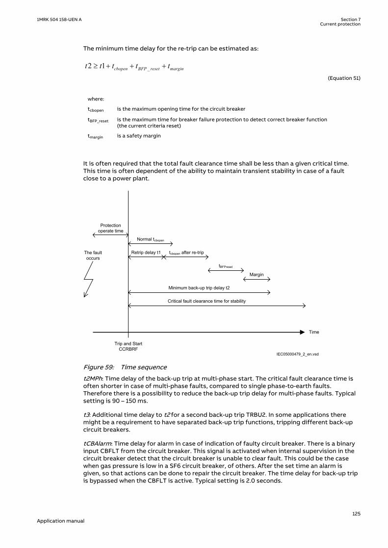
The minimum time delay for the re-trip can be estimated as:
_2 1³ + + +cbopen BFP reset margint t t t tEQUATION1430 V1 EN-US (Equation 51)
where:
tcbopen is the maximum opening time for the circuit breaker
tBFP_reset is the maximum time for breaker failure protection to detect correct breaker function(the current criteria reset)
tmargin is a safety margin
It is often required that the total fault clearance time shall be less than a given critical time.This time is often dependent of the ability to maintain transient stability in case of a faultclose to a power plant.
Time
The fault occurs
Protection operate time
Trip and Start CCRBRF
Normal tcbopen
Margin
Retrip delay t1 tcbopen after re-trip
tBFPreset
Minimum back-up trip delay t2
Critical fault clearance time for stability
IEC05000479_2_en.vsdIEC05000479 V2 EN-US
Figure 59: Time sequence
t2MPh: Time delay of the back-up trip at multi-phase start. The critical fault clearance time isoften shorter in case of multi-phase faults, compared to single phase-to-earth faults.Therefore there is a possibility to reduce the back-up trip delay for multi-phase faults. Typicalsetting is 90 – 150 ms.
t3: Additional time delay to t2 for a second back-up trip TRBU2. In some applications theremight be a requirement to have separated back-up trip functions, tripping different back-upcircuit breakers.
tCBAlarm: Time delay for alarm in case of indication of faulty circuit breaker. There is a binaryinput CBFLT from the circuit breaker. This signal is activated when internal supervision in thecircuit breaker detect that the circuit breaker is unable to clear fault. This could be the casewhen gas pressure is low in a SF6 circuit breaker, of others. After the set time an alarm isgiven, so that actions can be done to repair the circuit breaker. The time delay for back-up tripis bypassed when the CBFLT is active. Typical setting is 2.0 seconds.
1MRK 504 158-UEN A Section 7Current protection
125Application manual

tPulse: Trip pulse duration. This setting must be larger than the critical impulse time of circuitbreakers to be tripped from the breaker failure protection. Typical setting is 200 ms.
7.8 Directional underpower protection GUPPDUPSEMOD156693-1 v4
7.8.1 IdentificationSEMOD158941-2 v4
Function description IEC 61850identification
IEC 60617identification
ANSI/IEEE C37.2device number
Directional underpower protection GUPPDUPP <
2SYMBOL-LL V2 EN-US
37
7.8.2 ApplicationSEMOD151283-4 v5
The task of a generator in a power plant is to convert mechanical energy available as a torqueon a rotating shaft to electric energy.
Sometimes, the mechanical power from a prime mover may decrease so much that it does notcover bearing losses and ventilation losses. Then, the synchronous generator becomes asynchronous motor and starts to take electric power from the rest of the power system. Thisoperating state, where individual synchronous machines operate as motors, implies no risk forthe machine itself. If the generator under consideration is very large and if it consumes lots ofelectric power, it may be desirable to disconnect it to ease the task for the rest of the powersystem.
Often, the motoring condition may imply that the turbine is in a very dangerous state. The taskof the reverse power protection is to protect the turbine and not to protect the generatoritself.
Steam turbines easily become overheated if the steam flow becomes too low or if the steamceases to flow through the turbine. Therefore, turbo-generators should have reverse powerprotection. There are several contingencies that may cause reverse power: break of a mainsteam pipe, damage to one or more blades in the steam turbine or inadvertent closing of themain stop valves. In the last case, it is highly desirable to have a reliable reverse powerprotection. It may prevent damage to an otherwise undamaged plant.
During the routine shutdown of many thermal power units, the reverse power protection givesthe tripping impulse to the generator breaker (the unit breaker). By doing so, one prevents thedisconnection of the unit before the mechanical power has become zero. Earlier disconnectionwould cause an acceleration of the turbine generator at all routine shutdowns. This shouldhave caused overspeed and high centrifugal stresses.
When the steam ceases to flow through a turbine, the cooling of the turbine blades willdisappear. Now, it is not possible to remove all heat generated by the windage losses. Instead,the heat will increase the temperature in the steam turbine and especially of the blades. Whena steam turbine rotates without steam supply, the electric power consumption will be about2% of rated power. Even if the turbine rotates in vacuum, it will soon become overheated anddamaged. The turbine overheats within minutes if the turbine loses the vacuum.
The critical time to overheating a steam turbine varies from about 0.5 to 30 minutesdepending on the type of turbine. A high-pressure turbine with small and thin blades willbecome overheated more easily than a low-pressure turbine with long and heavy blades. The
Section 7 1MRK 504 158-UEN ACurrent protection
126Application manual

conditions vary from turbine to turbine and it is necessary to ask the turbine manufacturer ineach case.
Power to the power plant auxiliaries may come from a station service transformer connectedto the secondary side of the step-up transformer. Power may also come from a start-upservice transformer connected to the external network. One has to design the reverse powerprotection so that it can detect reverse power independent of the flow of power to the powerplant auxiliaries.
Hydro turbines tolerate reverse power much better than steam turbines do. Only Kaplanturbine and bulb turbines may suffer from reverse power. There is a risk that the turbinerunner moves axially and touches stationary parts. They are not always strong enough towithstand the associated stresses.
Ice and snow may block the intake when the outdoor temperature falls far below zero.Branches and leaves may also block the trash gates. A complete blockage of the intake maycause cavitations. The risk for damages to hydro turbines can justify reverse power protectionin unattended plants.
A hydro turbine that rotates in water with closed wicket gates will draw electric power fromthe rest of the power system. This power will be about 10% of the rated power. If there is onlyair in the hydro turbine, the power demand will fall to about 3%.
Diesel engines should have reverse power protection. The generator will take about 15% of itsrated power or more from the system. A stiff engine may require perhaps 25% of the ratedpower to motor it. An engine that is good run in might need no more than 5%. It is necessaryto obtain information from the engine manufacturer and to measure the reverse power duringcommissioning.
Gas turbines usually do not require reverse power protection.
Figure 60 illustrates the reverse power protection with underpower protection and withoverpower protection. The underpower protection gives a higher margin and should providebetter dependability. On the other hand, the risk for unwanted operation immediately aftersynchronization may be higher. One should set the underpower protection (reference angle setto 0) to trip if the active power from the generator is less than about 2%. One should set theoverpower protection (reference angle set to 180) to trip if the power flow from the networkto the generator is higher than 1%.
Underpower protection Overpower protection
Q Q
P P
Operating point without turbine torque
Margin Margin
OperateLine
OperateLine
Operating point without turbine torque
IEC09000019-2-en.vsdIEC09000019 V2 EN-US
Figure 60: Reverse power protection with underpower or overpower protection
7.8.3 Setting guidelinesSEMOD172134-4 v7
GlobalBaseSel: Selects the global base value group used by the function to define (IBase),(UBase) and (SBase).
1MRK 504 158-UEN A Section 7Current protection
127Application manual
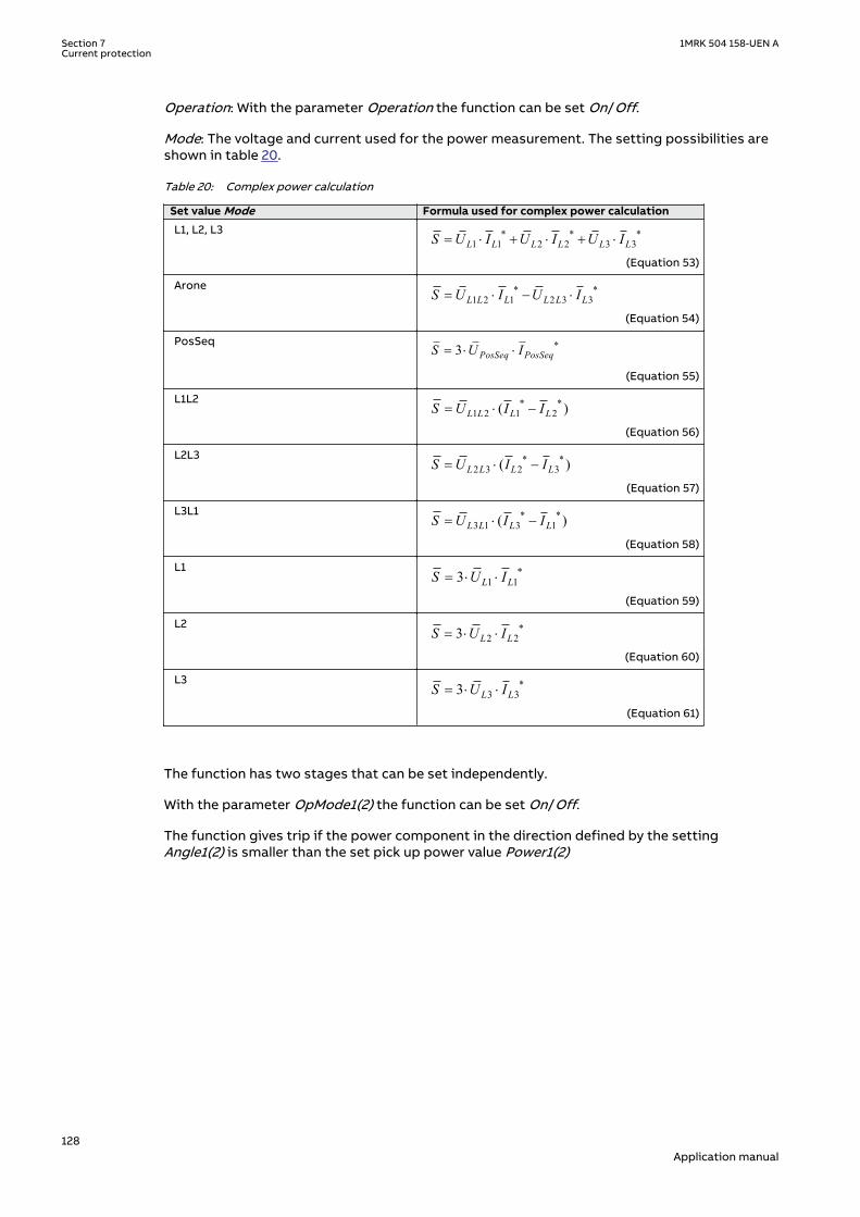
Operation: With the parameter Operation the function can be set On/Off.
Mode: The voltage and current used for the power measurement. The setting possibilities areshown in table 20.
Table 20: Complex power calculation
Set value Mode Formula used for complex power calculation
L1, L2, L3 * * *1 1 2 2 3 3L L L L L LS U I U I U I= × + × + ×
EQUATION1697 V1 EN-US (Equation 53)
Arone * *1 2 1 2 3 3L L L L L LS U I U I= × - ×
EQUATION1698 V1 EN-US (Equation 54)
PosSeq *3 PosSeq PosSeqS U I= × ×
EQUATION1699 V1 EN-US (Equation 55)
L1L2 * *1 2 1 2( )L L L LS U I I= × -
EQUATION1700 V1 EN-US (Equation 56)
L2L3 * *2 3 2 3( )L L L LS U I I= × -
EQUATION1701 V1 EN-US (Equation 57)
L3L1 * *3 1 3 1( )L L L LS U I I= × -
EQUATION1702 V1 EN-US (Equation 58)
L1 *1 13 L LS U I= × ×
EQUATION1703 V1 EN-US (Equation 59)
L2 *2 23 L LS U I= × ×
EQUATION1704 V1 EN-US (Equation 60)
L3 *3 33 L LS U I= × ×
EQUATION1705 V1 EN-US (Equation 61)
The function has two stages that can be set independently.
With the parameter OpMode1(2) the function can be set On/Off.
The function gives trip if the power component in the direction defined by the settingAngle1(2) is smaller than the set pick up power value Power1(2)
Section 7 1MRK 504 158-UEN ACurrent protection
128Application manual

Operate
Angle1(2)
Power1(2)
P
Q
en06000441.vsdIEC06000441 V1 EN-US
Figure 61: Underpower mode
The setting Power1(2) gives the power component pick up value in the Angle1(2) direction. Thesetting is given in p.u. of the generator rated power, see equation 62.
Minimum recommended setting is 0.2% of SN when metering class CT inputs into the IED areused.
3NS UBase IBase= × ×
EQUATION1708 V1 EN-US (Equation 62)
The setting Angle1(2) gives the characteristic angle giving maximum sensitivity of the powerprotection function. The setting is given in degrees. For active power the set angle should be0° or 180°. 0° should be used for generator low forward active power protection.
1MRK 504 158-UEN A Section 7Current protection
129Application manual

OperateAngle1(2) = 0°
Power1(2)
P
Q
en06000556.vsdIEC06000556 V1 EN-US
Figure 62: For low forward power the set angle should be 0° in the underpower function
TripDelay1(2) is set in seconds to give the time delay for trip of the stage after pick up.
Hysteresis1(2) is given in p.u. of generator rated power according to equation 63.
3NS UBase IBase= × ×
EQUATION1708 V1 EN-US (Equation 63)
The drop out power will be Power1(2) + Hysteresis1(2).
The possibility to have low pass filtering of the measured power can be made as shown in theformula:
( )1Old CalculatedS k S k S= × + - ×
EQUATION1893 V1 EN-US (Equation 64)
Where
S is a new measured value to be used for the protection function
Sold is the measured value given from the function in previous execution cycle
SCalculated is the new calculated value in the present execution cycle
k is settable parameter
The value of k=0.92 is recommended in generator applications as the trip delay is normallyquite long.
The calibration factors for current and voltage measurement errors are set % of rated current/voltage:
IAmpComp5, IAmpComp30, IAmpComp100
Section 7 1MRK 504 158-UEN ACurrent protection
130Application manual

UAmpComp5, UAmpComp30, UAmpComp100
IAngComp5, IAngComp30, IAngComp100
The angle compensation is given as difference between current and voltage angle errors.
The values are given for operating points 5, 30 and 100% of rated current/voltage. The valuesshould be available from instrument transformer test protocols.
7.9 Directional overpower protection GOPPDOPSEMOD172360-1 v4
7.9.1 IdentificationSEMOD176574-2 v4
Function description IEC 61850identification
IEC 60617identification
ANSI/IEEE C37.2device number
Directional overpower protection GOPPDOPP >
2DOCUMENT172362-IMG158942V2 EN-US
32
7.9.2 ApplicationSEMOD172358-4 v2
The task of a generator in a power plant is to convert mechanical energy available as a torqueon a rotating shaft to electric energy.
Sometimes, the mechanical power from a prime mover may decrease so much that it does notcover bearing losses and ventilation losses. Then, the synchronous generator becomes asynchronous motor and starts to take electric power from the rest of the power system. Thisoperating state, where individual synchronous machines operate as motors, implies no risk forthe machine itself. If the generator under consideration is very large and if it consumes lots ofelectric power, it may be desirable to disconnect it to ease the task for the rest of the powersystem.
Often, the motoring condition may imply that the turbine is in a very dangerous state. The taskof the reverse power protection is to protect the turbine and not to protect the generatoritself.
Steam turbines easily become overheated if the steam flow becomes too low or if the steamceases to flow through the turbine. Therefore, turbo-generators should have reverse powerprotection. There are several contingencies that may cause reverse power: break of a mainsteam pipe, damage to one or more blades in the steam turbine or inadvertent closing of themain stop valves. In the last case, it is highly desirable to have a reliable reverse powerprotection. It may prevent damage to an otherwise undamaged plant.
During the routine shutdown of many thermal power units, the reverse power protection givesthe tripping impulse to the generator breaker (the unit breaker). By doing so, one prevents thedisconnection of the unit before the mechanical power has become zero. Earlier disconnectionwould cause an acceleration of the turbine generator at all routine shutdowns. This shouldhave caused overspeed and high centrifugal stresses.
When the steam ceases to flow through a turbine, the cooling of the turbine blades willdisappear. Now, it is not possible to remove all heat generated by the windage losses. Instead,the heat will increase the temperature in the steam turbine and especially of the blades. Whena steam turbine rotates without steam supply, the electric power consumption will be about
1MRK 504 158-UEN A Section 7Current protection
131Application manual

2% of rated power. Even if the turbine rotates in vacuum, it will soon become overheated anddamaged. The turbine overheats within minutes if the turbine loses the vacuum.
The critical time to overheating of a steam turbine varies from about 0.5 to 30 minutesdepending on the type of turbine. A high-pressure turbine with small and thin blades willbecome overheated more easily than a low-pressure turbine with long and heavy blades. Theconditions vary from turbine to turbine and it is necessary to ask the turbine manufacturer ineach case.
Power to the power plant auxiliaries may come from a station service transformer connectedto the primary side of the step-up transformer. Power may also come from a start-up servicetransformer connected to the external network. One has to design the reverse powerprotection so that it can detect reverse power independent of the flow of power to the powerplant auxiliaries.
Hydro turbines tolerate reverse power much better than steam turbines do. Only Kaplanturbine and bulb turbines may suffer from reverse power. There is a risk that the turbinerunner moves axially and touches stationary parts. They are not always strong enough towithstand the associated stresses.
Ice and snow may block the intake when the outdoor temperature falls far below zero.Branches and leaves may also block the trash gates. A complete blockage of the intake maycause cavitations. The risk for damages to hydro turbines can justify reverse power protectionin unattended plants.
A hydro turbine that rotates in water with closed wicket gates will draw electric power fromthe rest of the power system. This power will be about 10% of the rated power. If there is onlyair in the hydro turbine, the power demand will fall to about 3%.
Diesel engines should have reverse power protection. The generator will take about 15% of itsrated power or more from the system. A stiff engine may require perhaps 25% of the ratedpower to motor it. An engine that is well run in might need no more than 5%. It is necessary toobtain information from the engine manufacturer and to measure the reverse power duringcommissioning.
Gas turbines usually do not require reverse power protection.
Figure 63 illustrates the reverse power protection with underpower IED and with overpowerIED. The underpower IED gives a higher margin and should provide better dependability. Onthe other hand, the risk for unwanted operation immediately after synchronization may behigher. One should set the underpower IED to trip if the active power from the generator isless than about 2%. One should set the overpower IED to trip if the power flow from thenetwork to the generator is higher than 1%.
Underpower IED Overpower IED
Q Q
P P
Operating point without turbine torque
Margin Margin
OperateLine
OperateLine
Operating point without turbine torque
IEC06000315-2-en.vsdIEC06000315 V2 EN-US
Figure 63: Reverse power protection with underpower IED and overpower IED
Section 7 1MRK 504 158-UEN ACurrent protection
132Application manual

7.9.3 Setting guidelinesSEMOD172150-4 v7
GlobalBaseSel: Selects the global base value group used by the function to define (IBase),(UBase) and (SBase).
Operation: With the parameter Operation the function can be set On/Off.
Mode: The voltage and current used for the power measurement. The setting possibilities areshown in table 21.
Table 21: Complex power calculation
Set value Mode Formula used for complex power calculation
L1, L2, L3 * * *1 1 2 2 3 3L L L L L LS U I U I U I= × + × + ×
EQUATION1697 V1 EN-US (Equation 66)
Arone * *1 2 1 2 3 3L L L L L LS U I U I= × - ×
EQUATION1698 V1 EN-US (Equation 67)
PosSeq *3 PosSeq PosSeqS U I= × ×
EQUATION1699 V1 EN-US (Equation 68)
L1L2 * *1 2 1 2( )L L L LS U I I= × -
EQUATION1700 V1 EN-US (Equation 69)
L2L3 * *2 3 2 3( )L L L LS U I I= × -
EQUATION1701 V1 EN-US (Equation 70)
L3L1 * *3 1 3 1( )L L L LS U I I= × -
EQUATION1702 V1 EN-US (Equation 71)
L1 *1 13 L LS U I= × ×
EQUATION1703 V1 EN-US (Equation 72)
L2 *2 23 L LS U I= × ×
EQUATION1704 V1 EN-US (Equation 73)
L3 *3 33 L LS U I= × ×
EQUATION1705 V1 EN-US (Equation 74)
The function has two stages that can be set independently.
With the parameter OpMode1(2) the function can be set On/Off.
The function gives trip if the power component in the direction defined by the settingAngle1(2) is larger than the set pick up power value Power1(2)
1MRK 504 158-UEN A Section 7Current protection
133Application manual
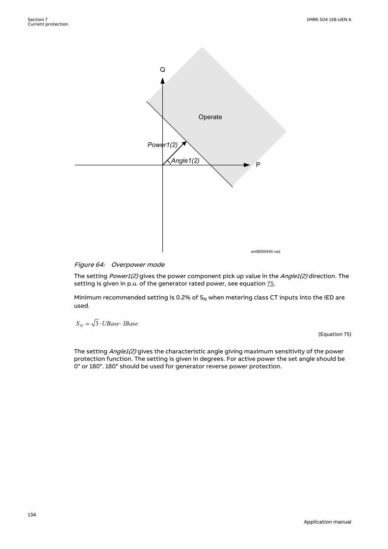
Operate
Angle1(2)
Power1(2)
P
Q
en06000440.vsdIEC06000440 V1 EN-US
Figure 64: Overpower mode
The setting Power1(2) gives the power component pick up value in the Angle1(2) direction. Thesetting is given in p.u. of the generator rated power, see equation 75.
Minimum recommended setting is 0.2% of SN when metering class CT inputs into the IED areused.
3NS UBase IBase= × ×
EQUATION1708 V1 EN-US (Equation 75)
The setting Angle1(2) gives the characteristic angle giving maximum sensitivity of the powerprotection function. The setting is given in degrees. For active power the set angle should be0° or 180°. 180° should be used for generator reverse power protection.
Section 7 1MRK 504 158-UEN ACurrent protection
134Application manual

Operate Angle1(2 ) = 180 o
Power1(2)
P
Q
IEC06000557-2-en.vsdIEC06000557 V2 EN-US
Figure 65: For reverse power the set angle should be 180° in the overpower function
TripDelay1(2) is set in seconds to give the time delay for trip of the stage after pick up.
Hysteresis1(2) is given in p.u. of generator rated power according to equation 76.
3NS UBase IBase= × ×
EQUATION1708 V1 EN-US (Equation 76)
The drop out power will be Power1(2) - Hysteresis1(2).
The possibility to have low pass filtering of the measured power can be made as shown in theformula:
( )1Old CalculatedS k S k S= × + - ×
EQUATION1893 V1 EN-US (Equation 77)
Where
S is a new measured value to be used for the protection function
Sold is the measured value given from the function in previous execution cycle
SCalculated is the new calculated value in the present execution cycle
k is settable parameter
The value of k=0.92 is recommended in generator applications as the trip delay is normallyquite long.
The calibration factors for current and voltage measurement errors are set % of rated current/voltage:
1MRK 504 158-UEN A Section 7Current protection
135Application manual

IAmpComp5, IAmpComp30, IAmpComp100
UAmpComp5, UAmpComp30, UAmpComp100
IAngComp5, IAngComp30, IAngComp100
The angle compensation is given as difference between current and voltage angle errors.
The values are given for operating points 5, 30 and 100% of rated current/voltage. The valuesshould be available from instrument transformer test protocols.
7.10 Broken conductor check BRCPTOCSEMOD171761-1 v3
7.10.1 IdentificationSEMOD172362-2 v2
Function description IEC 61850identification
IEC 60617identification
ANSI/IEEE C37.2device number
Broken conductor check BRCPTOC - 46
7.10.2 ApplicationSEMOD171858-5 v3
Conventional protection functions can not detect the broken conductor condition. Brokenconductor check (BRCPTOC) function, consisting of continuous current unsymmetrical checkon the line where the IED connected will give alarm or trip at detecting broken conductors.
7.10.3 Setting guidelinesSEMOD171866-5 v4
Broken conductor check BRCPTOC must be set to detect open phase/s (series faults) withdifferent loads on the line. BRCPTOC must at the same time be set to not operate formaximum asymmetry which can exist due to, for example, not transposed power lines.
All settings are in primary values or percentage.
Set IBase (given in GlobalBaseSel) to power line rated current or CT rated current.
Set minimum operating level per phase IP> to typically 10-20% of rated current.
Set the unsymmetrical current, which is relation between the difference of the minimum andmaximum phase currents to the maximum phase current to typical Iub> = 50%.
Note that it must be set to avoid problem with asymmetry under minimumoperating conditions.
Set the time delay tOper = 5 - 60 seconds and reset time tReset = 0.010 - 60.000 seconds.
Section 7 1MRK 504 158-UEN ACurrent protection
136Application manual
Section 8 Voltage protection
8.1 Loss of voltage check LOVPTUVSEMOD171868-1 v2
8.1.1 IdentificationSEMOD171954-2 v2
Function description IEC 61850identification
IEC 60617identification
ANSI/IEEE C37.2device number
Loss of voltage check LOVPTUV - 27
8.1.2 ApplicationSEMOD171876-4 v3
The trip of the circuit breaker at a prolonged loss of voltage at all the three phases is normallyused in automatic restoration systems to facilitate the system restoration after a majorblackout. Loss of voltage check (LOVPTUV) generates a TRIP signal only if the voltage in all thethree phases is low for more than the set time. If the trip to the circuit breaker is not required,LOVPTUV is used for signallization only through an output contact or through the eventrecording function.
8.1.3 Setting guidelinesSEMOD171929-4 v5
Loss of voltage check (LOVPTUV) is in principle independent of the protection functions. Itrequires to be set to open the circuit breaker in order to allow a simple system restorationfollowing a main voltage loss of a big part of the network and only when the voltage is lostwith breakers still closed.
All settings are in primary values or per unit. Set operate level per phase to typically 70% of theglobal parameter UBase level. Set the time delay tTrip=5-20 seconds.
8.1.3.1 Advanced users settingsSEMOD171929-8 v4
For advanced users the following parameters need also to be set. Set the length of the trippulse to typical tPulse=0.15 sec. Set the blocking time tBlock to block Loss of voltage check(LOVPTUV), if some but not all voltage are low, to typical 5.0 seconds and set the time delayfor enabling the function after restoration tRestore to 3 - 40 seconds.
1MRK 504 158-UEN A Section 8Voltage protection
137Application manual

138

Section 9 Multipurpose protection
9.1 General current and voltage protection CVGAPCIP14552-1 v2
9.1.1 IdentificationM14886-2 v3
Function description IEC 61850identification
IEC 60617identification
ANSI/IEEE C37.2device number
General current and voltageprotection
CVGAPC 2(I>/U<) -
9.1.2 ApplicationIP15008-1 v1
M13084-3 v4
A breakdown of the insulation between phase conductors or a phase conductor and earthresults in a short circuit or an earth fault respectively. Such faults can result in large faultcurrents and may cause severe damage to the power system primary equipment. Dependingon the magnitude and type of the fault different overcurrent protections, based onmeasurement of phase, earth or sequence current components can be used to clear thesefaults. Additionally it is sometimes required that these overcurrent protections shall bedirectional and/or voltage controlled/restrained.
The over/under voltage protection is applied on power system elements, such as generators,transformers, motors and power lines in order to detect abnormal voltage conditions.Depending on the type of voltage deviation and type of power system abnormal conditiondifferent over/under voltage protections based on measurement of phase-to-earth, phase-to-phase, residual- or sequence- voltage components can be used to detect and operate for suchincident.
The IED can be provided with multiple General current and voltage protection (CVGAPC)protection modules. The function is always connected to three-phase current and three-phasevoltage input in the configuration tool, but it will always measure only one current and onevoltage quantity selected by the end user in the setting tool.
Each CVGAPC function module has got four independent protection elements built into it.
1. Two overcurrent steps with the following built-in features:
• Definite time delay or Inverse Time Overcurrent TOC/IDMT delay for both steps• Second harmonic supervision is available in order to only allow operation of the
overcurrent stage(s) if the content of the second harmonic in the measured currentis lower than pre-set level
• Directional supervision is available in order to only allow operation of theovercurrent stage(s) if the fault location is in the pre-set direction (Forward orReverse). Its behavior during low-level polarizing voltage is settable (Non-Directional,Block,Memory)
• Voltage restrained/controlled feature is available in order to modify the pick-up levelof the overcurrent stage(s) in proportion to the magnitude of the measured voltage
• Current restrained feature is available in order to only allow operation of theovercurrent stage(s) if the measured current quantity is bigger than the setpercentage of the current restrain quantity.
2. Two undercurrent steps with the following built-in features:
1MRK 504 158-UEN A Section 9Multipurpose protection
139Application manual

• Definite time delay for both steps
3. Two overvoltage steps with the following built-in features
• Definite time delay or Inverse Time Overcurrent TOC/IDMT delay for both steps
4. Two undervoltage steps with the following built-in features
• Definite time delay or Inverse Time Overcurrent TOC/IDMT delay for both steps
All these four protection elements within one general protection function works independentlyfrom each other and they can be individually enabled or disabled. However it shall be oncemore noted that all these four protection elements measure one selected current quantity andone selected voltage quantity (see table 22 and table 23). It is possible to simultaneously useall four-protection elements and their individual stages. Sometimes in order to obtain desiredapplication functionality it is necessary to provide interaction between two or more protectionelements/stages within one CVGAPC function by appropriate IED configuration (for example,dead machine protection for generators).
9.1.2.1 Current and voltage selection for CVGAPC functionSEMOD53443-6 v3
CVGAPC function is always connected to three-phase current and three-phase voltage input inthe configuration tool, but it will always measure only the single current and the single voltagequantity selected by the end user in the setting tool (selected current quantity and selectedvoltage quantity).
The user can select, by a setting parameter CurrentInput, to measure one of the followingcurrent quantities shown in table 22.
Table 22: Available selection for current quantity within CVGAPC function
Set value for parameter"CurrentInput”
Comment
1 phase1 CVGAPC function will measure the phase L1 current phasor
2 phase2 CVGAPC function will measure the phase L2 current phasor
3 phase3 CVGAPC function will measure the phase L3 current phasor
4 PosSeq CVGAPC function will measure internally calculated positive sequencecurrent phasor
5 NegSeq CVGAPC function will measure internally calculated negative sequencecurrent phasor
6 3 · ZeroSeq CVGAPC function will measure internally calculated zero sequence currentphasor multiplied by factor 3
7 MaxPh CVGAPC function will measure current phasor of the phase withmaximum magnitude
8 MinPh CVGAPC function will measure current phasor of the phase with minimummagnitude
9 UnbalancePh CVGAPC function will measure magnitude of unbalance current, which isinternally calculated as the algebraic magnitude difference between thecurrent phasor of the phase with maximum magnitude and currentphasor of the phase with minimum magnitude. Phase angle will be set to0° all the time
10 phase1-phase2 CVGAPC function will measure the current phasor internally calculated asthe vector difference between the phase L1 current phasor and phase L2current phasor (IL1-IL2)
11 phase2-phase3 CVGAPC function will measure the current phasor internally calculated asthe vector difference between the phase L2 current phasor and phase L3current phasor (IL2-IL3)
Table continues on next page
Section 9 1MRK 504 158-UEN AMultipurpose protection
140Application manual

Set value for parameter"CurrentInput”
Comment
12 phase3-phase1 CVGAPC function will measure the current phasor internally calculated asthe vector difference between the phase L3 current phasor and phase L1current phasor ( IL3-IL1)
13 MaxPh-Ph CVGAPC function will measure ph-ph current phasor with the maximummagnitude
14 MinPh-Ph CVGAPC function will measure ph-ph current phasor with the minimummagnitude
15 UnbalancePh-Ph CVGAPC function will measure magnitude of unbalance current, which isinternally calculated as the algebraic magnitude difference between theph-ph current phasor with maximum magnitude and ph-ph currentphasor with minimum magnitude. Phase angle will be set to 0° all thetime
The user can select, by a setting parameter VoltageInput, to measure one of the followingvoltage quantities shown in table 23.
Table 23: Available selection for voltage quantity within CVGAPC function
Set value for parameter"VoltageInput"
Comment
1 phase1 CVGAPC function will measure the phase L1 voltage phasor
2 phase2 CVGAPC function will measure the phase L2 voltage phasor
3 phase3 CVGAPC function will measure the phase L3 voltage phasor
4 PosSeq CVGAPC function will measure internally calculated positive sequencevoltage phasor
5 -NegSeq CVGAPC function will measure internally calculated negative sequencevoltage phasor. This voltage phasor will be intentionally rotated for 180°in order to enable easier settings for the directional feature when used.
6 -3*ZeroSeq CVGAPC function will measure internally calculated zero sequence voltagephasor multiplied by factor 3. This voltage phasor will be intentionallyrotated for 180° in order to enable easier settings for the directionalfeature when used.
7 MaxPh CVGAPC function will measure voltage phasor of the phase withmaximum magnitude
8 MinPh CVGAPC function will measure voltage phasor of the phase withminimum magnitude
9 UnbalancePh CVGAPC function will measure magnitude of unbalance voltage, which isinternally calculated as the algebraic magnitude difference between thevoltage phasor of the phase with maximum magnitude and voltagephasor of the phase with minimum magnitude. Phase angle will be set to0° all the time
10 phase1-phase2 CVGAPC function will measure the voltage phasor internally calculated asthe vector difference between the phase L1 voltage phasor and phase L2voltage phasor (UL1-UL2)
11 phase2-phase3 CVGAPC function will measure the voltage phasor internally calculated asthe vector difference between the phase L2 voltage phasor and phase L3voltage phasor (UL2-UL3)
12 phase3-phase1 CVGAPC function will measure the voltage phasor internally calculated asthe vector difference between the phase L3 voltage phasor and phase L1voltage phasor (UL3-UL1)
Table continues on next page
1MRK 504 158-UEN A Section 9Multipurpose protection
141Application manual
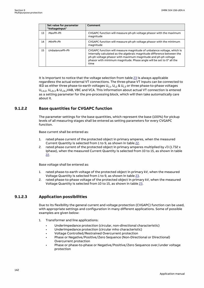
Set value for parameter"VoltageInput"
Comment
13 MaxPh-Ph CVGAPC function will measure ph-ph voltage phasor with the maximummagnitude
14 MinPh-Ph CVGAPC function will measure ph-ph voltage phasor with the minimummagnitude
15 UnbalancePh-Ph CVGAPC function will measure magnitude of unbalance voltage, which isinternally calculated as the algebraic magnitude difference between theph-ph voltage phasor with maximum magnitude and ph-ph voltagephasor with minimum magnitude. Phase angle will be set to 0° all thetime
It is important to notice that the voltage selection from table 23 is always applicableregardless the actual external VT connections. The three-phase VT inputs can be connected toIED as either three phase-to-earth voltages UL1, UL2 & UL3 or three phase-to-phase voltagesUL1L2, UL2L3 & UL3L1VAB, VBC and VCA. This information about actual VT connection is enteredas a setting parameter for the pre-processing block, which will then take automatically careabout it.
9.1.2.2 Base quantities for CVGAPC functionSEMOD53443-112 v3
The parameter settings for the base quantities, which represent the base (100%) for pickuplevels of all measuring stages shall be entered as setting parameters for every CVGAPCfunction.
Base current shall be entered as:
1. rated phase current of the protected object in primary amperes, when the measuredCurrent Quantity is selected from 1 to 9, as shown in table 22.
2. rated phase current of the protected object in primary amperes multiplied by √3 (1.732 xIphase), when the measured Current Quantity is selected from 10 to 15, as shown in table22.
Base voltage shall be entered as:
1. rated phase-to-earth voltage of the protected object in primary kV, when the measuredVoltage Quantity is selected from 1 to 9, as shown in table 23.
2. rated phase-to-phase voltage of the protected object in primary kV, when the measuredVoltage Quantity is selected from 10 to 15, as shown in table 23.
9.1.2.3 Application possibilitiesSEMOD53443-136 v2
Due to its flexibility the general current and voltage protection (CVGAPC) function can be used,with appropriate settings and configuration in many different applications. Some of possibleexamples are given below:
1. Transformer and line applications:
• Underimpedance protection (circular, non-directional characteristic)• Underimpedance protection (circular mho characteristic)• Voltage Controlled/Restrained Overcurrent protection• Phase or Negative/Positive/Zero Sequence (Non-Directional or Directional)
Overcurrent protection• Phase or phase-to-phase or Negative/Positive/Zero Sequence over/under voltage
protection
Section 9 1MRK 504 158-UEN AMultipurpose protection
142Application manual

• Special thermal overload protection• Open Phase protection• Unbalance protection
2. Generator protection
• 80-95% Stator earth fault protection (measured or calculated 3Uo)• Rotor earth fault protection (with external COMBIFLEX RXTTE4 injection unit)• Underimpedance protection• Voltage Controlled/Restrained Overcurrent protection• Turn-to-Turn & Differential Backup protection (directional Negative Sequence.
Overcurrent protection connected to generator HV terminal CTs looking intogenerator)
• Stator Overload protection• Rotor Overload protection• Loss of Excitation protection (directional pos. seq. OC protection)• Reverse power/Low forward power protection (directional pos. seq. OC protection,
2% sensitivity)• Dead-Machine/Inadvertent-Energizing protection• Breaker head flashover protection• Improper synchronizing detection• Sensitive negative sequence generator over current protection and alarm• Phase or phase-to-phase or Negative/Positive/Zero Sequence over/under voltage
protection• Generator out-of-step detection (based on directional pos. seq. OC)• Inadvertent generator energizing
9.1.2.4 Inadvertent generator energizationSEMOD151947-4 v2
When the generator is taken out of service, and non-rotating, there is a risk that the generatorcircuit breaker is closed by mistake.
Three-phase energizing of a generator, which is at standstill or on turning gear, causes it tobehave and accelerate similarly to an induction motor. The machine, at this point, essentiallyrepresents the subtransient reactance to the system and it can be expected to draw from oneto four per unit current, depending on the equivalent system impedance. Machine terminalvoltage can range from 20% to 70% of rated voltage, again, depending on the systemequivalent impedance (including the block transformer). Higher quantities of machine currentand voltage (3 to 4 per unit current and 50% to 70% rated voltage) can be expected if thegenerator is connected to a strong system. Lower current and voltage values (1 to 2 per unitcurrent and 20% to 40% rated voltage) are representative of weaker systems.
Since a generator behaves similarly to an induction motor, high currents will develop in therotor during the period it is accelerating. Although the rotor may be thermally damaged fromexcessive high currents, the time to damage will be on the order of a few seconds. Of morecritical concern, however, is the bearing, which can be damaged in a fraction of a second dueto low oil pressure. Therefore, it is essential that high speed tripping is provided. This trippingshould be almost instantaneous (< 100 ms).
There is a risk that the current into the generator at inadvertent energization will be limited sothat the “normal” overcurrent or underimpedance protection will not detect the dangeroussituation. The delay of these protection functions might be too long. The reverse powerprotection might detect the situation but the operation time of this protection is normally toolong.
For big and important machines, fast protection against inadvertent energizing should,therefore, be included in the protective scheme.
The protection against inadvertent energization can be made by a combination ofundervoltage, overvoltage and overcurrent protection functions. The undervoltage function
1MRK 504 158-UEN A Section 9Multipurpose protection
143Application manual

will, with a delay for example 10 s, detect the situation when the generator is not connected tothe grid (standstill) and activate the overcurrent function. The overvoltage function will detectthe situation when the generator is taken into operation and will disable the overcurrentfunction. The overcurrent function will have a pick-up value about 50% of the rated current ofthe generator. The trip delay will be about 50 ms.
9.1.3 Setting guidelinesIP15009-1 v2
GUID-F7AA2194-4D1C-4475-8853-C7D064912614 v4
When inverse time overcurrent characteristic is selected, the operate time ofthe stage will be the sum of the inverse time delay and the set definite timedelay. Thus, if only the inverse time delay is required, it is important to set thedefinite time delay for that stage to zero.
M13088-237 v4
The parameters for the general current and voltage protection function (CVGAPC) are set viathe local HMI or Protection and Control Manager (PCM600).
GlobalBaseSel: Selects the global base value group used by the function to define (IBase),(UBase) and (SBase).
The overcurrent steps has a IMinx (x=1 or 2 depending on step) setting to setthe minimum operate current. Set IMinx below StartCurr_OCx for every step toachieve ANSI reset characteristic according to standard. If IMinx is set aboveStartCurr_OCx for any step the ANSI reset works as if current is zero whencurrent drops below IMinx.
9.1.3.1 Directional negative sequence overcurrent protectionM13088-3 v5
Directional negative sequence overcurrent protection is typically used as sensitive earth-faultprotection of power lines where incorrect zero sequence polarization may result from mutualinduction between two or more parallel lines. Additionally, it can be used in applications onunderground cables where zero-sequence impedance depends on the fault current returnpaths, but the cable negative-sequence impedance is practically constant. It shall be notedthat directional negative sequence OC element offers protection against all unbalance faults(phase-to-phase faults as well). Care shall be taken that the minimum pickup of suchprotection function shall be set above natural system unbalance level.
An example will be given, how sensitive-earth-fault protection for power lines can be achievedby using negative-sequence directional overcurrent protection elements within a CVGAPCfunction.
This functionality can be achieved by using one CVGAPC function. The following shall be doneto ensure proper operation of the function:
1. Connect three-phase power line currents and three-phase power line voltages to oneCVGAPC instance (for example, GF04)
2. Set CurrentInput to NegSeq (please note that CVGAPC function measures I2 current andNOT 3I2 current; this is essential for proper OC pickup level setting)
3. Set VoltageInput to -NegSeq (please note that the negative sequence voltage phasor isintentionally inverted in order to simplify directionality
4. Set base current IBase value equal to the rated primary current of power line CTs5. Set base voltage UBase value equal to the rated power line phase-to-phase voltage in kV6. Set RCADir to value +65 degrees (NegSeq current typically lags the inverted NegSeq
voltage for this angle during the fault)7. Set ROADir to value 90 degree8. Set LowVolt_VM to value 2% (NegSeq voltage level above which the directional element
will be enabled)
Section 9 1MRK 504 158-UEN AMultipurpose protection
144Application manual

9. Enable one overcurrent stage (for example, OC1)10. By parameter CurveType_OC1 select appropriate TOC/IDMT or definite time delayed curve
in accordance with your network protection philosophy11. Set StartCurr_OC1 to value between 3-10% (typical values)12. Set tDef_OC1 or parameter “k” when TOC/IDMT curves are used to insure proper time
coordination with other earth-fault protections installed in the vicinity of this power line13. Set DirMode_OC1 to Forward14. Set DirPrinc_OC1 to IcosPhi&U15. Set ActLowVolt1_VM to Block
• In order to insure proper restraining of this element for CT saturations during three-phase faults it is possible to use current restraint feature and enable this element tooperate only when NegSeq current is bigger than a certain percentage (10% istypical value) of measured PosSeq current in the power line. To do this the followingsettings within the same function shall be done:
16. Set EnRestrainCurr to On17. Set RestrCurrInput to PosSeq18. Set RestrCurrCoeff to value 0.10
If required, this CVGAPC function can be used in directional comparison protection scheme forthe power line protection if communication channels to the remote end of this power line areavailable. In that case typically two NegSeq overcurrent steps are required. One for forwardand one for reverse direction. As explained before the OC1 stage can be used to detect faultsin forward direction. The built-in OC2 stage can be used to detect faults in reverse direction.
However the following shall be noted for such application:
• the set values for RCADir and ROADir settings will be as well applicable for OC2 stage• setting DirMode_OC2 shall be set to Reverse• setting parameter StartCurr_OC2 shall be made more sensitive than pickup value of
forward OC1 element (that is, typically 60% of OC1 set pickup level) in order to insureproper operation of the directional comparison scheme during current reversal situations
• start signals from OC1 and OC2 elements shall be used to send forward and reversesignals to the remote end of the power line
• the available scheme communications function block within IED shall be used betweenmultipurpose protection function and the communication equipment in order to insureproper conditioning of the above two start signals
Furthermore the other built-in UC, OV and UV protection elements can be used for otherprotection and alarming purposes.
9.1.3.2 Negative sequence overcurrent protectionM13088-5 v4
Example will be given how to use one CVGAPC function to provide negative sequence inversetime overcurrent protection for a generator with capability constant of 20s, and maximumcontinuous negative sequence rating of 7% of the generator rated current.
The capability curve for a generator negative sequence overcurrent protection, often usedworld-wide, is defined by the ANSI standard in accordance with the following formula:
1MRK 504 158-UEN A Section 9Multipurpose protection
145Application manual
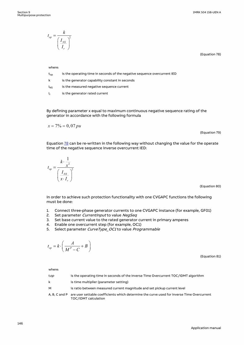
2op
NS
r
ktII
=æ öç ÷è ø
EQUATION1372 V1 EN-US (Equation 78)
where:
top is the operating time in seconds of the negative sequence overcurrent IED
k is the generator capability constant in seconds
INS is the measured negative sequence current
Ir is the generator rated current
By defining parameter x equal to maximum continuous negative sequence rating of thegenerator in accordance with the following formula
7% 0, 07x pu= =EQUATION1373 V1 EN-US (Equation 79)
Equation 78 can be re-written in the following way without changing the value for the operatetime of the negative sequence inverse overcurrent IED:
2
2
1
op
NS
r
kxt
Ix I
×=
æ öç ÷×è ø
EQUATION1374 V1 EN-US (Equation 80)
In order to achieve such protection functionality with one CVGAPC functions the followingmust be done:
1. Connect three-phase generator currents to one CVGAPC instance (for example, GF01)2. Set parameter CurrentInput to value NegSeq3. Set base current value to the rated generator current in primary amperes4. Enable one overcurrent step (for example, OC1)5. Select parameter CurveType_OC1 to value Programmable
op P
At k BM C
æ ö= × +ç ÷-è øEQUATION1375 V1 EN-US (Equation 81)
where:
top is the operating time in seconds of the Inverse Time Overcurrent TOC/IDMT algorithm
k is time multiplier (parameter setting)
M is ratio between measured current magnitude and set pickup current level
A, B, C and P are user settable coefficients which determine the curve used for Inverse Time OvercurrentTOC/IDMT calculation
Section 9 1MRK 504 158-UEN AMultipurpose protection
146Application manual

When the equation 78 is compared with the equation 80 for the inverse time characteristic ofthe OC1 it is obvious that if the following rules are followed:
1. set k equal to the generator negative sequence capability value2. set A_OC1 equal to the value 1/x23. set B_OC1 = 0.0, C_OC1=0.0 and P_OC1=2.04. set StartCurr_OC1 equal to the value x
then the OC1 step of the CVGAPC function can be used for generator negative sequenceinverse overcurrent protection.
For this particular example the following settings shall be entered to insure proper functionoperation:
1. select negative sequence current as measuring quantity for this CVGAPC function2. make sure that the base current value for the CVGAPC function is equal to the generator
rated current3. set k_OC1 = 204. set A_OC1= 1/0.072 = 204.08165. set B_OC1 = 0.0, C_OC1 = 0.0 and P_OC1 = 2.06. set StartCurr_OC1 = 7%
Proper timing of the CVGAPC function made in this way can easily be verified by secondaryinjection. All other settings can be left at the default values. If required delayed time reset forOC1 step can be set in order to ensure proper function operation in case of repetitiveunbalance conditions.
Furthermore the other built-in protection elements can be used for other protection andalarming purposes (for example, use OC2 for negative sequence overcurrent alarm and OV1 fornegative sequence overvoltage alarm).
9.1.3.3 Generator stator overload protection in accordance with IEC or ANSIstandards
M13088-81 v3
Example will be given how to use one CVGAPC function to provide generator stator overloadprotection in accordance with IEC or ANSI standard if minimum-operating current shall be setto 116% of generator rating.
The generator stator overload protection is defined by IEC or ANSI standard for turbogenerators in accordance with the following formula:
2
1op
m
r
ktII
=æ ö
-ç ÷è ø
EQUATION1376 V1 EN-US (Equation 82)
where:
top is the operating time of the generator stator overload IED
k is the generator capability constant in accordance with the relevant standard (k = 37.5 for the IECstandard or k = 41.4 for the ANSI standard)
Im is the magnitude of the measured current
Ir is the generator rated current
1MRK 504 158-UEN A Section 9Multipurpose protection
147Application manual

This formula is applicable only when measured current (for example, positive sequencecurrent) exceeds a pre-set value (typically in the range from 105 to 125% of the generator ratedcurrent).
By defining parameter x equal to the per unit value for the desired pickup for the overload IEDin accordance with the following formula:
x = 116% = 1.16puEQUATION1377 V2 EN-US (Equation 83)
formula 3.5can be re-written in the following way without changing the value for the operatetime of the generator stator overload IED:
2
2
2
1
1op
m
r
kxt
Ix I x
×=
æ ö-ç ÷×è ø
EQUATION1378 V1 EN-US (Equation 84)
In order to achieve such protection functionality with one CVGAPC functions the followingmust be done:
1. Connect three-phase generator currents to one CVGAPC instance (for example, GF01)2. Set parameter CurrentInput to value PosSeq3. Set base current value to the rated generator current in primary amperes4. Enable one overcurrent step (for example OC1)5. Select parameter CurveType_OC1 to value Programmable
op P
At k BM C
æ ö= × +ç ÷-è øEQUATION1375 V1 EN-US (Equation 85)
where:
top is the operating time in seconds of the Inverse Time Overcurrent TOC/IDMT algorithm
k is time multiplier (parameter setting)
M is ratio between measured current magnitude and set pickup current level
A, B, C and P are user settable coefficients which determine the curve used for Inverse Time OvercurrentTOC/IDMT calculation
When the equation 84 is compared with the equation 85 for the inverse time characteristic ofthe OC1 step in it is obvious that if the following rules are followed:
1. set k equal to the IEC or ANSI standard generator capability value2. set parameter A_OC1 equal to the value 1/x23. set parameter C_OC1 equal to the value 1/x24. set parameters B_OC1 = 0.0 and P_OC1=2.05. set StartCurr_OC1 equal to the value x
then the OC1 step of the CVGAPC function can be used for generator negative sequenceinverse overcurrent protection.
Section 9 1MRK 504 158-UEN AMultipurpose protection
148Application manual
1. select positive sequence current as measuring quantity for this CVGAPC function2. make sure that the base current value for CVGAPC function is equal to the generator rated
current3. set k = 37.5 for the IEC standard or k = 41.4 for the ANSI standard4. set A_OC1= 1/1.162 = 0.74325. set C_OC1= 1/1.162 = 0.74326. set B_OC1 = 0.0 and P_OC1 = 2.07. set StartCurr_OC1 = 116%
Proper timing of CVGAPC function made in this way can easily be verified by secondaryinjection. All other settings can be left at the default values. If required delayed time reset forOC1 step can be set in order to insure proper function operation in case of repetitive overloadconditions.
Furthermore the other built-in protection elements can be used for other protection andalarming purposes.
In the similar way rotor overload protection in accordance with ANSI standard can be achieved.
9.1.3.4 Open phase protection for transformer, lines or generators and circuitbreaker head flashover protection for generators
M13088-142 v3
Example will be given how to use one CVGAPC function to provide open phase protection. Thiscan be achieved by using one CVGAPC function by comparing the unbalance current with a pre-set level. In order to make such a function more secure it is possible to restrain it by requiringthat at the same time the measured unbalance current must be bigger than 97% of themaximum phase current. By doing this it will be insured that function can only pickup if one ofthe phases is open circuited. Such an arrangement is easy to obtain in CVGAPC function byenabling the current restraint feature. The following shall be done in order to insure properoperation of the function:
1. Connect three-phase currents from the protected object to one CVGAPC instance (forexample, GF03)
2. Set CurrentInput to value UnbalancePh3. Set EnRestrainCurr to On4. Set RestrCurrInput to MaxPh5. Set RestrCurrCoeff to value 0.976. Set base current value to the rated current of the protected object in primary amperes7. Enable one overcurrent step (for example, OC1)8. Select parameter CurveType_OC1 to value IEC Def. Time9. Set parameter StartCurr_OC1 to value 5%10. Set parameter tDef_OC1 to desired time delay (for example, 2.0s)
Proper operation of CVGAPC function made in this way can easily be verified by secondaryinjection. All other settings can be left at the default values. However it shall be noted that setvalues for restrain current and its coefficient will as well be applicable for OC2 step as soon asit is enabled.
Furthermore the other built-in protection elements can be used for other protection andalarming purposes. For example, in case of generator application by enabling OC2 step withset pickup to 200% and time delay to 0.1s simple but effective protection against circuitbreaker head flashover protection is achieved.
1MRK 504 158-UEN A Section 9Multipurpose protection
149Application manual

9.1.3.5 Voltage restrained overcurrent protection for generator and step-uptransformer
M13088-158 v4
Example will be given how to use one CVGAPC function to provide voltage restrainedovercurrent protection for a generator. Let us assume that the time coordination study givesthe following required settings:
• Inverse Time Over Current TOC/IDMT curve: ANSI very inverse• Pickup current of 185% of generator rated current at rated generator voltage• Pickup current 25% of the original pickup current value for generator voltages below 25%
of rated voltage
This functionality can be achieved by using one CVGAPC function. The following shall be donein order to ensure proper operation of the function:
1. Connect three-phase generator currents and voltages to one CVGAPC instance (forexample, GF05)
2. Set CurrentInput to value MaxPh3. Set VoltageInput to value MinPh-Ph (it is assumed that minimum phase-to-phase voltage
shall be used for restraining. Alternatively, positive sequence voltage can be used forrestraining by selecting PosSeq for this setting parameter)
4. Set base current value to the rated generator current primary amperes5. Set base voltage value to the rated generator phase-to-phase voltage in kV6. Enable one overcurrent step (for example, OC1)7. Select CurveType_OC1 to value ANSI Very inv8. If required set minimum operating time for this curve by using parameter tMin_OC1
(default value 0.05s)9. Set StartCurr_OC1 to value 185%10. Set VCntrlMode_OC1 to On11. Set VDepMode_OC1 to Slope12. Set VDepFact_OC1 to value 0.2513. Set UHighLimit_OC1 to value 100%14. Set ULowLimit_OC1 to value 25%
Proper operation of the CVGAPC function made in this way can easily be verified by secondaryinjection. All other settings can be left at the default values. Furthermore the other built-inprotection elements can be used for other protection and alarming purposes.
9.1.3.6 Loss of excitation protection for a generatorM13088-182 v3
Example will be given how by using positive sequence directional overcurrent protectionelement within a CVGAPC function, loss of excitation protection for a generator can beachieved. Let us assume that from rated generator data the following values are calculated:
• Maximum generator capability to contentiously absorb reactive power at zero activeloading 38% of the generator MVA rating
• Generator pull-out angle 84 degrees
This functionality can be achieved by using one CVGAPC function. The following shall be donein order to insure proper operation of the function:
1. Connect three-phase generator currents and three-phase generator voltages to oneCVGAPC instance (for example, GF02)
2. Set parameter CurrentInput to PosSeq3. Set parameter VoltageInput to PosSeq4. Set base current value to the rated generator current primary amperes5. Set base voltage value to the rated generator phase-to-phase voltage in kV6. Set parameter RCADir to value -84 degree (that is, current lead voltage for this angle)
Section 9 1MRK 504 158-UEN AMultipurpose protection
150Application manual
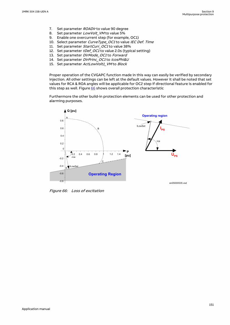
7. Set parameter ROADir to value 90 degree8. Set parameter LowVolt_VM to value 5%9. Enable one overcurrent step (for example, OC1)10. Select parameter CurveType_OC1 to value IEC Def. Time11. Set parameter StartCurr_OC1 to value 38%12. Set parameter tDef_OC1 to value 2.0s (typical setting)13. Set parameter DirMode_OC1 to Forward14. Set parameter DirPrinc_OC1 to IcosPhi&U15. Set parameter ActLowVolt1_VM to Block
Proper operation of the CVGAPC function made in this way can easily be verified by secondaryinjection. All other settings can be left at the default values. However it shall be noted that setvalues for RCA & ROA angles will be applicable for OC2 step if directional feature is enabled forthis step as well. Figure 66 shows overall protection characteristic
Furthermore the other build-in protection elements can be used for other protection andalarming purposes.
0.2 0.4 0.6
-0.2
0.6
0.8
0.8 1
DILowSet
B
A
C
0.4
0.2
0
1.2 1.4
-0.4
-0.6
-0.8
-rca
Operating Region
Q [pu]
P[pu]
rca
UPS
IPSILowSet
Operating region
en05000535.vsdIEC05000535 V2 EN-US
Figure 66: Loss of excitation
1MRK 504 158-UEN A Section 9Multipurpose protection
151Application manual

152
Section 10 Secondary system supervision
10.1 Fuse failure supervision FUFSPVCIP14556-1 v3
10.1.1 IdentificationM14869-1 v4
Function description IEC 61850identification
IEC 60617identification
ANSI/IEEE C37.2device number
Fuse failure supervision FUFSPVC - -
10.1.2 ApplicationSEMOD113803-4 v10
Different protection functions within the protection IED, operates on the basis of themeasured voltage in the relay point. Examples are:
• impedance protection functions• undervoltage function• energizing check function and voltage check for the weak infeed logic
These functions can operate unintentionally if a fault occurs in the secondary circuits betweenthe voltage instrument transformers and the IED.
It is possible to use different measures to prevent such unwanted operations. Miniature circuitbreakers in the voltage measuring circuits should be located as close as possible to thevoltage instrument transformers, and shall be equipped with auxiliary contacts that are wiredto the IEDs. Separate fuse-failure monitoring IEDs or elements within the protection andmonitoring devices are another possibilities. These solutions are combined to get the bestpossible effect in the fuse failure supervision function (FUFSPVC).
FUFSPVC function built into the IED products can operate on the basis of external binarysignals from the miniature circuit breaker or from the line disconnector. The first caseinfluences the operation of all voltage-dependent functions while the second one does notaffect the impedance measuring functions.
The negative sequence detection algorithm, based on the negative-sequence measuringquantities is recommended for use in isolated or high-impedance earthed networks: a highvalue of voltage 3U2 without the presence of the negative-sequence current 3I2 is a conditionthat is related to a fuse failure event.
The zero sequence detection algorithm, based on the zero sequence measuring quantities isrecommended for use in directly or low impedance earthed networks: a high value of voltage3U0 without the presence of the residual current 3I0 is a condition that is related to a fusefailure event. In cases where the line can have a weak-infeed of zero sequence current thisfunction shall be avoided.
A criterion based on delta current and delta voltage measurements can be added to the fusefailure supervision function in order to detect a three phase fuse failure. This is beneficial forexample during three phase transformer switching.
1MRK 504 158-UEN A Section 10Secondary system supervision
153Application manual

10.1.3 Setting guidelinesIP15000-1 v1
10.1.3.1 GeneralM13683-3 v5
The negative and zero sequence voltages and currents always exist due to different non-symmetries in the primary system and differences in the current and voltage instrumenttransformers. The minimum value for the operation of the current and voltage measuringelements must always be set with a safety margin of 10 to 20%, depending on the systemoperating conditions.
Pay special attention to the dissymmetry of the measuring quantities when the function isused on long untransposed lines, on multicircuit lines and so on.
The settings of negative sequence, zero sequence and delta algorithm are in percent of thebase voltage and base current for the function. Common base IED values for primary current(IBase), primary voltage (UBase) and primary power (SBase) are set in Global Base ValuesGBASVAL. The setting GlobalBaseSel is used to select a particular GBASVAL and used its basevalues.
10.1.3.2 Setting of common parametersM13683-9 v9
Set the operation mode selector Operation to On to release the fuse failure function.
The voltage threshold USealIn< is used to identify low voltage condition in the system. SetUSealIn< below the minimum operating voltage that might occur during emergencyconditions. We propose a setting of approximately 70% of UBase.
The drop off time of 200 ms for dead phase detection makes it recommended to always setSealIn to On since this will secure a fuse failure indication at persistent fuse fail when closingthe local breaker when the line is already energized from the other end. When the remotebreaker closes the voltage will return except in the phase that has a persistent fuse fail. Sincethe local breaker is open there is no current and the dead phase indication will persist in thephase with the blown fuse. When the local breaker closes the current will start to flow and thefunction detects the fuse failure situation. But due to the 200 ms drop off timer the outputBLKZ will not be activated until after 200 ms. This means that distance functions are notblocked and due to the “no voltage but current” situation might issue a trip.
The operation mode selector OpMode has been introduced for better adaptation to systemrequirements. The mode selector enables selecting interactions between the negativesequence and zero sequence algorithm. In normal applications, the OpMode is set to eitherUNsINs for selecting negative sequence algorithm or UZsIZs for zero sequence basedalgorithm. If system studies or field experiences shows that there is a risk that the fuse failurefunction will not be activated due to the system conditions, the dependability of the fusefailure function can be increased if the OpMode is set to UZsIZs OR UNsINs or OptimZsNs. Inmode UZsIZs OR UNsINs both negative and zero sequence based algorithms are activated andworking in an OR-condition. Also in mode OptimZsNs both negative and zero sequencealgorithms are activated and the one that has the highest magnitude of measured negative orzero sequence current will operate. If there is a requirement to increase the security of the fusefailure function OpMode can be selected to UZsIZs AND UNsINs which gives that both negativeand zero sequence algorithms are activated and working in an AND-condition, that is, bothalgorithms must give condition for block in order to activate the output signals BLKU or BLKZ.
10.1.3.3 Negative sequence basedM13683-17 v9
The relay setting value 3U2> is given in percentage of the base voltage UBase and should notbe set lower than the value that is calculated according to equation 86.
Section 10 1MRK 504 158-UEN ASecondary system supervision
154Application manual

1003
223
UBase
UU
EQUATION1519 V5 EN-US (Equation 86)
where:
U2 is the maximal negative sequence voltage during normal operation conditions, plus a margin of10...20%
UBase is the base voltage for the function according to the setting GlobalBaseSel
The setting of the current limit 3I2< is in percentage of parameter IBase. The setting of 3I2<must be higher than the normal unbalance current that might exist in the system and can becalculated according to equation 87.
1002
23 IBase
II
EQUATION1520 V5 EN-US (Equation 87)
where:
I2 is the maximal negative sequence current during normal operating conditions, plus a margin of10...20%
IBase is the base current for the function according to the setting GlobalBaseSel
10.1.3.4 Zero sequence basedM13683-43 v8
The IED setting value 3U0> is given in percentage of the base voltage UBase. The setting of3U0> should not be set lower than the value that is calculated according to equation 88.
1003
0303
UBase
UU
EQUATION1521 V4 EN-US (Equation 88)
where:
3U0 is the maximal zero sequence voltage during normal operation conditions, plus a margin of 10...20%
UBase is the base voltage for the function according to the setting GlobalBaseSel
The setting of the current limit 3I0< is done in percentage of IBase. The setting of 3I0< mustbe higher than the normal unbalance current that might exist in the system. The setting can becalculated according to equation 89.
3 03 0 100IIIBase
= × <
EQUATION2293 V3 EN-US (Equation 89)
where:
3I0< is the maximal zero sequence current during normal operating conditions, plus a margin of 10...20%
IBase is the base current for the function according to the setting GlobalBaseSel
1MRK 504 158-UEN A Section 10Secondary system supervision
155Application manual

10.1.3.5 Delta U and delta IGUID-02336F26-98C0-419D-8759-45F5F12580DE v7
Set the operation mode selector OpDUDI to On if the delta function shall be in operation.
The setting of DU> should be set high (approximately 60% of UBase) and the current thresholdDI< low (approximately 10% of IBase) to avoid unwanted operation due to normal switchingconditions in the network. The delta current and delta voltage function shall always be usedtogether with either the negative or zero sequence algorithm. If USetprim is the primary voltagefor operation of dU/dt and ISetprim the primary current for operation of dI/dt, the setting ofDU> and DI< will be given according to equation 90 and equation 91.
DUUSetUBase
prim> = 100.
EQUATION1523 V3 EN-US (Equation 90)
DIISetIBase
prim< = 100.
EQUATION1524 V4 EN-US (Equation 91)
The voltage thresholds UPh> is used to identify low voltage condition in the system. Set UPh>below the minimum operating voltage that might occur during emergency conditions. Asetting of approximately 70% of UBase is recommended.
The current threshold IPh> shall be set lower than the IMinOp for the distance protectionfunction. A 5...10% lower value is recommended.
10.1.3.6 Dead line detectionM13683-78 v4
The condition for operation of the dead line detection is set by the parameters IDLD< for thecurrent threshold and UDLD< for the voltage threshold.
Set the IDLD< with a sufficient margin below the minimum expected load current. A safetymargin of at least 15-20% is recommended. The operate value must however exceed themaximum charging current of an overhead line, when only one phase is disconnected (mutualcoupling to the other phases).
Set the UDLD< with a sufficient margin below the minimum expected operating voltage. Asafety margin of at least 15% is recommended.
Section 10 1MRK 504 158-UEN ASecondary system supervision
156Application manual

Section 11 Control
11.1 Synchrocheck, energizing check, and synchronizingSESRSYN
IP14558-1 v4
11.1.1 IdentificationM14889-1 v4
Function description IEC 61850identification
IEC 60617identification
ANSI/IEEE C37.2device number
Synchrocheck, energizing check, andsynchronizing
SESRSYN
sc/vc
SYMBOL-M V1 EN-US
25
11.1.2 Application examplesM12323-3 v6
The synchronizing function block can also be used in some switchyard arrangements, but withdifferent parameter settings. Below are some examples of how different arrangements areconnected to the IED analogue inputs and to the function block SESRSYN. One function blockis used per circuit breaker.
The input used below in example are typical and can be changed by use ofconfiguration and signal matrix tools.
The SESRSYN and connected SMAI function block instances must have thesame cycle time in the application configuration.
1MRK 504 158-UEN A Section 11Control
157Application manual

11.1.2.1 Single circuit breaker with double busbar, external voltage selectionM12325-3 v8
WA1WA2
QB1
QB2
LINE
QA1
IEC10000094-4-en.vsd
WA2_MCBWA1_MCB
LINE_VT
LINE_MCB
SESRSYNU3PBB1*U3PBB2*
U3PLN1*
U3PLN2*
GRP_OFF
UB1OKUB1FF
ULN1OKULN1FF
WA1_VT/WA2_VT
LINE_VT
LINE_MCB
WA1_MCB/WA2_MCB
WA1_MCB / WA2_MCB
WA1_VT / WA2_VT
IEC10000094 V4 EN-US
Figure 67: Connection of SESRSYN function block in a single breaker, double busbararrangement with external voltage selection
In this type of arrangement no internal voltage selection is required. The voltage selection ismade by external relays typically connected according to figure 67. Suitable voltage and VTfuse failure supervision from the two busbars are selected based on the position of the busbardisconnectors. This means that the connections to the function block will be the same as forthe single busbar arrangement. The voltage selection parameter CBConfig is set to No voltagesel.
11.1.2.2 Single circuit breaker with double busbar, internal voltage selectionM12326-3 v7
WA1WA2
QB1
QB2
LINE
QA1
IEC10000095-6-en.vsd
WA1_MCB WA2_MCB
LINE_VT
LINE_MCB
WA1_MCB
WA1_VT
WA2_VT
QB2
QB1
GRP_OFF
SESRSYNU3PBB1*
U3PBB2*
U3PLN1*
U3PLN2*
B1QOPENB1QCLDB2QOPENB2QCLD
UB1OKUB1FFUB2OKUB2FFULN1OKULN1FF
WA1_VT
WA2_VT
LINE_VT
QB1
QB2
WA1_MCB
WA2_MCB
LINE_MCB
IEC10000095 V4 EN-US
Figure 68: Connection of the SESRSYN function block in a single breaker, double busbararrangement with internal voltage selection
When internal voltage selection is needed, the voltage transformer circuit connections aremade according to figure 68. The voltage from the busbar 1 VT is connected to U3PBB1 and thevoltage from busbar 2 is connected to U3PBB2. The voltage from the line VT is connected toU3PLN1. The positions of the disconnectors and VT fuses shall be connected as shown infigure 68. The voltage selection parameter CBConfig is set to Double bus.
Section 11 1MRK 504 158-UEN AControl
158Application manual

11.1.3 Setting guidelinesM12550-3 v13
The setting parameters for the Synchronizing, synchrocheck and energizing check functionSESRSYN are set via the local HMI (LHMI) or PCM600.
This setting guidelines describes the settings of the SESRSYN function via the LHMI.
Common base IED value for primary voltage ( UBase ) is set in a Global base value function,GBASVAL, found under Main menu//Configuration/Power system/GlobalBaseValue/GBASVAL_X/UBase. The SESRSYN function has one setting for the bus reference voltage(GblBaseSelBus) and one setting for the line reference voltage (GblBaseSelLine) whichindependently of each other can be set to select one of the twelve GBASVAL functions used forreference of base values. This means that the reference voltage of bus and line can be set todifferent values. The settings for the SESRSYN function are found under Main menu/Settings/IED Settings/Control/Synchronizing(25,SC/VC)/SESRSYN(25,SC/VC):X has beendivided into four different setting groups: General, Synchronizing, Synchrocheck andEnergizingcheck.
General settings
Operation: The operation mode can be set On or Off. The setting Off disables the wholefunction.
GblBaseSelBus and GblBaseSelLine
These configuration settings are used for selecting one of twelve GBASVAL functions, whichthen is used as base value reference voltage, for bus and line respectively.
SelPhaseBus1 and SelPhaseBus2
Configuration parameters for selecting the measuring phase of the voltage for busbar 1 and 2respectively, which can be a single-phase (phase-neutral), two-phase (phase-phase) or apositive sequence voltage.
SelPhaseLine1 and SelPhaseLine2
Configuration parameters for selecting the measuring phase of the voltage for line 1 and 2respectively, which can be a single-phase (phase-neutral), two-phase (phase-phase) or apositive sequence voltage.
CBConfig
This configuration setting is used to define type of voltage selection. Type of voltage selectioncan be selected as:
• no voltage selection, No voltage sel.• single circuit breaker with double bus, Double bus• 1 1/2 circuit breaker arrangement with the breaker connected to busbar 1, 1 1/2 bus CB• 1 1/2 circuit breaker arrangement with the breaker connected to busbar 2, 1 1/2 bus alt. CB• 1 1/2 circuit breaker arrangement with the breaker connected to line 1 and 2, Tie CB
PhaseShift
This setting is used to compensate the phase shift between the measured bus voltage and linevoltage when:
• a. different phase-neutral voltages are selected (for example UL1 for bus and UL2 for line);• b. one available voltage is phase-phase and the other one is phase-neutral (for example
UL1L2 for bus and UL1 for line).
1MRK 504 158-UEN A Section 11Control
159Application manual

The set value is added to the measured line phase angle. The bus voltage is reference voltage.
Synchronizing settings
OperationSynch
The setting Off disables the Synchronizing function. With the setting On, the function is in theservice mode and the output signal depends on the input conditions.
UHighBusSynch and UHighLineSynch
The voltage level settings shall be chosen in relation to the bus/line network voltage. Thethreshold voltages UHighBusSynch and UHighLineSynch have to be set lower than the valuewhere the network is expected to be synchronized. A typical value is 80% of the rated voltage.
UDiffSynch
Setting of the voltage difference between the line voltage and the bus voltage. The differenceis set depending on the network configuration and expected voltages in the two networksrunning asynchronously. A normal setting is 0.10-0.15 p.u.
FreqDiffMin
The setting FreqDiffMin is the minimum frequency difference where the systems are definedto be asynchronous. For frequency differences lower than this value, the systems areconsidered to be in parallel. A typical value for FreqDiffMin is 10 mHz. Generally, the valueshould be low if both synchronizing and synchrocheck functions are provided, and it is betterto let the synchronizing function close, as it will close at exactly the right instance if thenetworks run with a frequency difference.
To avoid overlapping of the synchronizing function and the synchrocheckfunction the setting FreqDiffMin must be set to a higher value than usedsetting FreqDiffM, respective FreqDiffA used for synchrocheck.
FreqDiffMax
The setting FreqDiffMax is the maximum slip frequency at which synchronizing is accepted. 1/FreqDiffMax shows the time for the vector to move 360 degrees, one turn on thesynchronoscope, and is called Beat time. A typical value for FreqDiffMax is 200-250 mHz, whichgives beat times on 4-5 seconds. Higher values should be avoided as the two networksnormally are regulated to nominal frequency independent of each other, so the frequencydifference shall be small.
FreqRateChange
The maximum allowed rate of change for the frequency.
tBreaker
The tBreaker shall be set to match the closing time for the circuit breaker and should alsoinclude the possible auxiliary relays in the closing circuit. It is important to check that no slowlogic components are used in the configuration of the IED as there then can be big variationsin closing time due to those components. Typical setting is 80-150 ms depending on thebreaker closing time.
tClosePulse
The setting for the duration of the breaker close pulse.
tMaxSynch
Section 11 1MRK 504 158-UEN AControl
160Application manual

The setting tMaxSynch is set to reset the operation of the synchronizing function if theoperation does not take place within this time. The setting must allow for the setting ofFreqDiffMin, which will decide how long it will take maximum to reach phase equality. At thesetting of 10 mHz, the beat time is 100 seconds and the setting would thus need to be at leasttMinSynch plus 100 seconds. If the network frequencies are expected to be outside the limitsfrom the start, a margin needs to be added. A typical setting is 600 seconds.
tMinSynch
The setting tMinSynch is set to limit the minimum time at which the synchronizing closingattempt is given. The synchronizing function will not give a closing command within this time,from when the synchronizing is started, even if a synchronizing condition is fulfilled. A typicalsetting is 200 ms.
Synchrocheck settings
OperationSC
The OperationSC setting Off disables the synchrocheck function and sets the outputsAUTOSYOK, MANSYOK, TSTAUTSY and TSTMANSY to low. With the setting On, the function isin the service mode and the output signal depends on the input conditions.
UHighBusSC and UHighLineSC
The voltage level settings must be chosen in relation to the bus or line network voltage. Thethreshold voltages UHighBusSC and UHighLineSC have to be set lower than the value at whichthe breaker is expected to close with the synchronism check. A typical value can be 80% of thebase voltages.
UDiffSC
The setting for voltage difference between line and bus in p.u. This setting in p.u. is defined as(U-Bus/GblBaseSelBus) - (U-Line/GblBaseSelLine). A normal setting is 0,10-0,15 p.u.
FreqDiffM and FreqDiffA
The frequency difference level settings, FreqDiffM and FreqDiffA, shall be chosen dependingon the condition in the network. At steady conditions a low frequency difference setting isneeded, where the FreqDiffM setting is used. For autoreclosing a bigger frequency differencesetting is preferable, where the FreqDiffA setting is used. A typical value for FreqDiffM canbe10 mHz, and a typical value for FreqDiffA can be 100-200 mHz.
PhaseDiffM and PhaseDiffA
The phase angle difference level settings, PhaseDiffM and PhaseDiffA, shall also be chosendepending on conditions in the network. The phase angle setting must be chosen to allowclosing under maximum load condition. A typical maximum value in heavy-loaded networks canbe 45 degrees, whereas in most networks the maximum occurring angle is below 25 degrees.The PhaseDiffM setting is a limitation to PhaseDiffA setting. Fluctuations occurring at highspeed autoreclosing limit PhaseDiffA setting.
tSCM and tSCA
The purpose of the timer delay settings, tSCM and tSCA, is to ensure that the synchrocheckconditions remains constant and that the situation is not due to a temporary interference.Should the conditions not persist for the specified time, the delay timer is reset and theprocedure is restarted when the conditions are fulfilled again. Circuit breaker closing is thusnot permitted until the synchrocheck situation has remained constant throughout the setdelay setting time. Manual closing is normally under more stable conditions and a longeroperation time delay setting is needed, where the tSCM setting is used. During auto-reclosing,a shorter operation time delay setting is preferable, where the tSCA setting is used. A typicalvalue for tSCM can be 1 second and a typical value for tSCA can be 0.1 seconds.
1MRK 504 158-UEN A Section 11Control
161Application manual

Energizingcheck settings
AutoEnerg and ManEnerg
Two different settings can be used for automatic and manual closing of the circuit breaker.The settings for each of them are:
• Off, the energizing function is disabled.• DLLB, Dead Line Live Bus, the line voltage is below set value of ULowLineEnerg and the
bus voltage is above set value of UHighBusEnerg.• DBLL, Dead Bus Live Line, the bus voltage is below set value of ULowBusEnerg and the line
voltage is above set value of UHighLineEnerg.• Both, energizing can be done in both directions, DLLB or DBLL.
ManEnergDBDL
If the parameter is set to On, manual closing is also enabled when both line voltage and busvoltage are below ULowLineEnerg and ULowBusEnerg respectively, and ManEnerg is set toDLLB, DBLL or Both.
UHighBusEnerg and UHighLineEnerg
The voltage level settings must be chosen in relation to the bus or line network voltage. Thethreshold voltages UHighBusEnerg and UHighLineEnerg have to be set lower than the value atwhich the network is considered to be energized. A typical value can be 80% of the basevoltages.
ULowBusEnerg and ULowLineEnerg
The threshold voltages ULowBusEnerg and ULowLineEnerg, have to be set to a value greaterthan the value where the network is considered not to be energized. A typical value can be 40%of the base voltages.
A disconnected line can have a considerable potential due to, for instance,induction from a line running in parallel, or by being fed via the extinguishingcapacitors in the circuit breakers. This voltage can be as high as 30% or moreof the base line voltage.
Because the setting ranges of the threshold voltages UHighBusEnerg/UHighLineEnerg andULowBusEnerg/ULowLineEnerg partly overlap each other, the setting conditions may be suchthat the setting of the non-energized threshold value is higher than that of the energizedthreshold value. The parameters must therefore be set carefully to avoid overlapping.
UMaxEnerg
This setting is used to block the closing when the voltage on the live side is above the set valueof UMaxEnerg.
tAutoEnerg and tManEnerg
The purpose of the timer delay settings, tAutoEnerg and tManEnerg, is to ensure that the deadside remains de-energized and that the condition is not due to a temporary interference.Should the conditions not persist for the specified time, the delay timer is reset and theprocedure is restarted when the conditions are fulfilled again. Circuit breaker closing is thusnot permitted until the energizing condition has remained constant throughout the set delaysetting time.
Section 11 1MRK 504 158-UEN AControl
162Application manual

11.2 Apparatus control APCIP14560-1 v2
11.2.1 ApplicationIP14931-1 v1
M13443-4 v12
The apparatus control is a function for control and supervising of circuit breakers,disconnectors, and earthing switches within a bay. Permission to operate is given afterevaluation of conditions from other functions such as interlocking, synchrocheck, operatorplace selection and external or internal blockings.
The complete apparatus control function is not included in this product, andthe information below is included for understanding of the principle for the useof QCBAY, LOCREM, LOCREMCTRL, SCILO, SCSWI, SXCBR.
Figure 69 gives an overview from what places the apparatus control function receivecommands. Commands to an apparatus can be initiated from the Control Centre (CC), thestation HMI or the local HMI on the IED front.
Station HMI
GW
cc
Station bus
breakers disconnectors earthing switchesIEC08000227.vsd
ApparatusControl
IED
I/O
Local HMI
ApparatusControl
IED
I/O
ApparatusControl
IED
I/O
Local HMI
Local HMI
IEC08000227 V1 EN-US
Figure 69: Overview of the apparatus control functions
Features in the apparatus control function:
• Operation of primary apparatuses• Select-Execute principle to give high security• Selection and reservation function to prevent simultaneous operation• Selection and supervision of operator place• Command supervision• Block/deblock of operation• Block/deblock of updating of position indications• Substitution of position indications• Overriding of interlocking functions
1MRK 504 158-UEN A Section 11Control
163Application manual

• Overriding of synchrocheck• Pole discordance supervision• Operation counter• Suppression of mid position
The apparatus control function is realized by means of a number of function blocksdesignated:
• Switch controller SCSWI• Circuit breaker SXCBR• Circuit switch SXSWI• Bay control QCBAY• Position evaluation POS_EVAL• Bay reserve QCRSV• Reservation input RESIN• Local remote LOCREM• Local remote control LOCREMCTRL
The signal flow between the function blocks is shown in Figure 70. To realize the reservationfunction, the function blocks Reservation input (RESIN) and Bay reserve (QCRSV) also areincluded in the apparatus control function. The application description for all these functionscan be found below. The function SCILO in the Figure below is the logical node for interlocking.
Control operation can be performed from the local IED HMI. If the administrator has definedusers with the IED Users tool in PCM600, then the local/remote switch is under authoritycontrol. If not, the default (factory) user is the SuperUser that can perform control operationsfrom the local IED HMI without LogOn. The default position of the local/remote switch is onremote.
Section 11 1MRK 504 158-UEN AControl
164Application manual

en05000116.vsd
SXCBRSCSWI
SCILO
SXCBRSXCBR
SCSWI
SCILO
SXSWI
-QA1
-QB1
-QB9
IEC 61850
QCBAY
IEC05000116 V1 EN-US
Figure 70: Signal flow between apparatus control function blocks
Accepted originator categories for PSTO
If the requested command is accepted by the authority, the value will change. Otherwise theattribute blocked-by-switching-hierarchy is set in the cause signal. If the PSTO value ischanged during a command, then the command is aborted.
The accepted originator categories for each PSTO value are shown in Table 24
Table 24: Accepted originator categories for each PSTO
Permitted Source To Operate Originator (orCat)
0 = Off 4,5,6
1 = Local 1,4,5,6
2 = Remote 2,3,4,5,6
3 = Faulty 4,5,6
4 = Not in use 4,5,6
5 = All 1,2,3,4,5,6
6 = Station 2,4,5,6
7 = Remote 3,4,5,6
1MRK 504 158-UEN A Section 11Control
165Application manual

PSTO = All, then it is no priority between operator places. All operator places are allowed tooperate.
According to IEC 61850 standard the orCat attribute in originator category are defined inTable 25
Table 25: orCat attribute according to IE C61850
Value Description
0 not-supported
1 bay-control
2 station-control
3 remote-control
4 automatic-bay
5 automatic-station
6 automatic-remote
7 maintenance
8 process
11.2.1.1 Bay control (QCBAY)M16595-3 v8
The Bay control (QCBAY) is used to handle the selection of the operator place per bay. Thefunction gives permission to operate from two main types of locations either from Remote(for example, control centre or station HMI) or from Local (local HMI on the IED) or from all(Local and Remote). The Local/Remote switch position can also be set to Off, which means nooperator place selected that is, operation is not possible either from local or from remote.
For IEC 61850-8-1 communication, the Bay Control function can be set to discriminate betweencommands with orCat station and remote (2 and 3). The selection is then done through the IEC61850-8-1 edition 2 command LocSta.
QCBAY also provides blocking functions that can be distributed to different apparatuseswithin the bay. There are two different blocking alternatives:
• Blocking of update of positions• Blocking of commands
Section 11 1MRK 504 158-UEN AControl
166Application manual
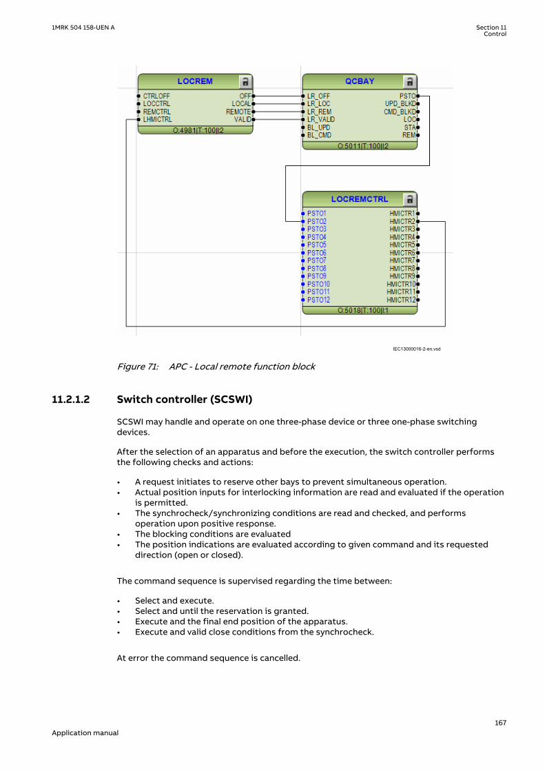
IEC13000016-2-en.vsd IEC13000016 V2 EN-US
Figure 71: APC - Local remote function block
11.2.1.2 Switch controller (SCSWI)M16596-3 v4
SCSWI may handle and operate on one three-phase device or three one-phase switchingdevices.
After the selection of an apparatus and before the execution, the switch controller performsthe following checks and actions:
• A request initiates to reserve other bays to prevent simultaneous operation.• Actual position inputs for interlocking information are read and evaluated if the operation
is permitted.• The synchrocheck/synchronizing conditions are read and checked, and performs
operation upon positive response.• The blocking conditions are evaluated• The position indications are evaluated according to given command and its requested
direction (open or closed).
The command sequence is supervised regarding the time between:
• Select and execute.• Select and until the reservation is granted.• Execute and the final end position of the apparatus.• Execute and valid close conditions from the synchrocheck.
At error the command sequence is cancelled.
1MRK 504 158-UEN A Section 11Control
167Application manual

In the case when there are three one-phase switches (SXCBR) connected to the switchcontroller function, the switch controller will "merge" the position of the three switches to theresulting three-phase position. In case of a pole discordance situation, that is, the positions ofthe one-phase switches are not equal for a time longer than a settable time; an error signal willbe given.
The switch controller is not dependent on the type of switching device SXCBR or SXSWI. Theswitch controller represents the content of the SCSWI logical node (according to IEC 61850)with mandatory functionality.
11.2.1.3 Switches (SXCBR/SXSWI)M16602-3 v5
Switches are functions used to close and interrupt an ac power circuit under normalconditions, or to interrupt the circuit under fault, or emergency conditions. The intention withthese functions is to represent the lowest level of a power-switching device with or withoutshort circuit breaking capability, for example, circuit breakers, disconnectors, earthingswitches etc.
The purpose of these functions is to provide the actual status of positions and to perform thecontrol operations, that is, pass all the commands to the primary apparatus via output boardsand to supervise the switching operation and position.
Switches have the following functionalities:
• Local/Remote switch intended for the switchyard• Block/deblock for open/close command respectively• Update block/deblock of position indication• Substitution of position indication• Supervision timer that the primary device starts moving after a command• Supervision of allowed time for intermediate position• Definition of pulse duration for open/close command respectively
The realizations of these function are done with SXCBR representing a circuit breaker and withSXSWI representing a circuit switch that is, a disconnector or an earthing switch.
Circuit breaker (SXCBR) can be realized either as three one-phase switches or as one three-phase switch.
The content of this function is represented by the IEC 61850 definitions for the logical nodesCircuit breaker (SXCBR) and Circuit switch (SXSWI) with mandatory functionality.
11.2.1.4 Reservation function (QCRSV and RESIN)M16609-3 v4
The purpose of the reservation function is primarily to transfer interlocking informationbetween IEDs in a safe way and to prevent double operation in a bay, switchyard part, orcomplete substation.
For interlocking evaluation in a substation, the position information from switching devices,such as circuit breakers, disconnectors and earthing switches can be required from the samebay or from several other bays. When information is needed from other bays, it is exchangedover the station bus between the distributed IEDs. The problem that arises, even at a highspeed of communication, is a space of time during which the information about the positionof the switching devices are uncertain. The interlocking function uses this information forevaluation, which means that also the interlocking conditions are uncertain.
To ensure that the interlocking information is correct at the time of operation, a uniquereservation method is available in the IEDs. With this reservation method, the bay that wantsthe reservation sends a reservation request to other bays and then waits for a reservationgranted signal from the other bays. Actual position indications from these bays are then
Section 11 1MRK 504 158-UEN AControl
168Application manual

transferred over the station bus for evaluation in the IED. After the evaluation the operationcan be executed with high security.
This functionality is realized over the station bus by means of the function blocks QCRSV andRESIN. The application principle is shown in Figure 72.
The function block QCRSV handles the reservation. It sends out either the reservation requestto other bays or the acknowledgement if the bay has received a request from another bay.
The other function block RESIN receives the reservation information from other bays. Thenumber of instances is the same as the number of involved bays (up to 60 instances areavailable). The received signals are either the request for reservation from another bay or theacknowledgment from each bay respectively, which have received a request from this bay. Alsothe information of valid transmission over the station bus must be received.
en05000117.vsd
IEDIED
From otherSCSWI inthe bay To other
SCSWIin thebay
3
Station bus
. . .
. . .
. . .
3
RESIN
EXCH_OUTEXCH_IN
RESIN
EXCH_OUTEXCH_IN
..
SCSWI
RES_RQRES_GRT
RES_DATA
QCRSVRES_RQ1
RES_RQ8
RES_GRT1
RES_GRT8
..
2
IEC05000117 V2 EN-US
Figure 72: Application principles for reservation over the station bus
The reservation can also be realized with external wiring according to the application examplein Figure 73. This solution is realized with external auxiliary relays and extra binary inputs andoutputs in each IED, but without use of function blocks QCRSV and RESIN.
SCSWI
SELECTEDRES_EXT
+
IED
BI BO
IED
BI BO
OROther SCSWI in the bay
en05000118.vsdIEC05000118 V2 EN-US
Figure 73: Application principles for reservation with external wiring
1MRK 504 158-UEN A Section 11Control
169Application manual

The solution in Figure 73 can also be realized over the station bus according to the applicationexample in Figure 74. The solutions in Figure 73 and Figure 74 do not have the same highsecurity compared to the solution in Figure 72, but instead have a higher availability, since noacknowledgment is required.
SCSWI
SELECTED
RES_EXT
IEDIED
OROther SCWI inthe bay
Station bus. . .
SPGAPCIN
RESGRANT
IntlReceive
. . .
. . .
RESGRANT
IntlReceive
IEC05000178-3-en.vsd IEC05000178 V3 EN-US
Figure 74: Application principle for an alternative reservation solution
11.2.2 Interaction between modulesM16626-3 v7
A typical bay with apparatus control function consists of a combination of logical nodes orfunctions that are described here:
• The Switch controller (SCSWI) initializes all operations for one apparatus. It is thecommand interface of the apparatus. It includes the position reporting as well as thecontrol of the position
• The Circuit breaker (SXCBR) is the process interface to the circuit breaker for theapparatus control function.
• The Circuit switch (SXSWI) is the process interface to the disconnector or the earthingswitch for the apparatus control function.
• The Bay control (QCBAY) fulfils the bay-level functions for the apparatuses, such asoperator place selection and blockings for the complete bay.
• The Reservation (QCRSV) deals with the reservation function.• The Protection trip logic (SMPPTRC) connects the "trip" outputs of one or more protection
functions to a common "trip" to be transmitted to SXCBR.• The Autorecloser (SMBRREC) consists of the facilities to automatically close a tripped
breaker with respect to a number of configurable conditions.• The logical node Interlocking (SCILO) provides the information to SCSWI whether it is
permitted to operate due to the switchyard topology. The interlocking conditions areevaluated with separate logic and connected to SCILO .
• The Synchrocheck, energizing check, and synchronizing (SESRSYN) calculates andcompares the voltage phasor difference from both sides of an open breaker withpredefined switching conditions (synchrocheck). Also the case that one side is dead(energizing-check) is included.
• The Generic Automatic Process Control function, GAPC, handles generic commands fromthe operator to the system.
The overview of the interaction between these functions is shown in Figure 75 below.
Section 11 1MRK 504 158-UEN AControl
170Application manual

IEC05000120-2-en.vsd
SXCBR(Circuit breaker)
Interlockingfunctionblock
(Not a LN)
SCSWI(Switching control)
QCBAY(Bay control)
SMBRREC
(Auto-reclosure)
I/O
Trip
Close rel.
Res. req.
Star
t AR
Close CB
Position
Res. granted
Operator placeselection
SCSWI(Switching control)
SXSWI(Disconnector)
Open cmdClose cmd
Position
SESRSYN(Synchrocheck & Synchronizer)
SCILO
SCILO
Synchrocheck OK
QCRSV(Reservation) Res. req.
Res. granted
GAPC(Generic
Automatic Process Control) Open/Close
Open/Close
Enable close
Enable open
Open rel.
Close rel.Open rel.
SMPPTRC(Trip logic)
Position
Enab
leop
enEn
able
clos
e
Pos.
from
ot
her b
ays
I/O
Open cmdClose cmd
(Interlocking)
(Interlocking)
Synchronizing in progress
IEC05000120 V2 EN-US
Figure 75: Example overview of the interactions between functions in a typical bay
11.2.3 Setting guidelinesM16669-3 v4
The setting parameters for the apparatus control function are set via the local HMI or PCM600.
11.2.3.1 Bay control (QCBAY)M16670-3 v7
If the parameter AllPSTOValid is set to No priority, all originators from local and remote areaccepted without any priority.
If the parameter RemoteIncStation is set to Yes, commands from IEC 61850-8-1 clients at bothstation and remote level are accepted, when the QCBAY function is in Remote. If set to No, thecommand LocSta controls which operator place is accepted when QCBAY is in Remote. If
1MRK 504 158-UEN A Section 11Control
171Application manual

LocSta is true, only commands from station level are accepted, otherwise only commandsfrom remote level are accepted.
The parameter RemoteIncStation has only effect on the IEC 61850-8-1communication. Further, when using IEC 61850 edition 1 communication, theparameter should be set to Yes, since the command LocSta is not defined inIEC 61850-8-1 edition 1.
11.2.3.2 Switch controller (SCSWI)M16673-3 v6
The parameter CtlModel specifies the type of control model according to IEC 61850. Thedefault for control of circuit breakers, disconnectors and earthing switches the control modelis set to SBO Enh (Select-Before-Operate) with enhanced security.
When the operation shall be performed in one step, and no monitoring of the result of thecommand is desired, the model direct control with normal security is used.
At control with enhanced security there is an additional supervision of the status value by thecontrol object, which means that each command sequence must be terminated by atermination command.
The parameter PosDependent gives permission to operate depending on the positionindication, that is, at Always permitted it is always permitted to operate independent of thevalue of the position. At Not perm at 00/11 it is not permitted to operate if the position is inbad or intermediate state.
tSelect is the maximum allowed time between the select and the execute command signal,that is, the time the operator has to perform the command execution after the selection of theobject to operate. When the time has expired, the selected output signal is set to false and acause-code is given.
The time parameter tResResponse is the allowed time from reservation request to thefeedback reservation granted from all bays involved in the reservation function. When the timehas expired, the control function is reset, and a cause-code is given.
tSynchrocheck is the allowed time for the synchrocheck function to fulfill the close conditions.When the time has expired, the function tries to start the synchronizing function. IftSynchrocheck is set to 0, no synchrocheck is done, before starting the synchronizing function.
The timer tSynchronizing supervises that the signal synchronizing in progress is obtained inSCSWI after start of the synchronizing function. The start signal for the synchronizing is set ifthe synchrocheck conditions are not fulfilled. When the time has expired, the control functionis reset, and a cause-code is given. If no synchronizing function is included, the time is set to 0,which means no start of the synchronizing function is done, and when tSynchrocheck hasexpired, the control function is reset and a cause-code is given.
tExecutionFB is the maximum time between the execute command signal and the commandtermination. When the time has expired, the control function is reset and a cause-code isgiven.
tPoleDiscord is the allowed time to have discrepancy between the poles at control of threeone-phase breakers. At discrepancy an output signal is activated to be used for trip or alarm,and during a command, the control function is reset, and a cause-code is given.
SuppressMidPos when On suppresses the mid-position during the time tIntermediate of theconnected switches.
The parameter InterlockCheck decides if interlock check should be done at both select andoperate, Sel & Op phase, or only at operate, Op phase.
Section 11 1MRK 504 158-UEN AControl
172Application manual

11.2.3.3 Switch (SXCBR/SXSWI)M16675-3 v7
tStartMove is the supervision time for the apparatus to start moving after a commandexecution. When the time has expired, the switch function is reset, and a cause-code is given.
During the tIntermediate time the position indication is allowed to be in an intermediate (00)state. When the time has expired, the switch function is reset, and a cause-code is given. Theindication of the mid-position at SCSWI is suppressed during this time period when theposition changes from open to close or vice-versa if the parameter SuppressMidPos is set toOn in the SCSWI function.
If the parameter AdaptivePulse is set to Adaptive the command output pulse resets when anew correct end position is reached. If the parameter is set to Not adaptive the commandoutput pulse remains active until the timer tOpenPulsetClosePulse has elapsed.
tOpenPulse is the output pulse length for an open command. If AdaptivePulse is set toAdaptive, it is the maximum length of the output pulse for an open command. The defaultlength is set to 200 ms for a circuit breaker (SXCBR) and 500 ms for a disconnector (SXSWI).
tClosePulse is the output pulse length for a close command. If AdaptivePulse is set toAdaptive, it is the maximum length of the output pulse for an open command. The defaultlength is set to 200 ms for a circuit breaker (SXCBR) and 500 ms for a disconnector (SXSWI).
11.2.3.4 Bay Reserve (QCRSV)M16677-3 v3
The timer tCancelRes defines the supervision time for canceling the reservation, when thiscannot be done by requesting bay due to for example communication failure.
When the parameter ParamRequestx (x=1-8) is set to Only own bay res. individually for eachapparatus (x) in the bay, only the own bay is reserved, that is, the output for reservationrequest of other bays (RES_BAYS) will not be activated at selection of apparatus x.
11.2.3.5 Reservation input (RESIN)M16678-3 v3
With the FutureUse parameter set to Bay future use the function can handle bays not yetinstalled in the SA system.
11.3 Logic rotating switch for function selection and LHMIpresentation SLGAPC
SEMOD114936-1 v4
11.3.1 IdentificationSEMOD167845-2 v3
Function description IEC 61850identification
IEC 60617identification
ANSI/IEEE C37.2device number
Logic rotating switch for functionselection and LHMI presentation
SLGAPC - -
11.3.2 ApplicationSEMOD114927-4 v6
The logic rotating switch for function selection and LHMI presentation function (SLGAPC) (orthe selector switch function block, as it is also known) is used to get a selector switchfunctionality similar with the one provided by a hardware multi-position selector switch.
1MRK 504 158-UEN A Section 11Control
173Application manual
Hardware selector switches are used extensively by utilities, in order to have differentfunctions operating on pre-set values. Hardware switches are however sources formaintenance issues, lower system reliability and extended purchase portfolio. The virtualselector switches eliminate all these problems.
SLGAPC function block has two operating inputs (UP and DOWN), one blocking input (BLOCK)and one operator position input (PSTO).
SLGAPC can be activated both from the local HMI and from external sources (switches), via theIED binary inputs. It also allows the operation from remote (like the station computer).SWPOSN is an integer value output, giving the actual output number. Since the number ofpositions of the switch can be established by settings (see below), one must be careful incoordinating the settings with the configuration (if one sets the number of positions to x insettings – for example, there will be only the first x outputs available from the block in theconfiguration). Also the frequency of the (UP or DOWN) pulses should be lower than thesetting tPulse.
From the local HMI, the selector switch can be operated from Single-line diagram (SLD).
11.3.3 Setting guidelinesSEMOD115063-294 v6
The following settings are available for the Logic rotating switch for function selection andLHMI presentation (SLGAPC) function:
Operation: Sets the operation of the function On or Off.
NrPos: Sets the number of positions in the switch (max. 32).
OutType: Steady or Pulsed.
tPulse: In case of a pulsed output, it gives the length of the pulse (in seconds).
tDelay: The delay between the UP or DOWN activation signal positive front and the outputactivation.
StopAtExtremes: Sets the behavior of the switch at the end positions – if set to Disabled, whenpressing UP while on first position, the switch will jump to the last position; when pressingDOWN at the last position, the switch will jump to the first position; when set to Enabled, nojump will be allowed.
11.4 Selector mini switch VSGAPCSEMOD158754-1 v3
11.4.1 IdentificationSEMOD167850-2 v3
Function description IEC 61850identification
IEC 60617identification
ANSI/IEEE C37.2device number
Selector mini switch VSGAPC - -
11.4.2 ApplicationSEMOD158803-5 v7
Selector mini switch (VSGAPC) function is a multipurpose function used in the configurationtool in PCM600 for a variety of applications, as a general purpose switch. VSGAPC can be usedfor both acquiring an external switch position (through the IPOS1 and the IPOS2 inputs) and
Section 11 1MRK 504 158-UEN AControl
174Application manual

represent it through the single line diagram symbols (or use it in the configuration through theoutputs POS1 and POS2) as well as, a command function (controlled by the PSTO input), givingswitching commands through the CMDPOS12 and CMDPOS21 outputs.
The output POSITION is an integer output, showing the actual position as an integer number 0– 3.
An example where VSGAPC is configured to switch Autorecloser on–off from a button symbolon the local HMI is shown in figure76. The I and O buttons on the local HMI are normally usedfor on–off operations of the circuit breaker.
IEC07000112-3-en.vsd
PSTO
CMDPOS12
IPOS1
NAM_POS1NAM_POS2
IPOS2
CMDPOS21OFFON
VSGAPC
SMBRRECONOFF
SETON
INTONE
INVERTERINPUT OUT
IEC07000112 V3 EN-US
Figure 76: Control of Autorecloser from local HMI through Selector mini switch
VSGAPC is also provided with IEC 61850 communication so it can be controlled from SAsystem as well.
11.4.3 Setting guidelinesSEMOD158807-4 v4
Selector mini switch (VSGAPC) function can generate pulsed or steady commands (by settingthe Mode parameter). When pulsed commands are generated, the length of the pulse can beset using the tPulse parameter. Also, being accessible on the single line diagram (SLD), thisfunction block has two control modes (settable through CtlModel): Dir Norm and SBO Enh.
11.5 Generic communication function for Double Pointindication DPGAPC
SEMOD55384-1 v4
11.5.1 IdentificationGUID-E16EA78F-6DF9-4B37-A92D-5C09827E2297 v3
Function description IEC 61850identification
IEC 60617identification
ANSI/IEEE C37.2device number
Generic communication function forDouble Point indication
DPGAPC - -
11.5.2 ApplicationSEMOD55391-5 v8
Generic communication function for Double Point indication (DPGAPC) function block is usedto send double point position indication to other systems, equipment or functions in thesubstation through IEC 61850-8-1 or other communication protocols. It is especially intendedto be used in the interlocking station-wide logics. To be able to get the signals into othersystems, equipment or functions, one must use other tools, described in the Engineering
1MRK 504 158-UEN A Section 11Control
175Application manual

manual, and define which function block in which systems, equipment or functions shouldreceive this information.
More specifically, DPGAPC function reports a combined double point position indicationoutput POSITION, by evaluating the value and the timestamp attributes of the inputs OPENand CLOSE, together with the logical input signal VALID.
When the input signal VALID is active, the values of the OPEN and CLOSE inputs determine thetwo-bit integer value of the output POSITION. The timestamp of the output POSITION will havethe latest updated timestamp of the inputs OPEN and CLOSE.
When the input signal VALID is inactive, DPGAPC function forces the position to intermediatedstate.
When the value of the input signal VALID changes, the timestamp of the output POSITION willbe updated as the time when DPGAPC function detects the change.
Refer to Table 26 for the description of the input-output relationship in terms of the value andthe quality attributes.
Table 26: Description of the input-output relationship
VALID OPEN CLOSE POSITIONValue Description
0 - - 0 Intermediate
1 0 0 0 Intermediate
1 1 0 1 Open
1 0 1 2 Closed
1 1 1 3 Bad State
11.5.3 Setting guidelinesSEMOD55398-5 v4
The function does not have any parameters available in the local HMI or PCM600.
11.6 Single point generic control 8 signals SPC8GAPCSEMOD176448-1 v3
11.6.1 IdentificationSEMOD176456-2 v3
Function description IEC 61850identification
IEC 60617identification
ANSI/IEEE C37.2device number
Single point generic control 8 signals SPC8GAPC - -
11.6.2 ApplicationSEMOD176511-4 v5
The Single point generic control 8 signals (SPC8GAPC) function block is a collection of 8 singlepoint commands that can be used for direct commands for example reset of LED's or puttingIED in "ChangeLock" state from remote. In this way, simple commands can be sent directly tothe IED outputs, without confirmation. Confirmation (status) of the result of the commands issupposed to be achieved by other means, such as binary inputs and SPGGIO function blocks.
Section 11 1MRK 504 158-UEN AControl
176Application manual

PSTO is the universal operator place selector for all control functions. Even ifPSTO can be configured to allow LOCAL or ALL operator positions, the onlyfunctional position usable with the SPC8GAPC function block is REMOTE.
11.6.3 Setting guidelinesSEMOD176518-4 v5
The parameters for the single point generic control 8 signals (SPC8GAPC) function are set viathe local HMI or PCM600.
Operation: turning the function operation On/Off.
There are two settings for every command output (totally 8):
Latchedx: decides if the command signal for output x is Latched (steady) or Pulsed.
tPulsex: if Latchedx is set to Pulsed, then tPulsex will set the length of the pulse (in seconds).
11.7 AutomationBits, command function for DNP3.0AUTOBITS
SEMOD158589-1 v3
11.7.1 IdentificationGUID-C3BB63F5-F0E7-4B00-AF0F-917ECF87B016 v4
Function description IEC 61850identification
IEC 60617identification
ANSI/IEEE C37.2device number
AutomationBits, command functionfor DNP3 AUTOBITS - -
11.7.2 ApplicationSEMOD158637-5 v4
Automation bits, command function for DNP3 (AUTOBITS) is used within PCM600 in order toget into the configuration the commands coming through the DNP3.0 protocol.The AUTOBITSfunction plays the same role as functions GOOSEBINRCV (for IEC 61850) and MULTICMDRCV(for LON).AUTOBITS function block have 32 individual outputs which each can be mapped as aBinary Output point in DNP3. The output is operated by a "Object 12" in DNP3. This objectcontains parameters for control-code, count, on-time and off-time. To operate an AUTOBITSoutput point, send a control-code of latch-On, latch-Off, pulse-On, pulse-Off, Trip or Close. Theremaining parameters are regarded as appropriate. For example, pulse-On, on-time=100, off-time=300, count=5 would give 5 positive 100 ms pulses, 300 ms apart.
For description of the DNP3 protocol implementation, refer to the Communication manual.
11.7.3 Setting guidelinesSEMOD158639-5 v3
AUTOBITS function block has one setting, (Operation: On/Off) enabling or disabling thefunction. These names will be seen in the DNP3 communication management tool in PCM600.
11.8 Single command, 16 signals SINGLECMDSEMOD119849-1 v2
1MRK 504 158-UEN A Section 11Control
177Application manual

11.8.1 IdentificationGUID-2217CCC2-5581-407F-A4BC-266CD6808984 v1
Function description IEC 61850identification
IEC 60617identification
ANSI/IEEE C37.2device number
Single command, 16 signals SINGLECMD - -
11.8.2 ApplicationM12445-3 v3
Single command, 16 signals (SINGLECMD) is a common function and always included in theIED.
The IEDs may be provided with a function to receive commands either from a substationautomation system or from the local HMI. That receiving function block has outputs that canbe used, for example, to control high voltage apparatuses in switchyards. For local controlfunctions, the local HMI can also be used. Together with the configuration logic circuits, theuser can govern pulses or steady output signals for control purposes within the IED or viabinary outputs.
Figure 77 shows an application example of how the user can connect SINGLECMD viaconfiguration logic circuit to control a high-voltage apparatus. This type of command controlis normally carried out by sending a pulse to the binary outputs of the IED. Figure 77 shows aclose operation. An open breaker operation is performed in a similar way but without thesynchro-check condition.
SinglecommandfunctionSINGLECMD
CMDOUTy
OUTy
Close CB1
&User-definedconditionsSynchro-check
Configuration logic circuits
en04000206.vsdIEC04000206 V2 EN-US
Figure 77: Application example showing a logic diagram for control of a circuit breakervia configuration logic circuits
Figure 78 and figure 79 show other ways to control functions, which require steady On/Offsignals. Here, the output is used to control built-in functions or external devices.
Section 11 1MRK 504 158-UEN AControl
178Application manual

SinglecommandfunctionSINGLECMD
CMDOUTy
OUTy
Function n
en04000207.vsd
Function n
IEC04000207 V2 EN-US
Figure 78: Application example showing a logic diagram for control of built-in functions
Singlecommandfunction
SINGLESMD
CMDOUTy
OUTy
Device 1
User-definedconditions
Configuration logic circuits
en04000208.vsd
&
IEC04000208 V2 EN-US
Figure 79: Application example showing a logic diagram for control of external devicesvia configuration logic circuits
11.8.3 Setting guidelinesM12448-3 v2
The parameters for Single command, 16 signals (SINGLECMD) are set via the local HMI orPCM600.
Parameters to be set are MODE, common for the whole block, and CMDOUTy which includesthe user defined name for each output signal. The MODE input sets the outputs to be one ofthe types Off, Steady, or Pulse.
1MRK 504 158-UEN A Section 11Control
179Application manual

• Off, sets all outputs to 0, independent of the values sent from the station level, that is, theoperator station or remote-control gateway.
• Steady, sets the outputs to a steady signal 0 or 1, depending on the values sent from thestation level.
• Pulse, gives a pulse with 100 ms duration, if a value sent from the station level is changedfrom 0 to 1. That means the configured logic connected to the command function blockmay not have a cycle time longer than the cycle time for the command function block.
Section 11 1MRK 504 158-UEN AControl
180Application manual

Section 12 Logic
12.1 Tripping logic SMPPTRCIP14576-1 v4
12.1.1 IdentificationSEMOD56226-2 v6
Function description IEC 61850identification
IEC 60617identification
ANSI/IEEE C37.2device number
Tripping logic SMPPTRC
I->O
SYMBOL-K V1 EN-US
94
12.1.2 ApplicationM12252-3 v8
All trip signals from the different protection functions shall be routed through the trip logic. Inits simplest alternative the logic will only link the TRIP signal and make sure that it is longenough.
Tripping logic SMPPTRC offers three different operating modes:
• Three-phase tripping for all fault types (3ph operating mode)• Single-phase tripping for single-phase faults and three-phase tripping for multi-phase and
evolving faults (1ph/3ph operating mode). The logic also issues a three-phase trippingcommand when phase selection within the operating protection functions is not possible,or when external conditions request three-phase tripping.
• Two-phase tripping for two-phase faults.
The three-phase trip for all faults offers a simple solution and is often sufficient in well meshedtransmission systems and in sub-transmission systems. Since most faults, especially at thehighest voltage levels, are single phase-to-earth faults, single-phase tripping can be of greatvalue. If only the faulty phase is tripped, power can still be transferred on the line during thedead time that arises before reclosing. Single-phase tripping during single-phase faults mustbe combined with single pole reclosing.
One SMPPTRC function block should be used for each breaker, if the line is connected to thesubstation via more than one breaker. Assume that single-phase tripping and autoreclosing isused on the line. Both breakers are then normally set up for 1/3-phase tripping and 1/3-phaseautoreclosing. As an alternative, the breaker chosen as master can have single-phase tripping,while the slave breaker could have three-phase tripping and autoreclosing. In the case of apermanent fault, only one of the breakers has to be operated when the fault is energized asecond time. In the event of a transient fault the slave breaker performs a three-phasereclosing onto the non-faulted line.
The same philosophy can be used for two-phase tripping and autoreclosing.
To prevent closing of a circuit breaker after a trip the function can block the closing.
1MRK 504 158-UEN A Section 12Logic
181Application manual

The two instances of the SMPPTRC function are identical except, for the name of the functionblock (SMPPTRC1 and SMPPTRC2). References will therefore only be made to SMPPTRC1 in thefollowing description, but they also apply to SMPPTRC2.
12.1.2.1 Three-phase trippingM14828-7 v8
A simple application with three-phase tripping from the logic block utilizes part of the functionblock. Connect the inputs from the protection function blocks to the input TRIN. If necessary(normally the case) use a logic OR block to combine the different function outputs to thisinput. Connect the output TRIP to the digital Output/s on the IO board.
This signal can also be used for other purposes internally in the IED. An example could be thestarting of Breaker failure protection. The three outputs TRL1, TRL2, TRL3 will always beactivated at every trip and can be utilized on individual trip outputs if single-phase operatingdevices are available on the circuit breaker even when a three-phase tripping scheme isselected.
Set the function block to Program = 3Ph and set the required length of the trip pulse to forexample, tTripMin = 150ms.
For special applications such as Lock-out refer to the separate section below. The typicalconnection is shown below in figure 80. Signals that are not used are dimmed.
BLOCK
BLKLKOUT
TRIN
TRINL1
TRINL2
TRINL3
PSL1
PSL2
PSL3
1PTRZ
1PTREF
P3PTR
SETLKOUT
RSTLKOUT
SMPPTRC
TRIP
TRL1
TRL2
TRL3
TR1P
TR2P
TR3P
CLLKOUT
³1
Impedance protection zone 1 TRIP
EF4PTOC TRIP
en05000544.vsd
Impedance protection zone 3 TRIP
Impedance protection zone 2 TRIP
IEC05000544 V2 EN-US
Figure 80: Tripping logic SMPPTRC is used for a simple three-phase tripping application
12.1.2.2 Single- and/or three-phase trippingM14828-11 v4
The single-/three-phase tripping will give single-phase tripping for single-phase faults andthree-phase tripping for multi-phase fault. The operating mode is always used together with asingle-phase autoreclosing scheme.
The single-phase tripping can include different options and the use of the different inputs inthe function block.
The inputs 1PTRZ and 1PTREF are used for single-phase tripping for distance protection anddirectional earth fault protection as required.
The inputs are combined with the phase selection logic and the start signals from the phaseselector must be connected to the inputs PSL1, PSL2 and PSL3 to achieve the tripping on therespective single-phase trip outputs TRL1, TRL2 and TRL3. The Output TRIP is a general trip
Section 12 1MRK 504 158-UEN ALogic
182Application manual

and activated independent of which phase is involved. Depending on which phases areinvolved the outputs TR1P, TR2P and TR3P will be activated as well.
When single-phase tripping schemes are used a single-phase autoreclosing attempt isexpected to follow. For cases where the autoreclosing is not in service or will not follow forsome reason, the input Prepare Three-phase Trip P3PTR must be activated. This is normallyconnected to the respective output on the Synchrocheck, energizing check, and synchronizingfunction SESRSYN but can also be connected to other signals, for example an external logicsignal. If two breakers are involved, one TR block instance and one SESRSYN instance is usedfor each breaker. This will ensure correct operation and behavior of each breaker.
The output Trip 3 Phase TR3P must be connected to the respective input in SESRSYN to switchSESRSYN to three-phase reclosing. If this signal is not activated SESRSYN will use single-phasereclosing dead time.
Note also that if a second line protection is utilizing the same SESRSYN thethree-phase trip signal must be generated, for example by using the three-triprelays contacts in series and connecting them in parallel to the TR3P outputfrom the trip block.
The trip logic also has inputs TRINL1, TRINL2 and TRINL3 where phase-selected trip signals canbe connected. Examples can be individual phase inter-trips from remote end or internal/external phase selected trip signals, which are routed through the IED to achieve, for exampleSESRSYN, Breaker failure, and so on. Other back-up functions are connected to the input TRINas described above. A typical connection for a single-phase tripping scheme is shown infigure 81.
BLOCK
BLKLKOUT
TRIN
TRINL1
TRINL2
TRINL3
PSL1
PSL2
PSL3
1PTRZ
1PTREF
P3PTR
SETLKOUT
RSTLKOUT
SMPPTRC
TRIP
TRL1
TRL2
TRL3
TR1P
TR2P
TR3P
CLLKOUT
TR3P
SMBRRECPREP3P
³1
TR3P
Phase Selection
PSL1
PSL2
PSL3
Distance protection zone 1 TRIP
Distance protection zone 2 TRIP
Distance protection zone 3 TRIP
Overcurrent protection TRIP
IEC05000545-3-en.vsdIEC05000545 V3 EN-US
Figure 81: The trip logic function SMPPTRC used for single-phase tripping application
12.1.2.3 Single-, two- or three-phase trippingM14828-15 v3
The single-/two-/three-phase tripping mode provides single-phase tripping for single-phasefaults, two-phase tripping for two-phase faults and three-phase tripping for multi-phasefaults. The operating mode is always used together with an autoreclosing scheme with settingProgram = 1/2/3Ph or Program = 1/3Ph attempt.
1MRK 504 158-UEN A Section 12Logic
183Application manual

The functionality is very similar to the single-phase scheme described above. HoweverSESRSYN must in addition to the connections for single phase above be informed that the tripis two phase by connecting the trip logic output TR2P to the respective input in SESRSYN.
12.1.2.4 Lock-outM14828-18 v4
This function block is provided with possibilities to initiate lock-out. The lock-out can be set toonly activate the block closing output CLLKOUT or initiate the block closing output and alsomaintain the trip signal (latched trip).
The lock-out can then be manually reset after checking the primary fault by activating theinput reset Lock-Out RSTLKOUT.
If external conditions are required to initiate Lock-out but not initiate trip this can be achievedby activating input SETLKOUT. The setting AutoLock = Off means that the internal trip will notactivate lock-out so only initiation of the input SETLKOUT will result in lock-out. This isnormally the case for overhead line protection where most faults are transient. Unsuccessfulautoreclose and back-up zone tripping can in such cases be connected to initiate Lock-out byactivating the input SETLKOUT.
12.1.2.5 Blocking of the function blockM14828-21 v3
The function block can be blocked in two different ways. Its use is dependent on theapplication. Blocking can be initiated internally by logic, or by the operator using acommunication channel. Total blockage of the trip function is done by activating the inputBLOCK and can be used to block the output of the trip logic in the event of internal failures.Blockage of lock-out output by activating input BLKLKOUT is used for operator control of thelock-out function.
12.1.3 Setting guidelinesM12274-3 v6
The parameters for Tripping logic SMPPTRC are set via the local HMI or PCM600.
The following trip parameters can be set to regulate tripping.
Operation: Sets the mode of operation. Off switches the tripping off. The normal selection isOn.
Program: Sets the required tripping scheme. Normally 3Ph or 1/2Ph are used.
TripLockout: Sets the scheme for lock-out. Off only activates the lock-out output. On activatesthe lock-out output and latches the output TRIP. The normal selection is Off.
AutoLock: Sets the scheme for lock-out. Off only activates lock-out through the inputSETLKOUT. On additonally allows activation through the trip function itself. The normalselection is Off.
tTripMin: Sets the required minimum duration of the trip pulse. It should be set to ensure thatthe breaker is tripped correctly. Normal setting is 0.150s.
12.2 Trip matrix logic TMAGAPCIP15121-1 v4
Section 12 1MRK 504 158-UEN ALogic
184Application manual

12.2.1 IdentificationSEMOD167882-2 v3
Function description IEC 61850identification
IEC 60617identification
ANSI/IEEE C37.2device number
Trip matrix logic TMAGAPC - -
12.2.2 ApplicationM15321-3 v11
The trip matrix logic TMAGAPC function is used to route trip signals and other logical outputsignals to different output contacts on the IED.
The trip matrix logic function has 3 output signals and these outputs can be connected tophysical tripping outputs according to the specific application needs for settable pulse orsteady output.
12.2.3 Setting guidelinesM15291-3 v5
Operation: Operation of function On/Off.
PulseTime: Defines the pulse time when in Pulsed mode. When used for direct tripping ofcircuit breaker(s) the pulse time delay shall be set to approximately 0.150 seconds in order toobtain satisfactory minimum duration of the trip pulse to the circuit breaker trip coils.
OnDelay: Used to prevent output signals to be given for spurious inputs. Normally set to 0 or alow value.
OffDelay: Defines a delay of the reset of the outputs after the activation conditions no longerare fulfilled. It is only used in Steady mode. When used for direct tripping of circuit breaker(s)the off delay time shall be set to at least 0.150 seconds in order to obtain a satisfactoryminimum duration of the trip pulse to the circuit breaker trip coils.
ModeOutputx: Defines if output signal OUTPUTx (where x=1-3) is Steady or Pulsed.
12.3 Logic for group alarm ALMCALHGUID-64EA392C-950F-486C-8D96-6E7736B592BF v1
12.3.1 IdentificationGUID-64EA392C-950F-486C-8D96-6E7736B592BF v1
Function description IEC 61850identification
IEC 60617identification
ANSI/IEEE C37.2device number
Logic for group alarm ALMCALH - -
12.3.2 ApplicationGUID-70B268A9-B248-422D-9896-89FECFF80B75 v1
Group alarm logic function ALMCALH is used to route alarm signals to different LEDs and/oroutput contacts on the IED.
ALMCALH output signal and the physical outputs allows the user to adapt the alarm signal tophysical tripping outputs according to the specific application needs.
1MRK 504 158-UEN A Section 12Logic
185Application manual

12.3.3 Setting guidelinesGUID-0BDD898A-360B-4443-A5CF-7619C80A17F4 v2
Operation: On or Off
12.4 Logic for group alarm WRNCALH
12.4.1 IdentificationGUID-3EBD3D5B-F506-4557-88D7-DFC0BD21C690 v4
Function description IEC 61850identification
IEC 60617identification
ANSI/IEEE C37.2device number
Logic for group warning WRNCALH - -
12.4.1.1 ApplicationGUID-FC0DBB7B-FF86-44BF-83D6-DDF120A176DE v1
Group warning logic function WRNCALH is used to route warning signals to LEDs and/oroutput contacts on the IED.
WRNCALH output signal WARNING and the physical outputs allows the user to adapt thewarning signal to physical tripping outputs according to the specific application needs.
12.4.1.2 Setting guidelinesGUID-B08F2636-33DA-4937-92EB-1A8AC0909AB4 v2
OperationOn or Off
12.5 Logic for group indication INDCALH
12.5.1 IdentificationGUID-3B5D4371-420D-4249-B6A4-5A168920D635 v4
Function description IEC 61850identification
IEC 60617identification
ANSI/IEEE C37.2device number
Logic for group indication INDCALH - -
12.5.1.1 ApplicationGUID-9BAD30FB-4B75-4E14-82A8-6A59B09FA6EA v1
Group indication logic function INDCALH is used to route indication signals to different LEDsand/or output contacts on the IED.
INDCALH output signal IND and the physical outputs allows the user to adapt the indicationsignal to physical outputs according to the specific application needs.
12.5.1.2 Setting guidelinesGUID-7E776D39-1A42-4F90-BF50-9B38F494A01E v2
Operation: On or Off
12.6 Configurable logic blocksIP11009-1 v3
The configurable logic blocks are available in two categories:
Section 12 1MRK 504 158-UEN ALogic
186Application manual
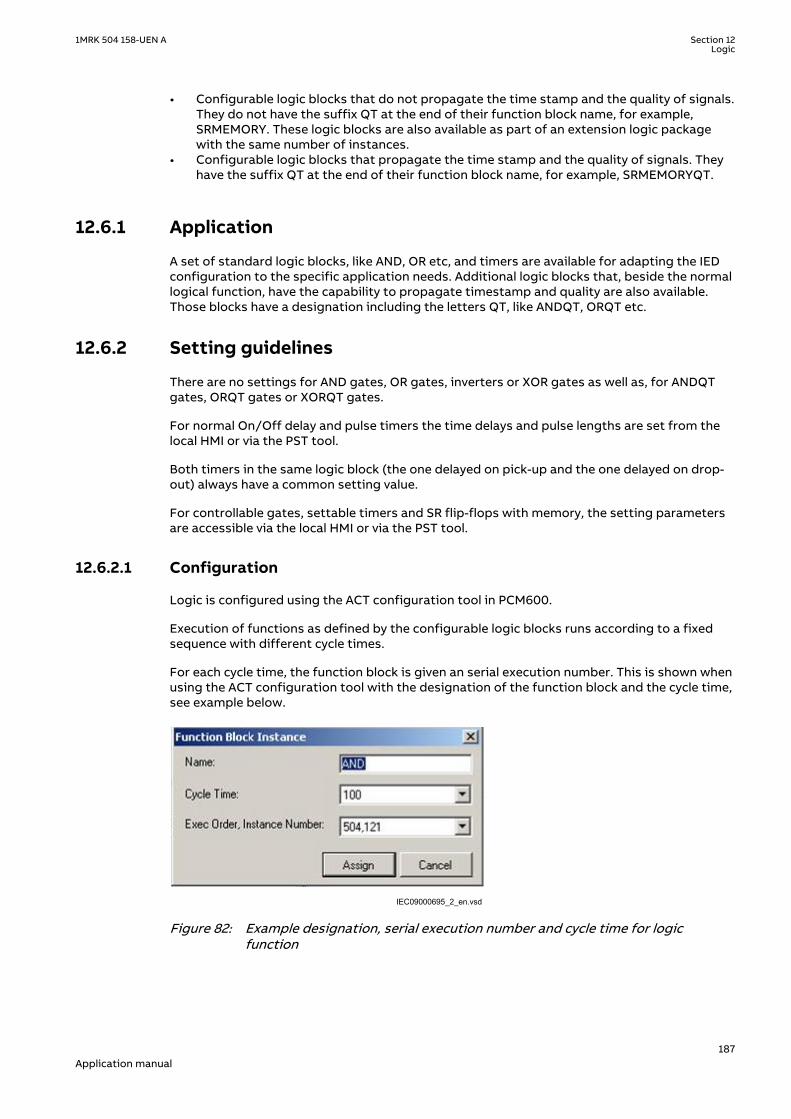
• Configurable logic blocks that do not propagate the time stamp and the quality of signals.They do not have the suffix QT at the end of their function block name, for example,SRMEMORY. These logic blocks are also available as part of an extension logic packagewith the same number of instances.
• Configurable logic blocks that propagate the time stamp and the quality of signals. Theyhave the suffix QT at the end of their function block name, for example, SRMEMORYQT.
12.6.1 ApplicationGUID-F5D6F065-441B-4296-AC56-F4DC1F5487E3 v3
A set of standard logic blocks, like AND, OR etc, and timers are available for adapting the IEDconfiguration to the specific application needs. Additional logic blocks that, beside the normallogical function, have the capability to propagate timestamp and quality are also available.Those blocks have a designation including the letters QT, like ANDQT, ORQT etc.
12.6.2 Setting guidelinesGUID-E6BD982D-9E47-4CC2-9666-6E5CABA414C0 v3
There are no settings for AND gates, OR gates, inverters or XOR gates as well as, for ANDQTgates, ORQT gates or XORQT gates.
For normal On/Off delay and pulse timers the time delays and pulse lengths are set from thelocal HMI or via the PST tool.
Both timers in the same logic block (the one delayed on pick-up and the one delayed on drop-out) always have a common setting value.
For controllable gates, settable timers and SR flip-flops with memory, the setting parametersare accessible via the local HMI or via the PST tool.
12.6.2.1 ConfigurationGUID-D93E383C-1655-46A3-A540-657141F77CF0 v4
Logic is configured using the ACT configuration tool in PCM600.
Execution of functions as defined by the configurable logic blocks runs according to a fixedsequence with different cycle times.
For each cycle time, the function block is given an serial execution number. This is shown whenusing the ACT configuration tool with the designation of the function block and the cycle time,see example below.
IEC09000695_2_en.vsdIEC09000695 V2 EN-US
Figure 82: Example designation, serial execution number and cycle time for logicfunction
1MRK 504 158-UEN A Section 12Logic
187Application manual

IEC09000310-2-en.vsdIEC09000310 V2 EN-US
Figure 83: Example designation, serial execution number and cycle time for logicfunction that also propagates timestamp and quality of input signals
The execution of different function blocks within the same cycle is determined by the order oftheir serial execution numbers. Always remember this when connecting two or more logicalfunction blocks in series.
Always be careful when connecting function blocks with a fast cycle time tofunction blocks with a slow cycle time.Remember to design the logic circuits carefully and always check the executionsequence for different functions. In other cases, additional time delays must beintroduced into the logic schemes to prevent errors, for example, race betweenfunctions.
12.7 Fixed signal function block FXDSIGNIP15080-1 v2
12.7.1 IdentificationSEMOD167904-2 v2
Function description IEC 61850identification
IEC 60617identification
ANSI/IEEE C37.2device number
Fixed signals FXDSIGN - -
12.7.2 ApplicationM15322-3 v11
The Fixed signals function FXDSIGN generates nine pre-set (fixed) signals that can be used inthe configuration of an IED, either for forcing the unused inputs in other function blocks to acertain level/value, or for creating certain logic. Boolean, integer, floating point, string types ofsignals are available.
One FXDSIGN function block is included in all IEDs.
Example for use of GRP_OFF signal in FXDSIGN
The Restricted earth fault function REFPDIF can be used both for auto-transformers andnormal transformers.
When used for auto-transformers, information from both windings parts, together with theneutral point current, needs to be available to the function. This means that three inputs areneeded.
Section 12 1MRK 504 158-UEN ALogic
188Application manual

I3PW1CT1I3PW2CT1 I3P
REFPDIF
IEC09000619_3_en.vsdIEC09000619 V3 EN-US
Figure 84: REFPDIF function inputs for autotransformer application
For normal transformers only one winding and the neutral point is available. This means thatonly two inputs are used. Since all group connections are mandatory to be connected, the thirdinput needs to be connected to something, which is the GRP_OFF signal in FXDSIGN functionblock.
I3PW1CT1I3PW2CT1 I3P
REFPDIF
GRP_OFFFXDSIGN
IEC09000620_3_en.vsdIEC09000620 V3 EN-US
Figure 85: REFPDIF function inputs for normal transformer application
12.8 Boolean 16 to Integer conversion B16ISEMOD175715-1 v1
12.8.1 IdentificationSEMOD175721-2 v2
Function description IEC 61850identification
IEC 60617identification
ANSI/IEEE C37.2device number
Boolean 16 to integer conversion B16I - -
12.8.2 ApplicationSEMOD175832-4 v4
Boolean 16 to integer conversion function B16I is used to transform a set of 16 binary (logical)signals into an integer. It can be used – for example, to connect logical output signals from afunction (like distance protection) to integer inputs from another function (like line differentialprotection). B16I does not have a logical node mapping.
The Boolean 16 to integer conversion function (B16I) will transfer a combination of up to 16binary inputs INx where 1≤x≤16 to an integer. Each INx represents a value according to thetable below from 0 to 32768. This follows the general formula: INx = 2x-1 where 1≤x≤16. The sumof all the values on the activated INx will be available on the output OUT as a sum of the valuesof all the inputs INx that are activated. OUT is an integer. When all INx where 1≤x≤16 areactivated that is = Boolean 1 it corresponds to that integer 65535 is available on the output
1MRK 504 158-UEN A Section 12Logic
189Application manual

OUT. B16I function is designed for receiving up to 16 booleans input locally. If the BLOCK inputis activated, it will freeze the output at the last value.
Values of each of the different OUTx from function block B16I for 1≤x≤16.
The sum of the value on each INx corresponds to the integer presented on the output OUT onthe function block B16I.
Name of input Type Default Description Value whenactivated
Value whendeactivated
IN1 BOOLEAN 0 Input 1 1 0
IN2 BOOLEAN 0 Input 2 2 0
IN3 BOOLEAN 0 Input 3 4 0
IN4 BOOLEAN 0 Input 4 8 0
IN5 BOOLEAN 0 Input 5 16 0
IN6 BOOLEAN 0 Input 6 32 0
IN7 BOOLEAN 0 Input 7 64 0
IN8 BOOLEAN 0 Input 8 128 0
IN9 BOOLEAN 0 Input 9 256 0
IN10 BOOLEAN 0 Input 10 512 0
IN11 BOOLEAN 0 Input 11 1024 0
IN12 BOOLEAN 0 Input 12 2048 0
IN13 BOOLEAN 0 Input 13 4096 0
IN14 BOOLEAN 0 Input 14 8192 0
IN15 BOOLEAN 0 Input 15 16384 0
IN16 BOOLEAN 0 Input 16 32768 0
The sum of the numbers in column “Value when activated” when all INx (where 1≤x≤16) areactive that is=1; is 65535. 65535 is the highest boolean value that can be converted to aninteger by the B16I function block.
12.9 Boolean to integer conversion with logical noderepresentation, 16 bit BTIGAPC
SEMOD175753-1 v4
12.9.1 IdentificationSEMOD175757-2 v4
Function description IEC 61850identification
IEC 60617identification
ANSI/IEEE C37.2device number
Boolean 16 to integer conversionwith logic node representation
BTIGAPC - -
12.9.2 ApplicationSEMOD175849-4 v5
Boolean 16 to integer conversion with logic node representation function BTIGAPC is used totransform a set of 16 binary (logical) signals into an integer. BTIGAPC can receive an integerfrom a station computer – for example, over IEC 61850–8–1. These functions are very useful
Section 12 1MRK 504 158-UEN ALogic
190Application manual

when you want to generate logical commands (for selector switches or voltage controllers) byinputting an integer number. BTIGAPC has a logical node mapping in IEC 61850.
The Boolean 16 to integer conversion function (BTIGAPC) will transfer a combination of up to16 binary inputs INx where 1≤x≤16 to an integer. Each INx represents a value according to thetable below from 0 to 32768. This follows the general formula: INx = 2x-1 where 1≤x≤16. The sumof all the values on the activated INx will be available on the output OUT as a sum of the valuesof all the inputs INx that are activated. OUT is an integer. When all INx where 1≤x≤16 areactivated that is = Boolean 1 it corresponds to that integer 65535 is available on the outputOUT. BTIGAPC function is designed for receiving up to 16 booleans input locally. If the BLOCKinput is activated, it will freeze the output at the last value.
Values of each of the different OUTx from function block BTIGAPC for 1≤x≤16.
The sum of the value on each INx corresponds to the integer presented on the output OUT onthe function block BTIGAPC.
Name of input Type Default Description Value whenactivated
Value whendeactivated
IN1 BOOLEAN 0 Input 1 1 0
IN2 BOOLEAN 0 Input 2 2 0
IN3 BOOLEAN 0 Input 3 4 0
IN4 BOOLEAN 0 Input 4 8 0
IN5 BOOLEAN 0 Input 5 16 0
IN6 BOOLEAN 0 Input 6 32 0
IN7 BOOLEAN 0 Input 7 64 0
IN8 BOOLEAN 0 Input 8 128 0
IN9 BOOLEAN 0 Input 9 256 0
IN10 BOOLEAN 0 Input 10 512 0
IN11 BOOLEAN 0 Input 11 1024 0
IN12 BOOLEAN 0 Input 12 2048 0
IN13 BOOLEAN 0 Input 13 4096 0
IN14 BOOLEAN 0 Input 14 8192 0
IN15 BOOLEAN 0 Input 15 16384 0
IN16 BOOLEAN 0 Input 16 32768 0
The sum of the numbers in column “Value when activated” when all INx (where 1≤x≤16) areactive that is=1; is 65535. 65535 is the highest boolean value that can be converted to aninteger by the BTIGAPC function block.
12.10 Integer to Boolean 16 conversion IB16SEMOD158367-1 v2
12.10.1 IdentificationSEMOD167941-2 v2
Function description IEC 61850identification
IEC 60617identification
ANSI/IEEE C37.2device number
Integer to boolean 16 conversion IB16 - -
1MRK 504 158-UEN A Section 12Logic
191Application manual
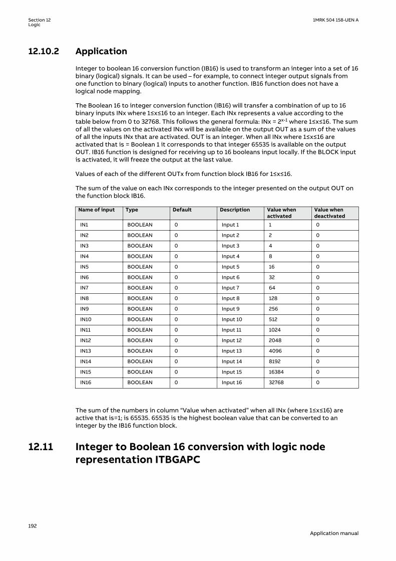
12.10.2 ApplicationSEMOD158499-5 v4
Integer to boolean 16 conversion function (IB16) is used to transform an integer into a set of 16binary (logical) signals. It can be used – for example, to connect integer output signals fromone function to binary (logical) inputs to another function. IB16 function does not have alogical node mapping.
The Boolean 16 to integer conversion function (IB16) will transfer a combination of up to 16binary inputs INx where 1≤x≤16 to an integer. Each INx represents a value according to thetable below from 0 to 32768. This follows the general formula: INx = 2x-1 where 1≤x≤16. The sumof all the values on the activated INx will be available on the output OUT as a sum of the valuesof all the inputs INx that are activated. OUT is an integer. When all INx where 1≤x≤16 areactivated that is = Boolean 1 it corresponds to that integer 65535 is available on the outputOUT. IB16 function is designed for receiving up to 16 booleans input locally. If the BLOCK inputis activated, it will freeze the output at the last value.
Values of each of the different OUTx from function block IB16 for 1≤x≤16.
The sum of the value on each INx corresponds to the integer presented on the output OUT onthe function block IB16.
Name of input Type Default Description Value whenactivated
Value whendeactivated
IN1 BOOLEAN 0 Input 1 1 0
IN2 BOOLEAN 0 Input 2 2 0
IN3 BOOLEAN 0 Input 3 4 0
IN4 BOOLEAN 0 Input 4 8 0
IN5 BOOLEAN 0 Input 5 16 0
IN6 BOOLEAN 0 Input 6 32 0
IN7 BOOLEAN 0 Input 7 64 0
IN8 BOOLEAN 0 Input 8 128 0
IN9 BOOLEAN 0 Input 9 256 0
IN10 BOOLEAN 0 Input 10 512 0
IN11 BOOLEAN 0 Input 11 1024 0
IN12 BOOLEAN 0 Input 12 2048 0
IN13 BOOLEAN 0 Input 13 4096 0
IN14 BOOLEAN 0 Input 14 8192 0
IN15 BOOLEAN 0 Input 15 16384 0
IN16 BOOLEAN 0 Input 16 32768 0
The sum of the numbers in column “Value when activated” when all INx (where 1≤x≤16) areactive that is=1; is 65535. 65535 is the highest boolean value that can be converted to aninteger by the IB16 function block.
12.11 Integer to Boolean 16 conversion with logic noderepresentation ITBGAPC
SEMOD158419-1 v3
Section 12 1MRK 504 158-UEN ALogic
192Application manual

12.11.1 IdentificationSEMOD167944-2 v4
Function description IEC 61850identification
ANSI/IEEE C37.2device number
Integer to boolean 16 conversionwith logic node representation
ITBGAPC - -
12.11.2 ApplicationSEMOD158512-5 v7
Integer to boolean 16 conversion with logic node representation function (ITBGAPC) is used totransform an integer into a set of 16 boolean signals. ITBGAPC function can receive an integerfrom a station computer – for example, over IEC 61850–8–1. This function is very useful whenthe user wants to generate logical commands (for selector switches or voltage controllers) byinputting an integer number. ITBGAPC function has a logical node mapping in IEC 61850.
The Integer to Boolean 16 conversion with logic node representation function (ITBGAPC) willtransfer an integer with a value between 0 to 65535 communicated via IEC 61850 andconnected to the ITBGAPC function block to a combination of activated outputs OUTx where1≤x≤16.
The values of the different OUTx are according to the Table 27.
If the BLOCK input is activated, it freezes the logical outputs at the last value.
Table 27: Output signals
Name of OUTx Type Description Value whenactivated
Value whendeactivated
OUT1 BOOLEAN Output 1 1 0
OUT2 BOOLEAN Output 2 2 0
OUT3 BOOLEAN Output 3 4 0
OUT4 BOOLEAN Output 4 8 0
OUT5 BOOLEAN Output 5 16 0
OUT6 BOOLEAN Output 6 32 0
OUT7 BOOLEAN Output 7 64 0
OUT8 BOOLEAN Output 8 128 0
OUT9 BOOLEAN Output 9 256 0
OUT10 BOOLEAN Output 10 512 0
OUT11 BOOLEAN Output 11 1024 0
OUT12 BOOLEAN Output 12 2048 0
OUT13 BOOLEAN Output 13 4096 0
OUT14 BOOLEAN Output 14 8192 0
OUT15 BOOLEAN Output 15 16384 0
OUT16 BOOLEAN Output 16 32768 0
The sum of the numbers in column “Value when activated” when all OUTx (1≤x≤16) are activeequals 65535. This is the highest integer that can be converted by the ITBGAPC function block.
1MRK 504 158-UEN A Section 12Logic
193Application manual
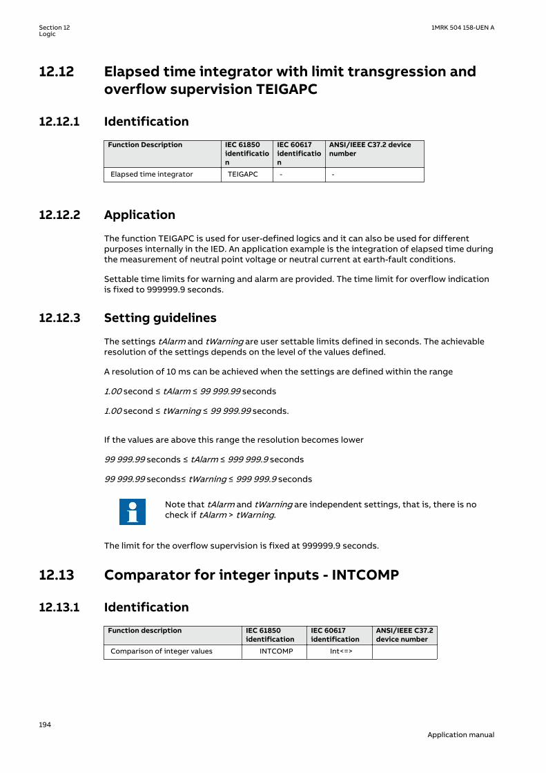
12.12 Elapsed time integrator with limit transgression andoverflow supervision TEIGAPC
12.12.1 IdentificationGUID-1913E066-37D1-4689-9178-5B3C8B029815 v3
Function Description IEC 61850identification
IEC 60617identification
ANSI/IEEE C37.2 devicenumber
Elapsed time integrator TEIGAPC - -
12.12.2 ApplicationGUID-B4B47167-C8DE-4496-AEF1-5F0FD1768A87 v2
The function TEIGAPC is used for user-defined logics and it can also be used for differentpurposes internally in the IED. An application example is the integration of elapsed time duringthe measurement of neutral point voltage or neutral current at earth-fault conditions.
Settable time limits for warning and alarm are provided. The time limit for overflow indicationis fixed to 999999.9 seconds.
12.12.3 Setting guidelinesGUID-2911D624-87D5-4427-BB2F-E0D1072394FA v2
The settings tAlarm and tWarning are user settable limits defined in seconds. The achievableresolution of the settings depends on the level of the values defined.
A resolution of 10 ms can be achieved when the settings are defined within the range
1.00 second ≤ tAlarm ≤ 99 999.99 seconds
1.00 second ≤ tWarning ≤ 99 999.99 seconds.
If the values are above this range the resolution becomes lower
99 999.99 seconds ≤ tAlarm ≤ 999 999.9 seconds
99 999.99 seconds≤ tWarning ≤ 999 999.9 seconds
Note that tAlarm and tWarning are independent settings, that is, there is nocheck if tAlarm > tWarning.
The limit for the overflow supervision is fixed at 999999.9 seconds.
12.13 Comparator for integer inputs - INTCOMP
12.13.1 IdentificationGUID-5992B0F2-FC1B-4838-9BAB-2D2542BB264D v1
Function description IEC 61850identification
IEC 60617identification
ANSI/IEEE C37.2device number
Comparison of integer values INTCOMP Int<=>
Section 12 1MRK 504 158-UEN ALogic
194Application manual
12.13.2 ApplicationGUID-4C6D730D-BB1C-45F1-A719-1267234BF1B9 v1
The function gives the possibility to monitor the level of integer values in the system relativeto each other or to a fixed value. It is a basic arithmetic function that can be used formonitoring, supervision, interlocking and other logics.
12.13.3 Setting guidelinesGUID-ADA3E806-BEF1-4D15-B270-207386A0AEE4 v1
For proper operation of comparison the set value should be set within the range of ± 2 ×10⁹.
Setting procedure on the IED:
EnaAbs: This setting is used to select the comparison type between signed and absolutevalues.
• Absolute: The function will do absolute comparison between input and reference value• Signed: The function will do signed comparison between input and reference value
RefSource: This setting is used to select the reference source between input and setting forcomparison.
• REF: The function will take reference value from input REF• SetValue: The function will take reference value from setting SetValue
SetValue: This setting is used to set the reference value for comparison when settingRefSource is selected as SetValue.
12.13.4 Setting exampleGUID-13302FD6-1585-42FE-BD6D-44F231982C59 v1
For absolute comparison between inputs:
Set the EnaAbs = 1
Set the RefSource = 1
Similarly for Signed comparison between inputs
Set the EnaAbs = 0
Set the RefSource =1
For absolute comparison between input and setting
Set the EnaAbs = 1
Set the RefSource = 0
SetValue shall be set between -2000000000 to 2000000000
Similarly for signed comparison between input and setting
Set the EnaAbs = 0
Set the RefSource = 0
SetValue shall be set between -2000000000 to 2000000000.
1MRK 504 158-UEN A Section 12Logic
195Application manual

12.14 Comparator for real inputs - REALCOMP
12.14.1 IdentificationGUID-0D68E846-5A15-4C2C-91A2-F81A74034E81 v1
Function description IEC 61850identification
IEC 60617identification
ANSI/IEEE C37.2device number
Comparator for real inputs REALCOMP Real<=>
12.14.2 ApplicationGUID-5F7B1683-9799-4D27-B333-B184F8861A5B v1
The function gives the possibility to monitor the level of real values in the system relative toeach other or to a fixed value. It is a basic arithmetic function that can be used for monitoring,supervision, interlocking and other logics.
12.14.3 Setting guidelinesGUID-DE69FF5B-7D34-4A30-9060-214E98BFF798 v1
Setting procedure on the IED:
EnaAbs: This setting is used to select the comparison type between signed and absolutevalues.
• Absolute: The function will do absolute comparison between input and reference value.• Signed: The function will do signed comparison between input and reference value.
RefSource: This setting is used to select the reference source between input and setting forcomparison.
• REF: The function will take reference value from input REF• SetValue: The function will take reference value from setting SetValue
SetValue: This setting is used to set the reference value for comparison when settingRefSource is selected as SetValue. If this setting value is less than 0.2% of the set unit then theoutput INLOW will never pickups.
RefPrefix: This setting is used to set the unit of the reference value for comparison whensetting RefSource is selected as SetValue. It has 5 unit selections and they are Milli, Unity, Kilo,Mega and Giga.
EqualBandHigh: This setting is used to set the equal condition high band limit in % ofreference value. This high band limit will act as reset limit for INHIGH output when INHIGH ishigh in last execution.
EqualBandLow: This setting is used to set the equal condition low band limit in % of referencevalue. This low band limit will act as reset limit for INLOW output when INLOW is high in lastexecution.
12.14.4 Setting exampleGUID-E7070CF6-B44B-4799-BE18-5C75B9FE2A87 v1
Let us consider a comparison is to be done between current magnitudes in the range of 90 to110 with nominal rating is 100 and the order is kA.
For the above condition the comparator can be designed with settings as follows,
Section 12 1MRK 504 158-UEN ALogic
196Application manual

EnaAbs = Absolute
RefSource = SetValue
SetValue = 100
RefPrefix = Kilo
EqualBandHigh = 5.0 % of reference value
EqualBandLow = 5.0 % of reference value
Operation
The function will set the outputs for the following conditions,
INEQUAL will set when the INPUT is between the ranges of 95 to 105 kA.
INHIGH will set when the INPUT crosses above 105 kA.
INLOW will set when the INPUT crosses below 95 kA.
If the comparison should be done between two current magnitudes then those current signalsneed to be connected to function inputs, INPUT and REF. Then the settings should be adjustedas below,
EnaAbs = Absolute
RefSource = REF
EqualBandHigh = 5.0 % of reference value
EqualBandLow = 5.0 % of reference value.
1MRK 504 158-UEN A Section 12Logic
197Application manual

198
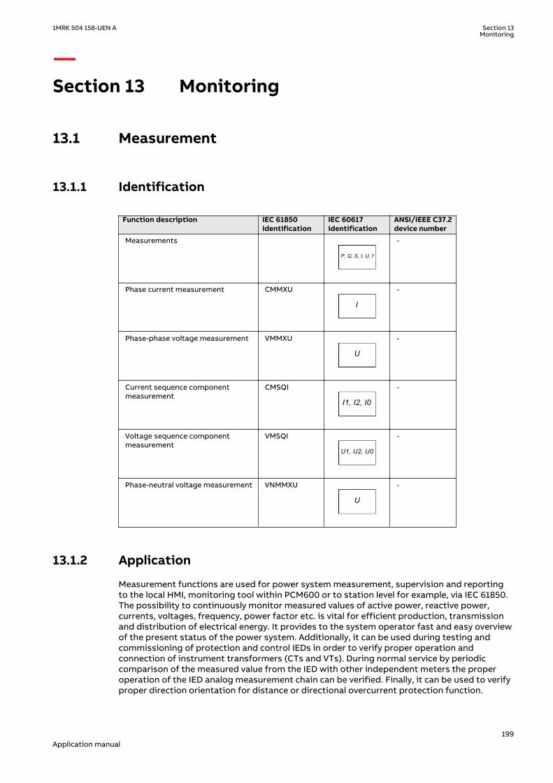
Section 13 Monitoring
13.1 MeasurementGUID-9D2D47A0-FE62-4FE3-82EE-034BED82682A v1
13.1.1 IdentificationSEMOD56123-2 v7
Function description IEC 61850identification
IEC 60617identification
ANSI/IEEE C37.2device number
Measurements
P, Q, S, I, U, f
SYMBOL-RR V1 EN-US
-
Phase current measurement CMMXU
I
SYMBOL-SS V1 EN-US
-
Phase-phase voltage measurement VMMXU
U
SYMBOL-UU V1 EN-US
-
Current sequence componentmeasurement
CMSQI
I1, I2, I0
SYMBOL-VV V1 EN-US
-
Voltage sequence componentmeasurement
VMSQI
U1, U2, U0
SYMBOL-TT V1 EN-US
-
Phase-neutral voltage measurement VNMMXU
U
SYMBOL-UU V1 EN-US
-
13.1.2 ApplicationSEMOD54488-4 v11
Measurement functions are used for power system measurement, supervision and reportingto the local HMI, monitoring tool within PCM600 or to station level for example, via IEC 61850.The possibility to continuously monitor measured values of active power, reactive power,currents, voltages, frequency, power factor etc. is vital for efficient production, transmissionand distribution of electrical energy. It provides to the system operator fast and easy overviewof the present status of the power system. Additionally, it can be used during testing andcommissioning of protection and control IEDs in order to verify proper operation andconnection of instrument transformers (CTs and VTs). During normal service by periodiccomparison of the measured value from the IED with other independent meters the properoperation of the IED analog measurement chain can be verified. Finally, it can be used to verifyproper direction orientation for distance or directional overcurrent protection function.
1MRK 504 158-UEN A Section 13Monitoring
199Application manual

The available measured values of an IED are depending on the actual hardware(TRM) and the logic configuration made in PCM600.
All measured values can be supervised with four settable limits that is, low-low limit, low limit,high limit and high-high limit. A zero clamping reduction is also supported, that is, themeasured value below a settable limit is forced to zero which reduces the impact of noise inthe inputs.
Dead-band supervision can be used to report measured signal value to station level whenchange in measured value is above set threshold limit or time integral of all changes since thelast time value updating exceeds the threshold limit. Measure value can also be based onperiodic reporting.
The measurement function, , provides the following power system quantities:
• P, Q and S: three phase active, reactive and apparent power• PF: power factor• U: phase-to-phase voltage amplitude• I: phase current amplitude• F: power system frequency
,The measuring functions CMMXU, VMMXU and VNMMXU provide physical quantities:
• I: phase currents (amplitude and angle) (CMMXU)• U: voltages (phase-to-earth and phase-to-phase voltage, amplitude and angle) (VMMXU,
VNMMXU)
The function calculates three-phase power quantities by using fundamental frequency phasors(DFT values) of the measured current respectively voltage signals. The measured powerquantities are available either, as instantaneously calculated quantities or, averaged valuesover a period of time (low pass filtered) depending on the selected settings.
It is possible to calibrate the measuring function above to get better then class 0.5presentation. This is accomplished by angle and amplitude compensation at 5, 30 and 100% ofrated current and at 100% of rated voltage.
The power system quantities provided, depends on the actual hardware, (TRM)and the logic configuration made in PCM600.
The measuring functions CMSQI and VMSQI provide sequence component quantities:
• I: sequence currents (positive, zero, negative sequence, amplitude and angle)• U: sequence voltages (positive, zero and negative sequence, amplitude and angle).
13.1.3 Zero clampingGUID-8DABC3F5-6615-493C-B839-A5C557A2FAE8 v3
The measuring functions, CVMMXN, CMMXU, VMMXU and VNMMXU have no interconnectionsregarding any setting or parameter.
Zero clampings are also entirely handled by the ZeroDb for each and every signal separately foreach of the functions. For example, the zero clamping of U12 is handled by UL12ZeroDb inVMMXU, zero clamping of I1 is handled by IL1ZeroDb in CMMXU ETC.
Example how CVMMXN is operating:
Section 13 1MRK 504 158-UEN AMonitoring
200Application manual

The following outputs can be observed on the local HMI under Measurements/Monitoring/Servicevalues(P_Q)/CVMMXN(P_Q)
S Apparent three-phase power
P Active three-phase power
Q Reactive three-phase power
PF Power factor
ILAG I lagging U
ILEAD I leading U
U System mean voltage, calculated according to selected mode
I System mean current, calculated according to selected mode
F Frequency
The settings for this function is found under Measurements/Monitoring/Servicevalues(P_Q)/CVMMXN(P_Q)
It can be seen that:
• When system voltage falls below UGenZeroDB, the shown value for S, P, Q, PF, ILAG, ILEAD,U and F on the local HMI is forced to zero
• When system current falls below IGenZeroDB, the shown value for S, P, Q, PF, ILAG, ILEAD,U and F on the local HMI is forced to zero
• When the value of a single signal falls below the set dead band for that specific signal, thevalue shown on the local HMI is forced to zero. For example, if apparent three-phasepower falls below SZeroDb the value for S on the local HMI is forced to zero.
13.1.4 Setting guidelinesSEMOD54481-165 v13
The available setting parameters of the measurement function , CMMXU, VMMXU, CMSQI,VMSQI, VNMMXU are depending on the actual hardware (TRM) and the logic configurationmade in PCM600.
The parameters for the Measurement functions , CMMXU, VMMXU, CMSQI, VMSQI, VNMMXUare set via the local HMI or PCM600.
GlobalBaseSel: Selects the global base value group used by the function to define (IBase),(UBase) and (SBase).
Operation: Off/On. Every function instance (, CMMXU, VMMXU, CMSQI, VMSQI, VNMMXU) canbe taken in operation (On) or out of operation (Off).
The following general settings can be set for the Measurement function ().
PowAmpFact: Amplitude factor to scale power calculations.
PowAngComp: Angle compensation for phase shift between measured I & U.
Mode: Selection of measured current and voltage. There are 9 different ways of calculatingmonitored three-phase values depending on the available VT inputs connected to the IED. Seeparameter group setting table.
k: Low pass filter coefficient for power measurement, U and I.
UGenZeroDb: Minimum level of voltage in % of UBase used as indication of zero voltage (zeropoint clamping). If measured value is below UGenZeroDb calculated S, P, Q and PF will be zero.
1MRK 504 158-UEN A Section 13Monitoring
201Application manual

IGenZeroDb: Minimum level of current in % of IBase used as indication of zero current (zeropoint clamping). If measured value is below IGenZeroDb calculated S, P, Q and PF will be zero.
UAmpCompY: Amplitude compensation to calibrate voltage measurements at Y% of Ur, whereY is equal to 5, 30 or 100.
IAmpCompY: Amplitude compensation to calibrate current measurements at Y% of Ir, where Yis equal to 5, 30 or 100.
IAngCompY: Angle compensation to calibrate angle measurements at Y% of Ir, where Y isequal to 5, 30 or 100.
The following general settings can be set for the Phase-phase current measurement(CMMXU).
IAmpCompY: Amplitude compensation to calibrate current measurements at Y% of Ir, where Yis equal to 5, 30 or 100.
IAngCompY: Angle compensation to calibrate angle measurements at Y% of Ir, where Y isequal to 5, 30 or 100.
The following general settings can be set for the Phase-phase voltage measurement(VMMXU).
UAmpCompY: Amplitude compensation to calibrate voltage measurements at Y% of Ur, whereY is equal to 5, 30 or 100.
UAngCompY: Angle compensation to calibrate angle measurements at Y% of Ur, where Y isequal to 5, 30 or 100.
The following general settings can be set for all monitored quantities included in thefunctions (, CMMXU, VMMXU, CMSQI, VMSQI, VNMMXU) X in setting names below equals S, P,Q, PF, U, I, F, IL1-3, UL1-3UL12-31, I1, I2, 3I0, U1, U2 or 3U0.
Xmin: Minimum value for analog signal X set directly in applicable measuring unit.
Xmax: Maximum value for analog signal X.
XZeroDb: Zero point clamping. A signal value less than XZeroDb is forced to zero.
Observe the related zero point clamping settings in Setting group N for (UGenZeroDb andIGenZeroDb). If measured value is below UGenZeroDb and/or IGenZeroDb calculated S, P, Qand PF will be zero and these settings will override XZeroDb.
XRepTyp: Reporting type. Cyclic (Cyclic), amplitude deadband (Dead band) or integraldeadband (Int deadband). The reporting interval is controlled by the parameter XDbRepInt.
XDbRepInt: Reporting deadband setting. Cyclic reporting is the setting value and is reportinginterval in seconds. Amplitude deadband is the setting value in % of measuring range. Integraldeadband setting is the integral area, that is, measured value in % of measuring rangemultiplied by the time between two measured values.
XHiHiLim: High-high limit. Set in applicable measuring unit.
XHiLim: High limit.
XLowLim: Low limit.
XLowLowLim: Low-low limit.
XLimHyst: Hysteresis value in % of range and is common for all limits.
Section 13 1MRK 504 158-UEN AMonitoring
202Application manual

All phase angles are presented in relation to defined reference channel. The parameterPhaseAngleRef defines the reference, see section "Introduction".
Calibration curves
It is possible to calibrate the functions (, CMMXU, VMMXU and VNMMXU) to get class 0.5presentations of currents, voltages and powers. This is accomplished by amplitude and anglecompensation at 5, 30 and 100% of rated current and voltage. The compensation curve willhave the characteristic for amplitude and angle compensation of currents as shown infigure 86 (example). The first phase will be used as reference channel and compared with thecurve for calculation of factors. The factors will then be used for all related channels.
IEC05000652 V2 EN-US
Figure 86: Calibration curves
13.1.4.1 Setting examplesSEMOD54481-4 v4
Three setting examples, in connection to Measurement function (), are provided:
• Measurement function () application for a OHL• Measurement function () application on the secondary side of a transformer• Measurement function () application for a generator
For each of them detail explanation and final list of selected setting parameters values will beprovided.
The available measured values of an IED are depending on the actual hardware(TRM) and the logic configuration made in PCM600.
1MRK 504 158-UEN A Section 13Monitoring
203Application manual

Measurement function application for a 110kV OHLSEMOD54481-12 v10
Single line diagram for this application is given in figure 87:
110kV Busbar
110kV OHL
P Q
600/1 A110 0,1/
3 3kV
IEC09000039-2-en.vsd
IED
IEC09000039-1-EN V2 EN-US
Figure 87: Single line diagram for 110kV OHL application
In order to monitor, supervise and calibrate the active and reactive power as indicated infigure 87 it is necessary to do the following:
1. Set correctly CT and VT data and phase angle reference channel PhaseAngleRef (seesection "Setting of the phase reference channel") using PCM600 for analog input channels
2. Connect, in PCM600, measurement function to three-phase CT and VT inputs3. Set under General settings parameters for the Measurement function:
• general settings as shown in table 28.• level supervision of active power as shown in table 29.• calibration parameters as shown in table 30.
Table 28: General settings parameters for the Measurement function
Setting Short Description Selectedvalue
Comments
Operation Operation Off/On On Function must be On
PowAmpFact Amplitude factor to scalepower calculations
1.000 It can be used during commissioning toachieve higher measurement accuracy.Typically no scaling is required
PowAngComp Angle compensation for phaseshift between measured I & U
0.0 It can be used during commissioning toachieve higher measurement accuracy.Typically no angle compensation is required.As well here required direction of P & Qmeasurement is towards protected object (asper IED internal default direction)
Mode Selection of measured currentand voltage
L1, L2, L3 All three phase-to-earth VT inputs areavailable
k Low pass filter coefficient forpower measurement, U and I
0.00 Typically no additional filtering is required
UGenZeroDb Zero point clamping in % ofUbase
25 Set minimum voltage level to 25%. Voltagebelow 25% will force S, P and Q to zero.
IGenZeroDb Zero point clamping in % ofIbase
3 Set minimum current level to 3%. Currentbelow 3% will force S, P and Q to zero.
UBase (set inGlobal base)
Base setting for voltage levelin kV
400.00 Set rated OHL phase-to-phase voltage
IBase (set inGlobal base)
Base setting for current levelin A
800 Set rated primary CT current used for OHL
Section 13 1MRK 504 158-UEN AMonitoring
204Application manual

Table 29: Settings parameters for level supervision
Setting Short Description Selectedvalue
Comments
PMin Minimum value -100 Minimum expected load
PMax Minimum value 100 Maximum expected load
PZeroDb Zero point clamping in 0.001%of range
3000 Set zero point clamping to 45 MW that is, 3%of 200 MW
PRepTyp Reporting type db Select amplitude deadband supervision
PDbRepInt Cycl: Report interval (s), Db: In% of range, Int Db: In %s
2 Set ±Δdb=30 MW that is, 2% (larger changesthan 30 MW will be reported)
PHiHiLim High High limit (physical value) 60 High alarm limit that is, extreme overloadalarm
PHiLim High limit (physical value) 50 High warning limit that is, overload warning
PLowLim Low limit (physical value) -50 Low warning limit. Not active
PLowLowlLim Low Low limit (physical value) -60 Low alarm limit. Not active
PLimHyst Hysteresis value in % of range(common for all limits)
2 Set ±Δ Hysteresis MW that is, 2%
Table 30: Settings for calibration parameters
Setting Short Description Selectedvalue
Comments
IAmpComp5 Amplitude factor to calibratecurrent at 5% of Ir
0.00
IAmpComp30 Amplitude factor to calibratecurrent at 30% of Ir
0.00
IAmpComp100 Amplitude factor to calibratecurrent at 100% of Ir
0.00
UAmpComp5 Amplitude factor to calibratevoltage at 5% of Ur
0.00
UAmpComp30 Amplitude factor to calibratevoltage at 30% of Ur
0.00
UAmpComp100 Amplitude factor to calibratevoltage at 100% of Ur
0.00
IAngComp5 Angle calibration for current at5% of Ir
0.00
IAngComp30 Angle pre-calibration forcurrent at 30% of Ir
0.00
IAngComp100 Angle pre-calibration forcurrent at 100% of Ir
0.00
Measurement function application for a power transformerSEMOD54481-61 v8
Single line diagram for this application is given in figure 88.
1MRK 504 158-UEN A Section 13Monitoring
205Application manual

110kV Busbar
200/1
35 / 0,1kV
35kV Busbar
500/5
P Q
31,5 MVA110/36,75/(10,5) kV
Yy0(d5)
UL1L2
IEC09000040-1-en.vsd
IED
IEC09000040-1-EN V1 EN-US
Figure 88: Single line diagram for transformer application
In order to measure the active and reactive power as indicated in figure 88, it is necessary todo the following:
1. Set correctly all CT and VT and phase angle reference channel PhaseAngleRef (see section"Setting of the phase reference channel") data using PCM600 for analog input channels
2. Connect, in PCM600, measurement function to LV side CT & VT inputs3. Set the setting parameters for relevant Measurement function as shown in the following
table 31:
Section 13 1MRK 504 158-UEN AMonitoring
206Application manual
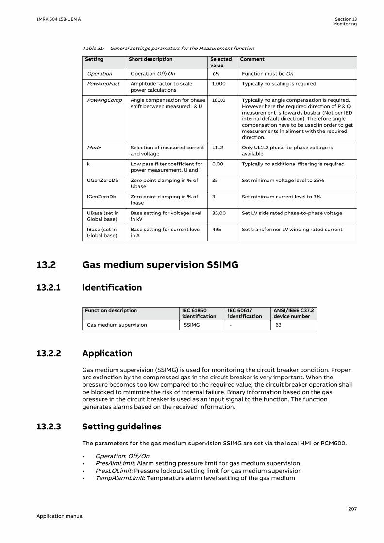
Table 31: General settings parameters for the Measurement function
Setting Short description Selectedvalue
Comment
Operation Operation Off/On On Function must be On
PowAmpFact Amplitude factor to scalepower calculations
1.000 Typically no scaling is required
PowAngComp Angle compensation for phaseshift between measured I & U
180.0 Typically no angle compensation is required.However here the required direction of P & Qmeasurement is towards busbar (Not per IEDinternal default direction). Therefore anglecompensation have to be used in order to getmeasurements in aliment with the requireddirection.
Mode Selection of measured currentand voltage
L1L2 Only UL1L2 phase-to-phase voltage isavailable
k Low pass filter coefficient forpower measurement, U and I
0.00 Typically no additional filtering is required
UGenZeroDb Zero point clamping in % ofUbase
25 Set minimum voltage level to 25%
IGenZeroDb Zero point clamping in % ofIbase
3 Set minimum current level to 3%
UBase (set inGlobal base)
Base setting for voltage levelin kV
35.00 Set LV side rated phase-to-phase voltage
IBase (set inGlobal base)
Base setting for current levelin A
495 Set transformer LV winding rated current
13.2 Gas medium supervision SSIMGGUID-358AD8F8-AE06-4AEA-9969-46E5299D5B4B v3
13.2.1 IdentificationGUID-AD96C26E-C3E5-4B21-9ED6-12E540954AC3 v3
Function description IEC 61850identification
IEC 60617identification
ANSI/IEEE C37.2device number
Gas medium supervision SSIMG - 63
13.2.2 ApplicationGUID-A840E38C-CC42-4995-A569-A6092DDB81B2 v5
Gas medium supervision (SSIMG) is used for monitoring the circuit breaker condition. Properarc extinction by the compressed gas in the circuit breaker is very important. When thepressure becomes too low compared to the required value, the circuit breaker operation shallbe blocked to minimize the risk of internal failure. Binary information based on the gaspressure in the circuit breaker is used as an input signal to the function. The functiongenerates alarms based on the received information.
13.2.3 Setting guidelinesGUID-DF6BEC98-F806-41CE-8C29-BEE9C88FC1FD v1
The parameters for the gas medium supervision SSIMG are set via the local HMI or PCM600.
• Operation: Off/On• PresAlmLimit: Alarm setting pressure limit for gas medium supervision• PresLOLimit: Pressure lockout setting limit for gas medium supervision• TempAlarmLimit: Temperature alarm level setting of the gas medium
1MRK 504 158-UEN A Section 13Monitoring
207Application manual

• TempLOLimit: Temperature lockout level of the gas medium• tPresAlarm: Time delay for pressure alarm of the gas medium• tPresLockOut: Time delay for level lockout indication of the gas medium• tTempAlarm: Time delay for temperature alarm of the gas medium• tTempLockOut: Time delay for temperature lockout of the gas medium• tResetPresAlm: Reset time delay for level alarm of the gas medium• tResetPresLO: Reset time delay for level lockout of the gas medium• tResetTempAlm: Reset time delay for temperature lockout of the gas medium• tResetTempLO: Reset time delay for temperature alarm of the gas medium
13.3 Liquid medium supervision SSIMLGUID-37669E94-4830-4C96-8A67-09600F847F23 v3
13.3.1 IdentificationGUID-4CE96EF6-42C6-4F2E-A190-D288ABF766F6 v2
Function description IEC 61850identification
IEC 60617identification
ANSI/IEEE C37.2device number
Liquid medium supervision SSIML - 71
13.3.2 ApplicationGUID-140AA10C-4E93-4C23-AD57-895FADB0DB29 v5
Liquid medium supervision (SSIML) is used for monitoring the circuit breaker condition. Properarc extinction by the compressed oil in the circuit breaker is very important. When the levelbecomes too low, compared to the required value, the circuit breaker operation is blocked tominimize the risk of internal failures. Binary information based on the oil level in the circuitbreaker is used as input signals to the function. In addition to that, the function generatesalarms based on received information.
13.3.3 Setting guidelinesGUID-0C8E498B-2A65-44ED-91D6-53EC72F49222 v1
The parameters for the Liquid medium supervision SSIML are set via the local HMI or PCM600.
• Operation: Off/On• LevelAlmLimit: Alarm setting level limit for liquid medium supervision• LevelLOLimit: Level lockout setting limit for liquid medium supervision• TempAlarmLimit: Temperature alarm level setting of the liquid medium• TempLOLimit: Temperature lockout level of the liquid medium• tLevelAlarm: Time delay for level alarm of the liquid medium• tLevelLockOut: Time delay for level lockout indication of the liquid medium• tTempAlarm: Time delay for temperature alarm of the liquid medium• tTempLockOut: Time delay for temperature lockout of the liquid medium• tResetLevelAlm: Reset time delay for level alarm of the liquid medium• tResetLevelLO: Reset time delay for level lockout of the liquid medium• tResetTempAlm: Reset time delay for temperature lockout of the liquid medium• tResetTempLO: Reset time delay for temperature alarm of the liquid medium
13.4 Breaker monitoring SSCBR
13.4.1 IdentificationGUID-0FC081B2-0BC8-4EB8-9529-B941E51F18EE v7
Section 13 1MRK 504 158-UEN AMonitoring
208Application manual

Function description IEC 61850identification
IEC 60617identification
ANSI/IEEE C37.2device number
Breaker monitoring SSCBR - -
13.4.2 ApplicationGUID-45572680-3A39-4B3C-8639-4E4C5A95AA26 v9
The circuit breaker maintenance is usually based on regular time intervals or the number ofoperations performed. This has some disadvantages because there could be a number ofabnormal operations or few operations with high-level currents within the predeterminedmaintenance interval. Hence, condition-based maintenance scheduling is an optimum solutionin assessing the condition of circuit breakers.
Circuit breaker contact travel time
Auxiliary contacts provide information about the mechanical operation, opening time andclosing time of a breaker. Detecting an excessive traveling time is essential to indicate theneed for maintenance of the circuit breaker mechanism. The excessive travel time can be dueto problems in the driving mechanism or failures of the contacts.
Circuit breaker status
Monitoring the breaker status ensures proper functioning of the features within theprotection relay such as breaker control, breaker failure and autoreclosing. The breaker statusis monitored using breaker auxiliary contacts. The breaker status is indicated by the binaryoutputs. These signals indicate whether the circuit breaker is in an open, closed or error state.
Remaining life of circuit breaker
Every time the breaker operates, the circuit breaker life reduces due to wear. The wear in abreaker depends on the interrupted current. For breaker maintenance or replacement at theright time, the remaining life of the breaker must be estimated. The remaining life of a breakercan be estimated using the maintenance curve provided by the circuit breaker manufacturer.
Circuit breaker manufacturers provide the number of make-break operations possible atvarious interrupted currents. An example is shown in figure 89.
1MRK 504 158-UEN A Section 13Monitoring
209Application manual

Num
ber o
f mak
e-br
eak
oper
atio
ns (
n)
Interrupted current (kA)
P1
P2
100000
50000
20000
10000
2000
5000
1000
100
200
500
10
20
50
0.1 0.2 0.5 1 2 5 10 20 50 100
IEC12000623_1_en.vsdIEC12000623 V1 EN-US
Figure 89: An example for estimating the remaining life of a circuit breaker
Calculation for estimating the remaining life
The graph shows that there are 10000 possible operations at the rated operating current and900 operations at 10 kA and 50 operations at rated fault current. Therefore, if the interruptedcurrent is 10 kA, one operation is equivalent to 10000/900 = 11 operations at the rated current.It is assumed that prior to tripping, the remaining life of a breaker is 10000 operations.Remaining life calculation for three different interrupted current conditions is explained below.
• Breaker interrupts at and below the rated operating current, that is, 2 kA, the remaininglife of the CB is decreased by 1 operation and therefore, 9999 operations remaining at therated operating current.
• Breaker interrupts between rated operating current and rated fault current, that is, 10 kA,one operation at 10kA is equivalent to 10000/900 = 11 operations at the rated current. Theremaining life of the CB would be (10000 – 10) = 9989 at the rated operating current afterone operation at 10 kA.
• Breaker interrupts at and above rated fault current, that is, 50 kA, one operation at 50 kAis equivalent to 10000/50 = 200 operations at the rated operating current. The remaininglife of the CB would become (10000 – 200) = 9800 operations at the rated operatingcurrent after one operation at 50 kA.
Accumulated energy
Monitoring the contact erosion and interrupter wear has a direct influence on the requiredmaintenance frequency. Therefore, it is necessary to accurately estimate the erosion of thecontacts and condition of interrupters using cumulative summation of Iy. The factor "y"
Section 13 1MRK 504 158-UEN AMonitoring
210Application manual

depends on the type of circuit breaker. The energy values were accumulated using the currentvalue and exponent factor for CB contact opening duration. When the next CB openingoperation is started, the energy is accumulated from the previous value. The accumulatedenergy value can be reset to initial accumulation energy value by using the Reset accumulatingenergy input, RSTIPOW.
Circuit breaker operation cycles
Routine breaker maintenance like lubricating breaker mechanism is based on the number ofoperations. A suitable threshold setting helps in preventive maintenance. This can also be usedto indicate the requirement for oil sampling for dielectric testing in case of an oil circuitbreaker.
Circuit breaker operation monitoring
By monitoring the activity of the number of operations, it is possible to calculate the numberof days the breaker has been inactive. Long periods of inactivity degrade the reliability for theprotection system.
Circuit breaker spring charge monitoring
For normal circuit breaker operation, the circuit breaker spring should be charged within aspecified time. Detecting a long spring charging time indicates the time for circuit breakermaintenance. The last value of the spring charging time can be given as a service value.
Circuit breaker gas pressure indication
For proper arc extinction by the compressed gas in the circuit breaker, the pressure of the gasmust be adequate. Binary input available from the pressure sensor is based on the pressurelevels inside the arc chamber. When the pressure becomes too low compared to the requiredvalue, the circuit breaker operation is blocked.
13.4.3 Setting guidelinesGUID-AB93AD9B-E6F8-4F1A-B353-AA1008C15679 v2
The breaker monitoring function is used to monitor different parameters of the circuitbreaker. The breaker requires maintenance when the number of operations has reached apredefined value. For proper functioning of the circuit breaker, it is also essential to monitorthe circuit breaker operation, spring charge indication or breaker wear, travel time, number ofoperation cycles and accumulated energy during arc extinction.
13.4.3.1 Setting procedure on the IEDGUID-4E895FEA-74BF-4B11-A239-0574F8FF5188 v4
The parameters for breaker monitoring (SSCBR) can be set using the local HMI or Protectionand Control Manager (PCM600).
Common base IED values for primary current (IBase), primary voltage (UBase) and primarypower (SBase) are set in Global base values for settings function GBASVAL.
GlobalBaseSel: It is used to select a GBASVAL function for reference of base values.
Operation: On or Off.
IBase: Base phase current in primary A. This current is used as reference for current settings.
OpenTimeCorr: Correction factor for circuit breaker opening travel time.
CloseTimeCorr: Correction factor for circuit breaker closing travel time.
tTrOpenAlm: Setting of alarm level for opening travel time.
1MRK 504 158-UEN A Section 13Monitoring
211Application manual

tTrCloseAlm: Setting of alarm level for closing travel time.
OperAlmLevel: Alarm limit for number of mechanical operations.
OperLOLevel: Lockout limit for number of mechanical operations.
CurrExponent: Current exponent setting for energy calculation. It varies for different types ofcircuit breakers. This factor ranges from 0.5 to 3.0.
AccStopCurr: RMS current setting below which calculation of energy accumulation stops. It isgiven as a percentage of IBase.
ContTrCorr: Correction factor for time difference in auxiliary and main contacts' opening time.
AlmAccCurrPwr: Setting of alarm level for accumulated energy.
LOAccCurrPwr: Lockout limit setting for accumulated energy.
SpChAlmTime: Time delay for spring charging time alarm.
tDGasPresAlm: Time delay for gas pressure alarm.
tDGasPresLO: Time delay for gas pressure lockout.
DirCoef: Directional coefficient for circuit breaker life calculation.
RatedOperCurr: Rated operating current of the circuit breaker.
RatedFltCurr: Rated fault current of the circuit breaker.
OperNoRated: Number of operations possible at rated current.
OperNoFault: Number of operations possible at rated fault current.
CBLifeAlmLevel: Alarm level for circuit breaker remaining life.
AccSelCal: Selection between the method of calculation of accumulated energy.
OperTimeDelay: Time delay between change of status of trip output and start of main contactseparation.
13.5 Event function EVENTIP14590-1 v2
13.5.1 IdentificationSEMOD167950-2 v2
Function description IEC 61850identification
IEC 60617identification
ANSI/IEEE C37.2device number
Event function EVENT
S00946 V1 EN-US
-
13.5.2 ApplicationM12805-6 v10
When using a Substation Automation system with LON or SPA communication, time-taggedevents can be sent at change or cyclically from the IED to the station level. These events are
Section 13 1MRK 504 158-UEN AMonitoring
212Application manual

created from any available signal in the IED that is connected to the Event function (EVENT).The EVENT function block is used for LON and SPA communication.
Analog and double indication values are also transferred through the EVENT function.
13.5.3 Setting guidelinesIP14841-1 v1
M12811-3 v2
The parameters for the Event (EVENT) function are set via the local HMI or PCM600.
EventMask (Ch_1 - 16)M12811-5 v2
The inputs can be set individually as:
• NoEvents• OnSet, at pick-up of the signal• OnReset, at drop-out of the signal• OnChange, at both pick-up and drop-out of the signal• AutoDetect
LONChannelMask or SPAChannelMaskM12811-15 v2
Definition of which part of the event function block that shall generate events:
• Off• Channel 1-8• Channel 9-16• Channel 1-16
MinRepIntVal (1 - 16)M12811-29 v3
A time interval between cyclic events can be set individually for each input channel. This can beset between 0 s to 3600 s in steps of 1 s. It should normally be set to 0, that is, no cycliccommunication.
M12811-34 v1
It is important to set the time interval for cyclic events in an optimized way tominimize the load on the station bus.
13.6 Disturbance report DRPRDREIP14584-1 v2
13.6.1 IdentificationM16055-1 v7
Function description IEC 61850 identification IEC 60617identification
ANSI/IEEE C37.2device number
Disturbance report DRPRDRE - -
Disturbance report A1RADR - A4RADR - -
Disturbance report B1RBDR - B8RBDR - -
1MRK 504 158-UEN A Section 13Monitoring
213Application manual

13.6.2 ApplicationM12152-3 v8
To get fast, complete and reliable information about disturbances in the primary and/or in thesecondary system it is very important to gather information on fault currents, voltages andevents. It is also important having a continuous event-logging to be able to monitor in anoverview perspective. These tasks are accomplished by the disturbance report functionDRPRDRE and facilitate a better understanding of the power system behavior and relatedprimary and secondary equipment during and after a disturbance. An analysis of the recordeddata provides valuable information that can be used to explain a disturbance, basis for changeof IED setting plan, improve existing equipment, and so on. This information can also be usedin a longer perspective when planning for and designing new installations, that is, adisturbance recording could be a part of Functional Analysis (FA).
Disturbance report DRPRDRE, always included in the IED, acquires sampled data of all selectedanalog and binary signals connected to the function blocks that is,
• Maximum 30 external analog signals,• 10 internal derived analog signals, and• 128 binary signals.
Disturbance report function is a common name for several functions that is, Indications (IND),Event recorder (ER), Event list (EL), Trip value recorder (TVR), Disturbance recorder (DR).
Disturbance report function is characterized by great flexibility as far as configuration,starting conditions, recording times, and large storage capacity are concerned. Thus,disturbance report is not dependent on the operation of protective functions, and it canrecord disturbances that were not discovered by protective functions for one reason oranother. Disturbance report can be used as an advanced stand-alone disturbance recorder.
Every disturbance report recording is saved in the IED. The same applies to all events, whichare continuously saved in a ring-buffer. Local HMI can be used to get information about therecordings, and the disturbance report files may be uploaded in the PCM600 using theDisturbance handling tool, for report reading or further analysis (using WaveWin, that can befound on the PCM600 installation CD). The user can also upload disturbance report files usingFTP or MMS (over 61850–8–1) clients.
If the IED is connected to a station bus (IEC 61850-8-1), the disturbance recorder (record madeand fault number) and the fault locator information are available. The same information isobtainable if IEC 60870-5-103 is used.
13.6.3 Setting guidelinesIP14874-1 v1
M12179-64 v7
The setting parameters for the Disturbance report function DRPRDRE are set via the local HMIor PCM600.
It is possible to handle up to 40 analog and 128 binary signals, either internal signals or signalscoming from external inputs. The binary signals are identical in all functions that is,Disturbance recorder (DR), Event recorder (ER), Indication (IND), Trip value recorder (TVR) andEvent list (EL) function.
User-defined names of binary and analog input signals is set using PCM600. The analog andbinary signals appear with their user-defined names. The name is used in all related functions(Disturbance recorder (DR), Event recorder (ER), Indication (IND), Trip value recorder (TVR) andEvent list (EL)).
Figure 90 shows the relations between Disturbance report, included functions and functionblocks. Event list (EL), Event recorder (ER) and Indication (IND) uses information from thebinary input function blocks (BxRBDR). Trip value recorder (TVR) uses analog information from
Section 13 1MRK 504 158-UEN AMonitoring
214Application manual

the analog input function blocks (AxRADR),. Disturbance report function acquires informationfrom both AxRADR and BxRBDR.
Trip value rec
Event list
Event recorder
Indications
Disturbancerecorder
AxRADR
BxRBDR
Disturbance Report
Binary signals
Analog signals
DRPRDRE
IEC09000337-3-en.vsdx
IEC09000337 V3 EN-US
Figure 90: Disturbance report functions and related function blocks
For Disturbance report function there are a number of settings which also influences the sub-functions.
Three LED indications placed above the LCD screen makes it possible to get quick statusinformation about the IED.
Green LED:
Steady light In Service
Flashing light Internal failure
Dark No power supply
Yellow LED:
Steady light Triggered on binary signal N with SetLEDx = Start (or Startand Trip)
Flashing light The IED is in test mode
Red LED:
Steady light Triggered on binary signal N with SetLEDx = Trip (or Startand Trip)
Flashing The IED is in configuration mode
1MRK 504 158-UEN A Section 13Monitoring
215Application manual
OperationM12179-82 v6
The operation of Disturbance report function DRPRDRE has to be set On or Off. If Off isselected, note that no disturbance report is registered, and none sub-function will operate(the only general parameter that influences Event list (EL)).
Operation = Off:
• Disturbance reports are not stored.• LED information (yellow - start, red - trip) is not stored or changed.
Operation = On:
• Disturbance reports are stored, disturbance data can be read from the local HMI and froma PC for example using PCM600.
• LED information (yellow - start, red - trip) is stored.
Every recording will get a number (0 to 999) which is used as identifier (local HMI, disturbancehandling tool and IEC 61850). An alternative recording identification is date, time andsequence number. The sequence number is automatically increased by one for each newrecording and is reset to zero at midnight. The maximum number of recordings stored in theIED is 100. The oldest recording will be overwritten when a new recording arrives (FIFO).
To be able to delete disturbance records, Operation parameter has to be On.
The maximum number of recordings depend on each recordings totalrecording time. Long recording time will reduce the number of recordings toless than 100.
The IED flash disk should NOT be used to store any user files. This might causedisturbance recordings to be deleted due to lack of disk space.
13.6.3.1 Recording timesM12179-88 v4
The different recording times for Disturbance report are set (the pre-fault time, post-faulttime, and limit time). These recording times affect all sub-functions more or less but not theEvent list (EL) function.
Prefault recording time (PreFaultRecT) is the recording time before the starting point of thedisturbance. The setting should be at least 0.1 s to ensure enough samples for the estimationof pre-fault values in the Trip value recorder (TVR) function.
Postfault recording time (PostFaultRecT) is the maximum recording time after thedisappearance of the trig-signal (does not influence the Trip value recorder (TVR) function).
Recording time limit (TimeLimit) is the maximum recording time after trig. The parameterlimits the recording time if some trigging condition (fault-time) is very long or permanently set(does not influence the Trip value recorder (TVR) function).
Post retrigger (PostRetrig) can be set to On or Off. Makes it possible to choose performanceof Disturbance report function if a new trig signal appears in the post-fault window.
Section 13 1MRK 504 158-UEN AMonitoring
216Application manual
PostRetrig = Off
The function is insensitive for new trig signals during post fault time.
PostRetrig = On
The function completes current report and starts a new complete report that is, the latter willinclude:
• new pre-fault- and fault-time (which will overlap previous report)• events and indications might be saved in the previous report too, due to overlap• new trip value calculations if installed, in operation and started
Operation in test modeM12179-492 v4
If the IED is in test mode and OpModeTest = Off. Disturbance report function does not saveany recordings and no LED information is displayed.
If the IED is in test mode and OpModeTest = On. Disturbance report function works in normalmode and the status is indicated in the saved recording.
13.6.3.2 Binary input signalsM12179-90 v8
Up to 128 binary signals can be selected among internal logical and binary input signals. Theconfiguration tool is used to configure the signals.
For each of the 128signals, it is also possible to select if the signal is to be used as a trigger forthe start of the Disturbance report and if the trigger should be activated on positive (1) ornegative (0) slope.
OperationN: Disturbance report may trig for binary input N (On) or not (Off).
TrigLevelN: Trig on positive (Trig on 1) or negative (Trig on 0) slope for binary input N.
Func103N: Function type number (0-255) for binary input N according to IEC-60870-5-103, thatis, 128: Distance protection, 160: overcurrent protection, 176: transformer differentialprotection and 192: line differential protection.
Info103N: Information number (0-255) for binary input N according to IEC-60870-5-103, that is,69-71: Trip L1-L3, 78-83: Zone 1-6.
See also description in the chapter IEC 60870-5-103.
13.6.3.3 Analog input signalsM12179-92 v5
Up to 40 analog signals can be selected among internal analog and analog input signals.PCM600 is used to configure the signals.
The analog trigger of Disturbance report is not affected if analog input M is to be included inthe disturbance recording or not (OperationM = On/Off).
If OperationM = Off, no waveform (samples) will be recorded and reported in graph. However,Trip value, pre-fault and fault value will be recorded and reported. The input channel can still beused to trig the disturbance recorder.
If OperationM = On, waveform (samples) will also be recorded and reported in graph.
NomValueM: Nominal value for input M.
1MRK 504 158-UEN A Section 13Monitoring
217Application manual

OverTrigOpM, UnderTrigOpM: Over or Under trig operation, Disturbance report may trig forhigh/low level of analog input M (On) or not (Off).
OverTrigLeM, UnderTrigLeM: Over or under trig level, Trig high/low level relative nominal valuefor analog input M in percent of nominal value.
13.6.3.4 Sub-function parametersM12179-389 v3
All functions are in operation as long as Disturbance report is in operation.
IndicationsM12179-448 v4
IndicationMaN: Indication mask for binary input N. If set (Show), a status change of thatparticular input, will be fetched and shown in the disturbance summary on local HMI. If not set(Hide), status change will not be indicated.
SetLEDN: Set red LED on local HMI in front of the IED if binary input N changes status.
Disturbance recorderM12179-446 v4
OperationM: Analog channel M is to be recorded by the disturbance recorder (On) or not (Off).
If OperationM = Off, no waveform (samples) will be recorded and reported in graph. However,Trip value, pre-fault and fault value will be recorded and reported. The input channel can still beused to trig the disturbance recorder.
If OperationM = On, waveform (samples) will also be recorded and reported in graph.
Event recorderM12179-444 v4
Event recorder (ER) function has no dedicated parameters.
Trip value recorderM12179-442 v3
ZeroAngleRef: The parameter defines which analog signal that will be used as phase anglereference for all other analog input signals. This signal will also be used for frequencymeasurement and the measured frequency is used when calculating trip values. It is suggestedto point out a sampled voltage input signal, for example, a line or busbar phase voltage(channel 1-30).
Event listM12179-440 v3
Event list (EL) (SOE) function has no dedicated parameters.
13.6.3.5 ConsiderationM12179-420 v5
The density of recording equipment in power systems is increasing, since the number ofmodern IEDs, where recorders are included, is increasing. This leads to a vast number ofrecordings at every single disturbance and a lot of information has to be handled if therecording functions do not have proper settings. The goal is to optimize the settings in eachIED to be able to capture just valuable disturbances and to maximize the number that ispossible to save in the IED.
The recording time should not be longer than necessary (PostFaultrecT and TimeLimit).
• Should the function record faults only for the protected object or cover more?• How long is the longest expected fault clearing time?• Is it necessary to include reclosure in the recording or should a persistent fault generate a
second recording (PostRetrig)?
Minimize the number of recordings:
Section 13 1MRK 504 158-UEN AMonitoring
218Application manual
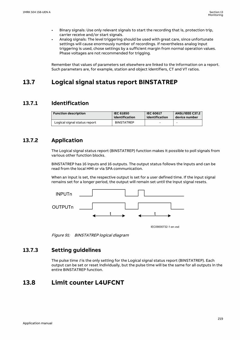
• Binary signals: Use only relevant signals to start the recording that is, protection trip,carrier receive and/or start signals.
• Analog signals: The level triggering should be used with great care, since unfortunatesettings will cause enormously number of recordings. If nevertheless analog inputtriggering is used, chose settings by a sufficient margin from normal operation values.Phase voltages are not recommended for trigging.
Remember that values of parameters set elsewhere are linked to the information on a report.Such parameters are, for example, station and object identifiers, CT and VT ratios.
13.7 Logical signal status report BINSTATREPGUID-E7A2DB38-DD96-4296-B3D5-EB7FBE77CE07 v2
13.7.1 IdentificationGUID-E0247779-27A2-4E6C-A6DD-D4C31516CA5C v3
Function description IEC 61850identification
IEC 60617identification
ANSI/IEEE C37.2device number
Logical signal status report BINSTATREP - -
13.7.2 ApplicationGUID-F9D225B1-68F7-4D15-AA89-C9211B450D19 v3
The Logical signal status report (BINSTATREP) function makes it possible to poll signals fromvarious other function blocks.
BINSTATREP has 16 inputs and 16 outputs. The output status follows the inputs and can beread from the local HMI or via SPA communication.
When an input is set, the respective output is set for a user defined time. If the input signalremains set for a longer period, the output will remain set until the input signal resets.
t t
INPUTn
OUTPUTn
IEC09000732-1-en.vsdIEC09000732 V1 EN-US
Figure 91: BINSTATREP logical diagram
13.7.3 Setting guidelinesGUID-BBDA6900-4C1A-4A7C-AEA5-3C49C2749254 v2
The pulse time t is the only setting for the Logical signal status report (BINSTATREP). Eachoutput can be set or reset individually, but the pulse time will be the same for all outputs in theentire BINSTATREP function.
13.8 Limit counter L4UFCNTGUID-22E141DB-38B3-462C-B031-73F7466DD135 v1
1MRK 504 158-UEN A Section 13Monitoring
219Application manual
13.8.1 IdentificationGUID-F3FB7B33-B189-4819-A1F0-8AC7762E9B7E v2
Function description IEC 61850identification
IEC 60617identification
ANSI/IEEE C37.2device number
Limit counter L4UFCNT -
13.8.2 ApplicationGUID-41B13135-5069-4A5A-86CE-B7DBE9CFEF38 v2
Limit counter (L4UFCNT) is intended for applications where positive and/or negative flanks ona binary signal need to be counted.
The limit counter provides four independent limits to be checked against the accumulatedcounted value. The four limit reach indication outputs can be utilized to initiate proceedingactions. The output indicators remain high until the reset of the function.
It is also possible to initiate the counter from a non-zero value by resetting the function to thewanted initial value provided as a setting.
If applicable, the counter can be set to stop or rollover to zero and continue counting afterreaching the maximum count value. The steady overflow output flag indicates the next countafter reaching the maximum count value. It is also possible to set the counter to rollover andindicate the overflow as a pulse, which lasts up to the first count after rolling over to zero. Inthis case, periodic pulses will be generated at multiple overflow of the function.
13.8.3 Setting guidelinesGUID-5AECCDBC-7385-4D9F-940C-9D4A0E59B106 v1
GUID-DA5DA8D7-4821-4BFB-86CC-28658E376270 v1
The parameters for Limit counter L4UFCNT are set via the local HMI or PCM600.
13.9 Running hour-meter TEILGAPC
13.9.1 IdentificationGUID-3F9EF4FA-74FA-4D1D-88A0-E948B722B64F v1
Function Description IEC 61850identification
IEC 60617identification
ANSI/IEEE C37.2 devicenumber
Running hour-meter TEILGAPC - -
13.9.2 ApplicationGUID-225D8341-2D31-49F1-9B49-571346C0FE26 v1
The function is used for user-defined logics and it can also be used for different purposesinternally in the IED. An application example is to accumulate the total running/energized timeof the generator, transformer, reactor, capacitor bank or even line.
Settable time limits for warning and alarm are provided. The time limit for overflow indicationis fixed to 99999.9 hours. At overflow the accumulated time resets and the accumulationstarts from zero again.
13.9.3 Setting guidelinesGUID-D3BED56A-BA80-486F-B2A8-E47F7AC63468 v1
The settings tAlarm and tWarning are user settable limits defined in hours. The achievableresolution of the settings is 0.1 hours (6 minutes).
Section 13 1MRK 504 158-UEN AMonitoring
220Application manual

tAlarm and tWarning are independent settings, that is, there is no check iftAlarm > tWarning.
The limit for the overflow supervision is fixed at 99999.9 hours.
The setting tAddToTime is a user settable time parameter in hours.
1MRK 504 158-UEN A Section 13Monitoring
221Application manual

222
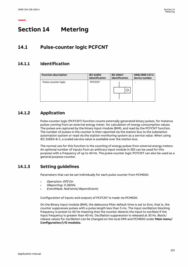
Section 14 Metering
14.1 Pulse-counter logic PCFCNTIP14600-1 v3
14.1.1 IdentificationM14879-1 v4
Function description IEC 61850identification
IEC 60617identification
ANSI/IEEE C37.2device number
Pulse-counter logic PCFCNT
S00947 V1 EN-US
-
14.1.2 ApplicationM13395-3 v6
Pulse-counter logic (PCFCNT) function counts externally generated binary pulses, for instancepulses coming from an external energy meter, for calculation of energy consumption values.The pulses are captured by the binary input module (BIM), and read by the PCFCNT function.The number of pulses in the counter is then reported via the station bus to the substationautomation system or read via the station monitoring system as a service value. When usingIEC 61850–8–1, a scaled service value is available over the station bus.
The normal use for this function is the counting of energy pulses from external energy meters.An optional number of inputs from an arbitrary input module in IED can be used for thispurpose with a frequency of up to 40 Hz. The pulse-counter logic PCFCNT can also be used as ageneral purpose counter.
14.1.3 Setting guidelinesM13396-4 v9
Parameters that can be set individually for each pulse counter from PCM600:
• Operation: Off/On• tReporting: 0-3600s• EventMask: NoEvents/ReportEvents
Configuration of inputs and outputs of PCFCNT is made via PCM600.
On the Binary input module (BIM), the debounce filter default time is set to 5ms, that is, thecounter suppresses pulses with a pulse length less than 5 ms. The input oscillation blockingfrequency is preset to 40 Hz meaning that the counter detects the input to oscillate if theinput frequency is greater than 40 Hz. Oscillation suppression is released at 30 Hz. Block/release values for oscillation can be changed on the local HMI and PCM600 under Main menu/Configuration/I/O modules.
1MRK 504 158-UEN A Section 14Metering
223Application manual

The setting is common for all input channels on BIM, that is, if limit changes aremade for inputs not connected to the pulse counter, the setting also influencesthe inputs on the same board used for pulse counting.
14.2 Function for energy calculation and demand handlingETPMMTR
SEMOD153638-1 v2
14.2.1 IdentificationSEMOD175537-2 v4
Function description IEC 61850identification
IEC 60617identification
ANSI/IEEE C37.2device number
Function for energy calculation anddemand handling
ETPMMTR W_Varh -
14.2.2 ApplicationSEMOD175546-4 v5
Energy calculation and demand handling function (ETPMMTR) is intended for statistics of theforward and reverse active and reactive energy. It has a high accuracy basically given by themeasurements function . This function has a site calibration possibility to further increase thetotal accuracy.
The function is connected to the instantaneous outputs of as shown in figure 92.
ETPMMTR
PQSTARTACCSTOPACCRSTACCRSTDMD
ACCINPRGEAFPULSEEARPULSEERFPULSEERRPULSE
EAFALMEARALMERFALMERRALMEAFACCEARACCERFACCERRACC
MAXPAFDMAXPARDMAXPRFDMAXPRRD
IEC13000184-1-en.vsd IEC13000190 V1 EN-US
Figure 92: Connection of energy calculation and demand handling function ETPMMTR tothe measurements function (CVMMXN)
The energy values can be read through communication in MWh and MVArh in monitoring toolof PCM600 and/or alternatively the values can be presented on the local HMI. The local HMIgraphical display is configured with PCM600 Graphical Display Editor tool (GDE) with ameasuring value which is selected to the active and reactive component as preferred. Also allAccumulated Active Forward, Active Reverse, Reactive Forward and Reactive Reverse energyvalues can be presented.
Maximum demand values are presented in MWh or MVArh in the same way.
Alternatively, the energy values can be presented with use of the pulse counters function(PCGGIO). The output energy values are scaled with the pulse output setting values
Section 14 1MRK 504 158-UEN AMetering
224Application manual

EAFAccPlsQty, EARAccPlsQty, ERFAccPlsQty and ERVAccPlsQty of the energy meteringfunction and then the pulse counter can be set-up to present the correct values by scaling inthis function. Pulse counter values can then be presented on the local HMI in the same wayand/or sent to the SA (Substation Automation) system through communication where thetotal energy then is calculated by summation of the energy pulses. This principle is good forvery high values of energy as the saturation of numbers else will limit energy integration toabout one year with 50 kV and 3000 A. After that the accumulation will start on zero again.
14.2.3 Setting guidelinesSEMOD175556-4 v6
The parameters are set via the local HMI or PCM600.
The following settings can be done for the energy calculation and demand handling functionETPMMTR:
GlobalBaseSel: Selects the global base value group used by the function to define (IBase),(UBase) and (SBase).
Operation: Off/On
EnaAcc: Off/On is used to switch the accumulation of energy on and off.
tEnergy: Time interval when energy is measured.
tEnergyOnPls: gives the pulse length ON time of the pulse. It should be at least 100 ms whenconnected to the Pulse counter function block. Typical value can be 100 ms.
tEnergyOffPls: gives the OFF time between pulses. Typical value can be 100 ms.
EAFAccPlsQty and EARAccPlsQty: gives the MWh value in each pulse. It should be selectedtogether with the setting of the Pulse counter (PCGGIO) settings to give the correct total pulsevalue.
ERFAccPlsQty and ERVAccPlsQty : gives the MVArh value in each pulse. It should be selectedtogether with the setting of the Pulse counter (PCGGIO) settings to give the correct total pulsevalue.
For the advanced user there are a number of settings for direction, zero clamping, max limit,and so on. Normally, the default values are suitable for these parameters.
1MRK 504 158-UEN A Section 14Metering
225Application manual

226
Section 15 Station communication
15.1 Communication protocolsM14815-3 v12
Each IED is provided with a communication interface, enabling it to connect to one or manysubstation level systems or equipment, either on the Substation Automation (SA) bus orSubstation Monitoring (SM) bus.
Available communication protocols are:
• IEC 61850-8-1 communication protocol• LON communication protocol• SPA or IEC 60870-5-103 communication protocol• DNP3.0 communication protocol
Several protocols can be combined in the same IED.
15.2 IEC 61850-8-1 communication protocolIP14616-1 v2
15.2.1 Application IEC 61850-8-1IP14865-1 v2
M13912-3 v4
IEC 61850-8-1 communication protocol allows vertical communication to HSI clients and allowshorizontal communication between two or more intelligent electronic devices (IEDs) from oneor several vendors to exchange information and to use it in the performance of their functionsand for correct co-operation.
GOOSE (Generic Object Oriented Substation Event), which is a part of IEC 61850–8–1 standard,allows the IEDs to communicate state and control information amongst themselves, using apublish-subscribe mechanism. That is, upon detecting an event, the IED(s) use a multi-casttransmission to notify those devices that have registered to receive the data. An IED can, bypublishing a GOOSE message, report its status. It can also request a control action to bedirected at any device in the network.
M13913-3 v5
Figure93 shows the topology of an IEC 61850–8–1 configuration. IEC 61850–8–1 specifies only theinterface to the substation LAN. The LAN itself is left to the system integrator.
1MRK 504 158-UEN A Section 15Station communication
227Application manual

KIOSK 2 KIOSK 3
Station HSIBase System
EngineeringWorkstation
SMSGateway
Printer
CC
IEC09000135_en.vsd
KIOSK 1
IED 1
IED 2
IED 3
IED 1
IED 2
IED 3
IED 1
IED 2
IED 3
IEC09000135 V1 EN-US
Figure 93: SA system with IEC 61850–8–1M16925-3 v4
Figure94 shows the GOOSE peer-to-peer communication.
Control Protection Control ProtectionControl and protection
GOOSE
en05000734.vsd
Station HSIMicroSCADA
Gateway
IEDA
IEDA
IEDA
IEDA
IEDA
IEC05000734 V1 EN-US
Figure 94: Example of a broadcasted GOOSE message
Section 15 1MRK 504 158-UEN AStation communication
228Application manual

15.2.2 Horizontal communication via GOOSE for interlockingGOOSEINTLKRCV
SEMOD173197-1 v2
PID-415-SETTINGS v5
Table 32: GOOSEINTLKRCV Non group settings (basic)
Name Values (Range) Unit Step Default Description
Operation OffOn
- - Off Operation Off/On
15.2.3 Setting guidelinesSEMOD55317-5 v6
There are two settings related to the IEC 61850–8–1 protocol:
Operation User can set IEC 61850 communication to On or Off.
GOOSE has to be set to the Ethernet link where GOOSE traffic shall be send and received.
15.2.4 Generic communication function for Single Point indicationSPGAPC, SP16GAPC
SEMOD55999-1 v4
15.2.4.1 ApplicationSEMOD55350-5 v7
Generic communication function for Single Point Value (SPGAPC) function is used to send onesingle logical output to other systems or equipment in the substation. It has one visible input,that should be connected in ACT tool.
15.2.4.2 Setting guidelinesSEMOD55376-5 v5
There are no settings available for the user for SPGAPC.
15.2.5 Generic communication function for Measured Value MVGAPCSEMOD55402-1 v3
15.2.5.1 ApplicationSEMOD55872-5 v9
Generic communication function for Measured Value MVGAPC function is used to send theinstantaneous value of an analog signal to other systems or equipment in the substation. Itcan also be used inside the same IED, to attach a RANGE aspect to an analog value and topermit measurement supervision on that value.
15.2.5.2 Setting guidelinesSEMOD55424-5 v5
The settings available for Generic communication function for Measured Value (MVGAPC)function allows the user to choose a deadband and a zero deadband for the monitored signal.Values within the zero deadband are considered as zero.
The high and low limit settings provides limits for the high-high-, high, normal, low and low-low ranges of the measured value. The actual range of the measured value is shown on therange output of MVGAPC function block. When a Measured value expander block (RANGE_XP)
1MRK 504 158-UEN A Section 15Station communication
229Application manual
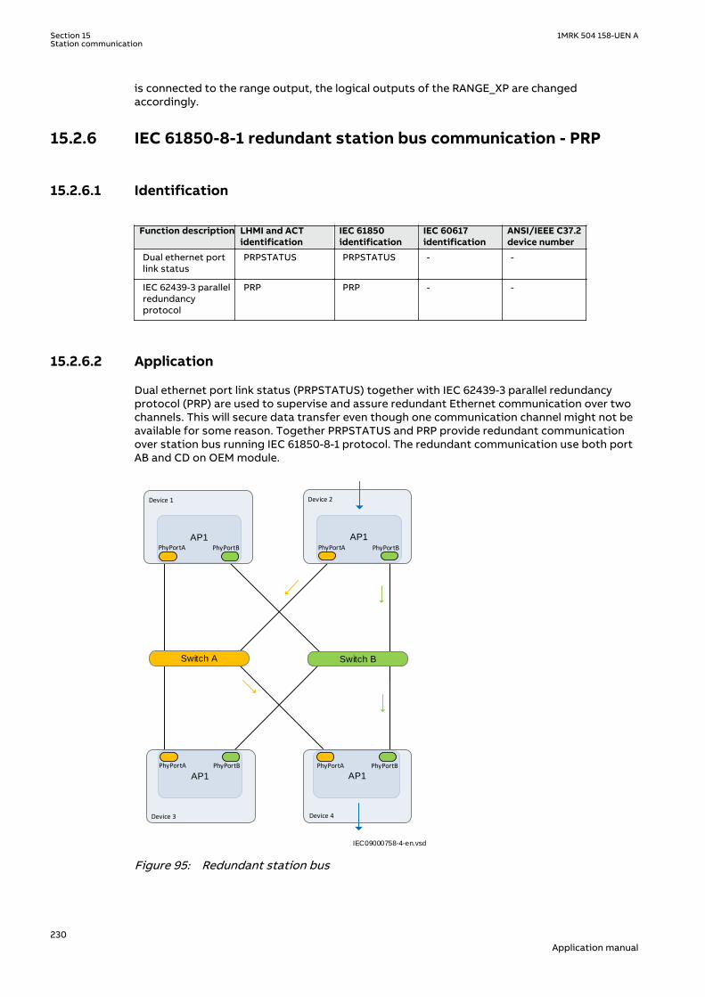
is connected to the range output, the logical outputs of the RANGE_XP are changedaccordingly.
15.2.6 IEC 61850-8-1 redundant station bus communication - PRPGUID-FF43A130-7D2D-4BA3-B51C-80398D73228F v3
15.2.6.1 IdentificationGUID-00C469E6-00D4-4780-BD0D-426647AB8E0F v3.1.1
Function description LHMI and ACTidentification
IEC 61850identification
IEC 60617identification
ANSI/IEEE C37.2device number
Dual ethernet portlink status
PRPSTATUS PRPSTATUS - -
IEC 62439-3 parallelredundancyprotocol
PRP PRP - -
15.2.6.2 ApplicationGUID-5B5581EA-4306-404B-98A7-7BDA6A306E7B v2.1.1
Dual ethernet port link status (PRPSTATUS) together with IEC 62439-3 parallel redundancyprotocol (PRP) are used to supervise and assure redundant Ethernet communication over twochannels. This will secure data transfer even though one communication channel might not beavailable for some reason. Together PRPSTATUS and PRP provide redundant communicationover station bus running IEC 61850-8-1 protocol. The redundant communication use both portAB and CD on OEM module.
IEC09000758-4-en.vsd
Switch A
AP1 PhyPortB PhyPortA
AP1 PhyPortA PhyPortB
AP1
PhyPortB PhyPortA
AP1
PhyPortA PhyPortB
Switch B
Device 1 Device 2
Device 3 Device 4
IEC09000758 V4 EN-US
Figure 95: Redundant station bus
Section 15 1MRK 504 158-UEN AStation communication
230Application manual

15.2.6.3 Setting guidelinesGUID-6AD04F29-9B52-40E7-AA07-6D248EF99FC6 v2
Redundant communication (PRP) is configured in the local HMI under Main menu/Configuration/Communication/Ethernet configuration/PRP
The settings are found in the Parameter Setting tool in PCM600 under IED Configuration/Communication/Ethernet configuration/PRP. By default the settings are read only in theParameter Settings tool, but can be unlocked by right clicking the parameter and selectingLock/Unlock Parameter.
Operation: The redundant communication will be activated when this parameter is set toOn.After confirmation the IED will restart and the setting alternatives Rear OEM - Port AB andCD will not be further displayed in the local HMI. The ETHLANAB and ETHLANCD in theParameter Setting Tool are irrelevant when the redundant communication is activated, onlyPRP IPAdress and IPMask are valid.
IEC10000057-3-en.vsdIEC10000057 V3 EN-US
Figure 96: PST screen: PRP Operation is set to On, which affect Rear OEM - Port AB andCD which are both set to PRP
1MRK 504 158-UEN A Section 15Station communication
231Application manual

15.3 LON communication protocolIP14420-1 v1
15.3.1 ApplicationIP14863-1 v1
M14804-3 v4
Control Center
IED IEDIED
Gateway
Star couplerRER 111
Station HSIMicroSCADA
IEC05000663-1-en.vsdIEC05000663 V2 EN-US
Figure 97: Example of LON communication structure for a station automation system
An optical network can be used within the station automation system. This enablescommunication with the IEDs through the LON bus from the operator’s workplace, from thecontrol center and also from other IEDs via bay-to-bay horizontal communication.
The fibre optic LON bus is implemented using either glass core or plastic core fibre opticcables.
Table 33: Specification of the fibre optic connectors
Glass fibre Plastic fibre
Cable connector ST-connector snap-in connector
Cable diameter 62.5/125 m 1 mm
Max. cable length 1000 m 10 m
Wavelength 820-900 nm 660 nm
Transmitted power -13 dBm (HFBR-1414) -13 dBm (HFBR-1521)
Receiver sensitivity -24 dBm (HFBR-2412) -20 dBm (HFBR-2521)
The LON ProtocolM14804-32 v2
The LON protocol is specified in the LonTalkProtocol Specification Version 3 from EchelonCorporation. This protocol is designed for communication in control networks and is a peer-to-peer protocol where all the devices connected to the network can communicate with eachother directly. For more information of the bay-to-bay communication, refer to the sectionMultiple command function.
Section 15 1MRK 504 158-UEN AStation communication
232Application manual

Hardware and software modulesM14804-35 v4
The hardware needed for applying LON communication depends on the application, but onevery central unit needed is the LON Star Coupler and optical fibers connecting the star couplerto the IEDs. To interface the IEDs from the MicroSCADA with Classic Monitor, applicationlibrary LIB520 is required.
The HV Control 670 software module is included in the LIB520 high-voltage process package,which is a part of the Application Software Library in MicroSCADA applications.
The HV Control 670 software module is used for control functions in the IEDs. The modulecontains a process picture, dialogues and a tool to generate a process database for thecontrol application in MicroSCADA.
When using MicroSCADA Monitor Pro instead of the Classic Monitor, SA LIB is used togetherwith 670 series Object Type files.
The HV Control 670 software module and 670 series Object Type files are usedwith both 650 and 670 series IEDs.
Use the LON Network Tool (LNT) to set the LON communication. This is a software toolapplied as one node on the LON bus. To communicate via LON, the IEDs need to know
• The node addresses of the other connected IEDs.• The network variable selectors to be used.
This is organized by LNT.
The node address is transferred to LNT via the local HMI by setting the parameterServicePinMsg = Yes. The node address is sent to LNT via the LON bus, or LNT can scan thenetwork for new nodes.
The communication speed of the LON bus is set to the default of 1.25 Mbit/s. This can bechanged by LNT.
15.3.2 MULTICMDRCV and MULTICMDSNDSEMOD119881-1 v3
15.3.2.1 IdentificationGUID-1A6E066C-6399-4D37-8CA5-3074537E48B2 v3
Function description IEC 61850identification
IEC 60617identification
ANSI/IEEE C37.2device number
Multiple command and receive MULTICMDRCV - -
Multiple command and send MULTICMDSND - -
15.3.2.2 ApplicationM14790-3 v5
The IED provides two function blocks enabling several IEDs to send and receive signals via theinterbay bus. The sending function block, MULTICMDSND, takes 16 binary inputs. LON enablesthese to be transmitted to the equivalent receiving function block, MULTICMDRCV, which has16 binary outputs.
1MRK 504 158-UEN A Section 15Station communication
233Application manual

15.3.2.3 Setting guidelinesSEMOD119915-1 v1
SettingsM14789-4 v3
The parameters for the multiple command function are set via PCM600.
The Mode setting sets the outputs to either a Steady or Pulsed mode.
15.4 SPA communication protocolIP14614-1 v1
15.4.1 ApplicationIP14785-1 v1
SEMOD115767-5 v5
SPA communication protocol as an alternative to IEC 60870-5-103. The same communicationport as for IEC 60870-5-103 is used.
When communicating with a PC connected to the utility substation LAN, via WAN and theutility office LAN, as shown in figure 98, and using the rear Ethernet port on the opticalEthernet module (OEM), the only hardware required for a station monitoring system is:
• Optical fibres from the IED to the utility substation LAN.• PC connected to the utility office LAN.
IED IEDIED
Substation LAN
IEC05000715-4-en.vsd
Remote monitoring
Utility LAN
WAN
IEC05000715 V4 EN-US
Figure 98: SPA communication structure for a remote monitoring system via asubstation LAN, WAN and utility LAN
The SPA communication is mainly used for the Station Monitoring System. It can includedifferent IEDs with remote communication possibilities. Connection to a computer (PC) can bemade directly (if the PC is located in the substation) or by telephone modem through atelephone network with ITU (former CCITT) characteristics or via a LAN/WAN connection.
glass <1000 m according to optical budget
plastic <25 m (inside cubicle) according to optical budget
FunctionalitySEMOD115767-25 v2
The SPA protocol V2.5 is an ASCII-based protocol for serial communication. Thecommunication is based on a master-slave principle, where the IED is a slave and the PC is themaster. Only one master can be applied on each fiber optic loop. A program is required in themaster computer for interpretation of the SPA-bus codes and for translation of the data thatshould be sent to the IED.
Section 15 1MRK 504 158-UEN AStation communication
234Application manual

For the specification of the SPA protocol V2.5, refer to SPA-bus Communication Protocol V2.5.
15.4.2 Setting guidelinesM11876-3 v4.1.1
The setting parameters for the SPA communication are set via the local HMI.
SPA, IEC 60870-5-103 and DNP3 uses the same rear communication port. Set the parameterOperation, under Main menu /Configuration /Communication /SLM configuration /Rearoptical SPA-IEC-DNP port /Protocol selection to the selected protocol.
When the communication protocols have been selected, the IED is automatically restarted.
The most important settings in the IED for SPA communication are the slave number and baudrate (communication speed). These settings are absolutely essential for all communicationcontact to the IED.
These settings can only be done on the local HMI for rear channel communication and for frontchannel communication.
The slave number can be set to any value from 1 to 899, as long as the slave number is uniquewithin the used SPA loop.
The baud rate, which is the communication speed, can be set to between 300 and 38400 baud.Refer to technical data to determine the rated communication speed for the selectedcommunication interfaces. The baud rate should be the same for the whole station, althoughdifferent baud rates in a loop are possible. If different baud rates in the same fiber optical loopor RS485 network are used, consider this when making the communication setup in thecommunication master, the PC.
For local fiber optic communication, 19200 or 38400 baud is the normal setting. If telephonecommunication is used, the communication speed depends on the quality of the connectionand on the type of modem used. But remember that the IED does not adapt its speed to theactual communication conditions, because the speed is set on the local HMI.
1MRK 504 158-UEN A Section 15Station communication
235Application manual
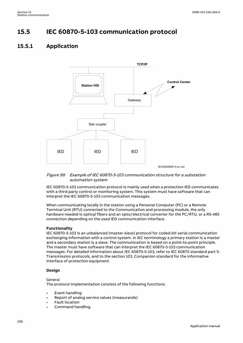
15.5 IEC 60870-5-103 communication protocolIP14615-1 v2
15.5.1 ApplicationIP14864-1 v1
M17109-3 v6
TCP/IP
Control Center
IED IEDIED
Gateway
Star coupler
Station HSI
IEC05000660-4-en.vsdIEC05000660 V4 EN-US
Figure 99: Example of IEC 60870-5-103 communication structure for a substationautomation system
IEC 60870-5-103 communication protocol is mainly used when a protection IED communicateswith a third party control or monitoring system. This system must have software that caninterpret the IEC 60870-5-103 communication messages.
When communicating locally in the station using a Personal Computer (PC) or a RemoteTerminal Unit (RTU) connected to the Communication and processing module, the onlyhardware needed is optical fibers and an opto/electrical converter for the PC/RTU, or a RS-485connection depending on the used IED communication interface.
FunctionalityM17109-38 v3
IEC 60870-5-103 is an unbalanced (master-slave) protocol for coded-bit serial communicationexchanging information with a control system. In IEC terminology a primary station is a masterand a secondary station is a slave. The communication is based on a point-to-point principle.The master must have software that can interpret the IEC 60870-5-103 communicationmessages. For detailed information about IEC 60870-5-103, refer to IEC 60870 standard part 5:Transmission protocols, and to the section 103, Companion standard for the informativeinterface of protection equipment.
DesignM17109-41 v1
GeneralM17109-43 v2
The protocol implementation consists of the following functions:
• Event handling• Report of analog service values (measurands)• Fault location• Command handling
Section 15 1MRK 504 158-UEN AStation communication
236Application manual

• Autorecloser ON/OFF• Teleprotection ON/OFF• Protection ON/OFF• LED reset• Characteristics 1 - 4 (Setting groups)
• File transfer (disturbance files)• Time synchronization
HardwareM17109-59 v1
When communicating locally with a Personal Computer (PC) or a Remote Terminal Unit (RTU)in the station, using the SPA/IEC port, the only hardware needed is:· Optical fibers, glass/plastic· Opto/electrical converter for the PC/RTU· PC/RTU
CommandsM17109-62 v3
The commands defined in the IEC 60870-5-103 protocol are represented in a dedicatedfunction blocks. These blocks have output signals for all available commands according to theprotocol.
• IED commands in control direction
Function block with defined IED functions in control direction, I103IEDCMD. This block usePARAMETR as FUNCTION TYPE, and INFORMATION NUMBER parameter is defined for eachoutput signal.
• Function commands in control direction
Function block with pre defined functions in control direction, I103CMD. This block includesthe FUNCTION TYPE parameter, and the INFORMATION NUMBER parameter is defined for eachoutput signal.
• Function commands in control direction
Function block with user defined functions in control direction, I103UserCMD. These functionblocks include the FUNCTION TYPE parameter for each block in the private range, and theINFORMATION NUMBER parameter for each output signal.
StatusM17109-74 v5
The events created in the IED available for the IEC 60870-5-103 protocol are based on the:
• IED status indication in monitor direction
Function block with defined IED functions in monitor direction, I103IED. This block usePARAMETER as FUNCTION TYPE, and INFORMATION NUMBER parameter is defined for eachinput signal.
• Function status indication in monitor direction, user-defined
Function blocks with user defined input signals in monitor direction, I103UserDef. Thesefunction blocks include the FUNCTION TYPE parameter for each block in the private range, andthe INFORMATION NUMBER parameter for each input signal.
• Supervision indications in monitor direction
Function block with defined functions for supervision indications in monitor direction,I103Superv. This block includes the FUNCTION TYPE parameter, and the INFORMATIONNUMBER parameter is defined for each output signal.
1MRK 504 158-UEN A Section 15Station communication
237Application manual

• Earth fault indications in monitor direction
Function block with defined functions for earth fault indications in monitor direction, I103EF.This block includes the FUNCTION TYPE parameter, and the INFORMATION NUMBERparameter is defined for each output signal.
• Fault indications in monitor direction
Function block with defined functions for fault indications in monitor direction, I103FLTPROT.This block includes the FUNCTION TYPE parameter, and the INFORMATION NUMBERparameter is defined for each input signal.
This block is suitable for distance protection, line differential, transformer differential, over-current and earth-fault protection functions.
• Autorecloser indications in monitor direction
Function block with defined functions for autorecloser indications in monitor direction,I103AR. This block includes the FUNCTION TYPE parameter, and the INFORMATION NUMBERparameter is defined for each output signal.
MeasurandsM17109-99 v2
The measurands can be included as type 3.1, 3.2, 3.3, 3.4 and type 9 according to the standard.
• Measurands in public range
Function block that reports all valid measuring types depending on connected signals,I103Meas.
• Measurands in private range
Function blocks with user defined input measurands in monitor direction, I103MeasUsr. Thesefunction blocks include the FUNCTION TYPE parameter for each block in the private range, andthe INFORMATION NUMBER parameter for each block.
Fault locationM17109-108 v1
The fault location is expressed in reactive ohms. In relation to the line length in reactive ohms,it gives the distance to the fault in percent. The data is available and reported when the faultlocator function is included in the IED.
Disturbance recordingsM17109-111 v8
• The transfer functionality is based on the Disturbance recorder function. The analog andbinary signals recorded will be reported to the master by polling. The eight lastdisturbances that are recorded are available for transfer to the master. A file that hasbeen transferred and acknowledged by the master cannot be transferred again.
• The binary signals that are included in the disturbance recorder are those that areconnected to the disturbance function blocks B1RBDR to B6RBDR. These function blocksinclude the function type and the information number for each signal. For moreinformation on the description of the Disturbance report in the Technical referencemanual. The analog channels, that are reported, are those connected to the disturbancefunction blocks A1RADR to A4RADR. The eight first ones belong to the public range andthe remaining ones to the private range.
SettingsM17109-116 v1
Section 15 1MRK 504 158-UEN AStation communication
238Application manual

Settings for RS485 and optical serial communicationM17109-118 v11
General settings
SPA, DNP and IEC 60870-5-103 can be configured to operate on the SLM optical serial portwhile DNP and IEC 60870-5-103 only can utilize the RS485 port. A single protocol can be activeon a given physical port at any time.
Two different areas in the HMI are used to configure the IEC 60870-5-103 protocol.
1. The port specific IEC 60870-5-103 protocol parameters are configured under:Main menu/Configuration/Communication/Station Communication/IEC60870-5-103/
• <config-selector>• SlaveAddress• BaudRate• RevPolarity (optical channel only)• CycMeasRepTime• MasterTimeDomain• TimeSyncMode• EvalTimeAccuracy• EventRepMode• CmdMode• RepIntermediatePos
<config-selector> is:
• “OPTICAL103:1” for the optical serial channel on the SLM• “RS485103:1” for the RS485 port
2. The protocol to activate on a physical port is selected under:Main menu/Configuration/Communication/Station Communication/Portconfiguration/
• RS485 port
• RS485PROT:1 (off, DNP, IEC103)
• SLM optical serial port
• PROTOCOL:1 (off, DNP, IEC103, SPA)
GUID-CD4EB23C-65E7-4ED5-AFB1-A9D5E9EE7CA8 V3 ENGUID-CD4EB23C-65E7-4ED5-AFB1-A9D5E9EE7CA8 V3 EN-US
Figure 100: Settings for IEC 60870-5-103 communication
The general settings for IEC 60870-5-103 communication are the following:
• SlaveAddress and BaudRate: Settings for slave number and communication speed (baudrate).
1MRK 504 158-UEN A Section 15Station communication
239Application manual

The slave number can be set to any value between 1 and 254. The communication speed,can be set either to 9600 bits/s or 19200 bits/s.
• RevPolarity: Setting for inverting the light (or not). Standard IEC 60870-5-103 setting isOn.
• CycMeasRepTime: See I103MEAS function block for more information.• EventRepMode: Defines the mode for how events are reported. The event buffer size is
1000 events.
Event reporting mode
If EventRepMode = SeqOfEvent, all GI and spontaneous events will be delivered in the orderthey were generated by BSW. The most recent value is the latest value delivered. All GI datafrom a single block will come from the same cycle.
If EventRepMode = HiPriSpont, spontaneous events will be delivered prior to GI event. Toprevent old GI data from being delivered after a new spontaneous event, the pending GI eventis modified to contain the same value as the spontaneous event. As a result, the GI dataset isnot time-correlated.
Settings from PCM600M17109-132 v2
I103USEDEFGUID-A41170D6-2846-4E5E-8B7F-85B53D4EF6B6 v1
For each input of the I103USEDEF function there is a setting for the information number of theconnected signal. The information number can be set to any value between 0 and 255. To getproper operation of the sequence of events the event masks in the event function is to be setto ON_CHANGE. For single-command signals, the event mask is to be set to ON_SET.
In addition there is a setting on each event block for function type. Refer to description of theMain Function type set on the local HMI.
CommandsM17109-138 v2
As for the commands defined in the protocol there is a dedicated function block with eightoutput signals. Use PCM600 to configure these signals. To realize the BlockOfInformationcommand, which is operated from the local HMI, the output BLKINFO on the IEC commandfunction block ICOM has to be connected to an input on an event function block. This inputmust have the information number 20 (monitor direction blocked) according to the standard.
Disturbance RecordingsM17109-141 v8
For each input of the Disturbance recorder function there is a setting for the informationnumber of the connected signal. The function type and the information number can be set toany value between 0 and 255. To get INF and FUN for the recorded binary signals, there areparameters on the disturbance recorder for each input. The user must set these parameters towhatever he connects to the corresponding input.
Refer to description of Main Function type set on the local HMI.
Recorded analog channels are sent with ASDU26 and ASDU31. One information element inthese ASDUs is called ACC, and it indicates the actual channel to be processed. The channelson disturbance recorder are sent with an ACC as shown in Table 34.
Table 34: Channels on disturbance recorder sent with a given ACC
DRA#-Input ACC IEC 60870-5-103 meaning
1 1 IL1
2 2 IL2
3 3 IL3
4 4 IN
5 5 UL1
6 6 UL2
Table continues on next page
Section 15 1MRK 504 158-UEN AStation communication
240Application manual

DRA#-Input ACC IEC 60870-5-103 meaning
7 7 UL3
8 8 UN
9 64 Private range
10 65 Private range
11 66 Private range
12 67 Private range
13 68 Private range
14 69 Private range
15 70 Private range
16 71 Private range
17 72 Private range
18 73 Private range
19 74 Private range
20 75 Private range
21 76 Private range
22 77 Private range
23 78 Private range
24 79 Private range
25 80 Private range
26 81 Private range
27 82 Private range
28 83 Private range
29 84 Private range
30 85 Private range
31 86 Private range
32 87 Private range
33 88 Private range
34 89 Private range
35 90 Private range
36 91 Private range
37 92 Private range
38 93 Private range
39 94 Private range
40 95 Private range
Function and information typesM17109-145 v5
Product type IEC103mainFunType value Comment:
REL 128 Compatible range
REC 242 Private range, use default
RED 192 Compatible range
RET 176 Compatible range
1MRK 504 158-UEN A Section 15Station communication
241Application manual
REB 207 Private range
REQ 245 Private range
Refer to the tables in the Technical reference manual /Station communication, specifying theinformation types supported by the communication protocol IEC 60870-5-103.
To support the information, corresponding functions must be included in the protection IED.
There is no representation for the following parts:
• Generating events for test mode• Cause of transmission: Info no 11, Local operation
Glass or plastic fibre should be used. BFOC/2.5 is the recommended interface to use(BFOC/2.5 is the same as ST connectors). ST connectors are used with the optical power asspecified in standard.
For more information, refer to IEC standard IEC 60870-5-103.
15.6 DNP3 Communication protocol
15.6.1 ApplicationGUID-EF1F0C38-9FF6-4683-8B10-AAA372D42185 v1
For more information on the application and setting guidelines for the DNP3 communicationprotocol refer to the DNP3 Communication protocol manual.
Section 15 1MRK 504 158-UEN AStation communication
242Application manual

Section 16 Security
16.1 Authority status ATHSTATSEMOD158575-1 v2
16.1.1 ApplicationSEMOD158527-5 v3
Authority status (ATHSTAT) function is an indication function block, which informs about twoevents related to the IED and the user authorization:
• the fact that at least one user has tried to log on wrongly into the IED and it was blocked(the output USRBLKED)
• the fact that at least one user is logged on (the output LOGGEDON)
The two outputs of ATHSTAT function can be used in the configuration for different indicationand alarming reasons, or can be sent to the station control for the same purpose.
16.2 Self supervision with internal event list INTERRSIGIP1721-1 v2
16.2.1 ApplicationM12625-3 v9
The protection and control IEDs have many functions included. The included self-supervisionwith internal event list function block provides good supervision of the IED. The fault signalsmake it easier to analyze and locate a fault.
Both hardware and software supervision is included and it is also possible to indicate possiblefaults through a hardware contact on the power supply module and/or through thecommunication.
Internal events are generated by the built-in supervisory functions. The supervisory functionssupervise the status of the various modules in the IED and, in case of failure, a correspondingevent is generated. Similarly, when the failure is corrected, a corresponding event is generated.
Apart from the built-in supervision of the various modules, events are also generated when thestatus changes for the:
• built-in real time clock (in operation/out of order).• external time synchronization (in operation/out of order).
Events are also generated:
• whenever any setting in the IED is changed.
The internal events are time tagged with a resolution of 1 ms and stored in a list. The list canstore up to 40 events. The list is based on the FIFO principle, that is, when it is full, the oldestevent is overwritten. The list contents cannot be modified, but the whole list can be clearedusing the Reset menu in the LHMI.
The list of internal events provides valuable information, which can be used duringcommissioning and fault tracing.
1MRK 504 158-UEN A Section 16Security
243Application manual
The information can, in addition to be viewed on the built in HMI, also be retrieved with the aidof a PC with PCM600 installed and by using the Event Monitoring Tool. The PC can either beconnected to the front port, or to the port at the back of the IED.
16.3 Change lock CHNGLCKGUID-B48775D0-ACF0-49C6-A7F6-69AF37F1C68F v1
16.3.1 ApplicationGUID-51EEC9C7-8ECF-4546-BC26-326861654340 v4
Change lock function CHNGLCK is used to block further changes to the IED configuration oncethe commissioning is complete. The purpose is to make it impossible to perform inadvertentIED configuration and setting changes.
However, when activated, CHNGLCK will still allow the following actions that does not involvereconfiguring of the IED:
• Monitoring• Reading events• Resetting events• Reading disturbance data• Clear disturbances• Reset LEDs• Reset counters and other runtime component states• Control operations• Set system time• Enter and exit from test mode• Change of active setting group
The binary input controlling the function is defined in ACT or SMT. The CHNGLCK function isconfigured using ACT.
LOCK Binary input signal that will activate/deactivate the function, defined in ACT or SMT.
GUID-8C333BC0-AA7A-4ED1-A772-18C22E8EEE62 v4
When CHNGLCK has a logical one on its input, then all attempts to modify the IEDconfiguration and setting will be denied and the message "Error: Changes blocked" will bedisplayed on the local HMI; in PCM600 the message will be "Operation denied by activeChangeLock". The CHNGLCK function should be configured so that it is controlled by a signalfrom a binary input card. This guarantees that by setting that signal to a logical zero,CHNGLCK is deactivated. If any logic is included in the signal path to the CHNGLCK input, thatlogic must be designed so that it cannot permanently issue a logical one to the CHNGLCKinput. If such a situation would occur in spite of these precautions, then please contact thelocal ABB representative for remedial action.
16.4 Denial of service DOS
16.4.1 ApplicationGUID-64F4D905-9F73-4073-B8F6-8D373155316A v4
The denial of service functions (DOSFRNT, DOSLANAB and DOSLANCD) are designed to limitthe CPU load that can be produced by Ethernet network traffic on the IED. The communicationfacilities must not be allowed to compromise the primary functionality of the device. Allinbound network traffic will be quota controlled so that too heavy network loads can be
Section 16 1MRK 504 158-UEN ASecurity
244Application manual

controlled. Heavy network load might for instance be the result of malfunctioning equipmentconnected to the network.
DOSFRNT, DOSLANAB and DOSLANCD measure the IED load from communication and, ifnecessary, limit it for not jeopardizing the IEDs control and protection functionality due tohigh CPU load. The function has the following outputs:
• LINKUP indicates the Ethernet link status• WARNING indicates that communication (frame rate) is higher than normal• ALARM indicates that the IED limits communication
16.4.2 Setting guidelinesGUID-CE3344E8-539B-47E0-9C19-8239988BDBCF v2
The function does not have any parameters available in the local HMI or PCM600.
1MRK 504 158-UEN A Section 16Security
245Application manual

246

Section 17 Basic IED functions
17.1 IED identifiers TERMINALIDIP15060-1 v2
17.1.1 ApplicationM15324-3 v6
IED identifiers (TERMINALID) function allows the user to identify the individual IED in thesystem, not only in the substation, but in a whole region or a country.
Use only characters A-Z, a-z and 0-9 in station, object and unit names.
17.2 Product information PRODINFGUID-F67243CA-2429-4118-BBFF-3D62BF55E080 v2
17.2.1 ApplicationGUID-D78786E6-C34A-4E63-9D1E-0582C8F1F7E1 v7
The Product identifiers function contains constant data (i.e. not possible to change) thatuniquely identifies the IED:
• ProductVer• ProductDef• FirmwareVer• SerialNo• OrderingNo• ProductionDate• IEDProdType
The settings are visible on the local HMI , under Main menu/Diagnostics/IED status/Productidentifiers and under Main menu/Diagnostics/IED Status/IED identifiers
This information is very helpful when interacting with ABB product support (e.g. during repairand maintenance).
17.2.2 Factory defined settingsM11789-39 v10
The factory defined settings are very useful for identifying a specific version and very helpful inthe case of maintenance, repair, interchanging IEDs between different Substation AutomationSystems and upgrading. The factory made settings can not be changed by the customer. Theycan only be viewed. The settings are found in the local HMI under Main menu/Diagnostics/IEDstatus/Product identifiers
The following identifiers are available:
• IEDProdType
• Describes the type of the IED. Example: REL650
• ProductDef
• Describes the release number from the production. Example: 2.1.0
• FirmwareVer
1MRK 504 158-UEN A Section 17Basic IED functions
247Application manual

• Describes the firmware version.• The firmware version can be checked from Main menu/Diagnostics/IED status/
Product identifiers• Firmware version numbers run independently from the release production numbers.
For every release number there can be one or more firmware versions depending onthe small issues corrected in between releases.
• ProductVer
• Describes the product version. Example: 2.1.0
1 is the Major version of the manufactured product this means, new platform of the product
2 is the Minor version of the manufactured product this means, new functions or new hardwareadded to the product
3 is the Major revision of the manufactured product this means, functions or hardware is eitherchanged or enhanced in the product
• IEDMainFunType
• Main function type code according to IEC 60870-5-103. Example: 128 (meaning lineprotection).
• SerialNo• OrderingNo• ProductionDate
17.3 Measured value expander block RANGE_XPSEMOD52451-1 v2
17.3.1 IdentificationSEMOD113212-2 v3
Function description IEC 61850identification
IEC 60617identification
ANSI/IEEE C37.2device number
Measured value expander block RANGE_XP - -
17.3.2 ApplicationSEMOD52434-4 v5
The current and voltage measurements functions (CVMMXN, CMMXU, VMMXU and VNMMXU),current and voltage sequence measurement functions (CMSQI and VMSQI) and IEC 61850generic communication I/O functions (MVGAPC) are provided with measurement supervisionfunctionality. All measured values can be supervised with four settable limits, that is low-lowlimit, low limit, high limit and high-high limit. The measure value expander block ( RANGE_XP)has been introduced to be able to translate the integer output signal from the measuringfunctions to 5 binary signals, that is below low-low limit, below low limit, normal, above high-high limit or above high limit. The output signals can be used as conditions in the configurablelogic.
17.3.3 Setting guidelinesSEMOD113223-4 v1
There are no settable parameters for the measured value expander block function.
Section 17 1MRK 504 158-UEN ABasic IED functions
248Application manual
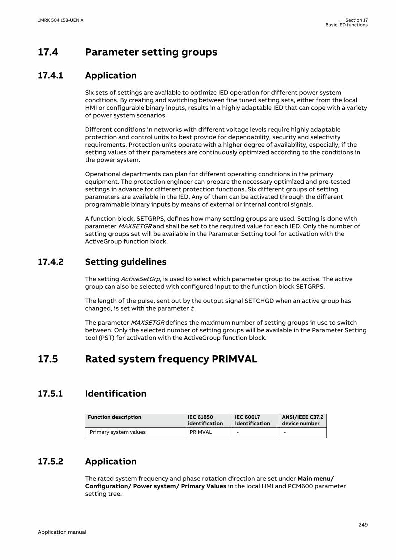
17.4 Parameter setting groupsIP1745-1 v1
17.4.1 ApplicationM12007-6 v9
Six sets of settings are available to optimize IED operation for different power systemconditions. By creating and switching between fine tuned setting sets, either from the localHMI or configurable binary inputs, results in a highly adaptable IED that can cope with a varietyof power system scenarios.
Different conditions in networks with different voltage levels require highly adaptableprotection and control units to best provide for dependability, security and selectivityrequirements. Protection units operate with a higher degree of availability, especially, if thesetting values of their parameters are continuously optimized according to the conditions inthe power system.
Operational departments can plan for different operating conditions in the primaryequipment. The protection engineer can prepare the necessary optimized and pre-testedsettings in advance for different protection functions. Six different groups of settingparameters are available in the IED. Any of them can be activated through the differentprogrammable binary inputs by means of external or internal control signals.
A function block, SETGRPS, defines how many setting groups are used. Setting is done withparameter MAXSETGR and shall be set to the required value for each IED. Only the number ofsetting groups set will be available in the Parameter Setting tool for activation with theActiveGroup function block.
17.4.2 Setting guidelinesM15259-3 v4
The setting ActiveSetGrp, is used to select which parameter group to be active. The activegroup can also be selected with configured input to the function block SETGRPS.
The length of the pulse, sent out by the output signal SETCHGD when an active group haschanged, is set with the parameter t.
The parameter MAXSETGR defines the maximum number of setting groups in use to switchbetween. Only the selected number of setting groups will be available in the Parameter Settingtool (PST) for activation with the ActiveGroup function block.
17.5 Rated system frequency PRIMVALIP15064-1 v2
17.5.1 IdentificationGUID-B8B3535D-227B-4151-9E98-BEB85F4D54DE v1
Function description IEC 61850identification
IEC 60617identification
ANSI/IEEE C37.2device number
Primary system values PRIMVAL - -
17.5.2 ApplicationM15288-3 v6
The rated system frequency and phase rotation direction are set under Main menu/Configuration/ Power system/ Primary Values in the local HMI and PCM600 parametersetting tree.
1MRK 504 158-UEN A Section 17Basic IED functions
249Application manual
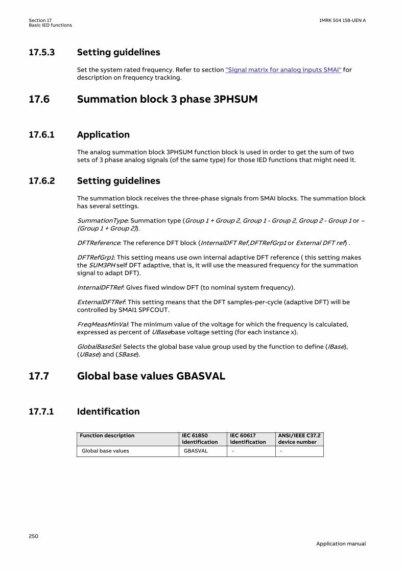
17.5.3 Setting guidelinesM15292-3 v2
Set the system rated frequency. Refer to section "Signal matrix for analog inputs SMAI" fordescription on frequency tracking.
17.6 Summation block 3 phase 3PHSUMSEMOD55968-1 v2
17.6.1 ApplicationSEMOD56004-4 v3
The analog summation block 3PHSUM function block is used in order to get the sum of twosets of 3 phase analog signals (of the same type) for those IED functions that might need it.
17.6.2 Setting guidelinesSEMOD56006-4 v7
The summation block receives the three-phase signals from SMAI blocks. The summation blockhas several settings.
SummationType: Summation type (Group 1 + Group 2, Group 1 - Group 2, Group 2 - Group 1 or –(Group 1 + Group 2)).
DFTReference: The reference DFT block (InternalDFT Ref,DFTRefGrp1 or External DFT ref) .
DFTRefGrp1: This setting means use own internal adaptive DFT reference ( this setting makesthe SUM3PH self DFT adaptive, that is, it will use the measured frequency for the summationsignal to adapt DFT).
InternalDFTRef: Gives fixed window DFT (to nominal system frequency).
ExternalDFTRef: This setting means that the DFT samples-per-cycle (adaptive DFT) will becontrolled by SMAI1 SPFCOUT.
FreqMeasMinVal: The minimum value of the voltage for which the frequency is calculated,expressed as percent of UBasebase voltage setting (for each instance x).
GlobalBaseSel: Selects the global base value group used by the function to define (IBase),(UBase) and (SBase).
17.7 Global base values GBASVALGUID-2FDB0A2C-10FE-4954-B6E4-9DA2EEEF1668 v1
17.7.1 IdentificationGUID-0D5405BE-E669-44C8-A208-3A4C86D39115 v3
Function description IEC 61850identification
IEC 60617identification
ANSI/IEEE C37.2device number
Global base values GBASVAL - -
Section 17 1MRK 504 158-UEN ABasic IED functions
250Application manual
17.7.2 ApplicationGUID-D58ECA9A-9771-443D-BF84-8EF582A346BF v4
Global base values function (GBASVAL) is used to provide global values, common for allapplicable functions within the IED. One set of global values consists of values for current,voltage and apparent power and it is possible to have twelve different sets.
This is an advantage since all applicable functions in the IED use a single source of base values.This facilitates consistency throughout the IED and also facilitates a single point for updatingvalues when necessary.
Each applicable function in the IED has a parameter, GlobalBaseSel, defining one out of thetwelve sets of GBASVAL functions.
17.7.3 Setting guidelinesGUID-E3F5D754-BD17-4729-895B-957A09C2AC75 v3
UBase: Phase-to-phase voltage value to be used as a base value for applicable functionsthroughout the IED.
IBase: Phase current value to be used as a base value for applicable functions throughout theIED.
SBase: Standard apparent power value to be used as a base value for applicable functionsthroughout the IED, typically SBase=√3·UBase·IBase.
17.8 Signal matrix for binary inputs SMBISEMOD55793-1 v2
17.8.1 ApplicationM15310-3 v2
The Signal matrix for binary inputs function SMBI is used within the Application Configurationtool in direct relation with the Signal Matrix tool. SMBI represents the way binary inputs arebrought in for one IED configuration.
17.8.2 Setting guidelinesM15312-3 v3
There are no setting parameters for the Signal matrix for binary inputs SMBI available to theuser in Parameter Setting tool. However, the user shall give a name to SMBI instance and theSMBI inputs, directly in the Application Configuration tool. These names will define SMBIfunction in the Signal Matrix tool. The user defined name for the input or output signal will alsoappear on the respective output or input signal.
17.9 Signal matrix for binary outputs SMBOSEMOD55215-1 v2
17.9.1 ApplicationSEMOD55213-5 v4
The Signal matrix for binary outputs function SMBO is used within the ApplicationConfiguration tool in direct relation with the Signal Matrix tool. SMBO represents the waybinary outputs are sent from one IED configuration.
1MRK 504 158-UEN A Section 17Basic IED functions
251Application manual
17.9.2 Setting guidelinesSEMOD55228-5 v2
There are no setting parameters for the Signal matrix for binary outputs SMBO available to theuser in Parameter Setting tool. However, the user must give a name to SMBO instance andSMBO outputs, directly in the Application Configuration tool. These names will define SMBOfunction in the Signal Matrix tool.
17.10 Signal matrix for mA inputs SMMISEMOD55233-1 v2
17.10.1 ApplicationSEMOD55237-5 v2
The Signal matrix for mA inputs function SMMI is used within the Application Configurationtool in direct relation with the Signal Matrix tool. SMMI represents the way milliamp (mA)inputs are brought in for one IED configuration.
17.10.2 Setting guidelinesSEMOD55247-5 v2
There are no setting parameters for the Signal matrix for mA inputs SMMI available to the userin the Parameter Setting tool. However, the user must give a name to SMMI instance and SMMIinputs, directly in the Application Configuration tool.
17.11 Signal matrix for analog inputs SMAISEMOD55751-1 v2
17.11.1 ApplicationSEMOD55744-4 v10
Signal matrix for analog inputs (SMAI), also known as the preprocessor function block,analyses the connected four analog signals (three phases and neutral) and calculates allrelevant information from them like the phasor magnitude, phase angle, frequency, true RMSvalue, harmonics, sequence components and so on. This information is then used by therespective functions connected to this SMAI block in ACT (for example protection,measurement or monitoring functions).
17.11.2 Frequency valuesGUID-B494B93C-B5AA-4FD6-8080-8611C34C2AD8 v5
The SMAI function includes a functionality based on the level of positive sequence voltage,MinValFreqMeas, to validate if the frequency measurement is valid or not. If the positivesequence voltage is lower than MinValFreqMeas, the function freezes the frequency outputvalue for 500 ms and after that the frequency output is set to the nominal value. A signal isavailable for the SMAI function to prevent operation due to non-valid frequency values.MinValFreqMeas is set as % of UBase/√3
If SMAI setting ConnectionType is Ph-Ph, at least two of the inputs GRPxL1, GRPxL2 andGRPxL3, where 1≤x≤12, must be connected in order to calculate the positive sequence voltage.Note that phase to phase inputs shall always be connected as follows: L1-L2 to GRPxL1, L2-L3to GRPxL2, L3-L1 to GRPxL3. If SMAI setting ConnectionType is Ph-N, all three inputs GRPxL1,GRPxL2 and GRPxL3 must be connected in order to calculate the positive sequence voltage.
If only one phase-phase voltage is available and SMAI setting ConnectionType is Ph-Ph, theuser is advised to connect two (not three) of the inputs GRPxL1, GRPxL2 and GRPxL3 to thesame voltage input as shown in figure 101 to make SMAI calculate a positive sequence voltage.
Section 17 1MRK 504 158-UEN ABasic IED functions
252Application manual
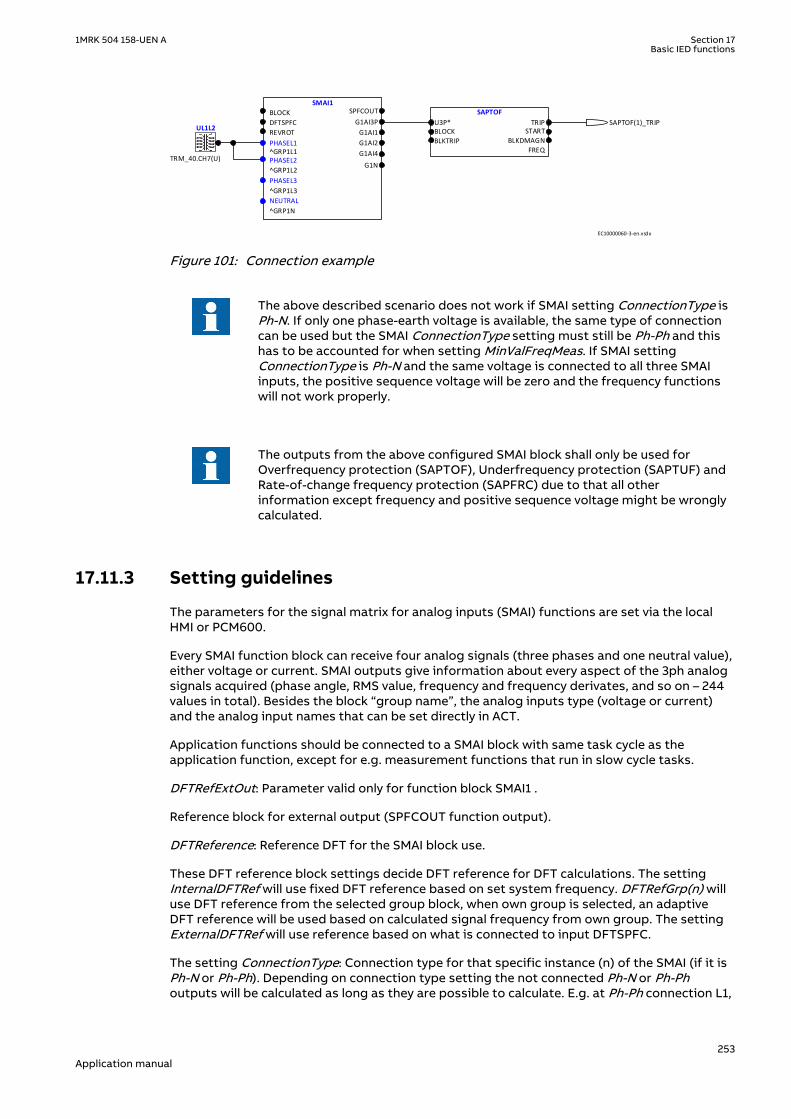
SMAI1
BLOCK
DFTSPFC
REVROT
^GRP1L1
^GRP1L2
^GRP1L3
^GRP1N
SPFCOUT
G1AI3P
G1AI1
G1AI2
G1AI4
G1N
NEUTRAL
PHASEL3
PHASEL2
PHASEL1
UL1L2
SAPTOF
U3P*BLOCK
BLKTRIP
TRIPSTART
BLKDMAGN
FREQTRM_40.CH7(U)
SAPTOF(1)_TRIP
EC10000060-3-en.vsdx
IEC10000060 V3 EN-US
Figure 101: Connection example
The above described scenario does not work if SMAI setting ConnectionType isPh-N. If only one phase-earth voltage is available, the same type of connectioncan be used but the SMAI ConnectionType setting must still be Ph-Ph and thishas to be accounted for when setting MinValFreqMeas. If SMAI settingConnectionType is Ph-N and the same voltage is connected to all three SMAIinputs, the positive sequence voltage will be zero and the frequency functionswill not work properly.
The outputs from the above configured SMAI block shall only be used forOverfrequency protection (SAPTOF), Underfrequency protection (SAPTUF) andRate-of-change frequency protection (SAPFRC) due to that all otherinformation except frequency and positive sequence voltage might be wronglycalculated.
17.11.3 Setting guidelinesGUID-C8D6C88B-87C6-44C1-804B-CF1594365EE6 v8
The parameters for the signal matrix for analog inputs (SMAI) functions are set via the localHMI or PCM600.
Every SMAI function block can receive four analog signals (three phases and one neutral value),either voltage or current. SMAI outputs give information about every aspect of the 3ph analogsignals acquired (phase angle, RMS value, frequency and frequency derivates, and so on – 244values in total). Besides the block “group name”, the analog inputs type (voltage or current)and the analog input names that can be set directly in ACT.
Application functions should be connected to a SMAI block with same task cycle as theapplication function, except for e.g. measurement functions that run in slow cycle tasks.
DFTRefExtOut: Parameter valid only for function block SMAI1 .
Reference block for external output (SPFCOUT function output).
DFTReference: Reference DFT for the SMAI block use.
These DFT reference block settings decide DFT reference for DFT calculations. The settingInternalDFTRef will use fixed DFT reference based on set system frequency. DFTRefGrp(n) willuse DFT reference from the selected group block, when own group is selected, an adaptiveDFT reference will be used based on calculated signal frequency from own group. The settingExternalDFTRef will use reference based on what is connected to input DFTSPFC.
The setting ConnectionType: Connection type for that specific instance (n) of the SMAI (if it isPh-N or Ph-Ph). Depending on connection type setting the not connected Ph-N or Ph-Phoutputs will be calculated as long as they are possible to calculate. E.g. at Ph-Ph connection L1,
1MRK 504 158-UEN A Section 17Basic IED functions
253Application manual

L2 and L3 will be calculated for use in symmetrical situations. If N component should be usedrespectively the phase component during faults IN/UN must be connected to input 4.
Negation: If the user wants to negate the 3ph signal, it is possible to choose to negate only thephase signals Negate3Ph, only the neutral signal NegateN or both Negate3Ph+N. negationmeans rotation with 180° of the vectors.
GlobalBaseSel: Selects the global base value group used by the function to define (IBase),(UBase) and (SBase).
MinValFreqMeas: The minimum value of the voltage for which the frequency is calculated,expressed as percent of UBase (for each instance n).
Settings DFTRefExtOut and DFTReference shall be set to default valueInternalDFTRef if no VT inputs are available.
Even if the user sets the AnalogInputType of a SMAI block to “Current”, theMinValFreqMeas is still visible. However, using the current channel values asbase for frequency measurement is not recommendable for a number ofreasons, not last among them being the low level of currents that one can havein normal operating conditions.
Examples of adaptive frequency tracking
Preprocessing block shall only be used to feed functions within the sameexecution cycles (e.g. use preprocessing block with cycle 1 to feed transformerdifferential protection). The only exceptions are measurement functions(CVMMXN, CMMXU,VMMXU, etc.) which shall be fed by preprocessing blockswith cycle 8.
When two or more preprocessing blocks are used to feed one protectionfunction (e.g. over-power function GOPPDOP), it is of outmost importance thatparameter setting DFTReference has the same set value for all of thepreprocessing blocks involved
Section 17 1MRK 504 158-UEN ABasic IED functions
254Application manual

IEC07000197.vsd
SMAI instance 3 phase groupSMAI1:1 1SMAI2:2 2SMAI3:3 3SMAI4:4 4SMAI5:5 5SMAI6:6 6SMAI7:7 7SMAI8:8 8SMAI9:9 9
SMAI10:10 10SMAI11:11 11SMAI12:12 12
Task time group 1
SMAI instance 3 phase groupSMAI1:13 1SMAI2:14 2SMAI3:15 3SMAI4:16 4SMAI5:17 5SMAI6:18 6SMAI7:19 7SMAI8:20 8SMAI9:21 9
SMAI10:22 10SMAI11:23 11SMAI12:24 12
Task time group 2
SMAI instance 3 phase groupSMAI1:25 1SMAI2:26 2SMAI3:27 3SMAI4:28 4SMAI5:29 5SMAI6:30 6SMAI7:31 7SMAI8:32 8SMAI9:33 9
SMAI10:34 10SMAI11:35 11SMAI12:36 12
Task time group 3
AdDFTRefCh7
AdDFTRefCh4
IEC07000197 V2 EN-US
Figure 102: Twelve SMAI instances are grouped within one task time. SMAI blocks areavailable in three different task times in the IED. Two pointed instances areused in the following examples.
The examples shows a situation with adaptive frequency tracking with one reference selectedfor all instances. In practice each instance can be adapted to the needs of the actualapplication. The adaptive frequency tracking is needed in IEDs that belong to the protectionsystem of synchronous machines and that are active during run-up and shout-down of themachine. In other application the usual setting of the parameter DFTReference of SMAI isInternalDFTRef.
Example 1
1MRK 504 158-UEN A Section 17Basic IED functions
255Application manual

IEC07000198-2-en.vsd
SMAI1:1BLOCKDFTSPFC^GRP1L1^GRP1L2^GRP1L3^GRP1N
SPFCOUTAI3P
AI1AI2AI3AI4AIN
SMAI1:13BLOCKDFTSPFC^GRP1L1^GRP1L2^GRP1L3^GRP1N
SPFCOUTAI3P
AI1AI2AI3AI4AIN
SMAI1:25BLOCKDFTSPFC^GRP1L1^GRP1L2^GRP1L3^GRP1N
SPFCOUTAI3P
AI1AI2AI3AI4AIN
IEC07000198 V3 EN-US
Figure 103: Configuration for using an instance in task time group 1 as DFT reference
Assume instance SMAI7:7 in task time group 1 has been selected in the configuration to controlthe frequency tracking . Observe that the selected reference instance (i.e. frequency trackingmaster) must be a voltage type. Observe that positive sequence voltage is used for thefrequency tracking feature.
For task time group 1 this gives the following settings (see Figure 102 for numbering):
SMAI1:1: DFTRefExtOut = DFTRefGrp7 to route SMAI7:7 reference to the SPFCOUT output,DFTReference = DFTRefGrp7 for SMAI1:1 to use SMAI7:7 as reference (see Figure 103) SMAI2:2 –SMAI12:12: DFTReference = DFTRefGrp7 for SMAI2:2 – SMAI12:12 to use SMAI7:7 as reference.
For task time group 2 this gives the following settings:
SMAI1:13 – SMAI12:24: DFTReference = ExternalDFTRef to use DFTSPFC input of SMAI1:13 asreference (SMAI7:7)
For task time group 3 this gives the following settings:
SMAI1:25 – SMAI12:36: DFTReference = ExternalDFTRef to use DFTSPFC input as reference(SMAI7:7)
Example 2
Section 17 1MRK 504 158-UEN ABasic IED functions
256Application manual

IEC07000199-2-en.vsd
SMAI1:13BLOCKDFTSPFC^GRP1L1^GRP1L2^GRP1L3^GRP1N
SPFCOUTAI3P
AI1AI2AI3AI4AIN
SMAI1:1BLOCKDFTSPFC^GRP1L1^GRP1L2^GRP1L3^GRP1N
SPFCOUTAI3P
AI1AI2AI3AI4AIN
SMAI1:25BLOCKDFTSPFC^GRP1L1^GRP1L2^GRP1L3^GRP1N
SPFCOUTAI3P
AI1AI2AI3AI4AIN
IEC07000199 V3 EN-US
Figure 104: Configuration for using an instance in task time group 2 as DFT reference.
Assume instance SMAI4:16 in task time group 2 has been selected in the configuration tocontrol the frequency tracking for all instances. Observe that the selected reference instance(i.e. frequency tracking master) must be a voltage type. Observe that positive sequencevoltage is used for the frequency tracking feature.
For task time group 1 this gives the following settings (see Figure 102 for numbering):
SMAI1:1 – SMAI12:12: DFTReference = ExternalDFTRef to use DFTSPFC input as reference(SMAI4:16)
For task time group 2 this gives the following settings:
SMAI1:13: DFTRefExtOut = DFTRefGrp4 to route SMAI4:16 reference to the SPFCOUT output,DFTReference = DFTRefGrp4 for SMAI1:13 to use SMAI4:16 as reference (see Figure 104)SMAI2:14 – SMAI12:24: DFTReference = DFTRefGrp4 to use SMAI4:16 as reference.
For task time group 3 this gives the following settings:
SMAI1:25 – SMAI12:36: DFTReference = ExternalDFTRef to use DFTSPFC input as reference(SMAI4:16)
17.12 Test mode functionality TESTMODEIP1647-1 v3
17.12.1 ApplicationM11407-3 v8
The protection and control IEDs may have a complex configuration with many includedfunctions. To make the testing procedure easier, the IEDs include the feature that allowsindividual blocking of a single-, several-, or all functions.
This means that it is possible to see when a function is activated or trips. It also enables theuser to follow the operation of several related functions to check correct functionality and tocheck parts of the configuration, and so on.
1MRK 504 158-UEN A Section 17Basic IED functions
257Application manual

17.12.1.1 IEC 61850 protocol test modeGUID-82998715-6F23-4CAF-92E4-05E1A863CF33 v5
The function block TESTMODE has implemented the extended testing mode capabilities forIEC 61850 Ed2 systems. Operator commands sent to the function block TESTMODE determinethe behavior of the functions. The command can be given remotely from an IEC 61850 client orfrom the LHMI under the Main menu/Test/Function test modes/Communication/StationCommunication/IEC61850 LD0 LLN0/LD0LLN0:1. The possible values of the function blockTESTMODE are described in Communication protocol manual, IEC 61850 Edition 1 and Edition2.
There is no setting in PCM600 via PST for the TESTMODE function block.
To be able to set the function block TESTMODE remotely, the setting via pathon LHMI and in PST: Main menu/Configuration/Communication/ StationCommunication/IEC61850-8-1/IEC61850-8-1:1RemoteModControl may not beset to Off. The possible values of the parameter RemoteModControl are Off,Maintenance or All levels. The Off value denies all access to function blockTESTMODE from remote, Maintenance requires that the category of theoriginator (orCat) is Maintenance and All levels allow any orCat.
The DataObject Mod of the Root LD.LNN0 can be set on the LHMI under Main menu/Test/Function test modes/Communication/Station communication/IEC61850 LD0 LLN0/LD0LLN0:1 to On, Off, TestBlocked,Test or Blocked.
When the setting of the DataObject Mod is changed at this level, all Logical Nodes inside thelogical device update their own behavior according to IEC61850-7-4. The supported values ofthe function block TESTMODE are described in Communication protocol manual, IEC 61850Edition 2. When the function block TESTMODE is in test mode the Start LED on the LHMI isturned on with steady light.
The parameter Mod of any specific function block can be configured under Main menu/Test/Function test modes/Communication/Station Communication
The parameter Mod can be set on the LHMI to the same values as for the DataObject Mod ofthe Root LD.LNN0 to On, Off, TestBlocked,Test or Blocked. For Example, Main menu/ Test/Function test modes/ Differential protection/GeneratorDiff(87G,3Id/I>)/ GENPDIF(87G,3Id/I>):1.
It is possible that the behavior of the function block TESTMODE is also influenced by othersources as well, independent of the mode communicated via the IEC61850-8-1 station bus. Forexample the insertion of the test handle into the test switch with its auxiliary contact isconnected to a BI on the IED and further inside the configuration to the input IED_TEST on thefunction block TESTMODE. Another example is when loss of Service Values appears, or asexplained above the setting via the LHMI.
When setting via PST or LHMI the parameterOperation of any function in an IED is set to Off,the function is not executed and the behavior (beh) is set toOff and it is not possible tooverride it. When a behavior of a function is Off the function will not execute. The related Modkeeps its current state.
When IEC 61850 Mod of a function is set to Off or Blocked, the Start LED on theLHMI will be set to flashing to indicate the abnormal operation of the IED.
The IEC 61850-7-4 gives a detailed overview over all aspects of the test mode and other statesof mode and behavior. The status of a function block behavior Beh is shown on the LHMI under
Section 17 1MRK 504 158-UEN ABasic IED functions
258Application manual
the Main menu/Test/Function status/Function group/Function block descriptive name/LNname/Outputs.
• When the Beh of a function block is set to Test, the function block is not blocked and allcontrol commands with a test bit are accepted.
• When the Beh of a function block is set to Test/blocked, all control commands with a testbit are accepted. Outputs to the process via a non-IEC 61850 link data are blocked by thefunction block. Only process-related outputs on function blocks related to primaryequipment are blocked. If there is an XCBR function block used, the outputs EXC_Openand EXC_Close are blocked.
• When the Beh of a function block is set to Blocked, all control commands with a test bitare accepted. Outputs to the process via a non-IEC 61850 link data are blocked by thefunction block. In addition, the function block can be blocked when their Beh is blocked.This can be done if the function block has a block input.
The block status of a component is shown on the LHMI as the Blk output under the same pathas for Beh:Main menu/Test/Function status/Function group/Function block descriptivename/LN name/Outputs. If the Blk output is not shown, the component cannot be blocked.
17.12.2 Setting guidelinesM15260-3 v7
Remember always that there are two possible ways to place the IED in the TestMode= On”state. If, the IED is set to normal operation (TestMode = Off), but the functions are still shownbeing in the test mode, the input signal IED_TEST on the TESTMODE function block isactivated in the configuration.
Forcing of binary input and output signals is only possible when the IED is in IED test mode.
17.13 Time synchronization TIMESYNCHGENIP1750-1 v2
17.13.1 ApplicationM11345-3 v9
Use time synchronization to achieve a common time base for the IEDs in a protection andcontrol system. This makes it possible to compare events and disturbance data between allIEDs in the system. If a global common source (i.e. GPS) is used in different substations for thetime synchronization, also comparisons and analysis between recordings made at differentlocations can be easily performed and a more accurate view of the actual sequence of eventscan be obtained.
Time-tagging of internal events and disturbances are an excellent help when evaluating faults.Without time synchronization, only the events within one IED can be compared with eachother. With time synchronization, events and disturbances within the whole network, can becompared and evaluated.
In the IED, the internal time can be synchronized from the following sources:
• BIN (Binary Minute Pulse)• DNP• GPS• IEC103• SNTP• IRIG-B• SPA• LON• PPS
1MRK 504 158-UEN A Section 17Basic IED functions
259Application manual

Out of these, LON and SPA contains two types of synchronization messages:
• Coarse time messages are sent every minute and contain complete date and time, that isyear, month, day, hour, minute, second and millisecond.
• Fine time messages are sent every second and comprise only seconds and milliseconds.
The selection of the time source is done via the corresponding setting.
It is possible to set a backup time-source for GPS signal, for instance SNTP. In this case, whenthe GPS signal quality is bad, the IED will automatically choose SNTP as the time-source. At agiven point in time, only one time-source will be used.
17.13.2 Setting guidelinesIP15089-1 v3
All the parameters related to time are divided into two categories: System time andSynchronization.
17.13.2.1 System timeM11348-119 v5
The time is set with years, month, day, hour, minute, second and millisecond.
17.13.2.2 SynchronizationM11348-143 v4
The setting parameters for the real-time clock with external time synchronization are set vialocal HMI or PCM600. The path for Time Synchronization parameters on local HMI is Mainmenu/Configuration/Time/Synchronization. The parameters are categorized as TimeSynchronization (TIMESYNCHGEN) and IRIG-B settings (IRIG-B:1) in case that IRIG-B is used asthe external time synchronization source.
TimeSynchM11348-167 v18
When the source of the time synchronization is selected on the local HMI, the parameter iscalled TimeSynch. The time synchronization source can also be set from PCM600. The settingalternatives are:
FineSyncSource can have the following values:
• Off• SPA• LON• BIN (Binary Minute Pulse)• SNTP• IRIG-B• PPS
CoarseSyncSrc which can have the following values:
• Off• SPA• LON• DNP• IEC 60870-5-103
The function input to be used for minute-pulse synchronization is called BININPUT. For adescription of the BININPUT settings, see the Technical Manual.
The system time can be set manually, either via the local HMI or via any of the communicationports. The time synchronization fine tunes the clock (seconds and milliseconds).
Section 17 1MRK 504 158-UEN ABasic IED functions
260Application manual

The parameter SyncMaster defines if the IED is a master, or not a master for timesynchronization within a Substation Automation System, for IEDs connected in acommunication network (IEC 61850-8-1). The SyncMaster can have the following values:
• Off• SNTP -Server
All protection functions will be blocked if the AppSynch parameter is set toSynch while there is no 9-2 synchronization source. For more informationplease refer to the "IEC/UCA 61850-9-2LE communication protocol" section.
1MRK 504 158-UEN A Section 17Basic IED functions
261Application manual

262

Section 18 Requirements
18.1 Current transformer requirementsIP15171-1 v2
M11609-3 v2
The performance of a protection function will depend on the quality of the measured currentsignal. Saturation of the current transformers (CTs) will cause distortion of the current signalsand can result in a failure to operate or cause unwanted operations of some functions.Consequently CT saturation can have an influence on both the dependability and the securityof the protection. This protection IED has been designed to permit heavy CT saturation withmaintained correct operation.
18.1.1 Current transformer classificationM11611-3 v1
M11611-4 v4
To guarantee correct operation, the current transformers (CTs) must be able to correctlyreproduce the current for a minimum time before the CT will begin to saturate. To fulfill therequirement on a specified time to saturation the CTs must fulfill the requirements of aminimum secondary e.m.f. that is specified below.
There are several different ways to specify CTs. Conventional magnetic core CTs are usuallyspecified and manufactured according to some international or national standards, whichspecify different protection classes as well. There are many different standards and a lot ofclasses but fundamentally there are three different types of CTs:
• High remanence type CT• Low remanence type CT• Non remanence type CT
The high remanence type has no limit for the remanent flux. This CT has a magnetic corewithout any airgaps and a remanent flux might remain almost infinite time. In this type oftransformers the remanence can be up to around 80% of the saturation flux. Typical examplesof high remanence type CT are class P, PX, TPX according to IEC, class P, X according to BS (oldBritish Standard) and non gapped class C, K according to ANSI/IEEE.
The low remanence type has a specified limit for the remanent flux. This CT is made with asmall air gap to reduce the remanence to a level that does not exceed 10% of the saturationflux. The small air gap has only very limited influences on the other properties of the CT. ClassPXR, TPY according to IEC are low remanence type CTs.
The non remanence type CT has practically negligible level of remanent flux. This type of CThas relatively big air gaps in order to reduce the remanence to practically zero level. In thesame time, these air gaps reduce the influence of the DC-component from the primary faultcurrent. The air gaps will also decrease the measuring accuracy in the non-saturated region ofoperation. Class TPZ according to IEC is a non remanence type CT.
Different standards and classes specify the saturation e.m.f. in different ways but it is possibleto approximately compare values from different classes. The rated equivalent limitingsecondary e.m.f. Eal according to the IEC 61869–2 standard is used to specify the CTrequirements for the IED. The requirements are also specified according to other standards.
18.1.2 ConditionsM11610-3 v1
M11610-4 v4
The requirements are a result of investigations performed in our network simulator. Thecurrent transformer models are representative for current transformers of high remanence
1MRK 504 158-UEN A Section 18Requirements
263Application manual
and low remanence type. The results may not always be valid for non remanence type CTs(TPZ).
The performances of the protection functions have been checked in the range fromsymmetrical to fully asymmetrical fault currents. Primary time constants of at least 120 mshave been considered at the tests. The current requirements below are thus applicable bothfor symmetrical and asymmetrical fault currents.
Depending on the protection function phase-to-earth, phase-to-phase and three-phase faultshave been tested for different relevant fault positions for example, close in forward andreverse faults, zone 1 reach faults, internal and external faults. The dependability and securityof the protection was verified by checking for example, time delays, unwanted operations,directionality, overreach and stability.
The remanence in the current transformer core can cause unwanted operations or minoradditional time delays for some protection functions. As unwanted operations are notacceptable at all maximum remanence has been considered for fault cases critical for thesecurity, for example, faults in reverse direction and external faults. Because of the almostnegligible risk of additional time delays and the non-existent risk of failure to operate theremanence have not been considered for the dependability cases. The requirements below aretherefore fully valid for all normal applications.
It is difficult to give general recommendations for additional margins for remanence to avoidthe minor risk of an additional time delay. They depend on the performance and economyrequirements. When current transformers of low remanence type (for example, TPY, PR) areused, normally no additional margin is needed. For current transformers of high remanencetype (for example, P, PX, TPX) the small probability of fully asymmetrical faults, together withhigh remanence in the same direction as the flux generated by the fault, has to be kept in mindat the decision of an additional margin. Fully asymmetrical fault current will be achieved whenthe fault occurs at approximately zero voltage (0°). Investigations have shown that 95% of thefaults in the network will occur when the voltage is between 40° and 90°. In addition fullyasymmetrical fault current will not exist in all phases at the same time.
18.1.3 Fault currentM11613-3 v1
M11613-4 v3
The current transformer requirements are based on the maximum fault current for faults indifferent positions. Maximum fault current will occur for three-phase faults or single phase-to-earth faults. The current for a single phase-to-earth fault will exceed the current for a three-phase fault when the zero sequence impedance in the total fault loop is less than the positivesequence impedance.
When calculating the current transformer requirements, maximum fault current for therelevant fault position should be used and therefore both fault types have to be considered.
18.1.4 Secondary wire resistance and additional loadM11614-3 v1
M11614-4 v4
The voltage at the current transformer secondary terminals directly affects the currenttransformer saturation. This voltage is developed in a loop containing the secondary wires andthe burden of all relays in the circuit. For earth faults the loop includes the phase and neutralwire, normally twice the resistance of the single secondary wire. For three-phase faults theneutral current is zero and it is just necessary to consider the resistance up to the point wherethe phase wires are connected to the common neutral wire. The most common practice is touse four wires secondary cables so it normally is sufficient to consider just a single secondarywire for the three-phase case.
The conclusion is that the loop resistance, twice the resistance of the single secondary wire,must be used in the calculation for phase-to-earth faults and the phase resistance, theresistance of a single secondary wire, may normally be used in the calculation for three-phasefaults.
Section 18 1MRK 504 158-UEN ARequirements
264Application manual

As the burden can be considerable different for three-phase faults and phase-to-earth faults itis important to consider both cases. Even in a case where the phase-to-earth fault current issmaller than the three-phase fault current the phase-to-earth fault can be dimensioning for theCT depending on the higher burden.
In isolated or high impedance earthed systems the phase-to-earth fault is not thedimensioning case. Therefore, the resistance of the single secondary wire can always be usedin the calculation for this kind of power systems.
18.1.5 General current transformer requirementsM11615-3 v3
The current transformer ratio is mainly selected based on power system data for example,maximum load and/or maximum fault current. It should be verified that the current to theprotection is higher than the minimum operating value for all faults that are to be detectedwith the selected CT ratio. It should also be verified that the maximum possible fault current iswithin the limits of the IED.
The current error of the current transformer can limit the possibility to use a very sensitivesetting of a sensitive residual overcurrent protection. If a very sensitive setting of this functionwill be used it is recommended that the current transformer should have an accuracy classwhich have an current error at rated primary current that is less than ±1% (for example, 5P). Ifcurrent transformers with less accuracy are used it is advisable to check the actual unwantedresidual current during the commissioning.
18.1.6 Rated equivalent secondary e.m.f. requirementsSEMOD53723-1 v1
M11616-3 v2
With regard to saturation of the current transformer all current transformers of highremanence and low remanence type that fulfill the requirements on the rated equivalentlimiting secondary e.m.f. Eal below can be used. The characteristic of the non remanence typeCT (TPZ) is not well defined as far as the phase angle error is concerned. If no explicitrecommendation is given for a specific function we therefore recommend contacting ABB toconfirm that the non remanence type can be used.
The CT requirements for the different functions below are specified as a rated equivalentlimiting secondary e.m.f. Eal according to the IEC 61869-2 standard. Requirements for CTsspecified according to other classes and standards are given at the end of this section.
18.1.6.1 Transformer differential protectionSEMOD54689-4 v4
The current transformers must have a rated equivalent limiting secondary e.m.f. Eal that islarger than the maximum of the required rated equivalent limiting secondary e.m.f. Ealreqbelow:
sr Ral alreq rt ct L 2
pr r
I SE E 30 I R RI I
æ ö³ = × × × + +ç ÷
è øEQUATION1412 V2 EN-US (Equation 92)
sr Ral alreq tf ct L 2
pr r
I SE E 2 I R RI I
æ ö³ = × × × + +ç ÷
è øEQUATION1413 V2 EN-US (Equation 93)
1MRK 504 158-UEN A Section 18Requirements
265Application manual

where:
Irt The rated primary current of the power transformer (A)
Itf Maximum primary fundamental frequency current that passes two mainCTs and the power transformer (A)
Ipr The rated primary CT current (A)
Isr The rated secondary CT current (A)
Ir The rated current of the protection IED (A)
Rct The secondary resistance of the CT (W)
RL The resistance of the secondary wire and additional load (W). The loopresistance containing the phase and neutral wires must be used for faultsin solidly earthed systems. The resistance of a single secondary wire shouldbe used for faults in high impedance earthed systems.
SR The burden of an IED current input channel (VA). SR=0.020 VA/channel forIr=1 A and SR=0.150 VA/channel for Ir=5 A
In substations with breaker-and-a-half or double-busbar double-breaker arrangement, thefault current may pass two main CTs for the transformer differential protection withoutpassing the power transformer. In such cases and if both main CTs have equal ratios andmagnetization characteristics the CTs must satisfy equation 92 and equation 94.
sr Ral alreq f ct L 2
pr r
I SE E I R RI I
æ ö³ = × × + +ç ÷
è øEQUATION1414 V2 EN-US (Equation 94)
where:
If Maximum primary fundamental frequency current that passes two main CTs without passing thepower transformer (A)
18.1.6.2 Distance protectionM11619-3 v5
The current transformers must have a rated equivalent limiting secondary e.m.f. Eal that islarger than the maximum of the required rated equivalent limiting secondary e.m.f. Ealreqbelow:
k max sr Ral alreq ct L 2
pr r
I I SE E a R RI I
× æ ö³ = × × + +ç ÷
è øEQUATION1080 V2 EN-US (Equation 95)
kzone1 sr Ral alreq ct L 2
pr r
I I SE E k R RI I
× æ ö³ = × × + +ç ÷
è øEQUATION1081 V2 EN-US (Equation 96)
Section 18 1MRK 504 158-UEN ARequirements
266Application manual

where:
Ikmax Maximum primary fundamental frequency current for close-in forward andreverse faults (A)
Ikzone1 Maximum primary fundamental frequency current for faults at the end ofzone 1 reach (A)
Ipr The rated primary CT current (A)
Isr The rated secondary CT current (A)
Ir The rated current of the protection IED (A)
Rct The secondary resistance of the CT (W)
RL The resistance of the secondary wire and additional load (W). In solidlyearthed systems the loop resistance containing the phase and neutralwires should be used for phase-to-earth faults and the resistance of thephase wire should be used for three-phase faults.In isolated or high impedance earthed systems the resistance of the singlesecondary wire can always be used.
SR The burden of an IED current input channel (VA). SR=0.020 VA/channel forIr=1 A and SR=0.150 VA/channel for Ir=5 A
a This factor depends on the design of the protection function and can be afunction of the primary DC time constant of the close-in fault current.
k This factor depends on the design of the protection function and can be afunction of the primary DC time constant of the fault current for a fault atthe set reach of zone 1.
The a- and k-factors have the following values for the different types ofdistance function:High speed distance: (ZMFPDIS and ZMFCPDIS)Quadrilateral characteristic:a = 1 for primary time constant Tp £ 400 msk = 3 for primary time constant Tp £ 200 msMho characteristic:a = 2 for primary time constant Tp £ 400 ms (For a = 1 the delay inoperation due to saturation is still under 1.5 cycles)k = 3 for primary time constant Tp £ 200 msQuadrilateral distance: (ZMQPDIS, ZMQAPDIS and ZMCPDIS, ZMCAPDISand ZMMPDIS, ZMMAPDIS)a = 1 for primary time constant Tp £ 100 msa = 3 for primary time constant Tp > 100 and £ 400 msk = 4 for primary time constant Tp £ 50 msk = 5 for primary time constant Tp > 50 and £ 150 msMho distance: (ZMHPDIS)a = 1 for primary time constant Tp £ 100 msa = 3 for primary time constant Tp > 100 and £ 400 msk = 4 for primary time constant Tp £ 40 msk = 5 for primary time constant Tp > 40 and £ 150 ms
18.1.6.3 Breaker failure protectionM11621-3 v5
The CTs must have a rated equivalent limiting secondary e.m.f. Eal that is larger than or equalto the required rated equivalent limiting secondary e.m.f. Ealreq below:
1MRK 504 158-UEN A Section 18Requirements
267Application manual
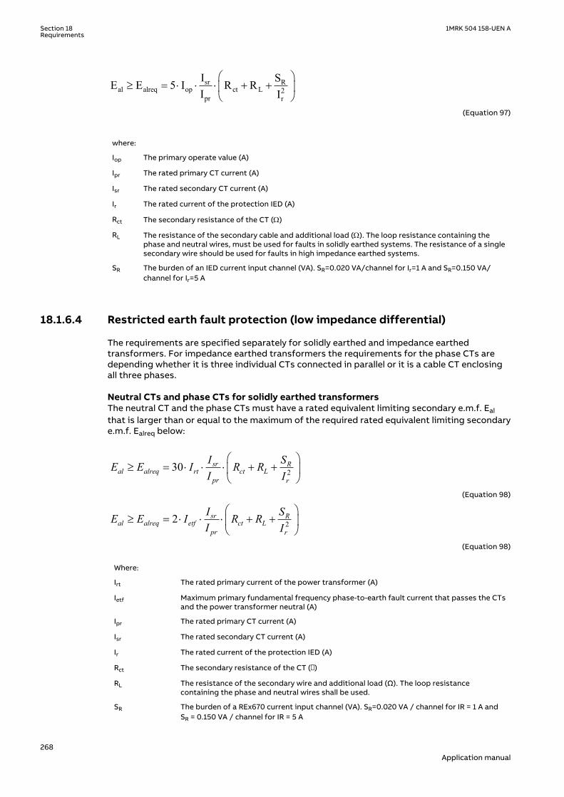
sr Ral alreq op ct L 2
pr r
I SE E 5 I R RI I
æ ö³ = × × × + +ç ÷
è øEQUATION1380 V2 EN-US (Equation 97)
where:
Iop The primary operate value (A)
Ipr The rated primary CT current (A)
Isr The rated secondary CT current (A)
Ir The rated current of the protection IED (A)
Rct The secondary resistance of the CT (W)
RL The resistance of the secondary cable and additional load (W). The loop resistance containing thephase and neutral wires, must be used for faults in solidly earthed systems. The resistance of a singlesecondary wire should be used for faults in high impedance earthed systems.
SR The burden of an IED current input channel (VA). SR=0.020 VA/channel for Ir=1 A and SR=0.150 VA/channel for Ir=5 A
18.1.6.4 Restricted earth fault protection (low impedance differential)GUID-AFAFC587-6986-4FF4-A5E1-6F5DC0A72A6B v1
The requirements are specified separately for solidly earthed and impedance earthedtransformers. For impedance earthed transformers the requirements for the phase CTs aredepending whether it is three individual CTs connected in parallel or it is a cable CT enclosingall three phases.
Neutral CTs and phase CTs for solidly earthed transformersGUID-7CD7512F-F7BD-479E-B7B6-0D5DF22869D4 v2
The neutral CT and the phase CTs must have a rated equivalent limiting secondary e.m.f. Ealthat is larger than or equal to the maximum of the required rated equivalent limiting secondarye.m.f. Ealreq below:
230 sr Ral alreq rt ct L
pr r
I SE E I R RI I
æ ö³ = × × × + +ç ÷
è øEQUATION2237 V2 EN-US (Equation 98)
22 sr Ral alreq etf ct L
pr r
I SE E I R RI I
æ ö³ = × × × + +ç ÷
è øEQUATION2238 V2 EN-US (Equation 98)
Where:
Irt The rated primary current of the power transformer (A)
Ietf Maximum primary fundamental frequency phase-to-earth fault current that passes the CTsand the power transformer neutral (A)
Ipr The rated primary CT current (A)
Isr The rated secondary CT current (A)
Ir The rated current of the protection IED (A)
Rct The secondary resistance of the CT ()
RL The resistance of the secondary wire and additional load (Ω). The loop resistancecontaining the phase and neutral wires shall be used.
SR The burden of a REx670 current input channel (VA). SR=0.020 VA / channel for IR = 1 A andSR = 0.150 VA / channel for IR = 5 A
Section 18 1MRK 504 158-UEN ARequirements
268Application manual

In substations with breaker-and-a-half or double-busbar double-breaker arrangement, thefault current may pass two main phase CTs for the restricted earth fault protection withoutpassing the power transformer. In such cases and if both main CTs have equal ratios andmagnetization characteristics the CTs must satisfy Requirement (12) and the Requirement (14)below:
2sr R
al alreq ef ct Lpr r
I SE E I R RI I
æ ö³ = × × + +ç ÷
è øEQUATION2239 V2 EN-US (Equation 99)
Where:
Ief Maximum primary fundamental frequency phase-to-earth fault current that passes two mainCTs without passing the power transformer neutral (A)
Neutral CTs and phase CTs for impedance earthed transformersGUID-FA79C943-A19B-47E2-BFC5-C9D01347302A v2
The neutral CT and phase CTs must have a rated equivalent limiting secondary e.m.f. Eal that islarger than or equal to the required rated equivalent limiting secondary e.m.f. Ealreq below:
23 sr Ral alreq etf ct L
pr r
I SE E I R RI I
æ ö³ = × × × + +ç ÷
è øEQUATION2240 V2 EN-US (Equation 100)
Where:
Ietf Maximum primary fundamental frequency phase-to-earth fault current that passes theCTs and the power transformer neutral (A)
Ipr The rated primary CT current (A)
Isr The rated secondary CT current (A)
Ir The rated current of the protection IED (A)
Rct The secondary resistance of the CT (Ω)
RL The resistance of the secondary wire and additional load (Ω). The loop resistancecontaining the phase and neutral wires shall be used.
SR The burden of a REx670 current input channel (VA). SR = 0.020 VA / channel for Ir = 1 Aand SR = 0.150 VA / channel for Ir = 5 A
In case of three individual CTs connected in parallel (Holmgren connection) on the phase sidethe following additional requirements must also be fulfilled.
The three individual phase CTs must have a rated equivalent limiting secondary e.m.f. Eal thatis larger than or equal to the maximum of the required rated equivalent limiting secondarye.m.f. Ealreq below:
22 sr Ral alreq tf ct Lsw
pr r
I SE E I R RI I
æ ö³ = × × × + +ç ÷
è øEQUATION2241 V2 EN-US (Equation 101)
1MRK 504 158-UEN A Section 18Requirements
269Application manual
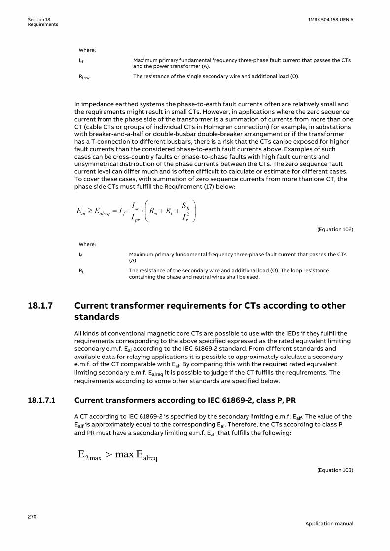
Where:
Itf Maximum primary fundamental frequency three-phase fault current that passes the CTsand the power transformer (A).
RLsw The resistance of the single secondary wire and additional load (Ω).
In impedance earthed systems the phase-to-earth fault currents often are relatively small andthe requirements might result in small CTs. However, in applications where the zero sequencecurrent from the phase side of the transformer is a summation of currents from more than oneCT (cable CTs or groups of individual CTs in Holmgren connection) for example, in substationswith breaker-and-a-half or double-busbar double-breaker arrangement or if the transformerhas a T-connection to different busbars, there is a risk that the CTs can be exposed for higherfault currents than the considered phase-to-earth fault currents above. Examples of suchcases can be cross-country faults or phase-to-phase faults with high fault currents andunsymmetrical distribution of the phase currents between the CTs. The zero sequence faultcurrent level can differ much and is often difficult to calculate or estimate for different cases.To cover these cases, with summation of zero sequence currents from more than one CT, thephase side CTs must fulfill the Requirement (17) below:
2sr R
al alreq f ct Lpr r
I SE E I R RI I
æ ö³ = × × + +ç ÷
è øEQUATION2242 V2 EN-US (Equation 102)
Where:
If Maximum primary fundamental frequency three-phase fault current that passes the CTs(A)
RL The resistance of the secondary wire and additional load (Ω). The loop resistancecontaining the phase and neutral wires shall be used.
18.1.7 Current transformer requirements for CTs according to otherstandards
SEMOD53771-1 v1
M11623-4 v3
All kinds of conventional magnetic core CTs are possible to use with the IEDs if they fulfill therequirements corresponding to the above specified expressed as the rated equivalent limitingsecondary e.m.f. Eal according to the IEC 61869-2 standard. From different standards andavailable data for relaying applications it is possible to approximately calculate a secondarye.m.f. of the CT comparable with Eal. By comparing this with the required rated equivalentlimiting secondary e.m.f. Ealreq it is possible to judge if the CT fulfills the requirements. Therequirements according to some other standards are specified below.
18.1.7.1 Current transformers according to IEC 61869-2, class P, PRM11623-6 v3
A CT according to IEC 61869-2 is specified by the secondary limiting e.m.f. Ealf. The value of theEalf is approximately equal to the corresponding Eal. Therefore, the CTs according to class Pand PR must have a secondary limiting e.m.f. Ealf that fulfills the following:
2max alreqE max E>EQUATION1383 V3 EN-US (Equation 103)
Section 18 1MRK 504 158-UEN ARequirements
270Application manual
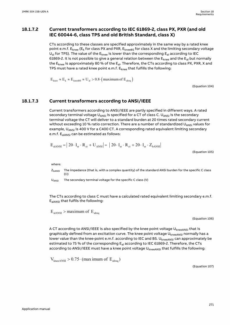
18.1.7.2 Current transformers according to IEC 61869-2, class PX, PXR (and oldIEC 60044-6, class TPS and old British Standard, class X)
M11623-14 v5
CTs according to these classes are specified approximately in the same way by a rated kneepoint e.m.f. Eknee (Ek for class PX and PXR, EkneeBS for class X and the limiting secondary voltageUal for TPS). The value of the Eknee is lower than the corresponding Eal according to IEC61869-2. It is not possible to give a general relation between the Eknee and the Eal but normallythe Eknee is approximately 80 % of the Eal. Therefore, the CTs according to class PX, PXR, X andTPS must have a rated knee point e.m.f. Eknee that fulfills the following:
( )knee k kneeBS al alreqE E E U 0.8 maximum of E» » » > ×
EQUATION2100 V2 EN-US (Equation 104)
18.1.7.3 Current transformers according to ANSI/IEEEM11623-22 v6
Current transformers according to ANSI/IEEE are partly specified in different ways. A ratedsecondary terminal voltage UANSI is specified for a CT of class C. UANSI is the secondaryterminal voltage the CT will deliver to a standard burden at 20 times rated secondary currentwithout exceeding 10 % ratio correction. There are a number of standardized UANSI values forexample, UANSI is 400 V for a C400 CT. A corresponding rated equivalent limiting secondarye.m.f. EalANSI can be estimated as follows:
alANSI sr ct ANSI sr ct sr bANSIE 20 I R U 20 I R 20 I Z= × × + = × × + × ×
EQUATION971 V2 EN-US (Equation 105)
where:
ZbANSI The impedance (that is, with a complex quantity) of the standard ANSI burden for the specific C class(W)
UANSI The secondary terminal voltage for the specific C class (V)
The CTs according to class C must have a calculated rated equivalent limiting secondary e.m.f.EalANSI that fulfils the following:
alANSI alreqE maximum of E>
EQUATION1384 V2 EN-US (Equation 106)
A CT according to ANSI/IEEE is also specified by the knee point voltage UkneeANSI that isgraphically defined from an excitation curve. The knee point voltage UkneeANSI normally has alower value than the knee-point e.m.f. according to IEC and BS. UkneeANSI can approximately beestimated to 75 % of the corresponding Eal according to IEC 61869-2. Therefore, the CTsaccording to ANSI/IEEE must have a knee point voltage UkneeANSI that fulfills the following:
kneeANSI alreqV 0.75 (max imum of E )> ×EQUATION2101 V2 EN-US (Equation 107)
1MRK 504 158-UEN A Section 18Requirements
271Application manual

18.2 Voltage transformer requirementsM11608-3 v5
The performance of a protection function will depend on the quality of the measured inputsignal. Transients caused by capacitive voltage transformers (CVTs) can affect someprotection functions.
Magnetic or capacitive voltage transformers can be used.
The capacitive voltage transformers (CVTs) should fulfill the requirements according to the IEC61869-5 standard regarding ferro-resonance and transients. The ferro-resonancerequirements of the CVTs are specified in chapter 6.502 of the standard.
The transient responses for three different standard transient response classes, T1, T2 and T3are specified in chapter 6.503 of the standard. CVTs according to all classes can be used.
The protection IED has effective filters for these transients, which gives secure and correctoperation with CVTs.
18.3 SNTP server requirementsGUID-588FCD12-C494-445E-8488-8287B34EFD9A v4
The SNTP server to be used is connected to the local network, that is not more than 4-5switches or routers away from the IED. The SNTP server is dedicated for its task, or at leastequipped with a real-time operating system, that is not a PC with SNTP server software. TheSNTP server should be stable, that is, either synchronized from a stable source like GPS, orlocal without synchronization. Using a local SNTP server without synchronization as primary orsecondary server in a redundant configuration is not recommended.
Section 18 1MRK 504 158-UEN ARequirements
272Application manual

Section 19 GlossaryM14893-1 v15
AC Alternating current
ACC Actual channel
ACT Application configuration tool within PCM600
A/D converter Analog-to-digital converter
ADBS Amplitude deadband supervision
ADM Analog digital conversion module, with time synchronization
AI Analog input
ANSI American National Standards Institute
AR Autoreclosing
ASCT Auxiliary summation current transformer
ASD Adaptive signal detection
ASDU Application service data unit
AWG American Wire Gauge standard
BBP Busbar protection
BFOC/2,5 Bayonet fiber optic connector
BFP Breaker failure protection
BI Binary input
BIM Binary input module
BOM Binary output module
BOS Binary outputs status
BR External bistable relay
BS British Standards
BSR Binary signal transfer function, receiver blocks
BST Binary signal transfer function, transmit blocks
C37.94 IEEE/ANSI protocol used when sending binary signals between IEDs
CAN Controller Area Network. ISO standard (ISO 11898) for serialcommunication
CB Circuit breaker
CBM Combined backplane module
CCITT Consultative Committee for International Telegraph and Telephony. AUnited Nations-sponsored standards body within the InternationalTelecommunications Union.
CCM CAN carrier module
CCVT Capacitive Coupled Voltage Transformer
Class C Protection Current Transformer class as per IEEE/ ANSI
CMPPS Combined megapulses per second
CMT Communication Management tool in PCM600
1MRK 504 158-UEN A Section 19Glossary
273Application manual

CO cycle Close-open cycle
Codirectional Way of transmitting G.703 over a balanced line. Involves two twistedpairs making it possible to transmit information in both directions
COM Command
COMTRADE Standard Common Format for Transient Data Exchange format forDisturbance recorder according to IEEE/ANSI C37.111, 1999 / IEC60255-24
Contra-directional Way of transmitting G.703 over a balanced line. Involves four twistedpairs, two of which are used for transmitting data in both directionsand two for transmitting clock signals
COT Cause of transmission
CPU Central processing unit
CR Carrier receive
CRC Cyclic redundancy check
CROB Control relay output block
CS Carrier send
CT Current transformer
CU Communication unit
CVT or CCVT Capacitive voltage transformer
DAR Delayed autoreclosing
DARPA Defense Advanced Research Projects Agency (The US developer of theTCP/IP protocol etc.)
DBDL Dead bus dead line
DBLL Dead bus live line
DC Direct current
DFC Data flow control
DFT Discrete Fourier transform
DHCP Dynamic Host Configuration Protocol
DIP-switch Small switch mounted on a printed circuit board
DI Digital input
DLLB Dead line live bus
DNP Distributed Network Protocol as per IEEE Std 1815-2012
DR Disturbance recorder
DRAM Dynamic random access memory
DRH Disturbance report handler
DSP Digital signal processor
DTT Direct transfer trip scheme
EHV network Extra high voltage network
EIA Electronic Industries Association
EMC Electromagnetic compatibility
EMF Electromotive force
EMI Electromagnetic interference
Section 19 1MRK 504 158-UEN AGlossary
274Application manual

EnFP End fault protection
EPA Enhanced performance architecture
ESD Electrostatic discharge
F-SMA Type of optical fiber connector
FAN Fault number
FCB Flow control bit; Frame count bit
FOX 20 Modular 20 channel telecommunication system for speech, data andprotection signals
FOX 512/515 Access multiplexer
FOX 6Plus Compact time-division multiplexer for the transmission of up to sevenduplex channels of digital data over optical fibers
FTP File Transfer Protocol
FUN Function type
G.703 Electrical and functional description for digital lines used by localtelephone companies. Can be transported over balanced andunbalanced lines
GCM Communication interface module with carrier of GPS receiver module
GDE Graphical display editor within PCM600
GI General interrogation command
GIS Gas-insulated switchgear
GOOSE Generic object-oriented substation event
GPS Global positioning system
GSAL Generic security application
GSE Generic substation event
HDLC protocol High-level data link control, protocol based on the HDLC standard
HFBR connector type Plastic fiber connector
HMI Human-machine interface
HSAR High speed autoreclosing
HV High-voltage
HVDC High-voltage direct current
IDBS Integrating deadband supervision
IEC International Electrical Committee
IEC 60044-6 IEC Standard, Instrument transformers – Part 6: Requirements forprotective current transformers for transient performance
IEC 60870-5-103 Communication standard for protection equipment. A serial master/slave protocol for point-to-point communication
IEC 61850 Substation automation communication standard
IEC 61850–8–1 Communication protocol standard
IEEE Institute of Electrical and Electronics Engineers
IEEE 802.12 A network technology standard that provides 100 Mbits/s on twisted-pair or optical fiber cable
IEEE P1386.1 PCI Mezzanine Card (PMC) standard for local bus modules. Referencesthe CMC (IEEE P1386, also known as Common Mezzanine Card)
1MRK 504 158-UEN A Section 19Glossary
275Application manual
standard for the mechanics and the PCI specifications from the PCI SIG(Special Interest Group) for the electrical EMF (Electromotive force).
IEEE 1686 Standard for Substation Intelligent Electronic Devices (IEDs) CyberSecurity Capabilities
IED Intelligent electronic device
I-GIS Intelligent gas-insulated switchgear
IOM Binary input/output module
Instance When several occurrences of the same function are available in the IED,they are referred to as instances of that function. One instance of afunction is identical to another of the same kind but has a differentnumber in the IED user interfaces. The word "instance" is sometimesdefined as an item of information that is representative of a type. Inthe same way an instance of a function in the IED is representative of atype of function.
IP 1. Internet protocol. The network layer for the TCP/IP protocol suitewidely used on Ethernet networks. IP is a connectionless, best-effortpacket-switching protocol. It provides packet routing, fragmentationand reassembly through the data link layer.2. Ingression protection, according to IEC 60529
IP 20 Ingression protection, according to IEC 60529, level 20
IP 40 Ingression protection, according to IEC 60529, level 40
IP 54 Ingression protection, according to IEC 60529, level 54
IRF Internal failure signal
IRIG-B: InterRange Instrumentation Group Time code format B, standard 200
ITU International Telecommunications Union
LAN Local area network
LIB 520 High-voltage software module
LCD Liquid crystal display
LDCM Line differential communication module
LDD Local detection device
LED Light-emitting diode
LNT LON network tool
LON Local operating network
MCB Miniature circuit breaker
MCM Mezzanine carrier module
MPM Main processing module
MVAL Value of measurement
MVB Multifunction vehicle bus. Standardized serial bus originally developedfor use in trains.
NCC National Control Centre
NOF Number of grid faults
NUM Numerical module
OCO cycle Open-close-open cycle
OCP Overcurrent protection
OEM Optical Ethernet module
Section 19 1MRK 504 158-UEN AGlossary
276Application manual

OLTC On-load tap changer
OTEV Disturbance data recording initiated by other event than start/pick-up
OV Overvoltage
Overreach A term used to describe how the relay behaves during a fault condition.For example, a distance relay is overreaching when the impedancepresented to it is smaller than the apparent impedance to the faultapplied to the balance point, that is, the set reach. The relay “sees” thefault but perhaps it should not have seen it.
PCI Peripheral component interconnect, a local data bus
PCM Pulse code modulation
PCM600 Protection and control IED manager
PC-MIP Mezzanine card standard
PMC PCI Mezzanine card
POR Permissive overreach
POTT Permissive overreach transfer trip
Process bus Bus or LAN used at the process level, that is, in near proximity to themeasured and/or controlled components
PSM Power supply module
PST Parameter setting tool within PCM600
PT ratio Potential transformer or voltage transformer ratio
PUTT Permissive underreach transfer trip
RASC Synchrocheck relay, COMBIFLEX
RCA Relay characteristic angle
RISC Reduced instruction set computer
RMS value Root mean square value
RS422 A balanced serial interface for the transmission of digital data in point-to-point connections
RS485 Serial link according to EIA standard RS485
RTC Real-time clock
RTU Remote terminal unit
SA Substation Automation
SBO Select-before-operate
SC Switch or push button to close
SCL Short circuit location
SCS Station control system
SCADA Supervision, control and data acquisition
SCT System configuration tool according to standard IEC 61850
SDU Service data unit
SLM Serial communication module.
SMA connector Subminiature version A, A threaded connector with constantimpedance.
SMT Signal matrix tool within PCM600
SMS Station monitoring system
1MRK 504 158-UEN A Section 19Glossary
277Application manual

SNTP Simple network time protocol – is used to synchronize computer clockson local area networks. This reduces the requirement to have accuratehardware clocks in every embedded system in a network. Eachembedded node can instead synchronize with a remote clock,providing the required accuracy.
SOF Status of fault
SPA Strömberg Protection Acquisition (SPA), a serial master/slave protocolfor point-to-point and ring communication.
SRY Switch for CB ready condition
ST Switch or push button to trip
Starpoint Neutral point of transformer or generator
SVC Static VAr compensation
TC Trip coil
TCS Trip circuit supervision
TCP Transmission control protocol. The most common transport layerprotocol used on Ethernet and the Internet.
TCP/IP Transmission control protocol over Internet Protocol. The de factostandard Ethernet protocols incorporated into 4.2BSD Unix. TCP/IPwas developed by DARPA for Internet working and encompasses bothnetwork layer and transport layer protocols. While TCP and IP specifytwo protocols at specific protocol layers, TCP/IP is often used to referto the entire US Department of Defense protocol suite based uponthese, including Telnet, FTP, UDP and RDP.
TEF Time delayed earth-fault protection function
TLS Transport Layer Security
TM Transmit (disturbance data)
TNC connector Threaded Neill-Concelman, a threaded constant impedance version of aBNC connector
TP Trip (recorded fault)
TPZ, TPY, TPX, TPS Current transformer class according to IEC
TRM Transformer Module. This module transforms currents and voltagestaken from the process into levels suitable for further signalprocessing.
TYP Type identification
UMT User management tool
Underreach A term used to describe how the relay behaves during a fault condition.For example, a distance relay is underreaching when the impedancepresented to it is greater than the apparent impedance to the faultapplied to the balance point, that is, the set reach. The relay does not“see” the fault but perhaps it should have seen it. See also Overreach.
UTC Coordinated Universal Time. A coordinated time scale, maintained bythe Bureau International des Poids et Mesures (BIPM), which forms thebasis of a coordinated dissemination of standard frequencies and timesignals. UTC is derived from International Atomic Time (TAI) by theaddition of a whole number of "leap seconds" to synchronize it withUniversal Time 1 (UT1), thus allowing for the eccentricity of the Earth'sorbit, the rotational axis tilt (23.5 degrees), but still showing the Earth'sirregular rotation, on which UT1 is based. The Coordinated UniversalTime is expressed using a 24-hour clock, and uses the Gregoriancalendar. It is used for aeroplane and ship navigation, where it is also
Section 19 1MRK 504 158-UEN AGlossary
278Application manual

sometimes known by the military name, "Zulu time." "Zulu" in thephonetic alphabet stands for "Z", which stands for longitude zero.
UV Undervoltage
WEI Weak end infeed logic
VT Voltage transformer
3IO Three times zero-sequence current.Often referred to as the residual orthe earth-fault current
3UO Three times the zero sequence voltage. Often referred to as theresidual voltage or the neutral point voltage
1MRK 504 158-UEN A Section 19Glossary
279Application manual

280

281

ABB ABSubstation Automation ProductsSE-721 59 Västerås, SwedenPhone +46 (0) 21 32 50 00
www.abb.com/protection-control
© Copyright 2016 ABB.All rights reserved.
Scan this QR code to visit our website
1MR
K 5
04
158
-UE
N