
Transfer-Length Measurements on Concrete Railroad Ties Fabricated with 15 Different Prestressing...
19
Bodapati, Peterman, Zhao, Beck, Wu, Holste, Arnold, Benteman, Schweiger 2013 PCI/NBC TRANSFER-LENGTH MEASUREMENTS ON CONCRETE RAILROAD TIES FABRICATED WITH 15 DIFFERENT PRESTRESSING REINFORCEMENTS Naga Narendra B. Bodapati, CE Department, Kansas State University, Manhattan, KS Robert J. Peterman, PhD, PE, CE Department, Kansas State University, Manhattan, KS Weixin Zhao, PhD, MNE Department, Kansas State University, Manhattan, KS B. Terry Beck, PhD, MNE Department, Kansas State University, Manhattan, KS Chih-Hang John Wu, PhD, IMSE Department, Kansas State University, Manhattan, KS Joseph R. Holste, M. S., CE Department, Kansas State University, Manhattan, KS Matthew L. Arnold, M. S., CE Department, Kansas State University, Manhattan, KS Ryan Benteman, CE Department, Kansas State University, Manhattan, KS Robert Schweiger, CE Department, Kansas State University, Manhattan, KS ABSTRACT An in-depth evaluation of the bond of different prestressing reinforcements that are used in the manufacturing of pre-tensioned concrete railroad ties was conducted as part of a research project funded by the Federal Rail Administration (FRA). Fifteen (15) different prestressing reinforcements that are used to fabricate pre-tensioned concrete railroad ties worldwide were obtained and stored in a low-humidity environment. These reinforcements were then used to manufacture pre-tensioned concrete prisms in the laboratory, and railroad ties at a PCI member plant. All of the prisms and ties were fabricated using the same concrete mix design, so the primary variable in this portion of the study was the prestressing reinforcement type. These reinforcements consisted of smooth and indented prestressing wires, a smooth 3-wire strand, plus smooth and indented 7-wire strands. Fifty (50) different transfer-lengths were measured with each reinforcement, for a combined total of 750 transfer lengths. As such, this was the most transfer-lengths ever determined for concrete railroad ties in production. The transfer-lengths were determined by measuring concrete surface strains. This was done using both the traditional Whittemore gage methodology as well as by using an automated laser-speckle imaging device. This paper summarizes the findings from 120 transfer length measurements in the laboratory, plus 750 transfer length measurements at a PCI member plant using the same prestressing reinforcements. Keywords: Prestress, Bond, Transfer Length, Railroad Ties, Indented Wire, Strand
Transcript of Transfer-Length Measurements on Concrete Railroad Ties Fabricated with 15 Different Prestressing...
Bodapati, Peterman, Zhao, Beck, Wu, Holste, Arnold, Benteman, Schweiger 2013 PCI/NBC
0
TRANSFER-LENGTH MEASUREMENTS ON CONCRETE RAILROAD TIES
FABRICATED WITH 15 DIFFERENT PRESTRESSING REINFORCEMENTS
Naga Narendra B. Bodapati, CE Department, Kansas State University, Manhattan, KS
Robert J. Peterman, PhD, PE, CE Department, Kansas State University, Manhattan, KS
Weixin Zhao, PhD, MNE Department, Kansas State University, Manhattan, KS
B. Terry Beck, PhD, MNE Department, Kansas State University, Manhattan, KS
Chih-Hang John Wu, PhD, IMSE Department, Kansas State University, Manhattan, KS
Joseph R. Holste, M. S., CE Department, Kansas State University, Manhattan, KS
Matthew L. Arnold, M. S., CE Department, Kansas State University, Manhattan, KS
Ryan Benteman, CE Department, Kansas State University, Manhattan, KS
Robert Schweiger, CE Department, Kansas State University, Manhattan, KS
ABSTRACT
An in-depth evaluation of the bond of different prestressing reinforcements that are used in
the manufacturing of pre-tensioned concrete railroad ties was conducted as part of a
research project funded by the Federal Rail Administration (FRA). Fifteen (15) different
prestressing reinforcements that are used to fabricate pre-tensioned concrete railroad ties
worldwide were obtained and stored in a low-humidity environment. These reinforcements
were then used to manufacture pre-tensioned concrete prisms in the laboratory, and railroad
ties at a PCI member plant. All of the prisms and ties were fabricated using the same
concrete mix design, so the primary variable in this portion of the study was the prestressing
reinforcement type. These reinforcements consisted of smooth and indented prestressing
wires, a smooth 3-wire strand, plus smooth and indented 7-wire strands. Fifty (50) different
transfer-lengths were measured with each reinforcement, for a combined total of 750
transfer lengths. As such, this was the most transfer-lengths ever determined for concrete
railroad ties in production. The transfer-lengths were determined by measuring concrete
surface strains. This was done using both the traditional Whittemore gage methodology as
well as by using an automated laser-speckle imaging device. This paper summarizes the
findings from 120 transfer length measurements in the laboratory, plus 750 transfer length
measurements at a PCI member plant using the same prestressing reinforcements.
Keywords: Prestress, Bond, Transfer Length, Railroad Ties, Indented Wire, Strand
Bodapati, Peterman, Zhao, Beck, Wu, Holste, Arnold, Benteman, Schweiger 2013 PCI/NBC
1
INTRODUCTION
Prestressed concrete railroad ties are becoming increasingly popular in the United
States, and are an essential component for higher speed railway lines. Hanna (1979) 7 stated
that an increased service life and more track stability can be achieved through the usage of
concrete crossties over wooden ties. In order for these prestressed concrete ties to function
adequately over their expected service life, the prestressing force must be fully introduced
into the railroad tie at a location before the rail load is applied. The length required to transfer
the prestress force into the concrete member is referred to as the “Transfer Length” 2
.
Since the prestressed concrete ties are relatively short, and have extremely large
impact loads applied near the member ends, most of the prestressed concrete railroad tie
producers utilize indented prestressing wires or indented prestressing strands rather than
traditional 7-wire smooth prestressing strands. It is generally understood that these
indentations serve to improve the bond between the steel and the concrete and therefore
reduce the transfer length 8, 11
.
However, because the broad application of these indented reinforcing steels has been
so limited, current design codes in the United States do not yet address indented prestressing
wire or indented strands in terms of recommended design assumptions for transfer and
development length. Moreover, there is currently not even a standardized indentation pattern
(shape, size, depth of indent, etc.) that is utilized by all wire manufacturers. Thus, the
corresponding bond behavior of these different reinforcements, in terms of average transfer
lengths and typical variations, has been essentially unknown.
Thus, there existed the need to determine and quantify the prestressing steel variables
that affect the transfer length in prestressed concrete crossties, so that the proper performance
of the ties can be ensured throughout their entire service life. These variables include the
type of reinforcing (wires vs. strands), the indent geometry, and the surface condition of the
reinforcement.
Current code expressions 1, 2
recommend a transfer length assumption of 60 db for 7-
wire strands, where db is the diameter of the strand. This implies that shorter transfer lengths
will be achieved by decreasing the diameter of a pre-tensioned strand. However, information
about the difference in bond that can be expected from the different prestressing steel types
that are used in the manufacture of concrete railroad ties is essentially absent from the
literature.
Nineteen different reinforcements that are currently used in the production of pre-
tensioned concrete crossties worldwide were obtained and evaluated in the laboratory portion
of this study. These reinforcements included 5.32-mm (0.209-inch) diameter wires (both
indented and smooth), 3/8-inch diameter 7-wire strands (both indented and smooth), 5/16-
inch diameter 3-wire smooth strands, and 3/8”-diameter indented 3-wire strands. Among
Bodapati, Peterman, Zhao, Beck, Wu, Holste, Arnold, Benteman, Schweiger 2013 PCI/NBC
2
these reinforcement types, the 5.32-mm (0.209-inch) diameter wires are the most commonly
used by tie manufacturers in the United States.
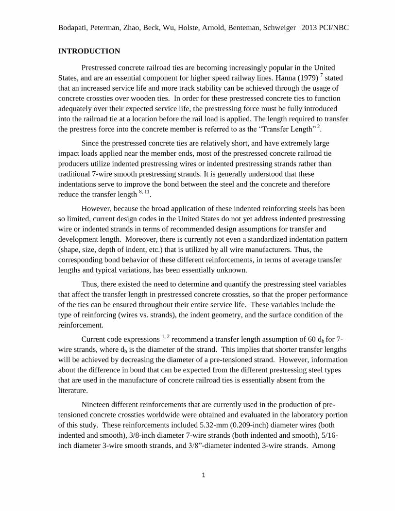
Fifteen of these nineteen reinforcements (Fig. 1.) were then selected and each was used to
manufacture 45 concrete railroad ties, in addition to the bond testing that was conducted in
the laboratory. This paper presents a summary of the transfer length investigation that was
conducted to determine the bond performance of these 15 different reinforcements.
Figure 1 (a): Twelve different 5.32-mm (0.209-inch)-diameter prestressing wires
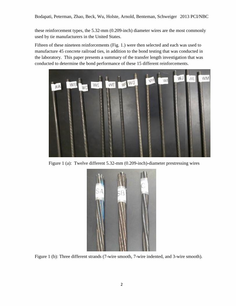
Figure 1 (b): Three different strands (7-wire smooth, 7-wire indented, and 3-wire smooth).
Bodapati, Peterman, Zhao, Beck, Wu, Holste, Arnold, Benteman, Schweiger 2013 PCI/NBC
3
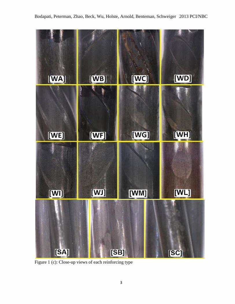
Figure 1 (c): Close-up views of each reinforcing type

Bodapati, Peterman, Zhao, Beck, Wu, Holste, Arnold, Benteman, Schweiger 2013 PCI/NBC
4
This work was accomplished in two phases. During the first phase, concrete prisms
were cast in a controlled environment at Kansas State University (KSU) laboratories. These
prisms were designed to have a prestressing steel spacing and overall concrete-to-steel ratio
that is representative of pre-tensioned concrete railroad ties. During the second Phase, a team
of KSU researchers traveled to a PCI member plant to determine transfer lengths on precast
concrete railroad ties that were fabricated using the different reinforcements. A test matrix
for the present work is shown in Table 1.
The work presented in this paper is part of a larger project funded by the Federal Rail
Administration (FRA) that is aimed at generating a quantitative understanding of the
interaction between the concrete mixes and prestressing steel reinforcements that are used in
the fabrication of prestressed concrete crossties. The project goal is: “to develop a
comprehensive understanding of the variables affecting the transfer length in prestressed
concrete crossties, and to apply this knowledge to ensure the proper design and fabrication of
these members for high speed railway applications.”
Table1. Test matrix for the laboratory and plant phases
Laboratory Phase Plant Phase
Release strength 4500 ± 220 psi ≥ 5000 psi
Number of transfer lengths
measured for each reinforcement 6 Approximately 50
Slump 6 ± 1 inches 8 ± 2 inches
Laboratory Phase-Experimental Set-Up
During the laboratory phase, three 69-inch-long prisms were fabricated with each of
the 15 different reinforcements, for a total of 45 prisms. These provided a total of 90 transfer
length measurements, one per end. The three prisms with each reinforcement type were cast,
end-to-end, on a 20-ft long prestressing bed at the Kansas State University (KSU) laboratory.
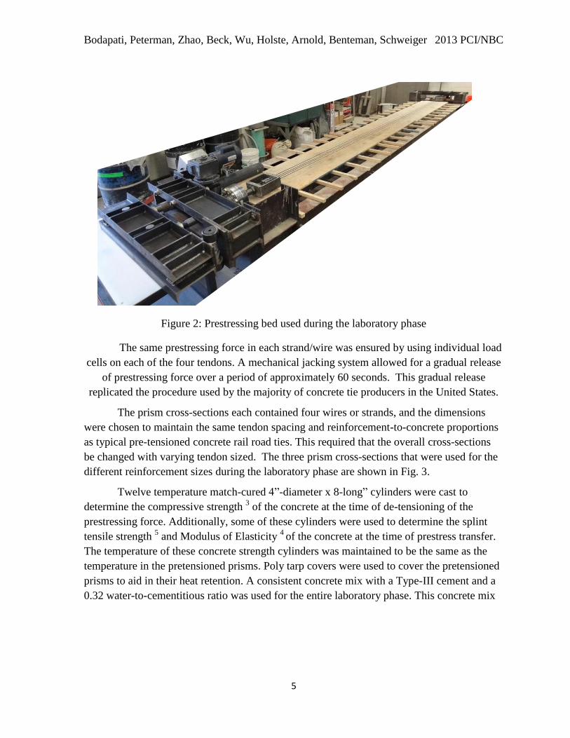
The prestressing bed used during the laboratory phase is shown in Fig. 2.
Bodapati, Peterman, Zhao, Beck, Wu, Holste, Arnold, Benteman, Schweiger 2013 PCI/NBC
5
Figure 2: Prestressing bed used during the laboratory phase
The same prestressing force in each strand/wire was ensured by using individual load
cells on each of the four tendons. A mechanical jacking system allowed for a gradual release
of prestressing force over a period of approximately 60 seconds. This gradual release
replicated the procedure used by the majority of concrete tie producers in the United States.
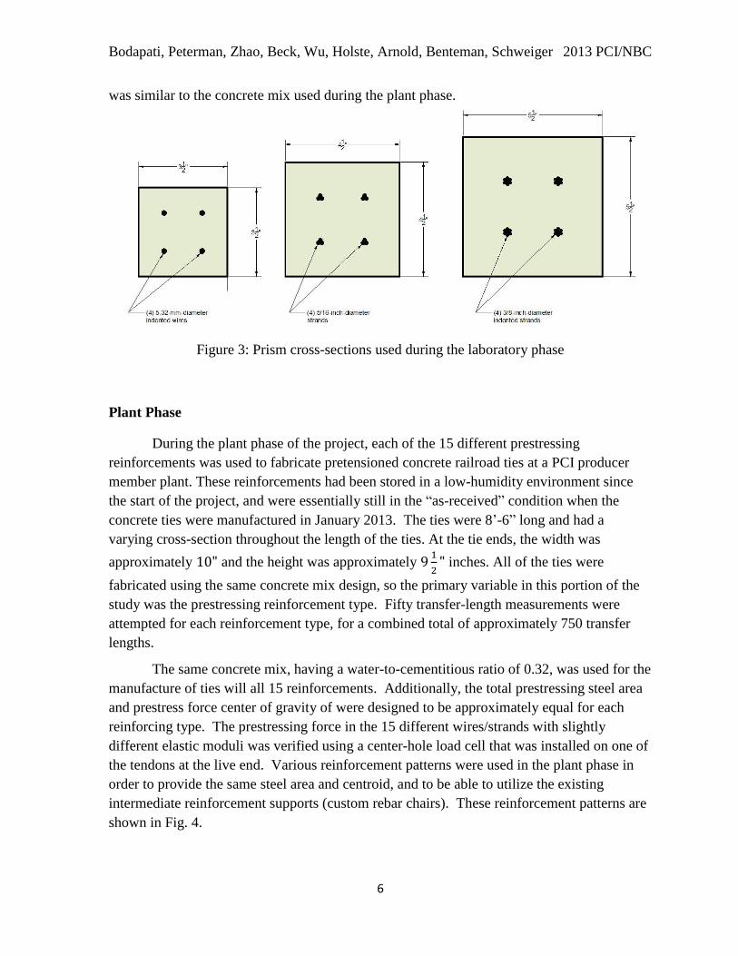
The prism cross-sections each contained four wires or strands, and the dimensions
were chosen to maintain the same tendon spacing and reinforcement-to-concrete proportions
as typical pre-tensioned concrete rail road ties. This required that the overall cross-sections
be changed with varying tendon sized. The three prism cross-sections that were used for the
different reinforcement sizes during the laboratory phase are shown in Fig. 3.
Twelve temperature match-cured 4”-diameter x 8-long” cylinders were cast to
determine the compressive strength 3 of the concrete at the time of de-tensioning of the
prestressing force. Additionally, some of these cylinders were used to determine the splint
tensile strength 5 and Modulus of Elasticity
4 of the concrete at the time of prestress transfer.
The temperature of these concrete strength cylinders was maintained to be the same as the
temperature in the pretensioned prisms. Poly tarp covers were used to cover the pretensioned
prisms to aid in their heat retention. A consistent concrete mix with a Type-III cement and a
0.32 water-to-cementitious ratio was used for the entire laboratory phase. This concrete mix
Bodapati, Peterman, Zhao, Beck, Wu, Holste, Arnold, Benteman, Schweiger 2013 PCI/NBC
6
was similar to the concrete mix used during the plant phase.
Figure 3: Prism cross-sections used during the laboratory phase
Plant Phase
During the plant phase of the project, each of the 15 different prestressing
reinforcements was used to fabricate pretensioned concrete railroad ties at a PCI producer
member plant. These reinforcements had been stored in a low-humidity environment since
the start of the project, and were essentially still in the “as-received” condition when the
concrete ties were manufactured in January 2013. The ties were 8’-6” long and had a
varying cross-section throughout the length of the ties. At the tie ends, the width was
approximately and the height was approximately
inches. All of the ties were
fabricated using the same concrete mix design, so the primary variable in this portion of the
study was the prestressing reinforcement type. Fifty transfer-length measurements were
attempted for each reinforcement type, for a combined total of approximately 750 transfer
lengths.
The same concrete mix, having a water-to-cementitious ratio of 0.32, was used for the
manufacture of ties will all 15 reinforcements. Additionally, the total prestressing steel area
and prestress force center of gravity of were designed to be approximately equal for each
reinforcing type. The prestressing force in the 15 different wires/strands with slightly
different elastic moduli was verified using a center-hole load cell that was installed on one of
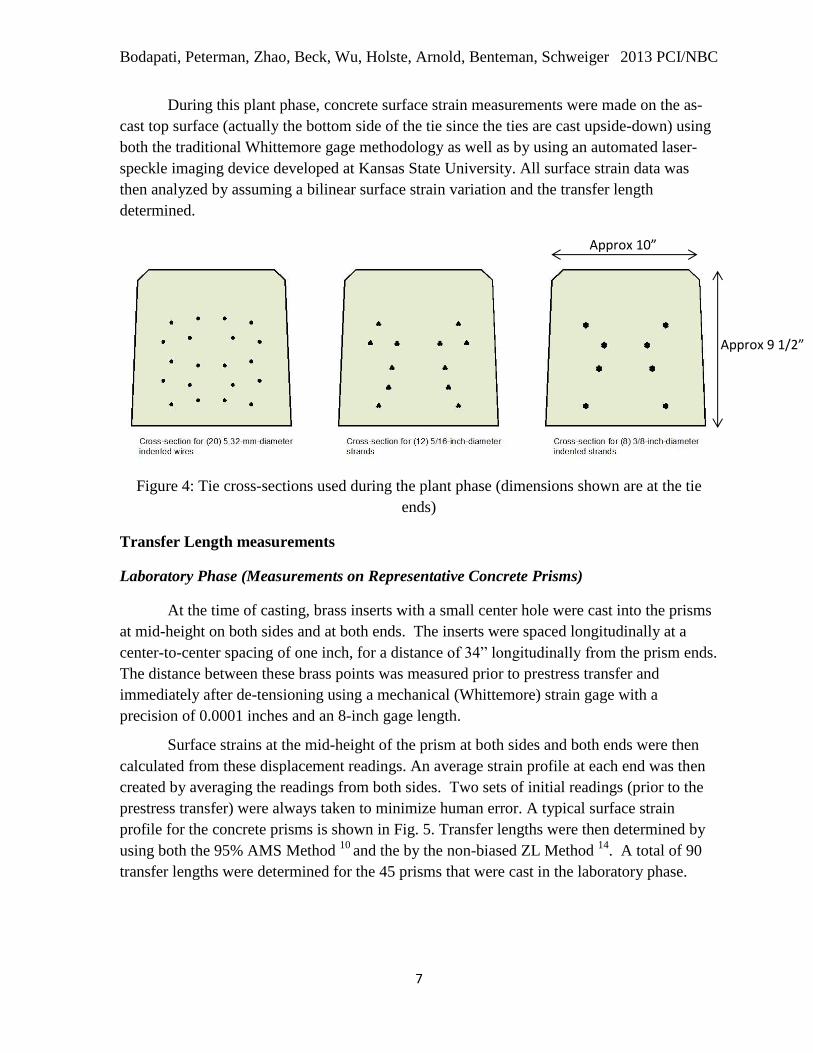
the tendons at the live end. Various reinforcement patterns were used in the plant phase in
order to provide the same steel area and centroid, and to be able to utilize the existing
intermediate reinforcement supports (custom rebar chairs). These reinforcement patterns are
shown in Fig. 4.
Bodapati, Peterman, Zhao, Beck, Wu, Holste, Arnold, Benteman, Schweiger 2013 PCI/NBC
7
During this plant phase, concrete surface strain measurements were made on the as-
cast top surface (actually the bottom side of the tie since the ties are cast upside-down) using
both the traditional Whittemore gage methodology as well as by using an automated laser-
speckle imaging device developed at Kansas State University. All surface strain data was
then analyzed by assuming a bilinear surface strain variation and the transfer length
determined.
Figure 4: Tie cross-sections used during the plant phase (dimensions shown are at the tie
ends)
Transfer Length measurements
Laboratory Phase (Measurements on Representative Concrete Prisms)
At the time of casting, brass inserts with a small center hole were cast into the prisms
at mid-height on both sides and at both ends. The inserts were spaced longitudinally at a
center-to-center spacing of one inch, for a distance of 34” longitudinally from the prism ends.
The distance between these brass points was measured prior to prestress transfer and
immediately after de-tensioning using a mechanical (Whittemore) strain gage with a
precision of 0.0001 inches and an 8-inch gage length.
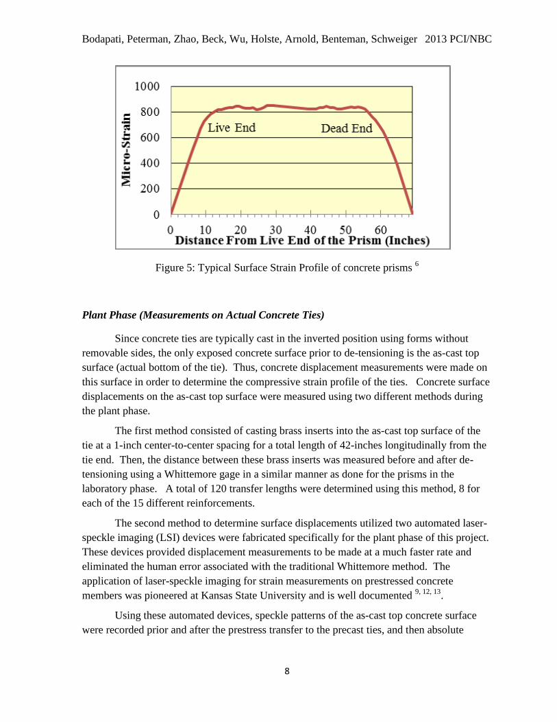
Surface strains at the mid-height of the prism at both sides and both ends were then
calculated from these displacement readings. An average strain profile at each end was then
created by averaging the readings from both sides. Two sets of initial readings (prior to the
prestress transfer) were always taken to minimize human error. A typical surface strain
profile for the concrete prisms is shown in Fig. 5. Transfer lengths were then determined by
using both the 95% AMS Method 10
and the by the non-biased ZL Method 14
. A total of 90
transfer lengths were determined for the 45 prisms that were cast in the laboratory phase.
Approx 10”
Approx 9 1/2”
Bodapati, Peterman, Zhao, Beck, Wu, Holste, Arnold, Benteman, Schweiger 2013 PCI/NBC
8
Figure 5: Typical Surface Strain Profile of concrete prisms 6
Plant Phase (Measurements on Actual Concrete Ties)
Since concrete ties are typically cast in the inverted position using forms without
removable sides, the only exposed concrete surface prior to de-tensioning is the as-cast top
surface (actual bottom of the tie). Thus, concrete displacement measurements were made on
this surface in order to determine the compressive strain profile of the ties. Concrete surface
displacements on the as-cast top surface were measured using two different methods during
the plant phase.
The first method consisted of casting brass inserts into the as-cast top surface of the
tie at a 1-inch center-to-center spacing for a total length of 42-inches longitudinally from the
tie end. Then, the distance between these brass inserts was measured before and after de-
tensioning using a Whittemore gage in a similar manner as done for the prisms in the
laboratory phase. A total of 120 transfer lengths were determined using this method, 8 for
each of the 15 different reinforcements.
The second method to determine surface displacements utilized two automated laser-
speckle imaging (LSI) devices were fabricated specifically for the plant phase of this project.
These devices provided displacement measurements to be made at a much faster rate and
eliminated the human error associated with the traditional Whittemore method. The
application of laser-speckle imaging for strain measurements on prestressed concrete
members was pioneered at Kansas State University and is well documented 9, 12, 13
.
Using these automated devices, speckle patterns of the as-cast top concrete surface
were recorded prior and after the prestress transfer to the precast ties, and then absolute
Bodapati, Peterman, Zhao, Beck, Wu, Holste, Arnold, Benteman, Schweiger 2013 PCI/NBC
9
displacements were determined using advanced digital image processing algorithms. The
images were obtained at a 0.5-inch center-to-center spacing over a total longitudinal distance
of 32 inches from the member ends.
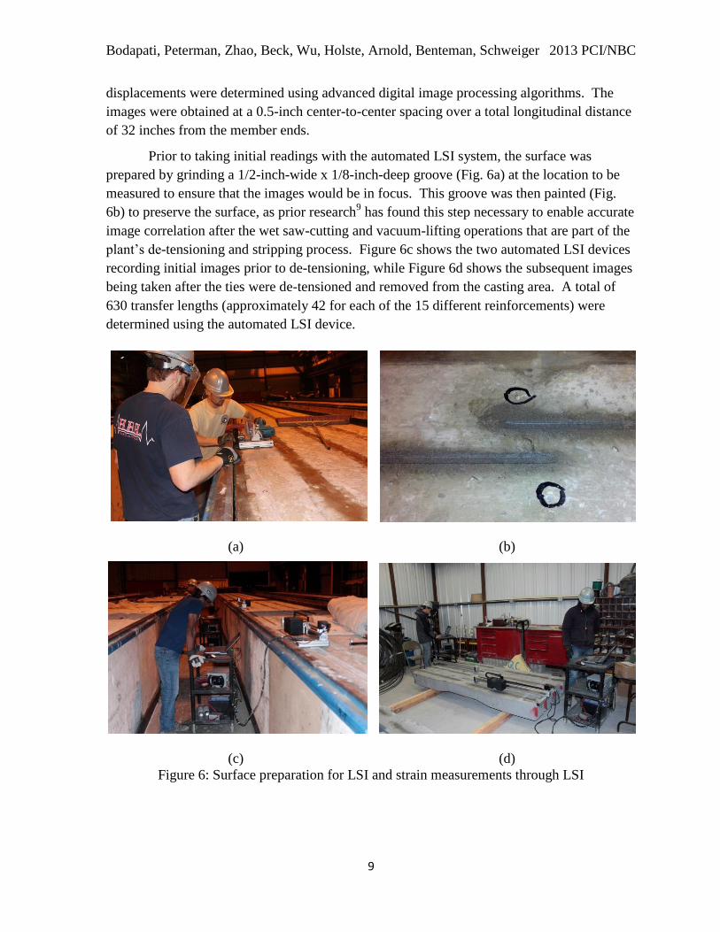
Prior to taking initial readings with the automated LSI system, the surface was
prepared by grinding a 1/2-inch-wide x 1/8-inch-deep groove (Fig. 6a) at the location to be
measured to ensure that the images would be in focus. This groove was then painted (Fig.
6b) to preserve the surface, as prior research9 has found this step necessary to enable accurate
image correlation after the wet saw-cutting and vacuum-lifting operations that are part of the
plant’s de-tensioning and stripping process. Figure 6c shows the two automated LSI devices
recording initial images prior to de-tensioning, while Figure 6d shows the subsequent images
being taken after the ties were de-tensioned and removed from the casting area. A total of
630 transfer lengths (approximately 42 for each of the 15 different reinforcements) were
determined using the automated LSI device.
(a) (b)
(c) (d)
Figure 6: Surface preparation for LSI and strain measurements through LSI

Bodapati, Peterman, Zhao, Beck, Wu, Holste, Arnold, Benteman, Schweiger 2013 PCI/NBC
10
Results
During the laboratory phase, all 45 prisms with 15 reinforcements were cast with the
same concrete mix proportions. A consistent concrete strength of (4500±220) psi was
maintained at the time of prestress transfer for the entire laboratory phase. The transfer length
measurements, along with the measured concrete properties from the laboratory phase, are
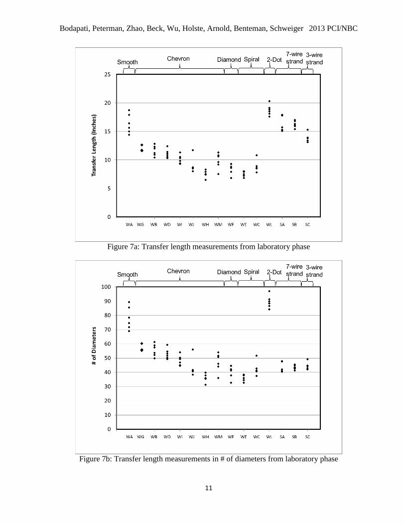
tabulated in Table2and plotted in Fig. 7a.
From Table 2, the average transfer lengths of the 5.32-mm (0.209-inch) wires ranged
from 7.4 in. to 18.7 in. This corresponds to a value of 35 db to 90 db, where db is the diameter
of the wire in inches. Fig. 7b shows the laboratory transfer length results in terms of diameter
(inches) of the reinforcement type. Note, current codes 1, 2
recommend a transfer length
assumption of 60 db for 7-wire prestressing strands. The highest average transfer lengths
were obtained when the smooth wire (WA) and 2-dot (WL) were used and these values were
16.3 in. and 18.7 in., respectively.
Table2. Transfer lengths and concrete strengths from laboratory phase
Wire/
Strand
Type
Indent
Type
Transfer Lengths Release
Strength
(psi)
Split
Tensile
Strength
(psi)
Modulus
of
Elasticity
(x106 psi)
Min.
(in.)
Avg.
(in.)
Max.
(in.)
WA Smooth 14.4 16.3 18.7 4664 418 3.53
WB Chevron 10.4 11.6 12.8 4453 403 3.46
WC Spiral 7.8 8.8 10.8 4701 482 3.88
WD Chevron 10.3 11.1 12.4 4400 476 3.89
WE Spiral 6.8 7.4 8.0 4650 479 3.46
WF Diamond 6.8 8.5 9.3 4466 466 3.71
WG Chevron 11.6 11.8 12.6 4697 496 3.55
WH Chevron 6.5 7.5 8.3 4695 485 3.90
WI Chevron 9.3 10.1 11.3 4547 439 3.73
WJ Chevron 8.0 9.0 11.7 4521 409 3.63
WL 2-Dot 17.6 18.7 20.3 4476 328 3.58
WM Chevron 7.5 9.8 11.3 4506 415 3.55
SA Smooth 15.1 16.2 17.9 4636 481 3.68
SB Indented 15.4 16.3 17.0 4736 419 3.98
SC Smooth 13.1 13.8 15.3 4449 390 3.70
Bodapati, Peterman, Zhao, Beck, Wu, Holste, Arnold, Benteman, Schweiger 2013 PCI/NBC
11
Figure 7a: Transfer length measurements from laboratory phase
Figure 7b: Transfer length measurements in # of diameters from laboratory phase
Bodapati, Peterman, Zhao, Beck, Wu, Holste, Arnold, Benteman, Schweiger 2013 PCI/NBC
12
The average transfer length of the Chevron-shaped indented wires ranged from 7.5 in.
(WH) to 11.8 in. (WG), or 36 db to 56 db. The average transfer length of the Spiral-indented
wires ranged from 7.4 in. to 8.8 in., or 35 db to 42 db.
The average transfer lengths for the 7-wire 3/8”-diameter smooth (SA) and 7-wire
3/8”-diameter indented (SB) strands were nearly identical at 16.2 in. and 16.3 in.,
respectively. This corresponds to a value of 43 db which is significantly less than the
assumption of 60 db in current code equations. It was noted by the researchers that strand SA
had some very minor surface rusting, whereas strand SB did not contain any visible rusting.
The 3-wire 5/16”-diameter smooth strand (SC) had an average transfer length of 13.8 in.,
which corresponds to 44 db.
During the plant phase of this study, pre-tensioned concrete railroad ties were
fabricated at a PCI member plant with the same 15 reinforcements and transfer lengths
determined. Fifty (50) transfer lengths (TLs) were determined for each reinforcement type,
of which 8 TL’s were determined using the Whittemore data and 42 TLs were determined
using the automated LSI device data. These transfer lengths, along with the measured
concrete properties from the plant phase are tabulated in Table 3 and plotted in Fig. 8a.
Since these ties were manufactured in a production environment where many other
ties were also being fabricated during the same day, de-tensioning did not occur at precisely
the same compressive strength for each reinforcement. Rather, the ties were de-tensioned
when the compressive strength was at least 5000 psi and when the de-tensioning crew was
available. Thus, the compressive strength at de-tensioning varied between 5063 psi and 6650
psi for the ties manufactured with the 15 different reinforcements.
By comparing Fig. 8a. with Fig. 7a., it is obvious that there is a greater amount of
scatter in the plant data that in the laboratory data for each reinforcing type. This may largely
be due to the fact that there were 50 measurements that occurred on 25 ties that were cast
near the beginning, middle, and ends of a 450-ft-long prestressing bed. It is important to note
that the entire bed is poured with about 14 different batches of the same concrete mix over
nearly a 2-hour period.
Thus, there would naturally be some variations in the fresh concrete properties from
mix-to-mix, but there may be also be significant differences in the maturity (compressive
strength, tensile strength, and MOE) of the different mixes at the time of de-tensioning. The
compressive strengths reported in Table 3 were from match-cured cylinders corresponding to
thermocouples placed near the end of the bed and from the last batch of concrete cast. Thus,
these cylinders are used to ensure that the entire bed is likely at or above the minimum
compressive strength of 5000 psi prior to de-tensioning.

Bodapati, Peterman, Zhao, Beck, Wu, Holste, Arnold, Benteman, Schweiger 2013 PCI/NBC
13
Table 3. Transfer lengths and concrete strengths from the plant phase
Wire/
Strand
Type
Indent
Type
Transfer Lengths Release
Strength
(psi)
Split
Tensile
Strength
(psi)
Min.
(in.)
Avg.
(in.)
Max.
(in.)
WA Smooth 10.7 14.3 18.0 5365 672
WB Chevron 6.1 10.2 16.0 6450 573
WC Spiral 5.0 11.2 22.9 5617 520
WD Chevron 5.4 9.7 15.7 5440 550
WE Spiral 4.5 8.6 14.5 5277 618
WF Diamond 4.9 7.8 13.0 5063 513
WG Chevron 5.8 10.9 16.0 5440 550
WH Chevron 5.1 8.3 11.5 5063 513
WI Chevron 6.0 10.8 14.9 5217 515
WJ Chevron 5.4 9.4 14.8 5447 598
WL 2-Dot 7.2 13.3 22.9 6600 554
WM Chevron 4.1 9.2 14.2 6650 590
SA Smooth 7.7 14.4 20.7 5277 618
SB Indented 11.6 15.6 20.5 6600 554
SC Smooth 9.0 15.9 22.9 5617 520
From Table 3, the average transfer lengths of the 5.32-mm (0.209-inch) wires ranged
from 7.8 in. to 14.3 in. This corresponds to a value of 37db to 68db, where db is the diameter
of the wire. As with the laboratory phase, the highest average transfer lengths were obtained
when the smooth wire (WA) and 2-dot (WL) were used and these values were 14.3 in. and
13.3 in., respectively. This corresponds to 68 db and 64 db, where db is the diameter of the
wire. Fig. 8b shows the plant phase transfer length results in terms of diameter (inches) of the
reinforcement type.
The average transfer length of the chevron-shaped indented wires ranged from 8.3 in.
(WH) to 10.9 in. (WG), or 40db to 52db. The average transfer length of the Spiral-indented
wires ranged from 8.6 in. to 11.2 in., or 41db to 53db.

Bodapati, Peterman, Zhao, Beck, Wu, Holste, Arnold, Benteman, Schweiger 2013 PCI/NBC
14
Figure 8a: Transfer length measurements from plant phase
Figure 8b: Transfer length measurements in # of diameters from plant phase
Bodapati, Peterman, Zhao, Beck, Wu, Holste, Arnold, Benteman, Schweiger 2013 PCI/NBC
15
The average transfer lengths for the 7-wire 3/8”-diameter smooth (SA) and 7-wire
3/8”-diameter indented (SB) strands were 14.4 in. and 15.6 in. respectively. This
corresponds to values of 38 db and 42 db respectively, which are significantly less than the
assumption of 60db in current code equations. Since the reinforcement source was the same
for both laboratory and plant phases; Strand SA had some very minor surface rusting,
whereas strand SB did not contain any visible rusting. The 3-wire 5/16”-diameter smooth
strand (SC) had an average transfer length of 15.9 in., which corresponds to 51 db.
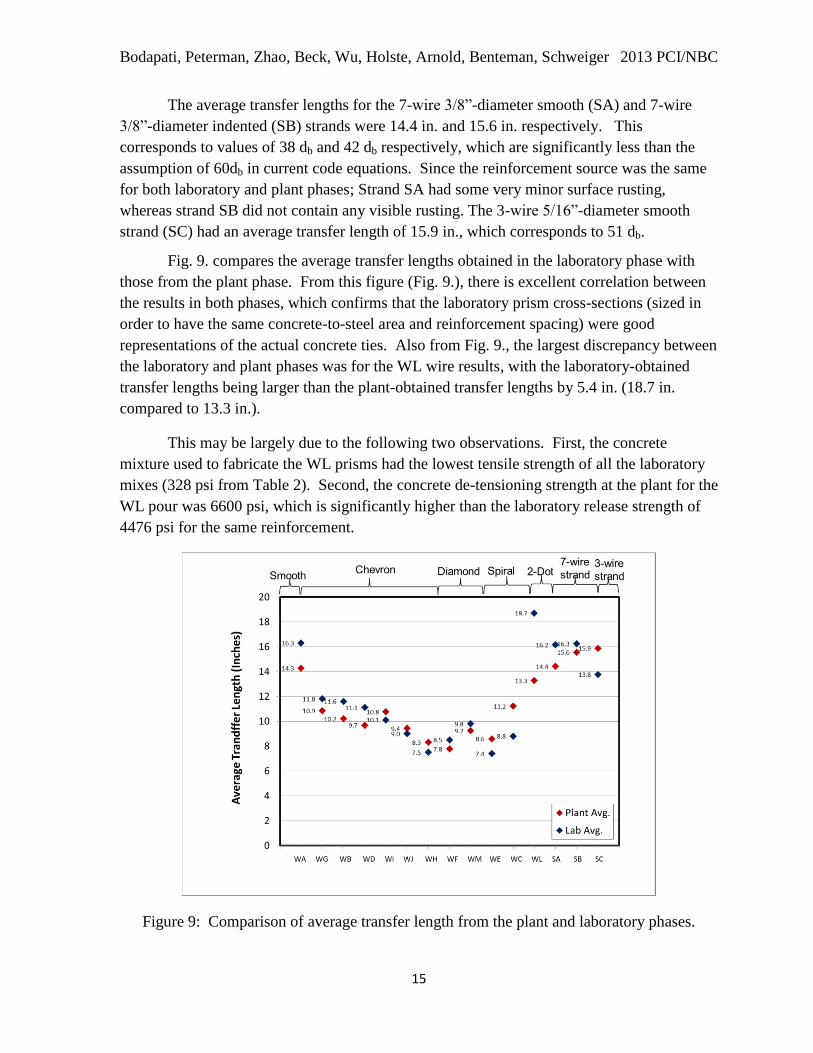
Fig. 9. compares the average transfer lengths obtained in the laboratory phase with
those from the plant phase. From this figure (Fig. 9.), there is excellent correlation between
the results in both phases, which confirms that the laboratory prism cross-sections (sized in
order to have the same concrete-to-steel area and reinforcement spacing) were good
representations of the actual concrete ties. Also from Fig. 9., the largest discrepancy between
the laboratory and plant phases was for the WL wire results, with the laboratory-obtained
transfer lengths being larger than the plant-obtained transfer lengths by 5.4 in. (18.7 in.
compared to 13.3 in.).
This may be largely due to the following two observations. First, the concrete
mixture used to fabricate the WL prisms had the lowest tensile strength of all the laboratory
mixes (328 psi from Table 2). Second, the concrete de-tensioning strength at the plant for the
WL pour was 6600 psi, which is significantly higher than the laboratory release strength of
4476 psi for the same reinforcement.
Figure 9: Comparison of average transfer length from the plant and laboratory phases.
Bodapati, Peterman, Zhao, Beck, Wu, Holste, Arnold, Benteman, Schweiger 2013 PCI/NBC
16
Conclusions
Based on the work presented in this paper, the following conclusions can be drawn.
1. Results from both phases indicated that there is a large variation in the bond quality
of reinforcements that are currently used in the fabrication of pre-tensioned concrete
railroad ties worldwide.
2. In the laboratory phase, which used concrete with a strength at de-tensioning of 4500
psi ±220 psi, the average transfer lengths for the 15 different reinforcements ranged
from 7.4 in. to 18.7 in. In the plant phase, which had a higher strength at de-
tensioning, average transfer lengths of these same reinforcements was between 7.8 in.
and 15.9 in.
3. The best-bonding wires had the most pronounced indentations (Diamond, Chevron,
and Spiral) while the lowest-bonding wires were the Smooth and 2-Dot wires.
4. The smooth 7-wire 3/8”-diameter strand (SA) had slightly better bond characteristics
than the indented 7-wire 3/8”-diameter strand (SB). In the laboratory phase, SA had
an average transfer length of 16.2 in. while SB had an average transfer length of 16.3
in. In the plant phase, SA had an average transfer length of 14.4 in. while SB had an
average transfer length of 15.6 in.
5. There was excellent correlation between the plant-phase data and the laboratory-
phase data. This indicates that the laboratory prisms, cast with a similar concrete
mixture, were able to accurately represent the behavior of the same reinforcement in a
concrete railroad tie. Therefore, in the future, the bond performance of a new
reinforcement in concrete railroad ties could be determined by measuring transfer
lengths on similar prisms using a representative concrete mix.
6. The automated LSI devices performed well and enabled an unprecedented amount of
data to be collected in a very short time period. As a result, 750 transfer lengths were
able to be determined during the plant phase, of which 630 were from LSI data.
Recommendations
Because the results presented herein indicate that the transfer length for concrete railroad ties
can vary significantly based on the prestressing reinforcement type used, it is highly
recommended that the railroad tie producers determine the transfer lengths corresponding to
their unique combinations of prestressing reinforcement and concrete mixtures. Based on the
findings of this study, 4-wire or 4-strand laboratory prisms could be used to obtain
representative transfer-length data.
Bodapati, Peterman, Zhao, Beck, Wu, Holste, Arnold, Benteman, Schweiger 2013 PCI/NBC
17
Acknowledgements
The authors would like to thank the Federal Railroad Administration (FRA) for providing the
majority of the funding that made this research possible. Additionally, LB Foster/CXT
Concrete Ties donated extensive resources, including all of the reinforcements, to make the
project a success. The researchers would also like to thank Drs. Hailing Yu and David Jeong
at the John A. Volpe National Transportation Systems Center for their valuable suggestions
and parallel analysis work. Finally, the authors wish to thank the Precast/Prestressed
Concrete Institute (PCI) for establishing an industry advisory panel to the project, the Kansas
State University Transportation Center (K-State UTC) for graduate student tuition support,
and the Advanced Manufacturing Institute (AMI) for manufacturing services.
References
1. AASHTO LRFDBridge Design Specifications, 6th Edition.
2. ACI Committee 318. Building Code Requirements for Structural Concrete, 318-11,
American Concrete Institute, 2011.
3. ASTM Standard C39, 2012a, “Standard Test Method for Compressive Strength of
Cylinder Concrete Specimens.” ASTM International, West Conshohocken, PA, 2012,
DOI: 10.1520/C0039_C0039M-12A, www.astm.org.
4. ASTM Standard C469, 2010, “Standard Test Method for Static Modulus of Elasticity
and Poisson’s Ratio of concrete in Compression.” ASTM International, West
Conshohocken, PA, 2010, DOI: 10.1520/C0469_C0469M-10, www.astm.org.
5. ASTM Standard C496, 2011, “Standard Test Method for Splitting Tensile Strength of
Cylindrical Concrete Specimens.” ASTM International, West Conshohocken, PA,
2011, DOI: 10.1520/C0496_C0496M-11, www.astm.org.
6. Bodapati, N. et. al., (2013). “Influence of Indented Wire Geometry and Concrete
Parameters on the Transfer Length in Prestressed Concrete Crossties”, Proc. 2013
Joint Rail Conference. Paper Reference #JRC2013-2463. Knoxville, TN.
7. Hanna, Amir N. “Prestressed Concrete Ties for North American Railroads.” PCI
Journal Sept.-Oct. 1979:32-61.
8. Kaar, Paul H., N. W. Hanson. “Bond Fatigue Tests of Beams simulating Pretensioned
Concrete Crossties.” PCI Journal 20.5 Sept. - Oct. 1975: 65-80.
9. Murphy, R., (2012) Determining the Transfer Length in Prestressed Concrete
Railroad Ties Produced In The United States. Thesis. Kansas State University,
Kansas.
10. Russell, B. W., and N. H. Burns. 1993. Design Guidelines for Transfer, Development
and Debonding of Large-Diameter Seven-Wire Strands in Pretensioned Concrete
Girders,1210-5F, Center for Transportation Research, the University of Texas at
Austin, Austin, Tex., Jan. 1993, 300 pp.
11. Srinivasa Rao, P., P. Kalyanasundaram, and M. F. Sharief. “Transmission Length of
Ribbed Bars in Pre-Tensioned Concrete.” The Indian Concrete Journal 51.5 May
1977: 149-153.

Bodapati, Peterman, Zhao, Beck, Wu, Holste, Arnold, Benteman, Schweiger 2013 PCI/NBC
18
12. Zhao, W. (2011). Development of a Portable Optical-Strain Sensor with Applications
to Diagnostic Testing of Prestressed Concrete. Dissertation. Kansas State University,
Kansas.
13. Zhao, W., K. Larson, R. Peterman, T. Beck, and J. Wu. “Development of a Laser-
Speckle Imaging Device to Determine the Transfer Length in Pre-Tensioned Concrete
Members.” PCI Journal 57.1 Winter 2012: 135-143.
14. Zhao, W. et. al., (2013). “A Direct Comparison of the Traditional Method and a New
Approach in Determining 220 Transfer Lengths in Prestressed Concrete Railroad
Ties”, Proc. 2013 Joint Rail Conference. Paper Reference #JRC2013-2469.
Knoxville, TN.