Concept of Prestressing
15
2/12/2017 1 Concept of Prestressing Concept of Prestressing Concept of Prestressing Prestressing the concrete is to transfer precompression (compressive stress) to the concrete How the prestressing force transmitted to concrete can be explained by concept of prestressing
-
Upload
khangminh22 -
Category
Documents
-
view
1 -
download
0
Transcript of Concept of Prestressing
2/12/2017
1
Concept of PrestressingConcept of Prestressing
Concept of Prestressing
Prestressing the concrete is to transfer precompression (compressive stress) to the concrete
How the prestressing force transmitted to concrete can be explained by concept of prestressing
2/12/2017
2
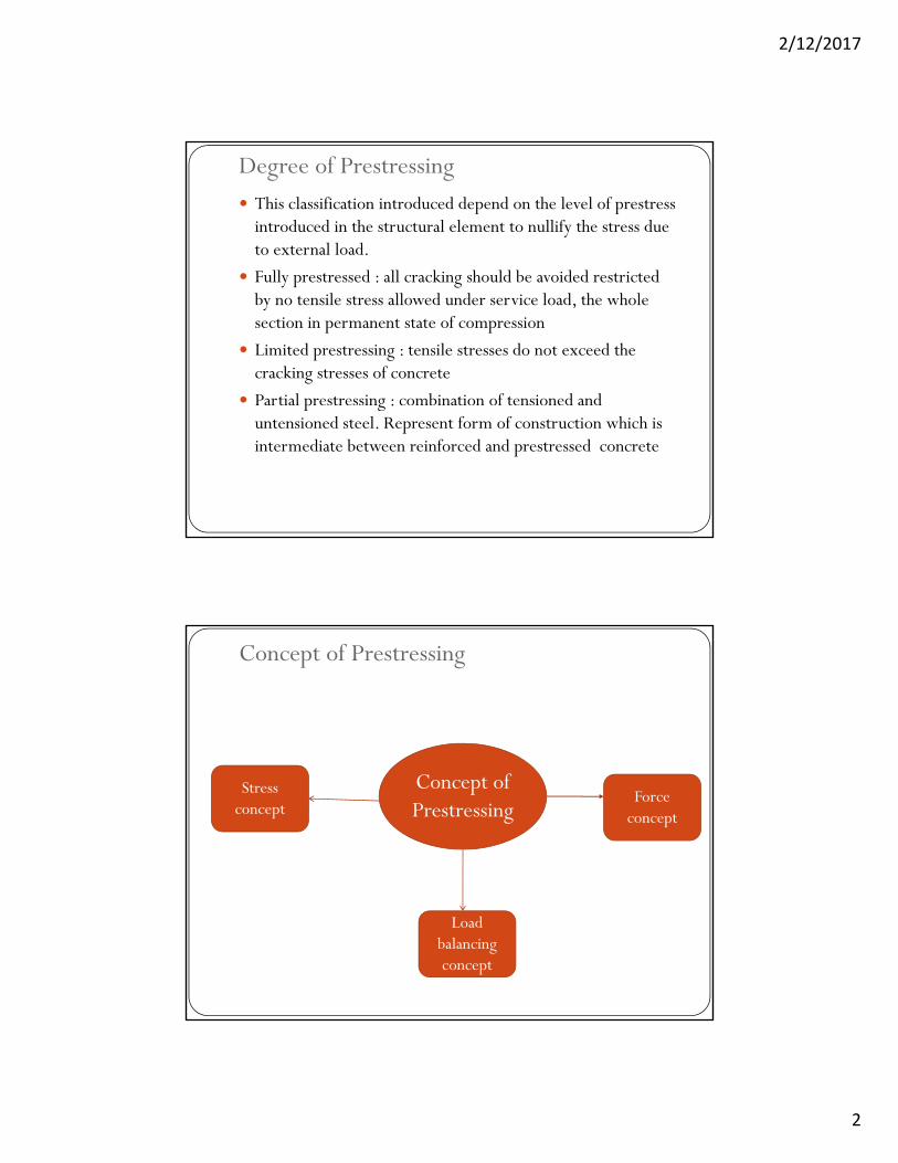
Degree of Prestressing This classification introduced depend on the level of prestress
introduced in the structural element to nullify the stress due to external load.
F ll t d ll ki h ld b id d t i t d Fully prestressed : all cracking should be avoided restricted by no tensile stress allowed under service load, the whole section in permanent state of compression
Limited prestressing : tensile stresses do not exceed the cracking stresses of concrete
Partial prestressing : combination of tensioned and p g :untensioned steel. Represent form of construction which is intermediate between reinforced and prestressed concrete
Concept of Prestressing
Concept of Prestressing
Stress concept
Force concept
Load balancing concept

2/12/2017
3
Stress Concept The concept that considering prestressing force transmitted to
concrete as initial internal stress to counteract the internal stress developed due to external loads is known as stress concept
The combination of the effect of external loads and prestressing p gare studied together as equivalent stresses and compared with permissible levels of stresses in the material
The procedures of this concept can be divided into two stages: stress at transfer/stage 1 and stress at service/stage 2
For stage 1, the stresses across cross section due to self weight and prestressing are taken into account
For stage 2, the stresses caused by prestressing, dead and live loads and other external loads are calculated together through the depth of cross section
The stresses should be within the permissible limits
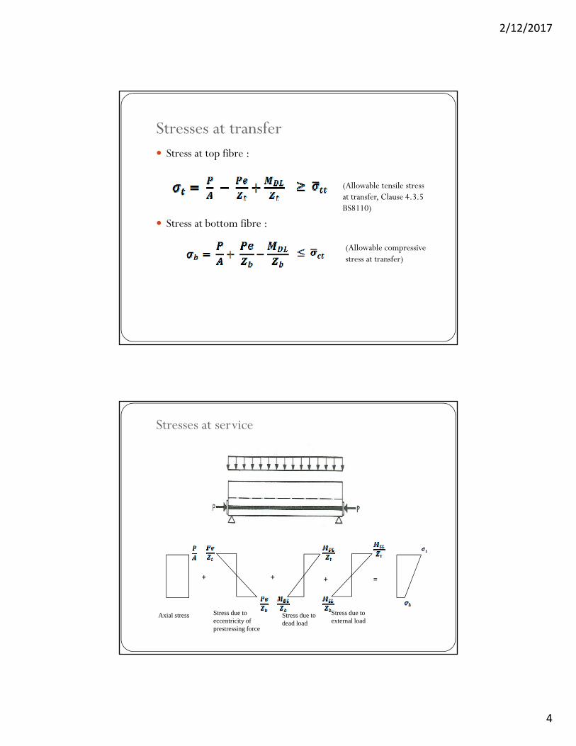
Stresses at transfer
+- +
+ + =
Axial stress Stress due toeccentricity of prestressing force
Stress due to dead load
+
+ -
2/12/2017
4
Stresses at transfer Stress at top fibre :
Stress at bottom fibre :
(Allowable tensile stress at transfer, Clause 4.3.5 BS8110)
(Allowable compressive stress at transfer)stress at transfer)
Stresses at service
+ + =
Axial stress Stress due to dead load
Stress due to eccentricity of prestressing force
+
Stress due to external load

2/12/2017
5
Stresses at service Stress at top fibre :
Stress at bottom fibre :
(Allowable compressive stress at service, Clause 4.3.4 BS8110)
(Allowable tensile stress at service)
Stress concept
In stress concept, we used theory of bending throughout the analysis where:
- it is assumed that plane sections remain plane before or - it is assumed that plane sections remain plane before or after the moments are applied
- the top and the bottom fibre of the structural elements are subjected to maximum stresses
The permissible/allowable streses under compression and tension in the materials concrete and steel do have a major role to play in analysis and design of prestressed concrete structure based on stress concept
2/12/2017
6
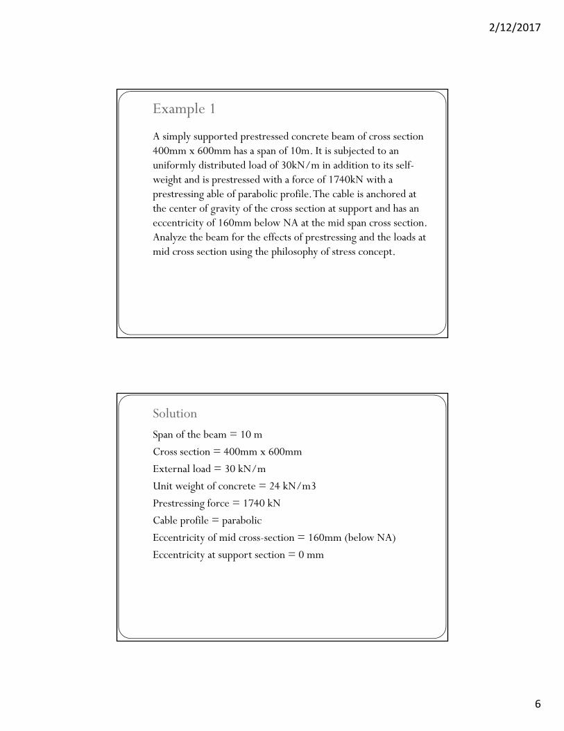
Example 1
A simply supported prestressed concrete beam of cross section 400mm x 600mm has a span of 10m. It is subjected to an uniformly distributed load of 30kN/m in addition to its self-weight and is prestressed with a force of 1740kN with a prestressing able of parabolic profile. The cable is anchored at the center of gravity of the cross section at support and has an eccentricity of 160mm below NA at the mid span cross section. Analyze the beam for the effects of prestressing and the loads at mid cross section using the philosophy of stress concept.g p p y p .
SolutionSpan of the beam = 10 m
Cross section = 400mm x 600mm
External load = 30 kN/m
Unit weight of concrete = 24 kN/m3
Prestressing force = 1740 kN
Cable profile = parabolic
Eccentricity of mid cross-section = 160mm (below NA)
Eccentricity at support section = 0 mmy pp
2/12/2017
7
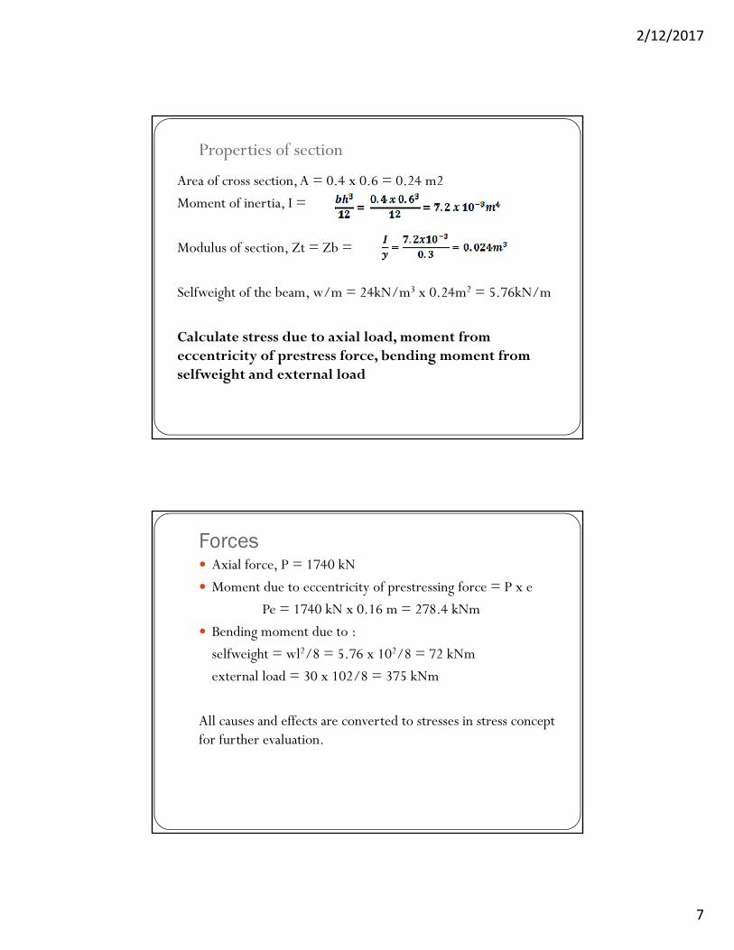
Properties of section
Area of cross section, A = 0.4 x 0.6 = 0.24 m2
Moment of inertia, I =
Modulus of section, Zt = Zb =
Selfweight of the beam, w/m = 24kN/m3 x 0.24m2 = 5.76kN/m
Calculate stress due to axial load, moment from eccentricity of prestress force, bending moment from selfweight and external load
Forces Axial force, P = 1740 kN
Moment due to eccentricity of prestressing force = P x e
Pe = 1740 kN x 0.16 m = 278.4 kNm
Bending moment due to :
selfweight = wl2/8 = 5.76 x 10²/8 = 72 kNm
external load = 30 x 102/8 = 375 kNm
All causes and effects are converted to stresses in stress concept pfor further evaluation.

2/12/2017
8
At transfer
+ + =
Stresses at top fibre :
Axial stress Stress due toeccentricity of prestressing force
Stress due to dead load
Stresses at bottom fibre :
At service
+ + =+
Stress at top fibre :
Axial stress Stress due to dead load
Stress due to eccentricity of prestressing force
Stress due to external load
Stress at bottom fibre :
2/12/2017
9
Force Concept
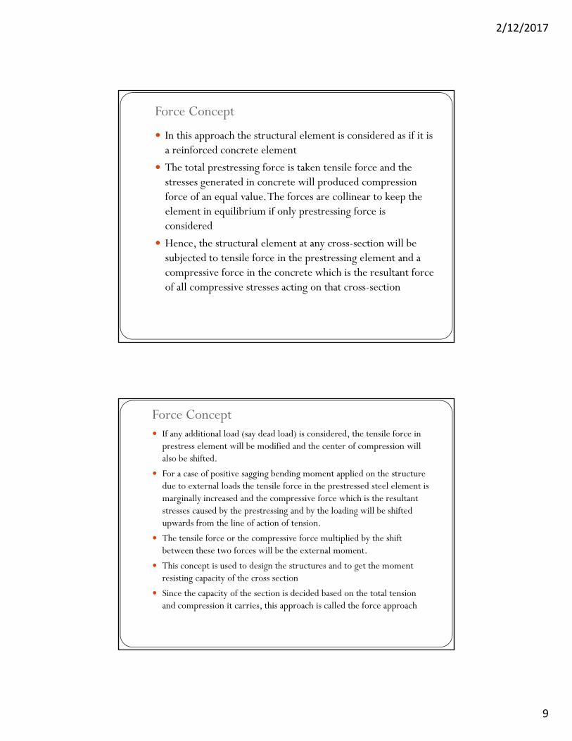
In this approach the structural element is considered as if it is a reinforced concrete element
The total prestressing force is taken tensile force and the gstresses generated in concrete will produced compression force of an equal value. The forces are collinear to keep the element in equilibrium if only prestressing force is considered
Hence, the structural element at any cross-section will be subjected to tensile force in the prestressing element and a subjected to tensile force in the prestressing element and a compressive force in the concrete which is the resultant force of all compressive stresses acting on that cross-section
Force Concept If any additional load (say dead load) is considered, the tensile force in
prestress element will be modified and the center of compression will also be shifted.
For a case of positive sagging bending moment applied on the structure due to external loads the tensile force in the prestressed steel element is marginally increased and the compressive force which is the resultant stresses caused by the prestressing and by the loading will be shifted upwards from the line of action of tension.
The tensile force or the compressive force multiplied by the shift between these two forces will be the external moment.
This concept is used to design the structures and to get the moment This concept is used to design the structures and to get the moment resisting capacity of the cross section
Since the capacity of the section is decided based on the total tension and compression it carries, this approach is called the force approach

2/12/2017
10
Example
Analyze the beam in Example 1 using force concept.
SolutionSolution
In force concept all causes and effects are considered as forces for evaluation.
Bending moment at mid span due to :
a) Selfweight = 72 kNm (top – comp, bottom –tension)
b) External load = 375 (top – comp bottom –tension)b) External load 375 (top comp, bottom tension)
Total bending moment = 447 kNm
Prestressing force = 1470 kN

2/12/2017
11
When the prestressing force of 1740 kN (tensile) in the cables alone is acting, the stresses generated in concrete will lead to a resultant compression of equal value (1740 kN) and the compression also acts at the same level of prestressing force. The forces are collinear.
Stage 1/at transferWhen selfweight starts acting (which is immediately after prestress) there will be a small increase in the tensile forc in the cables. But this is neglected.The total tensile force in the cable = 1740 kNTotal compressive force = 1740 kN (to keep the section in equilibrium)p ( p q )But the resultant compression will act at a different level, so that the compression and the tension will form a couple to resist dead load bending moment
Dead load bending moment = 72 kNm
Distance between the tensile force (cable position) and the center of resultant compression, a
a = M/P = 72/1740 = 0.04138 m.
Distance of compression from the NA of cross section
= 0.16 – 0.04138 m = 118.6 mm
1.35
15.85
T
a = 41.38mm
NA118.6mm
160mm

2/12/2017
12
The resultant compression will act at 118.6mm from NA only for a given stress distribution.
The stress distribution can be evaluated as detailed below :
Stress at top = Stress at top =
Stress at the bottom = 7250 + 8599.95 = 15849.95 N/mm2
Stage II/ at service
When the external load also starts acting the resultant (final) bending moment shall be resisted by the total compression and total tension with a lever arm.
Total tension = 1740 kN
Total moment to be resisted = dead load + bending moment due to other loads
= 72 + 375 = 447 kNm
Lever arm required, a = M/P = 447/1740 = 0.2569 m
Resultant center of compression will be located at 256.9mm from the center of tension cable position
2/12/2017
13
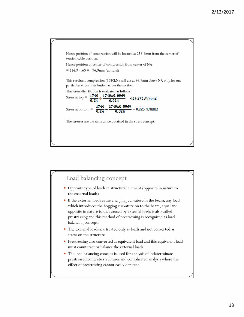
Hence position of compression will be located at 256.9mm from the center of tension cable position.
Hence position of center of compression from center of NA
= 256.9 -160 = - 96.9mm (upward)
This resultant compression (1740kN) will act at 96.9mm above NA only for one particular stress distribution across the section.
The stress distribution is evaluated as follows
Stress at top =
Stress at bottom =
The stresses are the same as we obtained in the stress concept.
Load balancing concept Opposite type of loads in structural element (opposite in nature to
the external loads)
If the external loads cause a sagging curvature in the beam, any load which introduces the hogging curvature on to the beam equal and which introduces the hogging curvature on to the beam, equal and opposite in nature to that caused by external loads is also called prestressing and this method of prestressing is recognized as load balancing concept.
The external loads are treated only as loads and not converted as stress on the structure
Prestressing also converted as equivalent load and this equivalent load Prestressing also converted as equivalent load and this equivalent load must counteract or balance the external loads
The load balancing concept is used for analysis of indeterminate prestressed concrete structures and complicated analysis where the effect of prestressing cannot easily depicted
2/12/2017
14
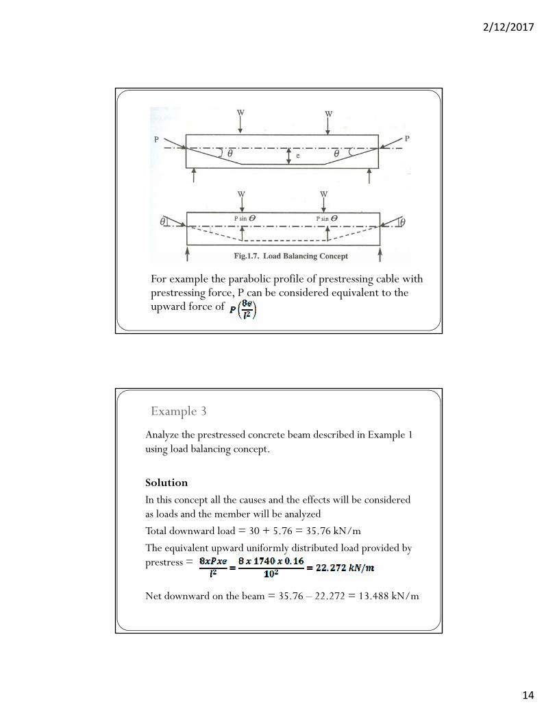
For example the parabolic profile of prestressing cable with prestressing force, P can be considered equivalent to the upward force of
Example 3
Analyze the prestressed concrete beam described in Example 1 using load balancing concept.
Solution
In this concept all the causes and the effects will be considered as loads and the member will be analyzed
Total downward load = 30 + 5.76 = 35.76 kN/m
The equivalent upward uniformly distributed load provided by q p y p yprestress =
Net downward on the beam = 35.76 – 22.272 = 13.488 kN/m
2/12/2017
15
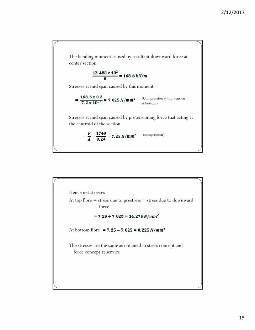
The bending moment caused by resultant downward force at center section
Stresses at mid span caused by this moment
(Compression at top, tension at bottom)
Stresses at mid span caused by pretensioning force that acting at the centroid of the section
(compression)
Hence net stresses :
At top fibre = stress due to prestress + stress due to downward force
At bottom fibre
The stresses are the same as obtained in stress concept and force concept at service force concept at service