TRAK® TRL 1540V, 1840V ProtoTRAK® VL CNC
118
TRAK® TRL 1540V, 1840V ProtoTRAK® VL CNC Safety, Programming, Operating & Care Manual Southwestern Industries, Inc. P. O. Box 9066 Compton, CA 90224-9066 USA T | 310.608.4422 | F | 310. 764.2668 Plant location: 2615 Homestead Place Rancho Dominguez, CA 90220-5610 USA Service Department: 800.367.3165 e-mail: [email protected] | [email protected] | web: southwesternindustries.com Document: P/N 22635 Version: 033103
-
Upload
khangminh22 -
Category
Documents
-
view
1 -
download
0
Transcript of TRAK® TRL 1540V, 1840V ProtoTRAK® VL CNC

TRAK® TRL 1540V, 1840V ProtoTRAK® VL CNC
Safety, Programming, Operating & Care Manual
Southwestern Industries, Inc. P. O. Box 9066 Compton, CA 90224-9066 USA T | 310.608.4422 | F | 310. 764.2668
Plant location: 2615 Homestead Place Rancho Dominguez, CA 90220-5610 USA
Service Department: 800.367.3165 e-mail: [email protected] | [email protected] | web: southwesternindustries.com
Document: P/N 22635 Version: 033103

Copyright 2002, Southwestern Industries, Inc. All rights are reserved. No part of this publication may be reproduced, stored in a retrieval system, or transmitted, in any form or by any means, mechanical, photocopying, recording or otherwise, without the prior written permission of Southwestern Industries, Inc. While every effort has been made to include all the information required for the purposes of this guide, Southwestern Industries, Inc. assumes no responsibility for inaccuracies or omission and accepts no liability for damages resulting from the use of the information contained in this guide. All brand names and products are trademarks or registered trademarks of their respective holders. Southwestern Industries, Inc. 2615 Homestead Place Rancho Dominguez, CA 90220 Phn 310/608-4422 Fax 310/764-2668 Service Department Phn 800/367-3165 Fax 310/886-8029

Table of Contents 1.0 Introduction 1.1 Manual Organization 1 2.0 Safety Specifications & Lubrication 2.1 Safety Publications 3 2.2 Danger, Warning, Caution and Note
Labels and Notices Used in this Manual 3 2.3 Safety Precautions 6 3.0 Description 3.1 Display Pendant Front 9
3.1.1 Keyboard Hard Keys 9 3.1.2 Soft Keys 10 3.1.3 Emergency Stop Switch 11
3.1.4 The Liquid Crystal Display 11 3.2 Pendant Left Side 11 3.3 Pendant Right Side 12 3.4 Machine Specifications 13 3.5 Spindle Motor 13 3.5.1 Spindle Speed Ranges 13 3.6 Electronic Handwheels 14 3.7 Lubrication System 14 3.7.1 Headstock 14
3.7.2 Automatic Lubrication Pump 14 3.8 Electrical Cabinet 15 3.9 Using Electronic Handwheels 15 3.10 Using the Jog Stick 15 3.11 Sliding Doors & Interlock Switch 15 3.11.1 For the 1840V 15 3.11.2 For the 1540V 16 3.12 Optional Equipment 16 3.12.1 Collet Closer 16 3.12.2 Chuck 16 3.12.3 Gang Tooling 16 3.12.4 Indexer Option 16 3.12.5 Offline Programming 17 3.12.6 Steady Rest 17 3.12.7 Tooling Kit 17 3.12.8 Remote Stop/Go Switch 17
4.0 Basic Operation 4.1 Switching the TRAK TRL On/Off 19 4.2 Switching the ProtoTRAK VL On 19 4.3 Shutting down the ProtoTRAK VL CNC 20 4.4 Spindle Forward/Off/Reverse 21 4.5 Using the Electronic Handwheels 21 4.6 Using the Jog Stick 21 4.7 Emergency Stop 21 4.8 Coolant Pump 21 4.9 Windows Desktop 22 4.10 Help Functions 22 4.10.1 Math Helps 22 4.11 Windows Up or Down 23 4.12 Using a Mouse & Keyboard 23 4.13 Tool Pedestal 24
4.14 Tail Stock 24 4.15 Spindle Operation 24 4.16 Spindle Speed Ranges 24 5.0 Definitions, Terms & Concepts 5.1 ProtoTRAK VL CNC Axis Conventions 25 5.2 Absolute & Incremental Reference 25 5.3 Referenced & Non-Referenced Data 25 5.4 Tool Tip Radius Compensation 26 5.5 Tool Offset 26 5.6 Connective Events 27 5.7 Conrad 27 5.8 Chamfer 27 5.9 Absolute, Tool & Program References 29 5.10 Feedrate Conventions 29 5.11 Spindle Speed Conventions 29 6.0 DRO Mode 6.1 Enter DRO Mode 31 6.2 DRO Functions 31 6.3 Fine & Coarse Resolution 32 6.4 Power Feed 32 6.5 Do One 32 6.5.1 Taper Do One 33 6.5.2 Radius Do One 33 6.5.3 Fillet Do One 33 6.6 Go To 34 6.7 Return to Home 34 6.8 Changing Spindle Speed 34 6.9 Tool # 35 6.10 Tool Tip Radius Compensation in
DRO Mode 35 7.0 Program Mode
Part 1: Getting Started & Some General Info 7.1 Programming Overview 37 7.2 Enter Program Mode 37 7.3 Program Header Screen 38 7.3.1 Program Name 38 7.3.2 Event Comments 39 7.3.3 Program Header Softkeys 39 7.4 Assumed Inputs 40 7.5 Incremental Reference Position 40 7.6 Programming Spindle Speeds & Feedrates 40 7.7 Softkeys within Events 41 7.8 Programming Events 41 7.9 Editing Data While Programming 42 7.10 Look 42 8.0 Program Mode
Part 2: Program Events 8.1 Posn Position Events 45 8.2 Drill Events 45 8.3 Bore Events 46 8.4 Turn Events 46
i TRAK TRL 1540V, 1840V ProtoTRAK VL CNC Safety, Programming, Operating & Care Manual

8.5 ARC Events 47 8.6 Cycle Events 48 8.7 Thread Event 51 8.7.1 Standard Thread Event 51 8.7.2 Custom Thread Event 52 8.8 Repeat Events 53 8.9 Finish Cuts 54 9.0 Edit Mode 9.1 Delete Events 55 9.2 Spreadsheet EditingTM 55
9.2.1 Selecting Data to be Displayed on the Search Edit Table 56
9.2.2 Sorting Data 57 9.2.3 Making Global Changes to Data 57
9.3 Erase Program 59 9.4 Clipboard 59 10.0 Set Up Mode 10.1 Enter Set-Up Mode 61 10.2 Tool Set-Up 61
10.2.1 Practical Technique for Accurate Tool Setting 63
10.2.2 Tool Set-Up When Adding or Changing Tools 63
10.3 Tool Path 64 10.3.1 Soft Keys in Tool Path 64 10.4 Reference Positions (REF POSN) 65 10.4.1 Home Positions 65 10.4.2 Limit Positions 65 10.5 The Tool Table 65 10.5.1 Soft keys in the Tool Table 65 10.6 Max RPM – Limiting Spindle Speed 66 10.7 Saving Tool Data 66 10.8 Tool Groups 66 10.8.1 Single Tool Setup 67 10.8.2 Gang Tool Setup 67 10.8.3 Indexer Setup 67 10.9 Service Codes 69 11.0 Run Mode 11.1 Run Mode Screen 69 11.2 Starting to Run 69 11.3 Program Run 70 11.4 Door Position in Run Mode 71 11.5 Program Run Messages 71 11.6 TRAKing 72 11.7 Stop 72 11.8 Feedrate & Spindle Speed Override 72 11.9 Threading Exceptions 72 11.10 Data Errors 73 11.11 Fault Messages 73 11.12 Run Sequence 73 12.0 Program In/Out Mode 12.1 Softkey Selections in the Program In/Out Mode 76 12.2 Basic Navigation of Program In/Out Mode
Screens 76 12.2.1 Basic Parts of the Program In/
Out Mode Screens 76
12.2.2 Softkeys in the Program In/Out Mode Screens 76
12.3 Opening a File 77 12.4 Saving Programs 77 12.5 Copying Programs 78 12.6 Deleting Programs 79 12.7 Renaming 79 12.8 Backing Up 80 12.9 ConvertersTM 81 12.9.1 Activating Converters 81
12.9.2 Converting from a Different Format Into a ProtoTRAK VL CNC 82
12.9.3 Converting from the ProtoTRAK VM to a Different Format 83
12.10 ProtoTRAK Compatibility 83 12.10.1 File Formats 83 12.10.2 Nested Repeats 84
12.10.3 ProtoTRAK VL & ProtoTRAK LX3 Compatibility 84
12.10.4 ProtoTRAK VL & ProtoTRAK LX2 Compatibility 84
12.10.5 ProtoTRAK SL & ProtoTRAK VL Compatibility 84
12.11 Running G Code Files 85 12.11.1 G Codes Recognized by the
ProtoTRAK VL CNC 85 12.11.2 M Codes Supported by the ProtoTRAK VL CNC 86 12.11.3 Valid Characters for Word/Address
Sequences 86 12.12 Networking 86 12.12.1 What is a Network? 86
12.12.2 Why would you want to use the networking capability of the ProtoTRAK VL CNC control? 87
12.12.3 A Word of Advice Before Setting Up Your Network 87
12.12.4 Peer-to-Peer Networking 87 12.12.5 Basic Network Set-Up 88 12.12.6 Server and Client Networking 93
12.12.7 Network Description of the ProtoTRAK 95
12.13 RS232 Interface 95 12.13.1 Connections 96 12.13.2 Receiving a File 96 12.13.3 Sending a File 97 12.14 CAD/CAM and Post Processors 98 12.14.1 Writing a Post Processor 98 12.14.2 Convertible G-Codes 99 13.0 Sample Program 101
Addendum Notice to ProtoTRAK VL CNC Users A-i ProtoTRAK VL CNC User Registration Form A-ii
ii TRAK TRL 1540V, 1840V ProtoTRAK VL CNC Safety, Programming, Operating & Care Manual

1.0 Introduction From manual work to short-run production, TRAK V Series Lathes are the most efficient machines you can use. They are more efficient than engine lathes, even for manual jobs. Slide the door back and operate the ProtoTRAK VL CNC in DRO mode. You have the convenience of large dimensional information on the easy-to-read CNC screen, and the efficiency of powerful routines to manually machine a taper, radius or fillet.
When parts have some complexity or more than one is required, the easy programming and minimal set-up of the ProtoTRAK VL CNC make it the best possible technology for the job. When you machine the part, you have complete control over the CNC with the powerful TRAKing®
feature so that you can move swiftly and confidently through your work. For short run production, the TRAK V Series Lathe is right at home. Generous cross slide travel and control interface enable you to mount optional gang tooling or an automatic indexer for tool changes. The interlocked door slides in front of the workpiece, protecting you from coolant and chips. Advanced program management keeps past jobs at your fingertips and ready for quick turn-around. 1.1 Manual Organization
Section 2 of this manual provides important safety information. It is highly recommended that all operators of this product review this safety information.
Section 3 provides a description of the TRAK TRL 1540V, 1840V and the ProtoTRAK VL CNC.
Section 4 describes the operation of the lathe and some basic operations of the ProtoTRAK VL CNC.
Section 5 defines some terms and concepts useful in learning to program and operate the ProtoTRAK VL CNC.
The ProtoTRAK VL CNC is organized into six Modes of operation that are described in the following sections.
Section 6 DRO: Digital Readout, jog, and powerfeed operations.
Section 7 Programming, Part 1: covers some general programming information and instructions on starting new programs.
Section 8 Programming, Part 2: Program Events - instructions for the canned cycles, or events used to program the ProtoTRAK VL CNC.
Section 9 Edit: for routines to make large-scale changes to programs in current memory, including the powerful Spreadsheet Editing®
Section 10 Set-Up: Tool information, part graphics and special codes.
Section 11 Run: Instructions on running a program to machine your part.
Section 12 Program In/Out: Storing and managing your programs.
1 Southwestern Industries, Inc.
TRAK TRL 1540V, 1840V ProtoTRAK VL CNC Safety, Programming, Operating & Care Manual .

2 Southwestern Industries, Inc.
TRAK TRL 1540V, 1840V ProtoTRAK VL CNC Safety, Programming, Operating & Care Manual

2.0 Safety Specifications & Lubrication The safe operation of the TRAK TRL 1540V, 1840V ProtoTRAK VL CNC depends on its proper use and the precautions taken by each operator.
• Read and study this TRAK TRL 1540V, 1840V ProtoTRAK VL CNC Safety, Programming, Operating, and Care Manual. Be certain that every operator understands the operation and safety requirements of this machine before its use.
• Always wear safety glasses and safety shoes.
• Always stop the spindle and check to ensure the CNC control is in the stop mode before
changing or adjusting the tool or workpiece.
• Never wear gloves, rings, watches, long sleeves, neckties, jewelry, or other loose items when operating, or around the machine.
• Use adequate point of operation safeguarding. It is the responsibility of the employer to
provide and ensure point of operation safeguarding per ANSI B11.6-1984. 2.1 Safety Publications
Refer to and study the following publications for assistance in enhancing the safe use of this machine: Safety Requirements For The Construction, Care And Use of Lathes (ANSI B11.6-2001). Available from the American National Standards Institute, 11 West 42nd Street, New York, NY 10036. Concepts And Techniques Of Machine Safeguarding (OSHA Publication Number 3067). Available from The Publication Office - O.S.H.A., U.S. Department of Labor, 200 Constitution Avenue, NW, Washington, DC 20210. All other regulations specific to the State in which the machine is installed.
2.2 Danger, Warning, Caution, and Note Labels and Notices As Used In This Manual
DANGER - Immediate hazards that will result in severe personal injury or death. Danger labels on the machine are red in color. WARNING - Hazards or unsafe practices that could result in severe personal injury and/or damage to the equipment. Warning labels on the machine are gold in color. CAUTION - Hazards or unsafe practices that could result in minor personal injury or equipment/product damage. Caution labels on the machine are gold in color. NOTE - Call attention to specific issues requiring special attention or understanding.
3 Southwestern Industries, Inc.
TRAK TRL 1540V, 1840V ProtoTRAK VL CNC Safety, Programming, Operating & Care Manual

230 Volts
Safety & Information Labels Used On The TRAK TRL 1540V & 1840V Lathe
It is forbidden by OSHA regulations and by law to deface, destroy or remove any of these labels
4 Southwestern Industries, Inc.
TRAK TRL 1540V, 1840V ProtoTRAK VL CNC Safety, Programming, Operating & Care Manual

Safety & Information Labels Used On The TRAK TRL 1540V & 1840V Lathe
It is forbidden by OSHA regulations and by law to deface, destroy or remove any of these labels
5 Southwestern Industries, Inc.
TRAK TRL 1540V, 1840V ProtoTRAK VL CNC Safety, Programming, Operating & Care Manual

2.3 Safety Precautions
WARNING! Use only chucks which are rated to the maximum RPM of the lathe.
1. Do not operate this machine before the TRAK TRL 1540V, 1840V and ProtoTRAK VL CNC
Programming, Operating and Care Manual have been studied and understood.
2. Do not run this machine without knowing the function of every control key, button, knob, or handle. Ask your supervisor or a qualified instructor for help when needed.
3. Protect your eyes. Wear approved safety glasses (with side shields) at all times.
4. Don't get caught in moving parts. Before operating this machine, remove all jewelry,
including watches and rings, neckties, and any loose-fitting clothing.
5. Keep your hair away from moving parts. Wear adequate safety head gear.
6. Protect your feet. Wear safety shoes with oil-resistant, anti-skid soles, and steel toes.
7. Take off gloves before you start the machine. Gloves are easily caught in moving parts.
8. Remove all tools (wrenches, chuck keys, etc.) from the machine before you start. Loose items can become dangerous flying projectiles.
9. Never operate any machine tool after consuming alcoholic beverages, or taking strong
medications, or while using non-prescription drugs.
10. Protect your hands. Stop the machine spindle and ensure that the CNC control is in the STOP mode:
• Before changing tools • Before changing parts • Before you clear away the chips, oil or coolant. Always use a chip scraper or
brush • Before you make an adjustment to the part, chuck, coolant nozzle or take
measurements • Before you open safeguards (protective shields, etc.). Never reach for the part,
tool, or fixture around a safeguard.
11. Protect your eyes and the machine as well. Don't use a compressed air hose to remove the chips or clean the machine (oil, coolant, etc.).
12. Stop and disconnect the power to the machine before you change belts, pulley, gears, etc.
13. Keep work area well lighted. Ask for additional light if needed.
14. Do not lean on the machine while it is running.
15. Prevent slippage. Keep the work area dry and clean. Remove the chips, oil, coolant and
obstacles of any kind around the machine.
6 Southwestern Industries, Inc.
TRAK TRL 1540V, 1840V ProtoTRAK VL CNC Safety, Programming, Operating & Care Manual

16. Avoid getting pinched in places where the spindle, carriage, cross slide or sliding door create "pinch points" while in motion.
17. Securely clamp and properly locate the workpiece in the chuck or in the fixture. Use
proper tool holding equipment.
18. Use correct cutting parameters (speed, feed, and depth of cut) in order to prevent tool breakage.
19. Use proper cutting tools for the job.
20. Prevent damage to the workpiece or the cutting tool. Never start the machine (including the rotation of the spindle) if the tool is in contact with the part.
21. Don't use dull or damaged cutting tools. They break easily and may become airborne.
Inspect the sharpness of the edges, and the integrity of cutting tools and their holders.
22. Large overhangs on cutting tools when not required result in accidents and damaged parts.
23. Prevent fires. When machining certain materials (magnesium, etc.) the chips and dust are highly flammable. Obtain special instruction from your supervisor before machining these materials.
24. Prevent fires. Keep flammable materials and fluids away from the machine and hot,
flying chips.
25. Never change gears when the spindle is rotating.
26. Do not rotate the spindle by hand unless the Red Emergency Stop button is pressed.
27. Guard against stock whipping hazard. A rotating workpiece extending beyond the normal extremities of the headstock is a hazard. Either avoid this practice or equip the lathe with a guard such as a stock tube.
7 Southwestern Industries, Inc.
TRAK TRL 1540V, 1840V ProtoTRAK VL CNC Safety, Programming, Operating & Care Manual

8 Southwestern Industries, Inc.
TRAK TRL 1540V, 1840V ProtoTRAK VL CNC Safety, Programming, Operating & Care Manual
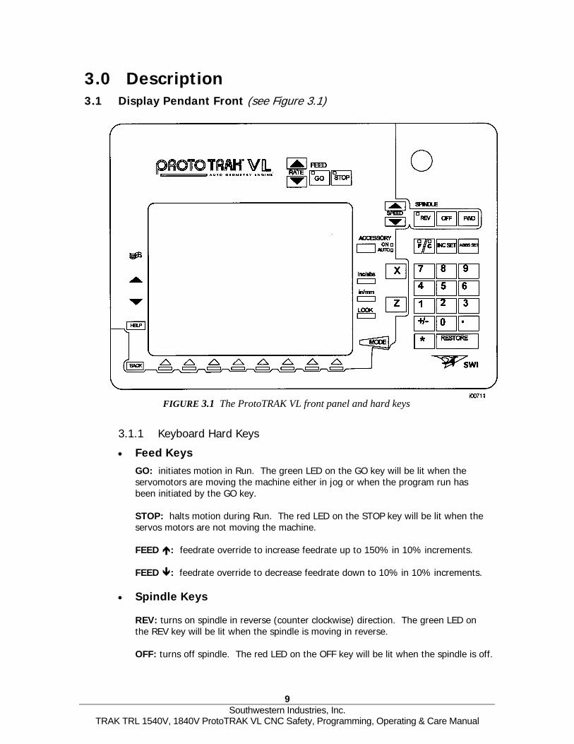
3.0 Description 3.1 Display Pendant Front (see Figure 3.1)
FIGURE 3.1 The ProtoTRAK VL front panel and hard keys
3.1.1 Keyboard Hard Keys
• Feed Keys GO: initiates motion in Run. The green LED on the GO key will be lit when the servomotors are moving the machine either in jog or when the program run has been initiated by the GO key.
STOP: halts motion during Run. The red LED on the STOP key will be lit when the servos motors are not moving the machine.
FEED : feedrate override to increase feedrate up to 150% in 10% increments.
FEED : feedrate override to decrease feedrate down to 10% in 10% increments.
• Spindle Keys
REV: turns on spindle in reverse (counter clockwise) direction. The green LED on the REV key will be lit when the spindle is moving in reverse.
OFF: turns off spindle. The red LED on the OFF key will be lit when the spindle is off.
9 Southwestern Industries, Inc.
TRAK TRL 1540V, 1840V ProtoTRAK VL CNC Safety, Programming, Operating & Care Manual

FWD: turns on spindle in forward (clockwise) direction. The green LED on the FWD key will be lit when the spindle is moving in the forward direction.
SPEED : spindle speed override to increase spindle rpm up to 150% in 5% increments.
SPEED : spindle speed override to decrease spindle rpm down to 10% in 5% increments.
ACCESSORY: Turns coolant on and off.
F/C: select between fine and course feed for the X and Z handwheels. The green LED’s indicate which feed is active.
INC SET: loads incremental dimensions and general data
ABS SET: loads absolute dimensions and general data
INC/ABS: switches all or one axis from incremental to absolute or absolute to incremental
IN/MM: causes Inch to Metric or Metric to Inch conversion of displayed data
LOOK: part graphics in Program mode
X, Z: selects axis for subsequent commands
RESTORE: clears an entry, aborts a keying procedure
0-9, +/-, . : inputs numeric data with floating point format. Data is automatically + unless +/- key is pressed. All input data is automatically rounded to the system's resolution.
MODE: to change from one mode of operation to another
3.Beproshde Sothaexthe
TRAK T
: Windows® functions including access to the Windows desktop and shut down of the ProtoTRAK VL CNC.
: reinstates a window.
: eliminates a window.
HELP: displays help information, math help or additional functions. Active for additional functions when the help symbol (a blue question mark) is displayed on the screen next to the HELP key.
1.2 Soft Keys neath the display are 8 keys that are labeled with arrows. These keys are called software grammable or soft keys. A description of the function or use of each of these keys will be
own at the bottom of the display directly above each key. If, at any time, there is no scription above a key, that key will not operate.
metimes the description or function of the key is visible but grayed out. This indicates t the particular function is not available because of some other condition. For
ample, if the home is not set, the RUN mode key will be grayed out because setting home is a necessary step for running a program.
10 Southwestern Industries, Inc.
RL 1540V, 1840V ProtoTRAK VL CNC Safety, Programming, Operating & Care Manual

3.1.3 Emergency Stop Switch There are two emergency stop buttons, one on the control panel and one on the door. The emergency stop (E-stop) switch kills all power to the spindle and ProtoTRAK's servomotors. The computer and pendant remain powered.
3.1.4 The Liquid Crystal Display (LCD) The display of the ProtoTRAK VL is a 10.4" active-matrix color LCD. The very top is the Status Line that shows the overall status of the ProtoTRAK VL. This includes the current Mode, the current program part number, the current tool number and whether the X and Z dimensions are in inch or millimeter (mm). Just above the soft keys is a direct input line that appears when an input is required.
3.2 Pendant Left Side (See Figure 3.2 for a description of the left side panel of the display.)
FIGURE 3.2 The ProtoTRAK VL left side with connectors labeled
11 Southwestern Industries, Inc.
TRAK TRL 1540V, 1840V ProtoTRAK VL CNC Safety, Programming, Operating & Care Manual

3.3 Pendant Right Side (See Figure 3.3 for a description of the connectors and features located on the right side of the display panel.)
FIGURE 3.3 The ProtoTRAK VL right side
12 Southwestern Industries, Inc.
TRAK TRL 1540V, 1840V ProtoTRAK VL CNC Safety, Programming, Operating & Care Manual

3.4 Machine and Control Specifications
Capacity 1540V 1840V ProtoTRAK VL CNC Hardware` Height of Centers 8” 9” Two-Axis CNC, two-axis DRO Distance Between Centers 40” 40 ¼” Intel Pentium processor with built-in video Ethernet Swing Over Bed 15” 18 ½” cards Swing Over Saddle Wings 15” 17” 32 MB of RAM with expansion slot available Swing Over Cross Slide 6 5/8” 9” Hard drive Cross Slide Travel 11 ½” 13” TEAC floppy drive Max. Recommended Dia. in Steel 5” 18” Ports and connectors: RS232, network (RJ45), P/S 2 Tool Section Max ¾” 1” keyboard and mouse Coolant 12 gal. 13 gal. 10.4” color active-matrix LCD
Bed Brushless A.C. Servo Motors rated at 704 in-oz Width 12 5/8” 14 ½” continuous torque Height 12 5/8” 13 3/8” 250 IPM rapid traverse
Headstock Precision ground ballscrews for cross slide and Spindle Nose A2-5 D1-6 longitudinal travel Spindle Through Hole 2 1/8” 2.36” Override of programmed feedrate and rapid with Spindle Taper MT #6 MT #6 graphical indicator Taper in Reduction Sleeve MT #4 MT #4 Polycarbonate sealed membrane with LED status lights Spindle Diameter Front Bearing 3.15” 3.35” Gasket sealed enclosures Number of Bearings 5 3 Electronic handwheels Bearing Class (Radial Runout) P2 (ABEC 9) P5 Jogstick for convenient jog Number of Spindle Speed Ranges 1 2 Magnetek AC spindle drive Spindle Speed Range (RPM) 150-4000 80-850
250-2500 Digital servo amplifiers custom designed for lathe operation
Spindle Motor H.P. 10 10 Voltage 220 220 Amps, Full Load 36 36 Phase/Hz 3/60 3/60
Dimensions Net Inches, LxWxH, lbs. 89x53x70, 4100 91x53x70, 4500 Ship Inches, LxWxH, lbs. 90x55x73, 4650 97x58x72, 5170
Other Coolant Pump Motor 1/8 HP 1/8 HP Spindle Motor Brake Dynamic Braking Way Surface Hardness 400 – 450 HB Head Stock Lubrication Grease Oil Bath
Optional Equipment Steady Rest (Type, Diameter) Roller, ½”-5½” Solid, ¾” – 6” Tooling Kit ¾” Chuck 6” A2-5 8” D1-6 5C Collet Closer A2-5 D Camlock Indexer Option ¾”, 8 Position Gang Tooling ¾”
3.5 Spindle Motor
The spindle motor is a 10 HP variable speed motor that drives the spindle by a belt.
3.5.1 Spindle Speed Ranges Model TRL 1540V has one spindle speed range, from 150 to 4000 RPM. Model 1840V has two spindle speed ranges that you select using a lever on the headstock. The L (low) setting is from 80 to 850 RPM. The H (high) setting is from 250 to 2500 RPM.
13 Southwestern Industries, Inc.
TRAK TRL 1540V, 1840V ProtoTRAK VL CNC Safety, Programming, Operating & Care Manual

3.6 Electronic Handwheels The electronic handwheels of the TRAK TRL 1540V or 1840V operate when the ProtoTRAK VL CNC is in a mode where the machinist controls the motion of the table, saddle and ram. This includes the DRO mode, the set-up mode and TRAKing in the Run mode. The electronic handwheels will not operate while the ProtoTRAK VL is moving the machine through the servomotors.
3.7 Lubrication System
3.7.1 Headstock The 1540V does not have gears, so there is no lubrication system in the headstock.
For the 1840V, check the site glass on the headstock periodically each day to make sure oil is being pumped to the headstock. The level of the oil in the headstock oil reservoir can be checked by the sight level located under the spindle cover. If oil level is low, fill to the sight level with Mobil DTE 24 or equivalent oil. The headstock oil reservoir holds approximately 3 1/2 gallons. Depending on operating conditions, usually about once a year, the headstock should be drained and wiped out before adding new oil. A drain valve is located under the spindle cover. Refill the headstock with oil to the site level. 3.7.2 Automatic Lubrication Pump The auto lube system provides centralized automatic lubrication for the cross slide, saddle and ball screws. Flow is proportioned to each lubrication point with appropriately sized orifices. The lube pumps’ 2-liter reservoir is serviced with S.A.E. 30 weight oil. The Pump’s output can be regulated through a series of dipswitches that control the pause time between pumping cycles, and the duration of the pumping cycle as shown below. Switches are located under the pump control cover.
Pause Time Pump Time 1 = 2.5 min 1 = 2.5 sec 2 = 5 min 2 = 5 sec 3 = 10 min 3 = 10 sec 4 = 20 min 4 = 20 sec 5 = 40 min 6 = 80 min
If two or more of the switches are in the “ON” position, the time is additive. Pause Time Example: 52.5 min = switch 1 + 3 + 5 LED’s on the pumps’ control indicate operating conditions as shown below: Green = power on Yellow = pump operating Red = warning; out of oil The pump may also be operated manually with a push button located on the pumps’ control panel.
14 Southwestern Industries, Inc.
TRAK TRL 1540V, 1840V ProtoTRAK VL CNC Safety, Programming, Operating & Care Manual

CAUTION! Failure to properly lubricate the lathe will result in the premature failure of bearings
and sliding surfaces.
CAUTION! Failure to manually activate the pump at the beginning of each day, or allowing the Auto Lube to run
dry may cause severe damage to the TRL 1540V, 1840V way surfaces and ballscrews.
In order to adjust the factory settings or discharge the lubrication pump, go to the Service Codes (from the Set-Up Mode). Select E, Lube Pump Set Up.
3.8 Electrical Cabinet The machines use a single electrical source for the machine and the control. 220v power is wired directly to the disconnect switch.
3.9 Using Electronic Handwheels
The X (cross slide), and Z (carriage) handwheels are located on the apron. They are electronic, that is they are not mechanically connected to the machine, but rather create electronic signals to command the servo motors to drive the ball screws which, in turn, drive the carriage and cross slide. The handwheels will not work unless the ProtoTRAK VL CNC is turned on, and in the DRO mode, or in the Set Up mode, or in the TRAKing feature in the Run mode. Counterclockwise motion on the Z handwheel moves the carriage left 0.40" per revolution in .002" increments in coarse feed, or .10" per revolution in .0005" increments in fine feed. See Section 6.10 to switch from coarse to fine and back. Clockwise motion on the X handwheel moves the cross-slide away from you .10" per revolution in .0005" increments (on diameter) in coarse feed, or .02" per revolution in .0001" increments in fine feed. See Section 6.3 to switch from coarse to fine and back.
3.10 Using the Jog Stick
The jog stick is located on the carriage apron in between the X and Z handwheel. The jog stick will operate only if the ProtoTRAK VL CNC is turned on, and in the DRO mode or Set-Up mode, or in the TRAKing feature in the Run mode. Move the stick left or right to move the carriage left or right at 150 inches per minute. Move the stick up or down to move the cross slide in or out at 100 inches per minute of diameter, or 50 inches per minute of actual cross slide speed.
3.11 Sliding Doors and Interlock Switch
3.11.1 For the 1840V
The 1840V has a single door that may be rolled out of the way for set ups and machining in the DRO mode or in the Run Mode while using the TRAKing feature. For running a CNC program, the door must be positioned over the chuck in order to close the interlock switch. The ProtoTRAK VL CNC will not run a program unless the door is in this protective position.
15 Southwestern Industries, Inc.
TRAK TRL 1540V, 1840V ProtoTRAK VL CNC Safety, Programming, Operating & Care Manual

3.11.2 For the 1540V The 1540V has two doors that roll along slides. These doors may be positioned out of the way for set ups and machining in the DRO mode or in the Run Mode while using the TRAKing feature. For running a CNC program, one of the doors must be positioned over the chuck in order to close the interlock switch. The ProtoTRAK VL CNC will not run a program unless the door is in this protective position. If you prefer, the left door may be removed easily by lifting it off its track. To do this safely, we recommend that two people lift the door on and off the track.
3.12 Optional Equipment
3.12.1 Collet Closer SWI supplies a Royal 5C collet closer with an extended nose.
• 1540V - A2-5 • 1840V - D camlock
If you purchase collet closer from another source, be sure to get the extended nose type. The tapered-sleeve bushing style of collet closer sits too far back in the spindle and exposes the chuck mounting holes. This makes it likely for contamination to enter the spindle bearings.
3.12.2 Chuck This is a Strong brand chuck, non-adjustable, featuring separate top jaws and master jaws. The chuck features an adapter plate so that it may be used with a different machine having a different spindle nose. The chucks are rated by the manufacturer for the maximum spindle speed of the machine model.
• 1540V - 6" A2-5 • 1840V - 8" D1-6
3.12.3 Gang Tooling The gang tooling option for both models includes the following:
• 6 each riser blocks • 1 each double facing tool block • 2 each single facing tool block • 1 each side tool holder • 6 spacer blocks
The riser blocks are iron nickel plated to prevent rust. The tool blocks and spacer blocks are black anodized. SWI supplies only the complete kits. To purchase individual tool blocks and other accessories such as boring bar bushings, please see your local dealer.
3.12.4 Indexer Option A Dorian model Smart-Dex 20 indexer is available installed at the factory. This indexer has 8 stations for 3/4" tooling. Coolant is supplied at each tool. If installation is required outside the factory, there is an additional charge.
16 Southwestern Industries, Inc.
TRAK TRL 1540V, 1840V ProtoTRAK VL CNC Safety, Programming, Operating & Care Manual

3.12.5 Offline Programming Optional software is available for programming your ProtoTRAK VL CNC on your desktop computer. The screens of the system look exactly like the screens you encounter when running the ProtoTRAK VL CNC at the machine. The control's hard keys are mapped to your keyboard. 3.12.6 Steady Rest The steady rest for the 1540V is a roller type and can accommodate diameters from 1/2" to 5 1/2". The steady rest for the 1840V is solid brass nib, and can accommodate diameters from 3/4" to 6". 3.12.7 Tooling Kit The tooling kit option is Dorian brand tooling that contains a tool post and a variety of different tool holders. The tool post has a quick release mechanism for quick and easy changes of tool holders, repeatable to within .001" The tooling kit package includes:
• A quick-change tool post; • 4 each 3/4" square tool holders for turning, facing and boring • 1 each Morse taper drill holders • 1 each tool holder, boring
3.12.8 Remote Stop/Go Switch The Remote Stop/Go Switch (RSG) is a hand-held, push-button switch that does exactly the same thing as the STOP/GO button on the ProtoTRAK VL display.
17 Southwestern Industries, Inc.
TRAK TRL 1540V, 1840V ProtoTRAK VL CNC Safety, Programming, Operating & Care Manual

18 Southwestern Industries, Inc.
TRAK TRL 1540V, 1840V ProtoTRAK VL CNC Safety, Programming, Operating & Care Manual

4.0 Basic Operation One of the things that makes the TRAK TRL so easy to use is that most of the operations of the ProtoTRAK VL CNC are organized in Modes. Modes are logical groups of activities that naturally belong together. This eliminates the need to memorize operations – just select a mode and choose among the soft keys.
Most operations will be discussed within the section that treats the mode later in this manual. The operations described in this section either don’t fit in a particular mode, or they are relevant to more than one mode. 4.1 Switching the TRAK TRL On/Off
Power to the TRAK TRL 1540V or 1840V is turned on through the main on/off switch located on the back of the main electrical cabinet. The machine main switch must be on for power to go to the ProtoTRAK VL CNC.
4.2 Switching the ProtoTRAK VL CNC On
To turn the ProtoTRAK VL CNC on, move the toggle switch on the display side right panel to the Up position.
The Windows operating system and the ProtoTRAK VL CNC software will take a few seconds to load from the system's hard drive to its memory. If you have connected the ProtoTRAK VL CNC to a network, it may take as long as 90 seconds for the communications to be established. When complete, the ProtoTRAK VL CNC Select Mode screen will appear and the Windows desktop will be in the background.
FIGURE 4.2.1 This is the first screen you will see after the ProtoTRAK VL CNC is finished booting up
19 Southwestern Industries, Inc.
TRAK TRL 1540V, 1840V ProtoTRAK VL CNC Safety, Programming, Operating & Care Manual

The first screen encountered after power up has the F1 soft key labeled "Check System". Press this to start a routine that aligns the servomotors. Another screen will appear with a warning to remove obstacles and the F1 soft key labeled "GO". Press go and the motors will move slowly, moving the carriage and cross slide less than an inch. The process is over in 10 seconds or so. The ProtoTRAK VL CNC will start up with the spindle disabled for safety. It will be necessary to set a MAX RPM in SET UP Mode to enable the spindle. Refer to Section 10.6 MAX RPM. It is a good idea at this time to lubricate the sliding surfaces and ballscrews, particularly if the machine has been idle for an extended period of time. From the MODE screen press the SERV CODES softkey. Selection option E LUBE PUMP SETTINGS. Press the soft key for SERVICE CODE 300. The lubrication pump will run for the programmed time. Select the Mode of operation by pressing the soft key beneath the labeled box. Notice that the EDIT and RUN soft keys are grayed out. They will not function because there is no program in the ProtoTRAK VL CNC. Once a program is entered, the EDIT key will function. Once a program is entered and the necessary SET-UP operations are complete, the RUN key will function.
FIGURE 4.2.2 The main “select a mode” screen. Shown here, the Edit and Run Modes are gr out because there is no program in current memory
The ProtoTRAK VL CNC has a screen saver already programmed in. If the system is not used (either by a key stroke or by counting) for 20 continuous minutes, the display will turn itself off. The LED’s on the keypad will flash every few seconds to indicate that the system is still on. Press any key or move any axis to bring the screen back to its previous display. The key you press will be ignored except to turn the screen on.
4.3 Shutting down the ProtoTRAK VL CNC Important: the system must be turned off properly. First press the Window
key and then press the SHUT DOWN soft key. After a few seconds, you will message "it is now safe to turn off your computer". Turn the ProtoTRAK VL moving the toggle switch on the display side panel to the down position.
If the CNC is not shut down properly, the system will make you wait while it disk self-diagnostic routine and scold you for not following the instructions.
Note: When you turn the PROTOTRAK VL CNC off, always wait a few seconds befo
20 Southwestern Industries, Inc.
TRAK TRL 1540V, 1840V ProtoTRAK VL CNC Safety, Programming, Operating & Ca
s hard see the CNC off by
runs a scan
re turning it back on.
re Manual

4.4 Spindle Forward/Off/Reverse The spindle is controlled through the hard keys of the pendant. It is only operational while the ProtoTRAK VL CNC is in the DRO or the Run modes. The spindle speed is programmed in the events during part programming. Programmed spindle speeds may be changed in the Edit or Program mode and the spindle speed may be set for manual operation in the DRO mode.
The spindle speed that is set or programmed may be overridden from 5% to 150% in 5% increments as it is running by pressing the SPEED up or down hard keys.
4.5 Using the Electronic Handwheels
The X (cross slide), and Z (carriage) handwheels are located on the apron. They are electronic, that is they are not mechanically connected to the machine, but rather create electronic signals to command the servomotors to drive the ball screws that, in turn, drive the carriage and cross slide. The handwheels will not work unless the ProtoTRAK VL CNC is turned on, and in the DRO mode, or in the Set Up mode, or in the TRAKing feature in the Run mode. Counterclockwise motion on the Z handwheel moves the carriage left 0.40" per revolution in .002" increments in coarse feed, or .10" per revolution in .0005" increments in fine feed. Clockwise motion on the X handwheel moves the cross slide away from you .10" per revolution in .0005" increments (on diameter) in coarse feed, or .02" per revolution in .0001" increments in fine feed. See Section 6.3 to switch from coarse to fine and back.
4.6 Using the Jog Stick
The jog stick is located on the carriage apron in between the X and Z handwheel. The jog stick will operate only if the ProtoTRAK VL CNC is turned on, and in the DRO mode or Set-Up mode, or in the TRAKing feature in the Run mode. Move the stick left or right to move the carriage left or right at 150 inches per minute. Move the stick up or down to move the cross slide in or out at 100 inches per minute of diameter, or 50 inches per minute of actual cross slide speed.
4.7 Emergency Stop There are two emergency stop buttons, one on the control panel and one on the
door.Press the button to shut off power to the spindle motor and axis motors. Rotate the switch to release.
4.8 Coolant Pump
The coolant pump for your TRAK Lathe is operated by the Accessory key on the front panel. The Accessory key has a light to indicate how it will operate. Press the key until it is on the setting you want. The Accessory setting you choose will be retained as you change modes, but will need to be reset after turning the CNC off and back on. The light settings and their meanings: No light – the coolant pump will not come on. Use this setting when you do not want coolant.
21 Southwestern Industries, Inc.
TRAK TRL 1540V, 1840V ProtoTRAK VL CNC Safety, Programming, Operating & Care Manual

On – the coolant pump will come on and stay on while the CNC is in the DRO, Run or Set-up modes. Auto – Depress and hold the accessory key for 2 seconds. The coolant pump will now turn on and off when the spindle turns on and off. This is probably the most useful setting for most of your machining with coolant.
4.9 Windows Desktop The Windows desktop is accessed by pressing the Windows hard key and then choosing the WINDOWS 98 soft key. The ProtoTRAK VL CNC program will continue running in the background. To get back to the ProtoTRAK VL CNC, press the BACK hard key.
4.10 Help Functions
When a blue question mark appears next to the HELP hard key, that means special functions or configuration settings are available for the current operation. For example, at the program header with the highlight on the program name, the blue question mark appears. Pressing the HELP key at that time will call up a table with alpha and special characters you can use to name your program. 4.10.1 Math Helps When the blue question mark does not appear, pressing HELP will initiate the Math Helps.
FIGURE
Matcalc Fortwo
TRAK TR
4.10.1 The first Math Helps screen. Choose among the alternatives based on the information you need to calculate
h Helps are powerful routines that enable you to use the data you have available to ulate missing print data.
example, Math Help type 28 enables you to solve an entire right triangle by giving known pieces of data. To exit from the Math Help, press the Mode key.
22 Southwestern Industries, Inc.
L 1540V, 1840V ProtoTRAK VL CNC Safety, Programming, Operating & Care Manual

FIGURE 4.10.2 Math Help 28. In this example, by entering the length of line A and the value of angle G, the other values are calculated
You may have the Math Help solutions load directly into your program. This saves you from having to write down the solution and then key it in. While you are programming the event that needs the data from Math Help, simply press the HELP key to start the Math Help. Once a solution is obtained, you will have the following soft key selections: Load Begin: will load the displayed solution into the event as the X and Z beginning.
Load End: will load the displayed solution into the event as the X and Z end.
Load Center: will load the displayed solution into the event as the X and Z center.
Next Solution: when there is more than one solution to the problem, this will display the alternative solutions.
Edit: this allows you to go back to the data you entered in order to make changes. Once you do this, the Resolve key will appear.
Resolve: press this to have the Math Help use the new data to give new solutions.
4.11 Windows Up or Down Some of the selections in the ProtoTRAK VL CNC will cause a window to appear with a message. To eliminate the window in order to see what is behind it, press the u hard key. To restore the window, press the t hard key.
4.12 Using a Mouse & Keyboard
A P/S 2 mouse and keyboard may be used. See Figure 3.3 for the location of the connectors. The ProtoTRAK VL CNC should be turned on with the mouse plugged in so that the display will recognize the hardware.
23 Southwestern Industries, Inc.
TRAK TRL 1540V, 1840V ProtoTRAK VL CNC Safety, Programming, Operating & Care Manual

4.13 Tool Pedestal The tool pedestal is held to the top of the cross-slide with four bolts with T nuts. A T-slot is machined on top of the pedestal that will accommodate most common tool posts.
4.14 Tail Stock
The tail stock may be positioned along its V-way by releasing the lock with the lock handle. On the 1840V, the tail stock can also be locked with the nut located on the operator side of the tail stock. The quill may be locked with the quill lock at any position along its travel. The tail stock may be centered with the spindle through the set screw on the tail stock base.
4.15 Spindle Operation
The spindle is operated by the SPINDLE keys on the front panel. The spindle will only operate while the CNC is in the DRO, Run or Set-Up modes. Note: for safety, the spindle of the TRAK lathe will not come on until you turn it on. The CNC will not turn on the spindle as a command in the part program. Use the REV (reverse), OFF, or FWD (forward) keys to turn the spindle on or off. The LED on the key will indicate its status. When running a CNC part program, the spindle speed is one of the programmed inputs. Percentage override of the programmed spindle speed is done with the SPEED up and down arrows on the front panel. This will vary the programmed speed from 5% to 150% of the value programmed. In DRO mode, the spindle speed is set by pressing the SPIN SPEED soft key and entering a value when prompted. Percentage override of the spindle speed is done with the SPEED up and down arrows on the front panel. This will vary the speed you set from 5% to 150%.
In program RUN, the spindle will not turn on during CNC run when the door is open (unless you are TRAKing).
4.16 Spindle Speed Ranges
The model 1540V has only one spindle speed range (150 - 4000 RPM). Any value within this range may be set or programmed at any time. The model 1840V has two spindle speed ranges (80 - 850 and 250 - 2500 RPM). In order to go from one range to the other, you must change gears on the headstock.
WARNING!
Do not shift headstock gears while motor is running.
If a spindle speed is programmed that is not within the range of the machine, the ProtoTRAK VL CNC will go the maximum or minimum possible for its range. If the gears are left in Neutral, the spindle will not turn on and the CNC screen will display an error message.
24 Southwestern Industries, Inc.
TRAK TRL 1540V, 1840V ProtoTRAK VL CNC Safety, Programming, Operating & Care Manual

25 Southwestern Industries, Inc.
TRAK TRL 1540V, 1840V ProtoTRAK VL CNC Safety, Programming, Operating & Care Manual

5.0 Definitions, Terms & Concepts 5.1 ProtoTRAK VL CNC Axis Conventions
Z Axis: positive Z-axis motion is defined as the carriage moving to the right when facing the lathe. Measurement away from the chuck is positive on the workpiece. X Axis: positive X-axis motion is defined as the cross slide moving toward you. Measurement away from the part centerline and toward you is positive. All X motion is displayed as diameter (not radius) dimensions.
5.2 Absolute & Incremental Reference
The TRAK TRL may be programmed and operated in either (or in a combination) of absolute or incremental dimensions. An absolute reference from which all absolute dimensions are measured (in DRO, and program operation) can be set at any point on or even off the workpiece. To help understand the difference between absolute and incremental position, consider the following example:
i00222
5.3 Referenced and Non-Referenced Data
Data is always loaded into the TRAK TRL by using the INC SET or ABS SET key. X, Z positions are referenced data. In entering any X, or Z position data, you must note whether it is an incremental or absolute dimension and enter it accordingly. All other information (non-referenced data), such as tool offset, feedrate, etc. is not a position and may, therefore, be loaded with either the INC SET or ABS SET key. This manual uses the term SET when either INC SET or ABS SET may be used interchangeably.
25 Southwestern Industries, Inc.
TRAK TRL 1540V, 1840V ProtoTRAK VL CNC Safety, Programming, Operating & Care Manual

5.4 Tool Tip Radius Compensation When turning along the side of a part (constant X), or along the face (constant Z), the tool tip radius is not particularly important. However, as soon as you begin to machine a taper or contour, the tool tip radius has a substantial impact. Consider the drawing below. If you had an infinitely sharp tool (no tool tip radius), assume its point was at X0, Z0. Another tool with a tool tip radius of R1 and another of R2 are also shown. Note that all three positioned as shown have the same X contact (X0, X1, X2) and if moved sideways, would cut the same diameter. Likewise, they all have the same Z contact, and if moved in would cut the same face length. However, if moved on a 45 degree taper (or any other angle) so that the cutting point was in the middle of the radius, the three tools would cut or contact along much different lines.
i00217
5.5 Tool Offset
When you define the shape of the part to be turned, you must also specify where the tool should be relative to the part. This is done by looking along the direction of the tool motion and declaring whether the tool is to the right or left of the part. Examples of tool left are:
i00218
26 Southwestern Industries, Inc.
TRAK TRL 1540V, 1840V ProtoTRAK VL CNC Safety, Programming, Operating & Care Manual

Examples of tool right are: i00219
Tool center may be programmed for special circumstances where you wish to ignore the effects of tool geometry and radius.
5.6 Connective Events
Connective events occur between two turning events (either Turn or Arc) when the X and Z ending points of the first event are in the same location as the X and Z starting points of the next event. In addition, the tool offset and tool number of both events must be the same.
5.7 Conrad
Conrad is a unique feature of the TRAK TRL that allows you to program a tangentially connecting radius between connective events. For the figure below, you simply program a Turn event from X1, Z1 to X2, Z2 with tool left offset, and another Turn event from X2, Z2 to X3, Z3 also with tool left offset. During the programming of the first Turn event, the system will prompt for Conrad at which time you input the numerical value of the tangentially connecting radius (r=k). The system will calculate the tangent points T1 and T2, and direct the tool cutter to move continuously from X1, Z1 through T1, r=k, T2 to X3, Z3.
i00238
27 Southwestern Industries, Inc.
TRAK TRL 1540V, 1840V ProtoTRAK VL CNC Safety, Programming, Operating & Care Manual

For the figure below, you program an Arc event from X1, Z1 to X2, Z2 with tool offset left, and another Arc event from X2, Z2 to X3, Z3 also with tool offset left. During the programming of the first Arc event, the system will prompt for Conrad at which time you input the numerical value of the tangentially connecting radius r=k3. The system will calculate the tangent points T1 and T2 and direct the tool cutter to move continuously from X1, Z1 through T1, r=k3, T2 to X3, Z3.
i00239
Note: Conrad must always be the same as or larger than the tool radius for inside corners. If conrad is less than the tool radius, and an inside corner is machined, the TRAK TRL will ignore the Conrad. Note: If you program an arc using Conrad rather than an ARC, never use a Conrad whose radius is as large or larger than the length of either line connected by the Conrad plus the tool tip radius. In the figure below, R plus the tool nose radius must be less than the programmed line ab or bc; otherwise, program the arc with an ARC Event.
i00220
5.8 Chamfer
The TRAK TRL also allows for easy chamfer input. A chamfer may be programmed between two turn events, two arcs, or a turn and an arc.
i00221
28 Southwestern Industries, Inc.
TRAK TRL 1540V, 1840V ProtoTRAK VL CNC Safety, Programming, Operating & Care Manual

In both cases above a chamfer programmed with dimension b will cut a chamfer along line c.
5.9 Absolute, Tool, and Program References
When you operate a lathe, what you are interested in is where your tool is relative to the workpiece. However, what the TRAK TRL monitors is how far the carriage and cross slide move. This creates two problems.
The first has to do with using more than one tool. When you change tools, the tip on one will, most likely, not be in the same position relative to the part as the previous tool. Just changing the tool doesn't move the carriage or cross slide, so the TRAK TRL doesn't know that the new tip isn't where the other was. Obviously, what's needed is for you to tell the TRAK TRL what the differences (or offsets) are from tool to tool (this is done easily in the Set Up Mode), and to always tell the control which tool you are using at any given time.
The second problem has to do with establishing the machine and part reference. When you turn the TRAK TRAK TRL on, it has no idea where the carriage, cross slide, or tool tip is. It only knows how far it has moved since the last input reference (all references are lost when the control is turned off). Also, if you are going to turn a part, the control has no idea where you have chucked it. Is it sticking out of the chuck a little? A lot? What you need to do is select a tool--and always tell the control which one--and tell the TRAK TRL where that tool is, relative to the workpiece.
In general, most programs and parts will have their centerline as the absolute zero reference in the X-axis. For the Z-axis, two handy references are the end of the part (generally after it has been faced), or any face of the chuck.
5.10 Feedrate Conventions
Carriage feedrate (Z motion) and cross slide feedrate (X motion) may, in most cases, be input directly as inches per minute (ipm) or as inches per revolution (ipr) of the spindle. The relationship between these is:
ipm = ipr x RPM or
ipr = ipm/RPM
Math Help 30 will calculate these values for you.
All feedrates must be programmed between 0.100 and 100 ipm (2.5 - 2500 mm/min) or between 0.001 and 0.099 ipr (0.025 and 2.5 mm/rev).
5.11 Spindle Speed Conventions For programmed parts, spindle speed may be set as direct RPM or as a surface speed in surface feet per minute (SFM) or surface meters per minute (SMM).
The relationship between RPM and SFM is
SFM = RPM x Diameter x π
12
or
29 Southwestern Industries, Inc.
TRAK TRL 1540V, 1840V ProtoTRAK VL CNC Safety, Programming, Operating & Care Manual

SFM = 0.26 x RPM x Diameter (in inches) For example, when you are cutting at a diameter of 3 inches and a RPM of 600, then your SFM would be 0.26 x 600 x 3 = 468. Math help 31 will calculate RPM or SFM for you. Surface speed is the relative speed between the workpiece and the tool during a cut. That is, it is the speed that the workpiece passes across the tool. Notice in the formula above that if you wanted the SFM to be constant during the cut you would have to change RPM as the tool moved to a different diameter - for example while facing. When you program the spindle speed as SFM in the program mode the TRAK TRL will assume that you want to maintain constant surface speed (CSS) and will automatically vary the spindle RPM to maintain the program value.
Note that if you program with constant surface speeds and inch per revolution feeds, then not only does the spindle RPM increase as you face cut towards the centerline but the cross slide will move at a faster rate as well.
30 Southwestern Industries, Inc.
TRAK TRL 1540V, 1840V ProtoTRAK VL CNC Safety, Programming, Operating & Care Manual

6.0 DRO MODE The ProtoTRAK VL CNC operates in DRO Mode as a sophisticated 2-axis digital readout with jog and power feed capability. Most DRO operations, except power feed and Return Home, may be done with the sliding door open. 6.1 Enter DRO Mode Press MODE, select DRO soft key. The screen will show:
6.2 DR
Cle
Inc
Ressele
Pre
Reszero
Notdisp
Preaxis
Notwhe
TRAK T
FIGURE 6.1 The DRO screen
O Functions ar Entry: Press RESTORE, then re-enter all keys.
h to MM or MM to Inch: Press IN/MM and note LCD screen status line.
et One Axis: Press X or Z, INC SET. This zeros the incremental position in the cted axis.
set: Press X or Z, numeric data, INC SET to preset selected axis.
et Absolute Reference: Press X or Z, ABS SET to set selected axis absolute to at the current position.
e: This will also reset the incremental dimension if the absolute position is being layed when it is reset.
set Absolute Reference: Press X or Z, numeric data, ABS SET to set the selected absolute to a preset location for the current machine position.
e: This will also reset the incremental dimension if the absolute position is being displayed n it is preset.
31 Southwestern Industries, Inc.
RL 1540V, 1840V ProtoTRAK VL CNC Safety, Programming, Operating & Care Manual

Recall Absolute Position of All Axes: Press INC/ABS. Note the dimension for each axis is labeled INC or ABS. Press INC/ABS again to revert to the original reading.
Recall Absolute Position of One Axis: Press X or Z, INC/ABS. Note the INC or ABS label for each axis. Repeat to get selected axis back to original reading.
6.3 Fine and Coarse Resolution Press the F/C key to switch back and forth from fine to coarse.
Resolution Travel/Revolution X Fine .0001"/.005mm .02"/1mm Coarse .0005"/.02mm .10"/4mm Z Fine .0005"/.02mm .10"/4mm Coarse .002"/.05mm .40"/10mm
6.4 Power Feed
The servomotors can be used as a power feed for the carriage or cross slide, or both simultaneously. The door must be closed to run a power feed move.
a. Press the POWER FEED soft key.
b. A message box will appear that shows the power feed dimensions. All power feed moves are entered as incremental moves from the current position to the next position.
c. Enter a position by pressing the axis key, the distance to go and the +/- key (if needed). Input the entry by pressing INC SET. For example, if you wanted to make a power feed move of 2.00" of the cross slide in the negative direction, you would enter: X, 2, +/-, INC SET.
d. Initiate the power feed move by pressing GO.
e. The feedrate is automatically set to 10 ipm (or 254 mm per min). To power feed in IPR, press the IPR soft key. This key will toggle between IPM and IPR. Press FEED or FEED to adjust the feedrate.
f. Press STOP to halt power feed. Press GO to resume.
g. Repeat the process beginning at "c" above as often as you wish.
h. Press RETURN soft key to return to manual DRO operation. 6.5 Do One
The purpose of the Do One Events is to allow you to make simple chamfer, taper, radius, and fillet moves, one at a time, within the DRO Mode and without the need for creating an entire program. When you select the DO ONE soft key shown in Figure 6.1, the soft keys will read:
32 Southwestern Industries, Inc.
TRAK TRL 1540V, 1840V ProtoTRAK VL CNC Safety, Programming, Operating & Care Manual

6.5.1 Taper Do One When you select the TAPER soft key, the Data Input Line will prompt you to enter a taper angle.
The system defaults to a positive 45 degree taper angle for a convenient chamfer. If this is the angle you wish, acknowledge so by pressing SET. You may specify any other angle by inputting the number and pressing SET. The angle is in reference to the part centerline. Turning the Z handwheel counterclockwise, or the X clockwise, will move the tool from Point A (where you are), towards or past Point B as long as you turn the handwheel (see below).
i00223 Press RETURN to revert back to normal DRO operation. 6.5.2 Radius Do One
When you select the RADIUS soft key, the Data Input Line will prompt you to enter a radius value. Input and SET the radius you want through the keyboard. The radius may be positive or negative. Turning the Z handwheel counterclockwise, or the X clockwise will move the tool from Point A (where you are), towards Point B (see below). The tool will automatically stop when you reach B.
i00224 Press RETURN to revert back to normal DRO operation. 6.5.3 Fillet Do One
When you select the FILLET soft key, the Data Input Line will prompt you to enter a radius value.
33
Southwestern Industries, Inc. TRAK TRL 1540V, 1840V ProtoTRAK VL CNC Safety, Programming, Operating & Care Manual

Input and SET the fillet radius you want through the keyboard. The radius may be positive or negative.
Turning the Z handwheel counterclockwise, or the X clockwise will move the tool from Point A (where you are), towards Point B (see below). The tool will automatically stop when you reach B.
i00225
Press RETURN to revert back to normal DRO operation. 6.6 Go To
The Go To function in the DRO mode allows you to set a dimension in X or Z at which you want the machine to stop moving when you are cranking manually. For example, if you wanted to machine manually exactly 2" of carriage motion, you would input: Go To, Z, 2, Inc Set. While the Go To window is displayed, the ProtoTRAK VL CNC will not let you pass that 2" dimension you set.
a. Press the Go To key.
b. Enter the axis X or Z or a combination of both.
c. Press Inc Set or Abs Set.
d. Crank the handwheel. Motion will stop at the entered dimension even if you continue to crank the handwheel.
6.7 Return to Home
At any time during manual DRO operation you may automatically move the tool tip to your home location in X and Z by pressing the RETURN HOME soft key. When you do, the conversation line will read "Check Tool then press GO." Make sure your tool and its path is clear and the door is closed. Press the GO key. When you do, the carriage and cross slide will move at rapid speed to your X and Z home position. Home position is established in the Set Up Mode.
6.8 Changing Spindle Speed
The programmed spindle speed in RPM or surface speed in surface feet per minute (SFM) or surface meters per minute (SMM) is shown in the status line. Pressing the SPIN SPEED soft key can modify the speed. The conversation line will show the current speed. Check to make sure you are in the proper gear range (for the TRAK TRL 1840V only). Then input the speed you wish and press INC SET to program RPM or ABS SET to program SFM. You may do this procedure while the spindle is running or still. (NOTE: the spindle must be turned off to change the gear speed range.) If you do input a speed that is beyond the available range for the gear speed range that you have selected, the spindle
34
Southwestern Industries, Inc. TRAK TRL 1540V, 1840V ProtoTRAK VL CNC Safety, Programming, Operating & Care Manual

will default to the minimum or maximum of the range and flash that RPM display in the status line.
6.9 Tool #
The ProtoTRAK VL CNC allows you to use the offsets for tools in your Tool Table (see Section 10.5) in the DRO Mode. To change tools, press the TOOL # soft key and enter the tool number when prompted by the Data Input Line. If you do not wish to use the tools in the Tool Table, simply ignore the Tool # feature.
6.10 Tool Tip Radius Compensation in DRO Mode
As mentioned in Section 5.4, the tool tip radius is not important when you are turning along the side of a part (moving only Z), or along the face (moving only X). And in manual operation in the DRO Mode, these are the only motions that you can do. It's just not possible to move X and Z simultaneously with both hands along a precisely coordinated path. Therefore, even if your tool has a radius, the DRO will display point X0, Z0 in the figure in Section 5.4. In other words, it will display the X and Z contact line positions, which is where the tool will cut when you move either of the handwheels. In Do One operation the tool is moved simultaneously in both the X and Z axes, but the readout still refers to point X0, Z0 in the figure in Section 5.4. This theoretical point will be driven through the taper or radius. As a consequence, if the tool tip radius is large, you may not machine the exact dimension you expect. These errors will generally be insignificant and can be eliminated all together by using a full program (see Section 7).
35
Southwestern Industries, Inc. TRAK TRL 1540V, 1840V ProtoTRAK VL CNC Safety, Programming, Operating & Care Manual

36
Southwestern Industries, Inc. TRAK TRL 1540V, 1840V ProtoTRAK VL CNC Safety, Programming, Operating & Care Manual

.
7.0 Program Mode Part 1: Getting Started & Some General Information
7.1 Programming Overview The ProtoTRAK VL CNC makes programming easy by allowing you to program the actual part geometry as defined by the print.
The basic strategy is to fill in the initial program information and then program the features of the part by selecting the soft key event types (geometry) and then follow all instructions in the Data Input Line.
When an event is selected, all the prompts that need to be input will be shown on the right side of the screen. The first prompt will be highlighted and also shown in the Data Input Line. Input the dimension or data requested and press INC SET or ABS SET. For X or Z dimension data it is very important to properly select INC SET or ABS SET. For all other data either SET will do.
As data is being entered it will show in the Data Input Line. When SET, the data will be transferred to the list of prompts in the right side of the screen, and the next prompt will be shown in the Data Input Line.
When all data for an event has been entered, the entire event will be shifted to the left side of the screen and the conversation line will ask you to select the next event.
7.2 Enter Program Mode
Press MODE, select PROGRAM soft key.
The ProtoTRAK VL CNC will allow only one program in current memory. To write a new program, you must first erase the one in current memory (you may want to first store the program for use in the future). If there is already a program in current memory, entering the Program mode will allow you to edit or add to that program.
FIGURE 7.2 The Program Mode header screen
37 Southwestern Industries, Inc.
TRAK TRL 1540V, 1840V ProtoTRAK VL CNC Safety, Programming, Operating & Care Manual

.
7.3 Program Header Screen The first screen you see when you enter the Program Mode is the Program Header Screen. The Program Header Screen allows you to name the part program and request event comments. The softkey selections allow you to enter the program at any point. 7.3.1 Program Name Programs written on the ProtoTRAK VL CNC are usually named for the part that is to be machined. When programs (or files) are named using the ProtoTRAK VL CNC, the name can be up to 20 characters long. Programs imported into the ProtoTRAK VL CNC may be longer. While 20 characters are allowed, the entire program name may not be shown in the status line or the program header screen.
FIGURE 7.3 Pressing the Help hard key when the Program Name is highlighted calls up alpha keys Program names can include numbers, letters, spaces and other characters. When the Program name prompt is highlighted, the Data Input Line will show "Program Name:". At this point you may:
• Press number keys. • Press Help to access alpha keys and special characters in the ProtoTRAK VL CNC. • Use a keyboard plugged into the ProtoTRAK VL CNC to name the program.
To use the alpha keys and special characters on the ProtoTRAK VL CNC:
• Use the Clear softkey to erase the entire line; the Backspace softkey to erase the last character or number. Use the arrow softkeys to move around the table.
38 Southwestern Industries, Inc.
TRAK TRL 1540V, 1840V ProtoTRAK VL CNC Safety, Programming, Operating & Care Manual

.
• Once the character you want is highlighted, use the Enter softkey to load the character into the program name.
e
• press the End
part number. If none is entered and a GO TO soft key is art number 0.
een just above the X ,
set to Yes, when the highlight is on the
e.
.3.3 Program Header Softkeys
t
next
nter the event number you wish to go to and then press SET. Puts the ber
e GO TO selections will take you to the eginning, with the program header information summarized on the left (as Event 0) and the
Select an Event options for Event 1 on the right.
• Use the blank space on the lower right of the table to insert a space into thprogram name.
Once you finish entering the letters and special characters,softkey. This tells the ProtoTRAK VL CNC that you are finished with the alphatable. Numbers may still be added to the program name.
When you are finished with the program name, press SET to enter it into the currentmemory. Note: It is not necessary to enter apushed, the system will assume a p
7.3.2 Event Comments In the program header screen, you have the opportunity to turn on the prompt for the vent Comments. If you select "Yes" for event comments, you will have the opportunity E
to insert a comment in each event. For Cycle events, you will be able to enter a comment at the cycle header event, but not for each Cycle Turn and Cycle Arc events. he comment you insert will appear in the RUN mode on the scrT
position dimension as the event begins to run. Comments may be composed of lettersnumbers and some symbols and may be up to 20 characters. While programming with the Event CommentsEvent Comments prompt, you may enter a comment using the same methods used to enter a program name, as described abov
7The following softkeys are encountered in the Program Header Screen. DATA FWD: moves the highlight forward through the programming options without setting an input into the program. DATA BACK: moves the highlight backward through the programming options withousetting an input into the program. GO TO BEGIN: puts the Program Header on the left side of the screen and the first event on the right side. GO TO END: puts the last programmed event on the left side of the screen and the event to be programmed on the right side. GO TO #: erequested event number on the right side of the screen and the previous event numon the left.
ote: for a new program that has no Events, all thNb
39 Southwestern Industries, Inc.
TRAK TRL 1540V, 1840V ProtoTRAK VL CNC Safety, Programming, Operating & Care Manual

.
7.4 Assumed Inputs The ProtoTRAK VL CNC will automatically program the following when you simply press SET (either INC SET or ABS SET):
TOOL OFFSET: for a Turn or Arc Event, same as the last event if that event was a Turn or Arc event
FEED PER MIN/FEED PER REV: same as last event if that event was a Turn, Arc, or Cycle
RPM/SURFACE SPEED: same as last event
TOOL #: same as last event
You may change these assumed inputs by simply inputting the desired data when the event is programmed.
7.5 Incremental Reference Position When X and Z data for the beginning position of any event are input as incremental data, this increment must be measured from some known point in the previous event. Following are the positions for each event type from which the incremental moves are made in the subsequent event:
POSITION: X and Z programmed
DRILL: X = 0 ABS, Z FINAL and Z RAPID programmed
BORE: X, Z FINAL, and Z RAPID programmed
TURN: X END and Z END programmed
ARC: X END and Z END programmed
CYCLE: the last X and Z programmed
REPEAT: The appropriate reference position for the event prior to the first event that was repeated.
THREAD: The X END and Z END programmed
For example, if an ARC event followed a TURN event, a 2.0 inch incremental Z BEG would mean that in the Z direction the beginning of the ARC event is 2.0 inches from the end of the TURN event.
7.6 Programming Spindle Speeds and Feedrates
If you are not completely familiar with working with constant surface speed (CSS) programming, please go back and review sections 5.10 and 5.11 to be sure you understand them. With this knowledge we suggest the following:
• If you program with CSS (by inputting SFM or SMM) the X absolute zero must be at the part or spindle centerline. Fortunately this is the only logical place anyway.
• When you program for CSS we recommend that you program feeds in inches per revolution (IPR) or millimeters per revolution (MMPR). If you use IPM or MMPM and CSS you can end up with some unexpected cuts, especially if the workpiece has both small and large diameters.
• Check the machinery handbook or your insert supplier charts for recommended SFM or SMM speeds. These recommendations are often broad so experiment cautiously.
• CSS and IPR or MMPR programming will provide the best part finish.
40 Southwestern Industries, Inc.
TRAK TRL 1540V, 1840V ProtoTRAK VL CNC Safety, Programming, Operating & Care Manual

.
7.7 Softkeys within Events Once a geometry such as Turn or Arc is selected, the softkeys will change. See Figure 7.7
FIGURE 7.7 Soft keys used while programming an event
PAGE FWD: moves forward through the programmed events.
PAGE BACK: moves backwards through the programmed events.
DATA FWD: moves forward through the event inputs. Note, use the DATA FWD key and not a SET key when you do not want to input a value.
DATA BACK: moves backwards through the event inputs.
DATA BOTTOM: puts the highlight on the last input.
INSERT EVENT: use this to insert a new event into the program. This new event will take the place of the one that was on the right side of the screen when you pressed the INSERT EVENT key. That event, and all the events that follow, increase their event number by one. For example, if you started with a program of four events, if you were to press the INSERT EVENT key while Event 3 was on the right side of the screen, the previous Event 3 would become Event 4 and the previous Event 4 would become Event 5. If you insert a Subroutine event, the event numbers will increase by one as when you insert another kind of event. If you insert a copy event, the event numbers will increase by the number of events that are copied.
DELETE EVENT: this will delete the event on the right side of the screen. 7.8 Programming Events
Once you press the appropriate GO TO soft key, you will begin to define your part as a series of Events. For the ProtoTRAK VL CNC, an Event is a geometry, or a feature of a part.
41 Southwestern Industries, Inc.
TRAK TRL 1540V, 1840V ProtoTRAK VL CNC Safety, Programming, Operating & Care Manual

.
FIGURE 7.8.1 The header screen has been completed and is on the left side. Select an event type from the soft keys
42 Southwestern Industries, Inc.
TRAK TRL 1540V, 1840V ProtoTRAK VL CNC Safety, Programming, Operating & Care Manual

.
After an event type is selected from the soft keys, the prompts for that event will appear on the right side of the screen. The data you need to enter to program the event will appear in the Data Input Line. As soon as you enter one piece of data by pressing the INC SET or ABS SET key, the next prompt will appear in the Data Input Line.
FIGURE 7.8.3 Here, a Thread event was selected. The ProtoTRAK VL CNC is prompting you to enter the number of passes it will take to machine the thread
7.9 Editing Data While Programming
While programming an event, all data is entered by pressing the appropriate numeric keys and pressing INC SET or ABS SET. If you enter an incorrect number before you press INC SET or ABS SET you may clear the number by pressing RESTORE. Then, input the correct number and press SET. If incorrect data has been entered and SET, you may correct it as long as you are still programming that same event. Press the DATA BACK or DATA FWD (Forward) soft key until the incorrect prompt and data are highlighted and shown in the conversation line. Enter the correct number and SET. The ProtoTRAK VL CNC will not allow you to skip past prompts (by pressing DATA FWD) which need to be entered to complete an event. Previous events may be edited by pressing the BACK hard key to the left of the soft keys. The previous event will be shifted from the left side of the screen to the right and may be edited. The BACK key may be pressed all the way to the Program Header Screen (the PAGE BACK softkey will work as well).
7.10 LOOK
As you program each event, it is helpful to see your part drawn. For quick graphics while in the Program Mode, press the LOOK hard key.
43 Southwestern Industries, Inc.
TRAK TRL 1540V, 1840V ProtoTRAK VL CNC Safety, Programming, Operating & Care Manual

.
This function is active at the end of each event, or whenever the conversation line is prompting Select Event. Press the LOOK key and the ProtoTRAK VL CNC will draw the part. Press LOOK again, or BACK to bring back the Select Event screen. You may also select a new view or adjust the view.
Softkeys in LOOK:
ADJUST VIEW: gives additional options for adjusting the view of the drawing. See below.
FIT DRAW: automatically resizes the drawing to fit the entire part program on the screen.
LIST STEP: displays the list of events on the left side of the screen and with a purple highlight on the first event. As LIST STEP is pushed, the highlight shifts to the next event. As this happens, that event is also highlighted in the graphics by having its color change to purple.
Softkeys in Adjust view:
FIT DRAW: automatically resizes the drawing to fit the entire part program on the screen.
6: shifts drawing down.
5: shifts drawing up.
3: shifts drawing to the left.
4: shifts drawing to the right.
ZOOM IN: makes the drawing larger.
ZOOM OUT: makes the drawing smaller
RETURN: returns you to the first LOOK screen. The adjustments you made will stay on the screen until you press another selection that overrides those adjustments. The LIST STEP function may be used with the adjustment unaltered.
Note: The LOOK routine does not check for programming errors. Use Tool Path to check movement of the tool.
44 Southwestern Industries, Inc.
TRAK TRL 1540V, 1840V ProtoTRAK VL CNC Safety, Programming, Operating & Care Manual

.
45 Southwestern Industries, Inc.
TRAK TRL 1540V, 1840V ProtoTRAK VL CNC Safety, Programming, Operating & Care Manual

8.0 Program Mode Part 2: Program Events
Events are fully defined pieces of geometry. By programming events, you tell the ProtoTRAK VL what geometry you want to end up with; it figures the tool path for you from your answers to the prompts and the tool information you give it in the Set-Up Mode. 8.1 POSN: Position Events
This event type positions the tool at a specified position. The positioning is always at rapid speed (modified by feedrate override) and in the most direct path possible from the previous location. Position is most often used to move the tool away from the part so that when it rapids to a next non-connective event or home, it will not crash into the workpiece. To program a Position event press the POSN soft key. Prompts for the Position event: X: is the X dimension (diameter) Z: is the Z dimension RPM/SURFACE SPEED: is the spindle speed. Enter data and press INC SET for RPM or ABS SET for SFM or SMM CONTINUE: asks you if you wish to continue on to the next event (press 1, SET), or pause after the tool is at position (press 0, SET) TOOL#: is the tool number you assign from 1-99
8.2 DRILL Events
This event allows you to drill a hole at the centerline of the part (X = 0 ABS) using the carriage and cross slide. In many instances it may be more convenient to program a Position event with a No continue, and drill with the tailstock. The event tool motion will be to rapid in a straight line to X = 0 ABS and the programmed Z RAPID position, then feed the programmed number of pecks to Z END, then rapid out to Z RAPID. The drill will also come out to Z Rapid after each peck. Prompts for the Drill Event: Z RAPID: is the Z dimension to transition from rapid to feed Z END: is the Z depth of the hole RPM/SURFACE SPEED: is the spindle speed. Enter data and press INC SET for RPM or ABS SET for SFM or SMM. If the drill is programmed using CSS the RPM will be calculated based on what drill diameter you enter to tool setup mode.
45 Southwestern Industries, Inc.
TRAK TRL 1540V, 1840V ProtoTRAK VL CNC Safety, Programming, Operating & Care Manual

FEED PER MIN/FEED PER REV: is the Z drilling feedrate. Enter data (0.1 - 99.9 ipm/2.5 - 2500 mmpm) and press INC SET for inch per minute feed or enter data (0.001 - 0.099 ipr/0.025 - 2.5 mmpr) and press ABS SET for inch per revolution feed # PECKS: is the number of tool withdrawal cycles. Each cycle drills and then retracts to the Z rapid position. The factory setting is for each peck to be successively smaller, taking the largest cuts at the beginning and the smallest at the end. You may change this to equal pecks. To do this, press the HELP key when the highlight is on this prompt. This will take you to a screen where you may choose to have the same amount of material taken per peck. This new setting will remain until you change it again. TOOL#: is the tool number you assign from 1-99
8.3 Bore Events
This event allows you to bore a part using a standard boring bar. The event tool motion will be to rapid in a straight line to the programmed X dimension, the programmed Z RAPID position, then feed to Z FINAL, then feed .01 inch towards the centerline in X to clear the tool from the part, then rapid out to Z RAPID. Prompts for the Bore Event: X: is the diameter of the bore Z RAPID: is the Z dimension to transition from rapid to feed Z FINAL: is the Z depth of the bore RPM/SURFACE SPEED: is the spindle speed. Enter data and press INC SET for RPM or ABS SET for SFM or SMM FEED PER MIN/FEED PER REV: is the Z boring feedrate. Enter data (0.1 - 99.9 IPM/2.5 - 2500 MMPM) and press INC SET for inch per minute feed or enter data (0.001 - 0.099 IPR/0.025 - 2.5 MMPR) and press ABS SET for inch per revolution feed
TOOL#: is the tool number you assign from 1-99
8.4 Turn Events This event allows you to turn in a straight line from any one XZ point to another, including an inside or outside taper. This event should be used for facing since this is also a straight line move from one XZ point to another. The event may be programmed with a CHAMFER or CONRAD if it is connective with the next event. The event tool motion will be to rapid to the X BEGIN, Z BEGIN position, then feed to X END, Z END with consideration for CHAMFER or CONRAD if one is programmed. Prompts for the Turn Event: X BEGIN: is the X dimension to the beginning of the cut (diameter) Z BEGIN: is the Z dimension to the beginning of the cut
46 Southwestern Industries, Inc.
TRAK TRL 1540V, 1840V ProtoTRAK VL CNC Safety, Programming, Operating & Care Manual

X END: is the X dimension to the end of the cut; incremental is from X Begin Z END: is the Z dimension to the end of the cut; incremental is from Z Begin
CHAMFER/CONRAD: is the dimension of a chamfer or tangential radius to the next event. Use ABS SET for chamfer, or INC SET for conrad.
TOOL OFFSET: is the selection of the tool offset to right (input 1), offset to left (input 2), or tool center--no offset (input 0) relative to the programmed edge and direction of tool cutter movement (see Section 5.5) RPM/SURFACE SPEED: is the spindle speed. Enter data and press INC SET for RPM or ABS SET for SFM or SMM FEED PER MIN/FEED PER REV: is the turning feedrate. Enter data (0.1 - 99.9 IPM/2.5 - 2500 MMPM) and press INC SET for inch per minute feed or enter data (0.001 - 0.099 IPR/0.025 - 2.5 MMPR) and press ABS SET for inch per revolution feed TOOL #: is the tool number you assign from 1-99
8.5 ARC Events This event allows you to turn with circular contouring any arc (fraction of a circle). The event tool motion will be to rapid to the X Begin, Z Begin position, then feed to X End, Z End in a circular path. Prompts for the Arc Event: X BEGIN: is the X dimension to the beginning of the arc cut (diameter) Z BEGIN: is the Z dimension to the beginning of the arc cut X END: is the X dimension to the end of the arc cut; incremental is from X Begin Z END: is the Z dimension to the end of the arc cut; incremental is from Z Begin RADIUS: is the radius of the arc (not measured in diameter)
CHAMFER/CONRAD: is the dimension of a chamfer or tangential radius to the next event. Use ABS SET for a chamfer, or INC SET for conrad. DIRECTION: is the clockwise (input 1), or counterclockwise (input 2) direction of the arc looking down from the top TOOL OFFSET: is the selection of the tool offset to right (input 1), offset to left (input 2), or tool center--no offset (input 0) relative to the programmed edge and direction of tool cutter movement (see Section 5.5) RPM/SURFACE SPEED: is the spindle speed. Enter data and press INC SET for RPM or ABS SET for SFM or SMM
47 Southwestern Industries, Inc.
TRAK TRL 1540V, 1840V ProtoTRAK VL CNC Safety, Programming, Operating & Care Manual

FEED PER MIN/FEED PER REV: is the turning feedrate. Enter data (0.1 - 99.9 IPM/2.5 - 2500 MMPM) and press INC SET for inch per minute feed or enter data (0.001 - 0.099 IPR/0.025 - 2.5 MMPR) and press ABS SET for inch per revolution feed TOOL #: is the tool number you assign from 1-99
8.6 Cycle Events
The Cycle Event is not a single event, but rather a group of Turn and Arc events. It allows you to program complex shapes (including the shape of the starting material) that require several roughing passes without the need to program each tool motion step.
i00226
Consider the part above that is being machined from a rough casting. Lines 1-6 represent the finished part, and lines 7-9 represent the casting, or something a little bigger than the casting.
You program this part by first defining the finished part, lines 1 through 6 as Cycle Turns and Cycle Arcs. Then you define the casting, lines 7 through 9, by programming Cycle Position events for the line end points. The Cycle must be closed. In this drawing, this means that line 9 must end where line 1 begins. In the Cycle header screen, you program how you want the entire sequence to be machined. One of the choices you make is whether you want the roughing passes to be in the X axis or the Z axis. For that reason, it is necessary that all features of the part must be entirely visible either in the X axis or Z axis. The following examples illustrate this. In order to understand the rule, forget for a moment any consideration of what kind of tool you would have to use to cut the part.
In the drawing to the left, not all of the features of the part are visible in either the X or Z axis. Looking at the part in the X view, line segments 1 through 3 are not visible. Looking at the part from the Z view, line segments 6, 7 and part of 8 are not visible. Since the part must be completely visible in one view or the other, this part cannot be machined with one cycle. The Z view may also be
48 Southwestern Industries, Inc.
TRAK TRL 1540V, 1840V ProtoTRAK VL CNC Safety, Programming, Operating & Care Manual

from the other direction, looking from the chuck. And the X view can also be from looking out from the centerline for ID turning. The solution to this part is simple. Divide the part into two Cycles, one cycle to machine segments 1 through 4 and one to machine segments 5 through 8. The tool motion in Cycle depends on whether you select to rough the material with successive turning passes (Z motion with constant X), or facing passes (X motion with constant Z). If you choose turning (approach = Z), the tool will rapid to a point at the programmed material. Then the tool will feed at a constant X position across until it nears one of the part lines leaving enough material for the programmed finish cut. This is repeated until the part is completely roughed. Then the tool will feed along the part lines standing off an amount equal to the finish cut. Then the carriage will move to home and call out the finish tool. This tool will rapid to the beginning of the first line and turn the part to its final dimension.
There are times where you have already completed the roughing passes and wish to go over the finish pass again – for example, after a tool modifier is entered. In the Run Mode, select the START EVENT # soft key and enter the event number of the Cycle header event. You will have the choice of starting at the roughing or finishing pass. To program, press the CYCLE soft key. The screen will show:
FIGURE 8.6 The Cycle header screen. The purpose of this screen is to define the overall parameters of the cycle event through the following prompts: X BEG: the X dimension to the beginning of the cycle Z BEG: the Z dimension to the beginning of the cycle # OF PASSES: is the number of equal depth cuts used to rough the part. When the highlight is on this prompt, the blue ? will be displayed on the screen next to the HELP
49 Southwestern Industries, Inc.
TRAK TRL 1540V, 1840V ProtoTRAK VL CNC Safety, Programming, Operating & Care Manual

key. If you press the HELP key, you will be given the choice of changing this prompt to Depth of Pass. APPROACH: is to select if the roughing is to be done along X with facing passes (input 0, SET), or along Z with turning passes (input 1, SET) RPM/SURFACE SPEED: is the spindle speed. Enter data and press INC SET for RPM or ABS SET for SFM or SMM FEED PER MIN/FEED PER REV: is the roughing feedrate. Enter data (0.1 - 99.9 IPM/2.5 - 2500 MMPM) and press INC SET for inch per minute feed or enter data (0.001 - 0.099 IPR/0.025 - 2.5 MMPR) and press ABS SET for inch per revolution feed TOOL #: is the number you assign to the roughing tool FIN CUT: is the depth of the final finish cut made with the finish tool FIN RPM/SURFACE SPEED: is the spindle speed. Enter data and press INC SET for RPM or ABS SET for SFM or SMM FIN FEED PER MIN/FEED PER REV: is the finish feedrate. Enter data (0.1 - 99.9 IPM/2.5 - 2500 MMPM) and press INC SET for inch per minute feed or enter data (0.001 - 0.099 IPR/0.025 - 2.5 MMPR) and press ABS SET for inch per revolution feed FIN TOOL #: is the number you assign to the finishing tool
When the screen is complete, the ProtoTRAK VL CNC will prompt you to input a series of TURN, ARC and POSITION events to describe the part and the original material. The first screen will have the soft keys:
Where you would continue to define the finished part with CYCLE TURN and CYCLE ARC events. Follow this by defining the shape of the original material with CYCLE POSITION events. When the last CYCLE POSITION event is defined it must end where the first cycle event began. Press the END CYCLE soft key to end the cycle event. If the last CYCLE POSITION event does not end at the beginning of the first cycle event, the system will prompt you that the cycle is not “Closed” and ask for a YES or NO response. If YES is selected, the system will automatically enter a closing CYCLE POSITION event. If NO is selected, you may enter your own closing CYCLE POSITION event(s). LOOK may be used to view the completed cycle event without each tool pass displayed. Use TOOL PATH to display all tool passes.
Special care must be taken with tool set up and the Cycle routine, especially when doing back cuts. When we designed the Cycle, we had to make a choice. The way other CNCs handle the tooling issue is to force the operator to define the tool that he is using very thoroughly. Instead of the few simple inputs required to set up the tools in the
50 Southwestern Industries, Inc.
TRAK TRL 1540V, 1840V ProtoTRAK VL CNC Safety, Programming, Operating & Care Manual

ProtoTRAK, they require you to put in several more dimensions – all so the CNC can determine whether or not the tool will do the programmed move without crashing. Keep in mind that the CNC doesn't do anything to help you set the tools up, it just requires you to tell it a lot of information so that it can generate an error message. Rather than add this complication to the CNC, we chose to give you the capability to do the back cuts, and leave it to you to judge for yourself whether or not the tool will fit. Getting the right tool set-up is the same with either approach. With the ProtoTRAK, you don’t have to deal with the complication of telling the CNC a lot more data.
8.7 Thread Event This event allows you to machine standard or custom I.D. or O.D. threads. They may be straight or tapered, and may be one through ten multiple leads. The event tool motion will be to rapid to the X Begin, Z Begin position, then feed to a depth equal to the total thread depth adjusted for the number of passes, then feed to X End, Z End, then rapid away from the thread, then return to X Begin, Z Begin and repeat for the total number of passes. The depth of each pass is calculated to remove an equal volume of material.
The spindle speed for a thread can be programmed in either RPM or CSS. It should be noted that the spindle speed will not increase for each pass if the thread is programmed in CSS. The initial speed calculated will be used for each pass in the thread. When you program a thread, the system assumes a standard thread and will automatically calculate the minor diameter for you based on the pitch. If you need to machine an acme or a buttress thread, you can choose Custom Thread programming. This will allow you to program the minor diameter of the thread. In order to choose Custom Thread, simply press the HELP key when you begin to program the thread event. A blue question mark will appear next to the HELP key when you first select the Thread event and before you enter the X Begin data, indicating that this choice is available.
8.7.1 Standard Thread Event
The ProtoTRAK VL CNC will automatically calculate the depth of a standard thread. Press the Thread soft key. The screen will show:
51 Southwestern Industries, Inc.
TRAK TRL 1540V, 1840V ProtoTRAK VL CNC Safety, Programming, Operating & Care Manual

Where:
X BEGIN: is the X dimension or major diameter where the thread begins (diameter) Note: ID threads are also programmed using the major diameter for X begin.
Z BEGIN: is the Z dimension where the thread begins X END: is the X dimension or major diameter when the thread will end. This should be 0, INC SET for a straight thread Z END: is the Z dimension where the thread ends PITCH: is the distance from one thread crest to the next in inches or mm. It is equal to one divided by the number of threads per inch. For example, the pitch for a 1/4-20 screw is 1 divided by 20 = .05 inches. # PASSES: is the number of passes (1-99) to cut the thread to its final depth (excludes spring passes)
# SPRING PASSES: is the number of passes (0-99) at the final depth PLUNGE ANGLE: is the angle the tool feeds into the beginning depth. The default 29.5 degrees is recommended SIDE: selects whether this is an I.D. (input 0,SET), or O.D. (input 1,SET) thread # STARTS: selects whether the thread is single lead (input SET or 1,SET), double lead (input 2,SET), triple lead (input 3,SET), etc. (up to 10 leads) RPM/SURFACE SPEED: is the spindle speed. Enter data and press INC SET for RPM or ABS SET for SFM or SMM TOOL #: is the tool number you assign from 1-99
8.7.2 Custom Thread Event
This event allows you to machine a non-standard or custom thread such as an Acme or Butress thread. When you first enter the Thread Event, press the HELP key to choose the Custom Thread.
The prompts for the Custom Thread Event: X MAJOR BEGIN: is the X dimension or major diameter where the thread begins (diameter) Z BEGIN: is the Z dimension where the thread begins X MINOR BEGIN: is the minor diameter of the thread. If you want to program a custom tapered thread the ending minor diameter will be calculated from the X major end information. In other words, the minor diameter will be parallel to the major diameter. X MAJOR END: is the X dimension or major diameter when the thread will end. This should be 0, INC SET for a straight thread
52 Southwestern Industries, Inc.
TRAK TRL 1540V, 1840V ProtoTRAK VL CNC Safety, Programming, Operating & Care Manual

Z END: is the Z dimension where the thread ends PITCH: is the distance from one thread crest to the next in inches or mm. It is equal to one divided by the number of threads per inch. For example, the pitch for a 1/4-20 screw is 1 divided by 20 = .05 inches. # PASSES: is the number of passes (1-99) to cut the thread to its final depth (excludes spring passes)
# SPRING PASSES: is the number of passes (0-99) at the final depth PLUNGE ANGLE: is the angle the tool feeds into the beginning depth. SIDE: selects whether this is an I.D. (input 0,SET), or O.D. (input 1,SET) thread # STARTS: selects whether the thread is single lead (input SET or 1,SET), double lead (input 2,SET), triple lead (input 3,SET), etc. (up to 10 leads)
RPM/SURFACE SPEED: is the spindle speed. Enter data and press INC SET for RPM or ABS SET for SFM or SMM TOOL #: is the tool number you assign from 1-99
8.8 Repeat Events
The Repeat event allows you to repeat an event or a group of events up to 99 times, or insert events from the Clipboard with an offset in X and/or Z. This can be useful for a simple roughing cycle (and where a full CYCLE event is inappropriate) at increasing depths. It is also very useful in programming rough and finish events without having to worry about adjusting the dimensions for the finish cut (see Section 8.9 below).
Prompts for the Repeat Event:
FIRST EVENT #: is the event number of the first event to be repeated LAST EVENT #: is the event number of the last event to be repeated; if only one event is to be repeated, the Last Event # is the same as the First Event # X OFFSET: is the incremental X offset from event to be repeated (diameter) Z OFFSET: is the incremental Z offset from event to be repeated # REPEATS: is the number of times events are to be repeated up to 99 TOOL #: is the tool number you assign from 1-99
CLIPBOARD: pastes previously stored events from another program into the current program. After you press the Clipboard key, you will enter the offset from the previous program's absolute zero to the current program's absolute zero (see figure below). For information about putting events into the clipboard, see Section 9.4.
53 Southwestern Industries, Inc.
TRAK TRL 1540V, 1840V ProtoTRAK VL CNC Safety, Programming, Operating & Care Manual

FIGURE 8.8 In the above example, the offset that puts the turned shape in the desired location is X= 0.50 and Z = -1.00.
8.9 Finish Cuts
The Cycle event is designed with a built-in finish cut routine. You may, however, want to program a roughing cut and a finish cut on a part which has been defined by BORE, TURN, and ARC events.
The hard way to do this is to adjust all the X and Z dimensions (this is especially tricky for arcs) for the roughing cut, then program the correct part dimensions for the finish cut. The easy way is to use the following technique:
a. Program the actual part shape and ignore the need to leave material for a finish cut.
b. Use one Repeat event to repeat all the events in "a" above, but call out a different
tool number even if you are actually using the same tool.
c. In Set-Up Mode input an XMOD and ZMOD for the tool in the events programmed in "a" above that is equal to the finish cut material you wish to leave. See Section 10 for how to input this data.
d. In Set-Up Mode make NO special adjustment to XMOD or ZMOD for the tool
programmed in the Repeat event in "b" above.
When the part is being run the XMOD and ZMOD from "c" will command the tool to stay away by this amount when the events from "a" are machined. However, when these events are repeated from "b", the correct dimensions will be cut on the part.
54 Southwestern Industries, Inc.
TRAK TRL 1540V, 1840V ProtoTRAK VL CNC Safety, Programming, Operating & Care Manual

9.0 Edit Mode Within Program Mode, you can recall and re-input specific data prompt by prompt. The Edit Mode contains powerful routines for more extensive program changes. The changes you make in the Edit Mode affect only the program in current memory. In order to preserve the changes for future use, the program must be stored again under the same name in the In/Out Mode.
9.1 Delete Events
To delete a group of events in the program, press Delete Events. The Data Input Line will prompt for the first event to be deleted. Input the event number of the first event and press set. Next the Data Input Line will prompt for the last event number to be deleted. Put in the last number and press Set.
The remaining events will be renumbered.
9.2 Spreadsheet Editing™
Spreadsheet Editing allows you to view program inputs in a table and make global changes to the program. This is particularly useful if you are working with a large program and you need to make a change to many events. When you press the SEARCH EDIT softkey, the screen will load a table that contains data for every event. See Figure 9.2.1
FIGURE 9.2.1 The Search Edit softkey launches Spreadsheet Editing. View the entire program by the variables you select
55 Southwestern Industries, Inc.
TRAK TRL 1540V, 1840V ProtoTRAK VL CNC Safety, Programming, Operating & Care Manual

The first time the screen appears, the data is sorted by event number. Each row represents the data for the event number shown in the first column on the left. The event number is always displayed in the first column, but the other data displayed on the table can be changed. Soft Keys in Search Edit: PAGE FWD: pages forward through the table. PAGE BACK: pages backwards through the table. 6534: highlights data for editing. Only data that is highlighted and appears in the Data Input Line may be edited. Note: the EVT# (event number) and (event) TYPE may not be edited in Search Edit so the highlighter will not go there. SORT: enables you to change the sort to any of the data displayed. See Section 9.2.2 CHANGE ALL: enables you to make global changes of data. See 9.2.3
9.2.1 Selecting Data to be Displayed on the Search Edit Table In order to change the data selected in the table, press the HELP hard key. There will be a listing of all the data types that may be edited in Search Edit. Press the RETURN soft key and the table will be reloaded with the data that you selected.
FIGURE 9.2.2 Pressing Help while viewing the spreadsheet lets you change the program parameters
56 Southwestern Industries, Inc.
TRAK TRL 1540V, 1840V ProtoTRAK VL CNC Safety, Programming, Operating & Care Manual

After you press the HELP hard key, the screen will display all the different parameters that can be displayed on the spreadsheet. To either select or deselect any parameter, simply highlight that parameter and press SET. When you are finished, press the Return softkey and return to the spreadsheet. 9.2.2 Sorting Data Data may be sorted by any of the data types displayed in the column head. Red letters show which column is used for sorting the data. To change the sort, press the SORT softkey, then select the type of data you want to use for sorting from the softkeys. The table will be changed to sort the data in ascending order (the smallest value first, the largest last).
9.2.3 Making Global Changes to Data Sometimes it is useful to be able to change data in a program without having to go through each event one at a time. For example, if you were to want to change the tool number for every turn event, it may be a chore to go through each event in a long program to make the changes on that event type.
In order to make global changes: 1. Sort the data in a way that groups together the things you want to change.
2. Highlight the data value that is highest on the table (nearest to the top) that you
want changed.
3. Press the CHANGE ALL softkey. All the inputs that are the same as the one you highlighted and are listed together below the data you highlighted will then be highlighted.
4. Enter the new value, then press set. All the highlighted data will be changed to the
value you just input.
Example: From the screen shown in Figure 9.2.1, we will change the RPM for each of the cycle turn events in the program. 1. Sort by event type to get all the cycle turn events together.
2. Highlight the RPM in the first cycle turn event (Event #2). See Figure 9.2.3
3. Press the CHANGE ALL softkey. All the RPM’s in the cycle turn events are
highlighted. See Figure 9.2.4
4. Type in the new RPM value and press INC SET or ABS SET. See Figure 9.2.5
57 Southwestern Industries, Inc.
TRAK TRL 1540V, 1840V ProtoTRAK VL CNC Safety, Programming, Operating & Care Manual

In this example, the RPM was changed from 1250 to 1750.
FIGURE 9.2.3 After sorting by Event Type, the highlighter is placed on the RPM of the first Cycle Turn Event
FIGURE 9.2.4 Pressing the Change All softkey highlights the RPM for all the Cycle Turn events
58 Southwestern Industries, Inc.
TRAK TRL 1540V, 1840V ProtoTRAK VL CNC Safety, Programming, Operating & Care Manual

FIGURE 9.2.5 Type the new RPM and then SET to change all the previously highlighted values 9.3 Erase Program
Use the ERASE PROG soft key to erase the program from the current memory. Erasing the program from current memory will not affect any programs that are stored.
If you have made changes to the program and wish to save this modified program, you will need to store it. See Section 12.4
9.4 Clipboard The Clipboard feature is a way to copy events in one program in order to put them into a different program. It is a two-part process that takes place in two different Modes. First, in the Edit Mode, the desired events are copied, or placed on the Clipboard, from the source program. Then the events are inserted into the destination program in the Program Mode.
When you press the Clipboard key from the Edit Mode, you start the process that copies the events that you want to put into a different program than the one in current memory.
Before you do that, you should write a program or open the program file that has the events you want to copy. This is called the source program. Inspect the events you want to copy. Make sure that the dimensioned data uses Absolute references in the first event to be copied and in all events where it will be important. Incremental references may be used, but keep in mind where the Incremental reference will be made from. See the section on Incremental Reference Position in this manual. In addition, you may want to modify this program in order to get all the events you want together. For example, if you want to copy events 2-5 and 7-12, you may want to modify the program to delete events 1 and 6 first. That way, you can copy the all the
59 Southwestern Industries, Inc.
TRAK TRL 1540V, 1840V ProtoTRAK VL CNC Safety, Programming, Operating & Care Manual

events as they are now numbered from 1 to 10. Remember that you can modify this program just for this purpose and it will not affect the original program unless you save it with the modifications in the Program In/Out Mode.
When the source program is ready, press the CLIPBOARD softkey. A message will appear that says "Copy Events Onto Clipboard" and the Data Input Line will read "From Event". Enter the number of the first event that you want copied and press SET. The Data Input Line will read "To Event". Enter the number of the last event you want copied and press SET. The group of events that you have specified is now on the clipboard and will remain there until you replace it with something else by going through the same procedure. When power is turned off to the CNC the clipboard information will also be lost. The events on the clipboard are inserted into a program in the Program Mode. See Section 8.8.
60 Southwestern Industries, Inc.
TRAK TRL 1540V, 1840V ProtoTRAK VL CNC Safety, Programming, Operating & Care Manual

61 Southwestern Industries, Inc.
TRAK TRL 1540V, 1840V ProtoTRAK VL CNC Safety, Programming, Operating & Care Manual

10.0 Set Up Mode
The Set-Up Mode is used to input tool data, set a home position, and visually check out a program.
10.1 Enter Set-Up Mode
Press MODE and select the SET-UP soft key. The display will show:
FIGURE 10.1 The Set-Up Mode
10.2 Tool Set-Up
Please refer to Section 5.4 Tool Tip Radius Compensation, 5.9 Absolute, Tool, and Program References and 6.9 Tool Number. It is important that you fully understand the concepts in these sections before you Set-Up your tools.
The purpose of Tool Set-Up is to define each tool's type, offset from the other tools, tip radius, and modifiers. The MOD's, or modifiers, are simply small adjustments to the offsets that can be used to adjust for offset errors, tool wear, part deflection, or finish cuts.
Input the tool number and SET. Then, on the next screen, select SET NEW if you wish to describe a complete new tool, or EDIT if you wish to simply edit an existing description. If you select SET NEW, the display will show:
61 Southwestern Industries, Inc.
TRAK DPMV3, DPMV5, ProtoTRAK VL CNC Safety, Programming, Operating & Care Manual

Input the tool type 1 through 8 and SET. If, for example, you chose 1 (the right-hand turn or face tool) the display would show:
Where:
X: will prompt "move to known X value, input and SET" which means, touch the tool to some known reference at SET X in the picture on the left side of the screen, then input this reference X dimension and SET
Z: will prompt "Move to known Z value, input and set" which means, touch the tool to some known reference at SET Z in the picture on the left side of the screen, then input this reference Z dimension and SET
62 Southwestern Industries, Inc.
TRAK TRL 1540V,1840V ProtoTRAK VL CNC Safety, Programming, Operating & Care Manual

R: is to define the tool nose radius X MOD: is to input an adjustment or modifier to the X offset. A positive X MOD will make the part O.D. or I.D. diameter larger by this amount Z MOD: is to input an adjustment or modifier to the Z offset. A positive Z MOD will shift the part away from the chuck Repeat the above procedure for all of the tools.
Note: The RPM value will be shown in the status line. To change the value it must be done in DRO mode. CAUTION! The objective of Tool Set-Up is to establish the position of each tool relative to the others. To do this, the procedure must be conducted with one common counting or absolute reference. That is, between setting one tool and the next it is crucial that you do not go back into the DRO mode and change the absolute reference. If this happens, see Section 10.2.2
10.2.1 Practical Technique for Accurate Tool Setting The problem with setting tools as described in Section 10.2 above is that it is generally not possible to touch a tool off with high precision. Furthermore, under real cutting conditions the tool, part and machine deflect a little so that what you move and what you cut are not exactly the same. If the parts you are machining require a high level of accuracy you should do the following:
a. Set the tools as described in Section 10.2.
b. Machine a test part that is as similar to your part as possible—same material, shape, etc.
c. Measure the test part carefully noting which tool cut which dimension.
d. Input X and Z modifiers that will maximize the parts accuracy.
10.2.2 Tool Set-Up When Adding or Changing Tools For tool setting, it is absolutely necessary for every tool to be set with the same absolute reference. Therefore, if you add a new tool, or reset an existing one, you must be certain that your absolute reference is correct for the existing tools. Follow this procedure:
a. Load one of the existing tools.
b. Enter DRO Mode and call out the above Tool #.
c. Touch off the side of a known diameter and X preset it in absolute.
d. Touch off the end of a part or the chuck and Z preset it in absolute.
e. Load the new tool.
f. Set the new tool as you would in Section 10.2 measuring X diameter as you normally would, and measuring Z from the same position as "d" above.
63 Southwestern Industries, Inc.
TRAK TRL 1540V, 1840V ProtoTRAK VL CNC Safety, Programming, Operating & Care Manual

10.3 Tool Path When the TOOL PATH soft key is pressed, the program is processed and the tool path graphics are displayed.
FIGURE 10.3 The Tool Path graphics show the program and tool positions
Most programming errors that would prevent the program from running are detected when the tool path graphics are selected.
The displayed graphic is automatically sized to fit the screen and an icon that represents the X and Z orientation is placed at the program's absolute 0 reference point. The path shown on the screen represents the center of the tool. Colors provide information about the tool path: • Position and drill events are drawn in yellow. • Rapid moves are in red. • Programmed geometry is in blue.
10.3.1 Soft keys in Tool Path ADJUST VIEW: calls up additional softkeys to adjust the view. See below.
FIT DRAW: will re-draw, automatically sizing to fit the screen (necessary only if an adjustment changed the drawing from its initial sizing).
STEP: each press of the STEP button shows the next tool move. You may hold the STEP button down to draw the graphic without repeated button presses. To complete the drawing automatically, press FIT DRAW.
Soft keys in ADJUST VIEW:
FIT: same as the FIT DRAW.
6534: moves the drawing in that direction.
ZOOM IN, ZOOM OUT: resizes the drawing.
RETURN: returns to the previous soft keys, retaining the adjustments that were made to the drawing.
64 Southwestern Industries, Inc.
TRAK TRL 1540V,1840V ProtoTRAK VL CNC Safety, Programming, Operating & Care Manual

10.4 Reference Positions (REF POSN) The Reference Positions screen shows the home locations and software limits for all axes.
10.4.1 Home Positions X and Z home positions are where the cross slide and carriage go when there is a tool change or at the end of the program. This is relative to the tool tip for the displayed tool number. These dimensions must always be from absolute zero.
10.4.2 Limit Positions X and Z limit positions (one for plus direction, one for minus) will stop the program if they are exceeded during run. Note that pressing the LIMIT ON/OFF soft key will turn the prompted limit off, or back on to its input value. If the limits are turned on, your program and home positions must fit within the limits you define. If you turn on the limits and leave them at the default of 0 Absolute, the program will not run.
10.5 The Tool Table
Pressing the Tool Table softkey in the Set Up mode displays the tool information that is in current memory. All 99 possible lathe tools may be viewed. The Tool Table is a convenient way to edit the radius, X modifier and Z modifier for a tool. In order to change tool types for a tool number or set the references, you must do the Tool Set Up described above.
10.5.1 Softkeys in the Tool Table Data Up, Data Down, Data Left, Data Right – move the highlight around the data in the tool table.
Erase table – Erases all the data in the tool table.
Return – Returns to the first screen in the Set Up Mode.
65 Southwestern Industries, Inc.
TRAK TRL 1540V, 1840V ProtoTRAK VL CNC Safety, Programming, Operating & Care Manual

10.6 Max RPM – Limiting Spindle Speed
The ProtoTRAK allows you to limit the maximum spindle speed. When a maximum spindle speed is set it will limit the RPM of the spindle to this value no matter what speed is programmed. If a speed is programmed higher than the maximum limit, the maximum RPM limit programmed will flash in the status line.
When programming the maximum RPM limit you have the choice of entering the number desired and pressing SET, or teaching the speed desired. The following describes how to TEACH the maximum RPM.
To TEACH the maximum RPM, press the MAX RPM soft key in SETUP mode and turn on the spindle. The spindle RPM will default to the lowest RPM in that gear. To set the maximum RPM press the SPEED UP or SPEED DOWN key. The RPM will increase with each press. Once you reach the desired RPM, press INC SET. This value will be stored until the next time you press INC SET in maximum RPM mode. The factory default for MAX RPM is set at 0 RPM. You will have to set a suitable MAX RPM to begin using your lathe.
WARNING!
Set a maximum RPM that will not exceed maximum RPM rating of your chuck.
10.7 Saving Tool Data
Tool types, offsets, radii, and modifiers are not saved with the program (see Section 12 for Program In/Out). To save this data, press the SAVE TOOLS softkey from the screen in Section 10.1.
WARNING!
If you turn the ProtoTRAK VL CNC off (or if you lose power) and you have not saved your tools, all of your tool data will be lost! It is a good habit to do a simple SAVE TOOLS after you
have made any tool additions or changes.
WARNING! For any one tool number, only one set of tool data may exist at any time. When you do a SAVE
TOOLS, the data for each tool number will be updated and the previous data (if different) will be lost.
10.8 Tool Groups
The Tool Groups soft key gives you the option of running programs using a single setup, an indexer, or a gang tooling setup. You can switch back and forth between either one of these setups at any time. The software will default to this single tool mode every time the control is turned on, a new program is written or a program is retrieved from storage.
It is very important to know which tool group mode you are in before running a program. In the Set-Up Mode, after you press the Tool Group key you will see the soft keys: Single, Gang Tools and Indexer. The softkey that is grayed out is the mode that is currently active. In the Run mode, the tool group type will be shown at the top of the screen next to the tool number. You could possibly crash if you think you are in Single Tool (manual tool change) and you are actually in Indexer or Gang Tool – that is why we
66 Southwestern Industries, Inc.
TRAK TRL 1540V,1840V ProtoTRAK VL CNC Safety, Programming, Operating & Care Manual

have the system change back to Single Tool when the power is turned on or when a new program is loaded. Note: Before running any program, always draw the tool path to verify the tool is following the path you want. 10.8.1 Single Tool Setup When using a single tool setup, the carriage will return to the programmed home position for each tool change. Once the tool reaches this position the spindle will turn off and the control will prompt you to load the next tool. Turn the spindle on and press GO to continue the program. If you are using the coolant pump in AUTO mode the coolant pump will come back on automatically once you press the GO button or go into TRAKing mode. Please refer to Section 10.2 for procedures on how to setup up tools. 10.8.2 Gang Tool Setup If you choose a gang tooling setup, all tools mounted on the cross-slide and called out in the program will carry out their operations without shutting down the spindle or turning off the coolant. The gang tooling feature allows you to mount as many tools as you can across the cross-slide.
The machines lend themselves well to this type of setup because of their long X-axis travel. Once the tools are bolted down to the cross-slide the tool setup procedures will be the same as the single tool setup (see Section 10.2). You will need to make sure the tools are positioned such that there is enough travel for the tools to complete their programmed path without exceeding the travel limits of the X-axis. A home position will only need to be set in the Z direction. After each tool completes its machining, the tool will retract only in the Z direction back to the set home position. From here, the next tool will follow a direct path to its starting point. It will be important to add the necessary position moves to make sure the next tool does not take a direct line into the material and cause a crash. This could very well be the case if you are using a tool that is mounted on the back side of the piece but is programmed to machine on the front side of the piece.
Before running the program, draw the tool path in setup mode to verify the tools are following the correct path. At the end of your program the spindle will turn off and prompt you to start the next part. The only time the spindle will shut down and prompt you to press GO during a program is when you enter continue NO in a position event. This will be useful if you need to flip the part around in the chuck jaws in the middle of a program. The TRAKing feature works the same way in gang tooling mode as in the single tool mode.
The gang tooling kit consists of 6 tooling blocks, one (1) side tool holder and six (6) riser blocks. The six tool blocks will include: (2) facing tool blocks – single, (1) facing tool block double and (3) boring bar holders.
10.8.3 Indexer Setup If you choose the Indexer, the tools that are called out in the program will automatically be changed by the indexer without shutting down the spindle or turning off the coolant.
The indexer SWI supplies as an option is a Dorian brand Smart-Dex 20 with 8 positions. These positions are marked 1 - 8 on the indexer. These position numbers must correspond to the tool numbers you assign in Tool set-up. To set up each tool, first go to the DRO mode and enter the tool number. This will cause the indexer to move that tool into position (if it doesn't, make sure your Tool Group is
67 Southwestern Industries, Inc.
TRAK TRL 1540V, 1840V ProtoTRAK VL CNC Safety, Programming, Operating & Care Manual

set to Indexer). Once the tool is in the right position, go to the Tool Set Up and set the tools up as instructed in Section 10.2. During program mode, the tool and indexer will go home from the end of a cut in the straightest path in the X and Z axes simultaneously for tool changes. Draw the tool path before machining to make sure that the tool will not crash. You may prevent this easily by inserting position events. The indexer will go to the home position relative to the tip of the tool that just has just finished. Then it will index to the next tool called out in the program. After indexing, the screen will update to show the new tool number and the machine will move to bring the tip of the new tool to the home position. Then the program will continue running. Keep this sequence in mind as you set your tools up. Make sure your home position is set far enough away so that a long tool doesn't crash into your part when it indexes.
10.9 Service Codes
These are special codes that may be entered into the ProtoTRAK VL to call up routines used in installation, setting of preferences, machine checkout and service.
The following is a summary of the service codes available. See SWI publication TRAK TRL V Series Safety, Installation, Maintenance, Service & Parts List Manual (P/N 22633) for detailed information about using service codes.
WARNING!
Before using service codes, be aware that some of the routines are very powerful and may change system settings in a way you don’t want. Some of the routines cause
the servos to come on and move at rapid speed.
Category Service Code Comments Software version 33 Displays current software versions and system
settings. 141 load EEPROM file To load in set-up values from a disk in the
floppy drive 142 save EEPROM file To set-up values to a file on a floppy drive 316 software update – master Use with floppy disk 317 software update – slave 318 converter activation Machine set-up 123 sensor calibration 132 handwheel test 100 open loop test DANGER! The machine will move! 203 brushless motor alignment routine 129 arc accuracy setting To enter the preference. 147 initialize indexer Moves indexer into next position 301 lube pump cycle time The frequency of the pumps 302 lube pump impulse time The duration of the pumps 323 RS232 com port Change default com port Servo calibration 128 backlash calibration constant 127 auto backlash configuration 11 backlash hysteresis test 12 feed forward constant CAUTION! The servo parameters may change.Service code None Shortcut to entering the service code when you
68 Southwestern Industries, Inc.
TRAK TRL 1540V,1840V ProtoTRAK VL CNC Safety, Programming, Operating & Care Manual

number know it Lubrication pump switch
Code 300 Runs for programmed time
69 Southwestern Industries, Inc.
TRAK TRL 1540V, 1840V ProtoTRAK VL CNC Safety, Programming, Operating & Care Manual

11.0 RUN MODE 11.1 Run Mode Screen Press MODE and select the RUN soft key. The display will show:
FIGURE 11.1 The Run Mode. The ProtoTRAK VL CNC awaits your instructions for how to begin machining Part Number SWI 42302L
Items on the Run Screen:
Event counter: this will be the current event number and event type.
Repeat: if a repeat event is in the event counter, this will show which repeat number, for example, if you program a drill with 5 repeats, this will show which repeat of the event that is being machined.
Spindle RPM: the programmed RPM as adjusted with the spindle override
Red bar: graphical representation of the Spindle override
Override: % of spindle override
Feed Rate: programmed feedrate of the current move as adjusted by the feed override.
Green bar: graphical representation of the feed override
Override: % of feed override. 11.2 Starting to Run
Before running a part, you need to establish the position relationship between the part and tool. That is, you need to be certain that when the readout displays X=0 ABS and Z=0 ABS for any input tool, then that tool is at the program absolute zero of the part. To do this:
69 Southwestern Industries, Inc.
TRAK TRL 1540V, 1840V ProtoTRAK VL CNC Safety, Programming, Operating & Care Manual

a. Enter the DRO Mode.
b. Load a tool and call up its Tool #.
c. Load a part.
d. Move to a known position on the part.
e. ABS SET this position.
f. Enter Run Mode and begin Run by pressing the START soft key.
If you wish to start in the middle of a program, press the START EVENT # soft key, input the number of the first event you wish to run, and SET.
11.3 Program Run
When you have started, the carriage and the cross slide will move to home and the display will show the following if you are in single tool setup:
FIGURE 11.3 The machine is ready to run the program. Note: If you are in a gang tool or indexer set-up, you will not be prompted to load a tool. Where:
• The part number being run is shown in the status line.
• The current X, Z absolute positions are shown in the information area.
• The actual tool Feedrate is shown at the bottom of the information area.
70 Southwestern Industries, Inc.
TRAK TRL 1540V, 1840V ProtoTRAK VL CNC Safety, Programming, Operating & Care Manual

• The TRAKING soft key (lit only in a STOP condition) activates the TRAKING feature (see Section 11.5).
• The SHOW ABS soft key (which is automatically assumed if one of the other 3 show keys are not selected) will show the absolute X, Z positions as the part is run. The display will always show the point defined by the intersection of the SET X and SET Z lines from the screen figures in the Set Up mode (except X for a drill is the drill centerline). This is also point X0, Z0 in Section 5.4.
• The SHOW INC soft key will show the incremental (or distance to go within the
event) X, Z positions as the part is run. The display will always show the point defined by the intersection of the SET X and SET Z lines from the screen figures in the Set Up mode (except X for a drill is the drill centerline). This is also point X0, Z0 in Section 5.4.
• The SHOW PATH soft key will show the tool path graphics as the part is run.
• The SHOW PROG soft key will show the programmed data for the event being run,
and the next event as the part is run.
The run procedure is very simple. Follow the instructions on the conversation line and proceed by pressing the GO key.
11.4 Door Position in Run Mode
The door must be closed when the lathe is making a move that is not directed by you by turning the handwheel. If the door is not closed, a message will appear and the lathe will not operate until the door is closed. In the Run mode, the door must be closed for the following moves: • Rapid to Home position at the beginning of program Run (right after you press the
START key).
• CNC run. Once you press the TRAKing softkey, the door does not need to be closed. If you go from TRAKing back to CNC run, you must close the door again.
11.5 Program Run Messages
During Program Run, all messages that will help you to run the part will appear in a window. The messages you will usually see are:
Load Tool __ __: Means to load the tool requested and press GO to continue. Run Over: Means that the program run is complete. If you are running a second part that will be fixtured/clamped in the exact same position as the first part, you do not need to relocate the absolute 0 and restart. Instead, press the NEXT PART soft key when the conversation line states "Run Over" and system will proceed directly to Event 1.
71 Southwestern Industries, Inc.
TRAK TRL 1540V, 1840V ProtoTRAK VL CNC Safety, Programming, Operating & Care Manual

11.6 TRAKING
The TRAKING feature allows you to progress through the program run using either the X or Z handwheel to control both axes of motion. The TRAKING soft key will be lit whenever the program run is in a STOP condition. Press the TRAKING soft key to activate this feature and use as follows:
a. Rotate the Z handwheel counterclockwise (motion into the part) to move the carriage
AND cross slide forward through the programmed path.
b. Or, rotate the X handwheel clockwise (motion into the part) to move the carriage AND cross slide forward through the programmed path.
c. The F/C, fine/coarse resolution selection is activated.
d. The faster you move the handwheel, the faster you will move the tool.
e. If you stop turning the handwheel, the tool will stop.
f. If you reverse the handwheel, you will move backwards through the program.
g. You may use the jog stick to jog away from your programmed position (handy for clearing a stringy chip or making a measurement). Turning the handwheel will bring you back to the programmed position you left in a straight line.
h. To resume CNC run, press STOP. The TRAKING and CNC RUN softkeys will light.
Press the CNC RUN soft key and the GO key to resume CNC run. Or press TRAKING to resume TRAKing.
11.7 Stop
At any time, pressing the STOP key may halt the program. This freezes the program at that point. To continue, press the GO key or TRAKING soft key.
11.8 Feedrate and Spindle Speed Override
The run feedrate may be changed at any time by pressing the FEED or FEED keys. Each press increases or reduces the programmed feedrate, as well as rapid by 10%. The spindle speed (in RPM or SFM or SMM) may be changed at any time by pressing the SPEED and SPEED keys. Each press increases or decreases the programmed speed by 5%.
11.9 Threading Exceptions
If your program contains a thread event and you are using the TRAKing feature, the CNC run automatically takes over for the actual threading pass. The run reverts to TRAKing to reposition for the next pass or for the next event.
If you cut a thread and then wish to adjust the XMOD for a more precise thread, you may re-run the event without cross-threading the part. However, you may NOT change RPM from the first run to the next.
72 Southwestern Industries, Inc.
TRAK TRL 1540V, 1840V ProtoTRAK VL CNC Safety, Programming, Operating & Care Manual

11.10 Data Errors Section 8 describes several rules that must be followed to successfully program a part. In addition, a program must make sense geometrically. Data errors will nearly always be detected when the ProtoTRAK VL CNC runs through a program--either as a Trial Run or on an actual part run. They may also be detected in the Set Up mode when using the Draw Part or Tool Path Graphics routines. When a data error is encountered by the system, an error message will appear on the ProtoTRAK VL CNC display. The message will help you identify the event that caused the error and makes a suggestion for fixing the error.
11.11 Fault Messages
The ProtoTRAK performs a number of automatic checks or self-diagnostics on itself. If problems are found it will signal you through the display. A window will display "Fault __ __ __ __". The information area will display an explanation and suggested solution. Press the RETURN key to get back to the Select Mode screen.
11.12 Run Sequence The following sequence of button pushes are the most efficient for running the program.
In single tool set up:
Mode To enter Mode screen Run To enter Run mode Start Either START or START EVENT # plus the number Go Takes you back to home, this is needed even if you are there
already. Spindle FWD Starts spindle. Press spindle only when you finish loading the tool at
the "load tool" prompt. Go or TRAKing
Choose CNC run or TRAKing.
In gang tool or indexer set up:
Mode To enter Mode screen Run To enter Run mode Start Either START or START EVENT #, will take the tool tip for the
current tool to the home position Spindle FWD Starts spindle. Go or TRAKing
Choose CNC run or TRAKing. The machine will go to the home position, index to the programmed tool and then begin the part run.
73 Southwestern Industries, Inc.
TRAK TRL 1540V, 1840V ProtoTRAK VL CNC Safety, Programming, Operating & Care Manual

74 Southwestern Industries, Inc.
TRAK TRL 1540V, 1840V ProtoTRAK VL CNC Safety, Programming, Operating & Care Manual

12.0 Program In/Out Mode From the Select Mode screen, press the PROG IN/OUT softkey. The first screen you see will ask: "LIST SUPPORTED PROGRAMS ONLY?" With a highlighted YES or NO.
FIGURE 12.0 Supp not ha softke Supported programview other types ofThis type of file is nand work on it. Wepossible to view, anCNC (as well as on Filenames and Fi
Most places in the Pprogram or part is cgive to the programVL CNC can have pCNC’s must have fil File extensions are and are composed appears after a file Usually, but not alwprograms, like thosat all. Also, a user ProtoTRAK CNC’s aused for files, or prfor the ProtoTRAK L A file extension thaProtoTRAK VL CNC you specify this extis explained in Sect
TRAK TRL 15
orted programs are part programs that can run on the ProtoTRAK VL CNC. You do ve to answer this question every time when you are at this screen. Simply press the y for the operation you want.
s are the programs that will run on your ProtoTRAK VL CNC. It is possible to files through the Program In/Out Mode, for example, Microsoft Word® files. ot supported on the ProtoTRAK VL CNC in the sense that you cannot open it recommend a "Yes" response to this prompt. If "No" is selected, it is d inadvertently damage, files that are critical to running the ProtoTRAK VL other networked computers.)
le Extensions
rotoTRAK VL CNC, we refer to the program or part. In Program In/Out Mode, this alled a file. Filenames are program names or part names. They are the name you s you write on the ProtoTRAK VL CNC, plus a file extension. Although the ProtoTRAK
rogram names up to 25 characters that use letters and special symbols, most other e names that are eight or fewer characters using numbers only.
part of filenames that help describe the file. They appear after the filename of three letters following a period. For example, .doc is the extension that name for a file stored using Microsoft Word™.
ays, the file name indicates what program was used to create the file. Some e found in early models of CNC, do not attach a file extension to a file name may attach his own extension to a file name for his own purposes.
lways attach an extension to every file that is stored. The extension .lx2 is ograms, (written and) stored on a ProtoTRAK LX2. The extension .lx3 is used X3. The ProtoTRAK VL CNC uses the extension .PT4.
t is unique to the ProtoTRAK VL CNC is .GCD. The .GCD extension tells the that a particular program is a standard RS274, or G Code program. When ension, the ProtoTRAK VL CNC will treat that program in a special way. This ion 12.9.2.
75 Southwestern Industries, Inc.
40V, 1840V ProtoTRAK VL CNC Safety, Programming, Operating & Care Manual

12.1 Softkey Selections in the Program In/Out Mode YES: to display only supported programs.
NO: to display all files.
OPEN: to bring a program from storage into the current memory.
SAVE: to save the program that is in current memory to storage.
COPY: to select and make a copy of a file in storage for pasting in another storage location.
DELETE: to remove a file from a storage location without altering the current memory.
RENAME: to rename a file or folder.
BACK UP: to perform a convenient back up of program files to another storage location. 12.2 Basic Navigation of Program In/Out Mode Screens
The screens in the Program In/Out Mode do not have the normal ProtoTRAK look and feel because they are derived from the Windows operating system. Most functions may be performed using a mouse or keyboard. Softkeys are provided to operate the system through the control's keys.
12.2.1 Basic Parts of the Program In/Out Mode Screens The status line at the top of the screen will display:
• The mode • The program name for the program in current memory (if any).
The Look In area shows the storage areas (or drives) and directories that are being displayed below in the listing area.
In the listing area (the biggest part of the screen) appears all the files and folders for the location shown in the Look In box. The File Name box shows the program file on which the operation will be performed.
Parts of the screen unique to specific operations will be discussed below. 12.2.2 Softkeys in the Program In/Out Mode Screens Use the softkeys to move around any of the screens in the Program In/Out Mode: TAB: Moves the highlight between the parts of the screen. Where applicable, tabbing to an area will cause a drop-down box to appear, showing all the selections possible.
DATA FWD, DATA BACK: Moves the highlight up and down through the list. Press and hold for automatic advancement.
OPEN FOLDER: Use this key to open a highlighted folder that contains program files. When the highlight is on the root directory, this will collapse the list displayed and show the next level up. The root directory is represented by a folder with an up arrow followed by two periods. The root directory will disappear when the most basic organization for the drive in the Look In box is reached.
76 Southwestern Industries, Inc.
TRAK TRL 1540V, 1840V ProtoTRAK VL CNC Safety, Programming, Operating & Care Manual

12.3 Opening a File To open a program file from a storage location, press the OPEN softkey from the Program In/Out Mode screen. The ProtoTRAK VL CNC will always default to the last folder you had open. Find the file using the softkeys as described above in the Section on basic navigation. In addition to the basic parts of the screen described above, two additional parts of the screen appear in the open operation: File Name: - Displays the name of the file that is highlighted from the list.
Open As: - lists the formats for which the file may be opened. The default is .PT4. Two additional softkeys appear:
OPEN FILE: Opens the highlighted program file and puts it in current memory. Only one file may be in current memory at a time, if one is there already, a warning message will appear before that file is overwritten.
RETURN: Returns to the Program In/Out Mode screen. When the open operation is finished, the system will return to the Select Mode screen.
12.4 Saving Programs
To save a program file to a storage location, press the SAVE softkey from the Program In/Out Mode screen. Find the drive and folder you want to save the program file in using the softkeys as described above in the Section on basic navigation. Three additional parts of the screen appear once the SAVE softkey is pressed:
FIGURE 12.4 The Save screen
File Name: displays the name of the file that is in current memory. Save As: lists the formats for which the file may be saved. The default is .PT4.
77 Southwestern Industries, Inc.
TRAK TRL 1540V, 1840V ProtoTRAK VL CNC Safety, Programming, Operating & Care Manual

Three additional softkeys appear:
CREATE FOLDER: Use this to create a new folder for the program file. This new folder will be added to the list shown in the listing area, at the same level of organization as the files and folders shown. Once the CREATE FOLDER softkey is pressed, a Data Input Line will appear for entering the name of the folder. The name "Folder1" will be written in the box. To accept this name, press SET. You may input a name you select by writing over this name. Use the same procedure for naming a program (see Section 7.3.1).
SAVE FILE: Saves the program file to the location shown in the Look In area.
RETURN: Returns to the Program In/Out Mode screen.
Once the save operation is finished, you will see the file name added to the files in the listing area.
12.5 Copying Programs To copy a program file from one storage location to another, press the COPY softkey from the Program In/Out Mode screen. Only one file may be copied at a time using this operation. To copy multiple files or folders, see Section 12.8 Back up.
FIGURE 12.5 The Copy screen
The copy operation is in two parts. First, use the navigation procedure described in Section 12.2 above and highlight the program you wish to copy. Press the COPY FILE softkey to copy the file. Then go to the new file or drive, open it using the Open Folder softkey and press Paste file. Once the file has been copied, it can be pasted to as many other locations as you want.
Additional softkeys in COPY: COPY FILE: Makes a copy of the highlighted file.
PASTE FILE: Writes a copy of the file to the location shown in the Look In box.
RETURN: Returns to the Program In/Out Mode screen. When the pasting operation is finished, you will see the file name added to the listing area.
78 Southwestern Industries, Inc.
TRAK TRL 1540V, 1840V ProtoTRAK VL CNC Safety, Programming, Operating & Care Manual

12.6 Deleting Programs Programs in current memory are removed from current memory in Edit Mode. See Section 9.3 To remove a program file from a storage location, press the DELETE softkey from the Program In/Out Mode screen. Use the navigation procedure described in Section 12.2 above and highlight the program file or folder you wish to delete. Press the DELETE FILE or DELETE FOLDER softkey. A warning message will appear for confirmation. Additional Softkeys in DELETE: DELELE FILE: Press this to delete a file. DELETE FOLDER: Press this to delete a folder.
Softkeys that appear with the confirmation message: YES: Press this if you want to delete. NO: Press this if you do not want to delete. The delete operation will be aborted and the previous softkey selections will return. When the delete operation is finished, the file or folder name will disappear from the listing area.
12.7 Renaming
To rename either a file or a folder, press the RENAME softkey from the Program In/Out Mode screen. To rename a file or folder:
1. Use the navigation procedure described in Section 12.2 above and highlight the program file or folder you wish to rename.
2. TAB to the New Name area and enter a new name. Use the same procedure as for naming a program (see Section 7.3.1).
3. TAB to the New Extension and enter a new extension.
4. Press eithe RENAME FILE or RENAME FOLDER.
FIGURE 12.7
TRAK TRL 1540V
r
Renaming a file. Press the Help hard key to call up the alpha keys
79 Southwestern Industries, Inc.
, 1840V ProtoTRAK VL CNC Safety, Programming, Operating & Care Manual

Additional parts of the screen appear once the RENAME softkey is pressed: New Name: When a file or folder is highlighted, the name will appear here. When the TAB, the RENAME FILE or RENAME FOLDER softkey is pressed, the highlight will move here and you will then be able to write in a new name.
New Extension: A new extension can be given to the file picking from the ones available. If the file name already contains an extension, you will have to erase the old one before giving it a new one.
Additional softkeys: RENAME FOLDER - Press once a new name has been entered into the New Name and New Extension areas to change the name of the folder.
RENAME FILE- Press once a new name has been entered into the New Name and New Extension areas to change the name of the file.
RETURN - Returns to the Program In/Out Mode screen. 12.8 Backing Up
In order to protect your important programs, it is a good idea to back them up regularly. That way, if a floppy disk or hard drive becomes unusable, you will not have to re-write the program. To back up your files, press the BACK UP softkey from the Program In/Out Mode screen.
FIGURE 12.8 Backing up. The top part of the screen shows all the items in Drive A. The bottom part shows the items that have been picked for backing up
The basic procedure for backing up is:
1. Use the navigation procedure described in Section 12.2 above and highlight the program file or folder you wish to back up.
2. Press the BACKUP FROM softkey. You will see the item appear, along with its directory path, in the new listing area under the main listing area.
3. Repeat the above for as many items as you wish.
4. Use the navigation procedure to select a different drive or a different folder.
80 Southwestern Industries, Inc.
TRAK TRL 1540V, 1840V ProtoTRAK VL CNC Safety, Programming, Operating & Care Manual

5. Open the drive or folder using the Open folder key.
6. Press BACKUP TO.
When the back up operation is completed, you will see the items and their directories in the new location. Note: it is good practice to back up files to a different drive, rather than to a different folder on the same drive. For example, if you keep your programs on the ProtoTRAK VL CNC hard drive, it is a good idea to back them up on a floppy disk or to another computer that is networked into the ProtoTRAK VL CNC. That way, if the ProtoTRAK VL CNC hard drive becomes unusable, you will have the part programs somewhere else so that you can reload them when the problem with the ProtoTRAK VL CNC hard drive is resolved.
12.9 Converters™
Converters are programs within the ProtoTRAK VL CNC that translate CNC program files of another format into a ProtoTRAK VL CNC file, or a ProtoTRAK VL CNC file into a different format. With converters, you can run programs written on the ProtoTRAK VL CNC on a machine that does not have a ProtoTRAK VL CNC and vice versa.
Each ProtoTRAK VL CNC comes with converters for other ProtoTRAK and TRAK CNC’s. Converters for other brands of CNC’s are sold separately. Program conversions take place by first translating the file into a neutral run engine, then from neutral to the desired file format. For this reason, you should think of conversions as being only one way. The conversion process changes the file in ways that are harmless and so the results are correct. However, when converted back, it will not be the same as it was originally written; it will create the same part, but some of the lines of code will be different.
12.9.1 Activating Converters Converters must be activated before you can use them. Standard converters include those that handle the translation between the ProtoTRAK VL CNC and other TRAK CNC’s. Optional converters are purchased separately. Standard converters and optional converters that are ordered and shipped with the machine are activated at the factory. You can tell which converters are activated by looking in the Open As (see Figure 12.9.3) or Save As windows (see Figure 12.4). If you purchase a converter after you have installed your machine, you must activate it yourself using a simple procedure:
1. Go to Set Up Mode, Service Codes, then A. Software.
2. Press the soft key for Service Code 318. 3. A screen will appear that lists all the converters available for the version of
ProtoTRAK VL CNC software that you have. The converters that are active are listed in black; the inactive converters are grayed out. See Figure 12.9.1.
4. Place the cursor over the inactive converter you want.
5. Press the Install soft key.
6. There is a password that enables you to use the converter. Enter the password in the Data Input Line and press Set. If you do not have the password, call the SWI Customer Service Group at (800) 367-3165. You will need to make arrangements to pay the fee for the converter before you are given the password.
81 Southwestern Industries, Inc.
TRAK TRL 1540V, 1840V ProtoTRAK VL CNC Safety, Programming, Operating & Care Manual

FIGURE 12.9.1 Service Code 318 displays a list of converters available on the ProtoTRAK VL CNC software version you are running. On this list, the first three converters are active, the fourth is not active.
12.9.2 Converting From a Different Format into a ProtoTRAK VL CNC Conversions from a different format into a ProtoTRAK VL CNC occur when the file is opened.
FIGURE 12.9.2 Use the Open As box to tell the ProtoTRAK VL CNC what kind of file it is Use the Open As box to tell the ProtoTRAK VL CNC what format the file is in so that it knows how to convert it to the ProtoTRAK VL CNC format. In Figure 12.9.1 the ProtoTRAK VL CNC could guess that the file to be converted was from a previous version of ProtoTRAK because of its file extension (.mx3). But since file extensions may be missing or may not really describe the file format correctly, you can use the Open As box to declare the file type. All files, or programs, open on the ProtoTRAK VL CNC as a .PT4 file (with one exception, G-Code files, see below). Once the file is opened as ProtoTRAK VL CNC file, you may store it as ProtoTRAK VL CNC file with the same filename and the extension .PT4. The drop-down menu in the Open As box shows which converters are available. Open As types that are grayed out indicate converters that are available for purchase.
82 Southwestern Industries, Inc.
TRAK TRL 1540V, 1840V ProtoTRAK VL CNC Safety, Programming, Operating & Care Manual

12.9.3 Converting From the ProtoTRAK VL CNC to a Different Format Files, or programs, are converted from the ProtoTRAK VL CNC to a different format using the Save function of Program In/Out Mode.
FIGURE 12.9.3 Use the Save A Use the Save Asprogram (in the
In Figure 12.9.3although the progiven for converlong and consist
12.10 ProtoTRAKFile exchange bethe ProtoTRAK Vcan store and reaccomplished bytransfer files betyou must have t
Note: Previous PrProtoTRAK VL Ccharacters. Be suthat will be retrievin the ProtoTRAK
12.10.1 The ProtoTRAK Previous ProtoTR ProtoTRAK LX2 ProtoTRAK LX3
TRAK TRL 1540V,
s box to tell the ProtoTRAK VL CNC what file format you want to end up with
box to tell the ProtoTRAK VL CNC what kind of file you want the current .PT4 format) to be converted into.
the file name 00254 is being saved on drive A as a .mx3 file. Note that gram or part name as shown in the status line is BRKT005, the file name ting the file conforms to the .mx3 format – fewer than eight characters ing of numbers.
Compatibility tween the ProtoTRAK VL CNC and other ProtoTRAKs is possible because L CNC is backward compatible. In other words, the ProtoTRAK VL CNC trieve other ProtoTRAK files. The actual transfer of the files can be using a floppy disk, zip disk, RS232 and/or Ethernet cable. In order to ween the ProtoTRAK VL CNC and previous generations of ProtoTRAK, he .LX2 converter activated. See Section 12.9 above.
otoTRAK allow numeric filenames of eight (8) characters or less, while the NC allow alphanumeric filenames (letters and numbers) of up to twenty-five (25) re to use only numeric filenames when storing a file on a ProtoTRAK VL CNC ed by previous ProtoTRAK. Before conversion, you can easily rename the file VL CNC current memory.
File Formats VL CNC can store and retrieve the following ProtoTRAK “dot” file formats.
AK “dot” file formats:
.LX2 .LX2
83 Southwestern Industries, Inc.
1840V ProtoTRAK VL CNC Safety, Programming, Operating & Care Manual

12.10.2 Nested Repeats The ProtoTRAK VL CNC handles nested repeats differently. For programs run on the ProtoTRAK VL CNC, the nested repeat must reference all event numbers from a previous Repeat event, not just the previous Repeat event number. For example:
Acceptable Not acceptable Event #13 repeat events #1-12 Event #13 repeat events #1-12 Event #14 repeat events #1-13 Event #14 repeat events #13 In the example above, the nested repeat of Event #13 would be ignored by the ProtoTRAK VL CNC.
12.10.3 ProtoTRAK VL and ProtoTRAK LX3 Compatibility Besides the issue of nested repeats discussed above, there are very few feature differences between the ProtoTRAK VL CNC and the ProtoTRAK LX3 CNCs. These files will open and run between the two lathe CNCs with little, if any, conversion issues. 12.10.4 ProtoTRAK VL and ProtoTRAK LX2 Compatibility In addition to the issue of nested repeats discussed above, there are other differences between the ProtoTRAK LX2 CNC and the ProtoTRAK VL CNC. When converting files between these controls, keep the following in mind: The LX2 does not program the spindle RPM. When a VL program is converted to a program that is loaded onto an LX2 control, this information will be ignored by the control. If a program written on an LX2 control is converted to a VL program, the spindle RPM must be added to the events. The LX2 cannot be run in CSS mode, so its feed is always programmed in inches or millimeters per minute.
• If the LX2 program is run on the VL CNC, it will use the feed per minute. If you want it changed to CSS, you will have to edit the program.
• If the VL program is run on the LX2 CNC and the VL program is programmed in feed per minute, no adjustments are necessary, the LX2 will run the part as programmed.
• If the VL program is run on the LX2 CNC and the VL program is programmed in feed per revolution, the LX2 will convert the programmed data into 0 inches or mm per minute. It will be necessary to edit the program.
12.10.5 ProtoTRAK SL and ProtoTRAK VL Compatibility The ProtoTRAK SL and ProtoTRAK VL differ in very minor ways, having to do with the programmable spindle speeds and CSS programming of the ProtoTRAK VL. When opening a ProtoTRAK VL program on a ProtoTRAK SL, the following must be kept in mind. The ProtoTRAK SL does not program the spindle RPM. When a ProtoTRAK VL program is converted to a program that is loaded onto the ProtoTRAK SL, this information will be ignored by the control. If a program written on the ProtoTRAK SL is loaded on a ProtoTRAK VL, the spindle RPM must be added to the program. The ProtoTRAK SL cannot be run in CSS mode, so its feed is always programmed in inches or millimeters per minute.
84 Southwestern Industries, Inc.
TRAK TRL 1540V, 1840V ProtoTRAK VL CNC Safety, Programming, Operating & Care Manual

• If the ProtoTRAK SL program is run on a ProtoTRAK VL CNC, it will use the feed per minute. If you want it changed to CSS, you will have to edit the program.
• If the ProtoTRAK VL program is run on the ProtoTRAK SL CNC and the feed is programmed in inches or mm per minute, no adjustments are necessary, the ProtoTRAK SL will run the part as programmed.
• If the ProtoTRAK VL program is run on the ProtoTRAK SL CNC and the feed is programmed in inches or mm per revolution, the ProtoTRAK SL CNC will convert the data into 0 inches per minute. It will be necessary to edit the program.
12.11 Running G Code Files
The ProtoTRAK VL allows you to run G Code files directly without having them converted to the ProtoTRAK VL programming format. You may want to do this if you have a very large CAM file made up of small XZ position moves. In these cases, the ProtoTRAK VL CNC can handle the files more efficiently by running the G Code directly. While running the G Code file directly does not give you the benefit of the easy programming format of the ProtoTRAK VL CNC, you are not likely to be able to use this benefit with a very large or complex file anyway.
To run the G Code file directly, open the file using OPEN AS: G Code .GCD. The entire program will be brought into current memory. You will be able to view the tool path when you run the program in the Run Mode, but you will not be able to edit the program or view it in the Program Mode. In order to edit the program, you will have to use the same application (usually CAM) that you used to write the program originally.
12.11.1 G Codes Recognized by the ProtoTRAK VL CNC
G00 Positioning (rapid) G01 Linear interpolation (feed) G02 Circular interpolation CW G03 Circular interpolation CCW G16 Selects a vertical plane via a bearing angle (value in ‘D’ word) from the x axis G17 Selects the XY plane for circular interpolation G18 Selects the XZ plane for circular interpolation G19 Selects the YZ plane for circular interpolation G20 Input in inch G21 Input in mm G40 Cutter compensation cancel (for SWI it means center) G41 Cutter compensation left G42 Cutter compensation right G61 Exact stop check mode G64 Cutting mode (no hesitation between events. NOHES=true) G80 Hole machining canned cycle G81 Drill canned cycle G82 Spot drilling canned cycle G83 Peck drilling canned cycle G84 Tapping canned cycle G85 Boring canned cycle G96 Constant surface speed on G97 Constant surface speed cancel G98 Feed per minute G99 Feed per revolution
85 Southwestern Industries, Inc.
TRAK TRL 1540V, 1840V ProtoTRAK VL CNC Safety, Programming, Operating & Care Manual

12.11.2 M Codes Supported by the ProtoTRAK VL CNC
M00 Program stop with prompt (press go to procd.) M01 Optional stop M02 End of program (no rewind) M03 Spindle CW M04 Spindle CCW M05 Spindle stop M06 Tool change M07 Mist coolant ON M08 Flood coolant ON M09 Coolant OFF M30 End program (rewind stop) M79 Send SWI ‘O’ (ascii 79) commands, value in ‘P’ word M98 Subroutine Call to block (PWORD), repeat (L WORD) 12.11.3 Valid Characters for Word/Address Sequences
G Prepare to execute a G COMMAND ParseGcode M Prepare to execute a M COMMAND ParseMcode N Introduces a block number ParseEventNum T Specifies the tool number to use ParseToolNum F Specifies a feedrate ParseFcode S Specifies a spindle rpm ParseScode D Specifies the diameter for the current tool ParseDval, E Optional parameter ParseEval, X Specifies the X dimension ParseXval, Y Specifies the Y dimension ParseYval, Z Specifies the Z dimension ParseZval, I Specifies the incremental X dimension ParseIval J Specifies the incremental Y dimension ParseJval K Specifies the incremental Z dimension ParseKval L An Optional Parameter ParseLval P An Optional Parameter ParsePval ( Introduces a comment ParseComment
12.12 Networking This portion of the ProtoTRAK SL CNC manual is written to give you a brief overview of networking and point out the benefits that can be received when setting up the ProtoTRAK SL CNC control in a network environment. There are many resources available at most bookstores on this subject.
12.12.1 What is a Network? A network is nothing more than two or more computers connected by a cable so that they can exchange information.
Networks are often called LANs (Local Area Network)
86 Southwestern Industries, Inc.
TRAK TRL 1540V, 1840V ProtoTRAK VL CNC Safety, Programming, Operating & Care Manual

12.12.2 Why would you want to use the networking capability of the ProtoTRAK VL CNC control? 1. To allow an easy way to backup programs to other computers or a dedicated storage device(s) connected to the network.
2. To transfer files between the ProtoTRAK VL CNC control and other VL, ProtoTRAK or Fanuc-type controls
3. To import CAD/CAM programs written on other computers connected to the network
4. To access printers on the network
5. To access e-mail over the network
6. To access an internet modem that is connected to the network
7. To run programs that are larger than the ProtoTRAK VL CNC control’s storage capabilities from network storage devices connected to the network
8. To allow easy access for customer service support (i.e.; software updates and access to error logs via the internet)
The two most common types of networking are peer-to-peer networking and networking using a server and clients. Both types of networking can be used in a multitude of configurations, so for the purpose of this manual, we will focus on their most basic forms. 12.12.3 A Word of Advice Before Setting up Your Network Setting up a network can be very tricky. Getting all the necessary components to install correctly and to communicate with your software properly can literally require hours of troubleshooting, even by experts. If you are very knowledgeable about networking and/or have set up a network before, then we encourage you to proceed through the following set of instructions. If you have little or no experience with computers or networking, then we strongly urge you to find a computer consultant to help you set up the network with your new ProtoTRAK VL CNC control. You can find these people in the Yellow Pages. 12.12.4 Peer-to-Peer Networking The most basic type of networking is called peer-to-peer networking. This involves simply connecting two or more computers together with a cable attached to a network interface card, which is installed into each computer. Network Interface Card (also known as an Ethernet Card): an electronic circuit adapter card that is placed inside a computer and allows it to attach to a special network cable. Network Cable: The network cable is what physically plugs into a network interface card to allow the computers to communicate with one another. There are many types of network cables. The network interface card inside the ProtoTRAK VL CNC control requires a twisted-pair category 5 rated network cable, which looks like a telephone cable and is readily available at most computer supply stores.
In a peer-to-peer network, all the computers that are connected together are thought of as peers, or equals. The ProtoTRAK VL CNC control can be considered a peer to other CNC’s or desktop computers.
87 Southwestern Industries, Inc.
TRAK TRL 1540V, 1840V ProtoTRAK VL CNC Safety, Programming, Operating & Care Manual

Peer-to-peer networking features are built right into the Windows 95/98/ME/XP software. If you are using any of these Microsoft operating systems you do not have to purchase any additional software to set up this type of network. The ProtoTRAK VL CNC control uses the Windows 95 OSR2 operating system.
FIGURE 12.12.4 Peer-to-Peer (desktop PC to ProtoTRAK)
12.12.5 Basic Network Set-Up This section will give you instructions for the most basic set-up of one ProtoTRAK with one desktop computer. The desktop computer must have an Ethernet card installed. Use a crossover CAT5 cable to connect the machines. Before you begin, connect a keyboard and mouse to your ProtoTRAK and turn the ProtoTRAK on with them connected so that it will recognize them. If your set-up is more complicated than that pictured in Figure 12.12.4, you should skip this section and see Section 12.12.6.
1. For the ProtoTRAK VL and VM CNCs, press the Windows key and then press
Windows 98. For the ProtoTRAK SM and VL, press the SYS key, then press CONFIG NETWORK. This will take you to the Windows desktop.
2. From there, click on START, then go to SETTINGS, CONTROL PANEL.
3. Double click the “NETWORK” icon, and go to the Configuration tab. You should get a window that looks something like the one below.
Figure 12.12.5.1
88 Southwestern Industries, Inc.
TRAK TRL 1540V, 1840V ProtoTRAK VL CNC Safety, Programming, Operating & Care Manual

There are 4 components that are needed:
• Client for Microsoft Networks • Realtek PCI Fast Ethernet Adapter • TCP/IP • File and Printer sharing.
1. Double click on Realtek PCI Fast Ethernet, it should be the one with the green icon next to it.
2. Under the Bindings tab, make sure that you have the option checked off which should read TCP/IP as shown in Figure 12.12.5.2.
Figure 12.12.5.2
3. Exit this window and go back to the first Network window.
4. Highlight the line which reads “TCP/IP—Realtek PCI Fast Ethernet”
5. Click on “Properties”, under the “IP address” tab, select “Specify an IP address”. Now type in an IP address, making sure to match the first set of numbers with the IP address of the computer that you are connecting to. (You can obtain your computer’s current IP number by going to START -> RUN -> WINIPCFG. Otherwise you can manually enter one).
Figure 12.12.5.3
6. Click on the “DNS Configuration” tab, and make sure that it is disabled. 89
Southwestern Industries, Inc. TRAK TRL 1540V, 1840V ProtoTRAK VL CNC Safety, Programming, Operating & Care Manual

7. Click on the “WINS Configuration” tab, and make sure that is disabled as well.
8. Click on the “Bindings” tab, and make sure that you have “Client for Microsoft Network” and “File and printer sharing” checked. You will need these in order to log on correctly as well as be able to transfer files from one computer to the other.
Figure 12.12.5.4 TCP bindings
9. Close this window and return to the original Network window. Click on the “Identification” tab.
10. Compare these settings to the ones on your computer, and make sure that workgroup is the same for both, and that they each have unique computer names. (See Figure 12.12.5.5)
Figure 12.12.5.5 Identification
11. Finally, close the windows. Restart the ProtoTRAK.
12. On your computer, you want to make sure (using the same steps), that you have TCP/IP installed, matching workgroups, unique computer names, unique IP
90 Southwestern Industries, Inc.
TRAK TRL 1540V, 1840V ProtoTRAK VL CNC Safety, Programming, Operating & Care Manual

addresses that will work together (192.162.0.1 & 192.162.0.2 for example), Client for Microsoft Windows, and file and printer sharing enabled.
13. Restart both the computer and your ProtoTRAK. To verify that we have successfully networked both computers together, on your desktop double click on Network Neighborhood. You should see each other’s computer name here. If not, contact SWI customer service or your systems administrator for technical support.
Now you will need to share and map at least one drive in order to be able to transfer files back and forth between two networked computers. Sharing a drive determines what folders on your computer you want to share with the rest of the network. Mapping sets up a drive on your computer as a shortcut to a shared folder across a network. Depending on your needs, you would most likely want to share a folder on your PC, and map it on your ProtoTRAK.
14. To share a drive / folder on your computer, first you must locate it using Windows
Explorer. Double click on MY COMPUTER, then on C DRIVE. Find the folder you wish to share, then using the right mouse button click on it and select SHARING. You can also share the entire C drive if you’d like (making everything on your hard drive available for sharing). You should get a window like the one below.
Figure 12.12.5.6 Sharing
15. Make sure you select the option “Shared As”, and most likely you will want to select Full access type, so that you can open AND save files across the network. Click on OK when you are finished.
16. To map a drive on your ProtoTRAK, go into Windows 98, then double click on NETWORK NEIGHBORHOOD on your desktop. You should be able to see the name of the computer(s) that you are currently networked to. Double click on the one you wish to map to, and when opened you should see a list of all folders that we enabled sharing. Right click on one of these folders, and select “Map Network Drive”, you should get a window like the one below.
91 Southwestern Industries, Inc.
TRAK TRL 1540V, 1840V ProtoTRAK VL CNC Safety, Programming, Operating & Care Manual

Figure 12.12.5.7 Mapping
17. Choose an available drive letter of your choice, make sure that the “Reconnect at
logon” option is checked, and click OK. From now on, the drive letter that you chose will be assigned as a shortcut to the shared folder (which is actually a folder stored on the networked computer). On your ProtoTRAK, you will be able to see this drive when you go to PROG IN/OUT, and attempt to OPEN or SAVE your files. Using the TAB button to move to the LOOK IN window, you should now be able to save / retrieve to and from your newly mapped network drive.
92 Southwestern Industries, Inc.
TRAK TRL 1540V, 1840V ProtoTRAK VL CNC Safety, Programming, Operating & Care Manual

FIGURE 12.12.6 Peer-to-Peer (3 desktop PC’s and 1 VL CNC control hooked to a hub
12.12.6 Server and Client Network Overview A more complex type of network, often found within an office environment, involves the use of a server and individual clients. Connecting more than two computers requires the addition of a hub. Server: a computer that is dedicated primarily to the task of providing shared resources, such as hard drives, and printers to other users on a network. Client: a computer that has access to a network server and shares its resources.
Hub: a device that allows multiple computers to communicate with each other. We recommend that you use a DHCP switch instead of a simple hub. The switch will automatically assign IP addresses, subnet masks, and gateway addresses in addition to performing the distribution functions of a hub. This will make setting up multiple CNCs or computers easier. Simply use the default settings shown in Section 12.12.6 and plug the devices into the switch.
93 Southwestern Industries, Inc.
TRAK TRL 1540V, 1840V ProtoTRAK VL CNC Safety, Programming, Operating & Care Manual

FIGURE 12.12.7 Typical server and client set-up diagram
In many companies, a main database is often kept on the server and is accessed by the clients. The client can be thought of as an individual desktop computer in an office cubicle. When the person using a client needs to make a change to a main database, he accesses the server through the network.
The server uses software specifically designed to manage this type of network set-up. The most commonly used software is Microsoft Windows NT/2000. This software carries
94 Southwestern Industries, Inc.
TRAK TRL 1540V, 1840V ProtoTRAK VL CNC Safety, Programming, Operating & Care Manual

out the tasks of coordinating the access to shared network resources among the network client computers. Most clients use a desktop version of Microsoft Windows 95/98/ME/XP. 12.12.7 Network Description of the ProtoTRAK
The following table summarizes important settings for the ProtoTRAK V series and ProtoTRAK S series CNCs. It is intended for use by a professional Network Administrator. Note: The ProtoTRAK has many similarities to a desktop computer, but it is somewhat different because the use of the computer's resources is optimized for running part programs and a machine in real time. In order to avoid causing a slow-down or even instability in the operating system of the control, keep the following in mind while setting up the network:
• Do not use a resource-intensive networking program such as SMS. • Avoid loading in programs that direct background tasks, e.g. anti-virus programs.
ProtoTRAK system SL or SM VL or VM
Windows 95 OSR 2 98 Second edition Processor Pentium 2 - 233 Pentium 2 - 233 Memory- RAM 32 32 Disk Compact flash, optional
second compact flash Hard drive, 2 gig or bigger
Floppy drive Yes Yes Network 10/100 base T Ethernet 10/100 base T Ethernet Ports available COM1, LPT 1 COM1, LPT 1 System software Not available to user. Instead
use second flash drive, Network or LPT CDROM
Full Windows distribution on hard drive in C:\WIN98.
System and network set up Default password PT4 Default user name PT4 Default computer name PT4SN0001 Default work group SWI Network settings Client for MS Networks File and print sharing Default protocols Net beui TCP/IP Network log in Windows log in* Enabled share level access control TCP/IP set up Obtain IP address automatically Dns Disabled Gateway Not used Wins configuration Use DHCP for wins resolution
*do not change 12.13 RS232 Interface
While networking and floppy disks are more modern, reliable and convenient methods, the RS232 protocol may also be used to transfer files between the ProtoTRAK VL CNC and other controls and computers. The ProtoTRAK VL CNC will support RS232 file transfer for Open and
95 Southwestern Industries, Inc.
TRAK TRL 1540V, 1840V ProtoTRAK VL CNC Safety, Programming, Operating & Care Manual

Save operations in the Program In/Out Mode. The other operations (such as Back up) cannot be done through RS232.
12.13.1 Connections
To transfer a file between the ProtoTRAK VL CNC and a remote computer or control, the two systems must be connected to each other with an RS232 cable. On the ProtoTRAK VL CNC, plug the cable into the connector on the left side of the pendant (see Figure 3.2). On the remote computer or control, the cable may go to any available serial port. The baud rate for the ProtoTRAK VL CNC is set at 4800; use Service Code 37 to reset the baud rate.
The pin-out for the 9-pin connector is the standard RS232 PC - PC Laplink/Interlink cable (PC 9 way female - PC 9 way female).
9D Female
RS232 signal
Pin
Pin 9D Female
RS232 signal GND Case ––––– Case Gnd TxD 3 ––––– 2 RxD RxD 2 ––––– 3 TxD RTS 7 ––––– 6 DSR CTS 8 ––––– 4 DTR DSR 6 ––––– 7 RTS SG 5 ––––– 5 SG
DTR 4 ––––– 8 CTS
12.13.2 Receiving a File
Receiving a file via the RS232 is done through the file Open command. See Figure 12.13.1.
Figure 12.13.1 The RS232 port is selected in the Look In box.
Once the RS232 port is selected, pressing the Tab key will position the cursor in the now empty list of contents. A message window will appear prompting you to enter the file name of the file you wish to receive. Press Tab again to move the cursor to the File Name box. You may name the file the same name as the one it has on the remote
96 Southwestern Industries, Inc.
TRAK TRL 1540V, 1840V ProtoTRAK VL CNC Safety, Programming, Operating & Care Manual

computer or control, or you may give it a different name. After entering the file name, move the cursor to the Open As box and select the format of the file that you wish to receive as it exists in the remote computer or control. For example, if you were transferring a Haas file from a Haas CNC, you would select the file type: HS1.
After you have set up the ProtoTRAK VL CNC to receive the file, press the Open soft key. A message window will appear to notify you that the ProtoTRAK VL CNC is ready to receive the file.
If the remote computer or control is a TRAK or ProtoTRAK CNC (or is a computer that is running ProtoTRAK or TRAK A.G.E. offline software) you can send the file by simply using the Save softkey (via the RS232) in the Program In/Out Mode. If the remote computer or control is not a TRAK or ProtoTRAK CNC, consult your manual for sending files via the communications port.
Modern Windows operating systems have programs such as Windows hyper-terminal and CAD/CAM systems have the capability of communicating via the RS232 port.
The commands for an MS-DOS system are:
'mode COM1: 4800,e,7,1' – to set up the port where COM1 is the serial port on the remote computer and 'copy “filename” COM1: ' – to send a copy of the file to the COM1 port.
As the program is received it will be converted into the ProtoTRAK VL CNC format and put into the current memory. Once the transfer is complete, the Select a Mode screen will appear.
12.13.3 Sending a File Sending a file via the RS232 is done through the file Save command. Transfer will take place only with a program that is in the ProtoTRAK VL CNC's current memory.
As with receiving the file, the RS232 port must be selected in the Look In box. Since the file name does not transfer with the program through RS232, you can ignore the file name box. Place the cursor into the Save As box and select a file format. The ProtoTRAK VL CNC will convert the file to the format that you select as it is being sent to the remote computer or control. Once the transfer is set up, press the Save soft key. The ProtoTRAK VL CNC will be placed in a ready state for transferring the file to the remote computer or control. A second Save key press is required to go from this ready state to actually sending. The remote computer or control must be set up to receive the file. If the remote computer or control is a TRAK or ProtoTRAK CNC (or is a computer that is running ProtoTRAK or TRAK A.G.E. offline software) you can receive the file by simply using the Open softkey (via the RS232) in the Program In/Out Mode. If the remote computer or control is not a TRAK or ProtoTRAK CNC, consult your manual for sending files via the communications port.
97 Southwestern Industries, Inc.
TRAK TRL 1540V, 1840V ProtoTRAK VL CNC Safety, Programming, Operating & Care Manual

Modern Windows operating systems have programs such as Windows hyper-terminal and CAD/CAM systems have the capability of communicating via the RS232 port. The MS-DOS commands for receiving the file are:
'mode COM1: 4800,e,7,1' and then: 'copy "filename" COM1:'
The receiving computer or control will attach the filename to the program it receives via the RS232 port.
When the receiving computer or control is ready, press the Save key a second time to send the file.
Once the file is sent, the Program In/Out Mode Save screen will remain and the Look In drive will change to the one used previous to the RS232 operation.
12.14 CAD/CAM and Post Processors. In addition to running G-code files, the ProtoTRAK will also accept CAM files and convert them into the ProtoTRAK events. This is a great advantage as it allows you to have your CAD/CAM programmer send files to the machine that the machinist can then work with in the familiar ProtoTRAK interface. The machinist can modify the program as necessary without having to go back to the CAD/CAM programmer. In order to run a CAM program, the program must be posted through a post-processor that makes some adjustments to the output of the CAM software so that it is understood by the ProtoTRAK. The ProtoTRAK uses a post-processor that is very similar to the Fanuc 6T. If you are not familiar with writing a post-processor, we recommend that you contact your CAD/CAM supplier. We will be happy to work with him to get you the post-processor you need.
12.14.1 Writing a Post Processor The following are modifications to a Fanuc 6 post-processor that are necessary for writing the ProtoTRAK post-processor. Beginning file format - The ProtoTRAK has no special requirements, it does not need any special characters. This is unlike the Fanuc that uses the % to initiate the rewinding of the tape. End of file format - the ProtoTRAK requires the % to show the end of the file. Characters after the % will be ignored. Beginning of an operation - the ProtoTRAK requires that the tool number, feedrate and tool offset appear before, or on the same line as, a move command. In addition, the ProtoTRAK VL (but not the SL) requires the spindle speed be set. The absolute zero of the ProtoTRAK is set in a different mode and does not need to be set at the beginning of each operation. Lines – The line feed (or carriage return/line feed) signals the end of the line (ASCII code hex 0A or 0D0A). A semicolon is optional.
98 Southwestern Industries, Inc.
TRAK TRL 1540V, 1840V ProtoTRAK VL CNC Safety, Programming, Operating & Care Manual

Coordinates - may be formatted in inch or metric. The coordinate words are X, Z, I, L and K. The valid ranges are:
• Inch: min -99.9999 to max +99.9999 • Mm: min -999.99 to max +99.999 Rapid moves - may be modal or non-modal. Modal means that data is generated only if it is different from the last position. Linear moves - G01 are formatted the same as rapid moves. Arcs - Arc centers are specified by the address I and K for the X and Z axes. The number following the I and K are incrementally referenced from the starting point of the arc. Radius values are not allowed. Tool Numbers and Tool Changes - the format of the tool number is from T1 to T99. Combined tool number and offset numbers cannot be used. During program run, the ProtoTRAK will rapid to home for a tool change and pause for the tool to be loaded manually and the operator to press GO. Automatic tool changes with an indexer may be programmed with the ProtoTRAK VL. Feed rates - the ProtoTRAK SL is programmed in inches (or mm) per minute. G99, feed per revolution, will not be recognized and must be converted by the post-processor. Valid ranges are .1" to 99.9" or 2.5mm to 2500mm. The ProtoTRAK VL can be programmed using G99, valid ranges are 0.001" to 0.099" per revolution or 0.025mm to 2.5mm per revolution.
Spindle speed - the ProtoTRAK SL does not have CSS, so it will not recognize G96. The ProtoTRAK VL will recognize G96 or G97. Diameter - the X-axis is programmed in diameter, not in cross slide motion. File name - use the .CAM extension so the ProtoTRAK will recognize the file as a CAM file and convert it into ProtoTRAK events when it is opened. File names may include up to 20 alpha-numeric characters.
12.14.2 Convertible G-Codes The following G-codes may be used in a CAM file that you want to have converted to a ProtoTRAK program. G Codes that are not on the list below have no correspondent operation in the ProtoTRAK events and will be ignored when the program is converted. If a G Code is essential to your program and you do not see it here, you can do one of two things. • Convert the file from CAM to ProtoTRAK and add an event to the resulting ProtoTRAK
program. This is probably the easiest way to insert a complex geometry like a custom thread into the program.
• Run the program as a GCD file (See section 12.11).
99 Southwestern Industries, Inc.
TRAK TRL 1540V, 1840V ProtoTRAK VL CNC Safety, Programming, Operating & Care Manual

G Code Description Notes
G00 Rapid positioning G01 Linear interpolation G02 Circular interpolation CW G03 Circular interpolation CCW G20 Input in inch G21 Input in metric G40 Cutter compensation cancel G41 Cutter compensation left G42 Cutter compensation right G80 Hole machining canned cycle cancel G83 Face hole machining cycle G85 Face boring cycle G92 Simple thread cutting cycle G96 Constant surface speed control on ProtoTRAK VL only G97 Constant surface speed control cancel ProtoTRAK VL only G98 Per minute feed G99 Per revolution feed ProtoTRAK VL only
100 Southwestern Industries, Inc.
TRAK TRL 1540V, 1840V ProtoTRAK VL CNC Safety, Programming, Operating & Care Manual

13.0 Sample Program i00227 Step 1 Decide how the part will be machined. Saw a piece of material from 3 inch stock slightly longer than 4", and face the end which will be held in the step jaws of the chuck. The material used in this example is 1020 steel. NOTE: The part below was programmed, as an example, using 2 different speed and feed values: CSS and in/rev and also RPM and in/min. The speed and feeds can be programmed using any combination. Establish the program absolute zero as the centerline for X, and the left side of the part (against the chuck jaw step) for Z. The program strategy will be:
a. Use a Turn Event to face the part to length with a roughing Turn/Face.
b. Use a Cycle Event to rough (with the above tool) and finish (with a finishing Turn/Face tool) the outside shape.
c. Use a Drill Event and a 13/16 drill to open the hole.
d. Use a Bore Event and boring tool to size the hole.
e. Use a Thread Event and thread insert to make the 1"-8 thread.
101 Southwestern Industries, Inc.
TRAK TRL 1540V, 1840V ProtoTRAK VL CNC Safety, Programming, Operating & Care Manual

Step 2 Erase any program that is in the current memory.
a. Be sure you have stored the current program (see Section 12) if you wish to save it.
b. Press MODE, select EDIT, press ERASE PROG, press YES. Step 3 Enter the Program Mode and input the program name. Step 4 Select TURN and input the following data to face the part for Event 1: X Begin 3.1 abs Z Begin 4.0 abs X End 0 abs Z End 0 inc (or 4.0 abs set) Chamfer set (a 0 is not required) Tool Offset 1 for Right RPM/Surface Speed 1000 INC SET or 400 ABS SET Feed per minute/Feed per rev 5 INC SET or 0.005 ABS SET Tool # 1 Step 5 Create the program for the outside profile by inputting the following data:
a. Press CYCLE to define the overall parameters and input for Event 2:
X Begin 3.00 ABS Z Begin 4.00 ABS Side 1 # of Passes 10 Approach Z RPM/Surface Speed 1000 INC SET or 400 ABS SET Feed per minute/Feed per rev 5 INC SET or 0.005 ABS SET Tool # 1 Fin Cut .005 Fin RPM/Surface Speed 1000 INC SET or 400 ABS SET Fin Feed per minute/Feed per rev 3.0 INC SET or 0.003 ABS SET Fin Tool # 2
b. Press CYCLE TURN to define the 1.5 O.D. and chamfer to the next event and input for
Event 3:
X End 0 inc Z End 2.5 abs Chamfer .05 abs set
c. Press CYCLE ARC to define the .25 radius arc and input for Event 4:
Direction 1 set (clockwise) X End 2.0 abs
102 Southwestern Industries, Inc.
TRAK TRL 1540V, 1840V ProtoTRAK VL CNC Safety, Programming, Operating & Care Manual

Z End -.25 inc Radius .25 Chamfer abs set
d. Press CYCLE TURN to define the 2.0 O.D. and input for Event 5:
X End 0 inc Z End 1.5 abs Chamfer abs set
e. Press CYCLE TURN to define the taper and input for Event 6:
X End 3.0 abs Z End .75 abs Chamfer abs set
f. Press CYCLE POSN (position) to define the O.D. of the original stock and input for Event 7:
X End 3.0 abs Z End 4.0 abs
g. Press CYCLE POSN to define the right side end of the material and position you back to
the X Begin and Z Begin where you started (b) and input for Event 8:
X End 1.5 abs Z End 4.0 abs
h. Press END CYCLE to declare the end of the cycle event group of events.
Step 6 Select DRILL and input the following data to drill a 13/16 (.8125) hole for Event 9: Z Rapid 4.1 abs Z Final 1.7 abs (drill .3 farther to compensate for tip) RPM/Surface Speed 425 INC SET or 100 ABS SET Feed per minute/Feed per rev 2.0 INC SET or 0.005 ABS SET # Pecks 5 Tool # 3 Step 7 Select BORE to size hole to .875 (the minor diameter) and input for Event 10: X .875 abs Z Rapid 4.1 abs Z Final 1.95 abs (a little clearance for the thread insert) RPM/Surface Speed 625 INC SET or 150 ABS SET Z Feed per minute/Feed per rev 3 INC SET or 0.005 ABS SET Tool # 4
103 Southwestern Industries, Inc.
TRAK TRL 1540V, 1840V ProtoTRAK VL CNC Safety, Programming, Operating & Care Manual

Step 8 Select THREAD to program the 1"-8 thread 2.0 inch deep and input for Event 11: X Begin 1.0 abs (the major diameter) Z Begin 4.1 abs X End 0 inc (no taper) Z End 2.0 abs Pitch .1 # of Passes 6 # of Spring Passes 2 Plunge Angle 29.5 (use recommended default) Side 1 for inside # of Starts 1 (this is a single lead thread) RPM/Surface Speed 625 INC SET or 150 ABS SET Tool # 5 Step 9 Enter the Set-Up Mode (see Section 9) and select REF POSN (reference position) to set a home for the tool. For X Home, press 4, ABS SET and for Z HOME, 6, ABS SET to identify a point well off the part where the tool will go at Run start, tool change, and Run End. Leave the software limits OFF. Press RETURN, MODE, DRO. Step 10 Load the part into the chuck. In the DRO Mode and with a facing tool, take a skim cut on the face of the part so that you have a consistent and flat surface to touch-off your tools. Use a micrometer or vernier to measure the part diameter and length. Press MODE, SET UP, TOOL SET UP. Step 11 Configure Tool #1 (the roughing turn/face tool). a. Mount the tool into its holder and mount on the tool post. b. Press 1, SET. c. Press SET NEW. d. Press 1, SET because Tool #1 is a right-hand turn/face tool. e. Using the handwheels, move the tool so that it touches the side of the part as shown by the
SET X line on the ProtoTRAK screen diagram. f. Input the part diameter (say 3.004), ABS SET.
g. Move the tool so that it touches the face of the part as shown by the SET Z line on the
screen.
104 Southwestern Industries, Inc.
TRAK TRL 1540V, 1840V ProtoTRAK VL CNC Safety, Programming, Operating & Care Manual

h. Input the length of the part (say 4.073), ABS SET or you may input 0, ABS SET. i. Input the tool tip radius and SET. If you are using inserts, this radius will be shown on the
box. j. Ignore XMOD and ZMOD for now. k. Press BACK or SET, moving the highlight through the X and Z mod. Step 12 Configure Tool #2 (the finish turn/face tool). a. Mount the tool as in Step 11. b. Press 2, SET. c. Press SET NEW. d. Press 1, SET because Tool #1 is a right-hand turn/face tool. e.-k. Follow the directions in Step 11 being sure in (h) to touch off the same place and input the same dimension as you used before. Step 13 Configure Tool #3 (the 13/16 drill). a. Follow the same pattern as above, inputting Tool #3 and selecting Drill (5). b. For setting X, touch the side of the drill to the side of the part nearest you and input the
3.004 part diameter. For setting Z, touch the tip to the end of the part and set the same number you did for Steps 11 or 12.
c. Input and SET the drill diameter when prompted. d. Press RETURN. Step 14 a. Configure Tool #4 (the boring bar). b. Follow the same pattern as above, inputting Tool #4 and selecting Bore (3). c. For setting X, touch the tool as shown to the side of the part away from you and input -
3.004, ABS SET. Set Z and the Radius as above. d. Press RETURN. Step 15 Configure Tool #5 (the threading tool). a. Follow the same pattern as above, inputting Tool #5 and selecting Thread ID (8).
105 Southwestern Industries, Inc.
TRAK TRL 1540V, 1840V ProtoTRAK VL CNC Safety, Programming, Operating & Care Manual

b. For setting X, touch the tool as shown to the side of the part away from you (just as you did with the boring tool) and input -3.004, ABS SET. Set Z as above.
c. Press RETURN. Step 16While still in the Set Up Mode, check your program by selecting TOOL PATH and pressing START. It should look like this:
Step 17 Run the part. a. Press MODE and select DRO. b. Load Tool #1 and press TOOL #, 1, SET. c. In the Z direction, touch Tool #1 to the bottom of the jaw step and set Z = 0 ABS SET. d. Load a part and measure its diameter. e. Touch Tool #1 to the side of the part and set X = 3.004 ABS SET (or the diameter you
measured in [d] above). f. Press MODE, and select RUN. g. Press START then GO. The carriage will rapid so that Tool #1 is at home (X=4., Z=6.). h. Start the spindle at an appropriate RPM. Note all feeds in the program assume an aluminum
part. Adjust if necessary. i. Press TRAKING. j. Turn the Z handwheel counterclockwise and machine the first part. k. If you wish to run in pure CNC instead of TRAKING, press STOP, CNC RUN, GO. Step 18 Correcting the program to get a more accurate part. It is difficult in Tool Set Up, Steps 11-15, to touch off the part with necessary precision. As a consequence, your part dimensions may not be exactly to print. To correct, or "tweak" a program: a. Run and then measure the first part.
106 Southwestern Industries, Inc.
TRAK TRL 1540V, 1840V ProtoTRAK VL CNC Safety, Programming, Operating & Care Manual

b. Enter Set Up Mode and Select TOOL SET UP. c. Enter the tool number that created the inaccurate cut. Select EDIT. d. Press DATA FWD to XMOD or ZMOD. Input the dimension equal to the part error.
Remember a plus XMOD makes the diameter bigger, and a plus ZMOD makes the part longer.
e. Re-run the part. f. If you can't risk ruining the first part, input a plus (for O.D.), or minus (for I.D.) .02 XMOD
and ZMOD for every tool. Then run the part, measure your errors, adjust the XMOD and ZMOD, and re-run.
107 Southwestern Industries, Inc.
TRAK TRL 1540V, 1840V ProtoTRAK VL CNC Safety, Programming, Operating & Care Manual

108 Southwestern Industries, Inc.
TRAK TRL 1540V, 1840V ProtoTRAK VL CNC Safety, Programming, Operating & Care Manual

Checklist In order for SWI to process a trainee for certification, all aspects of the training on the product must be successfully completed to the satisfaction of the trainer and the trainee. Please fill out and sign this document when the training is completed and send it to Ruby Yonan at Southwestern Industries. Upon receipt, the certification document will be created and sent to the trainee. Complete the following information:
Full name of
person to receive certification
Company name and complete
address
Name of trainer
Machine Name Machine Model
Machine Serial No.
Prot
oTR
AK
VL
Trai
ning
Place a checkmark next to each of the completed training areas: 1. Definitions, terms and concepts for Axes, Planes and Referenced Data
2. The DRO Mode, and using the machine tool manually 3. Programming; using all canned cycles
4. Editing capabilities
5. Using all of the program storage and retrieval choices
6. Converting data from other program sources
7. Setting up tools and using the tool table
8. Programming, setting up and running a complete part
9. Understanding networking capabilities
10. Using Math Help
11. Using AGE capability in programming profiles
12. Using Windows functions for non programming functions
13. A review of related SWI products and compatibility to the VL control
Trainee Signature
Date
Trainer Signature Date
F10371-3, 05-30-02

Southwestern Industries, Inc
Trav-A-Dial & TRAK Warranty Policy
Warranty Trav-A-Dial and TRAK products are warranted to the original purchaser to be free from defects in work-manship and materials for the following periods:
Warranty Period Product
Materials Factory Labor New Trav-A-Dial 1 Year 1 Year New TRAK 1 Year 1 Year Any EXCHANGE Unit 90 Days 90 Days
The warranty period starts on the date of the invoice to the original purchaser from Southwestern Industries, Inc. (SWI) or their authorized distributor. If a unit under warranty fails, it will be repaired or exchanged at our option for a properly functioning unit in similar or better condition. Such repairs or exchanges will be made FOB Factory/Los Angeles or the location of our nearest factory representative or authorized distributor.
Disclaimers of Warranties • This warranty is expressly in lieu of any other warranties, express or implied, including any
implied warranty of merchantability or fitness for a particular purpose, and of any other obligations or liability on the part of SWI (or any producing entity, if different).
• Warranty repairs/exchanges do not cover incidental costs such as installation, labor, freight, etc.
• SWI is not responsible for consequential damages from use or misuse of any of its products.
• Trav-A-Dial/TRAK products are precision mechanical/electromechanical measurement systems
and must be given the reasonable care that these types of instruments require:
• Replacement of chip scrapers and wipers is the responsibility of the customer. Consequently, the warranty does not apply if chips have been allowed to enter the mechanism.
• Accidental damage, beyond the control of SWI, is not covered by the warranty. Thus, the
warranty does not apply if an instrument has been abused, dropped, hit, disassembled or opened.
• Improper installation by or at the direction of the customer in such a way that the product
consequently fails, is considered to be beyond the control of the manufacturer and outside the scope of the warranty.