QNX® Neutrino® Device Drivers - CiteSeerX
65
QNX ® Neutrino ® Device Drivers Input Devices For targets running QNX ® Neutrino ® 6.3.0 or later © 2009, QNX Software Systems GmbH & Co. KG.
-
Upload
khangminh22 -
Category
Documents
-
view
0 -
download
0
Transcript of QNX® Neutrino® Device Drivers - CiteSeerX

QNX® Neutrino® Device DriversInput Devices
For targets running QNX® Neutrino® 6.3.0 or later
© 2009, QNX Software Systems GmbH & Co. KG.

© 2000–2009, QNX Software Systems GmbH & Co. KG. All rights reserved.
Published under license by:
QNX Software Systems International Corporation175 Terence Matthews CrescentKanata, OntarioK2M 1W8CanadaVoice: +1 613 591-0931Fax: +1 613 591-3579Email: [email protected]: http://www.qnx.com/
Publishing history
Electronic edition published 2009.
QNX, Neutrino, Photon, Photon microGUI, Momentics, and Aviage are trademarks, registered in certain jurisdictions, of QNX Software Systems GmbH & Co. KG. and areused under license by QNX Software Systems International Corporation. All other trademarks belong to their respective owners.

Contents
About the Input DDK vWhat you’ll find in this guide vii
Building DDKs vii
Typographical conventions ix
Note to Windows users x
Technical support x
Overview 11DDK source code 3
Inside an input driver 3
Types of event bus lines 4
How modules are linked 5
Interface to the system 6
Source file organization for devi-* 6
Writing an Input Device Driver 92Creating an input module 11
input_module_t data type 11
Data format 12
Keyboard devices 12
Absolute devices 13
Calibration file format 14
Relative devices 14
Callbacks in your module 15
Which callbacks are required? 15
Callback sequence 16
Writing a combination device/protocol module 16
A note about reentrancy 16
Testing and Debugging Your Driver 193Debugging a keyboard/mouse driver 21
Module Functions 234
April 21, 2009 Contents iii
© 2009, QNX Software Systems GmbH & Co. KG.
devctrl() 26
init() 27
input() 28
output() 29
parm() 30
pulse() 31
reset() 32
shutdown() 33
Input API Reference 355begin() 38
buff_append() 39
buff_create() 40
buff_delete() 41
buff_flush() 42
buff_getc() 43
buff_putc() 44
buff_waiting() 45
clk_get() 46
devi_enqueue_packet() 47
devi_register_interrupt() 48
devi_register_pulse() 50
devi_register_timer() 51
devi_request_iorange() 52
Index 53
iv Contents April 21, 2009

About the Input DDK
April 21, 2009 About the Input DDK v


© 2009, QNX Software Systems GmbH & Co. KG. Building DDKs
What you’ll find in this guideThe following table may help you find information quickly:
If you want to: Go to:
Get an overview of input modules andhow they’re linked
Overview
Use a non-Photon interface to thesystem
Overview
Understand the source file organizationfor devi-*
Overview
Begin writing your own input driver Writing an Input Device Driver
Learn about the data formats of protocolmodules
Writing an Input Device Driver
Write a driver for a keyboard device Writing an Input Device Driver
Write a driver for a touchscreen Writing an Input Device Driver
Write a driver for a mouse Writing an Input Device Driver
Combine device and protocolfunctionality in a single driver
Writing an Input Device Driver
Debug your driver Testing and Debugging Your Driver
Look up a module function Module Functions
Look up an interface function in theInput API
API Reference
Building DDKsYou can compile the DDK from the IDE or the command line.
• To compile the DDK from the IDE:
Please refer to the Managing Source Code chapter, and “QNX Source Package” inthe Common Wizards Reference chapter of the IDE User’s Guide.
• To compile the DDK from the command line:
Please refer to the release notes or the installation notes for information on thelocation of the DDK archives.
DDKs are simple zipped archives, with no special requirements. You mustmanually expand their directory structure from the archive. You can install theminto whichever directory you choose, assuming you have write permissions for thechosen directory.
April 21, 2009 About the Input DDK vii

Building DDKs © 2009, QNX Software Systems GmbH & Co. KG.
Historically, DDKs were placed in /usr/src/ddk_VERSION directory, e.g./usr/src/ddk-6.2.1. This method is no longer required, as each DDK archiveis completely self-contained.
The following example indicates how you create a directory and unzip the archivefile:
# cd ˜# mkdir my_DDK# cd my_DDK# unzip /path_to_ddks/ddk-device_type.zipThe top-level directory structure for the DDK looks like this:
ddk_install_dir
config
elo
hirun
...
prebuilt
apps
install
calib deviinclude
sys
usr
src
platforms
lib
hardware
Directory structure for this DDK.
viii About the Input DDK April 21, 2009

© 2009, QNX Software Systems GmbH & Co. KG. Typographical conventions
You must run:
. ./setenv.shbefore running make, or make install.
Additionally, on Windows hosts you’ll need to run the Bash shell (bash.exe) beforeyou run the . ./setenv.sh command.
If you fail to run the . ./setenv.sh shell script prior to building the DDK, youcan overwrite existing binaries or libs that are installed in $QNX_TARGET.
Each time you start a new shell, run the . ./setenv.sh command. The shell needsto be initialized before you can compile the archive.
The script will be located in the same directory where you unzipped the archivefile. It must be run in such a way that it modifies the current shell’s environment,not a sub-shell environment.
In ksh and bash shells, All shell scripts are executed in a sub-shell by default.Therefore, it’s important that you use the syntax
. <script>which will prevent a sub-shell from being used.
Each DDK is rooted in whatever directory you copy it to. If you type make withinthis directory, you’ll generate all of the buildable entities within that DDK nomatter where you move the directory.
all binaries are placed in a scratch area within the DDK directory that mimics thelayout of a target system.
When you build a DDK, everything it needs, aside from standard system headers, ispulled in from within its own directory. Nothing that’s built is installed outside ofthe DDK’s directory. The makefiles shipped with the DDKs copy the contents ofthe prebuilt directory into the install directory. The binaries are built fromthe source using include files and link libraries in the install directory.
Typographical conventionsThroughout this manual, we use certain typographical conventions to distinguishtechnical terms. In general, the conventions we use conform to those found in IEEEPOSIX publications. The following table summarizes our conventions:
Reference Example
Code examples if( stream == NULL )
Command options -lR
Commands make
Environment variables PATH
continued. . .
April 21, 2009 About the Input DDK ix

Technical support © 2009, QNX Software Systems GmbH & Co. KG.
Reference Example
File and pathnames /dev/null
Function names exit()
Keyboard chords Ctrl-Alt-Delete
Keyboard input something you type
Keyboard keys Enter
Program output login:
Programming constants NULL
Programming data types unsigned short
Programming literals 0xFF, "message string"
Variable names stdin
User-interface components Cancel
We use an arrow (→) in directions for accessing menu items, like this:
You’ll find the Other... menu item under Perspective→Show View.
We use notes, cautions, and warnings to highlight important messages:
Notes point out something important or useful.
CAUTION: Cautions tell you about commands or procedures that may haveunwanted or undesirable side effects.!
WARNING: Warnings tell you about commands or procedures that could bedangerous to your files, your hardware, or even yourself.
Note to Windows usersIn our documentation, we use a forward slash (/) as a delimiter in all pathnames,including those pointing to Windows files.
We also generally follow POSIX/UNIX filesystem conventions.
Technical supportTo obtain technical support for any QNX product, visit the Support + Services areaon our website (www.qnx.com). You’ll find a wide range of support options,including community forums.
x About the Input DDK April 21, 2009

Chapter 1
Overview
In this chapter. . .DDK source code 3Inside an input driver 3How modules are linked 5Interface to the system 6Source file organization for devi-* 6
April 21, 2009 Chapter 1 • Overview 1


© 2009, QNX Software Systems GmbH & Co. KG. DDK source code
This chapter provides an overview of writing input device drivers for QNX Neutrino.Use this along with the code in the sample and hirun directories (underddk_install_dir/ddk-input/src/hardware/devi).
DDK source codeWhen you install the DDK package, the source is put into a directory under theddk_install_dir/ddk-input directory. Currently, the directory structure for the InputDDK looks like this:
ddk_install_dir
config
elo
hirun
...
prebuilt
apps
install
calib deviinclude
sys
usr
src
platforms
lib
hardware
Directory structure for the Input DDK.
Inside an input driverThe input driver consists of two main components:
• a group of input modules
• a library used in manipulating these modules.
At run time, modules are linked together to form a data path for gathering data from aninput device, processing the data, and then outputting the data to the system.
There are three types of modules:
April 21, 2009 Chapter 1 • Overview 3

Inside an input driver © 2009, QNX Software Systems GmbH & Co. KG.
• device modules
• protocol modules
• filter modules.
The modules are typically organized as follows:
Interface
Filter
Protocol
Device
Input device
Event bus line
The input chain.
When modules are linked together, they form an “event bus line.” Data passes from aninput device up the event bus line and out to the system. Conversely, configurationcontrol flows the other way (i.e. down the line to the device).
Types of event bus linesThere are three different types of event bus lines:
• relative
• absolute
• keyboard
The term “relative” simply means that the device provides position data that’s relativeto the last location it reported. This is typically the method that mice use.
An “absolute” bus line is used with devices (e.g. touchscreens) that provide positiondata at absolute coordinates.
Finally, a “keyboard” type of bus line is one in which some sort of keypad deviceprovides codes for every key press and release.
4 Chapter 1 • Overview April 21, 2009

© 2009, QNX Software Systems GmbH & Co. KG. How modules are linked
How modules are linkedAs mentioned earlier, there are three types of modules:
Device-layer module
Responsible for communicating with a hardware or software device.It typically has no knowledge of the format of the data from thedevice; it’s responsible only for getting data.
Protocol-layer module
Interprets the data it gets from a device module according to aspecific protocol.
Filter module Provides any further data manipulation common to a specific classof event bus.
Modules are linked together according to the command-line parameters passed intothe input driver. The command line has the following format:
devi-driver_name [options] protocol [protocol_options][device [device_options]] [filter [filter_options]]
In this example:
devi-hirun ps2 kb -2 &
the elements are as follows:
hirun the “high-runner” input driver, which contains mouse and keyboarddrivers used in most desktop systems.
ps2 specifies the PS/2 mouse protocol, a three-byte protocol indicating mousemovement and button states.
kb specifies the kb device module, which can communicate with a standardPC 8042-type keyboard controller.
-2 specifies an option to the kb module, telling it to set up communication toits second (or auxiliary) port, which is for a PS/2 mouse.
You don’t need to specify a filter module, because the three classes of event bus linesare represented by three modules, called rel, abs, and keyboard. When the inputdriver parses the command line, it can tell from the ps2 module that it needs to link inthe rel filter-module. The only time you would explicitly specify a filter module onthe command line is if you need to pass it optional command-line parameters. Forexample:
devi-hirun ps2 kb -2 rel -G2
This tells the relative filter module to multiply X and Y coordinates passed in by 2,effectively providing a gain factor (a faster-moving mouse).
April 21, 2009 Chapter 1 • Overview 5

Interface to the system © 2009, QNX Software Systems GmbH & Co. KG.
Interface to the systemAfter data has passed from the input device up the event bus line to the filter module,it’s passed to the system. There are currently two interfaces to the system:
Photon interface This requires that the Photon server is running. It passes datafrom the input to Photon via raw system events. Keyboard datais given by raw keyboard events, while relative and absolute datais given by raw pointer events. See the Photon docs for more onPhoton events.
Resource manager interface
This interface establishes a pathname under the /dev directory,which can be read by applications to get input data. Forexample, a relative event bus line would be represented by thefile /dev/mouse0. Reading from /dev/mouse0 would providepointer packets, as defined in <sys/dcmd_input.h>. Multipleopens are allowed, and device files can be opened in blocking ornon-blocking mode, with I/O notification (i.e. select(),ionotify()) supported.
The default interface started by the input system is the Photon interface. If you want torun input drivers without Photon, then you’d use the resource manager interface.
You start the resource manager interface by passing the -r option to the devi-*driver. You can disable the Photon interface by passing the -P option to the devi-*driver.
Source file organization for devi-*The input (or devi-*) source base is organized as follows:
devi
lib sampleelo hirun
How the input SDK source base is organized.
The lib directory contains “glue” code used by all drivers. It contains thecommand-line parsing code, the code used to manipulate modules and event bus lines,the code for the Photon and resource manager interfaces, as well as the filter modules(rel, abs, and keyboard). In addition, the lib directory contains functions used by
6 Chapter 1 • Overview April 21, 2009

© 2009, QNX Software Systems GmbH & Co. KG. Source file organization for devi-*
modules to request services of the input system (e.g. for attaching interrupts and pulsehandlers, mapping device I/O space, etc.)
We don’t recommend changing anything in the lib directory. The source code is theresimply to aid in understanding and debugging.
The hirun directory is an example of an actual input driver, devi-hirun. In thisdirectory, you’ll find various device and protocol modules.
The elo directory contains source for the “ELO” touchscreen drivers.
The sample directory contains sample code with lots of comments detailing the stepsrequired to initialize your module, and what to put in your module’s functions.
When writing your own input driver, you would create your own directory and putyour new input modules there.
April 21, 2009 Chapter 1 • Overview 7


Chapter 2
Writing an Input Device Driver
In this chapter. . .Creating an input module 11Data format 12Keyboard devices 12Absolute devices 13Relative devices 14Callbacks in your module 15Writing a combination device/protocol module 16A note about reentrancy 16
April 21, 2009 Chapter 2 • Writing an Input Device Driver 9


© 2009, QNX Software Systems GmbH & Co. KG. Creating an input module
Creating an input moduleTo write an input driver, you must first create your own input module. The sampledirectory contains a sample skeleton for creating a module. We recommend that youuse this as a starting point.
A module is represented by a data type called input_module_t. It contains variousdata fields and function pointers representing its interface.
input_module_t data typeWriting an input module consists of simply creating an input_module_t
representing your module and filling in the relevant interface functions.
struct _input_module {
input_module_t *up; // Up and down modules in bus line -input_module_t *down; // for internal use onlystruct Line *line; // driver bus line - for internal use onlyint flags; // module flagsint type; // type of modulechar name[12]; // module name (used in devi-* commands)char date[12]; // date of compilationconst char *args; // list of module args (used in devi-* commands)void *data; // private module data// pointers to user-supplied module functionsint (*init)(input_module_t *);int (*reset)(input_module_t *);int (*input)(input_module_t *, int, void *);int (*output)(input_module_t *, void *, int);int (*pulse)(message_context_t *, int, unsigned, void *);int (*parm)(input_module_t *, int, char *);int (*devctrl)(input_module_t *, int, void *);int (*shutdown)(input_module_t *, int);
};
flags Only one flag has been defined — MODULE_FLAG_INUSE, which indicatesa valid module.
type A combination (OR) of two descriptors:
• driver class:
- DEVI_CLASS_KBD — keyboard
- DEVI_CLASS_REL — relative
- DEVI_CLASS_ABS — absolute
• driver layer that this module represents:
- DEVI_MODULE_TYPE_FILTER — filter
- DEVI_MODULE_TYPE_PROTO — protocol
- DEVI_MODULE_TYPE_DEVICE — device
args List of module parameters where each parameter is represented by a singlecharacter. If there’s an optional argument, the parameter has the format x:(the : means that the optional argument is expected).
April 21, 2009 Chapter 2 • Writing an Input Device Driver 11

Keyboard devices © 2009, QNX Software Systems GmbH & Co. KG.
data Usually a pointer to a module’s local data. This can be assigned in the init()module function.
In the sample directory
The code in the sample directory provides lots of comments detailing the stepsrequired to initialize your module, and what to put in your module’s functions.
You’ll also find two modules:
• samp_dev — an example of a device module.
• samp_proto — the MS-mouse protocol code with lots of comments.
You’ll also find a README file that provides further background info on how thesystem processes data from keyboard and absolute devices.
In many embedded systems, a combination device/protocol module is called for. Fordetails, see the section on “Writing a combination device/protocol module” in thischapter.
Data formatDevice modules can pass data in any format they want up to protocol modules. Butprotocol modules must pass data in a specific format to filter modules.
This protocol module: Must format data into a:
Keyboard struct packet_kbd
Relative struct packet_rel
Absolute struct packet_abs
See the header <devi.h> for the format of these structures. All these structures havea timestamp field; you fill them in using the library call clk_get().
Keyboard devicesWhen writing keyboard device modules, keep in mind that the protocol/filter layerswill expect make-and-break scan codes indicating when a key is pressed down andreleased. The easiest thing to do is to map the scan codes your device sends to thestandard PC scan codes. This way you won’t have to make any filter-layer changes —it will all just work like a normal PC keyboard. Standard PC scan codes are availablein any PC hardware book.
When passing up a struct packet_kbd to the filter layer, all you need to do is:
1 Fill in the key_scan field of the struct _keyboard_datawith the scan code.
2 Fill in the flags field with KEY_SCAN_VALID.
12 Chapter 2 • Writing an Input Device Driver April 21, 2009

© 2009, QNX Software Systems GmbH & Co. KG. Absolute devices
The keyboard filter layer will read in a keyboard definition file and interpret the scancodes it receives based on the contents of this file.
The keyboard definition files are typically kept in the location$PHOTON_PATH/keyboard, where $PHOTON_PATH depends on you systemconfiguration (e.g. this might be /usr/photon on your machine). In this directorythere’s a file called sample.kdef, which provides a sample definition file. The.kdef files are compiled into .kbd files using the utilities kbcvt and mkkbd.
Both of these utilities are shipped with Photon for QNX 4.
You shouldn’t have to play around with these mapping files very much if you mapyour scan codes appropriately. The only place where you might need to modify thesefiles is if your keyboard has special keys. In this case, you would start with a standarddefinition file (e.g. en_US_101.kdef), and add your unique scan codes.
When the driver starts up and initializes the keyboard filter module, the module will tryto load in a mapping definition file. It uses the following algorithm to look for the file:
1 The module tries to open the keyboard configuration file/etc/system/trap/.KEYBOARD. If this file exists, the module just reads thekeyboard filename from it.
2 If the keyboard mapping filename is empty, the module tries to take it from theKBD environment variable.
3 If the keyboard mapping filename is still empty, the module assigns the standardUS keyboard definition file (en_US_101.kbd) to it.
4 The module tries to find this file in the %PHOTON%/keyboard directory.
5 If the PHOTON environment variable isn’t defined, the module tries to open itin the /usr/photon/keyboard directory.
Absolute devicesThe elo directory contains an example of a touchscreen protocol module.
Absolute devices (e.g. touchscreens) need to be calibrated. They typically generate“raw” coordinates that must be translated into actual screen coordinates. The screencoordinates they’re translated into depend on the screen resolution.
The device/protocol layer module receives raw coordinates from the touchscreendevice, formats a packet_abs structure, and passes it up to the absolute filter.
The absolute filter module takes care of translating raw coordinates into screencoordinates. To do this, the module tries to locate and read in a calibration file onstartup via:
1 Command-line option to the absolute filter (-f filename)
April 21, 2009 Chapter 2 • Writing an Input Device Driver 13

Relative devices © 2009, QNX Software Systems GmbH & Co. KG.
2 ABSF environment variable
3 /etc/system/config/calib.hostname
Calibration file formatThe format of this file is as follows:
XLxYL:XHxYH:XRL XRH YRL YRH SWAP
where:
XL X screen coordinate of upper left side (typically 0).
YL Y screen coordinate of upper left side (typically 0).
XH X screen coordinate of lower right side (typically X screen resolution − 1).
YH Y screen coordinate of lower right side (typically Y screen resolution − 1).
XRL Raw touchscreen X coordinate at upper left side.
XRH Raw touchscreen X coordinate at lower right side.
YRL Raw touchscreen Y coordinate at upper left side.
YRH Raw touchscreen Y coordinate at lower right size.
SWAP Whether to swap X or Y axes (0 is no, 1 is yes.) It’s safe to leave this as 0.
This calibration file is typically generated by the Photon touchscreen calibrationapplication, calib. When the utility starts, it sends a message to the devi- driverasking it to switch to raw mode, and then solicits coordinate info by asking the user totouch the screen at all four corners and the middle. After doing this, calib formatsthe absf file, sends a calibration message to the devi-* driver, and writes the file.
Relative devicesThe hirun directory contains examples of a mouse device (kb.c) and protocol(msoft.c, ps2.s, msys.c) modules.
Since these modules cover all the main types of relative devices, you probably won’tneed to develop something new from scratch. If you need to implement support forany device that’s not completely supported by this driver, you can simply copy the filesfrom this directory into a new one and modify them.
Note that Microsoft and Mouse Systems class devices don’t have a device module —they just use /dev/serN to get raw data from a serial communication port. A PS/2mouse shares the 8042 controller device driver (kb.c) with a standard keyboard.
The protocol layer module receives raw coordinates from the mouse, formats apacket_rel structure, and then passes it up to the relative filter.
14 Chapter 2 • Writing an Input Device Driver April 21, 2009

© 2009, QNX Software Systems GmbH & Co. KG. Callbacks in your module
The relative filter module implements an acceleration algorithm, converts raw datareceived from the protocol level according to the current speed parameter, and emitsthis data in the form of events to Photon.
Callbacks in your moduleThe main part of developing a new module involves implementing several standardcallback functions, combined “under the roof” of the module’s instance of theinput_module_t structure.
Consider implementing the following callbacks:
init() Should be called for a one-time initialization of a module’s state afterit’s loaded.
reset() Used to reset a module’s and/or device’s state. You would call it whenthe module is linked into an event bus line; if necessary, it could becalled from your code as a reaction to any sort of device trouble.
input() You usually implement this callback function in protocol modules aspart of the device-to-interface data channel.
output() Usually called by higher-layer modules asking for data to be sent tothe device. You can use this callback for passing commands to controlan input device.
pulse() Usually implemented in device class modules. This callback isautomatically activated each time that a registered interrupt handlerwants to notify a device module about input activity.
parm() Called by the Input Runtime System to parse any command-lineparameters given to the module.
devctrl() Used by modules in an event bus line to send commands to each other.This callback may also be called as a response to the external devctl()call. You can use this callback for reconfiguring a driver on the fly.
shutdown() Called when the Input Runtime System is shutting down.
Which callbacks are required?To decide which callback functions should be implemented in a module, you’ll need toconsider the module’s purpose. In general, a device module must have the followingfunctions:
• pulse() (if it doesn’t use an interrupt handler)
• init()
• parm()
April 21, 2009 Chapter 2 • Writing an Input Device Driver 15

Writing a combination device/protocol module © 2009, QNX Software Systems GmbH & Co. KG.
• devctrl()
A protocol module, in turn, must have at least the input() function (and optionallyinit(), parm(), and devctrl()).
Callback sequenceAt startup, the Input Runtime System always calls a module’s callback functions in thefollowing sequence:
init() → parm() → reset()
Writing a combination device/protocol moduleIf you’re writing a driver for a custom type of device where it doesn’t make sense tosplit up the functionality of device and protocol, you can write a combination module.
To do this, you simply proceed as you would when writing a “normal” driver: fill inyour callbacks, talk to your device, interpret its protocol, etc.
In addition, there are two things you have to do:
1 In the type field, put in DEVI_MODULE_TYPE_DEVICE |
DEVI_MODULE_TYPE_PROTO in addition to the DEVI_CLASS_ manifest.
2 When you’ve interpreted the data from your device, package up a structpacket_* (depending on your class of device) and send it up.
A note about reentrancyBecause the devi-* framework is multithreaded, you should be aware of a possiblereentrancy issue. When a devi-* driver is invoked, a module may be specifiedmultiple times, where each invocation will belong to a separate event bus line.
An example is the keyboard controller device module (kb). This module cancommunicate with a keyboard and with a PS/2 mouse. We would invoke the driver asfollows:
devi-hirun kbd kb ps2 kb -2
Here we’ll have two event bus lines: one for the keyboard and one for the mouse.Upon initialization, the input framework will use the static kb data structure(input_module_t) for one of the bus lines and dynamically allocate/copy anotherone for the other bus line.
If you keep your module-specific data confined to the private data member of themodule structure, you won’t have any problems with reentrancy. But if your modulecontains global variables, then you’ll have to use some sort of mutual exclusionmechanism for protection.
Note that you don’t have to ensure that the init(), reset(), and parm() callbacks arereentrant, because they’re always called from a single thread upon initialization.
16 Chapter 2 • Writing an Input Device Driver April 21, 2009

© 2009, QNX Software Systems GmbH & Co. KG. A note about reentrancy
(However, if for some reason you need to call them when the runtime system is up,then you’d have to ensure that they’re reentrant.) The callbacks used at runtime (e.g.the pulse() callback) are the ones at risk.
For more information, see the keyboard controller module code (hirun/kb.c).
April 21, 2009 Chapter 2 • Writing an Input Device Driver 17


Chapter 3
Testing and Debugging Your Driver
April 21, 2009 Chapter 3 • Testing and Debugging Your Driver 19


© 2009, QNX Software Systems GmbH & Co. KG.
You can use the standard debugger to debug your driver code or you can use the oldprintf() method.
If you’re using printf(), make sure you specify at least one -v command-line option toyour driver. Otherwise, the devi lib will close stdout.
Debugging a keyboard/mouse driverIf you’re going to use the standard debugger for a keyboard/mouse driver, perhaps themost convenient method is to use remote debugging via telnet.
This approach helps you avoid eventual problems caused by the contamination of testdata with debug input activity.
Note that you can run your driver without graphics being started simply by starting thePhoton server first.
If you’re writing a touchscreen driver and are just testing out getting raw coordinates,then you can use the -G option to devi-* to tell it not to search for a graphics regionwhen it starts up.
PS/2 mouse
While testing a PS/2-type of mouse, you can use the -d filename parameter of thedevice-level module (see kb.c) in order to collect and analyze raw data received fromthe device.
Keyboard filter module
In most cases, you don’t need to redesign the keyboard filter module. But if you needto, you can use the -p filename command-line option to devi-hirun in order todebug your program separately without affecting the existing input system.
The protocol module kbd uses the supplied filename to create and open a FIFO fileand then duplicates to this file all data passed to the standard filter module.
To access this data, your application should always be READ-blocked on this file.Alternatively, you can use the -f filename option to devi-hirun to simply create aseparate file with the same data and then use this data for debug purposes.
April 21, 2009 Chapter 3 • Testing and Debugging Your Driver 21


Chapter 4
Module Functions
April 21, 2009 Chapter 4 • Module Functions 23


© 2009, QNX Software Systems GmbH & Co. KG.
You can create a module by providing the functions listed here and by saving pointersto them in the input_module_t structure.
Function Summary
devctrl() Allow for configuration of a module by an external source
init() Initialize a module’s private data
input() Pass data to a higher layer module
output() Pass data to a lower layer module
parm() Process the command-line arguments to the module
pulse() Process data gathered by the interrupt handler
reset() Reset the module to its initial state
shutdown() Clean up when the input manager is about to terminate
April 21, 2009 Chapter 4 • Module Functions 25

devctrl() © 2009, QNX Software Systems GmbH & Co. KG.
Allow for the configuration of a module by an external source
Synopsis:static int devctrl( inout_module_t *pModule,
int event,void *ptr );
Description:This function lets an external source — typically another module — configure amodule. It’s invoked by an output module at arbitrary points of execution.
The pModule parameter holds a pointer to a module descriptor.
What this function should do depends on which layer it’s in:
Device If event is meaningful, assign type to ptr and process. Read and updatethe pointer as appropriate.
If event isn’t meaningful, return -1 and set errno to EINVAL.
Protocol If event is meaningful, assign type to ptr and process. Read and updatethe pointer as appropriate.
If event isn’t meaningful and there’s a linked input module, invoke theinput module’s devctrl() callback.
To add a new DEVCTL command, make an entry in include/const.h and defineany data sent with the DEVCTL in struct.h.
Returns:EOK
Classification:Your code
Safety
Interrupt handler Yes
Signal handler Yes
Thread Yes
26 Chapter 4 • Module Functions April 21, 2009

© 2009, QNX Software Systems GmbH & Co. KG. init()Initialize a module’s private data
Synopsis:static int init( input_module_t *pModule );
Description:This function initializes the data structure pointed to by pModule. It’s invoked by theInput Runtime System during startup before the module is linked into an event bus.
This function should allocate and initialize any private data in the data structure.
Returns:EOK Success.
ENOMEM There isn’t enough memory to allocate private data member.
Examples:See any module.
Classification:Your code
Safety
Interrupt handler Yes
Signal handler Yes
Thread Yes
April 21, 2009 Chapter 4 • Module Functions 27

input() © 2009, QNX Software Systems GmbH & Co. KG.
Pass data to a higher-layer module
Synopsis:static int input( input_module_t *pModule,
int num,void *ptr );
Description:This function is used to pass data to a higher-layer module. It’s called by anothermodule from either its input() or pulse() callback.
This function should process num elements of data located at ptr.
Returns:EOK
Examples:See protocol/msoft.c.
Classification:Your code
Safety
Interrupt handler Yes
Signal handler Yes
Thread Yes
28 Chapter 4 • Module Functions April 21, 2009

© 2009, QNX Software Systems GmbH & Co. KG. output()Pass data to a lower-layer module
Synopsis:static int output( input_module_t *pModule,
void *ptr,int num );
Description:This function is used to pass data to a lower-layer module. It’s called by an outputmodule at arbitrary points in execution.
This function should:
• Read num elements of data from ptr and send it to an external device.
Or
• Call the next lower layer’s output() callback.
Returns:EOK
Examples:See device/uart.c.
Classification:Your code
Safety
Interrupt handler Yes
Signal handler Yes
Thread Yes
April 21, 2009 Chapter 4 • Module Functions 29

parm() © 2009, QNX Software Systems GmbH & Co. KG.
Process the command-line arguments to the module
Synopsis:static int parm( message_context_t *pContext,
int opt,void *optarg );
Description:This function processes the command-line arguments passed to the module. It’s calledby the Input Runtime System at startup.
This function is invoked once for each option letter or option-letter/option-argumentpair. It’s called only if opt is meaningful to pContext (i.e. the args member ofpContext points to a string that contains the character opt).
This function should process the option letter, opt, along with its option argumentsoptarg, if applicable.
Returns:EOK
Classification:Your code
Safety
Interrupt handler Yes
Signal handler Yes
Thread Yes
30 Chapter 4 • Module Functions April 21, 2009

© 2009, QNX Software Systems GmbH & Co. KG. pulse()Process data gathered by the interrupt handler
Synopsis:static int pulse( message_context_t *pContext,
int code,unsigned flags,void *data );
Description:This function processes data gathered by the interrupt handler. It’s called by the InputRuntime System on receiving a pulse or proxy associated with this callback.
This function should handle the condition being signalled by the pulse. At someapplication-determined point, it should call the output module’s input() callback.
The arguments are:
pContext Pointer to message context structure.
code Value that you specify as the third parameter of thedevi_register_interrupt() call.
flags This parameter isn’t used.
data Pointer to module descriptor.
Returns:EOK
Examples:See device/uart.c.
Classification:Your code
Safety
Interrupt handler Yes
Signal handler Yes
Thread Yes
April 21, 2009 Chapter 4 • Module Functions 31

reset() © 2009, QNX Software Systems GmbH & Co. KG.
Reset the module to its initial state
Synopsis:static int reset( input_module_t *pModule );
Description:This function resets the module to its initial state. It’s called by the Input RuntimeSystem at startup. The module has already been linked into an event bus line by thetime this function is called.
If your module includes an interrupt handler, reset() should call devi_register_pulse()and store the pulse code it returns in the module’s private data.
Returns:EOK
Examples:See any module.
Classification:Your code
Safety
Interrupt handler Yes
Signal handler Yes
Thread Yes
32 Chapter 4 • Module Functions April 21, 2009

© 2009, QNX Software Systems GmbH & Co. KG. shutdown()Clean up when the input manager terminates
Synopsis:static int shutdown( message_context_t *pContext,
int delay );
Description:This function is used to perform any required cleanup before the devi-* programterminates. It’s called by the Input Runtime System when a terminal signal has beencaught.
This function should bring the state of the system to a point suitable for processtermination.
The arguments are:
pContext Pointer to the message context structure
delay Reserved for future use. For now use 0.
Returns:EOK
Examples:See device/kb.c.
Classification:Your code
Safety
Interrupt handler Yes
Signal handler Yes
Thread Yes
April 21, 2009 Chapter 4 • Module Functions 33


Chapter 5
Input API Reference
April 21, 2009 Chapter 5 • Input API Reference 35


© 2009, QNX Software Systems GmbH & Co. KG.
The Input DDK includes the following interface functions:
Function Summary
begin() Initialize resource manager and activate driver bus line
buff_append() Append bytes to circular buffer
buff_create() Create a circular buffer
buff_delete() Delete bytes from circular buffer
buff_flush() Clear the circular buffer
buff_getc() Get character from circular buffer
buff_putc() Place character on circular buffer
buff_waiting() Determine the number of bytes stored in circular buffer
clk_get() Get the time from the OS Process Manager
devi_enqueue_packet() Dispatch a completed packet
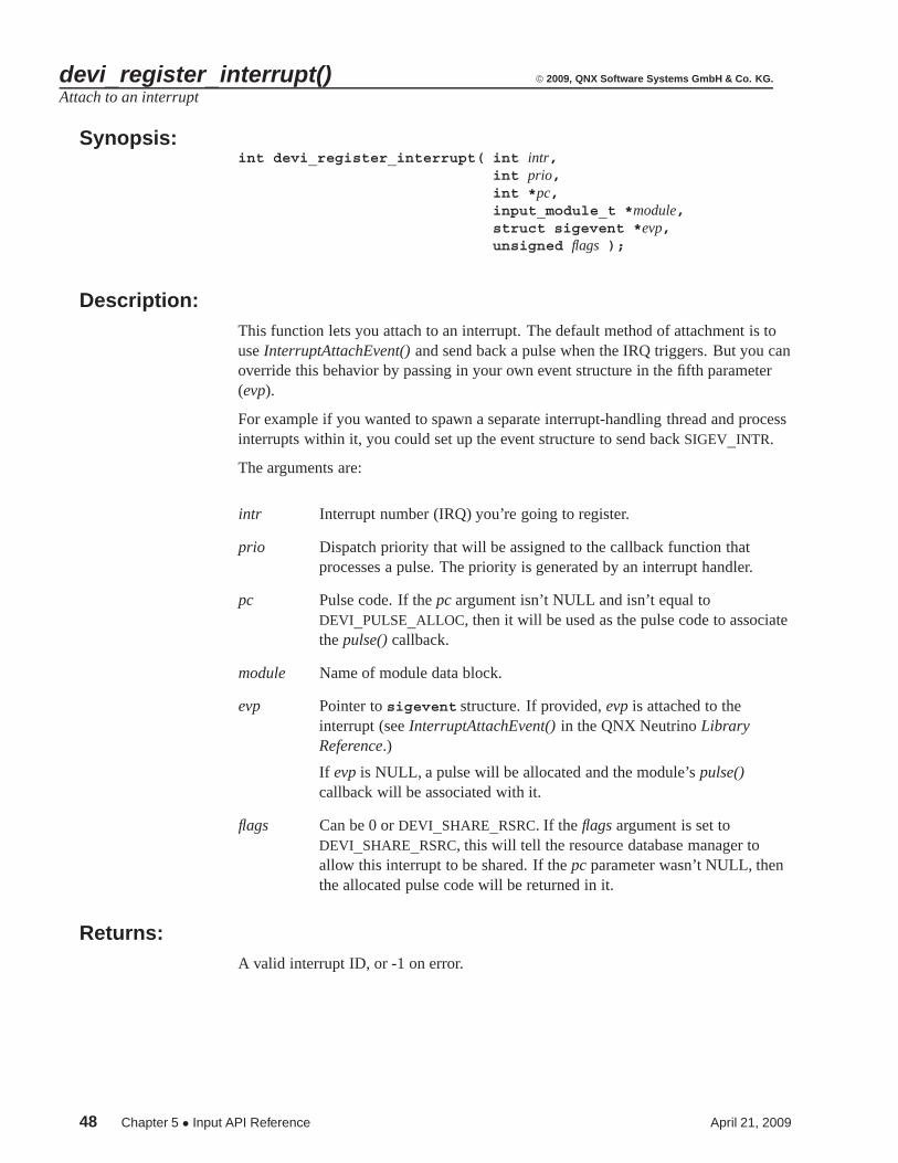
devi_register_interrupt() Attach to an interrupt
devi_register_pulse() Associate a pulse code with a function
devi_register_timer() Create a timer
devi_request_iorange() Map device registers into memory
April 21, 2009 Chapter 5 • Input API Reference 37

begin() © 2009, QNX Software Systems GmbH & Co. KG.
Initialize resource manager and activate driver bus line
Synopsis:int begin( int argc,
char *argv[]);
Description:This function initializes the resource manager and activates the driver bus line. Thebegin() function should be called at the end of your initialization process, because itnever returns control until the program is closed.
The arguments are:
argc The number of elements in the argv array.
argv An array of command-line arguments.
Returns:Always returns 0.
Classification:QNX
Safety
Interrupt handler Not applicable
Signal handler Not applicable
Thread Not applicable
38 Chapter 5 • Input API Reference April 21, 2009
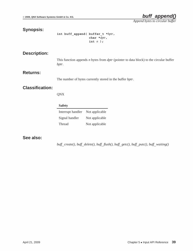
© 2009, QNX Software Systems GmbH & Co. KG. buff_append()Append bytes to circular buffer
Synopsis:int buff_append( buffer_t *bptr,
char *dptr,int n );
Description:This function appends n bytes from dptr (pointer to data block) to the circular bufferbptr.
Returns:The number of bytes currently stored in the buffer bptr.
Classification:QNX
Safety
Interrupt handler Not applicable
Signal handler Not applicable
Thread Not applicable
See also:buff_create(), buff_delete(), buff_flush(), buff_getc(), buff_putc(), buff_waiting()
April 21, 2009 Chapter 5 • Input API Reference 39

buff_create() © 2009, QNX Software Systems GmbH & Co. KG.
Create a circular buffer
Synopsis:struct buffer *buff_create( unsigned size,
unsigned rsize );
Description:This function creates a circular buffer made up of size number of rsize records.
Returns:A pointer to an initialized buffer handle, or NULL if memory for the buffer datacouldn’t be allocated.
All the other buff_*() functions take as their first argument the handle returned by thesuccessful execution of buff_create().
Classification:QNX
Safety
Interrupt handler Not applicable
Signal handler Not applicable
Thread Not applicable
See also:buff_append(), buff_delete(), buff_flush(), buff_getc(), buff_putc(), buff_waiting()
40 Chapter 5 • Input API Reference April 21, 2009

© 2009, QNX Software Systems GmbH & Co. KG. buff_delete()Delete bytes from the circular buffer
Synopsis:int buff_delete( buffer_t *bptr,
char *dptr,int n );
Description:This function removes n bytes from the circular buffer bptr and places them in dptr(pointer to data block).
Returns:The number of bytes removed from the buffer bptr.
Classification:QNX
Safety
Interrupt handler Not applicable
Signal handler Not applicable
Thread Not applicable
See also:buff_create(), buff_append(), buff_flush(), buff_getc(), buff_putc(), buff_waiting()
April 21, 2009 Chapter 5 • Input API Reference 41

buff_flush() © 2009, QNX Software Systems GmbH & Co. KG.
Clear the circular buffer
Synopsis:int buff_flush( buffer_t *bptr );
Description:This function clears the circular buffer bptr.
Returns:EOK.
Classification:QNX
Safety
Interrupt handler Not applicable
Signal handler Not applicable
Thread Not applicable
See also:buff_append(), buff_create(), buff_delete(), buff_getc(), buff_putc(), buff_waiting()
42 Chapter 5 • Input API Reference April 21, 2009

© 2009, QNX Software Systems GmbH & Co. KG. buff_getc()Get a character from the circular buffer
Synopsis:int buff_getc( buffer_t *bptr );
Description:This function retrieves a character from the circular buffer bptr, removing it from thebuffer in the process.
Returns:The character currently at the head of the circular buffer bptr, or -1 if the buffer isempty.
Classification:QNX
Safety
Interrupt handler Not applicable
Signal handler Not applicable
Thread Not applicable
See also:buff_append(), buff_create(), buff_delete(), buff_flush(), buff_putc(), buff_waiting()
April 21, 2009 Chapter 5 • Input API Reference 43

buff_putc() © 2009, QNX Software Systems GmbH & Co. KG.
Place a character on the circular buffer
Synopsis:int buff_putc( buffer_t *bptr,
char c );
Description:This function places a character c on the circular buffer bptr.
Returns:The number of bytes currently stored in the buffer bptr.
Classification:QNX
Safety
Interrupt handler Not applicable
Signal handler Not applicable
Thread Not applicable
See also:buff_append(), buff_create(), buff_delete(), buff_flush(), buff_getc(), buff_waiting()
44 Chapter 5 • Input API Reference April 21, 2009

© 2009, QNX Software Systems GmbH & Co. KG. buff_waiting()Determine the number of bytes stored in the circular buffer
Synopsis:int buff_waiting( buffer_t *bptr );
Description:This function determines the number of bytes stored in the circular buffer bptr.
Returns:The number of bytes currently stored in the buffer bptr.
Classification:QNX
Safety
Interrupt handler Not applicable
Signal handler Not applicable
Thread Not applicable
See also:buff_append(), buff_create(), buff_delete(), buff_flush(), buff_getc(), buff_putc()
April 21, 2009 Chapter 5 • Input API Reference 45

clk_get() © 2009, QNX Software Systems GmbH & Co. KG.
Get the time from the OS Process Manager
Synopsis:void clk_get( struct timespec *tspec );
Description:This function loads the timespec structure pointed to by tspec with the current timefrom procnto’s internal clock.
Classification:QNX
Safety
Interrupt handler Not applicable
Signal handler Not applicable
Thread Not applicable
46 Chapter 5 • Input API Reference April 21, 2009

© 2009, QNX Software Systems GmbH & Co. KG. devi_enqueue_packet()Dispatch a completed packet
Synopsis:int devi_enqueue_packet( input_module_t *module,
char *dptr,unsigned size ) ;
Description:This function is used by filter-layer modules to dispatch a completed packet to theproper interface, to Photon, or to a resource manager.
The arguments are:
module Name of module data block.
dptr Pointer to data block.
size Size of data block.
Returns:0 on success, -1 on error.
Classification:QNX
Safety
Interrupt handler Not applicable
Signal handler Not applicable
Thread Not applicable
April 21, 2009 Chapter 5 • Input API Reference 47
devi_register_interrupt() © 2009, QNX Software Systems GmbH & Co. KG.
Attach to an interrupt
Synopsis:int devi_register_interrupt( int intr,
int prio,int *pc,input_module_t *module,struct sigevent *evp,unsigned flags );
Description:This function lets you attach to an interrupt. The default method of attachment is touse InterruptAttachEvent() and send back a pulse when the IRQ triggers. But you canoverride this behavior by passing in your own event structure in the fifth parameter(evp).
For example if you wanted to spawn a separate interrupt-handling thread and processinterrupts within it, you could set up the event structure to send back SIGEV_INTR.
The arguments are:
intr Interrupt number (IRQ) you’re going to register.
prio Dispatch priority that will be assigned to the callback function thatprocesses a pulse. The priority is generated by an interrupt handler.
pc Pulse code. If the pc argument isn’t NULL and isn’t equal toDEVI_PULSE_ALLOC, then it will be used as the pulse code to associatethe pulse() callback.
module Name of module data block.
evp Pointer to sigevent structure. If provided, evp is attached to theinterrupt (see InterruptAttachEvent() in the QNX Neutrino LibraryReference.)
If evp is NULL, a pulse will be allocated and the module’s pulse()callback will be associated with it.
flags Can be 0 or DEVI_SHARE_RSRC. If the flags argument is set toDEVI_SHARE_RSRC, this will tell the resource database manager toallow this interrupt to be shared. If the pc parameter wasn’t NULL, thenthe allocated pulse code will be returned in it.
Returns:A valid interrupt ID, or -1 on error.
48 Chapter 5 • Input API Reference April 21, 2009

© 2009, QNX Software Systems GmbH & Co. KG. devi_register_interrupt()
Classification:QNX
Safety
Interrupt handler Not applicable
Signal handler Not applicable
Thread Not applicable
April 21, 2009 Chapter 5 • Input API Reference 49
devi_register_pulse() © 2009, QNX Software Systems GmbH & Co. KG.
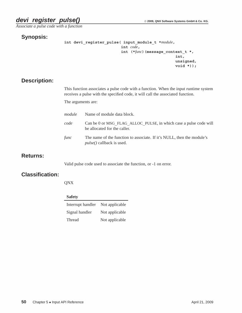
Associate a pulse code with a function
Synopsis:int devi_register_pulse( input_module_t *module,
int code,int (*func)(message_context_t *,
int,unsigned,void *));
Description:This function associates a pulse code with a function. When the input runtime systemreceives a pulse with the specified code, it will call the associated function.
The arguments are:
module Name of module data block.
code Can be 0 or MSG_FLAG_ALLOC_PULSE, in which case a pulse code willbe allocated for the caller.
func The name of the function to associate. If it’s NULL, then the module’spulse() callback is used.
Returns:Valid pulse code used to associate the function, or -1 on error.
Classification:QNX
Safety
Interrupt handler Not applicable
Signal handler Not applicable
Thread Not applicable
50 Chapter 5 • Input API Reference April 21, 2009

© 2009, QNX Software Systems GmbH & Co. KG. devi_register_timer()Create a timer
Synopsis:timer_t devi_register_timer( input_module_t *module,
int prio,int *pc,struct sigevent *evp );
Description:This function creates a timer. To arm the timer, the caller must call the OS librarytime_settime() function.
The default notification is a pulse when the timer expires. You can override this bypassing a prebuilt event in evp.
The arguments are:
module Name of module data block.
prio Dispatch priority that will be assigned to the callback function thatprocesses a pulse. The priority is generated by an interrupt handler.
pc Pulse code. If the pc argument isn’t NULL and isn’t equal toDEVI_PULSE_ALLOC, then it will be used as the pulse code to associatethe pulse() callback.
evp Pointer to sigevent structure. If provided, evp is attached to theinterrupt (see InterruptAttachEvent() in the QNX Neutrino LibraryReference.)
Returns:0 on success, -1 on error.
Classification:QNX
Safety
Interrupt handler Not applicable
Signal handler Not applicable
Thread Not applicable
April 21, 2009 Chapter 5 • Input API Reference 51

devi_request_iorange() © 2009, QNX Software Systems GmbH & Co. KG.
Map device registers into memory
Synopsis:uintptr_t devi_request_iorange( unsigned start,
unsigned len,unsigned flags );
Description:This function maps device registers into memory.
The arguments are:
start Start of I/O port area to map.
len Length of I/O port area.
flags The flags parameter can be set to DEVI_SHARE_RSRCM to indicate that theI/O range can be shared.
Returns:A pointer to the first location in the mapped-in range or MAP_FAILED on error.
Classification:QNX
Safety
Interrupt handler Not applicable
Signal handler Not applicable
Thread Not applicable
52 Chapter 5 • Input API Reference April 21, 2009

Index
A
absolute (type of device/event bus) 4
B
begin() 38buff_append() 39buff_create() 40buff_delete() 41buff_flush() 42buff_getc() 43buff_putc() 44buff_waiting() 45
C
calibration file format 14callbacks 17clk_get() 12, 46combination device/protocol module 16conventions
typographical ix
D
data formatsfor protocol modules 12
debugging 21printf() method of 21
devctrl() module function 26DEVI_CLASS_ 16devi_enqueue_packet() 47devi_register_interrupt() 48devi_register_pulse() 50devi_register_timer() 51devi_request_iorange() 52devi-*
command line 5devi-hirun 5device-layer modules 5driver
running without graphics 21
E
elo directory 7, 13en_US_101.kdef 13event bus lines 4
F
filter-layer modules 5
G
graphics regiontelling driver to ignore 21
April 21, 2009 Index 53

Index © 2009, QNX Software Systems GmbH & Co. KG.
H
hirun directory 3, 7, 14
I
init() module function 27input
library 3input_module_t 11input driver
interface to 6main parts of 3
input() module function 28, 31interrupt handlers 31
K
KEY_SCAN_VALID 12keyboard
definition file 13locations of filter module 13module 17scan codes 12type of device/event bus 4
L
lib directory 7
M
Microsoft mouse 14mkkbd 13modules
command-line arguments 30configuring from an external source 26device-layer 5filter-layer 5functions
devctrl() 26init() 27input() 28, 31output() 29parm() 30pulse() 28, 31reset() 32shutdown() 33
linked according to command-line options5
organization of 4passing data
to a higher layer 28to a lower layer 29
private data 27protocol-layer 5types of 3, 5
Mouse Systems mouse 14MS-mouse protocol code (samp_proto) 12
O
output() module function 29
P
packet_rel 14parm() module function 30pathname delimiter in QNX documentation xPhoton
how to disable interface 6interface to input driver 6
protocol-layer modules 5data formats of 12
PS/2 mouse 14, 21pulse() module function 28, 31
R
reentrancy 16global variables and 16
54 Index April 21, 2009

© 2009, QNX Software Systems GmbH & Co. KG. Index
relative (type of device/event bus) 4, 14reset() module function 32resource manager
interfacehow to enable 6to input driver 6when to use 6
S
samp_dev 12samp_proto 12sample device module (samp_dev) 12sample directory 3, 11shutdown() module function 33source code
file organization of 6struct _keyboard_data 12struct packet_* 16struct packet_abs 12struct packet_kbd 12struct packet_rel 12
T
touchscreenscalibrating 13testing 21
typographical conventions ix
April 21, 2009 Index 55