Track-and-trace-Systeme VML Prime - SICK Germany
188
OPERATING INSTRUCTION EN VML Prime Track and trace systems
-
Upload
khangminh22 -
Category
Documents
-
view
0 -
download
0
Transcript of Track-and-trace-Systeme VML Prime - SICK Germany

O P E R A T I N G I N S T R U C T I O N
EN
VML PrimeTrack and trace systems

Operating instructions
VML Prime
2 Operating instructions | SICK 8019514 / ZNX6 / 2017-02-23 Subject to change without notice
This work is protected by copyright. Any rights derived from the copyright shall be reserved for SICK AG. Reproduction of this document or parts of this document is only permissible within the limits of the legal determination of Copyright Law. Alteration or abridgment of the document is not permitted without the explicit written approval of SICK AG.

Operating instructions
VML Prime
8019514/ZNX6/2017-02-23 Operating instructions | SICK 3 Subject to change without notice
Contents
Contents 1 About these operating instructions ............................................................................... 7
1.1 Purpose of this document .................................................................................... 7 1.2 Target group .......................................................................................................... 7 1.3 Information depth ................................................................................................. 7 1.4 Abbreviations used ............................................................................................... 8 1.5 Symbols used ........................................................................................................ 9
2 Safety ............................................................................................................................ 10 2.1 Qualified safety personnel ..................................................................................10 2.2 Applications of the device...................................................................................11 2.3 Intended use .......................................................................................................12 2.4 General safety notes and protective measures ................................................13
2.4.1 Safety notes and symbols ...................................................................13 2.4.2 General safety notes ............................................................................14 2.4.3 Potential sources of danger ................................................................14 2.4.4 Operating entity responsibilities .........................................................17
2.5 Protecting the environment ................................................................................18 2.5.1 Power consumption .............................................................................18 2.5.2 Disposal after final decommissioning ................................................18
3 Product description ..................................................................................................... 19 3.1 Scope of delivery .................................................................................................19
3.1.1 System variants....................................................................................19 3.1.2 Measuring range and measurement accuracy ..................................21 3.1.3 Accessories (optional)..........................................................................22
3.2 Specific features .................................................................................................23 3.2.1 The system components .....................................................................23 3.2.2 VML Prime operating principle ............................................................29 3.2.3 Data output ..........................................................................................32 3.2.4 Calibratable operation .........................................................................32
3.3 Project planning ..................................................................................................33 3.3.1 Conveying system requirements .........................................................33 3.3.2 Mounting requirements .......................................................................34
3.4 Status indicators .................................................................................................36 3.4.1 MLG-2 light grids ..................................................................................36 3.4.2 LED of the separate photoelectric retro-reflective sensor .................37 3.4.3 LEDs on the controller .........................................................................38
3.5 Interfaces .............................................................................................................39
4 Mounting ...................................................................................................................... 40 4.1 Preparation for mounting ...................................................................................40
4.1.1 Getting the frame components ready .................................................40 4.1.2 Getting the devices ready ....................................................................40 4.1.3 Getting the accessories ready .............................................................40
4.2 Assembling the item aluminum frame ...............................................................41 4.2.1 Frame components ..............................................................................41 4.2.2 Screwing on the bracket ......................................................................42 4.2.3 Aligning the frame ................................................................................43 4.2.4 Leveling the frame ...............................................................................43 4.2.5 Anchoring the frame to the floor .........................................................44 4.2.6 Attaching the cable holders.................................................................44
Operating instructions
VML Prime
4 Operating instructions | SICK 8019514 / ZNX6 / 2017-02-23 Subject to change without notice
Contents
4.3 Mounting the light grids ..................................................................................... 45 4.3.1 Overview ............................................................................................... 45 4.3.2 Mounting the light grids using QuickFix ............................................. 46
4.3.2.1 Assembling QuickFix brackets 46 4.3.2.2 Pre-mounting sender and receiver on the QuickFix bracket46 4.3.2.3 Attaching sender and receiver to the mounting frame 47
4.3.3 Mounting the protective pipe with sender ......................................... 49 4.3.3.1 Installing the MLG in the protective pipe 49 4.3.3.2 Attaching the protective pipe to the mounting frame 52
4.3.4 Fine adjustment of the light grids ....................................................... 54 4.3.4.1 Making sure the light beams fall on the center of the gap54 4.3.4.2 Adjusting the horizontal light grids 55 4.3.4.3 Adjusting the vertical light grid 57
4.3.5 Mounting and connecting the cleaning unit ...................................... 58 4.3.5.1 Mounting the vent duct 58 4.3.5.2 Mounting and connecting the fan 59
4.4 Mounting the measuring wheel encoder........................................................... 61 4.5 Mounting the photoelectric sensor (VML Prime 2D H only) ............................. 62 4.6 Mounting the controller cabinet ........................................................................ 63 4.7 Using the steel frame ......................................................................................... 64
4.7.1 Assembling the steel frame ................................................................ 64 4.7.2 Mounting the components on the steel frame .................................. 68
4.7.2.1 Mounting the light grids on the steel frame 68 4.7.2.2 Mounting the protective pipe without cleaning unit 70 4.7.2.3 Mounting the protective pipe with cleaning unit 72 4.7.2.4 Mounting the measuring wheel encoder 74 4.7.2.5 Mounting the photoelectric sensor 75 4.7.2.6 Installing the controller cabinet 76
4.7.3 Aligning the steel frame with the conveyor ........................................ 77 4.7.4 Attaching cable clamps to the steel frame ........................................ 78
4.8 Dismantling the measurement system ............................................................. 79
5 Electrical installation ................................................................................................... 80 5.1 Wiring diagram .................................................................................................... 81 5.2 General notes ..................................................................................................... 82
5.2.1 Routing the cable to the MSC800 ...................................................... 82 5.2.2 Connecting the cable shielding .......................................................... 83 5.2.3 Connecting wire ends in the controller terminal block ...................... 83
5.3 Components in the controller cabinet ............................................................... 84 5.4 Connecting the voltage supply to the controller ............................................... 85 5.5 Connecting the light grids .................................................................................. 86
5.5.1 Connecting the sender and receiver .................................................. 87 5.5.2 Connecting the light grids with the MSC800 using tee
connectors ........................................................................................... 87 5.6 Connecting the measuring wheel encoder........................................................ 90 5.7 Connecting the separate photoelectric sensor ................................................. 91 5.8 Connecting the fan ............................................................................................. 92
6 Commissioning ............................................................................................................. 93 6.1 Starting commissioning ...................................................................................... 93
6.1.1 Switching on the system ..................................................................... 93 6.1.2 Checking the operational readiness of the devices .......................... 93
6.1.2.1 Checking the operational readiness of the MSC800 93
Operating instructions
VML Prime
8019514/ZNX6/2017-02-23 Operating instructions | SICK 5 Subject to change without notice
Contents
6.1.2.2 Ensuring the operational readiness of the light grids 94 6.1.2.3 Ensuring the operational readiness of the separate
photoelectric sensor 95 6.1.2.4 Checking the operational readiness of the measuring
wheel encoder 97 6.2 Preparing the configuration PC ..........................................................................98
6.2.1 Establishing a connection with the configuration PC.........................98 6.2.2 Installing SOPAS ...................................................................................98
6.3 Creating a configuration in SOPAS .....................................................................99 6.3.1 Launching SOPAS ................................................................................99 6.3.2 Transferring the VML Prime to a SOPAS project ............................. 100 6.3.3 Loading device drivers into the SOPAS project ............................... 101 6.3.4 Setting the VML Prime to online ...................................................... 103
6.4 Opening the configuration and analysis interface ......................................... 104 6.4.1 Selecting the configuration .............................................................. 105 6.4.2 Teaching in light grids ....................................................................... 106 6.4.3 Calibrating light grids in relation to the coordinate system of
the conveyor ...................................................................................... 107 6.4.4 Calibrating the incremental encoder ............................................... 112 6.4.5 Specifying the system environment ................................................. 114 6.4.6 Configuring the data output ............................................................. 115 6.4.7 Saving the configuration permanently in devices ........................... 118
6.5 Performing a test run ....................................................................................... 119 6.6 Optimizing the measurement results .............................................................. 121
6.6.1 Optimizing the height measurement ............................................... 121 6.6.2 Optimizing the length measurement ............................................... 122 6.6.3 Optimizing the width measurement ................................................. 122
7 Maintenance .............................................................................................................. 123 7.1 Maintenance during operation ........................................................................ 124
7.1.1 Visual inspection of the cables ........................................................ 124 7.1.2 Light grid ............................................................................................ 124 7.1.3 Cleaning unit components ............................................................... 125
7.1.3.1 Cleaning the IPG2 protective pipe 125 7.1.3.2 Changing the air filter mat 126
7.1.4 Measuring wheel encoder ................................................................ 127 7.1.5 Photoelectric retro-reflective sensor ................................................ 127
7.2 Replacing components .................................................................................... 128 7.2.1 Replacing light grids ......................................................................... 128
7.2.1.1 Replacing MLG 129 7.2.1.2 Replacing the protective pipe with MLG 130 7.2.1.3 Subsequent work 131
7.2.2 Replacing the fan .............................................................................. 133 7.2.3 Replacing components in the control cabinet ................................ 134
7.2.3.1 Replacing the MSC800 134 7.2.3.2 Replacing the battery in the MSC800 135 7.2.3.3 Replacing the power supply unit 136
7.2.4 Replacing the measuring wheel encoder ........................................ 137 7.2.5 Replacing the separate photoelectric retro-reflective sensor ........ 139 7.2.6 Checking the measurement accuracy ............................................. 140
7.3 Disposal ............................................................................................................ 140

Operating instructions
VML Prime
6 Operating instructions | SICK 8019514 / ZNX6 / 2017-02-23 Subject to change without notice
Contents
8 Fault diagnosis ........................................................................................................... 141 8.1 Response to faults ............................................................................................ 141 8.2 SICK support ..................................................................................................... 141 8.3 Fault indicators of the components ................................................................. 141
8.3.1 Fault indicator on the light grids ....................................................... 141 8.3.2 Fault indicator on the separate photoelectric retro-reflective
sensor ................................................................................................ 142 8.4 Troubleshooting with the MSC800 .................................................................. 142 8.5 Detailed fault analysis in SOPAS ..................................................................... 146
9 Technical specifications ............................................................................................ 148 9.1 VML Prime data sheet ...................................................................................... 148
9.1.1 MSC800-1100 data sheet ................................................................ 149 9.1.2 MLG-2 light grid data sheet .............................................................. 150 9.1.3 Data sheet for measuring wheel encoder ........................................ 151 9.1.4 WL27-3 photoelectric retro-reflective sensor data sheet ............... 152
9.2 VML Prime dimensional drawings ................................................................... 153 9.2.1 MLG-2 Pro dimensional drawings ..................................................... 153 9.2.2 Dimensional drawing of IPG2 protective pipe ................................. 154 9.2.3 Dimensional drawing of fan unit....................................................... 155 9.2.4 Dimensional drawing of MSC800-100 ............................................. 156 9.2.5 Dimensional drawing of measuring wheel encoder ........................ 157 9.2.6 Separate WL27-3 photoelectric retro-reflective sensor .................. 158
9.3 Compliance with EU directives ......................................................................... 159 9.4 Error codes (VMD status) ................................................................................. 160 9.5 Circuit diagrams ................................................................................................ 162
9.5.1 VML Prime 3D .................................................................................... 162 9.5.2 VML Prime 2D V ................................................................................. 168 9.5.3 VML Prime 2D H ................................................................................ 174
10 Appendix ..................................................................................................................... 180 10.1 List of tables ..................................................................................................... 180 10.2 List of figures .................................................................................................... 181 10.3 Keywords index ................................................................................................. 185
Operating instructions Chapter 1
VML Prime
8019514/ZNX6/2017-02-23 Operating instructions | SICK 7 Subject to change without notice
About these operating instructions
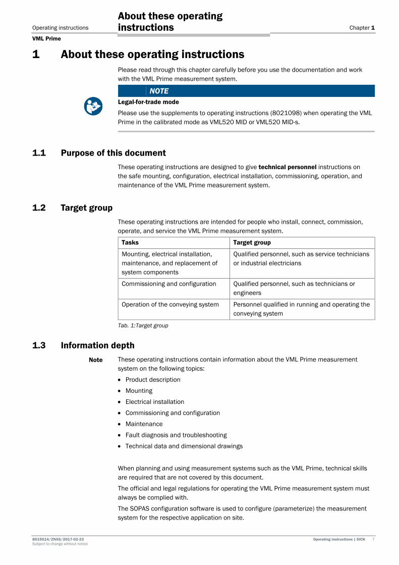
1 About these operating instructions Please read through this chapter carefully before you use the documentation and work with the VML Prime measurement system.
NOTE Legal-for-trade mode
Please use the supplements to operating instructions (8021098) when operating the VML Prime in the calibrated mode as VML520 MID or VML520 MID-s.
1.1 Purpose of this document These operating instructions are designed to give technical personnel instructions on the safe mounting, configuration, electrical installation, commissioning, operation, and maintenance of the VML Prime measurement system.
1.2 Target group These operating instructions are intended for people who install, connect, commission, operate, and service the VML Prime measurement system.
Tasks Target group
Mounting, electrical installation, maintenance, and replacement of system components
Qualified personnel, such as service technicians or industrial electricians
Commissioning and configuration Qualified personnel, such as technicians or engineers
Operation of the conveying system Personnel qualified in running and operating the conveying system
Tab. 1: Target group
1.3 Information depth These operating instructions contain information about the VML Prime measurement system on the following topics:
• Product description
• Mounting
• Electrical installation
• Commissioning and configuration
• Maintenance
• Fault diagnosis and troubleshooting
• Technical data and dimensional drawings
When planning and using measurement systems such as the VML Prime, technical skills are required that are not covered by this document.
The official and legal regulations for operating the VML Prime measurement system must always be complied with.
The SOPAS configuration software is used to configure (parameterize) the measurement system for the respective application on site.
Note
Chapter 1 Operating instructions
VML Prime
8 Operating instructions | SICK 8019514 / ZNX6 / 2017-02-23 Subject to change without notice
About these operating instructions
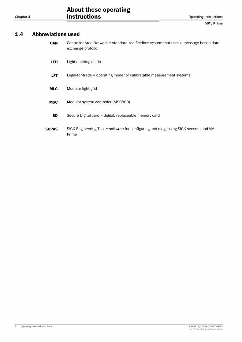
1.4 Abbreviations used Controller Area Network = standardized fieldbus system that uses a message-based data exchange protocol
Light emitting diode
Legal-for-trade = operating mode for calibratable measurement systems
Modular light grid
Modular system controller (MSC800)
Secure Digital card = digital, replaceable memory card
SICK Engineering Tool = software for configuring and diagnosing SICK sensors and VML Prime
CAN
LED
LFT
MLG
MSC
SD
SOPAS

Operating instructions Chapter 1
VML Prime
8019514/ZNX6/2017-02-23 Operating instructions | SICK 9 Subject to change without notice
About these operating instructions
1.5 Symbols used Recommendations are designed to assist you in the decision-making process with respect to the use of a certain function or technical measure.
Notes provide information about the features of a device, application tips, or other useful information.
Instructions that must be carried out in the described order are referred to as step-by-step instructions and are indicated by numbered lists. Carefully read and follow the instructions for action.
Instructions for taking action are indicated by an arrow. Carefully read and follow the instructions for action.
LED symbols describe the status of a diagnostics LED. Examples: The LED is illuminated continuously. The LED is flashing. The LED is off.
Sender and receiver
In figures and connection diagrams, the symbol indicates the sender and indicates the receiver.
Recommendation
Note
1. / 2. ...
,
Chapter 2 Operating instructions
VML Prime
10 Operating instructions | SICK 8019514 / ZNX6 / 2017-02-23 Subject to change without notice
Safety
2 Safety This chapter concerns your own safety and the safety of the system operator.
Please read this chapter carefully before you begin working with VML Prime.
2.1 Qualified safety personnel The VML Prime must only be mounted, commissioned, and maintained by adequately qualified personnel.
The following qualifications are necessary for the various tasks:
Tasks Qualification
Mounting and maintenance
• Practical technical training
• Knowledge of the current safety regulations in the workplace
Electrical installation and device replacement
• Practical electrical training
• Knowledge of current electrical safety regulations
• Knowledge of device control and operation in the particular application concerned (e.g., conveying system, mounting system, crane)
Commissioning, operation, and configuration
• Knowledge concerning device control and operation in the particular application concerned (e.g., conveying system, mounting system, crane, etc.)
• Knowledge concerning the software and hardware environment of the particular application concerned (e.g., conveying system, mounting system, crane etc.)
• Basic knowledge of the Windows operating system used
• Basic knowledge of data transmission
• Basic knowledge of the design and setup (addressing) of Ethernet connections when connecting the MSC800 to the network
• Basic knowledge of how to use an HTML browser (e.g. Internet Explorer) to access the online help
Tab. 2 Qualified safety personnel
Operating instructions Chapter 2
VML Prime
8019514/ZNX6/2017-02-23 Operating instructions | SICK 11 Subject to change without notice
Safety
2.2 Applications of the device The VML Prime measurement system is used to determine object dimensions on flat belt conveying systems with the help of light grids. Light grids are non-contact optical measurement systems which detect the object contour using the principle of shadowing. The use of light grids means it is even possible to recognize reflective, transparent, or very dark objects, such as PET containers wrapped in film.
On the basis of the number of interrupted light beams, the evaluation unit simulates an object model and derives the individual object dimensions from this. All information is output to downstream systems via a central data interface for further processing.
VML Prime is available in different system variants.
• VML Prime 3D is made up of two light grid pairs which span the conveyor belt vertically and horizontally. With this system variant, it is possible to determine the length, width, and height of objects as well as the rotation of the object and the box volume.
• VML Prime 2D V is made up of a vertical light grid pair. With this system variant, it is possible to determine the object height. If the objects are aligned on the belt, it is also possible to determine the object length.
• VML Prime 2D H is made up of a horizontal light grid pair. With this system variant, it is possible to determine the width and length of objects as well as the rotation of the object. If the objects are aligned on the belt, it is also possible to determine the object length.
Legal-for-trade mode
If VML Prime is used for billing purposes on the basis of the dimensions determined, the measurement system must be operated with the VML520 MID or VML520 MID-s calibratable system variant (in legal-for-trade mode, abbrev.: LFT mode). You can find more information in the supplement to operating instructions (8021098).
Customized extensions such as SICK identification solutions and weighing systems can be easily integrated.
Note
Chapter 2 Operating instructions
VML Prime
12 Operating instructions | SICK 8019514 / ZNX6 / 2017-02-23 Subject to change without notice
Safety
2.3 Intended use The VML measurement system may only be used as described in section 2.2 Applications of the device. It may only be used by qualified personnel in the environment in which it was mounted and initially commissioned by qualified safety personnel in accordance with these operating instructions.
The equipment may be operated in an industrial environment. The system can be used for the dimensioning of objects of any kind, before they are forwarded to downstream systems.
For example, by way of the classification of objects into automated high bays, smooth operation of the entire system, and of the conveying and sorter systems and storage and retrieval systems in particular, can be ensured. Downtimes are reduced.
The VML Prime measurement system must not be used outdoors or in an explosion-protected environment.
If used in any other way or if alterations are made to the system or the devices are opened – including in the context of mounting and installation – this will void any warranty claims directed to SICK AG.
Operating instructions Chapter 2
VML Prime
8019514/ZNX6/2017-02-23 Operating instructions | SICK 13 Subject to change without notice
Safety
2.4 General safety notes and protective measures 2.4.1 Safety notes and symbols
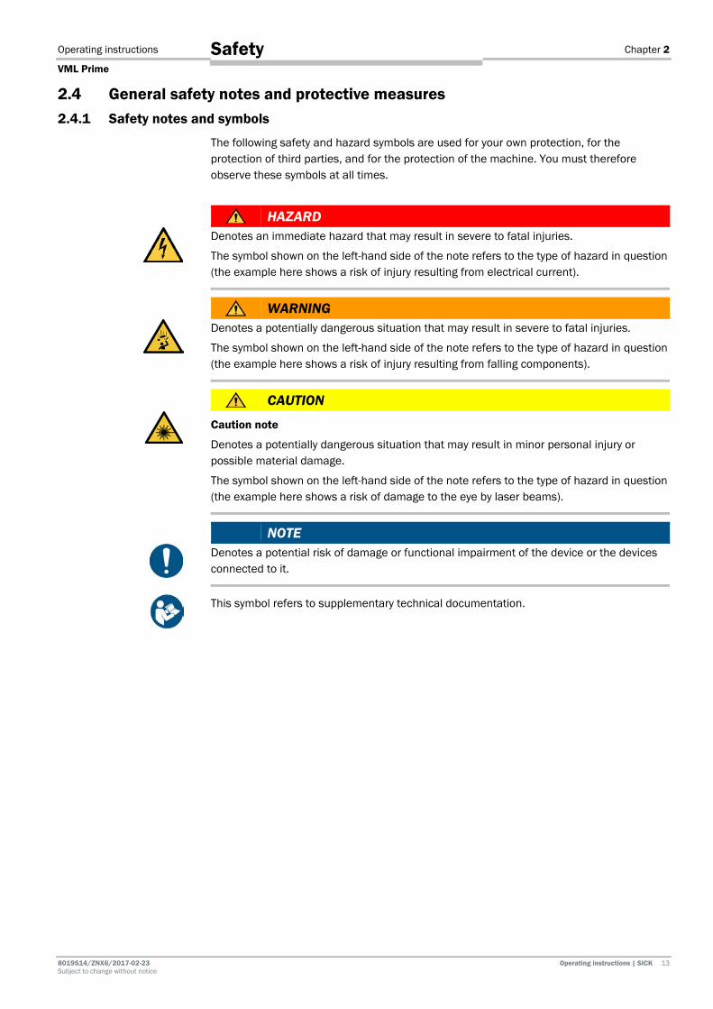
The following safety and hazard symbols are used for your own protection, for the protection of third parties, and for the protection of the machine. You must therefore observe these symbols at all times.
HAZARD Denotes an immediate hazard that may result in severe to fatal injuries.
The symbol shown on the left-hand side of the note refers to the type of hazard in question (the example here shows a risk of injury resulting from electrical current).
WARNING Denotes a potentially dangerous situation that may result in severe to fatal injuries.
The symbol shown on the left-hand side of the note refers to the type of hazard in question (the example here shows a risk of injury resulting from falling components).
CAUTION
Caution note
Denotes a potentially dangerous situation that may result in minor personal injury or possible material damage.
The symbol shown on the left-hand side of the note refers to the type of hazard in question (the example here shows a risk of damage to the eye by laser beams).
NOTE Denotes a potential risk of damage or functional impairment of the device or the devices connected to it.
This symbol refers to supplementary technical documentation.

Chapter 2 Operating instructions
VML Prime
14 Operating instructions | SICK 8019514 / ZNX6 / 2017-02-23 Subject to change without notice
Safety
2.4.2 General safety notes
General, recognized safety-related rules and regulations were taken into account in the design and manufacture of the measurement system. However, risks for the cresulting from the measurement system cannot be completely ruled out. The safety notes below must therefore be observed.
WARNING
Safety notes
Observe the following to ensure the safe use of the system as intended.
• The notes in these operating instructions (e.g., regarding use, mounting, installation, or integration into the machine controller) must be observed.
• All official and statutory regulations governing the operation of the system must be complied with.
• The national and international legal specifications apply to the installation and use of the system, to its commissioning, and to recurring technical inspections, in particular:
– The accident prevention regulations and work safety regulations
– Any other relevant safety regulations
• The manufacturer and user of the system are responsible for coordinating and complying with all applicable safety specifications and regulations in cooperation with the relevant authorities.
• The checks must be carried out by qualified safety personnel or specially qualified and authorized personnel and must be recorded and documented to ensure that the tests can be reconstructed and retraced at any time.
• These operating instructions must be made available to the operator of the system. The system operator must be instructed by qualified safety personnel and must read the operating instructions.
WARNING VML Prime is not a safety device for human protection and it therefore does not comply with any safety standards.
• MLG-2 light grids may not be used for personal protection applications.
• MLG-2 light grids may not be used as a safety device to prevent access for persons, their hands, or other body parts to hazardous areas for safety purposes.
• For safety applications, please contact SICK.
WARNING The light grids must not be used outdoors or in explosion-hazardous areas.
2.4.3 Potential sources of danger
The measurement system has been designed in a way that allows for safe operation. Protective devices reduce potential risks to the maximum possible extent. However, a certain level of risk will always remain.
Awareness of potential sources of danger in the measurement system will help you to work in a safer manner and thus prevent accidents.
To avoid risks, please also observe the special warnings in each of the individual chapters.

Operating instructions Chapter 2
VML Prime
8019514/ZNX6/2017-02-23 Operating instructions | SICK 15 Subject to change without notice
Safety
Risks during transport and mounting
WARNING
Risk of injury due to components tipping over
If profiles of the mounting frame have been upended, they could possibly tip over during disassembly.
Do not perform mounting work alone unless it is absolutely safe to do so.
Where applicable, ask a second person to assist you with the component replacement process.
Wear safety shoes.
WARNING
Risk of injury due to falling components when mounting the steel frame
The steel frame components weigh up to 25 kg.
Do not perform any mounting work alone.
Ask a second person to hold the components during mounting.
Wear safety shoes.
WARNING
Risk of injury due to falling components when mounting the controller
Heavy devices such as the controller cabinet may fall over during mounting:
The controller cabinet weighs approx. 15 kg.
Do not perform mounting work alone unless it is absolutely safe to do so.
Where applicable, ask a second person to assist you with the component replacement process.
Wear safety shoes.
WARNING
Risk of injury during mounting and installation
Mounting and installation work may only be performed when the conveyor is not in operation.

Chapter 2 Operating instructions
VML Prime
16 Operating instructions | SICK 8019514 / ZNX6 / 2017-02-23 Subject to change without notice
Safety
Risks during electrical installation
HAZARD
Risk of injury due to electrical current
The central control unit of the system is connected to the power supply (AC 100 ... 264 V / 50 ... 60 Hz).
Standard safety requirements must be met when working on electrical systems.
The power supply must be disconnected when attaching and detaching electrical connections.
Select and implement wire cross-sections and their correct fuse protection in accordance with the applicable standards.
HAZARD
Risk of injury and damage due to electrical current
Improper handling of live devices may lead to severe personal injury or death by electric shock.
Electrical installation and maintenance work must always be carried out by personnel authorized to do so.
Do not touch any live parts.
In the event of danger, immediately disconnect the system from the power supply.
Always use original fuses with the specified current rating.
The controller cabinet must be securely closed during operation.
Report any damaged cables to the maintenance team without delay.
WARNING
Risk of tripping due to cables! Risk of damage to cables!
Exposed cables on the floor in areas used by people can pose a risk.
Lay all cables so that there is no risk of tripping and all cables are protected against damage.
Risks during commissioning and configuration
WARNING
Risk resulting from incorrect commissioning and configuration!
Do not commission without testing by qualified personnel!
Before you operate the system or a device for the first time, you must have it checked and approved by qualified safety personnel.
NOTE
Do not switch off the voltage supply during the configuration!
If you switch off the voltage supply during the configuration, you will lose all parameters that have already been configured.
Operating instructions Chapter 2
VML Prime
8019514/ZNX6/2017-02-23 Operating instructions | SICK 17 Subject to change without notice
Safety
Risks during maintenance and repair work
HAZARD
Disconnect the power to the system
Make sure the power supply for the entire system is disconnected throughout the entire time that you are carrying out maintenance and repair work.
HAZARD
Risk of injury due to electrical current
Only a qualified electrician or trained person working under the guidance and supervision of a qualified electrician is permitted to work on electrical systems or equipment, and they must comply with the electrical regulations.
NOTE
Claims under the warranty rendered void
Do not open the device housing. The devices are sealed.
If the device is opened, any warranty claims against SICK AG will be void.
Dangers in the event of faults
WARNING
Danger due to malfunction!
Cease operation if the cause of the malfunction has not been clearly identified.
Immediately put the machine/system out of operation if you cannot clearly identify or allocate the fault and if you cannot safely remedy the fault.
2.4.4 Operating entity responsibilities
The operating entity or system manufacturer must execute the electrical installation in compliance with the respective provisions of the local EVU as well as applicable standards.

Chapter 2 Operating instructions
VML Prime
18 Operating instructions | SICK 8019514 / ZNX6 / 2017-02-23 Subject to change without notice
Safety
2.5 Protecting the environment The VML Prime measurement system has been designed to minimize its impact on the environment. It consumes very little energy.
Always act in an environmentally responsible manner at work. For this reason, please note the following information regarding disposal.
2.5.1 Power consumption
Including its components, the VML Prime measurement system consumes no more than 100 W.
2.5.2 Disposal after final decommissioning
Always dispose of unusable or irreparable devices in an environmentally safe manner in accordance with the relevant national waste disposal regulations.
Dispose of all electronic assemblies as hazardous waste. The electronic assemblies are easy to dismantle.
Also see chapter 7.3 Disposal.
SICK AG does not take back devices that are unusable or irreparable.
Note

Operating instructions Chapter 3
VML Prime
8019514/ZNX6/2017-02-23 Operating instructions | SICK 19 Subject to change without notice
Product description
3 Product description This chapter provides information on the special features of the VML Prime measurement system. It describes the design and operating principle of the system solution.
NOTE Legal-for-trade mode
Please use the supplements to operating instructions (8021098) when operating the VML Prime in the calibrated mode as VML520 MID or VML520 MID-s.
3.1 Scope of delivery NOTE
It is recommended that you carefully check for and report transport damage of any kind as soon as possible after receiving the system.
Also verify that the delivery includes all components listed on the delivery note.
3.1.1 System variants
VML Prime is available in the VML Prime 3D, VML Prime 2D V, and VML Prime 2D H -system variants.
• VML Prime 3D is made up of two light grid pairs which span the conveyor belt vertically and horizontally.
• VML Prime 2D V is made up of a vertical light grid pair.
• VML Prime 2D H is made up of a horizontal light grid pair. VML Prime 3D components and cables
• 1 controller cabinet with MSC800-1100 and power supply module
• 2 MLG-2 light grid pairs for horizontal and vertical installation
• 1 measuring wheel encoder
• 2 cables to connect sender and receiver (5-pin)
• 2 tee connectors (8-pin, 8-pin, 5-pin)
• 2 connecting cables to connect the tee connector to the MSC800 (8-pin shielded, open-ended)
• 1 connecting cable for measuring wheel encoder – shielded (black with green male connector)
VML Prime 2D V system variant components and cables
• 1 controller cabinet with MSC800-1100 and power supply module
• 1 MLG-2 light grid pair for vertical installation
• 1 measuring wheel encoder
• 1 cable to connect sender and receiver (5-pin)
• Tee connector (8-pin, 8-pin, 5-pin)
• 1 connecting cable to connect the tee connector to the MSC800 (8-pin shielded, open-ended)
• 1 connecting cable for measuring wheel encoder – shielded (black with green male connector)

Chapter 3 Operating instructions
VML Prime
20 Operating instructions | SICK 8019514 / ZNX6 / 2017-02-23 Subject to change without notice
Product description
VML Prime 2D H system variant components and cables
• 1 controller cabinet with MSC800-1100 and power supply module
• 1 MLG-2 light grid pair for horizontal installation
• 1 measuring wheel encoder
• 1 photoelectric retro-reflective sensor
• 1 cable to connect sender and receiver (5-pin)
• Tee connector (8-pin, 8-pin, 5-pin)
• Connecting cable to connect the tee connector to the MSC800 (8-pin shielded, open-ended)
• 1 connecting cable for measuring wheel encoder – shielded (black with green male connector)
• 1 connecting cable for the photoelectric retro-reflective sensor (black with green male connector)

Operating instructions Chapter 3
VML Prime
8019514/ZNX6/2017-02-23 Operating instructions | SICK 21 Subject to change without notice
Product description
3.1.2 Measuring range and measurement accuracy
NOTE Legal-for-trade mode
Special operating points apply to the operation of a calibrated VML520 MID or VML520 MID-s. You can find these in the supplement to operating instructions.
Component Explanation
Min. object size (L x W x H)
Up to 50 mm x 50 mm x 5 mm
The minimum detectable object size depends on the beam separation and the conditions of the conveyor.
The minimum object length depends on the diameter of the roll at the belt gap. It is calculated using the following formula:
L (min.) = 2.5 * Ø (roll)
Max. object size (L x W x H)
2,600 mm x 1,000 mm x 1,000 mm
Higher object sizes on request.
Conveying system • Flat conveying surface
• Both belts synchronized at the same speed
• On one level, not misaligned
• Singulated objects (see minimum distance)
Dimensioning accuracy (L x W x H)
Up to ± 5 mm x 5 mm x 2 mm up to 1.0 m/s
Up to ± 5 mm x 5 mm x 5 mm up to 2.0 m/s
The values depend on the beam separation and the belt speed.
Higher speeds on request.
Minimum distance between objects
200 mm
Minimum distance between the vertical light grid and the first data output point
Data output typically occurs 300 ms (milliseconds) after the measuring range at the earliest (measured from the back edge of the object* and depending on the maximum object size and conveyor speed).
* Assumed max. object dimensions 650 mm x 650 mm x 450 mm (L x W x H)
Tab. 3: Naming convention of the system variants (examples)
Chapter 3 Operating instructions
VML Prime
22 Operating instructions | SICK 8019514 / ZNX6 / 2017-02-23 Subject to change without notice
Product description
3.1.3 Accessories (optional)
The following accessories are recommended for mounting and commissioning:
Mounting frame
• Aluminum profiles for setting up the frame (as per the order)
• Universal connection sets, L-brackets, and angled feet for mounting profiles
• Mounting kits for the controller and the light grids
Steel frame
Steel frame construction as an alternative to the item profiles
System teach-in accessories (optional)
• SICK reference box (order no. SICK PN 4040035)

Operating instructions Chapter 3
VML Prime
8019514/ZNX6/2017-02-23 Operating instructions | SICK 23 Subject to change without notice
Product description
3.2 Specific features 3.2.1 The system components
Depending on the system variant, the VML Prime measurement system consists of one horizontal and/or one vertical pair of light grids, the MSC800 control unit, and a measuring wheel encoder.
Fig. 1: VML Prime 3D structure
The VML Prime 2D H system variant also requires a separate photoelectric retro-reflective sensor for triggering the system.
Fig. 2: Structure of VML Prime 2D H with separate photoelectric retro-reflective sensor
Chapter 3 Operating instructions
VML Prime
24 Operating instructions | SICK 8019514 / ZNX6 / 2017-02-23 Subject to change without notice
Product description
To facilitate mounting of the system components on the customer’s conveying system, aluminum profiles can be provided for constructing the frame.
In all system variants, the light grids are mounted between two conveyor belts. In the VML Prime 3D system variant, the light grids are mounted at right angles for volume detection.
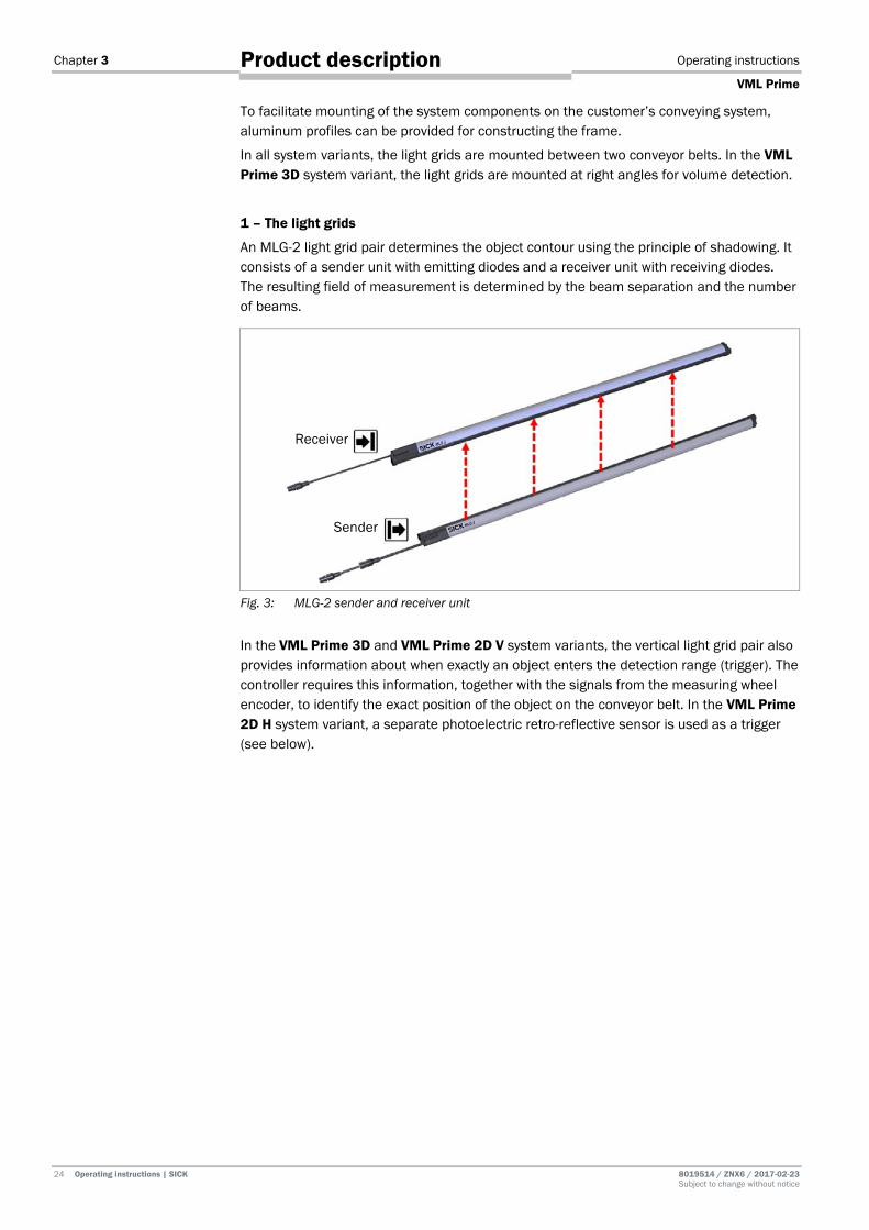
1 – The light grids
An MLG-2 light grid pair determines the object contour using the principle of shadowing. It consists of a sender unit with emitting diodes and a receiver unit with receiving diodes. The resulting field of measurement is determined by the beam separation and the number of beams.
Fig. 3: MLG-2 sender and receiver unit
In the VML Prime 3D and VML Prime 2D V system variants, the vertical light grid pair also provides information about when exactly an object enters the detection range (trigger). The controller requires this information, together with the signals from the measuring wheel encoder, to identify the exact position of the object on the conveyor belt. In the VML Prime 2D H system variant, a separate photoelectric retro-reflective sensor is used as a trigger (see below).
Receiver
Sender
Operating instructions Chapter 3
VML Prime
8019514/ZNX6/2017-02-23 Operating instructions | SICK 25 Subject to change without notice
Product description
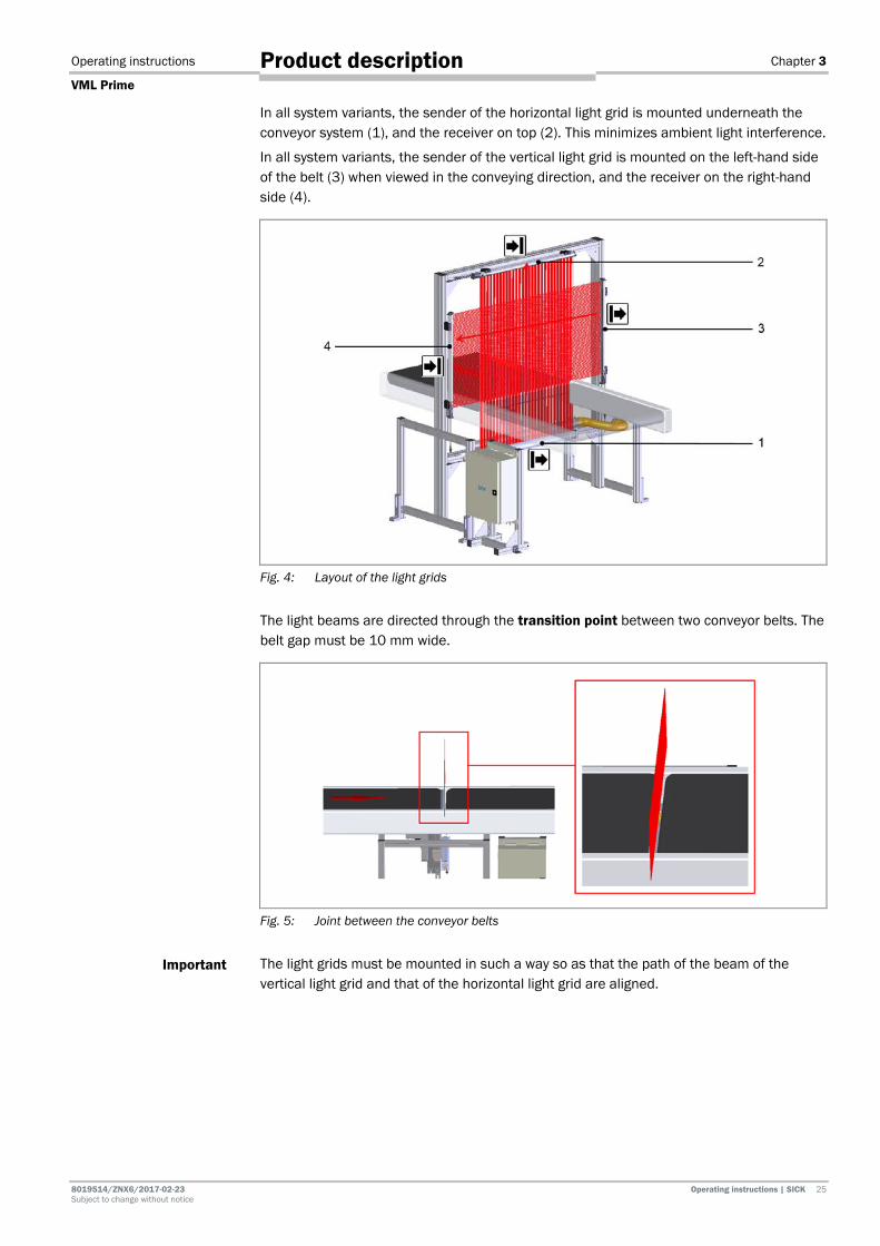
In all system variants, the sender of the horizontal light grid is mounted underneath the conveyor system (1), and the receiver on top (2). This minimizes ambient light interference.
In all system variants, the sender of the vertical light grid is mounted on the left-hand side of the belt (3) when viewed in the conveying direction, and the receiver on the right-hand side (4).
Fig. 4: Layout of the light grids
The light beams are directed through the transition point between two conveyor belts. The belt gap must be 10 mm wide.
Fig. 5: Joint between the conveyor belts
The light grids must be mounted in such a way so as that the path of the beam of the vertical light grid and that of the horizontal light grid are aligned.
Important

Chapter 3 Operating instructions
VML Prime
26 Operating instructions | SICK 8019514 / ZNX6 / 2017-02-23 Subject to change without notice
Product description
1a – Protective pipe and cleaning unit (recommended)
We recommend fitting the VML Prime 3D and VML Prime 2D H system variants with a cleaning set for the sender unit of the light grid mounted underneath the conveyor belt. This prevents an increased risk of contamination of the emitting diodes due to the horizontal mounting position of the sender below the belt.
The sender module (1) is mounted in a closed protective pipe made of plastic (2). The light beams are directed vertically upward through the Plexiglas to the receiver diodes.
Fig. 6: IPG2 protective pipe with sender
As in variant 1, the sender module (1) is pre-mounted in a closed protective pipe (2). In addition, there is a vent duct with vent slot (3) mounted parallel to the plastic pipes, as well as a fan with hose (4).
Fig. 7: IPG2 protective pipe with sender and cleaning unit
Variant 1
Variant 2
Operating instructions Chapter 3
VML Prime
8019514/ZNX6/2017-02-23 Operating instructions | SICK 27 Subject to change without notice
Product description
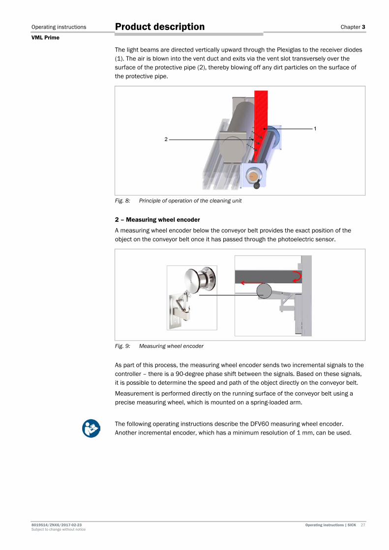
The light beams are directed vertically upward through the Plexiglas to the receiver diodes (1). The air is blown into the vent duct and exits via the vent slot transversely over the surface of the protective pipe (2), thereby blowing off any dirt particles on the surface of the protective pipe.
Fig. 8: Principle of operation of the cleaning unit
2 – Measuring wheel encoder
A measuring wheel encoder below the conveyor belt provides the exact position of the object on the conveyor belt once it has passed through the photoelectric sensor.
Fig. 9: Measuring wheel encoder
As part of this process, the measuring wheel encoder sends two incremental signals to the controller – there is a 90-degree phase shift between the signals. Based on these signals, it is possible to determine the speed and path of the object directly on the conveyor belt.
Measurement is performed directly on the running surface of the conveyor belt using a precise measuring wheel, which is mounted on a spring-loaded arm.
The following operating instructions describe the DFV60 measuring wheel encoder. Another incremental encoder, which has a minimum resolution of 1 mm, can be used.
Chapter 3 Operating instructions
VML Prime
28 Operating instructions | SICK 8019514 / ZNX6 / 2017-02-23 Subject to change without notice
Product description
2nd photoelectric retro-reflective sensor (VML Prime 2D H only)
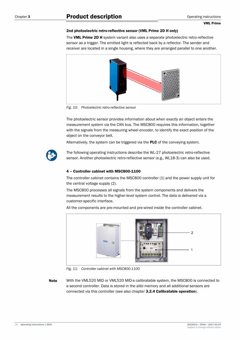
The VML Prime 2D H system variant also uses a separate photoelectric retro-reflective sensor as a trigger. The emitted light is reflected back by a reflector. The sender and receiver are located in a single housing, where they are arranged parallel to one another.
Fig. 10: Photoelectric retro-reflective sensor
The photoelectric sensor provides information about when exactly an object enters the measurement system via the CAN bus. The MSC800 requires this information, together with the signals from the measuring wheel encoder, to identify the exact position of the object on the conveyor belt.
Alternatively, the system can be triggered via the PLC of the conveying system.
The following operating instructions describe the WL-27 photoelectric retro-reflective sensor. Another photoelectric retro-reflective sensor (e.g., WL18-3) can also be used.
4 – Controller cabinet with MSC800-1100
The controller cabinet contains the MSC800 controller (1) and the power supply unit for the central voltage supply (2).
The MSC800 processes all signals from the system components and delivers the measurement results to the higher-level system control. The data is delivered via a customer-specific interface.
All the components are pre-mounted and pre-wired inside the controller cabinet.
Fig. 11: Controller cabinet with MSC800-1100
With the VML520 MID or VML520 MID-s calibratable system, the MSC800 is connected to a second controller. Data is stored in the alibi memory and all additional sensors are connected via this controller (see also chapter 3.2.4 Calibratable operation).
Note

Operating instructions Chapter 3
VML Prime
8019514/ZNX6/2017-02-23 Operating instructions | SICK 29 Subject to change without notice
Product description
Supplementary system components
In principle, AutoIdent systems or scales can also be added to the VML Prime measurement system.
AutoIdent systems: Laser scanners and camera-based systems allow the automatic identification of the object using its bar code, thereby accelerating process automation.
The LTR data for focusing the camera systems is provided by VML Prime.
Scales: The in-motion scales determine the weight of the passing object. The weight, together with the bar code and the calculated volume, can be transmitted for the purpose of controlling the goods and material flow.
3.2.2 VML Prime operating principle
The VML Prime measurement system dimensions individual objects on flat conveying systems. The objects must not be placed side by side and there must be a minimum distance of 200 mm (measured from the rear edge of the object to the front edge of the subsequent object) between them as they are being transported.
Fig. 12: Correct minimum distance between objects
Objects that are touching or lying side-by-side cannot be measured using the VML Prime.
Fig. 13: Non-permissible object positions (touching and side-by-side)
Recording the measured values
The light grids span one horizontal and/or one vertical monitoring field. Providing no object is located within this field, the light beams from the sender lines will hit the diodes of the receiver lines.

Chapter 3 Operating instructions
VML Prime
30 Operating instructions | SICK 8019514 / ZNX6 / 2017-02-23 Subject to change without notice
Product description
If the monitoring field is interrupted by an object, the shadowing and the resulting number of light beams prevented from reaching the receiver lines can be used to detect the profile of the object.
The change in the number of beams at the receiver lines resulting from this shadowing is transmitted to the MSC800 via the light grid interfaces in the form of a digital signal.
Calculating volume with VML Prime 3D
The motion of the object generates two-dimensional sections in the VML Prime 3D system variant.
Fig. 14: VML Prime 3D operating principle
The individual 2D sections of the object are merged together in the MSC800. When the transport speed and the position of the object on the belt are also taken into account, a three-dimensional image can be rendered. The smallest enveloping cuboid and volume of this image can then be determined from this.
To calculate the length, the system needs to know the position of the object on the conveyor belt after it has passed in front of the trigger. This is provided by the measuring wheel encoder in the form of incremental signals.
Calculating height and length* with VML Prime 2D V
In the VML Prime 2D V system variant, the vertical light grid pair provides one-dimensional rows of dots of the respective object side.
Fig. 15: VML Prime 2D V operating principle
Operating instructions Chapter 3
VML Prime
8019514/ZNX6/2017-02-23 Operating instructions | SICK 31 Subject to change without notice
Product description
The individual 2D rows of dots of the object are merged together in the MSC800. To calculate the side contour, the most extreme/highest point of the incoming data is always evaluated. When the transport speed and the position of the object on the belt are also taken into account, a two-dimensional image can be rendered, from which the object height is detected.
* VML Prime 2D V can also output the trigger length, which corresponds to the object length with aligned objects.
Calculating the width, length, and angle of rotation with VML Prime 2D H
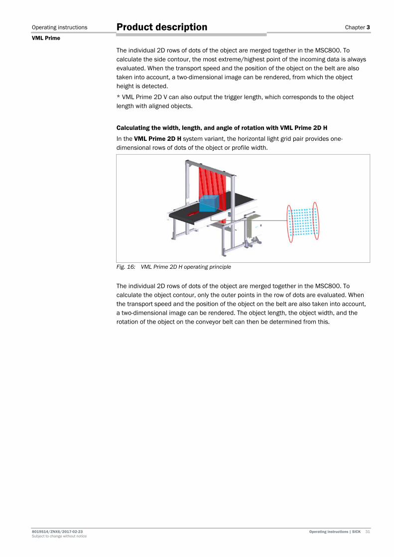
In the VML Prime 2D H system variant, the horizontal light grid pair provides one-dimensional rows of dots of the object or profile width.
Fig. 16: VML Prime 2D H operating principle
The individual 2D rows of dots of the object are merged together in the MSC800. To calculate the object contour, only the outer points in the row of dots are evaluated. When the transport speed and the position of the object on the belt are also taken into account, a two-dimensional image can be rendered. The object length, the object width, and the rotation of the object on the conveyor belt can then be determined from this.
Chapter 3 Operating instructions
VML Prime
32 Operating instructions | SICK 8019514 / ZNX6 / 2017-02-23 Subject to change without notice
Product description
3.2.3 Data output All information converges in the MSC800 central control unit. The MSC800 processes the trigger signal and forwards the object’s position so that the length can be calculated.
The data of all measurement results is output to the higher-level system control by the host data interface. Alternatively, the digital switching outputs of the MSC800 are available for further processing of the deformation result.
In addition to the measured values, the LTR data for camera focusing can also be transmitted if desired.
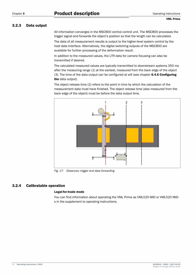
The calculated measured values are typically transmitted to downstream systems 350 ms after the measuring range (1) at the earliest, measured from the back edge of the object (3). The time of the data output can be configured at will (see chapter 6.4.6 Configuring the data output).
The object release time (2) refers to the point in time by which the calculation of the measurement data must have finished. The object release time (also measured from the back edge of the object) must be before the data output time.
Fig. 17: Distances: trigger and data forwarding
3.2.4 Calibratable operation Legal-for-trade mode
You can find information about operating the VML Prime as VML520 MID or VML520 MID-s in the supplement to operating instructions.
Operating instructions Chapter 3
VML Prime
8019514/ZNX6/2017-02-23 Operating instructions | SICK 33 Subject to change without notice
Product description
3.3 Project planning 3.3.1 Conveying system requirements
The following requirements apply to the conveying system and the objects that are being transported:
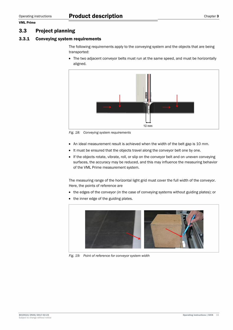
• The two adjacent conveyor belts must run at the same speed, and must be horizontally aligned.
Fig. 18: Conveying system requirements
• An ideal measurement result is achieved when the width of the belt gap is 10 mm.
• It must be ensured that the objects travel along the conveyor belt one by one.
• If the objects rotate, vibrate, roll, or slip on the conveyor belt and on uneven conveying surfaces, the accuracy may be reduced, and this may influence the measuring behavior of the VML Prime measurement system.
The measuring range of the horizontal light grid must cover the full width of the conveyor. Here, the points of reference are
• the edges of the conveyor (in the case of conveying systems without guiding plates); or
• the inner edge of the guiding plates.
Fig. 19: Point of reference for conveyor system width
Chapter 3 Operating instructions
VML Prime
34 Operating instructions | SICK 8019514 / ZNX6 / 2017-02-23 Subject to change without notice
Product description
3.3.2 Mounting requirements
Frame
The VML Prime measurement system requires both a stable, secure frame to prevent rotation and a sufficient load bearing capacity to support the light grids and the controller cabinet, where applicable.
• The frame must be assembled in such a way that it is free of vibrations and oscillations.
• The frame must be rectangular, and must be positioned at right angles to the conveying direction.
• The frame must be firmly anchored in the ground.
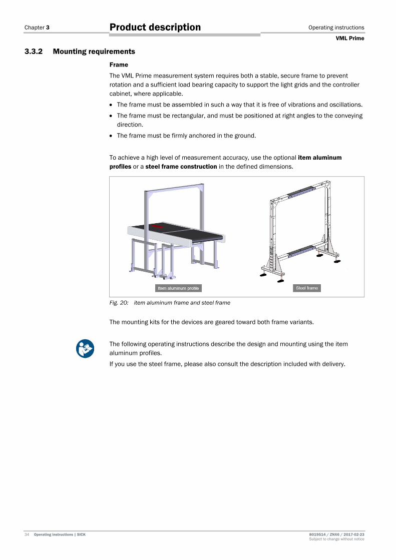
To achieve a high level of measurement accuracy, use the optional item aluminum profiles or a steel frame construction in the defined dimensions.
Fig. 20: item aluminum frame and steel frame
The mounting kits for the devices are geared toward both frame variants.
The following operating instructions describe the design and mounting using the item aluminum profiles.
If you use the steel frame, please also consult the description included with delivery.
Operating instructions Chapter 3
VML Prime
8019514/ZNX6/2017-02-23 Operating instructions | SICK 35 Subject to change without notice
Product description
Mounting the light grids
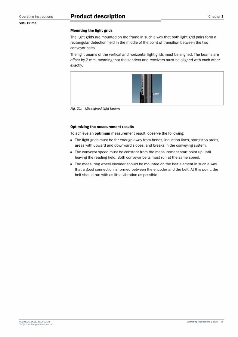
The light grids are mounted on the frame in such a way that both light grid pairs form a rectangular detection field in the middle of the point of transition between the two conveyor belts.
The light beams of the vertical and horizontal light grids must be aligned. The beams are offset by 2 mm, meaning that the senders and receivers must be aligned with each other exactly.
Fig. 21: Misaligned light beams
Optimizing the measurement results
To achieve an optimum measurement result, observe the following:
• The light grids must be far enough away from bends, induction lines, start/stop areas, areas with upward and downward slopes, and breaks in the conveying system.
• The conveyor speed must be constant from the measurement start point up until leaving the reading field. Both conveyor belts must run at the same speed.
• The measuring wheel encoder should be mounted on the belt element in such a way that a good connection is formed between the encoder and the belt. At this point, the belt should run with as little vibration as possible

Chapter 3 Operating instructions
VML Prime
36 Operating instructions | SICK 8019514 / ZNX6 / 2017-02-23 Subject to change without notice
Product description
3.4 Status indicators The accessible LEDs of the VML Prime measurement system are located on the sender and receiver units of the light grids and in the controller cabinet.
The light grids are fully automatic in normal operation and require no operator intervention.
3.4.1 MLG-2 light grids
The receivers of the MLG-2 have three LEDs on the connection side. These provide a visual indication of the operational status and any occurring faults.
Fig. 22: Status indicators on the MLG-2 (receiver unit) LEDs on the MLG-2 receiver
No. LED indicator Description
1 Green Green LED permanently illuminated Supply voltage on
Green Green LED off Supply voltage off or too low
2 Yellow Yellow LED permanently illuminated Light path interrupted (at least one beam interrupted)
Yellow Yellow LED off Light path is free
Yellow (3 Hz)
Yellow LED flashing rapidly Contamination warning or alignment mode is active (the signal arriving at the receiver is too weak)
The alignment mode is not permanently deactivated until after teach-in
Yellow (1 Hz)
Yellow LED flashing slowly Teach-in active
3 Red Red LED permanently illuminated A fault has occurred. The type of fault will be indicated by a combination of the yellow and the green LEDs.
Red (10 Hz)
Red LED flashing rapidly
An error has occurred during teach-in.
Tab. 4: Status indicators – light grid (receiver)
Operating instructions Chapter 3
VML Prime
8019514/ZNX6/2017-02-23 Operating instructions | SICK 37 Subject to change without notice
Product description
LEDs on the MLG-2 sender
No. LED indicator Description
1 Green Green LED permanently illuminated Supply voltage on
1 Red Red LED permanently illuminated Hardware fault
Tab. 5: Status indicators – light grid (sender)
3.4.2 LED of the separate photoelectric retro-reflective sensor
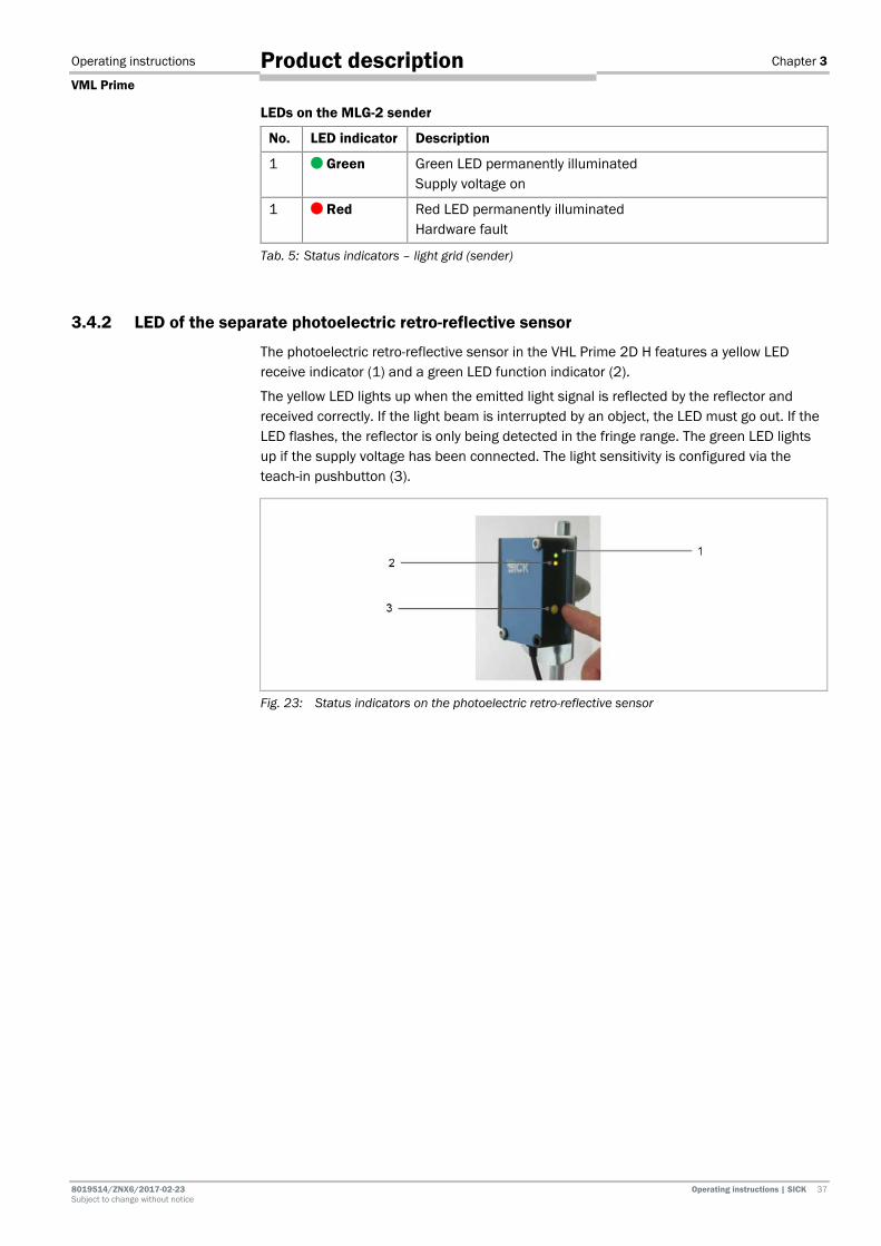
The photoelectric retro-reflective sensor in the VHL Prime 2D H features a yellow LED receive indicator (1) and a green LED function indicator (2).
The yellow LED lights up when the emitted light signal is reflected by the reflector and received correctly. If the light beam is interrupted by an object, the LED must go out. If the LED flashes, the reflector is only being detected in the fringe range. The green LED lights up if the supply voltage has been connected. The light sensitivity is configured via the teach-in pushbutton (3).
Fig. 23: Status indicators on the photoelectric retro-reflective sensor

Chapter 3 Operating instructions
VML Prime
38 Operating instructions | SICK 8019514 / ZNX6 / 2017-02-23 Subject to change without notice
Product description
3.4.3 LEDs on the controller
Fig. 24: Status indicators on the MSC800 controller
LED Color Meaning
READY Green ON: Controller is ready for operation OFF: Controller is not ready for operation
SYSTEM READY Green ON: Complete system consisting of MSC800 and all connected devices is ready for operation OFF: Complete system is not ready for operation
RESULT Green ON: There is a valid read result OFF: No valid read result
RUN FIELDBUS Green ON: Fieldbus communication is active OFF: No fieldbus communication
READY FIELDBUS Green ON: Fieldbus application is ready OFF: Fieldbus application is not ready
OUT Green ON: Switching output is active OFF: Switching output is deactivated
IN, TRIGGER, INC Green ON: Switching input is active OFF: Switching input is deactivated
POWER (1/2) Green ON: Supply voltage is on OFF: No supply voltage
microSD ACT
Green ON: MSC800 reading data from / writing data to microSD card OFF: Deactivated
PROFIBUS STA ERR
Green Green
ON: Data interface is ready for communication ON: Bus or communication error
ETHERNET LNK ACT 100
Green Green Green
ON: Data interface is connected to Ethernet ON: Data transmission ON: Data transmission rate 100 Mbit/s OFF: Data transmission rate 10 Mbit/s
HOST (1/2) AUX (1/2) Tx 232
Green Green
ON: Data interface is sending data ON: Interface is operating as an RS-232 interface OFF: Interface is operating as an RS-422/485 interface
CAN 1/2 Rx
ON: Data interface is receiving data
Tab. 6: Status indicators on the MSC800 controller
Operating instructions Chapter 3
VML Prime
8019514/ZNX6/2017-02-23 Operating instructions | SICK 39 Subject to change without notice
Product description
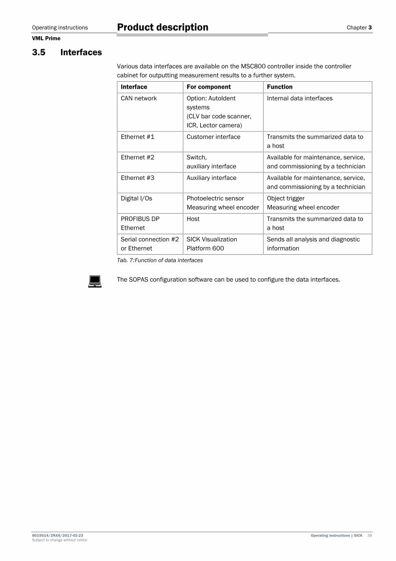
3.5 Interfaces Various data interfaces are available on the MSC800 controller inside the controller cabinet for outputting measurement results to a further system.
Interface For component Function
CAN network Option: AutoIdent systems (CLV bar code scanner, ICR, Lector camera)
Internal data interfaces
Ethernet #1 Customer interface Transmits the summarized data to a host
Ethernet #2 Switch, auxiliary interface
Available for maintenance, service, and commissioning by a technician
Ethernet #3 Auxiliary interface Available for maintenance, service, and commissioning by a technician
Digital I/Os Photoelectric sensor Measuring wheel encoder
Object trigger Measuring wheel encoder
PROFIBUS DP Ethernet
Host Transmits the summarized data to a host
Serial connection #2 or Ethernet
SICK Visualization Platform 600
Sends all analysis and diagnostic information
Tab. 7: Function of data interfaces
The SOPAS configuration software can be used to configure the data interfaces.
Chapter 4 Operating instructions
VML Prime
40 Operating instructions | SICK 8019514 / ZNX6 / 2017-02-23 Subject to change without notice
Mounting
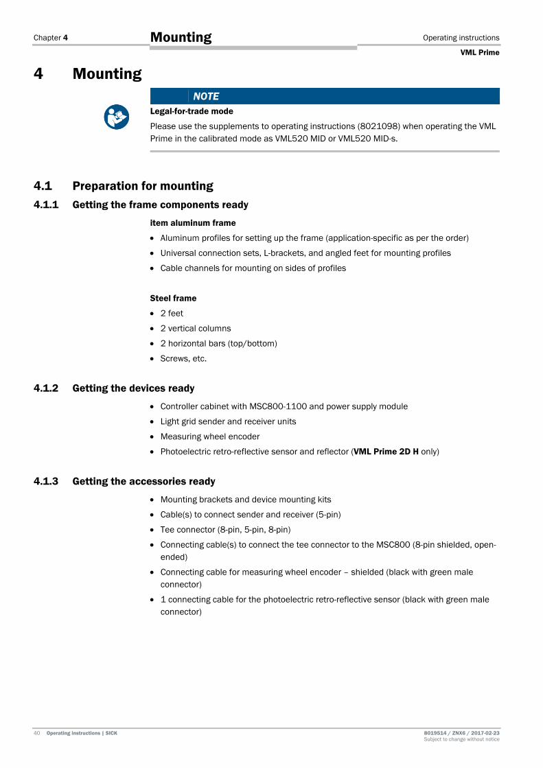
4 Mounting NOTE
Legal-for-trade mode
Please use the supplements to operating instructions (8021098) when operating the VML Prime in the calibrated mode as VML520 MID or VML520 MID-s.
4.1 Preparation for mounting 4.1.1 Getting the frame components ready
item aluminum frame
• Aluminum profiles for setting up the frame (application-specific as per the order)
• Universal connection sets, L-brackets, and angled feet for mounting profiles
• Cable channels for mounting on sides of profiles
Steel frame
• 2 feet
• 2 vertical columns
• 2 horizontal bars (top/bottom)
• Screws, etc.
4.1.2 Getting the devices ready
• Controller cabinet with MSC800-1100 and power supply module
• Light grid sender and receiver units
• Measuring wheel encoder
• Photoelectric retro-reflective sensor and reflector (VML Prime 2D H only)
4.1.3 Getting the accessories ready
• Mounting brackets and device mounting kits
• Cable(s) to connect sender and receiver (5-pin)
• Tee connector (8-pin, 5-pin, 8-pin)
• Connecting cable(s) to connect the tee connector to the MSC800 (8-pin shielded, open-ended)
• Connecting cable for measuring wheel encoder – shielded (black with green male connector)
• 1 connecting cable for the photoelectric retro-reflective sensor (black with green male connector)

Operating instructions Chapter 4
VML Prime
8019514/ZNX6/2017-02-23 Operating instructions | SICK 41 Subject to change without notice
Mounting
4.2 Assembling the item aluminum frame 4.2.1 Frame components
The frame that holds the device components is constructed in the form of a gate around the conveying system. The gate must be mounted at the gap between two conveyor belts so the light beams from the light grid fall on the center of the gap.
The gate frame is usually made up of individual aluminum profiles. The height and width of the profiles are customer-specific. More detail can be found in the delivery specification.
The frame consists of the following components:
Fig. 25: item mounting frame: components
Number Designation
1 Carrier profiles
2 Transverse profiles for connecting the two carrier profiles
3 Brackets for stabilizing the frame
4 Longitudinal and transverse profiles for constructing the foot and for mounting the devices
5 Angled feet for leveling and anchoring the frame to the floor
Tab. 8: item mounting frame: components
The aluminum profiles are mounted using the universal connector for extruded aluminum profiles that is included with delivery. Universal connectors for extruded aluminum profiles are rectangular friction-fitted aluminum profile connectors that can be adjusted.
Fig. 26: item mounting frame: universal connector for mounting the item profiles
Chapter 4 Operating instructions
VML Prime
42 Operating instructions | SICK 8019514 / ZNX6 / 2017-02-23 Subject to change without notice
Mounting
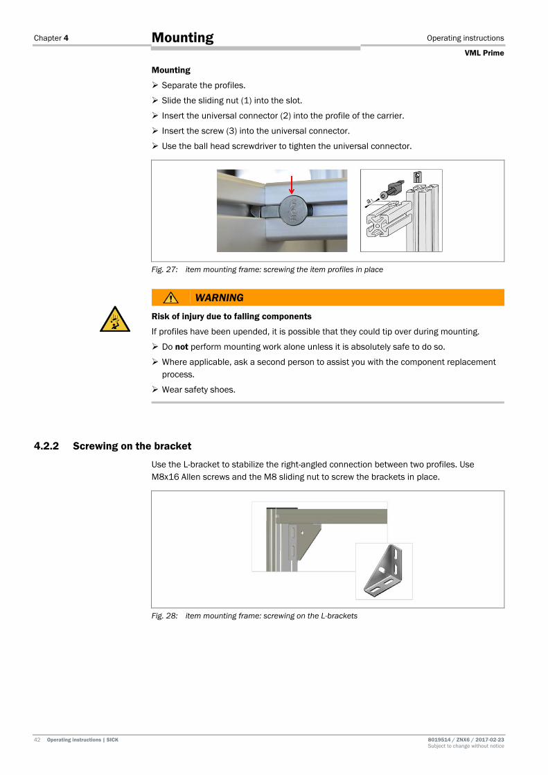
Mounting
Separate the profiles.
Slide the sliding nut (1) into the slot.
Insert the universal connector (2) into the profile of the carrier.
Insert the screw (3) into the universal connector.
Use the ball head screwdriver to tighten the universal connector.
Fig. 27: item mounting frame: screwing the item profiles in place
WARNING
Risk of injury due to falling components
If profiles have been upended, it is possible that they could tip over during mounting.
Do not perform mounting work alone unless it is absolutely safe to do so.
Where applicable, ask a second person to assist you with the component replacement process.
Wear safety shoes.
4.2.2 Screwing on the bracket
Use the L-bracket to stabilize the right-angled connection between two profiles. Use M8x16 Allen screws and the M8 sliding nut to screw the brackets in place.
Fig. 28: item mounting frame: screwing on the L-brackets

Operating instructions Chapter 4
VML Prime
8019514/ZNX6/2017-02-23 Operating instructions | SICK 43 Subject to change without notice
Mounting
4.2.3 Aligning the frame
The frame must be aligned at a right angle to itself and at a right angle to the conveyor belt. The transverse profiles must run parallel to the conveying system.
The distances from the belt must be equidistant, i.e., the same on both sides.
Fig. 29: item mounting frame: aligning the frame
4.2.4 Leveling the frame
Adjusting the angled foot enables uneven floors to be compensated for simply by adjusting the height. This allows the frame to be aligned horizontally and vertically.
Fig. 30: item mounting frame: using the angled adjustable feet to level the frame
1. Turn the setting screw (1) of the adjustable feet to raise or lower the carrier profiles until the entire frame is perpendicular to the conveying direction.
2. Fix the selected height by tightening the side fixing screw (2).

Chapter 4 Operating instructions
VML Prime
44 Operating instructions | SICK 8019514 / ZNX6 / 2017-02-23 Subject to change without notice
Mounting
4.2.5 Anchoring the frame to the floor
The frame must be screwed to the floor via the angled adjustable feet.
Use the 10 mm high-load dowels and concrete screws included with delivery.
Screw down the frame at all angled adjustable feet.
If the frame is standing on a grate, use hook bolts instead of the high-load dowels.
4.2.6 Attaching the cable holders
Use the universal cable tie block supplied to attach the connecting cables to the profile. It enables cables to be easily mounted on a profile.
Fig. 31: Universal cable tie block
Check how the cables are to be routed at the site. Typically the connection cable and connecting cable for the vertical components are mounted on the lower transverse profile and lead to the controller cabinet. The connection cable for the vertical components is taken to the right-hand longitudinal profile due to the mounting position (viewed in conveying direction).
Mounting
Mount the universal cable tie block in the profile slot with a hammer head nut.
Cable ties for bundling cables and tubes are mounted on the universal cable tie block.
Note

Operating instructions Chapter 4
VML Prime
8019514/ZNX6/2017-02-23 Operating instructions | SICK 45 Subject to change without notice
Mounting
4.3 Mounting the light grids 4.3.1 Overview
Mount the vertical and horizontal light grid components on the frame in the order described:
1. Horizontal receiver at the top
2. Horizontal sender (in the protective pipe if necessary)
3. Vertical receiver on the right (in conveying direction)
4. Vertical sender on the left (in conveying direction)
Fig. 32: Mounting the components (overview)
• The end with the cable connection on the associated sender and receiver units must always point in the same direction. Due to the beam offset of 2 mm, the cable connections for the horizontal light grid (in conveying direction) must point to the right and the cable connections for the vertical light grid must point downward.
If they are mounted inversely, the monitored areas will not be in a single plane.
• The light grid is mounted (in conveying direction) behind the frame.
• Sender and receiver must not be installed at 180° rotated relative to each other. The sender and receiver must be mounted in the same orientation.
• Sender and receiver can each be recognized via an icon on the type label.
Icon Designation
Sender unit
Receiver unit
All light grid beams must lie exactly on a single plane. The light beams sent must fall exactly on and at a right angle to the relevant receiver unit diode. To achieve this, the components must be aligned on the frame.
The frame must ensure that the vertical light grids are orthogonal to the conveying system and the horizontal ones are parallel to it.
Notes
Alignment

Chapter 4 Operating instructions
VML Prime
46 Operating instructions | SICK 8019514 / ZNX6 / 2017-02-23 Subject to change without notice
Mounting
4.3.2 Mounting the light grids using QuickFix 4.3.2.1 Assembling QuickFix brackets
Sender and receiver are each mounted on the aluminum profiles of the frame using two QuickFix brackets.
QuickFix brackets are supplied in four individual parts that must be assembled before mounting.
Fig. 33: Assembling QuickFix brackets
1. Push both parts of the clamping housing into one another (1, 2).
2. Connect both individual parts using an M5 screw.
3. Screw the sliding nut onto the screw. The sliding nut is used to mount the QuickFix bracket on the aluminum profile of the mounting frame.
If you use a different frame, a screw-nut is required instead of a sliding nut.
4. Get the brackets ready for mounting in a disconnected state.
4.3.2.2 Pre-mounting sender and receiver on the QuickFix bracket
Before mounting, attach two QuickFix brackets to each of the two senders and receivers.
If the horizontal sender is installed in the protective pipe, other brackets are used for mounting (see chapter 4.3.3 Mounting the protective pipe with sender).
1. Pull the QuickFix brackets apart and insert the light grid.
2. Make sure that the head of the QuickFix bracket is placed exactly in the MLG-2 housing slot.
Fig. 34: QuickFix bracket head in the MLG-2 housing slot
Note
Note
Operating instructions Chapter 4
VML Prime
8019514/ZNX6/2017-02-23 Operating instructions | SICK 47 Subject to change without notice
Mounting
3. Attach the two QuickFix brackets to the component housing. Push the two parts of the bracket together until you hear a click.
Fig. 35: Attaching the QuickFix bracket to the MLG-2 housing
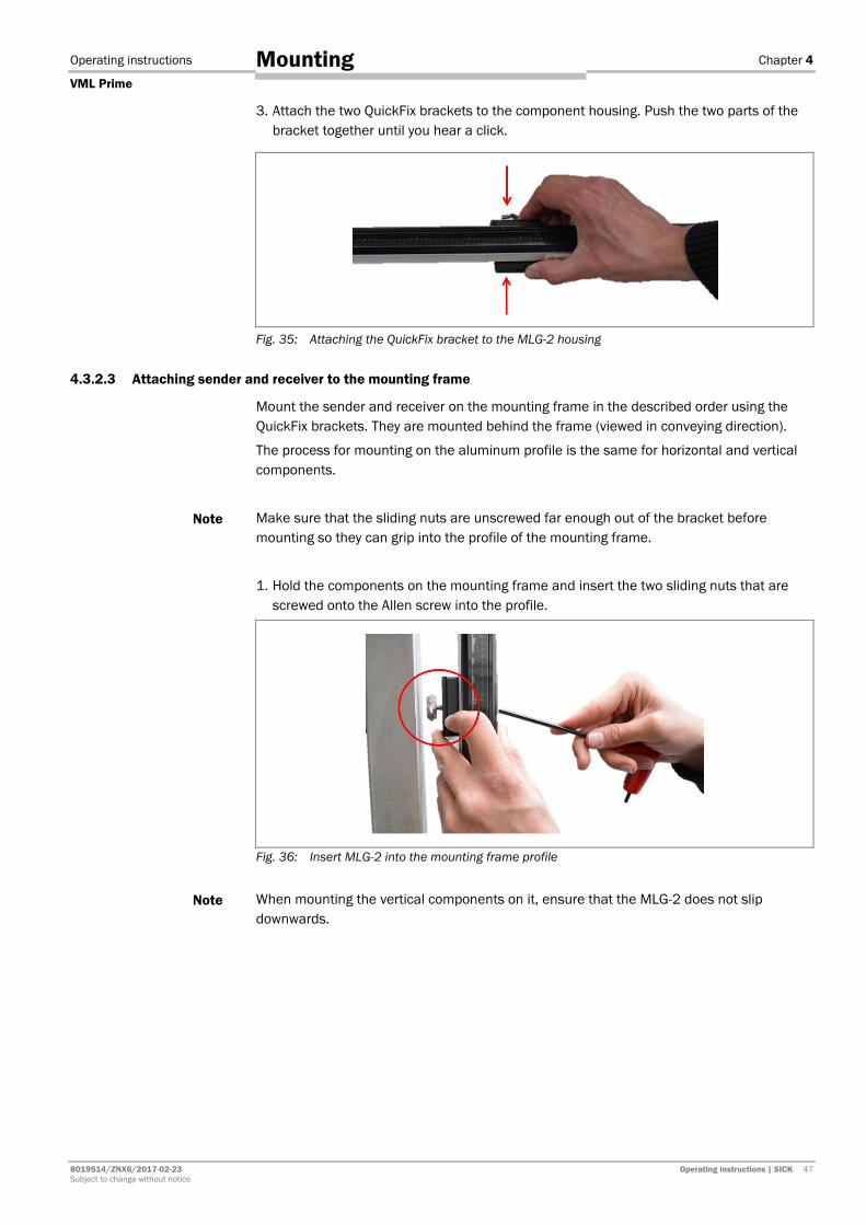
4.3.2.3 Attaching sender and receiver to the mounting frame
Mount the sender and receiver on the mounting frame in the described order using the QuickFix brackets. They are mounted behind the frame (viewed in conveying direction).
The process for mounting on the aluminum profile is the same for horizontal and vertical components.
Make sure that the sliding nuts are unscrewed far enough out of the bracket before mounting so they can grip into the profile of the mounting frame.
1. Hold the components on the mounting frame and insert the two sliding nuts that are screwed onto the Allen screw into the profile.
Fig. 36: Insert MLG-2 into the mounting frame profile
When mounting the vertical components on it, ensure that the MLG-2 does not slip downwards.
Note
Note

Chapter 4 Operating instructions
VML Prime
48 Operating instructions | SICK 8019514 / ZNX6 / 2017-02-23 Subject to change without notice
Mounting
2. Screw the Allen screw into the sliding nut.
3. Screw the two brackets so the components can still be moved in the profile slot.
Fig. 37: Screwing MLG-2 into the profile
4. Align the components in the aluminum profile. An approximate alignment is sufficient at this stage. They are aligned more precisely in a subsequent step.
5. Locate the horizontal components along the y-axis so that they are midway above or beneath the conveyor belt.
Fig. 38: Locating the horizontal receiver unit in the MLG-2 in the profile
6. In the case of the vertical components, the first diode should be approx. 2 mm above the conveyor belt.
Use a water level to level the horizontal sender and receiver units.
Important
Operating instructions Chapter 4
VML Prime
8019514/ZNX6/2017-02-23 Operating instructions | SICK 49 Subject to change without notice
Mounting
4.3.3 Mounting the protective pipe with sender
The horizontal sender is installed in the IPG2 protective pipe before mounting. The protective pipe is fixed to the mounting frame with two mounting brackets.
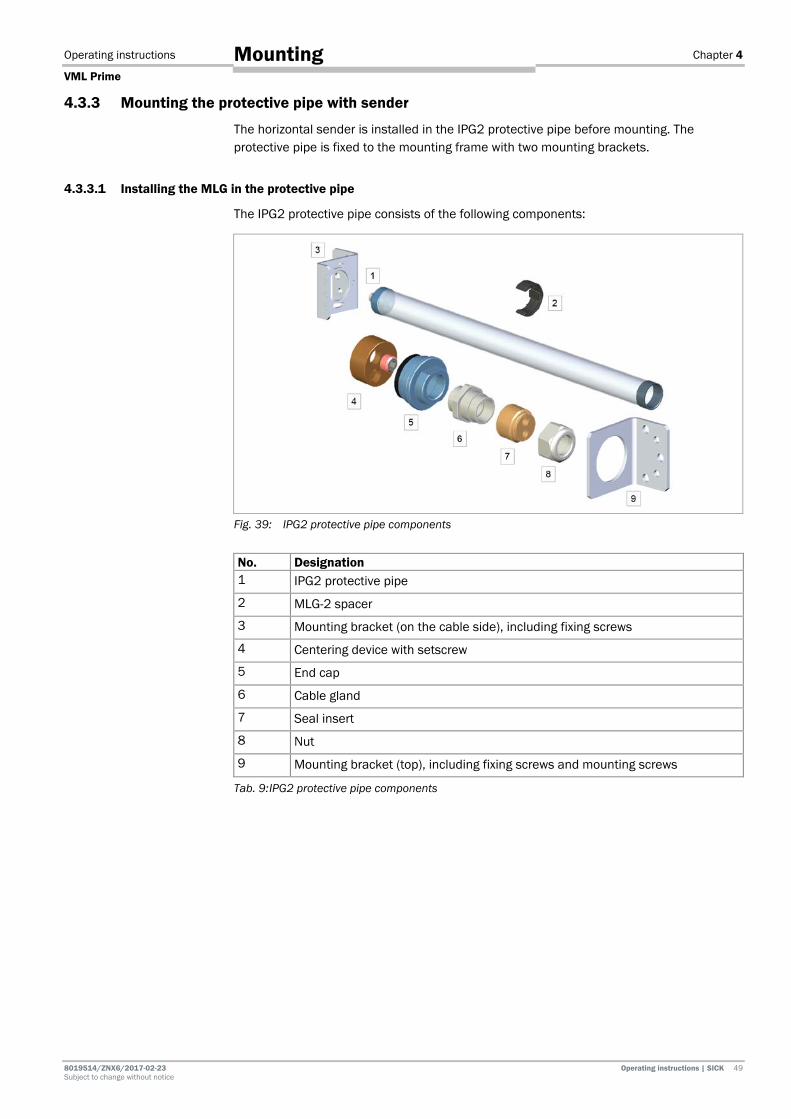
4.3.3.1 Installing the MLG in the protective pipe
The IPG2 protective pipe consists of the following components:
Fig. 39: IPG2 protective pipe components
No. Designation 1 IPG2 protective pipe
2 MLG-2 spacer
3 Mounting bracket (on the cable side), including fixing screws
4 Centering device with setscrew
5 End cap
6 Cable gland
7 Seal insert
8 Nut
9 Mounting bracket (top), including fixing screws and mounting screws
Tab. 9: IPG2 protective pipe components
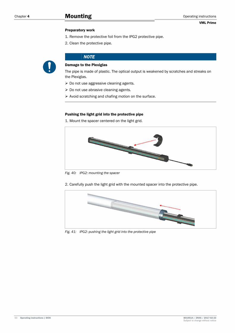
Chapter 4 Operating instructions
VML Prime
50 Operating instructions | SICK 8019514 / ZNX6 / 2017-02-23 Subject to change without notice
Mounting
Preparatory work
1. Remove the protective foil from the IPG2 protective pipe.
2. Clean the protective pipe.
NOTE
Damage to the Plexiglas
The pipe is made of plastic. The optical output is weakened by scratches and streaks on the Plexiglas.
Do not use aggressive cleaning agents.
Do not use abrasive cleaning agents.
Avoid scratching and chafing motion on the surface.
Pushing the light grid into the protective pipe
1. Mount the spacer centered on the light grid.
Fig. 40: IPG2: mounting the spacer
2. Carefully push the light grid with the mounted spacer into the protective pipe.
Fig. 41: IPG2: pushing the light grid into the protective pipe
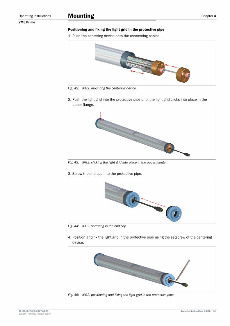
Operating instructions Chapter 4
VML Prime
8019514/ZNX6/2017-02-23 Operating instructions | SICK 51 Subject to change without notice
Mounting
Positioning and fixing the light grid in the protective pipe
1. Push the centering device onto the connecting cables.
Fig. 42: IPG2: mounting the centering device
2. Push the light grid into the protective pipe until the light grid clicks into place in the upper flange.
Fig. 43: IPG2: clicking the light grid into place in the upper flange
3. Screw the end cap into the protective pipe.
Fig. 44: IPG2: screwing in the end cap
4. Position and fix the light grid in the protective pipe using the setscrew of the centering device.
Fig. 45: IPG2: positioning and fixing the light grid in the protective pipe

Chapter 4 Operating instructions
VML Prime
52 Operating instructions | SICK 8019514 / ZNX6 / 2017-02-23 Subject to change without notice
Mounting
Final steps
1. Screw the cable gland to the end piece.
2. Push the seal insert into the cable gland.
Fig. 46: IPG2: mounting the cable gland and seal insert
3. Screw the nut onto the cable gland.
Fig. 47: IPG2: screwing the nut onto the cable gland
4.3.3.2 Attaching the protective pipe to the mounting frame
Special brackets are provided for mounting the protective pipe and light grid. The brackets are mounted with a screw in each profile slot.
Attaching the cable-side bracket (floating bearing) to the profile.
1. Insert the sliding nut into the side slot on the lower mounting frame.
2. Place the bracket at the side on the profile.
3. Screw the bracket in place with the fixing screw.
Do not tighten the screw yet.
Fig. 48: IPG2: attaching the lower bracket to the profile
Note

Operating instructions Chapter 4
VML Prime
8019514/ZNX6/2017-02-23 Operating instructions | SICK 53 Subject to change without notice
Mounting
Inserting the protective pipe
1. Insert the protective pipe with the light grid into the lower bracket. Carefully pull the connecting cable through the cutout.
2. Hold the protective pipe at the top end with one hand.
Fig. 49: IPG2: placing the protective pipe on the cable-side bracket
Mounting the upper bracket on the protective pipe
1. Put the bracket on the upper end of the protective pipe.
1. Align the protective pipe with the MLG in the brackets in such a way that the diodes of the MLG point vertically upward.
2. Fix this position. To do this, screw both fixing screws into the two through holes. Tighten the screws.
3. Screw the bracket in place on the mounting frame with the fixing screw. Do not tighten this screw yet.
Fig. 50: IPG2: aligning the protective pipe and fixing the position

Chapter 4 Operating instructions
VML Prime
54 Operating instructions | SICK 8019514 / ZNX6 / 2017-02-23 Subject to change without notice
Mounting
4.3.4 Fine adjustment of the light grids 4.3.4.1 Making sure the light beams fall on the center of the gap
Firstly, make sure that the light grid beams fall on the center of the gap.
1. Move the frame with the mounted light grids in the x-axis until the component diodes fall on the center of the gap. Use the upper horizontal grid as a reference.
Fig. 51: Making sure the light beams fall on the center of the gap
2. Check they are centered using a plumbline. To do this, first place the plumbline on the first diode of the horizontal receiver.
In order to be able to identify the diodes better behind the blackened glass of the receiver, it is best to illuminate them with a flashlight.
Fig. 52: Using a plumbline to check that the light beams are centered
3. The plumbline should settle in the center of the gap.
Fig. 53: Plumbline in the center of the gap
4. Repeat this thorough check for the last diode.
Tip
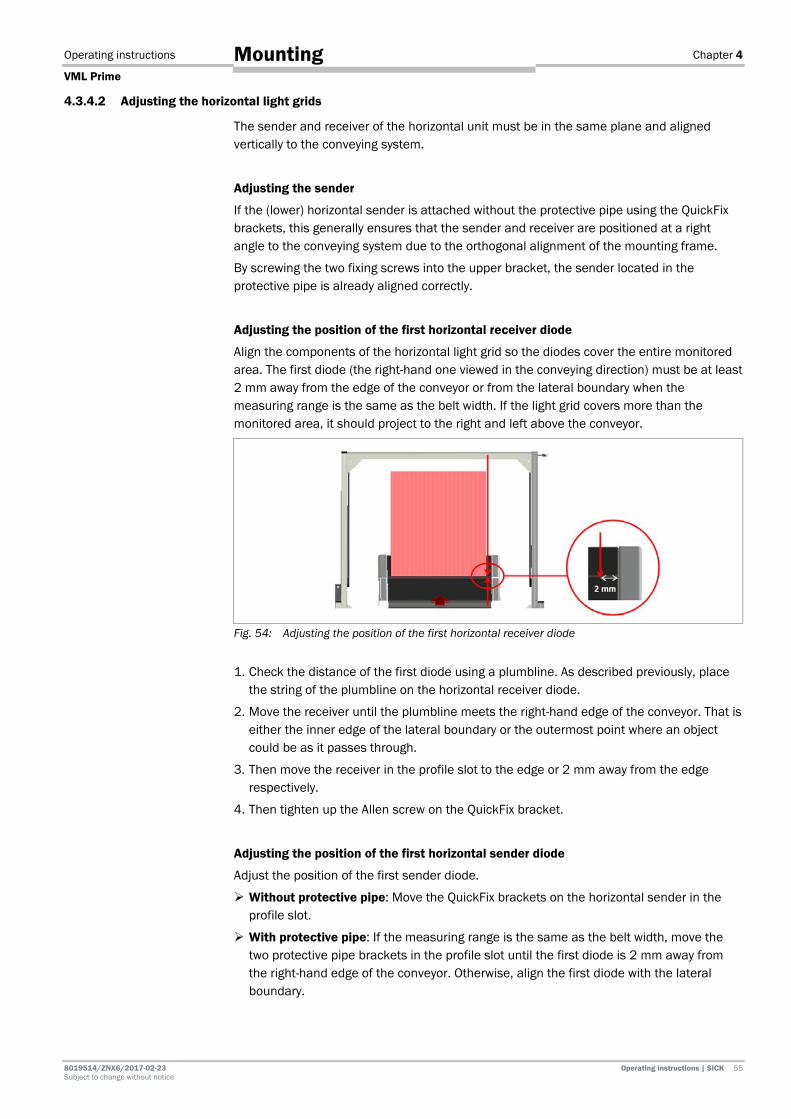
Operating instructions Chapter 4
VML Prime
8019514/ZNX6/2017-02-23 Operating instructions | SICK 55 Subject to change without notice
Mounting
4.3.4.2 Adjusting the horizontal light grids
The sender and receiver of the horizontal unit must be in the same plane and aligned vertically to the conveying system.
Adjusting the sender
If the (lower) horizontal sender is attached without the protective pipe using the QuickFix brackets, this generally ensures that the sender and receiver are positioned at a right angle to the conveying system due to the orthogonal alignment of the mounting frame.
By screwing the two fixing screws into the upper bracket, the sender located in the protective pipe is already aligned correctly.
Adjusting the position of the first horizontal receiver diode
Align the components of the horizontal light grid so the diodes cover the entire monitored area. The first diode (the right-hand one viewed in the conveying direction) must be at least 2 mm away from the edge of the conveyor or from the lateral boundary when the measuring range is the same as the belt width. If the light grid covers more than the monitored area, it should project to the right and left above the conveyor.
Fig. 54: Adjusting the position of the first horizontal receiver diode
1. Check the distance of the first diode using a plumbline. As described previously, place the string of the plumbline on the horizontal receiver diode.
2. Move the receiver until the plumbline meets the right-hand edge of the conveyor. That is either the inner edge of the lateral boundary or the outermost point where an object could be as it passes through.
3. Then move the receiver in the profile slot to the edge or 2 mm away from the edge respectively.
4. Then tighten up the Allen screw on the QuickFix bracket.
Adjusting the position of the first horizontal sender diode
Adjust the position of the first sender diode.
Without protective pipe: Move the QuickFix brackets on the horizontal sender in the profile slot.
With protective pipe: If the measuring range is the same as the belt width, move the two protective pipe brackets in the profile slot until the first diode is 2 mm away from the right-hand edge of the conveyor. Otherwise, align the first diode with the lateral boundary.

Chapter 4 Operating instructions
VML Prime
56 Operating instructions | SICK 8019514 / ZNX6 / 2017-02-23 Subject to change without notice
Mounting
Checking the correct position of the first diode
The alignment must ensure that the light grid beams fall exactly in a single plane and that each emitting diode meets the opposite receiver diode vertically.
Check the correct position of the first two diodes using a plumbline.
Without protective pipe: Place the string of the plumbline on the first receiver diode. The plumb must fall exactly on the first sender diode.
With protective pipe: When the light grid is mounted in the protective pipe, the plumb needs to fall from the (in conveying direction) left mechanical end of the upper light grid on the upper bracket of the protective pipe (top of MLG).
Fig. 55: Checking the correct position of the first diodes

Operating instructions Chapter 4
VML Prime
8019514/ZNX6/2017-02-23 Operating instructions | SICK 57 Subject to change without notice
Mounting
4.3.4.3 Adjusting the vertical light grid
Align the two components of the vertical light grid on the mounting frame so that the first diode (viewed from below) is approx. 2 mm above the conveyor belt.
Fig. 56: Aligning the vertical light grid
1. First move the vertical receiver in the z-direction until you have achieved the required distance between the first diode and the belt.
In order to determine the required distance more precisely, place a sheet of paper on the gap. This provides a clearly defined zero point for measuring the height.
2. Take the sender to the same height.
3. Place a board or a profile on the two components.
4. Place a spirit level on the board and make sure that the two components are level.
Fig. 57: Checking the alignment of the vertical light grid
Tip
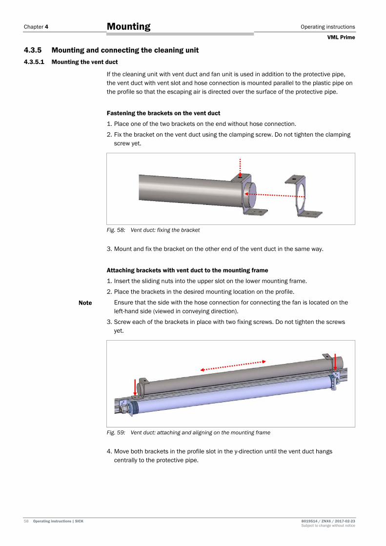
Chapter 4 Operating instructions
VML Prime
58 Operating instructions | SICK 8019514 / ZNX6 / 2017-02-23 Subject to change without notice
Mounting
4.3.5 Mounting and connecting the cleaning unit 4.3.5.1 Mounting the vent duct
If the cleaning unit with vent duct and fan unit is used in addition to the protective pipe, the vent duct with vent slot and hose connection is mounted parallel to the plastic pipe on the profile so that the escaping air is directed over the surface of the protective pipe.
Fastening the brackets on the vent duct
1. Place one of the two brackets on the end without hose connection.
2. Fix the bracket on the vent duct using the clamping screw. Do not tighten the clamping screw yet.
Fig. 58: Vent duct: fixing the bracket
3. Mount and fix the bracket on the other end of the vent duct in the same way.
Attaching brackets with vent duct to the mounting frame
1. Insert the sliding nuts into the upper slot on the lower mounting frame.
2. Place the brackets in the desired mounting location on the profile.
Ensure that the side with the hose connection for connecting the fan is located on the left-hand side (viewed in conveying direction).
3. Screw each of the brackets in place with two fixing screws. Do not tighten the screws yet.
Fig. 59: Vent duct: attaching and aligning on the mounting frame
4. Move both brackets in the profile slot in the y-direction until the vent duct hangs centrally to the protective pipe.
Note
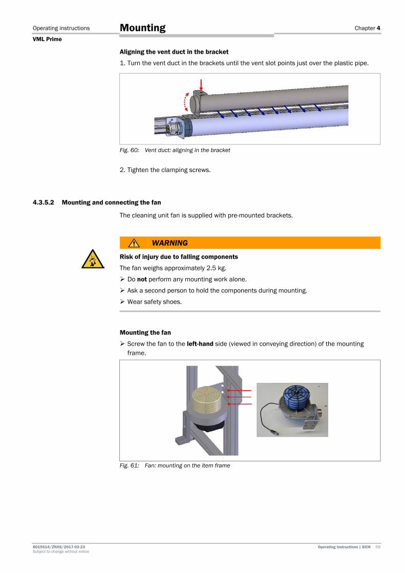
Operating instructions Chapter 4
VML Prime
8019514/ZNX6/2017-02-23 Operating instructions | SICK 59 Subject to change without notice
Mounting
Aligning the vent duct in the bracket
1. Turn the vent duct in the brackets until the vent slot points just over the plastic pipe.
Fig. 60: Vent duct: aligning in the bracket
2. Tighten the clamping screws.
4.3.5.2 Mounting and connecting the fan
The cleaning unit fan is supplied with pre-mounted brackets.
WARNING
Risk of injury due to falling components
The fan weighs approximately 2.5 kg.
Do not perform any mounting work alone.
Ask a second person to hold the components during mounting.
Wear safety shoes.
Mounting the fan
Screw the fan to the left-hand side (viewed in conveying direction) of the mounting frame.
Fig. 61: Fan: mounting on the item frame

Chapter 4 Operating instructions
VML Prime
60 Operating instructions | SICK 8019514 / ZNX6 / 2017-02-23 Subject to change without notice
Mounting
Connecting the hose
The flexible hose connection is supplied with two attached brackets for fixing to the relevant couplings.
Connect the fan and vent duct using the flexible hose connection and fix the hose connection using the pre-mounted brackets.
Fig. 62: Attaching the hose connection to the fan
Make sure you do not bend the flexible hose connection too sharply.
Attach the hose as straight as possible to the fan couplings and the couplings on the vent duct.
Note
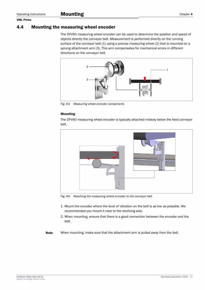
Operating instructions Chapter 4
VML Prime
8019514/ZNX6/2017-02-23 Operating instructions | SICK 61 Subject to change without notice
Mounting
4.4 Mounting the measuring wheel encoder The DFV60 measuring wheel encoder can be used to determine the position and speed of objects directly the conveyor belt. Measurement is performed directly on the running surface of the conveyor belt (1) using a precise measuring wheel (2) that is mounted on a sprung attachment arm (3). This arm compensates for mechanical errors in different directions on the conveyor belt.
Fig. 63: Measuring wheel encoder components
Mounting
The DFV60 measuring wheel encoder is typically attached midway below the feed conveyor belt.
Fig. 64: Attaching the measuring wheel encoder to the conveyor belt
1. Mount the encoder where the level of vibration on the belt is as low as possible. We recommended you mount it near to the revolving axle.
2. When mounting, ensure that there is a good connection between the encoder and the belt.
When mounting, make sure that the attachment arm is pulled away from the belt.
Note

Chapter 4 Operating instructions
VML Prime
62 Operating instructions | SICK 8019514 / ZNX6 / 2017-02-23 Subject to change without notice
Mounting
4.5 Mounting the photoelectric sensor (VML Prime 2D H only) When using the VML Prime 2D H, mount the photoelectric sensor and reflector on the frame in accordance with the technical drawing. A mounting bracket is included for the mounting of the photoelectric retro-reflective sensor.
1. Insert the two M6 sliding nuts (1) into the slot of the carrier profile on which the photoelectric sensor is mounted.
2. Place the support rail on the profile and screw it on with two M6 screws (see the two arrows).
Fig. 65: Mounting the photoelectric sensor mounting bracket
3. Mount the photoelectric retro-reflective sensor on the mounting bracket using the two M5 hexagon screws.
4. Align the photoelectric sensor in such a way that the light band runs parallel to the conveying surface and perpendicular to the conveying direction. Fix the photoelectric sensor using the clinch stud (see the circle in the following figure).
Fig. 66: Mounting the photoelectric sensor
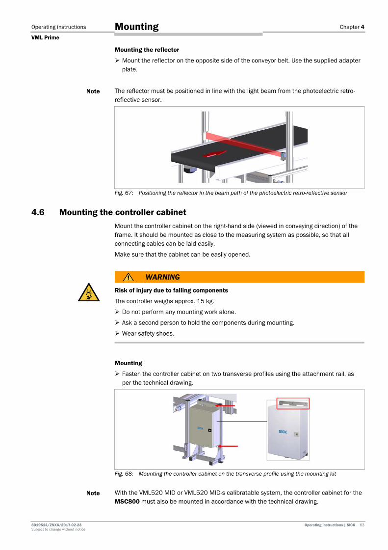
Operating instructions Chapter 4
VML Prime
8019514/ZNX6/2017-02-23 Operating instructions | SICK 63 Subject to change without notice
Mounting
Mounting the reflector
Mount the reflector on the opposite side of the conveyor belt. Use the supplied adapter plate.
The reflector must be positioned in line with the light beam from the photoelectric retro-reflective sensor.
Fig. 67: Positioning the reflector in the beam path of the photoelectric retro-reflective sensor
4.6 Mounting the controller cabinet Mount the controller cabinet on the right-hand side (viewed in conveying direction) of the frame. It should be mounted as close to the measuring system as possible, so that all connecting cables can be laid easily.
Make sure that the cabinet can be easily opened.
WARNING
Risk of injury due to falling components
The controller weighs approx. 15 kg.
Do not perform any mounting work alone.
Ask a second person to hold the components during mounting.
Wear safety shoes.
Mounting
Fasten the controller cabinet on two transverse profiles using the attachment rail, as per the technical drawing.
Fig. 68: Mounting the controller cabinet on the transverse profile using the mounting kit
With the VML520 MID or VML520 MID-s calibratable system, the controller cabinet for the MSC800 must also be mounted in accordance with the technical drawing.
Note
Note
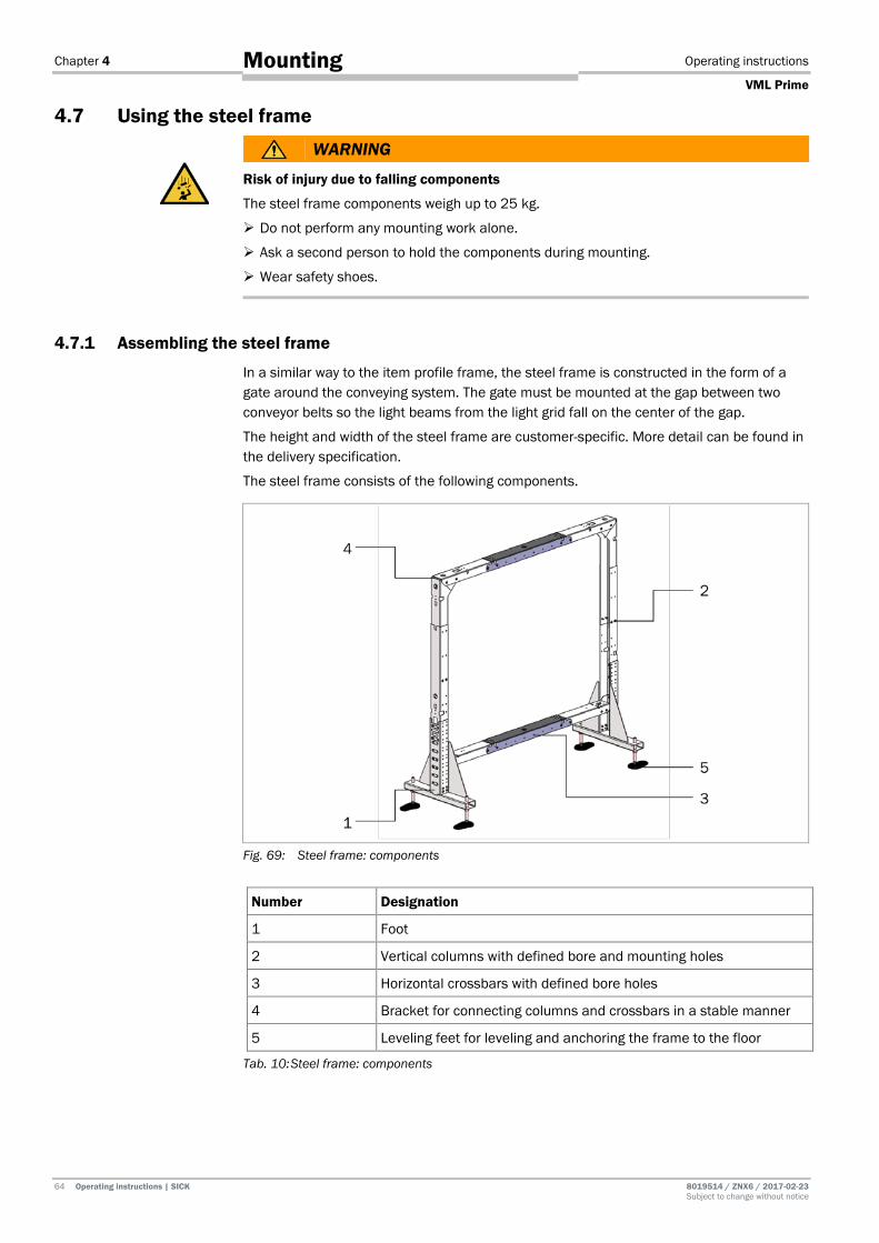
Chapter 4 Operating instructions
VML Prime
64 Operating instructions | SICK 8019514 / ZNX6 / 2017-02-23 Subject to change without notice
Mounting
4.7 Using the steel frame
WARNING
Risk of injury due to falling components
The steel frame components weigh up to 25 kg.
Do not perform any mounting work alone.
Ask a second person to hold the components during mounting.
Wear safety shoes.
4.7.1 Assembling the steel frame
In a similar way to the item profile frame, the steel frame is constructed in the form of a gate around the conveying system. The gate must be mounted at the gap between two conveyor belts so the light beams from the light grid fall on the center of the gap.
The height and width of the steel frame are customer-specific. More detail can be found in the delivery specification.
The steel frame consists of the following components.
Fig. 69: Steel frame: components
Number Designation
1 Foot
2 Vertical columns with defined bore and mounting holes
3 Horizontal crossbars with defined bore holes
4 Bracket for connecting columns and crossbars in a stable manner
5 Leveling feet for leveling and anchoring the frame to the floor
Tab. 10: Steel frame: components
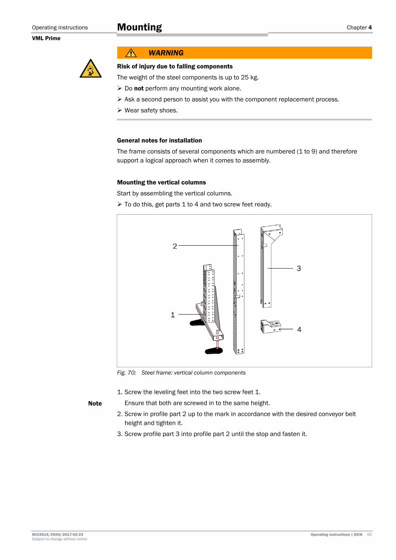
Operating instructions Chapter 4
VML Prime
8019514/ZNX6/2017-02-23 Operating instructions | SICK 65 Subject to change without notice
Mounting
WARNING
Risk of injury due to falling components
The weight of the steel components is up to 25 kg.
Do not perform any mounting work alone.
Ask a second person to assist you with the component replacement process.
Wear safety shoes.
General notes for installation
The frame consists of several components which are numbered (1 to 9) and therefore support a logical approach when it comes to assembly.
Mounting the vertical columns
Start by assembling the vertical columns.
To do this, get parts 1 to 4 and two screw feet ready.
Fig. 70: Steel frame: vertical column components
1. Screw the leveling feet into the two screw feet 1.
Ensure that both are screwed in to the same height.
2. Screw in profile part 2 up to the mark in accordance with the desired conveyor belt height and tighten it.
3. Screw profile part 3 into profile part 2 until the stop and fasten it.
Note

Chapter 4 Operating instructions
VML Prime
66 Operating instructions | SICK 8019514 / ZNX6 / 2017-02-23 Subject to change without notice
Mounting
4. Push profile part 4 into profile part 2 and fasten it. With the help of the marks, the column can be quickly adjusted to the detection height of the MLG-2 used.
Fig. 71: Steel frame: mark for detection height
5. Fasten the bracket to the bracket of the lower horizontal bar with profile part 4.
Fig. 72: Steel frame: mounting the bracket for horizontal bars
Assembling the horizontal crossbars
Assemble the profile parts of both horizontal bars.
1. Insert both profile parts with the number 5 and profile part 6 into one another and tighten these.
2. With the help of the marks, the bar can be quickly adjusted to the detection width of the MLG-2 used.
Fig. 73: Steel frame: assembling the lower crossbar
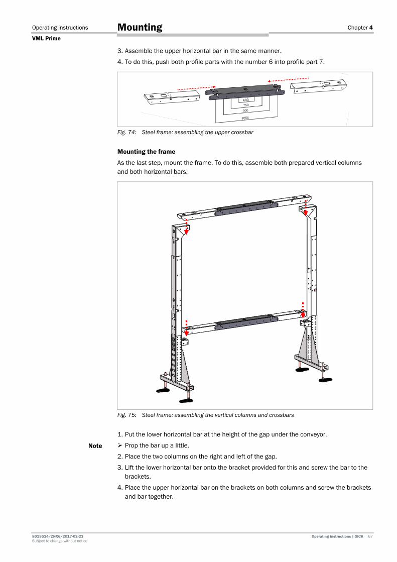
Operating instructions Chapter 4
VML Prime
8019514/ZNX6/2017-02-23 Operating instructions | SICK 67 Subject to change without notice
Mounting
3. Assemble the upper horizontal bar in the same manner.
4. To do this, push both profile parts with the number 6 into profile part 7.
Fig. 74: Steel frame: assembling the upper crossbar
Mounting the frame
As the last step, mount the frame. To do this, assemble both prepared vertical columns and both horizontal bars.
Fig. 75: Steel frame: assembling the vertical columns and crossbars
1. Put the lower horizontal bar at the height of the gap under the conveyor.
Prop the bar up a little.
2. Place the two columns on the right and left of the gap.
3. Lift the lower horizontal bar onto the bracket provided for this and screw the bar to the brackets.
4. Place the upper horizontal bar on the brackets on both columns and screw the brackets and bar together.
Note

Chapter 4 Operating instructions
VML Prime
68 Operating instructions | SICK 8019514 / ZNX6 / 2017-02-23 Subject to change without notice
Mounting
4.7.2 Mounting the components on the steel frame
With the exception of the controller cabinet, all device components are attached directly to the steel frame.
Pre-defined holes facilitate mounting.
Fig. 76: Steel frame: component overview
4.7.2.1 Mounting the light grids on the steel frame
The light grids are mounted on the steel frame with QuickFix brackets in the same way as on the item frame. Separate brackets are used to mount the protective pipe.
The layout is described in detail in chapter 4.3 Mounting the light grids.
Ensure that the connecting cables of the horizontal light grid point in the conveying direction to the right and those of the vertical light grid point downward.
Attaching QuickFix brackets
Firstly, mount the QuickFix brackets on the frame profile in the bore holes provided for this purpose.
Unlike on the item profile, no sliding nut is using for mounting.
Fig. 77: Steel frame: holes for mounting the light grids
Note
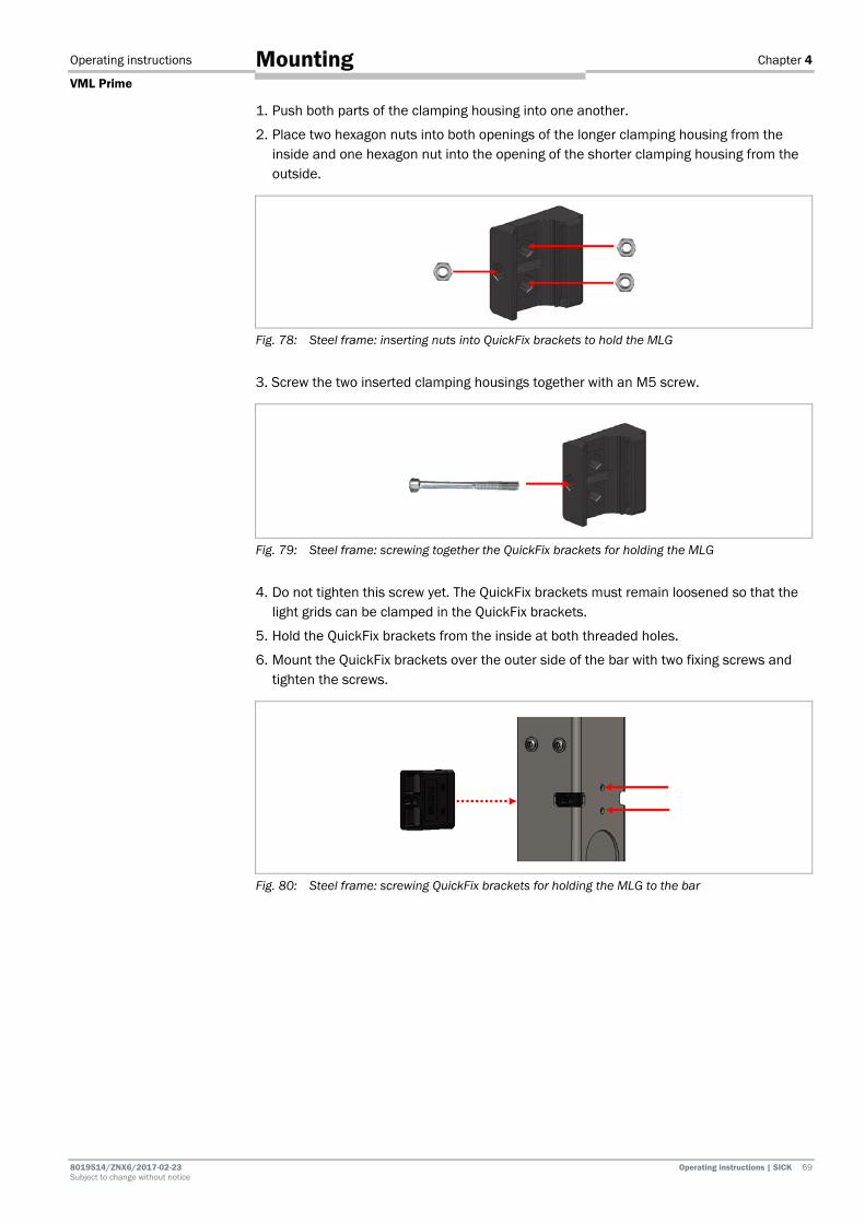
Operating instructions Chapter 4
VML Prime
8019514/ZNX6/2017-02-23 Operating instructions | SICK 69 Subject to change without notice
Mounting
1. Push both parts of the clamping housing into one another.
2. Place two hexagon nuts into both openings of the longer clamping housing from the inside and one hexagon nut into the opening of the shorter clamping housing from the outside.
Fig. 78: Steel frame: inserting nuts into QuickFix brackets to hold the MLG
3. Screw the two inserted clamping housings together with an M5 screw.
Fig. 79: Steel frame: screwing together the QuickFix brackets for holding the MLG
4. Do not tighten this screw yet. The QuickFix brackets must remain loosened so that the light grids can be clamped in the QuickFix brackets.
5. Hold the QuickFix brackets from the inside at both threaded holes.
6. Mount the QuickFix brackets over the outer side of the bar with two fixing screws and tighten the screws.
Fig. 80: Steel frame: screwing QuickFix brackets for holding the MLG to the bar

Chapter 4 Operating instructions
VML Prime
70 Operating instructions | SICK 8019514 / ZNX6 / 2017-02-23 Subject to change without notice
Mounting
Mounting the light grids in the QuickFix bracket
1. Firstly, insert the sender and receiver of the vertical light grid in the loosened QuickFix brackets.
2. Then lower the light grid until the upper end touches the bracket.
Fig. 81: Steel frame: clamping the MLG in the QuickFix bracket
3. Now tighten the QuickFix bracket.
4. Firstly, insert the sender and receiver of the horizontal light grid in the loosened QuickFix brackets.
5. Then push the light grid to the right in the conveying direction until the end touches the bracket.
4.7.2.2 Mounting the protective pipe without cleaning unit
If the sender installed in the IPG2 protective pipe is used without a cleaning unit and fan, the same brackets are used for mounting the protective pipe on the steel frame as for mounting on the item profile frame.
Installing the light grid in the protective pipe
Install the light grid in the protective pipe. Detailed information on this can be found in chapter 4.3.3 Mounting the protective pipe with sender.

Operating instructions Chapter 4
VML Prime
8019514/ZNX6/2017-02-23 Operating instructions | SICK 71 Subject to change without notice
Mounting
Attaching the protective pipe to the transverse profile
The protective pipe is mounted on the lower crossbar. The crossbar has pre-defined holes which enable mounting without additional alignment of the protective pipe in the y-direction. The brackets are each fixed with two screws.
Fig. 82: Steel frame: holes for mounting the protective pipe
Carry out installation in the same way as in chapter 4.3.3.2 Attaching the protective pipe to the mounting frame.
1. Mount the cable-side bracket on the crossbar with the two fixing screws.
2. Insert the protective pipe with the light grid into the bracket.
3. Put the bracket on the upper end of the protective pipe and fix the protective pipe. Screw both fixing screws into the through holes.
4. Now mount the upper bracket on the crossbar with the two fixing screws.
Fig. 83: Steel frame: attaching the protective pipe to the transverse profile
Aligning the protective pipe
Align the protective pipe with the MLG in the brackets in such a way that the diodes of the MLG point vertically upward and then fix this position.

Chapter 4 Operating instructions
VML Prime
72 Operating instructions | SICK 8019514 / ZNX6 / 2017-02-23 Subject to change without notice
Mounting
4.7.2.3 Mounting the protective pipe with cleaning unit
If the protective pipe is mounted together with the vent duct and fan, special brackets are used which hold both the protective pipe and the vent duct. The crossbar has pre-defined holes.
The procedure is essentially the same as mounting protective pipes and the vent duct in the individual brackets (for this, see the chapters 4.3.3.2 Attaching the protective pipe to the mounting frame and 4.3.5.1 Mounting the vent duct).
Mounting the protective pipe
1. Mount the cable-side bracket on the crossbar with the two fixing screws.
Fig. 84: Steel frame: attaching the bracket for mounting the protective pipe and vent duct
2. Insert the protective pipe with the cable-side light grid into the lower cutout of the bracket.
3. Hold the top end of the light grid with one hand.
Fig. 85: Steel frame: putting the protective pipe in the bracket
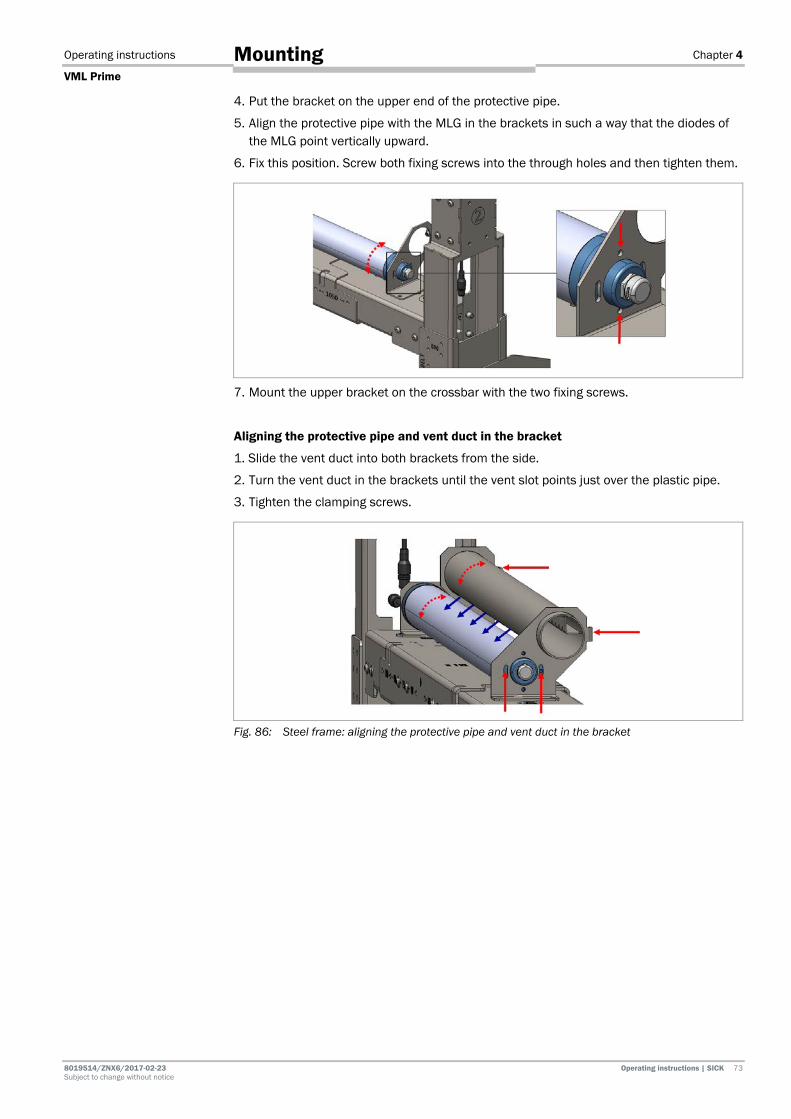
Operating instructions Chapter 4
VML Prime
8019514/ZNX6/2017-02-23 Operating instructions | SICK 73 Subject to change without notice
Mounting
4. Put the bracket on the upper end of the protective pipe.
5. Align the protective pipe with the MLG in the brackets in such a way that the diodes of the MLG point vertically upward.
6. Fix this position. Screw both fixing screws into the through holes and then tighten them.
7. Mount the upper bracket on the crossbar with the two fixing screws.
Aligning the protective pipe and vent duct in the bracket
1. Slide the vent duct into both brackets from the side.
2. Turn the vent duct in the brackets until the vent slot points just over the plastic pipe.
3. Tighten the clamping screws.
Fig. 86: Steel frame: aligning the protective pipe and vent duct in the bracket
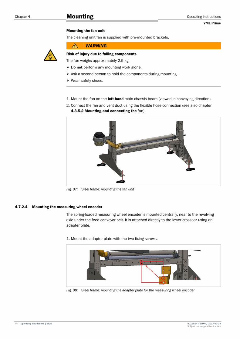
Chapter 4 Operating instructions
VML Prime
74 Operating instructions | SICK 8019514 / ZNX6 / 2017-02-23 Subject to change without notice
Mounting
Mounting the fan unit
The cleaning unit fan is supplied with pre-mounted brackets.
WARNING
Risk of injury due to falling components
The fan weighs approximately 2.5 kg.
Do not perform any mounting work alone.
Ask a second person to hold the components during mounting.
Wear safety shoes.
1. Mount the fan on the left-hand main chassis beam (viewed in conveying direction).
2. Connect the fan and vent duct using the flexible hose connection (see also chapter 4.3.5.2 Mounting and connecting the fan).
Fig. 87: Steel frame: mounting the fan unit
4.7.2.4 Mounting the measuring wheel encoder
The spring-loaded measuring wheel encoder is mounted centrally, near to the revolving axle under the feed conveyor belt. It is attached directly to the lower crossbar using an adapter plate.
1. Mount the adapter plate with the two fixing screws.
Fig. 88: Steel frame: mounting the adapter plate for the measuring wheel encoder

Operating instructions Chapter 4
VML Prime
8019514/ZNX6/2017-02-23 Operating instructions | SICK 75 Subject to change without notice
Mounting
2. Place the mounting bracket of the measuring wheel encoder on the adapter plate and screw it tight.
Select a mounting height which ensures a good connection between the encoder and the underside of the conveyor belt.
Fig. 89: Steel frame: attaching the measuring wheel encoder to the adapter plate
4.7.2.5 Mounting the photoelectric sensor
The separate photoelectric sensor used by the VML Prime 2D H system variant is fastened centrally to the gap in the frame profile together with the reflector. The lower threaded holes for the QuickFix brackets of the vertical light grids are used for this.
1. Mount the photoelectric retro-reflective sensor on the mounting bracket using the two M5 hexagon screws.
Fig. 90: Steel frame: mounting the photoelectric sensor on the mounting bracket
2. Hold the mounting bracket from the inside at both threaded holes.
3. Mount the bracket over the outer side of the bar with two fixing screws and tighten the screws. The photoelectric sensor is correctly aligned due to its prescribed mounting position.
Fig. 91: Steel frame: mounting the photoelectric sensor on the bar
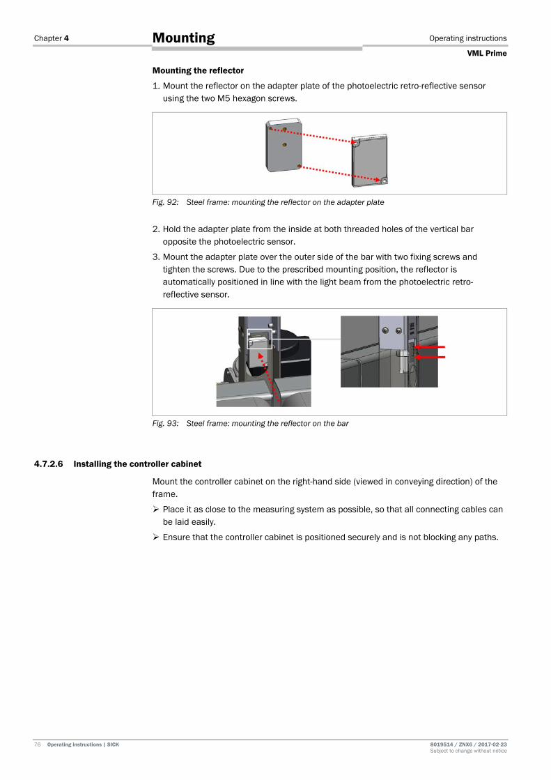
Chapter 4 Operating instructions
VML Prime
76 Operating instructions | SICK 8019514 / ZNX6 / 2017-02-23 Subject to change without notice
Mounting
Mounting the reflector
1. Mount the reflector on the adapter plate of the photoelectric retro-reflective sensor using the two M5 hexagon screws.
Fig. 92: Steel frame: mounting the reflector on the adapter plate
2. Hold the adapter plate from the inside at both threaded holes of the vertical bar opposite the photoelectric sensor.
3. Mount the adapter plate over the outer side of the bar with two fixing screws and tighten the screws. Due to the prescribed mounting position, the reflector is automatically positioned in line with the light beam from the photoelectric retro-reflective sensor.
Fig. 93: Steel frame: mounting the reflector on the bar
4.7.2.6 Installing the controller cabinet
Mount the controller cabinet on the right-hand side (viewed in conveying direction) of the frame.
Place it as close to the measuring system as possible, so that all connecting cables can be laid easily.
Ensure that the controller cabinet is positioned securely and is not blocking any paths.

Operating instructions Chapter 4
VML Prime
8019514/ZNX6/2017-02-23 Operating instructions | SICK 77 Subject to change without notice
Mounting
4.7.3 Aligning the steel frame with the conveyor
The mounting situation on site ensures that the light grids are correctly aligned with one another, the light grid beams fall in a single plane, and each emitting diode meets the opposite receiver diode vertically.
The light grids do not need to be aligned manually.
Only the mounting frame needs to be aligned with the conveyor. This alignment is performed with the alignment aid included with delivery.
Placing the alignment aid on the vertical bar
Place the alignment aid on both vertical columns. The alignment aid must rest on profile part 2 in each case.
As a result, the upper edge of the alignment aid is located on the first light beam of the vertical light grid.
Making sure the light beams fall on the center
Align the frame in the x-direction in such a way that the alignment aid is centered in the belt gap.
Fig. 94: Steel frame: making sure the light beams fall on the center of the conveyor

Chapter 4 Operating instructions
VML Prime
78 Operating instructions | SICK 8019514 / ZNX6 / 2017-02-23 Subject to change without notice
Mounting
Determining the distance to the conveyor
It is important to ensure that the entire width of the conveyor is covered by the light grids. The alignment aid is also used to determine the correct distance between the mounting frame and the right-hand and left-hand edge of the conveyor.
Align the frame in such a way that the first and last light beam of the horizontal light grids correspond to the mark on the alignment aid.
Fig. 95: Steel frame: determining the distance to the conveyor
4.7.4 Attaching cable clamps to the steel frame
Use cable clamps to fix the connecting cables. They make it easy to fix cables to the steel bars.
Fig. 96: Steel bar: cable clamps

Operating instructions Chapter 4
VML Prime
8019514/ZNX6/2017-02-23 Operating instructions | SICK 79 Subject to change without notice
Mounting
4.8 Dismantling the measurement system
WARNING
Risk of injury due to components tipping over
If profiles of the mounting frame have been upended, it is possible that they could tip over during disassembly.
Do not perform any mounting work alone.
Where applicable, ask a second person to assist you with the component replacement process.
Wear safety shoes.
Dismantling
1. Switch off the supply voltage.
2. Disconnect all connection cables.
3. Remove all devices from the mounting brackets.
4. Dismantle the frame.
On final decommissioning, please observe the requirements for environmentally correct disposal in chapter 7.3 Disposal.
Note
Chapter 5 Operating instructions
VML Prime
80 Operating instructions | SICK 8019514 / ZNX6 / 2017-02-23 Subject to change without notice
Electrical installation
5 Electrical installation HAZARD
Risk of injury due to electrical current
Only a qualified electrician or trained person working under the guidance and supervision of a qualified electrician is permitted to work on electrical systems or equipment, and they must comply with the electrical regulations.
HAZARD
Disconnect the power to the system
The system could inadvertently start while you are connecting the devices.
Make sure that the entire system is disconnected from the power supply during the electrical installation work.
HAZARD
Risk of injury due to electrical current
The central control unit of the system is connected to the power supply (AC 100 ... 264 V / 50 ... 60 Hz).
Standard safety requirements must be met when working on electrical systems.
The power supply must be disconnected when attaching and detaching electrical connections.
Select and implement wire cross-sections and their correct fuse protection in accordance with the applicable standards.
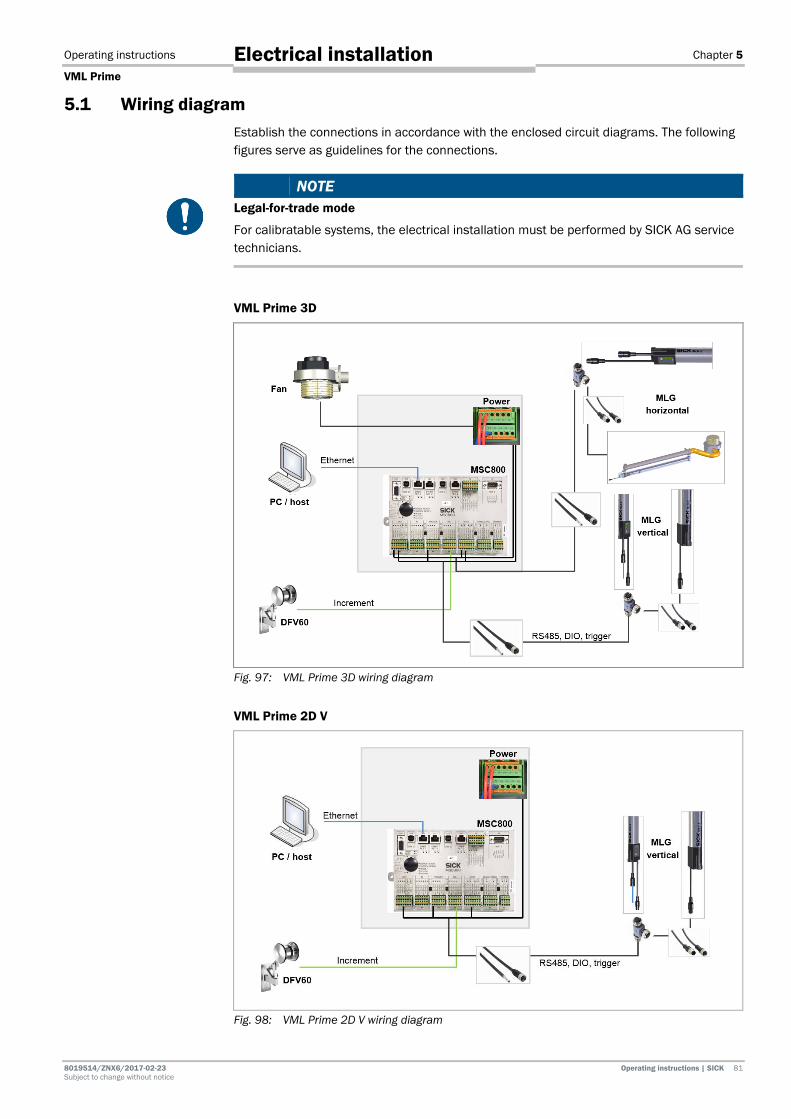
Operating instructions Chapter 5
VML Prime
8019514/ZNX6/2017-02-23 Operating instructions | SICK 81 Subject to change without notice
Electrical installation
5.1 Wiring diagram Establish the connections in accordance with the enclosed circuit diagrams. The following figures serve as guidelines for the connections.
NOTE Legal-for-trade mode
For calibratable systems, the electrical installation must be performed by SICK AG service technicians.
VML Prime 3D
Fig. 97: VML Prime 3D wiring diagram
VML Prime 2D V
Fig. 98: VML Prime 2D V wiring diagram

Chapter 5 Operating instructions
VML Prime
82 Operating instructions | SICK 8019514 / ZNX6 / 2017-02-23 Subject to change without notice
Electrical installation
VML Prime 2D H
Fig. 99: VML Prime 2D H wiring diagram
Be sure to also observe the VML Prime circuit diagrams contained in the appendix to these operating instructions.
5.2 General notes 5.2.1 Routing the cable to the MSC800
Be sure to closely observe the following notes during connection to the MSC800:
1. Run the cable to the controller cabinet. Use the cable channels on the mounting frame.
2. Put the rubber sleeve over the cable
3. Route the cable through the sleeve and cable entry of the controller cabinet.
Fig. 100: Guiding cables in the controller cabinet through sleeve and cable entries
4. Tightly screw the cable entry.
Note
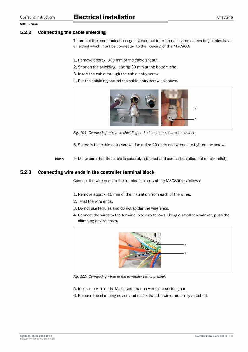
Operating instructions Chapter 5
VML Prime
8019514/ZNX6/2017-02-23 Operating instructions | SICK 83 Subject to change without notice
Electrical installation
5.2.2 Connecting the cable shielding
To protect the communication against external interference, some connecting cables have shielding which must be connected to the housing of the MSC800.
1. Remove approx. 300 mm of the cable sheath.
2. Shorten the shielding, leaving 30 mm at the bottom end.
3. Insert the cable through the cable entry screw.
4. Put the shielding around the cable entry screw as shown.
Fig. 101: Connecting the cable shielding at the inlet to the controller cabinet
5. Screw in the cable entry screw. Use a size 20 open-end wrench to tighten the screw.
Make sure that the cable is securely attached and cannot be pulled out (strain relief).
5.2.3 Connecting wire ends in the controller terminal block
Connect the wire ends to the terminals blocks of the MSC800 as follows:
1. Remove approx. 10 mm of the insulation from each of the wires.
2. Twist the wire ends.
3. Do not use ferrules and do not solder the wire ends.
4. Connect the wires to the terminal block as follows: Using a small screwdriver, push the clamping device down.
Fig. 102: Connecting wires to the controller terminal block
5. Insert the wire ends. Make sure that no wires are sticking out.
6. Release the clamping device and check that the wires are firmly attached.
Note

Chapter 5 Operating instructions
VML Prime
84 Operating instructions | SICK 8019514 / ZNX6 / 2017-02-23 Subject to change without notice
Electrical installation
5.3 Components in the controller cabinet The control cabinet of the MSC800-1100 contains the logic unit and the power supply unit.
Fig. 103: Components in the MSC800-1100
No. Component
1 Terminals for line voltage IN
2 Circuit breaker for protective contact socket and power supply module 3 Power supply module 10 A for
3 supply voltage DC 24 V
4 Fuses for supply voltage DC 24 V
5 Terminals for supply voltage OUT (DC 24 V, max. 10 A)
6 Logic unit with connections and SD memory card for parameter cloning
7 Cable entries (M screw connections)
Tab. 11: Components in the MSC800-1100

Operating instructions Chapter 5
VML Prime
8019514/ZNX6/2017-02-23 Operating instructions | SICK 85 Subject to change without notice
Electrical installation
5.4 Connecting the voltage supply to the controller
HAZARD
Disconnect the power to the system
The system could inadvertently start while you are connecting the devices. Make sure that the entire system is disconnected from the power supply during the
electrical installation work.
HAZARD
Risk of injury due to electrical current
The power supply (AC 100 ... 264 V/50 ... 60 Hz) is protected by a 1-pin line safety switch (phase).
If the phase and neutral conductors are swapped when connecting to the -X100 terminal block, there is a risk of electrocution if you touch the respective contacts, even after the input circuit has been switched off with the -F12 circuit breaker.
Carefully connect the power supply to the -X100 terminal block.
Verify that the power supply is connected correctly before the main switch is used to switch on the customer’s power.
To ensure the cables are securely attached and in compliance with the IP 54 enclosure rating, the coupling nuts for strain relief on the controller cabinet must be tightened.
Check that the cables are firmly attached.
No visible metal surfaces are permitted on the wires.
Connect the voltage supply to the X100 terminal block as follows:
Fig. 104: Connecting the MSC800 to the external voltage supply
Terminal Color of the terminal block
Signal Function
-X100/1.1 Gray L Power supply AC 100 ... 264 V/50 ... 60 Hz (phase)
-X100/1.4 Blue N Power supply AC 100 ... 264 V/50 ... 60 Hz (neutral conductor)
-X100/1.6 Green-yellow PE Protective conductor
Tab. 12: Pin assignment of the -X100 terminal block on the MSC800
Note

Chapter 5 Operating instructions
VML Prime
86 Operating instructions | SICK 8019514 / ZNX6 / 2017-02-23 Subject to change without notice
Electrical installation
5.5 Connecting the light grids The sender and receiver of each light grid are synchronized via a cable. This means that cabling is required between the sender and receiver. For ease of connection, tee connectors are available.
The tee connectors connect the sender and the receiver. They also make it possible to connect the latter to the MSC800.
Light grid connections
The light grids feature the following connections:
Fig. 105: MLG-2 connections
No. Component
1 Sender data connecting cable
2 Receiver data connecting cable
3 The receiver unit also features an Ethernet connection for maintenance purposes.
Connecting cables
The following connecting cables are supplied for connecting the light grids:
• Tee connectors (8-pin, 5-pin, 8-pin) for connecting the sender and receiver to each other and for connecting them to the MSC800.
• 5-pin connecting cable for connecting the sender to the tee connector.
• 8-pin connecting cable with an open end for connecting the tee connector and the MSC800.

Operating instructions Chapter 5
VML Prime
8019514/ZNX6/2017-02-23 Operating instructions | SICK 87 Subject to change without notice
Electrical installation
5.5.1 Connecting the sender and receiver
Re-establish the connection between the sender and the receiver.
Fig. 106: Connecting the sender and receiver
1. Connect the 8-pin female connector of the tee connector to the male connector of the cable connection on the receiver and screw together the plug connector.
2. Connect the male connector of the 5-pin connecting cable to the 5-pin female connector of the tee connector and screw together the plug connector.
3. Run the cable to the sender.
4. Connect the 5-pin cable connection of the sender to the connecting cable and screw together the plug connector.
5.5.2 Connecting the light grids with the MSC800 using tee connectors
Using the relevant tee connectors, connect the horizontal and vertical light grids with the MSC800. The connection is made using a cable with an 8-pin plug connector on one end and an open end for connection to the MSC800 on the other.
Fig. 107: Connecting the light grids with the MSC800 using tee connectors
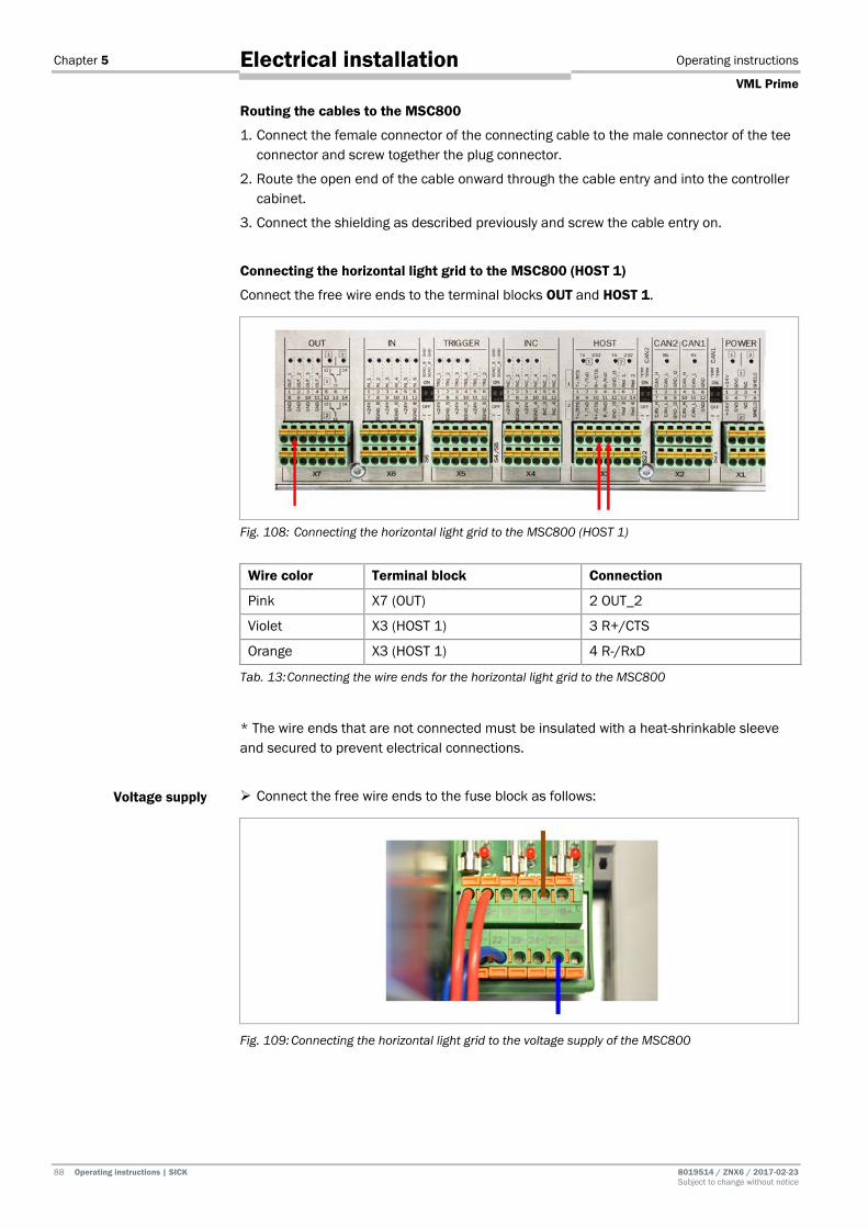
Chapter 5 Operating instructions
VML Prime
88 Operating instructions | SICK 8019514 / ZNX6 / 2017-02-23 Subject to change without notice
Electrical installation
Routing the cables to the MSC800
1. Connect the female connector of the connecting cable to the male connector of the tee connector and screw together the plug connector.
2. Route the open end of the cable onward through the cable entry and into the controller cabinet.
3. Connect the shielding as described previously and screw the cable entry on.
Connecting the horizontal light grid to the MSC800 (HOST 1)
Connect the free wire ends to the terminal blocks OUT and HOST 1.
Fig. 108: Connecting the horizontal light grid to the MSC800 (HOST 1)
Wire color Terminal block Connection
Pink X7 (OUT) 2 OUT_2
Violet X3 (HOST 1) 3 R+/CTS
Orange X3 (HOST 1) 4 R-/RxD
Tab. 13: Connecting the wire ends for the horizontal light grid to the MSC800
* The wire ends that are not connected must be insulated with a heat-shrinkable sleeve and secured to prevent electrical connections.
Connect the free wire ends to the fuse block as follows:
Fig. 109: Connecting the horizontal light grid to the voltage supply of the MSC800
Voltage supply

Operating instructions Chapter 5
VML Prime
8019514/ZNX6/2017-02-23 Operating instructions | SICK 89 Subject to change without notice
Electrical installation
Wire color Area on fuse block Connection
Brown F1_6 15 +
Blue F1_6 25 -
Tab. 14: Connecting the horizontal light grid to the voltage supply of the MSC800
Connecting the vertical light grid to the MSC800 (HOST 2)
Connect the free wire ends to the terminal blocks OUT and HOST 2. As the vertical light grid also acts as a measurement trigger, the terminal block TRIGGER must also be taken into consideration.
Fig. 110: Connecting the vertical light grid to the MSC800 (HOST 2)
Wire color Terminal block Connection
Pink X7 (OUT) 3 OUT_3
Black X5 (TRIGGER) 1 TRG_1
Violet X3 (HOST 2) 10 R+/CTS
Orange X3 (HOST 2) 11 R-/RxD
Tab. 15: Connecting the vertical light grid to the MSC800 (HOST 2)
Connect the free wire ends to the fuse block as follows:
Fig. 111: Connecting the vertical light grid to the voltage supply of the MSC800
Wire color Area on fuse block Connection
Brown F1_6 16 +
Blue F1_6 26 -
Tab. 16: Connecting the vertical light grid to the voltage supply of the MSC800
Voltage supply

Chapter 5 Operating instructions
VML Prime
90 Operating instructions | SICK 8019514 / ZNX6 / 2017-02-23 Subject to change without notice
Electrical installation
5.6 Connecting the measuring wheel encoder The DFV60 measuring wheel encoder is connected to the controller via a connecting cable that is included with delivery. There is an M12 female connector at one end of this. The other end is open with shielding.
Fig. 112: Measuring wheel encoder – MSC800 connecting cable 1. Screw the M12 plug connector onto the male connector on the measuring wheel
encoder. 2. Route the open end of the cable to the controller cabinet and then through the cable
entry and into the MSC800. 3. Put the shielding around the cable entry screw of the controller cabinet. 4. Screw in the cable entry screw.
Connecting encoder cable to the MSC800
Connect the free wire ends to the INC terminal block (1).
Fig. 113: Connecting measuring wheel encoder connecting cable to MSC800
Wire color Terminal block Connection
White X4 (INC) 1 INC_1
Black X4 (INC) 2 INC_2
Brown X4 (INC) 7 24 V
Blue X4 (INC) 8 SGND_4
Tab. 17: Connecting measuring wheel encoder connecting cable to MSC800
Switching on the signal ground
Activate the signal ground for the measuring wheel encoder. Using a small screwdriver, push the two switches TRIGGER and INC upwardbetween
the two terminal blocks.

Operating instructions Chapter 5
VML Prime
8019514/ZNX6/2017-02-23 Operating instructions | SICK 91 Subject to change without notice
Electrical installation
5.7 Connecting the separate photoelectric sensor With the VHL Prime 2D H, the photoelectric retro-reflective sensor is connected to the controller via a connecting cable included with delivery. There is an M12 plug connector at one end of it. The other end is open without shielding.
Fig. 114: Photoelectric retro-reflective sensor – MSC800 connecting cable
1. Screw the M12 plug connector into the male connector on the photoelectric retro-reflective sensor.
2. Route the open end of the cable to the controller and onwards through the cable entry and into the controller cabinet.
Connecting the photoelectric sensor to the MSC800
Connect the two free wire ends to the X5 (TRIGGER) terminal block as follows:
Fig. 115: Connecting photoelectric retro-reflective sensor connecting cable to MSC800
Wire color Terminal block Connection
Black TRIGGER 1 TRG_1
Brown TRIGGER 7 24 V
Blue TRIGGER 8 SGND_5
White Not connected*
Tab. 18: Connecting photoelectric retro-reflective sensor connecting cable to MSC800
Switching on the signal ground
Switch on the signal ground for the trigger signal.
Using a small screwdriver, push the SGND 5 GND switch upward.
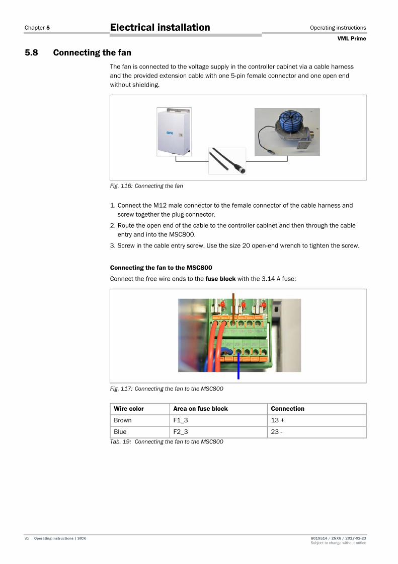
Chapter 5 Operating instructions
VML Prime
92 Operating instructions | SICK 8019514 / ZNX6 / 2017-02-23 Subject to change without notice
Electrical installation
5.8 Connecting the fan The fan is connected to the voltage supply in the controller cabinet via a cable harness and the provided extension cable with one 5-pin female connector and one open end without shielding.
Fig. 116: Connecting the fan
1. Connect the M12 male connector to the female connector of the cable harness and screw together the plug connector.
2. Route the open end of the cable to the controller cabinet and then through the cable entry and into the MSC800.
3. Screw in the cable entry screw. Use the size 20 open-end wrench to tighten the screw.
Connecting the fan to the MSC800
Connect the free wire ends to the fuse block with the 3.14 A fuse:
Fig. 117: Connecting the fan to the MSC800
Wire color Area on fuse block Connection
Brown F1_3 13 +
Blue F2_3 23 - Tab. 19: Connecting the fan to the MSC800

Operating instructions Chapter 6
VML Prime
8019514/ZNX6/2017-02-23 Operating instructions | SICK 93 Subject to change without notice
Commissioning
6 Commissioning WARNING
Do not commission without testing by qualified safety personnel
Before you operate the VML Prime measurement system for the first time, you must have it checked and approved by qualified safety personnel. Observe the notes provided in chapter 2 Safety.
NOTE Legal-for-trade mode
For calibratable systems, commissioning must be performed by SICK AG service technicians.
6.1 Starting commissioning 6.1.1 Switching on the system
Establish the voltage supply. The system starts up automatically with a delay of 10 seconds.
Internal check for operational readiness
The light grids and the MSC800 central control unit perform self-diagnostics to check whether they are ready for operation.
Operational readiness after 60 s
The system is ready for operation after approx. 60 seconds.
6.1.2 Checking the operational readiness of the devices
If all the devices have been connected correctly, a check can be performed following power-up to see whether the devices are functioning correctly.
6.1.2.1 Checking the operational readiness of the MSC800
If the controller is ready for operation after power-up, the DEVICE READY and SYSTEM READY LEDs must be illuminated.
Fig. 118: Checking the operational readiness of the MSC800

Chapter 6 Operating instructions
VML Prime
94 Operating instructions | SICK 8019514 / ZNX6 / 2017-02-23 Subject to change without notice
Commissioning
6.1.2.2 Ensuring the operational readiness of the light grids
If the light grids are connected to the voltage supply correctly, the green LEDs on both the sender and the receiver will be illuminated.
Fig. 119: Checking voltage supply to the light grids
Checking signal strength
After the system is switched on for the first time, the alignment mode for coarse alignment is active at the receiver unit. The yellow LED on the receiver unit flashes rapidly if the signal it is receiving is too weak. The LED goes out as soon as the signal strength is sufficient.
The LED behavior does not provide information about optimum alignment of the components. It only indicates whether the signal arriving at the receiver is strong enough.
After the first teach-in process, the alignment mode is deactivated.
Checking whether objects are detected
Move an object into the monitoring field. The yellow LED must light up on the receiver of each of the light grid pairs. The yellow LED lights up if at least one beam of light is interrupted.
Fig. 120: Checking object detection at the light grids
Once the object is removed, the yellow LED should go out.
Yellow (3 Hz)
Note
Note
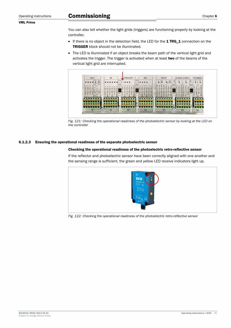
Operating instructions Chapter 6
VML Prime
8019514/ZNX6/2017-02-23 Operating instructions | SICK 95 Subject to change without notice
Commissioning
You can also tell whether the light grids (triggers) are functioning properly by looking at the controller.
• If there is no object in the detection field, the LED for the 1 TRG_1 connection on the TRIGGER block should not be illuminated.
• The LED is illuminated if an object breaks the beam path of the vertical light grid and activates the trigger. The trigger is activated when at least two of the beams of the vertical light grid are interrupted.
Fig. 121: Checking the operational readiness of the photoelectric sensor by looking at the LED on the controller
6.1.2.3 Ensuring the operational readiness of the separate photoelectric sensor
Checking the operational readiness of the photoelectric retro-reflective sensor
If the reflector and photoelectric sensor have been correctly aligned with one another and the sensing range is sufficient, the green and yellow LED receive indicators light up.
Fig. 122: Checking the operational readiness of the photoelectric retro-reflective sensor
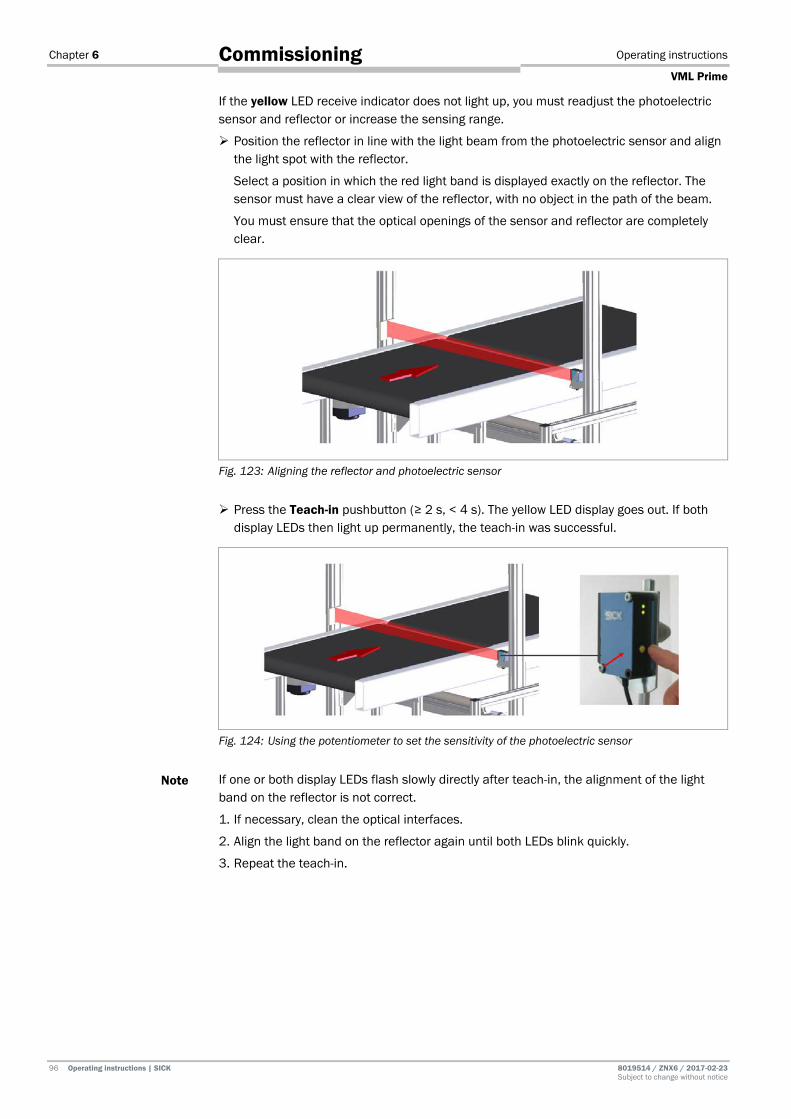
Chapter 6 Operating instructions
VML Prime
96 Operating instructions | SICK 8019514 / ZNX6 / 2017-02-23 Subject to change without notice
Commissioning
If the yellow LED receive indicator does not light up, you must readjust the photoelectric sensor and reflector or increase the sensing range.
Position the reflector in line with the light beam from the photoelectric sensor and align the light spot with the reflector.
Select a position in which the red light band is displayed exactly on the reflector. The sensor must have a clear view of the reflector, with no object in the path of the beam.
You must ensure that the optical openings of the sensor and reflector are completely clear.
Fig. 123: Aligning the reflector and photoelectric sensor
Press the Teach-in pushbutton (≥ 2 s, < 4 s). The yellow LED display goes out. If both display LEDs then light up permanently, the teach-in was successful.
Fig. 124: Using the potentiometer to set the sensitivity of the photoelectric sensor
If one or both display LEDs flash slowly directly after teach-in, the alignment of the light band on the reflector is not correct.
1. If necessary, clean the optical interfaces.
2. Align the light band on the reflector again until both LEDs blink quickly.
3. Repeat the teach-in.
Note

Operating instructions Chapter 6
VML Prime
8019514/ZNX6/2017-02-23 Operating instructions | SICK 97 Subject to change without notice
Commissioning
Checking whether objects are detected
Move an object into the light beam. The yellow LED receive indicator should go out.
Once the object is removed, the LED should light up again.
You can also tell whether the device is functioning properly by looking at the controller. If the path to the reflector is clear, the LED for the 1 TRG_1 connection on the TRIGGER block should light up. The LED goes out if an object breaks the light beam and activates the trigger.
Fig. 125: Checking the operational readiness of the photoelectric sensor by looking at the LED on the MSC800
6.1.2.4 Checking the operational readiness of the measuring wheel encoder
Check that the measuring wheel encoder is functioning correctly.
Turn the measuring wheel of the encoder by hand – if possible – and watch the INC_1 and INC_2 LEDs on the INC terminal block.
• The LEDs should be flashing.
Fig. 126: Checking the operational readiness of the encoder by looking at the LEDs on the controller
Alternatively, you can also start the conveyor belt.
Make sure that there is good contact between the measuring wheel and the conveyor belt.
Note

Chapter 6 Operating instructions
VML Prime
98 Operating instructions | SICK 8019514 / ZNX6 / 2017-02-23 Subject to change without notice
Commissioning
6.2 Preparing the configuration PC 6.2.1 Establishing a connection with the configuration PC
The VML Prime volume measurement system is configured via a configuration PC.
Fig. 127: Connecting to the configuration PC
Connecting the configuration PC
1. Connect the configuration PC to the MSC800 controller with an Ethernet cable.
2. Use the free X10 Ethernet interface on the MSC800 to do so.
Upon delivery, the default IP address for the MSC800 is 192.168.0.1. It is adjusted during the configuration process.
Make sure that the configuration PC is in the number range of the MSC800. If not, change the IP address of the configuration PC accordingly.
6.2.2 Installing SOPAS
Install the latest version of the configuration software from the SICK homepage on the configuration PC.
1. Open the www.sick.de website in the browser.
2. Enter SOPAS in the search field and start the search.
3. Download the latest version of the SOPAS Engineering Tool software and save this in a temporary directory on the configuration PC.
4. Start the installation by double-clicking the setup.exe file.
5. Select the Installation installation type. The installation is prepared.
6. Select the user language of the wizard.
Note
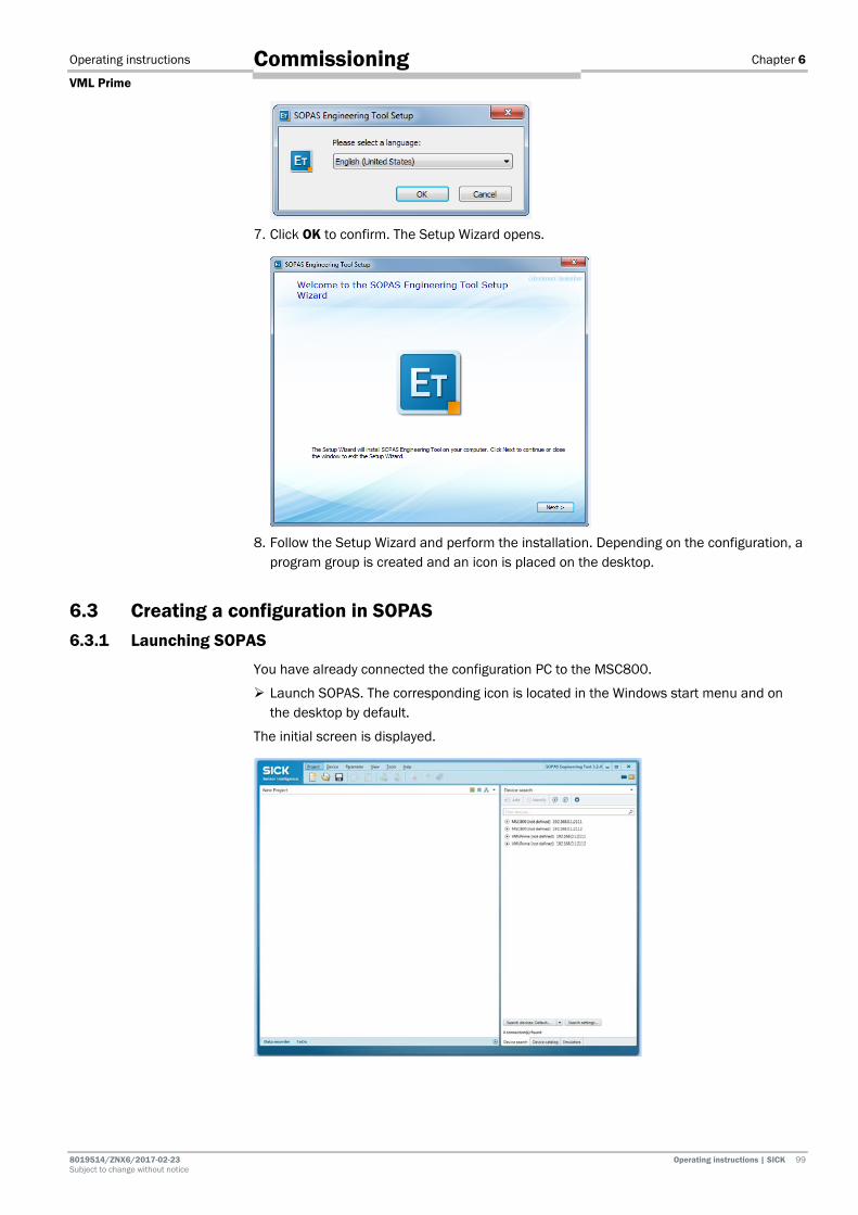
Operating instructions Chapter 6
VML Prime
8019514/ZNX6/2017-02-23 Operating instructions | SICK 99 Subject to change without notice
Commissioning
7. Click OK to confirm. The Setup Wizard opens.
8. Follow the Setup Wizard and perform the installation. Depending on the configuration, a
program group is created and an icon is placed on the desktop.
6.3 Creating a configuration in SOPAS 6.3.1 Launching SOPAS
You have already connected the configuration PC to the MSC800.
Launch SOPAS. The corresponding icon is located in the Windows start menu and on the desktop by default.
The initial screen is displayed.

Chapter 6 Operating instructions
VML Prime
100 Operating instructions | SICK 8019514 / ZNX6 / 2017-02-23 Subject to change without notice
Commissioning
If the number ranges for the MSC800 and the configuration PC correspond, then the connected VML Prime system is detected and displayed in the list of connected devices on the right-hand side.
MSC800 and VML Prime use two ports (like all SICK devices). Ports are part of the network address and can be used to establish various connections between the devices. Port 2112 is freely configurable but port 2111 is a fixed port for outputting data. It is used for device configuration.
6.3.2 Transferring the VML Prime to a SOPAS project
Add the detected VML Prime system to a SOPAS project. One or more devices are combined and edited in a single project.
1. In the list, select the detected VML Prime with the port 2111.
2. Click the Add icon to transfer the VML Prime into the project.
Alternatively, you can transfer by double-clicking on the list entry or dragging and dropping.
The transferred system is displayed in the left-hand window as a tile.
A notification will appear if the device drivers for the connected VML Prime are not yet known in the SOPAS project.
Note
Note

Operating instructions Chapter 6
VML Prime
8019514/ZNX6/2017-02-23 Operating instructions | SICK 101 Subject to change without notice
Commissioning
6.3.3 Loading device drivers into the SOPAS project
Install the device driver for the VML Prime. By doing so, a copy of the device parameters is created in the SOPAS project.
Getting started
1. Press OK to confirm you have seen the notification.
2. Click Install device driver in the tile.
3. You will be asked where you want to get the device drivers from. During initial
commissioning, only the SICK.com or disk option is active.
4. Click OK to confirm. The device driver manager wizard opens.
Selecting a data source
1. Specify whether you would like to obtain the device driver from the SICK homepage or from a local disk.
We recommend obtaining the current device driver directly from the SICK homepage. Select the From www.mysick.com option.
Recommendation

Chapter 6 Operating instructions
VML Prime
102 Operating instructions | SICK 8019514 / ZNX6 / 2017-02-23 Subject to change without notice
Commissioning
2. Click Next to establish the connection to the driver manager. The driver which is suitable for the VML Prime system is activated automatically.
3. Click Next to confirm your selection. The device drivers are downloaded and installed in the SOPAS project. A notification informs you that the download process is complete.
4. End the device driver installation by clicking Finish. The device driver manager closes.
It can be inferred from the tile that the VML Prime is now recognized by the configuration PC but is not yet connected to the system, meaning that it is still offline.

Operating instructions Chapter 6
VML Prime
8019514/ZNX6/2017-02-23 Operating instructions | SICK 103 Subject to change without notice
Commissioning
6.3.4 Setting the VML Prime to online
Establish a connection between the SOPAS project and the VML Prime. This connection will make it possible to read parameters and configuration data from the devices in the connected system or write these to the system devices from SOPAS.
1. Click the Offline button in the tile.
Alternatively, you can open the context menu and select the Go online command there.
2. You are prompted to synchronize the VML Prime’s device data with the device data of the SOPAS project.
3. As the SOPAS project has not yet received any device data during the initial
commissioning, click the Read parameters option.
The connection between the VML Prime and the configuration PC is now established. Online appears in the tile. The LED lights up green.
The parameters are transferred from the connected system devices to the SOPAS project. The SOPAS project and system devices are therefore synchronized.

Chapter 6 Operating instructions
VML Prime
104 Operating instructions | SICK 8019514 / ZNX6 / 2017-02-23 Subject to change without notice
Commissioning
6.4 Opening the configuration and analysis interface The SOPAS configuration and analysis interface guides you through all of the necessary settings during commissioning and provides detailed system information during operation.
Click in the project tree by double-clicking on the tile. The configuration and analysis interface is opened.
The top area contains the menu bar and toolbar as well as a bar with workflow symbols to switch between the individual workspaces of the configuration and analysis interface. The bars are visible in all workspaces.
The layout and structure of the lower area depend on which workspace has been selected.
A check is performed to see whether VML Prime has already been configured. If this is not the case, you will be prompted to launch the commissioning wizard.
Click Yes. You will then be taken through three wizards.
Note

Operating instructions Chapter 6
VML Prime
8019514/ZNX6/2017-02-23 Operating instructions | SICK 105 Subject to change without notice
Commissioning
6.4.1 Selecting the configuration
Firstly, in the System type wizard, select the VML Prime configuration installed at your site.
On the pages that follow, we will describe the VML Prime 3D configuration.
1. Click on the VML configuration.
2. Press Finish to confirm.
The parameter set of the selected system is loaded. The parameters are subsequently adapted to the local requirements.
For this, the wizard for configuring the position of the volume measurement system in relation to the conveyor opens first of all.
Note

Chapter 6 Operating instructions
VML Prime
106 Operating instructions | SICK 8019514 / ZNX6 / 2017-02-23 Subject to change without notice
Commissioning
6.4.2 Teaching in light grids
The light grids must be taught in during initial commissioning.
The teach-in process ensures optimum sensitivity of the light grids. For this, the switching thresholds for all beams are adjusted for the sensing range and the ambient conditions.
Prerequisites
Before the teaching in the light grids, the following prerequisites must be fulfilled.
Clean the front screen of the MLG-2 modules. Stop the conveyor belt to prevent vibrations during the teach-in process. Remove all objects from the detection field. During teach-in, there must be no objects
in the light path.
Performing the teach-in process
Both light grid pairs are taught in separately.
1. In the Teach MLGs area, click the Teach Y-MLG button. The horizontal light grid pair is taught in.
At the MLG-2 receiver, all LEDs will briefly illuminate one after the other. The yellow LED flashes slowly during the teach-in process.
If the teach-in process has been successful, the yellow LED on the receiver will go out. A successful teach-in process will be indicated by a green light symbol on the page of the wizard.
2. Perform the teach-in process in the same way for the vertical light grid pair.
Teach-in process unsuccessful
If the teach-in process for a light grid pair has been unsuccessful, the red LED on the relevant receiver will flash rapidly. A red light symbol will be displayed on the page of the wizard.
In this case, check that the light grid pairs are correctly aligned, that the front screens are clean, and that there are no objects located in the light path.
Then carry out the teach-in process again.
Check whether the MLG-2 sender is connected.

Operating instructions Chapter 6
VML Prime
8019514/ZNX6/2017-02-23 Operating instructions | SICK 107 Subject to change without notice
Commissioning
Permanently blanking beams (for systems with guiding plates or protective barriers)
If beams are shadowed during the teach-in process, this will be taken into account accordingly for all measurements in future.
Therefore, it is essential that no objects are accidentally located in the light path.
The targeted exclusion of certain beams is only intended for conveying systems with guiding plates or protective barriers, if the latter permanently shadow individual diodes.
Through the teach-in process, VML Prime can be adjusted to the permanently shadowed diodes so that this does not have a disruptive effect on the calculation of measurement values.
In doing so, it does not matter if there are diodes below the guiding plates or not. No measuring points below the guiding plates are required for measuring objects.
Fig. 128: Permanently blanking beams
The one prerequisite is that the object height to be measured is higher than the guiding plates.
6.4.3 Calibrating light grids in relation to the coordinate system of the conveyor
The position of the light grids in relation to the origin of the conveyor is determined using a reference box.
We recommend using the SICK reference box available as an accessory with the defined dimensions 402 mm x 302 mm x 202 mm. This reference box can be ordered from SICK using part number SICK PN 4040035.
The reference box is placed in different positions on the conveyor belt and measured. The wizard determines all key system parameters, such as resolution, detection height, and detection width, from the measured values.
These values only need to be checked for plausibility and then saved.
Getting started
Click Next to end the successful teach-in process for the light grids. You will end up at the position wizard.
You can also call up the wizard at a later date in the System Configuration workspace via the SOPAS configuration and analysis interface.
Note

Chapter 6 Operating instructions
VML Prime
108 Operating instructions | SICK 8019514 / ZNX6 / 2017-02-23 Subject to change without notice
Commissioning
Storing the reference dimension for configuration
On the first page of the wizard, specify the size of the reference box.
If you select the SICK Box option, the fixed values of the reference box are displayed.
They cannot be changed.
If you select the Custom Box option, you must enter the length, width, and height of the box in the fields at the bottom.
Determining the resolution
On the second page of the wizard, the resolution (beam separation) of the light grids used is determined on the basis of the diodes shadowed by the reference box.
1. When the page is called up, the height and width values which are to be measured are specified.
2. Place the reference box on the conveyor belt as described on the page of the wizard.
Ensure that the height and width values specified on the page of the wizard correspond to the actual height and width.
Place the reference box without twisting it.
Note
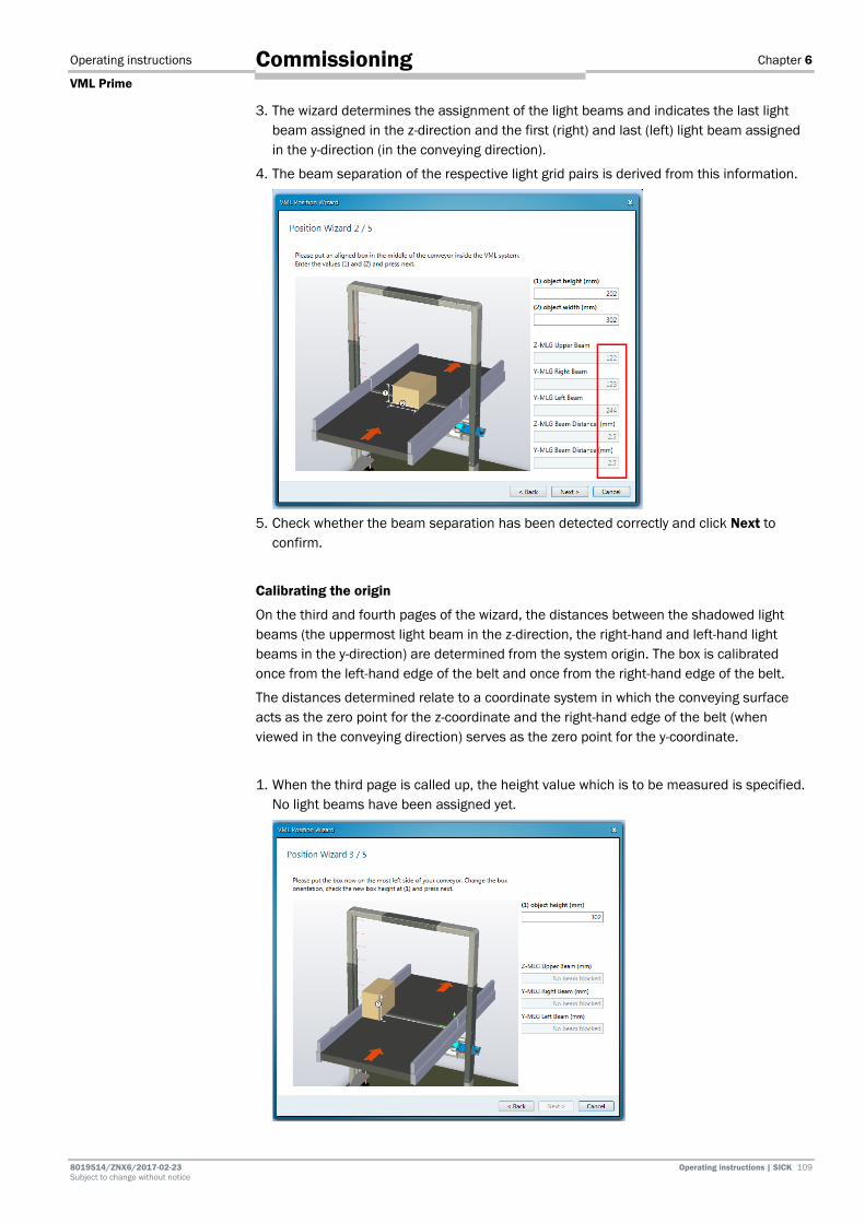
Operating instructions Chapter 6
VML Prime
8019514/ZNX6/2017-02-23 Operating instructions | SICK 109 Subject to change without notice
Commissioning
3. The wizard determines the assignment of the light beams and indicates the last light beam assigned in the z-direction and the first (right) and last (left) light beam assigned in the y-direction (in the conveying direction).
4. The beam separation of the respective light grid pairs is derived from this information.
5. Check whether the beam separation has been detected correctly and click Next to
confirm.
Calibrating the origin
On the third and fourth pages of the wizard, the distances between the shadowed light beams (the uppermost light beam in the z-direction, the right-hand and left-hand light beams in the y-direction) are determined from the system origin. The box is calibrated once from the left-hand edge of the belt and once from the right-hand edge of the belt.
The distances determined relate to a coordinate system in which the conveying surface acts as the zero point for the z-coordinate and the right-hand edge of the belt (when viewed in the conveying direction) serves as the zero point for the y-coordinate.
1. When the third page is called up, the height value which is to be measured is specified. No light beams have been assigned yet.

Chapter 6 Operating instructions
VML Prime
110 Operating instructions | SICK 8019514 / ZNX6 / 2017-02-23 Subject to change without notice
Commissioning
2. Place the reference box on the left-hand edge of the conveyor (in the conveying direction) as described on the page of the wizard. Make sure that the specified height value of the box corresponds to the actual box height.
3. Check whether the uppermost beam separation corresponds to the specified box
height. The difference between the left-hand and right-hand beam separation must correspond to the actual box width.
4. Click Next to confirm your selection.
5. Proceed in the same way on the fourth page. The only difference is that another height value is specified.
6. Place the box on the right-hand edge of the conveyor (in the conveying direction) as described.
7. Check whether the uppermost beam separation corresponds to the specified box
height. The difference between the right-hand light beam and the left-hand light beam must correspond to the actual box width.
8. Click Next to confirm your selection.

Operating instructions Chapter 6
VML Prime
8019514/ZNX6/2017-02-23 Operating instructions | SICK 111 Subject to change without notice
Commissioning
Defining the measuring range limits
On the fifth page of the position wizard, the measuring range suitable for the conveyor is determined from the values calculated previously.
A distance is factored in on all sides of the measuring range so that excess heights and excess widths can be detected and output.
The values have the following meanings:
Value Meaning
Y-Position of MLG Distance factored in for the first diode from the y-zero point (= right-hand edge of the conveyor)
Z-Position of MLG Distance factored in for the first diode from the z-zero point (= conveyor surface as zero)
Y-MLG Beam distance Resolution of the horizontal light grid
Z-MLG Beam distance Resolution of the vertical light grid
Upper Height of the measuring field in the z-direction (= detection height of the MLG) plus 2 mm.
Left Width of the measuring field plus 10 mm.
Right Right-hand edge of the conveying system (= 0) minus 10 mm
Checking the measuring range limits
1. Check whether the calculated measuring range limits are suitable for your requirements.
2. Click Finish to confirm the values.

Chapter 6 Operating instructions
VML Prime
112 Operating instructions | SICK 8019514 / ZNX6 / 2017-02-23 Subject to change without notice
Commissioning
6.4.4 Calibrating the incremental encoder
In this step, the fixed preset encoder settings of the measuring wheel encoder are adjusted to the actual measuring situation on site.
For this, a length correction factor is calculated on the basis of five valid length measurements of the reference object. This is used to correct mechanical influences on the measurements (caused by slip, for example).
Getting started
Click Finish to quit the position wizard. You will end up at the encoder wizard.
You can also call up the wizard at a later date in the System Configuration workspace via the SOPAS configuration and analysis interface.
Storing the reference dimension for configuration
On the first page of the wizard, specify the length of the reference box.
If you select the SICK Box option, the length of the reference box is fixed. It cannot be changed.
If you select the Custom Box option, you must enter the length in the length field.
Note

Operating instructions Chapter 6
VML Prime
8019514/ZNX6/2017-02-23 Operating instructions | SICK 113 Subject to change without notice
Commissioning
Determining the correction value
On the second page of the wizard, the correction value for the length calculation is specified.
1. When the page is called up, no measured values are displayed yet. The Length correction factor field contains the factor 1.
2. Measure the reference box several times in a row.
Make sure that the long side of the box is guided through the light grids parallel to the conveying direction and at a constant speed.
3. The measurement results are listed in a table. The number of valid measurements is incremented.
4. Take the deviation between the measured length value and the actual length value from
the Delta (mm) column. The Correction column specifies the relevant factor with which the measured length value is corrected to obtain the actual length.
The average correction value generated using the measurements is displayed in the Correction field.
Note
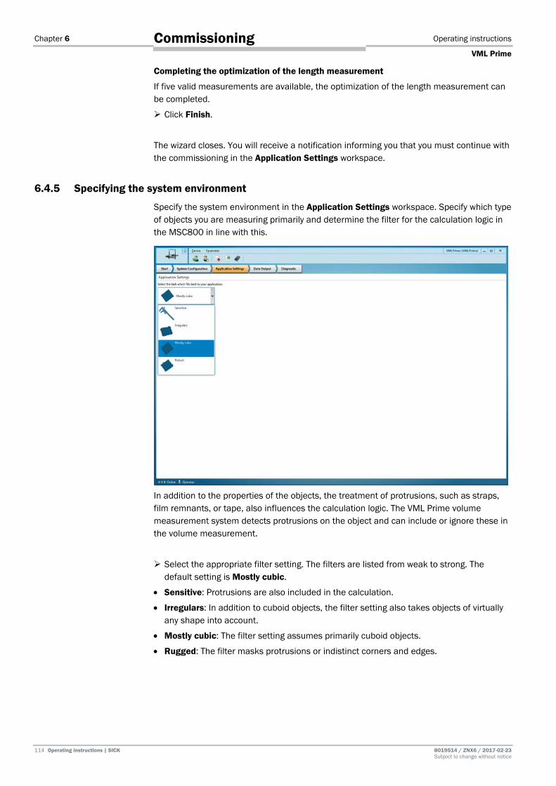
Chapter 6 Operating instructions
VML Prime
114 Operating instructions | SICK 8019514 / ZNX6 / 2017-02-23 Subject to change without notice
Commissioning
Completing the optimization of the length measurement
If five valid measurements are available, the optimization of the length measurement can be completed.
Click Finish.
The wizard closes. You will receive a notification informing you that you must continue with the commissioning in the Application Settings workspace.
6.4.5 Specifying the system environment
Specify the system environment in the Application Settings workspace. Specify which type of objects you are measuring primarily and determine the filter for the calculation logic in the MSC800 in line with this.
In addition to the properties of the objects, the treatment of protrusions, such as straps, film remnants, or tape, also influences the calculation logic. The VML Prime volume measurement system detects protrusions on the object and can include or ignore these in the volume measurement.
Select the appropriate filter setting. The filters are listed from weak to strong. The default setting is Mostly cubic.
• Sensitive: Protrusions are also included in the calculation.
• Irregulars: In addition to cuboid objects, the filter setting also takes objects of virtually any shape into account.
• Mostly cubic: The filter setting assumes primarily cuboid objects.
• Rugged: The filter masks protrusions or indistinct corners and edges.
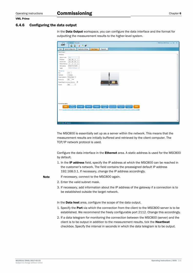
Operating instructions Chapter 6
VML Prime
8019514/ZNX6/2017-02-23 Operating instructions | SICK 115 Subject to change without notice
Commissioning
6.4.6 Configuring the data output
In the Data Output workspace, you can configure the data interface and the format for outputting the measurement results to the higher-level system.
The MSC800 is essentially set up as a server within the network. This means that the measurement results are initially buffered and retrieved by the client computer. The TCP/IP network protocol is used.
Configure the data interface in the Ethernet area. A static address is used for the MSC800 by default.
1. In the IP address field, specify the IP address at which the MSC800 can be reached in the customer’s network. The field contains the preassigned default IP address 192.168.0.1. If necessary, change the IP address accordingly.
If necessary, connect to the MSC800 again.
2. Enter the valid subnet mask.
3. If necessary, add information about the IP address of the gateway if a connection is to be established outside the target network.
In the Data host area, configure the scope of the data output.
1. Specify the Port via which the connection from the client to the MSC800 server is to be established. We recommend the freely configurable port 2112. Change this accordingly.
2. If a data telegram for monitoring the connection between the MSC800 (server) and the client is to be output in addition to the measurement results, tick the Heartbeat checkbox. Specify the interval in seconds in which the data telegram is to be output.
Note

Chapter 6 Operating instructions
VML Prime
116 Operating instructions | SICK 8019514 / ZNX6 / 2017-02-23 Subject to change without notice
Commissioning
3. Define the reference point of the data output and the output time using the Output related to and Position (1) fields.
• The data output time is usually related to the trailing edge of the object. This is also the default setting. In this case, the information in the Position field calculates the output time as a distance value from the trailing edge to the measuring range.
The output time therefore depends on the object length.
• If the reference point for the data output is switched to the leading edge, you must take the object length into account when specifying the distance value. The distance value must not be smaller than the maximum object length plus the calculation time for the path of 300 ms.
Select this setting if you wish to always have the same output time, regardless of the object length.
4. The Output length in conveyor direction checkbox is ticked by default. This means that the length of the object is always determined in the conveying direction, even if this is not the longest side of the object.
If you untick the checkbox, the VML Prime determines the longest side, regardless of
the orientation of the object on the conveyor belt.

Operating instructions Chapter 6
VML Prime
8019514/ZNX6/2017-02-23 Operating instructions | SICK 117 Subject to change without notice
Commissioning
5. Determine the scope of the output in the Format field using the Easy and Expert entries. The character string of the select output format in described in detail in the lower area with the number of bytes.
6. Use the illustration to find out the bytes in which the information relevant to you is supplied. Note the order of the measured values within the character string.
A character is saved in a byte. The individual values are separated by a semicolon within the character string.
7. In the Expert format, more information is provided.
If you have enabled Heartbeat, this is broken down in both output formats in the character string.
Note

Chapter 6 Operating instructions
VML Prime
118 Operating instructions | SICK 8019514 / ZNX6 / 2017-02-23 Subject to change without notice
Commissioning
6.4.7 Saving the configuration permanently in devices
If you are connected to the system via SOPAS, all the changes to the configuration are transferred to the devices and applied immediately. However, they are only saved in the devices’ volatile memory.
Saving the configuration permanently
To save the configuration permanently in the device, click the Permanently Save Parameters icon in the SOPAS toolbar.
The configuration for all devices in the system is saved in one step.
The configuration saved permanently in the devices is loaded each time the devices are restarted.
Saving the configuration on the configuration PC
You can also save the configured and displayed settings as a file on your PC. The settings within this file can be loaded subsequently (if required) and transferred to the device.
1. In the configuration and analysis interface, click on the Device menu item and select the Export command.
2. Select a directory and file name and then confirm your choice.

Operating instructions Chapter 6
VML Prime
8019514/ZNX6/2017-02-23 Operating instructions | SICK 119 Subject to change without notice
Commissioning
6.5 Performing a test run Finish commissioning the system by performing a test run. The test run must make sure that VML Prime is working correctly and that it is delivering plausible measured values.
Use a reference box to test the measurement accuracy of the system.
Getting started
1. Go to the Start workspace in the configuration and analysis interface.
2. The measurement results from the encoder correction factor calculation are displayed in the Application area.
3. If you click on the delete icon, all measurement results will be removed from the Volume Result table.
Checking the measurement results
Measure the reference box at various orientations and positions on the conveyor belt. Placing the reference box on the left-hand and right-hand sides of the conveyor belt and in the middle is sufficient.

Chapter 6 Operating instructions
VML Prime
120 Operating instructions | SICK 8019514 / ZNX6 / 2017-02-23 Subject to change without notice
Commissioning
The measurement results from the measuring runs are listed line-by-line in the Volume Result table.
This list can be used to verify the measurement accuracy of the system.
Make sure that the calculated measured values are within the tolerance range.
Make sure that the measured values are also correct for all orientations of the object.
Displaying the status
If the measurements are free of errors, a value of 0 appears in the VMD Status 1 column.
If there is an incorrect measurement, further information on the error can be provided by the status value.
For this, show the VMD Status 2 and VMD Status 3 columns using the arrow button in the table header.
The table in the appendix shows how you can decode the errors using the numerical code (see chapter 9.4 Error codes (VMD status)).
If no dimensions are calculated
If no dimensions are calculated, proceed as follows:
Check that the system has been cabled correctly.
Ensure that the signal ground of the measuring wheel encoder and the trigger is switched on.
Check that the encoder parameters have been determined correctly.
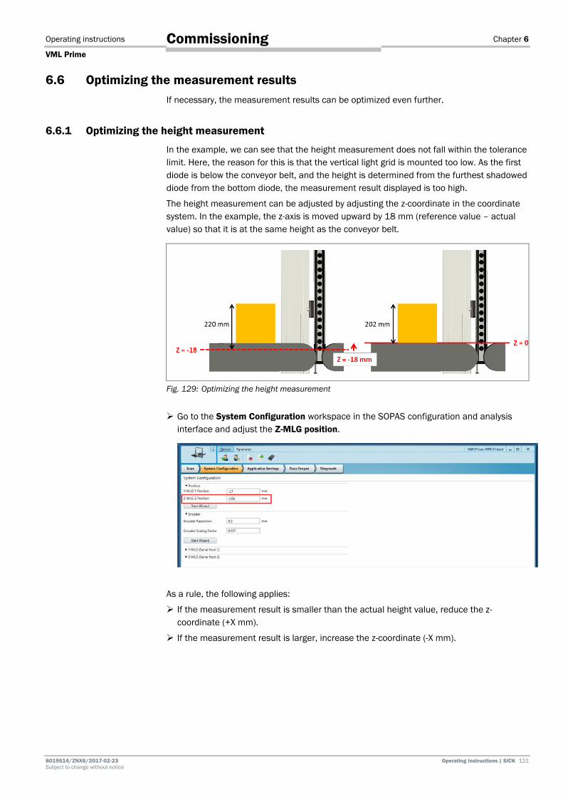
Operating instructions Chapter 6
VML Prime
8019514/ZNX6/2017-02-23 Operating instructions | SICK 121 Subject to change without notice
Commissioning
6.6 Optimizing the measurement results If necessary, the measurement results can be optimized even further.
6.6.1 Optimizing the height measurement
In the example, we can see that the height measurement does not fall within the tolerance limit. Here, the reason for this is that the vertical light grid is mounted too low. As the first diode is below the conveyor belt, and the height is determined from the furthest shadowed diode from the bottom diode, the measurement result displayed is too high.
The height measurement can be adjusted by adjusting the z-coordinate in the coordinate system. In the example, the z-axis is moved upward by 18 mm (reference value – actual value) so that it is at the same height as the conveyor belt.
Fig. 129: Optimizing the height measurement
Go to the System Configuration workspace in the SOPAS configuration and analysis interface and adjust the Z-MLG position.
As a rule, the following applies:
If the measurement result is smaller than the actual height value, reduce the z-coordinate (+X mm).
If the measurement result is larger, increase the z-coordinate (-X mm).

Chapter 6 Operating instructions
VML Prime
122 Operating instructions | SICK 8019514 / ZNX6 / 2017-02-23 Subject to change without notice
Commissioning
6.6.2 Optimizing the length measurement
If a systematic length error occurs, the length correction factor of the incremental encoder may need to be adjusted.
Do not change the factor manually in the System Configuration workspace.
Call up the VML encoder wizard and correct the factor by carrying out new measurements of the reference object (see chapter 6.4.4 Calibrating the incremental encoder).
6.6.3 Optimizing the width measurement The width values determined should not require measurement calibration if the light grids have been correctly mounted and aligned. If deviations from the required width of the reference box should arise, however, this could be a result of misalignment of the two horizontal MLG-2 components in the y-direction.
Fig. 130: Optimizing the width measurement
This would mean that although the beam still hits the receiver diodes due to beam expansion in this case, it does not do so at the perpendicular angle required. Due to the inclination of the light beams, an object might shadow more diodes than if the beam were pointing in a vertical direction, resulting in a deviation in the width measurement. Check the mechanical structure of measurement assembly and correctly align the
horizontal components with the y-axis.
Note
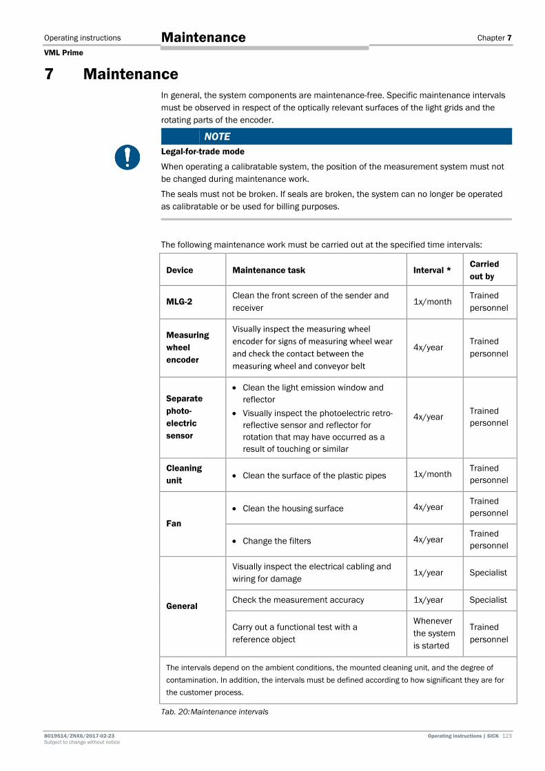
Operating instructions Chapter 7
VML Prime
8019514/ZNX6/2017-02-23 Operating instructions | SICK 123 Subject to change without notice
Maintenance
7 Maintenance In general, the system components are maintenance-free. Specific maintenance intervals must be observed in respect of the optically relevant surfaces of the light grids and the rotating parts of the encoder.
NOTE Legal-for-trade mode
When operating a calibratable system, the position of the measurement system must not be changed during maintenance work.
The seals must not be broken. If seals are broken, the system can no longer be operated as calibratable or be used for billing purposes.
The following maintenance work must be carried out at the specified time intervals:
Device Maintenance task Interval * Carried out by
MLG-2 Clean the front screen of the sender and receiver
1x/month Trained personnel
Measuring wheel encoder
Visually inspect the measuring wheel encoder for signs of measuring wheel wear and check the contact between the measuring wheel and conveyor belt
4x/year Trained personnel
Separate photo-electric sensor
• Clean the light emission window and reflector
• Visually inspect the photoelectric retro-reflective sensor and reflector for rotation that may have occurred as a result of touching or similar
4x/year Trained personnel
Cleaning unit • Clean the surface of the plastic pipes 1x/month
Trained personnel
Fan
• Clean the housing surface 4x/year Trained personnel
• Change the filters 4x/year Trained personnel
General
Visually inspect the electrical cabling and wiring for damage
1x/year Specialist
Check the measurement accuracy 1x/year Specialist
Carry out a functional test with a reference object
Whenever the system is started
Trained personnel
The intervals depend on the ambient conditions, the mounted cleaning unit, and the degree of contamination. In addition, the intervals must be defined according to how significant they are for the customer process.
Tab. 20: Maintenance intervals

Chapter 7 Operating instructions
VML Prime
124 Operating instructions | SICK 8019514 / ZNX6 / 2017-02-23 Subject to change without notice
Maintenance
7.1 Maintenance during operation 7.1.1 Visual inspection of the cables
Regularly check the electrical installation. Check that all cable connections are securely attached.
WARNING
Loose connections or scorched cables
Defects such as loose connections or scorched cables must be rectified immediately.
HAZARD
Damaged cable insulation
There is a risk of electrocution if the insulation of the connecting cables is damaged.
7.1.2 Light grid
The MLG-2 modular light grid is maintenance-free. Depending on the ambient conditions, regular cleaning is required. Depending on the ambient conditions of the MLG-2, the front screens must be cleaned regularly and in the event of contamination.
Fig. 131: Cleaning the light grids
Contamination message
The MLG-2 light grid has a contamination warning which is indicated via a flashing yellow light emitting diode on the receiver.
The yellow LED also displays the same flashing behavior during the teach-in process.
The contamination message is also displayed in the SOPAS software and can be depicted accordingly via the communication protocol.
Static charges cause dust particles to stick to the front screen. You can reduce this effect by using a SICK anti-static plastic cleaner (part number 5600006) and a SICK lens cloth (part number 4003353).
3 Hz yellow
Recommendation
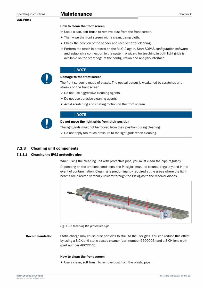
Operating instructions Chapter 7
VML Prime
8019514/ZNX6/2017-02-23 Operating instructions | SICK 125 Subject to change without notice
Maintenance
How to clean the front screen
Use a clean, soft brush to remove dust from the front screen.
Then wipe the front screen with a clean, damp cloth.
Check the position of the sender and receiver after cleaning.
Perform the teach-in process on the MLG-2 again. Start SOPAS configuration software and establish a connection to the system. A wizard for teaching in both light grids is available on the start page of the configuration and analysis interface.
NOTE
Damage to the front screen
The front screen is made of plastic. The optical output is weakened by scratches and streaks on the front screen.
Do not use aggressive cleaning agents.
Do not use abrasive cleaning agents.
Avoid scratching and chafing motion on the front screen.
NOTE
Do not move the light grids from their position
The light grids must not be moved from their position during cleaning.
Do not apply too much pressure to the light grids when cleaning.
7.1.3 Cleaning unit components 7.1.3.1 Cleaning the IPG2 protective pipe
When using the cleaning unit with protective pipe, you must clean the pipe regularly.
Depending on the ambient conditions, the Plexiglas must be cleaned regularly and in the event of contamination. Cleaning is predominantly required at the areas where the light beams are directed vertically upward through the Plexiglas to the receiver diodes.
Fig. 132: Cleaning the protective pipe
Static charge may cause dust particles to stick to the Plexiglas. You can reduce this effect by using a SICK anti-static plastic cleaner (part number 5600006) and a SICK lens cloth (part number 4003353).
How to clean the front screen
Use a clean, soft brush to remove dust from the plastic pipe.
Recommendation
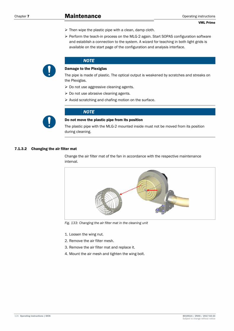
Chapter 7 Operating instructions
VML Prime
126 Operating instructions | SICK 8019514 / ZNX6 / 2017-02-23 Subject to change without notice
Maintenance
Then wipe the plastic pipe with a clean, damp cloth.
Perform the teach-in process on the MLG-2 again. Start SOPAS configuration software and establish a connection to the system. A wizard for teaching in both light grids is available on the start page of the configuration and analysis interface.
NOTE
Damage to the Plexiglas
The pipe is made of plastic. The optical output is weakened by scratches and streaks on the Plexiglas.
Do not use aggressive cleaning agents.
Do not use abrasive cleaning agents.
Avoid scratching and chafing motion on the surface.
NOTE
Do not move the plastic pipe from its position
The plastic pipe with the MLG-2 mounted inside must not be moved from its position during cleaning.
7.1.3.2 Changing the air filter mat
Change the air filter mat of the fan in accordance with the respective maintenance interval.
Fig. 133: Changing the air filter mat in the cleaning unit
1. Loosen the wing nut.
2. Remove the air filter mesh.
3. Remove the air filter mat and replace it.
4. Mount the air mesh and tighten the wing bolt.

Operating instructions Chapter 7
VML Prime
8019514/ZNX6/2017-02-23 Operating instructions | SICK 127 Subject to change without notice
Maintenance
7.1.4 Measuring wheel encoder
Make sure that the incremental encoder is in direct and secure contact with the drive technology and that the measuring wheel is not slipping as it turns.
Fig. 134: Visual inspection of measuring wheel encoder
Check the level of wear on the measuring wheel.
If it is so badly worn that contact with the conveyor belt is impaired, the entire measuring wheel encoder must be replaced.
7.1.5 Photoelectric retro-reflective sensor
Contamination can result in faulty switching behavior.
Remove any contamination on the optical surfaces of the sensors to prevent faulty switching behavior.
Check the screws and plug connectors at regular intervals.
Check that the photoelectric sensor and reflector are correctly aligned.

Chapter 7 Operating instructions
VML Prime
128 Operating instructions | SICK 8019514 / ZNX6 / 2017-02-23 Subject to change without notice
Maintenance
7.2 Replacing components Faulty or damaged components must be dismantled and replaced with new or repaired components. All customer-specific parameters are stored on the microSD card for the MSC800.
Therefore, components can be easily replaced without involving a qualified electrician or trained personnel.
NOTE Repair work on the individual components may only be performed by qualified and authorized service personnel from SICK AG.
HAZARD
Disconnect the power to the system
Make sure the power supply for the entire system is disconnected throughout the entire time that you are carrying out maintenance and repair work.
HAZARD
Risk of injury due to electrical current
Only a qualified electrician or trained person working under the guidance and supervision of a qualified electrician is permitted to work on electrical systems or equipment, and they must comply with the electrical regulations.
7.2.1 Replacing light grids
In principle, individual components of a light grid pair can be exchanged.
NOTE
Claims under the warranty rendered void
Do not open the device housing. The devices are sealed.
None of the parts inside it need to be maintained or replaced.
If the device is opened, any warranty claims against SICK AG will be void.
NOTE Legal-for-trade mode
For calibratable systems, the customer may not replace the light grid.
The light grid seals must not be broken. If a seal is broken, the system can no longer be operated as calibratable or be used for billing purposes.
Please contact the manufacturer if repair is needed.

Operating instructions Chapter 7
VML Prime
8019514/ZNX6/2017-02-23 Operating instructions | SICK 129 Subject to change without notice
Maintenance
Removing cabling
When replacing the sender unit, unscrew the extension cable from the cable connector on the sender.
When replacing a receiver unit, unscrew the tee connector from the cable attachment on the receiver.
7.2.1.1 Replacing MLG
Light grids, which are clamped directly in a QuickFix bracket, are removed from the bracket and replaced with the new device.
The following procedure applies to both item frames and steel frames.
Removing the MLG from the QuickFix bracket
1. Slightly unscrew the fixing screw on the QuickFix bracket.
2. Undo the clamps and take the components out of the two brackets. The brackets remain mounted on the mounting frame.
Fig. 135: Removing the MLG from the QuickFix bracket
Mounting the replacement device
Mount the replacement device in the reverse order.
1. Insert the replacement sender or receiver unit in the QuickFix brackets on the mounting frame. Make sure that the head of the QuickFix bracket is placed exactly in the MLG-2 housing slot.
2. Attach the two QuickFix brackets to the component housing. Push the two parts of the bracket together until you hear a click.
3. Screw the Allen screw into the sliding nut.
4. Make sure that the components are hanging centrally above the conveying surface. In the case of vertical components the first diode should be approx. 2 mm above the conveying surface.
5. Re-establish the connection to the connecting cables.

Chapter 7 Operating instructions
VML Prime
130 Operating instructions | SICK 8019514 / ZNX6 / 2017-02-23 Subject to change without notice
Maintenance
7.2.1.2 Replacing the protective pipe with MLG
If the IPG2 protective pipe is being used, the MLG-2 must be removed. The procedure is illustrated for side mounting of the protective pipe on the item profile. The same applies to the steel frame.
Removing the protective pipe
1. Loosen and remove the two fixing screws from the slot in the upper bracket.
2. Undo the fixing screw on the upper bracket and move the bracket within the profile slot out of the protective pipe in the y-direction.
Fig. 136: Removing the protective pipe
Hold the protective pipe with one hand.
3. Pull the protective pipe out of the cable-side bracket.
Removing the light grid from the protective pipe
For removal, the assembly procedure is performed in reverse order. Detailed information can be found in chapter 4.3.3.1 Installing the MLG in the protective pipe.
Fig. 137: Removing the light grid from the protective pipe
1. Screw the nut from the cable gland on the cable-side end.
2. Remove the seal insert.
3. Screw the cable gland from the end cap.
4. Undo the setscrew in the centering device.
5. Remove the end cap.
6. Pull the centering device out of the protective pipe.
7. Disconnect the centering device from the connecting cable.
8. Pull the light grid out of the protective pipe.
9. Remove the spacer.
Note
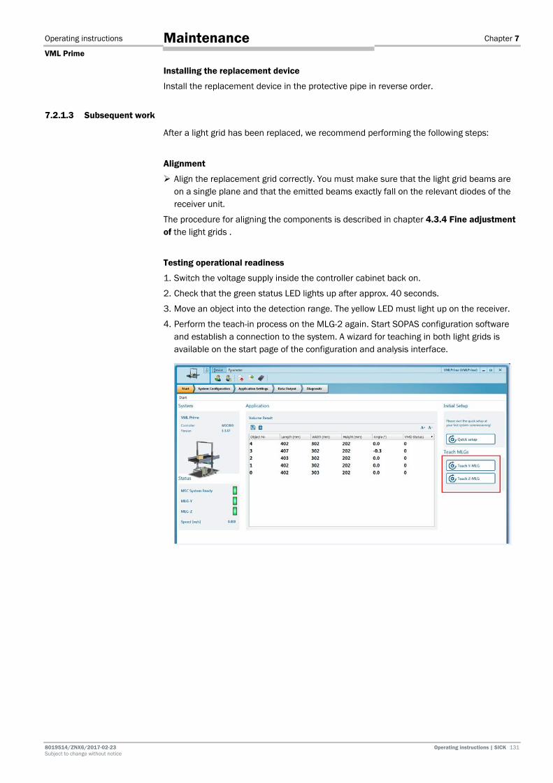
Operating instructions Chapter 7
VML Prime
8019514/ZNX6/2017-02-23 Operating instructions | SICK 131 Subject to change without notice
Maintenance
Installing the replacement device
Install the replacement device in the protective pipe in reverse order.
7.2.1.3 Subsequent work
After a light grid has been replaced, we recommend performing the following steps:
Alignment
Align the replacement grid correctly. You must make sure that the light grid beams are on a single plane and that the emitted beams exactly fall on the relevant diodes of the receiver unit.
The procedure for aligning the components is described in chapter 4.3.4 Fine adjustment of the light grids .
Testing operational readiness
1. Switch the voltage supply inside the controller cabinet back on.
2. Check that the green status LED lights up after approx. 40 seconds.
3. Move an object into the detection range. The yellow LED must light up on the receiver.
4. Perform the teach-in process on the MLG-2 again. Start SOPAS configuration software and establish a connection to the system. A wizard for teaching in both light grids is available on the start page of the configuration and analysis interface.

Chapter 7 Operating instructions
VML Prime
132 Operating instructions | SICK 8019514 / ZNX6 / 2017-02-23 Subject to change without notice
Maintenance
Running through the commissioning wizard (recommended)
We recommend calling up the position wizard on the SOPAS configuration and analysis interface and running through it again.
This will ensure that optimum measurement results are also achieved after the component has been replaced.
1. Switch to the System Configuration workspace.
2. In the Position area, click the Start Wizard button.
Additional information can be found in chapter 6.4.3 Calibrating light grids in relation
to the coordinate system of the conveyor.
Performing a test run
Start a test run with the reference object and check whether the VML Prime measuring system is providing plausible measurement results.

Operating instructions Chapter 7
VML Prime
8019514/ZNX6/2017-02-23 Operating instructions | SICK 133 Subject to change without notice
Maintenance
7.2.2 Replacing the fan
The replacement device is supplied with a pre-mounted bracket.
Removing the fan
1. Unscrew the connecting cable from the cable connector on the fan.
2. Undo the bracket and remove the connecting hose from the fan couplings.
Fig. 138: Replacing the fan
3. Undo the fixing screws on the bracket and remove the fan with its bracket from the mounting frame.
Mounting the replacement device
1. Mount the replacement device on the mounting frame in the reverse order.
2. Tighten the fixing screws and check that the device is securely attached.
3. Place the connecting hose on the fan couplings and screw the hose connection into place.
4. Plug the connecting cable into the female connector of the cable connection and screw the M12 plug connector into place.

Chapter 7 Operating instructions
VML Prime
134 Operating instructions | SICK 8019514 / ZNX6 / 2017-02-23 Subject to change without notice
Maintenance
7.2.3 Replacing components in the control cabinet 7.2.3.1 Replacing the MSC800
NOTE
VML520 MID or VML520 MID-s
With the VML520 MID or VML520 MID-s calibratable systems, the customer may not remove or replace the controller.
Please contact the manufacturer if repair is needed.
HAZARD
Risk of injury due to electrical current
The power supply unit of the controller cabinet is connected to the power supply (AC 100 ... 264 V / 50 ... 60 Hz).
Standard safety requirements must be met when working on electrical systems.
Before removing the controller, you should make a note of how the cables are assigned to the connections.
Removing connecting cables
1. Switch off the controller supply voltage.
2. Unplug the connected Ethernet cable (1) from the female connector.
Fig. 139: Unplugging the cables and terminal blocks from the controller
3. Unplug the terminal blocks (2), together with the cabling, from the controller slots.
Make sure that no wires are pulled out from the terminal blocks.
Removing the controller
1. Undo the controller fixing screw (3) on the left-hand side.
2. Pull the controller to the right and then remove it from the control cabinet.
3. Remove the microSD card from the slot (4) in the controller that has been removed.
Note
Note

Operating instructions Chapter 7
VML Prime
8019514/ZNX6/2017-02-23 Operating instructions | SICK 135 Subject to change without notice
Maintenance
Installing the controller
1. Insert the microSD card that you have removed into Slot SD 1 on the new controller.
2. Insert the new controller in the control cabinet.
3. Pull it to the left and use the fixing screw to secure it in the control cabinet.
4. Place the terminal blocks, together with the cabling, back inside the designated slots.
5. Plug the Ethernet cables into the designated connectors.
6. Check the switch positions of the micro switches between the terminal blocks. Set them to the same positions as the switches on the controller that has been removed (signal ground).
7. Switch the controller supply voltage back on. The controller starts and, after initialization, loads the parameter set from the memory card to the permanent parameter memory of the logic unit.
7.2.3.2 Replacing the battery in the MSC800
NOTE Legal-for-trade mode
For calibratable systems, the customer may not replace the battery.
Please contact the manufacturer if repair is needed.
A battery powers the real-time clock of the MSC800. The battery must be replaced when drained.
Fig. 140: Position of the battery in the MSC800 controller
1. Remove the black plastic cover on the MSC800.
2. Remove the battery from the holder and replace it with a new type 2032 CR battery.
3. Reattach the black plastic cover.
4. Dispose of the old battery as hazardous waste in accordance with the RoHS guidelines (Europe).
5. Set the system time again using the SOPAS software (project tree MSC800 System REAL-TIME CLOCK area).
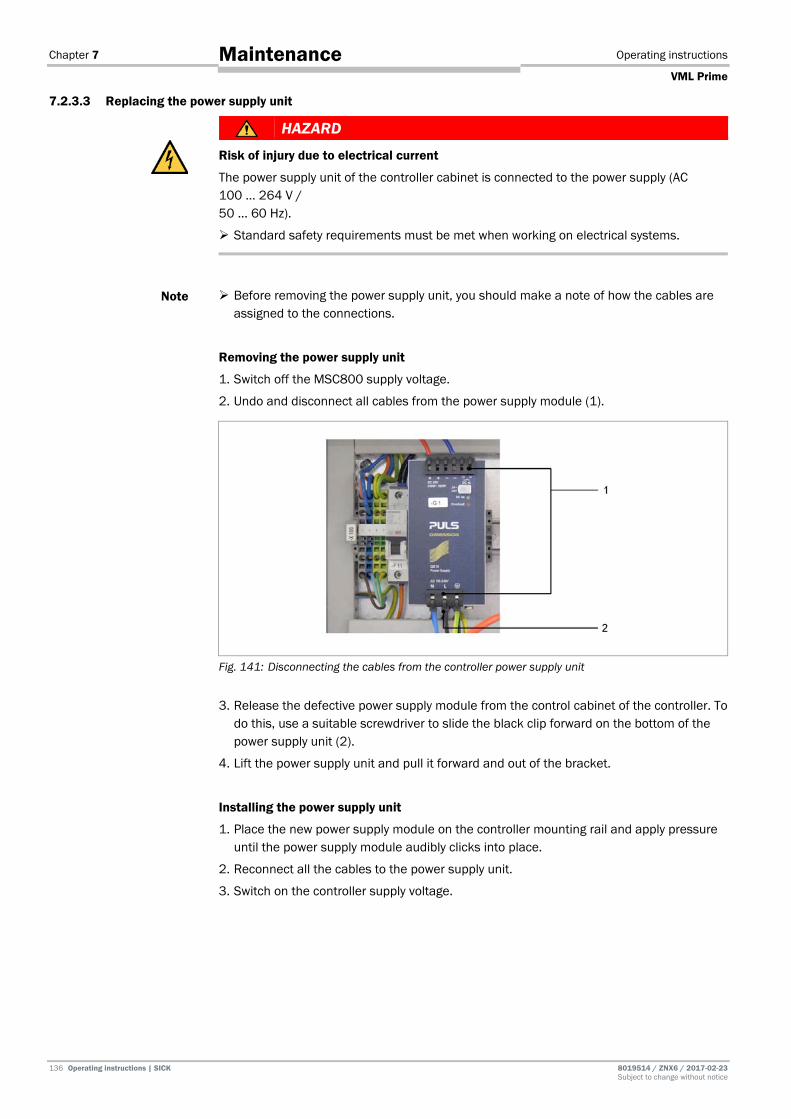
Chapter 7 Operating instructions
VML Prime
136 Operating instructions | SICK 8019514 / ZNX6 / 2017-02-23 Subject to change without notice
Maintenance
7.2.3.3 Replacing the power supply unit
HAZARD
Risk of injury due to electrical current
The power supply unit of the controller cabinet is connected to the power supply (AC 100 ... 264 V / 50 ... 60 Hz).
Standard safety requirements must be met when working on electrical systems.
Before removing the power supply unit, you should make a note of how the cables are assigned to the connections.
Removing the power supply unit
1. Switch off the MSC800 supply voltage.
2. Undo and disconnect all cables from the power supply module (1).
Fig. 141: Disconnecting the cables from the controller power supply unit
3. Release the defective power supply module from the control cabinet of the controller. To do this, use a suitable screwdriver to slide the black clip forward on the bottom of the power supply unit (2).
4. Lift the power supply unit and pull it forward and out of the bracket.
Installing the power supply unit
1. Place the new power supply module on the controller mounting rail and apply pressure until the power supply module audibly clicks into place.
2. Reconnect all the cables to the power supply unit.
3. Switch on the controller supply voltage.
Note
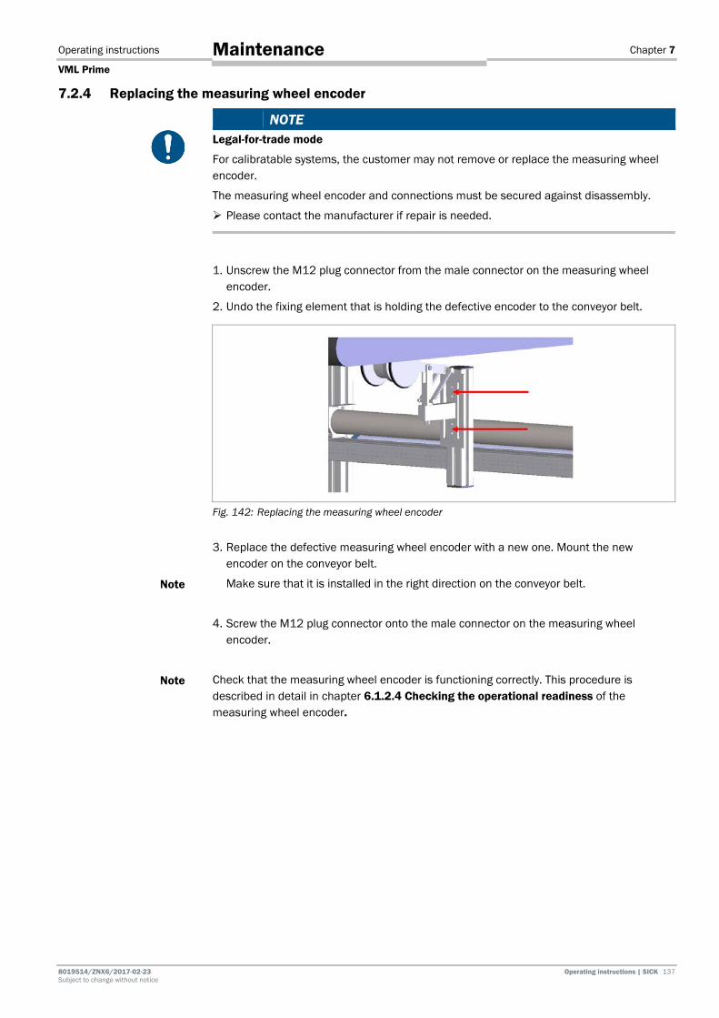
Operating instructions Chapter 7
VML Prime
8019514/ZNX6/2017-02-23 Operating instructions | SICK 137 Subject to change without notice
Maintenance
7.2.4 Replacing the measuring wheel encoder
NOTE Legal-for-trade mode
For calibratable systems, the customer may not remove or replace the measuring wheel encoder.
The measuring wheel encoder and connections must be secured against disassembly.
Please contact the manufacturer if repair is needed.
1. Unscrew the M12 plug connector from the male connector on the measuring wheel encoder.
2. Undo the fixing element that is holding the defective encoder to the conveyor belt.
Fig. 142: Replacing the measuring wheel encoder
3. Replace the defective measuring wheel encoder with a new one. Mount the new encoder on the conveyor belt.
Make sure that it is installed in the right direction on the conveyor belt.
4. Screw the M12 plug connector onto the male connector on the measuring wheel encoder.
Check that the measuring wheel encoder is functioning correctly. This procedure is described in detail in chapter 6.1.2.4 Checking the operational readiness of the measuring wheel encoder.
Note
Note

Chapter 7 Operating instructions
VML Prime
138 Operating instructions | SICK 8019514 / ZNX6 / 2017-02-23 Subject to change without notice
Maintenance
Running through the commissioning wizard (recommended)
We recommend calling up the encoder wizard on the SOPAS configuration and analysis interface and running through it again.
This will ensure that optimum measurement results are also achieved after the component has been replaced.
1. Switch to the System Configuration workspace.
2. In the Encoder area, click the Start Wizard button.
Additional information can be found in chapter 6.4.4 Calibrating the incremental
encoder.

Operating instructions Chapter 7
VML Prime
8019514/ZNX6/2017-02-23 Operating instructions | SICK 139 Subject to change without notice
Maintenance
7.2.5 Replacing the separate photoelectric retro-reflective sensor
NOTE
VML520 MID or VML520 MID-s
With the VML520 MID or VML520 MID-s calibratable systems, the customer may not replace the photoelectric sensor.
Please contact the manufacturer if repair is needed.
1. Unscrew the M12 plug connector from the male connector on the photoelectric retro-reflective sensor.
2. Undo the clinch stud (1) which fixes the photoelectric retro-reflective sensor to the mounting bracket.
3. Undo both M5 hexagon screws (2) on the mounting bracket. When doing so, hold the photoelectric retro-reflective sensor with one hand.
Fig. 143: Replacing the photoelectric retro-reflective sensor 4. Remove the defective photoelectric sensor from the mounting bracket.
5. Replace the defective photoelectric sensor with a new one.
6. Mount the replacement device on the mounting bracket using the two M5 hexagon screws.
7. Fix the photoelectric sensor in place with the clinch stud.
8. Screw the M12 plug connector onto the male connector on the photoelectric retro-reflective sensor.
9. Align the photoelectric sensor correctly on the reflector. The reflector must be in line with the light beam from the photoelectric retro-reflective sensor.
Check that the photoelectric retro-reflective sensor is functioning correctly. There is a detailed description of how to do this in the chapter entitled Checking the operational readiness of the photoelectric retro-reflective sensor.
Note

Chapter 7 Operating instructions
VML Prime
140 Operating instructions | SICK 8019514 / ZNX6 / 2017-02-23 Subject to change without notice
Maintenance
7.2.6 Checking the measurement accuracy
The measurement accuracy must be checked after performing the following maintenance work/modifications:
• Replacement of a light grid (sender unit, receiver unit).
• Replacement of the measuring wheel encoder.
• Changes to the frame that alter the position of the light grids.
• Replacement of the belt on the conveying line that has the measuring wheel encoder attached to it.
• Changes to the side edges of the belt (changing measuring range, performing the teach-in function again)
7.3 Disposal Unusable or irreparable devices must be dismantled and disposed of in an environmentally safe manner in accordance with the relevant national waste disposal regulations.
SICK AG is not currently able to take back devices that are irreparable or can no longer be used.

Operating instructions Chapter 8
VML Prime
8019514/ZNX6/2017-02-23 Operating instructions | SICK 141 Subject to change without notice
Fault diagnosis
8 Fault diagnosis This chapter describes how to identify and remedy faults affecting the VML Prime measurement system.
8.1 Response to faults
WARNING
Danger due to malfunction!
Cease operation if the cause of the malfunction has not been clearly identified.
Immediately put the machine/system out of operation if you cannot clearly identify or allocate the fault and if you cannot safely remedy the fault.
8.2 SICK support If you cannot remedy the error with the help of the information provided in this chapter, please contact your SICK subsidiary.
8.3 Fault indicators of the components This section explains what the LED fault indicators of the individual devices mean and how to respond to them.
8.3.1 Fault indicator on the light grids
If the red LED lights up on the sender and receiver units, this indicates that a fault has occurred.
The receiver unit indicates the type of fault via a combination of red, yellow, and green LEDs.
Red LED
Yellow LED
Green LED
Problem Cause Remedy
Hardware fault Device is defective. Replace the device.
Synchronization error
Connecting cable not connected or cable faulty.
Connect the device correctly.
Replace any defective cables.
Short-circuit Faulty power supply.
Establish the correct voltage supply.
3 Hz
yellow
Contamination warning
MLG-2 front screen contaminated.
Clean the front screen.
Tab. 21: LED indicators in case of a fault at the MLG receiver
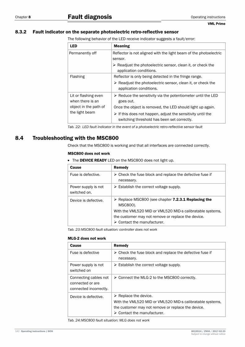
Chapter 8 Operating instructions
VML Prime
142 Operating instructions | SICK 8019514 / ZNX6 / 2017-02-23 Subject to change without notice
Fault diagnosis
8.3.2 Fault indicator on the separate photoelectric retro-reflective sensor The following behavior of the LED receive indicator suggests a fault/error:
LED Meaning
Permanently off Reflector is not aligned with the light beam of the photoelectric sensor. Readjust the photoelectric sensor, clean it, or check the
application conditions. Flashing Reflector is only being detected in the fringe range.
Readjust the photoelectric sensor, clean it, or check the application conditions.
Lit or flashing even when there is an object in the path of the light beam
Reduce the sensitivity via the potentiometer until the LED goes out.
Once the object is removed, the LED should light up again.
If this does not happen, adjust the sensitivity until the switching threshold has been set correctly.
Tab. 22: LED fault indicator in the event of a photoelectric retro-reflective sensor fault
8.4 Troubleshooting with the MSC800 Check that the MSC800 is working and that all interfaces are connected correctly.
MSC800 does not work
• The DEVICE READY LED on the MSC800 does not light up.
Cause Remedy
Fuse is defective. Check the fuse block and replace the defective fuse if necessary.
Power supply is not switched on.
Establish the correct voltage supply.
Device is defective. Replace MSC800 (see chapter 7.2.3.1 Replacing the MSC800).
With the VML520 MID or VML520 MID-s calibratable systems, the customer may not remove or replace the device. Contact the manufacturer.
Tab. 23: MSC800 fault situation: controller does not work MLG-2 does not work
Cause Remedy
Fuse is defective Check the fuse block and replace the defective fuse if necessary.
Power supply is not switched on
Establish the correct voltage supply.
Connecting cables not connected or are connected incorrectly.
Connect the MLG-2 to the MSC800 correctly.
Device is defective. Replace the device. With the VML520 MID or VML520 MID-s calibratable systems, the customer may not remove or replace the device. Contact the manufacturer.
Tab. 24: MSC800 fault situation: MLG does not work

Operating instructions Chapter 8
VML Prime
8019514/ZNX6/2017-02-23 Operating instructions | SICK 143 Subject to change without notice
Fault diagnosis
Checking the measuring wheel encoder
The LEDs on the INC terminal block should flash alternately as the measuring wheel turns.
Fig. 144: MSC800 fault situation: LED for incremental signals
If the LEDs do not flash, possible causes might be:
Cause Remedy
There is no/insufficient contact between the measuring wheel and the conveyor belt.
Make sure that there is good contact between the measuring wheel and the conveyor belt on site.
If the measuring wheel shows signs of wear, replace it.
Replace the measuring wheel encoder if necessary.
Signal ground not activated. Set the SGND_4 signal ground switch to on.
Wire is not attached correctly in the terminal block (2).
Check that the wires are attached correctly.
Encoder is defective. Replace the device.
With the VML520 MID or VML520 MID-s calibratable systems, the customer may not remove or replace the device.
Contact the manufacturer.
Tab. 25: MSC800 fault situation: LED for incremental signals
Checking the trigger
If the measuring range is clear, the LED at connection 1 TRG_1 in the TRIGGER block should not light up (1). If an object is located in the measuring range, the LED should light up.
Fig. 145: MSC800 fault situation: LED for triggering

Chapter 8 Operating instructions
VML Prime
144 Operating instructions | SICK 8019514 / ZNX6 / 2017-02-23 Subject to change without notice
Fault diagnosis
If the LEDs light up, even when the measuring range is clear, possible causes might be:
Cause Remedy
Path of the beam is permanently shadowed by an object.
Guiding plates or protective barriers have not been blanked.
Blank the guiding plates or protective barriers using the teach-in process.
Tab. 26: MSC800 fault situation: LED for triggering (LED lights up)
If the LEDs do not light up, even when there is an object in the measuring range, possible causes might be:
Cause Remedy
Signal ground not activated.
Set the SGND_5 signal ground switch to on.
Wire is not attached correctly in the terminal block.
Correct the position of the wires in the TRIGGER terminal block.
Trigger wires not inserted or are inserted incorrectly.
Insert the black wire into the TRIGGER terminal block at connection point 1 TRG_1.
Voltage supply not on. Establish the correct voltage supply.
Tab. 27: MSC800 fault situation: LED for triggering (LED does not light up)
“SYSTEM READY” LED does not light up
The SYSTEM READY LED on the MSC800 does not light up.
Fig. 146: MSC800 fault situation: “SYSTEM READY” LED does not light up

Operating instructions Chapter 8
VML Prime
8019514/ZNX6/2017-02-23 Operating instructions | SICK 145 Subject to change without notice
Fault diagnosis
Possible causes can include:
Cause Remedy
MLG-2 is defective Replace the device.
With the VML520 MID or VML520 MID-s calibratable systems, the customer may not remove or replace the device.
Contact the manufacturer.
Diodes significantly contaminated
Clean the front screens of the sender and receiver units
MSC800 is defective Replace the device.
With the VML520 MID or VML520 MID-s calibratable systems, the customer may not remove or replace the device.
Contact the manufacturer.
Host 1 and Host 2 not wired or wired incorrectly
Check and correctly wire the connections at the HOST1 and HOST2 terminal blocks.
Tab. 28: MSC800 fault situation: “SYSTEM READY” LED does not light up
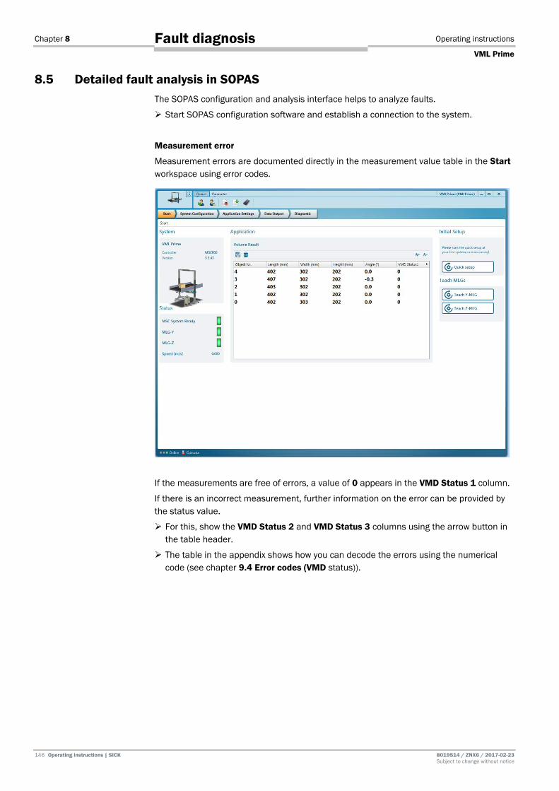
Chapter 8 Operating instructions
VML Prime
146 Operating instructions | SICK 8019514 / ZNX6 / 2017-02-23 Subject to change without notice
Fault diagnosis
8.5 Detailed fault analysis in SOPAS The SOPAS configuration and analysis interface helps to analyze faults.
Start SOPAS configuration software and establish a connection to the system.
Measurement error
Measurement errors are documented directly in the measurement value table in the Start workspace using error codes.
If the measurements are free of errors, a value of 0 appears in the VMD Status 1 column.
If there is an incorrect measurement, further information on the error can be provided by the status value.
For this, show the VMD Status 2 and VMD Status 3 columns using the arrow button in the table header.
The table in the appendix shows how you can decode the errors using the numerical code (see chapter 9.4 Error codes (VMD status)).

Operating instructions Chapter 8
VML Prime
8019514/ZNX6/2017-02-23 Operating instructions | SICK 147 Subject to change without notice
Fault diagnosis
System messages and error codes
The Diagnostic workspace lists both system and error messages.
Fault output is staggered, allowing for an increasingly detailed level of analysis. Communication errors can occur when transmitting telegrams to the MSC800 via the Ethernet interface, for example.
The system differentiates between four error types: information, warning, error, and severe error.
Please contact SICK support for a more detailed analysis of the fault situation.
Cause of severe measurement errors
Severe measurement errors can be caused by various factors, including:
Cause Remedy
Static object in measuring range
Remove the object from the measuring range.
Although the MLG-2 is no longer taking measurements, it is not indicating a fault
Check the connecting cables and replace defective cables.
Check the MLG-2 and, if necessary, replace the device.
Check whether the trigger is permanently engaged.
There is no/insufficient contact between the measuring wheel and the conveyor belt
Check the measuring wheel for signs of wear.
Replace the measuring wheel encoder if necessary.
Tab. 29: Cause of severe measurement errors
Note

Chapter 9 Operating instructions
VML Prime
148 Operating instructions | SICK 8019514 / ZNX6 / 2017-02-23 Subject to change without notice
Technical specifications
9 Technical specifications 9.1 VML Prime data sheet
Component Explanation
Min. object size (L x W x H)
Up to 50 mm x 50 mm x 5 mm
The minimum detectable object size depends on the beam separation and the conditions of the conveyor.
The minimum object length depends on the diameter of the roll at the belt gap. It is calculated using the following formula:
L (min.) = 2.5 * Ø (roll)
Max. object size (L x W x H)
2,600 mm x 1,000 mm x 1,000 mm
Higher object sizes on request.
Conveying system • Flat conveying surface
• Both belts synchronized at the same speed
• On one level, not misaligned
• Singulated objects (see minimum distance)
Dimensioning accuracy (L x W x H)
Up to ± 5 mm x 5 mm x 2 mm up to 1.0 m/s
Up to ± 5 mm x 5 mm x 5 mm up to 2.0 m/s
The values depend on the beam separation and the belt speed.
Higher speeds on request.
Minimum distance between objects
200 mm
Minimum distance between the vertical light grid and the first data output point
Data output typically occurs 300 ms (milliseconds) after the measuring range at the earliest (measured from the back edge of the object* and depending on the maximum object size and conveyor speed).
* Assumed max. object dimensions 650 mm x 650 mm x 450 mm (L x W x H)
Tab. 30: VML Prime data sheet
NOTE Legal-for-trade mode
Special operating points apply to the operation of a calibrated VML520 MID or VML520 MID-s. You can find these in the supplement to operating instructions (8021098).
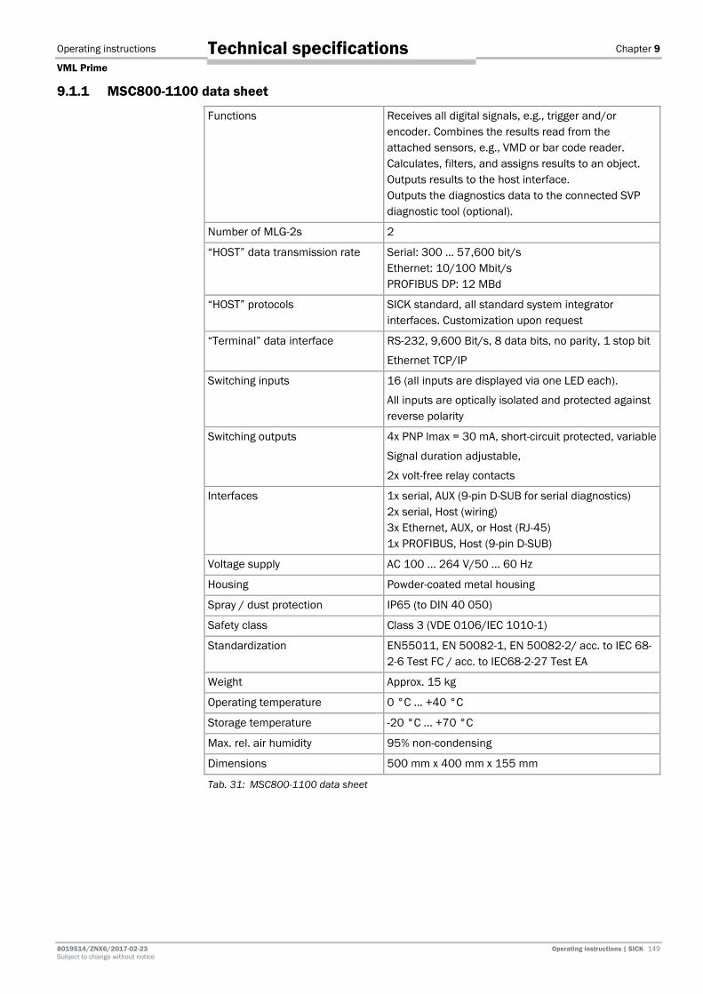
Operating instructions Chapter 9
VML Prime
8019514/ZNX6/2017-02-23 Operating instructions | SICK 149 Subject to change without notice
Technical specifications
9.1.1 MSC800-1100 data sheet
Functions Receives all digital signals, e.g., trigger and/or encoder. Combines the results read from the attached sensors, e.g., VMD or bar code reader. Calculates, filters, and assigns results to an object. Outputs results to the host interface. Outputs the diagnostics data to the connected SVP diagnostic tool (optional).
Number of MLG-2s 2
“HOST” data transmission rate Serial: 300 ... 57,600 bit/s Ethernet: 10/100 Mbit/s PROFIBUS DP: 12 MBd
“HOST” protocols SICK standard, all standard system integrator interfaces. Customization upon request
“Terminal” data interface RS-232, 9,600 Bit/s, 8 data bits, no parity, 1 stop bit
Ethernet TCP/IP
Switching inputs 16 (all inputs are displayed via one LED each).
All inputs are optically isolated and protected against reverse polarity
Switching outputs 4x PNP lmax = 30 mA, short-circuit protected, variable
Signal duration adjustable,
2x volt-free relay contacts
Interfaces 1x serial, AUX (9-pin D-SUB for serial diagnostics) 2x serial, Host (wiring) 3x Ethernet, AUX, or Host (RJ-45) 1x PROFIBUS, Host (9-pin D-SUB)
Voltage supply AC 100 ... 264 V/50 ... 60 Hz
Housing Powder-coated metal housing
Spray / dust protection IP65 (to DIN 40 050)
Safety class Class 3 (VDE 0106/IEC 1010-1)
Standardization EN55011, EN 50082-1, EN 50082-2/ acc. to IEC 68-2-6 Test FC / acc. to IEC68-2-27 Test EA
Weight Approx. 15 kg
Operating temperature 0 °C ... +40 °C
Storage temperature -20 °C ... +70 °C
Max. rel. air humidity 95% non-condensing
Dimensions 500 mm x 400 mm x 155 mm
Tab. 31: MSC800-1100 data sheet

Chapter 9 Operating instructions
VML Prime
150 Operating instructions | SICK 8019514 / ZNX6 / 2017-02-23 Subject to change without notice
Technical specifications
9.1.2 MLG-2 light grid data sheet
The following information applies to an MLG-2 with a beam separation of 5 mm.
General data
Protection class III (EN 61140)
Enclosure rating IP 65 and IP 67 (EN 60529) * Do not use light grids outdoors without protection (risk of
condensation)
Class according to UL 60947 Class 2
Ambient operating temperature -30 °C … +55 °C
Storage temperature -40 °C … +70 °C
Vibration resistance 5 g, 10 Hz ... 55 Hz (EN 60068-2-6)
Shock resistance 15 g, 16 ms (EN 60068-2-27)
Electromagnetic compatibility
According to EN 61000-6-2 Immunity standard for industrial environments and EN 61000-6-4 Emission standard for industrial environments
MTTF 120,000 h
Dimensions See Chapter 9.2.1 MLG-2
Weight Sender and receiver approx. 2 kg/m + 0.1 kg
Materials
Housing Front screen
Aluminum, anodized PMMA
Firmware version See type label
Electrical data
Supply voltage VS DC 24 V ± 20%
Residual ripple (within VS) < 10%
Current consumption of sender < 110 mA + (0.05 mA × number of beams)
Current consumption of receiver < 120 mA + (0.2 mA × number of beams)
Technical measurement data
Wavelength 850 nm
Ambient light immunity 150,000 lx (constant light, indirect)
Beam separation 2.5 mm; 5 mm; 10 mm
Number of beams See 9.2.1 MLG-2 Pro dimensional drawings
Detection height See 9.2.1 MLG-2 Pro dimensional drawings
Initialization time after switch-on
< 1 s
Response time < 11 ms
Minimum presence time < 5.6 ms
Tab. 32: MLG-2 light grids

Operating instructions Chapter 9
VML Prime
8019514/ZNX6/2017-02-23 Operating instructions | SICK 151 Subject to change without notice
Technical specifications
9.1.3 Data sheet for measuring wheel encoder
Component Explanation
Electrical interface 4.5 … 32 V
Number of lines 30
Reference signal Quantity: 1 Position: 90° electric., logically gated with A and B
Error limits ± 0.03°
Signal HTL
Supply voltage DC 4.5 ... 30 V
Enclosure rating IP 65 acc. to EN 60529
Weight 0.5 kg
Operating temperature range -20 °C …+100 °C
Storage temperature range (without packaging)
-40 °C … +100 °C
Rel. Air humidity 90%, non-condensing
Dimensions [W x H x D] 220 mm x 288 mm x 86 mm
Tab. 33: Data sheet for measuring wheel encoder
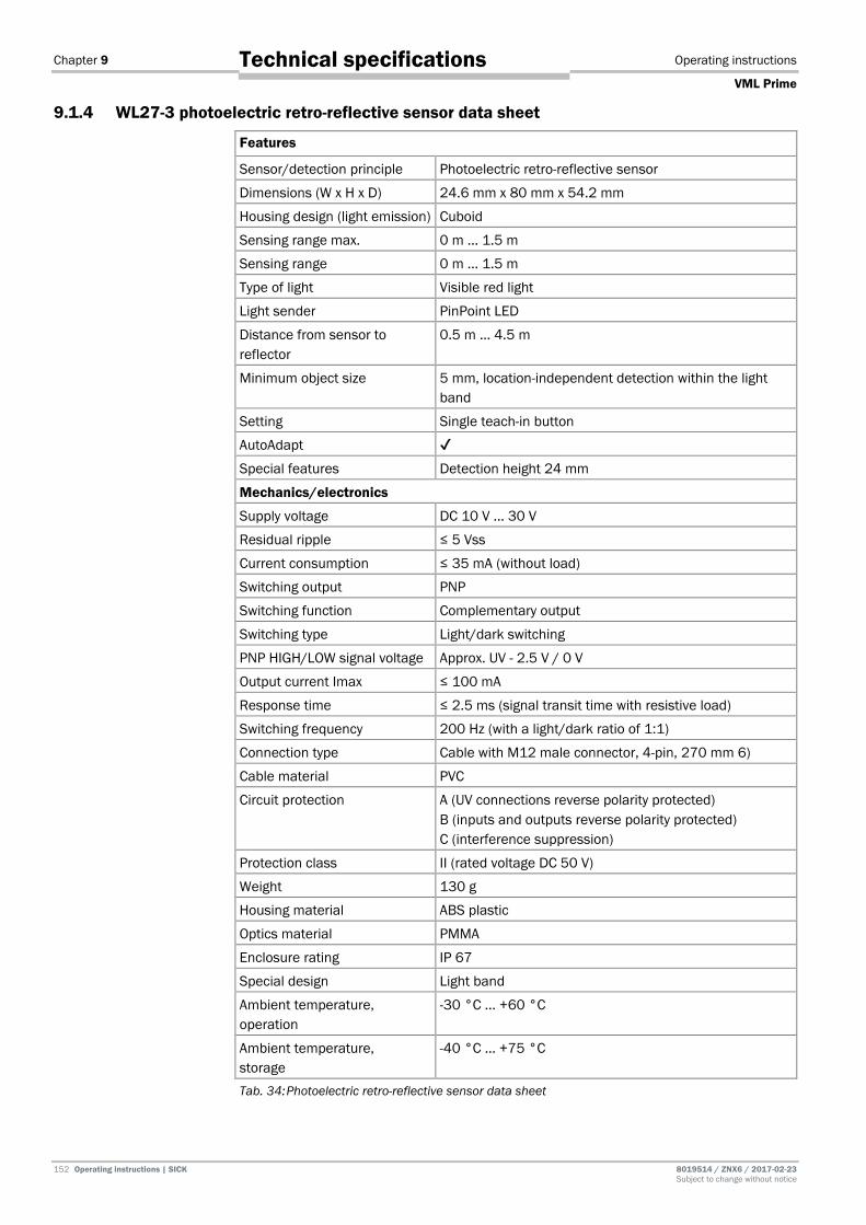
Chapter 9 Operating instructions
VML Prime
152 Operating instructions | SICK 8019514 / ZNX6 / 2017-02-23 Subject to change without notice
Technical specifications
9.1.4 WL27-3 photoelectric retro-reflective sensor data sheet
Features
Sensor/detection principle Photoelectric retro-reflective sensor
Dimensions (W x H x D) 24.6 mm x 80 mm x 54.2 mm
Housing design (light emission) Cuboid
Sensing range max. 0 m ... 1.5 m
Sensing range 0 m ... 1.5 m
Type of light Visible red light
Light sender PinPoint LED
Distance from sensor to reflector
0.5 m ... 4.5 m
Minimum object size 5 mm, location-independent detection within the light band
Setting Single teach-in button
AutoAdapt ✔
Special features Detection height 24 mm
Mechanics/electronics
Supply voltage DC 10 V ... 30 V
Residual ripple ≤ 5 Vss
Current consumption ≤ 35 mA (without load)
Switching output PNP
Switching function Complementary output
Switching type Light/dark switching
PNP HIGH/LOW signal voltage Approx. UV - 2.5 V / 0 V
Output current Imax ≤ 100 mA
Response time ≤ 2.5 ms (signal transit time with resistive load)
Switching frequency 200 Hz (with a light/dark ratio of 1:1)
Connection type Cable with M12 male connector, 4-pin, 270 mm 6)
Cable material PVC
Circuit protection A (UV connections reverse polarity protected) B (inputs and outputs reverse polarity protected) C (interference suppression)
Protection class II (rated voltage DC 50 V)
Weight 130 g
Housing material ABS plastic
Optics material PMMA
Enclosure rating IP 67
Special design Light band
Ambient temperature, operation
-30 °C ... +60 °C
Ambient temperature, storage
-40 °C … +75 °C
Tab. 34: Photoelectric retro-reflective sensor data sheet
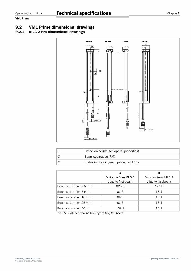
Operating instructions Chapter 9
VML Prime
8019514/ZNX6/2017-02-23 Operating instructions | SICK 153 Subject to change without notice
Technical specifications
9.2 VML Prime dimensional drawings 9.2.1 MLG-2 Pro dimensional drawings
Detection height (see optical properties)
Beam separation (RM)
Status indicator: green, yellow, red LEDs
A Distance from MLG-2
edge to first beam
B Distance from MLG-2
edge to last beam Beam separation 2.5 mm 62.25 17.25
Beam separation 5 mm 63.3 16.1
Beam separation 10 mm 68.3 16.1
Beam separation 25 mm 83.3 16.1
Beam separation 50 mm 108.3 16.1 Tab. 35: Distance from MLG-2 edge to first/last beam
M12; 4-pin
M12; 8-pin
M12; 5-pin
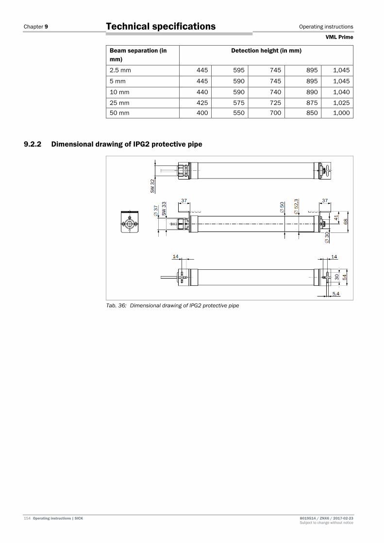
Chapter 9 Operating instructions
VML Prime
154 Operating instructions | SICK 8019514 / ZNX6 / 2017-02-23 Subject to change without notice
Technical specifications
Beam separation (in mm)
Detection height (in mm)
2.5 mm 445 595 745 895 1,045
5 mm 445 590 745 895 1,045
10 mm 440 590 740 890 1,040
25 mm 425 575 725 875 1,025 50 mm 400 550 700 850 1,000
9.2.2 Dimensional drawing of IPG2 protective pipe
Tab. 36: Dimensional drawing of IPG2 protective pipe
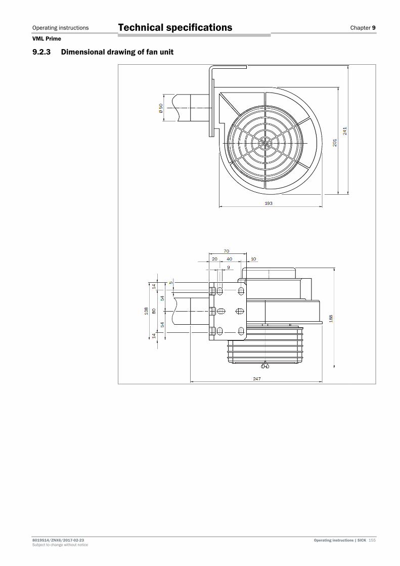
Operating instructions Chapter 9
VML Prime
8019514/ZNX6/2017-02-23 Operating instructions | SICK 155 Subject to change without notice
Technical specifications
9.2.3 Dimensional drawing of fan unit

Chapter 9 Operating instructions
VML Prime
156 Operating instructions | SICK 8019514 / ZNX6 / 2017-02-23 Subject to change without notice
Technical specifications
9.2.4 Dimensional drawing of MSC800-100

Operating instructions Chapter 9
VML Prime
8019514/ZNX6/2017-02-23 Operating instructions | SICK 157 Subject to change without notice
Technical specifications
9.2.5 Dimensional drawing of measuring wheel encoder

Chapter 9 Operating instructions
VML Prime
158 Operating instructions | SICK 8019514 / ZNX6 / 2017-02-23 Subject to change without notice
Technical specifications
9.2.6 Separate WL27-3 photoelectric retro-reflective sensor
Fig. 147: Dimensional drawing of WL27-3 photoelectric retro-reflective sensor
Light band outlet opening
Mounting hole Ø 5.2 mm
Green LED indicator: supply voltage active
LED indicator: status of received light beam
Sensititvity control: single teach-in button

Operating instructions Chapter 9
VML Prime
8019514/ZNX6/2017-02-23 Operating instructions | SICK 159 Subject to change without notice
Technical specifications
9.3 Compliance with EU directives EU declaration of conformity (extract)
The undersigned, who represents the manufacturer below, hereby declares that the product complies with the regulations of the EU directive(s) below (including all relevant changes), and that it is based on the relevant standards and/or technical specifications.
Complete EU declaration of conformity for download
You can call up the EU declaration of conformity and the current operating instructions for the protective device by entering the item number in the search field at www.sick.com (part number: see the type label entry in the Ident. no. field).
After successful standardization, the declaration of conformity for the system is declared according to the following directive:
Measuring Instruments Directive: 2014/32/EU (2016-04-20)
The customer receives the certificate after successful standardization.
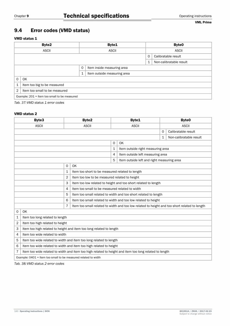
Chapter 9 Operating instructions
VML Prime
160 Operating instructions | SICK 8019514 / ZNX6 / 2017-02-23 Subject to change without notice
Technical specifications
9.4 Error codes (VMD status) VMD status 1
Byte2 Byte1 Byte0 ASCII ASCII ASCII
0 Calibratable result
1 Non-calibratable result
0 Item inside measuring area
1 Item outside measuring area
0 OK
1 Item too big to be measured
2 Item too small to be measured
Example: 201 = Item too small to be measured
Tab. 37: VMD status 1 error codes
VMD status 2
Byte3 Byte2 Byte1 Byte0 ASCII ASCII ASCII ASCII
0 Calibratable result
1 Non-calibratable result
0 OK
1 Item outside right measuring area
4 Item outside left measuring area
5 Item outside left and right measuring area
0 OK
1 Item too short to be measured related to length
2 Item too low to be measured related to height
3 Item too low related to height and too short related to length
4 Item too small to be measured related to width
5 Item too small related to width and too short related to length
6 Item too small related to width and too low related to height
7 Item too small related to width and too low related to height and too short related to length
0 OK
1 Item too long related to length
2 Item too high related to height
3 Item too high related to height and item too long related to length
4 Item too wide related to width
5 Item too wide related to width and item too long related to length
6 Item too wide related to width and item too high related to height
7 Item too wide related to width and item too high related to height and item too long related to length
Example: 0401 = Item too small to be measured related to width
Tab. 38: VMD status 2 error codes

Operating instructions Chapter 9
VML Prime
8019514/ZNX6/2017-02-23 Operating instructions | SICK 161 Subject to change without notice
Technical specifications
VMD status 3
Byte6 Byte5 Byte4 Byte3 Byte2 Byte1 Byte0 ASCII ASCII ASCII ASCII ASCII ASCII ASCII
0
0
0
0
0
0
8 Incorrect measurement data due to heavy contamination
Example: 8000000 = Contamination message *
* A contamination message is only issued if the beams which have been shadowed through the measured object are contaminated.
Tab. 39: VMD status 2 error codes

Chapter 9 Operating instructions
VML Prime
162 Operating instructions | SICK 8019514 / ZNX6 / 2017-02-23 Subject to change without notice
Technical specifications
9.5 Circuit diagrams 9.5.1 VML Prime 3D
Overview

Operating instructions Chapter 9
VML Prime
8019514/ZNX6/2017-02-23 Operating instructions | SICK 163 Subject to change without notice
Technical specifications
Power supply

Chapter 9 Operating instructions
VML Prime
164 Operating instructions | SICK 8019514 / ZNX6 / 2017-02-23 Subject to change without notice
Technical specifications
MSC800 X1-X4

Operating instructions Chapter 9
VML Prime
8019514/ZNX6/2017-02-23 Operating instructions | SICK 165 Subject to change without notice
Technical specifications
MSC800 X5-X8
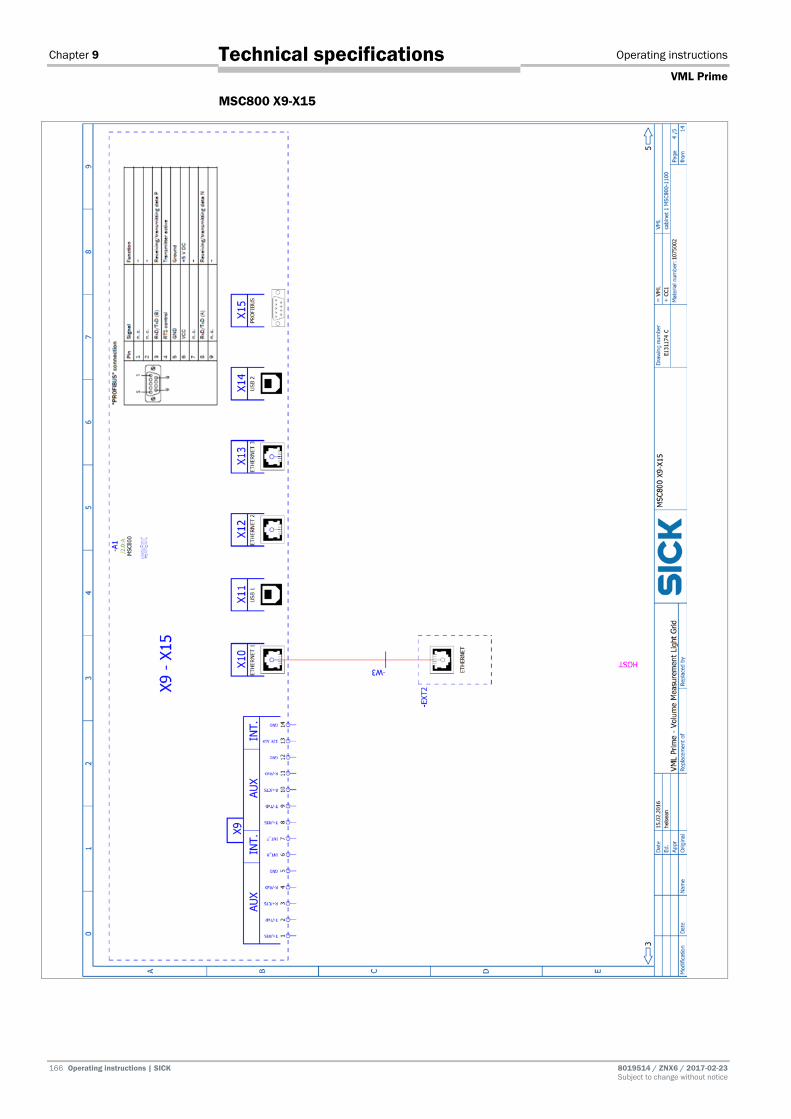
Chapter 9 Operating instructions
VML Prime
166 Operating instructions | SICK 8019514 / ZNX6 / 2017-02-23 Subject to change without notice
Technical specifications
MSC800 X9-X15

Operating instructions Chapter 9
VML Prime
8019514/ZNX6/2017-02-23 Operating instructions | SICK 167 Subject to change without notice
Technical specifications
MLG

Chapter 9 Operating instructions
VML Prime
168 Operating instructions | SICK 8019514 / ZNX6 / 2017-02-23 Subject to change without notice
Technical specifications
9.5.2 VML Prime 2D V
Overview
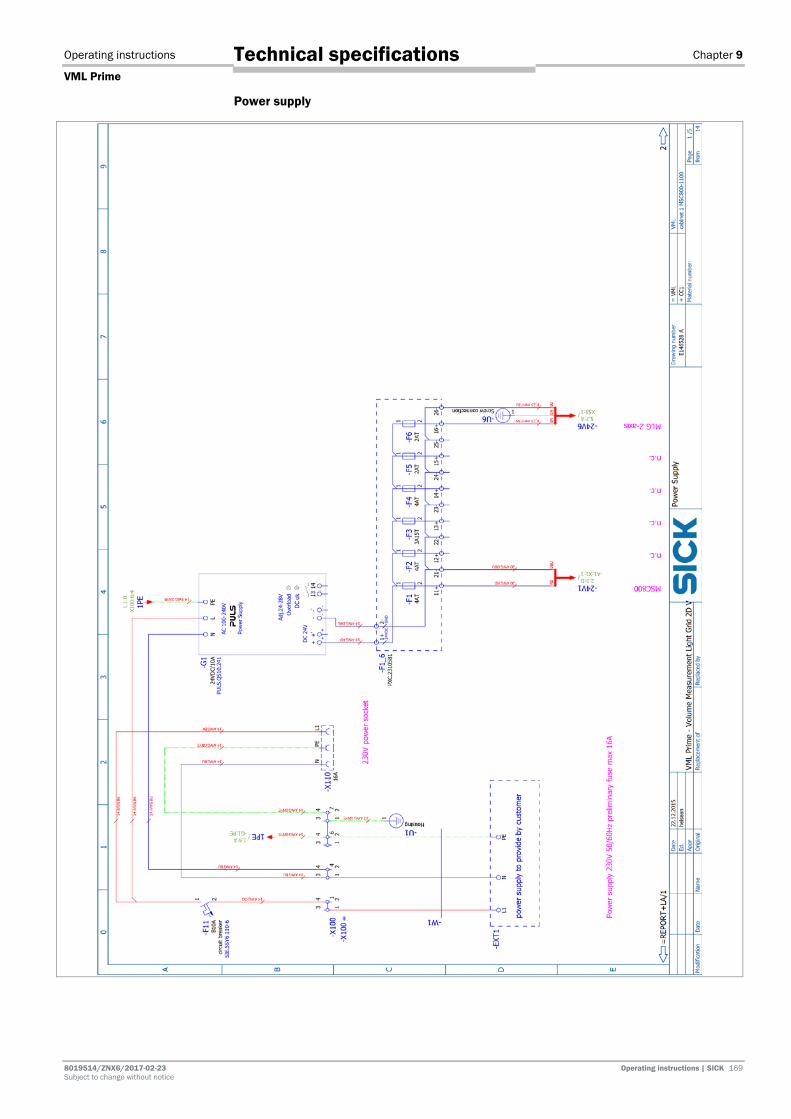
Operating instructions Chapter 9
VML Prime
8019514/ZNX6/2017-02-23 Operating instructions | SICK 169 Subject to change without notice
Technical specifications
Power supply
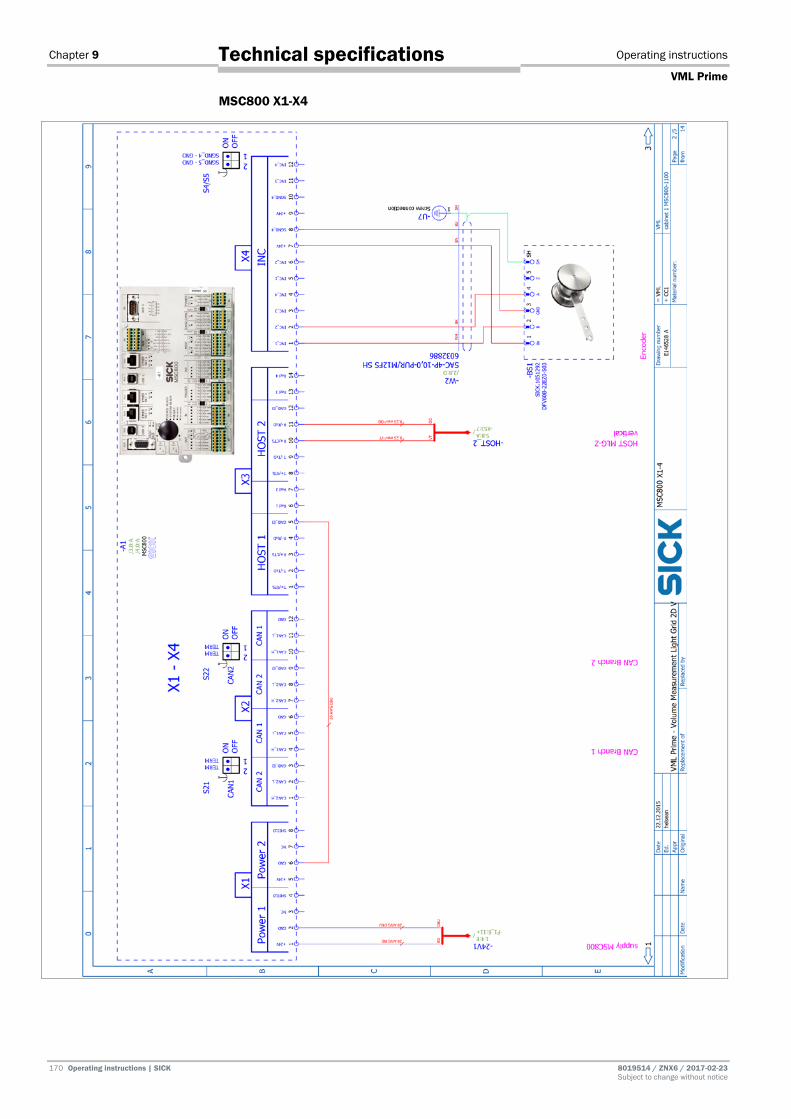
Chapter 9 Operating instructions
VML Prime
170 Operating instructions | SICK 8019514 / ZNX6 / 2017-02-23 Subject to change without notice
Technical specifications
MSC800 X1-X4

Operating instructions Chapter 9
VML Prime
8019514/ZNX6/2017-02-23 Operating instructions | SICK 171 Subject to change without notice
Technical specifications
MSC800 X5-X8

Chapter 9 Operating instructions
VML Prime
172 Operating instructions | SICK 8019514 / ZNX6 / 2017-02-23 Subject to change without notice
Technical specifications
MSC800 X9-X15
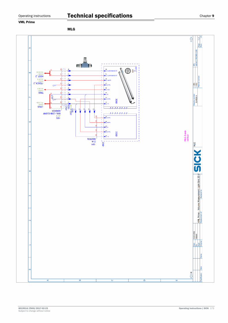
Operating instructions Chapter 9
VML Prime
8019514/ZNX6/2017-02-23 Operating instructions | SICK 173 Subject to change without notice
Technical specifications
MLG
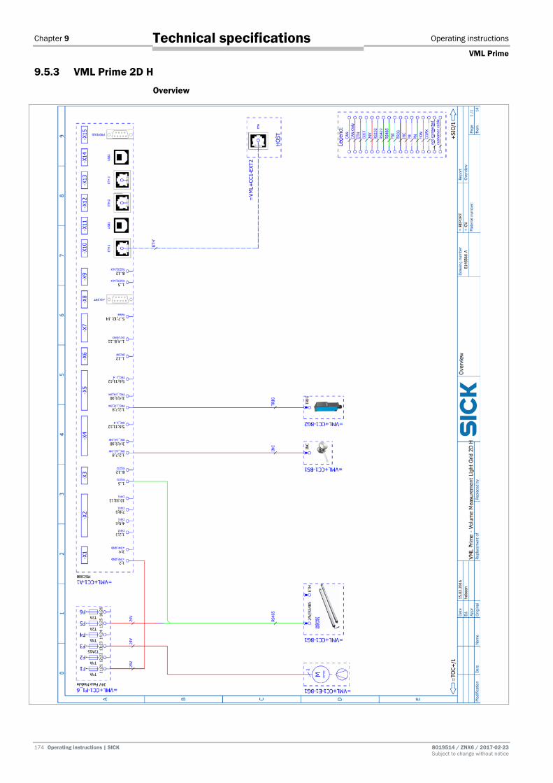
Chapter 9 Operating instructions
VML Prime
174 Operating instructions | SICK 8019514 / ZNX6 / 2017-02-23 Subject to change without notice
Technical specifications
9.5.3 VML Prime 2D H
Overview
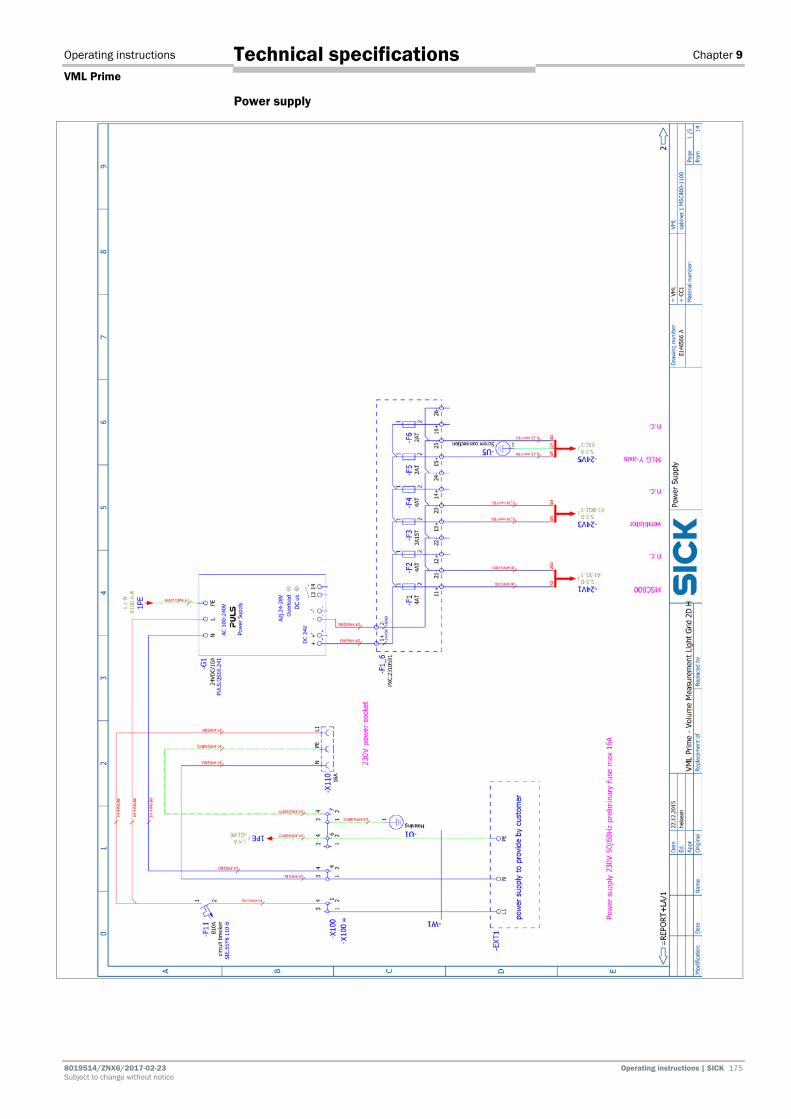
Operating instructions Chapter 9
VML Prime
8019514/ZNX6/2017-02-23 Operating instructions | SICK 175 Subject to change without notice
Technical specifications
Power supply
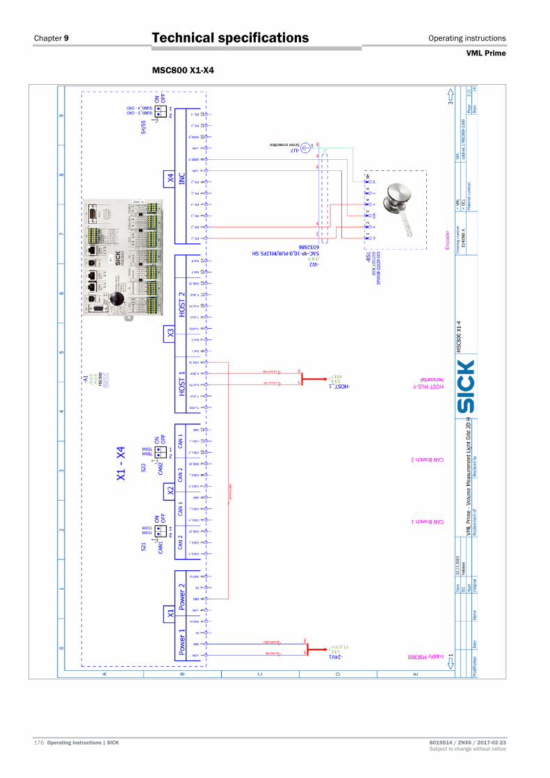
Chapter 9 Operating instructions
VML Prime
176 Operating instructions | SICK 8019514 / ZNX6 / 2017-02-23 Subject to change without notice
Technical specifications
MSC800 X1-X4
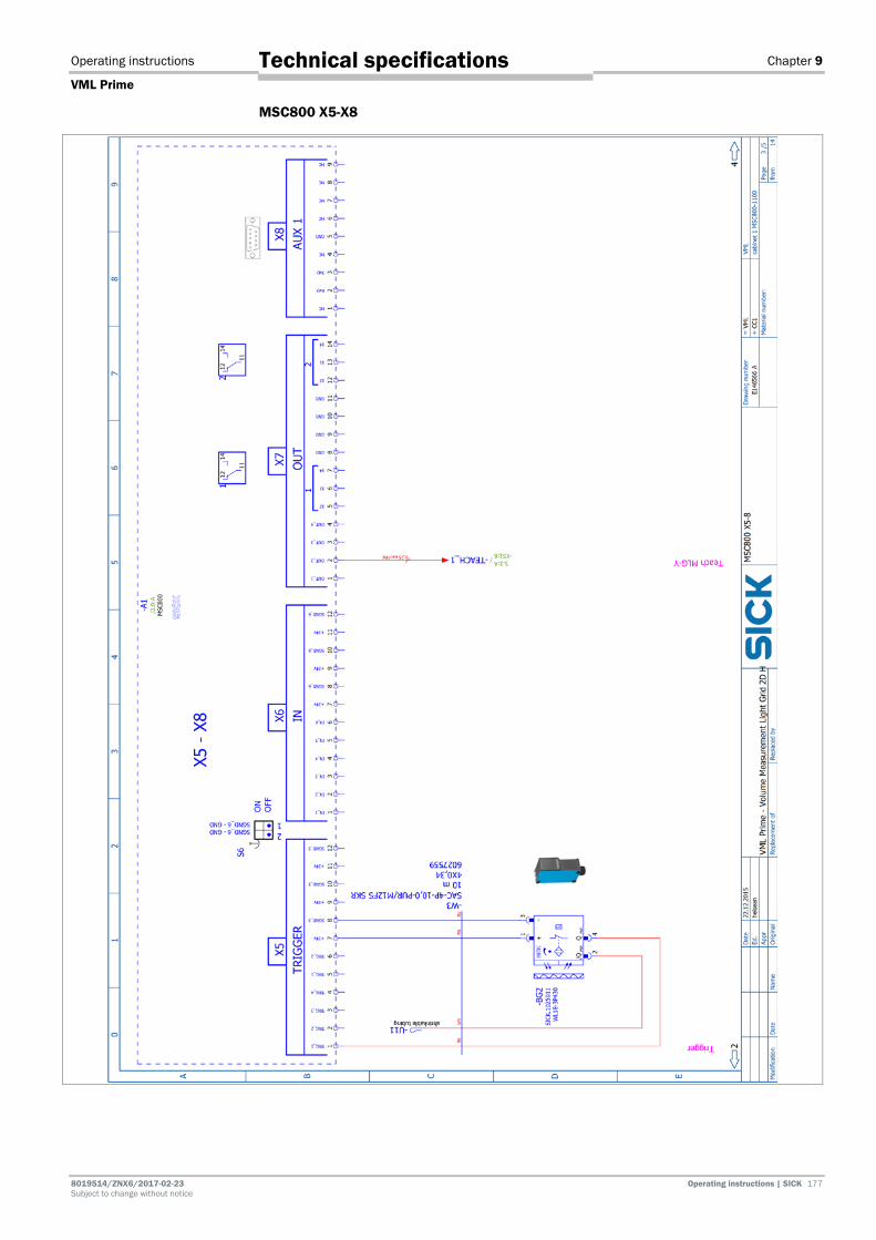
Operating instructions Chapter 9
VML Prime
8019514/ZNX6/2017-02-23 Operating instructions | SICK 177 Subject to change without notice
Technical specifications
MSC800 X5-X8

Chapter 9 Operating instructions
VML Prime
178 Operating instructions | SICK 8019514 / ZNX6 / 2017-02-23 Subject to change without notice
Technical specifications
MSC800 X9-X15
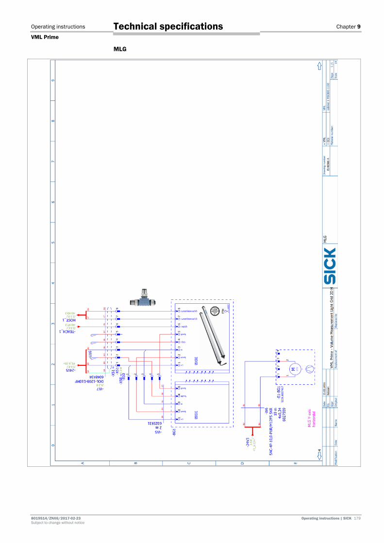
Operating instructions Chapter 9
VML Prime
8019514/ZNX6/2017-02-23 Operating instructions | SICK 179 Subject to change without notice
Technical specifications
MLG

Chapter 10 Operating instructions
VML Prime
180 Operating instructions | SICK 8019514 / ZNX6 / 2017-02-23 Subject to change without notice
Appendix
10 Appendix 10.1 List of tables
Tab. 1: Target group ........................................................................................................... 7 Tab. 2 Qualified safety personnel ................................................................................... 10 Tab. 3: Naming convention of the system variants (examples) ..................................... 21 Tab. 4: Status indicators – light grid (receiver) ............................................................... 36 Tab. 5: Status indicators – light grid (sender) ................................................................. 37 Tab. 6: Status indicators on the MSC800 controller ...................................................... 38 Tab. 7: Function of data interfaces .................................................................................. 39 Tab. 8: item mounting frame: components ..................................................................... 41 Tab. 9: IPG2 protective pipe components ....................................................................... 49 Tab. 10: Steel frame: components .................................................................................... 64 Tab. 11: Components in the MSC800-1100 ..................................................................... 84 Tab. 12: Pin assignment of the -X100 terminal block on the MSC800 ........................... 85 Tab. 13: Connecting the wire ends for the horizontal light grid to the MSC800 ............. 88 Tab. 14: Connecting the horizontal light grid to the voltage supply of the MSC800 ...... 89 Tab. 15: Connecting the vertical light grid to the MSC800 (HOST 2) .............................. 89 Tab. 16: Connecting the vertical light grid to the voltage supply of the MSC800 ........... 89 Tab. 17: Connecting measuring wheel encoder connecting cable to MSC800 .............. 90 Tab. 18: Connecting photoelectric retro-reflective sensor connecting cable to
MSC800 ................................................................................................................ 91 Tab. 19: Connecting the fan to the MSC800 .................................................................... 92 Tab. 20: Maintenance intervals ....................................................................................... 123 Tab. 21: LED indicators in case of a fault at the MLG receiver ...................................... 141 Tab. 22: LED fault indicator in the event of a photoelectric retro-reflective sensor
fault ..................................................................................................................... 142 Tab. 23: MSC800 fault situation: controller does not work ........................................... 142 Tab. 24: MSC800 fault situation: MLG does not work ................................................... 142 Tab. 25: MSC800 fault situation: LED for incremental signals ...................................... 143 Tab. 26: MSC800 fault situation: LED for triggering (LED lights up).............................. 144 Tab. 27: MSC800 fault situation: LED for triggering (LED does not light up) ................ 144 Tab. 28: MSC800 fault situation: “SYSTEM READY” LED does not light up .................. 145 Tab. 29: Cause of severe measurement errors .............................................................. 147 Tab. 30: VML Prime data sheet ........................................................................................ 148 Tab. 31: MSC800-1100 data sheet ................................................................................. 149 Tab. 32: MLG-2 light grids ................................................................................................ 150 Tab. 33: Data sheet for measuring wheel encoder ......................................................... 151 Tab. 34: Photoelectric retro-reflective sensor data sheet .............................................. 152 Tab. 35: Distance from MLG-2 edge to first/last beam .................................................. 153 Tab. 36: Dimensional drawing of IPG2 protective pipe .................................................. 154 Tab. 37: VMD status 1 error codes .................................................................................. 160 Tab. 38: VMD status 2 error codes .................................................................................. 160

Operating instructions Chapter 10
VML Prime
8019514/ZNX6/2017-02-23 Operating instructions | SICK 181 Subject to change without notice
Appendix
Tab. 39: VMD status 2 error codes ................................................................................. 161
10.2 List of figures Fig. 1: VML Prime 3D structure .......................................................................................23 Fig. 2: Structure of VML Prime 2D H with separate photoelectric retro-reflective
sensor ....................................................................................................................23 Fig. 3: MLG-2 sender and receiver unit ..........................................................................24 Fig. 4: Layout of the light grids ........................................................................................25 Fig. 5: Joint between the conveyor belts ........................................................................25 Fig. 6: IPG2 protective pipe with sender .........................................................................26 Fig. 7: IPG2 protective pipe with sender and cleaning unit ...........................................26 Fig. 8: Principle of operation of the cleaning unit ..........................................................27 Fig. 9: Measuring wheel encoder ....................................................................................27 Fig. 10: Photoelectric retro-reflective sensor ....................................................................28 Fig. 11: Controller cabinet with MSC800-1100 ...............................................................28 Fig. 12: Correct minimum distance between objects.......................................................29 Fig. 13: Non-permissible object positions (touching and side-by-side) ...........................29 Fig. 14: VML Prime 3D operating principle .......................................................................30 Fig. 15: VML Prime 2D V operating principle ....................................................................30 Fig. 16: VML Prime 2D H operating principle ...................................................................31 Fig. 17: Distances: trigger and data forwarding ...............................................................32 Fig. 18: Conveying system requirements ..........................................................................33 Fig. 19: Point of reference for conveyor system width .....................................................33 Fig. 20: item aluminum frame and steel frame ................................................................34 Fig. 21: Misaligned light beams ........................................................................................35 Fig. 22: Status indicators on the MLG-2 (receiver unit) ...................................................36 Fig. 23: Status indicators on the photoelectric retro-reflective sensor ...........................37 Fig. 24: Status indicators on the MSC800 controller .......................................................38 Fig. 25: item mounting frame: components .....................................................................41 Fig. 26: item mounting frame: universal connector for mounting the item profiles ......41 Fig. 27: item mounting frame: screwing the item profiles in place .................................42 Fig. 28: item mounting frame: screwing on the L-brackets .............................................42 Fig. 29: item mounting frame: aligning the frame ............................................................43 Fig. 30: item mounting frame: using the angled adjustable feet to level the
frame .....................................................................................................................43 Fig. 31: Universal cable tie block ......................................................................................44 Fig. 32: Mounting the components (overview) .................................................................45 Fig. 33: Assembling QuickFix brackets .............................................................................46 Fig. 34: QuickFix bracket head in the MLG-2 housing slot ..............................................46 Fig. 35: Attaching the QuickFix bracket to the MLG-2 housing .......................................47 Fig. 36: Insert MLG-2 into the mounting frame profile ....................................................47 Fig. 37: Screwing MLG-2 into the profile ...........................................................................48 Fig. 38: Locating the horizontal receiver unit in the MLG-2 in the profile .......................48 Fig. 39: IPG2 protective pipe components .......................................................................49

Chapter 10 Operating instructions
VML Prime
182 Operating instructions | SICK 8019514 / ZNX6 / 2017-02-23 Subject to change without notice
Appendix
Fig. 40: IPG2: mounting the spacer .................................................................................. 50 Fig. 41: IPG2: pushing the light grid into the protective pipe .......................................... 50 Fig. 42: IPG2: mounting the centering device .................................................................. 51 Fig. 43: IPG2: clicking the light grid into place in the upper flange ................................ 51 Fig. 44: IPG2: screwing in the end cap ............................................................................. 51 Fig. 45: IPG2: positioning and fixing the light grid in the protective pipe ....................... 51 Fig. 46: IPG2: mounting the cable gland and seal insert ................................................ 52 Fig. 47: IPG2: screwing the nut onto the cable gland ...................................................... 52 Fig. 48: IPG2: attaching the lower bracket to the profile................................................. 52 Fig. 49: IPG2: placing the protective pipe on the cable-side bracket ............................. 53 Fig. 50: IPG2: aligning the protective pipe and fixing the position ................................. 53 Fig. 51: Making sure the light beams fall on the center of the gap ................................ 54 Fig. 52: Using a plumbline to check that the light beams are centered ......................... 54 Fig. 53: Plumbline in the center of the gap ...................................................................... 54 Fig. 54: Adjusting the position of the first horizontal receiver diode .............................. 55 Fig. 55: Checking the correct position of the first diodes ................................................ 56 Fig. 56: Aligning the vertical light grid .............................................................................. 57 Fig. 57: Checking the alignment of the vertical light grid ................................................ 57 Fig. 58: Vent duct: fixing the bracket ................................................................................ 58 Fig. 59: Vent duct: attaching and aligning on the mounting frame ................................ 58 Fig. 60: Vent duct: aligning in the bracket........................................................................ 59 Fig. 61: Fan: mounting on the item frame ........................................................................ 59 Fig. 62: Attaching the hose connection to the fan ........................................................... 60 Fig. 63: Measuring wheel encoder components .............................................................. 61 Fig. 64: Attaching the measuring wheel encoder to the conveyor belt .......................... 61 Fig. 65: Mounting the photoelectric sensor mounting bracket ....................................... 62 Fig. 66: Mounting the photoelectric sensor ..................................................................... 62 Fig. 67: Positioning the reflector in the beam path of the photoelectric retro-
reflective sensor ................................................................................................... 63 Fig. 68: Mounting the controller cabinet on the transverse profile using the
mounting kit .......................................................................................................... 63 Fig. 69: Steel frame: components .................................................................................... 64 Fig. 70: Steel frame: vertical column components .......................................................... 65 Fig. 71: Steel frame: mark for detection height ............................................................... 66 Fig. 72: Steel frame: mounting the bracket for horizontal bars ...................................... 66 Fig. 73: Steel frame: assembling the lower crossbar ...................................................... 66 Fig. 74: Steel frame: assembling the upper crossbar ..................................................... 67 Fig. 75: Steel frame: assembling the vertical columns and crossbars ........................... 67 Fig. 76: Steel frame: component overview ....................................................................... 68 Fig. 77: Steel frame: holes for mounting the light grids .................................................. 68 Fig. 78: Steel frame: inserting nuts into QuickFix brackets to hold the MLG ................. 69 Fig. 79: Steel frame: screwing together the QuickFix brackets for holding the
MLG ....................................................................................................................... 69

Operating instructions Chapter 10
VML Prime
8019514/ZNX6/2017-02-23 Operating instructions | SICK 183 Subject to change without notice
Appendix
Fig. 80: Steel frame: screwing QuickFix brackets for holding the MLG to the bar .........69 Fig. 81: Steel frame: clamping the MLG in the QuickFix bracket ....................................70 Fig. 82: Steel frame: holes for mounting the protective pipe ..........................................71 Fig. 83: Steel frame: attaching the protective pipe to the transverse profile .................71 Fig. 84: Steel frame: attaching the bracket for mounting the protective pipe and
vent duct ...............................................................................................................72 Fig. 85: Steel frame: putting the protective pipe in the bracket ......................................72 Fig. 86: Steel frame: aligning the protective pipe and vent duct in the bracket ............73 Fig. 87: Steel frame: mounting the fan unit ......................................................................74 Fig. 88: Steel frame: mounting the adapter plate for the measuring wheel
encoder .................................................................................................................74 Fig. 89: Steel frame: attaching the measuring wheel encoder to the adapter
plate .......................................................................................................................75 Fig. 90: Steel frame: mounting the photoelectric sensor on the mounting bracket ......75 Fig. 91: Steel frame: mounting the photoelectric sensor on the bar ..............................75 Fig. 92: Steel frame: mounting the reflector on the adapter plate .................................76 Fig. 93: Steel frame: mounting the reflector on the bar ..................................................76 Fig. 94: Steel frame: making sure the light beams fall on the center of the
conveyor ................................................................................................................77 Fig. 95: Steel frame: determining the distance to the conveyor .....................................78 Fig. 96: Steel bar: cable clamps ........................................................................................78 Fig. 97: VML Prime 3D wiring diagram ..............................................................................81 Fig. 98: VML Prime 2D V wiring diagram ..........................................................................81 Fig. 99: VML Prime 2D H wiring diagram ..........................................................................82 Fig. 100: Guiding cables in the controller cabinet through sleeve and cable
entries ...................................................................................................................82 Fig. 101: Connecting the cable shielding at the inlet to the controller cabinet ................83 Fig. 102: Connecting wires to the controller terminal block ..............................................83 Fig. 103: Components in the MSC800-1100 .....................................................................84 Fig. 104: Connecting the MSC800 to the external voltage supply ....................................85 Fig. 105: MLG-2 connections ...............................................................................................86 Fig. 106: Connecting the sender and receiver ....................................................................87 Fig. 107: Connecting the light grids with the MSC800 using tee connectors ...................87 Fig. 108: Connecting the horizontal light grid to the MSC800 (HOST 1) ...........................88 Fig. 109: Connecting the horizontal light grid to the voltage supply of the MSC800 .......88 Fig. 110: Connecting the vertical light grid to the MSC800 (HOST 2) ...............................89 Fig. 111: Connecting the vertical light grid to the voltage supply of the MSC800 ...........89 Fig. 112: Measuring wheel encoder – MSC800 connecting cable ...................................90 Fig. 113: Connecting measuring wheel encoder connecting cable to MSC800 ...............90 Fig. 114: Photoelectric retro-reflective sensor – MSC800 connecting cable ...................91 Fig. 115: Connecting photoelectric retro-reflective sensor connecting cable to
MSC800 ................................................................................................................91 Fig. 116: Connecting the fan ...............................................................................................92 Fig. 117: Connecting the fan to the MSC800 .....................................................................92
Chapter 10 Operating instructions
VML Prime
184 Operating instructions | SICK 8019514 / ZNX6 / 2017-02-23 Subject to change without notice
Appendix
Fig. 118: Checking the operational readiness of the MSC800 ......................................... 93 Fig. 119: Checking voltage supply to the light grids .......................................................... 94 Fig. 120: Checking object detection at the light grids ....................................................... 94 Fig. 121: Checking the operational readiness of the photoelectric sensor by
looking at the LED on the controller .................................................................... 95 Fig. 122: Checking the operational readiness of the photoelectric retro-reflective
sensor ................................................................................................................... 95 Fig. 123: Aligning the reflector and photoelectric sensor .................................................. 96 Fig. 124: Using the potentiometer to set the sensitivity of the photoelectric sensor ...... 96 Fig. 125: Checking the operational readiness of the photoelectric sensor by
looking at the LED on the MSC800 ..................................................................... 97 Fig. 126: Checking the operational readiness of the encoder by looking at the
LEDs on the controller .......................................................................................... 97 Fig. 127: Connecting to the configuration PC ..................................................................... 98 Fig. 128: Permanently blanking beams ............................................................................ 107 Fig. 129: Optimizing the height measurement ................................................................. 121 Fig. 130: Optimizing the width measurement .................................................................. 122 Fig. 131: Cleaning the light grids ...................................................................................... 124 Fig. 132: Cleaning the protective pipe .............................................................................. 125 Fig. 133: Changing the air filter mat in the cleaning unit ................................................ 126 Fig. 134: Visual inspection of measuring wheel encoder ................................................ 127 Fig. 135: Removing the MLG from the QuickFix bracket ................................................. 129 Fig. 136: Removing the protective pipe ............................................................................ 130 Fig. 137: Removing the light grid from the protective pipe ............................................. 130 Fig. 138: Replacing the fan ............................................................................................... 133 Fig. 139: Unplugging the cables and terminal blocks from the controller...................... 134 Fig. 140: Position of the battery in the MSC800 controller ............................................. 135 Fig. 141: Disconnecting the cables from the controller power supply unit .................... 136 Fig. 142: Replacing the measuring wheel encoder.......................................................... 137 Fig. 143: Replacing the photoelectric retro-reflective sensor ......................................... 139 Fig. 144: MSC800 fault situation: LED for incremental signals ...................................... 143 Fig. 145: MSC800 fault situation: LED for triggering ....................................................... 143 Fig. 146: MSC800 fault situation: “SYSTEM READY” LED does not light up .................. 144 Fig. 147: Dimensional drawing of WL27-3 photoelectric retro-reflective sensor ........... 158

Operating instructions Chapter 10
VML Prime
8019514/ZNX6/2017-02-23 Operating instructions | SICK 185 Subject to change without notice
Appendix
10.3 Keywords index
A Abbreviations ........................................... 8
Accessories ........................................... 22
Alignment .............................................. 43
Application settings ............................ 114
Applications .......................................... 11
Attaching the cable holders ................. 44
Attaching the L-brackets ...................... 42
B Blanking beams .................................. 107
C Cables
Visual inspection ............................ 124
Calibrating
Measuring wheel encoder .............. 112
MLG-2 .............................................. 107
Changing the air filter mat ................. 126
Checking operational readiness .......... 93
Measuring wheel encoder ................ 97
MLG-2 ................................................ 94
MSC800 ............................................ 93
Photoelectric retro-reflective sensor 95
Checking the measurement accuracy ......................................................... 140
Cleaning
IPG2 protective pipe ....................... 125
MLG-2 .............................................. 124
Photoelectric retro-reflective sensor ..................................................... 127
Cleaning unit
Components ...................................... 26
Mounting ........................................... 58
Commissioning ..................................... 93
Application settings ........................ 114
Calibrating MLG-2 ........................... 107
Calibrating the measuring wheel encoder ....................................... 112
Configuring the data output ........... 115
Saving the configuration ................ 118
Selecting the configuration ............ 105
Teaching in MLG-2 .......................... 106
Test run ........................................... 119
Component fault indicators ............... 141
Components ......................................... 23
Configuration computer
Connecting to VML Prime ................. 98
Configuring the data output ............... 115
Controller
Replacing the battery ..................... 135
Replacing the power supply unit ... 136
Troubleshooting .............................. 142
Voltage supply .................................. 85
Controller cabinet ................................. 28
Components...................................... 84
Mounting ........................................... 63
Controller voltage supply...................... 85
D Data interfaces ..................................... 39
Data output ........................................... 32
Diagnostics in SOPAS ......................... 146
Dimensional drawings ........................ 153
Dismantling ........................................... 79
Disposal .............................................. 140
E EC compliance with EU directives ..... 159
Electrical installation ............................ 80
Environment ......................................... 18
F Fan
Connecting ........................................ 92
Mounting ........................................... 59
Replacing ........................................ 133
Fault diagnosis ................................... 141
Fault indicator
MLG-2 .............................................. 141
Photoelectric retro-reflective sensor ..................................................... 142
Faults .................................................. 142
Fine adjustment.................................... 54
I Information depth .................................... 7
Intended use ......................................... 12
Interfaces .............................................. 39

Chapter 10 Operating instructions
VML Prime
186 Operating instructions | SICK 8019514 / ZNX6 / 2017-02-23 Subject to change without notice
Appendix
IPG2
Cleaning .......................................... 125
item frame
Aligning .............................................. 43
Leveling ............................................. 43
Mounting ........................................... 41
K Keywords index .................................. 185
L Leveling ................................................. 43
List of figures ...................................... 181
List of tables ....................................... 180
M Maintenance ...................................... 123
Measurement accuracy ........................ 21
Measurement results
Optimizing ....................................... 121
Measuring range ................................... 21
Measuring wheel encoder .................... 27
Checking operational readiness....... 97
Connecting ........................................ 90
Mounting ........................................... 61
Mounting (steel frame) ..................... 74
Replacing ........................................ 137
Visual inspection ............................ 127
Minimum distance between objects .... 29
MLG-2 .................................................... 24
Checking operational readiness....... 94
Cleaning .......................................... 124
Cleaning unit ..................................... 26
Connecting ........................................ 86
Fault indicator ................................ 141
Installing in the protective pipe ........ 49
Layout ................................................ 25
Mounting (steel frame) ..................... 68
Protective pipe .................................. 26
Replacing ........................................ 128
Sender and receiver unit .................. 24
Mounting ............................................... 40
Controller cabinet .............................. 63
Fan ..................................................... 59
item frame ......................................... 41
Measuring wheel encoder ................ 61
Measuring wheel encoder (steel frame) ............................................ 74
MLG-2 ................................................ 45
MLG-2 (steel frame) .......................... 68
Photoelectric retro-reflective sensor 62
Photoelectric retro-reflective sensor (steel frame) .................................. 75
Protective pipe .................................. 70
Protective pipe with cleaning unit .... 72
Steel frame ........................................ 64
Vent duct ........................................... 58
Mounting frame .................................... 24
Mounting the steel frame ..................... 64
MSC800 ................................................ 28
Checking operational readiness ...... 93
Replacing ........................................ 134
Troubleshooting ............................. 142
O Operating entity responsibilities .......... 17
Optimizing the measurement results 121
P Photoelectric retro-reflective sensor .... 28
Checking operational readiness ...... 95
Cleaning .......................................... 127
Connecting ........................................ 91
Fault indicator ................................ 142
Mounting ........................................... 62
Mounting (steel frame) ..................... 75
Replacing ........................................ 139
Product description ............................... 19
Project planning .................................... 33
Protective measures ............................. 13
Protective pipe ...................................... 49
Components ............................... 26–49
Installing MLG ................................... 49
Mounting (steel frame) ..................... 70
Mounting on the item frame ............ 52
Mounting with cleaning unit (steel frame) ............................................ 72
Q QuickFix brackets .................................. 46

Operating instructions Chapter 10
VML Prime
8019514/ZNX6/2017-02-23 Operating instructions | SICK 187 Subject to change without notice
Appendix
R Recording the measured values .......... 29
Replacement of components ............. 128
Replacing components ....................... 128
Replacing the battery in the controller ......................................................... 135
Requirements
Conveying system ............................. 33
Data output ....................................... 32
Frame ................................................ 34
Mounting the MLG-2......................... 35
S Safety .................................................... 10
Safety notes .......................................... 13
Saving the configuration .................... 118
Scope of delivery .................................. 19
SICK support ....................................... 141
SOPAS
Diagnostics ..................................... 146
Installing ............................................ 98
Launching ......................................... 99
Status indicators .................................. 36
MLG-2 ................................................ 36
MSC800 ............................................ 38
Photoelectric sensor ......................... 37
Steel frame
Aligning with the conveyor ............... 77
Structure of the measurement system 23
Switching on the signal ground ........... 90
Symbols .................................................... 9
System variants .................................... 19
T Target group ............................................. 7
Teach-in ............................................... 106
Teaching in
Blanking beams .............................. 107
MLG-2 .............................................. 106
Technical specifications ..................... 148
Test run ............................................... 119
Troubleshooting
MSC800 .......................................... 142
V Vent duct
Mounting ........................................... 58
Visual inspection
Cables ............................................. 124
Measuring wheel encoder .............. 127
VML Prime operating principle ............ 29
W Wiring diagram ..................................... 81

SICK AG | Waldkirch | Germany | www.sick.com
8019
514/
2017
-02-
23 ∙
DOC
OM/I
TL (2
017-
08) ∙
A4
4c in
t46
Further locations at www.sick.com
AustraliaPhone +61 3 9457 0600 1800 334 802 – tollfreeE-Mail [email protected]
AustriaPhone +43 22 36 62 28 8-0E-Mail [email protected]
Belgium/LuxembourgPhone +32 2 466 55 66E-Mail [email protected]
BrazilPhone +55 11 3215-4900E-Mail [email protected]
CanadaPhone +1 905 771 14 44E-Mail [email protected]
Czech RepublicPhone +420 2 57 91 18 50E-Mail [email protected]
ChilePhone +56 2 2274 7430E-Mail [email protected]
ChinaPhone +86 20 2882 3600E-Mail [email protected]
DenmarkPhone +45 45 82 64 00E-Mail [email protected]
FinlandPhone +358-9-2515 800E-Mail [email protected]
FrancePhone +33 1 64 62 35 00E-Mail [email protected]
GermanyPhone +49 211 5301-301E-Mail [email protected]
Hong KongPhone +852 2153 6300E-Mail [email protected]
HungaryPhone +36 1 371 2680E-Mail [email protected]
IndiaPhone +91 22 4033 8333E-Mail [email protected]
IsraelPhone +972 4 6881000E-Mail [email protected]
ItalyPhone +39 02 274341E-Mail [email protected]
JapanPhone +81 3 5309 2112E-Mail [email protected]
MalaysiaPhone +6 03 8080 7425E-Mail [email protected]
MexicoPhone +52 472 748 9451E-Mail [email protected]
NetherlandsPhone +31 30 2044 000E-Mail [email protected]
New Zealand Phone +64 9 415 0459 0800 222 278 – tollfreeE-Mail [email protected]
Norway Phone +47 67 81 50 00E-Mail [email protected]
PolandPhone +48 22 539 41 00E-Mail [email protected]
RomaniaPhone +40 356 171 120 E-Mail [email protected]
RussiaPhone +7 495 775 05 30E-Mail [email protected]
SingaporePhone +65 6744 3732E-Mail [email protected]
SlovakiaPhone +421 482 901201E-Mail [email protected]
SloveniaPhone +386 591 788 49E-Mail [email protected]
South AfricaPhone +27 11 472 3733E-Mail [email protected]
South KoreaPhone +82 2 786 6321E-Mail [email protected]
SpainPhone +34 93 480 31 00E-Mail [email protected]
SwedenPhone +46 10 110 10 00E-Mail [email protected]
SwitzerlandPhone +41 41 619 29 39E-Mail [email protected]
TaiwanPhone +886 2 2375-6288E-Mail [email protected]
ThailandPhone +66 2645 0009E-Mail [email protected]
TurkeyPhone +90 216 528 50 00E-Mail [email protected]
United Arab EmiratesPhone +971 4 88 65 878E-Mail [email protected]
United KingdomPhone +44 1727 831121E-Mail [email protected]
USAPhone +1 800 325 7425 E-Mail [email protected]
VietnamPhone +84 945452999E-Mail [email protected]