TR-M2M-0001v2.4.1 ユースケース Use Cases Collection
142
TR-M2M-0001v2.4.1 ユースケース Use Cases Collection 2016 年 11 月 30 日制定 一般社団法人 情報通信技術委員会 THE TELECOMMUNICATION TECHNOLOGY COMMITTEE
-
Upload
khangminh22 -
Category
Documents
-
view
4 -
download
0
Transcript of TR-M2M-0001v2.4.1 ユースケース Use Cases Collection

TR-M2M-0001v2.4.1
ユースケース
Use Cases Collection
2016 年 11 月 30 日制定
一般社団法人
情報通信技術委員会
THE TELECOMMUNICATION TECHNOLOGY COMMITTEE

i
TR-M2M-0001v2.4.1
Use Cases Collection
<参考> [Remarks]
1.国際勧告等の関連 [Relationship with international recommendations and standards]
本技術レポートは、oneM2M で作成された Technical Report 0001 (Version 2.4.1) に準拠している。
[This Technical Report is transposed based on the Technical Report 0001 (Version 2.4.1) developed by oneM2M.]
2.作成専門委員会 [Working Group]
oneM2M 専門委員会 [oneM2M Working Group]
© oneM2M Partners Type 1 (ARIB, ATIS, CCSA, ETSI, TIA, TSDSI, TTA, TTC) Page 1 of 140
This is a draft oneM2M document and should not be relied upon; the final version, if any, will be made available by oneM2M Partners
Type 1
ONEM2M
TECHNICAL REPORT Document
Number TR-0001-V2.4.1
Document
Name: Use Cases Collection
Date: 2016-August-30
Abstract: This oneM2M Technical Report includes a collection of use cases
from various M2M industry segments. Use cases focus on the
sequence of interactions among actors, and may include potential
requirements.
This Specification is provided for future development work within oneM2M only. The Partners
accept no liability for any use of this Specification.
The present document has not been subject to any approval process by the oneM2M Partners Type 1.
Published oneM2M specifications and reports for implementation should be obtained via the
oneM2M Partners' Publications Offices.

© oneM2M Partners Type 1 (ARIB, ATIS, CCSA, ETSI, TIA, TSDSI, TTA, TTC) Page 2 of 140
This is a draft oneM2M document and should not be relied upon; the final version, if any, will be made available by oneM2M Partners
Type 1
About oneM2M
The purpose and goal of oneM2M is to develop technical specifications which address the
need for a common M2M Service Layer that can be readily embedded within various
hardware and software, and relied upon to connect the myriad of devices in the field with
M2M application servers worldwide.
More information about oneM2M may be found at: http//www.oneM2M.org
Copyright Notification
No part of this document may be reproduced, in an electronic retrieval system or otherwise,
except as authorized by written permission.
The copyright and the foregoing restriction extend to reproduction in all media.
© 2016, oneM2M Partners Type 1 (ARIB, ATIS, CCSA, ETSI, TIA, TSDSI, TTA, TTC).
All rights reserved.
Notice of Disclaimer & Limitation of Liability
The information provided in this document is directed solely to professionals who have the
appropriate degree of experience to understand and interpret its contents in accordance with
generally accepted engineering or other professional standards and applicable regulations.
No recommendation as to products or vendors is made or should be implied.
NO REPRESENTATION OR WARRANTY IS MADE THAT THE INFORMATION IS
TECHNICALLY ACCURATE OR SUFFICIENT OR CONFORMS TO ANY STATUTE,
GOVERNMENTAL RULE OR REGULATION, AND FURTHER, NO
REPRESENTATION OR WARRANTY IS MADE OF MERCHANTABILITY OR
FITNESS FOR ANY PARTICULAR PURPOSE OR AGAINST INFRINGEMENT OF
INTELLECTUAL PROPERTY RIGHTS. NO oneM2M PARTNER TYPE 1 SHALL BE
LIABLE, BEYOND THE AMOUNT OF ANY SUM RECEIVED IN PAYMENT BY
THAT PARTNER FOR THIS DOCUMENT, WITH RESPECT TO ANY CLAIM, AND IN
NO EVENT SHALL oneM2M BE LIABLE FOR LOST PROFITS OR OTHER
INCIDENTAL OR CONSEQUENTIAL DAMAGES. oneM2M EXPRESSLY ADVISES
ANY AND ALL USE OF OR RELIANCE UPON THIS INFORMATION PROVIDED IN
THIS DOCUMENT IS AT THE RISK OF THE USER.

© oneM2M Partners Type 1 (ARIB, ATIS, CCSA, ETSI, TIA, TSDSI, TTA, TTC) Page 3 of 140
This is a draft oneM2M document and should not be relied upon; the final version, if any, will be made available by oneM2M Partners
Type 1
Contents
CONTENTS ...................................................................................................................................................................... 3
1 SCOPE ..................................................................................................................................................................... 12
2 REFERENCES ....................................................................................................................................................... 13
2.1 NORMATIVE REFERENCES .................................................................................................................................. 13 2.2 INFORMATIVE REFERENCES ............................................................................................................................... 13
3 ACRONYMS ........................................................................................................................................................... 13
4 CONVENTIONS..................................................................................................................................................... 16
5 ENERGY USE CASES ........................................................................................................................................... 16
5.1 WIDE AREA ENERGY RELATED MEASUREMENT/CONTROL SYSTEM FOR ADVANCED TRANSMISSION AND
DISTRIBUTION AUTOMATION .......................................................................................................................................... 16 5.1.1 Description ............................................................................................................................................... 16 5.1.2 Source ....................................................................................................................................................... 17 5.1.3 Actors ........................................................................................................................................................ 17 5.1.4 Pre-conditions ........................................................................................................................................... 17 5.1.5 Triggers ..................................................................................................................................................... 17 5.1.6 Normal Flow ............................................................................................................................................. 17 5.1.7 Alternative Flow ....................................................................................................................................... 19 5.1.8 Post-conditions ......................................................................................................................................... 19 5.1.9 High Level Illustration .............................................................................................................................. 19 5.1.10 Potential Requirements ............................................................................................................................. 19
5.2 ANALYTICS USE CASE FOR M2M ...................................................................................................................... 20 5.2.1 Description ............................................................................................................................................... 20 5.2.2 Source ....................................................................................................................................................... 22 5.2.3 Actors ........................................................................................................................................................ 22 5.2.4 Pre-conditions ........................................................................................................................................... 22 5.2.5 Triggers ..................................................................................................................................................... 22 5.2.6 Normal Flow ............................................................................................................................................. 22 5.2.7 Alternative Flow 1 .................................................................................................................................... 22 5.2.8 Post-conditions ......................................................................................................................................... 23 5.2.9 High Level Illustration .............................................................................................................................. 23 5.2.10 Potential requirements .............................................................................................................................. 25
5.3 SMART METER READING ................................................................................................................................... 25 5.3.1 Description ............................................................................................................................................... 25 5.3.2 Source ....................................................................................................................................................... 25 5.3.3 Actors ........................................................................................................................................................ 25 5.3.4 Pre-conditions ........................................................................................................................................... 25 5.3.5 Triggers ..................................................................................................................................................... 25 5.3.6 Normal Flow ............................................................................................................................................. 25 5.3.7 Alternative Flow ....................................................................................................................................... 28 5.3.8 Post-conditions ......................................................................................................................................... 28 5.3.9 High Level Illustration .............................................................................................................................. 28 5.3.10 Potential Requirements ............................................................................................................................. 28
5.4 ENVIRONMENTAL MONITORING OF REMOTE LOCATIONS TO DETERMINE HYDROPOWER ................................. 29 5.4.1 Description ............................................................................................................................................... 29 5.4.2 Source ....................................................................................................................................................... 29 5.4.3 Actors ........................................................................................................................................................ 29 5.4.4 Pre-conditions ........................................................................................................................................... 29 5.4.5 Triggers ..................................................................................................................................................... 30 5.4.6 Normal Flow ............................................................................................................................................. 30 5.4.7 Alternative Flow ....................................................................................................................................... 30 5.4.8 Post-conditions ......................................................................................................................................... 31 5.4.9 High Level Illustration .............................................................................................................................. 31 5.4.10 Potential Requirements ............................................................................................................................. 31
5.5 OIL AND GAS PIPELINE CELLULAR/SATELLITE GATEWAY ................................................................................ 31

© oneM2M Partners Type 1 (ARIB, ATIS, CCSA, ETSI, TIA, TSDSI, TTA, TTC) Page 4 of 140
This is a draft oneM2M document and should not be relied upon; the final version, if any, will be made available by oneM2M Partners
Type 1
5.5.1 Description ............................................................................................................................................... 31 5.5.2 Source ....................................................................................................................................................... 31 5.5.3 Actors ........................................................................................................................................................ 32 5.5.4 Pre-conditions ........................................................................................................................................... 32 5.5.5 Triggers ..................................................................................................................................................... 32 5.5.6 Normal Flow ............................................................................................................................................. 32 5.5.7 Alternative Flow ....................................................................................................................................... 33 5.5.8 Post-conditions ......................................................................................................................................... 34 5.5.9 High Level Illustration .............................................................................................................................. 35 5.5.10 Potential Requirements ............................................................................................................................. 35
6 ENTERPRISE USE CASES .................................................................................................................................. 37
6.1 SMART BUILDING .............................................................................................................................................. 37 6.1.1 Description ............................................................................................................................................... 37 6.1.2 Source ....................................................................................................................................................... 37 6.1.3 Actors ........................................................................................................................................................ 37 6.1.4 Pre-conditions ........................................................................................................................................... 38 6.1.5 Triggers ..................................................................................................................................................... 38 6.1.6 Normal Flow ............................................................................................................................................. 38 6.1.7 Alternative Flow ....................................................................................................................................... 39 6.1.8 Post-conditions ......................................................................................................................................... 39 6.1.9 High Level Illustration .............................................................................................................................. 39 6.1.10 Potential Requirements ............................................................................................................................. 39
6.2 USE CASES FOR MACHINE SOCIALIZATION ......................................................................................................... 40 6.2.1 Description ............................................................................................................................................... 40 6.2.2 Source ....................................................................................................................................................... 40 6.2.3 Actors ........................................................................................................................................................ 40 6.2.4 Pre-conditions ........................................................................................................................................... 40 6.2.5 Triggers ..................................................................................................................................................... 40 6.2.6 Normal Flow ............................................................................................................................................. 40 6.2.7 Alternative Flow ....................................................................................................................................... 40 6.2.8 Post-conditions ......................................................................................................................................... 41 6.2.9 High Level Illustration .............................................................................................................................. 41 6.2.10 Potential Requirements ............................................................................................................................. 41
7 HEALTHCARE USE CASES ............................................................................................................................... 41
7.1 M2M HEALTHCARE GATEWAY ......................................................................................................................... 41 7.1.1 Description ............................................................................................................................................... 41 7.1.2 Source ....................................................................................................................................................... 41 7.1.3 Actors ........................................................................................................................................................ 42 7.1.4 Pre-conditions ........................................................................................................................................... 42 7.1.5 Triggers ..................................................................................................................................................... 42 7.1.6 Normal Flow ............................................................................................................................................. 43 7.1.7 Alternative Flow ....................................................................................................................................... 44 7.1.8 Post-conditions ......................................................................................................................................... 48 7.1.9 High Level Illustration .............................................................................................................................. 48 7.1.10 Potential Requirements ............................................................................................................................. 49
7.2 USE CASE ON WELLNESS SERVICES .................................................................................................................. 51 7.2.1 Description ............................................................................................................................................... 51 7.2.2 Source ....................................................................................................................................................... 51 7.2.3 Actors ........................................................................................................................................................ 51 7.2.4 Pre-conditions ........................................................................................................................................... 52 7.2.5 Triggers ..................................................................................................................................................... 52 7.2.6 Normal Flow ............................................................................................................................................. 52 7.2.7 Alternative Flow ....................................................................................................................................... 52 7.2.8 Post-conditions ......................................................................................................................................... 53 7.2.9 High Level Illustration .............................................................................................................................. 53 7.2.10 Potential Requirements ............................................................................................................................. 53
7.3 SECURE REMOTE PATIENT CARE AND MONITORING............................................................................................ 54 7.3.1 Description ............................................................................................................................................... 54 7.3.2 Source ....................................................................................................................................................... 56

© oneM2M Partners Type 1 (ARIB, ATIS, CCSA, ETSI, TIA, TSDSI, TTA, TTC) Page 5 of 140
This is a draft oneM2M document and should not be relied upon; the final version, if any, will be made available by oneM2M Partners
Type 1
7.3.3 Actors ........................................................................................................................................................ 56 7.3.4 Pre-conditions ........................................................................................................................................... 56 7.3.5 Triggers ..................................................................................................................................................... 56 7.3.6 Normal Flow ............................................................................................................................................. 56 7.3.7 Alternative Flow ....................................................................................................................................... 57 7.3.8 Post-conditions ......................................................................................................................................... 58 7.3.9 High Level Illustration .............................................................................................................................. 58 7.3.10 Potential requirements .............................................................................................................................. 58
8 PUBLIC SERVICES USE CASES ........................................................................................................................ 59
8.1 STREET LIGHT AUTOMATION ............................................................................................................................ 59 8.1.1 Description ............................................................................................................................................... 59 8.1.2 Source ....................................................................................................................................................... 60 8.1.3 Actors ........................................................................................................................................................ 60 8.1.4 Pre-conditions ........................................................................................................................................... 60 8.1.5 Triggers ..................................................................................................................................................... 60 8.1.6 Normal Flow ............................................................................................................................................. 60 8.1.7 Alternative Flow ....................................................................................................................................... 63 8.1.8 Post-conditions ......................................................................................................................................... 63 8.1.9 High Level Illustration .............................................................................................................................. 63 8.1.10 Potential Requirements ............................................................................................................................. 63
8.2 USE CASE ON DEVICES, VIRTUAL DEVICES AND THINGS .................................................................................. 64 8.2.1 Description ............................................................................................................................................... 64 8.2.2 Source ....................................................................................................................................................... 65 8.2.3 Actors ........................................................................................................................................................ 65 8.2.4 Pre-conditions ........................................................................................................................................... 65 8.2.5 Triggers ..................................................................................................................................................... 65 8.2.6 Normal Flow ............................................................................................................................................. 65 8.2.7 Alternative Flow ....................................................................................................................................... 65 8.2.8 Post-conditions ......................................................................................................................................... 65 8.2.9 High Level Illustration .............................................................................................................................. 65 8.2.10 Potential Requirements ............................................................................................................................. 66
8.3 CAR/BICYCLE SHARING SERVICES .................................................................................................................... 66 8.3.1 Description .................................................................................................. Error! Bookmark not defined. 8.3.2 Source .......................................................................................................... Error! Bookmark not defined. 8.3.3 Actors ........................................................................................................... Error! Bookmark not defined. 8.3.4 Pre-conditions .............................................................................................. Error! Bookmark not defined. 8.3.5 Triggers ........................................................................................................ Error! Bookmark not defined. 8.3.6 Normal Flow ................................................................................................ Error! Bookmark not defined. 8.3.7 Alternative Flow .......................................................................................... Error! Bookmark not defined. 8.3.8 Post-conditions ............................................................................................ Error! Bookmark not defined. 8.3.9 High Level Illustration ................................................................................. Error! Bookmark not defined. 8.3.10 Potential Requirements ................................................................................ Error! Bookmark not defined.
8.4 SMART PARKING ............................................................................................................................................... 66 8.4.1 Description .................................................................................................. Error! Bookmark not defined. 8.4.2 Source .......................................................................................................... Error! Bookmark not defined. 8.4.3 Actors ........................................................................................................... Error! Bookmark not defined. 8.4.4 Pre-conditions .............................................................................................. Error! Bookmark not defined. 8.4.5 Triggers ........................................................................................................ Error! Bookmark not defined. 8.4.6 Normal Flow ................................................................................................ Error! Bookmark not defined. 8.4.7 Alternative Flow .......................................................................................... Error! Bookmark not defined. 8.4.8 Post-conditions ............................................................................................ Error! Bookmark not defined. 8.4.9 High Level Illustration ................................................................................. Error! Bookmark not defined. 8.4.10 Potential Requirements ................................................................................ Error! Bookmark not defined.
8.5 INFORMATION DELIVERY SERVICE IN THE DEVASTATED AREA .......................................................................... 66 8.5.1 Description ............................................................................................................................................... 66 8.5.2 Source ....................................................................................................................................................... 67 8.5.3 Actors ........................................................................................................................................................ 67 8.5.4 Pre-conditions ........................................................................................................................................... 67 8.5.5 Triggers ..................................................................................................................................................... 67 8.5.6 Normal Flow ............................................................................................................................................. 67

© oneM2M Partners Type 1 (ARIB, ATIS, CCSA, ETSI, TIA, TSDSI, TTA, TTC) Page 6 of 140
This is a draft oneM2M document and should not be relied upon; the final version, if any, will be made available by oneM2M Partners
Type 1
8.5.7 Alternative Flow ....................................................................................................................................... 68 8.5.8 Post-conditions ......................................................................................................................................... 68 8.5.9 High Level Illustration .............................................................................................................................. 69 8.5.10 Potential Requirements ............................................................................................................................. 69
8.6 HOLISTIC SERVICE PROVIDER ............................................................................................................................ 70 8.6.1 Description ............................................................................................................................................... 70 8.6.2 Source ....................................................................................................................................................... 70 8.6.3 Actors ........................................................................................................................................................ 70 8.6.4 Pre-conditions ........................................................................................................................................... 71 8.6.5 Triggers ..................................................................................................................................................... 71 8.6.6 Normal Flow ............................................................................................................................................. 71 8.6.7 Alternative flow ......................................................................................................................................... 72 8.6.8 Post-conditions ......................................................................................................................................... 72 8.6.9 High Level Illustration .............................................................................................................................. 72 8.6.10 Potential requirements .............................................................................................................................. 72
9 RESIDENTIAL USE CASES ................................................................................................................................ 73
9.1 HOME ENERGY MANAGEMENT .......................................................................................................................... 73 9.1.1 Description ............................................................................................................................................... 73 9.1.2 Source ....................................................................................................................................................... 73 9.1.3 Actors ........................................................................................................................................................ 73 9.1.4 Pre-conditions ........................................................................................................................................... 73 9.1.5 Triggers ..................................................................................................................................................... 74 9.1.6 Normal Flow ............................................................................................................................................. 74 9.1.7 Alternative Flow ....................................................................................................................................... 74 9.1.8 Post-conditions ......................................................................................................................................... 74 9.1.9 High Level Illustration .............................................................................................................................. 75 9.1.10 Potential Requirements ............................................................................................................................. 75
9.2 HOME ENERGY MANAGEMENT SYSTEM (HEMS) ............................................................................................. 76 9.2.1 Description ............................................................................................................................................... 76 9.2.2 Source ....................................................................................................................................................... 76 9.2.3 Actors ........................................................................................................................................................ 76 9.2.4 Pre-conditions ........................................................................................................................................... 76 9.2.5 Triggers ..................................................................................................................................................... 76 9.2.6 Normal Flow ............................................................................................................................................. 76 9.2.7 Alternative Flow ....................................................................................................................................... 77 9.2.8 Post-conditions ......................................................................................................................................... 77 9.2.9 High Level Illustration .............................................................................................................................. 77 9.2.10 Potential Requirements ............................................................................................................................. 77
9.3 PLUG-IN ELECTRICAL CHARGING VEHICLES AND POWER FEED IN HOME SCENARIO .......................................... 77 9.3.1 Description ............................................................................................................................................... 77 9.3.2 Source ....................................................................................................................................................... 78 9.3.3 Actors ........................................................................................................................................................ 78 9.3.4 Pre-conditions ........................................................................................................................................... 78 9.3.5 Triggers ..................................................................................................................................................... 78 9.3.6 Normal Flow ............................................................................................................................................. 79 9.3.7 Alternative Flow ....................................................................................................................................... 79 9.3.8 Post-conditions ......................................................................................................................................... 79 9.3.9 High Level Illustration .............................................................................................................................. 80 9.3.10 Potential Requirements ............................................................................................................................. 80
9.4 REAL-TIME AUDIO/VIDEO COMMUNICATION .................................................................................................... 81 9.4.1 Description ............................................................................................................................................... 81 9.4.2 Source ....................................................................................................................................................... 81 9.4.3 Actors ........................................................................................................................................................ 81 9.4.4 Pre-conditions ........................................................................................................................................... 82 9.4.5 Triggers ..................................................................................................................................................... 82 9.4.6 Normal Flow ............................................................................................................................................. 82 9.4.7 Alternative Flow ....................................................................................................................................... 82 9.4.8 Post-conditions ......................................................................................................................................... 82 9.4.9 High Level Illustration .............................................................................................................................. 82 9.4.10 Potential Requirements ............................................................................................................................. 82
© oneM2M Partners Type 1 (ARIB, ATIS, CCSA, ETSI, TIA, TSDSI, TTA, TTC) Page 7 of 140
This is a draft oneM2M document and should not be relied upon; the final version, if any, will be made available by oneM2M Partners
Type 1
9.5 EVENT TRIGGERED TASK EXECUTION USE CASE .............................................................................................. 83 9.5.1 Description ............................................................................................................................................... 83 9.5.2 Source ....................................................................................................................................................... 83 9.5.3 Actors ........................................................................................................................................................ 83 9.5.4 Pre-conditions ........................................................................................................................................... 83 9.5.5 Triggers ..................................................................................................................................................... 83 9.5.6 Normal Flow ............................................................................................................................................. 83 9.5.7 Alternative Flow ....................................................................................................................................... 83 9.5.8 Post-conditions ......................................................................................................................................... 84 9.5.9 High Level Illustration .............................................................................................................................. 84 9.5.10 Potential Requirements ............................................................................................................................. 84
9.6 SEMANTIC HOME CONTROL .............................................................................................................................. 85 9.6.1 Description ............................................................................................................................................... 85 9.6.2 Source ....................................................................................................................................................... 85 9.6.3 Actors ........................................................................................................................................................ 85 9.6.4 Pre-conditions ........................................................................................................................................... 85 9.6.5 Triggers ..................................................................................................................................................... 85 9.6.6 Normal Flow ............................................................................................................................................. 85 9.6.7 Alternative Flow ....................................................................................................................................... 86 9.6.8 Post-conditions ......................................................................................................................................... 86 9.6.9 High Level Illustration .............................................................................................................................. 86 9.6.10 Potential Requirements ............................................................................................................................. 86
9.7 SEMANTIC DEVICE PLUG AND PLAY .................................................................................................................. 86 9.7.1 Description ............................................................................................................................................... 86 9.7.2 Source ....................................................................................................................................................... 86 9.7.3 Actors ........................................................................................................................................................ 86 9.7.4 Pre-conditions ........................................................................................................................................... 87 9.7.5 Triggers ..................................................................................................................................................... 87 9.7.6 Normal Flow ............................................................................................................................................. 87 9.7.7 Alternative Flow ....................................................................................................................................... 87 9.7.8 Post-conditions ......................................................................................................................................... 87 9.7.9 High Level Illustration .............................................................................................................................. 87 9.7.10 Potential Requirements ............................................................................................................................. 87
9.8 TRIGGERING IN THE FIELD DOMAIN................................................................................................................... 87
10 RETAIL USE CASES ........................................................................................................................................ 88
10.1 VENDING MACHINES ......................................................................................................................................... 88 10.1.1 Description ............................................................................................................................................... 88 10.1.2 Source ....................................................................................................................................................... 88 10.1.3 Actors ........................................................................................................................................................ 88 10.1.4 Pre-conditions ........................................................................................................................................... 88 10.1.5 Triggers ..................................................................................................................................................... 88 10.1.6 Normal Flow ............................................................................................................................................. 88 10.1.7 Alternative Flow ....................................................................................................................................... 88 10.1.8 Post-conditions ......................................................................................................................................... 88 10.1.9 High Level Illustration .............................................................................................................................. 88 10.1.10 Potential Requirements ......................................................................................................................... 89
11 TRANSPORTATION USE CASES .................................................................................................................. 89
11.1 VEHICLE DIAGNOSTIC & MAINTENANCE REPORT ............................................................................................. 89 11.2 USE CASE ON REMOTE MAINTENANCE SERVICES ............................................................................................. 89 11.3 TRAFFIC ACCIDENT INFORMATION COLLECTION ............................................................................................... 89 11.4 FLEET MANAGEMENT SERVICE USING DTG (DIGITAL TACHOGRAPH) .............................................................. 89 11.5 USE CASES FOR ELECTRONIC TOLL COLLECTION (ETC) SERVICE ..................................................................... 90 11.6 USE CASES FOR TAXI ADVERTISEMENT ............................................................................................................. 90 11.7 USE CASE ON VEHICLE DATA SERVICE ............................................................................................................. 90 11.8 SMART AUTOMATIC DRIVING ............................................................................................................................ 90 11.9 USE CASE ON VEHICLE DATA WIPE SERVICE .................................................................................................... 90
12 OTHER USE CASES ......................................................................................................................................... 91
12.1 EXTENDING THE M2M ACCESS NETWORK USING SATELLITES .......................................................................... 91

© oneM2M Partners Type 1 (ARIB, ATIS, CCSA, ETSI, TIA, TSDSI, TTA, TTC) Page 8 of 140
This is a draft oneM2M document and should not be relied upon; the final version, if any, will be made available by oneM2M Partners
Type 1
12.1.1 Description ............................................................................................................................................... 91 12.1.2 Source ....................................................................................................................................................... 91 12.1.3 Actors ........................................................................................................................................................ 91 12.1.4 Pre-conditions ........................................................................................................................................... 91 12.1.5 Triggers ..................................................................................................................................................... 91 12.1.6 Normal Flow ............................................................................................................................................. 92 12.1.7 Alternative Flow ....................................................................................................................................... 92 12.1.8 Post-conditions ......................................................................................................................................... 92 12.1.9 High Level Illustration .............................................................................................................................. 92 12.1.10 Potential Requirements ......................................................................................................................... 92
12.2 M2M DATA TRAFFIC MANAGEMENT BY UNDERLYING NETWORK OPERATOR ................................................. 93 12.2.1 Description ............................................................................................................................................... 93 12.2.2 Source ....................................................................................................................................................... 93 12.2.3 Actors ........................................................................................................................................................ 93 12.2.4 Pre-conditions ........................................................................................................................................... 93 12.2.5 Triggers ..................................................................................................................................................... 93 12.2.6 Normal Flow ............................................................................................................................................. 93 12.2.7 Alternative Flow ....................................................................................................................................... 95 12.2.8 Post-conditions ......................................................................................................................................... 95 12.2.9 High Level Illustration .............................................................................................................................. 95 12.2.10 Potential Requirements ......................................................................................................................... 95
12.3 OPTIMIZED M2M INTERWORKING WITH MOBILE NETWORKS (OPTIMIZING CONNECTIVITY MANAGEMENT
PARAMETERS) ................................................................................................................................................................ 96 12.3.1 Description ............................................................................................................................................... 96 12.3.2 Source ....................................................................................................................................................... 96 12.3.3 Actors ........................................................................................................................................................ 96 12.3.4 Pre-conditions ........................................................................................................................................... 97 12.3.5 Triggers ..................................................................................................................................................... 97 12.3.6 Normal Flow ............................................................................................................................................. 97 12.3.7 Alternative Flow ....................................................................................................................................... 98 12.3.8 Post-conditions ......................................................................................................................................... 98 12.3.9 High Level Illustration .............................................................................................................................. 98 12.3.10 Potential Requirements ......................................................................................................................... 98
12.4 OPTIMIZED M2M INTERWORKING WITH MOBILE NETWORKS (OPTIMIZING MOBILITY MANAGEMENT
PARAMETERS) ................................................................................................................................................................ 99 12.4.1 Description ............................................................................................................................................... 99 12.4.2 Source ....................................................................................................................................................... 99 12.4.3 Actors ........................................................................................................................................................ 99 12.4.4 Pre-conditions ......................................................................................................................................... 100 12.4.5 Triggers ................................................................................................................................................... 100 12.4.6 Normal Flow ........................................................................................................................................... 100 12.4.7 Alternative Flow ..................................................................................................................................... 101 12.4.8 Post-conditions ....................................................................................................................................... 101 12.4.9 High Level Illustration ............................................................................................................................ 101 12.4.10 Potential Requirements ....................................................................................................................... 101
12.5 SLEEPY NODE USE CASE ................................................................................................................................. 102 12.5.1 Description ............................................................................................................................................. 102 12.5.2 Source ..................................................................................................................................................... 102 12.5.3 Actors ...................................................................................................................................................... 102 12.5.4 Pre-conditions ......................................................................................................................................... 103 12.5.5 Triggers ................................................................................................................................................... 103 12.5.6 Normal Flow ........................................................................................................................................... 103 12.5.7 Alternative Flow ..................................................................................................................................... 104 12.5.8 Post-conditions ....................................................................................................................................... 104 12.5.9 High Level Illustration ............................................................................................................................ 105 12.5.10 Potential Requirements ....................................................................................................................... 105
12.6 USE CASE ON COLLECTION OF M2M SYSTEM DATA ........................................................................................ 106 12.6.1 Description ............................................................................................................................................. 106 12.6.2 Source ..................................................................................................................................................... 106 12.6.3 Actors ...................................................................................................................................................... 106 12.6.4 Pre-conditions ......................................................................................................................................... 106

© oneM2M Partners Type 1 (ARIB, ATIS, CCSA, ETSI, TIA, TSDSI, TTA, TTC) Page 9 of 140
This is a draft oneM2M document and should not be relied upon; the final version, if any, will be made available by oneM2M Partners
Type 1
12.6.5 Triggers ................................................................................................................................................... 107 12.6.6 Normal Flow ........................................................................................................................................... 107 12.6.7 Alternative Flow ..................................................................................................................................... 107 12.6.8 Post-conditions ....................................................................................................................................... 107 12.6.9 High Level Illustration ............................................................................................................................ 107 12.6.10 Potential Requirements ....................................................................................................................... 108
12.7 LEVERAGING BROADCASTING/ MULTICASTING CAPABILITIES OF UNDERLYING NETWORKS .......................... 108 12.7.1 Description ............................................................................................................................................. 108 12.7.2 Source ..................................................................................................................................................... 109 12.7.3 Actors ...................................................................................................................................................... 109 12.7.4 Pre-conditions ......................................................................................................................................... 109 12.7.5 Triggers ................................................................................................................................................... 109 12.7.6 Normal Flow ........................................................................................................................................... 109 12.7.7 Alternative Flow ..................................................................................................................................... 110 12.7.8 Post-conditions ....................................................................................................................................... 110 12.7.9 High Level Illustration ............................................................................................................................ 110 12.7.10 Potential Requirements ....................................................................................................................... 111
12.8 LEVERAGING SERVICE PROVISIONING FOR EQUIPMENT WITH BUILT-IN M2M DEVICE ................................... 112 12.8.1 Description ............................................................................................................................................. 112 12.8.2 Source ..................................................................................................................................................... 112 12.8.3 Actors ...................................................................................................................................................... 113 12.8.4 Pre-conditions ......................................................................................................................................... 113 12.8.5 Triggers ................................................................................................................................................... 113 12.8.6 Normal Flow ........................................................................................................................................... 113 12.8.7 High Level Illustration ............................................................................................................................ 116 12.8.8 Service Model ......................................................................................................................................... 116 12.8.9 Entity Model ............................................................................................................................................ 116 12.8.10 Potential requirements ........................................................................................................................ 117
12.9 SEMANTICS QUERY FOR DEVICE DISCOVERY ACROSS M2M SERVICE PROVIDERS ........................................... 117 12.9.1 Description ............................................................................................................................................. 117 12.9.2 Source ..................................................................................................................................................... 117 12.9.3 Actors ...................................................................................................................................................... 117 12.9.4 Pre-conditions ......................................................................................................................................... 118 12.9.5 Triggers ................................................................................................................................................... 118 12.9.6 Normal Flow ........................................................................................................................................... 118 12.9.7 Alternative Flow ..................................................................................................................................... 118 12.9.8 Post-conditions ....................................................................................................................................... 118 12.9.9 High Level Illustration ............................................................................................................................ 119 12.9.10 Potential Requirements ....................................................................................................................... 119
12.10 UNDERLYING NETWORK SERVICE ACTIVATION AND DEACTIVATION............................................................ 120 12.10.1 Description.......................................................................................................................................... 120 12.10.2 Source ................................................................................................................................................. 120 12.10.3 Actors .................................................................................................................................................. 120 12.10.4 Pre-conditions ..................................................................................................................................... 121 12.10.5 Triggers ............................................................................................................................................... 121 12.10.6 Normal Flow ....................................................................................................................................... 121 12.10.7 Alternative Flow.................................................................................................................................. 121 12.10.8 Post-conditions ................................................................................................................................... 121 12.10.9 High Level Illustration ........................................................................................................................ 121 12.10.10 Potential requirements ........................................................................................................................ 122
12.11 AN INDUSTRIAL USE CASE FOR ON-DEMAND DATA COLLECTION FOR FACTORIES......................................... 122 12.12 SMART IRRIGATION SYSTEM ....................................................................................................................... 122
12.12.1 Description.......................................................................................................................................... 122 12.12.2 Source ................................................................................................................................................. 123 12.12.3 Actors .................................................................................................................................................. 123 12.12.4 Pre-conditions ..................................................................................................................................... 123 12.12.5 Triggers ............................................................................................................................................... 123 12.12.6 Normal Flow ....................................................................................................................................... 124 12.12.7 Alternative flow ................................................................................................................................... 124 12.12.8 Post-conditions ................................................................................................................................... 124 12.12.9 High Level Illustration ........................................................................................................................ 124

© oneM2M Partners Type 1 (ARIB, ATIS, CCSA, ETSI, TIA, TSDSI, TTA, TTC) Page 10 of 140
This is a draft oneM2M document and should not be relied upon; the final version, if any, will be made available by oneM2M Partners
Type 1
12.12.10 Potential requirements ........................................................................................................................ 124 12.13 GROUP REGISTRATION MANAGEMENT USE CASE ....................................................................................... 125
12.13.1 Description.......................................................................................................................................... 125 12.13.2 Source ................................................................................................................................................. 125 12.13.3 Actors .................................................................................................................................................. 125 12.13.4 Pre-conditions ..................................................................................................................................... 125 12.13.5 Triggers ............................................................................................................................................... 125 12.13.6 Normal Flow ....................................................................................................................................... 125 12.13.7 Alternative flow ................................................................................................................................... 127 12.13.8 Post-conditions ................................................................................................................................... 127 12.13.9 High Level Illustration ........................................................................................................................ 127 12.13.10 Potential requirements ........................................................................................................................ 127
12.14 MULTICAST USING GROUP ........................................................................................................................... 127 12.14.1 Description.......................................................................................................................................... 127 12.14.2 Source ................................................................................................................................................. 127 12.14.3 Actors .................................................................................................................................................. 127 12.14.4 Pre-conditions ..................................................................................................................................... 127 12.14.5 Triggers ............................................................................................................................................... 128 12.14.6 Normal Flow ....................................................................................................................................... 128 12.14.7 Alternative flow ................................................................................................................................... 128 12.14.8 Post-conditions ................................................................................................................................... 128 12.14.9 High Level Illustration ........................................................................................................................ 128 12.14.10 Potential requirements ........................................................................................................................ 128
12.15 ACCESS CONTROL USING GROUP .................................................................................................................. 128 12.15.1 Description.......................................................................................................................................... 129 12.15.2 Source ................................................................................................................................................. 129 12.15.3 Actors .................................................................................................................................................. 129 12.15.4 Pre-conditions ..................................................................................................................................... 129 12.15.5 Triggers ............................................................................................................................................... 129 12.15.6 Normal Flow ....................................................................................................................................... 129 12.15.7 Alternative flow ................................................................................................................................... 129 12.15.8 Post-conditions ................................................................................................................................... 130 12.15.9 High Level Illustration ........................................................................................................................ 130 12.15.10 Potential requirements ........................................................................................................................ 130
12.16 PERSONAL DATA MANAGEMENT MECHANISM BASED ON USER’S PRIVACY PREFERENCE .............................. 130 12.16.1 Description.......................................................................................................................................... 130 12.16.2 Source ................................................................................................................................................. 130 12.16.3 Actors .................................................................................................................................................. 130 12.16.4 Pre-conditions ..................................................................................................................................... 131 12.16.5 Triggers ............................................................................................................................................... 131 12.16.6 Normal Flow ....................................................................................................................................... 131 12.16.7 Alternative flow ................................................................................................................................... 132 12.16.8 Post-conditions ................................................................................................................................... 132 12.16.9 High Level Illustration ........................................................................................................................ 132 12.16.10 Potential requirements ........................................................................................................................ 133
12.17 QUALITY OF SENSOR DATA ......................................................................................................................... 133 12.17.1 Description.......................................................................................................................................... 133 12.17.2 Source ................................................................................................................................................. 133 12.17.3 Actors .................................................................................................................................................. 133 12.17.4 Pre-conditions ..................................................................................................................................... 134 12.17.5 Triggers ............................................................................................................................................... 134 12.17.6 Normal Flow ....................................................................................................................................... 134 12.17.7 Alternative flow ................................................................................................................................... 134 12.17.8 Post-conditions ................................................................................................................................... 134 12.17.9 High Level Illustration ........................................................................................................................ 134 12.17.10 Potential requirements ........................................................................................................................ 135
12.18 AGRICULTURE MONITORING DRONE SYSTEM ............................................................................................... 135 12.18.1 Description.......................................................................................................................................... 135 12.18.2 Source ................................................................................................................................................. 136 12.18.3 Actors .................................................................................................................................................. 136 12.18.4 Pre-conditions ..................................................................................................................................... 136

© oneM2M Partners Type 1 (ARIB, ATIS, CCSA, ETSI, TIA, TSDSI, TTA, TTC) Page 11 of 140
This is a draft oneM2M document and should not be relied upon; the final version, if any, will be made available by oneM2M Partners
Type 1
12.18.5 Triggers ............................................................................................................................................... 136 12.18.6 Normal Flow ....................................................................................................................................... 136 12.18.7 Alternative Flow.................................................................................................................................. 136 12.18.8 Post-conditions ................................................................................................................................... 137 12.18.9 High Level Illustration ........................................................................................................................ 137 12.18.10 Potential requirements ........................................................................................................................ 137
12.19 TERMS AND CONDITIONS MARKUP LANGUAGE FOR PRIVACY POLICY MANAGER - USE CASE ................... 137 12.19.1 Description.......................................................................................................................................... 137 12.19.2 Source ................................................................................................................................................. 139 12.19.3 Actors .................................................................................................................................................. 139 12.19.4 Pre-conditions ..................................................................................................................................... 139 12.19.5 Triggers ............................................................................................................................................... 139 12.19.6 Normal Flow ....................................................................................................................................... 139 12.19.7 Alternative flow ................................................................................................................................... 139 12.19.8 Post-conditions ................................................................................................................................... 139 12.19.9 High Level Illustration ........................................................................................................................ 139 12.19.10 Potential requirements ........................................................................................................................ 140
13 HISTORY .......................................................................................................................................................... 140

© oneM2M Partners Type 1 (ARIB, ATIS, CCSA, ETSI, TIA, TSDSI, TTA, TTC) Page 12 of 140
This is a draft oneM2M document and should not be relied upon; the final version, if any, will be made available by oneM2M Partners
Type 1
1 Scope
The present document includes a collection of use cases from a variety of M2M industry segments (listed in
table 1). Each use case may include a description, source, actors, pre-conditions, triggers, normal
and alternative flow of sequence of interactions among actors and system, post-conditions, illustrations and
potential requirements. The potential requirements provide an initial view of what oneM2M requirements
could arise from the Use Case as seen by the contributor. These are intended to help the reader understand the
use case's needs. These potential requirements may have been subsequently submitted by the contributor for
consideration as candidate oneM2M requirements, which may or may not have been agreed as a oneM2M
requirement (often after much editing). As such, there may not be a direct mapping from the potential
requirements to agreed oneM2M requirements [i.15].
Table 1-1
Industry
Segment
oneM2M Use Cases
Agriculture
Smart
Irrigation
System
Use Case
for
Agricultural
Drone
Energy
Wide area
Energy
related
measurement
/control
system for
advanced
transmission
and
distribution
automation
Analytics
for
oneM2M
Smart Meter
Reading
Environmental
Monitoring for
Hydro-Power
Generation
using Satellite
M2M
Oil and
Gas
Pipeline
Cellular
/Satellite
Gateway
Enterprise Smart
building
Healthcare
M2M
Healthcare
Gateway
Wellness
services
Secure
remote
patient care
and
monitoring
Industrial
On-demand
data
collection for
factories
[i.20]
Quality of
Sensor Data
Public
Services
Street Light
Automation
Devices,
Virtual
devices and
Things
Car/Bicycle
Sharing
Services
[i.22]
Smart parking
[i.22]
Informati
on
Delivery
service in
the
devastate
d area
Holistic
Service
Provider
Residential Home Energy
Management
Home
Energy
Managemen
t System
Plug-In
Electrical
Charging
Vehicles and
power feed in
home
scenario
Real-time
Audio/Video
Communication
Event
Triggered
Task
Execution
Semantic
Home
Control
Semantic
Device Plug
and Play
Triggering
in the field
domain
[i.19]
Retail Vending
Machines
Trans-
portation
Vehicle
Diagnostic &
Maintenance
Report [i.22]
Remote
Maintenanc
e services
[i.22]
Traffic
Accident
Information
collection
[i.22]
Fleet
management
service using
Digital
Tachograph
[i.22]
Electronic
Toll
Collection
Services
[i.22]
Taxi
advertism
ent
[i.22]
Vehicle
Data
Services
[i.22]
Smart
Automatic
Driving
[i.22]
Vehicle
Data
Wipe
Service
[i.22]
Other
Extending the
M2M Access
Network
using
Satellites
M2M data
traffic
managemen
t by
underlying
network
operator
Optimizing
connectivity
management
parameters
with mobile
networks
Optimizing
mobility
management
parameters with
mobile
networks
Sleepy
nodes
Collection
of M2M
system
data
Leveraging
Broadcastin
g /
Multicastin
g Capability
of
Underlying
Networks
Service
Provisionin
g for
Equipment
with Built-
in Device
Semantics
query for
device
discovery
on Inter-
M2M SP
Underlying
network service
activation and
deactivation
Other
(Continued)
Group
Registration
Management
Multicast
using group
Access
control using
group
Personal data
management
system based
on user’s
privacy
preferemce
Terms
And
Condition
s Markup
Language
for
Privacy
Policy
Manager

© oneM2M Partners Type 1 (ARIB, ATIS, CCSA, ETSI, TIA, TSDSI, TTA, TTC) Page 13 of 140
This is a draft oneM2M document and should not be relied upon; the final version, if any, will be made available by oneM2M Partners
Type 1
2 References
References are either specific (identified by date of publication and/or edition number or version number) or
non-specific. For specific references, only the cited version applies. For non-specific references, the latest
version of the referenced document (including any amendments) applies.
2.1 Normative references
Not applicable.
2.2 Informative references
The following referenced documents are not necessary for the application of the present document but they
assist the user with regard to a particular subject area.
[i.1] oneM2M Drafting Rules (http://member.onem2m.org/Static_pages/Others/Rules_Pages/oneM2M-Drafting-
Rules-V1_0.doc)
[i.2] ETSI TR 102 935 v2.1.1, Machine to Machine communications (M2M);Applicability of M2M architecture
to Smart Grid Networks; Impact of Smart Grids on M2M platform
[i.3] ETSI TS102 689 V1.1.1, Machine-to-Machine communications (M2M);M2M service requirements
[i.4] ETSI TR 102 732, Machine to Machine Communications (M2M); Use cases of M2M applications for
eHealth
[i.5] ETSI TR 102 897, Machine to Machine Communications (M2M);Use cases of M2M applications for City
Automation
[i.6] HGI-GD017-R3, Use Cases and Architecture for a Home Energy Management Service
[i.7] ISO/ IEC 15118 Road vehicles, vehicle to grid communication
[i.8] Mandate 486, MANDATE FOR PROGRAMMING AND STANDARDISATION ADDRESSED TO THE
EUROPEAN STANDARDISATION BODIES IN THE FIELD OF URBAN RAIL
[i.9] DIN specification 70121, ELECTROMOBILITY - DIGITAL COMMUNICATION BETWEEN A D.C. EV
CHARGING STATION AND AN ELECTRIC VEHICLE FOR CONTROL OF D.C. CHARGING IN THE
COMBINED CHARGING SYSTEM
[i.10] ETSI TR 102 638, Intelligent Transport Systems (ITS);Vehicular Communications; Basic Set of
Applications; Definitions
[i.11] 3GPP TS 22.386
[i.12] 3GPP TS 23.682, Architecture enhancements to facilitate communications with packet data networks and
applications
[i.13] 3GPP TR 23.887, Architectural Enhancements for Machine Type and other mobile data applications
[i.14] Communications Guidelines defined in Continua Health Alliance, The Continua Version 2012 Design
Guidelines
[i.15] oneM2M-TS-0002-Requirements Technical Specification
[i.16] ETSI TS103.383 Smart Cards; Embedded UICC; Requirements Specification
[i.17] IEC 61850 Communication networks and systems in substations
[i.18] oneM2M Requirements Technical Specification TS-0002
[i.19] oneM2M-TR-0013 Home Domain Enablement Technical Report
[i.20] oneM2M-TR-0018 Industrial Domain Enablement Technical Report
[i.21] oneM2M-TR-0016 Authorization Architecture and Access Control Policy
[i.22] oneM2M-TR-0026 Vehicular Domain Enablement Technical Report
3 Acronyms
For the purposes of the present document, the following abbreviations apply:
A/C Air Conditioner
AHD Application Hosting Device
AL Authorization Level
AMI Advanced Metering Infrastructure
AMS Asset Management System

© oneM2M Partners Type 1 (ARIB, ATIS, CCSA, ETSI, TIA, TSDSI, TTA, TTC) Page 14 of 140
This is a draft oneM2M document and should not be relied upon; the final version, if any, will be made available by oneM2M Partners
Type 1
AP Applications Provider
API Application Programming Interface
ARIB Association of Radio Industries and Business
ARPU Average Revenue per User
ATIS Alliance for Telecommunications Industry Solutions
BMS Building Management System
BTS Bus Ticket System
CCSA China Communications Standards Association
CCTV Closed Circuit Television
CIM Common Information Model
CIP Critical Infrastructure Protection
CIS Customer Information System
CL Criticality Level
CMS Cryptographic Message Syntax
CP Care Provider
CPU Central Processing Unit
DER Distributed Energy Resources
DMS Distribution Management System
DNP Distributed Network Protocol
DP Device Provider
DR Demand Response
DRX Discontinuous reception
DSDR Distribution Systems Demand Response
DSM Demand Side Management
DSO Distribution System Operator
DAP Data Aggregation Point
DB DataBase
DSRC Dedicated Short Range Communications
DTG Digital TachoGraph
DVR Digital Video Recorder
ECU Engine Control Unit
EGW Energy GateWay
EHR Electronics Health Record
EMS Energy Management System
EPBA Equipment Provider Back-end Application
ESB Enterprise Service Bus
ESI Energy Services Interface
ETC Electronic Toll Collection
ETRI Electronics and Telecommunications Research Institute
ETSI European Telecommunications Standards Institute
ETWS Earthquake and Tsunami Warning System
EV Electric Vehicle
eUICC Embedded Universal Integrated Circuit Card
EVC Electric Vehicle Charging
EVCE Electric Vehicle Charging Equipment
EVC-SP Electric Vehicle Charging Service Provider
FAN Field Area Network
FFS For Further Study
FMS Fleet Management Service
GPS Global Positioning System
HAMS Home Automation Management System
HAN Home Area Network
HEM Home Energy Management
HEMS Home Energy Management System
HIPPA Health Insurance Portability and Accountability Act
HMI Human Machine Interface
HSM Hardware Security Module
HV High Voltage
ICCID Integrated Circuit Card Identifier
IEC International Electrotechnical Commission
IMSI International Mobile Subscriber Identity

© oneM2M Partners Type 1 (ARIB, ATIS, CCSA, ETSI, TIA, TSDSI, TTA, TTC) Page 15 of 140
This is a draft oneM2M document and should not be relied upon; the final version, if any, will be made available by oneM2M Partners
Type 1
IP Internet Protocol
ITS Intelligent Transportation System
ITS-S Intelligent Transportation System Station
KCA Korean Communications Agency
KDDI Kokusai Denshin Denwa International
LAN Local Area Network
LATAM Latin American
LDR Low Data Rate
LG Lucky Goldstar
MDMS Meter Data Management System
MDM Medical Device Manufacturer
MDN Mobile Directory Number
MDMMS Medical Device Monitoring & Management Service
MNO Mobile Network Operator
MSCN M2M Service Capabilities Network
MSISDN Mobile Station International Subscriber Directory Number
MSP M2M Service Platform
MTC Machine Type Communications
MV Medium Voltage
M2M Machine to Machine
NAN Neighborhood Area Network
NEC Nippon Electric Company
NFC Near Field Communications
NMS Network Management System
NTT Nippon Telegram and Telegraph
OBU On Board Unit
PAN Personal Area Network
PC Personal Computer
PEV Plug-in Electric Vehicle
PHEV Plug-In Hybrid Electric Vehicle
PKCS Public Key Cryptology Standards
PLC Power Line Communications
PMU Phase Measurement Unit
QoS Quality of Service
RL Redaction Level
RSU Road Side Unit
RTU Remote Terminal Unit
SCADA Supervisory Control And Data Acquisition
SDDTE Small Data and Device Triggering Enhancements
SDS Samsung Data Systems
SGCG Smart Grid Coordination Group
SGIP Smart Grid Interoperability Panel
SIM Subscriber Identity Module
SK South Korea
SLA Service Level Agreement
SM Smart Meter
SMS Short Message Service
SN Sleepy Node
SP Service Provider
SW SoftWare
TNC Trusted Network Connect
TPM Trusted Platform Module
TPMS Tire Pressure Monitoring System
TSO Transmission System Operator
TIA Telecommunications Industry Association
TSDSI Telecommunications Standards Development Society, India
TTA Telecommunications Technology Association
TTC Telecommunications Technology Committee
TV TeleVision
UD User Device
UE User Equipment

© oneM2M Partners Type 1 (ARIB, ATIS, CCSA, ETSI, TIA, TSDSI, TTA, TTC) Page 16 of 140
This is a draft oneM2M document and should not be relied upon; the final version, if any, will be made available by oneM2M Partners
Type 1
UEPCOP User Equipment Power Consumption OPtimizations
UIM User Identity Module
USB Universal Serial Bus
VIP Very Important Person
WAM Wide Area Measurement
WAMS Wide Area Measurement System
WAN Wide Area Network
WCDMA Wideband Code Division Multiple Access
WG Wireless Gateway
WLAN Wireless Local Area Network
3GPP 3rd Generation Partnership Project
4 Conventions
The key words “Shall”, ”Shall not”, “May”, ”Need not”, “Should”, ”Should not” in this document are to be
interpreted as described in the oneM2M Drafting Rules [i.1]
5 Energy Use Cases
5.1 Wide area Energy related measurement/control system for advanced transmission and distribution automation
5.1.1 Description
Background:
Phase Measurement Units (PMUs, aka Synchrophasors) in power electrical systems, is a technology that
provides a tool for power system operators and planners to measure the state of the electrical system and
manage power quality.
PMUs are positioned across the high voltage (HV) transmission and Medium voltage (MV) distribution
network, operated by transmission and distribution system operators (TSO/DSO) respectively, typically in a
substation where network node connections are made and the distribution of load is of importance.
PMUs usually generate bulk statistical information transmitted hourly or daily or event based. They are capable
of continuously monitoring the wide-area network status online, so continuous information streaming data will
be available to control centers from hundreds of PMUs at once which requires a stable communication network
with sufficient capacity and quality.
The communications network that is used to collect, monitor and control electricity power systems (HV
transmission and MV Distribution power systems) are usually owned by Electricity TSO/DSO and are very
secure and reliable.
PMUs are sampled from widely dispersed locations in the power system network and synchronized from the
common time source of a global positioning system (GPS) radio clock. PMUs measure voltages and currents at
diverse locations on a power grid and output accurately time-stamped voltage and current phasors, allowing for
synchronized comparison of two quantities in real time. These comparisons can be used to assess system
conditions.
Description:
This use case shows the feasibility of High voltage /MV supervision through the interconnection of PMUs
especially via mobile broadband communication networks. Thus not requiring any additional TSO/DSO internal
network extensions especially in remote sites.
Through analysis of PMU power state information collected in operator control centers (TSO/DSO), the
TSO/DSO can send control information to PMUs, in the same mobile broadband communication network, to
control the power flow in the power system.
Transmission delay of less than a second for the transmission of PMU measurements in near real time to
TSO/DSO in the case of control centers.
Black-out causes propagates within minutes and sometimes only seconds through entire national and even
international transport & distribution networks. So the transmission of control is critical in the range of less than
seconds.

© oneM2M Partners Type 1 (ARIB, ATIS, CCSA, ETSI, TIA, TSDSI, TTA, TTC) Page 17 of 140
This is a draft oneM2M document and should not be relied upon; the final version, if any, will be made available by oneM2M Partners
Type 1
5.1.2 Source
oneM2M-REQ-2012-0030R07 Wide area Energy related measurement/control system for Advanced
transmission and Distribution Automation
Note: from ETSI TR 102 935 v2.1.1 [i.2]
5.1.3 Actors
Energy system operators:
o Transmission System Operator (TSO) is responsible for operation, maintenance and development
of the transmission network in its own control area and at interconnections with other control
areas, long-term power system ability to meet the demand, and grid connection of the
transmission grid users, including the DSOs.
o Distribution System Operator (DSO) is responsible for operation, maintenance and development
of its own distribution grid and where applicable at the connections with other grids, ensuring the
long-term ability to meet the distribution demand, regional grid access and grid stability,
integration of renewables at the distribution level and regional load balancing (if that is not done
by the balance responsible party).
Communication operator (s) provider of the access network (Telcos)
o System operators and/or providers of service layer platform(s) which can provide
services/common functionalities for applications that are independent of the underlying
network(s).
5.1.4 Pre-conditions
Communication/connectivity networks (phase network) to collect the measurements from PMUs to centers.
5.1.5 Triggers
System conditions deducted from the analysis of collected data trigger a counter measure action for example to
curtail or reduce power flow in a HV/MV transmission.
5.1.6 Normal Flow
Interactions between actors and system required for successful execution of the use case or scenario.

© oneM2M Partners Type 1 (ARIB, ATIS, CCSA, ETSI, TIA, TSDSI, TTA, TTC) Page 18 of 140
This is a draft oneM2M document and should not be relied upon; the final version, if any, will be made available by oneM2M Partners
Type 1
Figure 5-1 An example flow for the TSO scenario
An example flow for the TSO scenario:
1. WAMS application subscribes to PMU data which is owed by the Transmission System Operator
2. Measurements requested are sent back through (service provider) Telco operator and System Operator to TSO
center for the WAM application
3. Measurements sent to the system operator are collected and can be stored by the operator.
4. Notification message is sent to WAMS application in TSO control center when the system operator receives the
measurement. WAMS application/TSO control center can pull/push the data measurements
5. Based on measurements collected, WAMS application/ TSO control center initiates a control command to shut
down a transmission line under its controlled area
6. The Control command is sent to system operator where an appropriate communication network is selected to
send the control command
7. Then control command is sent by system operator to the PMU under TSO controlled area to initiate the
execution of the command e.g. the shutdown of a specific transmission line
Figure 5-2 An example flow for DSO scenario
An example flow for DSO scenario:
TSO
Communication
operator
System operatorWAMS
application
TSO
control centre
1.Subscribe2.Measurement
3.Measurement
4.Notification
4.a.Measurement
5. Control(e.g. shut down a transmission line )
6. Control
(e.g.shut down a transmission line )7. Control
( e.g. shut down a transmission line )
PMUs
DSO
commuincation
operator
System operatorWAMS
application
DSO
control centre
1.Subscribe2.Measurement
3.Measurement
4.Notification
4.a.Measurement
5. Control(e.g. reduce power flow)6. Control
(e.g. reduce power flow )7. Control
( e.g. reduce power flow)
PMUs

© oneM2M Partners Type 1 (ARIB, ATIS, CCSA, ETSI, TIA, TSDSI, TTA, TTC) Page 19 of 140
This is a draft oneM2M document and should not be relied upon; the final version, if any, will be made available by oneM2M Partners
Type 1
1. WAMS application subscribes to the PMU data
2. Measurements are sent through Telco operator
3. Measurements sent to system operator where they are stored.
4. Notification sent to WAMS application in DSO control center when the measurements are received by
system operator. WAMS application in DSO control center pulls the measurements
5. Based on measurements collected WAMS application in DSO control center, initiates a control command
to reduce flow in a particular region under its controlled area.
6. Control command sent to system operator where an appropriate communication network is selected to
send the control command.
7. Then control command is sent to the PMU under DSO control to initiate the execution of the command
e.g. the change of power flow.
5.1.7 Alternative Flow
None
5.1.8 Post-conditions
Corrective or Restricted operation of power electrical network as a result of the preventive action because of
the shut-down of (a part) power network.
5.1.9 High Level Illustration
Figure 5-3 High Level Illustration of Wide Area Measurement System
5.1.10 Potential Requirements
Extracted from ETSI service requirements [i.3] (Ref TS102 689 V1.1.1) but suitable for this use case.
1. Data collection and reporting capability/function
The M2M System (e.g. be owned by System Operator) shall support the reporting from a specific M2M
Device (e.g. PMU) or group of M2M Devices or group of M2M collectors in the way requested by the M2M
Application (e.g. WAM) as listed below:
a. a periodic reporting with the time period being defined by the M2M application;
T
S
D
S
O
T
S
T
S
TSO control centre
Data flow
Power flow

© oneM2M Partners Type 1 (ARIB, ATIS, CCSA, ETSI, TIA, TSDSI, TTA, TTC) Page 20 of 140
This is a draft oneM2M document and should not be relied upon; the final version, if any, will be made available by oneM2M Partners
Type 1
b. an on-demand reporting with two possible modes. One is an instantaneous collecting and reporting of
data, the other one is a reporting of the data that were pre-recorded at the indicated specific time
period;
c. an event-based reporting e.g. transient fault (Note specific time requirements FFS)
2. Remote control of M2M Devices
The M2M System shall support the capability for an Application to remotely control M2M Devices that
support this capability; e.g. control power flow or shut down a regional power network to prevent a black-out
event
3. Information collection & delivery to multiple applications
The M2M System shall support the ability for multiple M2M Applications (in this use case the WAM) to
interact with multiple applications on the same M2M Devices (in this case can interact with many PMUs)
simultaneously
4. Data store and share
The M2M System shall be able to store data to support the following requirements:
a. Provide functionality to store and retrieve data.
b. Establish storage policies for stored data (e.g. define maximum byte size of the stored data).
c. Enable data sharing of stored data subjected to access control
5. Security requirements
a. Authentication of M2M system with M2M devices/ /collectors
The M2M system shall support mutual authentication with M2M Device or M2M Gateway/collector. For
example mutual authentication may be requested between a service providers/operators and the entity
requesting the service. The parties may choose the strength of authentication to ensure appropriate level of
security.
b. Authentication of applications on M2M devices with M2M applications on the network
When there is a request for data access or for M2M Device/Gateway access, the M2M Device or M2M
Gateway access, the application on M2M Device or M2M Gateway shall be able to mutually authenticate or
M2M Applications on the Network from which the access request is received.
c. Data integrity
The M2M System shall be able to support verification of the integrity of the data exchanged.
d. Prevention of abuse of network connection
M2M security solution shall be able to prevent unauthorized use of the M2M Device/Gateway.
6. Privacy
The M2M System shall be able to protect confidentiality of collected information.
a. Security credential and software upgrade at the Application level.
i. Where permitted by the security policy, M2M System shall be able to remotely provide the
following features, at the Application level:
ii. Secure updates of application security software and firmware of the M2M Device/Gateway.
iii. Secure updates of application security context (security keys and algorithms) of the M2M
Device/Gateway.
b. This functionality should be provided by a tamper-resistant Secured Environment (which may be an
independent Security Element) in M2M Devices/Gateways supporting this functionality.
7. Continuous Connectivity
The M2M System shall support continuous connectivity, for M2M applications requesting the same M2M
service on a regular and continuous basis. This continuous connectivity may be de-activated upon request of
the Application or by an internal mechanism in the M2M system.
5.2 Analytics Use Case for M2M 1
5.2.1 Description 2
The term “analytics” is often used to describe complex algorithms applied to data which provide actionable 3
insights. Simpler algorithms may also provide actionable insights – here we use the term “compute” for them. 4
Both “analytics” and “compute” may be used similarly by an M2M System to provide benefits to M2M 5
applications. This use case uses a simple “compute” example to introduce the topic. 6

© oneM2M Partners Type 1 (ARIB, ATIS, CCSA, ETSI, TIA, TSDSI, TTA, TTC) Page 21 of 140
This is a draft oneM2M document and should not be relied upon; the final version, if any, will be made available by oneM2M Partners
Type 1
M2M application service providers may wish to use analytics for several purposes. There are many analytics 7
providers who may offer their libraries directly to application service providers. However there are situations 8
where application service providers may wish to apply analytics to their M2M data from devices before it is 9
delivered to the “back-end” of the application “in the cloud”. 10
11
To satisfy M2M application service provider needs, a oneM2M system may offer compute/analytics 12
capabilities which may be internally or externally developed. Furthermore, these compute/analytics capabilities 13
may be geographically distributed. Benefits to M2M application service providers might include: 14
Convenience - due to integration 15
Simplicity - due to a cross-vertical standardized analytics interface 16
Cost savings – due to resource minimization (of compute, storage, and/or network) 17
Improved performance – due to offloading/edge computing 18
19
M2M service providers may also benefit by deploying distributed compute/analytics to optimize operations 20
such as regional management e.g. device/gateway software updates. 21
The use case described below assumes: 22
millions of devices continuously report M2M data from devices at geographically diverse locations 23
the M2M application is interested in receiving only certain sets of data based upon changes in 24
particular data elements. 25
26
Use of oneM2M computation and analytics for anomaly detection and filtering avoids the use of bandwidth 27
needed to transport unnecessary device data to the back-end of the M2M application. To enable the oneM2M 28
system to do this, the M2M application specifies: 29
1. Which device data (the baseline set) is needed to create a baseline (which is indicative of “normal” 30
operation). 31
2. The duration of the training period used to set a baseline 32
3. The method to create/update the baseline 33
4. Which device data (the trigger set) is to be compared to the baseline 34
5. The method of comparison between the baseline set and the trigger set. 35
6. The variation of M2M data in comparison to the baseline used to trigger action 36
7. Which data (the storage set) is to be stored in addition to the data used in the baseline. 37
8. Which data (the report set, which may include data from the baseline set, trigger set and the storage 38
set) which is to be reported to the M2M application upon trigger. 39
9. “Location directives” which expresses where the device data collection point, storage and 40
compute/analytics program and libraries should be located. (Distributed, possibly hierarchical 41
locations may be specified, and may be defined by max response time to devices, geographic 42
location, density of convergent device data flows, available compute/storage capacity, etc.). 43
10. “Lifecycle management directives” for compute/analytics program and libraries instances e.g. on 44
virtual machines. 45
The action by the oneM2M system in response to a trigger in this use case is to send the filtered report set to 46
the M2M application; however, other alternative actions are summarized below (which would require different 47
information from the M2M application). 48
49
50
Figure 5-4 Analytics Use Case for M2M 51

© oneM2M Partners Type 1 (ARIB, ATIS, CCSA, ETSI, TIA, TSDSI, TTA, TTC) Page 22 of 140
This is a draft oneM2M document and should not be relied upon; the final version, if any, will be made available by oneM2M Partners
Type 1
52
Example of distributed, non-hierarchical location of analytics use case – normal flow 53
A hierarchical version of this use case would locate different compute/analytics at different levels of a 54
hierarchy. 55
5.2.2 Source 56
oneM2M-REQ-2013-0102R03 Analytics for oneM2M 57
5.2.3 Actors 58
Devices – aim is to report what they sense 59
Analytics library provider – aim is to provide analytics libraries to customers 60
M2M application service provider – aim is to provide an M2M application to users 61
5.2.4 Pre-conditions 62
Before an M2M system’s compute/analytics may be used, the following steps are to be taken: 63
1. The M2M application service provider requests compute/analytics services from the oneM2M system. 64
A request may include parameters required by analytics to perform computation and reporting, plus 65
parameters required by the oneM2M system to locate and manage the lifecycle of the analytics 66
computation instance (see 5.2.1). 67
2. The oneM2M system selects a source Analytics library provider for, and obtains the appropriate 68
analytics library. 69
3. The oneM2M system provisions the appropriate analytics library at a location that meets the M2M 70
application service provider’s location directives. 71
4. The oneM2M system generates a program based upon the M2M application service provider’s 72
request. 73
5. The oneM2M system provisions the appropriate program based upon the M2M application service 74
provider’s request at the location(s) of step 3. 75
6. The oneM2M system starts collecting M2M data from devices and inputs them into the provisioned 76
compute/analytics program for the duration of the baseline-training period. A baseline is established, 77
which may include bounds for M2M data ranges, bounds for frequency of M2M data received, 78
bounds for relative M2M data values to other M2M data values, etc. 79
5.2.5 Triggers 80
Triggering is described within 5.2.7. 81
5.2.6 Normal Flow 82
1. The devices provide M2M data to the oneM2M system. 83
2. The oneM2M system stores a set of M2M data (the storage set) from the devices 84
3. The oneM2M system uses analytics to compare M2M data (the trigger set) from devices with the 85
baseline. 86
4. The oneM2M system determines whether the variation between the M2M data set and the baseline 87
exceeds the specified bounds of the trigger condition, if it does then the following action occurs: 88
5. The oneM2M system sends the requested M2M data (the report set), to the M2M application service 89
provider. 90
5.2.7 Alternative Flow 1 91
The action to be taken by the oneM2M system following a trigger may be different than step 11 above. 92
For example, the action may be to initiate conditional collection where for some duration or until some other 93
trigger occurs. 94
A. A current collection scheme of device data is modified e.g. more frequent updates, or 95
B. A new collection scheme is initiated 96
97
Other alternative actions may include, but are not limited to: 98
Initiating device/gateway diagnostics e.g. following a drop in the number of responding devices 99
Sending control commands to devices 100
Sending alerts to other oneM2M system services e.g. fraud detection 101
Sending processed (e.g. cleansed, normalized, augmented) data to the application 102

© oneM2M Partners Type 1 (ARIB, ATIS, CCSA, ETSI, TIA, TSDSI, TTA, TTC) Page 23 of 140
This is a draft oneM2M document and should not be relied upon; the final version, if any, will be made available by oneM2M Partners
Type 1
5.2.8 Post-conditions 103
None. 104
105
5.2.9 High Level Illustration 106
107
108
Figure 5-5 High level illustration of Analytics use case 109
110
Concrete Example Oil and Gas 111 The above description is of the abstracted use case; a more concrete example is as follows: 112
Oil and gas exploration, development, and production are important potential use cases for M2M. To stay 113
competitive energy companies are continuously increasing the amount of data they collect from their field 114
assets, and the sophistication of the processing they perform on that data. This data can literally originate 115
anywhere on Earth, is transported to decision makers over limited bandwidths, and often must be reacted to on 116
real-time time scales. An M2M system can prove very useful in its ability to perform analytics, data storage, 117
and business intelligence tasks closer to the source of the data. 118
Oil and Gas companies employ some of the most sophisticated and largest deployments of sensors and 119
actuators networks of any vertical market segment. These networks are highly distributed geographically, often 120
spanning full continents and including thousands of miles of piping and networking links. Many of these 121
deployments (especially during the exploration phases) must reach very remote areas (hundreds of miles away 122
from the nearest high bandwidth Internet connection), yet provide the bandwidth, latency and reliability 123
required by the applications. These networks are typically mission critical, and sometimes life critical, so 124
robustness, security, and reliability are key to their architecture. 125
Oil and gas deployments involve a complex large-scale system of interacting subsystems. The associated 126
networks are responsible for the monitoring and automatic control of highly critical resources. The economic 127
and environmental consequences of events like well blowouts, pipeline ruptures, and spills into sensitive 128
ecosystems are very severe, and multiple layers of systems continuously monitor the plant to drive their 129
probability of occurrence toward zero. If any anomalies are detected, the system must react instantly to correct 130
the problem, or quickly bring the network into a global safe state. The anomalies could be attributable to many 131
different causes, including equipment failure, overloads, mismanagement, sabotage, etc. When an anomaly is 132
detected, the network must react on very fast timescales, probably requiring semi-autonomous techniques and 133
local computational resources. Local actions like stopping production, closing valves, etc. often ripple quickly 134
through the entire system (the system can’t just close a valve without coordinating with upstream and 135
downstream systems to adjust flows and insure all parameters stay within prescribed limits). Sophisticated 136
analytics at multiple levels aids the system in making these quick decisions, taking into account local 137
conditions, the global state of the network, and historical trends mined from archival big data. They may help 138
detect early signs of wear and malfunction before catastrophic events happen. 139
Security is critical to Oil and Gas networks. This includes data security to insure all data used to control and 140
monitor the network is authentic, private, and reaches its intended destination. Physical security of installations 141

© oneM2M Partners Type 1 (ARIB, ATIS, CCSA, ETSI, TIA, TSDSI, TTA, TTC) Page 24 of 140
This is a draft oneM2M document and should not be relied upon; the final version, if any, will be made available by oneM2M Partners
Type 1
like wells, pump stations, refineries, pipelines, and terminals is also important, as these could be threatened by 142
saboteurs and terrorists. 143
There are three broad phases to the Oil and Gas use case: Exploration, Drilling and Production. Information is 144
collected in the field by sensors, may be processed locally and used to control actuators, and is eventually 145
transported via the global internet to a headquarters for detailed analysis. 146
147
Exploration 148 During the exploration phase, where new fields are being discovered or surveyed, distributed process 149
techniques are invaluable to manage the vast quantities of data the survey crews generate, often in remote 150
locations not serviced by high bandwidth internet backbones. A single seismic survey dataset can exceed one 151
Petabyte in size. Backhauling this data to headquarters over the limited communications resources available in 152
remote areas is prohibitive (Transporting a petabyte over a 20Mb/s satellite link takes over 12 years), so 153
physical transport of storage media is currently used, adding many days of time lag to the exploration process. 154
Distributed computing can improve this situation. A compute node in the field is connected to the various 155
sensors and other field equipment used by the exploration geologists to collect the data. This node includes 156
local storage arrays, and powerful processor infrastructures to perform data compression, analysis, and 157
analytics on the data set, greatly reducing its size, and highlighting the most promising elements in the set to be 158
backhauled. This reduced data set is then moved to headquarters over limited bandwidth connections. 159
160
Drilling 161 When oil and gas fields are being developed, large quantities of data are generated by the drilling rigs and 162
offshore platforms. Tens of thousands of sensors monitor and record all conditions on the rig, and thousands of 163
additional sensors can be located downhole on the drill string, producing terabyte data sets. Distributed 164
compute nodes can unify all of these sensor systems, perform advanced real-time analytics on the data, and 165
relay the appropriate subset of the data over the field network to headquarters. Reliably collecting, storing and 166
transporting this data is essential, as the future performance of a well can be greatly influenced by the data 167
collected and the decisions made as it is being drilled. 168
A subset of the data collected (wellhead pressure, for example) is safety critical, and must be continuously 169
analyzed for anomalies in real-time to insure the safety of the drilling operations. Because of the critical 170
latency requirements of these operations, they are not practical for the Cloud, and distributed computing 171
techniques are valuable to achieve the necessary performance. 172
173
Production 174 Once wells are producing, careful monitoring and control is essential to maximize the productivity of a field. A 175
field office may control and monitor a number of wells. A computing node at that office receives real-time 176
reports from all the monitoring sensors distributed across the field, and makes real-time decisions on how to 177
best adjust the production of each well. Some fields also include injection wells, and the computing node 178
closes the feedback loop between the injection rates and the recovery rates to optimize production. Some 179
analytics are performed in the local computing node, and all the parameters are stored locally and uplinked to 180
headquarters for more detailed analysis and archiving. Anomalies in sensor readings are instantly detected, and 181
appropriate reactions are quickly computed and relayed to the appropriate actuators. 182
The Pump Station shown also includes a computing node. It is responsible for monitoring and controlling the 183
pumps / compressors responsible for moving the product from the production field to the refinery or terminal 184
in a safe and efficient manner. Many sensors monitor the conditions of the pipelines, flows, pressures, and 185
security of the installation for anomalous conditions, and these are all processed by the local computing node. 186
187
Conclusion 188 The oneM2M Services Layer could offer “cloud-like” services to M2M Applications of computation/analytics 189
functions commonly used across verticals, where those functions are optimally placed near to the sources of 190
M2M data. 191
These services could include: 192
1. Advertisement of services to M2M Applications 193
2. Acceptance of M2M Applications’ directives over the “North-bound” interface. 194
3. Selection of where the requested computation/analytics functions are optimally placed 195
4. Provisioning and maintenance of virtual machine and computation/analytics functions (provided by 196
oneM2M provider or 3rd party) 197
5. Redirection of M2M traffic to the virtual machine 198
6. Delivery of virtual machine output to other virtual machines or directly to M2M Applications (e.g. of 199
filtered M2M data) 200
The M2M Applications and the M2M Service Provide may benefit from these services: 201

© oneM2M Partners Type 1 (ARIB, ATIS, CCSA, ETSI, TIA, TSDSI, TTA, TTC) Page 25 of 140
This is a draft oneM2M document and should not be relied upon; the final version, if any, will be made available by oneM2M Partners
Type 1
oneM2M Services Layer use of virtual machines on behalf of M2M Applications (e.g. to trigger new/modified 202
data collection or device diagnostics or low latency M2M Device control) 203
oneM2M Services Layer use of virtual machines on behalf of the oneM2M Service Provider (e.g. optimized 204
device management, fraud detection) 205
5.2.10 Potential requirements 206
1. The oneM2M system should be able to accept standardized inputs from M2M application providers which 207
request compute/analytics services. 208
2. Note: Many Analytics APIs exist today, the most popular one being Google analytics service 209
3. The oneM2M system should be able to select analytics libraries from Analytics library providers. 210
4. The oneM2M system should be able to locate and run instances of compute/analytics programs and 211
libraries at locations requested by M2M applications service providers. 212
5. The oneM2M system should be able to manage the lifecycle of instances of compute/analytics programs 213
and libraries. 214
6. The oneM2M system should be able to steer device data to inputs of instances of compute/analytics 215
programs 216
7. The oneM2M system should be able to take operational and management action as a result of analytics 217
reports received. 218
8. The oneM2M system should specify supported compute/analytics triggers and actions. 219
220
5.3 Smart Meter Reading 221
5.3.1 Description 222
This clause provides selected Smart Meter Reading use cases 223
5.3.2 Source 224
oneM2M-REQ-2013-0217R02 Smart Meter Reading Use Case 225
Note: use case information extracted from SGIP/OpenSG 226
REQ-2015-0563 pCR on smart meter reading 227
228
5.3.3 Actors 229
Smart Meters (SM), Data Aggregation Points (DAPs), 230
Advanced Metering Infrastructure (AMI) Head-end, 231
Meter Data Management System (MDMS), 232
Customer Information System (CIS) 233
234
5.3.4 Pre-conditions 235
Availability of meter data. 236
Smart Meters which are deployed in a block (e.g. same house, building, community, etc.) with the same 237
behaviour based on default configuration or charging policy could be assigned as a group. 238
239
5.3.5 Triggers 240
Smart meter on-demand or bulk interval meter read request events 241
5.3.6 Normal Flow 242
Smart Grid Interoperability Panel (SGIP) (http://www.sgip.org) and OpenSG users group 243
(http://osgug.ucaiug.org/default.aspx) have been leading this effort in North America. An informative 244
document has been submitted to OneM2M based on the SGIP activity. In general, a number of external 245
organizations such as the SGIP or the SGCG (Smart Grid Coordination Group) in Europe have been working 246
to define use cases for Smart Grid (SG). Portals such as the Smart Grid Information Clearing House 247

© oneM2M Partners Type 1 (ARIB, ATIS, CCSA, ETSI, TIA, TSDSI, TTA, TTC) Page 26 of 140
This is a draft oneM2M document and should not be relied upon; the final version, if any, will be made available by oneM2M Partners
Type 1
(http://www.sgiclearinghouse.org) to assist with distributing information about smart grid initiatives in the US. 248
The use-cases presented are derived in part from the above publicly available information. 249
Figure 5-6 shows the conceptual actors/data flow diagram based on a more detailed diagram developed by SG-250
Net. The more detailed diagram developed by SG-Net can be seen in the associated submission related to 251
SGIP-based Smart Grid Use Cases. 252
In Figure 5-7 each element is an “actor” that is communicating with another actor using the shown data flows. 253
As an example, consider “Smart Meter” in the “Customer” quadrant (lower right). Smart Meter (SM) 254
communicates with a number of other actors, such as a Data Aggregation Point (DAP) located in the AMI 255
Network. The DAP can then transmit the aggregated data to the Utility Service Provider using the Wide Area 256
Network. The meter reading information can reach the data center for the Utility Service Provider via the AMI 257
Headend which can forward the information to the MDMS which can coordinate with the CIS to store/retrieve 258
meter data and to determine customer billing information. In certain variations such as cellular-based smart 259
metering systems, a DAP entity may be bypassed, or merely serve as a pass-through for the information flow 260
between the utility data center and the smart meter. 261
262
Wide Area Network
(Private/Public, Wired, Wireless)
Internet/Extranet
AMI Network
Market
Services
Interface
Generation
Bulk Generation
DistributionTransmission Customer
Internet/
Extranets
DAP (jm)
Meter (jn)
2way
ESI
In meter
HAN
Energy
Services
Interface (ESI)
Smart
AppliancesPHEV
Sub-
meter
Fie
ld A
rea
Ne
two
rk Regulaors
Field
Sensor
Cap-BanK
Sub Station
Network
FAN
GW
RTU
Regional
Distr.
SCADA
Circuit
Break.
Markets
Operations
Transmission
Ops
Distribution Ops
Service
Providers
AMI
Headend
CIS/Billing CIS/Billing
MDMS
Distr.
SCADA
FEP
Event/
OMS
Utility 3rd
Party
Cellular
Other
Ops.
Mgmt.
WAN
GW
263
Figure 5-6 Conceptual Actors/Data Flow Diagram 264

© oneM2M Partners Type 1 (ARIB, ATIS, CCSA, ETSI, TIA, TSDSI, TTA, TTC) Page 27 of 140
This is a draft oneM2M document and should not be relied upon; the final version, if any, will be made available by oneM2M Partners
Type 1
Utility Data Center/AMI Head End
Smart Meter
MET
ER R
EADI
NG R
EQUE
ST
(Cur
rent
Rea
ding
OR
Set o
f Pas
t Rea
ding
s)
Wide Area Network
MET
ER R
ESPO
NSE
Utility Data Center / AMI Head End
DAP
Smart Meter
Wide Area NetworkM
ETER
REA
DIN
G RE
QU
EST
(Cur
rent
Rea
ding
OR
Set o
f Pas
t Rea
ding
s)FO
RWAR
D RE
QU
EST
TO M
ETER
MET
ER
RESP
ON
SE
POSS
IBLE
AGG
REGA
TIO
N O
F RE
SPO
NSE
S AC
ROSS
MET
ERS
MET
ER R
ESPO
NSE
(S) F
ORW
ARDE
D
265
Figure 5-7 Typical Smart Meter Reading Flows A (on left) and B (on right) 266
267
Typically, a utility data center processing application communicates end-to-end via the AMI Headend with a 268
smart meter data application at the edge. Figure 5.3.6-2 shows two possible flows A and B depending on 269
whether there is a DAP entity along the path from the Utility Data Center / AMI Headend and the Smart Meter. 270
271
In flow A, the Utility Data Center / AMI Headend can make a request to the Smart Meter directly. Typically 272
there may be 3 to 6 such requests per day (typically < 10 times per day). The request could indicate that the 273
current meter reading is desired. Alternatively, multiple meter readings over a period of time such as for a few 274
hours (e.g. from 2 p.m. to 8 p.m.) for a given day or across days could be requested. The Smart Meter 275
completes the request and communicates it back to the Utility Data Center / AMI HeadEnd. Typical in such 276
on-demand or bulk-interval read requests, a reasonably immediate response is desired of the order of a few 277
seconds, so that there is not necessarily any significant delay tolerance allowed for the response. However, it is 278
possible that, in current systems or in future systems, such requests could optionally carry a delay tolerance 279
associated with the request depending on the urgency of the request. The size of the meter reading response 280
can be of the order of a few tens to hundreds of bytes, and is also implementation dependent. 281
282
In flow B, the Utility Data Center / AMI Headend can make a request to the Smart Meter that can be received 283
via the DAP. Typically there may be 3 to 6 such requests per day (typically < 10 times per day). The request 284
could indicate that the current meter reading is desired or that multiple meter readings over a period of time are 285
desired. The Smart Meter completes the request and sends its response to the DAP. This response from the 286
Smart Meter to the DAP is typically desired in the order of 15 to 30 seconds, as suggested in the submitted 287

© oneM2M Partners Type 1 (ARIB, ATIS, CCSA, ETSI, TIA, TSDSI, TTA, TTC) Page 28 of 140
This is a draft oneM2M document and should not be relied upon; the final version, if any, will be made available by oneM2M Partners
Type 1
informative document related to SGIP-based Smart Grid Use Cases. However the actual delay in processing 288
can be implementation dependent across smart metering systems across the world. The size of the meter 289
reading response can be of the order of a few tens to hundreds of bytes, and is also implementation dependent. 290
291
In case that the Smart Meters belong to a group, there are two ways to distribute the request from the Utility 292
Data Center / AMI Headend to Smart Meters: the Utility Data Center / AMI Headend sends a request to DAP 293
then DAP distributes it to all Smart Meters, or the Utility Data Center / AMI Headend sends same requests to 294
all Smart Meters via DAP which acts as a router. There are several ways to submit the data from Smart Meters 295
to the Utility Data Center / AMI Headend: The DAP entity can buffer the data for some time, receive data from 296
many meters, and then submit the aggregated data across meters to the Utility Data Center / AMI Head End. 297
The duration for which the DAP may buffer data can be implementation dependent, and could last for several 298
seconds or minutes. In some variants, the DAP may serve merely as a router, so that it directly forwards the 299
smart meter response to the Utility Data Center / AMI HeadEnd without performing any aggregation tasks. In 300
further variants, the DAP entity could be merely a virtual processing entity and not a physical one, where such 301
a virtual entity could even potentially reside on the other side (not shown) of the wide area network associated 302
with the Utility Data Center / AMI Head End. For instance, the Utility Data Center / AMI Headend could send 303
a request to DAP for distributing it to all Smart Meters in a group, and if the DAP belongs to the third party, 304
the DAP shall serve as a router to directly forward the smart meter response to the Utility Data Center / AMI 305
HeadEnd without performing any aggregation tasks. 306
307
Summary 308
To summarize, meter reading requests could request a single meter reading or a set of meter readings. Such 309
requests may occur a few times (typically < 10) per day and can be of the order of a few tens of bytes. Meter 310
reading responses can be of the order of a few 10s to 100s of bytes typically. Meter reading responses are 311
typically expected in the order of a few seconds after reception of the request at the meter. Any delay tolerance 312
associated with such requests can be optional or implementation dependent. In some system variants, a DAP 313
entity may not exist at all so that the Utility Data Center / AMI Head End communicates directly with the 314
smart meter. In other end-to-end system variants, a DAP entity may serve as an intermediate processing or 315
forwarding entity between the Smart Meter and the Utility Data Center / AMI Head End. In such cases, the 316
DAP entity may be either a physical or virtual processing entity in the end-to-end system and can assist with 317
buffering and aggregating meter reading responses. The duration of buffering or aggregation at the DAP entity 318
can be implementation dependent and could be of the order of a few seconds or minutes typically. 319
320
5.3.7 Alternative Flow 321
None 322
5.3.8 Post-conditions 323
None 324
5.3.9 High Level Illustration 325
None 326
5.3.10 Potential Requirements 327
328
1. The M2M System shall be able to provide identity verification between the M2M device and the 329
M2M server. 330
2. The M2M System shall be able to protect confidentiality of data (i.e. Smart Meter Response), even 331
when DAP is deployed by the third party. 332
333

© oneM2M Partners Type 1 (ARIB, ATIS, CCSA, ETSI, TIA, TSDSI, TTA, TTC) Page 29 of 140
This is a draft oneM2M document and should not be relied upon; the final version, if any, will be made available by oneM2M Partners
Type 1
5.4 Environmental Monitoring of Remote Locations to 334
Determine Hydropower 335
5.4.1 Description 336
Monitoring environmental parameters and effects in remote locations is of increasing interest due to the rapidly 337
changing Global Climate and the world in general. Parameters such as temperate, pressure, water levels, snow 338
levels, seismic activity have significant effects on applications such as green energy (wind and hydro power), 339
agriculture, weather forecasting and tsunami warnings. The demand for remote monitoring information (real 340
time and historical) has been increasing over the past decade and expected to increase exponentially in the 341
foreseeable future. 342
Environmental monitoring is a M2M application where satellite is the only communications alternative as no 343
other infrastructure is generally in such remote localities. This case study attached presents one solutions 344
where satellite communication is commonly used for environmental monitoring. This is Hydro power 345
generation through snow/water monitoring. 346
This attached paper provides an overview of the solution and how satellite is used to support this requirement. 347
The document also outlines why the solution requires M2M remote satellite communications. 348
5.4.2 Source 349
oneM2M-REQ-2013-0123R02 Use-case Hydro-Power Monitoring Satellite 350
5.4.3 Actors 351
Energy companies 352
5.4.4 Pre-conditions 353
Two main requirements exist for remote monitoring in Hydro Power Generation. Firstly, there needs to be 354
monitoring of the flow and supply of water to generate the power itself. Secondly, there needs to be monitoring 355
of the environmental impact the hydro-electricity has on surrounding ecosystems for the storage of water and 356
resulting change in natural flow. 357
Flow and Supply of Water: Availability and supply of water is fundamental to hydro generated power and is 358
very seasonal and related to the regional climate. In cold climates such as Canada and Norway, water is 359
supplied by snow where reservoirs are located in high locations and catchment areas cover extensive mountain 360
regions. Snow levels, melting periods and supplies are inconsistent throughout the year. Reservoirs and storage 361
facilities are designed to take into account seasonal inconsistencies from mother nature. In more tropical areas 362
such as Brazil, tropical downfalls in the wet seasonal periods are important for flow management and are also 363
seasonal. 364
Regardless of region, accurate sensors are critical to monitor water flow and supply such as rain fall, snow 365
levels, snow temperature, snow wetness, reservoirs levels and other seasonal parameters. These sensor 366
readings are critical to ensure Hydro companies can accurately predicate and monitor power generation levels. 367
Sensor readings need to be sent back in near real time to Hydro processing plants to maintain operations. The 368
location for the sensors are in mountainous and hard to reach areas that experience harsh environmental 369
factors, partially high water/snow falls. Power or communication infrastructure is generally not available; 370
therefore reliable satellite communication is the only option. 371
Sensor data is sent back consistently at short interval rates generally every five minutes from a number of 372
multiple sensors in each location. Monthly usages in the region of 5 MB-10MB per month are typical 373
depending on the number of sensor registers to poll and the M2M SCADA (supervisory control and data 374
acquisition) communication protocol used (e.g. Modbus or priority protocol protocols used such as Totalflow). 375
Environmental impact that hydro-electricity has on surrounding ecosystems: Hydro-Electricity has the 376
potential to affect the local ecosystems upstream and downstream from the generating plants. Government and 377
world regulations are in place to ensure these systems minimize the impact on the local environment. Close 378
monitoring and reporting of the surrounding areas are also part of the monitoring solution. Factors such as soil 379
salinity, water levels, fish stock levels and erosion are some parameters that could be potentially monitored to 380
ensure regulation and adhered to. This type of data is not critical for the power generation, however is required 381
historically for trend analysis. Near real time communications is require for these types of sensors. 382
Sensor data is sent back long consistently interval rates generally every 30 minutes to 1 hour from a number of 383
multiple sensors in each location. Monthly usages in the region of 1 MB-2 MB per month are typical, 384
depending on the number of sensor registers to poll and the M2M SCADA communication protocol used. 385

© oneM2M Partners Type 1 (ARIB, ATIS, CCSA, ETSI, TIA, TSDSI, TTA, TTC) Page 30 of 140
This is a draft oneM2M document and should not be relied upon; the final version, if any, will be made available by oneM2M Partners
Type 1
5.4.5 Triggers 386
Two triggers that initiate information being sent over this architecture. 387
• Constant polling and 388
• Conditional polling. 389
390
Constant Polling: Sensor polling rates are set by the Hydro operator. This information is used at the host to 391
provide real time data as well as historical for trending analysis. Polling rates depend on the rate of change in 392
environmental changes or how often data is required to make decision on flow rates through the Pembroke. 393
Rates could be every few minutes up to few hours, but rates are constant. This data is very important to 394
determine power requirements for the satellite terminal. The more data the more power that is required. 395
396
Conditional Polling: Information can be sent from the RTU based on specified events, sharp rise in water 397
levels, temperate and any specific data. This data must be fed back to the Hydro control (host) in the event 398
critical controls need to be made on the Hydro station. 399
5.4.6 Normal Flow 400
Remote Sensor/Satellite Terminal Integration: Remote sensors are normally connected to a Remote Terminal 401
Unit (RTUs) that condition the sensors values into registers that are transmitted (over satellite) to a host. The 402
RTU polls (or changes register value in some circumstances) register values from Programmable Logic 403
Controllers (PLCs) that are connected to the aforementioned sensors. The RTU will then use a M2M (SCADA) 404
communication protocol to send the register values to the host. SCADA protocol are designed to be very 405
compact, only sending the minimum require data to the host, thus why serial based communication is popular. 406
Modbus, DNP3 (Distributed Network Protocol), IEC 61850 [i.17] (used in electrical substations) or other 407
priority based communication protocols are used and are generally based around serial communication to keep 408
traffic to a minimum. IP is starting to become more popular to support these SCADA protocols. 409
The host resides in a corporate network of the Hydro provider, which analyses and presents this data into 410
meaning information to make decisions on. The host is normally a hydro-power monitoring application 411
designed specifically by the hydro provider that is integrated with the remote monitoring sites and controls for 412
the Hydro plant. The host normally has a very advanced Human Machine Interface (HMI) to process data to a 413
human operator, and through this, the human operator monitors water flow and controls the amount of water 414
flowing through the penstock to the turbine. 415
As mentioned, RTUs communicate via either serial (RS-232/485) or IP layer 2 M2M SCADA protocols. 416
Majority of modern based satellite communications systems support IP only layer two protocols and it is very 417
common for RTUs to communicate via serial only. Terminals servers are usually placed in line between RTUs 418
and satellite terminals where serial communication is required. 419
Satellite Service solution: L Band satellite service are the most popular used by Hydro plants in LATAM and 420
North America. The L band satellite service operates over the L band frequency range (1.5GHz to 1.6GHz). 421
This band is unique as it is not attenuated by weather where other high frequency band solutions operate in. 422
Remote terminals in this application must be able to operate in wet tropical and cold snow ranges. 423
The terminal normally provides a direct IP network connection to the customer corporate control network 424
(backhaul) via secure IP VPNs or leased line. A backhaul satellite solution is sometimes used for increase 425
reliability. The L band satellite network must offers geographical redundancy for downlink earth station and 426
backhaul infrastructure. 427
Satellite Terminal Solution: The L band satellite terminal must operate with extremely low power, less than 428
1W idle and 20W transmit. Majority of power used by remote terminals is used during the idle state. Solar 429
power designs are suitable for the most modern L band satellite terminals terminal to operate in remote 430
locations. 431
Remote terminal management and control is essential for this remote application. The terminal must 432
continually ensure the terminal is on-net. If the terminal seems to be unable to transmit (or receive), the 433
terminal automatically must reboots and reconnects itself to the network (known as watchdog). This removes 434
the requirement to send someone to reboot the terminal. Remote management is conducted via out of band 435
signaling. Terminal status, manual reboot and remote firmware updates are also essential of the operation of 436
the remote terminal. 437
5.4.7 Alternative Flow 438
None 439

© oneM2M Partners Type 1 (ARIB, ATIS, CCSA, ETSI, TIA, TSDSI, TTA, TTC) Page 31 of 140
This is a draft oneM2M document and should not be relied upon; the final version, if any, will be made available by oneM2M Partners
Type 1
5.4.8 Post-conditions 440
None 441
5.4.9 High Level Illustration 442
443
Figure 5-8 High Level Illustration of Environmental Monitoring for Hydro-Power Generation using 444
Satellite M2M 445
5.4.10 Potential Requirements 446
1. The M2M System shall provide mechanisms for ensuring round trip communications of specified 447
times from sensors to actuators. 448
2. The M2M System shall support power constrained devices. 449
3. The M2M System shall support an M2M Application’s choice of communications transport 450
characteristics e.g. Reliable or unreliable. 451
4. The M2M System shall support commonly used communications mechanisms for local area devices, 452
e.g. RS-232/RS422. 453
5. The M2M System must provide communication availability to exceed 99.5% (1.83 days/year). 454
455
5.5 Oil and Gas Pipeline Cellular/Satellite Gateway 456
5.5.1 Description 457
This use case addresses a cellular gateway to transport oil and gas pipeline data to a backend server, to 458
remotely monitor, manage and control devices equipped in the pipeline (e.g. meters, valves, etc.). 459
Oil and gas companies can have meters are remote destinations that makes manual monitoring of the state of 460
these meters as an expensive task to be pursued on a regular basis. Automated monitoring of oil and gas 461
pipeline data can streamline the remote monitoring and management of these remote pipeline meters. 462
When a fault is monitored on specific link of the pipeline network, it is necessary to open or shut the pipeline 463
valve to block the link or to provide detour route. Also, when there is a necessity to change the quantity of oil 464
and gas in pipeline, the valves should be damped through remote control. 465
5.5.2 Source 466
oneM2M-REQ-2013-0294R01 Oil and Gas Pipeline Cellular/Satellite Gateway 467
oneM2M-REQ-2013-0399 Additional Use Case for Oil and Gas UC 468
469

© oneM2M Partners Type 1 (ARIB, ATIS, CCSA, ETSI, TIA, TSDSI, TTA, TTC) Page 32 of 140
This is a draft oneM2M document and should not be relied upon; the final version, if any, will be made available by oneM2M Partners
Type 1
5.5.3 Actors 470
Oil and gas pipeline meters, valve controllers, cellular networks, backend servers, remote monitoring, 471
management and control software 472
5.5.4 Pre-conditions 473
Cellular network connectivity, Satellite connectivity 474
5.5.5 Triggers 475
New pipeline sensor data requiring transport to a backend server 476
Network dynamic access constraint or network utilization constraints or prior network access policy 477
constraints or device energy minimization considerations can cause delay tolerant sensor data to be buffered 478
(and aggregated if needed) at the gateway and transmitted at a later time 479
Processing of recent measurements can result in remote requests for additional or more frequent measurements 480
A firmware upgrade becomes available that needs to get pushed to the gateways 481
5.5.6 Normal Flow 482
Sensor data related to oil/gas quantity and quality, pressure, load, temperature, and consumption data is 483
forwarded to backend server that is processed by a remote monitoring service associated with the oil and gas 484
pipeline. Pipeline sensors and pipeline cellular gateways can communicate with each other wirelessly (if 485
sensors and gateways are different nodes in the system). Pipeline cellular or satellite gateways can serve as 486
aggregation points. Sensor data may be locally forwarded until it reaches a gateway or directly transmitted to 487
the gateway depending on proximity of the sensor(s) to each gateway on the pipeline. 488
489
Oil and Gas Provider Remote Monitoring and Management
Server
Pipeline Meter Gateway
Pipeline Meter
Sensors
Pipeline Meter
Sensors
490
Figure 5-9 Flow - Oil and Gas Pipeline Gateway 491
492

© oneM2M Partners Type 1 (ARIB, ATIS, CCSA, ETSI, TIA, TSDSI, TTA, TTC) Page 33 of 140
This is a draft oneM2M document and should not be relied upon; the final version, if any, will be made available by oneM2M Partners
Type 1
5.5.7 Alternative Flow 493
Alternative Flow 1 494 Pipeline meter data can be stored, aggregated, and forwarded at an appropriate time based on network 495
availability constraints or policy constraints or energy minimization constraints for the pipeline meter gateway. 496
Transmission policies can be designed made to minimize network overhead. 497
Oil and Gas Provider Remote Monitoring and Management
Server
Pipeline Meter Gateway
Pipeline Meter
Sensors
Pipeline Meter
Sensors
Sens
orDa
ta
Netw
ork
Cons
traint
s
498
Figure 5-10 Alternative Flow 1 - Oil and Gas Pipeline gateway 499
500
Alternative Flow 2 501 Pipeline meter data can be processed by the remote monitoring and management service. If any anomalies are 502
detected, additional measurements could be triggered, or more frequent measurements could be triggered, or 503
measurements by additional sensors can be triggered by the remote service manager. Firmware upgrades can 504
also be provided by the remote management service. Remote measurement requests are typically triggered or 505
polled only as absolutely needed so as to avoid the overhead of unnecessary polling and network congestion 506
using such schemes with Normal Flow or Alternative Flow 1 preferred for reporting sensor data. 507

© oneM2M Partners Type 1 (ARIB, ATIS, CCSA, ETSI, TIA, TSDSI, TTA, TTC) Page 34 of 140
This is a draft oneM2M document and should not be relied upon; the final version, if any, will be made available by oneM2M Partners
Type 1
Oil and Gas Provider Remote Monitoring and Management
Server
Pipeline Meter Gateway
Pipeline Meter
Sensors
Pipeline Meter
Sensors
Remo
te
Mana
geme
nt
Requ
ests
508
Figure 5-11 Alternative Flow 2 - Oil and Gas Pipeline gateway 509
510
Alternative Flow 3 511 Valve control data should be delivered in real-time. For this purpose, Pipeline Meter Gateway can be used to 512
transport valve control data as well. The Gateway should be connected to and control the targeted valve 513
controllers. 514
515
516
Figure 5-12 Alternative Flow 3 - Oil and Gas Pipeline gateway 517
5.5.8 Post-conditions 518
Sensor data is stored in a database associated with the backend server. Remote monitoring service verifies the 519
status of the different pipeline meters. 520
521
1. Alternative Flow 1 522
Oil and Gas Pipeline Provider
Remote Monitoring, Management
Pipe
line
valv
Pip
elin
e

© oneM2M Partners Type 1 (ARIB, ATIS, CCSA, ETSI, TIA, TSDSI, TTA, TTC) Page 35 of 140
This is a draft oneM2M document and should not be relied upon; the final version, if any, will be made available by oneM2M Partners
Type 1
Data is buffered and transmitted when the network or policy constraints or energy optimization constraints 523
allow transmission of delay-tolerant pipeline sensor data 524
2. Alternative Flow 2 525
More frequent or additional measurement request events can get triggered from the network based on 526
processing of recent measurement data. 527
3. Alternative Flow 3 528
When a valve controller received errored information from the gateway, the valve controller should send a 529
request of retransmission to the gateway. 530
531
5.5.9 High Level Illustration 532
Oil and Gas Provider Remote Monitoring and Management
Server
Pipeline Meter Gateway
Pipeline Meter
Sensors
Pipeline Meter
Sensors
533
Figure 5-13 High Level Illustration - Oil and Gas Pipeline Gateway 534
535
5.5.10 Potential Requirements 536
Rationale 537 This use case sets out from the presence of a gateway between one or more oil and gas pipeline sensor(s) and a 538
backend server. One gateway node may serve multiple pipeline sensors and data may be forwarded multihop 539
until it reaches a gateway. Data mules can collect data and dump the information at a gateway for 540
transportation. The ability to locally forward data wirelessly between nodes to a local aggregation point 541
serving as a gateway may be desirable depending on the location of sensor nodes and gateway nodes. Even 542
though the use case is assuming a cellular/satellite gateway, this restriction is not needed in general. 543
Resulting requirements: 544 1. The M2M system shall be capable of supporting gateway nodes that are capable of transporting sensor 545
measurements to back end servers. 546
2. The M2M system shall be capable of supporting static or mobile peer forwarding nodes that are capable of 547
transporting sensor measurements to a gateway node. 548
549
Rationale 550

© oneM2M Partners Type 1 (ARIB, ATIS, CCSA, ETSI, TIA, TSDSI, TTA, TTC) Page 36 of 140
This is a draft oneM2M document and should not be relied upon; the final version, if any, will be made available by oneM2M Partners
Type 1
Pipeline sensors can measure data at predetermined times. Pipeline sensors can also take measurements at 551
random times or based on a request from a backend server to study the health of the pipeline. Therefore, new 552
measurement data may become available at any time. When measurement data is available, the data can be 553
processed locally to understand the criticality of the information. Based on the criticality/urgency of the 554
information, the data can be transported over the network immediately or in a delay-tolerant manner. If an 555
anomaly is detected with regard to the measured data, more frequent measurements may be taken locally or 556
requested from the backend server, to continually assess the criticality of the situation. In case there is no new 557
or relevant information, the system may choose not to transport unnecessary data to reduce network or reduce 558
device energy usage. 559
Resulting requirements: 560 3. Whenever a pipeline sensor has measurement data available, it shall be possible for the sensor to send a 561
request to the local pipeline gateway to transport new measurement data to the backend server. 562
4. Whenever measurement data is available, it shall be possible for the pipeline sensor or a local processing 563
node/gateway to process the information and assess the urgency or criticality of the information, and tag 564
the data appropriately to be critical/urgent or delay-tolerant. 565
5. Whenever measurement data is available that is determined to be critical/urgent, it shall be possible for the 566
local gateway to send the information to a backend server as soon as possible (such as within in a few 567
100s of ms). Delay-tolerant data shall be transported within the delay tolerance specified. 568
6. Whenever measurement data is available that is determined to be not important, the system may choose to 569
not transport the data to reduce network usage or to reduce device energy usage. 570
7. More frequent measurements may be taken such as when one or more anomalies are detected in the 571
system, which can result it more data and more frequent urgent transmissions in the system, depending on 572
the criticality of the data. 573
574
Rationale 575 Local analytics service functions can be executed to process sensor information. A service function could 576
consist of evaluation rules based on sensor data, and decisions based on rules associated with the data. An 577
evaluation engine can process the rules to then decide whether/when to transmit data. Analytics processing can 578
also be done in a distributed manner, with additional processing on the backend server, or configurability of 579
the evaluation rules at the local gateway by the backend server. 580
Resulting requirements: 581 8. A local analytics service function can be executed on the local processing gateway based on evaluation 582
rules associated with the measurement data, and decisions can be taken based on the processing. 583
9. A distributed analytics service function can be executed in collaboration with a backend server, where 584
additional processing of data can be performed at the backend server, or where the rules associated with 585
local processing can be configurable by a backend server. 586
587
Rationale 588 Incoming requests from the pipeline sensor to the pipeline gateway may not result in immediate forwarding of 589
the data to the backend server if any of the following is applicable: Dynamically changing cellular network 590
availability (coverage); cellular network utilization constraints (policies); device energy consumption or 591
memory constraints. In one of the flows also the quality of the data to be transported (alert=high priority) was 592
relevant for determining when the connection needs to be triggered. Categorization of traffic such as 593
abnormal/urgent data such as a pipeline failure, versus normal traffic can be done at the gateway. Tagging and 594
processing such traffic differently based on application/network/device constraints can be done at the local 595
processing gateway. The system should allow a provisioning policy for handling categorized traffic at the local 596
processing gateway. In many cases, in oil and gas pipeline systems, it is desirable to avoid unnecessary polling 597
of the sensors and minimized network usage. Therefore it is desirable to enable to the system to determine 598
policies for transmitting data such as a scheduled transmission versus an aggressive polling request based on 599
the urgency of information, or aggregating information based on delay tolerance, to best utilize network 600
resources. 601
Resulting requirements: 602 10. The local pipeline gateway needs to be capable to buffer incoming requests from the pipeline sensor for 603
transporting data to the backend server and support forwarding them at a later time – which could 604
potentially be a very long time in the order of hours, days or even more – depending on cellular network 605
availability, cellular network utilization policies, device constraints 606
11. The local pipeline gateway needs to be capable to accept parameters with incoming requests from the 607
pipeline sensor which define a delay tolerance for initiating the delivery of the sensor measurements or 608
parameters for categorizing sensor measurements into different levels of priority/QoS. 609

© oneM2M Partners Type 1 (ARIB, ATIS, CCSA, ETSI, TIA, TSDSI, TTA, TTC) Page 37 of 140
This is a draft oneM2M document and should not be relied upon; the final version, if any, will be made available by oneM2M Partners
Type 1
12. The local pipeline gateway needs to be cable of receiving policies which express cellular network 610
utilization constraints and which shall govern the decision making in the gateway when initiating 611
connectivity over cellular networks. 612
13. The local pipeline gateway needs to be capable to trigger connections to the cellular network in line with 613
the parameters given by the request to transport data and in line with configured policies regarding 614
utilization of the cellular network. 615
14. The local pipeline gateway shall have the ability to categorize the data based on the abnormality/urgency 616
or delay tolerance of the data. 617
15. The local pipeline gateway can be provisioned with policies to handle categorized traffic. 618
619
Rationale 620 The use case also describes a flow in which the backend server could initiate an action on the local pipeline 621
gateway. The action could include a request for a measurement, or a firmware upgrade push to the gateway, or 622
a change in the policies associated with data transportation. In particular, the ability to provide remote 623
firmware upgrades or remote provisioning of policies is particularly desirable for these pipeline gateways at 624
remote locations. 625
Resulting requirements: 626 16. The M2M system shall support transport of data from the backend server to the local pipeline gateway. 627
17. The M2M system shall support of triggering a cellular connection to the local pipeline gateway in case the 628
gateway supports such functionality 629
630
631
6 Enterprise Use Cases 632
6.1 Smart Building 633
6.1.1 Description 634
Smart building is a M2M service that utilizes a collection of sensors, controllers, allerter, gateways deployed at 635
the correct places in the building combined with applications and server resides on the Internet to enable the 636
automatic management of the building with just limited human labour. Smart building system can greatly 637
reduce the cost involved in managing the building like energy consumption, labour cost. With the smart 638
building system, services like video monitor, light control, air-condition control and power supply can all be 639
managed at the control center. Some services can be triggered automatically to save the precious time in case 640
of fire, intruder, gas leak etc. 641
6.1.2 Source 642
oneM2M-REQ-2013-0122R04 Use Case Smart Building 643
) 644
6.1.3 Actors 645
M2M Service Provider: A company that provides M2M service including entities like gateway, platform and 646
enables the communication between them. The M2M Service Provider also exposes APIs for the development 647
of all kinds of applications. The gateway provided by the Service Provider can be used to connect to different 648
devices such as sensors, controllers. 649
Control Centre: The manage center of the building, all data collected by the sensor is reported to the Control 650
Centre and all commands are sent from the Control Centre. The Control Centre is in charge of the controlling 651
of the equipment deployed around the building. 652
Smart Building Service Provider: A company that provides smart building services. A Smart Building 653
Service Provider is a professional in the area. It is in charge of install the device all around the building, set up 654
the Control Centre and provide the application that is used to manage the Control Centre and necessary 655
training to workers in the Control Centre on how to manage the system. The Smart Building Service Provider 656
has a business contract with the M2M Service Provider in utilizing the communication, gateway, M2M 657
platform and APIs provided by the M2M Service Provider. 658

© oneM2M Partners Type 1 (ARIB, ATIS, CCSA, ETSI, TIA, TSDSI, TTA, TTC) Page 38 of 140
This is a draft oneM2M document and should not be relied upon; the final version, if any, will be made available by oneM2M Partners
Type 1
6.1.4 Pre-conditions 659
The Smart Building Service Provider establishes a business relationship with the M2M Service Provider in 660
using the gateway, M2M platform and APIs. 661
The Smart Building Service Provider installs all the sensors, controllers, allerter in and around the building and 662
sets up the Control Centre in the building with the application to run the system. 663
The Control Centre belongs to an estate management company and takes charge of several buildings all over 664
the city. The building in the use case is one of them. 665
6.1.5 Triggers 666
None 667
6.1.6 Normal Flow 668
The light control of the building 669
The Control Centre needs to control the light in the building by different areas and different floors. The 670
Control Centre also needs to switch on and off all the light in the building. For the management of the lights, 671
the Smart Building Service Provider deployed one gateway in each floor to get connection with the lights in 672
the same floor. Each floor of the building has at least 100 lights and the building has 50 floors above the 673
ground and 5 floors under the ground and each light can be switched separately. The lights in every floor is 674
connected with the gateway using local WIFI network, the gateway is connected with the M2M platform using 675
paid 3GPP network, the Control Centre is connect with the M2M platform using fixed network. A patrolling 676
worker with a mobile device can access to the gateway’s local network to switch the lights. The illustration can 677
be seen in figure 6.1 678
In order to switch the light from the whole floor, instead of sending request from the Control Centre 100 times, 679
the Control Centre creates a group on the gateway of each floor to include all the light on that floor. As a 680
result, the Control Centre could switch the light of a whole floor just by sending one request to the group 681
created on the gateway, the gateway fans out the request to each light to switch them off. 682
In order to switch the light of the building, instead of sending request from the Control Centre 5500 times, the 683
Control Centre could create a group on the M2M platform to include all the groups created on each gateway on 684
each floor. In this way, the Control Centre simply send one request to the group on the M2M platform, the 685
group fans out the request to the group on every gateway, the group on the gateway fans out the request to each 686
lights to switch it. 687
The maintenance of the member of the group is the duty of a worker with a mobile device. Whenever a new 688
light is installed, the worker adds the light to the group of the corresponding floor. Whenever a broken light is 689
removed, the worker with the mobile device first searches the light from the group and removes the light from 690
the group. 691
The Control Centre creates the group in the purpose of controlling the lights, so the group is configured to 692
accept lights only in case the group may cause unexpected result on other devices introduced to the group by 693
mistake. For example, if the type of the group is configured as “light”, then “wash machine” cannot be a 694
member of the group. Because the commands to wash machine is much more complicated. If a wash machine 695
is added to the group of lights by mistake, it may cause unexpected behavior to the wash machine. 696
The add and remove of the members of the group of each floor is not necessary to be known to the Control 697
Centre, but the Control Centre do know how to switch off the lights from the whole floor. In this way the 698
Control Centre is exempt from the trivial task of maintaining each single light. However in the mean time, the 699
administrator of the Control Centre can always make a list of all the lights and view their status from the 700
Control Centre by retrieving from the group. 701
Intruder 702
With the deployment of smart building system, the number of patrollers is greatly reduced. For the security 703
reason, a number of motion detector and cameras are installed all over the building. 704
The motion detector and the cameras are configured to work together. During the period when certain floor of 705
the building is in safe mode, whenever the motion detector detects a moving object, the camera captures a 706
picture of the moving object immediately. The picture is sent to the Control Centre for the inspector to verify if 707
it is an intruder or an automated image recognition system. As a result of fast reaction, the motion detector 708
must trigger the photo shot as soon as possible. 709
If the inspector sitting in the Control Centre finds that the object captured in the photo is a dog or a cat, he 710
could just ignore the picture. If the figure caught in the picture is a stranger with some professional tools to 711
break into a room. The inspector could send out a security team as soon as possible to the location based on the 712
location reported from the motion detector. 713
Fire alarm 714

© oneM2M Partners Type 1 (ARIB, ATIS, CCSA, ETSI, TIA, TSDSI, TTA, TTC) Page 39 of 140
This is a draft oneM2M document and should not be relied upon; the final version, if any, will be made available by oneM2M Partners
Type 1
In case of an emergency, the residents of the building need to be evacuated immediately. All the devices 715
related to a fire alarm need to be triggered almost at the same time. Whenever the fire sensor detects a fire in 716
the building, a chain group of devices associated with the fire detection shall be turned on simultaneously such 717
as the siren, the evacuation guide light, start the water pouring system, stop the elevator, cut off the electricity 718
at certain areas, send message to the hospital, call the fireman, in a way not interrupting each other. Due to the 719
possible latency and unavailability on the network to the Control Centre, the trigger of the devices on one floor 720
is configured in the gateway. 721
If only one fire sensor in one room of the building detects a fire with a range less than one square meter, siren 722
and water pouring system in the room would be switched on to alarm the resident to put out the fire. If lots of 723
fire sensors all detect fire together with smoke sensors, temperature sensors reporting unusual situations, the 724
whole fire alarm system will be triggered and all the residents in the building will be evacuated. If in the mean 725
time of a fire alarm, the sensors detect that the temperature is below the threshold which means the fire is 726
under control, the alarm can be cancelled automatically to all sirens and actuators to avoid the panic. 727
With the configuration on the gateway, the trigger of the devices can be very fast so that the damage caused by 728
the fire can be limited to its minimum 729
6.1.7 Alternative Flow 730
None 731
6.1.8 Post-conditions 732
None 733
6.1.9 High Level Illustration 734
735
Figure 6-1 Smart Building Scenario 736
737
6.1.10 Potential Requirements 738
1. The M2M system shall support the action chain harmonize a series of actions among a group of between 739
devices, in a way not interrupting each other. 740
2. The M2M system shall harmonize a series of actions based on certain conditions that support the action 741
chain between devices shall subject to certain conditions. 742
3. The M2M system shall support the devices to report their locations. 743
4. The M2M system shall support a mechanism to group a collection of devices together. 744
5. The M2M system shall support that same operations can be dispatched to each device via group. 745
6. The M2M system shall support the members’ management in a group i.e. add, remove, retrieve and 746
update. 747
7. The M2M system shall support that the group can check if its member devices are of one type. 748
8. The M2M system shall support the group to include another group as a member. 749

© oneM2M Partners Type 1 (ARIB, ATIS, CCSA, ETSI, TIA, TSDSI, TTA, TTC) Page 40 of 140
This is a draft oneM2M document and should not be relied upon; the final version, if any, will be made available by oneM2M Partners
Type 1
6.2 Use cases for machine socialization 750
751
6.2.1 Description 752
A robot is designed to clean rooms in hotel. The task of the robot is to keep all rooms clean. If the hotel has 753
only one robot, it has to clean rooms one by one. If the hotel has two robots, they will complete the task more 754
efficiently if they cooperate with each other. If robot A has cleaned a room, it may inform the other robot that 755
this room has been cleaned, so robot B can move to another room for clean job. This implies that if multiple 756
robots share a same task, cooperation will improve the efficiency. As in the hotel scenario, the robots owner 757
may not tell the robots explicitly that there exists another robot with the same task. So, firstly, the robot must 758
have the capability to discover other robots and find out if they share the same task as itself. Secondly, a robot 759
must realize what kind information will effect other robots behaviour, and it must transmit messages in order 760
to share these information to other co-operators. For example, after a machine scan a room, it will find out the 761
clean status of that room (clean or dirty), when a robot is cleaning a room or after it is cleaned, it will change 762
the status of that room, the information will effect other robots’ behaviour, because for any other robots it is 763
unnecessary to go to a room that is being cleaned or has been cleaned by another robot. Thirdly, a robot must 764
have the knowledge about the message interface of other robots. Only with this knowledge, it can send inform 765
or command to another robots. 766
A cloud robot service platform may play an important role in this hotel scenario. Because the platform may 767
help robots to discover each other, and the platform may initialize a powerful commander to optimize the job 768
with multiple robots. 769
770
6.2.2 Source 771
REQ-2015-0658R01 772
773
6.2.3 Actors 774
The clean robot is designed to keep all rooms clean. They may cooperate with each other directly or with 775
the help of cloud robot service platform. 776
Cloud robot service platform can discover the underline cooperation between machines. 777
778
6.2.4 Pre-conditions 779
Multi-robots share the same tasks or correlated tasks. 780
781
6.2.5 Triggers 782
1. A robot discover another robot with the same or correlated tasks. 783
784
6.2.6 Normal Flow 785
A robot A is deployed in a hotel. 786
Another robot B is deployed in a hotel. 787
Robot A&B discover each other (the discovery is performed by themselves or aided by the cloud robot 788
service platform) 789
Robot A share information to robot B and Robot B share information to Robot A. 790
The cloud robot service platform help to optimize the task process and help the robots to cooperate with 791
each other. 792
793
6.2.7 Alternative Flow 794
None 795
796

© oneM2M Partners Type 1 (ARIB, ATIS, CCSA, ETSI, TIA, TSDSI, TTA, TTC) Page 41 of 140
This is a draft oneM2M document and should not be relied upon; the final version, if any, will be made available by oneM2M Partners
Type 1
6.2.8 Post-conditions 797
None. 798
799
6.2.9 High Level Illustration 800
M2M ServicePlatform
Robot A Robot B
Existence discovery
Existence discovery
Taskdiscovery
Message interfacediscovery
Optimizedcommand
Optimizedcommand
801 802
6.2.10 Potential Requirements 803
1. A M2M infrastructure shall be able to support the machine socialization functionalities, such as existence 804
discovery, correlated task discovery, message interface discovery and process optimization for multiple 805
machines with same tasks. 806
807
808
7 Healthcare Use Cases 809
7.1 M2M Healthcare Gateway 810
7.1.1 Description 811
This use case addresses a healthcare gateway to transport healthcare sensor data from a patient to a backend 812
server and to also support bidirectional communications between a backend server via a gateway. The use case 813
results in a set of potential requirements out of which some are specific to the fact that cellular connectivity is 814
assumed between gateway and backend. Other than that, this use case is not restricted to cellular connectivity. 815
This use case also addresses the situations where some of M2M System components are not available due to, 816
for example, disaster 817
7.1.2 Source 818
oneM2M-REQ-2012-0057R02 Use Case M2M Cellular Healthcare Gateway 819
oneM2M-REQ-2012-0208R01 Correction to M2M Healthcare Gateway Use Case 820

© oneM2M Partners Type 1 (ARIB, ATIS, CCSA, ETSI, TIA, TSDSI, TTA, TTC) Page 42 of 140
This is a draft oneM2M document and should not be relied upon; the final version, if any, will be made available by oneM2M Partners
Type 1
oneM2M-REQ-2013-0283R01 Addendum to M2M Healthcare Gateway Use Case 821
oneM2M-REQ-2013-0185R03 Use case of peer communication 822
oneM2M-REQ-2013-0356R01 Correction to M2M Healthcare Gateway Use Case, 823
824
Note: Several scenarios also supported by guidelines [i.14] defined in Continua Health Alliance should be 825
covered by this use case. 826
827
7.1.3 Actors 828
Patients using healthcare sensors 829
Health-care gateways (also known as AHDs (Application Hosting Devices) in Continua Health Alliance 830
terminology). Examples of healthcare gateways can include wall plugged devices with wired or wireless 831
connectivity, or mobile devices such as smartphones. 832
Operating healthcare service enterprise backend servers (equivalent to a WAN Device (Wide Area 833
Network Device) in Continua Health Alliance terminology) 834
Health care providers, operating healthcare enterprise backend servers 835
Care givers and authorized users that could eventually access health sensor data 836
Wide Area Network operator 837
7.1.4 Pre-conditions 838
Operational healthcare sensor(s) that requires occasionally or periodically transport of sensor data to a 839
backend server. 840
A local healthcare gateway is available that can be used to transport data from the healthcare sensor to a 841
backend server. It is open as regards who owns and/or operates this local gateway. Different scenarios 842
shall be possible supported (patient, healthcare provider, care-giver, M2M service provider, wide area 843
network operator). 844
Network connectivity is available for transporting healthcare sensor data from the local gateway to the 845
backend server. 846
A backend server that is hosting applications to collect measurement data and makes it available to care-847
givers, healthcare-providers or the patient. 848
7.1.5 Triggers 849
The following triggers could initiate exchange of information according to the flows described further-below: 850
Patient-initiated measurement request (Trigger A). In this case, the patient decides to take a 851
measurement and triggers the processing in the system. 852
Static configured policy at a healthcare gateway that requests patient to initiate measurement (Trigger 853
B). This can be an explicit message from the gateway device to a patient device, or it could just a 854
indicator on the gateway itself such as a pop-up message or an indicator light requesting 855
measurement. 856
Static configured policy at a healthcare gateway that directly requests sensor data without patient 857
intervention (Trigger C). This can be used in conjunction or in lieu of Triggers A or B. Some sensor 858
data may be measurable or accessible without patient intervention so that the gateway merely needs to 859
communicate with one or more sensors to obtain the data. 860
Patient monitoring app on healthcare service backend server that triggers generation of sensor data 861
(Trigger D). 862
Dynamic patient monitoring request from the healthcare service provider (Trigger E). 863
Availability of new patient healthcare data at a healthcare gateway that requires transport to a backend 864
server. 865
Availability of new patient healthcare data at a backend server that requires sharing with authenticated 866
users such as a nurse/doctor (healthcare provider) and a patient’s relative (such as a child care-giver). 867
Health care service provider needing to contact patient to take measurements. 868
Analysis of healthcare patient sensor info or trends that triggers the need to take action on behalf of 869
patient (for example determination of a deteriorating health condition). 870
QoS-aware data buffering policy on the healthcare gateway. 871
Network-aware and/or device-aware delay-tolerant data management policy on the healthcare 872
gateway. Network dynamic access constraints or network utilization constraints or prior network 873
access policy constraints or device energy minimization considerations can cause delay tolerant 874
sensor data to be buffered (and aggregated if needed) at the gateway and transmitted at a later time. 875

© oneM2M Partners Type 1 (ARIB, ATIS, CCSA, ETSI, TIA, TSDSI, TTA, TTC) Page 43 of 140
This is a draft oneM2M document and should not be relied upon; the final version, if any, will be made available by oneM2M Partners
Type 1
Failure in the components of the M2M System for the healthcare service. (e.g. functional failure in 876
Wide Area Network, functional failure in Healthcare Service Backend Server). 877
878
The following clauses describe different flows that are possible in the m2m healthcare gateway system. For 879
each flow, the events corresponding to the flow are high-lighted in the corresponding figure. Other events may 880
be shown in a figure that are preserved to reflect the different types of processing that can occur in the system, 881
with new events added in each subsequent figure to increase the complexity of the system. The high-level 882
illustration in 7.1 provides a comprehensive summary description of the overall system. 883
7.1.6 Normal Flow 884
A measurement of the healthcare sensor is initiated as shown in 7-1. Patient can initiate the generation of 885
sensor data such as taking a glucose meter measurement (Trigger A). The measurement may also be initiated 886
based on some pre-defined schedule. 887
1. At the healthcare gateway (Trigger B or C). 888
2. The healthcare sensor data is forwarded to a backend server by a healthcare-gateway. If the data has a QoS 889
indicator such as dynamic latency/bandwidth and/or delay tolerance, the gateway can determine whether 890
to send the data immediately, or whether to buffer and send the data at a later time. Buffered data can be 891
aggregated with past data or future data for a future aggregated transmission over the network. In 892
wireless/cellular networks, aggregated transmissions can reduce the utilization of the network by 893
requesting access to the network less frequently. 894
3. Measured data (or processed/interpreted versions of the data) that arrives at the healthcare service 895
enterprise backend server may need to be forwarded to authorized subscribers – such as family care-giver 896
or a nurse/doctor – via notifications. Subscriptions can be set up in advance, and configured at the backend 897
server, so that when the data arrives, the subscribers can be notified. Filters can be associated with the 898
subscriptions, so that only selective data or alert information can be sent to subscribers. 899

© oneM2M Partners Type 1 (ARIB, ATIS, CCSA, ETSI, TIA, TSDSI, TTA, TTC) Page 44 of 140
This is a draft oneM2M document and should not be relied upon; the final version, if any, will be made available by oneM2M Partners
Type 1
Healthcare ServiceBackend Server
HealthCare Gateway(QOS-aware buffered transmissions)
Healthcare
Sensor(s)
Wide Area NetworkFO
RW
AR
DS
DA
TA
SEN
DS
SEN
SOR
DA
TA
HealthcarePatient
TAKESMEASUREMENT
(Trigger AOrResponse to Trigger B)
HealthcareProviderFamily Care
Giver
NO
TIFY
SUB
SCR
IBE
SUB
SCR
IBE
NO
TIFY
SEN
SOR
DA
TA R
EQU
EST
(Tri
gge
r C
) MEA
SUREM
ENT REQ
UEST
(Trigger B)
900
Figure 7-1 Healthcare Measurement Data Processing Flow 901
902
903
7.1.7 Alternative Flow 904
Alternative Flow 1– Network/Device-aware transmissions 905
The flow in figure 7-2 depicts network/device-aware constraint processing in the system. This flow is the same 906
as the regular flow with the following exceptions: The healthcare sensor data may need be stored on the 907
gateway and forwarded at a future time based on one or more of the following factors: 908
delay tolerances associated with the data. 909
network policy constraints (efficiency, avoidance of peak loads, protection of spectrum). 910
device constraints (energy consumption, data tariff). 911
temporary lack of coverage of network connectivity. 912
Multiple measurements can be aggregated and transmitted together at a future time. 913
Measurements can be taken with or without patient intervention and sent to the healthcare gateway. As 914
measured data arrives at the healthcare gateway, its QoS indicators such as dynamic latency/bandwidth and 915
delay tolerance can be processed. Delay tolerant data can be buffered and aggregated with past and future 916

© oneM2M Partners Type 1 (ARIB, ATIS, CCSA, ETSI, TIA, TSDSI, TTA, TTC) Page 45 of 140
This is a draft oneM2M document and should not be relied upon; the final version, if any, will be made available by oneM2M Partners
Type 1
delay-tolerant data, with network/device-aware constraints can applied to determine an appropriate time to 917
transmit the data. 918
919
Figure 7-2 Network/Device-aware Flow 920
921
Alternative Flow 2– Remote Monitoring 922 Figure 7-3 depicts the event flow for remote monitoring from the healthcare service enterprise backend server. 923
The backend server may expect the patient to submit sensor data periodically or with a pre-defined schedule. In 924
the absence of a typically expected sensor data event, the backend server can trigger an event to request the 925
patient to take a measurement. 926
In this case, the trigger (Trigger D) arrives over a wide-area-network from the patient monitoring app on the 927
healthcare service backend server delivered to the healthcare gateway. The patient monitoring app could 928
generate this request based on a statically configured policy to request measurements or due to some dynamic 929
needs based on processing of previous patient data. 930
Optionally, the healthcare service provider may generate a measurement request (Trigger E) that can be 931
received by the patient monitoring app on the backend server, which can subsequently submit a request over 932
the wide area network for the patient monitoring request to the healthcare gateway. 933
The healthcare gateway forwards the received request to the patient. In many cases, it is possible that a device 934
associated with the patient, such as the healthcare cellular gateway, or a smartphone connected to the gateway, 935
does not always have an active network connection, and that such a device may be asleep. In such a case, the 936
Healthcare ServiceBackend Server
HealthCare Gateway(QoS-aware buffered transmissions)
(network/device-aware transmissions)
HealthcareSensor(s)
Wide Area Network
FOR
WA
RD
SD
ATA
SEN
DS
SE
NS
OR
DA
TA
HealthcarePatient
TAKESMEASUREMENT
HealthcareProviderFamily Care
Giver
NO
TIF
Y
SUBS
CR
IBE
SUBS
CR
IBE
NO
TIF
Y
SEN
SOR
DA
TA R
EQ
UE
STSTA
TIC NETW
OR
K ACCESS PO
LICIES
DYNA
MIC N
ETWO
RK C
ON
STRAIN
TS
MEA
SUREM
ENT R
EQU
EST

© oneM2M Partners Type 1 (ARIB, ATIS, CCSA, ETSI, TIA, TSDSI, TTA, TTC) Page 46 of 140
This is a draft oneM2M document and should not be relied upon; the final version, if any, will be made available by oneM2M Partners
Type 1
measurement request can arrive with a wakeup trigger (such as using an SMS) (also called “shoulder tap” in 937
Continua Health Alliance terminology) to the healthcare gateway, which can then establish connectivity with 938
the backend server to determine the purpose for the trigger, and then subsequently process the patient 939
measurement request. 940
The patient subsequently takes the sensor measurement upon receiving the request. Alternatively, some sensor 941
measurements could be taken without patient intervention. Measured sensor data is then received at the 942
healthcare gateway, and subsequently transmitted based on processing the QoS/Network/Device-aware 943
constraints for transmission. 944
945
Figure 7-3 Remote Monitoring Flow 946
947
Alternative Flow 3 Local Gateway Data Analysis 948
Figure 7-4 illustrates a Local Gateway Data Analysis flow of events. The local gateway node can continuously 949
process the data that it forwards. It can have smart algorithms to detect health anomalies associated with the 950
patient. In case no anomalies are detected, the health sensor data may only be forwarded occasionally (see also 951
alternative flow 1). In case an anomaly is detected, the local gateway needs to send an alert to the health care 952
provider or the care-giver or to the patient if desired. 953
Healthcare Service
Backend Server
HealthCare Gateway(QOS-aware buffered transmissions )
(network/device-aware transmissions)
HealthcareSensor(s)
Wide Area Network
FOR
WA
RD
SD
ATA
SEN
DS
SEN
SOR
DA
TA
HealthcarePatient
TAKESMEASUREMENT
HealthcareProvider
Family CareGiver
NO
TIF
Y
SUB
SCR
IBE
SUB
SCR
IBE
NO
TIF
Y
SEN
SOR
DA
TA R
EQU
EST
REQ
UES
TS
ME
AS
UR
EM
EN
T
RE
QU
EST
SM
EAS
UR
EME
NT
(Tri
gger
DO
RR
esp
on
se t
o T
rig
ger
E)
STATIC N
ETWO
RK ACCESS PO
LICIES
DYN
AM
IC NETW
OR
K CON
STRA
INTS
(optional)
Patient Monitoring
App
MEA
SUR
EMEN
T REQU
EST
ME
ASU
REM
EN
TR
EQ
UE
ST
(Tri
gge
r E
)

© oneM2M Partners Type 1 (ARIB, ATIS, CCSA, ETSI, TIA, TSDSI, TTA, TTC) Page 47 of 140
This is a draft oneM2M document and should not be relied upon; the final version, if any, will be made available by oneM2M Partners
Type 1
954
Figure 7-4 Local Gateway Data Analysis Flow 955
956
Alternative Flow 4 – Partial Failure Case 957
Figure 7-5 illustrates a partial system failure, i.e. the failure of Healthcare Service Backend Server and/or the 958
failure of the connection between Healthcare Gateway and Wide Area Network. In this situation, nevertheless, 959
components of the healthcare system that are not in failure should continue their normal operations. Examples 960
of the ‘normal operation’ are as follows: 961
1. Reports from Healthcare sensor are received by and stored in Healthcare Gateway 962
2. Notification from Healthcare Gateway (e.g. Measurement triggers) is forwarded to Patient 963
3. If the messages transmitted between Healthcare Sensors and Healthcare Gateway were encrypted 964
before the failure for the privacy of patients, that encryption should be maintained after the failure. 965
(c.f. For maintaining the security mechanism in an isolated domain, a locally operable key 966
management mechanism can be introduced.) 967
968
H ealth care Service
Backen d Server
H ealth C are G atew ay(Q O S-aw are b u ffered tran sm issio n s )
(n etw o rk/d evice-aw are tran sm issio n s )( lo cal d ata an alysis )
H ealth careSen so r(s)
W ide A rea N etw ork
FO
RW
AR
DS
DA
TA
SEN
DS
SEN
SOR
DA
TA
H ealth carePatien t
TA KE SM EA SUR EM EN T
H ealth carePro vid er
Fam ily C areG iver
ALE
RT
NO
TIF
ICA
TIO
N
SUB
SCR
IBE
SEN
SO
R D
ATA
RE
QU
EST
BA
CK
END
SE
RV
ER
ME
ASU
RE
MEN
T R
EQU
EST
FORW
AR
DIN
G
(op
tio
nal
)
REQ
UES
TS
ME
ASU
RE
MEN
T
(op
tio
nal
)
S TATIC N
ETWO
R K AC CESS PO
L ICIES
DYN
AMI C N
ETWO
RK CON
STRAIN
TS
(o ptional)
Patien t M o n ito rin g
A p p
LOC
AL
DA
TA
AN
ALY
SIS
ME
AS
UR
EMEN
T R
EQU
EST
ALE
RT
NO
TIF
ICA
TIO
N
SUB
SCR
IBE
MEA
SUR
EM
ENT
REQ
UE
ST
(Tri
gger
E)

© oneM2M Partners Type 1 (ARIB, ATIS, CCSA, ETSI, TIA, TSDSI, TTA, TTC) Page 48 of 140
This is a draft oneM2M document and should not be relied upon; the final version, if any, will be made available by oneM2M Partners
Type 1
969
Figure 7-5 Example of failures in components of the M2M System for healthcare service 970
971
7.1.8 Post-conditions 972
1. Normal flow 973 Sensor data is stored in a database associated with the backend server. Healthcare provider and care-giver 974
observe data to ascertain status of patient’s health. 975
2. Alternative Flow 1 976 Data is buffered and transmitted when the network constraints or policy constraints or device energy 977
minimization constraints allow the transmission of delay-tolerant data. 978
3. Alternative Flow 2 979 Patient takes measurement and sends data to backend server. 980
4. Alternative Flow 3 981 Local data analysis with indication of abnormal condition results in an alert message sent to the health care 982
provider and optionally to the patient. 983
5. Alternative Flow 4 984 Components of the healthcare system that are not in failure continue their normal operations. 985
986
7.1.9 High Level Illustration 987
Figure 7-6 summarizes the overall description of this use-case. All the flows and connectivity should be self-988
explanatory based on the discussions in the previous clauses. 989
Family Care Giver Healthcare Provider
Healthcare Service
Backend Server
Wide Area Network
Healthcare
Sensor(s)
Healthcare
Patient
Healthcare
Gateway
Failure
Failure

© oneM2M Partners Type 1 (ARIB, ATIS, CCSA, ETSI, TIA, TSDSI, TTA, TTC) Page 49 of 140
This is a draft oneM2M document and should not be relied upon; the final version, if any, will be made available by oneM2M Partners
Type 1
990
Figure 7-6 Healthcare Gateway High Level Illustration 991
7.1.10 Potential Requirements 992
Rationale 993 This use case sets out from the presence of a gateway between one or more healthcare sensor(s) and a backend 994
server. Even though the use case is assuming a cellular gateway, this restriction is not needed in general. 995
Resulting requirement: 996 1. The M2M system shall be capable of supporting gateway nodes that are capable of transporting 997
sensor measurements to back end servers. 998
999
Rationale 1000 Sensors can measure patient data with or without patient initiation. Therefore, new measurement data may 1001
become available at any time. 1002
Resulting requirement: 1003
Healthcare Service
Backend Server
HealthCare Gateway(QOS-aware buffered transmissions )
(network/device-aware transmissions )(local data analysis)
HealthcareSensor(s)
Wide Area Network
FOR
WA
RD
S
DA
TA
SEN
DS
SEN
SOR
DA
TA
HealthcarePatient
TAKESMEASUREMENT
HealthcareProvider
Family CareGiver
SUB
SCR
IBE
SEN
SOR
DA
TA R
EQ
UES
T
BA
CKE
ND
SE
RVER
ME
ASU
RE
MEN
T R
EQU
EST
FORW
ARD
ING
RE
QU
ESTS
MEA
SUR
EME
NT
ST ATIC NETW
ORK ACCESS PO
LICIES
DYN
AM
IC NETW
ORK CO
NSTR
AINTS
Patient Monitoring
App
ME
ASU
REM
ENT
REQ
UES
T
SUB
SCR
IBE
NO
TIFY
NO
TIFY
MEA
SUR
EM
ENT
RE
QU
EST
(Tri
gge
r E)

© oneM2M Partners Type 1 (ARIB, ATIS, CCSA, ETSI, TIA, TSDSI, TTA, TTC) Page 50 of 140
This is a draft oneM2M document and should not be relied upon; the final version, if any, will be made available by oneM2M Partners
Type 1
2. Whenever a healthcare sensor has measurement data available, it shall be possible for the sensor to 1004
send a request to the local healthcare gateway to transport new measurement data to the backend 1005
server. 1006
1007
Rationale 1008 Incoming requests from the healthcare sensor to the healthcare gateway may not result in immediate 1009
forwarding of the data to the backend server if any of the following is applicable: Dynamically changing 1010
cellular network availability (coverage); cellular network utilization constraints (policies); device energy 1011
consumption or memory constraints or mobility, and data delay tolerance/QoS information. In some cases, the 1012
delay tolerance may be very low (implying requiring immediate transport) whereas in other cases, the delay 1013
tolerance can be significant. In some other variants where real-time delivery or near-real-time delivery is of 1014
interest, then real-time latency and bandwidth QoS requirements become significant. More than one healthcare 1015
sensor may provide data at the same time, so that the healthcare gateway will need to process one or more 1016
concurrent data streams. Event categories associated with the data to be transported (such as alert=high 1017
priority) can also be relevant for determining when the connection needs to be triggered. 1018
Resulting requirements: 1019 3. The local healthcare gateway needs to be capable to buffer incoming requests from the healthcare 1020
sensor for transporting data to the backend server and support forwarding them at a later time – which 1021
could potentially be a very long time in the order of hours, days or even more – depending on cellular 1022
network availability, cellular network utilization policies, device constraints 1023
4. The local healthcare gateway needs to be capable of accepting parameters with incoming requests 1024
from the healthcare sensor source which define a QoS policy for initiating the delivery of the sensor 1025
measurements or parameters for categorizing sensor measurements into different levels of 1026
priority/QoS. 1027
5. The local healthcare gateway needs to be able to concurrently process multiple streams of data from 1028
different sources with awareness for the stream processing requirements for each of the streams. The 1029
local healthcare gateway needs to address the QoS policy of one or more concurrent streams while 1030
taking into account network constraints such as available link performance and network cost. The 1031
local healthcare gateway needs to adapt to dynamic variations in the available link performance or 1032
network communication cost or network availability to deliver one or more data streams concurrently 1033
6. The local healthcare gateway needs to be capable of receiving policies which express cellular network 1034
utilization constraints and which shall govern the decision making in the gateway when initiating 1035
connectivity over cellular networks. 1036
7. The local healthcare gateway needs to be capable to trigger connections to the cellular network in line 1037
with the parameters given by the request to transport data and in line with configured policies 1038
regarding utilization of the cellular network 1039
1040
Rationale 1041 A subscription and notification mechanism was described in this use case. Only authenticated and authorized 1042
users (e.g. care-giver, relatives, and doctors) shall be able to subscribe to healthcare sensor measurement data 1043
and get notifications and access to the measured data. These authenticated and authorized stakeholders are 1044
typically using applications that use the M2M system to access the measured data. 1045
Resulting requirement: 1046 8. The M2M system shall be capable of supporting a mechanism to allow applications (residing on the 1047
local gateway, on the backend server or on the sensor itself) to subscribe to data of interest and get 1048
notifications on changes or availability of that data. 1049
9. The M2M system needs to be able to allow access to data that is being transported or buffered only to 1050
authenticated and authorized applications 1051
1052
Rationale 1053 The use case also describes a flow in which the backend server could initiate an action on the local healthcare 1054
gateway. 1055
Resulting requirements: 1056 10. The M2M system shall support transport of data from the backend server to the cellular healthcare 1057
gateway. 1058
11. The M2M system shall support of triggering a cellular connection to the local healthcare gateway in 1059
case the gateway supports such functionality. 1060
Rationale 1061 Different subscribers may be interested in different information so that each subscriber may want to get 1062
notified only for events of interest to that subscriber: 1063
Resulting requirements: 1064

© oneM2M Partners Type 1 (ARIB, ATIS, CCSA, ETSI, TIA, TSDSI, TTA, TTC) Page 51 of 140
This is a draft oneM2M document and should not be relied upon; the final version, if any, will be made available by oneM2M Partners
Type 1
12. Subscriber-specific filters can be set up at the healthcare service enterprise backend server so that 1065
each subscriber can be notified only when information/events relevant to the subscriber are 1066
available/occur. 1067
1068
Rationale 1069 The M2M healthcare gateway device can be without an active network connection because it is in a sleep 1070
mode of operation to save energy and/or because it is trying to save radio/network resources. A patient 1071
monitoring app may be desirous of communicating with the gateway device when the gateway device is in this 1072
sleep mode of operation. 1073
Resulting requirements: 1074 13. The M2M system shall be able to support a wakeup trigger (aka "shoulder-tap") mechanism (such as 1075
using SMS or alternate mechanisms) to wake up the gateway. The gateway can subsequently establish 1076
a network connection and query the enterprise backend server for additional information, and the 1077
enterprise backend server may then respond with adequate information to enable further processing of 1078
its request. 1079
14. When some of the components of M2M System are not available (e.g. WAN connection lost), the 1080
M2M System shall be able to support the normal operation of components of the M2M System that 1081
are available. 1082
15. When some of the components of M2M System are not available (e.g. WAN connection lost), the 1083
M2M System shall be able to support the confidentiality and the integrity of data between authorized 1084
components of the M2M System that are available. 1085
1086
7.2 Use Case on Wellness Services 1087
7.2.1 Description 1088
This use case introduces several services based on wellness data collected by wellness sensor devices via 1089
mobile device such as smartphones and tablets which is regarded as M2M gateway. 1090
Some wellness sensor devices are equipped with M2M area network module and measure individual wellness 1091
data. The mobile device connects to the wellness sensor devices by using the M2M area network technology, 1092
collecting and sending the wellness data to application server. 1093
It is important to consider that mobile device as M2M gateway has mobility. For instance, there are 1094
possibilities for a mobile device to simultaneously connect to many wearable wellness sensor devices, and to 1095
connect newly to wellness sensor devices which have never connected previously at the location of outside. 1096
This use case illustrates potential requirements from the use case of wellness services utilizing mobile device. 1097
7.2.2 Source 1098
oneM2M-REQ-2013-0167R03 Use Case on Wellness Services 1099
7.2.3 Actors 1100
M2M Device: wellness sensor device is blood pressure sensor, heart rate sensor and weight scale, for 1101
example. It can measure wellness data of users, may be multi-vendor, and equipped with several kind of 1102
communication protocol. 1103
M2M Area Network: network which connects between M2M device and M2M gateway. 1104
M2M Gateway: mobile device (e.g. a smart phone) which can receive wellness data from wellness sensor 1105
devices and communicate with application servers. 1106
Mobile Network: network which has functions to communicate wellness data and control message 1107
between M2M gateway and M2M service platform. 1108
M2M Service Platform: platform where management server is located and which is used by the 1109
Application Server to communicate with the M2M Gateway. 1110
Management Server: server which manages the gateway such as mobile device, and controls its 1111
configuration such as installing/uninstalling applications. 1112
Application Server: server which serves the wellness services such as indicating the graph of wellness data 1113
trend. 1114
Note: Definition of some words is in discussion. Therefore, the description of these actors may change. 1115

© oneM2M Partners Type 1 (ARIB, ATIS, CCSA, ETSI, TIA, TSDSI, TTA, TTC) Page 52 of 140
This is a draft oneM2M document and should not be relied upon; the final version, if any, will be made available by oneM2M Partners
Type 1
7.2.4 Pre-conditions 1116
Wellness sensor devices are able to establish a connection to the mobile device in order to send wellness 1117
data to M2M Service Platform or Application Server. 1118
It is first time to associate the mobile device with the wellness sensor devices. 1119
7.2.5 Triggers 1120
New wellness sensor devices such as weight scale are detected by mobile device. User tries to associate the 1121
detected devices. Examples are below: 1122
User buys several kind of wearable wellness sensor devices such as blood pressure sensor, heart rate 1123
sensor. In order to start monitoring vital data using these sensors, User tries setting of these devices 1124
simultaneously. Note that please refer to [i.4] ETSI TR 102 732 “Use cases of M2M applications for 1125
eHealth”. (Normal Flow) 1126
User buys wellness sensor devices such as weight scale, and newly deploys them at User’s house to 1127
check the wellness status daily. (Normal Flow) 1128
User goes to a fitness center to do exercise and checks the effect by utilizing equipment which is 1129
owned by fitness center and has never connected to User’s mobile device. (Alternative Flow 1) 1130
7.2.6 Normal Flow 1131
Usually wellness sensor devices are bought by Users. These devices are deployed in User’s house, or are worn 1132
with User. 1133
1. The mobile device detects new wellness sensor devices and tries to connect to it under User’s 1134
permission to connect (pairing between sensor device and mobile device). 1135
2. The mobile device has established a connection to the wellness sensor device, and then the mobile 1136
device receives additional information of the wellness sensor device (e.g. type of device, service 1137
certificates of the device, required application software …). 1138
3. The mobile device is provided with the appropriate application software from the Management Server 1139
and is appropriately configured by the Management Server. 1140
4. When the User measures the data by using wellness sensor device, the mobile device collects the data 1141
and sends it to the Application Server. 1142
7.2.7 Alternative Flow 1143
Alternative Flow 1 1144 1. As indicated in the Normal Flow, usually the wellness service collects the data from wellness sensor 1145
devices which the User owns. 1146
2. When the mobile device is brought outside, there is an opportunity to connect new wellness sensor 1147
devices (e.g. blood pressure which is set in fitness center). 1148
3. The mobile device detects new wellness sensor devices and tries to connect to them under User’s 1149
permission to connect. 1150
4. The mobile device has established a connection to the wellness sensor device and then the mobile 1151
device receives additional information of the wellness sensor device (e.g. type of device, service 1152
certificates of the device, required application software …). 1153
5. The mobile device is provided with the appropriate application software and is appropriately 1154
configured by the Management Server. 1155
6. When the User measures the data by using wellness sensor device, the mobile device collects the data 1156
and sends it to the Application Server. 1157
1158
Alternative Flow 2 1159 1. The wellness service may be an optional subscriber service to be charged. The User subscribes it and 1160
creates an account on the Application Server. 1161
2. When the User utilizes the wellness service, at first the User needs to activate the service on the 1162
Application Server. 1163
3. When the mobile device detects wellness sensor devices, it requests the Management Server to 1164
provide appropriate application software with configuration to the mobile device. 1165
4. The Management Server checks with the Application Server if the User has subscribed to the service 1166
and activated it or not. 1167
5. And then, if the User is not subscribed to the service or has not activated it, the Management Server 1168
does not provide any application software. 1169

© oneM2M Partners Type 1 (ARIB, ATIS, CCSA, ETSI, TIA, TSDSI, TTA, TTC) Page 53 of 140
This is a draft oneM2M document and should not be relied upon; the final version, if any, will be made available by oneM2M Partners
Type 1
1170
Alternative Flow 3 1171 After the User has collected the data, the User is able to disconnect the mobile device from the wellness sensor 1172
device and to de-activate the service. 1173
1. If the User brings the mobile device out of the range of M2M Area Network, the mobile device 1174
disconnects the wellness sensor device automatically. 1175
2. The User is also able to disconnect these devices by operating settings of the mobile device or by 1176
waiting for a while until the wellness sensor device disconnect by itself. 1177
3. The User is also able to cancel the optional service. The User applies the cancellation to the 1178
Application Server. After the Application Server accepts the cancellation, the Management Server 1179
checks with the Application Server. The Management Server confirms the cancellation, it makes 1180
application software de-activate and/or remove from the mobile device. 1181
1182
7.2.8 Post-conditions 1183
Measured wellness data are stored in the M2M Service Platform or the Application Server. 1184
User is able to access to the Application Server and explore the graph of the wellness data trend. 1185
7.2.9 High Level Illustration 1186
1187
Figure 7-7 Wellness Service High Level Illustration 1188
1189
7.2.10 Potential Requirements 1190
1. M2M Gateway SHALL be able to detect device that can be newly installed (paired with the M2M 1191
Gateway). 1192
2. Upon detection of a new device the M2M Gateway SHALL be able to be provisioned by the M2M Service 1193
Platform with an appropriate configuration which is required to handle the detected device. 1194
3. The M2M Service Platform SHALL be able to provide an authenticated and authorized application in the 1195
M2M Gateway with appropriate configuration data. 1196
1197

© oneM2M Partners Type 1 (ARIB, ATIS, CCSA, ETSI, TIA, TSDSI, TTA, TTC) Page 54 of 140
This is a draft oneM2M document and should not be relied upon; the final version, if any, will be made available by oneM2M Partners
Type 1
7.3 Secure remote patient care and monitoring 1198
7.3.1 Description 1199
E-health applications, that provide the capability for remote monitoring and care, eliminate the need for 1200
frequent office or home visits by care givers, provide great cost-saving and convenience as well as 1201
improvements. “Chronic disease management” and “aging independently” are among the most prominent use 1202
cases of remote patient monitoring applications. More details of the actors and their relationships for these use 1203
cases are mentioned in details in an ETSI document [i.4] and are not covered here. Instead this contribution 1204
provides an analysis of specific security issues pertaining to handling of electronic health records (EHR) to 1205
provide a set of requirements in the context of oneM2M requirement definition work. 1206
Remote patient monitoring applications allow measurements from various medical and non-medical devices in 1207
the patient’s environment to be read and analyzed remotely. Alarming results can automatically trigger 1208
notifications for emergency responders, when life-threatening conditions arise. On the other hand, trigger 1209
notifications can be created for care givers or family members when less severe anomalies are detected. 1210
Dosage changes can also be administered based on remote commands, when needed. 1211
In many cases, the know-how about the details of the underlying communications network and data 1212
management may be outsourced by the medical community to e-health application/ solution provider. The e-1213
health solution provider may in turn refer to M2M service providers to provide services such as connectivity, 1214
device management. The M2M service provider may intend to deploy a service platform that serves a variety 1215
of M2M applications (other than e-health solution provider). To that end, the M2M service provider may seek 1216
to deploy optimizations on network utilization, device battery or user convenience features such as ability of 1217
using web services to reach application data from a generic web browser. The M2M service provider may try 1218
to provide uniform application programming interfaces (APIs) for all those solution providers to reach its 1219
service platform in a common way. From the standpoint of the M2M application, the application data layer 1220
rides on top a service layer provided by this service platform. By providing the service platform and its APIs, 1221
the M2M SP facilitates development and integration of applications with the data management and 1222
communication facilities that are common for all applications. 1223
As part of providing connectivity services, the M2M service provider may also provide secure sessions for 1224
transfer of data for the solution providers that it serves. In many jurisdictions around the world, privacy of 1225
patient healthcare data is tightly regulated and breaches are penalized with hefty fines. This means the e-health 1226
application provider may not be able to directly rely on the security provided by the M2M service provider 1227
links/sessions and instead implement end to end security at application layer. This puts additional challenges 1228
on the M2M service platform, since it needs to provide its optimizations on encrypted data. 1229
One particular issue with e-health is that not only the data is encrypted, but it may also contain data at different 1230
sensitivity levels, not all of which appropriate to each user. For instance in the US the Health Insurance 1231
Portability and Accountability Act (HIPAA) regulates the use and disclosure of protected health information. 1232
Different actors within a healthcare scenario may have different levels of authorizations for accessing the data 1233
within the health records, so the information system must take care to present the health data to each user 1234
according to the level of authorization for that user. A process, common to address this issue is redaction. This 1235
means that one starts with a document that originally includes data of all sensitivity levels and then removes 1236
any piece of information that has a higher sensitivity level than the pre-determined redaction level (RL). The 1237
end result is a redacted version of the initial document that can be presented to a person/entity that has the 1238
matching authorization level (AL). Persons with lower AL are not authorized to view this particular version of 1239
document. The redaction engine can produce multiple versions of the initial records, where each version 1240
corresponds to one redaction level (RL) including material at specific sensitivity level (and lower). 1241

© oneM2M Partners Type 1 (ARIB, ATIS, CCSA, ETSI, TIA, TSDSI, TTA, TTC) Page 55 of 140
This is a draft oneM2M document and should not be relied upon; the final version, if any, will be made available by oneM2M Partners
Type 1
Record for person with
Full authorization
Record for person
authorized
for moderate data
Record for person
authorized
Only for unrestricted data
Full
record
Restricted data
Moderate data
Unrestricted data
1242
Figure 7-8 – An illustration of a process with 2 levels of redaction. Black color indicates a data field that 1243
is masked from an unauthorized user. 1244
Care must be taken to ensure that only authorized users have access to data. Therefore, the system must match 1245
the redaction level (RL) of data with the authorization level (AL) and present the proper version of the record 1246
for each actor. 1247
The redaction engine may reside at a policy control server or at the application server operated by the M2M 1248
application service provider. The policy server may also hold policies on which users get which authorization 1249
level (AL), while an authorization server may be in charge of authenticating each user and assigning her the 1250
proper AL. 1251
In a system relying on notifications based on prior subscriptions, data must be examined first to determine 1252
which subscribers should receive notifications and then only those subscribers should be capable to retrieve the 1253
data about which the notification is sent. 1254
1255

© oneM2M Partners Type 1 (ARIB, ATIS, CCSA, ETSI, TIA, TSDSI, TTA, TTC) Page 56 of 140
This is a draft oneM2M document and should not be relied upon; the final version, if any, will be made available by oneM2M Partners
Type 1
Figure 7-9 An e-Health application service capable of monitoring remote sensor devices and producing 1256
notifications and data to health care personnel based on their authorization level. 1257
7.3.2 Source 1258
oneM2M-REQ-2013-0227R02 e-Health application security use case 1259
7.3.3 Actors 1260
Patients using sensor (medical status measurement) devices 1261
E-Health application service providers, providing sensor devices and operating remote patient monitoring, 1262
care and notification services 1263
Care givers (e.g. nurses, doctors, homecare assistants, emergency responders) and other administrative 1264
users with authorization to access healthcare data (e.g. insurance providers, billing personnel). We also 1265
refer to these entities as “participants in the healthcare episode” in some occasions. 1266
M2M service providers, network operators, providing connectivity services for the patients, e-health 1267
application providers and care givers. 1268
1269
7.3.4 Pre-conditions 1270
A categorization rule set, that is able to categorize various entries within a medical record according to the 1271
sensitivity levels and label them accordingly, must exist. 1272
A redaction engine that is able to examine the raw medical record and produce different versions of the 1273
record at different redaction levels (RL) with only data that is at or below a sensitivity level. 1274
A policy engine that is able to examine medical records and determine level of criticality (applicable to 1275
one of the flows described). 1276
A set of authorization policies that describe what authorization level (AL) is required to be able to access 1277
data at each redaction level (RL). 1278
An authorization engine/server that interacts with each user of the e-health application to verify their 1279
claimed AL, for example the server may perform an authentication function with the user. 1280
The e-health application server that is capable of interacting with the authorization server to check the AL 1281
of each user to determine the user’s RL before serving data at the requested (or appropriate) RL to that 1282
user. 1283
1284
7.3.5 Triggers 1285
Creation of new measurement data by a remote medical device. 1286
Analysis of received measurement data at application servers, and determination of need for redaction, or 1287
creation of alarms and notifications, etc. 1288
Requests from participants in a health care episode (caregivers) for sensitive medical records. 1289
Arrival of new participants (new doctors, etc.) in the health care episode 1290
1291
7.3.6 Normal Flow 1292
In the main flow a remote medical device performs a measurement and sends it to an e-health application 1293
provider’s (AP) application server, which in turn processes the data and notifies the appropriate actors 1294
regarding the condition of the patient. 1295
The AP provides an application client to be installed on the device, and the application servers that interact 1296
with all the application clients. Both the application client and application server use the data management and 1297
communication facilities within the service layer exposed through the service layer APIs. 1298
1299
This flow could be as follows: 1300
The sensor on the medical device performs a measurement and reports it to the application client on 1301
the device. 1302
The application client (e.g. an e-health application) uses the service layer API to reach the service 1303
layer (provided by M2M service provider) within the device to transfer data to the application server. 1304
When application level data privacy is required, the application client on the device must encrypt the 1305
sensor data before passing the data to the service layer. Since the data must be kept private from 1306

© oneM2M Partners Type 1 (ARIB, ATIS, CCSA, ETSI, TIA, TSDSI, TTA, TTC) Page 57 of 140
This is a draft oneM2M document and should not be relied upon; the final version, if any, will be made available by oneM2M Partners
Type 1
service layer function, the encryption keys and engine used by the application client must be kept 1307
within a secure environment that is out of reach of the M2M service provider. This may require a set 1308
of secure APIs to reach the application’s secure environment. It may however be more convenient that 1309
these APIs are bundled with the secure APIs used to reach keys/ environment that secures the service 1310
layer, so that each application only deals with one set of APIs. 1311
The service layer (provided by M2M service provider) passes the data from the device to the M2M 1312
service provider servers. 1313
The M2M service layer at the server side passes the data to the e-health application server. 1314
At this point, the application needs to prepare to notify any interested parties (caregivers) that have 1315
subscribed to receive notifications regarding the status or data received about a patient. However, 1316
when application data is encrypted and redaction is to applied, more intelligence must be applied 1317
regarding who is authorized to receive a notification regarding status update. This may be done as 1318
follows: 1319
After the e-health application server receives the data from M2M SP server, it decrypts the data, 1320
analyzes and performs redactions based on application policies (possibly with help of policy servers). 1321
This produces multiple versions of the initial data (one at each redaction level). The application server 1322
then re-encrypts each redacted version. Each encrypted version needs to be tagged based on the 1323
redaction level (RL) it contains and possibly the authorization level (AL) it requires for viewing. 1324
The application server passes the tagged data (multiple files) to the M2M service provider server (the 1325
service layer server) 1326
The M2M SP server will then sends a notification to each of the subscribers as long as their AL is at 1327
or above the level required to view any of the data just received. This means a separate authorization 1328
server may have initially performed an authorization of each user that requests to subscribe to data 1329
regarding each patient. The authorization would need to assess the identity of the user, her role and 1330
the claimed AL before registering the user for notifications. It is possible that the authorization server 1331
upon assertion of AL for each user provide the necessary decryption keys for receiving encrypted 1332
redacted data to the user’s device. In that case, the device that the user is using needs to be 1333
authenticated based on a verifiable identity (an identity that is bound to a tamper-proof identity within 1334
the secured environment). Alternatively, the decryption keys may be present within the user devices 1335
(e.g. specific USB stick!) through other means. In either case a mechanism must exist to release 1336
decryption keys stored with an authenticated device’s secure storage based on the user authorization 1337
and thus a binding of user and device authentications may be important. 1338
1339
1340
Figure 7-10 Dealing with Redaction in an M2M system separating Application layer and Service layer. 1341
The Service layer functions are provided by M2M service provider, while application layer functions are 1342
provided by application provider. 1343
1344
7.3.7 Alternative Flow 1345
Alternative Flow No 1 1346 One alternative flow is when a user requests information regarding a patient without having previously 1347
subscribed for any notifications. The M2M SP server must first refer the user to the authorization server to 1348
assert the user’s authorization level (AL) before serving the user with a response. 1349
1350
Alternative Flow No 2 1351

© oneM2M Partners Type 1 (ARIB, ATIS, CCSA, ETSI, TIA, TSDSI, TTA, TTC) Page 58 of 140
This is a draft oneM2M document and should not be relied upon; the final version, if any, will be made available by oneM2M Partners
Type 1
One alternative flow is when a user requests to provide instruction commands regarding a patient to a remote 1352
device. The service must make sure that the user has the proper AL to issue the command. 1353
1354
Alternative Flow No 3 1355 One alternative flow is when users are categorized not based on authorization levels but based on the level of 1356
their responsiveness. For instance, a life-critical event must cause the emergency responders to receive 1357
notifications and act very quickly, while a less critical event may only lead to a family member to be alerted. 1358
The subscription/ notification system should provide this level of granularity, i.e. information can be tagged 1359
based on criticality level. There must also be a policy engine that categorize the data based on its criticality 1360
level (CL). 1361
7.3.8 Post-conditions 1362
Normal flow 1363 Multiple versions of patient record exist for multiple redaction levels at the M2M service provider servers. 1364
Each user can pull the version corresponding to her AL after she has been notified about presence of new data. 1365
The server can serve the data based on its RL tagging or AL tagging. 1366
Alternative Flow No 3 1367 Data is tagged with criticality level and served to each user according to their level of responsiveness. 1368
1369
7.3.9 High Level Illustration 1370
Not provided 1371
7.3.10 Potential requirements 1372
1. The M2M system shall support M2M applications with establishing a security context for protecting 1373
the privacy of application data from the underlying M2M service. 1374
1375
This means support of synchronous exchanges required by identification/ authentication/ or other security 1376
algorithms for establishment of security associations (keys, parameters, algorithms) for end-to-end encryption 1377
and integrity protection of data. Furthermore, any exchanges for establishing the M2M application security 1378
context can use the security context at underlying layers (e.g. M2M service layer) to protect the exchanges (as 1379
another layer of security), but the M2M application security context, once established, would be invisible to 1380
the M2M system. 1381
1382
2. The M2M system must support mechanisms for binding identities used at service layer and/or 1383
application layer to the tamper proof identities that are available within the device secured 1384
Environment. 1385
1386
Anchoring higher layer identities to a low level identity (e.g. identities that are protected at the hardware or 1387
firmware level) is needed to be able to securely verify claimed identities during device authentication 1388
processes at various levels. Also APIs providing lower layer identities to application layer for the purpose of 1389
binding application layer identities and lower layer identities. 1390
1391
3. M2M devices and M2M system shall support provisioning of application specific parameters and 1392
credentials prior and/or after field deployment, while preserving the privacy of provisioned material 1393
from M2M system if needed. 1394
1395
This means the M2M devices must support identities and credentials that are independent of the M2M system 1396
provider credentials and could be used for delivery of application specific parameters/credentials. 1397
4. When M2M application data security is independent of M2M system, the Secured Environment 1398
within devices or infrastructure entities shall provide separation between the secured environments for 1399
each application and the secured environment for M2M service layer. 1400
5. The secure environment described in requirement above shall provide both secure storage (for keys, 1401
sensitive material) and secure execution engine (for algorithms and protocols) for security functions 1402
for each application or service layer. 1403
6. The security functions provided by the Secured Environment should be exposed to both M2M service 1404
layer and M2M applications through a set of common APIs that allow use of Secured Environment of 1405
each of M2M service layer and M2M applications in a uniform fashion. 1406
7. The M2M service layer must be able to perform authorization before serving users with sensitive data. 1407

© oneM2M Partners Type 1 (ARIB, ATIS, CCSA, ETSI, TIA, TSDSI, TTA, TTC) Page 59 of 140
This is a draft oneM2M document and should not be relied upon; the final version, if any, will be made available by oneM2M Partners
Type 1
8. The authorization process should support more than two authorization levels and the service layer 1408
must be able to accommodate response/ notifications to the users based on their level of authorization. 1409
9. The M2M service layer must accommodate tagging of opaque application data for various purposes, 1410
such as urgency levels, authorization/redaction levels, etc. 1411
10. There must be a mechanism to allow the M2M application or service layer to bind user credentials/ 1412
authorizations to device credentials, such that credentials within the device can be used for security 1413
purposes during or after a user is authenticated/ authorized. 1414
11. The M2M service layer must be able to accommodate delay requirements for the application based on 1415
the tagging applied to the application data. For instance, data that is marked critical must create 1416
notifications for first-level responders. 1417
12. Any software client, especially those performing security functions (e.g. authentication clients) must 1418
be integrity protected (signed) and verified after device power up/reset or before launch. Widely 1419
deployed standards such PKCS#7 or CMS should be used for code signing. 1420
1421
1422
1423
1424
1425
8 Public Services Use Cases 1426
8.1 Street Light Automation 1427
8.1.1 Description 1428
Street Light Automation can be considered as part of the City Automation (ETSI classifier) vertical industry 1429
segment – and related to others e.g. Energy, Intelligent Transportation Systems, etc. 1430
Industry segment organisations: none known 1431
Industry segment standards: none known 1432
Deployed: with varying functionality, in multiple countries 1433
1434
Street Light Automation Goals 1435
Improve public safety 1436
Reduced energy consumption / CO2 emissions 1437
Reduce maintenance activity 1438
1439
Methods 1440
Sensing and control 1441
Communications 1442
Analytics 1443
1444
A street light automation service provider, provides services to control the luminosity of each street light 1445
dependent upon (resulting in 10 sub-use cases): 1446
Local (street level) 1447
1. Light sensors 1448
2. Power quality sensors 1449
3. Proximity sensors (civilian or emergency vehicles, pedestrians) 1450
Street light automation service provider operation center 1451
4. Policies (regulatory & contractual) 1452
5. Ambient light analytics (sunrise/sunset, weather, moonlight, etc.) 1453
6. Predictive analytics (lights parts of streets predicted to be used, etc.) 1454
Communications received from other service providers 1455
7. Traffic light service (emergency vehicle priority) 1456
8. Emergency services (vehicle routing, police action, etc.) 1457
9. Road maintenance service (closures and/or diversions) 1458
10. Electricity service (power overload) 1459

© oneM2M Partners Type 1 (ARIB, ATIS, CCSA, ETSI, TIA, TSDSI, TTA, TTC) Page 60 of 140
This is a draft oneM2M document and should not be relied upon; the final version, if any, will be made available by oneM2M Partners
Type 1
8.1.2 Source 1460
oneM2M-REQ-2012-0036R07 Proposed Use Case Street Light Automation 1461
Note: From public document research: “Street Light Control” use case identified in [i.5] ETSI TR 102 897 1462
8.1.3 Actors 1463
Street light automation application service provider, has the aim is to adjust street light luminosity. 1464
Street light devices have the aim is to sense, report, execute local and remote policies, illuminate street. 1465
Traffic light application service provider, has the aim is to enhance their emergency vehicle service using 1466
street lighting. 1467
Emergency services application services provider, have the aim is to brightly illuminate police action areas 1468
and brightly illuminate planned path of emergency vehicles. 1469
Road maintenance application service provider, has the aim is to obtain extra street light signaling near 1470
closed roads. 1471
Electricity application service provider, has the aim is to have electricity consumers reduce their load 1472
when an overload is declared. 1473
8.1.4 Pre-conditions 1474
See sub-case flows. 1475
8.1.5 Triggers 1476
See sub-case flows. 1477
8.1.6 Normal Flow 1478
1. Sub use case 1 - Local: Light sensors 1479
Summary: (no atomic action steps) 1480
Trigger: Detected light level moves below/above threshold 1481
Action: Increase/decrease luminosity in a set of street lights 1482
Detailed flow (no confirmation, etc. – actors in “quotes”, system under study in italics) 1483
a. “Street lights” message the Street light system that street light sensors have detected light level 1484
movement below/above threshold. 1485
b. Street light system informs the “street light operation center” with the street light sensor information. 1486
c. “Street light operation center” messages the Street light system with a street light control message to 1487
increase/decrease luminosity according to “street light operation center” policy. 1488
d. Street light system messages the “street lights” with a street light control message to increase/decrease 1489
luminosity according to “street light operation center” policy. 1490
e. Optionally (normal case), if “street lights” receive a control command from the Street light system 1491
within some time, then, “street lights” increase/decrease luminosity in a set of street lights according 1492
to “street light operation center” policy. 1493
f. Optionally (alternative case), if “street lights” do not receive a control command from the Street light 1494
system within some time, then, “street lights” increase/decrease luminosity in a set of street lights, 1495
according to local policy. 1496
1497
Note that the terminology “policy” refers to a set of rules which may be dependent upon variables output from 1498
analytics algorithms. 1499
1500
2. Sub use case 2 - Local: Light sensors 1501
Local: Power quality sensors 1502
Summary: (no atomic action steps) 1503
Trigger: Detected input voltage level moves above/below threshold 1504
Action 1: Send alert message to electricity service provider 1505
Action 2: Decrease/increase energy applied to a set of street lights 1506
Detailed flow (no confirmation, etc. – actors in “quotes”, system under study in italics) 1507
a. “Street lights” message the Street light system that street light power sensors have detected input 1508
voltage level movement above/below threshold 1509
b. Street light system informs the “street light operation center” with the street light sensor information 1510
c. “Street light operation center” messages the Street light system with an alert message to “electricity 1511
service provider” according to “street light operation center” policy. 1512

© oneM2M Partners Type 1 (ARIB, ATIS, CCSA, ETSI, TIA, TSDSI, TTA, TTC) Page 61 of 140
This is a draft oneM2M document and should not be relied upon; the final version, if any, will be made available by oneM2M Partners
Type 1
d. Street light system informs “electricity service provider” of alert message. 1513
e. “Street light operation center” messages the Street light system with a street light control message to 1514
increase/decrease luminosity according to “street light operation center” policy. 1515
f. Optionally (normal case), if “street lights” receive a control command from the Street light system 1516
within some time, then, “street lights” increase/decrease luminosity in a set of street lights according 1517
to “street light operation center” policy. 1518
g. Optionally (alternative case), if “street lights” do not receive a control command from the Street light 1519
system within some time, then, “street lights” increase/decrease luminosity in a set of street lights, 1520
according to local policy 1521
1522
3. Sub use case 3 - Local: proximity sensors (civilian or emergency vehicles, pedestrians) 1523
Summary: (no atomic action steps) 1524
Trigger: Civilian or emergency vehicle or pedestrian detected entering/leaving street section 1525
Action: Increase/decrease luminosity in a set of street lights 1526
Detailed flow (no confirmation, etc. – actors in “quotes”, system under study in italics) 1527
a. “Street lights” message the Street light system that street light power sensors have detected civilian or 1528
emergency vehicle or pedestrian detected entering/leaving street section. 1529
b. Street light system informs the “street light operation center” with the street light sensor information. 1530
c. “Street light operation center” messages the Street light system with a control message to 1531
increase/decrease luminosity according to “street light operation center” policy. 1532
d. Street light system messages the “street lights” with a street light control message to increase/decrease 1533
luminosity according to “street light operation center” policy. 1534
e. Optionally (normal case), if “street lights” receive a control command from the Street light system 1535
within some time, then “street lights” increase/decrease luminosity in a set of street lights according to 1536
“street light operation center” policy. 1537
f. Optionally (alternative case), if “street lights” do not receive a control command from the Street light 1538
system within some time, then, “street lights” increase/decrease luminosity in a set of street lights, 1539
according to local policy. 1540
1541
4. Sub use case 4 – Operation Centre: Policies (regulatory & contractual) 1542
Summary: (no atomic action steps) 1543
Trigger: SLA non-conformity for low intensity imminent 1544
Action: Increase luminosity in a set of street lights to keep within SLA 1545
Detailed flow (no confirmation, etc. – actors in “quotes”, system under study in italics) 1546
a. The “street light operation center” detects through analytics that an SLA regarding minimum street 1547
light intensity is in danger of not being met. 1548
b. “Street light operation center” messages the Street light system with a control message to increase 1549
luminosity according to “street light operation center” policy. 1550
c. Street light system messages the “street lights” with a street light control message to increase 1551
luminosity according to “street light operation center” policy. 1552
1553
5. Sub use case 5 - Operation center: Ambient light analytics (sunrise/sunset, weather, moonlight) 1554
Summary: (no atomic action steps) 1555
Trigger 5a: A band of rain moves across an area of street lights 1556
Action 5a: Increase/decrease luminosity in a rolling set of street lights 1557
Trigger 5b: Sunrise/sunset is predicted to occur area in 30 minutes 1558
Action 5b: Decrease/increase luminosity in a rolling set of street lights 1559
Detailed flow (no confirmation, etc. – actors in “quotes”, system under study in italics) 1560
a. The “street light operation center” detects through analytics that (5a) a band of rain is moving across 1561
an area of street lights, or (5b) Sunrise/sunset is predicted to occur area in 30 minutes. 1562
b. “Street light operation center” messages the Street light system with a street light control message to 1563
increase/decrease luminosity according to “street light operation center” policy. 1564
c. The Street light system messages the “street lights” to increase/decrease luminosity in a set of street 1565
lights according to “street light operation center” policy. 1566
1567
6. Sub use case 6 - Operation center: Predictive analytics (lights parts of streets predicted to be used) 1568
Summary: (no atomic action steps) 1569
Precondition: Vehicle paths are tracked via proximity sensors and a route model is generated 1570
Trigger: A vehicle enters a street section which has 85% probability of taking the next left turn 1571
Action: Increase luminosity on current street section ahead and also on street on next left 1572
Detailed flow (no confirmation, etc. – actors in “quotes”, system under study in italics) 1573

© oneM2M Partners Type 1 (ARIB, ATIS, CCSA, ETSI, TIA, TSDSI, TTA, TTC) Page 62 of 140
This is a draft oneM2M document and should not be relied upon; the final version, if any, will be made available by oneM2M Partners
Type 1
a. “Street lights” message the Street light system that street light power sensors have detected civilian or 1574
emergency vehicle entering street section 1575
b. Street light system informs the “street light operation center” with the street light sensor information 1576
c. “Street light operation center” messages the Street light system with a control message to 1577
increase/decrease luminosity according to “street light operation center” policy. 1578
d. Street light system messages the “street lights” with a street light control message to increase/decrease 1579
luminosity according to “street light operation center” policy. 1580
1581
7. Sub use case 7 - From other service providers: Traffic light service input (emergency vehicle priority) 1582
Summary: (no atomic action steps) 1583
Trigger: An emergency vehicle is approaching a junction 1584
Action: Increase luminosity in street lights along streets leading away from junction 1585
Detailed flow (no confirmation, etc. – actors in “quotes”, system under study in italics) 1586
a. “Traffic light service provider” messages the Street light system that emergency vehicle approaching 1587
street junction from certain direction. 1588
b. Street light system informs the “street light operation center” with the street junction information. 1589
c. “Street light operation center” messages the Street light system with a control message to increase 1590
luminosity according to “street light operation center” policy. 1591
d. Street light system messages the “street lights” with a street light control message to increase 1592
luminosity according to “street light operation center” policy. 1593
1594
8. Sub use case 8 - From other service providers: Emergency services input (vehicle routing, police action) 1595
Summary: (no atomic action steps) 1596
Trigger 8a: An emergency vehicle route becomes active 1597
Action 8a: Increase luminosity in street lights along vehicle route 1598
Trigger 8b: An area is declared as having an active police action 1599
Action 8b: Increase luminosity in street lights within police action area 1600
Detailed flow (no confirmation, etc. – actors in “quotes”, system under study in italics) 1601
a. “Emergency services provider” messages the Street light system that (8a) emergency vehicle street 1602
route is active, or (8b) an area is declared as having an active police action 1603
b. Street light system informs the “street light operation center” with the street junction information 1604
c. “Street light operation center” messages the Street light system with a control message to increase 1605
luminosity according to “street light operation center” policy. 1606
d. Street light system messages the “street lights” with a street light control message to increase 1607
luminosity according to “street light operation center” policy. 1608
1609
9. Sub use case 9 - From other service providers: Road maintenance service input (closures and/or 1610
diversions) 1611
Summary: (no atomic action steps) 1612
Trigger 9a: A road is closed 1613
Action 9a: Program a changing luminosity pattern in street lights near to closed road 1614
Trigger 9b: A route diversion is activated 1615
Action 9b: Program a changing luminosity pattern in street lights along the streets of the diversion 1616
Detailed flow (no confirmation, etc. – actors in “quotes”, system under study in italics) 1617
a. “Road Maintenance service provider” messages the Street light system that (9a) a road is closed, or 1618
(9b) a route diversion is activated 1619
b. Street light system informs the “street light operation center” with the road maintenance information 1620
c. “Street light operation center” messages the Street light system with a control message to set lights to 1621
changing luminosity pattern according to “street light operation center” policy. 1622
d. Street light system messages the “street lights” with a street light control message to set lights to 1623
changing luminosity pattern according to “street light operation center” policy. 1624
1625
10. Sub use case 10 - From other service providers: Electricity service input (power overload) 1626
Summary: (no atomic action steps) 1627
Trigger: A power overload situation is declared 1628
Action: Decrease luminosity in a set of street lights 1629
Detailed flow (no confirmation, etc. – actors in “quotes”, system under study in italics) 1630
a. “Electricity service provider” messages the Street light system that (9a) that an overload condition 1631
exists across some area. 1632
b. Street light system informs the “street light operation center” with the overload condition information 1633

© oneM2M Partners Type 1 (ARIB, ATIS, CCSA, ETSI, TIA, TSDSI, TTA, TTC) Page 63 of 140
This is a draft oneM2M document and should not be relied upon; the final version, if any, will be made available by oneM2M Partners
Type 1
c. “Street light operation center” messages the Street light system with a control message to decrease 1634
luminosity according to “street light operation center” policy. 1635
d. Street light system messages the “street lights” with a street light control message to decrease 1636
luminosity according to “street light operation center” policy. 1637
1638
8.1.7 Alternative Flow 1639
In the case of loss of communications, street lights have local policies which they obey. 1640
8.1.8 Post-conditions 1641
Street light luminosity or luminosity pattern is adjusted as needed. 1642
8.1.9 High Level Illustration 1643
1644
Figure 8-1 Street Light Automation High Level Illustration 1645
1646
8.1.10 Potential Requirements 1647
Generic (needed by two or more verticals or applications) 1648
1. The M2M solution shall support the ability to collect information from M2M devices. 1649
2. The M2M solution shall support the ability to deliver collected information from M2M devices to 1650
M2M applications. 1651
3. The M2M solution shall support control commands (for devices) from M2M applications. 1652
4. The M2M solution shall support control commands for groups of M2M devices. 1653
5. The M2M solution shall support the ability to receive device application software from M2M 1654
applications. 1655
6. The M2M solution shall support the ability to deliver device application software to M2M devices. 1656
7. The M2M solution shall provide mechanisms for information sharing, i.e. receiving information from 1657
M2M applications (information providing) to be consumed by other M2M applications (information 1658
consuming). 1659
8. The M2M solution shall provide charging mechanisms for information sharing among M2M 1660
applications. 1661
9. The M2M solution shall support the ability to provide an estimate of the time period from when a 1662
device sent a message to the M2M solution until when it responded with a message to the device. 1663

© oneM2M Partners Type 1 (ARIB, ATIS, CCSA, ETSI, TIA, TSDSI, TTA, TTC) Page 64 of 140
This is a draft oneM2M document and should not be relied upon; the final version, if any, will be made available by oneM2M Partners
Type 1
10. The M2M solution shall provide security context (authentication, encryption, integrity protection) for 1664
secure connection between entities. The security context shall include mechanisms and techniques on 1665
how to setup a security connection , and where the security connection information is stored and how 1666
to establish the secure connection 1667
11. The M2M service layer shall provide security mechanisms to facilitate the end to end security of 1668
M2M applications. 1669
12. The M2M service layer shall provide security mechanisms to avoid compromising the end to end 1670
security of M2M applications. 1671
1672
Specific (to this vertical/use case) 1673
None 1674
Note that the terminology: 1675
“Device application software” refers to application software that runs on a device including programs, 1676
patches, program data, configuration, etc. 1677
“M2M application” is any application that makes use of the M2M service layer - some form of prior 1678
agreement may be needed. 1679
1680
Security Considerations 1681
Attack vectors and example impacts: 1682
o By sending false reports of sensors to applications 1683
o Energy provider overdriving voltage 1684
By sending false control commands to devices 1685
o Blackout to obscure crime 1686
By blocking valid messages 1687
o Energy wastage 1688
1689
8.2 Use Case on Devices, Virtual Devices and Things 1690
8.2.1 Description 1691
The municipality of a Smart City operates an Application Service that monitors traffic flow and switches 1692
traffic lights depending on traffic. This “traffic application” controls the traffic lights and a couple of 1693
surveillance cameras to observe traffic flow. 1694
The traffic application makes several of the surveillance cameras discoverable in the M2M System and 1695
potentially allows access to the data (the video streams) of these cameras. The surveillance cameras can be 1696
searched and discovered in the M2M System based on search criteria such as type (e.g. video camera for 1697
traffic) and other meta-data (e.g. location or activation state). 1698
In addition to (physical) devices the traffic application publishes “virtual devices” that act similar to sensors 1699
and provide derived data such as: number of vehicles that passed during the last minute/hour, average speed of 1700
vehicles … 1701
Also these “virtual devices” can be searched and discovered in the M2M System based on type and other meta-1702
data. 1703
However, in contrast to the previous case (real devices) virtual devices only implemented as software and do 1704
not require a Connectivity Layer. They are data structures published by the traffic application. 1705
The traffic application charges other applications to receive data from these virtual devices. 1706
Finally, the traffic application also publishes “things” in the M2M System like roads and intersections. Other 1707
“things” the traffic application might publish are phased traffic lights (green wave). 1708
“Things” are similar to “virtual devices” but have relations to other “things” (e.g. a section of a road lies 1709
between two intersections). 1710
A “street”, published by the traffic application, provides information on the average speed of traffic, 1711
congestion level, etc. A “series of phased traffic lights” provides information about which traffic lights are in 1712
phase, the current minimal/maximal/optimal speed, etc. 1713
The “traffic application” of the Smart City charges other applications to access data from its published 1714
“things”. 1715
A second Application Service, a “logistics application” is operated by a company that manages a fleet of trucks 1716
to deliver goods all over the country. This “logistics application” provides an optimal route for each truck at 1717
any time. 1718
One of the trucks is currently driving in the Smart City. The logistics application has a service level agreement 1719
with the traffic application of the Smart City. 1720

© oneM2M Partners Type 1 (ARIB, ATIS, CCSA, ETSI, TIA, TSDSI, TTA, TTC) Page 65 of 140
This is a draft oneM2M document and should not be relied upon; the final version, if any, will be made available by oneM2M Partners
Type 1
The logistics application discovers all things (streets, intersections…) that are relevant to calculate an optimal 1721
route for the truck, based on type and location. It uses the published data and is charged for the access to these 1722
data. 1723
8.2.2 Source 1724
oneM2M-REQ-2012-0073 Use Case on Devices - Virtual devices - Things 1725
8.2.3 Actors 1726
The municipality of a Smart City (Application Service Provider) 1727
The fleet management company (Application Service Provider) 1728
The M2M Service provider (M2M Service provider) 1729
8.2.4 Pre-conditions 1730
The municipality of a Smart City operates a “traffic application” that monitors traffic flow and switches 1731
traffic lights. 1732
The fleet management company operates a “logistics application” that manages a fleet of trucks. 1733
Both Applications are using the same M2M Service Capabilities Network (MSCN) operated by the M2M 1734
Service provider. 1735
The traffic application allows the logistics application to access some of its Devices, Virtual devices and 1736
Things. 1737
8.2.5 Triggers 1738
None 1739
8.2.6 Normal Flow 1740
The traffic application creates Virtual devices (e.g. traffic sensors) and Things (e.g. streets, series of 1741
phased traffic lights…) for use by other M2M applications in the MSCN of the M2M Service operator. 1742
The traffic application publishes the semantic description (types, relations, and meta-data) of its Devices 1743
(e.g. cameras), Virtual devices and Things in the MSCN of the M2M Service operator. The traffic 1744
application restricts discoverability of its Virtual devices and Things to applications provided by business 1745
partners of the municipality of a Smart City. 1746
The traffic application enables access to the data of some of its traffic cameras to all M2M applications, 1747
but access to the data of virtual devices and things is restricted to applications of business partners (e.g. the 1748
logistics application). 1749
The logistics application searches the MSCN of the M2M Service operator for things and virtual devices 1750
in the vicinity of the truck. Based on the semantic search criteria (described by reference to a taxonomy or 1751
ontology) only the things and virtual devices that are useful for calculating the route of the truck are 1752
discovered. 1753
The logistics application reads the data from relevant things and virtual devices and calculates the optimal 1754
route for the truck. 1755
The logistics application is charged by the MSCN of the M2M Service operator for reading the data from 1756
things and virtual devices of the traffic application. 1757
The traffic application is reimbursed for usage of its things and virtual devices. 1758
8.2.7 Alternative Flow 1759
None 1760
8.2.8 Post-conditions 1761
None 1762
8.2.9 High Level Illustration 1763
None 1764

© oneM2M Partners Type 1 (ARIB, ATIS, CCSA, ETSI, TIA, TSDSI, TTA, TTC) Page 66 of 140
This is a draft oneM2M document and should not be relied upon; the final version, if any, will be made available by oneM2M Partners
Type 1
8.2.10 Potential Requirements 1765
1. The M2M System shall provide a capability to an Application shall be able to create Virtual Devices 1766
and Things in the M2M Service Capability Network. 1767
2. The M2M System shall provide a capability to an Application shall be able to publish semantic 1768
descriptions and meta-data (e.g. location) of its Devices, Virtual Devices and Things in the M2M 1769
Service Capability Network. 1770
3. The M2M System shall provide a capability to an Application to search for and discover Devices, 1771
Virtual Devices and Things in the M2M Service Capability Network based on their semantic 1772
descriptions and meta-data. The supported formats of semantic descriptions shall be described in the 1773
oneM2M standard. 1774
4. The M2M System shall provide a capability to an Application shall be able to control, via the M2M 1775
Service Capability Network, access to semantic descriptions and meta-data of its Devices, Virtual 1776
Devices and Things. 1777
5. The M2M System shall provide a capability to an Application shall be able to allow, via the M2M 1778
Service Capability Network, access to its Devices, Virtual Devices and Things to individual other 1779
applications. 1780
1781
8.3 Car/Bicycle Sharing Services 1782
-void – 1783
1784
Note: This use case can be found in TR-0026 [i.22]. 1785
Source: oneM2M-REQ-2012-0132R01 Use Case: Car/Bicycle Sharing Services 1786
1787
1788
8.4 Smart Parking 1789
-void – 1790
1791
Note: This use case can be found in TR-0026 [i.22]. 1792
Source: oneM2M-REQ-2013-0169R03 Use Case Smart Parking 1793
1794
8.5 Information Delivery service in the devastated area 1795
8.5.1 Description 1796
Background 1797
When a disaster occurs in the metro area, many victims require various kinds of information such as 1798
traffic, safety and evacuation area. However, it may be difficult to collect such information 1799
immediately and properly. 1800
1801
Description 1802
This is the use case of a M2M Service that transmits required information to the User Devices (UDs) 1803
of disaster victims immediately and automatically. Some of the information shall be maintained 1804
before a disaster happens. 1805
UD connects to the Wireless Gateways (WGs). The WGs properly provide the UDs with the 1806
information stored on its local DB to avoid the network congestion. 1807
When Disaster Sensor detect a serious disaster, the Service Provider multicasts the latest information 1808
which the victims need such as traffic congestion, locations of closest hospitals and evacuation area. 1809
The UDs receive and update the information automatically. 1810
After the disaster happens, the Service Provider continues to update the information according to the 1811
situation of traffic, safety and evacuation area as well as the data from Disaster Sensors and 1812
Equipment for public information. 1813

© oneM2M Partners Type 1 (ARIB, ATIS, CCSA, ETSI, TIA, TSDSI, TTA, TTC) Page 67 of 140
This is a draft oneM2M document and should not be relied upon; the final version, if any, will be made available by oneM2M Partners
Type 1
8.5.2 Source 1814
oneM2M-REQ-2012-0074R09 Use Case: Information Delivery service in the devastated area 1815
8.5.3 Actors 1816
Service Provider has the aim to assist disaster victims by providing information to victims who have 1817
User Devices (UDs). 1818
Disaster Sensor shall detect a disaster and send the disaster detection to the Service Provider. 1819
Equipment shall send information to the Service Provider. 1820
The UDs shall receive the information from the Service Provider to support the disaster victim in 1821
emergency. 1822
Wireless Gateway (WG) can send the information from the Service Provider to the UDs by wireless 1823
connection (e.g. WiFi, 3GPP) in an emergency. 1824
8.5.4 Pre-conditions 1825
In times when disasters are not present (peace time), the Equipment collects information to be used 1826
for disaster situations (emergencies). The information is maintained in the DBs on the Service 1827
Provider’s Disaster Information Network. 1828
The Service Provider shall have reliable, secure communication with the Disaster Sensor by checking 1829
the certificate issued by the Disaster Sensor. 1830
When receiving information regarding a disaster from the Service Provider, the WGs shall have the 1831
method to check if the information is reliable prior to distributing the information to UDs. 1832
UDs shall be able to receive the message from the Disaster Sensor by the other communication paths. 1833
The WG may be used for the other services for specific UDs in peace time. In case of emergency, 1834
every subscribed UDs should be able to receive the message from the Service Provider through the 1835
WG. 1836
Communication connections among UDs, WGs and Service Provider are established. 1837
When the network connectivity is available, the information on DB in the Service Provider-Disaster 1838
Information Network and local DBs in the WGs should be capable of being regularly synchronized 1839
and updated. 1840
8.5.5 Triggers 1841
The detection of a disaster (emergency) by the disaster sensor 1842
8.5.6 Normal Flow 1843
Normal flow for collecting information during a disaster 1844
1845
1846
1847
Figure 8-2 In Peace Time 1848
1849
UD WG Service Provider Equipment Disaster Sensor
In Peace Time
Access:ClosePurpose:professional use Updated Information
Updated Information
Information Request

© oneM2M Partners Type 1 (ARIB, ATIS, CCSA, ETSI, TIA, TSDSI, TTA, TTC) Page 68 of 140
This is a draft oneM2M document and should not be relied upon; the final version, if any, will be made available by oneM2M Partners
Type 1
1850
Figure 8-3 In emergency 1851
1852
1. WGs request the updated information from the Service Provider in peace time repeatedly and stores 1853
the information in their local DBs. 1854
2. Disaster Sensors send messages to start the processing flow of the information delivery service to the 1855
Service Provider if they detect the disaster trigger. 1856
3. The Service Provider should be able to allow every UD to access to the Databases in the WGs and 1857
Service Provider’s Disaster Information Network. 1858
4. The Service Provider sends the latest information to UDs automatically. WGs can send the stored 1859
information on the local DB to the UDs in order to suppress the network congestion. 1860
1861
8.5.7 Alternative Flow 1862
UDs can request their dedicated information from WGs. When the network connectivity between the WG and 1863
Service Provider is established, WGs can request from the Service Provider the dedicated information for the 1864
UDs (e.g. family safety and their refuge area, personal medical information). 1865
8.5.8 Post-conditions 1866
None 1867
Disaster Trigger
In Emergency
Access:OpenPurpose:general use
Disaster Detection
Disaster Trigger
Stored Information
(Multicast)Updated Information
Updated Information
(Multicast)Updated Information
(Multicast)
Information RequestInformation Request
Updated Information
(Unicast)
Updated Information
(Unicast)Updated Information
(Unicast)
UD WG Service Provider Equipment Disaster Sensor

© oneM2M Partners Type 1 (ARIB, ATIS, CCSA, ETSI, TIA, TSDSI, TTA, TTC) Page 69 of 140
This is a draft oneM2M document and should not be relied upon; the final version, if any, will be made available by oneM2M Partners
Type 1
8.5.9 High Level Illustration 1868
1869
Figure 8-4 High Level System View 1870
1871
1872
8.5.10 Potential Requirements 1873
Table 8-1 1874
Requirement ID Classification Requirement Text
HLR-088-a Data reporting The M2M System shall provide capabilities to Applications to
update/synchronize Application specific databases between the
Network Application and Gateway Application.
Fulfilled by HLR-041.
HLR-087 Data reporting The M2M System shall support transmission of Application
specific data (e.g. tsunami and earthquake detection sensor data)
from Devices and oneM2M external sources (e.g. ETWS data) to
Applications in the Network.
Fulfilled by HLR-046.
HLR-088-b Data storage A (wireless) Gateway shall be able to autonomously provide
Devices that are attached via the LAN of the Gateway with
trusted data that is locally stored in the Gateway.
Trusted data and retrieval fulfilled by HLR-041 ACLs.
HLR-088-c Data reporting When the WAN connection between the Gateway and Service
provider is not possible, the Gateway shall continue to provide
data that is locally stored on the Gateway to authorized Devices.
HLR-089 Data reporting A (wireless) Gateway shall be able to transmit data (e.g. disaster
warnings) to M2M Devices that are connected to the Gateway and
are authorized to receive the data.
Fulfilled by HLR-010.

© oneM2M Partners Type 1 (ARIB, ATIS, CCSA, ETSI, TIA, TSDSI, TTA, TTC) Page 70 of 140
This is a draft oneM2M document and should not be relied upon; the final version, if any, will be made available by oneM2M Partners
Type 1
HLR-092-a Security A M2M Device that receives broadcast data from a (wireless)
Gateway shall be able to verify that the (wireless) Gateway is
authorized to broadcast the data (e.g. disaster warnings) and that
the data is authentic.
Fulfilled by HLR-185 and HLR-213.
HLR-092-b Security The M2M System shall provide capabilities to the Service
Provider to enable/disable open access of M2M Devices to the
Gateway.
If access of M2M Devices to the Gateway is open any
M2M Device shall be allowed to receive data from the
Gateway.
If access of M2M Devices to the Gateway is not open
only authorized M2M Devices shall be allowed to
receive data from the Gateway.
Fulfilled by HLR-180, HLR-201
1875
8.6 Holistic Service Provider 1876
1877
8.6.1 Description 1878
In this use case a “Holistic Service Provider” provides M2M Application services for a large building, an 1879
industry facility, a sports complex, a public infrastructure, etc. In contrast to ‘normal’ M2M Application 1880
service providers a Holistic Service Provider mainly aggregates and combines data from other M2M 1881
Application service providers of the facility, e.g. to provide analytics ore forecast services. 1882
In this use case a Holistic Service Provider for a football stadium provides the optimal fill status of the water 1883
reservoir of the stadium, taking into account: 1884
Event calendar and occupancy patterns for the planned events 1885
Current weather conditions and forecast, 1886
Ticket sales, 1887
lawn irrigation with the target to enable a high level of rain water 1888
The requirement for such a scenario is that M2M Application service providers can provide limited access to a 1889
subset of their M2M data to the Holistic Service Provider. In addition this needs to be done in a semi-1890
automated way that requires minimal human involvement 1891
1892
8.6.2 Source 1893
REQ-2015-0527R01 1894
Note: This use case has been gathered from material of the EU FP7 Project CAMPUS 21 1895
(http://www.campus21-project.eu), in particular from Deliverable 1.1 “Analysis of Existing Business Models 1896
and Procurement Schemes” (http://www.campus21-project.eu/media/publicdeliverables/D1-1.pdf) 1897
1898
8.6.3 Actors 1899
Holistic Management Service Provider (HM): A company that provides holistic management 1900
services for energy, material and resource flows for any kinds of facilities. The actor provides the 1901
synergetic analytics over all data sources within different dimensions like time, space and context, and 1902
provides decision support for advanced facility control operations. This actor cooperates with the 1903
facility operator in order to provide holistic data management and control. 1904
According to oneM2M terminology the HM is a M2M Application Service Provider 1905
Facility Operator (FO): A company that is in charge of the operation of facility. The main focus is 1906
the main facility’s metering and control system (e.g. building automation systems) and therefore the 1907
operation of the facility in a cost- and energy-efficient manner. This actor will cooperate with third 1908
party facility services in order to enable holistic data integration. It is in charge of the business 1909

© oneM2M Partners Type 1 (ARIB, ATIS, CCSA, ETSI, TIA, TSDSI, TTA, TTC) Page 71 of 140
This is a draft oneM2M document and should not be relied upon; the final version, if any, will be made available by oneM2M Partners
Type 1
relations for all actors active within and for the facility. 1910
According to oneM2M terminology the FO is a M2M Application Service Provider 1911
Third Party Facility ICT provider (TP): A company which provides an additional sensor/ control/ 1912
metering system into the facility operated independently (installed permanently or temporarily, e.g. 1913
event ticketing system) from the main facility monitoring system. This actor might have a business 1914
relation with the facility operator, and enables access to its data. 1915
According to oneM2M terminology the TP is a M2M Application Service Provider 1916
All the above mentioned actors provide oneM2M System compliant M2M Application services. 1917
1918
8.6.4 Pre-conditions 1919
In order to provide services the Holistic Management Service Provider (HM) needs to get access to 1920
M2M data of multiple, independent Third Party Facility ICT providers (TP) in near real time. He 1921
needs to prove legitimacy of his request to access these data by some authorization of the Facility 1922
Operator (FO) 1923
The Facility Operator has established a business relationship with the Holistic Management Service 1924
Provider 1925
(FO HM) 1926
The Facility Operator has established business relationships with Third Party Facility ICT providers 1927
that provide: 1928
o The event calendar and ticket sales (TP for event management) 1929
o ticket sales solutions at the stadium 1930
o maintenance (temperature- and humidity control, irrigation) of the lawn of the stadium 1931
o maintenance (filling level, quality control, outflow- and inflow control) of the water reservoir 1932
of the stadium 1933
(FO TP) 1934
Facility Operator, Holistic Management Service Provider and Third Party Facility ICT providers has 1935
established business relationships with the M2M Service Provider. 1936
(FO, HM, TP M2M-SP) 1937
Note, there is no business relationship between the Holistic Management Service Provider and Third Party 1938
Facility ICT providers. 1939
1940
8.6.5 Triggers 1941
N/A 1942
1943
8.6.6 Normal Flow 1944
1. Offline Step: 1945
(a) The Holistic Management Service Provider (HM) requests the Facility Operator (FO) to provide 1946
him with data read-access to event calendar, ticketing information, lawn conditions and water 1947
reservoir conditions. These data are required with a certain quality/granularity (e.g. twice a day). 1948
Moreover actuation-access to the inflow of the water reservoir is requested 1949
(b) The Facility Operator (FO) returns a list of IDs of Third Party Facility ICT providers (TP) whose 1950
Applications provide these data 1951
2. The Facility Operator (FO) provides the HM with an electronic token that certifies the FO’s consent 1952
to allowing the HM’s applications to access Third Party Facility ICT provider (TP) data. 1953
This consent – and the token - is restricted to only 1954
o The TPs and the data of these TPs that are required for the holistic service 1955
o The necessary quality/granularity of the data. 1956
The Facility Operator (FO) can at any time revoke his consent by invalidating the electronic token 1957

© oneM2M Partners Type 1 (ARIB, ATIS, CCSA, ETSI, TIA, TSDSI, TTA, TTC) Page 72 of 140
This is a draft oneM2M document and should not be relied upon; the final version, if any, will be made available by oneM2M Partners
Type 1
3. Based on list of IDs of TPs the M2M Application of the HM discovers relevant applications of the 1958
TPs 1959
4. The M2M Application of the HM requests read / write access to the relevant data of the TPs 1960
applications. The electronic token provided by the FO is attached to this request to prove its 1961
legitimacy. 1962
5. Since the legitimacy of the data access request is proven through the electronic token the TP enables 1963
the data access to the HM with the necessary quality/granularity of the data. 1964
1965
8.6.7 Alternative flow 1966
N/A 1967
1968
8.6.8 Post-conditions 1969
N/A 1970
8.6.9 High Level Illustration 1971
1972
Holistic Management
(HM)
Facility Operator
(FO)
Third Party(TP)
Business / trust relationships
(1) Send authorization token
(2) Send data access request with authorization token
(3) TP enables data access
(A)
(B)(C)I hereby testify the legitimacy of (C) to re-quest data xyz from (B)
signed: (A)
1973 1974
8.6.10 Potential requirements 1975
1. When an M2M Application (A) has access (read and/or write) to application data of another M2M 1976
Application (B) then (A) shall be able to create an electronic means - e.g. a token - that certifies the 1977
consent of (A) that a third M2M Application (C) is authorized to access these data too. 1978
2. The M2M Application (A) shall be able to provide a third M2M Application (C) with this authorization 1979
token. 1980
3. The M2M Application (A) shall be able to restrict the consent expressed in the authorization token to 1981
specify: 1982
the authorized M2M Application (C) 1983
the data accessed from a specified M2M Application (B) 1984
the type of data access (read and/or write) and time when (how often) data can be accessed. 1985

© oneM2M Partners Type 1 (ARIB, ATIS, CCSA, ETSI, TIA, TSDSI, TTA, TTC) Page 73 of 140
This is a draft oneM2M document and should not be relied upon; the final version, if any, will be made available by oneM2M Partners
Type 1
in case of subscription to the data the time granularity of providing data updates 1986
4. An M2M Application (B) shall be able to receive a request to access its data from an M2M Application 1987
(C) together with an authorization token that certifies the consent of M2M Application (A) that (C) has 1988
been authorized by (A) to access these data. 1989
5. The M2M Application (A) that had issued the authorization token shall be able to revoke the authorization 1990
token. 1991
6. When an authorization token has been revoked, then any M2M Application (B) that had granted access to 1992
its data based on the presence of this authorization token shall receive notification by the M2M System 1993
that the authorization token has been revoked. 1994
1995
9 Residential Use Cases 1996
9.1 Home Energy Management 1997
9.1.1 Description 1998
This use case is to manage energy consumption at home so that consumers can be aware of their daily home 1999
energy consumptions and able to control this consumption by remote actions on home appliances. Innovative 2000
services can be developed from the data (energy) collection and sent to either the consumers/ equipment or to 2001
Business-to-Business market. 2002
The use case focuses on a home Energy Gateway (EGW) that collects energy information from the electrical 2003
home network and communicates it to an M2M system for aggregating and processing of the data. Services 2004
can then be developed from the collected data. 2005
The EGW performs an initial treatment of the data received from various sources (sensors, context) as follows: 2006
aggregating and processing the obtained information: 2007
sending some information to the remote M2M system e.g. sending alerts through the M2M system 2008
using some information locally for immediate activation of some actuators/appliances 2009
Is connected (wirelessly or via wireline) to home devices, including the home electrical meter, for 2010
information on global or individual consumption of the appliances 2011
Providing displayable consumed energy-related information to the end-user/consumer terminals (PC, 2012
mobile phone, tablet, TV screen, etc.) 2013
Ref:[i.6] {HGI-GD017-R3 (Use Cases and Architecture for a Home Energy Management Service} 2014
9.1.2 Source 2015
oneM2M-REQ-2012-0058R03 Home Energy Management 2016
Note: from [i.2] ETSI TR 102 935 v2.1.1 2017
9.1.3 Actors 2018
User: user of home appliance 2019
Communication operators: in charge of communicating the collected information via any protocol (e.g. 2020
ZigBee, PLC, Bluetooth 4.0 …) to EGW and from the EGW to the M2M system 2021
Energy gateway SP: in charge of collecting & transmitting securely energy information from appliances to 2022
the M2M system and receiving remote controls/commands from the M2M system 2023
System operators/providers of service layer platform(s): in charge of providing services/common 2024
functionalities for applications (e.g. HEM) that are independent of the underlying network(s); e.g. they are 2025
in charge of collecting the status information of home devices and controlling them via the energy 2026
gateway. 2027
Application Service Provider: Provides Home Energy Management (HEM) Application for the user 2028
through the M2M system 2029
9.1.4 Pre-conditions 2030
None 2031

© oneM2M Partners Type 1 (ARIB, ATIS, CCSA, ETSI, TIA, TSDSI, TTA, TTC) Page 74 of 140
This is a draft oneM2M document and should not be relied upon; the final version, if any, will be made available by oneM2M Partners
Type 1
9.1.5 Triggers 2032
None 2033
9.1.6 Normal Flow 2034
2035
Figure 9-1 Home Energy Management Normal Flow 2036
2037
1. HEM application (M2M device) subscribe to System Operator/SP for information from home device(s). 2038
2. Information from devices which could be M2M devices (smart meters, electric lightening, fridge, washing 2039
machine etc.) at home is collected by the Energy Gateway Operator (EGW) via communication network 2040
operator. . Information may include room, temperature, occupancy, energy consumption. 2041
3. Collected information is stored in the EGW SP and may be processed at energy gateway. As a result, 2042
control message may be sent back to device from the energy GW depending on policies stored in the 2043
energy gateway. 2044
4. Collected information may also be sent to system operator which contains the M2M service platform for 2045
storage via communication network. 2046
5. Subscribed application (HEM) is notified information is available for processing. Its subscribe M2M 2047
operator can process the information before sending to HEM application depending on subscription 2048
profile. 2049
6. HEM application reacts to the shared /collected information and can send control message (e.g. To switch 2050
a home device e.g. light /appliance or washing machine) via the system operator. 2051
7. Control is propagated back through different operator to appropriate M2M device(s). 2052
2053
9.1.7 Alternative Flow 2054
None 2055
9.1.8 Post-conditions 2056
None 2057
communication
operator(LAN)
System
operator(M2M
system)
HEM application
1.Subscribe
2. (Collected )
Information (device energy consumption, or
temperature, or occupancy )
5.Notification
7. Control(e.g. switch off light, or
appliance)8. Control (e.g. switch off light, or
appliance)
devicesEGW
operator
EGW
Service
Provider
9. Control (e.g. switch off light, or
appliance)
10. Control (e.g. switch off light, or
appliance)
3. (Collected )
Information (device energy consumption,
or temperature, or
occupancy )
4. (Collected )
Information (device energy consumption,
or temperature, or
occupancy )
6. (Collected )
Information (device energy consumption,
or temperature, or occupancy
)
Comm’s
operator (WAN)
3a. Control(e.g. switch off light, or
appliance)
3b. Control(e.g. switch off light, or
appliance)
alternative

© oneM2M Partners Type 1 (ARIB, ATIS, CCSA, ETSI, TIA, TSDSI, TTA, TTC) Page 75 of 140
This is a draft oneM2M document and should not be relied upon; the final version, if any, will be made available by oneM2M Partners
Type 1
9.1.9 High Level Illustration 2058
2059
Figure 9-2 Home Energy Management System High Level Illustration 2060
2061
9.1.10 Potential Requirements 2062
1. Similar to that of WAMS use case summarized as follows: 2063
a. Data collection and reporting capability/function 2064
b. Remote control of M2M Devices 2065
c. Information collection & delivery to multiple applications 2066
d. Data store and share 2067
e. Authentication of M2M system with M2M devices/ /collectors 2068
f. Authentication of M2M devices with M2M applications 2069
g. Data integrity 2070
h. Prevention of abuse of network connection 2071
i. Privacy 2072
j. Security credential and software upgrade at the Application level. 2073
k. In addition the following requirements are needed: 2074
l. The M2M system shall support a Gateway 2075
m. The Gateway can be per home or per multiple homes e.g. a Gateway Concentrator. 2076
2. Configuration Management 2077
3. Pre provisioning of the M2M Devices and Gateways: 2078
a. The M2M System shall support mechanisms to perform simple and scalable pre provisioning of M2M 2079
Devices/Gateways. 2080
4. Management of multiple M2M Devices/Gateways 2081
a. The M2M Application e.g. the HEM application shall be able to interact with one or multiple M2M 2082
Devices/Gateways, e.g. for information collection, control, either directly or through using M2M 2083
Service Capabilities. 2084
b. The HEM application shall be able to share anonymous data with energy partners to provide the 2085
consumer with special energy rates. 2086
5. Support for subscribing to receive notification: 2087
a. The M2M System shall support a mechanism for allowing applications to subscribe and being notified 2088
of changes. 2089
b. The M2M System operator shall be is able to support subscription of the HEM application to 2090
subscribe. 2091
home gateway
M2M SCs
M2M GW
e.g. home energy box
Service Platform
ICT devices for control &
command
connected devices
e.g. temperature sensor, occupancy sensor, smart plug, electric smart meter
WAN LAN

© oneM2M Partners Type 1 (ARIB, ATIS, CCSA, ETSI, TIA, TSDSI, TTA, TTC) Page 76 of 140
This is a draft oneM2M document and should not be relied upon; the final version, if any, will be made available by oneM2M Partners
Type 1
6. Support for optimizing notification: 2092
The M2M System shall be able to may support a mechanism for delaying notification of Connected Devices in 2093
the case of a congested communication network. 2094
7. Support for store and forward 2095
a. The M2M System shall be able to support a mechanism to manage a remote access of information from 2096
other Connected Devices. When supported the M2M system shall be able to aggregate requests and delay 2097
to perform the request depending on a given delay and/or category e.g. the M2M application does not have 2098
to connect in real time with the devices. 2099
2100
2101
9.2 Home Energy Management System (HEMS) 2102
9.2.1 Description 2103
This use case introduces several services based on HEMS technologies. 2104
Home appliances from multiple vendors are connected to a LAN or PAN, and controlled by the gateway 2105
device. 2106
The gateway device aggregates functionalities of home appliances by getting their status and sending this to 2107
the management server. 2108
The gateway device is also upgradable to host newly released home appliance(s). 2109
The gateway device provides an API for remote control which takes privacy and authorization issues into 2110
account. 2111
9.2.2 Source 2112
oneM2M-REQ-2012-0072R05 Use Case Home Energy Management System (HEMS) 2113
2114
9.2.3 Actors 2115
User: user (owner) of the home appliances 2116
Home Appliance: appliances which may be from multiple vendors and are monitored and/or controlled 2117
energy consumption 2118
Gateway Device: a device installed in the user’s home and receives remote control commands from the 2119
management server 2120
Management Server: the server which is in charge of collecting the status of appliances and controlling the 2121
appliances via the gateway device 2122
HEMS Application Server: the server which provides HEMS service for the user through the remote 2123
management server 2124
9.2.4 Pre-conditions 2125
WAN connectivity to the Gateway Device is installed 2126
Service contract is required, and authentication credentials for the Management Service are installed on 2127
the Gateway device. 2128
9.2.5 Triggers 2129
New Air Conditioner (for example) is installed 2130
9.2.6 Normal Flow 2131
1. User operates the Gateway Device to identify newly installed Air Conditioner (A/C) on the LAN. 2132
2. The newly installed A/C is identified by the Gateway Device. 2133
3. The Gateway Device requests the Management Server to provide support software for the A/C. 2134
4. The support software is installed on the Gateway Device. 2135
5. The Gateway Device registers the functionalities of the A/C to the Management Server. 2136
6. The Management Server notifies the event of the installation of the A/C to the HEMS Application Server. 2137
7. The HEMS Application Server is reconfigured with the newly installed A/C. 2138
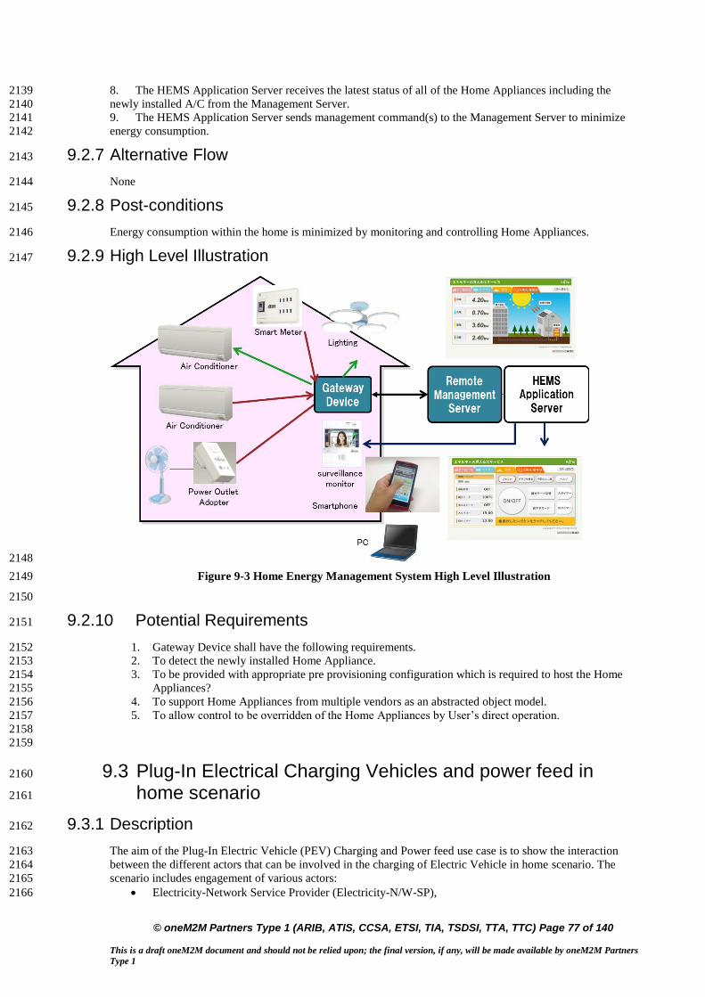
© oneM2M Partners Type 1 (ARIB, ATIS, CCSA, ETSI, TIA, TSDSI, TTA, TTC) Page 77 of 140
This is a draft oneM2M document and should not be relied upon; the final version, if any, will be made available by oneM2M Partners
Type 1
8. The HEMS Application Server receives the latest status of all of the Home Appliances including the 2139
newly installed A/C from the Management Server. 2140
9. The HEMS Application Server sends management command(s) to the Management Server to minimize 2141
energy consumption. 2142
9.2.7 Alternative Flow 2143
None 2144
9.2.8 Post-conditions 2145
Energy consumption within the home is minimized by monitoring and controlling Home Appliances. 2146
9.2.9 High Level Illustration 2147
2148
Figure 9-3 Home Energy Management System High Level Illustration 2149
2150
9.2.10 Potential Requirements 2151
1. Gateway Device shall have the following requirements. 2152
2. To detect the newly installed Home Appliance. 2153
3. To be provided with appropriate pre provisioning configuration which is required to host the Home 2154
Appliances? 2155
4. To support Home Appliances from multiple vendors as an abstracted object model. 2156
5. To allow control to be overridden of the Home Appliances by User’s direct operation. 2157
2158
2159
9.3 Plug-In Electrical Charging Vehicles and power feed in 2160
home scenario 2161
9.3.1 Description 2162
The aim of the Plug-In Electric Vehicle (PEV) Charging and Power feed use case is to show the interaction 2163
between the different actors that can be involved in the charging of Electric Vehicle in home scenario. The 2164
scenario includes engagement of various actors: 2165
Electricity-Network Service Provider (Electricity-N/W-SP), 2166
1

© oneM2M Partners Type 1 (ARIB, ATIS, CCSA, ETSI, TIA, TSDSI, TTA, TTC) Page 78 of 140
This is a draft oneM2M document and should not be relied upon; the final version, if any, will be made available by oneM2M Partners
Type 1
Dedicated Electric Vehicle Charging SP (EVC-SP) who takes care of special functions like the 2167
Demand Response (DR) enablement (cost effective PEV Charging and Power Feed), 2168
PEV-SP in charge of functions related to PEV service and maintenance (providing a data connection 2169
for PEV health purposes such as managing Power Feed cycles, PEV-SW upgrading & remote fault 2170
analysis, etc.) 2171
PEV manufacturer in charge of replacing faulty parts for the PEV 2172
2173
PEV can be considered as a load and also as power storage (DER resource). In the latter case, a Power Feed 2174
from the PEV's battery into the Electricity-N/W is required. 2175
The Electricity-N/W-SP is responsible for the residential homes (smart) metering. Depending on local laws, 2176
the metering for the (Electrical Vehicle Charging Equipment) EVCE may be independent and might be a 2177
physical part of the EVCE. 2178
Depending on the PEV's brand, a parallel wired data connection may be included in the EVCE charging plug 2179
to enable the PEV's controller to access its agreed service and maintenance provider (PEV-SP). In case of no 2180
wired connection (high data rate, e.g. Ethernet), a short reach link, e.g. via ZigBee® or even Bluetooth® may 2181
be established (medium data rate ~2 Mb/s). This connection will then be routed via the EVCE's mobile 2182
broadband link to the PEV-SP's control center in parallel to the charging and power feed control data, which is 2183
routed to the EVC-SP's control center. 2184
2185
Related Standard activities: 2186
TC 69 committee: working on [i.7] ISO/ IEC 15118 parts 1-4, vehicle to grid communication; 2187
currently under development 2188
EU standardisation Mandate 486 to CEN, CENELEC and ETSI (for further information refer to [i.8] 2189
Mandate 486) 2190
Open 2G: using [i.9] DIN specification 70121and [i.7] IEC 15118 2191
DIN specification [i.9] 70121 defines the requirements for the communications between the electric 2192
vehicle (EV) and the charging EVCE). 2193
9.3.2 Source 2194
oneM2M-REQ-2012-0059R02 Plug-In Electric Vehicle Charging (PEV) 2195
Note: from [i.2] ETSI TR 102 935 v2.1.1 2196
9.3.3 Actors 2197
Electricity Network service provider (Electricity N/W-SP/DSO) is responsible for the residential 2198
homes smart metering. 2199
Electricity vehicle charging service provider (EVC-SP) takes care of special functions like the 2200
Demand Response (DR) enablement (cost effective PEV Charging and Power Feed) 2201
PEV service provider (PEV SP) offering functions in conjunction with PEV service and maintenance 2202
(PEV health check and management such as management of power feed cycles, PEV-SW upgrading 2203
& remote fault analysis, etc.) 2204
Communication operator /provider provide the public wireless data service to PEV-SP and EVC SP 2205
control centers. 2206
9.3.4 Pre-conditions 2207
Connection from PEV to EVCE through a wired EVCE plug (data communication) or wirelessly (ZigBee or 2208
Bluetooth) or any short range technology. 2209
Public communication network from EVCE to PEV SP and EVCE SP control centers. 2210
Public communication between EVCE metering and El. N/W SP 2211
9.3.5 Triggers 2212
Control and pricing announcements from El. N/W SP to for example balance the power N/W 2213
Control and pricing trigger/initiate PEV being charged at a particular time with a specific power feed cycle that 2214
is appropriate for consumer (cheaper) and for El. N/W SP (balance power system). 2215
PEV health management through PEV control link to EVCE 2216
e.g. PEV SP initiates health check when PEV is plugged into EVCE for charging; if there is a problem detected 2217
or a PEV part status is over a certain limit, this will trigger a corrective measure according to health check 2218
result (e.g. PEV SP place an order for a part replacement to PEV manufacturer, or SW upgrade, etc.) 2219
EVCE SP will control and manage EVCE through EVCE control link; 2220

© oneM2M Partners Type 1 (ARIB, ATIS, CCSA, ETSI, TIA, TSDSI, TTA, TTC) Page 79 of 140
This is a draft oneM2M document and should not be relied upon; the final version, if any, will be made available by oneM2M Partners
Type 1
9.3.6 Normal Flow 2221
An example flow to show the interaction between PEV SP (PEV health check), PEV manufacturer (PEV 2222
defect part replacement) and EVC SP (metering/charging): 2223
• Red colour to refer to flow related to EVC charging application 2224
• Green colour refer to flow related to PEV SP application 2225
• Blue colour refer to flow related to PEV manufacturer application 2226
2227
2228
2229
Figure 9-4 PEV Normal Flow 2230
2231
1. PEV management application and EVC metering/charging application subscribe to information related to 2232
PEV. 2233
2. 2234
2a. PEV is plugged to EVCE 2235
2b. PEV related information (e.g. PEV1) is sent to communication operator 2236
2c. PEV charging related information (e.g. .charging period) 2237
3. Information sent in step 2 are sent to system operator which trigger the notification in step 4 2238
4. Notifications are sent to the subscribed applications. 2239
5. PEV charging parameters pulled/pushed to the EVC-SP 2240
6. PEV management application sent an initiation of health check message to system operator 2241
7. Initiation message is sent by system operator through communication operator to PEV to start the health 2242
check 2243
8.-9. A PEV part defect is detected and a message is sent to the system operator, which triggers the notification 2244
of the PEV SP 2245
10. System operator is sent a defect Notification to PEV SP application of the car part. 2246
11. Which in turn send an order of the defected part to system operator 2247
12. System operator sends the order to a PEV manufacturer 2248
2249
9.3.7 Alternative Flow 2250
None 2251
9.3.8 Post-conditions 2252
None 2253
System
operatorPE V management
application
1.Subscribe to PEV 2b. PEV attached
4a. Notification
6. Initiate PEV health check
EVCEPEV
communication
operator
4b. PEV attached
EVC SPPEV SP
3b. PEV attached
7. Initiate PEV health check
8. Initiate PEV health check
9. Defect in PEV
car part 10. Defect in PEV
car part 11. Defect in PEV car part
12. Defect in PEV
car part
2a. PEV plugged
2c. PEV
charging
related
parameters
3a. PEV charging
related parameters
EVC
metering/
charging
4C. PEV CHARGING PAARAMETERS notification
5. PEV CHARGING PAARAMETERS

© oneM2M Partners Type 1 (ARIB, ATIS, CCSA, ETSI, TIA, TSDSI, TTA, TTC) Page 80 of 140
This is a draft oneM2M document and should not be relied upon; the final version, if any, will be made available by oneM2M Partners
Type 1
9.3.9 High Level Illustration 2254
2255
Figure 9-5 PEV Charging High Level Illustration 2256
2257
9.3.10 Potential Requirements 2258
1. Secure communication of the following transactions: 2259
i. SW upgrade by PEV manufacturer, 2260
ii. Collecting PEV status info for health check will trigger control or command (e.g. order new part, 2261
trigger to do a car service) to another SP 2262
iii. Collecting charging information (metering) from EVCE i.e. power feed cycle and time and 2263
charging period to the EVC-SP control center (the metering could be home owned smart meter or 2264
Utility owned) 2265
iv. Collection metering info from EVCE (PEV considered as a load or resource), to Electric N/W 2266
provider for billing purposes. Controlling EVCE e.g. SW upgrade, part order 2267
v. Pricing info from Electricity Network SP to EVC SP 2268
vi. Fleet management control center to collect location information of PEV 2269
2. Potential requirements are similar to those of WAMS: 2270
i. Data collection and reporting capability/function including data delivery to multiple applications 2271
ii. Remote control of M2M Devices 2272
iii. Data store and share 2273
iv. Authentication of M2M system with M2M devices/ /collectors 2274
v. Authentication of M2M devices with M2M applications 2275
vi. Data integrity 2276
vii. Prevention of abuse of network connection 2277
viii. Privacy 2278
ix. Security credential and software upgrade at the Application level. 2279
2280

© oneM2M Partners Type 1 (ARIB, ATIS, CCSA, ETSI, TIA, TSDSI, TTA, TTC) Page 81 of 140
This is a draft oneM2M document and should not be relied upon; the final version, if any, will be made available by oneM2M Partners
Type 1
9.4 Real-time Audio/Video Communication 2281
9.4.1 Description 2282
So far, session control and Real-time audio/video communication are taken as basic capabilities in H2H 2283
telecom network. People may think that device does not need to listen or watch something from elsewhere 2284
except itself, thus there is no need for M2M system to support such kinds of human oriented capabilities, 2285
however, this is not the case. The following are some use cases in which session control for real-time 2286
audio/video communication is needed. 2287
2288
Use Case 1: Home Surveillance 2289
One person, when travelling far from home, would like to use the application installed on his/her cell phone or 2290
pad computer to monitor his/her house, via the cameras fixed inside or outside his/her house. In the case the 2291
person makes a call to the camera through his/her cell phone or pad computer requesting for image/video 2292
transmission, the camera can answer the call request and automatically start transmission of images/video 2293
captured by the camera. 2294
The camera may be able to initiate an audio/video call or send messages for alarm addressing to the cell phone 2295
of the person in the case there are abnormal images captured by the camera, e.g. the image changes or the 2296
camera are moved. The cameras can communicate with other M2M devices via wired or wireless network. The 2297
communication can be between the M2M application on the M2M device and the M2M application applied in 2298
a service center which provides home surveillance service to the users. 2299
In order to have a clearer look at the images captured by the cameras, some commands can be sent to the 2300
camera to adjust some parameters on the cameras, e.g. tilt, zoom in/out, adjust the focus, initiate recording, and 2301
so on. For easy and better control of the camera along with the video transmission, the commands can be 2302
transported within the same session as for video transmission. It is assumed that standalone session can be 2303
created to control the cameras as well. 2304
The cell phone can also start calling the camera automatically according to some predefined rules. For 2305
example, the cell phone calls the camera and records the audio/video information automatically every night 2306
while the owner is sleeping. 2307
2308 Use Case 2: Doorbell Controller 2309
One person, when he/she is away from home, his/her children or parents may forget to take the keys and lock 2310
them from entering into the house. After they push the door bell or door controller with cameras equipped, the 2311
application installed on the door bell or door controller may initiate a video call to the person’s cell phone in 2312
which it shows who are standing before the door, and once the user answers the call reaching his/her cell 2313
phone, the door will open. 2314
Also, when the motion detector equipped near the doorbell detects some abnormal movements near the door, 2315
the motion detector notifies the doorbell with a camera to start a call to the owner’s cell phone. When the 2316
owner answers the phone, he/she will be able to make sure if the movements are normal. 2317
2318
Use Case 3: Customized Home Service 2319
One person, when he/she is away from home, he/her may use his/her mobile device to coordinate appointments 2320
using calendar application or to search information on internet. His/her mobile device also can trace its 2321
location using GPS. By collecting the information, his/her life pattern/context and interests can be analyzed. 2322
2323
Using well-analyzed information, a service provider can provide user- customized home service with home 2324
appliances which have capability of showing video or playing audio like smart television or smart refrigerator. 2325
2326
He/she may come back to home and turn on TV. Channels would be recommended based on analyzed data of 2327
his/her preference. Then commercial advertisement on TV would be shown regarding of his/her interest and 2328
personal information. 2329
9.4.2 Source 2330
oneM2M-REQ-2013-0281R02 Use Case real time audio video communication 2331
oneM2M-REQ-2013-0398R01 Use Case of Additional audio video 2332
2333
9.4.3 Actors 2334
M2M Service Provider: 2335

© oneM2M Partners Type 1 (ARIB, ATIS, CCSA, ETSI, TIA, TSDSI, TTA, TTC) Page 82 of 140
This is a draft oneM2M document and should not be relied upon; the final version, if any, will be made available by oneM2M Partners
Type 1
A company that provides M2M service including one or more of the entities e.g. devices with camera, 2336
oneM2M platform and service center for surveillance and alarm reaction. 2337
2338
Service Centre: 2339
The service center provides home surveillance and other corresponding services, e.g. initiating an audio/video 2340
call to the host of the home in case there are intruders or initiating a multimedia conference call for 2341
consultation for a patient. 2342
9.4.4 Pre-conditions 2343
Before the audio/video call could be set up, the following steps are to be taken: 2344
The Devices are configured with the number/address to which an audio/video call can be initiated for 2345
alarm 2346
The oneM2M system allocates unique identifiers for the devices 2347
The devices need to be registered in the oneM2M system 2348
9.4.5 Triggers 2349
None 2350
9.4.6 Normal Flow 2351
1. The device registers in oneM2M system. 2352
2. When receiving request towards or from the device for an audio/video call, the oneM2M system 2353
authorizes if the originator is allowed to send the request. 2354
3. If it is allowed, the oneM2M system route the message accordingly and create a connection between the 2355
originator and the receiver for real-time audio and video transfer, and even commands for camera control. 2356
4. After the communication is completed, the oneM2M system releases the connection and resources. 2357
9.4.7 Alternative Flow 2358
None 2359
9.4.8 Post-conditions 2360
None 2361
9.4.9 High Level Illustration 2362
2363
Figure 9-6 High Level Illustration of Real-time Audio/Video Communication 2364
9.4.10 Potential Requirements 2365
1. The oneM2M system shall provide a capability to allocate unique identifiers to devices for 2366
identification and session routing in oneM2M system. 2367
2. The oneM2M system shall support to establish and terminate real-time audio/video session between 2368
M2M applications. 2369
oneM2M system
DeviceDevice Device
Smart Phone/Service Centre
session control for audio/video communication
audio/video data packet

© oneM2M Partners Type 1 (ARIB, ATIS, CCSA, ETSI, TIA, TSDSI, TTA, TTC) Page 83 of 140
This is a draft oneM2M document and should not be relied upon; the final version, if any, will be made available by oneM2M Partners
Type 1
3. The oneM2M system shall provide a capability for a device to be registered in the system. 2370
4. The oneM2M system shall support authorization if a request to and from the device for real-time 2371
audio/video call establishment is allowed. 2372
5. The oneM2M system shall provide a capability for routing a request for real-time audio/video call 2373
establishment from or to the device. 2374
6. The oneM2M system shall provide a capability for media control (e.g. negotiation of transcoding, 2375
QoS) between the M2M applications for real-time audio/video data packet transmission. 2376
2377
2378
9.5 Event Triggered Task Execution Use Case 2379
9.5.1 Description 2380
Gateway Device may be required to configure for executing some tasks which are triggered by pre-defined 2381
events. 2382
9.5.2 Source 2383
oneM2M-REQ-2013-0176R03 Event Triggered Task Exec Use Case 2384
REQ-2015-0596 Event Trigger Use Case Revise 2385
9.5.3 Actors 2386
Management Server, 2387
Gateway Device which has the characteristic both M2M Gateway (aggregate measured value) and M2M 2388
Device (accepting setting change), 2389
Thermometer and Air Conditioner (M2M Device), 2390
Data Storage Server, 2391
User 2392
9.5.4 Pre-conditions 2393
Gateway Device is configured to work as the gateway for collecting data from some sensor devices 2394
installed at home network. 2395
Sensor Devices are configured to accept the management request from Gateway Device which requests 2396
reporting measured data on demand 2397
9.5.5 Triggers 2398
M2M System is going to configure Gateway Device for scheduling task execution for data collection from 2399
sensor devices. 2400
9.5.6 Normal Flow 2401
1. Management Server requests management on scheduling task settings of Gateway Device to fetch the 2402
current value of the thermometer, and report collected data from a thermometer (one of the Sensor Devices 2403
in this use case) every 30 minutes. 2404
2. Gateway Device establishes the connection to the thermometer, and collects measured data. 2405
3. Gateway Device reports the collected data to Data Storage Server. 2406
9.5.7 Alternative Flow 2407
Alternative Flow 1 2408
1. (after step 2 in normal flow,) Gateway Device stores series of measured data associating with the 2409
source Sensor Device. 2410
2. Management Server requests Gateway Device to report the log data which summarize series of 2411
measured data by Sensor Devices for one day. 2412
2413
Alternative Flow 2 2414

© oneM2M Partners Type 1 (ARIB, ATIS, CCSA, ETSI, TIA, TSDSI, TTA, TTC) Page 84 of 140
This is a draft oneM2M document and should not be relied upon; the final version, if any, will be made available by oneM2M Partners
Type 1
1. Management Server configures the M2M Application on the Gateway Device to start monitoring 2415
energy consumption of Air Conditioner, when the device is turned on, and to stop monitoring when 2416
that is turned off. 2417
2. M2M Application on the Gateway Device subscribes requests notification on the power status change 2418
of Air Conditioner. 2419
3. When the user turned on the Air Conditioner, the Gateway Device is notified by event notifition for 2420
the status change. 2421
4. M2M Application on the Gateway Device starts monitoring the energy consumption of the Air 2422
Conditioner. 2423
5. When User turned off the Air Conditioner, the M2M Application on the Gateway Device is notified 2424
the status change 2425
6. Gateway Device stops monitoring the energy consumption of the Air Conditioner. 2426
2427
Alternative Flow 3 2428
1. Management Server configures the M2M Application on the Gateway Device to report the energy 2429
consumption when the total energy consumption exceeded over the 20kW per day. 2430
2. M2M Application on the Gateway Device keeps collecting data about energy consumption from 2431
home electronics (i.e. Air Conditioner). 2432
3. When the total energy consumption exceeded over the 20kW per day, the M2M Application on the 2433
Gateway sends notify the report to the Data Storage Server. 2434
2435
9.5.8 Post-conditions 2436
Collected data is stored on the Data Storage Server for further use 2437
9.5.9 High Level Illustration 2438
2439
Figure 9-7 Event triggered Task Execution High Level Illustration 2440
2441
9.5.10 Potential Requirements 2442
1. M2M System Shall support timer triggered data collection on M2M Gateway from M2M Device. 2443
2. M2M System Shall support M2M Gateway which reports collection of data measured by M2M 2444
Device. 2445
3. M2M System Shall support to start/stop monitoring measured data by M2M Device triggered by 2446
status change of M2M Device to be monitored. 2447
4. M2M System Shall support conditional report from M2M Gateway which reports measured data by 2448
M2M Device(s). The condition can be expressed as event notification message which is triggered by 2449
M2M Application which is monitoring threshold and/or size of value change. 2450
2451

© oneM2M Partners Type 1 (ARIB, ATIS, CCSA, ETSI, TIA, TSDSI, TTA, TTC) Page 85 of 140
This is a draft oneM2M document and should not be relied upon; the final version, if any, will be made available by oneM2M Partners
Type 1
9.6 Semantic Home Control 2452
9.6.1 Description 2453
This use case demonstrates co-operation between two independent M2M applications. The co-operation is 2454
made possible because one application can find the other application through semantic information about the 2455
application’s resources. This semantic information is available in the M2M System. 2456
One application is a building management system (BMS) for a big apartment house. The BMS is operated by a 2457
building manager, e.g. the owner of the apartment house. BMS has knowledge about the blueprints of all the 2458
apartments in the house, e.g. it knows which heater is located in which room (heaters are assumed to be 2459
equipped with temperature sensors/actuators). 2460
The other application is a home energy management system (HEMS). It has been subscribed by the tenant of 2461
one of the apartments. HEMS controls the heaters of the apartment (among other purposes). 2462
Because HEMS can find the resources of BMS – e.g. the resource that represents the tenant’s apartment and 2463
the heaters therein HEMS can configure itself automatically (and can adapt to changes over time) and doesn’t 2464
require human configuration. 2465
Finding the right resources in the M2M System is made possible through semantic annotation of the resources 2466
9.6.2 Source 2467
oneM2M-MAS-2013-0020 Semantic use cases from ETSI Semantics TR 2468
9.6.3 Actors 2469
Building manager: is running a Building management system (BMS) for his apartment house. 2470
Tenant of an apartment: has subscribed to a home energy management system (HEMS) for his apartment. 2471
M2M service provider: is providing access to the M2M System for both applications, BMS and HEMS. 2472
Building management system (BMS): is a M2M network application. 2473
Home energy management system (HEMS): is a M2M network application. 2474
2475
9.6.4 Pre-conditions 2476
The Building management system (BMS) is an M2M application that contains all the information needed to 2477
manage a large apartment house. In particular it contains the construction details of the tenant’s apartment, 2478
where the doors and windows are located, where the heaters are, their capacity, etc. The BMS is used for 2479
overall control of the building, but information relevant for individual apartments (e.g. control of the heaters, 2480
built-in sensors for windows and doors) can be made available to authorized tenants. In case of fire, the 2481
complete blueprint of the house can be made available to fire-fighters. 2482
In the M2M System the BMS makes its information available as M2M resources, similar to as if they were 2483
data transmitted by a device. E.g. the complete apartment, individual rooms, their heaters and windows could 2484
be represented as M2M resources. 2485
A new tenant is renting an apartment in the house. As he is moving in, he also subscribes to a general-purpose 2486
home energy management system (HEMS) that promised a very efficient heater control. E.g. the HEMS 2487
always uses the best available electricity tariff and the heating is turned off when windows are open. 2488
As part of the subscription, the HEMS is granted access to the respective resources used by the BMS in the 2489
M2M system. In particular, the building manager has permitted access of the tenant’s HEMS to those 2490
resources of the BMS that are needed for energy management of the tenant’s apartment (rooms, heaters, door-2491
and window sensors, etc.). Other resources not needed for this task are not exposed to the HEMS. 2492
9.6.5 Triggers 2493
None 2494
9.6.6 Normal Flow 2495
The newly subscribed HEMS will immediately start discovering new devices in the apartment. Once the BMS 2496
has granted access, the HEMS will discover the resources of the BMS that are related to the apartment. Using 2497
the semantic description of the devices the HEMS can immediately find out about the available rooms, heaters, 2498
temperature sensors, etc. With this knowledge it can configure itself without any human intervention. 2499
Since the BMS has configured its devices to be represented in the M2M System as abstract devices, the HEMS 2500
can use this information to immediately control the devices using the offered abstract command set. 2501

© oneM2M Partners Type 1 (ARIB, ATIS, CCSA, ETSI, TIA, TSDSI, TTA, TTC) Page 86 of 140
This is a draft oneM2M document and should not be relied upon; the final version, if any, will be made available by oneM2M Partners
Type 1
Consequently, HEMS does not have to understand the specifics (e.g. specific protocol) of a particular heater 2502
control. 2503
Later, the building manager installs a new device into the tenant’s apartment which can help in efficient energy 2504
management. This new device is also managed by BMS. Using the selection rule of the HEMS service, the 2505
new device will get immediately available to the HEMS. The HEMS will discover the new device and will use 2506
it to control the apartment’s energy consumption. 2507
9.6.7 Alternative Flow 2508
None 2509
9.6.8 Post-conditions 2510
None 2511
9.6.9 High Level Illustration 2512
None 2513
2514
9.6.10 Potential Requirements 2515
1. The M2M System shall support a common (e.g. per vertical domain) semantic data model (e.g. 2516
represented by Ontology) available to M2M application. 2517
2. The M2M System shall provide discovery capabilities that enable the discovery of M2M resources 2518
based on their semantic information, e.g. semantic categories and relationship among them. (e.g. all 2519
heaters and windows in a room; the room in which a window is located…). 2520
3. The M2M System shall provide representation and discovery functionality of real-world entities 2521
(rooms, windows) that are not necessarily physical devices. 2522
4. The M2M system shall be able to map control commands issued towards an abstract device to the 2523
concrete commands of a specific device. 2524
2525
9.7 Semantic Device Plug and Play 2526
9.7.1 Description 2527
This use case applies with any verticals, below just take home automation as an example. The use case is about 2528
when a device is newly registered in a home, it will find its own character and its relationship with its 2529
neighbour devices and Things automatically based on semantic information within the M2M system without 2530
the interference of human being. For example, the house owner bought a lamp and a switch to the lamp for his 2531
house. Both the lamp and switch is enabled with wireless abilities to be able to communicate with the home 2532
automation gateway and other devices. The lamp is for the lobby and accordingly the switch is located near the 2533
entrance of the lobby. When the house owner has placed the lamp and the switch properly, a simple power-on 2534
would make the lamp and the switch work fine. 2535
9.7.2 Source 2536
oneM2M-MAS-2013-0020 Semantic use cases from ETSI Semantics TR 2537
2538
9.7.3 Actors 2539
Home automation service provider: is providing home automation service by providing applications 2540
running on home automation devices such as gateway, lamp, switch, TV, air-condition etc. 2541
Home automation management system (HAMS): is a network application. 2542
Device manufacturer: produces devices as M2M nodes. 2543
M2M service provider: provides M2M service acts as a platform where all M2M nodes can register to. 2544
House owner: is a consumer of the home automation service. 2545

© oneM2M Partners Type 1 (ARIB, ATIS, CCSA, ETSI, TIA, TSDSI, TTA, TTC) Page 87 of 140
This is a draft oneM2M document and should not be relied upon; the final version, if any, will be made available by oneM2M Partners
Type 1
9.7.4 Pre-conditions 2546
The house owner has a contract with the home automation service provider for the home automation service. 2547
The home automation service provider has a business relationship with the M2M service provider and the 2548
device manufacturer. The home automation management system manages all the devices and their 2549
relationships registered in the house. Each device has its role and serves fixed services among all home 2550
devices. 2551
9.7.5 Triggers 2552
None 2553
9.7.6 Normal Flow 2554
When the house owner buys new devices for his house, the newly bought devices will register to the M2M 2555
service provider and expose to the M2M SP its role and functionalities including their semantic descriptions. 2556
According to such information, the HAMS will compare the semantic description of the new device with the 2557
semantic description of the existing devices in the house and judge their relationships by semantic inference. 2558
Then the HAMS will help establish the relationship between the new device and the device in the home and 2559
the relationship is maintained in the M2M SP. For example the HAMS finds that the lamp is to be controlled 2560
by the switch, it may then bind the status of the switch to the action of the lamp. If the status of the switch is 2561
ON, an “ON” command will be sent to the lamp automatically. 2562
9.7.7 Alternative Flow 2563
None 2564
9.7.8 Post-conditions 2565
None 2566
9.7.9 High Level Illustration 2567
None 2568
9.7.10 Potential Requirements 2569
1. The M2M System shall support a semantic data model that is at least common to the vertical industry 2570
in which a Thing is used to describe Things registered in the M2M System. 2571
2. The M2M entity shall be able to expose its semantic description to the M2M System. 2572
3. If a Thing is capable to expose semantic information to the M2M System the M2M System shall be 2573
able to use that information to represent the Thing. 2574
4. The M2M System shall be able to describe the semantic relationship between Things. 2575
2576
9.8 Triggering in the Field Domain 2577
- void – 2578
2579
Note: This use case can be found in TR-0013 [i.19] 2580
Source: REQ-2014-0447 Use case for Triggering in Field Domain 2581
2582
2583
2584

© oneM2M Partners Type 1 (ARIB, ATIS, CCSA, ETSI, TIA, TSDSI, TTA, TTC) Page 88 of 140
This is a draft oneM2M document and should not be relied upon; the final version, if any, will be made available by oneM2M Partners
Type 1
10 Retail Use Cases 2585
10.1 Vending Machines 2586
10.1.1 Description 2587
In some situations, vending machine providers need to limit the network access for vending machines based on 2588
their geographic location. The providers do NOT want the vending machine user to move the machine from 2589
the specified area to other locations (potentially for better sales), so that the providers can control the 2590
geographic distribution of their vending machines and make decisions based on data statistics and analysis 2591
(e.g. which are the best selling areas? How many products are sold in specified areas during specified time? 2592
(and so on). 2593
10.1.2 Source 2594
REQ-2014-0466R05 Use case for vending machine 2595
10.1.3 Actors 2596
Vending machine, which can automatically sell products and report data information to the application 2597
platform through M2M service platform 2598
The M2M service platform, which can control the vending machine device and its access to the network 2599
Vending machine application platform, which can accept the data report from vending machine, monitor 2600
its status, and perform data analysis. 2601
10.1.4 Pre-conditions 2602
The location information of the Vending machine is provided to the M2M Service platform by the Underlying 2603
network. 2604
10.1.5 Triggers 2605
Vending machine restarts and registers to M2M service platform 2606
Vending machine reports data information (e.g., each sale transaction or products selling information and 2607
so on). 2608
10.1.6 Normal Flow 2609
The vending machine restarts and registers to M2M service platform. 2610
The M2M service platform checks the geographic location policy. If current geographical location of the 2611
vending machine is in the permitted area, it allows the vending machine to register. Otherwise, it denies 2612
access. 2613
After vending machine successfully registers, it reports data information (for example, the product selling 2614
information and the stock information) periodically or for each product sale to the vending machine 2615
application platform through M2M service platform. 2616
The M2M service platform checks the geographic location policy. If the current geographic location of the 2617
vending machine is in the permitted area, it allows for the data report. Otherwise, it will be denied. 2618
The vending machine application platform receives the data information report, records the information 2619
and performs data analysis. 2620
10.1.7 Alternative Flow 2621
None 2622
10.1.8 Post-conditions 2623
None 2624
10.1.9 High Level Illustration 2625
2626

© oneM2M Partners Type 1 (ARIB, ATIS, CCSA, ETSI, TIA, TSDSI, TTA, TTC) Page 89 of 140
This is a draft oneM2M document and should not be relied upon; the final version, if any, will be made available by oneM2M Partners
Type 1
2627
Figure 10-1 – High level illustration of Vending Machines use case 2628
2629
10.1.10 Potential Requirements 2630
1. The M2M service platform shall be able to support the geographic location-based network access 2631
policy. (see also requirement OSR-047) 2632
2. The M2M service platform shall be able to support a geographical boundary within a network access 2633
policy. (see also requirement OSR-047) 2634
2635
11 Transportation Use Cases 2636
11.1 Vehicle Diagnostic & Maintenance Report 2637
- void – 2638
2639
Note: This use case can be found in TR-0026 [i.22]. 2640
Source: oneM2M-REQ-2012-0067R03 Vehicle Stolen and Vehicle Diagnostics 2641
2642
2643
11.2 Use Case on Remote Maintenance Services 2644
- void – 2645
2646
Note: This use case can be found in TR-0026 [i.22]. 2647
Source: oneM2M-REQ-2013-0188R06 Use Case Remote Maintenance 2648
2649
2650
11.3 Traffic Accident Information Collection 2651
- void – 2652
2653
Note: This use case can be found in TR-0026 [i.22]. 2654
Source: oneM2M-REQ-2013-0264R05 Use Case Traffic Accident Information Collection 2655
Note: From [i.10] ETSI TR 102 638 2656
2657
11.4 Fleet Management Service using DTG (Digital 2658
Tachograph) 2659
- void – 2660
2661
Note: This use case can be found in TR-0026 [i.22]. 2662
Source: oneM2M-REQ-2013-0219R01 Use case – Fleet management using DTG 2663

© oneM2M Partners Type 1 (ARIB, ATIS, CCSA, ETSI, TIA, TSDSI, TTA, TTC) Page 90 of 140
This is a draft oneM2M document and should not be relied upon; the final version, if any, will be made available by oneM2M Partners
Type 1
2664
2665
11.5 Use cases for Electronic Toll Collection (ETC) service 2666
2667
- void – 2668
2669
Note: This use case can be found in TR-0026 [i.22]. 2670
Sources: 2671
REQ-2014-0431R03 Use cases for Electronic Toll Collection (ETC) service 2672
REQ-2014-0449R02 Use cases for Electronic Toll Collection (ETC) service 2673
2674
2675
11.6 Use cases for Taxi Advertisement 2676
- void – 2677
2678
Note: This use case can be found in TR-0026 [i.22]. 2679
Source: REQ-2014-0467R02 Use case for taxi advertisement 2680
2681
2682
11.7 Use Case on Vehicle Data Service 2683
2684
- void – 2685
2686
Note: This use case can be found in TR-0026 [i.22]. 2687
Source: REQ-2014-0472R06 Use Case on Vehicle Data Services 2688
2689
2690
2691
11.8 Smart Automatic Driving 2692
- void – 2693
2694
Note: This use case can be found in TR-0026 [i.22]. 2695
Source: REQ-2015-0554-Smart Automatic Driving 2696
2697
2698
2699
11.9 Use Case on Vehicle Data Wipe Service 2700
- void – 2701
2702
Note: This use case can be found in TR-0026 [i.22]. 2703
Source: REQ-2015-0589R04 Usecase on vehicle data wipe service 2704
2705
2706
2707

© oneM2M Partners Type 1 (ARIB, ATIS, CCSA, ETSI, TIA, TSDSI, TTA, TTC) Page 91 of 140
This is a draft oneM2M document and should not be relied upon; the final version, if any, will be made available by oneM2M Partners
Type 1
12 Other Use Cases 2708
12.1 Extending the M2M Access Network using Satellites 2709
12.1.1 Description 2710
This Use Case demonstrates a scenario that extends the M2M access network using satellite communications. 2711
It serves to emphasize that satellite communication is a key component of the network domain to be 2712
incorporated in future requirements work at OneM2M on Smart Metering and other M2M use cases. 2713
In locations that are difficult to reach with fixed-line or cellular communications, a machine-to-machine 2714
(M2M) satellite solution extends terrestrial coverage and provides access to devices that require remote 2715
monitoring and control. Satellite-based communication networks provide communications that integrate 2716
seamlessly with any remote IP based application. Satellite networks offer IP connectivity, ubiquitous real time 2717
coverage, robust security, high availability compared to cellular networks. Satellite M2M solutions are also 2718
much more cost-effective than some years due to advances in satellite technology. 2719
Traditional satellite communications has had a stigma of being expensive and requiring large, power-hungry 2720
terminals too complex to integrate with applications. Modern satellite networking, however, provides 2721
competitive price solutions, ubiquitous coverage, and a high level of availability which compliment terrestrial 2722
networks. For this reason, it is important to consider satellite services for Supervisory Control and Data 2723
Acquisition (SCADA) applications, low data rate (LDR) solutions, and other remote, unmanned machine-to-2724
machine (M2M) services. 2725
12.1.2 Source 2726
oneM2M-REQ-2012-0061R02 Use Case Smart Metering with Satellite Communications 2727
12.1.3 Actors 2728
Service Providers for M2M 2729
12.1.4 Pre-conditions 2730
The following additional functionalities or sub scenarios are explained in a high level format, to relate to 2731
electricity, gas, heating, and water. 2732
2733
1. Distribution Automation 2734
Deploying satellite M2M services along power distribution lines, as a supporting link, allows electrical utility 2735
providers to connect to their data centers and extend their network reach to the boundaries of their entire 2736
service territory, improving decision-making and operational efficiencies. A single, two-way IP data 2737
connection provides automated monitoring and control of re-closers, switches, or other distribution devices – 2738
anywhere - enabling utility providers to maintain continuous surveillance and control of their distribution 2739
network for voltage fluctuations, outages and service demands. 2740
2741
2. Substation Connectivity 2742
M2M Satellite communications provide services for electricity substations in locations that may be difficult to 2743
reach with fixed-line or cellular communications. 2744
M2M Satellite communications contains the flexibility to cope with both low-volume high-frequency traffic 2745
and bursts of high-volume, low-frequency traffic. If a primary link breaks down, satellite communications can 2746
automatically provide backup communications at any substation. 2747
2748
3. Disaster Recovery 2749
Business continuity is vital for utilities that provide essential services such as electricity, water and gas to 2750
millions of people as they need to be able to recover immediately from natural or manmade disasters. When a 2751
catastrophic event causes terrestrial networks to fail, utilities companies can rapidly deploy satellite terminals 2752
to provide an alternative communications path, enabling them to maintain communications, diagnose issues 2753
quickly, and run critical applications. 2754
12.1.5 Triggers 2755
The need to access M2M user devices (UDs) that may not be reachable with terrestrial and wireless networks. 2756

© oneM2M Partners Type 1 (ARIB, ATIS, CCSA, ETSI, TIA, TSDSI, TTA, TTC) Page 92 of 140
This is a draft oneM2M document and should not be relied upon; the final version, if any, will be made available by oneM2M Partners
Type 1
12.1.6 Normal Flow 2757
An example of a M2M communication using satellite service is Smart Metering (valves, electricity meter, gas 2758
meter, water meter, and heat meter). Smart Metering devices over a small area connect to aggregation points or 2759
Smart Meter Concentrators via a local, meshed wireless network. These aggregation points, or concentrators, 2760
collect usage data and distribute control data to and from consumers in a limited geographical area, 2761
transmitting it back to the utility’s data center (Figure 12-1). 2762
The satellite connectivity backhauls Smart Meter data from a satellite antenna mounted on an Advanced 2763
Metering Infrastructure (AMI) concentrator to the utility’s data center. Each AMI concentrator links to 2764
multiple smart meters via a local wireless network. 2765
In this configuration example, satellite communications co-locate with the primary gateway communication to 2766
aggregate meter data at the gateway, extending the network reach across a utility’s entire service. 2767
12.1.7 Alternative Flow 2768
None 2769
12.1.8 Post-conditions 2770
None 2771
12.1.9 High Level Illustration 2772
2773
Figure 12-2 Extended Smart Metering Configuration (source: ETSI) 2774
12.1.10 Potential Requirements 2775
1. Satellite access shall be considered in all M2M network domain architectures. 2776
2777
2778
2779

© oneM2M Partners Type 1 (ARIB, ATIS, CCSA, ETSI, TIA, TSDSI, TTA, TTC) Page 93 of 140
This is a draft oneM2M document and should not be relied upon; the final version, if any, will be made available by oneM2M Partners
Type 1
12.2 M2M Data Traffic Management by Underlying Network 2780
Operator 2781
12.2.1 Description 2782
According to the data traffic condition, e.g. current traffic congestion status, in underlying networks, the 2783
underlying network operators (e.g. mobile network operators) would like to manage the M2M data traffic in 2784
their networks in conjunction with M2M service platform and/or M2M application server providers in order to 2785
avoid losing the M2M communication data packets in the networks. 2786
The M2M service platform and/or M2M application server providers will change their configuration such as 2787
data transmission interval or stop sending data over the underlying networks for some duration after receiving 2788
the notification from underlying networks. 2789
This use case illustrates handling of M2M data transmission based on the data traffic condition information of 2790
underlying network and interworking among the M2M service application server, M2M platform and the 2791
underlying network. 2792
12.2.2 Source 2793
oneM2M-REQ-2013-0175R03 Use Case on M2M data traffic management by underlying network operator 2794
2795
12.2.3 Actors 2796
The M2M application server providing data transmission control according to the data traffic condition of 2797
underlying network 2798
The application server has functions to receive data traffic condition information from the M2M platforms 2799
and/or the underlying networks, and control M2M data transmissions according to the received 2800
information. 2801
The M2M service platform providing data transmission control according to the data traffic condition 2802
information of underlying networks 2803
The M2M service platform has functions to receive the data traffic condition information from the 2804
underlying networks, and/or control M2M data transmissions according to the information. 2805
The underlying network providing the data traffic condition information 2806
The underlying network has functions to send the data traffic condition information to M2M application 2807
servers, M2M service platforms, and/or M2M devices. 2808
The data traffic condition information includes required transmission interval, required maximum data 2809
rate, required maximum data volume, current traffic congestion status, congested network area 2810
information etc. 2811
The M2M device providing data transmission control according to the data traffic condition information 2812
The M2M device to receive the data traffic condition information from the underlying networks or M2M 2813
service platforms, and control M2M data transmissions. 2814
12.2.4 Pre-conditions 2815
The underlying network monitors the status of the data traffic, analyze the status, define the traffic condition 2816
and provides the data traffic condition information to M2M application servers, M2M platforms and/or M2M 2817
devices. 2818
12.2.5 Triggers 2819
None 2820
12.2.6 Normal Flow 2821
Normal Flow 1: 2822
1. The mobile network sends the data traffic condition information to the M2M service platform and/or 2823
M2M application server. 2824
2. After the M2M service application server receives the data traffic condition information from the 2825
underlying network in step1, and it controls M2M data transmission accordingly. 2826

© oneM2M Partners Type 1 (ARIB, ATIS, CCSA, ETSI, TIA, TSDSI, TTA, TTC) Page 94 of 140
This is a draft oneM2M document and should not be relied upon; the final version, if any, will be made available by oneM2M Partners
Type 1
3. After the M2M application service platform receives the data traffic condition information from the 2827
underlying network in step 1 via the M2M service platform, it and controls M2M data transmissions 2828
accordingly. 2829
4. The M2M service platform may send M2M data transmission configuration information to the M2M 2830
device. 2831
5. After the M2M device may receive M2M data transmission configuration information from the M2M 2832
service platform in step 4, it and may controls M2M data transmissions accordingly. 2833
2834
2835
Figure 12-3 Normal Flow 1 of Data Traffic Management by Underlying Network Operator 2836
2837
Normal Flow 2: 2838
1. The underlying mobile network sends the data traffic condition information to the M2M device as 2839
well as M2M service platform. 2840
2. Upon receiving the information, the M2M device re-configures the application behaviour, e.g. the 2841
interval extension of communication, by M2M service layer capability. The re-configuration profile 2842
may be statically stored or can be overwritten by control from the M2M service platform. 2843
3. Upon receiving the information, the M2M service platform controls M2M data transmission 2844
accordingly in cooperation with M2M service application server described in step 1 to step 3 in 2845
normal flow 1. 2846
2847
2848
2849
Figure 12-4 Normal Flow 2 of Data Traffic Management by Underlying Network Operator 2850
13.1.1 1
2
3
4
5
6
7
8
9
M2M service platform
Underlying network
M2M device
1
4
1
5
2
M2M application server 3

© oneM2M Partners Type 1 (ARIB, ATIS, CCSA, ETSI, TIA, TSDSI, TTA, TTC) Page 95 of 140
This is a draft oneM2M document and should not be relied upon; the final version, if any, will be made available by oneM2M Partners
Type 1
12.2.7 Alternative Flow 2851
None 2852
12.2.8 Post-conditions 2853
None 2854
12.2.9 High Level Illustration 2855
2856
Figure 12-5 High Level Illustration of Data Traffic Management by Underlying Network Operator 2857
2858
12.2.10 Potential Requirements 2859
1. The M2M service platform SHALL be able to receive the data traffic condition information from the 2860
Underlying network and notify it to the M2M application server. The M2M application server 2861
SHALL be able to control M2M data transmission based on the Underlying Network data traffic 2862
condition. 2863
2. The M2M service platform MAY SHALL be able to control M2M data transmission based on the 2864
Underlying Network data traffic condition. 2865
3. The M2M device SHALL be able to control M2M data transmission based on the Underlying 2866
Network data traffic condition. 2867
4. The M2M device SHALL control M2M application behavior implemented on top of M2M service 2868
layer when the M2M device received notification regarding Underlying Network data traffic 2869
condition from the Underlying Network. 2870
2871
2872

© oneM2M Partners Type 1 (ARIB, ATIS, CCSA, ETSI, TIA, TSDSI, TTA, TTC) Page 96 of 140
This is a draft oneM2M document and should not be relied upon; the final version, if any, will be made available by oneM2M Partners
Type 1
12.3 Optimized M2M interworking with mobile networks 2873
(Optimizing connectivity management parameters) 2874
12.3.1 Description 2875
Background on the use case and current state in 3GPP. 2876
M2M Services, due to their nature (generally not involving human conversations), will most likely create much 2877
lower Average Revenue Per User (ARPU) to an Underlying mobile Network than ordinary Human-to-Human 2878
traffic. 2879
Since M2M services, and in particular the oneM2M standard, relies on Underlying Networks (often mobile 2880
networks) the success of M2M will inevitably depend on the fact that M2M traffic in the underlying network 2881
will compete with human-to-human traffic; both, technically (use of resources) and economically (ARPU). 2882
If M2M traffic in the Underlying Network would not be competitive with human-to-human traffic then a 2883
significant sector of M2M services – i.e. those with low ARPU – could not be realized. 2884
To enable economically feasible M2M business e.g. 3GPP seeks to reduce the costs – impact of traffic to the 2885
network and the consumption of radio resources – that M2M devices will create for their networks. 2886
E.g. already as early as in 2008 3GPP has created a first set of requirements on Machine Type 2887
Communications (MTC) in [i.11] TS 22.386. These were finally approved in 3GPP Rel-10 (2010). 2888
However, due to the (at the current point in time) low priority of M2M business for 3GPP Networks only 2889
limited work has been done in 3GPP architecture, radio- and protocol groups until now. 2890
E.g. only 2 out of 4 building blocks: MTCe-SDDTE (Small Data and Device Triggering Enhancements) and 2891
MTCe-UEPCOP (UE Power Consumption Optimizations) have been prioritized by SA2 to be handled in 2892
current 3GPP Rel-12. 2893
SA2 (architecture) normative work can be found in [i.12] TS 23.682, the architecture study in [i.13] TR 23.887 2894
We believe - and hope - that when in a few years 3GPP Rel-12/13 networks will be in operation then M2M 2895
traffic will have a significant share in 3GPP networks. Therefore it is crucial that oneM2M expresses its needs 2896
and potential impact to 3GPP now. 2897
OneM2M, representing a high level of expertise in M2M business, needs to actively offer support to 3GPP and 2898
other Underlying Network technologies. 2899
Overview of the use case 2900
Many mobile data applications are characterized by transmission of small data packets. Frequent small data 2901
transmission may cause the network load by the mobile terminal changing frequently between idle and 2902
connected state, if the terminal returns to idle mode soon after the data transmission. On the other hand, when 2903
the mobile terminal is kept connected state unnecessarily (if normal operation involves only small data 2904
transmission), it has impact on mobile terminal power consumption and radio resources consumption. 2905
In order to reduce both, the control load related to the state transition and the consumption of radio resources, 2906
the mobile network (e.g. 3GPP) needs to adjust configuration parameters (the connect keep timer, the radio 2907
reception interval, etc.) based on the data transmission interval (frequent or infrequent) of the mobile terminal. 2908
It is important for a mobile network to be informed about a change of data transmission interval of a M2M 2909
device which is handled or monitored on service layer. However, such a change of data transmission interval is 2910
not easily detected by the mobile network. 2911
This use case illustrates detection of a change of data transmission interval on service layer and notification to 2912
the mobile network by interworking between the M2M service platform and the mobile network. 2913
12.3.2 Source 2914
oneM2M-REQ-2013-0231R02 Use Case on Mobile Network interworking-connectivity 2915
12.3.3 Actors 2916
An M2M Application, hosted on an application server, provides services for creating flood warnings by 2917
making use of (and communicating with) an M2M Device that is measuring water levels of a river. 2918
o If the M2M Application detects that the water level becomes hazardous by the measurement data 2919
of the M2M device it sends a request to change the communication mode (normal->abnormal) to 2920
the M2M device (the water sensor), and sends current data transmission interval (frequent 2921
communication) of the M2M device to the M2M service platform. 2922
o The data transmission interval includes interval level (normal or frequent), interval value (5min, 2923
30 min, 1h) etc. 2924
The M2M service platform provided by the M2M service provider 2925

© oneM2M Partners Type 1 (ARIB, ATIS, CCSA, ETSI, TIA, TSDSI, TTA, TTC) Page 97 of 140
This is a draft oneM2M document and should not be relied upon; the final version, if any, will be made available by oneM2M Partners
Type 1
o The M2M service platform has functions to get the data transmission interval from the 2926
application server, analyze the information to detect the change of the transmission interval of the 2927
M2M device and send the current data transmission interval of the M2M device to the mobile 2928
network if any changes are discovered. 2929
The mobile network provided by the mobile network operator 2930
o The mobile network has functions to get the current data transmission interval of the M2M device 2931
from the M2M service platform and inform the mobile network about it. 2932
The M2M device 2933
o The M2M device (the water level sensor) has functions to collect the measurement data and send 2934
it the application server. 2935
o The M2M device has two communication modes. 2936
The normal communication mode (the water level is within a safe range): the data 2937
transmission interval is infrequent (e.g. once an hour). 2938
The abnormal communication mode (the water level exceeds the normal range 2939
(hazards)): the data transmission interval is frequent (e.g. every minute). 2940
o The M2M device has function to change into abnormal communication mode (the data 2941
transmission interval is frequent) by a request to change the communication mode (normal-2942
>abnormal) from the application server. 2943
12.3.4 Pre-conditions 2944
The water level of the river is safe. It means the data transmission interval of the M2M device (the sensor) 2945
is infrequent (the communication mode is normal). 2946
The configuration parameters of the mobile network about the M2M device 2947
o The connection keep time :Short 2948
12.3.5 Triggers 2949
The water level of the river changes to hazardous through heavy rain. It means the data transmission interval 2950
changes to frequent (the communication mode is abnormal) from normal (the communication mode is normal). 2951
12.3.6 Normal Flow 2952
2953
Figure 12-6 Normal Flow - Optimizing connectivity management parameters 2954
2955
1. The application server checks the measurement data from the M2M device (the water sensor). 2956
2. If the application server detects that the water level becomes hazardous by the measurement data, sends a 2957
request to change the communication mode (normal->abnormal) to the M2M device (the water sensor), 2958
send current communication interval (frequent) of the M2M device to the M2M service platform. 2959
3. The M2M service platform detects the change of the data transmission interval (infrequent->frequent) of 2960
the M2M device based on the current communication interval (frequent), and sends the current data 2961
transmission interval of the M2M device to the mobile network. 2962
4. The mobile network adjusts configuration parameters of the mobile network about the M2M device based 2963
on the current data transmission interval of the M2M device if necessary. 2964
1

© oneM2M Partners Type 1 (ARIB, ATIS, CCSA, ETSI, TIA, TSDSI, TTA, TTC) Page 98 of 140
This is a draft oneM2M document and should not be relied upon; the final version, if any, will be made available by oneM2M Partners
Type 1
E.g. the configuration parameters of a 3GPP network may include the connection keep time (e.g. the inactivity 2965
timer, the idle (dormant) timer), the radio reception interval (e.g. the DRX (discontinuous reception) timer) etc. 2966
12.3.7 Alternative Flow 2967
None 2968
12.3.8 Post-conditions 2969
The configuration parameters of the mobile network about the M2M device 2970
The connection keep time :Long 2971
12.3.9 High Level Illustration 2972
2973
Figure 12-7 High Level Illustration - Optimizing connectivity management parameters 2974
2975
12.3.10 Potential Requirements 2976
1. The M2M service platform SHALL be able to provide the Underlying Network with information 2977
related to M2M devices that allows optimizations in the Underlying Network with regard to M2M 2978
traffic. 2979
An example of such useful information to a cellular network is the current (or change of 2980
the) set of data transmission scheduling descriptors including interval times (5min, 30 min, 2981
1h), time ranges (10pm-6pm) etc. of the M2M Device 2982
How to utilize such information by the cellular network is the cellular operator 2983
implementation dependent and outside the scope of oneM2M. 2984
2985
2. The M2M service platform MAY be able to compute the information with which the Underlying 2986
Network should be provided by analyzing the information received from the M2M application before 2987
providing to the Underlying Network. 2988
2989
Note: The interface to convey such information to the Underlying Network will depend on the type 2990
(e.g. 3GPP, 3GPP2, fixed) of the Underlying Network. 2991
1

© oneM2M Partners Type 1 (ARIB, ATIS, CCSA, ETSI, TIA, TSDSI, TTA, TTC) Page 99 of 140
This is a draft oneM2M document and should not be relied upon; the final version, if any, will be made available by oneM2M Partners
Type 1
12.4 Optimized M2M interworking with mobile networks 2992
(Optimizing mobility management parameters) 2993
12.4.1 Description 2994
Background on the use case and current state in 3GPP 2995
M2M Services, due to their nature (generally not involving human conversations), will most likely create much 2996
lower Average Revenue Per User (ARPU) to an Underlying mobile Network than ordinary Human-to-Human 2997
traffic. 2998
Since M2M services, and in particular the oneM2M standard, relies on Underlying Networks (often mobile 2999
networks) the success of M2M will inevitably depend on the fact that M2M traffic in the underlying network 3000
will compete with human-to-human traffic; both, technically (use of resources) and economically (ARPU). 3001
If M2M traffic in the Underlying Network would not be competitive with human-to-human traffic then a 3002
significant sector of M2M services – i.e. those with low ARPU – could not be realized. 3003
To enable economically feasible M2M business e.g. 3GPP seeks to reduce the costs – impact of traffic to the 3004
network and the consumption of radio resources – that M2M devices will create for their networks. 3005
E.g. already as early as in 2008 3GPP has created a first set of requirements on Machine Type 3006
Communications (MTC) in [i.11] TS 22.386. These were finally approved in 3GPP Rel-10 (2010). 3007
However, due to the (at the current point in time) low priority of M2M business for 3GPP Networks only 3008
limited work has been done in 3GPP architecture, radio- and protocol groups until now. 3009
E.g. only 2 out of 4 building blocks: MTCe-SDDTE (Small Data and Device Triggering Enhancements) and 3010
MTCe-UEPCOP (UE Power Consumption Optimizations) have been prioritized by SA2 to be handled in 3011
current 3GPP Rel-12. 3012
SA2 (architecture) normative work can be found in [i.13] TS 23.682, the architecture study in [i.13] TR 23.887 3013
We believe - and hope - that when in a few years 3GPP Rel-12/13 networks will be in operation then M2M 3014
traffic will have a significant share in 3GPP networks. Therefore it is crucial that oneM2M expresses its needs 3015
and potential impact to 3GPP now. 3016
OneM2M, representing a high level of expertise in M2M business, needs to actively offer support to 3GPP and 3017
other Underlying Network technologies. 3018
3019
Overview of the use case 3020
For optimizing traffic handling it is important for a mobile network to know about the mobility characteristics 3021
(e.g. low mobility) of a M2M device to adjust configuration parameters (the traffic (paging) area, the location 3022
registration interval, etc.). Such mobility characteristics are not easily detected by the mobile network itself but 3023
depend on the M2M service and need to be provided by the service layer. 3024
Currently e.g. the assumption in 3GPP is that such mobility characteristics are relatively static and do not 3025
change for the device. However in reality one and the same device (e.g. device in a car) may at one time be 3026
stationary – low mobility characteristics when the car is parked – and at other times be mobile – high mobility 3027
characteristics when driving. 3028
Therefore it becomes important for the mobile network to be informed about mobility characteristics (and 3029
changes of it) of a M2M device. However such information can only be provided on service layer and not by 3030
the mobile network itself. 3031
This use case illustrates detection of a change of mobility characteristics on service layer (through the M2M 3032
Application) and notification (through the oneM2M Service Capabilities) to the mobile network by 3033
interworking between the M2M service platform and the mobile network. 3034
3035
12.4.2 Source 3036
oneM2M-REQ-2013-0137R02 Use Case on Mobile Network interworking-mobility 3037
12.4.3 Actors 3038
The application server providing an application for a fleet management company 3039
The application server has functions to get the mobility related M2M information from the M2M device 3040
and send the current mobility characteristics based on the mobility related M2M information to the M2M 3041
service platform. 3042
The M2M service platform provided by the M2M service provider 3043
The M2M service platform has functions to get the current mobility characteristics from the application 3044
server, analyze the information to detect the change of the mobility characteristics of the M2M device 3045

© oneM2M Partners Type 1 (ARIB, ATIS, CCSA, ETSI, TIA, TSDSI, TTA, TTC)Page 100 of 140
This is a draft oneM2M document and should not be relied upon; the final version, if any, will be made available by oneM2M Partners
Type 1
based on the current mobility characteristics and send the current mobility characteristics of the M2M 3046
device to the mobile network if any changes are discovered. 3047
The mobility characteristics include mobility status (high mobility, low mobility, no mobility), direction 3048
and speed, etc. 3049
The mobile (transport) network provided by the mobile network operator 3050
The mobile network has functions to get the current mobility characteristics of the M2M device from the 3051
M2M service platform and adjust the configuration parameters of the mobile network about the M2M 3052
device based on the current mobility characteristics of the M2M device. 3053
The configuration parameters of the mobile network include the traffic (paging) area, the location 3054
registration interval, etc. 3055
The M2M device 3056
The M2M device has functions to collect the mobility related M2M information from sensors within the 3057
vehicle and send it to the application server. 3058
The mobility related M2M information includes engine on/off, navigation system on/off, and GPS data 3059
etc. 3060
12.4.4 Pre-conditions 3061
An M2M Application, hosted on an application server, provides services for fleet management by making use 3062
of (and communicating with) an M2M Device that is mounted on a vehicle of the fleet. 3063
The vehicle is running on the road. It means the mobility characteristics of the M2M device (the 3064
vehicle) is high mobility (the engine is on) 3065
The configuration parameters of the mobile network about the M2M device 3066
o The traffic (paging) area: Wide 3067
o The location registration interval: Short 3068
12.4.5 Triggers 3069
The vehicle stops at a parking lot. It means the mobility characteristics of the M2M device (the vehicle) 3070
changes from high mobility (the engine is on) to no mobility (the engine is off). 3071
12.4.6 Normal Flow 3072
3073
Figure 12-8 Normal Flow - Optimizing mobility management parameters 3074
3075
1. The M2M device collects the mobility related M2M information (the engine is off) from sensors within 3076
the vehicle and sends it to the application server. 3077
2. The application server gets the mobility related M2M information of the M2M device (the vehicle) and 3078
sends the current mobility characteristics (high mobility) based on the mobility related M2M information 3079
to the M2M service platform. 3080
1
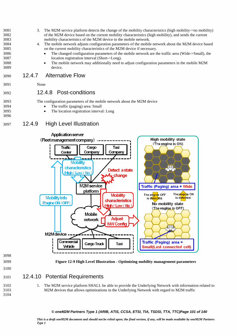
© oneM2M Partners Type 1 (ARIB, ATIS, CCSA, ETSI, TIA, TSDSI, TTA, TTC)Page 101 of 140
This is a draft oneM2M document and should not be relied upon; the final version, if any, will be made available by oneM2M Partners
Type 1
3. The M2M service platform detects the change of the mobility characteristics (high mobility->no mobility) 3081
of the M2M device based on the current mobility characteristics (high mobility), and sends the current 3082
mobility characteristics of the M2M device to the mobile network. 3083
4. The mobile network adjusts configuration parameters of the mobile network about the M2M device based 3084
on the current mobility characteristics of the M2M device if necessary. 3085
The changed configuration parameters of the mobile network are the traffic area (Wide->Small), the 3086
location registration interval (Short->Long). 3087
The mobile network may additionally need to adjust configuration parameters in the mobile M2M 3088
device. 3089
12.4.7 Alternative Flow 3090
None 3091
12.4.8 Post-conditions 3092
The configuration parameters of the mobile network about the M2M device 3093
The traffic (paging) area: Small 3094
The location registration interval: Long 3095
3096
12.4.9 High Level Illustration 3097
3098
Figure 12-9 High Level Illustration - Optimizing mobility management parameters 3099
3100
12.4.10 Potential Requirements 3101
1. The M2M service platform SHALL be able to provide the Underlying Network with information related to 3102
M2M devices that allows optimizations in the Underlying Network with regard to M2M traffic 3103
3104
1

© oneM2M Partners Type 1 (ARIB, ATIS, CCSA, ETSI, TIA, TSDSI, TTA, TTC)Page 102 of 140
This is a draft oneM2M document and should not be relied upon; the final version, if any, will be made available by oneM2M Partners
Type 1
An example of such useful information to a cellular network is the current (or change) of the mobility 3105
characteristics include moving range (e.g. high mobility, low mobility, no mobility, or speed range), 3106
moving direction and moving speed, etc. of the M2M device. 3107
3108
2. How to utilize such information by the cellular network is the cellular operator implementation dependent 3109
and outside the scope of oneM2M. 3110
3111
3. The M2M service platform MAY be able to compute the information with which the Underlying Network 3112
should be provided by analyzing the information received from the M2M application before providing to 3113
the Underlying Network. 3114
3115
Note: The interface to convey such information to the Underlying Network will depend on the type (e.g. 3116
3GPP, 3GPP2, Fixed) of the Underlying Network. 3117
12.5 Sleepy Node Use Case 3118
12.5.1 Description 3119
Many e-Health applications involve the use of medical devices which may be connected to a monitoring 3120
service. The device user or the user’s care providers may periodically need to observe measurements or 3121
interact with the device to optimize treatment. 3122
Communications capabilities with multiple entities may be required. For example, communications may be 3123
needed between the device and a service/application that collects and analyzes the monitored information. In 3124
another application communications to allow some control over the device. In one such case the 3125
communications may be between the device and the user’s care provider(s) and in another case the 3126
communication may be with the device manufacturer. Short range communications capability that operates 3127
through other devices such as Smartphone or home gateway is assumed to conserve battery life. 3128
One example of such a device is a diabetes management system that includes an insulin pump and a blood 3129
glucose monitor. 3130
An insulin pump is used to deliver the insulin. Two types of insulin are commonly used one is fast acting the 3131
other slow. The fast acting is usually administered in conjunction with a meal, while the slow acting is used 3132
throughout the day. 3133
When and how often the blood glucose level monitor needs to take a reading varies with the daily routine as 3134
well as the user’s condition. 3135
The need to report the monitored information could vary from an instantaneous reading ordered by the user’s 3136
care provider to a record of readings at varying intervals over different time periods. 3137
Usually, the monitored information is stored on the device for a period of time before being periodically 3138
downloaded. In some cases, the data is sent to a monitoring service, which may perform analysis of the 3139
information in preparation for reporting to the user’s care providers. 3140
This device can automatically operate the above mentioned functions when needed. Programming of some of 3141
these functions can be varied depending on the condition of the user. Sometimes during a daily routine 3142
automated operation is preferred (e.g. while traveling or sleeping). Automation is more important for some 3143
device users, such as infants, which cannot operate the device manually. 3144
Occasionally, there may be a need to download new firmware to a device to correct a software problem or 3145
provide new programming. 3146
The proper functioning of the device is important to maintaining the user’s health. The device needs to be 3147
operational when needed (i.e. reliable). Optimizing the devices battery life contributes to its reliable 3148
functioning. To maximize the life of the device’s battery requires putting certain of its functions to sleep for 3149
different time intervals (i.e. sleep cycles) when not needed. 3150
Sleep mode device handling is a fundamental issue/requirement for the M2M system. Although there are 3151
several requirements in this domain, currently there is no use case clearly addressing this functionality. 3152
12.5.2 Source 3153
oneM2M-REQ-2013-0261R03 Sleepy Node Use Case 3154
. 3155
12.5.3 Actors 3156
Sleepy Node (SN) 3157

© oneM2M Partners Type 1 (ARIB, ATIS, CCSA, ETSI, TIA, TSDSI, TTA, TTC)Page 103 of 140
This is a draft oneM2M document and should not be relied upon; the final version, if any, will be made available by oneM2M Partners
Type 1
A device that spends a large amount of its lifetime disconnected from the network, mainly to save power, 3158
or just because it’s not capable of storing the energy required for its reliable operation. The device wake 3159
up may be based on a variety of methods including but not restricted to: local physical interrupts or 3160
triggers, alarms, notifications, etc. 3161
Sleepy node devices may own and host a set of resources that need to be made available to the other 3162
network participants as if it were a typical, always connected device. In some cases low-power, low-range 3163
communication technologies (e.g. Zigbee or Bluetooth) may be used to establish connections with relays 3164
or gateways capable of longer-range communication (e.g. the user’s home Wi-Fi router or smartphone). In 3165
this use case several devices used for medical treatment (e.g. insulin pump and blood glucose monitor) 3166
embody sleepy node functionality. 3167
3168
Medical Device Monitoring & Management Service (MDMMS) 3169
This service periodically collects medical information from the user’s monitoring device. Such a service 3170
usually provides analysis of the device information for use by medical professionals (e.g. user’s care 3171
providers). This service can also initiate communication with the device (to send it a command, to re-3172
program it, to update its firmware, etc.). Additional services could be provided to other actors through the 3173
collection and analysis of additional information such as device reachability, connection and 3174
synchronization requirements, battery status, etc. 3175
3176
Care Provider (CP) 3177
Care Providers refers to medical professionals responsible for evaluating and directing treatment for an 3178
illness or disease. In this use case the Care Providers are M2M Application Service Providers that interact 3179
with the user’s medical device. The Care Providers require access to the data provided by the device as 3180
well as to applications and functions residing on the device. 3181
3182
Medical Device Manufacturer (MDM) 3183
The medical device manufacturer will occasionally require to access and control the device to, for 3184
example, download a firmware update or to re-program the device. 3185
12.5.4 Pre-conditions 3186
In this use case the user (e.g. patient) is assumed to be wearing a medical device that operates as a Sleepy 3187
Node. However, other similar use cases may involve a medical device that has been surgically implanted 3188
within the user, which places an even higher degree of emphasis on its power conservation characteristics. The 3189
device has been provisioned for communication using the oneM2M System and is capable of establishing a 3190
data connection for communicating with the MDMMS. 3191
12.5.5 Triggers 3192
A variety of triggers might be associated with the overall use case: 3193
Scheduled transfer of information from SN to MDMMS 3194
Command from MDMMS to SN (initiated by CP) 3195
Alarm condition at SN requiring interaction with MDMMS 3196
Update of SN firmware (by MDMMS or MDM) 3197
Status update or servicing of the SN (by CP, MDMMS or MDM) 3198
To be noted: triggers for device wake up are different than the use case triggers and may be based on a variety 3199
of methods such as: local physical interrupts or triggers, alarms, notifications, etc. Communications between 3200
SN and the MDMMS may be triggered by either entity. 3201
12.5.6 Normal Flow 3202
A. Initial setup of SN to MDMMS communications 3203
1. The device is first installed /powered up. 3204
2. Network connectivity with the oneM2M System will be established. 3205
3. Communications between SN and MDMMS are initiated by either entity, depending on individual 3206
requirements. Device, capability, service, subscription, user, etc. information is exchanged. 3207
4. The SN and MDMMS may exchange SN specific information such (power cycles, allowable 3208
communication wake-up triggers, etc.) 3209
5. The device may receive commands from the MDMMS. 3210
6. The device completes any received commands and communicates status as appropriate. 3211
7. The device returns to a sleep state. 3212

© oneM2M Partners Type 1 (ARIB, ATIS, CCSA, ETSI, TIA, TSDSI, TTA, TTC)Page 104 of 140
This is a draft oneM2M document and should not be relied upon; the final version, if any, will be made available by oneM2M Partners
Type 1
B. SN to MDMMS transfer of information 3213
1. The device wakes up from a sleep cycle. The wake up may occur based on any number of 3214
asynchronous events. 3215
2. The device initiates communication with the MDMMS. Because the device has been in a sleep 3216
condition that does not support any network connectivity, it is possible that a data connection with the 3217
oneM2M System will need to be re-established. 3218
3. Once a data connection is established, the device transfers its accumulated information payload to 3219
the MDMMS. 3220
4. The device may receive commands from the MDMMS that are either sent directly during the 3221
established communication session or have been sent previously and stored in an intermediate node. 3222
5. The device completes any received commands and communicates status as appropriate. 3223
6. The device returns to a sleep state. 3224
C. Command from MDMMS to SN 3225
1. Care Provider initiates command to the device (e.g. change in insulin delivery rate) via MDMMS. 3226
2. MDMMS may schedule delivery of the command based on any relevant scheduling information 3227
(such as service and application requirements, notification types, network congestion status, SN 3228
power cycle status, SN reachability, etc.). Several commands may be aggregated, ordered or queued 3229
and delivered to the SN or an intermediary node. 3230
3. Command(s) are delivered by the intermediary node or MDMMS to the SN after its wake up. 3231
4. The device completes any received commands and communicates status as appropriate. 3232
5. The device returns to a sleep state. 3233
D. Alarm condition at SN requiring interaction with MDMMS 3234
1. The device wakes up outside of its sleep cycle due to an alarm condition (e.g. blood glucose levels 3235
below a predetermined threshold). 3236
2. The device initiates communication with the MDMMS. Because the device has been in a sleep 3237
condition that does not support any network connectivity, it is possible that a data connection with the 3238
oneM2M System will need to be re-established. 3239
3. Once a data connection is established, the device communicates the alarm condition to the 3240
MDMMS. 3241
4. The device may receive commands from the MDMMS that are either sent directly during the 3242
established communication session or have been sent previously and stored in an intermediate node. 3243
5. The device completes any received commands and communicates status as appropriate, but also 3244
maintains the communication session until the alarm condition is cleared or otherwise resolved. 3245
6. The device returns to a sleep state. 3246
E. Update of SN firmware 3247
1. MDMMS is notified by MDM that the device firmware must be updated. 3248
2. MDMMS schedules the firmware update. 3249
3. The device wakes up and receives a notification that firmware update is requested. This may 3250
require additional action by the user (e.g. plugging the device into a power source during the update 3251
process) and by the MDMMS to establish a communication channel between the MDM and the 3252
device to perform the data transfer and/or execute the update process. 3253
4. The device returns to a sleep state. 3254
F. SN status update or servicing 3255
1. Various SN status and/or parameters (battery status, reachability state, etc.) are requested via 3256
MDMMS 3257
2. MDMMS notifies the SN. 3258
3. The device initiates communication with the MDMMS. Because the device has been in a sleep 3259
condition that does not support any network connectivity, it is possible that a data connection with the 3260
oneM2M System will need to be re-established. 3261
4. Upon device wake up 3262
G. The device returns to a sleep state 3263
12.5.7 Alternative Flow 3264
None 3265
12.5.8 Post-conditions 3266
In most cases, the SN will resume sleep as detailed in the flow clause, but the state of wakefulness is 3267
determined by other factors such as device, application, service or subscription requirements. 3268

© oneM2M Partners Type 1 (ARIB, ATIS, CCSA, ETSI, TIA, TSDSI, TTA, TTC)Page 105 of 140
This is a draft oneM2M document and should not be relied upon; the final version, if any, will be made available by oneM2M Partners
Type 1
12.5.9 High Level Illustration 3269
None 3270
12.5.10 Potential Requirements 3271
The following is a list of previously submitted requirements with impact on SN functionality, which is now re-3272
submitted for consideration for this scenario. 3273
Table 12-1 3274
Temp req.
nr.
Submitted
req. number
Initial
submitter
Requirement
SNR-001 HLR-118 Telecom
Italia
The M2M System may be aware of the reachability state of
the Applications.
SNR-002 HLR-024 Telecom
Italia
The M2M System shall be able to support a variety of
different M2M Devices/Gateways types, e.g. active M2M
Devices and sleeping M2M Devices, upgradable M2M
Devices/Gateways and not upgradable M2M
Devices/Gateways.
SNR-003 HLR-055 Telecom
Italia
The M2M System should support time synchronization.
M2M Devices and M2M Gateways may support time
synchronization. The level of accuracy and of security for the
time synchronization can be system specific.
SNR-004 HLR-114 Telecom
Italia
The M2M System shall support testing the connectivity
towards a selected set of Applications at regular intervals
provided the Applications support the function.
SNR-005 HLR-095 Fujitsu The M2M System shall be able to support a mechanism for
delaying notification of Connected Devices in the case of a
congested communication network.
SNR-006 HLR-096 Fujitsu The M2M System shall be able to support a mechanism to
manage a remote access of information from other Connected
Devices. When supported the M2M system shall be able to
aggregate requests to perform the request depending on a
given delay and/or category e.g. the M2M application does
not have to connect in real time with the devices.
SNR-007 HLR-097 Telecom
Italia
The M2M System may support a mechanism for delaying
notifying a Connected Objects.
SNR-008 HLR-098 Telecom
Italia
The M2M System may support a mechanism to manage a
remote access of information from Applications and shall be
able to aggregate requests and delay to perform the request
depending on a given delay and/or category.
SNR-009 HLR-115 Telecom
Italia
The Applications and their resources operational status shall
be monitorable.
SNR-010 HLR-161 ALU,
Huawei
The M2M System shall be capable of retrieving information
related to the environment (e.g. battery, memory, current
time) of a M2M Gateway or Device
3275
Informative annex to Potential Requirements 3276
3277
Requirements TS content related to Sleepy Node functionality 3278
OSR-002 3279 The M2M system shall support communication means that can accommodate devices with constrained 3280
computing (e.g. small CPU, memory, battery) or communication capabilities (e.g. 2G wireless modem, certain 3281
WLAN node) as well as rich computing (e.g. large CPU, memory) or communication (e.g. 3/4G wireless 3282
modem, wireline) capabilities. 3283
OSR-013 3284 The M2M System shall be aware of the delay tolerance acceptable by the M2M Application and shall schedule 3285
the communication accordingly or request the underlying network to do it, based on policies criteria. 3286
OSR-015 3287

© oneM2M Partners Type 1 (ARIB, ATIS, CCSA, ETSI, TIA, TSDSI, TTA, TTC)Page 106 of 140
This is a draft oneM2M document and should not be relied upon; the final version, if any, will be made available by oneM2M Partners
Type 1
The M2M system shall support different communication patterns including infrequent communications, small 3288
data transfer, large file transfer, streamed communication. 3289
MGR-001 3290 M2M System shall support management and configuration of resource constrained devices. 3291
3292
Other agreed requirements related to Sleepy Node functionality 3293
(HLR-005) 3294 The M2M System shall support M2M applications accessing the M2M system by means of a non continuous 3295
connectivity. 3296
(HLR-006) 3297 The M2M System shall be able to manage communication towards a device which is not continuously 3298
reachable. 3299
(HLR-047) 3300 The M2M System shall be able to manage the scheduling of network access and of messaging. 3301
(HLR-137) 3302 The M2M System shall provide the capability to notify M2M Applications of the availability of, and changes 3303
to, available M2M Application/management data on the M2M Device/Gateway, including changes to the 3304
M2M Area Network. 3305
3306
12.6 Use Case on collection of M2M System data
12.6.1 Description
M2M Service Providers have a need to provide the Application Service Providers with data and analysis
related to the behavior of the M2M System as well as the service provider supplied components of the M2M
System (e.g. Device Gateway) M2M Operators face two problems.
M2M Service Providers can utilize the methods of Big Data by collecting M2M System data for the behavior
of the M2M System as well as data from M2M System components provided by the Service Provider.
In this scenario, the data is collected from M2M Gateways and Devices provided by the M2M Service
Provider. The M2M System data that is collected from the M2M Devices and Gateways can be described as:
M2M System Behavior
Component Properties
M2M System Behavior: Data related to the operation of the M2M Applications within the M2M System.
Types of data that is to be collected includes information related Messages transmittal and reception (e.g.
bytes, response times, event time).
Component Properties: Data related to the Service Provider supplied components as the component is in use by
the M2M System (e.g. location, speed of the component, other anonymous data).
With this data, the M2M Service Provide can provide:
1. Analysis of the data without knowledge of content of the Application’s data.
2. Insights into the operation of the M2M Applications. For example, the M2M Service Provider
can infer the "correct" state of the application or the network status changes, by the analysis of
the data, and then trigger some kinds of optimization mechanisms.
12.6.2 Source
oneM2M-REQ-2013-0279R04 Collection of non-application data
12.6.3 Actors
Front-end data-collection equipment (e.g. M2M Devices and Gateways) :
Management Platform (e.g. M2M Service Provider’s Platform)
Monitor Center (e.g. M2M Application’s Platform)
M2M System Data Collection Center
12.6.4 Pre-conditions
None

© oneM2M Partners Type 1 (ARIB, ATIS, CCSA, ETSI, TIA, TSDSI, TTA, TTC)Page 107 of 140
This is a draft oneM2M document and should not be relied upon; the final version, if any, will be made available by oneM2M Partners
Type 1
12.6.5 Triggers
Time trigger: collecting data at a specific time;
Position trigger: collecting data when position changed;
Behavior trigger: collecting data when certain behavior happened
12.6.6 Normal Flow
1. The M2M Device and Gateway collects M2M System data.
2. Once a trigger is activated, the M2M Devices and Gateway sends the M2M System data to the M2M
System Data Collection Center.
12.6.7 Alternative Flow
None
12.6.8 Post-conditions
None
12.6.9 High Level Illustration
Figure 12-10 Vehicle Operation Management System
Vehicle Operation Management System provide users a new telecommunications business with
remote collection, transmission, storage, processing of the image and alarm signals.
Front-End Data Collection Equipment include Front-End 3G camera, Electronic Station, Car DVR,
costumed car GPS, WCDMA wireless routers and other equipment.
Management Platform with business management function, include:
o Forwarding, distribution, or storage of images
o Linkage process of alarms
o Management and maintenance of the vehicle status data.
Monitor Center: consists of TV wall, soft / hardware decoder, monitor software, etc.
车辆状态数据需求部门
显示屏
前端采集设备
Server Server Server Server
Manage PC
Storage Array
Storage server
fireware
Interface machine
Manage Platform
Vehicle State Data Demand Department
IP MAN
Front-end acquisition devices
camera
inputscreen
camera
Advertisement screen
station
Access NetworkWCDMA
fireware
VPDN
Monitor center
clientclient
Big-screen television
Digital
decoder
M2M Data Collection Center
Front-end data-collection equipment
Management Platform(M2M Service Platform)
Monitor Center(M2M Application’s Platform)
M2M Network

© oneM2M Partners Type 1 (ARIB, ATIS, CCSA, ETSI, TIA, TSDSI, TTA, TTC)Page 108 of 140
This is a draft oneM2M document and should not be relied upon; the final version, if any, will be made available by oneM2M Partners
Type 1
Vehicle State Data Demand Department: such as auto 4S shop, vehicle repair shop, vehicle
management center, automobile and parts manufacturers, government regulatory platform, etc.
M2M System Data Collection Center: use built-in data collectors resided in Network Equipment,
M2M Platform, Costumed M2M Modules and Costumed M2M Terminal Devices to collect M2M
System data.
12.6.10 Potential Requirements
Figure 12-11 M2M System Data Collection Processing Flow
1. M2M System should support M2M System data collection.
As illustrated in Figure 12.6.10 1, we suggest that M2M System data collector should reside in:
M2M Service Providers’ Platform
M2M Network Equipment
M2M Devices and Gateways
M2M Communication Module
12.7 Leveraging Broadcasting/ Multicasting Capabilities of Underlying Networks
12.7.1 Description
This use case illustrates that an automotive telematics (Application) service provider XYZ Ltd. alerts vehicles
around where a traffic accident has just happened. The alerted vehicles could go slow or go another route to
prevent a second accident and to avoid the expected traffic jam.
In this case, the automotive telematics service provider XYZ Ltd. takes advantage of broadcasting/multicasting
capability of underlying communication networks. Some kinds of communication networks (in particular, a
mobile communication network) have the capability to broadcast/multicast a message in specific areas.
Utilizing this capability, XYZ Ltd. can alert at once all the relevant vehicles within a specific region. This
approach can avoid burst traffic in the communication network and provides a simple and cost-efficient way
for XYZ Ltd. to implement this neighbourhood alerting mechanism.
app1 app2 app3
M2M Service Provider's Platform
M2M Network
M2M GateWay M2M Module
M2M System Data Collector
M2M System Data Collector
M2M System Data Collector
M2M System Data Collector
M2M System Data Collection Center

© oneM2M Partners Type 1 (ARIB, ATIS, CCSA, ETSI, TIA, TSDSI, TTA, TTC)Page 109 of 140
This is a draft oneM2M document and should not be relied upon; the final version, if any, will be made available by oneM2M Partners
Type 1
Note: Ordinary unicast messaging mechanism is inadequate here. The alert messages shall be delivered in a
timely manner to all the relevant vehicles within a specific region. XYZ Ltd. therefore needs to select the
relevant vehicles that should receive the alert messages according to their current registered location (It needs
continuous location management of vehicles). Moreover the underlying communication network has to route
large number of unicast messages with very short delay.
However it is hard for XYZ Ltd. to utilize broadcasting/multicasting functionality of underlying networks
directly which can vary with kinds of communication networks (e.g. 3GPP, 3GPP2, WiMAX or WiFi).
A oneM2M service provider ABC Corp. facilitates this interworking between XYZ Ltd. and a variety of
communication network service providers (or operators). ABC Corp. exposes unified/standardized interfaces
to utilize broadcasting (or multicasting) capability of communication networks. ABC Corp. authenticates the
requester (=XYZ Ltd.), validates and authorizes the request, then calls the corresponding function of the
appropriate communication networks.
Note: There are many other scenarios in which broadcasting/multicasting capability of underlying
communication networks provides significant benefit in a M2M system. For example,
Warning about a crime incident
o When a security firm detects a break-in at a house, it sets off all neighborhood burglar alarms
and alerts the M2M Application on the subscribed users’ cellular phones around there.
Monitoring a water delivery system
o When a water-supply corporation detects a burst of a water pipe, it remotely shuts off the
water supply valves in that block, and alerts the M2M Application on the subscribed users’
cellular phones around there.
The potential requirements in this contribution cover the above and all similar use cases, too.
12.7.2 Source
oneM2M-REQ-2013-0260R02 Leveraging Broadcasting - Multicasting Capability of Underlying Networks
12.7.3 Actors
The automotive telematics service provider: XYZ Ltd.
It provides automotive telematics service as a M2M application.
The oneM2M service provider: ABC Corp.
It provides a common platform to support diverse M2M applications and services.
The communication network service providers (or operators): AA Wireless, BB Telecom and CC Mobile
They operate communication networks.
Some of them have the capability to broadcast/multicast a message in specific areas. The
broadcasting/multicasting capability is available for external entities.
The vehicles:
They have communication capability as M2M devices, and have user interfaces (e.g. displays, audio
speakers) or actuators to control driving.
Note: roles are distinct from actors. For example, the oneM2M service provider role may be performed by any
organization that meets the necessary standardization requirements, including MNOs.
12.7.4 Pre-conditions
The vehicles are able to communicate in one or more communication networks.
12.7.5 Triggers
The automotive telematics service provider XYZ Ltd. detects a traffic accident.
How it detects the accident and captures details of the accident is out of scope of this use case.
12.7.6 Normal Flow
1. XYZ Ltd. estimates the location and impact of the accident to specify the area in which all the relevant
vehicles should be alerted.

© oneM2M Partners Type 1 (ARIB, ATIS, CCSA, ETSI, TIA, TSDSI, TTA, TTC)Page 110 of 140
This is a draft oneM2M document and should not be relied upon; the final version, if any, will be made available by oneM2M Partners
Type 1
2. XYZ Ltd. requests oneM2M service provider ABC Corp. to alert subscribed vehicles in the specified area.
That request encapsulates the alert message (payload) and alert parameters (options).
o The request contains the payload to be delivered to vehicles. It can contain for
example the alert level (how serious and urgent), the location and time of the
accident, and directions to the driver (e.g. go slow or change routes).
o The request also defines targeted receivers of the message and specifies alert
options. They can contain for example the area to be covered, the type of devices to
be alerted, the option whether the alerting should be repeated, the repetition
interval, and stopping conditions.
3. ABC Corp. receives the alert request from XYZ Ltd. It authenticates the requester (=XYZ Ltd.), validates
and authorizes the request. When the request from XYZ Ltd. does not have alert parameters, ABC Corp.
analyzes the alert message to determine broadcast parameters. Then it chooses appropriate
communication network service providers (or operators) to meet the alert request from XYZ Ltd.
4. ABC Corp. requests AA Wireless and CC Mobile to broadcast the alert message in the specified area.
That request encapsulates the alert message (payload) and broadcast parameters.
o The alert message is the payload to be delivered to vehicles. The contents are the
same as from ABC Corp. but the format and encoding of the message may be
different from AA Wireless and CC Mobile.
o The broadcast parameters define targeted receivers of the message and specify
broadcast options. They can contain for example the area to be covered, the type of
devices to be alerted, the option whether the broadcast should be repeated, the
repetition interval, and stopping conditions. The format of the parameters can be
different between AA Wireless and CC Mobile.
ABC Corp. may need to cover a part of the broadcasting functions for some communication network
service providers. For example, if CC Mobile does not have the functionality to repeat broadcasting
periodically, ABC Corp. repeatedly requests CC Mobile to broadcast the message, in order to meet the
request from XYZ Corp.
12.7.7 Alternative Flow
None
12.7.8 Post-conditions
The vehicles around where the traffic accident has just happened are properly alerted about the accident.
12.7.9 High Level Illustration

© oneM2M Partners Type 1 (ARIB, ATIS, CCSA, ETSI, TIA, TSDSI, TTA, TTC)Page 111 of 140
This is a draft oneM2M document and should not be relied upon; the final version, if any, will be made available by oneM2M Partners
Type 1
Figure 12-12 High level illustration 1
Figure 12-13 High Level Illustration 2
12.7.10 Potential Requirements
1. oneM2M System SHALL be able to leverage broadcasting and multicasting capability of Underlying
Networks.
2. oneM2M System SHALL enable a M2M Application to request to broadcast/multicast a message in
specific geographic areas.
That request SHALL encapsulate the message (payload) from the M2M Application,
relevant parameters (options) and optionally credentials for authentication and authorization.
The M2M System SHALL support that request to be independent of the types of the
Underlying Networks.
3. oneM2M System SHALL support mechanisms for Authentication, Authorization and Accounting of
an M2M Application to request to broadcast/multicast a message.
oneM2M System SHALL authenticate the M2M Application.
CC MobileAA WirelessBB Telecom
ABC Corp.ABC Corp.
XYZ Ltd.
Vehicles
Telematics Service Provider
oneM2M Service Provider
Communication NetworkService Providers (or operators)
Base Stations
Crash Point
! Detect an accident
Request to alert vehicles
Request to broadcast the alert message in specific areas
Broadcast the alert message
…… ……
Post-conditions(Accident Occurred)
Pre-conditions(No Accident)
Crash
Alert & Directions
•Accident Location
•Request to Go Slow ……
Broadcast Area

© oneM2M Partners Type 1 (ARIB, ATIS, CCSA, ETSI, TIA, TSDSI, TTA, TTC)Page 112 of 140
This is a draft oneM2M document and should not be relied upon; the final version, if any, will be made available by oneM2M Partners
Type 1
oneM2M System SHALL validate and authorize the request.
oneM2M System SHALL support accounting on handling the request.
4. oneM2M System SHALL be able to select appropriate underlying networks to broadcast/multicast a
message in specified geographic areas according to capability/functionality of those networks.
5. oneM2M System SHALL be able to receive information on broadcasting/multicasting
capability/functionality of each underlying network.
6. oneM2M System SHALL be able to indicate towards the Underlying Network that a message needs
to be broadcasted/multicasted and to determine its broadcast parameters (or multicast parameters),
e.g. the area to be covered, the type of devices to be alerted, the option whether the broadcast should
be repeated, the repetition interval, and stopping conditions.
7. oneM2M System SHALL be able to analyze a message from a M2M Application to determine
broadcast parameters.
8. Interfaces to address the above requirements SHALL be standardized by oneM2M.
Note: roles are distinct from actors. An actor may play one or more roles and the economic boundary
conditions of a particular market will decide which role(s) will be played by a particular actor.
12.8 Leveraging Service Provisioning for Equipment with Built-in M2M Device
12.8.1 Description
Some industrial equipment is so complicatedly designed that it’s difficult for users themselves to maintain,
such as construction engineering equipment, air compressor, large medical instrument and so on. Vehicles with
online service can also be seen as one kind of such equipment. Therefore, equipment vendors build back-end
applications to monitor and maintain them remotely. They also collect data from them for analysis in order to
improve service level and product quality. We call such service provided by equipment providers as
“equipment remote maintenance service”.
Equipment providers can integrate remote communication unit into equipment directly. But often, they get
M2M device from other providers, which mainly provide remote communication capability. They embed one
M2M device into one equipment.
More and more equipment begin to use mobile network to communicate with the back-end application because
of the convenience and low-cost of the current mobile network. In this case, SIM Card or UIM Card should be
put into the M2M device. eUICC [i.16] can be one of the best choices.
This contribution mainly focuses on M2M service provisioning in the above case. M2M service consists of the
service provided by M2M service platform and network service provided by the mobile network. Therefore,
full M2M service provisioning consists of M2M service provisioning and network service provisioning. The
former is to allow M2M device to talk with M2M service platform. The latter is to make M2M device access
mobile network.
M2M service platform is operated by M2M Service Providers (M2M SP). With M2M SP’s help, Equipment
Providers don’t need to manage mobile-network specific identifiers, such as IMSI, MSISDN or MDN. They
just use Equipment ID / Equipment Name and Device ID / Device Name to identify equipment and device.
M2M Service Platform can hide the complexity of the underlying mobile network.
For devices managed by M2M Service platform, there are two kinds of M2M Service status. One is
administrative status. The other is operational status. The former is to tell whether M2M Service has been
allowed to be running by M2M SP for a device. “active” means it’s allowed. “de-active” means it’s not
allowed. The latter is to tell whether M2M Service is available now for a device. “available” means it function
correctly now. “unavailable” means it doesn’t function correctly now. For example, if related IMSI has been
deactivated by MNO, M2M Service operational status of the device is unavailable.
For network identifiers, Network Service administrative status is to tell whether network service has been
allowed to be running for a network identifier by MNO. “active” means it’s allowed. “de-active” means it’s
not allowed.
12.8.2 Source
oneM2M-REQ-2013-0171R03 M2M Service Provisioning for Equipment with Built-in M2M Device

© oneM2M Partners Type 1 (ARIB, ATIS, CCSA, ETSI, TIA, TSDSI, TTA, TTC)Page 113 of 140
This is a draft oneM2M document and should not be relied upon; the final version, if any, will be made available by oneM2M Partners
Type 1
12.8.3 Actors
Equipment Provider (EP)
Vendors who make equipment with built-in remote communication capability, sell and install equipment,
and provide equipment remote maintenance service
Equipment User (EU)
Customers who use equipment
M2M Device Provider (M2M DP)
Vendors who make M2M Device with built-in remote communication capability and other M2M service
capability
M2M Service Provider (M2M SP)
Service provider who provide M2M service which including network service
Mobile Network Operator (MNO)
Service provider who provide mobile network service
Equipment Provider Back-end Application (EPBA)
One kind of M2M Applications by which EPs can monitor, control, and collect data from their equipment.
It is normally located in EP’s office.
M2M Service Platform (MSP)
Platform which is operated by M2M SP and provides M2M Service
Equipment
It is made by EP, which can do some specific work in some specific areas, such as concrete machinery,
hoisting machinery and air compressor.
M2M Device
Device embedded into equipment, which serves the function of communication between equipment and
EPBA. It also talks with MSP to use M2M service.
12.8.4 Pre-conditions
EU uses equipment remote maintenance service provided by EP.
EP uses M2M Service provided by M2M SP.
M2M Service provided by M2M SP includes Network Service. That is to say, M2M service provider chooses
which MNO’s network to be used.
12.8.5 Triggers
None.
12.8.6 Normal Flow
Equipment’s lifetime can be summarized as following figure:
Figure 12-14 Equipment lifetime
M2M service provisioning for equipment with built-in M2M device mainly consists of the following scenarios:
Pre-provisioning Scenario
Manufacture and Test Scenario

© oneM2M Partners Type 1 (ARIB, ATIS, CCSA, ETSI, TIA, TSDSI, TTA, TTC)Page 114 of 140
This is a draft oneM2M document and should not be relied upon; the final version, if any, will be made available by oneM2M Partners
Type 1
Installation Scenario
EP Suspends / Resumes / Stops Equipment Remote Maintenance Service Scenario
M2M SP Suspends / Resumes M2M Service Scenario
MNO Suspends / Resumes Network Service Scenario
Replacing-device Scenario
1. Pre-provisioning Scenario
At first, M2M SP prepares a batch of SIM/UIM cards from MNOs and registers the information of these cards
in MSP, such as ICCID, IMSI and so on
2. Manufacture and Test Scenario
Device Manufacture Phase: M2M DP gets SIM/UIM card from M2M SP, and puts it into the module, and
integrates the module into the device. Then, M2M DP configures the device ID parameter in device.
Device Test Phase: After that, M2M DP tests the device. Before and after the test, M2M DP or M2M SP sets
M2M Service administrative status of specific ICCID as “active” or “de-active”, which allows MSP to talk
with underlying mobile network to activate or deactivate the network service administrative status of the
corresponding IMSI. In the test process, M2M Device reports its device ID and ICCID/IMSI to MSP. Thus,
MSP knows such binding info.
Equipment Manufacture Phase: After that, EP gets the device and puts it into their equipment. Then, EP
configures the equipment ID parameter in device.
Equipment Test Phase: EP also tests the equipment. Before and after the test, EP or M2M SP sets the M2M
Service administrative status of specific device as “active” or “de-active”, which allows MSP to talk with
underlying mobile network to activate or deactivate the network service administrative status of the
corresponding IMSI. In the test process, Equipment reports its device ID and equipment ID to EPBA.
Figure 12-15
3. Installation Scenario
Before the installation, EP sets equipment remote maintenance service of specific equipment as “active”, and it
talks with MSP to set M2M service administrative status of the corresponding device as “active”, and which
also allows MSP to notify underlying mobile network to set network service administrative status of the
corresponding IMSI as “active”. Then, EP continues to install the equipment. After that, the equipment can be
put into operation.
Figure 12-16
4. EP Suspends / Resumes / Stops Equipment Remote Maintenance Service Scenario

© oneM2M Partners Type 1 (ARIB, ATIS, CCSA, ETSI, TIA, TSDSI, TTA, TTC)Page 115 of 140
This is a draft oneM2M document and should not be relied upon; the final version, if any, will be made available by oneM2M Partners
Type 1
EP may suspend, resume, or stop equipment remote maintenance service of specific equipment.
For suspending and resuming scenario, EP sets equipment remote maintenance service of specific equipment
as “de-active” or “active”, which may trigger MSP to set M2M service administrative status of the
corresponding device as “de-active” or “active”, and which also may trigger MSP to notify underlying mobile
network to set network administrative status of the corresponding IMSI as “de-active” or “active”. But, in
some cases, the above administrative statuses don't correlation together. It’s up to different business model and
management policy.
Figure 12-17
For stopping scenario, EP sets equipment remote maintenance service of specific equipment as “stopped”,
which may trigger MSP to set M2M service administrative status of the corresponding device as “stopped”,
and which also may trigger underlying mobile network to reclaim the corresponding IMSI.
5. M2M SP Suspends / Resumes M2M Service Scenario
M2M SP may suspend or resume M2M service of specific device, which may let MSP talk with underlying
mobile network to deactivate or activate network service administrative status of the corresponding IMSI.
After that, MSP should notify EPBA of such M2M service administrative status change of the device if EPBA
has registered such notification, which allows EPBA to do some operations.
Figure 12-18
6. MNO Suspends / Resumes Network Service Scenario
MNO may suspend or resume network service of specific IMSI. If that happens, underlying mobile network
may notify MSP the change of specific IMSI. Then, MSP may change the M2M service operational status of
the corresponding device to “unavailable” or “available”. After that, MSP may also notify EPBA of the M2M
service operational status change of the corresponding device if EPBA has registered such notification.

© oneM2M Partners Type 1 (ARIB, ATIS, CCSA, ETSI, TIA, TSDSI, TTA, TTC)Page 116 of 140
This is a draft oneM2M document and should not be relied upon; the final version, if any, will be made available by oneM2M Partners
Type 1
Figure 12-19
7. Replacing-device Scenario
In some cases, EP may decide to replace bad device with new one in the equipment.
EP sets equipment remote maintenance service of specific equipment as “replaced”, which triggers MSP set
M2M service administrative status of the corresponding device as “stopped”, which also may trigger MSP to
notify underlying mobile network to reclaim the corresponding IMSI.
The following procedure is the same as the Equipment Manufacture Phase in Manufacture and Test Scenario
12.8.7 High Level Illustration
M2M Service Platform
EPBA
(M2M Application)
Preinstalled
M2M Device
Mobile Network
Equipment
I/F A
I/F B
SIM/UIM
Card
I/F C
Equipment ID
device ID
network Identifier
(such as IMSI)
Figure 12-20 High Level Illustration
12.8.8 Service Model
EP provides equipment remote maintenance service to EU. M2M SP provides M2M service to EP. MNO
provides network service to M2M SP.
Equipment remote maintenance service consists of M2M service which is provided by M2M SP and other
service provided by EP.
M2M service consists of network service which is provided by MNO and other service provided by M2M SP.
M2M service operational status will be de-active if network service administrative status is de-active.
12.8.9 Entity Model
EPBA uses equipment ID to identify specific equipment.
EPBA and MSP uses device ID to identify specific device. MSP and underlying mobile network use network
identifier such as IMSI, MSISDN, MDN or External id to identify specific user in its network.

© oneM2M Partners Type 1 (ARIB, ATIS, CCSA, ETSI, TIA, TSDSI, TTA, TTC)Page 117 of 140
This is a draft oneM2M document and should not be relied upon; the final version, if any, will be made available by oneM2M Partners
Type 1
One equipment has only one M2M device in it at one time. EP can replace old M2M device in equipment with
new one.
One M2M device has only one SIM/UIM card in it.
12.8.10 Potential requirements
1. The M2M System shall identify and manage M2M Service status of devices.
Note: There are two kinds of M2M Service status. One is administrative status. The other is operational
status. The former is to tell whether M2M Service has been allowed to be running by M2M SP for a
device. “active” means it’s allowed. “de-active” means it’s not allowed. The latter is to tell whether M2M
Service is available now for a device. “available” means it function correctly now. “unavailable” means it
doesn’t function correctly now. For example, if related IMSI has been deactivated by MNO, M2M Service
operational status of the device is unavailable.
2. The M2M System should identify Network Service administrative status of device-related network
identifiers such as IMSI, MSISDN, MDN, or External id.
3. Note: Network Service administrative status is to tell whether network service has been allowed to be
running for a network identifier by MNO. “active” means it’s allowed. “de-active” means it’s not allowed.
The M2M System should support the correlation of service identifier of a device in service layer and
related mobile network identifier such as IMSI, MSISDN, MDN, or External id in underlying network
layer.
Note: Different MNOs may expose different kinds of network identifiers to the M2M System. It’s up to
MNO.
4. System should notify underlying mobile network that Network Service administrative status of related
mobile network identifier should be changed when M2M Service administrative status of a device changes
if underlying mobile network can receive such notification and has subscribed such notification.
5. The M2M System shall notify M2M Application when M2M Service administrative status of a device
changes if M2M Application has subscribed such notification. The M2M System should notify M2M
Application when M2M Service operational status of a device changes if M2M Application has
subscribed such notification.
6. The M2M System should change M2M Service operational status of the corresponding device to available
or unavailable when it receives the notification from the underlying mobile network that Network Service
administrative status of a mobile network identifier has changed to active or de-active, if the underlying
mobile network can send such notification to the M2M System.
7. The M2M System should support M2M Application to activate or de-activate M2M Service
administrative status of a device.
12.9 Semantics query for device discovery across M2M Service Providers
12.9.1 Description
This use case describes discovery of a device based on metadata of the device such as the type of device or its
location. It is similar to the use case “Use Case on Devices, Virtual Devices and Things” in section 8.2
however in the present use case the discovery may be extended to the domains of different M2M service
providers.
12.9.2 Source
REQ-2014-0005R01 Semantics query for device discovery across M2M Service Providers
12.9.3 Actors
M2M Application Provider
The M2M Application Provider provides an application which can employ a device that has already been
installed and is operated by a different M2M Application Provider. However, the M2M Application
Provider does not have any information (ID, URI, etc.) that can identify the device, the M2M service
provider and the M2M Application Provider which the device belongs to.
M2M Service Provider 1

© oneM2M Partners Type 1 (ARIB, ATIS, CCSA, ETSI, TIA, TSDSI, TTA, TTC)Page 118 of 140
This is a draft oneM2M document and should not be relied upon; the final version, if any, will be made available by oneM2M Partners
Type 1
M2M Service Provider 1 is a service provider with whom the M2M Application Provider has a contractual
relationship.
M2M Service Provider 2
M2M Service Provider 2 is a service provider with whom the M2M Application Provider does not have a
contractual relationship. The M2M Service Infrastructure of M2M Service Provider 1 can communicate
with the M2M Service Infrastructure of M2M Service Provider 2 via an inter-provider interface.
The device which M2M Application Provider wants to employ is connected to M2M Service Provider 2.
12.9.4 Pre-conditions
An M2M Device (e.g. a surveillance camera in a public space, a thermometer for agriculture in a field, etc.)
has been installed and is operated in the domain of M2M Service Provider 2.
The M2M Application Provider has found the device in the real world (in the public space, the agriculture
field, etc.) and wants to make use of the device within his application. The M2M Application Provider,
however, does not have any information (ID, URI, etc.) that can identify the device. Further, the M2M
Application Provider does not know which M2M Service Provider the device belongs to.
The M2M Application Provider has a contractual relationship with M2M Service Provider 1.
M2M Service Providers 1 and 2 have databases that contain information on their devices. The databases
include location information (where each device is currently located) and the device type.
12.9.5 Triggers
Using a suitable interface (e.g. a web-page) of the M2M Application the M2M Application Provider creates a
request for using the device. The request contains location information about the device and possibly a device
type.
12.9.6 Normal Flow
0. The M2M Application launches a query within the domain of M2M Service Provider 1 to find and
identify the device. The query is invoked with location information on the device and information on the
device type.
1. The database of M2M Service Provider 1 is searched whether the requested device is connected to his
domain or not.
2. If the requested device is connected to M2M Service Provider 1, M2M Service Provider 1 returns to the
M2M Application the information to identify the device (ID, URI, etc.) and terms of use for the device.
3. If the requested device is not connected to M2M Service Provider 1 then M2M Service Provider 1
forwards the query to other M2M Service Providers to which M2M Service Provider 1 has an inter-
provider system interface. Forwarding may depend on whether some criteria of the query are known to be
supported / not supported by a certain Service Provider (e.g. if it is known that the devices of a Service
Provider only operate in a certain geographical region and the query looks for a device in a different
region).
4. The query is executed in the domains of the other M2M Service Providers.
5. If the requested device is connected to M2M Service Provider 2 then M2M Service Provider 2 returns to
M2M Service Provider 1 the information to identify the device (ID, URI, etc.) and terms of use for the
device.
6. M2M Service Provider 1 returns to M2M Application Provider the information to identify the device (ID,
URI, etc.) and terms of use.
12.9.7 Alternative Flow
None
12.9.8 Post-conditions
M2M Application Provider can start to employ the device on the basis of the terms of use sent by M2M
Service Provider 1.

© oneM2M Partners Type 1 (ARIB, ATIS, CCSA, ETSI, TIA, TSDSI, TTA, TTC)Page 119 of 140
This is a draft oneM2M document and should not be relied upon; the final version, if any, will be made available by oneM2M Partners
Type 1
12.9.9 High Level Illustration
Figure 12-21 High Level Illustration of Semantics discovery across M2M Service Providers
12.9.10 Potential Requirements
The following requirements extend the requirement SMR-004 from section 6.3.2 (Semantic Requirements) of
[i.18]:
SMR-004: The M2M System shall provide capabilities to discover M2M Resources based on semantic
descriptions.
1. The M2M System shall provide a capability to an M2M Application to search (semantic query)
within the domain of the application’s M2M Service Provider to discover M2M Devices, Virtual
Devices and Things on the basis of their semantic descriptions and meta-data such as device location
or a device type.
2. The M2M System shall provide a capability to a M2M Service Provider to automatically forward
such a semantic query via standardized inter-provider interfaces to the domains of other M2M Service
providers in order to extend the search to these domains.
Note: Based on Service Provider’s policies forwarding can depend on whether some criteria of the query are
known to be supported / not supported by a certain Service Provider (e.g. if it is known that the devices of a
Service Provider only operate in a certain geographical region and the query looks for a device in a different
region).
If M2M Devices, Virtual Devices and Things that match the criteria are found within the domain of a M2M
Service Provider to which the semantic query had been forwarded then the search results may be returned via
standardized inter-provider interfaces to the domain of the M2M Service Provider that had forwarded the
query. The search result shall contain sufficient information to identify the device and the term of use for the
device.
3. The M2M System shall provide the capability to return to the M2M Application that had issued the
semantic query the results of the query from the M2M Service Provider’s domain and from M2M
Service Provider domains to which the query had been forwarded.
The supported formats for semantic queries shall be described in the oneM2M standard.

© oneM2M Partners Type 1 (ARIB, ATIS, CCSA, ETSI, TIA, TSDSI, TTA, TTC)Page 120 of 140
This is a draft oneM2M document and should not be relied upon; the final version, if any, will be made available by oneM2M Partners
Type 1
12.10 Underlying network service activation and deactivation
12.10.1 Description
Background of the use case
Currently, for flexible M2M service deployments and low network service subscription cost, some underlying
network operators have developed their private network service activation and deactivation APIs and opened
them to M2M application providers. The M2M systems may need to support reusing the network service
activation and deactivation capability provided by underlying network via transforming these network APIs
and opening for M2M applications.
Overview of the use case
In the M2M device, a network service module (e.g. SIM card) will be embedded to support the network
communication. For some potential requirements, the network service module need be activated or deactivated
by remote or local M2M applications via M2M platform.
In the context of this use case, an active network service module means that the network service module
enables the M2M device to send / receive M2M traffic. An inactive network service module does not allow the
M2M device to send / receive M2M traffic, however the service module, together with the M2M device, is
capable to exchange signaling with M2M platform according to network operator’s policy.
The network entity of underlying network can activate/deactivate network service module according to
network policy and network service activation/deactivation request.
The following scenarios are given to show above requirements.
Factory acceptance test
During the factory acceptance test of the M2M device, the network service module need be activated for M2M
service testing. After the test, the network service module need be deactivated for saving the network
subscription cost.
Starting usage
When the M2M device are sold and the user starts to use it, the network service module need be activated to
support the M2M service. The network service module may be activated via M2M platform by local M2M
applications in the case that the local M2M applications detects the M2M device in use or by remote M2M
applications in the case that the user requests the M2M application server to active the M2M device.
Abandon
When the M2M device is abandoned by user, the network service of the M2M device need to be deactivated
for reducing network service subscription cost. In this case, the network service module will be deactivated via
M2M platform by remote M2M applications.
Lost
When the M2M device is lost or stolen, the network service of the M2M device need be deactivated for
reducing network service subscription cost. In this case, the network service module will be deactivated via
M2M platform by remote M2M applications.
Abused
When the M2M device is misused by user (e.g. used for certain forbidden services), the remote M2M
application server intends to stop providing M2M service and deactivate the network service of target M2M
device via M2M platform.
Similarly, if a M2M device is used outside a specific geographic area in which the M2M device is supposed to
operate (e.g. a vending machine is removed from its assigned place) then a location enabled M2M device may
deactivate the network service module.
12.10.2 Source
REQ-2014-0446R02 Underlying network service activation and deactivation use case
12.10.3 Actors
Underlying network operator
M2M service provider
M2M Application server (operated by a M2M Application Service provider)
M2M platform (operated by the M2M service provider)
M2M device (containing a network service module)
Network service module (operated by the Underlying network operator)

© oneM2M Partners Type 1 (ARIB, ATIS, CCSA, ETSI, TIA, TSDSI, TTA, TTC)Page 121 of 140
This is a draft oneM2M document and should not be relied upon; the final version, if any, will be made available by oneM2M Partners
Type 1
12.10.4 Pre-conditions
The mobile network operator opens the service interface, i.e. network API, for remote activation and
deactivation of underlying network service.
12.10.5 Triggers
The following triggers could initiate exchange of information.
Trigger A:
The M2M application on M2M device initiates the activation request. In this case, the M2M device is in use,
and the M2M application intends to activate / deactivate the network service of the corresponding M2M device
via an M2M platform.
(Note that even if the network service of the M2M device is deactivated, the M2M device may still be able
to connect to target M2M platform according to the policy of network operator. )
Trigger B:
The M2M application server initiates the activation/deactivation request. In this case, the M2M application
intends to activate / deactivate the network service of the target M2M device via M2M platform.
12.10.6 Normal Flow
Trigger A: When the M2M device is in first use, network service activation request will be triggered by local M2M
application on M2M device (Trigger A).
1. The M2M application on M2M device initiates the activation request to M2M platform.
2. The M2M platform uses the network service activation API provided by the underlying network
operator to active the network service module of the corresponding M2M device and feedback the
activation information.
Trigger B: When the user intends to reuse the M2M device, network service activation request will be triggered by remote
M2M application, and when the M2M device is misused by users, network service deactivation request will be
triggered by remote M2M application. (Trigger B).
1. The M2M application server initiates the activation/deactivation request to M2M platform.
2. The M2M platform uses the network service activation/deactivation API provided by the underlying
network operator to activate/deactivate the network service module of target M2M device and
feedback the activation/deactivation information to the M2M application server.
12.10.7 Alternative Flow
None.
12.10.8 Post-conditions
Trigger A: The M2M device can send / receive M2M traffic if the network service module is activated successfully
according to network activation request.
Trigger B: The M2M device cannot send / receive M2M traffic but may be able to exchange signaling with M2M
platform if the network service module is deactivated successfully according to network deactivation request.
12.10.9 High Level Illustration
Fig. 11-22 and Fig. 11-23 describe the normal flow of this use case for Trigger A and Trigger 2 from high
level aspect.

© oneM2M Partners Type 1 (ARIB, ATIS, CCSA, ETSI, TIA, TSDSI, TTA, TTC)Page 122 of 140
This is a draft oneM2M document and should not be relied upon; the final version, if any, will be made available by oneM2M Partners
Type 1
M2M Device
M2M Platform
Underlying Network
1)initial network activation request
1)initial network activation request
2)activate the network service module via reusing the underlying network APIs
Figure 12-22 - Normal flow description for Trigger A
M2M Device
M2M Platform
Underlying Network
1)initial network activation/deactivation request
2)activate/deactivate the network service module via reusing the underlying network capability
M2M Application
Server
Figure 12-23 - Normal flow description for Trigger B
12.10.10 Potential requirements
1. The M2M systems shall support the capability of reusing the network service activation and deactivation
capability in underlying network via Mcn reference point.
12.11 An industrial use case for on-demand data collection for factories
- void –
Note: This use case can be found in TR-0018 [i.20].
Source: REQ-2014-0487R03: A use case for industry: On-demand data collection for factories
12.12 Smart Irrigation System
12.12.1 Description
The use case describes a smart irrigation system in which all the valves and sensors deployed around the
farmland are centrally controlled and managed by Irrigation Administration Centre. The sensors include
temperature, humidity, illumination and soil moisture level. The Irrigation Administration Centre collects data
© oneM2M Partners Type 1 (ARIB, ATIS, CCSA, ETSI, TIA, TSDSI, TTA, TTC)Page 123 of 140
This is a draft oneM2M document and should not be relied upon; the final version, if any, will be made available by oneM2M Partners
Type 1
from those sensors and decides if it’s time to irrigate the farmland. Because the soil condition and the plant are
different depend on the area of the farmland. The timing of the irrigation may be different. According to the
pre-configured policies, and the Irrigation Administration Centre decides which valves to open, which valves
to close as well as how much the value opens to irrigate the farmland.
12.12.2 Source
REQ-2015-0528R03 Use case on transactions (Smart Irrigation System).
12.12.3 Actors
Irrigation Administration Centre (IAC): The application that analyses the data collected by sensors
and control the valves to irrigate the farmland.
Smart Irrigation Service Provider: The Smart Irrigation Service Provider provides special sensors and
valves to implement irrigation system. The Smart Irrigation Service Providers also own the database
on the policies of how to irrigate certain plant based on the data collected by sensors. The Smart
Irrigation Service Provider helps the customer of its system to deploy the irrigation system which
includes the deployment of gateways, sensors and valves into the farmland. Prepare the channel and
pipes to let the water flow to every corner of the farmland. The installation and configuration of the
Irrigation Administration Centre. And make sure the system is working fine before the finishing of its
service.
M2M Service Provider: The M2M Service Provider provides M2M platform, M2M Gateway and
standard ways to connect devices with each other. The Smart Irrigation Service Provider subscribes
the service provided by M2M Service Provider to deploy its own service.
Farmer: The customer that purchases the service from Smart Irrigation Service Provider. After the
installation of the Smart Irrigation System, the farmer will no longer worry about the irrigation of its
farmland.
Sensors and Valves: Sensors and Valves deployed by Smart Irrigation Service Provider. The Valves
are connected by channels or pipes. The sensors are scattered around the farmland include
temperature sensor, humidity sensor, light sensor, soil moisture sensor.
Channels and Pipes: Channels and pipes are jointly connected by valves from the source of the water
to every corner of the farmland. Channels are half closed and may be overflowed if the water cannot
be released in time. Pipes are closed and have standard pressure limit. If the downstream valve cannot
be opened in time, may cause irregular pipe pressure which may result in fall of the junction valve or
leak of water.
M2M Gateway: M2M Gateways are deployed by M2M Service Provider to connect with sensors and
valves around the farmland. M2M Gateway collects data from sensors and reports the data to M2M
Platform. M2M Gateway also distribute control message from M2M Platform to valves.
M2M Platform: M2M Platform is deployed by M2M Service Provider. It stores sensor data and valve
conditions which are read or written by Irrigation Administration Centre application.
12.12.4 Pre-conditions
The subscription relationships between farmer, Smart Irrigation Service Provider, M2M Service Provider are
carefully contracted.
Channels and Pipes are connected with valves from the source of water to every corner of the farmland.
Sensor are scattered around the farmland and connected with gateway and finally connected with the M2M
Platform.
Irrigation Administration Centre is registered with M2M Platform and can successfully read or write sensor
and valve state data.
To irrigate one part of the farmland, it may need to open several valves at the same time or in a certain order. If
failed to do so, it may cause water overflow of the channel or irregular pressure of the water pipes. This may
then result in unexpected irrigation or water leak.
12.12.5 Triggers
Based on the sensors data read by the Irrigation Administration Centre, the Irrigation Administration Centre
decides to irrigate one part of the farmland.

© oneM2M Partners Type 1 (ARIB, ATIS, CCSA, ETSI, TIA, TSDSI, TTA, TTC)Page 124 of 140
This is a draft oneM2M document and should not be relied upon; the final version, if any, will be made available by oneM2M Partners
Type 1
12.12.6 Normal Flow
1) IAC read sensors data from M2M Platform of Area_A of the farmland.
2) IAC detects that according to current condition, Area_A needs to be irrigated half an hour later.
3) IAC detects that to irrigate Area_A, Valve_1, Valve_3 and Valve_7 need to be opened at the same time. Valve
needs to be opened to 10%, Value_3 needs to be opened to 50% and Valve_7 needs to be opened to 100%.
4) IAC then sends request to M2M Platform to indicate to switch the valves to corresponding percentage in half an
hour.
5) Valve_1, Valve_3 and Valve_7 responded with success information immediately.
6) Valve_1, Valve_3 and Valve_7 adjusted its open percentage after half an hour. Irrigation starts.
7) IAC detects that according to current condition, the water in Area_A would be sufficient.
8) IAC then sends request to M2M Platform to indicate to switch the valves off in 5 min.
9) Valve_1, Valve_3 and Valve_7 responded with success information immediately.
10) Valve_1, Valve_3 and Valve_7 is shut off in 5 min. Irrigation stopped.
12.12.7 Alternative flow
The alternative flow is about the scenario that something error happened during the operation of the valves.
1) IAC read sensors data from M2M Platform of Area_A of the farmland.
2) IAC detects that according to current condition, Area_A needs to be irrigated half an hour later.
3) IAC detects that to irrigate Area_A, Valve_1, Valve_3 and Valve_7 need to be opened at the same time. Valve
needs to be opened to 10%, Value_3 needs to be opened to 50% and Valve_7 needs to be opened to 100%.
4) IAC then sends request to M2M Platform to indicate to switch the valves to corresponding percentage in half an
hour.
5) Valve_1 and Valve_7 responded with success information immediately but Valve_3 responded with a failure.
6) IAC requests to Valve_1 and Valve_7 the cancellation of the operation.
7) Valve_1 and Valve_7 responded the success cancellation.
8) Irrigation failed, the IAC will try some time later again for the irrigation.
12.12.8 Post-conditions
None
12.12.9 High Level Illustration
12.12.10 Potential requirements
1. The oneM2M system shall support distributed transactions to multiple devices or applications where the
transaction includes the characteristics of atomicity, consistency, isolation and durability.
Area_A
Water Source
Valve_1 Valve_3
Valve_7
Water flow
GW
M2M Platform
IAC
sensor
data

© oneM2M Partners Type 1 (ARIB, ATIS, CCSA, ETSI, TIA, TSDSI, TTA, TTC)Page 125 of 140
This is a draft oneM2M document and should not be relied upon; the final version, if any, will be made available by oneM2M Partners
Type 1
2. The oneM2M system shall support the completion of distributed transactions to multiple devices or
applications while maintaining the order of the operations and performing the transaction within a given time
frame.
12.13 Group Registration Management Use Case
12.13.1 Description
A user’s smart phone hosts several workout tracking applications and several home automation applications.
The workout tracking applications were provided with the user’s gym membership. When in the gym, the
workout applications are used to reserve and monitor the availability of workout equipment (e.g., treadmills)
and track the user’s workout performance. While at home, the workout tracking applications are used to track
the user’s workout performance.
The home automation application are used to control smart devices in the home while the user is at home or on
the road.
When the user is at home, both the workout and home automation applications (ADN-AE’s) register with the
user’s home automation gateway (MN-CSE) so that they can communicate with smart devices and workout
equipment in the home. While on the road, the home automation applications register with an M2M Server
(IN-CSE) that can be used to monitor and control devices in the home via the home automation gateway (MN-
CSE). The workout applications (ADN-AE’s) also register with the M2M Server and take advantage of a
location tracking service that the M2M Server offers. The location tracking service will be used by the
workout application to detect when the host devices enters a gym.
Upon entering the gym, the workout applications (ADN-AE’s) register with an M2M Gateway (MN-CSE) that
is owned by the gym. The geographical availability of new services triggers the workout applications to search
for a new service layer and a registration to a new service layer.
12.13.2 Source
REQ-2015-0561 Use case group registration
12.13.3 Actors
Workout Applications (ADN-AE’s)
Home Automation Applications (ADN-AE’s)
Home Gateway (MN-CSE)
Gym Gateway (MN-CSE)
M2M Server (IN-CSE)
12.13.4 Pre-conditions
The Home GW (MN-CSE) is registered with the M2M Server (IN-CSE)
12.13.5 Triggers
Location change
12.13.6 Normal Flow

© oneM2M Partners Type 1 (ARIB, ATIS, CCSA, ETSI, TIA, TSDSI, TTA, TTC)Page 126 of 140
This is a draft oneM2M document and should not be relied upon; the final version, if any, will be made available by oneM2M Partners
Type 1
3a Notify of Server Registration point availibility and re-register
2a. Location Change (Enter the Gym)
Home Automation
AE3
Device CSE
Home GWM2M Server
0b. AE Registrations
Workout App 1
Workout App 2
1c.Device Re-Registration
1a. Location Change (Leave the Home)
2b. Service Layer discovery
1b. Service Layer Discovery
Gym GW
0a.Device Registration
2c.Device Re-Registration
0a. The Device (ASN-CSE) is registered with the home GW (MN_CSE) (i.e. via Wi-Fi).
0b. The workout and home automation applications AEs are registered with the ASN-CSE
1a. The user leaves the home, thus losing its network connection to the Home Gateway (MN-CSE).
1b. The device (smart phone) performs service discovery and determines that the M2M Server (IN-CSE) can be
reached (i.e. via cellular).
1c. The device registers with the M2M Server (IN-CSE) (i.e. via cellular).
2a. The user enters the gym.
2b. The device performs service layer discovery and determines the availability of the gym GW (MN-CSE) as
registration point. Alternatively M2M Server (IN-CSE) notifies the device of the new registration point available
at the gym. The cellular connection continues to be available.
2c. The device re-registers at Gym Gateway (MN-CSE) (e.g. via Wi-Fi___33)and announces the workout
applications AE1 and AE2.The device does not announce applications which cannot be serviced by the gym
gateway (e.g. home automation AE3)
3. The device notifies the home automation application AE3 of the availability of the M2M Server as registration
point and AE3 re-registers directly with the IN-CSE

© oneM2M Partners Type 1 (ARIB, ATIS, CCSA, ETSI, TIA, TSDSI, TTA, TTC)Page 127 of 140
This is a draft oneM2M document and should not be relied upon; the final version, if any, will be made available by oneM2M Partners
Type 1
12.13.7 Alternative flow
Depiction of alternative flows is not relevant
12.13.8 Post-conditions
The workout applications (AE1 and AE2) are being serviced by the Gym Gateway (MN-CSE) via a WiFi
connection. The home automation applications (AE3) is now registered to the M2M Server (IN-CSE) via a
cellular connection.
12.13.9 High Level Illustration
See high level flow
12.13.10 Potential requirements
1. The oneM2M System shall provide the capability to notify a device hosting a group of applications that it
should perform discovery when alternative registration points are available (e.g., via different underlying
networks) based on the service requirements of each of the applications hosted.
2. The oneM2M System shall provide the capability to register applications in group or independently, based on
their service requirements.
12.14 Multicast using group
12.14.1 Description
In the smart metering scenario, meters are reporting their collected data to the server in a predefined frequency.
If it is decided to change the frequency, the server will have to change the policy to every meter by unicast
manner. It’s preferred that the system may utilize the broadcast or multicast mechanism to send out the
configuration message to all the eligible devices at one time to save the network resources.
12.14.2 Source
REQ-2015-0557R01-Use Case multicast using group
12.14.3 Actors
Metering Company: The Company that provides metering service to collect metering data from all the
meters deployed across the city.
M2M SP Platform: The platform provided by the M2M Service Provider to collect metering data from all
meters.
Meter: The meter device that is equipped with a wireless of wired network capability that connects with
the M2M SP Platform to report their metering data.
12.14.4 Pre-conditions
The Metering Company and M2M Service Provide has signed contract about delivering the M2M Service.
The Metering Company deploys Meters with pre-configuration on the frequency of reporting the data.
The Meters connect and register with the M2M SP Platform and periodically reports metering data.

© oneM2M Partners Type 1 (ARIB, ATIS, CCSA, ETSI, TIA, TSDSI, TTA, TTC)Page 128 of 140
This is a draft oneM2M document and should not be relied upon; the final version, if any, will be made available by oneM2M Partners
Type 1
12.14.5 Triggers
The Metering Company decided to change the report frequency.
12.14.6 Normal Flow
1. The Metering Company creates a group on the M2M SP Platform and include all the meters as group
members.
2. After the successful creation of group, the Metering Company then sends a policy configuration message
to all meters through the group.
3. The M2M SP Platform determines if the connection of the meters supports broadcast/ multicast.
4. The M2M SP Platform then makes the best use of the broadcast/ multicast mechanism to fan out
configuration messages.
5. After the receiving of the policies, meters start to report the metering data using the new frequency.
12.14.7 Alternative flow
None
12.14.8 Post-conditions
12.14.9 High Level Illustration
12.14.10 Potential requirements
1. The oneM2M System shall be able to select an appropriate Underlying Network to broadcast or multicast data
depending on the network’s broadcast/multicast support and the connectivity supported by the targeted group
of M2M Devices/Gateways.[OSR-052]
2. The M2M System shall be capable of collecting asynchronous responses pertaining to the broadcasted
messages.
12.15 Access control using group
Metering Company
M2M SP Platform
M
e
M
e
M
e
M
e
M
e
M
e
……
Policy
configur
ation
Meterin
g data
reportin

© oneM2M Partners Type 1 (ARIB, ATIS, CCSA, ETSI, TIA, TSDSI, TTA, TTC)Page 129 of 140
This is a draft oneM2M document and should not be relied upon; the final version, if any, will be made available by oneM2M Partners
Type 1
12.15.1 Description
The Parking Management System of the building is in charge of collecting the number of the available parking
slot by the sensor that was set above each slot. The Parking Management System publishes the information on
the M2M Platform for vehicles which is destined to the building to acquire. However, the information is only
disclosed to vehicles that has proper access rights. The Parking Management System uses a group to organize
the vehicles that has the correct access rights.
12.15.2 Source
REQ-2015-0556R01-Use Case access control using group
12.15.3 Actors
Parking Management System: The Parking Management System uses the M2M SP to host its parking slot
reservation service. The Parking Management System reports the available number of parking slots to the
M2M platform for vehicles to acquire.
M2M SP: The M2M Service Provider provides M2M platform as well as the connection between the
platform, vehicles and the Parking Management System.
Vehicle: The Vehicle acquires the available parking slot number of the building and decides if to reserve
one from the Parking Management System or choose another nearby parking area.
12.15.4 Pre-conditions
The Parking Management System, the M2M SP and the Vehicles have established business relationship with
each other.
Some Vehicles has been authorized by the Parking Management System to read the available parking slot
information while some others are not.
The Parking Management System created a group on the platform of the M2M SP to organize all the Vehicles
that are authorized.
12.15.5 Triggers
One Vehicle attempts to acquire the available parking slot number from the platform.
12.15.6 Normal Flow
1. The Vehicle that is destined to the building acquires the available parking slot from the platform.
2. The platform inspects if the Vehicle is among the group that is authorized to retrieve such information.
3. The platform finds that the Vehicle is a member of the group.
4. The platform responds back the information to the Vehicle.
12.15.7 Alternative flow
1. The Vehicle that is destined to the building acquires the available parking slot from the platform.
2. The platform inspects if the Vehicle is among the group that is authorized to retrieve such information.
3. The platform finds that the Vehicle is not a member of the group.
4. The platform rejects the acquire attempt from the Vehicle.

© oneM2M Partners Type 1 (ARIB, ATIS, CCSA, ETSI, TIA, TSDSI, TTA, TTC)Page 130 of 140
This is a draft oneM2M document and should not be relied upon; the final version, if any, will be made available by oneM2M Partners
Type 1
12.15.8 Post-conditions
12.15.9 High Level Illustration
12.15.10 Potential requirements
1. The M2M System shall support grouping of M2M applications that have the same access control rights
towards specific resources, so that access control can be performed by validating if the M2M application is a
member of certain group.
12.16 Personal data management mechanism based on user’s privacy preference
12.16.1 Description
Because the data collected by the M2M platforms may include personal information or sensitive information
of data providers, the access to such data should be controlled appropriately. This use case shows the data
management mechanism based on data provider’s privacy preferences, which is developed as a PPM (Privacy
Policy Manager). Because access from application service providers to the collected data at M2M service
platform is controlled based on the privacy preferences that are configured by the data providers, unnecessary
and unwanted access to the collected data is blocked appropriately.
12.16.2 Source
REQ-2015-0576-Use case of PPM
12.16.3 Actors
Front-end data-collection equipment (M2M devices): This actor collects various kinds of data and sends
the data to a management platform. The collected data may include sensitive or privacy information of
data providers.
Platform of M2M SP
Parking Management System
Vehicle 1 Vehicle 2
Available
parking slot
Group of Authorized
Vehicles

© oneM2M Partners Type 1 (ARIB, ATIS, CCSA, ETSI, TIA, TSDSI, TTA, TTC)Page 131 of 140
This is a draft oneM2M document and should not be relied upon; the final version, if any, will be made available by oneM2M Partners
Type 1
Management platform (M2M Service Provider’s Platform): The management platform stores the data
collected by M2M devices. This also has authorization function that manages the access control to the
stored data.
Data provider: A data provider is a user of services from application service providers. The user
subscribes services, and the management platform starts to collect data related to the user and its services.
In case that a service requires personal information of a user, such data are collected by the management
platform. So the user becomes the data provider. The data that are provided by the data provider may
include sensitive or private information. The data provider can configure his/her privacy preference for the
collected personal data. If the data provider would not like to permit the application service provider to
collect or access specific kinds of data, the data provider can configure the privacy preference of the
service to control the data collection or access. The management platform control the data collection from
the M2M devices and the data access from the application service providers to the collected personal data
based on the privacy preferences.
PPM: A PPM function manages privacy preferences of the data providers. The data providers configure
their privacy preferences while subscribing application services. The application service providers present
the data providers which kinds of data are collected and used by the application service, and the data
providers configure their privacy preferences to give access permissions to several kinds of collected data.
Although an application service provider may use many kinds of data from a data provider, the data
provider can permit the subset of listed data by configuring the privacy preference for its application
service. A PPM function also has mechanism to record the usage of the collected data. When application
service providers access to the collected data from data providers, its accesses are logged to the PPM. If
the data providers would like to refer the past usage of their personal data, they can check it by accessing
the PPM. The data provider can request the application service providers to delete the collected data based
on the record of access log.
Application service providers: This actor provides many kinds of services to service users. In case the
application service providers use the data stored in the management platform, they access to the data via
authorization function. Because this function provides access control to the data, the function asks a PPM
and decides whether the application service provider has access permission to the accessing data or not.
12.16.4 Pre-conditions
None
12.16.5 Triggers
Service subscribing trigger: configuring privacy preference of data providers for each service
Data collection trigger: collecting data at M2M modules
Data access trigger: accessing collected data from application service providers
Data usage reference trigger: referring usage of collected data from application service providers
Data deletion trigger: requesting deletion of accessed and stored data in application service providers
12.16.6 Normal Flow
The following normal flow is described based on a figure in High Level Illustration (XX.X.9).
a) Configuration of privacy preference by data provider
1. When a user starts to subscribe a service of application service provider, the user checks the privacy
policy of service. The privacy policy explains what kinds of data will be accessed to provide the
service. If the user permits the application service provider to access the collected data by M2M
management platform, the user becomes the data provider.
2. The data provider can select the kinds of data that the application service provider can use by using
the PPM. If the data provider would not like to permit the application service provider to access
specific kinds of data, the data provider can configure the privacy preference to enable this situation.

© oneM2M Partners Type 1 (ARIB, ATIS, CCSA, ETSI, TIA, TSDSI, TTA, TTC)Page 132 of 140
This is a draft oneM2M document and should not be relied upon; the final version, if any, will be made available by oneM2M Partners
Type 1
In other words, because this access permission can be defined item by item, the data provider can
restricts the access to the part of collected data.
b) M2M data collection
1. The M2M Service Provider’s platform collects data related to the data providers by using M2M
devices. In this phase, unwanted and unused data are not collected by configuring privacy
preference in PPM appropriately.
c) M2M data access from application service providers
1. When application service providers access to the collected data in M2M Data, they access M2M
Service Provider’s Platform. The authorization function in the platform controls access to the M2M
Data based on the privacy preference stored in the PPM. The authorization function retrieves
privacy preference to the target data from the PPM.
2. If the access is permitted, the target data are transferred to the application service provider. If the
access is not permitted, the authorization function responds to the application service provider with
the notification of access denied with reasons.
d) Traceability of personal data usage
1. When the application service providers access to the collected data in M2M Data, all the access and
its result (access permitted, access denied) are recorded and stored at the PPM.
2. If the data provider would like to check the status of data usage by application providers, the data
provider access to the PPM. The data provider can recognize that which application provider
accessed to what kinds of collected data.
3. If the data provider would like to delete the collected data that were stored in the application service
providers, the data provider can request the application service providers to delete the transferred
data by specifying access record in the PPM.
12.16.7 Alternative flow
None
12.16.8 Post-conditions
None
12.16.9 High Level Illustration
Figure x-xx Overview of Personal Data Management mechanism using PPM

© oneM2M Partners Type 1 (ARIB, ATIS, CCSA, ETSI, TIA, TSDSI, TTA, TTC)Page 133 of 140
This is a draft oneM2M document and should not be relied upon; the final version, if any, will be made available by oneM2M Partners
Type 1
12.16.10 Potential requirements
1. The M2M system shall support the capability of managing the data collection and access to the collected data
by using authorization mechanism to avoid unnecessary and unwanted personal information access based on
the privacy preference defined by the data provider.
2. The M2M Service Provider’s Platform system shall provide an interface that enables access control for
personal data of a data provider by using access control policy defined by the data provider as privacy
preference.
12.17 Quality of Sensor Data
12.17.1 Description
It is quite popular to transmit observation values of the sensor as a form of time series data in social
infrastructure, i.e. factories, power plants, water systems, or railroad systems. In these handling of sensor
values, observation value is transmitted with “quality bit”, which represents quality of data, i.e. the observation
value is valid or not by reference to predefined normal operating condition of the sensor.
The quality bit is used as a quality indicator of observation value of sensor. In other words, it is used as a basis
for considering whether the value is usable or not, or how the value should be used.
Here we consider an example case where water is stored in a tank and is conveyed by a pump. The water level
of a tank is observed by a sensor, and data collection policy (named data catalogue) is utilized at oneM2M MN
to transmit average of 2 observation values. The observation value is not adequate to be utilized when there is
any abnormality in the electric power source of the sensor or in controller. The average value is not adequate to
be utilized when one of observation values is not adequate. Therefore, information such as “the observation
value of sensor of water level lacks quality” is added in order to make the application work as intended.
12.17.2 Source
REQ-2015-0599R03 Sensor Data Quality
12.17.3 Actors
Tank1: Tank stores water
Pump1: Pump conveys water
Water level sensor1: It observes water level of a tank1 and transmit the observation value d1 to
PLC/DCS1 at fixed time intervals
Electric power source of water level sensor1: It supplies electric power which is required for the water
level sensor1 to work correctly
PLC(Programmable Logic Controller)/DCS(Distributed Control System)1: PLC/DCS receives two
observation values, i.e. water level of tank1 and status signal of electric power source of water level
sensor1, and transmit a form of water level data d1 with a quality bit q1 at fixed time intervals. When
the electric power source of water level sensor1 is abnormal or PLC/DCS1 itself has some
abnormality, the water level observation value d1 is considered to be incorrect and the quality bit q1
is set to “not good.”
Tank2: Tank stores water
Pump2: Pump conveys water
Water level sensor2: It observes water level of tank2 and transmit the observation value d1 to
PLC/DCS2 at fixed time intervals
Electric power source of water level sensor2: It supplies electric power which is required for the water
level sensor to work correctly
PLC/DCS2: PLC/DCS receives two observation values, i.e. water level of tank2 and status signal of
electric power source of water level sensor2, and transmit a form of water level data d2 with a quality

© oneM2M Partners Type 1 (ARIB, ATIS, CCSA, ETSI, TIA, TSDSI, TTA, TTC)Page 134 of 140
This is a draft oneM2M document and should not be relied upon; the final version, if any, will be made available by oneM2M Partners
Type 1
bit q2 at fixed time intervals. When the electric power source of water level sensor2 is abnormal or
PLC/DCS2 itself has some abnormality, the water level observation value d2 is considered to be
incorrect and the quality bit q2 is set to “not good.”
oneM2M MN: oneM2M MN receives water level observation values d1 and its corresponding
quality bit q1 from PLC/DCS1 as a form of time series data, receives water level observation value d2
and its corresponding quality bit q2 from PLC/DCS2 as a form of time series data, calculates average
value d3 as specified by data catalogue, and transmits the average value d3 and its quality bit q3 to
oneM2M platform. When quality bit q1 or q2 is “not good”, the calculated average d3 is considered
to be incorrect and quality bit q3 is set to “not good.”
oneM2M platform: oneM2M platform receives time series data and its corresponding quality bit
from oneM2M MN and transmit them to Application.
oneM2M Application: oneM2M Application receives time series data and its corresponding quality
bit, and performs user-defined procedure(s) referring quality bit value.
Real-time Ethernet: Real-time Ethernet connects PLC/DCS and oneM2M MN.
Underlying network: connects oneM2M MN and oneM2M platform.
12.17.4 Pre-conditions
Observation value of sensor is coupled with its quality bit and correspondence relation is defined.
12.17.5 Triggers
PLC/DCS receives observation value at fixed time intervals and receives status signal of electric power supply
of the water volume sensor.
12.17.6 Normal Flow
1. When the electric power source of water level sensor1 is normal and PLC/DCS1 has no abnormality, the
observation value d1 is considered to present correct water level and to be usable and PLC/DCS1 adds quality
bit q1 “good” to the observation value d1. Otherwise, when the electric power source of water level sensor 1 is
abnormal or PLC/DCS1 has some abnormality, the observation value d1 is considered to be incorrect and
PLC/DCS1 adds quality bit q1 “not good” to the observation value d1. Similarly, PLC/DCS2 adds quality bit
q2 “good” or “not good” to the observation value d2.
2. oneM2M MN receives observation value d1 and its corresponding quality bit q1 from PLC/DCS1 as a
form of time series data receives observation value d2 and its corresponding quality bit q2 from PLC/DCS2 as
a form of time series data, calculates average value d3 as specified by data catalogue, and transmits the average
value d3 and its quality bit q3 to oneM2M platform. When q1 or q2 is “not good”, the calculated average value
d3 is considered to be incorrect and quality bit q3 is set to “not good.”
3. oneM2M platform receives time series data and its corresponding quality bit from oneM2M MN, and
transmits them to oneM2M application.
4. Application receives time series data and its corresponding quality bit from oneM2M platform and
performs user-defined procedure(s) referring quality bit value. Usually, observation value with quality bit “not
good” is not used to monitoring or controlling functions.
12.17.7 Alternative flow
None.
12.17.8 Post-conditions
None.
12.17.9 High Level Illustration

© oneM2M Partners Type 1 (ARIB, ATIS, CCSA, ETSI, TIA, TSDSI, TTA, TTC)Page 135 of 140
This is a draft oneM2M document and should not be relied upon; the final version, if any, will be made available by oneM2M Partners
Type 1
12.17.10 Potential requirements
1. The oneM2M system shall provide capability to manage data quality description of resource.
12.18 Agriculture monitoring drone system
12.18.1 Description
Drone was originally developed for military purpose for surveillance of enemy troops. However, the drone is
now used in a wide variety area specifically in sport, logistic, media, industry, and agriculture area. Since
drone can be equipped with GPS flight assistance, Sensor, Radar, and Camera, it can detect abnormal action
when it fly over the farmland and report the data to the administration center. In addition, the drone can carry
pesticides and spray over the crop to protect it from fungal infections.
Drone collects the information regarding the condition of farmland and crop and send the monitoring data to
the administration center. At agriculture administration center, the aggregated data can be analyzed and the
information used for smart faming solution e.g., knowing how much fertilizer needs to be used, detecting what
harmful insects are living in the farmland.
Drone is operated with battery power and after receiving command message from administration center, it
follows the action described in the command message e.g., modifying monitoring region coverage, coming
back to the battery charging station. If a series of command messages are not delivered to each drone because
of communication loss or if the message is delivered well but it malfunctioned then the desired actions are not
tank1
pump1
Water
level
sensor1
Real-time
Ethernet
PLC/DCS1
oneM2M MN
oneM2M Platform
Application
Underlying Network
Sensor Data with
Quality Information
Electric
power source of
water level
sensor1
tank2
pump2
Water
level
sensor2
PLC/DCS2
Electric
power source of
water level
sensor2
Data catalogue
Sensor Data with
Quality Information
Summarized Sensor Data with
Quality Information

© oneM2M Partners Type 1 (ARIB, ATIS, CCSA, ETSI, TIA, TSDSI, TTA, TTC)Page 136 of 140
This is a draft oneM2M document and should not be relied upon; the final version, if any, will be made available by oneM2M Partners
Type 1
performed. In order to prevent this situation, service transaction mechanism was introduced in the M2M
platform. This use case is based on service transaction and this additionally introduces policy-based transaction
rescheduling mechanism.
12.18.2 Source
REQ-2015-0607R01 Use Case for Agricultural Drone
12.18.3 Actors
Drone, which can monitor the condition of farmland and crop and report data to the administration
center through M2M platform. It also carry pesticides or fertilizer on the move to spray over the crop.
M2M Platform, which can manage the resources about drones and receive message from drone and
deliver control message to the drone connected via access network.
Agriculture Monitoring Administration Center (AMC), which receive the data from drones for
monitoring farmland and crops and send the command message to each drone for desired action.
12.18.4 Pre-conditions
None
12.18.5 Triggers
The battery level of one drone is low and needs to be recharged. In this situation, AMC sends the drone a
command message which indicates the drone coming back. At the same time, AMC sends group of drones
command messages which direct coverage modification about monitoring region.
12.18.6 Normal Flow
00. All Drone are registered with M2M Platform and AMC sends control messages to each drone for
monitoring the farmland and crop.
01. If one drone’s battery level become low, AMC gets this information and waits for sending the control
message which indicates the drone with low level battery should come back to the battery charging
station. If one drone come back to the charging station and then the number of drone monitoring the
farmland decrease. Thus each drone needs to update its monitoring coverage. To this end, AMC waits for
sending each drone control messages which indicate modifying its monitoring coverage.
02. Because a series of command message is important, AMC initiates transaction triggering mechanism and
sends command message to drone 1~6.
03. In this situation, drone 1~5 responded with success information, drone 3 has a problem and responded
with failure information.
04. Because transaction mechanism was initiated, AMC sends the roll-back message to drone 1~6 which
enables each drones to cancel the received command message and return to the previous status.
12.18.7 Alternative Flow
The alternative flow is about the scenario represents policy-based rescheduling mechanism.
00. AMC initiates transaction triggering mechanism and sends command message to drone 1~6.
01. In this situation, drone 1~5 responded with success information, drone 3 has a problem and responded
with failure information.
02. Based on the responding message from drone 1~6, M2M platform triggers transaction rescheduling
mechanism referring to the transaction policy.
03. Transaction group is created for transaction rescheduling for example, drone 1~3 are grouped with A,
drone 4~6 are grouped with B.
04. In this case, if drone 3 fails again as the same in previous situation, only drone 1~3 in Group A would be
affected by the cancellation of the operation.

© oneM2M Partners Type 1 (ARIB, ATIS, CCSA, ETSI, TIA, TSDSI, TTA, TTC)Page 137 of 140
This is a draft oneM2M document and should not be relied upon; the final version, if any, will be made available by oneM2M Partners
Type 1
12.18.8 Post-conditions
None.
12.18.9 High Level Illustration
12.18.10 Potential requirements
1. The oneM2M System shall support transaction management to multiple devices or applications providing
policy based mechanism that should be invoked (e.g. keep status, re-schedule, rollback) depending on the
outcome of the desired operation.
12.19 Terms And Conditions Markup Language for Privacy Policy Manager - Use Case
12.19.1 Description
Given different legal jurisdictions and individual preferences, there is a need to at least semi-automate the
process for configuring privacy preferences and agreement to Terms and Conditions (T&C’s). Otherwise the
user (data subject) would have to agree multiple T&C’s and each smart device and service would have to have
a GUI that the user would have to access and configure to set their privacy preferences by hand. A better way
forward would be to allow the profile owner configure a single set of profile’s (house, work, personal,
parental, legal etc.) and as a new smart device or service is added:

© oneM2M Partners Type 1 (ARIB, ATIS, CCSA, ETSI, TIA, TSDSI, TTA, TTC)Page 138 of 140
This is a draft oneM2M document and should not be relied upon; the final version, if any, will be made available by oneM2M Partners
Type 1
A. Where the terms and conditions fall within the parameters set in the user’s profile, the device can be
automatically authorised (with a notification to the user). If the T&C don’t fall within the parameters set, only
the differences (as a delta to the user’s profile) are presented to the user for authorisation with the exception of
the parental/Legal profile which the user will not be able to override, only the profile owner (e.g. parent/Local
government respectively) can override.
B. The user’s privacy settings from their profile can be automatically configured where relevant, with
confirmation notification to the user. Where it’s not possible to fully configure the relevant security controls
the user is alerted and can manually decide
To make this possible we need to be able to convert Terms & Conditions and privacy settings in to a standard
mark-up language that can be understood by smart devices and translated in to a human readable format.
Another advantage of this mark-up language will allow standard translations of this mark-up language in to
multiple human languages allowing new compliant devices to be rapidly brought to market in multiple
countries. Customers can also shop for devices and services that meet their requirements, such a meeting their
defined minimal level of data encryption, thus allow business to more easily market the high value features of
their products to mass market customers.
Consider someone buying a prebuilt new home in the year 2025, the buyer will be looking at a home with
integrated smart sensors, smart home appliances, each selected by builder or their subcontractor. Each of these
will potentially have a separate set of terms and conditions, such as the Oven, fridge, washing machine,
security motion sensor, fire alarm etc. just in an integrated kitchen alone. Currently as part of the legal
information that the builder has to provide to a buyer certain paperwork, mainly focuses on legal liabilities
governed by law which the buyer’s solicitor will check on buyer behalf for any issues.
In 2025 the buyer will also have to go through potentially dozens of sets of T&C before purchasing the
property, the buyer may also need to check this with their insurer (e.g. who can access alarm data) and
Mortgage company as they could affect the value of the property (such as the issues with zero priced solar
panels & roof leases in the UK, example of devices). In addition to the smart devices, which may be tied to
specific service, selected by the builder such as electrical power and water, the builder may have selected other
services such as Fire and security monitoring services that are pre-configured as part of the smart home.
[The builder may have selected these as they provide free trials they can use to demonstrate the features, may
be required to by law (Energy), their own backers (such as banks funding the development wanting
fire/security monitoring to protect their investment), the smart device makers may offer a discounted price in
return for connecting the service or the builder may be provided with finical incentives to “install” a service by
a specific company. There will be business interest by service providers in getting builders to pre-select and
configure their services on the grounds that inertia selling will convert a percentage of home buyers in to
customers.]
The home purchaser will have to read though all the terms and conditions*, decide which he agrees with, which
he does not, then go through the process to disable each of the devices/services they don’t accept the T&C for,
add their own selected services before configuring the devices and services how they want. In theory as each
of the devices and services is gathering data about the new owner, they should suspend their operation until the
user has formally provided informed consent to the T&C in accordance to local laws.
This will require that smart devices and services do the following:
Announce their presence to the new owner.
Be able to display their terms and conditions directly to the user.
Have some way for the new owner to accept the terms and conditions.
Configure their preferences
Be able to receive a revocation of permissions command and delete user configuration to trigger the above
steps.
Another option would be for all machine to machine devices to be able to communicate this information to a
user’s selected control devices e.g a Smart Phone.

© oneM2M Partners Type 1 (ARIB, ATIS, CCSA, ETSI, TIA, TSDSI, TTA, TTC)Page 139 of 140
This is a draft oneM2M document and should not be relied upon; the final version, if any, will be made available by oneM2M Partners
Type 1
12.19.2 Source
REQ-2015-0619R02 Terms And Conditions Markup Language for Privacy Policy Manager
12.19.3 Actors
Names are based on the current EU data protection definitions.
Data subject. The living individual about who the data is captured. May or may not be the data owner.
Data owner. The individual who owns the data. E.g. the home owner. Can be the data processor or a
separate entity. [But also need to account for Non EU companies who may believe they own the data].
Data processor. The entity who processes the data on behalf of the data owner
12.19.4 Pre-conditions
N/A
12.19.5 Triggers
N/A
12.19.6 Normal Flow
1. The profile owner configures a single set of profile’s (house, work, personal, parental, legal etc.)
2. A new smart device or service is added:
3. Where the terms and conditions fall within the parameters set in the data subject’s profile, the device can
be automatically authorised (with a notification to the data subject).
4. If the T&C don’t fall within the parameters set, only the differences (as a delta to the data subjects profile
are presented to the data subjects for authorisation.
5. The data subject will not be able to override the parental/legal profile. Only the profile owner (e.g.
parent/local government respectively) can override.
6. The data subject’s privacy settings from their profile can be automatically configured where relevant, with
confirmation notification to the data subject..
12.19.7 Alternative flow
Where it’s not possible to fully configure the relevant security controls the data subject is alerted and can
manually decide
12.19.8 Post-conditions
The data subject has given or refused informed consent for data capture for each oneM2M service based only
on the deltas between each new service and the terms and conditions already accepted.
12.19.9 High Level Illustration
The concept of a Privacy Policy Manager (PPM), as described in TR-0016 [i.21] is
“The PPM had been adapted to large scale HEMS (Home Energy Management System) as trial, and they had
started evaluation of PPM effectiveness.
The PPM is based on the following two main concepts:
Based on ‘Privacy by Design’, Inclusion in the architecture of a personal data distribution base.
Based on ‘Privacy First’, the provision of an “end users function” by which end users can manage their
own personal data distribution according to their privacy preferences.”

© oneM2M Partners Type 1 (ARIB, ATIS, CCSA, ETSI, TIA, TSDSI, TTA, TTC)Page 140 of 140
This is a draft oneM2M document and should not be relied upon; the final version, if any, will be made available by oneM2M Partners
Type 1
An overview of the proposal is shown below (Data Provider is the equivalent of Data Subject in UE data
protection legislation).
12.19.10 Potential requirements
1. The oneM2M system shall store and process privacy preferences in an interoperable manner.
2. The oneM2M system shall support privacy profiles at various levels to care for conditions of legal
requirements, manufacturers, and data subjects.
3. The oneM2M system shall be able to prioritise privacy profiles where there is a conflict between profiles
(legal profile takes priority over data subject profile, for example).
13 History
Publication history
V.2.4.1 30-Aug-2016 Publication