IoT/M2M Area Network 物聯網區域網路
187
IoT/M2M Area Network 物聯網區域網路 行動寬頻尖端技術跨校教學聯盟
-
Upload
khangminh22 -
Category
Documents
-
view
0 -
download
0
Transcript of IoT/M2M Area Network 物聯網區域網路
IoT/M2M Area Network物聯網區域網路
行動寬頻尖端技術跨校教學聯盟

Outline
Introduction to M2M Area Networks
Example M2M Area Protocols
— ANSI C12 Suite
— Zigbee (IEEE 802.15.4)
— Bluetooth Low Energy (BLE)
2
INTRODUCTION TO M2M AREA NETWORKS
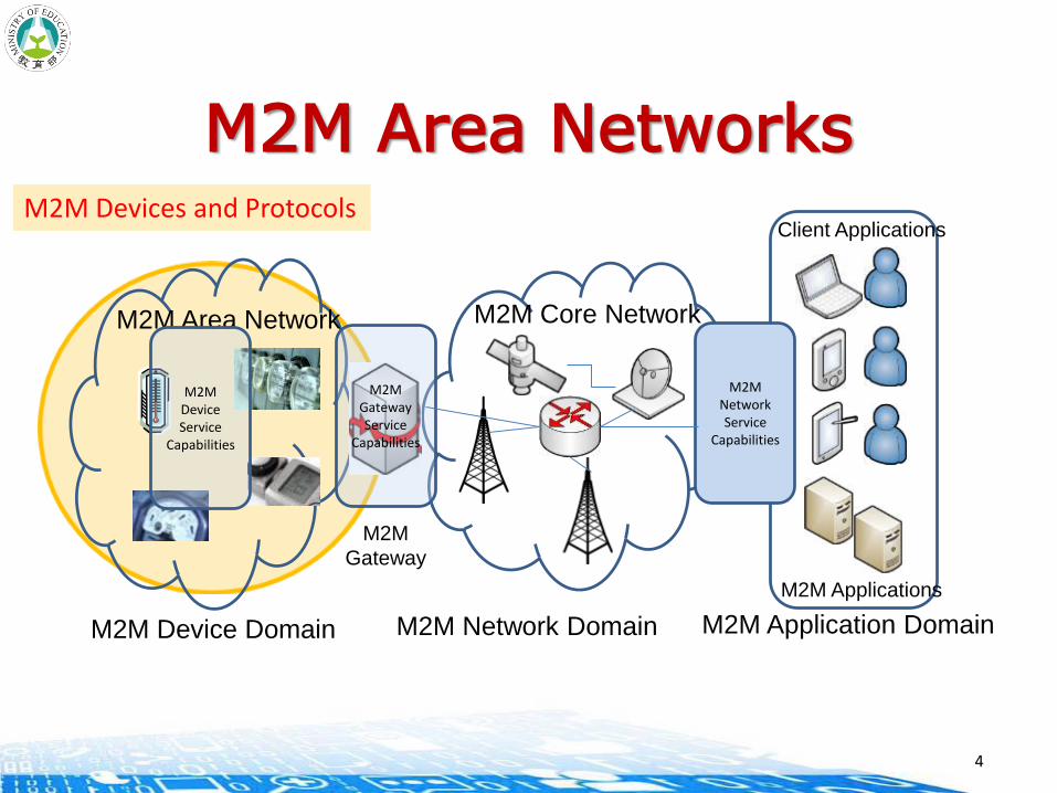
M2M Area NetworksM2M Devices and Protocols
M2M Applications
Client Applications
M2M
Gateway
M2M Core NetworkM2M Area Network
M2MNetworkService
Capabilities
M2MGatewayService
Capabilities
M2MDeviceService
Capabilities
M2M Device Domain M2M Network Domain M2M Application Domain
4
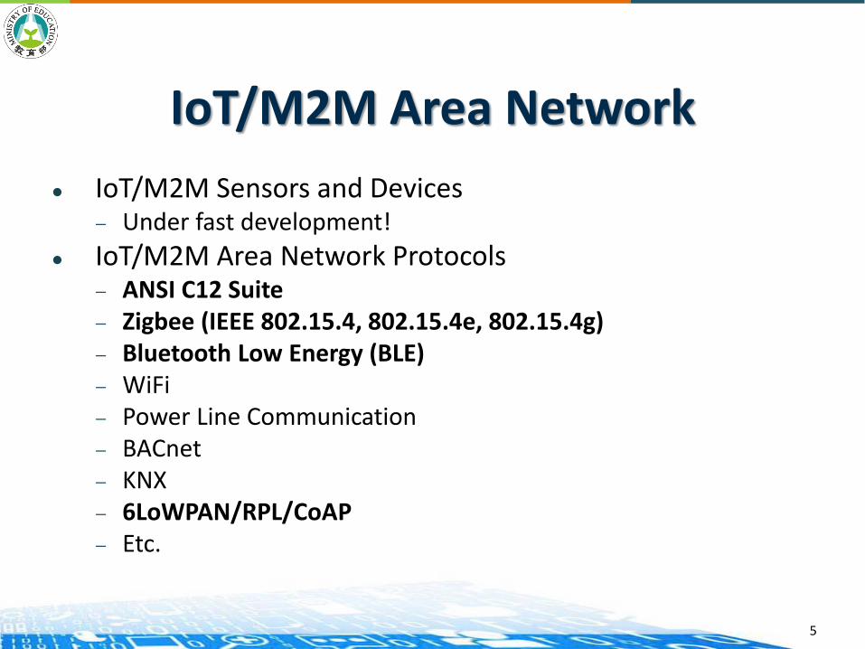
IoT/M2M Area Network
IoT/M2M Sensors and Devices— Under fast development!
IoT/M2M Area Network Protocols— ANSI C12 Suite— Zigbee (IEEE 802.15.4, 802.15.4e, 802.15.4g)— Bluetooth Low Energy (BLE)— WiFi— Power Line Communication— BACnet— KNX— 6LoWPAN/RPL/CoAP— Etc.
5

Catalog of IoT/M2M Sensors (1)
Embedded in Smart Phones — Accelerometer : Measure the three-axis acceleration— Magnetic : Measure the magnetic potential vector — Orientation : Measure the direction— Gyroscope : Measure the orientation, based on angular
momentum (角動量)
— Temperature :Measure the temperature— Light: Measure the luminosity— Pressure : Measure the pressure (壓力觸控感測(Force
Sensing))— Proximity : Measure whether any object is closing— GPS : Positioning the current latitude and longitude— NFC : Allow smartphones to transfer data to each other
within 10 cm— Etc.
6

Catalog of IoT/M2M Sensors (2)
Analogy-hall sensor磁力感測
Knock sensor
Laser-transmit
Infrared-receiver
Passive buzzer
Push button
Light break sensor
18B20 Temperature Sensor
Active buzzer
Colorful Auto-flash
Infrared-transmitter
Tilt-Switch(傾斜開關)
7
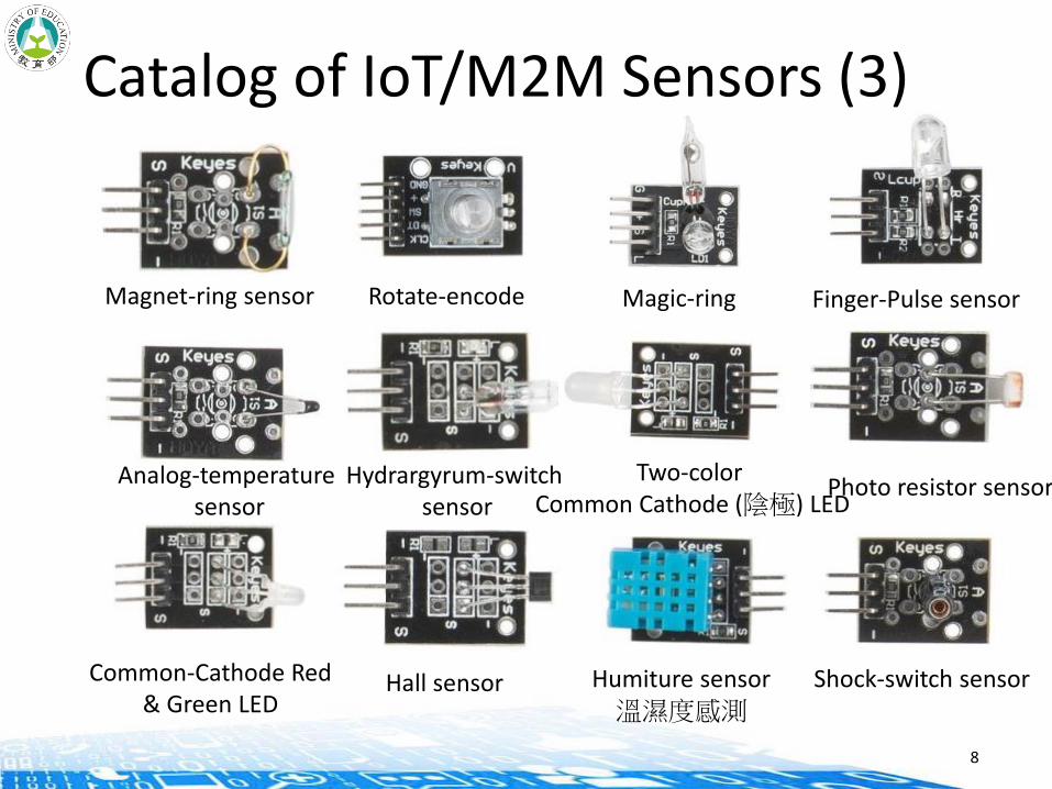
Catalog of IoT/M2M Sensors (3)
Magnet-ring sensor
Analog-temperature sensor
Common-Cathode Red& Green LED
Rotate-encode
Hydrargyrum-switch sensor
Hall sensor
Magic-ring
Two-color Common Cathode (陰極) LED
Humiture sensor溫濕度感測
Finger-Pulse sensor
Photo resistor sensor
Shock-switch sensor
8

Catalog of IoT/M2M Sensors (4)
Obstacle avoidance sensor
Microphone sensor
Linear-Hall sensor
Digital-Temperature sensor
Line Tracking sensor
High-Sensitive voice sensor
Metal touch sensor
Flame sensor
Magnetic spring
9

Catalog of IoT/M2M Sensors (5)
Graphic LCD 5110 Ultrasound Sensor Gas sensor
16 pin LCD module
PIR* sensor*Passive infrared
Xbee S2 wire antenna 9 gram Plastic Servo Motor(伺服馬達)
10
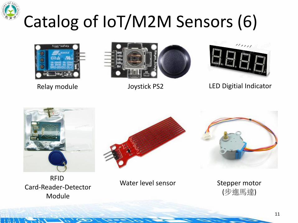
Catalog of IoT/M2M Sensors (6)
Relay module Joystick PS2 LED Digitial Indicator
RFID Card-Reader-Detector
Module
Water level sensor Stepper motor(步進馬達)
11
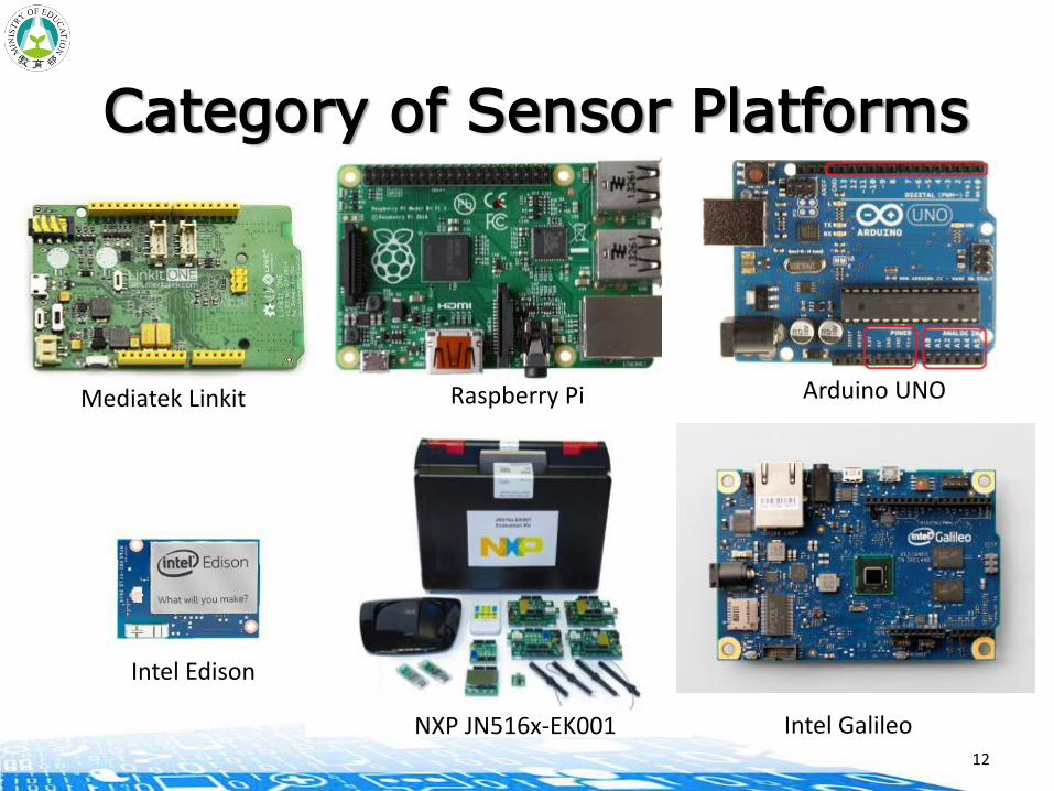
Category of Sensor Platforms
NXP JN516x-EK001
Arduino UNO
Intel Galileo
Raspberry Pi
12
Intel Edison
Mediatek Linkit
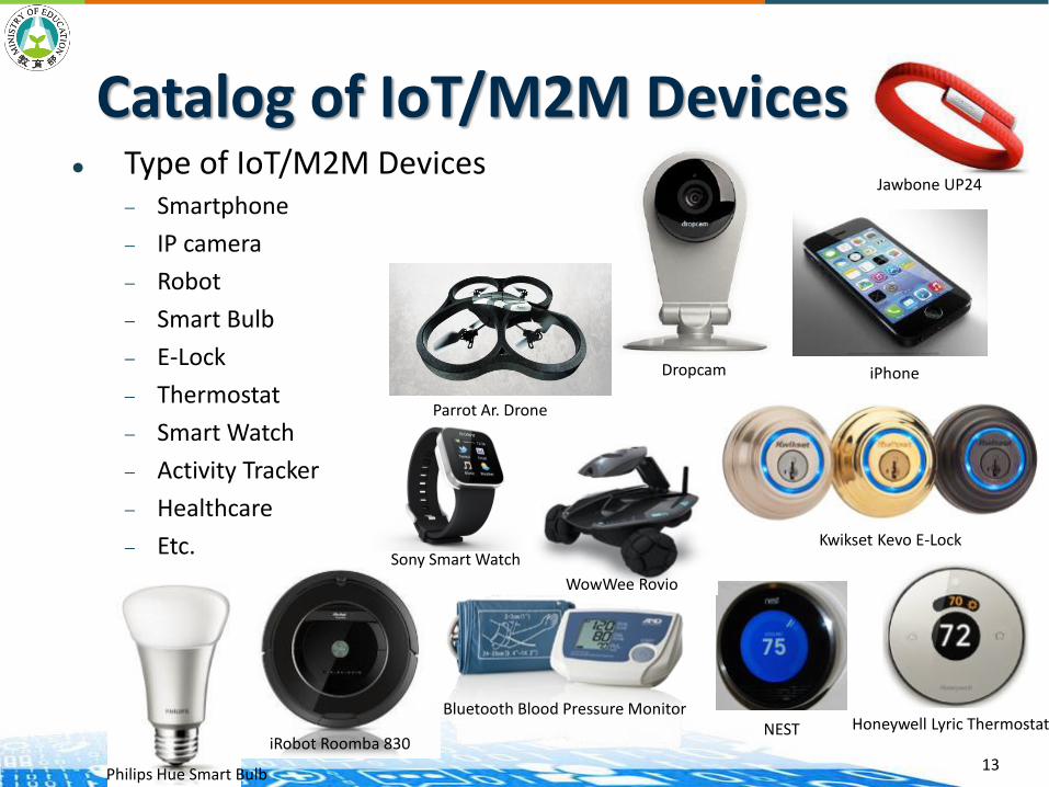
Catalog of IoT/M2M Devices Type of IoT/M2M Devices
— Smartphone
— IP camera
— Robot
— Smart Bulb
— E-Lock
— Thermostat
— Smart Watch
— Activity Tracker
— Healthcare
— Etc.
iRobot Roomba 830
Parrot Ar. Drone
Bluetooth Blood Pressure Monitor
Sony Smart Watch
WowWee Rovio
Kwikset Kevo E-Lock
NEST Honeywell Lyric Thermostat
Dropcam iPhone
Jawbone UP24
Philips Hue Smart Bulb13
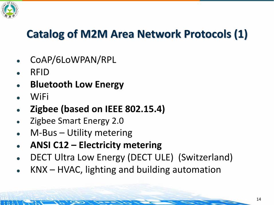
Catalog of M2M Area Network Protocols (1)
CoAP/6LoWPAN/RPL RFID Bluetooth Low Energy WiFi Zigbee (based on IEEE 802.15.4) Zigbee Smart Energy 2.0
M-Bus – Utility metering ANSI C12 – Electricity metering DECT Ultra Low Energy (DECT ULE) (Switzerland) KNX – HVAC, lighting and building automation
14
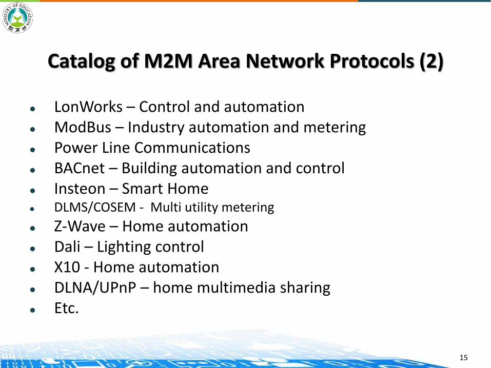
Catalog of M2M Area Network Protocols (2)
LonWorks – Control and automation ModBus – Industry automation and metering Power Line Communications BACnet – Building automation and control Insteon – Smart Home DLMS/COSEM - Multi utility metering
Z-Wave – Home automation Dali – Lighting control X10 - Home automation DLNA/UPnP – home multimedia sharing Etc.
15
EXAMPLE M2M AREA PROTOCOLS

ANSI C12 SUITE
C12.19C12.18C12.21C12.22RFC 6142
ANSI C12 Suite
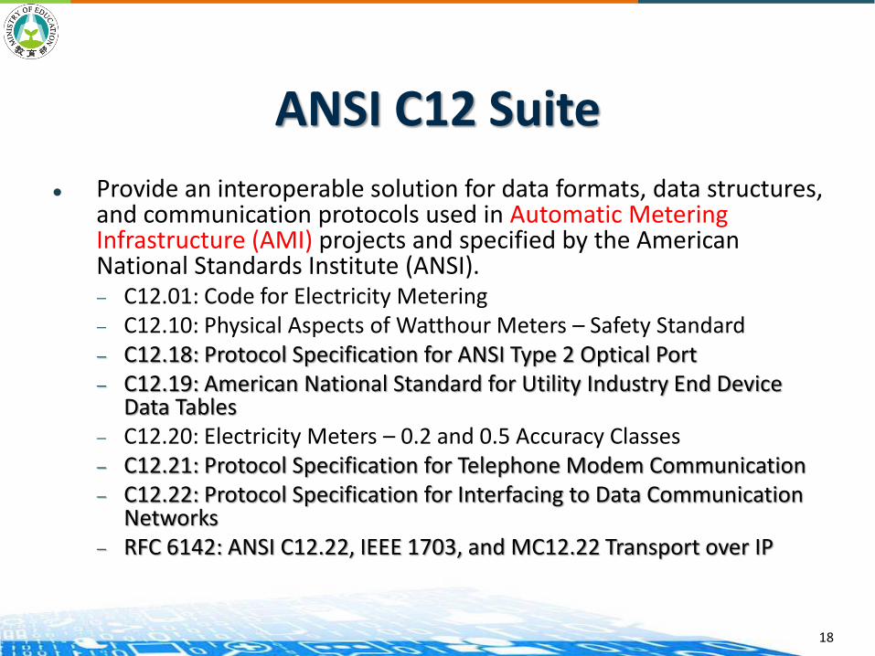
Provide an interoperable solution for data formats, data structures, and communication protocols used in Automatic Metering Infrastructure (AMI) projects and specified by the American National Standards Institute (ANSI). — C12.01: Code for Electricity Metering— C12.10: Physical Aspects of Watthour Meters – Safety Standard— C12.18: Protocol Specification for ANSI Type 2 Optical Port— C12.19: American National Standard for Utility Industry End Device
Data Tables— C12.20: Electricity Meters – 0.2 and 0.5 Accuracy Classes— C12.21: Protocol Specification for Telephone Modem Communication— C12.22: Protocol Specification for Interfacing to Data Communication
Networks— RFC 6142: ANSI C12.22, IEEE 1703, and MC12.22 Transport over IP
18

19
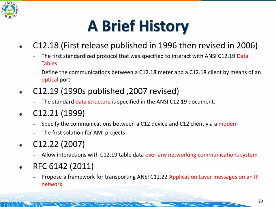
A Brief History C12.18 (First release published in 1996 then revised in 2006)
— The first standardized protocol that was specified to interact with ANSI C12.19 Data Tables
— Define the communications between a C12.18 meter and a C12.18 client by means of an optical port
C12.19 (1990s published ,2007 revised)— The standard data structure is specified in the ANSI C12.19 document.
C12.21 (1999)— Specify the communications between a C12 device and C12 client via a modem
— The first solution for AMI projects
C12.22 (2007)— Allow interactions with C12.19 table data over any networking communications system
RFC 6142 (2011)— Propose a framework for transporting ANSI C12.22 Application Layer messages on an IP
network
20
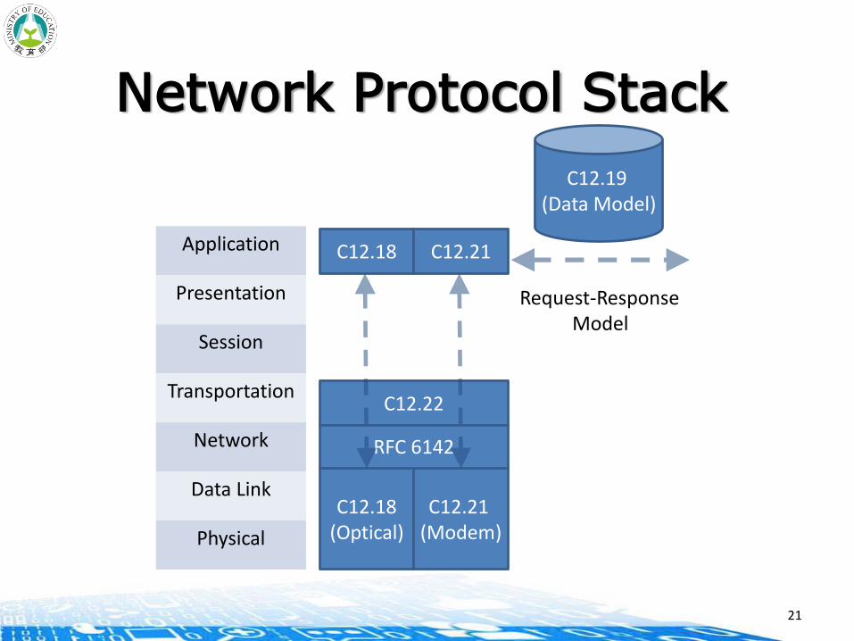
Network Protocol Stack
C12.19(Data Model)
C12.18Application
Presentation
Session
Transportation
Network
Data Link
Physical
C12.21
C12.18(Optical)
C12.21(Modem)
Request-ResponseModel
RFC 6142
C12.22
21
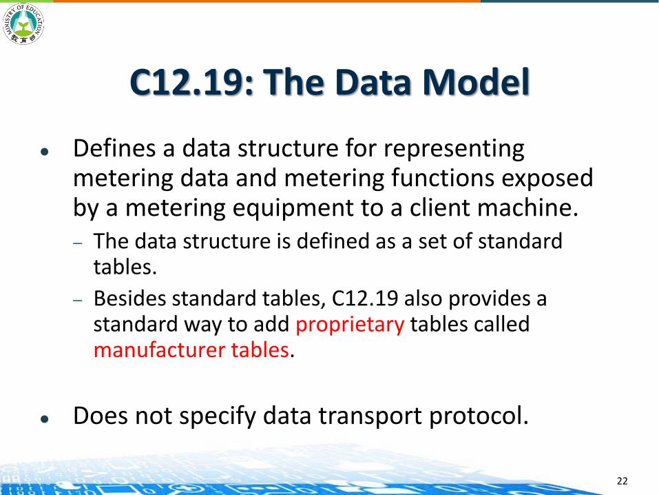
C12.19: The Data Model
Defines a data structure for representing metering data and metering functions exposed by a metering equipment to a client machine.— The data structure is defined as a set of standard
tables.
— Besides standard tables, C12.19 also provides a standard way to add proprietary tables called manufacturer tables.
Does not specify data transport protocol.
22

Decade Tables that share a common purpose or are relative to
a common feature are called a “decade”.— There are 17 decades in the version published in 2007.
0 Configuration Tables
9 6 Load Profile Tables 8 12 Network Control Tables
Defined in ANSI C12.22
1 Data Source Tables 9 7 History & Events Logs
10 13 Relay Control Tables
Defined in ANSI C12.22
2 Register Tables 9 8 User-Defined Tables 10 14 Extended User Defined Tables
4
3 Local Display Tables 5 9 Telephone Control Tables
9 15 Quality of Service Tables
9
4 Security Tables 7 10 Extended Source Tables
4 16 One-Way Tables 5
5 Time-of-Use Tables 7 11 Load Control & Pricing Tables
9
23

Read/Write Services
The read service request allows the transfer of table data from a sending party to a receiving party.— Full table read: specified by Table_Identifier— Partial table read
○ Index-based: specified by up to 5 indexes and optionally an element count
○ Offset-based: specified by an offset and optionally a count
The write service allows unsolicited data to be sent to a receiving party.— Support both full and partial table write
24
Three Remarkable Tables in Decade 0
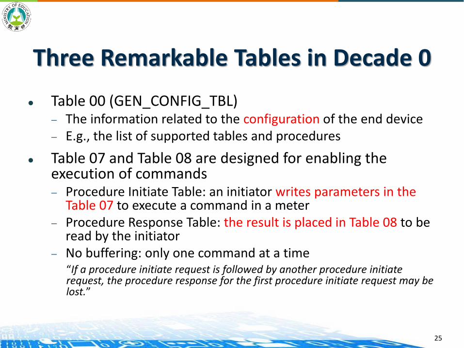
Table 00 (GEN_CONFIG_TBL)— The information related to the configuration of the end device— E.g., the list of supported tables and procedures
Table 07 and Table 08 are designed for enabling the execution of commands— Procedure Initiate Table: an initiator writes parameters in the
Table 07 to execute a command in a meter— Procedure Response Table: the result is placed in Table 08 to be
read by the initiator— No buffering: only one command at a time
“If a procedure initiate request is followed by another procedure initiate request, the procedure response for the first procedure initiate request may be lost.”
25

C12.18: Basic Point-to-Point Communication over an Optical Port
The communications between an electric metering equipment and another client device via an optical port— The first standardized protocol that was specified to
interact with ANSI C12.19 Data Tables
— Focuses on the physical, data link and application layers
Three main functionalities— Modification of the communication channel;
— Transport of information to and from the metering device;
— Closure of the communication channel when communications are complete.
26
Protocol Specifications for Electric Metering (PSEM)
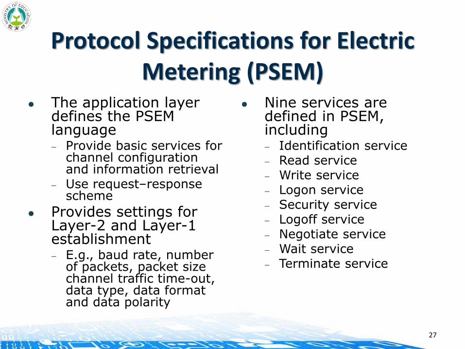
The application layer defines the PSEM language— Provide basic services for
channel configuration and information retrieval
— Use request–response scheme
Provides settings for Layer-2 and Layer-1 establishment — E.g., baud rate, number
of packets, packet size channel traffic time-out, data type, data format and data polarity
Nine services are defined in PSEM, including — Identification service— Read service— Write service— Logon service— Security service— Logoff service— Negotiate service— Wait service— Terminate service
27
C12.21: An Extension of C12.18 for Modem Communication
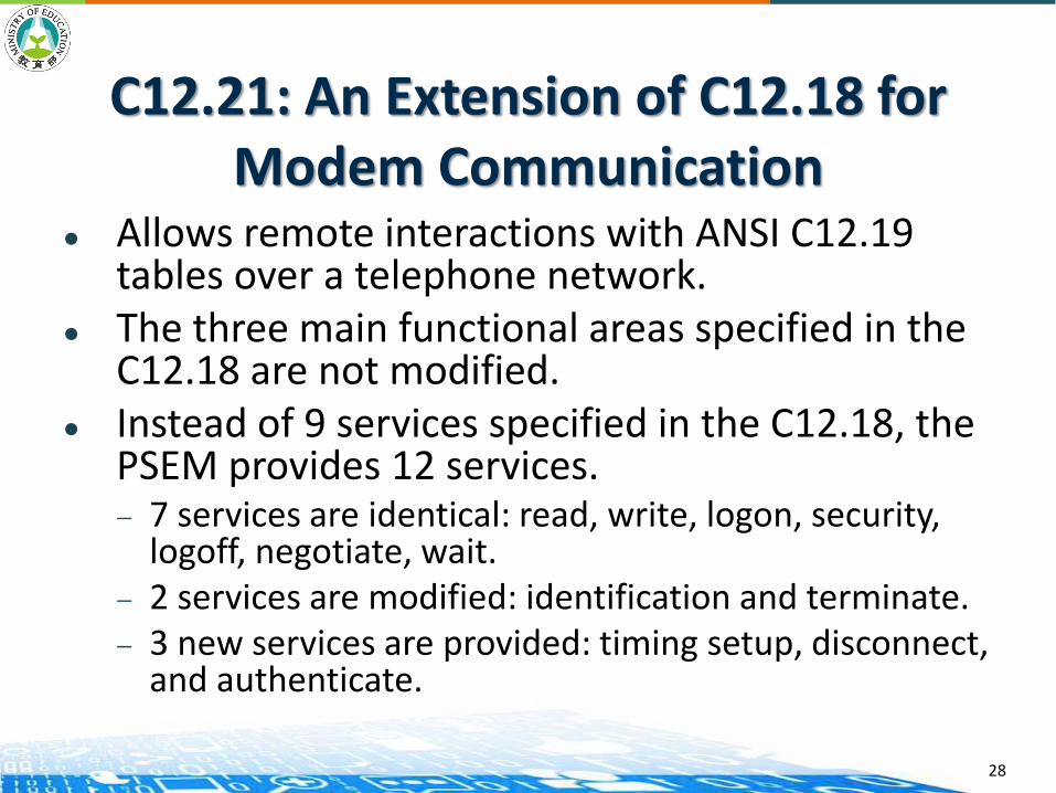
Allows remote interactions with ANSI C12.19 tables over a telephone network.
The three main functional areas specified in the C12.18 are not modified.
Instead of 9 services specified in the C12.18, the PSEM provides 12 services.— 7 services are identical: read, write, logon, security,
logoff, negotiate, wait. — 2 services are modified: identification and terminate.— 3 new services are provided: timing setup, disconnect,
and authenticate.
28
Interactions with the Data-Link Layer
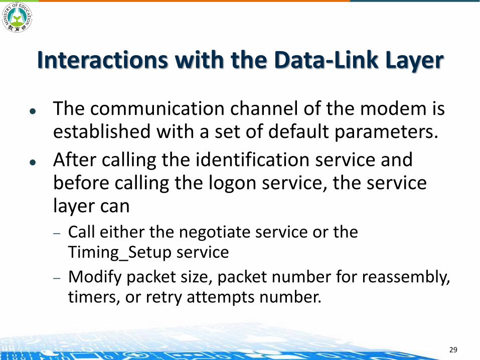
The communication channel of the modem is established with a set of default parameters.
After calling the identification service and before calling the logon service, the service layer can — Call either the negotiate service or the
Timing_Setup service
— Modify packet size, packet number for reassembly, timers, or retry attempts number.
29
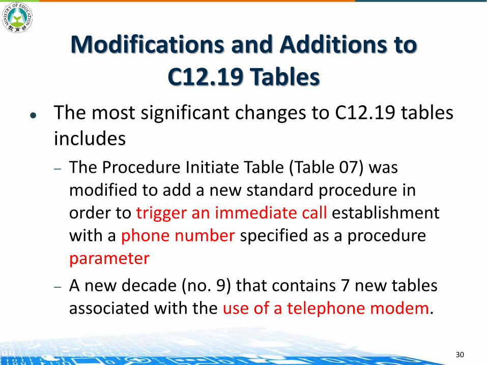
Modifications and Additions to C12.19 Tables
The most significant changes to C12.19 tables includes
— The Procedure Initiate Table (Table 07) was modified to add a new standard procedure in order to trigger an immediate call establishment with a phone number specified as a procedure parameter
— A new decade (no. 9) that contains 7 new tables associated with the use of a telephone modem.
30

C12.22: Enable Transportation over any Networking Communication System
Defines several types of network elements that are used in a reference topology
Describes interfaces between different types of network elements
New data tables are added and some existing tables are also modified
31
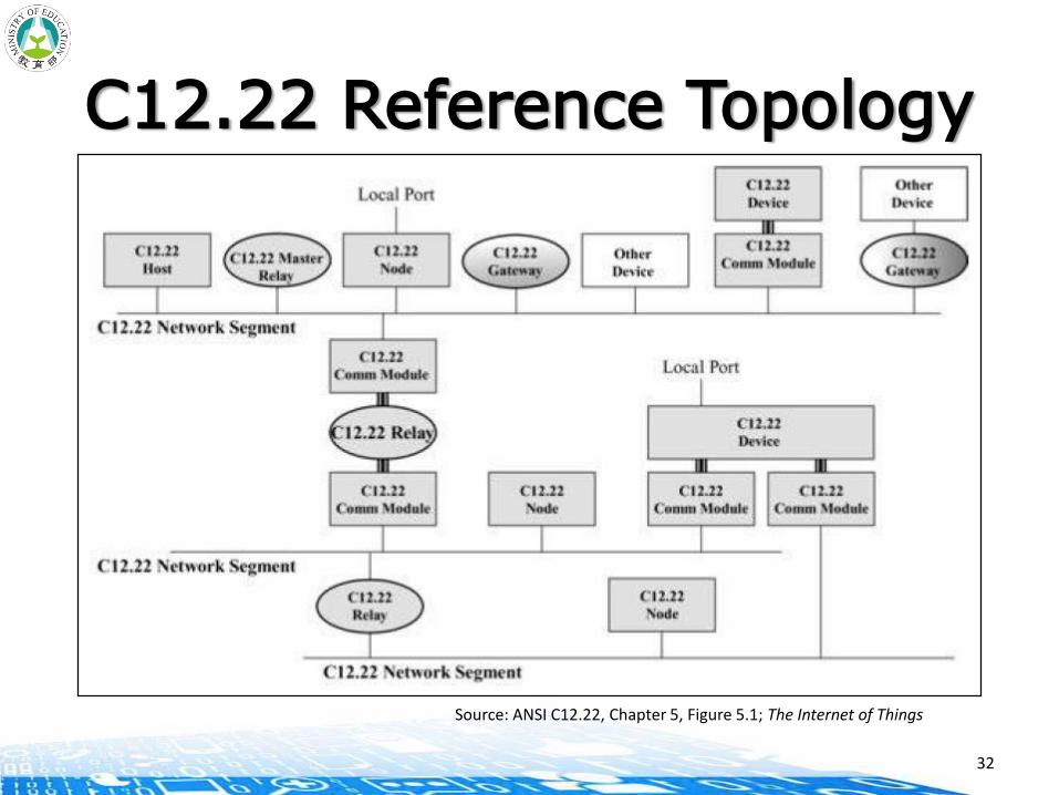
C12.22 Reference Topology
Source: ANSI C12.22, Chapter 5, Figure 5.1; The Internet of Things
32

Network Elements in C12.22 (1/2)
C12.22 Host: this is a termination point in a C12.22 network. It may be an authentication host or/and notification host.
C12.22 Device: this is a network element that contains a C12.22 application.
C12.22 Communication Module: this is a hardware device that allows communications between a C12.22 Device and a C12.22 network.
C12.22 Node: it is a combined C12.22 communication-module/device network element.
33

Network Elements in C12.22 (2/2)
C12.22 Master Relay:
C12.22 Relay:
— This layer 7 address is called ApTitle (application process title)
C12.22 Gateway: this is a protocol converter from the C12.22 protocol to any other protocol.
34

C12.22 Node to C12.22 NetworkCommunications
The protocol stack between a C12.22 node and a C12.22 network is only defined at layer 7.
The new version of the PSEM protocol contains 13 services:— Three services are unchanged: the read, write and security services.— Six services are modified (compared to C12.21): identification, logon,
logoff, terminate, disconnect, and wait services.— Four new services are provided: registration, deregistration, resolve,
and trace services.
The extended PSEM (EPSEM) is specified to allow sending multiple requests and receiving multiple responses simultaneously.
C12.22 security mechanism supports both authentication and encryption
35

C12.22 Communication Module The concept of C12.22 communication modules is introduced to model
the communication ports of C12.22 meters.— Connects to the C12.22 Device through an interface defined in the C12.22
standard. — Connects to any LAN (e.g., ZigBee, …), WAN (DSL, GPRS, …), or MAN
(Ethernet, …).
Source: The Internet of Things, Chapter 10, Figure 10.1.
36
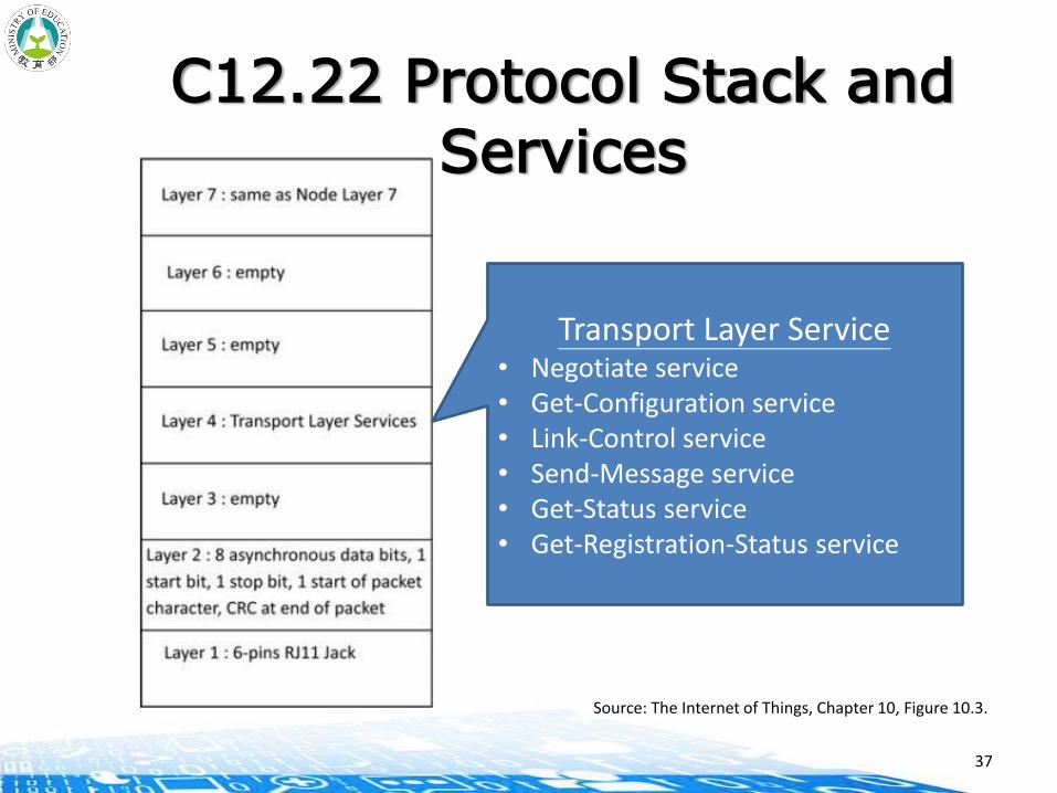
C12.22 Protocol Stack and Services
Source: The Internet of Things, Chapter 10, Figure 10.3.
Transport Layer Service• Negotiate service• Get-Configuration service• Link-Control service• Send-Message service• Get-Status service• Get-Registration-Status service
37
C12.19 Updates
Decade 12 “Node Network Control Tables” is added, modeling the C12.22 node access to a C12.22 network
Decade 13 “Relay Control Tables” is added, related with the management of a C12.22 relay.
The content of the Procedure Initiate Table is augmented with 4 new procedures (Registration, Deregistration, Network Interface Control, and Exception Report), related to the newly added Decade 12
38
RFC 6142: C12.22 Transport Overan IP Network
Transport C12.22 messages by using TCP and UDP transports over an IP network. — Specifies an encoding for the native IP address in the appropriate fields of
ANSI C12.19 Tables.
○ IPv4 and IPv6 are two possible options.
— Port number 1153 was assigned by IANA* for both TCP and UDP.
Since C12.22 has its own security mechanism, transport layer security is not mandated. RFC 6142 allows the use of a transport layer security mechanism as an enhancement.
*IANA: Internet Assigned Number Authority
39

RFC 6142: C12.22 Transport Overan IP Network (Cont.)
To facilitate the reading of numerous C12.22 meters, the support of IP multicast is required in all C12.22 hosts, relays and master relays and recommended in the C12.22 nodes.— Meters with a common C12.22 multicast group ApTitle can be reached by
sending a single EPSEM read request.
— 224.0.2.4 for IPv4 and FF0X::24 for IPv6 have been assigned by IANA to a newly created “All C1222 Nodes” multicast group.
— TTL (Time To Live) attribute in an IP packet header is used to limiting the propagation of C12.22 IP multicast messages.
40

ZIGBEE

ZigBee
ZigBee is a standardized wireless protocol for personal area networking, or “WPAN.”
The protocol is the work and property of the ZigBee Alliance, a consortium that creates and promotes this WPAN standard
ZigBee is built on IEEE 802.15.4 standard that defines physical (PHY) and Medium Access Control (MAC) layers of a WPAN.
The ZigBee Alliance defines Network (NWK) and Application (APL) layer specifications to complete what is called the ZigBee stack.
Designed for low cost, low power, low data rate, low duty cycle wireless connectivity.
42
ZigBee Architecture Objectives
Support all target environments and applications that are in the scope of ZigBee:— Ensure that devices are efficient in their use of the available
bandwidth
Provide a platform and implementation for wirelessly networked devices:— Make it easy to design and develop ZigBee devices
— Reduce today’s cost of building wireless solutions
Ensure interoperability through the definition of application profiles— Enable out-of-the-box interoperable devices where desired by
manufacturers
43
Source: https://www.nxp.com/files/training_pdf/28081_ZIGBEE_OVERVIEW_WBT.pdf

ZigBee Architecture Objectives
Define the ZigBee network and stack models— Define ZigBee device types and core functions— Define layers and modules with their interfaces, and services
Provide the framework to allow a separation of concerns for the specification, design, and implementation of ZigBee devices— Help to create and coordinate consistent use of terms in
ZigBee
Allow future extension of ZigBee— Enable both extension of the basic ZigBee platform as well as
ZigBee application profiles
44
Source: https://www.nxp.com/files/training_pdf/28081_ZIGBEE_OVERVIEW_WBT.pdf
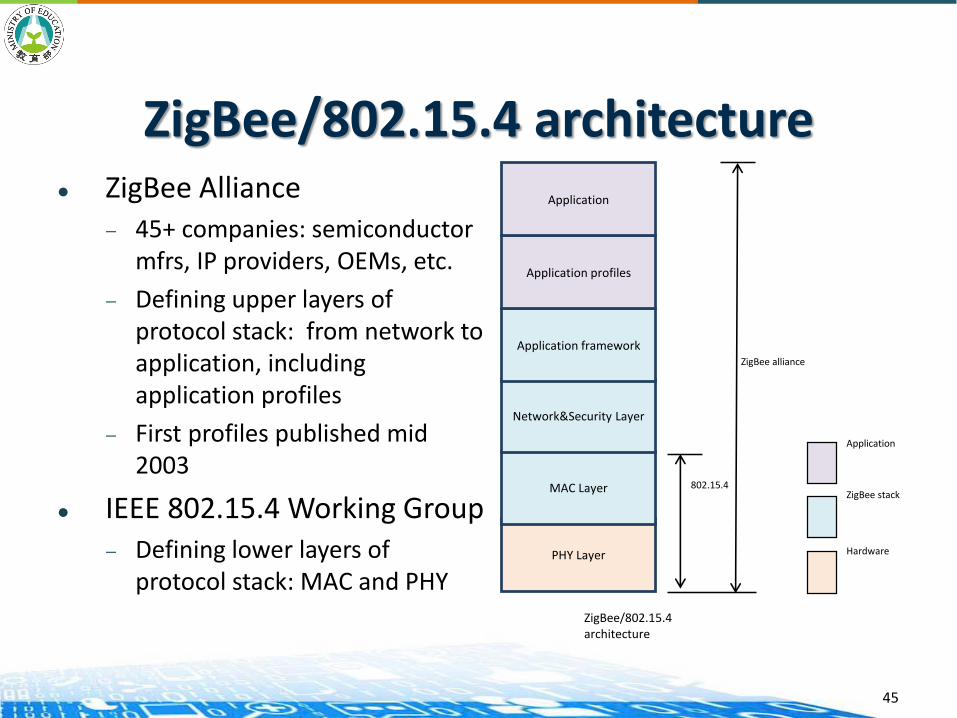
ZigBee/802.15.4 architecture ZigBee Alliance
— 45+ companies: semiconductor mfrs, IP providers, OEMs, etc.
— Defining upper layers of protocol stack: from network to application, including application profiles
— First profiles published mid 2003
IEEE 802.15.4 Working Group— Defining lower layers of
protocol stack: MAC and PHYPHY Layer
MAC Layer
Network&Security Layer
Application framework
Application profiles
Application
802.15.4
ZigBee alliance
Hardware
ZigBee stack
Application
ZigBee/802.15.4 architecture
45

ZigBee/802.15.4 architecture
46
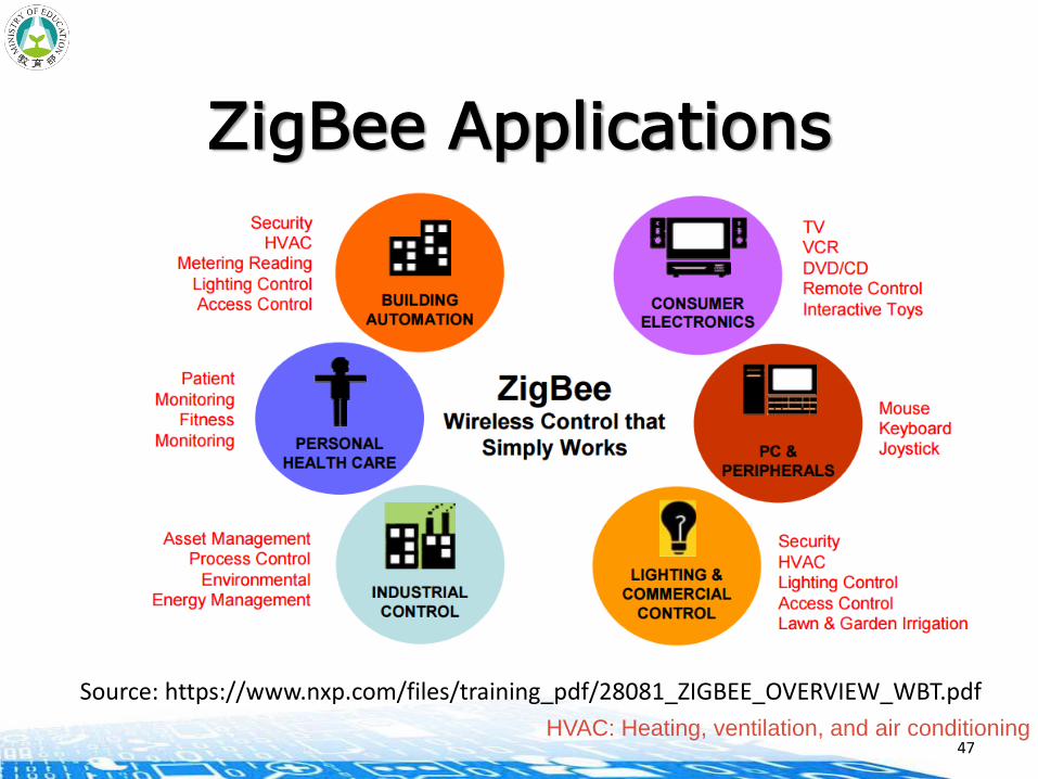
ZigBee Applications
47
Source: https://www.nxp.com/files/training_pdf/28081_ZIGBEE_OVERVIEW_WBT.pdf
HVAC: Heating, ventilation, and air conditioning
ZigBee Market Goals
Global band operation, 2.4 GHz unlicensed band or one of the 900MHz regional bands
Unrestricted geographic use
RF penetration through walls and ceilings
Automatic or semi-automatic installation
Easy to add or remove devices
Low cost
48

ZigBee Technical Specs
Data throughput: 20 kbps to 250 kbps
Range: 10 to 75 m coverage
Scalability: Up to 100 collocated networks
— Each network could have up to 1000 nodes in practice
Low power: Up to 2 years of battery life on standard alkaline batteries
49

ZigBee Network Models
50
RFD: Reduced Function DeviceFFD: Full Function DeviceCoordinator: A full function device that manages the network.
Source: https://www.nxp.com/files/training_pdf/28081_ZIGBEE_OVERVIEW_WBT.pdf
Components
PAN coordinator (ZigBee coordinator)
— Main controller of a PAN
— A network has exactly one PAN coordinator
Coordinator (ZigBee router)
— Provide synchronization services through the transmission of beacons
Device (ZigBee end device)
— Any entity w/ IEEE 802.15.4 MAC and PHY interface
51
IEEE 802.15.4 Device Types
Network Coordinator— Maintains overall network knowledge; most sophisticated of the three
types; requires most memory and computing power
Full Function Device (FFD)— Carries full 802.15.4 functionality and all features specified by the
standard— Additional memory, computing power make it ideal for a network
router function— Could also be used in network edge devices where the network
touches other networks or devices that are not IEEE 802.15.4 compliant
Reduced Function Device (RFD)— Carriers limited (as specified by the standard) functionality to control
cost and complexity— General usage will be in network edge devices
52

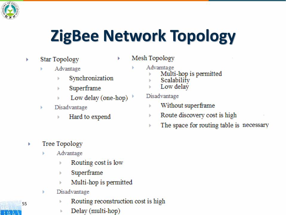
ZigBee Network Topology
53
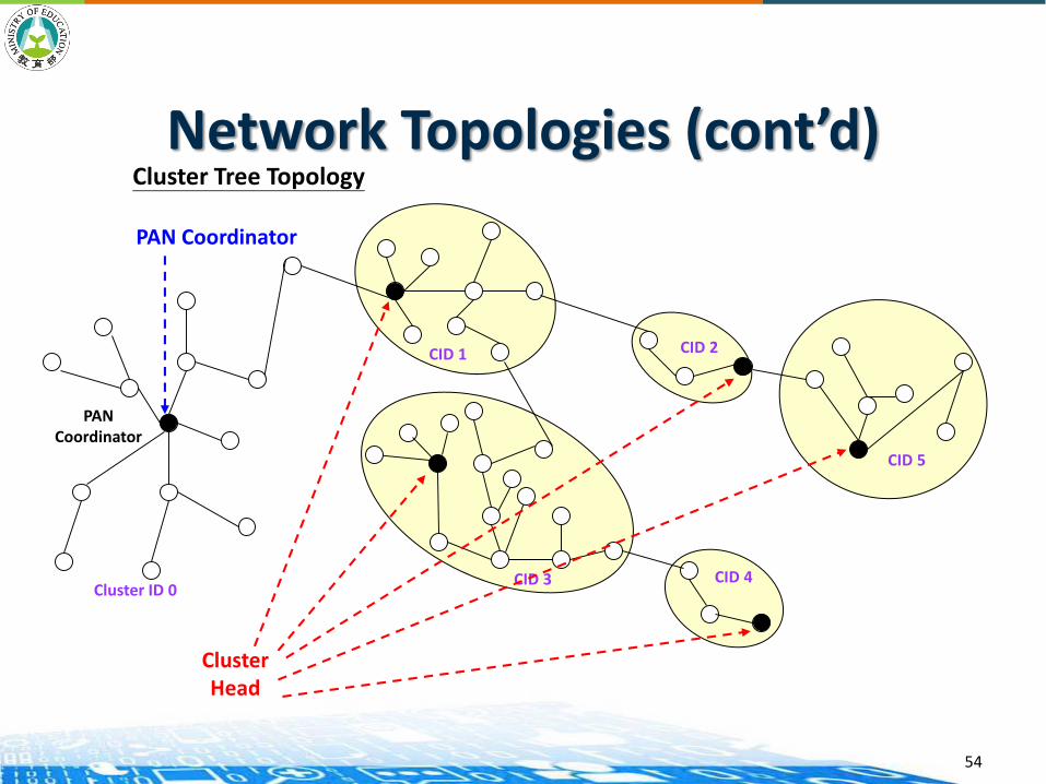
Network Topologies (cont’d)Cluster Tree Topology
ClusterHead
CID 1
CID 3
CID 2
CID 5
CID 4
PAN Coordinator
PANCoordinator
Cluster ID 0
54
ZigBee Network Topology
55
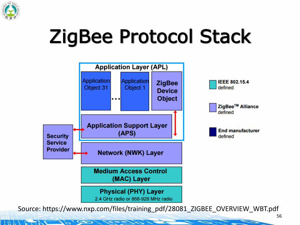
ZigBee Protocol Stack
56
Source: https://www.nxp.com/files/training_pdf/28081_ZIGBEE_OVERVIEW_WBT.pdf
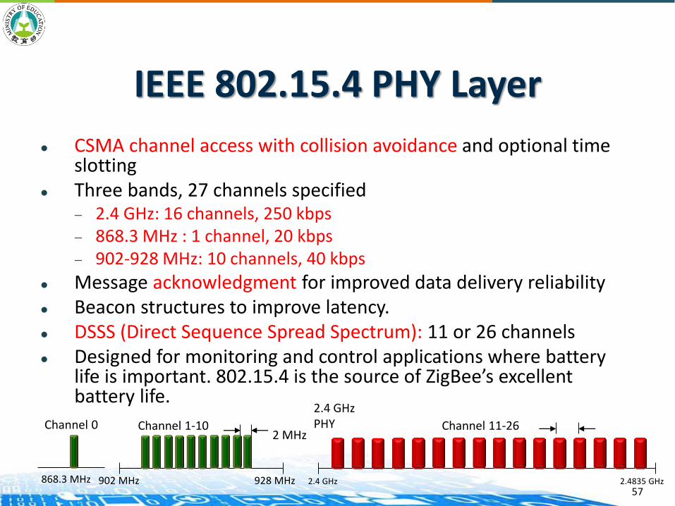
IEEE 802.15.4 PHY Layer
CSMA channel access with collision avoidance and optional time slotting
Three bands, 27 channels specified — 2.4 GHz: 16 channels, 250 kbps— 868.3 MHz : 1 channel, 20 kbps— 902-928 MHz: 10 channels, 40 kbps
Message acknowledgment for improved data delivery reliability Beacon structures to improve latency. DSSS (Direct Sequence Spread Spectrum): 11 or 26 channels Designed for monitoring and control applications where battery
life is important. 802.15.4 is the source of ZigBee’s excellent battery life.
57
Channel 0
868.3 MHz
Channel 1-102 MHz
902 MHz 928 MHz
Channel 11-26
2.4 GHzPHY
2.4 GHz 2.4835 GHz
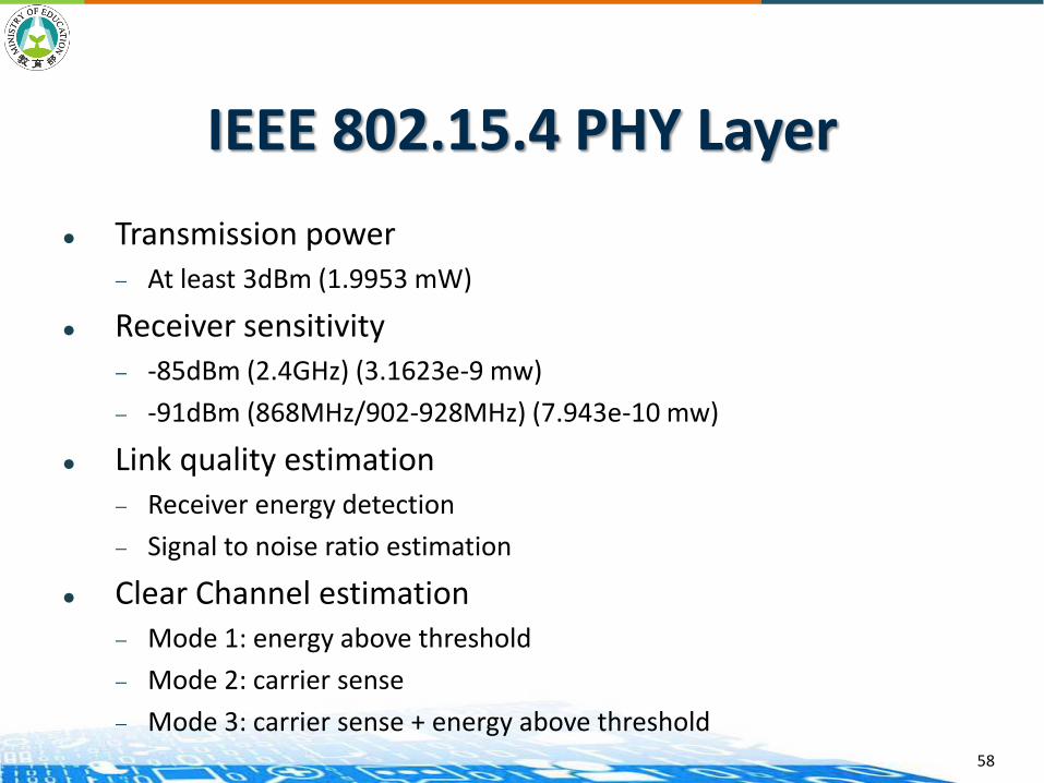
IEEE 802.15.4 PHY Layer
Transmission power— At least 3dBm (1.9953 mW)
Receiver sensitivity — -85dBm (2.4GHz) (3.1623e-9 mw)
— -91dBm (868MHz/902-928MHz) (7.943e-10 mw)
Link quality estimation— Receiver energy detection
— Signal to noise ratio estimation
Clear Channel estimation— Mode 1: energy above threshold
— Mode 2: carrier sense
— Mode 3: carrier sense + energy above threshold58
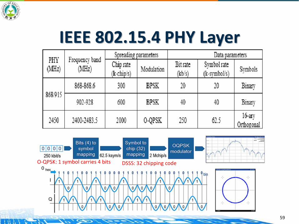
IEEE 802.15.4 PHY Layer
59
O-QPSK: 1 symbol carries 4 bits DSSS: 32 chipping code

IEEE 802.15.4 MAC Features
Employs 64-bit IEEE & 16-bit short addresses
— Ultimate network size can be 264 nodes (more than probably needed)
— Using local addressing, simple networks of more than 65,000 (216) nodes can be configured, with reduced address overhead
Simple frame structure
Reliable delivery of data
Supports AES-128 security
Employs CSMA-CA channel access for better coexistence
Offers optional superframe structure for improved latency
60
IEEE 802.15.4 MAC Options
Non-beacon network— Standard ALOHA CSMA-CA communications— Positive acknowledgment for successfully received
packets
Optional beacon-enabled network— Superframe structure
○ For dedicated bandwidth and low latency○ Set up by network coordinator to transmit beacons at
predetermined intervals» 15ms to 252sec (15.38ms ∗ 2n where 0 ≤ n ≤ 14)» 16 equal-width time slots between beacons» Channel access in each time slot is contention free
61

802.15.4 Beacon Frame Format
62
• The beacon frame is much more complex as it must convey the synchronization and guaranteed time slot (GTS) information to all of the devices in the network.
• Beacons add a new level of functionality to a network. Client devices can wake up only when a beacon is to be broadcast, listen for their address, and if hear nothing, return to sleep.
• Beacons are important for mesh and cluster tree networks to keep all of the nodes synchronized without requiring nodes to consume precious battery energy listening for long periods of time.
Source: https://www.nxp.com/files/training_pdf/28081_ZIGBEE_OVERVIEW_WBT.pdf
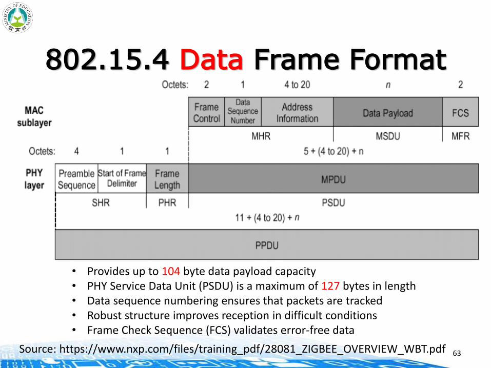
802.15.4 Data Frame Format
63
• Provides up to 104 byte data payload capacity• PHY Service Data Unit (PSDU) is a maximum of 127 bytes in length• Data sequence numbering ensures that packets are tracked• Robust structure improves reception in difficult conditions• Frame Check Sequence (FCS) validates error-free data
Source: https://www.nxp.com/files/training_pdf/28081_ZIGBEE_OVERVIEW_WBT.pdf
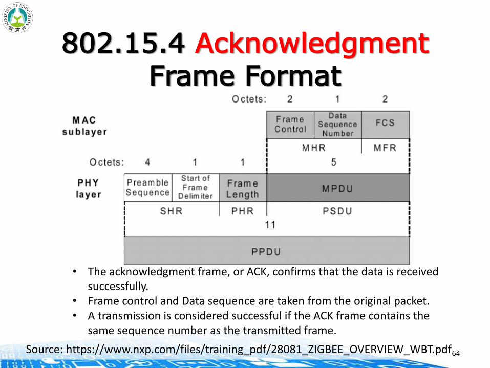
802.15.4 AcknowledgmentFrame Format
64
• The acknowledgment frame, or ACK, confirms that the data is received successfully.
• Frame control and Data sequence are taken from the original packet. • A transmission is considered successful if the ACK frame contains the
same sequence number as the transmitted frame.
Source: https://www.nxp.com/files/training_pdf/28081_ZIGBEE_OVERVIEW_WBT.pdf

802.15.4 Command Frame Format
65
The command frame is used for remote control. Instead of data as thepayload, this frame contains command information. A command type byte isadded as well. The MPDU must still be 127 bytes or less as with the Dataframe.
Source: https://www.nxp.com/files/training_pdf/28081_ZIGBEE_OVERVIEW_WBT.pdf
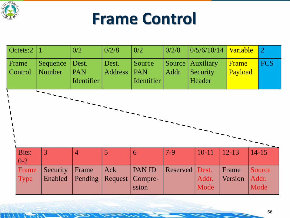
Octets:2 1 0/2 0/2/8 0/2 0/2/8 0/5/6/10/14 Variable 2
Frame
Control
Sequence
Number
Dest.
PAN
Identifier
Dest.
Address
Source
PAN
Identifier
Source
Addr.
Auxiliary
Security
Header
Frame
Payload
FCS
Bits:
0-2
3 4 5 6 7-9 10-11 12-13 14-15
Frame
Type
Security
Enabled
Frame
Pending
Ack
Request
PAN ID
Compre-
ssion
Reserved Dest.
Addr.
Mode
Frame
Version
Source
Addr.
Mode
Frame Control
66
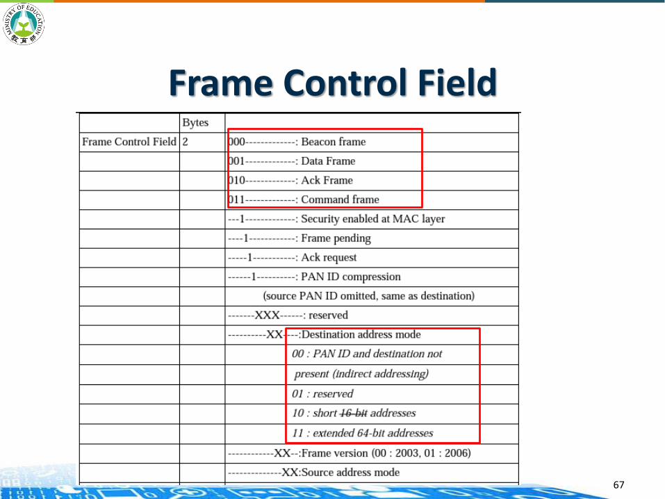
Frame Control Field
67
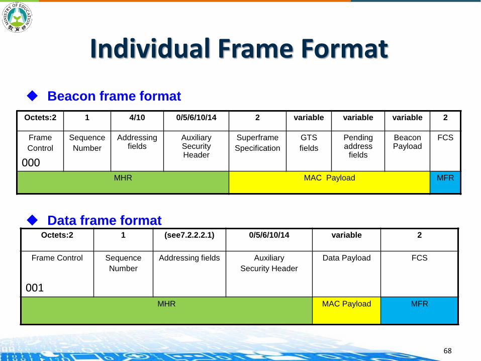
Individual Frame Format
Octets:2 1 4/10 0/5/6/10/14 2 variable variable variable 2
Frame
Control
Sequence
Number
Addressing fields
Auxiliary Security Header
Superframe
Specification
GTS
fields
Pending address
fields
Beacon Payload
FCS
MHR MAC Payload MFR
Beacon frame format
Octets:2 1 (see7.2.2.2.1) 0/5/6/10/14 variable 2
Frame Control Sequence
Number
Addressing fields Auxiliary
Security Header
Data Payload FCS
MHR MAC Payload MFR
Data frame format
000
001
68
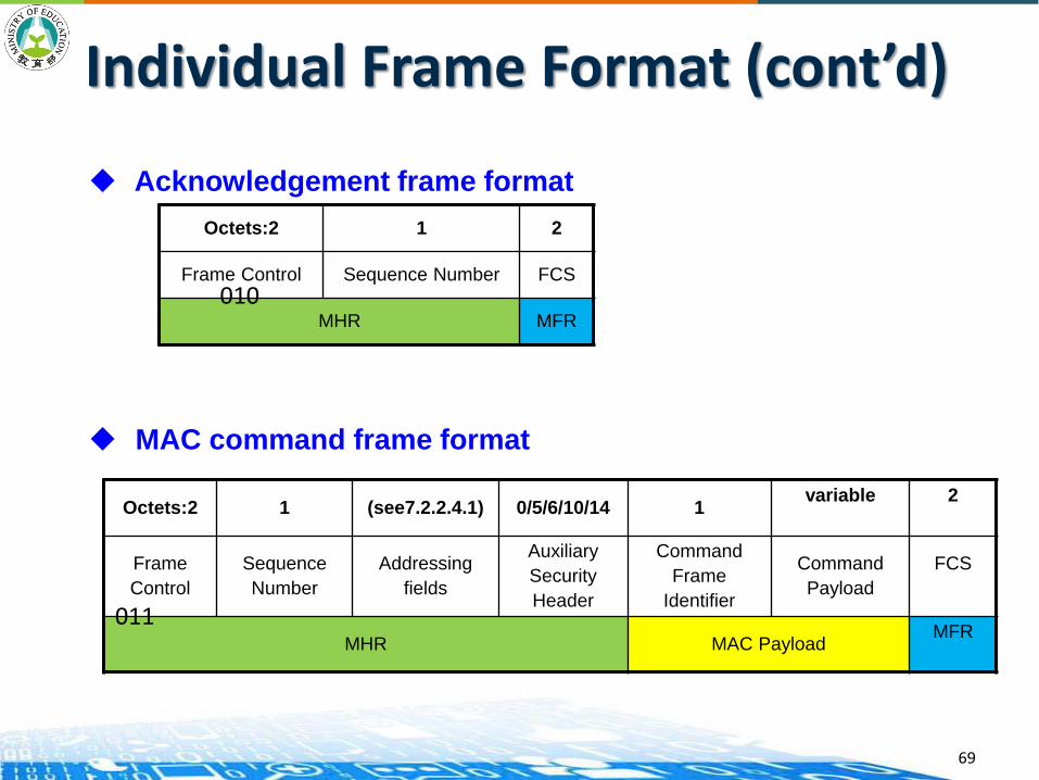
Individual Frame Format (cont’d)
Acknowledgement frame format
MAC command frame format
Octets:2 1 2
Frame Control Sequence Number FCS
MHR MFR
Octets:2 1 (see7.2.2.4.1) 0/5/6/10/14 1variable 2
Frame
Control
Sequence
Number
Addressing
fields
Auxiliary
Security
Header
Command
Frame
Identifier
Command
Payload
FCS
MHR MAC PayloadMFR
010
011
69
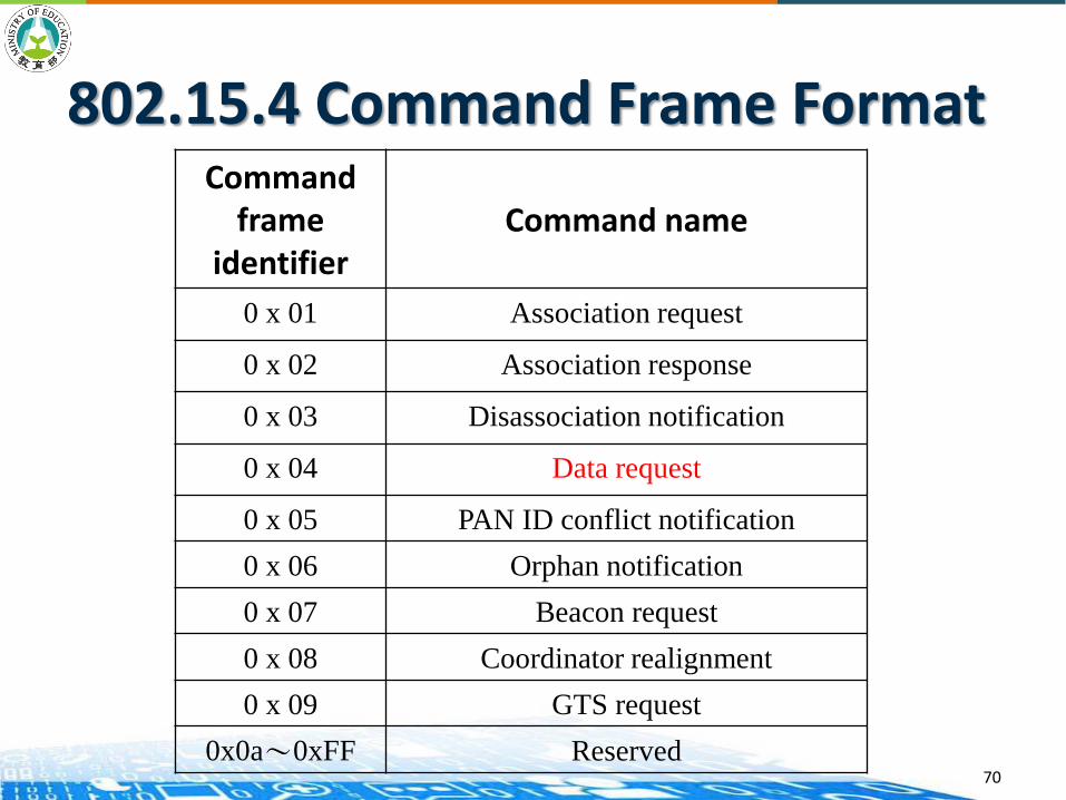
Command frame
identifierCommand name
0 x 01 Association request
0 x 02 Association response
0 x 03 Disassociation notification
0 x 04 Data request
0 x 05 PAN ID conflict notification
0 x 06 Orphan notification
0 x 07 Beacon request
0 x 08 Coordinator realignment
0 x 09 GTS request
0x0a~0xFF Reserved70
802.15.4 Command Frame Format
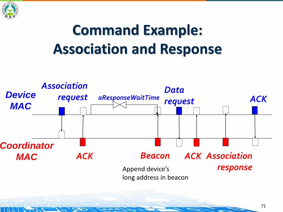
Command Example:Association and Response
Coordinator
MAC
Device
MAC
Association request
ACK
aResponseWaitTimeDatarequest
ACK Association response
ACK
Beacon
Append device’slong address in beacon
71

Wireless Networking Basics Network scan: the ability of a device to detect active
channels within its communications range. This range is often called, in personal area networking, the Personal Operating Space (POS).
Creating/Joining a PAN: the ability to form a network on unused channels within the POS. In the case of ZigBee, the network is a PAN. Joining is the ability to join a network within the POS.
Device discovery: the ability to identify the devices on active channels in the PAN.
Service discovery: the ability to determine what features or services are supported on devices within a network.
Binding: the ability to communicate at the application level with other devices in the network.
72
Source: https://www.nxp.com/files/training_pdf/28081_ZIGBEE_OVERVIEW_WBT.pdf
Device Discovery
Channel Scan
Association
Disassociation
Synchronizing
73
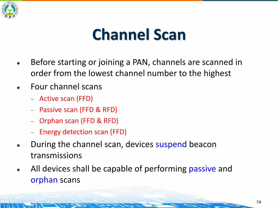
Channel Scan
Before starting or joining a PAN, channels are scanned in order from the lowest channel number to the highest
Four channel scans— Active scan (FFD)
— Passive scan (FFD & RFD)
— Orphan scan (FFD & RFD)
— Energy detection scan (FFD)
During the channel scan, devices suspend beacon transmissions
All devices shall be capable of performing passive and orphan scans
74
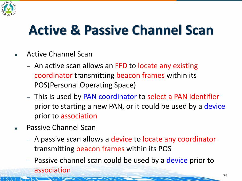
Active & Passive Channel Scan
Active Channel Scan
— An active scan allows an FFD to locate any existing coordinator transmitting beacon frames within its POS(Personal Operating Space)
— This is used by PAN coordinator to select a PAN identifierprior to starting a new PAN, or it could be used by a deviceprior to association
Passive Channel Scan
— A passive scan allows a device to locate any coordinatortransmitting beacon frames within its POS
— Passive channel scan could be used by a device prior to association
75
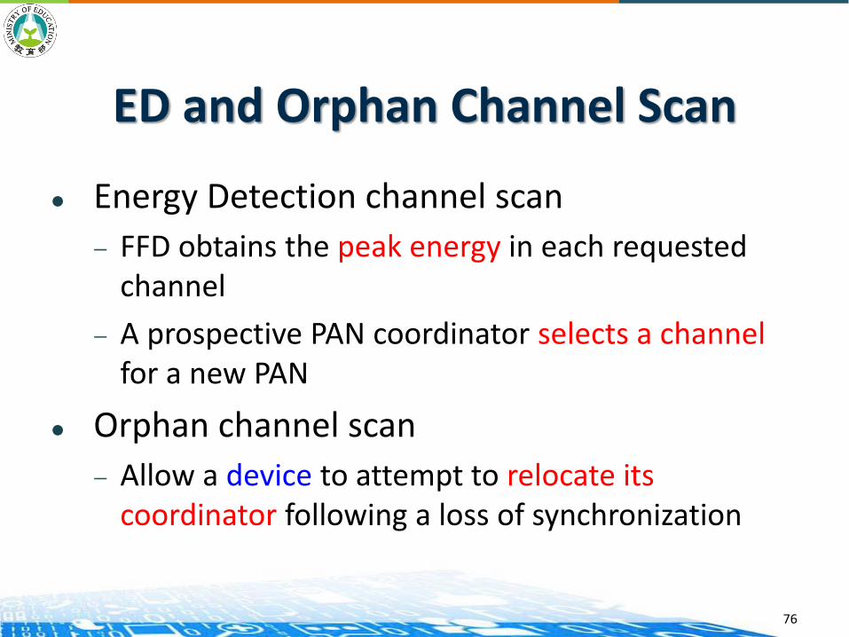
ED and Orphan Channel Scan
Energy Detection channel scan
— FFD obtains the peak energy in each requested channel
— A prospective PAN coordinator selects a channelfor a new PAN
Orphan channel scan
— Allow a device to attempt to relocate its coordinator following a loss of synchronization
76

Association
If device wait a aResponseWaitTime and no any Association response, then Association failure
Coordinator
MAC
Device
MAC
Association request
ACK
aResponseWaitTimeDatarequest
ACK Association response
ACK
Beacon
Append device’slong address in beacon
77
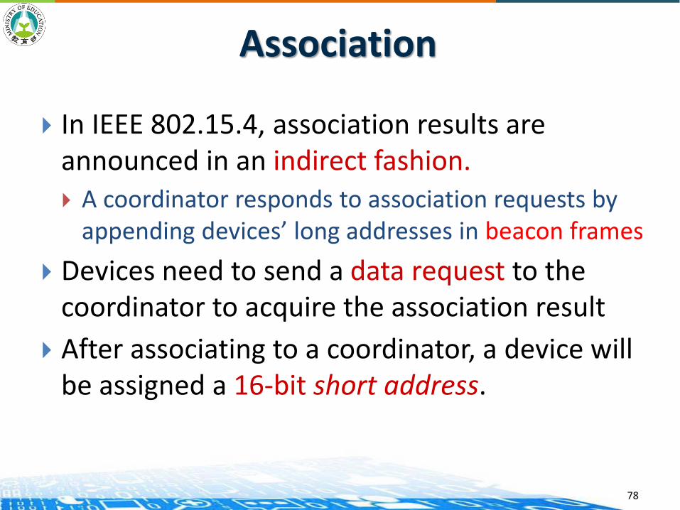
Association
In IEEE 802.15.4, association results are announced in an indirect fashion. A coordinator responds to association requests by
appending devices’ long addresses in beacon frames
Devices need to send a data request to the coordinator to acquire the association result
After associating to a coordinator, a device will be assigned a 16-bit short address.
78

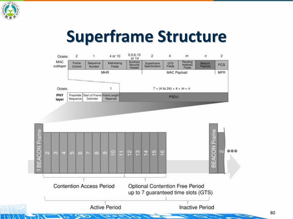
Superframe Structure
Optional use
Superframe format is defined by the PAN coordinator
The superframe
— Bounded by network beacons
— Sent by the coordinator
— Divided into 16 equally sized slots
The beacon frame is transmitted in the first slot of each superframe
79
Superframe Structure
80

802.15.4 Beacon Frame Format
81
• The beacon frame is much more complex as it must convey the synchronization and guaranteed time slot (GTS) information to all of the devices in the network.
• Beacons add a new level of functionality to a network. Client devices can wake up only when a beacon is to be broadcast, listen for their address, and if hear nothing, return to sleep.
• Beacons are important for mesh and cluster tree networks to keep all of the nodes synchronized without requiring nodes to consume precious battery energy listening for long periods of time.
Source: https://www.nxp.com/files/training_pdf/28081_ZIGBEE_OVERVIEW_WBT.pdf
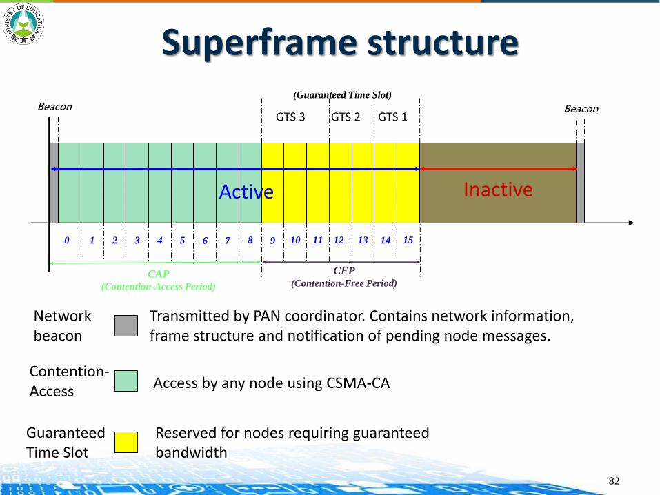
Superframe structure
CFP
(Contention-Free Period)
GTS 3 GTS 2 GTS 1
CAP
(Contention-Access Period)
Beacon
Inactive
10 2 3 4 5 6 7 8 9 10 11 12 13 14 15
Beacon
Active
Transmitted by PAN coordinator. Contains network information,frame structure and notification of pending node messages.
Networkbeacon
Contention-Access Access by any node using CSMA-CA
GuaranteedTime Slot
Reserved for nodes requiring guaranteed bandwidth
(Guaranteed Time Slot)
82
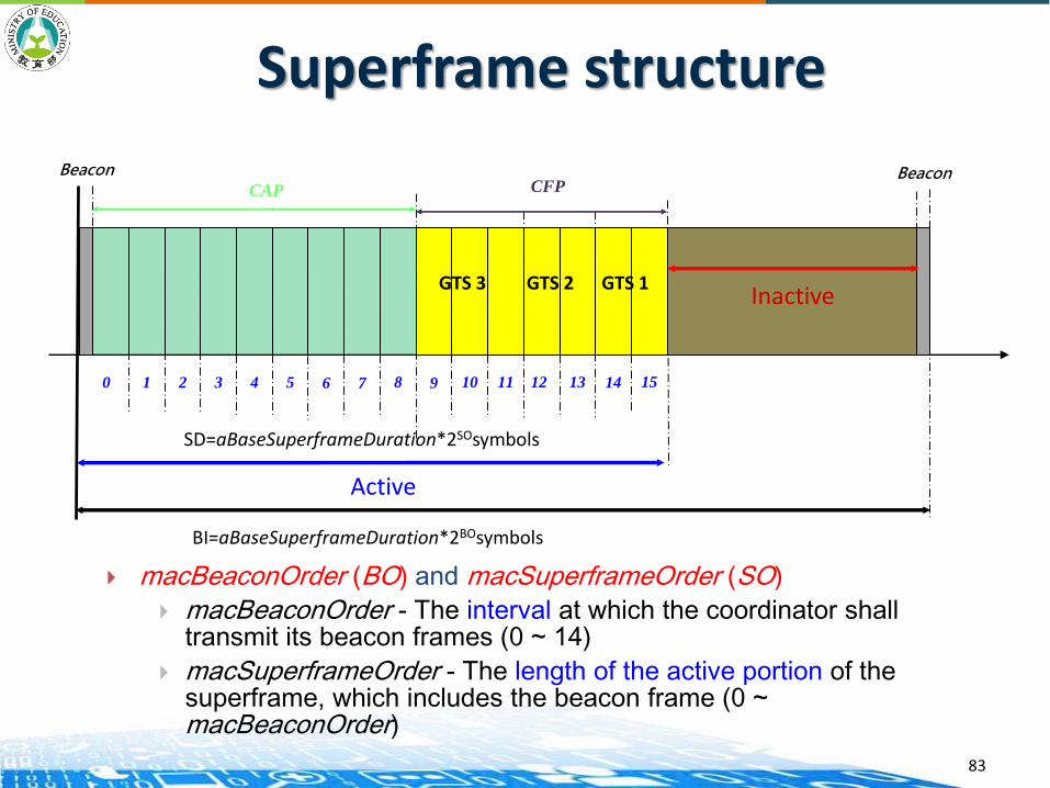
Superframe structure
GTS 3 GTS 2 GTS 1
Beacon
Inactive
10 2 3 4 5 6 7 8 9 10 11 12 13 14 15
Beacon
Active
CFPCAP
SD=aBaseSuperframeDuration*2SOsymbols
BI=aBaseSuperframeDuration*2BOsymbols
macBeaconOrder (BO) and macSuperframeOrder (SO)
macBeaconOrder - The interval at which the coordinator shall transmit its beacon frames (0 ~ 14)
macSuperframeOrder - The length of the active portion of the superframe, which includes the beacon frame (0 ~ macBeaconOrder)
83

Superframe structure
The values of BO and the beacon interval (BI) are related
as follows:
BI = 15.36 2BO ms, if 0 BO 14
(aBaseSuperframeDuration=960 symbols=15.36ms)
The values of SO and the superframe duration (SD) are
related as follows:
SD = 15.36 2SO ms, if 0 SO BO 14
Note: If BO =15, the coordinator will not transmit beacon and the value of SO
shall be ignored. (non beacon-enable network)
84
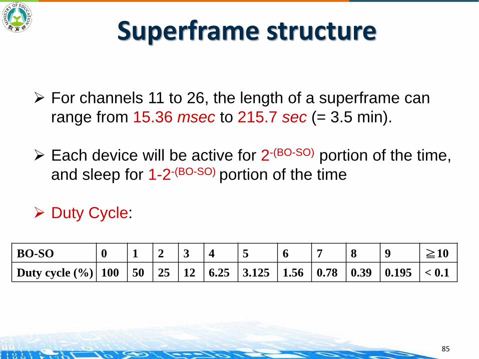
Superframe structure
For channels 11 to 26, the length of a superframe can
range from 15.36 msec to 215.7 sec (= 3.5 min).
Each device will be active for 2-(BO-SO) portion of the time,
and sleep for 1-2-(BO-SO) portion of the time
Duty Cycle:
BO-SO 0 1 2 3 4 5 6 7 8 9 ≧10
Duty cycle (%) 100 50 25 12 6.25 3.125 1.56 0.78 0.39 0.195 < 0.1
85

802.15.4 MAC
Channel Access
— Un-slotted CSMA-CA
— Slotted CSMA-CA
86
Channel Access
Non Beacon-enable networks
No beacon frame
unslotted CSMA/CA channel access mechanism
Beacon-enable networks
With beacon frame
Slotted CSMA/CA channel access mechanism
87
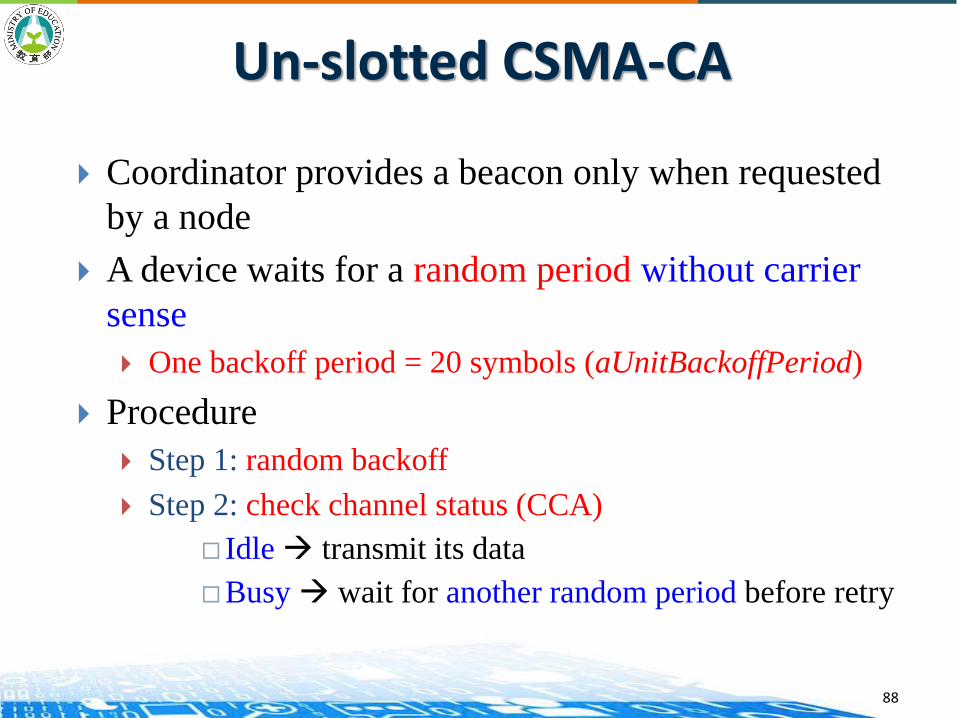
Un-slotted CSMA-CA
Coordinator provides a beacon only when requested
by a node
A device waits for a random period without carrier
sense
One backoff period = 20 symbols (aUnitBackoffPeriod)
Procedure
Step 1: random backoff
Step 2: check channel status (CCA)
Idle transmit its data
Busy wait for another random period before retry
88
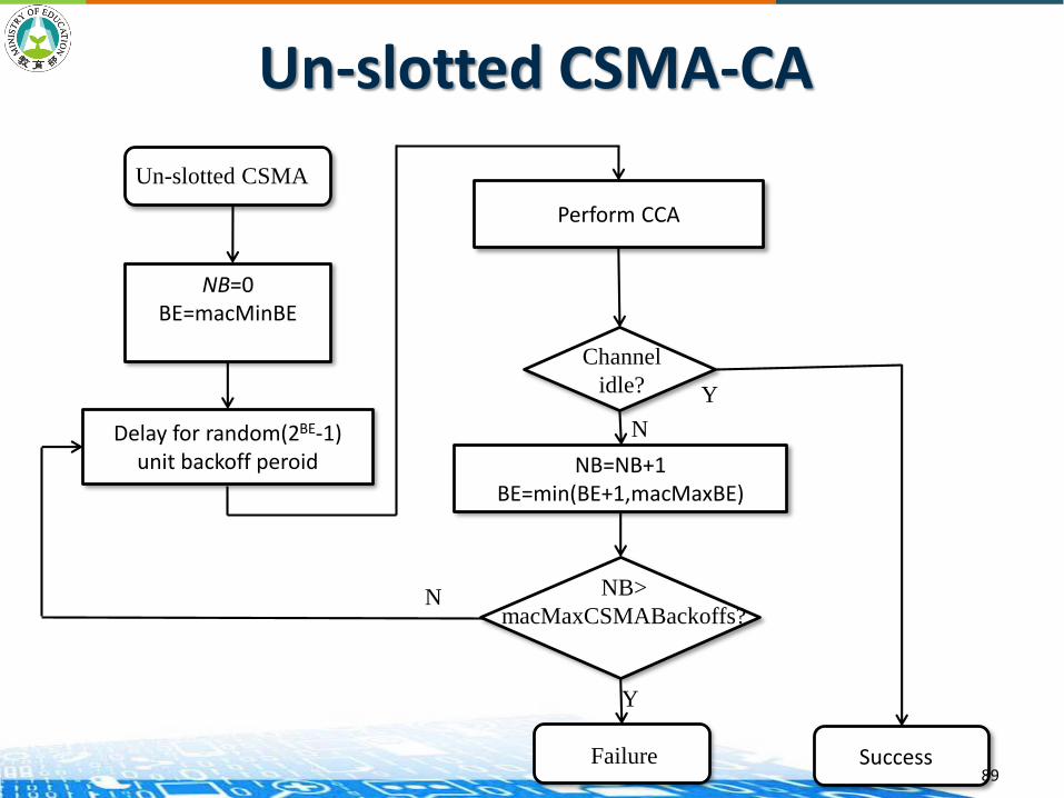
Perform CCA
Channel
idle?
NB=NB+1BE=min(BE+1,macMaxBE)
NB>
macMaxCSMABackoffs?
Failure Success
Y
Y
N
N
Un-slotted CSMA-CA
NB=0BE=macMinBE
Un-slotted CSMA
Delay for random(2BE-1) unit backoff peroid
89

Slotted CSMA/CA Algorithm PAN coordinator periodically broadcasts a
superframe
A beacon frame, 15 time slots (CAP and GTS), and
an optional inactive period
It is similar to the unslotted CSMA-CA but
follows the backoff slot boundary
Every device in the PAN shall be aligned with
the superframe slot
90
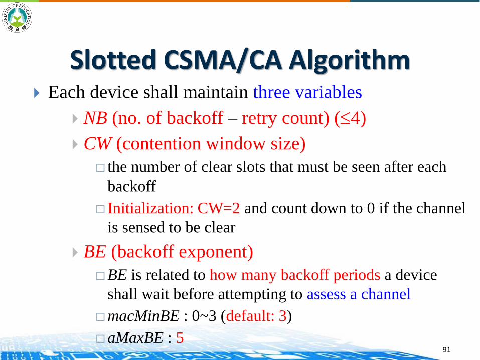
Slotted CSMA/CA Algorithm Each device shall maintain three variables
NB (no. of backoff – retry count) (4)
CW (contention window size)
the number of clear slots that must be seen after each
backoff
Initialization: CW=2 and count down to 0 if the channel
is sensed to be clear
BE (backoff exponent)
BE is related to how many backoff periods a device
shall wait before attempting to assess a channel
macMinBE : 0~3 (default: 3)
aMaxBE : 591
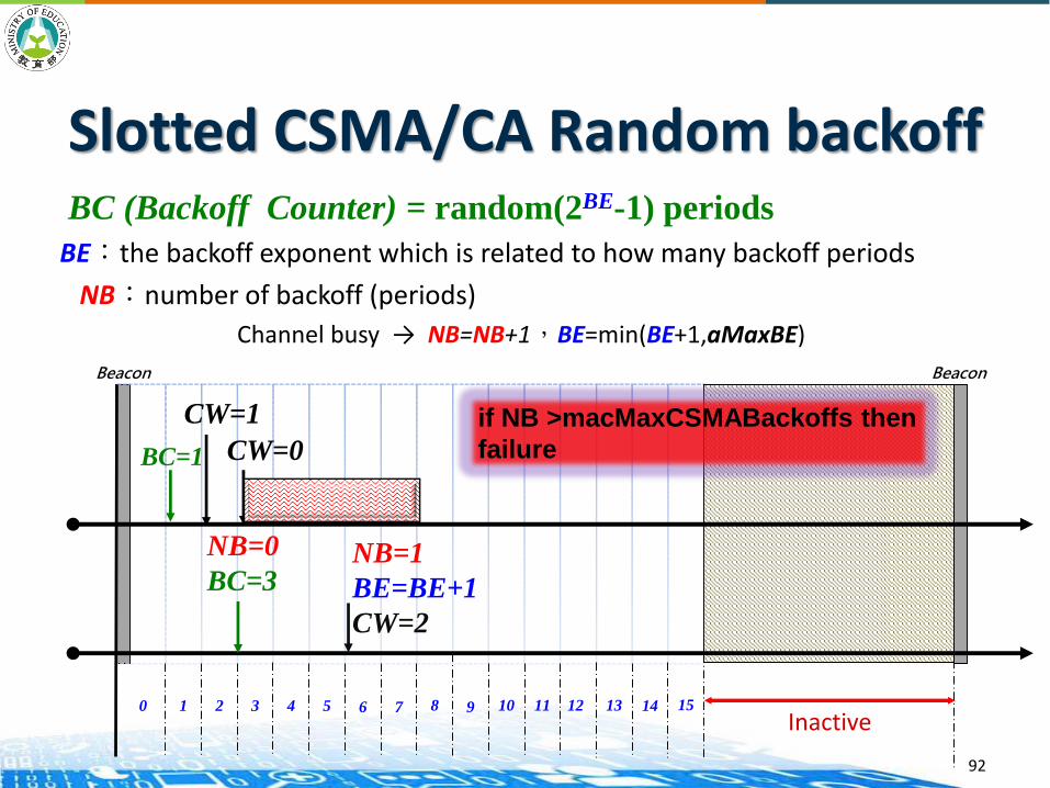
Slotted CSMA/CA Random backoff
BE:the backoff exponent which is related to how many backoff periods
NB︰number of backoff (periods)
Channel busy → NB=NB+1,BE=min(BE+1,aMaxBE)
BC (Backoff Counter) = random(2BE-1) periods
Beacon
Inactive10 2 3 4 5 6 7 8 9 10 11 12 13 14 15
Beacon
BC=1
CW=1
CW=0
NB=0
BC=3NB=1
BE=BE+1
CW=2
if NB >macMaxCSMABackoffs then
failure
92
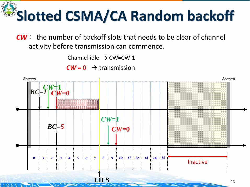
Slotted CSMA/CA Random backoffCW: the number of backoff slots that needs to be clear of channel
activity before transmission can commence.
Channel idle → CW=CW-1
CW = 0 → transmission
Beacon
Inactive10 2 3 4 5 6 7 8 9 10 11 12 13 14 15
Beacon
CW=1CW=0BC=1
LIFS
BC=5 CW=0
CW=1
93
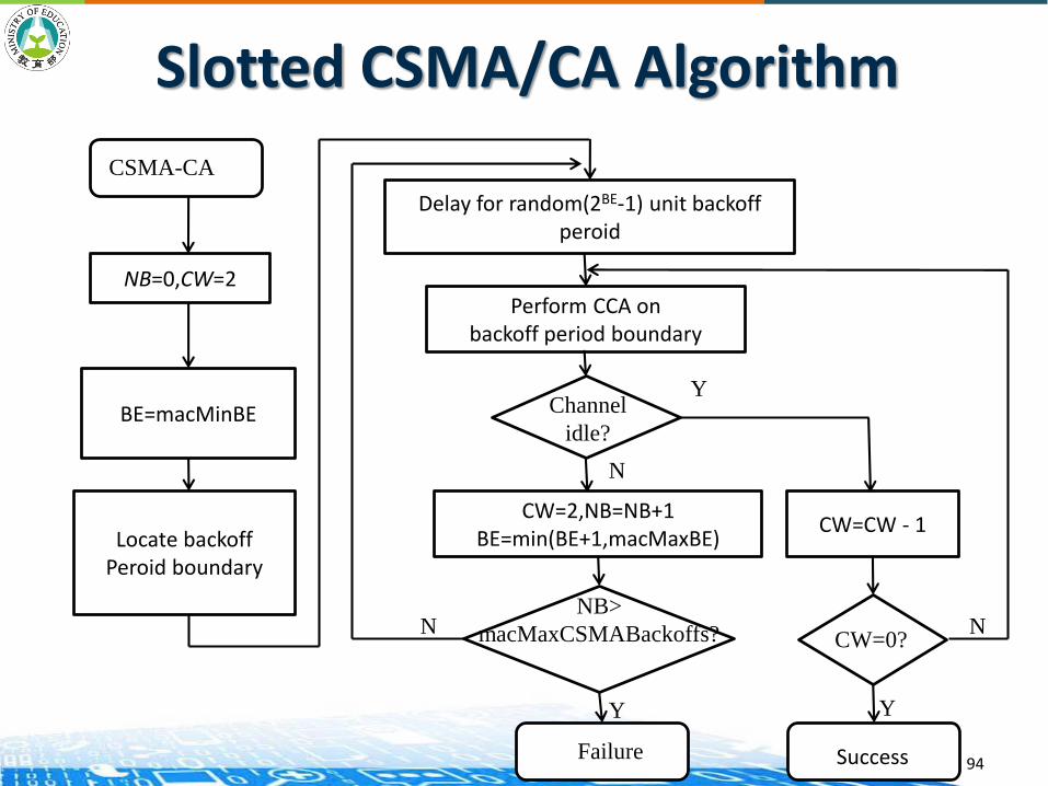
NB=0,CW=2
CSMA-CA
BE=macMinBE
Locate backoffPeroid boundary
Delay for random(2BE-1) unit backoffperoid
Perform CCA onbackoff period boundary
Channel
idle?
CW=2,NB=NB+1BE=min(BE+1,macMaxBE)
NB>
macMaxCSMABackoffs?
CW=CW - 1
CW=0?
Failure Success
Y
YY
N N
N
Slotted CSMA/CA Algorithm
94
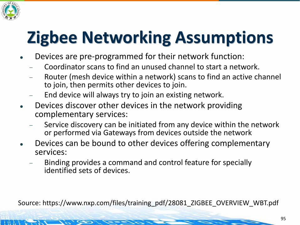
Zigbee Networking Assumptions Devices are pre-programmed for their network function:
— Coordinator scans to find an unused channel to start a network.— Router (mesh device within a network) scans to find an active channel
to join, then permits other devices to join.— End device will always try to join an existing network.
Devices discover other devices in the network providing complementary services:
— Service discovery can be initiated from any device within the network or performed via Gateways from devices outside the network
Devices can be bound to other devices offering complementary services:
— Binding provides a command and control feature for specially identified sets of devices.
95
Source: https://www.nxp.com/files/training_pdf/28081_ZIGBEE_OVERVIEW_WBT.pdf

Zigbee Routing Architecture
96
• Star Network - one coordinator networked with one or more end devices• Cluster Tree - where devices branch off of a tree, the network backbone. • Mesh network - Routing paths are not as constrained as in the cluster tree topology.
Mesh networking permits path formation from any source to any destination device.
Source: https://www.nxp.com/files/training_pdf/28081_ZIGBEE_OVERVIEW_WBT.pdf
Device Addressing
97
Two or more devices communicate on the same physical channel constitute a WPAN.
A WPAN includes at least one FFD (PAN coordinator)
Each independent PAN will select a unique PAN identifier
Each device operating on a network has a unique 64-bit extended address. This address can be used for direct communication in the PAN.
A device also has a 16-bit short address, which is allocated by the PAN coordinator when the device associates with its coordinator.
97
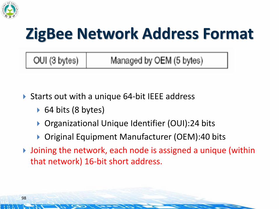
ZigBee Network Address Format
Starts out with a unique 64-bit IEEE address
64 bits (8 bytes)
Organizational Unique Identifier (OUI):24 bits
Original Equipment Manufacturer (OEM):40 bits
Joining the network, each node is assigned a unique (within that network) 16-bit short address.
98

Address Assignment Algorithm Network addresses are assigned to devices with a distributed
address assignment scheme in ZigBee.
Three network parameters are determined by ZigBee coordinator.
A ZigBee router has the maximum number of children (Cm) .
A parent node has the maximum number of child routers (Rm).
The depth of the network is (Lm).
A parent device utilizes Rm, Cm ,and Lm to compute a parameter called Cskip
It is used to compute the size of its children’s address pools
99

Address Assignment Algorithm ZigBee provides rules that Cm >= Rm, therefore ZigBee router
can provide at least (Cm-Rm) ZigBee connections of ZigBee devices.
The address of device is assigned by parent router. For ZigBeecoordinator, the whole network is divided into (Rm+1) blocks.
Rm blocks will be allocated to its Rm sub-router, and the final block is preserved for the (Cm-Rm) end devices connected with it.
ZigBee router(in depth d) uses these parameters to compute a Cskip value. (The depth of coordinator is defined as 0 )
100

Concept of Routing for Tree Topology
101
Cm=3, Rm=2, and Lm=3
Routing for Tree topology
In a tree networks, when a device receives a packet, it first checks if it is the destination or one of its child end devices is the destination
If so, accept the packet or forward it to a child
Otherwise, relay it along the tree
This is made possible by its addressing scheme!!
102
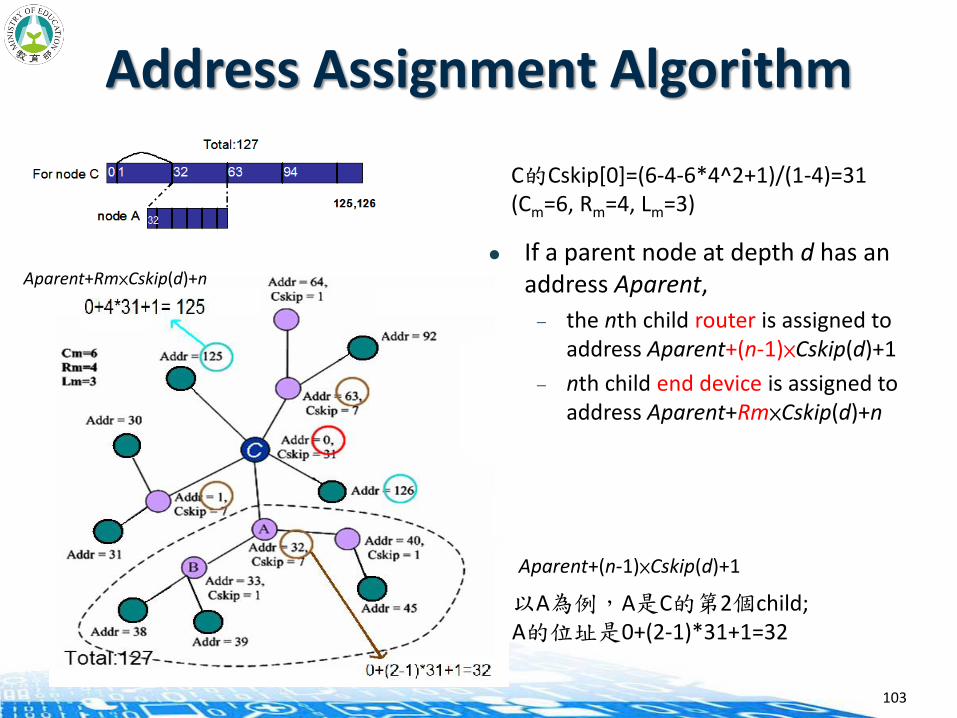
Address Assignment Algorithm
If a parent node at depth d has an address Aparent,
— the nth child router is assigned to address Aparent+(n-1)×Cskip(d)+1
— nth child end device is assigned to address Aparent+Rm×Cskip(d)+n
103
以A為例,A是C的第2個child;A的位址是0+(2-1)*31+1=32
C的Cskip[0]=(6-4-6*4^2+1)/(1-4)=31(Cm=6, Rm=4, Lm=3)
Aparent+Rm×Cskip(d)+n
Aparent+(n-1)×Cskip(d)+1
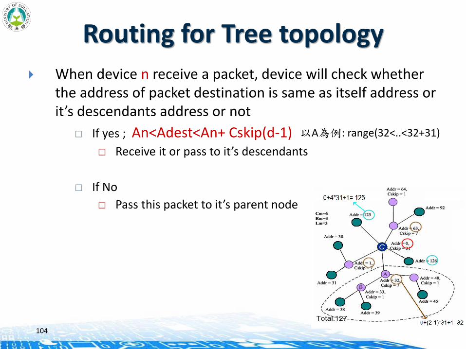
Routing for Tree topology
When device n receive a packet, device will check whether the address of packet destination is same as itself address or it’s descendants address or not
If yes ; An<Adest<An+ Cskip(d-1) Receive it or pass to it’s descendants
If No
Pass this packet to it’s parent node
104
以A為例: range(32<..<32+31)
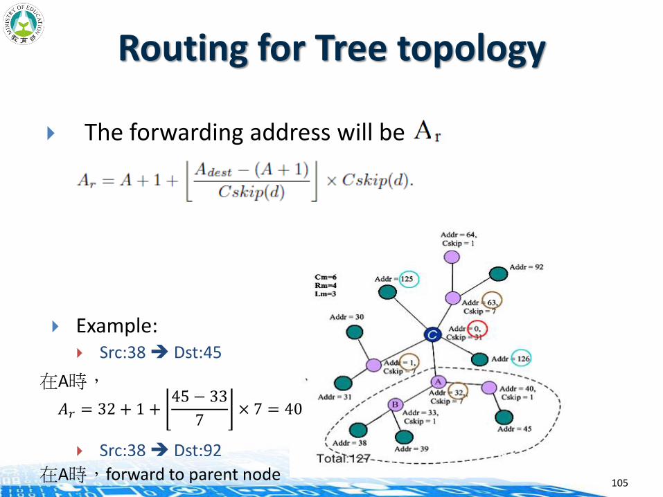
Routing for Tree topology
The forwarding address will be
Example: Src:38 Dst:45
Src:38 Dst:92
105
在A時,
在A時,forward to parent node
𝐴𝑟 = 32 + 1 +45 − 33
7× 7 = 40
Application Support Features Profile: Profiles are used to define a device’s application capability
and drive the application details. An example of a profile would be Home Control—Lighting.
Endpoint: Endpoints are the physical dimensions added to a ZigBee device which permit multiple application support, addressed by the Endpoint number (0-31).
Interface: Interfaces are defined per endpoint and allow such things as extra proprietary capability extensions and backward compatibility.
Key Relationships: Maximum of 30 Endpoints per ZigBee device (0 is reserved to describe
the device itself and 31 is reserved for broadcast messaging to all endpoints)
Maximum of 8 Interfaces per Endpoint One Profile described per Interface
106
Source: https://www.nxp.com/files/training_pdf/28081_ZIGBEE_OVERVIEW_WBT.pdf
IEEE 802.15.4e
2008: TSMP(Time Synchronized Mesh Protocol) is standardized in ISA100.11a — The IEEE 802.15.4e Working group is created.
— Issue: IEEE 802.15.4-2006 MAC is ill-suited for low-power multi-hop network because of
○ high energy consumption due to relay/router nodes
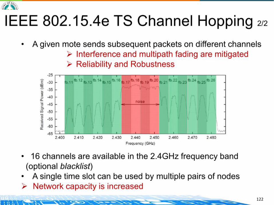
○ use of a single channel that implies interference and multi-path fading
— Final aim: to redesign the existing IEEE 802.15.4-2006 MAC Std. and make it suitable for low-power multi-hop networks in industrial applications
107
IEEE 802.15.4e
2009: TSMP is standardized in WirelessHART
2010: Part of IEEE 802.15.4e draft
2011: IEEE802.15.4e draft in Sponsor Ballot (opened on 27 July 2011 and closed on 28 August with 96% of votes being affirmative)
16 April 2012: IEEE802.15.4e TSCH published
108
IEEE 802.15.4e
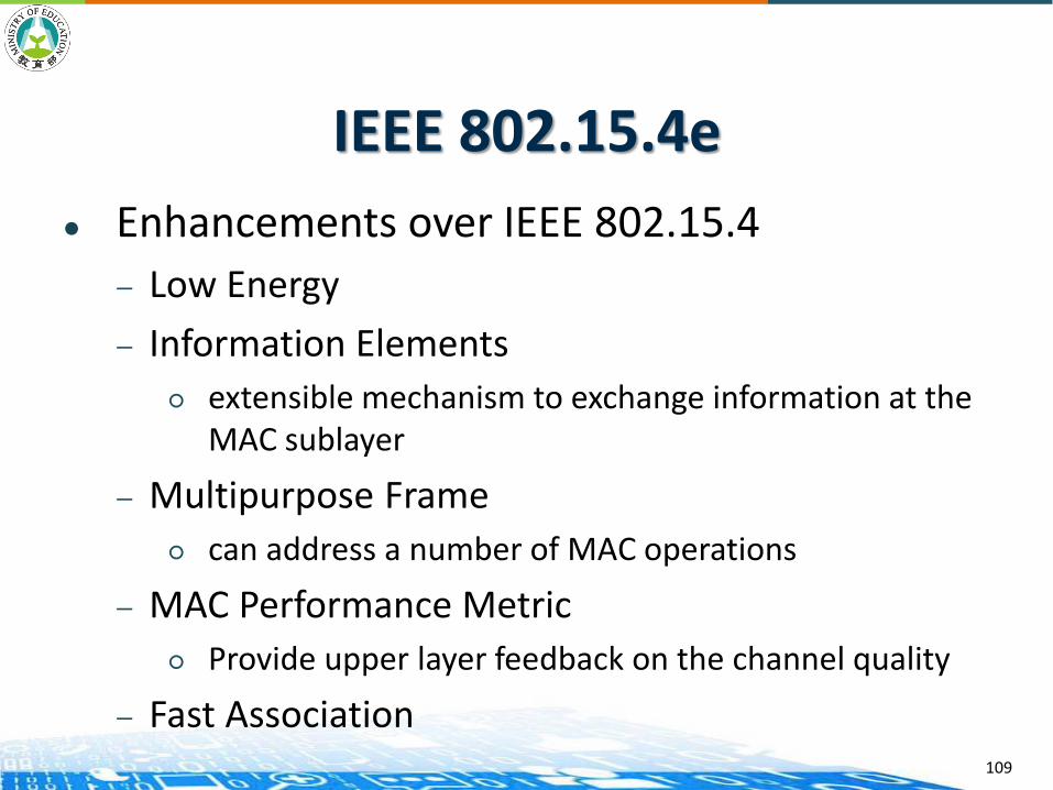
Enhancements over IEEE 802.15.4
— Low Energy
— Information Elements
○ extensible mechanism to exchange information at the MAC sublayer
— Multipurpose Frame
○ can address a number of MAC operations
— MAC Performance Metric
○ Provide upper layer feedback on the channel quality
— Fast Association109

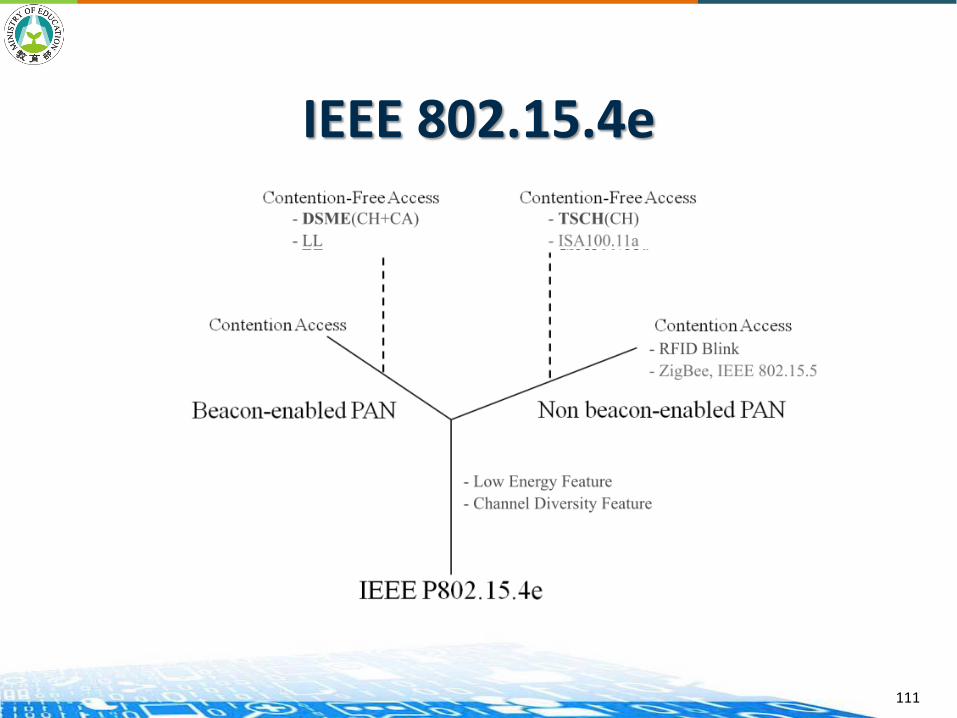
IEEE 802.15.4e
MAC operation modes
— Time Slotted Channel Hopping (TSCH)
— Deterministic and Synchronous Multi-channel Extension (DSME)
— Low Latency Deterministic Network (LLDN)
110
IEEE 802.15.4e
111

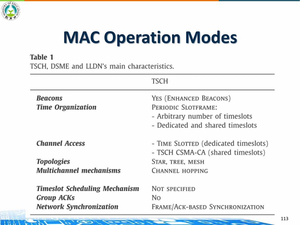
MAC Operation Modes
112
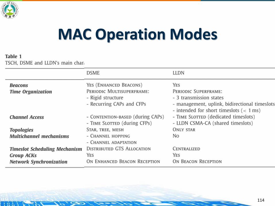
MAC Operation Modes
113
MAC Operation Modes
114
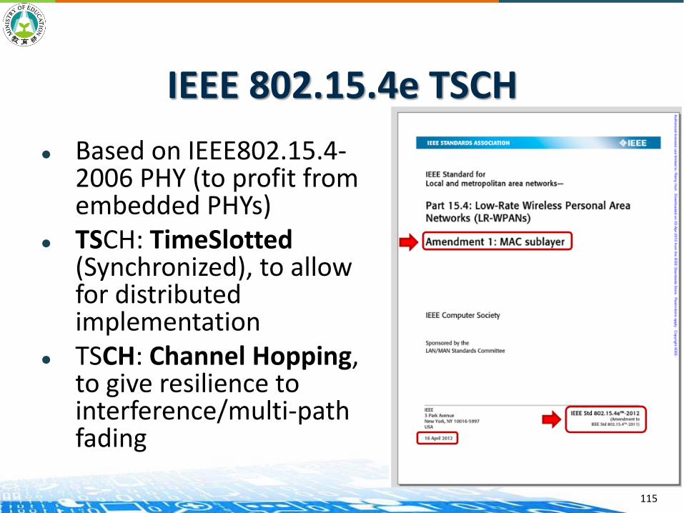
IEEE 802.15.4e TSCH
Based on IEEE802.15.4-2006 PHY (to profit from embedded PHYs)
TSCH: TimeSlotted(Synchronized), to allow for distributed implementation
TSCH: Channel Hopping, to give resilience to interference/multi-path fading
115
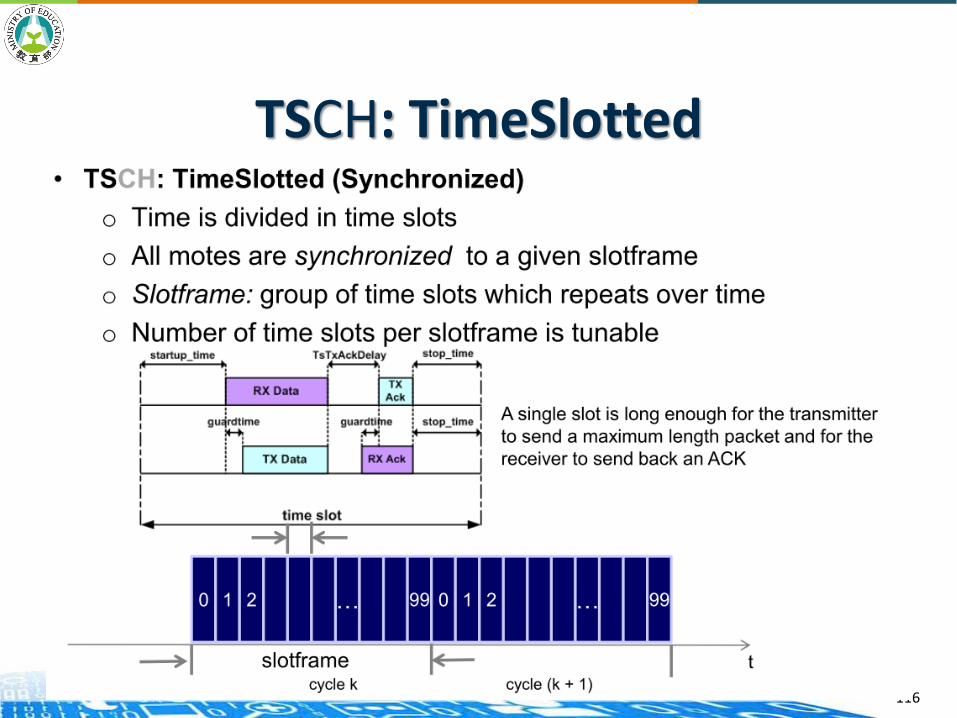
TSCH: TimeSlotted
116
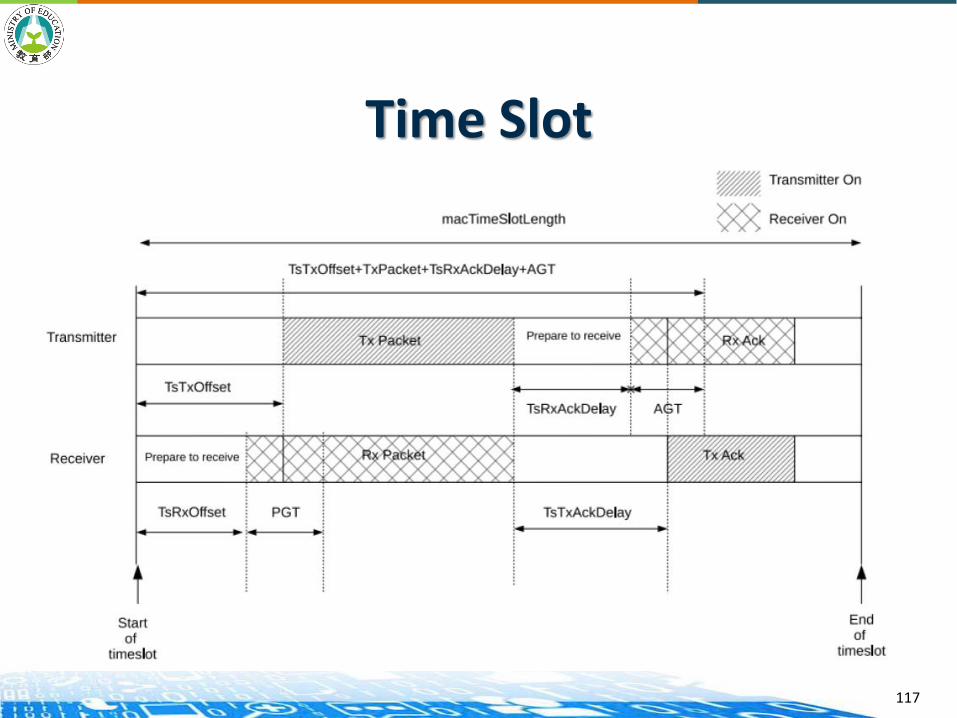
Time Slot
117

118

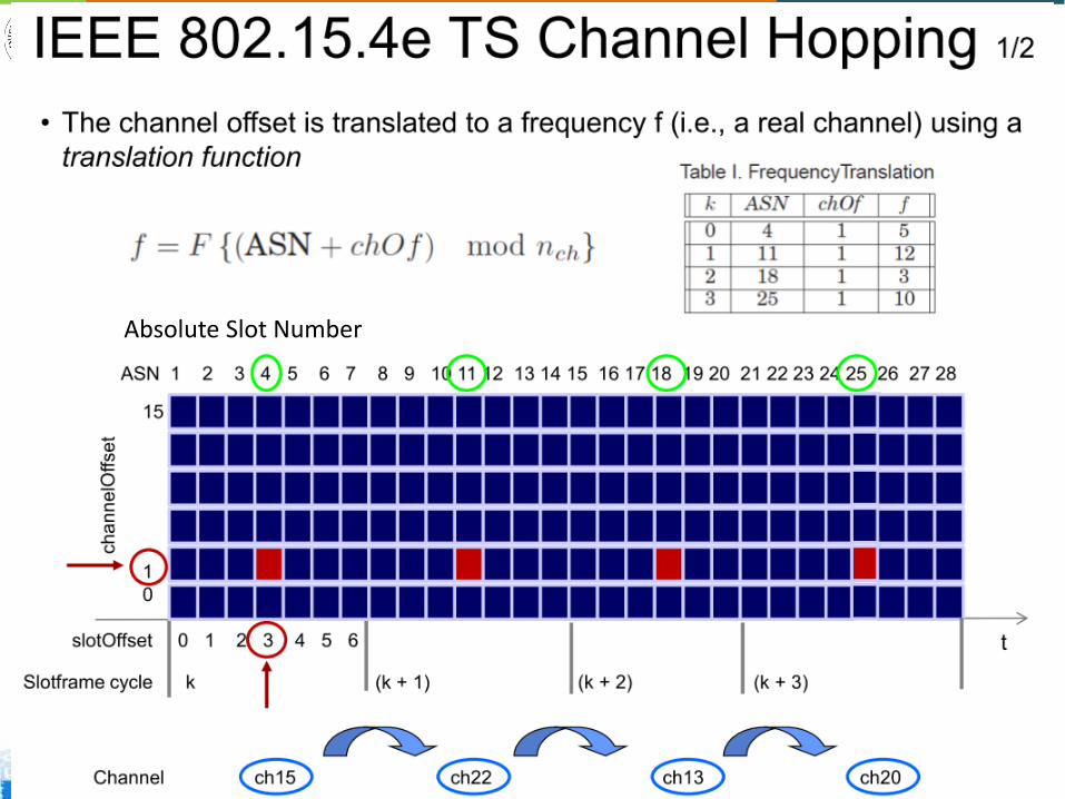
TSCH Schedule Each node follows a communication schedule
A schedule is a matrix of cells, each of them indexed by a slotOffset and a channelOffset
Each cell can be assigned to a pair of nodes, in a given direction
A scheduled cell can be used by one and/or multiple couples of devices (i.e., dedicated and/or shared)
119
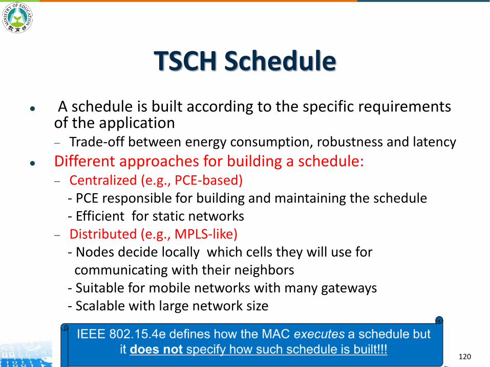
TSCH Schedule
A schedule is built according to the specific requirements of the application — Trade-off between energy consumption, robustness and latency
Different approaches for building a schedule: — Centralized (e.g., PCE-based)
- PCE responsible for building and maintaining the schedule - Efficient for static networks
— Distributed (e.g., MPLS-like) - Nodes decide locally which cells they will use for
communicating with their neighbors - Suitable for mobile networks with many gateways - Scalable with large network size
120
TSCH Channel Hopping
121
Absolute Slot Number
122

IPv6 over TSCH
123

802.15.4 Protocol Stacks
124

802.15.4g
Wireless Neighborhood Area Network (WNAN)
IPv6 based Wireless Smart Utility Network (Wi-SUN) based on IEEE 802.15.4g— IEEE 802.15.4g, also known as the Smart Utility
Networks (SUN), was approved by IEEE in March, 2012
Initially Japan focused, now expanding globally (US, South East Asia, India, Europe)
Target smart utility use cases
MAC may be based on or not based on 802.15.4
125

802.15.4g
Frequency:— 868 MHz (EU), 915 MHz (USA), 2.4 GHz ISM bands
(worldwide)
Maximum bandwidth: 200kHz~1.2MHz
Data rate: 50kbps ~ 1Mbps
Modulation: FSK, OFDM, OQPSK
Range: 100m
Application: FAN, HAN, smart utility networks, smart grid, smart metering
126

802.15.4g
3 physical layer (PHY) standards supported: — MR-FSK*: 2FSK and 4FSK modulation used — MR-OFDM: 4 options with different FFT size and
bandwidths — MR-O-QPSK*: DSSS and multiplexed DSSS used
Frequency bands depend on regulatory requirements, may include bands around 169, 450-510, 780, 863-870, 896-960, 1427-1518, and 2400-2483 MHz
Wi-SUN Alliance PHY conformance tests and profiles being developed for MR-FSK PHY.
127

802.15.4g
128

BLUETOOTH LOW ENERGY
Bluetooth
Bluetooth is a wireless technology standard for building personal area networks (PANs).
It is based on short-wavelength UHF radio waves in the ISM band from 2.4 to 2.485 GHz for fixed and mobile devices. (79 1-MHz channels)
Invented by telecom vendor Ericsson in 1994, it was originally conceived as a wireless alternative to RS-232 data cables.
Bluetooth versions— Bluetooth 1.0 announced in 1999.— Bluetooth 1.1 (IEEE 802.15.1-2002) announced in 2002 (1.2: frequency
hopping)— Bluetooth 2.0 announced in 2004 (Differential Phase-Shift Keying) (2.1:
security enhancement EDR)— Bluetooth 3.0 announced in 2009 (24Mbps)
130
Bluetooth Network
Piconet
— 1 master device, 7 slave devices
Scatternet
— A devices can be a master node in one piconet and a slave node in another piconet
— Or a device is a slave node in two piconets
131
Bluetooth Low Energy (BLE)
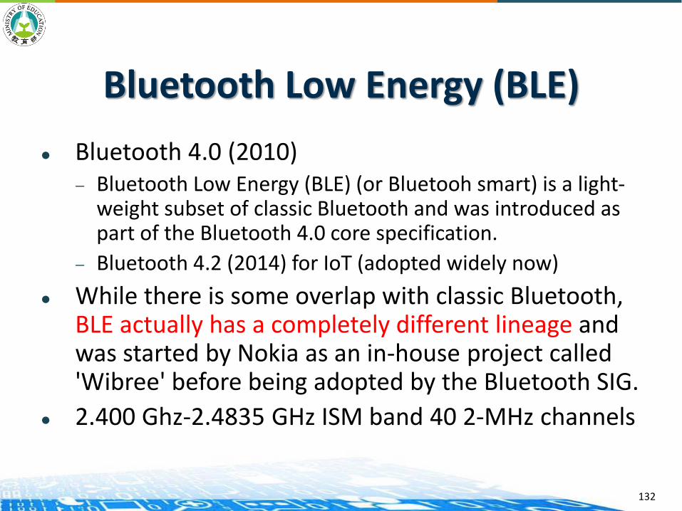
Bluetooth 4.0 (2010)— Bluetooth Low Energy (BLE) (or Bluetooh smart) is a light-
weight subset of classic Bluetooth and was introduced as part of the Bluetooth 4.0 core specification.
— Bluetooth 4.2 (2014) for IoT (adopted widely now)
While there is some overlap with classic Bluetooth, BLE actually has a completely different lineage and was started by Nokia as an in-house project called 'Wibree' before being adopted by the Bluetooth SIG.
2.400 Ghz-2.4835 GHz ISM band 40 2-MHz channels
132

Bluetooth Low Energy (BLE)
133
Bluetooth Low Energy (BLE)
134

Bluetooth 5
Officially unveiled on 16 June 2016 Mainly focused on Internet of Things technology Features
— Slot Availability Mask (SAM)— 2 Mbit/s PHY for LE (2 times more than that of 4.0)— LE Long Range (4 time more than that of 4.0)— High Duty Cycle Non-Connectable Advertising— LE Advertising Extensions— LE Channel Selection Algorithm #2— Widely adopted now
135
BLE Protocol Stack
136
BLE Physical Layer
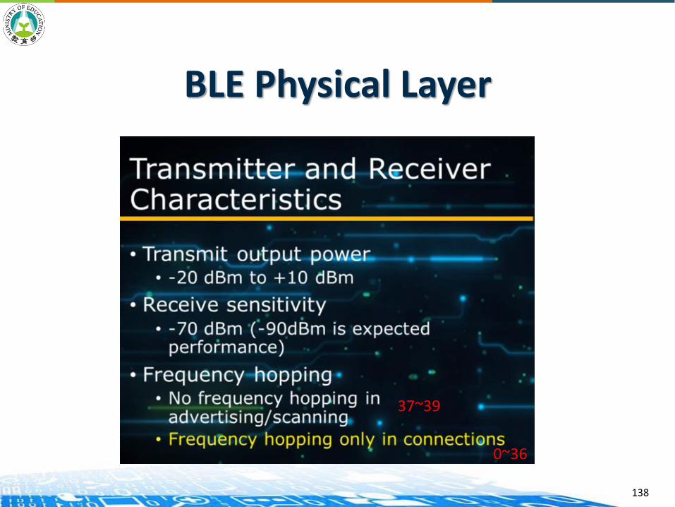
137
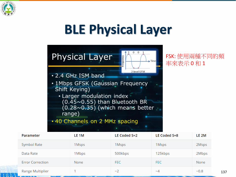
FSK: 使用兩種不同的頻率來表示 0 和 1
BLE Physical Layer
138
37~39
0~36
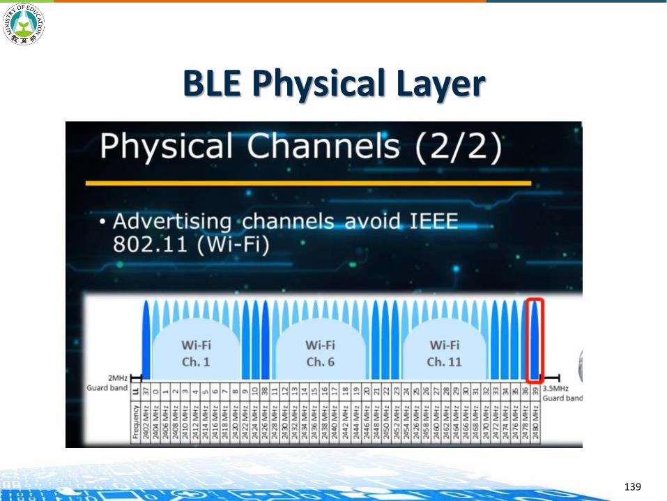
BLE Physical Layer
139
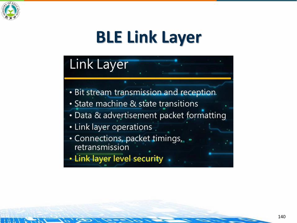
BLE Link Layer
140

BLE Link Layer
141

BLE Link Layer
142
Broadcaster/Peripheral
Observer/Central
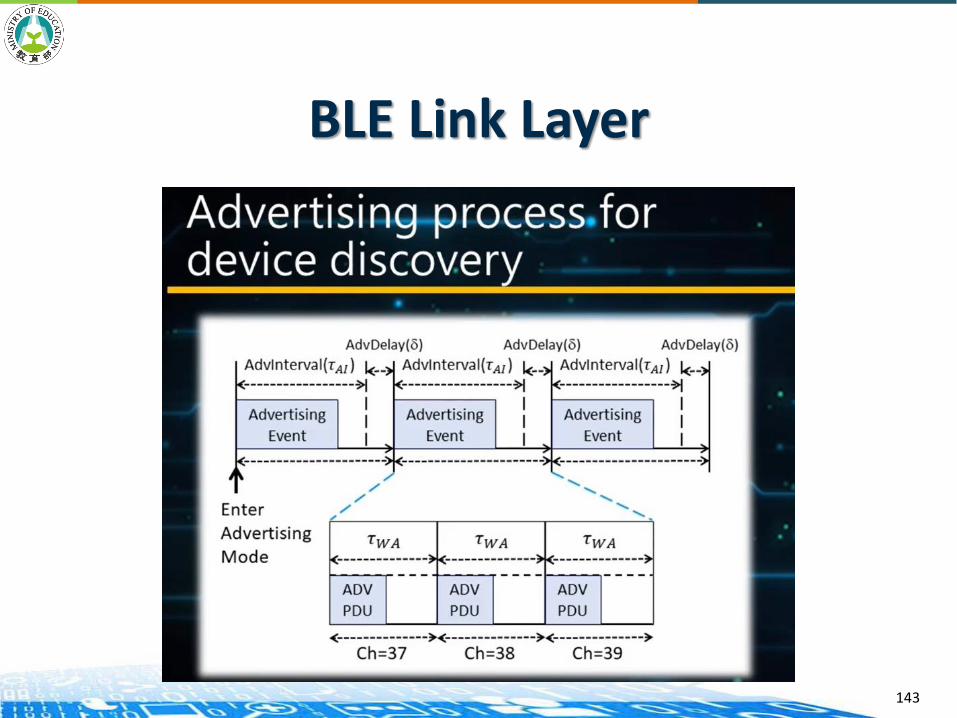
BLE Link Layer
143

BLE Link Layer
144

BLE Link Layer
145

BLE Link Layer
146

BLE Link Layer
147
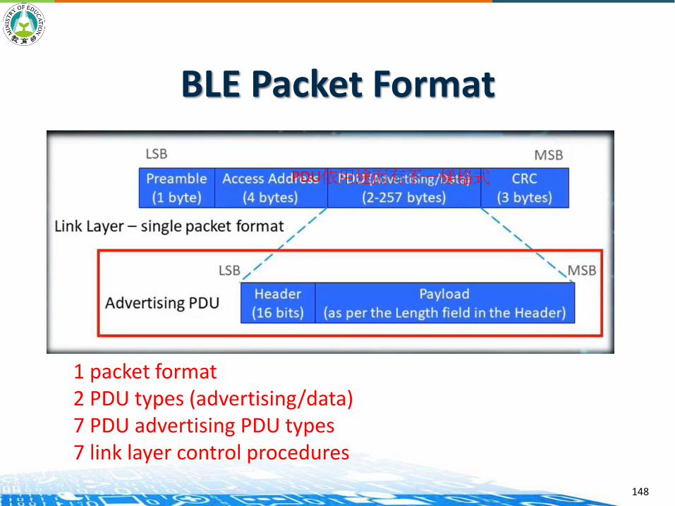
BLE Packet Format
148
PDU依用途而有不一樣格式
1 packet format2 PDU types (advertising/data)7 PDU advertising PDU types7 link layer control procedures

BLE Advertising PDU Header
149
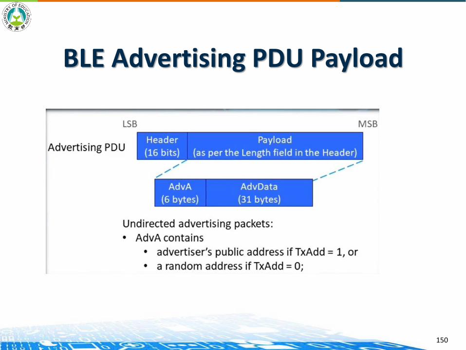
BLE Advertising PDU Payload
150

BLE Connection Data Format
151
Double check: CRC + MIC

BLE Connection Data Format
152

Frequency Hopping
Follow following equation
𝑓𝑛+1 = 𝑓𝑛 + ℎ𝑜𝑝 𝑚𝑜𝑑 37
Hop is a random number between 5~16 (selected by the master node)
153

Logical Link Control and Adaptation Protocol (L2CAP)
Segmentation: Permits upper level protocols and applications to transmit and receive upper layer data packets up to 23bytes in length
Multiplexing: Provides channel management, allowing for logical channels between two endpoints, supported by the link layer
154

Security Manager Protocol (SMP)
Performs authentication and key management Uses AES-128 as the encryption algorithm for security
procedures Works with GAP to manage relationships between
devices:— Pairing: encryption between two devices once a
connection has been established between them— Authentication: verification that a peer device can be
trusted, providing protection against “Man-in-the-Middle” attacks
— Bonding: long-term relationship between devices; security and identity information is saved for re-use next time the devices are connected
155
Attribute Protocol (ATT)
An attribute is a discrete value that has associated with it the following three properties:
— A handle(address)
— A type
— A set of permissions
ATT defines the over-the-air protocol for reading, writing, and discovering attributes
156
Generic Access Profile (GAP)
GAP governs connections and advertising in Bluetooth.
GAP defines various roles for devices, but the two key concepts to keep in mind are Central Devices and Peripheral Devices.— Peripheral devices are small, low power, resource
constrained devices that can connect to a much more powerful central device. Peripheral devices are things like a heart rate monitor, a BLE enabled proximity tag, etc.
— Central devices are usually the mobile phone or tablet that you connect to with far more processing power and memory.
157
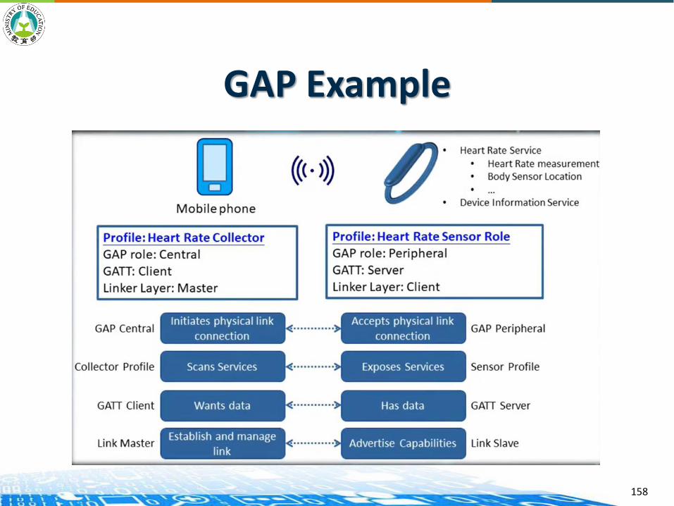
GAP Example
158

Advertising and Scan Response Data
Two ways to send advertising out with GAP. Both payloads are identical and can contain up to 31 bytes of data.
The Advertising Data payload (mandatory): that is constantly transmitted out from the device to let central devices in range know that it exists.
The Scan Response payload (optional): that central devices can request, and allow more information fit in the advertising payload such as strings for a device name, etc.
159
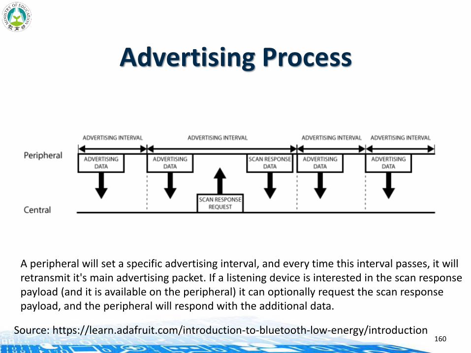
Advertising Process
160
A peripheral will set a specific advertising interval, and every time this interval passes, it willretransmit it's main advertising packet. If a listening device is interested in the scan response payload (and it is available on the peripheral) it can optionally request the scan response payload, and the peripheral will respond with the additional data.
Source: https://learn.adafruit.com/introduction-to-bluetooth-low-energy/introduction
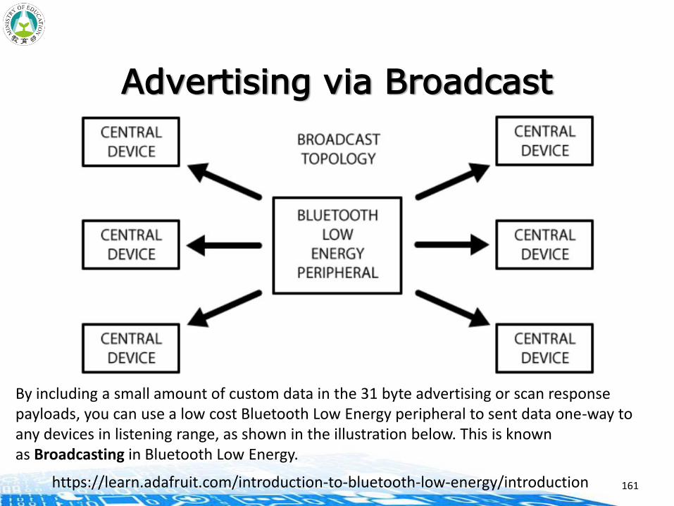
Advertising via Broadcast
161
By including a small amount of custom data in the 31 byte advertising or scan response payloads, you can use a low cost Bluetooth Low Energy peripheral to sent data one-way to any devices in listening range, as shown in the illustration below. This is known as Broadcasting in Bluetooth Low Energy.
https://learn.adafruit.com/introduction-to-bluetooth-low-energy/introduction
GATT
Once a connection between a peripheral and a central device is established, the advertising process will stop
— No advertising packets will be sent out
Use GATT services and characteristics to communicate in both directions
162
Exclusive Connection of GATT
With GATT, connections are exclusive
— A BLE peripheral can only be connected to one central device (a mobile phone, etc.) at a time!
— As soon as a peripheral connects to a central device, it will stop advertising itself and other devices will no longer be able to see it or connect to it until the existing connection is broken.
163

Connected Topology
164
A peripheral can only connect to a central device but a central device can connect upTo 7 peripherals. Once a connection is established between a peripheral and a central device, communication can take place in both directions.
https://learn.adafruit.com/introduction-to-bluetooth-low-energy/introduction

Server-Client in GATT Transactions
Client: Typically sends a request to the GATT server. The client can read and/or write attributes found in the server.
Server: One of the main roles of the server is to store attributes. Once the client makes a request, the server must make the attributes available.
The IoT device is known as the GATT Server, which holds the ATT lookup data and service and characteristic definitions, and the GATT Client (smart phone/tablet) sends requests to this server.
165
GATT Transactions
166
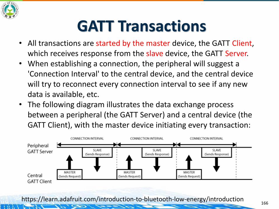
• All transactions are started by the master device, the GATT Client, which receives response from the slave device, the GATT Server.
• When establishing a connection, the peripheral will suggest a 'Connection Interval' to the central device, and the central device will try to reconnect every connection interval to see if any new data is available, etc.
• The following diagram illustrates the data exchange process between a peripheral (the GATT Server) and a central device (the GATT Client), with the master device initiating every transaction:
https://learn.adafruit.com/introduction-to-bluetooth-low-energy/introduction
GATT Services and Characteristics
GATT is an acronym for the Generic Attribute Profile.
It defines the way that two Bluetooth Low Energy devices transfer data back and forth using concepts called Services and Characteristics.
It makes use of a generic data protocol called the Attribute Protocol (ATT), which is used to store Services, Characteristics and related data in a simple lookup table using 16-bit IDs for each entry in the table.
167

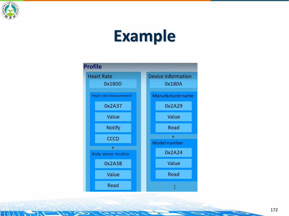
Services and Characteristics GATT transactions in BLE are based on high-level, nested
objects called Profiles, Services and Characteristics.
168
• Profile: This is simply a pre-defined collection of Services compiled by either the Bluetooth SIG or by the peripheral designers.
• Service: contains specific chunks of data called characteristics. A service can have one or more characteristics, and each service distinguishes itself from other services by means of a unique numeric ID called a UUID.
• Characteristic: encapsulates as single data point. Similarly to Services, each Characteristic has a pre-defined UUID. Used to send data back to the BLE peripheral.
https://learn.adafruit.com/introduction-to-bluetooth-low-energy/introduction
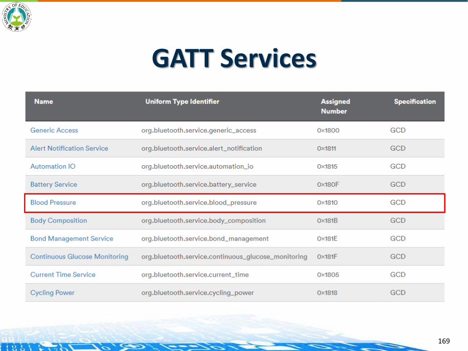
GATT Services
169

Blood PressureService Characteristics
170

Example
171
ClientCentral
ServerPeripheral
Example
172
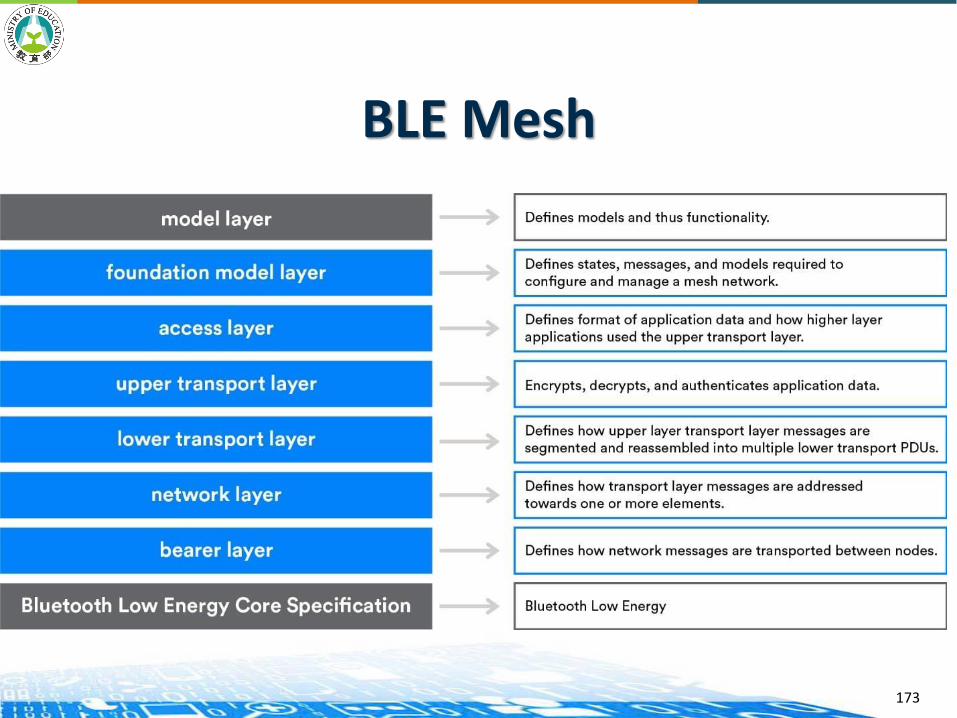
BLE Mesh
173
BLE Mesh
174
BLE Mesh
175

Node Roles in BLE Mesh
176
P, R, F needs to be always on.
Managed broadcast (restricted forwarding)
Maximum hop (network diameter) : 127 Max. nodes: 65536

Node Roles in BLE Mesh
177原文網址:https://kknews.cc/digital/eggb3pz.html

BLE Mesh Security
178
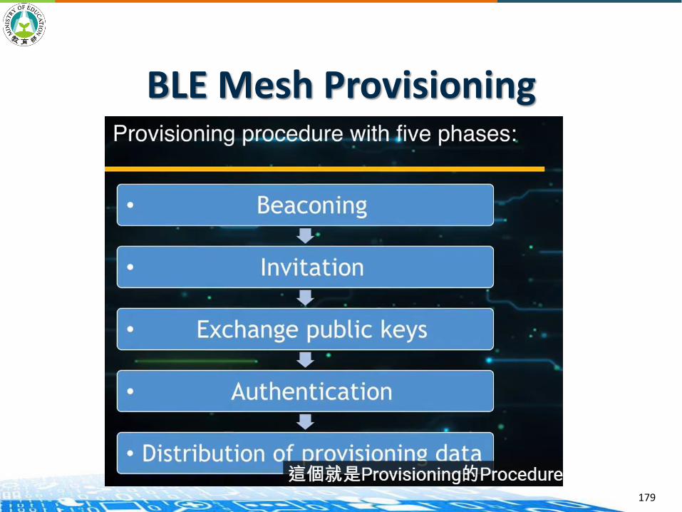
BLE Mesh Provisioning
179
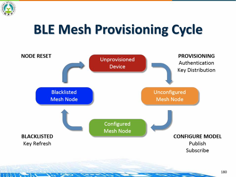
BLE Mesh Provisioning Cycle
180

BLE Mesh Message: Publish/Subscribe
181

BLE Mesh Node
182
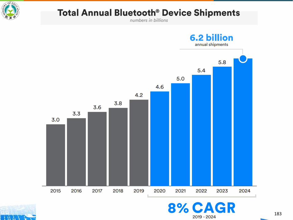
183
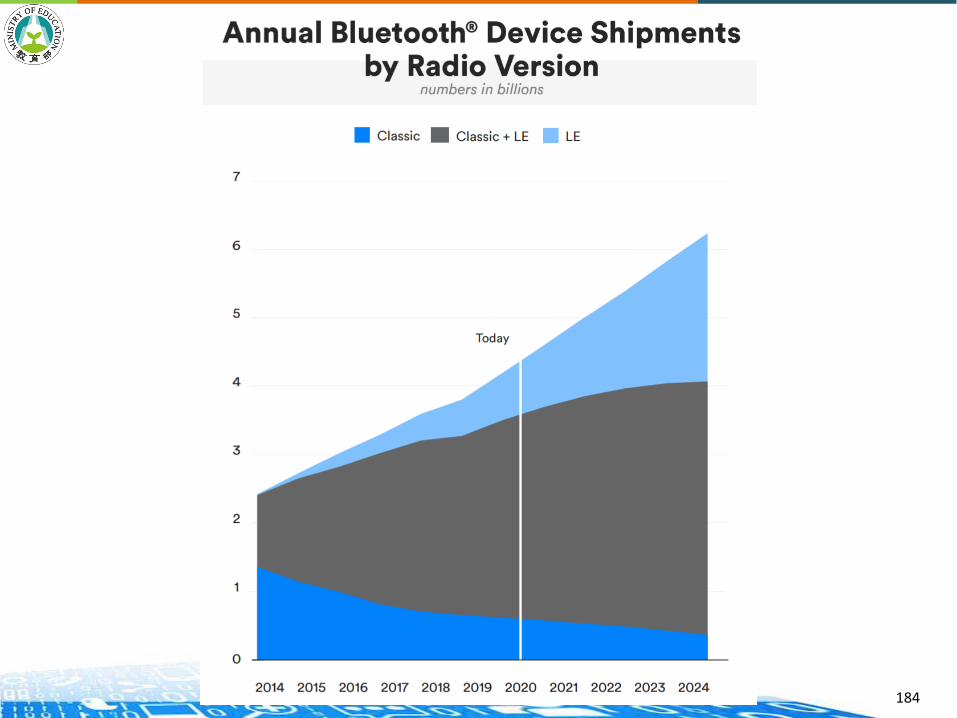
184

185
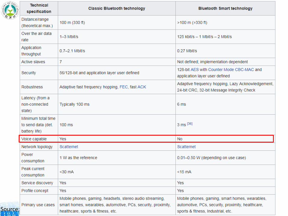
Feature ZigBee Bluetooth Classic (BT) Bluetooth Smart
Design Focus Wireless networking among sensors
Wireless keyboards, mouse, headsets
Wireless sensor and fitness devices
IEEE Standard 802.15.4 802.15.1 802.15.1
Network Type Mesh, ZigBee PRO Piconet, Master/Slave;Scatternet
Scatternet
Distance 75-100m line of sight 10m (33ft) min >10m >(33ft)
Nodes Connected, max 65000 8 N/A
Operating Band 2.400 Ghz-2.4835 GHz ISM band
16 channels, 5MHz apart,2MHz used
Direct Spread Spectrum
2.400 Ghz-2.4835 GHz ISM band
79 1-MHz channelsFrequency Spread
Spectrum
2.400 Ghz-2.4835 GHz ISM band
40 2-MHz channelsFrequency Spread
Spectrum
Throughput 0.03Mbps 1-3Mbps 0.27Mbps
Latency with Connect 15ms 100ms - 3sec 3-6ms
Type of Data Operational instructionsLow data rate
Continuous streamingAll types of data; text,
multimediaRelatively high speeds
Burst
Voice No Yes No
Security EAP (Extensible Authentication Protocol)
56/128-bit and application layer user
defined
128-bit AES (Advanced Encryption Standard)
with Counter Mode CBC-MAC and application layer
user defined
Power Consumed(dependent on
application)
30mW 100 mW 0.01-0.5W
Modulation Direct Sequence Spread Spectrum
Frequency Hopping Spread Spectrum
Gaussian Frequency Shift Keying
A Comparison
between ZigBee,
BT and BLE
Source: http://www.allaboutcircuits.com/technical-articles/zigbee-vs-bluetooth-and-bluetooth-smart/
1~100mW
186Source: http://www.allaboutcircuits.com/technical-articles/zigbee-vs-bluetooth-and-bluetooth-smart/
Summary
An M2M area network consists of many types of sensors/actuators/devices and (wireless) communication protocols.
We show many examples of those sensors/ actuators/devices.
We cover three examples of M2M area protocols: ANSI C12 Suite, ZigBee (IEEE 802.15.4), Bluetooth Low Energy (BLE).
Sensor platforms such as Arduino and Raspberry Pi are important tools for connecting and enabling sensors/actuators.
187