Workflow-driven tool integration using model transformations
Towards the Use of XPDL as Planning andScheduling Modeling Tool: the Workflow
Patterns Approach
Arturo Gonzalez-Ferrer, Juan Fdez-Olivares, Luis Castillo, and Lluvia Morales
Departamento de Ciencias de la Computacion e IAUniversity of Granada, Spain
Abstract. This paper presents a transformation from a business processmodel diagram stored in XPDL format, into a hierarchical extension ofthe PDDL planning language, using the concept of workflow patterns asbase of the translation process. The proposed architecture is evaluatedwithin a specific teamwork project management scenario: the allocationof human resources and web services for the cooperative development ofon-line courses in an e-learning center.
1 Introduction
The integration of Planning and Scheduling (P&S) and Business Process Man-agement (BPM) is a significant challenge for enterprise environments. On theone hand, BPM tools are able to deal with goals specification, environmentalanalysis, design, implementation, enactment, monitoring and evaluation of busi-ness processes[7], and they are acquiring an increasing business value for theefficient and intelligent knowledge management on these organisations. How-ever, they lack of power for the anticipated planning and decision making oforganisational processes. On the other hand, automated P&S, defined as ”theprocess of generating possible representations of future behaviour prior to theuse of such plans to constrain or control that behaviour”[16], is a technologythat, due to the absence of simple modeling tools, has not explode its greatpotential in enterprise environments. Therefore, a common framework includingthese technologies would be interesting from both points of view.
Introducing an automated P&S system into the BPM life cycle[7] of a com-pany, capable of both interpreting and reasoning about an initial workflow modelrepresentation, would contribute to cover these missing goals, as it providessupport for the generation of action plans, whatever these actions are carriedout by humans or by remote calls to web services[5], as well as support fordecision-making on key issues like tasks organization and resources allocation.Furthermore, if we were able to automatically transform the information presentin a process model (usually described by a BPM diagram created by businessanalysts) to its corresponding P&S representation, we would overcome the tra-ditional obstacle for P&S technology: the use of complex languages to model aplanning domain. This paper gives further insights into this integration process.
Prior work on the use of P&S for the automatic generation of business processmodels is exposed in [10] (using an augmentation of STRIPS representation). Asopposite to this work, our approach shows how to use an existing process modeldiagram stored in a standard BPM language, to automatically generate P&S rep-resentations using the HTN[12] planning paradigm (detailed later in this paper).Afterwards, we use the output of this transformation as input of an intelligentplanner in order to prepare action plans and resources allocation that, after thecorresponding validation by a business manager, would be helpful for decisionmaking on risk management[7], mainly to avoid unwanted situations, like the de-tection of high loads of work in a specific period, or the incapacity to completea project before a deadline, which is specially useful in ad-hoc workflows withhuman intervention. Some authors worked in similar problems as coordinatingthe design of airplanes[1], or workflow coordination in a mobile environment[11].
So, the main contributions of this paper can be summarized as:
1. To stablish the cornerstone for a new way to model P&S problems using astandard business process modeling tool, overcoming the need of new ad-hoctools or languages[15] as well as the need for staff training on P&S languages.
2. To introduce the concept of workflow patterns decomposition for the auto-matic transformation of BPM diagrams into HTN planning representations.
3. To show how to integrate P&S technology at a low cost within a BPMframework, to make the most of an existing process model for anticipatedmanagement planning and resources allocation.
The paper is structured as follows. Section 2 describe the real case the paperis focused on. Section 3 provides an overview of the technologies used. Section 4details the architecture overview and the mapping algorithm. Section 5 exposesome results and Section 6 contains a conclusion of the contribution made andfuture work.
2 E-learning Management Scenario
In order to expose the contributions mentioned before, the paper is centeredaround the process of creating an online course within a Learning ManagementSystem. This process implies the participation and the correct interaction of dif-ferent roles (instructional designers, graphic designers, HTML developers, sysad-mins, tutors, students, etc). The corresponding process model will be customisedaccordingly to the operation of an specific e-learning center. In this case we havebeen supported by the teamwork experience of CEVUG1. The resulting processmodel diagram can be observed at Figure 1.
Note that some of the tasks needed to complete the process can only bedone by a specific worker/role, and they can have some previous dependencies.For example, the task ”content authoring” (A2) could only be completed by acontent author and the task of ”training authors on instructional design” (A1)
1 University of Granada E-learning Center, http://cevug.ugr.es
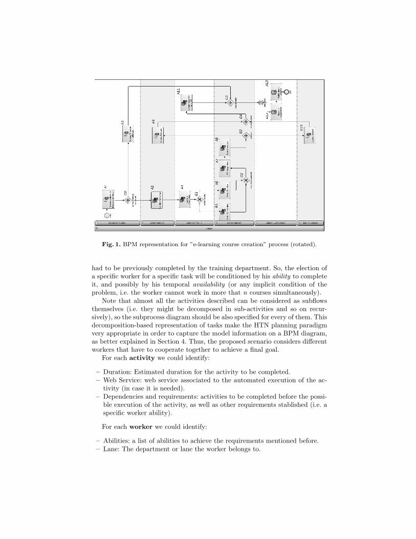
Fig. 1. BPM representation for ”e-learning course creation” process (rotated).
had to be previously completed by the training department. So, the election ofa specific worker for a specific task will be conditioned by his ability to completeit, and possibly by his temporal availability (or any implicit condition of theproblem, i.e. the worker cannot work in more that n courses simultaneously).
Note that almost all the activities described can be considered as subflowsthemselves (i.e. they might be decomposed in sub-activities and so on recur-sively), so the subprocess diagram should be also specified for every of them. Thisdecomposition-based representation of tasks make the HTN planning paradigmvery appropriate in order to capture the model information on a BPM diagram,as better explained in Section 4. Thus, the proposed scenario considers differentworkers that have to cooperate together to achieve a final goal.
For each activity we could identify:
– Duration: Estimated duration for the activity to be completed.– Web Service: web service associated to the automated execution of the ac-
tivity (in case it is needed).– Dependencies and requirements: activities to be completed before the possi-
ble execution of the activity, as well as other requirements stablished (i.e. aspecific worker ability).
For each worker we could identify:
– Abilities: a list of abilities to achieve the requirements mentioned before.– Lane: The department or lane the worker belongs to.
– Number of courses: number of courses the worker is working on.– Availability dates: dates in which the worker is available to be assigned a
task.
This information will help us to establish the preconditions for the executionof actions, and to represent temporal knowledge associated to the problem (thatmight also be automatically generated[2], though not addressed in this paper).The BPM language chosen in order to capture all the mentioned information isXPDL[3], which is detailed in the next section.
3 Technical Background
In this section XPDL and the concept of workflow patterns are defined. We alsointroduce the HTN planning paradigm, as well as some equivalences with BPM.
3.1 XPDL and Workflow Patterns
The goal of XPDL[3] language is to store and exchange the process diagram.An XPDL file offers a one-to-one representation of the original Business ProcessManagement Notation (BPMN)[8] process diagram. The main advantage of us-ing XPDL as modeling language is that it is a common language used amongbusiness analysts, and it can be used to represent the organisation activity eas-ily, storing it in an XML standard format. There are a lot of modeling toolsthat already incorporate XPDL natively or as an additional plug-in. Some ofthe tools evaluated store process models either using a proprietary format ordirectly BPEL[8], but ideally this should be done in XPDL, as it was thoughtfor modeling, not for execution[9]. We have used ”TIBCO Business Studio”2,since it supports XPDL v2.0 and it is offered for free.
XPDL offers some standard tags to represent business processes. The defini-tion of a WorkflowProcess consists of one or more Activities (also called Im-plementation Activities), each comprising a logical, self-contained unit of work,which will be carried out by Participants and/or computer Applications.Activities are related to one another via Transitions. Transitions may be con-ditional (involving expressions which are evaluated to permit or inhibit the tran-sition) or unconditional, and may result in the sequential or parallel operation ofindividual activities within the process. In graphical terms, a transition is a con-nection between two nodes. Special activities, referred to as Route Activities,are used to implement decisions that affect the sequence flow path through theprocess. An activity may also be a subflow (ActivitySet), being itself a con-tainer for the execution of a (separately specified) process. Lanes are used toorganise and categorise activities, often used for specifying roles, departments,etc. XPDL assumes a number of standard DataTypes (string, integer, float, date,etc) that are relevant to DataFields, environmental or participant data, andthat may be used to define expressions, to support conditional evaluations and2 available at http://www.tibco.com
assignment of new values to DataFields or Parameters. In case these tags arenot expressive enough to represent all the information wanted, XPDL providesthe extendedAttribute element, that can be appropriate in most cases. Forfurther details about XPDL, refer to its specification[3].
On the other hand, Workflow Patterns[14] are those generic structures thatrepresent frequently-used relationships between tasks in a process, and that aretypically nested to form the whole process model[4]. As clearly exposed in thenext subsection, a workflow pattern decomposition of any XPDL process can beeasily converted into an HTN domain definition. However, XPDL lacks of somepower for the correct representation of some complex patterns[13]. Therefore,only the most basic ones has been studied in this paper, those that can be wellrepresented and are expressive enough for the definition of most processes.
3.2 HTN Planning
The Hierarchical Task Network (HTN) planning paradigm was developed in or-der to express planning problems in a structured way, by means of the definitionof compound tasks that are reduced into a network of lowest level activities, orprimitive non-decomposable actions whose execution represents a state change.HTN planners use as input two different files:(a) the problem, which encodesthe initial state (literals that are true at the beginning of the problem) and thetask-goal (a partially ordered set of tasks that need to be carried out), and (b)the domain, which encodes reduction schemes for compound tasks as (possiblyalternative) decomposition methods through the definition of (compound andprimitive) tasks and the order in which they should be decomposed, as well asa set of predicates and constants definitions.
HTN-PDDL Notation. The HTN planning domain language used in thiswork is a hierarchical extension of PDDL[2], and it use the following notation:
– (:types), (:constants), (:predicates) and (:functions).– (:task) to express compound tasks. Its definition can include :parameters,
and different (:methods with associated :preconditions and :tasks that rep-resents its corresponding lowest level task decomposition.
– (:durative-action) to express primitive actions, composed of :parameters,:duration, :condition and :effects caused by the execution of this action.
– (:objects) to define objects that are present in the problem.– (:init) to define the set of literals that are initially true.– (:task-goals) to define the set of high level tasks to achieve.
Therefore, the HTN paradigm is able to represent the hierarchical structureof the domain and it is also expressive enough to capture the expert knowledgein order to drive the planner to a desirable solution. We have used the HTNP3
planner for this paper, as it is already known how to translate workflow patternsfor semantic web services composition[5], as well as its adaptation to temporalknowledge[2]. Therefore, plans obtained using the task representation describedabove could be interpreted as workflow instances.3 Formerly named SIADEX, refer to [2] for details.
4 Architecture Overview
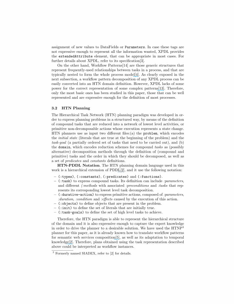
A sketch of the proposed architecture can be observed in Figure 2. Firstly, wehave to draw the model for a specific process of the company in close cooperationwith its managers, specifying all the needed information (in our case mentionedon Section 2) and storing it in XPDL. Afterwards, the basic workflow patternspresent in that model are analysed, finding a decomposition tree for them (Fig.3) that will be automatically mapped into an HTN-PDDL task network, takinginto account the transformations mentioned in next subsection.
E-learning &BPM EXPERTS
Task Workflow Representation
XPDL Representation
export
PDDLRepresentation
parse +
transform
draw
HTN Planner:SIADEX Action Plan
generates
analyse +
Bussiness process management engine
Fig. 2. Architecture for business antici-pated management planning
E
PSplit (A1, P2, P3)
Seq (A2, P4)
XChoice (A4,A5,A6)
Seq (P5, P6)
SMerge (A3,A11,P10)
Seq (A7, P7)
Seq (P8, P3)
Seq (A12,A13)
end
PSplit (A8,A9,A10)
start
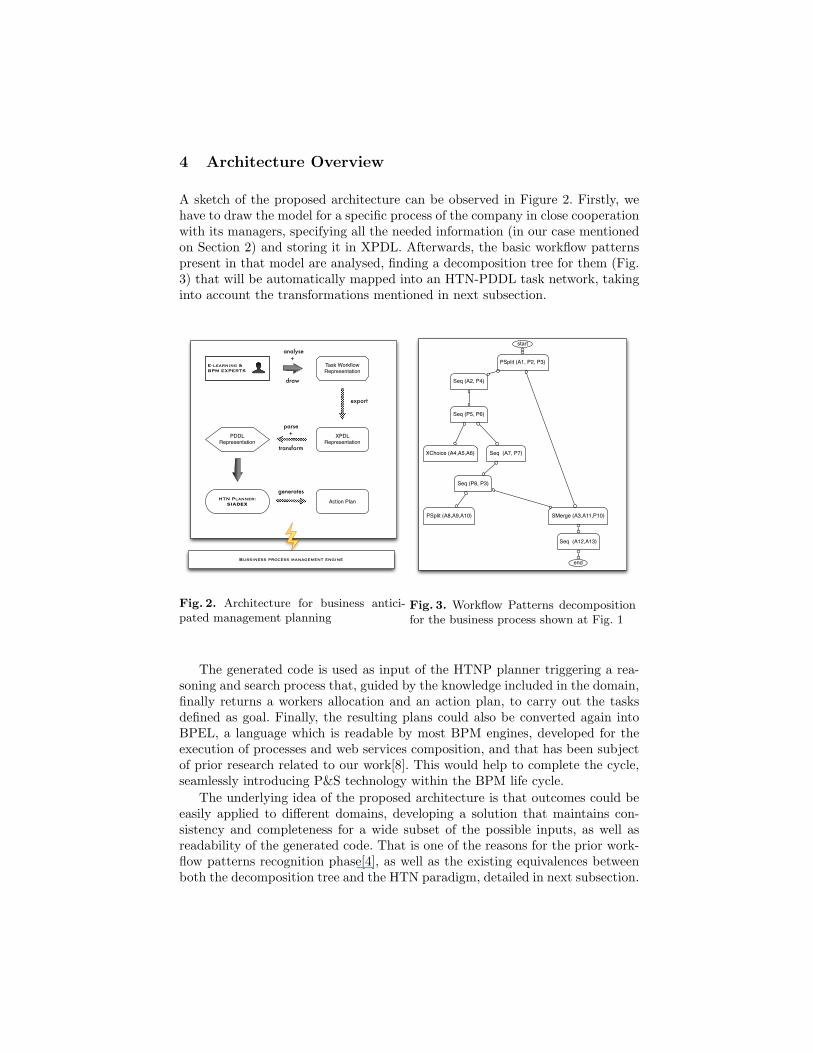
Fig. 3. Workflow Patterns decompositionfor the business process shown at Fig. 1
The generated code is used as input of the HTNP planner triggering a rea-soning and search process that, guided by the knowledge included in the domain,finally returns a workers allocation and an action plan, to carry out the tasksdefined as goal. Finally, the resulting plans could also be converted again intoBPEL, a language which is readable by most BPM engines, developed for theexecution of processes and web services composition, and that has been subjectof prior research related to our work[8]. This would help to complete the cycle,seamlessly introducing P&S technology within the BPM life cycle.
The underlying idea of the proposed architecture is that outcomes could beeasily applied to different domains, developing a solution that maintains con-sistency and completeness for a wide subset of the possible inputs, as well asreadability of the generated code. That is one of the reasons for the prior work-flow patterns recognition phase[4], as well as the existing equivalences betweenboth the decomposition tree and the HTN paradigm, detailed in next subsection.
4.1 XPDL to HTN-PDDL Mapping
What drives us to propose the use of XPDL to model P&S problems followingthe HTN paradigm, is the existing equivalence between both. The basis for thisstatement is the fact that most business processes modeled under XPDL canbe decomposed as a set of related workflow patterns (defined in Section 3.1).This set is what we call a workflow patterns decomposition tree. For example,the process diagram of Figure 1 can be expressed as the decomposition treeshown in Figure 3. As we can observe, the root node is a ”Parallel Split” inwhich, after the execution of activity A1, the blocks P2 and P3 are executedin parallel. At the same time, block P2 is defined as Sequence(A2, P4) (leftchild node) and block P3 is defined as SimpleMerge(A3,A11,P10) (right childnode) . Subsequently, every of the existing blocks, Px, are recursively defined asa new decomposition, until we complete the whole diagram. This finally formsthe decomposition tree shown at Figure 3. The mapping of this structure intoan HTN-PDDL domain is intuitive, as detailed next.
Workflow activities as durative-actions. The execution of an activity ina workflow corresponds to the execution of a primitive action in an HTN-PDDLdomain. XPDL Activity names should also be mapped as HTN-PDDL constants,used as parameters of a predicate (completed ?a -activity), that indicatesthe completion of this activity upon its execution (defined as an :effect), andthat can also be used in preconditions statements needed for the execution ofother tasks. XPDL Participants and Lanes will be mapped as objects, makingpossible the allocation of participants to activities through the inclusion of aparameter (?p - participant) in the durative-action definition. Furthermore,the membership of a Participant Px to a Lane Ly will be mapped as an initcondition of the problem, using the previously defined predicate (belongstolanePx Ly). This predicate can also be used as precondition (i.e. the activity A3 canonly be done by participants that belongs to the training department). Theduration of an activity is modeled using the XPDL extendedAttribute tag.
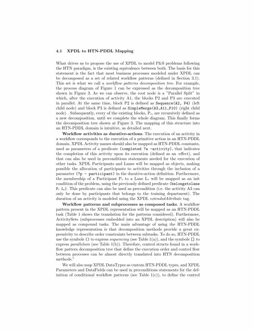
Workflow patterns and subprocesses as composed tasks. A workflowpattern present in the XPDL representation will be mapped as an HTN-PDDLtask (Table 1 shows the translation for the patterns considered). Furthermore,ActivitySets (subprocesses embedded into an XPDL description) will also bemapped as compound tasks. The main advantage of using the HTN-PDDLknowledge representation is that decomposition methods provide a great ex-pressivity to describe order constraints between subtasks. To do so, HTN-PDDLuse the symbols () to express sequencing (see Table 1(a)), and the symbols [] toexpress parallelism (see Table 1(b)). Therefore, control structs found in a work-flow pattern decomposition tree that define the execution order and control flowbetween processes can be almost directly translated into HTN decompositionmethods.”
We will also map XPDL DataTypes as custom HTN-PDDL types, and XPDLParameters and DataFields can be used in preconditions statements for the def-inition of conditional workflow patterns (see Table 1(c)), to define the control
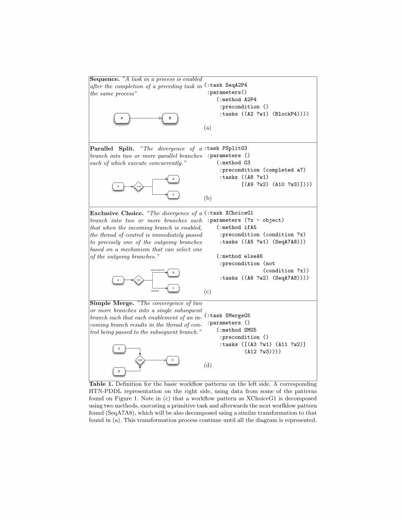
Sequence. ”A task in a process is enabledafter the completion of a preceding task inthe same process”
A B
(:task SeqA2P4
:parameters()
(:method A2P4
:precondition ()
:tasks ((A2 ?w1) (BlockP4))))
(a)
Parallel Split. ”The divergence of abranch into two or more parallel brancheseach of which execute concurrently.”
A
B
AND
C
:task PSplitG3
:parameters ()
(:method G3
:precondition (completed a7)
:tasks ((A8 ?w1)
[(A9 ?w2) (A10 ?w3)])))
(b)
Exclusive Choice. ”The divergence of abranch into two or more branches suchthat when the incoming branch is enabled,the thread of control is immediately passedto precisely one of the outgoing branchesbased on a mechanism that can select oneof the outgoing branches.”
A
B
XOR
C
whereToGo==B
otherwise
(:task XChoiceG1
:parameters (?x - object)
(:method ifA5
:precondition (condition ?x)
:tasks ((A5 ?w1) (SeqA7A8)))
(:method elseA6
:precondition (not
(condition ?x))
:tasks ((A6 ?w2) (SeqA7A8))))
(c)
Simple Merge. ”The convergence of twoor more branches into a single subsequentbranch such that each enablement of an in-coming branch results in the thread of con-trol being passed to the subsequent branch.”
A
B
XOR C
(:task SMergeG5
:parameters ()
(:method SMG5
:precondition ()
:tasks ([(A3 ?w1) (A11 ?w2)]
(A12 ?w3))))
(d)
Table 1. Definition for the basic workflow patterns on the left side. A correspondingHTN-PDDL representation on the right side, using data from some of the patternsfound on Figure 1. Note in (c) that a workflow pattern as XChoiceG1 is decomposedusing two methods, executing a primitive task and afterwards the next worfklow patternfound (SeqA7A8), which will be also decomposed using a similar transformation to thatfound in (a). This transformation process continue until all the diagram is represented.
flow between two activities. Finally, the task goal for the planning problem cor-respond to the root node of the workflow patterns decomposition tree.
5 Results
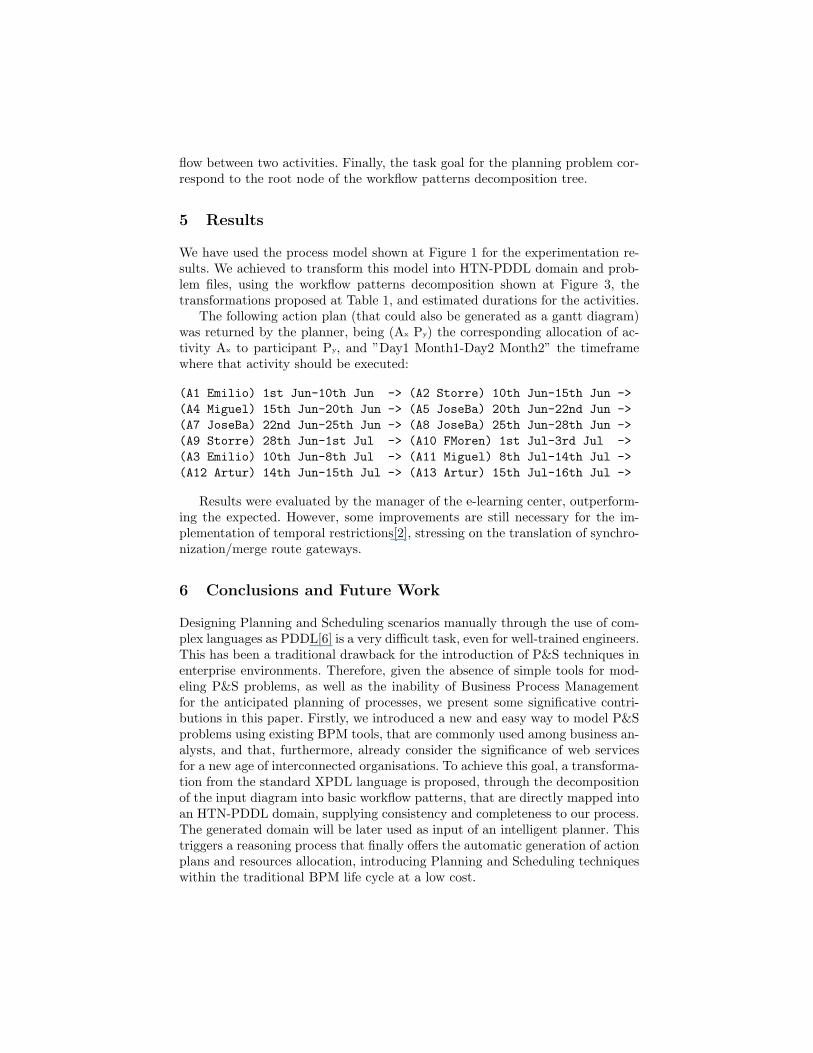
We have used the process model shown at Figure 1 for the experimentation re-sults. We achieved to transform this model into HTN-PDDL domain and prob-lem files, using the workflow patterns decomposition shown at Figure 3, thetransformations proposed at Table 1, and estimated durations for the activities.
The following action plan (that could also be generated as a gantt diagram)was returned by the planner, being (Ax Py) the corresponding allocation of ac-tivity Ax to participant Py, and ”Day1 Month1-Day2 Month2” the timeframewhere that activity should be executed:
(A1 Emilio) 1st Jun-10th Jun -> (A2 Storre) 10th Jun-15th Jun ->(A4 Miguel) 15th Jun-20th Jun -> (A5 JoseBa) 20th Jun-22nd Jun ->(A7 JoseBa) 22nd Jun-25th Jun -> (A8 JoseBa) 25th Jun-28th Jun ->(A9 Storre) 28th Jun-1st Jul -> (A10 FMoren) 1st Jul-3rd Jul ->(A3 Emilio) 10th Jun-8th Jul -> (A11 Miguel) 8th Jul-14th Jul ->(A12 Artur) 14th Jun-15th Jul -> (A13 Artur) 15th Jul-16th Jul ->
Results were evaluated by the manager of the e-learning center, outperform-ing the expected. However, some improvements are still necessary for the im-plementation of temporal restrictions[2], stressing on the translation of synchro-nization/merge route gateways.
6 Conclusions and Future Work
Designing Planning and Scheduling scenarios manually through the use of com-plex languages as PDDL[6] is a very difficult task, even for well-trained engineers.This has been a traditional drawback for the introduction of P&S techniques inenterprise environments. Therefore, given the absence of simple tools for mod-eling P&S problems, as well as the inability of Business Process Managementfor the anticipated planning of processes, we present some significative contri-butions in this paper. Firstly, we introduced a new and easy way to model P&Sproblems using existing BPM tools, that are commonly used among business an-alysts, and that, furthermore, already consider the significance of web servicesfor a new age of interconnected organisations. To achieve this goal, a transforma-tion from the standard XPDL language is proposed, through the decompositionof the input diagram into basic workflow patterns, that are directly mapped intoan HTN-PDDL domain, supplying consistency and completeness to our process.The generated domain will be later used as input of an intelligent planner. Thistriggers a reasoning process that finally offers the automatic generation of actionplans and resources allocation, introducing Planning and Scheduling techniqueswithin the traditional BPM life cycle at a low cost.
Future work will explore the HTN-PDDL representation of complex workflowpatterns and will also study how to represent more demanding temporal restric-tions that are usually present in business processes, so that we can increase thecapacity of the business analyst to represent real planning domains through theuse of the same business modeling tools.
Acknowledgments. We would like to be specially grateful to CEVUG staff,specially to F. Moreno Ruiz and M. Gonzalez Laredo for their invaluable help.
References
1. A. Bahrami. ”Integrated Process Management: From Planning to Work Execu-tion”. In IEEE Workshop on Business Service Networks, pages 11–18, 2005.
2. L. Castillo, J. Fdez-Olivares, O. Garcıa-Perez, and F. Palao. ”Efficiently handlingtemporal knowledge in an HTN planner”. In 16th ICAPS Conf., pages 63–72, 2006.
3. Workflow Management Coalition. ”XML Process Definition Language Specifica-tion, v2.1”. WFMC-TC-1025, pages 1–216, 2008.
4. T. Dirgahayu, D. A. C. Quartel, and M. J. van Sinderen. ”Development of trans-formations from business process models to implementations by reuse”. In 3rdInternational Workshop on Model-Driven Enterprise Information Systems, pages41–50, 2007.
5. J.Fdez-Olivares, T. Garzon, L. Castillo, O.Garcıa-Perez, and F. Palao. ”A Mid-dleware for the automated composition and invocation of semantic web servicesbased on HTN planning techniques”. In LNAI 4788, pages 70–79. Springer, 2007.
6. D. Long and M. Fox. ”PDDL2.1: An Extension to PDDL for Expressing TemporalPlanning Domains”. Journal of Artificial Intelligence Research, 20:61–124, 2003.
7. M.Z. Muehlen and D. Ting-Yi Ho. ”Risk Management in the BPM Lifecycle”. InLNCS 3812, pages 454–466. Springer, 2006.
8. C. Ouyang, M. Dumas, A. Hofstede, and W.M.P. van der Aalst. ”Pattern-basedtranslation of BPMN process models to BPEL web services”. International Journalof Web Services Research, 5(1):42–62, 2007.
9. N. Palmer. ”Workflow and BPM in 2007: Bussiness Process Standards see a newglobal imperative”. BPM and Workflow Handbook, pages 9–14, 2007.
10. M.D. R-Moreno, D. Borrajo, A. Cesta, and A. Oddi. ”Integrating planning andscheduling in workflow domains”. Expert Systems with Applications, 33(2):389–406,2007.
11. R. Sen, G. Hackmann, M. Haitjema, G.C. Roman, and C. Gill. ”CoordinatingWorkflow Allocation and Execution in Mobile Environments”. In CoordinationModels and Languages, LNCS 4467, pages 249–267. Springer, 2007.
12. E. Sirin, B. Parsia, D. Wu, J. Hendler, and D. Nau. ”HTN planning for web servicescomposition using shop2”. Journal of Web Semantics, 1(4), 2004.
13. W.M.P. van der Aalst. ”Patterns and XPDL: A critical Evaluation of the XMLProcess Definition Language”. QUT report FIT-TR-2003-06, pages 1–30, 2003.
14. W.M.P. van der Aalst, A.H.M. ter Hofstede, B. Kiepuszewski, and A.P. Barros.”Workflow Patterns”. Distributed and Parallel Databases, 14(1):5–51, 2003.
15. T.S. Vaquero, V.M.C. Romero, F. Tonidandel, and J.R. Silva. ”itSIMPLE 2.0: AnIntegrated Tool for Designing Planning Domains”. In 17th ICAPS Conf., 2007.
16. R. Wilson and F.C. Keil. ”MIT Encyclopedia of Cognitive Science”, pages 652–654.MIT Press, 2001.
Copyright © 2022 FDOKUMEN