
Integrating planning and scheduling in workflow domains
18
Integrating planning and scheduling in workflow domains Marı ´a Dolores R-Moreno a, * , Daniel Borrajo b , Amedeo Cesta c , Angelo Oddi c a Departamento de Automa ´ tica, Universidad de Alcala ´ , Carretera Madrid-Barcelona, Km. 33,600, 28871 Alcala ´ de Henares, Madrid, Spain b Departamento de Informa ´ tica, Universidad Carlos III de Madrid, Avda. de la Universidad, 30, 28911 Legane ´s, Madrid, Spain c ISTC-CNR-Italian National Research Council, Viale Marx 15, I-00137 Rome, Italy Abstract One of the main obstacles in applying AI planning techniques to real problems is the difficulty to model the domains. Usually, this requires that people that have developed the planning system carry out the modeling phase since the representation depends very much on a deep knowledge of the internal working of the planning tools. On some domains such as business process reengineering (BPR), there has already been work on the definition of languages that allow non-experts entering knowledge on processes into the tools. We propose here the use of one of such BPR languages to enter knowledge on the organisation processes to be used by planning tools. Then, planning tools can be used to semi-automatically generate business process models. As instances of this domain, we will use the workflow modeling tool SHAMASH, where we have exploded its object oriented structure to introduce the knowledge through its user-friendly interface and, using a translator transform it into predicate logic terms. After this con- version, real models can be automatically generated using a planner that integrates planning and scheduling, IPSS. We present results in a real workflow domain, the telephone installation (TI) domain. Ó 2006 Elsevier Ltd. All rights reserved. Keywords: Planning and scheduling; Workflow management systems; Business process reengineering; Makespan minimisation; Time windows 1. Introduction In the last years, companies and markets have quickly grown in complexity so they are looking for flexible and dynamic ways to efficient manage their resources and processes. Due to the competitive nature of businesses and the strong pressure of the market, quality initiatives and the gradual improvement of processes are not enough for the continuous and dynamic changes that current organisations need. Levels of changes so radical need new and powerful tools that can allow the efficient redesign and management of the organisation. Also improving cus- tomer service and increasing customer retention is gaining importance. This is the main objective of BPR (Hammer & Champy, 1993). Over the past few decades, BPR has become fashionable among medium and big enterprises due to its capability to present solutions that improve this type of management. Although there have already been many approaches to the computer-aided design of processes, very few have focused on the automatic generation of process models that have in mind the organisation resources as well as their capabilities and availability. Once the organisation has been studied in depth from a process and resources perspective, corresponding models are modeled in order to handle processes and resources computationally. Business processes are usually repre- sented as workflow, that is, computerised models within which all the parameters needed for the completion of the processes can be defined: resources involved, orders, tasks, conditions, goals, quality criteria, information flow, etc. Workflow management systems (WFMSs) (Leymann & Roller, 1994; Medina-Mora, Winograd, & Flores, 1993; Mohan, 1997) have been deployed in sectors like insurance, banking, accounting, manufacturing, telecommunications, 0957-4174/$ - see front matter Ó 2006 Elsevier Ltd. All rights reserved. doi:10.1016/j.eswa.2006.05.027 * Corresponding author. Tel.: +34 918856607. E-mail addresses: [email protected] (M.D. R-Moreno), dborrajo@ ia.uc3m.es (D. Borrajo), [email protected] (A. Cesta), [email protected] (A. Oddi). www.elsevier.com/locate/eswa Expert Systems with Applications 33 (2007) 389–406 Expert Systems with Applications
Transcript of Integrating planning and scheduling in workflow domains

www.elsevier.com/locate/eswa
Expert Systems with Applications 33 (2007) 389–406
Expert Systemswith Applications
Integrating planning and scheduling in workflow domains
Marıa Dolores R-Moreno a,*, Daniel Borrajo b, Amedeo Cesta c, Angelo Oddi c
a Departamento de Automatica, Universidad de Alcala, Carretera Madrid-Barcelona, Km. 33,600, 28871 Alcala de Henares, Madrid, Spainb Departamento de Informatica, Universidad Carlos III de Madrid, Avda. de la Universidad, 30, 28911 Leganes, Madrid, Spain
c ISTC-CNR-Italian National Research Council, Viale Marx 15, I-00137 Rome, Italy
Abstract
One of the main obstacles in applying AI planning techniques to real problems is the difficulty to model the domains. Usually, thisrequires that people that have developed the planning system carry out the modeling phase since the representation depends very muchon a deep knowledge of the internal working of the planning tools. On some domains such as business process reengineering (BPR), therehas already been work on the definition of languages that allow non-experts entering knowledge on processes into the tools. We proposehere the use of one of such BPR languages to enter knowledge on the organisation processes to be used by planning tools. Then, planningtools can be used to semi-automatically generate business process models.
As instances of this domain, we will use the workflow modeling tool SHAMASH, where we have exploded its object oriented structure tointroduce the knowledge through its user-friendly interface and, using a translator transform it into predicate logic terms. After this con-version, real models can be automatically generated using a planner that integrates planning and scheduling, IPSS. We present results ina real workflow domain, the telephone installation (TI) domain.� 2006 Elsevier Ltd. All rights reserved.
Keywords: Planning and scheduling; Workflow management systems; Business process reengineering; Makespan minimisation; Time windows
1. Introduction
In the last years, companies and markets have quicklygrown in complexity so they are looking for flexible anddynamic ways to efficient manage their resources andprocesses. Due to the competitive nature of businessesand the strong pressure of the market, quality initiativesand the gradual improvement of processes are not enoughfor the continuous and dynamic changes that currentorganisations need. Levels of changes so radical need newand powerful tools that can allow the efficient redesignand management of the organisation. Also improving cus-tomer service and increasing customer retention is gainingimportance. This is the main objective of BPR (Hammer &Champy, 1993).
0957-4174/$ - see front matter � 2006 Elsevier Ltd. All rights reserved.
doi:10.1016/j.eswa.2006.05.027
* Corresponding author. Tel.: +34 918856607.E-mail addresses: [email protected] (M.D. R-Moreno), dborrajo@
ia.uc3m.es (D. Borrajo), [email protected] (A. Cesta), [email protected](A. Oddi).
Over the past few decades, BPR has become fashionableamong medium and big enterprises due to its capability topresent solutions that improve this type of management.Although there have already been many approaches tothe computer-aided design of processes, very few havefocused on the automatic generation of process models thathave in mind the organisation resources as well as theircapabilities and availability.
Once the organisation has been studied in depth from aprocess and resources perspective, corresponding modelsare modeled in order to handle processes and resourcescomputationally. Business processes are usually repre-sented as workflow, that is, computerised models withinwhich all the parameters needed for the completion of theprocesses can be defined: resources involved, orders, tasks,conditions, goals, quality criteria, information flow, etc.Workflow management systems (WFMSs) (Leymann &Roller, 1994; Medina-Mora, Winograd, & Flores, 1993;Mohan, 1997) have been deployed in sectors like insurance,banking, accounting, manufacturing, telecommunications,

390 M.D. R-Moreno et al. / Expert Systems with Applications 33 (2007) 389–406
administration and customer service (Lydiard, Jarvis, &Drabble, 1999) but it does not have significant commercialimpact yet, because of problems related to the cost of pro-cess modeling and the inflexibility in their execution.
We can see WFMSs as a set of methods and technolo-gies that allows modeling and managing some of the pro-cesses that happen in the company (there are someprocesses that will likely never be modeled in workflow sys-tems because, they are either too difficult to formalize, ortoo dynamic). It can provide active support to a businessprocess by controlling the routing of work around theorganisation automatically. This is done based on the busi-ness processes models describing the flow, the decisions, theexceptions, the resources to be used, etc.
WFMS co-ordinates user and system participants,together with the appropriate data resources, which maybe accessible directly by the system or off-line to achievedefined goals by setting deadlines. The co-ordinationinvolves passing tasks to participants’ agents, and ensuringthat all complete their tasks successfully. In case of excep-tions, actions to solve the problem can be triggered, orhuman operators alerted.
Optimising the organisation procedures, routines andresource management, several aspects must be considered.Examples are the activities or tasks that should be per-formed; the organisation model that describes the roles ofeach agent (software or human), who can perform whatin the organisation; and the information model thatdescribes which information is needed to perform anactivity.
In the last few years an increasing development of doc-umentation tools and/or process modeling techniques haveemerged that represent and reason computationally aboutthe knowledge of the current processes and resources. Usu-ally, the task of defining those models is performed withthe aid of a set of tools that provide a graphical represen-tation of them, together with the relations among theactivities that occur within the processes. The human isusually an expert in the processes that take place in theorganisation. Many issues need to be considered on thistask and implemented like the reusability of past processes,accessibility to the models by the different agents in theorganisation, consistency of usage, or selection of the rightmodel.
Prior to WFMS, many enterprises created special-purposetailored applications to support their processes. The advan-tage of WFMS-based solutions is that the workflow repre-sentation is explicit, and separated from the applicationcode. This means that a WFMS can be customised quicklyto support a new business or process, and that workflowsare relatively easy to modify when a process changes. Cur-rent WFMS do not address all aspects of the problem,however. In general, they do not deal with scheduling, thatis, resources management/allocation. Similarly, while theyprovide means of generating exception events when thingsgo wrong, they do not have a built-in re-planning functionor automatic methods for adapting the workflow model
according to those exceptions. They do, however, provideinterfaces so that application-specific modules performingthese functions can be integrated.
Workflow systems hold the promise of facilitating theeveryday operation of many enterprises and work environ-ments. Despite the popularity of these products, there isstill a lack of maturity in some respect, i.e., a lack of asemantic associated to the models or an easy way to reasonabout that semantic, that could be overcome using tech-niques coming from other fields such as artificial intelli-gence (AI).
Without any doubt, the application of AI techniques toWorkflow Management systems has created a big expecta-tion. The AI community and in particular the planning andscheduling field, has been applying successful techniques indifferent and complex domains like robotics, satellites ormilitary logistics. In these domains, there are activities thatmust be performed (planning) in a temporal horizon thatconsume or produce resources (scheduling). During execu-tion, completion of activities, and delays and other prob-lems are detected to take the appropriate measures(rectify the situation, or in more drastic cases, a new plan)to satisfy the goals. In order to represent this information,rich representation models are needed, the majority ofthem based on predicate logic as is the case of the planningstandard language, PDDL2.2 (Edelkamp & Hoffmann,2004). There is also the HTN representation where planningproblems and operators are organised into a set of tasks.High level tasks are reduced into a set of lower levels andthe way to do it can be done in several ways as in Yang(1997) and Kuter et al. (2005).
In the past, some researchers saw the advantages of theintegration of AI planning and scheduling for workflowgeneration, as shown by the existence of a Technical Co-ordination Unit of the European research network on plan-ning and scheduling, PLANET (PLANET), on applicationsof planning and scheduling to workflow. This has lead tosome exploratory work reflected in a Roadmap PLANETand some related work (Hannebaeur, 1999; Kearney &Borrajo, 2000; Myers & Berry, 1999; R-Moreno & Kear-ney, 2002).
The aim that we want to achieve with this integration isdouble. From one hand, given that the majority of BP
tools are based on objects and rules, we propose to trans-late this knowledge into first order predicate logic, in par-ticular into the planning domain definition languagePDDL2.2.
On the other hand, we propose an integrated P&S fram-kework to automatically solve BRP problems. In the liter-ature there are basically two approaches to solve this typeof problems. The component based approach (Cesta,Pecora, & Rasconi, 2004), where the two subproblems ofplanning and scheduling are just solved one after the other,and the integrated approach (Ghallab & Laruelle, 1994;Tate, Drabble, & Kirby, 1994) where there is an uniformrepresentation without the decomposition over two sequen-tial subproblems. We believe that systems that integrate

M.D. R-Moreno et al. / Expert Systems with Applications 33 (2007) 389–406 391
P&S, as IPSS (R-Moreno, 2003), are the best suitable can-didates and we will explain why IPSS is one of the bestplanners suited for the automatic solving of BPR problems.
The paper is structured as follows: Section 2 describesthe main concepts that Workflow and AI planning systemsshare. Next, Sections 3 and 5 introduces instances of bothdomains, SHAMASH and IPSS, explaining on Section 4 howthe integration can be possible with a simple example ofinstalling a new telephone line in a telecom company thatis explained in detail on Section 6. Then, Section 7 showssome results of IPSS against state of the art planners.Finally, Sections 8 and 9 outlines the future work andconclusions.
2. Workflow management and AI planning and scheduling
The first step for the integration of workflow manage-ment and AI planning and scheduling Systems is to identifypoints in common by understanding the way both work.
2.1. WFMS
The main module in WFMS is the workflow engine thatis in charge of coordinating the model execution and deter-mining the agents (human or software), the data, the busi-ness constraints and other applications implied in theprocess. The Workflow Management Coalition (WFMC)Management Coalition provides a general architectureframework where five interfaces are identified with relationto the workflow engine:
• Tools to model, define and analyse the flow of the con-trol in the processes.
• Administration module.• Monitoring module.• Simulation module.• Re-engineering workflow module.
The workflow engine must include: an assignation taskmodule in charge of assigning the tasks among the differentagents that participate in the processes, a knowledge base-line of the organisation structure and a module to handlethe exceptions and failures recover.
When modeling workflow systems, we need to identifyand use definitions of the different elements that will beused, such as:
• Tasks: each task is an activity or a set of actions handledas a whole. They require a set of resources, and whenthese resources include humans they usually play a rolefor each task.
• Persons (users): the tasks are performed in a definedorder by specific human resources (or agents playingthe human roles) based on rules or business constraints.
• Roles: each role defines a set of potential competencesthat exist in the organisation. They are defined indepen-dently of the persons to whom the roles will be assigned.
• Routing: each routing defines the sequences of steps thatthe documents (or data) must follow within the work-flow system. It is very important that the WFMS hasthe capability of routing the tasks to remote or occa-sional users.
• Transitions: are logical rules that determine the flow ofthe document within the system. They express whataction is going to be executed depending on the valueof logical expressions. The rules can have varying com-plexity with multiple options, variations and exceptions.
• Data: are the documents, files, images, registers in thedata base and other type of information used to performthe work.
• Event: is an interruption that contains information. Theevents can be triggered by the user or appear during aprocess according to the state of the data or decisionsmade by the user.
• Deadline: is the maximum time that is assigned to a taskto be concluded, the maximum time to execute a path,or to finish a task before a given date, etc. We can assignevents to deadlines so when the time limit is reachedsome events can be triggered.
• Process: is a set of linked activities within anorganisation.
• Policy: is a characterization of a set of constraints or arecommendation on how tasks should be performed.
Fig. 1 shows the workflow architecture proposed by theWFMC. The Process Model is the first stage in the adop-tion of a Workflow solution and involves the crucial taskof revealing and recording all of the manual and automaticinternal business processes of an organisation. From there,the user designs, models, optimises and simulates the orga-nisation’s processes through user friendly interfaces. Weinclude in this stage the design of the process templates thatcan be instantiated and enacted by a workflow system.Then, it comes the process planning where the activitiesrequired to achieve some user goals are instantiated,resources assigned, and a preliminary scheduling per-formed. These two stages are included in the process defi-nition interface of Fig. 1.
Next, the enactment/execution stage is defined, whereagents (software or humans) carry out the activities, withthe workflow system co-ordinating execution. The monitor-ing stage runs concurrently with Enactment/Execution, sostatus information is made available to human operators.Exceptions, such as deviation from the plan, and subsidiaryprocesses are initiated to solve problems.
2.2. AI planning and scheduling
AI planning and scheduling (AI P&S) consists of a set oftechniques on modeling, searching for solutions of prob-lems with time and resources, execution, monitoring andrepair. Although they have been two very related fieldsthey have evolved separately. Planning generates a plan(sequence or parallelization of activities) such that it

Fig. 1. Architecture proposal by WFMC.
392 M.D. R-Moreno et al. / Expert Systems with Applications 33 (2007) 389–406
achieves a set of goals given an initial state and satisfying aset of domain constraints represented in operators sche-mas. In scheduling systems, activities are organised alongthe time line having in mind the resources available. Thesesystems can perfectly handle temporal reasoning andresource consumption, together with some quality criteria(usually centred around time or resource consumption)but they cannot produce the needed activities and their pre-cedence relations given that they lack an expressive lan-guage to represent the activities. Traditionally, planningwas first performed and the solution was given as an inputto the scheduling systems.
So in these systems, the user should first supply adomain description that is composed of a set of operators.An instance of a business process, (e.g., the accountingprocess) is analogous to a plan in AI. In business processmanagement (BPM) terminology, a plan also includes allo-cation of resources and target start and end times, while inAI terminology this task is usually performed by schedul-ing techniques. Currently, there is an increasing interestto integrate these two fields because of real domains needsas for example, workflow domains. Thus, systems as IPSS(R-Moreno, 2003; R-Moreno, Oddi, Borrajo, Cesta, &Meziat, 2004b), SAPA (Do & Kambhampati, 2003) or IXTET
(Ghallab & Laruelle, 1994) are suitable candidates to solvethis type of problems.
At a high level, the inputs of a planner are:
• Domain theory: the STRIPS representation originallyproposed by Fikes and Nilsson is one of the mostwidely used alternatives (Fikes & Nilsson, 1971). Itwas introduced to overcome what were seen as compu-tational difficulties in using states to build plans. In theSTRIPS representation, a world state is represented by a
set of logical formulae, the conjunction of which isintended to describe the given state. Actions are repre-sented by so-called operators. An operator consists ofpre-conditions (conditions that must be true to allowthe action execution), and post-conditions or effects(usually constituted of an add list and a delete list).The add list specifies the set of formulae that becometrue in the resulting state while the delete list specifiesthe set of formulae that are no longer true and mustbe deleted from the description of the state.
• Problem: is described in terms of an initial state andgoals. Those states are represented by a logical formulathat specifies a situation for which one is looking for asolution.– Initial state: in planning, one has to specify the start-
ing situation of the posed problem.– Goals: are often viewed as specifications for a plan.
They describe the successful behaviours that execu-tion of the plan should produce; they specify whatone would like to be true at the end of the solutionof the problem for a given time.
AI planners generate as an output a plan or set of plansif a solution exists. A plan can be seen as a sequence ofoperator applications that can lead from the initial stateto a state in which the goals are reached.
Once we have described the main elements in AI P&Ssystems, we can identify the following phases when usingthem for solving problems:
• Domain modeling: in this phase the user introduces theknowledge to the system, that is, the operators, the ini-tial conditions and goals. Each planner has its own syn-tax although lately there has been an effort to unify the

M.D. R-Moreno et al. / Expert Systems with Applications 33 (2007) 389–406 393
syntax in a common language: the Planning DomainDefinition Language, now in the 2.2 version (PDDL2.2)(Edelkamp & Hoffmann, 2004).
• Planning and scheduling: the plan is outlined as a set ofinstantiated actions in a given order. Commonly, plansdo not contain information about resources, so in someproblems planning and scheduling can be separated. Inother cases, this idea has to be abandoned and mecha-nisms to handle resources through constraining equa-tions must be integrated to solve the problem.
• Execution: this stage relates to the actions’ execution.• Monitoring: the results of the actions execution can dif-
fer from the actions expected results, so monitoringmust take place to anticipate events or re-plan if the ini-tial plan cannot be achieved.
2.3. Common phases in both systems
AI P&S and BPM are complementary disciplines withmuch to gain from collaboration. The ability to invokeAI components flexibly and dynamically from within theworkflow framework would considerably enhance businessproductivity. Table 1 outlines at a high level the conceptsthat AI P&S share with the Workflow community (for amore detailed description we refer to the Workflow Man-agement PLANET TCU PLANET roadmap).
Each BPR domain (e.g., the accounting process in anorganisation) can be defined in terms of a set of activities(they are also called tasks or even processes) that are per-formed by organisation agents (either human or software).Therefore, there is a strong relation between operators inplanning and activities in BPR.
For BPR, a problem might be described as a processthat has to be designed (modeled) for a particular task tobe performed within the organisation. For instance, model-ing the purchasing of an organisation would be the prob-lem that one has to solve. In the initial state would be allknowledge that the organisation has about itself and hasto be for a specific process within the organisation. Exam-ples of information that should appear in the initial statewould be: the hierarchical and/or functional representationof the organisation, the resources that it uses and whenthey are available, the documents that are generated, etc.
Table 1Concepts mapping between AI P&S and workflow
AI P&S Workflow
Modeling + planning andscheduling
Modeling and Scheduling
Execution EnactmentRe-planning ExceptionsMonitoring MonitoringOperators Activities, tasks, . . .
Initial State Organisation, resourcesGoals Business goals, service provision, . . .
The goals might be represented by the business goal ofthe organisation with respect to that process. For instance,a purchase process has to be completed, having in mind aset of time or cost constraints, or even some user satisfac-tion criteria.
As a result, BPR processes can be sequences of activities,adding conditional branches or activities occurring simul-taneously (that is, plans in P&S).
Another common approach to model workflow system isthe Petri Nets formalism (Purvis, Purvis, & Lemalu, 2001).It is a formal and graphical language which is appropriatefor modeling concurrent, asynchronous, distributed, paral-lel, non-deterministic and/or stochastic systems. It is a par-ticular case of directed graph with an initial state called theinitial marking. There are two kinds of nodes: places andtransitions. Arcs are either from a place to a transition ora transition to a place. The basic problem with Petri Netsis that they are so simple that even a small system needsmany states and transitions (known as the state explosion).Instead, we will use the AI planning formalism to modelprocesses and also validate them avoiding inconsistenciesand it can give other solutions in case exceptions occur(re-planning).
3. The SHAMASH tool
Once the different stages between both areas have beenidentified, in this section we describe the features of a work-flow modeling tool, SHAMASH. SHAMASH (Aler, Borrajo,Camacho, & Sierra-Alonso, 2002), a R&D project fundedby the IV Esprit Program, generated a process modelingtool that allows simulation, modeling and optimisation ofbusiness processes taking into account a realistic modelof the organisation. This aspect combined with the featuresthat the tool embodies, make SHAMASH a powerful tool forBPR. The richer modeling capabilities allow among others,modeling of organisation standards and rules of proce-dures, business goals, automatic validation and optimisa-tion of the models, or generation of HTML output, suchthat people from the organisation can freely browse theprocesses in which they participate.
The SHAMASH tool consists of four subsystems as Fig. 2shows:
• Author subsystem: this module provides a user-friendlyinterface that enables definitions of three types ofknowledge: on standards (policies), on processes andon the organisation. The standards, or norms, constrainhow processes should behave according to the internalcompany criteria. The interface allows the user to createtheir structure, related standards or processes, organisa-tion resources to be used, business goals, flow elementsand its attributes. Processes are computational units
within the organisations. The user can describe thesequence of steps or conditionals to be completed toaccomplish some goal. Each step or activity has pre-and post-conditions that define its behaviour. Once the

Fig. 2. SHAMASH architecture.
394 M.D. R-Moreno et al. / Expert Systems with Applications 33 (2007) 389–406
user has defined his/her processeses, the tool allows con-nection of the related process so they can be simulatedand optimised. SHAMASH also allows the user to definelibraries of processes to be used in other modelingapplications.
• Simulation and optimisation subsystem: this is animportant part of the modeling tool. The simulatorcan check the behaviour of the process that the userhas created. The simulation is a semantic-based one,given that it has into account the behaviour definedfor each activity using a rule-based representation andhistorical data or different probabilities distributions.SHAMASH also helps in detecting static problems (usingvalidation expert heuristics) and spotting problems thatcan only be detected when the model is running (asunderused resources or bottlenecks). Also, the tool isable to automatically perform an optimisation phaseby which new better models are generated by searchingthe space of process models and using business goals assearch metrics. The user can decide whether to adopt thenew models, or to continue with the old ones.
• Text generation subsystem: this subsystem is responsiblefor maintaining coherence between the graphical(defined by specific people in the organisation) and thetext versions (the ones seen by most people in the orga-nisation). SHAMASH allows to automatically generate anew HTML version in accordance with the changes made.
• Workflow interface subsystem: SHAMASH cannot directlybe used as a workflow engine. An interface is needed toautomatically translate the defined process models intothe input of a workflow engine. As a result, a WPDL
(Workflow Process Description Language), the standardlanguage generated by the WFMC, can be generated asoutput of the process representation.
The tool also allows the user to create and maintainknowledge about the organisation through an interface.
The behaviour of the model is defined through objectsand rules with a well-defined and easy-to-use syntax. Thisallows detailed specification of how activities are per-formed, what inputs they take and in what format, howthe outputs are generated from the inputs, etc.
3.1. SHAMASH as a knowledge based system
The Knowledge Base of SHAMASH and the applicationsdeveloped with it contain all the knowledge about thedomain: the objects, their methods, and rules to define theprocesses and validation behaviour. The object-orientationhelps in two ways: first, it is a good way to structure theknowledge on processes and organisations; second, it canbe user extendible by using object inheritance.
When defining a domain, the user starts by selecting andadding, through the interface, the new objects and attri-butes that belong to the process. In SHAMASH the main clas-ses that represent the organisation are:
• Activity: defines the types of actions involved in the pro-cess. For instance, in a process of installing a new line,receiving the customer order, building a cable or sendinga invoice.
• Element: defines the elements and their features (attri-butes such as name or the capacity type: binary multi-capacity) that flows through a process. That is, theinputs and outputs of the tasks. For instance, an invoice,or a new line.
• Resource: defines the resources available in the organi-sation, such as people or software and their features(attributes). There are several types of resources suchas human or material resources, and the last one canbe consumable or available.
• Role: defines the roles that the people on the organisa-tion can play in the mentioned activities, as Engineeror Technician.

M.D. R-Moreno et al. / Expert Systems with Applications 33 (2007) 389–406 395
• Unit: defines the units in an organisation that can beeither individuals or groups of people, such as EngineerDepartment, or Tom Miller.
3.2. Rule based approach
SHAMASH follows a rule-based approach for defining thebehaviour of some elements in the Knowledge Base. Themain rationality for having used rules for defining behav-iour was that the user companies selected them as theknowledge formalism that was closer for them to repre-sent the knowledge about the behaviour of the elementsof the processes. Rules can access any represented infor-mation about the organisation, its structure, its processes,as well as its business rules (or standards). Therefore, veryrich semantic behaviour can be defined within the pro-cesses, which account for a more realistic representationof them.
In order to help the user on entering the rules, a syntax-driven Rule Editor was defined. In the Rule Editor, theuser can easily define, modify or remove rules in order todescribe the behaviour of standards and processes, estab-lish validation functions and optimisation criteria, etc.
For the integration of the IPSS with SHAMASH we had totranslate from the BPR based language of SHAMASH into theIPSS language (Carbonell et al., 1992), as it is describedbelow.
The SHAMASH ontology on processes adopts an activity-centred modeling viewpoint (Myers & Berry, 1999). Theactivities use resources to satisfy the process requirementsdefined by the user. Every activity has a set of precondi-tions that must be true to execute an activity or a process.
Rules can be used to define these conditions and to ver-ify if an activity can be executed or not, or if it has achievedwhat it was supposed to (process goals). In SHAMASH thereare three types of rules that can be triggered in an activity:pre-condition, behaviour and post-condition rules. Thefirst type are represented as rules that have to be firedbefore the activity execution. The post-conditions ruleshave to be true after the activity execution and the behav-
Fig. 3. A pseudocode example o
iour activities define what the activity should do. Any ofthe mentioned rules is composed of two parts:
• The left part of the rule: defines the preconditions of therule, i.e., when the right part of the rule can be executed.
• The right part of the rule: defines the postconditions.
An example of a behaviour rule syntax in pseudocode isshown in Fig. 3. This rule says that if there is a Spare Linewith attributes IsCable equal to No and Available equal toYes, and there is an Employee with hours-left greater orequal to three, then after the execution of the activity thefield IsCable will be modified to Yes and the employee willhave in its activities list to build the cable.
The activities need objects (e.g., data or information)that are created and modified within a process, through aseries of activities. In Fig. 3, BuildCable and Available areattributes of the SpareLine object. The SpareLine will bemodified by different activities depending on its initial val-ues. The user will specify in each activity the input and out-put data. The activities also need resources to be performedand those are assigned according to the organisation struc-ture and the activity rules of behaviour. In the example, weneed an employee with at least 3 h available; if there is any,the Spare Line task will be assigned to the list of tasks thatthe resource (employee) must perform. SHAMASH allows theuser to define the type of resource that will be associated toeach activity during the definition stage.
Once the user has defined all the data, activities andorganisation structure that will be part of his/her process,he/she should specify the flow of control, i.e., the orderin which activities are executed, and how they are linked.In the case of big processes, this stage is usually quitetedious for the user: draw all the activities, decision pointsand all the control connectors. The focus of our work is toautomatically generate the model, avoiding going throughall the drawing process, and making sure that the estab-lished connections among activities conform a validsequence of activities. After the model has been automati-cally generated, the user can simulate and optimise the pro-cess using SHAMASH, as it had been defined by him/her. If
f a SHAMASH behaviour rule.

396 M.D. R-Moreno et al. / Expert Systems with Applications 33 (2007) 389–406
the model does not satisfy his/her expectations, he/shecould modify it as required.
4. The automatic model generation
In this section we make the connection between AI plan-ning and workflow tools more precise, by describing firsthow to translate an organisation model described in termsof SHAMASH into a planning domain model for IPSS, howIPSS can produce the desired plan (model), and how thisis translated back into SHAMASH (R-Moreno, Oddi, Bor-rajo, Cesta, & Meziat, 2004a).
To automate the process models generation in workflowmodeling tools, and in particular, in SHAMASH, we need totranslate the rich semantic representation of SHAMASH intoAI planning languages. This is not an easy tasks as theselanguages do not use ontology representation (attributes)neither rules. The translation must be done not only atthe syntactic level but also at the semantic level.
The general translation process presented in this sectioncould serve to any planner that uses logical formulae. Wehave used IPSS (R-Moreno et al., 2004b) because it canreason about time (deadlines, time windows, etc.) and itcan separate the resource reasoning from the logical rea-soning what makes it a good candidate for workflowdomains (not all the state of the arts planners can do thisreasoning although they are based on logical formulae).A first step for the automatic process generation was touse the PRODIGY planner (Veloso et al., 1995) but the disad-vantages of using this planner were: the needs of domaindependent coded functions for the time reasoning, notexplicit language for time and resources, impossibility ofimposing deadlines at specific goals or providing as outputa Total Order plan.
To overcome the drawbacks of the PRODIGY planner, wehave used IPSS because it can reason about parallelactions, time and resources, or minimise the makespan asthese domains require. The automatic process generationusing IPSS is as follows: first, the system translates the SHA-
Fig. 4. SHAMASH and
MASH objects and rules into the IPSS language (Carbonellet al., 1992). Then, IPSS produces a parallel plan of activ-ities. And later, this sequence is translated back into SHA-
MASH to be presented graphically to the user. This processis shown in Fig. 4. The translation has in mind the differentsemantics of BPR and AI planning concepts as well as theirsimilarities:
Predicates: IPSS domain theory is an augmentation ofthe STRIPS representation. In this representation, a worldstate is represented by a set of grounded literals, the con-junction of which is intended to describe the given state.The states in SHAMASH are represented as C++ objects (thatis, instances, attributes and their values). To represent themin IPSS we have generated, for each tuple hinstance, attri-bute, valuei in SHAMASH, a binary predicate whose nameis the attribute name. Its two arguments correspond tothe identifier of the instance that it belongs to, and thevalue of the attribute. For instance, one of the attributesof the order document element in the installing a line pro-cess of any telecom company is the type of paymentmethod (visa, check or cash). If there is an instance of anorder document, order-Client123, whose payment methodattribute has check as value, then this is translated intothe predicate:(Payment order-Client123 Check)
Operators: task dependency is represented in BPR asactivities with pre- and post-conditions, following theWFMC standard. As mentioned before, in SHAMASH thereare three types of rules that can be triggered in an activity:pre-condition, behaviour and post-condition rules and eachrule has pre-conditions and post-conditions. On the otherhand, IPSS has operators with preconditions and effects.Therefore, each activity name is translated into an operatorname, the pre-condition rules and the left-hand side of thebehaviour rule in an activity into the operator precondi-tions and the right-hand side of the behaviour rules andpost-conditions rules into the operator effects. Pre andpost-conditions refer to questions about the contents ofthe process at a given moment. Most of these questions
IPSS integration.

Fig. 5. IPSS example of a plan.
M.D. R-Moreno et al. / Expert Systems with Applications 33 (2007) 389–406 397
refer to knowing the value of a given attribute of aninstance, or setting it. In order to translate those questionsand settings, the translation of attribute values into literalsin the previous paragraph is taken into account.
Also, to establish the precedence between activities in aprocess, they must have the same input/output elements.For instance, in a installing a line process (explained in moredetail in the next section) the activity Set-Spare-Availableprecedes the activity Check-Line, so the output element ofthe Set-Spare-Available activity (Spare Line element) mustbe the same as the input element of the activity Check-Line.In IPSS, input/output elements are operator parameters(params in Fig. 9), that is, the variables that will appear withthe operator name when it is instantiated.
Types: IPSS requires that each variable in the operatorsbelongs to a user-defined type. Since SHAMASH follows anobject-oriented approach, it represents all static knowledgeas classes and instances. Therefore, every class in SHAMASH
is translated into a IPSS type. Thus, the Element class willbe translated as:(ptype-of Element: top-type)
and the classes that belong to the Element class (as theSpare Line element) as:(ptype-of SpareLine Element)
SHAMASH has also five basic types that are translated intoIPSS user-defined types. For example, SHAMASH representsinteger numbers as type integer. Given that IPSS has thecapability of allowing to define variables with continuousvalues, called infinite types, this SHAMASH type is definedin IPSS as such.
Problem: apart from the domain theory, IPSS also needsthe problem initial state and goals. In SHAMASH the initialstate is represented as the instances of the organisationunits, roles, resources and elements defined by the userfor each BPR domain (activities and organisation). Forexample, the instance that represents a human resource(e.g., Tom) can have its availability as one of its attributes.If it is considered a boolean attribute, this information istranslated as:(Availability Tom TRUE)
IPSS allows to separate the resource reasoning from thecausal reasoning (see Section 5.2). Most of the plannersconsider discrete resources like agents (human or software)as logical predicates. This causes the search to becomeintractable when the number of resources increase as thenumber of causal links increases. These results are shownin Srivastava, Kambhampati, and DO (2001) and R-Moreno(2003).
The resources defined in a hierarchy in SHAMASH aretreated in the resource field in IPSS (see Fig. 9).
The availability (represented as such as in SHAMASH) as anumeric value can also be represented. This could also betranslated into IPSS as:(Availability Tom 0.7)
Goals: in relation to IPSS goals, we translate the usergoals defined in the SHAMASH process into the IPSS problemgoals. As an example, in a Installing a Line process, the aimof the process might be defined as client satisfaction. If wedefine it as when the client has allocated the line for usingthe phone line, it could be represented in IPSS as:(Allocated-Line order-Client123 TRUE)
Also if the conditions of the problem require to specify adeadline in the plan or in some (all) of the goals, this can beeasily specified by a parameter when running IPSS in thefirst case or using the reserved words before, after, at andwithin in the second case. IPSS is able to handle any ofthe Allen prmitive (Allen, 1984). For example, we canexpress that a required Line (the one with identifier number3) should be allocated before 6 o’clock as follows:((Allocated Line3 TRUE) before 6)
Metrics: if there were quality metrics in SHAMASH for theprocess, they could also be translated into IPSS. The qual-ity metric(s) that want to be considered within the processmodel generation can be represented in each operatorusing the cost field (Fig. 9 shows an example of the defini-tion of the time quality metric). If any metric is defined,IPSS will try to find a plan minimising that metric.
Plan: the planner generates a sequence of instantiatedoperators (activities). This sequence or plan representsthe activities instances or tasks dependency in a processmodel. A plan in IPSS for a simplified process would looklike the Fig. 5. It shows when each operator starts and fin-ishes considering as the origin time value the 0. Then, theplan is translated back into SHAMASH, where it is graphicallypresented. Once the activities are translated back to SHA-
MASH interface, the user can change its order, add/deletenew activities if the results are not as expected or improvethe model obtained by simulating and optimising it.
5. IPSS: an integrated system
IPSS R-Moreno (2003) and R-Moreno et al. (2004a),based on the non-linear metric planner QPRODIGY (Borrajo,Vegas, & Veloso, 2001), integrates AI planning and sched-uling techniques. In IPSS, the planner and the schedulerinterleave information during the solving process. It is sub-divided in two levels: IPSS-P that corresponds to the planningreasoner, and IPSS-S that corresponds to the scheduling rea-soner. The planner focuses on the actions selection (possiblyin the optimisation of some quality metric different than

398 M.D. R-Moreno et al. / Expert Systems with Applications 33 (2007) 389–406
time-resource usage), and the scheduler on the time andresource assignments. IPSS-P is composed of the QPRODIGY
planner and the Deordering layer that transforms the totalordered (TO) plan to a parallel plan that the schedulingcomponent needs. IPSS-S is composed of the Ground-CSP
and Meta-CSP layers, for the time and resources reasoning.The whole architecture is shown in Fig. 6.
The planning level performs a bi-directional search: itbegins by performing backward search from the goals,selecting which goals to achieve, which operator to use toachieve the corresponding goal, and which bindings touse for its variables. As soon as it can apply any selectedoperator, it decides whether apply it or continue subgoal-ing. If, at any decision point, it applies one operator, theplanner consults the scheduler for the time and resourceconsistency. If the resource-time reasoner finds the planinconsistent, then the planner backtracks. If not, the oper-ator gets applied, current state is modified, and search con-tinues. The planner also allows to choose actions under apre-defined metric: actions that consume less quantity of a
given resource, actions that take less time in being executed,actions that maximise the capacity, etc. The scheduler alsohelps using other optimisation criteria during the solvingprocess as minimising the makespan or maximisingresource usage.
5.1. IPSS-P
The planner we are using generates TO plans. This typeof plans is not appropriate if we are looking for time andresource optimisation. That is, some orderings can beremoved from the incomplete plan being generated by theplanner, allowing parallel executions of operators. This isreferred as deordering of the solution, and IPSS has a mod-ule that transforms the incomplete TO plan into an incom-plete partial ordered (PO) plan. Given that the deorderingprocess can be generally NP-HARD (Backstrom, 1998), wehave followed a greedy incremental heuristic approach to
Fig. 6. IPSS ar
avoid searching in the space of all possible deorderings.The Minimal Link Deordered heuristic tries to place theoperators as near to the origin and between them as possi-ble, that is to minimise the makespan. This heuristic makesthe Deorder-layer not complete, but we obtain good resultsas the experimental section shows.
The deordering algorithm starts computing the link thatsatisfies that the preconditions of the operator that is goingto be added, is supported by the effects of an operator in thelist of applied operators. The links search starts from theorigin until the last operator applied. Links and threatssolving techniques have been applied in order to obtain avalid incomplete order solution.
Once the new links are computed, this layer provides thenew links to the scheduler module. Given that there couldbe new precedence constraints computed by the schedulerin case of resource conflicts, the scheduler could add newlinks.
The reasons to choose QPRODIGY are manyfold. Amongthem, we can highlight the possibility of defining and han-dling different quality metrics (Borrajo et al., 2001), reason-ing about multiple criteria (Aler & Borrajo, 2002),flexibility to easily define new behaviours, capability to rep-resent and reason about numeric variables, definition ofconstrains on variable values in preconditions of operators,explicit definition of control knowledge as well as its auto-matic acquisition through different machine learning tech-niques (Veloso et al., 1995), and explicit rationale of eachproblem solving episode through the search tree.
5.2. IPSS-S
IPSS-S is composed of the Ground-CSP and the Meta-CSP
layers. The Ground-CSP layer represents the set of temporalconstraints as a Simple Temporal Problem (Dechter, Meiri,& Pearl, 1991). In particular, significant events, as start/endtime of operators are represented as temporal variable tpi
called time points.
chitecture.

M.D. R-Moreno et al. / Expert Systems with Applications 33 (2007) 389–406 399
The time complexity for add (included the consistencychecking) or remove a constraint is O(ne), where n is thecurrent number of time points and e is the number of con-straints. In fact we have used a Bellman-Ford basedimplementation.
In the Meta-CSP layer, resource constraints are super-imposed, giving rise to a set of resource conflicts that aresolved with a number of sequencing decisions (Cesta, Oddi,& Smith, 1998; Cesta, Oddi, & Smith, 2002).
To handle cumulative resources, special attention has tobe paid to the Meta-CSP due to exponential time to com-plete the computation. To address this problem two mainideas have been integrated:
1. After propagation in the Ground-CSP, the earliest starttime of all temporal variables are extracted; this is usedas a basis for computing the Minimal Critical Set (MCS)(i.e., the Meta-CSP).
2. A polynomial MCS sampling method is introduced toextract a subset of MCSs and overcomes the exponentialworst case of complete enumeration.
If the Meta-CSP has no assigned variables, there are noremaining resource conflicts and a solution has been found.But if the set of possible orderings of a conflict is emptythen there is no feasible solution.
One of our goals is to minimise the makespan, at thesame time that we compute a valid plan. If we use the feed-back from the Meta-CSP, we can aim at using efficiently allthe available resources. As a first approach to using suchfeedback, we have implemented a resource (load) balancingheuristic in the form of domain dependent control rules tochoose resource bindings that minimise the makespanand at the same time avoid resource conflicts. When IPSShas to make a decision on which bindings should assignto an operator variables, it can use a set of control rulesfor making this decision. These control rules consult theMeta-CSP module through a condition in their left-handside to know which is the resource less used in that timepoint.
Fig. 7 shows an example of a control rule for the Build-
Cable operator in the TI domain. The resource-less-used-pmeta-predicate implements the consult to the Meta-CSP. Itbinds the worker (hwwi variable) that should build the cablewith the one that the Meta-CSP has decided is less used. Asthe results on Section 7 show, these control rules cangreatly improve the makespan.
Fig. 7. A control rule to bind r
6. An example: installing a new telephone line
A domestic or a company customer contacts a telecomcompany customer service (over the phone, in a shop orvia the Internet). Let us say Mary Thompson contacts thatcompany to ask for a new telephone line (ADSL, normalline or enterprise). At this point the business process starts(if the user agrees to the terms and conditions). The cus-tomer details are needed to see if she is an existing customerand already has a line with them (in that case, a discountwill be applied to the second line). If the customer is askinga line for the first time, a spare pair of wires must be avail-able from the house to make a connection from the distri-bution point (DP, e.g., telegraph pole). If no pair isavailable, then a new cable must be built (and the customermust be notified that the delivery date will be delayed).
Afterwards, it is necessary to check that there is a spareline card available in the exchange (in that case it isreserved/allocated). If none is available, an installationmust be arranged. Installation involves making the connec-tion at the DP (connecting a drop wire to the pair of wiresthat lead back to the exchange). Then, someone must:
• Contact the customer to arrange a visit to the house tofit new network terminating equipment (NTE, that is,the box on the wall that the phone is plugged into);
• Arrange for an engineer to turn up on the right day/timeto test the line end to end and install the NTE;
• Allocate a telephone number to the new line and config-ure the exchange;
• Update the exchange, line plant and customer records;• And of course, check with customer that he/she is happy
with the service.
In this process there are several activities to perform:build a cable (BUILD-CABLE), set the spare pair of wires avail-able (SET-SPARE-AVAILABLE), check if there is a spare linecard available in the exchange (CHECK-LINE), contact thecustomer to fit the NTE (FIT-NTE), test the line (TEST-LINE),allocate a telephone number (ALLOCATE-NUMBER) andupdate customer data (UPDATE-DATA). These activities canbe performed by any of the workers in the company, eachone with different levels of knowledge: more expertise theyare less time is required to execute the activity.
As an example of a possible behaviour of the BUILD-
CABLE activity, the rule describing its behaviour is shownin Fig. 8. Fig. 9 shows its corresponding IPSS operator.
esources in the TI domain.
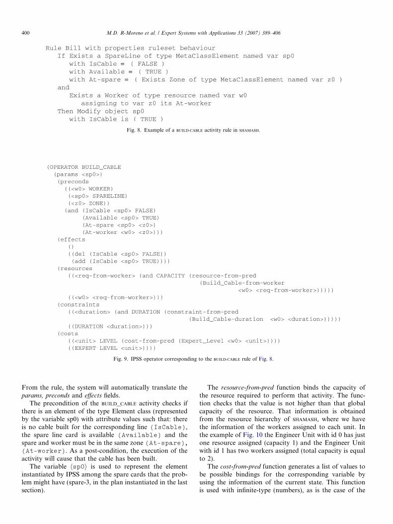
Fig. 8. Example of a BUILD-CABLE activity rule in SHAMASH.
Fig. 9. IPSS operator corresponding to the BUILD-CABLE rule of Fig. 8.
400 M.D. R-Moreno et al. / Expert Systems with Applications 33 (2007) 389–406
From the rule, the system will automatically translate theparams, preconds and effects fields.
The precondition of the BUILD_CABLE activity checks ifthere is an element of the type Element class (representedby the variable sp0) with attribute values such that: thereis no cable built for the corresponding line (IsCable),the spare line card is available (Available) and thespare and worker must be in the same zone (At-spare),(At-worker). As a post-condition, the execution of theactivity will cause that the cable has been built.
The variable hsp0i is used to represent the elementinstantiated by IPSS among the spare cards that the prob-lem might have (spare-3, in the plan instantiated in the lastsection).
The resource-from-pred function binds the capacity ofthe resource required to perform that activity. The func-tion checks that the value is not higher than that globalcapacity of the resource. That information is obtainedfrom the resource hierarchy of SHAMASH, where we havethe information of the workers assigned to each unit. Inthe example of Fig. 10 the Engineer Unit with id 0 has justone resource assigned (capacity 1) and the Engineer Unitwith id 1 has two workers assigned (total capacity is equalto 2).
The cost-from-pred function generates a list of values tobe possible bindings for the corresponding variable byusing the information of the current state. This functionis used with infinite-type (numbers), as is the case of the

Table 2The different IPSS configurations used
Name Description
IPSS Temporal planner with three layers: Meta-CSP,Ground-CSP and Deorder-layer
IPSS-R Temporal planner with a load balancing heuristic andthree separate layers: Meta-CSP, Ground-CSP andDeorder-layer
Fig. 10. IPSS problem for the Installing a Line example.
M.D. R-Moreno et al. / Expert Systems with Applications 33 (2007) 389–406 401
integer type, and in this case generates all the numeric val-ues of the predicate Expert_Level in the problem.Depending on the level of expertise (being 10 the higher)the duration of the activity will vary and so does the cost.
The duration value is specified in the constraints field bythe constraint-from-pred function. This function allowsspecifying the minimum and maximum value of the dura-tion and let the schedule module of IPSS reason about it.Also, through this function we can specify temporal win-dows in the operator start time.
With respect to the problem definition, Fig. 10 showsthe initial conditions generated automatically from theorganisation information. This includes issues such aswho works in each unit (Assigned to Engineer-
Unit-Expert-0 Tom), the cost per hour of the employeesbelonging to a given category (Cost Engineer-Unit-
Expert-0 798Euro) and other information related tothe details of the line. The Figure also shows the goals thatIPSS needs to accomplish. In this case, the only goal is toallocate the line with identifier number 3. With theseconditions IPSS generates the plan described before, withresources, units and roles in that process.
7. Experiments
In this section the different IPSS configurations areexplained and the comparison against some state of theart planners will be presented. We have defined two setsof experiments:
• Quantitative experiments for makespan minimisation,without time windows.
• Experiments with time windows.
The problems represented in the second type sets ofexperiments play an important role in BPR. Most of the
processes that are defined in a company have a deadline:activities have to be performed before or inside a temporalwindow. We show in the next subsection how IPSS canhandle it when most of the state of the art cannot.
7.1. IPSS configurations used
Table 2 shows the name of each IPSS configuration usedand a brief description.
• IPSS bases its search in the QPRODIGY search integratedwith the algorithm that converts incrementally the partialTO plan into a partial PO plan. Then, the Ground-CSP layerchecks its consistency and provides the temporal infor-mation back to the search. Finally, the Meta-CSP layerchecks resource conflicts.
• IPSS-R bases its search in the QPRODIGY search integratedwith the three layers working together and a load bal-ancing heuristic that controls the resource usage. First,the TO plan generated into a PO plan by the Deorder-layer. Then, the other two layers work in parallel: theTemporal Network that checks the temporal consistencyand the resource layer that checks resource consistency,provides temporal and resource information back to thesearch that helps on next decisions to be made. The heu-ristic helps on deciding the resource to perform eachactivity.

402 M.D. R-Moreno et al. / Expert Systems with Applications 33 (2007) 389–406
The following section describes the results obtained byIPSS and other state of the art planners.
7.2. Telephone installation (TI) domain
In order to exploit parallelism, we will consider thatallocating a line can be done in parallel to any otheractivity. Also, to reduce the number of activities to beaccomplished, we have only considered the operatorsBUILD-CABLE, SET-SPARE-AVAILABLE and CHECK-LINE. The restof operations must be performed in sequence.
The modeling of the domain does not consider if theworker is or not occupied doing something else. So, apartfrom planners that provide serial solutions, as, for exam-ple, SERISTAR (that belongs to the HSP family Bonet & Geff-ner, 2001), FF (Hoffmann, 2002) or QPRODIGY (Borrajoet al., 2001), the solution given by other planners as LPG
(Gerevini & Dimopoulos, 2002) or MIPS (Edelkamp &Helmert, 2000; Wah & Chen, 2003) is not correct becausein the modelization we do not consider the resource occu-pability so they can assign different actions to the sameworker at the same time.
In order to compare not only TO planners against ourapproach, we have also coded this domain having in mindthe availability of the chosen worker for performing the cor-responding action. In this case, each action (operator)requires the worker not to be busy on performing someactions. After the execution of the action, the agent (worker)is freed by a dummy action (the free-worker action). Thisforces the planners that reason about parallel actions notto consider parallelizing two actions that require the sameworker. We have called this domain the TI_OCCU domain.
We have randomly generated 11 sets of problems, with 3problems in each set, increasing the number of goals (1, 2,3, 4, 5, 10, 15, 20, 30, 40, 50). Then, for each set we haveincreased the number of workers (2, 3, 4, 5, 6, 7, 8, 9, 10,20, 30, 40, 50). The total time given to solve each problem(time bound) was 120 s.
The set of problems for the TI_OCCU domain is exactlythe same as in the TI domain with the particularity thatin all the problems the availability of the worker must beexplicitly set to not-occupied (that is, in the initial condi-tions we add the predicate (not-occupied hworkeri) for eachhworkeri in the problem), so we have added an extra oper-ator to free the worker with duration 0.
Given that LPG bases its search in a non-deterministiclocal search, we have run five times each problem, and con-sidered the best solution, the median solution and the worstsolution. This is represented in the tables by LPG-Min, LPG-
Med (it will be considered the baseline to compare theresults) and LPG-Max, respectively. Tables 3 and 4 showthe number of solved problems by each planner consider-ing the number of workers1 and goals.2 As it can be seen,
1 W2 with two workers, W3 with 3 workers and so on.2 G1 stands for problems with one goal, G2 with two goals and so on.
IPSS-R, FF and LPG are fast and efficient planners that solveall problems. Then, IPSS almost solves all the problemsand the worst performance is by the MIPS planner.
Fig. 11 shows the makespan obtained for all the plan-ners in problems solved by all. We have not included MIPS
in the graphs due to the low percentage of problems solved,but if considered, it obtains the worst results in makespanand time although it gets the plans with less numberof operators than LPG. The best results are obtained byIPSS-R and LPG-Min. Then, LPG-Med, LPG-Max, IPSS and theworse makespan is, as expected, by FF because it is a TOplanner.
With regards to the number of operators in the solu-tions, FF finds the shortest solutions, followed by the IPSSconfigurations and then LPG runs (note that in this config-uration we have considered the free-worker operator so thenumber of operators must be higher than in the others).Fig. 12 shows these results.
With respect to the execution time, FF is faster thanany of the LPG runs or the IPSS configurations as Fig. 13shows. Also, IPSS runs in COMMONLISP while the rest ofplanners run in C, that usually makes the execution muchfaster. But, time in workflow system it is not critical as itcould be in others domains as satellites or roboticswhere obtaining a plan fast is needed in order to makedecisions.
An important feature of our system that the rest of theIPC state of the art planners do not incorporate, is the abil-ity to impose temporal windows to the goals. This is a verycritical problem in workflow system because in most of thecases the activities that have to be performed would not bevalid if they are not executed in a specific temporalhorizon. For example, it is common in telecommunicationcompanies to agree on installing a telephone line in 2 days,so plans whose execution takes more time are notvalid.
To test this type of problems we have not generated anyset of problems but we show how IPSS works through anexample. Because we could set the temporal windows inthe operators or in the goals, we have decided to imposethe temporal constraints on the goals for clarity.
Let us consider a problem with 6 workers (W1, W2,. . . ,W6) that have to perform 5 goals: checking five spareline cards (SP0, . . . ,SP4). The star-shaped spare lines alsoneed to set the spare pair of wires. Fig. 14 shows the dispo-sition of the spare lines, the workers and the communica-tion among the different zones.
For simplicity all the activities have a unit duration. Wewill impose temporal windows in four of the five goals asFig. 15 shows. The first goal has to start after the timeinstant 3, the second goal should start before the timeinstant 4, the third goal should be contained in the interval(2 5) and the forth goal should start at the time instant 1.The (check_line spare4) goal can start at anytime.
The solution that IPSS finds to the problem of Fig. 14 isshown in Fig. 16, that achieves a solution fulfilling all goalconstraints.

Table 3Number of problems solved by each planner in the TI domain from a total of 429 problems given 120 s considering the no. of workers
System W2 W3 W4 W5 W6 W7 W8 W9 W10 W20 W30 W40 W50 Solved %
LPG 33 33 33 33 33 33 33 33 33 33 33 33 33 429 100FF 33 33 33 33 33 33 33 33 33 33 33 33 33 429 100IPSS-R 33 33 33 33 33 33 33 33 33 33 33 33 33 429 100IPSS 29 32 33 33 33 33 33 33 33 33 33 33 33 424 98MIPS 24 27 26 25 25 25 24 24 23 9 0 0 0 232 54
Table 4Number of problems solved by each planner in the TI domain from a total of 429 problems given 120 s considering the no. of goals
System G1 G2 G3 G4 G5 G10 G15 G20 G30 G40 G50 Solved %
LPG 39 39 39 39 39 39 39 39 39 39 39 429 100FF 39 39 39 39 39 39 39 39 39 39 39 429 100IPSS-R 39 39 39 39 39 39 39 39 39 39 39 429 100IPSS 39 39 39 39 39 39 39 39 39 39 35 424 98MIPS 30 29 29 30 29 27 23 25 10 0 0 232 54
Fig. 11. Makespan for FF, LPG, IPSS and IPSS-R in TI.
Fig. 12. Number of operators by FF, LPG, IPSS and IPSS-R in TI.
M.D. R-Moreno et al. / Expert Systems with Applications 33 (2007) 389–406 403

Fig. 13. Time for FF, LPG, IPSS and IPSS-R in TI.
Fig. 14. Initial conditions for the temporal windows example.
Fig. 15. Temporal windows imposed to the goals.
Fig. 16. The solution to the te
404 M.D. R-Moreno et al. / Expert Systems with Applications 33 (2007) 389–406
8. Related work
Several research groups have integrated AI techniqueswith workflow management systems (support the modelingand the enactment phase of the software engineering pro-cess). Some have applied planning tools in the enactment
mporal windows example.

M.D. R-Moreno et al. / Expert Systems with Applications 33 (2007) 389–406 405
phase and very few have integrated planning techniqueswith BPR tools during the modeling phase.
The SWIM system (Berry & Drabble, 2000) integratesprocess instantiation, task allocation, execution, monitor-ing and optimisation for improvement in the schedule.There is a Process Library that provides the correct processdefinition to the Dynamic Process Manager. New processescan also be added to this library.
The MILOS project (Goldmann, Munch, & Holz, 2000) isa process modeling and enactment approach that providesproject planning and management support like resourceallocation and time scheduling for tasks in the project.The MILOS workflow engine allows the model and plan tobe changed during project enactment and provides supportfor process restarts whenever necessary. The library of pro-cess models contains descriptions of best practices in soft-ware development for a given company. The projectmanager selects processes and methods from the librarycreating an initial project plan. The plan is uploaded tostandard project management tools as MS-Project.
The TBPM (Jarvis et al., 2000) project is based on workcarried out in the Enterprise project (Stader, 1996) and cen-tres around an intelligent workflow engine that includes aninteractive process planner. The planner uses AI techniquesbased on O-Plan (Currie & Tate, 1991) to assist in taskplanning, while permitting the user to participate in plan-ning decisions. An agent-based architecture supports theexecution and co-ordination of the planned process amongmultiple participants and distributes processes across com-puter networks. The user is able to plan a task by assem-bling fragments and then to refine it, generating ahierarchical model of the process to be performed. Formore flexibility, the user is able to edit the process modelbefore and during its enactment, in order to specialise it.
In all these systems the modeling phase is based on aprocess library, but there is no automatic generation aswe have outlined in this integration of SHAMASH-IPSS. Eachtime new model/templates are created, there is no need tocreate a library; the planner will generate the correct oneautomatically.
9. Conclusions and future work
In this paper, the representation problem for workflowdomains has been faced. We have used the SHAMASH work-flow modeling tool generated in an EU Esprit Project. Toprovide a frame of reference between Workflow Systemsand AI planners, the stages that both areas have in com-mon has been described following the classification givenby some researchers (Kearney & Borrajo, 2000; PLANET).The translation between both fields has had in mind thedifferent semantics of BPR and AI planning concepts aswell as their similarities.
We have described the advantages of using IPSS formodeling processes in SHAMASH, a Knowledge Based Sys-tem that uses an object oriented and rule-based approach.The SHAMASH rules and objects are translated into types
and operators to produce a plan that correspond to a pro-cess instance (tasks dependency). Each plan will varydepending on the resources available, elements that flowthrough the process and the different tasks that the organ-isations can introduce to adapt their processes to the mar-ket changes. With this approach the models generated areautomatically validated avoiding inconsistencies in linkingactivities and saving time to the user.
Finally, we also wanted to study the issues that AI plan-ners can gain with this approach. Generally, to specify thedomain theory, a deep understanding of the way AI plan-ners work and its terminology is needed. However, if weuse a tool like SHAMASH, the description language is closerto the user and allows an automatic verification of the syn-tax through a friendly interface. In this integration wecould have also used the PDDL2.2 language instead. Then,any planner that supports PDDL2.2 could exploit theadvantages of using a descriptive language as the one usedin SHAMASH. Although some planners of the competitioncannot reason, for instance, about temporal windows ordeadlines, IPSS does. And this is usually a strong require-ment that drove us to build a system with the propertiesthat IPSS presents.
Acknowledgements
The SHAMASH project has being carried out in the courseof the R&D project funded by the Esprit Program of theCommission of the European Communities as projectnumber 25491. A complementary grant was given by theSpanish research commission, CICYT, under project num-ber TIC98-1847-CE. We thank the partners of this project,who have originated and contributed to the ideas reported:UF (Union Fenosa), SAGE (Software AG Espana),SEMA GROUP sae, UC3M (Universidad Carlos III deMadrid), WIP (Wirstchaft und infrastruktur & Co Plan-ungs KG), and EDP (Electricidade de Portugal). We wouldspecially like to thank all the UC3M team, the PLANETpeople and Paul Kearney (BT). Through talks with himwe have outlined many ideas. This work has also been par-tially funded by grant MCyT TIC2002-04146-C05-05 andthe UAH project PI2005/084.
References
Aler, R., & Borrajo, D. (2002). Learning single-criteria control knowledgefor multi-criteria planning. In Proceedings of the AIPS-02 workshop on
planning and scheduling with multiple criteria (pp. 35–40).Aler, R., Borrajo, D., Camacho, D., & Sierra-Alonso, A. (2002). A
knowledge-based approach for business process reengineering, SHA-MASH. Knowledge Based Systems, 15(8), 473–483.
Allen, J. (1984). Towards a general theory of action and time. Artificial
Intelligence, 23, 123–154.Backstrom, C. (1998). Computational aspects of reordering plans. Journal
of Artificial Intelligence Research, 9, 99–137.Berry, P. M., & Drabble, B. (2000). SWIM: an AI-based system for
organizational management. In Proceedings of the 2nd NASA interna-
tional workshop on planning and scheduling for space, San Francisco,California.

406 M.D. R-Moreno et al. / Expert Systems with Applications 33 (2007) 389–406
Bonet, B., & Geffner, H. (2001). Planning as heuristic search. Artificial
Intelligence, 129(1–2), 5–33.Borrajo, D., Vegas, S., & Veloso, M. (2001). Quality-based learning for
planning. In Working notes of the IJCAI’01 workshop on planning with
resources.Carbonell, J. G., Blythe, J., Etzioni, O., Gil, Y., Joseph, R., Kahn, D.,
et al., 1992. PRODIGY4.0: The manual and tutorial. Tech. Rep. CMU-CS-92-150, Department of Computer Science.
Cesta, A., Oddi, A., & Smith, S. (1998). Profile based algorithms to solvemultiple capacitated metric scheduling problems. In Proceedings of the
fourth international conference on artificial intelligence planning systems
(AIPS-98).Cesta, A., Oddi, A., & Smith, S. (2002). A constrained-based method for
project scheduling with time windows. Journal of Heuristics, 8,109–136.
Cesta, A., Pecora, F., & Rasconi, R. (2004). Biasing the structure ofscheduling problems through classical planners. In Proceedings of the
workshop on integrating planning into scheduling.Currie, K., & Tate, A. (1991). O-plan: the open planning architecture.
Artificial Intelligence, 52, 49–86.Dechter, R., Meiri, I., & Pearl, J. (1991). Temporal constraint networks.
Artificial Intelligence, 49, 61–95.Do, M. B., & Kambhampati, S. (2003). SAPA: a scalable multi-objective
metric temporal planner. Journal of Artificial Intelligence Research, 20,155–194.
Edelkamp, S., & Helmert, M. (2000). On the Implementation of MIPS. InAIPS workshop on model-theoretic approaches to planning.
Edelkamp, S., & Hoffmann, J. (2004). PDDL2.2: the language for the
classical part of the 4th international planning competition. Tech. Rep.Technical Report No. 195, Institut fur Informatik.
Fikes, R., & Nilsson, N. (1971). STRIPS: a new approach to the applicationof theorem proving to problem solving. Artificial Intelligence, 2,189–208.
Gerevini, A., & Dimopoulos, Y. (2002). Temporal planning throughmixed integer programming. In Proceedings of the AIPS’02 workshop
on planning for temporal domains.Ghallab, M., & Laruelle, H. (1994). Representation and control in IxTeT,
a temporal planner. In Proceedings of the second international
conference on AI planning systems (AIPS-94).Goldmann, S., Munch, J., & Holz, H. (2000). Distributed process
planning support with MILOS. International Journal of Software
Engineering and Knowledge Engineering, 10(4), 511–525.Hammer, M., & Champy, J. (1993). Reengineering the corporation. In
Reengineering the corporation. New York: Harper Business Press.Hannebaeur, M. (1999). From formal workflow models to intelligent
agents. In AAAI-99 workshop on agent-based systems in the business
context. Brian Drabble and Peter Jarvis Cochairs.Hoffmann, J. (2002). The metric-FF planning system: translating ignoring
delete lists to numerical state variables. Journal of Artificial Intelligence
Research.Jarvis, P., Moore, J., Chung, P., Mcbriar, I., Stader, J., Ravinranathan,
M. et al. (2000). Applying intelligent workflow management in thechemicals industries. In L. Fisher (Ed.), The workflow handbook 2001.Published in association with the Workflow Management Coalition(WfMC).
Kearney, P., & Borrajo, D. (2000). An R&D agenda for AI planningapplied to workflow. In Proceedings of the eBusiness and eWork
conference 2000.
Kuter, U., Nau, D., Pistore, M., & Traverso, P. (2005). The Yoyo planner:going where hierarchical task-network planning meets with symbolicmodel checking. In Proceedings of the 15th international conference on
automated planning and scheduling (ICAPS’05).Leymann, F., & Roller, D. (1994). Business process management with
FlowMark. In Proceedings of the IEEE computer society international
conference.Lydiard, T., Jarvis, P., & Drabble, B. (1999). Realizing real commercial
benefits from workflow: a report from the trenches. In AAAI-99
workshop on agent-based systems in the business context. Brian Drabbleand Peter Jarvis Cochairs.
Medina-Mora, R., Winograd, T., & Flores, P. (1993). Action workflow asthe enterprise integration technology. Bulletin of the Technical Com-
mittee on Data Engineering. IEEE Computer Society, 6, 2.Mohan, C. (1997). Recent trends in workflow management products,
standards and research. In Proceedings NATO advanced study institute
(ASI) on workflow management systems and interoperability.Myers, K. L. & Berry, P. M. (1999). At the boundary of workflow and AI.
In AAAI-99 workshop on agent-based systems in the business context.Brian Drabble and Peter Jarvis Cochairs.
PLANET. Network home page: European Network of Excellence in AIplanning. Available from http://planet.dfki.de/index.html.
PLANET. Workflow management TCU road map. Available from http://scalab.uc3m.es/dborrajo/planet/wm-tcu/.
Purvis, M., Purvis, M., & Lemalu, S. (2001). A framework for distributedworkflow systems. In Proceedings of the 34th annual Hawaii international
conference on system sciences (HICSS-34). IEEE Computer Society.R-Moreno, M. D. (2003). Representing and Planning tasks with time and
resources. PhD thesis, Universidad de Alcala, Spain.R-Moreno, M. D., & Kearney, P. (2002). Integrating AI planning with
workflow management system. International Journal of Knowledge-
Based Systems, 15, 285–291.R-Moreno, M. D., Oddi, A., Borrajo, D., Cesta, A., & Meziat, D. (2004a).
Planning and scheduling for workflow domains. In The ECAI’04
‘‘planning and scheduling: Bridging theory to practice’’ workshop.R-Moreno, M. D., Oddi, A., Borrajo, D., Cesta, A., & Meziat, D. (2004b).
IPSS: integrating hybrid reasoners for planning and scheduling. InProceedings of the 16th European conference on artificial intelligence,ECAI04.
Srivastava, B., Kambhampati, R., & DO, M. B. (2001). Planning theproject management way: efficient planning by effective integration ofcausal and resource reasoning in RealPlan. Artificial Intelligence, 131,73–134.
Stader, J. (1996). Results of the enterprise project. In Proceedings 16th
international conference of the British computer society specialist group
on expert systems, Cambridge, UK.Tate, A., Drabble, B., & Kirby, R. K. (1994). O-Plan2: An open
architecture for command, planning, and control. Morgan Kaufman.Veloso, M., Carbonell, J., Perez, A., Borrajo, D., Fink, E., & Blythe, J.
(1995). Integrating planning and learning: the PRODIGY architecture.Journal of Experimental and Theoretical, AI 7, 81–120.
Wah, B. W. & Chen, Y. (2003). Partitioning of temporal planningproblems in mixed space using the theory of extended saddle points. In15th IEEE international conference on tools with artificial intelligence
(ICTAI’03).Workflow Management Coalition. Available from http://www.wfmc.org/.Yang, Q. (1997). Intelligent in planning. A decomposition and abstraction
based approach. Springer.