MODEL-BASED STRUCTURAL DESIGN WORKFLOW OF ...
32
MODEL-BASED STRUCTURAL DESIGN WORKFLOW OF CIVIL ENGINEERING STRUCTURES LAB UNIVERSITY OF APPLIED SCIENCES Bachelor of Technology Double Degree Programme in Civil and Construction Engineering Autumn 2020 Emiliia Rusakova
-
Upload
khangminh22 -
Category
Documents
-
view
1 -
download
0
Transcript of MODEL-BASED STRUCTURAL DESIGN WORKFLOW OF ...
MODEL-BASED STRUCTURAL DESIGN
WORKFLOW OF CIVIL ENGINEERING
STRUCTURES
LAB UNIVERSITY OF APPLIED SCIENCES Bachelor of Technology Double Degree Programme in Civil and Construction Engineering Autumn 2020 Emiliia Rusakova
APPENDIX 1
Abstract
Author(s)
Rusakova Emiliia
Type of publication
Bachelor’s thesis
Published
Autumn 2020 Number of pages
31 + 1 appendix
Title of publication
Model-based structural design workflow of civil engineering structures
Name of Degree
Bachelor of Technology
Abstract
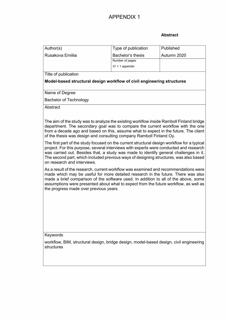
The aim of the study was to analyze the existing workflow inside Ramboll Finland bridge department. The secondary goal was to compare the current workflow with the one from a decade ago and based on this, assume what to expect in the future. The client of the thesis was design and consulting company Ramboll Finland Oy.
The first part of the study focused on the current structural design workflow for a typical project. For this purpose, several interviews with experts were conducted and research was carried out. Besides that, a study was made to identify general challenges in it. The second part, which included previous ways of designing structures, was also based on research and interviews.
As a result of the research, current workflow was examined and recommendations were made which may be useful for more detailed research in the future. There was also made a brief comparison of the software used. In addition to all of the above, some assumptions were presented about what to expect from the future workflow, as well as the progress made over previous years.
Keywords
workflow, BIM, structural design, bridge design, model-based design, civil engineering structures
3
CONTENTS
1 INTRODUCTION ................................................................................................ 5
2 DISCRIPTION OF USED RESEARCH MEATHODS .......................................... 5
3 GENERAL INFORMATION ................................................................................ 6
3.1 Workflow description ................................................................................... 7
3.2 Challenges of model based structural design ............................................ 10
3.3 Guidelines, codes and regulations ............................................................ 14
4 CURRENT WORKFLOW OF MODEL BASED STRUCTURAL DESIGN .......... 15
4.1 Required documents for completion of a civil structure ............................. 15
4.1.1 Drawings ............................................................................................... 16
4.1.1.1 General arrangement drawing ........................................................ 17
4.1.1.2 Measurement drawing .................................................................... 17
4.1.1.3 Reinforcement drawing ................................................................... 18
4.1.2 BIM Model ............................................................................................. 18
4.1.3 Tables ................................................................................................... 20
4.1.4 Specifications ........................................................................................ 21
4.2 Calculations ................................................................................................ 21
4.3 Preliminary design ...................................................................................... 23
4.4 Initial data ................................................................................................... 23
5 COMPARISON OF WORKFLOW (2010 VS. 2020) .......................................... 25
5.1 Transition to a new process with model design ........................................... 25
5.2 Parallel design process (Cooperation among technologies and people) ..... 27
5.3 The development of a future workflow......................................................... 28
6 CONCLUSIONS AND RECOMMENDATIONS ................................................. 29
REFERENCES........................................................................................................ 31
APPENDICES ......................................................................................................... 32

4
TERMINOLOGY
BIM Building Information Modelling, the process of collective creation
and use of information about the construction, forming a reliable
basis for all decisions over the lifetime of the object.
IFC Industry Foundation Classes, an open file format developed by
buildingSMART International for exchange of built environment
information.
CAD Computer-aided design, the use of computers to aid in the
creation, modification, analysis, or optimization of a design.
KPI Key Performance Indicator, the critical (key) indicators of
progress toward an intended result.
CDE Common Data Environment, is the single source of information
used to collect, manage and disseminate documentation, the
graphical model and non-graphical data for the whole project
team.
API Application Programming Interface, a computing interface which
defines interactions between multiple software intermediaries.
FEM Finite Element Method, a numerical technique used to perform
finite element analysis (FEA) of any given physical phenomenon.
SSOT Single Source of Truth, the practice of structuring information
models and associated data schema such that every data
element is mastered (or edited) in only one place.
MVD Model View Definition, a subset of the overall IFC schema to
describe data exchange for a specific use or workflow, narrowing
the scope depending on the need of the receiver.
NCCI Non-Contradictory Complementary Information, are documents
that the National committees consider useful for assisting the
user to apply the Eurocode, are not essential for compliance with
the Eurocode but may provide background material or other
guidance.
5
1 INTRODUCTION
The current thesis project’s aim is to reveal the concept of efficient work in terms of model
based structural design of civil engineering structures. When choosing the subject of the
current thesis, a significant amount of data was considered: the relevance of the topic to
the engineering team, the potential impact it could make to them, etc. For this reason,
the first suggested topic was comparison of two well-known modelling software and the
workflow that goes with them. During the research, an important decision was made
concerning the chosen topic. The most useful contribution is to study the current
workflow and find ways to improve it, if necessary, to achieve a less time-consuming and
better result. Moreover, the current research would be helpful in deciding whether or not
additional software, working in tandem with Autodesk Revit®, should be added to the
already existing Tekla Structures® based workflow. This is a matter of time, quality and
cost efficiency of the company.
The current research is divided into three main parts. The first one describes general
information regarding the topic. The second one gives more thorough insight into the
current workflow. The third one presents the comparison of the workflow in the past as
well as the estimate of what to expect in the future.
2 DISCRIPTION OF USED RESEARCH MEATHODS
In the thesis, Ramboll Finland bridge design expert interviews were chosen as one of
the research methods. Interview questions were prepared in advance and reviewed
before the interviews were held. Interviewees were selected in order to obtain a full
perspective from different work and software experiences, specialization, etc.
The list of interviewees is as follows:
1) Augustin Ceillier, designer (Tekla Structures®, Rhino® expert)
2) Seppo Kokko, senior project manager (extensive work experience)
3) Timo Säkkinen, project manager (Tekla Structures® expert)
4) Eero Särkkä, project manager
5) Daniel Lõhmus (Autodesk Revit® expert)
6) Sean LeCoultre, structural engineer (complex structural analyses expert)

6
There was a total of 6 interview questions. The questions were divided into three groups
with a sub question: With the exception of one calculation related interview, which was
held via Microsoft Teams, the questions were submitted to the interviewees by email.
Interviewees were asked the following questions:
1) What is the workflow in current infrastructure design projects?
- What are the common problems and how can they be avoided?
2) How much has the workflow changed compared to the previous decade, what
are the main differences?
- What to expect in the future and how it will develop?
3) How is information exchanged with other disciplines?
- What can be improved?
Other research methods used in the current thesis were literature study and observing a
case project. Literature study was focused on national and international BIM guidelines,
codes, regulations and other BIM related publications that provided information about
the current state of BIM in infrastructure projects. Gathered info was complemented with
interviews of experts and integrated throughout all phases of the thesis. Moreover,
visiting the InfraBIM Open 2020 event, which took place from 3rd to 5th of February in
Tampere, gave a huge opportunity to collect some of the useful information for the
current thesis and working life in general.
3 GENERAL INFORMATION
Further, a general workflow will be described as well as general challenges, which can
occur throughout the project and the overview of the current guidelines, codes and
regulations will be presented.
Nowadays, the working process is centered around a model-based workflow. Building
Information Modeling (BIM) technologies that contain 3D modelling are widely used in
many construction industries projects in Finland. BIM is a modelling technology and a
correlated set of processes to deliver, analyze and connect building models [1]. What
should be noted is that BIM makes the work of engineers and designers more efficient,
as well as it helps to provide up-to-date, accurate information to contractors on the
construction site. BIM can be used not only at the design and construction stages, but
also throughout the entire design lifecycle to perform monitoring and maintenance tasks.
7
In general, they increase the efficiency of all parties involved. This increase in efficiency
leads to a reduction in the required time for design and construction work, lowering costs
while setting up more unusual and complex solutions in architectural and structural
design. It is fair to state that this improves the social value of the final structure.
3.1 Workflow description
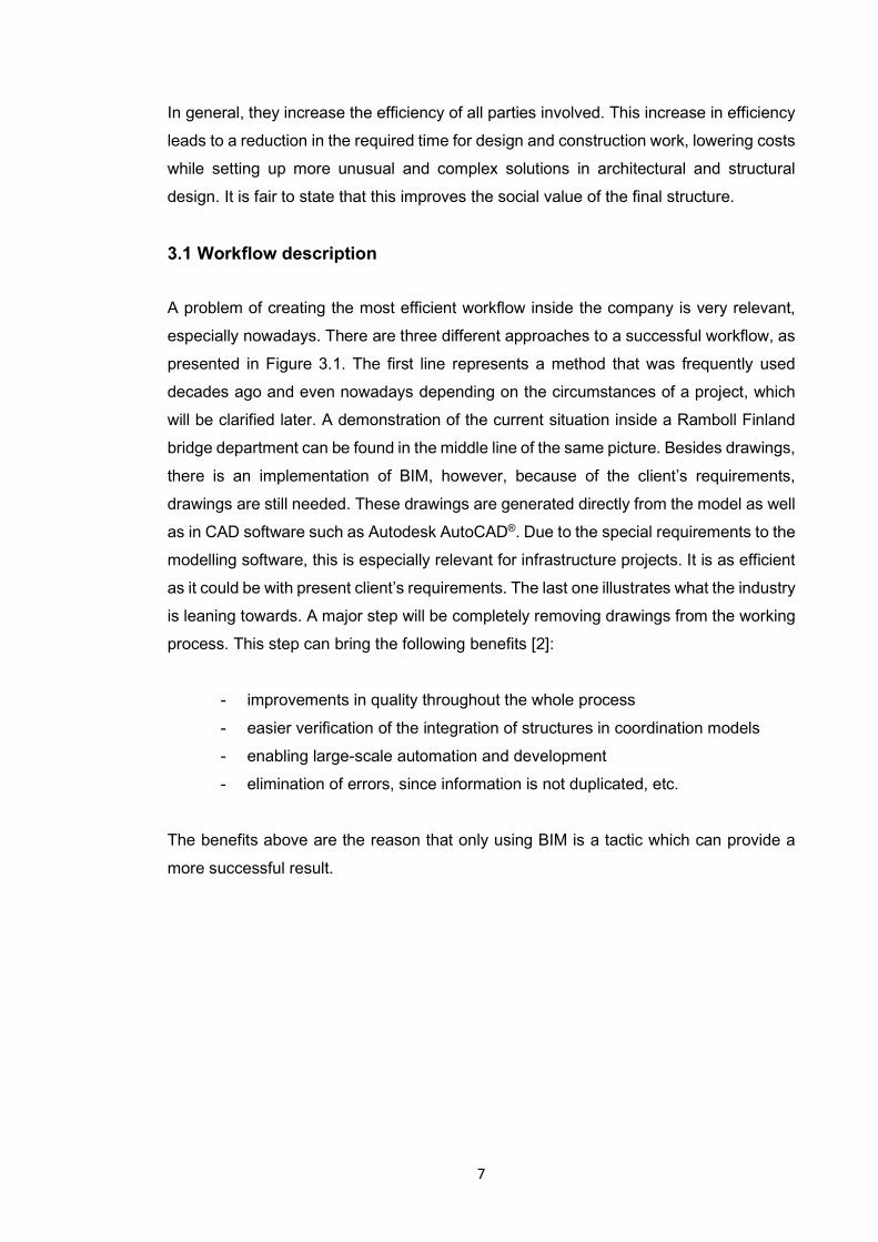
A problem of creating the most efficient workflow inside the company is very relevant,
especially nowadays. There are three different approaches to a successful workflow, as
presented in Figure 3.1. The first line represents a method that was frequently used
decades ago and even nowadays depending on the circumstances of a project, which
will be clarified later. A demonstration of the current situation inside a Ramboll Finland
bridge department can be found in the middle line of the same picture. Besides drawings,
there is an implementation of BIM, however, because of the client’s requirements,
drawings are still needed. These drawings are generated directly from the model as well
as in CAD software such as Autodesk AutoCAD®. Due to the special requirements to the
modelling software, this is especially relevant for infrastructure projects. It is as efficient
as it could be with present client’s requirements. The last one illustrates what the industry
is leaning towards. A major step will be completely removing drawings from the working
process. This step can bring the following benefits [2]:
- improvements in quality throughout the whole process
- easier verification of the integration of structures in coordination models
- enabling large-scale automation and development
- elimination of errors, since information is not duplicated, etc.
The benefits above are the reason that only using BIM is a tactic which can provide a
more successful result.
8
Figure 3.1 Approaches to a successful bridge BIM workflow (Partala 2020)
Since time and money have a direct correlation between them, it is preferable to optimize
a department’s schedule to avoid time loss due to miscoordination and poor time
management. This reduces the total project duration and keeps the same level of quality
in resulting structure or to elevate it.
New software is being released and standards and methods are being updated. Different
design stages, calculations, geotechnical surveys are done by different people and even
companies. Thus, with all the people involved, their work must be combined into a
complete common result which includes complex work done by all the parties involved.
This leads to the conclusion that the transfer of information, resources, and materials
through departments that perform a sequence of actions on components is a definition
of a workflow [3].
All procedures are created on the initial data provided by different parties. It is a common
thing that during projects various modifications of the primary information take place and
all the people involved should have access to updates. Infrastructure projects today are
based on the initial information material, which doesn’t necessarily mean 3D or BIM,
Initial information material is a well-organized system of reference data folders. The
purpose of the initial information material is to organize and coordinate reference data
for the next stage (Särkkä 2020). Another thing that should be mentioned is that the
submittal is the responsibility of the project lead, which often is the road department, but
not always. Table 3.1. shows general steps in the workflow for 3 disciplines.

9
Road Geo Bridge
Land survey
Tender design Tender design Tender design
Proposal of different
design options
Proposal of different
design options
Proposal of different
design options
Subsurface investigation,
additional surveys near
the bridge
Agreement with options Agreement with options Agreement with options
Finalizing the design
Finalizing the design
Finalizing the design
Submitting initial
information material with
other deliverables
Table 3.1 General steps in the workflow for 3 disciplines (Särkkä 2020)
After getting the initial data, it is possible to start building infrastructure geometry
according to it, as well as performing required calculations. Once the design is complete,
it is sent to other disciplines for checking and integration into their design. The table
above illustrates the ideal way of how the design is finalized; however, in real life,
finalizing design works occurs in parallel between each discipline.
Central to the success of the BIM approach is the reliable exchange of digital information
between the parties involved without any data loss, regardless of the software in which
the information was generated. In order to facilitate the exchange of information,
standards have been developed for open BIM data models. One of the data formats
created by buildingSmart for BIM is the Industry Foundation Classes (IFC) specification
[4]. Finland also has a InfraModel-format based on LandXML built for infrastructure.
IFC is used a lot to exchange data in buildings projects. IFC Road and IFC Bridges are
under development, more standardization of transmission formats needs to be done in
future. For this reason, it seems that there is not yet a suitable format for common data
exchange in infrastructure projects. The industry still relies heavily on 2D formats which
transfers geometry data only. It is often used by road designers for cross-sections and
10
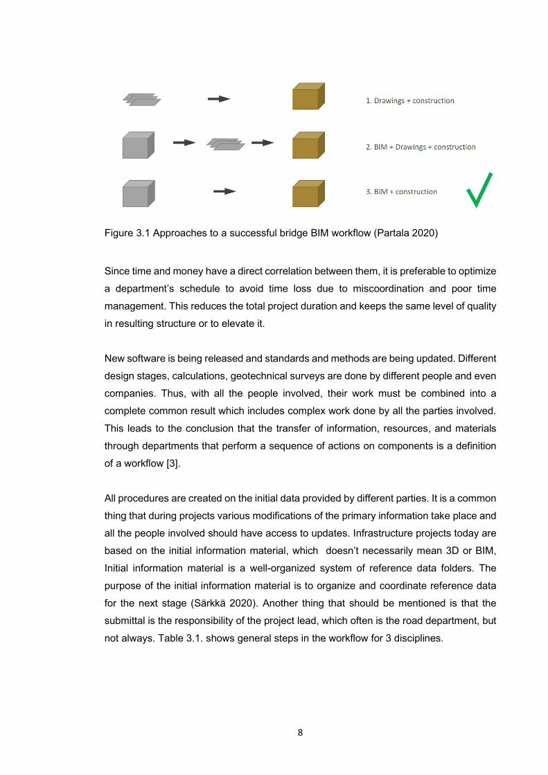
longitudinal sections as a deliverable. However, the approach is different between
disciplines. More information regarding IFC format can be found in Table 3.2 [5].
IFC
Format STEP, XML
Today Terrain, buildings, structure
Future ifcRoad, ifcRail, ifcBridge,
ifcPorts&Waterways (ifcTunnel)
Geometry types Point, line,curve, alignment, surface,
solid, DRrep
Object geometry representation Multiple ways to describe, Multiple Model
View Definition (MVD) rules for each case
Attributes Multiple sets, custom sets
Coordinates Local / Global
Visual appearance Color, Texture
Software support Extensive
Table 3.2 IFC description (Sireeni 2020)
Another thing worth mentioning is that the infrastructure model and calculation models
are developed in parallel. Complex geometries use FEM-based software to refine the
structural analysis. More simple geometry may rely on hand calculations only.
3.2 Challenges of model based structural design
Nowadays almost every infrastructure project in Finland is performed completely or partly
by using a model-based technology. Such a way of project execution can lead to
increased Key Performance Indicator (KPI) of structural design, better coordination and
improves project workflow.
The benefits of model-based method are:
- a possibility to perform structural design in the same model simultaneously by
using cloud services
- an automatization of processes usually made manually (such as part-
drawing/assembly-drawing/cast-unit drawing creation)
- an opportunity to avoid clashes, mismatches and catch incorrect design solutions
11
- possibility for model-based design to provide a common design environment,
which facilitates general communication, data analysis, and system verification
between various (development) groups.
- ability for engineers to locate and correct errors early in system design, when the
time and financial impact of system modification are minimized.
- design reuse, for upgrades and for derivative systems with expanded capabilities,
is facilitated [6]
There are differences in expertise and practice in data modeling between the technology
disciplines. Some of the disciplines have been operating in a BIM-environment for years
and some are just moving on to model-based workflow. As for bridges specifically, BIM-
models have started to be ordered since 2011 [7], however model-based design has
been used in projects even earlier. Later on, the use of BIM-models has extended to
other areas of the infrastructure sector.
Instructions, guides and specifications are becoming more accurate and more of them
are coming out almost every year. As a result of development work associated with
infrastructure business/field data modelling, the infrastructure field has gotten, for
example, general data modelling requirements, infraBIM nomenclature, which outlines
numbering and naming practices that cover the life cycle of infrastructure structures and
models, and several instructions regarding data modelling and infra modelling. The
direction on how to make BIM models and how to utilize them fully is starting to become
clear. However, there are still challenges related to a co-operation process. The
instructions and requirements are becoming more precise and will be added almost
every year. As a result of the development work related to the castle, e.g. general
information modeling the infraBIM nomenclature and several data model and
infrastructure model guidelines. The direction of and overall exploitation in the sector is
beginning to take shape, but challenges still lie in technology and cooperation processes.
The benefits of BIM are often found to improve cooperation and information flow.
However, some studies have shown that not all the collaboration related problems have
decreased with the introduction of BIM, even though design and data models offer the
opportunity for visual and easy communication[8], [9].
Software has evolved a lot and today it is possible for many people to work
simultaneously in the same model regardless of the employee’s location. The model can
be joined from different locations/offices and access and viewing rights can be distributed

12
to third parties. The development of technology brings a constant introduction of new
tools to facilitate data transfer and collaboration. For example, cloud-based data model
servers and sharing model environments provide good platforms for developing
cooperation, coordination and reviewing the models of the various parties.
With the development of the field, new challenges have also emerged in planning
cooperation. The software produce material in their own native format and support the
use of different standards and formats. When combining data models, it is necessary to
consider different variations that increase the risk of data change or loss. The aim is to
produce model material in open data model formats and standards, such as Inframodel
and IFC. However, currently bridge design programs are not able to take full advantage
of the above-mentioned formats because the lack of IFC standards and Inframodel civil
engineering structures support for bridges, causing some data loss.
Challenges in data management and data transfer increase the risk of compatibility
mismatch. Data model-based design has also brought changes to the way projects are
implemented. Design is carried out simultaneously with different types of technology and
design models are becoming more and more refined as the project progresses. Also,
different parties use many different methods and software. Finding the optimal balance
between people, processes and technology is really challenging. It is very important that
everyone understands the interdependencies between their own technique and other
techniques. Therefore, planning coordination and reliable information flow are very
important for the success of the project.
With the input data, the biggest problem is that disciplines depend on each other's
submissions, and the submission schedule is the same for each of them.
The process of designing an infrastructure project inside Ramboll bridge department
begins with the input data. In the current workflow, initial data such as road/rail/trail
alignment are provided by other disciplines. The input data in 3D format ensures good
quality of the model. If there are no models or they are of poor quality, it is very difficult
to connect different disciplines e.g. road or landscape. It should also be noted that the
level of precision required in design to achieve the required construction tolerances
varies from one discipline to another. The tolerance for bridges is in millimeters, and for
roads it is in centimeters. Also, the input data obtained from previous parties is not
always developed for complex structures. This means that often in order for the
infrastructure to not have multiple curves or edges, it is necessary to rework this input

13
data to make it more rational (Ceillier 2020). To make it easier to correct errors between
disciplines, it is important that the accuracy of the disciplines strives to match the
accuracy of the tools used. Moreover, there are some common problems that arise when
design changes from other disciplines occur. Good communication between them helps
to avoid usage of outdated data.
At the moment, the problem of data exchange is still not completely solved. In the future,
a single working platform for data exchange should be developed, and all disciplines will
work with the same information model, which will reduce the need for information
transformation, which is one common cause of design errors. The use of non-up-to-date
information as source material will be significantly decreased.
One of the major issues is that how and where to find proper information and is it useful
or is there a need to ask someone to modify it before it is possible to use it. Sometimes
moving data takes longer than some specific design tasks. One way to avoid that kind of
issues would be to have a plan of data management in projects.
Besides the above, there is a lack of a Common Data Environment (CDE) that can
centralize the information from all the disciplines and make it readable in a format usable
for all disciplines.
“Another way to improve information exchange could be by opening Application
Programming Interface (API) so that links between different programs could be made”
says Eero Särkkä, one of the interviewees.
Some problems can occur when it's too late to change them, so it's crucial to have an
extensive general design phase when models are already being used. This way it may
be possible to catch problems early on and fix them while it's still easy to do. The earlier
the change occurs, the less impact it will have on the workflow and cost.
During the modeling process, many problems will arise that can affect the design of
infrastructure, its calculations, and possibly other disciplines as well. However, this may
not be true for simpler structures.
Due to all the above, it is obvious that the final solution is not known at the beginning of
the design process. Therefore, the design tools must be very flexible.

14
3.3 Guidelines, codes and regulations
Guidelines, building codes and regulations are essential for any type of construction work
carried out in any part of the world. They differ a lot from one country to the other,
however in the countries that are part of the European Union they are quite similar since
all the design and construction works are done in line with the requirements of
Eurocodes.
This chapter of the thesis is dedicated to guidelines, codes and regulations that apply to
one-member state, Finland.
In the current workflow, civil engineering structures design is mostly based on
Eurocodes, Non-Contradictory Complementary Information (NCCI), which are guides to
Eurocode with Finnish National Annexes implemented and Common BIM requirements,
as well as client specific BIM guidelines. Eurocodes are quite expansive, trying to cover
everything and guides are narrower. Eurocodes control the country specific design
requirements with national annexes. NCCI’s take national features that rely on the design
and construction traditions that developed in one particular country. The geographical
and climate difference are also considered. For example, the snow load differs a lot from
the northern to the southern part of the EU. Common Eurocodes are giving common
values and refer to the national annex for more info. Most of the guidelines focused on
bridge design can be found on Finnish Transport Infrastructure Agency webpage [10].
Common BIM requirements that are essential for the modelling part are presented in
buildingSmart webpage [11]. The guide emphasizes the importance of a combined
model for the bridge object as a whole and in terms of identifying any inconsistencies.
Nowadays different guidelines, codes and regulations are still based on science, and
assumptions made by engineers in the past. This has proven its workability. Some of the
reliability coefficients are still not completely clear, so they are accepted with a larger
margin.
In conclusion, it can be mentioned yet again that guidelines and regulations are essential
for any type of design or construction carried out nowadays since they assure quality,
usability and effectiveness of the structures.

15
4 CURRENT WORKFLOW OF MODEL BASED STRUCTURAL
DESIGN
The problem of achieving the most efficient workflow is crucial for the success of the
company. The third chapter focuses on the company's current detailed workflow in terms
of efficiency. It is structured to provide a more in-depth understanding of how the end
result can be successfully achieved. This is achieved by considering the elements of the
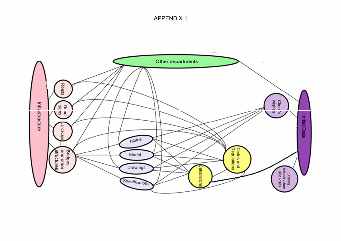
workflow, starting with the final result and moving to the input data. A diagram of the
workflow scheme can be found appendix 1.
Infrastructure, also known as civil structures, is a combination of bridge or any other
special structures, roads, road signs and landscape. Being a part of infrastructure,
bridges are often an iconic symbol of culture and are both fascinating and appealing to
the imagination.
The major part of infrastructure and the one that provides the road connection over the
hurdles like rivers, valley, dry or wetland is called bridges or viaducts, overpasses and
flyovers, etc. Other typical infrastructure elements which are often being designed by
consulting companies are retaining walls, pile slabs.
Retaining walls are relatively rigid walls used for supporting soil laterally so that it can be
retained at different levels on the two sides.
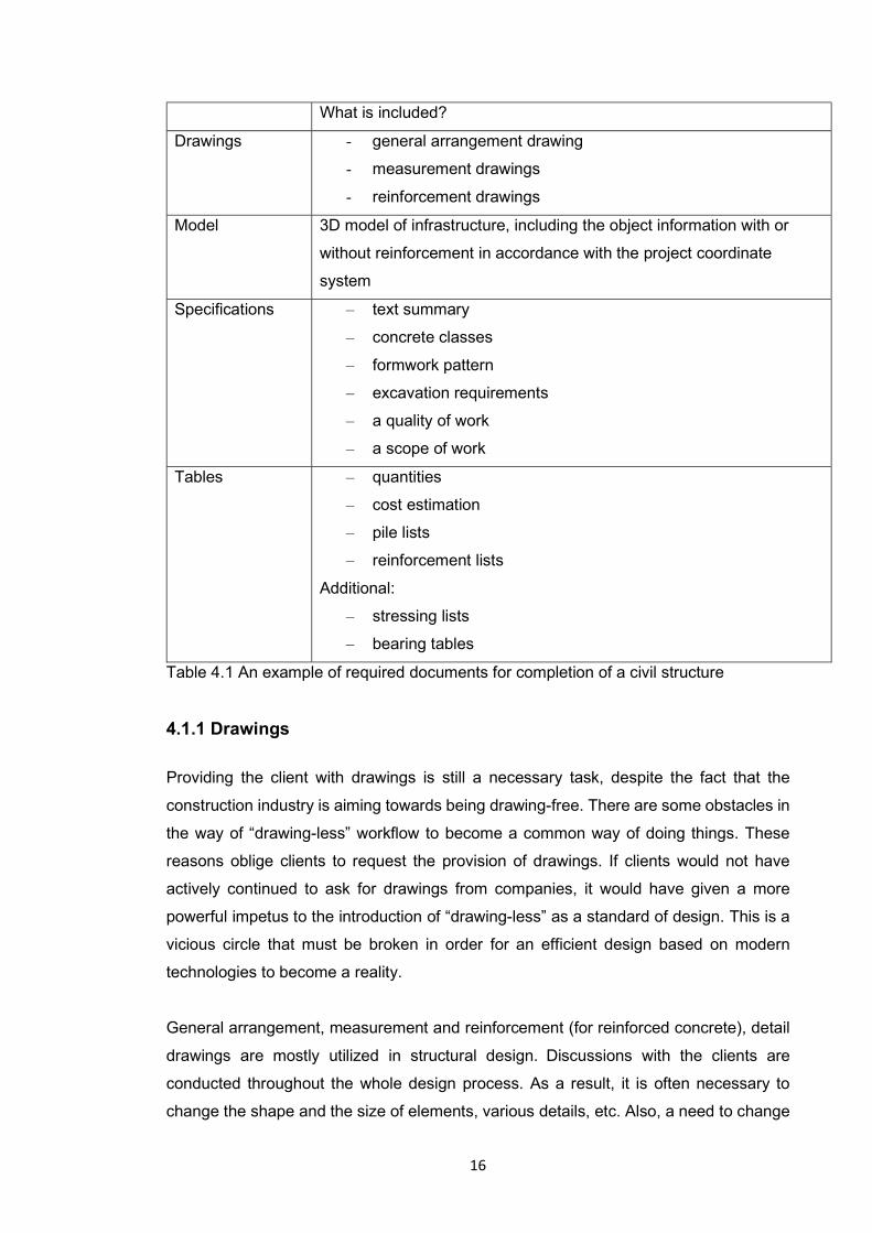
4.1 Required documents for completion of a civil structure
Initially, it is important to determine what is currently requested from the client to
complete a civil structure. Table 4.1 contains a brief description of what will be explained
later on within the current thesis project:
16
What is included?
Drawings - general arrangement drawing
- measurement drawings
- reinforcement drawings
Model 3D model of infrastructure, including the object information with or
without reinforcement in accordance with the project coordinate
system
Specifications – text summary
– concrete classes
– formwork pattern
– excavation requirements
– a quality of work
– a scope of work
Tables – quantities
– cost estimation
– pile lists
– reinforcement lists
Additional:
– stressing lists
– bearing tables
Table 4.1 An example of required documents for completion of a civil structure
4.1.1 Drawings
Providing the client with drawings is still a necessary task, despite the fact that the
construction industry is aiming towards being drawing-free. There are some obstacles in
the way of “drawing-less” workflow to become a common way of doing things. These
reasons oblige clients to request the provision of drawings. If clients would not have
actively continued to ask for drawings from companies, it would have given a more
powerful impetus to the introduction of “drawing-less” as a standard of design. This is a
vicious circle that must be broken in order for an efficient design based on modern
technologies to become a reality.
General arrangement, measurement and reinforcement (for reinforced concrete), detail
drawings are mostly utilized in structural design. Discussions with the clients are
conducted throughout the whole design process. As a result, it is often necessary to
change the shape and the size of elements, various details, etc. Also, a need to change
17
parts of the structure may arise at any design stage due to errors of the human factor
and other departments.
The paper sizes and frames vary depending on the city the project is being made for.
Many of the cities have their own drawing standards. The title block contains information
about scale, project name and number, drawing number, who created, checked and
approved it and when was it, etc. The text block is slightly different in each drawing type.
It provides info about concrete classes, steel and bar sizes, etc.
Approved drawings are plotted and stored in .pdf format.
4.1.1.1 General arrangement drawing
The main drawing requested by the clients is general arrangement, which provides the
contractor and site workers with a layout of the structure (plan view, side view) as well
as the general cross section and coordinates, a measurement line and a road alignment,
which is provided by road department. Also, this drawing includes a map, where location
of the structure can be seen, a list of the other drawings with their numbers and a text
block.
Usually, the general arrangement drawing is created before any other type of drawing
and sometimes before the model, even though currently, the model is another document
that needs to be provided in the early stages of the project. In the current workflow, it is
created in AutoCAD®. Because the workflow is model-based and the general
arrangement drawing is not linked to the model, there is a risk of coordination errors.
This drawing can include a variety of reference drawings (Xrefs) given by other
departments. Xrefs usually show information about the layout of the road, rock surface,
wires, pipes, etc.
Sometimes, when clients request, for example, an additional small structure in an
existing large project, general arrangement drawing can also serve as a preliminary
design tool.
4.1.1.2 Measurement drawing
Creating a measurement drawing is another important step in the current workflow. The
aim of this type of geometric representation is to accurately scale objects, parts and

18
details based on the designed and calculated dimensions. Parts of the entire structure
are presented in a more detailed way. Measurement drawing can consist of plan and
side view, cross-sections and different details (for example expansion joints, formwork
patterns, etc.). Besides dimensions, measurement drawings also show level marks,
expansion joints, coordinate points of the object (not just on measurement line) and the
measurement line itself.
Generally, a measurement drawing is created in Tekla Structures® or Autodesk Revit®,
where it is fairly simple to create a variety of views from the model. If the project is done
without a model creation, then the Measurement drawing is done in AutoCAD®.
4.1.1.3 Reinforcement drawing
Reinforcement drawings are made to provide site workers with a reinforcement layout
inside the structure. It has a side and plan view and cross-sections to make all rebars
visible and understandable for workers on site. All the bar groups have to be marked with
its position number, number of bars in the group, diameter, spacing and length. The
software situation is the same as for measurement drawings. When using Tekla
Structures® or Autodesk Revit®, information about each group of bars is taken from the
model, which significantly simplifies the process of creating a drawing.
4.1.2 BIM Model
The BIM model is a 3D representation of the designed structure, that includes information
such as material properties within. The presence of reinforcement inside the model
depends on the customer’s requirements. Sometimes, when the designed structure is
simple enough and creating a model can take a long time, it is possible to skip creating
it.
Preliminary design of the future structure must be approved by the client before the
creation of a detailed model. The completed model should be presented in the format
approved by the client. Software such as Tekla Structures® or Autodesk Revit® provides
an efficient way to create a simple model. This software has the possibility to model the
structure, as well as to perform a reinforcement modelling.
19
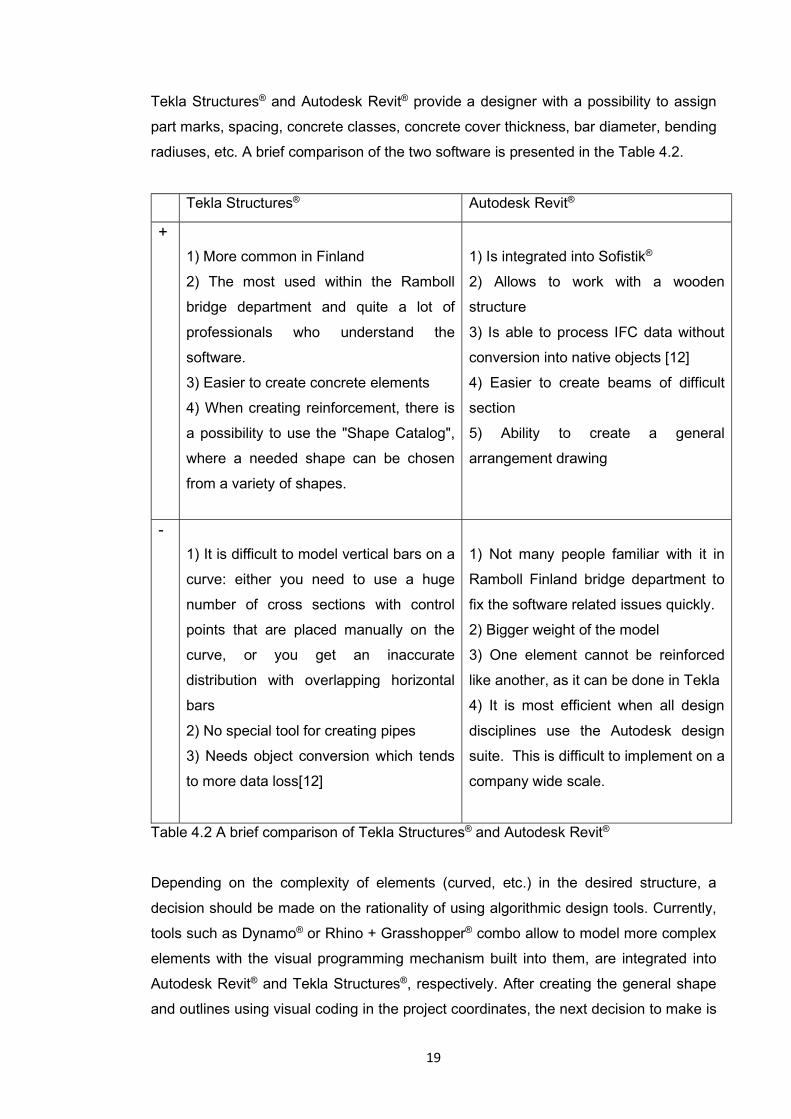
Tekla Structures® and Autodesk Revit® provide a designer with a possibility to assign
part marks, spacing, concrete classes, concrete cover thickness, bar diameter, bending
radiuses, etc. A brief comparison of the two software is presented in the Table 4.2.
Tekla Structures® Autodesk Revit®
+
1) More common in Finland
2) The most used within the Ramboll
bridge department and quite a lot of
professionals who understand the
software.
3) Easier to create concrete elements
4) When creating reinforcement, there is
a possibility to use the "Shape Catalog",
where a needed shape can be chosen
from a variety of shapes.
1) Is integrated into Sofistik®
2) Allows to work with a wooden
structure
3) Is able to process IFC data without
conversion into native objects [12]
4) Easier to create beams of difficult
section
5) Ability to create a general
arrangement drawing
-
1) It is difficult to model vertical bars on a
curve: either you need to use a huge
number of cross sections with control
points that are placed manually on the
curve, or you get an inaccurate
distribution with overlapping horizontal
bars
2) No special tool for creating pipes
3) Needs object conversion which tends
to more data loss[12]
1) Not many people familiar with it in
Ramboll Finland bridge department to
fix the software related issues quickly.
2) Bigger weight of the model
3) One element cannot be reinforced
like another, as it can be done in Tekla
4) It is most efficient when all design
disciplines use the Autodesk design
suite. This is difficult to implement on a
company wide scale.
Table 4.2 A brief comparison of Tekla Structures® and Autodesk Revit®
Depending on the complexity of elements (curved, etc.) in the desired structure, a
decision should be made on the rationality of using algorithmic design tools. Currently,
tools such as Dynamo® or Rhino + Grasshopper® combo allow to model more complex
elements with the visual programming mechanism built into them, are integrated into
Autodesk Revit® and Tekla Structures®, respectively. After creating the general shape
and outlines using visual coding in the project coordinates, the next decision to make is

20
whether the reinforcement will be modeled and, if so, where it will be done. One option
is to continue working in algorithmic design tool or transfer already modeled structure to
Autodesk Revit® or Tekla Structures® and reinforce it there. For more complex
geometries, the first option is more efficient compared to second one. All properties of
concrete and steel can be easily assigned in Rhino + Grasshopper® combo, as well as
phases, with subsequent data transfer to Tekla. Autodesk Revit® and Dynamo® combo
is not in common use in the Ramboll bridge unit at the moment of this study.
4.1.3 Tables
Tables help to analyze the completed structure and structuralize all the expenses and
the amount of material spent. For this purpose, quantities with the cost estimation are
being calculated. There are plenty of tools to help designers. One of them is Fore, which
includes pricelists. Data modelling is conducted using the design, conditions and quality
standards and general guidelines.
Pile lists are essential in order to provide workers on site with a complete and reliable
information for the construction. Reinforcement, stressing and structural bearings lists
can be done using different report templates. By using Tekla Structures® or Autodesk
Revit® it is possible to create reports directly from the model database, so the information
is always up-to-date (Figure 4.4). Note that when the model changes, the reports are not
updated automatically [13].
Figure 4.1 Example of a report in Tekla Structures® (image from teklastructures.support.tekla.com)
21
4.1.4 Specifications
Construction specifications or specs are written details for work that is required to be
completed in a construction project.
Materials, concrete classes, formwork pattern, excavation requirements are included in
these details as well as the quality and the scope of work and the text summary.
Contractors use these specs with suppliers as a guide to select the right materials for
the particular project. In addition to this, the specifications currently override the drawings
and model if there is a conflict between the design documents.
Designers and engineers usually produce specifications before the work on site begins.
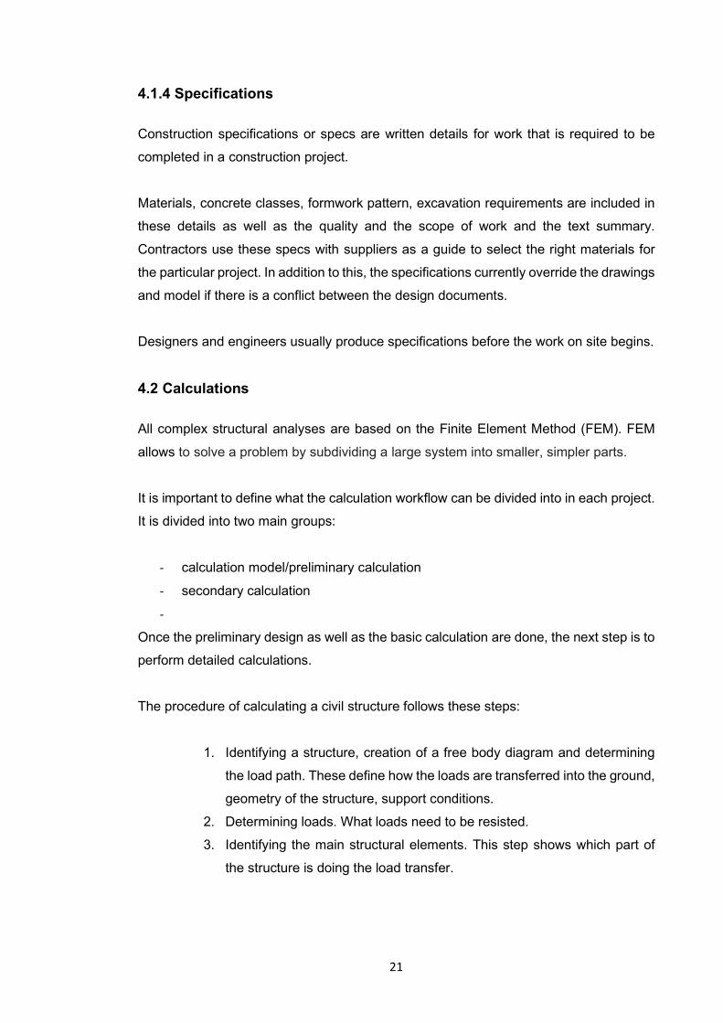
4.2 Calculations
All complex structural analyses are based on the Finite Element Method (FEM). FEM
allows to solve a problem by subdividing a large system into smaller, simpler parts.
It is important to define what the calculation workflow can be divided into in each project.
It is divided into two main groups:
- calculation model/preliminary calculation
- secondary calculation
-
Once the preliminary design as well as the basic calculation are done, the next step is to
perform detailed calculations.
The procedure of calculating a civil structure follows these steps:
1. Identifying a structure, creation of a free body diagram and determining
the load path. These define how the loads are transferred into the ground,
geometry of the structure, support conditions.
2. Determining loads. What loads need to be resisted.
3. Identifying the main structural elements. This step shows which part of
the structure is doing the load transfer.
22
4. Determining load combinations. What are the possibilities of these loads
occurring at the same time? How accurate the estimated load values are.
Different loads have different load factors depending on their certainty.
5. Performing simple/rough hand calculations. Hand calculations will be
used later to verify the FEM-analysis model results and determine order
of magnitude errors. In this stage only main design loads are being
calculated.
6. Creation of the FEM-model based on the information above.
7. Determining material properties. Checking the results to verify their
validity.
8. Performing capacity verification checks and refining and repeating the
steps above until a suitable solution is found.
Buildings and infrastructure have a slight difference in their calculations due to the
loading and combinations of them. LUSAS® is a FEM-analyses software currently used
for civil structures. It has a smart combination facility that deals with favorable and
unfavorable factors very well and search to find the worst case for you. It is a lot easier
to figure out the worst case of a load combination. Karamba®, which is a plug-in for
Grasshopper®, at the time of writing does not have this facility either. Also, LUSAS® is
very user-friendly and much easier to catch mistakes compared to some FEM-analysis
software.
Another reason for LUSAS® usage in the current workflow in Ramboll bridge
departments is due to its long history in the company. One of the benefits of using the
same software inside a big company is the possibility of building a large community of
users and sharing license costs.
If the structure is on piles and not on spread footing, especially if the shape is complex,
then it is more reasonable to use FEM-analysis software.
One of the problems with using LUSAS® is the inability to easily connect to other
software. Sofistik® sometimes can be user-unfriendly, however it has a possibility to
connect with several other BIM-software including Autodesk Revit®, or algorithmic design
software such as Grasshopper.
Presumably, in the future calculation workflow, there would be a combination of FEM-
software. Sofistik® will be used for bridges that fit the standard bridge architecture where
23
as LUSAS® would be used for specialty structures that are less like standard civil
structure solutions.
4.3 Preliminary design
Once the department and designers get the initial data to start a new requested project,
the first thing to work on is the preliminary design.
Preliminary design is a step that allows to provide a basic idea of what the future structure
will be in accordance with the client’s wishes, codes and regulations. It is also based on
the data provided by other departments and already existing plans. General shapes and
outlines of the structure in the preliminary design are based on rough calculations.
Preliminary design can be presented in the shape of a model or a drawing. Rough
specifications are sometimes provided in the preliminary design phase, as well as some
tables. Designer should provide a client with a rough cost estimate as well.
4.4 Initial data
In order to start development of a new project, the initial data material must be gathered.
It shows the current state of the infrastructure project and provides a basis for design. A
basic bridge project is taken as an example.
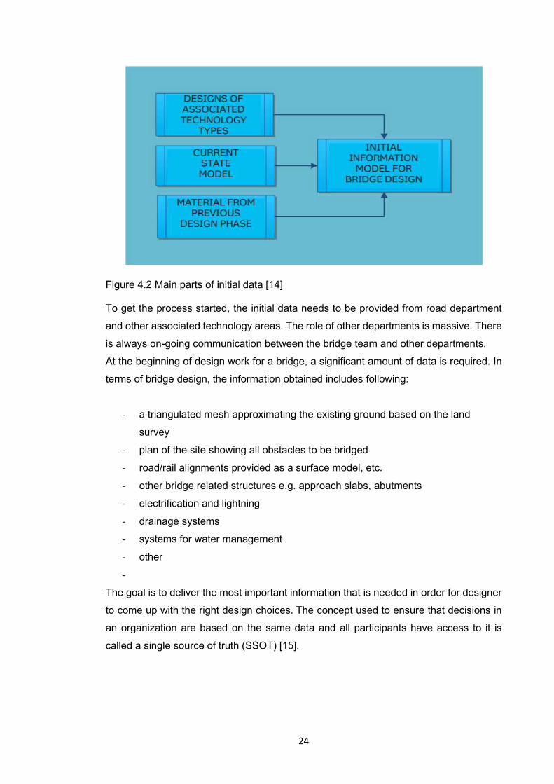
The initial data for bridge modelling can be split into three different parts (Figure 4.2):
- design-phase data received from the designers of other technology areas
- current state model
- material from previous design phase
24
Figure 4.2 Main parts of initial data [14] To get the process started, the initial data needs to be provided from road department
and other associated technology areas. The role of other departments is massive. There
is always on-going communication between the bridge team and other departments.
At the beginning of design work for a bridge, a significant amount of data is required. In
terms of bridge design, the information obtained includes following:
- a triangulated mesh approximating the existing ground based on the land
survey
- plan of the site showing all obstacles to be bridged
- road/rail alignments provided as a surface model, etc.
- other bridge related structures e.g. approach slabs, abutments
- electrification and lightning
- drainage systems
- systems for water management
- other
-
The goal is to deliver the most important information that is needed in order for designer
to come up with the right design choices. The concept used to ensure that decisions in
an organization are based on the same data and all participants have access to it is
called a single source of truth (SSOT) [15].

25
5 COMPARISON OF WORKFLOW (2010 VS. 2020)
5.1 Transition to a new process with model design
Nowadays, almost every project except for the simple ones is model based.
Implementation of modelling has changed workflow a lot. In addition to the constant
growth of modeling software, requirements are also developing so there is a constant
need to adapt to this. It has a significant amount of advantages which were previously
discussed throughout this work.
Even 10 years ago workflow was slightly different than how it is done today, only few
projects were done using 3D-modelling. Because of that, one of the biggest problems
was the number of mistakes made in the design phase. A lot of mistakes that were often
made in a 2D project decades ago just do not exist now, as BIM users catch the mistakes
before they ever make it to the design documents. What is more, the transition from using
2D tools to using 3D ones has given an opportunity to catch problems earlier than before.
Another improvement in existing modelling technology based on parametric design tools
over the old is the ability to automatically update the model. In tools such as
Grasshopper® or Dynamo®, it is possible to automatically modify the entire model and its
parts by modifying the input data or several parameters. There is no need to go back to
the starting point whenever there is even a small change and redo everything manually
as it used to be. Consequently, it takes less time for the designer to make changes to
the model, resulting in lower project costs (Figure 5.1).
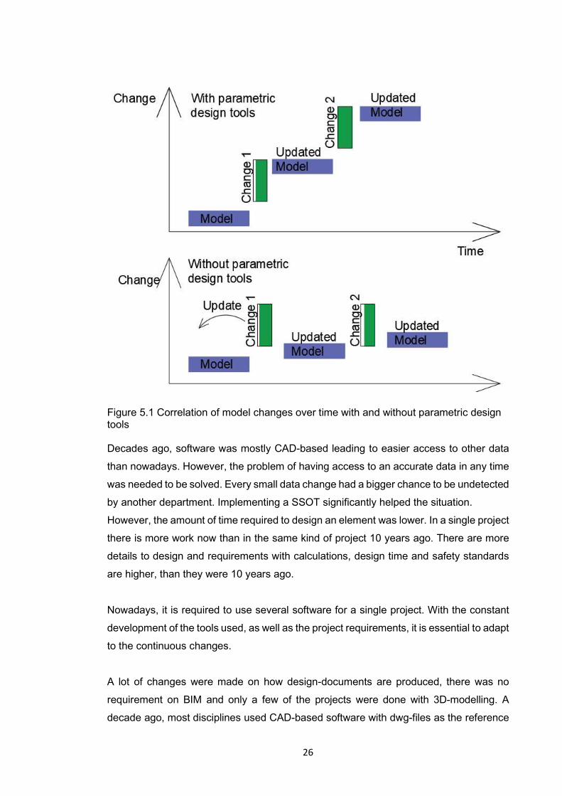
26
Figure 5.1 Correlation of model changes over time with and without parametric design tools Decades ago, software was mostly CAD-based leading to easier access to other data
than nowadays. However, the problem of having access to an accurate data in any time
was needed to be solved. Every small data change had a bigger chance to be undetected
by another department. Implementing a SSOT significantly helped the situation.
However, the amount of time required to design an element was lower. In a single project
there is more work now than in the same kind of project 10 years ago. There are more
details to design and requirements with calculations, design time and safety standards
are higher, than they were 10 years ago.
Nowadays, it is required to use several software for a single project. With the constant
development of the tools used, as well as the project requirements, it is essential to adapt
to the continuous changes.
A lot of changes were made on how design-documents are produced, there was no
requirement on BIM and only a few of the projects were done with 3D-modelling. A
decade ago, most disciplines used CAD-based software with dwg-files as the reference
27
for everybody, making data access and exchange easier than it is today. However, not
all disciplines use 3D at the same level. There is a slight discrepancy in the tools used
and workflow integration between different disciplines, which apparently wasn't the case
a while ago.
The 3D tools made shape creation easier, which can lead to a lack of rationalization of
the geometry which makes it harder to build. However, with 2D CAD drawings were
easier and rewriting the input data was simple.
Besides all the above, 2D drawings are still required as well as models. As an estimate,
with the same kind of structure this increases the amount of work by approximately 30%
compared to a decade ago (Kokko 2020). Opposed to projects back then, everything
requires more time nowadays, the deliverables are more extensive due to the BIM +
drawings workflow, as well as the tighter schedules.
To sum up, it should be mentioned once again that the process of improving a model
design is still occurring. The most valuable difference from a decade ago is the
introduction of model-based design, which gave a huge opportunity to expand the quality
of the resulting structure.
5.2 Parallel design process (Cooperation among technologies and people)
One of the benefits of BIM is often the improved cooperation between project members.
However, it has been observed that data model-based work is not self-evident enough
to raise cooperation to the desired level.
Misunderstandings and misinterpretations are common problems in communicating
using messaging tools, such as e-mail. Also, it is not always clear to the recipient how
important the message is or how busy the receiver is. Face-to-face communication has
been found to be the most effective form of communication to avoid misunderstandings.
Nowadays, people that work at the same project can be located in different offices and
sometimes even countries, in which case there is not always the possibility of a face-to-
face discussion. Modern technologies allow to make video calls and, if necessary, are
able to visually show what the problem is or the problem that needs to be solved together
[16].
28
In addition, modern technologies provide the opportunity for a parallel workflow, since
different people can be responsible for different parts of the structure. The modelling
software has a tool for working together at the same time in the same project and implies
that there will be less chances of overlap, since all data is updated in real time. Working
at the same time on the same project, it ultimately takes less time to design, resulting in
cost savings.
5.3 The development of a future workflow
With all technologies, guidelines and software evolving it is safe to say that the workflow
changes according to it, too. More than that, it is changing fast. An overview of what to
expect in the future regarding the development of the workflow is presented in the current
chapter.
Less human resources will be involved in design work in the future. The amount of work
performed automatically by computers continues to increase (Lõhmus 2020). Although,
future schedules will be tighter and projects will be even more complicated, the software
development will ease the work a lot.
Presumably, besides all the above, the next most rational step to improve development,
reduce cost and time in the future will be to decrease the number of 2D documents and
eventually move to a completely drawing-less workflow. In the future all disciplines will
work with the same informational model decreasing the need for information transforming
which has been very big reason for mistakes in designs. The use of outdated information
as a source material will decrease fundamentally (Kokko 2020).
In conclusion, it can be stated that the progress in design tools and standards happens
all the time, it is a constantly evolving process. It is impossible to be totally sure of what
is coming but it is possible to predict next steps based on the current problems in the
structural design industry and suggested appropriate solutions that can solve them. What
happens next remains to be seen, and the only reasonable option is to be prepared for
changes and be able to adapt new ways to the current workflow.
29
6 CONCLUSIONS AND RECOMMENDATIONS
A significant amount of information was researched during the process of writing this
thesis. Conducting an interview survey gave an inside and experienced view on the
reviewed topic, which made it possible to understand the process deeper.
Based on the work that has been made and the results of it, it is possible to say that this
thesis reviews how and why the current workflow inside the bridge department has
proven its efficiency. To sum up, the main goals of the current work has been achieved:
it explores the current organization of the workflow, reveals the concept of effective
workflow from the perspective of model-based structural design, as well as a brief
comparison of software. Another thing worth mentioning is possible replacement of the
main software used for structural analyses.
Moreover, reflecting on the workflow of the previous decade and comparing it with the
situation at the time of writing the current thesis, helps to make an assumption about
what to expect in the future.
Currently, the industry is going towards the drawing-less workflow. Further research is
needed to determine a variety of details, which must be taking into account, in order to
speed the transition, for example how to transfer the info to the site, etc. When it would
become possible depends on different aspects, which were not the focus of this work.
However, it can be mentioned once again that the covered topics only provide the most
general information and the most general ideas. To get more use out of the topic, it
should be explored in much greater detail.

30
List of Figures
Figure 3.1 Approaches to a successful bridge BIM workflow, p. 8
Figure 4.1 Example of a report in Tekla Structures®, p. 20
Figure 4.2 Main parts of initial data, p. 24
Figure 5.1 Correlation of model changes over time with and without parametric design tools, p.26
List of Tables
Table 3.1 General steps in the workflow for 3 disciplines, p. 9
Table 3.2 IFC description, p. 10
Table 4.1 Required documents for completion of a civil structure, p. 16
Table 4.2 A brief comparison of Tekla Structures® and Autodesk Revit®, p. 19
31
REFERENCES [1] Bargstädt, 2015, Challenges of BIM for Construction Site Operations, p.52. https://www.researchgate.net/publication/282831756_Challenges_of_BIM_for_Construction_Site_Operations
[2] Partala, 2020, BIM workflow in a model-based bridge project, Highway 4 Kirri-Tikkakoski
[3] Garcia-Lopez & Fischer, 2016, A Construction Workflow Model for Analyzing the Impact of In-project Variability, p. 2. https://www.researchgate.net/publication/303515386_A_Construction_Workflow_Model_for_Analyzing_the_Impact_of_In-Project_Variability#:~:text=In%20construction%2C%20workflow%20is%20defined,components%20(LCI%202015).
[4] Delgado & Brilakis, 2015, Open data model standards for structural performance monitoring of infrastructure assets, p.1. https://www.repository.cam.ac.uk/bitstream/handle/1810/252346/D%c3%a1vila%2c%20Brilakis%2c%20%26%20Middleton%202015%20CIB%20W78%20Conference.pdf?sequence=1&isAllowed=y
[5] Wikipedia. Model-based design. https://en.wikipedia.org/wiki/Model-based_design
[6] Sireeni, 2020, Future of Inframodel development
[7] Noeskoski 2011, Liikennevirasto siirtyy tilaamaan tietomalleja siltahankkeissa. http://ril.easypage.fi/media/files/tietomallit/liikenneviraston-siirtyy-tilaamaan-tietomalleja-siltahankkeissa.pdf
[8] Kerosuo, 2015, BIM-based Collaboration across organizational and disciplinary boundaries through knotworking, p. 201-208. http://hdl.handle.net/10138/216712
[9] Volk, Stengel, 2014, Building Information Modeling(BIM) for existing buildings - literature review and future needs, p. 109-127
[10] Guidelines of the Finnish transport agency, p.10-15 https://julkaisut.vayla.fi/pdf7/tieohjeet_1.11.2019_web.pdf
[11] Building Smart. Common InfraBIM Requirements. 2019. https://buildingsmart.fi/en/common-bim-requirements-2012/
[12] Wilkinson & Xia 2015, Sustainable Buildings and Structures, p. 181 https://books.google.fi/books?hl=fi&lr=&id=lRyvCgAAQBAJ&oi=fnd&pg=PA175&dq=tekla+and+revit+&ots=he2gFpLbnk&sig=QzBa0bkqpJR5wvgGMXBeUubSe2Y&redir_esc=y#v=onepage&q=tekla%20and%20revit&f=false
[13] Tekla Structures. Reports. https://teklastructures.support.tekla.com/2020/en/rep_reports
[14] Guidelines of the Finnish transport agency. BIM Guidelines for Bridges. https://julkaisut.vayla.fi/pdf8/lo_2014-06eng_bim_guidelines_web.pdf
[15] Talend. Single Source of Truth – What it is and Why You Want it Yesterday. https://www.talend.com/resources/single-source-truth/
[16] Bergström, 2017, Project Communication Between Designers and Engineers. http://documents.vsect.chalmers.se/CPL/exjobb2007/ex2007-092.pdf
APPENDIX 1