Towards real time implementation of reconstructive signal processing algorithms using systolic...
13
Towards real time implementation of reconstructive signal processing algorithms using systolic arrays coprocessors A. Castillo-Atoche a,b, * , D. Torres-Roman b,1 , Y. Shkvarko b,1 a Universidad Autónoma de Yucatán, Av. Industrias No Contaminates S/N, Mérida, Yuc., Mexico b Centro de Investigación y de Estudios Avanzados del I.P.N. (CINVESTAV), Av. Cientifìca 1145, Colonia el Bajío, Guadalajara, Jal., Mexico article info Article history: Received 30 September 2009 Received in revised form 24 March 2010 Accepted 4 May 2010 Available online 1 June 2010 Keywords: Systolic arrays Hardware/Software co-design FPGA abstract Reconstructive signal processing algorithms encompass a broad spectrum of computational methods. Fortunately, most of the methods fall into the classes of the matrix algebraic calculations, convolution, or transform type algorithms. These algorithms possess common properties such as regularity, locality and recursiveness. Considering such general class of reconstructive signal processing (SP) techniques, in this paper we propose a new Hardware/Software (HW/SW) co-design paradigm for the implementa- tion of reconstructive SP algorithms via efficient systolic arrays integrated as digital SP coprocessors units. In particular, the selected matrix–matrix and matrix–vector multiplication algorithms are imple- mented in a systolic computing fashion that meets the real time SP system requirements when employ- ing the developed Hardware/Software Co-Design method oriented at the use of a Xilinx Field Programmable Gate Array (FPGA) XC4VSX35-10ff668. Ó 2010 Elsevier B.V. All rights reserved. 1. Introduction Modern adaptive reconstructive signal/image processing tech- niques are computationally extremely expensive and the majority of them are not suitable for a real time implementation with the existing digital signal processors (DSPs) or personal computers (PCs) [1–4]. However, most of the reconstructive signal processing (SP) algorithms incorporate two major groups of computational operations: basic algebraic matrix-form operations and discrete- inertial transforms like convolution, correlation techniques, digital filtering, etc. that also can be formalized in matrix formats [1–4]. The real time implementation of such SP techniques depends critically both on the employed parallel computation techniques and on the parallel processor technology. In the early 1980s, Kung [5] proposed the concept of systolic array (SA) processing to per- form efficient parallelized computing. In general, the SA is defined as a simple class of concurrent processors, in which the processed data move in a regular and periodic manner, utilizing only a small number of simple processing elements with corresponding local communications [5]. While the SA concept was originally formu- lated intuitively to perform the correlation of two sequences, sys- tematic design of SAs for certain class of allowable algorithms (i.e., single assignment algorithms) have been next proposed under the general name of dependence graph mapping [5–7]. Nevertheless, even recent studies of the SA-related techniques for implementing the reconstructive SP algorithms are still fraught with crucial lim- itations on acceptable computational complexity that hinder the possibilities to achieve the real time implementation performances [1–4,8,16], etc. The predominant challenge of this paper is to present a novel SA-based computational procedure aimed at implementation of the basic matrix-form reconstructive SP algorithms taking into ac- count the regularity, locality and recursiveness properties using SA coprocessors for the real time SP computing via employing the pro- posed hardware/software (HW/SW) co-design paradigm. The prin- cipal innovative proposition with the HW/SW co-design that distinguishes our approach from the previous studies [8–11,16] consists in the implementation of a new reconfigurable high speed interface between the SW (embedded processor) and the HW-SA architectures with an efficient control system (global and local) for the interface and the SAs. In [8], an alternative HW/SW co-de- sign method was developed to achieve the near real time imple- mentation of the convex regularization-based procedures for reconstructive SP. However, in that previous study [8], no SA archi- tectures were considered. Another work in [16] proposed a com- pletely different approach with the incorporation of the SA-based implementation schemes but reduced only to the matched space filtering architecture based on the triple matrix multiplication 1383-7621/$ - see front matter Ó 2010 Elsevier B.V. All rights reserved. doi:10.1016/j.sysarc.2010.05.004 * Corresponding author at: Universidad Autónoma de Yucatán, Av. Industrias No Contaminates S/N, Mérida, Yuc., Mexico. Tel.: +52 999 9300550x1051; fax: +52 999 9300559. E-mail addresses: [email protected], [email protected] (A. Castillo- Atoche), [email protected] (D. Torres-Roman), [email protected] (Y. Shkvarko). 1 Tel.: +52 33 3777 3600; fax: +52 33 3777 3609. Journal of Systems Architecture 56 (2010) 327–339 Contents lists available at ScienceDirect Journal of Systems Architecture journal homepage: www.elsevier.com/locate/sysarc
Transcript of Towards real time implementation of reconstructive signal processing algorithms using systolic...

Journal of Systems Architecture 56 (2010) 327–339
Contents lists available at ScienceDirect
Journal of Systems Architecture
journal homepage: www.elsevier .com/ locate /sysarc
Towards real time implementation of reconstructive signal processingalgorithms using systolic arrays coprocessors
A. Castillo-Atoche a,b,*, D. Torres-Roman b,1, Y. Shkvarko b,1
a Universidad Autónoma de Yucatán, Av. Industrias No Contaminates S/N, Mérida, Yuc., Mexicob Centro de Investigación y de Estudios Avanzados del I.P.N. (CINVESTAV), Av. Cientifìca 1145, Colonia el Bajío, Guadalajara, Jal., Mexico
a r t i c l e i n f o
Article history:Received 30 September 2009Received in revised form 24 March 2010Accepted 4 May 2010Available online 1 June 2010
Keywords:Systolic arraysHardware/Software co-designFPGA
1383-7621/$ - see front matter � 2010 Elsevier B.V. Adoi:10.1016/j.sysarc.2010.05.004
* Corresponding author at: Universidad AutónomaContaminates S/N, Mérida, Yuc., Mexico. Tel.: +52 9999300559.
E-mail addresses: [email protected], acastillo@gdAtoche), [email protected] (D. Torres-Roman)(Y. Shkvarko).
1 Tel.: +52 33 3777 3600; fax: +52 33 3777 3609.
a b s t r a c t
Reconstructive signal processing algorithms encompass a broad spectrum of computational methods.Fortunately, most of the methods fall into the classes of the matrix algebraic calculations, convolution,or transform type algorithms. These algorithms possess common properties such as regularity, localityand recursiveness. Considering such general class of reconstructive signal processing (SP) techniques,in this paper we propose a new Hardware/Software (HW/SW) co-design paradigm for the implementa-tion of reconstructive SP algorithms via efficient systolic arrays integrated as digital SP coprocessorsunits. In particular, the selected matrix–matrix and matrix–vector multiplication algorithms are imple-mented in a systolic computing fashion that meets the real time SP system requirements when employ-ing the developed Hardware/Software Co-Design method oriented at the use of a Xilinx FieldProgrammable Gate Array (FPGA) XC4VSX35-10ff668.
� 2010 Elsevier B.V. All rights reserved.
1. Introduction
Modern adaptive reconstructive signal/image processing tech-niques are computationally extremely expensive and the majorityof them are not suitable for a real time implementation with theexisting digital signal processors (DSPs) or personal computers(PCs) [1–4]. However, most of the reconstructive signal processing(SP) algorithms incorporate two major groups of computationaloperations: basic algebraic matrix-form operations and discrete-inertial transforms like convolution, correlation techniques, digitalfiltering, etc. that also can be formalized in matrix formats [1–4].
The real time implementation of such SP techniques dependscritically both on the employed parallel computation techniquesand on the parallel processor technology. In the early 1980s, Kung[5] proposed the concept of systolic array (SA) processing to per-form efficient parallelized computing. In general, the SA is definedas a simple class of concurrent processors, in which the processeddata move in a regular and periodic manner, utilizing only a smallnumber of simple processing elements with corresponding localcommunications [5]. While the SA concept was originally formu-
ll rights reserved.
de Yucatán, Av. Industrias No9300550x1051; fax: +52 999
l.cinvestav.mx (A. Castillo-, [email protected]
lated intuitively to perform the correlation of two sequences, sys-tematic design of SAs for certain class of allowable algorithms (i.e.,single assignment algorithms) have been next proposed under thegeneral name of dependence graph mapping [5–7]. Nevertheless,even recent studies of the SA-related techniques for implementingthe reconstructive SP algorithms are still fraught with crucial lim-itations on acceptable computational complexity that hinder thepossibilities to achieve the real time implementation performances[1–4,8,16], etc.
The predominant challenge of this paper is to present a novelSA-based computational procedure aimed at implementation ofthe basic matrix-form reconstructive SP algorithms taking into ac-count the regularity, locality and recursiveness properties using SAcoprocessors for the real time SP computing via employing the pro-posed hardware/software (HW/SW) co-design paradigm. The prin-cipal innovative proposition with the HW/SW co-design thatdistinguishes our approach from the previous studies [8–11,16]consists in the implementation of a new reconfigurable high speedinterface between the SW (embedded processor) and the HW-SAarchitectures with an efficient control system (global and local)for the interface and the SAs. In [8], an alternative HW/SW co-de-sign method was developed to achieve the near real time imple-mentation of the convex regularization-based procedures forreconstructive SP. However, in that previous study [8], no SA archi-tectures were considered. Another work in [16] proposed a com-pletely different approach with the incorporation of the SA-basedimplementation schemes but reduced only to the matched spacefiltering architecture based on the triple matrix multiplication

328 A. Castillo-Atoche et al. / Journal of Systems Architecture 56 (2010) 327–339
and the 1-D convolution. The proposed here HW/SW co-design ap-proach develops a new paradigm for the SA-based architecture de-sign with the implementation of the specialized hardware modulessuch as the efficient systolic coprocessors that results in a consid-erably decreased computational complexity and required process-ing time for implementing the matricial SP procedures.
Next, the rest of the paper is organized as follows: in Section 2,the SW co-design stage 1 which corresponds to the parallelizationof the SP procedures is developed. The SW co-design stage 2 re-lated to the mapping onto the SAs procedure is performed and de-tailed in Section 3. Section 4 develops the HW co-design stage thatintegrates the SAs as coprocessor units. In Section 5, the perfor-mance analysis gained with the proposed HW/SW co-design ap-proach is performed and discussed. A resuming example of theimplementation of the reconstructive SP operations as efficientSAs coprocessors via the HW/SW co-design paradigm for remotesensing (RS) imagery is presented in Section 6. Finally, the conclu-sions are summarized in Section 7.
2. SW co-design stage 1: parallelization of SP procedures
In this section, the basic algebraic matrix operations (matrix–vector and matrix–matrix multiplication) that constitute the base
Fig. 1. Single assignment of the matrix–vector multiplication algorithm. (a)
Fig. 2. Locally recursive representation of the matrix–vector multiplication.
of the most computationally consuming applications in the recon-structive SP applications are transformed into the required parallelalgorithmic representation format. A manifold of different ap-proaches can be used to represent parallel algorithms, e.g. [5–7].In all the cases, to achieve the maximum possible parallelism inan algorithm, the so-called data dependencies in the computationsmust be analyzed [5,12]. Formally, these dependencies are to beexpressed via the corresponding dependence graph (DG) [6]. Fol-lowing [6], we define the dependence graph G ¼ ½P;E� as a compos-ite set where P represents the nodes and E represents the arcs oredges in which each e 2 E connects p1; p2 2 P that is formalizedas e ¼ p1 ! p2 [5]. Next, the data dependencies analysis of the ma-trix–matrix and the matrix–vector multiplication algorithmsshould be performed aimed at their efficient parallelization.
2.1. Parallelized matrix–vector multiplication
The conventional matrix–vector multiplication of an n �m ma-trix A with a vector x of dimension m is given by
y ¼ Ax ð1Þ
where y is an n-dimensional (n-D) output vector. The jth element ofy is computed as
Single assignment algorithm. (b) Single assignment dependence graph.
(a) Locally recursive algorithm. (b) Locally recursive dependence graph.

Fig. 3. Single assignment of the matrix–matrix multiplication algorithm. (a) Single assignment algorithm. (b) Single assignment dependence graph.
A. Castillo-Atoche et al. / Journal of Systems Architecture 56 (2010) 327–339 329
yj ¼Xn
i¼1
ajixi; j ¼ 1; . . . ;m ð2Þ
where aji represent the corresponding element of A.In Fig. 1, we present the conventional so-called single assign-
ment algorithm [6,7] that performs the computing of theproduct (1). In this algorithm, one variable assignment is repre-sented for each point (i.e., processor element) in the 2-D DG, andeach variable assignment occurs only once for each coordinate inthe DG.
At the SW co-design level, we transform such multiplicationalgorithm into the locally recursive algorithm [5] without globaldata dependencies (in terms of a recursive form) as it is clarifiedin Fig. 2.
The modified locally recursive algorithm avoids large routingresources and drivers that are translated into the large amount ofbuffers in the final systolic architecture. As it is evident from theanalysis of the structures shown in Fig. 2, the variable being broad-cast was removed by passing the variable through each of theneighbors processing elements (PEs). In the example test case,we now consider for the matrix–vector single assignment algo-rithm of Fig. 1 and for the locally recursive of Fig. 2, the followingspecifications: m = n = 4, the clock period of 10 ns and the data-word length of 32 bits. From the reported time performance anal-ysis, one can conclude that for both algorithms the latency is 30 ns,
Fig. 4. Locally recursive representation of the matrix–matrix multiplication.
the throughput is 984.61 Mbits/s and the time processing achievedis 160 ns.
2.2. Parallelized matrix–matrix multiplication
The multiplication of an m � n matrix A with an n � p matrix Bresults in an m � p output matrix C = AB with the elements
cij ¼Xn
k¼1
aikbkj; i ¼ 1; . . . ;m; j ¼ 1; . . . ;p: ð3Þ
In Fig. 3, we present the conventional single assignment algorithmfor computational implementation of the product (3) and the corre-sponding data dependencies in the 3-D DG.
Also at the SW co-design stage, we construct the locally recur-sive algorithm for efficient computing of such matrix–matrix mul-tiplication specified in Fig 4(a) with the corresponding datadependencies in a 3-D DG illustrated in Fig. 4(b).
The following specifications were considered for the simplifiedsimulations test case reported in Figs. 3 and 4: m = n = p = 2, theclock period of 10 ns and the data-word length of 32 bits. The re-sults are indicative of the following: both algorithms manifestthe latency of 10 ns, the throughput is 1.828 Gbits/s and the timeprocessing achieved is 80 ns.
(a) Locally recursive algorithm. (b) Locally recursive dependence graph.

330 A. Castillo-Atoche et al. / Journal of Systems Architecture 56 (2010) 327–339
Once the algorithms are transformed into their parallelized lo-cally recursive representation forms, we are ready to proceed withtheir transformations onto the array processors.
3. SW co-design stage 2: mapping onto systolic arrays
A conventional systolic array (SA) consists of a number of proces-sors elements (PEs) and interconnection links among the PEs [5,6].Mapping the algorithms onto the SA means that the correspondingprocessor array directly supports the related computations andcommunications while the design is performed [6]. The systolic de-sign maps an N-dimensional (N-D) DG into a lower dimensional sys-tolic array. Recall that the SA is a space–time representation of thecomputational operations, in which the function description definesthe behavior within a node, whereas the structural description spec-ifies the interconnections (edges and delays) between the corre-sponding graph nodes [5]. In order to derive a regular SAarchitecture with a minimum possible number of nodes, we proposeto follow the linear projection approach for processor assignment[7], i.e., the nodes of the DG in a certain straight line are to be prop-erly projected onto the corresponding PEs in the processor array rep-resented by the corresponding assignment projection vector d. Thus,we seek for a linear order reduction transformation
T : GN ! GN�1 ð4Þ
that maps the N-D DG (GN) onto the (N–1)-D SA (GN�1). The desiredlinear transformation matrix T can be partitioned into two functionsas follows:
T ¼P
R
� �; ð5Þ
where P is a (1 � p)-D vector (composed of the first row of T) whichdetermines the time scheduling. This vector indicates the normaldirection of the equi-temporal hyper-planes in the DG, ‘equi-tem-poral’ being understood in the sense that all the nodes on the samehyper-plane must be processed at the same time. The (p-1) � p sub-matrix R in (6) is composed of the rest rows of T that determine thespace processor. The partitioning (6) yields the regular SA of (N�1)dimension specified by the mapping
TU ¼ K; ð6Þ
where K is composed of the new revised vector schedule (repre-sented by the first row of the SA) and the inter-processor commu-
Fig. 5. Mapping transformation of the ma
nications (represented by the rest rows of the SA). In (7), thematrix U specifies the data dependencies of the locally recursivealgorithm represented by the corresponding DG (5).
3.1. Matrix–vector systolic array implementation
Once the matrix–vector algorithm is transformed into the lo-cally recursive representation-form, the following specificationsfor the transformation onto the SA is defined as follows:P ¼ ½1 1� for the vector schedule, d ¼ ½1 0� for the projectionvector and R ¼ ½0 1� for the space processor, respectively. Withthese specifications the transformation matrix becomes
T ¼ PR
� �¼ 1 1
0 1
� �. Next, we specify the dependence vectors of
the locally recursive algorithm: U ¼ ½Ua Ux Uy �, where
Ua ¼01
� �, Ux ¼
10
� �and Uy ¼
01
� �represent the dependencies
of the corresponding variables in the algorithm. With these depen-dencies we next specify the SA as follows:
TU ¼ K!1 10 1
� �|fflfflfflfflffl{zfflfflfflfflffl}
T
0 1 01 0 1
� �|fflfflfflfflfflfflfflfflffl{zfflfflfflfflfflfflfflfflffl}
U
¼1 1 11 0 1
� �|fflfflfflfflfflfflfflfflffl{zfflfflfflfflfflfflfflfflffl}
K
ð7Þ
In Fig. 5, we illustrate the mapping of the matrix–vector DG ontothe constructed SA architecture with the employed projection vec-tor d ¼ ½1 0�.
As it is evident from the transformation presented in Fig. 5, onlyfour processor elements are needed to implement the simplifiedtest matrix–vector multiplication algorithm (i.e., for m = n = 4) fol-lowing the proposed SA-oriented procedure.
Fig. 5 presents the time performance analysis of the SA incomparison with the traditional sequential algorithms previ-ously reported in Figs. 1 and 2. For the same specified opera-tional parameters (i.e., m = n = 4, the clock period of 10 nsand the data-word length of 32 bits). The achieved the latencyis 30 ns, the throughput is 3.2 Gbits/s and the time processingrequires 70 ns. A commonly used measure for the time process-ing efficiency is the resulting speed-up factor from the execu-tion time of a single processor (i.e., the locally sequentialalgorithm) and the execution time of the corresponding SA. Inthe reported here analysis, the efficiency ratio of 2.28 isachieved for the simplified above matrix–vector test case. We
trix–vector multiplication algorithm.

A. Castillo-Atoche et al. / Journal of Systems Architecture 56 (2010) 327–339 331
refer to Section 5, the complete efficiency analysis for differentmatrix–vector dimensions.
3.2. Systolic array implementation of matrix–matrix multiplication
The SA for performing the matrix–matrix multiplication in theproposed parallel format employs the following specifications inthe transformations defined by (6): P ¼ ½1 1 1� for the vectorschedule, d ¼ ½0 0 1� for the projection vector and
R ¼ 1 0 00 1 0
� �for the space processor. Once the transformation
matrix T ¼ PR
� �¼
1 1 11 0 00 1 0
24
35 is defined, the dependence vectors
are specified by U ¼ Ua Ub Uc½ �, where Ua ¼100
24
35; Ub ¼
010
24
35
and Uc ¼001
24
35 represent the dependences of the corresponding
variables in the algorithm. With these specifications, we next con-struct the SA via
TU ¼ K!1 1 11 0 00 1 0
264
375
|fflfflfflfflfflfflfflfflffl{zfflfflfflfflfflfflfflfflffl}T
1 0 00 1 00 0 1
264
375
|fflfflfflfflfflfflfflfflffl{zfflfflfflfflfflfflfflfflffl}U
¼1 1 11 0 00 1 0
264
375
|fflfflfflfflfflfflfflfflffl{zfflfflfflfflfflfflfflfflffl}K
: ð8Þ
Fig. 6. Mapping transformation of the matrix–matrix multiplication algorithm.
The transformation in (9) performs the mapping onto the 2-D SAarchitecture that we illustrate in Fig. 6. The architecture presentedin Fig. 6 requires only four processing elements (i.e., consideringthe simplified test case of m = n = p = 2) to perform the matrix–ma-trix multiplication algorithm following the proposed SA-orientedprocedure. However, in the case of realistic problems (e.g., RSscenes of 1K � 1K pixel size as next presented in Section 6) to exe-cute the reconstructive SP techniques, we propose the following:with the established HW/SW co-design architecture, the propersegmentation of the scene frame is realized with the parallelizedcomputing performed over the partitioned segments (i.e., themapped fixed-size SA) followed by the relevant integration of theoverall partial processed data. We refer to Section 5, the scalabilityanalysis in terms of HW resources varying the number of PEs of thefixed-size SA architecture.
The next specifications were also considered in Fig. 6: the peri-od of clock of 10 ns and the data-word length of 32 bits. In theresuming time performance analysis, we achieved a latency of10 ns, a throughput of 4.26 Gbits/s, a time processing of 40 nsand the gained efficiency ratio of 2.
While performing the mapping of the matrix algorithms ontothe corresponding SA, we propose to use at the HW design stage,the precision of 32 bits fixed-point for all operations, 9-bit integerand 23-bits decimal for the implementation of each systolic copro-cessor (i.e., the matrix–matrix and the matrix–vector SAs). Thisprecision guarantees numerical computational errors less than104 referring to the MATLAB-based Fixed-point Toolbox [23]. Usingsuch the MATLAB fixed-point toolbox we generated all the numer-ical test sequences required to verify computationally the pro-posed HW/SW co-design methodology (i.e., test sequences forperforming the SW simulation and for the HW verifications). Theresults of such SW simulation and HW performance analysis willbe presented and discussed further on in Section 6.4 in the resum-ing example of the reconstructive SP performances gains.
4. HW co-design stage: integration of the systolic arrays ascoprocessor units
One of the advantages of FPGA-based embedded systems con-sist in their ability to integrate the customized user cores with asoft or hard embedded processor in system-on-a-chip (SoC) solu-tions [13]. Considerable improvements in algorithm executiontime are expected when such customized user cores are employedas hardware accelerators to perform the computationally intensiveoperations. However, the integration of the customized user cores(SA coprocessors) with a soft or hard embedded processor [18](SW-block) transfers the time-critical matrix computations fromthe processor to the coprocessor, which implies, as a counterpart,an intense data exchange between the coprocessor and the hostprocessor system due to the large amount of data involved in suchtype of operations. For this reason, we point to two key issues to beconsidered in the integration of the HW units with the embeddedprocessor (SW) taking into consideration the system platform con-strains imposed by the selected FPGA Xilinx Virtex-4 XC4VSX35-10ff668.
First, during the design phase, the designer needs to considerthe particular processor type (soft or hard) and the transfer bus be-tween the SW and HW blocks for the HW/SW co-design as it isillustrated in Fig. 7. In this study, we propose to use the Microblazeembedded processor (for the restricted platform) and the On ChipPeripheral Bus (OPB) for transferring the data from/to the embed-ded processor to/from the coprocessor. Such the OPB is a fully syn-chronous bus [14] that connects other separate 32-bit data buses.The overall system architecture (based on the FPGA XC4VSX35-

Fig. 7. Integration of SAs as coprocessors.
332 A. Castillo-Atoche et al. / Journal of Systems Architecture 56 (2010) 327–339
10ff668 with the embedded processor and the OPB buses) restrictsthe corresponding processing frequency to 100 MHz.
Second, to avoid unnecessary multiple data transfer from theembedded processor data memory to the coprocessors, a reconfig-urable interface must be implemented to feed efficiently the SA.Since an SA processor is to be used as an attached coprocessor,the proper design of the reconfigurable interface unit must employ,in a specified spatial–temporal manner, all the required opera-tional and control functions. These functions are: the loading andstoring the data to/from the embedded processor and the data/con-trol parallel transfer through the corresponding processorelements.
A challenging task of the interface is to manage the block of dataensuring that the control system is able to balance the low band-width of the system input–output (I/O) transfer bus and the re-quired high bandwidth for the data exchange of thecorresponding SA processors. To satisfy the high bandwidthrequirements of the SA processors, we propose to incorporatememory buffers into the interface with the SA as specified in theblock diagram of Fig. 8.
In order to examine the architecture organization of the pro-posed reconfigurable interface, let us consider the matrix–matrixmultiplication integration example (i.e., as coprocessor) with twoinput matrices A and B of the dimensions m � n and n � p, respec-tively, w-bit integer elements, and the output matrix C of thedimension m � p. Fig. 9 presents the reconfigurable architectureof the proposed interface for the exemplified matrix–matrix SA.
From the analysis of the architecture presented in Fig. 9, theproposed interface has the ability to reconfigurate the data se-quence flow to the SAs in space and time modes. First, the in-
Fig. 8. Block diagram of the inter
put–output machine employs the FIFO memory and realizes theinterface between the systolic architecture and the embedded pro-cessor. It is important to note that, when just one portion of thedata at a time is transferred from/to the host processor to/fromthe coprocessor, such FIFO memory guarantees the input/outputbandwidth of 32-bits per clock cycle (see [14], for more details).
Also, the spatial–temporal procedure that stores the sequenceof data in the specific order for the corresponding SA is employedin the architecture. One can deduce from Fig. 9 that once the dataare correctly permuted in the blocks of RAM’s, then at each cycle ofclock the data are extracted in a parallel fashion from the RAMmemories and are properly ordered for the corresponding SAs.
For the purpose of the reconfigurability, an addressable genera-tion unit (AGU) based on the look up tables (LUTs), was incorpo-rated into the architecture presented in Fig. 9. Such LUTs areimplemented via the corresponding RAM memories, so the usercan load each LUT via the relevant embedded processor.
The design of the proposed control system is one of the crucialissues of this study. First, the processor element classification isrealized (each PE of different type has an individual behavioralspecification with its own time–space index vector [5],I ¼ ½t p1 p2�
T where t is the index time and p1 and p2 are the pro-cessor indexes). Second, the control signals are defined. In thisstudy, we partition the control system into two levels: global andlocal control. The global control is performed to guarantee the datatransfer to the SAs in a specific order with the proposed interfaceand to habilitate the local control of the corresponding SA. Alsowith the global control, we satisfy the high bandwidth require-ments of the SA processors.
The local control (specified for each particular SA design) isimplemented based on the corresponding SA time-processor anal-ysis as specified in Figs. 10(a) and 11(a).
The key point in the realization of this proposed system controlis that the local control is only connected to the first PE (i.e., forPE_01, p1 ¼ 0 ^ p2 ¼ 1). To be precise, in the local controller archi-tecture of Figs. 10(b) and 11(b), two structures are identified: thecounter and the decoder. The counter generates the temporal indexand the decoder generates the control signals obeying the condi-tions specified in Table 1.
Table 1 specifies the bases for the synthesis of an automatedcontrol generation unit. Next, in Figs. 10(c) and 11(c), we illustratethe proposed data path design. Such automated control flow strat-egy provides a considerable simplification of the complete controlsystem in comparison with [8–10], because in the proposed controlsystem, the control signals are transferred through the neighboringPEs following the space–time schedule identified by the hyper-planes directions in the corresponding matrix–vector and ma-trix–matrix multiplication DGs.
face with the systolic arrays.

Fig. 10. Matrix–vector systolic array: (a) Space–time analysis; (b) Local control design; and (c) Data path design.
Fig. 9. Architecture of the reconfigurable interface.
A. Castillo-Atoche et al. / Journal of Systems Architecture 56 (2010) 327–339 333
5. Performance analysis
In this section, we complete our study with the comparativeperformance analysis of the computational complexity of perform-ing the matrix–matrix and the matrix–vector multiplications, cor-respondingly. In Table 2, we report the synthesis results evaluatedby different metrics that are indicative of the efficiency of the pro-posed SA architectures and the reconfigurable interface. The XilinxXST synthesis tool of the Integrated Software Environment (ISETM)WebPACK™ 9.1i was used for the simplified test case of a 4 � 4data matrix and a 4 � 1 data vector reported in Table 2. The clock
frequency of 100 MHz is the selected timing constrain consideredfor the synthesis.
The synthesis results clarify that the interface occupies morearea than the systolic arrays. However, the reconfigurable designof the interface supports different systolic architectures, e.g., ma-trix–matrix multiplication, matrix–vector multiplication, convolu-tion, and correlation. In Fig. 12, we report the resource utilizationanalysis of the proposed systolic hardware architecture designsfor different numbers of processors elements (PEs).
Next, we evaluate the time processing consumptions utilizedwith the designed coprocessor architectures. In the time process-

Fig. 11. Matrix–matrix systolic array: (a) space–time analysis; (b) local control design; and (c) data path design.
Table 1Synthesis bases for the local control generation unit.
Controlstructures
Control conditions
Matrix–vector (n � n matrix,n-vector)
Matrix–matrix (n � nmatrices)
Counter t 6 2n � 1 t 6 3n � 2Decoder PE_01==1, if (t = 1 to
t = p1 + np2)PE_01==1, if (t = 1 tot = p1 + np2)
Table 2Synthesis results for the 4 � 1 data vector and 4 � 4 data matrix.
Synthesis metrics Systolicmatrix–matrixmultiplication
Systolicmatrix–vectormultiplication
Interface
Number of slices 386 48 2688Number of DSP’48b 16 4 NANumber of LUTsa 513 NA 2578Number of flip-flops 768 96 2514Fmax (MHz) 115.3 210.6 204.3
a LUTs is an acronym to Look Up Tables structures.* DSP48 are dedicated DSP blocks in high-end FPGAs – such as the Xilinx�
XtremeDSP™ slice in Virtex™-4 [24].
334 A. Castillo-Atoche et al. / Journal of Systems Architecture 56 (2010) 327–339
ing analysis, the overall time required to implement the proposedalgorithmic computations with the designed coprocessor architec-ture is defined as
Fig. 12. Resource utilization varying the number of PEs. (a) Mat
tc ¼ ts þ tI þ ts ð9Þ
where ts represents the transfer time from the embedded processorto the SA, tI is the time processing utilized by the interface and ts isthe time processing of the SA. Note that parallel and pipelined solu-tions properly employed in the SAs, exploit the regularity, localityand recursiveness algorithmic properties formalized at the SW co-design stage by (5)–(7). From the analysis of the resource utilizationof Fig. 12, it follows that in the case of the matrix–vector multipli-cation systolic architecture, the total time for performing the mul-tiplication of a square n � n matrix and an n-vector requires only2n � 1 clock cycles and occupies an area of 48 slices (for the testexample of n = 4) with a data precision of 32-b. An interesting alter-native design of a unidirectional linear systolic array (ULSA) forcomputing a matrix–vector multiplication was performed in [15],however, the total time required was 3n � 2 clock cycle. Therefore,this time (3n � 2 clock cycle) of Ref. [15] exceeds that achieved withour proposed architecture (2n � 1 clock cycles).
With the n � n matrix–matrix multiplication systolic architec-ture developed in this study, the most time consuming operationsrequired only 3n � 2 clock cycles and the area occupied 386 slicesfor the data precision of 32-b (e.g., considering the same n = 4 testcase). Another alternative implementations for systolic matrixmultiplication are presented in [9–11]. In [9], the systolic matrixmultiplication design occupied an area of 110 slices (i.e., data pre-cision of 8 bits) with the corresponding time processing ofn2 + 3n + 2 clock cycles. Mencer et al. [10] presented the matrix–matrix multiplication architecture with an area performance of954 slices for the data precision of 8 bits. An alternative matrix–
rix–vector multiplication. (b) Matrix–matrix multiplication.
A. Castillo-Atoche et al. / Journal of Systems Architecture 56 (2010) 327–339 335
matrix multiplication systolic architecture was also proposed in[11], which approached a total time of n2 + 2n clock cycles and54,500 slices for the data precision of 64 bits. As it is easy to deducefrom the area–time comparative analysis with all those alterna-tives implementations, the proposed systolic architectures for per-forming the matrix–vector multiplication and matrix–matrixmultiplication manifest the best area–time trade-off performances.
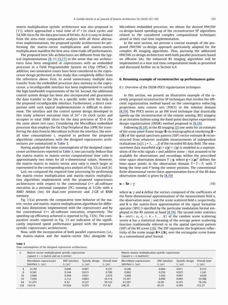
The proposed here SAs architectures are different from the typ-ical implementations [9–11,15,17] in the sense that our architec-tures have been integrated as coprocessors with an embeddedprocessor in a Field Programmable System on Chip (FPSoC). Inaddition, two innovative issues have been considered in the copro-cessor design performed in this study that completely differs fromthe references above. First, to avoid unnecessary multiple datatransfer from the embedded processor data memory to the copro-cessor, a reconfigurable interface has been implemented to satisfythe high bandwidth requirements of the SA. Second, the additionalcontrol system design has been also incorporated and guaranteesthe data transfer to the SAs in a specific order with the help ofthe proposed reconfigurable interface. Furthermore, a direct com-parison with such typical implementations is difficult to deter-mine. The interface and the control system design developed inthis study achieves execution time of 2n2 + 2n clock cycles andoccupies in total 2688 slices for the data precision of 32-b (forthe same above test case). Considering the MicroBlaze embeddedprocessor that employs the On Chip Peripheral Bus (OPB) for trans-ferring the data from/to Microblaze to/from the interface, the over-all time consumptions tc required to perform the proposedalgorithmic computations with the designed coprocessors archi-tectures are summarized in Table 3.
Having analyzed the time consumptions of the designed copro-cessor architectures reported in Table 3, one can easily deduce thatthe matrix–matrix to matrix–vector computational time ratio isapproximately two times for all n-dimensional values. However,the matrix–matrix to matrix–vector area ratio is much larger asrepresented in the corresponding area analysis of Fig. 12(a) and (b).
Last, we compared the required time processing for performingthe matrix–vector multiplication and matrix–matrix multiplica-tion algorithms implemented with the proposed coprocessorsarchitectures with respect to the conventional C++ all-softwareexecution in a personal computer (PC) running at 3 GHz with aAMD Athlon (tm) 64 dual-core processor and 2 GB of RAMmemory.
Fig. 13(a) presents the comparative time behavior of the ma-trix–vector and matrix–matrix multiplication algorithms for differ-ent data dimensions implemented with the coprocessors and bythe conventional C++ all-software execution, respectively. Thespeeding-up efficiency achieved is reported in Fig. 13(b). The com-parative results reported in Fig. 13 are indicative of the signifi-cantly improved speed performance gained with the proposedsystolic coprocessors architectures.
Now, with the incorporation of both parallel coprocessors (i.e.,the matrix–matrix and the matrix–vector SAs) alongside the
Table 3Time consumptions of the designed coprocessor architectures.
n Matrix–vector multiplication systolic coprocessor(square n � n matrix and an n-vector)
Microblaze-coprocessorsInterface ts (ls)
HW interfacetI (ls)
Systolic designts (ls)
Overall timetc (ls)
4 0.150 0.040 0.007 0.1978 0.541 0.144 0.015 0.700
16 2.044 0.544 0.031 2.61932 7.939 2.112 0.063 10.11464 31.275 8.32 0.127 39.722
128 124.14 33.024 0.255 157.42
Microblaze embedded processor, we obtain the desired HW/SWco-design-based speeding-up of the reconstructive SP algorithmsrelated to the considered complex computational techniquesaimed at their real time implementation.
In the next section, we present a concise example of the pro-posed HW/SW co-design approach particularly adapted for thecomplex RS imaging algorithms. Thus, pursuing the addressedHW/SW co-design architecture with both parallel processors basedon efficient SAs, the enhanced RS imaging algorithms will beimplemented in a near real time computational mode as presentedand discussed further on in Section 6.4.
6. Resuming example of reconstructive sp performances gains
6.1. Overview of the DEDR-POCS regularization techniques
In this section, we present an illustrative example of the re-cently proposed reconstructive SP techniques that involve the effi-cient regularization method based on the convergence enforcingprojections onto convex sets (POCS) in the solution domain[8,19]. The POCS serves as an SW level technique that drasticallyspeeds-up the reconstruction of the remote sensing (RS) imageryin an iterative fashion using the fixed-point descriptive experimentdesign regularization (DEDR) method proposed in [8,19].
Following [8,19], in the RS imaging [2] one seeks for an estimateof the scene pixel-frame image bB via lexicographical reordering bB =L{bb} of the spatial spectrum pattern (SSP) vector estimate bb recon-structed from whatever available measurements of independentrealizations {u(j); j = 1, . . ., J} of the recorded RS data field. The mea-surement data wavefield u(y) = s(y) + c(y) is modeled as a superpo-sition of the echo signals s and additive noise c that assumed to beavailable for observations and recordings within the prescribedtime–space observation domain Y 3 y, where y = (t,p)T defines thetime–space points in the observation domain Y = T � P, with Tbeing the time and P being the sensor position. The conventionalfinite-dimensional vector-form approximation form of the RS dataobservation model is given by [8,19]
u ¼ Seþ c ð10Þ
where u, c and e define the vectors composed of the coefficients ofthe finite-dimensional approximations of the measurement field u,the observation noise c and the scene scattered field e, respectively,and S is the matrix-form approximation of the signal formationoperator (SFO) S specified by the particular modulation format em-ployed in the RS system at hand [8,19]. The second order statisticsb ¼ vectf< ek; e�k >; k ¼ 1; . . . ;Kg of the random scene scatteringvector e has a statistical meaning of the average power scatteringfunction traditionally referred to as the spatial spectrum pattern(SSP) of the RS scene [19]. The SSP represents the brightness reflec-tivity of the scene image B = L{b}, over the rectangular scene framein a conventional pixel format.
Matrix–matrix multiplication systolic coprocessor(square n � n matrices)
Microblaze-coprocessorsinterface ts (ls)
HW interfacetI (ls)
Systolic designts (ls)
Overall timetc (ls)
0.240 0.064 0.011 0.3150.962 0.256 0.023 1.2413.849 1.024 0.047 4.920
15.397 4.096 0.095 19.58861.587 16.38 0.191 78.162
246.35 65.53 0.383 312.27

Fig. 13. Comparative analysis of the matrix–vector and matrix–matrix coprocessors versus all-software implementation. (a) Time behavior. (b) Speed-up analysis.
336 A. Castillo-Atoche et al. / Journal of Systems Architecture 56 (2010) 327–339
To avoid the cumbersome operator inversions prescribed by theDEDR-related robust spatial filtering (RSF) and robust adaptivespatial filtering (RASF) methods [8], the SSP reconstruction SP tech-niques were developed in [8,19] in a form of the iterative fixed-point procedures that define a sequence of the SSP estimates
b½iþ1� ¼T½i�fb½i�g ¼ fK½i�SþR�1c YR�1
c SK½i�gdiag; i ¼ 0;1; . . . ð11Þ
where R�1c ¼ ð1=c0ÞI, is the diagonal-form inverse noise correlation
matrix specified by the noise power c0, Y = aver{uu+} is the currentRS correlation data matrix estimate [8] and the nonlinear fixed-point iteration operator T½i� is defined by the right-hand side of(12), while
K½i� ¼ Kðb½i�Þ ¼ ðWþ aD�1ðb½i�ÞÞ�1: ð12Þ
See [8,19] for the computational details of the unified DEDR-POCS technique. Eq. (12) serves as the adaptive reconstructionoperator at the ith iteration step with the regularizing termD�1ðb½i�Þ ¼ diag�1ðb½i�Þ in which W represents the RS system pointspread matrix [19]
W ¼ SþR�1c S ð13Þ
Using (13), (14), and (12) can be next transformed to the followingiterative mapping:
b½iþ1� ¼ T½i�b½i�; i ¼ 0;1; . . . ð14Þ
with the output of the Matched Spaced Filtering (MSF) algorithm
b½0� ¼ bðMSFÞ ¼ fSþYSgdiag ð15Þ
as the zero-step iteration and the matrix-form fixed-point iterationoperator
T½i� ¼ 2diagðfX½i�gdiagÞ �X½i� �X½i�; i ¼ 0;1; . . . ð16Þ
in which {�}diag defines a vector composed of the principaldiagonal of the embraced matrix, � denotes the Shur–Hadamar(element-by-element) matrix product [20], and matrix X½i� is adap-tively updated at each iteration as
X½i� ¼ Xðb½i�Þ ¼ I� ðWþ adiag�1ðb½i�ÞÞ; i ¼ 0;1; . . . ð17Þ
Note that the operators (16) and (17) do not involve matrixinversions (in contrast to the initial reconstruction operator (12)),which are now performed in an iterative fashion.
Next, the orthogonal projecting window operator Pja?jr and therange-azimuth factorization operator Pa?r (i.e., POCS operators)are incorporated into the algorithm to enforce the convergence ofthe overall POCS-regularized fixed-point iterative RSF/RASF algo-
rithms that result in the unified DEDR-POCS-regularized procedure[8,19]
B½iþ1� ¼ TPOCSðSARÞ½i�Lfb½i�g; i ¼ 0;1; . . . ð18Þ
in which the zero-step iteration B½0� ¼ Lfb½0�g is formed using theconventional MSF imaging algorithm b½0� ¼ bðMSFÞ ¼ SþYSdiag, andTPOCSðSARÞ½i� represents the matrix-form POCS-regularized fixed-pointiteration operator specified by (16).
Note that from the formal SW-level co-design point of view,such DEDR-POCS technique (16), (18) can be considered as a prop-erly ordered sequence of the vector–matrix and matrix–matrixmultiplication procedures that we next can perform in an efficientcomputational fashion following the proposed above HW/SW co-design paradigm.
6.2. HW/SW co-design implementation
In this sub-section, we present a concise description of the pro-posed HW/SW co-design approach particularly adapted to theDEDR-POCS type algorithms, and also demonstrate the efficientHW implementation of the SW processing tasks (i.e., the selectedmatrix–matrix and matrix–vector operations) with the systolic ar-rays as coprocessors units. We propose to use the Microblazeembedded processor (for the restricted platform) and the On ChipPeripheral Bus (OPB) for transferring the data from/to the embed-ded processor to/from the proposed coprocessor HW cores. Suchthe OPB is a fully synchronous bus [14] that connects other sepa-rate 32-bit data buses. The overall system architecture (based onthe FPGA XC4VSX35-10ff668 with the embedded processor andthe OPB buses) restricts the corresponding processing frequencyto 100 MHz.
Following the presented above HW/SW co-design paradigm, wedecompose now the deterministic DEDR-POCS RSF and RASF algo-rithms previously developed at the SW-design level into the stan-dard MicroBlaze embedded processor and by two coprocessors(i.e., the matrix–matrix and matrix–vector SAs). In the HW design,we consider to use the precision of 32 bits fixed-point, 9-bit integerand 23-bits decimal for the implementation of all fixed-point oper-ations in each SA coprocessor.
Now, we proceed with the development of the procedure formapping the corresponding algorithms onto SAs. The first stepfor mapping the algorithms onto SAs consist in transform the sin-gle assignment algorithms into the locally recursive representation(i.e., see the corresponding figures of Section 2). The followingparameters were defined: m = n = 64 for the matrix–vector andm = n = p = 10 for the matrix–matrix dimensions, the period ofclock of 10 ns and the data precision of 32 bits. The time perfor-

Table 4IOSNR of the POCS-regularized DEDR-RSF and DEDR-RASF algorithms evaluated fordifferent SNRs.
SNR (dB) RSF method RASF methodIOSNR (dB) IOSNR (dB)
5 5.63 7.3410 6.83 9.8715 8.52 11.6520 9.71 13.04
A. Castillo-Atoche et al. / Journal of Systems Architecture 56 (2010) 327–339 337
mance analysis for the matrix–vector locally recursive algorithm isthe following: the latency is 630 ns, the throughput is 50.78 Mbits/s and the time processing achieved is 40.96 ls. In the case of thematrix–matrix locally recursive algorithm, we achieved a latencyof 90 ns, a throughput of 320 Mbits/s and a time processing of10 ls.
In the second step (see Section 3 for more details), we map thelocally recursive algorithms into the corresponding SA. The ma-trix–matrix employs the following specifications in the transfor-mation defined by (6): P ¼ ½1 1 1� for the vector schedule,
d ¼ ½0 0 1� for the projection vector and R ¼ 1 0 00 1 0
� �for
the space processor. The SA for performing the 1-D matrix–vectorstructure employs now the following specifications in the transfor-mation defined by (6): P ¼ ½1 1� for the vector schedule,d ¼ ½1 0� for the projection vector and R ¼ ½0 1� for the spaceprocessor, respectively. The topological distributions of the pro-cessing elements (PEs) in such systolic structures are previouslyshown in Figs. 5 and 6. The time performance analysis is next pre-sented considering the same period of clock of 10 ns and the dataprecision of 32 bits. For the matrix–vector 1D-SA, the results arethe following: the latency is 630 ns, the throughput is 3.2 Gbits/sand the time processing is 1.27 ls. In the case of the matrix–matrix2D-SA, we achieved a latency of 90 ns, a throughput of 16.84 Gbits/s and a processing time of 0.28 ls. The resulting speed-up effi-ciency factor from the locally recursive algorithms and the SAscoprocessors are next presented: 32.25 for the matrix–vector and35.71 for the matrix–matrix. With respect to the HW analysis,the key synthesis metric is the DSP’48 element and in this study,both SAs architectures require 164 of 192 elements for the selectedtarget-FPGA Xilinx Virtex-4 XC4VSX35-10ff668.
The final step of the HW/SW co-design implementation is theintegration of the SAs as coprocessor units. The reconfigurableinterface of Fig. 9 is used to efficiently feed the SAs and also, toavoid unnecessary multiple data transfer from the embedded pro-cessor data memory to the proposed coprocessors. The imple-mented global control will satisfy the high bandwidthrequirements of the SAs and the parameters of the local controlrepresented in Figs. 10 and 11, are next specified: t 6 127 andPE_01==1 if (t = 1 to t = 64), and t 6 22 and PE_01==1 if (t = 1 tot = 8) for the matrix–vector and matrix–matrix control architec-tures, respectively.
6.3. Performance metrics
In the verification simulation experiments, we considered theconventional side-looking synthetic aperture radar (SAR) with thefractionally synthesized aperture as an RS imaging system [2,20].The regular SFO of such SAR is factored along two axes in the imageplane: the azimuth or cross-range coordinate (horizontal axis, x)and the slant range (vertical axis, y), respectively. We consideredthe conventional triangular SAR range ambiguity function (AF)[20] Wr(y) and Gaussian approximation [8], Wa(x) = exp(–(x)2/a2),of the SAR azimuth AF with the adjustable fractional parameter, a.Note that in the imaging radar theory [20,21], an AF is referred toas the continuous-form approximation of the PSM W defined by(13) and serves as an equivalent to the point spread function inthe conventional image processing terminology [2].
In analogy to the image reconstruction [3,21] for quantitativeevaluation of the RS reconstruction performances, we employedthe quality metric defined as an improvement in the output sig-nal-to-noise ratio (IOSNR)
IOSNR ¼ 10log10
PKk¼1ðb
ðMSFÞk � bkÞ2PK
k¼1ðbðpÞk � bkÞ2
; p ¼ 1;2 ð19Þ
where bk represents the value of the kth element (pixel) of the ori-ginal image B, bðMSFÞ
k represents the value of the kth element (pixel)of the degraded image formed applying the MSF technique, and bðpÞk
represents a value of the kth pixel of the image reconstructed withtwo considered DEDR-POCS-related methods, p = 1, 2, where p = 1corresponds to the POCS-RSF algorithm and p = 2 corresponds tothe POCS-RASF algorithm, respectively.
According to this quality metric, the higher is the IOSNR, thebetter is the improvement of the image enhancement/recon-structed with the particular employed algorithm.
6.4. Verification simulation results
In this study, the simulations were performed with a large scale(1K-by-1K) pixel format RS image borrowed from the real-worldhigh-resolution terrain SAR imagery (south-west Guadalajara re-gion, Mexico [22]). The quantitative measures of the imageenhancement/reconstruction performance gains achieved withthe particular employed POCS-RSF and POCS-RASF techniques,evaluated via the IOSNR metric (19), are reported in Table 4.
Next, the qualitative results are presented in Fig. 14. Fig. 14(a)shows the original test scene image. Fig. 14(b) presents the noisedlow-resolution (degraded) scene image formed with the conven-tional MSF algorithm. Fig. 14(c) presents the scene image recon-structed with the POCS-regularized RSF algorithm. Fig. 14(d)presents the scene image reconstructed employing the POCS-regu-larized RASF algorithm.
From the analysis of the qualitative and quantitative simulationresults reported in Fig. 14 and Table 4, one may deduce that, theRASF method over-performs the robust non-adaptive RSF in allsimulated scenarios.
Next, we compared the required processing time for two differ-ent implementation schemes as reported in Table 5. In the firstcase, the reference POCS-regularized procedures for the RSF andRASF algorithms were implemented in the conventional MATLABsoftware in a personal computer (PC) running at 1.73 GHz with aPentium (M) processor and 1 GB of RAM memory. In the secondcase, the same DEDR-related algorithms were implemented usingthe proposed here HW/SW co-design approach with the special-ized SA-based efficient reconstructive SP hardware modules em-ployed in the Xilinx FPGA XC4VSX35-10ff668.
Analyzing the reported simulation results one may deduce thefollowing. The FPGA based HW/SW co-design approach manifeststhe (near) real time high-resolution reconstruction of the RS imag-ery. The implementation of the proposed HW/SW co-design archi-tecture helps to reduce the overall processing time. Particularly,the exemplified test implementation of the DEDR-RASF algorithmwith the SAs takes only 2.13 s per iteration for the image recon-struction and requires not more than 10 iterations. Thus the pro-posed HW/SW co-design-based implementation architecturereduces the overall processing time approximately 10 times incomparison with the recently proposed speeded-up unifiedDEDR-POCS techniques that employ the MATLAB computationalschemes.

Fig. 14. Simulation results: (SNR = 20 dB): (a) original test scene; (b) degraded scene image formed applying the MSF method; (c) image reconstructed applying the POCS-regularized RSF algorithm; and (d) image reconstructed applying the POCS-regularized RASF algorithm.
Table 5Comparative processing time study.
Method Processing timeper iteration (s)
RSF RASF
Iterative fixed-point POCS-regularization(PCimplementation)
19.70 20.05
Proposed HW/SW Co-design with SAs-basedcoprocessors for POCS-regularization
2.09 2.13
338 A. Castillo-Atoche et al. / Journal of Systems Architecture 56 (2010) 327–339
7. Conclusions
The principal result of this study consists in the development ofsystematic SW procedures for the transformation of the basic SPalgorithms into the efficient HW architectures oriented at theimplementation of the SAs as coprocessors units. In this study,we have concentrated our efforts at the most computationally con-suming transforms that involve matrix–vector and matrix–matrixmultiplication algorithms for reconstructive SP applications. Thealgorithmic signal processing properties such as regularity, localityand recursiveness were taken into account in the transformation ofthe corresponding algorithms into the relevant SA architecturesfollowing the proposed Hardware/Software (HW/SW) co-designparadigm. We have examined that pursuing the proposed HW/SW co-design approach, with the specialized hardware modulessuch as the efficient systolic coprocessors, a variety of complexreconstructive SP techniques can be algorithmically ‘‘properlyadapted’’ for the SA-based implementation in a computationallyefficient parallel fashion in a context of the (near) real time SP sys-tem requirements. We have exemplified the efficiency of the pro-posed HW/SW co-design approach via the simulation experimentof the computational implementation of the recently proposedhigh consuming unified DEDR-POCS algorithms for reconstructiveSP of the RS imagery. At the HW level design, we partitioned thecontrol system into two levels: global and local control. Such con-
trol partitioning leads to a considerable simplification of the over-all control system design, because, with the employed localcontrol, the habilitation signals are transferred through the neigh-boring PEs while the global control guarantees the data transfer tothe SAs in a specific order ‘‘properly adapted’’ to the interface. Inaddition, for the proposed interface unit, the reconfigurabilityproperty was achieved via the use of addressable generation units(AGUs) based on the look up tables (LUTs). It is important to notethat the proposed SA-based execution of the correspondingmatrix–vector and matrix–matrix multiplication algorithms mani-fests the drastically reduced overall implementation complexity.We do believe that pursuing the addressed HW/SW co-designapproach a variety of computationally extremely intensive recon-structive SP techniques can be efficiently implemented in near realcomputational time.
Acknowledgment
The authors would like to thank to Dr. Manuel Guzman of IntelCorporation for his technical support in this study.
References
[1] J. Pan, T. Zhou, Y. Han, M. Jiang, Variable weighted ordered subset imagereconstruction algorithm, International Journal of Biomedical Imaging 2006(2006) 7, doi:10.1155/IJBI/2006/10398.
[2] Y.V. Shkvarko, Unifying regularization bayesian estimation methods forenhanced imaging with remotely sensed data. Part I – theory, IEEETransactions on Geoscience and Remote Sensing 42 (2004) 923–931.
[3] V.I. Ponomaryov, Real-time 2D–3D filtering using order statistics basedalgorithms, Journal Real-Time Image Processing 1 (2007) 173–194.
[4] Y. Shkvarko, I.E. Villalon-Turrubiates, Real-time reconstruction of remotesensing imagery: aggregation of robust regularization with neural computing,in: Proceedings of the 17th International Association for Mathematics andComputers in Simulation World Congress (IMACS), Paris France, July 2005, pp.55–61.
[5] S.Y. Kung (VLSI Array Processors), Prentice Hall, 1988.[6] S.C. Lo, S.N. Jean, Mapping algorithms to VLSI array processors, in: IEEE
International Conference on Acoustics, Speech, and Signal Processing, vol. 4,April 1988, pp. 2033–2036.

A. Castillo-Atoche et al. / Journal of Systems Architecture 56 (2010) 327–339 339
[7] D.I. Moldovan, On the design of algorithms for VLSI systolic arrays, Proceedingsof the IEEE 71 (1) (1983) 113–120.
[8] A. Castillo, Y.V. Shkvarko, D. Torres, H.M. Perez, Convex regularization-basedhardware/software co-design for real-time enhancement of remote sensingimagery, International Journal of Real Time Image Processing, Edit. Springer-Verlag, Special issue on Architectures and Techniques for Real-Time Processingof Remote Sensing, August 2009, pp. 261–272, ISSN: 1861-8200 (Print) 1861-8219 (Online), doi:10.1007/s11554-009-0115-3.
[9] P. Zicari, P. Corsonello, S. Perri, G. Cocorullo, A matrix product accelerator forfield programmable systems on chip, Microprocessors and Microsystems 32(2) (2008) 53–67.
[10] O. Mencer, M. Morf, M. Flynn, High performance FPGA design for adaptivecomputing, in: IEEE Symposium on Field-Programmable Custom ComputingMachines, Napa Valley, CA, April 1998, pp. 167–169.
[11] L. Zhuo, V.K. Prasanna, Scalable and modular algorithms for floating-pointmatrix multiplication on FPGAs, Parallel and Distributed ProcessingTechniques and Applications, February 2004, pp. 328–332.
[12] H.T. Kung, C.E. Leiserson, Systolic arrays (for VLSI), in: Sparse MatrixProceedings, November 1978, pp. 256–282.
[13] Z. Navabi, Embedded Core Design with FPGAs, McGraw-Hill Professional, 2006.[14] IBM Microelectronics division, On chip Peripheral Bus: Architecture
Specifications, IBM, version 2.1, April 2001.[15] I.Z. Milovanovic, E.I. Milovanovic, M.P. Bekakos, Synthesis of a unidirectional
systolic array for matrix–vector multiplication, Mathematical and ComputerModeling 43 (5-6) (2006) 612–619, doi:10.1016/j.mcm.2005.11.009. ISSN:0895-7177.
[16] A. Castillo Atoche, D. Torres Roman, Y. Shkvarko, Experiment designregularization-based hardware/software co-design for real-time enhancedimaging in uncertain remote sensing environment, Eurasip Journal ofAdvanced Signal Processing 2010 (2010) 21p.
[17] Lee, Jae-Jin, Song, Gi-Yong, Implementation of the super-systolic array forconvolution, in: Proceedings of the ASP-DAC Design Automation Conference,2003, pp. 491–494.
[18] U. Meyer Baese, Digital Signal Processing with Field Programmable Gate Array,third ed., Springer, 2007.
[19] Y.V. Shkvarko, H.M. Perez, A. Castillo, Enhanced radar imaging in uncertainenvironment: a descriptive experiment design regularization paradigm’’,International Journal of Navigation and Observation (2008) 1–11.
[20] D.R. Wehner, High-Resolution Radar, second ed., Artech House, Boston, 1994.[21] F.M. Henderson, A.V. Lewis, Principles and applications of imaging radar, third
ed., Manual of Remote Sensing, Wiley, New York, 1998.[22] Space imaging in: <http://www.spaceimaging.com/quicklook>. GeoEye Inc.,
2008.[23] Fixed-Point Toolbox™ User’s Guide, MATLAB: <http://www.mathworks.com>.[24] Virtex-4 FPGA User Guide, <http://www.xilinx.com>.
Alejandro Castillo Atoche, Master Science of CINVE-STAV (Center of Research and Advanced Studies of I.P.N.,2002); Electronic Engineer of ITM (Institute Techno-logical of Merida, 2000). Presently, he is a Ph.D. studentin Telecommunications with the CINVESTAV Jalisco atGuadalajara, Mexico. His thesis advisor is Prof. YuriyShkvarko (Senior Member IEEE, Regular Member of theMexican Academy of Sciences) and Dr. Deni TorresRoman (IEEE Member, Regular Member of the MexicanAcademy of Sciences) from the CINVESTAV Jalisco. Hisresearch work is in applications of intelligent signalprocessing to remote sensing imagery, Real time sys-
tems applications, Embedded Systems and FPGA based Hardware/Software co-design. He has published four paper in international journals and 15 papers ininternational conferences on these topics.
Deni Torres Roman received a Ph.D. degree in tele-communication from Technical University Dresden,Germany in 1986. He was professor at the University ofOriente, Cuba. Co-author of a book about Data Trans-mission. He was awarded the TelecommunicationResearch Prize in 1993 from AHCIET Association andwas recipient of the 1995 best Paper Award fromAHCIET Review, Spain. Since 1996 he is associate pro-fessor at Research and Advanced Studies Center of IPN(Cinvestav- Mexico). His research interests includehardware and software designs for applications in thetelecommunication area. He is a member of the IEEE.
Yuriy V. Shkvarko, Ph.D. (1980), D.Sc. (1990), TitularUniversity Professor (1994), Senior Member of IEEE(2004), Senior Member of Mexican National System ofInvestigators (SNI–II, 2002), Regular Member of theMexican National Academy of Sciences (2003). Pres-ently, he is with the CINVESTAV, IPN at Guadalajara,Mexico. His research interests are in applications ofsignal processing to remote sensing, imaging radar andnavigation, particularly in inverse problems, stochasticestimation, adaptive spatial analysis, statistical sensorarray and multichannel processing, system fusion andneural network computing. He holds 12 patents of the
ex USSR, and has published two books and some 140 papers in internationaljournals and conference records on these topics.