Towards Precise, Scalable and Automatic Analysis of Analog and Mixed Signal Circuits
31
Faiq Khalid Lodhi, Nadra Ramzan, Osman Hassan Analog Mixed Signal (AMS) Group NUST, Islamabad ICIET 2010
Transcript of Towards Precise, Scalable and Automatic Analysis of Analog and Mixed Signal Circuits

Faiq Khalid Lodhi, Nadra Ramzan, Osman Hassan
Analog Mixed Signal (AMS) GroupNUST, Islamabad
ICIET 2010

OutlineIntroductionRelated WorkProposed ApproachExperimental ResultsComparisonConclusion

Analog Mixed Signal CircuitAnalog and mixed-signal Circuits
designs to combine analog and digital content more tightly
than ever before.

Why we analyze the Analog Mixed Signal Circuit?
To check if the circuit gives correct output for all possible inputs
To identify the unstable stateTo identify the Noise and leakage current
To observe the behavior of the circuit under given set of parameters

Analysis TechniquesThere are following techniques that are using for the analysis and verification of the AMS circuits
Paper-and-Pencil Proof MethodSimulationsFormal Verification
Most commonly used technique is Simulations

Paper-and-Pencil Proof Method
Make the mathematical model by using any technique i.e. Differential equation
Solve the differential equations by using any techniques to find the values of the required circuit parameters i.e. Laplace Transform
This method assures 100% accuracyLimitations of this method are scalability and human errors due to complexity

SimulationsTo observe the behavior of the circuit, We simulate the circuits on different simulator
Following methods are commonly used for simulationTypical simulatorMATLABComputer Algebra system (CAS)

Simulation Methods of Analog Mixed Signal Circuit
Typical Simulator (Traditional Approach)Easy to use and user friendly interfaceDue to limitations of Computers it cannot assure 100% accuracy
MATLAB (Recent approach)More Complicated Due to limitations of Computers it cannot assure 100% accuracy
Cannot solve higher order circuitsSimulation using CAS (Recently Proposed)
Based on mathematical modelingCombination of typical simulator and CASPrecise, scalable and easy to useIt assures 100% accuracy

Proposed ApproachCAS based Simulator
Gives the general solution of the circuits
May or may not use the initial conditions for ODE
Uses MAXIMA (Computer algebra system) which is an open source software

Block Diagram

CAS based SimulatorThis simulator consists of three parts
Spice SimulatorDifferential equation Translator
Computer Algebra system (CAS)

Spice SimulatorThis part is similar to the typical simulator except the following things
Provides the interactive GUIDisplays the solution of circuit
Graphical Results Tabulated Results
Provides the net list of the schematic circuit

Differential equation Translator
Software interface in C++ Translates the schematics to the corresponding differential equations (mathematically models the schematics)
It saves the differential equation in text file
The format of the differential equations is compatible to MAXIMA

CAS based SimulatorThis part uses the MAXIMA in order to solve the mathematical model of the circuitsUse of MAXIMA (CAS) which has two interfaces wxMAXIMA: it is the user interface from which user can give the software an equation to solve
xMAXIMA: this interface can read the equation directly from a text file
In order to generate equation from a given text file we use xMAXIMA

Experimental Circuit For the evaluation of the performance of our proposed technique we use the following circuit of an Impulse Generator.

Experimental Results In order to compare the results we solve the Impulse Generator circuit using the following techniques
Paper Pencil Proof MethodSimulation
Typical SimulatorMATLABCAS Based Simulator

Paper Pencil Proof Method Results
Mathematical model of the impulse generator in the form of differential equations

Paper Pencil Proof Method ResultsGraphical solution of the mathematical model using any plotter

MATLAB (SIMULINK) Results Using the mathematical model of the circuit we rearrange the equation

MATLAB (SIMULINK) Results SIMULINK model for calculating V0

MATLAB (SIMULINK) ResultsSimulink model for calculating current

MATLAB (SIMULINK) ResultsGraphical solution of the voltage of this model
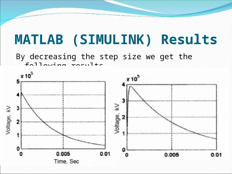
MATLAB (SIMULINK) ResultsBy decreasing the step size we get the following results

CAS based Simulator The working of the simulator can be described in the following three steps
Step 1: User draws the circuit schematics on the Spice Simulator
Step 2: Mathematical modeler translates the .net file into a differential equation
Step 3: MAXIMA (CAS) solves the equation to give generalized results

CAS based SimulatorStep 1:Draw the schematic circuit on the Spice simulator

CAS based SimulatorStep 2: Translate the .net file into a differential equation in the MAXIMA format

CAS based SimulatorStep 3: MAXIMA gives the following results that are very close to the actual values

Comparison Graphical results obtained using three different techniques show that
Simulink graphical solution has large deviations from the values obtained by pen-and-pencil proof method which is due to large step size
Decreasing the step size increases the solution time
Results obtained using the proposed technique are more accurate and the difference in values is less than or equal to ±0.5

ConclusionThe analysis results of the CAS based proposed technique are more accurate then existing alternatives.
CAS provides the general solution Larger circuits can be handled easily
CAS also provides the esteemed components value

Future WorkAny kind of Lower order linear AMS circuit can be solved using the proposed technique
Can be extended to solve higher order no-linear circuits
Can be extended to solve non-linear circuits

THANK YOUANY QUESTIONS ?