PERFORMANCE AND HANDOFF EVALUATION OF HETEROGENEOUS WIRELESS NETWORKS (HWNS) USING OPNET SIMULATOR
Upload
khangminh22Category
view
0download
0
Towards Collaboration in HeterogeneousWireless Networks
vorgelegt vonM. Sc.
Piotr Gawłowicz
an der Fakultät IV – Elektrotechnik und Informatikder Technischen Universität Berlin
zur Erlangung des akademischen Grades
Doktor der Ingenieurwissenschaften– Dr.-Ing. –
genehmigte Dissertation
Promotionsausschuss:Vorsitzender: Prof. Dr.-Ing. habil. Falko Dressler
Gutachter: Prof. Dr.-Ing. Adam WoliszGutachter: Prof. Edward W. KnightlyGutachter: Prof. Mahesh K. MarinaGutachter: Prof. Dr.-Ing. Matthias Hollick
Tag der wissenschaftlichen Aussprache: 11. Juni 2021
Berlin 2021

Piotr Gawłowicz, Towards Collaboration in Heterogeneous Wireless Net-works, Ph.D. Thesis (Dissertation), Technische Universität Berlin, 2021.
Telekommunikationsnetze (TKN)Fakultät IV – Elektrotechnik und InformatikTechnische Universität BerlinJahr der Veröffentlichung: 2021
Tag der mündlichen Prüfung: June 11, 2021
Veröffentlicht unter CC BY-NC-ND 4.0 International(Namensnennung – Nicht kommerziell – Keine Bearbeitung)https://creativecommons.org/licenses/by-nc-nd/4.0/deed.de
Licensed under CC BY-NC-ND 4.0 International(Attribution – Non-Commercial – No Derivatives)https://creativecommons.org/licenses/by-nc-nd/4.0/deed.en

To Olga and Haniawith all my love!


A B S T R A C T
The wireless spectrum is getting crowded with heterogeneous tech-nologies that are designed to satisfy various requirements of existingand emerging applications. Unfortunately, due to diverse operationprinciples, the channel access coordination methods that work wellin homogeneous networks are not applicable or perform poorly inheterogeneous environments. Hence, coexisting networks suffer fromfrequent collisions and significant performance degradation. Further-more, even homogeneous wireless networks operate independentlyand are adversaries to each other, i.e., they compete for limited radioresources.
This dissertation aims to improve wireless coexistence by enablingcollaboration between networks that are heterogeneous concerningtechnology and ownership. To this end, the key challenges and oppor-tunities of collaboration are considered in three main parts.
First, we address the issue of information exchange that is needed forcollaboration but missing among heterogeneous technologies due totheir incompatible physical layers. We describe two cross-technologycommunication (CTC) schemes. LtFi enables direct over-the-air datatransmission from LTE-U to WiFi, while NOTCH is a generic CTCframework that can be parametrized for any pair of wireless technolo-gies. As a proof of concept, we use NOTCH to enable bidirectionalCTC between LTE-U/LAA and WiFi.
Second, having the possibility of communication, we build a com-mon control plane and create two collaboration schemes. In XZero,an unlicensed LTE base station uses its beamforming capabilities toreduce interference at neighboring WiFi nodes. To this end, the nodescollaboratively perform the null-beam search. NxWLAN enables col-laboration among separately owned WiFi networks. Specifically, itenables secure infrastructure sharing and cross-network traffic deliv-ery to form a composite network and serve wireless clients from theaccess point providing the best connectivity.
Finally, to move the boundaries of wireless communication, we needto make networks to identify collaboration opportunities and au-tonomously optimize their parameters. Motivated by recent advancesin robotics, we believe that also wireless networks can learn to collabo-rate from interactions with each other and an environment. Therefore,we build ns3-gym, the framework for learning-based approaches thatcan be used in a large scope of networking research problems. Then,using ns3-gym, we implement an online learning algorithm for thedistributed optimization of channel access probabilities in coexistingWiFi networks.
v


Z U S A M M E N FA S S U N G
Das verfügbare Spektrum für drahtlose Kommunikation füllt sichmehr und mehr mit heterogenen Technologien, welche jeweils fürunterschiedlicher Anforderungen bestehender oder aufkommenderAnwendungen entworfen wurden. Unglücklicherweise sind die ver-schiedenen Kanalzugriffsverfahren, die in homogenen Netzwerkengut funktionieren, aufgrund ihrer unterschiedlichen Funktionswei-sen in heterogenen Umgebungen zueinander nicht kompatibel odersie beeinträchtigen die Leistung des gesamten Netzwerks sehr stark.Heterogene Netzwerke leiden unter häufigen Kollisionen und schlech-ter Gesamtleistung. Zudem operieren selbst homogene Netzwerkeunabhängig voneinander und stehen im Wettbewerb um knappe Res-sourcen im Spektrum.
Ziel dieser Dissertation ist es, die Koexistenz in Drahtlosnetzwerken zuverbessern, indem in sowohl in der Technologie als auch in der Verwal-tung heterogenen Netzwerken eine Zusammenarbeit ermöglicht wird.Die zentralen Herausforderungen werden in drei Themenbereichenbetrachtet.
Zunächst muss das Problem des Informationsaustausches adressiertwerden, welcher in heterogenen Netzwerken fehlt, aufgrund der in-kompatiblen Physikalischen Schichten. Dieser ist aber dennoch zentralist für eine effektive Kollaboration. Dafür werden zwei sog. “Cross-Technology Communication” (CTC) Mechanismen beschrieben. LtFiermöglicht die direkte Datenübertragung zwischen LTE-U und Wi-Fi. NOTCH hingegen ist ein generisches CTC-System, das beliebigfür ein gegebenes Paar von Drahtlostechnologien parametrisiert wer-den kann. Beispielhaft wird hier NOTCH benutzt um bi-direktionaleKommunikation zwischen LTE-U/LAA und WiFi zu ermöglichen.
Aufbauend auf der Möglichkeit der Kommunikation wird eine ge-meinsame Steuerebene benötigt, wofür hier zwei Kollaborationsme-chanismen entwickelt werden. In XZero wird Fähigkeit des sog. Be-amformings bei einer LTE-Basisstation genutzt, um die Interferenz beibenachbarten WiFi-Knoten zu reduzieren. Um dies zu erreichen führenalle Knoten kollaborativ eine Suche nach der optimalen Beamkonfi-guration aus. NxWLAN ermöglicht eine Zusammenarbeit zwischenseparat verwalteten WiFi-Netzwerken. Hierbei wird eine gemeinsameund sichere Infrastruktur aufgebaut, auf deren Basis Datenverkehrzwischen den Netzwerken ausgetauscht werden kann. Somit wird eingrößerer Netzwerkverbund gebildet, welcher die WLAN-Stationenjeweils von dem Access Point mit der besten Konnektivität bedient.
Abschließend wird die Möglichkeit betrachtet, dass Netzwerke eigen-ständig Gelegenheit für Kollaboration erkennen und autonom ihre Pa-
vii

rametrisierung optimieren. Die kürzlichen Fortschritte in der Robotikgeben Anlass zu der Überzeugung, dass Netzwerke Zusammenarbeitanhand ihrer Interaktion untereinander und mit ihrer Umgebung ler-nen können. Zu diesem Zweck wurde ns3-gym gebaut — ein Systemfür maschinelles Lernen im Kontext der Forschung an Telekommunika-tionsnetzwerken. Mittels ns3-gym wird ein Online-Machine-Learning-Algorithmus zur verteilten Optimierung der Kanalzugriffswahrschein-lichkeit von benachbarten WiFi-Netzwerken vorgestellt.
viii

A C K N O W L E D G M E N T S
This thesis would not have been possible without the help of manypeople.
First of all, I would like to sincerely thank my supervisor Prof.Adam Wolisz for providing a working environment that encouragedcreativity, for giving me the freedom to choose interesting researchtopics, and for advising me during the work that resulted in thisdissertation. I am also immensely thankful to Dr. Anatolij Zubow formany years of fruitful cooperation, some really nice publications andlong hours spent discussing (not only) research-related topics. I amalso especially grateful to Prof. Jean Walrand for numerous discussionsand productive collaborations.
I am grateful to Prof. Edward W. Knightly, Prof. Mahesh K. Marinaand Prof. Matthias Hollick for serving as referees of this dissertationand for their insightful suggestions and feedback. Moreover, I wouldlike to thank Prof. Falko Dressler for serving as the chairman of thedissertation committee.
My days at TU Berlin would certainly not have been the samewithout the kind words of support from my colleagues. I would liketo take this opportunity to thank them. I refrain from naming thegroup members, being afraid that I will be embarrassed by forgettingto mention every single one of them.
I would like to show my greatest thanks to my family for theirunconditional love, trust, encouragement and unwavering support.Finally, I wish to thank my wife, Olga, and daughter, Hanna, whoprovide a very special spark in my life. Without that spark and theirtremendous love, this work would not be possible. I am very blessedto have all of you in my life.
Throughout this thesis, I explicitly use the personal pronoun “we”instead of “I” in this thesis in order to acknowledge all the peoplethat I collaborated with and everybody who made my PhD journeyan enjoyable one.
ix


C O N T E N T S
1 introduction 1
1.1 Motivation . . . . . . . . . . . . . . . . . . . . . . . . . . 2
1.2 Challenges . . . . . . . . . . . . . . . . . . . . . . . . . . 3
1.3 Research Contributions . . . . . . . . . . . . . . . . . . . 4
1.4 Dissertation Outline . . . . . . . . . . . . . . . . . . . . 7
1.5 Relevant Publications . . . . . . . . . . . . . . . . . . . . 7
2 background and related work 9
2.1 Heterogeneous Wireless Technologies . . . . . . . . . . 9
2.1.1 OFDM Primer . . . . . . . . . . . . . . . . . . . . 11
2.1.2 WiFi . . . . . . . . . . . . . . . . . . . . . . . . . 11
2.1.3 Unlicensed LTE . . . . . . . . . . . . . . . . . . . 15
2.1.4 Comparison of WiFi and LTE . . . . . . . . . . . 17
2.1.5 Coexistence of WiFi and Unlicensed LTE . . . . 17
2.2 Coexistence . . . . . . . . . . . . . . . . . . . . . . . . . 18
2.2.1 Co-Channel Interference . . . . . . . . . . . . . . 18
2.2.2 Radio Resource Management . . . . . . . . . . . 19
2.2.3 Coexistence in Unlicensed Bands . . . . . . . . . 19
2.2.4 Interference Avoidance . . . . . . . . . . . . . . . 20
2.2.5 Interference Cancellation . . . . . . . . . . . . . 21
2.2.6 Interference Nulling . . . . . . . . . . . . . . . . 22
2.3 Collaboration in Wireless Networks . . . . . . . . . . . 23
2.3.1 Coordination, Cooperation and Collaboration . 23
2.3.2 Existing Collaboration Techniques . . . . . . . . 24
2.3.3 Collaboration Frameworks . . . . . . . . . . . . 27
2.4 Cross-Technology Communication . . . . . . . . . . . . 28
2.4.1 Energy Modulation-based CTC . . . . . . . . . . 29
2.4.2 Signal-Level CTC . . . . . . . . . . . . . . . . . . 33
2.4.3 CTC as Enabler for Collaboration . . . . . . . . 36
2.5 Learning-based Approaches in Wireless Communication 37
2.5.1 Stochastic Convex Optimization . . . . . . . . . 37
2.5.2 Reinforcement Learning . . . . . . . . . . . . . . 38
2.5.3 Software Toolkits for Learning-based Approaches 39
2.5.4 Learning to Collaborate . . . . . . . . . . . . . . 40
2.5.5 Learning in Wireless Networks . . . . . . . . . . 41
2.5.6 ns-3 Network Simulator . . . . . . . . . . . . . . 42
i cross-technology communication
3 cross-technology communication for lte-u and
wifi 45
3.1 Introduction . . . . . . . . . . . . . . . . . . . . . . . . . 45
3.2 System Design . . . . . . . . . . . . . . . . . . . . . . . . 46
3.2.1 Architecture Overview . . . . . . . . . . . . . . . 46
xi

xii contents
3.2.2 Data Modulation . . . . . . . . . . . . . . . . . . 48
3.2.3 Frame Synchronization & Demodulation . . . . 48
3.2.4 Load-Aware Adaptive Coding Scheme . . . . . 49
3.3 Transmission Rate Analysis . . . . . . . . . . . . . . . . 51
3.4 Prototype Implementation . . . . . . . . . . . . . . . . . 52
3.4.1 LtFi Transmitter . . . . . . . . . . . . . . . . . . . 52
3.4.2 LtFi Receiver . . . . . . . . . . . . . . . . . . . . 53
3.5 Experimental Evaluation . . . . . . . . . . . . . . . . . . 53
3.6 Multi-Cell Operation . . . . . . . . . . . . . . . . . . . . 56
3.6.1 Cross-technology Neighbor Identification . . . . 57
3.6.2 Estimating LTE-U BSs in Proximity . . . . . . . 59
3.6.3 System-level Simulations . . . . . . . . . . . . . 60
3.7 Summary . . . . . . . . . . . . . . . . . . . . . . . . . . . 62
4 generic cross-technology communication scheme 63
4.1 Introduction . . . . . . . . . . . . . . . . . . . . . . . . . 63
4.2 Exploiting Cross-observability . . . . . . . . . . . . . . 65
4.2.1 Cross-observable Power Modulation . . . . . . . 65
4.2.2 Punched Cards – the Data-bearing Power Patterns 67
4.2.3 Handling CTC Inter Symbol Interference . . . . 68
4.3 System Design . . . . . . . . . . . . . . . . . . . . . . . . 68
4.3.1 Architecture Overview . . . . . . . . . . . . . . . 68
4.3.2 Synchronization & Frame Detection . . . . . . . 69
4.3.3 Channel Estimation & Demodulation . . . . . . 70
4.3.4 Channel Access & Framing . . . . . . . . . . . . 70
4.3.5 Broadcast Cross-technology Channel . . . . . . 71
4.3.6 Bootstrapping . . . . . . . . . . . . . . . . . . . . 71
4.4 Punched Cards for WiFi and LTE* CTC . . . . . . . . . 72
4.4.1 NOTCH Punch Card Design . . . . . . . . . . . 72
4.4.2 Creating CTC Punched Cards in LTE* . . . . . . 73
4.4.3 Creating CTC Punched Cards in WiFi . . . . . . 73
4.5 Prototype Implementation . . . . . . . . . . . . . . . . . 78
4.5.1 LTE-U/LAA Side . . . . . . . . . . . . . . . . . . 78
4.5.2 WiFi Side . . . . . . . . . . . . . . . . . . . . . . . 79
4.6 Performance Evaluation . . . . . . . . . . . . . . . . . . 81
4.6.1 Punched Cards over the Air . . . . . . . . . . . . 81
4.6.2 Frame Error Rate . . . . . . . . . . . . . . . . . . 81
4.6.3 Periodic CTC-Slot Correction . . . . . . . . . . . 82
4.6.4 Impact on In-technology Transmissions . . . . . 83
4.6.5 Robustness to Interference . . . . . . . . . . . . . 85
4.6.6 Increasing CTC Reliability . . . . . . . . . . . . . 86
4.7 Summary . . . . . . . . . . . . . . . . . . . . . . . . . . . 87
ii cross-technology and cross-network collabo-ration
5 cross-technology interference-nulling 91
5.1 Introduction . . . . . . . . . . . . . . . . . . . . . . . . . 91

contents xiii
5.2 System Model . . . . . . . . . . . . . . . . . . . . . . . . 92
5.3 CTC as Collaboration Enabler . . . . . . . . . . . . . . . 93
5.3.1 Cross-Technology Control Channels . . . . . . . 93
5.3.2 Cross-Technology Channel Measurement . . . . 95
5.4 Collaborative Null-beam Search . . . . . . . . . . . . . 96
5.4.1 General Idea . . . . . . . . . . . . . . . . . . . . . 96
5.4.2 Signal Precoding Vectors . . . . . . . . . . . . . 97
5.4.3 Power Correction . . . . . . . . . . . . . . . . . . 97
5.4.4 Linear Null-beam Search . . . . . . . . . . . . . 99
5.4.5 Tree-based Null-beam Search . . . . . . . . . . . 99
5.4.6 Null-beam Search for Multiple Stations . . . . . 101
5.5 Prototype Implementation . . . . . . . . . . . . . . . . . 101
5.6 Performance Evaluation . . . . . . . . . . . . . . . . . . 102
5.6.1 Over-the-cable Experiments . . . . . . . . . . . . 102
5.6.2 Over-the-air Experiments in ORBIT Testbed . . 103
5.6.3 Reconfiguration Delay . . . . . . . . . . . . . . . 105
5.7 Summary . . . . . . . . . . . . . . . . . . . . . . . . . . . 107
6 wireless infrastructure sharing in residential
area networks 109
6.1 Introduction . . . . . . . . . . . . . . . . . . . . . . . . . 109
6.2 Motivation . . . . . . . . . . . . . . . . . . . . . . . . . . 111
6.3 System Design . . . . . . . . . . . . . . . . . . . . . . . . 112
6.3.1 Requirements . . . . . . . . . . . . . . . . . . . . 112
6.3.2 Architecture Overview . . . . . . . . . . . . . . . 112
6.3.3 NxWLAN Setup Procedure . . . . . . . . . . . . 113
6.3.4 STA Association Procedure . . . . . . . . . . . . 114
6.3.5 STA Steering . . . . . . . . . . . . . . . . . . . . . 115
6.3.6 Normal Mode of Operation . . . . . . . . . . . . 118
6.4 Prototype Implementation . . . . . . . . . . . . . . . . . 119
6.4.1 Discovery and Communication Module . . . . . 119
6.4.2 RAP, VAP and WTP . . . . . . . . . . . . . . . . 120
6.4.3 802.11 Frames Tunneling . . . . . . . . . . . . . 121
6.4.4 Probe Response TX Power Programming . . . . 121
6.4.5 Rate Adaptation . . . . . . . . . . . . . . . . . . 121
6.5 Evaluation . . . . . . . . . . . . . . . . . . . . . . . . . . 121
6.5.1 End-to-end Parameter Selection . . . . . . . . . 122
6.5.2 Testbed Results . . . . . . . . . . . . . . . . . . . 123
6.5.3 Simulation Results . . . . . . . . . . . . . . . . . 125
6.6 Summary . . . . . . . . . . . . . . . . . . . . . . . . . . . 128
iii learning to collaborate
7 framework for machine learning in networking
research 131
7.1 Introduction . . . . . . . . . . . . . . . . . . . . . . . . . 131
7.2 Motivation . . . . . . . . . . . . . . . . . . . . . . . . . . 132
7.3 Framework Architecture . . . . . . . . . . . . . . . . . . 132

xiv contents
7.3.1 ns-3 Network Simulator . . . . . . . . . . . . . . 133
7.3.2 OpenAI Gym . . . . . . . . . . . . . . . . . . . . 134
7.3.3 ns3-gym Middleware . . . . . . . . . . . . . . . . 134
7.4 Implementation . . . . . . . . . . . . . . . . . . . . . . . 135
7.4.1 Environment Gateway . . . . . . . . . . . . . . . 135
7.4.2 Environment Proxy . . . . . . . . . . . . . . . . . 138
7.4.3 Discussion . . . . . . . . . . . . . . . . . . . . . . 139
7.5 Environments . . . . . . . . . . . . . . . . . . . . . . . . 140
7.5.1 Typical Workflow . . . . . . . . . . . . . . . . . . 140
7.5.2 Example Environments . . . . . . . . . . . . . . 140
7.5.3 Multi-Agent Environments . . . . . . . . . . . . 141
7.5.4 Emulation Mode . . . . . . . . . . . . . . . . . . 141
7.6 Case-Study Examples . . . . . . . . . . . . . . . . . . . . 141
7.6.1 Cognitive Radio – Wideband Sensing . . . . . . 142
7.6.2 Cognitive Radio – Narrowband Sensing . . . . . 143
7.7 Summary . . . . . . . . . . . . . . . . . . . . . . . . . . . 144
8 distributed learning in wifi 145
8.1 Introduction . . . . . . . . . . . . . . . . . . . . . . . . . 145
8.2 Optimization of WiFi throughput . . . . . . . . . . . . . 146
8.2.1 Analytical Model of Contention-based MediumAccess . . . . . . . . . . . . . . . . . . . . . . . . 146
8.2.2 Proportional-fair Allocation . . . . . . . . . . . . 147
8.3 Distributed Contention Window Learning . . . . . . . . 148
8.3.1 Primer on Distributed Convex Optimization . . 149
8.3.2 Practical Issues . . . . . . . . . . . . . . . . . . . 149
8.3.3 Proposed Approach . . . . . . . . . . . . . . . . 150
8.3.4 Impact of Diverse Coordination Levels . . . . . 151
8.4 Performance Evaluation . . . . . . . . . . . . . . . . . . 152
8.4.1 Selection of Measurement Slot Duration . . . . 152
8.4.2 Homogeneous Traffic . . . . . . . . . . . . . . . 153
8.4.3 Heterogeneous Traffic . . . . . . . . . . . . . . . 154
8.4.4 Dynamic Scenario . . . . . . . . . . . . . . . . . 156
8.4.5 Unsaturated traffic . . . . . . . . . . . . . . . . . 158
8.4.6 Flow-In-the-Middle Topology . . . . . . . . . . . 158
8.5 Summary . . . . . . . . . . . . . . . . . . . . . . . . . . . 160
9 conclusions and future work 163
author’s publications 167
bibliography 173

L I S T O F F I G U R E S
Figure 2.1 The basic concept of the energy modulation-based CTC schemes. . . . . . . . . . . . . . . . 30
Figure 2.2 Reinforcement Learning. . . . . . . . . . . . . . 39
Figure 3.1 Integration of LtFi-Air-Interface into LTE-U eNBand WiFi. . . . . . . . . . . . . . . . . . . . . . . 47
Figure 3.2 Example of CTC data modulation at LTE-U side. 48
Figure 3.3 Visualization of an example WiFi MAC statesdistribution. . . . . . . . . . . . . . . . . . . . . 49
Figure 3.4 Example of a received signal and the demodu-lation at WiFi side. . . . . . . . . . . . . . . . . 49
Figure 3.5 Analytical results of the LtFi data rate. . . . . . 52
Figure 3.6 Experiment setup – LTE-U BS (left) with co-located two WiFi BSSs (right). . . . . . . . . . . 53
Figure 3.7 LtFi demodulator performance – Frame ErrorRate (FER) vs. LTE-U RX power with defaultED threshold. . . . . . . . . . . . . . . . . . . . 55
Figure 3.8 LtFi demodulator performance – Symbol ErrorRate (SER) vs. LTE-U RX power with defaultED threshold. . . . . . . . . . . . . . . . . . . . 55
Figure 3.9 LtFi demodulator performance – Frame ErrorRate (FER) vs. LTE-U RX power using differentED thresholds. . . . . . . . . . . . . . . . . . . . 55
Figure 3.10 Operation of LtFi in multi-cell environment. . 56
Figure 3.11 Overview of the proposed scheme allowing LtFifor operation in a multi-cell environment. . . . 58
Figure 3.12 Structure of the LtFi neighbor discovery frame. 59
Figure 3.13 Performance of LtFi in a multi-cell scenario. . 62
Figure 4.1 NOTCH: Creation of CTC punched cards ontop of OFDM resources. . . . . . . . . . . . . . 64
Figure 4.2 Cross-observability of the OFDM signal. . . . . 66
Figure 4.3 CTC power pattern encoding schemes. . . . . . 67
Figure 4.4 OFDM symbol grouping strategies. . . . . . . . 68
Figure 4.5 The conceptual architecture of NOTCH. . . . . 69
Figure 4.6 NOTCH’s preamble detection mechanism. . . 70
Figure 4.7 NOTCH WiFi-based transmitter. . . . . . . . . 74
Figure 4.8 64-QAM constellation diagram. . . . . . . . . . 74
Figure 4.9 Internal structure of NOTCH WiFi-based trans-mitter. . . . . . . . . . . . . . . . . . . . . . . . . 75
Figure 4.10 Platforms used in LTE*-WiFi NOTCH prototype. 79
Figure 4.11 Practical limitations of the spectrum scanningprovided in AR928x WiFi chip. . . . . . . . . . 80
xv

xvi list of figures
Figure 4.12 Spectrograms of punched cards: LTE*→WiFiand WiFi→LTE*. . . . . . . . . . . . . . . . . . . 81
Figure 4.13 Impact of SNR on LTE*→WiFi FER. . . . . . . 82
Figure 4.14 Impact of SNR on WiFi→LTE* FER. . . . . . . 82
Figure 4.15 Impact of periodic CTC-slot correction on CTCFER. . . . . . . . . . . . . . . . . . . . . . . . . . 83
Figure 4.16 CTC impact on legacy WiFi transmissions. . . 84
Figure 4.17 CTC FER for various number of nulled LTE SCs. 84
Figure 4.18 Impact of modulated LTE RBs TX power onCTC FER. . . . . . . . . . . . . . . . . . . . . . . 84
Figure 4.19 CTC FER under WiFi background traffic. . . . 85
Figure 4.20 Impact of CTC-symbol duration on FER. . . . 86
Figure 4.21 Impact of repetitive transmission on FER. . . . 86
Figure 5.1 System model: co-located LTE* and WiFi cells. 93
Figure 5.2 Overview of the Collaboration Architecture. . 94
Figure 5.3 Overview of the null-beam search procedure inXZero. . . . . . . . . . . . . . . . . . . . . . . . . 98
Figure 5.4 Illustrative example of the Tree-based Null-Beam search algorithm. . . . . . . . . . . . . . . 100
Figure 5.5 Example of the null-beam search for multiplenodes. . . . . . . . . . . . . . . . . . . . . . . . . 101
Figure 5.6 Over-the-cable experiment: setup and results . 103
Figure 5.7 Example receive power on four antennas, with-out and with TX power correction. . . . . . . . 104
Figure 5.8 Overview of nodes used in ORBIT testbed. . . 105
Figure 5.9 INR reduction after nulling for the tree-basedand linear null-beam search. . . . . . . . . . . . 105
Figure 5.10 Comparison of INR reduction without and withthe power correction. . . . . . . . . . . . . . . . 106
Figure 6.1 Operation of classical WLANs and NxWLAN. 110
Figure 6.2 Architecture of NxWLAN system. . . . . . . . 113
Figure 6.3 EAP Neighbor Discovery Procedure and Setupof WTP and VAP. . . . . . . . . . . . . . . . . . 114
Figure 6.4 Client association procedure in NxWLAN. . . 115
Figure 6.5 Encoding of EAP’s willingness to serve a clientin the transmit power of Probe Response packet. 117
Figure 6.6 Illustrative example of client steering in NxWLAN.117
Figure 6.7 NxWLAN implementation details . . . . . . . 120
Figure 6.8 Experiment setup: two adjacent residential apart-ments each with a single EAP. . . . . . . . . . . 124
Figure 6.9 Experimental results of NxWLAN performancein a scenario with no background traffic. . . . 125
Figure 6.10 Experimental results of NxWLAN performancein a scenario with the congested home EAP. . . 126
Figure 6.11 Simulation results of NxWLAN performance ina scenario with no background traffic. . . . . . 127

list of figures xvii
Figure 6.12 Simulation results of NxWLAN performance ina scenario with the congested home EAP. . . . 127
Figure 7.1 Architecture of ns3-gym framework. . . . . . . 133
Figure 7.2 Implementation of the Gym::make() function. . 139
Figure 7.3 Implementation of the Gym::step(action) func-tion. . . . . . . . . . . . . . . . . . . . . . . . . . 139
Figure 7.4 Channel access pattern of periodic interferer. . 142
Figure 7.5 Learning performance of RL-based CognitiveRadio transmitter in the case of wideband sensing.143
Figure 7.6 Narrow-band observations of cognitive radiotransmitter. . . . . . . . . . . . . . . . . . . . . . 143
Figure 7.7 Learning performance of RL-based CognitiveRadio transmitter in the case of narrowbandsensing. . . . . . . . . . . . . . . . . . . . . . . . 144
Figure 8.1 Interaction between distributed agents and theenvironment. . . . . . . . . . . . . . . . . . . . . 149
Figure 8.2 Convergence of individual CW under variousmeasurement slot duration τ ∈ {25, 50, 100, 200}ms.153
Figure 8.3 Convergence of the proposed algorithm withtwo transmitting nodes under various coordi-nation. . . . . . . . . . . . . . . . . . . . . . . . 154
Figure 8.4 Convergence of the proposed algorithm withtwo transmitting nodes and η ∈ {0.05, 0.1, 0.3}. 155
Figure 8.5 Convergence of the proposed algorithm withten transmitting nodes under various coordina-tion. . . . . . . . . . . . . . . . . . . . . . . . . . 155
Figure 8.6 Convergence of the proposed algorithm withten transmitting nodes and η ∈ {0.05, 0.1, 0.3}. . 156
Figure 8.7 Air-time allocation, individual throughput andpacket rate in the case of heterogeneous traffic. 156
Figure 8.8 Air-time allocation, individual throughput andpacket rate in the case of heterogeneous traffic. 157
Figure 8.9 Air-time allocation and individual throughputin dynamic scenario. . . . . . . . . . . . . . . . 157
Figure 8.10 Individual contention window and packet ratein unsaturated scenario. . . . . . . . . . . . . . 158
Figure 8.11 Flow-In-the-Middle (FIM) Topology. . . . . . . 159
Figure 8.12 Individual contention window and air-time al-location in FIM topology. . . . . . . . . . . . . . 160
Figure 8.13 Air-time allocation attained by 802.11 WiFi andusing the proposed learning-based approach inthe FIM topology. . . . . . . . . . . . . . . . . . 160

L I S T O F TA B L E S
Table 2.1 Comparison of the energy modulation-basedCTC schemes. . . . . . . . . . . . . . . . . . . . 32
Table 2.2 Comparison of the signal-level CTC schemes. . 35
Table 3.1 Available LtFi Symbol Lengths. . . . . . . . . . 51
Table 3.2 Simulation parameters used during the evalua-tion of LtFi multi-cell. . . . . . . . . . . . . . . . 61
Table 4.1 CORB Parameters for CTC between WiFi (802.11n)and LTE. . . . . . . . . . . . . . . . . . . . . . . 73
Table 4.2 64-QAM Symbols with the Smallest Amplitude. 76
Table 4.3 WiFi Convolutional Encoder State Groups. . . 76
Table 4.4 Examples of NOTCH encoder operation. . . . 77
L I S T I N G S
Listing 7.1 ns3-gym C++ interface. . . . . . . . . . . . . . . 135
Listing 7.2 Example definition of the GetObservationSpacefunction. . . . . . . . . . . . . . . . . . . . . . . 136
Listing 7.3 Example definition of the GetObservation func-tion. . . . . . . . . . . . . . . . . . . . . . . . . . 137
Listing 7.4 Example definition of the ExecuteActions func-tion. . . . . . . . . . . . . . . . . . . . . . . . . . 137
Listing 7.5 Example Python script showing interaction be-tween an agent and ns-3 environment. . . . . . 138
xviii

A C R O N Y M S
3GPP 3rd Generation Partnership Project
ACK acknowledgment
AP access point
API application programming interface
AWGN Additive White Gaussian Noise
BEB binary exponential back-off
BER Bit Error Rate
BS base station
BSS basic service set
CC cross-correlation
CC Component Carrier
CCI Co-Channel Interference
CCS cross-carrier scheduling
CDMA Code Division Multiple Access
CFP contention-free period
COMP Coordinated Multi-Point Transmission
CORB Cross-Observable Resource Block
COTS Commodity-off-the-Shelf
CP Cyclic Prefix
CP contention period
CS carrier sensing
CSAT Carrier Sense Adaptive Transmission
CSI Channel State Information
CSMA/CA Carrier Sense Multiple Access with Collision Avoid-ance
CT-CCI Cross Technology Co-Channel Interference
CTC Cross-Technology Communication
CTI Cross-Technology Interference
CTIN cross-technology interference nulling
CTS Clear-to-Send
CW contention window
xix

xx Acronyms
DCF Distributed Coordination Function
DL downlink
ED energy detection
eNB Evolved Node B
FCC Federal Communications Commission
FDMA Frequency Division Multiple Access
FER Frame Error Rate
FFT Fast Fourier Transform
FRR Frame Reception Rate
HCCA Hybrid Controlled Channel Access
HT Hidden Terminal
IC interference cancellation
INR Interference-to-Noise Ratio
IoT Internet of Things
ISI inter-symbol interference
ISM Industrial, Scientific and Medical
ISP Internet Service Provider
LBT Listen-Before Talk
LTE Long-Term Evolution
LTE-LAA LTE Licensed-Assisted Access
LTE-U LTE-Unlicensed
LWA LTE-WLAN Aggregation
MAC Medium Access Control
MCS Modulation and Coding Scheme
MIMO Multiple-Input Multiple-Output
MRC Maximal-ratio combining
NIC network interface card
OFDM Orthogonal Frequency-Division Multiplexing
OFDMA Orthogonal Frequency-Division Multiple Access

Acronyms xxi
PAN Personal Area Network
PCF Point Coordination Function
PDCCH Physical Downlink Control CHannel
PDSCH Physical Downlink Shared CHannel
PHY physical
PRACH Physical Random Access Channel
PSD power spectral density
PSS Primary Synchronization Signal
QAM Quadrature Amplitude Modulation
QoS Quality of Service
RB Resource Block
RBB Radio Resource Block
RF radio frequency
RL Reinforcement Learning
RRM Radio Resource Management
RS Reference Signal
RSS received signal strength
RTS Request-to-Send
RTT Round Trip Time
RU Resource Unit
RX receiver
SDMA Space Division Multiple Access
SDN Software-Defined Networking
SDR Software-Defined Ratio
SER Symbol Error Rate
SIC Successive Interference Cancellation
SINR Signal-to-Interference-plus-Noise Ratio
SNR Signal-to-Noise Ratio
SoI signal of interest
SSS Secondary Synchronization Signal
STA station
TCP Transmission Control Protocol
TDMA Time Division Multiple Access

xxii Acronyms
TX transmitter
TXOP transmit opportunity
U-NII Unlicensed National Information Infrastructure
UE User Equipment
UL uplink
ULA Uniform Linear Array
WLAN Wireless Local Area Network
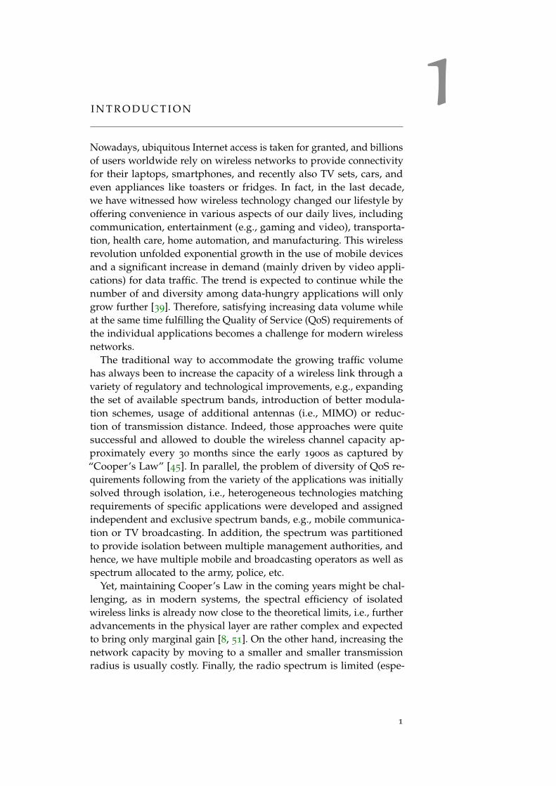
1I N T R O D U C T I O N
Nowadays, ubiquitous Internet access is taken for granted, and billionsof users worldwide rely on wireless networks to provide connectivityfor their laptops, smartphones, and recently also TV sets, cars, andeven appliances like toasters or fridges. In fact, in the last decade,we have witnessed how wireless technology changed our lifestyle byoffering convenience in various aspects of our daily lives, includingcommunication, entertainment (e.g., gaming and video), transporta-tion, health care, home automation, and manufacturing. This wirelessrevolution unfolded exponential growth in the use of mobile devicesand a significant increase in demand (mainly driven by video appli-cations) for data traffic. The trend is expected to continue while thenumber of and diversity among data-hungry applications will onlygrow further [39]. Therefore, satisfying increasing data volume whileat the same time fulfilling the Quality of Service (QoS) requirements ofthe individual applications becomes a challenge for modern wirelessnetworks.
The traditional way to accommodate the growing traffic volumehas always been to increase the capacity of a wireless link through avariety of regulatory and technological improvements, e.g., expandingthe set of available spectrum bands, introduction of better modula-tion schemes, usage of additional antennas (i.e., MIMO) or reduc-tion of transmission distance. Indeed, those approaches were quitesuccessful and allowed to double the wireless channel capacity ap-proximately every 30 months since the early 1900s as captured by“Cooper’s Law” [45]. In parallel, the problem of diversity of QoS re-quirements following from the variety of the applications was initiallysolved through isolation, i.e., heterogeneous technologies matchingrequirements of specific applications were developed and assignedindependent and exclusive spectrum bands, e.g., mobile communica-tion or TV broadcasting. In addition, the spectrum was partitionedto provide isolation between multiple management authorities, andhence, we have multiple mobile and broadcasting operators as well asspectrum allocated to the army, police, etc.
Yet, maintaining Cooper’s Law in the coming years might be chal-lenging, as in modern systems, the spectral efficiency of isolatedwireless links is already now close to the theoretical limits, i.e., furtheradvancements in the physical layer are rather complex and expectedto bring only marginal gain [8, 51]. On the other hand, increasing thenetwork capacity by moving to a smaller and smaller transmissionradius is usually costly. Finally, the radio spectrum is limited (espe-
1

2 introduction
cially in the frequency bands most attractive from the point of viewof propagation and cost of transceivers), and its scarcity problem islooming on the horizon. Therefore, there are two alternatives to ac-commodate the emerging needs, namely, mix heterogeneous traffic ina single complex technology or mix dedicated heterogeneous technolo-gies in a shared spectrum band. In fact, both approaches are followedin recent years. For example, 5G technology promises to meet therequirements of diverse traffic using a single system. Simultaneously,a set of wireless technologies (e.g., WiFi, Bluetooth, ZigBee, TSCH,LoRa, and NB-IoT) coexisting in shared unlicensed bands is beingdeveloped to satisfy various requirements regarding communicationspeed, distance, reliability, equipment cost, and energy budget, etc.
This thesis is devoted to the second of the above-listed approaches.Specifically, drawing on the experience of the crowded 2.4 GHz un-licensed Industrial, Scientific and Medical (ISM) band, it is obviousthat the naive coexistence of heterogeneities leads to mutual interfer-ence, waste of wireless resources, and thus significant performancedegradation in all networks sharing the same radio bands [62, 126]. Inother words, the coexistence of heterogeneities destroys advancementsin the area of wireless channel capacity. Therefore, the proliferationof wireless technologies makes them victims of their own success:densely deployed wireless devices tend to compete for limited radioresources and, in the end, adversely impact each other.
Fortunately, there are still gains to be obtained through the efficientspectrum (re)usage by following a two-fold approach, namely openingthe entire radio spectrum for general usage and employing coordi-nated coexistence among competing technologies. The former requiresbreaking with the tradition of static separation of wireless technolo-gies in their exclusive licensed bands via careful regulation. Note thatconservative frequency assignment often leads to low utilization insome parts of the radio spectrum and the resource shortage in otherparts. The unchaining of frequency bands obviously will result in theincreased spectrum occupancy, but at the same time, will intensify thechallenge of coexistence between heterogeneous technologies. As aremedy, recent research shows that an explicit and coordinated Ra-dio Resource Management (RRM) among co-located heterogeneousnetworks is needed to tackle inter-technology interference efficiently,ensure fair coexistence and bring performance breakthroughs in thespectrum sharing [23, 37, 78, 160, 175, 194, 198].
1.1 motivation
Although coordination seems to be simple within a single network be-longing to a given administrative management domain (e.g., throughthe introduction of a central controller), the harmonized operationof separately managed networks is neither easy nor natural. In a

1.2 challenges 3
general case, the coordination requires mutual collaboration betweendistributed actors that is especially challenging in heterogeneous en-vironments due to diverse characteristics of technologies, competinginterests of co-located networks as well as their ownership status.
Nevertheless, the collaboration is expected to enable joint optimiza-tion of the scarce spectrum resources, which is essential to meetthe individual goals of involved networks [149, 154]. This could beachieved by a plethora of approaches, including dynamic resourceallocation, interference mitigation, as well as cross-network handoverand traffic delivery (i.e., roaming). Specifically, we believe that thecollaborating networks will eventually behave like a single unit thatcan adjust its operation in response to changing wireless and trafficconditions and provide connectivity with improved QoS to any userby selecting the most suitable technology and with the best utilizationof wireless resources. It is worth noting that having understood thepotential benefits from mutual collaboration, in 2017, the US researchagency DARPA started Spectrum Collaboration Challenge [42] withthe main goal to overcome the artificial scarcity in the radio spectrum.
1.2 challenges
Enabling collaboration is a challenging task that requires a rethinkingof modern wireless networks. Here, we identify the most critical issues.
Independent Operation. Although modern wireless technologiesare equipped with more and more optimization and adaptabilityfeatures, they still operate as self-sufficient and independent islands,i.e., each network adapts its operation according to its own (possiblyselfish) policy and local knowledge of the environment. However, theindependent operation becomes inappropriate in coexistence scenariosas the state of the environment depends on the joint action of allnetworks coupled by shared wireless resources that are unaware ofeach other’s decisions.
Inappropriate Capabilities. In general, nodes of a single technologyusually employ some built-in coordination methods in their operationsuch as time-slotted operation, channel reservation (e.g., using RT-S/CTS mechanism), interference nulling, or Listen-Before Talk (LBT).However, those methods are not applicable or perform poorly in het-erogeneous environments as the different technologies with diverseoperation principles are largely oblivious to each other due to theincompatible physical layers. Take an example of already very ad-vanced technologies like WiFi and LTE, whose newest generationsprovide peak data rates in the order of Gbps. However, under coexis-tence scenarios in unlicensed bands, they still rely on rather primitivecoexistence schemes based on energy-sensing and hence suffer fromfrequent collisions and significant throughput degradation of up to90% [5, 27].

4 introduction
Ownership issues. An instance of a wireless network is currentlydeployed to provide connectivity for its legitimate users, be it mobilesubscribers in the case of cellular networks or access point (AP) ownersin the case of local area networks. Take an example of an apartmentbuilding, where tens of networks, owned by strangers, compete forchannel access. Not knowing (read: not trusting) each other, ownersapply strict policies to secure exclusive access for their wireless nodes.However, quite the contrary is true in fact: recent research [161] showsthe potential gains of access points sharing in residential environ-ments due to unsynchronized workloads and shorter communicationdistances [12, 79, 143]. This can be easily explained as a terminalcloser to an access point uses higher modulation schemes and henceless air-time, what in the end leads to the overall win-win situation.Nevertheless, infrastructure sharing is so far limited due to securityand cross-domain restrictions.
Lack of control channels. Any attempt to effectively collaborateincludes the necessity to exchange information that is, paradoxically,hard to realize between diverse communication technologies. In mostcases, researchers implicitly assume the existence of a control channelbetween heterogeneous networks. This assumption might hold in acase of unified management, where a single authority operates theentire wireless infrastructure. However, in a general coexistence sce-nario, the heterogeneities are not only unable to communicate, but,even worse, they are unaware of each other. Note that we observe sim-ilar problems in homogeneous networks that are owned by multipleoperators.
The development of new collaborating wireless technologies willtake decades, and anyway, they will have to coexist with legacy sys-tems. Therefore, a better idea is to integrate collaboration mechanismsinto already existing technologies. To this end, we need to considerthe technical cost of each proposed scheme carefully. Specifically, forany solution to be practical and to attract users and vendors, anymodification in the hardware is impossible, while the software mod-ifications should be small enough so that they are compatible withalready deployed devices.
1.3 research contributions
In this dissertation, we focus on enabling and exploiting collaborationfor wireless resource and interference management in heterogeneouswireless networks. The contributions pertain to the following areas:
1. Cross-Technology CommunicationThe information exchange facilitates an efficient collaboration amongheterogeneous networks. The heterogeneities used to be unable tocommunicate with each other. Fortunately, in recent years, direct

1.3 research contributions 5
communication between devices adhering to diverse technologieswas enabled using so-called Cross-Technology Communication (CTC).Usually, CTC schemes are designed for each pair of technologiesseparately and the proposed solutions pertain mostly to WiFi, ZigBee,and Bluetooth [28, 83, 104, 105, 124, 204].
This thesis offers two contributions to this area. LtFi is a CTCscheme that enables unidirectional transmission from an LTE-U basestation (BS) to co-located WiFi nodes that operate in overlappingunlicensed bands. It exploits the standard coexistence mechanismof subframe puncturing to encode CTC data. Specifically, a BS cre-ates a cross-technology channel by changing the relative position ofsubframe puncturing within its transmissions. The system is fullycompliant with LTE-U technology and works with commercial-off-the-shelf (COTS) WiFi hardware, which was confirmed with a prototypeimplementation. Our results show that LtFi frames can be decoded atlow received power (i.e., -92 dBm) with the data rate of 100 bps.
NOTCH is a generic framework that enables CTC unicast anda cross-technology broadcast channel for the class of OFDM-basedwireless systems. Specifically, a NOTCH transmitter modulates thepower level of the wireless resources in its OFDM grid to create thetwo-dimensional message-bearing power patterns, which can be cross-observed and decoded by a heterogeneous OFDM receiver. As a proofof concept, we have implemented an instance of NOTCH that estab-lishes bidirectional over-the-air communication between LTE-U/LAAand WiFi. The prototype uses standard-compliant features of bothtechnologies and does not require any hardware modification. Ourcomprehensive evaluation reveals that NOTCH achieves robust CTCbetween both technologies with a data rate of up to 84 kbps.
2. Cross-Technology and Cross-Network CollaborationAlthough CTC enables information exchange between heterogeneoustechnologies, the communication channel is limited in data rate, andoften its capacity is traded against the capacity of underlying wire-less systems. At the same time, most wireless networks are deployedto provide Internet access and hence are potentially connected overthe global wired network. Therefore, we use over-the-air CTC fortime-critical control communication and establish high capacity com-munication over the Internet backhaul. The original idea was proposedby Zehl et al. [198] for homogeneous WiFi networks. Here, we extend itfor the case of heterogeneous environments. Having the possibility ofinformation exchange, we have proposed two collaboration schemes.
XZero is the system that enables the cross-technology interferencenulling between LTE-U BS and WiFi nodes. Specifically, in additionto neighbor discovery and control communication, XZero exploitsthe NOTCH CTC scheme to measure Channel State Information (CSI)between heterogeneous nodes. However, as only partial CSI (i.e., ampli-tude) can be estimated, we have designed an iterative null-beam search

6 introduction
algorithm, where the WiFi node sends its feedback about the measuredinterferences to the LTE BS in order to collaboratively find proper sig-nal precoding matrix for interference nulling. Our experimental resultsreveal, on average, a reduction by 15.7 dB in interference-to-noise ratioat the nulled WiFi nodes when LTE-U BS is equipped with four anten-nas. Note that XZero enables the usage of beamforming capabilities ina heterogeneous environment.
NxWLAN is the system that enables collaboration in dense andchaotic WLAN deployments by making a secure sharing of WiFiinfrastructure (i.e., access points) owned by potentially not knowingeach other’s neighbors possible. This way, the co-located APs constructa composite network, and a wireless station (STA) might be servedby a neighbor’s AP when it provides better signal quality than theown AP. Specifically, access points collaborate by relaying frames.However, as the typical over-the-air relaying would unnecessarilyincrease channel occupancy, we have implemented relaying over thebackhaul infrastructure and leverage growing wired link capacityto save wireless resources. Our evaluation using the COTS-basedprototype shows that collaboration brings massive throughput gainsto residential area networks.
3. Learning to CollaborateAs exchange of collaboration messages among wireless nodes mightbe costly in terms of used radio resources or even not available, inthe last part of the thesis, we focus on distributed learning-basedapproaches. Specifically, being motivated by recent advancementsin multi-agent learning algorithms successfully applied in robotics,we argue that wireless nodes can also learn collaborative behaviorssimply by interacting and observing others’ actions. Here, we study aclass of convex problems and show that the lack of direct informationexchange can be partially compensated by observation and learning.
In order to enable the studying of learning-based approaches innetworking research, we have built the ns3-gym framework. It is basedon two well-known and acknowledged by research community toolk-its, namely, ns-3 [214] and OpenAI Gym [20]. In particular, ns3-gymsimplifies representing an ns-3 simulation as an environment in theGym framework and exposing state and control knobs of entities fromthe simulation for the agents’ learning purposes. The framework isgeneric and can be used for a wide range of networking problemsincluding homogeneous and heterogeneous wireless coexistence sce-narios. Furthermore, it allows implementation, training and testingcentralized (i.e., single agent-based) as well as distributed (i.e., multi-ple agent-based) learning algorithms.
Using the ns3-gym framework, we have developed an online learn-ing algorithm for the distributed optimization of random channelaccess parameters (i.e., contention window) in an environment con-sisting of overlapping but separately managed WiFi networks. Note

1.4 dissertation outline 7
that the environment is homogeneous in terms of technology, butheterogeneous in terms of ownership and management. Moreover,despite distributed WiFi nodes understand each other’s frames, thereis no communication channel between co-located networks envisioned,and hence no information exchange nor coordination is possible. Ouralgorithm is based on a distributed stochastic convex optimizationframework, where nodes estimate a value of the network utility func-tion (defined as the sum of the logarithms of individual throughputs)by observing each others’ transmissions. Using simulations, we haveshown that by following a simple two-point gradient estimation proce-dure, distributed WiFi nodes can iteratively learn optimal contentionwindow values and collaboratively maximize the network utility.
1.4 dissertation outline
The remainder of this work is organized into three parts that focus onour research contributions. In Chapter 2, we present background in-formation and summarize related work. Part I covers CTC. Chapter 3
describes how LtFi enables unidirectional CTC transmission from anLTE-U eNB towards WiFi nodes. In Chapter 4, we present our genericNOTCH framework and use it to enable bidirectional CTC betweenunlicensed LTE and WiFi. In Part II, we present our contributionsin the area of cross-network and cross-technology collaboration. Thecross-technology interference nulling scheme is proposed and investi-gated in Chapter 5. In Chapter 6, we describe our NxWLAN systemthat enables collaboration through infrastructure sharing owned bydifferent authorities in residential areas. Part III covers our ns3-gymframework for studying learning-based approaches in wireless net-works in Chapter 7. Our considerations on distributed learning ofback-off procedure parameters using stochastic convex optimizationframework are presented in Chapter 8. Finally, Chapter 9 concludesthis dissertation.
1.5 relevant publications
The research results obtained during this Ph.D. have been publishedin scientific journals and presented at international conferences. Specif-ically, the thesis is based on the technical content presented in thefollowing peer-reviewed publications:
• P. Gawłowicz, A. Zubow, A. Wolisz, Enabling Cross-technologyCommunication between LTE Unlicensed and WiFi, IEEE INFOCOM,2018 (Chapter 3 and 5)
• P. Gawłowicz, A. Zubow, Demo: Practical Cross-technology RadioResource Management between LTE-U and WiFi Networks, IEEEINFOCOM, 2018 (Chapter 3 and 5)

8 introduction
• P. Gawłowicz, A. Zubow, S. Bayhan, A. Wolisz, Punched Cardsover the Air: Cross-Technology Communication Between LTE-U/LAAand WiFi, IEEE WoWMoM 2020, Best Paper Award (Chapter 4)
• P. Gawłowicz, A. Zubow, S. Bayhan, Demo: Cross-Technology Com-munication between LTE-U/LAA and WiFi, IEEE INFOCOM, 2020,Best Demo Paper Award (Chapter 4)
• A. Zubow, P. Gawłowicz, S. Bayhan, On Practical CoexistenceGaps in Space for LTE-U/WiFi Coexistence, European Wireless, 2018
(Chapter 5)
• S. Bayhan, P. Gawłowicz, A. Zubow, A. Wolisz, Null-While-Talk:Interference Nulling for Improved Inter-Technology Coexistence inLTE-U and WiFi Networks, Pervasive and Mobile Computing,April, 2019 (Chapter 5)
• P. Gawłowicz, A. Zubow, S. Bayhan, Demo: Cross-TechnologyInterference Nulling for Improved LTE-U/WiFi Coexistence, ACMMobiSys, 2018 (Chapter 5)
• P. Gawłowicz, S. Zehl, A. Zubow, A. Wolisz, NxWLAN: TowardsTransparent and Secure Usage of Neighbors‘ Access Points in Residen-tial WLANs, IEEE WiMob, 2017 (Chapter 6)
• P. Gawłowicz, A. Zubow, ns-3 meets OpenAI Gym: The Playgroundfor Machine Learning in Networking Research, ACM MSWiM, 2019
(Chapter 7)
• P. Gawłowicz, J. Walrand, A. Wolisz, Distributed Learning forProportional-Fair Resource Allocation in Coexisting WiFi Networks,IFIP WiOpt, 2021 (to appear) (Chapter 8)

2B A C K G R O U N D A N D R E L AT E D W O R K
In this chapter, we provide essential background information on het-erogeneous wireless communication systems and present related work.We discuss the current wireless standards in Section 2.1 and their co-existence in the unlicensed bands in Section 2.2. In Section 2.3, wedescribe current trends towards enabling collaboration among hetero-geneities. Section 2.4 reviews the recent cross-technology communica-tion approaches. Finally, in Section 2.5, we summarize recent researchtrends of using learning-based techniques to optimize wireless net-work operation.
2.1 heterogeneous wireless technologies
Wireless communication is based on the artificial generation of radiowaves, a type of electromagnetic radiation (a form of energy) withinthe radio spectrum, i.e., the part of the electromagnetic spectrum withfrequencies between 30 Hz and 300 GHz.
Radio communication was born in 1895 when Marconi demon-strated the first wireless transmission over a distance of 18 milesbetween Isle of Wight and a boat in the English Channel [140]. In thebeginning, wireless technology was used for information transmission(though unidirectional) in radio and television broadcasting systemsthat became widespread throughout the world. Over the years, thetechnology advanced rapidly to enable transmissions over longer dis-tances with better quality, less power, and smaller devices. Meanwhile,radio systems that originally transmitted analog signals transformedinto digital systems carrying binary bits of data information.
The unprecedented wireless revolution started at the turn of the21st century with the development of 2G (and later 3G) cellular com-munication that was followed by a wide adaptation of cellphonesand the unexpected success of wireless computer networks (WirelessLocal Area Networks (WLANs)) based on IEEE 802.11 WiFi standard.Since then, the number of wireless technologies matching specificapplication requirements has exploded. The efforts were additionallyintensified by the emergence of Internet-of-Things (IoT) networking.
Most wireless systems operate in the radio spectrum between30 MHz and 60 GHz. The radio spectrum is a limited resource that ineach country is allocated and regulated by governmental agencies (e.g.,Federal Communications Commission (FCC) in the US). For wirelesssystems that span multiple countries, spectrum bands are allocated bythe International Telecommunications Union Radio Communications
9

10 background and related work
group (ITU-R) [71]. The spectrum is allocated in blocks (i.e., chunks)as licensed bands (which are assigned to specific operators) or unli-censed bands (which can be used by any operator subject to certainoperational requirements). The allocation decisions are static in tem-poral and spatial dimensions, i.e., they are valid for extended periods(usually decades) and large geographical regions (e.g., country-wide).The static and exclusive nature of the current spectrum governanceregime is inefficient and will have to be changed in the future toaccommodate a growing demand for wireless data transmission [15].Specifically, this spectrum management model dates back to the initialdays of wireless communications, when the technologies requiredinterference-free mediums to achieve acceptable quality, and the sim-ple separation in frequency was the easiest solution to provide it. Asa result, this artifact of outdated technologies often leads to artificialaccess limitation-based spectrum scarcity.
In this work, we focus on bands where wireless technologies areforced to coexist, and hence the unlicensed bands might be considereda testing ground for future spectrum sharing solutions. There exist anumber of unlicensed bands, e.g., the 2.4 GHz (Industrial, Scientificand Medical (ISM)), the 5 GHZ (Unlicensed National InformationInfrastructure (U-NII)) or the 60 GHz band (millimeter-wave band)that is getting more and more attention thanks to emerging WiGig(i.e., 802.11ad/ay) technology. Moreover, new bands are being releasedfor unlicensed usage. For example, very recently (i.e., in April 2020),FCC unleashed 1.2 GHz of spectrum in the 6 GHz band [54].
The unlicensed bands are battlefields for technologies like WiFi,ZigBee, Bluetooth, and unlicensed LTE as they operate on overlappingfrequencies and compete for wireless resources. Those technologiesare specialized for various applications and use-cases, hence they weredesigned with diverse channel bandwidth, channel access methods,communication speed, distance, etc. For example, WiFi and unlicensedLTE operate with wide-band channels (up to 160 MHz) and advancedmodulation schemes to provide high communication speed in theorder of a couple of Gbps in the newest generations. In contrast, Zig-Bee exhibits a low data rate of 250 kbps but is optimized in energyconsumption, which makes it a great option for the long-term deploy-ments that operate on a limited energy source, such as a coin cellbattery. Bluetooth is present in most wearable devices to form thePersonal Area Network (PAN) and allows for communication overshort distances with a data rate of up to 3 Mbps.
In this dissertation, we develop new collaboration solutions usingmainly WiFi (in particular 802.11n/ac) and unlicensed LTE technolo-gies as examples of heterogeneous wireless systems. Therefore, in thefollowing subsections, we describe details of their specifications. Westart with a description of the OFDM technique as both WiFi and LTEuse it in their physical layers.

2.1 heterogeneous wireless technologies 11
2.1.1 OFDM Primer
Orthogonal Frequency-Division Multiplexing (OFDM) divides theavailable spectrum bandwidth B into many small and partially over-lapping frequency bands called subcarriers [140]. The subcarrier fre-quencies are selected in such a way that they are orthogonal to oneanother, i.e., signals on subcarriers do not interfere. In practice, OFDMis efficiently implemented using Fast Fourier Transform (FFT) [41].In an OFDM system with FFT size N, each subcarrier has the samewidth of B/N Hz. Each subcarrier can be modulated independently(e.g., Quadrature Amplitude Modulation (QAM)). After modulation,the sender performs an inverse FFT to convert the frequency domainrepresentation into the time domain, which is sent over the air inter-face. The time needed to transmit these N samples is usually calledthe FFT period, which is equal to N/B sec. On the receiver side, theOFDM signal is converted back into the frequency domain usingFFT, and each subcarrier is demodulated. OFDM is robust in envi-ronments with strong multipath as a technique called Cyclic Prefix(CP) is used to guard against symbol misalignment. In a nutshell, anOFDM transmitter (TX) spreads its transmission on a two-dimensionalgrid, which we will refer to as OFDM time-frequency grid hereafter.Some wireless technologies like LTE or 802.11ax use OFDM to imple-ment multiplexing techniques, i.e., Orthogonal Frequency-DivisionMultiple Access (OFDMA). Specifically, they leverage the possibilityof assigning subsets of subcarriers to diverse users.
In most cases, to lower the complexity of their design, today man-ufactured OFDM systems do not allow to control the transmissionpower of each subcarrier independently. Instead, they define resourceblocks (RB) spanning over K subcarriers and L FFT periods and exposeinterfaces for controlling the TX power at the granularity of a RB. Notethat an RB might cover an entire transmission (e.g., a complete framein WiFi).
2.1.2 WiFi
IEEE 802.11 WiFi is the most popular protocol family for WLANs.According to the Cisco Visual Networking Index (VNI) (Fig. 21) [38] bythe end of 2022, more than half of the global IP traffic will be generatedby WiFi devices. Moreover, according to Upadhyay et al. [171] alreadyin 2016, nearly 74% of all households (worldwide) equipped withbroadband Internet access owned at least one WiFi access point (AP).
The first version of the standard was released in 1997 and is pe-riodically updated by the IEEE LAN/MAN Standards Committee.802.11 defines a set of Medium Access Control (MAC) and physical(PHY) layer specifications that ensure interoperability between devicesfollowing the standard. Here, we present mostly the features available

12 background and related work
in the 802.11n version of the standard, as we use it as a basis for theimplementation of our prototypes. For a detailed description of theWiFi until 802.11ac, we point to the book authored by Perahia andStacey [152]. As there are no books yet published on newer versions ofthe standard, we refer to tutorial papers authored by Khorov et al. [101]and Garcia-Rodriguez et al. [61] for an overview of the 802.11ax and802.11be amendments, respectively.
PHY-layer: The most widely used 802.11 physical layer is based onOFDM. The default channel has a bandwidth of 20 MHz, and thereare options to aggregate adjacent channels together, i.e., up to 2 and8 channels in 802.11n and 802.11ac/ax, respectively. The possibilityto aggregate up to 16 channels (i.e., 320 MHz) is expected in 802.11be(WiFi 7) [61]. The total number of OFDM subcarriers depends on theWiFi version and the number of aggregated channels. For instance, in802.11n, the 20 MHz channel consists of 64 subcarriers with 312.5 KHzspacing, however, only 56 of these 64 are used for communication,occupying the bandwidth of 17.5 MHz. The remaining eight subcar-riers (i.e., three and four guards at both bandwidth edges and oneDC (Direct Current) component in the middle) are null-subcarriersthat do not carry any signal. Moreover, four of those 56 subcarriers,so-called pilots, are used to track and correct phase impairments. Theyare loaded with pseudo-random pilot symbols, and their inviolabilityis crucial for signal demodulation. The FFT period (3.2µs) togetherwith cyclic prefix (0.8µs) constitute WiFi symbol (4µs). In 802.11ax,the subcarrier spacing was reduced to 78.125 KHz, which automati-cally results in a longer symbol duration of 12.8µs (plus cyclic prefixwith the duration of 0.8, 1.6 or 3.2µs). Up to 802.11ac, a single frametransmission carries data from/to one station (STA) using a singleModulation and Coding Scheme (MCS) for all subcarriers. The newer802.11ax version introduces OFDMA that allows grouping subcarriers(tones) into multiple Resource Units (RUs) and assigning individualRUs within a single frame transmission to different users, but stillwith a single MCS index per user. The MCS index represents themodulation type and the coding rate that is used for data transmis-sion. The set of modulations contains BPSK, QPSK, and M-QAM.Each newer version increases the order M of the QAM, i.e., 802.11nsupports 64-QAM, while 802.11ac and 802.11ax introduced 256-QAMand 1024-QAM, respectively. Moreover, 802.11be envisions usage of4096-QAM (4K-QAM) modulation. The coding rate indicates howmuch of the data stream is actually being used to transmit usable andredundant data. It is expressed as a fraction between 1/2 (the leastefficient) and 5/6 (the most efficient). Multiple-Input Multiple-Output(MIMO) operation mode has been an integral part of WiFi since 2009,when the 802.11n standard amendment was published. Most 802.11nbased cards support both spatial receive diversity (via Maximal-ratiocombining (MRC) technique) and up to 4× 4 multiplexing (via direct-

2.1 heterogeneous wireless technologies 13
mapped MIMO), allowing to transmit four independent data streamssimultaneously. Transmit diversity (i.e., beamforming) is optional in802.11n; however, it is mandatory in newer generations. MIMO dimen-sions were extended by the 802.11ac amendment to 8× 8 and will befurther extended in 802.11be to 16× 16. Moreover, 802.11n supportssingle-user MIMO (SU-MIMO), where all spatial streams are sent to asingle-user. Starting from 802.11ac, the streams can be sent to multipleusers using multi-user MIMO (MU-MIMO).
MAC-layer: WiFi transmits data as self-contained frames, which canbe independently detected and decoded thanks to the prependedpreamble and PLCP header (i.e., control data), respectively. The maxi-mal WiFi frame duration is bound (e.g., to 5.484 ms in 802.11n). Thetransmission power can be set on a per-frame basis and is the same forall subcarriers. WiFi supports two different medium access schemes,namely contention-based access using Distributed Coordination Func-tion (DCF) and contention-free access using Point Coordination Func-tion (PCF) and Hybrid Controlled Channel Access (HCCA).
Contention-based Channel Access: Following DCF, the coexistenceamong multiple WiFi is achieved by both physical carrier sensing (i.e.,WiFi STAs perform random channel access using a Listen-Before Talk(LBT) scheme) and virtual channel reservation (i.e., stations mightreserve channel air-time using Request-to-Send (RTS) and Clear-to-Send (CTS) frames). The DCF is based on the Carrier Sense MultipleAccess with Collision Avoidance (CSMA/CA) method and employsbinary exponential back-off (BEB) to control the contention window(CW). Specifically, in DCF, before a frame transmission, a WiFi stationhas to perform a random back-off procedure. To this end, it initializesits back-off counter with a random number drawn uniformly from{0, . . . ,CW− 1}, where CW is the contention window. Then, the stationobserves the wireless channel and decrements the counter wheneverthe channel is sensed idle during a DCF inter-frame space (DIFS)and freezes the back-off counter otherwise. Finally, when the back-offcounter reaches zero, the station transmits a frame. If the transmissionis successful (as indicated by the reception of an acknowledgment(ACK)), the station sets CW to the minimal value, i.e., CWmin, forthe next transmission. Otherwise, it doubles the previous contentionwindow and performs the frame retransmission. The CW is increaseduntil it reaches the maximal value defined by CWmax.Performance Anomaly: By design, DCF ensures equal long term chan-nel access probabilities to all involved stations, thus guaranteeingframe-level fairness. However, frame-fairness leads to the so-calledperformance anomaly problem when stations use different transmissionrates. Stations employ various modulation and coding schemes topreserve transmission robustness in response to the quality of theradio link they experience, and that depends on their communicationdistance, mobility, and other factors. The lower MCSs offer increased

14 background and related work
robustness against errors at the cost of a drop in data rate. Conse-quently, the WiFi stations that use lower data rates occupy the channelfor an extended air-time period that could be otherwise used moreefficiently by the faster clients. In simple terms, under the frame-levelfairness, a station with poor transmission conditions slows down fasterstations. This pathological behavior was first identified in 802.11bnetworks [88]. Then, Patras et al. [150] demonstrated that the effect isdramatically exacerbated in today’s high throughput networks (i.e.,802.11n/ac), where the data rates among stations may vary by two or-ders of magnitude, e.g., the throughput of a station that uses the datarate 780 Mbps is almost the same as that of a co-existing station thatuses the data rate 6 Mbps. The proportional-fair allocation, introducedby Kelly et al.[99], was shown to address the performance anomalyproblem appropriately[29]. By definition, it maximizes the networkutility defined as the sum of the logarithms of individual throughputssubject to the constraints that the communication conditions impose onthe individual stations. The proportional fairness in WiFi networks hasbeen extensively studied [115, 118, 119]. In [29, 120], it was formulatedas a convex optimization problem that is solved by selecting optimalcontention window values for the stations. The proposed approachesare deployed in a central node (e.g., AP or a controller node) andrequire knowledge of the average frame duration [150] or throughputof each transmitting station [55]. However, such centralized operationcannot be assumed in the case of overlapping but separately managedWiFi networks.
Contention-free Channel Access: In PCF, a central controller or PointCoordinator (PC) (typically AP) has a higher priority to access themedium to start a contention-free period and polls other stations totransmit data. HCCA is similar to the PCF, but hybrid coordinator(HC) residing in the AP may poll the station during both the con-tention period (CP) and contention-free period (CFP), which reduceschannel access latency. Moreover, a polled station is granted a transmitopportunity (TXOP) during which the station may transmit multipleframes subject to the limit on the TXOP duration. Note that in PCF, thePC polls the station for each frame individually. Although having beenstandardized already in the early version of the WiFi standard, neitherPCF nor HCCA is used in Commodity-off-the-Shelf (COTS) devicesdue to their extreme implementation complexity and some flaws in thebehavior in dense deployment [101]. However, polling-based channelaccess is revisited in 802.11ax under the name of Trigger-based Ran-dom Access. Here, a newly introduced Trigger frame is transmitted byan AP, and it contains scheduling information about subsequent ULmulti-user (MU) transmission (enabled by the usage of OFDMA). Thescheduled channel access is the default scheme in 802.11ax, however,stations still use the contention-based channel access (i.e., random ac-cess) to transmit buffer status reports when the AP has no information

2.1 heterogeneous wireless technologies 15
about pending UL traffic at a station. Note that AP usually assignssome RUs for random access.
2.1.3 Unlicensed LTE
Long-Term Evolution (LTE) standard was primarily a cellular systemoperating in licensed bands. However, as mobile operators were suffer-ing more and more from the spectrum scarcity problem faced in theirlicensed bands, they started looking into unlicensed spectrum oppor-tunities, i.e., they decided to offload part of the data traffic towardsunlicensed bands (mostly 5 GHz band).
First, the offloading was performed over WiFi using the LTE-WLANAggregation (LWA) [117] technology. Specifically, in LWA, an LTEEvolved Node B (eNB) (LTE’s name for a base station) operating inthe licensed band is combined with one or more WiFi APs in theunlicensed band, and the mobile device (i.e., User Equipment (UE))supporting both technologies may utilize both links simultaneously.The LWA can be deployed without hardware changes to mobile de-vices, and unlike other methods (e.g., using LTE and WiFi simulta-neously), it allows using both links for a single traffic flow (throughbearer splitting mechanism). The main disadvantage of LWA is thatLWA operators have to maintain two technologies in their networkinfrastructure, which might increase their operation cost.
For this reason, starting from Release 13, the 3rd Generation Partner-ship Project (3GPP) (i.e., a consortium of standards organizations thatdevelop protocols for mobile telecommunications) expanded LTE op-eration to unlicensed spectrum bands. Initially, only for the downlink(DL) traffic, but later in Release 14 also for uplink (UL) traffic. There aretwo standard-compliant versions of LTE meant for unlicensed bands,namely LTE-Unlicensed (LTE-U) [112] and LTE Licensed-Assisted Ac-cess (LTE-LAA) [1, 111]. The third option, namely LTE MulteFire [158],is tightly aligned with the 3GPP standards and builds on elements ofRelease 13 and Release 14, however, it is not part of the 3GPP standard.All three versions provide tight integration with internal LTE mecha-nisms. Therefore, they can be realized using the existing core networkfor the backhaul and utilizing other capabilities, including security andauthentication. In other words, operators can manage their networkcomposed of licensed and unlicensed parts in a unified way. Only afew modifications to base stations are necessary to accommodate thenew frequencies and incorporate the capabilities required to ensurefair sharing of the unlicensed resources. Moreover, the support forunlicensed LTE has to be built into new mobile devices.
In this dissertation, we focus on LTE-U and LTE-LAA. We start witha brief description of legacy LTE as both versions inherit its features.For a detailed description of the LTE standard and its extensions, wepoint to Dahlman et al. [43].

16 background and related work
LTE: LTE supports different channel bandwidths from 1.4 MHz to 20
MHz. The subcarrier spacing is always the same and equals 15 KHz.For example, an LTE eNb that transmits over a 20 MHz channel usesthe sampling rate of 30.72 MHz and 2048 OFDM subcarriers. However,only 1200 subcarriers are used, hence, the occupied bandwidth is equalto 18 MHz. The classical LTE transmits a continuous stream of data,which is organized into 10 ms frames, each consisting of 10 sub-frameswith a duration of 1 ms. A sub-frame is further divided into two 0.5 msslots and each slot contains 6 or 7 OFDM symbols depending on theduration of a cyclic prefix. The time-frequency radio resources areorganized as Resource Blocks (RBs). A single RB is equal to one slot intime and 12 subcarriers in frequency. Hence, there are 100 RBs in the20 MHz channel. These RBs are grouped into two main physical chan-nels: the control and the data channel. In the downlink, these channelsare known as Physical Downlink Control CHannel (PDCCH) andPhysical Downlink Shared CHannel (PDSCH). PUCCH and PUSCHare the corresponding uplink control and data channels, respectively.The PDCCH occupies the first 1 to 3 OFDM symbols in each even slotand carries control information, including RB-to-UE (User Equipment)assignments. Moreover, LTE employs two synchronization signals, i.e.,Primary Synchronization Signal (PSS) and Secondary SynchronizationSignal (SSS) that are carried in the sub-frames 0 and 5 on 62 centralsubcarriers. The PSS/SSS signals contain cell information and areused by UEs to achieve time and frequency synchronization with theeNB. PUCCH is allocated two RBs at both edges of the channel band-width. A single PUCCH transmission occupies two RB distributedacross two time slots and on a different edge of the bandwidth inboth slots. In addition, the Physical Random Access Channel (PRACH)is used by UEs to request an uplink allocation from a base station.LTE employs Reference Signals (RSs) in both downlink and uplinkto enable coherent transmission. To this end, reference symbols (orpilot symbols) are inserted in the OFDM time-frequency grid to allowchannel estimation. LTE offers a limited DL power control allowingfor a small adjustment (i.e., in range of [-6 dB, +3 dB]) of TX powerfor all RBs allocated to a single user by means of setting user-specificpower offset (PA parameter) [2, 3].
LTE-U/LAA: LTE leverages carrier aggregation framework to supportthe utilization of the unlicensed bands as secondary Component Car-riers (CCs) in addition to the licensed anchor serving as the primaryCC [156]. Both LTE versions used in unlicensed carriers, i.e., LTE-Uand LTE-LAA [202], inherit the described frame structure. The key dif-ference from the classical LTE is their non-continuous channel access.While LTE-U periodically (de-)activates its unlicensed CC at coarsetime scales (≈20 ms duration) through a duty-cycling approach, LTE-LAA relies on LBT mechanism and achieves finer timescale channelaccess (1-10 ms). In this dissertation, we will denote by LTE* these

2.1 heterogeneous wireless technologies 17
unlicensed LTE variants unless there is a need to specify the specificversion. The frame structure in unlicensed LTE can be simplified whenusing the cross-carrier scheduling (CCS) feature, which allows an eNB tosend RB-to-UE assignments information for the unlicensed resourcesin the PDCCH of the licensed CC. In the case of CSS, the unlicensedCC does not contain PDCCH, and the PDSCH starts from the veryfirst OFDM symbol. Finally, in the unlicensed 5 GHz band, LTE* isrestricted to operate with the bandwidth of 10 MHz or 20 MHz [114].Note that 20 MHz bandwidth corresponds to the regular channelwidth in WiFi.
2.1.4 Comparison of WiFi and LTE
Although being competitors defined by two distinct standardizationbodies, both WiFi and LTE* are converging to use similar features(e.g., OFDM(A), channel aggregation, MIMO, high-order modulations,scheduled and random channel access) in their physical layers [116].Note that they even use the same channel bandwidth of 20 MHz inthe unlicensed 5 GHz band.
However, there are still many fundamental differences that makethose two systems distinct and unable to decode each other frames.The easiest to spot is the usage of diverse subcarrier spacing in theirOFDM grids. But, they are not even able to detect the beginning of eachother frames due to differences in time and frequency synchronizationmechanisms, i.e., WiFi performs synchronization every frame using thepreamble, while in LTE*, the synchronization is performed periodically(i.e., every 5 ms using PSS and SSS signals).
2.1.5 Coexistence of WiFi and Unlicensed LTE
The unlicensed LTE is a newcomer to the 5 GHz band, where WiFi wasso far the dominant technology. This forced coexistence raises issues,and special care has to be taken to assure fair spectrum sharing. Thegeneral goal is to make an unlicensed LTE network impact WiFi nomore than any other WiFi network in the same channel [209]. However,due to differences in their physical layers and operation principles, itis a challenging task. For example, LTE-LAA adopts the Listen-Before-Talk (LBT) procedure similar to the CSMA/CA used in WiFi. Note thateven the slot duration (i.e., 9,µs) and the contention window evolutionprocedure (i.e., BEB) are the same as in WiFi. However, the differencesin the definition of the collision lead to the unfair advantage forLTE-LAA [7]. Furthermore, although being already very advanced andefficient, both technologies base their coexistence on mutual exclusionin time using energy-sensing mechanisms. As a result, they may sufferfrom frequent collisions and significant throughput degradation of upto 90% [5, 27].

18 background and related work
2.2 coexistence
The coexistence is defined as the fact of living or existing togetherat the same time and/or in the same place. Therefore, whenever co-located wireless systems operate simultaneously in (even partially)overlapping frequency bands, they coexist. The performance of eachsystem might be negatively affected due to the operation of othersystems. Hence, the main challenge in the unlicensed spectrum isto mitigate the negative effects of coexistence and/or improve theperformance of coexisting systems. Moreover, as the wireless resourcesare limited, it is essential to prevent a situation when one systemuses all resources. Ideally, the coexisting nodes should share resourcesaccording to their individual needs and/or based on fairness measures(e.g., min-max or proportional fairness). In this section, we discussthe existing solutions that improve the performance in coexistencescenarios in both homogeneous and heterogeneous environments.
2.2.1 Co-Channel Interference
When there is only a single transmitter, the successful detection anddecoding of a signal are determined by the strength of the useful signaland the noise power, the so-called Signal-to-Noise Ratio (SNR). Thereceived signal strength (RSS) depends on the communication distance(i.e., it decreases as the receiver moves further from the transmitter)and obstacles located on the propagation path, while the noise consistsof unwanted signals emitted by many possible sources, which includesthermal noise, atmospheric noise, and noise from radio frequency (RF)components [71]. To a certain degree, the transmitter can increase itstransmission power to maintain high SNR value and hence improvecommunication reliability and/or extend the communication distance.A wireless system operating in such a regime is called transmissionpower limited or noise limited system.
In a situation where multiple co-located wireless nodes transmit con-currently and in the same frequency band, their signals overlap anddistort each other (i.e., they collide). This effect is called Co-Channel In-terference (CCI). In addition, when the signals are generated by nodesadhering to heterogeneous technologies, the distortion is called CrossTechnology Co-Channel Interference (CT-CCI) or Cross-TechnologyInterference (CTI) in short. In case of interference, the successful de-tection and decoding of a signal depend on the individual value ofthe Signal-to-Interference-plus-Noise Ratio (SINR). Interference playsa crucial role in limiting the capacity of the coexisting wireless net-works. Note that the signals generated by other nodes contribute tothe interference value (that has an adverse impact on SINR). Henceincreasing transmission power by one of the nodes might be consid-ered selfish behavior. In more and more cases, interference has a much

2.2 coexistence 19
stronger impact on the performance of the wireless system than noise.Such a system is then called interference-limited, and SINR becomes afundamental parameter determining its performance. Therefore, thegeneral idea of the radio resource management schemes, presented inthe following subsections, is to maintain a high (or improve) value ofSINR of the signal of interest.
2.2.2 Radio Resource Management
The problem of CCI was identified already in the first cellular com-munication systems and the early solutions for collision avoidancewere based on orthogonalizing transmissions from multiple nodesin one of the following domains: frequency (i.e., Frequency DivisionMultiple Access (FDMA)), time (i.e., Time Division Multiple Access(TDMA)), code (i.e., Code Division Multiple Access (CDMA)), or space(i.e., Space Division Multiple Access (SDMA)) [71]. Traditionally, or-thogonalization is achieved at multiple stages. First, a regulator (e.g.,FCC in the US) assigns spectrum chunks to various authorities andcompanies (i.e., orthogonalization in frequency). Then, for example,a mobile company carefully plans network deployments within theassigned bands to limit CCI between neighboring cells (i.e., orthogo-nalization in space). Finally, within each cell, a centralized coordinator(i.e., scheduler) grants exclusive medium access to each transmitter(e.g., base station or user terminals) either in the time domain byassigning individual time-slots (i.e., TDMA) or in code domain byassigning unique spreading code (i.e., CDMA). Note that in modernwireless systems (e.g., LTE), the scheduler might allocate resourcesalso in the frequency domain at a finer granularity (i.e., subcarriers inOFDMA) and in the space domain (i.e., SDMA) using beamforming.
2.2.3 Coexistence in Unlicensed Bands
An unlicensed band is a chunk of frequency spectrum allocated forgeneral use. Usually, it can be used without any restrictions. However,some countries enforce some regulations, e.g., limits on maximaltransmission power, obligation to use the listen-before-talk mechanism,or the maximal duration of a single transmission.
As anyone can deploy a network, the deployments in unlicensedbands are chaotic and cannot benefit from the precise planning as inthe case of licensed bands. Moreover, since they are separately owned,there is no central coordinator that might enforce sophisticated andefficient medium access or reservation methods. Therefore, in con-trast to the licensed bands, the networks operating in the unlicensedbands usually follow decentralized channel access approaches such asrandom access using CSMA/CA. The channel reservation is possibleamong distributed nodes adhering to the same technology, e.g., WiFi

20 background and related work
nodes might use Request-to-Send / Clear-to-Send (RTS/CTS) mecha-nism. Moreover, the centralized coordination can be achieved within asingle cell (e.g., WiFi AP polling connected client STAs), but there isno orchestration among multiple networks.
The coexistence issue gets even more challenging in heterogeneousenvironments due to the lack of communication (and understanding)between nodes. In other words, the heterogeneities lack the func-tionality of the harmonious and collaborative sharing of the wirelessresources. Instead, they compete with each other and cause destructivewireless interference, known as the cross-technology coexistence prob-lem [72, 176, 197, 203, 206]. The research activities on cross-technologycoexistence mainly focus on interference avoidance, cancellation, andnulling. Note that cross-technology coexistence is not only a challeng-ing problem in academia [30] but also industry is concerned about it.For example, to study the coexistence issues between WiFi and 3GPPtechnologies (LTE and 5G), IEEE 802.11 launched a Coexistence Stand-ing Committee (Coex SC). However, so far, its activities were fruitlessas both standardization communities are not willing to change theirown technologies [102]. Therefore, we argue that the technical cost ofthe improved coexistence should be as small as possible.
2.2.4 Interference Avoidance
The easiest technique to avoid cross-technology interferences is toensure that the heterogeneous networks do not operate in the overlap-ping spectrum bands. In fact, even in unlicensed bands, each technol-ogy defines its channels, and it is possible to select the non-overlappingones for each technology. For example, an LTE-U BS estimates the uti-lization of each possible channel to select the least occupied one [113].Zhangyu et al. [78] propose a dynamic channel assignment scheme toachieve fair coexistence between LTE* and WiFi. Li et al. [122] proposea coexistence scheme for WiFi and ZigBee, where a WiFi transmitterswitches off subcarriers overlapping with the ZigBee channel.
In the case of the overlapping channels, the heterogeneous systemsco-habit depending on mutual exclusion in time to achieve coexis-tence. To this end, they employ their standard random channel accessmechanism based on CSMA/CA. However, in the cross-technologyenvironment, nodes have to use the energy-based carrier sensing (CS)that is known to be less sensitive (e.g., -62 dBm in WiFi) as comparedto preamble-based CS methods (e.g., -82 dBm in WiFi). As a result, theHidden Terminal (HT) problem is much more frequent [94]. Note thatthe RTS/CTS mechanism cannot be applied if nodes cannot decodeeach other’s frames. Moreover, due to differences in PHY-layers (e.g.,energy detection (ED) threshold, TX power, etc.), the HT problemmight be asymmetric, e.g., a WiFi node may not detect low-powerZigBee node, while the ZigBee node perfectly detects the high-power

2.2 coexistence 21
WiFi node. Zhang et al. [203] proposed a cooperative busy tone techniquethat allows a ZigBee node to improve its visibility by broadcasting ahigh-power beacon that triggers the back-off scheme of a WiFi node.As a newcomer in the 5 GHz band, LTE-LAA has a more sensitive EDthreshold (i.e., -72 dBm) to provide friendly coexistence with WiFi thatis a dominant technology in this band. However, the differences intheir operation (e.g., collision detection mechanism [7]) may still resultin unfairness, where LTE-LAA is favored. Li et al. [121] proposeda distributed algorithm to adaptively change the energy detectionthresholds to encourage more concurrent transmissions without intro-ducing too many collisions and hence facilitate the efficient coexistenceof WiFi and LTE-LAA.
Some technologies access the wireless channel periodically and en-sure fair air-time sharing by adapting their duty-cycle, e.g., in LTE-U,the Carrier Sense Adaptive Transmission (CSAT) mechanism accountsfor the number of WiFi nodes observed in its neighborhood to leavethe air-time proportional to this number. Note that although LTE-Uassesses the medium without LBT, it still relies on CSMA/CA ofco-located WiFi nodes to avoid collisions. Qualcomm [113] recom-mends that LTE-U should use a period of 40, 80, or 160 ms, and limitsthe maximal duty cycle to 50%. In addition, LTE-U transmissionscontain frequent gaps (so called subframe puncturing) during its on-time, which allow WiFi to transmit delay-sensitive data, e.g., VoIP.At least 2 ms puncturing has to be applied every 20 ms according toQualcomm’s proposal [113]. In [23, 24, 160] authors tune the channelaccess parameters to improve the coexistence of random access andscheduled transmitters between LTE-U and WiFi.
2.2.5 Interference Cancellation
In the case of overlapping transmissions, the received signal is a sum ofthe desired signal, interfering signal, and noise. Unlike the noise that isof stochastic nature, the interference is deterministic, and hence it canbe decoded and subtracted from the received signal. The interferencecancellation (IC) at the receiver is a multi-step process repeated untilthe signal of interest (SoI) is decoded. This technique (known asSuccessive Interference Cancellation (SIC) [185]) increases the capacityof the wireless channel by making concurrent transmissions possible,however, at the cost of increased decoding complexity.
ZigZag decoding [73] is a pioneering work that introduced SIC into802.11n WiFi networks. Specifically, an AP exploits the fact that twopackets that have collided in a hidden terminal scenario are likely tocollide again but with different frame overlap due to the random back-off procedure. Therefore, the AP may store the signals received duringthose two collisions and perform decoding using SIC. WizBee [188]leverages SIC for the case of WiFi and ZigBee coexistence. Specifically,

22 background and related work
in case of a collision, a WizBee node first demodulates and decodes aWiFi frame as its signal is usually much stronger. Then, it generatesthe WiFi waveform again using the received payload, adds the realchannel impact, and uses the interference cancellation technique tosubtract the known WiFi signal. Finally, it uses a standard ZigBeedecoder to extract a ZigBee frame from the remaining signal. Similarto WizBee, ZIMO [189] leverages cross-technology interference cancel-lation to remove the WiFi signal and recover the ZigBee signal. Themain difference between those two schemes is that WizBee features asingle antenna operation, while ZIMO exploits two RX antennas. Yunet al. [197] use IC to let LTE and WiFi transmit concurrently and decodeboth interfered signals. The authors explain that when the collided sig-nals are received on two antennas, the MIMO equations can be solved(and hence both signals can be recovered) if all channel coefficients areknown. To estimate the channels, the authors exploit the fact that evenwhen LTE and WiFi use 20 MHz, their signal bandwidth are 18 MHzand 16.25 MHz (802.11a). Hence, LTE has 0.875 MHz on each side notinterfered by WiFi, and the standard channel estimation can be usedfor this part. The rest of the channel estimation is performed in aniterative way, where one-by-one subcarrier is extrapolated from thealready cleared part and then subtracted from the signal. TIMO [72]implements interference cancellation at a WiFi receiver equipped withtwo antennas to enable cross-technology coexistence with other unli-censed devices (e.g., wireless baby monitors or cordless phones). Theauthors notice that it is sufficient to know only the ratio between twochannels (between an interferer and WiFi node) to solve the MIMOequations. Then, they propose an approach to estimate this ratio.
2.2.6 Interference Nulling
The modern wireless standards (e.g., 802.11n/ac/ax and LTE) equipdevices with multiple antennas and make use of MIMO to increasethe link capacity by sending many streams of information concur-rently. However, the multiple antenna arrays can also be used to nullthe interference. Specifically, the copies of the same signal emittedby different antennas propagate over different paths and reach thereceiver’s antenna with different phase offset and power. Therefore,when correctly precoded at the transmitter node, the combined signalis either amplified (i.e., beamforming) or attenuated (i.e., nulling) atthe receiver. Note that a similar operation can be performed at thereceiver side when equipped with multiple antennas. Nevertheless, inboth cases, the Channel State Information (CSI) between the interfer-ing transmitter and the receiver is required. Obtaining CSI is relativelyeasy in the case of homogeneous nodes but is challenging if the nodesadhere to diverse wireless standards.

2.3 collaboration in wireless networks 23
Kumar et al. [110] designed the OpenRF system that uses com-modity WiFi cards to perform interference nulling to facilitate betterspectrum sharing among co-located networks. Geraci et al. [60, 70]leverage a MIMO-based interference nulling scheme for coexisting LTEand WiFi systems. A similar approach is followed by Yin et al. [191].However, both groups provide only simulation results without experi-mental evaluation. In contrast, Bertizzolo et al. [16] implement a newbeamforming-based cognitive framework named CoBeam, where eachnode connects multiple wireless technologies to the same RF antennafront-end. Using the RX chain of the correct technology, CoBeam nodeestimates CSI from the overheard transmission and then applies it(exploiting channel reciprocity) to steer null-beam towards the trans-mitting node. Neither coordination nor signaling is required betweennodes in the CoBeam framework, but each node has to implementmultiple wireless standards.
2.3 collaboration in wireless networks
With the current business models, an instance of a wireless network isdeployed only to fulfill a single goal, i.e., provide the connectivity forits users. As a result, even co-located network instances operate com-pletely independently. In fact, the networks are considered adversariescompeting for channel resources using the local knowledge.
This work focuses on collaboration in wireless environments, whereinstead of being adversaries, the networks establish collaborative al-liances. A significant aspect of collaboration is that by coming together,the parties can achieve more than alone.
2.3.1 Coordination, Cooperation and Collaboration
The wireless coexistence can be improved by enabling coordination,cooperation, and collaboration between networks. Each is a distinctand separate concept of interaction between agents (e.g., nodes, net-works, controllers). First, we establish a general understanding ofcollaboration and clarify how it is distinct from coordination andcooperation.
Gray and Wood [76] define collaboration as a process through whichparties who see different aspects of a problem can constructively exploretheir differences and search for solutions that go beyond their own limitedvision of what is possible. Note that collaboration is a process and nota predefined interaction organization. The process involves an ex-ploration phase, where agents learn about the others’ capabilities,constraints, and goals. To this end, all parties have to establish re-lationships that might be subject to changes over time. The agentsusually work together at the intersection of individual and sharedgoals and negotiate to find mutually beneficial solutions. They main-

24 background and related work
tain a significant amount of autonomy and jointly decide on rules thatguide their interaction. A group of agents may decide to give certainaspects of individual autonomy to the alliance as a whole [76]. Mostcollaboration requires leadership, although the form of leadershipcan be social within a decentralized and egalitarian group. Finally,agents usually have complementary resources that make collaborationbeneficial.
Cooperation is similar to collaboration except that there is no sharedgoal, i.e., parties work together to support some goal (e.g., each agentmight have an individual goal or support its peer’s goal) [183]. Inits simplest form, it involves things working in harmony, side byside (i.e., being friendly and not disturbing), while more advancedforms involve information exchange between agents regarding theirobservations and intents (i.e., no need for guessing) as well as sharingof their resource (e.g., computing power).
Finally, coordination is the most structured and formal form of in-teraction, where agents work together with rules to achieve a commongoal. They give up a significant amount of autonomy. Coordination in-troduces a structured organization of the relationships among agents.Usually, a high-ranking agent (i.e., coordinator) is employed to makethe decision process quick [183]. Note that coordination is a specifictype of collaboration with stronger dependencies, i.e., agents are as-signed carefully planned tasks and execute them in an organizedway.
It is easy to spot the difference between coordination and collabora-tion. However, the border between collaboration and cooperation isfuzzy, especially in the case of wireless networks. For example, a nodecooperates by relaying frames to extend the neighbor’s communica-tion distance; however, if transmission over relay takes less air-timethan the direct transmission (thanks to better channel conditions andhence higher data rates), the node collaborates because now it hasmore channel air-time available for its own frames, i.e., the networkthroughput increases. For this reason, we consistently use term collabo-ration in this dissertation unless there is a need to differentiate it formcooperation.
2.3.2 Existing Collaboration Techniques
The collaboration is already present in today’s wireless networks, butin most cases, it is limited to the nodes of the same technology and/orthose owned (or managed) by a single authority. It can be implementedat different protocol stack levels and both in control (e.g., negotiation ofcontrol parameters) and data planes (e.g., collaborative data delivery).Here, we briefly review the existing collaborative schemes.
Relaying: Relaying is a type of collaboration used to extend com-munication distance, increase the frame transmission’s reliability, or

2.3 collaboration in wireless networks 25
save air-time if multi-hop transmission can be achieved in a shortertime than the direct transmission. In EchoRing [52], a wireless nodedynamically selects another node, i.e., relay, that helps during thetransmission process. Specifically, the relay retransmits a frame whenthe primary transmission was not successful (as indicated by miss-ing acknowledgment). The collaborating nodes have to be selectedcarefully so that the transmission can benefit from spatial diversity.
Distributed MIMO: In a distributed MIMO technique, multiple wire-less terminals act as a distributed antenna array and transmit a singleframe simultaneously [85, 86]. As the nodes are distributed, a tighttime synchronization between them is required to coordinate theirtransmissions. In cellular networks, this technique is known as Coordi-nated Multi-Point Transmission (COMP) [137]. MegaMIMO [155] is adistributed MIMO system that enables independent WiFi access points(APs) to jointly beamform their signals and communicate with theirclients on the same channel as if they were one large MIMO transmit-ter. The key feature of MegaMIMO is a new low-overhead techniquefor synchronizing the phase of multiple transmitters in a distributedmanner. Specifically, the downlink packets are first distributed to allMegaMIMO APs over a wired network, then a preselected lead APcontends for channel access using CSMA mechanism, and before theactual frame transmission, it sends a synchronization header, whichcauses the slave APs to join the transmission. The selection of APstaking part in a joint transmission as well as their coordination is exe-cuted over the wired network (i.e., Ethernet). This concept is naturallyextendable to multiple receivers, e.g., BBN [208] improves the uplinkreception by enabling multiple WiFi APs to combine signals receivedfrom their clients.
Cross-Network Traffic Delivery: Mobile operators usually sign bilat-eral agreements (i.e., roaming) to let each other’s clients use theirnetwork infrastructure in regions where a client cannot get servicefrom its own operator. Therefore, roaming is a well-established co-operation method used by operators to increase network coverage.Smart Roaming (SR) [174] tightens the inter-operator cooperation by en-abling operators to share network infrastructure for efficiency reasonseven in areas covered by both operators. SR might bring significantgains in the spectrum usage efficiency (i.e., up to 43% in the case ofthree operators as long as their cells are not aligned) in comparisonto the case where operators do not collaborate. Nevertheless, mobileoperators are usually against SR and use the quality of service as adifferentiating factor. Similar cooperation techniques were proposedfor WLAN networks. FatVAP [98] is a system that allows a WiFi STAclient to be simultaneously connected to multiple APs that makes itpossible to aggregate backhaul links behind them. The solution makessense only if a wireless link’s capacity is higher than the bandwidthof the Internet connections. In PISA [87], a mobile terminal is served

26 background and related work
by visiting AP, which tunnels its IP packets to the STA’s home AP.PISA requires additional software to be installed on the client device.Moreover, the registration of both APs and mobile devices is required,and the membership is verified while accessing the visiting APs.
Cross-Technology Traffic Delivery: Before LTE moved to 5 GHz un-licensed band, mobile operators used technologies like LTE-WLANAggregation (LWA) [117, 141] that combine an LTE eNB with one ormore WiFi APs. Specifically, in LWA, traffic from an LTE base stationoperating in a licensed band is offloaded and delivered to the userterminal by WiFi AP in an unlicensed band. Note that the LWA mech-anism introduces fewer coexistence issues than LTE-U/LAA, as it usesWiFi technology in the unlicensed band.
Common Control Plane: The performance degradation of wirelessnetworks coexisting in unlicensed bands comes also from the fact thatthe co-located networks are separately managed or, in fact, not man-aged at all, e.g., in residential areas, each AP is managed by its ownerthat frequently lacks wireless specific knowledge and configurationskills. For this reason, APs used to be deployed with a default (i.e., pre-programmed by manufacturer) and static configuration, e.g., the largescale measurements presented in [18] reveal that WiFi channel 1 is used37% more often than channel 6 and 11. The networks’ performancemight be significantly improved when the operation of APs is harmo-nized and coordinated, e.g., through managing the transmit poweras shown in [6]. The idea of so-called managed WiFi was first realizedin enterprise networks, and it is based on removing the managementfunctions of the MAC from individual APs and shifting them to adedicated controller. There are already well-established managementsystems for enterprise WiFi networks; however, the area is dominatedby centralized solutions that perform RRM for all attached APs, e.g.,proprietary Cisco Meraki [18] or open-source OpenWISP [147]. Zubowet al. [210] proposed a Software-Defined Networking (SDN) basedarchitecture for centralized spectrum brokerage in residential infras-tructure networks. CoAP [151] proposes a vendor-neutral centralizedframework for configuration, coordination and management of resi-dential 802.11 APs using an open application programming interface(API) implemented over OpenFlow [138]. Specifically, the authors pro-pose to deploy and use a cloud-based controller for each residentialbuilding that controls the operation of APs located in the building(e.g., channel assignment). Note that a similar approach is currentlyrealized by Internet Service Provider (ISP), that might configure APsremotely (as long as the same ISP provides the users’ APs). Distributedapproaches are less frequent. Resfi [199] is a framework enabling dis-tributed radio resource management in residential WiFi deployments.Resfi generalizes RxIP [134] which does not aim for the Radio ResourceManagement (RRM) but instead targets the discovery and mitigationof the hidden terminal problem. Aerohive [40] is a commercial WiFi

2.3 collaboration in wireless networks 27
management system that features a distributed control plane, elim-inating the need for a dedicated WLAN controller (which might beconsidered a single-points-of-failure). A comprehensive survey of theWiFi management systems is presented in [47]. FlexRAN [58] is SDNbased approach for coordination of mobile radio access networks.Specifically, it is a flexible architecture that separates control and dataplanes and features both distributed and centralized modes of op-eration. Finally, also the case of inter-technology management andnetwork optimization was addressed in recent years. For example,ORCHESTRA [44] facilitates inter-technology handovers and multi-technology load-balancing and provides a centralized control planethat uses those mechanisms efficiently. WiSHFUL [159] is an openarchitecture targeting control and management of heterogeneous wire-less networks. It provides unified programming interfaces (UPIs) thatallow writing generic and platform-independent control programs.Specifically, the platform-specific programming interface of heteroge-neous wireless devices is hidden behind generic UPIs. In WiSHFUL,the controller logic may be implemented in a centralized, distributed,and hierarchical manner. UniFlex [67] is our open-source implementa-tion of the WiSHFUL architecture. Riggio et al. [157] proposed a setof programming primitives to control the wireless network that hidethe implementation details of the underlying technology. Based on theproposed abstractions, the authors implemented an example controllerfor enterprise WiFi networks.
2.3.3 Collaboration Frameworks
Enabling collaboration requires new functions and services to bedeveloped and integrated into wireless standards including, amongothers, an information exchange that is, paradoxically, hard to realizebetween diverse communication technologies. The first attempts tostructure collaboration in a general framework were presented in [149,154]. According to the framework, efficient and seamless collaborationrequires the following functions to be present:
1. Learning – an ability to observe and learn properties of thewireless environment, including spectrum sensing and neighbordiscovery.
2. Dissemination – an ability to spread useful information to thepotentially interested network entities.
3. Optimization and adaptation – an ability to improve the config-uration of the system based on the obtained information.
4. Execution – an ability to translate optimization results intoproper settings of the network and execute it in the networkin a coordinated manner.

28 background and related work
5. Policy Support – an ability to put constraints on the optimiza-tion process and change them dynamically in response to changesin the wireless environment.
6. Access Control – an ability to put constraints on informationlearning and dissemination as well as to restrict participation incollaboration processes based on rules and trust mechanisms.
Despite the clarity of these functions and the fact that most ofthe currently deployed wireless technologies intrinsically includessome or even all of them, they are not mutually accessible amongtechnologies for interaction, e.g., due to lack of the possibility ofdecoding heterogeneous signals, the dissemination of information isrestricted to a single technology. This way, the collaboration is hardlypresent between heterogeneous technologies, and if so, it is solved ona case-by-case basis only partially using listed functions.
The IEEE 1900.4 standard [22], released in 2009, proposes a generalarchitecture for RRM where the decision-making process is distributedbetween coexisting wireless networks [56, 144]. Its main goal is tofacilitate resource usage optimization to improve the overall compositecapacity in an environment with heterogeneous technologies. To thisend, the standard defines interfaces for the collaborative exchange ofcontext information between the networks. Nevertheless, the standardwas never implemented and it seems to be abandoned.
2.4 cross-technology communication
For a long time, heterogeneous wireless technologies were believed tobe unable to communicate with each other due to the differences intheir PHY layers. The introduction of Cross-Technology Communica-tion (CTC) broke this stereotype. Consequently, in recent years CTChas become an increasingly popular research topic, as it promisedto enable direct exchange of information among devices employingincompatible wireless technologies without the need for expensivemulti-radio gateways. In general, CTC uses a side channel that ismutually available for both technologies (e.g., power modulation andsensing are one of the simplest side channels).
Heretofore, the research efforts were focused on designing CTCschemes between incompatible technologies in the 2.4 GHz ISM band.The numerous examples include CTC between WiFi and ZigBee [31,33, 81, 82, 104, 124, 180, 193, 204], between WiFi and Bluetooth [34, 181],between ZigBee and Bluetooth [95, 97], between LTE and ZigBee [129].The existing CTC schemes usually enable one-way communication.Some CTC schemes might be used to implement a bi-directional chan-nel (subject to proper parametrization), but it is usually more efficientto employ two different CTC schemes designed and optimized for spe-

2.4 cross-technology communication 29
cific directions. A simple broadcast CTC among multiple technologiesis also possible, as demonstrated by Brunner et al. [21].
The available CTC solutions mainly fall into two categories, namelyenergy modulation-based CTC and signal-level CTC. We discuss bothtypes in the following subsections.
2.4.1 Energy Modulation-based CTC
The fact that the channels of heterogeneous technologies are over-lapping opened a way to introduce very simple energy modulation,which allowed for the implementation of low data rate CTC channelsand conveying data between them. In fact, regardless of its PHY layer,each wireless device can sense the received signal strength (RSS) thatmight be influenced (i.e., modulated) by remote nodes (e.g., by chang-ing their transmission power) [28]. Therefore, in energy-based CTCschemes, a transmitter modulates CTC data bits by constructing data-bearing energy patterns that can be sensed, detected, and decoded bya heterogeneous receiver.
The CTC energy patterns are created by modulating three possibleparameters: the intensity of the energy, the gap between energy bursts,and the duration of an energy burst. Moreover, we notice that the pat-terns belong to two categories. The unstructured energy patterns do notfollow any specific structure, e.g., the bursts are sent asynchronouslyas their timing is not important. While the structured energy patterns arecreated on top of a predefined grid structure in time and/or frequency.Usually, the CTC schemes define their own structure (e.g., they di-vide time into slots) or adopt some pre-existing structure (e.g., WiFibeacons are sent periodically, so they can be used as time referencepoints) and propose diverse schemes to modulate energy level of thegrid slots.
Unstructured Energy Patterns: Esense [28] and HoWiES [205] enableover-the-air WiFi to ZigBee communication by injecting dummy pack-ets with durations that are unlikely to be used in regular WiFi traffic.In particular, they map the CTC messages into the alphabet set con-sisting of very long frames. The duration of the frames has to bedistinguishable by a ZigBee receiver that samples RSS with a limitedsampling frequency. Esense’s alphabet contains 100 frames with di-verse durations, which allows sending of 100 different messages fromWiFi to ZigBee. HoWiES increases the number of possible messagesto 2744 by combining multiple long frames from the basic alpha-bet. Note that even if the frames (i.e., characters) belong to the sameCTC message (i.e., word), the frames are sent asynchronously andcan possibly be interleaved by regular transmissions from co-locatednodes. Hence, to correctly receive a CTC message, a ZigBee receiverfilters out regular frames (i.e., they are short and do not belong to thealphabet). Although these methods avoid modifying hardware and

30 background and related work
work with COTS, they need to send dedicated very long frames, whichsignificantly reduce channel air-time available for native transmissions.
Structured Energy Patterns: Fig. 2.1 shows the basic concept of theenergy modulation-based CTC approaches that are based on struc-tured energy patterns, i.e., the time is slotted, and the slot denotesthe energy modulation unit. To influence the power level of a specificslot, a transmitter may send a variable number of frames, changetheir duration, and/or change its transmission power. On a receiverside, a heterogeneous node performs spectrum sensing (e.g., basedon a sampling of RSS with limited frequency), computes the averageenergy of each slot, and compares it with a predefined threshold todemodulate CTC bits. Note that the receiver has to synchronize withthe slot structure created by a transmitter. This is usually achieved byusing an energy pattern known to the receiver (i.e., preamble) andbased on cross-correlation (CC) techniques. The granularity of theenergy modulation (i.e., the slot size) has to be selected appropriatelybased on the capabilities of a transmitter (e.g., the granularity of theTX power control) and a receiver (e.g., spectrum sensing resolution).Usually, other factors have to be considered, e.g., the negative impacton the underlying transmissions. Note that the higher granularityof the energy modulation (i.e., the denser energy pattern grid, forexample, the shorter the time slots of the pattern structure), the higherCTC data rates are achieved.
TimeSlot
Time
Po
wer
Frame TransmissionMean Power Level
Measured During Slot
Figure 2.1: The basic concept of the energy modulation-based CTC schemes,i.e., energy modulation on top of a time-slotted grid.
First, we describe the CTC schemes that reuse pre-existing slotted-time structures as a basis to generate message-bearing power patterns.DCTC [96] adopts the WiFi beacons as reference points for its energypattern and defines multiple critical time points spaced equally withina beacon period. The critical time points are assigned alternating labelsto indicate bit 0 or 1. Specifically, if a frame transmission overlaps witha critical time point, a specific CTC bit is received. To modulate CTCbits, a data frame transmission is delayed to cover the nearest criticaltime point that indicates the required bit. EMF [32] modulates CTCsymbols by dividing the period between two WiFi beacons into twoslots and influences the occupancy ratio of the slots by shifting thetransmission of WiFi frames. For example, bit 0 is transmitted whenthe occupancy in slot 1 is higher than in slot 2. FreeBee [105] also usesthe timing structure determined by WiFi beacons, however in a bitdifferent way. Specifically, a ZigBee node first synchronizes with the
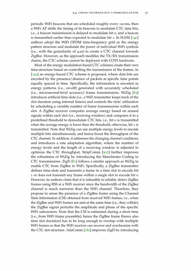
2.4 cross-technology communication 31
periodic WiFi beacons that are scheduled roughly every 100 ms, thena WiFi AP shifts the timing of its beacons to modulate CTC data bits,i.e., a beacon transmission is delayed to modulate bit 0, and a beaconis transmitted earlier than expected to modulate bit 1. In SLEM [190]authors adopt the WiFi OFDM time-frequency grid as the energypattern structure and modulate the power of individual WiFi symbols(i.e., with the granularity of 4µs) to create a CTC channel towardsZigBee. However, as the approach modifies the TX/RX transmissionchains, the CTC scheme cannot be deployed with COTS hardware.
Most of the energy modulation-based CTC schemes create their owntime-structure based on controlling the transmission of the frames. In[192] an energy-based CTC scheme is proposed, where data bits areencoded by the presence/absence of packets at specific time pointsequally spaced in time. Specifically, the information is encoded asenergy patterns (i.e., on-off) generated with accurately scheduled(i.e., microsecond-level accuracy) frame transmissions. WiZig [83]introduces artificial time slots (i.e., a WiFi transmitter keeps track of theslot duration using internal timers) and controls the slots’ utilizationby scheduling a variable number of frame transmissions within eachslot. A ZigBee receiver computes average energy based on sensedsignals within each slot (i.e., receiving window) and compares it to apredefined threshold to demodulate CTC bits, i.e., bit 0 is transmittedwhen the average energy is lower than the threshold; otherwise, bit 1 istransmitted. Note that WiZig can use multiple energy levels to encodemultiple bits simultaneously and hence boost the throughput of theCTC channel. In addition, it addresses the changing channel conditionsand introduces a rate adaptation algorithm, where the number ofenergy levels and the length of a receiving window is adjusted tooptimize the CTC throughput. StripComm [207] further improvesthe robustness of WiZig by introducing the Manchester Coding toCTC transmissions. ZigFi [81] follows a similar approach as WiZig toenable CTC from ZigBee to WiFi. Specifically, a ZigBee transmitterdefines time-slots and transmits a frame in a time slot to encode bit1 or does not transmit any frame within a single slot to encode bit 0.However, its authors claim that it is infeasible to reliably detect ZigBeeframes using RSS at a WiFi receiver since the bandwidth of the ZigBeechannel is much narrower than the WiFi channel. Therefore, theypropose to sense the presence of a ZigBee frame using the ChannelState Information (CSI) obtained from received WiFi frames, i.e., whenthe ZigBee and WiFi frames are sent at the same time (i.e., they collide),the ZigBee signal perturbs the amplitude and phase of the specificWiFi subcarriers. Note that the CSI is estimated during a short time(i.e., from WiFi frame preamble); hence the ZigBee frame (hence alsotime slot duration) has to be long enough to overlap with multipleWiFi frames so that the WiFi receiver can recover and synchronize withthe CTC slot structure. AdaComm [182] improves ZigFi by introducing

32 background and related work
a learning-based decoding method to cope with channel dynamics.B2W2 [34] uses a similar approach as ZigFi to build a CTC channelfrom BLE to WiFi. C-Morse [193] creates short (dot) and long (dash)energy bursts by transmitting one or multiple WiFi frames with smallinter-frame intervals, respectively. Then, it combines multiple burstsinto two sequences to encode bits 0 and 1. The approach is similar tothe one used by HoWiES [205], however, here, the transmissions ofthe bursts belonging to the same sequence (i.e., energy pattern) areperformed with predefined time intervals. GapSence [204] prependslegacy packets with a short customized preamble containing sequencesof energy pulses. The length of silent gaps between them encodes theCTC data. Such an approach requires dedicated hardware and is notcompatible with COTS devices.
In general, the energy modulation-based CTC approaches striveto be transparent to upper protocol layers and can be implementedwith commercial wireless devices. However, they suffer from thelow data rate that usually does not exceed 1 Kbps. In Table. 2.1, wepresent comparison of (maximal) data rates of the described CTCschemes. The table also contains information about standard compli-ance and whether the prototypes were implemented with COTS orSoftware-Defined Ratio (SDR) platforms. Note that the comparison ofthe transmission reliability is not presented as some of the schemespresent only Bit Error Rate (BER), while the others Symbol Error Rate(SER) or Frame Error Rate (FER).
Table 2.1: Comparison of the energy modulation-based CTC schemes.
Scheme CTC Direction Data RateStandard
ComplianceImplementation
Esense WiFi→ ZigBee n/a ✓ COTS
HoWiES WiFi→ ZigBee n/a ✓ COTS
DCTC WiFi→ ZigBee 760 bps ✓ SDR
ZigBee→WiFi 190 bps ✓ SDR
EMF WiFi→ ZigBee 200 bps ✓ SDR
ZigBee→WiFi 110 bps ✓ SDR
FreeBee WiFi→ZigBee 31.5 bps ✓ COTS
ZigBee→WiFi 14.6 bps ✓ COTS
Bluetooth→WiFi 17.5 bps ✓ COTS
Bluetooth→ZigBee 17.8 bps ✓ COTS
SLEM WiFi→ZigBee 10 kbps × SDR
WiZig WiFi→ZigBee 154 bps ✓ SDR
StripComm WiFi→ZigBee 1.1 kbps ✓ COTS
ZigBee→WiFi 78 bps ✓ COTS
ZigFi ZigBee→WiFi 215.9 bps ✓ COTS
AdaComm ZigBee→WiFi 229 bps ✓ COTS
B2W2 Bluetooth→WiFi 3.1 kbps ✓ SDR
C-Morse WiFi→ZigBee 936 bps ✓ SDR
ZigBee→WiFi 215 bps ✓ SDR
GapSence WiFi→ZigBee n/a × SDR

2.4 cross-technology communication 33
2.4.2 Signal-Level CTC
The second class of CTC approaches known as signal-level CTC reusesthe waveform of native technologies or proposes a simple signalmodulation scheme to achieve high data-rate communication betweenheterogeneous devices. Specifically, the signal emulation techniquefocuses on the generation of a foreign waveform (e.g., ZigBee frame)in a heterogeneous transmitter (e.g., WiFi device), while cross-decodingtechnique enables demodulation and decoding of a foreign waveformat a heterogeneous receiver. Moreover, using the signal emulationtechnique, it is possible to generate CTC waveforms based on a simplemodulation scheme that can be detected and decoded at a receiveradhering to heterogeneous technology. The details of those threetechniques are presented below.
Signal Emulation: Recently, it was shown that the wireless signal ofone wireless technology might be effectively emulated (i.e., generated)by a transmitter adhering to heterogeneous technology if special careis taken to correctly select symbols (i.e., constellation points). As theused symbols are dependent on the payload bits, the transmitter em-ulates the desired waveform by selecting the frame payload, i.e., therequired waveform (with a preamble, headers, and data payload ofthe targeted technology) is produced from the data payload bits aftertraversing the transmission chain. In general, an advanced technology(e.g., WiFi) has enough degree of freedom in its signal modulation toemulate a complete waveform of simple and narrowband technology(e.g., ZigBee or Bluetooth). The emulated signal follows the standardof simple technology, and hence it can be directly demodulated with-out a need for hardware or software modifications. However, as thesignal cannot be emulated perfectly (i.e., it can be only approximated),the bit error rate is usually higher compared to the case of a regu-lar in-technology transmission (e.g., the frame reception ratio of theWeBee CTC scheme is around 50% [124]). Nevertheless, as the nativetechnologies add redundancy (i.e., some extra data) to transmittedmessages through the usage of the channel coding, the signal distor-tions introduced by the emulation technique are tolerable, and thesuccessful CTC operation is possible. Note that the signal-level CTCtechniques significantly increase the throughput compared to energymodulation-based CTC approaches as they operate with the standarddata rates of the emulated technology (e.g., 250 Kbps in the case ofemulation of Zigbee signal).
The signal-emulation CTC was proposed by WeBee [124] that en-ables a commercial WiFi device to transmit (i.e., emulate) a ZigBeesignal by proper selection of its frame payload bits. WeBee operateswith data rates of ZigBee but suffers from a high packet error ratedue to the inherent distortions of the emulated signal. TwinBee [31]improves WeBee in terms of reliability by recovering chip errors in-

34 background and related work
troduced by imperfect signal emulation. Specifically, TwinBee usestwo components: chip-combining coding and soft mapping. The for-mer targets recovering the Cyclic Prefix (CP) related and boundaryerrors. The latter helps to reduce QAM quantization errors. Long-Bee [125] builds on top of WeBee and concentrates the transmissionenergy into a narrow band channel (i.e., 5 MHz) by down-clockingthe standard operations of WiFi (i.e., 20 MHz) to extend the com-munication range. Note that besides the default full-clocked 20MHzoperation, IEEE 802.11-2007 standard [93] supports the OFDM-basedPHY with two down-clocked operations, namely, 10MHz (half-clocked)and 5MHz (quarter-clocked) sampling-rate. The down-clocking oper-ation is supported in many commercial WiFi devices (e.g., Atheros5414). Moreover, the IEEE 802.11ah standard [165] uses the 802.11a/gphysical layer that is down-clocked to one of the flexible bandwidths,i.e., 1MHz, 2MHz, 4MHz, 8MHz, and 16MHz. Hence, although im-plemented with the SDR platform, the LongBee can be potentiallydeployed with COTS hardware. WIDE [80] proposes digital emulationto generate the binary phase shift sequence of ZigBee’s signal andachieve CTC from WiFi to ZigBee. Specifically, the authors leveragethe fact that a ZigBee receiver relies on the phase shift modulationto decode symbols rather than the shape of the analog time-domainwaveform. In other words, the emulation of the analog signal is notneeded, as it is enough to generate a waveform that follows a phaseshift modulation. Many phase sequences satisfy the requirement ofphase shift modulation. Therefore, the authors design an appropriatephase sequence with relatively small emulation errors to achieve areliable CTC. Using a similar technique, in BlueBee [97] a Bluetoothdevice emulates the signal of ZigBee. Specifically, it selects the properBluetooth frame payload in order to emulate a legitimate ZigBee frame.ULTRON [27] is an emulation-based CTC approach, which allows em-bedding a valid WiFi CTS frame in LTE transmissions for the purposeof cross-technology channel reservation. Specifically, the content ofan LTE frame (which produces a valid CTS frame after traversing theLTE TX chain) is predetermined once and prepended to every LTEBS transmission to trigger the virtual channel reservation mechanismof co-located WiFi nodes. This way, ULTRON is not a generic CTCapproach as it only targets a specific application.
Cross-Decoding: LEGO-Fi [82] and XBee [95] use a cross-decodingtechnique to realize the CTC at the receiver side for the case of ZigBee-WiFi and ZigBee-Bluetooth, respectively. The cross-decoding exploitsthat the WiFi/Bluetooth receiver’s signal processing capability offersenough flexibility to process a ZigBee frame and pushes the complex-ity of CTC signal decoding to the receiver (RX) side (conversely to thesignal emulation). Specifically, the ZigBee signal leaves distinguishablefeatures when passing through the WiFi/Bluetooth RX chain. There-

2.4 cross-technology communication 35
fore, the signal sequences demodulated by a heterogeneous receivercan be mapped to symbols of the native technology.
Note that a receiver puts the signal received on RF front-end to theRX chain only after being notified about an incoming transmission(e.g., by preamble-based frame detection logic in WiFi). In XBee, aZigBee receiver uses an emulation technique to encode BLE preamblein front of the CTC frame. This way, it makes the BLE receiver recog-nize the ZigBee frame as a valid BLE frame and put it further into thedemodulation and cross-decoding. LEGO-Fi extends the WiFi’s RXchain with extra processing blocks to enable detection of the ZigBeepreamble. If the ZigBee preamble is detected, LEGO-Fi proceeds withcross-decoding. To this end, it reuses some blocks of the WiFi RX chain(e.g., quadrature demodulator) and maps the demodulated phase shiftsequences to ZigBee symbols.
Along with the emulation-based approaches, the cross-decodingtechnique allows accomplishing high data-rate bidirectional CTCbased on the transmission of native radio waveforms.
Simple Modulation Scheme: Finally, there are CTC approaches thatdo not emulate heterogeneous waveforms but can generate waveformscarrying CTC data based on a simple modulation scheme that is un-derstandable by both involved parties. In SymBee [180], a ZigBeenode transmits carefully prepared payload (similar as in emulationtechnique) to create phase patterns detectable by a WiFi receiver. Onthe WiFi side, authors reuse the idle listening mechanism that contin-uously processes any incoming signal and searches for a WiFi frame.Although SymBee remains fully compatible with both standards andnon-disruptive to their operation, it cannot be deployed using COTSWiFi as the output signal from the idle listening mechanism is notexposed.
Table. 2.2 presents comparison of the signal-level CTC schemes.The table contains information about CTC data rate, frame receptionrate (FFR), standard compliance, and whether the prototypes wereimplemented with COTS or SDR platforms.
Table 2.2: Comparison of the signal-level CTC schemes.
Scheme CTC DirectionData Rate
[Kbps]FRR
Standard
ComplianceImplementation
WeBee WiFi→ ZigBee 250 ≈50% ✓ COTS
TwinBee WiFi→ ZigBee 250 ≈99% ✓ COTS
LongBee WiFi→ ZigBee 250 ⩾90% ✓ SDR
WIDE WiFi→ ZigBee 250 ≈86% ✓ SDR
BlueBee Bluetooth→ ZigBee 250 ≈90% ✓ COTS
LEGO-Fi ZigBee→WiFi 250 ≈90% × SDR
XBee ZigBee→ Bluetooth 250 ≈80% ✓ COTS
SymBee ZigBee→WiFi 31.25 BER⩽30% ✓ SDR
ULTRON* LTE-U/LAA→WiFi 6500 ⩾98% ✓ SDR* ULTRON is not a generic CTC scheme.

36 background and related work
2.4.3 CTC as Enabler for Collaboration
The CTC has the potential to bring a plethora of benefits and appli-cations by enabling diverse technologies to interact with each otherseamlessly. The first motivation for CTC was to get rid of expen-sive multi-radio gateways and enable smartphones equipped withWiFi interface to directly control Internet of Things (IoT) devices (e.g.,light bulbs) that usually employ simpler technologies like ZigBee andBluetooth. Yan et al. [148] CTC was used for data dissemination andcollection among heterogeneous IoT devices.
Recently, the CTC was also successfully applied to improve co-existence efficiency. Zhimeng et al. [194] exploit CTC to coordinatechannel access between WiFi and ZigBee nodes and hence combatcross-technology interference. Specifically, in their approach, a WiFiAP reserves the channel for a ZigBee node by generating a CTS frameand immediately notifying the ZigBee node about the following silentperiod over the CTC channel. The cross-technology virtual channelreservation was first proposed in [27] for the case of unlicensed LTEand WiFi, where LTE BS generates a valid CTS frame using signalemulation technique. Another CTC application is cross-technologytime synchronization [77, 196], which enables synchronizing clocks ofheterogeneous wireless nodes with high accuracy directly over the airinterfaces. Therefore, the implementation of a cross-technology timedivision multiple access (TDMA) scheme is possible. Esense [28] usesCTC to discover interfering links between heterogeneous nodes (i.e., tobuild interference maps). Finally, one can think of applications aimingto reduce the power wastage in dense network deployments [59]. Herea device equipped with diverse wireless interfaces may aggressivelyswitch most of them off during low activity periods, whereas a cross-technology wake-up radio can be used to switch them on in the caseof increased demand.
We believe that thanks to the CTC, co-located heterogeneous net-works can collaborate with each other and negotiate the spectrumusage. However, to create useful applications on top of CTC, onerequires the existence of a collaboration protocol that describes thesemantic and syntactic of the communication language (including theformat of available frames, addressing scheme, etc.). Unfortunately,most of the CTC schemes provide only a data pipe, that can carryarbitrary data, i.e., the work stops after the design of the CTC datapipe and its evaluation in terms of BER and/or FER. In the caseof signal-level CTC approaches, the problem of node addressing issolved inherently as the transmitter uses the real frame structure ofthe heterogeneous technology and the real address of the targetedheterogeneous device. However, the development of collaborationprotocols that run on constrained CTC links (e.g., in terms of datarate) is still an open issue.

2.5 learning-based approaches in wireless communication 37
2.5 learning-based approaches in wireless communica-tion
Over the last two decades, wireless technologies have evolved intovery complex and advanced systems. Specifically, in each generation,those systems include new mechanisms that aim to improve theirperformance. Each mechanism, however, comes with a plethora ofparameters to be set correctly to achieve the required results, e.g.,Khorov et al. [101] shows that depending on the combination of Re-source Unit (RU) assignment in 802.11ax, the network throughputmay vary between by more than 100% (i.e., between 100 and 280 Mbpsin the considered scenario). Usually, multiple parameters have to betuned together to achieve the best performance in specific use-cases.This is not a trivial task as the dependencies between the parametersand their joint optimization might have a highly non-linear impacton the network performance. Furthermore, the parameters have to bequickly adapted in response to changing wireless propagation condi-tions, traffic fluctuations, and diverse QoS requirements. Finally, thelevel of complexity is even further increased in coexisting networks,where diverse parameters have to be tuned across multiple nodes.
Due to those issues, the traditional radio resource managementalgorithms may fail to guarantee a reasonable performance level acrossall scenarios. We believe that the learning-based approaches can helpus to manage the increased complexity of today’s wireless networks.Specifically, instead of engineering closed-formed control solutions(usually based on over-simplified models), in those approaches, anagent learns the best behavior from interactions with the environment.
The family of learning-based approaches covers Stochastic ConvexOptimization (SCO) and more advanced techniques as reinforcementlearning (RL). In the SCO, an agent tries to find the best parametervalues using the stochastic gradient descent (SGD) method and itera-tively optimizes a given convex utility function. While in RL, an agentinteracts with the environment and reinforces (or inhibits) particularpatterns (i.e., policy) of behavior depending on the resulting reward(or penalty). In the following subsections, we briefly describe bothtechniques.
2.5.1 Stochastic Convex Optimization
A Stochastic Convex Optimization deals with minimizing of the ex-pected value of a function F(x, ξ) that is convex in x ∈ Rd where ξ issome random vector:
Find x∗ = argminx∈K
f(x) := E(F(x, ξ)). (2.1)
The setup is that one has access to sample values of F(x, ξ).

38 background and related work
If one could measure the gradient ∇f(x) of the function, one coulduse a gradient descent algorithm where the parameters at the t-thiteration, xt, are updated according to xt+1 = xt − ηt∇f(x), whereηt is the step size at iteration t. However, in practical scenarios thereis no access to the actual gradient ∇f(x). Accordingly, the stochasticgradient descent (SGD) algorithms rely on constructing noisy gradi-ent estimates gt using the observed performance metrics, which arethen used to adjust the parameters according to xt+1 = xt − ηtgt.The Kiefer-Wolfowitz (KW) algorithm [103] is a two-point gradientestimation procedure that combines two function evaluations withperturbed values of its variable to compute the gradient estimate.The simultaneous perturbation stochastic approximation (SPSA) algo-rithm [163] is an extension of the KW algorithm towards multivariateproblems. Specifically, in SPSA, the partial derivatives with respectto the different variables are estimated by simultaneously perturbingeach variable by an independent and zero-mean amount, instead ofperturbing the variables one at a time.
2.5.2 Reinforcement Learning
Reinforcement Learning (RL) is one of three basic machine learningparadigms, alongside supervised and unsupervised learning, and isbeing already used in robotics for years as it allows the design ofsophisticated control algorithms [107]. The main advantage of RL is itsability to learn to interact with the surrounding environment based onits own experience. Fig. 2.2 shows an overview of the learning processthat is as follows:
1. An agent observes the current state of the environment.
2. Based on the observation and its policy, the agent selects andexecutes an action in the environment.
3. The environment, in turn, returns a reward associated with thisspecific action in the particular state.
4. The agent updates its policy based on the obtained reward.
The way an environment transforms the agent’s action taken in thecurrent state into the next state and a reward is unknown. Hence,the agent’s main goal is to learn a policy to select the best actionfrom its action set and maximize its cumulated reward. The learningis performed using a trial and error approach with the feedback(i.e., reward) obtained from the environment. The policy is simply afunction that maps states to the actions. In a simple case, the policycan be imagined as a look-up table that stores the mapping betweenthe observed state of the environment to the best action. However, inreal use-cases, the number of possible states (i.e., observation space) is

2.5 learning-based approaches in wireless communication 39
Agent
Observe state St+1
Reward Rt+1
Take action At
Model
EnvironmentState
Figure 2.2: Reinforcement Learning.
enormous (if not infinite), thus the simple approach with the look-uptable is not feasible. For this reason, RL agents often make use of verycomplex neural networks (NN) that consist of multiple neuron layers.Such networks are commonly called Deep Neural Networks (DNN),hence the machine learning subcategory is called Deep ReinforcementLearning. DNN approximates the policy function, and during thelearning process, its internal parameters are tuned to find the bestapproximation. The learning is an iterative process during which asolver follows a gradient search that leads to smaller errors of theapproximation. The output of this learning is a policy that defines adistribution over actions conditioned on states, i.e.,
∏(action|state).
2.5.3 Software Toolkits for Learning-based Approaches
Here, we provide an overview of tools that simplify the developmentand training of learning-based algorithms.
Numerical Computation Libraries: In recent years, the task of de-veloping and training the neural networks was simplified by theemergence of numerical computation libraries. For instance, Keras1
provides a high-level Python API allowing to create and optimizeeven a very complex neural network in just a few lines of code. Kerasruns on top of TensorFlow2 [4] that allows representing numericalcomputation as a data flow graph, i.e., nodes represent mathematicaloperations, while edges represent the multidimensional data arraysthat flow between them. Finally, with only minor changes, TensorFlowallows performing the computations on a single CPU and GPU as wellas distributed clusters of them using the same code.
OpenAI Gym: OpenAI Gym [20] is a Python-based toolkit for devel-oping and comparing learning-based algorithms. It provides a simpleAPI that unifies interactions between an agent and an environment.Specifically, any environment can be integrated into the Gym as longas all the observations, actions, and rewards can be represented asstructured (e.g., vector or map) numerical data. Note that Gym makes
1 https://keras.io/
2 https://www.tensorflow.org/

40 background and related work
no assumptions about an agent’s structure (just provides input dataand action knobs) and is compatible with any numerical computa-tion library. Based on the unified interface Gym provides access to acollection of standardized environments. The framework was alreadyintegrated with various environments in areas ranging from videogames (e.g., Ping-Pong) to robotics [20, 145, 146].
Reference RL Agents: The replication of the published RL algorithmsis a challenging task, especially for people entering the machine learn-ing area. Usually, they are very complex, and even a small difference(e.g., bug) in the implementation may affect their performance. Re-leasing a code repository along with the published paper is a goodpractice, however, still not the case for most publications. Fortunately,recently the high-quality reference implementations of RL algorithmshave become available [48, 53, 127]. Researchers can use them as abase and apply them to the problems in their respective areas.
2.5.4 Learning to Collaborate
The success of learning-based approaches comes from its applicationsin single-agent domains where training is much easier than in multi-agent domains. Specifically, when an environment is not updatingits strategy (so-called stationary environment), an agent can learn fromits own past experience. In the case of multiple agents, each agentis changing its behavior (i.e., policy) as training progresses, and theenvironment (formed by all agents) becomes inherently non-stationaryfrom the perspective of any individual agent.
Nevertheless, there are many important applications that involveinteraction between multiple agents, where emergent behavior andcomplexity arise from agents co-learning together, e.g., multi-robotcontrol or multi-player games. Specifically, in such environments, anumber of distributed agents repeatedly interact with each other whiletrying to achieve some goal. The nature of the interaction betweenagents can be collaborative, competitive, or mixed, while agents mightshare the goal or multiple individual goals may exist. The key featurein this problem is that to each agent, the environment consists of allother agents who are simultaneously making sequential decisions.Hence, each agent’s reward depends not only on their own action butalso on the joint action of all other agents. Moreover, in the multi-agentscenario, usually, each agent has access to local information (i.e., itsown observations), and the synchronization of the global knowledgemight be subject to delays, errors, or might not be possible at all dueto missing communication channels.
The traditional reinforcement learning approaches are poorly suitedto multi-agent environments. Those environments are better addressedwith distributed optimization and learning techniques. Lowe at al. [130]proposes a framework of centralized training with decentralized ex-

2.5 learning-based approaches in wireless communication 41
ecution, where agents use extra information (i.e., global knowledge)to ease training but only local information during the execution time.This way, the agents can approximate models of other agents andeffectively use them in their own policy learning procedure. Basedon the proposed framework, the authors show that distributed agentscan learn collaborative and competitive behavior.
The heterogeneous wireless networks are a great example of a multi-agent environment. Specifically, distributed wireless nodes are coupledwith each other through shared radio resources and usually are com-peting for them. They have diverse capabilities and objectives (e.g.,high throughput, low latency, or low energy consumption). Moreover,due to the nature of wireless propagation, each node has its own localview of the network state, and the potential exchange of informationconsumes resources. We believe that the proposed multi-agent learn-ing algorithms might be successfully applied in the area of coexistingheterogeneous networks, so they can learn to collaborate and helpeach other achieve their goals.
2.5.5 Learning in Wireless Networks
Recently, we have seen a boom in the usage of machine learning ingeneral and RL in particular for the optimization of communicationand networking systems ranging from scheduling [11, 35], resourcemanagement [135], congestion control [108, 123, 186], routing [172]and adaptive video streaming [136]. Each proposed approach showssignificant improvements compared to traditionally designed algo-rithms. However, to reach such a superb level, an RL control agentrequires much training (i.e., interactions) with an environment tolearn the best policies. Similarly, the recent advancements in the imagerecognition area have been enabled by the rise of large labeled datasets(e.g., ImageNet [46]). Due to the lack of alternatives, many researchgroups engineer and use their custom training environments usingnetwork simulators or testbeds. For example, Komondor [13] is a low-complexity wireless network simulator for the next-generation high-density WLANs, including support for novel WLAN mechanisms likedynamic channel bonding (DCB) or spatial reuse. In addition, Komon-dor permits including intelligent ML-based agents in the wirelessnodes to optimize their operation based on an implemented learningalgorithm. Komondor is focused only on simulating WLAN operationand does not provide detailed models of other protocol stack layersnor different wireless technologies. This limits the potential of MLfor cross-layer control/optimization or cross-technology collaboration.Chinchali et al. [35] presented another custom-built network simulatorusing OpenAI’s Gym environment in order to study the schedulingof cellular network traffic. Building new simulators from scratch isnot needed as there are already widely accepted tools available. In the

42 background and related work
following section, we provide a brief description of the ns-3 networksimulator that might be reused as a training environment for agentlearning purposes.
2.5.6 ns-3 Network Simulator
ns-3 [214] is a discrete-event network simulator for networking sys-tems, targeted primarily for research and educational use. It is anopen-source project developed in C++ using an object-oriented pro-gramming model.
ns-3 tries to reflect the reality as close as possible. Therefore it usesseveral core concepts and abstractions that map well to how computersand networks are built, i.e., a Node is a fundamental entity connectedto the network. It is a container for Applications, Protocols andNetwork Devices. An application is a user program that generatespacket flows. A protocol represents a logic of network and transport-level protocols (e.g., TCP, OSRL routing). A Network Device is anentity connected to a Channel that is the basic communication sub-network abstraction. As in the real-world, in order to build a networksystem, one has to perform a set of tasks, including installing networkdevices in nodes and connecting them to channels, allocating properMAC addresses, configuring the protocol stacks of all nodes, etc. ns-3provides a set of functions (so-called helpers) that simplifies the tediouswork behind an easy to use API.
The introduced abstractions came with the unified interfaces be-tween entities, which allowed researchers to work in parallel on dif-ferent parts of the protocol stack without any problems during inte-gration, e.g., any application can send packets over Ethernet or WiFinetwork devices. Based on the core concepts, the ns-3 communitydeveloped a vast set of networking protocols (e.g., IP, TCP, UDP) andcommunication technologies (e.g., Ethernet, WiFi, LTE, WiMAX) withdetailed modeling of physical layer operations. Furthermore, ns-3 of-fers a variety of statistical models for wireless channels, mobility, andtraffic generation. In addition, ns-3 can interact with external systems(e.g., real-time LTE testbed [84]), applications (e.g., using direct codeexecution technique [168]) and libraries (i.e., Click [167]).
Finally, ns-3 also provides generic tracing and attribute configurationsubsystems. The former signals state changes in a network modeland allow monitoring of the internal state and parameters of anyentity (e.g., node, protocol, device) in a simulation. The latter allowscontrolling parameters and attributes of those entities at run-time.

Part I
C R O S S - T E C H N O L O G Y C O M M U N I C AT I O N


3C R O S S - T E C H N O L O G Y C O M M U N I C AT I O N F O RLT E - U A N D W I F I
Cross-Technology Communication (CTC) paves a way toward explicitcollaboration as it enables direct communication between co-locatedheterogeneous networks. Specifically, using CTC, the networks maysimply exchange information about their current traffic conditions,negotiate a fair air-time usage [64] or even coordinate channel ac-cess [194].
As discussed in the background chapter (§2.4), thanks to the re-cent advances in the CTC area, the CTC portfolio contains solutionstargeting mostly WiFi, ZigBee, and Bluetooth. Unfortunately, noneof them is directly applicable to WiFi and unlicensed LTE* which re-cently became competitors in the 5 GHz band and suffer from frequentcollisions and significant performance degradation under coexistingscenarios (§2.1.5).
3.1 introduction
Consequently, in this chapter, we describe LtFi [68], a scheme thatenables a cross-technology communication between an LTE-U base sta-tion (BS) and co-located WiFi nodes. The scheme belongs to the familyof the energy modulation-based CTC solutions with the structuredenergy pattern as classified in the background chapter (§2.4).
Fundamental for LtFi is the creation of a broadcast side-channelon top of the LTE-U air interface that is decodable by legacy WiFiinterfaces. Specifically, LtFi exploits the fact the LTE-U transmissionsare structured in time (i.e., the signal is periodic as the LTE-U usesduty-cycled channel access) and adopts this structure as a basis forthe creation of the CTC message-bearing energy pattern. The CTCbits are encoded using the mechanism of subframe puncturing (i.e.,Almost Blank Subframe), which stops (punctures) the transmissionfor a short time (1-2 ms). The relative position of such punctureswithin the LTE-U’s on-time is used to modulate information data onthe CTC channel. On the WiFi side, Commodity-off-the-Shelf (COTS)hardware ability to monitor the MAC states allows distinguishingbetween the reception of WiFi and non-WiFi signals. The latter isused as input for the CTC receiver. The so established unidirectionalbroadcast over-the-air CTC enables the LTE-U network to transmitarbitrary information. For example, it might be used to announceconnection and identification information (e.g., the public IP addressof the LTE-U BS Management Unit) to co-located WiFi nodes, that,
45

46 cross-technology communication for lte-u and wifi
in turn, use this information to establish over-the-wired backhaul abidirectional control channel with the BS.
Contributions: Our key contributions are three-fold:
• We have designed the LtFi, an energy modulation-based CTCscheme that enables over-the-air data transmission betweenLTE-U BS and WiFi nodes. The solution features low complexityand is fully compliant with LTE-U, and works with commod-ity WiFi hardware. Moreover, it can be easily integrated withexisting devices as it is only a software add-on.
• Our analytical results reveal that LtFi achieves the data rate upto 665 bps. Here, using open-source LTE implementation andcommodity WiFi hardware, we have implemented LtFi proto-type operating with a data rate of 100 bps. Our experimentalevaluation shows that LtFi operates successfully even at verylow received power level of -92 dBm.
• We have designed and evaluated extensions of LtFi that allow forits operation in a multi-cell environment. Specifically, we targetthe cross-technology neighbor discovery application, where WiFinodes try to determine with whom they are interfering.
3.2 system design
This section gives an overview of LtFi. First, we present the generalarchitecture of our LtFi system. Then in the following sections, wegive a detailed description of its components.
3.2.1 Architecture Overview
Fig. 3.1 shows how LtFi is integrated into LTE and WiFi systems. Notethat as LtFi is only an add-on to existing standards, it can be easilyintegrated with already deployed devices by performing a softwareupdate, i.e., no protocol changes are needed.
The most desired feature of LtFi is transparency, meaning that itshould not disturb the operation of higher layers in WiFi nor LTE-U.Moreover, it should not introduce any additional overhead (like theover-the-air transmission of additional control frames or signals) butrather use the side-channel information to encode CTC data withoutdestroying the regular LTE-U frames.
The LtFi exploits the freedom to place the subframe puncturing intoLTE-U transmission assured in the LTE-U standard. Specifically, totransmit the CTC information, LtFi modulates the puncturing positionduring LTE-U’s on-time. The puncturing has a length of 1 or 2 ms, hencethe additional delay experienced by LTE-U data packets is negligible.LtFi transmitter (TX) is interfaced with the LTE-U scheduler, which is

3.2 system design 47
PDCP
RLC
MAC
PHY
Scheduler
LtFi-Air TX
TX LTE Data
TX LtFi Data
Sen
de
r
LTE-U eNb
MAC
PHY
RX WiFi Data
LtFi-Air RX
WiFi
Rec
eiv
er
MAC State Samples
RSSI Samples
RX LtFi Data
Figure 3.1: Integration of LtFi-Air-Interface into LTE-U eNB and WiFi – LtFirequires an interface to the LTE-U scheduler as well as access toWiFi MAC layer information.
responsible for managing available wireless resources, i.e., ResourceBlocks (RBs). Specifically, the LtFi TX sends a vector −→s = [s1, s2, ..., sk]of CTC symbols to the eNb scheduler. A CTC symbol si is representedby the relative puncturing position, i.e., the eNb scheduler takes −→sinto its radio resource scheduling decision and stalls (punctures) itstransmission for 1-2 ms at the time points given in the CTC symbols.Moreover, the interface between LtFi TX and eNb scheduler is usedto negotiate the LtFi symbol duration, the number of punctures persymbol as well as the configuration of the length of a puncture. Thisis needed to adapt to changing LTE-U traffic load (see §3.2.4) and/orwireless channel conditions.
On the receiver side, a WiFi node, typically an AP, needs to decodethe LtFi CTC signal. As direct decoding of the LTE-U frames is notpossible due to incompatible physical layers, the LtFi receiver hasto detect and demodulate radio patterns based on received signalstrength (RSS) observation. This can be achieved using the spectrumscanning capabilities of WiFi chipsets (e.g., Atheros). However, itrequires to obtain and process a large amount of spectral scan data.Instead, we find a simpler solution, i.e., we utilize the possibility tomonitor the signal detection logic of modern WiFi cards (e.g., Atheros802.11n/ac). Precisely, a WiFi network interface card (NIC) can monitorthe relative amount of time spent in the energy detection (ED) statewithout triggering packet reception (RX), i.e., interference (Intf ) state,which is entered when receiving of a strong non-WiFi signal. As LTE-Uis so far the only source of interference in the 5 GHz band, it is safeto assume LTE-U being the non-WiFi signal. In order to detect therelative position of the puncturing in the LTE-U’s on-time, the Intfstate is sampled with a sufficiently high rate, i.e., sample duration of0.25 ms, and hence sampling frequency equals 4 kHz.

48 cross-technology communication for lte-u and wifi
Time
TX
LTE-U
Signal Symbol encoded in puncturing position
000
001
010
011
100
101
110
111
Figure 3.2: Example of CTC data modulation at LTE-U side. Here a CTCsymbol encodes three bits.
Besides the already mentioned (de-)modulator, the LtFi’s TX/RXchain contains modules for preamble detection and cyclic redundancycheck. The preamble is used to mark the start of the LtFi frame,while the error detection using CRC is required to provide reliablecommunication over a noisy channel.
3.2.2 Data Modulation
This section describes the basics of LtFi’s modulation techniques. Asalready described in the Background (Chapter 2), in order to coexistwith WiFi, a LTE-U BS has to preempt (puncture) its transmission afterat most 20 ms, but additional interruptions are allowed. We use suchbasic 20 ms chunk of LTE-U transmission to encode one LtFi symbolby modulating the puncture’s relative position within the transmissionduration. Note that the interruption in transmission (puncturing) donot contribute to the on-time of LTE-U, and the remaining data haveto be transmitted in additional chunks.
For the sake of clarity of presentation, we here describe the simplestmodulation process assuming that the LTE-U BS has buffered enoughdata, and we use only a single puncture for encoding CTC data.
Without loss of generality, in Fig. 3.2, we present a single LtFi symbolwith 20 ms duration that consists of 18 ms of LTE-U’s transmissionand one puncture of 2 ms. We use the 1-out-of-N encoding. Therefore,there are eight possible puncturing positions, which allows for theencoding of three bits in one LtFi symbol. Note that puncturing isnot possible at the beginning and at the end of the transmission asit would only shorten the LTE-U’s transmission instead of creatingcoexistence gaps.
3.2.3 Frame Synchronization & Demodulation
The input to LtFi receiver is a signal created based on the observationof the relative amount of time the WiFi NIC spent in specific states,namely, i) idle, ii) receive (RX), iii) transmit (TX) and iv) interference(Intf ) — see Fig. 3.3.

3.2 system design 49
0 5 10 15 20 25 30 35 40
Time [ms]
0.00
0.25
0.50
0.75
1.00
Rel
ati
ve
Dw
ell
Tim
e
MAC States Distribution
Intf
Tx
Rx
Idle
Figure 3.3: Visualization of an example WiFi MAC states distribution.
0 50 100 150 200 250
Time [ms]
Rec
eived
CT
CS
ign
al Symbol 1
λ(5) = 100
Symbol 2
λ(8) = 111
Symbol 3
λ(3) = 010
Figure 3.4: Example of a received signal and the demodulation at WiFi side.
Fig. 3.4 shows an example of received Intf signal in a clean channel,while the pseudo-code of the algorithm used for synchronization anddemodulation is shown in Listing 2. Unfortunately, in practice, the Intfsignal is noisy and has to be cleaned. For this purpose, we employthe other three states (lines 11-12). The preamble detector is based oncalculating the cross-correlation (line 16) between the known preamblepattern and the received signal. When the value of the computed cross-correlation exceeds a predefined threshold τp (line 17), the receiverassumes it has just detected a preamble (i.e., it is synchronized withthe beginning of the frame) and starts decoding CTC symbols (lines 21-29). The receiver might still restart decoding if the preamble detectorcomputes a higher cross-correlation value (line 19). The CTC symboldecoding is performed in the following way: the receiver computesthe cross-correlation to each valid symbol and takes the one with thehighest value. Each symbol is afterward de-mapped to bits — see anexample in Fig. 3.4. The receiver continues until it decodes all symbolsof the fixed-length LtFi frame. Note that the LTE-U cycle length has tobe known a priori or discovered automatically as proposed in [142].
3.2.4 Load-Aware Adaptive Coding Scheme
Previously, we assumed that the LTE-U BS has saturated traffic, i.e.,there is enough data so that one LtFi symbol of 20 ms duration is sentin each LTE-U cycle. In practice, however, as network traffic is bursty

50 cross-technology communication for lte-u and wifi
Algorithm 1: LtFi air-interface receiver (preamble detection anddemodulation).
Input: Tc ▷ LTE-U cycle durationInput: ∆t = 250µs ▷ Sampling interval→ fs = 4 kHz
Input: EDt,RXt, TXt, IDLEt The amount of time spent in each MACstate during last ∆t
Input: τ1, τ2, τ3 ∈ ⟨0, 1⟩ ▷ Thresholds for signal cleaningInput: τp ▷ Preamble Detection ThresholdInput: P = {p1, . . . ,pN} ▷ Preamble Reference SignalInput: M1, . . . ,Mk ▷ Set of k possible LtFi symbolsInput: L ▷ LtFi frame length
1 W ← Tc∆t ▷ Window Size (i.e., samples in LTE-U cycle)
2 N← 4W ▷ Preamble Length3 t0 ← 0 ▷ LtFi Symbol Start Marker4 s← 0 ▷ Synchronization Flag5 R← 0 ▷ Cross-correlation of last synchronization6 l← 0 ▷ Number of decoded symbols7 F← {} ▷ Decoded bits of frame8 while True do9 t← t+ 1 ▷ For each new sample10 Intft ← EDt − RXt
11 St ← Intft ▷ Interference signal (i.e., LTE-U)12 St[St > τ1] = 1; St[1− St > τ2] = 0 ▷ Signal cleaning13 St[RXt > τ3] = 0; St[TXt > τ3] = 0; St[IDLEt > τ3] = 0
14 St = St − 0.5 ▷ Remove DC for better CC properties15 P ← St−N, . . . ,St ▷ Last N samples of recv. signal16 r = ⟨P, P⟩ = ∑N
i=1 pi × pi ▷ Preamble Detector17 if r ⩾ τp and s = 0 then18 s← 1; R← r; t0 ← t ▷ Preamble detected→ synchronization
19 if r ⩾ R and s = 1 then20 R← r; t0 ← t; l← 0; F← {} ▷ Re-synchronization with higher
CC21 if s = 1 and t− t0 = W then22 l← l+ 1; t0 ← t
23 M← St−W , . . . ,St ▷ Received LtFi symbol24 ⟨M,Mk⟩ = ∑W
i=1mi × mki ▷ Cross-correlation (CC)
k∗ = argmaxk
(⟨M,Mk⟩) ▷ Symbol with highest CC
25 B = map(Mk∗) ▷ Symbol-to-bit mapping26 F← {F,B} ▷ Append bits to frame27 if l = L then28 yield F
29 l← 0; s← 0; F← {}
(e.g., adaptive video streaming), the duration of the LTE-U’s on-time isexpected to be variable.
To deal with the issue of variable duty cycles, we introduce theLoad-Aware Adaptive Coding Scheme that selects the proper symbollength and number of punctures depending on the network load in

3.3 transmission rate analysis 51
the LTE-U network. In Table 3.1, we show the LtFi symbol lengthstogether with the number of available puncture positions as well asthe number of bits that can be encoded using single puncturing of1 ms. Note that without affecting its throughput, an LTE-U BS mayuse cycle and on-time of longer duration (i.e., the same duty-cycle)to create a LtFi symbol encoding more bits. Here, we use 1-out-of-Nencoding, but it is also possible to encode more bits if we introducemore punctures within the LTE-U’s transmission. We evaluate suchcases in the following section.
Table 3.1: Available LtFi Symbol Lengths.
Min LTE-U Max LTE-U Available Number of
on-time on-time puncture positions encoded bits
4 5 2 1
6 9 4 2
10 17 8 3
18 20 16 4
3.3 transmission rate analysis
In this section, we provide a theoretical analysis of the achievable datarate of the LtFi CTC channel. Note that an LTE-U BS has to apply onepuncture within its continuous transmission of the maximal durationof 20 ms. Here, we adopt that 20 ms transmission chunks as the LtFisymbols. Moreover, we assume operation at high SNR, i.e., the WiFireceiver can detect and decode CTC signals with high probability.
We define z as the number of 20 ms LTE-U transmission chunks (i.e.,LtFi symbols) present during a single cycle with a duration of Tcycle.Inside the symbol, we can add up to k punctures of 1-2 ms durationto encode CTC data bits. The number of available LtFi symbols M
grows with the number of puncture position combinations and can becomputed as the binomial coefficient (3.1), where n is the number ofpossible puncturing positions. Hence, by increasing k more bits canbe encoded into a single LtFi symbol. Therefore, the LtFi data rate canbe computed using the following equations:
M =
(n
k
)=
n!k!(n− k)
, 0 ⩽ k ⩽ n (3.1)
R[bps] =⌊log2(M)⌋ · z
Tcycle(3.2)
Note that when increasing k the LTE-U BS has to send its remainingdata in additional chunks that can be used to create additional LtFisymbols (i.e., z grows) still within the same LTE-U cycle.
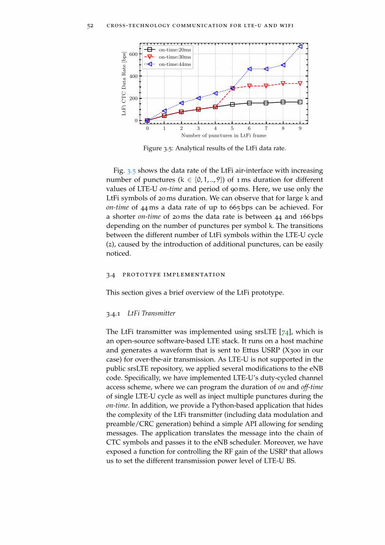
52 cross-technology communication for lte-u and wifi
0 1 2 3 4 5 6 7 8 9
Number of punctures in LtFi frame
0
200
400
600
LtF
iC
TC
Data
Rate
[bp
s]
on-time:20ms
on-time:30ms
on-time:44ms
Figure 3.5: Analytical results of the LtFi data rate.
Fig. 3.5 shows the data rate of the LtFi air-interface with increasingnumber of punctures (k ∈ {0, 1, .., 9}) of 1 ms duration for differentvalues of LTE-U on-time and period of 90 ms. Here, we use only theLtFi symbols of 20 ms duration. We can observe that for large k andon-time of 44 ms a data rate of up to 665 bps can be achieved. Fora shorter on-time of 20 ms the data rate is between 44 and 166 bpsdepending on the number of punctures per symbol k. The transitionsbetween the different number of LtFi symbols within the LTE-U cycle(z), caused by the introduction of additional punctures, can be easilynoticed.
3.4 prototype implementation
This section gives a brief overview of the LtFi prototype.
3.4.1 LtFi Transmitter
The LtFi transmitter was implemented using srsLTE [74], which isan open-source software-based LTE stack. It runs on a host machineand generates a waveform that is sent to Ettus USRP (X300 in ourcase) for over-the-air transmission. As LTE-U is not supported in thepublic srsLTE repository, we applied several modifications to the eNBcode. Specifically, we have implemented LTE-U’s duty-cycled channelaccess scheme, where we can program the duration of on and off-timeof single LTE-U cycle as well as inject multiple punctures during theon-time. In addition, we provide a Python-based application that hidesthe complexity of the LtFi transmitter (including data modulation andpreamble/CRC generation) behind a simple API allowing for sendingmessages. The application translates the message into the chain ofCTC symbols and passes it to the eNB scheduler. Moreover, we haveexposed a function for controlling the RF gain of the USRP that allowsus to set the different transmission power level of LTE-U BS.

3.5 experimental evaluation 53
WiFi BSS
AP / LtFi Rx STA
BS / LtFi TxUE
Figure 3.6: Experiment setup – LTE-U BS (left) with co-located two WiFi BSSs(right).
3.4.2 LtFi Receiver
For the WiFi node, we have selected off-the-shelf equipment usingAtheros AR95xx chipset as it allows direct monitoring of the signaldetection logic of the WiFi NIC at a very fine granularity level. Moredetails on Atheros signal detection logic can be found in [142] and thepatent from Atheros [92]. We sample the Atheros registers with a rateof 4 kHz and process the data in blocks of 1 s window sizes. For thispurpose, we migrated the RegMon tool [90] to SMP systems (Ubuntu16.04) and provided a patch to the upstream ath9k wireless driver.Moreover, we replaced the ring buffer in RegMon with a relay filesystem (relayfs) as it provides an efficient mechanism for transferringlarge amounts of data from kernel to user-space. The LtFi receiveris implemented entirely in Python language. It runs in real-time,occupying only up to 15% of a single core of Intel i5-4250U (1.30 GHz)CPU time.
3.5 experimental evaluation
The experiment setup consists of a single LTE-U BS and two WiFi BSSs(i.e., AP with associated STA). LtFi runs on one of the WiFi APs, placed2 m away from the LTE-U BS. The second BSS is used for backgroundtraffic generation. During the experiment, the transmission power ofthe LTE-U BS (hence LtFi TX) was varied. The LTE-U CSAT period(Tcycle) and on-time duration was set to 40 ms and 19 ms (i.e., z = 1
and n = 16), respectively. With such configuration and using a single1 ms long puncture (k = 1), LtFi achieves a transmission data rateof 100 bps, i.e., there are 25 LTE-U cycles in one second, and in each,we can encode 4 bits using 1-out-16 encoding. The transmitted LtFiframe consists of 4 preamble symbols, 4 bytes of data payload (8 LtFisymbols) and 2 bytes of CRC sum (4 LtFi symbols). Therefore, theframe accommodates 16 LtFi symbols in total and lasts for 40× 16 =
640ms. Therefore, the payload throughput equals 1000ms640ms × 4 ∗ 8bit =

54 cross-technology communication for lte-u and wifi
50bps. Note that the throughput can be improved by extending thepayload duration while keeping the preamble size fixed.
As the performance metric for the LtFi air-interface, we selectedthe LtFi Frame Error Rate (FER) and LtFi Symbol Error Rate (SER).We measured both values for different received signal strength levelsof the LTE-U signal at the LtFi-enabled WiFi node in three differentscenarios, namely:
1) Clear Channel: the wireless channel was free from WiFi trafficand only the LTE-U BS was transmitting during its on-time. Thefour WiFi nodes were idle.
2) Background Traffic: similar to the first scenario, except that the non-LtFi WiFi BSS was generating WiFi background traffic. We dis-tinguished between two cases, namely, i) light (UDP 10 Mbit/s)and ii) heavy (backlogged TCP) traffic.
3) WiFi AP DL: similar to scenario 1, except that the LtFi-enabledAP itself was generating traffic to its client station. As in thesecond scenario, we have two cases with light and high load.
The Clear Channel scenario represents the simplest environment forLtFi due to the absence of any other signal except the LTE-U. TheBackground Traffic is more challenging as the LtFi RX node receivesa mix containing both LTE-U and WiFi signals. The last scenario,WiFi AP DL is the worst case as the LtFi-enabled AP is additionallytransmitting itself WiFi traffic and thus — due to the half-duplexconstraint — is temporarily unable to receive the LtFi signal.
In order to ensure statistical significance, each presented resultis calculated based on the transmission of 103 LtFi frames. As theconfidence intervals are very small, we decided not to show them inthe figures to improve the readability.
Fig. 3.7 shows the FER for the three different scenarios. We cansee that the LtFi air-interface can operate close to the receive signalstrength required for energy detection based carrier sensing (i.e., thestandard value in WiFi equals -62 dBm). For example, in Clear Channelscenario a power level of -60.5 dBm is sufficient to reliably decodeLtFi frames. Moreover, we see a very narrow region with intermediateFERs, e.g., 1-2 dB for Clear Channel. For the other two scenarios, aslightly higher receive power is required, e.g., -57 dBm for BackgroundTraffic (high). Finally, we see that in WiFi AP DL (high) scenario, theFER stays above 20 % even for high receive power levels. This can beexplained by the mentioned half-duplex constraint. The SER is shownin Fig. 3.8. Interestingly, here the SER is smallest in Background Traffic(light), as the RX signal caused by the light WiFi traffic helps to cleanIntf signal (see Listing 2, lines 12-13).

3.5 experimental evaluation 55
−64 −62 −60 −58 −56 −54
LTE-U Rx Power at WiFi [dBm]
0.0
0.2
0.4
0.6
0.8
1.0
FE
R[%
]
Frame Error Rate
clear channel
background (light)
background (high)
WiFi AP DL (light)
WiFi AP DL (high)
Figure 3.7: LtFi demodulator performance – Frame Error Rate (FER) vs. LTE-U RX power with default ED threshold.
−64 −62 −60 −58 −56 −54
LTE-U Rx Power at WiFi [dBm]
0.0
0.2
0.4
0.6
0.8
1.0
SE
R[%
]
Symbol Error Rate
clear channel
background (light)
background (high)
WiFi AP DL (light)
WiFi AP DL (high)
Figure 3.8: LtFi demodulator performance – Symbol Error Rate (SER) vs.LTE-U RX power with default ED threshold.
−100 −90 −80 −70 −60
LTE-U Rx Power at WiFi [dBm]
0.0
0.2
0.4
0.6
0.8
1.0
FE
R[%
]
Frame Error Rate (clear channel)
θ = 3
θ = 12
θ = 20
θ = 28
Noise Level
Figure 3.9: LtFi demodulator performance – Frame Error Rate (FER) vs. LTE-U RX power using different ED thresholds.

56 cross-technology communication for lte-u and wifi
BS 0
BS 1
BS 2
LtFi RX
Unaligned LTE-U cyclesAligned LTE-U cycles
& same DCAligned LTE-U cycles
& different DC
t
t
t
t
LtFi SymbolLtFi
Puncture creating LtFi Symbol
TON
Decodable LtFi symbol
Min
Symbol
TONTON
Figure 3.10: Operation of LtFi in multi-cell environment.
Fig. 3.9 shows the FER in the Clear Channel scenario for the WiFiNIC operating with different ED threshold values1. The black curvecorresponds to the default configuration used in the Atheros WiFiNIC (θ = 28), which results in the ED threshold of -62 dBm. Thehighest sensitivity was achieved with θ = 3, where the LtFi receivercan decode the signal at very low receive power levels, i.e., -92 dBm.
3.6 multi-cell operation
So far, we discussed the scenario where a WiFi node is co-located witha single LTE-U BS. However, in real deployments, multiple LTE-U BSsmight be co-located. In this section, we will extend LtFi to support amulti-cell scenario.
For the following, we assume the worst-case scenario where all co-located LTE-U BSs are using the same unlicensed spectrum channel.Let us note that during the channel selection procedure, each LTE-UBS tries to avoid channels already occupied by the other operatorsand chooses the channel occupied by its own operator. Therefore,with high probability, all LTE-U BS operating on the same channel aremanaged by a single operator. Nevertheless, the question of the impactof overlapping transmissions from multiple LTE-U BSs (allowed bythe LTE standard supporting operation with frequency reuse one) isstill open.
If we simply allow each LTE-U BS to broadcast asynchronouslydifferent CTC signals as described in §7.3, it would lead to veryunfavorable transmission conditions. Specifically, for each specificinstance of the CTC channel, all the other transmission should beconsidered as interference making the decoding of the CTC signaldifficult or even impossible (i.e., the usual SINR computations pertain
1 Atheros chips allows for changing ED threshold by writing its value to AR_PHY_CCA
register.

3.6 multi-cell operation 57
properly) – Fig. 3.10(left). The CTC transmission success would beheavily dependent on the geometry, i.e., the WiFi station’s location inrelation to all neighbor LTE BSs. Mathematically, we can formulate itas follows. Let V be the set of co-located LTE-U BSs operating on thesame unlicensed radio channel. The SINR of the CTC signal from BSv ∈ V can be computed as:
SINRv =Pv
RXσ2 +
∑w∈V∧w =v P
vCCI
(3.3)
where PvRX is the total transmit power from BS v, Pv
CCI is the co-channelinterference power level (from the remaining BSs) and σ2 is the Ad-ditive White Gaussian Noise (AWGN) power level. The decoding ofthe LtFi CTC signal transmitted by v can only be successful when theLtFi receiver node is located very close to v as only there the SINRv
is high. At the cell-edge, the interfering signals have similar powerlevels, so the SINRv is low, and any signal cannot be decoded. Notethat in the case of using the MAC state monitoring as the input signalto the LtFi receiver, the energy detection (ED) threshold of WiFi NIC(that is also the sensitivity level of the LtFi receiver) has to be adaptedappropriately.
The most robust solution assuring the best possible CTC transmis-sion can be achieved by two conditions imposed on a set of LTE BSscreating a neighborhood:
i) enforcing all LTE-U BSs within this neighborhood to have duty-cycles aligned in time,
ii) and assuring that all of them will have embedded the sameinformation on the CTC – Fig. 3.10(middle).
Note that LTE-U BSs are not required to have the same network load asthe LtFi symbol is always formed using the transmission of a BS withthe lowest duty-cycle – Fig. 3.10(right). Such coordinated transmissionof the CTC information is simple to achieve if there is a common entitycontrolling the duty cycles and all the LTE-U BSs in the neighborhood(e.g., single building) are managed by a single operator. In fact, theLTE system is designed to operate with a frequency reuse factor of 1.
3.6.1 Cross-technology Neighbor Identification
We design and evaluate extensions of LtFi that allow for its operationin a multi-cell environment. Specifically, we target the cross-technologyneighbor discovery and identification use-case, where WiFi nodes tryto determine with whom they are interfering and to set up communica-tion channels over the wired Internet. We believe the cross-technologyneighbor discovery will be one of the most important applications ofthe CTC channel in the case of wireless coexistence.

58 cross-technology communication for lte-u and wifi
Transmitted cluster ID:
5 5 2 2 1 1 5 5 5 5 5 2 7 7 5 5 4 4 4 4 1 1 1 1 5 4 4 5 4 1 6 6 4 4 4 4 4 4 4 4 3 0
Cellslot
0123456
1 2 3 4 5 6
66
Example network:
00
1
22
33
44
55
WiFi
A
B
C
Network ID: 1
6
Example network:
0
1
2
3
4
5
WiFi
A
B
C
Network ID: 1
1
5
4
0.
1 5
Cel
l ID
:
2
Network ID Cluster #1 Cluster #2 Cluster #3 Cluster #4 Cluster #5 Cluster #6
1.
4.
Transmitted CTC signal (for cells 0, 1 and 4):
Decodeableat pos. A:
Decodeableat pos. A:
1
1
5
5
5
5
4
5
2
5
5
4
1
1
2
Figure 3.11: Overview of the proposed scheme allowing LtFi for operationin a multi-cell environment. Example network consisting ofmultiple co-located LTE-U BSs and WiFi nodes placed at threelocations. For illustration, each CTC symbol encodes 3 bits of in-formation. The table shows cluster IDs for the six configurationsfor each cell (BS).
Having constraint to transmit the same data on CTC from all LTE-UBSs, we divide the problem of proximity detection into two sub-problems: i) detection of the LTE-U network identified by the publicIP address of its LtFi Management Unit and ii) detection of the LTE-UBS IDs in interference range. The first is solved by programming allLTE-U BS to transmit the same data over CTC, i.e., public IP address.In the absence of any interference, this data can be easily decoded byany WiFi node. The second is solved by introducing BS clustering inthe LTE-U network where adjacent BSs are grouped into clusters, eachaccommodating three of them. We demand that members of the samecluster send the same data over the CTC, whereas different clusters cansend different data. For WiFi nodes located inside those clusters, theSINR is improved due to the absence of intra-cluster interference. Thisenables the WiFi node A from Fig. 3.11 to decode the data on the CTCchannel from the cluster containing cells 0, 1, and 4. However, such astatic non-overlapping clustering is not sufficient as WiFi nodes locatedat cluster edges will suffer from the inter-cluster interference. We solvethis issue by using a dynamic clustering where the members of agiven cluster are not fixed but change periodically. For a cluster size

3.6 multi-cell operation 59
of three, we have six overlapping cluster configurations with changingmembers to cover all the six cell-edges. As with overlapping clusters,a BS is no longer a member of exactly one cluster, the overlappingclusters need to be orthogonalized in time.
4 Symbols 4 Bytes 2B 2B 2B
Preamble ...
2B 2B
LtFiMU IP address
CRC CRC CRC1:CLS ID 6:CLS ID
Figure 3.12: Structure of the LtFi neighbor discovery frame.
We define the LtFi frame consisting of two parts that have to besent by each BSs synchronously — Fig 3.12. The first part containsthe network ID (e.g., IP address of the network controller), whilethe second part consists of the six cluster IDs that the BS is part of.Depending on the WiFi node location, only a subset of the six clusterIDs can be decoded from which the WiFi node can derive the set ofinterfering BSs. A separate CRC protects each element of the message.This is required to make sure that each part of the CTC message canbe decoded independently as the receiver experiences different SINRfor each of them. Note that the start and the end of each elementof the message have to be aligned with LtFi symbol boundaries, i.e.,corresponding data bits of different cluster IDs have to be sent inseparate LtFi symbols. The message has a size of 30 Bytes plus fourLtFi symbols for the preamble, and it is repeated in an infinite loop.Note that message is created only once for each BS after the executionof clustering procedure.
Fig. 3.11 illustrates LtFi’s multi-cell operation with the dynamicclustering approach. At location A the WiFi node can decode thenetwork ID and only the cluster-ID 5. As no other cluster IDs can bedecoded, the WiFi node assumes to be located between the cells beingmembers of cluster 5 during configuration (time-slot) 1, namely cell 0,1, and 4. At location B the WiFi node is at the edge between cells 4 and6. Here, the cluster-ID 4 can be decoded in configuration 2 and 3 whichcorresponds to the clusters containing {3, 4, 6} and {4, 5, 6} cells. Notethat in this illustrative example, we assume that the signals receivedfrom non-adjacent BSs are weak and have only a minor impact.
3.6.2 Estimating LTE-U BSs in Proximity
A WiFi node continuously decodes the information it receives on theLtFi air-interface. After decoding the first part of the frame (i.e., theIP address), it creates a control channel over the wired Internet withthe LTE-U network controller. In the next step, the WiFi node retrievesfrom the controller a code-book which is required to derive the ac-tual LTE-U BS IDs from the correctly decoded <configuration/slot
number, cluster ID> tuples. Note that this is required as we apply

60 cross-technology communication for lte-u and wifi
Algorithm 2: Deriving the LTE-U BSs in proximity.Input: C = {(i1, c1), . . . , (in, cm)} ▷ Set of decoded configuration
number and cluster IDsInput: Z ▷ Code-book received from LTE-U network
1 X← {Z(i, c), (i, c) ∈ C} ▷ Translate C into set of sets of cells IDs usingcode-book Z
2 Y ← ⋃A∈XA ▷ Y contains cell IDs being member of any element in X
3 return Y ▷ Return the set of cell IDs in proximity
dynamic (overlapping) clustering in the LTE-U network. The code-book is a matrix that is constructed as follows. The entry in row i andcolumn j contains the set of cell IDs being members of the cluster i inconfiguration (time-slot) j. Note that for a cluster size of three, we needsix overlapping cluster configurations, hence i, j ∈ (1, 6). The matrixshown below is the code-book for the example given in Fig. 3.11. Hereonly the entries for the clusters with ID 4 and 5 are shown:
Z =
⎡⎢⎢⎢⎢⎢⎣...
{3, 6, } {3, 4, 6} {4, 5, 6} {5, 6, } {2, 4, 5} {2, 5, }
{0, 1, 4} {0, 1, } {1, 2, } {1, 2, 4} {1, , } {6, , }...
⎤⎥⎥⎥⎥⎥⎦The final step is the computation of the set of BS IDs from the
data received over the LtFi CTC channel for which the algorithm isshown in Listing 2. For our example from Fig. 3.11, the WiFi nodeat the location B has C = {(2, 4), (3, 4)} and using the code-book Z itdetermines:
X = {{3, 4, 6}, {4, 5, 6}}
Y = {3, 4, 5, 6}
Therefore, the LTE-U BSs in the proximity of a WiFi node at locationB are 3, 4, 5 and 6.
3.6.3 System-level Simulations
We use simulations for the sake of LtFi performance evaluation in amulti-cell environment. The objective is to show that a WiFi node is,indeed, able to estimate the set of LTE-U BSs in its proximity. However,we provide only a limited evaluation of this scheme, as in Chapter 4
we propose a much better CTC approach that inherently addressesthe issue of multiple transmitters (i.e., it adopts and relies on mediumaccess mechanisms of the underlying technologies to avoid collisions).
We conduct system-level simulations using Matlab according to themethodology recommended by the IEEE 802.16m group [164]. The

3.6 multi-cell operation 61
Table 3.2: Simulation parameters.
Parameter Value
LTE-U BS Number 20
LTE-U Antenna type omni-directional
LTE-U TX power/FFR/MAC 20 dBm/1/CSAT
LtFi RX sensitivity rel. to noise -77 dBm
Pathloss model Motley-Keenan (α = 0.44)
Correlated shadowing σ 0 & 6 dB
setup mimics an indoor office scenario. The LTE-U BSs are placed ina hexagonal grid with inter-BS distance set to 50 m. All of them areusing the same unlicensed channel (5.2 GHz) and are transmittingthe LtFi signal as described in §4.3.4. The LtFi receiver is placed on aregular grid. The remaining parameters are summarized in Table 3.2.
For the simulations, we use the following simplified model accord-ing to which the LtFi receiver can correctly decode the information aslong as it can distinguish the puncture within LTE-U’s transmission.Thus, the energy received during puncture (from all LtFi transmitters)has to be lower, while energy received during on-time has to be higherthan the energy detection threshold.
The value of sensitivity level was selected to be -77 dBm (i.e., 19 dBabove the noise floor), as it achieves the best performance in thedefined scenario2. Note that modern WiFi NICs allow tuning of theED threshold, which can be used to develop an adaptation mechanismaiming to improve the SER of LtFi receiver. At each location, the LtFiproximity detection algorithm (Listing 2) was executed in order toestimate the number of LTE-U BSs in its vicinity.
Fig. 3.13a shows the estimated number of neighboring LTE-U BSsfor each LtFi receiver location. In the absence of shadowing, i.e., σ = 0,we observe a strong correlation between the LtFi’s receiver positionsand the number of estimated LTE-U BSs. When the LtFi receiver isplaced close to a single LTE-U BS, the number of reported BSs is up toseven, whereas for locations between three BSs, the reported numberis three. Finally, Fig. 3.13b shows the results for an environmentwith Shadowing, i.e., σ = 6. Note that here we consider only resultsobtained from a single reception of the LtFi frame. However, in reality,the frame and hence neighbor detection procedure runs in a loop.Therefore, we conclude that a LtFi-enabled WiFi node can accuratelyidentify the interfering LTE-U BSs in its proximity.
2 In the case of Atheros WiFi NIC the ED is configured with θ = 23.

62 cross-technology communication for lte-u and wifi
−50 0 50
Location [m]
−50
0
50
Loca
tion
[m]
3.03.54.04.55.05.56.06.57.0
(a) Without shadowing
−50 0 50
Location [m]
−50
0
50
Loca
tion
[m]
0
1
2
3
4
5
6
7
(b) With Shadowing
Figure 3.13: Number of detected LTE-U BSs at each spatial location. Blackrectangles mark the location of LTE-U BSs. An ED threshold ofθ = 23 (-77 dBm) is used.
3.7 summary
In this chapter, we describe LtFi that the first attempt to enable CTCbetween WiFi and unlicensed LTE. Specifically, LtFi is the energymodulation-based CTC scheme that enables unidirectional over-the-air transmission from LTE-U to WiFi. LtFi is fully compliant andtransparent for both technologies, which was confirmed with our pro-totypical implementation using open-source LTE stack and commodityWiFi hardware. Our experiment results show that LtFi frames can bereliably decoded even at very low received power (i.e., -92 dBm), andit provides a data rate of up to a few hundreds of bits per second.
Moreover, we have designed a mechanism allowing for the success-ful operation of LtFi CTC in multi-cell scenarios. The mechanism isfocused on enabling the cross-technology neighbor discovery betweenWiFi and LTE-U networks. Unfortunately, the multi-cell operationfurther reduces the already low data rate of the LtFi and requirescoordination of the CTC channel among co-located LTE-U BS.
In order to address those shortcomings, in the next Chapter 4, wedescribe our second and more advanced CTC scheme that enablesbidirectional communication between LTE* (i.e., both LTE-U and LTE-LAA) and WiFi, provides orders of magnitude higher CTC data ratesand inherently addresses the issue of multiple transmitters.

4G E N E R I C C R O S S - T E C H N O L O G Y C O M M U N I C AT I O NS C H E M E
As seen in the background chapter (§2.4), the energy modulation-basedCross-Technology Communication (CTC) schemes usually create mes-sage bearing power patterns on top of a predefined grid structureto enable over-the-air communication between specific a pair of tech-nologies. For example, they divide time into equal-length slots andmodulate the average energy level during each slot by transmitting avariable number of frames. As opposed to earlier technology-specificapproaches, in this chapter, we provide a generic CTC frameworkthat can be tailored for various wireless technologies and applica-tions. The framework covers the family of energy modulation-basedCTC schemes with the structured energy patterns and can be used todetermine the data rate using their energy pattern grid parameters.
4.1 introduction
Based on our paper [66], in this chapter, we present a geNeric crOss-TeCHnology Communication (NOTCH) framework that can be usedto enable direct over-the-air CTC between heterogeneous wirelesssystems and hence empower co-located wireless networks, regard-less of their technologies, to establish common control channel andimplement coexistence strategies minimizing the impact of Cross-Technology Interference (CTI). We introduce NOTCH using OFDM-based systems (i.e., WiFi and LTE*) that can generate 2-dimensionalmessage-bearing power patterns on top of the fine-grained time-frequency OFDM grids. Nevertheless, the framework can be suc-cessfully applied to CTC schemes operating with arbitrarily definedpattern grids. For example, a single-carrier system can be consid-ered a special case of OFDM, i.e., with one subcarrier, where only1-dimensional power modulation in time is possible. A similar anal-ogy applies when a receiver can sample only signal power strength.Note that NOTCH covers the family of energy modulation-based CTCschemes with structured energy patterns. In addition, it belongs to thesignal level CTC class when it creates a simple amplitude modulationon top of the OFDM grid.
NOTCH features an innovative usage of symbol-level energy modu-lation for the creation of CTC channel and achieves high efficiency bybuilding on new insights on cross-technology signal reception. Specifi-cally, having the possibility to create cross-observable power patterns,NOTCH-transmitter (TX) performs amplitude modulation (in time
63

64 generic cross-technology communication scheme
TimeP
ow
erOFDM Resource Grid
CTC punched card
* =
Waveform within-technology and CTC data
Figure 4.1: NOTCH creates CTC punched cards using OFDM resources.
and/or frequency domain) to impose the message-bearing patternsinto the waveform and hence convey CTC data across diverse wirelesstechnologies. For the case of OFDM-based systems, our approachis best imagined as a punched card from the early days of comput-ers where digital data is represented by the presence or absence ofholes in predefined positions – Fig. 4.1. We have demonstrated thatsuch message patterns are easily decodable when cross-observed ata NOTCH-receiver (RX) although the receiver adheres to a differentwireless technology.
The key principle behind the design of NOTCH is to embed theintended power patterns into a wireless signal without corrupting in-technology transmission (i.e., between nodes of the same technology)and in the presence of technology constraints (e.g., lack of fine-grainedsymbol-level power control).
Contributions: Our key contributions are three-fold:
• We have analyzed the cross-technology observability (shortlycross-observability) of specific power variation patterns embeddedinto signals when transmitted and received by heterogeneouswireless technologies.
• We have introduced NOTCH, a generic energy modulation-based CTC scheme that encodes data as message-bearing powerpatterns imposed within the wireless transmission. Its unique-ness comes from its capability to jointly transmit CTC data withhigh efficiency and negligible overhead to the underlying in-technology communication.
• We have demonstrated the feasibility of NOTCH for the caseof WiFi and LTE-U/LAA, i.e., we have designed and imple-mented a prototype using SDR and COTS hardware. As WiFidoes not support fine-grained (i.e., per symbol) power control,NOTCH emulates (i.e., mimics) such functionality by forcinglow power 64-QAM constellation points on the specific subcarri-ers. Our evaluations reveal that it achieves reliable and efficientCTC with a bi-directional data rate up to 84 kbps (i.e., orders of

4.2 exploiting cross-observability 65
magnitude faster than state-of-the-art energy modulation-basedCTC approaches) without significantly affecting in-technologycommunication.
4.2 exploiting cross-observability
Here, we analyze OFDM signal modulation in the power domain anddemonstrate that it can be used as a basis to create a CTC betweenheterogeneous OFDM-based technologies.
4.2.1 Cross-observable Power Modulation
Due to the different physical layer parameters, the heterogeneousOFDM-based systems cannot successfully decode the cross-receivedsignals. However, the OFDM-based RX may use its FFT module toestimate the power spectral density (PSD) [153] in the points givenby the center frequencies of the used subcarriers. The resolution ofthe PSD estimate is determined by its OFDM grid and is equal to thesubcarrier spacing (∆fRX) in frequency and to FFT period (∆TRX) intime. If the OFDM TX, during its transmission, is able to modulatethe TX power of the radio resources at the granularity of RX’s PSDresolution, the RX can detect those power changes. We state that suchpower variation performed by TX is cross-observable by RX.
Fig. 4.2 shows an illustrative example, where TX A groups its radioresources into Cross-Observable Resource Block (CORB) with the sizeof three subcarriers in frequency and one FFT period in the timedimension and modulates TX power level of each block to create across-observable power pattern. The same CORB can be represented (withrespect to its bandwidth and duration) in the OFDM grid of RX Bwith one subcarrier and three FFT periods. Hence, RX B can recognizethe power pattern imposed by the transmitter in its PSD estimate.Although the obtained pattern is recognizable, it is slightly distorteddue to asymmetries in the physical layers of both technologies (i.e.,sampling rate and FFT size). This process can be compared to imageresampling, i.e., transforming a sampled image from one coordinatesystem to another [50]. Note that we assume silently in this examplethat TX A can control TX power of its radio resources at the highestgranularity, i.e., each subcarrier during each FFT period, which is notthe case for most of the OFDM-based wireless systems.
The number of the time-frequency resources that have to be groupedtogether in a CORB depends on the sampling rates and FFT sizes ofboth involved systems. However, according to the Nyquist samplingtheorem, reconstruction of the 2D signal is possible when the samplingrate for each dimension is at least twice of the signal bandwidth in theconsidered dimension. Hence, given an OFDM-based TX and RX witha different subcarrier spacing ∆f and symbol duration ∆T , a CORB

66 generic cross-technology communication scheme
OFDM System ATransmitter
OFDM System BReceiver
Low Power Slot
High Power Slot
Power PatternResampling
Per FFT BinPower Measurement
TimeFre
q
Figure 4.2: An OFDM TX imposes power patterns into its OFDM time-frequency grid that can be cross-observed but slightly distortedat another OFDM RX.
has to satisfy the following equations for its duration ∆TCORB and thebandwidth ∆fCORB:
∆TCORB = a ·∆TTX + ϵa ⩾ b ·∆TRX + ϵb (4.1)
a ⩾ 1,b ⩾ 2 where a,b ∈N, ϵa → 0, ϵb → 0 (4.2)
∆fCORB = n ·∆fTX + ϵn ⩾ m ·∆fRX + ϵm (4.3)
n ⩾ 1,m ⩾ 2 where n,m ∈N, ϵn → 0, ϵm → 0 (4.4)
Note that the CORB does not have to be the same in both commu-nication directions. Moreover, multiple CORBs may exist, but higherCTC data rates can be achieved under finer granularity — see the nextsubsection. We use ϵ variables to indicate that small errors in fulfillingthe above equations are allowed, i.e., a given value does not have tobe necessarily an exact multiple of the corresponding one.
The constraint (4.4) assures that the power modulation of any CORB(even randomly placed in the OFDM grid of TX) can be cross-observedat the RX as long as it is located within RX’s bandwidth. However,assuming no carrier frequency drift (CFD), it can be relaxed to m ⩾ 1,when correctly placing CORB in the OFDM grid of TX, i.e., at thecenter frequency of one of the RX’s subcarriers. In such a case, thesingle frequency bin absorbs the entire power of CORB as there is noleakage to adjacent subcarriers [153]. Our evaluation reveals that inpractice, small values of CFD of the commodity hardware are tolerable.
Finally, the equations can also be used to determine CORB param-eters for a single-carrier wireless system, i.e., the bandwidth of thesingle subcarrier ∆f covers the entire channel. A similar approach canbe followed in the case the fine-grained spectral scanning capabilitiesare not present and only RX power sampled with limited rate is avail-able, i.e., ∆fRX covers the entire channel and ∆TRX is reciprocal to thereceive signal strength (RSS) sampling rate. If the power pattern iscreated on top of the time-slotted grid structure, ∆TTX equals the slotduration.

4.2 exploiting cross-observability 67
…
8 C
TC
sy
ms
= 8
bit
s
N
…
N
1 o
ut
of
8 =
3 b
its
…
N
2 x
(1
ou
t o
f 4)
= 4
bit
s
CTC-slot
TimeFre
q
Figure 4.3: CTC power pattern encoding schemes: (left) power modulationof each CORB, (middle) 1-out-of-N encoding, (right) 1-out-of-Nencoding in two subgroups.
The power pattern can be cross-observed only within overlappingspectrum (∆BPP) that is computed as the intersection of the spectrumbands of both systems given by intervals:
∆BPP = (FstartTX , Fend
TX )∩ (FstartRX , Fend
RX ). (4.5)
4.2.2 Punched Cards – the Data-bearing Power Patterns
Having the possibility to exchange cross-observable power patterns,we create the message-bearing patterns and establish a CTC channelto transmit meaningful data. Specifically, we use the CORB as a singleCTC-symbol and modulate its power level. CTC-symbols are organizedinto a CTC-grid with the spacing equal to the duration of one CORBin time (i.e., CTC-slot) and its bandwidth in frequency (i.e., CTC-subcarrier). A CTC-frame carries data encoded into a message-bearingpattern as depicted in Fig. 4.1. Note that in the frequency domain, theCTC-frame resembles punched cards, where a hole means bit 0 andits absence bit 1.
Assuming operation at high SNR and large difference betweenthe individual power levels, i.e., allowing to detect them with highprobability, the maximum data rate (Nyquist capacity) of the CTCchannel equals:
RCTC =⌊ ∆BPP
∆fCORB
⌋· log2 P
∆TCORB
[bits
s
](4.6)
where P is the number of distinguishable transmission power levels.Here, we use two power levels (e.g., low/high or on/off), as it issufficient to create a CTC punched card. However, our approach canbe extended to multiple power levels.
Modulation of all available CTC-symbols may have a negative effecton the underlying in-technology transmissions1 (i.e., lower data rate
1 Note that from the perspective of the native technology RX, the modulation of powerof already scheduled resources is seen as channel fading.

68 generic cross-technology communication scheme
Inter CTC Symbol Interference
Low Power CTC symbol
High Power CTC symbol
a) Constant Symbol Grouping
5 5 5 5 5 5 4 5 5 4
b) Variable Symbol Grouping
Tx
Rx
OFDM symbols
Figure 4.4: OFDM symbol grouping strategies.
and/or a higher bit error rate). Therefore, we use 1 out of N encoding,e.g., we encode k bits by lowering the power of only one out of N = 2k
CTC-subcarriers. Explaining using our analogy of punched cards, wecreate a single hole in each column of a punched card. Furthermore, wecan increase the CTC data rate by dividing available CTC-subcarriersinto groups and creating a hole in each group — see Fig. 4.3. Note thata similar approach can also be applied in the time dimension (e.g., asin the previous chapter).
4.2.3 Handling CTC Inter Symbol Interference
If the energy modulation is performed with an OFDM symbol levelgranularity, it usually happens that the CTC-slot duration used ina transmitter is not exactly the same as the one used in a receiver.For example, the LTE symbol’s duration (i.e., 71.4µs) is not exactly amultiple of the duration of the WiFi one (i.e., 4µs). The direct effectof this mismatch is inter-symbol interference (ISI) in the time domain,which grows with the number of received CTC-slots — Fig. 4.4a. Thealignment of the CTC-grid between TX and RX can be periodically cor-rected by grouping a variable number of OFDM symbols — Fig. 4.4b.
4.3 system design
Next, we present the design of NOTCH system supporting the CTCfollowing the concepts from the previous section.
4.3.1 Architecture Overview
Fig. 4.5 shows the conceptual architecture of the NOTCH. The CTC TXencodes the incoming CTC data and creates a CTC-frame. The frameis then mapped to a matrix of size matching TX’s OFDM grid. Theelements are weights between 0 and 1, encoding the intended powerpattern. The matrix is passed to the power control module, whichapplies it row-by-row to the output of the OFDM modulator. Theability to control the transmission power is essential for the operationof NOTCH. However, direct power control is missing in most OFDM-

4.3 system design 69
Data
FFT
Higher Protocol
Stack Layers
Demodulator
Data
Analog PHY
Higher Protocol
Stack Layers
Modulator
OFDM(A) Transmitter OFDM(A) Receiver
CTC Data CTC Data
Analog PHY
IFFT
NOTCH Transmitter
(In-)direct Sub-carrier
Power Control
NOTCH Receiver
Sub-carrierPower
Measurement
Figure 4.5: The conceptual architecture of NOTCH with colored blocks show-ing the required OFDM technologies’ extensions.
based technologies. Fortunately, in LTE and WiFi, similar effects canbe achieved indirectly (see §4.4).
At the receiver side, the CTC signal is sampled by performingthe power measurements of frequency bins of each OFDM symbol(i.e., the output of the FFT block). The samples are passed to theNOTCH RX that aggregates them according to the given CTC-gridand decodes the CTC-frame. Note that an OFDM-RX puts the receivedsignal into its FFT block only after being notified about an incomingtransmission (e.g., by frame detection logic in WiFi). Fortunately, thestate-of-art commodity WiFi chips (e.g., ath9k and ath10k) offer somelimited spectrum sensing capabilities and allow sampling the powerof each frequency bin at a decent rate when the device is not busywith transmission or reception. We assume similar capabilities incommodity LTE devices and exploit them for our CTC scheme. Notethat in 3GPP Release 13, the operation of unlicensed LTE was onlyspecified in the downlink (DL); however, the eNBs have to supportpower sensing capabilities to select the least loaded wireless channelin the case of LTE-U and enable energy-sensing-based coexistence inthe case of LTE-LAA. Furthermore, the uplink (UL) operation in theunlicensed channel was included in 3GPP Release 14. Therefore, Rel-14
compliant eNBs are equipped with a full RX chain, and the FFT blockcan be reused for spectrum scanning purposes (like in ath9k/ath10k).
4.3.2 Synchronization & Frame Detection
NOTCH introduces its own synchronization mechanism based onthe CTC preamble detection. Specifically, an NOTCH TX marks thebeginning of a CTC-frame with a predefined preamble, i.e., a uniquepower pattern, while a receiver is equipped with a preamble detectorbased on calculating the 2D cross-correlation of the received signal andthe known preamble pattern. The classical requirements for preamble

70 generic cross-technology communication scheme
Known PreamblePattern
FramePreamble
FrameData Payload
2D CrossCorrelation
PreambleDetection
Data Demodulation
TimeF
req
Figure 4.6: NOTCH’s preamble detection mechanism.
hold, namely, the preamble pattern has to be carefully selected toensure good detection properties, (e.g., cross-correlation with a singleand very high peak) and special care has to be taken to avoid repeatingit inside the frame. The detector computes cross-correlation everytime a new row of samples is received from FFT until a peak isdetected, as illustrated in Fig.4.6. From this point in time, the receiver issynchronized with the beginning of the frame and starts demodulatingthe CTC-symbols.
4.3.3 Channel Estimation & Demodulation
An NOTCH RX follows a classical approach to overcome the channelfrequency selectivity, i.e., it performs channel estimation to obtain thereference power level of each CTC-subcarrier. To this end, it measurestheir average receive power at the moment of the CTC preamble de-tection. The preamble is created using different power levels, however,the changes are known and can be easily reverted. Afterward, to revealthe received CTC punched card, the NOTCH demodulator takes thesamples row-by-row and compares the power of each CTC-symbolwith the reference level. If a symbol power level is significantly lowerthan the reference level, the demodulator marks a hole at its positionin the punched card.
4.3.4 Channel Access & Framing
NOTCH only overlays power patterns onto the underlaying frames.Thus, it completely adopts and depends on the channel access schemesof the underlying technology to avoid collisions and allow efficientmulti-node operation. However, when legacy nodes do not send dataframes, NOTCH TX cannot communicate. This issue can be solvedby introducing a mechanism allowing to trigger the transmission ofdummy frames in the underlying technology.

4.3 system design 71
4.3.5 Broadcast Cross-technology Channel
NOTCH allows for implementation of the cross-technology broadcastchannel (CTBC), which is received simultaneously by multiple het-erogeneous technologies. The CTBC can be realized in two followingapproaches.
First of all, the NOTCH can jointly transmit CTC and in-technologydata by imposing the CTC message bearing power pattern on top ofunderlying transmissions. Hence, we can set the same payload contentinto both CTC and in-technology frames. This approach might be seenas superposition coding [178], where the objective is to communicatetwo messages simultaneously by encoding them into a single signalin two layers. In the case of NOTCH one layer is the complex in-technology OFDM signal, while the second one is the 2-dimensionalpower envelope (i.e., the power pattern).
Second, the generic NOTCH can be parameterized in a way allowingthe creation of a message-bearing power pattern understandable bymultiple heterogeneous receivers. To this end, we define parametersof a CORB that is cross-observable among considered technologiesby extending equations (4.1–4.4) with extra constraints allowing eachreceiver to sample and decode it correctly. Note that in most cases, theCTBC brings one-to-many communication at the cost of low data-rate.
4.3.6 Bootstrapping
NOTCH has to be correctly configured to enable efficient CTC betweenspecific pairs of heterogeneous OFDM-based technologies. However, anewly deployed node has no prior knowledge about co-located wire-less technologies and no clue about the proper NOTCH parametersallowing bootstrapping communication. As the number of existing(most popular) wireless technologies is limited, we can envision atleast three approaches:
• Brute-force discovery: During the active cross-technology neigh-bor discovery process, the new node transmits CTC data usingdifferent CTC configurations, i.e., for each known technology.Moreover, during the passive listening phase, it runs multipleinstances of NOTCH in parallel again using different CTC con-figurations.
• CTC broadcast: The new node uses the broadcast cross-technologychannel during the discovery phase to negotiate NOTCH param-eters for each pair of technologies.
• Physical layer discovery: The new node performs spectrum scan-ning to discover and determine coexisting wireless technologiesbased on their unique features (e.g., as proposed in [175], [162]).

72 generic cross-technology communication scheme
Then, it starts using NOTCH configuration predefined for thediscovered technologies.
A detailed description and evaluation are out of scope for this work.
4.4 punched cards for wifi and lte* ctc
On top of the OFDM grid, LTE and WiFi introduce their own logicalstructures that cannot be arbitrarily modified. Therefore, additionalconstraints have to be considered when integrating NOTCH withthe underlying systems. To this end, we have to select the subset ofradio resources available for CTC carefully. Our general rule of thumbis to avoid time-frequency resources meant for time and frequencysynchronization, channel estimation, and those carrying control dataas they are crucial for the proper demodulation of the native signal.Specifically, we impose CTC-frame only on radio resources that carrydata. Moreover, in this section, we address the issue of the missinginterface allowing for fine-grained power control of OFDM resourcesin both systems.
4.4.1 NOTCH Punch Card Design
WiFi→LTE*: The asynchronous nature of WiFi and the lack of fine-grained TX power control of OFDM resources within single transmis-sion prevent implementation of efficient NOTCH-based CTC. However,as we will show in §4.4.3, it is possible to emulate the missing powercontrol feature at the granularity of a single subcarrier in the frequencyand duration of two LTE symbols in time, which allows us to embedCTC-frame within a single WiFi frame. Following our rules, we cannotimpose a CTC pattern in the first part of the WiFi frame (i.e., preamble,PLCP, and data header) and cannot use the pilot subcarriers. Therefore,WiFi offers its 52 data subcarriers during data payload for the CTCmodulation.
Punched Card: Out of the 52 available WiFi subcarriers, we take asubset of 48 and divide them into three groups. In each group, welower the TX power of a single one in 16 available positions, effectivelyencoding four CTC data bits. Hence, in a single CTC-slot (i.e., withduration of two LTE symbols), we can encode 4 · 3 = 12 bits, resultingin a data rate of 12bit
2·71.4µs = 84 kbps.
LTE*→WiFi: We assume the usage of cross-carrier scheduling feature inLTE* and exclude the 62 central subcarriers carrying PSS/SSS. Notethat they overlap (band-wise) with three WiFi subcarriers, i.e., onenull and two data subcarriers assuming operation at the same centerfrequency. As we demonstrate in §4.4.2, LTE allows modulating theTX power at the RB granularity. Although the bandwidth of two RBsis slightly wider than that of a single WiFi subcarrier, we found that

4.4 punched cards for wifi and lte* ctc 73
Table 4.1: CORB Parameters for CTC between WiFi (802.11n) and LTE.
Frequency dimension Time dimension
Subcarriers Symbols
Direction Tx Rx ∆fCORB Tx Rx ∆TCORB
WiFi→ LTE 1 ≈21 315 KHz 36 ≈2 142.8 µs
LTE→WiFi 24 ≈1 312.5 KHz 7 125 500 µs
the same punched card with 48 CTC-subcarriers as in the case ofWiFi→LTE* can be used. However, due to longer CTC-slot duration,the expected data rate equals 12bit
0.5ms = 24 kbps.In Table 4.1, we summarize the parameters of CORB enabling CTC
between WiFi and LTE*. Note that the parameters conform to the equa-tions (4.1–4.4), e.g., the power modulation of a single WiFi subcarrieris observed on roughly 21 LTE subcarriers.
4.4.2 Creating CTC Punched Cards in LTE*
We envision two approaches to generate punched cards that utilizefeatures provided by LTE standard and require only software updates.Specifically, we exploit the fact that the Resource Allocation Type 1
(RAT1) [2] allows a scheduler to assign the resources at a granularityof a single RB.
RB Blacklisting: The NOTCH TX blacklists intended RBs in eachscheduling round. Hence, the scheduler omits those RBs when al-locating resources. As the bandwidth of a single WiFi subcarriercorresponds to roughly 21 LTE subcarriers, up to 3 RBs overlapping(band-wise) with a single WiFi subcarrier have to be blacklisted at theworst case. Therefore, a throughput drop of up to 9% (i.e., 3 · 3 out 100
RBs) is expected for in-technology communication.
RB Power Control: The NOTCH TX exploits the built-in DL powercontrol mechanism of LTE. Specifically, instead of blacklisting, it justlowers the TX power of particular RBs. This scheme is beneficial asit creates a smaller overhead for the LTE communication, i.e., thescheduler may still allocate the RBs with the lower power to UEsexperiencing good channel conditions or just slightly decreasing theirMCS.
4.4.3 Creating CTC Punched Cards in WiFi
To enable punched cards generation by commodity WiFi devices, wepropose a standard-compliant per-subcarrier power control emulationthrough payload modification. Specifically, we interleave WiFi payloadbits with extra bits in the proper positions, i.e., pattern generating bits —

74 generic cross-technology communication scheme
WiFiFrame
Scrambler
Interleaver
Modulation (QAM)
+ Pilot InsertionIFFT
Cyclic Prefix
Insertion
0
1
Current State
CTCData
NOTCH Transmitter
ConvolutionalEncoder
WiFi+ CTCSignal
Figure 4.7: NOTCH WiFi-based transmitter.
Amin =√2
Amax = 7√2
Aavg =√42
Figure 4.8: 64-QAM constellation diagram.
Fig. 4.7. Hence, after passing the WiFi TX chain, the modified payloadproduces the waveform carrying both the WiFi payload and CTCpower pattern.
TX Power Control Emulation: NOTCH emulates per-subcarrier powercontrol by exploiting the property of M-QAM modulation and the factthat during receiving of single CTC-symbol, an LTE*-based CTC RXobserves only the average power of multiple WiFi OFDM symbols.
Specifically, the M-QAM modulation, where M = 2b, allows en-coding groups of b bits into the constellation alphabet given asαM−QAM = {±(2m− 1)± (2m− 1)j}, where m ∈ {1, ...,
√M/2}. There-
fore, the different constellation points are achieved by modulating boththe phase and the amplitude. For instance in 64-QAM, four pointsclose to the center of the constellation diagram (Smin = ±1± 1i) havethe smallest amplitude, i.e., Amin =
√2, while the points in the four
corners (Smax = ±7± 7i) the highest one, i.e., Amax = 7√2. As each
point is equally probable, the average power of CTC-symbol observedby LTE*-based NOTCH RX equals Pavg = A2
avg = 42 – see Fig. 4.8.

4.4 punched cards for wifi and lte* ctc 75
CTCData
PunchedCard
S 52 x NPC-to-
SubcarriersMapper
NOTCHEncoder
(i) (ii)
Important Symbols-to-Bits
Mapper
(iii)
S 312 x N
(iv)
S 312 x NWiFi De-puncturer
(e.g. R=5/6)
(v)
S520 x N
(vi)
Bit MultiplexerController
WiFiDeinterleaver
ConvolutionalEncoder State
Input Selector
Bit Significance Matrix
Resource Significance Matrix
B312 x N
Bit Matrix&
B312 x NB
Matrix-to-VectorReshaper
s260N
b260N
(vii)
520 x N
Figure 4.9: Internal structure of NOTCH WiFi-based transmitter.
NOTCH TX forces a WiFi TX to use only the four low amplitudeQAM points, i.e., Smin, on the selected subcarriers for the dura-tion of CTC-symbol. Hence, the averaged symbol power observedby NOTCH RX equals Pmin = A2
min = 2. The difference between theaverage and minimal power levels equals Ravg−min = 10 log 10(42/2) =
13.22dB. As we will demonstrate, it is sufficient to establish CTC. Forthe description of the WiFi TX chain, we point to [152]. To determinewhen and which bit, 0 or 1, should be interleaved into the WiFi pay-load, we designed a simple heuristic based on reversing the WiFi TXchain.
In Fig. 4.9, we show how the NOTCH TX creates the pattern gener-ating bits sequence, from step (i) to step (vii). (i) The NOTCH encodesincoming CTC payload and creates a CTC punched card. (ii) Thepunched card is mapped to WiFi OFDM grid and represented as aresource significance matrix S52,N, where 52 refers to the 52 datasubcarriers used in 802.11n and N is the number of OFDM sym-bols. Specifically, the mapper sets Sij = 1 if the subcarrier i duringthe OFDM symbol j should have a low power level (i.e., be loadedwith the low-amplitude 64-QAM constellation point) to encode CTCpattern; otherwise, Sij = 0. (iii) The subcarrier matrix S52,N is trans-formed to the bit matrix S312,N by replicating its columns six times.Now, Sij = 1 means that this bit is a pattern generating bit and hasto be loaded correctly with a proper bit (position-wise) of the low-amplitude constellation point. To this end, a helper matrix B312,N
storing required bits on proper positions is constructed. The matrixis filled with the constellation point bits bk from Table 4.2 as follows:Bi,j = bi mod 6 if Si,j = 1 and is not determined, i.e., Bi,j = x oth-erwise. Note that any bit on positions b5 and b2 (Table 4.2) can beused. Hence, they can be removed from the significance bit matrixS312,N. (iv) The columns of both matrices S and B are permuted ac-cording to the WiFi deinterleaver and (v) extended with additionalzero bits in the positions determined by WiFi de-puncturing pattern.For instance, the puncturing pattern for the code rate R = 5/6 isP5/6 = [1, 1, 1, 0, 0, 1, 1, 0, 0, 1]. Therefore, during de-puncturing, four

76 generic cross-technology communication scheme
Table 4.2: 64-QAM Symbols with the Smallest Amplitude.
SymbolSymbol Bits
b5 b4 b3 b2 b1 b0
-1 - 1j 0 1 0 0 1 0
-1 + 1j 0 1 0 1 1 0
+1 - 1j 1 1 0 0 1 0
+1 + 1j 1 1 0 1 1 0
Bit
Mask0 1 1 0 1 1
zero bits are added every six bits which increases the size of bothmatrices from (312,N) to (520,N). (vi) As the convolutional encoderoutputs two bits for each incoming bit, both matrices are transformedinto vectors of length of 260N storing two bits in each position, i.e.,S520,N → s260N and B520,N → b260N. (vii) Having both s and b, thebit multiplexer controller knows when to switch between WiFi pay-load bits (sj = b00) and CTC pattern bits (sj = b00). Moreover, in thelatter case, it knows what should be the output of the convolutionalencoder, i.e., bj. However, it does not know what should be an inputbit to make the encoder generate it.
The convolution encoder used in WiFi can be represented as a finitestate machine, where the one input bit activates the transition betweenstates, and two output bits are generated during the transition. Weobserve that all 64 possible states of WiFi encoder can be classifiedinto four groups generating the same output bits when fed with thesame input bit — Table 4.3. Another important observation is thatwe can arbitrarily set one of the two output bits in each state groupby switching the input bit between 0 and 1. For instance, when theencoder is in the state from group D, we can put bit 1 to its input toset the next output bit at the position 0 to 0 or put bit 0 as input to setit to 1. Similarly, we can set the output bit at position 1. However, wecannot set both output bits at the same time.
Table 4.3: WiFi Convolutional Encoder State Groups.
State
Group
Input Bit
0 1
A 00 11
B 11 00
C 10 01
D 01 10

4.4 punched cards for wifi and lte* ctc 77
The NOTCH TX exploits the above observation to determine theinput bit knowing the current state of the convolution encoder andrequired output bj in the next step. In Table 4.4, we show threeexamples.
Table 4.4: Examples of NOTCH encoder operation.
Ex.1 Ex.2 Ex.3
Importance Mask sj 01 10 00
Required Output bj x1 0x xx
Encoder State Group C A x
Input Bit 1 1 WiFi Data Bits
Encoder Output 01 00 xx
The simple heuristic observes only the current state and does notrequire any memory. Unfortunately, it may fail when both output bitshave to be set, i.e., sj = b11. Note that we set one out of two bits arbi-trary, while the other one is set correctly with the probability of 50%.However, the matrix S is very sparse, i.e., it contains only 12 significantbits (ones) in each column that are scattered by the WiFi de-interleaverand interleaved with extra zero bits by the WiFi de-puncturer on 520
positions. Although the probability of having two adjacent significantbits is very low, we cannot guarantee to always force the usage ofthe smallest amplitude constellation points in the required positionsof the OFDM grid. However, note that LTE*-based CTC RX observesonly the average power of 21 WiFi symbols. Therefore, even if ourapproach fails to force low amplitude constellation points in a few outof 21 OFDM symbols, the CTC symbols can be correctly received. Ourexperiments with interleaving random WiFi with random CTC bitsreveal a very low fail-rate (i.e., less than 1%) and confirm the properoperation of NOTCH.
This approach modifies neither the hardware nor the firmware andintroduces only a slight overhead in frame size (i.e., 4.6%) in the caseof MCS 7 as we add 12 every 260 bits2. Legacy WiFi receivers canreceive the modified WiFi frame, but some extra steps are required toremove the CTC generating bits from WiFi payload before passing itto the higher layers, i.e., interleaved pattern bits result in a negativeresult of CRC check, what is an indicator for an STA to remove CTCmessage and check CRC again. To this end, we add the length ofa CTC message and its bits at the beginning of the WiFi payload.Knowing both the WiFi receiver can generate vector s and use it topuncture the decoded bits in the positions j where sj = b00. Note that
2 Note that the control messages for collaboration purposes are not sent with each WiFiframe. Moreover, the expected gains from the collaboration enabled by CTC exceedits overheads.

78 generic cross-technology communication scheme
the CTC power pattern cannot be imposed on the WiFi payload partcarrying the CTC bits as they have to be decoded first.
4.5 prototype implementation
Next, we introduce the NOTCH prototype, which we have imple-mented using Software-defined Radio (SDR) platforms and commod-ity WiFi devices.
4.5.1 LTE-U/LAA Side
To be fully operational (w.r.t. DL LTE and CTC transmissions), ourprototype requires an LTE implementation supporting the followingfeatures: i) carrier aggregation with licensed and unlicensed carriercomponents (CC), ii) cross-carrier scheduling for the unlicensed CC,iii) Resource Allocation Type 1, iv) discontinuous channel access in theunlicensed band (duty-cycling or LBT), and v) DL power control bymeans of setting PA parameter for RBs assigned to a user.
NOTCH TX: As, to the best of our knowledge, no open-source LTEimplementation provides all these features, we selected the srsLTEframework [74] and introduced a direct power control interface in LTETX, however, sacrificing the operation of the DL channel3. Specifically,before performing IFFT, we multiply time/frequency resources of theselected RBs with weights specified by the NOTCH TX, i.e., in rangeof [0,1]. Since we manipulate the already-scheduled resources, a UEmay not be able to receive and decode the PDSCH. Furthermore, toemulate the discontinuous channel access, we implement a signal gatethat is mostly closed, i.e., the time-domain signal is nulled beforebeing passed to the RF front-end. The duty-cycled access of LTE-U isachieved by opening the signal gate at a slot boundary for a durationof a frame, while LTE-LAA random channel access is emulated byopening the gate at a random point in time. The NOTCH TX isimplemented in Python, and it sends the weights as matrices over TCPsocket to the srsLTE transmitter. For over-the-air transmission, we usethe Ettus USRP-X310 SDR platform.
NOTCH RX: We configure LTE nodes to operate in a selected 20 MHzchannel. In addition, we have modified srsLTE to make it alwaysperform FFT operation (i.e., spectrum scanning mode). Then, we copythe output of the FFT block, compute the power of each frequency binand send it to the NOTCH RX implemented in Python over a socketfor CTC decoding.
3 Note that with a more advanced LTE implementation, NOTCH TX should interfacewith a MAC scheduler for RB blacklisting and TX power control.

4.5 prototype implementation 79
LTE-U
Tx Side Rx Side
srsLTE + USRP B205mini
WiFi 802.11n
Atheros AR928xand USRP B205mini
LTE-U
srsLTE + USRP B205mini
WiFi 802.11n/ac
Atheros AR928x(n) and QCA988x(ac)
LTE-to-LTE WiFi-to-WiFi CTC
Figure 4.10: Platforms used in LTE*-WiFi NOTCH prototype.
4.5.2 WiFi Side
We selected COTS WiFi devices based on Atheros AR928x (802.11n)and QCA988x (802.11ac) controlled with open-source ath9k and ath10kdrivers, respectively.
NOTCH TX: We generate the content of the WiFi frame carrying bothvalid WiFi payload and CTC message-bearing pattern using MatlabWLAN Toolbox [131]. Then, we send the frame over a monitor in-terface (i.e., raw 802.11 socket). Specifically, we have implementedNOTCH TX as described in §4.4.3. First, we interleave the scrambledWiFi payload bits with CTC pattern generating bits. Second, we passthe modified payload through the WiFi descrambler as the payload isscrambled again when entering the real WiFi device. The usage of thesame scrambler seed value is essential to generate the intended CTCpower pattern. Atheros AR928x chipset increments the scramblingseed value from 1 to 127 (i.e., 7 bits) by one every time it transmits aframe. In ath5k supported WiFi cards, the scrambling seed can be eas-ily fixed to the value of 1 by setting bit 0 into the GEN_SCRAMBLERfield in the control register AR5K_PHY_CTL (0x992c) of the driver.Although not being described, we have found out that the same regis-ter and value allow for the same effects also in ath9k WiFi cards. Wehave not confirmed this feature in ath10k chipsets. Therefore, in ourprototype implementation, the ath9k WiFi cards are used as CTC TXand RX, while ath10k-based chipset only as CTC RX. Note that evenwithout fixing scrambler seed to the value of 1, the CTC message issent correctly once in 127 transmissions.
Unfortunately, when sending the frames over the monitor interface,the driver does not use the 802.11 MPDU aggregation. Therefore, themaximal frame size is limited by MSDU size, i.e., 3839 bytes. As weuse MCS 5 (64-QAM, 2/3) during our experiments, the maximal frame

80 generic cross-technology communication scheme
25 50 75 100 125 150 175 200
Inter-sample interval [µs]
0.00
0.05
0.10
0.15
Pro
bab
ilit
y0.00
0.25
0.50
0.75
1.00
CD
F
Figure 4.11: Practical limitations of the spectrum scanning provided inAR928x WiFi chip. The interval between spectrum samples isnot constant.
duration is bound to ≈600µs and contains only four CTC-slots. Weovercome this issue by generating the waveform of a long WiFi frame(with MPDU aggregation) in Matlab and sending it using USRP SDR.
NOTCH RX: Atheros AR928x and QCA988x chipsets provide limitedspectral scanning capabilities performing FFT operation and reportingsignal strength of each frequency bin i, i.e., |hi|
2, at a rate of up to50 kHz. AR928x performs the 64-point FFT operation for 20 MHz chan-nel but reports magnitude for 56 subcarriers. QCA988x provides up to256-point FFT for a 20 MHz channel with a resolution of 78.125 kHz.We use three different configurations for our WiFi-based CTC RX,namely Ath9k FFT-64, Ath10k FFT-64 and Ath10k FFT-256. The sam-ples are delivered only if the device is not busy with TX/RX of WiFiframes, hence scanning mode does not affect the performance ofin-technology transmissions. The FFT samples are copied from thespectral driver to user space using relayfs as soon as they becomeavailable.
We faced a practical limitation when using those two Atheros chips,namely, it turned out that the spectral samples are delivered in irregu-lar periods, i.e., the interval between the majority of FFT samples islower than 75µs, however, there are 20% of the samples which arriveafter this value — see Fig. 4.11.
Hence, we cannot simply rely on the counting of received samplesto aggregate them according to the proper CTC power pattern grid.Fortunately, the samples are time-stamped, allowing us for resam-pling. Specifically, we collect samples during the 100µs window andaggregate them (i.e., compute the mean value for each frequency bin)before passing to the NOTCH RX. If no samples were received duringthe window, we repeat the last aggregated sample to keep the streamsynchronous. Therefore, we sample a single CTC-symbol (i.e., 0.5 ms)five times that conforms with the Nyquist sampling theorem.

4.6 performance evaluation 81
0 1 2 3 4 5
Time (ms)
Ban
dw
idth
20M
Hz
0 0.5 1
Time (ms)
Figure 4.12: Spectrograms of punched cards: LTE*→WiFi and WiFi→LTE*.
4.6 performance evaluation
We evaluated the performance of the NOTCH prototype in a smalltestbed located in an office space. During our experiments, all LTE andWiFi nodes operate on the same 20 MHz channel at 5GHz unlicensedband. The initial distance between nodes was set to 3m. To ensurestatistical significance, each presented result is an average of 103
transmitted frames. Note that the confidence intervals are not shownin the figures for two reasons, i.e., they are very small and wouldmake the figures less readable.
4.6.1 Punched Cards over the Air
The generation of a message-bearing power pattern on top of thelegacy in-technology transmission is a base for the CTC. In Fig. 4.12,we show the spectrograms of NOTCH punched cards. It is easy torecognize the low-power CTC-symbols as well as their duration thatequals 0.5 ms in the case of LTE*→WiFi and 0.142 ms (i.e., two LTEOFDM symbols) in the case of WiFi→LTE*. We use three low-powerCTC-symbols in each slot to encode data as described in §4.4.1, whilethe preamble pattern spans over two CTC-slots and is generated withfour low-power CTC-symbols assuring its uniqueness.
4.6.2 Frame Error Rate
To evaluate the performance of NOTCH CTC in terms of frame errorrate (FER), we selected an unoccupied wireless channel to avoid ex-ternal interference and either varied the TX power of the CTC TX orchange the distance between nodes to influence the received powerand SNR.

82 generic cross-technology communication scheme
−5 0 5 10 15 20 25 30
SNR [dB]
0.0
0.2
0.4
0.6
0.8
1.0
FE
R[%
]
Ath9k (FFT-64)
Ath10k (FFT-64)
Ath10k (FFT-256)
Figure 4.13: Impact of SNR on LTE*→WiFi FER.
0 5 10 15 20 25 30
SNR [dB]
0.0
0.2
0.4
0.6
0.8
1.0
FE
R[%
]
CTC MsgDur. Size Src
0.6ms - 24b - COTS
0.6ms - 24b - USRP
1.2ms - 72b - USRP
2.3ms - 168b - USRP
Figure 4.14: Impact of SNR on WiFi→LTE* FER.
The results shown in Fig. 4.13 and Fig. 4.14 prove that NOTCH en-ables a bidirectional CTC between LTE* and WiFi. It operates reliablywhen the SNR exceeds 12 dB.
Fig. 4.13 presents the FER of LTE*→WiFi CTC, when using maxi-mal CTC-frame size (i.e., restricted by maximal LTE-LAA continuoustransmission of 10 ms). The ATH10k-based NOTCH RX outperformsthe ATH9k-based one when using a larger FFT size, i.e., 256 vs. 64.4
Fig. 4.14 illustrates that there is no difference in FER of WiFi→LTE*CTC when sending WiFi frames with imposed CTC patterns fromCOTS and USRP devices. Moreover, we can see that the increase inthe CTC-frame duration has a marginal impact on FER.
4.6.3 Periodic CTC-Slot Correction
The CTC-slot duration has to be periodically corrected to keep italigned between NOTCH TX and RX so that errors caused by grow-ing ISI are avoided. In the case of LTE*→WiFi CTC, our WiFi-basedNOTCH RX realizes such correction implicitly as it performs resam-
4 In the case of 256-point FFT, the power of each CTC-subcarrier is a sum of powervalues of four FFT bins. This is a known technique to reduce the error of PSDestimate [153].

4.6 performance evaluation 83
pling of FFT samples to fix the issues related to the variable inter-sample intervals (§4.5.2).
0.6ms 1.2ms 2.3ms 4.0ms 5.0ms
CTC Message Duration
0.0
0.2
0.4
0.6
0.8
1.0F
RR
[%]
w/o Correction
w/ Correction
Figure 4.15: Impact of periodic CTC-slot correction on CTC FER.
Fig. 4.15 illustrates the Frame Reception Rate (FRR) of CTC betweenWiFi→LTE* with and without periodic CTC-slot correction. Duringthe experiment, the CTC signal was received at the SNR of 30 dB.Therefore, the degradation of the FRR is attributed to the CTC-slotmisalignment. We observe that the misalignment has a negligibleimpact in the case of short CTC-frames but is harmful for long frames.Fortunately, using the variable grouping of WiFi OFDM symbols,we can periodically correct the alignment of the CTC-slots betweenNOTCH TX and RX and improve the FRR significantly.
4.6.4 Impact on In-technology Transmissions
The WiFi-based NOTCH TX interleaves WiFi payload bits with extrabits to impose the CTC-frame into the WiFi frame. To confirm thatour approach does not degrade WiFi transmissions, we conduct anexperiment, where we first send only standard WiFi frames and thenonly modified frames (i.e., with CTC) to WiFi RX using MCS-5 (64-QAM, 2/3). Fig. 4.16 shows that there is no difference in FER in bothcases. Therefore, the only overhead caused by CTC is the slightlylonger frame, e.g., it equals 5.8 % in the case of MCS-5 as 12 bits areadded every OFDM symbol carrying 208 payload bits.
Due to missing features of the used LTE platform (see §4.5.1), wecould not measure the overhead on LTE caused by our CTC scheme.However, we can estimate that it does not exceed 9 % as the LTEscheduler operates at RBs level, and it has to blacklist at most 3 × 3
out of 100 RBs to impose NOTCH message-bearing pattern.The bandwidth of the three RBs (36 LTE SCs) exceeds a single WiFi
subcarrier’s bandwidth almost two times. Therefore, next, we havechecked whether the nulling of all 36 LTE SCs is required for theproper CTC operation. Fig. 4.17 shows the FER of CTC when nulling adifferent number of LTE subcarriers around the center frequency of the

84 generic cross-technology communication scheme
−85 −80 −75 −70 −65 −60
RX Power [dBm]
0.0
0.2
0.4
0.6
0.8
1.0
FE
R[%
]
WiFi w/o CTC
WiFi w/ CTC
Figure 4.16: CTC impact on legacy WiFi transmissions.
10 20 30 40 50 60
Number of nulled LTE sub-carriers
0.0
0.2
0.4
0.6
0.8
1.0
FE
R[%
]
Ath9k (FFT-64)
Ath10k (FFT-256)
Figure 4.17: CTC FER for various number of nulled LTE SCs.
corresponding WiFi subcarrier. First, we observe that NOTCH operatescorrectly when nulling between 20 and 48 subcarriers. This provesthat reliable CTC can be achieved at the level of LTE scheduler andat the granularity of RBs. Second, for an Ath10k-based NOTCH RX,nulling of only 16 LTE SCs is enough for a decent CTC operation.Thus, the overhead of CTC on LTE can be reduced as in most casesthe blacklisting of two RBs overlapping (band-wise) with one WiFisubcarrier is sufficient.
OFF -12dB -6dB -3dB 0dB
Power Level of modulated LTE RBs
0.0
0.2
0.4
0.6
0.8
1.0
FE
R[%
]
Ath9k (FFT-64)
Ath10k (FFT-256)
Figure 4.18: Impact of modulated LTE RBs TX power on CTC FER.

4.6 performance evaluation 85
Fig. 4.18 proves that reducing the power level by 9 dB instead ofblacklisting the RBs (OFF) allows a reliable CTC transmission. Notethat in LTE standard, the maximal TX power reduction is -6 dB, whichallows for decent CTC operation in the case of ath10k-based CTC RX.Hence, the RBs can be used for LTE* transmissions, which furtherlimits the CTC overheads.
4.6.5 Robustness to Interference
Since the LTE-U accesses the wireless channel in a duty-cycled manner,the collisions with the WiFi frames are expected. Therefore, we studythe impact of the background WiFi traffic on the performance of theLTE-U→WiFi CTC. To this end, in addition to the CTC TX and RX, weplaced two additional WiFi nodes in their vicinity and set up a UDPconnection with a variable data rate.
5 10 15 20 25 30
SNR [dB]
0.0
0.2
0.4
0.6
0.8
1.0
FE
R[%
]
WiFiLink-Layer
Retransm
ission
s
Saturated
Sat. w/ Aggr.
CBR=20Mbps
CBR=10Mbps
CBR=5Mbps
CBR=1Mbps
Figure 4.19: CTC FER under WiFi background traffic.
Fig. 4.19 shows the CTC FER performance reported by the Ath10k-based NOTCH receiver for diverse SNR values. We observe that FERincreases with increasing background WiFi traffic. However, the per-formance drop is bearable (less than 20%) even with the data traffic atthe constant bit rate of 20 Mbps. In the case of saturated data trafficwithout (i.e., throughput around 32 Mbps) and with (i.e., 38 Mbps) theMAC frame aggregation, the NOTCH receiver can correctly receiveCTC-frames only when SNR exceeds 30 dB (i.e., the LTE-U power ishigh enough to block WiFi through its energy detection (ED) mech-anism). Moreover, we can identify the transition area (SNR of 24 dBand 28 dB), where the LTE-U signal is not detected by the WiFi TXbut is strong enough to corrupt the frames at the WiFi RX. Hence, theframes are often retransmitted, leading to higher channel utilizationthat negatively impacts CTC performance.

86 generic cross-technology communication scheme
4.6.6 Increasing CTC Reliability
We show that NOTCH can achieve reliable operation when SNRexceeds 12 dB. To allow for operation in the lower SNR regime, we havetwo options: i) increase the CTC-symbol duration or ii) transmit theframe multiple times. Note that both solutions improve the reliabilitybut at the expense of CTC capacity.
−5 0 5 10 15 20 25 30
SNR [dB]
0.0
0.2
0.4
0.6
0.8
1.0F
ER
[%] Ath9k
Ath10k
Rx FFT CTC Sym
Ath9k - 64 - 0.5ms
Ath9k - 64 - 1.0ms
Ath9k - 64 - 2.0ms
Ath10k - 256 - 0.5ms
Ath10k - 256 - 1.0ms
Ath10k - 256 - 2.0ms
Figure 4.20: Impact of CTC-symbol duration on FER.
Fig. 4.20 shows the FER of the CTC under different CTC-symboldurations reported by two WiFi-based NOTCH RXs. We can see thatlonger CTC-symbols facilitate operation at a lower SNR regime, e.g.,with symbol duration of 2 ms (i.e., four LTE slots), the ath10k-basedNOTCH RX can operate reliably at SNR of 5 dB.
0 1 2 3 4
Number of repetitions
0.0
0.1
0.2
0.3
0.4
0.5
FE
R[%
]
Ath10k (FFT-256)
Ath10k (FFT-256) with MRC
Figure 4.21: Impact of repetitive transmission on FER.
Fig. 4.21 shows the impact of the number of retransmissions on theperformance of LTE*→WiFi CTC. In this scenario, the ath10k-basedNOTCH RX operated at the SNR of 3 dB, and the short CTC-symbolduration was used. The FER drops when increasing the number ofretransmissions, e.g., four retransmissions allow for significant FERreduction, roughly by a factor of 10. Moreover, maximum ratio com-bining (MRC) brings further gains in terms of the decreased FER bycombining the energy from multiple copies of the same frame beforedecoding.

4.7 summary 87
4.7 summary
In this chapter, we have described NOTCH, a generic energy modulation-based CTC scheme that supports direct communication between het-erogeneous OFDM-based wireless technologies. NOTCH imposescross-observable data-bearing patterns on top of wireless transmis-sions of underlying technologies that can be cross-observed and de-coded by a heterogeneous receiver. Moreover, NOTCH can be used tocompute the data rate for the energy modulation-based CTC schemesthat create message-bearing power patterns on top of an arbitrar-ily defined grid structure (e.g., OFDM grid or slots in time). Theimplementation of an instance of NOTCH requires consideration oftechnology-specific constraints of involved parties (e.g., the lack ofsymbol-level and per-subcarrier transmission power control) as wellas platform-specific limitations (e.g., imperfect spectrum scanningcapability).
As proof of concept, using standard-compliant mechanisms, wehave implemented and demonstrated the bidirectional communica-tions between WiFi and LTE-LAA/U using both low-cost commoditydevices and SDR platforms. Our extensive experiments revealed thatNOTCH achieves reliable communication with bit rates of 84 Kbps,however at the cost of up to 9% data rate drop in the in-technologycommunication. Fortunately, as we explain in the next Chapter 5, theCTC serves only as a control channel and the collaboration messagesare not sent with (i.e., not imposed on) each frame transmission. Fur-thermore, the expected gains of the collaboration enabled by CTCexceed its overheads.
Lastly, the NOTCH-based CTC is superior to the LtFi from Chap-ter 3 as it provides bidirectional communication and a higher datarate. However, it requires fine-grained (i.e., subcarrier-level) spectrumscanning capabilities, which so far are present only in Atheros-basedWiFi NICs. Therefore, LtFi might be seen as a fallback solution (onlyfor LTE-U and WiFi) that provides low-data rate CTC but requires onlylimited RX power (i.e., channel-level) sampling capabilities. Moreover,LtFi has only a marginal impact on the data rate of the underlyingLTE-U transmissions.
We believe that NOTCH opens new avenues for efficient cross-technology collaboration between diverse technologies in the unli-censed spectrum. Finally, it is worth mentioning that Yao et al. [190]presented a CTC scheme for WiFi and ZigBee, which is compliantwith our generic framework. Specifically, the authors also modulatethe power of individual subcarriers within a single WiFi frame andcarefully select the duration of the CTC symbol, so it is detectable bya ZigBee device.


Part II
C R O S S - T E C H N O L O G Y A N D C R O S S - N E T W O R KC O L L A B O R AT I O N


5C R O S S - T E C H N O L O G Y I N T E R F E R E N C E - N U L L I N G
The first part of this thesis was focused on enabling data exchangebetween co-located heterogeneous wireless networks. In this chapter,we exploit this new ability to establish control channels for collab-oration purposes and propose a novel coexistence scheme for WiFiand LTE-U/LAA networks. Specifically, both systems have built-incoexistence mechanisms (based on listen-before-talk or duty-cycling)that base their spectrum sharing strategy on mutual exclusion in time,i.e., they try to separate conflicting transmissions by allowing at mostone node to access a channel at a given time instant. To make thecoexistence more efficient, a significant body of research developssolutions based on dynamic tuning of channel access parameters (e.g.,[23, 160, 202]), emulation of channel reservation frames [27] or evenfurther separation in frequency (e.g., [78]).
Contrary to the prior work, we target improving coexistence andhigher spectrum utilization thanks to mutual exclusion in space,i.e., we employ existing beamforming capabilities of modern wire-less nodes equipped with multiple antennas to perform interferencenulling between heterogeneous nodes. To this end, we have exploitedCross-Technology Communication (CTC) scheme from Chapter 4 tomeasure Channel State Information (CSI) between heterogeneities.However, as only amplitude information (i.e., the level of mutualinterference) is available, we design a beam search algorithm whereboth nodes collaboratively find a signal precoding matrix yieldinginterference cancellation.
5.1 introduction
Smart antennas can unlock the potential of unlicensed spectrum byletting the coexisting networks transmit concurrently without harmfulinterference. This is possible by strategically allocating the antennadegrees-of-freedom for both beamforming toward the intended re-ceiver and interference nulling toward the victim receiver(s).
However, interference nulling requires obtaining CSI towards thesuffering node, which can be easily accomplished in the case of homo-geneous technology but is challenging in the case of heterogeneousnetworks. In particular, not being able to understand nor even todistinguish each other’s transmissions, heterogeneous wireless nodescannot measure the CSI and simply regard those signals as noise.
In this chapter, we describe XZero [211], which is a practical systemenabling the cross-technology interference nulling (CTIN) between
91

92 cross-technology interference-nulling
LTE* BS and WiFi nodes. Specifically, we have enabled an LTE* BSequipped with an antenna array to leverage beamforming capabilitiesand perform interference-nulling towards co-located WiFi nodes inorder to decrease the negative impact caused by its downlink trans-missions on these WiFi nodes.
XZero relies on the CTC scheme developed in Chapter 4 to esti-mate CSI between BS and WiFi nodes. Specifically, it exploits theCTC frame reception mechanism, particularly the frame detection andsynchronization based on preamble detection and the channel estima-tion procedure. However, as only the partial CSI (i.e., per-subcarriersignal power) can be measured, we have proposed an iterative beamsearch where LTE* BS decides on its signal precoding configurationbased on the feedback about the interference intensity from the re-mote WiFi nodes. A decent interference cancellation (i.e., deep nulls)can be achieved only with a very fine-grained angular resolution. Anexhaustive linear search in such a large space takes too long time tobe practical in real environments. Therefore, we have designed a tree-based search where the BS starts with wide null-beams and focusestowards the correct direction, being guided by constant feedback fromthe WiFi node.
Contributions: Our key contributions are three-fold:
• We have designed XZero, a practical CTIN system that canquickly find the suitable precoding configuration used for inter-ference nulling between LTE* BS and WiFi nodes without havingto search the whole angular space.
• We have addressed the lack of complex channel state informationby performing partial CSI measurements over CTC channeland by employing collaborative tree-based null-beam searchprocedure.
• We have implemented a prototype of XZero using the USRP SDRplatform running srsLTE and commodity WiFi hardware andevaluate its performance in a large indoor testbed. Our resultsreveal, on average, a reduction by 15.7 dB in interference-to-noiseratio at the nulled WiFi nodes when using four antennas atLTE* BS.
5.2 system model
We consider a system consisting of a single unlicensed LTE* network(i.e., BS serving multiple UEs) co-located with a WiFi basic service set(BSS) (i.e., AP with multiple STAs) as depicted in Fig. 5.1. Both theLTE* and the WiFi cells operate on the same unlicensed channel in5 GHz band with a bandwidth of 20 MHz. The networks are underseparate management, e.g., the LTE* network is managed by a mobile

5.3 ctc as collaboration enabler 93
UE
STA1
STA N
WiFi APLTE* BSLTE* BS
Nulling
Figure 5.1: System model: LTE* BS equipped with K antennas performs cross-technology interference-nulling towards a co-located WiFi nodeequipped with a single antenna.
operator, while the WiFi network is owned by a private user. TheBS is equipped with a Uniform Linear Array (ULA) with K antennaelements. The AP is equipped with a single antenna. The transmitpower budget for the BS is Pl, i.e., after precoding the transmit poweron all antennas sums up to Pl. For the BS, we consider the downlinkcase where it precode its transmitted signal to achieve interferencenulling at the selected WiFi nodes. The precoding weights can beassigned on a per Radio Resource Block (RBB) level. The total numberof RRBs in a 20 MHz channel equals NRBB = 100. The BS might adhereto LTE-U or LTE-LAA standards as the proposed solution applies toboth of them.
5.3 ctc as collaboration enabler
The main objective of XZero is to improve the co-existence betweenco-located LTE* and WiFi networks through collaboration. However,the fact that they employ diverse physical layers makes this taskchallenging. Specifically, even when WiFi and LTE* networks areco-located and suffer from mutual interferences, they are not onlyunable to communicate, but they do not even know whom they areinterfering with. Moreover, the complex CSI required for interferencenulling cannot be measured between heterogeneous nodes.
This section describes how we address those two issues using theCTC scheme developed in the previous chapter.
5.3.1 Cross-Technology Control Channels
CTC enables heterogeneous nodes to exchange arbitrary information.We exploit this new ability to establish control channels for collabora-tion purposes. However, the CTC usually comes with some constraints,

94 cross-technology interference-nulling
e.g., CTC channels are often either unidirectional or asymmetric interms of capacity. Moreover, they are limited in data rate, and often thecapacity of CTC channel is traded against the capacity of underlyingwireless systems, e.g., in NOTCH, the CTC data rate of 84 kbps isachieved at the cost of up to 5.8% data rate drop in WiFi system whichmight translate to throughput drop in order of a few Mbps. Therefore,the CTC shall be used only when absolutely necessary not to lose thegains obtained through collaboration. At the same time, most wirelessnetworks are deployed to provide Internet access and hence are po-tentially connected and able to communicate over the global wirednetwork. Unfortunately, this possibility cannot be directly utilized asa discovery component for detection and identification of co-locatedand interfering cells is missing.
Therefore, we employ the collaboration architecture that was origi-nally proposed by Zehl et al. [198] for homogeneous WiFi networksand adapt it to the case of heterogeneous networks. Similarly, weminimize the usage of the over-the-air communication to limit itsoverhead on channel capacity and offload the collaboration relateddata exchange into wired connections. Specifically, the CTC is used forcross-technology neighbor discovery and identification, and exchangeIP addresses of wired interfaces that are used subsequently to establishcommunication channels over Internet backhaul.
Fig. 5.2 gives an overview of the collaboration architecture. First,the over-the-air CTC is used to transmit identification parameters anddata (e.g., IP address of a wired Internet interface and cell ID) betweenheterogeneous nodes. Using this information, the nodes can establishhigh data rate control channels over Internet backhaul and employeven communication-demanding interference and radio resource man-agement approaches. Note that the procedure is executed successfullyeven in the case of unidirectional CTC.
WiFi AP
LTE*BS
Over-the-air Control Channel using CTC
Over-the-wire ControlChannel over Internet
Figure 5.2: Overview of the Collaboration Architecture, where both wirelessand wired control channels are used.
As described in the previous chapter, the generic NOTCH frameconsists of a preamble (spanning over two CTC-slots) and payload. Weextend this structure to facilitate collaboration. Specifically, we intro-duce a field (i.e., a frame header) carrying the source node identifierand frame type. Given that the node ID has to be unique only in the

5.3 ctc as collaboration enabler 95
local neighborhood and that a single CTC-slot accommodates 12 bits,we allocate 10 bits for the identifier and 2 for the frame type.
Then, we define the Cross-Technology Neighbor Discovery andIdentification frame (i.e., type 0) that contains the IP address of anode’s management unit. The size of the IPv4 address is 32 bits,which can be encoded in three CTC-slots. Therefore, the duration ofthe entire frame equals 6 CTC-slots, i.e., 3 ms in the case of LTE*CTC transmitter. Finally, the neighbor discovery frame has to bebroadcasted periodically over CTC channels, for example, with 1 sinterval.
5.3.2 Cross-Technology Channel Measurement
The estimation of complex CSI requires precise time and frequencysynchronization between transmitter and receiver, which can be easilyachieved within a single technology but is challenging in the case ofheterogeneous nodes. In particular, heterogeneities cannot detect anddecode each others’ signals due to asymmetries in their parameters(e.g., sampling rate or FFT size) and simply treat them as noise.
CTC might help here. Specifically, in the previous chapter, we de-signed the NOTCH scheme, where a CTC receiver detects and syn-chronizes with the beginning of the CTC frame using a preambledetection mechanism and then performs channel estimation for thepurpose of signal equalization. This way, the heterogeneous receivercan correctly detect the foreign signal and measure its power withsubcarrier granularity, i.e., |hs|
2, s=1 . . .NSC, where NSC is the num-ber of subcarriers of the receiver. In other words, a partial CSI (i.e.,amplitude information) can be estimated using the CTC channel.
As we describe in the next section, multiple beamforming precodingmatrices have to be tested during the null-beam search procedure.However, using the standard CTC frame, a receiver estimates the par-tial CSI only once, which would make the procedure unnecessarilylong in time as it requires the transmission of multiple CTC frames.Therefore, we introduce two new CTC frames: Channel Soundingframe (type 1) and Null-Beam Search frame (type 2). The former al-lows for measuring per-subcarrier signal power from each TX antennaindependently, while the latter allows testing multiple nulling config-urations within a single CTC frame. Note that during the ChannelSounding frame no precoding is applied. In particular, in both frames,the first part of the frame (i.e., preamble and frame header) is trans-mitted without any precoding using only a single antenna, while eachconsecutive CTC-slot is transmitted using each antenna separately orby all TX antennas with various beamforming configurations. In addi-tion, we introduce a configuration group ID in the Null-Beam Searchframe (i.e., after the frame header) to be able to map the precodingconfiguration with the measurement feedback from WiFi nodes.

96 cross-technology interference-nulling
From our experiments, we found out that it is sufficient to testeach configuration for a duration of 1 ms, as using commercial WiFihardware (i.e., Atheros WiFi chip), we can achieve decent power esti-mation averaged over up to 50 spectral scan samples. As the maximalcontinuous transmission of LTE-LAA is limited to 10 ms, at most 20
CTC-slots (each 0.5 ms) can be created. Note that four of them haveto be dedicated to the preamble, header, and sequence number, whilethe remaining ones (i.e., 8 ms) can be used to test up to 8 variousbeamforming configurations.
5.4 collaborative null-beam search
Being equipped with the ability to measure per-subcarrier power, aWiFi node and LTE* BS may collaboratively perform a null-beamsearch. Here, we assume that a WiFi node to null was already selectedfollowing some policy (e.g., the one that suffers the most from LTE*transmissions or the most active one in the channel), and we con-centrate on the actual steps of nulling procedure. Please refer to ourjournal paper [14] for a detailed evaluation of selection approaches.
5.4.1 General Idea
Fig. 5.3 shows the standard operation of XZero. The LTE* and WiFinetworks collaborate over the cross-technology control channels (bothwired and wireless). In case the decision was made to null a specificWiFi node, the BS sends a request message asking the WiFi node toprepare for the null-beam search procedure, then the WiFi node replieswith an acknowledgment (ACK). Note that these messages are sentover a wired control channel as they are not time-critical.
Next, the BS sends the Channel Sounding frame to measure howsignals from its antennas are received at a selected WiFi node. Notethat within a single LTE* transmission with a duration of 10 ms signalfrom up to 8 antennas can be measured. The WiFi node estimatesthe per-subcarrier RX power level for each TX antenna and sends itsestimates to the BS, where it is needed in the power correction step –see the next subsection §5.4.3. The used commercial WiFi hardware(i.e., Atheros chipsets) provides spectral scan measurements with an8-bit resolution for 64 subcarriers. Therefore, the feedback messagehas a size of 64× 8× K, where K is the number of TX antennas atthe BS. For example, with K = 4 the size equals 2048 bits. Note that asingle 2.3 ms long WiFi frame carries 168 bits of CTC payload, so thesensing the measurement feedback over wireless CTC would requirethe transmission of at least 13 WiFi frames with the total durationof around 30 ms. In addition, if we account for the non-deterministicchannel access delay, it turns out that it is more efficient and, in most

5.4 collaborative null-beam search 97
cases, faster to send the feedback message in a single IP frame overthe wired control channel.
In the subsequent step, both nodes perform a collaborative null-beam search procedure, i.e., the BS creates various radiation patternsby precoding its transmission with the predefined beamforming con-figurations and test them using the Null-Beam Search frame, whilethe WiFi nodes measure the impact of precoding and feedback ID (i.e.,configuration group ID and configuration position within the frame)of the precoding configuration yielding the lowest RX power level(i.e., the lowest Interference-to-Noise Ratio (INR)) to the BS. Note thatthe RX power level might vary between various subcarriers due tothe multipath propagation. Therefore per-subcarrier ID feedback is re-quired. Since up to 8 beam configurations can be tested within a singleNull-Beam Search frame, the configuration position number can beencoded using 3 bits. Therefore, the feedback message contains 12 bitsof the beam configuration group ID and 3× 64 = 192 bits of configu-ration IDs for each subcarrier, hence its size equals 204 bits. Note thatthe feedback might be successfully sent over the CTC channel on topof a single WiFi frame with a duration of around 3 ms, however, due topractical reasons (i.e., non-real-time operation of our WiFi-based CTCtransmitter prototype), we send it over the wired channel. The searchstops after a configuration yielding the best interference reduction isfound.
5.4.2 Signal Precoding Vectors
In XZero, the precoding vector is computed using the linear-constraintminimum-variance (LCMV) beamformer [173] as it allows a BS to putthe signal in the desired direction (i.e., UE) and to place nulls into otherdirections, i.e., WiFi nodes. The inputs to the LCMV are the directionof arrival angles. The precoding vectors w ∈ C1×NRBB are computedfor each antenna at the LTE* BS. Specifically, an XZero-enabled LTE*BS generates vectors to steer the null-beam in any direction in theangular space between −90◦ and +90◦ with the resolution of 1◦. Toavoid degradation in the LTE* network throughput during the nullsearch, the signal towards the UE is always beamformed – see Fig. 5.1.Hence, the UE can continue to receive its downlink traffic while theBS searches for the null-beam towards a WiFi node.
5.4.3 Power Correction
In a real wireless environment, the multipath signal propagationresults in frequency-selective channel fading, making our computedsignal precoding vectors inappropriate. Specifically, the vectors arecomputed with an assumption that the signals from diverse antennas

98 cross-technology interference-nulling
Report results
Run null-beam search
Feedback the best config
Null Search
3
WiredInterface
AirInterface
Decision to null
1
Collaboration
Prepare for null-search
ACK
Run power measurement
Est. INR
Powerest.
2
For-each level
AirInterface
WiredInterface
WiFi APLTE* BS
Figure 5.3: Overview of the null-beam search procedure in XZero. The LTE*and WiFi networks collaborate with each other over the cross-technology control channels. The process starts when the decisionto null a particular WiFi node is made. Before the actual null-search, there is a phase where the power received on each antennapath is measured.
reach a receiver with similar power, which is usually not a case withmultipath signal propagation.
Hence, before performing the actual null-search, we measure thepower on each antenna path independently using the Channel Sound-ing CTC frame. This information is feedbacked to the LTE* BS andused to correct the precoding values so that the power (more specifi-cally, power of each subcarrier) in each antenna path is the same whenreceived at the WiFi node. However, the difference between the WiFiand LTE physical layer, i.e., subcarrier and RB orientation, poses achallenge for XZero in this step. In WiFi, a 20 MHz channel accom-modates 64 subcarriers, each with 312.5 kHz bandwidth, whereas anLTE channel with 20 MHz bandwidth consists of RBs with 180 kHzbandwidth and 12 subcarriers (15 kHz spacing). To perform mappingbetween the measured signal at the WiFi receiver and LTE transmitterRB, we find a WiFi subcarrier s that has the closest central frequencyto that of the LTE RB r, i.e., s = arg mins∈NSC
|fc(r) − fc(s)| wherefc(·) gives the center frequency of a WiFi subcarrier or RRB. Notethat one could apply other methods for more accurate estimation, e.g.,extrapolation from 312.5 kHz to 180 kHz values. However, this aspectis out of scope for this work.

5.4 collaborative null-beam search 99
Let W denote the BS’s actual precoding weight matrix: W ∈ CK×NRBB .Then, we calculate the column r corresponding to RRB r of the power-corrected weight matrix as follows:
Wr=w⊙(|h0
s |2
|hs|2
) 12
, where s= arg mins∈NSC|fc(r)−fc(s)| (5.1)
where w is the precomputed precoding vector (§5.4.2), |h0s |2 and |hs|
2
denote per-subcarrier power measured from the first antenna (i.e.,reference) and from the antenna whose precoding vector is beingcorrected, respectively. Finally, ⊙ is the element-wise multiplication.
In a final step, we normalize to ensure power after precoding sumsup to the transmit power budget:
W∗r =Wr
∥Wr∥F(5.2)
where ∥ · ∥F denotes the Frobenius norm.
5.4.4 Linear Null-beam Search
The simplest null-beam search algorithm involves testing all precodingconfigurations in a linear order, i.e., the LTE* BS performs a sectorlevel sweep with a codebook of the predefined null-beam patterns.Note that in XZero, we define 180 sectors with 1
◦ angular resolution.Since only 8 sectors can be tested in a single Null-Beam Search framewith a duration of 10 ms, the LTE* BS has to transmit a sequence of23 of such frames to test all sectors. At the end of the sequence, aWiFi node reports to the BS the identifier of the best sector yielding(i.e., the lowest INR) for each subcarrier. The BS then applies theselected configurations, and both nodes can profit from reduced in-terference. The procedure has to be triggered every time a changein wireless propagation conditions occurs. Therefore, in a dynamicenvironment, it might be executed in a loop, and nodes might spenda long time sweeping, without a possibility to gain from exploitingthe null configuration. Our Linear null-beam Search is similar to thesector level sweep defined in the IEEE 802.11ad standard (i.e., 60 GHzband), however, we search for a null-beam instead of a normal beam.
5.4.5 Tree-based Null-beam Search
In dense network deployments, we need to keep in mind that eachsector level sweep performed by a pair of devices pollutes the wholewireless channel in all directions, i.e., note that putting a null-beam ina specific direction implies the existence of a beam in another direction.
Therefore, instead of performing a full linear sector level sweep, wepropose a Tree-based Null-beam Search algorithm that reduces the

100 cross-technology interference-nulling
-50 0 50-100
-50
0
-50 0 50-100
-50
0
-50 0 50-100
-50
0
-30 -20 -10 0 10 20 30-100
-50
0
-30 -20 -10 0 10 20 30-100
-50
0
-30 -20 -10 0 10 20 30-100
-50
0
-10 -5 0 5 10-100
-50
0
-10 -5 0 5 10-100
-50
0
-10 -5 0 5 10-100
-50
0
-3 -2 -1 0 1 2 3-100
-50
0
Pow
er (
dB)
-3 -2 -1 0 1 2 3Azimuth angle (degrees)
-100
-50
0
-3 -2 -1 0 1 2 3-100
-50
0
Tree level 2:
Tree level 3:
Est. null direction:
Tree leaves:
Tree level 1:
-50 0 50Azimuth angle (degrees)
-100
-50
0
Pow
er (
dB)
Tree-based Null-Beam Search Algorithm:
Ground truth nulling direction:
LT
E*
BS
WiFi AP
1
Figure 5.4: Illustrative example of Tree-based Null-beam Search algorithm(with K=8 antennas). The WiFi node to be nulled is located at 1
◦
from the LTE-U BS.
number of sectors to be tested (i.e., shorter sweeping time), however,at the cost of more communication between LTE* BS and WiFi node.
Fig. 5.4 shows how XZero estimates the nulling direction (1◦ inthis example) by performing a tree-based search where the LTE* BSis equipped with ULA with K = 8 antennas. The BS executes nullsweeps in multiple steps. Specifically, it starts with wide null sectors,and being guided by the feedback from a WiFi node it narrows thesector in subsequent steps. The wide sectors are achieved by puttingmultiple null-beams close to each other in angular space. In the caseof symmetric ULA, at level 1, we break the range from -90
◦ to 90◦
into three sectors each covering 60◦. Each sector is again split up into
smaller sectors at the next level, e.g., at level 2, the range from -30◦
to 30◦ is split up into three sectors, each covering 20
◦. Note that thenumber of nulls at each level is different, i.e., 6, 4, 2, and 1. This isneeded to guide the null-beam search in the right subtree, i.e., there isexactly one sector giving the lowest interference-to-noise ratio (INR)at each tree level. The algorithm stops after testing leaf nodes whereonly a single null is used. Our Tree-based Null-beam Search is similarto [91] except that we search for null-beams.
The tree-based search yields a shorter sweeping time, and it allowsthe LTE* BS to focus toward the proper direction quickly. Therefore, itreduces the negative impacts of the null-beam search on the perfor-mance of both networks. Moreover, the shorter the sweeping time, themore often a sweep can be performed to react to wireless environment

5.5 prototype implementation 101
changes. In the considered example, the BS has to transmit only fourNull-Beam Search frames (i.e., one for each level), testing only threesectors in each one. Therefore, a single Null-Beam Search frame mightbe reduced to 5 ms. However, as at each stage, feedback from theWiFi node has to be reported (i.e., sent over-the-air in the CTC frameimposed onto a WiFi frame with a duration of at least 3 ms). Note thatfurther advancements are possible, e.g., since up to 8 null sectors canbe tested in a single Null-Beam Search frame, the BS might flattenthe search tree or even apply speculative branch prediction. Thoseadvanced schemes are, however, out of the scope of this work.
5.4.6 Null-beam Search for Multiple Stations
When multiple WiFi nodes are to be nulled, XZero can search in par-allel to incur a lower reconfiguration delay compared to sequentialsearch for multiple users. Fig. 5.5 shows how the tree-based searchis executed for nulling four stations— STA1 to STA4. In this exam-ple, STA1 and STA2 are in a similar angular location relative to theLTE-BS, and STA-4 is at a different angular orientation comparedto the remaining three stations. Here, we can see that multiple sub-trees are expanded in parallel. This is especially beneficial if multipleWiFi nodes are co-located, i.e., at the same angular direction, whereXZero achieves faster configuration than sequential execution of tree-search for each user. Unfortunately, in the multi-user searching case,the proposed power correction (§5.4.3) cannot be applied, resulting ina slight degradation in INR per user (§5.6).
... ...... ... ... ...
STA1 STA2 STA3 STA4
Level 4... ...... ... ... ...
STA1 STA2 STA3 STA4
Level 4
Level 3Level 3
Level 2Level 2
Level 1Level 1
Figure 5.5: Example of the null-beam search for multiple nodes. Only theblack nodes are visited.
5.5 prototype implementation
The XZero prototype extends the NOTCH platform presented in Chap-ter 4. Specifically, we extended srsLTE framework with the possibilityto send waveform stream over multiple antennas and the to pre-code each antenna stream by multiplying the signal with an arbitraryprecoding matrix. The precoding matrices are computed in Matlab

102 cross-technology interference-nulling
and injected into the srsLTE from a control application developed inPython. Moreover, we introduced three new CTC frame types intoNOTCH, i.e., Cross-Technology Neighbor Discovery and Identificationframe (type 0), Channel Sounding frame (type 1), and Null-BeamSearch frame (type 2). Both CTC TX and RX were extended to sendand receive those frames properly. Both nodes, i.e., LTE* BS and WiFiAP, were extended to communicate over the wired network for thecollaboration purposes, e.g., the AP sends the feedback measuredfrom the null-beam search frames to the BS.
5.6 performance evaluation
We evaluate the performance of XZero by means of experiments. As theperformance metric, we report INR at the WiFi node, with and withoutnulling. We calculate the INR as the ratio between the received powerduring the LTE*’s transmission and the power received when thechannel is idle (i.e., noise level): INR = PLTE∗/PNoise. Subsequently,we calculate the interference reduction due to nulling as ∆INR.
In the following, we have two sets of experiments: (i) over-the-cableexperiments in our lab to mimic a controlled wireless channel wherethere are no multipath effects and (ii) over-the-air experiments in theORBIT grid testbed [109] representing a realistic wireless scenario. Weaim to understand the performance difference between XZero’s treeand linear search in terms of possible INR reduction (i.e., ∆INR) atthe nulled WiFi nodes. We compare both XZero approaches with abaseline without interference nulling.
5.6.1 Over-the-cable Experiments
In this scenario, we aim to understand the upper bound in ∆INRXZero can provide under optimal conditions. Hence, we use a wired(i.e., frequency flat) channel. We mix the output of BS’s K=2 antennaports using a channel combiner (Fig. 5.6). Next, the combined signalis transmitted over a coaxial cable to a single WiFi node, and the INRis measured. Since the noise floor depends on the BS’s (i.e., USRPplatform) transmit gain (i.e., the carrier frequency is always presenteven when a BS do not transmit its frames), it is measured each timewhen the BS is not transmitting (i.e., after reception of an LTE frame).
Fig. 5.6 plots the measured INR values before and after nulling fordifferent transmission power levels. As the figure shows, the measure-ment points are clustered below the x = y line and close to the x-axis,meaning that the INR before nulling is significantly higher than theINR after XZero’s nulling operation. On average, the interference isreduced by ∆INR=25 dB.

5.6 performance evaluation 103
LTE-U BS(USRP)
Ant 1
Ant 2
SignalCombiner
Attenuator(30dB)
WiFi AP(Atheros WiFi)
0 10 20 30 40
INR [dB]
0
10
20
30
40IN
Rafternulling[dB]
∆ INR ≈ 25 dB
x=y
INR
Figure 5.6: Over-the-cable experiment: setup and INR before vs. after nullingfor LTE* BS transmit power level between 0 and 27 dB.
5.6.2 Over-the-air Experiments in ORBIT Testbed
While the interference reduction achieved by XZero in the previousscenario is very promising, unfortunately, such a high reduction inINR may not be achievable in the existence of multipath effects thatwould occur in a real wireless channel. To evaluate the robustnessof XZero against multipath effects, we perform an over-the-air exper-iment under real conditions with severe multipath (i.e., frequencyselective fading) channel. As an example, Fig. 5.7 shows the receivedpower at a randomly selected WiFi node from each BS’s transmit an-tenna. We see very strong frequency selectivity of up to 12 dB, whichmay hamper the operation of XZero as interference nulling becomesdifficult in such a channel. Hence, in XZero we perform power correc-tion (§5.4.3). The receiver power after correction is shown in Fig. 5.7.Here, all antenna paths have similar receive signal strength, and thetotal emitted power over all transmit antennas stays the same afterpower correction, i.e., some paths are strengthened, others weakened.
The BS’s transmitter hardware used during this experiment is shownin Fig. 5.8. We select K=4 transmit antennas arranged along a line (i.e.,ULA) with a spacing of 7.18 cm. Note that with four antennas, wecan create up to three null-beams. The RF center frequency is set to2.412 GHz (i.e., WiFi channel 1 in 2.4 GHz ISM band) as the antennaspacing is fixed in the ORBIT grid and too large for 5 GHz band.
We construct the search tree in the following way. At the first level,we divide the angular space of 180
◦ into 8 sectors as we can testeight sectors in a single Null-Beam Search frame. Therefore, eachlevel-1 sector covers 22.5◦ and accommodates three equally spacednull-beams. At the second level of the search tree, again we divide thelevel-1 sector into eight sub-sectors, each covering 2.8◦ and created

104 cross-technology interference-nulling
0 10 20 30 40 50
−90
−80
−70
−60
−50
Rec
eive
pow
er[d
Bm
]
Before power correction
0 10 20 30 40 50
WiFi OFDM subcarriers
−90
−80
−70
−60
−50
Rec
eive
pow
er[d
Bm
]
After power correctionTX Ant A
TX Ant B
TX Ant C
TX Ant D
Figure 5.7: Receive power of each antenna path at node13-13 without (top)and with (bottom) the power correction.
with two null-beams. Finally, level-2 sectors are divided into fourlevel-3 sectors, each using only one null-beam. Note that there are intotal 256 nodes in the search tree.
For the experiment, we randomly select 27 WiFi nodes equippedwith Atheros 802.11n NIC from the ORBIT grid1. The placement ofthe BS and the location of the WiFi nodes are shown in Fig. 5.8.
Next, we execute the two null search algorithms, namely linear andtree-based null-beam search, and record the reduction in INR (∆INR)due to nulling as compared to a baseline without nulling. As Fig. 5.9shows, we observe a significant reduction in INR for both schemes.More specifically, the average ∆INR is 15.7 dB, while for some nodes,the INR reduction can be up to 30 dB. However, XZero’s tree-searchachieves, in general, a slightly lower ∆INR compared to that of linearsearch. We attribute this difference to possible wrong decisions madeduring the tree search, i.e., wrong subtree traversed. However, as weshow in the next section, the reconfiguration delay of the tree-basedsearch is up to multiple times lower than that of the linear search. Thisresults in a trade-off between null search speed and achieved ∆INR.
1 www.orbit-lab.org

5.6 performance evaluation 105
= location of LTE-U BS = location of WiFi nodes
Figure 5.8: Experiments in ORBIT testbed: MIMO mini-rack used forXZero transmitter and node placement in grid layout with ≈ 1mspacing.
13-13 13-8 14-1 14-10 14-11 14-13 14-20 14-7 14-8 16-16 16-5 17-10 17-20 17-2 18-13 19-16 19-1 19-2 19-3 19-4 20-10 20-17 20-1 20-3 20-5 20-7 20-8
WiFi node ID
0
10
20
30
∆IN
R[d
B]
Tree-Based Search
Linear Search
Figure 5.9: INR reduction after nulling for the tree-based and linear null-beam search.
Finally, Fig. 5.10 shows the advantage from the proposed power cor-rection (§5.4.3). We see that, on average, 3.7 dB is achieved comparedto the case when power correction is not applied.
5.6.3 Reconfiguration Delay
The null-beam search has to be performed periodically to adapt tochanges in the wireless environment, e.g., due to node mobility and

106 cross-technology interference-nulling
0 5 10 15 20 25 30
INR reduction by nulling [dB]
0.0
0.2
0.4
0.6
0.8
1.0
CD
F
3.7 dB
w/o Power Correction
w/ Power Correction
Figure 5.10: Comparison of INR reduction without and with the power cor-rection.
traffic fluctuations. Furthermore, even when nodes are stationary, fastreconfiguration capability is desirable as the environment is not static,e.g., moving people.
Xzero employs an iterative null-beam search algorithm that testsmultiple precoding configurations to find the best one. Therefore, theduration of this search depends on the number of precoding patternsas well as how fast they can be tested. As already mentioned, withina single Null-Beam Search frame created on top of the LTE* framewith a duration of 10 ms, up to 8 various nulling configurations canbe measured. However, the inter-frame interval of the LTE* framesdepends on the channel access type and the congestion level in awireless channel. For example, in the case of the LTE-U (i.e., duty-cycling), the inter-frame interval is fixed, and LTE frames are generatedevery CSAT period (e.g., 40 ms or 80 ms), while in the case of LTE-LAA(i.e., listen-before-talk) the inter-frame interval is non-deterministicand depends on the load in the channel (i.e., number of transmittingnodes as well as their transmission duration). Therefore, in the formercase, the null-beam search duration can be explicitly computed, whileit is not possible to determine exact bounds in the latter case. Weexpect that due to the frame-level fairness of CSMA protocol, thesearch is much quicker with LTE-LAA than with LTE-U when thereare only a few nodes transmitting. In addition, the beam-search relatedframes might be assigned higher priority, i.e., be transmitted with asmaller contention window.
The number of nulling configurations that have to be tested differsin linear and tree-based search. Specifically, in the former case, wedefine 180 sectors with 1
◦ angular resolution. As only 8 sectors can betested in a single Null-Beam Search frame with a duration of 10 ms, 23
of such frames with a total duration of 230 ms have to be generated bythe LTE* BS. However, this is the minimum required time to transmitand test all null-beam patterns, and the duration of the entire sector

5.7 summary 107
level sweep procedure depends on channel access time. For example,in the case of LTE-U and CSAT period of 40 ms, the procedure takes23× 40ms = 920ms. Note that a WiFi node sends its feedback onlyonce after all null-beam patterns are tested and measured.
In the case of the tree-based search, the number of null-beam pat-terns to be tested is reduced, however, feedback from a WiFi node isrequired at every level of the search tree. As shown in the example inFig. 5.4, the BS has to transmit only four Null-Beam Search frames (i.e.,one for each level), testing only three sectors in each one. Therefore,a single Null-Beam Search frame might be reduced to 5 ms. At eachstage, feedback from the WiFi node is reported (i.e., sent over-the-airin a CTC frame with a duration of at least 3 ms to accommodatethe feedback information) to guide the search procedure into theproper tree branch. As a result, the total search duration is reduced to4× (5+ 3) = 32ms (without accounting for the access delay), which isat least 7× faster than the linear search. In the case of LTE-U and CSATperiod of 40 ms, the procedure takes 4× 40ms = 160ms. Moreover,the tree-based search is less sensitive to the channel load in the case ofthe LTE-LAA, i.e., as fewer frames have to be generated (4 vs. 23) thereis much less non-deterministic channel access delay involved. Thetree-based search is faster than the linear search at the cost of slightlyincreased INR. Therefore, it should be preferred over exhaustive linearsearch in mobile environments, i.e., the shorter the sweeping time, themore often a sweep can be performed to react to wireless environmentchanges.
The design of the search tree (i.e., tree fanout) is an importantfactor determining the duration of the null-beam search procedure. Ingeneral, the flatter the tree, the fewer Null-Beam Search frames haveto be transmitted and the shorter the search duration. However, if thenumber of nodes at some level exceeds 8, more than one frame hasto be transmitted at the given level. Further advancements are alsopossible. For instance, thanks to the channel coherence bandwidth,the neighboring subcarriers experience similar propagation conditions.Hence, various configurations can be tested simultaneously, e.g., if wetest different configurations on a group of two neighboring subcarriers,we can speed up the linear search by a factor of two times. Moreover,since up to 8 null sectors can be tested in a single Null-Beam Searchframe, the BS might apply dynamic adaptation of tree fanout orapproaches using speculative branching and intelligent null-beamtracking. Those advanced schemes are, however, out of the scope ofthis work.
5.7 summary
In this chapter, we have shown that the coexistence between hetero-geneous networks can be improved through: i) the existence of a

108 cross-technology interference-nulling
common control plane and ii) re-usage of the coexistence mechanismsdesigned for in-technology operation.
We have proposed to set up the control plane with the help ofcross-technology communication. Specifically, using the CTC, wirelessnodes first perform over-the-air cross-technology neighbor discovery,i.e., they broadcast the IP address of their wired interfaces, receivesuch information from neighbors, and then (given that the networksare connected to the Internet) they establish IP connectivity. Then,the CTC channel might be still used to carry the control information.However, depending on the parameters of the used CTC scheme (e.g.,data rate, payload size, reliability) and the amount of the control datato be exchanged, a high-throughput wired connection might turn outto be better (i.e., faster and more reliable) alternative.
Next, we have developed a practical system, XZero, improving thecoexistence between co-located LTE* and WiFi networks. In XZero, anLTE* BS employs its existing signal beamforming capabilities to reducethe cross-technology interference at neighboring WiFi nodes. XZerobuilds on top of the NOTCH scheme, and use it to establish controlchannels and measure Channel State Information (CSI) between theheterogeneous technologies. The signal nulling requires knowledge ofthe complex CSI, but only the amplitude (i.e., one part of the CSI) canbe estimated from the CTC channel. Therefore, we have designed acollaborative null-beam search algorithm, where an LTE* BS decideson signal precoding configuration based on the feedback from theremote WiFi node. We have proposed and evaluate two schemes,namely linear and tree-based search. The former one requires testingnulling in all possible directions (i.e., we use 180 null configurations,each covering 1◦), while in the latter one, the BS starts with widenull-beams (i.e., sectors) and focus towards the correct direction beingdriven by feedback from the WiFi node.
As a proof of concept, we have implemented a prototype of XZero us-ing SDR platform for LTE* and COTS for WiFi, and evaluated its per-formance in a large indoor testbed. Our experimental analysis showsthat XZero can achieve a significant interference reduction on thenulled WiFi nodes, i.e., average interference reduction of 15.7 dB. Thetree-based search provides slightly worse interference reduction per-formance, however, it finds the best nulling configuration at least 7×faster than the exhaustive linear search. To the best of our knowledge,XZero is the first low-complexity practical system enabling cross-technology interference-nulling between LTE* and WiFi networks.

6W I R E L E S S I N F R A S T R U C T U R E S H A R I N G I NR E S I D E N T I A L A R E A N E T W O R K S
In the previous chapter, we described a collaboration architecturewhere a control plane among coexisting networks is built using bothover-the-air and wired communication channels. Then, we have pre-sented XZero, where wireless nodes use both channels to negotiatecontrol parameters to use wireless resources efficiently.
Here, we extend the proposed architecture to enable collaborationat the data plane level through infrastructure sharing. Specifically,in today’s dense deployment of wireless networks, it happens veryoften that the network offering the best connectivity (e.g., in terms ofthroughput) cannot be accessed due to lack of subscription, security,or cross-domain restrictions. This is mainly caused by the traditionalbusiness models that tend to give operators the roles of owners of allnetwork infrastructure and do not envision sharing as an option.
We argue that those deep-rooted models have to change and evolvefrom owning to sharing of network resources. Specifically, the sepa-rately owned networks should unify their efforts to enable dynamicload balancing and cross-network traffic delivery over the (co-)existinginfrastructures. Note that the collaboration in the data plane requiresmuch collaboration in the control plane, i.e., the candidates for in-frastructure sharing have to be selected based on potential gains, theproper parameters and settings have to be conveyed among networks(e.g., routing configuration). Finally, such collaboration provides net-works with a new degree-of-freedom as they can now select the wirelesstermination point and technology.
6.1 introduction
In this chapter, using an example of co-located WiFi networks, weshow the advantages of mutual network infrastructure sharing andcross-network traffic delivery. Specifically, we enable collaboration indense and chaotic WLAN deployments — the challenging reality inresidential areas. Note that the environment is homogeneous in termsof technology but heterogeneous in terms of management and owner-ship. Moreover, we face similar issues as in the case of heterogeneoustechnologies, i.e., there are no communication channels among theindividual coexisting WiFi networks. Therefore, similarly, as in Chap-ter 5, the networks have to perform over-the-air neighbor discoveryand establish IP connectivity to build a common control plane.
109

110 wireless infrastructure sharing in residential area networks
Bob’s Living Room
Alice’s hallway
Alice’s Living Room
Bob’s hallway
Bob’s
WLAN
Alice’s WLAN
Bob’s Living Room
Alice’s hallway
Alice’s Living Room
Bob’s hallway
Bob’s
NxWLAN
Alice’s NxWLAN
Figure 6.1: Operation of classical WLANs and NxWLAN.
Having built the common control plane, we show that the neighbor-ing networks can construct a composite network and provide trafficdelivery services to each other when they identify the potential op-portunities, e.g., a mobile wireless station (STA) might be served by aneighbor’s AP when it provides better signal quality than the own AP.Further performance gains are expected due to balancing the networkload over spatially co-located APs operating on different radio chan-nels or having asymmetric workloads. In other words, the networkscan unify their efforts under a common goal (i.e., serving clients withthe least possible resources). The task not only requires dealing withtechnological issues but also with human concerns, e.g., lack of trustin the guest’s scope of actions, suspicion of the owner’s disrespect forprivacy, or the fear of performance degradation.
We have addressed those issues with our NxWLAN (Neighborhoodextensible WLAN) [63], a distributed system that enables a secureextension of the user’s home WLAN through the usage of neighboringAPs – see Fig. 6.1. In the NxWLAN, a client STA always authenti-cates against the home AP using the pass-phrase already stored inthe device and without revealing any security credentials to untrustedneighboring APs. This is achieved by tunneling users’ 802.11 framesover the Internet between their home and visited network infrastruc-ture. Specifically, we have implemented over-the-wire relaying andleverage the growing wired link capacity to save wireless resourcesthrough offloading users’ traffic to the best wireless anchor point.Furthermore, APs interact with each other over the distributed controlplane, and they can put their own policy as for the willingness to serveguest clients and the amount of resources available to them.

6.2 motivation 111
Contributions: Our key contributions are three-fold:
• We have designed the NxWLAN, a framework enabling securesharing of WiFi infrastructure in residential environments.
• We have implemented the NxWLAN prototype using COTShardware. It is a software system that has to be installed on APsand requires no modifications to client STAs.
• Results from our performance evaluation using a small 802.11nindoor testbed and network simulations in ns-3 show that collab-oration brings massive gains to today’s residential area networks.
6.2 motivation
According to Upadhyay et al. [171] already in 2016, nearly 74% of allhouseholds (worldwide) equipped with broadband Internet accessowned at least one WiFi Access Point (AP). The increased popular-ity of IEEE 802.11 WiFi in residential (home) environments leads todense, unplanned, and thus chaotic deployments. APs are frequentlydeployed unfavorably in terms of radio coverage and use interferingfrequency/power settings.
In fact, in some parts of one’s apartment, the usage of the neigh-bor’s AP might be preferred as it might provide better signal qualitythan the own AP. Shi et al. [161] evaluated the potential for mutualWLAN sharing (i.e., allowing others access to own AP) in residentialenvironments and revealed that the sharing could be advantageous.Specifically, the authors revealed that for about 15% of clients, theirhome APs do not provide the best signal for more than 50% of thetime. Additionally, due to having unsynchronized workloads [12, 79,143], there is an opportunity to utilize unused resources (both radioand backhaul) of neighboring APs by means of balancing users’ traffic.
Unfortunately, as of today, the residential APs are under the individ-ual management of their owners, and while even in one’s apartment,usually tens of neighboring APs are visible [18] – only the own onemight be used. Specifically, WLAN-sharing is prohibited due to thefollowing reasons:
• Lack of trust in the guest’s scope of actions (e.g., piracy) – re-strictive regulations (e.g., the "Störerhaftung" in Germany [184])make users responsible for traffic that goes over their home AP.
• Fear of performance degradation due to consumption of addi-tional radio and backhaul resources.
• Overhead and side effects of configuration for admitting thirdparty users.
• Expectation of unfair behavior of neighbors, i.e., free-riders.

112 wireless infrastructure sharing in residential area networks
• Suspicion of the owner’s disrespect for privacy, e.g., recordingof user information.
6.3 system design
This section gives an overview of NxWLAN. We start with the designrequirements. Then, we present the general architecture of our systemfollowed by a detailed description of its components.
6.3.1 Requirements
The main goal of NxWLAN is to open any home AP to be usedby users of neighboring APs. We believe that the proposed solutionshould meet the following requirements:
• Possibility to use the neighbors’ APs to access the home networkand the Internet without disclosing credentials securing the ownAP access.
• Assuring that only neighbors having verified privileges to accesstheir own AP will be admitted by the neighbors’ AP.
• Support for steering client stations to the most suitable AP formeans of providing the best possible connectivity.
• Support for sharing policy configuration, i.e., the load createdby the visiting STAs should not create an unacceptable burdenon the usage of the AP by its owner.
• Providing roaming STA with link-layer connection to homeWLAN (layer 2), i.e., users should be able to access all devices,including printers and network-attached storage.
• Lack of any specific, additional (re)configuration or softwareinstallation at a client station (STA), i.e., it would be inconvenientfor users and almost impossible to provide software for all kindsof STA devices with a plethora of operating systems and wirelessnetwork interface card (NIC).
6.3.2 Architecture Overview
The overview of the NxWLAN architecture is presented in Fig. 6.2. Inorder to support NxWLAN, each AP has to be upgraded with someadditional software components to become an Enhanced Access Point(EAP). Specifically, each EAP consists of a Real Access Point (RAP),a Virtual Access Point (VAP), a set of Wireless Termination Points(WTPs), an SDN switch, and a controller.
The RAP is the legacy AP that STAs use in the absence of collabo-rative neighbors. A single VAP is activated on-demand in the home
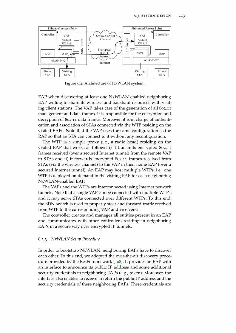
6.3 system design 113
VAP
SD
N S
wit
ch
WTPWTP
WTP RAP
HomeSTA
VisitingSTA
SD
N S
wit
ch
WTPWTP
WTPRAP
HomeSTA
VisitingSTA
Encrypted 802.11 frames
Internet
Enhanced Access Point Enhanced Access Point
WLAN NIC
Virtual WLAN
WLAN NIC
Secure Control Channel
VAP
Virtual WLAN
Controller Controller
Figure 6.2: Architecture of NxWLAN system.
EAP when discovering at least one NxWLAN-enabled neighboringEAP willing to share its wireless and backhaul resources with visit-ing client stations. The VAP takes care of the generation of all 802.11
management and data frames. It is responsible for the encryption anddecryption of 802.11 data frames. Moreover, it is in charge of authenti-cation and association of STAs connected via the WTP residing on thevisited EAPs. Note that the VAP uses the same configuration as theRAP so that an STA can connect to it without any reconfiguration.
The WTP is a simple proxy (i.e., a radio head) residing on thevisited EAP that works as follows: i) it transmits encrypted 802.11
frames received (over a secured Internet tunnel) from the remote VAPto STAs and ii) it forwards encrypted 802.11 frames received fromSTAs (via the wireless channel) to the VAP in their home EAP (over asecured Internet tunnel). An EAP may host multiple WTPs, i.e., oneWTP is deployed on-demand in the visiting EAP for each neighboringNxWLAN-enabled EAP.
The VAPs and the WTPs are interconnected using Internet networktunnels. Note that a single VAP can be connected with multiple WTPs,and it may serve STAs connected over different WTPs. To this end,the SDN switch is used to properly steer and forward traffic receivedfrom WTP to the corresponding VAP and vice versa.
The controller creates and manages all entities present in an EAPand communicates with other controllers residing in neighboringEAPs in a secure way over encrypted IP tunnels.
6.3.3 NxWLAN Setup Procedure
In order to bootstrap NxWLAN, neighboring EAPs have to discovereach other. To this end, we adopted the over-the-air discovery proce-dure provided by the ResFi framework [198]. It provides an EAP withan interface to announce its public IP address and some additionalsecurity credentials to neighboring EAPs (e.g., token). Moreover, theinterface also enables to receive in return the public IP address and thesecurity credentials of these neighboring EAPs. These credentials are

114 wireless infrastructure sharing in residential area networks
then used to set up bi-directional secure communication tunnels overthe Internet. ResFi makes use of additional vendor-specific informa-tion elements added within Probe Response (PRES), and Probe Request(PREQ) frames to enable data exchange during the standard 802.11
active scanning procedure. This way, all neighboring EAPs (even thoseoperating on different channels) can discover each other.
Fig. 6.3 illustrates the NxWLAN Setup Procedure. Upon the discov-ery, the EAP1 creates a VAP and sends a WTP Setup Request messagesto all discovered neighboring EAPs. According to the configured poli-cies, the neighboring EAPs may reject or proceed with this request.After successfully creating the WTP and network tunnel, the EAP2
responds with a WTP Setup Complete message to the requesting EAP1.In case of rejection, e.g., due to being overloaded by many visitingSTAs, an EAP may not respond, and the procedure is aborted. Afterreceiving the confirmation message, the EAP1 completes the VAP con-figuration and sets up a tunnel according to the configuration receivedfrom the neighboring EAP2. From this point, the VAP and WTPs canexchange (encrypted) 802.11 frames over the tunnel.
Over-the-air Neighbor Discovery
WTP Setup Request
WTP Setup Complete
Tunneling Encrypted802.11 frames
Neighbor EAP2 discovered
Control Channel Setup
Setup VAP
Setup WTP for EAP1
EAP1 EAP2
Figure 6.3: EAP Neighbor Discovery Procedure and Setup of WTP and VAP.
6.3.4 STA Association Procedure
Fig. 6.4 presents a STA association procedure in NxWLAN. To connectto an EAP, an 802.11 STA normally performs an active scan by broad-casting a PREQ sequentially over all available WLAN channels asspecified in the 802.11 standard. The PREQ can be received potentiallyby a RAP directly or indirectly by VAPs using the corresponding WTPsdeployed on the visiting EAPs. In standard WLANs, all APs that are

6.3 system design 115
in the reception range of the STA transmitting a PREQ should send aunicast PRES immediately upon the reception of a PREQ as an STAstays on a single channel only for a limited time [26]. In NxWLAN,the RAP answers as usual, while all WTPs forward the received PREQover tunnels to the corresponding VAP, which in turn generates aPRES to be tunneled back to the corresponding WTP for transmission.
In NxWLAN, we exploit the locality of the target environment, i.e.,the fact that there is a limited number of neighboring EAPs, andforward the PREQ to every neighboring VAP, i.e., participating EAPs.Thanks to this mechanism, NxWLAN works even with MAC addressrandomization in client stations, e.g., Android OS since version 6.0 [9].
...
WTPWTPWTPWTP STASTA
Tunneled PREQs
PREQ
RAPRAPVAPVAP
EAP
VAPVAP
EAP
...Relayed PRESs
......
...
Tunneled PRESsDirect PRES
Select the best AP
Auth. RequestTunneled
Auth. Request
WTPWTP
Calculation and programming of
TX Power for Probe Responses
(Algorithm 1)
Figure 6.4: Client association procedure in NxWLAN. For reasons of clarity,the reception of the PREQ by only a single visiting EAP is shown.
6.3.5 STA Steering
For the network load balancing reasons (in both radio and backhaul),NxWLAN steers a new client STA to a particular EAP to be eitherdirectly or indirectly served by the Home AP (RAP) or one of theneighboring APs (WTP), respectively. Therefore, on receiving a PREQframe, each EAP estimates its willingness to directly serve this clientvia RAP or indirectly via one of the deployed WTPs. The willingnessdepends on the EAP’s available capacity in the radio and backhaulnetwork as well as the quality of the radio link towards the STA. Notethat the computation of the willingness is different for RAPs andWTPs as for the latter ones, the network traffic has to be tunneled

116 wireless infrastructure sharing in residential area networks
over the backhaul to the corresponding VAP. Hence, also the availablebackhaul capacity needs to be taken into account. To this end, eachEAP periodically measures and announces its available DL and ULbandwidth to its peers.
Unfortunately, due to tight timing constraints during the searchphase, i.e., an STA stays on a distinct channel only up to 100 ms [26],the EAPs do not have enough time to harmonize their willingnessvalues in order to reach a consensus on the best EAP to serve thatparticular STA. In NxWLAN, we solve this as follows. We exploitthe fact that an ordinary 802.11 STA always connects to the AP thatprovides the strongest signal, i.e., as measured from the PRES frame.Therefore, each EAP encodes its willingness by means of setting aproper transmission power for the PRES frames to be sent to the STA,i.e., in general, different values for RAP and WTPs. If the transmitpower is selected properly, it is possible to steer the client STA toan intended RAP or WTP of a particular EAP. Therefore, we haveto ensure that the received power at the client side is higher for thePRES sent by the EAP with higher willingness. We have designed andimplemented an algorithm for computing the TX power that takesthe available capacity in both the wireless and the wired network(backhaul) as well as the quality of the radio link towards the STA intoaccount (Algorithm 3). Note that each EAP can compute willingness toserve the new STA of all neighboring EAPs having only their periodicDL/UL capacity reports as input.
Moreover, our algorithm requires knowledge of the pathloss be-tween STA and EAP. Here we assume the transmission power of theSTA is set to a fixed value, does not change over time, and is knownto all EAPs. As future work, we would like to utilize the 802.11kand 802.11v standards that allow STAs to report to EAP the RSSI ofreceived beacon frames.
The complete pseudo-code for the calculation of the transmit powerfor the PRES frames is depicted in Algorithm 3. The algorithm isexecuted independently by each EAP upon the reception of a PREQ.Note that Algorithm 3 can be easily modified so that the visited EAPcan enforce its own strategy (policy) as for the amount of resources(radio and backhaul) shared with the visiting clients. The helperfunction that maps the EAP’s willingness to serve the client to thetransmit power of the PRES frame is shown in Algorithm 4. Note thatthis algorithm takes the pathloss to the client into account to makesure that the PRES frame will be received with the intended powerregardless of the distance between client and EAP (Fig. 6.5). Considerthe following illustrative example (Fig. 6.6). Here, the PREQ sent bythe STA is received by two different EAPs with different receivedpower levels P
Preqrx , i.e., -75 dBm and -85 dBm respectively. Depending
on the network load, in radio and backhaul, each EAP computes itswillingness to serve this client w, here 0.4 and 0.025 for the lightly and

6.3 system design 117
0.0 0.1 0.2 0.3 0.4 0.5
AP willingness to serve a client, w [0=low,1=high]
−90
−80
−70
−60
−50
RX
pow
erof
Pro
be
Req
ues
t[d
Bm
]
2
4
6
8 10 12 14 16
Configured TX power of Probe Response [dBm]
Figure 6.5: Encoding of EAP’s willingness to serve a client in the transmitpower of Probe Response packet.
EAP1
STA
EAP2
PrxPreq = -75 dBm
2aAlg. 1
PtxPrep = 16 dBm
PrxPreq = -75 dBm
2aAlg. 1
PtxPrep = 16 dBm
(w1 = 0.4)
lightly loaded
(w1 = 0.4)
lightly loaded
highly loaded (w2 = 0.025)highly loaded (w2 = 0.025)
PrxPreq = -65 dBm
2b Alg. 1
PtxPrep = 2 dBm
PrxPreq = -65 dBm
2b Alg. 1
PtxPrep = 2 dBm
EAP1: PrxPrep = -79 dBm
EAP2: PrxPrep = -83 dBm
3STA will connect to EAP1 (-79 > -83)
EAP1: PrxPrep = -79 dBm
EAP2: PrxPrep = -83 dBm
3STA will connect to EAP1 (-79 > -83)
(PtxPreq = 20 dBm)
1
(PtxPreq = 20 dBm)
1
STA sendsProbe Request
Figure 6.6: Illustrative example of client steering in NxWLAN.
highly loaded EAP respectively. From both values PPreqrx and w the TX
power of the PRES PPreptx is estimated (see Fig. 6.5 with w and P
Preqrx on
x and y-axis respectively), here 16 dBm and 2 dBm respectively. Theclient receives two PRES packets and connects to EAP1 as the PRES isreceived with higher power PPrep
rx .The function getMACRate() calculates the maximum client MAC
layer throughput. When considering a single WLAN BSS and assum-ing 802.11 DCF packet-level fairness and no external interference, thefunction can be defined as follows:
getMACRate() = γk × RkPHY (6.1)

118 wireless infrastructure sharing in residential area networks
where RkPHY is the physical layer rate of client k and γk is its relative
air-time:
γk =1/Rk
PHY∑i∈C 1/Ri
PHY(6.2)
where C is the set of active clients in WLAN BSS.
Algorithm 3: Computation of the TX power of Probe Responseframes for RAP and all VAPs represented by their WTPs. Notethat an EAP has to sent multiple Probe Response frames.
Input: PPreqrx ▷ Receive power of Probe Request transmitted by scanning client station.
1 Function CalcProbeResponseTxPower:2 C← GetFatClients() ▷ Get the clients served by this EAP which are generating
large network traffic.3 R∗PHY ← EstimatePhyRate(PPreq
rx ) ▷ Estimate the expected PHY rate of the newclient when served by this EAP using the measured RX power from ProbeRequest (look-up table).
4 rapDlBh← GetAvailableDlBackhaul() ▷ Get available downlink backhaulcapacity of EAP.
5 rapUlBh← GetAvailableUlBackhaul() ▷ Get available uplink backhaul capacityof EAP.
6 R∗MAC ← GetMacRate(C,R∗PHY) ▷ Predict expected client capacity at MAC layerwhen served directly.
7 R∗ALL ← min(R∗MAC, rapDlBh) ▷ Take minimum of available DL backhaul andwireless capacity.
8 w∗← min(1,R∗ALL/RMAXALL ) ▷ Calculate and normalize AP’s willingness to serve
client directly using RAP.9 P
Preptx,rap ← EncodeEapWillingness(PPreq
rx ,w∗) ▷ Encode AP’s willingness into TXpower of Probe Response.
10 forall vap ∈ GetVaps() do11 vapDlBh← GetReportedDlBackhaul(vap) ▷ Get reported available DL
backhaul capacity of EAP.12 vapUlBh← GetReportedUlBackhaul(vap) ▷ Get reported available UL
backhaul capacity of EAP.13 R
vapALL ← min(R∗MAC, rapDlBh) ▷ Take the minimum of available backhauland wireless capacity.
14 R ′vapALL ← min(Rvap
ALL, vapDlBh, vapUlBh) ▷ Consider packet tunneling fromWTP to VAP.
15 wvap ← min(1, R ′vapALL/R
MAXALL ) ▷ Calculate EAP’s willingness to serve client
indirectly via WTP.16 P
Preptx,vap ← EncodeEapWillingness(PPreq
rx ,wvap) ▷ Encode EAP’s willingnessinto PRES TX power.
17 return PPreptx,rap,PPrep
tx,vap1, . . . ,PPrep
tx,vapN▷ Return the TX power values for all PRESs
(RAP and VAPs).
6.3.6 Normal Mode of Operation
Dealing with 802.11 Control Frames: Every 802.11 unicast frametransmission has to be acknowledged by the receiver. The 802.11
standard defines that an ACK frame has to be sent after SIFS, whichequals 10µs. Tunneling a frame between WTP and VAP through theInternet backhaul would introduce a delay in order of at least (tens of)milliseconds, which is a few orders of magnitude higher. According tostandard, such a long delay would make the transmitter always assume

6.4 prototype implementation 119
Algorithm 4: Helper function which encodes EAP’s willingnessto serve the given STA into the transmit power of the ProbeResponse frame.
Input: PPreqrx ▷ Received power (dBm) from client’s Probe Request.
Input: w ▷ EAP’s willingness to serve this client.Input: Ptx ▷ The default STA transmit power (to be known).Input: Plow
rx ▷ The minimum receive power required for reception of Probe Request, e.g.,-90 dBm
Input: Phighrx ▷ The max possible receive power of Probe Request, e.g., -50 dBm.
1 Function EncodeEapWillingness:2 PL← Ptx −P
Preqrx ▷ Pathloss of link AP-STA.
3 Pmintx ← max(1,Plow
rx +PL) ▷ Minimum TX power to be used to avoid outage.
4 PPreptx ← min(Ptx,Pmin
tx +w× (Phighrx −Plow
rx )) ▷ Assumption: STA sends ProbeRequest with max power.
5 return PPreptx ▷ Return Probe Response TX power (dBm).
that the packet was lost and should be unnecessarily retransmitted,thus wasting valuable radio resources. For those reasons, tunneling ofACK frames is infeasible and all low-level functions of 802.11 MAC,including acknowledgment and channel access (DCF), have to be re-alized by the WTP. In general, because of timing requirements, allcontrol frames have to be generated by the wireless interface of theWTPs.
MAC Rate Adaptation: The quality of wireless channels may changevery fast due to many factors, like interference and fading. Therefore,the rate adaptation has to be done quickly to keep up with wire-less channel dynamics, i.e., in order of milliseconds. As in NxWLANframes between WTPs and VAPs are tunneled over the Internet, anadditional delay is introduced. Therefore, we argue that the WTP hasto be responsible for the rate control.
6.4 prototype implementation
Fig. 6.7 shows an overview of the NxWLAN implementation. We haveimplemented our prototype using open-source tools, and we deployedit on small-form-factor-PCs based on Intel NUCs running Ubuntu14.04. A detailed description of the prototype can be found in ourtechnical report [69].
6.4.1 Discovery and Communication Module
We adapted the existing open-source implementation of ResFi [198] forover-the-air discovery and communication between neighboring EAPs.The ResFi framework was originally designed to enable distributedRadio Resource Management (RRM) within residential WLAN de-ployments, e.g., distributed radio channel assignment [201]. Radiointerfaces of participating APs are used for the efficient discovery of

120 wireless infrastructure sharing in residential area networks
wlan1wlan1
Controller
Homehostapd
Visitinghostapd
P4 Switch
eth0phy0 mac80211_hwsim
hwsim0
Tu
nn
el 0 virtual wlan0
wlan0 mon0wlan1
Simple hostapd
VAPWTPsRAP Tunnels
Control Path Data Path
Discovery Module (ResFi)
Figure 6.7: NxWLAN implementation details – components inside a singleresidential Enhanced AP.
adjacent APs operating on the same or different radio channels andto create a side-channel for the exchange of connection configurationparameters (like the public IP address of AP’s RRM unit) and secu-rity credentials. Those data enable, in turn, the setting up of securedcommunication tunnels between adjacent APs via the (wired) Internet.
6.4.2 RAP, VAP and WTP
The RAP is deployed using a modified version of hostapd [133], thatimplements over-the-air discovery. The RAP is running on a virtualwireless interface created on top of a physical wireless device.
The enabler for the implementation of the VAP is the hw_sim [128]Linux kernel module. This module is usually used to test the 802.11
MAC subsystem functionality, as it allows the emulation of wirelesstransmissions on a single host machine. We modified this module tosniff and inject 802.11 frames from and to the virtual wireless channel.The VAP contains a standard version of hostapd.
The WTP is responsible for: i) sniffing 802.11 frames by using a mon-itor interface created on top of a physical wireless device and sendingthem to the switch, ii) receiving frames from the switch, and injectingthem to a monitor interface for over the air transmission. The framesare encapsulated with a RadioTap header. Moreover, the WTP containsa simplified version of hostapd, which is necessary for enabling ACKframe generation and rate control. Note that to force a WiFi deviceto respond with an ACK frame, one must configure a proper MACaddress matching the required destination MAC address. Moderndevices usually accommodate multiple (up to 8) MAC addresses for asingle physical interface.

6.5 evaluation 121
6.4.3 802.11 Frames Tunneling
Tunneling of 802.11 frames between the VAP and the WTPs is realizedusing L2TP tunnels [170], which are created after the EAP neighbordiscovery during the bootstrap phase. Basically, the L2TP protocol isused for interconnecting LAN networks over the Internet.
The switching of the 802.11 frames between the tunnels and themonitor interfaces is performed by a Software-Defined Networking(SDN) software switch. The switch was implemented in P4 [19], whichis a new approach for SDN [138] providing a high-level languagefor programming the forwarding plane of packet processors. Ourswitch forwards native 802.11 frames based on their destination MACaddress. The switch contains programmable match-tables that allowscontrolling its behavior.
6.4.4 Probe Response TX Power Programming
We modified the ath9k wireless driver to allow programming of thetransmission power of PRES frames. Every time the driver is handlinga PRES frame transmission, it takes the appropriate entry from theTX power table filled before by the EAP controller via the debugFS
interface. The appropriate TX power entries are calculated accordingto the algorithm presented in §6.3.5.
6.4.5 Rate Adaptation
For rate control, we use the Minstrel [187] algorithm as it is the mostcommonly used rate adaptation algorithm for 802.11 networks inLinux based systems. However, we faced a couple of problems whentrying to use it for the traffic injected over a monitor interface, i.e.,injected frames were not rate controlled and always transmitted withthe basic rate. Therefore, we used the approach as suggested in [200,212] where an association of an STA is faked to force the hostapdapplication to create an entry in the rate table for the given STA.Having such entry, the Minstrel algorithm can control the rate.
6.5 evaluation
This section is divided into three parts. First, we discuss the selection ofthe parameters for our evaluation scenarios. Second, we demonstratethe feasibility of NxWLAN’s implementation using COTS equipmentand provide results of its performance obtained in small scale 802.11
testbeds. Afterward, we extend our performance studies by usingnetwork simulations in ns-3.

122 wireless infrastructure sharing in residential area networks
6.5.1 End-to-end Parameter Selection
Since end-to-end bandwidth and latency between two neighboringEAPs significantly impact the operation and performance of NxWLAN,it is important to select those parameters properly for our test scenar-ios. Unfortunately, to the best of our knowledge, there are no largescale measurements of end-to-end connection parameters, especiallybetween residential clients operated by diverse ISPs. Due to a lackof such information, we were forced to deduce and estimate thoseparameters.
It is important to note that with NxWLAN, we are targeting highlypopulated residential areas. Moreover, we assumed and consideredthe following characteristics. In most cities, there are only a few dif-ferent ISPs in each city, making it highly probable that some of theneighboring EAPs are connected to the same one. In such cases, theend-to-end delay between two EAPs should be low. However, in casesin which cable modems are used as an access technology, subscribers(to some extent) are sharing their available bandwidth. Finally, weargue that in the future, highly populated areas have the best chancesto be repeatedly updated with the newest access technologies, likeFiber-to-the-Building/Home (FTTx).
Downlink and Uplink Speeds: A first approximation of user down-link and uplink speeds can be obtained from on-line tools, for example,using www.speedtest.net. Such tools allow users to test their Internet con-nection capacity and collect those measurements. In addition, statisticsof average connection speeds for countries and even for some big-ger cities are provided. For example, in 2020, the average connectionperformance in Germany is 115 Mbps in the downlink, and almost27 Mbps in the uplink (i.e., 115/27 Mbps), while Singapore is the coun-try with the fastest average connections, i.e., 225/225 Mbps. The worldaverage equals 85/45 Mbps. Of course, the presented measurementsshow the link parameters between the user and the closest test server.Nevertheless, we argue they are sufficient for the first approximationof links between two neighboring EAPs.
End-to-End Delay: To get the first estimation of the end-to-enddelay between residential clients, we have performed small scaleexperiments in Berlin. We measured the Round Trip Time (RTT) usingthe ping tool between three residential clients connected to differentISPs in different parts of the city. Our results have shown that theaverage RTT is in the range of 40-50 ms.
The end-to-end delay between two residential clients, A and B, iscomposed of the access delay of client A, the delay between borderrouter of A’s ISP and Internet Exchange Point (IXP), the delay betweenIXP and border router of B’s ISP; and the access delay of B. If bothusers are subscribed to the same ISP, the end-to-end delay consistsonly of the access delays. In [166] authors measured and reported that

6.5 evaluation 123
the access delay for most residential users is in the range of 0–10 ms.This is consistent with results from Japan performed in 2009 andpresented in [195]. As reported, the access delay for the four biggestISPs in big cities in Japan was around 1-2 ms. Also, data presentedin [49] confirms the range of 0-10 ms. Hence, we can assume that theaccess delay equals 10 ms in the worst-case scenario.
Unfortunately, we did not find similar measurement reports forthe delay between ISPs and IXPs. However, Feldmann et al. [132]found out that in many cases for residential Internet connections, thelocal (access) RTT dominates the remote (end-to-end) RTT, i.e., it takeslonger to get to the Internet than traveling the Internet. They alsoreported that local RTT is on average 7 ms, while a remote RTT of13 ms was reported for the users and servers located in Europe. Aswe target highly populated areas, we can assume that there is at leastone IXP in each bigger city, which minimizes the delay between twoISPs. Taking all of this into account, we assume that the delay betweenISP and IXP does not exceed 2 ms. Considering all our assumptions,the estimated end-to-end delay equals 24 ms and RTT 48 ms, which isconsistent with our small scale measurements (40-50 ms).
Finally, the maximal RTT is bounded by the time the STA stays ona single channel waiting for PRES after sending PREQ. In [26], thescanning interval was reported to be 100 ms for most WiFi cards. Ifthe RTT between two EAPs is higher than this interval, NxWLANsimply does not work. For this reason, EAPs should measure RTTbefore setting up the NxWLAN relationship, and abandon such anattempt in case RTT exceeds a predefined scanning interval.
Selected Parameters: Having investigated available measurementdata, we argue that 50 Mbps of bandwidth, and an end-to-end delay of25 ms between two residential clients are feasible. In our experiments,we always use RTT of 50 ms (as the worst-case scenario), while forInternet connection, we evaluated several different combinations ofdownlink and uplink speeds.
6.5.2 Testbed Results
In this section, we present results from the evaluation of the NxWLANprototype in a small real-world testbed. At first, the experimentalmethodology is introduced, thereafter the results are presented anddiscussed.
Methodology: The proposed NxWLAN approach is analyzed bymeans of experiments in a small indoor 802.11n testbed. The setupshown in Fig. 6.8 mimics two adjacent residential apartments, eachequipped with a single EAP. During the experiment, a client stationwas placed at ten different locations within Bob’s apartment, as shownin the figure.

124 wireless infrastructure sharing in residential area networks
The hardware used for the EAPs and client stations were standardx86 machines with Ubuntu 14.04 and Atheros WiFi NICs using AR9280
chipsets. For our experiments, we set the two EAPs on two differentnot otherwise used channels of the 5 GHz ISM band, i.e., channel40 and 48. The physical layer was set to 802.11n. We used the trafficcontrol tool [89] to emulate RTT of 50 ms and backhaul capacity (bothUL and DL) of 50 Mbit/s between two EAPs.
We considered the following two scenarios: i) without any back-ground traffic and ii) with high background traffic on home EAPand lightly loaded neighboring EAP. In both cases, we measured thedownlink TCP/IP throughput towards the client station using the iperftool [169]. We compare NxWLAN with a baseline in which the clientstation is always served by the home EAP.
Alice’sAP
Bob’s AP
0m
2m
6m
8m
4m
10m
12m
14m
16m
18m
Figure 6.8: Experiment setup: two adjacent residential apartments each witha single EAP.
Experiment 1: (Extended coverage): The objective of this experimentis two-fold. First, we want to show that the proposed approach canincrease the home WLAN coverage by using the neighboring EAP.Second, the visiting EAP can provide high throughput to the clientstation, although the 802.11 data traffic is tunneled to the home EAPover the emulated Internet connection.
Results 1: Fig. 6.9 shows the mean and standard error of the downlinkthroughput to the client station at the ten different locations. Everylocation point was measured ten times with the backlogged trafficover a period of 10s. The results reveal that in contrast to baseline,NxWLAN can provide coverage even at the far corner of the apart-ment. Moreover, the client achieves a high throughput (close to themaximum), while being served by the WTP on the neighboring EAP(locations 10-18 m).
Experiment 2: (Load balancing): In this experiment, we consider ascenario with unequal network load, i.e., the home EAP (Bob) ishighly loaded, whereas the neighboring EAP (Alice) is unused. Tothis end, we use two client stations with bulk TCP data transfers. We

6.5 evaluation 125
demonstrate that NxWLAN can steer the client device to the lightlyloaded EAP for load balancing reasons by manipulating the transmitpower of the PRES frame.
Results 2: In Fig. 6.10, we observe that compared to baseline, NxWLANcan dramatically increase the downlink throughput of the client. Specif-ically, in the baseline, the client station has to share the wirelessmedium with the two backlogged low-bitrate users (i.e., PHY rate of6 Mbps) in the home EAP, whereas in NxWLAN, the client is steeredto the neighboring idle EAP (Alice). Even at very close locations to thehome EAP, our proposed transmit power control for the PRES framescan successfully steer the client device to the far but lightly loadedneighboring EAP.
Note that in the baseline case, the performance of the STA usingrate control algorithm suffers due to packet fairness, i.e., it gets accessto the channel with the same probability as the STAs with the fixedslow rate (6 Mbps). Thus most of the time the STA waits for access,while its channel occupancy time is the shortest one. This issue can bepartially addressed by using Transmit Opportunity, here 1.5 ms.
0.0 2.5 5.0 7.5 10.0 12.5 15.0 17.5
Waypoint [m]
0
5
10
15
20
Th
rou
ghp
ut
[Mb
it/s
]
NxWLAN: served by VAP
Home AP only (µ± σx)
NxWLAN (µ± σx)
Figure 6.9: NxWLAN performance in the case of no background traffic. Theclient STA is served by WTP in Alice’s EAP after 12 m way-point.
6.5.3 Simulation Results
Methodology: We analyze the performance of larger configurations ofNxWLAN using network simulations in ns-3 [214]. Here, we considera scenario with five co-located EAPs in an area of the size of 300m×300m, i.e., one Home EAP in the middle and four neighboring EAPsat a distance of 75 m to the Home EAP operating on different channels.
For EAP’s Internet connection, we evaluate a couple of combinationsof DL and UL speeds and the round trip time of 50 ms.

126 wireless infrastructure sharing in residential area networks
0.0 2.5 5.0 7.5 10.0 12.5 15.0 17.5
Waypoint [m]
0
5
10
15
Th
rou
ghp
ut
[Mb
it/s
]NxWLAN: served by VAP
Home AP only w/ TXOP=0ms (µ± σx)
Home AP only w/ TXOP=1.5ms (µ± σx)
NxWLAN (µ± σx)
Figure 6.10: NxWLAN performance in the case of congested home EAP (Bob).The client STA is always served by WTP in Alice’s EAP.
We use the 802.11n standard for wireless access with HT40, shortGuard Interval, and Minstrel rate adaptation algorithm. All EAPsoperate on different RF channels in the 5 GHz ISM band. During asingle simulation, the client STA is placed in one of the locationsin the grid, calculated as (30x, 30y), x,y ∈ {0, 1, . . . , 10}. A single DLTCP bulk flow from a server in the backhaul network to the STA isestablished, and its throughput is measured. For each position, thesimulation is repeated 25 times, the simulation time is set to 10 s, andresults from the first 3 s are discarded to exclude the warm-up period.
We conduct two kinds of experiments and for both, we run a cam-paign of simulations without (baseline) and with NxWLAN enabled.
Experiment 1: (Extended coverage): In this experiment, the objectiveis to show that coverage of the home WLAN can be extended byutilizing the neighboring EAPs. As already mentioned, each EAPis operating on a different RF channel, and there is only one STAreceiving data. Thus, there are no interferences between EAPs, and theextension and throughput gains are achieved with NxWLAN only byreducing pathloss, i.e., STA always connects to the closest EAP withthe strongest signal.
Results 1: As shown in Fig. 6.11, NxWLAN offers a large gain incase the backhaul UL speed is high, e.g., when DL/UP equals 100/50
Mbps it offers on average a gain of STA throughput of 2.5×. Notethat even for a very slow backhaul configuration, like 20/5 Mbps,NxWLAN still offers gain compared to baseline, i.e., 1.24×, which isdue to improving the performance at the cell edge of the Home EAP.
Experiment 2: (Load balancing): In order to evaluate the performanceof NxWLAN with unequally loaded EAPs, we create a similar setupas in Experiment 1. In addition to the client STA of interest, we add

6.5 evaluation 127
100/50 50/25 20/10 20/5
Backhaul speed [DL/UL Mbit/s]
0
10
20
30
40
50
ST
Ath
rou
ghp
ut
[Mb
it/s
]
Home AP only
NxWLAN
Figure 6.11: Simulation results of NxWLAN performance in a scenario withno background traffic.
three additional client STAs served by the Home EAP and located at adistance of 0, 20, and 40 m from it. They generate background traffic,which saturates the Home EAP cell. To this end, each of them wasan endpoint of a single TCP bulk flow from a server in the backhaulnetwork.
200/100 100/50 80/40 50/25
Backhaul speed [DL/UL Mbit/s]
0
10
20
30
40
50
ST
Ath
rou
ghp
ut
[Mb
it/s
]
Home AP only
NxWLAN
Figure 6.12: Simulation results of NxWLAN performance in a scenario withthe congested home EAP.
Results 2: In Fig. 6.12, we can observe that with high-speed back-haul, NxWLAN allows the STA to achieve a high throughput gain ascompared to baseline, e.g., with 200/100 Mbps backhaul NxWLANoffers on average a gain of 7.7×. In the case of a slower backhaul, thebackhaul becomes the bottleneck, and therefore the gain of NxWLANis limited, e.g., with 50/25 Mbps backhaul, NxWLAN provides anaverage gain of 1.9×.

128 wireless infrastructure sharing in residential area networks
Results from our experiments and simulations are consistent andconfirm that NxWLAN can provide significant throughput gains inresidential environments.
6.6 summary
In this chapter, we have shown that the collaboration through in-frastructure sharing and cross-network traffic delivery bring massivegains in the coexisting networks in the unlicensed spectrum bands. Wehave used residential WiFi networks as an example of co-located andseparately owned wireless networks. Nevertheless, the presented con-cepts and mechanisms (e.g., tunneling of frames user’s between APsover wired Internet backbone) can be also applied to heterogeneousenvironments to enable cross-technology traffic delivery.
In particular, we have designed NxWLAN, a distributed system thatenables neighboring APs to mutually serve each others’ client stationswhen it is more efficient than the direct transmission from the homeAP. NxWLAN provides a secure extension of a user’s home WLANthrough the usage of co-located APs while maintaining the same levelof security as the home AP (e.g., WPA2) and without revealing anysecurity credentials to untrusted neighboring APs. This is achievedby tunneling (i.e., over-the-wire relaying) of encrypted WiFi framesbetween home and visited APs over the Internet backbone.
We have implemented and evaluated a NxWLAN prototype usingCOTS hardware in a mimicked residential scenario as well as throughsimulations. Our results show that NxWLAN can increase the radiocoverage of the home WLAN and improve users‘ performance whiletaking the load of the wireless radio channel and backhaul networkof both the neighboring and the home APs into account. The gainsare achieved thanks to the shortening of the communication linkand balancing the network load over co-located APs that operate ondifferent radio channels or experience asymmetric workloads.
As future work, we would like to evaluate potential gains of simul-taneous usage of XZero and NxWLAN in a scenario with coexistingheterogeneous wireless networks. Specifically, in a case when channelaccess of a home AP is frequently blocked due to interferences fromco-located LTE* BS (i.e., through carrier sensing mechanism), it mightbe worth redirecting WiFi traffic to a neighbouring AP which is cur-rently being nulled by the BS. Note that nulling of the home AP mightbe not possible, as the number of TX antennas is limited and hencethe BS can null only a limited number of WiFi nodes at the same time.

Part III
L E A R N I N G T O C O L L A B O R AT E


7F R A M E W O R K F O R M A C H I N E L E A R N I N G I NN E T W O R K I N G R E S E A R C H
As discussed in the background chapter (§2.5), the problem of learn-ing collaborative behaviors in multi-agent environments has attractedmuch research. Such environments contain a number of agents thattake independent decisions based on local observations to contributeto an overall goal or maximize individual rewards. The proposedlearning-based collaborative algorithms are successfully applied invirtual environments of multiplayer video games and real-world do-mains, e.g., in robotics, self-driving cars.
We argue that those learning-based algorithms might be also helpfulin handling complex interaction and dependencies in heterogeneousnetworks and eventually improving their coexistence. Specifically, webelieve that wireless nodes can learn to collaborate and optimizewireless resources usage through interaction and observation of eachothers’ activity.
7.1 introduction
In order to enable the studying of learning-based approaches in thewireless networking area, we have designed and implemented anns3-gym framework [65]. The framework is based on two well-knownand acknowledged by research community toolkits, namely, ns-3 andOpenAI Gym. It combines the advantages of these two, i.e., the ver-ified and tested models of ns-3 and the simplicity of prototypinglearning-based algorithms in Python language using numerical com-putation libraries (e.g., Tensorflow [4, 100]). Specifically, our ns3-gymallows representing an ns-3 simulation as an environment in the Gymframework and exposing state and control knobs of entities from thesimulation for the agent’s learning purposes. In simple form, it fa-cilitates feeding the learning models with the data generated in thesimulator.
The framework is generic and can be used in a wide range ofnetworking problems including homogeneous and heterogeneouswireless coexistence scenarios. Specifically, it can be used to develop,train and compare the performance of multi-agent learning-basedcollaboration algorithms in the virtual conditions of well-defined sim-ulation scripts (i.e., environments). In this chapter, we first describethe details of our ns3-gym framework. Then, we present an illustrativeexample from the cognitive radio area, where a wireless node learnsthe channel access pattern of a periodic interferer to avoid collisions
131

132 framework for machine learning in networking research
with it. In the next Chapter 8, we use ns3-gym for evaluation of a dis-tributed learning-based algorithm that allows nodes to collaborativelylearn optimal channel access parameters.
7.2 motivation
We believe that the application of machine learning (ML) techniquesin networking research is slowed down by the following factors:
• The existence of a knowledge gap — networking researchers lackML related knowledge and experience while ML researcherslack knowledge in networking [179].
• Lack of training environments — reinforcement learning (RL) re-quires a large number of interactions with an environment totrain an agent properly. The best way is to use a real-worldenvironment. However, it is time-consuming, and researchersusually lack the skills and/or hardware to set up a testbed, whilerandom exploration (required in RL to learn) in real networkdeployments can be unsafe for their operation.
• The need for reliable benchmarking [20] — currently, researchersbuild and use their environments on a case-by-case basis. Someof them use network simulators, others real-world hardware, i.e.,testbed. This issue makes the direct comparison of the perfor-mance of published algorithms difficult.
We argue that developing learning-based algorithms and trainingthem with the data generated in a simulation is often more practical(i.e., easier, faster, and safer) than running experiments in the realworld. Moreover, it allows everybody to test his/her ideas without aneed to buy and set up costly testbeds.
Furthermore, thanks to transfer learning, i.e., the ability to reusepreviously acquired knowledge in a new (more complex) system oran environment, the agent trained in a simulation can directly interactor be retrained in the real world much faster than when startingfrom the scratch [36]. How well the agent copes with the real-worldenvironment depends on the accuracy of the simulation models usedduring training. Our framework uses the ns-3 network simulator thatstrives to make its models reflect reality as close as possible. Hence,we believe the knowledge acquired in a simulation should remainreasonable also for the real world.
7.3 framework architecture
The architecture of ns3-gym as depicted in Fig. 7.1 consists of thefollowing major components, namely: ns-3 network simulator and

7.3 framework architecture 133
Node 1
Node N
Node 2Wired/Wireless
Network
Environment
Gateway
Environment
Proxy
OpenAI Gym
ns3-gym Middleware(ZMQ)
State Collection andAction Execution Callbacks
Agent
Gym API
Network Model
NetSimns-3
1
Workflow
1
2
3
4
C++
Python
Figure 7.1: Architecture of ns3-gym framework.
OpenAI Gym framework. The former is used to implement environ-ments, while the latter unifies their interface. Our main contribution isthe design and implementation of a generic interface between OpenAIGym and ns-3, which allows for seamless integration of those two. Inthe following, we describe our ns3-gym framework in detail.
7.3.1 ns-3 Network Simulator
ns-3 is a core part of our framework since it is used to implement asimulation scenario serving as an environment for a learning agent. Asimulation scenario contains a network model together with sched-uled changes in simulation conditions. One can create even complexnetwork models and study them under various traffic and mobilitypatterns by assembling the detailed models of communication com-ponents and channels provided in ns-3. An experimenter triggerschanges in some conditions during the course of a simulation byscheduling events, e.g., start/stop traffic sources.
The state of the entire network model is a composition of states ofits elements. The state representation of each entity depends on itsimplementation. For example, the state of a packet queue is a numeri-

134 framework for machine learning in networking research
cal value indicating the number of enqueued packets, while most ofthe protocols (e.g., Transmission Control Protocol (TCP)) are imple-mented as finite-state machines (FSM) jumping between predefinedstates. Note that in the latter case, the state can also be encoded intonumerical values. ns-3 provides proper interfaces allowing readingthe internal state of each entity.
It is up to the designer to decide which part of the simulationstate will be exposed to the agent for the learning purpose. In mostcases, it will be a sub-set of the network model state together withsome statistics collected during the last step execution (e.g., numberof TX/RX packets in a network device and mean inter-packet arrivalinterval). Usually, the observed state will be limited to a state of asingle instance of the protocol that the agent will control. The restentities of the network model implement and evolve the complex stateof the environment the agent is going to interact with. Similarly, thepossible actions are limited to changes of parameters of the observedentity. In other words, the agent can only partially observe the networkmodel by interacting with it though taken actions and experiencingits response in changes of the local observations.
7.3.2 OpenAI Gym
The main goal of the Gym framework is to provide a standardizedinterface allowing to access the state and execute actions in an envi-ronment. Note that the environment is defined entirely inside the sim-ulation scenario, making the Python code environment-independent,which allows the exchange of the agents’ implementation while keep-ing the environment’s conditions reproducible.
7.3.3 ns3-gym Middleware
ns3-gym middleware interconnects ns-3 network simulator and OpenAIGym framework. Specifically, it takes care of transferring state (i.e.,observations) and control (i.e., actions) between the Gym agent andthe simulation environment.
The middleware consists of two parts, namely Environment Gatewayand Environment Proxy. The gateway resides inside the simulator andis responsible for gathering the environment state into structurednumerical data and translating the received actions, again encodedas numerical values, into corresponding function calls with properarguments. The proxy receives the environment state and exposes ittowards an agent through the pythonic Gym API. Note that ns3-gymmiddleware transfers the state and actions as numerical values, and itis up to the researcher to define their semantics.

7.4 implementation 135
7.4 implementation
ns3-gym is a toolkit that consists of two software components (i.e.,Environment Gateway written in C++ and the Environment Proxy inPython) being add-ons to the existing ns-3 and OpenAI Gym frame-works. The toolkit simplifies the tasks of developing the networkingenvironments and training of the learning agents by taking care of thecommon tasks and hiding them behind easy to use API. Specifically,ns3-gym provides a way for collecting and exchanging informationbetween frameworks (including connection initialization and data(de)serialization), takes care of the management of ns-3 simulationprocess life-cycle as well as freezing the execution of simulation duringthe interaction with an agent. The communication between compo-nents is realized with ZMQ [213] sockets using the Protocol Buffers [75]library for serialization of messages.
The software package, together with clarifying examples, is pro-vided to the community as open-source under a GPL in our onlinerepository1. It is also available as a so-called ns-3 App that can beintegrated with any version of the simulator2.
In the following subsections, we describe the ns3-gym componentsin detail and explain how to use them with code examples.
7.4.1 Environment Gateway
In order to turn a ns-3 simulation scenario into a Gym environment,one need to i) instantiate OpenGymGateway and ii) implement its call-backs functions listed in Listing 7.1. Note that the functions have to beregistered in the gateway object.
1 Ptr<OpenGymSpace> GetObservationSpace();
2 Ptr<OpenGymSpace> GetActionSpace();
3 Ptr<OpenGymDataContainer> GetObservation();
4 float GetReward();
5 bool GetGameOver();
6 std::string GetExtraInfo();
7 bool ExecuteActions(Ptr<OpenGymDataContainer> action);
Listing 7.1: ns3-gym C++ interface.
The functions GetObservationSpace and GetActionSpace are usedto define observation and action spaces (i.e., data structures storingobservations and actions encoded as numerical values), respectively.Both spaces descriptions are created during the initialization of theenvironment and sent to the environment proxy object in the initial-ization message – Fig.7.2, where they are used to create corresponding
1 https://github.com/tkn-tub/ns3-gym/
2 https://apps.nsnam.org/app/ns3-gym

136 framework for machine learning in networking research
spaces in the Python domain. The following spaces defined in theOpenAI Gym framework are supported, namely:
1. Discrete — a discrete number between 0 and N.
2. Box — a vector or matrix of numbers of single type with valuesbounded between low and high limits.
3. Tuple — a tuple of simpler spaces.
4. Dict — a dictionary of simpler spaces.
Listing 7.2 shows an example definition of the observation space asC++ function. The space is going to be used to observe queue lengthsof all the nodes available in the network. The maximal queue sizewas set to 100 packets. Hence the values are integers and boundedbetween 0 and 100.
1 Ptr<OpenGymSpace> GetObservationSpace() {
2 uint32_t nodeNum = NodeList::GetNNodes ();
3 float low = 0.0;
4 float high = 100.0;
5 std::vector<uint32_t> shape = {nodeNum,};
6 std::string type = TypeNameGet<uint32_t> ();
7 Ptr<OpenGymBoxSpace> space = CreateObject<OpenGymBoxSpace>(low,
↪→high,shape,type);
8 return space;
9 }
Listing 7.2: Example definition of the GetObservationSpace function.
The step in ns3-gym framework can be executed synchronously,i.e., scheduled in predefined time-intervals (time-based step), e.g.,every 100 ms, or asynchronously, i.e., fired by an occurrence of specificevent (event-based step), e.g., packet loss. In both cases, one hasto define a proper callback that triggers the Notify function of theOpenGymGateway object.
After being notified about the end of a step – Fig.7.3 – the gatewaycollects the current state of the environment by calling the followingcallback functions:
1. GetObservation – collect values of observed variables and/orparameters in simulation;
2. GetReward – get the reward achieved during last step;
3. GetGameOver – check a predefined gameover condition;
4. GetExtraInfo – (optional) get extra information associated withthe current environment state.

7.4 implementation 137
The listing 7.3 shows an example implementation of the GetObservationobservation function. First, the box data container is created accordingto the observation space definition. Then the box is filled with thecurrent size of the queue of the WiFi interface of each node.
1 Ptr<OpenGymDataContainer> GetObservation() {
2 uint32_t nodeNum = NodeList::GetNNodes ();
3 std::vector<uint32_t> shape = {nodeNum,};
4 Ptr<OpenGymBoxContainer<uint32_t>> box =
↪→CreateObject<OpenGymBoxContainer<uint32_t>>(shape);
5
6 for (uint32_t i=0; i<nodeNum; i++) {
7 Ptr<Node> node = NodeList::GetNode (i);
8 Ptr<WifiMacQueue> queue = GetQueue (node);
9 uint32_t value = queue->GetNPackets();
10 box->AddValue(value);
11 }
12 return box;
13 }
Listing 7.3: Example definition of the GetObservation function.
The ns3-gym middleware delivers the collected environment’s stateto an agent that, in return, sends the action to be executed. Notethat the execution of a simulation is stopped during this interac-tion. Similarly to the observation, the action is also encoded as nu-merical values in a container. The user is responsible to implementthe ExecuteActions callback, that maps the numerical values to properactions, e.g., setting minimum MAC contention window size for the802.11 WiFi interface of each node – Listing 7.4.
1 bool ExecuteActions(Ptr<OpenGymDataContainer> action) {
2 Ptr<OpenGymBoxContainer<uint32_t> > box =
↪→DynamicCast<OpenGymBoxContainer<uint32_t> >(action);
3 std::vector<uint32_t> actionVector = box->GetData();
4
5 uint32_t nodeNum = NodeList::GetNNodes ();
6 for (uint32_t i=0; i<nodeNum; i++) {
7 Ptr<Node> node = NodeList::GetNode(i);
8 uint32_t cwSize = actionVector.at(i);
9 SetCwMin(node, cwSize);
10 }
11 return true;
12 }
Listing 7.4: Example definition of the ExecuteActions function.

138 framework for machine learning in networking research
7.4.2 Environment Proxy
The environment proxy is the northbound part of the middleware.It is wrapped by the Ns3GymEnv class that inherits from the genericGym environment, making it accessible through OpenAI Gym API.Specifically, the proxy translates the Gym function calls into messagesand sends them towards an environment gateway over a ZMQ socket.
1 import gym
2 import ns3gym
3 import MyAgent
4
5 env = gym.make(’ns3−v0’)6 obs = env.reset()
7 agent = MyAgent.Agent()
8
9 while True:
10 action = agent.get_action(obs)
11 obs, reward, done, info = env.step(action)
12
13 if done:
14 break
Listing 7.5: Example Python script showing interaction between an agentand ns-3 environment.
In the code listing 7.5, we present an example Python script showingthe usage of the ns3-gym framework. First, the ns-3 environment andagent are initialized — lines 5–7. Note that the creation of ns3-v0 en-vironment is achieved using the standard Gym API. Behind the scene,the ns3-gym engine starts an ns-3 simulation script located in the cur-rent working directory, establishes a ZMQ connection, and waits forthe environment initialization message — Fig.7.2. Optionally, the ns-3environment can be adjusted by passing command line arguments dur-ing the start of the script (e.g., seed, simulation time, number of nodes,etc.). This, however, requires to use Ns3Env(args={arg=value,...})
constructor instead of standard Gym::make(’ns3-v0’).At each step, the agent takes the observation and returns, based
on the implemented logic, the next action to be executed in the en-vironment — lines 9–11. Note that agent class is not provided in theframework, and the developers are free to define them as they want.For example, the simplest agent performs random actions. The exe-cution of the episode terminates (lines 13–14) when the environmentreturns done=true, which can be caused by the end of the simulationor meeting the predefined game-over condition.
In addition, a Gym environment also exposes a Gym::reset() func-tion that allows reverting the environment into the initial state. Thens3-gym implements the reset function by simply terminating thesimulation process and starting a new one reusing mechanisms of the

7.4 implementation 139
CreateGym::make()
NetworkModel
Start simulationscript Create
Create
Wait
ns-3 process
Send initializationmessage
EnvironmentProxy
EnvironmentGateway
Return env. object
Figure 7.2: Implementation of the Gym::make() function.
Gym::step(action)
Executestep Execute
action
Collect environment
state
Return state(obs., done,
reward, info)
Return state
Execute simulation
until the endof env. step
ns-3 process
Notify step end
NetworkModel
EnvironmentProxy
EnvironmentGateway
Figure 7.3: Implementation of the Gym::step(action) function.
make function. Note that the mapping of all the described functionsbetween corresponding C++ and Python functions is done by the ns3-gym framework automatically hiding the entire complexity behindeasy to use API.
7.4.3 Discussion
Although the ns-3 project supports Python bindings that would allowus to integrate it with OpenAI Gym directly in a single Python process,we have not taken this approach and decided to split ns3-gym intotwo communicating processes, i.e., ns-3 (C++) and OpenAI Gym(Python). We believe that the split is essential due to the followingreasons. First, during the learning process, an OpenAI Gym agenthas to keep its state (i.e., gained knowledge) across multiple episodes(i.e., simulation runs). Having two separate processes makes thisrequirement easier to fulfill. Moreover, it allows running multiple ns-3instances in parallel, even in a distributed environment. Hence, theagent learning process can be executed on powerful machines withthe support of GPUs, while ns-3 instances on ones equipped only withdecent CPUs. This feature is essential for techniques like A3C [139],which uses multiple agents interacting with their own copies of theenvironment for more efficient learning. Then, the independent, hence

140 framework for machine learning in networking research
more diverse, experience of all agents is periodically fused to theglobal learning network. Second, the ns-3 project is developed in C++,while Python bindings are generated automatically as an add-on thatallows only writing simulation scripts. Apparently, the developmentof scripts in C++ is easier for newcomers as there are much more codeexamples (while only a few in Python) and documentation, and moresupport from the community. Finally, having the C++ implementationallows updating existing C++ simulation scripts and examples to beused as OpenAI Gym environments.
7.5 environments
In the following subsections, we present a typical workflow whenusing the ns3-gym framework. Then, we briefly describe the envi-ronments provided as examples. Finally, we discuss the feasibilityof implementing multi-agent environments and the direct usage ofagents trained in a simulated environment in a real-world experimentusing the emulation mode available in ns-3.
7.5.1 Typical Workflow
A typical workflow of developing and training an agent is shownas numbers in Fig. 7.1: (1) Create a model of the network and con-figure scenario conditions (i.e., traffic, mobility, etc.) using standardfunctions of ns-3; (2) Instantiate ns3-gym environment gateway inthe simulation, i.e., create OpenGymGateway object and implement call-backs functions that collect a state of the environment to be sharedwith the agent and execute actions received from it; (3) Create thens3-gym environment proxy, i.e., create ns3-gym using the standardGym::make(’ns3-gym’) function; (4) Develop an agent using availablenumerical Python libraries that interacts with the environment usingthe standard Gym::step(action) function; (5*) Train the agent.
7.5.2 Example Environments
In addition to the generic ns3-gym interface where one can observeany variable in a simulation, we also provide custom environmentsalready prepared for specific use-cases. For example, TcpNs3Env is anenvironment for controlling parameters of TCP, where the observationstate, action and reward function are predefined using the RL map-ping proposed by [123]. This environment simplifies the developmentof own RL-based TCP solutions and can be further used as a bench-marking suite to compare the performance of different RL approachesin the context of TCP.DashNs3Env is another predefined environment for testing adaptive
video streaming solutions using our framework. Again the RL map-

7.6 case-study examples 141
ping for observation state, action and reward is predefined, i.e., asproposed by [136].
7.5.3 Multi-Agent Environments
As a communication network by nature is a multi-agent environment(e.g., wireless network), we believe that our ns3-gym framework maybe a useful tool to advance research and knowledge in the area ofmulti-agent learning in the context of wireless networks. Note that im-plementing a multi-agent environment can be achieved using multiple(i.e., one for each agent) or a single instance of the OpenGymGateway inns-3 simulation script. In the former case, the gateways communicatewith corresponding agents in separate Python processes, while in thelatter case, all agents are being trained in a single Python process.However, this approach requires to implement a switching mechanismsteering observations and actions to the proper agents (e.g., based onnode ID added to the observation vector).
7.5.4 Emulation Mode
Since the ns-3 allows for usage of real Linux protocol stacks insidesimulation [168] as well as can be run in the emulation mode forevaluating network protocols in real testbeds [25] (possibly interactingwith real-world implementations), it can act as a bridge between anagent implemented in Gym and a real-world environment. Thosecapabilities give the researchers the possibility to train their agents ina simulated network (possibly very fast using parallel environments)and test them afterward in a real testbed without changing any singleline of code. We believe that this intermediate step is of great im-portance for developing ML-based network control algorithms as itreduces the possible discontinuities when moving from simulation toreal-world.
7.6 case-study examples
In this section, we present two examples of a Cognitive Radio (CR)transmitter that learns the pattern of a periodic interferer to avoidcollisions with it. In the first example, the transmitter can sense theentire bandwidth (i.e., M = 4 wireless channels), whereas, in thesecond example, it can only monitor its own channel.
Specifically, we consider the problem of channel selection in a wire-less multi-channel environment, e.g., 802.11 networks with externalinterference. The objective of the agent is to select for the next timeslot a channel free of interference. We consider a simple illustrative ex-ample where the external interference, e.g., a microwave oven, follows

142 framework for machine learning in networking research
a periodic pattern, i.e., sweeping over all four channels in the sameorder as shown in Fig. 7.4.
0 10 20 30 40 50 60
Time Step
1
2
3
4
Ch
an
nel
s
Figure 7.4: Channel access pattern of periodic interferer.
We created a simple simulation scenario using existing functionalityfrom ns-3, i.e., interference created using WaveformGenerator classand sensing performed using SpectrumAnalyzer class. Our proposedRL mapping is:
• observation — occupation on each channel in the last time slot,i.e., a vector indicating whether a received signal power on eachchannel is below (-1) or above (+1) a predefined threshold, e.g.,-82 dBm; in addition, we can combine observations from last Ntime-steps;
• action — set the channel to be used for the next time slot,
• reward — +1 if no collision with interferer; otherwise -1,
• gameover — if more than three collisions happened during thelast ten time-slots
Our simple RL-based agent is based on the deep Q-learning tech-nique. It uses a neural network with two fully connected layers, i.e.,input and output. The M ·N neurons in input layer use ReLU activa-tion function, while the output layer uses softmax activation whoseoutput p ∈ (0, 1)M is a probability vector over the four possible chan-nels. We use Adam solver [106] during training to tune the neuralnetwork parameters.
7.6.1 Cognitive Radio – Wideband Sensing
Fig. 7.5 shows the learning performance. We see that after around25 episodes, using only its local (but wideband) observations, theagent has perfectly learned the behavior of the periodic interfererand was able to properly select the channel for the next time-slotavoiding any collision. Although it is not shown here, we observedthat using observations of the last N time-steps speeds up the learningprocess, i.e., with longer observation history, the agent can learn moredependencies in a single step. In Fig. 7.5, we show the case when theagent was fed with the data containing the observations from the lastfour time-steps (i.e., history size N = 4).

7.6 case-study examples 143
0 20 40 60 80 100
Episode
0
20
40
60
80
100
Ste
ps
Steps
Reward
Figure 7.5: Learning performance of RL-based Cognitive Radio transmitterin the case of wideband sensing.
7.6.2 Cognitive Radio – Narrowband Sensing
In contrast to the previous example, the CR transmitter has to learnto adapt to the interferer by performing narrowband sensing. Henceat a given point in time, the agent can only monitor the state ofthe currently used channel. The narrow-band observations of the CRtransmitter are illustrated in Fig. 7.6. Note that in a single time-slot, theTX can determine only whether the currently used channel is occupiedby interfered (red, +1) or is free (blue, -1) and has no information aboutthe other channels (white, 0). As shown in Fig. 7.7, we can observethat even narrowband sensing is sufficient to learn the behavior ofthe periodic interferer and select an interference-free channel for thefollowing time-slot. However, it requires a longer training process (i.e.,around 80 episodes) compared to the wideband sensing. Like in thecase of wideband sensing, we observe that longer observation historyshortens the learning process. Again in Fig. 7.7 we show the agent’slearning performance with the observation history size of N = 4.
0 10 20 30 40 50 60
Time Step
1
2
3
4
Ch
ann
els
Figure 7.6: Narrow-band observations of cognitive radio transmitter: collisionwith interferer (red), no collision (blue), no information (white).

144 framework for machine learning in networking research
0 20 40 60 80 100 120 140
Episode
0
20
40
60
80
100
Ste
ps
Steps
Reward
Figure 7.7: Learning performance of RL-based Cognitive Radio transmitterin the case of narrowband sensing.
7.7 summary
In this chapter, we describe the ns3-gym toolkit that simplifies thedevelopment and training of learning-based approaches to solve vari-ous problems in networking. This is achieved by interconnecting theOpenAI Gym with the ns-3 network simulator.
Our main motivation was the usage of learning-based algorithmsto improve the coexistence of heterogeneous wireless networks. Inparticular, we are interested in multi-agent environments where agents(e.g., wireless nodes or network controllers) can learn collaborativebehaviors by sharing local knowledge, interacting with each otherand observing the results of those interactions. Therefore, ns3-gymsupports multi-agent operation, i.e., it allows connecting multiplelearning-based algorithms to individual entities (e.g., wireless nodes)in the simulation.
In the next Chapter 8, we use the ns3-gym framework to develop andevaluate the performance of a distributed learning-based algorithmfor contention window optimization in co-existing WiFi networks.

8D I S T R I B U T E D L E A R N I N G F O RP R O P O RT I O N A L - FA I R R E S O U R C E A L L O C AT I O N I NC O E X I S T I N G W I F I N E T W O R K S
The deep machine learning techniques have the potential to handlecomplex interactions and dependencies among coexisting wireless net-works. They are especially helpful in problems in which deriving theclosed-form control algorithms improving coexistence is not feasible.Instead, they can leverage and make efficient use of the measurementdata generated from the networks to learn the collaborative policies.Nevertheless, they require a very long training process to achievethe required superb performance. On the other hand, some wirelessnetworking domain problems might be efficiently solved with muchsimpler learning-based approaches. Specifically, the family of convexproblems may be addressed with Stochastic Convex Optimization(SCO) framework.
8.1 introduction
In this chapter, we propose a simple collaboration scheme based ondistributed stochastic convex optimization. To this end, we revisit thewidely known performance anomaly that results in severe network utilitydegradation in WiFi networks when nodes use diverse modulationand coding schemes (MCSs). The anomaly is an inherent feature of theDistributed Coordination Function (DCF) that ensures equal long termchannel access probabilities to coexisting stations, thus guaranteeingframe-level fairness.
The proportional-fair allocation (i.e., air-time fairness) was shownto mitigate this anomaly and provide a good throughput to the sta-tions [150]. It can be achieved by selecting contention window valuesbased on the explicit solution of a convex optimization problem or,as proposed recently, by following a learning-based approach using astochastic gradient descent algorithm. The proposed approaches relyon the centralized operation, i.e., they are deployed in a central node(e.g., AP or controller) and require knowledge of individual MACparameters (e.g., frame duration) or throughput of each transmittingstation. However, such centralized operation cannot be assumed inthe case of overlapping but separately managed WiFi networks. Notethat in the considered scenario networks are heterogeneous in termsof management and ownership.
Here, we leverage recent theoretical work on asynchronous anddistributed optimization to propose a distributed learning-based algo-
145

146 distributed learning in wifi
rithm that allows WiFi nodes to independently optimize their channelaccess parameters and maximize resource utilization under the propor-tional fairness condition. Specifically, our approach is based on recentproof1 of the convergence of the Kiefer-Wolfowitz algorithm [103]in a distributed and asynchronous settings [177]. Those propertiesare highly beneficial for coexisting WiFi nodes as they allow learn-ing channel access parameters without any coordination nor explicitinformation exchange. Instead, the nodes use overheard frames tocompute the network utility and independently follow a gradientdescent method to optimize overall performance.
Contributions: Our key contributions are three-fold:
• We propose a simple approach for distributed contention win-dow tuning that achieves proportional fairness in coexisting WiFiscenarios. To this end, we apply the DA-KW algorithm to theWiFi domain while introducing slight modifications to addressthe practical issues.
• Using simulations, we evaluate the proposed approach in termsof convergence speed and achieved performance in multiple sce-narios. Moreover, we compare its performance with the standardWiFi DCF.
• We investigate the impact of the coordination (e.g., synchronizedexecution). It appears that there is no significant gain of thecoordination in the case of a single collision domain. However,coordination and information exchange allow achieving opti-mal channel time allocation in the case of overlapping collisiondomains.
8.2 optimization of wifi throughput
In this section, we present its analytical model that describes theoperation of the CSMA protocol. Then, we summarize the throughputoptimization in WiFi networks.
8.2.1 Analytical Model of Contention-based Medium Access
We briefly describe the analytical model derived in [150] which allowscomputing the total throughput achieved by WiFi nodes. We assumethat all nodes are in a single collision domain (i.e., each node overhearstransmissions of all other nodes). For the sake of clarity of presentation,in this section, we consider the case where all stations are saturated(i.e., they always have packets to transmit), but in §8.4, we also evaluate
1 The theoretical proof was provided by prof. Jean Walrand, who was also involved inthe work presented here.

8.2 optimization of wifi throughput 147
our algorithm in scenarios with non-saturated traffic. Note that themodel allows for arbitrary packet sizes and selection of MCS.
Let us consider a set of N wireless stations, where each activestation i accesses the channel with slot transmission probability λi. Therelation between channel access probability to a constant contentionwindow is CWi = 2−λi
λi[17]. The transmission failure probability
experienced by a station i equals pf,i = 1− (1− pn,i)(1− pi), wherepn,i is the probability that the transmission fails due to channel errors(e.g., noise or interference), while pi = 1−
∏Nj=1,j =i(1− λj) denotes
the collision probability experienced by a packet transmitted by thisstation. Then, the throughput of station i equals Si:
Si =ps,iDi
PeTe + PsTs + PuTu(8.1)
where, ps,i = λi(1− pf,i) is the probability of a successful transmis-sion performed by station i, while Di denotes its frame payload sizein bits. Pe =
∏Ni=1(1− λi) is the probability that the channel is idle
during a slot of duration Te (e.g., 9µs in 802.11n). Ps =∑N
i=1 ps,i andPu = 1− Pe − Ps are the expected probabilities of successful and un-successful transmission with the expected durations Ts =
∏Ni=1
ps,iPs
Ts,i
and Tu =∏N
i=1pu,iPu
Tu,i, respectively. Here, Ts,i and Tu,i are the dura-tions of a successful and a failed transmissions of each station that de-pend on the fixed preamble duration, the variable duration of a header,the size of a payload transmitted with the PHY rate Ci, and whetheran acknowledgment is sent (success) or not (failure). Finally, pu,i =
τipn,i∏N
j=1,j =i
(1− τj
)+ τi
(1−
∏i−1j=1(1− τj)
)∏Nj=i+1(1− τj) is the
probability of an unsuccessful transmission (either due to collision orchannel errors) of stations of highest index i (when labeling stationsaccording to their transmission durations). Note that the proper label-ing is needed as the duration of a collision is dominated by the framewith the longest duration involved in that collision, and collisionsshould only be counted once.
Using the transformed variable yi = λi
1−λi, the expression of a
station’s throughput (8.1) can be rewritten as:
Si = (1− pn,i)yi
YDi (8.2)
where Y = Te+∑N
i=1
(yiTs,i
∏i−1k=1 (1+ yk)
). We refer to [150] for the
details of the model and the transition from identity (8.1) to (8.2).
8.2.2 Proportional-fair Allocation
Following [29], we formulate the proportional-fair allocation prob-lem as a convex optimization problem. The global utility function isdefined as the sum of the logarithms of individual throughputs, i.e.,

148 distributed learning in wifi
U =∑N
i=1 Si, where Si = log(Si). The utility maximization problemis as follows:
maximizeN∑i=1
Si
s.t. Si ⩽ log(ziyi
YDi
), i = 1, 2, ...,N
and 0 ⩽ yi, i = 1, 2, ...,N (0 ⩽ λi ⩽ 1)
where zi = 1− pn,i. The constraints ensure that the optimal solutionis feasible, i.e., it is within the log-transformed rate region R. The rateregion R is a set of achievable throughput vectors S(λ) = [S1,S2, ...,SN]
as the vector λ of attempt probabilities ranges over domain [0, 1]N.The set R is known to be non-convex in 802.11 networks, but thelog-transformed rate region R is strictly convex [120]. Moreover, asthe strong duality and the KKT (Karush-Kuhn-Tucker) conditions aresatisfied, a global and unique solution exists.
The presented convex optimization problem can be solved explicitlyas proposed by Patras et al. [150]. To this end, a WiFi AP estimatesthe average frame transmission duration for each station and passit as an input to an optimization tool. The computed CW values aredistributed to nodes in a beacon frame. The optimization is executedperiodically (i.e., every beacon interval) to react to changes in thenetwork (e.g., traffic or wireless conditions).
An alternative approach was proposed by Famitafreshi et at. [55].The authors use a stochastic gradient descent (SGD) algorithm, whichcan iteratively learn the optimal contention window only by monitor-ing the network’s throughput. Specifically, the learning agent residesin the WiFi AP, where it measures the uplink throughput of eachconnected station and send the CW value updates to all the stations ina beacon frame. The algorithm combines two utility values measuredunder different CW values to compute the gradient and update theCW following the SGD algorithm.
Note that both proposed algorithms use global knowledge andcentralized operation (i.e., deployed in AP).
8.3 distributed contention window learning
In real-world coexistence scenarios, multiple networks under separatemanagement domains are co-located and have to coexist, and thereis no central entity with the full knowledge to perform the learning.Therefore, in contrast to the centralized learning approach, we pro-pose a collaborative learning scheme where distributed WiFi nodeslearn the optimal contention window values without coordination andinformation exchange. The scheme is based on a distributed convexoptimization framework, that we describe in the following subsection.

8.3 distributed contention window learning 149
8.3.1 Primer on Distributed Convex Optimization
In the distributed settings, a set of N distributed agents try to optimizea global objective function. The critical challenge is that agents makeindividual decisions simultaneously, and the value of the functiondepends on all agents’ actions. Moreover, we assume that the agentsare not synchronized (i.e., they query the function and update theirvariable asynchronously at a random point in time) and cannot com-municate. Specifically, each agent adjusts his own variable xi withoutknowing the values of the other variables, i.e., x−i. Fig. 8.1 shows theinteraction between agents and the environment.
Agent Agent Environmentstores
andcomputes
Agent starts with random
delay
Every submit
Observe
Figure 8.1: The interaction between distributed agents and the environment –agents asynchronously submit their individual variables to theenvironment and get noisy observations of its value.
Following the KW algorithm, each agent estimates the gradient byperturbing its own variable by a zero-mean change and querying theglobal function every time interval τ. Then, it uses those measurementsto determine the gradient and updates its variable in proportion tothe computed estimate. Note that agents perform such experimentswithout any coordination. Thus, when an agent attempts to get asecond evaluation of the function, the function may have alreadychanged due to another agent’s query. Intuitively, each agent gets gra-dient estimates corrupted due to the actions of other agents. However,Walrand [177] recently proved that the KW algorithm can convergeto the optimal solution in a distributed and asynchronous (DA) set-ting if the size of perturbation is bounded [177]. The distributed andasynchronous Kiefer-Wolfowitz (DA-KW) algorithm executed by eachagent is presented as Algorithm 5.
8.3.2 Practical Issues
There are a number of practical issues that have to be consideredwhen adopting the DA-KW algorithm for distributed CW control.First, the utility function evaluation is not immediate, as an agentcannot measure the instantaneous throughput. Instead, it has to countan amount of successfully transmitted data by overhearing frames andcompute the mean throughput of neighboring nodes over the mea-surement time slot τ. As agents follow this procedure simultaneously

150 distributed learning in wifi
Algorithm 5: DA-KW (executed by each agent i).
1 Input: Non-increasing sequences (δk) , (ηk)2 Input: Function sample interval τ ⩾ 1
3 Input: Phase offset pi ∈ {1, . . . , τ− 1}
4 Initialization: Choose arbitrary y0 ∈ R
5 for k = 0, 1, . . . , do6 Draw εk uniformly from {−1, 1}7 Let t = k× 2τ+ pi
8 At t set xt = yk + εkδk9 Observe g+k = f(xt).10 At t+ τ set xt+τ = yk − εkδk11 Observe g−k = f(xt+τ)
12 Compute gradient estimate gk =g+k−g−
k
2εkδk
13 Update yk+1 = yk − ηkgk14 if ∥xt − x∗∥ < ε∗ break15 end
with random phase offsets, the utility that each agent observes is anaverage of multiple function evaluations during τ that correspond tochanging CW of agents. Second, in contrast to the formal proof wherethe function is globally defined, the congestion window takes valuesin a discrete set between CWmin and CWmax. Finally, to make analgorithm responsive to changes (e.g., used data rates), we use con-stant exploration and learning parameters and remove the terminationcondition. Therefore, the algorithm cannot converge to the optimumvalue but only to its neighborhood.
8.3.3 Proposed Approach
We apply a modified version of the DA-KW algorithm to learn theIEEE 802.11’s CW cooperatively. More specifically, as illustrated in Al-gorithm 6, we introduce modifications to match the discussed practicalissues.
From the point of view of a single agent, our proposed techniqueworks as follows. During initialization, a WiFi node selects a contentionwindow value within the range of [CWmin,CWmax]. The integer CWvalue is converted to log-transformed variable y using function L.Specifically, L computes channel access probability as λ = 2
CW+1 , andthen transformed variable as y = log( λ
1−λ). By L−1, we designate theoperation inverse to L.
At a random time point t, node i perturbs its log-transformedvariable by a fixed exploration parameter δk, i.e., it replaces yk byyk + εkδk and converts that value back to the discrete CWt value.Next, for the duration of a single measurement slot τ (e.g., 100 ms), it

8.3 distributed contention window learning 151
Algorithm 6: Proposed Algorithm (executed by each agent i)
1 Input: L converts CW to log-transformed value y
2 Input: Constant parameters δk = δ,ηk = η
3 Input: Function sample interval τ4 Input: Random phase offset pi ∈ [0, τ]5 Initialization: Choose y0 ∈ [L(CWmin),L(CWmax)]
6 for k = 0, 1, . . . , do7 Draw εk uniformly from {−1, 1}8 Let t = k× 2τ+ pi
9 At t set CWt =⌈L−1(yk + εkδk)
⌉10 Observe transmissions of neighbors for τ and compute
g+k =∑N
i=1 Si.11 At t+ τ set CWt+τ =
⌈L−1(yk − εkδk)
⌉12 Observe transmissions of neighbors for τ and compute
g−k =∑N
i=1 Si.
13 Compute gradient estimate gk =g+k−g−
k
2εkδk
14 Update yk+1 = Πk (yk − ηkgk), where Πk is the projectionoperator onto Kδk
15 end
transmits all its frames applying the CWt value to the back-off proce-dure. Simultaneously, the node observes the environment formed byall WiFi nodes. That is, by overhearing frames, it counts the amountof data transmitted by each neighbor. At the end of the measurementslot, it computes the network utility, i.e., the sum of the logarithms ofthe estimated throughputs of the different nodes and the known ownthroughput. Then at t+ τ, the node again perturbs its log-transformedvariable, i.e., it replaces yk by yk− εkδk, and repeats the measurementprocedure. Finally, at t+ 2τ, it combines both measurements to com-pute the gradient estimate and updates its log-transformed variableyk+1 accordingly. The value is projected to the decision set definedas Kα = [A+ α,B− α], where α ⩽ B−A
2 . The projection of x to thenonempty interval [a,b] is defined as Π[a,b] = max{min{b, x},a}. Notethat the gradient descent is performed in a continuous domain usinglog-transformed variable y, which is then converted and discretizedinto an integer CW value.
8.3.4 Impact of Diverse Coordination Levels
To evaluate the impact of action synchronization among the distributednodes, we target the distributed scenario with a multi-step approachthat gradually removes the coordination between nodes:
Coordinated Learning: In the case of full coordination, the measure-ment slots of agents are synchronized, i.e., pi = 0 for i ∈ {1, ..,N}.

152 distributed learning in wifi
Specifically, agents perform the gradient estimation procedure andupdate the CW at the same time. Therefore, the utility function isevaluated with constant variables in each time slot.
Slotted Learning: In the second step, we remove the stage coordina-tion between agents, i.e., the time is still slotted, and agents enterthe gradient estimation procedure at the slot boundaries. However,they might be at a different stage of the procedure as pi ∈ {0, τ} fori ∈ {1, ..,N}. As a result, they perform a CW update at two differenttime points. The environment state does not change during a singlemeasurement period. However, it changes in each slot. Hence, agentsperform the first measurement (i.e., g−k ) under a different environmentstate than the second one (i.e., g+k ).
Uncoordinated Learning: In the general case, the actions of distributedagents are not synchronized, and at any point in time t each agentis at a different stage of the algorithm. Note that from each agent’sperspective, the environment state could change N− 1 times within asingle measurement period.
8.4 performance evaluation
We evaluate the distributed contention window tuning algorithm bymeans of simulations using our ns3-gym framework introduced inthe previous chapter. Specifically, we use the model for IEEE 802.11nin infrastructure-based mode and create multiple overlapping WiFinetworks. Note that nodes belonging to separate networks cannot com-municate. If not stated otherwise, we create a fully-connected topology(i.e., single collision domain), where nodes are uniformly spread in thearea of 10-by-10 m; hence, every transmitter can sense ongoing trans-missions. In order to change network contention conditions, we varythe number of transmitting nodes. Moreover, we change the data ratesand frame sizes to influence the solution of the proportional-fairnessproblem. To turn off the BEB procedure and enable simple uniformback-off, we assign the same value of CW to CWmin and CWmax. Webound the CW value to the range used in WiFi, i.e., CW ∈ {15, 1023},hence the log-transformed CW operates in y ∈ {−6.23,−1.94}. Weshow the convergence of the distributed algorithm using the evolutionof the contention window, air-time share, and throughput. Finally, wecompare the performance of our technique against the original IEEE802.11 BEB technique.
8.4.1 Selection of Measurement Slot Duration
First, we evaluate the impact of the measurement slot duration onthe quality of the network utility estimates and the algorithm’s con-vergence. To this end, we consider a scenario with five transmittingstations with homogeneous traffic, i.e., each station is backlogged with

8.4 performance evaluation 153
4
6
8
10CW
exp.
τ = 25ms
4
6
8
10
τ = 50ms
0 10 20 30 40 50 60
Time[s]
4
6
8
10
CW
exp.
τ = 100ms
0 10 20 30 40 50 60
Time[s]
4
6
8
10
τ = 200ms
Uncoordinated Learning with δ = 0.2, η = 0.1
Figure 8.2: Convergence of individual CW under various measurement slotduration τ ∈ {25, 50, 100, 200}ms.
1000 B UDP packets and transmits to its own AP with a data rate equalto 26 Mbps (MCS 3).
Fig. 8.2 shows the evolution of the contention window value (weshow c = log2(CW)) for each of transmitting nodes with four slotdurations, τ ∈ {25, 50, 100, 200}ms. We observe higher variability forsmaller values of τ, which is expected due to the random nature of theframe transmissions. Specifically, with smaller values of τ, the nodescannot collect enough statistics to accurately estimate the networkutility. These effects are alleviated by increasing the duration of τ sothat the throughput estimates become more accurate, but at the cost oflonger convergence time because updates are less frequent. For furtherevaluation, we select τ = 200ms, and leave its optimization as futurework.
8.4.2 Homogeneous Traffic
Next, we examine the sensitivity of the proposed distributed algorithmto the type of coordination and learning parameters. Moreover, wevary the number of active nodes with N ∈ {2, 10}. We use the samehomogeneous traffic parameters as in section §8.4.1. Note that theexploration parameter δ and the learning rate η were adequatelyselected to provide good performance.
Fig. 8.3 and Fig. 8.5 show a representative evolution of individualcontention windows, total network throughput, as well as allocation ofair-time in the scenario with two and ten nodes, respectively. In eachsetting, the nodes start with the same CW values. In the case of twonodes, one starts with CW = 1023 and the second one with CW = 15.

154 distributed learning in wifi
While, in the case of ten nodes, each starts with CW value equal to 2c,where c ∈ [4, 10]. First, we observe that the distributed nodes convergeto similar CW values, as expected because of the homogeneous traffic,and the algorithm converges to equal air-time allocation and optimaltotal network throughput. Note that in the case of ten active nodes,the total throughput is around 20% higher than that achieved by WiFi.In the case of two transmitters, the nodes cannot achieve better perfor-mance than WiFi, as the minimal contention window is limited to 15
(i.e., they cannot go lower this value). The algorithm converges fasterin the case of ten nodes, as the utility function becomes steeper withan increased number of nodes [55]. The variability of CW is higherfor ten nodes, as the node estimates become noisier. Nevertheless, thenetwork operates with approximately optimal utility. Moreover, inthe case of two nodes, we observe an interesting cooperative behaviorwhere the initially more aggressive node slows down to free moreair-time for its peer, then both nodes increase their aggressiveness tomaximize the utility.
Our results also show that the distributed algorithm behaves simi-larly with and without learning coordination, i.e., there is no signifi-cant advantage to coordination.
Finally, in Fig. 8.4 and Fig. 8.6 show the convergence behavior withdifferent learning rates η ∈ {0.05, 0.1, 0.3}. Increasing the value of η
allow the algorithm to take bigger steps and to converge faster in caseof two nodes. But, when N = 10, the higher learning rate brings morefluctuations due to increased noise in the utility estimates.
5
10
CW
exp.
Coordinated Learningδ = 0.2, η = 0.1
Node 1
Node 2
5
10
15
20
Thro
ughput
[Mbps]
Total
WiFi
Opt.
0 25 50 75 100
Time[s]
0
50
Air
-Tim
e[%
]
Node 1
Node 2
5
10
Slotted Learningδ = 0.2, η = 0.1
5
10
15
20
0 25 50 75 100
Time[s]
0
50
5
10
Uncoordinated Learningδ = 0.2, η = 0.1
5
10
15
20
0 25 50 75 100
Time[s]
0
50
Figure 8.3: Convergence of the proposed algorithm with two transmittingnodes under various coordination.
8.4.3 Heterogeneous Traffic
Here, we evaluate the performance of the algorithm under hetero-geneous traffic (in terms of packet size and used MCS), where the

8.4 performance evaluation 155
5
10
CW
exp.
Uncoordinated Learningδ = 0.2, η = 0.05
Node 1
Node 2
5
10
15
20
Thro
ughput
[Mbps]
Total
WiFi
Opt.
0 25 50 75 100
Time[s]
0
50
Air
-Tim
e[%
]
Node:1
Node:2
5
10
Uncoordinated Learningδ = 0.2, η = 0.1
5
10
15
20
0 25 50 75 100
Time[s]
0
50
5
10
Uncoordinated Learningδ = 0.2, η = 0.3
5
10
15
20
0 25 50 75 100
Time[s]
0
50
Figure 8.4: Convergence of the proposed algorithm with two transmittingnodes and η ∈ {0.05, 0.1, 0.3}.
5
10
CW
exp.
Coordinated Learningδ = 0.2, η = 0.1
5
10
15
20
Thro
ughput
[Mbps]
Total
WiFi
Opt.
0 25 50 75 100
Time[s]
0
20
40
Air
-Tim
e[%
]
5
10
Slotted Learningδ = 0.2, η = 0.1
5
10
15
20
0 25 50 75 100
Time[s]
0
20
40
5
10
Uncoordinated Learningδ = 0.2, η = 0.1
5
10
15
20
0 25 50 75 100
Time[s]
0
20
40
Figure 8.5: Convergence of the proposed algorithm with ten transmittingnodes under various coordination.
optimal CW values are not identical for all transmitting nodes. Weconsider two scenarios, where three nodes use diverse transmissionparameters: i) the same data rate (MCS3, 26 Mbps), but diverse packetsizes Di ∈ {250, 500, 1000}B; ii) the same packet size (1500 B), butdiverse data rates Mi ∈ {6.5, 26, 65}Mbps.
In Fig. 8.7 and Fig. 8.8, we compare the performance of our dis-tributed approach with standard WiFi operation. Specifically, we areinterested in air-time allocation, individual throughputs and packetsdata rate. Due to the symmetric contention process, WiFi assures anequal number of transmission opportunities to all nodes, i.e., frame-fairness. Our results show the performance anomaly problem in WiFi,i.e., despite using the higher data rate, the performance of the fasternodes is capped at that of the slowest station. In contrast, the proposed

156 distributed learning in wifi
5
10
CW
exp.
Uncoordinated Learningδ = 0.2, η = 0.05
5
10
15
20
Thro
ughput
[Mbps]
Total
WiFi
Opt.
0 25 50 75 100
Time[s]
0
20
40
Air
-Tim
e[%
]
5
10
Uncoordinated Learningδ = 0.2, η = 0.1
5
10
15
20
0 25 50 75 100
Time[s]
0
20
40
5
10
Uncoordinated Learningδ = 0.2, η = 0.3
5
10
15
20
0 25 50 75 100
Time[s]
0
20
40
Figure 8.6: Convergence of the proposed algorithm with ten transmittingnodes and η ∈ {0.05, 0.1, 0.3}.
algorithm allows nodes to successfully and quickly converge to equalair-time allocation (i.e., proportional-fair allocation) in both scenarios.
0
25
50
Air
-Tim
e[%
]
WiFi
0
5
10
TX
Data
[Mbps]
0 20 40 60 80 100
Time[s]
0
500
1000
1500
TX
Fra
mes
[1/s]
Node 1
Node 2
Node 3
0
25
50
Uncoordinated Learningδ = 0.2, η = 0.3
0
5
10
0 20 40 60 80 100
Time[s]
0
500
1000
1500
Figure 8.7: Air-time allocation, individual throughput and packet rate in thecase of heterogeneous traffic, i.e., all nodes use the same packetsize of 1500 B, but different data rates Mi ∈ {6.5, 26, 65}Mbps.
8.4.4 Dynamic Scenario
Using a setup similar as in the previous sections, we evaluate the adapt-ability of the proposed algorithm to network dynamics. Specifically,we consider a dynamic scenario with three transmitters that changedata rates (e.g., due to the change of wireless propagation condition).

8.4 performance evaluation 157
0
20
40A
ir-T
ime
[%]
WiFi
0
5
10
TX
Data
[Mbps]
0 20 40 60 80 100
Time[s]
0
1000
TX
Fra
mes
[1/s]
Node 1
Node 2
Node 3
0
20
40
Uncoordinated Learningδ = 0.2, η = 0.3
0
5
10
0 20 40 60 80 100
Time[s]
0
1000
Figure 8.8: Air-time allocation, individual throughput and packet rate inthe case of heterogeneous traffic, i.e., all nodes use the samedata rate of 26 Mbps (MCS3), but different packet sizes Di ∈{250, 500, 1000}B.
Fig. 8.9 show the individual air-time allocation and throughput. Thetraffic is saturated, and nodes use a packet size of 1000 B. The nodesstarts with the same data rate of 13 Mbps (MCS2), then at time t = 20 s,nodes change the data rates, i.e., Node-1 switches to 6.5 Mbps (MCS0)and Node-2 switches to 65 Mbps (MCS7). At t = 60 s, nodes changedata rates again, i.e., Node-1 switches to 65 Mbps (MCS7) and Node-2switches to 6.5 Mbps (MCS0). Node-3 never changes its data rate.
We observe in Fig. 8.9 that the algorithm can adapt to the changes indata rates. The convergence takes around 10 s after the change occurs.
0 20 40 60 80 100
Time[s]
0
20
40
60
80
Air
-Tim
e[%
]
Node:1 Node:2 Node:3
0 20 40 60 80 100
Time[s]
0.0
2.5
5.0
7.5
10.0
12.5
TX
Data
[Mbps]
Uncoordinated Learning, δ = 0.2, η = 0.3
Figure 8.9: Air-time allocation and individual throughput in dynamic sce-nario. Nodes starts with the same data rate. At t = 20 s andt = 60 s, node 1 and 2 change the used data rate.

158 distributed learning in wifi
4
6
8
10
CW
Exp.
Unsaturated Traffic
4
6
8
10
One Node Saturated
0 20 40 60 80 100
Time[s]
0
500
1000
1500T
XFra
mes
[1/s] Node 1
Node 2
Node 3
0 20 40 60 80 100
Time[s]
0
500
1000
1500
Uncoordinated Learning, δ = 0.2, η = 0.3
Figure 8.10: Individual contention window and packet rate in unsaturatedscenario (left) with offered load of ri ∈ {200, 400, 600}pkts/s andwith one node saturated (right), i.e., ri ∈ {200, 400, 2000}pkts/s.
8.4.5 Unsaturated traffic
Here, we evaluate the behavior of the proposed algorithm underunsaturated traffic conditions. Specifically, we simulate two scenarioswith three transmitting nodes, in which: i) the total offered load doesnot saturate the wireless channel, i.e., ri ∈ {200, 400, 600}pkts/s; ii) thetotal offered load saturates the wireless channel as one node operateswith saturated traffic, i.e., ri ∈ {200, 400, 2000}pkts/s. The nodes usehomogeneous transmission parameters, namely a data rate of 26 Mbps(MCS3), and a packet size of 1000 B.
Fig. 8.10 shows the evolution of individual contention windowand packet rate in both scenarios. We observe that in the case ofunsaturated traffic the nodes increase their aggressiveness until theoffered load is satisfied. Afterward, they operate with a stable CW, i.e.,the perturbation of the CW does not change the value of the networkutility, and hence the estimated gradient equals zero. In the secondscenario, the node with a high traffic load increases its aggressivenessuntil it saturates the wireless channel, but without negatively affectingthe slower nodes, i.e., they also adapt their CW properly to get enoughtransmission opportunities and satisfy their own traffic.
8.4.6 Flow-In-the-Middle Topology
Finally, we evaluate the behavior of the proposed scheme in a flow-in-the-middle (FIM) topology – Fig. 8.11. The FIM topology is a simplemulti-collision domain scenario, where nodes have asymmetric con-tention information. Specifically, the central transmitter can carriersense transmissions of both its neighbors, while the edge transmitters

8.4 performance evaluation 159
Figure 8.11: Flow-In-the-Middle (FIM) Topology: vertices, dotted lines, andarrows represent nodes, connectivity, and flows, respectively.
cannot carrier sense each other. Therefore, the middle transmitter de-fers its transmissions whenever at least one of its neighbors transmitsa frame, while concurrent transmissions of the edge nodes can occur.The transmissions of the edge nodes may interleave, leaving no silentperiods for the middle node. As a result, the throughput of the middlenode is lowered due to the lack of transmission opportunities. In theworst case, the middle node suffers from complete starvation [10].
We simulate a scenario where all nodes use the same data rate of26 Mbps (MCS3), and packet size of 1000 B. The traffic is saturated.We use the protocol interference model to simplify our simulationmodel. Moreover, there is no frame capture effect that makes a receiverdecode a frame with higher SNR in a case of collision. Note that whenusing the physical interference model together with the frame captureeffect enabled in FIM topology, it is possible (i.e., when receivers areclose to transmitters) that even in the case of collisions the framesbetween TX-RX pair can be correctly decoded, and hence, nodes cantransmit data without backoff. Furthermore, in the FIM topology,only the middle transmitter can estimate the global utility function,however only if frame transmissions of its neighbors are not colliding(i.e., the quality of estimation decreases when the edge nodes becomemore aggressive). The edge nodes can estimate the utility functiononly in their local collision domains. We consider two cases of CWlearning, namely uncoordinated learning, where nodes locally estimatethe utility function, and coordinated learning, where nodes performgradient estimation procedure synchronously and they exchange (e.g.,over a control channel) their own throughput values with all nodes tocompute the value of the global function.
Fig. 8.12 shows the evolution of the individual CW and the air-timeallocation, while the Fig. 8.13 show the air-time allocation averagedover the simulation duration (i.e., 100 s). Our results confirm theproblem of starvation of the middle node in the case of standardWiFi BEB operation, i.e., the middle node gets only 5% of the channelair-time, while the edge nodes around 80%. We also show the optimalair-time allocation found with extensive simulations. The proposedalgorithm improves the fairness among nodes, i.e., the middle nodegets assigned more air-time while the edge nodes get less. In the caseof coordinated learning, the nodes can find the CW values leading tothe optimal solution. However, in the case of uncoordinated learning,the distributed algorithm cannot converge. Instead, we can observe

160 distributed learning in wifi
oscillations in the CW evolution caused by inconsistent goals, i.e., themiddle node wants to achieve proportional fairness for three nodes,while the edge nodes optimize its operation for two nodes.
2
4
6
8
10
CW
exp.
Uncoordinated Learningδ = 0.2, η = 0.3
2
4
6
8
10
Coordinated Learningδ = 0.2, η = 0.3
Left Node
Middle Node
Right Node
0 20 40 60 80 100
Time[s]
0
20
40
60
Air
-Tim
e[%
]
0 20 40 60 80 100
Time[s]
0
20
40
60
Figure 8.12: Individual contention window and air-time allocation in FIMtopology for uncoordinated learning with locally estimated util-ity (left) and coordinated learning with global utility (right).
WiFi UncoordinatedLearning
CoordinatedLearning
Optimal0
20
40
60
80
Air
-Tim
e[%
]
Left Node Middle Node Right Node
Figure 8.13: Air-time allocation attained by 802.11 WiFi and using the pro-posed learning-based approach in the FIM topology. Optimalair-time allocation is presented for comparison.
8.5 summary
In this chapter, we show that wireless networks can improve theircoexistence using even simple learning-based algorithms. Specifically,we have shown that the distributed WiFi nodes can independently op-timize their channel access parameters to maximize the total networkthroughput under the proportional fairness conditions. To this end,we proposed and evaluated a collaboration scheme that is based onthe distributed version of the Kiefer-Wolfowitz algorithm. The schemerequires the knowledge of the overall utility which in the case of asingle collision domain might be estimated by each node. Hence, nei-ther an explicit exchange of information nor coordination (e.g., timesynchronization) is required. Specifically, the nodes independentlylearn the proper contention window values by overhearing each others’

8.5 summary 161
frame transmissions, which allows them to estimate the global utilityfunction and use it in the stochastic gradient estimation procedure.
Our work showed that coexisting WiFi networks can benefit fromthe proposed scheme in terms of increased throughput and air-timefairness. However, it also revealed practical limitations of the simpledistributed algorithm. First, the algorithm’s convergence is relativelyslow (i.e., in order of ten seconds). Second, the algorithms converge aslong as the nodes estimate the overall utility function (i.e., when theyare in a single collision domain). Otherwise, the algorithm oscillatesas each node tries to be fair for different numbers of neighbors. Theoscillations might be eliminated by synchronizing learning phasesamong nodes and providing them with the value of the global utilityfunction, but it requires communication.
Finally, we expect that the described learning-based algorithm mightbe applicable also in the case of the coexistence of heterogeneoustechnologies like WiFi and LTE-LAA. However, as nodes adheringto different technologies cannot estimate each others’ throughput(i.e., they cannot decode foreign frames), they have to employ Cross-Technology Communication (CTC) to share this information.


9C O N C L U S I O N S A N D F U T U R E W O R K
Wireless communication changed almost every aspect of our lives,and we are hungry for more. Unfortunately, in recent years, the radiospectrum has become a rare resource. This is mainly a consequence ofthe traditional static spectrum allocation that is the easiest way to elim-inate interference between diverse technologies, but at the same timeleads to inefficiencies in resource usage (i.e., artificial access limitation-based spectrum scarcity). We believe that opening the entire radiospectrum for wide usage is the next step as it allows for more flexibleand dynamic allocation and brings benefits in terms of its higherutilization. In fact, it already happens, e.g., recently Federal Commu-nications Commission (FCC) released 1200 MHz of spectrum in the6 GHz band for WiFi 6 (802.11ax). On the other hand, it also posesa challenge of coexistence between heterogeneous systems, whoseforetaste we experience now in unlicensed bands. Specifically, wirelessnetworks are basically adversaries – they compete with each otherfor the limited channel resources to provide connectivity to their ownusers and, hence, suffer from collisions and mutual interference.
In the context of this Ph.D. thesis, we focused on collaborationamong heterogeneous wireless networks. Specifically, in contrast to be-ing competitors, we make heterogeneous networks to work together toachieve individual and shared goals that they could not achieve alone.The task is challenging as it not only requires dealing with increasingheterogeneity and complexity but also with separate ownership andmanagement of wireless networks.
Although the objective of the collaboration is clear, i.e., make thespectrum sharing efficient, it can be achieved by diverse approaches,including joint signal transmission, channel access coordination, inter-ference mitigation, infrastructure sharing, etc. The common require-ment of those approaches is information exchange among involvedparticipants to negotiate resource usage and convey configurationparameters. Such a possibility is, however, not envisioned betweendiverse wireless standards. Therefore, researchers build direct com-munication between heterogeneous wireless technologies – commonlyreferred to as the Cross-Technology Communication (CTC) – to enablecontrol channels among collaborating nodes. We have identified a gapin the proposed solutions and fill the CTC portfolio with two newschemes. Specifically, we have enabled over-the-air communicationbetween unlicensed LTE and WiFi nodes. LtFi is an energy-modulationbased CTC scheme and targets those two technologies specifically. Incontrast, NOTCH is a general CTC framework covering the family of
163

164 conclusions and future work
energy-modulation based schemes with structured energy patterns.Moreover, NOTCH enables a cross-technology broadcast channel,where a data message is sent to multiple technologies simultaneouslyin a single transmission. Both schemes are compliant with unlicensedLTE and WiFi standards, which is shown with our prototype im-plementations. Note that our schemes can be employed in today’snetworks by performing only software updates. We believe that im-plication of CTC will be enormous and open up a broad spectrum ofnovel collaboration schemes making coexistence and spectrum sharingmore efficient.
The wireless technologies evolve to very complex and advanced sys-tems. However, even if they share the same spectrum bands, they arestill designed independently, treating each other as interference thathas to be avoided, hopefully using the same coexistence mechanismsas used internally. In fact, it is not easy in heterogeneous environ-ments due to, for instance, lack of the possibility of signal detectionand decoding or lack of time synchronization. In this thesis, we con-sider the beamforming capabilities of modern wireless technologiesthat are successfully used for interference nulling in homogeneousnetworks but cannot be directly applied among diverse technologiesdue to missing channel state information. Therefore, using the newpossibility of over-the-air communication, we have designed XZero,where an unlicensed LTE BS and WiFi nodes collaboratively performa null-beam search and successfully find the proper signal precodingmatrix yielding the lowest interference. Xzero is the first practicalsystem allowing to reuse the existing beamforming capabilities in aheterogeneous environment.
Efficient spectrum usage is usually achieved through resource shar-ing in time, frequency, or space domains. Using residential WiFi net-works, we have shown that it can be further improved by collaborativeinfrastructure sharing among co-located networks. Specifically, indense deployments, it often happens that an access point providingthe best connectivity cannot be accessed due to ownership issues. OurNxWLAN is a distributed system that allows co-located WiFi networksto construct a composite network to serve each other’s clients withimproved performance. As evaluated with our prototype implementa-tion, the massive throughput gains come mainly from shortening thecommunication links, sharing the spare network resources (both wiredand wireless), and balancing network load over spatially co-locatedAPs. Furthermore, NxWLAN preserves the same security level ashome AP without revealing any security credentials to potentiallyuntrusted neighboring APs.
The dependencies and interactions between heterogeneous partic-ipants in the random deployments are complex and unpredictable.Furthermore, the dynamically changing traffic, channel, and inter-ference conditions make the collaboration or even identification of

conclusions and future work 165
collaboration opportunities challenging. For those reasons, we arguethat traditionally designed collaboration schemes will fail to guaranteea reasonable performance level across all ranges of scenarios. Suchdynamics may better be handled by equipping the wireless nodes withcognitive features and make them learn to collaborate from interac-tions with each other and the environment. However, learning-basedapproaches require a lot of training, which involves random explo-ration and is potentially dangerous for network operation. Therefore,we have built ns3-gym, the framework that allows performing learningin the simulated world of the ns-3 network simulator. The frameworkcan be used in a large scope of problems in networking research.Moreover, it uses the OpenAI Gym programming interface (a com-monly accepted standard in the reinforcement learning community)and allows to immediately employ available learning algorithms innetworking problems.
Using ns3-gym, we have implemented a collaboration scheme forthe distributed optimization of channel access probabilities in CSMA-based networks. We have shown that in the case of a single collisiondomain, homogeneous wireless nodes can collaboratively optimizechannel usage (i.e., together learn the optimal channel access param-eters) just by observation of each others’ transmissions and withoutany exchange of information.
We envision further potential in using multi-agent deep learningtechniques to improve the collaboration among the heterogeneouswireless networks. It was recently shown that the distributed agentscould learn their own communication protocols (i.e., language) [57]that enable exchange of information and efficient collaboration. Thisway, there is no need to decide which parameters (or local obser-vations) have to be shared among nodes as the agents can figureout those issues on their own. It would be interesting to evaluatesuch approaches in the scope of wireless coexistence and how thelow bandwidth and delay of the CTC communication channel im-pact the created collaboration language and, eventually, the networkperformance.
Putting everything together, the work presented in this Ph.D. thesishighlights the challenges and opportunities that have to be consideredin the area of collaboration among heterogeneous networks. We believethat our work brings us closer towards ubiquitous communicationthat will be an ultimate effect of the collaboration of wireless networksregardless of their technology or ownership.


AU T H O R ’ S P U B L I C AT I O N S
Conference Papers
[1] Elnaz Alizadeh Jarchlo, Piotr Gawłowicz, Hossein Doroud,Bernhard Siessegger, Markus Jung, Giuseppe Caire, AnatolijZubow, and Zabih Ghassemlooy. “A Flexible Transport LayerProtocol Architecture for Handover in a Vehicular VLC Net-work.” In: 12th IEEE/IET International Symposium on Communi-cation Systems, Networks and Digital Signal Processing (CSNDSP2020). Virtual Conference: IEEE, July 2020. doi: 10 . 1109 /
CSNDSP49049.2020.9249575.
[2] Elnaz Alizadeh Jarchlo et al. “Analyzing Interface BondingSchemes for VLC with Mobility and Shadowing.” In: 12thIEEE/IET International Symposium on Communication Systems,Networks and Digital Signal Processing (CSNDSP 2020). VirtualConference: IEEE, July 2020. doi: 10.1109/CSNDSP49049.2020.9249515.
[3] Jerzy Domzał, Robert Wójcik, Dawid Kowalczyk, Piotr Gawłow-icz, Piotr Jurkiewicz, and Andrzej Kamisinski. “AdmissionControl in Flow-Aware Multi-Topology Adaptive Routing.”In: IEEE International Conference on Computing, Networking andCommunications (ICNC 2015). Anaheim, CA: IEEE, Feb. 2015.doi: 10.1109/ICCNC.2015.7069352.
[4] Piotr Gawłowicz, Jean Walrand, and Adam Wolisz. “DistributedLearning for Proportional-Fair Resource Allocation in Coexist-ing WiFi Networks.” In: 19th International Symposium on Mod-eling and Optimization in Mobile, Ad hoc, and Wireless Networks(WiOpt 2021). (to appear). Philadelphia, PA, USA: IFIP, Oct.2021.
[5] Piotr Gawłowicz, Sven Zehl, Anatolij Zubow, and Adam Wolisz.“NxWLAN: Towards Transparent and Secure Usage of Neigh-bors‘ Access Points in Residential WLANs.” In: 13th IEEE Inter-national Conference on Wireless and Mobile Computing, Networkingand Communications (WiMob 2017). Rome, Italy: IEEE, Oct. 2017.doi: 10.1109/WiMOB.2017.8115746.
[6] Piotr Gawłowicz and Anatolij Zubow. “ns-3 meets OpenAIGym: The Playground for Machine Learning in NetworkingResearch.” In: 22nd ACM International Conference on Modelling,Analysis and Simulation of Wireless and Mobile Systems (MSWiM2019). Miami Beach, FL: ACM, Nov. 2019. doi: 10 . 1145 /
3345768.3355908.
167

168 author’s publications
[7] Piotr Gawłowicz, Anatolij Zubow, Suzan Bayhan, and AdamWolisz. “Punched Cards over the Air: Cross-Technology Com-munication Between LTE-U/LAA and WiFi.” In: 21th IEEEInternational Symposium on a World of Wireless, Mobile and Mul-timedia Networks (WoWMoM 2020). Cork, Ireland: IEEE, Aug.2020. doi: 10.1109/WoWMoM49955.2020.00058.
[8] Piotr Gawłowicz, Anatolij Zubow, Mikolaj Chwalisz, and AdamWolisz. “UniFlex: A Framework for Simplifying Wireless Net-work Control.” In: IEEE International Conference on Communica-tions (ICC 2017). Paris, France: IEEE, May 2017. doi: 10.1109/ICC.2017.7997075.
[9] Piotr Gawłowicz, Anatolij Zubow, and Adam Wolisz. “EnablingCross-technology Communication between LTE Unlicensedand WiFi.” In: 37th IEEE Conference on Computer Communications(INFOCOM 2018). Honolulu, HI: IEEE, Apr. 2018. doi: 10.1109/INFOCOM.2018.8485984.
[10] Peter Ruckebusch et al. “A unified radio control architecturefor prototyping adaptive wireless protocols.” In: European Con-ference on Networks and Communications (EuCNC 2016). Athens,Greece, June 2016. doi: 10.1109/EuCNC.2016.7561005.
[11] Verónica Toro-Betancur, Suzan Bayhan, Piotr Gawłowicz, andMario Di Francesco. “CTC-CEM: Low-Latency Cross-TechnologyChannel Establishment with Multiple Nodes.” In: 21th IEEEInternational Symposium on a World of Wireless, Mobile and Mul-timedia Networks (WoWMoM 2020). Cork, Ireland: IEEE, Aug.2020. doi: 10.1109/WoWMoM49955.2020.00032.
[12] Robert Wójcik, Jerzy Domzał, Zbigniew Dulinski, Piotr Gawłow-icz, and Dawid Kowalczyk. “Performance Evaluation of Flow-Aware Multi-Topology Adaptive Routing.” In: IEEE Interna-tional Workshop on Communications Quality and Reliability (CQR2014). Tucson, AZ: IEEE, May 2014. doi: 10.1109/CQR.2014.7152450.
[13] Anatolij Zubow, Suzan Bayhan, Piotr Gawłowicz, and FalkoDressler. “DeepTxFinder: Multiple Transmitter Localizationby Deep Learning in Crowdsourced Spectrum Sensing.” In:IEEE International Conference on Computer Communication andNetworks (ICCCN 2020). to appear. Honolulu, HI: IEEE, Aug.2020. doi: 10.1109/ICCCN49398.2020.9209727.
[14] Anatolij Zubow, Piotr Gawłowicz, and Suzan Bayhan. “OnPractical Coexistence Gaps in Space for LTE-U/WiFi Coex-istence.” In: European Wireless Conference (EW 2018). Catania,Italy: VDE, May 2018.

author’s publications 169
[15] Anatolij Zubow, Piotr Gawłowicz, Kai Lennert Bober, VolkerJungnickel, Kai Habel, and Falko Dressler. “Hy-Fi: Aggregationof LiFi and WiFi using MIMO in IEEE 802.11.” In: 22nd IEEEInternational Symposium on a World of Wireless, Mobile and Mul-timedia Networks (WoWMoM 2021). Virtual Conference: IEEE,June 2021.
[16] Anatolij Zubow, Piotr Gawłowicz, and Falko Dressler. “OnPhase Offsets of 802.11ac Commodity WiFi.” In: 16th IEEE/IFIPConference on Wireless On demand Network Systems and Services(WONS 2021). to appear. Virtual Conference: Institute of Elec-trical and Electronics Engineers (IEEE), Mar. 2021.
[17] Anatolij Zubow, Sascha Rösler, Piotr Gawłowicz, and FalkoDressler. “GrGym: When GNU Radio goes to (AI) Gym.” In:22nd ACM International Workshop on Mobile Computing Systemsand Applications (HotMobile 2021). to appear. Virtual Conference:ACM, Feb. 2021.
Workshop Papers
[1] Piotr Gawłowicz, Nicola Baldo, and Marco Miozzo. “An Ex-tension of the Ns-3 LTE Module to Simulate Fractional Fre-quency Reuse Algorithms.” In: Workshop on ns-3 (WNS3 2015).Barcelona, Spain: ACM, June 2015. doi: 10.1145/2756509.2756524.
[2] Piotr Gawłowicz, Elnaz Alizadeh Jarchlo, and Anatolij Zubow.“Bringing MIMO to VLC using COTS WiFi.” In: IEEE Interna-tional Conference on Communications (ICC 2020), IEEE Workshopon Optical Wireless Communications (OWC 2020). Dublin, Ire-land: IEEE, June 2020. doi: 10.1109/ICCWorkshops49005.2020.9145232.
[3] Piotr Gawłowicz, Elnaz Alizadeh Jarchlo, and Anatolij Zubow.“WiFi over VLC using COTS Devices.” In: 39th IEEE Conferenceon Computer Communications (INFOCOM 2020), IEEE Workshopon Computer and Networking Experimental Research using Testbeds(CNERT 2020). Toronto, Canada: IEEE, July 2020. doi: 10.1109/INFOCOMWKSHPS50562.2020.9163042.
Journal Articles
[1] Suzan Bayhan, Piotr Gawłowicz, Anatolij Zubow, and AdamWolisz. “Null-While-Talk: Interference Nulling for ImprovedInter-Technology Coexistence in LTE-U and WiFi Networks.”In: Pervasive and Mobile Computing 56 (May 2019), pp. 71–87.doi: 10.1016/j.pmcj.2019.04.002.

170 author’s publications
[2] Suzan Bayhan, Anatolij Zubow, Piotr Gawłowicz, and AdamWolisz. “Smart Contracts for Spectrum Sensing as a Service.” In:IEEE Transactions on Cognitive Communications and Networking(TCCN) 5.3 (Sept. 2019), pp. 648–660. issn: 2332-7731. doi: 10.1109/TCCN.2019.2936190.
[3] Jerzy Domzał, Zbigniew Dulinski, Jacek Rzasa, Piotr Gawłow-icz, Edyta Biernacka, and Robert Wójcik. “Automatic Hid-den Bypasses in Software-Defined Networks.” In: Journal ofNetwork and Systems Management (2016). issn: 1573-7705. doi:10.1007/s10922-016-9397-5.
[4] Jerzy Domzał, Piotr Jurkiewicz, Piotr Gawłowicz, and RobertWójcik. “Flow Aggregation Mechanism for Flow-Aware Multi-Topology Adaptive Routing.” In: IEEE Communications Letters(Sept. 2017), pp. 2582–2585. issn: 1089-7798. doi: 10.1109/LCOMM.2017.2748101.
[5] Peter Ruckebusch et al. “WiSHFUL: Enabling CoordinationSolutions for Managing Heterogeneous Wireless Networks.”In: IEEE Communications Magazine (COMMAG) (2017), pp. 118–125. issn: 0163-6804. doi: 10.1109/MCOM.2017.1700073.
[6] Robert Wójcik, Jerzy Domzał, Zbigniew Dulinski, Piotr Gawłow-icz, and Piotr Jurkiewicz. “Loop Resolution Mechanism forFlow-Aware Multi-Topology Adaptive Routing.” In: IEEE Com-munications Letters (June 2015), pp. 1339–1342. issn: 1089-7798.doi: 10.1109/LCOMM.2015.2439679.
[7] Robert Wójcik, Jerzy Domzał, Zbigniew Dulinski, GrzegorzRzym, Andrzej Kamisinski, Piotr Gawłowicz, Piotr Jurkiewicz,Jacek Rzasa, Rafał Stankiewicz, and Krzysztof Wajda. “A surveyon methods to provide interdomain multipath transmissions.”In: Elsevier Computer Networks (COMNET) (Oct. 2016), pp. 233–259. issn: 1389-1286. doi: 10.1016/j.comnet.2016.08.028.
[8] Robert Wójcik, Jerzy Domzał, and Piotr Gawłowicz. “A newconcept of fairness in flow-aware networking.” In: InternationalJournal of Communication Systems (Nov. 2017). doi: 10.1002/dac.3362.
Posters and Demonstrations
[1] Piotr Gawłowicz and Anatolij Zubow. “Practical Cross-technologyRadio Resource Management between LTE-U and WiFi Net-works.” In: 37th IEEE Conference on Computer Communications(INFOCOM 2018), Demo Session. Honolulu, HI: IEEE, Apr. 2018.doi: 10.1109/INFCOMW.2018.8406905.

author’s publications 171
[2] Piotr Gawłowicz, Anatolij Zubow, and Suzan Bayhan. “Cross-Technology Interference Nulling for Improved LTE-U/WiFiCoexistence.” In: 16th ACM International Conference on MobileSystems, Applications, and Services (MobiSys 2018), Demo Session.Munich, Germany: ACM, June 2018. doi: 10.1145/3210240.3211110.
[3] Piotr Gawłowicz, Anatolij Zubow, and Suzan Bayhan. “Cross-Technology Communication between LTE-U/LAA and WiFi.”In: 39th IEEE Conference on Computer Communications (INFO-COM 2020), Demo Session. Toronto, Canada: IEEE, July 2020.doi: 10.1109/INFOCOMWKSHPS50562.2020.9162587.
[4] Thomas Kühne, Piotr Gawłowicz, Anatolij Zubow, Falko Dressler,and Giuseppe Caire. “Demo: Bringing Hybrid Analog-DigitalBeamforming to Commercial MU-MIMO WiFi Networks.” In:26th ACM International Conference on Mobile Computing andNetworking (MobiCom 2020), Demo Session. Virtual Conference:ACM, Sept. 2020. doi: 10.1145/3372224.3417320.
Technical Reports (non peer-reviewed)
[1] Piotr Gawłowicz, Sven Zehl, Anatolij Zubow, and Adam Wolisz.NxWLAN: Neighborhood eXtensible WLAN. Technical ReportTKN-16-002. Telecommunication Networks Group, TechnischeUniversität Berlin, July 2016.
[2] Piotr Gawłowicz and Anatolij Zubow. ns3-gym: Extending Ope-nAI Gym for Networking Research. Technical Report TKN-18-004.Telecommunication Networks Group, Technische UniversitätBerlin, Oct. 2018.
[3] Piotr Gawłowicz, Anatolij Zubow, Mikolaj Chwalisz, and AdamWolisz. UniFlex: Accelerating Networking Research and Experimen-tation through Software-Defined Wireless Networking. TechnicalReport TKN-16-0003. Technische Universität Berlin, Telecom-munication Networks Group, Nov. 2016.
[4] Piotr Gawłowicz, Anatolij Zubow, and Falko Dressler. Wi-Lo:Emulating LoRa using COTS WiFi. cs.NI 2105.04998. arXiv, May2021.
[5] Piotr Gawłowicz, Anatolij Zubow, and Adam Wolisz. LtFi:Cross-technology Communication for RRM between LTE-U andIEEE 802.11. Technical Report TKN-17-003. TelecommunicationNetworks Group, Technische Universität Berlin, July 2017.
[6] Anatolij Zubow, Piotr Gawłowicz, and Suzan Bayhan. XZero:On Practical Cross-Technology Interference-Nulling for LTE-U/WiFiCoexistence. Technical Report TKN-18-001. TelecommunicationNetworks Group, Technische Universität Berlin, Jan. 2018.

172 author’s publications
[7] Anatolij Zubow, Piotr Gawłowicz, and Suzan Bayhan. DeepLearning for Cross-Technology Communication Design. Techni-cal Report TKN-19-001. Telecommunication Networks Group,Technische Universität Berlin, Apr. 2019.
[8] Anatolij Zubow, Piotr Gawłowicz, and Falko Dressler. On PhaseOffsets of 802.11ac Commodity WiFi. eess.SP 2005.03755. arXiv,May 2020.

B I B L I O G R A P H Y
[1] 3GPP. url: http://www.3gpp.org.
[2] 3GPP. Evolved Universal Terrestrial Radio Access (E-UTRA); Phys-ical layer procedures. Tech. rep. TS 36.213. 2018.
[3] 3GPP. Evolved Universal Terrestrial Radio Access (E-UTRA); RadioResource Control (RRC); Protocol specification. Tech. rep. TS 36.331.2018.
[4] Martín Abadi, Paul Barham, Jianmin Chen, Zhifeng Chen,Andy Davis, Jeffrey Dean, Matthieu Devin, Sanjay Ghemawat,Geoffrey Irving, Michael Isard, et al. “Tensorflow: A systemfor large-scale machine learning.” In: 12th USENIX symposiumon operating systems design and implementation (OSDI’16). 2016,pp. 265–283.
[5] Fuad M. Abinader et al. “Enabling the Coexistence of LTE andWi-Fi in Unlicensed Bands.” In: IEEE Communications Magazine(COMMAG) (2014), pp. 54–61. issn: 0163-6804. doi: 10.1109/MCOM.2014.6957143.
[6] Aditya Akella, Glenn Judd, Srinivasan Seshan, and Peter Steenkiste.“Self-Management in Chaotic Wireless Deployments.” In: ACM/SpringerWireless Networks (WINET) 13.6 (Dec. 2007), pp. 737–755. issn:1022-0038. doi: 10.1007/s11276-006-9852-4.
[7] Zoraze Ali, Lorenza Giupponi, Josep Mangues-Bafalluy, andBiljana Bojovic. “Machine learning based scheme for contentionwindow size adaptation in LTE-LAA.” In: IEEE 28th AnnualInternational Symposium on Personal, Indoor, and Mobile RadioCommunications (PIMRC 2017). Montreal, Canada: IEEE, Oct.2017, pp. 1–7. doi: 10.1109/PIMRC.2017.8292751.
[8] Jeffrey G. Andrews, Xinchen Zhang, Greg Durgin, and Ab-hishek K. Gupta. “Are we approaching the fundamental limitsof wireless network densification?” In: IEEE CommunicationsMagazine (COMMAG) 54.10 (Oct. 2016), pp. 184–190. issn: 0163-6804. doi: 10.1109/MCOM.2016.7588290.
[9] Android.com. Android 6.0 Changes. [Online; accessed 23-March-2017]. 2016. url: https://developer.android.com/about/versions/marshmallow/android-6.0-changes.html.
[10] E. Aryafar, T. Salonidis, J. Shi, and E. Knightly. “SynchronizedCSMA Contention: Model, Implementation, and Evaluation.”In: IEEE/ACM Transactions on Networking (2013), pp. 1349–1362.doi: 10.1109/TNET.2012.2228225.
173

174 bibliography
[11] R. Atallah, C. Assi, and M. Khabbaz. “Deep reinforcementlearning-based scheduling for roadside communication net-works.” In: 15th International Symposium on Modeling and Opti-mization in Mobile, Ad Hoc, and Wireless Networks (WiOpt). 2017,pp. 1–8. doi: 10.23919/WIOPT.2017.7959912.
[12] Magdalena Balazinska and Paul Castro. “Characterizing Mobil-ity and Network Usage in a Corporate Wireless Local-Area Net-work.” In: 1st ACM International Conference on Mobile Systems,Applications, and Services (MobiSys 2003). San Francisco, CA:ACM, May 2003, pp. 303–316. doi: 10.1145/1066116.1066127.
[13] Sergio Barrachina-Muñoz, Francesc Wilhelmi, Ioannis Selinis,and Boris Bellalta. “Komondor: a Wireless Network Simu-lator for Next-Generation High-Density WLANs.” In: CoRRabs/1811.12397 (2018). arXiv: 1811.12397.
[14] Suzan Bayhan, Piotr Gawłowicz, Anatolij Zubow, and AdamWolisz. “Null-While-Talk: Interference Nulling for ImprovedInter-Technology Coexistence in LTE-U and WiFi Networks.”In: Pervasive and Mobile Computing 56 (May 2019), pp. 71–87.doi: 10.1016/j.pmcj.2019.04.002.
[15] Suzan Bayhan, Gürkan Gür, and Anatolij Zubow. The Future isUnlicensed: Coexistence in the Unlicensed Spectrum for 5G. cs.NI.2018. arXiv: 1801.04964.
[16] Lorenzo Bertizzolo, Emrecan Demirors, Zhangyu Guan, andTommaso Melodia. “CoBeam: Beamforming-based SpectrumSharingWith Zero Cross-Technology Signaling for 5G WirelessNetworks.” In: IEEE Conference on Computer Communications(INFOCOM). 2020, pp. 1429–1438. doi: 10.1109/INFOCOM41043.2020.9155498.
[17] Giuseppe Bianchi. “Performance Analysis of the IEEE 802.11
Distributed Coordination Function.” In: IEEE Journal on SelectedAreas in Communications (JSAC) 18.3 (Mar. 2000), pp. 535–547.issn: 0733-8716. doi: 10.1109/49.840210.
[18] Sanjit Biswas, John Bicket, Edmund Wong, Raluca Musaloiu-E, Apurv Bhartia, and Dan Aguayo. “Large-scale Measure-ments of Wireless Network Behavior.” In: ACM SIGCOMM2015. ACM, 2015. doi: 10.1145/2829988.2787489.
[19] Pat Bosshart et al. “P4: Programming Protocol-IndependentPacket Processors.” In: ACM SIGCOMM Computer Communica-tion Review (CCR) 44.3 (July 2014), pp. 87–95. issn: 0146-4833.doi: 10.1145/2656877.2656890.
[20] Greg Brockman, Vicki Cheung, Ludwig Pettersson, Jonas Schnei-der, John Schulman, Jie Tang, and Wojciech Zaremba. “OpenAIGym.” In: CoRR (2016). arXiv: 1606.01540.

bibliography 175
[21] Hannah Brunner, Rainer Hofmann, Markus Schuß, Jakob Link,Matthias Hollick, Carlo Alberto Boano, and Kay Römer. “Demo:Cross-Technology Broadcast Communication between Off-The-Shelf Wi-Fi, BLE, and IEEE 802.15.4 Devices.” In: InternationalConference on Embedded Wireless Systems and Networks (EWSN2020), Demo Session. Lyon, France: ACM, Feb. 2020, pp. 176–177.
[22] Soodesh Buljore, Hiroshi Harada, Stanislav Filin, Paul Houze,Kostas Tsagkaris, Oliver Holland, Klaus Nolte, Tim Farnham,and Vladimir Ivanov. “Architecture and enablers for optimizedradio resource usage in heterogeneous wireless access net-works: The IEEE 1900.4 Working Group.” In: IEEE Communi-cations Magazine (COMMAG) 47.1 (2009), pp. 122–129. issn:0163-6804. doi: 10.1109/MCOM.2009.4752689.
[23] Cristina Cano and Doug J. Leith. “Coexistence of WiFi and LTEin unlicensed bands: A proportional fair allocation scheme.”In: IEEE International Conference on Communications (ICC 2015).London, United Kingdom: IEEE, June 2015, pp. 2288–2293. doi:10.1109/ICCW.2015.7247522.
[24] Cristina Cano, Doug J. Leith, Andres Garcia-Saavedra, andPablo Serrano. “Fair Coexistence of Scheduled and Random Ac-cess Wireless Networks: Unlicensed LTE/WiFi.” In: IEEE/ACMTransactions on Networking (TON) 25.6 (Dec. 2017), pp. 3267–3281. issn: 1063-6692. doi: 10.1109/TNET.2017.2731377.
[25] Gustavo Carneiro, Helder Fontes, and Manuel Ricardo. “Fastprototyping of network protocols through ns-3 simulationmodel reuse.” In: Simulation Modelling Practice and Theory 19.9(Oct. 2011), pp. 2063 –2075. issn: 1569-190X. doi: 10.1016/j.simpat.2011.06.002.
[26] German Castignani, Andrés Arcia, and Nicolas Montavont. “AStudy of the Discovery Process in 802.11 Networks.” In: ACMSIGMOBILE Mobile Computing and Communications Review 15.1(Mar. 2011), pp. 25–36. issn: 1559-1662. doi: 10.1145/1978622.1978626.
[27] Eugene Chai, Karthik Sundaresan, Mohammad A. Khojastepour,and Rangarajan Sampath. “LTE in Unlicensed Spectrum: AreWe There Yet?” In: 22nd ACM International Conference on MobileComputing and Networking (MobiCom 2016). New York City, NY:ACM, Oct. 2016, pp. 135–148. doi: 10.1145/2973750.2973781.
[28] Kameswari Chebrolu and Ashutosh Dhekne. “Esense: Commu-nication through Energy Sensing.” In: 15th ACM InternationalConference on Mobile Computing and Networking (MobiCom 2009).Beijing, China: ACM, Sept. 2009, pp. 85–96. isbn: 978-1-60558-702-8. doi: 10.1145/1614320.1614330.

176 bibliography
[29] A. Checco and Doug J. Leith. “Proportional Fairness in 802.11
Wireless LANs.” In: IEEE Communications Letters 15.8 (Aug.2011), pp. 807–809. issn: 1089-7798. doi: 10.1109/LCOMM.2011.060811.110502.
[30] Bolin Chen, Jiming Chen, Yuan Gao, and Jie Zhang. “Coexis-tence of LTE-LAA and Wi-Fi on 5 GHz With CorrespondingDeployment Scenarios: A Survey.” In: IEEE CommunicationsSurveys & Tutorials 19.1 (Feb. 2017), pp. 7–32. issn: 1553-877X.doi: 10.1109/COMST.2016.2593666.
[31] Yongrui Chen, Zhijun Li, and Tian He. “TwinBee: ReliablePhysical-Layer Cross-Technology Communication with Symbol-Level Coding.” In: 37th IEEE Conference on Computer Communica-tions (INFOCOM 2018). Honolulu, HI: IEEE, Apr. 2018, pp. 153–161. doi: 10.1109/INFOCOM.2018.8485816.
[32] Zicheng Chi, Zhichuan Huang, Yao Yao, Tiantian Xie, HongyuSun, and Ting Zhu. “EMF: Embedding multiple flows of infor-mation in existing traffic for concurrent communication amongheterogeneous IoT devices.” In: 36th IEEE Conference on Com-puter Communications (INFOCOM 2017). Atlanta, GA: IEEE,May 2017, pp. 1–9. doi: 10.1109/INFOCOM.2017.8057109.
[33] Zicheng Chi, Yan Li, Zhichuan Huang, Hongyu Sun, and TingZhu. “Simultaneous Bi-directional Communications and DataForwarding using a Single ZigBee Data Stream.” In: 38th IEEEConference on Computer Communications (INFOCOM 2019). Paris,France: IEEE, Apr. 2019, pp. 577–585. doi: 10.1109/INFOCOM.2019.8737555.
[34] Zicheng Chi, Yan Li, Hongyu Sun, Yao Yao, Zheng Lu, andTing Zhu. “B2W2: N-Way Concurrent Communication for IoTDevices.” In: 14th ACM Conference on Embedded Network SensorSystems (SenSys 2016). Stanford, CA: ACM, Nov. 2016, pp. 245–258. doi: 10.1145/2994551.2994561.
[35] Sandeep Chinchali, Pan Hu, Tianshu Chu, Manu Sharma, ManuBansal, Rakesh Misra, Marco Pavone, and Sachin Katti. “Cel-lular Network Traffic Scheduling With Deep ReinforcementLearning.” In: 32nd AAAI Conference on Artificial Intelligence(AAAI-18). New Orleans, LA, Feb. 2018.
[36] Paul F. Christiano, Zain Shah, Igor Mordatch, Jonas Schneider,Trevor Blackwell, Joshua Tobin, Pieter Abbeel, and WojciechZaremba. “Transfer from Simulation to Real World throughLearning Deep Inverse Dynamics Model.” In: CoRR (2016). url:http://arxiv.org/abs/1610.03518.
[37] Mikolaj Chwalisz and Adam Wolisz. “Towards efficient coexis-tence of IEEE 802.15.4e TSCH and IEEE 802.11.” In: IEEE/IFIPNetwork Operations and Management Symposium (NOMS 2018).

bibliography 177
Taipei, Taiwan: IEEE, Apr. 2018. doi: 10.1109/NOMS.2018.8406146.
[38] Cisco. Cisco Visual Networking Index: Forecast and Trends, 2017–2022,White Paper. Accessed: 2020-10-20. 2019. url: https://davidellis.ca/wp-content/uploads/2019/05/cisco-vni-feb2019.pdf.
[39] Cisco. Cisco Annual Internet Report (2018–2023). Tech. rep. 2020.url: https://www.cisco.com/c/en/us/solutions/collateral/executive-perspectives/annual-internet-report/white-
paper-c11-741490.html.
[40] Tech. Rep. 71113 Cisco. Controllers, Cloud, and Cooperative Con-trol, White Paper. 2015. url: https : / / www . aerohive . com /
wp- content/uploads/Aerohive_Whitepaper_Controllers_
Cloud_Cooperative_Control.pdf.
[41] James W Cooley and John W Tukey. “An algorithm for themachine calculation of complex Fourier series.” In: Mathematicsof computation 19.90 (1965), pp. 297–301.
[42] DARPA. Spectrum Collaboration Challenge 2. Accessed: 2020-04-20. 2017. url: www.spectrumcollaborationchallenge.com.
[43] Erik Dahlman, Stefan Parkvall, and Johan Skold. 4G, LTE-Advanced Pro and The Road to 5G, Third Edition. 3rd ed. AcademicPress, 2016. isbn: 978-0-12-804575-6.
[44] Tom De Schepper, Jeroen Famaey, and Steven Latré. “Multi-technology Management of Heterogeneous Wireless Networks.”In: IEEE/IFIP Network Operations and Management Symposium(NOMS 2020). Budapest, Hungary: IEEE, Apr. 2020, pp. 1–6.doi: 10.1109/NOMS47738.2020.9110369.
[45] Digital Deliverance. Cooper’s Law Acting on Media. Accessed:2020-04-20. 2013. url: https://www.digitaldeliverance.com/the-rise/coopers-law/.
[46] J. Deng, W. Dong, R. Socher, L. Li, Kai Li, and Li Fei-Fei. “Ima-geNet: A large-scale hierarchical image database.” In: 2009 IEEEConference on Computer Vision and Pattern Recognition (CVPR).Miami, FL: IEEE, June 2009, pp. 248–255. doi: 10.1109/CVPR.2009.5206848.
[47] Behnam Dezfouli, Vahid Esmaeelzadeh, Jaykumar Sheth, andMarjan Radi. “A Review of Software-Defined WLANs: Ar-chitectures and Central Control Mechanisms.” In: IEEE Com-munications Surveys & Tutorials 21.1 (2019), pp. 431–463. issn:1553-877X. doi: 10.1109/COMST.2018.2868692.
[48] Prafulla Dhariwal, Christopher Hesse, Oleg Klimov, Alex Nichol,Matthias Plappert, Alec Radford, John Schulman, SzymonSidor, Yuhuai Wu, and Peter Zhokhov. OpenAI Baselines. 2017.url: https://github.com/openai/baselines.

178 bibliography
[49] Marcel Dischinger, Andreas Haeberlen, Krishna P. Gummadi,and Stefan Saroiu. “Characterizing Residential Broadband Net-works.” In: 7th ACM SIGCOMM Conference on Internet Measure-ment (IMC 2007). San Diego, CA: ACM, Oct. 2007, pp. 43–56.isbn: 978-1-59593-908-1. doi: 10.1145/1298306.1298313.
[50] Neil Anthony Dodgson. “Image Resampling.” PhD Thesis.University of Cambridge, 1992.
[51] Mischa Dohler, Robert W. Heath, Angel Lozano, ConstantinosB. Papadias, and Reinaldo A. Valenzuela. “Is the PHY LayerDead?” In: IEEE Communications Magazine (COMMAG) 49.4(Apr. 2011), pp. 159–165. issn: 0163-6804. doi: 10.1109/MCOM.2011.5741160.
[52] Christian Dombrowski and James Gross. “EchoRing: A low-latency, reliable token-passing MAC protocol for wireless in-dustrial networks.” In: Proceedings of European Wireless 2015;21th European Wireless Conference. VDE. 2015, pp. 1–8.
[53] Yan Duan, Xi Chen, Rein Houthooft, John Schulman, and PieterAbbeel. “Benchmarking Deep Reinforcement Learning for Con-tinuous Control.” In: CoRR abs/1604.06778 (2016). arXiv: 1604.06778. url: http://arxiv.org/abs/1604.06778.
[54] FCC Opens 6 GHz Band to Wi-Fi and Other Unlicensed Uses.Accessed: 2020-10-20. url: https://docs.fcc.gov/public/attachments/FCC-20-51A1.pdf.
[55] Golshan Famitafreshi and Cristina Cano. “Achieving Propor-tional Fairness in WiFi Networks via Bandit Convex Opti-mization.” In: International Conference on Machine Learning forNetworking (MLN 2019). Paris, France: Springer InternationalPublishing, Dec. 2019, pp. 85–98. isbn: 978-3-030-45778-5. doi:10.1007/978-3-030-45778-5_7.
[56] Stanislav Filin, Kentaro Ishizu, Homare Murakami, HiroshiHarada, Go Miyamoto, Tran Ha Nguyen, Shuzo Kato, andMikio Hasegawa. “Dynamic Spectrum Assignment and Ac-cess Scenarios, System Architecture, Functional Architectureand Procedures for IEEE P1900.4 Management System.” In:3rd International Conference on Cognitive Radio Oriented WirelessNetworks and Communications (CrownCom 2008). Singapore, Sin-gapore: IEEE, May 2008, pp. 1–7. doi: 10.1109/CROWNCOM.2008.4562487.
[57] Jakob Foerster, Ioannis Alexandros Assael, Nando de Freitas,and Shimon Whiteson. “Learning to Communicate with DeepMulti-Agent Reinforcement Learning.” In: Advances in NeuralInformation Processing Systems. Vol. 29. Curran Associates, Inc.,2016, pp. 2137–2145.

bibliography 179
[58] Xenofon Foukas, Navid Nikaein, Hassan Kassem, Mahesh K.Marina, and Kimon Kontovasilis. “FlexRAN: A Flexible andProgrammable Platform for Software-Defined Radio AccessNetworks.” In: 12th ACM International Conference on EmergingNetworking Experiments and Technologies (CoNEXT 2016). Irvine,CA: ACM, Dec. 2016, pp. 427–441. doi: 10.1145/2999572.2999599.
[59] Fatemeh Ganji, Lukasz Budzisz, and Adam Wolisz. “Assess-ment of the power saving potential in dense enterprise WLANs.”In: 24th IEEE Annual International Symposium on Personal, In-door, and Mobile Radio Communications (PIMRC 2013). London,United Kingdom: IEEE, Sept. 2013. doi: 10.1109/pimrc.2013.6666630.
[60] Adrian Garcia-Rodriguez, Giovanni Geraci, Lorenzo Galati-Giordano, Andrea Bonfante, Ming Ding, and David Lopez-Perez. “Massive MIMO Unlicensed: A New Approach to Dy-namic Spectrum Access.” In: IEEE Communications Magazine(COMMAG) 56.6 (June 2018), pp. 186–192. issn: 0163-6804. doi:10.1109/MCOM.2017.1700533.
[61] Adrian Garcia-Rodriguez, David Lopez-Perez, Lorenzo Galati-Giordano, and Giovanni Geraci. IEEE 802.11be: Wi-Fi 7 StrikesBack. cs.NI 2008.02815. Aug. 2020. arXiv: 2008.02815.
[62] Rosario G. Garroppo, Loris Gazzarrini, Stefano Giordano, andLuca Tavanti. “Experimental assessment of the coexistence ofWi-Fi, ZigBee, and Bluetooth devices.” In: 12th IEEE Interna-tional Symposium on a World of Wireless, Mobile and MultimediaNetworks (WoWMoM 2011). Lucca, Italy: IEEE, June 2011, pp. 1–9. doi: 10.1109/WoWMoM.2011.5986182.
[63] Piotr Gawłowicz, Sven Zehl, Anatolij Zubow, and Adam Wolisz.“NxWLAN: Towards Transparent and Secure Usage of Neigh-bors‘ Access Points in Residential WLANs.” In: 13th IEEE Inter-national Conference on Wireless and Mobile Computing, Networkingand Communications (WiMob 2017). Rome, Italy: IEEE, Oct. 2017.doi: 10.1109/WiMOB.2017.8115746.
[64] Piotr Gawłowicz and Anatolij Zubow. “Practical Cross-technologyRadio Resource Management between LTE-U and WiFi Net-works.” In: 37th IEEE Conference on Computer Communications(INFOCOM 2018), Demo Session. Honolulu, HI: IEEE, Apr. 2018.doi: 10.1109/INFCOMW.2018.8406905.
[65] Piotr Gawłowicz and Anatolij Zubow. “ns-3 meets OpenAIGym: The Playground for Machine Learning in NetworkingResearch.” In: 22nd ACM International Conference on Modelling,Analysis and Simulation of Wireless and Mobile Systems (MSWiM2019). Miami Beach, FL: ACM, Nov. 2019. doi: 10 . 1145 /
3345768.3355908.

180 bibliography
[66] Piotr Gawłowicz, Anatolij Zubow, Suzan Bayhan, and AdamWolisz. “Punched Cards over the Air: Cross-Technology Com-munication Between LTE-U/LAA and WiFi.” In: 21th IEEEInternational Symposium on a World of Wireless, Mobile and Mul-timedia Networks (WoWMoM 2020). Cork, Ireland: IEEE, Aug.2020. doi: 10.1109/WoWMoM49955.2020.00058.
[67] Piotr Gawłowicz, Anatolij Zubow, Mikolaj Chwalisz, and AdamWolisz. “UniFlex: A Framework for Simplifying Wireless Net-work Control.” In: IEEE International Conference on Communica-tions (ICC 2017). Paris, France: IEEE, May 2017. doi: 10.1109/ICC.2017.7997075.
[68] Piotr Gawłowicz, Anatolij Zubow, and Adam Wolisz. “EnablingCross-technology Communication between LTE Unlicensedand WiFi.” In: 37th IEEE Conference on Computer Communications(INFOCOM 2018). Honolulu, HI: IEEE, Apr. 2018. doi: 10.1109/INFOCOM.2018.8485984.
[69] Piotr Gawłowicz, Sven Zehl, Anatolij Zubow, and Adam Wolisz.NxWLAN: Neighborhood eXtensible WLAN. Technical ReportTKN-16-002. Telecommunication Networks Group, TechnischeUniversität Berlin, July 2016.
[70] Giovanni Geraci, Adrian Garcia-Rodriguez, David López-Pérez,Andrea Bonfante, Lorenzo Galati-Giordano, and Holger Claussen.“Operating Massive MIMO in Unlicensed Bands for EnhancedCoexistence and Spatial Reuse.” In: IEEE Journal on SelectedAreas in Communications (JSAC) 35.6 (June 2017), pp. 1282–1293.issn: 0733-8716. doi: 10.1109/JSAC.2017.2687658.
[71] Andrea Goldsmith. Wireless Communications. Cambridge, UnitedKingdom: Cambridge University Press, 2005. doi: 10.1017/CBO9780511841224.
[72] Shyamnath Gollakota, Fadel Adib, Dina Katabi, and SrinivasanSeshan. “Clearing the RF Smog: Making 802.11n Robust toCross-Technology Interference.” In: 11th ACM SIGCOMM Con-ference on Internet Measurement (IMC 2011). Berlin, Germany:ACM, Nov. 2011, pp. 170–181. doi: 10.1145/2018436.2018456.
[73] Shyamnath Gollakota and Dina Katabi. “Zigzag Decoding:Combating Hidden Terminals in Wireless Networks.” In: ACMSIGCOMM 2008. Seattle, WA: ACM, Aug. 2008, pp. 159–170.isbn: 978-1-60558-175-0. doi: 10.1145/1402958.1402977.
[74] Ismael Gomez-Miguelez, Andres Garcia-Saavedra, Paul D. Sut-ton, Pablo Serrano, Cristina Cano, and Doug J. Leith. “srsLTE:An Open-Source Platform for LTE Evolution and Experimenta-tion.” In: 22nd ACM International Conference on Mobile Computingand Networking (MobiCom 2016), 10th ACM International Work-shop on Wireless Network Testbeds, Experimental evaluation and

bibliography 181
Characterization (WiNTECH 2016). New York City, NY: ACM,Oct. 2016, pp. 25–32. doi: 10.1145/2980159.2980163.
[75] Google. Protocol Buffers. Accessed: 2020-08-20. 2020. url: https://developers.google.com/protocol-buffers/.
[76] Barbara Gray and Donna J. Wood. “Collaborative Alliances:Moving from Practice to Theory.” In: The Journal of Applied Be-havioral Science 27 (Mar. 1991). doi: 10.1177/0021886391271001.
[77] David Grubmair, Rainer Hofmann, Carlo Alberto Boano, andKay Römer. “Poster: Accurate Cross-Technology Clock Synchro-nization Among Off-the-Shelf Wireless Devices.” In: Proceedingsof the 2020 International Conference on Embedded Wireless Systemsand Networks. EWSN ’20. Junction Publishing, 2020.
[78] Zhangyu Guan and Tommaso Melodia. “CU-LTE: Spectrally-efficient and fair coexistence between LTE and Wi-Fi in unli-censed bands.” In: 35th IEEE Conference on Computer Communi-cations (INFOCOM 2016). San Francisco, CA: IEEE, Apr. 2016,pp. 1–9. doi: 10.1109/INFOCOM.2016.7524589.
[79] Aditya Gudipati, Daniel Perry, Li Erran Li, and Sachin Katti.“SoftRAN: Software Defined Radio Access Network.” In: SecondWorkshop on Hot Topics in Software Defined Networks (HotSDN2013). Hong Kong, China: ACM, Aug. 2013, pp. 25–30. isbn:978-1-4503-2178-5. doi: 10.1145/2491185.2491207.
[80] Xiuzhen Guo, Yuan He, Jia Zhang, and Haotian Jiang. “WIDE:Physical-level CTC via Digital Emulation.” In: 18th ACM/IEEEInternational Conference on Information Processing in Sensor Net-works (IPSN 2019). Montreal, Canada: ACM, Apr. 2019, pp. 49–60. doi: 10.1145/3302506.3310388.
[81] Xiuzhen Guo, Yuan He, Xiaolong Zheng, Liangcheng Yu, andOmprakash Gnawali. “ZigFi: Harnessing Channel State Infor-mation for Cross-Technology Communication.” In: IEEE/ACMTransactions on Networking (TON) 28.1 (2020), pp. 301–311. issn:1063-6692. doi: 10.1109/TNET.2019.2962707.
[82] Xiuzhen Guo, Yuan He, Xiaolong Zheng, Zihao Yu, and Yun-hao Liu. “LEGO-Fi: Transmitter-Transparent CTC with Cross-Demapping.” In: 38th IEEE Conference on Computer Communica-tions (INFOCOM 2019). Paris, France: IEEE, Apr. 2019, pp. 2125–2133. doi: 10.1109/INFOCOM.2019.8737659.
[83] Xiuzhen Guo, Xiaolong Zheng, and Yuan He. “WiZig: Cross-technology energy communication over a noisy channel.” In:36th IEEE Conference on Computer Communications (INFOCOM2017). Atlanta, GA: IEEE, May 2017, pp. 1–9. doi: 10.1109/INFOCOM.2017.8057108.

182 bibliography
[84] Rohit Gupta, Bjoern Bachmann, Russell Ford, Sundeep Rangan,Nikhil Kundargi, Amal Ekbal, Karamvir Rathi, Maria IsabelSanchez, Antonio de la Oliva, and Arianna Morelli. “Ns-3-based Real-time Emulation of LTE Testbed Using LabVIEWPlatform for Software Defined Networking (SDN) in CROWDProject.” In: Proceedings of the 2015 Workshop on Ns-3. WNS3 ’15.2015. doi: 10.1145/2756509.2756516.
[85] Ezzeldin Omar Hussein Hamed. “Practical distributed MIMOfor WiFi and LTE.” PhD thesis. Massachusetts Institute of Tech-nology, 2018.
[86] Ezzeldin Hamed, Hariharan Rahul, Mohammed A. Abdel-ghany, and Dina Katabi. “Real-Time Distributed MIMO Sys-tems.” In: ACM SIGCOMM 2016. Florianópolis, Brazil: ACM,Aug. 2016, pp. 412–425. doi: 10.1145/2934872.2934905.
[87] T. Heer, S. Gotz, Elias Weingartner, and Klaus Wehrle. “SecureWi-Fi sharing at global scales.” In: 8th International Conference onIntelligent Transportation Systems Telecommunications (ITST 2008).Phuket, Thailand: IEEE, Oct. 2008, pp. 1–7. doi: 10.1109/ICTEL.2008.4652624.
[88] Martin Heusse, Franck Rousseau, Gilles Berger-Sabbatel, andAndrzej Duda. “Performance Anomaly of 802.11b.” In: 22ndIEEE Conference on Computer Communications (INFOCOM 2003).Vol. 2. San Francisco, CA: IEEE, Mar. 2003, pp. 836–843. doi:10.1109/INFCOM.2003.1208921.
[89] Bert Hubert. TC - Manpage. Accessed: 2017-04-20. 2001. url:http://lartc.org/manpages/tc.txt.
[90] Thomas Hühn. “A Measurement-Based Joint Power and RateController for IEEE 802.11 Networks.” PhD Thesis. Berlin, Ger-many: Technical University of Berlin, July 2013. doi: 10.14279/depositonce-3725.
[91] Jason F Hunzinger. Intelligent base station antenna beam-steeringusing mobile multipath feedback. US Patent 7,146,164. Dec. 2006.
[92] Paul Husted and William Mcfarland. Method and apparatus forselective disregard of co-channel transmissions on a medium. 2009.url: http://www.freepatentsonline.com/7522669.html.
[93] IEEE. “Wireless LAN medium access control and physical layerspecifications.” In: IEEE 802.11 Standard (2007).
[94] Muhammad Iqbal, Cholilur Rochman, Vanlin Sathya, and Mon-isha Ghosh. “Impact of changing energy detection thresholdson fair coexistence of Wi-Fi and LTE in the unlicensed spec-trum.” In: 2017 Wireless Telecommunications Symposium (WTS).Chicago, IL: IEEE, Apr. 2017, pp. 1–9. doi: 10.1109/WTS.2017.7943527.

bibliography 183
[95] Wenchao Jiang, Song Min Kim, Zhijun Li, and Tian He. “Achiev-ing Receiver-Side Cross-Technology Communication with Cross-Decoding.” In: 24th ACM International Conference on Mobile Com-puting and Networking (MobiCom 2018). New Delhi, India: ACM,Oct. 2018, pp. 639–652. doi: 10.1145/3241539.3241547.
[96] Wenchao Jiang, Zhimeng Yin, Song Min Kim, and Tian He.“Transparent cross-technology communication over data traf-fic.” In: 36th IEEE Conference on Computer Communications (IN-FOCOM 2017). Atlanta, GA: IEEE, May 2017, pp. 1–9. doi:10.1109/INFOCOM.2017.8057086.
[97] Wenchao Jiang, Zhimeng Yin, Ruofeng Liu, Zhijun Li, Song MinKim, and Tian He. “BlueBee: A 10,000x Faster Cross-TechnologyCommunication via PHY Emulation.” In: 15th ACM Conferenceon Embedded Network Sensor Systems (SenSys 2017). Delft, Nether-lands: ACM, Nov. 2017. doi: 10.1145/3131672.3131678.
[98] Srikanth Kandula, Kate Ching-Ju Lin, Tural Badirkhanli, andDina Katabi. “FatVAP: Aggregating AP Backhaul Capacity toMaximize Throughput.” In: 5th USENIX/ACM Symposium onNetworked Systems Design and Implementation (NSDI 2008). Vol. 8.San Francisco, CA: USENIX, Apr. 2007, pp. 89–104.
[99] Frank Kelly, Aman. Maulloo, and David Tan. “Rate controlin communication networks: shadow prices, proportional fair-ness and stability.” In: Journal of the Operational Research Society(1998).
[100] Keras Framework. Accessed: 2020-08-20. url: www.keras.io.
[101] Evgeny Khorov, Anton Kiryanov, Andrey Lyakhov, and GiuseppeBianchi. “A Tutorial on IEEE 802.11ax High Efficiency WLANs.”In: IEEE Communications Surveys & Tutorials 21.1 (2019), pp. 197–216. issn: 1553-877X. doi: 10.1109/COMST.2018.2871099.
[102] Evgeny Khorov, Ilya Levitsky, and Ian F. Akyildiz. “CurrentStatus and Directions of IEEE 802.11be, the Future Wi-Fi 7.”In: IEEE Access 8 (May 2020), pp. 88664–88688. issn: 2169-3536.doi: 10.1109/ACCESS.2020.2993448.
[103] Jack Kiefer and Jacob Wolfowitz. “Stochastic estimation of themaximum of a regression function.” In: The Annals of Mathe-matical Statistics (1952).
[104] Song Min Kim and Tian He. “FreeBee: Cross-Technology Com-munication via Free Side-Channel.” In: 21st ACM InternationalConference on Mobile Computing and Networking (MobiCom 2015).Paris, France: ACM, Sept. 2015, pp. 317–330. doi: 10.1145/2789168.2790098.

184 bibliography
[105] Song Min Kim, Shigemi Ishida, Shuai Wang, and Tian He. “FreeSide-Channel Cross-Technology Communication in WirelessNetworks.” In: IEEE/ACM Transactions on Networking (TON)25.5 (Oct. 2017), pp. 2974–2987. issn: 1063-6692. doi: 10.1109/TNET.2017.2724539.
[106] Diederik P. Kingma and Jimmy Ba. “Adam: A Method forStochastic Optimization.” In: ICLR. 2015. url: http://arxiv.org/abs/1412.6980.
[107] Jens Kober, J. Andrew Bagnell, and Jan Peters. “Reinforcementlearning in robotics: A survey.” In: The International Journalof Robotics Research 32.11 (Aug. 2013), pp. 1238–1274. doi: 10.1177/0278364913495721.
[108] Yiming Kong, Hui Zang, and Xiaoli Ma. “Improving TCPCongestion Control with Machine Intelligence.” In: ACM SIG-COMM 2018, Workshop on Network Meets AI & ML (NetAI 2018).Budapest, Hungary: ACM, Aug. 2018. doi: 10.1145/3229543.3229550.
[109] Haris Kremo, Jing Lei, Ivan Seskar, and Larry Greenstein and-Predrag Spasojevic. “Characterization of the ORBIT IndoorTestbed Radio Environment.” In: 66th IEEE Vehicular TechnologyConference (VTC 2007-Fall). Baltimore, MD: IEEE, Sept. 2007.doi: 10.1109/VETECF.2007.206.
[110] Swarun Kumar, Diego Cifuentes, Shyamnath Gollakota, andDina Katabi. “Bringing Cross-Layer MIMO to Today’s WirelessLANs.” In: ACM SIGCOMM 2013. Hong Kong, China: ACM,Aug. 2013, pp. 387–398. doi: 10.1145/2486001.2486034.
[111] Hwan-Joon Kwon, Jeongho Jeon, Abhijeet Bhorkar, QiaoyangYe, Hiroki Harada, Yu Jiang, Liu Liu, Satoshi Nagata, BoonLoong Ng, and Thomas Novlan. “Licensed-Assisted Accessto Unlicensed Spectrum in LTE Release 13.” In: IEEE Commu-nications Magazine (COMMAG) 55.2 (2017), pp. 201–207. issn:0163-6804. doi: 10.1109/MCOM.2016.1500698CM.
[112] LTE-U Forum. url: http://www.lteuforum.org.
[113] LTE-U Technology and Coexistence. 2015. url: http : / / www .
lteuforum.org/workshop.html.
[114] M. Labib, V. Marojevic, J. H. Reed, and A. I. Zaghloul. “Ex-tending LTE into the Unlicensed Spectrum: Technical Analysisof the Proposed Variants.” In: IEEE Communications StandardsMagazine 1.4 (2017), pp. 31–39. issn: 2471-2825. doi: 10.1109/MCOMSTD.2017.1700040.

bibliography 185
[115] M. Laddomada, F. Mesiti, M. Mondin, and F. Daneshgaran. “Onthe throughput performance of multirate IEEE 802.11 networkswith variable-loaded stations: analysis, modeling, and a novelproportional fairness criterion.” In: IEEE Transactions on WirelessCommunications (TWC) 9.5 (2010), pp. 1594–1607. issn: 1536-1276. doi: 10.1109/TWC.2010.05.081191.
[116] S. Lagen, N. Patriciello, and L. Giupponi. “Cellular and Wi-Fiin Unlicensed Spectrum: Competition leading to Convergence.”In: 2020 2nd 6G Wireless Summit (6G SUMMIT). 2020, pp. 1–5.doi: 10.1109/6GSUMMIT49458.2020.9083786.
[117] Daniela Laselva, David Lopez-Perez, Mika Rinne, and TeroHenttonen. “3GPP LTE-WLAN Aggregation Technologies: Func-tionalities and Performance Comparison.” In: IEEE Communi-cations Magazine (COMMAG) 56.3 (2018), pp. 195–203. issn:0163-6804. doi: 10.1109/MCOM.2018.1700449.
[118] Y. Le, L. Ma, W. Cheng, X. Cheng, and B. Chen. “A TimeFairness-Based MAC Algorithm for Throughput Maximizationin 802.11 Networks.” In: IEEE Transactions on Computers 64.1(2015), pp. 19–31. issn: 0018-9340. doi: 10.1109/TC.2013.186.
[119] Yuan Le, Liran Ma, Wei Cheng, Xiuzhen Cheng, and BiaoChen. “Maximizing throughput when achieving time fairnessin multi-rate wireless LANs.” In: 31st IEEE Conference on Com-puter Communications (INFOCOM 2012). Orlando, FL: IEEE,Mar. 2012, pp. 2911–2915. doi: 10.1109/INFCOM.2012.6195728.
[120] Doug J. Leith, Vijay Subramanian, and Ken R. Duffy. “Log-convexity of rate region in 802.11e WLANs.” In: IEEE Com-munications Letters 14.1 (2010), pp. 57–59. issn: 1089-7798. doi:10.1109/LCOMM.2010.01.091154.
[121] L. Li, J. P. Seymour, L. J. Cimini, and C. Shen. “Coexistence ofWi-Fi and LAA Networks With Adaptive Energy Detection.”In: IEEE Transactions on Vehicular Technology (TVT) 66.11 (Nov.2017), pp. 10384–10393. issn: 1939-9359. doi: 10.1109/TVT.2017.2741261.
[122] Ping Li, Yubo Yan, Panlong Yang, Xiang-Yang Li, and QiongzhengLin. “Coexist WiFi for ZigBee Networks With Fine-Grained Fre-quency Approach.” In: IEEE Access 7 (Jan. 2019), pp. 135363–135376. issn: 2169-3536. doi: 10.1109/ACCESS.2019.2941963.
[123] Wei Li, Fan Zhou, Kaushik R. Chowdhury, and Waleed Meleis.“QTCP: Adaptive Congestion Control with Reinforcement Learn-ing.” In: IEEE Transactions on Network Science and Engineering6.3 (July 2019), pp. 445–458. doi: 10.1109/tnse.2018.2835758.

186 bibliography
[124] Zhijun Li and Tian He. “WEBee: Physical-Layer Cross-TechnologyCommunication via Emulation.” In: 23rd ACM International Con-ference on Mobile Computing and Networking (MobiCom 2017).Snowbird, UT: ACM, Oct. 2017, pp. 2–14. doi: 10 . 1145 /
3117811.3117816.
[125] Zhijun Li and Tian He. “LongBee: Enabling Long-Range Cross-Technology Communication.” In: 37th IEEE Conference on Com-puter Communications (INFOCOM 2018). Honolulu, HI: IEEE,Apr. 2018, pp. 162–170. doi: 10.1109/INFOCOM.2018.8485938.
[126] Chieh-Jan Mike Liang, Nissanka Bodhi Priyantha, Jie Liu, andAndreas Terzis. “Surviving Wi-Fi Interference in Low PowerZigBee Networks.” In: 8th ACM Conference on Embedded Net-worked Sensor Systems (SenSys 2010). Zürich, Switzerland: ACM,Nov. 2010, pp. 309–322. doi: 10.1145/1869983.1870014.
[127] Eric Liang, Richard Liaw, Robert Nishihara, Philipp Moritz,Roy Fox, Ken Goldberg, Joseph E. Gonzalez, Michael I. Jordan,and Ion Stoica. “RLlib: Abstractions for Distributed Reinforce-ment Learning.” In: International Conference on Machine Learning(ICML). 2018.
[128] Linux Community. MAC 802.11 HwSim. Accessed: 2017-04-20. url: https://wireless.wiki.kernel.org/en/users/drivers/mac80211\_hwsim.
[129] Ruofeng Liu, Zhimeng Yin, Wenchao Jiang, and Tian He. “LTE2B:Time-Domain Cross-Technology Emulation under LTE Con-straints.” In: 17th ACM Conference on Embedded Networked SensorSystems (SenSys 2019). New York City, NY: ACM, Nov. 2019,pp. 179–191. doi: 10.1145/3356250.3360022.
[130] Ryan Lowe, Yi Wu, Aviv Tamar, Jean Harb, OpenAI PieterAbbeel, and Igor Mordatch. “Multi-agent actor-critic for mixedcooperative-competitive environments.” In: Advances in NeuralInformation Processing Systems. 2017.
[131] MATLAB. MATLAB WLAN Toolbox. Accessed: 2019-07-18. url:https://www.mathworks.com/products/wlan.html.
[132] Gregor Maier, Anja Feldmann, Vern Paxson, and Mark All-man. “On Dominant Characteristics of Residential BroadbandInternet Traffic.” In: 9th ACM SIGCOMM Conference on InternetMeasurement (IMC 2009). Chicago, IL: ACM, Nov. 2009, pp. 90–102. isbn: 978-1-60558-771-4. doi: 10.1145/1644893.1644904.
[133] Jouni Malinen. hostapd. Accessed: 2017-04-20. url: https://w1.fi/hostapd/.

bibliography 187
[134] Justin Manweiler, Peter Franklin, and Romit Roy Choudhury.“RxIP: Monitoring the health of home wireless networks.” In:31st IEEE Conference on Computer Communications (INFOCOM2012). Orlando, FL: IEEE, Mar. 2012, pp. 558–566. doi: 10.1109/INFCOM.2012.6195797.
[135] Hongzi Mao, Mohammad Alizadeh, Ishai Menache, and SrikanthKandula. “Resource Management with Deep ReinforcementLearning.” In: 15th ACM Workshop on Hot Topics in Networks(HotNets 2016). Atlanta, GA: ACM, Nov. 2016. doi: 10.1145/3005745.3005750.
[136] Hongzi Mao, Ravi Netravali, and Mohammad Alizadeh. “Neu-ral Adaptive Video Streaming with Pensieve.” In: ACM SIG-COMM 2017. Los Angeles, CA: ACM, Aug. 2017. doi: 10.1145/3098822.3098843.
[137] Patrick Marsch and Gerhard P. Fettweis. Coordinated Multi-Pointin Mobile Communications: From Theory to Practice. CambridgeUniversity Press, 2011. doi: 10.1017/CBO9780511783029.
[138] Nick McKeown, Tom Anderson, Hari Balakrishnan, Guru M.Parulkar, Larry L. Peterson, Jennifer Rexford, Scott Shenker,and Jonathan S. Turner. “OpenFlow: Enabling Innovation inCampus Networks.” In: ACM SIGCOMM Computer Communica-tion Review (CCR) 38.2 (Mar. 2008), pp. 69–74. issn: 0146-4833.doi: 10.1145/1355734.1355746.
[139] Volodymyr Mnih, Adrià Puigdomènech Badia, Mehdi Mirza,Alex Graves, Timothy P. Lillicrap, Tim Harley, David Silver,and Koray Kavukcuoglu. “Asynchronous Methods for DeepReinforcement Learning.” In: CoRR (2016). url: http://arxiv.org/abs/1602.01783.
[140] Andreas Molisch. Wireless Communications. Wiley-IEEE Press,2005. isbn: 047084888X.
[141] Pavan Nuggehalli. “LTE-WLAN aggregation [Industry Perspec-tives].” In: IEEE Wireless Communications 23.4 (2016), pp. 4–6.issn: 1536-1284. doi: 10.1109/MWC.2016.7553017.
[142] M. Olbrich, A. Zubow, S. Zehl, and A. Wolisz. “WiPLUS: To-wards LTE-U Interference Detection, Assessment and Mitiga-tion in 802.11 Networks.” In: VDE European Wireless Conference.2017.
[143] Larissa Oliveira, Katia Obraczka, and Abel Rodríguez. “Char-acterizing User Activity in WiFi Networks: University Campusand Urban Area Case Studies.” In: 19th ACM InternationalConference on Modeling, Analysis and Simulation of Wireless andMobile Systems (MSWiM 2016). Floriana, Malta: ACM, Nov.2016, pp. 190–194. doi: 10.1145/2988287.2989172.

188 bibliography
[144] Eng Hwee Ong and Jamil Y Khan. “Distributed radio resourceusage optimization of WLANs based on IEEE 1900.4 architec-ture.” In: IFIP Wireless Days (WD 2009). Paris, France: IEEE,Dec. 2009, pp. 1–6. doi: 10.1109/WD.2009.5449703.
[145] OpenAI. OpenAI Gym documentation. Accessed: 2019-07-20. url:https://gym.openai.com/.
[146] OpenAI. OpenAI Gym source code. Accessed: 2019-07-20. url:https://github.com/openai/gym.
[147] OpenWISP. Accessed: 2020-08-20. url: www.openwisp.org.
[148] Yan Pan, Shining Li, Bingqi Li, Yu Zhang, Zhe Yang, Bin Guo,and Ting Zhu. “CDD: Coordinating Data Dissemination inHeterogeneous IoT Networks.” In: IEEE Communications Mag-azine (COMMAG) 58.6 (2020), pp. 84–89. issn: 0163-6804. doi:10.1109/MCOM.001.1900473.
[149] Arash Parsa, Ali Ercan, Pedro Malagon, Fred Burghardt, JanRabaey, and Adam Wolisz. “Connectivity Brokerage: FromCoexistence to Collaboration.” In: IEEE Radio and Wireless Sym-posium (RWS 2010). New Orleans, LA: IEEE, Jan. 2010, pp. 488–491. doi: 10.1109/RWS.2010.5434096.
[150] Paul Patras, Andres Garcia-Saavedra, David Malone, and DougJ. Leith. “Rigorous and practical proportional-fair allocation formulti-rate Wi-Fi.” In: Elsevier Ad Hoc Networks 36.1 (Jan. 2016),pp. 21 –34. issn: 1570-8705. doi: 10.1016/j.adhoc.2015.06.002.
[151] Ashish Patro and Suman Banerjee. “COAP: A Software-DefinedApproach for Home WLAN Management through an OpenAPI.” In: ACM SIGCOMM 2014, 9th ACM International Workshopon Mobility in the Evolving Internet Architecture (MobiArch 2014).Maui, HI: ACM, Sept. 2014. doi: 10.1145/2645892.2645902.
[152] Eldad Perahia and Robert Stacey. Next Generation Wireless LANs:802.11n and 802.11ac. 2nd ed. Cambridge University Press, 2013.isbn: 978-1-107-01676-7.
[153] William H. Press, Saul A. Teukolsky, William T. Vetterling,and Brian P. Flannery. Numerical Recipes in FORTRAN; The Artof Scientific Computing. 2nd. New York, NY, USA: CambridgeUniversity Press, 1993. isbn: 0521437164.
[154] Jan M. Rabaey, Adam Wolisz, Ali Ercan, Alvaro Araujo, FredBurghardt, Samah Mustafa, Arash Parsa, Sofie Pollin, WangI-Hsiang, and Pedro Malagon. Connectivity Brokerage - EnablingSeamless Cooperation in Wireless Networks. Whitepaper. Berkeley,CA: University of California, Berkeley, Sept. 2010.
bibliography 189
[155] Hariharan Rahul, Swarun Kumar, and Dina Katabi. “JMB: Scal-ing Wireless Capacity with User Demands.” In: ACM SIG-COMM Computer Communication Review (CCR) 42.4 (Aug. 2012),pp. 235–246. issn: 0146-4833. doi: 10.1145/2377677.2377722.
[156] Real-time LTE/Wi-Fi Coexistence Testbed. url: http://www.ni.com/white-paper/53044/en/.
[157] Roberto Riggio, Mahesh K. Marina, Julius Schulz-Zander, Sla-womir Kuklinski, and Tinku Rasheed. “Programming Abstrac-tions for Software-Defined Wireless Networks.” In: IEEE Trans-actions on Network and Service Management 12.2 (2015), pp. 146–162. doi: 10.1109/TNSM.2015.2417772.
[158] Claudio Rosa, Markku Kuusela, Frank Frederiksen, and KlausI. Pedersen. “Standalone LTE in Unlicensed Spectrum: RadioChallenges, Solutions, and Performance of MulteFire.” In: IEEECommunications Magazine (COMMAG) 56.10 (2018), pp. 170–177.issn: 0163-6804. doi: 10.1109/MCOM.2018.1701029.
[159] Peter Ruckebusch et al. “WiSHFUL: Enabling CoordinationSolutions for Managing Heterogeneous Wireless Networks.”In: IEEE Communications Magazine (COMMAG) (2017), pp. 118–125. issn: 0163-6804. doi: 10.1109/MCOM.2017.1700073.
[160] S. Sagari, S. Baysting, D. Saha, Ivan Seskar, Wade Trappe,and Dipankar Raychaudhuri. “Coordinated dynamic spectrummanagement of LTE-U and Wi-Fi networks.” In: IEEE Interna-tional Symposium on Dynamic Spectrum Access Networks (DySPAN2015). Stockholm, Sweden: IEEE, Sept. 2015, pp. 209–220. doi:10.1109/DySPAN.2015.7343904.
[161] Jinghao Shi, Liwen Gui, Dimitrios Koutsonikolas, ChunmingQiao, and Geoffrey Challen. “A Little Sharing Goes a Long Way:The Case for Reciprocal Wifi Sharing.” In: 2nd InternationalWorkshop on Hot Topics in Wireless (HotWireless 2015). Paris,France: ACM, Sept. 2015, pp. 6–10. isbn: 978-1-4503-3699-4.doi: 10.1145/2799650.2799652.
[162] Rayanchu Shravan, Ashish Patro, and Suman Banerjee. “Air-shark: Detecting Non-WiFi RF Devices using Commodity WiFiHardware.” In: 11th ACM SIGCOMM Conference on InternetMeasurement (IMC 2011). Berlin, Germany: ACM, Nov. 2011.doi: 10.1145/2068816.2068830.
[163] J. C. Spall. “Multivariate stochastic approximation using asimultaneous perturbation gradient approximation.” In: IEEETransactions on Automatic Control (1992).
[164] Roshni Srinivasan, Jeff Zhuang, Louay Jalloul, Robert Novak,and Jeongho Park. “IEEE 802.16m evaluation methodologydocument (EMD).” In: IEEE 802.16 Task Group m (TGm) CoreDocument (2008).

190 bibliography
[165] Weiping Sun, Munhwan Choi, and Sunghyun Choi. “IEEE802.11 ah: A long range 802.11 WLAN at sub 1 GHz.” In:Journal of ICT standardization (2013), pp. 83–108. doi: 10.13052/jicts2245-800X.115.
[166] Srikanth Sundaresan, Walter De Donato, Nick Feamster, RenataTeixeira, Sam Crawford, and Antonio Pescapè. “BroadbandInternet Performance: A View from the Gateway.” In: ACMSIGCOMM 2011. Toronto, Canada: ACM, Aug. 2011, pp. 134–145. doi: 10.1145/2018436.2018452.
[167] Lalith Suresh and Ruben Merz. “Ns-3-Click: Click ModularRouter Integration for Ns-3.” In: 4th ACM/ICST InternationalConference on Simulation Tools and Techniques for Communications,Networks and Systems (SIMUTools 2011). Barcelona, Spain: ICST,Mar. 2011, pp. 423–430.
[168] Hajime Tazaki, Frédéric Uarbani, Emilio Mancini, MathieuLacage, Daniel Camara, Thierry Turletti, and Walid Dabbous.“Direct Code Execution: Revisiting Library OS Architecturefor Reproducible Network Experiments.” In: 9th ACM Inter-national on Conference on Emerging Networking Experiments andTechnologies (CoNEXT 2013). Santa Barbara, CA: ACM, Dec.2013, pp. 217–228. doi: 10.1145/2535372.2535374.
[169] Ajay Tirumala, Feng Qin, Jon Dugan, Jim Ferguson, and KevinGibbs. iperf. Accessed: 2017-04-20. url: https://iperf.fr/.
[170] W Townsley, A Valencia, Allan Rubens, G Pall, Glen Zorn, andBill Palter. Layer Two Tunneling Protocol L2TP, RFC 2661. Tech.rep. 1999. url: https://www.rfc-editor.org/rfc/rfc2661.txt.
[171] Chirag Upadhyay. Global Broadband and WLAN (Wi-Fi) Net-worked Households Forecast 2012-2021. Accessed: 2020-10-20.2017. url: https://www.strategyanalytics.com/access-services/devices/connected-home/consumer-electronics/
reports/report-detail/global-broadband-and-wlan-(wi-
fi)-networked-households-forecast-2012-2021.
[172] Asaf Valadarsky, Michael Schapira, Dafna Shahaf, and AvivTamar. “Learning to Route.” In: 16th ACM Workshop on HotTopics in Networks (HotNets 2017). Palo Alto, CA: ACM, Nov.2018, pp. 185–191. doi: 10.1145/3152434.3152441.
[173] Harry L Van Trees. Optimum array processing: Part IV of detection,estimation, and modulation theory. Wiley, 2004. isbn: 978-0-471-09390-9. doi: 10.1002/0471221104.
[174] Bharat Venkitesh and Catherine Rosenberg. “Smart Roaming:How Operator Cooperation Can Increase Spectrum Usage Effi-ciency at Practically No Cost.” In: IEEE Transactions on Network

bibliography 191
and Service Management 16.2 (Sept. 2019), pp. 690–700. doi:10.1109/TNSM.2019.2912526.
[175] Christina Vlachou, Ioannis Pefkianakis, and Kyu-Han Kim.“LTERadar: Towards LTE-Aware Wi-Fi Access Points.” In: Pro-ceedings of the ACM on Measurement and Analysis of ComputingSystems 2.2 (June 2018). issn: 2476-1249. doi: 10.1145/3224428.
[176] Andra M. Voicu, Ljiljana Simic, and Marina Petrova. “Survey ofSpectrum Sharing for Inter-Technology Coexistence.” In: IEEECommunications Surveys & Tutorials 21.2 (2019), pp. 1112–1144.issn: 1553-877X. doi: 10.1109/COMST.2018.2882308.
[177] Jean Walrand. “Convergence of a Distributed Kiefer-WolfowitzAlgorithm.” In: arXiv e-prints, arXiv:2008.12856 (Aug. 2020),arXiv:2008.12856. arXiv: 2008.12856 [math.PR].
[178] Lele Wang, Eren Sasoglu, Bernd Bandemer, and Young-HanKim. “A comparison of superposition coding schemes.” In:IEEE International Symposium on Information Theory (ISIT 2013).Istanbul, Turkey: IEEE, July 2013, pp. 2970–2974. doi: 10.1109/ISIT.2013.6620770.
[179] Mowei Wang, Yong Cui, Xin Wang, Shihan Xiao, and JunchenJiang. “Machine Learning for Networking: Workflow, Advancesand Opportunities.” In: IEEE Network 32.2 (Mar. 2018), pp. 92–99. doi: 10.1109/mnet.2017.1700200.
[180] Wang Wang, Song Min Kim, and Tian He. “Symbol-Level Cross-Technology Communication via Payload Encoding.” In: 38thIEEE International Conference on Distributed Computing Systems(ICDCS 2018). Vienna, Austria: IEEE, July 2018, pp. 500–510.doi: 10.1109/ICDCS.2018.00056.
[181] Wei Wang, Shiyue He, Liang Sun, Tao Jiang, and Qian Zhang.“Cross-Technology Communications for Heterogeneous IoT De-vices Through Artificial Doppler Shifts.” In: IEEE Transactionson Wireless Communications (TWC) 18.2 (2018), pp. 796–806. issn:1536-1276. doi: 10.1109/TWC.2018.2883443.
[182] Weiguo Wang, Xiaolong Zheng, Yuan He, and Xiuzhen Guo.“AdaComm: Tracing Channel Dynamics for Reliable Cross-Technology Communication.” In: 19th IEEE International Confer-ence on Sensing, Communication, and Networking (SECON 2019).Boston, MA: IEEE, June 2019, pp. 1–9. doi: 10.1109/SAHCN.2019.8824843.
[183] David Allred Whetten and David L Rogers. Inter-organizationalCoordination: Theory, Research, and Implementation. Iowa StateUniversity Press, Ames, Iowa, 1982. doi: 10.1002/pam.4050030254.
[184] Wikipedia. German law: Störerhaftung. Accessed: 2020-11-20.2016. url: https://de.wikipedia.org/wiki/St%C3%B6rerhaftung.

192 bibliography
[185] Matthias Wildemeersch, Tony Q. S. Quek, Marios Kountouris,Alberto Rabbachin, and Cornelis H. Slump. “Successive Inter-ference Cancellation in Heterogeneous Networks.” In: IEEETransactions on Communications 62.12 (2014), pp. 4440–4453. issn:0090-6778. doi: 10.1109/TCOMM.2014.2370056.
[186] Keith Winstein and Hari Balakrishnan. “TCP ex machina: computer-generated congestion control.” In: ACM SIGCOMM 2013. HongKong, China: ACM, Aug. 2013. doi: 10.1145/2486001.2486020.
[187] Dong Xia, Jonathan Hart, and Qiang Fu. “Evaluation of theMinstrel rate adaptation algorithm in IEEE 802.11g WLANs.”In: IEEE International Conference on Communications (ICC 2013).Budapest, Hungary: IEEE, June 2013, pp. 2223–2228. doi: 10.1109/ICC.2013.6654858.
[188] Yubo Yan, Panlong Yang, Xiang-Yang Li, Yafei Zhang, JianjiangLu, Lizhao You, Jiliang Wang, Jinsong Han, and Yan Xiong.“WizBee: Wise ZigBee Coexistence via Interference Cancellationwith Single Antenna.” In: IEEE Transactions on Mobile Computing(TMC) 14.12 (Dec. 2015), pp. 2590–2603. issn: 1536-1233. doi:10.1109/TMC.2014.2359673.
[189] Panlong Yang, Yubo Yan, Xiang-Yang Li, Yafei Zhang, Yue Tao,and Lizhao You. “Taming Cross-Technology Interference forWi-Fi and ZigBee Coexistence Networks.” In: IEEE Transactionson Mobile Computing (TMC) 15.4 (2016), pp. 1009–1021. issn:1536-1233. doi: 10.1109/TMC.2015.2442252.
[190] Junmei Yao, Xiaolong Zheng, Jun Xu, and Kaishun Wu. “Cross-Technology Communication through Symbol-Level EnergyModulation for Commercial Wireless Networks.” In: 18th IEEEInternational Conference on Pervasive Computing and Communica-tions (PerCom 2020). Austin, TX: IEEE, Mar. 2020, pp. 1–10. doi:10.1109/PerCom45495.2020.9127370.
[191] Rui Yin, Geoffrey Ye Li, and Amine Maaref. “Spatial Reuse forCoexisting LTE and Wi-Fi Systems in Unlicensed Spectrum.”In: IEEE Transactions on Wireless Communications (TWC) 17.2(2018), pp. 1187–1198. issn: 1536-1276. doi: 10.1109/TWC.2017.2776932.
[192] Shengrong Yin, Qiang Li, and Omprakash Gnawali. “Intercon-necting WiFi Devices with IEEE 802.15.4 Devices without Usinga Gateway.” In: IEEE International Conference on Distributed Com-puting in Sensor Systems (DCOSS 2015). Fortaleza, Brazil: IEEE,June 2015, pp. 127–136. doi: 10.1109/DCOSS.2015.42.
[193] Zhimeng Yin, Wenchao Jiang, Song Min Kim, and Tian He.“C-Morse: Cross-technology communication with transparentMorse coding.” In: 36th IEEE Conference on Computer Communi-

bibliography 193
cations (INFOCOM 2017). Atlanta, GA: IEEE, May 2017, pp. 1–9.doi: 10.1109/INFOCOM.2017.8057107.
[194] Zhimeng Yin, Zhijun Li, Song Min Kim, and Tian He. “ExplicitChannel Coordination via Cross-Technology Communication.”In: 16th ACM International Conference on Mobile Systems, Appli-cations, and Services (MobiSys 2018). Munich, Germany: ACM,June 2018, pp. 178–190. doi: 10.1145/3210240.3210318.
[195] Kaoru Yoshida, Yutaka Kikuchi, Masateru Yamamoto, YorikoFujii, Ken’ichi Nagami, Ikuo Nakagawa, and Hiroshi Esaki.“Inferring POP-Level ISP Topology through End-to-End DelayMeasurement.” In: 10th International Conference on Passive andActive Network Measurement (PAM 2009). Seoul, South Korea:Springer, Apr. 2009, pp. 35–44. doi: 10.1007/978- 3- 642-00975-4_4.
[196] Zihao Yu, Chengkun Jiang, Yuan He, Xiaolong Zheng, andXiuzhen Guo. “Crocs: Cross-Technology Clock Synchronizationfor WiFi and ZigBee.” In: International Conference on EmbeddedWireless Systems and Networks (EWSN 2018). Madrid, Spain, Feb.2018, pp. 135–144. doi: 10.5555/3234847.3234865.
[197] Sangki Yun and Lili Qiu. “Supporting WiFi and LTE co-existence.”In: 34th IEEE Conference on Computer Communications (INFO-COM 2015). Hong Kong, China: IEEE, Apr. 2015, pp. 810–818.doi: 10.1109/INFOCOM.2015.7218451.
[198] Sven Zehl, Anatolij Zubow, Michael Döring, and Adam Wolisz.“ResFi: A Secure Framework for Self Organized Radio Re-source Management in Residential WiFi Networks.” In: IEEEWoWMoM 2016. Coimbra, Portugal: IEEE, 2016. doi: 10.1109/WoWMoM.2016.7523511.
[199] Sven Zehl, Anatolij Zubow, Michael Döring, and Adam Wolisz.“ResFi: A Secure Framework for Self Organized Radio ResourceManagement in Residential WiFi Networks.” In: 17th IEEE Inter-national Symposium on a World of Wireless, Mobile and MultimediaNetworks (WoWMoM 2016). Coimbra, Portugal: IEEE, June 2016.doi: 10.1109/WoWMoM.2016.7523511.
[200] Sven Zehl, Anatolij Zubow, and Adam Wolisz. “BIGAP — Aseamless handover scheme for high performance enterpriseIEEE 802.11 networks.” In: IEEE/IFIP Network Operations andManagement Symposium (NOMS 2016), Demo Session. Istanbul,Turkey: IEEE, Apr. 2016. doi: 10.1109/noms.2016.7502950.
[201] Sven Zehl, Anatolij Zubow, and Adam Wolisz. “Practical Dis-tributed Channel Assignment in Home Wi-Fi Networks.” In:18th IEEE International Symposium on A World of Wireless, Mo-bile and Multimedia Networks (WoWMoM 2017), Demo Session.

194 bibliography
Macau SAR, China: IEEE, June 2017. doi: 10.1109/WoWMoM.2017.7974331.
[202] Jingjing Zhang, Mao Wang, Min Hua, Tingting Xia, WenjieYang, and Xiaohu You. “LTE on License-Exempt Spectrum.” In:IEEE Communications Surveys & Tutorials 20.1 (2018), pp. 647–673. issn: 1553-877X. doi: 10.1109/COMST.2017.2771485.
[203] Xin Zhang and Kang G. Shin. “Enabling Coexistence of Het-erogeneous Wireless Systems: Case for ZigBee and WiFi.” In:12th ACM International Symposium on Mobile Ad Hoc Networkingand Computing (MobiHoc 2011). Paris, France: ACM, May 2011.doi: 10.1145/2107502.2107510.
[204] Xinyu Zhang and Kang G Shin. “Gap Sense: Lightweight co-ordination of heterogeneous wireless devices.” In: 32nd IEEEConference on Computer Communications (INFOCOM 2013). Turin,Italy: IEEE, Apr. 2013, pp. 3094–3101. doi: 10.1109/INFCOM.2013.6567122.
[205] Yifan Zhang and Qun Li. “HoWiES: A holistic approach toZigBee assisted WiFi energy savings in mobile devices.” In:32nd IEEE Conference on Computer Communications (INFOCOM2013). Turin, Italy: IEEE, Apr. 2013, pp. 1366–1374. doi: 10.1109/INFCOM.2013.6566930.
[206] Zenghua Zhao, Xuanxuan Wu, Xin Zhang, Jing Zhao, andXiang-Yang Li. “ZigBee vs WiFi: Understanding issues andmeasuring performances of their coexistence.” In: 33rd IEEEInternational Performance Computing and Communications Confer-ence (IPCCC 2014). Austin, TX: IEEE, Dec. 2014, pp. 1–8. doi:10.1109/PCCC.2014.7017082.
[207] Xiaolong Zheng, Yuan He, and Xiuzhen Guo. “StripComm:Interference-Resilient Cross-Technology Communication in Co-existing Environments.” In: 37th IEEE Conference on ComputerCommunications (INFOCOM 2018). Honolulu, HI: IEEE, Apr.2018, pp. 171–179. doi: 10.1109/INFOCOM.2018.8486374.
[208] Wenjie Zhou, Tarun Bansal, Prasun Sinha, and Kannan Srini-vasan. “BBN: Throughput Scaling in Dense Enterprise WLANswith Bind Beamforming and Nulling.” In: 20th ACM Inter-national Conference on Mobile Computing and Networking (Mo-biCom 2014). Maui, HI: ACM, Sept. 2014, pp. 165–176. doi:10.1145/2639108.2639113.
[209] Stefania Zinno, Giovanni Di Stasi, Stefano Avallone, and Gior-gio Ventre. “On a fair coexistence of LTE and Wi-Fi in theunlicensed spectrum: A Survey.” In: Elsevier Computer Commu-nications 115 (2018), pp. 35–50. issn: 0140-3664. doi: 10.1016/j.comcom.2017.10.019.

bibliography 195
[210] Anatolij Zubow, Michael Döring, Mikolaj Chwalisz, and AdamWolisz. “A SDN approach to spectrum brokerage in infrastructure-based Cognitive Radio networks.” In: IEEE International Sym-posium on Dynamic Spectrum Access Networks (DySPAN 2015).Stockholm, Sweden: IEEE, Sept. 2015. doi: 10.1109/dyspan.2015.7343933.
[211] Anatolij Zubow, Piotr Gawłowicz, and Suzan Bayhan. “OnPractical Coexistence Gaps in Space for LTE-U/WiFi Coex-istence.” In: European Wireless Conference (EW 2018). Catania,Italy: VDE, May 2018.
[212] Anatolij Zubow, Sven Zehl, and Adam Wolisz. “BIGAP —Seamless handover in high performance enterprise IEEE 802.11
networks.” In: IEEE/IFIP Network Operations and ManagementSymposium (NOMS 2016). Istanbul, Turkey: IEEE, Apr. 2016.doi: 10.1109/noms.2016.7502842.
[213] The ZeroMQ authors. ZeroMQ. Accessed: 2020-08-20. url: http://zeromq.org/.
[214] ns-3 network simulator. Accessed: 2020-08-20. url: www.nsnam.org.
Copyright © 2022 FDOKUMEN