A Heterogeneous Wireless Identification Network for the Localization of Animals Based on Stochastic...
16
Sensors 2009, 9, 3942-3957; doi:10.3390/s90503942 OPEN ACCESS sensors ISSN 1424-8220 www.mdpi.com/journal/sensors Article A Heterogeneous Wireless Identification Network for the Localization of Animals Based on Stochastic Movements ´ Alvaro Guti´ errez ? , Carlos Gonz ´ alez, Javier Jim´ enez-Leube, Santiago Zazo, Nelson Dopico and Ivana Raos ETSI Telecomunicaci´ on, Universidad Polit´ ecnica de Madrid, Avd. Complutense 30, 28040 Madrid, Spain; E-mails: [email protected] (C.G.); [email protected] (J.J.L.); [email protected] (S.Z.); [email protected] (N.D.); [email protected] (I.R.) ? Author to whom correspondence should be addressed; E-mail: [email protected]; Tel.: +34 91-549-57-00 Ext. 2318 Received: 27 April 2009; in revised form: 14 May 2009 / Accepted: 22 May 2009 / Published: 25 May 2009 Abstract: The improvement in the transmission range in wireless applications without the use of batteries remains a significant challenge in identification applications. In this paper, we describe a heterogeneous wireless identification network mostly powered by kinetic energy, which allows the localization of animals in open environments. The system relies on radio communications and a global positioning system. It is made up of primary and secondary nodes. Secondary nodes are kinetic-powered and take advantage of animal movements to activate the node and transmit a specific identifier, reducing the number of batteries of the system. Primary nodes are battery-powered and gather secondary-node transmitted informa- tion to provide it, along with position and time data, to a final base station in charge of the animal monitoring. The system allows tracking based on contextual information obtained from statistical data. Keywords: stochastic transmission; energy harvesting; heterogeneous network; energy- aware network
-
Upload
independent -
Category
Documents
-
view
2 -
download
0
Transcript of A Heterogeneous Wireless Identification Network for the Localization of Animals Based on Stochastic...

Sensors 2009, 9, 3942-3957; doi:10.3390/s90503942
OPEN ACCESS
sensorsISSN 1424-8220
www.mdpi.com/journal/sensors
Article
A Heterogeneous Wireless Identification Network for theLocalization of Animals Based on Stochastic MovementsAlvaro Gutierrez ?, Carlos Gonzalez, Javier Jimenez-Leube, Santiago Zazo, Nelson Dopico andIvana Raos
ETSI Telecomunicacion, Universidad Politecnica de Madrid, Avd. Complutense 30, 28040 Madrid,Spain; E-mails: [email protected] (C.G.); [email protected] (J.J.L.); [email protected](S.Z.); [email protected] (N.D.); [email protected] (I.R.)
? Author to whom correspondence should be addressed; E-mail: [email protected]; Tel.: +3491-549-57-00 Ext. 2318
Received: 27 April 2009; in revised form: 14 May 2009 / Accepted: 22 May 2009 / Published: 25 May2009
Abstract: The improvement in the transmission range in wireless applications without theuse of batteries remains a significant challenge in identification applications. In this paper, wedescribe a heterogeneous wireless identification network mostly powered by kinetic energy,which allows the localization of animals in open environments. The system relies on radiocommunications and a global positioning system. It is made up of primary and secondarynodes. Secondary nodes are kinetic-powered and take advantage of animal movements toactivate the node and transmit a specific identifier, reducing the number of batteries of thesystem. Primary nodes are battery-powered and gather secondary-node transmitted informa-tion to provide it, along with position and time data, to a final base station in charge of theanimal monitoring. The system allows tracking based on contextual information obtainedfrom statistical data.
Keywords: stochastic transmission; energy harvesting; heterogeneous network; energy-aware network

Sensors 2009, 9 3943
1. Introduction
The effects of physical and biological factors on activity patterns and movements of animals are ofmajor interest for biologists. A primary requisite for understanding certain aspects of animal behavior isknowing their location and mobility patterns. Tracking animals is important because they are often partof evolutionary and ecological experiments, they provide important ecosystem services and they are ofconservation concern.
The use of mobile sensor networks promises a fruitful future for animal behavioral sciences, althoughsome difficulties arise when trying to insert electronic devices in a natural environment. In most wirelesssensor networks, power is a constraint from both the technological and the ecological point of view.On the one hand, the power supply is a severe constraint in achieving a long lifetime in a wirelessautonomous embedded system. In a battery operated system, the system lifetime is directly related to thenode battery lifetime. Moreover, in an animal tracking case, if thousands of animals must be monitored,the thousands of nodes must be battery operated. Therefore, high maintenance costs result and a tedioustask of battery replacement will come up during a long term experiment. On the other hand, working inan outdoor large environment, the use of batteries might be harmful for the ecosystem. If we spread alarge amount of battery-powered nodes throughout the environment, there is a great possibility that somenodes get lost, and therefore an unexpected pollution might arise.
A number of different strategies have been used to provide power to animal tracking systems avoid-ing battery restrictions (see Section 2). Although the use of battery-powered systems is probably notcompletely avoidable, researchers must try to develop systems where the use of batteries is reduced to aminimum.
Following these lines of research, we have pursued the implementation of a heterogeneous networkfor animal tracking which tries to minimize the use of battery-powered nodes. This minimization isachieved by taking advantage of kinetic energy. During the day, animals perform different actions whichimply the generation of kinetic energy because of their movement. In the system proposed, this energy isconverted into electrical energy by the network’s nodes. The network is made up of secondary nodes andprimary nodes. The former are kinetic-powered nodes which, by taking advantage of animal movement,are able to transmit minimal information, while the latter are battery-powered nodes which take care ofsecondary-node communication events, adding location and current time and transmitting it to a centralmonitoring system. We have not attempted to carry out a conclusive study of animals movement, butrather suggest a design method for mobile sensor networks which: i) saves battery costs, ii) is able tooperate under sunlight restrictions and iii) takes advantage of animals’ kinetic energy. Therefore, wepursue the implementation of a wireless sensor network designed to provide quantitative data on animalbehavior under natural conditions.
The paper is organized as follows: Section 2 describes related work on harvesting systems and animaltracking. Section 3 sets out the network hardware, where the primary and secondary nodes are described.Experimental results are presented in Section 4. Finally, Section 5 concludes the paper and suggestsfuture developments.

Sensors 2009, 9 3944
2. Related Work
In recent decades different systems have been designed for animal tracking. Some of them make useof satellites which locate the animal’s position [1]. These systems allow the determination of the positionof animals which have been equipped with a satellite emitting system. They have been widely used inturtle [2], duck [3] or whale [4] tracking. However, its use is extremely expensive and requires all thesatellite transmitters in the animals to be updated in the satellite database. Moreover, satellites are notable to take more than some tens of measurements per day.
Other implementations are based on GPS devices which allow a larger data rate update [5]. How-ever, commercially available tracking systems lack the data storage capacity needed to collect animallocation data frequently over long-term deployment periods. Some commercial systems have remotedata-download capabilities, reducing the need to recapture tagged animals for data retrieval. These sys-tems download data via satellite, mobile communications (GSM) or radio communications. However,satellite systems are excessively expensive and GSM coverage is extremely limited in some areas withinthe Globe. Therefore, only radio communications or manual download are feasible for most of standardsystems. Nevertheless, these battery-powered systems need to be replaced once exhausted and sufferfrom the disadvantages already mentioned in Section 1.
Different researchers are working on energy harvesting systems which allow animal tracking systemsto take advantage of renewable energy, avoid battery replacement, or reduce its use to a minimum. Whenenergy harvesting is applied to mobile sensor networks, the energy from external power sources can beused to power the nodes and increase their lifetime. Energy harvesting can be divided into two categories:i) energy to use and ii) energy to store. In the former, the system directly powers the sensor node and itcontinues operating until the harvester stops suppling energy. In the latter, a storage system (typically abattery or super-capacitor) is present and the energy produced by the system is stored in the battery forits later use. Systems which generate energy for its direct use are the ones that must be actively pursuedfor an ecological environmental operation. However, most of the systems found in the literature makeuse of storage systems.
Most of these strategies make use of solar energy as the environmental energy source [6, 7]. In [8],for example, a single-storage energy harvesting system based on solar energy is built on a Mica2 plat-form [9]. The energy obtained is used to recharge a AA-size Ni-MH battery of 1,800 mAh capacity. In[10], the authors presented a system based on a double storage method. The primary system is rechargedusing a solar cell. If there is an excess of energy in the primary system, it recharges the secondary system.When there is not enough energy in the primary system, the node switches to the secondary system for itssupply until the primary system gets recharged again. In [11], a non-battery-powered node is presented.It uses a super-capacitor which is recharged by means of solar energy. The authors claim that the systemis able to operate for 20 years at 50% duty cycle. In [12], the authors also make use of a super-capacitorwhich is recharged when some of the photodiodes are enabled because of the light detection. Some ofthese implementations have been used for animal tracking, as in the zebranet project [13] or the Turtlenetproject [14]. However, solar energy is severely limited for latitudes where daily sunlight may be short insome seasons or the irradiance is not enough to power the system.

Sensors 2009, 9 3945
To deal with solar energy restrictions, some other techniques have been studied. In [15], the authorsdescribe a system which takes advantage of human motion and obtains enough energy for transmittinginformation. The system is based on a piezo-electric film (PolyVinylidene Fluoride) which generatesenergy when the film is bent. However, the communication is based on an RFID tag transmitter whichdoes not allow reading distances of more than just a few meters. Moreover, the system was used in a shoeand has only been tested on humans. In [16], the authors follow the same principle by taking advantageof finger motion. A piezo-electric system based on a push button is presented in [17]. The system is ableto transmit 12 bit information within a range of 15 meters. Although piezo-electric systems presented inthe literature try to avoid the use of batteries, the typical ranges achieved make these systems unsuitablefor animal tracking in open environments. Some other strategies make use of wind energy [18] orradio frequency energy such as RFID system [19]. However, while the former are not useful for animaltracking systems because animals avoid wind flows, the latter suffer from poor emission ranges whichmake the system unsuitable.
3. Hardware Description
3.1. The Network
The system goal is to create an identification network which is able to localize mammals in open en-vironments. The network architecture proposed is made up of three different elements: primary nodes,secondary nodes and base stations (see Figure 1). Primary and secondary nodes are mounted on animalsand therefore are mobile nodes, while base stations are static nodes. Secondary nodes are the simplest el-ements in the network. They take kinetic energy from the animal movements which produce just enoughpower to create and transmit a unique identification (ID) to the environment without confirmation of itsreception. If a primary node is within the range of transmission, it receives and stores the transmitted ID.Moreover, primary nodes are able to obtain their global position thanks to a Global Positioning System(GPS) which can be switched on and off depending on the final application needs. Therefore, a primarynode, which receives a transmission from a secondary node, approximates the secondary node positionthrough its own location. Moreover, while the primary node is moving in the environment, it creates atable with the different secondary nodes IDs received, their approximated position and the time when thetransmission was produced. When a primary node enters within the base station communication range, itdownloads all the information acquired from the secondary nodes along with its own trajectory informa-tion. A base station is a static battery-powered node which has access to the Internet and is able to offerthe data to a final monitoring system. Therefore, once the base station receives the data dumped by theprimary node, it will send it to the monitoring system. This monitoring system will receive informationfrom different base stations, hence it will merge all the information and supply it to the final user.
Following these principles, the final system has information about position estimates of primary andsecondary nodes. Therefore, it will be able to reconstruct the movements carried out by the differentanimals. Notice, that this reconstruction is an approximation of the real trajectories followed by theindividuals, because of the stochastic transmission of secondary nodes, the probabilistic reception ofthe primary nodes and the discretization of the GPS readings depending on the final application. Asobserved, the system provides a network structure to monitor animals in open environments. However,

Sensors 2009, 9 3946
for its correct working in a specific and real application, some parameters such as the time the primarynodes are listening to the secondary nodes, the times a GPS connects to obtain its position, the ratiobetween primary and secondary nodes, or the density of base stations among others, must be defined foreach specific application. Because secondary nodes are non-battery-powered nodes, simpler and cheaperthan primary nodes, the designers’ goal should be to try to reduce the number of primary nodes and basestations in favor of secondary nodes.
Figure 1. Network description.
*
*
*
*
BASE STATION
PRIMARY NODE
SECONDARY NODE
INTERNET
For the correct understanding of the network, the forthcoming subsections detail the different hard-ware nodes implemented.
3.2. Secondary Node
As previously explained, secondary nodes act as active IDs beacons. Each secondary node consistsof two different parts: a kinetic harvester module and a transmitter module. The former is in chargeof generating power produced by the animal’s movement while the latter is in charge of transmitting aunique identified ID.
Kinetic energy harvesting module
The kinetic module is divided into a magnetic-coil generator and a regulator circuit. The generator isdesigned with a cylindric tube with two coils located at each end of the tube and a “Neodymium-Boron-Iron” magnet inside the tube (see Figure 2).

Sensors 2009, 9 3947
When the generator is tilted, the magnet moves through the coils and it generates a voltage whichfollows Lenz law. As the magnet goes through one of the coils, a voltage cycle occurs. Figure 3 showsthe voltage waveform at the coil output in a swing of the magnet. Notice that the magnet starts at one endof the tube, and passes through the first coil (first positive cycle), moves out of the first coil (first negativecycle), passes through the second coil (second positive cycle) and finally comes out of the second coil(second negative cycle).
Figure 2. The magnetic kinetic generator module.
Figure 3. Waveform at the output of the magnetic kinetic generator module, after a fullswing.
01.
53.
0−
1.5
−3.
0
0 100 200 300 400 500 600 700 800
Sig
nal I
nten
sity
(V
)
Time (ms)
Once the power is available at the input of the regulator circuit, it has to be rectified and regulatedbefore powering the transmitter. A block and schematic diagram are detailed in Figure 4.
The energy supplied by the generator is first rectified by a diode bridge. Four Schottky diodes are usedto create the rectifier bridge; a voltage drop of about 0.25 V per diode is observed. A 100 µF capacitorand a 10 V limiting zener diode are located at the output of the bridge to protect the next stage input.

Sensors 2009, 9 3948
The regulator circuit adapts the input voltage to a steady stage voltage. A step-down dc-dc converter isused to stabilize the output to 3 V. The regulator charges two 100 µF capacitors in the short bursts thatcorrespond to the existence of energy at the input (a magnet swing) to the desired dc voltage (3V).
Figure 4. (a) Block and (b) Schematic diagram of the kinetic harvester module.
(a)
(b)
After the regulator, a control circuit with hysteresis is designed to ensure enough energy for a frametransmission. Two different hysteresis thresholds are obtained thanks to a Schottky diode at the outputto guarantee stability. Therefore, a nano-power comparator is used to ensure no energy is supplied tothe transmission module until a minimum voltage is accumulated in the storage capacitor (high levelhysteresis threshold). Once the comparator enables the output, it keeps energy delivery on until thestorage capacitor voltage drops below a minimum threshold (low level hysteresis threshold). The outputcontrol is managed with a pMOS transistor which acts as a switch. When the comparator allows theenergy delivery, it closes the switch, and when a given threshold is reached, the comparator opens it

Sensors 2009, 9 3949
again. Duration values of power pulses are typically above 20 ms, which allows more than one frametransmission as explained in the following section.
Transmission module
The secondary node’s communication is designed to operate in the 433 MHz ISM open band. Theband was selected because: i) it is an open band that can be used without licence, provided that someregulations are met, ii) commercial low cost IC chips are available for the ISM band, iii) propagationpath loss is lower as the frequency decreases and iv) the size of the antennas is reasonably small for aminiaturized node.
The transmission module consists of a radio frequency transmitter/controller with an 8 bit ID selectionswitch (see Figure 5). The modulation selected is binary FSK with a frequency deviation of about 25 kHzcoded in Manchester. When the power burst is available, the MCU initializes, loads the ID, turns on theRF emitter, waits for a stable signal and transmit the frame. For the prototype testing, the frame ratewas selected to comply with a 240 µs bit period. The selected value gives a raw symbol rate of about8 kbps and a data rate of about 4 kbps, because of the Manchester encoding. The frame is made up of 8ON/OFF transmission periods to allow synchronization, a 2 bit start word, 1 byte of data and 1 byte ofCRC, where the data byte contains the node ID. Therefore the transmission of a frame lasts for 6.24 ms.Using the ID described, a maximum of 256 nodes are tagged. However in a final production design, theID node should be flash-programed. Therefore, the ID could be increased up to the duration value powerpulses (typically above 20 ms).
Figure 5. Secondary node.
Finally an adapted antenna has been added. We have chosen a pig tail antenna (see Figure 5) whichallows the design of the board to be thinner than by using a standard monopole. Because future experi-ment expectations will involve mammals, we wanted the secondary node to be as least uncomfortable aspossible for the animals, without reducing range transmission capabilities. As shown in Figure 5, boththe harvesting and transmission modules are located in the same board.
3.3. Primary Node
The primary node is an autonomous battery powered system controlled by its own processor (seeFigure 6). It manages the secondary node’s communication reception and the exchange of information

Sensors 2009, 9 3950
with the base station. The node is equipped with a GPS, a 433 MHz receiver and a 166 MHz transceiver.The primary node is governed by an ARM-7 microcontroller selected because: i) its low cost and
consumption, ii) the internal peripherals can be independently controlled and therefore the consumptioncan be adjusted to the needs of the peripherals, iii) it allows the implementation of a real time operatingsystem, iv) it is a well studied architecture and v) it has a GCC compiler.
Figure 6. (a) Top and (b) bottom view of the primary node.
(a) (b)
Moreover, the board has been designed in such a way that all external peripherals (i.e. GPS and radios)are power-controlled by the microcontroller. When no peripheral is active and the microcontroller is insleep mode, a minimum consumption of 20 µA at 3.3 V is achieved. For each peripheral, the typicalconsumption when active is shown in Table 1. The board includes a 64 Mbit flash memory controlledthrough an SPI bus. This memory is in charge of storing the information provided by the secondarynodes for its transmission to the base station. In the board’s design we have actively pursued i) lowconsumption and ii) miniaturization. Therefore, each of the internal modules explained below tries tofollow the aforementioned characteristics. Moreover, because of the miniaturized components, the boardhas a size of 9x5 cm2 which fits the specifications of being carried by the target mammals.
Table 1. Consumption characteristics of the primary node.
Working mode Peripheral Consumption (mA @ 3.3V)
Sleep NONE 20 µAStandard NONE 20 mAStandard GPS 150 mAStandard 433 MHz radio 22 mAStandard 166 MHz radio 146 mA
A u-blox GPS module is integrated into the board. This GPS module allows a connection time of lessthan one second which reduces the position acquisition and therefore saves power. It has a -160 dBm

Sensors 2009, 9 3951
acquisition and tracking sensitivity and it is highly immune to jamming. Its low consumption character-istics and miniature size (16.0 x 12.2 mm2) make the module suitable for our application. Moreover, themodule allows several connectivity options (i.e. UART, SPI, USB and I2C). In our design, the controllercommunicates with the GPS module through a UART while the USB connector has also been introducedfor possible extended developments.
An FSK superhetorodyne dual-channel receiver has been introduced into the design for the commu-nication with the secondary node. It is tuned to receive at a frequency of 433 MHz and includes a lownoise amplifier, an image-reject mixer, a PLL, a local oscillator, a limiting amplifier, a low-noise FM de-modulator and a 3V voltage regulator. The module can be switched on and off by the microcontroller tosave power. Preliminary results show that the primary-secondary node communication achieves rangesof up to 100 m (see Section 4). A patch antenna as been added to the communication system whichallows high communication ranges.
The long range communication system is implemented with an ISM Band FSK transceiver. It isdesigned for operation in the low UHF and VHF bands and a 166 MHz band has been chosen. In theprimary-base station communication we emphasize maximum range, simple interface and high datarates. The transceiver allows a frame rate of up to 200 kbps and has a -119 dBm sensibility. Moreover,the transceiver allows a programmable output power from -16 dBm to +13 dBm in 0.3 dBm steps. Theantenna should be located on the top of the supporting animal, therefore an SMA connector has beenadded for the 166 MHz antenna. This connector allows the antenna to be wired to an upper position, forexample in a specific collar.
3.4. Base Station
For design simplicity, the base station and primary nodes are designed on the same printed circuitboard. The only difference between the base station node and the primary node is a USB interface whichallows communication with an embedded computer. Therefore, when the information from the primarynode is received by the base station, it communicates with the computer to download all the data. In theprimary node, the USB interface is not connected.
Because the base station is assumed to be in an area where electric power is present, it always keepsits radio transceiver on, waiting for any primary node to transmit the information. Moreover, it alsokeeps its 433 MHz radio interface enabled, so if any secondary node is within the communicating rangeit stores its ID together with the current time and its static position, as if it were a primary node. Becausethe base station is intended to be a static element of the network, it always has a predetermined globalposition. Therefore, the GPS module is not present in the board, saving costs and power.
4. Experimental Evaluation
Different experiments have been run to characterize and validate the localization and communicationsystems. The first experiment is developed in an obstacle-free environment with a secondary and aprimary node to test the stochastic 433 MHz link. The second experiment is developed with a primarynode and a base station node in an obstacle-free environment to analyze the 166 MHz link over theimplementation of a specific protocol. Finally, an experiment involving the GPS has been carried out to

Sensors 2009, 9 3952
estimate the time required for the GPS to obtain the current time and position.
4.1. Primary-Secondary nodes radio link experiment
One secondary node and one primary node are placed in an obstacle-free environment from 0 m to120 m in 10 m intervals as shown in Figure 7. At each distance the secondary node generator is swung 30times and therefore 30 frames are transmitted. Each time the primary node receives a frame it is storedin the EEPROM memory for its download in a PC computer. We have repeated this test for 12 differentpositions and 6 different nodes.
Figure 7. Physical arrangement of nodes for the Primary-Secondary radio link modellingexperiment. Figure not to scale.
E RR R R R
10 m.100 m.
10 m.
Figure 8 shows the error rate average of the communication system. We observe that for short dis-tances (less than 20 meters) all the frames transmitted arrive correctly at the primary node. When theemitter moves away from the receiver, some frames are not received and get lost. Only 30% of theframes arrive at the receiver at 100 m and no frame is received at larger distances. Moreover, we observeafter 30 m some of the frames received are not correctly decoded, with a maximum error of 40% whenthe nodes are at their maximum transmission range.
4.2. Primary-Base station nodes radio link experiment
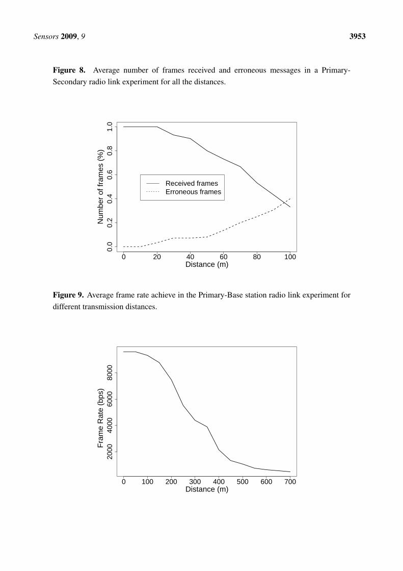
A similar test is carried out with the Primary-Base Station radio link. One primary node and onebase station node are placed in an obstacle-free environment from 0 m to 700 m in 50 m intervals. Ateach distance, the primary node transmits 30 messages which are received by the base station. ThePrimary-Base station radio link implements a communication protocol which is in charge of collisions.Therefore, all the frames transmitted by the primary node are received by the base station if it is withinthe communication range. However, because of the distance, some messages get lost and the primarynode must retransmit them until it receives an acknowledgement from the base station. The test messagesto be transmitted are made up of 6,000 bits. In a perfect link transmission a frame rate of 9,000 bps isachieved, because of the header and CRC load. However, we observe in Figure 9 this frame rate getsreduced because of the retransmission handled by the protocol. A maximum transmission range of 720 mhas been achieved. We have repeated this test for 15 different positions and four different nodes.
Sensors 2009, 9 3953
Figure 8. Average number of frames received and erroneous messages in a Primary-Secondary radio link experiment for all the distances.
0 20 40 60 80 100
0.0
0.2
0.4
0.6
0.8
1.0
Distance (m)
Num
ber
of fr
ames
(%
)
Received framesErroneous frames
Figure 9. Average frame rate achieve in the Primary-Base station radio link experiment fordifferent transmission distances.
0 100 200 300 400 500 600 700
2000
4000
6000
8000
Distance (m)
Fra
me
Rat
e (b
ps)

Sensors 2009, 9 3954
4.3. Localization and timing experiment
We have carried out an analysis of the GPS performance. The GPS selected is able to provide thecurrent GMT time, latitude and longitude. We tested the whole GPS system for a coldstart configuration.A coldstart is when the GPS has been powered off for a long period and then it is switched on. At thismoment, the GPS needs to find the satellite’s position to locate itself. The first data the GPS obtainsis the satellite connection and the current time. Typically, 5 to 20 seconds are needed for the timingacquisition. After this first period, the GPS obtains the satellite’s positions and once different satelliteshave been located, the GPS is able to obtain its own location. A period of 2 minutes on average is neededfor localization after a coldstart. Once located, the GPS updates its position every second.
4.4. A live animal test
Finally, we made a simple proof-of-concept study of the network in live animals. We have alreadydiscussed that we were not attempting to carry out an animal location study, but to provide the tools for afuture use. However, before providing these tools to researchers in charge of studying animal behaviors,we run some simple tests in animals to validate our system. The main idea for the animal test was tocheck i) if animal movements were able to swing the generator to produce enough energy for the IDtransmission and ii) if the node size and dimensions are feasible at least for some mammals.
We tested our system both in a dog and a reindeer. The best place for the secondary node location,turned out to be the animal neck (see Figure 10). When the animals move their neck (for example,because of a movement produced when looking for food on the ground), the generator is swung. Theneck was selected because, to best take advantage of the energy, the generator needs to be swung fromend to end. We also tested to adjust the secondary node to the legs and body of the animal. In thiscase, faster and more frequent movements were achieved. However, the magnet does not move along thewhole generator. Typically, it did not cross the two coils, hence it did not produce enough energy for aframe transmission.
Figure 10. A secondary node (a) in a hip bag around a dog neck in an Spanish courtyard and(b) mounted on a reflective collar around a reindeer neck in Northern Sweden.

Sensors 2009, 9 3955
During the trial, two generators were used to power the secondary nodes, although it was noticed thatthe transmission was also achievable with just one generator. Communication ranges of over 100 m havebeen also observed in an open area when the kinetic converter was activated by the animal movement.Average data transmissions rates of one frame every three minutes were estimated from the first resultsdepending on the animal’s activity. The modules were operationally tested at temperatures as low as -12 ◦C in Northern Sweden, although they were also tested in a cold experimental chamber at temperaturesof -25 ◦C. Moreover, all of the node’s components are rated at -40C, for its correct operation in differenttest environments.
5. Conclusions
In this paper we have described a heterogeneous mobile sensor network for animal tracking made upof battery-powered and kinetic-powered nodes. The system tries to minimize the use of battery-powerednodes to a minimum which satisfies future real animal experiments and provides the means for animallocalization. The system is based on the assumption that animals carrying kinetic-powered (secondary)nodes are tracked by their neighbors and their positions are approximated by the ones carrying battery-powered (primary) nodes. Therefore, primary nodes keep track of the information sent by secondarynodes and can download it to a base station when they enter its coverage range.
Secondary nodes have been designed with a 433 MHz transmitter powered by a kinetic converter sys-tem made with coils and magnets. Primary nodes implement a 433 MHz receiver to gather secondarynode information, a GPS to obtain its position periodically and a 166 MHz transceiver to communicatewith the base station. Moreover, the primary node and base station communication interface has beendesigned over the same printed circuit board for cost saving. The system has proved to achieve a commu-nication range of 100 m on the secondary-primary node communication and 700 m for the primary-basestation link.
We have tested the system in an animal environment (i.e. dogs and reindeers) showing good perfor-mances. In the future, we intend to introduce the system in a herd of reindeer in Northern Sweden tostudy the relationship between primary and secondary nodes needed to keep track of the herd and studyits behavior. However, depending on the animal behavior and the requisites of the experiment, differentparameters, such as acquiring data frequency of the GPS, the 166 MHz radio working cycle, or the timethe primary node must listen to a secondary node, should be studied before testing the system in a realscenario.
Acknowledgements
The authors acknowledge support from RBZ Robot Design S.L. Company. N. Dopico acknowledgessupport from the Community of Madrid and the European Social Fund. This work was supported by theN4C - Networking for Challenged Communications Citizens: Innovative Alliances and Test beds project,funded by the Seventh Framework Program (FP7-ICT-223994-N4C) of the European Commission. Thiswork was partly supported by the Wireless Hybrid Enhanced Mobile Radio Estimators project, funded bythe Seventh Framework Program (FP7-ICT-217033-WHERE) of the European Commission, the Span-ish Ministry of Industry, Tourism and Trade via the CSD2008-00010 COMONSENSE project and the

Sensors 2009, 9 3956
Spanish Ministry of Education via the TEC2007-67520-C02-01. The information provided is the soleresponsibility of the authors and does not reflect the European Commission’s opinion. The EuropeanCommission is not responsible for any use that might be made of data appearing in this publication.
References and Notes
1. Taillade, M. Trends in Satellite-Based Animal Tracking. Litografia Felici: Pisa, Italy, 1993; pp.291–297.
2. Papi, F.; Luschi, P.; Crosio, R.; R.Hughes, G. Satellite Tracking Experiments on the NavigationalAbility and Migratory Behaviour of the Loggerhead Turtle Caretta Caretta. Mar. Biol. 1997,129, 215–220.
3. Perry, M.C.; Kidwell, D.M.; Wells-Berlin, A.M.; Lohnes, E.J.R.; Olsen, G.H.; Osenton, P.C. Habi-tats Used by Black and Surf Scoters in Eastern North American as Determined by Satellite RadioTelemetry. In Second North American Sea Duck Conference. Patuxent Wildlife Research Center:Laurel, MA, 2005; pp. 21–35.
4. Rosa, L. D.; Secchi, E.; Maia, Y.; Zerbini, A.N.; Heide-Jorgensen, M. Movements of Satellite-Monitored Humpback Whales on Their Feeding Ground Along the Antarctic Peninsula. Polar Biol.2008, 31, 771–781.
5. Wark, T.; Crossman, C.; Hu, W.; Guo, Y.; Valencia, P.; Sikka, P.; Corke, P.; Lee, C.; Henshall,J.; Prayaga, K.; O’Grady, J.; Reed, M.; Fisher, A. The Design and Evaluation of a Mobile Sen-sor/Actuator Network for Autonomous Animal Control. In IPSN ’07: Proceedings of the 6thInternational Conference on Information Processing in Sensor Networks. ACM: New York, NY,2007; pp. 206-215.
6. Vijay, R.; Kansal, A.; Friedman, J.; Mani, S. Design Consideration sfor Solar Energy HarvestingWireless Embedded Systems. In Proceedings of the IEEE International Conference on InformationProcesing and Sensor Networks. IEEE Press: Piscataway, NJ, 2005, pp. 457–462.
7. Ritter, H.; Schiller, J.; Voigt, T.; Dunkels, A.; Alonso, J. Experimental Evaluation of LifetimeBounds for Wireless Sensor Networks. In Proceedings of the Second European Workshop onWireless Sensor Networks. IEEE Press: Piscataway, NJ, 2005; pp. 25–32.
8. Kansal, A.; Hsu, K.; Zahedi, S.; Srivastava, M.B. Power Management in Energy Harvesting SensorNetworks. Trans. Embed. Comput. Sys. 2007, 6, 1–32.
9. Hill, J.L.; Culler, D.E. Mica: A Wireless Platform for Deeply Embedded Neteworks. IEEE Micro2002, 22, 12–24.
10. Jiang, X.; Polastre, J.; Culler, D. Perceptual Environmentally Powered sensor Networks. InProceedings of the Fourth International Symposium on Information Processing in Sensor Networks.ACM Press: New York, NY, 2005; pp. 56–67.
11. Simjee, F.; Chou, P.H. Everlast: Long-life, Supercapacitor-Operated Wireless Sensor Node. InProceedings of the 2006 International Symposium on Low Power Electronics and Design. ACMPress: New York, NY, 2006; pp. 197–202.
12. Standley-Marbell, P.; Marculescu, D. An 0.9x1.2”, Low Power, Energy-Harvesting System withCustom Multi-Channel Communication Interface. In Proceedings of the Conference on Design,Automation and Test in Europe. ACM Press: New York, NY, 2007; pp. 15–20.

Sensors 2009, 9 3957
13. Zhang, P.; Sadler, C.M.; Lyon, S.A.; Martonosi, M. Hardware Design Experiences in ZebraNet.In Proceedings of the Second International Conference on Embedded Networked Sensor Systems.ACM Press: New York, NY, 2004; pp. 227–238.
14. http://prisms.cs.umass.edu/dome/turtlenet.15. Shenck, N.S.; Paradiso, J.A. Energy Scavering with Shoe-Mounted Piezoelectrics. IEEE Micro
2001, 21, 30–42.16. Starner, T. Human-Powered Wearable Computing. IBM Syst. J. 1996, 35, 618–629.17. Paradiso, J.A.; Feldmeier, M. A Compact, Wireless, Self-Powered Pushbutton Controller. In Pro-
ceedings of the third International Conference on Ubiquitous Computing. Springer-Verlag: Berlin,Germany, 2001; pp. 299–304.
18. Partk, C.; Chou, P.H. AmbiMax: Autonomous Energy Harvesting Platform for Multu-SupplyWireless Sensor Nodes. In Proceedings of the Third Annual Conference of IEEE CommunicationsSociety on Sensor and Ad Hoc Communications and Network. IEEE Press: Piscataway, NJ, 2006;pp. 168–177.
19. Want, R. An Introduction to RFID Technology. IEEE Pervas. Comput. 2006, 5, 1–25.
c© 2009 by the authors; licensee Molecular Diversity Preservation International, Basel, Switzerland.This article is an open-access article distributed under the terms and conditions of the Creative CommonsAttribution license (http://creativecommons.org/licenses/by/3.0/).