TOWARD REAGENTLESS ELECTROCHEMICALLY ... - SFU's Summit
200
TOWARD REAGENTLESS ELECTROCHEMICALLY ADDRESSABLE MICROARRAYS: SYNTHESIS OF SUITABLE MONOMERS AND ANCHOR MOLECULES by Frederick F.R.M. Chesneau BSc.Hons., Aston University, 2004 A THESIS SUBMITTED IN PARTIAL FULFILLMENT OF THE REQUIREMENTS FOR THE DEGREE OF MASTER OF SCIENCE in the School of Chemistry © Frederick F.R.M. Chesneau 2008 SIMON FRASER UNIVERSITY Spring 2008 All rights reserved. This work may not be reproduced in whole or in part, by photocopy or other means, without the permission of the author.
-
Upload
khangminh22 -
Category
Documents
-
view
1 -
download
0
Transcript of TOWARD REAGENTLESS ELECTROCHEMICALLY ... - SFU's Summit
TOWARD REAGENTLESS ELECTROCHEMICALLY
ADDRESSABLE MICROARRAYS: SYNTHESIS OF
SUITABLE MONOMERS AND ANCHOR MOLECULES
byFrederick F.R.M. Chesneau
BSc.Hons., Aston University, 2004
A THESIS SUBMITTED IN PARTIAL FULFILLMENT
OF THE REQUIREMENTS FOR THE DEGREE OF
MASTER OF SCIENCE
in the School
of
Chemistry
© Frederick F.R.M. Chesneau 2008
SIMON FRASER UNIVERSITY
Spring 2008
All rights reserved. This work may not be
reproduced in whole or in part, by photocopy
or other means, without the permission of the author.
Name:
Degree:
Title of Thesis:
Examining Committee:
Chair
Date Defended/Approved:
APPROVAL
Frederick F.R.M. Chesneau
Master of Science
Toward Reagentless Electrochemically AddressableMicroarrays: Sythesis of Suitable Monomers andAnchor Molecules
Dr. Zuo-Guang YeProfessor, Department of Chemistry
Dr. David J. VocadloSenior SupervisorAssistant Professor, Department of Chemistry
Dr. Hua-Zhong(Hogan) YuSupervisorAssociate Professor, Department of Chemistry
Dr. Melanie A. O'NeillSupervisorAssistant Professor, Department of Chemistry
Dr. Nancy R. FordeInternal ExaminerAssistant Professor, Department of Physics
March 31, 2008
11

SIMON PRASER UNIVERSITYLIBRARY
Declaration ofPartial Copyright Licence
The author, whose copyright is declared on the title page of this work, has grantedto Simon Fraser University the right to lend this thesis, project or extended essayto users of the Simon Fraser University Library, and to make partial or singlecopies only for such users or in response to a request from the library of any otheruniversity, or other educational institution, on its own behalf or for one of its users.
The author has further granted permission to Simon Fraser University to keep ormake a digital copy for use in its circulating collection (currently available to thepublic at the "Institutional Repository" link of the SFU Library website<www.lib.sfu.ca> at: <http://ir.lib.sfu.calhandle/1892/112>) and, without changingthe content, to translate the thesis/project or extended essays, if technicallypossible, to any medium or format for the purpose of preservation of the digitalwork.
The author has further agreed that permission for multiple copying of this work forscholarly purposes may be granted by either the author or the Dean of GraduateStudies.
It is understood that copying or publication of this work for financial gain shall notbe allowed without the author's written permission.
Permission for public performance, or limited permission for private scholarly use,of any multimedia materials forming part of this work, may have been granted bythe author. This information may be found on the separately cataloguedmultimedia material and in the signed Partial Copyright Licence.
While licensing SFU to permit the above uses, the author retains copyright in thethesis, project or extended essays, including the right to change the work forsubsequent purposes, including editing and publishing the work in whole or inpart, and licensing other parties, as the author may desire.
The original Partial Copyright Licence attesting to these terms, and signed by thisauthor, may be found in the original bound copy of this work, retained in theSimon Fraser University Archive.
Simon Fraser University LibraryBurnaby, BC, Canada
Revised: Fall 2007
Abstract
Combinatorial chemistry facilitates the synthesis of large libraries of compounds. However,
the screening of such libraries is time-consuming and remains a challenging problem. In
this thesis we propose that an array of gold electrodes could be used for the generation of
large combinatorial libraries of oligomers with defined sequences. The ability to address
individual electrodes in a controlled manner through directed electrochemical deprotection
of suitably designed molecules, facilitates the generation of spatially addressable libraries
that can be readily deconvoluted. Here, we outline this electrochemical strategy, which
involves electrochemical deprotection of surface-bound amines. Once deprotected, these
amines can be elaborated using monomeric units containing a suitable electrophile and an
amine protected by an electrochemically protected group. This process can be repeated to
generate the desired oligomers and should be amenable to such arrays. Enabling studies on
the electrochemical modification of monolayers of a diaryldisulfide molecule that inform on
optimising device design will also be presented.
iii

To my parents, my sisters and my late cousin Henry.
iv
v
"Impossible n 'est pas fraw;ais"
Napoleon Bonaparte
Acknowledgments
I would like to thank Dr. David J. Vocadlo for giving me the opportunity to work on
various aspects of chemistry, from chemical synthesis to biochemistry and electrochemistry.
Thanks go to Dr. Byron D. Gates and Pr. Neil R. Branda for their advice during my time
working on the Nanoparticles for Medecine project in 4DLabs. I would also like to thank all
my coworkers on the Nanoparticles for Medecine project for educting me on nanoparticles
and Scott Yuzwa for showing me the ropes in the biochemistry lab. Special thanks go
to Aleksandra Debowski for her patience during cell experiments for that project. More
related to the project described in this thesis, thanks go to Dr. Hogan Yu for letting me
use his laboratory space to perform both FT-IR and cyclic voltammetry experiments and
his advice, all the members of the Yu lab that I have befriended. And of course, I thank my
parents for allowing me to be where I am today and my banker for lending me the funds
that made it all possible.
vi

List of Abbreviations
General terms
3D
Calcd.
CM
conc.
(d)
8+
8
DNA
ELISA
equiv.
Expt.
expt
expts
LG
three dimensional
calculated
core
concentrated
decomposed
partially positive
partially negative
DeoxyriboNucleic Acid
Enzyme-Linked ImmunoSorbant Assay
equivalent
experimental
experiment
experiments
leaving group
vii
m.p.
PGM
pH
Lt.
SAM
SAMS
t
T
temp.
melting point
protecting group
potential Hydrogen
negative log of the acid ionization constant (Ka)
room temperature
self-assembled monolayer
self-assembled monolayers
time
temperature
temperature
Units of measure
A Angstrom
A area
°C degree Celsius
cm centimeter
g gram
M mole per liter
mg milligram
mM millimole per liter
J1m micrometer
viii

m% mole percent
ml milliliter
JLl microliter
MD megaohm
mol mole
mV millivolt
mV/s millivolt per second
MW molecular weight
s second
v/v volume by volume
V volt
wt. weight
Energy
~Go
kJ
Electron transfer
(J
free energy at standard conditions
free energy of activation
energy of activation
kilojoule
attenuation factor
IX
ko
kET
Electrochemistry
C
n
Q
preexponential factor
rate constant of electron transfer
reorganisational energy
Distance between the electron donor and acceptor
position of the electron acceptor
position of the electron donor
Coulombs
double-layer capacitance
Surface coverage
width at half peak height
Efficiency of the nth coupling
Peak potential
Faraday's constant
peak current
number of electrons involved in a redox process
charge
charge after nth deprotection cycle
charge after 1st deprotection cycle
x

Chemicals
4-ATP
Au(100)
Au(llO)
Au(l11)
Au(200)
Au(220)
Au(311)
BOC
BOC2 0
Cdiamine
C53
COOBt
DCC
DCU
DMSO
EDC.HCI
Et
EtOH
Fmoc
HOBt
4-aminothiophenol
gold 100 plane
gold 110 plane
gold 111 plane
gold 200 plane
gold 220 plane
gold 311 plane
tert-butyloxycarbonyl
di-tert-butyl dicarbonate
concentration of diamine
concentration of 53
N-hydroxybenzotriazole ester
dicyclohexylearbodimide
dicyclohexy1urea
dimethylsulfoxide
1-Ethyl-3-[3-dimethylaminopropyl]carbodiimide hydrochloride
ethyl
ethanol
(9H-fluoren-9-yl)methyl carbamate
N-hydoxybenzotriazole
xi
HQ hydroquinone
Me methyl
MeOH methanol
Pd/C 5% palladium on charcoal
R random group
RS- thiolate
TBDMS tert-butyldimethylsily1
TFA trifluoroacetic acid
THF tetrahydrofuran
Techniques
CHN
CV
E.A.
GC/MS
HPLC
MALDI-TOF
NMR
carbon, hydrogen, nitrogen
cyclic voltammetry
elemental analysis
gas chromatography / mass spectrometry
high performance liquid chromatography
matrix-assisted laser desorption/ionization-time of flight
nuclear magnetic resonance
br - broad
d - doublet
dd - doublet of doublet
xii
IH-NMR
13C-NMR
TLC
Rf
ddd - doublet of doublet of doublet
<5 - chemical shift
J - coupling constant
m - multiplet
MHz - megahertz
ppm - parts per million
q - quadruplet
s - singlet
t - triplet
proton nuclear magnetic resonance
carbon 13 nuclear magnetic resonance
thin layer chromatography
retention factor
xiii

Contents
Approval ii
Abstract iii
Dedication iv
Quotation v
Acknowledgments vi
List of Abbreviations vii
Contents xiv
List of Tables xx
List of Figures xxii
List of Schemes xxvii
1 Introduction 1
xiv
Combinatorial Chemistry or Rational Design? .
Spatially addressable arrays for chemical synthesis
1.1
1.2
1.1.1
1.1.2
1.2.1
1.2.2
1.2.3
Rational Design
Combinatorial Chemistry
Well plates . . . . . . . . . . . . . .
Photochemically addressable arrays
Electrochemically addressable arrays
1
2
3
7
7
8
8
1.3 Scope of the thesis . . . . . . . . . . . . . . . . . . . . . . . . . . . . . . . .. 12
1.3.1 Built-in deconvolution . . . . . . . . . . . . . . . . 12
1.3.2 High throughput, synthesis and efficiency . . . . . . . . . . . . . . .. 13
1.3.3 General Strategy . . . . . . . . . . . . . . . . . . . . . . . . . . . . . . 13
1.3.4 Archiving of the combinatorial libraries . . . . . . . . . . . . . . . .. 16
1.3.5 Design principles " 17
1.3.5.1 Electrode design . . . . . . . . . . . . . .. 17
1.3.5.2 Monolayers for microarray design 18
1.3.5.3 Monomer design . . . . . . . . . . . . . . . . . . . . . . . .. 20
1.3.6 Critical evaluation of the array design . . . . . . . . . . . . . . . . " 20
2 Design and synthesis of monomers 22
2.1 General considerations . . . . . . . . . . . . . . . . . . . . . . . . . . . . . . . 22
2.1.1 Unnatural amino acids in the synthesis and design of protein-like
structures . . . . . . . . . . . . . . . . . . . . . . . . . . . . . . . . .. 22
xv

2.1.2 Guiding principles for designing the synthetic routes . . . . . . . . . . 26
2.2 Rational design of the monomer. . . . . . . . . . . . . . . . . . . . . . . . .. 27
2.2.1 Selection of the leaving group .............. 28
2.2.1.1 Mixed anhydrides as leaving groups . . . . . . . . . . . . .. 29
2.2.1.2 Reactive esters as leaving groups. . . . . . . . . . . . . . .. 34
2.2.2 The protecting group 35
2.2.3 The core. . . . . . . . . . . . . . . . . . . . . . . . . . . . . . . . . .. 36
2.3 Amino benzoic acid series . . . . . . . . . . . . . . . . . . . . . . . . . . . .. 38
2.3.1 First approach . . 39
2.3.1.1 Retrosynthetic analysis and general synthetic scheme 39
2.3.2 Second approach . . . . . . . . . . . . . . . . . . . . . . . . . . 42
2.3.2.1 Retrosynthetic analysis and general synthetic scheme (Scheme
2.4) . . . . . . . . . . . . . . . . . . . . . . . . . . . . . . .. 43
2.3.2.2 Synthesis of the chloroformate intermediate (2) . . . . . . . . 44
2.3.2.3 Synthesis of the carbamate 13 . . . . . . . . . . . . . . . .. 48
2.3.2.4 Coupling of N-hydroxybenzotriazole (HOBt)-Synthesis of 16 50
2.3.2.5 Testing the reactivity of the aniline monomers to aniline nu-
cleophiles . . . . . . . . . . . . . . . . . . . . . . . . . . . .. 50
2.3.3 Experimental . . . . 53
2.3.3.1 Solvents and chemicals 53
2.3.3.2 Characterisation......................... 53
XVI

2.4 Aminomethylbenzoic series 61
2.4.1 Retrosynthetic analysis 62
2.4.1.1 First approach 62
2.4.1.2
2.4.1.3
Second approach
General Synthetic scheme
.................... 66
............ 67
2.4.1.4 Synthesis of carbamate intermediate 31 . . . . . . . . . . . . 67
2.4.1.5 Synthesis of benzylamine carbamate 33 ..... 69
2.4.1.6 Selective debenzylation - synthesis of 37-39 and 59 . . . . . 73
2.4.1.7 Coupling of N-hydroxybenzotriazole-synthesis of monomers
40-42 78
2.4.1.8 Conclusion............................ 79
2.4.2 Experimental . . . . . . . . . . . . . . . . . . . . . . . . . 81
2.4.2.1 Solvents and chemicals 81
2.4.2.2 Characterisation......................... 81
3 Self-assembled monolayers 88
3.1 A brief introduction to self-assembled monolayers . . . . . . . . . . . . . . .. 88
3.2 Effect of the molecular structure of the thiols on the formation of monolayers 91
3.2.1 Mercaptoalkane self-assembled monolayers . . . . . . . . . . . . . . 91
3.2.2 Self-assembled monolayers from amide-containing mercaptoalkanes 93
3.2.3 Arylthiol self-assembled monolayers 94
3.2.4 SAMS from thiols and disulfides .. . . . . . . . . . . . . . . . . . .. 96
xvii
3.2.5 Functional monolayers ~ the head group . . . . . . . . . . . . . . . .. 98
3.3 Electrochemistry of self-assembled monolayers . 99
3.3.1
3.3.2
General electrochemistry of self-assembled monolayers
Electron-transfer - from bulk to single molecules to SAMS
· 100
· 101
3.3.2.1 Influence of the monolayer thickness, arrangement and molec-
ular identity . . . . . . . . . . . . . . . . . . . . . . . .. . 104
3.3.2.2 Effect of the environment on the rate of electron transfer . 105
3.4 Synthesis and testing of anchor molecules · 109
3.4.1 Thioaniline-based anchor ..... · 109
3.4.1.1
3.4.1.2
Synthesis of disulfide 44 .
Growth of monolayers of disulfide 44 and thiol 45
· 111
· 112
3.4.1.3 Cyclic Voltammetry studies of monolayers formed from disul-
fide 44 . . . . . . . . . . . . . . . . . . . . . . . . . . 114
3.4.2 Amide-containing dialkyldisulfides as anchors - Synthesis of 55 129
3.4.2.1
3.4.2.2
Retrosynthetic analysis . . . .
Synthesis of diesterdisulfide 53
· 129
· 129
3.4.2.3 Synthesis of 55 via coupling of 1,6-diaminohexane to 53 . 130
3.4.2.4 Synthesis of 55 via coupling of monoamine 63 to diester-
3.5
disulfide 53 .
General experimental .
· 131
· 140
3.5.1 Synthesis ...
xviii
· 140
3.5.1.1
3.5.1.2
Solvents and chemicals
Characterisation
· 140
· 140
3.5.2 Monolayers . . . . . . . . · 141
3.5.2.1
3.5.2.2
3.5.2.3
Substrate preparation
Preparation of self-assembled monolayers
Characterisation
141
141
· 142
3.5.3 Experimental . . . . . . . · 143
4 Future Work
4.1 Coupling monomers to anchor molecules on a gold surface
148
· 148
4.1.1 Testing the surface chemistry . . . . . . . . . . . .
4.1.1.1 Reaction of monomers with amine-terminated self-assembled
monolayers . . . . . . . . .
· 148
· 149
4.1.1.2 Cyclic voltammetry studies · 151
4.2 Testing the array . . . . . . . . . . . . . . . · 153
A Visual index of compounds
Bibliography
xix
156
161
List of Tables
2.1 Protection of the carboxylic acid of aminobenzoic acids 42
2.2 Effect of the temperature, concentration and base on the yield of isolated
carbamate. . . . . . . . . . . . . . . . . . . . . . . . . . . . . . . . . . . . .. 47
2.3 Synthesis of aniline-based monomers ................... 50
2.4 Synthesis of the carbamate intermediate 31 69
2.5 Effect of the concentration, solvent, temperature and ratio of reactants and
reagents on the yield of 33. . . . . . . . . . . . . . . . . . . . . . . . . . . 70
2.6 Effect of the position of the substituent on the yield of benzyl carbamate 73
2.7 Hydrogenolysis of various benzylamine carbamates . . . . . . . . . . . . . 79
3.1 Table of FT-IR bands of 44 in KBr and as a monolayer on polycrystalline gold116
3.2 Data from CV scans of monolayers of 44 on various gold surfaces 120
3.3 Surface coverage and molecular area for various monolayers on polycrystalline
3.4
gold surfaces .
FT-IR bands and assignments for diamine 55
xx
. 121
. 139

4.1 Testing a 4 electrode array. . . . . . . . . . . . . . . . . . . . . . . . . . . . . 154
xxi
List of Figures
1.1
1.2
1.3
1.4
1.5
1.6
1.7
Two rationally designed drugs. . . . . . . . . . . . . . . . . . . .
Two general strategies for carrying out combinatorial chemistry .
The split and mix strategy. . . . . . . . . . . . . . . . . .
Enzyme inhibitors designed using combinatorial chemistry
A 96 well plate . . . . . . . . . . . .
A photochemically addressable array
Spatially addressable electrochemical arrays
2
4
5
6
8
9
9
1.8 An electrochemically addressable array. . . . . . . . . . . . . . . . . . . . .. 13
1.9 Transacylation . . . . . . . . . . . . . . ............. 14
1.10 Hydroquinone as amide and carboxyl protecting group. . . . . . . . . . . .. 15
1.11 Proposed oligomerisation scheme . . . . . . . . . . . . . . . . . . . . . . . .. 16
1.12 Effect of the differences in monolayer composition on the oxidation behaviour
of a gold surface as reflected by cyclic voltammetry study . . . . . . . . . .. 18
1.13 The two main types of electrochemically addressable arrays . . . . . . . . .. 19
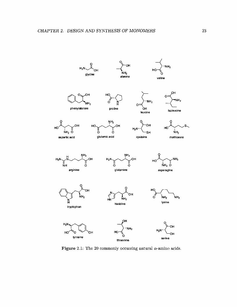
2.1 The 20 commonly occurring natural o:-amino acids . . . . . . . . . . . . . .. 23
xxii
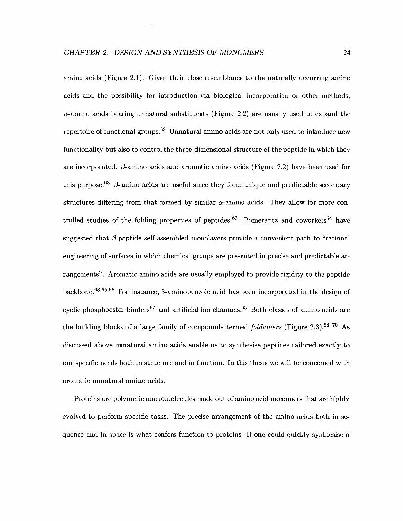
2.2 Some unnatural amino acids. . . . . . . . . . . . . . . . . . . . . . . . . . .. 25
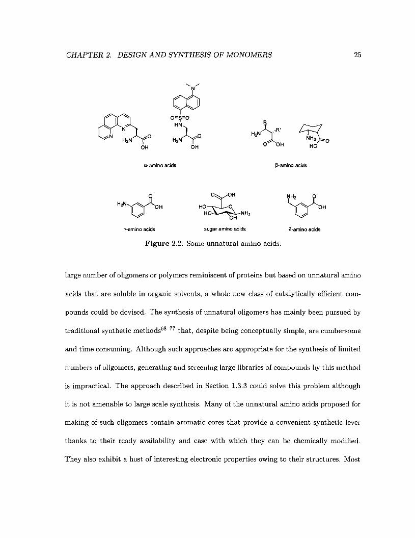
2.3 Examples of foldamers .... .......... " 26
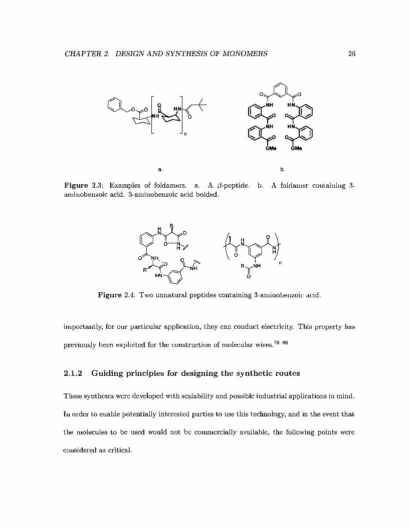
2.4 Two unnatural peptides containing 3-aminobenzoic acid . . . . . . . . . . .. 26
2.5 General design of the monomeric units . . 28
2.6 Desired reactivity of the monomeric unit with amine groups . . . . . . . . .. 28
2.7 Mixed benzoic acid anhydrides .. . . . . . . . . . . . . . . . . . . . . . . .. 30
2.8 1H-NMR of benzoic pivalic anhydride and its possible coupling products with
4-bromoaniline . . . . . . . . . . . . . . . . . . . . . . . . . . . . . . . . . . . 31
2.9 Mixed anhydrides of benzoic acid and chlorinated benzoic acids. . . . . . .. 32
2.10 Electron density map of benzoic 2,4-dichlorobenzoic anhydride 32
2.11 1H-NMR spectra of benzoic dichloro- and trichlorobenzoic anhydrides and
their reaction products. . . . . . . . . . . . . . . . . . . . . . . . . . . . . .. 33
2.12 Some reactive esters . .
2.13 Thiol displacement at the gold surface
...................... 34
................. 35
2.14 Hydroquinone as a protecting group for amines 37
2.15 Some commercially available aminobenzoic acids . . . . . . . . . . . . . . . . 38
2.16 An oligomer of 3-aminobenzoic acid 39
2.17 Synthetic scheme for the synthesis of carbamate 7 . . . . . . . . . . . . . . . 42
2.18 Proton NMR of the undesired byproduct 57 . . . . . . . . . . . . . . . . . . . 43
2.19 Setup for high dilution reactions . . . . . . . . . . . . . . . . . . . . . . . .. 46
xxiii

2.20 Structure of the phosgene-pyridine complex at various temperatures in methy-
lene chloride. . . . . . . . . . . . . . . . . . . . . . . . . . . . . . . . . . . . . 49
2.21 Aniline derivatives used to test 15 . . . .. 51
2.22 Reaction of (R)-l-phenylethanamine with aniline-based monomer 15 . . . . . 52
2.23 A few commercially available aminomethylbenzoic acids . . . . . . . . . . .. 61
2.24 Oligomers of aniline- and benzylamine-based amino acids 62
2.25 Structure of 4-(ammoniomethyl)benzoate 62
2.26 Some commercially available carboxybenzaldehydes. . . . . . . . . . . . . .. 67
2.27 Mechanism of benzyl carbamate formation. . . . . . . . . . . . . . . . . . .. 72
2.28 1H-NMR spectra of the products isolated from reactions of 3-carboxybenzaldehyde
with either 31 or 32 to generate 38 as the expected product. . . . . . . . .. 75
2.29 Proposed mechanism for the hydrogenolysis of O-benzyl alcohols 77
2.30 Proposed mechanism for the hydrogenolysis of N-benzylcarbamate 59 77
2.31 The various benzylamine monomers synthesised. . . . . . . . . . . . . 80
3.1 Schematic representation of a molecule capable of forming a monolayer. .. 89
3.2 Simplified growth mechanism of Self-assembled monolayers of thiols on gold 90
3.3 Cyclic voltammogram of short chain and long chain aminoalkyl thiol mono-
layers on polycrsytalline gold surfaces. . . . . . . . . . . . . . . . . . . . . .. 92
3.4 The different mercaptoalkanes capable of forming SAMS on gold . . . . . .. 93
3.5 Self-assembled monolayers from alkylthiols. . . . . . . . . . . . . . . . . . .. 94
3.6 Self-assembled monolayers from amide-containing alkylthiols. . . . . . . . .. 95
XXIV
3.7 Self-assembled monolayers from 4-aminothiophenol . . . . . . . . . . . . . .. 96
3.8 Self-assembled monolayers from various thiophenols . ..... 97
3.9 Three common functional headgroups for self-assembled monolayers ..... 98
3.10 Schematic representation of the double layer at an electrode surface
3.11 Marcus diagram of electron transfer .
3.12 Donor-acceptor pairs for SAMS adsorbed on an electrode
3.13 Effect of the amide linkage on the order of the monolayer
3.14 The resonance forms of aniline. . . . . . . .
3.15 The resonance forms of 4-aminothiophenol .
101
.102
.103
. 108
. 110
110
3.16 FT-IR spectra of monolayers formed from anchor molecules 44 and 45. 113
3.17 FT-IR spectra of monolayer of 44 on polycrystalline gold and of 44 in KBr . 115
3.18 Selection rules for the reflection of the electrical component of an infrared
light off a metal surface . . . . . . . . . . . . . . . . . . . . . . . . . . . . . . 117
3.19 Cyclic voltammogram of a monolayer of disulfide 44 on polycrystalline gold . 119
3.20 Arrangement of thiols on different gold surfaces 122
3.21 Comparison ofthe FT-IR spectra of a monolayer of 44 before and after cyclic
voltammetry. . . . . . . . . . . . . . . . . . . . . . . . . . .
3.22 Cyclic voltammogram of a monolayer of 4-aminothiophenol
3.23 Coupling of 53 with 1,6-diaminohexane
3.24 Coupling of 53 to 1,6-diaminohexane .
3.25 1Hand 13C NMR spectra of 63 ....
xxv
123
125
131
132
134
3.26 1H-NMR spectrum of 54 . ...
3.27 1Hand 13C NMR spectra of 55
3.28 Structures of the disulfides used by Bilewicz and coworkers
136
138
. 139
3.29 X-ray diffraction pattern of a gold slide obtained from EMF corporation . 142
4.1 Reaction of a monomer with an amine-terminated monolayer 150
4.2 Capping of unreacted surface amines after reaction of a monomer with an
4.3
4.4
amine-terminated monolayer
Possible coupling efficiency (Ecn ) profiles.
Schematic of a 4 electrode array
XXVI
152
153
. 155
List of Schemes
2.1 Synthesis of mixed benzoic acid anhydrides . . . . . . . . . . . . . . . . . ., 29
2.2 First retrosynthetic analysis of the aniline monomers 40
2.3 Protection of the acid terminus of 4-aminobenzoic acid . . . . . . . . . . . . . 40
2.4 Retrosynthetic approach to the aniline monomers involving a chloroformate
intermediate. . . . . . . . . . . . . . . . . . . . . . . . . . . . . . . . . . . .. 44
2.5 Synthetic scheme for the aniline series of monomers. . . . . . . . . . . . . . . 45
2.6 Formation of the carbonate byproduct in solution .. . 46
2.7 First retrosynthetic approach to the benzylamine monomers 63
2.8 Different ways to protect the acid terminal of benzylamine amino acids. 64
2.9 Synthesis of benzylamine carbamates via chloroformate intermediates 65
2.10 Second retrosynthetic approach to the benzylamine monomers. . . . . . . .. 66
2.11 Benzylamines . . .... 68
2.12 Reaction scheme for the synthesis of compound 38 via carbamate 32 . . . . . 74
2.13 Hydrogenolysis of benzyl ether 36 76
3.1 Synthesis of aniline-based anchors 111
xxvii
3.2 Retrosynthetic analysis of disulfide 55 . . . . . . . . . . . . . . . . . . 130
3.3 Synthetic scheme for the synthesis of N-Boc-1,6-diaminohexane (63) . 133
3.4 Synthetic scheme for the synthesis of 54 . 133
3.5 Synthetic scheme for the synthesis of 55
xxviii
. 135
Chapter 1
Introduction
1.1 Combinatorial Chemistry or Rational Design?
Chemistry has evolved from being an obscure science for a special few to a science that is
central to the society in which we live today. It is chemists that study, design and synthesise
the materials and molecules that are essential to our eveyday life. From plastics to complex
drugs, the influence of the chemist can be felt everywhere we look. Discoveries are not
always made just because we plan them, many of humanity's greatest breakthroughs have
been made by chance. Chemistry is no different and two main approaches now coexist for
the design of materials and molecules: rational design, which is a directed approach, and
combinatorial chemistry, which is a less targeted strategy.
1
CHAPTER 1. INTRODUCTION
a. b.
2
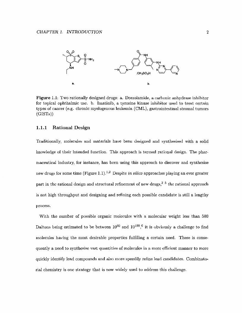
Figure 1.1: Two rationally designed drugs: a. Dorzolamide, a carbonic anhydrase inhibitorfor topical ophthalmic use. b. Imatinib, a tyrosine kinase inhibitor used to treat certaintypes of cancer (e.g. chronic myelogenous leukemia (CML), gastrointestinal stromal tumors(GISTs))
1.1.1 Rational Design
Traditionally, molecules and materials have been designed and synthesised with a solid
knowledge of their intended function. This approach is termed rational design. The phar-
maceutical industry, for instance, has been using this approach to discover and synthesise
new drugs for some time (Figure 1.1).1,2 Despite in silica approaches playing an ever greater
part in the rational design and structural refinement of new drugs,2 5 the rational approach
is not high throughput and designing and refining each possible candidate is still a lengthy
process.
With the number of possible organic molecules with a molecular weight less than 500
Daltons being estimated to be between 1060 and 10100 ,6 it is obviously a challenge to find
molecules having the most desirable properties fulfilling a certain need. There is conse-
quently a need to synthesise vast quantities of molecules in a more efficient manner to more
quickly identify lead compounds and also more speedily refine lead candidates. Combinato-
rial chemistry is one strategy that is now widely used to address this challenge.
CHAPTER 1. INTRODUCTION
1.1.2 Combinatorial Chemistry
3
General approach Combinatorial chemistry was first introduced in the 1980's7 and has
since emerged as an efficient way to quickly synthesise large numbers of molecules or mate
rials. In combinatorial chemistry, unlike in rational design, less emphasis is placed on the
details of the synthetic scheme and the absolute structure of the final products. Simple and
reliable reaction conditions are preferred and multiple reactant and reagent combinations are
used to yield a large variety of structurally diverse molecules or materials in a short period
of time. However, combinatorial techniques do not yield large amounts of final products,
rather focusing on providing a small amount of many different compounds for subsequent
screening. Despite this shortcoming the same library can be still be screened against many
potential targets thus maximising its usefulness. Both solution and solid phase variations
of combinatorial chemistry are commonly employed today (Figure 1.2).7
The introduction of solid supports in the form of resins by Merrifield in 19638 opened
the way to solid phase synthesis, notably, to solid phase combinatorial synthesis. By using
a solid support (generally polymer beads), it is easy to synthesise, handle and purify large
libraries. For these reasons, the solid phase approach is generally preferred over the solution
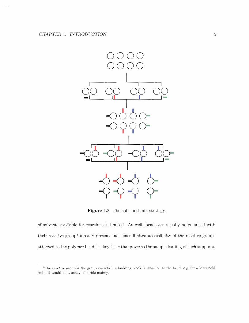
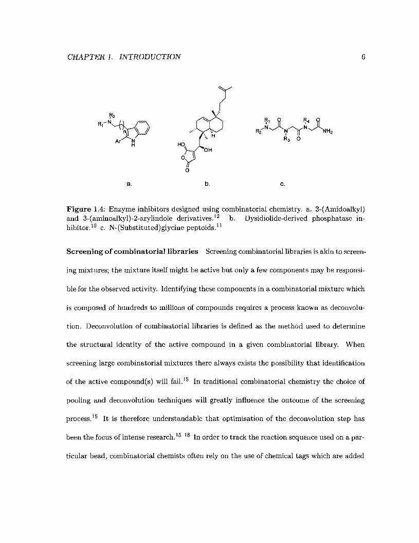
phase strategy. In addition to being used to generate traditional small molecules such
as lead enzyme inhibitors9 12 (Figure 1.4), solid phase combinatorial chemistry has been
successfully employed for the synthesis of biomolecules such as peptides and DNA.8,13,14
One of the most widely used solid phase techniques is the split and mix strategy in
which a pool of beads is split into several pots, each of which are then reacted with different

CHAPTER 1. INTRODUCTION
r=Cr-"O
---~---.----
-----,-CB
ASBO OA. ,'.' ~-.
a.
B~
...._-_ ..
-,--~,-
b.
4
Figure 1.2: Two general strategies for carrying out combinatorial chemistry: a. Solutionphase. b. Solid phase on beads.
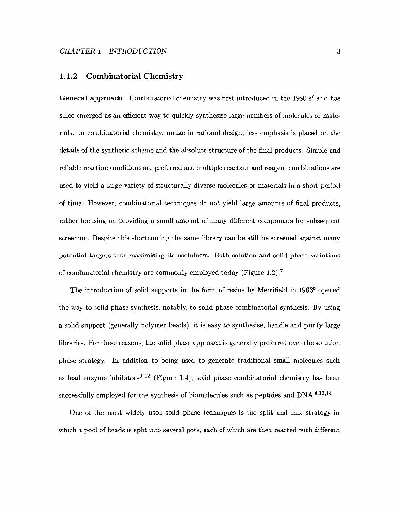
reagents. 7 Afterwards, they are pooled together and randomly split again into separate
pools for a second round of reactions. This operation is repeated as many times as is
deemed necessary to generate the library of interest (Figure 1.3).
Solid phase techniques suffer from several drawbacks related to the solid support itself
and to the methodology. The supports are usually polymer beads which have to be insol-
uble in the reaction solvent but still need to be permeable enough for the solvent to reach
the inside of the bead and ensure delivery of the reactants and reagents inside the bead,
thereby guarantying uniform and maximum reaction accross the bead. Therefore, the choice
CHAPTER 1. INTRODUCTION
00000000
I II
I I
00 00 00 00-I I II I
-0 00-099 0
I
Figure 1.3: The split and mix strategy.
5
of solvents available for reactions is limited. As well, beads are usually polymerised with
their reactive groupa already present and hence limited accessibility of the reactive groups
attached to the polymer bead is a key issue that governs the sample loading of such supports.
"The reactive group is the group via which a building block is attached to the bead. e.g. for a Merrificlrlresin, it would be a benzyl chloride moiety.
CHAPTER 1. INTRODUCTION 6
a.
o
b. c.
Figure 1.4: Enzyme inhibitors designed using combinatorial chemistry. a. 3-(Amidoalkyl)and 3-(aminoalkyl)-2-arylindole derivatives. 12 b. Dysidiolide-derived phosphatase inhibitor. lO c. N-(Substituted)glycine peptoids.u
Screening of combinatorial libraries Screening combinatorial libraries is akin to screen-
ing mixtures; the mixture itself might be active but only a few components may be responsi-
ble for the observed activity. Identifying these components in a combinatorial mixture which
is composed of hundreds to millions of compounds requires a process known as deconvolu-
tion. Deconvolution of combinatorial libraries is defined as the method used to determine
the structural identity of the active compound in a given combinatorial library. When
screening large combinatorial mixtures there always exists the possibility that identification
of the active compound(s) will fail.15 In traditional combinatorial chemistry the choice of
pooling and deconvolution techniques will greatly influence the outcome of the screening
process. 15 It is therefore understandable that optimisation of the deconvolution step has
been the focus of intense research. 15 18 In order to track the reaction sequence used on a par-
ticular bead, combinatorial chemists often rely on the use of chemical tags which are added
CHAPTER 1. INTRODUCTION 7
with the reaction mixture at every step of the reaction sequence. 19 Deconvolution of such
libraries is cumbersome, often requiring the use of techniques such as HPLC, GCjMS, mass
spectromet ry16 or an iterative strategy that is limited to relatively small libraries « 1024
compounds).l8 Being able to spatially address a library makes the deconvolution process
easier by eliminating the randomness inherent to combinatorial libraries and so facilitating
deconvolution. Three common types of spatially addressable arrays are presented below.
1.2 Spatially addressable arrays for chemical synthesis
1.2.1 Well plates
Well plates are extensively used in the biological sciences and chemistry (Figure 1.5).20
Well plates have been used in combinatorial chemistry as a way of enabling two-dimensional
screening by spatially fixing the different reactions in a matrix format.2l Each well contains
a solution with the desired reactants and chemistry is carried out in the wells. Such a setup
is unsuitable for peptide synthesis and screening. A method called peptides-on-pins was
designed to alleviate this problem by immobilising the peptide chain.22 In this method, the
growing peptides are fixed on pins that are dipped in each individual well containing the
necessary reagents for peptide coupling. The peptides thus synthesised can then be probed
by a standard ELISA assay (Enzyme-Linked ImmunoSorbent Assay).
CHAPTER 1. INTRODUCTION
2 3 4 5 6 7 8 9 10 11 12
A 000 0000B 00000000000cOOOOOOOOOOOD 00000000000E 00000000000F 00000000000GOOOOOOOOOOOH 00000000000
Figure 1.5: A 96 well plate.
1.2.2 Photochemically addressable arrays
8
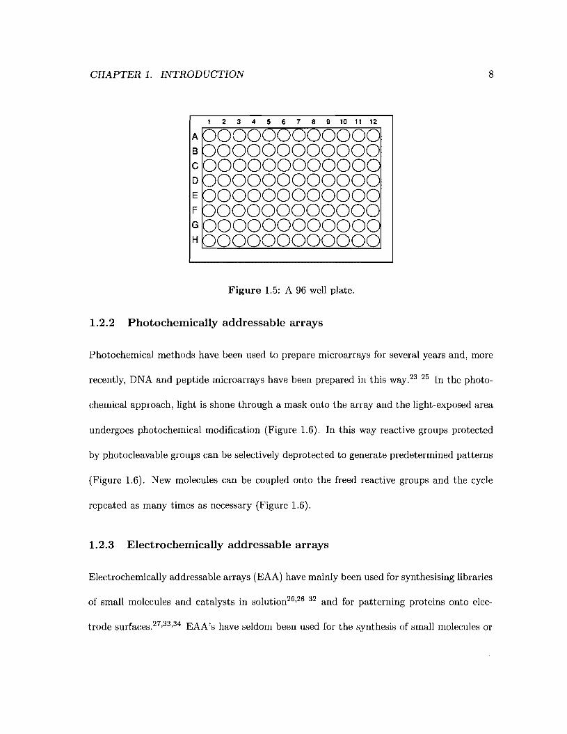
Photochemical methods have been used to prepare microarrays for several years and, more
recently, DNA and peptide microarrays have been prepared in this way.23 25 In the photo-
chemical approach, light is shone through a mask onto the array and the light-exposed area
undergoes photochemical modification (Figure 1.6). In this way reactive groups protected
by photocleavable groups can be selectively deprotected to generate predetermined patterns
(Figure 1.6). New molecules can be coupled onto the freed reactive groups and the cycle
repeated as many times as necessary (Figure 1.6).
1.2.3 Electrochemically addressable arrays
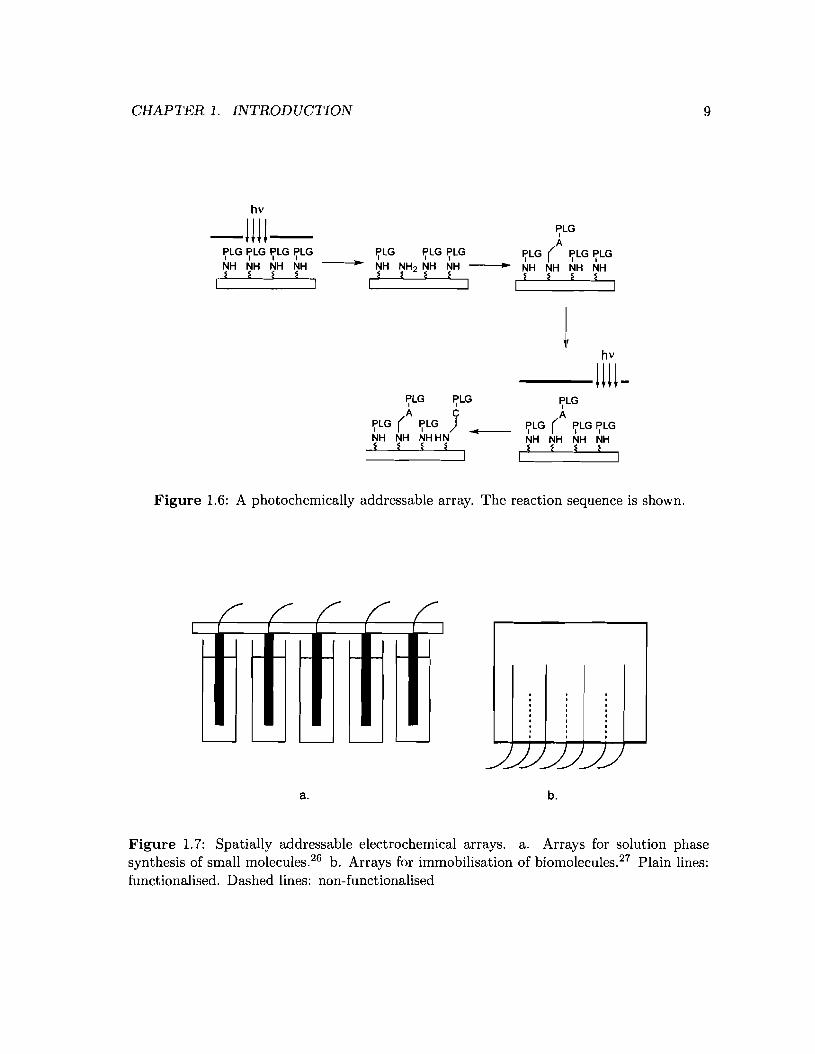
Electrochemically addressable arrays (EAA) have mainly been used for synthesising libraries
of small molecules and catalysts in solution26,28 32 and for patterning proteins onto elec-
trode surfaces.27,33,34 EAA's have seldom been used for the synthesis of small molecules or
CHAPTER 1. INTRODUCTION 9
hv
-!!H-~LG ~LG ~LG ~LG
NH NH NH NH~ ~ ~ ~
I
~LG
A~LG ~LG ~LG ~LG ( ~LG ~LG
-----;.~ NH NH2 NH NH -----l.~ NH NH NH NH~~ ~ ~ ~~~~
1 II....- ----J
jhv
--UU-..
~LG ~LG
A C~LG ( ~LG )NH NH NHHN
§ * * *
~LG
A~LG ( ~LG ~LGNH NH NH NH
* * § *I
Figure 1.6: A photochemically addressable array. The reaction sequence is shown.
a. b.
Figure 1.7: Spatially addressable electrochemical arrays. a. Arrays for solution phasesynthesis of small molecules.26 b. Arrays for immobilisation of biomolecules.27 Plain lines:functionalised. Dashed lines: non-functionalised
CHAPTER 1. INTRODUCTION 10
oligomers in solid phase. However, attempts have been made to use traditional chemistry
localised around an electrode35 38 but most of these approaches rely on the use of confining
agents to keep the electrochemically generated reagents in proximity to the electrode area.
The reaction times employed in these studies are very long (12 to 18 hours per coupling)
and, as such, these approaches are poorly suited for high throughput synthesis of combina
torial libraries. The approach taken by Egeland and coworkers is different since they use
an array of electrodes (primary surface) to pattern a secondary surface that carries amine
moieties protected by an acid labile group.39,40 Although this technique yields very well
defined patterns on the secondary surface, it relies on the electrochemical generation of acid
in the vicinity of the electrodes to selectively deprotect the area of interest. The acid thus
generated can lead to the degradation of the patterned surface in a matter of seconds. More
recently, Beyer et al. proposed a technique to alleviate the problems caused by the electro
chemical generation of acid as well as improve the coupling efficiency.41 They proposed to
deliver O-pentafluorophenyl esters of N-Fmoc-amino acids (Fmoc = (9H-fluoren-9-yl)methyl
carbamate) mixed in beads of N,N-diphenylformamide to specific sites of an array by guiding
the beads using electric fields. Once the particles have reached their intended targets, they
are all melted at once and subjected to standard Merrifield coupling conditions. Although
large libraries could be synthesised this way, the long coupling time and need for complex
machines to spray the beads are clear disadvantages of this method. Therefore, a real need
exists for simpler approaches to making large peptide libraries. The current limitations
and shortcomings of the techniques outlined above demonstrate the need to develop arrays
CHAPTER 1. INTRODUCTION 11
that do not use reagents such as acid or catalysts to effect amino acid coupling. We term
such arrays reagentless arrays. Indeed, no reagentless electrochemically addressable array
for chemical synthesis has been developed to date. This is especially critical in peptide
synthesis since some commonly used protecting groups are incompatible with the reagents
generated in the arrays mentioned in this paragraph and therefore degradation of the array
quality can ensue.37,39,40
CHAPTER 1. INTRODUCTION
1.3 Scope of the thesis
12
In this thesis will be presented the foundation work for the design of electrochemically
addressable reagentless arrays for the screening and deconvolution of oligomers. The main
focus of this thesis will be the design and synthesis of various molecules we believe to be
necessary for the development of such electrochemically addressable arrays.
1.3.1 Built-in deconvolution
Even though combinatorial chemistry enables the chemist to synthesise vast quantities of
molecules very quickly, it typically fails to satisfactorily address the issue of library decon
volution (Section 1.1.2). This issue is especially critical when synthesising molecules such
as peptides, since the composition and the precise order of the building-blocks are critical
pieces of information. Even the use of chemical tags in combinatorial chemistry does not
enable one to easily decode the order of the building-blocks in the final compound. By
fixing the various peptides (or oligomers) on a templated solid surface, such as an array of
gold electrodes, the order of addition of the building-blocks is controlled and known in real
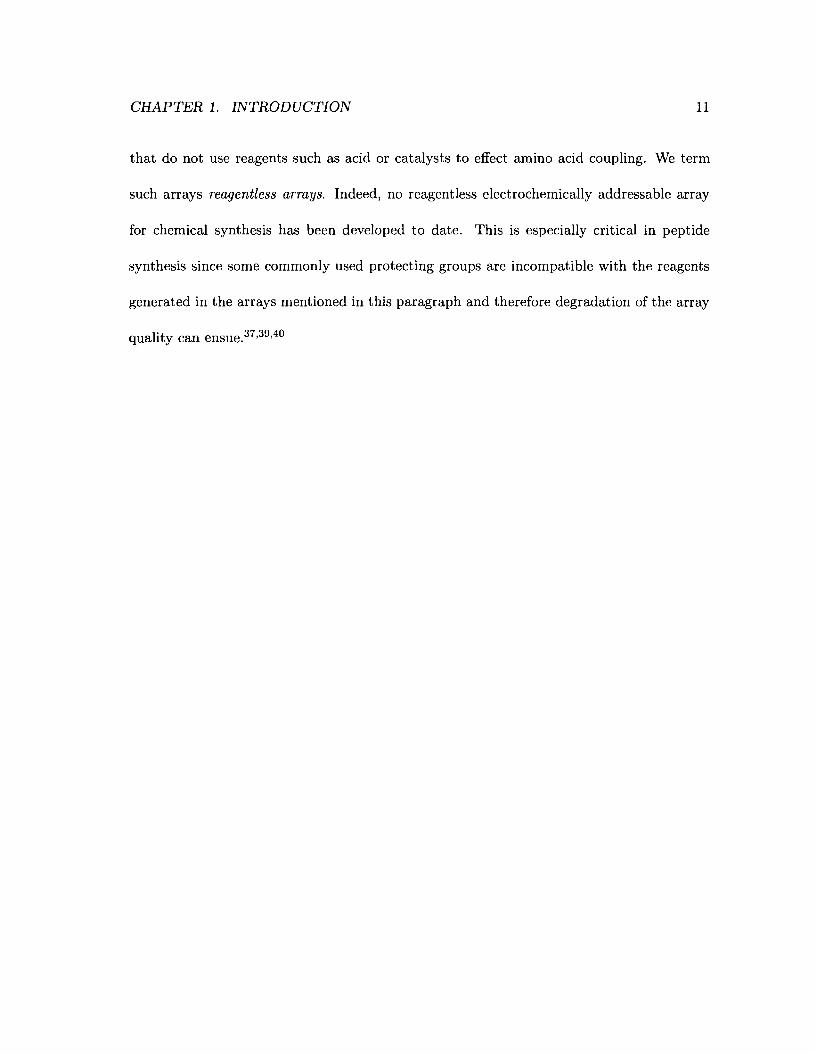
time; effectively eliminating the need for further deconvolution of the array (Figure 1.8).
This feature of the array is termed built-in or spatial deconvolution. Indeed, as soon as the
array is probed and a positive response is identified, the precise sequence of the oligomer is
known. In figure 1.8, if oligomer 3 is found to be active, the ABA oligomer is immediately
identified as the active species; both AAB and BAA have been eliminated as possible
hits. The synthesis of large quantities of compounds is not the aim of this project (only
CHAPTER 1. INTRODUCTION
31
2
13
Figure 1.8: An electrochemically addressable array. 1. Oligomer AAB. 2. Oligomer BAA.3. Oligomer ABA.
nanomolar quantities of product can potentially be synthesised on a given electrode). The
focus is rather on developing a strategy for rapid synthesis, screening and deconvolution of
combinatorial libraries of oligomers allowing rapid identification of lead compounds.
1.3.2 High throughput, synthesis and efficiency
The array being developed here is conceived from the ground up with high throughput and
low material usage in mind. This means that each step (synthesis, deconvolution, surface
reaction, electrochemistry, etc... ) has to be as efficient and reliable as possible. This will be
reflected, in this particular thesis, in the evaluation of the utility of the materials themselves
and the development of effective syntheses to obtain these materials.
1.3.3 General Strategy
Traditional synthetic methods make use of the chemical properties of the reactants and
products (i.e. chemical reactivity, acidity, basicity, etc... ) in order to successfully effect a
CHAPTER 1. INTRODUCTION 14
a.
¢OR<±>JLQOR 0
1'-':::: i.1 I
ii. ¢ R10t
OR+~
OH 0 0
b.
60RQ1'-':::: iii. + R10tOR
~
OH OH
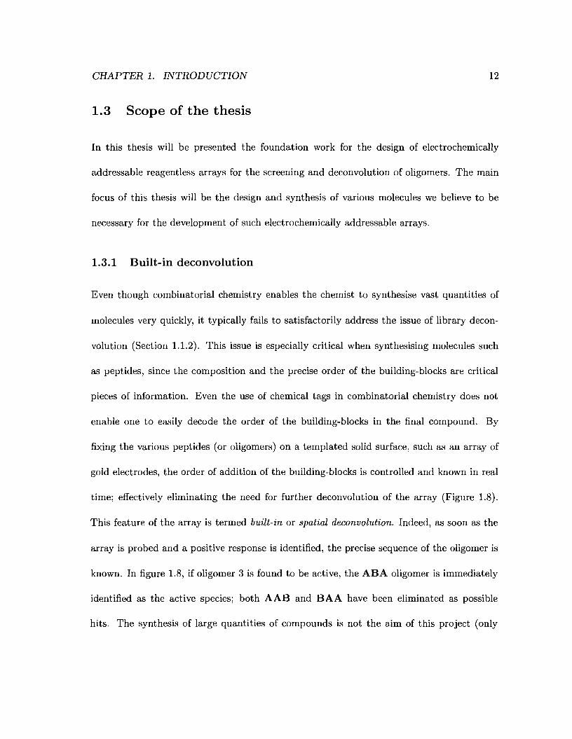
Figure 1.9: Transacylation. a. Electrochemical transacylation. i. -2 e- u. R 10H. b.traditional transacylation iii. R 10H, base.
transformation. Electrochemistry, on the other hand, makes use of the electronic properties
of the reactants (i.e. add or remove electrons to a molecule) to facilitate reactions. 42 45
For instance, by simply applying a potential across a solution of acylated hydroquinone,
it is possible to carry out a transacylation reaction under very mild conditions by making
use of the electrooxidation of hydroquinone42 (Figure 1.9). If electrochemistry were not
used, the very same reaction would typically require strongly basic conditions that could be
incompatible with other functionalities present on the product or the reactant.
Various electrochemically active groups have been used to protect various functional
groups such as amines, carboxylic acids and alcohols. 34 ,47 51 Hydroquinone has been suc-
cessfully used as an electrochemically cleavable protecting group for both amide27 ,33,34 and
carboxylic acid46 terminated self-assembled monolayers on gold but not amines (Figure
1.10). We propose to use hydroquinone as the basis for an electrochemically addressable
a.
CHAPTER 1. INTRODUCTION
oHN-'< 0
~N~-o-O~ S ·"H 0 , h OH
O~~O~
15
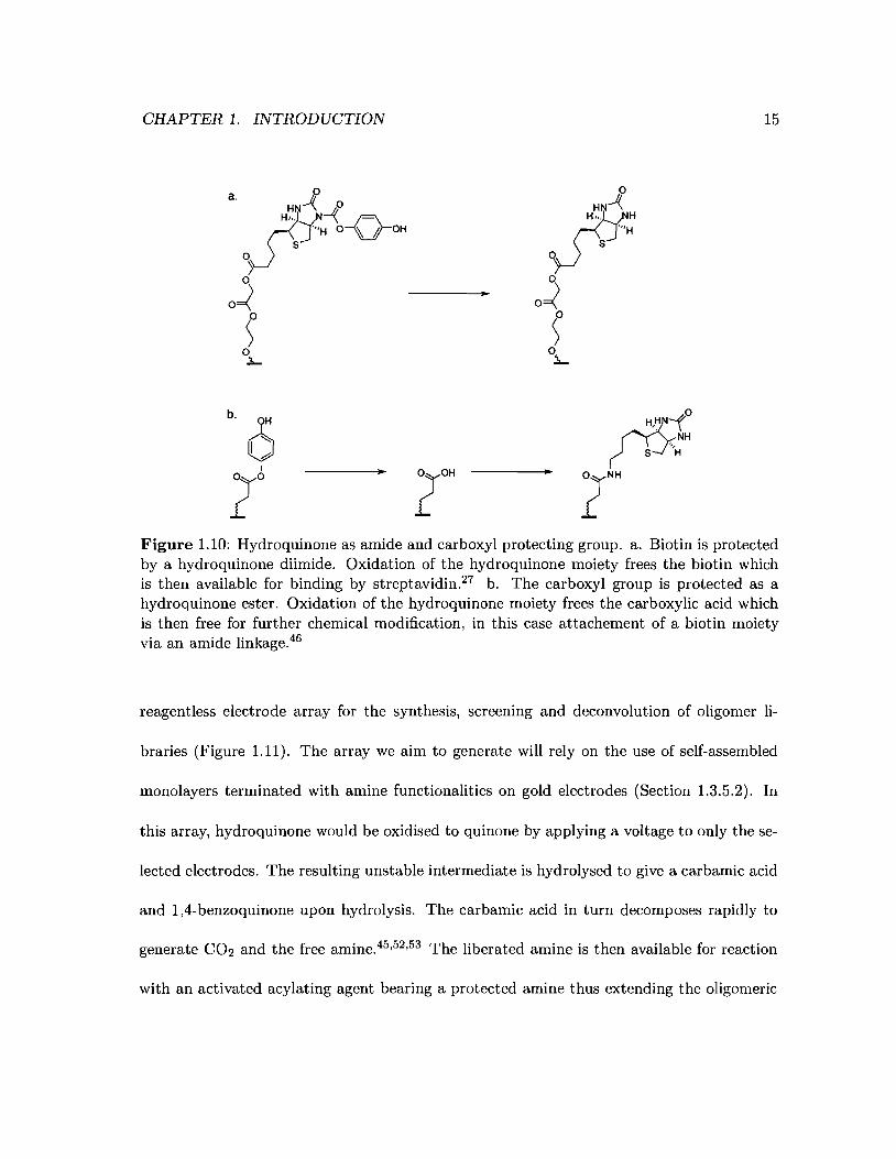
Figure 1.10: Hydroquinone as amide and carboxyl protecting group. a. Biotin is protectedby a hydroquinone diimide. Oxidation of the hydroquinone moiety frees the biotin whichis then available for binding by streptavidin.27 b. The carboxyl group is protected as ahydroquinone ester. Oxidation of the hydroquinone moiety frees the carboxylic acid whichis then free for further chemical modification, in this case attachement of a biotin moietyvia an amide linkage.46
reagentless electrode array for the synthesis, screening and deconvolution of oligomer li-
braries (Figure 1.11). The array we aim to generate will rely on the use of self-assembled
monolayers terminated with amine functionalities on gold electrodes (Section 1.3.5.2). In
this array, hydroquinone would be oxidised to quinone by applying a voltage to only the se-
lected electrodes. The resulting unstable intermediate is hydrolysed to give a carbamic acid
and 1,4-benzoquinone upon hydrolysis. The carbamic acid in turn decomposes rapidly to
generate CO2 and the free amine.45 ,52,53 The liberated amine is then available for reaction
with an activated acylating agent bearing a protected amine thus extending the oligomeric

CHAPTER 1. INTRODUCTION 16
chain. Since the new monomer can also be electrochemically deprotected, this cycle can, in
principle, be repeated as many times as necessary until the desired oligomer is obtained.
HO HO HO HO HO 0 HO HO
to oto to to be to toOJ
NH.1, .1, ~ .1, .1, 1. ~ oJ .1, JH
o NH 0 NH 0 NH 0 NH 0 NH NH 0 NH 0 NH
I ..L. ~ ..L. I r ..L. J. ..L. I I ..L. ..L. ..I. I
I ~
"h"h p"~ ~ 0,
.1, J )o NH 0 NH 0 NH
r ..L. ..L. ..I. I
Figure 1.11: Proposed oligomerisation scheme. Applied potential shown by twisted arrow.a. -2 e-. b. - Benzoquinone. c. - CO2 . d. Monomer, R = phenyl, alkyl.
1.3.4 Archiving of the combinatorial libraries
The amount of chemical data generated by combinatorial methods is immense and therefore
archiving of combinatorial libraries is essential if such techniques are to be used for cost- and
time-effective research and development. The method of generating combinatorial libraries
proposed in this thesis makes it possible to archive their output very easily. The spatial
resolution is a great tool to ease the archiving process as is the fact that the molecules in
the libraries will remain attached to metal surfaces. We estimate that a single 1 cm by
1 cm array of electrodes can support the synthesis of up to 10, 000 different compoundsb .4o
We envisage that such a system would be controlled by a computer54 56 which could then
bEstirnate based on electrodes 100 /-Lrn by 100 /-Lrn and 10 /-Lrn spacing between electrodes.
CHAPTER 1. INTRODUCTION 17
archive the data associated with the array (deprotectionjaddition sequences, cycle times,
deprotection voltages, addition of extra reagents, etc... ). Further discussion on these
details is beyond the scope of this thesis.
1.3.5 Design principles
1.3.5.1 Electrode design
The array will be composed of gold electrodes on an insulated medium spaced by a few
micrometers. Gold has been chosen since it forms oxide-free surfaces that are amenable to
self-assembled monolayer (SAM) formation. As well, the body of literature on self-assembled
monolayers on gold is vast which should facilitate our progress and aid interpretation of data
generated during research efforts.57 59 However, gold electrodes oxidise easily when poten-
tials in the vicinity of 1 V are used (Figure 1.12). This limit is important since it will play
a central role in the design of the electrochemically active monomers (see Sections 1.3.5.3
and 2.2) and the fatigueC behaviour of the final device. Fatigue is defined here as a com-
bination of electrode surface and self-assembled monolayer degradation. The composition
of the monolayer can also significantly influence the oxidation behaviour of the gold surface
(Figure 1.12) and as such will also playa key role in the overall performance of the device.
CFatigue is herein defined as the possible number of electrochemical cycles that one electrode can undergobefore the integrity of the device (electrode and SAM) is compromised.
CHAPTER 1. INTRODUCTION 18
1-amino-10-mercaptodecane monolayer
1.00.50.0
-~
-100 +--_----.----.->"'-----.--~-___,.Q.5
2iO 1-&re9dd
;ro-1-a-ri~1Q.1rercaptcxrore-cy.;tanine
1~
100
~- ~-
Pdential (V)
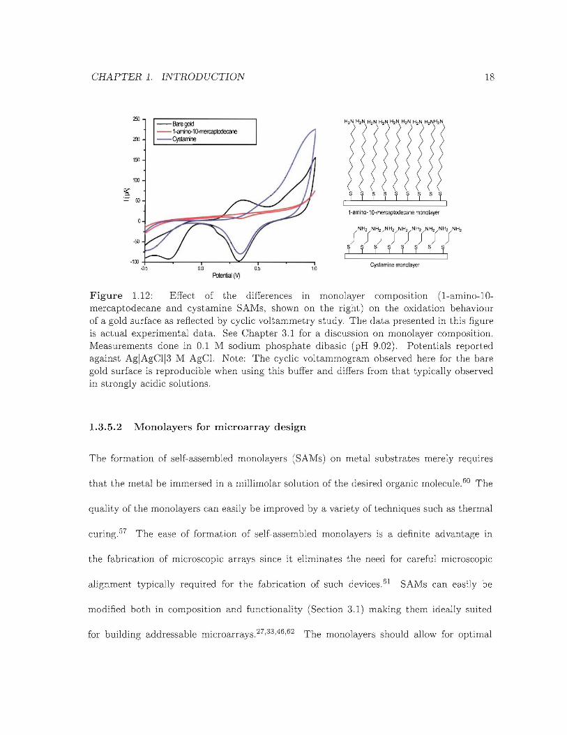
Figure 1.12: Effect of the differences in monolayer composition (1-amino-10mercaptodecane and cystamine SAMs, shown on the right) on the oxidation behaviourof a gold surface as reflected by cyclic voltammetry study. The data presented in this figureis actual experimental data. See Chapter 3.1 for a discussion on monolayer composition.Measurements done in 0.1 M sodium phosphate dibasic (pH 9.02). Potentials reportedagainst AgIAgCl13 M AgCI. Note: The cyclic voltammogram observed here for the baregold surface is reproducible when using this buffer and differs from that typically observedin strongly acidic solutions.
1.3.5.2 Monolayers for microarray design
The formation of self-assembled monolayers (SAMs) on metal substrates merely requires
that the metal be immersed in a millimolar solution of the desired organic molecule. 6o The
quality of the monolayers can easily be improved by a variety of techniques such as thermal
curing. 57 The ease of formation of self-assembled monolayers is a definite advantage in
the fabrication of microscopic arrays since it eliminates the need for careful microscopic
alignment typically required for the fabrication of such devices. 61 SAMs can easily be
modified both in composition and functionality (Section 3.1) making them ideally suited
for building addressable microarrays.27,:33,46,62 The monola.yers should a.llow for optimal
CHAPTERl. INTRODUCTION
~I
19
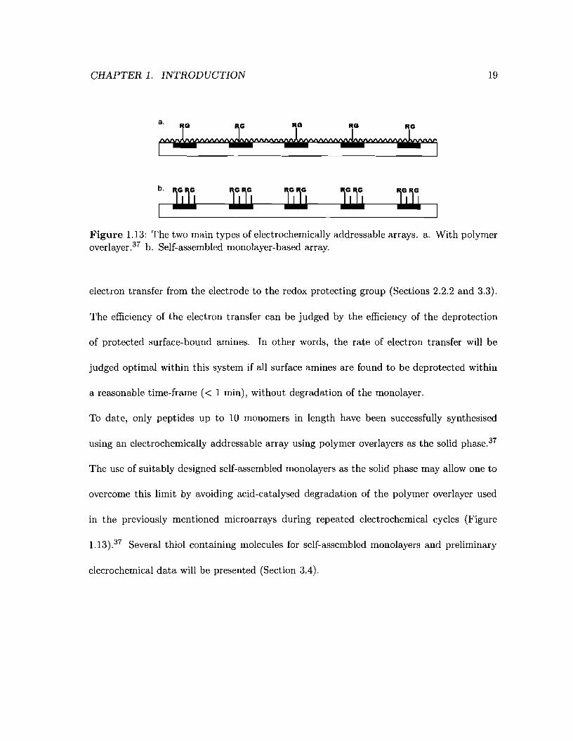
Figure 1.13: The two main types of electrochemically addressable arrays. a. With polymeroverlayer.37 b. Self-assembled monolayer-based array.
electron transfer from the electrode to the redox protecting group (Sections 2.2.2 and 3.3).
The efficiency of the electron transfer can be judged by the efficiency of the deprotection
of protected surface-bound amines. In other words, the rate of electron transfer will be
judged optimal within this system if all surface amines are found to be deprotected within
a reasonable time-frame « 1 min), without degradation of the monolayer.
To date, only peptides up to 10 monomers in length have been successfully synthesised
using an electrochemically addressable array using polymer overlayers as the solid phase.37
The use of suitably designed self-assembled monolayers as the solid phase may allow one to
overcome this limit by avoiding acid-catalysed degradation of the polymer overlayer used
in the previously mentioned microarrays during repeated electrochemical cycles (Figure
1.13).37 Several thiol containing molecules for self-assembled monolayers and preliminary
elecrochemical data will be presented (Section 3.4).

CHAPTER 1. INTRODUCTION
1.3.5.3 Monomer design
20
The new type of array being developed here requires a novel series of molecules (or building
blocks) to work with and therefore new amino acid based monomeric units were developed
for future use in the reagentless electrochemically addressable microarrays that we envision.
Two main series of monomers based on benzoic acid cores were designed. Their design
principles, synthesis and use will be presented in Chapter 2.
1.3.6 Critical evaluation of the array design
It is our belief that these arrays will ultimately be superior to previously available photo
chemical and electrochemical arrays. Our approach involves no reagents for oligomerisation
and provides this method with a clear advantage over any existing spatially addressable elec
trochemical or photochemical approach.24,25,37,41 As well, the use of monolayers gives us a
unique control over the performance of the device by allowing us to easily change the prop
erties of the self-assembled monolayers used on the surface of the array's electrodes (Section
1.3.5.2). By fixing the oligomers on an electrode surface, we can easily test those oligomers
by electrical feedback for folding or binding of an analyte of interest. Eventhough typical
electrode microarrays use electrodes 100 pm wide, we expect that further miniaturisation of
the electrode would be possible without significant degradation of the signal-to-noise ratio.
Variation in the shape of the electrodes may also help improve the signal-to-noise ratio.
However, the array design presented in this thesis does not allow for the synthesis of large

CHAPTER 1. INTRODUCTION 21
quantities of materials with at most less than a nanomole of oligomer per crn2 .d This implies
that if a suitable oligomer is found, traditional peptide chemistry will be required to scale
up the oligomer of interest.Even though the potential required for deprotection will be mild
(Section 2.2.2), electrochemical side-reactions cannot be ruled out. Furthermore, the high
concentration of amine nucleophiles at the surface may degrade the monomers in solution
(Chapter 4). This may be prevented by diluting the surface amines by simply modifying
the composition of the monolayers. Finally, incomplete deprotection of surface arnines may
result if the electron transfer from the electrode surface to the redox center at the tip of
the growing oligomer (Section 3.3.1) is not fast enough. This may lead to decreased yields
of oligomer and the formation of multiple length of oligorners on the same electrode. A full
discussion of the limitations touched upon above is beyond the scope of this thesis but these
issues should be addressed in the future.
dCalculated by assuming 25 A2 surface area per molecule givng 0.7 nmol.cm -2.

Chapter 2
Design and synthesis of monomers
Large libraries of oligomers can be synthesised for screening purposes using the approach
mentioned in Section 1.3. The novel approach described in this thesis requires suitable
monomeric units to be designed and synthesised. Since the surface of the arrays will display
both hydroxyl (present as part of the hydroquinone protecting group) and amine groups
(present after electrochemical deprotection), the reactivity of the monomers must be tuned
so as to enable selective discrimination of amines over alcohols (Figure 1.11).
2.1 General considerations
2.1.1 Unnatural ammo acids m the synthesis and design of protein-like
structures
Unnatural amino acids are non-genetically coded amino acids. They are useful for introduc
ing functionality into peptides that goes beyond that of the 20 commonly occuring natural
22
CHAPTER 2. DESIGN AND SYNTHESIS OF MONOMERS 23
~OHNH2
alanine
--<"'NH2HO-{
ovaline
O):0H HO 0 o3:H' ~~H'~I}, ..
o NNH2 Hphenylalanine proine OH
isoleucineleucine
HO~(OH~H2 tOH HO~S,HO~OH
H2N'"NH2 0 0 0 SH NH2
aspartic acid glutamic acid cysteine methionine
H ~H2
H2NI(N~OH
NH 0
arginine
~H2
H2N~(OH
o 0glutamine
HO~NH2NH2 0
asparagine
0HO~Q){oH ldOH- \ NH2 0 NH2 NH2
N HN NH2H histidine
lysine
tryptophan
OH
tOHH2N:('Q
~"NH'HO 0 ~ I OH HO H2N'"OH
tyrosine 0threonine
serine
Figure 2.1: The 20 commonly occurring natural a-amino acids.
CHAPTER 2. DESIGN AND SYNTHESIS OF MONOMERS 24
amino acids (Figure 2.1). Given their close resemblance to the naturally occurring amino
acids and the possibility for introduction via biological incorporation or other methods,
a-amino acids bearing unnatural substituents (Figure 2.2) are usually used to expand the
repertoire of functional groups.63 Unnatural amino acids are not only used to introduce new
functionality but also to control the three-dimensional structure of the peptide in which they
are incorporated. ,a-amino acids and aromatic amino acids (Figure 2.2) have been used for
this purpose.63 ,a-amino acids are useful since they form unique and predictable secondary
structures differing from that formed by similar a-amino acids. They allow for more con
trolled studies of the folding properties of peptides.63 Pomerantz and coworkers64 have
suggested that ,a-peptide self-assembled monolayers provide a convenient path to "rational
engineering of surfaces in which chemical groups are presented in precise and predictable ar
rangements". Aromatic amino acids are usually employed to provide rigidity to the peptide
backbone.63,65,66 For instance, 3-aminobenzoic acid has been incorporated in the design of
cyclic phosphoester binders67 and artificial ion channels.65 Both classes of amino acids are
the building blocks of a large family of compounds termed foldamers (Figure 2.3).68 70 As
discussed above unnatural amino acids enable us to synthesise peptides tailored exactly to
our specific needs both in structure and in function. In this thesis we will be concerned with
aromatic unnatural amino acids.
Proteins are polymeric macromolecules made out of amino acid monomers that are highly
evolved to perform specific tasks. The precise arrangement of the amino acids both in se
quence and in space is what confers function to proteins. If one could quickly synthesise a
CHAPTER 2. DESIGN AND SYNTHESIS OF MONOMERS 25
oOH
~yvO=~=O
HN
H2NlyO
OH
~,'R'H2N _1
o OH~O
HO
a-amino acids
H2N,~J.OHTV
y-amino acids
~OH
HO 0HO NH2
OH
sugar amino acids
J3-amino acids
t2~J.t) OH
Il-amino acids
Figure 2.2: Some unnatural amino acids.
large number of oligomers or polymers reminiscent of proteins but based on unnatural amino
acids that are soluble in organic solvents, a whole new class of catalytically efficient com-
pounds could be devised. The synthesis of unnatural oligomers has mainly been pursued by
traditional synthetic methods68 77 that, despite being conceptually simple, are cumbersome
and time consuming. Although such approaches are appropriate for the synthesis of limited
numbers of oligomers, generating and screening large libraries of compounds by this method
is impractical. The approach described in Section 1.3.3 could solve this problem although
it is not amenable to large scale synthesis. Many of the unnatural amino acids proposed for
making of such oligomers contain aromatic cores that provide a convenient synthetic lever
thanks to their ready availability and ease with which they can be chemically modified.
They also exhibit a host of interesting electronic properties owing to their structures. Most
CHAPTER 2. DESIGN AND SYNTHESIS OF MONOMERS 26
a. b.
Figure 2.3: Examples of foldamers. a. A ,B-peptide. b. A foldamer containing 3aminobenzoic acid. 3-aminobenzoic acid bolded.
Figure 2.4: Two unnatural peptides containing 3-aminobenzoic acid.
importantly, for our particular application, they can conduct electricity. This property has
previously been exploited for the construction of molecular wires.78 88
2.1.2 Guiding principles for designing the synthetic routes
These syntheses were developed with scalability and possible industrial applications in mind.
In order to enable potentially interested parties to use this technology, and in the event that
the molecules to be used would not be commercially available, the following points were
considered as critical.

CHAPTER 2. DESIGN AND SYNTHESIS OF MONOMERS
• Simple chemistry applicable to the synthesis of many different compounds
• As few purification steps as possible (avoid chromatography)
• Scalability
• High yielding
• Diversity (one precursor, many final compounds)
27
In this chapter, the design and synthesis of the first generation of monomeric units will be
presented.
2.2 Rational design of the monomer
For the purpose of discussion, a monomer is defined as a single molecule based on an amino
acid core and comprising the following parts: a leaving group (LG), a core (eM) and
an electrochemically-cleavable protecting group (PGM). These monomeric units are highly
functionalised molecules sporting an activated carboxylic acid, a carbamate and a phenol
functionality as a minimum. The activated carboxylic acid allows for the attachment of
the monomers to the growing oligomers through reaction with free surface-bound amine
functionalities. The amine group of the monomer will be protected as a carbamate contain
ing hydroquinone (Section 2.2.2). The highly functionalised nature of the monomeric units
poses several synthetic challenges that will be described in the following sections.
CHAPTER 2. DESIGN AND SYNTHESIS OF MONOMERS 28
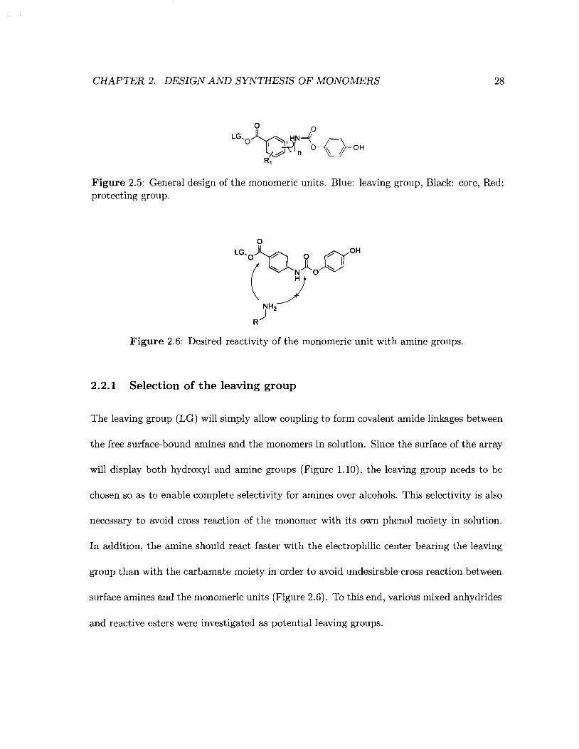
Figure 2.5: General design of the monomeric units. Blue: leaving group, Black: core, Red:protecting group.
Figure 2.6: Desired reactivity of the monomeric unit with amine groups.
2.2.1 Selection of the leaving group
The leaving group (LG) will simply allow coupling to form covalent amide linkages between
the free surface-bound amines and the monomers in solution. Since the surface of the array
will display both hydroxyl and amine groups (Figure 1.10), the leaving group needs to be
chosen so as to enable complete selectivity for amines over alcohols. This selectivity is also
necessary to avoid cross reaction of the monomer with its own phenol moiety in solution.
In addition, the amine should react faster with the electrophilic center bearing the leaving
group than with the carbamate moiety in order to avoid undesirable cross reaction between
surface amines and the monomeric units (Figure 2.6). To this end, various mixed anhydrides
and reactive esters were investigated as potential leaving groups.
CHAPTER 2. DESIGN AND SYNTHESIS OF MONOMERS
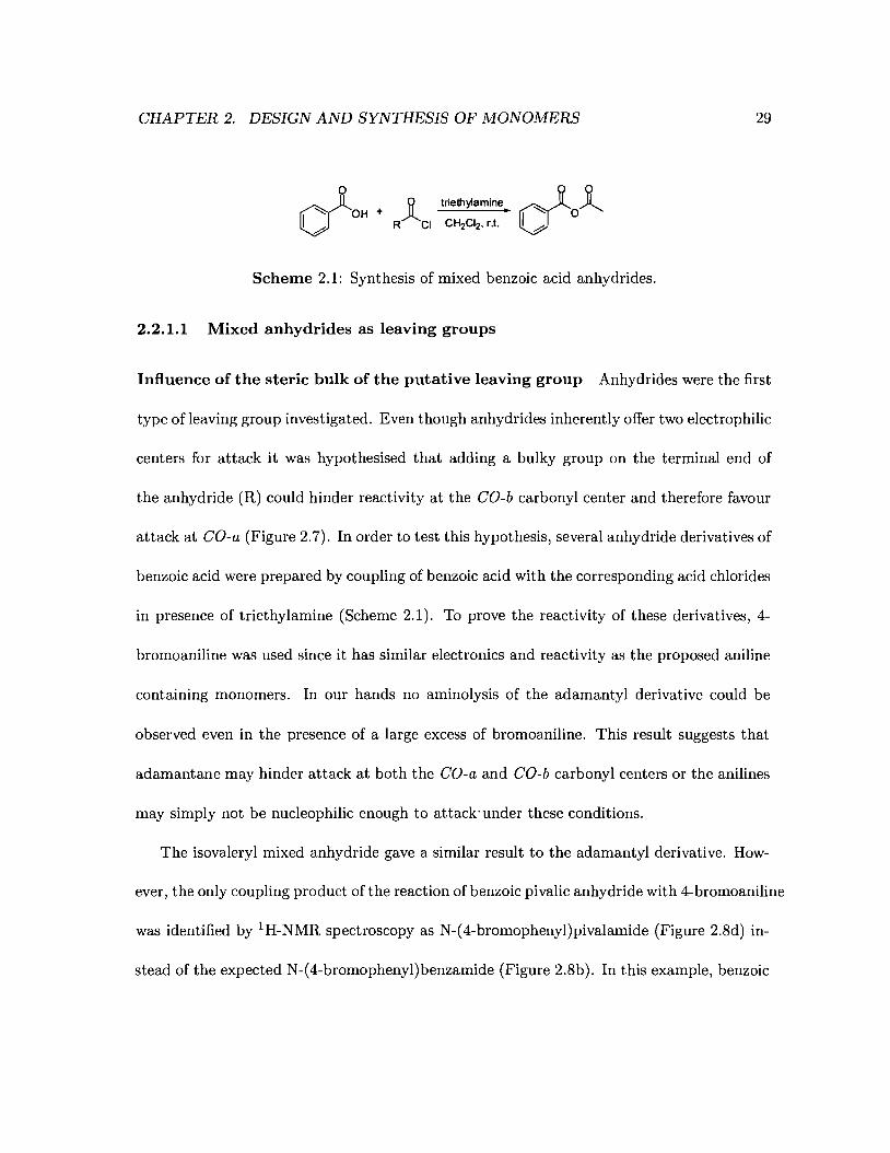
o d~~I-: OH + RJlCI triethylamine. I -: O~V CH2CI2, r.t. <'...,
Scheme 2.1: Synthesis of mixed benzoic acid anhydrides.
2.2.1.1 Mixed anhydrides as leaving groups
29
Influence of the steric bulk of the putative leaving group Anhydrides were the first
type of leaving group investigated. Even though anhydrides inherently offer two electrophilic
centers for attack it was hypothesised that adding a bulky group on the terminal end of
the anhydride (R) could hinder reactivity at the CO-b carbonyl center and therefore favour
attack at CO-a (Figure 2.7). In order to test this hypothesis, several anhydride derivatives of
benzoic acid were prepared by coupling of benzoic acid with the corresponding acid chlorides
in presence of triethylamine (Scheme 2.1). To prove the reactivity of these derivatives, 4-
bromoaniline was used since it has similar electronics and reactivity as the proposed aniline
containing monomers. In our hands no aminolysis of the adamantyl derivative could be
observed even in the presence of a large excess of bromoaniline. This result suggests that
adamantane may hinder attack at both the CO-a and CO-b carbonyl centers or the anilines
may simply not be nucleophilic enough to attack'under these conditions.
The isovaleryl mixed anhydride gave a similar result to the adamantyl derivative. How-
ever, the only coupling product of the reaction of benzoic pivalic anhydride with 4-bromoaniline
was identified by 1 H-NMR spectroscopy as N-(4-bromophenyl)pivalamide (Figure 2.8d) in-
stead of the expected N-(4-bromophenyl)benzamide (Figure 2.8b). In this example, benzoic
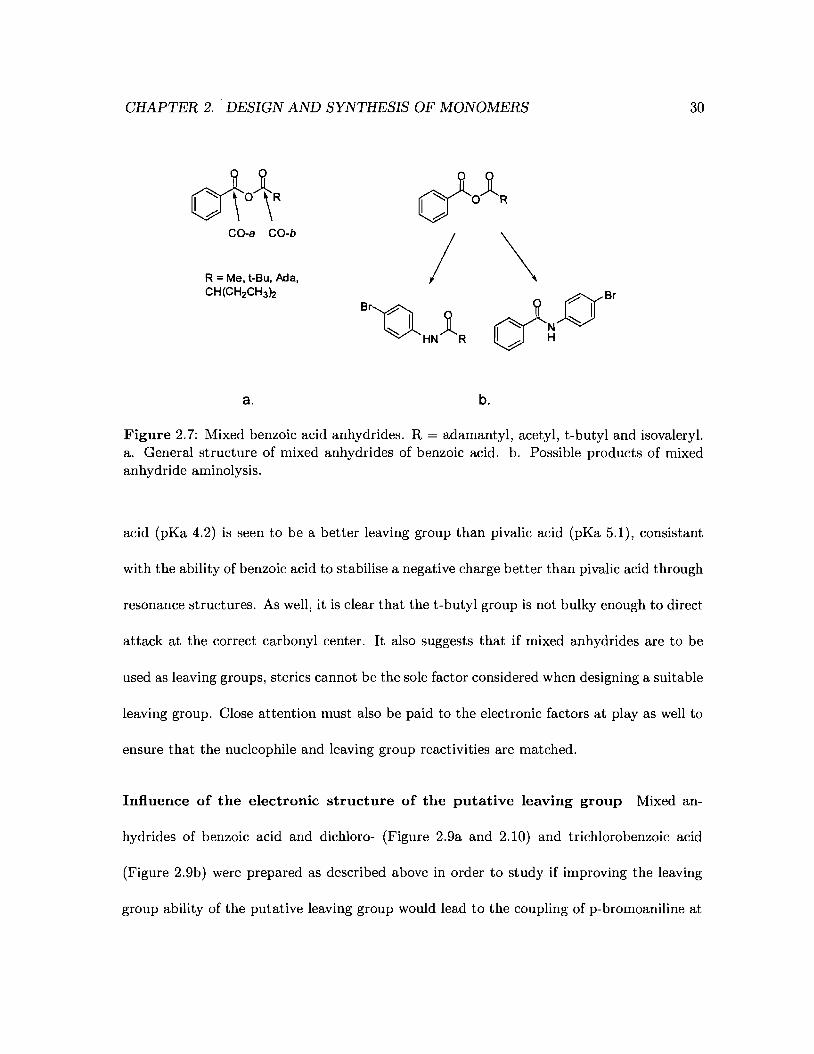
CHAPTER 2. DESIGN AND SYNTHESIS OF MONOMERS 30
CO-a CO-b
R = Me, t-Bu. Ada,CH(CH2CH3n
a. b.
Figure 2.7: Mixed benzoic acid anhydrides. R = adamantyl, acetyl, t-butyl and isovaleryl.a. General structure of mixed anhydrides of benzoic acid. b. Possible products of mixedanhydride aminolysis.
acid (pKa 4.2) is seen to be a better leaving group than pivalic acid (pKa 5.1), consistant
with the ability of benzoic acid to stabilise a negative charge better than pivalic acid through
resonance structures. As well, it is clear that the t-butyl group is not bulky enough to direct
attack at the correct carbonyl center. It also suggests that if mixed anhydrides are to be
used as leaving groups, sterics cannot be the sole factor considered when designing a suitable
leaving group. Close attention must also be paid to the electronic factors at playas well to
ensure that the nucleophile and leaving group reactivities are matched.
Influence of the electronic structure of the putative leaving group Mixed an-
hydrides of benzoic acid and dichloro- (Figure 2.9a and 2.10) and trichlorobenzoic acid
(Figure 2.9b) were prepared as described above in order to study if improving the leaving
group ability of the putative leaving group would lead to the coupling of p-bromoaniline at

CHAPTER 2. DESIGN AND SYNTHESIS OF MONOMERS
a.
cf°~b.
~yO, LLJI
j,
j i i i i i i i I I I9 6 7 6 5 4 2 10 8 6 4 2 0
c.
.D'\kd.
d 0• 1# 0 L
IJI I I I I I "0 I' , I I I
10 6 6 4 2 09 6 7 6 5 4 3 2
31
Figure 2.8: 1H-NMR of benzoic pivalic anhydride and its possible coupling products with4-bromoaniline. a. 1H-NMR of the benzoic pivalic anhydride in CDCI3 . b. Calculated 1HNMR of the coupling product of N-(4-bromophenyl)benzamide. c. Calculated IH-NMR ofN-(4-bromophenyl)pivalamide. d. 1H-NMR of the of the coupling product of 4-bromoanilineand benzoic pivalic anhydride in CDCb. Calculations performed using Chemdraw Ultra10.0.
the CO-a center as desired. Reaction of benzoic 2,4-dichlorobenzoic anhydride and benzoic
2,4,6-trichlorobenzoic anhydride with p-bromoaniline in methylene chloride was followed by
TLC (30/1; toluene / ethyl acetate). After leaving both reactions to proceed overnight a
new product having the same Rf was detected in both reactions. In the case of the reaction
of benzoic 2,4-dichlorobenzoic anhydride with p-bromoaniline, no benzoic acid release could
be observed by thin-layer chromatography, which hinted that attack of p-bromoaniline at the
CO-a center to form the desired N-(4-bromophenyl)benzamide product was occming (Fig-
me 2.11b). However, in the case of benzoic 2,4,6-trichlorobenzoic anhydride, benzoic acid
CHAPTER 2. DESIGN AND SYNTHESIS OF iVIONOMERS 32
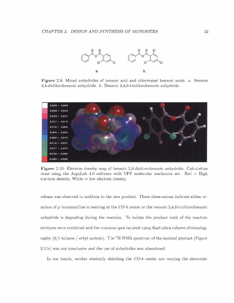
a.
d'onCI CI
b.
Figure 2.9: Mixed anhydrides of benzoic acid and chlorinated benzoic acids. a. Benzoic2,4-dichlorobenzoic anhydride. b. Benzoic 2,4,6-trichlorobenzoic anhydride.
Figure 2.10: Electron density map of benzoic 2,4-dichlorobenzoic anhydride. Calculationdone using the ArguLab 4.0 soft-ware with UFF molecular mechanics set. Red = Highelectron density, White = low electron density.
release was observed in addition to the new product. These observations indicate either re-
action of p-bromoaniline is reacting at the CO-b center or the benzoic 2,4,6-trichlorobenzoic
anhydride is degrading during the reaction. To isolate the product both of the reaction
mixtures were combined and the common spot isolated using flash silica column chromatog-
raphy (9/1 toluene / ethyl acetate). The 1H-NMR spectrum of the isolated product (Figure
2.11e) was not conclusive and the use of anhydrides was abandoned.
In our hands, neither sterically shielding the CO-b center nor varying the electronic
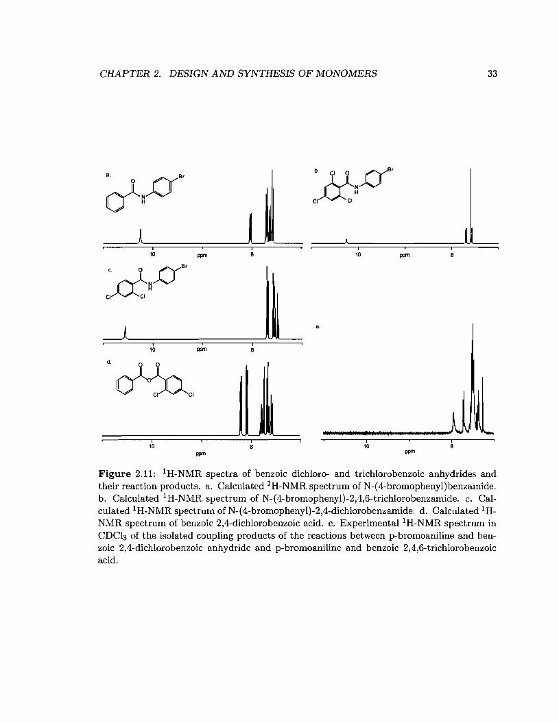
CHAPTER 2. DESIGN AND SYNTHESIS OF MONOMERS 33
I i I I10 ppm 8 10 ppm 8
c. 0 DB'CI~~
9.
I I10 ppm 8
d. 0 0
~,
I10
ppm
i8
I10
ppm
Figure 2.11: 1H-NMR spectra of benzoic dichloro- and trichlorobenzoic anhydrides andtheir reaction products. a. Calculated lH-NMR spectrum of N-(4-bromophenyl)benzamide.b. Calculated 1H-NMR spectrum of N-(4-bromophenyl)-2,4,6-trichlorobenzamide. c. Calculated 1H-NMR spectrum of N-(4-bromophenyl)-2,4-dichlorobenzamide. d. Calculated 1HNMR spectrum of benzoic 2,4-dichlorobenzoic acid. e. Experimental l H-NMR spectrum inCDCl3 of the isolated coupling products of the reactions between p-bromoaniline and benzoic 2,4-dichlorobenzoic anhydride and p-bromoaniline and benzoic 2,4,6-trichlorobenzoicacid.
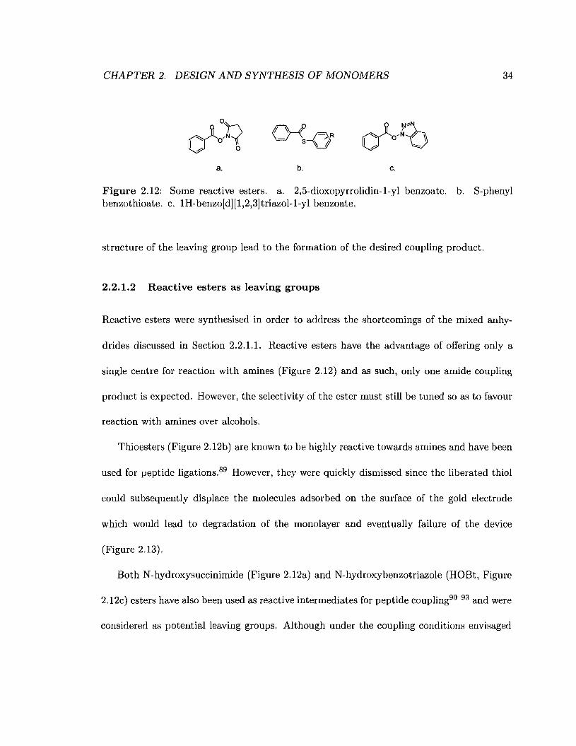
CHAPTER 2. DESIGN AND SYNTHESIS OF MONOMERS 34
a.
~ P R\J\S-ob. c.
Figure 2.12: Some reactive esters. a. 2,5-dioxopyrrolidin-l-yl benzoate. b. S-phenylbenzothioate. c. IH-benzo[d] [1,2,3]triazol-l-yl benzoate.
structure of the leaving group lead to the formation of the desired coupling product.
2.2.1.2 Reactive esters as leaving groups
Reactive esters were synthesised in order to address the shortcomings of the mixed anhy-
drides discussed in Section 2.2.1.1. Reactive esters have the advantage of offering only a
single centre for reaction with amines (Figure 2.12) and as such, only one amide coupling
product is expected. However, the selectivity of the ester must still be tuned so as to favour
reaction with amines over alcohols.
Thioesters (Figure 2.12b) are known to be highly reactive towards amines and have been
used for peptide ligations.89 However, they were quickly dismissed since the liberated thiol
could subsequently displace the molecules adsorbed on the surface of the gold electrode
which would lead to degradation of the monolayer and eventually failure of the device
(Figure 2.13).
Both N-hydroxysuccinimide (Figure 2.12a) and N-hydroxybenzotriazole (HOBt, Figure
2.12c) esters have also been used as reactive intermediates for peptide coupling90 93 and were
considered as potential leaving groups. Although under the coupling conditions envisaged

CHAPTER 2. DESIGN AND SYNTHESIS OF MONOMERS 35
-Figure 2.13: Thiol displacement at the gold surface. 4-aminothiophenol is replaced bythe thiophenol released from the reaction of S-phenyl benzothioate with a neighbouring4-aminothiophenol monolayer component.
(coupling of primary amines in the presence of phenol groups) N-hydroxysuccinimide could
be an appropriate choice, N-hydroxybenzotriazole was chosen since it has been shown that
its benzoate ester derivatives can be reacted with anilines in solution and are completely
inert to phenols unless triethylamine is added to the reaction mixture.94
2.2.2 The protecting group
The protecting group is used to restrict reactivity of amines bound to the growing oligomer
chain. Using an electrochemically labile protecting group facilitates the generation of a spa-
tially addressable array in the following way. Reaction of both surface-bound and solution
phase protected amines with electrophiles is prevented until an electrical potential is applied
and the resulting benzoquinone is hydrolysed off of the amine (Figure 1.10). Once the nu-
cleophilic amine group on the monolayer is unmasked, its reaction with monomers bearing
reactive N-hydroxybenzotriazole esters in the solution phase should allow extension of the
oligomer chain via formation of amide bonds as explained in Section 1.3.3 (Figure 1.11).
CHAPTER 2. DESIGN AND SYNTHESIS OF MONOMERS 36
Repetition of this sequence should permit further extension of the oligomer chain. The
hydroquinone protecting group can be cleanly and efficently removed under mild electro
chemical conditions (low potential). Although a host of electrochemically labile protecting
groups such as nosyl and tosyl groups have been used to protect amines, the electrochemical
cleavage of such groups can lead to the formation of side products. 50,51 The electrochem
ically cleavable cinnamyloxycarbonyl group has been used to protect amines,49 however,
the high negative potentials « -2.45 V) required for deprotection can potentially lead to
undesirable side products. The hydroquinone protecting group has been exploited by Kwak
and coworkers to protect the urea group of biotin so as to make an addressable array for
binding of streptavidin (a biotin binding protein).27 The electrochemical behaviour of hy
droquinone has been widely studied in a wide variety of solvents27,95 100 and its oxidation
potential was found to be low (0.5 V in aqueous solution). Similar to the cinnamyl group,
amines can be protected as hydroquinone carbamates. Given the suggestive results of Kwak
et ai. 27 and the well established electrochemistry of hydroquinone, the hydroquinone pro
tecting group was chosen as the electrochemically labile group to protect the primary amine
as a carbamate (Figure 2.14).
2.2.3 The core
The core of the monomeric units is key since it is the part of the monomer that will constitute
the main part of the oligomer after electrodeprotection (loss of the hydroquinone moiety
and liberation of the amine), coupling (cleavage of the reactive ester) and formation of the
amide linkage. It is the core that will make oligomers unique in sequence and confer their
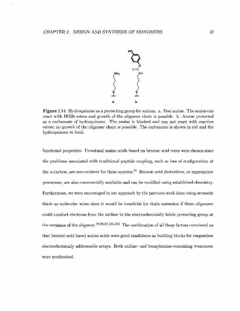
CHAPTER 2. DESIGN AND SYNTHESIS OF MONOMERS
H
Q0
o=(
fNH
~1 1a. b.
37
Figure 2.14: Hydroquinone as a protecting group for amines. a. Free amine. The amine canreact with HOBt esters and growth of the oligomer chain is possible. b. Amine protectedas a carbamate of hydroquinone. The amine is blocked and can not react with reactiveesters; no growth of the oligomer chain is possible. The carbamate is shown in red and thehydroquinone in bold.
functional properties. Unnatural amino acids based on benzoic acid cores were chosen since
the problems associated with traditional peptide coupling, such as loss of configuration at
the a-carbon, are non-existent for these systems.91 Benzoic acid derivatives, or appropriate
precursors, are also commercially available and can be modified using established chemistry.
Furthermore, we were encouraged in our approach by the previous work done using aromatic
thiols as molecular wires since it would be beneficial for chain extension if these oligomers
could conduct electrons from the surface to the electrochemically labile protecting group at
the terminus of the oligomer. 79 ,86,87,101,102 The combination of all these factors convinced us
that benzoic acid based amino acids were good candidates as building blocks for reagentless
electrochemically addressable arrays. Both aniline- and benzylamine-containing monomers
were synthesised.
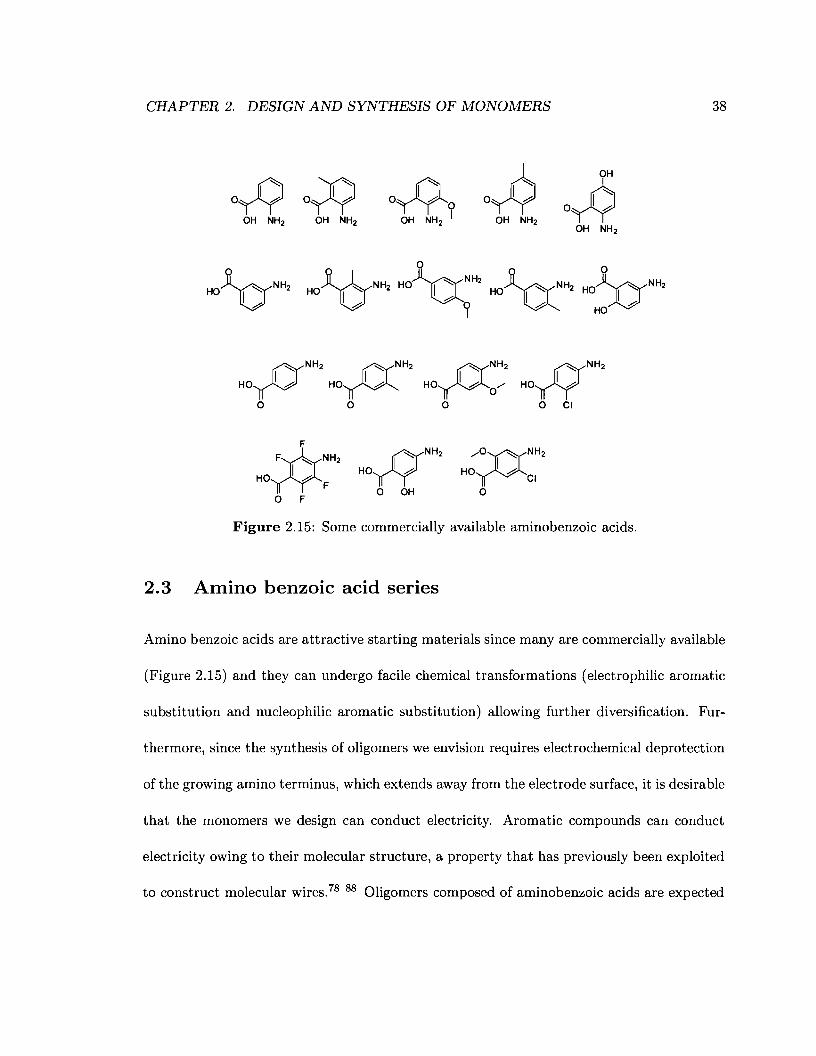
CHAPTER 2. DESIGN AND SYNTHESIS OF MONOMERS 38
~NH2 ~NH2
HO~ HO~o 0
~NH2H0nYo CI
F»"'" NH2
HO 1.0-F
o FH
NH2
HO I b'1o OH
/?CC"'"NH2
HO I bCI
o
Figure 2.15: Some commercially available aminobenzoic acids.
2.3 Amino benzoic acid series
Amino benzoic acids are attractive starting materials since many are commercially available
(Figure 2.15) and they can undergo facile chemical transformations (electrophilic aromatic
substitution and nucleophilic aromatic substitution) allowing further diversification. Fur-
thermore, since the synthesis of oligomers we envision requires electrochemical deprotection
of the growing amino terminus, which extends away from the electrode surface, it is desirable
that the monomers we design can conduct electricity. Aromatic compounds can conduct
electricity owing to their molecular structure, a property that has previously been exploited
to construct molecular wires. 78 88 Oligomers composed of aminobenzoic acids are expected

CHAPTER 2. DESIGN AND SYNTHESIS OF MONOMERS 39
Figure 2.16: An oligomer of 3-aminobenzoic acid. The extended conjugation is shown inbold.
to efficiently conduct current due to their extended conjugation (Figure 2.16) and are there-
fore expected to allow for efficient electron transfer (Section 3.3.1). Aminobenzoic acids
are therefore good candidates as starting materials for the synthesis of monomeric units for
electrochemically promoted oligomerisation. In this section the approach to the synthesis
of such monomers will be presented.
2.3.1 First approach
The critical step in making any of the monomers depicted in this thesis is the formation of
the carbamate moiety. Two main ways of doing so are via formation of either an isocyanate
intermediate or a chloroformate intermediate. In this section, we will be concerned with the
use of an isocyanate intermediate, which we term the isocyanate approach.
2.3.1.1 Retrosynthetic analysis and general synthetic scheme
Monomer 16 could be obtained from the deprotection of 7 followed by coupling with N-
hydroxybenzotriazole (Scheme 2.2). 7 could be synthesised from isocyanate 56 which in
turn could be obtained from sHyl ester 4.
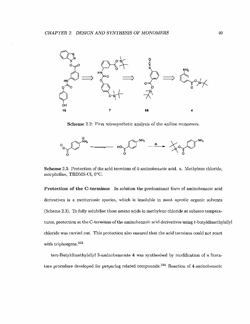
CHAPTER 2. DESIGN AND SYNTHESIS OF MONOMERS 40
Q~~,N
z===?9~0
?"I~
OH
16
I .......~O-Sl
)=1'04-HN;;0 ===>h\=( 1+
O-S~
7 56 4
Scheme 2.2: First retrosynthetic analysis of the aniline monomers.
a. ..
Scheme 2.3: Protection of the acid terminus of 4-aminobenzoic acid. a. Methylene chloride,morpholine, TBDMS-CI, O°C.
Protection of the C-terminus In solution the predominant form of aminobenzoic acid
derivatives is a zwitterionic species, which is insoluble in most aprotic organic solvents
(Scheme 2.3). To fully solubilise these amino acids in methylene chloride at subzero tempera-
tures, protection at the C-terminus of the aminobenzoic acid derivatives using t-butyldimethylsilyl
chloride was carried out. This protection also ensured that the acid terminus could not react
with triphosgene.103
tert-Butyldimethylsilyl 3-aminobenzoate 4 was synthesised by modification of a litera-
ture procedure developed for preparing related compounds. 104 Reaction of 4-aminobenzoic

CHAPTER 2. DESIGN AND SYNTHESIS OF MONOMERS 41
acid (1 equiv.) with tert-butyldimethylsilyl chloride (1.2 equiv.) in the presence of mor
pholine (2.2 equiv.) in methylene chloride at O°C for 18 hours, followed by extraction of
the reaction mixture with water and brine, afforded 4 in excellent yield (Table 2.1). The
identity of silyl ester 4 was established by IH-NMR, 13C-NMR and FT-IR spectroscopy.
Using this procedure, however, a small amount of tert-butyldimethylsilanol byproduct aris
ing from the decomposition of 4 and/or hydrolysis of tert-butyldimethylsilyl chloride was
consistently observed in the isolated material. 4 was not purified further, however, since
its presence was not found to be deleterious to the synthesis of 7 and the silanol byproduct
could easily be removed after subsequent steps. A series of C-protected amino acids was
made and is presented in Table 2.1. The present discussion will focus on molecules derived
from compounds 3-5 with an emphasis on compounds derived from 4. With 4 in hand, we
could now proceed with synthesising carbamate 7.
Attempted synthesis of carbamate 7 The synthesis of carbamate 7 was first at
tempted via isocyanate intermediate 56. 56 was synthesised by adding a solution of 4
(1 equiv.) in methylene chloride to a solution of triphosgene (0.33 equiv.) and triethy
lamine (2.3 equiv.) in methylene chloride at O°C (Figure 2.17). With isocyanate 56 in hand
we attempted the synthesis of carbamate 7 by in-situ dropwise addition of a solution of
4-(tert-butyldimethylsilyloxy)phenol (1, 1 equiv.) and triethylamine (1.1 equiv.) in methy
lene chloride to a solution of 56 in methylene chloride. Surprisingly however, addition of
two molecules of 1 to 56 was observed and compound 57 was obtained instead of the desired
product (Figure 2.18). In an effort to circumvent this problem, 1 was added in the absence
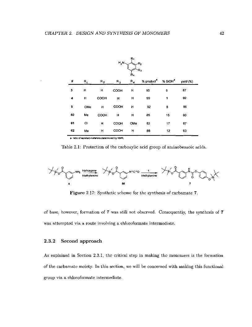
CHAPTER 2. DESIGN AND SYNTHESIS OF MONOMERS
R,
H'N~~~ R3
4
# R1 R2 R3 R4 % producta % SiOHa yield (%)
3 H H eOOH H 95 5 87
4 H eOOH H H 99 92
5 OMe H eOOH H 92 8 96
60 Me eOOH H H 85 15 90
61 el H eOOH OMe 83 17 87
62 Me H eOOH H 88 12 63
a. ratio of isolated matarials datermined by NMR.
Table 2.1: Protection of the carboxylic acid group of aminobenzoic acids.
42
,/ / 0/fi'O~NH2 triphosgen;
I triethylamineo
4
,/ / 0/fi'O~N=C=O •V triethylamine
56
Figure 2.17: Synthetic scheme for the synthesis of carbamate 7.
of base, however, formation of 7 was still not observed. Consequently, the synthesis of 7
was attempted via a route involving a chloroformate intermediate.
2.3.2 Second approach
As explained in Section 2.3.1, the critical step in making the monomers is the formation
of the carbamate moiety. In this section, we will be concerned with making this functional
group via a chloroformate intermediate.

CHAPTER 2. DESIGN AND SYNTHESIS OF MONOMERS
H13 HI
43
1.00 0.50
Solvent peak
0.00
H5
o ~~5HI/I"" I( I ""'jSi'OV 0 H7 # H9QH10
/ H4 H5 IH2 H3 .0 Hll
57 O'S/~/ '/ .......
H12 H13
Acetone I Acetic acid
I10.0
Impurity
I5.0
Figure 2.18: IH-NMR of undesired byproduct 57 in CDCb at 400 MHz. Top inset: Expansion of the 1.2 to 0 ppm region. Bottom inset: Expansion of the 8.5 to 6.5 ppm region.
2.3.2.1 Retrosynthetic analysis and general synthetic scheme (Scheme 2.4)
Aniline monomer 16 could be formed by coupling of N-hydroxybenzotriazole to the free
benzoic acid derivative 13 which, in turn, could be obtained by catalysed acid hydrolysis of
the silyl protecting groups off from compound 7. Reaction of the chloroformate intermediate
2 with tert-butyldimethylsilyl-4-aminobenzoate 4 would afford 7. Finally, chloroformate 2
could be obtained from the reaction of alcohol 1 with an appropriate phosgene equivalent.
With their synthetic scheme in mind the aniline series of monomers was prepared as
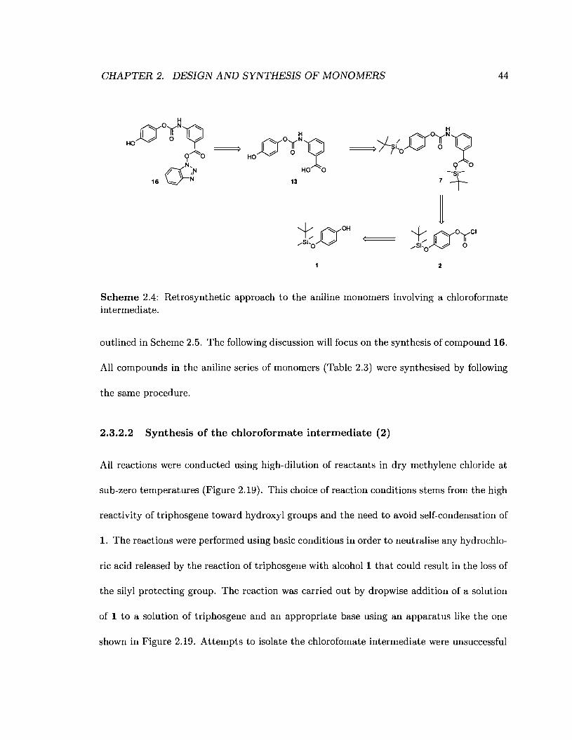
CHAPTER 2. DESIGN AND SYNTHESIS OF MONOMERS
r(YO[(~y~ ~ 0 I ~
HO
HO 0
13
2
44
Scheme 2.4: Retrosynthetic approach to the aniline monomers involving a chloroformateintermediate.
outlined in Scheme 2.5. The following discussion will focus on the synthesis of compound 16.
All compounds in the aniline series of monomers (Table 2.3) were synthesised by following
the same procedure.
2.3.2.2 Synthesis of the chloroformate intermediate (2)
All reactions were conducted using high-dilution of reactants in dry methylene chloride at
sub-zero temperatures (Figure 2.19). This choice ofreaction conditions stems from the high
reactivity of triphosgene toward hydroxyl groups and the need to avoid self-condensation of
1. The reactions were performed using basic conditions in order to neutralise any hydrochlo-
ric acid released by the reaction of triphosgene with alcohol 1 that could result in the loss of
the silyl protecting group. The reaction was carried out by dropwise addition of a solution
of 1 to a solution of triphosgene and an appropriate base using an apparatus like the one
shown in Figure 2.19. Attempts to isolate the chlorofomate intermediate were unsuccessful
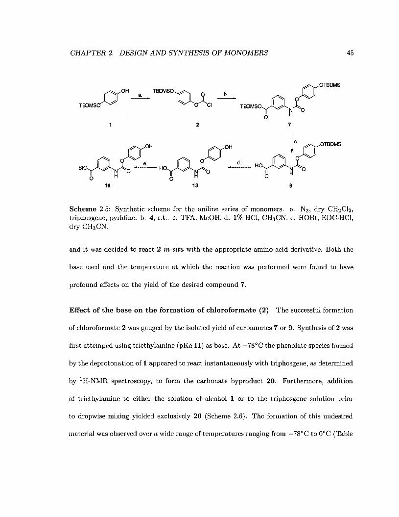
CHAPTER 2. DESIGN AND SYNTHESIS OF MONOMERS 45
O OH TBDMS0'QI a. ITBDMSO h- - ~ oJlCI
1
~OH
N8t- () ~ • e.~N 0
o H16
b.
2
r91r0H
NHO () ~ • d.
~~ 0o
13 9
Scheme 2.5: Synthetic scheme for the aniline series of monomers. a. N2, dry CH2Ch,triphosgene, pyridine. b. 4, r.t.. c. TFA, MeOH. d. 1% HCl, CH3CN. e. HOBt, EDC·HCl,dry CH3CN.
and it was decided to react 2 in-situ with the appropriate amino acid derivative. Both the
base used and the temperature at which the reaction was performed were found to have
profound effects on the yield of the desired compound 7.
Effect of the base on the formation of chloroformate (2) The successful formation
of chloroformate 2 was gauged by the isolated yield of carbamates 7 or 9. Synthesis of 2 was
first attemped using triethylamine (pKa 11) as base. At -78°C the phenolate species formed
by the deprotonation of 1 appeared to react instantaneously with triphosgene, as determined
by 1H-NMR spectroscopy, to form the carbonate byproduct 20. Furthermore, addition
of triethylamine to either the solution of alcohol 1 or to the triphosgene solution prior
to dropwise mixing yielded exclusively 20 (Scheme 2.6). The formation of this undesired
material was observed over a wide range of temperatures ranging from -78°C to O°C (Table
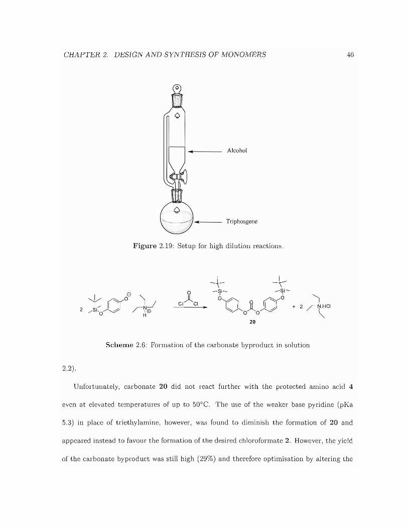
CHAPTER 2. DESIGN AND SYNTHESIS OF MONOMERS
Alcohol
46
Triphosgene
Figure 2.19: Setup for high dilution reactions.
..
+ +-~- -~~
o~ 9 ~o
~AJJo 0
20
1+ 2 rN.HC1
~
Scheme 2.6: Formation of the carbonate byproduct in solution
2.2).
Unfortunately, carbonate 20 did not react further with the protected amino acid 4
even at elevated temperatures of up to 50°C. The use of the weaker base pyridine (pKa
5.3) in place of triethylamine, however, was found to diminish the formation of 20 and
appeared instead to favour the formation of the desired chloroformate 2. However, the yield
of the carbonate byproduct was still high (29%) and therefore optimisation by altering the
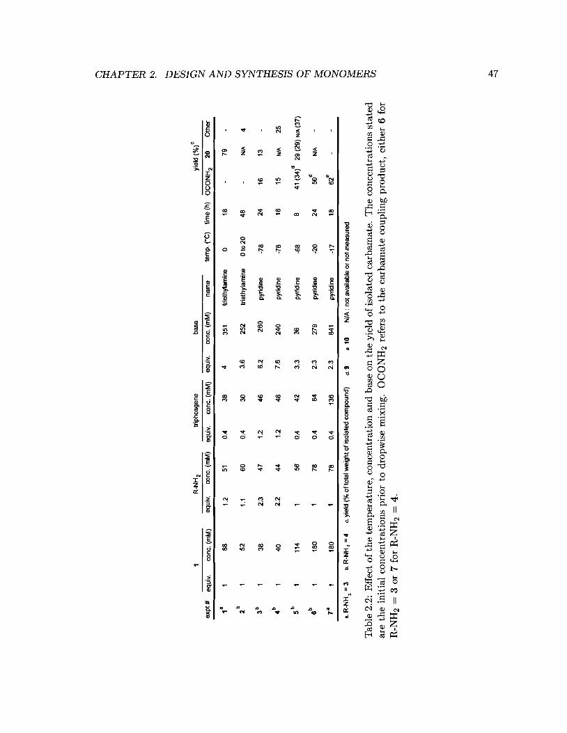
R-N
H2
trip
hosg
ene
base
yiel
d(%
)c
exp
t#eq
uiv.
cone
.(m
M)
equi
v.co
ne.
(mM
)eq
uiv.
cone
.(m
M)
equi
v.co
ne.
(mM
)na
me
tem
p.(O
C)
time
(h)
OC
ON
H2
20O
the
r
18
188
1.2
510.
43
84
351
trie
thyl
amin
e0
18-
79
b2
15
21.
16
00.
430
3.6
25
2tr
ieth
ylam
ine
oto
20
48
N/A
4
3b
138
2.3
47
1.2
46
6.2
26
0py
ridi
ne-7
82
416
13
4b
14
02.
244
1.2
487.
62
40
pyri
dine
-78
1815
NlA
25
Sb
111
41
560.
44
23.
336
pyri
dine
-68
841
(34
29(2
9)
NlA
(37)
6b
118
01
78
0.4
642.
327
9py
ridi
ne-2
02
4SO
dN
lA
781
18
01
78
0.4
136
2.3
841
pyri
dine
-17
186
2e
8.R
-NH
2=
3b.
R-N
H,
=4
c.yi
eld
(%o
ftot
alw
eig
hto
fiso
late
dco
mp
ou
nd
)d
.9e.
10
N/A
:n
ota
vaila
ble
or
notm
easu
red
Tab
le2.
2:E
ffec
tof
the
tem
pera
ture
,co
ncen
trat
ion
and
base
onth
eyi
eld
ofis
olat
edca
rbam
ate.
Th
eco
ncen
trat
ions
stat
edar
eth
ein
itia
lco
ncen
trat
ions
prio
rto
drop
wis
em
ixin
g.O
CO
NH
2re
fers
toth
eca
rbam
ate
coup
ling
prod
uct,
eith
er6
for
R-N
H2
=3
or7
for
R-N
H2
=4.
@ ~ "tl ~ ::0 ~ t1 ~ < ~ @ CJ':J ~ ~ tri CJ':J (jj ~ a < o ~ ~ Cf:J
,j::o
.-.:
J
CHAPTER 2. DESIGN AND SYNTHESIS OF MONOMERS
temperature was attempted.
48
Effect of the temperature on the formation of chloroformate 2 When the reaction
was performed at -78°C, it was observed that the yield of the final compound 7 was lower
than at -20°C and concomitantly, the yield of 20 increased. Notably, at -78°C a yellow
solid was observed to accumulate in solution over time. This solid was not isolated but
its observation is consistent with the formation and known solubility of phosgene-pyridine
complexes in methylene chloride.1°5 This phosgene adduct contains two pyridines bound
through a C2-N bound (Figure 2.20a); the adduct undergoes reversion to its components
at temperatures in excess of -30°C. This solid was suggested to have similar reactivity
as phosgene itself.1°5 At lower temperature (-78°C) the adduct in Figure 2.20 is the re
active species whereas at higher temperature (-20°C) triphosgene is the reactive species.
The higher yields of carbonate observed at the lower temperature (Table 2.2) lead us to
hypothesise that the phosgene-pyridine adduct is more reactive than triphosgene alone and
therefore all subsequent reactions were carried out at -20°C.
2.3.2.3 Synthesis of the carbamate 13
With chloroformate 2 in hand, we proceeded to synthesise carbamate 7. As explained
in Section 2.3.2.2, 2 was not isolated and tert-butyldimethylsilyl 3-aminobenzoate 4 (1.0
equiv.) was reacted in-situ with 2 (1.0 equiv.) in the presence of pyridine (1.0 equiv.)
to afford 7. Carbamate 7 could not be reliably purified by flash column chromatography
since it degraded to its free-acid derivative 9 during chromatography. We surmise that the
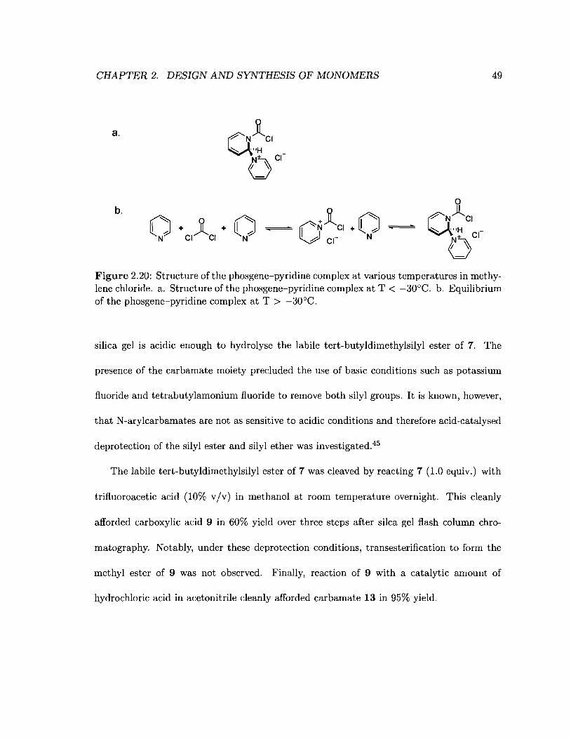
CHAPTER 2. DESIGN AND SYNTHESIS OF MONOMERS 49
a.
b. Jl ~O"'N CI + ~ J
.0 CI- N
o
a~CI_
eCI'I ~
Figure 2.20: Structure of the phosgene-pyridine complex at various temperatures in methylene chloride. a. Structure of the phosgene-pyridine complex at T < -30D e. b. Equilibriumof the phosgene-pyridine complex at T > -30 De.
silica gel is acidic enough to hydrolyse the labile tert-butyldimethylsilyl ester of 7. The
presence of the carbamate moiety precluded the use of basic conditions such as potassium
fluoride and tetrabutylamonium fluoride to remove both silyl groups. It is known, however,
that N-arylcarbamates are not as sensitive to acidic conditions and therefore acid-catalysed
deprotection of the silyl ester and silyl ether was investigated.45
The labile tert-butyldimethylsilyl ester of 7 was cleaved by reacting 7 (1.0 equiv.) with
trifluoroacetic acid (10% vIv) in methanol at room temperature overnight. This cleanly
afforded carboxylic acid 9 in 60% yield over three steps after silca gel flash column chro-
matography. Notably, under these deprotection conditions, transesterification to form the
methyl ester of 9 was not observed. Finally, reaction of 9 with a catalytic amount of
hydrochloric acid in acetonitrile cleanly afforded carbamate 13 in 95% yield.
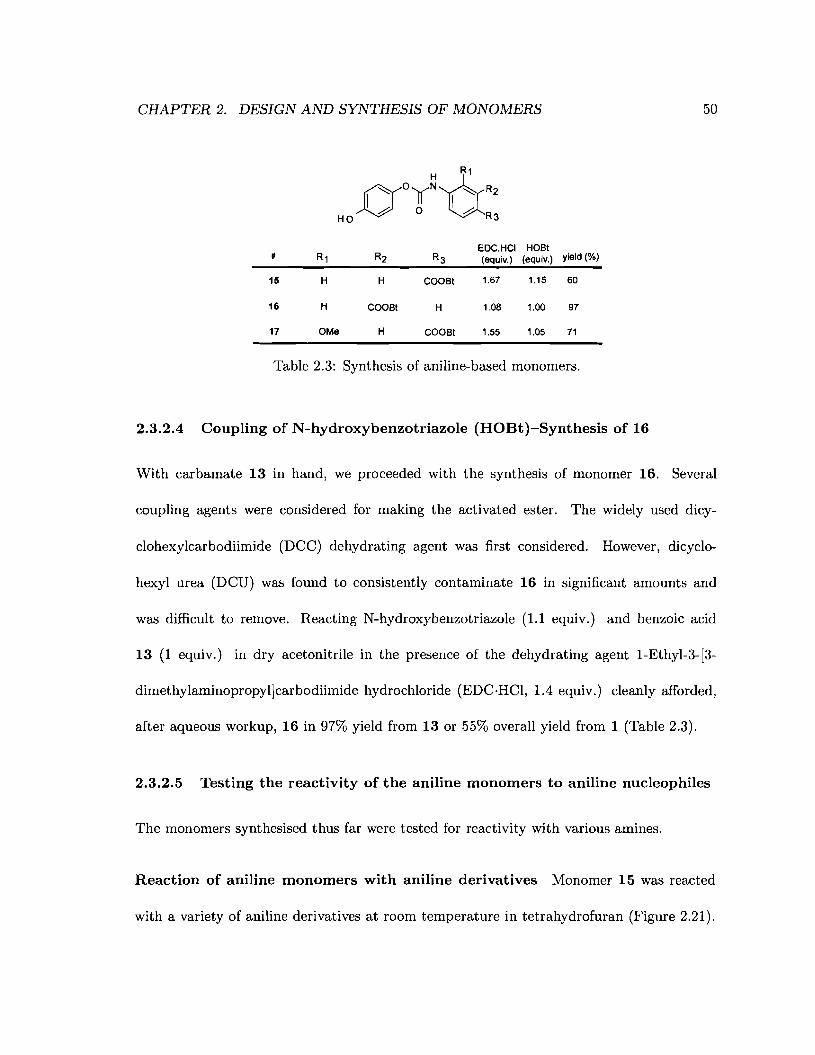
CHAPTER 2. DESIGN AND SYNTHESIS OF MONOMERS
f)°"~UR'I b 0 I bHO R3
EDC.HCI HOSt# R1 R2 R3 (equiv.) (equiv.) yield (%)
15 H H COOSt 1.67 1.15 60
16 H COOSt H 1.08 1.00 97
17 OMe H COOSt 1.55 1.05 71
Table 2.3: Synthesis of aniline-based monomers.
2.3.2.4 Coupling of N-hydroxybenzotriazole (HOBt)-Synthesis of 16
50
With carbamate 13 in hand, we proceeded with the synthesis of monomer 16. Several
coupling agents were considered for making the activated ester. The widely used dicy-
clohexylcarbodiimide (DCC) dehydrating agent was first considered. However, dicyclo-
hexyl urea (DCD) was found to consistently contaminate 16 in significant amounts and
was difficult to remove. Reacting N-hydroxybenzotriazole (1.1 equiv.) and benzoic acid
13 (1 equiv.) in dry acetonitrile in the presence of the dehydrating agent l-Ethyl-3-[3-
dimethylaminopropyl]carbodiimide hydrochloride (EDC·HCI, 1.4 equiv.) cleanly afforded,
after aqueous workup, 16 in 97% yield from 13 or 55% overall yield from 1 (Table 2.3).
2.3.2.5 Testing the reactivity of the aniline monomers to aniline nucleophiles
The monomers synthesised thus far were tested for reactivity with various amines.
Reaction of aniline monomers with aniline derivatives Monomer 15 was reacted
with a variety of aniline derivatives at room temperature in tetrahydrofuran (Figure 2.21).
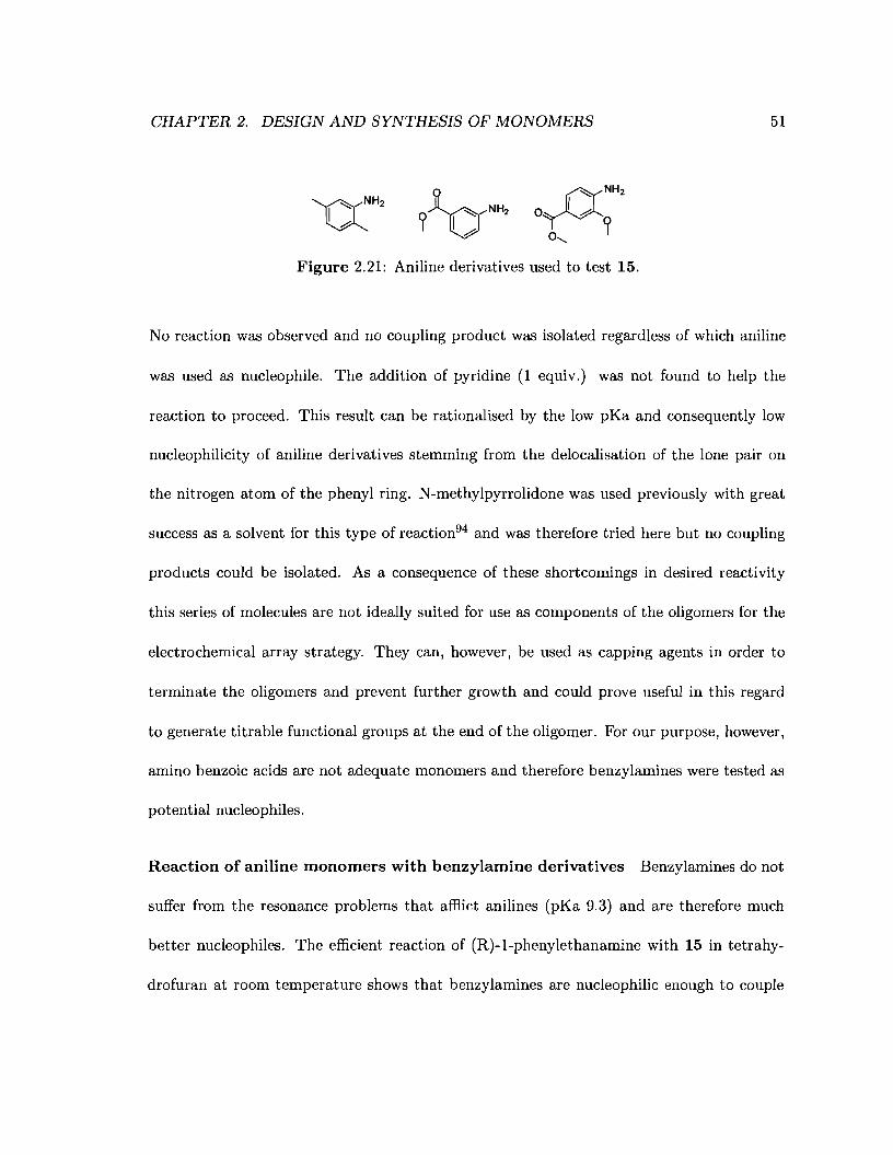
CHAPTER 2. DESIGN AND SYNTHESIS OF MONOMERS 51
Figure 2.21: Aniline derivatives used to test 15.
No reaction was observed and no coupling product was isolated regardless of which aniline
was used as nucleophile. The addition of pyridine (1 equiv.) was not found to help the
reaction to proceed. This result can be rationalised by the low pKa and consequently low
nucleophilicity of aniline derivatives stemming from the delocalisation of the lone pair on
the nitrogen atom of the phenyl ring. N-methylpyrrolidone was used previously with great
success as a solvent for this type of reaction94 and was therefore tried here but no coupling
products could be isolated. As a consequence of these shortcomings in desired reactivity
this series of molecules are not ideally suited for use as components of the oligomers for the
electrochemical array strategy. They can, however, be used as capping agents in order to
terminate the oligomers and prevent further growth and could prove useful in this regard
to generate titrable functional groups at the end of the oligomer. For our purpose, however,
amino benzoic acids are not adequate monomers and therefore benzylamines were tested as
potential nucleophiles.
Reaction of aniline monomers with benzylamine derivatives Benzylamines do not
suffer from the resonance problems that afflict anilines (pKa 9.3) and are therefore much
better nucleophiles. The efficient reaction of (R)-l-phenylethanamine with 15 in tetrahy-
drofuran at room temperature shows that benzylamines are nucleophilic enough to couple
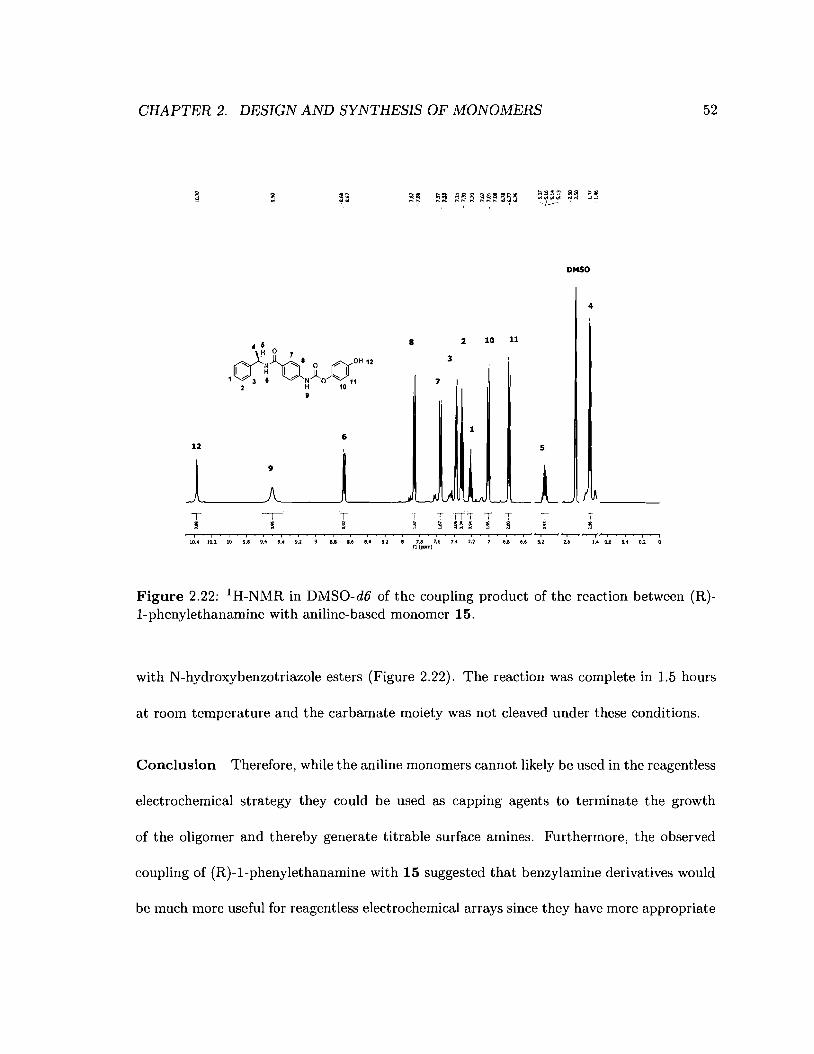
CHAPTER 2. DESIGN AND SYNTHESIS OF MONOMERS 52
8 2 10 11
3
7
DMSO
4
16
12
T ~,,-- T T ITT T ~,
~ ~ 9 5 B ~ 5i , , , i i , , i , i i i i I I
10.1 10.2 10 •.s ,.• ,.. '.2 U L6 ~. '.2 7.' 7•• 7.• 7.2 ...U(ppm)
5
1T I~
Figure 2.22: 1H-NMR in DMSO-d6 of the coupling product of the reaction between (R)I-phenylethanamine with aniline-based monomer 15.
with N-hydroxybenzotriazole esters (Figure 2.22). The reaction was complete in 1.5 hours
at room temperature and the carbamate moiety was not cleaved under these conditions.
Conclusion Therefore, while the aniline monomers cannot likely be used in the reagentless
electrochemical strategy they could be used as capping agents to terminate the growth
of the oligomer and thereby generate titrable surface amines. Furthermore, the observed
coupling of (R)-l-phenylethanamine with 15 suggested that benzylamine derivatives would
be much more useful for reagentless electrochemical arrays since they have more appropriate

CHAPTER 2. DESIGN AND SYNTHESIS OF MONOMERS
reactivity.
2.3.3 Experimental
2.3.3.1 Solvents and chemicals
53
All solvents were obtained from Caledon and used without purification except for triethy
lamine, pyridine and tetrahydrofuran which were obtained from Anachemia and distilled be
fore use. All deuterated solvents were obtained from Cambridge Isotope Laboratories, Inc..
Silica gel 60 was obtained from EMD (product # 9385 - 3). Trifluoroacetic acid and hydro
quinone were obtained from Sigma-Aldrich. l-Ethyl-3-[3-dimethylaminopropyl]carbodiimide
hydrochloride was obtained from Fluka. All other chemicals were obtained from Aldrich.
All chemicals were used without purification.
2.3.3.2 Characterisation
All FT-IR measurements of molecules were made on a Bomem M-B series spectrometer. All
molecules were measured as a KBr pellet or as films deposited from chloroform on a sodium
chloride disc. Each spectrum is the average of 32 or 64 measurements. NMR spectra eH
and 13C) were acquired on a Varian Inova 500 MHz spectrometer or a Brueker Avance 600
MHz spectrometer. Melting points were taken using a Electrothermal Mel Temp@ melting
point apparatus and were not corrected. CHN elemental analysis was performed on a Carlo
Erba Model 1106 CHN analyzer at Simon Fraser University.
CHAPTER 2. DESIGN AND SYNTHESIS OF MONOMERS 54
4-(tert-butyldimethylsilyloxy)phenol (1) 1 was synthesised using a modified litera
ture procedure. 106 A solution of tert-butyl-dimethylsilyl chloride (2.92 g, 19.4 mmol, 1.07
equiv.) in dry methylene chloride (20 ml) was added dropwise to a stirred solution of hydro
quinone (1.99 g, 18.1 mmol, 1 equiv.) and imidazole (2.68 g, 39.3 mmol, 2.17 equiv.) in dry
methylene chloride (35 ml) at O°C. The resulting suspension changed colour from colourless
to pink and was stirred overnight. The reaction mixture was washed with water (3x25 ml)
and the aqueous layer back-extracted with methylene chloride (3x25 ml). The combined
organic extracts were dried over sodium sulphate and the solvent removed in-vacuo. The
residue was purified by flash column chromatography (8/1 Hexanes / Ethyl acetate) to af
ford a colourless oil that crystallised upon standing (1.66 g, 41%). IH-NMR (CDCl3, 400
MHz) J (ppm) 6.70 (m, 4H), 0.97 (s, 9H), 0.16 (s, 6H); m.p. 53-55°C, lit. 56-57°C.
General Procedure for the Synthesis of tert-butyldimethylsilyl aminobenzoates
To a solution of tert-butylsimethylsilyl chloride (2.03 g, 13.5 mmol, 1.0 equiv.) and mor
pholine (2.98 g, 34.2 mmol, 2.53 equiv.) in dry methylene chloride (40 ml) at O°C was
added 4-aminobenzoic acid (2.15 g, 15.7 mmol, 1.16 equiv.). The reaction mixture was
stirred overnight, the volume made up to 100 ml with methylene chloride and washed with
water (3 x 35 ml). The organic layer was dried over sodium sulfate and the solvent removed
in-vacuo to yield a white solid in yields ranging from 84 to 92 %.
tert-butyldimethylsilyl 4-aminobenzoate (3) 1H-NMR (400 MHz, CDCl3) J (ppm)
7.85 (ABq, J = 8.8 Hz, 2H), 6.65 (ABq, J = 8.8 Hz, 2H), 1.01 (s, 9H), 0.35 (s, 6H); 13C-NMR
(100 MHz, CDCl3) J (ppm) 166.68, 150.79, 132.20, 121.12, 113.73, 25.71, 17.82, -4.68; IR
CHAPTER 2. DESIGN AND SYNTHESIS OF MONOMERS
(KBr) 1915.68 cm-i , 1669.27 cm-i (C=O).
55
tert-butyldimethylsilyl 3-aminobenzoate (4) 1H-NMR (400 MHz, CDC13) 6 (ppm)
7.43 (dt, J= 8, 1.2 Hz, 1H), 7.34 (m, 1H), 7.21 (t, J=8 Hz, 1H), 6.86 (ddd, J= 7.9, 2.4,0.8
Hz, 3H), 1.02 (s, 9H), 0.36 (s, 6H); i3C-NMR (100 MHz, CDC13) 6 (ppm) 191.51, 129.19,
120.38, 119.41, 116.26, 25.68, -4.77; IR (KBr) 1669.27 cm-i (C=O).
tert-butyldimethylsilyI4-amino-3-methoxybenzoate (5) iH-NMR (500 MHz, CDCI3)
6 (ppm) 7.48 (dd, 1H, J =8,2 Hz), 7.40 (s, 1H, J = 2 HZ), 6.79 (d, 1H, J = 8.5 Hz), 3.91
(s, 3H), 1.01 (s, 9H), 0.35 (s, 6H); m.p. 143-146°C.
(tert-butyldimethylsilyI 3- ((4- (tert-butyldimethylsilyloxy)phenoxy)-
carbonylamino)benzoate (7) To a solution of 1 (2.01 g, 8.98 mmol, 1.0 equiv.) in dry
methylene chloride (120 ml) was added dropwise to a solution of triphosgene (1.01 g, 3.41
mmol, 0.38 equiv.) in dry methylene chloride (80 ml) with dry pyridine (1.7 ml, 21.0 mmol,
2.34 equiv.) at -10°C. The reaction mixture was allowed to warm up to room temperature
and a solution of 13 (2.36 g, 9.39 mmol, 1.05 equiv.) in dry methylene chloride (100 ml) was
added dropwise at room temperature. The reaction mixture was washed with 1% aqueous
hydrochloric acid, water and brine (50 ml each). The organic layer was dried over sodium.sulfate and the solvent removed in-vacuo to yield an orange oil (8.9 g, quantitative) which
was used without purification. iH-NMR (400 MHz, CDC13) 6 (ppm) 7.89 (br. s, 2H), 7.77
(dt, J = 4,1.2 Hz, 1H), 7.42 (t, J = 8 Hz, 1H), 7.07 (br. s, 1H), 7.04 (ABq, J = 8.2 Hz, 2H),
6.83 (ABq, J = 8.2 Hz, 2H), 1.02 (s, 9H), 0.98 (s, 9H), 0.38 (s, 6H), 0.20 (s, 6H); i3C-NMR
CHAPTER 2. DESIGN AND SYNTHESIS OF MONOMERS 56
(100 MHz, CDCI3) 6 (ppm) 166.03, 153.31, 144.39, 137.67, 132.49, 129.34, 125.44, 122.30,
120.53,25.69,28.65,18.17,17.86, -4.47, -4.76; IR (KBr) 1748.4 cm-1 (C=O), 1547.6 cm-1
(HQ); E.A. Calcd. C 62.24, H 7.83, N 2.79, Expt. C 62.42, H 7.89, N 2.54; m.p. 97-98°C.
General Procedure for the Synthesis of (tert-butyldimethylsilyloxy)phenoxy)
carbonylamino)benzoic acids A solution of 7 in 10% methanolic solution of trifluo
roacetic acid (100 ml) was stirred overnight. When the reaction was complete by TLC the
solvent was removed in-vacuo and the pink residue taken up in ethyl acetate (150 ml) and
washed with 1% aqueous hydrochloric acid (3 x 50 ml). The organic layer was dried over
sodium sulfate and the solvent removed in-vacuo. The residue was purified by flash column
chromatography (2/1 ethyl acetate / hexanes with 1% acetic acid) yielding a white solid in
yields from 50 to 66% over three steps.
3-( (4-(tert-butyldimethylsilyloxy)phenoxy)carbonylamino)benzoic acid (9) 1H
NMR (500 MHz, CDCI3) 6 (ppm) 8.07 (br. s, 1H), 7.84 (d, J = 7 Hz, 2H), 7.46 (t, J = 8
Hz, 1H), 7.07 (br. s, 1H), 7.05 (m, 3H), 6.83 (ABq, J = 8.5 Hz, 2H), 0.99 (s, 9H), 0.20 (s,
6H); 13C-NMR (100 MHz, CDCI3) 6 (ppm) 144.37, 137.86, 130.01, 129.48, 125.52, 122.31,
120.56, 25.66, -4.47; IR (KBr) 1725.4 cm-1 (C=O), 1551.5 cm-1 (HQ); E.A. Calcd. C
61.99, H 6.50, N 3.61, Expt. C 61.71, H 6.61, N 3.45; m.p. 191-192°C.
4-((4-(tert-butyldimethylsilyloxy)phenoxy)carbonylamino)benzoic acid (11) IH_
NMR (500 MHz, CDCI3) 6 (ppm) 8.09 (ABq, J = 8.5 Hz, 2H), 7.56 (ABq, J = 8.5 Hz, 2H),
7.13 (br. s, 1H), 7.05 (ABq, J = 9 Hz, 2H), 6.84 (ABq, J = 9 Hz, 2H), 0.99 (s, 9H), 0.20 (s,
CHAPTER 2. DESIGN AND SYNTHESIS OF MONOMERS 57
6H); 13C-NMR (125 MHz, CDCh) 6 (ppm) 171.15, 153.47, 144.20, 142.46, 131.72, 124.29,
122.27, 120.60, 117.80, 25.64, 18.17, -4.48; IR (KBr) 1754.6 cm-1 (C=O), 1529.4 cm-1
(HQ); E.A. Calcd. C 61.99 H 6.50 N 3.61 Expt. C 62.15 H 6.67 N 3.87; ; m.p. >220°C.
4- ((4- (tert-butyldimethylsilyloxy)phenoxy)carbonylamino)-3-methoxybenzoic acid
(10) IH-NMR (500 MHz, Acetone-d6) 6 (ppm) 8.75 (s, 1H), 8.28 (s, 1H), 7.80 (dd, J =
8.5, 2 Hz, 1H), 7.16 (d, J = 8.5 Hz, 1H), 7.12 (ABq, J = 9 Hz, 2H), 6.91 (ABq, J = 9
Hz, 2H), 4.02 (s, 3H), 1.0 (s, 9H), 0.23 (s, 6H); 13C-NMR (125 MHz, Acetone-d6) 6 (ppm)
168.27, 154.88, 153.70, 146.99, 129.27, 127.82, 124.82, 124.52, 122.16, 112.02, 57.59, 27.00,
19.74, -3.39; IR (KBr) 1748.4 cm-1 (C=O), 1675.5 cm-1 (C=O), 1535.5 cm-1 (HQ); E.A.
Calcd. C 60.41, H 6.52, N 3.35 Expt. C 60.68, H 6.81, N 3.58; m.p. >220°C.
General Procedure for the Synthesis of ((4-hydroxyphenoxy)carbonylamino)
benzoic acids Concentrated hydrochloric acid (6 ml, 2.9% HCI vIv) was added to a
solution of 10 (0.18 g, 0.44 mmol, 1 equiv.) in 95% acetonitrile (70 ml). The reaction mixture
was stirred overnight. The solvent was reduced in-vacuo and the reaction mixture taken up
in ethyl acetate (100 ml) and the organic layer was washed with 1% aqueous hydrochloric
acid (30 ml) and water (30 ml). The organic layer was dried over sodium sulfate and the
solvent removed in-vacuo. The residue was purified by flash column chromatography (1/1
ethyl acetate / hexanes with 1% acetic acid) affording a white solid in yields between 90
and 97%.
CHAPTER 2. DESIGN AND SYNTHESIS OF MONOMERS 58
3-((4-hydroxyphenoxy)carbonylamino)benzoic acid (13) IH-NMR (500 MHz, Acetone
d6) J (ppm) 9.26 (br. s, 1H), 8.33 (s, 1H), 7.86 (dd, J = 8, 1.5 Hz, 1H), 7.74 (d, J = 7.5
Hz, 1H), 7.47 (t, J = 8 Hz, 1H), 7.04 (ABq, J = 8.5 Hz, 2H), 6.84 (ABq, J = 8.5 Hz, 2H);
13C-NMR (125 MHz, Acetone-d6) J (ppm) 168.35, 156.72, 154.10, 145.40, 141.18, 133.17,
130.86, 125.92, 124.52, 121.35, 117.29; IR (KBr) 1711.8 cm-1 (C=O), 1505.1 cm-1 (HQ);
E.A. Calcd. C 61.54 H 4.06 N 5.13 Expt. C 61.40 H 4.27 N 4.85; m.p. 218(d)OC.
4- ( (4-hydroxyphenoxy)carbonylamino)benzoic acid (12) 1H-NMR (500 MHz, Acetone
d6) J (ppm) 9.42 (br. s, 1H), 8.02 (ABq, J = 9 Hz, 2H), 7.73 (ABq, J = 8.5 Hz, 2H), 7.04
(ABq, J = 9 Hz, 2H), 6.85 (ABq, J = 9 Hz, 2H); 13C-NMR (125 MHz, Acetone-d6) J (ppm)
168.39, 156.85, 153.94, 145.32, 145.15, 132.65, 126.87, 124.49, 119.48, 117.36; IR (KBr)
1711.79 cm-1 (C=O), 1505.11 cm-1 (HQ); m.p. >220°C.
4-((4-hydroxyphenoxy)carbonylamino)-3-methoxybenzoic acid (14) IH-NMR (500
MHz, Acetone-d6) J (ppm) 8.75 (s, 1H), 8.23 (s, 1H), 7.80 (dd, J = 8.5, 2 Hz, 1H), 7.16
(d, J = 8.5 Hz, 1H), 7.05 (ABq, J = 9 Hz, 2H), 6.85 (ABq, J = 9 Hz, 2H), 4.02 (s, 3H);
13C-NMR (125 MHz, Acetone-d6) J (ppm) 168.29, 156.76, 153.91, 145.51, 129.36, 127.74,
124.81, 124.47, 117.32, 111.99, 57.59; IR (KBr) 1693.7 cm-1 (C=O), 1511.3 cm-1 (HQ);
E.A. Calcd. C 59.41, H 4.32, N 4.62, Expt. C 59.28, H 4.22, N 4.65; m.p. >260°C.
General procedure for the synhesis of 1H-benzo[d][1,2,3]triazol-1-yl ((4-hydroxy
phenoxy)carbonylamino)benzoates To a stirred solution of 1-Ethyl-3-(3-dimethyl-
CHAPTER 2. DESIGN AND SYNTHESIS OF MONOMERS 59
aminopropyl)carbodiimide hydrochloride (32.3 mg, 0.17 mmol, 1.55 equiv.) and N-hydroxy-
benzotriazole (15.5 mg, 0.12 mmol, 1.05 equiv.) in dry acetonitrile (10 ml) was added
dropwise a solution of 14 (33.5 mg, 0.11 mmol, 1.0 equiv.) in dry acetonitrile (20 ml) at
room temperaturea . Once the reaction was complete by TLC the solvent was reduced in-
vacuo to 2 ml and the reaction mixture dissolved in ethy acetate (100 ml). The organic
layer was washed with water (20 ml), dried over sodium sulfate and the solvent was removed
in-vacuo. The residue was recrystallised from ethyl acetate / hexanes yielding a white solid
in yields ranging from 60 to 97% (see Table 2.3).
1H-benzo[d] [1,2,3]triazol-1-yl 3-( (4-hydroxyphenoxy)carbonylamino)benzoate (16)
IH-NMR (500 MHz, Acetone-d6) 8 (ppm) 9.52 (s, 1H), 8.62 (s, 1H), 8.40 (br. s, 1H), 8.12
(dt, J = 8.1, 1 Hz, 1H), 8.07 (m, 1H), 8.03 (m, 1H), 7.88 (dt, J = 8.5, 1 Hz, 1H), 7.69 (m,
2H), 7.55 (td, J = 8, 1 Hz, 1H);
1H-benzo[d] [1,2,3]triazol-1-yI4-( (4-hydroxyphenoxy)carbonylamino)benzoate (15)
IH-NMR (500 MHz, Acetone-d6) 8 (ppm) 9.74 (s, IH), 8.42 (s, IH), 8.31 (ABq, J = 8.5 Hz,
2H), 8.12 (d, J = 8.5 Hz, 1H), 7.94 (ABq, J = 8.5 Hz, 2H), 7.84 (d, J = 8 Hz, 1H), 7.68 (t,
J = 7.5 Hz, 1H), 7.54 (t, J = 7.5 Hz, 1H), 7.08 (ABq, J = 8.5 Hz, 2H), 7.88 (ABq, J = 8.5
Hz, 2H); 13C-NMR (500 MHz, Acetone-d6) 8 (ppm) 164.35, 153.89, 147.83, 145.29, 145.2,
134.02, 130.79, 130.75, 126.48, 121.88, 120.31, 120.24, 120.06, 117.41, 110.87; E.A. Calcd.
C 61.54, H 3.62, N 14.35, Expt. C 61.31, H 3.60, N 14.01; m.p. 206(d)OC.
"When the compound was found to be only partially soluble in acetonitrile, an equal volume of ethylacetate was added to solubilise the compound
CHAPTER 2. DESIGN AND SYNTHESIS OF MONOMERS 60
IH-benzo[d] [1,2,3]triazol-l-yl 4-( (4-hydroxyphenoxy) carbonylamino)-3-methoxy
benzoate (17) 1H-NMR (500 MHz, Acetone-d6) 8 (ppm) 8.98 (8, IH), 8.53 (8, IH), 8.34
(8, IH), 8.10 (d, J = 8.5 Hz, 2H), 7.82 (d, J = 8.5 Hz, IH), 7.66 (t, J = 7.5 Hz, IH), 7.53
(t, J = 7.5 Hz, IH), 7.39 (d, J = 8.5 Hz, IH), 7.06 (ABq, J = 9 Hz, 2H), 6.85 (ABq, J =
9 Hz, 2H), 4.13 (8, 3H); 13C-NMR (500 MHz, MeOH-d4) 8 (ppm) 163.88, 156.41, 144.73,
144.61, 123.62, 120.81, 117.73, 116.67, 112.32, 112.23, 57.0; IR (KBr) 1774.4 cm-1 (C=O),
1506.51 cm-1 (HQ); E.A. Calcd. C 60.00, H 3.84, N 13.33, Expt. C 59.86, H 3.73, N 13.60;
m.p. 173(d)OC.
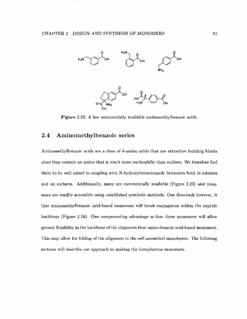
CHAPTER 2. DESIGN AND SYNTHESIS OF MONOMERS 61
o
H2N~OH
Figure 2.23: A few commercially available aminomethylbenzoic acids.
2.4 Aminomethylbenzoic serIes
Aminomethylbenzoic acids are a class of 6-amino acids that are attractive building blocks
since they contain an amine that is much more nucleophilic than anilines. We therefore find
them to be well suited to coupling with N-hydroxybenzotriazole benzoates both in solution
and on surfaces. Additionally, many are commercially available (Figure 2.23) and many
more are readily accessible using established synthetic methods. One drawback however, is
that aminomethylbenzoic acid-based monomers will break conjugation within the peptide
backbone (Figure 2.24). One compensating advantage is that these monomers will allow
greater flexibility in the backbone of the oligomers than aminobenzoic acid-based monomers.
This may allow for folding of the oligomers in the self-assembled monolayers. The following
sections will describe our approach to making the benzylamine monomers.
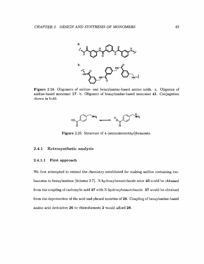
CHAPTER 2. DESIGN AND SYNTHESIS OF MONOMERS
b. thOHN
r"\ ° ~~;, - ~ ~HN1Y~ - HN-l
62
Figure 2.24: Oligomers of aniline- and benzylamine-based amino acids. a. Oligomer ofaniline-based monomer 17. b. Oligomer of benzylamine-based monomer 41. Conjugationshown in bold.
rY"NH2HO~ "',;======...
o
Figure 2.25: Structure of 4-(ammoniomethyl)benzoate.
2.4.1 Retrosynthetic analysis
2.4.1.1 First approach
We first attempted to extend the chemistry established for making aniline containing car-
bamates to benzylamines (Scheme 2.7). N-hydroxybenzotriazole ester 40 could be obtained
from the coupling of carboxylic acid 37 with N-hydroxybenzotriazole. 37 would be obtained
from the deprotection of the acid and phenol moieties of 28. Coupling of benzylamine-based
amino acid derivative 26 to chloroformate 2 would afford 28.
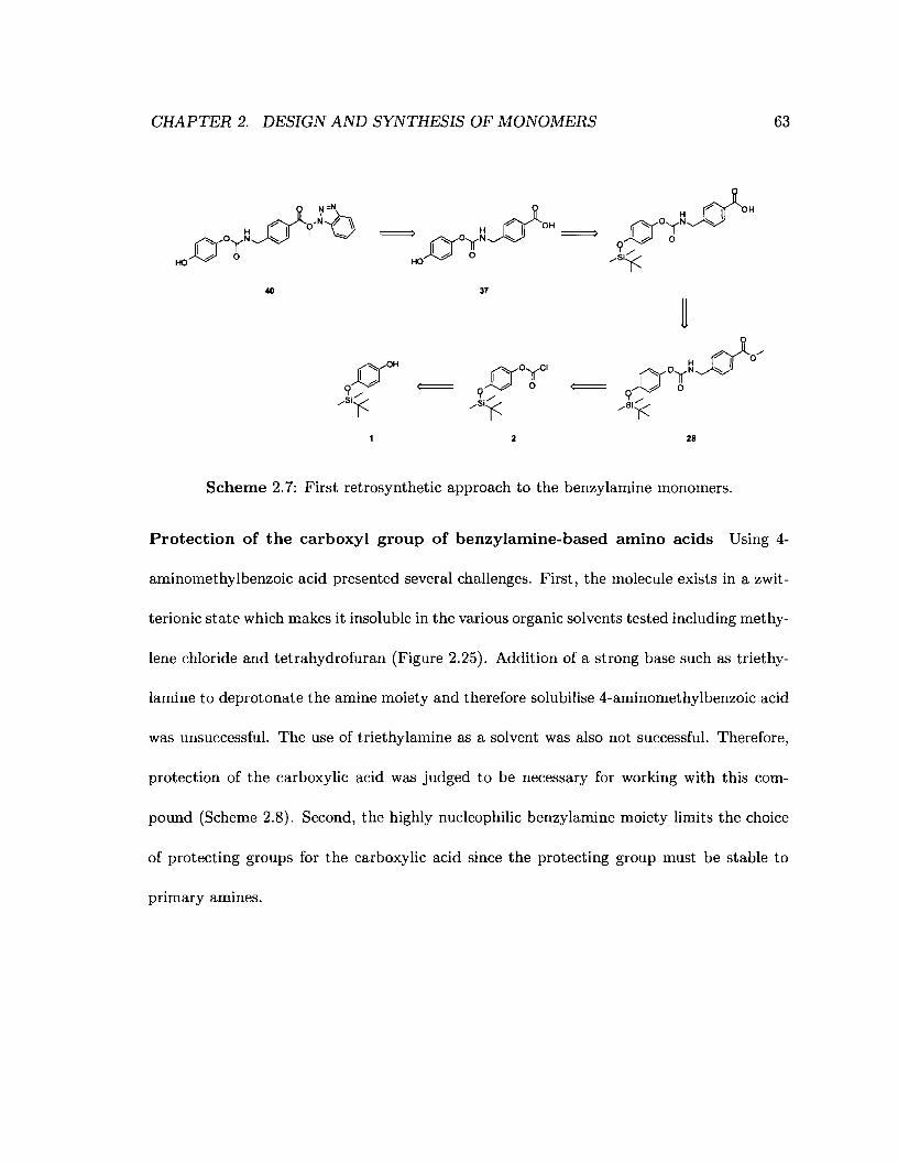
CHAPTER 2. DESIGN AND SYNTHESIS OF MONOMERS 63
40 37
28
Scheme 2.7: First retrosynthetic approach to the benzylamine monomers.
Protection of the carboxyl group of benzylamine-based amino acids Using 4-
aminomethylbenzoic acid presented several challenges. First, the molecule exists in a zwit-
terionic state which makes it insoluble in the various organic solvents tested including methy-
lene chloride and tetrahydrofuran (Figure 2.25). Addition of a strong base such as triethy-
lamine to deprotonate the amine moiety and therefore solubilise 4-aminomethylbenzoic acid
was unsuccessful. The use of triethylamine as a solvent was also not successful. Therefore,
protection of the carboxylic acid was judged to be necessary for working with this com-
pound (Scheme 2.8). Second, the highly nucleophilic benzylamine moiety limits the choice
of protecting groups for the carboxylic acid since the protecting group must be stable to
primary amines.
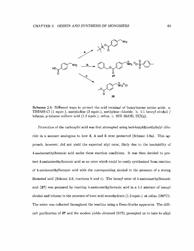
CHAPTER 2. DESIGN AND SYNTHESIS OF MONOMERS 64
b. r:7il1
rIY"'"~3.eO-~~• ~Ol~ 0"=1
o27
e erlY"NH3 -.CI
/O~
o26
Scheme 2.8: Different ways to protect the acid terminal of benzylamine amino acids. a.TBDMS-CI (1 equiv.), morpholine (3 equiv.), methylene chloride. b. 1:1 benzyl alcohol /toluene, p-toluene sulfonic acid (1.2 equiv.), reflux. c. 95% MeOH, HCI(g).
Protection of the carboxylic acid was first attempted using tert-butyldimethylsilyl chlo-
ride in a manner analogous to how 3, 4 and 5 were protected (Scheme 2.8a). This ap-
proach, however, did not yield the expected silyl ester, likely due to the insolubility of
4-aminomethylbenzoic acid under these reaction conditions. It was then decided to pro-
tect 4-aminomethylbenzoic acid as an ester which could be easily synthesised from reaction
of 4-aminomethylbenzoic acid with the corresponding alcohol in the presence of a strong
Br¢nsted acid (Scheme 2.8, reactions b and c). The benzyl ester of 4-aminomethylbenzoic
acid (27) was prepared by reacting 4-aminomethylbenzoic acid in a 1:1 mixture of benzyl
alcohol and toluene in the presence of tosic acid monohydrate (1.2 equiv.) at reflux (180°C).
The water was collected throughout the reaction using a Dean-Starke apparatus. The diffi-
cult purification of 27 and the modest yields obtained (51%) prompted us to turn to alkyl

CHAPTER 2. DESIGN AND SYNTHESIS OF MONOMERS 65
-+---Si_
I
°UOJLC1
2L~
N
)28
Scheme 2.9: Synthesis of benzylamine carbamates via chloroformate intermediates.
esters instead. The methyl ester of 4-(ammoniomethyl)benzoate was synthesised by react-
ing 4-(ammoniomethyl)benzoate in methanol saturated with Hel gas at room temperature
(Figure 2.8). The product (26) precipitated out of solution and filtration afforded 26 as a
white solid in 80% yield.
Synthesis of carbamate 28 The carbamate moiety was prepared in a similar manner
to that described in Section 2.3.2.3 (Scheme 2.9). 26 only partially dissolved in methylene
chloride at concentrations of 14 mM and afforded carbamate 28 as a white solid in 29% yield.
Subsequent efforts to deprotect the methyl ester using Lewis acids such as aluminium trichlo-
ride lO7 and trimethylsilyl iodidelO8,109 or hydrochloric acid in aqueous dimethyformamide
were unsuccessful. It has been observed that the cleavage of carbamates, and especially
benzyl carbamates, using trimethylsilyl iodide was more facile than that of esters. 108 The
substrates usually used in the studies cited above are simple substrates such as methyl ben-
zote or p-methyl toluate for which few side-reactions are expected. However, 28 is more
functionalised and multiple side-reactions can occur such as cleavage of the carbamate moi-
ety. Metal coordination to the phenol ether instead of the methyl ester is also expected. As
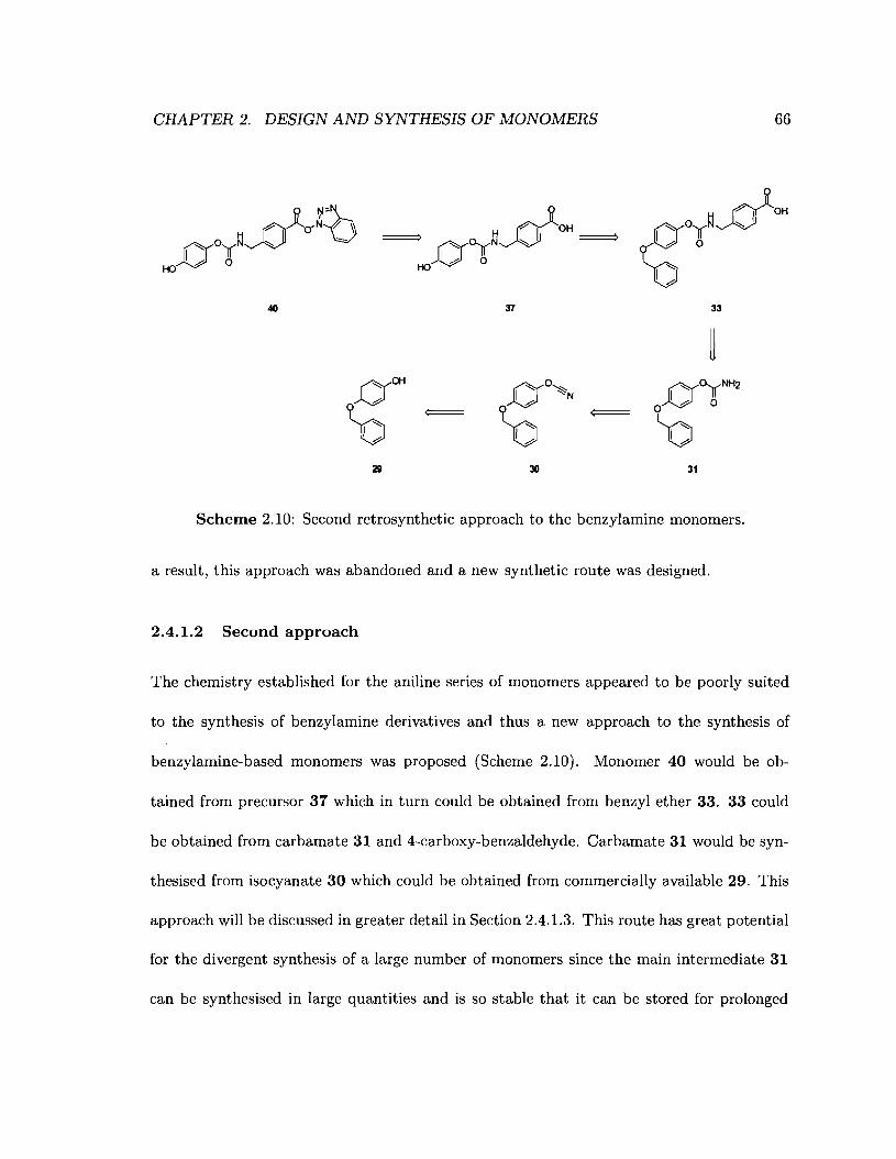
CHAPTER 2. DESIGN AND SYNTHESIS OF MONOMERS 66
40 33
29 30 31
Scheme 2.10: Second retrosynthetic approach to the benzylamine monomers.
a result, this approach was abandoned and a new synthetic route was designed.
2.4.1.2 Second approach
The chemistry established for the aniline series of monomers appeared to be poorly suited
to the synthesis of benzylamine derivatives and thus a new approach to the synthesis of
benzylamine-based monomers was proposed (Scheme 2.10). Monomer 40 would be ob-
tained from precursor 37 which in turn could be obtained from benzyl ether 33. 33 could
be obtained from carbamate 31 and 4-carboxy-benzaldehyde. Carbamate 31 would be syn-
thesised from isocyanate 30 which could be obtained from commercially available 29. This
approach will be discussed in greater detail in Section 2.4.1.3. This route has great potential
for the divergent synthesis of a large number of monomers since the main intermediate 31
can be synthesised in large quantities and is so stable that it can be stored for prolonged
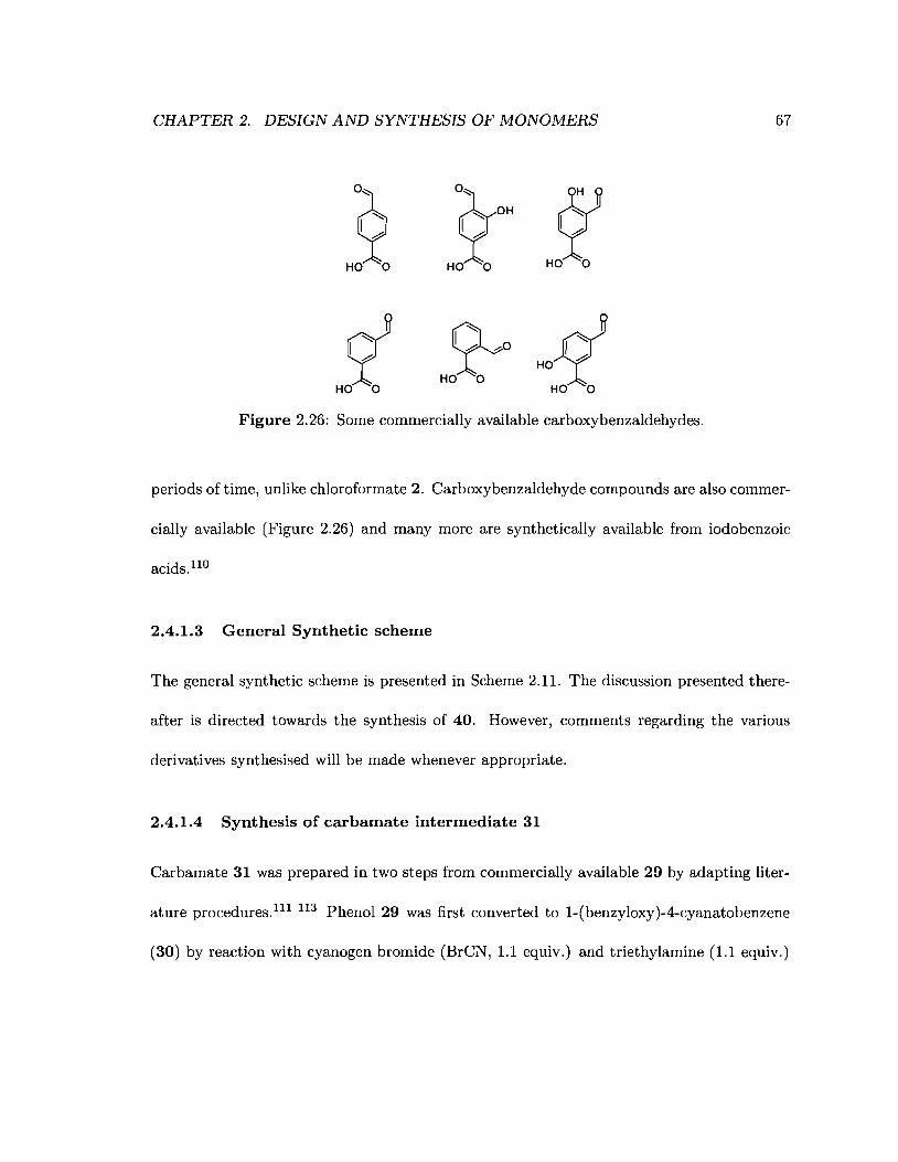
CHAPTER 2. DESIGN AND SYNTHESIS OF MONOMERS 67
°z'<:::: OH
Ih-
HO 0
~oHO 0
~HO~
HO 0
Figure 2.26: Some commercially available carboxybenzaldehydes.
periods of time, unlike chloroformate 2. Carboxybenzaldehyde compounds are also commer-
cially available (Figure 2.26) and many more are synthetically available from iodobenzoic
acids. 110
2.4.1.3 General Synthetic scheme
The general synthetic scheme is presented in Scheme 2.11. The discussion presented there-
after is directed towards the synthesis of 40. However, comments regarding the various
derivatives synthesised will be made whenever appropriate.
2.4.1.4 Synthesis of carbamate intermediate 31
Carbamate 31 was prepared in two steps from commercially available 29 by adapting liter-
ature procedures.111 113 Phenol 29 was first converted to 1-(benzyloxy)-4-cyanatobenzene
(30) by reaction with cyanogen bromide (BrCN, 1.1 equiv.) and triethylamine (1.1 equiv.)
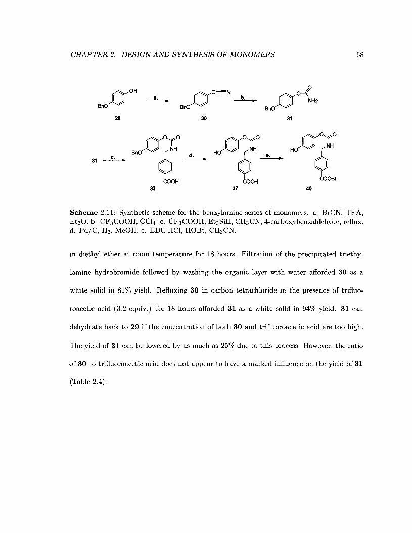
CHAPTER 2. DESIGN AND SYNTHESIS OF MONOMERS 68
('Y0H
~BnO
29
a. ..~O =N
BnO~
30
°O
O~b... I NH2
BnO .0
31
0°'(° 0°'(° 0°'(°~'A9~ HO I A 9~ HO I A 9~
c. d. e.31 .. ... ... P'IP'I P'I
~ ~~
COOH COOH COOBt
33 37 40
Scheme 2.11: Synthetic scheme for the benzylamine series of monomers. a. BrCN, TEA,Et20. b. CF3COOH, CCl4 , c. CF3COOH, Et3SiH, CH3CN, 4-carboxybenzaldehyde, reflux.d. Pd/C, H2 , MeOH. e. EDC·HCl, HOBt, CH3CN.
in diethyl ether at room temperature for 18 hours. Filtration of the precipitated triethy-
lamine hydrobromide followed by washing the organic layer with water afforded 30 as a
white solid in 81% yield. Refluxing 30 in carbon tetrachloride in the presence of trifluo-
roacetic acid (3.2 equiv.) for 18 hours afforded 31 as a white solid in 94% yield. 31 can
dehydrate back to 29 if the concentration of both 30 and trifluoroacetic acid are too high.
The yield of 31 can be lowered by as much as 25% due to this process. However, the ratio
of 30 to trifluoroacetic acid does not appear to have a marked influence on the yield of 31
(Table 2.4).
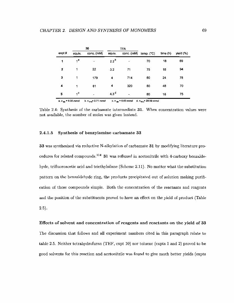
CHAPTER 2. DESIGN AND SYNTHESIS OF MONOMERS 69
30 TFAexpt# equiv. cone. (mM) equiv. cone. (mM) temp. (OC) time (h) yield (%)
1 1B 2.2 b 70 18 69
2 22 3.2 71 75 18 94
3 179 4 714 80 24 78
4 81 4 320 80 48 70
5 1c 4.3 d 80 18 75
B. " 30 = 0.33 mmol b. "TFA= 0.71 mmol c. " 30 = 6.63 mmol d. "TFA= 28.59 mmol
Table 2.4: Synthesis of the carbamate intermediate 31. When concentration values werenot available, the number of moles was given instead.
2.4.1.5 Synthesis of benzylamine carbamate 33
33 was synthesised via reductive N-alkylation of carbamate 31 by modifying literature pro-
cedures for related compounds. 1l4 31 was refluxed in acetonitrile with 4-carboxy benzalde-
hyde, trifluoroacetic acid and triethylsilane (Scheme 2.11). No matter what the substitution
pattern on the benzaldehyde ring, the products precipitated out of solution making purifi-
cation of these compounds simple. Both the concentration of the reactants and reagents
and the position of the substituents proved to have an effect on the yield of product (Table
2.5).
Effects of solvent and concentration of reagents and reactants on the yield of 33
The discussion that follows and all experiment numbers cited in this paragraph relate to
table 2.5. Neither tetrahydrofuran (THF, expt 10) nor toluene (expts 1 and 2) proved to be
good solvents for this reaction and acetonitrile was found to give much better yields (expts
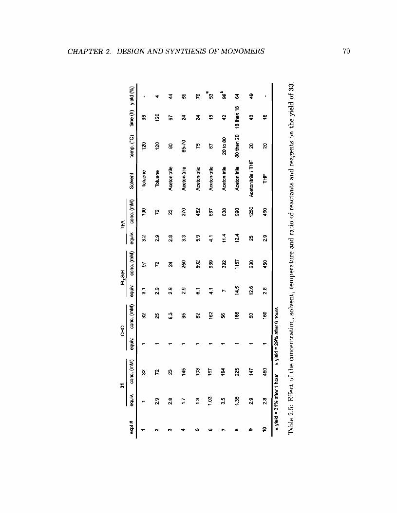
0 ~ 'i:l ~ ~ !'=I
31C
HO
Eta
SiH
TF
A~
exp
t#eq
uiv.
cone
.(m
M)
equi
v.co
ne.
(mM
)eq
uiv.
cone
.(m
M)
equi
v.co
ne.
(mM
)S
olve
ntte
mp.
(DC
)tim
e(h
)yi
eld
(%)
~ G32
132
3.1
973.
210
0T
olue
ne12
096
-< ~
22.
972
125
2.9
722.
972
Tol
uene
120
120
4~
32.
823
18.
32
.924
2.8
23A
ceto
nitr
ile80
67
44en ~
41.
714
51
852.
925
03.
327
0A
ceto
nitr
ile65
-70
2459
~ ~5
1.3
103
182
6.1
502
5.9
482
Ace
toni
trile
7524
70en
aen
61.
0316
71
162
4.1
669
4.1
667
Ace
toni
trile
67
1853
~7
3.5
194
156
739
211
.463
8A
ceto
nitr
ile20
to80
42
98b
~ 08
1.35
225
116
614
.511
5712
.499
0A
ceto
nitr
ile80
then
20
18th
en18
64~ 0
92.
914
71
5012
.663
025
1250
Ace
toni
trile
JT
HF
204
84
9~ ~
10
2.8
450
116
02
.84
50
2.9
460
TH
F2
018
en
8.yi
eld
=31
%af
ter
1ho
urb.
yiel
d=2
9%af
ter
6ho
urs
Tab
le2.
5:E
ffec
to
fth
eco
ncen
trat
ion,
solv
ent,
tem
per
atu
rean
dra
tio
ofre
acta
nts
and
reag
ents
onth
eyi
eld
of3
3.
-:r o
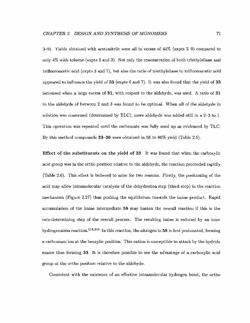
CHAPTER 2. DESIGN AND SYNTHESIS OF MONOMERS 71
3-9). Yields obtained with acetonitrile were all in excess of 44% (expts 3-9) compared to
only 4% with toluene (expts 2 and 3). Not only the concentration of both triethylsilane and
trifluoroacetic acid (expts 3 and 7), but also the ratio of triethylsilane to trifluoroacetic acid
appeared to influence the yield of 33 (expts 6 and 7). It was also found that the yield of 33
increased when a large excess of 31, with respect to the aldehyde, was used. A ratio of 31
to the aldehyde of between 2 and 3 was found to be optimal. When all of the aldehyde in
solution was consumed (determined by TLC), more aldehyde was added still in a 2-3 to 1.
This operation was repeated until the carbamate was fully used up as evidenced by TLC.
By this method compounds 33-36 were obtained in 56 to 86% yield (Table 2.5).
Effect of the substituents on the yield of 33 It was found that when the carboxylic
acid group was in the ortho position relative to the aldehyde, the reaction proceeded rapidly
(Table 2.6). This effect is believed to arise for two reasons. Firstly, the positioning of the
acid may allow intramolecular catalysis of the dehydration step (third step) in the reaction
mechanism (Figure 2.27) thus pushing the equilibrium towards the imine product. Rapid
accumulation of the imine intermediate 58 may hasten the overall reaction if this is the
rate-determining step of the overall process. The resulting imine is reduced by an ionic
hydrogenation reaction.1l4,1l5 In this reaction, the nitrogen in 58 is first protonated, forming
a carbonium ion at the benzylic position. This cation is susceptible to attack by the hydride
source thus forming 33. It is therefore possible to see the advantage of a carboxylic acid
group at the ortho position relative to the aldehyde.
Consistent with the existence of an effective intramolecular hydrogen bond, the ortho
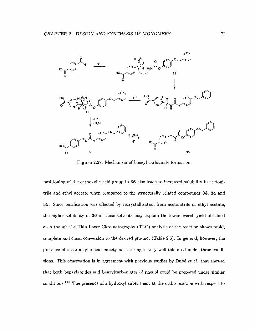
CHAPTER 2. DESIGN AND SYNTHESIS OF MONOMERS
H~_(£J'H oo~ H+7' ~ ~Q I -
o ~ 4'NAO:::""H '-! \
H
72
33
Figure 2.27: Mechanism of benzyl carbamate formation.
positioning of the carboxylic acid group in 36 also leads to increased solubility in acetoni-
trile and ethyl acetate when compared to the structurally related compounds 33, 34 and
35. Since purification was effected by recrystallisation from acetonitrile or ethyl acetate,
the higher solubility of 36 in those solvents may explain the lower overall yield obtained
even though the Thin Layer Chromatography (TLC) analysis of the reaction shows rapid,
complete and clean conversion to the desired product (Table 2.6). In general, however, the
presence of a carboxylic acid moiety on the ring is very well tolerated under these condi-
tions. This observation is in agreement with previous studies by DuM et al. that showed
that both benzylamides and benzylcarbamates of phenol could be prepared under similar
conditions,u4 The presence of a hydroxyl substituent at the ortho position with respect to

CHAPTER 2. DESIGN AND SYNTHESIS OF MONOMERS 73
o~~~o-o-o NH ~-/; Ra
# R 1 R 2 R 3 31 eHO Et3SIH TFA time (h) yield (%)
33 H H eOOH 1.3 5.9 6.1 24 70
34 H eOOH H 0.95 4 3.8 18 86
35 OH H eOOH 1.1 3.9 4.1 18 65
36 eOOH H H 0.94 3.4 3.3 8 56
Table 2.6: Effect of the position of the substituent on the yield of benzyl carbamate.
the aldehyde was also found to be well tolerated. This tolerance to substitution, combined
with the proven stability of fluorine substituted compounds under ionic hydrogenation con-
ditions1l4 should allow for the synthesis of diverse modular building blocks having various
substitution patterns.
2.4.1.6 Selective debenzylation - synthesis of 37-39 and 59
The following discussion will focus on the preparation of carbamate 38 although the other
compounds in this series were prepared in the same way. 38 could be obtained either from
coupling of 32 (resulting by hydrogenolysis of 31) with 3-carboxybenzaldehyde (Scheme
2.12) or by hydrogenolysis of benzyl ether 33.
Synthesis of carbamate 38 via 4-hydroxyphenyl carbamate (32) 32 was easily
obtained in quantitative yield by reacting benzyl ether 31 in methanol in the presence of
either PdjC (21 wt%) or PdCb (10 wt%) under an atmosphere of hydrogen for 18 hours

CHAPTER 2. DESIGN AND SYNTHESIS OF MONOMERS
¢NH' 0 0
l ~OH~~~oo1 : PdlC 9N~..
1"-'::..
(;MeOH CF3COOH 1"-'::
hEt3SiH b
OH CH3CN OH
31 32 38
Scheme 2.12: Reaction scheme for the synthesis of compound 38 via carbamate 32.
74
(Scheme 2.12). As we expected, under these conditions the carbamate moiety of 32 was left
untouched. 32 was then coupled to 3-carboxybenzaldehyde using the reaction conditions
described earlier (Section 2.4.1.5). Even after purification (flash column chromatography
on silica gel) significant quantities of an unidentified impurity were observed by 1H-NMR
(Figure 2.28). This impurity, however, was not observed when 38 was obtained from hy-
drogenolysis of 34 (Figure 2.28) allowing convenient and reliable access to this material. We
therefore used this route to prepare compound 38 routinely.
Synthesis of carbamate 38 via benzyl ether 34 Although 34 contains both O-benzyl
and N-benzyl groups, the O-benzyl moiety can be selectively cleaved by hydrogenolysis since
N-benzyl moieties are known to be considerably more stable to these conditions. llB This
proved to be true for the series of 34, 35 and 36. When benzyl ethers 34, 35 and 36
were hydrogenolysed in a 2 : 1 mixture of methanol and ethanol in the presence of 10-15%
PdCl2 only the free phenol product was observed in yields of "-J 95% for compounds 34 and
35 and none of the undesired p-methyl benzoic acid product expected from the cleavage of
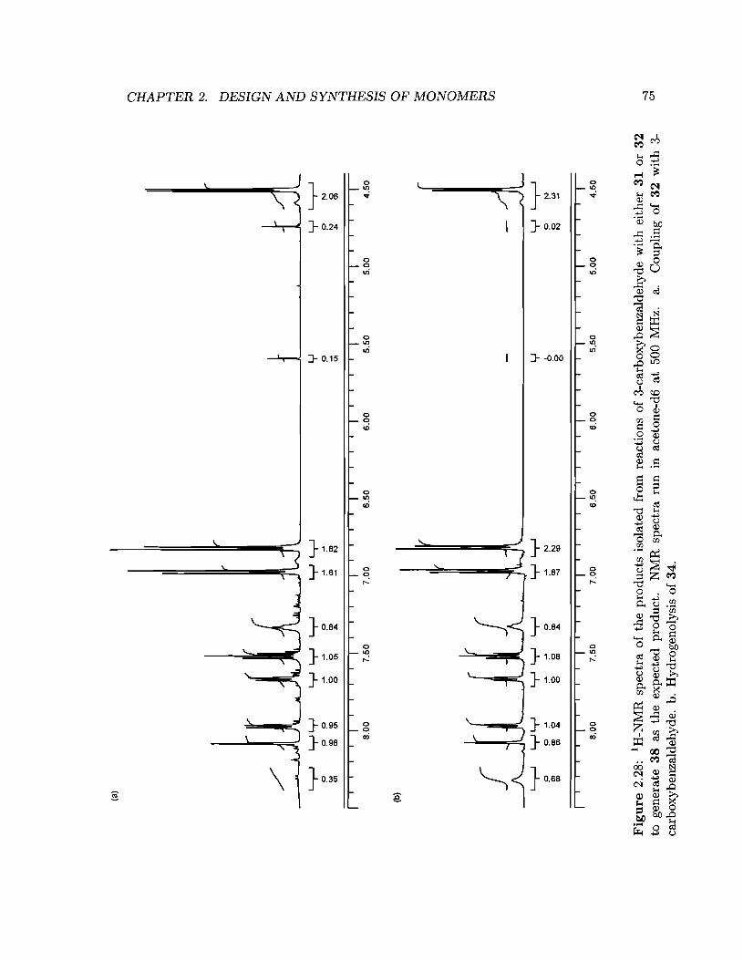
(al
@ ~ 'i:I t;5 ~ ~
II
II
II
II
II
II
II
II
II
II
II
II
II
II
II
II
II
II
II
II
IB.
OO
7.5
07
.00
6.5
06
.00
5.5
05
.00
4.5
0
~ ......
G < ~ ~ CJ:l ~ ~ ~ Ci) o ~ 6 < o ~ ~ CJ:l
y~
oN
(:)W
N~
b 8y~
N
~~
yy
yy
y~
~0
8lil
~o
0~
0>0>
<:>CD
CD...
.
L,-
-Jyy
/ ---J..J~I~~-W~
I,
LrJ
LL
,--J
yy
yy
yyy
yy~
0o
0~
~0
~~
!='
0N
'"<0
<0<:>
<:>0>
0>CD
~N
<:>01
CD01
001
....~
N01
....CD
(bl
II
II
II
II
II
II
II
II
II
II
II
II
II
II
II
II
II
II
II
II
IB
.OO
7.5
07
.00
6.5
06
.00
5.5
05
.00
4.5
0
Fig
ure
2.28
:1H
-NM
Rsp
ectr
ao
fth
epr
oduc
tsis
olat
edfr
omre
acti
ons
of3-
carb
oxyb
enza
ldeh
yde
wit
hei
ther
31
or3
2to
gene
rate
38
asth
eex
pect
edpr
oduc
t.N
MR
spec
tra
run
inac
eton
e-d6
at50
0M
Hz.
a.C
oupl
ing
of3
2w
ith
3ca
rbox
yben
zald
ehyd
e.b.
Hyd
roge
noly
sis
of34
.
~ 01
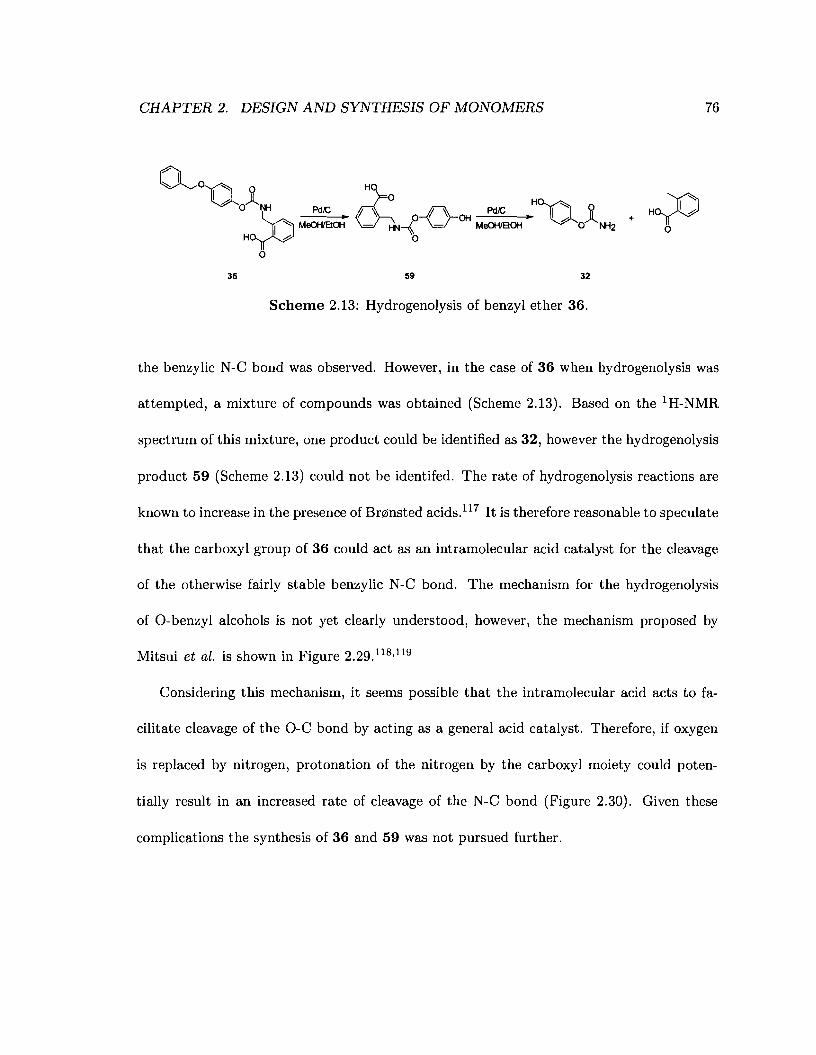
CHAPTER 2. DESIGN AND SYNTHESIS OF MONOMERS 76
Q~o~Jl.o NH Pd,c
~ MeoHIBoH
H~o
Ho)Oo
36 59 32
Scheme 2.13: Hydrogenolysis of benzyl ether 36.
the benzylic N-C bond was observed. However, in the case of 36 when hydrogenolysis was
attempted, a mixture of compounds was obtained (Scheme 2.13). Based on the IH-NMR
spectrum of this mixture, one product could be identified as 32, however the hydrogenolysis
product 59 (Scheme 2.13) could not be identifed. The rate of hydrogenolysis reactions are
known to increase in the presence of Br~lnsted acids.ll7 It is therefore reasonable to speculate
that the carboxyl group of 36 could act as an intramolecular acid catalyst for the cleavage
of the otherwise fairly stable benzylic N-C bond. The mechanism for the hydrogenolysis
of O-benzyl alcohols is not yet clearly understood, however, the mechanism proposed by
Mitsui et al. is shown in Figure 2.29.118 ,119
Considering this mechanism, it seems possible that the intramolecular acid acts to fa-
cilitate cleavage of the O-C bond by acting as a general acid catalyst. Therefore, if oxygen
is replaced by nitrogen, protonation of the nitrogen by the carboxyl moiety could poten-
tially result in an increased rate of cleavage of the N-C bond (Figure 2.30). Given these
complications the synthesis of 36 and 59 was not pursued further.

CHAPTER 2. DESIGN AND SYNTHESIS OF MONOMERS 77
*
* catalyst surface
~ ~7~:-~A/* , '"*
Bl
.. ~*
jH,
~H
Figure 2.29: Proposed mechanism for the hydrogenolysis of O-benzyl alcohols. 1l8,119
HO
chN-{-o-OH~ ~~~-o-OH -.~~J~-o-ooo ~ H:, 0 , 0
o O-H 0 o-H
59
.fr--~OH
o
• catalyst surface
+ --
Figure 2.30: Proposed mechanism for the hydrogenolysis of N-benzylcarbamate 59.
CHAPTER 2. DESIGN AND SYNTHESIS OF MONOMERS 78
Influence of the solvent and substitution pattern on the rate of hydrogenolysis
All O-benzyl compounds were insufficiently soluble in methanol, one of the best solvents for
hydrogenolysis. Addition of ethanol to generate in a 1/2 ratio of methanol to ethanol both
solubilised the compounds and enabled the reactions to proceed rapidly (Table 2.7). Notably,
the substitution pattern on the ring at the acid end of the compounds seemed to affect the
rate of cleavage of the benzylic O-C bond. Compared to compounds 34 and 35, the rate
of cleavage is dramatically reduced for the hydrogenolysis of 33 when palladium chloride is
used as the catalyst. Hydrogenolysis of 33 over Pd/C was not complete after 6 hours in
methanol-tetrahydrofuran (entry 1, table 2.7). Switching to a 9/1 mixture of ethanol-ethyl
acetate allowed for near quantitative conversion of 33 to 37 using Pd/C (entry 2, table 2.7).
Although tetrahydrofuran is a very good solvent for all O-benzyl compounds, it appears
detrimental for the efficient hydrogenolysis of 33. This observation is expected since protic
solvents are known to be better solvents for hydrogenolysis. So, increasing the amount of
protic solvent should increase the rate of the reaction as is seen for entries 1 and 3.
2.4.1.7 Coupling of N -hydroxybenzotriazole-synthesis of monomers 40-42
Monomers 40 to 42 (Figure 2.31) were synthesised using the same method developed for
the aniline series, the only change being that tetrahydrofuran was used as solvent for the
free acids (37-39). All compounds were reliably obtained in high yields (95 to 97%) as
white solids after recrystallisation from ethyl acetate / hexanes.

CHAPTER 2. DESIGN AND SYNTHESIS OF MONOMERS
H. He
6'Cc
H
•
H0'CcHd
-:? I h- OlNH catalystI h- 1
• o NH
~I » H2 »I":::R1 h- RJ R1 h- RJ
R2R2
33 R1 =H. R2 =H, R 3 =eOOH 37 R1 =H, R2 =H. R 3 =eOOH34 R1 =H, R2 =eOOH, R3 =H 38 R1 =H. R2 =eOOH, R3 =H35 R1 =OH, R2 =H. R 3 =eOOH 39 R1 = OH. R2 = H, R 3 =eOOH
reactant
expt# # cone. (mM) solvent (1/2) catalyst (wt%) time (h) yield (%)a
33 35 MeOH/THF Pd/C (10) 6 40
2 33 N/A EtOH 1EtOAcb
Pd/C (23) 7 95e
3 33 N/A MeOH 1EtOH PdC'2 (10) 2 54
4 33 N/A MeOH 1EtOH PdCI2 (10) 15 82
5 34 10 MeOH 1EtOH PdC'2 (11) 2.25 97
6 35 9 MeOH 1EtOH PdCI2 (11) 2 95
a. yield calculated by NMR using the ratio of the Integrations of protons (Ha + Hb) and (He + Hd).NMR spectra run in Aeetone-d6 at 500 MHz.b. ratio 9/1.
e. isolated yield.
79
Table 2.7: Hydrogenolysis of various benzylamine carbamates. NjA: data not available.
2.4.1.8 Conclusion
A versatile and divergent synthetic route to IH-benzo[dl[1,2,3]triazol-l-yl n-(((4-hydroxy-
phenoxy)carbonylamino)methyl)benzoates was developed. In this method the formation
of the carbamate moiety, a critical step in the synthesis of all the compounds presented
in this chapter, was effected by reductive alkylation of a common carbamate precursor:
4-(benzyloxy)phenyl carbamate 31). Hydrogenolysis of the resulting benzyl ether (com-
pounds 33-35) yields the free phenol product (compounds 37~39) which can then be

CHAPTER 2. DESIGN AND SYNTHESIS OF MONOMERS 80
~ro9,"::::b
o"QI"::::b
OH
40
q?o
o"'QI"::::b
OH
41
~t"~0I"::::
b OH
o"QI"::::b
OH
42
Figure 2.31: The various benzylamine monomers synthesised.
converted in high yields to their N-hydroxybenzotriazole benzoates (compounds 40-42).
All the reactants used in this synthesis were commercially available in multigram quanti-
ties and only compound 31 needed to be synthesised for use. Due to the ready availabil-
ity of the starting materials, the simple chemistry, scalability and high reactivity towards
N-hydroxybenzotriazole benzoates, the aminomethylbenzoic acid series of monomers (com-
pounds 40-42) appears ideally suited for use in reagent less electrochemical arrays. Testing is
underway to assess their reactivity with self-assembled monolayers of mercaptoalkyl amines
on polycrystalline gold surfaces.

CHAPTER 2. DESIGN AND SYNTHESIS OF MONOMERS
2.4.2 Experimental
2.4.2.1 Solvents and chemicals
81
All solvents were obtained from Caledon and used without purification except for triethy
lamine, pyridine and tetrahydrofuran which were obtained from Anachemia and distilled be
fore use. All deuterated solvents were obtained from Cambridge Isotope Laboratories, Inc..
Silica gel 60 was obtained from EMD (product # 9385 - 3). Trifluoroacetic acid and hydro
quinone were obtained from Sigma-Aldrich. 1-Ethyl-3-[3-dimethylaminopropyl]carbodiimide
hydrochloride was obtained from Fluka. All other chemicals were obtained from Aldrich.
All chemicals were used without purification.
2.4.2.2 Characterisation
All FT-IR measurements of molecules were made on a Bomem M-B series spectrometer. All
molecules were measured as a KBr pellet or as films deposited from chloroform on a sodium
chloride disc. Each spectrum is the average of 32 or 64 measurements. NMR spectra eH
and 13C) were acquired on a Varian Inova 500 MHz spectrometer or a Brueker Avance 600
MHz spectrometer. Melting points were taken using a Electrothermal Mel Temp@ melting
point apparatus and were not corrected. CHN elemental analysis was performed on a Carlo
Erba Model 1106 CHN analyzer at Simon Fraser University.
1-(benzyloxy)-4-cyanatobenzene (30) A solution of 4-(benzyloxy)phenol (29, 2.06 g,
10.3 mmol, 1 equiv.) and triethylamine (1.4 ml, 10.4 mmol, 1.01 equiv.) in diethyl ether (60
ml) was added dropwise to a solution of cyanogen bromide (1.14 g, 10.8 mmol, 1.05 equiv.)

CHAPTER 2. DESIGN AND SYNTHESIS OF MONOMERS 82
in diethyl ether (100 ml) at -10°C. The triethylamine hydrobromide precipitate was filtered
off and the filtrate was washed with 1% hydrochloric acid and dried over sodium sulfate. The
solvent was removed in-vacuo. The residue was purified by flash column chromatography
(9/1 Toluene / Ethyl acetate) yielding a white solid (1.89 g, 81%). IH-NMR (500 MHz,
Acetone-d6) J (ppm) 7.48 (d, J = 7 Hz, 2H), 7.40 (t, J = 7 Hz, 2H), 7.35 (m, 3H), 7.17
(ABq, J = 9.5 Hz, 2H), 5.17 (s, 2H); 13C-NMR (125 MHz, Acetone-d6) J (ppm) 159.21,
148.84, 138.75, 130.33, 129.80, 129.49, 118.38, 118.28, 72.05; IR (KBr) 2285.67 cm-1 (C=
N), 2238.4 cm-1 (C= N), 1501.71 cm-1 (HQ); E.A. Calcd. C 74.65, H 4.92, N 6.22, Expt.
C 74.59, H 5.11, N 6.12; m.p. 65 - 67°C.
4-(benzyloxy)phenyl carbamate (31) A solution of 30 (0.56 g, 2.5 mmol, 1 equiv.)
and trifluoroacetic acid (0.7 ml, 10.0 mmol, 10 equiv.) in carbon tetrachloride (14 ml) was
refluxed for 18 hours. The reaction mixture was cooled down to room temperature and
the solvent removed in-vacuo. The residue was recrystallised from ethyl acetate / hexanes
yielding a white solid (0.48 g, 78%). IH-NMR (500 MHz, Acetone-d6) J (ppm) 7.48 (d, J
= 7.5 Hz, 2H), 7.39 (t, J = 7.5 Hz, 2H), 7.32 (t, J = 7 Hz, 1H), 7.03 (ABq, J = 9 Hz, 2H),
6.98 (ABq, J = 9 Hz, 2H), 6.40 (br. s, 1H), 6.11 (br. s, 1H), 5.11 (s, 2H); 13C-NMR (125
MHz, Acetone-d6) J (ppm) 157.81, 147.12, 139.36, 130.25, 129.59, 129.39, 124.51, 116.83,
71.74; IR (KBr) 1763.65 cm-1 (C=O), 1709.34 cm-1 (C=O), 1509.94 cm-1 (HQ); m.p.
141 - 143°C.
General procedure for the synthesis of «(4-(benzyloxy)phenoxy)carbonylamino)
methyl)-benzoic acids Triethylsilane (100 J.lI, 0.63 mmol, 3.96 equiv.) and trifluoroacetic
CHAPTER 2. DESIGN AND SYNTHESIS OF MONOMERS 83
acid (40 jiJ, 0.58 mmol, 3.63 equiv.) were added to a solution of 31 (111.0 mg, 0.45 mmol,
2.81 equiv.) and 4-carboxybenzaldehyde (23.3 mg, 0.16 mmol, 1.0 equiv.) in acetonitrile (2
ml) at room temperature. The reaction mixture was then refluxed for 6 hours after which
time a white precipitate was observed. Additional triethylsilane (70 Itl, 0.44 mmol, 2.77
equiv.), trifluoroacetic acid (32 Itl, 0.46 mmol, 2.9 equiv.) and 4-carboxybenzaldehyde (14.6
mg, 0.097 mmol, 0.61 equiv.) and acetonitrile (1 ml to account for loss during reflux) were
added to the reaction mixture. After 15 hours triethylsilane (70 Itl, 0.44 mmol, 2.77 equiv.),
trifluoroacetic acid (25 Itl, 0.36 mmol, 2.27 equiv.) and 4-carboxybenzaldehyde (11.3 mg,
0.075 mmol, 0.47 equiv.) and acetonitrile (0.5 ml to account for loss during reflux) were
again added to the reaction mixture. When the reaction was complete by TLC, the white
solid was filtered off and rinsed twice with acetonitrile. The filtrate was evaporated under
reduced pressure and the residue recrystallised from ethyl acetate I hexanes to yield a white
solid in yields from 56 to 86%.
4-(((4-(benzyloxy)phenoxy)carbonylamino)methyl)-benzoic acid (33) 1H-NMR
(500 MHz, Acetone-d6) 15 (ppm) 8.02 (d, J = 8 Hz, 2H), 7.51 (ABq, J = 8 Hz, 2H),
7.48 (ABq, J = 7.5 Hz, 2H), 7.39 (t, J = 7.5 Hz, 2H), 7.33 (m, 2H), 7.07 (ABq, J = 8.5
Hz, 2H), 7.00 (ABq, J = 9 Hz, 2H), 5.11 (s, 2H), 4.58 (br. s, 0.2H), 4.50 (d, J = 6 Hz,
1.8H); 13C-NMR (125 MHz, Acetone-d6) 15 (ppm) 168.36, 131.65, 130.26, 129.60, 129.40,
129.12, 124.44, 116.90, 111.63,71.76; IR (KBr) 1722.83 cm-1 (C=O), 1702.21 cm-1 (C=O),
1503.86 cm-1 (HQ); E.A. Calcd. C 70.02, H 5.07, N 3.71, Expt. C 69.82, H 4.77, N 3.79;
m.p. 220-222°C.
CHAPTER 2. DESIGN AND SYNTHESIS OF MONOMERS 84
3-(((4-(benzyloxy)phenoxy)carbonylamino)methyl)-benzoic acid (34) 1H-NMR
(500 MHz, Aeetone-d6) 6 (ppm) 8.06 (8, 1H), 7.95 (d, J = 8 Hz, 1H), 7.65 (d, J = 7
Hz, IH), 7.49 (m, 3H), 7.38 (m, 4H), 7.06 (ABq, J = 9 Hz, 2H), 6.99 (ABq, J = 9 Hz, 2H),
5.11 (8, 2H), 4.49 (d, J = 6 Hz, 2H); 13C-NMR (150 MHz, Aeetone-d6) 6 (ppm) 168.53,
157.90, 157.05, 147.16, 141.99, 139.36, 133.80, 130.48, 130.37, 130.27, 130.18, 129.61, 129.41,
124.42, 116.92, 71.78, 46.06; IR (KBr) 1693.7 em-1 (C=O), 1498.9 em-1 (HQ); E.A. Caled.
with 0.3 H20b C 69.03, H 5.16, N 3.66, Expt. C 69.27, H 4.75, N 3.87; m.p. 186-188°C.
4-(((4-(benzyloxy)phenoxy)carbonylamino)methyl)-3-hydroxybenzoic acid (35)
IH-NMR (500 MHz, Aeetone-d6) 6 (ppm) 7.55 (m, 2H), 7.48 (m, 2H), 7.40 (m, 3H), 7.32
(t, J = 7 Hz, 1H), 7.26 (t, J = 6.5 Hz, 1H), 7.07 (ABq, J = 9 Hz, 2H), 6.99 (ABq, J = 9
Hz, 2H), 5.11 (8, 2H), 4.46 (d, J = 6.5 Hz, 2H); 13C-NMR (150 MHz, Aeetone-d6) 6 (ppm)
168.39,158.01,157.53,156.79,147.15,139.33, 132.72, 132.49, 130.57, 130.27, 129.63, 129.42,
124.44, 122.81, 118.05, 116.95, 71.79, 41.76; IR (KBr) 1670.9 em-1 (C=O), 1500.7 em-1
(HQ); E.A. Calcd. with 0.5 H20 C 65.67, H 5.01, N 3.48, Expt. C 65.68, H 4.70, N 3.76;
m.p. 220(d)OC.
2-(((4-(benzyloxy)phenoxy)carbonylamino)methyl)-benzoic acid (36) IH-NMR
(500 MHz, Aeetone-d6) 6 (ppm) 8.10 (8, 1H), 7.84 (m, 2H), 7.75 (t, J = 7.5 Hz, 1H), 7.49
(d, J = 7.5 Hz, 2H), 7.40 (t, J = 7.5 Hz, 1H), 7.33 (t, J = 7.3 Hz, 1H), 7.14 (ABq, J = 8 Hz,
2H), 7.04 (m, 3H), 5.13 (8, 2H); 13C-NMR (150 MHz, Aeetone-d6) 6 (ppm) 170.10, 158.41,
bRepeated on two different samples from two different reactions with different times on high vacuum.Both gave the similar result
CHAPTER 2. DESIGN AND SYNTHESIS OF MONOMERS 85
147.38, 146.53, 139.30, 136.36, 132.41, 130.32, 129.68, 129.44, 129.24, 126.63, 125.52, 124.42,
117.09,85.14,71.83; IR (KBr) 1746.0 cm-I (C=O), 1505.6 cm-I (HQ); m.p. 172 - 174°C.
General procedure for the synthesis of (((4-hydroxyphenoxy)carbonylamino)
methyl)benzoic acids Palladium chloride (5.7 mg, 10.9% w/w) was added to a solution
of 35 (52.2 mg, 0.13 mmol) in methanol/ethanol (5 / 15 ml). The reaction flask was sealed
with a rubber septum and purged three times with hydrogen. The reaction mixture was
then stirred under hydrogen atmosphere until the reaction was complete by TLC (2 to 15
hours). The reaction mixture was filtered over celite. The solvent was removed in vacuo to
afford a white solid in yields from 82 to 97%.
3-(((4-hydroxyphenoxy)carbonylamino)methyl)benzoic acid (38) IH-NMR (500
MHz, Acetone-d6) 6 (ppm) 8.3 (br. s, IH), 8.07 (s, IH), 7.96 (d, J = 7.5 Hz, IH), 7.49
(d, J = 7.5 Hz, IH), 7.32 (t, J = 6 Hz, IH), 6.96 (ABq, J = 9 Hz, 2H), 6.80 (ABq, J
= 9 Hz, 2H), 4.48 (d, J = 6 Hz, 2H); I3C-NMR (125 MHz, Acetone-d6) 6 (ppm) 168.69,
157.23, 156.27, 145.93, 141.85, 133.81, 132.43, 130.42, 130.28, 130.12, 124.29, 117.13,45.95;
IR (KBr) 3333.2 em-I, 1698.5 em-I, 1498.9 em-I, 1197.5 em-I.
4-(((4-hydroxyphenoxy)carbonylamino)methyl)-3-hydroxybenzoic acid (39) IH_
NMR (500 MHz, Acetone-d6) 6 (ppm) 9.0 (s, IH), 8.3 (s, IH), 7.55 (m, 2H), 7.41 (d, J =
8.5 Hz, IH), 7.24 (t, J = 6 Hz, IH), 6.96 (ABq, J = 9 Hz, 2H), 6.80 (ABq, J = 9 Hz, 2H),
4.46 (d, J = 6.5 Hz, 2H); I3C-NMR (125 MHz, Acetone-d6) 6 (ppm) 168.51, 157.82, 156.71,
156.38,145.89,132.52,132.47,130.61,124.31, 122.80, 118.05, 117.16,41.73; IR (KBr) 3335.2
CHAPTER 2. DESIGN AND SYNTHESIS OF MONOMERS
4- ( ((4-hydroxyphenoxy)carbonylamino)methyI)benzoic acid (37)
86
General procedure for the synthesis of IH-benzo[d][I,2,3]triazol-l-yl n
(((4-hydroxyphenoxy)carbonylamino)methyl)benzoates A solution of 39 (40 mg,
0.10 mmol, 1.0 equiv.) in distilled tetrahydrofuran (2 ml) was added dropwise to a stirred
solution of N-hydroxybenzotriazole (27.6 mg, 0.20 mmol, 2.0 equiv.) and l-Ethyl-3-(3
dimethyllaminopropyl)carbodiimide hydrochloride (41.9 mg, 0.22 mmol, 2.2 equiv.) in ace
tonitrile (2 ml). The reaction mixture was stirred at room temperature (20°C) for 1 hour.
The volume was reduced in-vacuo and the remaining solution taken up in ethyl acetate (100
ml) and washed with water (2 x 30 ml) and brine (30 ml). The organic layer dried over
sodium sulfate and the solvent removed in-vacuo affording a white solid in yields from 82
to 97%.
IH-benzo[d] [1,2,3]triazol-l-yl 3-( ((4-hydroxyphenoxy)carbonylamino)methyl)
benzoate (41) IH-NMR (500 MHz, Acetone-d6) <5 (ppm) 8.32 (s, IH), 8.22 (d, J = 7.5
Hz, IH), 8.12 (d, J= 8.5 Hz, IH), 7.88 (m, 2H), 7.67 (m, 2H), 7.54 (t, J = 8 Hz, IH), 7.45
(t, J = 6.5 Hz, IH), 6.97 (ABq, J = 9 Hz, 2H), 6.80 (ABq, J = 9 Hz, 2H), 4.58 (d, J = 6.5
Hz, 2H); 13C-NMR (150 MHz, Acetone-d6) <5 (ppm) 164.77, 157.27, 156.40, 145.95, 145.22,
143.21,136.52,131.21,131.01,130.66,127.08, 126.86, 124.51, 121.91, 121.76, 117.22, 117.14,
110.87.
CHAPTER 2. DESIGN AND SYNTHESIS OF MONOMERS 87
IH-benzo[d:1 [1,2,3]triazol-1-yl 4-( ((4-hydroxyphenoxy)carbonylamino)methyl)-3
hydroxybenzoate (42) IH-NMR (500 MHz, Aeetone-d6) 0 (ppm) 8.11 (d, J = 8.5 Hz,
1H), 7.84 (m, 2H), 7.76 (8, IH), 7.65 (m, 2H), 7.53 (t, J = 8 Hz, 1H), 7.37 (t, J = 6.1
Hz, 1H), 6.99 (ABq, J = 9 Hz, 2H), 6.82 (ABq, J = 9 Hz, 2H), 4.55 (d, J = 6.2 Hz, 2H);
I3C-NMR (125 MHz, Aeetone-d6) 0 (ppm) 164.62, 157.80, 157.27, 156.49, 145.94, 145.22,
136.06, 131.21, 130.79, 126.86, 124.35, 123.84, 121.83, 118.40, 117.22, 110.82; IR (NaCl)
3308.7 em-I, 1791.0 em-I, 1715.9 em-I, 1500.7 em-I, 1200.2 em-I.
1H-benzo[d:1 [1,2,3]triazol-1-yl 4-( ((4-hydroxyphenoxy)carbonylamino)methyl)
benzoate (40) IH-NMR (500 MHz, Aeetone-d6) 0 (ppm) 8.26 (8, IH), 8.21 (t, J = 6 Hz,
1H), 7.96 (d, J = 8.5 Hz, 1H), 7.91 (ABq, J = 8.5 Hz, 2H), 7.69 (d, J = 8.5 Hz, 1H), 7.54
(t, J = 8 Hz, 1H), 7.41 (m, 3H), 6.88 (ABq, J = 8.5 Hz, 2H), 6.71 (ABq, J = 8.5 Hz, 2H),
4.31 (d, J = 6.5 Hz, 2H); I3C-NMR (125 MHz, Aeetone-d6) 0 (ppm) 167.30, 155.45, 154.47,
144.60, 143.39, 129.58, 129.53, 127.93, 127.46, 127.18, 124.68, 122.64, 119.18, 115.48, 109.71,
43.82.
Chapter 3
Self-assembled monolayers
3.1 A brief introduction to self-assembled monolayers
For a more complete view on self-assembled monolayers, the reader is directed to two review
articles by Love et at. 59 and Ulman. 57
Self-assembled monolayers (SAMS) are one molecule-thick layers of molecules that sponta
neously form at certain interfaces. Amphifunctional molecules are typically used to form
such self-assembled monolayers. These molecules have one part exhibiting a strong affin
ity to a surface and another that exhibits little or no affinity for the same surface (Figure
3.1).120
Self-assembled monolayers on various solid surfaces are simply made by incubating the
surface in a millimolar solution of the amphifunctional molecule in an appropriate solvent.
Monocomponent (composed of one type of amphifunctional molecules) and multicomponent
88
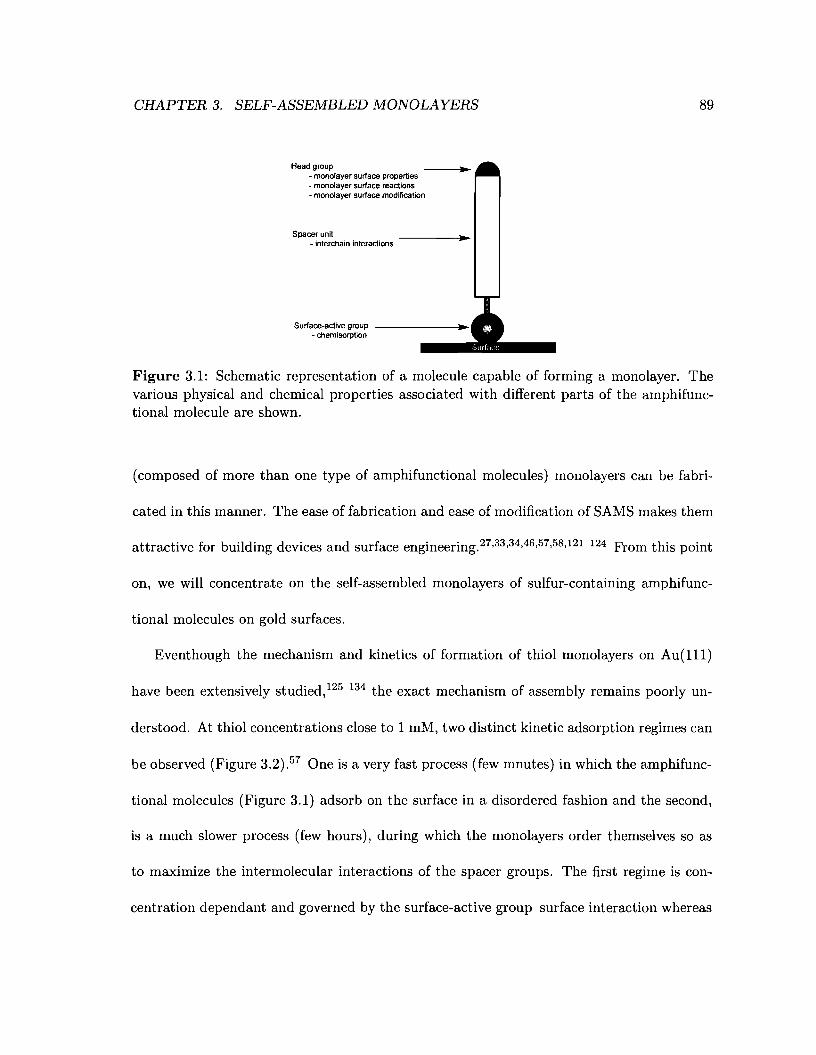
CHAPTER 3. SELF-ASSEMBLED MONOLAYERS
Head group- monolayer surface properties- monolayer surface reactions- monolayer surface modification
Spacer unil4 interchain interactions
89
Surface-active group• chemisorption
Figure 3.1: Schematic representation of a molecule capable of forming a monolayer. Thevarious physical and chemical properties associated with different parts of the amphifunctional molecule are shown.
(composed of more than one type of amphifunctional molecules) monolayers can be fabri-
cated in this manner. The ease of fabrication and ease of modification of SAMS makes them
attractive for building devices and surface engineering.27,33,34,46,57,58,121 124 From this point
on, we will concentrate on the self-assembled monolayers of sulfur-containing amphifunc-
tional molecules on gold surfaces.
Eventhough the mechanism and kinetics of formation of thiol monolayers on Au(l11)
have been extensively studied,125 134 the exact mechanism of assembly remains poorly un-
derstood. At thiol concentrations close to 1 mM, two distinct kinetic adsorption regimes can
be observed (Figure 3.2).57 One is a very fast process (few mnutes) in which the amphifunc-
tional molecules (Figure 3.1) adsorb on the surface in a disordered fashion and the second,
is a much slower process (few hours), during which the monolayers order themselves so as
to maximize the intermolecular interactions of the spacer groups. The first regime is con-
centration dependant and governed by the surface-active group-surface interaction whereas
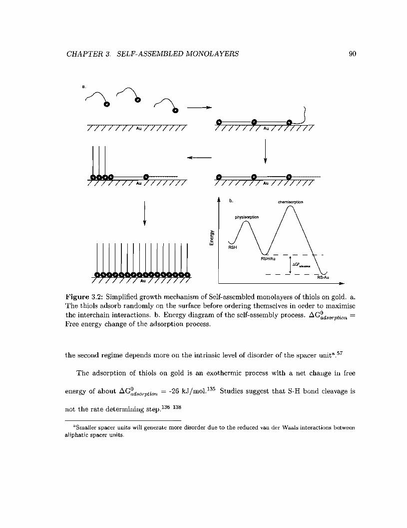
CHAPTER 3. SELF-ASSEMBLED MONOLAYERS 90
/11///1 Aul/II/II
1f; / I 11; Au /1 J'/III
b. chemisorption
RS-Au
Figure 3.2: Simplified growth mechanism of Self-assembled monolayers of thiols on gold. a.The thiols adsorb randomly on the surface before ordering themselves in order to maximisethe interchain interactions. b. Energy diagram of the self-assembly process. ~G~dSoTPtion =
Free energy change of the adsorption process.
the second regime depends more on the intrinsic level of disorder of the spacer unita .57
The adsorption of thiols on gold is an exothermic process with a net change in free
energy of about ~G~dSoTPtion = -26 kJ /mol. 135 Studies suggest that S-H bond cleavage is
not the rate determining step.136 138
aSmaller spacer units will generate more disorder due to the reduced van der Waals interactions betweenaliphatic spacer units.
CHAPTER 3. SELF-ASSEMBLED MONOLAYERS 91
3.2 Effect of the molecular structure of the thiols on the for-
mation of monolayers
The nature of the thiol employed for making a monolayer dictates, in part, the physical
(friction, adhesion, electrical, etc... ) and chemical (reactivity, layer-by-layer assembly,
etc... ) properties of the SAMS.57,139 143 Both the head group and the spacer unit can
impact the final structure and reactivity of the monolayer. The degree to which the surface
is protected from the environment of the bulk solutionb is also dependant upon the nature
of the monolayer (Figure 3.3).57
The various classes of thiols used for self-assembled monolayers will be presented below.
3.2.1 Mercaptoalkane self-assembled monolayers
A wide variety of mercaptoalkanes are able to form self-assembled monolayers on gold (Fig-
ure 3.4). Of these, thiols and disulfides have been the most intensely investigated.57,139
For this discussion we will focus on alkanethiols since these are the most studied systems.
Disulfides will be discussed, where appropriate, in the rest of this thesis.
On Au(lll) substrate, the S· .. S distance is typically 4.5 to 5 A, this spacing accounts,
in part, for the arrangement of the spacer units. Alkanethiols are typically tilted by about
32° with respect to the surface normal and 55° about the molecular axis with the molecule
in an all-trans conformation. 139 Self-assembled monolayers made from alkanehiols such as
bThe degree to which the surface is protected from the environment is qualitatively determined by comparing the cyclic voltammogram of a monolayer-protected surface to that of bare gold. The more similar thecyclic voltammogram the less protected the surface is deemed to be.
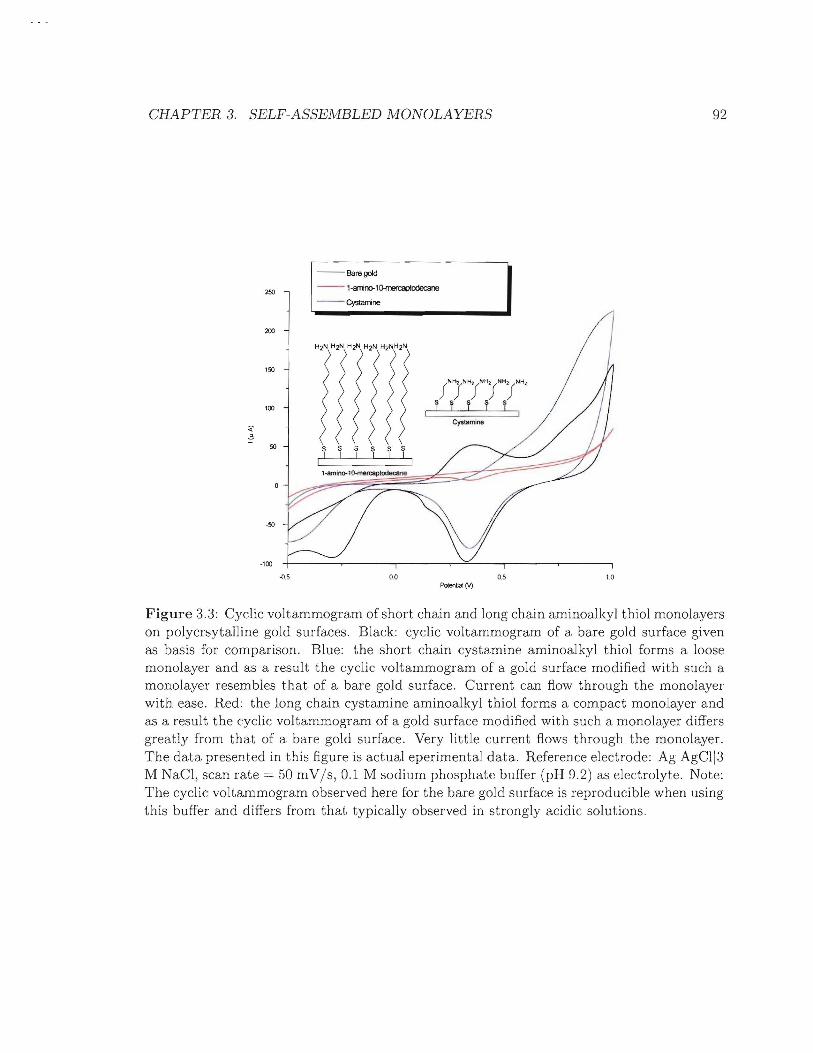
CHAPTER 3. SELF-ASSEMBLED MONOLAYERS 92
250
200
150
100
:<"-
50
·50
-100
1
- Bare gold I--1-alTino-llJ.mercaptodecane
~CystalT1lne-.-
CystamIne
ssssssI I I I I I
I
.(l.S 0.0Potential M
os 1.0
Figure 3.3: Cyclic voltammogram of short chain and long chain aminoalkyl thiol monolayerson polycrsytalline gold surfaces. Black: cyclic voltammogram of a bare gold surface givenas basis for comparison. Blue: the short chain cystamine aminoalkyl thiol forms a loosemonolayer and as a result the cyclic voltammogram of a gold surface modified with such amonolayer resembles that of a bare gold surface. Current can flow through the monolayerwith ease. Red: the long chain cystamine aminoalkyl thiol forms a compact monolayer andas a result the cyclic voltammogram of a gold surface modified with such a monolayer differsgreatly from that of a bare gold surface. Very little current flows through the monolayer.The data presented in this figure is actual eperimental data. Reference electrode: AgAgCl13M NaCl, scan rate = 50 mVIs, 0.1 M sodium phosphate buffer (pH 0.2) as electrolyte. Note:The cyclic voltammogram observed here for the bare gold surface is reproducible when usingthis buffer and differs from that typically observed in strongly acidic solutions.

CHAPTER 3. SELF-ASSEMBLED MONOLAYERS 93
HS
a.
~ ~o"S~
o '0-d.
~s-sb.
~So
e.
c.
-S}-o
S
f.
Figure 3.4: The different mercaptoalkanes capable offorming SAMS on gold. a. Alkanethiolb. Dialkyl disulfide c. Dialkyl sulfide d. Bunte salt e. Alkyl thioacetate f. Alkyl xanthate.
dodecanethiol are mainly stabilised by maximized van del' Waals interactions between the
carbon and hydrogen atoms in the spacer units. The shorter the alkane thiol (4 to 8 carbons),
the weaker the van del' Waals interactions, and therefore the less rigid and the more fluid
the monolayer becomes. The high number of possible van del' Waals contacts in the longer
alkane thiols (8 to 20 carbons) solidifies and stabilises the monolayer (Figure :3.5).134
3.2.2 Self-assembled monolayers from amide-containing mercaptoalkanes
The introduction of an amide group into the spacer unit allows hydrogen bonding between
spacer units of adjacent monolayer components. The increased strength of the interchain
interaction increases the thermal stability of the monolayer. 144 The amide sublayer is well
ordered, however, the amide linkage has a deleterious effect on the packing of the alkyl
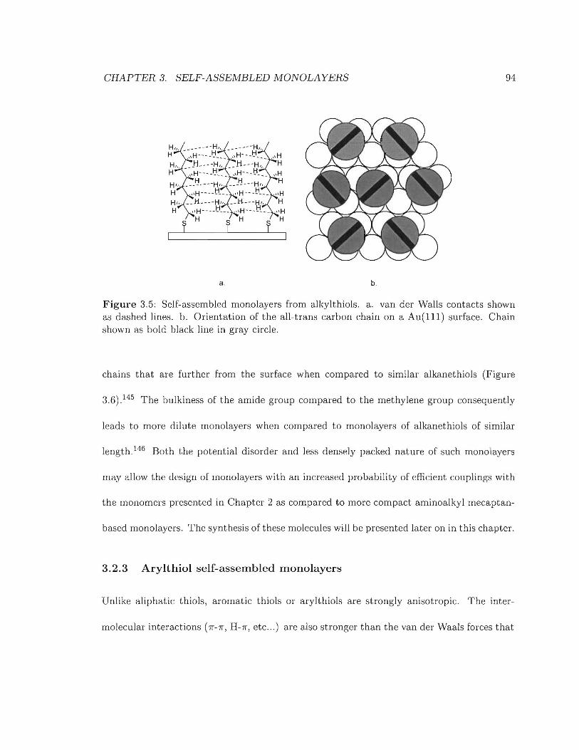
CHAPTER 3. SELF-ASSEMBLED MONOLAYERS 94
a. b.
Figure 3.5: Self-assembled monolayers from alkylthiols. a. van der Walls contacts shownas dashed lines. b. Orientation of the all-trans carbon chain on a Au(lll) surface. Chainshown as bold black line in gray circle.
chains that are further from the surface when compared to similar alkanethiols (Figure
3.6).145 The bulkiness of the amide group compared to the methylene group consequently
leads to more dilute monolayers when compared to monolayers of alkanethiols of similar
length. 146 Both the potential disorder and less densely packed nat me of such monolayers
may allow the design of mOllolayers with an increased probability of efficient couplings with
the monomers presented in Chapter 2 as compared to more compact aminoalkyl mecaptan-
based monolayers. The synthesis of these molecules will be presented later on in this chapter.
3.2.3 Arylthiol self-assembled monolayers
Unlike aliphatic thiols, aromatic thiols or arylthiols are strongly anisotropic. The inter-
molecular interactions (IT-IT, H-IT, etc ... ) are also stronger than the van der Waals forces that
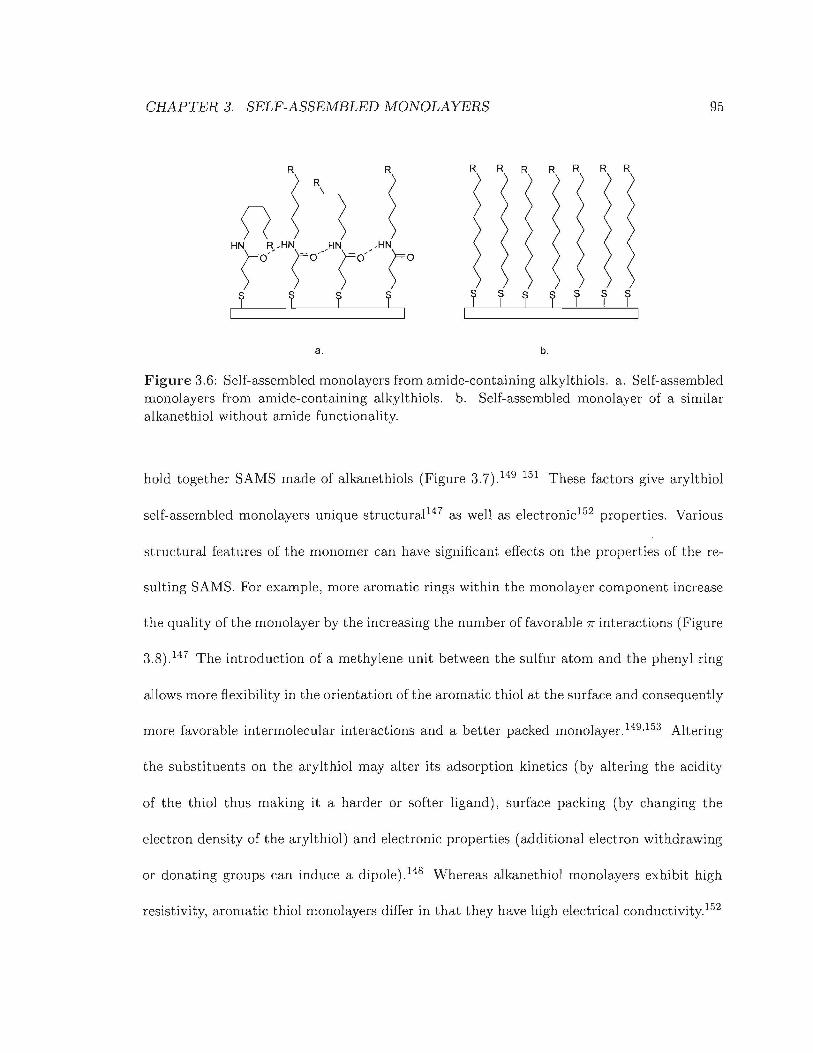
CHAPTER 3. SELF-ASSEMBLED MONOLAYERS 95
R R R R R R R R R
~R
~0 ~H~o~__H~o/HNro--
,HN
~of r f r r s r r s s rI I I
I I I
a. b.
Figure 3.6: Self-assembled monolayers from amide-containing alkylthiols. a. Self-assembledmonolayers from amide-containing alkylthiols. b. Self-assembled monolayer of a similaralkanethiol without amide functionality.
hold together SAMS made of alkanethiols (Figure 3.7).149 151 These factors give arylthiol
self-assembled monolayers unique structural147 as well as electronic152 properties. Various
structural features of the monomer can have significant effects on the properties of the re-
suIting SAMS. For example, more aromatic rings within the monolayer component increase
the quality of the monolayer by the increasing the number of favorable 7r interactions (Figure
3.8).147 The introduction of a methylene unit between the sulfur atom and the phenyl ring
allows more flexibility in the orientation of the aromatic thiol at the surface and consequently
more favorable intermolecular interactions and a better packed monolayer. 149,153 Altering
the substituents on the arylthiol may alter its adsorption kinetics (by altering the acidity
of the thiol thus making ita harder or softer ligand), surface packing (by changing the
electron density of the arylthiol) and electronic properties (additional electron withdrawing
or donating groups can induce a dipole).148 Whereas alkanethiol monolayers exhibit high
resistivity, aromatic thiol monolayers differ in that they have high electrical conductivity.152
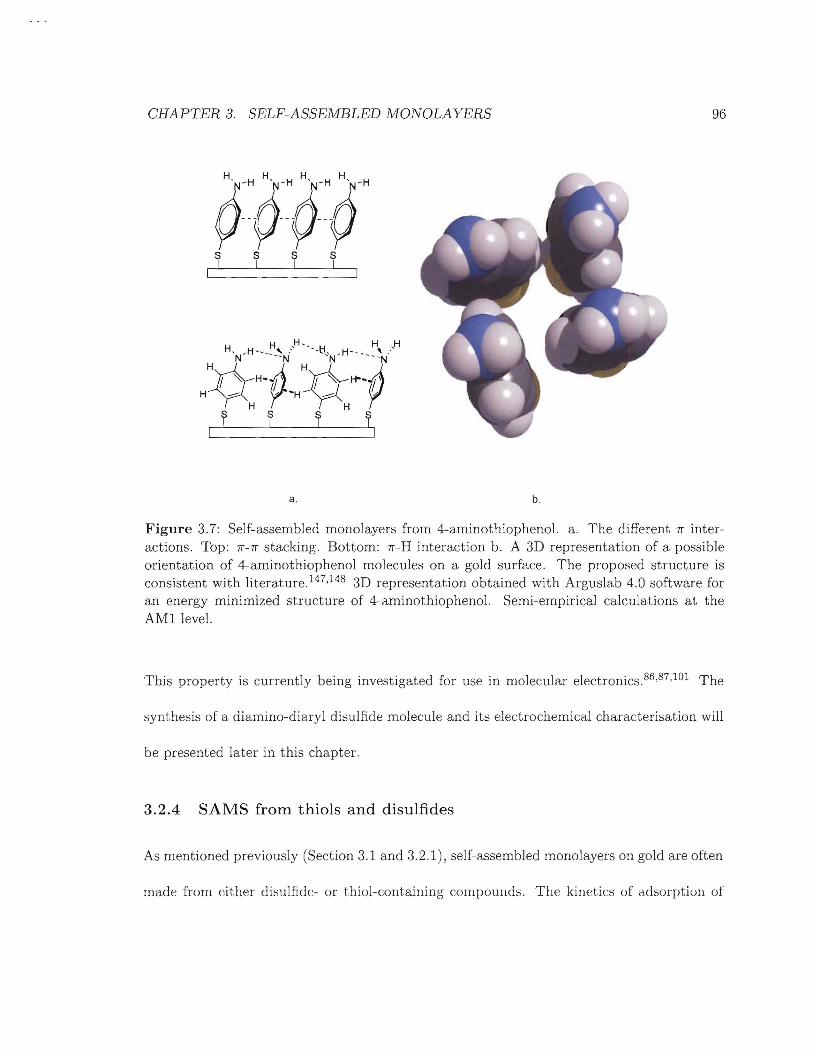
CHAPTER 3. SELF-ASSEMBLED MONOLAYERS 96
;rH-WH;r;ry--¢-y-ys s s SI I I I
a. b.
Figure 3.7: Self-assembled monolayers from 4-aminothiophenol. a. The different 1r interactions. Top: 1r-1r stacking. Bottom: 1r-H interaction b. A 3D representation of a possibleorientation of 4-aminothiophenol molecules on a gold surface. The proposed structure isconsistent with literature. 147,148 3D representation obtained with Arguslab 4.0 software foran energy minimized structure of 4-aminothiophenol. Semi-empirical calculations at theAMI level.
This property is currently being investigated for use in molecular electronics.86 ,87,lOl The
synthesis of a diamino-diaryl disulfide molecule and its electrochemical characterisation will
be presented later in this chapter.
3.2.4 SAMS from thiols and disulfides
As mentioned previously (Section 3.1 and 3.2.1), self-assembled monolayers on gold are often
made from either di~ulfidc- or thiol-containing compounds. The kinetics of adsorption of
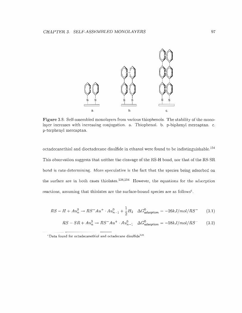
CHAPTER 3. SELF-ASSEMBLED MONOLAYERS 97
00s s s s s sI I I I I I
a. b. c.
Figure 3.8: Self-assembled monolayers from various thiophenols. The stability of the monolayer increases with increasing conjugation. a. Thiophenol. b. p-biphenyl mercaptan. c.p-terphenyl mercaptan.
octadecanethiol and dioctadecane disulfide in ethanol were found to be indistinguishable.154
This observation suggests that neither the cleavage of the RS-H bond, nor that of the RS-SR
bond is rate-determining. More speculative is the fact that the species being adsorbed on
the surface are in both cases thiolates. 138,154 However, the equations for the adsorption
reactions, assuming that thiolates are the surface-bound species are as followsc .
1RS - H + Au~ ~ RS-Au+ . AU~_l + "2H2 LlG~dsoPtion = -26kJjmolj RS- (3.1)
RS - SR + Au~ ----7 RS- Au+ . AU~_l LlG~dsoPtion = -58kJjmoljRS- (3.2)
"Data found for octadecanethiol and octadecane disulfide1:J5
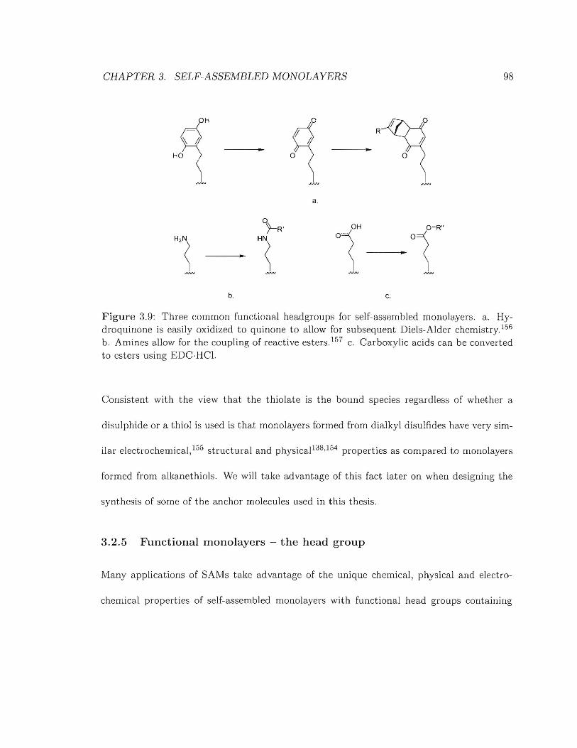
CHAPTER 3. SELF-ASSEMBLED MONOLAYERS 98
H
HO
R
o
a.
~R'
°1O-R"
"1 HN
°1~....
b. c.
Figure 3.9: Three common functional headgroups for self-assembled monolayers. a. Hydroquinone is easily oxidized to quinone to allow for subsequent Diels-Alder chemistry.156b. Amines allow for the coupling of reactive esters. 157 c. Carboxylic acids can be convertedto esters using EDC·HCI.
Consistent with the view that the thiolate is the bound species regardless of whether a
disulphide or a thiol is used is that monolayers formed from dialkyl disulfides have very sim-
ilar electrochemical,155 structural and physical 138,154 properties as compared to monolayers
formed from alkanethiols. We will take advantage of this fact later on when designing the
synthesis of some of the anchor molecules used in this thesis.
3.2.5 Functional monolayers - the head group
Many applications of SAMs take advantage of the unique chemical, physical and electro-
chemical properties of self-assembled monolayers with functional head groups containing

CHAPTER 3. SELF-ASSEMBLED MONOLAYERS 99
various functional groups such as carboxylic acids, amines, hydroquinone and many other ex
amples (Figure 3.9).130,158 160 F'unctionalised SAMs have been used in the fabrication of de
vices such as gas sensors,161 biosensors,158,162,163 surfaces for protein attachment27,33,34,48,164
and arrays for oligomer synthesis. 37
The chemistry typically used in solution can be used for the reactions between func
tionalised self-assembled monolayers with appropriately reactive solute molecules (Figure
3.9) .62,158,165 However, SAMs exhibit some properties that allow one to perform some
chemistry that would be otherwise very difficult in solution. For instance, amide bonds
can be made simply by pressing a silicon stamp soaked with a solution of an amine on
a monolayer of carboxylic acid-terminated alkanethiols143 The close proximity and high
local concentration of amines enables the reaction to proceed without traditional peptide
coupling reagents.
3.3 Electrochemistry of self-assembled monolayers
The electrochemical and electron transfer behaviour are critical parameters of the systems
that we wish to study and develop. The structure of the monolayers (anchors only or anchors
with monomers attached) will have a direct impact on the overall performance of the device.
In this section a simplified view of electrochemistry and electron-transfer in self-assembled
monolayers is presented to provide some background for the reader.
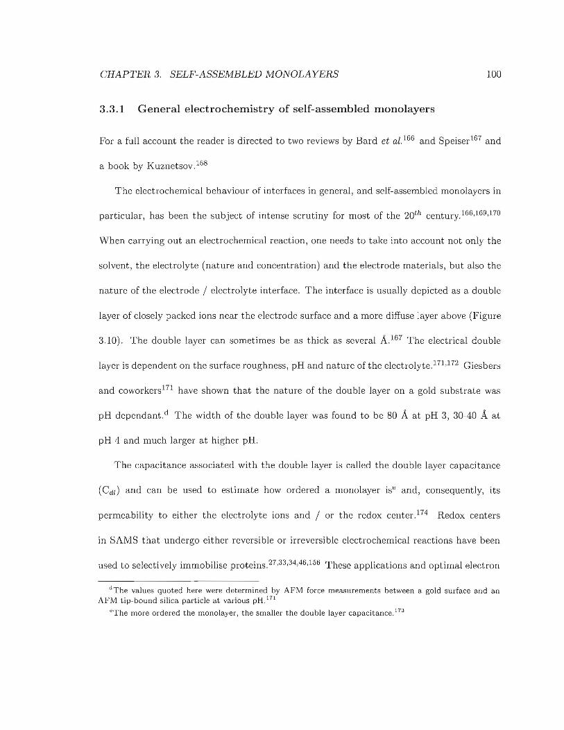
CHAPTER 3. SELF-ASSEMBLED MONOLAYERS
3.3.1 General electrochemistry of self-assembled monolayers
100
For a full account the reader is directed to two reviews by Bard et al. 166 and Speiser167 and
a book by Kuznetsov. 168
The electrochemical behaviour of interfaces in general, and self-assembled monolayers in
particular, has been the subject of intense scrutiny for most of the 20th century.166,169,170
When carrying out an electrochemical reaction, one needs to take into account not only the
solvent, the electrolyte (nature and concentration) and the electrode materials, but also the
nature of the electrode / electrolyte interface. The interface is usually depicted as a double
layer of closely packed ions near the electrode surface and a more diffuse layer above (Figure
3.10). The double layer can sometimes be as thick as several A.167 The electrical double
layer is dependent on the surface roughness, pH and nature of the electrolyte. 171 ,172 Giesbers
and coworkers171 have shown that the nature of the double layer on a gold substrate was
pH dependant. d The width of the double layer was found to be 80 A at pH 3, 30-40 A at
pH 4 and much larger at higher pH.
The capacitance associated with the double layer is called the double layer capacitance
(Cdd and can be used to estimate how ordered a monolayer ise and, consequently, its
permeability to either the electrolyte ions and / or the redox center. 174 Redox centers
in SAMS that undergo either reversible or irreversible electrochemical reactions have been
used to selectively immobilise proteins. 27 ,33,34,46,156 These applications and optimal electron
dThe values quoted here were determined by AFM force measurements between a gold surface and anAFM tip-bound silica particle at various pH17
!
"The more ordered the monolayer, the smaller the double layer capacitance. 17:J

CHAPTER 3. SELF-ASSEMBLED MONOLAYERS
I
-8:0 8
8: 0 8 0
-8 o 80
-8 0 80
8 0 8a. b.
101
Figure 3.10: Schematic representation of the double layer at an electrode surface. a. Acondensed layer of ions of opposite sign to the net charge at the electrode surface is foundnear the electrode surface. This layer is sometimes termed the Helmholtz layer. b. A morediffuse layer of ions of different charges is found on top of the Helmholtz layer. This layeris sometimes termed the Gouy-Chapman layer.
transfer is defined as a rate of electron transfer fast enough so as to not limit the function
of the proposed device.
3.3.2 Electron-transfer - from bulk to single molecules to SAMS
The modern theory of electron transfer has been formulated by Marcus (Figure 3.11).175,176
This model applies well to a wide range of donor-acceptor pairs and has been supported by
a wealth of experimental data. 177,178 Although this model has been formulated for a donor
and an acceptor separated by a medium such as a solvent, it is a good starting point for
understanding the electron-transfer processes in self-assembled monolayers.
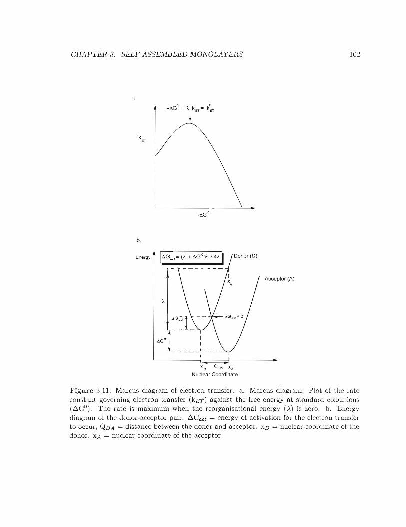
CHAPTER 3. SELF-ASSEMBLED MONOLAYERS
a.
kET
b.
Energy I~Gacl = (Ie + ~GQ? /4lel Donor (D)
I- - - - -II •
X o QQA xA
Nuclear Coordinate
Acceptor (A)
102
Figure 3.11: Marcus diagram of electron transfer. a. Marcus diagram. Plot of the rateconstant governing electron transfer (kET) against the free energy at standard conditions(~GO). The rate is maximum when the reorganisational energy (A) is ~ero. b. Energydiagram of the donor-acceptor pair. b.Gact = energy of activation for the electron transferto occur, QDA = distance between the donor and acceptor. XD = nuclear coordinate of thedonor. XA = nuclear coordinate of the acceptor.
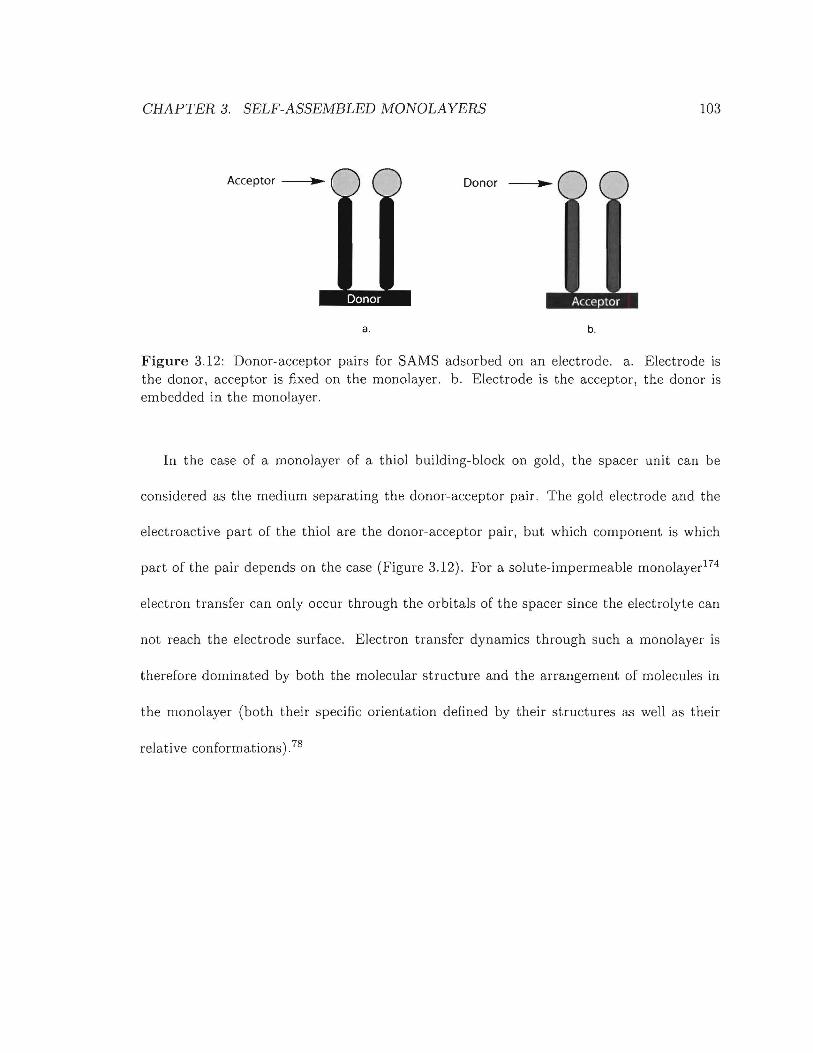
CHAPTER 3. SELF-ASSEMBLED MONOLAYERS 103
Acceptor -~..~
a,
Donor
b.
Figure 3,12: Donor-acceptor pairs for SAMS adsorbed on an electrode. a. Electrode isthe donor, acceptor is fixed on the monolayer. b. Electrode is the acceptor, the donor isembedded in the monolayer.
In the case of a monolayer of a thiol building-block on gold, the spacer unit can be
considered as the medium separating the donor-acceptor pair. The gold electrode and the
electroactive part of the thiol are the donor-acceptor pair, but which component is which
part of the pair depends on the case (Figure 3.12). For a solute-impermeable monolayer174
electron transfer can only occur through the orbitals of the spacer since the electrolyte can
not reach the electrode surface. Electron transfer dynamics through such a monolayer is
therefore dominated by both the molecular structure and the arrangement of molecules in
the monolayer (both their specific orientation defined by their structures as well as their
relative conformations), 78
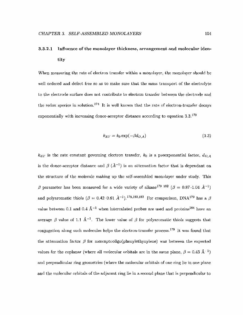
CHAPTER 3. SELF-ASSEMBLED MONOLAYERS 104
3.3.2.1 Influence of the monolayer thickness, arrangement and molecular iden
tity
When measuring the rate of electron transfer within a monolayer, the monolayer should be
well ordered and defect free so as to make sure that the mass transport of the electrolyte
to the electrode surface does not contribute to electron transfer between the electrode and
the redox species in solution.174 It is well known that the rate of electron-transfer decays
exponentially with increasing donor-acceptor distance according to equation 3.3. 179
kET = ko exp( -(3dD,A) (3.3)
kET is the rate constant governing electron transfer, ko is a preexponential factor, dD,A
is the donor-acceptor distance and (3 (A -1) is an attenuation factor that is dependant on
the structure of the molecule making up the self-assembled monolayer under study. This
(3 parameter has been measured for a wide variety of alkane179 182 ((3 = 0.87-1.04 A-I)
and polyaromatic thiols ((3 = 0.42-0.61 A-I ).179,180,183 For comparison, DNA179 has a (3
value between 0.1 and 0.4 A-I when intercalated probes are used and proteins184 have an
average (3 value of 1.1 A-I. The lower value of (3 for polyaromatic thiols suggests that
conjugation along such molecules helps the electron-transfer process.179 It was found that
the attenuation factor (3 for mercaptooligo(phenylethynylene) was between the expected
values for the coplanar (where all molecular orbitals are in the same plane, (3 = 0.43 A-I)
and perpendicular ring geometries (where the molecular orbitals of one ring lie in one plane
and the molecular orbitals of the adjacent ring lie in a second plane that is perpendicular to
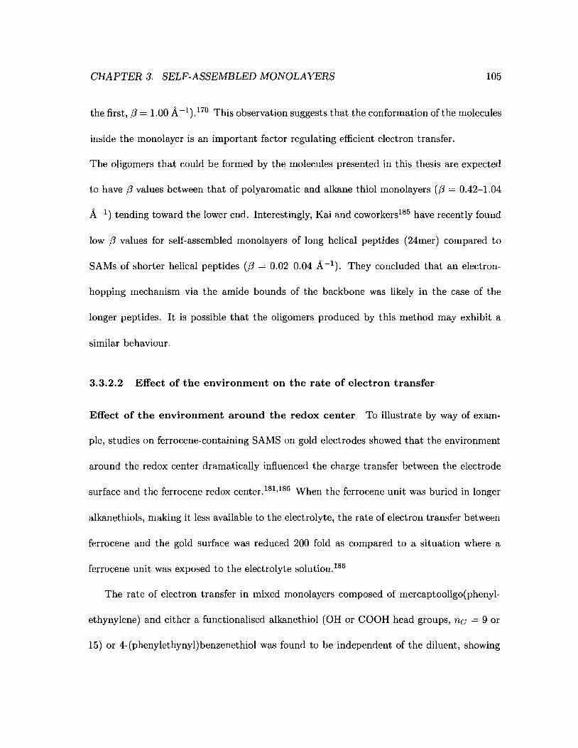
CHAPTER 3. SELF-ASSEMBLED MONOLAYERS 105
the first, (3 = 1.00 A-I) .170 This observation suggests that the conformation of the molecules
inside the monolayer is an important factor regulating efficient electron transfer.
The oligomers that could be formed by the molecules presented in this thesis are expected
to have (3 values between that of polyaromatic and alkane thiol monolayers ((3 = 0.42-1.04
A-I) tending toward the lower end. Interestingly, Kai and coworkers185 have recently found
low (3 values for self-assembled monolayers of long helical peptides (24mer) compared to
SAMs of shorter helical peptides ((3 = 0.02-0.04 A-I). They concluded that an electron
hopping mechanism via the amide bounds of the backbone was likely in the case of the
longer peptides. It is possible that the oligomers produced by this method may exhibit a
similar behaviour.
3.3.2.2 Effect of the environment on the rate of electron transfer
Effect of the environment around the redox center To illustrate by way of exam
ple, studies on ferrocene-containing SAMS on gold electrodes showed that the environment
around the redox center dramatically influenced the charge transfer between the electrode
surface and the ferrocene redox center. 181 ,186 When the ferrocene unit was buried in longer
alkanethiols, making it less available to the electrolyte, the rate of electron transfer between
ferrocene and the gold surface was reduced 200 fold as compared to a situation where a
ferrocene unit was exposed to the electrolyte solution. 186
The rate of electron transfer in mixed monolayers composed of mercaptooligo(phenyl
ethynylene) and either a functionalised alkanethiol (OH or COOH head groups, nc = 9 or
15) or 4-(phenylethynyl)benzenethiol was found to be independent of the diluent, showing
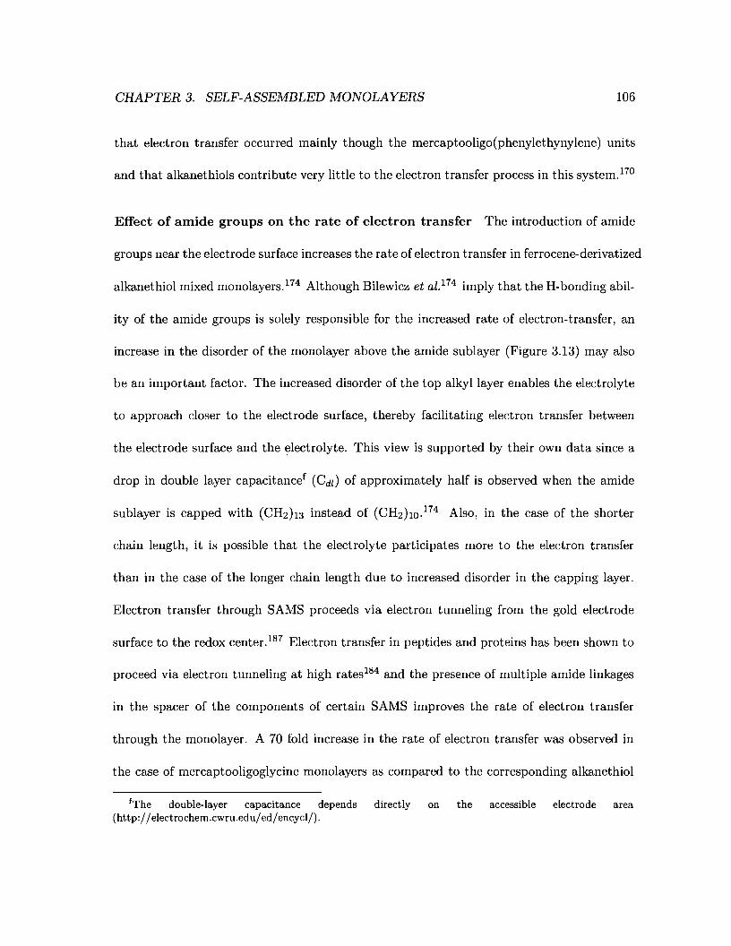
CHAPTER 3. SELF-ASSEMBLED MONOLAYERS 106
that electron transfer occurred mainly though the mercaptooligo(phenylethynylene) units
and that alkanethiols contribute very little to the electron transfer process in this system.17°
Effect of amide groups on the rate of electron transfer The introduction of amide
groups near the electrode surface increases the rate of electron transfer in ferrocene-derivatized
alkanethiol mixed monolayers. 174 Although Bilewicz et al. 174 imply that the H-bonding abil-
ity of the amide groups is solely responsible for the increased rate of electron-transfer, an
increase in the disorder of the monolayer above the amide sublayer (Figure 3.13) may also
be an important factor. The increased disorder of the top alkyl layer enables the electrolyte
to approach closer to the electrode surface, thereby facilitating electron transfer between
the electrode surface and the electrolyte. This view is supported by their own data since a
drop in double layer capacitancef (C dl ) of approximately half is observed when the amide
sublayer is capped with (CH2h3 instead of (CH2ho. 174 Also, in the case of the shorter
chain length, it is possible that the electrolyte participates more to the electron transfer
than in the case of the longer chain length due to increased disorder in the capping layer.
Electron transfer through SAMS proceeds via electron tunneling from the gold electrode
surface to the redox center.l87 Electron transfer in peptides and proteins has been shown to
proceed via electron tunneling at high rates184 and the presence of multiple amide linkages
in the spacer of the components of certain SAMS improves the rate of electron transfer
through the monolayer. A 70 fold increase in the rate of electron transfer was observed in
the case of mercaptooligoglycine monolayers as compared to the corresponding alkanethiol
fThe double-layer capacitance depends directly on the accessible electrode area(http://electrochem.cwru.edu/ed/encycl/).
CHAPTER 3. SELF-ASSEMBLED MONOLAYERS 107
(Figure 3.13).188 Notably, it has been established that the tunneling pathway in proteins is
a function of covalent and hydrogen bonds as well as through-space contacts. 184 It is rea
sonable to assume that similar factors are at play in the electron transfer through SAMS.
Such factors are critical for us as we contemplate the design of the monolayer component of
the Reagentless Electrochemically Addressable Array (RECAA) that we envision and are
therefore considered below.
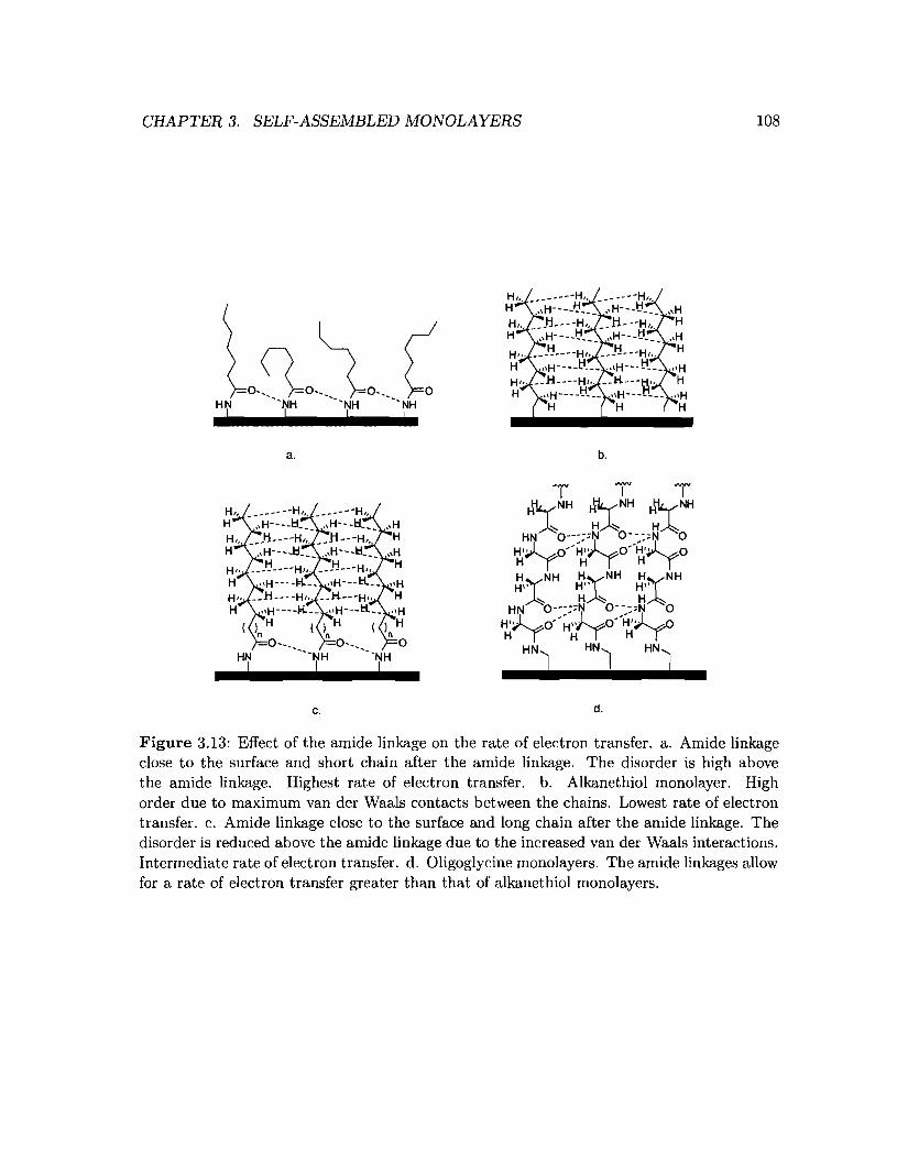
CHAPTER 3. SELF-ASSEMBLED MONOLAYERS 108
a.
c.
b.
d.
Figure 3.13: Effect of the amide linkage on the rate of electron transfer. a. Amide linkageclose to the surface and short chain after the amide linkage. The disorder is high abovethe amide linkage. Highest rate of electron transfer. b. Alkanethiol monolayer. Highorder due to maximum van der Waals contacts between the chains. Lowest rate of electrontransfer. c. Amide linkage close to the surface and long chain after the amide linkage. Thedisorder is reduced above the amide linkage due to the increased van der Waals interactions.Intermediate rate of electron transfer. d. Oligoglycine monolayers. The amide linkages allowfor a rate of electron transfer greater than that of alkanethiol monolayers.
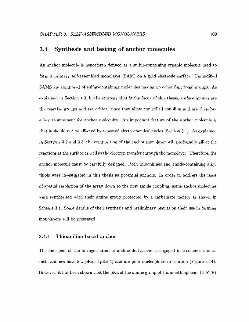
CHAPTER 3. SELF-ASSEMBLED MONOLAYERS
3.4 Synthesis and testing of anchor molecules
109
An anchor molecule is henceforth defined as a sulfur-containing organic molecule used to
form a primary self-assembled monolayer (SAM) on a gold electrode surface. Unmodified
SAMS are composed of sulfur-containing molecules having no other functional groups. As
explained in Section 1.3, in the strategy that is the focus of this thesis, surface amines are
the reactive groups and are critical since they allow controlled coupling and are therefore
a key requirement for anchor molecules. An important feature of the anchor molecule is
that it should not be affected by repeated electrochemical cycles (Section 3.1). As explained
in Sections 3.2 and 3.3, the composition of the anchor monolayer will profoundly affect the
reactions at the surface as well as the electron transfer through the monolayer. Therefore, the
anchor molecule must be carefully designed. Both thioanilines and amide-containing alkyl
thiols were investigated in this thesis as potential anchors. In order to address the issue
of spatial resolution of the array down to the first amide coupling, some anchor molecules
were synthesised with their amine group protected by a carbamate moiety as shown in
Scheme 3.1. Some details of their synthesis and preliminary results on their use in forming
monolayers will be presented.
3.4.1 Thioaniline-based anchor
The lone pair of the nitrogen atom of aniline derivatives is engaged in resonance and as
such, anilines have low pKa's (pKa 4) and are poor nucleophiles in solution (Figure 3.14).
However, it has been shown that the pKa of the amine group of 4-aminothiophenol (4-ATP)
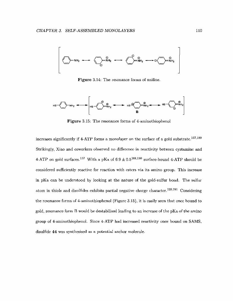
CHAPTER 3. SELF-ASSEMBLED MONOLAYERS 110
Figure 3.14: The resonance forms of aniline.
Figure 3.15: The resonance forms of 4-aminothiophenol
increases significantly if 4-ATP forms a monolayer on the surface of a gold substrate.157,189
Strikingly, Xiao and coworkers observed no difference in reactivity between cystamine and
4-ATP on gold surfaces. 157 With a pKa of 6.9 ± 0.5 189,190 surface-bound 4-ATP should be
considered sufficiently reactive for reaction with esters via its amino group. This increase
in pKa can be understood by looking at the nature of the gold-sulfur bond. The sulfur
atom in thiols and disulfides exhibits partial negative charge character.120,191 Considering
the resonance forms of 4-aminothiophenol (Figure 3.15), it is easily seen that once bound to
gold, resonance form B would be destabilised leading to an increase of the pKa of the amino
group of 4-aminothiophenol. Since 4-ATP had increased reactivity once bound on SAMS,
disulfide 44 was synthesised as a potential anchor molecule.
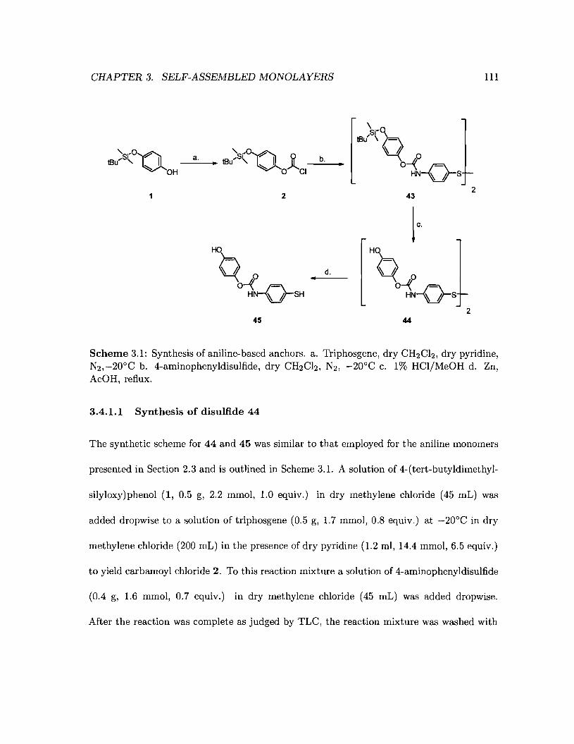
CHAPTER 3. SELF-ASSEMBLED MONOLAYERS
's-Q'-so,on a. lB)S(~ J. b.
Iflu" \ ~- b -flBu'" " I • •
~ OH ~ 0 CI a HN-Q-s
22 43
I"Q-f d. "Q-f•
°H~SH o HN-Q-S
245 44
III
Scheme 3.1: Synthesis of aniline-based anchors. a. Triphosgene, dry CH2CI2, dry pyridine,N2,-20°C b. 4-aminophenyldisulfide, dry CH2Ch, N2, -20°C c. 1% HCI/MeOH d. Zn,AcOH, reflux.
3.4.1.1 Synthesis of disulfide 44
The synthetic scheme for 44 and 45 was similar to that employed for the aniline monomers
presented in Section 2.3 and is outlined in Scheme 3.1. A solution of 4-(tert-butyldimethyl-
silyloxy)phenol (1, 0.5 g, 2.2 mmol, 1.0 equiv.) in dry methylene chloride (45 mL) was
added dropwise to a solution of triphosgene (0.5 g, 1.7 mmol, 0.8 equiv.) at -20°C in dry
methylene chloride (200 mL) in the presence of dry pyridine (1.2 ml, 14.4 mmol, 6.5 equiv.)
to yield carbamoyl chloride 2. To this reaction mixture a solution of 4-aminophenyldisulfide
(0.4 g, 1.6 mmol, 0.7 equiv.) in dry methylene chloride (45 mL) was added dropwise.
After the reaction was complete as judged by TLC, the reaction mixture was washed with
CHAPTER 3. SELF-ASSEMBLED MONOLAYERS 112
water (3 x 50 mL) and brine (50 mL) and dried over sodium sulfate. The solvent was
then removed in-vacuo. The residue was purified by flash column chromatography yielding
compound 43 as a yellow oil which crystallisied upon standing (60% yield). Disilyl ether 43
was characterised by IH-NMR, 13C-NMR, FT-IR spectroscopy and CHN elemental analysis.
The removal of the t-butyldimethylsilyl protecting groups of 43 was effected by reacting 43
in a 1% solution of hydrochloric acid in methanol at room temperature for three hours. The
final compound 44 was isolated as an off-white solid in 95% yield from silyl ether 43 and
was characterised by IH-NMR, 13C-NMR and FT-IR spectroscopy. The simplicity and well
established chemistry used in this synthetic sequence makes it amenable to preparation of
the target on gram scale. Disulfide 44 can easily be reduced to its thiophenol equivalent
45 by refluxing in acetic acid in presence of zinc dust (Scheme 3.1). Reducing 44 to 45,
however, is not necessary since it has been shown that disulfides produce monolayers that
are indistinguishable from those formed by the corresponding thiols. 138 Disulfide 44 was
therefore used in the studies presented in this chapter.
3.4.1.2 Growth of monolayers of disulfide 44 and thiol 45
The formation of monolayers of both 44 and 45 was evaluated by Fourier-Transform In
frared spectroscopy. The next two sections will present some preliminary results on the
formation and electrochemical behaviour of monolayers of disulfide 44 and thiophenol 45
on polycrystalline gold surfaces.
The infrared spectra of monolayers prepared from disulfide 44 closely resemble that of
monolayers prepared from thiophenol45 (Figure 3.16). Moreover, the spectra of monolayers
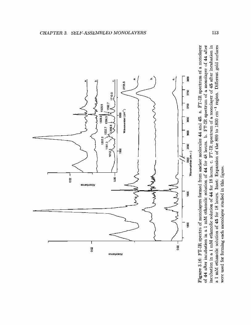
@ >: '"tl ~ ~ ~
/c.
~ ~ ~ ~ ~ t:""l ~ ~ a :< a t:""l~ ~ f]
c.b.a.
1710
.0
T15
00W
ave
nu
mb
er
(em
'1)
1000
...,
-I
II
II
II
II
I~
3500
3550
3600
3650
3700
3750
3800
Wa
ven
um
be
r(e
m-1
)
0.00
0.02
2l c: ~ 5l .0 «
1500
1000
0.00
0.02
1l c: ~ U> .0 «
Fig
ure
3.16
:F
T-I
Rsp
ectr
aof
mon
olay
ers
form
edfr
oman
chor
mol
ecul
es4
4an
d45
.a.
FT
-IR
spec
tru
mo
fa
mon
olay
ero
f4
4af
ter
incu
bati
onin
a1
mM
etha
noli
cso
luti
onof
44
for
48ho
urs.
b.F
T-I
Rsp
ectr
um
of
am
onol
ayer
of
44
afte
rin
cuba
tion
ina
1m
Met
hano
lic
solu
tion
of
44
for
18ho
urs.
c.F
T-I
Rsp
ectr
um
ofa
mon
olay
erof
45
afte
rin
cuba
tion
ina
1m
Met
hano
lic
solu
tion
of4
5fo
r18
hour
s.In
set:
Exp
ansi
ono
fth
e80
0to
1800
cm-1
regi
on.
Dif
fere
ntgo
ldsu
rfac
esw
ere
used
for
form
ing
each
mon
olay
erst
udie
din
this
figu
re.
..... ..... ""

CHAPTER 3. SELF-ASSEMBLED MONOLAYERS 114
of 44 and 45 were in close agreement with the FT-IR spectrum of 44 in KBr (Figure 3.17).
The amide I band (1710.0 cm-1)192 is weak in the FT-IR spectra of monolayers of 44 and
45 (Figure 3.16). However, the amide II (1530.8 cm-1) and the amide III band (1232.7
cm-1) are stronger (Table 3.1).
Considering the selection rule for an infrared radiation at a surface (Figure 3.18), the
very weak C=O stretch and the strong amide II and amide III bands suggest that the
carbonyl group lies perpendicular to the plane of incident light, and therefore parallel to
the gold surface. Furthermore, the stretching vibration of the hydroquinone ring at 1508.9
cm-1 is strong and sharp,27 suggesting that the hydroquinone ring lies mainly in the plane
of incident light (perpendicular to the surface). The sharp benzene ring stretching band at
1592.7 cm -1 was assigned to the thioaniline ring190 and also suggests that it lies mainly in
the plane of incident light. The formation of the monolayers was reproducible between gold
electrode surfaces, however, further studies would be required to verify these suppositions.
3.4.1.3 Cyclic Voltammetry studies of monolayers formed from disulfide 44
Monolayers of disulfide 44 on polycrystalline gold surfaces were studied by cyclic voltam
metry at a scan rate of 50 mV/s or 100 mV/s using 0.1 M sodium phosphate monobasic /
sodium phosphate dibasic buffer (pH 7.1) as electrolyte (Figure 3.19).
Irreversible modification of monolayers of disulfide 44 The cyclic voltammogram
obtained for a monolayer of 44 cycled between -0.1 and 1 V reveals a broad oxidation peak
(E) centered at 0.479 V on the anodic wave of the first scan (black line) that is followed
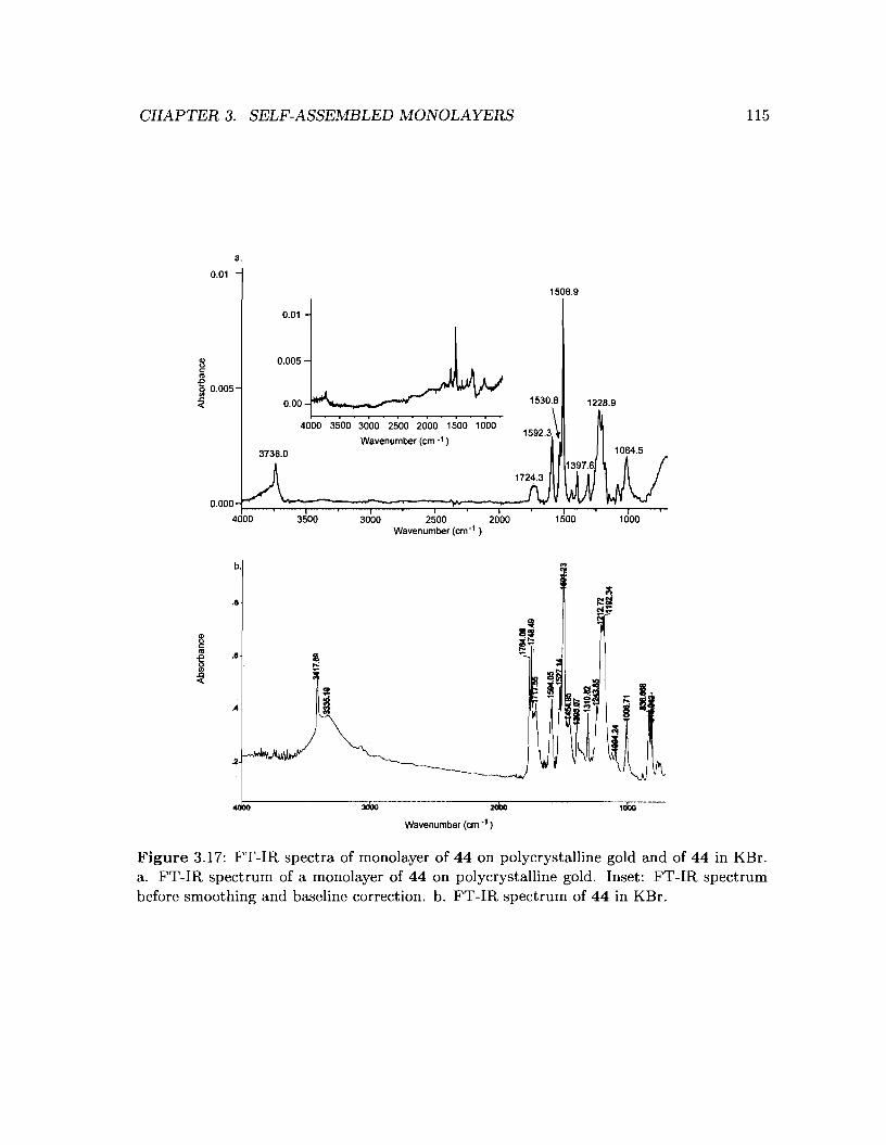
CHAPTER 3. SELF-ASSEMBLED MONOLAYERS 115
a.
0.01
1508.9
0.01
0.00
1000
1084.5
1228.9
1500
1530.8
1592.3\
3000 2500 2000Wavenumber (em-1 )
4000 3500 3000 2500 2000 1500 1000
Wavenumber (em -1 )
3500
0.005
3738.0
8c:
~~ 0.005
b.
...1:-:----------3O\iO.-..----.-..--..-......------::c2000
::c.=--------·"1000--
Wavenumber (em -1)
Figure 3.17: FT-IR spectra of monolayer of 44 on polycrystalline gold and of 44 in KBr.a. FT-IR spectrum of a monolayer of 44 on polycrystalline gold. Inset: FT-IR spectrumbefore smoothing and baseline correction. b. FT-IR spectrum of 44 in KBr.
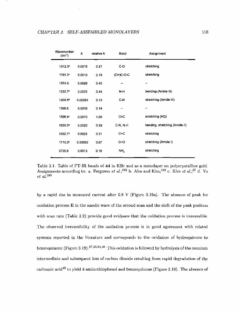
CHAPTER 3. SELF-ASSEMBLED MONOLAYERS
WavenumberA relative A Bond Assignment
(cm·1)
1012.3a 0.0015 0.21 C-O stretching
1181.3a 0.0013 0.19 (O=)C-O-C stretching
1203.3 0.0028 0.40
1232.7b 0.0031 0.44 N-H bending (Amide III)
1309.8a 0.00091 0.13 CoN stretching (Amide III)
1396.5 0.0010 0.14
1508.ge 0.0070 1.00 C=C stretching (HQ)
1529.5" 0.0020 0.29 C-N, N-H bending, stretching (Amide II)
1592.7d 0.0022 0.31 C=C stretching
1710.0' 0.00052 0.07 C=O stretching (Amide I)
3735.8 0.0013 0.19 NH2stretching
116
Table 3.1: Table of FT-IR bands of 44 in KBr and as a monolayer on polycrystalline gold.Assignments according to: a. Ferguson et al.;192 b. Ahn and Kimi193 c. Kim et al.i 27 d. Yuet al. 190
by a rapid rise in measured current after 0.8 V (Figure 3.19a). The absence of peak for
oxidation process E in the anodic wave of the second scan and the shift of the peak position
with scan rate (Table 3.2) provide good evidence that the oxidation process is irreversible.
The observed irreversibility of the oxidation process is in good agreement with related
systems reported in the literature and corresponds to the oxidation of hydroquinone to
benzoquinone (Figure 3.19).27,33,34,46 This oxidation is followed by hydrolysis of the oxonium
intermediate and subsequent loss of carbon dioxide resulting from rapid degradation of the
carbamic acid45 to yield 4-aminothiophenol and benzoquinone (Figure 3.19). The absence of

CHAPTER 3. SELF-ASSEj\lIBLED MONOLAYERS
p-polarisation
J \
117
s-polarisalion
Figure 3.18: Selection rules for the reflection of the electrical component of an infraredlight off of a metal surface. The sum of the electrical component vectors is shown on theright. A red point denotes a sum of zero. Top: p-polarised light, the electrical componentvector is within the plane of incident light. The phase of the reflected vector is shiftedby 900 with respect to the incident vector therefore, the sum of the incident and reflectedelectrical component vectors result in an electric field at the surface. Bottom: s-polarisedlight, the electrical component vector is rotated 900 with respect to the plane of incidentlight. The phase of the reflected vector is shifted by 1800 with respect to the incident vector,therefore, the sum of the incident and reflected electrical component vectors does not resultin an electric field at the surface.
a hydroquinone oxidation peak on the second scan proves that the removal of hydroquinone
from monolayers of disulfide 44 is clean and efficient. The reduction wave of the first scan
shows a broad reduction peak centered at 0.487 V which was shifted to 0.479 V in the second
scan. This peak has not been assigned, however it should be noted that when the monolayer
is cycled from a to 0.8 V this peak is not present in the cyclic voltammogram suggesting that
the reduction peak at 0.487 V is related to electrochemical processes occurring at voltages

CHAPTER 3. SELF-ASSEMBLED MONOLAYERS 118
over 0.8 V (Figure 3.19b.). It is likely possibility that the gold surface is oxidised at potentials
over 0.8 V. As well, we expect the monolayer to be modified above this potential. A more
detailed explanation will be presented in the following paragraphs.
Surface coverage and peak potential
fO=~nFA
(3.4)
The surface coverage can be derived from equation 3.4 where fa is the coverage in mol/cm2 ,
Q is the charge or peak area in C, n is the number of electrons involved in the process, F is
the Faraday constant (96,485.34 C/mol) and A is the working electrode areag in cm2. The
peak areas were determined using the GPES software assuming a straight baseline.
Both the peak potential for the redox process E (E p ), the width at half peak height
(Ep1 / 2) and the surface coverage (fa) of disulfide 44 were reproducibly observed using two
different electrodes and were fairly constant for a given electrode (Table 3.2, electrode 1) but
varied between electrodes (Table 3.2, electrodes 1 and 2). The surface coverage and area per
molecule (Table 3.3) of monolayers of 44 is larger than that of SAMs of 4-arninothiophenol
and comparable to both SAMs of 3-aminothiophenol and H2Q(CH2h2SH. Approximating
44 to a square, the distance between two molecules of 44 is between 5.2 and 6.3 A. This
value is slightly higher than the value for a typical (J3 x j3)R30° packing arrangement of
long chain alkyl thiols on a Au(111) surface (approximately 5 A).
gThe area was determined by mesuring the diameter of the working electrode area that was exposed tothe electrolyte solution. The formula for the area of a circle (A = 7fr2) was then used to calculate the area.

CHAPTER 3. SELF-ASSEMBLED MONOLAYERS 119
a.
0.00010
0.00008
O.D0Ca3
0.rxxxJ4
0.00002
ooסס0.0
-0.00002
0.0 0.2 0.4 0.6 0.8 1.0Potential M
¢ ¢°l,A( ° 0yOH
ONH -rL -e°2ONH ONH,"" H,o ""I ""I
1 1 1
0.80.602 0.4
Potential M
b.
0.00010
000008
0.00003
000Xl4
?- 0.00002
0./XXXXl
-0.00002
-D.00Xl400
Figure 3.19: Cyclic voltammogram of a monolayer of disulfide 44 on polycrystalline gold.Reference electrode: AgIAgCl13 IvI NaCI, scan rate = 50 mVIs, 0.1 M sodium phosphatebuffer (pH 7.1) as electrolyte. Cyclic voltammogram presented is representative of the dataobtained for at least 10 monolayers of 44. Top: Cycle from -0.1 to 1.0 V. Middle: Oxidationof 44 leads to the generation of 4-aminothiophenol via formation of benzoquinone and atransient carbamic acid. Bottom: Cycle from a to 0.8 V. The dip in current at 0.2 V couldnot be reproduced and was therefore attributed to experimental error.
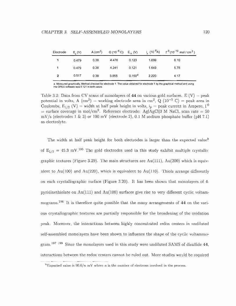
CHAPTER 3. SELF-ASSEMBLED MONOLAYERS
Electrode Ep
(V) A (cm 2 ) Q(10'5 C) E,fl (V) ip
(10·5A) r O(1 0.10 moll em 2 )
0.479 0.38 4.476 0.123 1.699 6.10
0.479 0.38 4.241 0.121 1.649 5.78
2 0.517 0.38 3.055 0.150 a 2.220 4.17
a. Measured graphically. Method checked for electrode 1. The value oblained for elec1rode 1 by the graphical method and usingthe GPES software was 0.121 in both cases.
120
Table 3.2: Data from CV scans of monolayers of 44 on various gold surfaces. E (V) = peakpotential in volts, A (cm2) = working electrode area in cm2 , Q (10-5 C) = peak area inCoulombs, E1/ 2 (V) = width at half peak height in volts, ip = peak current in Ampere, rO
= surface coverage in moljcm2 . Reference electrode: AgIAgCl13 M NaCl, scan rate = 50mV/s (electrodes 1 & 3) or 100 mV (electrode 2), 0.1 M sodium phosphate buffer (pH 7.1)as electrolyte.
The width at half peak height for both electrodes is larger than the expected valueh
of E1/ 2 = 45.3 mV. 195 The gold electrodes used in this study exhibit multiple crystallo-
graphic textures (Figure 3.29). The main structures are Au(lll), Au(200) which is equiv-
alent to Au(lOO) and Au(220), which is equivalent to Au(llO). Thiols arrange differently
on each crystallographic surface (Figure 3.20). It has been shown that rnonolayers of 4-
pyridinethiolate on Au(l11) and Au(lOO) surfaces give rise to very different cyclic voltam-
mograms. 196 It is therefore quite possible that the many arrangements of 44 on the vari-
ous crystallographic textures are partially responsible for the broadening of the oxidation
peak. Moreover, the interactions between highly concentrated redox centers in undiluted
self-assembled monolayers have been shown to influence the shape of the cyclic voltammo-
gram. 197 199 Since the monolayers used in this study were undiluted SAMS of disulfide 44,
interactions between the redox centers cannot be ruled out. More studies would be required
hExpected value is 90.6/n mV where n is the number of electrons involved in the process.
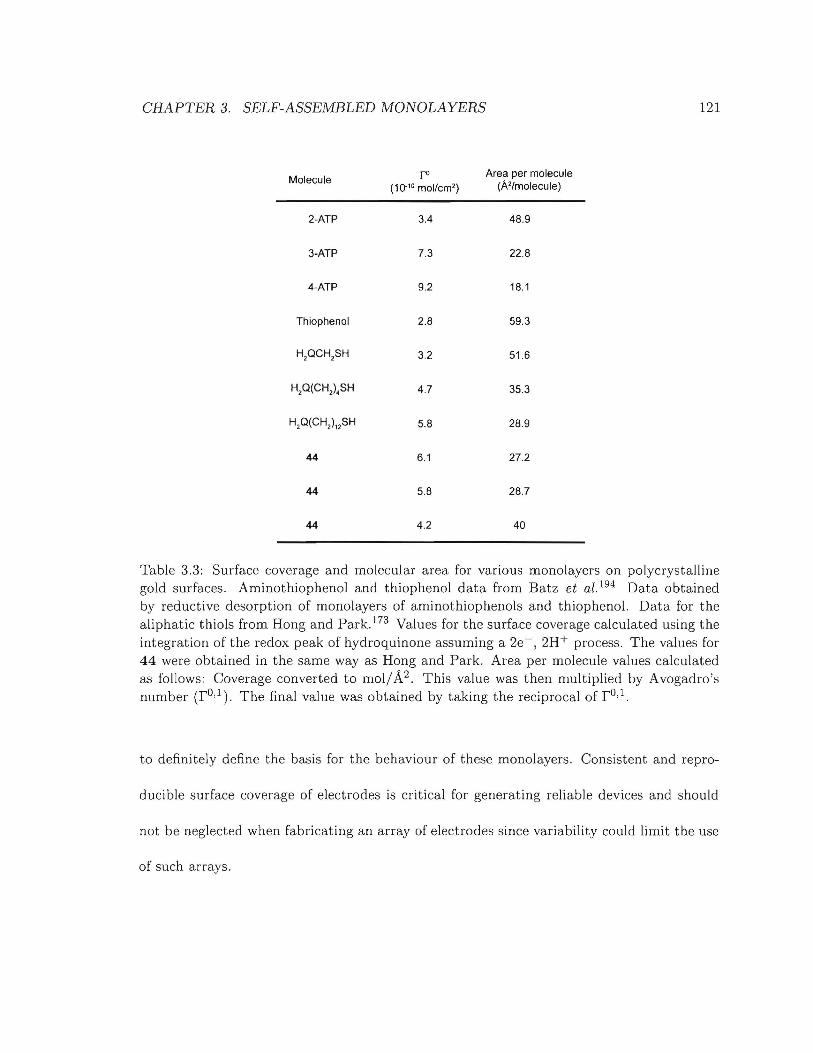
CHAPTER 3. SELF-ASSEMBLED MONOLAYERS
Molecule ro Area per molecule(10- '0 mol/em') (A'/moleeule)
2-ATP 3.4 48.9
3-ATP 7.3 22.8
4-ATP 9.2 18.1
Thiophenol 2.8 59.3
H,QCH,SH 3.2 51.6
H,Q(CH,).SH 4.7 35.3
H,Q(CH,)"SH 5.8 28.9
44 6.1 27.2
44 5.8 28.7
44 4.2 40
121
Table 3.3: Surface coverage and molecular area for various monolayers on polycrystallinegold surfaces. Aminothiophenol and thiophenol data from Batz et al. 194 Data obtainedby reductive desorption of monolayers of aminothiophenols and thiophenol. Data for thealiphatic thiols from Hong and Park. 173 Values for the surface coverage calculated using theintegration of the redox peak of hydroquinone assuming a 2e-, 2H+ process. The values for44 were obtained in the same way as Hong and Park. Area per molecule values calculatedas follows: Coverage converted to mollA2 . This value was then multiplied by Avogadro'snumber (rD,I). The final value was obtained by taking the reciprocal of rD,I.
to definitely define the basis for the behaviour of these monolayers. Consistent and repro-
ducible surface coverage of electrodes is critical for generating reliable devices and should
not be neglected when fabricating an array of electrodes since variability could limit the use
of such arrays.

CHAPTER 3. SELF-ASSEMBLED MONOLAYERS 122
••
a. b.
E] • Thiol
0/. Gold alom
Unit cell
c.
Figure 3.20: Arrangement of thiols on different gold surfaces. a. Thiols on Au(l11). b.Thiols on Au(llO). c. Thiols on Au(100).
Electrochemically promoted modification of monolayers of disulfide 44 A gold
electrode modified with a monolayer of 44 was characterised by cyclic voltammetry (2 cy-
cles of-O.l V to 1 V to -0.1 V) in 0.1 M sodiumphosphate buffer (pH 7.1) and then kept
at a potential of 0.6 V for 60 s in an effort to ensure that all of 44 had been converted
to 4-aminothiophenol. The resulting monolayer was then rinsed thoroughly with doubly
deionised water and anhydrous ethanol and then characterised by FT-IR spectroscopy (Fig-
ure 3.21).
The main hydroquinone ring stretching band at 1509.0 cm-1 in the FT-IR spectrum
of the unmodified monolayer of disulfide 44 is absent from the FT-IR spectrum of the
modified monolayer of 44 where it is replaced by a broad absorption band at 1466.4 em-1.
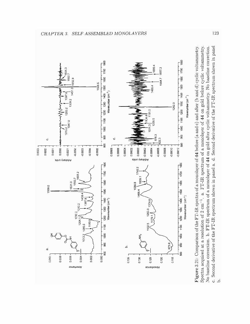
0.00
03
CJa.
0.00
02
~1
50
9.0
C.
0.01
0..,
Q0.
0001
'l::l
$
~'c
0.00
8-l
::l
0.ססOO
~~
1013
~t
0"'(
0~
-0.0
001
W
~:e
10
47
.0
""']D~
15
31
.0«
?""
I1
23
0.2
!15
93
.7-0
.000
2C
f) t.TJ~
1310
.2
A/6
05
2t--<
0.0
04
-1
20
4.V
\1
14
39
.4-0
.000
3'"!
j1
01
3.2
10
85
.5---
_.I ~
0.0
02
+-'
./'"
,"u
v'tJ
'-V"\
....
1\;
'J
v~""'\
-o.O
C04
Cf)
Cf) t.TJ
-0.0
005
15
08
.8
~0
.00
0I
Ii
II
iI
II
II
800
000
1000
1100
1200
1300
1400
1500
1600
1700
1800
800
000
1000
1100
1200
1300
1400
1500
1600
1700
1800
t--<W
aven
urrt
:er
(em
")W
aven
urrt
ler
(an
")
~0.
0000
8..,
d.:s:
0.00
006
-I0
b.0.
0000
4:<
0.13
5..,
0$
0CX
XX
l2t--< ~
'c
~0
13
0-I
DN
H2
'T-~OOOOOO
''''t:I
~~
1l-o
.CX
XX
l2C
f):'l
<l:c O
J-o
.CXX
Xl4
-e~t8
~63
10
58
.5
i...
""..
...
It16
80
.40 V> .0 <(
-0.0
0006
822.
30.
120
15
64
.71
65
7.3
-0.0
0008
01
15
-I-I
.../
"-0
.000
10
-0.0
0012
~1
26
2.0
1100
1200
1300
1400
1500
1600
1700
1800
II
II
II
1000
800
000
1000
1100
1200
1300
1400
1500
1600
1700
1800
Wa
ven
um
be
r(e
m")
Wav
enLn
t>er
(an
-,)
Fig
ure
3.21
:C
ompa
riso
nof
the
FT
-IR
spec
tra
ofa
mon
olay
erof
44
befo
re(a
and
c)an
daf
ter
(ban
dd)
cycl
icvo
ltam
met
ry.
Sp
ectr
aac
quir
edat
are
solu
tion
of2
cm-I
.a.
FT
-IR
spec
tru
mof
am
onol
ayer
of4
4on
gold
befo
recy
clic
volt
amm
etry
.N
oba
seli
neco
rrec
tion
.b.
FT
-IR
spec
tru
mof
am
onol
ayer
of4
4on
gold
afte
rcy
clic
volt
amm
etry
.N
oba
seli
neco
rrec
tion
.c.
Sec
ond
deri
vati
veof
the
FT
-IR
spec
tru
msh
own
inpa
nel
a.d.
Sec
ond
deri
vati
veof
the
FT
-IR
spec
tru
msh
own
inpa
nel
b.
......
tv eN
CHAPTER 3. SELF-ASSEMBLED MONOLAYERS 124
This suggests that the hydroquinone group has been cleaved from 44 and t.he modified
monolayer is expected to now be a monolayer of 4-aminothiophenol instead. The weak
band at 1588.8 cm -1 and the shoulder at 1492.6 cm -1 (benzene ring stretching bands)
suggest that 4-aminothiophenol is now present at the gold surface, since these values have
been previously reported for monolayers of 4-aminothiophenol on gold. 190 However, the
high absorbance of the modified monolayer of 44 suggests a multilayer structure or, as a
minimum, a structure that is not a strict monolayer of 4-aminothiopheno1. 200
From the second derivative of the FT-IR spectrum of a monolayer of 44 before cyclic
voltammetry (Figure 3.21c) three main features can be clearly identified; a band at 1203.2
(C-O stretch), one at 1508.8 (hydroquinone ring stretch) and one at 1592.7 cm- 1 (benzene
ring stretch) with the peak at 1508.8 cm-1 being the dominant feature. The corresponding
bands, and relative intensities, are also observed in the FT-IR spectrum (Figure 3.21a). The
high level of noise in the second derivative trace of the FT-IR spectrum of the monolayer
of 44 after cyclic voltammetry (Figure 3.21d) complicates the identification of detailed
features. However, three main bands were identified at 876.3, 1181.0 and 1262.0 cm -1 with
the peak at 1262.0 cm-1 being the dominant feature. The band at 1262.0 cm-1 was assigned
to the C-N stretching band. The three bands mentioned above (876.3, 1181.0 and 1262.0
cm -1) were also present in the FT-IR spectrum of a monolayer of 4-aminothiophenol on gold
reported by Yu et al.. 190 More studies, beyond these preliminary efforts, would be required
to ascertain the structure of the monolayer after the cyclic voltammetry experiment.
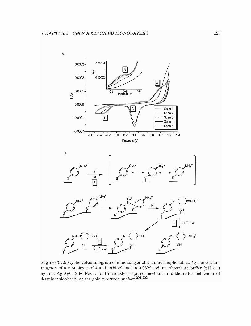
CHAPTER 3. SELF-ASSEMBLED MONOLAYERS 125
a.
--Scan 1--Scan 2--Scan 3--Scan 4--ScanS
0.0003 0.00004
g-
0.0002 000002
0.0001 0.4 0\3 0.8
$ Potential M-
OOסס.0
-0.0001
-0.6 -0.4 -0.2 0.0 0.2 0.4 0.6 0.8 1.0 1.2 1.4
PotenUal M
b.
- e
NK/ . NH/ d~+0- (-f ")J -~-.... ).J_.-.... . #
--L ...L ...L
Figure 3.22: Cyclic voltammogram of a monolayer of 4-aminothiopheno!. a. Cyclic voltammogram of a monolayer of 4-aminothiophenol in O.03M sodium phosphate buffer (pH 7.1)against AgIAgCl13 M NaC!. b. Previously proposed mechanism of the redox behaviour of4-aminothiophenol at the gold electrode surface. 201 ,202

CHAPTER 3. SELF-ASSEMBLED MONOLAYERS 126
Cyclic voltammetry of monolayers of 4-aminothiophenol on gold electrodes Mono-
layers of 4-aminothiophenol on polycrystalline gold surfaces were analysed by cyclic voltam-
metry (0.03 M sodium phosphate buffer, pH 7.1) in an attempt to clarify the results observed
in the FT-IR spectrum of monolayers made of 44 after electrochemical modification (Figure
3.22). The oxidation peaks A (1.05 V) and B (0.527 V) have been associated in the liter-
ature with the oxidation of 4-aminothiophenol to the 4-aminothiophenol radical cation and
ammonium hydroquinone respectively.201,202 Peaks C (0.402 V) and D (-0.315 V) could
not be assigned by refering to the literature. However, the voltammograms obtained were in
good agreement with previous studies involving 4-aminothiopheno1.201 203 The mechanism
proposed for the electrochemical behaviour of 4-aminothiophenoI2ol ,203 (Figure 3.22b) al-
lows for the possible radical polymerisation of 4-aminothiophenol on the gold surface. This
polymerisation could be the basis for an increase in layer thickness and hence an increase
in the intensity of the FT-IR signal of the thin film as observed in the FT-IR spectrum of
a monolayer of 44 after cyclic voltammetry (Figure 3.21) relative to the monolayer before
cyclic voltammetry.i However, further studies would be required to verify this preliminary
study and to fully understand the fate of the monolayer during the cyclic voltammetry exper-
iment. Regardless of the issues presented above, to the best of our knowledge, these results
are the first studies of electrochemical deprotection of self-assembled protected-amines at
electrode surfaces and reveal that we can carry out this reaction reproducibly.
iThe intensity of the FT-IR signal of thin films has been shown to increase with an increase in thicknessof the thin films. 20o
CHAPTER 3. SELF-ASSEMBLED MONOLAYERS 127
Circumventing the degradation of the deprotected monolayers As explained above,
self-assembled monolayers of 4-aminothiophenol can be degraded if the potential employed
is above 0.8 V (Ag IAgCl13 M NaCI reference electrode). However, the deprotection poten
tial of the hydroquinone carbamate of disulfide 44 was found to be in the vicinity of 0.5 V.
In most of the studies presented in this thesis the potential was varied up to 1 V. When the
maximum potential is kept under 0.8 V the monolayer, both the electrode surface and the
monolayer appear to be unmodified (Figure 3.19b). During device operation, the potential
applied would be kept in the vicinity of the deprotection potential of the hydroquinone car
bamate meaning that the degradation of the monolayers of 4-aminothiophenol observed in
our experiments would likely not be significant. As such, disulfide 44 can still be considered
as monolayer components for device fabrication.
Conclusion Both cyclic voltammetry and FT-IR data suggests that the hydroquinone
carbamate in monolayers of 44 is rapidly and irreversibly cleaved cleanly and efficiently
yielding benzoquinone, carbon dioxide and a significantly modified monolayer of 44. Cyclic
voltammetry of monolayers of 4-aminothiophenol (4-ATP) shows an oxidation peak in the
expected region for oxidation of hydroquinone to benzoquinone (0.520 V vs 0.479 to 0.532
V). It is therefore reasonable to propose that the monolayer will be irreversibly modified be
yond the desired product (a monolayer of 4-ATP). This suggests that such a monolayer might
not be useful for the fabrication of an electrochemical array as described in Section 1.3.5.
The degradation of the monolayer appears to be severe after cyclic voltammetry experiment
and device failure could occur after only a few cycles since the desired 4-aminothiophenol
CHAPTER 3. SELF-ASSEMBLED MONOLAYERS 128
monolayer has already undergone undesirable modification after only one CV cycle. How
ever, cyclic voltammograms where the maximum oxidising potential has been lowered to 0.8
V do not show the same degradation (Figure 3.19) peaks. As a consequence, monolayers
of disulfide 44 could be used for device fabrication if the hydroquinone carbamate depro
teet ion potential is kept below 0.8 V. However, further studies would be necessary to fully
understand the behaviour of these monolayers.
CHAPTER 3. SELF-ASSEMBLED MONOLAYERS
3.4.2 Amide-containing dialkyldisulfides as anchors - Synthesis of 55
129
As explained in Sections 3.2.2 and 3.3.2.2, the introduction of amide groups into the spacer
units of thiols or disulfides can significantly improve the efficiency of electron transfer and
alter various other properties of the monolayers. Since electron transfer through the mono
layer is critical to the development of electrochemical arrays of the type proposed here,
a method for synthesising amide-containing diaminoalkyldisulfides was devised in order to
enable testing of various amide-containing linkers as anchors.
3.4.2.1 Retrosynthetic analysis
Two main routes were identified for the synthesis of disulfide 55 (Scheme 3.2). 55 could
be obtained either by direct coupling of 1,6-diamine with 53 (Route 1) or by coupling of
64 with 53 followed by removal of the tert-butyloxycarbonyl (BOC) group under acidic
conditions (Route 2). The aim in this section is only to demonstrate the ease with which
such molecules can be prepared. The generality of the chemistry presented below allows for
variation in the position of the amide linkage within the anchor molecule.
3.4.2.2 Synthesis of diesterdisulfide 53
Diester 53 was synthesised by modifying a literature procedure.204 A solution of 4,4'-
dithiodibutyric acid (0.48 g, 1.99 mmol, 1 equiv.), 1-Ethyl-3-(3-dimethyllaminopropyl)
carbodiimide hydrochloride (0.95 g, 4.96 mmol, 2.49 equiv.) and N-hydroxysuccinimide
(0.50 g, 4.31 mmol, 2.17 equiv.) in dry acetonitrile (20 ml) and dry tetrahydrofuran (40
ml) was stirred at room temperature for 20 hours. The solvent was reduced in-vacuo and

CHAPTER 3. SELF-ASSEMBLED MONOLAYERS
Route 1:>
2
54
53
130
Scheme 3.2: Retrosynthetic analysis of disulfide 55.
the remaining solution taken up in ethyl acetate (100 ml) and washed with water (50 ml)
and brine (20 ml). The organic layer was dried over sodium sulfate and the solvent removed
in-vacuo to afford a white solid in 90% yield. This solid was identified as 53 by 1H-NMR
and FT-IR spectroscopy.
3.4.2.3 Synthesis of 55 via coupling of 1,6-diaminohexane to 53
When reacting a diamine with diacid 53, one has to be concerned with the possibility of
forming the undesired cyclic product (Figure 3.23). In order to minimise the probability of
forming the cyclic product, a dilute solution of 53 (CS3 = 6 - 16 mM) in either chloroform,
methanol or acetonitrile was added dropwise to a solution of 1,6-diaminohexane in the
same solvent (Cdiamine = 61 - 117 mM). The products obtained appear as a mixture, one
of which is a macrocyclic compound (Figure 3.24). This approach is therefore of limited

CHAPTER 3. SELF-ASSEMBLED MONOLAYERS 131
A ):(0~N-h 0~ H2N~f\ti.:
o 0 ( '; -0
5-5
53
o "'l, ~r-'<N-0 NH H~ 0H~ ~ -----------..
o 0 ) 0 0 0
5-5 5-5
Cyclic product
\"'l,'< 0"
5-555
Dithio-diamine product
Figure 3.23: Coupling of 53 with 1,6-diaminohexane. A distribution of both cyclicand dithio-diamine products is expected. Dilute conditions and addition 53 to 1,6diaminohexane was predicted to favour the formation of 55 and disfavour the dashed reaction to form the cyclic product.
use for producing amide-containing dialkyldisulfides, even with a diamine chain-length of 6
carbons. A second approach via monoprotected diamines is investigated in the next section.
3.4.2.4 Synthesis of 55 via coupling of monoamine 63 to diesterdisulfide 53
Synthesis of 63 tert-butyl 6-aminohexylcarbamate (63) was synthesised by modifying a
literature procedure (Scheme 3.3).205 In a typical procedure 1,6-diaminohexane (3.34 g, 28.8
mmol, 4.99 equiv.) was dissolved in chloroform (100 ml) and the solution was cooled to DoC.
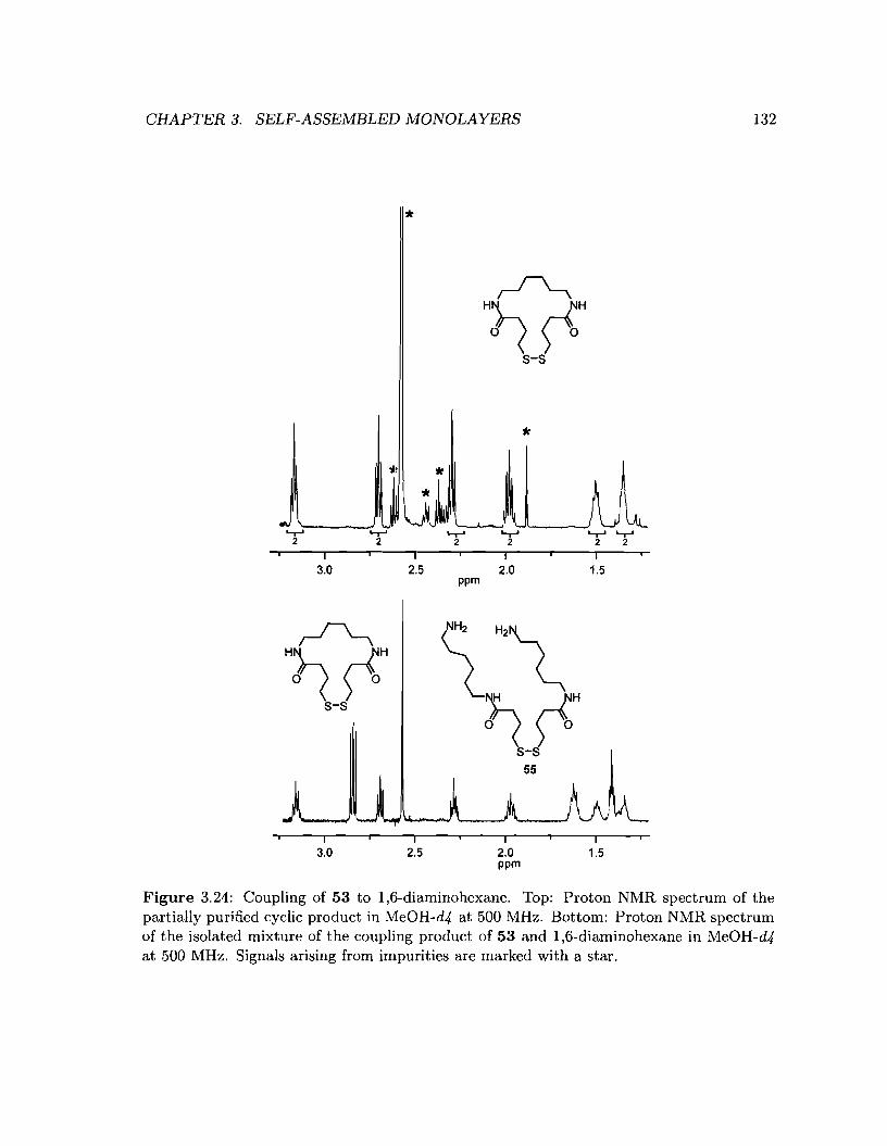
CHAPTER 3. SELF-ASSEMBLED MONOLAYERS
'*
'*
132
'-T-'2
I3.0
1l:~ '*'*
'-T-' '-T-'2 2
I2.5
ppm
'-T-'2
I2.0
'-T-' '-T-'2 2
I1.5
I3.0 2.5
l"'~00"
s-s55
I2.0ppm
I1.5
Figure 3.24: Coupling of 53 to 1,6-diaminohexane. Top: Proton NMR spectrum of thepartially purified cyclic product in MeOH-d4 at 500 MHz. Bottom: Proton NMR spectrumof the isolated mixture of the coupling product of 53 and 1,6-diaminohexane in MeOH-d4at 500 MHz. Signals arising from impurities are marked with a star.

CHAPTER 3. SELF-ASSEMBLED MONOLAYERS 133
H2N~NH25 equiv.
tBu'OJLOJloABu1 equiv.
~
CHCl s' O°C to r.t., 24 hr
Scheme 3.3: Synthetic scheme for the synthesis of N-Boc-1,6-diaminohexane (63).
53
TEA (2 equiv.)CH2CI2
20°C54
Scheme 3.4: Synthetic scheme for the synthesis of 54.
A solution of di-tert-butyl dicarbonate (BOC2 0, 1.26 g, 5.76 mmol, 1 equiv.) in chloroform
(10 mL) was added dropwise under vigorous stirring. Once the addition was complete, the
reaction was stirred at room temperature for 24 hours after which time a precipitate had
formed (assumed to be the diprotected by-product by analogy to the study of Krapcho and
coworkers.205 ) After filtration of the precipitate the solvent was removed in-vacuo. The
residue was taken up in ethyl acetate (100 ml) and washed with half-saturated brine (3 x 50
ml). The organic layer was dried over sodium sulphate and the solvent removed in-vacuo
yielding 63 as a colourless oil (0.8 g, 66%). The IH-NMR spectrum of 63 is in agreement
with the literature205 and its 13C-NMR spectrum is in agreement with its structure (Figure
3.25, 9 signals expected and 9 signals observed).
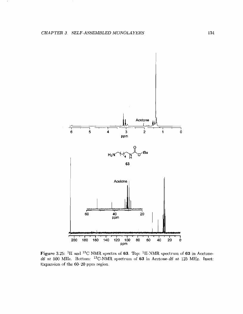
CHAPTER 3. SELF-ASSEMBLED MONOLAYERS 134
I
6I
5I I4 3
ppm
I
2Io
63
Acetone
I fJ,
I
I IIi i i
60 40 20ppm
I Ii I i I i I I i I i I i I I I I I
200 180 160 140 120 100 80 60 40 20 0ppm
Figure 3.25: IH and 13C NMR spectra of 63. Top: IH-NMR spectrum of 63 in Acetoned6 at 500 MHz. Bottom: 13C-NMR spectrum of 63 in Acetone-d6 at 125 MHz. Inset:Expansion of the 60-20 ppm region.
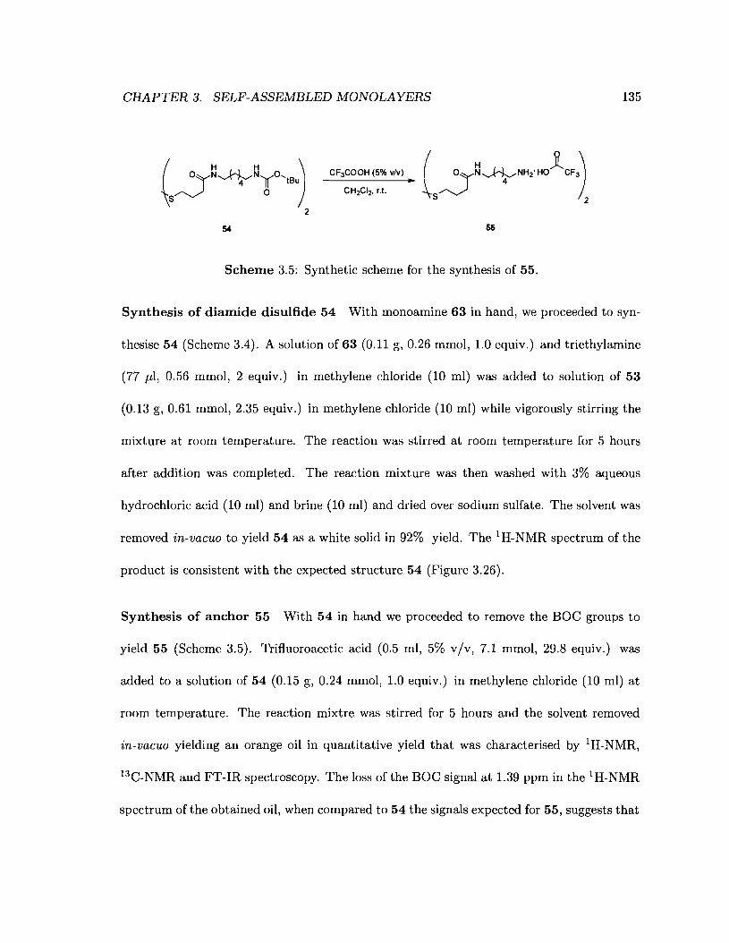
CHAPTER 3. SELF-ASSEMBLED MONOLAYERS 135
{S~~4~t"B)2
54 55
Scheme 3.5: Synthetic scheme for the synthesis of 55.
Synthesis of diamide disulfide 54 With monoamine 63 in hand, we proceeded to syn-
thesise 54 (Scheme 3.4). A solution of 63 (0.11 g, 0.26 mmol, 1.0 equiv.) and triethylamine
(77 J.d, 0.56 mmol, 2 equiv.) in methylene chloride (10 ml) was added to solution of 53
(0.13 g, 0.61 mmol, 2.35 equiv.) in methylene chloride (10 ml) while vigorously stirring the
mixture at room temperature. The reaction was stirred at room temperature for 5 hours
after addition was completed. The reaction mixture was then washed with 3% aqueous
hydrochloric acid (10 ml) and brine (10 ml) and dried over sodium sulfate. The solvent was
removed in-vacuo to yield 54 as a white solid in 92% yield. The 1H-NMR spectrum of the
product is consistent with the expected structure 54 (Figure 3.26).
Synthesis of anchor 55 With 54 in hand we proceeded to remove the BOC groups to
yield 55 (Scheme 3.5). Trifluoroacetic acid (0.5 ml, 5% v/v, 7.1 mmol, 29.8 equiv.) was
added to a solution of 54 (0.15 g, 0.24 mmol, 1.0 equiv.) in methylene chloride (10 ml) at
room temperature. The reaction mixtre was stirred for 5 hours and the solvent removed
in-vacuo yielding an orange oil in quantitative yield that was characterised by 1H-NMR,
13C-NMR and FT-IR spectroscopy. The loss of the BOC signal at 1.39 ppm in the 1H-NMR
spectrum of the obtained oil, when compared to 54 the signals expected for 55, suggests that

CHAPTER 3. SELF-ASSEMBLED MONOLAYERS
54Acetone
ppm
Acetone
136
ppm
Io
Figure 3.26: IH-NMR spectrum of 54 in acetone-d6 at 500 MHz. Inset: Expansion of the3.5 to 1.0 ppm region.
both amines have been fully deprotected. All the expected signals for the methylene protons
are present in the 1H-NMR spectrum (Figure 3.27a). Two broad signals at 13.6 and 12.0 ppm
totaling 0.6 integration units j are observed that we hypothesise to correspond to the three
ammonium protons. Two multiplets at 8.34 and 7.73 ppm totaling 1.21 integration units
were also observed but these peaks could not be assigned. The reaction product contained
jSignals integrated with respect to the signal at 1.8 ppm. The reference signal is assigned a value of 2integration units.

CHAPTER 3. SELF-ASSEMBLED MONOLAYERS 137
small amounts of other identifiable impurities, notably, 2-methyl-2-propanol (peaks at 2.09
and 1.28 ppm, 5 m% estmated by integration).
The quadruplet at 160.46 ppm (C=O, Jl = 36 Hz) in the 13C-NMR spectrum of 55
suggests the trifluoroacetic acid salt of the product has been isolated.k
The FT-IR spectrum of the final product shows bands characteristic of a primary am
monium ion at 3298.6, 3093.2, 1550.6 and 1130.0 cm-1 j the trifluoroacetate anion at 1635.9
and 1195.0 cm-1; and amide 1670.9 cm-1 (Amide I).
It was concluded from IH-NMR, 13C-NMR and FT-IR spectra that the isolated oil was
the desired product 55.
Conclusion We have shown that amide-containing dialkyldisulfides could be conveniently
synthesised in two steps from dithiodiester 53 as trifluoroacetic acid salts in excellent yields.
This method is amenable to a wide variety of diamines and dithiodiesters allowing for the
variation of the position of the amide linkage within the alkyl chain of the anchor. Such
molecules should readily allow the modulation of the electronic and structural properties of
self-assembled monolayers as described in Sections 3.2.2 and 3.3.2.2. Compound 55 is also
the first of a new series of compounds never before synthesised. It is, however, analogous to
the amide-containing dialkyldisulfides prepared by Bilewicz and coworkers (Figure 3.28).174
kThe splitting of the carbon signals at 160.46 ppm is due to the strong coupling of 19F to 13C.
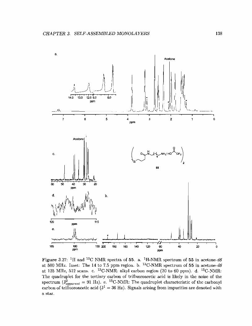
CHAPTER 3. SELF-ASSEMBLED MONOLAYERS 138
a.Acetone
I , , i j U i
14.0 13.0 12.0 9.0 8.0ppm
7 6 5 4ppm
3 2 o
Acetone
I
c.
55
60 50 40 30 20ppm
b.
o2060ppm
U_._"T",---.----,.,----.----,,....-.--r-..--,----r--I,',.r(-...,....--,----,----,---.------,
155 200 180 160 140 120
i
115
160ppm
ppm
i
120
165
Figure 3.27: IH and 13C NMR spectra of 55. a. IH-NMR spectrum of 55 in acetone-d6at 500 MHz. Inset: The 14 to 7.5 ppm region. b. 13C-NMR spectrum of 55 in acetone-d6at 125 MHz, 512 scans. c. 13C-NMR: alkyl carbon region (20 to 60 ppm). d. 13C-NMR:The quadruplet for the tertiary carbon of trifluoroacetic acid is likely in the noise of thespectrum (J~pparent = 91 Hz). e. 13C-NMR: The quadruplet characteristic of the carbonylcarbon of trifluoroacetic acid (Jl = 36 Hz). Signals arising from impurities are denoted witha star.
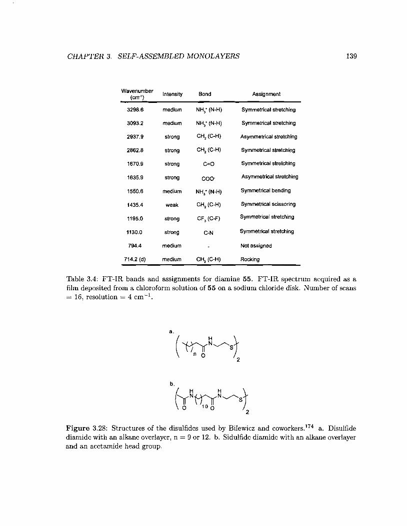
CHAPTER 3. SELF-ASSEMBLED MONOLAYERS 139
C=O Symmetrical stretching
Bond Assignment
NH; (N-H) Symmetrical stretching
CH2 (C-H) Symmetrical stretching
Not assigned
RockingCH2 (C-H)
C-N Symmetrical stretching
COO· Asymmetrical stretching
NH3
+ (N-H) Symmetrical stretching
CH2 (C-H) Asymmetrical stretching
NH3+ (N-H) Symmetrical bending
CH2
(C-H) Symmetrical scissoring
CF3 (C-F) Symmetrical stretching
WavenumberIntensity
(ern")
3298.6 medium
3093.2 medium
2937.9 strong
2862.8 strong
1670.9 strong
1635.9 strong
1550.6 medium
1435.4 weak
1195.0 strong
1130.0 strong
794.4 medium
714.2 (d) medium
Table 3.4: FT-IR bands and assignments for diamine 55. FT-IR spectrum acquired as afilm deposited from a chloroform solution of 55 on a sodium chloride disk. Number of scans= 16, resolution = 4 cm -1.
Figure 3.28: Structures of the disulfides used by Bilewicz and coworkers.174 a. Disulfidediamide with an alkane overlayer, n = 9 or 12. b. Sidulfide diamide with an alkane overlayerand an acetamide head group.

CHAPTER 3. SELF-ASSEMBLED MONOLAYERS
3.5 General experimental
3.5.1 Synthesis
3.5.1.1 Solvents and chemicals
140
Hexanes, ethyl acetate and diethyl ether were obtained from Caledon and used without
purification. Triethylamine, pyridine and tetrahydrofuran were obtained from Anachemia
and were distilled before use. All deuterated solvents were obtained from Cambridge Iso
tope Laboratories, Inc.. Silica gel 60 was obtained from EMD (product # 9385 - 3). Di
tert-butyldicarbonate, 4-aminothiophenol, potassium thioacetate, 4-aminophenyl disulfide,
cystamine dihydrochloride, tert-butyl-dimethylsilyl chloride, 4-dithiodibutyric acid and N
hydroxysuccinimide were obtained from Aldrich. Triftuoroacetic acid, hydroquinone and
lithium aluminium hydride were obtained from Sigma-Aldrich. 1,6-diaminohexane was ob
tained from Fluka. 5-bromopentanenitrile, 6-bromohexanenitrile and 7-bromoheptanenitrile
were obtained from TCI America. All chemicals were used without purification.
3.5.1.2 Characterisation
All FT-IR measurements of molecules were made on a Bomem M-B series spectrometer. All
molecules were measured as a KBr pellet or as films deposited from chloroform on a sodium
chloride disc. Each spectrum is the average of 32 or 64 measurements. NMR spectra (lH
and 13C) were acquired on a Varian Inova 500 MHz spectrometer or a Brueker Avance 600
MHz spectrometer. Melting points were taken using a Electrothermal Mel Temp@ melting
point apparatus and were not corrected. CHN elemental analysis was performed on a Carlo
CHAPTER 3. SELF-ASSEMBLED MONOLAYERS
Erba Model 1106 CHN analyzer at Simon Fraser University.
3.5.2 Monolayers
141
Only 18.3 MO water and 99% ethanol were used for rinsing of the modified and unmodified
gold slides. All buffers made using 18.3 MO water. Concentrated sulfuric acid was obtained
from Anachemia and 30% hydrogen peroxide solution was obtained from Caledon.
3.5.2.1 Substrate preparation
Glass slides coated with a 50 A chromium underlayer and aI, 000 A gold layer were
obtained from EMF corporation (product # CA134, Figure 3.29) and cut to between 1.5
and 2.0 cm in length by 2.54 cm wide. Prior to monolayer deposition, each gold slide was
cleaned in piranha solution (3 : 1 conc. H2S04 /30 % H2 0 2 ) at 90°C for 5 minutes in a
teflon container and rinsed with copious amounts of 18.3 MO water. The slides were then
rinsed with copious amounts of anhydrous ethanol, dried under a stream of dry nitrogen,
and stored in clean teflon containers until required for use.
3.5.2.2 Preparation of self-assembled monolayers
A cleaned gold slide was immersed in a 1 mM ethanolic solution of the corresponding thiol or
disulfide for one to two days. The slide was then rinsed with copious amounts of anhydrous
ethanol and dried under a stream of dry nitrogen. The modified plates were stored in clean
teflon containers until required for use.
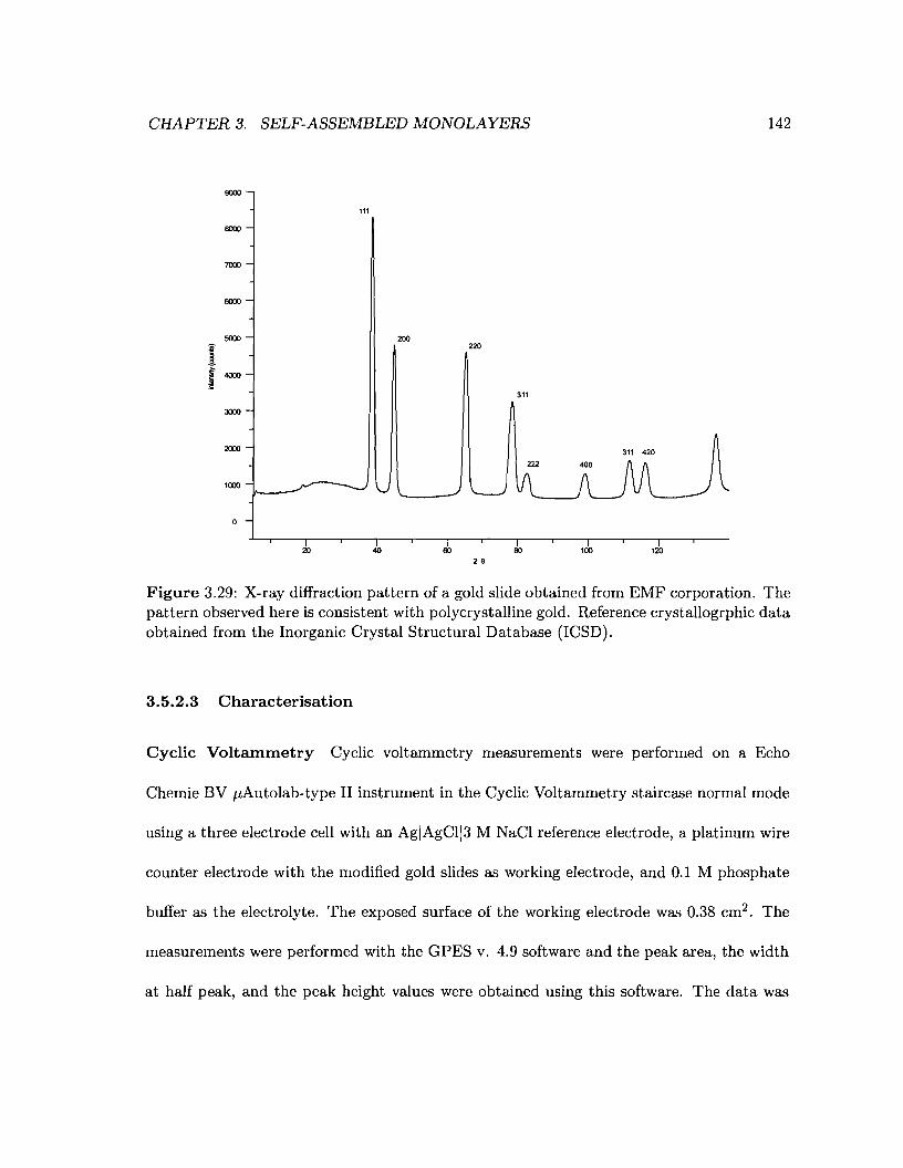
CHAPTER 3. SELF-ASSEMBLED MONOLAYERS 142
9000
111
IlOOO
7000
IlOOO
5000 200
I 220
r 4000
311
:JOOO
2000 311 420
1000
20 40 60 BO 100 12026
Figure 3.29: X-ray diffraction pattern of a gold slide obtained from EMF corporation. Thepattern observed here is consistent with polycrystalline gold. Reference crystallogrphic dataobtained from the Inorganic Crystal Structural Database (ICSD).
3.5.2.3 Characterisation
Cyclic Voltammetry Cyclic voltammetry measurements were performed on a Echo
Chemie BV j.lAutolab-type II instrument in the Cyclic Voltammetry staircase normal mode
using a three electrode cell with an AgIAgCl13 M NaCI reference electrode, a platinum wire
counter electrode with the modified gold slides as working electrode, and 0.1 M phosphate
buffer as the electrolyte. The exposed surface of the working electrode was 0.38 cm2 . The
measurements were performed with the GPES v. 4.9 software and the peak area, the width
at half peak, and the peak height values were obtained using this software. The data was
CHAPTER 3. SELF-ASSEMBLED MONOLAYERS
plotted using Origin v. 6.1.
143
Fourier transform infrared spectroscopy All FT-IR measurements of monolayers
were performed using a ThermoNicolet Nexus-IR 560 spectrometer equipped with a mer
cury cadmium telluride (MCT) detector and a KBr beam splitter fitted with a specular
reflectance accessory and a polariser set at 0° (polariser situated before the sample). Dry
air was purged through the instrument chamber for at least 2 h before each measurement
and a strong air flow was maintained while taking the measurement. Each measurement
consisted of 1024 scans acquired using the single beam setting at 2 cm-1 resolution. A back
ground spectrum was collected and subtracted from the measured monolayer spectrum. The
resulting spectrum was subjected to baseline correction and smoothed as appropriate using
the OMNIC software (v. 6.0a). The resulting data was plotted using Origin v. 6.1. Un
less stated otherwise, peak-picking the spectra was done on immediately after background
substraction and before any baseline correction or smoothing.
3.5.3 Experimental
bis(4-(tert-butyldimethylsilyloxy)phenyl) 4,4-disulfanediylbis(4,1-pheneylene)
dicarbamate (43) Triphosgene (0.5 g, 1.7 mmol, 0.8 equiv.) and dry pyridine (1.2 ml,
14.4 mmol, 6.5 equiv.) were added to dry methylene chloride (200 ml) under nitrogen and
cooled to -20°C. A solution of 1 (0.5 g, 2.2 mmol, 1.0 equiv.) in dry methylene chloride
(45 ml) was added dropwise over 45 minutes. A solution of 4-aminophenyl disulphide (0.4
g, 1.6 mmol, 0.7 equiv.) in dry methylene chloride (45 ml) was then added dropwise over
CHAPTER 3. SELF-ASSEMBLED MONOLAYERS 144
20 minutes. The resulting solution was stirred overnight and washed with a 1% aqueous
hydrochloric acid, water and brine (50 ml each). The organic extracts were dried over
sodium sulphate and the solvent evaporated in-vacuo to afford a yellow oil (quantitative)
which was then purified by two flash chromatography columns (30/1 toluene / ethyl acetate
followed by 5/1, hexanes / ethyl acetate) as a light yellow solid (0.5 g, 60%). IH-NMR (500
MHz, CDCI3) & (ppm) 7.42 (m, 8H), 7.02 (d, J = 9 Hz, 4H), 6.91 (s, 2H), 6.83 (d, J = 9 Hz,
4H), 0.98 (s, 18H), 0.20 (s, 12H); 13C-NMR (125 MHz, CDCI3) & (ppm) 153.3, 151.7, 144.3,
137.3, 131.7, 130.5, 122.3, 120.5, 119.1, 25.6, 18.2, -4.5; IR (KBr) 1725.35 cm-1 (C=O),
1499.97 cm-1 (HQ); E.A. Calcd. C 60.93, H 6.46, N 3.74, Expt. C 61.01, H 6.64, N 3.59;
m.p. 7275°C; .
bis(4-hydroxyphenyl) 4,4'-disulfanediylbis(4,1-phenylene)dicarbamate (44) A so
lution of 43 (0.5 g, 0.67 mmol, 1.0 equiv.) in MeOH/H20/HCI (95:4:1, 50 ml) was stirred
for 3 hours at room temperature. The solvent was evaporated in-vacuo and the residue
taken up in ethyl acetate (200 ml) and washed with water and brine (50 ml each). The
organic extract was dried over sodium sulfate and the solvent removed in-vacuo affording
an off-white solid (0.33 g, 95%). IH-NMR (500 MHz, DMSO-d6) & (ppm) 10.26 (s, 2H), 9.40
(s, 2H), 7.48 (m, 8H), 6.99 (ABq, J = 8.5 Hz, 4H), 6.75 (ABq, J = 8.5 Hz, 4H); 13C-NMR
(125 MHz, DMSO-d6) & (ppm) 154.4, 151.8, 142.0, 138.6, 131.0, 128.6, 123.1, 122.2, 115.0;
IR (KBr) 1748.49 cm-1 (C=O), 1501.23 cm-1 (HQ); E.A. Calcd. C 59.99, H 3.87, N 5.38,
Expt. C 59.62, H 3.76, N 5.21; m.p. 194(d)OC.
CHAPTER 3. SELF-ASSEMBLED MONOLAYERS 145
4-hydroxyphenyl 4-mercaptophenylcarbamate (45) To a solution of 44 (49.6 mg,
0.096 mmol, 1.0 equiv.) in glacial acetic acid (5 ml) was added zinc dust (0.51 g, 7.9 mmol,
81.9 equiv.). The mixture was refluxed for 7 hours at 90°C and filtered through celite and
washed with toluene. Toluene was added and the solvent removed in-vacuo to afford an
off-white solid (48 mg, 97%). IH-NMR (500 MHz, DMSO-d6) 0 (ppm) 11.94 (br. s, IH),
9.81 (br. s, IH), 9.38 (s, IH), 7.17 (m, 4H), 6.96 (ABq, J = 8.5 Hz, 2H), 6.74 (ABq, J = 9
Hz,2H)
bis(2,5-dioxopyrrolidin-l-yl) 4,4'-dithiodibutanoate (53) A solution of 4,4'-dithio
dibutyric acid (0.48 g, 1.99 mmol, 1 equiv.), l-Ethyl-3-(3-dimethyllaminopropyl)carbodiimide
hydrochloride (0.95 g, 4.96 mmol, 2.49 equiv.) and N-hydroxysuccinimide (0.50 g, 4.31
mmol, 2.17 equiv.) in dry acetonitrile (20 ml) and dry tetrahydrofuran (40 ml) was stirred
at room temperature for 20 hours. The solvent was reduced in-vacuo and the remaining
solution taken up in ethyl acetate (100 ml) and washed with water (50 ml) and brine (20
ml). The organic layer was dried over sodium sulfate and the solvent removed in-vacuo to
afford 53 as a white solid in (0.77 g, 90%). 1H-NMR (500 MHz, CDCl3) 0 (ppm) 2.82 (br. s,
8H), 2.75 (m, 8H), 2.14 (m, 4H); 13C-NMR (125 MHz, Acetone-d6) 0 (ppm) 171.50, 170.25,
38.07, 30.90, 27.25, 25.90; IR (KBr) 1733.51 cm-1 (C=O). E.A. Calcd. C 44.44, H 4.66, N
6.48, Expt. C 44.65, H 4.71, N 6.50; m.p. 115~116°C.
tert-butyl 6-aminohexylcarbamate (63) 63 was synthesised using a literature proce
dure. 206 A solution of di-tert-butyl dicarbonate (1.26 g, 5.76 mmol, 1 equiv.) in chloroform
(10 ml) was added dropwise to a a solution of 1,6-diaminohexane (3.34 g, 28.8 mmol, 4.99
CHAPTER 3. SELF-ASSEMBLED MONOLAYERS 146
equiv.) in chloroform (100 ml) at O°C under vigorous stirring. After the reaction was
complete by TLC the solvent was removed in-vacuo. The residue was taken up in ethyl
acetate and washed three times with half-saturated brine and the organic layer was dried
over sodium sulfate. Removal of the solvent in-vacuo afforded a colourless oil (1.2 g, 97%).
IH-NMR (500 MHz, Acetone-d6) 5 (ppm) 5.96 (br. s, IH), 3.15 (t, J = 7 Hz, 2H), 3.05 (q,
J = 7 Hz, 2H), 2.84 (br. s, IH), 1.44 (m, 17H); 13C-NMR (125 MHz, Acetone-d6) 5 (ppm)
157.62, 79.17, 52.72, 42.03, 32.67, 31.85, 30.83, 29.64, 28.97, 28.44.
4,4'-disulfanediylbis(N-(6-(tert-butyl carbamate)hexyl)butanamide) (54) A so
luttion of 63 (0.11 g, 0.26 mmol, 1.0 equiv.) in methylene chloride (10 ml) was added
dropwise to a stirred solution of 53 (0.13 g, 0.61 mmol, 2.35 equiv.) in methylene chloride
(10 ml) at room temperature. The solution was stirred for 5 hours at room temperature.
The volume was made to 100 ml with methylene chloride and the reaction mixture was
washed with 3% aqueous hydrochloric acid and brine (30 ml each). The organic layer was
dried over sodium sulfate and the solvent removed in-vacuo to afford a white solid (0.15 g,
92%). IH-NMR (500 MHz, Acetone-d6) 5 (ppm) 7.18 (br. s, 2H), 5.98 (br. s, 2H), 3.18 (dd,
J = 6.9, 12.7 Hz, 4H), 3.05 (dd, J = 6.7, 13.1 Hz, 4H), 2.74 (t, J = 7 Hz, 4H), 2.28 (t, J =
7.2 Hz, 4H), 1.48 (m, 9H), 1.39 (s, 19H), 1.33 (m, 8H); 13C-NMR (125 MHz, Acetone-d6)
5 (ppm) 173.12, 157.70, 79.27, 41.93, 40.59, 39.89, 36.01, 31.82, 31.44, 31.34, 29.68, 28.25,
28.12,26.95; IR (KBr) cm-1 (C=O). E.A. Calcd. C 56.75, H 9.21, N 8.82, Expt. C 56.54,
H 9.15, N 8.40; m.p. 89-90°C.
CHAPTER 3. SELF-ASSEMBLED MONOLAYERS 147
4,4'-disulfanediylbis(N-(6-aminiumhexyl)butanamide trifluoroacetate.) (55) Tri
fluoroacetic acid (0.5 ml, 5% v/v, 7.1 mmol, 29.8 equiv.) was added to a solution of 54 (0.15
g, 0.24 mmol, 1.0 equiv.) in methylene chloride (10 ml) at room temperature. The reaction
mixture was stirred for 5 hours. Toluene was added (5 ml) and the solvent was removed
in-vacuo affording an orange oil (166.5 mg, quant.). IH-NMR (500 MHz, Aeetone-d6) 6
(ppm) 3.79 (m, 2H), 3.18 (m, 4H), 2.73 (m, 4H), 2.56 (m, 4H), 2.33 (m, 4H), 1.97 (m, 4H),
1.80 (m, 4H), 1.45 (m, 6H); 13C-NMR (125 MHz, Aeetone-d6) 6 (ppm) 172.71, 159.9 (q, J
= 36 Hz), 117.12 (q, J = 91 Hz), 47.59, 39.94, 39.03, 38.06, 34.44, 27.51, 26.30, 25.49; IR
(KBr) 1670.9 em-I (C=O), 1195.0 em-I.
Chapter 4
Future Work
The work presented in this thesis has laid the foundations for studying the feasability of
reagentless electrochemically addressable arrays by providing the materials that we believe
to be necessary to our vision. The present chapter will outline various experiments that
we envision would serve to test the feasability of reagent less electrochemically addressable
arrays.
4.1 Coupling monomers to anchor molecules on a gold sur
face
4.1.1 Testing the surface chemistry
In Chapter 3.4.1 we have shown that monolayers formed from 4-aminothiophenol derivatives
are unsuitable for use as anchors in microarrays, hence monolayers formed from either
148
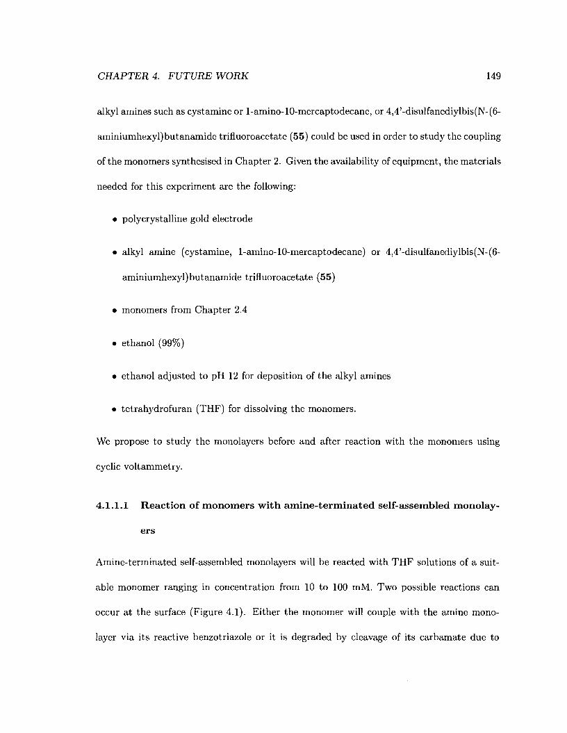
CHAPTER 4. FUTURE WORK 149
alkyl amines such as cystamine or l-amino-lO-mercaptodecane, or 4,4'-disulfanediylbis(N-(6
aminiumhexyl)butanamide trifluoroacetate (55) could be used in order to study the coupling
of the monomers synthesised in Chapter 2. Given the availability of equipment, the materials
needed for this experiment are the following:
• polycrystalline gold electrode
• alkyl amine (cystamine, l-amino-lO-mercaptodecane) or 4,4'-disulfanediylbis(N-(6
aminiumhexyl)butanamide trifluoroacetate (55)
• monomers from Chapter 2.4
• ethanol (99%)
• ethanol adjusted to pH 12 for deposition of the alkyl amines
• tetrahydrofuran (THF) for dissolving the monomers.
We propose to study the monolayers before and after reaction with the monomers using
cyclic voltammetry.
4.1.1.1 Reaction of monomers with amine-terminated self-assembled monolay-
ers
Amine-terminated self-assembled monolayers will be reacted with THF solutions of a suit
able monomer ranging in concentration from 10 to 100 mM. Two possible reactions can
occur at the surface (Figure 4.1). Either the monomer will couple with the amine mono
layer via its reactive benzotriazole or it is degraded by cleavage of its carbamate due to
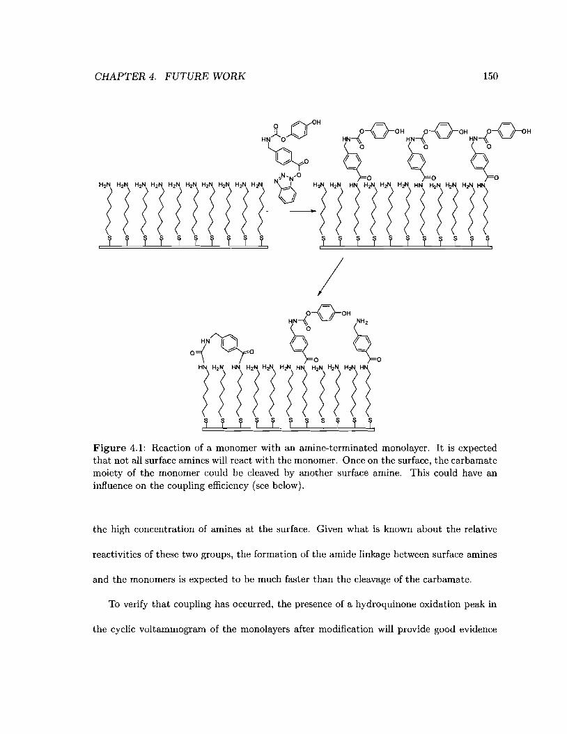
CHAPTER 4. FUTURE WORK 150
Figure 4.1: Reaction of a monomer with an amine-terminated monolayer. It is expectedthat not all surface amines will react with the monomer. Once on the surface, the carbamatemoiety of the monomer could be cleaved by another surface amine. This could have aninfluence on the coupling efficiency (see below).
the high concentration of amines at the surface. Given what is known about the relative
reactivities of these two groups, the formation of the amide linkage between surface amines
and the monomers is expected to be much faster than the cleavage of the carbamate.
To verify that coupling has occurred, the presence of a hydroquinone oxidation peak in
the cyclic voltammogram of the monolayers after modification will provide good evidence
CHAPTER 4. FUTURE WORK 151
supporting the predicted reactivity to form the desired amide linkages. However, it is
anticipated that if the carbamate moiety reacts with the surface amines to form a urea
moiety, the cyclic voltammogram should not exhibit the oxidation peak characteristic of the
oxidation of hydroquinone since the hydroquinone group would have already been displaced.
As such, a negative response, characterised by the absence of hydroquinone oxidation peak
in the cyclic voltammogram, could be interpreted as either a lack of coupling or that the
carbamate moiety was cleaved. Other tests such as MALDI-TOF or HPLC determination
of the surface species after thiol exchange should be carried out to verify the outcome. In
order to limit the probability of hydrolytic cleavage of the carbamate moiety at the surface,
all solvents used in this experiment should be dry. After each coupling event, it may be best
if all the remaining free amines were capped using a capping agent such as the one shown
in Figure 4.2.
4.1.1.2 Cyclic voltammetry studies
Integration of the hydroquinone oxidation peak in the cyclic voltammogram of a monolayer
of mercaptoalkylamines after reaction with the first monomer will provide the base value for
evaluating the efficiency of monomer coupling to surface-amine. If all amines are acylated
by a monomer, the integration value for the second coupling should match that of the first.
The coupling efficiency can then be formulated as follows:
(4.1)

CHAPTER 4. FUTURE WORK 152
Figure 4.2: Capping of unreacted surface amines after reaction of a monomer with an amineterminated monolayer. Capping the unreacted amines prevents further surface chemistry.This could have a beneficial influence on the coupling efficiency (see below).
where Qn is the integration of the hydroquinone oxidation peak from the nth cyclic voltam-
mogram and Q1 is the integration of the hydroquinone oxidation peak from the first cyclic
voltammogram. Its value is expected to always be lower than one. Repeating such measure-
ments for a significant number of coupling events (5 to 10) could yield a coupling efficiency
profile with respect to the distance of the protected amine from the electrode surface as
reflected by the number of couplings (Figure 4.3).
01234567Number of cycles
-------CHAPTER 4. FUTURE WORK
01234567Number of cycles
a.
~ 1.0
.~'-'Iew01
.!:::a.:::>
80.0-+--r--r-.,r--.--or--.---.--
01234567Number of cycles
c.
>. 1.0'-'l:III'0Iew01
.!:::a.:::>
8O.O-+....,...~--.,-r--,....--.---.--
b.
~ 1.0l:.!!!~w01.!:::a.:::>
80.0 -+....,...~-.,-.---or--.---.--
o 1 234 567Number of cycles
d.
153
Figure 4.3: Possible coupling efficiency (Ecn ) profiles. a. E Cn is close to 100% everytime. b.Ecn decreases linearly with increasing distance from the electrode surface. c. ECn decreasesin a slow exponential manner. d. ECn decreases sharply for the first coupling events andslowly after that.
4.2 Testing the array
Having tested the electrochemical process on a single electrode, we envisage using a 4 elec-
trode array, as a proof of concept, to test the feasibility of developing a reagentless electro-
chemically addressable array (Figure 4.4). A potential would be applied to, at most, three
of the electrodes per cycle, thus only exposing amines on these electrodes. Then, all four
electrodes would be incubated in a solution of a given monomer simultaneously. The process
would be repeated from between 3 and 5 times varying only the electrode(s) to which the
potential is applied. Table 4.1 presents an example of this experiment. The efficiency of each
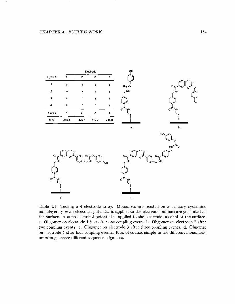
CHAPTER 4. FUTURE WORK 154
Cycle #
y
2 n
3 n
4 n
# units
MW 346.4
Electrode Q2 3 4
Y Y Y
oA~01"0y y y
2" 2" ~""In y y I: OHn n y
o ""'NH o NH
2 3 4 ~ ~479.6 612.7 745.8 j j
a. b.
c. d.
Table 4.1: Testing a 4 electrode array. Monomers are reacted on a primary cystaminemonolayer. y = an electrical potential is applied to the electrode, amines are generated atthe surface. n = no electrical potential is applied to the electrode, alcohol at the surface.a. Oligomer on electrode 1 just after one coupling event. b. Oligomer on electrode 2 aftertwo coupling events. c. Oligomer on electrode 3 after three coupling events. d. Oligomeron electrode 4 after four coupling events. It is, of course, simple to use different monomericunits to generate different sequence oligomers.
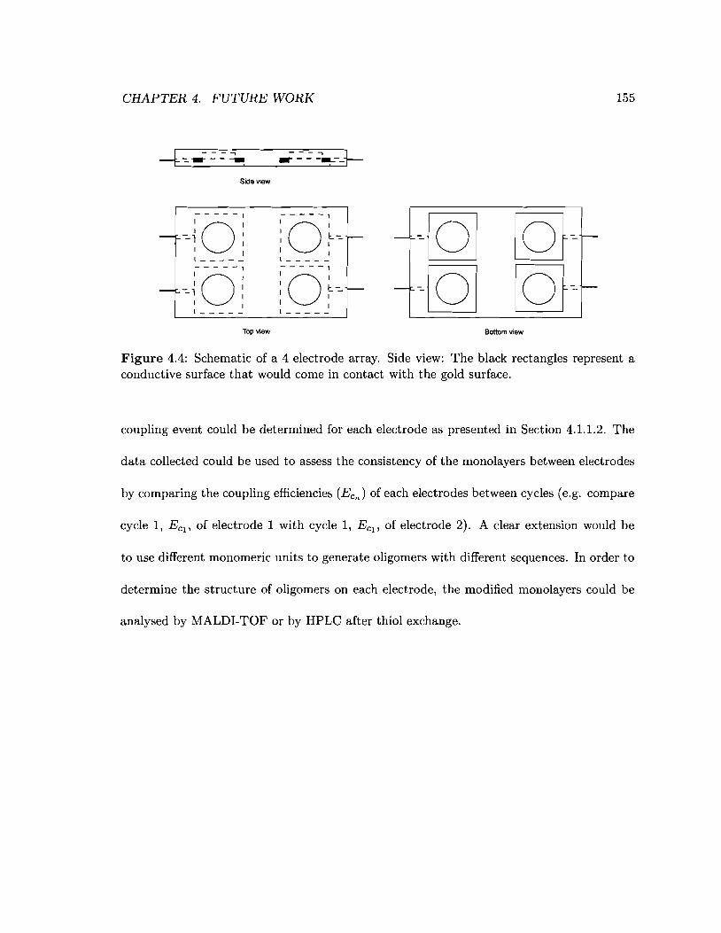
CHAPTER 4. FUTURE WORK 155
Side view
-- --~--+-
-
-
;-0----:-=-1 :
I I1 _
1-
0----;
-=- ~ :I I1 _
Top view
;-0----;: ~-=- -I 11 _
;-0----;: ~-=- -I I1 _
-
-
Bottom view
Figure 4.4: Schematic of a 4 electrode array. Side view: The black rectangles represent aconductive surface that would come in contact with the gold surface.
coupling event could be determined for each electrode as presented in Section 4.1.1.2. The
data collected could be used to assess the consistency of the monolayers between electrodes
by comparing the coupling efficiencies (EcJ of each electrodes between cycles (e.g. compare
cycle 1, Ecl' of electrode 1 with cycle 1, Ecl' of electrode 2). A clear extension would be
to use different monomeric units to generate oligomers with different sequences. In order to
determine the structure of oligomers on each electrode, the modified monolayers could be
analysed by MALDI-TOF or by HPLC after thiol exchange.

Appendix A
Visual index of compounds
156
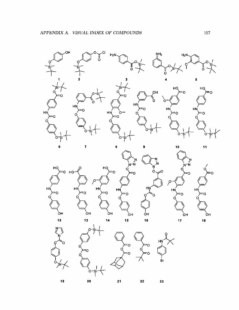
APPENDIX A. VISUAL INDEX OF COMPOUNDS 157
0(0H
~?-Si-
T
p-{HHN
)=0
4 5
9
12 13 14
[(1 O-~i+N PoAo
¢ 0)=0
q-~l+/°;Si-f19 20
;}O HO~
>=> >=>HN HN)=0 )=0
o 0
Q QOH OH
11
/opO
HN)=0
o
QOH
18
10
~,~,N-N
o
Ort'IVHN
)=0o
QOH
17
2322
n-~~_N~
Z¢~O
-?I::::::,...
OH
16
21
8
~~N-N
HO Q?-O=0 pOHN HN
)=0 )=0o 0
Q QOH OH
15
76

APPENDIX A. VISUAL INDEX OF COMPOUNDS
q. 9'2H'~1 2H'HOT'
I~
QHN .0
pO NH2
6(0, ~ 1.0 HN
1.0 $0H)r=O O? ° U ~I (;00 :::::-...
QI
h
:tOH
24 25 26 27 28 29
158
HX ~ HXY y ° YOH 9):0I ~ 1 ~ I 1 ~ I h
h ~ .0
OH 6 6 6 630 31 32 33 34 35 36
9~ H~ Q ,R~z~~I: I: 0 ~ ~9
N" NI~ ?oN-:::-N I~~ OH I~
h .0 OH
HN "
°"9 °"9o~ °9 °"9 o"¢~ I~ I~I h ~ .0 I~I~~
OH OH OH h
OHOH OH
37 38 39 40 41 42
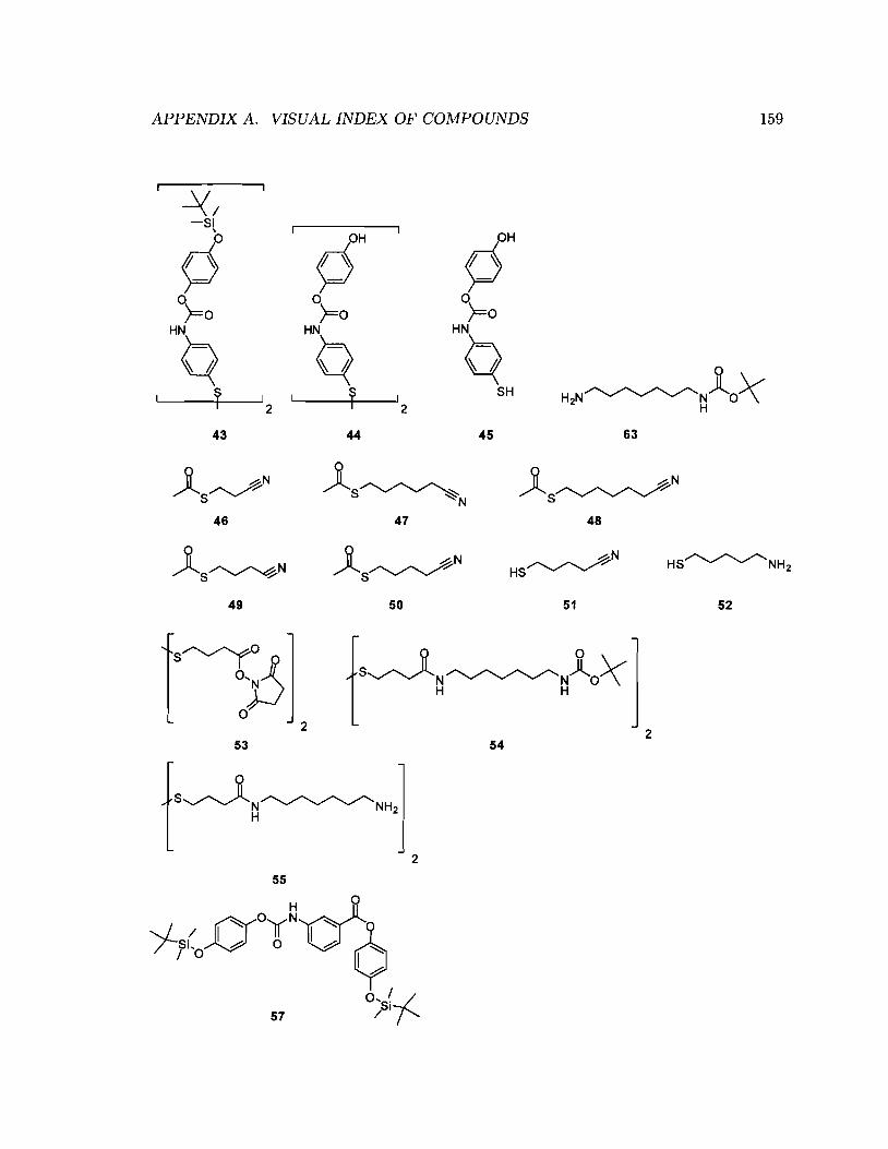
APPENDIX A. VISUAL INDEX OF COMPOUNDS 159
~/-Si
\
0 pH pHP ~ ~ ~ ~
°)=0 °)=0 °)=0HN HN HN
Q Q Qr I r I
SH2 2
43 44 45 63
)(~NS
46
)(S~'-':N
47
)(~NS
48
)(S~N49
)(~NS
50 51
HS~NH2
52
532
° °S~t.N~N)l.OX:H H
542
55
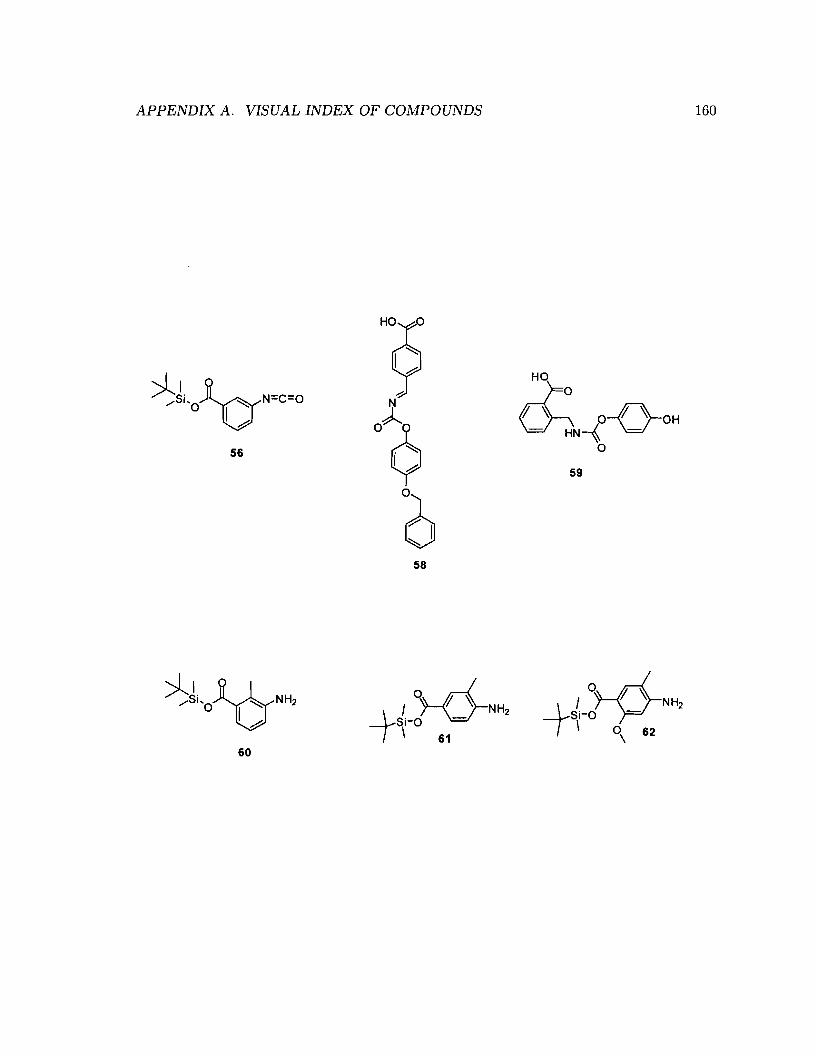
APPENDIX A. VISUAL INDEX OF COMPOUNDS 160
56
60
H
9I~~..-::
oJ¢I~~
658
HO
rr o-o-~OH~N-{ -o
59
References
1. Kresge, A. J. Ace. Chem. Res. 1987, 20, 364-370.
2. Greer, J.; Erickson, J. W.; Baldwin, J. J.; Varney, M. D. J. Med. Chem. 1994, 37,1035-1054.
3. Bowen, J. P.; Charifson, P. S.; Fox, P. C.; Kontoyanni, M.; Miller, A. B.; Schnur, D.;Stewart, E. L.; Vandyke, C. J. Clin. Pharma. 1993, 33, 1149-1164.
4. Schneider, G. Curro Med. Chem. 2002, 9, p2095 - 2101.
5. Schneider, G.; Fechner, U. Nat. Rev. Drug Discov. 2005, 4, 649-663.
6. Dobson, C. M. Nature 2004, 432, 824-828.
7. Furka, A. Drug Dev. Res. 1995, 36, 1-12.
8. Merrifield, R B. J. Am. Chem. Soc. 1963, 85, 2149-2154.
9. Brahm, D.; Metzger, S.; Bhargava, A.; MIler, 0.; Lieb, F.; Waldmann, H. Angew.Chem., Int. Ed. 2002, 41, 307-311.
10. Brohm, D.; Philippe, N.; Metzger, S.; Bhargava, A.; Muller, 0.; Lieb, F.; Waldmann, H.J. Am. Chem. Soc. 2002,124,13171--13178.
11. Zuckermann, R N.; Martin, E. J.; Spellmeyer, D. C.; Stauber, G. B.; Shoemaker, K. R;Kerr, J. M.; Figliozzi, G. M.; Goff, D. A.; Siani, M. A.; et al., J. Med. Chem. 1994,37, 2678-2685.
12. Willoughby, C. A.; Hutchinsa, S. M.; Rosauera, K. G.; Dhara, M. J.; Chapmana, K. T.;Chicchib, G. G.; Sadowskib, S.; Weinbergc, D. H.; Pateld, S.; Malkowitzb, L.;Di Salvoc, J.; Pacholokb, S. G.; Chengc, K. Biorg. Med. Chem. Lett. 2002, 12, 93-96.
13. Namuswe, F.; Goldberg, D. P. Chem. Commun. 2006, 2326-2328.
14. Hughes, M. D.; Zhang, Z.; Sutherland, A. J.; Andrew, J.; Santos, F.; Albert, F.;Hine, A. V. Nucl. Acids Res. 2005, 33, e32.
15. Konings, D.; Wyatt, J.; Ecker, D.; Freier, S. J. Med. Chem. 1996, 39, 2710-2719.
161

REFERENCES 162
16. Griffey, R H.; An, H. Y.; Cummins, L. L.; Gaus, H. J.; Haly, B.; Herrmann, R;Cook, P. D. Tetrahedron 1998, 54,4067-4076.
17. Patek, M.; Safar, P.; Smrcina, M.; Wegrzyniak, E.; Bjergarde, K; Weichsel, A.;Strop, P. J. Comb. Chem. 2004, 6,43-49.
18. Erb, E.; Janda, K; Brenner, S. Proc. Natl. Acad. Sci. U. S. A. 1994, 91, 11422-11426.
19. Porco, J. A. Comb. Chem. High Throughput Screening 2000, 3, 93-102.
20. Bryan, M. c.; Fazio, F.; Lee, H. K; Huang, C. Y.; Chang, A.; Best, M. D.;Calarese, D. A.; Blixt, 0.; Paulson, J. C.; Burton, D.; Wilson, 1. A.; Wong, C. H.J. Am. Chem. Soc. 2004, 126, 8640-8641.
21. Beeler, A. B.; Su, S.; Singleton, C. A.; Porco, J. A. J. Am. Chem. Soc. 2007, 129,1413-1419.
22. Pirrung, M. C. Chem. Rev. 1997, 97, 473-488.
23. Baldi, P.; Hatfield, G. W. DNA microarrays and gene expression; Cambridge University Press, 2002.
24. Pellois, J. P.; Zhou, X.; Srivannavit, 0.; Zhou, T.; Gulari, E.; Gao, X. Nature Biotech.2002, 20, 922-926.
25. Gao, X.; Zhou, X.; Gulari, E. Proteomics 2003, 3, 2135-2141.
26. Yudin, A. K; Siu, T. CUrT. Opin. Chem. Biol. 2001, 5, 269-272.
27. Kim, K; Yang, H.; Jon, S.; Kim, E.; Kwak, J. J. Am. Chem. Soc. 2004, 126, 1536815369.
28. Siu, T.; Li, W.; Fradkin, L. E.; Yudin, A. K Abstracts of Papers of the AmericanChemical Society 2001, 222, U124-U124.
29. Sljukic, B.; Baron, R; Salter, C.; Crossley, A.; Compton, R G. Anal. Chim. Acta2007, 590, 67-73.
30. Sullivan, M. G.; Utomo, H.; Fagan, P. J.; Ward, M. D. Anal. Chem. 1999, 71, 43694375.
31. Siu, T.; Li, W.; Yudin, A. K J. Comb. Chem. 2001, 3, 554-558.
32. Siu, T.; Li, W.; Yudin, A. K J. Comb. Chem. 2000, 2, 545-549.
33. Kim, K; Hwang, J.; Seo, 1.; Youn, T. H.i Kwak, J. Chem. Commun. 2006,4723-4725.
34. Kim, K; Yang, H.; Kim, E.; Han, Y. B.; Kim, Y. T.; Kang, S. H.; Kwak, J. Langmuir2002, 18, 1460-1462.

REFERENCES 163
35. Chen, C.; Nagy, G.; Walker, A. V.; Maurer, K; McShea, A.; Moeller, K D. J. Am.Chem. Soc. 2006, 128, 16020~16021.
36. Cheng, C. C.; Chu, Y. H. J. Comb. Chem. 1999, 1,461-466.
37. Maurer, K; McShea, A.; Strathmann, M.; Dill, K J. Comb. Chem. 2005, 7,637-640.
38. Tian, J.; Maurer, K; Tesfu, E.; Moeller, K D. J. Am. Chem. Soc. 2005, 127, 13921393.
39. Egeland, R; Marken, F.; Southern, E. Anal. Chem. 2002, 74, 1590~1596.
40. Egeland, R D.; Southern, E. M. Nucl. Acids Res. 2005, 33, e125-.
41. Beyer, M.; Nesterov, A.; Block, 1.; Konig, K.; Felgenhauer, T.; Fernandez, S.; Leibe, K.;Torralba, G.; Hausmann, M.; Trunk, D.; Lindenstruth, V.; Bischoff, F.R; Stadler, V.;Breitling, F. Science 2007, 318, 1888-.
42. Johnson, R W.; Bednarski, M. D.; O'Leary, B. F.; Grover, E. R Tetrahedron Lett.1981, 22, 3715-3718.
43. Johnson, R W.; Grover, E. R; MacPherson, L. J. Tetrahedron Lett. 1981, 22, 37193720.
44. Johnson, R W.; Grover, E. R; Macpherson, L. J.; Goldman, K Abstracts of Papersof the American Chemical Society 1981, 181, 58-0rgn.
45. Johnson, S. L.; Morrison, D. L. J. Am. Chem. Soc. 1972, 94, 1323-&.
46. Kim, K; Jang, M.; Yang, H.; Kim, E.; Kim, Y. T.; Kwak, J. Langmuir 2004, 20,3821-3823.
47. Barnhurst, L. A.; Wan, Y.; Kutateladze, A. G. Org. Lett. 2000, 2, 799--801.
48. Dondapati, S. K; Montornes, J. M.; Sanchez, P. L.; Acero Sanchez, J. L.;O'Sullivan, C.; Katakis, 1. Electroanalysis 2006, 18, 1879-1884.
49. Hansen, J.; Freeman, S.; Hudlicky, T. Tetrahedron Lett. 2003, 44, 1575--1578.
50. Lebouc, A.; Martin, P.; Carlier, R; Simonet, J. Tetrahedron 1985,41, 1251-1258.
51. Mairanovsky, V. G. Angew. Chem. Int. Ed. Engl. 1976, 15,281-292.
52. Aresta, M.; Ballivet-Tkatchenko, D.; Dell 'Amico, D. B.; Boschi, D.; Calderazzo, F.;Labella, L.; Bonnet, M. C.; Faure, R; Marchetti, F. Chem. Commun. 2000,1099--1100.
53. Khanna, R K; Moore, M. H. Spectrochim. Acta, Part A 1999, 55, 961-967.
54. Rohwedder, J.; Pasquini, C. Analyst 1998, 123, 1641-1648.
REFERENCES
55. Rohwedder, J.; Pasquini, C. Analyst 1998, 123, 1861-1866.
56. Freire, R.; Rohwedder, J.; Pasquini, C. Analyst 1999, 124, 1657~1660.
57. Ulman, A. Chem. Rev. 1996, 96, 1533-1554.
58. Schwartz, D. K. Ann. Rev. Phys. Chem. 2001, 52, 107-137.
164
59. Love, J. C.; Estroff, L. A.; Kriebel, J. K.; Nuzzo, R. G.; Whitesides, G. M. Chem. Rev.2005, 105, 1103-1169.
60. Badia, A.; Lennox, R. B.; Reven, L. Ace. Chem. Res. 2000, 33, 475-81.
61. Tender, L. M.; Opperman, K. A.; Hampton, P. D.; Lopez, G. P. Adv. Mater. 1998,10,73-75.
62. Devaraj, N. K.; Dinolfo, P. H.; Chidsey, C. E. D.; Collman, J. P. J. Am. Chem. Soc.2006, 128, 1794~1795.
63. Ishida, H.; Inoue, Y. Rev. Hetero. Chem. 1999, 19, 79-142.
64. Pomerantz, W.; Cadwell, K.; Hsu, Y.-J.; Gellman, S.; Abbott, N. Chem. Mater. 2007,19, 4436-4441.
65. Ishida, H.; Qi, Z.; Sokabe, M.; Donowaki, K.; Inoue, Y. J. Org. Chem. 2001, 66,2978-2989.
66. Kluczyk, A.; Popek, T.; Kiyota, T.; de Macedo, P.; Stefanowicz, P.; Lazar, C.; Konishi, Y. Curro Med. Chem. 2002, 9, 1871-1892.
67. Ishida, H.; Suga, M.; Donowaki, K.; Ohkubo, K. J. Org. Chem. 1995, 60, 5374-5375.
68. Gellman, S. H. Ace. Chem. Res. 1998, 31, 173-180.
69. Hue, 1. Eur. J. Org. Chem. 2004, 17-29.
70. Jiang, H.; Leger, J. M.; Dolain, C.; Guionneau, P.; Hue, 1. Tetrahedron 2003, 59,8365-8374.
71. Appella, D. H.; Christianson, L. A.; Karle, 1. L.; Powell, D. R.j Gellman, S. H. J. Am.Chem. Soc. 1996, 118, 13071-13072.
72. Hill, D. J.; Mio, M. J.; Prince, R. B.; Hughes, T. S.; Moore, J. S. Chem. Rev. 2001,101, 3893-4011.
73. Khan, A.; Kaiser, C.; Hecht, S. Angew. Chem. Int. Ed. 2006, 45, 1878-1881.
74. Krauthauser, S.; Christianson, L. A.; Powell, D. R.; Gellman, S. H. J. Am. Chem. Soc.1997,119,11719-11720.
REFERENCES 165
75. Sanford, A. R.; Yamato, K; Yang, X. W.j Yuan, L. H.; Han, Y. H.j Gong, B. Eur. J.Biochem. 2004, 271, 1416-1425.
76. Smaldone, R. A.j Moore, J. S. J. Am. Chem. Soc. 2007, 129, 5444-5450.
77. Yi, H. P.; Shao, X. B.; Hou, J. L.; Li, C.; Jiang, X. Kj Li, Z. T. New J. Chem.2005,29, 1213-1218.
78. Benniston, A. C.; Harriman, A. Chem. Soc. Rev. 2006, 35, 169-179.
79. Cai, L. T.; Yao, Y. X.; Yang, J. P.; Price, D. W.; Tour, J. M. Chem. Mater. 2002, 14,2905-2909.
80. Emberly, E. G.; Kirczenow, G. Phys. Rev. B 2001, 64, 235412-1-235412-8.
81. Ke, S. H.; Baranger, H. V.; Yang, W. T. J. Chem. Phys. 2005, 122,074704-1-0747048.
82. Lambert, C.; Kriegisch, V. Langmuir 2006, 22, 8807-8812.
83. Li, X. L.; He, J.; Hihath, J.; Xu, B. Q.; Lindsay, S. M.; Tao, N. J. J. Am. Chem. Soc.2006, 128, 2135-2141.
84. Park, S. H.j Pistol, C.; Ahn, S. J.; Reif, J. H.; Lebeck, A. R.; Dwyer, C.; LaBean, T. H.Angew. Chem. Int. Ed. 2006, 45, 735-739.
85. Stoermer, R. L.; Cederquist, K B.; McFarland, S. Kj Sha, M. Y.; Penn, S. G.; Keating, C. D. J. Am. Chem. Soc. 2006, 128, 16892-16903.
86. Tour, J. M. Ace. Chem. Res. 2000, 33,791-804.
87. Tour, J. M.j Jones, L.; Pearson, D. L.; Lamba, J. J. S.; Burgin, T. P.; Whitesides, G. M.jAllara, D. L.j Parikh, A. N.; Atre, S. V. J. Am. Chem. Soc. 1995, 117,9529-9534.
88. Zimbovskaya, N.; Gumbs, G. Appl. Phys. Lett. 2002, 81, 1518-1520.
89. Hodgson, D. R. W.; Sanderson, J. M. Chem. Soc. Rev. 2004, 33, 422-430.
90. Cline, G. W.; Hanna, S. B. J. Am. Chem. Soc. 1987, 109, 3087-3091.
91. Carpino, L. A.; Elfaham, A.; Albericio, F. J. Org. Chem. 1995, 60, 3561-3564.
92. Anderson, G.; Zimmerman, J.; Callahan, F. J. Am. Chem. Soc. 1964, 86, 1839-1842.
93. Anderson, G.; Zimmerman, J.; Callahan, F. J. Am. Chem. Soc. 1963, 85,3039.
94. Veda, M.; Oikawa, H.; Teshirogi, T. Synthesis 1983, 11,908-909.
95. Bensalah, N.; Gadri, A.; Canizares, P.; Saez, C.; Lobato, J.; Rodrigo, M. Environ. Sci.Technol. 2005, 39, 7234--7239.
REFERENCES
96. Eggins, B. R J. Chem. Soc. D-Chem. Commun. 1969, 1267-&.
97. Eggins, B. R; Chambers, J. Q. J. Chem. Soc. D-Chem. Commun. 1969,232-&.
98. Parker, V. D. Electrochim. Acta 1973, 18, 519-524.
99. Parker, V. D. J. Chem. Soc. D-Chem. Commun. 1969, 716-717.
100. Parker, V. D.; Eberson, L. J. Chem. Soc. D-Chem. Commun. 1970, 1289-1290.
101. James, D.; Tour, J. Aldrichimica Acta 2006, 39,47-56.
166
102. Takami, T.; Delamarche, E.; Michel, B.; Gerber, C.; Wolf, H.; Ringsdorf, H. Langmuir1995, 11,3876-3881.
103. Cotaraca, L.; Delogu, P.; Nardelli, A.; Sunjic, V. Synthesis 1996, 553-576.
104. Claussen, R.; Rabatic, B.; Stupp, S. J. Am. Chem. Soc. 2003, 125, 12680-12681.
105. King, J. A.; Donahue, P.; Smith, J. E. J. Org. Chem. 1988, 53, 6145-6147.
106. Lopez-Pelegrin, J.; Wentworth, P.; Sieber, F.; Metz, W.; Janda, K. J. Ory. Chem.2000, 65, 8527-8531.
107. Akiyama, T.; Hirofuji, H.; Hirose, A.; Ozaki, S. Synth. Commun. 1994, 24,2179-2185.
108. Olah, G. A.; Narang, S. C.; Gupta, B. G. B.; Malhotra, R J. Org. Chem. 1979, 44,1247-1251.
109. Morita, T.; Okamoto, Y; Sakurai, H. Chem. Commun. 1978, 874-875.
110. Cacchi, S.; Fabrizi, G.; Goggiamani, A. J. Comb. Chem 2004, 6, 692--694.
111. Grigat, E.; Putter, R. Chem. Ber. Rec. 1964, 97, 3018-&.
112. Martin, D. Chem. Ber. Rec. 1965, 98, 3286-&.
113. Kaupp, G.; Schmeyers, J.; Boy, J. Chem.-Eur. J. 1998, 4, 2467-2474.
114. DuM, D.; Scholte, A. A. Tetrahedron Lett. 1999, 40, 2295-2298.
115. Chatgilialoglu, C.; Ferreri, C.; Lucarini, M. J. Org. Chem. 1993, 58, 249-251.
116. Organic reactions; Adams, R, Blatt, A. H., Cope, A. C., McGrew, F., Niemann, C.,Snyder, H. R, Eds.; Wiley, 1953; pp 275-276.
117. Baltzly, R.; Buck, J. S. J. Am. Chem. Soc. 1943, 65, 1984-1992.
118. Mitsui, S.; Kudo, Y.; Kobayashi, M. Tetrahedron 1969, 25, 1921-1927.
119. Mitsui, S.; Imaizumi, S.; Esashi, Y. Bull. Chem. Soc. Jpn. 1970, 43, 2143-2152.
REFERENCES 167
120. Sellers, H.; Ulman, A.; Shnidman, Y.; Eilers, J. E. J. Am. Chem. Soc. 1993, 115,9389-9401.
121. Aoki, H.; Buhlmann, P.; Umezawa, Y. J. Electroanal. Chem. 1999, 473, 105-112.
122. Bunker, B. C.; Huber, D. L.; Kushmerick, J. G.; Dunbar, T.; Kelly, M.; Matzke, C.;Cao, J. G.; Jeppesen, J. 0.; Perkins, J.j Flood, A. H.; Stoddart, J. F. Langmuir 2007,23,31-34.
123. Chow, E.; Gooding, J. J. Electroanalysis 2006, 18, 1437-1448.
124. Chow, E.; Wong, E. L. S.; Pascoe, 0.; Hibbert, D. B.; Gooding, J. J. Anal. Bioanal.Chem. 2007, 387, 1489-1498.
125. Mikulski, P.; Herman, L.; Harrison, J. Langmuir 2005, 21, 12197-12206.
126. Shon, Y. S.; Lee, S.; Colorado, R.; Perry, S. S.; Lee, T. R. J. Am. Chem. Soc. 2000,122, 7556-7563.
127. Kim, Y. T.; Mccarley, R. L.; Bard, A. J. Langmuir 1993, 9, 1941-1944.
128. Woodward, J. T.; Doudevski, 1.; Sikes, H. D.; Schwartz, D. K. J. Phys. Chem. B 1997,101, 7535-7541.
129. Nuzzo, R. G.; Dubois, L. H.; Allara, D. L. J. Am. Chem. Soc. 1990, 112,558-569.
130. Wolf, H.; Ringsdorf, H.; Delamarche, E.; Takami, T.; Kang, H.; Michel, B.; Gerber, C.;Jaschke, M.; Butt, H. J.; Bamberg, E. J. Phys. Chem. 1995, 99, 7102-7107.
131. Delamarche, E.; Michel, B.; Gerber, C.; Anselmetti, D.; Guntherodt, H. J.; Wolf, H.;Ringsdorf, H. Langmuir 1994, 10, 2869-2871.
132. Delamarche, E.; Michel, B.; Kang, H.; Gerber, C. Langmuir 1994, 10, 4103-4108.
133. Poirier, G. E. Chem. Rev. 1997, 97, 1117-1127.
134. Poirier, G. E.; Tarlov, M. J. Langmuir 1994, 10, 2853-2856.
135. Schlenoff, J. B.; Li, M.; Ly, H. J. Am. Chem. Soc. 1995, 117, 12528-12536.
136. Grunze, M. Phys. Scr. 1993, T49B, 711-717.
137. Sellers, H. Surf. Sci. 1993, 294, 99-107.
138. Biebuyck, H. A.; Bian, C. D.; Whitesides, G. M. Langmuir 1994, 10, 1825-1831.
139. Mullen, T. J.; Dameron, A. A.; Andrews, A. M.; Weiss, P. S. Aldrichimica Acta 2007,40, 21-31.
140. Houston, J. E.; Kim, H. 1. Ace. Chem. Res. 2002, 35, 547-553.
REFERENCES
141. Choi, 1. S.; Chi, Y. S. Angew Chern Int Ed Engl 2006, 45, 4894-7.
142. Chechik, V. Annu. Rep. Prog. Chern., Sect. B. 2006, 102, 357-376.
143. Chechik, V.; Crooks, R M.; Stirling, C. J. M. Adv. Mater. 2000, 12, 1161-1171.
168
144. Valiokas, R.; Ostblom, M.; Svedhem, S.; Svensson, S.; Liedberg, B. J. Phys. Chern. B2002, 106, 10401-10409.
145. Clegg, R; Hutchison, J. J. Am. Chern. Soc. 1999, 121, 5319-5327.
146. Fabris, L.; Antonello, S.; Armelao, L.; Donkers, R; Polo, F.; Toniolo, c.; Maran, F. J.Am. Chern. Soc. 2006, 128,326-336.
147. Sabatani, E.; Cohenboulakia, J.; Bruening, M.; Rubinstein, 1. Langmuir 1993, 9,2974-2981.
148. Ulman, A. Ace. Chern. Res. 2001, 34, 855-863.
149. Tao, Y-T.; Wu, C.-C.; Eu, J.-Y; Lin, W.-L.; Wu, K-C.; Chen, C.-h. Langmuir 1997,13, 4018-4023.
150. Jin, Q.; Rodriguez, J. A.; Li, C. Z.; Darici, Y.; Tao, N. J. Surf. Sci. 1999,425, 101-111.
151. Xu, B. Q.; Tao, N. J. J. Science 2003, 301, 1221-1223.
152. Kaefer, D.; Witte, G.; Cyganik, P.; Terfort, A.; Woll, C. J. Am. Chern. Soc. 2006,128, 1723-1732.
153. Cyganik, P.; Buck, M.; Strunskus, T.; Shaporenko, A.; Wilton-Ely, J. D. E. T.;Zharnikov, M.; Woll, C. J. Am. Chern. Soc. 2006, 128, 13868-13878.
154. Bain, C. D.; Biebuyck, H. A.; Whitesides, G. M. Langmuir 1989, 5, 723-727.
155. Kolega, R R.; Schlenoff, J. B. Langmuir 1998, 14, 5469-5478.
156. Yousaf, M. N.; Mrksich, M. J. Am. Chern. Soc. 1999, 121, 4286-4287.
157. Xiao, S. J.; Wieland, M.j Brunner, S. J. Colloid Interface Sci. 2005, 290, 172-183.
158. Chaki, N. K; Vijayamohanan, K Biosens. Bioelectron. 2002, 17, 1-12.
159. Liu, Y. J.; Navasero, N. M.; Yu, H. Z. Langmuir 2004, 20, 4039-4050.
160. Tagowska, M.; Mazur, M.; Krysinski, P. Synth. Met. 2004, 140, 29-35.
161. Pasquinet, E.; Bouvier, C.; Thery-Merland, F.; Hairault, L.; Lebret, B.; Methivier, C.;Pradier, C. M. J. Colloid Interf. Sci. 2004, 272, 21-27.
162. Davis, F.; Higson, S. P. J. Biosens. Bioelectron. 2005, 21, 1-20.

REFERENCES 169
163. Wink, T.; vanZuilen, S. J.; Bult, A.; vanBennekom, W. P. Analyst 1997, 122, R43R50.
164. Chen, 1.; Howarth, M.; Lin, W.; Ting, A. Y. Nat. Methods 2005, 2, 99-104.
165. Niemz, A.; Jeoung, E.; Boal, A. K.; Deans, R; Rotello, V. M. Langmuir 2000, 16,1460~1462.
166. Bard, A. J.; Abruna, H. D.; Chidsey, C. E.; Faulkner, L. Rj Feldberg, S. W.; Itaya, K.;Majda, M.; Melroy, 0.; Murray, R W.; et al., J. Phys. Chem. 1993, 97, 7147-7173.
167. Speiser, B. Curro Org. Chem. 1999,3, 171-191.
168. Kuznetsov, A. Charge transfer in physics, chemistry and biology - Physical mechanismsof elementary processes and an introduction to the theory; Gordon and Breach, 1995;pp 291-333.
169. Adams, D. M. et al. J. Phys. Chem. B 2003, 107, 6668-6697.
170. Sachs, S. B.; Dudek, S. P.; Hsung, R. P.; Sita, 1. R.; Smalley, J. F.; Newton, M. D.;Feldberg, S. W.; Chidsey, C. E. D. J. Am. Chem. Soc. 1997, 119, 10563-10564.
In. Giesbers, M.; Kleijn, J. M.; Cohen Stuart, M. A. J. Colloid Inter! Sci. 2002, 248,88-95.
172. Barten, D.; Kleijn, J.; Duval, J.; van Leeuwen, H.; Lyklema, J.; Cohen Stuart, M.Langmuir 2003, 19, 1133- 1139.
173. Hong, H.-G.; Park, W. Langmuir 2001, 17, 2485-2492.
174. Bilewicz, R; Sek, S.; Zawisza, 1. Russ. J. Electrochem. 2002,38,29-38.
175. Marcus, R. A. J. Chem. Phys. 1956, 24, 966-978.
176. Marcus, R A.; Sutin, N. Biochim. Biophys. Acta, Rev. Bioenerg. 1985, 811, 265-322.
177. Clegg, A. D.; Rees, N. V.; Klymenko, O. V.; Coles, B. A.; Compton, R G. Journal ofElectroanalytical Chemistry 2005, 580, 78-86.
178. Clegg, A. D.; Rees, N. V.; Klymenko, O. V.; Coles, B. A.; Compton, R. G.ChemPhysChem 2004, 5, 1234-1240.
179. Holmlin, R; Haag, R.; Chabinyc, M.; Ismagilov, R; Cohen, A.; Terfort, A.; Rampi, M.;Whitesides, G. J. Am. Chem. Soc. 2001, 123, 5075-5085.
180. Wold, D.; Haag, R; Rampi, M.; Frisbie, C. J. Phys. Chem. B 2002, 106, 2813-2816.
181. Finklea, H.; Liu, 1.; Ravenscroft, M.; Punturi, S. J. Phys. Chem. 1996, 100, 1885218858.

REFERENCES
182. Protsailo, L. V.; Fawcett, W. R. Electrochim. Acta 2000, 45, 3497-3505.
170
183. Wakamatsu, S.; Fuji, S.; Akiba, D.; Fujihira, M. Jpn. J. Appl. Phys. 2006, 45, 27362742.
184. Winkler, J. R. Curro Opin. Chem. Biol. 2000,4, 192-198.
185. Kai, M.; Takeda, K; Morita, T.; Kimura, S. Journal of Peptide Science 2008, 14,192-202.
186. Sumner, J.; Creager, S. J. Phys. Chem. B 2001, 105, 8739-8745.
187. Newton, M. D.; Smalley, J. F. Phys. Chem. Chem. Phys. 2007, 9, 555-572.
188. Sek, S.; Moszynski, R.; Sepiol, A.; Misicka, A.; Bilewicz, R. J. Electroanal. Chem.2003, 550-551, 359-364.
189. Bryant, M. A.; Crooks, R. M. Langmuir 1993, 9, 385-387.
190. Yu, H. Z.; Xia, N.; Zhang, J.; Liu, Z. F. J. Eleetroanal. Chem. 1998,448, 119-124.
191. Zhong, C.-J.; Brush, R.; Anderegg, J.; Porter, M. Langmuir 1999, 15, 518-525.
192. Ferguson, M.; Low, E.; Morris, J. Langmuir 2004, 20, 3319-3323.
193. Ahn, S. J.; Kim, K B. Kor. Chem. Soc. 1998, 19, 888-891.
194. Batz, V.; Schneeweiss, M. A.; Kramer, D.; Hagenstrom, H.; Kolb, D. M.; Mandler, D.J. Eleetroanal. Chem. 2000, 491, 55-68.
195. Electroanalytical chemistry; Bard, A., Rubinstein, 1., Eds.; Marcel Dekker, Inc., 1996;Vol. 19, p 242.
196. Yoshimoto, S.; Sawaguchi, T.; Mizutani, F.; Taniguchi, 1. Electrochem. Commun.2000,2, 39-43.
197. Brown, A. P.; Anson, F. C. J. Electroanal. Chem. 1978, 92, 133-145.
198. Matsuda, H.; Aoki, K; Tokuda, K J. Electroanal. Chem. 1987, 211, 1-13.
199. Matsuda, H.; Aoki, K; Tokuda, K J. Electroanal. Chem. 1987, 211, 15-32.
200. Fourier Transform Infrared Spectroscopy; Ferraro, J., Basile, L., Eds.; Academic Press,Inc., 1985.
201. Hayes, W. A.; Shannon, C. Langmuir 1996, 12, 3688-3694.
202. Raj, C. R.; Kitamura, F.; Ohsaka, T. Langmuir 2001, 11, 7378-7386.

REFERENCES 171
203. Lukkari, J.; Kleemola, K.j Meretoja, M.; Ollonqvist, T.; Kankare, J. Langmuir 1998,14, 1705-1715.
204. Grubisha, D.; Lipert, R.; Park, H.-Y.; Driskell, J.; Porter, M. Anal. Chem. 2003, 75,5936--5943.
205. Krapcho, A. P.; Kuell, C. S. Synth. Commun. 1990, 20, 2559-2564.
206. Dardonville, C.; Fernandez-Fernandez, C.; Gibbons, S.-L.; Ryan, G. J.; Jagerovic, N.;Gabilondo, A. M.; Meana, J. J.; Callado, L. F. Bioorg. Med. Chem. 2006, 14, 65706580.