Synthesis of highly electrochemically active Li2S ...
6
Synthesis of highly electrochemically active Li 2 S nanoparticles for lithium–sulfur-batteries† M. Kohl, ab J. Br ¨ uckner, ab I. Bauer, ab H. Althues a and S. Kaskel * ab Carbothermal reduction of lithium sulfate below its melting point was used to produce sub-micron sized lithium sulfide particles which retain the morphology of the source particle. Using a lithium polysulfide- doped ether electrolyte, significantly enhanced activation of lithium sulfide could be accomplished in battery cells, achieving high discharge capacities up to 1360 mA h g sulfur 1 at a 0.1C rate. Showing an economically viable and scalable reaction routine for future lithium–sulfur-batteries. Introduction The lithium sulfur battery has the potential to signicantly surpass current Li-ion battery limitations related to low intrinsic discharge capacities of intercalation cathode mate- rials. At room temperature, sulfur has the highest known specic electrochemical capacity of solid materials (1672 mA h g 1 ), compared to about 250 mA h g 1 for LiCoO 2 . 1 On a system cell level, energy densities exceeding 400 W h kg 1 are expected, rendering the lithium sulfur battery system as a highly attractive next generation battery with substantially increasing interest in recent years. Nevertheless many open questions, especially in regards to a possible entry into the eld of consumer electronics and automotive, remain. The major challenge is to achieve both: long-life cycle reversibility and high energy densities. Recent work indicates that the high reactivity of the lithium metal anode limits the cycling reversibility through decompo- sition of electrolyte. 2 Because of the dendritic growth of lithium during plating, metallic lithium without SEI-protection is formed in each cycle leading to undesired byproducts and a rapid depletion of liquid electrolytes. Due to this fact stabili- zation of the solid electrolyte interface is very difficult and prolonged cycle life is only observed at an excess of electro- lyte. 3–5 To overcome this problem alternative anode materials have been developed. Intercalation materials such as hard carbons 6 or conversion electrodes such as silicon 2,7 and tin 8 do not form dendrites during charging and can form more stable SEIs. Improved cycling stability exceeding 1000 cycles has been reported. 2,6 However, in order to use these materials as anodes, prelithiation as an additional and time consuming process step is necessary prior to nal cell assembly. Another promising alternative is to use lithium sulde (Li 2 S) as cathode active material. In recent years research of lithium sulde as cathode material was not as advanced as it was for sulfur. However, lithium sulfur battery researchers are more and more addressing new strategies to use lithium sulde in Li–S batteries, because no prelithiation of anodes is required when using lithium sulde. The latter would allow processing schemes, analogue to Li-ion battery cathode active materials, which are also fully lithiated and do not need a lithium con- taining anode. 9 Recently Li 2 S nanoparticles were reported to have enhanced electrochemical activity of over 1000 mA h g 1 of respective mass of sulfur. They use commercially available lithium sulde, which is then processed by grinding or solution based precipi- tation. 10–14 Either way, working with commercially available lithium sulde, is not practicable for consumer oriented batteries, since prices are z400 times higher than for elemental sulfur. Also Li 2 S is usually delivered with other lithium salt impurities such as lithium oxide, -hydroxide and -carbonate. In addition, commercially available lithium sulde consists of 30–100 mm sized particles and has no electrochemical activity due to the large particle size. 15 In this work a novel approach for the synthesis of submicron- sized and highly electrochemically active Li 2 S-particles, based on the carbothermal reduction of lithium sulfate is reported. Ball milling is described as an effective method to reduce the particle size of the lithium sulfate starting material. Due to a tailored temperature program for the carbothermic reduction the small particle size of Li 2 SO 4 could be preserved and trans- ferred to the resulting Li 2 S particles. Moreover the addition of lithium polysulde to the electrolyte will be demonstrated to have signicant impact for enhanced lithium sulde particle activation. Composite cathodes thereby achieve high lithium sulde loadings of 3.5–4 mg cm 2 and a high active material utilization up to 83%. a Fraunhofer Institute for Material and Beam Technology (IWS), Winterbergstraße 28, D-01277 Dresden, Germany b Department of Inorganic Chemistry, Dresden University of Technology, Bergstraße 66, D-01062 Dresden, Germany. E-mail: [email protected] † Electronic supplementary information (ESI) available: S1: discharge capacity of cathodes from pristine Li 2 SO 4 $H 2 O reduced at 900 C. S2: SEM image of 84 h ball milled Li 2 SO 4 $H 2 O. See DOI: 10.1039/c5ta04504e Cite this: J. Mater. Chem. A, 2015, 3, 16307 Received 19th June 2015 Accepted 3rd July 2015 DOI: 10.1039/c5ta04504e www.rsc.org/MaterialsA This journal is © The Royal Society of Chemistry 2015 J. Mater. Chem. A, 2015, 3, 16307–16312 | 16307 Journal of Materials Chemistry A PAPER Open Access Article. Published on 03 July 2015. Downloaded on 1/24/2022 7:23:27 AM. This article is licensed under a Creative Commons Attribution-NonCommercial 3.0 Unported Licence. View Article Online View Journal | View Issue
-
Upload
khangminh22 -
Category
Documents
-
view
8 -
download
0
Transcript of Synthesis of highly electrochemically active Li2S ...

Journal ofMaterials Chemistry A
PAPER
Ope
n A
cces
s A
rtic
le. P
ublis
hed
on 0
3 Ju
ly 2
015.
Dow
nloa
ded
on 1
/24/
2022
7:2
3:27
AM
. T
his
artic
le is
lice
nsed
und
er a
Cre
ativ
e C
omm
ons
Attr
ibut
ion-
Non
Com
mer
cial
3.0
Unp
orte
d L
icen
ce.
View Article OnlineView Journal | View Issue
Synthesis of high
aFraunhofer Institute for Material and Beam
D-01277 Dresden, GermanybDepartment of Inorganic Chemistry, Dresde
D-01062 Dresden, Germany. E-mail: Stefan.
† Electronic supplementary information (cathodes from pristine Li2SO4$H2O reducemilled Li2SO4$H2O. See DOI: 10.1039/c5ta
Cite this: J. Mater. Chem. A, 2015, 3,16307
Received 19th June 2015Accepted 3rd July 2015
DOI: 10.1039/c5ta04504e
www.rsc.org/MaterialsA
This journal is © The Royal Society of C
ly electrochemically active Li2Snanoparticles for lithium–sulfur-batteries†
M. Kohl,ab J. Bruckner,ab I. Bauer,ab H. Althuesa and S. Kaskel*ab
Carbothermal reduction of lithium sulfate below its melting point was used to produce sub-micron sized
lithium sulfide particles which retain the morphology of the source particle. Using a lithium polysulfide-
doped ether electrolyte, significantly enhanced activation of lithium sulfide could be accomplished in
battery cells, achieving high discharge capacities up to 1360 mA h gsulfur�1 at a 0.1C rate. Showing an
economically viable and scalable reaction routine for future lithium–sulfur-batteries.
Introduction
The lithium sulfur battery has the potential to signicantlysurpass current Li-ion battery limitations related to lowintrinsic discharge capacities of intercalation cathode mate-rials. At room temperature, sulfur has the highest knownspecic electrochemical capacity of solid materials (1672mA h g�1), compared to about 250 mA h g�1 for LiCoO2.1 On asystem cell level, energy densities exceeding 400 W h kg�1 areexpected, rendering the lithium sulfur battery system as ahighly attractive next generation battery with substantiallyincreasing interest in recent years. Nevertheless many openquestions, especially in regards to a possible entry into the eldof consumer electronics and automotive, remain. The majorchallenge is to achieve both: long-life cycle reversibility andhigh energy densities.
Recent work indicates that the high reactivity of the lithiummetal anode limits the cycling reversibility through decompo-sition of electrolyte.2 Because of the dendritic growth of lithiumduring plating, metallic lithium without SEI-protection isformed in each cycle leading to undesired byproducts and arapid depletion of liquid electrolytes. Due to this fact stabili-zation of the solid electrolyte interface is very difficult andprolonged cycle life is only observed at an excess of electro-lyte.3–5 To overcome this problem alternative anode materialshave been developed. Intercalation materials such as hardcarbons6 or conversion electrodes such as silicon2,7 and tin8 donot form dendrites during charging and can form more stableSEIs. Improved cycling stability exceeding 1000 cycles has beenreported.2,6 However, in order to use these materials as anodes,
Technology (IWS), Winterbergstraße 28,
n University of Technology, Bergstraße 66,
ESI) available: S1: discharge capacity ofd at 900 �C. S2: SEM image of 84 h ball04504e
hemistry 2015
prelithiation as an additional and time consuming process stepis necessary prior to nal cell assembly. Another promisingalternative is to use lithium sulde (Li2S) as cathode activematerial. In recent years research of lithium sulde as cathodematerial was not as advanced as it was for sulfur. However,lithium sulfur battery researchers are more and moreaddressing new strategies to use lithium sulde in Li–Sbatteries, because no prelithiation of anodes is required whenusing lithium sulde. The latter would allow processingschemes, analogue to Li-ion battery cathode active materials,which are also fully lithiated and do not need a lithium con-taining anode.9
Recently Li2S nanoparticles were reported to have enhancedelectrochemical activity of over 1000 mA h g�1 of respectivemass of sulfur. They use commercially available lithium sulde,which is then processed by grinding or solution based precipi-tation.10–14 Either way, working with commercially availablelithium sulde, is not practicable for consumer orientedbatteries, since prices arez400 times higher than for elementalsulfur. Also Li2S is usually delivered with other lithium saltimpurities such as lithium oxide, -hydroxide and -carbonate. Inaddition, commercially available lithium sulde consists of30–100 mm sized particles and has no electrochemical activitydue to the large particle size.15
In this work a novel approach for the synthesis of submicron-sized and highly electrochemically active Li2S-particles, basedon the carbothermal reduction of lithium sulfate is reported.Ball milling is described as an effective method to reduce theparticle size of the lithium sulfate starting material. Due to atailored temperature program for the carbothermic reductionthe small particle size of Li2SO4 could be preserved and trans-ferred to the resulting Li2S particles. Moreover the addition oflithium polysulde to the electrolyte will be demonstrated tohave signicant impact for enhanced lithium sulde particleactivation. Composite cathodes thereby achieve high lithiumsulde loadings of 3.5–4 mg cm�2 and a high active materialutilization up to 83%.
J. Mater. Chem. A, 2015, 3, 16307–16312 | 16307

Fig. 2 SEM images from a Li2SO4$H2O sample before (a) and after (b)the heat treatment at 820 �C under argon atmosphere.
Journal of Materials Chemistry A Paper
Ope
n A
cces
s A
rtic
le. P
ublis
hed
on 0
3 Ju
ly 2
015.
Dow
nloa
ded
on 1
/24/
2022
7:2
3:27
AM
. T
his
artic
le is
lice
nsed
und
er a
Cre
ativ
e C
omm
ons
Attr
ibut
ion-
Non
Com
mer
cial
3.0
Unp
orte
d L
icen
ce.
View Article Online
Results and discussion
Lithium sulde can be synthesized through carbothermicreduction of lithium sulfate according to the followingequation:
Li2SO4 + xC / Li2S + xCOy (x ¼ 1–4; y ¼ 1–2)
Corresponding to the chemical enthalpies and entropies ofthe reactants and products the Gibbs energies DGR of the car-bothermic reduction reactions can be calculated in order toestimate the most likely reaction scheme at a given tempera-ture. However, this does not include activation energies thatneed to be met and volatile products leaving the reaction zoneimmediately aer synthesis.
According to the Gibbs free energies the reaction of fourmole carbon with one mole lithium sulfate to lithium suldeand carbon monoxide is most favored at temperatures above725 �C (Fig. 1). The carbothermic reduction of lithium sulfate tolithium sulde has been published since the 1950s however allpublished patents are referring to operation temperatures ofover 845 �C, the melting point of lithium sulfate.16–18 However,according to our studies, lithium sulde synthesized at thistemperature has a discharge capacity of only 20 mA h gsulfur
�1,(Fig. S1†) due to large particles size of the resulting lithiumsulde from the lithium sulfate melt in the Li2SO4/carbon blackblend.
To achieve smaller lithium sulde particles a new approachof the carbothermic reduction was developed. Instead of heat-ing above the melting point of lithium sulfate, lithium sulfatewas heated and reduced below its melting point. A temperatureof 820 �C, slightly below the melting point, was found toproduce high performance Li2S-materials. The advantage is thatlithium sulde prepared in this way retains the morphologyfrom the lithium sulfate with even smaller particle diametersthan the parent sulfate. The latter is a consequence of volumereduction to 45% of the original lithium sulfate particle volumedue to the lower molar volume of lithium sulde compared tolithium sulfate. At this temperature, the reaction of lithiumsulfate to lithium sulde and carbon monoxide is favored,
Fig. 1 Ellingham diagram for different carbothermal reductions.Numbers at the end of the lines are DGR values at 820 �C.
16308 | J. Mater. Chem. A, 2015, 3, 16307–16312
according to Fig. 1, which was also conrmed by the massdecrease from the reactants to solid products to 33.3 and 30.3%for samples with 66 and 69 wt% Li2SO4$H2O, respectively.
In order to evaluate a successful carbothermic reduction,SEM and X-ray diffraction (XRD) were performed. SEM images(Fig. 2) demonstrate a change in crystallinity from monocline(Li2SO4$H2O) to an octahedral crystal, which is an indication forLi2S particles. XRD measurements (Fig. 3) reveal the conversionof lithium sulfate monohydrate to lithium sulde showing noother crystalline impurities.
A commercially available carbon black (KB EC-600JD) with ahigh specic pore volume and surface area (Fig. 4) wasemployed to serve as both, the porous carbon host structure forthe active species in the cathode, as well as the reductant for thecarbothermic reduction.
Fig. 5a illustrates discharge capacities, for lithium suldefrom 4 h ball milled lithium sulfate. High specic surface areaenhances the amount of active reaction sites of the conductivecarbon host matrix for the active species in the cell, lithiumsulde, polysuldes and sulfur. Therefore, more of the activespecies are able to participate in the cell reaction whichincreases the degree of utilization of active material.19 This iswhy commercially available KB EC-600JD with a total porevolume of 4 cm3 g�1 and surface area of 1396 m2 g�1 was chosenfor the experiments. The high total pore volume, especially themesopore volume of KB EC-600JD enables a high loading ofactive species inltrated into the porous carbon host duringcycling, leading to a sufficient distribution of active specieswithin the pores. This contributes to good rate capability, high
Fig. 3 XRD powder patterns showing the conversion fromLi2SO4$H2O (black lines) to Li2S (red lines) after carbothermic reduc-tion at 820 �C.
This journal is © The Royal Society of Chemistry 2015
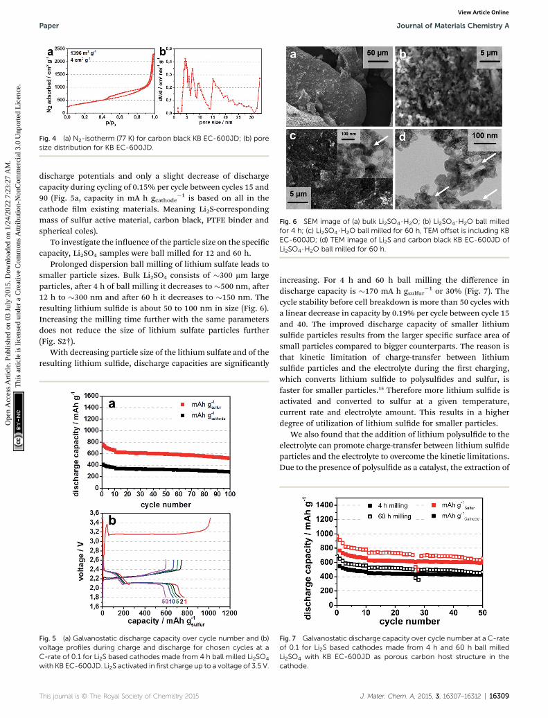
Fig. 4 (a) N2-isotherm (77 K) for carbon black KB EC-600JD; (b) poresize distribution for KB EC-600JD.
Fig. 6 SEM image of (a) bulk Li2SO4$H2O; (b) Li2SO4$H2O ball milledfor 4 h; (c) Li2SO4$H2O ball milled for 60 h, TEM offset is including KBEC-600JD; (d) TEM image of Li2S and carbon black KB EC-600JD ofLi2SO4$H2O ball milled for 60 h.
Paper Journal of Materials Chemistry A
Ope
n A
cces
s A
rtic
le. P
ublis
hed
on 0
3 Ju
ly 2
015.
Dow
nloa
ded
on 1
/24/
2022
7:2
3:27
AM
. T
his
artic
le is
lice
nsed
und
er a
Cre
ativ
e C
omm
ons
Attr
ibut
ion-
Non
Com
mer
cial
3.0
Unp
orte
d L
icen
ce.
View Article Online
discharge potentials and only a slight decrease of dischargecapacity during cycling of 0.15% per cycle between cycles 15 and90 (Fig. 5a, capacity in mA h gcathode
�1 is based on all in thecathode lm existing materials. Meaning Li2S-correspondingmass of sulfur active material, carbon black, PTFE binder andspherical coles).
To investigate the inuence of the particle size on the speciccapacity, Li2SO4 samples were ball milled for 12 and 60 h.
Prolonged dispersion ball milling of lithium sulfate leads tosmaller particle sizes. Bulk Li2SO4 consists of �300 mm largeparticles, aer 4 h of ball milling it decreases to �500 nm, aer12 h to �300 nm and aer 60 h it decreases to �150 nm. Theresulting lithium sulde is about 50 to 100 nm in size (Fig. 6).Increasing the milling time further with the same parametersdoes not reduce the size of lithium sulfate particles further(Fig. S2†).
With decreasing particle size of the lithium sulfate and of theresulting lithium sulde, discharge capacities are signicantly
Fig. 5 (a) Galvanostatic discharge capacity over cycle number and (b)voltage profiles during charge and discharge for chosen cycles at aC-rate of 0.1 for Li2S based cathodes made from 4 h ball milled Li2SO4
with KB EC-600JD. Li2S activated in first charge up to a voltage of 3.5 V.
This journal is © The Royal Society of Chemistry 2015
increasing. For 4 h and 60 h ball milling the difference indischarge capacity is �170 mA h gsulfur
�1 or 30% (Fig. 7). Thecycle stability before cell breakdown is more than 50 cycles witha linear decrease in capacity by 0.19% per cycle between cycle 15and 40. The improved discharge capacity of smaller lithiumsulde particles results from the larger specic surface area ofsmall particles compared to bigger counterparts. The reason isthat kinetic limitation of charge-transfer between lithiumsulde particles and the electrolyte during the rst charging,which converts lithium sulde to polysuldes and sulfur, isfaster for smaller particles.15 Therefore more lithium sulde isactivated and converted to sulfur at a given temperature,current rate and electrolyte amount. This results in a higherdegree of utilization of lithium sulde for smaller particles.
We also found that the addition of lithium polysulde to theelectrolyte can promote charge-transfer between lithium suldeparticles and the electrolyte to overcome the kinetic limitations.Due to the presence of polysulde as a catalyst, the extraction of
Fig. 7 Galvanostatic discharge capacity over cycle number at a C-rateof 0.1 for Li2S based cathodes made from 4 h and 60 h ball milledLi2SO4 with KB EC-600JD as porous carbon host structure in thecathode.
J. Mater. Chem. A, 2015, 3, 16307–16312 | 16309

Journal of Materials Chemistry A Paper
Ope
n A
cces
s A
rtic
le. P
ublis
hed
on 0
3 Ju
ly 2
015.
Dow
nloa
ded
on 1
/24/
2022
7:2
3:27
AM
. T
his
artic
le is
lice
nsed
und
er a
Cre
ativ
e C
omm
ons
Attr
ibut
ion-
Non
Com
mer
cial
3.0
Unp
orte
d L
icen
ce.
View Article Online
S-species from Li2S is facilitated as compared to the directformation of polysulde from Li2S which requires the simulta-neous oxidation and recombination of S-species on the Li2Ssurface.
A comparable process is the oxidation of lithium sulde topolysuldes with the help of sulfur.20,21
When applied to the lithium sulde containing battery cellsan addition of only 0.125 M Li2S6 in the electrolyte increases thedischarge capacity by �200 mA h gsulfur
�1 at the beginning ofthe cycling process and 120 mA h gsulfur
�1 at cycle 50 (Fig. 8a),because lithium polysuldes are oxidized to sulfur during therst charge, directly aer cell assembly. The amount of lithiumpolysuldes, when regarded as active material contributing tothe cell capacity, should increase the discharge capacity only byan amount of 67 mA h gsulfur
�1. Thus, the addition of lithiumpolysuldes enhances the utilization of lithium sulde in thecathode, presumably by promoting charge transfer effects at thesurface of lithium sulde particles.
The signicant difference in discharge capacity between68 wt% and 78 wt% lithium sulde containing cathodes,especially in the rst ten cycles, is based on the lower amount ofelectrochemical active species in the 68 wt% cell, leading to abetter distribution along the porous carbon black host material(Fig. 8b). The continual decline of discharge capacities is based
Fig. 8 (a) Galvanostatic discharge capacity over cycle number at a C-rateKB EC-600JD as porous carbon host structure in the cathode and 1 M Li0.125 M LiNO3 and 0.125 M Li2S6 polysulfide in DME/DOL (1 : 1 v/v) (emcapacities of cathodes consisting of 78 and 68 wt% Li2S with 0.125 M Li2Sdischarge for chosen cycles at a C-rate of 0.1 for Li2S based cathodes maddition to the electrolyte.
16310 | J. Mater. Chem. A, 2015, 3, 16307–16312
on the effect of the polysulde shuttle, which is present espe-cially aer a cycle number of over 50, despite the addition ofLiNO3 to the electrolyte solution. The polysulde shuttle leadsto a loss of electrochemical active material at the anode side.Due to an high active material loading of 3.5–4 mg cm�2 of Li2Sand resulting high areal discharge capacities of about 2.9 to3.4 mA h cm�2, the 0.125 M LiNO3 gets readily depleted fromthe electrolyte to due lithium formation during charging.Especially in the presented case, because only an amount of15 ml of electrolyte was used in coin cell preparation, in order tobe comparable to realistic cell manufacturing. This is theminimum amount which the electrodes need for sufficientwetting and reversible cycling. The depletion of nitrate duringcycling is one of the main challenges in using this additive.22
Due to the reason that the discharge capacity degradation ismainly based on depleting nitrate, this effect can be delayed bygiving more LiNO3 to the electrolyte solution. However byadding more lithium nitrate, especially in the case of the poly-sulde containing electrolyte, the electrolyte gains in densityand both used electrolytes, the one with and the one withoutpolysulde doping, are not directly comparable anymore.
In Fig. 9a the cyclic voltammograms for lithium suldecathodes with an electrolyte containing only conducting salt(LiTFSI) and lithium SEI former (LiNO3) in DME/DOL show in
of 0.1 for Li2S based cathodes made from 60 h ball milled Li2SO4 withTFSI, 0.25 M LiNO3 in DME/DOL (1 : 1 v/v) (filled symbols) or 1 M LiTFSI,pty symbols), respectively, as electrolyte; (b) comparing the discharge
6 polysulfide containing electrolyte; voltage profiles during charge andade from 60 h ball milled Li2SO4, (c) without and (d) with 0.125 M Li2S6
This journal is © The Royal Society of Chemistry 2015

Fig. 9 (a and b) Cyclic voltammograms for the two first cycles at ascan speed of 20 mV s�1, for Li2S based cathodes made from 60 h ballmilled Li2SO4 with KB EC-600JD as porous carbon host structure inthe cathode. (a) 1 M LiTFSI, 0.25 M LiNO3 in DME/DOL (1 : 1 v/v) and (b)1 M LiTFSI, 0.125 M LiNO3 and 0.125 M Li2S6 polysulfide in DME/DOL(1 : 1 v/v) as electrolyte.
Paper Journal of Materials Chemistry A
Ope
n A
cces
s A
rtic
le. P
ublis
hed
on 0
3 Ju
ly 2
015.
Dow
nloa
ded
on 1
/24/
2022
7:2
3:27
AM
. T
his
artic
le is
lice
nsed
und
er a
Cre
ativ
e C
omm
ons
Attr
ibut
ion-
Non
Com
mer
cial
3.0
Unp
orte
d L
icen
ce.
View Article Online
the 1st cycle a charge peak at 3.33 V vs. Li/Li+ in which lithiumsulde is oxidized to polysuldes and sulfur. For lithiumsulde embedded in micro- or mesopores of the porous carbonblack this oxidation occurs normally at a voltage of 2.35 V.Therefore, all lithium sulde particles exhibit an overpotentialof z1 V for the conversion into polysuldes and sulfur duringthe 1st charge. The cathodic discharge peaks at 2.35 V and 2.06V represent the electrochemical reduction of lithium poly-suldes Sx
2� (x ¼ 5–8) to short chain polysulde S42� and the
reduction of S42� to S2
2� and Li2S, respectively.23 Consequently,aer activation during the rst charge, the synthesized lithiumsulde behaves like normal sulfur – which it gets oxidized to inthe rst charge. By adding lithium polysuldes Li2S6 to theelectrolyte, the cyclic voltammogram of the 1st charge showstwo separate peaks at 2.27 and 2.40 V vs. Li/Li+ correspondingto the oxidation of Li2S and polysuldes to sulfur. This sulfuron the other hand helps to oxidize the remaining Li2S particlesat a voltage of 3.25 V, a lower voltage than it is needed for thepolysulde-free cells (Fig. 9). The following cycle displaysexactly the same behavior as the cell without addition of poly-suldes to the electrolyte, illustrating that aer the initialactivation of lithium sulde particles the entire electro-chemical active lithium sulde is now contributing to the cellreaction during subsequent cycling and no further activation isneeded.
The additional anodic peak at a voltage of 3.26 V vs. Li/Li+, inthe 2nd cycle for either cells with or without polysuldesupplement can be attributed to the decomposition of LiTFSIconducting salt in the electrolyte. This is a common problem forhigh voltage Li-ion batteries, because decomposed LiTFSI isable to corrode aluminum based current collectors.24 For thecell without polysulde addition this decomposition is visibleas a shoulder at 3.25 V for the 1st cycle (Fig. 9b). The decom-position peak is below and also detected at somewhat lowervoltages than the single oxidation peak for the rst charge in thecell without polysuldes addition to the electrolyte (Fig. 9a).Thus, polysuldes or sulfur cannot be formed from lithiumsulde without any LiTFSI salt decomposition in the cellwithout polysulde addition to the electrolyte. This can developinto a serious problem for the long term cycling stability, even ifLiTFSI is only decomposed during the rst charge.
It can be presumed, that even for the 1st cycle aer cellassembly, no special formation is needed and cells only need tobe activated to a voltage of 2.6 V vs. Li/Li+, the normal chargecut-off for lithium sulfur batteries,1 if polysuldes are added tothe electrolyte. This can be also conrmed by the differences inthe voltage proles of the rst charge between 4 h and 60 h ballmilled samples (Fig. 5b and 8c, red line) and the 60 h ballmilled sample with polysulde addition to the electrolyte(Fig. 8d, red line). The initial formation of lithium polysuldesfrom lithium sulde particles, which happens during the rstoverpotential peak,15 is 0.15 V lower for Li2S from 60 h ballmilled Li2SO4 (3.23 V) than for 4 h ball milled one (3.38 V), dueto faster activation kinetics of smaller lithium sulde particles.When adding polysuldes to the electrolyte, the initial kineticlimitation and overpotential does not exist. Also the subse-quent voltage plateau at 3.18 V and 2.90 V for the 4 h and 60 h
This journal is © The Royal Society of Chemistry 2015
ball milled samples, respectively, are lower for cells with poly-sulde containing electrolyte with 2.45 V, demonstrating thatinitial charging to 2.6 V can be sufficient to activate sub-micronsized lithium sulde particles in polysulde containingelectrolyte.
Conclusions
In summary, we have presented a novel approach for synthe-sizing nanosized lithium sulde (Li2S) using an economicallyviable and scalable carbothermal reduction. Ball milledlithium sulfate was reduced at temperatures below its meltingpoint to retain the submicron particle size. In addition it wasfound that smaller lithium sulde particles exhibit signi-cantly enhanced discharge capacities than larger particles.Furthermore, the crucial impact of lithium polysuldes as anelectrolyte additive on the activation barriers of lithium suldewas demonstrated. In particular, charging directly aer cellassembly to high cut-off voltages of 3.4 V and above is notneeded for 150 nm particle sized lithium sulde when poly-sulde is used as an additive.
J. Mater. Chem. A, 2015, 3, 16307–16312 | 16311

Journal of Materials Chemistry A Paper
Ope
n A
cces
s A
rtic
le. P
ublis
hed
on 0
3 Ju
ly 2
015.
Dow
nloa
ded
on 1
/24/
2022
7:2
3:27
AM
. T
his
artic
le is
lice
nsed
und
er a
Cre
ativ
e C
omm
ons
Attr
ibut
ion-
Non
Com
mer
cial
3.0
Unp
orte
d L
icen
ce.
View Article Online
Experimental
In order to reduce the particle size and to ensure sufficientmixing, lithium sulfate monohydrate (Carl Roth, >99% p.a.) andKetjen Black (KB EC-600JD) porous carbon black were ballmilled for 4 h and 60 h respectively at 400 rpm with 10 mininterval in a zirconia lined grinding beaker with 2 mm sizedzirconia balls within a dispersion of ethanol. Subsequent car-bothermal reduction of lithium sulfate monohydrate/KetjenBlack powder, with 66 or 69 wt% Li2SO4$H2O, was executed at820 �C for 3 h with an argon gas ow of 1200 sccm in a 40 mmdiameter tube furnace (HTM Reetz). Such treated samples withLi2S contents of 71 or 81 wt% were transferred into an argonlled glove box (MBraun) with monitored oxygen value of <0.1ppm and moisture level of <0.1 ppm.
Electrode sheets were prepared with a dry-process approachin an argon lled glove box as described elsewhere.25 Lithiumsulde/Ketjen Black powder is grinded with 3 wt% PTFE binder(Sigma Aldrich) and 1 wt% spherical coal as additive for betterprocessing. Grinding of the powders leads to sheets withthicknesses of z100 mm. These sheets were then laminatedonto carbon coated aluminum foil current collector. Circularelectrode discs with a diameter of 10 mm (corresponding to 3.5–4 mg cm�2 lithium sulde loading with a Li2S content of 68 and78 wt%, respectively) were punched from the electrode sheets.
Coin cells (MTI Corp., CR2016) were assembled in a glovebox. Metallic lithium (Pi-Kem, 99.0%, diameter 15.6 mm,thickness 250 mm) was used as anode. Porous polypropylene(Celgard 2500) was used as separator. The standard electrolytewas composed of 1 M lithium bis(triuoromethylsulfonyl)imide (LiTFSI, Sigma Aldrich, 99.95%), 0.25 M lithium nitrate(LiNO3, Alfa Aesar, 99.98%, anhydrous) in 1,2-dimethoxyethane(DME, Sigma Aldrich, 99.5%, anhydrous) and 1,3-dioxolane(DOL, Sigma Aldrich, 99.8%, anhydrous) with a mixing ration of1 : 1 v/v. The polysulde containing electrolyte consisted of 1 MLiTFSI, 0.125 M LiNO3 and 0.125 M Li2S6 polysulde in DME/DOL (1 : 1 v/v). The amount of electrolyte was xed at 15 mL, asthis is the minimum amount needed to ll the dead volume ofthe coin cell. Chemicals were used as received, except forLiTFSI, DME, and DOL. In order to remove residual water,LiTFSI and LiNO3 were dried at 120 �C under vacuum for 24 hbefore use and DME and DOL were dried and stored over a 3 Amolecular sieve.
Scanning electron microscope (SEM) images were acquiredwith a JEOL JSM-6610LV, TEM (transmission electron micro-scope) images with a Jeol JEM-2100, cyclic voltammetrymeasurements were performed with an Ivium-n-stat, X-raydiffraction powder patterns were recorded using a SiemensD5005, N2-isothermes were measured at 77 K on a Quantach-rome QuadraSorb and galvanostatic charge/discharge cyclingtests were performed with a BaSyTec Cell Test System (CTS) atroom temperature. Cut-off voltages for cycling were 1.8 and 2.6V or 3.4 V for the activation step, if not mentioned otherwise.Current rate during charge activation of lithium sulde in the1st cycle was at a C-rate of 0.01 if not mentioned otherwise. Forcycling a C-rate of 0.1 (167 mA gsulfur
�1) was chosen.
16312 | J. Mater. Chem. A, 2015, 3, 16307–16312
Acknowledgements
This research was nanced by the Fraunhofer project LiScell.We are grateful for the support. TEM measurements were per-formed by Dr Joerg Kaspar from Fraunhofer IWS Dresden.
Notes and references
1 X. Ji and L. Nazar, J. Mater. Chem., 2010, 20, 9821–9826.2 Z. Wei Seh, W. Li, J. J. Cha, G. Zheng, Y. Yang,M. T. McDowell, P.-C. Hsu and Y. Cui, Nat. Commun., 2013,4, 1331.
3 Y. Yang, G. Zheng and Y. Cui, Energy Environ. Sci., 2013, 6,1552.
4 W. Li, G. Zheng, Y. Yang, Z. W. Seh, N. Liu and Y. Cui, Proc.Natl. Acad. Sci. U. S. A., 2013, 110, 7148.
5 S. Lu, Y. Cheng, X. Wu and J. Liu, Nano Lett., 2013, 13, 2485.6 J. Bruckner, S. Thieme, F. Bottger-Hiller, I. Bauer,H. T. Grossmann, P. Strubel, H. Althues, S. Spange andS. Kaskel, Adv. Funct. Mater., 2014, 24, 1284–1289.
7 J. Hassoun, J. Kim, D.-J. Lee, H.-G. Jung, S.-M. Lee, Y.-K. Sunand B. Scrosati, J. Power Sources, 2012, 202, 308–313.
8 J. Hassoun and B. Scrosati, Angew. Chem., Int. Ed. Engl., 2010,49, 2371–2374.
9 B. Kang and G. Ceder, Nature, 2009, 458, 190–193.10 Y. Yang, M. T. McDowell, A. Jackson, J. J. Cha, S. S. Hong and
Y. Cui, Nano Lett., 2010, 10, 1486–1491.11 F. Wu, H. Kim, A. Magasinski, J. T. Lee, H.-T. Lin and
G. Yushin, Adv. Energy Mater., 2014, 4, 1400196.12 F. Wu, A. Magasinski and G. Yushin, J. Mater. Chem. A, 2014,
2, 6064.13 S. Jeong, D. Bresser, D. Buchholz, M.Winter and S. Passerini,
J. Power Sources, 2013, 235, 220–225.14 J. Guo, Z. Yang, Y. Yu, H. D. Abruna and L. A. Archer, J. Am.
Chem. Soc., 2013, 135, 763–767.15 Y. Yang, G. Zheng, S. Misra, J. Nelson, M. F. Toney and
Y. Cui, J. Am. Chem. Soc., 2012, 134, 15387–15394.16 E. Tor, United States Pat. Trademark Off., USPO395813, 1958,
pp. 1–8.17 J. Hml, Eur. Pat. Off., EP0994071B, 2004, pp. 1–14.18 A. Grahame, Eur. Pat. Off., EP1187790B, 2004, pp. 3–7.19 J. Zheng, M. Gu, M. J. Wagner, K. A. Hays, X. Li, P. Zuo,
C. Wang, J.-G. Zhang, J. Liu and J. Xiao, J. Electrochem.Soc., 2013, 160, A1624–A1628.
20 R. D. Rauh, F. S. Shuker, J. M. Marston and S. B. Brummer, J.Inorg. Nucl. Chem., 1977, 39, 1761–1766.
21 R. D. Rauh, K. M. Abraham, G. F. Pearson, J. K. Surprenant,S. B. Brummer and E. I. C. Corporation, J. Electrochem. Soc.,1979, 126, 523–527.
22 S. S. Zhang, Electrochim. Acta, 2012, 70, 344–348.23 M. Gao, X. Xiong, W. Wang, S. Zhao, C. Li, H. Zhang, Z. Yu
and Y. Huang, J. Power Sources, 2014, 248, 1149–1155.24 H. Louis, Y.-G. Lee, K. M. Kim, W. I. Cho and J. M. Ko, Bull.
Korean Chem. Soc., 2013, 34, 1795–1799.25 S. Thieme, J. Bruckner, I. Bauer, M. Oschatz, L. Borchardt,
H. Althues and S. Kaskel, J. Mater. Chem. A, 2013, 1, 9225.
This journal is © The Royal Society of Chemistry 2015