Toward graphene textiles in wearable eye tracking systems for ...
10
180 Toward graphene textiles in wearable eye tracking systems for human–machine interaction Ata Jedari Golparvar 1 and Murat Kaya Yapici *1,2,3 Full Research Paper Open Access Address: 1 Faculty of Engineering and Natural Sciences, Sabanci University, TR-34956 Istanbul, Turkey, 2 Sabanci University SUNUM Nanotechnology Research Center, TR-34956 Istanbul, Turkey and 3 Department of Electrical Engineering, University of Washington, Seattle, WA 98195, USA Email: Murat Kaya Yapici * - [email protected] * Corresponding author Keywords: electrooculography (EOG); flexible electronics; graphene; human–computer interaction (HCI); human–machine interface (HMI); personal assistive device (PAD); wearable smart textile Beilstein J. Nanotechnol. 2021, 12, 180–189. https://doi.org/10.3762/bjnano.12.14 Received: 19 November 2020 Accepted: 20 January 2021 Published: 11 February 2021 This article is part of the thematic issue "Nanogenerators and flexible electronics". Guest Editor: Y. Mao © 2021 Golparvar and Yapici; licensee Beilstein-Institut. License and terms: see end of document. Abstract The study of eye movements and the measurement of the resulting biopotential, referred to as electrooculography (EOG), may find increasing use in applications within the domain of activity recognition, context awareness, mobile human–computer and human–machine interaction (HCI/HMI), and personal medical devices; provided that, seamless sensing of eye activity and process- ing thereof is achieved by a truly wearable, low-cost, and accessible technology. The present study demonstrates an alternative to the bulky and expensive camera-based eye tracking systems and reports the development of a graphene textile-based personal assis- tive device for the first time. This self-contained wearable prototype comprises a headband with soft graphene textile electrodes that overcome the limitations of conventional “wet” electrodes, along with miniaturized, portable readout electronics with real-time signal processing capability that can stream data to a remote device over Bluetooth. The potential of graphene textiles in wearable eye tracking and eye-operated remote object interaction is demonstrated by controlling a mouse cursor on screen for typing with a virtual keyboard and enabling navigation of a four-wheeled robot in a maze, all utilizing five different eye motions initiated with a single channel EOG acquisition. Typing speeds of up to six characters per minute without prediction algorithms and guidance of the robot in a maze with four 180° turns were successfully achieved with perfect pattern detection accuracies of 100% and 98%, respec- tively. 180 Introduction Eye tracking technologies have many applications ranging from behavioral analytics to healthcare. For a brand leader, the prospect of seeing the world literally through consumer’s eyes, as opposed to relying on traditional market research methods, is the reason that makes eye tracking a clear winner in understanding the triggering subconscious facts in decision
-
Upload
khangminh22 -
Category
Documents
-
view
4 -
download
0
Transcript of Toward graphene textiles in wearable eye tracking systems for ...

180
Toward graphene textiles in wearable eye tracking systems forhuman–machine interactionAta Jedari Golparvar1 and Murat Kaya Yapici*1,2,3
Full Research Paper Open Access
Address:1Faculty of Engineering and Natural Sciences, Sabanci University,TR-34956 Istanbul, Turkey, 2Sabanci University SUNUMNanotechnology Research Center, TR-34956 Istanbul, Turkey and3Department of Electrical Engineering, University of Washington,Seattle, WA 98195, USA
Email:Murat Kaya Yapici* - [email protected]
* Corresponding author
Keywords:electrooculography (EOG); flexible electronics; graphene;human–computer interaction (HCI); human–machine interface (HMI);personal assistive device (PAD); wearable smart textile
Beilstein J. Nanotechnol. 2021, 12, 180–189.https://doi.org/10.3762/bjnano.12.14
Received: 19 November 2020Accepted: 20 January 2021Published: 11 February 2021
This article is part of the thematic issue "Nanogenerators and flexibleelectronics".
Guest Editor: Y. Mao
© 2021 Golparvar and Yapici; licensee Beilstein-Institut.License and terms: see end of document.
AbstractThe study of eye movements and the measurement of the resulting biopotential, referred to as electrooculography (EOG), may findincreasing use in applications within the domain of activity recognition, context awareness, mobile human–computer andhuman–machine interaction (HCI/HMI), and personal medical devices; provided that, seamless sensing of eye activity and process-ing thereof is achieved by a truly wearable, low-cost, and accessible technology. The present study demonstrates an alternative tothe bulky and expensive camera-based eye tracking systems and reports the development of a graphene textile-based personal assis-tive device for the first time. This self-contained wearable prototype comprises a headband with soft graphene textile electrodes thatovercome the limitations of conventional “wet” electrodes, along with miniaturized, portable readout electronics with real-timesignal processing capability that can stream data to a remote device over Bluetooth. The potential of graphene textiles in wearableeye tracking and eye-operated remote object interaction is demonstrated by controlling a mouse cursor on screen for typing with avirtual keyboard and enabling navigation of a four-wheeled robot in a maze, all utilizing five different eye motions initiated with asingle channel EOG acquisition. Typing speeds of up to six characters per minute without prediction algorithms and guidance of therobot in a maze with four 180° turns were successfully achieved with perfect pattern detection accuracies of 100% and 98%, respec-tively.
180
IntroductionEye tracking technologies have many applications ranging frombehavioral analytics to healthcare. For a brand leader, theprospect of seeing the world literally through consumer’s eyes,
as opposed to relying on traditional market research methods,is the reason that makes eye tracking a clear winner inunderstanding the triggering subconscious facts in decision
Beilstein J. Nanotechnol. 2021, 12, 180–189.
181
making. In entertainment and virtual reality applications, eyetracking enables a whole new interaction method with contents,and it could also add new security measures through retinalscanning.
In healthcare, eye tracking enables devices to help ease adisabled individual’s challenging life using their eye motions.Thousands of people suffer from extreme disabilities such assevere cerebral palsy and amyotrophic lateral sclerosis (ALS),which deprive them of muscular abilities. It is estimated thatapproximately 450,000 people worldwide are diagnosed withALS, and in the United States, the incidence of ALS is two perhundred thousand people [1]. Therefore, the advancement ofeye tracking technologies is critical for developing assistivedevices and human–computer interaction (HCI) platforms forpeople with disabilities.
Current technologies for eye tracking, however, by being eitherinvasive, expensive, or bulky [2-4] do not address the require-ments of a readily usable product in HCI intended for wide-spread use; and fail to meet the fundamental characteristics ofwearability in terms of size miniaturization, low-power opera-tion, ergonomics, and aesthetics. For example, althoughcamera-based eye tracking setups solve the invasivity issue anddisplay long-term functionality, they are hardly affordable dueto their hardware (e.g., camera) and image processing require-ments. Additionally, in videooculography, the camera has to bepositioned at a location suitable to capture eye movements(EMs), which limits the portability of such systems. Therefore,effort has been placed to investigate different methods to utilizeEMs in wearable applications.
To this end, electrooculography (EOG) is an economical(a typical EOG setup could be assembled at a cost of under100 EUR [5]), non-invasive, and reliable method for acquiringbiopotential signals around the eyes, and may overcome thelimitations of prior technologies. EOG is essentially based on asimple model of the human eye as a dipole with a permanentpotential difference between its forward and backward facingspots (i.e., the cornea-retinal potential of 0.4–1.0 mV where thecornea is positive) [6]. This potential difference sets up an elec-trical field in the tissues surrounding the eye, which generatesan electric field [7]. Two electrodes around the eyes can locatethe field vector rotation, which creates a more positive charge inthe electrode that the cornea is approaching [8]. The biopoten-tials resulting from eye activity, which are in fact waveformsthat relate the dipole fluctuations to the type of eye movement,are referred to as electrooculograms; while the specific tech-nique for recording is known as electrooculography [9]. Elec-trooculograms also occur in total darkness, when the eyes areclosed, even in visually impaired people [10].
So far, several EOG-based rehabilitation systems were de-veloped to mitigate everyday life challenges of and providesome means of communication for people with locked-insyndromes who have extremely limited peripheral mobility butstill retain their eye motor coordination [10]. Similarly, basicdeliberate eye movements such as saccades (i.e., fast eye move-ments), fixations (i.e., the duration between two saccades whenthe gaze is fixated at a point), and blinks have been used forhands-free operation in HCI and human–machine interfaces(HMIs) [11]. With the help of HCI and HMIs one can emulate acomputer mouse [12], type using a virtual keyboard [13], drivea wheelchair or control a robotic arm [14], change TV channels[15], and even improve user experience on virtual realitygaming [16] or smartphone operation [17]. Along these lines, inthe healthcare domain, as part of a hospital alarm system, EOG-based switches provided immobile patients with a safe and reli-able way of signaling an alarm [18]. Other promising studies re-ported the direct input of numbers, letters of the Englishalphabet, and Japanese Katakana symbols by eye movements tofurther help users to communicate complicated messages in arelatively short time [19].
However, despite the various demonstrators of wearable EOGdevices in the literature, which prove that EOG is a measure-ment technique that is reliable, easy to operate, and can be madecosmetically appealing, EOG-based devices still struggle topenetrate the wearables market, and their full potential hasnot been realized due to limitations of the sensing electrodes[20-22]. The combination of graphene with ordinary textilespresents a viable solution to this limitation [23]. Therefore,this work reports an alternative eye tracking system based onmonitoring the ocular biopotential. It demonstrates the firstgraphene textile-based wearable personal assistive devicefor interacting with machines and controlling objects. Withthe developed wearable system prototype, seamless “eye-oper-ated” remote control of objects is achieved, including cursormotion on screen for typing of text and the motion of a four-wheeled car; both of which demonstrate the vast potential ofgraphene textiles as an enabler of wearable assistive technolo-gies.
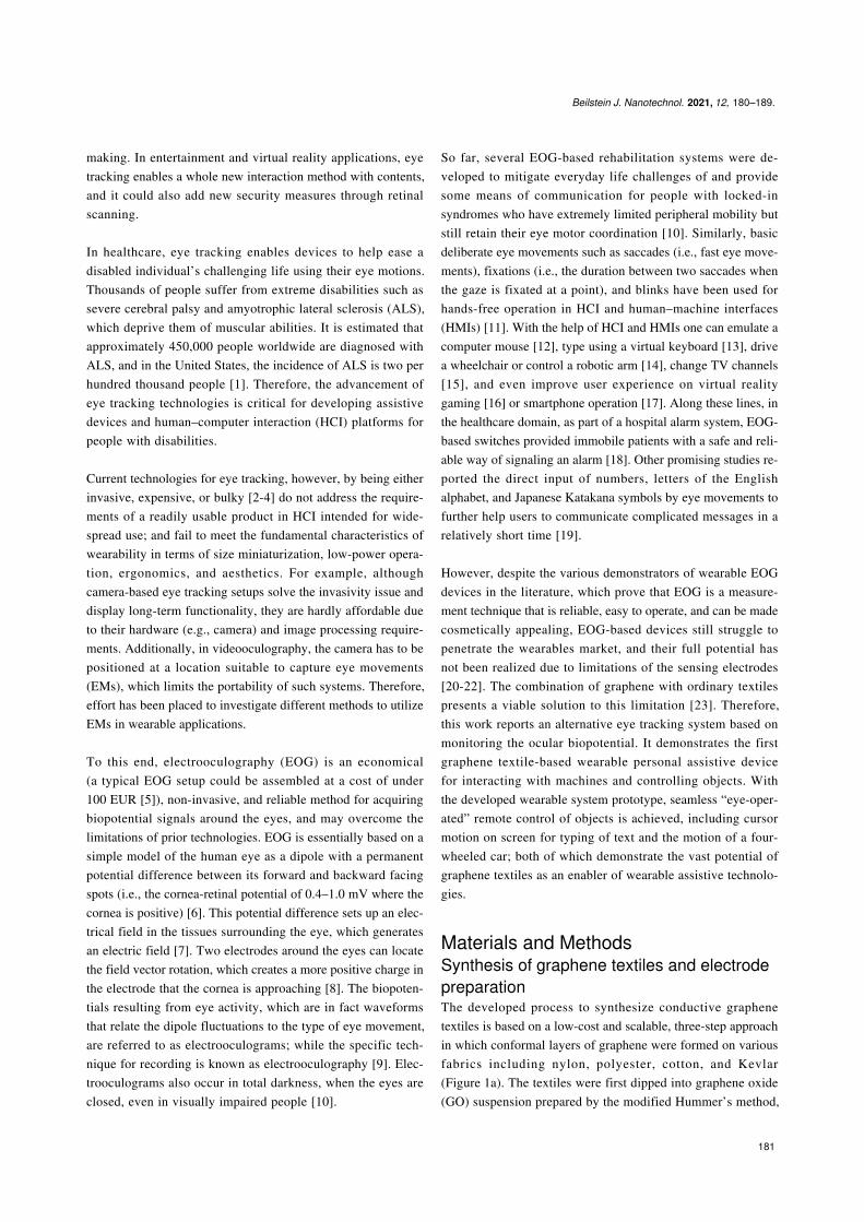
Materials and MethodsSynthesis of graphene textiles and electrodepreparationThe developed process to synthesize conductive graphenetextiles is based on a low-cost and scalable, three-step approachin which conformal layers of graphene were formed on variousfabrics including nylon, polyester, cotton, and Kevlar(Figure 1a). The textiles were first dipped into graphene oxide(GO) suspension prepared by the modified Hummer’s method,
Beilstein J. Nanotechnol. 2021, 12, 180–189.
182
Figure 1: (a) Schematic of the three-step process to obtain conformal graphene coatings on a variety of textiles including nylon, cotton, and polyester;(b) image of the graphene textile “active” electrode with integrated buffer circuitry along with component values and circuit schematic. Vin is connectedto the graphene textile, and Vout is connected to the snap button. Both are used to provide the connection of the “active” textile electrode to the signalacquisition unit; insets show the front side of the electrode assembly with the graphene textile and the dimensions of the miniaturized-PCB on the rearside of the electrode.
dried to allow for the layering of GO on the textiles, treated byreducing agents (e.g., hydrazine or hydrogen iodide), and rinsedwith distilled water to form a stable graphene coating on thetextiles. The prepared graphene textiles were then cut intopieces (ca. 3 × 3 cm) and mounted on flexible, polyethylene-based foam paddings, which were sandwiched between metallicsnap fasteners in order to establish an electrical connection withthe front-end circuitry. In this way, “passive” graphene textileelectrodes were formed, which can be directly used to capturesurface biopotentials without further modification. Conduc-tivity measurements showed resistance values of the textiles be-tween 1 and 10 kΩ and skin-electrode impedance values from87.5 kΩ (at 10 Hz) to 11.6 kΩ (at 1 kHz). Additionally, sincethe operation of the textile electrodes relies on charge flow,moisture and sweat can increase the interface conductivity ofthe skin electrodes and provide an even better signal-to-noiseratio (SNR) in long-term monitoring applications in contrast to“wet” electrodes, the functionality of which degrades over time[23].
However, one common issue in dry electrodes is the relativelyhigh skin-electrode contact impedance, which causes suscepti-bility to physical movements and power line interferences re-sulting in signal distortions. While the flexible, foldable natureof textile electrodes promotes wearability, it can adversely leadto dynamic contact conditions and, thereby, motion artifacts inthe acquired signal. A strategy to minimize this effect, whichwas investigated in this work, is to reduce the impedance of thesignal source by utilizing a buffer amplifier, which essentiallyconverts the high-impedance signal to a low-impedance signal.Figure 1b shows the circuit schematic and the components forbuilding “active” graphene textile electrodes. The componentsare an operational amplifier (OPA2365, Texas Instruments,USA) with a high input impedance, two resistors, and onecapacitor. A small-sized printed circuit board (ca. 0.9 × 1.3 cm)was designed and implemented to demonstrate a proof ofconcept. It allowed for robust integration and an electrical inter-face between the buffer-circuit components and the graphenetextiles to form “active” electrodes.

Beilstein J. Nanotechnol. 2021, 12, 180–189.
183
Figure 2: Overview of the system prototype showing the detailed hardware-level schematic of the portable, battery-powered, EOG acquisition unit in-cluding on-board filtering and gain stages, power management section, microcontroller unit to process and stream data wirelessly to a computer alongwith a custom-designed user interface, and the wearable headband with soft graphene textile electrodes.
Wearable system prototypeOne of the fundamental obstacles regarding the actual weara-bility of electronic systems is the lack of robust integrationschemes for the interface between soft sensing electrodes andrigid electronic components. We have addressed this issue byfollowing a system-level design perspective. A miniaturized,battery-powered, portable EOG acquisition unit with wirelessdata transmission capability was realized and directly inte-grated into a wearable headband, which also contained thegraphene textile electrodes (Figure 2). The electrodes weremounted in a newly introduced manner such that potentialcrosstalk between channels was eliminated. Also, electrodecount and hardware complexity were minimized by removingthe vertical acquisition channel without loss of controlcommands triggered by vertical EMs [24,25]. The readoutelectronics could be implemented in a small form factor(ca. 4 × 6 cm) that is easily attachable on a wearable custom-made headband. The front half of the headband was kept fairlynon-stretchable to maintain the electrode locations on the fore-head; while the rear side was made of elastic straps enablingsize adjustment to ensure a stable skin–electrode contact.
As shown in the detailed hardware schematic in Figure 2, thecircuit has second-order and fourth-order Butterworth high-passand low-pass filters with cut-off frequencies of 0.5 Hz and10 Hz, respectively, both based on Sallen–Key topology. Thepreferred instrumentation amplifier (INA122, Texas Instru-ments, USA) is specifically designed for battery-powered appli-
cations with the capability of running with a single supply.Similarly, the other operation amplifiers used in the design wereselected due to their single-supply and rail-to-rail features(OPA2365, Texas Instruments, USA) and are suitable forportable applications. For adjusting the gain in the post-amplifi-cation stage, a digitally programmable voltage divider(MAX5421, Maxim, USA) was used so that the gain can beconfigured at the software level through a graphical user inter-face (GUI). As a common practice in portable devices nowa-days, a lithium-ion/polymer battery with a rating of 3.7 V and500 mAh was chosen to power the system. The battery chargemanagement circuitry and DC–DC boost converter were basedon a MCP73831 (Microchip, USA) and a TPS61090 (TexasInstruments, USA), respectively.
To split the regulated 5 V, a rail splitter (TLE2426, TexasInstruments, USA) was used, which is essentially a voltagedivider with a buffer circuitry to prevent it from becomingunbalanced. The currents that can be typically handled bypower splitters are small (20–40 mA). Hence, additional bufferswith higher current ratings were accommodated in the powermanagement unit as a safety margin, despite the typically lowlevels of currents drawn by the signal acquisition unit. To adjustthe settings and to stream data to a computer, a popular off-the-shelf Bluetooth module (HC06) was used. A custom-designedGUI based on LabVIEW (National Instruments, USA) wasimplemented at the receiver end, enabling user-friendly opera-tion, calibration, gain adjustment, and event monitoring.

Beilstein J. Nanotechnol. 2021, 12, 180–189.
184
Figure 3: The first testing scenario shows the plot of induced EOG signals with inserted interpretations for each eye movement, which are used tomimic the movements of a mouse cursor to write “SUMEMS” (Sabanci University MEMS Group).
In the current version of the embedded system, the Bluetoothcoverage is ca. 5 m. The power consumption of the circuitry isca. 80 mW when the Bluetooth device is not paired and ca.150 mW when it is paired, which allows the battery to run in thepaired mode for about 4 h continuously without recharge. Thesemeasurements can be further improved by implementing sleep-mode functions to a microcontroller and upgrading the Blue-tooth module to a Bluetooth low-energy (BLE) module, such asHM-10, which has low power consumption and offers a higherrange up to several tens of meters.
Results and DiscussionDifferent eye movements along with a detection and classifica-tion algorithm having a success rate ranging from 85% up to100% for detecting eleven different patterns over an hour-longEOG recording experiment [25] were utilized to develop agraphene textile-based wearable eye mouse and a wearableassistive system to control movements of a four-wheeled robot.The wearable eye mouse controlled a cursor on a PC screen andsent x–y coordinates of the cursor to the GUI. On the computer,the GUI uses the “SetCursorPos” and “mouse_event” functionsof the Microsoft Windows User32.dll library to control cursormovement and blink actions, respectively. Swift horizontal eyemovements (to the left or right) control the horizontal move-ment of the cursor in two directions. In contrast, slow eyemovements control the cursor motion in vertical directions.Finally, voluntary blinking mimics the mouse click action.When swift or slow eye movements occur, the cursor starts tomove in the defined direction at a preconfigured speed until itreaches the edge of the display or until a different eye move-ment changes the cursor motion. For instance, the cursor willmove toward the left side after a swift left eye movement and
stop and execute a click action when a blink of the eye occurs.Some additional actions were implemented for better control,such as “cursor stop”, which stops the cursor motion at anypoint without causing a click action. For instance, when thecursor moves, either a swift left or a swift right eye movementcan stop the cursor movement. In this way, the user can achieveaccurate position control and fine-tune the cursor location whenneeded. Likewise, the “cursor snap” option was defined toallow for a rapid, discretized transition of the cursor from itsexisting location to the nearest key in the specified direction ofmotion.
To evaluate the performance of the graphene textile-basedwearable eye mouse, two different tests were carried out. In thefirst case, a single participant was trained and asked to type aspecific word, while the lateral or transverse movements of thecursor on the screen were continuous unless terminated byanother command. In the second case, “cursor snap” was acti-vated and five participants were requested to type five randomlyselected character sequences of equal length. Figure 3 demon-strates the first testing scenario with the developed eye mouseand the recorded electrooculograms together with their interpre-tation. The aim here is first to open Microsoft Word Office andthe Microsoft Windows virtual keyboard, to write a word, and,finally, to stop the GUI solely by eye movements. The differenteye movements and corresponding cursor actions specific to theeye movements are summarized in Table 1, along with a repre-sentative sequence of movements needed to type “SUMEMS”and the measured duration for each step.
Speed and initial starting point of the cursor, and several otheroptions are configurable in the GUI settings. In the first trial,

Beilstein J. Nanotechnol. 2021, 12, 180–189.
185
Figure 4: Diagram showing the two possible cursor movement directions to go from letter “A” to “K” in a standard QWERTY keyboard layout; path (a)could be implemented by seven swift left eye movements, and path (b) provides a faster route to reach the same destination by five swift right eyemovements.
Table 1: Summary of eye movement types with corresponding cursoractions and a representative typing sequence.
Sequence Type Action Duration [s]
1 swift left left direction 6.52 slow left down direction 14.73 blink click “S” instantaneous4 swift right right direction 15.75 slow right up direction 3.36 blink click “U” instantaneous7 swift right right direction 4.98 slow left down direction 6.19 swift left stop 3.510 swift left left direction 3.011 blink click “M” instantaneous12 swift left left direction 13.713 slow right up direction 5.814 blink click “E” instantaneous15 swift right right direction 13.316 slow left down direction 5.117 blink click “M” instantaneous18 swift left left direction 17.019 slow right up direction 3.420 blink click “S” instantaneous21 swift right right direction 28.922 blink click “Enter” instantaneous
the cursor speed (pointer speed on screen) was kept slow andset to 1 pixel every 30 ms, which, on average, is translated toone character every ca. 23 s. This resulted in a total typing timeof over 2 min for a 6-character word.
The cursor speed was gradually increased in subsequent trials toidentify the upper limit on typing speed with the developedwearable eye mouse system. The fundamental constraint on in-creasing the cursor speed is the inherent transient response ofelectrooculograms and the detection algorithm to account forthis behavior. On the occasion of an eye movement, a certainamount of time is required for the corresponding EOG signal to
complete its waveform and reach a steady state, upon which thedetection algorithm classifies the performed eye movement andexecutes the designated action. For instance, considering thecase of a blink, which is attributed to the mouse click or“select” action, at cursor speeds above a maximum threshold,there is the possibility that the user attempts to click and select aspecific letter but misses it due to the latency in commandexecution. In our trials with a trained participant, the cursorspeed was optimized such that the participant was able tocorrectly type one character per approx. 10 s, which corre-sponds to a typing speed of six characters per minute (CPM), amore than two-fold increase in the typing speed compared to thefirst trial. This is a reasonably good speed for a thresholding-based algorithm approach in which a pattern detection accuracyof up to 100% was achieved, and in alignment with earlierEOG-based spellers, which range from 2.4 to 12 CPM [26].
If the eye mouse is to be used only to facilitate the typing on avirtual keyboard, then, to readily increase the typing speed evenfor a non-trained user, some software-level realizations can beimplemented by applying a fixed coordinate system. That is, thecursor moves only to specific locations of the buttons of thevirtual keyboard. For example, in a standard QWERTYkeyboard, instead of performing one swift left eye movement toinitiate continuous movement of the cursor from letter “A” toletter “K,” one can perform seven swifts left movements totraverse the cursor one at a time to its nearest neighbor in theinitiated direction of movement (Figure 4a). Alternatively, fiveswift right movements can be performed to do the same task butin a comparatively faster way (Figure 4b).
To illustrate this, five volunteers have participated in a study totest the system by writing randomly generated six-letter se-quences, summarized in Table 2, together with the typing dura-tion. To train the volunteers, they were shortly briefed aboutwhich eye movement corresponds to which action, and theywere asked to explore the device before the actual experiment,by trying to write their names. All volunteers reported they feltcomfortable using the device shortly within merely 2–3 min.
Beilstein J. Nanotechnol. 2021, 12, 180–189.
186
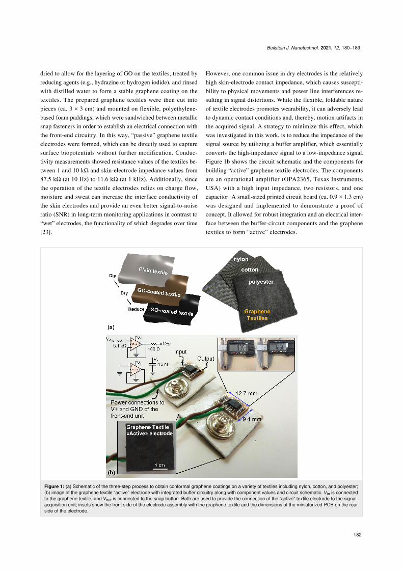
Figure 5: Overview of the second technology demonstrator for the wearable graphene textile-based assistive device for HMI applications. A four-wheeled robot is remotely controlled and steered in a maze. (a) Scenario-specific eye movements (EMs) allow one to steer the robot in different direc-tions as follows: (i) swift left EM or blinking trigger forward motion (↑), (ii) swift right EM triggers backward motion (↓), (iii) slow left EM triggers rota-tion to the left (←), (iv) slow right EM triggers rotation to the right (→). Insets show images of the eye during different movements. This includes eyeswhen fixated at the center, while performing a voluntary blink, while performing a right move and fixated at the right, and while performing a left moveand fixated at the left; (b) picture of the wearable eye tracker including smart headband with graphene textile electrodes and embedded electronicshoused by an acrylic holder all mounted on the head.
The shortest typing duration was 55 s, and the longest was 76 s,with an average typing speed of ca. 62 s for six characters orapprox. 6 CPM. By implementing letter and word predictionalgorithms, a further increase in typing speed can be expected[27].
Table 2: Summary of generated random letter sequences with corre-sponding typing duration using eye movements.
Subject Random letter sequence Duration [s]
1 p h n e x v 552 g z n b a y 693 l a w x s t 584 e m j b c b 535 g h e b v z 76
In recent years, there have been many studies on skin-compati-ble, body-worn devices, collectively referred to as wearableelectronics, for applications ranging from energy harvesting tohuman health and motion monitoring [28-34]. In a seconddemonstration, we have investigated the potential of the de-veloped graphene textile-based wearable system as an assistivedevice to remotely control objects, including the steering of awheelchair using eye movements, which is critical for ALSpatients. To show the feasibility of the developed system, themotion of an Arduino-based, custom-designed four-wheeledrobot was controlled (Figure 5). In this experiment, eye blinkand swift left and right eye movements initiate forward and
backward motions, while slow right and left movements enablerotation to the right and left sides.
To record the signals, both the robot and the acquisition unitwere paired with a laptop running the previously designed GUIwith slight modifications for enabling simultaneous communi-cation of the GUI with robot and EOG acquisition unit. Howev-er, in actual usage cases, the laptop can be eliminated bydirectly connecting the EOG unit to the robot. At the robot end,incoming commands are delivered to a DC motor driver (L298,STMicroelectronics, Switzerland) in the form of pulse-widthmodulation (PWM) signals with a configured duty cycle value(i.e., speed), which can be changed through settings. Tosimplify HRI and to improve the user control experience,forward/backward movements and rotation of the robot werepreset at a given distance (ca. 15 cm) and a given angle (ca.45°), both of which can be adjusted in the GUI. Based on thisconfiguration, eye movements were used to steer the robotalong the exit path of a maze without crossing the boundariesmarked with black tape (Figure 6).
A total of 41 eye movements including 19 swift left EMs(forward), two swift right EMs (backward), seven slow leftEMs (turn left), eleven slow right EMs (turn right), and a singleblink (forward) action were performed and recorded over aduration of ca. 200 s. Analysis of the extracted video framesalong with the recorded EOG waveforms revealed a detectionaccuracy of approx. 98%. Only one out of 41 eye movementswas misinterpreted with the developed system, demonstrating

Beilstein J. Nanotechnol. 2021, 12, 180–189.
187
Figure 6: Snapshots of the robot car at different instances and plot of the recorded EOG trace during steering of the robot over a duration of morethan 3 min with interpretations for the different eye movements (EMs) labeled in the waveform (video available in Supporting Information File 1).
the near excellent performance of the truly wearable headbandprototype for human–robot interaction and control.
ConclusionIn contrast to well-established vision-based gaze tracking, wedemonstrate electrooculography (EOG) with truly wearablegraphene textiles, enabling an effective, low-cost, low-power,body-worn embedded system with small form factor to monitorand utilize eye movements for the remote control of objects.EOG allows for a recording of ocular biopotentials regardless ofambient lighting conditions, camera line of sight, or the pres-ence of obstacles. Even when the subject’s eyes are closed,seamless detection and harnessing of eye movements for objectcontrol without the need for a camera is possible. Along withthe advantages of being soft and wearable in the form of a smart
textile-based accessory with peripheral electronics, the de-veloped EOG system can be utilized in virtual reality environ-ments and serve as a valuable communication platform forpeople with disabilities such as amyotrophic lateral sclerosis(ALS). In this study, we also demonstrated a proof of conceptof “active” graphene textile electrodes and achieved initialresults that warrant room for detailed investigation. Additional-ly, in the current work, the information obtained from EOGremains coarse, the users are static, and signal processing is yetto be optimized for mobile scenarios, which indicates futureresearch directions. We envision that further developments willbe possible with the results presented in this work, which laydown the foundations regarding the use of wearable graphenetextiles in control applications tailored explicitly to EOG-basedhuman–computer/robot interaction (HCI/HRI).

Beilstein J. Nanotechnol. 2021, 12, 180–189.
188
Supporting InformationSupporting Information File 1Video showing the steering and control of robot car.[https://www.beilstein-journals.org/bjnano/content/supplementary/2190-4286-12-14-S1.mp4]
AcknowledgementsThis article is based on the M.Sc. thesis of the first co-author.The experimental procedures involving volunteer humansubjects described in this research are followed by the ethicalprinciples outlined in the Helsinki Declaration of 1964, asrevised in 2013, and participants gave their informed consentfor inclusion before they participated in the study. The authorsgratefully thank the participants involved in this study.
FundingThis work was supported in part by the Sabanci Universityresearch fund.
ORCID® iDsAta Jedari Golparvar - https://orcid.org/0000-0002-1107-6380Murat Kaya Yapici - https://orcid.org/0000-0003-4328-5985
References1. ALS Association.
http://www.alsa.org/about-als/facts-you-should-know.html (accessedAug 3, 2019).
2. Whitmire, E.; Trutoiu, L.; Cavin, R.; Perek, D.; Scally, B.; Phillips, J.;Patel, S. EyeContact: scleral coil eye tracking for virtual reality. InProceedings of the 2016 ACM International Symposium on WearableComputers, Association for Computing Machinery: New York, NY,USA, 2016; pp 184–191. doi:10.1145/2971763.2971771
3. Ryan, J. D.; Riggs, L.; McQuiggan, D. A. J. Visualized Exp. 2010,No. 42, e2108. doi:10.3791/2108
4. Pfeiffer, T.; Latoschik, M. E.; Wachsmuth, I.J. Virtual Reality Broadcast. 2008, 5, No. 16.doi:10.20385/1860-2037/5.2008.16
5. Borghetti, D.; Bruni, A.; Fabbrini, M.; Murri, L.; Sartucci, F.Comput. Biol. Med. 2007, 37, 1765–1770.doi:10.1016/j.compbiomed.2007.05.003
6. Malmivuo, J.; Plonsey, R. Bioelectromagnetism: Principles andApplications of Bioelectric and Biomagnetic Fields; Oxford UniversityPress: New York, 1995.doi:10.1093/acprof:oso/9780195058239.001.0001
7. Häkkinen, V.; Hirvonen, K.; Hasan, J.; Kataja, M.; Värri, A.; Loula, P.;Eskola, H. Electroencephalogr. Clin. Neurophysiol. 1993, 86, 294–300.doi:10.1016/0013-4694(93)90111-8
8. Abbas, S. N.; Abo-Zahhad, M. Eye Blinking EOG Signals asBiometrics. In Biometric Security and Privacy; Jiang, R.;Al-maadeed, S.; Bouridane, A.; Crookes, D.; Beghdadi, A., Eds.; SignalProcessing for Security Technologies; Springer InternationalPublishing: Cham, Switzerland, 2017; pp 121–140.doi:10.1007/978-3-319-47301-7_5
9. Soundariya, R. S.; Renuga, R. Adv. Nat. Appl. Sci. 2017, 11, 38–43.10. Acar, G.; Ozturk, O.; Golparvar, A. J.; Elboshra, T. A.; Böhringer, K.;
Yapici, M. K. Electronics (Basel, Switz.) 2019, 8, 479.doi:10.3390/electronics8050479
11. Bissoli, A.; Lavino-Junior, D.; Sime, M.; Encarnação, L.;Bastos-Filho, T. Sensors 2019, 19, 859. doi:10.3390/s19040859
12. Lucena, S.; Conzelmann, P. Computer USB-Mouse Emulation UsingEOG. In Proceedings of the Instrumentation Systems, Circuits andTransducers (INSCIT), Sao Paulo, Brazil; 2019.doi:10.1109/inscit.2019.8868754
13. Barbara, N.; Camilleri, T. A.; Camilleri, K. P.Biomed. Signal Process. Control 2019, 47, 159–167.doi:10.1016/j.bspc.2018.07.005
14. Huang, Q.; Chen, Y.; Zhang, Z.; He, S.; Zhang, R.; Liu, J.; Zhang, Y.;Shao, M.; Li, Y. J. Neural Eng. 2019, 16, 026021.doi:10.1088/1741-2552/aafc88
15. Samann, F. E.; Hadi, M. S. J. Duhok Univ. 2018, 21, 54–64.doi:10.26682/sjuod.2018.21.1.5
16. Kumar, D.; Sharma, A. Electrooculogram-based virtual reality gamecontrol using blink detection and gaze calibration. In Proceedings of theInternational Conference on Advances in Computing, Communicationsand Informatics (ICACCI), Jaipur, India; 2016.doi:10.1109/icacci.2016.7732407
17. Valeriani, D.; Matran-Fernandez, A. Towards a wearable device forcontrolling a smartphone with eye winks. In Proceedings of theComputer Science and Electronic Engineering Conference (CEEC),Colchester, UK; 2015. doi:10.1109/ceec.2015.7332697
18. Venkataramanan, S.; Prabhat, P.; Choudhury, S. R.; Nemade, H. B.;Sahambi, J. Biomedical instrumentation based on electrooculogram(EOG) signal processing and application to a hospital alarm system. InProceedings of the International Conference on Intelligent Sensing andInformation, Chennai, India; 2005. doi:10.1109/icisip.2005.1529512
19. Chang, W.-D.; Cha, H.-S.; Kim, D. Y.; Kim, S. H.; Im, C.-H.J. NeuroEng. Rehabil. 2017, 14, 89. doi:10.1186/s12984-017-0303-5
20. Golparvar, A. J.; Yapici, M. K. IEEE Sens. J. 2018, 18, 8971–8978.doi:10.1109/jsen.2018.2868879
21. Homayounfar, S. Z.; Rostaminia, S.; Kiaghadi, A.; Chen, X.;Alexander, E. T.; Ganesan, D.; Andrew, T. L. Matter 2020, 3,1275–1293. doi:10.1016/j.matt.2020.07.030
22. Golparvar, A.; Yapici, M. K. Wearable graphene textile-enabled EOGsensing. In Proceedings of the IEEE Sensors Conferenc, 2017.doi:10.1109/icsens.2017.8234242
23. Yapici, M. K.; Alkhidir, T.; Samad, Y. A.; Liao, K. Sens. Actuators, B2015, 221, 1469–1474. doi:10.1016/j.snb.2015.07.111
24. Yapici, M. K.; Golparvar, A. Wearable graphene textile-basedelectro-ocular monitoring and object interaction system. US Pat. Appl.10824230, Nov 3, 2020.
25. Golparvar, A. J.; Yapici, M. K. J. Electrochem. Soc. 2019, 166,B3184–B3193. doi:10.1149/2.0241907jes

Beilstein J. Nanotechnol. 2021, 12, 180–189.
189
26. Saif, M. B.; Felzer, T. Replacement of the Standard ComputerKeyboard and Mouse by Eye Blinks. In Computers Helping People withSpecial Needs; Miesenberger, K.; Bühler, C.; Penaz, P., Eds.; ICCHP2016. Lecture Notes in Computer Science, Vol. 9769; SpringerInternational Publishing: Cham, Switzerland, 2016; pp 457–463.doi:10.1007/978-3-319-41267-2_64
27. MacKenzie, I. S.; Zhang, X. Eye typing using word and letter predictionand a fixation algorithm. In Proceedings of the Symposium on Eyetracking research & applications, Georgia, U.S.; 2008.doi:10.1145/1344471.1344484
28. Tang, Y.; Zhou, H.; Sun, X.; Diao, N.; Wang, J.; Zhang, B.; Qin, C.;Liang, E.; Mao, Y. Adv. Funct. Mater. 2020, 30, 1907893.doi:10.1002/adfm.201907893
29. Zhang, B.; Tang, Y.; Dai, R.; Wang, H.; Sun, X.; Qin, C.; Pan, Z.;Liang, E.; Mao, Y. Nano Energy 2019, 64, 103953.doi:10.1016/j.nanoen.2019.103953
30. Cui, X.; Zhao, T.; Yang, S.; Xie, G.; Zhang, Z.; Zhang, Y.; Sang, S.;Lin, Z.-H.; Zhang, W.; Zhang, H. Nano Energy 2020, 78, 105381.doi:10.1016/j.nanoen.2020.105381
31. Guo, R.; Zhang, H.; Cao, S.; Cui, X.; Yan, Z.; Sang, S. Mater. Des.2019, 182, 108025. doi:10.1016/j.matdes.2019.108025
32. Zhu, M.; Lou, M.; Yu, J.; Li, Z.; Ding, B. Nano Energy 2020, 78,105208. doi:10.1016/j.nanoen.2020.105208
33. Zhu, M.; Lou, M.; Abdalla, I.; Yu, J.; Li, Z.; Ding, B. Nano Energy 2020,69, 104429. doi:10.1016/j.nanoen.2019.104429
34. Lou, M.; Abdalla, I.; Zhu, M.; Wei, X.; Yu, J.; Li, Z.; Ding, B.ACS Appl. Mater. Interfaces 2020, 12, 19965–19973.doi:10.1021/acsami.0c03670
License and TermsThis is an Open Access article under the terms of theCreative Commons Attribution License(https://creativecommons.org/licenses/by/4.0). Please notethat the reuse, redistribution and reproduction in particularrequires that the author(s) and source are credited and thatindividual graphics may be subject to special legalprovisions.
The license is subject to the Beilstein Journal ofNanotechnology terms and conditions:(https://www.beilstein-journals.org/bjnano/terms)
The definitive version of this article is the electronic onewhich can be found at:https://doi.org/10.3762/bjnano.12.14