Scalable OneStep WetSpinning of Graphene Fibers and Yarns from Liquid Crystalline Dispersions of...
10
www.afm-journal.de FULL PAPER © 2013 WILEY-VCH Verlag GmbH & Co. KGaA, Weinheim 5345 www.MaterialsViews.com wileyonlinelibrary.com Rouhollah Jalili, Seyed Hamed Aboutalebi, Dorna Esrafilzadeh, Roderick L. Shepherd, Jun Chen, Sima Aminorroaya-Yamini, Konstantin Konstantinov, Andrew I. Minett, Joselito M. Razal,* and Gordon G. Wallace* 1. Introduction The discovery of graphene has spawned a significant interest in carbon nanomaterial research. [1,2] The extraordinary properties of this intriguing material have been used to advantage in numerous areas including composites, energy storage and conver- sion, nanoelectronics, sensors, biosensors, as a support for catalysts, and transparent conducting films. [1,3–9] However, in all of these studies, the performance levels obtained are limited by the ability to trans- late the properties inherent in graphene nanocomponents into the macroscopic structures needed for practical applica- tions. [4] In this context, the recent dis- covery of liquid crystalline (LC) behavior of graphene oxide (GO) dispersions in var- ious organic [8] and aqueous media brings added control to the assembly of larger structures using the chemical process approach. [10–16] The LC state can be used to direct the ordered assembly of nano- components in macroscopic structures via simple methods like wet-spinning. [14,17] The orientation induced by the anisotropic phase com- bined with the additional contribution of the flow field in fiber spinning methods provide a viable approach to the cre- ation of highly ordered domains and results in strong fibers without the need for post-spinning drawing treatments. [18,19] This advantage has been elegantly exploited in nature (e.g., by spiders) where relatively benign spinning conditions and minimal forces are used to “freeze” spider silk protein ori- entation and achieve outstanding mechanical properties. [19] LC carbon nanotube (CNT) solutions in superacids have been used to spin high-performance synthetic fibers, [18] with the order from the LC phase in the dispersion retained in the fiber. Recent reports described fiber wet-spinning of aqueous LC GO dispersions. [14,17] However, the concept of one-step large-scale fabrication of graphene fibers, which is crucial to realizing multi-functional textiles required for industry-based applications, has yet to be demonstrated. Here, we developed a one-step large-scale fabrication method to produce graphene fibers via a facile continuous in situ Scalable One-Step Wet-Spinning of Graphene Fibers and Yarns from Liquid Crystalline Dispersions of Graphene Oxide: Towards Multifunctional Textiles Key points in the formation of liquid crystalline (LC) dispersions of graphene oxide (GO) and their processability via wet-spinning to produce long lengths of micrometer-dimensional fibers and yarns are addressed. Based on rheo- logical and polarized optical microscopy investigations, a rational relation between GO sheet size and polydispersity, concentration, liquid crystallinity, and spinnability is proposed, leading to an understanding of lyotropic LC behavior and fiber spinnability. The knowledge gained from the straightfor- ward formulation of LC GO “inks” in a range of processable concentrations enables the spinning of continuous conducting, strong, and robust fibers at concentrations as low as 0.075 wt%, eliminating the need for relatively con- centrated spinning dope dispersions. The dilute LC GO dispersion is proven to be suitable for fiber spinning using a number of coagulation strategies, including non-solvent precipitation, dispersion destabilization, ionic cross- linking, and polyelectrolyte complexation. One-step continuous spinning of graphene fibers and yarns is introduced for the first time by in situ spin- ning of LC GO in basic coagulation baths (i.e., NaOH or KOH), eliminating the need for post-treatment processes. The thermal conductivity of these graphene fibers is found to be much higher than polycrystalline graphite and other types of 3D carbon based materials. DOI: 10.1002/adfm.201300765 Dr. R. Jalili, D. Esrafilzadeh, Dr. R. L. Shepherd, Dr. J. Chen, Dr. J. M. Razal, Prof. G. G. Wallace Intelligent Polymer Research Institute ARC Centre of Excellence for Electromaterials Science AIIM Facility, Innovation Campus University of Wollongong North Wollongong, NSW 2522, Australia E-mail: [email protected]; [email protected] S. H. Aboutalebi, Dr. S. Aminorroaya-Yamini, Dr. K. Konstantinov Institute for Superconducting and Electronic Materials AIIM Facility, Innovation Campus University of Wollongong North Wollongong, NSW 2522, Australia Prof. A. I. Minett Laboratory for Sustainable Technology School of Chemical and Biomolecular Engineering University of Sydney Sydney NSW 2006, Australia Adv. Funct. Mater. 2013, 23, 5345–5354
Transcript of Scalable OneStep WetSpinning of Graphene Fibers and Yarns from Liquid Crystalline Dispersions of...

www.afm-journal.de
FULL P
APER
www.MaterialsViews.com
Rouhollah Jalili , Seyed Hamed Aboutalebi , Dorna Esrafi lzadeh , Roderick L. Shepherd , Jun Chen , Sima Aminorroaya-Yamini , Konstantin Konstantinov , Andrew I. Minett , Joselito M. Razal , * and Gordon G. Wallace *
Scalable One-Step Wet-Spinning of Graphene Fibers and Yarns from Liquid Crystalline Dispersions of Graphene Oxide: Towards Multifunctional Textiles
© 2013 WILEY-VCH Verlag GmbH & Co. KGaA, Weinheim
Key points in the formation of liquid crystalline (LC) dispersions of graphene oxide (GO) and their processability via wet-spinning to produce long lengths of micrometer-dimensional fi bers and yarns are addressed. Based on rheo-logical and polarized optical microscopy investigations, a rational relation between GO sheet size and polydispersity, concentration, liquid crystallinity, and spinnability is proposed, leading to an understanding of lyotropic LC behavior and fi ber spinnability. The knowledge gained from the straightfor-ward formulation of LC GO “inks” in a range of processable concentrations enables the spinning of continuous conducting, strong, and robust fi bers at concentrations as low as 0.075 wt%, eliminating the need for relatively con-centrated spinning dope dispersions. The dilute LC GO dispersion is proven to be suitable for fi ber spinning using a number of coagulation strategies, including non-solvent precipitation, dispersion destabilization, ionic cross-linking, and polyelectrolyte complexation. One-step continuous spinning of graphene fi bers and yarns is introduced for the fi rst time by in situ spin-ning of LC GO in basic coagulation baths (i.e., NaOH or KOH), eliminating the need for post-treatment processes. The thermal conductivity of these graphene fi bers is found to be much higher than polycrystalline graphite and other types of 3D carbon based materials.
DOI: 10.1002/adfm.201300765
Dr. R. Jalili, D. Esrafi lzadeh, Dr. R. L. Shepherd, Dr. J. Chen, Dr. J. M. Razal, Prof. G. G. WallaceIntelligent Polymer Research Institute ARC Centre of Excellence for Electromaterials Science AIIM Facility, Innovation Campus University of Wollongong North Wollongong, NSW 2522, Australia E-mail: [email protected]; [email protected] S. H. Aboutalebi, Dr. S. Aminorroaya-Yamini, Dr. K. KonstantinovInstitute for Superconducting and Electronic Materials AIIM Facility, Innovation Campus University of Wollongong North Wollongong, NSW 2522, Australia Prof. A. I. MinettLaboratory for Sustainable Technology School of Chemical and Biomolecular Engineering University of Sydney Sydney NSW 2006, Australia
Adv. Funct. Mater. 2013, 23, 5345–5354
1. Introduction
The discovery of graphene has spawned a signifi cant interest in carbon nanomaterial research. [ 1 , 2 ] The extraordinary properties of this intriguing material have been used to advantage in numerous areas including composites, energy storage and conver-sion, nanoelectronics, sensors, biosensors, as a support for catalysts, and transparent conducting fi lms. [ 1 , 3–9 ] However, in all of these studies, the performance levels obtained are limited by the ability to trans-late the properties inherent in graphene nanocomponents into the macroscopic structures needed for practical applica-tions. [ 4 ] In this context, the recent dis-covery of liquid crystalline (LC) behavior of graphene oxide (GO) dispersions in var-ious organic [ 8 ] and aqueous media brings added control to the assembly of larger structures using the chemical process approach. [ 10–16 ] The LC state can be used to direct the ordered assembly of nano-components in macroscopic structures via simple methods like wet-spinning. [ 14 , 17 ]
The orientation induced by the anisotropic phase com-bined with the additional contribution of the flow field in fiber spinning methods provide a viable approach to the cre-ation of highly ordered domains and results in strong fibers without the need for post-spinning drawing treatments. [ 18 , 19 ] This advantage has been elegantly exploited in nature (e.g., by spiders) where relatively benign spinning conditions and minimal forces are used to “freeze” spider silk protein ori-entation and achieve outstanding mechanical properties. [ 19 ] LC carbon nanotube (CNT) solutions in superacids have been used to spin high-performance synthetic fibers, [ 18 ] with the order from the LC phase in the dispersion retained in the fiber. Recent reports described fiber wet-spinning of aqueous LC GO dispersions. [ 14 , 17 ] However, the concept of one-step large-scale fabrication of graphene fibers, which is crucial to realizing multi-functional textiles required for industry-based applications, has yet to be demonstrated.
Here, we developed a one-step large-scale fabrication method to produce graphene fi bers via a facile continuous in situ
5345wileyonlinelibrary.com

FULL
PAPER
5346
www.afm-journal.dewww.MaterialsViews.com
reduction in basic coagulation baths (i.e., NaOH or KOH). We examine the relationship between the size of GO sheets, the concentration of the dispersion and liquid crystallinity. We also develop further understanding in the required criteria to cor-relate processability with LC behavior, aspect ratio, and the dis-persion concentration to provide a viable platform for spinning of LC GO. We demonstrate a striking result that highlights the importance of GO sheet size and polydispersity in generating wet-spinnable LC GO dispersions from very low spinning dope concentrations (as low as 0.075 wt%). The new knowledge gained through rheological investigations provides a sound explanation as to why continuous spinning of binder-free GO fi bers is ena-bled by the LC behavior at this very low concentration.
2. Results and Discussion
2.1. Birefringence, Rheological Behavior, and Spinnability of GO Dispersions
Based on our previously described GO synthesis protocols and completely eliminating the sonication previously deemed nec-essary in the complete exfoliation of GO sheets, [ 10 ] we have produced ultra-large GO sheets with lateral size of up to ca. 100 μ m ( Figure 1 ). A scanning electron microscopy (SEM) survey of 250 GO sheets confi rmed that the majority of the lat-eral GO sheet sizes are in the tens of micrometers domain with an average lateral sheet size of 37 μ m (Figure S1 in the Sup-porting Information). Atomic force microscopy (AFM) analysis confi rmed that these GO sheets are indeed monolayer with an apparent thickness of ca. 0.81 nm (Figure 1 a). Also apparent in the AFM images is the highly wrinkled nature of the GO sheets with ca. 3 to 12 nm perturbations. The presence of wrin-kled sheets could be explained by the formation of hydrogen bonds among the oxygenated functional groups, [ 20 ] that are also believed to facilitate full delamination of monolayer sheets in aqueous dispersions. [ 9 ] The polydispersity ( σ ) of the system was determined by dividing the standard deviation of the diameter distribution (23 μ m) by the mean (37 μ m). In a polydisperse GO dispersion, large GO sheets generate excluded volume for small sheets giving rise to entropic rearrangement to form long-range ordering resembling a liquid crystalline state. The critical theo-retical volume fraction ( Φ ) for the transition between isotropic to nematic phase can be calculated based on Equation 1 , which served as a model system for liquid crystal phases of charged colloidal platelets. [ 21 , 22 ]
� =
3
8
√3
L
D
1 + σ 2
1 + 3σ 2ρ D3
(1)
The dimensionless number density ( ρ D 3 ) was experimen-tally found to be ρ iso D 3 = 2.7 and ρ nem D 3 = 4.3 for isotropic and nematic transition concentrations, respectively. However, there are some assumptions in this model which should be taken into account for any further improvement of the theo-retical foundation. These assumptions state that the parti-cles are rigid and the diameter distribution is symmetric. The sheet thickness ( L ) was estimated to be 0.81 nm based on AFM
wileyonlinelibrary.com © 2013 WILEY-VCH Verlag G
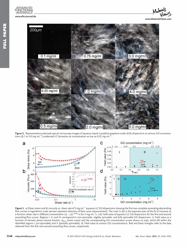
measurements and the GO sheet density was considered to be 2.2 g cm − 3 based on the literature. [ 10 ] The above equation gave a theoretical biphasic region between 0.05 and 0.09 mg mL − 1 . Aqueous GO dispersions at concentrations ranging from 0.10 to 5.00 mg mL − 1 were examined using polarized optical microscopy and showed the nematic phase starting to form at GO concentrations close to 0.25 mg mL − 1 ( Figure 2 ), which is higher than theoretical calculations (0.09 mg mL − 1 ). This differ-ence mainly arises as a result of fl exibility of GO sheets, which results in the wrinkling behavior. The wrinkling can also have profound effect on the charge concentrations on the surface of GO sheets leading to electrostatic anomaly on the surface and localization of electrostatic charges on some preferred regions. Also the asymmetry of size distribution and shape irregularity can play important roles in the deviation of theoretical estima-tions from experimental values.
A wet-spinning experiment (Figure S3 in the Supporting Information) involved injecting LC GO dispersion into a coagu-lation bath to produce gel-state GO fi ber. Below 0.25 mg mL − 1 , GO dispersions were completely isotropic and unspinnable (i.e., GO sheets simply spread into the coagulation bath). At higher concentration (between 0.25 and 0.75 mg mL − 1 ), transi-tion of biphasic to fully nematic phase is observed (i.e., when isotropic and nematic phases co-exist). This biphasic concen-tration range only demonstrated partial spinnability in fi ber-spinning processes. This partial spinnability is characterized by the weak cohesion of the GO dispersion upon injecting in the coagulation bath, which resulted in short lengths of gel-state GO fi bers. Also observed in this concentration range is that the nematic phase volume fraction ( φ nem ) increased with GO con-centration. Using GO concentration of ≥ 0.75 mg mL − 1 , when the fully nematic phase forms, in fi ber wet-spinning resulted in long lengths of robust gel-state fi bers. GO concentrations of 0.75 to 5 mg mL − 1 showed similar ease of spinnability.
Rheological investigations were carried out to correlate LC behavior, GO concentration, and spinnability. The rheo-logical behavior of the LC GO dispersions exhibited that of a non-Newtonian liquid with fl ow curves exhibiting yield values (the lowest shear stress necessary to produce viscous fl ow) [ 23 ] similar to the rheological behavior of plastic fl uids. [ 24 ] To better illustrate this behavior, the fl ow curves of 5 mg mL − 1 GO dis-persion are shown in Figure 3 a. After repeating the fl ow meas-urements, in the second run, the amount of the yield value on the ascending curve matches that of the descending curve in the very fi rst run suggesting the orientation of the anisotropic phase upon subjecting to the shear fi eld. The drop in the yield value in the second run (when the measurements are repeated) compared to the initial run corresponds to that of the aligned sample. Further confi rmation of this plastic behavior is evident from the apparent viscosity ( η ) that approaches ∞ as shear rate ( γ̇ ) approaches 0, which was found to experimentally scale as η ∼ ( γ̇ ) − 0.952 (Figure 3 b). It should be noted that the theoretical exponent for plastic materials has a value of − 1. This theoret-ical value suggests limited structural modifi cations, such as an alignment of the lamellar planes, but no viscous components. A viscous character would show an exponent value between − 1 and 0. Therefore the slight deviation from the theoretical value of − 1 [ 24 ] represents the viscous component of the mate-rial. The most feasible physical mechanism that can be taken
mbH & Co. KGaA, Weinheim Adv. Funct. Mater. 2013, 23, 5345–5354

FULL P
APER
www.afm-journal.dewww.MaterialsViews.com
Figure 1 . As-prepared GO dispersions predominantly contain giant monolayer GO sheets. a) AFM image of a large GO sheet with lateral size > 75 μ m. The inset shows the height profi le derived from the marked line in the AFM image showing monolayer GO sheet thickness of ca. 0.81 nm. b) High-resolution transmission electron microscopy (TEM) image of monolayer GO sheet and the corresponding electron diffraction pattern (inset). c) Representative SEM images of GO sheets present in as-prepared GO dispersions contain GO sheets with lateral size as large as 100 μ m. d) The corresponding lateral size distribution of GO sheets (the diameter of an equal-area circle).
into account for the observed plastic behavior of the LC phase is the sliding of lamellae along the layer of water molecules. Based on thermodynamics, there is no driving force for the relaxa-tion of the structure after sliding along any possible direction tangent to the lamellae. [ 24 ] It is also hypothesized that sliding can very likely occur between the water phase lamellae. There-fore, it is safe to assume that at the very fi rst stage (low strain), water is confi ned between the layers. After the initial confi ne-ment of water, the shear stress decreases and then increases with increasing shear rate. This water confi nement gives rise to the non-Newtonian behavior observed here. However, upon decreasing the concentration to the region where a mixture of phases can be observed, the exponent value completely devi-ates from the theoretical value of − 1, demonstrating the loss of plastic component (Figure 3 b, inset). It is pertinent to men-tion that at GO concentrations below 0.75 mg mL − 1 , a sharp deviation in the ideal scaling is evident as GO concentration decreased, suggesting the loss of the plastic component and the viscous component becoming more dominant. The prevailing
© 2013 WILEY-VCH Verlag GmAdv. Funct. Mater. 2013, 23, 5345–5354
behavior coincided with the emergence of isotropic phase as GO concentration decreased.
Figure 3 c,d show the yield value of GO dispersion as a func-tion of concentration and nematic phase volume fractions ( φ nem ) for the fi rst and second ascending shear stress. Inves-tigations of the rheological behavior of aqueous GO disper-sions (also evaluated as fi ber spinning solutions) reveal that yield values increase systematically with GO concentration. At concentrations ≤0.25 mg mL − 1 where φ nem is negligible, there was no difference between the two yield values for the fi rst and second ascending fl ows. This concentration range (I) was unspinnable. At 0.25 < GO ≤ 0.75 mg mL − 1 (II), the difference in yield values observed then increased with φ nem , which is in complete agreement with the transition concentration to a fully nematic phase observed in POM studies. Above 0.75 mg mL − 1 (III, fully nematic), the fl ow curves reveal signifi cant difference between yield values that increase almost linearly with GO con-centration. In this region, cohesion of the spinning solution dramatically improved and long lengths of robust gel fi ber were
5347wileyonlinelibrary.combH & Co. KGaA, Weinheim
FULL
PAPER
5348
www.afm-journal.dewww.MaterialsViews.com
wileyonlinelibrary.com © 2013 WILEY-VCH Verlag GmbH & Co. KGaA, Weinheim
Figure 3 . a) Shear stress and b) viscosity vs. shear rate of 5 mg mL − 1 aqueous LC GO dispersions showing the fi rst two complete ascending-descending fl ow curves in logarithmic scale (arrows represent direction of fl ow curve measurement). The inset in (b) is the exponent part of the fi t of viscosity as a function shear rate in different concentration ( η ∼ ( γ̇ ) –0.952 is for 5 mg mL –1 ). c,d) Yield value of aqueous LC GO dispersions for the fi rst and second ascending fl ow curves. Regions I, II, and III correspond to non-spinnable, slightly spinnable, and fully spinnable GO dispersions. c) Yield value as a function of nematic phase volume fraction, ϕ nem (main x -axis) and the corresponding GO concentration ( x -axis shown on top), which fall within the identifi ed regions I (un-spinnable) and II (partially spinnable). d) Yield value at various GO concentrations. Red and black triangles refer to the data obtained from the fi rst and second ascending fl ow curves, respectively.
Figure 2 . Representative polarized optical microscopy images of aqueous liquid crystalline graphene oxide (GO) dispersions at various GO concentra-tions (0.1 to 5.0 mg mL − 1 ) evidenced LC formation at concentration as low as 0.25 mg mL − 1 .
Adv. Funct. Mater. 2013, 23, 5345–5354

FULL P
APER
www.afm-journal.dewww.MaterialsViews.com
Figure 4 . Digital images of GO yarns produced using a multi-hole spinneret: a) snapshot of the formation of gel-state GO fi laments as they exit the multi-hole spinneret and b) when they are being pulled out from the bath for collection.
produced and subsequently dried without breaking. The shear-induced alignment of the LC phase could explain the observed excellent spinnability of the fully nematic LC GO dispersions. The large GO sheet dimensions and aspect ratio (the average lateral size of ca. 37 μ m and thickness of 0.8 nm give a mean aspect ratio of ca. 45 000, which is much higher than previous reports) [ 12–14 ] provide alignment of the sheets within the fi bers produced. [ 15 ] Of note is that the concentration and viscosity of a spinnable LC GO dispersion can be as low as 0.75 mg mL − 1 and ca. 30 Pa s, respectively. This concentration was around two orders of magnitude lower than the previously reported value for wet-spinning of LC GO dispersion. [ 14 ] Conventionally much higher concentration and viscosity are required for wet-spin-ning formulations. [ 25 ] This low concentration hold promises to a wide range of possibilities including new formulations of LC GO with different materials (CNTs, metallic based particles, polymers, etc) that are not accessible in the case of concentrated dispersions because of the viscosity limitations.
In a recent paper, [ 15 ] it was demonstrated that giant GO fl akes (larger than 10 μ m) can undergo a transition to an LC gel-like state. The gel-like LC state showed an unusually defect-free alignment over hundreds of micrometers. In general, a gel is considered as a semi-rigid network in which a liquid is held. [ 26 ] However, the gel-like state induced because of ultra-large GO sheets prepared in our study exhibits fundamental characteris-tics that ordinary gels do not have. These characteristics include exceptional uniformity of the network structure (large domain LC), and the anisotropy arising from having LC in the net-work, which are the common features of liquid crystalline gel structures (solvent content > 99%). [ 15 , 26 ] These unique features enable our as-prepared dispersions to be aligned by shear, as demonstrated by rheological studies, and ensure the preserva-tion of the order even at low concentrations as they form a gel-like LC fi ber as a result of wet-spinning.
2.2. GO and rGO Fibers
LC GO dispersions were found to be versatile for use in var-ious wet-spinning coagulation systems. [ 25 , 27–29 ] GO dispersions that displayed LC behavior (i.e., those above 0.75 mg mL − 1 )
© 2013 WILEY-VCH Verlag GmAdv. Funct. Mater. 2013, 23, 5345–5354
exhibited excellent spinnability in any of the following coagula-tion methods: non-solvent precipitation, dispersion destabiliza-tion using acid, base or salt solutions, ionic cross-linking using divalent cations, and coagulation by amphiphilic or oppositely charged polymers. Representative digital images of fi bers pro-duced using the above coagulation strategies are shown in Figure S4 (Supporting Information). Note that we identifi ed spinnability to be excellent only when continuous gel-state GO fi bers exceeded 10 m in length. These gel-state GO fi bers must also withstand the drying and collection process whereby the gel-state GO fi ber is passed through a series of bath con-taining water, acetone, and/or ethanol before being collected dry onto a spool. After drying, reduction of GO to rGO fi bers was achieved either by annealing at 220 ° C or by chemical treat-ment with hydrazine vapor. The scalability of this process was demonstrated by using the multi-fi lament spinning approach to produce GO yarns. This type of fi ber spinning was done by replacing the 1-hole spinneret with a 50-hole spinneret (with each orifi ce diameter of 100 μ m). Shown in Figure 4 is a snap-shot of the formation of gel-state GO fi laments as they exit the multi-hole spinneret and, at the other end, are being pulled out from the bath for collection.
Polarized optical microscopy images of the gel-state GO fi bers displayed birefringence ( Figure 5 a), which suggests highly ordered GO domains are preserved during this initial stage of the spinning process. It is important to note that, in the case of GO, the timescale for the formation of mono-domains without applying an external driving force would be infi nite. [ 13 ] Magnetic fi eld-assisted alignment of LC GO is reported to occur just after 5 h to form uniform LCs. [ 13 ] However, macroscopic alignement was obtained during wet-spinning in just a few sec-onds as a result of gentle shear stress applied through the spin-neret due to the presence of giant sheets (mean aspect ratio of 45 000 vs. 1600) [ 13 ] forming large LC domains. LCs with larger domains are known to yield macroscopic materials with higher microstructural order and better properties. [ 30 ] In addition, the tension applied through the spinneret oriented the LC domains and rapid coagulation preserved this orientation. In the dry-state fi bers, the morphology of the fi ber cross-section revealed that GO sheets are stacked in layers with some degree of folding and are orientated in the fi ber axis direction (Figure 5 b–d).
5349wileyonlinelibrary.combH & Co. KGaA, Weinheim

FULL
PAPER
535
www.afm-journal.dewww.MaterialsViews.com
Figure 5 . a) Polarized optical microscopy image of as-spun gel-state GO fi ber showing birefringence. Birefringence properties confi rmed ordered LC domains were formed and preserved during spinning process (arrows show polarizers direction). SEM images of an as-spun GO fi ber showing: b) corrugated surface and c) near-circular cross-section. d) Close-up SEM image of the cross-section of GO fi ber shown in b revealing GO sheet planes that are oriented along the fi ber axis. e,f) SEM images of crumpled and knotted rGO yarns (reduced by annealing) showing their fl exibility.
Analysis of the distinct sharp peak observed at 2 θ = 10.5 ° in the X-ray diffraction (XRD) pattern of room temperature washed/dried GO fi bers suggested that the observed layered GO sheets have a mean d- spacing of ca. 8.42 Å ( Figure 6 ). This d -spacing is similar to GO papers prepared from the same LC GO dispersions (Figure S1 in the Supporting Information), which confi rms that water molecules are retained in the inter-lamellar GO sheets. XRD analysis of the GO fi ber annealed at 220 ° C displayed a signifi cantly different XRD pattern but with a d -spacing (estimated from the maximum peak to be ca.
0 wileyonlinelibrary.com © 2013 WILEY-VCH Verlag G
Figure 6 . Comparison of XRD patterns of GO fi ber (8.42 Å), rGO fi ber (3.71 Å), and thermally expanded graphite (3.32 Å).
3.71 Å) close to that of the fully graphitic expanded graphite starting material, which showed a distinct sharp (002) peak at 26 ° and a d- spacing that corresponds to ca. 3.32 Å. These results suggest that water and the majority of the chemical functionalities in the GO sheets were removed after annealing and/or chemical reduction by hydrazine vapor; indicating the effectiveness of the reduction process. [ 9 , 10 ] The reduction of GO by annealing is further confi rmed by the signifi cantly higher electrical conductivity of rGO fi ber (ca. 2844 S m − 1 ) compared to the parent insulating GO fi ber.
2.3. Mechanical Properties
Representative stress–strain curves of the GO fi bers spun using various coagulation baths are compared in Figure 7 a and the mechanical properties along with the comparison with previous reports on graphene fi bers are summarized in Table 1 . It is evi-dent from the results coagulation bath employed and reduction of the GO sheets infl uence the mechanical properties of GO and rGO fi bers.
As-spun GO fi bers prepared by ionic cross-linking and polyionic complexation (using the positively charged polymer, chitosan) displayed the highest mechanical properties with Young’s modulus ( E ), ultimate strength ( δ ) and toughness ( T ) of 22.6 ± 1.9 GPa, 442 ± 18 MPa and 4.8 J g − 1 , respectively. In this case, both cross-linking and coagulation by oppositely charged polymers contribute to the enhancement in mechan-ical properties. However, it should be noted that chitosan is not expected to be able to penetrate into the internal of the fi ber and the strengthening, therefore, would just happen at the surface. The SEM image presented in Figure S5c (see the Supporting Information) clearly shows that the outer layer of the fi ber is
mbH & Co. KGaA, Weinheim Adv. Funct. Mater. 2013, 23, 5345–5354

FULL P
APER
www.afm-journal.dewww.MaterialsViews.com
© 2013 WILEY-VCH Verlag Gm
Figure 7 . Properties of GO and rGO fi bers: a) stress–strain curves of as-spun GO fi bers prepared using various coagulation baths and b) tempera-ture-dependent thermal conductivity of rGO fi ber in the 46 to 380 K range.
Table 1. Mechanical, electrical, and thermal properties of GO and rGO fi be
Production condition Young’s modulus [GPa]
Ultimate stress[MPa]
GO fi bers coagulated by chitosan 22.6 ± 1.9 442 ± 18
GO fi bers coagulated by CaCl 2 20.1 ± 2.1 412 ± 30
rGO fi bers coagulated by NaOH 11 ± 2.4 183 ± 25
rGO fi bers coagulated by NaOH
(further reduction at 220 ° C)9.0 ± 2.1 115 ± 19
Graphene nanoribbons fi bers annealed at
1500 ° C
36.2 378
rGO fi ber (glass pipeline moulding, annealed
at 230 ° C)
– 180
rGO fi ber (glass pipeline moulding, annealed
at 800 ° C)
– 420
rGO fi ber (reduced by hydroiodic acid) 5.4 130
GO fi bers coagulated by CaCl 2 (stretched) 6.3 364
rGO fi bers coagulated by CaCl 2
(reduced by hydroiodic acid and stretched)
11.2 501
Adv. Funct. Mater. 2013, 23, 5345–5354
much more compact than the core of the fi ber, indicating that the interaction mostly happens at the surface.
Apart from chitosan, coagulation in CaCl 2 , which exploits ionic cross-linking using divalent cations (Ca 2 + ), also resulted in fi bers with extraordinary mechanical properties ( E = 20.1 ± 2.1 GPa, δ = 412 ± 30 MPa, and T = 4.8 J g − 1 ). Divalent metal ions such as Mg 2 + , Ca 2 + , and Cu 2 + are known to readily react with carboxylate functional groups, typically located at the edges of GO sheets. [ 31 ] This chemical interaction can then result in mechanical enhancement of the fi nal architecture. It is expected that these ions can readily diffuse into the core of the fi bers resulting in exceptional cross-linking within the fi ber.
Partially reduced graphene oxide fi bers were fabricated employing continuous one-step wet-spinning in alkaline baths. In the case of alkaline baths, although the underlying reduc-tion mechanism is still unclear, it is possible that oxidative debris, which mainly comprises a mixture of complex aromatic structures containing COH-rich functional groups, is stripped from graphene oxide under alkaline conditions. [ 32 , 33 ] Other studies suggest a fast irreversible deoxygenation of graphene oxide under basic conditions. [ 34 ] However, irrespective of the mechanisms involved, employing alkaline coagulation baths results in the removal of oxygen multifunctionalities [ 32–35 ] and consequently water from the graphene oxide sheets, which in turn results in fi ber coagulation and elimination of hydrogen bonds in between GO sheets and weakening of the interlayer crosslinking. This water elimination leads to slightly lower mechanical properties compared to GO fi bers coagulated in acetone baths. For as-prepared GO fi bers spun using acetone, the lateral cohesion of the adjacent GO sheets is attributed to the strong van der Waals interactions (from the hydrophobic polyaromatic nanographene domains remaining on the basal planes) [ 9 , 20 ] and the formation of hydrogen bonds (mediated by the oxygenated functional groups and water molecules).
The best as-spun GO fi ber strength (ca. 442 MPa) is higher than previously reported GO and rGO-based materials such as GO papers (ca. 120 MPa), [ 36 ] RGOF/PVA fi bers (ca. 120 MPa), [ 37 ]
5351wileyonlinelibrary.combH & Co. KGaA, Weinheim
rs prepared in this study and previous reports.
Toughness [J g − 1 ]
Electrical conductivity [S m − 1 ]
Thermal conductivity [W m − 1 K − 1 ]
Ref.
4.8 – – This study
4.8 – – This study
1.6 221 – This study
1.3 2.8 × 10 2 1435 This study
– 2.8 × 10 3 – [ 38 ]
– 10 3 – [ 39 ]
– – – [ 39 ]
– 2.5 × 10 4 – [ 14 ]
– – – [ 17 ]
– 4.1 × 10 4 – [ 17 ]

FULL
PAPER
5352
www.afm-journal.dewww.MaterialsViews.com
LC GO fi bers (ca. 102 MPa), [ 14 ] stretched “ultrastrong” GO fi bers (364 MPa), [ 17 ] fi bers produced from graphene nanor-ibbons (378 MPa), [ 38 ] hydrothermally converted rGO fi bers (ca. 180 MPa), and thermally reduced rGO fi bers (420 MPa). [ 39 ] In terms of modulus, the GO fi ber (22.6 GPa) is inferior to the highest modulus of GO paper (42 GPa) [ 36 ] and fi bers pro-duced from graphene nanoribbons (36.2 GPa), [ 38 ] but the dif-ference in breaking strain is substantial (3.2% for GO fi ber vs. ca. 0.4% for GO paper and 1.1% for fi bers produced from gra-phene nanoribbons) resulting in toughness (4.8 J g − 1 ) consider-ably higher than both. [ 36 , 38 ] The strength of as-spun GO fi ber is also much higher than single yarns of pure multiwalled CNTs (ca. 250 MPa). [ 40 ] It should be noted that the GO used in this study is much larger compared to “giant GO” [ 17 ] (37 μ m in this study vs. 18 μ m), which is the basis of the enhanced improve-ment in mechanical properties attained in the current study.
As expected, annealed rGO fi bers have lower mechanical properties than the parent GO fi bers irrespective of the coag-ulation bath used. It is pertinent to mention that there are different reduction processes that can be used to reduce gra-phene oxide. However as a general guideline, irrespective of the mechanisms involved, reducing graphene oxide by either employing annealing at moderate temperatures (up to 220 ° C) or alkaline coagulation baths results in the removal of oxygen multifunctionalities, [ 32–35 ] and consequently water from the gra-phene oxide sheets, which in turn results in the elimination of hydrogen bonds in between GO sheets and weakening of inter-layer crosslinking. [ 35 ] This, in turn, results in inferior mechan-ical properties of reduced graphene oxide compared to parent graphene oxide. However, annealed rGO fi bers still displayed fl exibility and remained intact even when knots and twists were introduced (Figure 5 e,f). Notably, reasonable strong electrically conducting rGO fi bers were produced in a single step (i.e., no post-spinning annealing treatment is employed). A native conductivity of ca. 221 S m − 1 was obtained from NaOH spun rGO fi bers, which displayed modulus and tensile strengths of ca. 11 GPa and ca. 183 MPa, respectively (Table 1 ). This type of GO reduction process has also been employed in some lit-erature reports as a post-treatment process to reduce GO to rGO. [ 34 ] In contrast with previous reports, [ 14 , 17 ] here we show the continuous one-step production of rGO fi bers using alka-line coagulation baths, which is of technological interest as the need for reduction post-treatment processes can be eliminated. We also investigated the use of hydrazine (by exposing the fi ber to hydrazine vapor at 80 ° C) to reduce the GO fi bers. Although this reduction method was effective, as evidenced by increase in the electrical conductivity (ca. 250 S m − 1 ), the mechanical properties were found to be poorer compared to the parent GO fi ber. We attributed this decrease in mechanical properties to the signifi cant expansion of GO fi ber diameter (up to 400%) after hydrazine vapor treatment.
2.4. Thermal Conductivity
The thermal conductivity of the rGO fi ber was determined by a standard four-point probe method in the 50 to 380 K temperature range (Figure 7 b). Whilst the room temperature thermal conduc-tivity for our rGO fi bers (1435 W m − 1 K − 1 ) is signifi cantly higher
wileyonlinelibrary.com © 2013 WILEY-VCH Verlag G
than LC wet-spun CNT fi bers (20 W m − 1 K − 1 ), [ 18 ] magnetically aligned CNT fi lms (ca. 220 W m − 1 K − 1 ), [ 41 ] and graphene-based paper (ca. 112 W m − 1 K − 1 ), [ 42 ] it is however, lower than single layer pristine graphene (up to 5300 W m − 1 K − 1 ). [ 43 , 44 ] Interestingly, it is also higher than polycrystalline graphite (200 W m − 1 K − 1 ). [ 43 ]
It is known that the thermal conductivity of multilayer gra-phene is reduced in comparison to single-layer graphene, by an almost linear increment versus the number of layers and an enhancement in the interplanar van der Waals bonding strength. This is considered to be due to interlayer interactions and vibrational restrictions from neighboring layers, which limits the free vibration of the graphene sheets and imposes resistance on phonon transport. [ 45 ] Therefore, we believe that the thermal transport properties of our rGO fi bers are not an indication of the in-plane thermal conductivity of the indi-vidual layers due to the tangled nature of the rGO sheets in the fi ber and lattice defects that are introduced during GO sheet synthesis and subsequent reduction processes. These effects further contribute to the lower thermal conductivity measure-ments compared to pristine graphene. However, this hypoth-esis alone does not explain why the thermal conductivity of our rGO is higher than polycrystalline graphite. It should be noted that the measurements were performed along the longi-tudinal axis of rGo fi bers, as depicted in Figure S6 (Supporting Information). From the XRD patterns presented in Figure 6 , it is apparent that the interlayer d -spacing of rGO sheets in the rGO fi bers perpendicular to the longitudinal axis (0.371 nm) is higher than that of raw material (0.332), graphite and CNTs (0.34 nm), suggesting the presence of remaining multifunc-tionalities which might act as pillars increasing the interlayer spacing among individual sheets. We suggest that functional groups on the rGO planes enhance interplane bonding strength and consequently limit the vibration of the rGO sheets, which reduces the thermal conductivity compared to graphene; how-ever, this interplane bond strength is less than that of graphite.
3. Conclusions
In summary, the new fi ndings enabled us to spin continuous conducting, fully oriented, strong, and robust graphene fi bers and yarns at practical concentrations as low as 0.075 wt% (which is one order of magnitude lower than previously reported and the lowest ever reported value for spinning of any type of col-loidal solutions) eliminating the need for relatively concentrated spinning dope dispersions. This low concentration enables a whole range of possibilities, including new formulations of LC GO with different materials (CNTs, metallic based particles, polymers, etc.) that are not accessible in the case of concentrated dispersions because of the viscosity limitations. The scalability of the process was demonstrated by performing multi-fi lament spinning and producing a fundamentally unlimited length of yarns out of these fi bers. The promising properties of GO and rGO fi bers presented here are potentially applicable in many specialized technical applications. Fundamental understanding of the GO dispersion chemistry and rheology, the associated fi ber spinning processes, and the resultant material proper-ties, presented here along with one-step production of rGO fi bers, will provide scope for the development of next generation
mbH & Co. KGaA, Weinheim Adv. Funct. Mater. 2013, 23, 5345–5354

FULL P
APER
www.afm-journal.dewww.MaterialsViews.com
advanced GO/rGO-based fi ber architectures and associated technologies. The simplicity and the scalability of the processes described here will enable safe and cost-effective large-scale production of GO/rGO fi ber to fi nd a place in the smart fi ber industry (i.e., fi bers that integrate applications in energy, envi-ronmental monitoring, and biomedical engineering).
4. Experimental Section GO Synthesis : Dry expandable graphite fl akes (3772, Asbury Graphite
Mills USA) were fi rst thermally treated (at 1050 ° C for 15 s) and then used as precursor for GO synthesis following previously described methods. [ 9 , 46 ] Briefl y, expanded graphite (5 g) and sulfuric acid (1 L) were mixed and stirred in a fl ask. Then, KMnO 4 (50 g) was added to the mixture dropwise. The mixture was transferred into an ice bath, and Milli-Q (1 L) water and H 2 O 2 (250 mL) were poured slowly into the mixture, realizing a colour change of the suspension to light brown. Having stirred for another 30 min, the GO particles were then washed and centrifuged with a HCl solution (9:1 water/HCl by volume), then centrifuged again and washed with Milli-Q water until the pH of the solution became about 5. The resultant large GO sheets were dispersed in deionized water by gentle shaking (i.e., without the aid of sonication).
Characterization of GO Sheets : AFM and SEM analysis were carried out by fi rst depositing GO sheets from their dispersions on pre-cleaned and silanized silicon wafer (300 nm SiO 2 layer). Silane solution was prepared by mixing 3-aminopropyltriethoxysilane (Aldrich) with water (1:9 v/v) and one drop of hydrochloric acid (Sigma–Aldrich). Precut silicon substrates were silanized by immersing in aqueous silane solution for 30 min and then washed thoroughly with Millipore water. GO sheets were deposited onto silanized silicon substrates by immersing a silicon substrate into the GO dispersion (50 μ g mL − 1 ) for 5 s, then into a second container containing Millipore water for 30 s, and then air-drying. Prior to SEM and AFM analysis, GO sheets were observed under an optical microscope to ensure uniform GO sheet deposition was achieved. As-deposited GO sheets were directly examined by scanning electron microscopy (SEM, JEOL JSM-7500FA). The lateral size distributions of 256 isolated GO sheets were determined from 25 SEM images and analyzed using image analysis software (imageJ, http://rsb.info.nih.gov/ij/ ). The lateral size of ultra-large GO sheets was defi ned as the diameter of an equal-area circle. Atomic force microscopy (MFP-3D AFM Asylum Research, CA) was carried out in tapping mode under ambient conditions. Transmission electron microscopy was carried out on GO sheets deposited on holey carbon grid (a droplet from 50 μ g mL − 1 GO suspension) using JEOL JEM-2200FS. X-ray diffraction studies were performed using a powder XRD system (Philips1825) with CuK α radiation ( λ = 0.154 nm) operating at 40 keV and with a cathode current of 20 mA.
Characterization of GO Dispersions : The birefringence of GO dispersions was examined by polarized optical microscopy (Leica DM EP) operated in transmission mode. The volume fraction of liquid crystalline domains in birefringent solutions was estimated using previously reported methods. [ 22 , 47 ] Briefl y, 75 μ L of a series of GO dispersion concentration (0.1 to 5.0 mg mL − 1 ) was placed in a capillary tube (1.5 mm ID), sealed (using glue) and then left stationary for one week. The volume fraction of the stable birefringent (nematic) phase was then measured by polarized optical microscopy on the seventh day. The rheological properties of aqueous GO dispersions were investigated using a rheometer (AR-G2 TA Instruments) with a conical shaped spindle (angle: 2 ° , diameter: 40 mm). Approximately 600 μ L of GO dispersions was loaded into the rheometer with great care taken not to shear or stretch the sample. Shear stress and viscosity were measured at shear rates between 0.01 to 10 using logarithmic steps (total 200 points) for two complete (ascending and descending) cycles. Shear rate was kept constant at each point for 2 min and data recorded during the last 15 s are reported. Yield value and viscosity (at the lowest shear rate) were obtained and plotted as a function of concentration for the fi rst and second ascending cycles.
© 2013 WILEY-VCH Verlag GmAdv. Funct. Mater. 2013, 23, 5345–5354
Fiber Spinning : Two types of fi ber wet-spinning systems were utilized, as illustrated in Figure S3 (Supporting Information). The spinnability of GO dispersions was evaluated using the “petri dish method”. In this method, a GO dispersion was injected at fl ow rates between 5 and 10 mL h − 1 into a rotating petri dish (between 30 to 60 rpm) that contained the coagulation bath. Spinning trials were also carried out using a custom-built wet-spinning apparatus to demonstrate the continuous fi ber wet-spinning process. Dried GO fi bers were obtained by washing the gel-state GO fi bers with 25 vol% ethanol in water and then air-drying of the fi ber under tension at room temperature was performed. Reduction of GO fi bers (rGO) was carried out by overnight annealing at 220 ° C under vacuum or by exposing the fi bers (under tension) to hydrazine vapor at 80 ° C for 3 h.
Characterization of GO and rGO Fibers : As the cross-section of the fi bers are not perfectly circular, also reported elsewhere, [ 14 , 17 ] we calculated the mechanical properties and electrical conductivity based on the area of a circle with a diameter equal to the longest width (widest diameter) of the irregular fi bre (Figure S5 in the Supporting Information) and denoted the “overestimated area”. However, to have a fair comparison with other literature reports regarding graphene fi bers, we have now added calculated mechanical and electrical properties results based on the actual area denoted. The tensile properties of the GO and rGO fi bers were measured for 15 samples for each coagulation bath (average and deviation are reported) using a tensile tester (Shimadzu EZ-S) at a strain rate of 0.5% min − 1 . A linear four-point probe conductivity set-up with uniform 2.3 mm probe spacing was employed to measure the room temperature conductivity of the fi bers using a galvanostat current source (Princeton Applied Research Model 363) and a digital multimeter (HP Agilent 34401A). The temperature dependent thermal transport properties were measured in a physical property measurement system (PPMS 6500-Quantum Design), using the standard four-probe method. The pressure of the sample chamber was less than 5 × 10 − 4 Torr during the thermal conductivity measurements. Samples were mounted on quartz substrates with known thermal conductivity (1 W m − 1 K − 1 at room temperature). Therefore, the heat loss to the substrate was neglected. Heat was applied to one end of the fi ber by running current through the heater (I + /heat) and heat exits the fi ber to the coldfoot. The temperatures T hot and T cold were measured at the thermometer shoes. These data were employed by the equipment software to measure the thermal conductance ( K ) of the sample using K = kA / L where k is thermal conductivity, and, A and L are the cross-section of fi ber and the distance ( L = 3.13 mm) between two thermometer shoes, respectively. It should be noted that the overestimated area was used to determine the thermal conductivity of the samples, resulting in an underestimated thermal conductivity values.
Supporting Information Supporting Information is available from the Wiley Online Library or from the author.
Acknowledgements The authors thank Tony Romeo for technical assistance, the Australian Research Council (ARC) for fi nancial support, and the ANFF Materials Node for their provision of research facilities. This work was supported by ARC APD Fellowship DP098753 (JMR), ARC Discovery Project DP1093952 (KK and SHA) ARC Discovery Early Career Researcher Award DE130100310 (SAY) and ARC Federation Fellowship (GGW). Expandable graphite was kindly provided by Asbury Carbons.
Received: March 1, 2013 Revised: April 10, 2013
Published online: May 27, 2013
5353wileyonlinelibrary.combH & Co. KGaA, Weinheim

FULL
PAPER
5354
www.afm-journal.dewww.MaterialsViews.com
[ 1 ] Y. Zhu , S. Murali , W. Cai , X. Li , J. W. Suk , J. R. Potts , R. S. Ruoff , Adv. Mater. 2010 , 22 , 3906 .
[ 2 ] H. Chang , G. Wang , A. Yang , X. Tao , X. Liu , Y. Shen , Z. Zheng , Adv. Funct. Mater. 2010 , 20 , 2893 .
[ 3 ] Y. Zhu , S. Murali , M. D. Stoller , K. J. Ganesh , W. Cai , P. J. Ferreira , A. Pirkle , R. M. Wallace , K. A. Cychosz , M. Thommes , D. Su , E. A. Stach , R. S. Ruoff , Science 2011 , 332 , 1537 .
[ 4 ] H. Chen , M. B. Müller , K. J. Gilmore , G. G. Wallace , D. Li , Adv. Mater. 2008 , 20 , 3557 .
[ 5 ] M. G. Mohsen , A. S. Hamed , Y. Nariman , Z. Q. Bin , S. Farhad , C. Jie , L. Yayun , X. Allison , K. Jang-Kyo , MRS Proc. 2011 , 1334 , 2011 .
[ 6 ] G. Eda , G. Fanchini , M. Chhowalla , Nat. Nanotechnol. 2008 , 3 , 270 . [ 7 ] R. Lv , T. Cui , M.-S. Jun , Q. Zhang , A. Cao , D. S. Su , Z. Zhang ,
S.-H. Yoon , J. Miyawaki , I. Mochida , F. Kang , Adv. Funct. Mater. 2011 , 21 , 999 .
[ 8 ] R. Jalili , S. H. Aboutalebi , D. Esrafi lzadeh , K. Konstantinov , S. E. Moulton , J. M. Razal , G. G. Wallace , ACS Nano DOI: 10.1021/nn305906z.
[ 9 ] S. H. Aboutalebi , A. T. Chidembo , M. Salari , K. Konstantinov , D. Wexler , H. K. Liu , S. X. Dou , Energ. Environ. Sci. 2011 , 4 , 1855 .
[ 10 ] S. H. Aboutalebi , M. M. Gudarzi , Q. B. Zheng , J.-K. Kim , Adv. Funct. Mater. 2011 , 21 , 2978 .
[ 11 ] F. Guo , F. Kim , T. H. Han , V. B. Shenoy , J. Huang , R. H. Hurt , ACS Nano 2011 , 5 , 8019 .
[ 12 ] Z. Xu , C. Gao , ACS Nano 2011 , 5 , 2908 . [ 13 ] J. E. Kim , T. H. Han , S. H. Lee , J. Y. Kim , C. W. Ahn , J. M. Yun ,
S. O. Kim , Angew. Chem. Int. Ed. 2011 , 50 , 3043 . [ 14 ] Z. Xu , C. Gao , Nat. Commun. 2011 , 2 , 571 . [ 15 ] B. Dan , N. Behabtu , A. Martinez , J. S. Evans , D. V. Kosynkin ,
J. M. Tour , M. Pasquali , I. I. Smalyukh , Soft Matter 2011 , 7 , 11154 .
[ 16 ] G. Eda , M. Chhowalla , ACS Nano 2011 , 5 , 4265 . [ 17 ] Z. Xu , H. Sun , X. Zhao , C. Gao , Adv. Mater. 2013 , 25 , 188 . [ 18 ] L. M. Ericson , H. Fan , H. Peng , V. A. Davis , W. Zhou , J. Sulpizio ,
Y. Wang , R. Booker , J. Vavro , C. Guthy , A. N. G. Parra-Vasquez , M. J. Kim , S. Ramesh , R. K. Saini , C. Kittrell , G. Lavin , H. Schmidt , W. W. Adams , W. E. Billups , M. Pasquali , W.-F. Hwang , R. H. Hauge , J. E. Fischer , R. E. Smalley , Science 2004 , 305 , 1447 .
[ 19 ] F. Vollrath , D. P. Knight , Nature 2001 , 410 , 541 . [ 20 ] L. J. Cote , J. Kim , Z. Zhang , C. Sun , J. Huang , Soft Matter 2010 , 6 ,
6096 . [ 21 ] D. van der Beek , H. N. W. Lekkerkerker , Langmuir 2004 , 20 , 8582 . [ 22 ] F. M. van der Kooij , H. N. W. Lekkerkerker , J. Phys. Chem. B 1998 ,
102 , 7829 . [ 23 ] S. Paasch , F. Schambil , M. J. Schwuger , Langmuir 1989 , 5 , 1344 . [ 24 ] R. Mezzenga , C. Meyer , C. Servais , A. I. Romoscanu , L. Sagalowicz ,
R. C. Hayward , Langmuir 2005 , 21 , 3322 . [ 25 ] R. Jalili , J. M. Razal , P. C. Innis , G. G. Wallace , Adv. Funct. Mater.
2011 , 21 , 3363 .
wileyonlinelibrary.com © 2013 WILEY-VCH Verlag
[ 26 ] M. D. Kempe , N. R. Scruggs , R. Verduzco , J. Lal , J. A. Kornfi eld , Nat. Mater. 2004 , 3 , 177 .
[ 27 ] J. M. Razal , K. J. Gilmore , G. G. Wallace , Adv. Funct. Mater. 2008 , 18 , 61 .
[ 28 ] R. Jalili , J. M. Razal , G. G. Wallace , J. Mater. Chem. 2012 , 22 , 25174 .
[ 29 ] D. Esrafi lzadeh , J. M. Razal , S. E. Moulton , E. M. Stewart , G. G. Wallace , J. Controlled Release DOI: 10.1016/j.jconrel.2013.01.022.
[ 30 ] V. A. Davis , A. N. G. Parra-Vasquez , M. J. Green , P. K. Rai , N. Behabtu , V. Prieto , R. D. Booker , J. Schmidt , E. Kesselman , W. Zhou , H. Fan , W. W. Adams , R. H. Hauge , J. E. Fischer , Y. Cohen , Y. Talmon , R. E. Smalley , M. Pasquali , Nat. Nanotechnol. 2009 , 4 , 830 .
[ 31 ] S. Park , K.-S. Lee , G. Bozoklu , W. Cai , S. T. Nguyen , R. S. Ruoff , ACS Nano 2008 , 2 , 572 .
[ 32 ] J. P. Rourke , P. A. Pandey , J. J. Moore , M. Bates , I. A. Kinloch , R. J. Young , N. R. Wilson , Angew. Chem. Int. Ed. 2011 , 50 , 3173 .
[ 33 ] S. H. Aboutalebi , S. Aminorroaya-Yamini , I. Nevirkovets , K. Konstantinov , H. K. Liu , Adv. Energy Mater. 2012 , 2 , 1439 .
[ 34 ] X. Fan , W. Peng , Y. Li , X. Li , S. Wang , G. Zhang , F. Zhang , Adv. Mater. 2008 , 20 , 4490 .
[ 35 ] X. Lin , X. Shen , Q. Zheng , N. Yousefi , L. Ye , Y.-W. Mai , J.-K. Kim , ACS Nano 2012 , 6 , 10708 .
[ 36 ] D. A. Dikin , S. Stankovich , E. J. Zimney , R. D. Piner , G. H. B. Dommett , G. Evmenenko , S. T. Nguyen , R. S. Ruoff , Nature 2007 , 448 , 457 .
[ 37 ] M. K. Shin , B. Lee , S. H. Kim , J. A. Lee , G. M. Spinks , S. Gambhir , G. G. Wallace , M. E. Kozlov , R. H. Baughman , S. J. Kim , Nat. Commun. 2012 , 3 , 650 .
[ 38 ] C. Xiang , N. Behabtu , Y. Liu , H. G. Chae , C. C. Young , B. Genorio , D. E. Tsentalovich , C. Zhang , D. V. Kosynkin , J. R. Lomeda , C.-C. Hwang , S. Kumar , M. Pasquali , J. M. Tour , ACS Nano 2013 , 7 , 1628 .
[ 39 ] Z. Dong , C. Jiang , H. Cheng , Y. Zhao , G. Shi , L. Jiang , L. Qu , Adv. Mater. 2012 , 24 , 1856 .
[ 40 ] M. Zhang , K. R. Atkinson , R. H. Baughman , Science 2004 , 306 , 1358 .
[ 41 ] J. Hone , M. C. Llaguno , N. M. Nemes , A. T. Johnson , J. E. Fischer , D. A. Walters , M. J. Casavant , J. Schmidt , R. E. Smalley , Appl. Phys. Lett. 2000 , 77 , 666 .
[ 42 ] Q. Liang , X. Yao , W. Wang , Y. Liu , C. P. Wong , ACS Nano 2011 , 5 , 2392 .
[ 43 ] A. A. Balandin , S. Ghosh , W. Bao , I. Calizo , D. Teweldebrhan , F. Miao , C. N. Lau , Nano Lett. 2008 , 8 , 902 .
[ 44 ] A. A. Balandin , Nat. Mater. 2011 , 10 , 569 . [ 45 ] Z. Wei , Z. Ni , K. Bi , M. Chen , Y. Chen , Carbon 2011 , 49 , 2653 . [ 46 ] S. Iijima , Nature 1991 , 354 , 56 . [ 47 ] N. Miyamoto , T. Nakato , J. Phys. Chem. B 2004 , 108 , 6152 .
GmbH & Co. KGaA, Weinheim Adv. Funct. Mater. 2013, 23, 5345–5354