
Tome 2 – Volume 2 Teil 2 – Tomo 2
27
Tome 2 – Volume 2 Teil 2 – Tomo 2 ZR20249 Edition 3 LIRE ATTENTIVEMENT CE MANUEL AVANT LA MISE EN SERVICE DE VOTRE ZODIAC. CAREFULLY READ THIS MANUAL BEFORE OPERATING YOUR ZODIAC. LEGGERE ATTENTAMENTE PRIMA DE INIZIARE IL MONTAGGIO DEL VOSTRO ZODIAC. VOR INBETRIEBNAHME IHRES ZODIAC VORLIEGENDES HANDBUCH AUFMERKSAM LESEN. LEER CUIDADOSAMENTE ESTE MANUAL ANTES DE PONER EN SERVICIO SU ZODIAC.
-
Upload
khangminh22 -
Category
Documents
-
view
0 -
download
0
Transcript of Tome 2 – Volume 2 Teil 2 – Tomo 2

Tome 2 – Volume 2 Teil 2 – Tomo 2
ZR20249 Edition 3
LIRE ATTENTIVEMENT CE MANUEL AVANT LA MISE EN SERVICE DE VOTRE ZODIAC. CAREFULLY READ THIS MANUAL BEFORE OPERATING YOUR ZODIAC. LEGGERE ATTENTAMENTE PRIMA DE INIZIARE IL MONTAGGIO DEL VOSTRO ZODIAC. VOR INBETRIEBNAHME IHRES ZODIAC VORLIEGENDES HANDBUCH AUFMERKSAM LESEN. LEER CUIDADOSAMENTE ESTE MANUAL ANTES DE PONER EN SERVICIO SU ZODIAC.

Tome 2 - Volume 2 Teil 2 – Tomo 2

Page 2 of 26
VOLUME 2
DESCRIPTION - BUOYANCY CHAMBER PROPULSION SYSTEM
INSTALLATION AND CIRCUITS
CONTENTS
PAGE I - GENERAL DESCRIPTIONS
I-1-Technical characteristics ------------------------------------------------- 3 - 4 I-2-Inventory --------------------------------------------------------------------- 5 I-3-Location of items------------------------------------------------------------ 6-7 I-4- Handling --------------------------------------------------------------------- I-5-Location of accessories----------------------------------------------------- I-6-Tank / Fuel circuit----------------------------------------------------------- I-7-Electrical circuit ------------------------------------------------------------ 1-8-Safety labels------------------------------------------------------------------
8 - 9 10-12 13-17
18 19
II - BUOYANCY CHAMBER
II-1-Installing the buoyancy chamber on the hull------------------------- 20-21 II-2-Setting up the buoyancy chamber – Main steps--------------------- 22 II-3-Inflation system------------------------------------------------------------- II-4-Pressure ---------------------------------------------------------------------
23 24-25
III - PROPULSION SYSTEM
26

Page 3 / 26
E N G L I S H
DESCRIPTION - Technical characteristics
I-1-TECHNICAL CHARACTERISTICS
Dimensions
(m) 5.2 (ft) 17‘ 2“
(m) 4.02 (ft) 13‘ 2“
(m) 2.2 (ft) 7‘ 3“
(m) 1.2 (ft) 3‘ 11“
(m) 0.50 (ft) 1‘8“
Design category
(Directive 94/25/EC) C
Capacity
(ISO) 12
Maximum
Kg (1) 1150 lb. (1) 2535
Kg (2) 315 lb. (2) 694
Compartment 5
Engine configuration
Minimum power
recommended HP (3) 40 KW (3) 30
Maximum power
recommended HP 70 kW 53
Maximum power
allowed HP (3) 90 kW (3) 68
Maximum Maximum engine
weight Kg 200 Lbs 441
Overall dimensions
a (4) 4.46 m
14‘ 8“
b (4) 1.53 m 5‘
c (4) 0.81 m 2‘ 8“
a
b
c

Page 4 of 26
DESCRIPTION - Technical characteristics
NOTE
Dimension tolerance: +/- 4% Weight tolerance: +/- 5%
NOTE
(1) The maximum payload has been calculated according to ISO 6185 standards. Operating at or near maximum payload is only advised in calm water and at reduced speeds. (2) Weight shown not including accessories (3) The recommended power corresponds to optimum operation of the boat's capabilities for an average load (9 people.) (4) Hull dimensions without buoyancy chamber. Use the maximum authorized power with extreme caution (see "Sailing advice" chapter of Volume 1 of the manual.)
WARNING
DO NOT EXCEED THE MAXIMUM LOAD INDICATED ON THE MANUFACTURER'S PLATE. THE MAXIMUM LOAD INCLUDES THE WEIGHT OF THE ENGINE, FUEL, ACCESSORIES, PASSENGERS AND THEIR EQUIPMENT AND ANY OTHER TYPE OF LOAD.

Page 5 / 26
E N G L I S H
DESCRIPTION - Inventory
I-2-INVENTORY
HULL • Polyester hull • Counter-moulded non-slip deck • 1 Bow ring • 1 Anchor locker (capacity approximately 86 litres) + separating bulkhead • 2 traction chain plates • 1 Hull drain hole • 2 high flow rate self-bailers with stern well • 1 Tank 75 L • 1 Mooring cleat
BUOYANCY CHAMBER • Removable buoyancy chamber • Easy push valves • Anti-chafing band with wide profile • External handles • Internal handle • Lashing • Bow roller
STANDARD EQUIPMENT • 2 paddles • Foot inflator • Pressure gauge cap • Repair kit
OPTIONAL ACCESSORIES
• Sling • Roll bar • Console • Seat • Boarding ladder • Other options available. See your ZODIAC dealer

Page 6 of 26
DESCRIPTION – Location of items I-3-LOCATION OF ITEMS
7
8
11 12
13 34 23 6
10
4 5 1
14
7
8
11 12
13 4 23 6
10
4 5 1
14

Page 7 / 26
E N G L I S H
STRONGAN DUOTEX PRO 500 BUOYANCY CHAMBER BLACK/RED, DEFENCE 165 MM
ITEM REF.
DESIGNATION
1 Bow roller 2 Anchor locker cover 3 Lashing 4 Handle 5 Mooring cleat 6 Buoyancy chamber 7 AFT Chain plate 8 High flow rate self-bailer 9 Hull drain hole 10 Water shield 11 Valve/tank gauge access hatch 12 Tank surface below deck 13 Ventilation grille 14 Tank filler access
7
8
11 12
134 2 6
10
4 5 1
14
4

Page 8 of 26
DESCRIPTION - Handling
I-4-HANDLING I-4-1-Transportation The trailer installation recommendations are specified in VOLUME I of the owner's manual.
I-4-2-Storage Respect the position recommendations indicated below. Distances are expressed in millimetres.
WARNING
THE BOAT MUST REST ON THE BOW LINE
(SEE SKETCH BELOW).
800
2500

Page 9 / 26
E N G L I S H
DESCRIPTION - Handling 1-4-3-Lifting To lift your boat: You can use a 4-wire sling obtainable from your Zodiac dealer. To carry out this operation you have to:
a- Remove the aft chain plates and refit them with the ring reversed (facing forward).
b- Fit the bow of the boat with 2 additional chain plates (contact your ZODIAC dealer). The diagram below shows the areas where the fore chain plates are located (distances in millimetres).
All these fittings must be made watertight using Sikaflex.
A- Reverse the aft chain plates towards the bow
B- Fitting the fore chain plates
50
130
Detail of fore chain plate
130

Page 10 of 26
DESCRIPTION – Location of accessories I-5-1-Location of optional accessories I-5-1-1-Console/Seat/Bolster Your boat can accept certain optional accessories (console/seat/bolster). Position them in the locations indicated below to optimise use of the boat and be able to pass the wires under the deck. In addition, certain areas, particularly those above the tank, are subject to certain precautions when the tank is fitted (see diagram) The positioning dimensions are taken from the aft transom (distances in millimetres). Warning: To take advantage of the option to pass the wires under the deck and to avoid damaging the structure of the boat, the cable guide (provided with the boat) must be located in the grey-shaded area shown above (axis of non-slip area) WARNING: For safety reasons, the tank hatch must remain accessible and unencumbered by the position of accessories. It may however be entirely covered by the console, while remaining accessible through the console chest.
1700
Seat/bolster location
Console location
400
Cable guide hole drilling area Tank location area (delimited by non-slip area)
Tank access hatch
Page 11 / 26
E N G L I S H
DESCRIPTION – Location of accessories
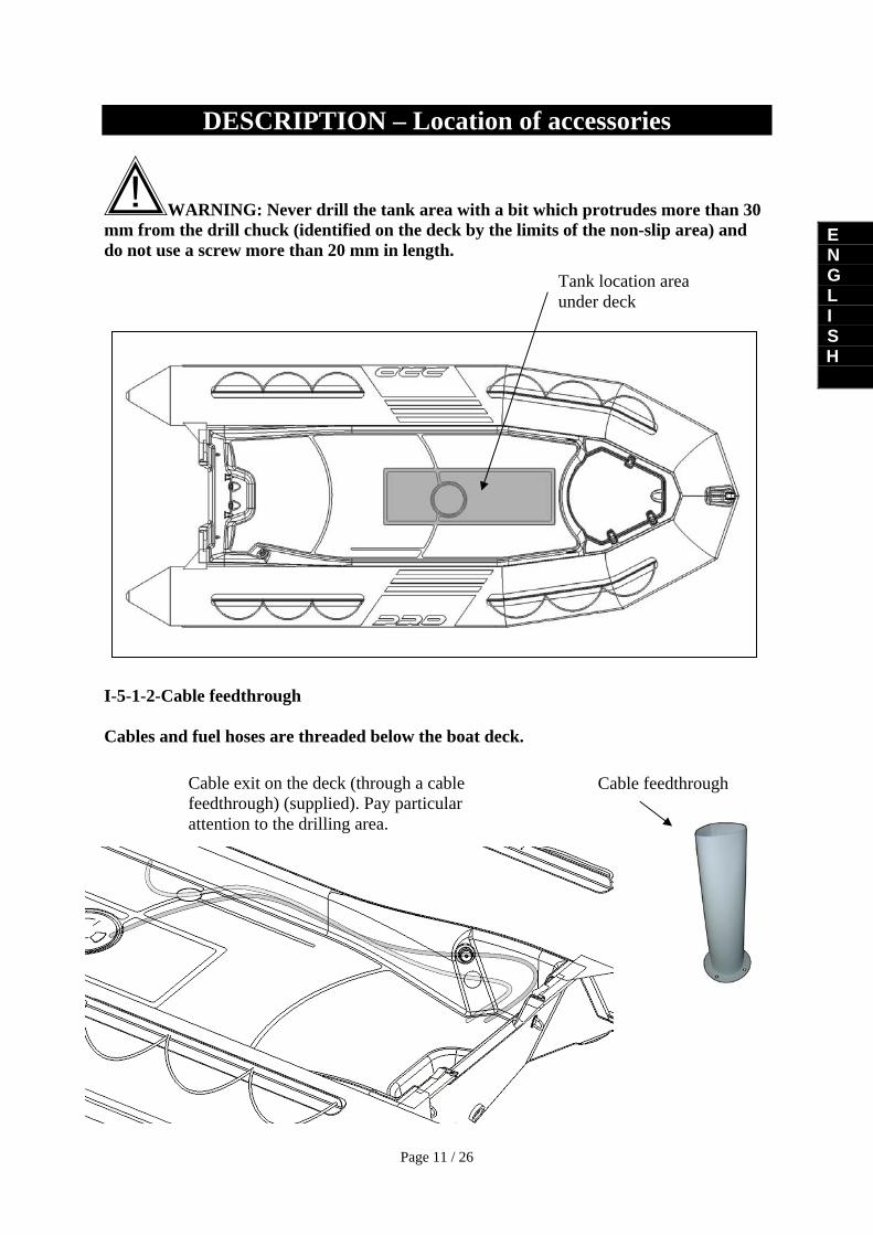
WARNING: Never drill the tank area with a bit which protrudes more than 30 mm from the drill chuck (identified on the deck by the limits of the non-slip area) and do not use a screw more than 20 mm in length. I-5-1-2-Cable feedthrough Cables and fuel hoses are threaded below the boat deck.
Tank location area under deck
Cable exit on the deck (through a cable feedthrough) (supplied). Pay particular attention to the drilling area.
Cable feedthrough

Page 12 of 26
DESCRIPTION – Location of accessories I-5-1-3-Roll bar and boarding ladder
A- Roll bar (for use to best advantage comply with the installation dimensions)
B- Boarding ladder (recommended position)
920
360
30
35

Page 13 / 26
E N G L I S H
DESCRIPTION –Tank /Fuel circuit Your boat is fitted with a tank of capacity 75 l located under the deck and filled through a hatch situated at the front of the boat under the anchor locker lid (see diagram below) I-6-1-Presentation of tank Draw the base of the pipe leaving the engine to appear at the top and the pipe to the tank to appear at the bottom I-6-2-Procedure for filling the tank To fill the tank, open the bow anchor locker lid (1), remove the small cover over the filling area (2) and lift the filler plug (3) to begin filling the tank.
Fuel line cutoff valve (accessible through the hatch on the deck)
Level probe
Filling Vent
12
3

Page 14 of 26
DESCRIPTION –Tank /Fuel circuit I-6-3-LOCKING THE PETROL CIRCUIT (valve) The fuel line is controlled by opening or closing the tank valve located under the deck and accessible by removing the hatch over it.
NOTE: - When not using your boat, close the fuel circuit valve. - When you are going to use your boat, open the fuel circuit valve.
WARNING
IN THE EVENT OF A PETROL LEAK OR A FIRE, THE PETROL CIRCUIT CLOSING VALVE LOCATED ON THE TANK ENABLES THE TANK TO BE CUT OFF FROM THE PETROL CIRCUIT AND MUST REMAIN CLOSED.
Fuel circuit valve Open
Fuel circuit valve Closed
Valve

Page 15 / 26
E N G L I S H
DESCRIPTION –Tank /Fuel circuit I-6-4–Maintenance (Replacing the tank)
NOTE:
If a problem occurs with your tank it can be replaced. A cavity is provided on the deck which can be cut out. A tank access hatch will then be installed. For your safety, a ZODIAC agent or dealer must carry out this installation. They are the only people qualified to carry out such work.
I-6-5-Water/fuel separator filter (delivered with the boat) In order to protect the engine, a water / fuel separating filter is placed on the engine’s fuel supply circuit
ITEM REF. DESIGNATION
1 Filter head, secured to boat 2 Replaceable filter cartridge
WARNING
IT IS VITAL TO REPLACE THE CARTRIDGE AFTER EVERY 50 HOURS OF USE.
1
2

Page 16 of 26
DESCRIPTION – Tank /Fuel circuit Recommended position: It is preferable to place the filter on the rear transom of the boat.
Changing the filter cartridge: Follow ZODIAC’s recommendations and those of the filter’s manufacturer. Place a draining funnel under the position of the cartridge to be replaced. Before replacing the filter, the pressure in the fuel feed system must be released. Follow the manual or the engine manufacturer’s instructions. Fuel is extremely inflammable. SWITCH OFF THE ENGINE, disconnect the battery and do not smoke or install the kit near to a naked flame. Put a drainage funnel under the place where the cartridge will be replaced. Before replacing the filter, the pressure in the fuel feed system must be released.
Filter

Page 17 / 26
E N G L I S H
DESCRIPTION – Tank /Fuel circuit I-6-6-Recommendations
WARNING
IN THE EVENT OF A PETROL LEAK OR A FIRE, THE
PETROL CIRCUIT CLOSING VALVE LOCATED ON THE TANK BELOW THE DECK MUST BE CLOSED.
HAVING A FULL TANK AVOIDS CONDENSATION APPEARING ON EACH OUTLET.
GET THE TANK CLEANED EVERY FIVE YEARS. CHECK THE TIGHTENING OF THE CLAMPS ON ALL
THE HOSES. WHEN YOU DRAIN THE FILTER, DO NOT EMPTY
THE WATER INTO THE BOAT. USE A RECOVERY TRAY UNDER THE FILTER.
CUT THE POWER SUPPLY BEFORE DISMANTLING THE FILTER CARTRIDGE.
CAREFULLY READ THE INFORMATION ON THE FILTER’S INSTRUCTIONS.
WARNING
PETROL IS HIGHLY INFLAMMABLE. ENSURE THAT
ENGINES ARE SWITCHED OFF AND THAT NOBODY IS SMOKING OR HAS A FLAME IN CLOSE PROXIMITY WHEN YOU ARE WORKING ON THE FUEL SYSTEM.

Page 18 of 26
INSTALLATION AND CIRCUIT – Electricity I-7- ELECTRICITY IV-7-1-Battery (not supplied) Recommendation for battery location I-7-2-Usage Comply with ZODIAC's recommendations and with the recommendations of the battery manufacturer for standard maintenance.
MAINTAIN YOUR BATTERY: KEEP THE BATTERY CLEAN AND DRY IN ORDER TO
AVOID PREMATURE WEAR. TIGHTEN AND MAINTAIN THE TERMINAL LUGS BY
GREASING THEM REGULARLY WITH VASELINE.
WARNING
THE WATER FROM THE WATER SUPPLY SYSTEM CONTAINS MINERAL WHICH DAMAGE BATTERIES. YOU SHOULD THUS ALWAYS TOP UP WITH DISTILLED WATER
WARNING
• KEEP THE BATTERIES AND THE ELECTROLYTE OUT OF THE REACH OF CHILDREN
• ALWAYS KEEP THE BATTERY UPRIGHT, NEVER ON ITS SIDE
• WHEN ADDING ELECTROLYTE OR WHEN RECHARGING THE BATTERY, ALWAYS REMOVE IT FROM THE ENGINE COMPARTMENT
• BATTERY ELECTROLYTE IS A TOXIC AND DANGEROUS LIQUID. IT CONTAINS SULPHURIC ACID WHICH CAN CAUSE SERIOUS BURNS. AVOID CONTACT WITH SKIN, EYES AND CLOTHES.
• BATTERIES CAN EMIT EXPLOSIVE GASES. KEEP THEM AWAY FROM SPARKS, NAKED FLAMES, AND CIGARETTES ETC.
• WHEN CHARGING OR USING A BATTERY, WORK IN A WELL-VENTILATED ENVIRONMENT. ALWAYS PROTECT YOUR EYES WHEN WORKING CLOSE TO A BATTERY.
NOTE:
If you do not plan to use your boat for a month or more, remove the battery and store it in a cool, dark, dry place. Fully recharge the battery before reusing it.
If the battery is being put away for a longer period, check electrolyte density at least once a month and recharge the battery as soon as density is too low. Electrolyte density: 1.28 to 20°C

Page 19 / 26
E N G L I S H
DESCRIPTION – Safety labels I-8-Safety labels You boat comes with safety labels. It is essential that you follow the recommendations on these in order to be able to use boat in total safety. Position on the deck

Page 20 of 26
INSTALLING THE BUOYANCY CHAMBER ON THE HULL
II-1-INSTALLING THE BUOYANCY CHAMBER ON THE HULL
IF THE BUOYANCY CHAMBER HAS BEEN STORED IN TEMPERATURES UNDER 0ºC, LEAVE IT IN A TEMPERATE PLACE (20ºC) FOR TWELVE HOURS BEFORE INSTALLATION.
1
To facilitate the positioning of the buoyancy chamber, apply liquid soap (A) to the hull rails 2
Position the bolt rope (a) of the buoyancy chamber (b) in the hull rail in the rails situated at the front of the boat (=> add an "a" and a "b" to the diagram).
3
- Pull the buoyancy chamber’s first tab towards the aft end of the boat. - Repeat for the other side of the buoyancy chamber. - The two protective flaps (sealing and exterior) should pass over the hull’s nose. - Fix the sealing protective flap to the hull using screws and fabric washers (supplied) by raising the buoyancy chamber’s nose. - Bring forward the buoyancy chamber’s nose in order to pull the exterior protective flap under the hull’s nose. - Pull the buoyancy chamber’s two tabs again as far as they will stretch towards the stern of the boat while trying to centre the nose in relation to the forward section of the hull. Slightly inflate the nose of the buoyancy chamber in order to check that it is well centred and perfectly hugs the hull. Restart the process if the buoyancy chamber is not correctly positioned.

Page 21 / 26
E N G L I S H
BUOYANCY CHAMBER – Fixing the protective flaps DETAIL OF FLAP FIXING 4
Put the internal protective flap in place 5
6
Fix the internal protective flap (screw + washers) 7
After fixing the internal protective flap on the hull, pull the buoyancy chamber gently towards the forward section in order to send the external protective flap over the forward nose (do not attach it at this point). Then pull the buoyancy chamber towards the aft end.
Then begin inflation
NOTE: • The external protective flap should be fixed on after the buoyancy chamber has been inflated

Page 22 of 26
BUOYANCY CHAMBER – Main steps II-2-SETTING UP THE BUOYANCY CHAMBER – MAIN STEPS When assembling the boat, it is important that you follow the procedure in the correct order. Proceed step by step, referring each time to the pages indicated for explanations.
INFLATION PROCEDURE PAGE SECTION 1. Make an inventory of all your boat’s components and learn to recognize them
5 to 7 Inventory Location
2. Start inflating the buoyancy chamber using working pressure
20-21 Installing the buoyancy chamber
22 to 25 Air pressure II -3-INFLATION SYSTEM THE INFLATION PUMP
a. adaptor b. tube nozzle c. tube connector d. inflation port
a
b
cd
EASY PUSH VALVES
To change position In inflating position In deflating position
Push The membrane is closed, the knob is up
The membrane is open, the knob is down
NOTE:
The plugs of the easy push valves are designed to screw in and unscrew without forcing.
Never force the caps as you will run the risk of unscrewing the whole of the valve’s internal
inflation system.

Page 23 / 26
E N G L I S H
BUOYANCY CHAMBER – Inflation system PRESSURE INDICATOR
BOAT INFLATION Activate all valves in the inflation position. Attach the hose connector to the inflator inflation port. To inflate your boat properly, the inflator should be correctly placed on the ground. The boat inflates rapidly if the inflator is used smoothly and without haste.
WARNING
DO NOT USE A COMPRESSOR
OR COMPRESSED AIR CYLINDER.

Page 24 of 26
BUOYANCY CHAMBER - Pressure INFLATING THE BUOYANCY CHAMBER • Place the adapter corresponding to the diameter of the semi built-in valve at the inflator
hose nozzle. Inflate the buoyancy mechanism, balancing the pressure between the different compartments until the partitions (a) are no longer visible (pressure = 240 mb)
NEVER PUT A COMPARTMENT
UNDER PRESSURE WHILE THE OTHERS
ARE STILL FULLY DEFLATED
a
100 %0 % 0 %
1
50 % 50 % 50 %
2
100 % 100 % 100 %
Inflating is complete: screw on the inflating valve caps.
NOTE:
A slight loss of air is normal before the cap is screwed on. Only the caps guarantee final air tightness.
II -4-PRESSURE
The correct pressure for the buoyancy chamber is 240 mb/ 3.4 PSI (middle of the green sector of the pressure gauge). Your boat is fitted with an ACCESS pressure indicator which provides a quick, efficient readout during inflation (see explanations for use in the "Inflation system" section).
Temperature of the surrounding air or water will proportionally influence the level of internal pressure in the buoyancy chamber
Ambient temperature Pressure inside the buoyancy tube
+1°C +4 mb / 0.06 PSI -1°C -4 mb / 0.06 PSI
Thus, it is important to anticipate: Check and adjust the pressure of the inflatable compartments (inflating or deflating according to the case) according to the temperature variations (especially when there is a considerable difference in temperature between morning and evening in particularly hot areas) and make sure that the pressure remains within the recommended pressure range (from 220 to 270 mb / green sector).

Page 25 / 26
E N G L I S H
BUOYANCY CHAMBER - Pressure RISK OF PRESSURE LOSS EXAMPLE: Your boat is exposed to direct sunlight on the beach (temperature=50°C) at the recommended pressure (240 mb/3.4 PSI). When you launch it (temperature=20°C), the temperature and internal pressure of the inflatable compartments will drop simultaneously (up to 120 mb) and YOU WILL THEN NEED TO REINFLATE until you regain the millibars lost due to the difference between the ambient air and water temperatures. A drop in pressure at the end of the day, when the outside temperature is dropping, is normal. RISK OF OVERPRESSURE: EXAMPLE: Your boat is inflated to its recommended pressure (240 mb/3.4 PSI) at the beginning or end of the day (low outside temperature = 10°C). Later in the day, your boat is exposed in the sun on the beach or on a yacht deck (temperature = 50°C). The temperature inside the inflatable compartments may rise to 70°C (particularly for dark buoyancy chambers), doubling the initial pressure (480 mb). YOU WILL THEN NEED TO DEFLATE the boat to return to the recommended pressure.
WARNING
IF YOUR BOAT IS OVERINFLATED, THERE WILL BE UNDUE PRESSURE ON THE INFLATABLE STRUCTURE THAT MAY RUPTURE IT.
IN CASE OF OVERPRESSURE EASY PUSH VALVE: Release air by depressing the valve plunger

Page 26 of 26
PROPULSION SYSTEM III - PROPULSION SYSTEM Complies with ZODIAC's recommendations and with the engine manufacturer's recommendations. For optimum use of your boat, seek advice from your dealer.