Tom 2 Instructions for Use and Technical Description - LINET
62
Tom 2 Paediatric hospital bed D9U001K40-0101 Version: 13 Publication Date: 2020-08 Instructions for Use and Technical Description
-
Upload
khangminh22 -
Category
Documents
-
view
4 -
download
0
Transcript of Tom 2 Instructions for Use and Technical Description - LINET
Tom 2Paediatric hospital bed
D9U001K40-0101
Version: 13
Publication Date: 2020-08
Instructions for Use and Technical Description
D9U001K40-0101_132
Manufacturer:
LINET spol. s r.o.Želevčice 5274 01 Slaný
Tel.: +420 312 576 111Fax: +420 312 522 668
E-mail: [email protected]://www.LINET.comService department: [email protected]
Tom 2Paediatric hospital bed
Author: LINET, s.r.o.Related links: www.linet.cz
D9U001K40-0101Version: 13Publication Date: 2020-08
Copyright © LINET, s.r.o., 2020Translation © LINET, 2020
All rights reserved. All trademarks and brands are the property of the appropriate owners. The manufacturer reserves the right to changes in the contents of this manual that relate to the product´s technical regulations. It is for this reason that the contents of this manual may indicate differences from the current manufacture of the product. Reproduction of the instructions for use, also excerpts, only with prior permission of the publisher. Subject to changes due to technical developments. All technical data are rated data and are subject to construction and manufacturing tolerances.
D9U001K40-0101_13
3
1 Symbols and Definitions .............................................41.1 Warning Notices ..........................................................41.1.1 Types of Warning Notices ........................................41.1.2 Structure of Warning Notices ...................................41.2 Instructions ..................................................................41.3 Lists .............................................................................41.4 Symbols on the Package ............................................51.5 Symbols and Labels on the Bed .................................61.6 Symbols and Labels on the Mattress ..........................91.7 Serial Label .................................................................111.7.1 Serial Label with UDI (Tom 2) ..................................111.7.2 Serial Label (mattress) .............................................121.7.3 Wash Label (mattress) .............................................121.8 Acoustic signalisation (Tom 2 with PB43 control unit) .131.9 Acoustic signalisation (Tom 2 with PB11 control unit) .131.10 Visual signalisation....................................................131.10.1 Mains Power LED (Mini ACP) ................................131.10.2 Accumulator Indicator (Mini ACP) ..........................131.10.3 Lock LED (Mini ACP) .............................................141.11 Night Bed Lighting (Tom 2 with PB43 control unit) ....141.12 Night Bed Lighting (Tom 2 with PB11 control unit) ....141.13 Definitions .................................................................151.14 Abbreviations ............................................................162 Safety Instructions .......................................................172.1 Safety instructions .......................................................193 Intended use (Tom 2) ...................................................203.1 Application environment – compliance with Paediatric stan-dard EN 50637 .................................................................203.2 User population ...........................................................203.3 Contraindications ........................................................203.4 Operator ......................................................................204 Incorrect Use ................................................................205 Product Description .....................................................215.1 Tom 2 (1K4) – Telescopic siderails with fixed head board and foot board .........................................................................215.2 Tom 2 (1K4) – Telescopic siderails with removable head board and foot board ........................................................226 Technical Specification ...............................................236.1 Type B Applied Parts ...................................................236.2 Mechanical Specifications (Tom 2) ............................236.3 Environment Conditions ..............................................246.4 Electrical Specification (LINET Control Unit) ...............246.5 Electromagnetic compatibility .....................................256.5.1 Manufacturer instructions - electromagnetic emissions ..........................................................................................266.5.2 Manufacturer instructions - electromagnetic susceptibility ..........................................................................................267 Use and Storage Conditions .......................................278 Scope of Delivery and Bed Variants ...........................288.1 Scope of Delivery ........................................................288.2 Bed Variants ................................................................289 Putting into Service .....................................................299.1 Accumulator Activation ................................................309.1.1 Placement of Control Section ..................................309.1.2 Removing the Isolating Foil ......................................309.1.3 Isolating Foil .............................................................309.2 Mattress support platform ...........................................319.2.1 Auto-Regression ......................................................319.3 Potential Equalisation .................................................329.4 Head Board and Foot Board .......................................339.5 Before Use ..................................................................369.6 Transport .....................................................................369.7 Firmware .....................................................................3610 Power Cable ...............................................................3611 Accumulator ...............................................................3711.1 Status Faulty Accumulator .........................................38
11.2 Status Discharged Accumulator ................................3811.3 Removing the Bed from Service...............................3812 Manipulation ...............................................................3912.1 Mini ACP (Attendant Control Panel) ..........................3912.1.1 Central STOP Button .............................................4012.1.2 Activating GO Button ..............................................4012.1.3 Position Buttons .....................................................4012.1.4 Lock .......................................................................4012.2 CPR Backrest Release (optionally available) ...........4212.3 Quick lowering of the backrest ..................................4312.3.1 Description of the connection of the backrest to the piston of actuator ........................................................................4312.3.2 Procedure of the quick lowering of the backrest ...4412.3.3 Procedure to reconnect the backrest to the piston of actuator.............................................................................4512.4 Siderails ....................................................................4612.4.1 Positions of siderails ..............................................4812.4.2 Openable siderail bars (optionally) ........................4912.5 Castor Control and Bed Transport ............................5012.5.1 Castor Control Levers ............................................5013 Equipment ..................................................................5113.1 Accessory Rails .........................................................5114 Mattress ......................................................................5114.1 EffectaCare 20P and CliniCare 10P ..........................5114.2 Rotating of the mattress ............................................5114.3 Technical specification of compatible mattress .........5214.4 Mattress cleaning and disinfectants ..........................5314.4.1 General Guidance ..................................................5314.4.2 Routine Cleaning and Disinfection .........................5414.4.3 Complete Cleaning and Disinfection ......................5414.4.4 Mattress Core ........................................................5415 Accessories ................................................................5515.1 Infusion Stand (integrated) ........................................5516 Cleaning/Disinfection ................................................5616.1 Safety Instructions for Cleaning and Disinfection of the Bed ..........................................................................................5716.2 General Instructions for Cleaning and Disinfection ...5716.2.1 Daily Cleaning ........................................................5716.2.2 Cleaning before Changing Patients .......................5716.2.3 Complete Cleaning / Cleaning before First Use .....5716.2.4 Cleaning of Spilled Fluids ......................................5716.2.5 Damaged Foam Mattress ......................................5716.3 Modes of Cleaning and Disinfection .........................5817 Troubleshooting .........................................................5918 Maintenance ...............................................................6018.1 Regular maintenance ................................................6018.2 Spare Parts ...............................................................6018.3 Safety Technical Checks ...........................................6019 Disposal ......................................................................6119.1 Environment Protection .............................................6119.2 Disposal ....................................................................6119.2.1 Within Europe ........................................................6119.2.2 Outside Europe ......................................................6120 Warranty ......................................................................6221 Standards and Regulations ......................................62
Table of Contents
D9U001K40-0101_134
1 Symbols and Definitions1.1 Warning Notices
1.1.1 Types of Warning NoticesWarning notices are differentiated by the type of danger using the following key words:
► CAUTION warns about the risk of material damage.► WARNING warns about the risk of physical injury.► DANGER warns about the risk of fatal injury.
1.1.2 Structure of Warning NoticesSIGNAL WORDS!Type and source of danger!► Measures to avoid the danger.
1.2 InstructionsStructure of instructions:
► Perform this step.Results, if necessary.
1.3 ListsStructure of bulleted lists:
■ List level 1 □ List level 2 ● List level 3
D9U001K40-0101_13
5
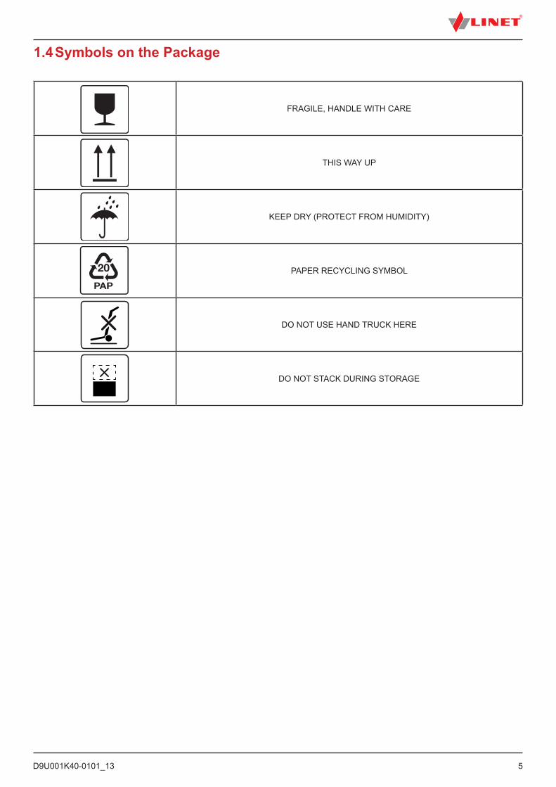
1.4 Symbols on the Package
FRAGILE, HANDLE WITH CARE
THIS WAY UP
KEEP DRY (PROTECT FROM HUMIDITY)
PAPER RECYCLING SYMBOL
DO NOT USE HAND TRUCK HERE
DO NOT STACK DURING STORAGE

D9U001K40-0101_136
1.5 Symbols and Labels on the Bed
READ INSTRUCTIONS FOR USE
WARNING
THERMAL PROTECTION OF TRANSFORMER
ONLY SUITABLE FOR INDOOR USE
PROTECTION AGAINST ACCIDENTS DUE TO ELECTRICAL CURRENT – TYPE B APPLIED PARTS
SAFETY ISOLATING TRANSFORMER, GENERAL
CE MARK OF CONFORMITY WITH EU REGULATION
JACK FOR ATTACHMENT OF CONDUCTOR FOR POTENTIAL EQUALISATION
SAFE WORKING LOAD
MAXIMUM WEIGHT OF PATIENT
WEIGHT OF BED
D9U001K40-0101_13
7
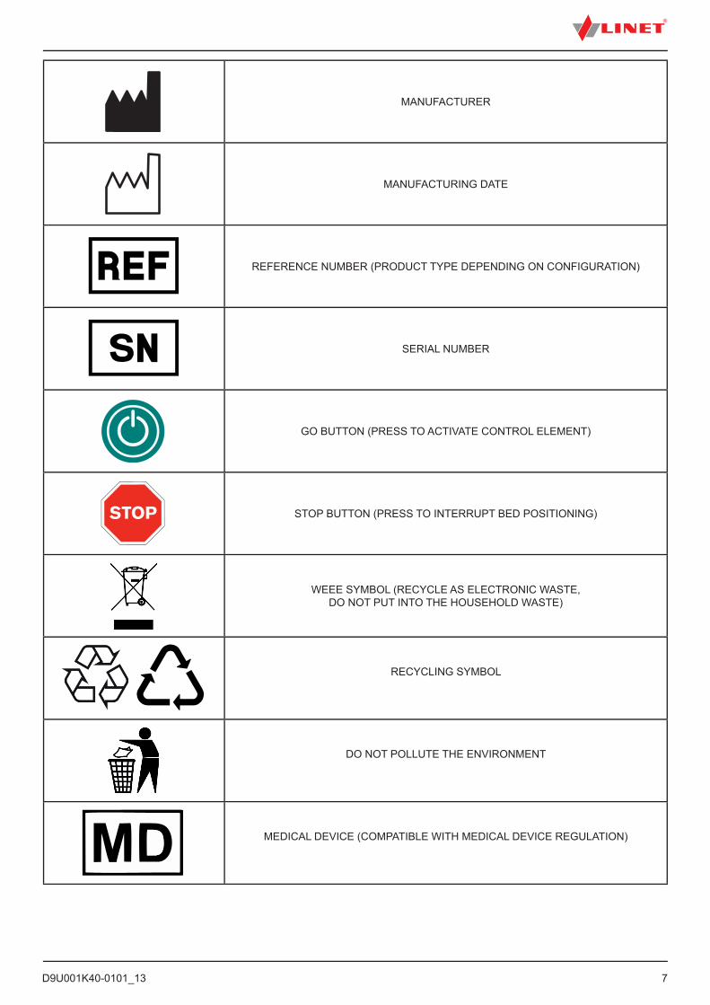
MANUFACTURER
MANUFACTURING DATE
REFERENCE NUMBER (PRODUCT TYPE DEPENDING ON CONFIGURATION)
SERIAL NUMBER
GO BUTTON (PRESS TO ACTIVATE CONTROL ELEMENT)
STOP BUTTON (PRESS TO INTERRUPT BED POSITIONING)
WEEE SYMBOL (RECYCLE AS ELECTRONIC WASTE, DO NOT PUT INTO THE HOUSEHOLD WASTE)
RECYCLING SYMBOL
DO NOT POLLUTE THE ENVIRONMENT
MEDICAL DEVICE (COMPATIBLE WITH MEDICAL DEVICE REGULATION)
D9U001K40-0101_138
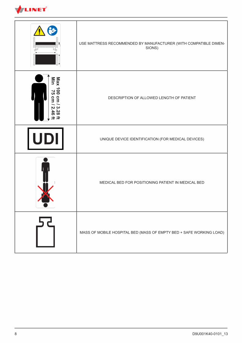
USE MATTRESS RECOMMENDED BY MANUFACTURER (WITH COMPATIBLE DIMEN-SIONS)
DESCRIPTION OF ALLOWED LENGTH OF PATIENT
UNIQUE DEVICE IDENTIFICATION (FOR MEDICAL DEVICES)
MEDICAL BED FOR POSITIONING PATIENT IN MEDICAL BED
MASS OF MOBILE HOSPITAL BED (MASS OF EMPTY BED + SAFE WORKING LOAD)
D9U001K40-0101_13
9
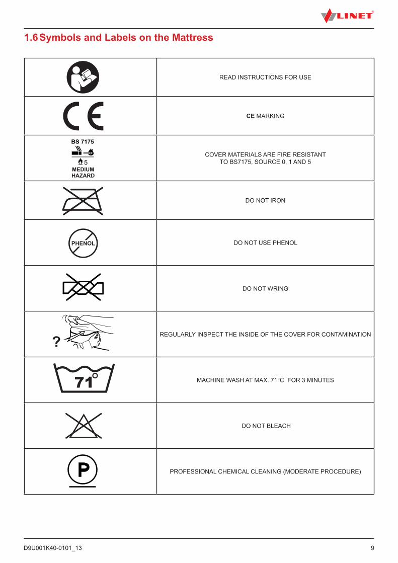
READ INSTRUCTIONS FOR USE
CE MARKING
COVER MATERIALS ARE FIRE RESISTANT TO BS7175, SOURCE 0, 1 AND 5
DO NOT IRON
DO NOT USE PHENOL
DO NOT WRING
REGULARLY INSPECT THE INSIDE OF THE COVER FOR CONTAMINATION
MACHINE WASH AT MAX. 71°C FOR 3 MINUTES
DO NOT BLEACH
PROFESSIONAL CHEMICAL CLEANING (MODERATE PROCEDURE)
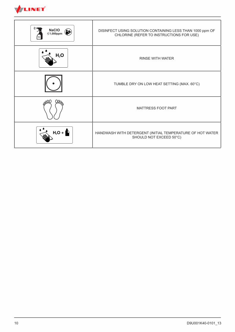
1.6 Symbols and Labels on the Mattress
D9U001K40-0101_1310
DISINFECT USING SOLUTION CONTAINING LESS THAN 1000 ppm OF CHLORINE (REFER TO INSTRUCTIONS FOR USE)
RINSE WITH WATER
TUMBLE DRY ON LOW HEAT SETTING (MAX. 60°C)
MATTRESS FOOT PART
HANDWASH WITH DETERGENT (INITIAL TEMPERATURE OF HOT WATER SHOULD NOT EXCEED 50°C)

D9U001K40-0101_13
11
1.7 Serial LabelPictures of serial labels below serve just for explanation of the signs and fields on the serial labels.
Fig. Serial Label with UDI (Tom 2)
Fig. Informational label with allowed length of patient
1K4XXXX-YY (Tom 2)
1
5 6 7 8 94
2 3
1 Address of Manufacturer
2 Manufacturing Date (Year-Month-Day)
3 DI (Device Identifier) / GTIN (Global Trade Item Number)
4 1D Bar code GS1-128 (Serial Number)
5 Configuration number
6 Electrical Specification
7 Serial Number
8 PI (Product Identifier)
9 2D Bar Code (GS1 DataMatrix) DI+PI=UDI
1.7.1 Serial Label with UDI (Tom 2)

D9U001K40-0101_1312
Fig. Wash label (mattress)
Fig. Serial label (mattress - EffectaCare 20 P)
Fig. Serial label (mattress - CliniCare 10 P)
1.7.2 Serial Label (mattress)
1.7.3 Wash Label (mattress)
75
EffectaCare 20 P
4PCLI1100AS
137x70x10 cm
72
CliniCare 10 P
4PRKI1100AS
137x70x10 cm
D9U001K40-0101_13
13
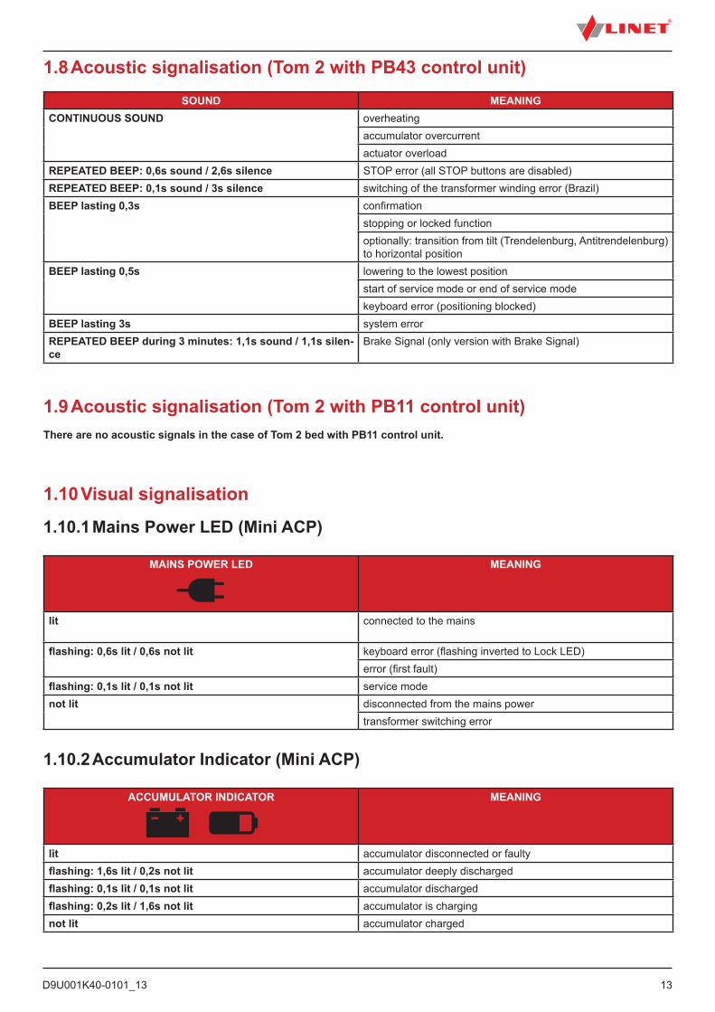
1.8 Acoustic signalisation (Tom 2 with PB43 control unit)
1.9 Acoustic signalisation (Tom 2 with PB11 control unit)There are no acoustic signals in the case of Tom 2 bed with PB11 control unit.
SOUND MEANINGCONTINUOUS SOUND overheating
accumulator overcurrentactuator overload
REPEATED BEEP: 0,6s sound / 2,6s silence STOP error (all STOP buttons are disabled)REPEATED BEEP: 0,1s sound / 3s silence switching of the transformer winding error (Brazil)BEEP lasting 0,3s confirmation
stopping or locked functionoptionally: transition from tilt (Trendelenburg, Antitrendelenburg) to horizontal position
BEEP lasting 0,5s lowering to the lowest positionstart of service mode or end of service modekeyboard error (positioning blocked)
BEEP lasting 3s system errorREPEATED BEEP during 3 minutes: 1,1s sound / 1,1s silen-ce
Brake Signal (only version with Brake Signal)
ACCUMULATOR INDICATOR MEANING
lit accumulator disconnected or faultyflashing: 1,6s lit / 0,2s not lit accumulator deeply dischargedflashing: 0,1s lit / 0,1s not lit accumulator dischargedflashing: 0,2s lit / 1,6s not lit accumulator is chargingnot lit accumulator charged
MAINS POWER LED MEANING
lit connected to the mains
flashing: 0,6s lit / 0,6s not lit keyboard error (flashing inverted to Lock LED)error (first fault)
flashing: 0,1s lit / 0,1s not lit service modenot lit disconnected from the mains power
transformer switching error
1.10 Visual signalisation
1.10.1 Mains Power LED (Mini ACP)
1.10.2 Accumulator Indicator (Mini ACP)
D9U001K40-0101_1314
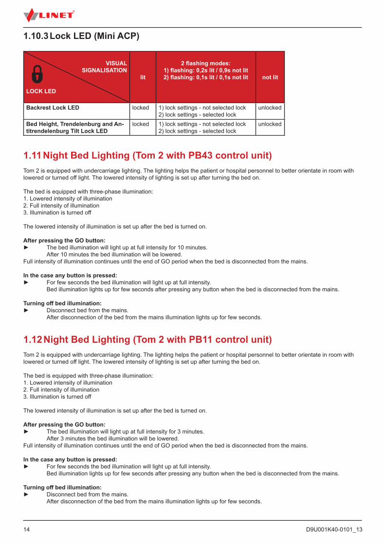
VISUAL SIGNALISATION
LOCK LED
lit
2 flashing modes:1) flashing: 0,2s lit / 0,9s not lit2) flashing: 0,1s lit / 0,1s not lit not lit
Backrest Lock LED locked 1) lock settings - not selected lock2) lock settings - selected lock
unlocked
Bed Height, Trendelenburg and An-titrendelenburg Tilt Lock LED
locked 1) lock settings - not selected lock2) lock settings - selected lock
unlocked
1.10.3 Lock LED (Mini ACP)
1.11 Night Bed Lighting (Tom 2 with PB43 control unit)Tom 2 is equipped with undercarriage lighting. The lighting helps the patient or hospital personnel to better orientate in room with lowered or turned off light. The lowered intensity of lighting is set up after turning the bed on.
The bed is equipped with three-phase illumination:1. Lowered intensity of illumination2. Full intensity of illumination3. Illumination is turned off
The lowered intensity of illumination is set up after the bed is turned on.
After pressing the GO button:► The bed illumination will light up at full intensity for 10 minutes. After 10 minutes the bed illumination will be lowered.Full intensity of illumination continues until the end of GO period when the bed is disconnected from the mains.
In the case any button is pressed:► For few seconds the bed illumination will light up at full intensity. Bed illumination lights up for few seconds after pressing any button when the bed is disconnected from the mains.
Turning off bed illumination:► Disconnect bed from the mains. After disconnection of the bed from the mains illumination lights up for few seconds.
1.12 Night Bed Lighting (Tom 2 with PB11 control unit)Tom 2 is equipped with undercarriage lighting. The lighting helps the patient or hospital personnel to better orientate in room with lowered or turned off light. The lowered intensity of lighting is set up after turning the bed on.
The bed is equipped with three-phase illumination:1. Lowered intensity of illumination2. Full intensity of illumination3. Illumination is turned off
The lowered intensity of illumination is set up after the bed is turned on.
After pressing the GO button:► The bed illumination will light up at full intensity for 3 minutes. After 3 minutes the bed illumination will be lowered.Full intensity of illumination continues until the end of GO period when the bed is disconnected from the mains.
In the case any button is pressed:► For few seconds the bed illumination will light up at full intensity. Bed illumination lights up for few seconds after pressing any button when the bed is disconnected from the mains.
Turning off bed illumination:► Disconnect bed from the mains. After disconnection of the bed from the mains illumination lights up for few seconds.
D9U001K40-0101_13
15
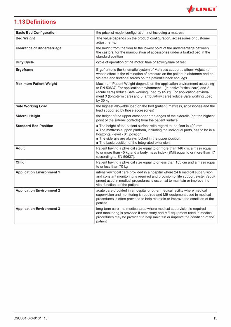
1.13 DefinitionsBasic Bed Configuration the pricelist model configuration, not including a mattressBed Weight The value depends on the product configuration, accessories or customer
adjustments. Clearance of Undercarriage the height from the floor to the lowest point of the undercarriage between
the castors, for the manipulation of accessories under a braked bed in the standard position
Duty Cycle cycle of operation of the motor: time of activity/time of rest
Ergoframe Ergoframe is the kinematic system of Mattress support platform Adjustment whose effect is the elimination of pressure on the patient´s abdomen and pel-vic area and frictional forces on the patient‘s back and legs.
Maximum Patient Weight Maximum Patient Weight depends on the application environment according to EN 50637. For application environment 1 (intensive/critical care) and 2 (acute care) reduce Safe working Load by 65 kg. For application environ-ment 3 (long-term care) and 5 (ambulatory care) reduce Safe working Load by 35 kg.
Safe Working Load the highest allowable load on the bed (patient, mattress, accessories and the load supported by those accessories)
Siderail Height the height of the upper crossbar or the edges of the siderails (not the highest point of the siderail controls) from the patient surface
Standard Bed Position ■ The height of the patient surface with regard to the floor is 400 mm ■ The mattress support platform, including the individual parts, has to be in a horizontal (level - 0°) position. ■ The siderails are always locked in the upper position. ■ The basic position of the integrated extension.
Adult Patient having a physical size equal to or more than 146 cm, a mass equal to or more than 40 kg and a body mass index (BMI) equal to or more than 17 (according to EN 50637).
Child Patient having a physical size equal to or less than 155 cm and a mass equal to or less than 70 kg
Application Environment 1 intensive/critical care provided in a hospital where 24 h medical supervision and constant monitoring is required and provision of life support system/equi-pment used in medical procedures is essential to maintain or improve the vital functions of the patient
Application Environment 2 acute care provided in a hospital or other medical facility where medical supervision and monitoring is required and ME equipment used in medical procedures is often provided to help maintain or improve the condition of the patient
Application Environment 3 long-term care in a medical area where medical supervision is required and monitoring is provided if necessary and ME equipment used in medical procedures may be provided to help maintain or improve the condition of the patient

D9U001K40-0101_1316
AC ( ~ ) Alternating CurrentACP Attendant Control PanelCE European ConformityCPR Cardiopulmonary ResuscitationdBA Sound Intensity UnitDC ( ) Direct CurrentCUC Configuration numberEMC Electromagnetic CompatibilityFET Field-effect transistorHF High FrequencyHPL High Pressure LaminateHW HardwareICU Intensive Care UnitINT. Duty CycleIP Ingress ProtectionIV IntravenousLED Light Emitting DiodesME Medical Electrical (Equipment)ON ActivationOFF Deactivationppm parts per million, millionth (1000 ppm = 0,1%)REF Reference Number (product type depending on configuration)SCU System Control Unit (active mattress)SN Serial NumberSW SoftwareSWL Safe Working LoadUDI Unique Device Identification (for medical devices)USB Universal Serial BusWEEE Waste Electrical and Electronic Equipment
1.14 Abbreviations
D9U001K40-0101_13
17
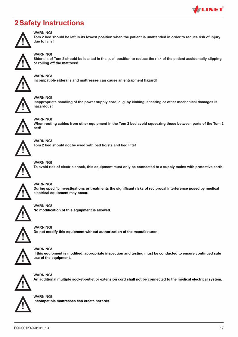
2 Safety InstructionsWARNING!Tom 2 bed should be left in its lowest position when the patient is unattended in order to reduce risk of injury due to falls!
WARNING!Siderails of Tom 2 should be located in the „up“ position to reduce the risk of the patient accidentally slipping or rolling off the mattress!
WARNING!Incompatible siderails and mattresses can cause an entrapment hazard!
WARNING!Inappropriate handling of the power supply cord, e. g. by kinking, shearing or other mechanical damages is hazardous!
WARNING!When routing cables from other equipment in the Tom 2 bed avoid squeezing those between parts of the Tom 2 bed!
WARNING!Tom 2 bed should not be used with bed hoists and bed lifts!
WARNING!To avoid risk of electric shock, this equipment must only be connected to a supply mains with protective earth.
WARNING!During specific investigations or treatments the significant risks of reciprocal interference posed by medical electrical equipment may occur.
WARNING!No modification of this equipment is allowed.
WARNING!Do not modify this equipment without authorization of the manufacturer.
WARNING!If this equipment is modified, appropriate inspection and testing must be conducted to ensure continued safe use of the equipment.
WARNING!An additional multiple socket-outlet or extension cord shall not be connected to the medical electrical system.
WARNING!Incompatible mattresses can create hazards.

D9U001K40-0101_1318
DANGER!Risk of injury or death due to use of incorrect equipment!Ensure the bed and its components are exclusively modified with the manufacturer´s approval.
WARNING!Any serious incident that has occurred in relation to the device should be reported to the manufacturer and the competent authority of the Member State in which the user and/or patient is established!
WARNING!Only authorised and trained person using the tool is allowed to change fuses and power supplies!
WARNING!This medical device is not intended for oxygen enriched environment!
WARNING!This medical device is not intended for use with flammable substances!
WARNING!This medical device is not portable medical electrical equipment!
WARNING!Make sure the duty cycle (2 min ON/18 min OFF) is not exceeded during bed positioning!
WARNING!Patient is allowed to use selected control elements only if hospital personnel had assessed that the patient´s physical and psychological state is in accordance with use of them and only if the hospital personnel had trained the patient in accordance with the instructions for use!
WARNING!The Tom 2 medical bed is intended for children!
WARNING!Equipments in close proximity or attached to the Tom 2 medical bed can cause a hazard, e.g. entrapment or tipping over.
WARNING!The Tom 2 medical bed shall not be used for transportation of a patient in any kind of vehicle.

D9U001K40-0101_13
19
2.1 Safety instructions► It is necessary to read the instructions for use before operating the bed.► Follow the instructions carefully.► Use the bed exclusively in its original condition.► If necessary, check the bed functions daily or at each staff rotation.► Use the bed exclusively with the correct mains supply.► Ensure that the bed is operated exclusively by qualified personnel who have been trained according to the instructions for use.► Ensure the bed is only moved or positioned upon even, hard floor surfaces listed in chapter Transport.► Replace any damaged parts immediately with original spare parts.► Ensure maintenance and installations are performed only by qualified personnel who have been trained by the manufactu-rer.► Do not apply excess weight or load to the bed according to SWL (safe working load).► Only one patient can use the bed at any time.► Take care to avoid injuries or squeezing when operating moving parts.► When using lifting poles or infusion stands, ensure nothing will be damaged when you move or adjust the bed.► Ensure castors are braked when the bed is not being moved, regardless of whether the bed is occupied or empty.► Ensure that siderails are operated by healthcare personnel only.► Never use the bed in areas where there is a hazard or risk of explosion.► Never handle the mains plug with wet hands.► Unplug the mains cable by pulling on the plug only.► Position the mains cable so there are no loops or bends in the cable; protect the cable from mechanical wear and tear.► Incorrect handling of the mains cable can cause an electric shock hazard, other serious injuries or damage to the bed.► Ensure the specified duty cycle (on-time) is not exceeded (see INT. on product label).► Ensure moving parts of the bed are not blocked.► To prevent failures, use exclusively the manufacturer’s original accessories and mattresses.► Adjust bed height when transporting the bed in order to facilitate overcoming possible obstacles. ► Ensure the bed and its components are exclusively modified with the manufacturer´s approval.► Any non-observance of this manual may lead to injuries or material damage.► Ensure there is no risk of crushing or otherwise injuring the patient’s limbs (e.g. between siderails and mattress platform, between movable parts etc.) before positioning the bed or folding down the siderails.► Close box for linen before using the Antitrendelenburg.► Do not put any objects (e.g. accessories, infusions, cables) between or on siderails and movable parts. Or between mattress platform and undercarriage of the bed.► Ensure that nobody can get injured while folding the siderails.► Ensure no injuries will occur when folding the siderails.► Ensure there is no risk of damaging the Mini ACP panel.► To prevent collisions, do not put oxygen bottle holders directly under the mattress platform.► Only use oxygen bottle holder approved by manufacturer.► Hospital personnel are fully responsible for bed adjustments and leaving patient without supervision in accordance with evaluation of patient’s health status and mental status.

D9U001K40-0101_1320
3 Intended use (Tom 2)The intended use is the hospitalization of the patient in the paediatric care units, which includes above all the following aspects:► Adjustment of the specific positions needed for the preventive reasons, routine nursing, treatments, mobilization, physio-therapy, examinations, sleeping, and relaxation. These positions are further specified and described in the clinical evaluation of this device, together with their potential clinical outcomes and benefits.► Providing the safe environment for the patient during all relevant procedures. The particular requirements on patient safety are the subject of the clinical evaluation, including evaluation of the risk/benefit ratio. The relevant safety issues are the part of the risk management file.► Patient in-bed indoor transport out of the patient room.► Providing the suitable working conditions for the caregivers to perform the routine and specific tasks during the patient hospitalization.
3.1 Application environment – compliance with Paediatric standard EN 50637Design of the Tom 2 medical bed allows immediate and unimpeded access to the patient from the head end of the medical bed in emergency situations in application environments 1, 2 and 3. For application environments 1 and 2 the Tom 2 must be configured with removable head board and foot board. For other application environments Tom 2 medical bed can be configured with remova-ble or non-removable head board and foot board.
3.2 User population► Paediatric patients from 75 -100 cm height in the standard and intensive care units (based on individual patient status assessment by caregiver the patient can utilize dedicated device functions) ► Caregivers (nurses, doctors, technical personnel, transport personnel, cleaning personnel)
3.3 Contraindications► The medical device is not intended for the adult patients use► The medical device is not intended for the premature baby► Certain positions are not suitable for specific diagnoses/medical conditions (e.g., higher ICP patients vs. Trendelenburg). Staff expert assessment / nursing consideration is needed in all individual case of contraindication
3.4 Operator► Caregiver
4 Incorrect UseThe bed is not suitable for adults.► The bed is not suitable for private use.► Ensure the safe working load is not exceeded.
NOTE For information concerning uses other than those outlined in the “Intended use” section above, please contact LINET®.
LINET®’s efforts in research, design and manufacture ensure LINET® products are of the highest quality and fitfor their intended purpose. However, LINET® can take no responsibility for any damage to the products or any harm to patients, staff or other individuals resulting from:► Not following the instructions in the manual, including warning notices.► Using the product for a purpose other than the intended purpose stated in the relevant documentation provided by LINET® (see Intended use).
D9U001K40-0101_13
21
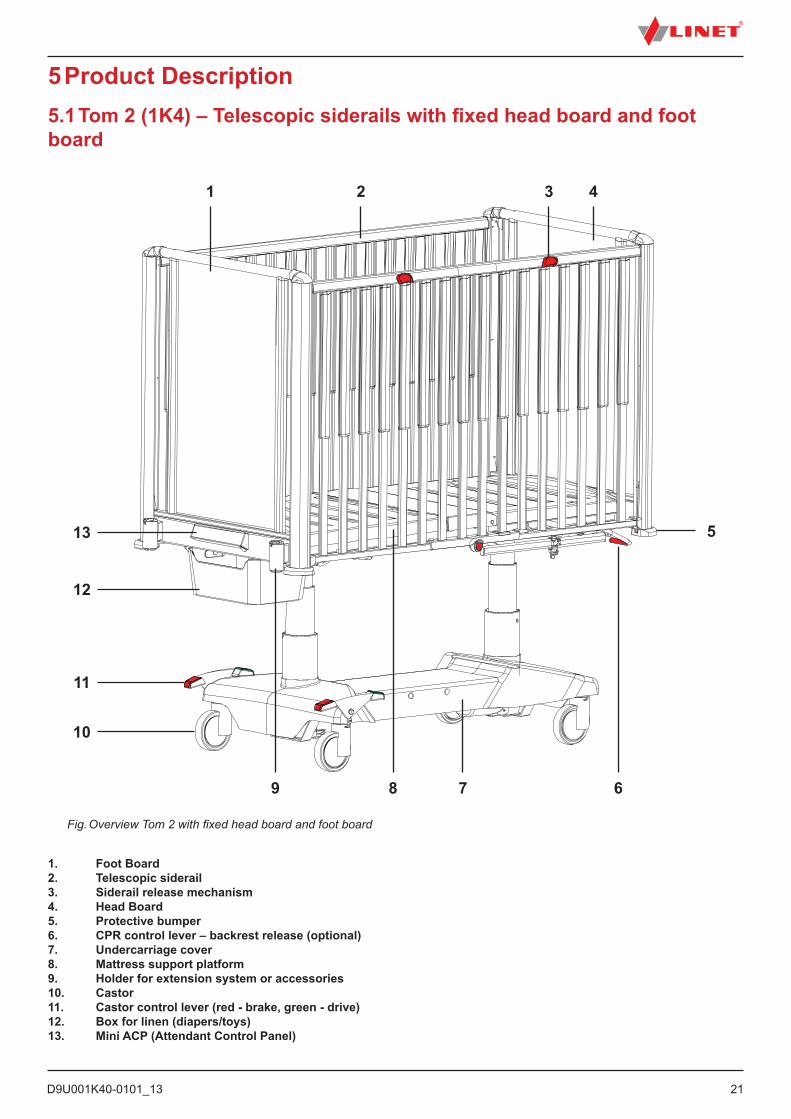
5 Product Description5.1 Tom 2 (1K4) – Telescopic siderails with fixed head board and foot board
Fig. Overview Tom 2 with fixed head board and foot board
1. Foot Board2. Telescopic siderail3. Siderail release mechanism4. Head Board5. Protective bumper6. CPR control lever – backrest release (optional)7. Undercarriage cover8. Mattress support platform9. Holder for extension system or accessories10. Castor11. Castor control lever (red - brake, green - drive)12. Box for linen (diapers/toys) 13. Mini ACP (Attendant Control Panel)
69 8 7
513
12
11
10
1 2 3 4
D9U001K40-0101_1322
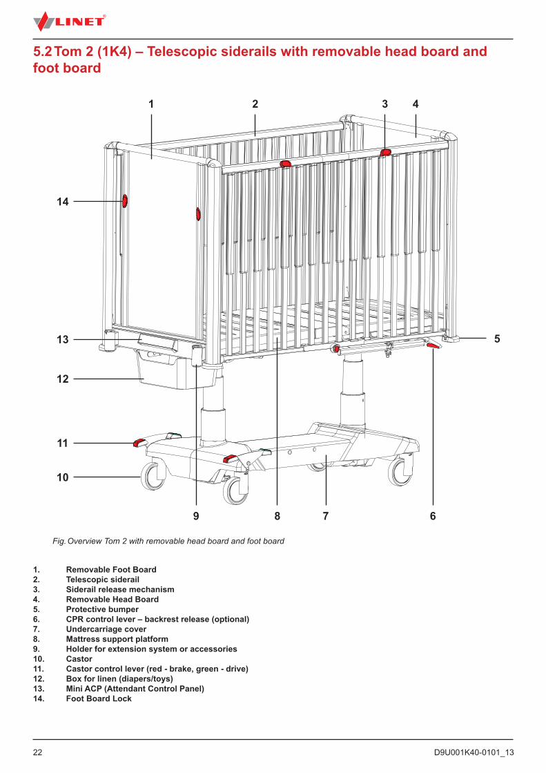
5.2 Tom 2 (1K4) – Telescopic siderails with removable head board and foot board
Fig. Overview Tom 2 with removable head board and foot board
1. Removable Foot Board2. Telescopic siderail3. Siderail release mechanism4. Removable Head Board5. Protective bumper6. CPR control lever – backrest release (optional)7. Undercarriage cover8. Mattress support platform9. Holder for extension system or accessories10. Castor11. Castor control lever (red - brake, green - drive)12. Box for linen (diapers/toys) 13. Mini ACP (Attendant Control Panel)14. Foot Board Lock
69 8
513
14
12
11
10
1 2 3 4
7
D9U001K40-0101_13
23
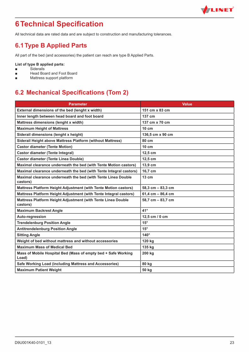
6 Technical SpecificationAll technical data are rated data and are subject to construction and manufacturing tolerances.
6.1 Type B Applied PartsAll part of the bed (and accessories) the patient can reach are type B Applied Parts.
List of type B applied parts:■ Siderails■ Head Board and Foot Board■ Mattress support platform
6.2 Mechanical Specifications (Tom 2)Parameter Value
External dimensions of the bed (lenght x width) 151 cm x 83 cmInner length between head board and foot board 137 cmMattress dimensions (lenght x width) 137 cm x 70 cm Maximum Height of Mattress 10 cmSiderail dimensions (lenght x height) 136,5 cm x 90 cmSiderail Height above Mattress Platform (without Mattress) 80 cmCastor diameter (Tente Motion) 10 cmCastor diameter (Tente Integral) 12,5 cmCastor diameter (Tente Linea Double) 12,5 cmMaximal clearance underneath the bed (with Tente Motion castors) 13,9 cmMaximal clearance underneath the bed (with Tente Integral castors) 16,7 cmMaximal clearance underneath the bed (with Tente Linea Double castors)
13 cm
Mattress Platform Height Adjustment (with Tente Motion castors) 58,3 cm – 83,3 cmMattress Platform Height Adjustment (with Tente Integral castors) 61,4 cm – 86,4 cmMattress Platform Height Adjustment (with Tente Linea Double castors)
58,7 cm – 83,7 cm
Maximum Backrest Angle 41°Auto-regression 12,5 cm / 0 cmTrendelenburg Position Angle 15° Antitrendelenburg Position Angle 15°Sitting Angle 140°Weight of bed without mattress and without accessories 120 kgMaximum Mass of Medical Bed 135 kgMass of Mobile Hospital Bed (Mass of empty bed + Safe Working Load)
200 kg
Safe Working Load (including Mattress and Accessories) 80 kgMaximum Patient Weight 50 kg
D9U001K40-0101_1324
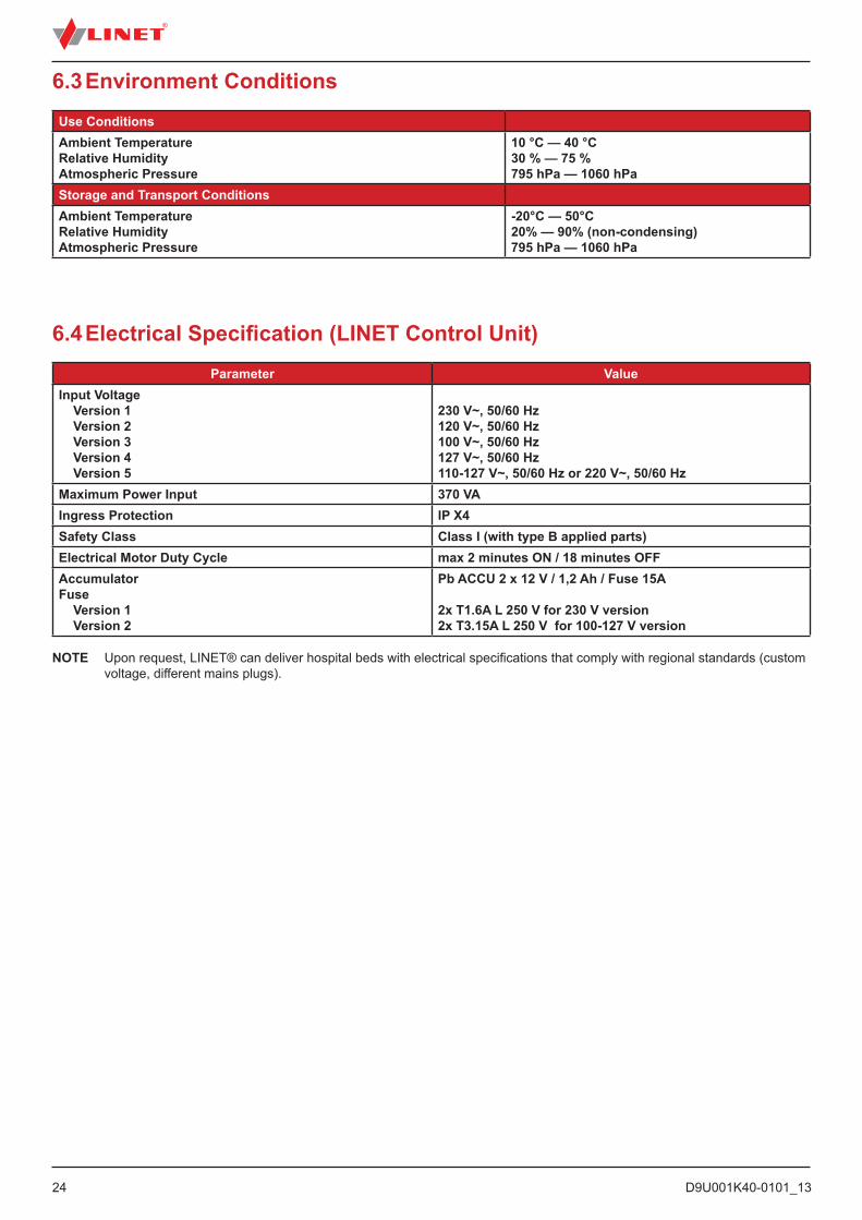
6.3 Environment ConditionsUse ConditionsAmbient TemperatureRelative HumidityAtmospheric Pressure
10 °C — 40 °C30 % — 75 %795 hPa — 1060 hPa
Storage and Transport ConditionsAmbient TemperatureRelative HumidityAtmospheric Pressure
-20°C — 50°C20% — 90% (non-condensing)795 hPa — 1060 hPa
6.4 Electrical Specification (LINET Control Unit)Parameter Value
Input Voltage Version 1 Version 2 Version 3 Version 4 Version 5
230 V~, 50/60 Hz120 V~, 50/60 Hz100 V~, 50/60 Hz127 V~, 50/60 Hz110-127 V~, 50/60 Hz or 220 V~, 50/60 Hz
Maximum Power Input 370 VAIngress Protection IP X4Safety Class Class I (with type B applied parts)Electrical Motor Duty Cycle max 2 minutes ON / 18 minutes OFF AccumulatorFuse Version 1 Version 2
Pb ACCU 2 x 12 V / 1,2 Ah / Fuse 15A
2x T1.6A L 250 V for 230 V version2x T3.15A L 250 V for 100-127 V version
NOTE Upon request, LINET® can deliver hospital beds with electrical specifications that comply with regional standards (custom voltage, different mains plugs).

D9U001K40-0101_13
25
6.5 Electromagnetic compatibilityBed is intended for hospitals except for near active HF surgical equipment and the RF shielded room of a medical system for mag-netic resonance imaging, where the intensity of EM disturbances is high.
Bed has defined no essential performance.
WARNING!It is recommended to avoid the use of this device next to or in block with other device, because it could lead to improper operation. If such use is needed, this device and the other equipment should be under surveillance to verify proper operation.
List of used cables:1. Mains cable, maximum length 6 m
WARNING!Use of the accessories, converters and other cables, than specified and provided by manufacturer of this bed could lead to increase of electromagnetic emission or lower the electromagnetic immunity of this bed and lead to improper operation.
WARNING!Mobile RF communication device (including end use devices like antenna cables and external antenna) should not be used closer than 30 cm (12 inches) from any part of this bed Tom 2, including cables specified by manu-facturer. Otherwise this could lead to deterioration of functionality of this bed.
WARNING!Do not overload the bed (SWL), respect the duty cycle (INT.) and consider chapter 18 Maintenance in order to maintain the basic safety with regard to electromagnetic disturbances for the expected service life.
D9U001K40-0101_1326
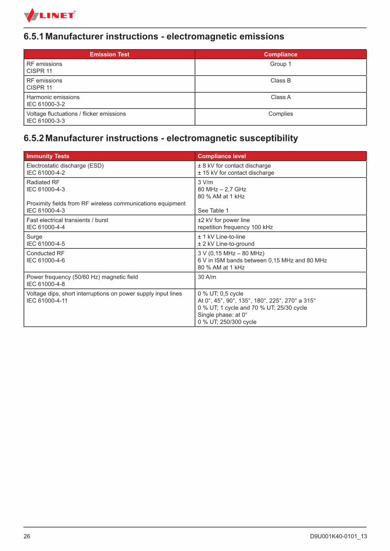
6.5.1 Manufacturer instructions - electromagnetic emissions
Emission Test ComplianceRF emissionsCISPR 11
Group 1
RF emissionsCISPR 11
Class B
Harmonic emissionsIEC 61000-3-2
Class A
Voltage fluctuations / flicker emissionsIEC 61000-3-3
Complies
6.5.2 Manufacturer instructions - electromagnetic susceptibility
Immunity Tests Compliance levelElectrostatic discharge (ESD) IEC 61000-4-2
± 8 kV for contact discharge± 15 kV for contact discharge
Radiated RFIEC 61000-4-3
Proximity fields from RF wireless communications equipmentIEC 61000-4-3
3 V/m 80 MHz – 2,7 GHz80 % AM at 1 kHz
See Table 1Fast electrical transients / burstIEC 61000-4-4
±2 kV for power line repetition frequency 100 kHz
Surge IEC 61000-4-5
± 1 kV Line-to-line± 2 kV Line-to-ground
Conducted RFIEC 61000-4-6
3 V (0,15 MHz – 80 MHz)6 V in ISM bands between 0,15 MHz and 80 MHz80 % AM at 1 kHz
Power frequency (50/60 Hz) magnetic fieldIEC 61000-4-8
30 A/m
Voltage dips, short interruptions on power supply input linesIEC 61000-4-11
0 % UT; 0,5 cycleAt 0°, 45°, 90°, 135°, 180°, 225°, 270° a 315°0 % UT; 1 cycle and 70 % UT; 25/30 cycleSingle phase: at 0°0 % UT; 250/300 cycle
D9U001K40-0101_13
27
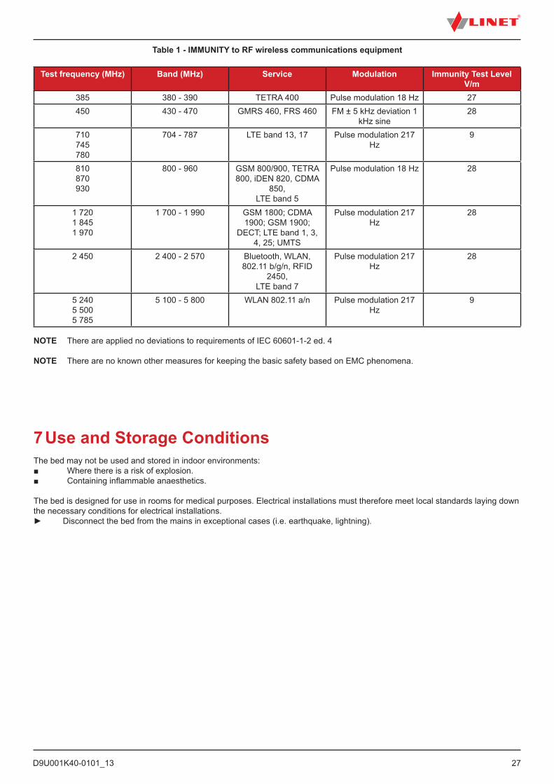
Table 1 - IMMUNITY to RF wireless communications equipment
Test frequency (MHz) Band (MHz) Service Modulation Immunity Test Level V/m
385 380 - 390 TETRA 400 Pulse modulation 18 Hz 27450 430 - 470 GMRS 460, FRS 460 FM ± 5 kHz deviation 1
kHz sine28
710745780
704 - 787 LTE band 13, 17 Pulse modulation 217 Hz
9
810870930
800 - 960 GSM 800/900, TETRA 800, iDEN 820, CDMA
850,LTE band 5
Pulse modulation 18 Hz 28
1 7201 8451 970
1 700 - 1 990 GSM 1800; CDMA 1900; GSM 1900;
DECT; LTE band 1, 3, 4, 25; UMTS
Pulse modulation 217 Hz
28
2 450 2 400 - 2 570 Bluetooth, WLAN, 802.11 b/g/n, RFID
2450,LTE band 7
Pulse modulation 217 Hz
28
5 2405 5005 785
5 100 - 5 800 WLAN 802.11 a/n Pulse modulation 217 Hz
9
NOTE There are applied no deviations to requirements of IEC 60601-1-2 ed. 4
NOTE There are no known other measures for keeping the basic safety based on EMC phenomena.
7 Use and Storage ConditionsThe bed may not be used and stored in indoor environments:■ Where there is a risk of explosion.■ Containing inflammable anaesthetics.
The bed is designed for use in rooms for medical purposes. Electrical installations must therefore meet local standards laying down the necessary conditions for electrical installations.► Disconnect the bed from the mains in exceptional cases (i.e. earthquake, lightning).
D9U001K40-0101_1328
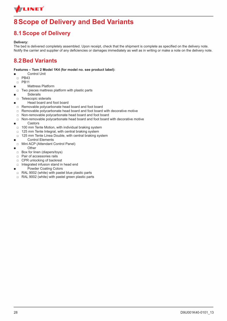
8 Scope of Delivery and Bed Variants8.1 Scope of DeliveryDelivery:The bed is delivered completely assembled. Upon receipt, check that the shipment is complete as specified on the delivery note. Notify the carrier and supplier of any deficiencies or damages immediately as well as in writing or make a note on the delivery note.
8.2 Bed VariantsFeatures – Tom 2 Model 1K4 (for model no. see product label):■ Control Unit □ PB43 □ PB11■ Mattress Platform □ Two pieces mattress platform with plastic parts■ Siderails □ Telescopic siderails■ Head board and foot board □ Removable polycarbonate head board and foot board □ Removable polycarbonate head board and foot board with decorative motive □ Non-removable polycarbonate head board and foot board □ Non-removable polycarbonate head board and foot board with decorative motive■ Castors □ 100 mm Tente Motion, with individual braking system □ 125 mm Tente Integral, with central braking system □ 125 mm Tente Linea Double, with central braking system■ Control Elements □ Mini ACP (Attendant Control Panel)■ Other □ Box for linen (diapers/toys) □ Pair of accessories rails □ CPR unlocking of backrest □ Integrated infusion stand in head end■ Powder Coating Colors □ RAL 9002 (white) with pastel blue plastic parts □ RAL 9002 (white) with pastel green plastic parts
D9U001K40-0101_13
29
9 Putting into ServiceWARNING!Risk of injury when working on the bed!► Ensure that the bed is disconnected from the mains connection prior to putting into service, putting out of service
and maintenance.► Ensure that the castors are locked prior to putting into service, putting out of service and maintenance.
CAUTION!Material damage due to incorrect putting into service!► Ensure that putting into service is performed exclusively by manufacturer´s customer service or trained hospital
personnel.
Set up the bed as follows:► Unpack the bed.► Remove isolating foil from mains control box (see Accumulator Activation).► Check the delivery (see Scope of Delivery and Bed Variants).► Install equipment and accessories.► Set up the bed exclusively on a suitable floor surface (see Transport).► Ensure the mains cable does not collide or get stretched when adjusting the bed. Check the plug is inserted correctly.► Do not leave any extension cords or power strips loose on the floor.► Ensure all the required mechanical and electrical prevention mechanisms are available on site.► There is no mains switch on the bed, i.e. the mains cable is the only means to isolate the bed from the mains.► Ensure the mains cable is always accessible.► The plug on the mains cable should only be changed and maintained by qualified and trained service technicians authoris-ed by the manufacturer.
D9U001K40-0101_1330
PULL
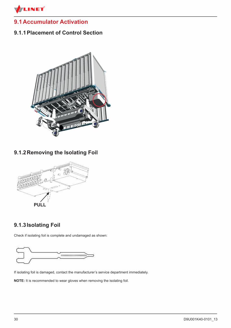
9.1 Accumulator Activation
9.1.1 Placement of Control Section
If isolating foil is damaged, contact the manufacturer’s service department immediately.
NOTE: It is recommended to wear gloves when removing the isolating foil.
9.1.2 Removing the Isolating Foil
9.1.3 Isolating Foil
Check if isolating foil is complete and undamaged as shown:
D9U001K40-0101_13
31
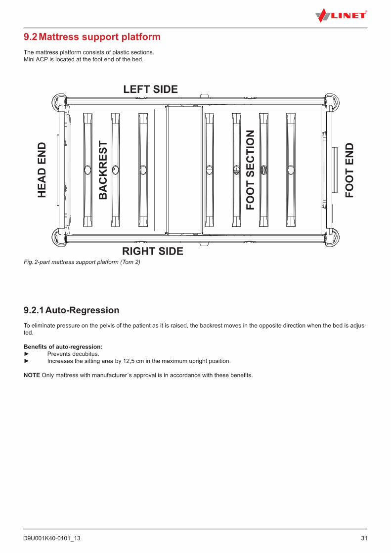
9.2 Mattress support platformThe mattress platform consists of plastic sections.Mini ACP is located at the foot end of the bed.
Fig. 2-part mattress support platform (Tom 2)
LEFT SIDE
RIGHT SIDE
HEA
D E
ND
BA
CK
RES
T
FOO
T SE
CTI
ON
FOO
T EN
D
9.2.1 Auto-RegressionTo eliminate pressure on the pelvis of the patient as it is raised, the backrest moves in the opposite direction when the bed is adjus-ted.
Benefits of auto-regression:► Prevents decubitus.► Increases the sitting area by 12,5 cm in the maximum upright position.
NOTE Only mattress with manufacturer´s approval is in accordance with these benefits.

D9U001K40-0101_1332
9.3 Potential EqualisationThe bed is equipped with a standard protective connector. This connector is used for potential equalisation between the bed and any intravascular or intracardiac device connected to the patient to protect the patient from static electric shocks.
Fig. Potential equalisation connector – male
Use equalisation connector if:■ The patient is connected to any intravascular or intracardiac device.
Before connecting the patient to an intravascular/intra-cardiac device:► Connect the ground wire of the device to the potential equalisation connector on the bed on which the patient in question is lying.► Use a standard hospital connector.► Make sure the connectors match.► Make sure there is no possibility of accidental disconnection.
Before moving the bed:► Disconnect the patient from the intravascular or intracardiac device.► Disconnect the potential equalisation connector.
Fig. Potential equalisation connector - female

D9U001K40-0101_13
33
WARNING!Tom 2 bed with non-removable head board and foot board is not intended for Intensive Care Units (ICU)!► Do not use Tom 2 bed with non-removable head board and foot board in Intensive Care Units (ICU)!
CAUTION!Material damage due to excess load!► Ensure nobody burdens siderails or head board/foot board.
9.4 Head Board and Foot BoardWARNING!Risk of injury due to wrongly installed head board and foot board!► After each installation of head board or foot board always check if the head board or foot board are properly locked.► Always check if the sheet does not obstruct the head board locks or foot board locks.► The safe position for patient who is left without supervision of personnel is with installed head board and foot board and with siderails in highest position. In all other cases (e.g. siderails down, removed head board and foot board etc.) the patient must be under supervision of personnel.
► Avoid injuring patient while removing head board and/or foot board or remove head board and/or foot board only on the bed without patient.
► Ensure the accessories / extension placed in holder will not collide with head board or foot board when removing it. Otherwise remove accessory / extension.
The bed Tom 2 can be equipped with removable head board and foot board or with non-removable head board and foot board. Removable head board and foot board allows easier access to the patient.

D9U001K40-0101_1334
Fig. Removing the head board
11
2 2
To remove head board and foot board: ► Unlock both locks on the upper part of the head board or foot board by pushing in the direction of arrows (1).► Grab the head board or foot board with both hands in the upper half of the head board or foot board.► Lift the head board or foot board up (2).► Rotate the head board or foot board slightly into the bed.► Remove the head board or foot board.
D9U001K40-0101_13
35
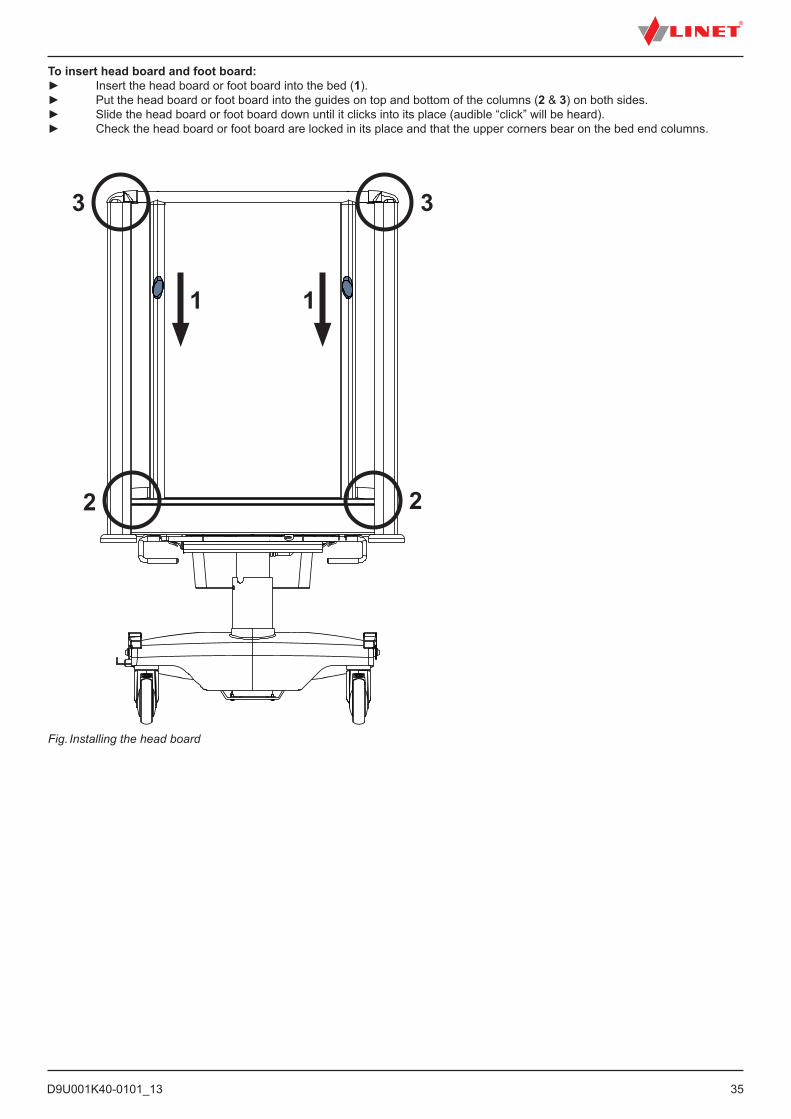
To insert head board and foot board:► Insert the head board or foot board into the bed (1).► Put the head board or foot board into the guides on top and bottom of the columns (2 & 3) on both sides.► Slide the head board or foot board down until it clicks into its place (audible “click” will be heard).► Check the head board or foot board are locked in its place and that the upper corners bear on the bed end columns.
Fig. Installing the head board
1 1
2
33
2
D9U001K40-0101_1336
9.5 Before UseCAUTION!Material damage due to temperature difference!► If there is a considerable temperature difference between the bed and the place of operation
(after transport/storage), leave bed unconnected for 24 hours to allow the temperature to equalise.
Prepare the bed for service as follows:► Connect the bed to the mains.► Raise the mattress platform to the highest position.► Remove the isolating foil from control section.► Lower and tilt the mattress platform to the lowest position.► Check the castors and main brake work correctly.► Check all of the functions on the control elements (Mini ACP).► Check the siderails function properly.► Dispose of all packaging (see Disposal).
9.6 TransportFor safe transport, observe the following:► Ensure no cables are run over when moving a bed.► Ensure the mains cable is disconnect from the mains.► Ensure the mains cable is attached with a hook (at the head end of the bed).► Ensure the castors are unlocked before moving the bed during the loading/unloading process (see Castor Control and Bed Transport).► Ensure the siderails are lifted and locked while the patient is on the bed during the transport.► Move the bed only on suitable floor surfaces.
Suitable surfaces:■ Tile■ Hard linoleum■ Hard flooring
Unsuitable surfaces:■ Soft, unsealed or defective flooring■ Soft wooden flooring ■ Soft and porous stone floors■ Carpeted floors with underlay■ Soft linoleum □ For longer distances, ensure the castor steering function (main control) is activated. □ Ensure the brakes are released while moving the bed.
9.7 FirmwareThe bed includes firmware that can be updated only by an authorised service technician.This firmware is protected against unauthorised access by mechanical housing (tool is needed to access), by seal (com-ponents with processor are sealed), by exclusive compatibility with an authorised software tool and by check of compati-bility of the new firmware with the bed.
10 Power CableCAUTION!Disconnecting bed from the mains does not stop motions of the bed! ► Stop the bed before disconnection bed from the mains.
Attachment plug is means of connecting and disconnecting bed from the mains.Power supply cable (mains power cable) must be attached with a hook at the head end of the bed during transport.
Where the integrity of the external protective conductor in the installation or its arrangement is in doubt► operate the bed from internal accumulator only.
D9U001K40-0101_13
37
11 AccumulatorCAUTION!Risk of reducing accumulator durability due to incorrect use!► Use bed on accumulator only in crisis situations (e.g.: power blackout, patient complications during transport, etc.).► After reconnecting bed to the mains charge accumulator to full capacity (see chart Accumulator charge status).
CAUTION!Risk of damage or destruction of accumulator!► If the accumulator is faulty, degassing may occur. In rare cases this might cause deformations of the accumulator case, control panel housing or cable.► If this occurs stop using the bed immediately (see Removing the Bed from Service).
► Inform the manufacturer’s service department immediately.
For declared lifetime period of leaded accumulators is recommended during storage:1. To prevent accumulators from deep discharging and to keep accumulators at least partly charged by regular recharging2. To store accumulators on the dry places with temperature from 10°C to 40°C3. To prevent accumulators from being in the sunshine
Accumulator lifetime could be up to 5 years if operated under optimum conditions.Accumulator capacity can be significantly reduced if:► too high ambient temperature► many accumulator charge/discharge cycles► recurrence of deep discharge► bed is often powered only by the accumulator
The accumulator supplied with the bed is delivered uncharged. The accumulator serves as a backup during power failures or while transporting the patient.
► Use only accumulators approved by the manufacturer.► The manufacturer provides a 6-month warranty for the full function of accumulators.► Check the accumulator functionality at least once a month in accordance with the user and service manuals and have the accumulator changed if necessary.► The manufacturer will assume no responsibility for any damage to the bed or the accumulator caused by: ■ Non-observance of the manufacturer’s instructions in the instructions for use. ■ Using accumulators not approved by the manufacturer. ■ Accumulator replacement non-qualified service organisation.
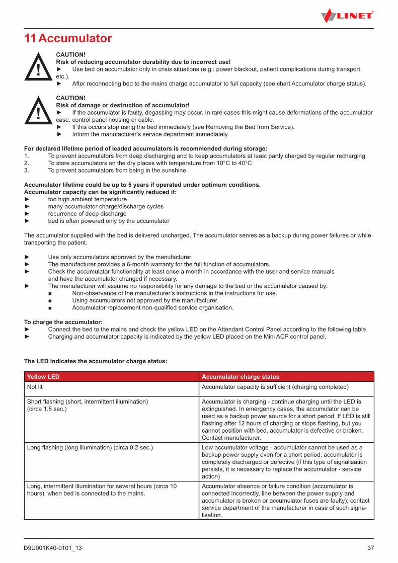
To charge the accumulator:► Connect the bed to the mains and check the yellow LED on the Attendant Control Panel according to the following table.► Charging and accumulator capacity is indicated by the yellow LED placed on the Mini ACP control panel.
The LED indicates the accumulator charge status:
Yellow LED Accumulator charge statusNot lit Accumulator capacity is sufficient (charging completed)
Short flashing (short, intermittent illumination) (circa 1.8 sec.)
Accumulator is charging - continue charging until the LED is extinguished. In emergency cases, the accumulator can be used as a backup power source for a short period. If LED is still flashing after 12 hours of charging or stops flashing, but you cannot position with bed, accumulator is defective or broken. Contact manufacturer.
Long flashing (long illumination) (circa 0.2 sec.) Low accumulator voltage - accumulator cannot be used as a backup power supply even for a short period; accumulator is completely discharged or defective (if this type of signalisation persists, it is necessary to replace the accumulator - service action)
Long, intermittent illumination for several hours (circa 10 hours), when bed is connected to the mains.
Accumulator absence or failure condition (accumulator is connected incorrectly, line between the power supply and accumulator is broken or accumulator fuses are faulty); contact service department of the manufacturer in case of such signa-lisation.
D9U001K40-0101_1338
To maintain maximum functionality of the accumulator:► Unplug the bed from the mains as least as possible.
In case the accumulator cover or control section is deformated by heat ► Unplug the bed from the mains.► Do not use the bed (see. Removing the Bed from Service.► Contact service of the manufacturer.
11.1 Status Faulty AccumulatorThe accumulator is regarded as faulty if at least one of the following conditions applies:► Accumulator charging constantly► Low voltage on accumulator► Low charging current of accumulator
Status “faulty accumulator” is indicated:► By the accumulator status indicator being constantly lit.► A fault accumulator status can be cancelled by pressing the STOP button.► Accumulator status data is saved and written to the “Blackbox”.
11.2 Status Discharged AccumulatorThe accumulator is regarded as discharged if the following condition is met:► Defined decrease of voltage depending on discharging current
Status “discharged accumulator” is:► Status is indicated by the accumulator status indicator flashing quickly.► This status will be cancelled automatically when the bed switches to sleep mode.
11.3 Removing the Bed from ServiceHow to remove the bed from service:► Disconnect the bed from the mains.► Disconnect the ground wire.► Deactivate the accumulator (see Deactivating the Accumulator).► Remove accessories.To prevent damage during storage:► Pack or cover the bed and accessories.► Ensure storage conditions are the same as the operating conditions.
NOTE: The bed can be removed from service only by a qualified service organization.
To activate the accumulator again:► Connect Power Cable to the mains.
D9U001K40-0101_13
39
12 ManipulationWARNING!Risk of injury when adjusting the bed!► Ensure there are no body parts between the mattress platform elements and the mattress platform frame when
adjusting the bed.► Ensure there are no body parts below the mattress platform frame before adjusting the bed.
► Secure or remove any items on the bed.
WARNING!Risk of injury due to moving parts!► Ensure no body parts are trapped between moving parts of the bed with accessories and mattress platform.
CAUTION!Material damage due to moving parts!► Ensure no objects (e.g. cables) are trapped between moving parts of the bed and mattress platform.► Ensure no objects are close to the bed or accessories (e.g. infusion stand, lifting pole) when the mattress
platform is moving.
Control elements:► Mini ACP (Attendant Control Panel)
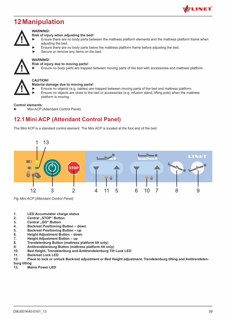
12.1 Mini ACP (Attendant Control Panel)The Mini ACP is a standard control element. The Mini ACP is located at the foot end of the bed.
Fig. Mini ACP (Attendant Control Panel)
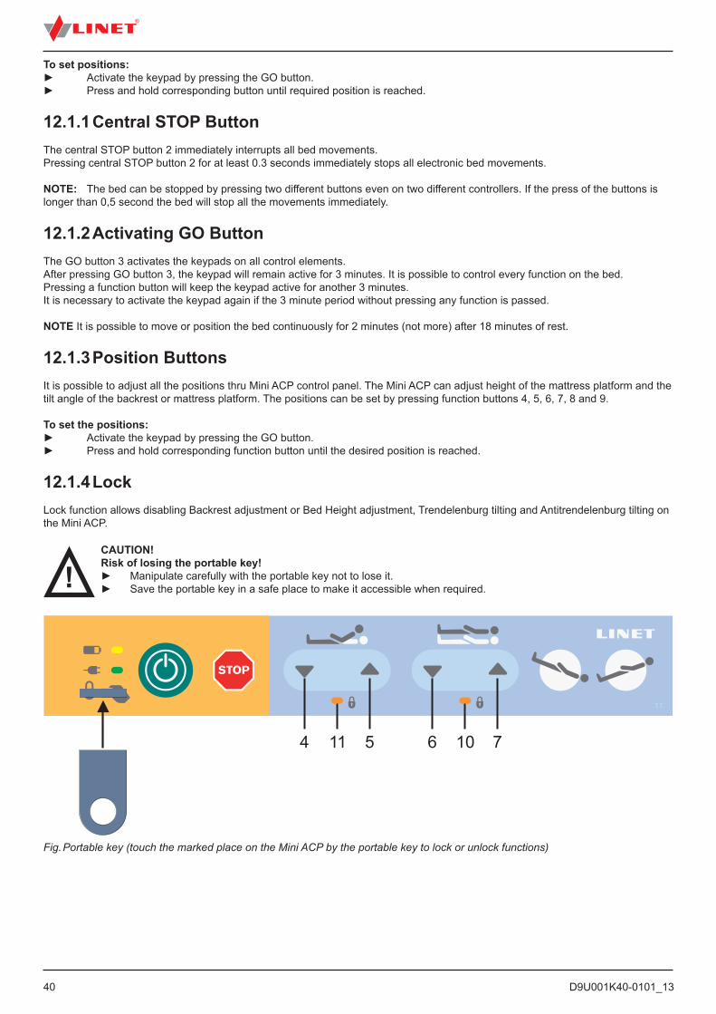
1. LED Accumulator charge status2. Central „STOP“ Button3. Central „GO“ Button4. Backrest Positioning Button – down5. Backrest Positioning Button – up6. Height Adjustment Button – down7. Height Adjustment Button – up8. Trendelenburg Button (mattress platform tilt only)9. Antitrendelenburg Button (mattress platform tilt only)10. Bed Height, Trendelenburg and Antitrendelenburg Tilt Lock LED11. Backrest Lock LED12. Place to lock or unlock Backrest adjustment or Bed Height adjustment, Trendelenburg tilting and Antitrendelen-burg tilting13. Mains Power LED
987651142312
1 13
10
D9U001K40-0101_1340
Fig. Portable key (touch the marked place on the Mini ACP by the portable key to lock or unlock functions)
To set positions:► Activate the keypad by pressing the GO button.► Press and hold corresponding button until required position is reached.
12.1.1 Central STOP ButtonThe central STOP button 2 immediately interrupts all bed movements.Pressing central STOP button 2 for at least 0.3 seconds immediately stops all electronic bed movements.
NOTE: The bed can be stopped by pressing two different buttons even on two different controllers. If the press of the buttons is longer than 0,5 second the bed will stop all the movements immediately.
12.1.2 Activating GO ButtonThe GO button 3 activates the keypads on all control elements.After pressing GO button 3, the keypad will remain active for 3 minutes. It is possible to control every function on the bed.Pressing a function button will keep the keypad active for another 3 minutes.It is necessary to activate the keypad again if the 3 minute period without pressing any function is passed.
NOTE It is possible to move or position the bed continuously for 2 minutes (not more) after 18 minutes of rest.
12.1.3 Position ButtonsIt is possible to adjust all the positions thru Mini ACP control panel. The Mini ACP can adjust height of the mattress platform and the tilt angle of the backrest or mattress platform. The positions can be set by pressing function buttons 4, 5, 6, 7, 8 and 9.
To set the positions:► Activate the keypad by pressing the GO button.► Press and hold corresponding function button until the desired position is reached.
12.1.4 LockLock function allows disabling Backrest adjustment or Bed Height adjustment, Trendelenburg tilting and Antitrendelenburg tilting on the Mini ACP.
765114 10
CAUTION!Risk of losing the portable key!► Manipulate carefully with the portable key not to lose it.► Save the portable key in a safe place to make it accessible when required.
D9U001K40-0101_13
41
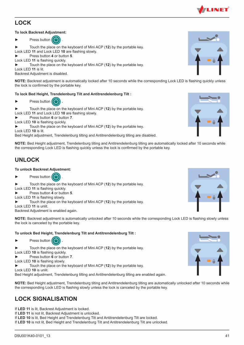
LOCK SIGNALISATIONIf LED 11 is lit, Backrest Adjustment is locked.If LED 11 is not lit, Backrest Adjustment is unlocked.If LED 10 is lit, Bed Height and Trendelenburg Tilt and Antitrendelenburg Tilt are locked.If LED 10 is not lit, Bed Height and Trendelenburg Tilt and Antitrendelenburg Tilt are unlocked.
LOCKTo lock Backrest Adjustment:
► Press button .
► Touch the place on the keyboard of Mini ACP (12) by the portable key.Lock LED 11 and Lock LED 10 are flashing slowly.► Press button 4 or button 5.Lock LED 11 is flashing quickly.► Touch the place on the keyboard of Mini ACP (12) by the portable key.Lock LED 11 is lit.Backrest Adjustment is disabled.
UNLOCKTo unlock Backrest Adjustment:
► Press button .
► Touch the place on the keyboard of Mini ACP (12) by the portable key.Lock LED 11 is flashing quickly.► Press button 4 or button 5.Lock LED 11 is flashing slowly.► Touch the place on the keyboard of Mini ACP (12) by the portable key.Lock LED 11 is unlit.Backrest Adjustment is enabled again.
NOTE: Backrest adjustment is automatically locked after 10 seconds while the corresponding Lock LED is flashing quickly unless the lock is confirmed by the portable key.
NOTE: Bed Height adjustment, Trendelenburg tilting and Antitrendelenburg tilting are automatically locked after 10 seconds while the corresponding Lock LED is flashing quickly unless the lock is confirmed by the portable key.
To lock Bed Height, Trendelenburg Tilt and Antitrendelenburg Tilt :
► Press button .
► Touch the place on the keyboard of Mini ACP (12) by the portable key.Lock LED 11 and Lock LED 10 are flashing slowly.► Press button 6 or button 7.Lock LED 10 is flashing quickly.► Touch the place on the keyboard of Mini ACP (12) by the portable key.Lock LED 10 is lit.Bed Height adjustment, Trendelenburg tilting and Antitrendelenburg tilting are disabled.
NOTE: Backrest adjustment is automatically unlocked after 10 seconds while the corresponding Lock LED is flashing slowly unless the lock is canceled by the portable key.
NOTE: Bed Height adjustment, Trendelenburg tilting and Antitrendelenburg tilting are automatically unlocked after 10 seconds while the corresponding Lock LED is flashing slowly unless the lock is canceled by the portable key.
To unlock Bed Height, Trendelenburg Tilt and Antitrendelenburg Tilt :
► Press button .
► Touch the place on the keyboard of Mini ACP (12) by the portable key.Lock LED 10 is flashing quickly.► Press button 6 or button 7.Lock LED 10 is flashing slowly.► Touch the place on the keyboard of Mini ACP (12) by the portable key.Lock LED 10 is unlit.Bed Height adjustment, Trendelenburg tilting and Antitrendelenburg tilting are enabled again.
D9U001K40-0101_1342
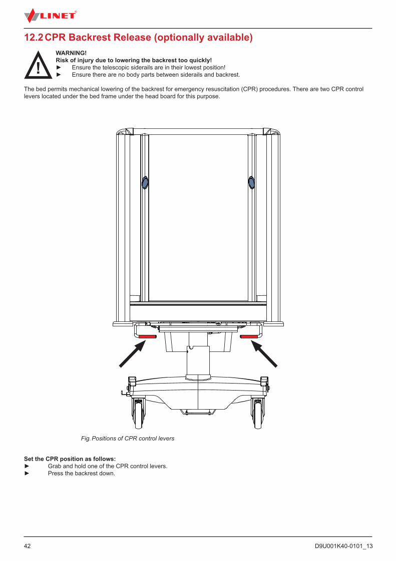
12.2 CPR Backrest Release (optionally available)WARNING!Risk of injury due to lowering the backrest too quickly!► Ensure the telescopic siderails are in their lowest position!► Ensure there are no body parts between siderails and backrest.
The bed permits mechanical lowering of the backrest for emergency resuscitation (CPR) procedures. There are two CPR control levers located under the bed frame under the head board for this purpose.
Fig. Positions of CPR control levers
Set the CPR position as follows:► Grab and hold one of the CPR control levers.► Press the backrest down.
D9U001K40-0101_13
43
12.3 Quick lowering of the backrestWARNING!Risk of crushing and trapping during quick lowering of the backrest!► Extra care must be taken to avoid pinching a hand or fingers between the backrest and the bed frame during quick lowering of the backrest!► Hold the backrest with one hand during quick lowering of the backrest to prevent the other hand from being pinched or perform the quick lowering of the backrest with the help of a second person who will hold the backrest all the time during lowering of the backrest so that it does not fall down spontaneously!
WARNING!Restriction of the backrest positioning after the quick lowering of the backrest► It is necessary that hospital technician enables the backrest positioning again after the quick lowering of the backrest by connecting the backrest to the piston of actuator!► If hospital personnel immediately need to position the backrest after the quick lowering of the backrest, the patient must be placed on another bed that allows this positioning!
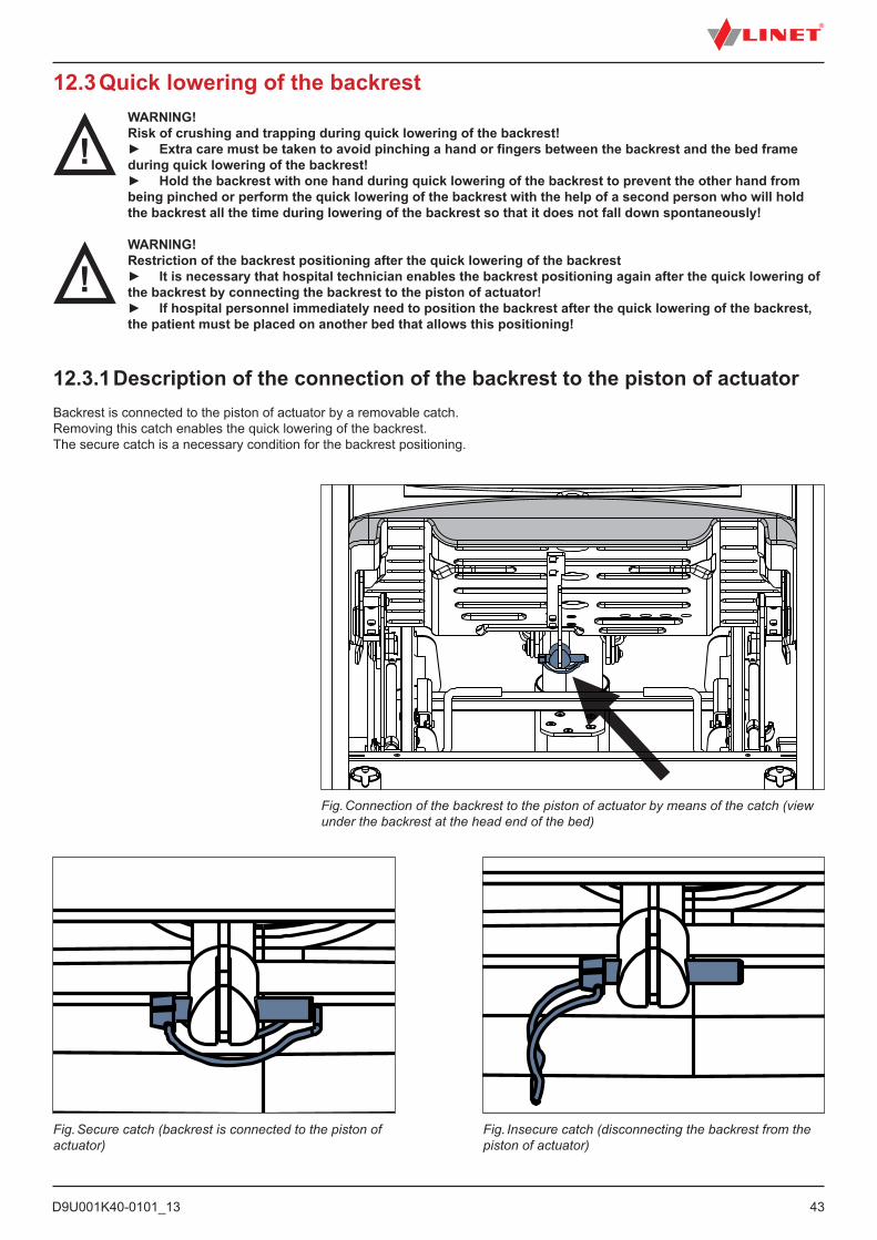
12.3.1 Description of the connection of the backrest to the piston of actuator Backrest is connected to the piston of actuator by a removable catch.Removing this catch enables the quick lowering of the backrest.The secure catch is a necessary condition for the backrest positioning.
Fig. Connection of the backrest to the piston of actuator by means of the catch (view under the backrest at the head end of the bed)
Fig. Secure catch (backrest is connected to the piston of actuator)
Fig. Insecure catch (disconnecting the backrest from the piston of actuator)
D9U001K40-0101_1344
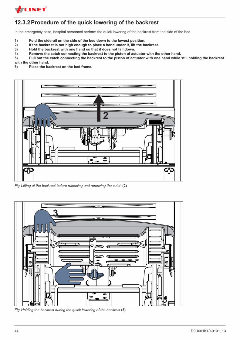
12.3.2 Procedure of the quick lowering of the backrest In the emergency case, hospital personnel perform the quick lowering of the backrest from the side of the bed.
1) Fold the siderail on the side of the bed down to the lowest position.2) If the backrest is not high enough to place a hand under it, lift the backrest.3) Hold the backrest with one hand so that it does not fall down.4) Remove the catch connecting the backrest to the piston of actuator with the other hand.5) Pull out the catch connecting the backrest to the piston of actuator with one hand while still holding the backrest with the other hand.6) Place the backrest on the bed frame.
Fig. Holding the backrest during the quick lowering of the backrest (3)
Fig. Lifting of the backrest before releasing and removing the catch (2)
2
3
D9U001K40-0101_13
45
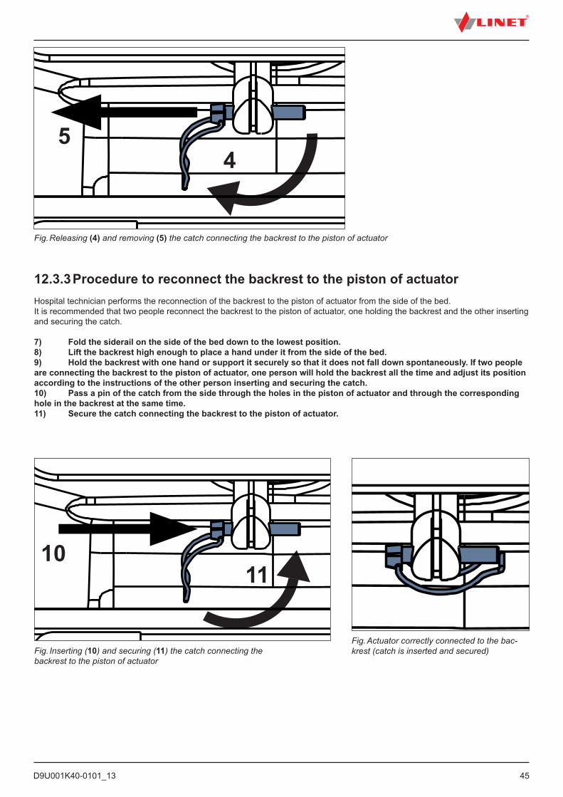
12.3.3 Procedure to reconnect the backrest to the piston of actuatorHospital technician performs the reconnection of the backrest to the piston of actuator from the side of the bed.It is recommended that two people reconnect the backrest to the piston of actuator, one holding the backrest and the other inserting and securing the catch.
7) Fold the siderail on the side of the bed down to the lowest position.8) Lift the backrest high enough to place a hand under it from the side of the bed.9) Hold the backrest with one hand or support it securely so that it does not fall down spontaneously. If two people are connecting the backrest to the piston of actuator, one person will hold the backrest all the time and adjust its position according to the instructions of the other person inserting and securing the catch.10) Pass a pin of the catch from the side through the holes in the piston of actuator and through the corresponding hole in the backrest at the same time.11) Secure the catch connecting the backrest to the piston of actuator.
Fig. Releasing (4) and removing (5) the catch connecting the backrest to the piston of actuator
Fig. Inserting (10) and securing (11) the catch connecting the backrest to the piston of actuator
4
11
5
10
Fig. Actuator correctly connected to the bac-krest (catch is inserted and secured)
D9U001K40-0101_1346
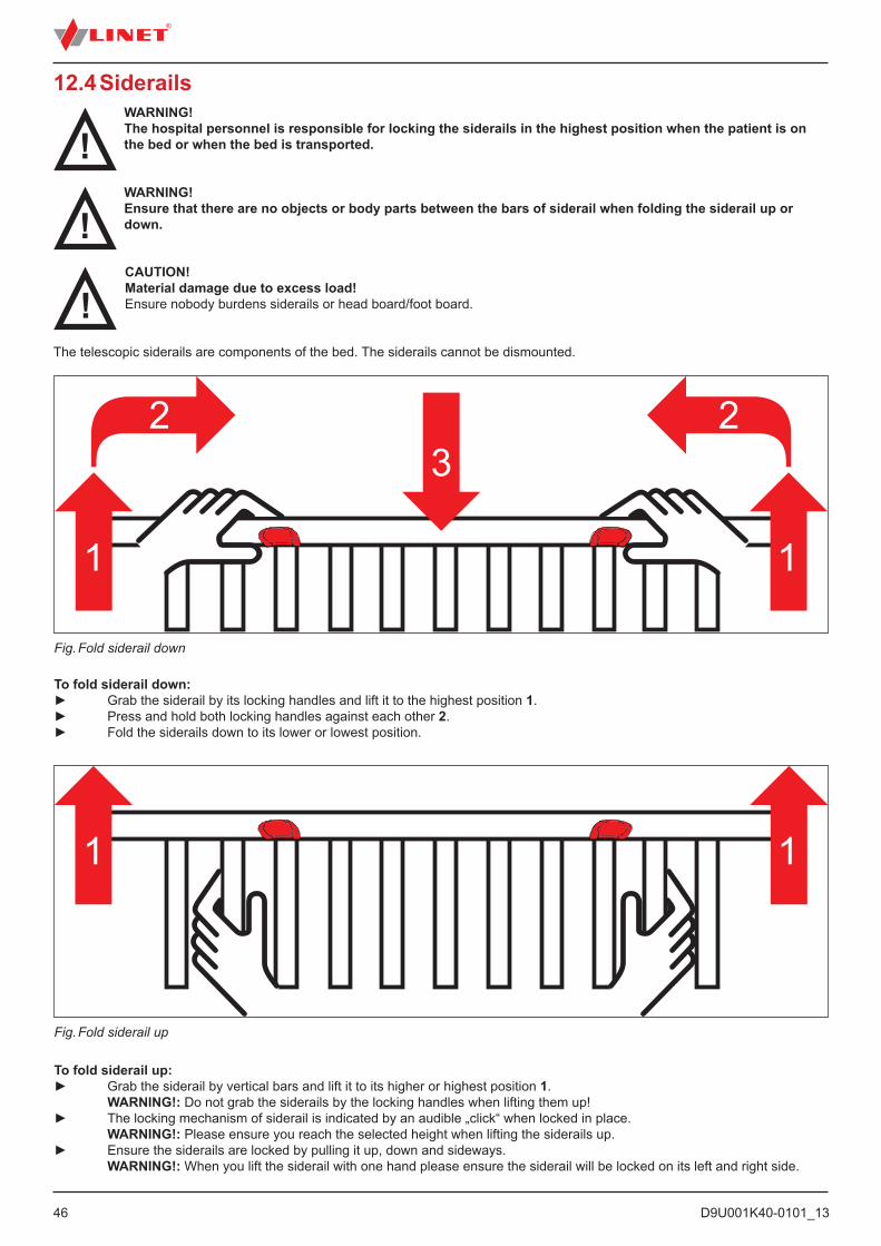
Fig. Fold siderail down
To fold siderail down:► Grab the siderail by its locking handles and lift it to the highest position 1.► Press and hold both locking handles against each other 2.► Fold the siderails down to its lower or lowest position.
Fig. Fold siderail up
12.4 Siderails
CAUTION!Material damage due to excess load!Ensure nobody burdens siderails or head board/foot board.
The telescopic siderails are components of the bed. The siderails cannot be dismounted.
WARNING!The hospital personnel is responsible for locking the siderails in the highest position when the patient is on the bed or when the bed is transported.
WARNING!Ensure that there are no objects or body parts between the bars of siderail when folding the siderail up or down.
To fold siderail up:► Grab the siderail by vertical bars and lift it to its higher or highest position 1. WARNING!: Do not grab the siderails by the locking handles when lifting them up!► The locking mechanism of siderail is indicated by an audible „click“ when locked in place. WARNING!: Please ensure you reach the selected height when lifting the siderails up.► Ensure the siderails are locked by pulling it up, down and sideways. WARNING!: When you lift the siderail with one hand please ensure the siderail will be locked on its left and right side.

D9U001K40-0101_13
47
Fig. Incorrectly locked siderail
D9U001K40-0101_1348
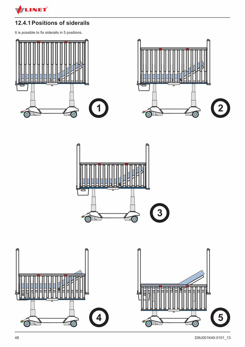
12.4.1 Positions of siderailsIt is possible to fix siderails in 5 positions.

D9U001K40-0101_13
49
Close the siderail bar as follows: ► Push the siderail bar down carefully until it latches into locked position.► Ensure the locking pin is secured in the bushing properly.
12.4.2 Openable siderail bars (optionally)WARNING!Risk of damaging due to incorrect use!► Always ensure the openable bar is locked properly. Check the locking by pulling the bar up, down, to-wards and from you.► Never leave the bed with opened bars without supervision of hospital personell if the patient is on the bed.
► Ensure that no accessories is blocked in locking mechanism or is blocking the locking mechanism. ► Do not position siderail if openable siderail bar is not locked in the lowest position! ► Openable siderail bars are equipped with safety brake reducing speed of their uncontrolled lowering.
Safety brake of the siderail bars functions correctly if speed of the uncontrolled lowering to the down position takes more than 1 second. Contact service department of the manufacturer if the uncontrolled lowering to the down position is quicker and takes less time.
Fig. Opening the siderail bars
Open the siderail bar as follows: ► Pull and hold the locking pin towards you (1).► While still holding the locking pin, lift the bar up to the highest position (2).
Magnet holds siderail bars in the highest position. Siderail bar has been opened (3).
CAUTION!Material damage due to incorrect using!► Avoid obstacles during closing siderail bars.► Ensure siderail bars are carefully locked in lowest position.
It is possible to equip the bed with openable siderail bars. This allows using e.g. redon bottles without having to fold whole siderail down. Openable siderail bars are equipped with safety brake reducing speed of their uncontrolled lowering.

D9U001K40-0101_1350
Fig. Pressed locking pin
12.5 Castor Control and Bed TransportCAUTION!Material damage due to incorrect transport or involuntary movement!► Prior to assembly, disassembly and maintenance, ensure the castors are locked.► Ensure the castors are locked while the bed is occupied and/or not being transported.► Prior to transport, ensure that bed is disconnected from mains.
► Put mains cable on hook provided for transport. ► Have the bed transported only by nursing or trained personnel.
CAUTION!Damage to the bed due to incorrect use!Use 100 mm and 125 mm castors exclusively on flat, even surfaces without any gaps!
The castor control levers are placed on the foot end of the undercarriage.
12.5.1 Castor Control Levers
Fig. Central braking system lever
12
3
1. Forward Movement The front left castor is locked. The bed mo-ves straight ahead. 2. Unrestricted Movement All of the castors are unlocked.3. Braked All of the castors are locked.
To move the bed:► Adjust the bed height to at least 20cm below maximum height.► Push the bed using columns on head or foot end.
D9U001K40-0101_13
51
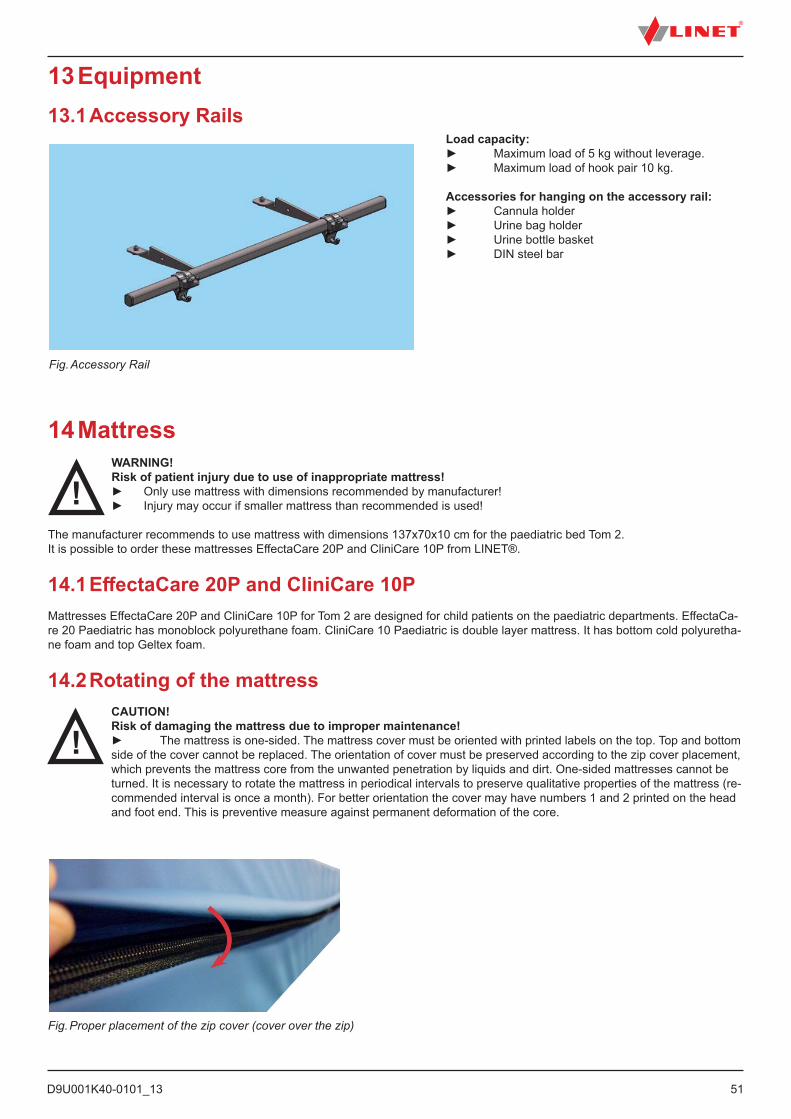
13 Equipment13.1 Accessory Rails
Fig. Accessory Rail
Load capacity:► Maximum load of 5 kg without leverage.► Maximum load of hook pair 10 kg.
Accessories for hanging on the accessory rail:► Cannula holder► Urine bag holder► Urine bottle basket ► DIN steel bar
14 MattressWARNING!Risk of patient injury due to use of inappropriate mattress!► Only use mattress with dimensions recommended by manufacturer!► Injury may occur if smaller mattress than recommended is used!
The manufacturer recommends to use mattress with dimensions 137x70x10 cm for the paediatric bed Tom 2.It is possible to order these mattresses EffectaCare 20P and CliniCare 10P from LINET®.
14.1 EffectaCare 20P and CliniCare 10PMattresses EffectaCare 20P and CliniCare 10P for Tom 2 are designed for child patients on the paediatric departments. EffectaCa-re 20 Paediatric has monoblock polyurethane foam. CliniCare 10 Paediatric is double layer mattress. It has bottom cold polyuretha-ne foam and top Geltex foam.
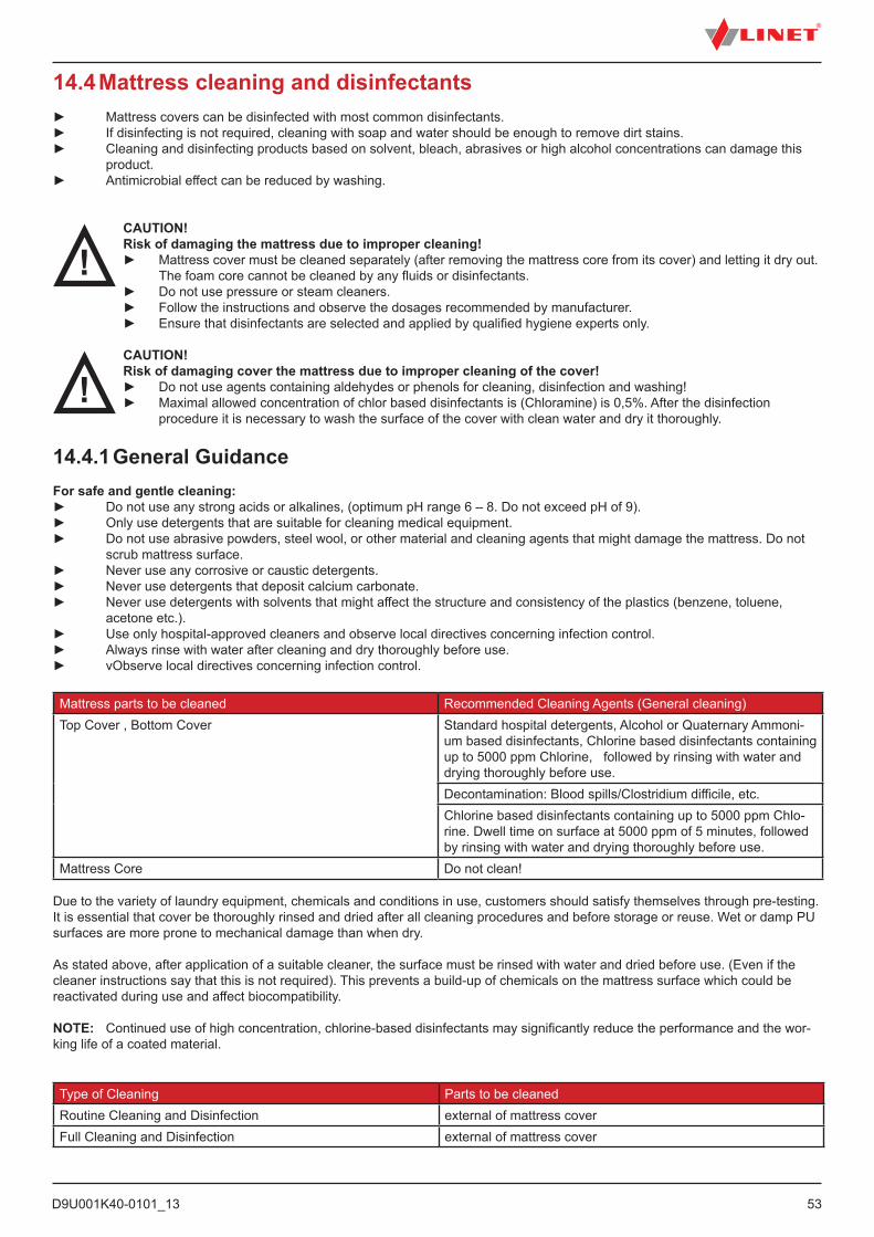
14.2 Rotating of the mattressCAUTION!Risk of damaging the mattress due to improper maintenance!► The mattress is one-sided. The mattress cover must be oriented with printed labels on the top. Top and bottom side of the cover cannot be replaced. The orientation of cover must be preserved according to the zip cover placement, which prevents the mattress core from the unwanted penetration by liquids and dirt. One-sided mattresses cannot be turned. It is necessary to rotate the mattress in periodical intervals to preserve qualitative properties of the mattress (re-commended interval is once a month). For better orientation the cover may have numbers 1 and 2 printed on the head and foot end. This is preventive measure against permanent deformation of the core.
Fig. Proper placement of the zip cover (cover over the zip)
D9U001K40-0101_1352
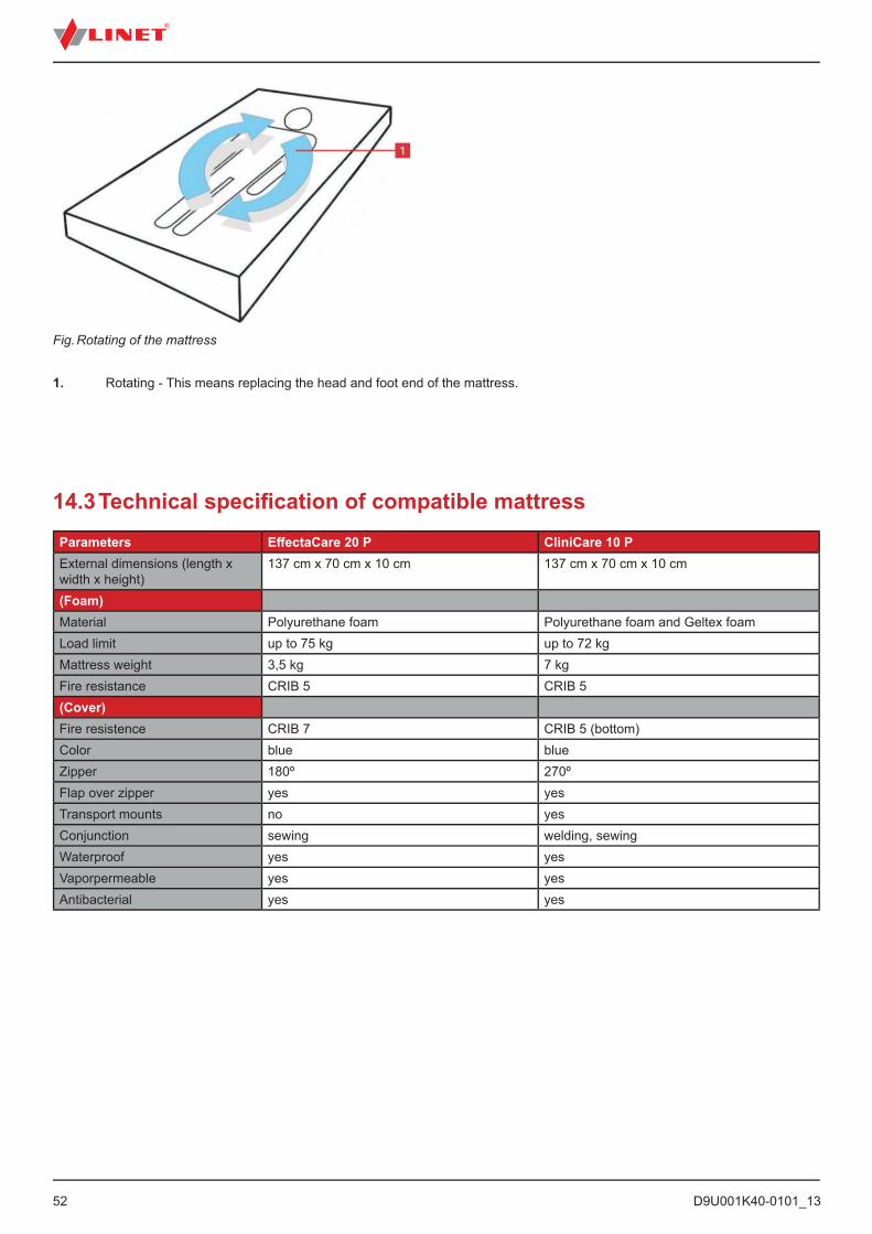
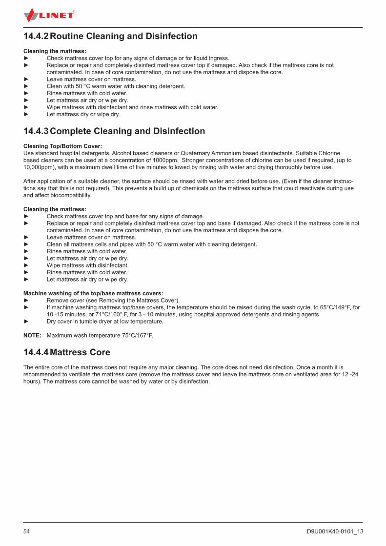
Fig. Rotating of the mattress
1. Rotating - This means replacing the head and foot end of the mattress.
14.3 Technical specifi cation of compatible mattressParameters Eff ectaCare 20 P CliniCare 10 PExternal dimensions (length x width x height)
137 cm x 70 cm x 10 cm 137 cm x 70 cm x 10 cm
(Foam)Material Polyurethane foam Polyurethane foam and Geltex foamLoad limit up to 75 kg up to 72 kgMattress weight 3,5 kg 7 kgFire resistance CRIB 5 CRIB 5(Cover)Fire resistence CRIB 7 CRIB 5 (bottom)Color blue blueZipper 180º 270ºFlap over zipper yes yesTransport mounts no yesConjunction sewing welding, sewingWaterproof yes yesVaporpermeable yes yesAntibacterial yes yes
D9U001K40-0101_13
53
14.4 Mattress cleaning and disinfectants► Mattress covers can be disinfected with most common disinfectants.► If disinfecting is not required, cleaning with soap and water should be enough to remove dirt stains.► Cleaning and disinfecting products based on solvent, bleach, abrasives or high alcohol concentrations can damage this product.► Antimicrobial effect can be reduced by washing.
CAUTION!Risk of damaging the mattress due to improper cleaning!► Mattress cover must be cleaned separately (after removing the mattress core from its cover) and letting it dry out.
The foam core cannot be cleaned by any fluids or disinfectants. ► Do not use pressure or steam cleaners.
► Follow the instructions and observe the dosages recommended by manufacturer. ► Ensure that disinfectants are selected and applied by qualified hygiene experts only.
CAUTION!Risk of damaging cover the mattress due to improper cleaning of the cover!► Do not use agents containing aldehydes or phenols for cleaning, disinfection and washing!► Maximal allowed concentration of chlor based disinfectants is (Chloramine) is 0,5%. After the disinfection
procedure it is necessary to wash the surface of the cover with clean water and dry it thoroughly.
14.4.1 General GuidanceFor safe and gentle cleaning:► Do not use any strong acids or alkalines, (optimum pH range 6 – 8. Do not exceed pH of 9). ► Only use detergents that are suitable for cleaning medical equipment. ► Do not use abrasive powders, steel wool, or other material and cleaning agents that might damage the mattress. Do not scrub mattress surface.► Never use any corrosive or caustic detergents.► Never use detergents that deposit calcium carbonate.► Never use detergents with solvents that might affect the structure and consistency of the plastics (benzene, toluene, acetone etc.). ► Use only hospital-approved cleaners and observe local directives concerning infection control. ► Always rinse with water after cleaning and dry thoroughly before use.► vObserve local directives concerning infection control.
Mattress parts to be cleaned Recommended Cleaning Agents (General cleaning)Top Cover , Bottom Cover Standard hospital detergents, Alcohol or Quaternary Ammoni-
um based disinfectants, Chlorine based disinfectants containing up to 5000 ppm Chlorine, followed by rinsing with water and drying thoroughly before use.Decontamination: Blood spills/Clostridium difficile, etc.Chlorine based disinfectants containing up to 5000 ppm Chlo-rine. Dwell time on surface at 5000 ppm of 5 minutes, followed by rinsing with water and drying thoroughly before use.
Mattress Core Do not clean!
Due to the variety of laundry equipment, chemicals and conditions in use, customers should satisfy themselves through pre-testing. It is essential that cover be thoroughly rinsed and dried after all cleaning procedures and before storage or reuse. Wet or damp PU surfaces are more prone to mechanical damage than when dry.
As stated above, after application of a suitable cleaner, the surface must be rinsed with water and dried before use. (Even if the cleaner instructions say that this is not required). This prevents a build-up of chemicals on the mattress surface which could be reactivated during use and affect biocompatibility.
NOTE: Continued use of high concentration, chlorine-based disinfectants may significantly reduce the performance and the wor-king life of a coated material.
Type of Cleaning Parts to be cleanedRoutine Cleaning and Disinfection external of mattress coverFull Cleaning and Disinfection external of mattress cover
D9U001K40-0101_1354
14.4.2 Routine Cleaning and DisinfectionCleaning the mattress:► Check mattress cover top for any signs of damage or for liquid ingress.► Replace or repair and completely disinfect mattress cover top if damaged. Also check if the mattress core is not contaminated. In case of core contamination, do not use the mattress and dispose the core.► Leave mattress cover on mattress.► Clean with 50 °C warm water with cleaning detergent.► Rinse mattress with cold water.► Let mattress air dry or wipe dry.► Wipe mattress with disinfectant and rinse mattress with cold water.► Let mattress dry or wipe dry.
14.4.3 Complete Cleaning and DisinfectionCleaning Top/Bottom Cover:Use standard hospital detergents, Alcohol based cleaners or Quaternary Ammonium based disinfectants. Suitable Chlorine based cleaners can be used at a concentration of 1000ppm. Stronger concentrations of chlorine can be used if required, (up to 10,000ppm), with a maximum dwell time of five minutes followed by rinsing with water and drying thoroughly before use.
After application of a suitable cleaner, the surface should be rinsed with water and dried before use. (Even if the cleaner instruc-tions say that this is not required). This prevents a build up of chemicals on the mattress surface that could reactivate during use and affect biocompatibility.
Cleaning the mattress:► Check mattress cover top and base for any signs of damage.► Replace or repair and completely disinfect mattress cover top and base if damaged. Also check if the mattress core is not contaminated. In case of core contamination, do not use the mattress and dispose the core.► Leave mattress cover on mattress.► Clean all mattress cells and pipes with 50 °C warm water with cleaning detergent.► Rinse mattress with cold water.► Let mattress air dry or wipe dry.► Wipe mattress with disinfectant.► Rinse mattress with cold water.► Let mattress air dry or wipe dry.
Machine washing of the top/base mattress covers:► Remove cover (see Removing the Mattress Cover).► If machine washing mattress top/base covers, the temperature should be raised during the wash cycle, to 65°C/149°F, for 10 -15 minutes, or 71°C/160° F, for 3 - 10 minutes, using hospital approved detergents and rinsing agents.► Dry cover in tumble dryer at low temperature.
NOTE: Maximum wash temperature 75°C/167°F.
14.4.4 Mattress CoreThe entire core of the mattress does not require any major cleaning. The core does not need disinfection. Once a month it is recommended to ventilate the mattress core (remove the mattress cover and leave the mattress core on ventilated area for 12 -24 hours). The mattress core cannot be washed by water or by disinfection.
D9U001K40-0101_13
55
15.1 Infusion Stand (integrated)WARNING!Risk of injury due using of unsuitable accessories!► Use infusion stands exclusively for accessories listed in the instructions for use.► Only mount an infusion pump to the lower (wider) telescopic section of an infusion stand above the head board /foot board.► Never mount an infusion pump to the upper (thiner) telescopic section of an infusion stand.► Ensure the infusion pump will not collide with any movable parts of the bed (especially backrest part) or with thepatient. This must be verified during installation.► Do not use the infusion stand as driving/pushing device during the bed transport.► Never use infusion stand to manipulate the bed.► In case of not following instructions from instructions for use there is a risk of collision with movable parts of the bed or injuring patient.
Infusion stand is integrated in the corner of head end.► Use exclusively infusion stands with 4 hooks for hanging IV bags or baskets for intravenous solutions.► Ensure that the weight-bearing capacity of the 4 hooks is not exceeded. Capacity per hook: 5 kg
15 AccessoriesWARNING!Risk of injury due to incompatible accessories!► Only the manufacturer’s original accessories can be used.
NOTE: The manufacturer assumes no responsibility for the use of accessories not approved by the manufacturer.
List of available accessories:■ IV holder (integrated) □ chrome-plated with 4 plastic hooks■ Infusion bottle basket □ For IV pole, stainless steel■ Oxygen bottle holder■ Pole for devices and accessories □ chrome-plated
NOTE: It is possible to attach additional IV pole compatible with Tom 2 to the bed.
WARNING!Risk of injury due to damaged accessories!► Use exclusively accessories in perfect condition.
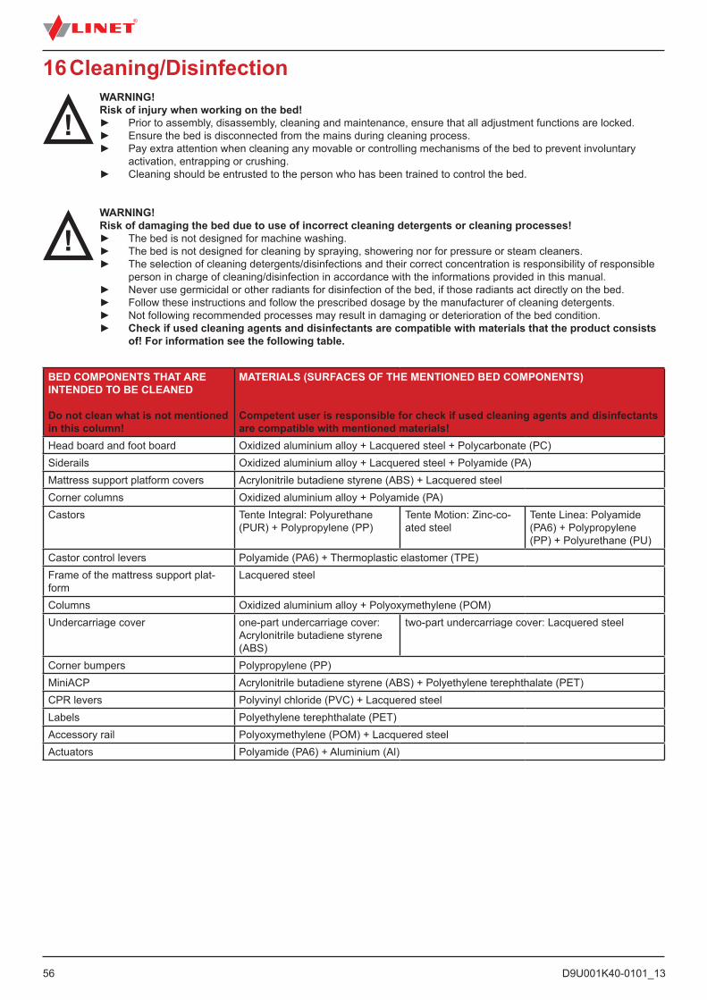
D9U001K40-0101_1356
16 Cleaning/DisinfectionWARNING!Risk of injury when working on the bed!► Prior to assembly, disassembly, cleaning and maintenance, ensure that all adjustment functions are locked.► Ensure the bed is disconnected from the mains during cleaning process.► Pay extra attention when cleaning any movable or controlling mechanisms of the bed to prevent involuntary
activation, entrapping or crushing. ► Cleaning should be entrusted to the person who has been trained to control the bed.
WARNING!Risk of damaging the bed due to use of incorrect cleaning detergents or cleaning processes!► The bed is not designed for machine washing.► The bed is not designed for cleaning by spraying, showering nor for pressure or steam cleaners.► The selection of cleaning detergents/disinfections and their correct concentration is responsibility of responsible
person in charge of cleaning/disinfection in accordance with the informations provided in this manual.► Never use germicidal or other radiants for disinfection of the bed, if those radiants act directly on the bed.► Follow these instructions and follow the prescribed dosage by the manufacturer of cleaning detergents.
► Not following recommended processes may result in damaging or deterioration of the bed condition. ► Check if used cleaning agents and disinfectants are compatible with materials that the product consists of! For information see the following table.
BED COMPONENTS THAT ARE INTENDED TO BE CLEANED
Do not clean what is not mentioned in this column!
MATERIALS (SURFACES OF THE MENTIONED BED COMPONENTS)
Competent user is responsible for check if used cleaning agents and disinfectants are compatible with mentioned materials!
Head board and foot board Oxidized aluminium alloy + Lacquered steel + Polycarbonate (PC)Siderails Oxidized aluminium alloy + Lacquered steel + Polyamide (PA)Mattress support platform covers Acrylonitrile butadiene styrene (ABS) + Lacquered steelCorner columns Oxidized aluminium alloy + Polyamide (PA)Castors Tente Integral: Polyurethane
(PUR) + Polypropylene (PP)Tente Motion: Zinc-co-ated steel
Tente Linea: Polyamide (PA6) + Polypropylene (PP) + Polyurethane (PU)
Castor control levers Polyamide (PA6) + Thermoplastic elastomer (TPE)Frame of the mattress support plat-form
Lacquered steel
Columns Oxidized aluminium alloy + Polyoxymethylene (POM)Undercarriage cover one-part undercarriage cover:
Acrylonitrile butadiene styrene (ABS)
two-part undercarriage cover: Lacquered steel
Corner bumpers Polypropylene (PP)MiniACP Acrylonitrile butadiene styrene (ABS) + Polyethylene terephthalate (PET)CPR levers Polyvinyl chloride (PVC) + Lacquered steelLabels Polyethylene terephthalate (PET)Accessory rail Polyoxymethylene (POM) + Lacquered steelActuators Polyamide (PA6) + Aluminium (Al)
D9U001K40-0101_13
57
16.1 Safety Instructions for Cleaning and Disinfection of the BedPreparation for cleaning:► Drive the bed on a place where the cleaning process will be performed and then brake the bed.► Position the mattress platform to its highest positions and also position the backrest and thighrest parts so the back side of those parts are accessible for cleaning.► Lock all adjustment functions of the bed to prevent involuntary adjustment of the bed or injuries during cleaning.► Disconnect the bed from the mains.► Check if all connectors are properly fixed (controllers, actuators and control unit).
Recommendations for cleaning:► Only use detergents designed for cleaning the medical technologies.► Dilute the detergents in accordance with instructions from manufacturer of detergents.► Never use any strong acids or bases. Optimal pH range is 6-8.► Never use abrasive powders, steel wool or other materials and detergents that may damage the surface of the bed.► Never use detergents with solvents that may affect the structure and consistency of the plastic parts (benzene, toluene, acetone etc.).
Cleaning process:► Clean by wiping the bed with damp, well-wrung textile material.► The detergent can be applied by spraying on bed or on the textile material.► Perform cleaning and disinfection of the bed in the appropriate range. The range of cleaning and disinfection should be distinguished according to the degree of contamination of the bed and the cleaning mode (daily, before changing patient or complete).► Electronic parts that may be contaminated clean carefully and only their outer side. Never open those connectors due to cleaning or disinfection. Those components should not be exposed to prolonged or continuous exposure to moisture.► Let the bed dry completely after cleaning or disinfection process.► After drying the bed place the mattress back on the mattress platform.► After drying the bed check functions of the bed.
16.2 General Instructions for Cleaning and Disinfection
16.2.1 Daily CleaningIt is recommended to clean all parts of the bed which are touched by patient or personnel (e.g. siderails, head board and foot board, handset, lifting pole etc.) and all handles, all control elements and accessory rails.
16.2.2 Cleaning before Changing PatientsIt is recommended to completely clean and disinfects all parts of the bed which are touched by patient or personnel (see Daily Cle-aning), mattress platform, columns, undercarriage covers and mattress.
16.2.3 Complete Cleaning / Cleaning before First UseIt is recommended to clean the bed completely before the first use and then at least once in 4-8 weeks.
16.2.4 Cleaning of Spilled FluidsSpilled fluids should be cleaned as soon as possible. Always disconnect the bed from mains before cleaning the spilled fluids. Some fluids used in health care may cause permanent stains.
16.2.5 Damaged Foam MattressMattress should be periodically checked for cracks, holes or cracks that may affect the integrity, water resistance or resistance to infections of the cover. Contact the service department of the manufacturer according to scope of damage to cover.
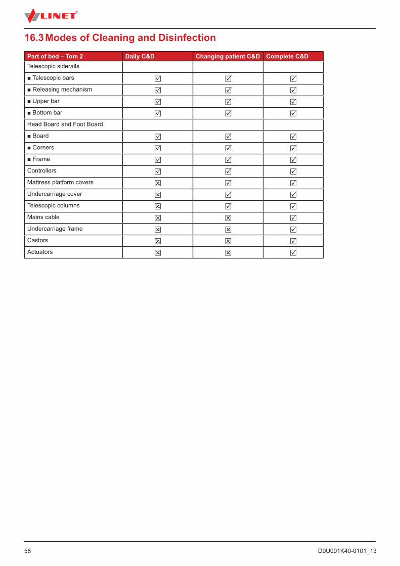
D9U001K40-0101_1358
16.3 Modes of Cleaning and DisinfectionPart of bed – Tom 2 Daily C&D Changing patient C&D Complete C&DTelescopic siderails
■ Telescopic bars ■ Releasing mechanism ■ Upper bar ■ Bottom bar Head Board and Foot Board
■ Board ■ Corners ■ Frame Controllers Mattress platform covers Undercarriage cover Telescopic columns Mains cable Undercarriage frame Castors Actuators
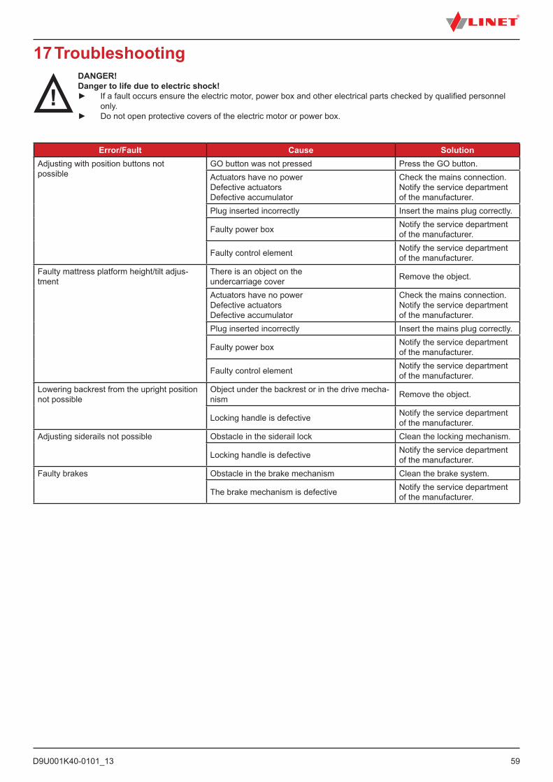
D9U001K40-0101_13
59
17 TroubleshootingDANGER!Danger to life due to electric shock!► If a fault occurs ensure the electric motor, power box and other electrical parts checked by qualified personnel
only. ► Do not open protective covers of the electric motor or power box.
Error/Fault Cause SolutionAdjusting with position buttons not possible
GO button was not pressed Press the GO button.Actuators have no power Defective actuators Defective accumulator
Check the mains connection.Notify the service department of the manufacturer.
Plug inserted incorrectly Insert the mains plug correctly.
Faulty power box Notify the service department of the manufacturer.
Faulty control element Notify the service department of the manufacturer.
Faulty mattress platform height/tilt adjus-tment
There is an object on the undercarriage cover Remove the object.
Actuators have no power Defective actuators Defective accumulator
Check the mains connection. Notify the service department of the manufacturer.
Plug inserted incorrectly Insert the mains plug correctly.
Faulty power box Notify the service department of the manufacturer.
Faulty control element Notify the service department of the manufacturer.
Lowering backrest from the upright position not possible
Object under the backrest or in the drive mecha-nism Remove the object.
Locking handle is defective Notify the service department of the manufacturer.
Adjusting siderails not possible Obstacle in the siderail lock Clean the locking mechanism.
Locking handle is defective Notify the service department of the manufacturer.
Faulty brakes Obstacle in the brake mechanism Clean the brake system.
The brake mechanism is defective Notify the service department of the manufacturer.
D9U001K40-0101_1360
18 MaintenanceWARNING!Risk of injury when working on the bed!► Ensure that the bed is disconnected from the mains power prior to installation, putting into service, maintenance and deinstallation.► Ensure that the castors are locked prior to installation, putting into service, maintenance and deinstallation.
WARNING!Risk of injury due to defective bed!► Have a defective bed repaired immediately.► If the defect cannot be repaired, do not use the bed.
CAUTION!Material damage due to incorrect maintenance!► Ensure that maintenance is performed exclusively by manufacturer´s customer service or by authorised service personnel certified by the manufacturer.► If the defect cannot be repaired, do not use the bed.
LINET ® recommends attaching the maintenance plaque to the bed.
18.1 Regular maintenance► Check regularly movable parts for wear.► Perform regularly visual check of the product (with delivery note if necessary).► Ask service department of the manufacturer for addition of the original spare parts if some product parts are missing.► Ask service department of the manufacturer for replacement of any damaged product parts by the original spare parts.► Check that the accumulator is working properly. Disconnect the bed from the mains power to check signalisation of accu-mulator indicator according to the instructions for use.► Have the accumulator replaced if it is not working properly.► Check regularly that all accessories are working properly.► Replace damaged accessories immediately.
18.2 Spare PartsThe serial label is located on the frame of the mattress support platform. The serial label contains information for claims and orde-ring replacement parts.
Information about spare parts is available from:■ Manufacturer´s customer service■ Sales department
18.3 Safety Technical ChecksWARNING!Risk of injury due to incorrect safety technical checks!► Ensure that safety technical checks are performed exclusively by manufacturer´s customer service or by authori-sed service personnel certified by the manufacturer.► Ensure that the safety technical checks are recorded in the service and maintenance log.
Safety technical check of the medical bed must be performed at least once every 12 months.
The procedure for performing the safety technical check is stipulated in EN 62353:2014.
NOTE On request, the manufacturer will provide service documentation (e.g. circuit diagrams, component part lists, descriptions, calibration instructions etc.) for service personnel for the repair of ME equipment designated by the manufacturer as repairable by service personnel.
D9U001K40-0101_13
61
19 Disposal19.1 Environment ProtectionThe company LINET® is aware of the importance of environmental protection for future generations. Within this company the environmental management system is applied in accordance with the internationally agreed standard ISO 14001. The compliance with this standard is annually tested by the external audit executed by an authorised company. Based on the Directive No. 2002/96/EC (Directive WEEE - Waste, Electric and Electronic Equipments) the company LINET, s. r. o. is registered in the List of Electric and Electronic Equipment Producers (Seznam výrobců elektrozařízení) on the Ministry of the Environment of the Czech Republic (Ministerstvo životního prostředí).
Materials used in this product are not environmentally hazardous. LINET® products meet valid requirements of national and Euro-pean legislation in the areas of RoHS and REACH, so they do not contain any prohibited substances in excess quantities. None of the wooden parts is made of tropical wood (such as mahogany, rosewood, ebony, teak etc.) or made of timber from the Amazon region or from similar rainforests. Product noise (sound pressure level) meets requirements of the regulations for the protection of public health against undesirable effects of noise and vibration in protected interior spaces of buildings (according to standard EN 50637). Used packaging materials are in accordance with requirements of the Packaging Act (Zákon o obalech). For disposal of packaging materials after installation of products contact your sales representative or manufacturer´s customer service about the possibility of a free take-back of packaging through an authorized company (more details on www.linet.cz).
19.2 DisposalThe main objective of the obligations arising from the European Directive No. 2012/19/EU on Waste, Electric and Electronic Equip-ments (nationally regulated in Act No. 185/2001 Coll. as amended. On Waste and in Decree of the Ministry of the Environment No. 352/2005 Coll. as amended), is to increase the re-use, material recovery and recovery of electric and electronic equipment at the required level, thereby avoiding the production of waste and thereby avoiding the possible harmful effects of hazardous substances contained in electric and electronic equipment on human health and the environment. LINET® electric and electronic equipments that have a built-in battery or accumulator are designed so that the used batteries or accumulators can be safely removed by LI-NET® qualified service technicians. There is an information about its type on the built-in battery or accumulator.
19.2.1 Within EuropeTo dispose of the electric and electronic equipment:
► The electric and electronic equipment must not be disposed of as household waste.► Dispose of this equipment at designated collection points or take-back points.
To dispose of the other equipment:
► The equipment must not be disposed of as household waste.► Dispose of this equipment at designated collection points or take-back points.
LINET® participates in a collective system with take-back company REMA System (see www.remasystem.cz/sberna-mista/). By bringing electric and electronic equipment to a take-back point, you participate in recycling and you save primary raw material resources while protecting your environment from effects of unprofessional disposal.
19.2.2 Outside Europe► Dispose of the product or its components in accordance with local laws and regulations!► Hire an approved waste disposal company for disposal!
D9U001K40-0101_1362
20 WarrantyLINET ® will only be held responsible for the safety and reliability of products that are regularly serviced, maintained and used in accordance with the safety guidelines.
Should a serious defect arise that cannot be repaired during maintenance:► Do not continue to use the bed.
This product is covered by a 24-month warranty from the date of purchase. The warranty covers all material and manufacturing-re-lated failures and errors. Failures and errors caused by incorrect use and external effects are not covered. Justified complaints will be fixed free of charge during the warranty period. Proof of purchase, with the date of purchase, is required for all warranty service. Our standard terms and conditions apply.
21 Standards and RegulationsApllied norms are stated on Declaration of Conformity.
The Tom 2 medical bed complies with the following standards and directives:■ EN 60601-1■ EN 60601-1-2■ EN 60601-1-6■ EN 50637■ ISO 14971
The manufacturer adheres to a certified quality management system in compliance with the following standards:■ ISO 9001■ ISO 14001■ ISO 13485■ MDSAP (Medical Device Single Audit Program)