
Thrust-Vector Control - CORE
70
Thrust Vector Control Stellar Explorations Dane Larkin [email protected] Harsimran Singh [email protected]
-
Upload
khangminh22 -
Category
Documents
-
view
4 -
download
0
Transcript of Thrust-Vector Control - CORE

Thrust Vector Control
Stellar Explorations
Dane Larkin [email protected]
Harsimran Singh [email protected]

Statement of Disclaimer
Since this project is a result of a class assignment, it has been graded and accepted as fulfillment of the course requirements. Acceptance does not imply technical accuracy or reliability. Any use of information in this report is done at the risk of the user. These risks may include catastrophic failure of the device or infringement of patent or copyright laws. California Polytechnic State University at San Luis Obispo and its staff cannot be held liable for any use or misuse of the project.

ContentsList of Tables ................................................................................................................................................. ii
List of Figures………………………………………………………………………………………………………………………………………….iii
Abstract…………………………………………………………………………………………………………………………………………………..v
Chapter
1 Introduction…………………………………….1
2 Background……………………………………..2
3 Design Development……………………....6
3.1 Objectives………………………………….6
3.2 Concept Selection………………………10
4 Final Design…………………………………...15
4.1 Design Description……………………16
4.2 Engineering Analysis…………………18
4.3 Cost Analysis…………………………….22
4.4 Materal/Component Selection…23
5 Manufacturing/Assembly………………26
6 Project Planning…………………………….28
6.1 Project Management Plan……….28
6.2 Design Verification Plan………….29
7 Conclusions & Recommendations..30
8 Final Project Update…………………….31
8.1 Materials………………………………..31
8.2 Design Changes………………………32
8.3 Manufacturing……………………....34

9 Testing…………………………………………………………………36
9.1 Testing Apparatus……………………………………………36
9.2 Wiring Setup…………………………………………………...37
APPENDIX A‐Concept Selection……………………………………..39‐40
APPENDIX B‐Engineering Analysis………………………………..41‐43
APPENDIX C‐Cost Analysis………………………………………………….44
APPENDIX D‐System Components & Assemblies……………45‐51
APPENDIX E‐Gantt Chart……………………………………………….52‐55
APPENDIX F‐Off the shelf components………………………….56‐62

ii
List of Tables
Table 1‐Engineering Specifications…………………………………………………p. 8
Table 2‐Decision Matrix……………………………………………………………….p. 10
Table 3‐Thermal Expansion Data…………………………………………….……p. 20
Table 4‐Cost Analysis...………………..………………………………………………p. 23
iii
List of Figures
Figure 1‐Jetavator Setup……………………………………………………….p. 5
Figure 2‐Rotatating Segment Setup……………………………………...p. 6
Figure 3‐Ball and Socket Setup………………………………………………p. 6
Figure 4‐Internal Maneuvering Vanes…………………………………...p.7
Figure 5‐Jetavator Reference Photo……………………………………p. 12
Figure 6‐Maneuvering Vanes Reference Photo…………………..p. 12
Figure 7‐Rotating Segments Reference Photo…………………….p. 13
Figure 8‐Maneuvering Vanes Installation……………………………p. 13
Figure 9‐Ball and socket setup susceptibility to erosion………p. 13
Figure 10‐Further development of ball and socket concept…p. 15
Figure 11‐Isometric view of solid model design…………………..p. 17
Figure 12‐Exploded view of solid model design…………………..p. 18
Figure 13‐Heat transfer in nozzle………………………………………..p. 20
Figure 14‐Thermal expansion of nozzle……………………………….p. 21
Figure 15‐Thermal expansion of collar………………………………..p. 23
Figure 16‐Forces on nozzle……………………………..…………………..p. 24
Figure 17‐Graphite Nozzle…………………………………………………..p. 25
Figure 18‐Inconel Flange…………………………………………………….p. 26
Figure 19‐Rapid Prototyped Components…………………………..p. 33
Figure 20‐Prototyped couplers and brackets………………………p. 34
Figure 21‐Design Flaws………………………………………………………p. 34

iv
Figure 22‐Design Flaw Solutions………………………………………p. 35
Figure 23‐Machined section of solid bar………………………….p. 36
Figure 24‐Fabricated features of collar……………………………p. 37
Figure 25‐Test Apparatus……………………………………………….p. 38
Figure 26‐Pre test setup…………………………………………………p. 38
Figure 27‐ Test objective verification……………………………..p.39
Figure 28‐ Wiring…………………………………………………………...p. 39

v
Abstract
The objective of this project was to design, build and test a thrust‐vectoring system for a solid booster rocket. The project was sponsored by Stellar Exploration. A two member team of Harsimran Singh and Dane Larkin worked toward the objective.

1
CHAPTER 1‐Introduction
The project described in this document is a thrust vectoring system that will be implemented in Stellar Exploration’s solid fuel test rocket. This document will outline Background research on the status of thrust vector control, the project requirements and objectives, how the success of the project will be evaluated, and prototype design. In addition the methods used and the timeline the project will follow will be thoroughly outlined. The success of this project is dependent on the cooperation of Dane Larkin and Harsimran Singh and on the participation of their sponsor Stellar Exploration at each part of the process. Dane Larkin and Harsimran Singh are responsible for delivering a viable prototype to Stellar Exploration. Stellar exploration is expected to review the progress and design reviews at each stage of the design. The final goals of this project are to design and build a functioning thrust vectoring system for use by Stellar Explorations.

2
CHAPTER 2‐Background
Stellar Exploration Incorporated is a small technology company which focuses on low‐cost scientific and space exploration projects. The company hires approximately three full time engineers. Stellar Exploration requires a thrust vectoring system for its Silver Sword rocket. By allowing operators to control the direction of thrust, the thrust vectoring system will make up for the drag produced and loss in performance incurred by the rocket fins. What follows is a list of background research on different thrust vectoring systems which have been used in the past.
Fixed nozzle systems
Fixed nozzle systems as the name states refer to nozzles that are solid mounted in the frame of the vehicle. The flow inside the nozzle itself is then changed to move the thrust vector. These were some of the first systems of thrust vector control developed in the Polaris and minute man rockets. The classification of fixed nozzle systems falls into these categories, secondary injection systems where the flow is the nozzle is changed by the addition or rerouting of fluid flow, and mechanical deflection where a mechanical element changes the direction of flow.
Liquid injection
Liquid injection encompasses any addition of a fluid that changes the characteristics of the combustion. By changing the combustion on one side of the nozzle the thrust vector can be changed. The method of injection, as well as the fluid that is injected, are both topics of much debate and research. one of the biggest decisions when considering this method of thrust vectoring is the liquid that will be used the two main divisions are whether the liquid will inhibit the combustion or contribute to combustion. Combustion inhibitors will tend to cool one side of the nozzle while combustion contributors will add fuel or other additives to increase thrust on one side of the nozzle. Advantages of this method of thrust vectoring are that it has fast response capability and add to thrust by adding mass to the fluid stream. The disadvantages of this system are that they are heavy and the amount the valve opens is not linearly related to the rate of change of the thrust vector.
Gas injection
Gas injection is very similar to liquid injection the difference being that instead of new gas being added to the fluid stream combustion gasses are rerouted from behind the nozzle into the diverging section changing the flow through the nozzle itself. The advantages of this method are that additional fluids do not need to be stored onboard and so the system overall is lighter in weight. The downside to this method however, is that the hot combustion gasses

have to enough t
Jet vane
Texiting fldeflect fractuatorsdirectly iburn relabe madedeflectiodeflectio
Jetavato
Tvanes beare para
Fig
Jet tab
Tout of tproportiorelativelystalls on stopped
be routed thto consider f
he jet vane ow of the nrom the cens are low ann the exhauatively cool, e of exotic hn of the vann and the in
r
he jetavatoreing in the flllel to the f
1. Jetavator
he jet tab sythe nozzle onal to the ay easy. The the tab. Theon this meth
hrough valvfurther testin
deflector isozzle. As thnterline of tnd thus theyst this causethe propellaeat resistanne must be mnherent drag
r is a similar ow the nozzlow. This sy
r Setup
ystem involvdisrupting
area of the tdownside ofe stalled flowhod because
es. In stationg.
characterizhe plate or fhe rocket. Ay can be capes the designant can burnnt material. Tmade in ordg of fluid on t
concept to tzle they are ystem has si
include tto the dedesign, bvane secjetavatorare F‐16
ves a plate athe flow. ab that is exf this systemw causes lote of the mat
3
onary tests t
zed by any ffin moves it Advantages opable of quicner to make n for relativeThe other pder to cause the vanes re
the jet vanepositioned milar heat rthat the defleflection of tbesides the hction, are thar restricts tand the Pola
t the end ofInitial adva
xposed to thm is that whes of erosionerial erosion
the valves co
fin or plate twill cause tof these sysck response one of thre
ely short perproblem witha change ineduce thrust
e the differenaround the restrictions ection of ththe thrust vheat consideat the systemhe exit diamaris A‐1.
f the nozzle antages thae flow this men the tab is on the insidn problems.
ould never b
that is direche flow exitstems are thtimes. Since choices, thriod of time, h this methon the thrust t.
nce being thperimeter oto the jet ve jetavator ivector. The derations menm can be hemeter. Nota
that can be at the thrumakes contrs in the fluidde of the no
be made re
ctly placed iting the nozzhat the forcece the bladehe propellanor the vaneod is that a vector. The
hat instead oof the nozzlevane. Advantis linearly redownsides ontioned in theavy and thaable applica
rotated intoust deflectioolling the syd stream theozzle. Testing
liable
n the zle to es on es are nt can es can large large
of the e and tages elated of this he jet at the ations
o and on is ystem e flow g was
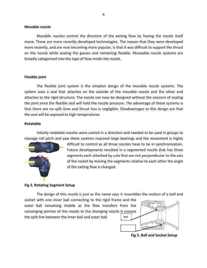
Movable
Mmove. Thmore recon the nbroadly c
Flexible j
Tsystem uattaches the joint that therthe seal w
Rotatabl
Inmanage
Fig 2. Rot
Tsocket wouter baconvergithe split
e nozzle
Movable nozhese are mocently, and anozzle whilecategorized
joint
he flexible juses a seal to the rigidsince the flere are no spwill be expo
e
nitially rotataroll pitch an
tating Segm
he design ofwith one innall remaininng portion oline betwee
zzles controore recently are now beco sealing theinto the type
joint systemthat attach structure. Texible seal wplit lines andsed to high t
able nozzlesnd yaw thes
difficuFuturesegmeof the of the
ment Setup
f this nozzlener ball connng mobile of the nozzlen the inner b
l the directdeveloped toming moree gasses ande of flow ins
m is the simes on the oThe nozzle cwill hold thed thrust losstemperature
s were cantee systems rlt to controle developmeents each attrocket by mexiting flow
e is just as thnecting to tas the floe to the divball and out
4
ion of the etechnologies popular, is d remainingside the nozz
mplest desigoutside of tcan now be d nozzle pres is negligiblees
ed in a directequired largl as all threeents resultedtached by cumoving the se is changed.
he name sayhe rigid fraw transfersverging nozzer ball.
exiting flows. The reasothat it was dg flexible. Mzle.
gn of the mthe movabledesigned wissure. The ade. Disadvant
tion and neege bearings e nozzles had in a segmuts that are negments rela
ys it resembme and thes from thele it crosses
Fig
Ball
Socket
w by having on that they difficult to suMoveable no
movable nozze nozzle anthout the codvantage of tages to this
eded to be uand the moave to be in mented nozzlnot perpendative to each
bles the mote e s
g 3. Ball and
the nozzle were develupport the tozzle system
zle systemsd the otheroncern of sef these systes design are
used in grouovement is hsynchronizale that has tdicular to theh other the a
tion of a bal
Socket Setu
itself oped hrust s are
. The r end ealing ems is e that
ups to highly ation. three e axis angle
ll and
up

Internal
Vthe hot tbetter gu
Fig 4. Int
maneuverin
Vanes are plathrust gasesuide a rocket
ernal Mane
ng vanes
aced along ts, the vanest projectile.
uvering Van
the inside w are maneuThis type of
nes
5
wall of the rovered by acsystem is co
ocket nozzlectuators to dommon on s
e. Being in tdirect the thsurface‐to‐ai
he direct pahrust in ordir missiles.
ath of der to

6
CHAPTER 3‐Design Development
3.1‐Objectives
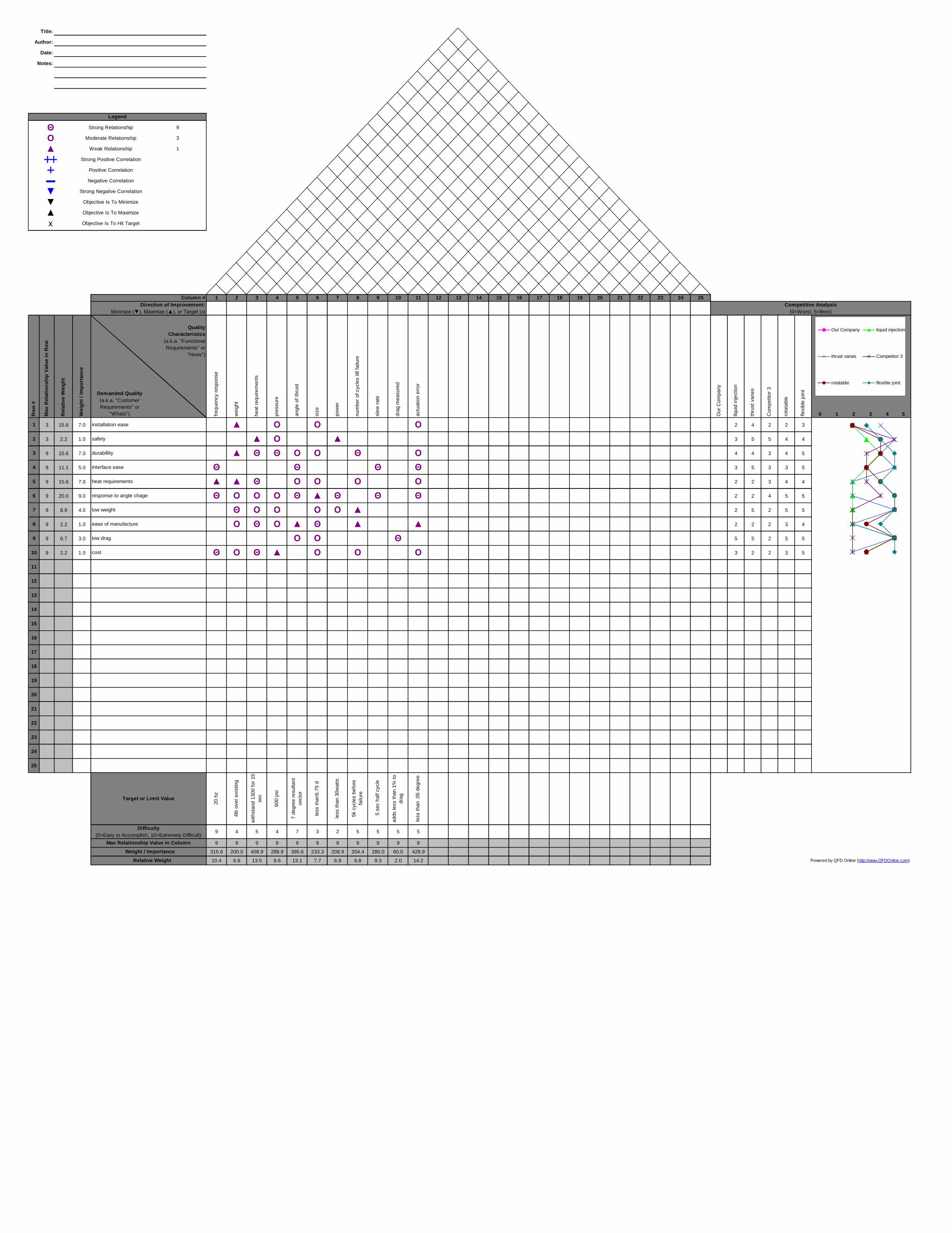
This team seeks to develop a thrust vectoring system for the Sword Fish rocket built by Stellar Exploration. The thrust vectoring system will help steer the rocket through the fifteen second boost phase, and will go un‐functional thereafter. As described in the background, many solutions currently exist to vector a rocket’s thrust. However, since most of these solutions may not suit Stellar Exploration’s requirements, we have put together a table of specifications using the Quality Function Deployment (QFD) method to translate customer requirements to engineering specifications. The solution(s) which best matches these specifications are further examined and given more consideration for development. The Appendices section provides a house of quality that this team used in the QFD method. This team also provides a specifications table in the Appendices section.
This team approximated the target values at the bottom of the house of quality, and intends to submit the target values for review and possible modification by Stellar Exploration. Each target value is assigned a relative weight. For example, the target value regarding heat requirements has a relative weight of 14.3%. This figure indicates the importance of heat requirements relative to other design specifications.
The derivation of relative weight proceeds as follows:
1. The user’s qualitative requirements such as installation, safety, etc are listed
in each row of the house of quality.
2. Each customer requirement is assigned an importance weight (i.e. 7.0 for
durability).
3. The importance weights for all customer requirements are added up and the
importance weight for each particular customer requirement is divided by
this sum. The resulting figure is then multiplied by one hundred and called
the relative weight for the particular customer requirement (i.e. 15.9% for
durability).
4. Along each column are listed quantifiable technical requirements such as
frequency response, weight, etc.
5. The intersecting cell between each column and row indicates how the
respective customer requirement correlates with the respective technical
7
requirement. If there is no correlation, the cell is left blank. The cell is filled
with a solid triangle if there is slight correlation, with a hollow circle if there
is medium correlation, and with a symbol that resembles theta if there is
strong correlation. For instance, heat requirement (quantitative) has light
correlation with safety, medium correlation with response to angle change,
strong correlation with durability, etc.
6. Each level of correlation is assigned a numerical value. A value of zero for no
correlation, one for light correlation, three for medium correlation, and nine
for strong correlation.
7. Take the relative weight for each customer requirement and multiply it by
the correlation value in each cell of each respective row (i.e. 15.9*9 for
durability and heat requirements).
8. Add up the resulting values along each column, and an importance weight is
obtained for each technical requirement (i.e. 425 for heat requirements).
This value is placed at the bottom of the house of quality.
9. Sum up the importance weights for all technical requirements, and divide
into the importance weight for a particular technical requirement. Multiply
the result by one hundred to obtain the relative weight for that technical
requirement (i.e. 14.3% for heat requirements).
The relative weight indicates the importance of a particular technical requirement for our design. Having a relative weight of 14.3%, heat requirement has a higher relative weight than any other technical requirement. It also has strong correlation with the greatest amount of customer requirements. Therefore, this team should have the greatest concern regarding heat requirement throughout the design, build, and test process. Not satisfactorily meeting heat requirements will result in the greatest adverse impact on most customer requirements.
The following table of engineering specifications highlights from left to right, the type of technical parameter, this team’s target numerical value for that parameter, the tolerances it must meet, the risk of not meeting each target (High (H), Low (L), or Medium (M)), and how this
8
team will meet each parameter (analysis (A), test (T), similarity to existing designs (S), or inspection (I)).
Table 1
Spec. # Parameter Description
Target Value (units)
Tolerance Risk Compliance
1 Frequency response
20 Hz Min. M A, T, S
2 Weight Adds <4 lbs on to system
Max. M A, T
3 Temperature Withstand 1300 ◦F
±20 ◦F L A, T, S
4 Pressure Withstand 600 psi
±50 psi L A, T, S
5 Thrust angle ±7 degrees from central
axis
Max. M A, T
6 Size < 5.75 in diameter1
Max. L A, I
7 Power usage < 30 watts Max. L A, S
8 Cycles till failure
5000 cycles ±150
Min. L A, T
9 Slew rate 0.5 seconds for half cycle
±0.001 second
H A, T, S
10 Drag Adds less than 1%
Max. L A, T
11 Actuation error
± 0.05 degrees
Max. M A, T
*For further reference see the bottom of the house of quality in Appendix A.
1See Appendix B
Frequency Response: Amount of cycles the actuators can achieve in one second.
Weight: Once installed on to the rocket, the system we design must not add more than 4 lbs. to the rocket’s pre‐installation weight.
Temperature: The system must withstand the high temperatures that result from fuel combustion and other factors.

9
Pressure: The system must withstand all pressures resulting from the rocket’s thrust and other factors.
Thrust Angle: *See frequency response above.
Size: The system must be able to fit within a 5.75 in diameter. *Also see Appendix B.
Power usage: The system must use no more than 30 watts of power from the rocket’s power supply.
Cycles till failure: The system must cycle thrust direction a minimum of 5000 cycles before failure.
Slew Rate: Amount of times in one second that the system can cycle direction of thrust between ± 7 degrees from the rocket’s central axis. The risk of not being able to meet this requirement is high. The thrust vectoring system requires a high cycling speed because it must finish steering the rocket to the correct trajectory within 15 seconds of launch. This team is unsure whether it can design a system to achieve this speed within the given power and size restrictions. If the cycling speed is achieved, this team is unsure whether all components of the system will function properly at the desired slew rate for a full duration of 15 seconds.
Drag: Once installed on to the rocket, the system must add no more than 1% of the rocket’s pre‐installation drag.
Actuation Error: The actual thrust angle must not deviate more or less than 0.05 degrees from the intended thrust angle.

CoCriinsteasSaf
dura
intehearequrespanglow easmanlow
Cos
3.2‐Con
Thacross theand cylindrelative toeach desigout of 100
*
lumn1 Coteria Wtallation se fety
ability
erface ease at uirements ponse to
gle change weight
se of nufacture drag
st
ncept Selec
his team usee top of the mder‐powered o characterisgn were sum0 (Table1.Col
Refer to the f
Fig 5.
olumn2 CoWeight Rat
6.8
2.3
15.9
11.4
15.9
15.9
15.9
2.3
11.4
2.3
100.1
ction
ed a decisionmatrix. Thesedesigns. Eactics such as imed, the balumn7). Thus,
following pho
Jetavator
Jetavator lumn3 Coluting Scor
8 9
6.5 105
6.5 10
7 16.5 10
5 5 6
64.5 645
matrix to see included thech design wasinstallation el and socket d this team fo
otos for refere
umn4 Columre Rating
54.420.7
03.3557
03.35
111.303.35
11.557
13.856.45
10
elect our tope jetavator, ins then given ase, durabilitdesign was found it to be t
Table 2
ence:
Fig
Vanes mn5 Columg Score
8.5 579 208 1277 79
4 63
7.5 119.8 127
6 1310 16 13
74 7407
p design. Thenternal manea 1‐10 ratinty, interface ound to have the best desig
6. Maneuve
Ball an6 Column
Rating
7.80.77.2 8.9.8
3.6 6.
.25 8.7.2
3.8114 13.87.4 83.
e four best deuvering vaneng (Table1.Coease, etc. Af the highest tgn.
ering Vanes
and Socket n7 Column8
Score
9 61.29 20.7.5 135.159 102.6
.5 103.35
.5 135.158 127.2
7 16.110 1148 18.4.5 8338.5
esigns were es, ball and soolumn(s) 3, 5,fter the ratingtotal rating o
Cylin8 Column9
Rating
2 8.57 95 96 9
5 7.5
5 82 5
1 74 9.54 75 79.5
listed ocket, , 7, 9) gs for f 83.5
nders Column10Score
57.820.7
143.1102.6
119.25
127.279.5
16.1108.316.1
7957.95
Installatio
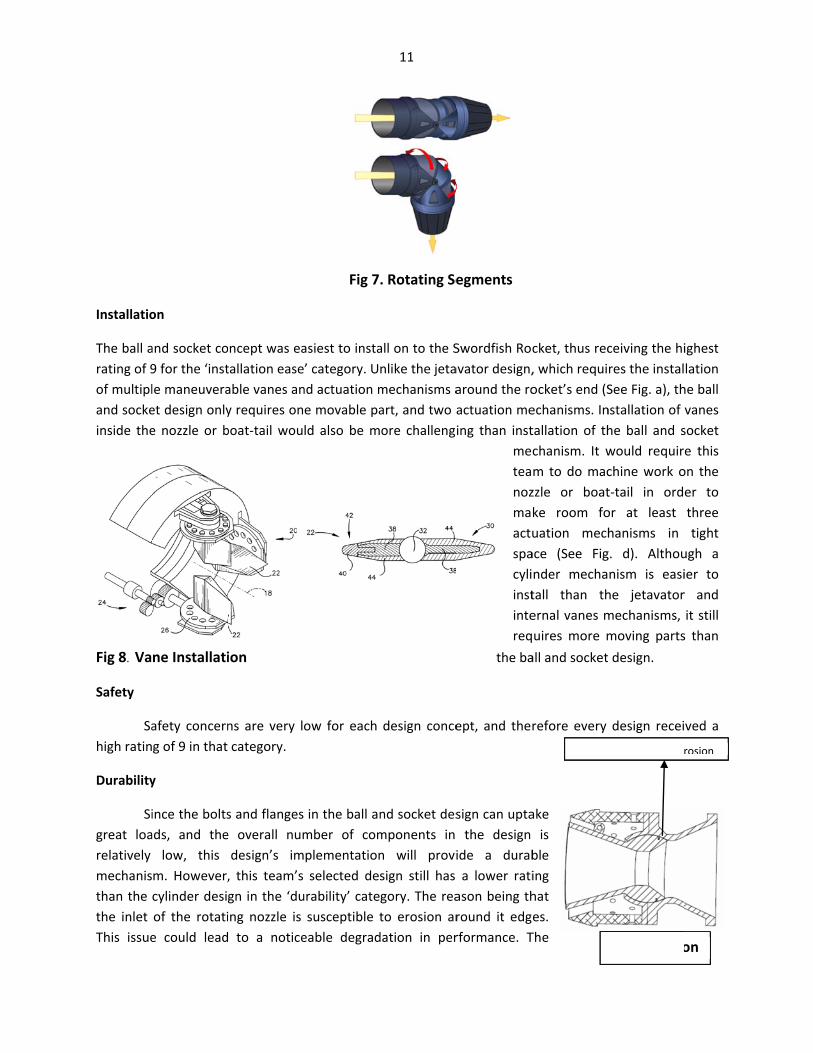
The ball arating of 9of multipland sockeinside the
Fig 8. Va
Safety
Sahigh ratin
Durability
Sigreat loarelatively mechanisthan the the inlet This issue
on
and socket co9 for the ‘instle maneuveraet design onlye nozzle or b
ne Installati
afety concerng of 9 in that
y
ince the boltsads, and the
low, this m. However,cylinder desigof the rotatie could lead
ncept was eatallation easeable vanes any requires onboat‐tail wou
ion
ns are very locategory.
s and flanges e overall numdesign’s im, this team’s gn in the ‘duing nozzle is to a notice
Fig 7
asiest to insta’ category. Und actuation me movable pald also be m
ow for each
in the ball anmber of complementationselected des
urability’ catesusceptible teable degrad
11
. Rotating Se
all on to the Snlike the jetamechanisms aart, and two aore challeng
design conce
nd socket desmponents in n will provisign still has gory. The reato erosion ardation in per
egments
Swordfish Rocavator design,around the roactuation meing than inst
meteanozmaactuspacyliinstintereq
the ba
ept, and ther
sign can uptathe design
ide a duraba lower rati
ason being thround it edgrformance. T
cket, thus rec, which requiocket’s end (Sechanisms. Intallation of thchanism. It wm to do maczzle or boatke room fouation mechace (See Fignder mechatall than thernal vanes muires more mall and socket
refore every
ake is
ble ing hat es. The
Edges S
ceiving the hires the instalSee Fig. a), thnstallation of he ball and swould requirchine work ot‐tail in ordor at least hanisms in g. d). Althounism is easihe jetavatormechanisms, moving parts design.
design recei
Susceptible to Er
Fig 9. Erosio
ighest lation he ball vanes socket e this on the er to three tight
ugh a ier to r and it still s than
ved a
rosion
on

12
jetavator and internal vane designs have lower ratings than both aforementioned designs. The greater number of small moving parts in the jetavator and internal vane mechanism increases the probability of failure.
Interfacing
Another selection parameter is how well each type of mechanism interfaces with the electronic control system on board the rocket. Again, the ball and socket design’s low number of moving parts and simplicity of actuation gives it a high rating of 9.
Heat Requirements
The rating given to each mechanism in the ‘heat requirements’ category indicates how well each type of design would withstand heat from the rocket exhaust. The cylinder powered concept was given the highest rating due to the fact that the cylinders would maneuver the nozzle from outside of the flow regime. Thus, the system has the least percentage of its surface area exposed to heat. Internal vanes, which would be placed directly in the path of the flow regime (see Fig b), will have the greatest percentage of surface area exposed to exhaust heat. This is why the particular design was given the lowest rating in the ‘heat requirements’ category.
System Response
The ‘response to angle change’ category indicates how fast a particular mechanism responds to signals from the electronic control system. The mechanism with the least complicated manner of set up and motion is given the highest rating.
Weight
This team gave the ball and socket design the highest rating in the ‘weight’ category for two reasons. One reason is the low number of components required for the design. Secondly, the ball and socket design requires redesign of the outward nozzle shape. We expect the redesign to reduce the overall weight of the rocket.
Manufacturability
Out of the four possible designs we considered, the ball and socket design rated among the highest in ease of manufacturability. The jetavator and internal vane based designs have many small components to them. This makes it more difficult and time consuming to precisely manufacture them. The relatively large size and lower number of components in the cylinder and ball and socket based designs makes the components much easier to manufacture.
Drag
The design that provides the lowest amount of drag is one that results in the least amount of surface area exposed to air flow around the rocket. Since most components of the jetavator design are located around the outer edge of the rocket’s back end (Fig. a), this particular design results in the

If su
greatest afor the ‘dsystem beand a high
Cost
Fosocket deof manufa
Further C
Our next our designtail. If it accelerati
If the entpredicts voperationcertain anthrough t
Another iimprove fnozzle’s rinside wateam predeffects.
nozzle extends urface is more ex
amount of surag’ categoryeing placed inhest rating of
or the ‘cost’ esign will costacture.
oncept Deve
steps involven. First this tedoes extendion, more roo
tire length of very low dragn of the entingle is the flhe back.
ssue is whethflow performrotating end wlls of the nozdicts that the
out further, its xposed to air flo
rface area exy. The internanside the rocf 10 is assigne
category thet the least to
lopment
e the resolutioeam needs tod outside, thom to maneuv
the nozzle ing, greater bacre system. Oow of gases
her to round mance (See Figwith a materzzle with lighe heat resista
ow.
posed to air fal vane basedket nozzle ored.
e ball and socprototype du
on of some do decide whetis team predver the nozzle
n Fig. f is shock pressure, aOne adverse partially thr
the edges ofg e). In additrial that will pt heat resistaant coating w
Fig 10. Furt
13
flow. This cond design resulr boat‐tail (Fig
cket design iue to the lowe
design issues, ther or not oudicts lower be, but increas
ortened and mand very littlepossibility ofrusting agains
f the nozzle intion, this teamprevent frictiant material will help minim
ther Develop
nsideration relts in all mechg. b). Thus, ze
s assigned ther number of
as well as fuur nozzle shoback pressuresed drag.
made to staye space to maf the shortenst the walls
nlet to prevem is considerion and makeis another opmize perform
Boat‐Tail
pment of Co
esulted in thehanisms of thero area is ex
he highest raf components
urther modificould extend oe, possibly g
y inside the baneuver the nned nozzle bof the boat‐
nt erosion aloring coating te actuation eption under cmance degrad
oncept
e lowest ratinhe thrust vectxposed to air
ating. The bas and relative
cations to imutside of the greater speed
boat‐tail, this nozzle for effebeing rotated‐tail before e
ong the edgethe outside oeasier. Coatinconsiderationdation due to
g of 5 toring r flow,
ll and e ease
prove boat‐d and
team ective d to a exiting
es and of the ng the n. This o heat

14
Linear actuator analysis and selection is discussed further on in this report under “Analysis and “Material/Component Selection”

CHAPT
*NOT
TER 4‐Fina
TE: Actua
al Design
Isometric V
ator setup
See C
n
View of th
p and pro
Chapter 8
15
Fig 11
he Final So
ototype r
8 for furt
olid Model
requirem
her detai
Design
ents have
ils
e change
ed.
4.1‐Des
Item No.
3; also re
direction
Item No
setup ag
for moun
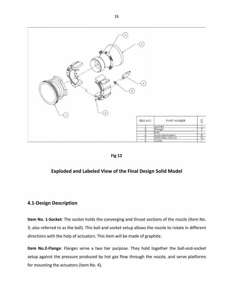
Explod
sign Descri
. 1‐Socket: T
eferred to as
ns with the h
.2‐Flange: F
ainst the pr
nting the act
ded and La
ption
The socket h
s the ball). T
help of actua
Flanges serv
ressure prod
tuators (Item
beled View
holds the con
his ball and
ators. This ite
e a two tie
duced by ho
m No. 4).
16
Fig 12
w of the Fi
nverging and
socket setu
em will be m
r purpose. T
ot gas flow t
inal Design
d throat sec
p allows the
made of grap
They hold t
through the
n Solid Mo
tions of the
e nozzle to ro
phite.
together the
nozzle, and
odel
nozzle (Item
otate in diffe
e ball‐and‐so
d serve platf
m No.
erent
ocket
forms

17
These items will be made of Inconel 718. It was decided that in addition to the required
ductility, the flanges would need to demonstrate superior strength at high temperatures. Thus,
Inconel is assumed to be a good choice for these requirements.
Item No.3‐Ball (interchangeably called nozzle from this point on): This component is a
converging‐diverging nozzle which accelerates hot gas flow from subsonic to supersonic. The
outside of the converging section is shaped like a sphere to allow rotation via the ball‐and‐
socket setup for the sake of vectoring thrust in different directions.
This item will be made of graphite. Graphite was chosen for its resistance to oxidation and
suitable thermal properties. These thermal properties included low conduction and thermal
expansion coefficients. The ball’s outside diameter was made small enough to make up for
thermal expansion due to high temperatures during operation.
Item No.4‐Actuator Assembly: Actuators push and pull against the diverging section of the
nozzle, causing rotation all along the converging spherical section.
Actuators were mainly chosen based on how much force each could supply. Analysis revealed
that each actuator would need to put out 20 pounds of force. This takes into account that each
actuator would be working against both the weight of the nozzle and the pressure built up
inside the nozzle.
Item No.5‐Actuator Mount: Holds the actuator in place and connects the actuators to the
diverging section of the nozzle.
Item No.6‐Collar: Mounts onto the diverging section of the nozzle and serves as a mount for
the actuator mounts. This item will be made of Inconel 718.
A major design consideration was making this collar thick enough so that it didn’t pop out of its
slot once thermal expansion took effect.
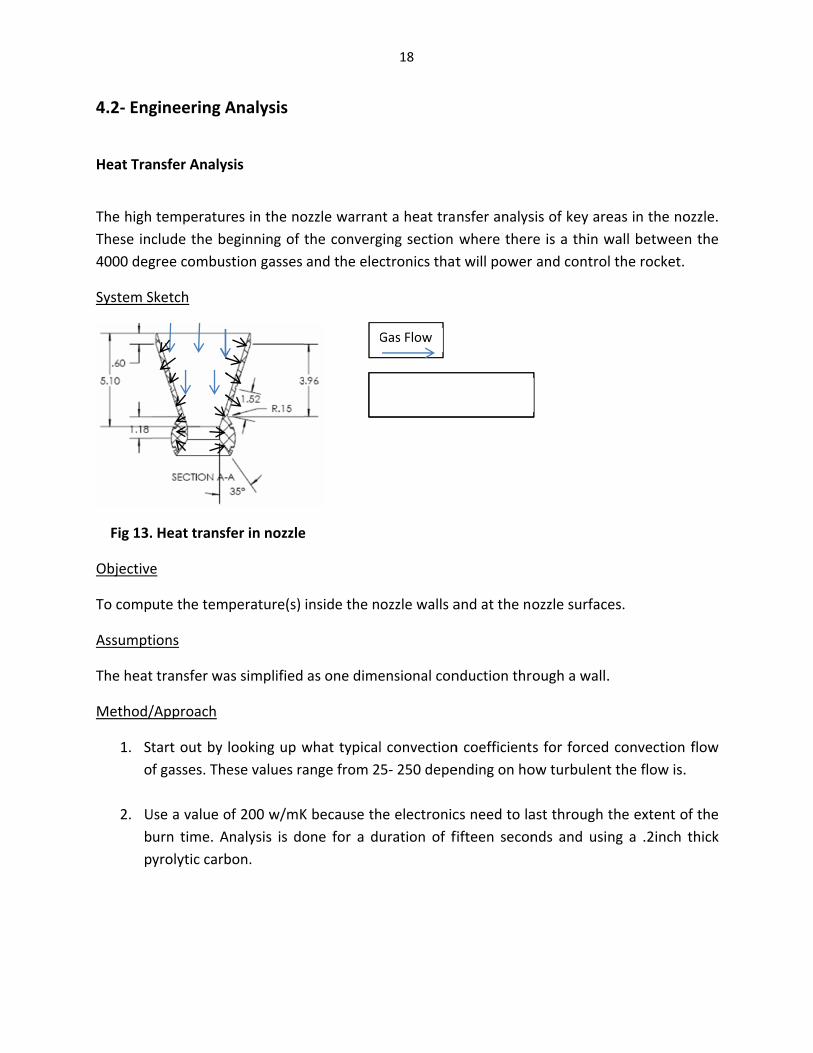
4.2‐ Eng
Heat Tra
The high These inc4000 deg
System S
Fig 13.
Objective
To comp
Assumpt
The heat
Method/
1. Sto
2. Ubp
gineering A
nsfer Analys
temperaturclude the begree combus
Sketch
Heat transf
e
ute the tem
ions
t transfer wa
/Approach
tart out by f gasses. The
Use a value ourn time. Ayrolytic carb
Analysis
sis
res in the noeginning of stion gasses
fer in nozzle
perature(s)
as simplified
looking up wese values ra
of 200 w/mKAnalysis is dobon.
ozzle warranthe convergand the elec
e
inside the n
as one dime
what typicalange from 2
K because thone for a du
G
H
18
nt a heat traging section ctronics that
ozzle walls a
ensional con
l convection5‐ 250 depe
he electronicuration of f
Gas Flow
Heat Conduct
nsfer analyswhere thert will power
and at the no
nduction thr
n coefficientending on ho
cs need to lafifteen secon
tion
sis of key arere is a thin w and control
ozzle surface
ough a wall.
s for forcedow turbulent
ast through tnds and usin
eas in the nowall betweel the rocket.
es.
.
convectiont the flow is.
the extent ong a .2inch
ozzle. n the
flow .
of the thick
Results
Analysis degrees. materials
Thermal
Due to tundergo expansiothe nozzl
System S
Fig 14. Th
Objective
The purpsurface oduring di
Assumpt
1. Tsad
Approach
1. Tvamex
results gaveThis tempes.
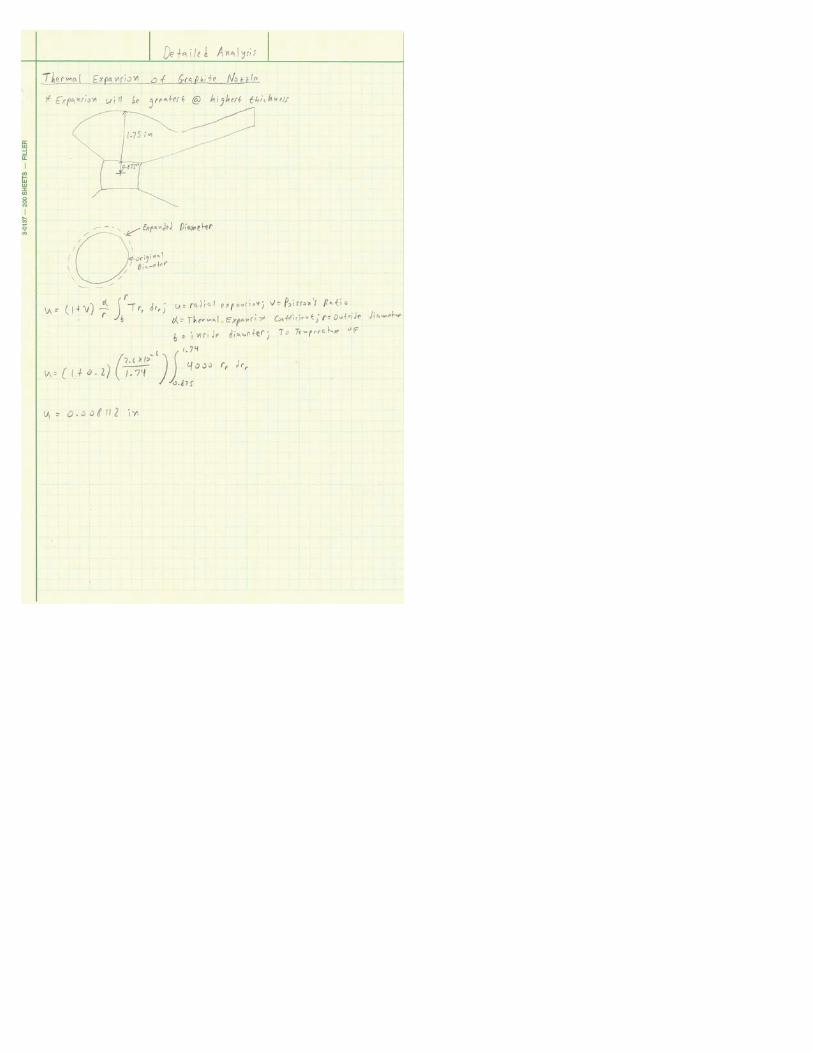
Expansion A
temperaturethermal exp
on of the nozle can actua
Sketch
hermal expa
e
pose of thisof the nozzlimension spe
ions
he thermal ame as the iameters as
h/Method
he nozzle carying innermore than oxpansion wo
Nozzle fits
here
e a relativeerature ana
Analysis on t
es of up topansion. Thezzle may genlly overcome
ansion of no
s analysis ise. Doing soecification.
expansion athermal exthe given cr
onverges onr and outer one point alould occur.
ly constantlysis really g
the Nozzle
o 3400 degre contact strnerate moree.
Socket
ozzle
to find theo will allow
at each cropansion forross section.
n the insidediameters, tong the no
Direction of
19
temperaturgave a start
rees Fahrenresses betwee friction tha
e point of mthis team t
ss section o a hollow c
e and has athermal expozzle length
f Nozzle Expan
re through ting point t
nheit, this teen the nozzan the solen
maximum eo take ther
of the nozzlcylinder with
a spherical opansion analto see whe
nsion
the wall rigo be able t
team expectzle and flangnoid actuato
expansion alrmal expans
e will be aph the same
outside surflysis had to ere the gre
ght around to start cho
ts the nozzges upon thers used to r
long the ouion into acc
pproximatelyinner and o
face. Due tobe conductatest amou
3400 osing
zle to ermal otate
utside count
y the outer
o the ed at nt of
20
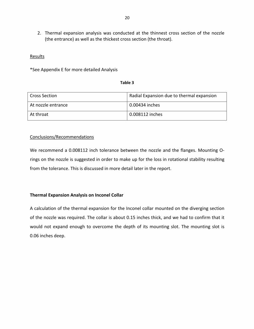
2. Thermal expansion analysis was conducted at the thinnest cross section of the nozzle (the entrance) as well as the thickest cross section (the throat).
Results
*See Appendix E for more detailed Analysis
Table 3
Cross Section Radial Expansion due to thermal expansion
At nozzle entrance 0.00434 inches
At throat 0.008112 inches
Conclusions/Recommendations
We recommend a 0.008112 inch tolerance between the nozzle and the flanges. Mounting O‐
rings on the nozzle is suggested in order to make up for the loss in rotational stability resulting
from the tolerance. This is discussed in more detail later in the report.
Thermal Expansion Analysis on Inconel Collar
A calculation of the thermal expansion for the Inconel collar mounted on the diverging section
of the nozzle was required. The collar is about 0.15 inches thick, and we had to confirm that it
would not expand enough to overcome the depth of its mounting slot. The mounting slot is
0.06 inches deep.

System S
Fig 15. T
Objective
The obje
it is not g
Assumpt
1. A
Method/
1. A
m
Results
Radial Ex
Depth of
Conclusio
The therm
Sketch
Thermal exp
e
ctive of this
greater than
ions
Approximate
/Approach
Apply a basic
materials prin
xpansion on
f Slot: 0.06 in
ons/Recomm
mal expansi
ansion of co
s analysis is t
the depth o
collar to be
c thermal e
nciples.
Collar: 5.303
nches
mendations
on of the co
Collar placeinches in dewhich is 0.0
Direction
ollar
to compute
of the collar’
a hollow cy
xpansion eq
38*10^‐3 inc
ollar does no
es on mounting septh) via this rai06 inches in heig
of collar exp
21
the radial e
s mounting
linder.
quation to t
ches
t clear the s
slot (0.06 sed edge, ght.
ansion
expansion of
slot.
the collar us
lot depth. It
f the collar,
sing advanc
t is good to u
and confirm
ed mechani
use as is.
m that
ics of

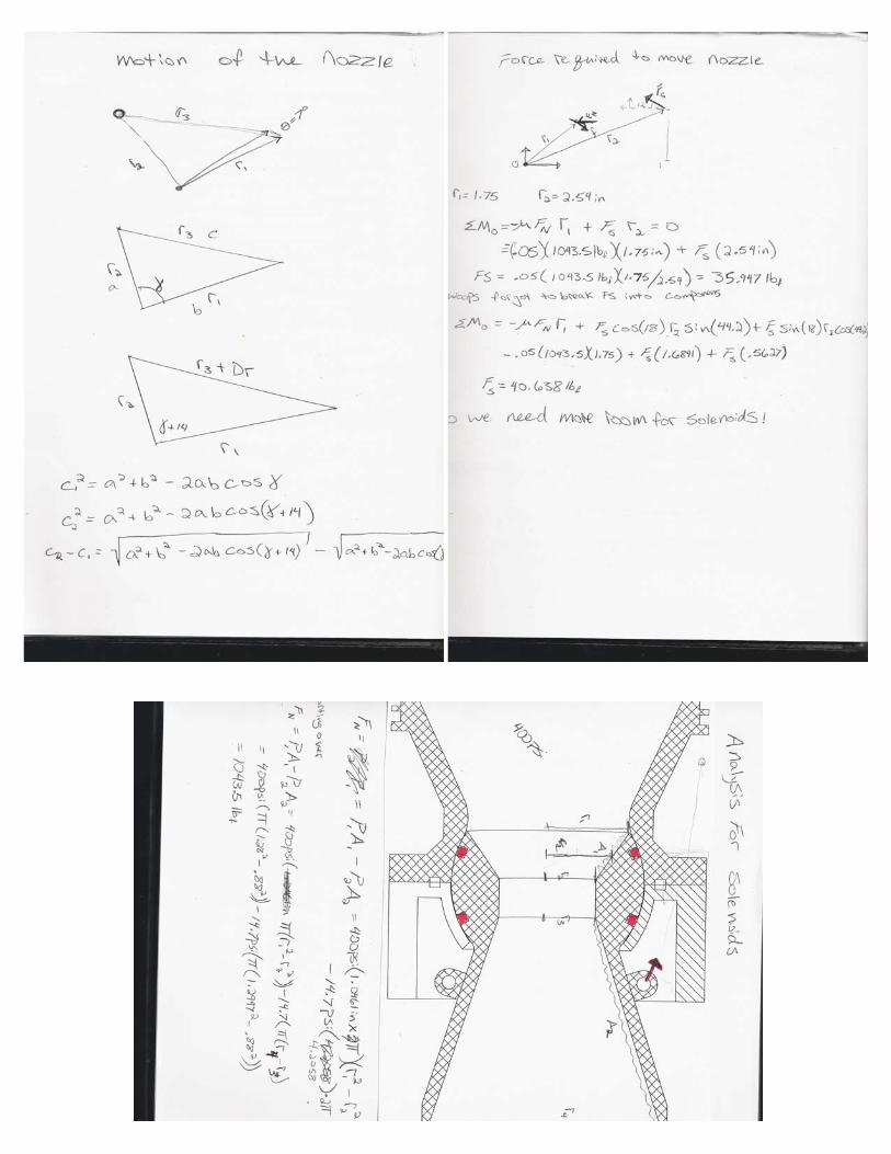
Force An
Actuator
System S
Fig
Assumpt
In this an
would be
Method/
The max
that wou
Results
The resu
40lbs.
4.3‐Cos
The price
used. Th
nalysis
r selection re
Sketch
g 16. Forces
ions
nalysis it was
e the main fr
/Approach
imum press
uld be on the
lts of this an
t Analysis
e of Inconel
e lowest pri
equires an an
on nozzle
s realized th
riction comp
ure differen
e seals.
nalysis told u
component
ice is for Inc
nalysis of th
at the seals
ponent to pr
ce across th
us that the f
ts varies dep
conel 600 (i
Seal Mounfriction for
Collafor a
Actuatio
22
e force requ
mounted ov
rovide resista
he nozzle wa
orce require
pending on
.e. bar price
nts (Point of arces)
ar Mount (Poactuation forc
on Forces
uired to rota
ver the ball‐
ance to mot
as used to ap
ed to break t
the grade o
e. Cell #8), w
action for
oints of actionces)
te the nozzl
‐shaped sect
tion.
pproximate
the friction w
of Inconel th
while the hig
n
e.
tion of the n
the normal
would be ar
he sponsor w
ghest price
nozzle
force
round
wants
is for

Inconel 7
applicatio
Inconel f
can be se
4.4‐Mat
Nozzle W
not selec
propertie
M
Graphite
Inconel
Grafoil
Carbon F
Aluminum
718 (i.e. bar
ons, but Inco
fasteners ha
een in the ta
terial/Com
We chose to m
cted for this
es.
Material
Felt
m
r price. Cell
onel 600 ma
ve a lead tim
able below (F
mponent Se
make the no
application
Co
1 Nozzle
5 Fastene
Collar
9 O‐Ring 13 Insulati17 Linear A
#8). Incone
ay suffice du
me of 1‐2 w
Fasteners. C
election
ozzle out of g
due to their
omponent(s
ers, Flanges,
Seals
ion
Actuators
23
el 718 is ma
e to the very
weeks to man
ell #8).
Table 4
graphite. Me
r thermal and
)
2 1,6”LonGra
, 6 8 refastDiasoli4mmmm
10 4
14 N/A
18 8
Fig 17 G
ainly used i
y small oper
nufacture. T
etals such as
d oxidation
Quantity
” Diameter,1ng, aphite Rod eadymade teners, meter; 6” d bar; Hex Hm diameterm long fasten
A
Graphite Noz
n aerospace
rating time.
The cost of t
s aluminum
12” 3 Solid
$256
7 6”
long Head r, 12 ners
FasteeachBar: eachHex Quot
11 $90 e
15 N/A
19 $80 e
Total:
zzle
e and gas n
he finished
and steel we
Price
6
eners:$34‐$4
$1450‐$ Head Fastete Requesteeach
each
~$1910‐$2870
nozzle
parts
ere
4
44 8
$2400
eners: d 12
16 20
21

Regardin
metals o
impact o
oxidative
In additio
aluminum
requires
stability d
Flanges
Our team
Inconel. A
may go w
seconds.
extreme
However
Stellar Ex
condition
Fastener
This team
to be ap
other com
ng oxidation
xidize easily
on the syste
e nature of t
on, graphite
m and a min
a smaller to
during opera
m chose to
Although Inc
with a lower
Inconel wa
temperatur
r, one impor
xploration sp
ns.
s
m chose Inco
propriate, a
mponents o
properties,
y, fuel flow t
em’s perfor
he fuel will h
e has a coeff
nimum of 5
olerance be
ation.
have flange
conel 718 is
r grade of In
s selected fo
res.
rtant thing to
pecifies that
onel ¼‐20X3
as they wou
f the system
the solid fue
through an a
rmance. Ho
have a neglig
ficient of exp
.5 in/in ◦F fo
tween the n
es and faste
most suitab
nconel due t
or its superi
o note is tha
t the prototy
slotted flat
ld negate th
m.
24
el used to po
aluminum o
wever, grap
gible impact
pansion of 2
or steel. A l
nozzle and f
ners of the
ble for gas no
to the small
or yield and
at we will on
ype needs to
head socket
he risk of int
ower the roc
or steal nozz
phite does
t during the
2.2 in/in ◦F c
lower therm
flange. This
system ma
ozzle applica
operation t
d rupture str
Fig 1
nly use Incon
o be tested
t cap fasten
terference b
cket is highly
le will have
not oxidize
17 seconds
compared to
mal expansio
poses less
ade out of
ations, we
time of 17
rengths at
18. Inconel F
nel in our pr
under extre
ers. We felt
between fas
y oxidative.
a highly adv
easily, and
of operation
o 12.3 in/in
on for the n
risk to rotat
Flange
rototype des
eme temper
flat head sc
stener heads
Since
verse
d the
n.
◦F for
nozzle
tional
sign if
ature
crews
s and

25
Actuator selection
The selection of actuators was difficult due to force and space requirements. Initially solenoids
were thought more suitable because of their ability to produce very quick movements. The
problem with solenoids is that for the force desired the lightest ones are around thirty pounds.
This weight would not be reasonable to add to the rocket.
Due to the stated reasons, linear actuators were then decided upon. Many actuators that could
provide the desired force were very large. After a long search, two actuators that would be
suitable were found. One was the T‐NA series made by Zaber. These actuators are 3 inches long
and can produce a peak thrust of 14.6lbs. However, they sell this actuator for one thousand
dollars apiece. The actuator chosen was the Frigelli L12 series actuator. These actuators come
in a range of options with different gearing and lengths of stroke. The 10mm (.394in) stroke
option with a 210 to 1 gear ratio that with a 12 volt battery will produce a peak force of
45N(10.1lbf) at 2.5mm/s(.0984in/s). Four of these actuators will be required in each direction
to produce the 40lbf. Each actuator is equipped with its own feedback potentiometer that will
give the length of each actuator so they can be controlled more accurately. The cost of these
actuators is 80 dollars. The 12‐volt model will draw around 130mA at peak force. That means
that the system will use 12.48 watts maximum.
Grafoil
Grafoil seals were selected due to their good combination of rigidity and flexibility under the
given circumstances. These characteristics will help the system to maintain stable rotation. In
addition, this material can withstand up to 6000 degrees Fahrenheit.
Carbon Felt
Carbon felt provided the lowest thermal conductivity of any material we could find. Hence, it
was the best choice for insulation. In addition, it can be used in low enough amounts for it to
not have a big effect on the system’s weight specifications.

26
CHAPTER 5‐Manufacturing/Assembly
Manufacturing/Assembly
Nozzle Parts
This team plans to manufacture the nozzle on a CNC lathe machine. Facilities on the Cal Poly
campus have machines which are capable of following the shape profile of our nozzle design.
After obtaining the overall shape of the nozzle, slots for O‐rings and collar will be made on a
lathe machine.
Flanges
The flanges will be manufactured in a similar fashion as the nozzle parts. However, in addition,
boring and threading is required for where the bolts will be placed.
Further Fabrication and Assembly Instructions
The boat tail will need to be modified from its current design to provide more space for the
components of the system to move. What needs to be done first is the inside rear section that
is currently a continuation of the nozzle must be lathed so that the new nozzle will have room
to maneuver inside it. The other thing that must be done is to cut notches so that the actuators
will have room to move. This can be accomplished using the chop saw first to create the angled
cuts and then a rotary cutting blade to finish the bottom part of the trapezoid shaped cuts.
The collar that is placed around the nozzle to provide attachment points for the actuators will
be manufactured by taking a ring of the metal (either steel or inconel) being used for the
flanges and lathing the circular portion then the ring will be cut and tabs will be welded to the
ends of the ring. These tabs will be used to clamp the collar onto the nozzle. The last step will
be to drill holes for the screws that will hold the actuator brackets. *For further detail, see the
“Manufacturing section” in Chapter 8.
27
Assembly of the entire system starts with inspection of the parts all dimensions should be
checked so that problems will not be encountered later. After all the dimensions have been
checked the first parts that can be put together are the actuator brackets and the collar. The
brackets can be attached using hex head screws coming from the inside of the collar and
holding the brackets on with one washer and a nut at this stage they can just be tightened by
hand and be tightened down later. Once all the brackets are attached the collar can be slipped
down over the small end of the ball/nozzle and fitted into the locating slot a bolt can be slipped
through the hole in the tabs and finger tightened. Take the grafoil seals and cut two lengths
that will fit into the slots on the round part of the ball. This piece can now be put aside. Now
measure another length of grafoil for the slot in the carbon socket. Place the socket down on a
bench so that the slot with the seal is pointing up. Now the ball can be placed into the socket.
Take the two flanges and the remaining actuator brackets and attach them to their
corresponding holes in the flanges with provided bolts. Now the flanges can be placed on the
socket around the ball aligned with the bolt holes. Care should be taken to place the grafoil
seals into the slots in the flanges without damaging them. The ¼ 20x3in bolts can be placed in
the holes in the flange and through the socket. Washers and nuts can be tightened onto the
bolts securing the ball and flanges to the socket. The next thing is to fit the actuators into the
brackets place the actuator in the brackets using the M4 bolts provided. These bolts can be
tightened next you can tighten the bolts holding the actuator brackets down and move on to
the next actuator until all eight have been attached. Once all the actuators are in place the bolt
for the collar should be tightened. The next step is to flip the hole assembly over and insulate
the chamber where the batteries and controller will be kept. Care should be taken with the
assembly in this position since it may be unstable. Taking the insulating carbon felt loosely wrap
this section with long strips overlapping the previous end with each successive pass until there
is just enough room to place the batteries and other electrical components directly up against
the aluminum fuselage. Once the electronics have been hooked up the entire assembly can be
inserted into the fuselage and assembly is complete.
This rocket nozzle is designed to be used once so no maintenance schedule or repair is
recommended.
28
CHAPTER 6‐Project Planning
6.1‐Project Management Plan
This team has completed the final design phase of the product. The original plan was to have
this final design report completed by February 1, 2011(Gantt Chart, Row 34). However, we have
been delayed by a few days, and this report is now complete on February 5, 2011.
The first milestone was the Project Requirements Document (Gantt Chart, Row 14). This
document showed a translation of all customer requirements to engineering specifications.
Requirements such as durability (QFD, Row 3) were translated to requirements such as ability
to withstand a specified high temperature.
Milestones including the Preliminary Design Presentation (Gantt Chart, Row 20), creation of the
solid model (Gantt Chart, Row 25), Conceptual Design Report (Gantt Chart, Row 28), and
Conceptual Design Review (Gantt Chart, Row 29) served to present the basic workings of the
system. The Conceptual Design Report included everything from the Project Requirements
Document, a finalized design concept, a project management plan, etc. The Conceptual Design
Review consisted of a presentation of the Conceptual Design Report’s main parts to the project
sponsor.
The current report is a more detailed version of the Conceptual Design Report. The content
takes into account detailed analysis used to finalize system dimensions. It also expands on
additional subsystems such as the actuators.
For the final design phase of the project, Harsimran Singh handled the thermal expansion
analysis and contact stress analysis. This is in addition to taking charge in acquisition of
materials such as graphite, Inconel bars, and Inconel fasteners. Dane Larkin so far handled the
digital solid modeling of the design and analysis relating to actuation of the system. This is in
addition to taking charge in acquisition of materials/components such as linear actuators, graph
foil O‐rings and carbon felt insulation.

29
From this point on, this team will be concerned with manufacturing and testing the system. A
lead time of 1‐2.5 weeks for acquisition of all materials (Gantt Chart, Rows 36 & 37), and 8‐10
weeks to build and fully test the system (Gantt Chart, Rows 37‐39) is expected. However, this is
only the case if this team builds the prototype itself. If a third party is chosen to manufacture
some components, the building time will differ from what is previously stated. A visual model of
the management plan is available in Appendix F along with a summary. A summary of testing
and design verification plans is provided below.
6.2‐Design Verification/Testing Plan
Plans to validate the concept will begin by measuring general attributes of the assembly such as
overall weight size and clearance between moving parts and range of motion of the nozzle.
After general attributes have been measured the assembly will be fitted into a test fixture that
resembles the back end of the rocket. The actuators can then be hooked up to function
generators that will produce voltage to move the nozzle. With the function generators hooked
up, measurement of the actuation speed can be obtained. The next test would be to set the
function generators up so that they would be able to cycle the nozzle through the two degrees
of freedom for 5 thousand cycles. During the previous tests the power requirements will be
measured by oscilloscopes. These tests will be able to show that our design meets the
requirements that were set out at the beginning of the project.
In addition, the system prototype must undergo the required gas flow testing. This will verify
that the system reacts as desired to operational temperatures and pressures.

30
CHAPTER 7‐Conclusions and Recommendations
The outside diameter of the nozzle’s converging and throat sections is designed a specific
amount smaller than the inside diameter on each flange cross section to take thermal
expansion during operation into account. The O‐rings mounted on top of the nozzle are
specifically dimensioned to make up for the difference in diameter. These O‐rings reestablish
the rotational stability of the nozzle, which would otherwise be compromised by the nozzle not
being flush with the flanges. Any careless changing of these dimensions will have an adverse
impact on system performance.
This team has left it up to the sponsor to decide which grade of Inconel should be used.
Although industry generally uses 718 grade for aerospace and gas nozzle applications, we
recommend the use of a lower grade such as Inconel 600 or 625. Systems in industry are
expected to operate for much longer durations than the 17 second operating time of our
system. In addition, Inconel 718 is a much more expensive grade. The use of Inconel 600 will be
a cheaper financial alternative for Stellar Exploration. Even if Stellar Exploration decides to use
Inconel 718 for future applications, the use of a lower grade would be more practical at least
for the current testing purposes.
Unless overall system dimensions are increased, we recommend continued use of flat head
fasteners to negate the possibility of interference between the fastener heads and other parts
of the system.
The Inconel collar mounted on the diverging section of the nozzle is predicted to expand 0.0032
inches under the given conditions. We recommend not making its mounting slot shallower than
a depth of 0.0032 inches.

Chapte
The prec
will unde
actuation
limit the
Thus, th
current m
nozzle, a
Written a
current p
8.1‐Mat
The nozz
called Ac
also rapid
Sock
er 8‐Final
ceding writte
ergo full tes
n tests. How
project req
e prototype
model uses s
nd rapid pro
and visual m
prototype m
terials
zle, flanges a
crylonitrile b
d prototype
ket
l Project U
en materials
sting. That
wever, for th
uirements t
e has not b
standard ste
ototyping ma
material pres
odel.
and socket a
butadiene st
models, but
Fig 19
Updates
s and the ma
is to say, th
he purposes
o a prototyp
been built u
eel nuts and
aterials.
sented from
re rapid pro
tyrene (ABS
t are made o
Nozzle
9. Rapid Pr
31
aterials in th
he prototyp
of this senio
pe that will
using materi
bolts, a stee
m here on un
ototype mod
). All actuat
of resin‐base
rototyped C
he Appendic
pe will unde
or project St
only need t
ials such as
el collar con
ntil the Appe
dels made en
tor mountin
ed rapid pro
Componen
ces regard a
ergo both h
tellar Explor
o undergo a
s graphite a
nnecting the
endices sect
ntirely out o
g brackets a
totype mate
nts
prototype w
ot gas tests
ration decid
actuation tes
and Inconel
e actuators t
tion concern
f a thermop
and coupler
erial instead
Flange
which
s and
ed to
sting.
. The
o the
ns the
plastic
rs are
.

All bolts a
8.2‐Des
The origi
the colla
actuator
Too mmounconstr
and threaded
sign Chang
inal design c
r and flange
per mount p
many actuatornts could causraining
Actua
stock are sta
ges
called for th
es. Howeve
posed risks o
R
r se
ator coupler
ndard steel p
he actuator
r, mounting
of over cons
Resin
Fig 21. Des
32
rs and moun
Fig 20
parts bought f
mounts pro
g actuators c
straining the
sign Flaws
ting bracket
from a hardw
ovided by th
close to the
e system.
Apro
ts
ware store.
he supplier t
e flanges, an
Actuators nextrevent necesotation
to be install
nd mounting
t to flanges mssary amount
ed at
g one
may of

In order
from 16
Fig 22)
moved f
nozzle r
ends.
Original
r to resolve
to 8 by cou
increased
further bac
rotation. Th
Mounting Po
Two actthreade
e these iss
upling two a
the length
ck from the
e couplers
oints
Fig 22. Des
tuators coupleed stock
ues, the n
actuators a
h of the as
e flanges. T
are fixed t
sign Flaw So
ed using
33
umber of m
t each poin
ssembly, th
This preven
o the rest o
Altered Mo(Moved bac
olutions
mounting p
nt. The cou
hus allowin
nted any s
of the asse
ounting Point ck from flang
points was
plers (see y
ng mountin
sort of inte
embly with o
es)
first decre
yellow bloc
ng points to
rference du
off the shel
ased
cks in
o be
uring
lf rod
34
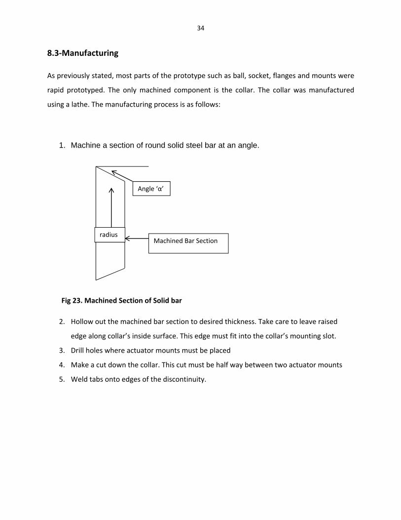
8.3‐Manufacturing
As previously stated, most parts of the prototype such as ball, socket, flanges and mounts were
rapid prototyped. The only machined component is the collar. The collar was manufactured
using a lathe. The manufacturing process is as follows:
1. Machine a section of round solid steel bar at an angle.
Fig 23. Machined Section of Solid bar
2. Hollow out the machined bar section to desired thickness. Take care to leave raised
edge along collar’s inside surface. This edge must fit into the collar’s mounting slot.
3. Drill holes where actuator mounts must be placed
4. Make a cut down the collar. This cut must be half way between two actuator mounts
5. Weld tabs onto edges of the discontinuity.
Angle ‘α’
Machined Bar Section radius

Thick
Raised Ed
Fig
kness
dge
24. Fabricat
Place cut
Welde
ted features
t here
ed Tabs 35
s of collar
Holes foor actuator mounts
Triang
Wei
Chapte
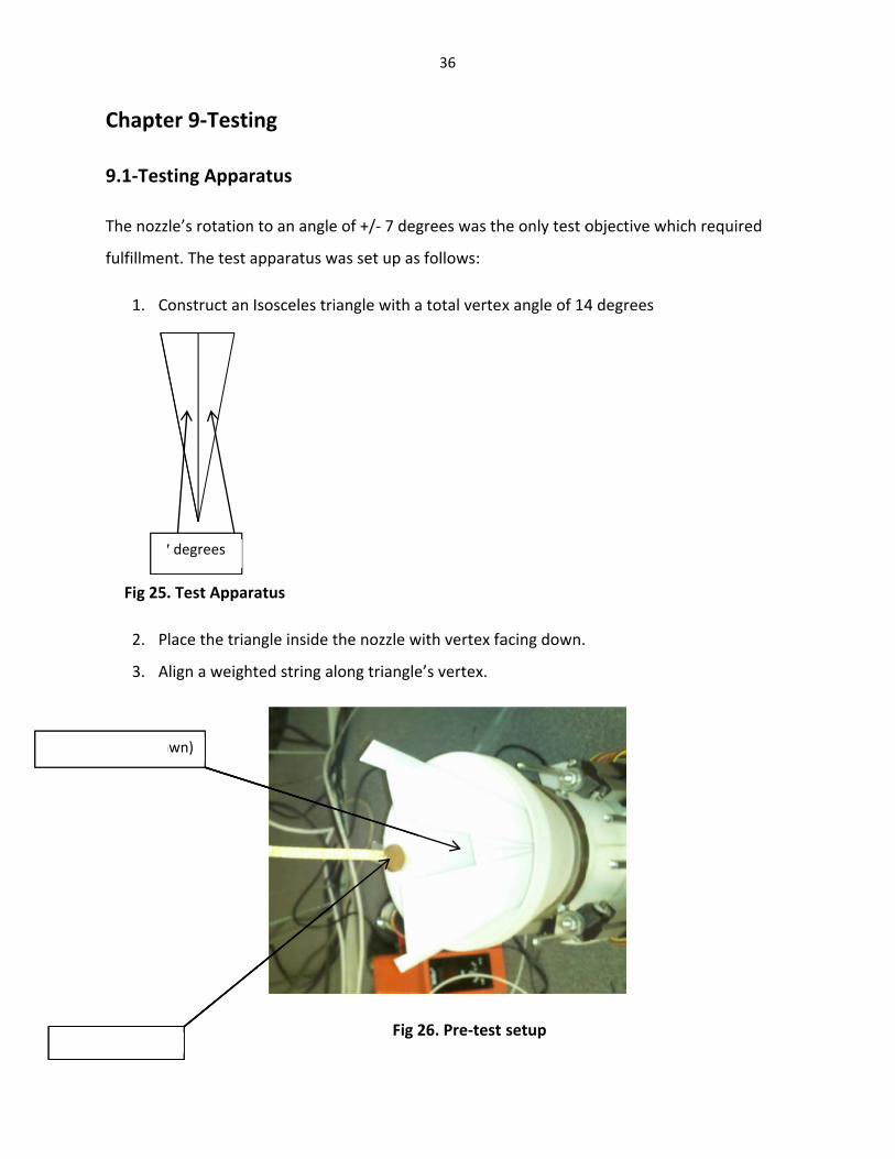
9.1‐Test
The nozz
fulfillmen
1. C
Fig 25
2. P
3. A
7
gle (Hand Dra
ighted String
er 9‐Testi
ting Appar
zle’s rotation
nt. The test a
onstruct an
. Test Appar
lace the tria
Align a weigh
7 degrees
awn)
ing
ratus
n to an angle
apparatus w
Isosceles tri
ratus
ngle inside t
hted string al
e of +/‐ 7 deg
was set up as
angle with a
the nozzle w
long triangle
Fig 2
36
grees was th
s follows:
a total vertex
with vertex fa
e’s vertex.
26. Pre‐test
he only test o
x angle of 14
acing down.
setup
objective wh
4 degrees
hich required
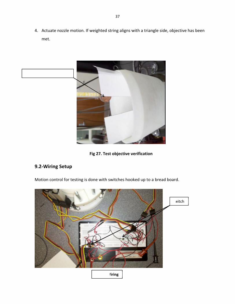
4. A
m
9.2‐W
Motio
Alignment a
Actuate nozz
met.
Wiring Set
on control fo
at 7 degrees
le motion. If
tup
or testing is
f weighted st
Fig 27. Test
done with s
Fig 28. W
37
tring aligns w
t objective v
witches hoo
Wiring
with a triang
verification
oked up to a
gle side, obje
bread board
Sw
ective has be
d.
witch
een

38
Each actuation point on an axis of rotation has a polarity opposite to the point at the other end
of the axis. Thus, as one pair of actuators extends the pair on the other end of the axis
contracts. These motions rotate the nozzle.

Jetavator Vanes Ball and Socket Cylinders Column1 Column2 Column3 Column4 Column5 Column6 Column7 Column8 Column9 Column10Criteria Weight Rating Score Rating Score Rating Score Rating Score installation ease 6.8 8 54.4 8.5 57.8 9 61.2 8.5 57.8Safety 2.3 9 20.7 9 20.7 9 20.7 9 20.7durability 15.9 6.5 103.35 8 127.2 8.5 135.15 9 143.1interface ease 11.4 5 57 7 79.8 9 102.6 9 102.6heat requirements 15.9 6.5 103.35 4 63.6 6.5 103.35 7.5 119.25response to angle change 15.9 7 111.3 7.5 119.25 8.5 135.15 8 127.2low weight 15.9 6.5 103.35 8 127.2 8 127.2 5 79.5ease of manufacture 2.3 5 11.5 6 13.8 7 16.1 7 16.1low drag 11.4 5 57 10 114 10 114 9.5 108.3Cost 2.3 6 13.8 6 13.8 8 18.4 7 16.1
100.1 64.5 6456.45 74 7407.4 83.5 8338.5 79.5 7957.95
meuser
Text Box
39 APPENDIX A
Quality
Characteristics
(a.k.a. "Functional
Requirements" or
"Hows")
Demanded Quality
(a.k.a. "Customer
Requirements" or
"Whats") 0 1 2 3 4 5
1 3 15.6 7.0 2 4 2 2 3
2 3 2.2 1.0 3 5 5 4 4
3 9 15.6 7.0 4 4 3 4 5
4 9 11.1 5.0 3 5 3 3 5
5 9 15.6 7.0 2 2 3 4 4
6 9 20.0 9.0 2 2 4 5 5
7 9 8.9 4.0 2 5 2 5 5
8 9 2.2 1.0 2 2 2 3 4
9 9 6.7 3.0 5 5 2 5 5
10 9 2.2 1.0 3 2 2 3 5
11
12
13
14
15
16
17
18
19
20
21
22
23
24
25
┼┼
▬
▼
9
3
1
Strong Relationship
Moderate Relationship
Weak Relationship
Title:
Author:
Date:
Negative Correlation
Strong Negative Correlation
Θ
Ο
Legend
┼
Strong Positive Correlation
Positive Correlation
Notes:
x
Objective Is To Minimize
Objective Is To Maximize
Objective Is To Hit Target
▲
▼
▲
2521 22 23 2419 201817
5k c
ycle
s b
efo
re
failu
re
.5 s
ec h
alf c
ycle
3 2
10.4
9
20 h
z
Ο Ο▲ Ο
Θ
cost Θ Ο Θ
Ο Θ
Ο Ο
▲ ▲
low drag
Ο Ο
Θ Θ
Ο ▲ Θ
Θ Ο
Ο Θ ▲ Θ
▲
Ο Ο
Ο Ο Ο
safety ▲
less t
han5.7
5 d
less t
han 3
0w
att
s
durabillity ▲ Θ
Competitive Analysis
(0=Worst, 5=Best)
4lb
over
exis
ting
withsta
nd 1
300 f
or
15
sec
600 p
si
7 d
egre
e r
esultant
vecto
r
Powered by QFD Online (http://www.QFDOnline.com)
Our
Com
pany
liquid
inje
ction
thru
st
vanes
Com
petito
r 3
rota
table
flexib
le join
t
5 5
Ο ▲
Θ Ο
9 9 9 9
6.6 13.5 9.6 13.1
288.9 395.6
4 5 4 7
408.9
9
280.0
7.7 6.9 6.8 9.3
233.3 208.9 204.4
9 9
interface ease Θ
Θ
9
200.0
Ο Ο
Θ
▲ Θ
Θ
Ο
9 10 11 12 13 14 16
Rela
tive W
eig
ht
4 5 6 7Column # 1 2 3 8 15
dra
g m
easure
d
Ro
w #
Direction of Improvement:
Minimize (▼), Maximize (▲), or Target (x)
frequency r
esponse
Weig
ht
/ Im
po
rtan
ce
heat requirements ▲
response to angle chage Θ
low weight
ease of manufacture
Θ
Ο
428.9
2.0 14.2
9
315.6
9 9
5 5
pow
er
num
ber
of
cycle
s t
ill f
ailu
re
sle
w r
ate
60.0
▲ Ο Ο
adds less t
han 1
% t
o
dra
g
less t
han .
05 d
egre
e
weig
ht
heat
requirem
ents
pre
ssure
angle
of
thru
st
siz
e
actu
ation e
rror
Οinstallation ease
Relative Weight
Difficulty
(0=Easy to Accomplish, 10=Extremely Difficult)
Max R
ela
tio
nsh
ip V
alu
e i
n R
ow
Max Relationship Value in Column
Target or Limit Value
Weight / Importance
Our Company liquid injection
thrust vanes Competitor 3
rotatable flexible joint
meuser
Text Box
40
meuser
Text Box
41 APPENDIX B
meuser
Text Box
Actuators
meuser
Text Box
Actuators

meuser
Text Box
Heat Transfer Analysis
meuser
Text Box
Thermal Expansion of Collar
meuser
Text Box
42
meuser
Text Box
Thermal Expansion of Nozzle
meuser
Text Box
43

Material/Component Vendor Price Contact
Graphite www.GraphiteStore.com $256 for one
graphite rod
Address: GraphiteStore.com, Inc. 1348 Busch Parkway Buffalo Grove, IL 60089 US
Phone: 800-305-1664 (Toll Free US only) 847-279-1925
Fax: 847-279-1926
E-mail: [email protected]
Fasteners Fastener Solutions, Inc. $34‐$44 for each fastener
Quote
Requested on Smaller Dimension Fasteners
Name: Matt Bridges
Office:866 463 2910 ext. 242F
Cell: 225-200-7909
Fax: 225-927-9292 http://www.fastenersolutions.com
Inconel Rods California Metal and
Supply, Inc.
$1450‐$2400 for each bar
Phone: 800 707 6061
Fax: 800 707 3439
http://californiametal.com
Linear Actuators Firgelli Technologies $80 each Phone: 206‐347‐9684
Fax: 206‐347‐9684
[email protected], www.firgelli.com
Graf Foil www.sealsales.com $90 each Phone: 714‐361‐1435
Carbon Felt ChemShine N/A Tel:0086‐592‐5530176
Fax:0086‐592‐5531751
Email:info@chemshine‐group.com
meuser
Text Box
44 APPENDIX C

.88.60
A A
18°
R1.75.05.19
67°.06.15
.17
5.10
1.18
.603.96
R.151.52
35°SECTION A-A
5 4 3 2 1
TOLERANCE: .001
DATE: 2/5/11
NEXT ASSY: SCALE: 1/4
UNITS: INCHES
DWG #: 001
MATERIAL: CARBON
TITLE: BALL
GROUP:
DRAWN BY: DANE LARKIN CKD BY: SIMRAN SINGH INIT: INIT: Stellar Thrust Control
meuser
Text Box
45 APPENDIX D

.50
1.35
.10
.10
.19
.19
A
A
6X .25
R2.35
50°
25°
2.92
5.75
3.50
R1.76
3.50
R2.88
1.13
25°
.50
.75
.40
45°
.30
.17
2.38
.09.19
SECTION A-A
5 4 3 2 1
TOLERANCE: .001
DATE: 2/5/11
NEXT ASSY: SCALE:2:1
UNITS:INCHES
DWG #: 004
MATERIAL: CARBON
TITLE: SOCKET
GROUP:
DRAWN BY:DANE LARKIN CKD BY:SIMRAN SINGH INIT: INIT: Stellar Thrust Control
meuser
Text Box
46

4.76
B B
15°
6.00
3.75
5.75
2.252.50
.25
.40.80
1.70
.95
SECTION B-B
5 4 3 2 1
TOLERANCE: .001
DATE: 2/5/11
NEXT ASSY: SCALE:1:4
UNITS:INCHES
DWG #: 002
MATERIAL: ALUMINUM
TITLE: MODIFIED BOAT TAIL
GROUP:
DRAWN BY: DANE LARKIN CKD BY: SIMRAN SINGHINIT: INIT: Stellar thrust control
meuser
Text Box
47

.07
A
AR.20
.50.25
.17
.12
.25
18°
.06
.10
.141.74
SECTION A-A
5 4 3 2 1
TOLERANCE: .001
DATE:2/5/11
NEXT ASSY: SCALE: 2:1
UNITS: INCHES
DWG #:003
MATERIAL: STEEL OR INCONEL
TITLE: COLLAR
GROUP:
DRAWN BY: DANE LARKIN CKD BY: SIMRAN SINGHINIT: INIT: Stellar Thrust Control
meuser
Text Box
48

R2.35
R.13X4
2.6013°
.10
50°
25°
.53
R1.95
R1.76
.28
R2.88.14
.09
.19
R1.95
2.00
.20
5 4 3 2 1
TOLERANCE: .001
DATE:2/5/11
NEXT ASSY: SCALE: 2:1
UNITS: INCHES
DWG #: 005
MATERIAL: ALUMINUM OR INCONEL
TITLE: FLANGE
GROUP:
DRAWN BY: DANE LARKIN CKD BY: SIMRAN SINGHINIT: INIT: Stellar Thrust Control
meuser
Text Box
49

5 4 3 2 1
TOLERANCE: .001
DATE: 2/5/11
NEXT ASSY: SCALE: 1:2
UNITS:INCHES
DWG #: 006
MATERIAL:
TITLE: FULL ASSEMBLY
GROUP:
DRAWN BY:DANE LARKIN CKD BY: SIMRAN SINGH INIT: INIT: Stellar Thrust Control
meuser
Text Box
50

12
5
3
6
4
ITEM NO. PART NUMBER QTY
.
1 socket 12 flange 23 ball 14 actuatorAssem 85 actuator mount 166 collar 1
5 4 3 2 1
TOLERANCE: .001
DATE: 2/5/11
NEXT ASSY: SCALE: 1:4
UNITS: INCHES
DWG #: 007
MATERIAL:
TITLE: EXPLODED ASSEMBLY
GROUP:
DRAWN BY:DANE LARKIN CKD BY: SIMRAN SINGH INIT: INIT: Stellar Thrust Control
meuser
Text Box
51
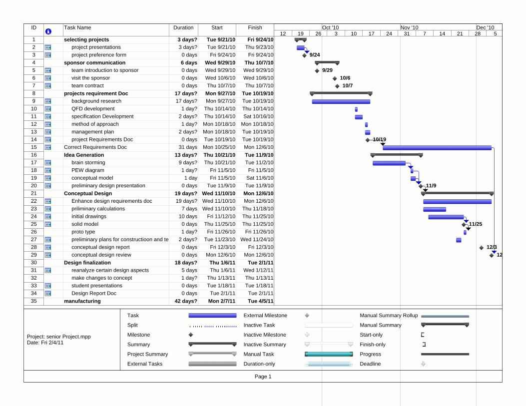
ID Task Name Duration Start Finish
1 selecting projects 3 days? Tue 9/21/10 Fri 9/24/102 project presentations 3 days? Tue 9/21/10 Thu 9/23/103 project preference form 0 days Fri 9/24/10 Fri 9/24/104 sponsor communication 6 days Wed 9/29/10 Thu 10/7/105 team introduction to sponsor 0 days Wed 9/29/10 Wed 9/29/106 visit the sponsor 0 days Wed 10/6/10 Wed 10/6/107 team contract 0 days Thu 10/7/10 Thu 10/7/108 projects requirement Doc 17 days? Mon 9/27/10 Tue 10/19/109 background research 17 days? Mon 9/27/10 Tue 10/19/1010 QFD development 1 day? Thu 10/14/10 Thu 10/14/1011 specification Development 2 days? Thu 10/14/10 Sat 10/16/1012 method of approach 1 day? Mon 10/18/10 Mon 10/18/1013 management plan 2 days? Mon 10/18/10 Tue 10/19/1014 project Requirements Doc 0 days Tue 10/19/10 Tue 10/19/1015 Correct Requirements Doc 31 days Mon 10/25/10 Mon 12/6/1016 Idea Generation 13 days? Thu 10/21/10 Tue 11/9/1017 brain storming 9 days? Thu 10/21/10 Tue 11/2/1018 PEW diagram 1 day? Fri 11/5/10 Fri 11/5/1019 conceptual model 1 day Fri 11/5/10 Sat 11/6/1020 preliminary design presentation 0 days Tue 11/9/10 Tue 11/9/1021 Conceptual Design 19 days? Wed 11/10/10 Mon 12/6/1022 Enhance design requirements doc 19 days? Wed 11/10/10 Mon 12/6/1023 priliminary calculations 7 days Wed 11/10/10 Thu 11/18/1024 initial drawings 10 days Fri 11/12/10 Thu 11/25/1025 solid model 0 days Thu 11/25/10 Thu 11/25/1026 proto type 1 day? Fri 11/26/10 Fri 11/26/1027 preliminary plans for constructioon and te 2 days? Tue 11/23/10 Wed 11/24/1028 conceptual design report 0 days Fri 12/3/10 Fri 12/3/1029 conceptual design review 0 days Mon 12/6/10 Mon 12/6/1030 Design finalization 18 days? Thu 1/6/11 Tue 2/1/1131 reanalyze certain design aspects 5 days Thu 1/6/11 Wed 1/12/1132 make changes to concept 1 day? Thu 1/13/11 Thu 1/13/1133 student presentations 0 days Tue 1/18/11 Tue 1/18/1134 Design Report Doc 0 days Tue 2/1/11 Tue 2/1/1135 manufacturing 42 days? Mon 2/7/11 Tue 4/5/11
9/24
9/2910/610/7
10/19
11/9
11/25
12/312
12 19 26 3 10 17 24 31 7 14 21 28 5Oct '10 Nov '10 Dec '10
Task
Split
Milestone
Summary
Project Summary
External Tasks
External Milestone
Inactive Task
Inactive Milestone
Inactive Summary
Manual Task
Duration-only
Manual Summary Rollup
Manual Summary
Start-only
Finish-only
Progress
Deadline
Page 1
Project: senior Project.mppDate: Fri 2/4/11
meuser
Text Box
52 APPENDIX E

ID Task Name Duration Start Finish
36 contact sponsor about materials 5 days? Mon 2/7/11 Fri 2/11/1137 machineing and assembly 21 days? Fri 2/11/11 Sat 3/12/1138 testing 11 days? Mon 3/14/11 Mon 3/28/1139 fixing anything that is broken 6 days? Tue 3/29/11 Tue 4/5/1140 final project design report 0 days Fri 6/3/11 Fri 6/3/11
12 19 26 3 10 17 24 31 7 14 21 28 5Oct '10 Nov '10 Dec '10
Task
Split
Milestone
Summary
Project Summary
External Tasks
External Milestone
Inactive Task
Inactive Milestone
Inactive Summary
Manual Task
Duration-only
Manual Summary Rollup
Manual Summary
Start-only
Finish-only
Progress
Deadline
Page 2
Project: senior Project.mppDate: Fri 2/4/11
meuser
Text Box
53

12/312/6
1/182/1
5 12 19 26 2 9 16 23 30 6 13 20 27 6 13 20 27 3 10 17 24 1 8 15 22 29 5'10 Jan '11 Feb '11 Mar '11 Apr '11 May '11 Jun '11
Task
Split
Milestone
Summary
Project Summary
External Tasks
External Milestone
Inactive Task
Inactive Milestone
Inactive Summary
Manual Task
Duration-only
Manual Summary Rollup
Manual Summary
Start-only
Finish-only
Progress
Deadline
Page 3
Project: senior Project.mppDate: Fri 2/4/11
meuser
Text Box
54

6/3
5 12 19 26 2 9 16 23 30 6 13 20 27 6 13 20 27 3 10 17 24 1 8 15 22 29 5'10 Jan '11 Feb '11 Mar '11 Apr '11 May '11 Jun '11
Task
Split
Milestone
Summary
Project Summary
External Tasks
External Milestone
Inactive Task
Inactive Milestone
Inactive Summary
Manual Task
Duration-only
Manual Summary Rollup
Manual Summary
Start-only
Finish-only
Progress
Deadline
Page 4
Project: senior Project.mppDate: Fri 2/4/11
meuser
Text Box
55

meuser
Text Box
56 APPENDIX F

meuser
Text Box
57

Close
Grade: GR001CC
Manufacturer: Graphtek LLC
Method of Manufacturing: Isostatically Pressed
Description: High strength, wear resistant graphite
PROPERTY US VALUE METRIC VALUE
Density 0.065 lb/in 3 1.81 gr/cm 3
Shore Hardness 76
Flexural Strength 7250 psi 50 mpa
Oxidizing Atmosphere 801 °F 427 °C
Neutral Atmosphere 5000 °F 2760 °C
Porosity 12 %
Electrical Resistivity 0.00055 ohm/inch ohm/cm
Thermal Conductivity 49 BTU/(h.ft 2 °F/ft) 85 W/(m 2 . K/m)
Ash Content 100 ppm
CTE 2.6 in/in °F x 10 -6 4.6 Microns/m °C
Close
Page 1 of 1Graphite Store: Product Data Sheet • GR001CC
2/5/2011http://www.graphitestore.com/pop_up_grades.asp?gr_name=GR001CC
meuser
Text Box
58

Firgelli Technologies’ unique line of Miniature Linear Actuators enables a new
generation of motion-enabled product designs, with capabilities that have
never before been combined in a device of this size. These small linear ac-
tuators are a superior alternative to designing with awkward gears, motors,
servos and linkages.
Firgelli’s L series of micro linear actuators combine the best features of our
existing micro actuator families into a highly flexible, configurable and
compact platform with an optional sophisticated on-board microcontroller.
The first member of the L series, the L12, is an axial design with a powerful
drivetrain and a rectangular cross section for increased rigidity. But by far
the most attractive feature of this actuator is the broad spectrum of available
configurations.
Benefits→ Compact miniature size
→ Simple control using industry
standard interfaces
→ Low voltage
→ Equal push / pull force
→ Easy mounting
Applications→ Robotics
→ Consumer appliances
→ Toys
→ Automotive
→ Industrial automation
L12 Specifications
Gearing Option 50 100 210
Peak Power Point 1 12 N @ 11 mm/s 23 N @ 6 mm/s 45 N @ 2.5 mm/s
Peak Efficiency Point 6 N @ 16 mm/s 12 N @ 8 mm/s 18 N @ 4 mm/s
Max Speed (no load) 23 mm/s 12 mm/s 5 mm/s
Backdrive Force 2 43 N 80 N 150 N
Stroke Option 10 mm 30 mm 50 mm 100 mm
Weight 28 g 34 g 40 g 56 g
Positional Accuracy 0.1 mm 0.2 mm 0.2 mm 0.3 mm
Max Side Force (fully extended) 50 N 40 N 30 N 15 N
Mechanical Backlash 0.1 mm
Feedback Potentiometer 2.75 kΩ/mm ± 30%, 1% linearity
Duty Cycle 20 %
Lifetime 1000 hours at rated duty cycle
Operating Temperature –10°C to +50°C
Storage Temperature –30°C to +70°C
Ingress Protection Rating IP–54
Audible Noise 55 dB at 45 cm
Stall Current 450 mA at 5 V & 6 V, 200 mA at 12 V
Miniature Linear Motion Series • L12
�� cm AWG leadwires with �.�� mm pitch female header connector
Dimensions (mm)
1 1 N (Newton) = 0.225 lbf (pound-force)
2 a powered-off actuator will statically hold a force up to the Backdrive Force
Firgelli Technologies Inc.
4585 Seawood Tce.
Victoria, BC V8N 3W1
Canada
1 (206) 347-9684 phone
1 (888) 225-9198 toll-free
1 (206) 347-9684 fax
www.firgelli.com
Co
pyr
igh
t 20
08 ©
Fir
ge
lli T
ech
no
log
ies
Inc.
Pa
ten
t P
en
din
g. •
23
July
20
08
meuser
Text Box
59

Model SelectionThe L12 has five configurable features. L12 configurations are identified according to the following scheme:
L12-SS-GG-VV-C-L
feature options
SS: Stroke Length (in mm) 10, 30, 50, 100
Any stroke length between 10 and 100 mm is available on custom orders, in 2 mm increments.
GG: Gear reduction ratio
(refer to force/speed plots)
50, 100, 210
Other gearing options may be possible on custom orders.
VV: Voltage 06 6 V (5 V power for Controller options B and P)
12 12 V
C: Controller B Basic 2-wire open-loop interface, no position feedback, control, or limit switching. Positive voltage extends, negative retracts.
S 2-wire open-loop interface (like B option) with limit switching at stroke endpoints.
P Simple analog position feedback signal, no on-board controller.
I Integrated controller with Industrial and RC servo interfaces (see L12 Controller Options section). Not available with 10mm stroke length configurations.
R RC Linear Servo. Not available with 10mm stroke or 12 volts.
L: Mechanical or electrical
interface customizations
Custom option codes will be issued by Firgelli for custom builds when applicable.
Gearing Option��������
Force (N) Force (N)
Spee
d (m
m/s
)
Curren
t (m
A)
�� V ModelsGearing Option�� ��� ���
6 V ModelsGearing Option�� ��� ���
�
��
��
��
��
��
��
��
���
���
���
���
���
� �� �� �� ��� �� �� �� ��
L12 SpecificationsLoad Curves Current Curves
Basis of OperationThe L12 actuator is designed to move push or pull loads along its full stroke length. The speed of travel is determined by the gearing of the actua-tor and the load or force the actuator is working against at a given point in time (see Load Curves chart on this datasheet). When power is removed, the actuator stops moving and holds its position, unless the applied load exceeds the backdrive force, in which case the actuator will backdrive. Stalling the actuator under power for short peri-ods of time (several seconds) will not damage the actuator. Do not reverse the supply voltage polar-ity to actuators containing an integrated control-ler (I controller option).
Each L12 actuator ships with two mounting clamps, two mounting brackets and two rod end options: a clevis end and a threaded end with nut (see drawing on page 4). When changing rod ends, extend the actuator completely and hold the round shaft while unscrewing the rod end. Standard lead wires are 28 AWG, 30 cm long with 2.56 mm (0.1") pitch female header connector (Hi-Tec™ and Futaba™ compatible). Actuators are a sealed unit (IP–54 rating, resistant to dust and water ingress but not fully waterproof).
Ordering informationSample quantities may be ordered with a credit card directly from www.firgelli.com.
Please contact Firgelli at [email protected] for volume pricing or custom configurations.
Note that not all configuration combinations are stocked as standard products. Please refer to www.firgelli.com/orders for current inventory.
Miniature Linear Motion Series • L12 Firgelli Technologies Inc. for more info call 1 (888) 225-9198 or visit www.firgelli.com
meuser
Text Box
60

L12 Controller options
Option B—Basic 2-wire interface
WIRINg:
1 (red) Motor V+ (5 V or 12 V)
2 (black) Motor ground
The –B actuators offer no control or feed-back mechanisms. While voltage is applied to the motor V+ and ground leads, the ac-tuator extends. If the polarity of this volt-age is reversed, the actuator retracts. The 5 V actuator is rated for 5 V but can oper-ate at 6 V.
Option S—Basic 2-wire interface
WIRINg:
1 (red) Motor V+ (5 V or 12 V)
2 (black) Motor ground
When the actuator moves to a position within 0.5mm of its fully-retracted or ful-ly-extended stroke endpoint, a limit switch will stop power to the motor. When this occurs, the actuator can only be reversed away from the stroke endpoint. Once the actuator is positioned away from it’s stroke endpoint, normal operation resumes. For custom orders, limit switch trigger posi-tions can be modified at the time of man-ufacture, in 0.5mm increments.
Option P—Position feedback signal
WIRINg:
1 (orange) Feedback potentiometer negative reference rail
2 (purple) Feedback potentiometer wiper (position signal)
3 (red) Motor V+ (5 V or 12 V)
4 (black) Motor ground
5 (yellow) Feedback potentiometer positive reference rail
The –P actuators offer no built-in control-ler, but do provide an analog position feed-back signal that can be input to an exter-nal controller. While voltage is applied to the motor V+ and ground leads, the actua-tor extends. If the polarity of this voltage is reversed, the actuator retracts. Actuator stroke position may be monitored by pro-viding any stable low and high reference voltages on leads 1 and 5, and then read-ing the position signal on lead 2. The volt-age on lead 2 will vary linearly between the two reference voltages in proportion to the position of the actuator stroke.
Option I—Integrated controller with
industrial and RC servo interfaces
WIRINg:
1 (green) Current input signal (used for 4–20 mA interface mode)
2 (blue) Voltage input signal (used for the 0–5V interface mode and PWM interface modes)
3 (purple) Position Feedback signal (0–3.3 V, linearly proportional to actuator position)
4 (white) RC input signal (used for RC-servo compatible interface mode)
5 (red) Motor V+ (+6 Vdc for 6 V models, +12 Vdc for 12 V models)
6 (black) ground
The –I actuator models feature an on-board software-based digital microcon-troller. The microcontroller is not user-programmable
The six lead wires are split into two con-nectors. Leads 4, 5 and 6 terminate at a universal RC servo three-pin connector (Hi-Tec™ and Futaba™ compatible). Leads 1, 2 and 3 terminate at a separate, similarly sized connector.
When the actuator is powered up, it will repeatedly scan leads 1, 2, 4 for an input signal that is valid under any of the four supported interface modes. When a valid signal is detected, the actuator will self-configure to the corresponding interface mode, and all other interface modes and input leads are disabled until the actuator is next powered on.
0–5 V Interface Mode: This mode allows the actuator to be controlled with just a battery, and a potentiometer to signal the desired position to the actuator – a simple interface for prototypes or home automa-tion projects. The desired actuator posi-tion (setpoint) is input to the actuator on lead 2 as a voltage between ground and 5 V. The setpoint voltage must be held on lead 2 until the desired actuator stroke po-sition is reached. Lead 2 is a high imped-ance input.
4–20 mA Interface Mode: This mode is compatible with PLC devices typically used in industrial control applications. The desired actuator position (setpoint) is input to the actuator on lead 1 as a current between 4 mA and 20 mA. The setpoint cur-rent must be held on lead 1 until the de-sired actuator stroke position is reached.
RC Servo Interface Mode: This is a stan-dard hobby-type remote-control digital ser-vo interface (CMOS logic), compatible with servos and receivers from manufacturers like Futaba™ and Hi-Tec™. The desired ac-tuator position is input to the actuator on lead 4 as a positive 5 Volt pulse width signal. A 1.0 ms pulse commands the controller to fully retract the actuator, and a 2.0 ms pulse signals full extension. If the motion of the actuator, or of other servos in your system, seems erratic, place a 1–4Ω resistor in series with the actuator’s red V+ leadwire.
PWM Mode: This mode allows control of the actuator using a single digital output pin from an external microcontroller. The desired actuator position is encoded as the duty cycle of a 5 Volt 1 kHz square wave on actuator lead 2, where the % duty cycle sets the actuator position to the same % of full stroke extension. The waveform must be 0V to +5V in order to access the full stroke range of the actuator.
Option R—RC Linear Servo
WIRINg:
1 (white) RC input signal
2 (red) Motor V+ (6 VOC)
3 (black) ground
The –R actuators or ‘linear servos’ are a direct replacement for regular radio controlled hobby servos. Operation is as above in RC servo interface mode (option I). The –R actuators are available in 6 volt and 30, 50 and 100 mm strokes only.
Miniature Linear Motion Series • L12 Firgelli Technologies Inc. for more info call 1 (888) 225-9198 or visit www.firgelli.com
meuser
Text Box
61

Miniature Linear Motion Series • L12 Firgelli Technologies Inc. for more info call 1 (888) 225-9198 or visit www.firgelli.com
meuser
Text Box
62