
Navigation Considerations for Low-Thrust Planetary Missions
11
. . AAS 98-201 Navigation Considerations for Low-Thrust Planetary Missions P. J. Wolff, F. Pinto, B. G. Williams, R. M. Vaughan, Navigationand Flight MechanicsSection,Jet PropulsionLaboratory,CaliforniaInstitute of Technology, Pasadena,CA 91109 Motivated by the upcoming launch of the solar electric propulsion mission New Millennium Deep Space 1, an analysis of the operational navigation strategies affecting ground based, deep space orbit determination of low thrust missions is addressed. Simulations are performed to assess strategies for radiometric based calibration of the SEP engine. Covarkmce analysis studies are conducted for the cruise phase of the Deep Space 1 trajecto~ with particular attention to the transition from powered flight to ballistic coast. Orbit determination strategies for coping with a spacecraft whose dynamics are corrupted by relatively large, long term stochastic perturbations are assessed. Sensitivities of navigation accuracy to variations in data scheduling, observation data noise, and stochastic parameter mismodeling are compared, INTRODUCTION Over the past several years, deep space exploration missions which use low-thrust propulsion to accomplish mission goals have been gaining renewed interest. Proposals are being made for ion propulsion systems (IPS) (both solar and nuclear powered) and solar sailing configurations that all generate relatively low-level, long-term accelerations on the spacecraft, These low thrust technologies can provide a specific impulse an order of magnitude larger than that achievable with conventional chemical propulsion systems, and thus enable a whole new class of planetary exploration using smaller launch vehicles, Several of these innovative designs have been proposed to NASA’s Discovery program and to NASA’s New Millennium technology program. The upcoming launch of the solar electric propulsion (SEP) mission New Millennium Deep Space 1 provides the most immediate need for an analysis of the operational issues related to the navigation of low- thrust missions The presence of a solar electric propulsion system can reduce or eliminate the need for planetary flybys which eases launch window constraints due to the alignment of solar system bodies. Also, low-thrust mission design can be more robust because a spacecraft does not have to be controlled to a single prescribed trajectory (as with standard ballistic missions): If a spacecraft deviates significantly from its nominal trajectory, a completely new trajectory cart be reoptimized to satisfy the current mission objectives, Although low-thrust technology provides enhanced flexibility and robustness in mission design, the inherent difficulties in characterizing the errors of the reconstructed thrust 1
-
Upload
independent -
Category
Documents
-
view
4 -
download
0
Transcript of Navigation Considerations for Low-Thrust Planetary Missions

. .
AAS 98-201
Navigation Considerations for Low-Thrust Planetary Missions
P. J. Wolff, F. Pinto, B. G. Williams, R. M. Vaughan,Navigationand Flight MechanicsSection,Jet PropulsionLaboratory,CaliforniaInstitute of Technology,
Pasadena,CA 91109
Motivated by the upcoming launch of the solar electric propulsionmission New Millennium Deep Space 1, an analysis of theoperational navigation strategies affecting ground based, deepspace orbit determination of low thrust missions is addressed.Simulations are performed to assess strategies for radiometricbased calibration of the SEP engine. Covarkmce analysis studiesare conducted for the cruise phase of the Deep Space 1 trajecto~with particular attention to the transition from powered flight toballistic coast. Orbit determination strategies for coping with aspacecraft whose dynamics are corrupted by relatively large, longterm stochastic perturbations are assessed. Sensitivities ofnavigation accuracy to variations in data scheduling, observationdata noise, and stochastic parameter mismodeling are compared,
INTRODUCTIONOver the past several years, deep space exploration missions which use low-thrustpropulsion to accomplish mission goals have been gaining renewed interest. Proposals arebeing made for ion propulsion systems (IPS) (both solar and nuclear powered) and solarsailing configurations that all generate relatively low-level, long-term accelerations on thespacecraft, These low thrust technologies can provide a specific impulse an order ofmagnitude larger than that achievable with conventional chemical propulsion systems, andthus enable a whole new class of planetary exploration using smaller launch vehicles,Several of these innovative designs have been proposed to NASA’s Discovery programand to NASA’s New Millennium technology program. The upcoming launch of the solarelectric propulsion (SEP) mission New Millennium Deep Space 1 provides the mostimmediate need for an analysis of the operational issues related to the navigation of low-thrust missions
The presence of a solar electric propulsion system can reduce or eliminate the need forplanetary flybys which eases launch window constraints due to the alignment of solarsystem bodies. Also, low-thrust mission design can be more robust because a spacecraftdoes not have to be controlled to a single prescribed trajectory (as with standard ballisticmissions): If a spacecraft deviates significantly from its nominal trajectory, a completelynew trajectory cart be reoptimized to satisfy the current mission objectives,
Although low-thrust technology provides enhanced flexibility and robustness in missiondesign, the inherent difficulties in characterizing the errors of the reconstructed thrust
1

present significant challenges to the orbit determination analyst. SEP uses a low butcontinuous thrust which lasts for days or weeks, On the other hand, chemical propulsionprovides thrusts at a higher level for much shorter periods of time (a few seconds to tens ofminutes). When the thrust is deactivated, the spacecraft essentially follows a ballistictrajecto~ where the dynamics affecting the equations of motion are precisely known. Thishighly accurate dynamic modeling makes precision orbit determination possible. Fortypical low-thrust missions, a 1% random error in the execution of the commanded thrustprofile induces stochastic perturbations which are three orders of magnitude larger than thetypical stochastic disturbances (usually attributed to outgassing and solar pressuremismodeling) considered in conventional ballistic navigation. The presence of this highlevel of dynamic stochastic disturbances necessitates a more sophisticated analysis of theachievable orbit determination accuracies of low thrust missions.
This paper uses the proposed trajectory for the New Millennium Deep Space 1 (DS 1)mission for data simulations and covariance analysis. New Millennium DS 1 is a technologyvalidation mission which is scheduled for a July 1998 launch. During its two year primemission DS 1 will encounter the near Earth asteroid 3352 McAuliffe, the planet Mars, andcomet 76P/West-Kohoutek-Ikemura (WKI). Among the primary technologiesdemonstrated on DS 1 are the xenon ion engine and an autonomous optical navigationsystem (AUTONAV). The AUTONAV system [1] processes optical observations ofselected beacon asteroids against a background of known stars. Via onboard imageprocessing, the asteroid position in the camera frame is precisely located, By incorporatingthe knowledge of the camera pointing, the ephemeris of the constellation of beaconasteroids, and the locations of the background stars the spacecraft position can bedetermined. After the onboard orbit determination system updates the trajectory, theguidance portion of the AU’TONAVsystem computes any requisite updates to the ionpropulsion system commanded thrust profile. Prior to targeted flybys, AUTONAVincorporates images of the target body into its orbit determination process. This produceshighly accurate position information relative to the target body. All of the image processing,orbit determination, and guidance will be performed by the onboard computer withoutrequiring any ground telecommunications. Although AUTONAV is designed to be theprime navigation system for the DS 1 mission, conventional ground based radiometricnavigation tracking data will be processed concurrently for the purpose of system validationand fault recovery. The analysis presented in this paper concentrates on the use of theseconventional ground based navigation technologies applied to a deep space low-thrustmission.
The segment of the DS 1 mission analyzed in this study spans from launch to the McAuliffeencounter. This segment encompasses a post launch calibration of the IPS, a long cruisephase with the thrusters operational, a transition from powered flight to ballistic coast, anda targeted flyby of a small body. From a trajectory design point of view, a mission to a nearEarth asteroid is not representative of an ideal application of SEP technology (as discussedby Sauer, et al. [2,3]). However, the results of simulated ground based radiometric IPScalibration and the accuracy analysis for powered flight during cruise should be applicableto most classes of SEP missions. The analysis of the transition from powered flight tocoast is relevant for fast high energy flyby missions which typically employ coast arcs priorto targeted gravity assist swingbys.
In contrast, missions which use low-thrust to accomplish a rendezvous and orbit about aplanetary object must thrust continuously up to the point where the relative position andvelocity are reduced enough so that an orbit injection can be accomplished. As in the
2

navigation for a flyby mission, the cruise orbit determination errors could be allowed togrow quite large between times of updates, perhaps to tens of thousands of kilometers inposition and several kilometers per second in velocity. Depending on the target body,thrusting and navigation guidance update cycles would be shortened and their frequencyincreased toward the end of the cruise, at a distance of several million kilometers, in orderto deliver the spacecraft to the body with less uncertainty than that typically allowed duringthe earlier parts of a low-thrust thrusting period.
At about one hundred days prior to the rendezvous, a typical mission might performweekty updates while using both radio metric tracking and optical navigation pictures of thetarget body. Exact distances for first optical detection depend on the particular mission andspacecraft design; however, it is possible to generalize the terminal navigation for many ofthe interplanetary rendezvous cases since their final trajectory ends up tangent to the targetbody with nominally zero velocity. Hence, starting with weekly optical navigationpictures, the relative positionat navigation errors should quickly be reduced to a fewhundred kilometers. Between pictures, the cross-track errors in the target plane (normat tothe relative velocity vector) will quickly grow due to degradation of position knowledgefrom the stochastic errors in the low-thrust profile. In order to deliver the spacecraft to atarget several radii from the body with a few kilometers error, the frequency of opticalnavigation pictures will have to be increased. With daily pictures, it should be possible tonavigate the spacecraft to within a few days of closest approach with an error of about tenkilometers. Determining the range to the body to an accuracy any better than the a prioriknowledge of the body ephemeris will remain difficult up until the very last hours of therendezvous when the optical parallax will begin to produce relative motion in the focalplane for a sequence of pictures.
For a given mission, a judicious placement of low-thrust guidance update cycles and opticalnavigation pictures might produce relative errors of a few tens of kilometers in position anda few hundreds of meters per second in velocity. For rendezvous with an asteroid orcomet, these errors are likely too large for direct injection into orbit about the body, so thelow-thrust approach scenario would transition to a more conventional deep spacenavigation approach using impulsive chemical maneuvering capabilities during the last fewhours of approach. For these small bodies it is important that the relative velocity not beallowed to become too small, say less than a couple of meters per second, when within afew radii of the body to avoid collision,
LOW THRUST NAVIGATION OVERVIEWThe goal of the orbit determination process is to ascertain whether the spacecraft iscurrently following the prescribed trajectory. If the spacecraft has been determined todeviate from the nominal trajectory, the guidance element determines the requiredadjustments to the thrust profile which nulls the errors in the trajectory. The guidance canbe carried out via a complete (yet computationally intensive) trajectory reoptimization whichamounts to solving a calculus of variations problem. This approach will be adopted forDS 1 in the event that anomalies are encountered in the AUTONAV system which willrequire that the backup ground navigation and guidance system be used for missionoperations. If deviations from the nominal are sufficiently small, a more computationallyefficient linear perturbation approach to performing guidance could be adopted. Thisapproach was examined in [4].
A typical ground-based navigation cycle involves acquiring radiometric tracking data from
3

the Deep Space Network at regular time intervals (typically two eight hour passes perweek). From the downlink spacecraft telemetry the thrust profile is reconstructed andincorporated into the dynamic models used by the orbit determination system. Afler theorbit determination is completed, the optimal flight path is recomputed and the associatedupdate of the SEP thrust profile for the subsequent cycle is uploaded to the spacecraft.Large orbit determination uncertainties can be tolerated until the approach of a coast phaseboundary or the final target. At these critical junctures, the navigation and guidance updatecycles will need to be executed more often. Thus, a non-autonomous low-thrust navigationsystem may incur greater operational costs due to the increased communicationsrequirements to support these complex scenarios. These cost considerations motivated thedevelopment of the onboard autonomous navigation system which is to be demonstrated onthe DS 1 mission. The ground navigation system for DS 1 will provide independentvalidation of the orbit information output by the onboard system. The covariancecomputations discussed in this paper can be used to develop success criteria for thetrajectory comparisons between the ground and onboard navigation systems.
LOW-THRUST CALIBRATIONIn order to calibrate the IPS thrusters, the spacecraft will be commanded to orient the thrustvector along the spacecraft-to-Earth line of sight to provide a strong doppler signature in theradiometric tracking data. Strategies for calibrating the SEP engine are analyzed by datasimulations where a truth model of the thrust profile is constructed and the orbitdetermination system attempts to recover the thrust model by reducing the simulated data.Doppler and range observations are simulated using a spacecraft trajectory whose dynamicsare derived from the “truth” thrust profile. Noise is applied to the simulated observationsvia a pseudorandom number generator. Then an incorrect thrust model is hypothesized andused to initialize the iterative orbit determination system, Each iteration of the orbitdetermination process adjusts parameters of the thrust model until the residuals between themodeled observations and the simulated “truth” observations is minimized. This iterativeprocess is depicted in figure 1. After the orbit determination process has converged thecomputed thrust profile is compared to the “truth” profile. If the profiles match then thesimulated calibration is judged to be successful.
The IPS calibration was scheduled to be performed 5 days after launch. The IPS wasscheduled to be turned on for a short period of time and then turned off. The thrust profileconsisted of a sequence of one hour periods of constant thrust interspersed with 30 minutetransition periods modeled as linear ramps. We are only concerned with matching theconstant thrust segments with their corresponding components in the “truth” profile. Thecalibration simulation contained three constant segments with thrust levels of 25, 50, and70 mN. The errors in the initial modeled thrust profile ranged from 10% to 20% of the truevalues. Doppler and range measurements were scheduled continuously throughout thethrusting phase in addition to 24 hour periods prior to and following the thrust period. Passthrough observation residuals exhibit a distinct signature as shown in figure 2. Afteriterating three times through the orbit determination system, the residuals are reduced to thelevels of the data noise and the recovered thrust profile differs from the true model by lessthan 0.2 %.
The above’describes an idealized scenario where the thrust model is perfectly parametrizedand orbit determination filter state includes includes the entire set of parameters which weremismodeled. Another simulation was generated with a thrust orientation offset 5 degreesfrom the spacecraft-Earth line of sight. If the orientation is not adjusted in the orbitdetermination filter, the residuals after several iterations display a low level yet systematic
4

signature as shown in figure 3. One may expect that the errors in the orientation wouldalias into errors in the recovered thrust profile. Despite the gross mismodeling of the thrustorientation, the relative errors in the recovered thrust model ranged from 0.6% to 2.O!ZOwith a maximum absolute error of 0.5 mN. If the orbit determination filter adjusted theorientation, the signature on the postfit residuals was removed and the maximum relativethrust error was reduced to 1.2%. However, the errors in the recovered orientation angleswere quite large and ranged from 0.5 to 5 degrees. The formal sigmas on the most poorlydetermined angles were approximately 10 degrees which implies that the short thrustingdata arc provides poor information content for recovering thrust orientation errors. Anothersimulation scenario applied a large timing error of 5 seconds to the thrust profile. Thepostfit residuals in figure 3 exhibit a signature during the thrusting period which indicatesmismodeling of the thrust. However, the recovered values of the thrust magnitudes werestill quite good with a maximum absolute thrust error of 0.2 mN ( 0.3% relative error). Inoperations, the timing errors can be reduced by compressing the Doppler data to asubsecond count time. The timing of II% events can be recovered (to the time resolution ofthe radiometric data) by correlating changes in the Doppler signature with state changes ofthe IPS. These preliminary results indicate the feasibility of calibrating the thmstmagnitude of the IPS by using short arcs of Doppler and range data. However, thurstorientation errors cannot be reliably recovered in a short calibration run.
CRUISE COVARIANCE ANALYSISA covariance analysis was conducted for the portion of the DS1 trajectory spanning from30 days after launch to the flyby of McAuliffe. The IPS was operational during the entiretime until 20 days before the McAuliffe flyby where the spacecraft enters a terminal coastphase. The baseline tracking data schedule consisted of two eight hour passes of coherentx-band doppler and range each week. One of the two weekly passes was from theGoldstone, California complex while the second eight hour pass was acquired from Spainand Australia on alternate weeks. The data noise for the doppler was 0.1 mm/s normalizedto a 60 second compression time; the noise on the range data was 10 meters. Randomerrors in the reconstructed IPS thrust profiles were modeled as Gauss-Markov processnoise accelerations. The selection of five day time constant for the stochastic process noisewas based upon a previous analysis described by McDanell [5] which yielded a robust filterfor a low thrust comet mission. The batch update interval was 6 hours and the steady stateprocess noise uncertainty was chosen to be 109 km/s2 which corresponds to a thrust errorof approximately 170. The adjusted parameters in the orbit determination filter consisted ofthe initial position and velocity, solar pressure scale factors, and the piecewise constantstochastic accelerations. Consider parameters are not adjusted but their uncertainties areallowed to inflate the data noise covariance via the sensitivity of the estimate error withrespect to parameter variations. The consider parameters and their assumed uncertaintiesare tabulated in figure 4.
The position error covariance results were mapped over a 38 day period where thespacecraft transitioned from powered flight to ballistic coast on the 20th day of the 38 daymapping period. The covariance in the thrusting region indicates the steady stateperformance during powered flight. Of interest in the coast region are the time required toreach the new, reduced steady state uncertainty and the magnitude of the steady state error.The position error for the baseline strategy is depicted in figure 5. The “scatter” in the 3Dposition uncertainty during powered flight is the result of undersampling the mappedcovariance. If the mapped position error is plotted at a higher time resolution (figure 6) thedependence of the magnitude of position error on the tracking data schedule becomes
5

apparent. The error is at a relative minimum immediately after a pass of data has beenprocessed. In the intervals between passes, the covariance propagation is driven by alarge stochastic component which results in a steep rise in the position uncertainty. Figure6 shows “stray” values of the uncertainty between relative maximum and minimum errors.These points correspond to the filtered covariance mapped to the middle of a tracking pass,Under the baseline filter scenario, missed tracking passes result in serious degradation ofthe position knowledge. The baseline scenario was altered so that only doppler data wereprocessed. This corresponds to a spacecraft whose transponder lacks a ranging capability.The doppler only position uncertainty was magnified by up to a factor of four in thethrusting region but more importantly, the steady state error in the coast region increased bya factor of six. From the standpoint of navigation accuracy the removal of a rangingcapability is inadvisable because of severely compromised orbit knowledge during thecritical coast phase.
The robustness of the baseline filter design can be assessed by analyzing the resultingcovariances under assumptions of incomxt stochastic modeling and incorrect data noise,The analysis of a non-optimal filter requires the precomputation of the Kalman gains for thebaseline filter. The non-optimal covarkmce is generated by driving the baseline filter(defined by its gain profile) with mismodeled stochastic processes or incorrect observationdata noise. We first consider incorrect stochastic modeling of the thrust reconstructionerror. When the steady state sigma for the stochastic acceleration was doubled, the positionerror within the thrust region increased from 40 to 60% over the uncertainties in thebaseline case (figure 8). When the steady state sigma was increased by a factor of five, theposition error in the thrust region ranged from a low of 159 km to a high of 978 km whichamounts to a relative error increase of up to 400!7i0. Because the non-optimal stochasticacceleration model is active only during the thrusting phase, the steady state sigmas withinthe coast phase are affected minimally by the non-optimal filter. If the random error in thethrust profile is significantly less than the assumed level of the baseline filter (1Ye),then thebaseline statistics would be pessimistic. Figure 9 shows the reduction in the position errordue to improvements in modeling the thrust profile. A new set of non-optimal covarianceswas generated by systematically changing the time constant for the stochastic thurst model,When the time constant is increased, the acceleration error approaches the behavior of anon-stochastic bias. However, the filter was much less sensitive to the mismodeled timeconstant compared to errors in characterizing the steady state stochastic acceleration. If thebaseline filter is executed with degraded noise assumptions on the range data, the mappedposition error changes very slightly compared to the optimal baseline filter. Thus, theoutput position errors are relatively insensitive to errors in characterizing the data noise forrange. However, when non-optimally weighted doppler data are processed the degradationin the position information is much more severe (figure 10). This increased sensitivity isprobably due to the fact that the doppler is more effective than range for observing the time-varying stochastic thrust, If the non-optimally weighted doppler results in greater errors inthe estimation of the stochastic thrust, then the position errors will be increased due to thehigh sensitivity of the position error to thrust errors. The sensitivity to mismodeled dopplerdata noise is important because unfavorable Earth-spacecarft-sun geometries can result ingreater fluctuations in the solar plasma along the signal path which increases the dopplersystem noise to beyond the baseline assumptions of 0.1 mm/s.
ASTEROID FLYBY COVARIANCE ANALYSISSeveral days before the McAuliffe flyby, optical images of the target asteroid areincorporated into the navigation solution. The center finding error for the optical navigationframes was assumed to be 1/2 the apparent diameter of the asteroid, During this final
6

approach coast phase, the filter estimates several trajectory correction maneuvers using anapriori uncertainty of 1‘-ZOof the AV’S. In addition the McAuliffe ephemeris is adjusted.
CONCLUSIONSimulations for the IPS calibration show that neither errors in the thrust orientation northruster timing errors which are large relative to the performance expected on NewMillennium DS 1 will seriously hamper the recovery of the thrust magnitude. This suggeststhat reliable ground based calibration of the output of the IPS is feasible. However, shortduration (on the order of several hours) engine calibration strategies were ineffective incorrecting thrust orientation errors. Covariance analyses for the cruise phase showed thatrange data were necessa~ for reducing the orbit uncertainty, but the position uncertainty isrelatively insensitive to variations in the quality of the range data. On the other hand,position errors were much more sensitive to mismodeled doppler data noise during thethrusting phase of a mission. The covariance analysis also quantitatively showed theimprovement in orbit uncertainty that results from both a reduction and a correctcharacterization of the errors in the reconstructed thrust profile.
The approach used in this paper to generate the navigation covariance results did notaccount for any guidance laws. The guidance during the powered flight mission phasesmay be carried out by using either the same techniques used to search the nominal trajectoryor by using various linearized perturbation techniques. In order to completely analyze thenavigation errors, a scenario for re-targeting and calculating control gains for the linearizedguidance scheme needs to be specified and included. Such a scenario was studiedpreviously for a comet Halley rendezvous mission [8], and would be a good starting pointfor refining the results presented here.
ACKNOWLEDGMENTSThe research described in this paper was carried out by the Jet Propulsion Laboratory,California Institute of Technology, under contract with the National Aeronautics and SpaceAdministration.
REFERENCES
1. Riedel, J. E., et al., “Navigation for the New Millennium: Autonomous Navigationfor Deep Space 1”, Proceedings of the 12th International Symposium on Space FlightDynamics, Darrnstadt, Germany, 2-6 June 1997.
2. Sauer, C. G., Yen, C. L,, “Planetary Mission Capability of Small Low Power SolarElectric Propulsion Systems”, IAA-L-0706, IAA International Conference on Low-Cost Planetary Missions, Apr 12-151994.
3. Sauer, C. G., “Planetary Mission Performance for Small Solar Electric PropulsionSpacecraft”, AAS 93-561, AAS/AIAA Astrodynamics Specialist Conference,Victoria, B.C., Canada, Aug 16-19, 1993.
4. Jacobson, R. A., “Limited Variance Control in Statistical Low Thrust Guidance
7

Analysis:’ AAS/AIAA Astrodynamics Conference, Paper 75-066, Nassau, Bahamas,Jul 1975.
5. McDanell, J. P., “Earth-based Orbit Determination for Solar Electric Spacecraft WithApplication to a Comet Encke Rendezvous”, AIAA-73- 174, AIAA 1lth AerospaceSciences Meeting, Washington D,C., Jan 11-12, 1973,
6. Kakuda, R., Sercel, J., Lee, W., “Small Body Rendezvous Mission Using SolarElectric Ion Propulsion: Low Cost Mission Approach and Technology Requirements”,IAA-L-07 10, IAA International Conference on Low-Cost Planetary Missions, Apr 12-151994.
7. Deep Space 1 Mission Plan, May 1997, JPL Internal Document
8. Wood, L. J., Hast, S. L., “Navigation System Design for a Halley Flyby/I’empel 2Rendezvous Mission Using Ion Drive”, AAS 79-110, AAS/AIAA AstrodynamicsSpecialist Conference, Provincetown, Mass., Jun 25-27, 1979.
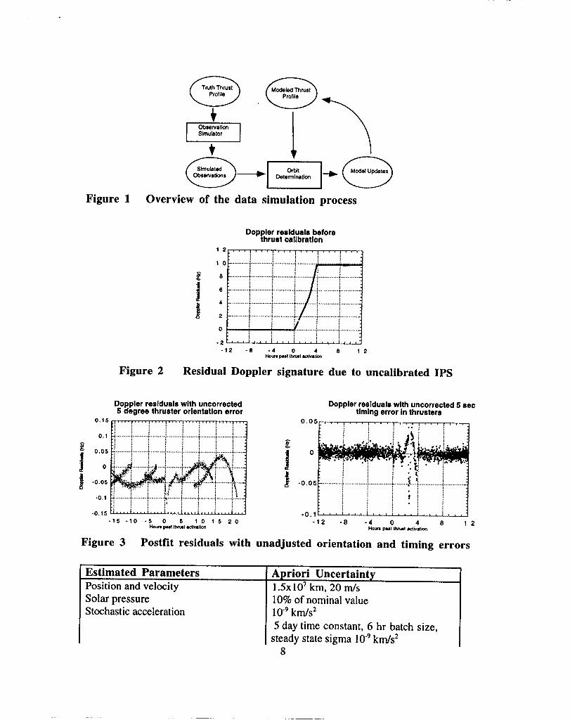
Figure 1
&&.+,.&
Overview of the data simulation process
Figure 2
-12 -8 -4 0 4 8~ WIUIIWIadhdcm12
Residual Doppler signature due to uncalibrated IPS
Doppler residuals with uncorrected5 degree thruster orientation error
-15 -lo -5 0 5 101520~ W! Ihfuit dkalbn
Figure 3 Postfit residuals with
Doppler residuals with uncorrected 5 sectiming error in thruatera
0.05 1 I 1 1!.. :
14
!i!
-0.1-12 -8 -4 0 4 8 12
HOlmpacth-w Kiw,tiwl
unadjusted orientation and timing errors
Estimated Parameters Apriori UncertaintyPosition and velocity 1.5x10⁷ km, 20 m/sSolar pressure - 10% of nom-inalvalueStochastic acceleration 109 krn/s2
5 day time constant, 6 hr batch size,steady state sigma 109km/s2
8

.
Impulsive chemical maneuvers(active only during approach phase)McAuliffe ephemeris(active only during approach phase)Consider ParametersStation locations
UT1 and polar motionTroposphere (wet and dry )Ionosphere
1% execution error
Correlated covariance provided byJPL’s Solar System Dynamics group
Correlated covariance determined fromVLBI processing.2 msec, 15 nrad,4cm, 10cm.5 x 10’7elec/m2
Figure 4 Covariance analysis assumptions
Transition from Powered Fiight to Baiiiatic Coast(Baseiine Fiiter - Doppier + Range)
500
400
300
200
100
0-20 -15 -lo -5 0 5 1015
Days since beginning of coast phase
Figure 5 Mapped position error for baseline strategy
3D Position Error within Thrusting Arc(Basaiins Strstegy)
3oo~. .r, .,, ,!, ,,r, ,,, ,.l .,r~ny
Ii ‘ ‘i!: +
:= j;:
250 :■ :
. . . . . . . . . . . . . . . ~ . . . . . ..m. . . . . . . . ..i . . . . . . . . . . . . ..m..+ . . . . . .::
●?::;m~~,
200 ■ ! ;. . . . . ...!. ~w. T..= . . ..1. . . . . . . . ..~. . .. . . ...t.s .. . . ..j . . . . . . . . i:. ■ ✚ J
J :. . ..i . . .. ..i.! . . . . . . . . ..i . . . . . . . .4
02468101 214Oay8put 12+40w1 098
Figure 6 Position uncertainty during powered flight

. ,
Tranaltlon from Powerad Flight to Balllstlc Coast(Dopplar Only)
-20 -15 -lo -5 0 5 1015Oay*cimx beginning d cad plus.
Figure 7 Position uncertainty for doppler only strategy
Tranaltion from Powarad Fli ht to Balllstlc Coasth
Transition from Powered Fli ht to Ballistic CoastNon-Optimal Filter: PSIG A = baseline x 2 hNon-Optlmel Filter: PSIQ A = baseline x 2
500
L:l L:rl
500
400 ..........s................i.. .......... .............. ............;ti:: 400 .........mj................. ..........!...........................E
:Ul, :
; 300 +............ ........ .... .............j .............. ............ & 300 ; ...................... ...................\..............~............
i ~● ;
200 :.......=...} ..............p.............f.............j............. 200 ?::............ . .. . .................... .. .
~ -m ~ b.:
100 ...9 . . . . ..j . . . . . . . . . ..a . .. . ..m.. . .. . . . . . . . . .. . .. . . . . .. . . . . . . . . . 100 .. ..! . . . . . ..~..i . . . . ..m .. . . ..= . . . . . . . . . . . . .. . . . . . . . . . .. .. . . . . . . .;m:
,spmmmm~,so 0
■ ■ ■=mmicm
-20 -lo 0 1020 30 -20 -lo 0 1020 30oay8 *inca beginning d 0m61 Ptu$o owl SIN L+-dlg d C.msl phme
Figure 8 Covariance due to mismodeled process noise sigma
Non-Optimal Filter: PSIGMA = 1/2 x baeeline Non-Optimal Filter: PSIGMA = 1/5 x baseline
Soo-. ,,r. ,r. r.. ,rr. ,rr, rr. 8, .,.., 500:~; f:; ~
1’ L:]
;~[ ~~:::: : ::;;:: ::: :;! ;~~ ;
400 . . . . . . . . . . . . . . . . .. .. . . .. . . . . . . . . . . . . . .. . . . . . . . . .. . .. . . . . . . . . . . . . . . ,
E :~!!!:!l
400 .. . . . ../ . . . . . . . ../. . . . . . . ..\. . . . . . ..+ . . . . . . ..+ . . . . . . ..} . . . . . . ..~...
Eli~:~!l
& 300 ; . .. . . . . . . . . . . . . . . .. . . . . . . . . . . .. . ..~. . . . . . . ..~. . . . . . . . .. . . . .. . . . .. . . . $ 300 ... . .. . . . . . . .. . ..~. . . . . . ..j . . . . . . ..f . . . . . . ..~ . . . . . . . . . . . . . . . . . . . .
i!
:!: :~~
i
:!::: ;; ;;
200 : . . . . . ..~ . . . . . . ..~ . . . . . . ..~ . . . . . . ..~. . . . . . . ..~. . . . . . . ..j . . . . . . . . .. . . . 200 .. . . ...~. . . .. .. ..\. . . . . . . . . . . . . . . ..j . . . . . . ..{ . . . . . . . . . . . . . . . . . . . .
j::::-i !m !::~m: ::: y
;:: :::
100 . . . . . . . . ..9 .. . ..i .. . . . ..m ... . . . ..* . .. . . . . . . . . . . .. ..} .. . . . . . . .. .. . 100 .. . . ...!.. ..m.! . .. . . . . . ..a . . . ..i...a..~ . . . .. . . . . . . . . . .. ..~...
a~m;m!q:: q’ =-9.?:::;; :mmaimqm ~;;
o “’’i’-’’’’’’’’’’’’’’’’u”!mm’8m ■
o.20 -15 .10 -5 0 5 1015 -20 -15 -lo -5 0 5 1015
tiy8 dtvx bodnniw d -81 @O lhys SIW* Lu.Jhling d mu! plum
Figure 9 Effect of enhanced calibration of the thrust error
10